GUIDELINES FOR SUBMISSION AND FORMAT FOR BE (CIVIL) PROJECTS DEPARTMENT OF CIVIL ENGINEERING NED UNIVERSITY OF ENGINEERING & TECHNOLOGY KARACHI, PAKISTAN

Welcome message from author
This document is posted to help you gain knowledge. Please leave a comment to let me know what you think about it! Share it to your friends and learn new things together.
Transcript

GUIDELINES FOR SUBMISSION AND
FORMAT FOR
BE (CIVIL) PROJECTS
DEPARTMENT OF CIVIL ENGINEERING
NED UNIVERSITY OF ENGINEERING & TECHNOLOGY
KARACHI, PAKISTAN

2 GUIDELINES FOR SUBMISSION AND FORMAT FOR BE
(CIVIL) PROJECTS
These guidelines shall be read in conjunction with “BE (CIVIL), Project monitoring,
Management and Assessment”
2.1 GENERAL
a) Project shall normally be undertaken on a topic agreed upon by a member of faculty,
who shall be act as supervisor(s) for that project group. The maximum number of
students in a group shall be restricted to eight (8) and minimum number to three (3).
b) The commencement date of project shall start from the date of beginning of the
session each year, and the completed project shall have to be submitted during the
last teaching week of fall semester.
c) The project forms part of the overall assessment for the BE (CIVIL) examination,
and is a requirement for partial fulfilment of the degree. The date of the presentation
of the project for final assessment shall by the Chairman of the Department in
consultation with the supervisor(s).
2.2 SUBMISSION
a) At the time of examination, the candidate(s) shall normally be required to submit
two (2) bound copies of the project, conforming to 2(b) given under with no
signatures.
b) The project report shall conform in layout, binding and presentation to the
requirement set out below under “Format of project”
c) Once the examination has been completed it is the responsibility of the
candidate(s) who has presented the project, to ensure that an addendum is pasted
at the end incorporating all changes, corrections, omissions and errors as pointed
out by the examiners, and the two (2) copies are bound in accordance with
“Format of project” duly signed by supervisor(s) and Chairman of the department,
with in a notified period. Non-compliance shall culminate in withholding of
result. These two copies shall become the property of the department and shall be
deposited in project library of the Department.
d) The final corrected hardbound copies of the project report must be accompanied
by a CD containing the following:
i. MS Word form of the final corrected version of the report.
ii. Source files (e.g.: MS Excel sheets used in data analysis, data files
etc)
iii. A README file (.Doc) describing the layout of the CD contents.
iv. Any other relevant files/documents.
v. The CD shall be placed in the pocket of the back cover.
2.3 FORMAT OF PROJECT
2.3.1 General
The provision of the general format shall be observed whenever appropriate, but may be
modified on the advice of the candidate(s) supervisor, after consultation with Chairman.
2.3.1.1 Number of pages
The total number of pages composing figures, tables, plates, charts, graphs, and written
material shall not exceed one hundred (100). Appendices may be added and in that case,
the total number of pages shall not exceed two hundred (200)
2.3.1.2 Size of paper
The size of paper shall be international A4 (8.27”×11.69”). Paper shall be of good
quality and of sufficient opacity for normal reading. One side only of the paper shall be
used. These shall be no border or any other printed matter on the paper except text,
figures etc., related to project.
2.3.2 Cover
1. Binding. The project shall be bound within boards in navy blue buckram. The
binding shall be fixed kind in which leaves are permanently secured. Metallic
corner protection should not be provided.
2. Front cover. The front cover shall contain the matter as given in the attached
sample, page (6). The lettering shall be gold in at least (8 mm) type.
2.3.3 Typographical Details
1. Layout
Margins at the binding (left-hand) edge shall be 40 mm (1.5”) and other margins shall be
20 mm (0.75”) 1.5 spacing shall be used between the lines except heading of sections and
sub-section, which shall be of double spacing. Foot notes, quotations, references
photographs and/or figure shall have single spacing
2. Type setting
Project shall be presented in a permanent and legible form in typescript. Typing should
be of even quality, with clear black characters. Drawings should be in black ink. Copies
produced by photographic or comparable permanent process are acceptable.
2.3.4 Pagination
1. Page Numbering. Pages shall be numbered consecutively throughout the project,
including figures, plates, charts, graphs and appendices. Page number shall be in
English numerals starting from chapter; all other pages before the start of the
chapter, including inner cover shall be numbered in roman numerals (see sample
pages 7-25)
2. Position of page numbers. Shall be located centrally at the bottom of the page
approximately 10 mm (0.5”) above the age
2.3.5 Preliminaries
1. Title page (inner cover). The title page shall conformed to the sample , page (7)
2. Certificate. The certificate shall follow the title page according to the sample
page.
3. Table of the contents. Table of the content shall follow certificate according to
the sample, page (9). All the other contents before start of the chapter shall be
placed as given in “Table of the contents-sample”. Sample for each is also
attached for ready reference from page (13) thought page (19).
4. Abstract. There shall be an abstract, or summary of the project report of
approximately 200 words. The abstract shall provide a synopsis of the project and
shall state clearly the nature and scope of work under taken.
2.3.6 Text
1. Introduction. The first chapter of the project shall be “Introduction” defining the
relation n of work done to the other work in the same field, need of the study,
scope and objective, beneficiary and the methodology to accomplish the study.
2. Chapters and Sections. Project shall be divided as appropriate into chapters,
section and sub section, the system of headings shall be consistent and should
provide a clear indication of the changes in content. The chapter, section and sub
section shell be numbered, e.g., chapter 2 for chapters, 2.1 for sections and 2.1.1
for subsections the headings and spacing shell be as shown in sample, page (20).
3. Reference citation, Figures, Plates etc. Reference cited in the text should be
identified by numbers type as super script, or if on the line, in brackets,
immediately following relevant word or perhaps in the text. Tables, figures,
plates, and the charts etc. should have captions. If these are borrowed from some
reference then they should be cited in the round brackets following the caption
e.g. (After Ref 1). All figures, plates, tables and charts should be well connected
with the text, and should be placed after the relevant chapter in the order so that
tables first, then figures and then plates. The number shall depict the chapter to
which they blowing e.g. Fig 2.1 means first figure of chapter 2. Sample for each
is attached herewith, pages 21, 22, 23.
4. Equation Numbering. Each equation shall be given a number. The number shall
depict the chapter to which they belong e.g. first equation of chapter 2 shall be
written as (2.1). Sample for an equation is attached here with, Page 25. The
equation shall be cited as Eq. (2.1).
5. Unbounded Material. Each item unbounded material e.g. maps, blue print etc.,
shall be marked with project title and batch, and shall be placed in an additional
pocket of the back cover.
1.2 End Matter
1. References. The list of references should be arranged in the order in which the
references are identified in the projects. Every reference in the list should enable
the reader to identify work cited as per sample, page (24) . The reference should
be written in a consistent format taken from any reputed journal or ISO standards.
For gaudiness purposes format of one the journal has been followed and is given
in sample page (24)
e.g. , For book 1, 2, & 3 are appropriate.
For journals 4, 5, 6, & 7 are appropriate
For conference, proceeding 8 is appropriate
For Thesis 9 appropriate

2. Bibliography. If a bibliography is supplied. It should be arranged in a logical
order, for example alphabetically by authors in broad subject class.
3. Appendices. Appendices shall follow main text. Appendices many contest of
supporting material or considerable length or of list or documents. All calculation
for design project and working table for construction management project shall be
placed in appendices. The main text shell only content summarized design table
sample provided on page (25).

PERFORMANCE OF BLENDED CEMENTS IN
AGGRESSIVE ENVIRONMENTS
DEPARTMENT OF CIVIL ENGINEERING
NED UNIVERSITY OF ENGINEERING AND TECHNOLOGY KARACHI, PAKISTAN
i
PERFORMANCE OF BLENDED CEMENTS IN
AGGRESSIVE ENVIRONMENTS
BATCH 2007-2008
By
NAME SEAT NO
1. MUHAMMAD ARSALAN ASHRAF CE-071
2. SYED DANISH JAVED CE-072
3. MUHAMMAD SHARIQ SIDDIQUI CE-074
4. BILAL AHMED CE-075
5. MUHAMMAD ALI BUKHARI CE-077
6. MUHAMMAD OMER ALI SIDDIQUI CE-105
7. MUHAMMAD JUNAID KHAN CE-307
DEPARTMENT OF CIVIL ENGINEERING
NED UNIVERSITY OF ENGINEERING AND TECHNOLOGY KARACHI, PAKISTAN
ii
CERTIFICATE
This is to certify that the following students of batch 2007-2008 have successfully
completed the final year project in partial fulfilment of requirements for a Bachelor’s
Degree in Civil Engineering from NED University of Engineering and Technology,
Karachi, Pakistan.
MUHAMMAD ARSALAN ASHRAF CE-071
SYED DANISH JAVED CE-072
MUHAMMAD SHARIQ SIDDIQUI CE-074
BILAL AHMED CE-075
MUHAMMAD ALI BUKHARI CE-077
MUHAMMAD OMER ALI SIDDIQUI CE-105
MUHAMMAD JUNAID KHAN CE-307
PROJECT SUPERVISOR
__________________________ Prof. Dr. Asad-ur-Rehman Khan (Internal) Department of Civil Engineering
NED University of Engineering & Technology, Karachi.
__________________________ Prof. Dr. Asad-ur-Rehman Khan Chairman Department of Civil Engineering
NED University of Engineering & Technology, Karachi.
__________________________ …………………………………...
(External)

iii
iv
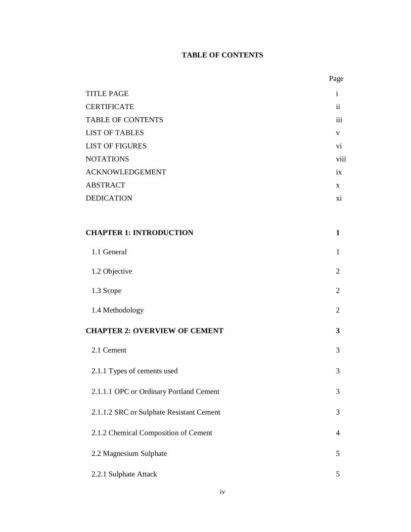
TABLE OF CONTENTS
Page
TITLE PAGE i
CERTIFICATE ii
TABLE OF CONTENTS iii
LIST OF TABLES v
LIST OF FIGURES vi
NOTATIONS viii
ACKNOWLEDGEMENT ix
ABSTRACT x
DEDICATION xi
CHAPTER 1: INTRODUCTION 1
1.1 General 1
1.2 Objective 2
1.3 Scope 2
1.4 Methodology 2
CHAPTER 2: OVERVIEW OF CEMENT 3
2.1 Cement 3
2.1.1 Types of cements used 3
2.1.1.1 OPC or Ordinary Portland Cement 3
2.1.1.2 SRC or Sulphate Resistant Cement 3
2.1.2 Chemical Composition of Cement 4
2.2 Magnesium Sulphate 5
2.2.1 Sulphate Attack 5
v
2.2.1.1 External Sulphate Attack 6
2.2.1.2 Internal Sulphate Attack 6
2.2.2 Mechanism of Sulphate Attack 6
2.2.3 Sources of Sulphate Attack 7
2.3 Seawater 7
2.3.1 Mechanism of Seawater Attack 8
2.4 Fly Ash 9
2.4.1 Classifications and Specifications 9
2.4.2 Mix Design 9
2.4.3 Effect of Fly Ash on cement 10
CHAPTER 3: EXPERIMENTAL PROGRAM 13
3.1 Introduction 13
3.2 Preparations of Cubes 14
3.3 Preparations of Solutions 14
3.4 Seawater 15
CHAPTER 4: RESULTS AND DISCUSSIONS 17
4.1 Visual Inspection 17
4.2 Reduction in compressive strength 17
CHAPTER 5: CONCLUSIONS 36
5.1 Conclusions 36
REFERENCES 38
vi
LIST OF TABLES
Page
Table 2.1 Chemical formulae and cement nomenclature for major 12
constituents of Portland cement
Table 3.1 Parameters of seawater used for experimental works. 16
Table 4.1 Visual Inspection for OPC samples for 90 days curing 22
Table 4.2 Visual Inspection for OPC samples for 180 days curing 22
Table 4.3 Visual Inspection for SRC samples for 90 days curing 22
Table 4.4 Visual Inspection for SRC samples for 180 days curing 22
Table 4.5 Percent compressive strength for cement mortar specimen 23
after 90 days in 1% MgSO4
Table 4.6 Percent compressive strength for cement mortar specimen 23
after 90 days in 2% MgSO4
Table 4.7 Percent compressive strength for cement mortar specimen 24
after 90 days in 4% MgSO4
Table 4.8 Percept compressive strength for cement mortar specimen 24
after 90 days in Seawater
Table 4.9 Percent compressive strength for cement mortar specimen 25
after 180 days in 1% MgSO4
Table 4.10 Percent compressive strength for cement mortar specimen 25
after 180 days in 2% MgSO4
Table 4.11 Percent compressive strength for cement mortar specimen 26
after 180 days in 4% MgSO4
Table 4.12 Percent compressive strength for cement mortar specimen 26
after 180 days in Seawater
vii
LIST OF FIGURES
Page
Figure 4.1 Cement mortar specimens exposed to 1% MgSO4 for 90 days 27
Figure 4.2 Cement mortar specimens exposed to 2% MgSO4 for 90 days 27
Figure 4.3 Cement mortar specimens exposed to 4% MgSO4 for 90 days 27
Figure 4.4 Cement mortar specimens exposed to Seawater for 90 days 28
Figure 4.5 Cement mortar specimens exposed to 1% MgSO4 for 180 days 28
Figure 4.6 Cement mortar specimens exposed to 2% MgSO4 for 180 days 28
Figure 4.7 Cement mortar specimens exposed to 4% MgSO4 for 180 days 29
Figure 4.8 Cement mortar specimens exposed to Seawater for 180 days 29
Figure 4.9 Cement mortar specimens exposed to 1% MgSO4 for 90 days 29
Figure 4.10 Cement mortar specimens exposed to 2% MgSO4 for 90 days 30
Figure 4.11 Cement mortar specimens exposed to 4% MgSO4 for 90 days 30
Figure 4.12 Cement mortar specimens exposed to Seawater for 90 days 30
Figure 4.13 Cement mortar specimens exposed to 1% MgSO4 for 180 days 31
Figure 4.14 Cement mortar specimens exposed to 2% MgSO4 for 180 days 31
Figure 4.15 Cement mortar specimens exposed to 4% MgSO4 for 180 days 31
Figure 4.16 Cement mortar specimens exposed to Seawater for 180 days 32
Figure 4.17 Percent compressive strength of cement types for 90 days in 32
1% MgSO4
Figure 4.18 Percent compressive strength of cement types for 90 days in 32
2% MgSO4
Figure 4.19 Percent compressive strength of cement types for 90 days in 33
4% MgSO4
viii
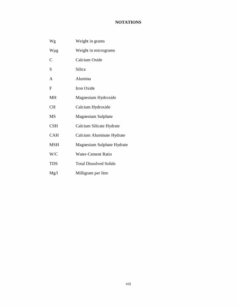
NOTATIONS
Wg Weight in grams
Wµg Weight in micrograms
C Calcium Oxide
S Silica
A Alumina
F Iron Oxide
MH Magnesium Hydroxide
CH Calcium Hydroxide
MS Magnesium Sulphate
CSH Calcium Silicate Hydrate
CAH Calcium Aluminate Hydrate
MSH Magnesium Sulphate Hydrate
W/C Water-Cement Ratio
TDS Total Dissolved Solids
Mg/l Milligram per litre

ix
ACKNOWLEDGEMENT
First praise is to Allah, the Almighty, on whom ultimately we depend for sustenance and
guidance. Acknowledgment is due to NED University of Engineering & Technology,
Karachi for the support it has provided us for the completion of the project. We would
like to thank everyone who had contributed to the successful completion of this project.
We would like to express our gratitude to our project supervisor,
___________________for his advice, guidance and his enormous patience throughout the
development of the work. We would like to thank our Co-supervisor, ______________
for her constant attention and her valuable time.
In addition, we would also like to express our gratitude to our loving parents and friends
who helped and given us the encouragement.
x
ABSTRACT
This project is focused on the performance of different cement types blended with fly ash,
exposed to seawater and sulphate environments. Fly ash is a by-product obtained from the
combustion of organic materials. It is a pozzolanic material that is very useful when used
in combination with cement and helps increase its compressive strength. Fly ash is being
used in concrete and it is important that it is observed for its potential as a binder for
concrete. It is also important to observe its behaviour when it is placed in contact with
seawater and sulphate environments and how they affect the blended cement.
Different percentages of fly ash were used for preparing cement specimens to observe
their behaviour accordingly. The environments provided are focused on sulphate attacks
on concrete from seawater and environments with varying percentages of magnesium
sulphate. The strength and deterioration rate of the blended cements was observed and
analysed.
On the basis of the experimental works carried out during the project a few observations
made were that, blending of cement with fly ash results in a decrease in the compressive
strength of concrete in the initial days, but after 28 days its compressive strength starts to
increase. It is better to utilize blends of fly ash for OPC and SRC for seawater, which is
the source of both sulphate attack and corrosion.

xi
DEDICATION
The project is especially dedicated to our parents, our supervisor and co supervisor for
helping us out during the completion of the entire project.
12
CHAPTER NO. 4
RESULTS AND DISCUSSIONS
This chapter discusses the compressive strength results of the cement mortar specimens
prepared and placed in environments. The testing of the cubes of standard OPC and SRC
cubes are done at the end of 28 days of curing. The cubes that are immersed in the aggressive
environment are tested for their compressive strength after the completion of their 90 and 180
days exposure.
2.4 VISUAL INSPECTION
The specimens are rated on a six-point scale ranging from 0 to 5 with 0 indicating the least or
no deterioration.(13)After their designated exposure period the cement mortar cubes are taken
out of their respective solutions, these cubes are placed for visual inspection to monitor the
deterioration caused by the aggressive events. The changes in samples are noted in the form
of deterioration ratings based on the visual changes like chipped off edges and corners,
cracking and other changes (swelling, shrinkage, expansion or compaction).
The deterioration is classified on a six-point scale ranging from 0 to 5. A rating of 0 indicates
a no change in the sample and a rating of 5 indicates a complete failure. The deterioration is
hence graded according to the mentioned ratings and results are tabulated. The images of the
samples at 90 and 180 days after the placement in solutions are also provided.
The noted observations of the inspected samples are given in Table and can be viewed in
figure.
2.5 REDUCTION IN COMPRESSIVE STRENGTH
For the compressive strength test the mortars are tested at the end of 90 and 180 days of
placement in solutions. The effect of sulphate attack is determined in the form percentage
reduction of compressive strength in the mortar specimen as given in Eq. (4.1).
%� � � � � � � � � � � � � � � � � � � � � � � � � � � � � =
� − �
�× 100 (4.1)
13
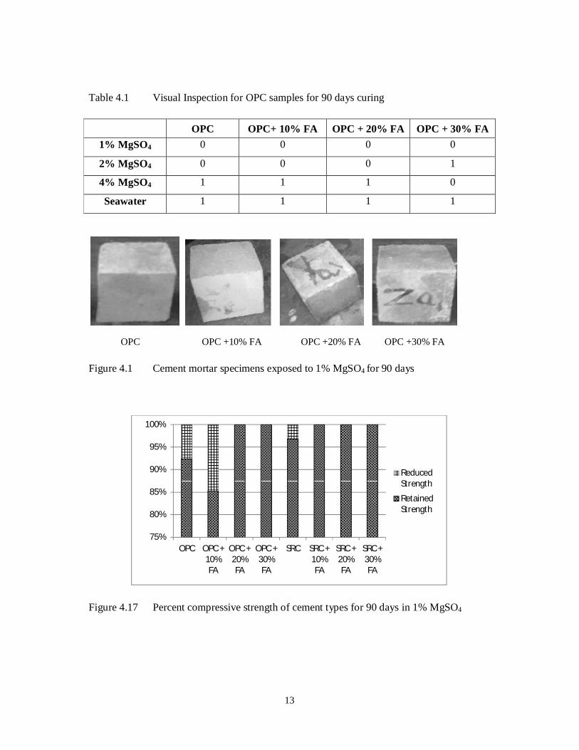
Table 4.1 Visual Inspection for OPC samples for 90 days curing
OPC OPC+ 10% FA OPC + 20% FA OPC + 30% FA
1% MgSO4 0 0 0 0
2% MgSO4 0 0 0 1
4% MgSO4 1 1 1 0
Seawater 1 1 1 1
OPC OPC +10% FA OPC +20% FA OPC +30% FA
Figure 4.1 Cement mortar specimens exposed to 1% MgSO4 for 90 days
Figure 4.17 Percent compressive strength of cement types for 90 days in 1% MgSO4
75%
80%
85%
90%
95%
100%
OPC OPC +10%FA
OPC +20%FA
OPC +30%FA
SRC SRC +10%FA
SRC +20%FA
SRC +30%FA
ReducedStrength
RetainedStrength
14
REFERENCES
1. Al-Amoudi, O.S.B., “Attack on Plain and Blended Cements Exposed to Aggressive
Sulphate Environments,” Cement & Concrete Composites, Special Issue on: Sulphate
Attack and Thaumasite Formation, Vol. 24, Nos. 3-4, June-August 2002, pp. 305-316.
2. http://en.wikipedia.org/wiki/Cement
3. http://www.cnx.org/content/m16445/latest/
4. http://en.wikipedia.org/wiki/Magnesium_sulfate
5. http://www.understanding-cement.com/sulfate.html
6. Al-Dulaijan, S.U., “Sulphate Resistance of Plain and Blended Cements Exposed to
Magnesium Sulphate Solutions,” Construction and Building Materials Journal, Vol. 21,
No. 8, August 2007, pp. 1792-1802.
7. http://en.wikipedia.org/wiki/Seawater
8. M.Sc. hand outs by Professor S.F.A. Rafeeqi, NED University of Engineering and
Technology
9. Admixtures and Ground Slag for Concrete 1990; ACI Comm. 226 1987c
10. Halstead, W. J. 1986. Use of fly ash in concrete. NCHRP 127 (October). Washington:
Transportation Research Board, National Research Council.
11. Studies on high-performance blended/multi-blended cement and their durability
Related Documents