Wire Rope Guidelines (Version 1. – English) - 10/2018 Page 1 Guidelines for Handling, Installation and Maintenance of Wire Ropes

Welcome message from author
This document is posted to help you gain knowledge. Please leave a comment to let me know what you think about it! Share it to your friends and learn new things together.
Transcript

Wire Rope Guidelines (Version 1. – English) - 10/2018 Page 1
Guidelines for Handling, Installation and
Maintenance of Wire Ropes

Wire Rope Guidelines (Version 1. – English) - 10/2018 Page 2
COPYRIGHT
CASAR Drahtseilwerk Saar GmbH reserves all rights for these guidelines. In
particular, we claim copyright and competition law protection for this.
It is only permitted to change or copy these guidelines or parts of them with our
express prior consent.
These technical documents or parts of them may not be duplicated, distributed,
made available to third parties or used in an unauthorised way for competitive
purposes without our prior consent.
Limbach, 02/10/2018
Board of Management
CASAR Drahtseilwerk Saar GmbH
Casarstraße 1, 66459 Kirkel-Limbach
Germany

Wire Rope Guidelines (Version 1. – English) - 10/2018 Page 3
EC DECLARATION OF CONFORMITY
Complies with the Directive on Machinery 2006/42/EC in the valid version
We, Casar Drahtseilwerk Saar GmbH, hereby declare under our sole authority that the
machine described in the following meets all relevant requirements of the EU Directive
on Machinery 2006/42/EC. It is also confirmed that the delivery was checked and
complies with the agreements made during order acceptance.
The following harmonised standards were used:
EN ISO 12100 Safety of machinery – General design principles – Risk assessment
and risk reduction
EN 12385-1: 2002+A1: 2008 Steel wire ropes - Safety - Part 1: General
requirements
EN 12385-2: 2002+A1: 2008 Steel wire ropes - Safety - Part 2: Terms, designation
and classification
EN 12385-3: 2004+A1: 2008 Steel wire ropes - Safety - Part 3: Information for use
and maintenance
EN 12385-4: 2002+A1: 2008 Steel wire ropes - Safety - Part 4: Stranded ropes for
general lifting purposes
EN 12385-10: 2003+A1: 2008 Steel wire ropes - Safety - Part 10: Spiral ropes for
general structural applications
EN 13411-4: 2011-06 End connections for steel wire ropes - Safety - Part 4: Cast
with metal and plastic
The following other standards and specifications were used:
EN10264-1: 2012-3 Steel wire and wire products - Steel wire for ropes - Part 1:
General requirements
EN10264-2: 2012-3 Steel wire and wire products - Steel wire for ropes - Part 2:
Cold-drawn non-alloy steel wire for ropes for general applications.
Changes to the machine as well as non-observance of the regulations from EN
12385-3
“Steel wire rope – Safety; Part 3: Information for use and maintenance” as well as
ISO 4309
“Cranes - Wire ropes - Care, maintenance, installation, examination and discard”
will void the validity of this declaration.
Limbach, 02/10/2018
Board of Management
CASAR Drahtseilwerk Saar GmbH
Casarstraße 1, 66459 Kirkel-Limbach
Germany

Wire Rope Guidelines (Version 1. – English) - 10/2018 Page 4
INSTALLATION DECLARATION
Installation declaration according to EC Directive on Machinery 2006/42/EC /
Annex IIB)
We hereby declare that the “incomplete machine”, as far as possible in the scope
of delivery, complies with the basic requirements of the
Directive on Machinery (2006/42/EC)
EMC – Guidelines (2004/108/EC).
Commissioning of the incomplete machine is not permitted until it has been
installed in a machine and this complies with regulations of the EC Directive on
Machinery and the EC declaration of conformity according to annex II A.
The associated directive includes important technical safety information and
regulations for the installation, commissioning, maintenance and servicing of the
product.
Special technical documents according to Annex VII Part B were issued for the
product. These documents can be sent by post or email to a national authority
following a reasoned request.
Information: If the product is modified without agreement from the manufacturer,
this declaration shall cease to apply.
Limbach, 02/10/2018
Board of Management
CASAR Drahtseilwerk Saar GmbH
Casarstraße 1, 66459 Kirkel-Limbach
Germany

Wire Rope Guidelines (Version 1. – English) - 10/2018 Page 5
CONTENTS
Copyright ................................................................................................ 2
EC declaration of conformity ......................................................................3
Installation declaration ............................................................................. 4
1. General .................................................................................................7
1.1 Preface ................................................................................................... 7
1.2 Intended use ......................................................................................... 8
1.3 Liability ................................................................................................. 9
2. Safety ................................................................................................ 10
2.1 Presentation of warning information ................................................... 10
2.2 Presentation of danger levels ............................................................... 11
2.3 Safety symbols..................................................................................... 12
2.4 Dangers resulting from non-observance of safety information ............ 14
2.5 Safety information for the wire rope operator ..................................... 14
2.6 Material-related health and safety information ................................... 15
2.7 Medical emergency measures .............................................................. 17
2.8 Information for an emergency ............................................................. 18
3. Specification of wire ropes .................................................................... 19
3.1 General ................................................................................................ 19
3.2 Components and manufacture of a wire rope/stranded rope ................ 19
3.3 Direction of lay of the rope ................................................................... 23
3.4 Lay type of the rope ............................................................................. 23
3.5 Choosing the correct direction of lay ................................................... 25
3.6 Rotation-resistant and non-rotation-resistant ropes ........................... 26
3.7 Strength ............................................................................................... 27
3.8 Surface ................................................................................................ 27
3.9 Diameter and manufacturing tolerance ............................................... 27
3.10 Wire rope length ............................................................................... 28
3.11 The application temperature range of CASAR special wire ropes ....... 28
4. Handling wire ropes ............................................................................. 29
4.1 Transporting special wire ropes ........................................................... 29
4.2 Storing special wire ropes ................................................................... 29
5. Installation of steel wire ropes ............................................................... 30
5.1 Incorrect unwinding ............................................................................. 30

Wire Rope Guidelines (Version 1. – English) - 10/2018 Page 6
5.2 Correctly unwinding a steel wire rope from the coil .............................. 30
5.3 Correctly unwinding a steel wire rope from the reel ............................. 31
5.4 Winding the rope from a reel to a drum ............................................... 31
5.5 The fleet angle ..................................................................................... 32
5.6 The grooves of drums and sheaves ...................................................... 33
5.7 Installing the new rope ......................................................................... 35
5.8 The preload .......................................................................................... 38
5.9 “Breaking in” the steel wire rope ..........................................................39
5.10 Cutting steel wire ropes......................................................................39
6. Maintaining steel wire ropes ................................................................. 41
6.1 Relubricating steel wire ropes .............................................................. 41
6.2 Cleaning wire ropes ............................................................................. 43
6.3 Removing broken wires ........................................................................ 43
7. Discard criteria according to DIN ISO 4309 .............................................. 44
7.1 Visible wire breaks ............................................................................... 44
7.2 Diameter reduction .............................................................................. 47
7.3 Strand break........................................................................................ 48
7.4 Corrosion ............................................................................................ 49
7.5 Deformation and other damage .......................................................... 50
Bibliography/directory of applicable standards ........................................... 53

Wire Rope Guidelines (Version 1. – English) - 10/2018 Page 7
1. GENERAL
These guidelines apply for wire ropes in terms of the Directive on Machinery
2006/42/EC of the manufacturer CASAR Drahtseilwerk Saar GmbH, registered at
the Saarbrücken local court HRB 17125.
1.1 PREFACE
These guidelines are aimed at persons who directly or indirectly come into contact
with wire ropes and should always be available to them.
They should ease the proper handling of wire ropes and convey the necessary
expertise.
Compliance with the instructions in the guidelines should ensure the safe handling
of wire ropes and help to prevent dangers and minimise repair costs and
downtimes.
Our number one priority is user safety, which is best achieved by our joint efforts.
We feel that you make a major contribution to safety if you:
1. Comply with employer, job site and governmental rules
2. Read, understand and follow the instructions in this and other manuals
supplied with the wire ropes.
3. Use good safe work practices in a common-sense way
4. Only have trained/certified operators, directed by informed and
knowledgeable supervision, handling installing and maintaining the wire
ropes. If there is anything in this manual that is not clear or which you
believe should be added, please contact us:
Internet: www.casar.de
Phone: +49 6841 / 8091 0
DANGER
Failure to obey the instructions and safety rules in this manual will result in death
or serious injury.

Wire Rope Guidelines (Version 1. – English) - 10/2018 Page 8
IMPORTANT:
Wire ropes are used in a variety of different applications. For reasons of clarity, all
detailed information cannot be provided and every conceivable operational case
cannot be covered in these guidelines. In the event of problems, uncertainties or if
further information is required, we ask you to contact CASAR Drahtseilwerk Saar
GmbH (“manufacturer” in the following) directly.
1.2 INTENDED USE
Intended use
The Directive on Machinery 2006/42/EC, Art. 1e specifies what is considered
intended use when using wire ropes. Normal use is considered to be its use for
lifting purposes, as part of lifting gear or load handling equipment.
Any other use beyond this is excluded from the liability of the manufacturer as
improper use.
Unauthorised changes
If unauthorised changes are made to the wire ropes, the manufacturer shall not be
liable for any damage resulting from this.
If the wire ropes are incorrectly or improperly handled as well as if they are used by
unauthorised or untrained personnel, there are serious dangers:
Dangers that affect life and limb
Dangers relating to the wire ropes themselves
Dangers for assets of the user
If the wire ropes are used outside of Germany, the safety regulations of the
country of use apply.
Regulations in the country of use
Not only these guidelines are authoritative. Together with them, national rules
and regulations must be observed that apply at the deployment site, i.e. in the
country of use. The binding regulations for accident prevention as well as the
technical rules that are valid for safe and proper work are to be applied in
particular.
Important: The emergency numbers applicable in the country of use must always
be specified.
Wire Rope Guidelines (Version 1. – English) - 10/2018 Page 9
Limited load
The specified permitted loads of the wire ropes must be complied with due to
reasons of safety and liability.
Observe the following: Further information can be found in the technical
documentation of the machine manufacturer.
Use, maintenance, servicing
If regulations for operational, technical maintenance or servicing conditions are set
on the part of the wire rope or machine manufacturer, these regulations for
intended use must also be complied with.
1.3 LIABILITY
Liability cases
Due diligence obligations stated as part of the Directive on Machinery 2006/42/EC
were complied with on the part of the manufacturer. Therefore, the
manufacturer’s liability is limited to damage to the rope that has occurred despite
proper use. The contractual agreements are the basis for the guarantee.
Correction of faults
Defects that arise must only be corrected by persons trained for this and specially
assigned to do so.
Limitations of liability
We assume no liability for safety defects that are not yet accounted for according
to today’s technical understanding. Furthermore, we assume no liability for the
effects of
Violations of safety information,
Violations of information about special dangers,
Violations of the ban on unauthorised design changes to the systems and
devices.
In addition, as the manufacturer, we assume no liability for the use of our wire
ropes in conjunction with faulty and non-compliant systems and devices.

Wire Rope Guidelines (Version 1. – English) - 10/2018 Page 10
2. SAFETY
2.1 PRESENTATION OF WARNING INFORMATION
Warning information is stated by us before all handling instructions with which
residual risks can be associated. This information must always be observed and
followed.
To indicate this, the warning information is clearly separated from other text and
identified multiple times with
1) a symbol,
2) a colour scheme (for example, red stands for the highest danger level),
3) signal words such as ‘Warning’, ‘Danger’, ‘Caution’ or ‘Attention’ as well
as
4) possible text for explanations.
As the symbols alone do not provide adequate safety information, it is important
to read the complete text of the safety information.
In these guidelines, the differentiation of danger levels and presentation
according to danger levels occurs as follows:

Wire Rope Guidelines (Version 1. – English) - 10/2018 Page 11
2.2 PRESENTATION OF DANGER LEVELS
Warnings for possible personal injury
DANGER
Highest danger level. Reference to an imminently dangerous situation that will
cause death or serious injury if the safety regulations are not complied with.
WARNING
Warning information. Reference to an imminently dangerous situation that can
cause death or serious injury if the safety regulations are not complied with.
CAUTION
Reference for care to be taken. Reference to a possibly dangerous situation that
can cause property damage or slight to moderate injury if the safety regulations
are not complied with.
Warnings for possible property damage
ATTENTION
Reference for compliance. Refers to possibly harmful situations that can cause
damage to the product or its surroundings if not complied with.

Wire Rope Guidelines (Version 1. – English) - 10/2018 Page 12
2.3 SAFETY SYMBOLS
2.3.1 Prohibition symbols
The prohibition symbols used in these guidelines indicate when and/or which
protective clothing is to be worn when working with wire ropes to prevent possible
dangers for persons.
Attention! – General mandatory signs
Wear safety gloves – Protective gloves protect hands from friction, abrasion,
piercing and deep cuts as well as contact with hot surfaces.
Wear a helmet – A helmet provides protection from falling and flying parts and
materials.
Wear eye protection – Goggles protect eyes from flying parts and liquid splashes.
Wear safety shoes – Safety shoes protect feet from heavy falling parts and
prevent slipping on slippery floors.
Wear protective clothing – Tight work clothing with a low tear strength, tight
arms and without protruding parts is advised. Wear face protection!
Use face protection
Wear a mask!
Read the operating instructions!

Wire Rope Guidelines (Version 1. – English) - 10/2018 Page 13
2.3.2 Warning symbols
The warning symbols used in these guidelines indicate different dangers that can
arise while using ropes. They indicate the type of possible risks.
Attention! – General warning of a hazardous area
Warning of risk of being pulled in
Warning of crushing
2.3.3 Prohibition sign
Prohibited! – Symbol for designating a general prohibition.
2.3.4 Rescue sign
First aid – Reference to first aid equipment.

Wire Rope Guidelines (Version 1. – English) - 10/2018 Page 14
2.4 DANGERS RESULTING FROM NON-OBSERVANCE OF SAFETY
INFORMATION
CAUTION
The wire ropes described in the guidelines are manufactured according to DIN
EN 12385-1:2002+A1:2008. This means: They correspond to the current state of
technology with regard to their operational safety and construction. They are
protected against dangers according to the Directive on Machinery 2006/42/EC.
Danger information: To prevent dangers arising when handling wire ropes, the
personnel involved must be trained, the ropes should be properly handled used for
their intended purpose.
2.5 SAFETY INFORMATION FOR THE WIRE ROPE OPERATOR
CAUTION
Knowledge of safety regulations
The entire team of persons who are involved with the use of wire ropes – from the
workers to the supervisors – must be familiar with the safety regulations from this
chapter (chapter 2). The guidelines must be available at the installation site for
direct inspection. All safety information must be followed. The required protective
clothing/equipment must be provided and used. The wire ropes may only be
operated when in a perfect condition.
Special information about the topic of withdrawal from service can be found
on page 42/43.
INFORMATION
Proper employee training relevant to safety
Specific training is used to prevent accidents and downtimes: It is important that
user companies train their employees to properly work with wire ropes in a
focused, comprehensive and verifiable manner. The competences in the team for
maintenance, servicing and cleaning should also be clearly assigned. Also ensure
proper training for relevant work here.

Wire Rope Guidelines (Version 1. – English) - 10/2018 Page 15
2.6 MATERIAL-RELATED HEALTH
AND SAFETY INFORMATION
2.6.1 General
The materials for the manufacture of wire ropes are not harmful to health at the
time of their delivery. They are made of non-harmful, unalloyed steel wire, steel
wire with a coating, wire ropes with plastic sheath or non-rusting steel wire.
Harmful substances can therefore only arise or come into being during further
processing.
CAUTION
Important information: Only persons who are familiar with the handling of wire
ropes and who are assigned to do so may use wire ropes during work.
2.6.2 Dust and vapours – possible dangers
during further processing
CAUTION
Dust and vapours that arise during further processing due to cutting,
annealed cutting, grinding and cleaning ropes can be a hazard to the
health of the persons involved.
An acute health hazard can arise during improper handling of fibre cores
made of natural or synthetic fibres, rope lubricants, possible fillers as well
as sheaths.
Vapours that are a hazard to respiration can arise when cutting ropes
using cutting discs or during annealed cutting.

Wire Rope Guidelines (Version 1. – English) - 10/2018 Page 16
Always ensure appropriate safety equipment – especially during work
that is a hazard to the eyes. During cutting and annealed cutting, wear
tight-fitting clothing, eye protection, safety gloves and safety shoes
2.6.3 Proper handling of lubricants
CAUTION
Precautionary measures when using lubricants:
Different lubricants are used to protect wire ropes. Prevent skin contact with
these lubricants! The following points generally apply: Clean your hands after
they come into contact with wire ropes and, if necessary, apply skin
protection cream.
Make sure protective gloves do not let through lubricants.
Wear protective clothing to prevent unnecessary contact.
Make use of first aid treatment even for the most minor injuries.

Wire Rope Guidelines (Version 1. – English) - 10/2018 Page 17
Avoid the following at all costs:
Put cloths or tools contaminated with lubricant in pockets.
Use dirty cloths for wiping off lubricants from the skin.
Wear clothing contaminated with lubricants.
Use solvent such as paraffin or gasoline to remove lubricants from the skin.
2.6.4 Other rope components
CAUTION
Even if lubricants, natural fibres, synthetic fibres and synthetic fillers as well as
sheaths in a solid form are not flammable or explosive, they can still support fires
in conjunction with other substances. The required fire protection is therefore to
be ensured on the part of the user.
2.7 MEDICAL EMERGENCY MEASURES
INFORMATION
For inhalation of hazardous materials: Take the person concerned into the fresh
air and get medical help.
For skin contact: Clean the areas of skin with soap and water.
For contact with the eyes: Rinse out the harmful substances intensively under
running water. Seek medical help.
If rope components are swallowed: Get direct medical help.

Wire Rope Guidelines (Version 1. – English) - 10/2018 Page 18
2.8 INFORMATION FOR AN EMERGENCY
1. Report accident: call 112
Who reports the accident?
What happened?
Where is the place of injury?
How many persons are injured?
Wait for queries.
2. Provide first aid.
Secure the accident site to prevent consequential injury
Take any injured persons out of the danger zone
Look after injured persons
3. Initiate further measures.
Alert first aid helper/emergency response officer
Alternatively: Emergency doctor, tel. 112
Fire department, tel. 112
Different local emergency numbers are to be added by the user and must
be clearly visible.

Wire Rope Guidelines (Version 1. – English) - 10/2018 Page 19
3. SPECIFICATION OF WIRE ROPES
3.1 GENERAL
A rope is an elongated, flexible, elastic element made of twisted fibres or wires for
transferring tensile forces.
3.2 COMPONENTS AND MANUFACTURE OF A WIRE
ROPE/STRANDED ROPE
According to DIN EN 12385-2, a "stranded rope is “a construction made of several
strands that are helically twisted in one (single layer rope) or several layers
(rotation-resistant or parallel lay rope) around an insert or core”.
Only wires that meet the requirements of EN 10264-2 are used for the
manufacture of our stranded ropes. These wires are first twisted into strands that
are finally closed into ropes. During the course of the manufacturing process,
lubricant is applied to the strands, core and the rope to prevent internal friction
and to protect the rope from corrosion.

Wire Rope Guidelines (Version 1. – English) - 10/2018 Page 20
3.2.1 Core types
DIN EN 12385-2 defines the core as “an element in the middle of a round rope
around which the strands of a stranded rope are helically twisted.”
Wire rope with fibre core Wire rope with steel core

Wire Rope Guidelines (Version 1. – English) - 10/2018 Page 21
The different core types according to DIN EN 12385-2
3.2.2 Strand types
DIN EN 12385-2 defines a strand as “an element of the rope that consists of a
construction of wires with a suitable form and suitable dimensions that has been
helically twisted in one or more layers around a core.”
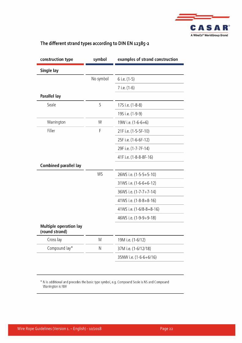
Wire Rope Guidelines (Version 1. – English) - 10/2018 Page 22
The different strand types according to DIN EN 12385-2

Wire Rope Guidelines (Version 1. – English) - 10/2018 Page 23
3.3 DIRECTION OF LAY OF THE ROPE
right hand lay rope Z left hand lay rope S
3.4 LAY TYPE OF THE ROPE
3.4.1 Ordinary lay
The wires in the outer strands have an opposite direction of lay than the outer
strands in the rope. As a result, the wires practically lie on an axis with the rope
itself.
left (zS) right (sZ)
The first letter refers to the direction of lay of the strand and the second letter
refers to the direction of lay of the rope.

Wire Rope Guidelines (Version 1. – English) - 10/2018 Page 24
3.4.2 Lang lay
The wires in the strands as well as the strands themselves have the same direction
of lay. The wires therefore form an angle to the axis of the rope.
left (sS) right (zZ)
The first letter refers to the direction of lay of the strand and the second letter
refers to the direction of lay of the rope.
sS zZ

Wire Rope Guidelines (Version 1. – English) - 10/2018 Page 25
3.5 CHOOSING THE CORRECT DIRECTION OF LAY
The choice of the correct direction of lay is essential for the proper functioning of a
reeving system. A wrong direction of lay leads to torque build-up, spooling
problems and structural changes.
ATTENTION
One layer spooling: For drums with one layer, the following applies:
right hand drum – left hand rope
left hand drum – right hand rope
Multiple layer spooling: With multiple layer spooling, the direction of spooling
changes from layer to layer. So the direction of lay of the rope would also have to
be changed from layer to layer. Here, the direction of lay should be chosen for the
layer which is working the most:
right hand layer – left hand rope
left hand layer – right hand rope
Multiple part reeving: In a multiple part reeving system, the influence of the fleet
angles between the sheaves is often greater than the influence of the drum. In this
case, the direction of lay of the rope should be chosen depending on the direction
of the reeving:
right hand reeving – left hand lay rope
left hand reeving – right hand lay rope
And here is how you determine the direction of the winding of the drum or reeving
system: Place yourself at the fix point (⊗) of the rope on the drum (at the reeving
system) and follow the turns of the rope with your finger.
right hand drum - left hand lay rope
left hand drum - right hand lay rope
If you move your finger clockwise, the drum (reeving system) is right hand, and needs a left hand lay rope.
If you move your finger counter-clockwise, the drum (reeving system) is left hand, and needs a right hand lay rope.

Wire Rope Guidelines (Version 1. – English) - 10/2018 Page 26
3.6 ROTATION-RESISTANT AND NON-ROTATION-RESISTANT
ROPES
A helically twisted wire rope tends to “untwist” to reduce its torque under load.
The result is that every wire rope - the manufacturer, strength, etc. does not play a
role - tends to twist under load.
In a conventional rope that consists of at least 2 strand layers that are twisted
around the core in a helical form, the direction of lay of the outer strands matches
that of the inner strands. All strands generate a torque under load that is directed
in the same, i.e. opening, direction and the rope starts to twist.
A rotation-resistant rope has a steel core that functions as an independent rope
and is closed in the opposite direction like the outer strands. Under load, the steel
core tries to untwist in one direction while the outer strands try to untwist in the
opposite direction. The rope is designed in a way so that the torques of the steel
core and the outer strands compensate over a wide load range and thus almost no
twisting occurs even at a great lifting height.
Rotation-resistant The direction of lay of the outer strands is opposite to the direction of lay of the steel core.
Non-rotation-resistant The direction of lay of the outer strands and steel core are identical.

Wire Rope Guidelines (Version 1. – English) - 10/2018 Page 27
3.7 STRENGTH
DIN EN 12385-4 specifies 3 common rope strength classes: 1770, 1960 and 2160.
According to the standard, this involves the performance level of the breaking
force that is designated with a number.
Note: This does not necessarily mean that the actual rated strength of the wires in
the rope corresponds to this rope strength class.
3.8 SURFACE
According to DIN EN 12385-1, for bright ropes, the replacement of bright wires
with galvanised wires is limited to inner wires, core wires, filler wires and wires of
the core.
For galvanised stranded ropes, all wires, including the wires of the core, must be
galvanised.
A class B coating according to EN 10244-2 must be provided for galvanised wires.
The mass of the coating is specified in g/m². For example, it can be determined
using the gas volume procedure.
3.9 DIAMETER AND MANUFACTURING TOLERANCE
Manufacturing tolerances:
CASAR special wire ropes are manufactured in a tolerance zone between +0% and
+4%. Usually, our ropes cover the upper tolerance limit, i.e. between +2% and
+4%. CASAR special wire ropes therefore meet the requirements of renowned
drum manufacturers and can be used on their products without hesitation. Wire
Wire Rope Guidelines (Version 1. – English) - 10/2018 Page 28
ropes with limited tolerances and special tolerances can of course also be
manufactured on request.
3.10 WIRE ROPE LENGTH
According to DIN EN 12385-1, the actual supplied length of the unloaded rope
must correspond to the nominal length, whereby the following limiting
dimensions apply:
For a length up to 400 m: 0% to +5%
For a length between 400 and 1000 m: 0 m to +20 m
For a length over 1000 m: 0% to +2%
3.11 THE APPLICATION TEMPERATURE RANGE OF CASAR
SPECIAL WIRE ROPES
WARNING
The application temperature range of our CASAR special wire ropes is always
specified on the data sheets in the main catalogue. With the specified values for
the permitted minimum and maximum temperature, all components used for the
relevant rope construction are taken into account. The limitation is usually
implemented by the plastic or lubricant used. For example, a maximum value of
115°C applies for the plastic in our ropes with plastic coated steel core.
This rope must also be able to operate in the short-term in a work environment
with high surrounding temperatures. It is important that this temperature of 115°C
does not extend over the entire rope cross-section. CASAR special wire ropes are
therefore used in many steelworks around the world, although the application
temperatures briefly reach several hundred degrees Celsius. However, these ropes
can only be exposed to these high temperatures very briefly and overheating can
be prevented by long cooling times and their favourable thermal conductivity
value. The actual rope temperature can be determined with a laser infra-red
thermometer, for example.

Wire Rope Guidelines (Version 1. – English) - 10/2018 Page 29
4. HANDLING WIRE ROPES
4.1 TRANSPORTING SPECIAL WIRE ROPES
ATTENTION
Incorrect handling
Any contact between the steel prongs of the fork lift
truck and the rope should be avoided
Correct handling
Transporting the ropes with textile slings
or tools such as steel rods
4.2 STORING SPECIAL WIRE ROPES
ATTENTION
General rules:
Keep storage times short
Steel wire ropes should be stored inside in a clean, dry and cool location
However, if the ropes have to be stored outside, the rope must be
protected from heat, rain and dust
Ropes should not stand on the ground without protection - store on reel
Storage outside requires a special breathable protective film that
protects the rope from rainwater but also allows condensation to escape

Wire Rope Guidelines (Version 1. – English) - 10/2018 Page 30
5. INSTALLATION OF STEEL WIRE ROPES
Objective: The rope should be introduced into the reeving system of the
application without tension, twisting or damage.
5.1 INCORRECT UNWINDING
ATTENTION
Removal from coil from the side Removal from reel from the side
Incorrect: The work operation shown creates a torsion for each winding in the
rope that can result in loops. If this rope is then pulled tight, it causes irreparable
kinks. The rope must be discarded.
5.2 CORRECTLY UNWINDING A STEEL WIRE ROPE FROM THE
COIL
Unwinding with a turntable Rolling out on the ground
Correct: The rope should be rolled out on a turntable or like a tyre on the ground.
However, when rolling out, make sure that the ground is clean so that the rope
lubricant cannot pick up dirt and form an abrasive paste.

Wire Rope Guidelines (Version 1. – English) - 10/2018 Page 31
5.3 CORRECTLY UNWINDING A STEEL WIRE ROPE FROM THE
REEL
Unwinding with a turntable Unwinding with a frame
A turntable can also be used when unwinding the rope from a reel. However, the
use of a frame or winding block to neatly unwind the rope is recommended for
large reels and thick ropes.
5.4 WINDING THE ROPE FROM A REEL TO A DRUM
CAUTION
During the manufacturing process, every steel wire rope receives its preferred
bending direction. Make certain that it bends in the same direction when it is
wound from the reel onto the drum. For this reason, the rope winding on the drum
and the rope unwinding from the reel must always hold the same position, i.e.
bottom to bottom or top to top. If the rope is pulled diagonally, i.e. winding in the
opposite direction to the preferred bending direction, it will either try to twist
between reel and drum or it will later try to regain its preferred position when in
practical service. In both cases, structural changes to the rope may occur.
Correct winding in bending direction Incorrect winding opposite
to bending direction

Wire Rope Guidelines (Version 1. – English) - 10/2018 Page 32
5.5 THE FLEET ANGLE
The fleet angle (β) describes the lateral deflection of a rope on the drum or, in the
reeving system, the deflection that a rope experiences, which spools from a fixed
sheave from one edge of a drum to the other. Here it must be taken into account
that the fleet angle for a typical arrangement with the sheave central to the drum
naturally has its maximum at the drum edges. In addition the rope grooves on the
drum itself also describe an angle, the so-called pitch angle (α), that must be
subtracted from the fleet angle (β) or added to it.
CAUTION
Generally the rope fleet angle causes the rope to not wind to its lowest point but
instead the sheave first touches an edge and then rolls into the bottom of the
groove. This so-called “forced torsion of the rope” increases with the fleet angle.
The authoritative ISO standard 16625 limits the fleet angle to 4° for non-rotation-
resistant ropes and 2° for rotation-resistant and low rotation ropes. This narrow
restriction for low rotation and rotation-resistant ropes results from the fact that
ropes with steel cores closed in the opposite direction respond more sensitively to
forced torsion than conventional ones.
Lateral deflection can of course arise during rope installation. Here, the specified
maximum fleet angle from ISO 16625 must also be complied with to prevent
twisting developing during rope installation. The fleet angle can be minimised by
establishing as large a distance as possible between the reel and drum or head
pulley sheave.

Wire Rope Guidelines (Version 1. – English) - 10/2018 Page 33
5.6 THE GROOVES OF DRUMS AND SHEAVES
Naturally, each component of a crane that comes into direct contact with the rope
has an effect on the service life. This also includes the grooves of the sheaves and
the drum whose quality and dimensional accuracy have a significant influence on
the service life of the rope. Here, the grooves should have a diameter that is
slightly larger than the effective diameter of the rope. ISO 16625 prescribes that
the diameter of the grooves must be a minimum of 5% and a maximum of 10%
more than the rope diameter. As an optimum value, the standard specifies a
groove diameter of 7.5% more than the rope diameter.
CAUTION
If the diameter of the sheave is too small for the rope (Fig. A), the rope is
compromised when winding on the sheave or drum. This can lead to wire breaks in
the inside of the rope caused by so-called arch pressure. An additional effect is
excessive length of the outer strands in respect of the reduced rope diameter. This
excessive strand length is typically shifted to a point and results in strand
loosening or even birdcage deformation (see figure “Birdcage deformation” in
section 7.5).
A rope groove that is too large results in a greater surface pressure of the rope in
the bottom of the groove as the support at the edges is missing and therefore the
contact area is reduced (Fig. C). The increased pressure in the bottom of the
groove and the additional tensions due to the intensified rope deformation
(ovalisation of the rope) lead to a reduction of the service life.
In general, falling below 5% has significantly more serious consequences for the
service life of the rope than exceeding 10%.
To determine the diameter of the rope grooves of sheaves and drums, so-called
groove gauges are used. These are pressed into the rope groove and should be

Wire Rope Guidelines (Version 1. – English) - 10/2018 Page 34
well positioned over broad sections of the circumference. The rope groove is then
OK.
If the groove gauge only lies at the edge, the
groove is too narrow for the gauge.
If the groove gauge lies above the majority of the
circumference, the groove dimensions are OK.
The groove profile should also be circular and smooth and should not feature any
furrows. The depth of the groove (h) should at least correspond to 1.5x the rope
inner diameter. The opening angle (ω) should be between 45° and 60°.
If a rope groove does not have a smooth profile, but instead has so-called negative
imprints, the relevant drum or sheave must be reworked or replaced during the
next rope replacement.

Wire Rope Guidelines (Version 1. – English) - 10/2018 Page 35
5.7 INSTALLING THE NEW ROPE
CAUTION
Usually the new wire rope is pulled up by a thinner rope or the old rope. In both
cases, a safe connection between these ropes must be ensured.
When pulling up with the thinner rope, it must be ensured that it cannot rotate.
Ideally, rotation-resistant rope designs or 3-strand or 4-strand ropes are used.
However, if conventional wire ropes are used, you must at least make sure that
they have the same direction of lay as the rope to be installed.
If the new rope is pulled in with the help of the used one, the transfer of the twist
of the old rope, built up in the reeving system, into the new rope must be
prevented. Welding the ends to each other is strongly discouraged. In addition,
this type of connection can break due to the long length of the rigid connection
zone as a result of the bending load when running over sheaves. Here, it is
recommended to connect the wire ropes through two mounting lugs welded at the
ends (rings or chain links), also called mounting eyes, which are connected using
strands or thin ropes. This connection is flexible and prevents the transfer of twist.
The number of turns after installation is also used as an indicator for the intensity
of the twist on the rope.
However, the constantly increasing performance of cranes and winches
throughout the world lead to increasing requirements for the ropes as well as the
accessories. That is why CASAR offers a special solution for rope installation - the
heavy-load installation eye.

Wire Rope Guidelines (Version 1. – English) - 10/2018 Page 36
Heavy-load installation eye
There are two versions of the heavy-load installation eye (patent pending). The
first one is completely welded, which can also be achieved with protective gas on
the construction site. It must be noted that the welding is not easy and must be
carried out by a specialist. The strong weld seams guarantee a secure connection.
The second version is a combination of a pressed-in sleeve and a welded
installation eye. To attach the installation eye, first the outer strands of the rope
must be stripped off to be able to push the sleeve on the steel core. The sleeve is
then pressed on the steel core and the gap between the sleeve and outer strands
are welded. This mixture of welding and pressing provides additional safety, as the
connection area between rope and installation eye is very large and there are two
load paths independent of each other.
At first glance, an installation eye does not seem to be spectacular, as its service is
ended when rope installation is completed and it is not significant for the ongoing
operation. However, every expert knows the errors that can be made during
installation and the dramatic impact this can have on the rope. With our heavy
load installation eye, we have succeeded in developing a strong and reliable
installation aid for our partners and customers. This is particularly important for
installation in mines, on offshore platforms and large cranes where ropes with
large piece weights must be installed. In addition, we recommend installing this
rope under a certain preload, which additionally increases the load on the
installation eye.
Both versions of the heavy load installation eye achieve extraordinarily high
breaking forces. This minimum breaking force can be further increased by small
changes to the design. Even special designs that meet special requirements with
regard to freedom of movement, boreholes, etc. can be realised at any time
without difficulty.
Wire Rope Guidelines (Version 1. – English) - 10/2018 Page 37
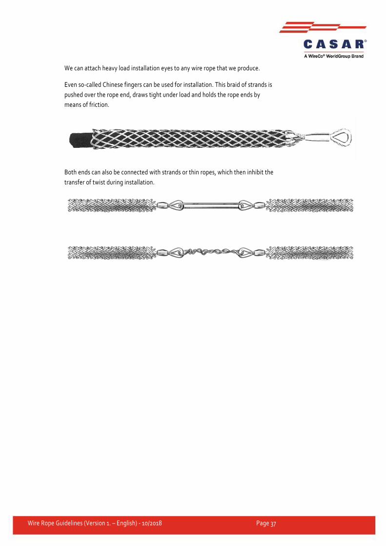
We can attach heavy load installation eyes to any wire rope that we produce.
Even so-called Chinese fingers can be used for installation. This braid of strands is
pushed over the rope end, draws tight under load and holds the rope ends by
means of friction.
Both ends can also be connected with strands or thin ropes, which then inhibit the
transfer of twist during installation.

Wire Rope Guidelines (Version 1. – English) - 10/2018 Page 38
5.8 THE PRELOAD
Application of the preload using a braking disc at the
reel
Application of the preload by braking the reel
flange
To achieve perfect multiple layer spooling of the rope on the drum, it is very
important - particularly with the so-called Lebus spooling - to apply a tensioning
load to the wire ropes during the installation.
If the first layers are too loose, the top layers might be wedged into the bottom
layers under load. This could seriously damage the rope. The unwinding rope
might even be clamped, so that the direction of spooling could suddenly be
reversed during the course of unwinding. The result could be the abrupt lifting of
the load that was actually travelling downwards.
The tensioning load should range from 1% to 2% of the minimum breaking load of
the wire ropes.
In many cases, it might suffice to wind the rope quite normally in order to unwind
it and then rewind it with the help of an outer load. In other cases, however, e.g.
when erecting a tower crane that has not yet reached its maximum height, the
procedure mentioned above is not possible. In these cases, the tensioning load
must already be applied when installing the rope. Ample rope tension can be
provided by a simple plank bearing against the reel flanges or by a braking disk
attached to the reel.
ATTENTION
Under no circumstances should one attempt to generate the tensioning load by
jamming the rope, for instance between two boards.
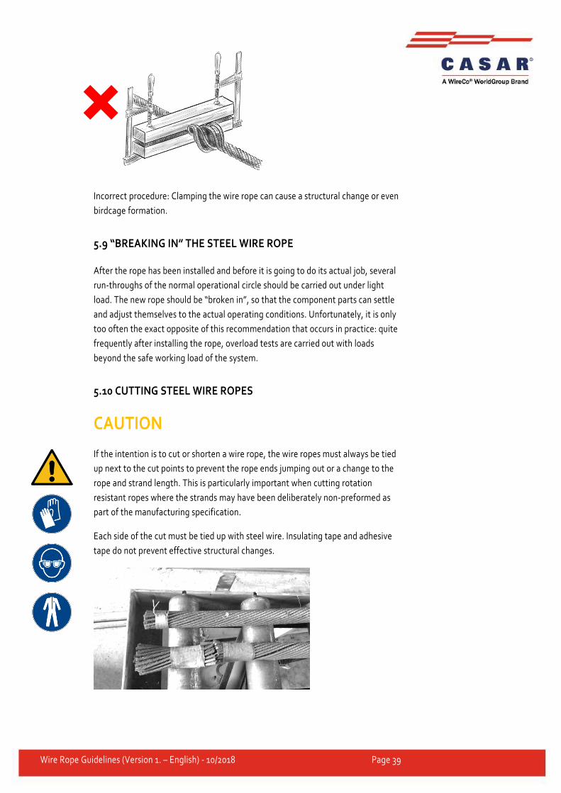
Wire Rope Guidelines (Version 1. – English) - 10/2018 Page 39
Incorrect procedure: Clamping the wire rope can cause a structural change or even
birdcage formation.
5.9 “BREAKING IN” THE STEEL WIRE ROPE
After the rope has been installed and before it is going to do its actual job, several
run-throughs of the normal operational circle should be carried out under light
load. The new rope should be “broken in”, so that the component parts can settle
and adjust themselves to the actual operating conditions. Unfortunately, it is only
too often the exact opposite of this recommendation that occurs in practice: quite
frequently after installing the rope, overload tests are carried out with loads
beyond the safe working load of the system.
5.10 CUTTING STEEL WIRE ROPES
CAUTION
If the intention is to cut or shorten a wire rope, the wire ropes must always be tied
up next to the cut points to prevent the rope ends jumping out or a change to the
rope and strand length. This is particularly important when cutting rotation
resistant ropes where the strands may have been deliberately non-preformed as
part of the manufacturing specification.
Each side of the cut must be tied up with steel wire. Insulating tape and adhesive
tape do not prevent effective structural changes.

Wire Rope Guidelines (Version 1. – English) - 10/2018 Page 40
d
L = min. 2 x d

Wire Rope Guidelines (Version 1. – English) - 10/2018 Page 41
6. MAINTAINING STEEL WIRE ROPES
6.1 RELUBRICATING STEEL WIRE ROPES
ATTENTION
During the production process, the rope receives intensive lubrication. This
provides the rope with ample protection against corrosion and is meant to reduce
the friction between the elements which make up the rope as well as the friction
between rope and sheaves or drums. Generally, this lubrication does not last over
the full service life of a wire rope. For this reason, German standard DIN ISO 4309
recommends relubricating a wire rope before any signs of dryness and corrosion
appear. Special attention should be given to the rope zones that run over sheaves,
onto the drum or from it, as well as sections that run over compensating sheaves.
When choosing the relubricant, it must be ensured that it is in accordance with the
recommendations of the rope manufacturer. We can give you further details and a
recommendation for this.

Wire Rope Guidelines (Version 1. – English) - 10/2018 Page 42
There are several techniques for lubricant application:
The most common ones at present are painting or swabbing. Quite often, the
lubricant is applied at a sheave.
Sometimes a continuous drip method is used. If only a little lubricant is required,
spray nozzles can be applied.
Various other systems allow the application of a continuous lubricant bath.
Maximum penetration of the lubricant into the gaps of the rope can only be
guaranteed, if high pressure lubrication is applied with the help of a pressure
lubricator. With this method, the two halves of a sleeve, which is equipped with
rubber sealings, are clamped round the rope and screwed together. While the rope
runs through the lubricator, the lubricant is pressed into the sleeve at a pressure up
to about 30 bars.

Wire Rope Guidelines (Version 1. – English) - 10/2018 Page 43
IMPORTANT All different methods of relubrication of steel wire ropes should be carried out
regularly from the beginning of the service life of the rope and not only after the
first damage has been ascertained.
6.2 CLEANING WIRE ROPES
If a wire rope is very dirty, it should be cleaned externally from time to time. This
applies particularly to ropes operating in extremely abrasive conditions and to
those that take up chemicals.
Effective cleaning without proper tools is quite a laborious job. Appliances with
rotating brushes and an air blast drying stem to follow or a so-called “rope
porcupine”, a rotating sleeve equipped with brushes, which is drawn along the
steel wire rope, are recommended.
6.3 REMOVING BROKEN WIRES
ATTENTION
If, during an inspection, ends of broken wires are detected which might cross
adjacent wires and destroy them when running over sheaves, these broken wire
ends must be removed.
Under no circumstances should the broken wire ends be pinched off with a pair of
nippers. The best method is to move the wire ends backwards and forwards until
they break deep in the valley between two outer strands.

Wire Rope Guidelines (Version 1. – English) - 10/2018 Page 44
7. DISCARD CRITERIA ACCORDING TO DIN
ISO 4309
7.1 VISIBLE WIRE BREAKS
CAUTION
The maximum permitted number of wire breaks complies with the so-called “rope
category number” (RCN) or the total number of load-bearing wires in the outer
strand layer of the rope. The RCN number for each CASAR rope of each diameter
is listed in the CASAR rope catalogue. Either a section that is 6x the nominal rope
diameter or 30x the nominal rope diameter is used here as the reference length.

Wire Rope Guidelines (Version 1. – English) - 10/2018 Page 45
Single layer and parallel stranded ropes
Number of visible wire breaks that indicate that the discard state has been reached
or exceeded for single layer and parallel stranded ropes.
NOTE: Ropes with outer strands in the Seale design for which the number of wires
per strand is 19 or less (e.g. 6 × 19 Seale) are classified in this table two lines above
the line in which the design would normally be due to the number of load-bearing
wires in the outer strands.
1) For the purposes of this international standard, filler wires are not considered as load-bearing wires and
are not included in the value for n.
2) A broken wire has two ends (counted as one wire).
3) The values apply for damage in the crossover areas and overlays of windings due to deflection angles (not
for rope sections that only run on sheaves and do not reel on the drum).
4) For ropes on motors of groups M5 to M8, double the listed number of wire breaks can be applied.
5) d = rope nominal diameter.
The classes M1 to M4 are the same as the motor groups 1Em to 1Am
The classes M5 to M8 are the same as the motor groups 2m to 5m
Please also observe the standards specific to the country and application.

Wire Rope Guidelines (Version 1. – English) - 10/2018 Page 46
Rotation-resistant rope
Number of visible wire breaks that indicate withdrawal from service has been
reached or exceeded for low rotation ropes.
NOTE: Ropes with outer strands in the Seale design for which the number of wires
in each strand is 19 or less (e.g. 18 × 19 Seale - WSC) are classified in this table two
lines above the line in which the design would normally be due to the number of
load-bearing wires in the outer strands.
1) For the purposes of this international standard, filler wires are not considered as load-bearing wires and
are not included in the value for n.
2) A broken wire has two ends.
3) The values apply for damage in the crossover areas and overlays of windings due to deflection angles (not
for rope sections that only run on sheaves and do not reel on the drum).
4) d = rope nominal diameter.
Please also observe the standards specific to the country and application.

Wire Rope Guidelines (Version 1. – English) - 10/2018 Page 47
7.2 DIAMETER REDUCTION
7.2.1 Uniform reduction along the rope

Wire Rope Guidelines (Version 1. – English) - 10/2018 Page 48
Calculation method to determine the extent of the diameter reduction:
dref - dm
dnom× 100%
dref = reference diameter, measured diameter of a rope section that is not bent
over sheaves that was immediately measured after commissioning the rope
dm = measured diameter
dnom = nominal rope diameter
7.2.2 Local reduction
If there is an apparent local diameter reduction, due to failure of a rope core, for
example, discard the rope.
7.3 STRAND BREAK
Discard the rope immediately, if a complete strand is broken.

Wire Rope Guidelines (Version 1. – English) - 10/2018 Page 49
7.4 CORROSION
a) Examples of this are shown in figures B.11 and B.12. An example of the progress of external corrosion in a
rope is shown in Annex H.
b) For each other intermediate state, an assessment with regard to the degree of severity classification must
be performed (i.e. proportion of the combined effect).
c) The wire surface can also feel raw due to oxidation of the galvanised wires; however the overall condition
may not be so serious as for ungalvanised wires. In such cases, the tester can consider the application of a
lower proportion of the combined effect compared with the classification specified in this table.
d) An example of this is given in figure B 19.
e) The assessment of corrosion in the inside of the rope is subjective; if the severity of corrosion in the inside
of the rope is not certain, the rope should be discarded.

Wire Rope Guidelines (Version 1. – English) - 10/2018 Page 50
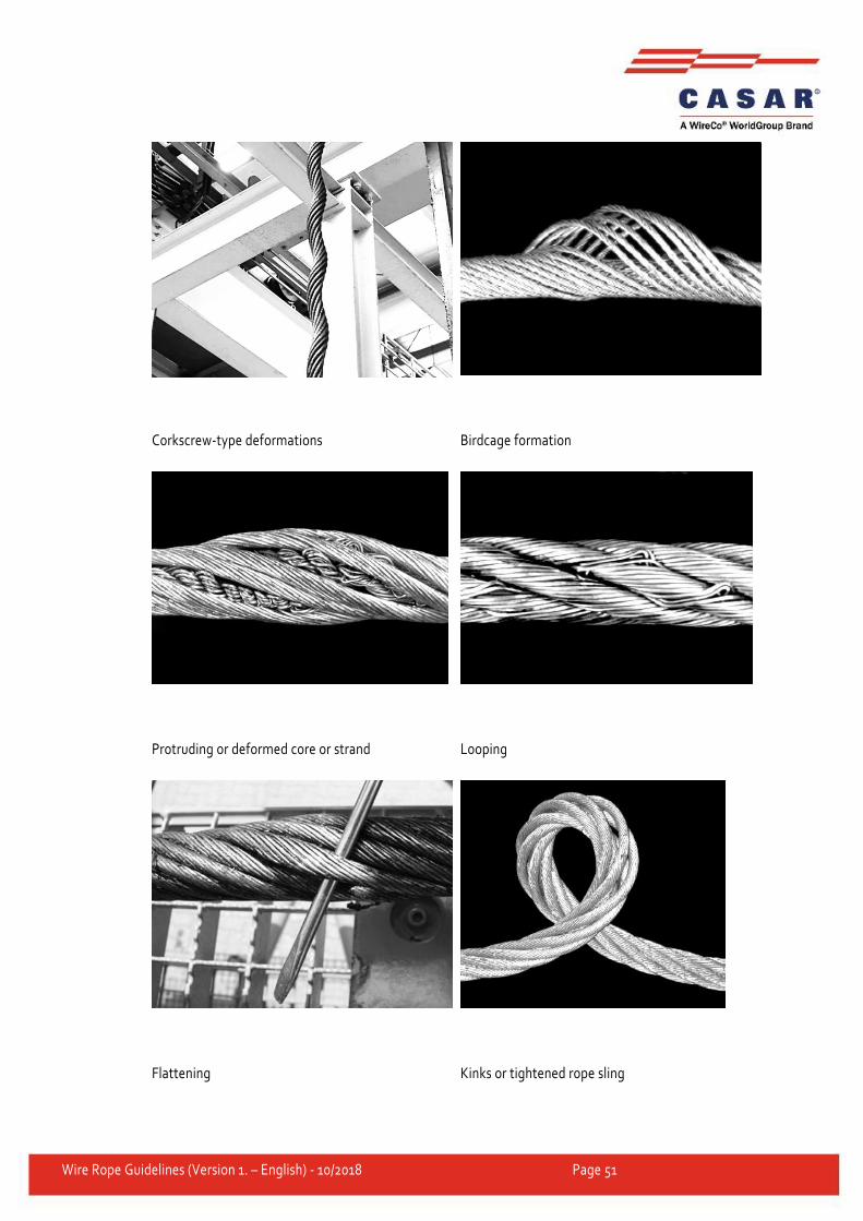
7.5 DEFORMATION AND OTHER DAMAGE
Every visible deviation of the rope from its normal shape is classified as
deformation. DIN ISO 4309 lists the following types of deformations and
damage:
Corkscrew-type deformations
Birdcage formation
Protruding or deformed core or strand
Looping
Local increase in rope diameter
Flattening
Kinks or tightened rope sling
Kinks in the rope
Damage due to heat exposure or light arcs
If this type of damage occurs, examine the damaged area intensively and make a
decision about operational readiness with aid of the standard.
Wire Rope Guidelines (Version 1. – English) - 10/2018 Page 51
Corkscrew-type deformations Birdcage formation
Protruding or deformed core or strand Looping
Flattening Kinks or tightened rope sling

Wire Rope Guidelines (Version 1. – English) - 10/2018 Page 52
Kinks in the rope Damage due to heat exposure or light arcs
Worn-out or elongated wires of a casting crane
rope

Wire Rope Guidelines (Version 1. – English) - 10/2018 Page 53
BIBLIOGRAPHY/DIRECTORY OF
APPLICABLE STANDARDS
EC Directive on Machinery 2006/42/EC / Annex IIB
ISO 4309:2010-08 Cranes – Wire ropes – Maintenance and servicing, inspection
and storage
ISO 16625:2013 Cranes and hoists – Selection of wire ropes, drums and sheaves
EN 12385-1: 2002+A1: 2008 Steel wire ropes - Safety - Part 1: General
requirements
EN 12385-2: 2002+A1: 2008 Steel wire ropes - Safety - Part 2: Terms, designation
and classification
EN 12385-3: 2004+A1: 2008 Steel wire ropes - Safety - Part 3: Information for use
and maintenance
EN 12385-4: 2002+A1: 2008 Steel wire ropes - Safety - Part 4: Stranded ropes for
general lifting purposes
EN 12385-10: 2003+A1: 2008 Steel wire ropes - Safety - Part 10: Spiral ropes for
general structural applications
EN 13411-4: 2011-06 End connections for steel wire ropes - Safety - Part 4: Cast
with metal and plastic
EN10264-1: 2012-3 Steel wire and wire products - Steel wire for ropes - Part 1:
General requirements
EN10264-2: 2012-3 Steel wire and wire products - Steel wire for ropes - Part 2:
Cold-drawn non-alloy steel wire for ropes for general applications.
Related Documents