Guided wrinkling in swollen, pre-patterned photoresist thin films with a crosslinking gradient† Chi-Mon Chen, Jason C Reed and Shu Yang * A new thin film buckling system was developed from photosensitive SU-8 thin films doped with UV light absorbing dye, resulting in a depth-wise gradient modulus after photocrosslinking. When the film was swollen by an organic solvent, a wide range of wrinkling patterns was obtained, including lamella, peanut and semi-hexagonal patterns. Both the morphology and wavelength were found to be dependent on the original film thickness. By leveraging the thermoplasticity of SU-8, we imprinted one- dimensional (1-D) patterns on the dyed SU-8 with variable pitch and height from 1 mm to 20 mm and 15 nm to 2 mm, respectively. We then swelled the patterned films and investigated the interactions between the intrinsic buckling waves (both size and morphology) and the pre-patterns. As the pre- pattern pitch decreased, the swollen film in the patterned region evolved from isotropic wrinkles to out- of-phase, anisotropic waves, which further became in-phase when the pre-pattern pitch was smaller than the intrinsic wrinkle wavelength. For the latter, the aligned wrinkle morphology varied dramatically when the pre-pattern height decreased: from perpendicular to the pre-pattern wavevector to dual orientation with one set of wrinkles remained perpendicularly ordered and the other set of local buckling patterns aligned in parallel to the pre-pattern, and finally back to isotropic ones. Since the pre- patterns of different size and shape could be readily prepared, the combination of physical confinement together with controlled swelling in a graded thin film offers a new approach to access a wide range of controllable hierarchical patterns. Introduction Wrinkling in thin lms, including bi-layers 1–14 and layers with crosslinking gradient, 15–17 is of interest for a wide variety of applications, including organic light-emitting diodes, 5 exible electronics, 18,19 microlens arrays, 9,20 adhesives 21,22 and thin lm metrology. 23 Depending on the type and conditions of the stress induced, pattern morphology and dimensions can be ne- tuned with wavelength spanning from 0.1 to 100 mm when the stress exceeds the critical buckling stress. Mechanical 6,7,24 and osmotic stresses 8–12,21,25,26 are commonly utilized to generate wrinkles. Typically, random wrinkle morphology is formed on at 1,2,5,14,15,17,24 and curved lms 27,28 under an isotropic stress (e.g. thermal annealing and solvent swelling/annealing). For most applications, however, ordered structures 9,18,19,22 are desired. It has been demonstrated that one-dimension (1-D) ripples and two-dimension (2-D) zigzag wrinkles can be created by controlling the level and direction of applied mechanical strain. 6,29–32 In the case of heating/cooling or solvent swelling/ annealing of a patterned lm, 2–4,10,11,26,33–35 the growing wrinkles can be aligned with the pattern edges due to the stress relaxa- tion perpendicular to the propagating swelling wave front. 13 This alignment persists to a certain distance before the wrinkles become isotropic again. This persistence length is typically much larger than the intrinsic wavelength, which is determined by the stress state and the respective Young's modulus of the lm and substrate. 7,9,12,26 It has been suggested that when conning the wrinkle with a template that is comparable to or smaller than the persistent length, morphological alignment can be induced, where the wrinkle morphology depends on both the boundary geometry and the stress state. 2,3,9,26 So far, experimentally there have been only a few scattered results from pre-patterns with feature size smaller than the wrinkle wave- length or amplitude. 2,32,36,37 For example, Okayasu et al. 2 pre- sented preliminary results on small pattern effects on thermally induced wrinkles but the mechanism was not well-understood and the aligned wrinkles did not show long-range in-phase order. Ohzono et al. 38,39 and Lee et al. 32 have also studied wrinkle formation on small subsumed patterns. However, for both of their systems, the wrinkles were mechanically generated whose Department of Materials Science and Engineering, University of Pennsylvania, 3231 Walnut Street, Philadelphia, PA 19104, USA. E-mail: [email protected]; Fax: +1-215-573-2128; Tel: +1-215-898-9645 † Electronic supplementary information (ESI) available: The relative transmittance of 3.8 mm thick dyed SU-8; the swelling behavior of a free-standing, dyed SU-8 lm; early stage of buckling of the pre-patterned ( p ¼ 20 mm, h ¼ 800 nm), dyed SU-8; schematic of the shiing of the neutral plane in the presence of pre-patterns. See DOI: 10.1039/c3sm51881g Cite this: Soft Matter, 2013, 9, 11007 Received 10th July 2013 Accepted 19th September 2013 DOI: 10.1039/c3sm51881g www.rsc.org/softmatter This journal is ª The Royal Society of Chemistry 2013 Soft Matter , 2013, 9, 11007–11013 | 11007 Soft Matter PAPER

Welcome message from author
This document is posted to help you gain knowledge. Please leave a comment to let me know what you think about it! Share it to your friends and learn new things together.
Transcript

Soft Matter
PAPER
Department of Materials Science and Engin
Walnut Street, Philadelphia, PA 19104, USA
+1-215-573-2128; Tel: +1-215-898-9645
† Electronic supplementary informatitransmittance of 3.8 mm thick dyedfree-standing, dyed SU-8 lm; early stage20 mm, h ¼ 800 nm), dyed SU-8; schemain the presence of pre-patterns. See DOI:
Cite this: Soft Matter, 2013, 9, 11007
Received 10th July 2013Accepted 19th September 2013
DOI: 10.1039/c3sm51881g
www.rsc.org/softmatter
This journal is ª The Royal Society of
Guided wrinkling in swollen, pre-patterned photoresistthin films with a crosslinking gradient†
Chi-Mon Chen, Jason C Reed and Shu Yang*
A new thin film buckling system was developed from photosensitive SU-8 thin films doped with UV light
absorbing dye, resulting in a depth-wise gradient modulus after photocrosslinking. When the film was
swollen by an organic solvent, a wide range of wrinkling patterns was obtained, including lamella,
peanut and semi-hexagonal patterns. Both the morphology and wavelength were found to be
dependent on the original film thickness. By leveraging the thermoplasticity of SU-8, we imprinted one-
dimensional (1-D) patterns on the dyed SU-8 with variable pitch and height from 1 mm to 20 mm and
15 nm to 2 mm, respectively. We then swelled the patterned films and investigated the interactions
between the intrinsic buckling waves (both size and morphology) and the pre-patterns. As the pre-
pattern pitch decreased, the swollen film in the patterned region evolved from isotropic wrinkles to out-
of-phase, anisotropic waves, which further became in-phase when the pre-pattern pitch was smaller
than the intrinsic wrinkle wavelength. For the latter, the aligned wrinkle morphology varied dramatically
when the pre-pattern height decreased: from perpendicular to the pre-pattern wavevector to dual
orientation with one set of wrinkles remained perpendicularly ordered and the other set of local
buckling patterns aligned in parallel to the pre-pattern, and finally back to isotropic ones. Since the pre-
patterns of different size and shape could be readily prepared, the combination of physical confinement
together with controlled swelling in a graded thin film offers a new approach to access a wide range of
controllable hierarchical patterns.
Introduction
Wrinkling in thin lms, including bi-layers1–14 and layers withcrosslinking gradient,15–17 is of interest for a wide variety ofapplications, including organic light-emitting diodes,5 exibleelectronics,18,19 microlens arrays,9,20 adhesives21,22 and thin lmmetrology.23 Depending on the type and conditions of the stressinduced, pattern morphology and dimensions can be ne-tuned with wavelength spanning from 0.1 to 100 mm when thestress exceeds the critical buckling stress. Mechanical6,7,24 andosmotic stresses8–12,21,25,26 are commonly utilized to generatewrinkles.
Typically, random wrinkle morphology is formed onat1,2,5,14,15,17,24 and curved lms27,28 under an isotropic stress (e.g.thermal annealing and solvent swelling/annealing). For mostapplications, however, ordered structures9,18,19,22 are desired. Ithas been demonstrated that one-dimension (1-D) ripples and
eering, University of Pennsylvania, 3231
. E-mail: [email protected]; Fax:
on (ESI) available: The relativeSU-8; the swelling behavior of aof buckling of the pre-patterned ( p ¼tic of the shiing of the neutral plane10.1039/c3sm51881g
Chemistry 2013
two-dimension (2-D) zigzag wrinkles can be created bycontrolling the level and direction of applied mechanicalstrain.6,29–32 In the case of heating/cooling or solvent swelling/annealing of a patterned lm,2–4,10,11,26,33–35 the growing wrinklescan be aligned with the pattern edges due to the stress relaxa-tion perpendicular to the propagating swelling wave front.13
This alignment persists to a certain distance before the wrinklesbecome isotropic again. This persistence length is typicallymuch larger than the intrinsic wavelength, which is determinedby the stress state and the respective Young's modulus of thelm and substrate.7,9,12,26 It has been suggested that whenconning the wrinkle with a template that is comparable to orsmaller than the persistent length, morphological alignmentcan be induced, where the wrinkle morphology depends onboth the boundary geometry and the stress state.2,3,9,26 So far,experimentally there have been only a few scattered results frompre-patterns with feature size smaller than the wrinkle wave-length or amplitude.2,32,36,37 For example, Okayasu et al.2 pre-sented preliminary results on small pattern effects on thermallyinduced wrinkles but the mechanism was not well-understoodand the aligned wrinkles did not show long-range in-phaseorder. Ohzono et al.38,39 and Lee et al.32 have also studied wrinkleformation on small subsumed patterns. However, for both oftheir systems, the wrinkles were mechanically generated whose
Soft Matter, 2013, 9, 11007–11013 | 11007
Soft Matter Paper
morphology depends primarily on the applied stress ratherthan the pre-patterns.
Here, we were interested in the effect of pre-pattern size onthe wrinkle formation and morphological evolution. For thispurpose, we designed a new wrinkling system using SU-8photoresist thin lms (200 nm to 4 mm thick) consisting of light-absorbing dye molecules to create a depth-wise modulusgradient aer photo-crosslinking. Wrinkles were induced byexposing the dyed SU-8 thin lms to tetrahydrofuran (THF)solvent vapor. We then imprinted the dyed SU-8 lm into 1-Dchannels by capillary force lithography (CFL)40,41 to guide thewrinkle formation and orientation. The pattern pitch was variedfrom 1 mm to 20 mm and height from 15 nm to 2 mm, that is anorder of magnitude larger than, comparable to, or an order ofmagnitude smaller than the intrinsic wavelength and ampli-tude of the wrinkles obtained from the at lm, while keepingthe pre-pattern's width/pitch ratio constant. At the smallest pre-pattern pitch (1 mm), the swollen lm in the patterned regionevolved from isotropic wrinkles to dual orientational ones,where one set of wrinkles perpendicularly oriented to the pre-patterns and the other set of locally buckled patterns aligned inparallel to the pre-patterns as the pre-pattern height increased.Further increase of the pattern size and pitches led to aniso-tropic waves perpendicular to the pre-pattern either in-phase orout-of-phase depending on the size of the pre-pattern pitch vs.the intrinsic wrinkle wavelength. At the largest pre-pattern pitch(20 mm), isotropic wrinkles were conned to the thicker regions.
ExperimentalMaterials and fabrication
The SU-8 in g-butyrolactone solution (SU-8 2 from Microchem)was mixed with rhodamine B (Aldrich) of 6.26 mM, followed bysonication for 1 h to obtain homogeneous solutions. The coverglasses or Si wafers were used as substrates for coating SU-8lms. They were freshly cleaned by oxygen plasma (HarrickExpanded Plasma Cleaner & PlasmaFlo�) at �30 W for 1 h. Thedyed SU-8 lm was spin-coated at 500 to 6000 rpm for 30 s onthe substrate, and prebaked at 65 �C for 1–5 min and 95 �C for1–5 min, respectively. The lm was ood exposed to UV light(Newport 97435) of dosages ranging from 50 to 400 mJ cm�2,followed by post-exposure bake (PEB) at 95 �C for the sameduration as the pre-bake. For controlled swelling, the cured SU-8 lm was placed in a glass jar and exposed to tetrahydrofuran(THF) (Fisher Scientic), which was placed in a separate glass
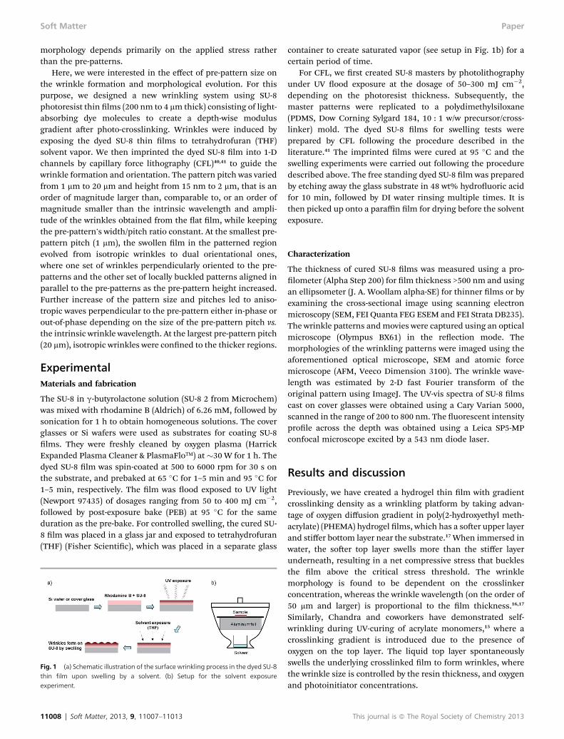
Fig. 1 (a) Schematic illustration of the surface wrinkling process in the dyed SU-8thin film upon swelling by a solvent. (b) Setup for the solvent exposureexperiment.
11008 | Soft Matter, 2013, 9, 11007–11013
container to create saturated vapor (see setup in Fig. 1b) for acertain period of time.
For CFL, we rst created SU-8 masters by photolithographyunder UV ood exposure at the dosage of 50–300 mJ cm�2,depending on the photoresist thickness. Subsequently, themaster patterns were replicated to a polydimethylsiloxane(PDMS, Dow Corning Sylgard 184, 10 : 1 w/w precursor/cross-linker) mold. The dyed SU-8 lms for swelling tests wereprepared by CFL following the procedure described in theliterature.41 The imprinted lms were cured at 95 �C and theswelling experiments were carried out following the proceduredescribed above. The free standing dyed SU-8 lm was preparedby etching away the glass substrate in 48 wt% hydrouoric acidfor 10 min, followed by DI water rinsing multiple times. It isthen picked up onto a paraffin lm for drying before the solventexposure.
Characterization
The thickness of cured SU-8 lms was measured using a pro-lometer (Alpha Step 200) for lm thickness >500 nm and usingan ellipsometer (J. A. Woollam alpha-SE) for thinner lms or byexamining the cross-sectional image using scanning electronmicroscopy (SEM, FEI Quanta FEG ESEM and FEI Strata DB235).The wrinkle patterns andmovies were captured using an opticalmicroscope (Olympus BX61) in the reection mode. Themorphologies of the wrinkling patterns were imaged using theaforementioned optical microscope, SEM and atomic forcemicroscope (AFM, Veeco Dimension 3100). The wrinkle wave-length was estimated by 2-D fast Fourier transform of theoriginal pattern using ImageJ. The UV-vis spectra of SU-8 lmscast on cover glasses were obtained using a Cary Varian 5000,scanned in the range of 200 to 800 nm. The uorescent intensityprole across the depth was obtained using a Leica SP5-MPconfocal microscope excited by a 543 nm diode laser.
Results and discussion
Previously, we have created a hydrogel thin lm with gradientcrosslinking density as a wrinkling platform by taking advan-tage of oxygen diffusion gradient in poly(2-hydroxyethyl meth-acrylate) (PHEMA) hydrogel lms, which has a soer upper layerand stiffer bottom layer near the substrate.17 When immersed inwater, the soer top layer swells more than the stiffer layerunderneath, resulting in a net compressive stress that bucklesthe lm above the critical stress threshold. The wrinklemorphology is found to be dependent on the crosslinkerconcentration, whereas the wrinkle wavelength (on the order of50 mm and larger) is proportional to the lm thickness.16,17
Similarly, Chandra and coworkers have demonstrated self-wrinkling during UV-curing of acrylate monomers,15 where acrosslinking gradient is introduced due to the presence ofoxygen on the top layer. The liquid top layer spontaneouslyswells the underlying crosslinked lm to form wrinkles, wherethe wrinkle size is controlled by the resin thickness, and oxygenand photoinitiator concentrations.
This journal is ª The Royal Society of Chemistry 2013
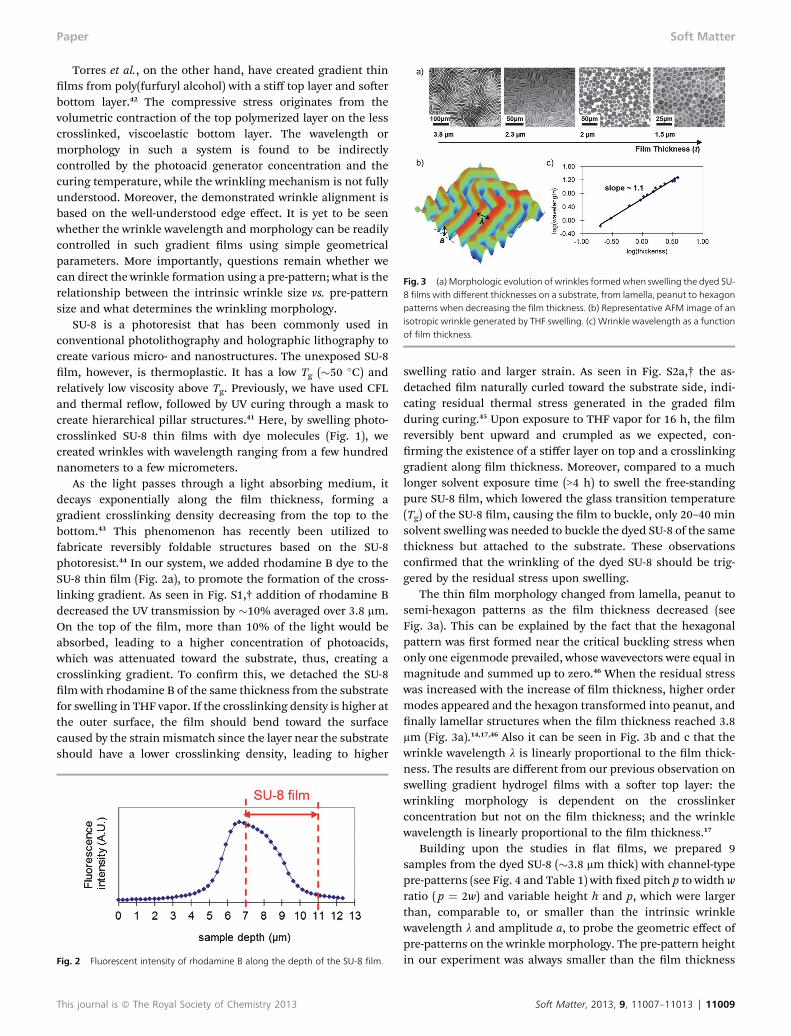
Fig. 3 (a) Morphologic evolution of wrinkles formedwhen swelling the dyed SU-8 films with different thicknesses on a substrate, from lamella, peanut to hexagonpatterns when decreasing the film thickness. (b) Representative AFM image of anisotropic wrinkle generated by THF swelling. (c) Wrinkle wavelength as a functionof film thickness.
Paper Soft Matter
Torres et al., on the other hand, have created gradient thinlms from poly(furfuryl alcohol) with a stiff top layer and soerbottom layer.42 The compressive stress originates from thevolumetric contraction of the top polymerized layer on the lesscrosslinked, viscoelastic bottom layer. The wavelength ormorphology in such a system is found to be indirectlycontrolled by the photoacid generator concentration and thecuring temperature, while the wrinkling mechanism is not fullyunderstood. Moreover, the demonstrated wrinkle alignment isbased on the well-understood edge effect. It is yet to be seenwhether the wrinkle wavelength and morphology can be readilycontrolled in such gradient lms using simple geometricalparameters. More importantly, questions remain whether wecan direct the wrinkle formation using a pre-pattern; what is therelationship between the intrinsic wrinkle size vs. pre-patternsize and what determines the wrinkling morphology.
SU-8 is a photoresist that has been commonly used inconventional photolithography and holographic lithography tocreate various micro- and nanostructures. The unexposed SU-8lm, however, is thermoplastic. It has a low Tg (�50 �C) andrelatively low viscosity above Tg. Previously, we have used CFLand thermal reow, followed by UV curing through a mask tocreate hierarchical pillar structures.41 Here, by swelling photo-crosslinked SU-8 thin lms with dye molecules (Fig. 1), wecreated wrinkles with wavelength ranging from a few hundrednanometers to a few micrometers.
As the light passes through a light absorbing medium, itdecays exponentially along the lm thickness, forming agradient crosslinking density decreasing from the top to thebottom.43 This phenomenon has recently been utilized tofabricate reversibly foldable structures based on the SU-8photoresist.44 In our system, we added rhodamine B dye to theSU-8 thin lm (Fig. 2a), to promote the formation of the cross-linking gradient. As seen in Fig. S1,† addition of rhodamine Bdecreased the UV transmission by �10% averaged over 3.8 mm.On the top of the lm, more than 10% of the light would beabsorbed, leading to a higher concentration of photoacids,which was attenuated toward the substrate, thus, creating acrosslinking gradient. To conrm this, we detached the SU-8lm with rhodamine B of the same thickness from the substratefor swelling in THF vapor. If the crosslinking density is higher atthe outer surface, the lm should bend toward the surfacecaused by the strain mismatch since the layer near the substrateshould have a lower crosslinking density, leading to higher
Fig. 2 Fluorescent intensity of rhodamine B along the depth of the SU-8 film.
This journal is ª The Royal Society of Chemistry 2013
swelling ratio and larger strain. As seen in Fig. S2a,† the as-detached lm naturally curled toward the substrate side, indi-cating residual thermal stress generated in the graded lmduring curing.45 Upon exposure to THF vapor for 16 h, the lmreversibly bent upward and crumpled as we expected, con-rming the existence of a stiffer layer on top and a crosslinkinggradient along lm thickness. Moreover, compared to a muchlonger solvent exposure time (>4 h) to swell the free-standingpure SU-8 lm, which lowered the glass transition temperature(Tg) of the SU-8 lm, causing the lm to buckle, only 20–40 minsolvent swelling was needed to buckle the dyed SU-8 of the samethickness but attached to the substrate. These observationsconrmed that the wrinkling of the dyed SU-8 should be trig-gered by the residual stress upon swelling.
The thin lm morphology changed from lamella, peanut tosemi-hexagon patterns as the lm thickness decreased (seeFig. 3a). This can be explained by the fact that the hexagonalpattern was rst formed near the critical buckling stress whenonly one eigenmode prevailed, whose wavevectors were equal inmagnitude and summed up to zero.46 When the residual stresswas increased with the increase of lm thickness, higher ordermodes appeared and the hexagon transformed into peanut, andnally lamellar structures when the lm thickness reached 3.8mm (Fig. 3a).14,17,46 Also it can be seen in Fig. 3b and c that thewrinkle wavelength l is linearly proportional to the lm thick-ness. The results are different from our previous observation onswelling gradient hydrogel lms with a soer top layer: thewrinkling morphology is dependent on the crosslinkerconcentration but not on the lm thickness; and the wrinklewavelength is linearly proportional to the lm thickness.17
Building upon the studies in at lms, we prepared 9samples from the dyed SU-8 (�3.8 mm thick) with channel-typepre-patterns (see Fig. 4 and Table 1) with xed pitch p to width wratio ( p ¼ 2w) and variable height h and p, which were largerthan, comparable to, or smaller than the intrinsic wrinklewavelength l and amplitude a, to probe the geometric effect ofpre-patterns on the wrinkle morphology. The pre-pattern heightin our experiment was always smaller than the lm thickness
Soft Matter, 2013, 9, 11007–11013 | 11009
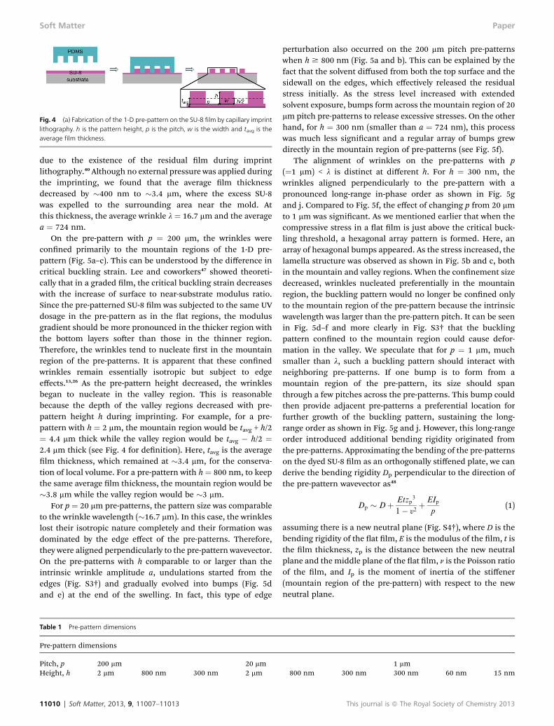
Fig. 4 (a) Fabrication of the 1-D pre-pattern on the SU-8 film by capillary imprintlithography. h is the pattern height, p is the pitch, w is the width and tavg is theaverage film thickness.
Soft Matter Paper
due to the existence of the residual lm during imprintlithography.40 Although no external pressure was applied duringthe imprinting, we found that the average lm thicknessdecreased by �400 nm to �3.4 mm, where the excess SU-8was expelled to the surrounding area near the mold. Atthis thickness, the average wrinkle l ¼ 16.7 mm and the averagea ¼ 724 nm.
On the pre-pattern with p ¼ 200 mm, the wrinkles wereconned primarily to the mountain regions of the 1-D pre-pattern (Fig. 5a–c). This can be understood by the difference incritical buckling strain. Lee and coworkers47 showed theoreti-cally that in a graded lm, the critical buckling strain decreaseswith the increase of surface to near-substrate modulus ratio.Since the pre-patterned SU-8 lm was subjected to the same UVdosage in the pre-pattern as in the at regions, the modulusgradient should be more pronounced in the thicker region withthe bottom layers soer than those in the thinner region.Therefore, the wrinkles tend to nucleate rst in the mountainregion of the pre-patterns. It is apparent that these connedwrinkles remain essentially isotropic but subject to edgeeffects.13,26 As the pre-pattern height decreased, the wrinklesbegan to nucleate in the valley region. This is reasonablebecause the depth of the valley regions decreased with pre-pattern height h during imprinting. For example, for a pre-pattern with h ¼ 2 mm, the mountain region would be tavg + h/2¼ 4.4 mm thick while the valley region would be tavg � h/2 ¼2.4 mm thick (see Fig. 4 for denition). Here, tavg is the averagelm thickness, which remained at �3.4 mm, for the conserva-tion of local volume. For a pre-pattern with h ¼ 800 nm, to keepthe same average lm thickness, the mountain region would be�3.8 mm while the valley region would be �3 mm.
For p ¼ 20 mm pre-patterns, the pattern size was comparableto the wrinkle wavelength (�16.7 mm). In this case, the wrinkleslost their isotropic nature completely and their formation wasdominated by the edge effect of the pre-patterns. Therefore,they were aligned perpendicularly to the pre-pattern wavevector.On the pre-patterns with h comparable to or larger than theintrinsic wrinkle amplitude a, undulations started from theedges (Fig. S3†) and gradually evolved into bumps (Fig. 5dand e) at the end of the swelling. In fact, this type of edge
Table 1 Pre-pattern dimensions
Pre-pattern dimensions
Pitch, p 200 mm 20 mmHeight, h 2 mm 800 nm 300 nm 2 mm
11010 | Soft Matter, 2013, 9, 11007–11013
perturbation also occurred on the 200 mm pitch pre-patternswhen h $ 800 nm (Fig. 5a and b). This can be explained by thefact that the solvent diffused from both the top surface and thesidewall on the edges, which effectively released the residualstress initially. As the stress level increased with extendedsolvent exposure, bumps form across the mountain region of 20mm pitch pre-patterns to release excessive stresses. On the otherhand, for h ¼ 300 nm (smaller than a ¼ 724 nm), this processwas much less signicant and a regular array of bumps grewdirectly in the mountain region of pre-patterns (see Fig. 5f).
The alignment of wrinkles on the pre-patterns with p(¼1 mm) < l is distinct at different h. For h ¼ 300 nm, thewrinkles aligned perpendicularly to the pre-pattern with apronounced long-range in-phase order as shown in Fig. 5gand j. Compared to Fig. 5f, the effect of changing p from 20 mmto 1 mm was signicant. As we mentioned earlier that when thecompressive stress in a at lm is just above the critical buck-ling threshold, a hexagonal array pattern is formed. Here, anarray of hexagonal bumps appeared. As the stress increased, thelamella structure was observed as shown in Fig. 5b and c, bothin the mountain and valley regions. When the connement sizedecreased, wrinkles nucleated preferentially in the mountainregion, the buckling pattern would no longer be conned onlyto the mountain region of the pre-pattern because the intrinsicwavelength was larger than the pre-pattern pitch. It can be seenin Fig. 5d–f and more clearly in Fig. S3† that the bucklingpattern conned to the mountain region could cause defor-mation in the valley. We speculate that for p ¼ 1 mm, muchsmaller than l, such a buckling pattern should interact withneighboring pre-patterns. If one bump is to form from amountain region of the pre-pattern, its size should spanthrough a few pitches across the pre-patterns. This bump couldthen provide adjacent pre-patterns a preferential location forfurther growth of the buckling pattern, sustaining the long-range order as shown in Fig. 5g and j. However, this long-rangeorder introduced additional bending rigidity originated fromthe pre-patterns. Approximating the bending of the pre-patternson the dyed SU-8 lm as an orthogonally stiffened plate, we canderive the bending rigidity Dp perpendicular to the direction ofthe pre-pattern wavevector as48
Dp � Dþ Etzp3
1� y2þ EIp
p(1)
assuming there is a new neutral plane (Fig. S4†), where D is thebending rigidity of the at lm, E is the modulus of the lm, t isthe lm thickness, zp is the distance between the new neutralplane and the middle plane of the at lm, n is the Poisson ratioof the lm, and Ip is the moment of inertia of the stiffener(mountain region of the pre-pattern) with respect to the newneutral plane.
1 mm800 nm 300 nm 300 nm 60 nm 15 nm
This journal is ª The Royal Society of Chemistry 2013
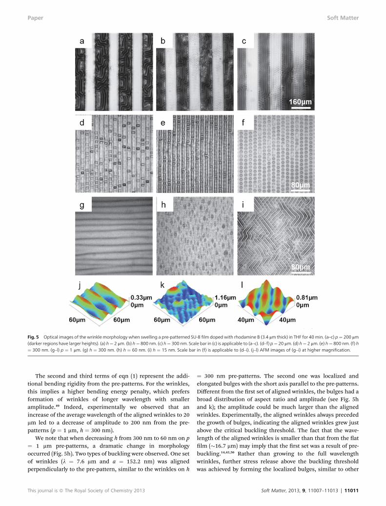
Fig. 5 Optical images of the wrinkle morphology when swelling a pre-patterned SU-8 film doped with rhodamine B (3.4 mm thick) in THF for 40 min. (a–c) p¼ 200 mm(darker regions have larger heights). (a) h¼ 2 mm. (b) h¼ 800 nm. (c) h¼ 300 nm. Scale bar in (c) is applicable to (a–c). (d–f) p¼ 20 mm. (d) h¼ 2 mm. (e) h¼ 800 nm. (f) h¼ 300 nm. (g–l) p ¼ 1 mm. (g) h ¼ 300 nm. (h) h ¼ 60 nm. (i) h ¼ 15 nm. Scale bar in (f) is applicable to (d–i). (j–l) AFM images of (g–i) at higher magnification.
Paper Soft Matter
The second and third terms of eqn (1) represent the addi-tional bending rigidity from the pre-patterns. For the wrinkles,this implies a higher bending energy penalty, which prefersformation of wrinkles of longer wavelength with smalleramplitude.49 Indeed, experimentally we observed that anincrease of the average wavelength of the aligned wrinkles to 20mm led to a decrease of amplitude to 200 nm from the pre-patterns (p ¼ 1 mm, h ¼ 300 nm).
We note that when decreasing h from 300 nm to 60 nm on p¼ 1 mm pre-patterns, a dramatic change in morphologyoccurred (Fig. 5h). Two types of buckling were observed. One setof wrinkles (l ¼ 7.6 mm and a ¼ 152.2 nm) was alignedperpendicularly to the pre-pattern, similar to the wrinkles on h
This journal is ª The Royal Society of Chemistry 2013
¼ 300 nm pre-patterns. The second one was localized andelongated bulges with the short axis parallel to the pre-patterns.Different from the rst set of aligned wrinkles, the bulges had abroad distribution of aspect ratio and amplitude (see Fig. 5hand k); the amplitude could be much larger than the alignedwrinkles. Experimentally, the aligned wrinkles always precededthe growth of bulges, indicating the aligned wrinkles grew justabove the critical buckling threshold. The fact that the wave-length of the aligned wrinkles is smaller than that from the atlm (�16.7 mm) may imply that the rst set was a result of pre-buckling.14,42,50 Rather than growing to the full wavelengthwrinkles, further stress release above the buckling thresholdwas achieved by forming the localized bulges, similar to other
Soft Matter, 2013, 9, 11007–11013 | 11011
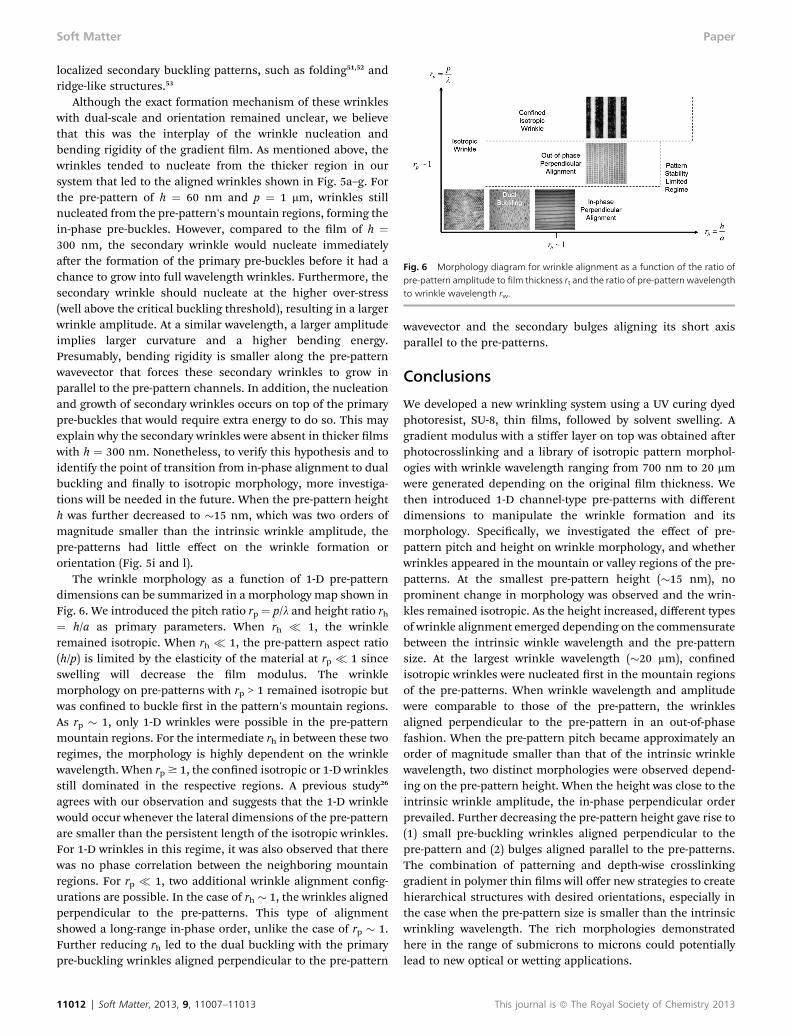
Fig. 6 Morphology diagram for wrinkle alignment as a function of the ratio ofpre-pattern amplitude to film thickness rt and the ratio of pre-pattern wavelengthto wrinkle wavelength rw.
Soft Matter Paper
localized secondary buckling patterns, such as folding51,52 andridge-like structures.53
Although the exact formation mechanism of these wrinkleswith dual-scale and orientation remained unclear, we believethat this was the interplay of the wrinkle nucleation andbending rigidity of the gradient lm. As mentioned above, thewrinkles tended to nucleate from the thicker region in oursystem that led to the aligned wrinkles shown in Fig. 5a–g. Forthe pre-pattern of h ¼ 60 nm and p ¼ 1 mm, wrinkles stillnucleated from the pre-pattern's mountain regions, forming thein-phase pre-buckles. However, compared to the lm of h ¼300 nm, the secondary wrinkle would nucleate immediatelyaer the formation of the primary pre-buckles before it had achance to grow into full wavelength wrinkles. Furthermore, thesecondary wrinkle should nucleate at the higher over-stress(well above the critical buckling threshold), resulting in a largerwrinkle amplitude. At a similar wavelength, a larger amplitudeimplies larger curvature and a higher bending energy.Presumably, bending rigidity is smaller along the pre-patternwavevector that forces these secondary wrinkles to grow inparallel to the pre-pattern channels. In addition, the nucleationand growth of secondary wrinkles occurs on top of the primarypre-buckles that would require extra energy to do so. This mayexplain why the secondary wrinkles were absent in thicker lmswith h ¼ 300 nm. Nonetheless, to verify this hypothesis and toidentify the point of transition from in-phase alignment to dualbuckling and nally to isotropic morphology, more investiga-tions will be needed in the future. When the pre-pattern heighth was further decreased to �15 nm, which was two orders ofmagnitude smaller than the intrinsic wrinkle amplitude, thepre-patterns had little effect on the wrinkle formation ororientation (Fig. 5i and l).
The wrinkle morphology as a function of 1-D pre-patterndimensions can be summarized in a morphology map shown inFig. 6. We introduced the pitch ratio rp ¼ p/l and height ratio rh¼ h/a as primary parameters. When rh � 1, the wrinkleremained isotropic. When rh � 1, the pre-pattern aspect ratio(h/p) is limited by the elasticity of the material at rp � 1 sinceswelling will decrease the lm modulus. The wrinklemorphology on pre-patterns with rp > 1 remained isotropic butwas conned to buckle rst in the pattern's mountain regions.As rp � 1, only 1-D wrinkles were possible in the pre-patternmountain regions. For the intermediate rh in between these tworegimes, the morphology is highly dependent on the wrinklewavelength. When rp $ 1, the conned isotropic or 1-D wrinklesstill dominated in the respective regions. A previous study26
agrees with our observation and suggests that the 1-D wrinklewould occur whenever the lateral dimensions of the pre-patternare smaller than the persistent length of the isotropic wrinkles.For 1-D wrinkles in this regime, it was also observed that therewas no phase correlation between the neighboring mountainregions. For rp � 1, two additional wrinkle alignment cong-urations are possible. In the case of rh � 1, the wrinkles alignedperpendicular to the pre-patterns. This type of alignmentshowed a long-range in-phase order, unlike the case of rp � 1.Further reducing rh led to the dual buckling with the primarypre-buckling wrinkles aligned perpendicular to the pre-pattern
11012 | Soft Matter, 2013, 9, 11007–11013
wavevector and the secondary bulges aligning its short axisparallel to the pre-patterns.
Conclusions
We developed a new wrinkling system using a UV curing dyedphotoresist, SU-8, thin lms, followed by solvent swelling. Agradient modulus with a stiffer layer on top was obtained aerphotocrosslinking and a library of isotropic pattern morphol-ogies with wrinkle wavelength ranging from 700 nm to 20 mmwere generated depending on the original lm thickness. Wethen introduced 1-D channel-type pre-patterns with differentdimensions to manipulate the wrinkle formation and itsmorphology. Specically, we investigated the effect of pre-pattern pitch and height on wrinkle morphology, and whetherwrinkles appeared in the mountain or valley regions of the pre-patterns. At the smallest pre-pattern height (�15 nm), noprominent change in morphology was observed and the wrin-kles remained isotropic. As the height increased, different typesof wrinkle alignment emerged depending on the commensuratebetween the intrinsic winkle wavelength and the pre-patternsize. At the largest wrinkle wavelength (�20 mm), connedisotropic wrinkles were nucleated rst in the mountain regionsof the pre-patterns. When wrinkle wavelength and amplitudewere comparable to those of the pre-pattern, the wrinklesaligned perpendicular to the pre-pattern in an out-of-phasefashion. When the pre-pattern pitch became approximately anorder of magnitude smaller than that of the intrinsic wrinklewavelength, two distinct morphologies were observed depend-ing on the pre-pattern height. When the height was close to theintrinsic wrinkle amplitude, the in-phase perpendicular orderprevailed. Further decreasing the pre-pattern height gave rise to(1) small pre-buckling wrinkles aligned perpendicular to thepre-pattern and (2) bulges aligned parallel to the pre-patterns.The combination of patterning and depth-wise crosslinkinggradient in polymer thin lms will offer new strategies to createhierarchical structures with desired orientations, especially inthe case when the pre-pattern size is smaller than the intrinsicwrinkling wavelength. The rich morphologies demonstratedhere in the range of submicrons to microns could potentiallylead to new optical or wetting applications.
This journal is ª The Royal Society of Chemistry 2013

Paper Soft Matter
Acknowledgements
The research is funded in part by National Science Foundation(NSF) MRSEC (# DMR05-20020) and GOALI grant (# DMR-1105208). We appreciate Zhiming Chen and Wan-Ting Hsiehfor providing glass mold, and Professor Daeyeon Lee and Iris Yifor the assistance on thickness measurement using a J. A.Woollam a-SE ellipsometer. We acknowledge the Penn RegionalNanotechnology Facility (PRNF) and The Laboratory forResearch on the Structure of Matter (LRSM, NSF/MRSEC, #DMR-1120901) at the University of Pennsylvania for access toSEM, as well as Penn Vet Imaging Core for the use of a LeicaSP5-MP confocal microscope. We also thank the Nano/BioInterface Center (NBIC) for use of a Veeco Dimension3100 under the support of NSF/NSEC award # DMR08-32802.
Notes and references
1 N. Bowden, S. Brittain, A. G. Evans, J. W. Hutchinson andG. M. Whitesides, Nature, 1998, 393, 146.
2 T. Okayasu, H. L. Zhang, D. G. Bucknall and G. A. D. Briggs,Adv. Funct. Mater., 2004, 14, 1081.
3 S. J. Kwon, P. J. Yoo and H. H. Lee, Appl. Phys. Lett., 2004, 84,4487.
4 P. J. Yoo, K. Y. Suh, S. Y. Park and H. H. Lee, Adv. Mater.,2002, 14, 1383.
5 W. H. Koo, S. M. Jeong, F. Araoka, K. Ishikawa, S. Nishimura,T. Toyooka and H. Takezoe, Nat. Photonics, 2010, 4, 222.
6 P. C. Lin and S. Yang, Appl. Phys. Lett., 2007, 90, 241903.7 W. M. Choi, J. Z. Song, D. Y. Khang, H. Q. Jiang, Y. Y. Huangand J. A. Rogers, Nano Lett., 2007, 7, 1655.
8 J. Y. Chung, A. J. Nolte and C. M. Stafford, Adv. Mater., 2009,21, 1358.
9 E. P. Chan and A. J. Crosby, Adv. Mater., 2006, 18, 3238.10 S. J. Kwon and J. G. Park, J. Phys. Chem. C, 2007, 111, 4404.11 W. X. Qian, R. B. Xing, X. H. Yu, X. J. Quan and Y. C. Han,
J. Chem. Phys., 2007, 126, 064901.12 H. Vandeparre, S. Gabriele, F. Brau, C. Gay, K. K. Parker and
P. Damman, So Matter, 2010, 5751.13 H. Vandeparre and P. Damman, Phys. Rev. Lett., 2008, 101,
124301.14 D. Breid and A. J. Crosby, So Matter, 2011, 7, 4490.15 D. Chandra and A. J. Crosby, Adv. Mater., 2011, 23, 3441.16 M. Guvendiren, J. A. Burdick and S. Yang, So Matter, 2010,
6, 2044.17 M. Guvendiren, S. Yang and J. A. Burdick, Adv. Funct. Mater.,
2009, 19, 3038.18 D. Y. Khang, H. Q. Jiang, Y. Huang and J. A. Rogers, Science,
2006, 311, 208.19 D. H. Kim, J. H. Ahn, W. M. Choi, H. S. Kim, T. H. Kim,
J. Z. Song, Y. G. Y. Huang, Z. J. Liu, C. Lu and J. A. Rogers,Science, 2008, 320, 507.
20 D. Chandra, S. Yang and P. C. Lin, Appl. Phys. Lett., 2007, 91,251912.
21 E. P. Chan, E. J. Smith, R. C. Hayward and A. J. Crosby, Adv.Mater., 2008, 20, 711.
This journal is ª The Royal Society of Chemistry 2013
22 P. C. Lin, S. Vajpayee, A. Jagota, C. Y. Hui and S. Yang, SoMatter, 2008, 4, 1830.
23 J. Y. Chung, A. J. Nolte and C. M. Stafford, Adv. Mater., 2011,23, 349.
24 K. Emenko, M. Rackaitis, E. Manias, A. Vaziri,L. Mahadevan and J. Genzer, Nat. Mater., 2005, 4, 293.
25 D. Breid and A. J. Crosby, So Matter, 2009, 5, 425.26 E. P. Chan and A. J. Crosby, So Matter, 2006, 2, 324.27 S. Kundu, C. S. Davis, T. Long, R. Sharma and A. J. Crosby,
J. Polym. Sci., Part B: Polym. Phys., 2011, 49, 179.28 A. C. Trindade, J. P. Canejo, L. F. V. Pinto, P. Patricio,
P. Brogueira, P. I. C. Teixeira and M. H. Godinho,Macromolecules, 2011, 44, 2220.
29 T. Ohzono and M. Shimomura, Phys. Rev. B: Condens. MatterMater. Phys., 2004, 69, 132202.
30 T. Ohzono and M. Shimomura, Phys. Rev. E: Stat., Nonlinear,So Matter Phys., 2005, 72, 025203.
31 T. Ohzono and M. Shimomura, Langmuir, 2005, 21, 7230.32 J. H. Lee, H. W. Ro, R. Huang, P. Lemaillet, T. A. Germer,
C. L. Soles and C. M. Stafford, Nano Lett., 2012, 12, 5995.33 P. J. Yoo and H. H. Lee, Langmuir, 2008, 24, 6897.34 J. Yin and C. H. Lu, So Matter, 2012, 8, 6528.35 E. P. Chan, J. M. Karp and R. S. Langer, J. Polym. Sci., Part B:
Polym. Phys., 2011, 49, 40.36 C. F. Guo, V. Nayyar, Z. W. Zhang, Y. Chen, J. J. Miao,
R. Huang and Q. Liu, Adv. Mater., 2012, 24, 3010.37 T. Ohzono, H. Watanabe, R. Vendamme, C. Kamaga,
T. Kunitake, T. Ishihara and M. Shimomura, Adv. Mater.,2007, 19, 3229.
38 T. Ohzono, H. Watanabe, R. Vendamme, C. Kamaga,T. Kunitake, T. Ishihara and M. Shimomura, Adv. Mater.,2007, 19, 3229.
39 T. Ohzono, H. Watanabe, R. Vendamme, C. Kamaga,T. Kunitake, T. Ishihara and M. Shimomura, Adv. Mater.,2007, 19, 3229.
40 K. Y. Suh, Y. S. Kim and H. H. Lee, Adv. Mater., 2001, 13, 1386.41 Y. Zhang, C. T. Lin and S. Yang, Small, 2010, 6, 768.42 J. M. Torres, C. M. Stafford and B. D. Vogt, So Matter, 2012,
8, 5225.43 M. Gaudet, J. C. Camart, L. Buchaillot and S. Arscott, Appl.
Phys. Lett., 2006, 88, 024107.44 M. Jamal, A. M. Zarafshar and D. H. Gracias, Nat. Commun.,
2011, 2, 527.45 S. Keller, G. Blagoi, M. Lillemose, D. Haeiger and A. Boisen,
J. Micromech. Microeng., 2008, 18, 125020.46 T. Tanaka, S. T. Sun, Y. Hirokawa, S. Katayama, J. Kucera,
Y. Hirose and T. Amiya, Nature, 1987, 325, 796.47 D. Lee, N. Triantafylldis, J. R. Barber and M. D. Thouless,
J. Mech. Phys. Solids, 2008, 56, 858.48 N. J. Huffington, J. Appl. Mech., 1956, 23, 15.49 J. Groenewold, Physica A, 2001, 298, 32.50 R. Huang and S. H. Im, Phys. Rev. E: Stat., Nonlinear, So
Matter Phys., 2006, 74, 026214.51 P. Kim, M. Abkarian andH. A. Stone, Nat. Mater., 2011, 10, 952.52 Y. Ebata, A. B. Croll and A. J. Crosby, SoMatter, 2012, 8, 9086.53 J. F. Zang, X. H. Zhao, Y. P. Cao and J. W. Hutchinson,
J. Mech. Phys. Solids, 2012, 60, 1265.
Soft Matter, 2013, 9, 11007–11013 | 11013
Related Documents


