GUIDE TO MINIMISING THE RISK OF DELAMINATION IN CONCRETE

Welcome message from author
This document is posted to help you gain knowledge. Please leave a comment to let me know what you think about it! Share it to your friends and learn new things together.
Transcript

GUIDE TO MINIMISING THE RISK OF
DELAMINATION IN CONCRETE

COPYRIGHT AND DISCLAIMER
© June 2021 Concrete New Zealand Incorporated
ISBN: 978-0-908956-83-8 (print) ISBN: 978-0-908956-84-5 (online)
Except where the Copyright Act allows, no part of this publication may be reproduced, stored in any retrieval system in any form, or transmitted by any means, without the prior permission in writing of Concrete New Zealand.
All information provided with this Guide is for general guidance only and in no way replaces the services of professional consultants. No liability can be accepted by Concrete New Zealand from its use.
Concrete New Zealand Incorporated Level 4, Solnet House, 70 The Terrace, Wellington PO Box 448, Wellington
Tel: (04) 499 8820 | E-mail: [email protected] | Web: www.concretenz.org.nz

1
CONTENTS INTRODUCTION 2
CHARACTERISING CONCRETE SURFACE LAYERS 3
CAUSES OF DELAMINATION OF CONCRETE 4
Premature finishing 4
Excess air content 4
Delayed finishing 5
Surface crusting/top-down stiffening 5
Unusual bleeding and setting 5
Longer-term factors 5
DIAGNOSIS OF DELAMINATION 6
Detecting delamination 6
Diagnosing the cause of delamination 7
MITIGATION DELAMINATION RISK 8
Environmental control 8
Controlling bleed 8
Monitoring air contents 10
Timing of finishing operations 10
Surface treatments 11
RECOMMENDATIONS 12
Design aspects 12
Monitoring performance 12
Forensic investigation of delamination issues 12
Remedial options 13
CONCLUSIONS 14
REFERENCES 15
Concrete NZ wishes to thank the following companies for sponsoring this document:
• Allied Concrete
• Certus
• Conset Construction
• Conslab
• Golden Bay Cement
• Grouting Services
• iNFORCE
• ISL
• South Pacific Diamond Tools
• Tradesmart

2
INTRODUCTIONDelamination is defined as a zone of weakness or separation along a plane parallel to the concrete surface caused by a either material, processing and/or environmental factors. These surface defects vary in size, depth and timing depending on the cause and other related factors. The prevalence of delamination problems is mostly associated with floor slabs, which has increased in the last twenty years as larger industrial floors have given rise to modern finishing systems [1].
Delamination of concrete has been widely reported overseas with more frequent occurrence coinciding with widespread use of ride-on machines in the early 2000’s and a further spike in cases over the last five to ten years [2].
Delamination of finished floor slabs represents a failure of the wearing surface such that the highly finished and hard layer is replaced by a rough and irregular indentation. These defects in the surface are a significant serviceability issue since they disrupt the otherwise hard and smooth surface of finished concrete. Repairs to restore the aesthetics and resistance of the concrete surface have been undertaken successfully but these need to be thoroughly investigated.
To understand the mechanism responsible for concrete delamination, the characteristics of the concrete surface and techniques used to finish floors needs to be explained. This is important since finishing operation during construction of concrete slabs produces significant differences in surface properties of concrete [3].

3
This Guide is written to provide the necessary awareness of risks and mitigations strategies for delamination of concrete, with specific focus on finished floor slabs. Finishing of concrete floors is done to produce an even, hard-wearing surface and consists of the following phases [4]:
• Screeding is the process of levelling concrete to the required flatness and levelness while simultaneously compacting through the depth of slab to remove entrapped air voids
• Floating of concrete is done to remove surface imperfections and provides further compaction without sealing the surface from bleed water rising
• Trowelling of concrete happens at final set when the concrete is starting to stiffen rapidly and the process effectively polishes the surface drawing up cement to improve surface hardness
Finishing of concrete results in different layers being formed close to the wearing surface that are characterised by the following zones [1]:
• Densified surface layer of typically 1-3 mm with increased cement paste and an absence of entrapped or entrained air bubbles
• Distorted layer of up to 10mm with cement paste and some fine aggregate where trowelling has distorted air bubbles into lenses and air contents is below that found in the bulk concrete
• As placed or bulk concrete is the underlying material that is relatively homogeneous and unaffected by the trowelling done on the surface
Timing of these finishing phases is critical to achieve optimum surface properties for achieving excellent performance of floor slabs. The window of finishability is important to allow the contractor sufficient time to finish the whole slab and this is illustrated in Figure 1 for a theoretical case. Exact timing of these operation will depend on the size of the concrete floor being cast, the nature of the concrete mix being used and the ambient temperature on site. The time available for final finishing operation (e.g. power floating and trowelling) can vary quite significantly with the advent of modern chemical admixtures and placing techniques not always helping control this window of finishability [5, 6].
CHARACTERISING CONCRETE SURFACE LAYERS
Typical time after batching concrete (hours)
6.00.0 0.5 1.0 1.5 2.0 2.5 3.0 3.5 4.0 4.5 5.0 5.5
Conc
rete
pro
pert
ies
Fini
shin
g ac
tiviti
es
Bleeding rate
Indentation depth
Window of finishability
Waiting period
Placing Final floating
Screeding Trowelling
Initial floating
Late finishingPremature finishing
No indentation
Stiffening
Figure 1: Timing of placing and finishing a typical concrete floor

4
These near-surface characteristics can be assessed using petrographic techniques where thin-sections from cores are petrographically examined under microscope. This type of examination needs to identify and classify anomalies resulting from air voids or bleed water that are responsible for most cases of delamination of concrete. In theory this appears relatively simple but concrete is a complex, composite material with multiple phases, especially at a micro-level.

5
CAUSES OF DELAMINATION OF CONCRETE
Figure 2: Mechanisms responsible for delamination of concrete
Delamination is generally the result of air voids or bleed water trapped under a dense polished concrete surface that creates zones of weakness (see Figure 2). These surface defects can be caused by several different factors and mechanisms including premature finishing, excess air, delayed finishing, surface crusting, unusual bleeding and long-term factors [7, 8].
Trapping of bleed water lenses
Mechanism 1
Bleed water collects under finished surface
Distorted air voids near surface
Mechanism 2
Zone of weakness along elongated voids
Bleed water channels
Bleed lenses collect under aggregate
Entrained & entrapped
air voids
Distorted air voids
near surface
PREMATURE FINISHINGDensification of the concrete surface before bleeding has ceased may trap water beneath the cement skin and result in relatively shallow delaminations of less than 3 mm [9]. Finishing operations are traditionally started when bleed water sheen is no longer visible on the surface and footprints are less than 5 mm. These two indications are physically related in that bleeding ceases as concrete approaches final set, which leads to a significant increase in stiffening. Misreading the condition of the concrete on site sometimes occurs when the following conditions are present:
• Evaporation of bleed water from the surface of concrete will prematurely dry and stiffen the surface
• Machine finishing means the operator may not have physically assessed the surface stiffness of either the whole slab or slower setting areas that were poured at higher slump or in shaded areas
• Large areas of finishing where the window of finishability is perceived to be too short may encourage the finishing crew to start prematurely
EXCESS AIR CONTENTTrowelling of concrete containing excess air can cause bubbles to accumulate and form lenses that can cause zones of weakness that are typically located at 5-10 mm from the surface [10, 11, 12]. Concrete may contain a range of air bubbles when initially cast on site that include large entrapped air bubbles, medium-sized mix bubbles and micro-sized entrained air bubbles. High intensity compaction of the surface during floating removes larger-sized air bubbles and depresses smaller-sized bubble from the surface skin.
The presence of excess air in concrete may create weak zones as these voids elongate and agglomerate under the high shearing action of finishing operations. It has also been speculated that the presence of these lenses of air may also have some role in the phenomenon of late bleed where a second period of bleeding is seen during finishing. This is thought to be heavy finishing machines applying pressure on the concrete surface and squeezing deformed air pockets, which then flex and release trapped bleed water.

6
DELAYED FINISHINGWorking the concrete surface beyond final set can cause air and water to be squeezed out of the surface layer to collect deeper in the concrete at a depth of 5-20 mm. Prolonged finishing may also cause delamination by over-layering where mortar is removed from high spots to fill hollows [1, 5]. This practice often occurs in the following conditions:
• Adverse weather conditions such as high temperatures that lead to rapid stiffening and water is sometimes added to the surface to get more paste to achieve the required flatness and finish
• Larger than normal areas to be finished may lead to finishing taking longer than expected and areas may be too stiff to achieve the specified flatness tolerance
SURFACE CRUSTING/TOP-DOWN STIFFENINGWind and/or a warm surface can cause the top layer to stiffen rapidly while the interior concrete is still plastic and continues to bleed [7]. This can sometimes also occur when the base is cold and retards setting of the interior concrete will the surface is exposed to warmer conditions. Concrete used for floor slabs is supplied with a wide range of aggregates and strength grades and this leads to significant differences in bleed rate of the material. Concrete mixes should nevertheless be designed to have a steady bleed rate to protect the surface from plastic shrinkage cracking.
UNUSUAL BLEEDING AND SETTINGSpecial concrete mixes that contain SCMs such as fly ash may have lower and longer rates of bleeding that need different timing when it comes to finishing. The window of finishability may also be much shorter than normal when using some chemical admixtures that cause rapid stiffening [5]. The mechanics of delamination are essentially the same as that of premature finishing where bleed water is trapped beneath the cement skin at a depth of less than 5 mm. Unusual bleeding may also take the form of late bleeding where there appears to be some interruption in the normal process. Typically bleeding occurs slowly at first then steady for several hours before reducing as the concrete stiffens. Occasionally working of the surface appears to reactivate bleed that is assumed to be trapped beneath the surface and this has been postulated to be due to excess air voids.
LONGER-TERM FACTORSDelamination may occur in hardened concrete as a result of internal expansive reaction such as freeze-thaw, alkali silica reaction (ASR) or corrosion of steel reinforcement [1, 13]. These processes can cause delamination in concrete despite the absence of latent defects and are induced by internal pressure from long-term deterioration processes. Depth of delamination is generally deeper than those for early-age damage and may be at the level of reinforcement within the concrete.
These types of delaminations are diagnostic by occurring much later after construction as well as having other physically distinguishing features. Hardened concrete subject to stresses causing delamination with fracture through some aggregate particles rather than around stone particles as happens with most early-age defects. Delaminations may also have signs of reaction product such as silica gel, in the case of ASR, or rust, in the case of corrosion of reinforcement.
Table 1: Causes of delamination of concrete of new floor slabs
Cause Mechanism Location Other factorsPremature finishing Bleed water trapped 1-3 mm Large floor areas requiring finishingExcess air content Air lenses formed 5-10 mm Air entrainment or foaming issuesDelayed finishing Deeper voids 5-20 mm Adverse weather or logistical issuesSurface crusting Bleed water trapped Varies Adverse weather esp. hot & windy
Unusual bleeding Air and water 1-5 mm Entrapped air near the surface

7
DIAGNOSIS OF DELAMINATIONSurvey and investigation of concrete floors is often done to identify the extent and cause of delamination beneath the surface. These investigations are generally reliable when the extent of the potential damage is needed but establishing the cause is complicated by interaction of material, processing and environmental factors [14]. Figure 3 shows how some delamination areas are obvious on the surface while others are more deep seated and may not be apparent.
DETECTING DELAMINATIONLocating areas of delamination is done using a range of techniques with increasing levels of sophistication and expense that include visual, mechanical and non-destructive scanning. A summary of these technique is briefly given below with more details available in the following references.
• Visual appearance can be diagnostic with shallow delaminations since these areas will dry more rapidly that the surrounding concrete and when rewet will hold moisture for longer. Craze cracking may also be associated with these localised areas.
• Trapping and chain dragging may also identify hollowness beneath the surface but this is somewhat subjective and occasionally destructive if heavy hammering occurs
• Rebound hardness testing of the surface using a Schmidthammer may provide useful information when delaminated areas are deeper but this method is too intense when assessing shallow areas of potential delamination
• More sophisticated scanning technology is sometimes used that is done with infrared thermography, impact-echo and ground penetrating radar. Care should be taken when interpreting this data as operators tend to have limited experience with micro-assessment that is required when assessing the surface quality of concrete.
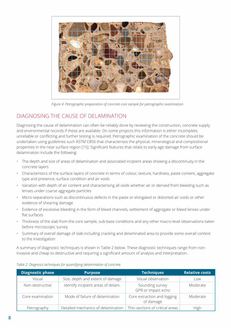
• Destructive testing using cores is sometimes undertaken but while this is invasive it is able to identify the extent of the problem and is generally done for forensic reasons (e.g. to identify the mechanism of delamination and therefore the most likely cause of the problem). Figure 4 shows a concrete core that has been sliced in half and prepared for image analysis
Figure 3: Typical pattern of delamination and likely causes
Shallow surface delamination (2-5mm deep)
Causes: Premature finishing Over-layering of paste
Unusual bleeding
Deeper delamination (5-15mm deeper)
Causes: Excess entrapped air Surface crusting Long-term effects
8
Figure 4: Petrographic preparation of concrete core sample for petrographic examination
DIAGNOSING THE CAUSE OF DELAMINATIONDiagnosing the cause of delamination can often be reliably done by reviewing the construction, concrete supply and environmental records if these are available. On some projects this information is either incomplete, unreliable or conflicting and further testing is required. Petrographic examination of the concrete should be undertaken using guidelines such ASTM C856 that characterises the physical, mineralogical and compositional properties in the near surface region [15]. Significant features that relate to early-age damage from surface delamination include the following:
• The depth and size of areas of delamination and associated incipient areas showing a discontinuity in the concrete layers
• Characteristics of the surface layers of concrete in terms of colour, texture, hardness, paste content, aggregate type and presence, surface condition and air voids
• Variation with depth of air content and characterising all voids whether air or derived from bleeding such as lenses under coarse aggregate particles
• Micro-separations such as discontinuous defects in the paste or elongated or distorted air voids or other evidence of shearing damage
• Evidence of excessive bleeding in the form of bleed channels, settlement of aggregate or bleed lenses under flat surfaces
• Thickness of the slab from the core sample, sub-base conditions and any other macro-level observations taken before microscopic survey
• Summary of overall damage of slab including cracking and delaminated area to provide some overall context to the investigation
A summary of diagnostic techniques is shown in Table 2 below. These diagnostic techniques range from non-invasive and cheap to destructive and requiring a significant amount of analysis and interpretation.
Table 2: Diagnosis techniques for quantifying delamination of concrete
Diagnostic phase Purpose Techniques Relative costsVisual Size, depth and extent of damage Visual observation Low
Non-destructive Identify incipient areas of delam. Sounding surveyGPR or impact echo
Moderate
Core examination Mode of failure of delamination Core extraction and logging of damage
Moderate
Petrography Detailed mechanics of delamination Thin sections of critical areas High

9
MITIGATION DELAMINATION RISKThree main factors need to be controlled to mitigate the risk delamination of concrete; namely controlling environment, material and processing. Specific factors that should be considered before construction are listed below and these may require significant planning and optimisation [16, 17].
ENVIRONMENTAL CONTROLDelamination issues are mostly related to in situ concrete where environmental conditions are less controlled than for precast concrete. The surface of concrete may be exposed directly to the environment that increases the risk of problems due to temperature, wind and humidity fluctuations. These dynamic processes will affect concrete properties and complicate finishing operations when these differences require significant adjustments in the timing of operations across a large slab.
Where casting large industrial slabs the vagaries of the environment can be significantly reduced by building the structure first. By having the walls and roof in place before placing concrete for the floor has the advantage of moderating the influence of ambient conditions. Large buildings will however create their own climate due to draughts set up across openings and higher temperatures in some cases.
CONTROLLING BLEEDConcrete mix designs need to have some robustness to deal with construction practices that are sometimes less than optimum. This particularly applies to bleeding of concrete that should not be reduced below a certain threshold level since this protects the surface and provides an indication of timing of finishing. Modern concrete mix design has increasingly reduced bleeding of concrete as chemical admixture usage has progressively cut the water demand of concrete to limit drying shrinkage and improve strength. Figure 5 shows the major material influences affecting bleeding of concrete.
Cement content (kg/m3)
325
13
250
10
275
11
300
12
350
14
375
15
400
16
170W
ater demand (L/m
3)Effec
tive
poro
sity
(%)
200
190
180
160
150
140
Very high
High
Moderate
Low
Figure 5: Qualitative bleed estimates based on concrete mix properties

10
There is no minimum level of bleeding that concrete should have for use in industrial slabs since this will depend on the application and environmental applications. Concrete suppliers should however undertake appropriate trials on concrete mixes to characterise the bleed of concrete mixes used in these applications. While such trials are usually done in accordance with ASTM C232 under laboratory conditions these data provide a useful reference that can be compared when there are concerns. Material factors that may influence bleeding of concrete include air content, grading of sand, silt or clay contamination, colour pigments and cement fineness.
MONITORING AIR CONTENTSMonitoring of air content of concrete is important since this can fluctuate due to material, seasonal and application differences. When using air entrained concrete, adjustment is made regularly to ensure air contents remain relatively constant despite changes in temperature and sometimes material properties. Concrete without air entrainment typically has air contents between one and two percent. Industrial floors are usually designed with concrete that does not have air entrainment but it is still important to monitor air contents to ensure defoaming action in modern chemical admixtures is effective.
Control and monitoring of air contents in concrete is traditionally done at the concrete plant after initial batching and mixing. This plant-based testing may need to be supplemented when there are concerns about delamination risk to concrete slabs and a limited amount of site-based testing is recommended. This is particularly important when using new chemical admixtures or materials that may interfere with defoaming agents. Research from Europe has shown how extended mixing and agitation can result in a significant increase in air content for concrete arriving on site (see Figure 6 from RILEM TC-268 SIF report).
Mixing period (minutes)
Air c
onte
nt (%
)
320 kg/m3 CEM | 42.5 R; W/C 0.55; S4
0 200
12
10
8
6
4
2
40 60 80 100 120 140 160
PCE1, Standard
PCE1, TV204
PCE3, Standard
PCE3, TV204
MEL, Standard
MEL, TV204
PCE4, Standard
PCE4, TV204
NAF1, Standard
NAF1, TV204
Figure 6: Air contents of non-air entrained concrete with extended mixing [5]
TIMING OF FINISHING OPERATIONSFinishing of concrete slabs is traditionally done by specialist contractors who have the expertise to ensure timing and methodology are appropriate. Better documentation of these operations could reduce disputes in cases involving delamination problems. Just as the delivery of concrete is fully documented in terms of material supplied and timing of discharge into the slab, the same could be documented for areas of the slab being finished. Where more sophisticated methods such as semi-adiabatic calorimetry or thermal imaging are used these should be logged together with an activity summary.

11
SURFACE TREATMENTS Application of surface applied treatments are sometimes used to achieve improved hardness of the concrete to resist abrasion and wear. These surface treatments generally consist of dry shake powders that require care to ensure consistent application and timing. These types of application are difficult to control and their contribution to problems such as delamination are difficult to quantify. It is known that these materials can cause differential volume changes near the surface that can exacerbate the risk of delamination.
A summary of recommended measures for mitigating the risk of surface delamination of concrete are shown in Table 3. Some of these measures are relatively easy to quantify and control of these is effective.
Table 3: Mitigation methods to reduce the risk of delamination of concrete
Mitigation measure Practicality Difficulty EffectivenessEnvironment Requires planning of
construction Often done with industrial
slabsVery effective means
of controlBleeding Correct mix design – trial
and testingRoutinely done by concrete suppliers
Effective by materials vary
Air content Regular monitoring at plant & site
Requires extra testing on site
Effective but needs more monitoring
Finishing operations Specialist activity by contractors
Requires better recording on site
Critical but difficult to quantify
Surface treatments Equipment & expertise Difficult to quantify this activity
Uncertain but not widely used
12
Recommendations for mitigating the risk for delamination of concrete include design, monitoring and forensic investigations.
DESIGN ASPECTSWhen considering recommendations to mitigate the risk of delamination it is tempting to simply fall back on a list of prescriptive limits for concrete mixes supplied for floor slabs. This approach assumes that the damage is primarily a material issue. Using a prescriptive specification methodology such as this does not allow flexibility across a wide range of materials and applications. While this approach is questionable, some typical prescriptive limits for concrete are as follows [5]:
• Maximum air content of 3.0 percent in fresh concrete
• Maximum high range water-reducing admixture of 1.0 percent by weight of cement
• Minimum water content of 180 L/m3 in the concrete mix design
• Maximum cement content of 320 kg/m3 in the concrete mix design
• Limits of the contribution of fines content contribution from sand
• Other properties such as concrete temperature limits when placing
• No guidance on the consistence level (e.g. slump) is given
These limitations on the concrete mix are implicitly based on ensuring reasonable bleeding of fresh concrete. Unfortunately, these material limits also have a significant effect on other properties such as workability, strength and drying shrinkage. A much more effective approach for specifying concrete used for concrete floors is using performance-based methods such as compressive strength is applied for structural applications. This may be more difficult to specify and measure but has the advantage of being more flexible and is also more related to delamination risk.
MONITORING PERFORMANCEWhat types of performance are therefore relevant to concrete mixes used for industrial floor slabs? The two most obvious performance parameters are bleeding of concrete and setting time and consistence is probably more important than rigid limits [18]. Predictions of these performance-based properties can then be made for specific projects and the actual in situ performance can be monitored and compared with predicted values.
This performance-based approach is increasingly being used in the United States where semi-adiabatic calorimetry is used during construction of industrial concrete floors to monitor setting times and ensure the window of finishability is known in real-time [19]. There is also increasing use of sensors cast into slabs that provide real-time monitoring of important properties such as temperature, which is closely linked with cement hydration and therefore setting time.
FORENSIC INVESTIGATION OF DELAMINATION ISSUESWhen designing and constructing large industrial slabs there is always the risk of surface delamination. It is important that the extent and severity of any areas of suspected delamination are thoroughly investigated and an objective framework is used when interpreting relevant data. A hierarchy of investigative techniques is commonly used when investigating deterioration of concrete, which is shown in Table 4. The full suite of tests would not be appropriate in many cases but understanding what can be determined and inferred from these forensic investigations is important.
RECOMMENDATIONS

13
Table 4: Summary of techniques for surface delamination reporting [19, 20, 21, 22, 23 & 24]
Methodology Technique Relative cost InterpretationOn site visual Logging floor Cheap to undertake on
most floorsEasy only if when
delamination shallowOn site NDT Sounding survey
Impact echo/GPRCheap
ExpensiveRequires experienceRequires expertise
Core examination Extracting cores Cheap but causes damage to slab
Useful but may damage surface
Thin section Petrographic analysis Expensive for petrographic report
Requires expertise from petrographer
Image analysis Petrographic analysis Moderate for void count and shape
Software for quick analysis of voids
Chemical analysis Cement content or contaminants
Moderate using testing laboratory
Easy but not always relevant to issue
REMEDIAL OPTIONSRepair of concrete floors that exhibit signs of delamination have been successfully repaired in the past but this remedial work depends on several factors, that include:
• Aesthetic requirements of the finished floor surface
• Depth of delamination and extent of the problem
• Confidence that forensic survey has identified all significant areas of delamination
Two types of repair are typically specified to remove delamination or incipient areas of potential delamination. These two approaches are as follows:
• Shallow delamination typically less than 3-4 mm where the cement skin is loose or delaminated and the slab surface requires grinding back to a competent substrate (these delaminations are generally easy to identify and repair process can be monitored and approved with some confidence)
• Deeper delaminated zones typically between 5-15 mm where cracking runs through the concrete matrix, the surface is intact apart from minor cracking and epoxy injection must be undertaken by expert repair contractors (some grinding may still be required after treatment to achieve the required finish)
Most cases involving delamination do not exhibit wholesale damage across the slab surface but involve localised areas of a limited extent. Replacement of concrete slabs with only limited delamination is expensive and often cannot be justified when repair of the surface can be done. Agreement of possible strategies before construction may better inform all construction parties of the risks and options.
14
Damage associated with delaminated areas on concrete slabs does not appear to be reducing despite the advent of modern materials and construction practices. The effect of these surface defects has a major impact on the aesthetics and serviceability of floors and has led to numerous disputes and costly remedial measures. With the increasing use of post-tensioned systems for industrial slabs, delamination remains the last major defect that may occur in practice.
The cause of delamination and best forms of mitigation is not simple otherwise the issue would be largely resolved and written off as being due to either inappropriate concrete mix designs, unreliable concrete supply or poor construction practice. Delamination of concrete is problematic as the mechanism is both complicated (i.e. involves a high level of difficulty) and complex (i.e. involves many components). Major factors involved such as concrete, processing and environment have a complicated interaction between components. The overall effect is complex since these material, processing and environmental factors are inter-related with an unknown impact on the risk of delamination.
Major risk factors for delamination are reasonably well understood and there is also agreement on effective mitigation methods. Inflexible and simplistic methods of specifying concrete should be avoided such as using prescriptive limits. A better approach is to rely on performance-based methods and to ensure testing and monitoring is undertaken to control both material supply and construction practice.
CONCLUSIONS
15
1. Jana, D., Delamination – A State of the Art Report, Proc. of 29th Conference on Cement Microscopy, Quebec, 2007.
2. Cement and Concrete Association of New Zealand, Surface delamination in slab on ground construction, CCANZ, Wellington, 2002.
3. Spannenberg, R.H., Us the right finishing tools at the right time, Concrete Construction, 1996.
4. Cement and Concrete Association of New Zealand, Concrete Construction Guide for New Zealand, CCANZ, Wellington, 2006.
5. Pollet, V., RILEM TC 268-SIF Surface delamination of concrete industrial floors and other durability related aspects guide, RILEM, Paris, 2017.
6. Suprenant, B.A. and Malisch, W.R., The true window of finishability, Concrete Construction, 1998.
7. Cement Concrete and Aggregates Australia, Delamination of concrete industrial floors, CCAA, Sydney, 2009.
8. Plimmer, J., Delamination of concrete floor surfaces, Concrete, London, 1990.
9. Perenchio, W., Finishing too early – trowelling the surface of a slab while the concrete is still bleeding, Concrete Construction, 2001.
10. Suprenant, B.A. and Malisch, W.R., Diagnosing slab delaminations – Part 1, Concrete Construction, 1998.
11. Whiting, D.A. & Nagi, M.A., Manual of control of air content in concrete, Portland Cement Association, 1998.
12. Lankard, D., Air entrainment and delamination, ACI Concrete International, 2004.
13. Manning, D.G. and Holt, F.B., Detecting delamination in concrete bridge decks, ACI Concrete International, 1980.
14. Khan, M.S., Detecting corrosion-induced delamination, ACI Concrete International, 2003.
15. American Society for Testing and Materials, ASTM C856-02 Standard practice for petrographic examination of hardened concrete, ASTM, Philadelphia, 2002.
16. National Ready-Mix Concrete Association, CIP20 Delamination of trowelled concrete surfaces, NRMCA, Silver Springs, 2004.
17. Transport Research Board, Control of cracking of concrete – State of the Art Report, TRB, 2006.
18. Mackechnie, J.R., Fresh concrete performance guidelines, SESOC Journal, November 2018.
19. American Society of Testing and Materials, ASTM C1753-15 Standard practice for evaluating early hydration of hydraulic cementitious mixtures using thermal measurements, ASTM, Philadelphia, 2015.
20. Rocha, J.H.A. and Pavoas, Y.V., Detection of delaminations in reinforced concrete bridges using infrared thermography, Revista Inginieria de Construccion, 2019.
21. Poole, A. and Sims, I., Concrete Petrography – A handbook of investigative techniques, Second Edition, CRC Press, 2020.
22. Scherr, J.F. and Grosse, C.U, Delamination detection on a concrete bridge deck using impact echo scanning, Structural Concrete, FIB, Nov. 2020.
23. USBR Guide to Concrete Repair, US Dept. of the Interior, Bureau of Reclamation, August 2015.
24. Allen, R.T.L., Edwards, S.C. and Shaw, D,N., Repair of Concrete Structures, CRC Press, 2019.
REFERENCES

16
NOTES

17

18

19
Flatness and LevelnessFloor Pro�le Assessment
• De�ned Movement, High Bay & Narrow Aisle• Fast & Accurate Measure• Self-Propelled & Laser Guided• Reporting to UK Concrete Society TR 34 4th ed., Fmin, EN 15620, DIN 15185 & VDMA
DESIGNER• Con�rmation of
speci�cation achieved prior to handover
OWNER• Classi�cation compliance
BUILDER• Assessment of construction
methodology• Aisle wheelpath grind
reporting
TENNANT• E�ciency of use• Early assessment of aisle
usability• Assists materials handling
speci�cation• Static lean assessment
[email protected] | +64 21 287 8781www.certus.nz

20
MAKE HARD EASY.
0800 4 ALLIED | alliedconcrete.co.nz
Innovative, reliable and awarded. The choice is easy.
CONCRETEEQUIPMENT&TOOLS
MADE IN JAPAN
MADE IN USA
CONTRACTOR TOUGH Introducing a Real Game Changer in the concrete placing / flooring market.
New game-changing technology produces hardened, abrasion resistant, and dustproofed concrete floors.
PRO Float will produce faster, better results and provides long-term advantages to the concrete slab.
Can SAVE up to 50% of cost of placement construction costs.
CURING AND TROWELING AIDMost Innovative Product at WOC 2013
-
-
-
-
-
Eliminates the costs and hassle of adding water to cure
Eliminates the cost of any other treatments to densify the concrete floor
Reduces the physical costs and time to place the concrete floor
Increases the finish options e.g. polished look at significantly reduced costs
Reduces or eliminates the issues related to delamination
PRO FLOAT
Full Tech | Specs | Test Reports | Videos of PRO Float application:
www.concretesealers.co.nz/concrete-finishing/

21
We produce and supply consistent quality cement that you can rely on. We call it NZ grade - you know where it’s made, what it’s made of, who made it and that it’s made for the NZ market. It’s Genuine so you
can trust it.
Being Genuine is part of our fundamental approach to do business.

22
OUR WORLD IS FLAT. Conset Construction.The leaders in delivering
large scale flat slabs.Results set in concrete.
CONSETCONSTRUCTION.CO.NZ
PODIUMCONCRETE.CO.NZ
THE POST-TENSIONED
SLAB SPECIALISTS
All around New Zealand, Grouting Services has delivered post-tensioned slabs for the country’s iconic businesses, buildings, bridges and sports stadiums. In fact, we’ve specialised in post-tensioning for 50 years and provide both a design and construction service. No wonder so many Project Managers trust Grouting Services and its partnership with leading slab construction company Conset Construction.
For more information, visit groutingservices.co.nz or call 09 837 2510. RETAINING YOUR BUSINESS IS OUR BUSINESS

23

24
OPTIMISING CONCRETESLABS AND PAVEMENTDESIGNS
0800 463 672www.inforceglobal.com
iNFORCESIMPLIFY WITH CONFIDENCE.
� DESIGN � SPECIFICATION � ONSITE SUPPORT
www.concretenz.org.nz
WE’VE BEEN SPECIALISING INDIAMOND FOR 30 YEARS
0800 77 38 [email protected]
www.diamond-tools.co.nz
••••••••• • “Specialising in Diamond”• •
••••
••••30 YEARS
3030


Related Documents