Guide Specifications for Xerxes Underground Petroleum Storage Tanks 10 Short form: The contractor shall provide a double-wall or triple-wall fiberglass reinforced plastic (FRP) UL-listed underground storage tank as shown on the drawings. The tank size, fittings and accessories shall be as shown on the drawings. The fiberglass tank shall be manufactured by Xerxes Corporation. The tank shall be tested and installed according to the Xerxes Installation Manual and Operating Guidelines for Fiberglass Underground Storage Tanks in effect at time of installation. Long form: Part I: General 1.01 Quality Assurance A. Acceptable Manufacturer: Xerxes Corporation B. Governing Standards, as applicable: 1. Underwriters Laboratories (UL) Standard for Safety 1316 Glass-Fiber-Reinforced Plastic Underground Storage Tanks for Petroleum Products, Alcohols, and Alcohol-Gasoline Mixtures. A UL label shall be attached to each tank. 2. National Fire Protection Association (NFPA) Standards: NFPA 30: Flammable and Combustible Liquids Code, NFPA 30A: Code for Motor Fuel Dispensing Facilities and Repair Garages, NFPA 31: Standard for the Installation of Oil-Burning Equipment. 3. City of New York Department of Buildings M.E.A., #161-89-M. 4. American Concrete Institute (ACI) standard ACI 318-11, Building Code Requirements for Structural Concrete. C. Submittals 1. Contractor shall submit ___ copies of shop drawings, manufacturer’s product brochures, Installation Instructions and calibration charts. Part II: Products 2.01 Double-Wall and Triple-Wall Fiberglass Reinforced Plastic (FRP) Underground Storage Tanks: A. Loading Conditions – Tank shall meet these design criteria: 1. Interstitial Pressure – The interstitial space of the tank shall withstand a minimum 20-psig pressure test. 2. Internal Load – Tank shall withstand a 5-psig air-pressure test with a 5:1 safety factor. 3. Surface Loads – Tank shall withstand surface H-20 and HS-20 axle loads when properly installed according to Xerxes’ current Installation Manual and Operating Guidelines. 4. External Hydrostatic Pressure – Tank shall be designed for 7’ of overburden over the top of the tank, the hole fully flooded and a safety factor of 5:1 against general buckling. B. Product Storage: 1. The primary compartment of double-wall and triple-wall tanks shall be vented and operated at atmospheric pressure only. 2. Tank shall be capable of storing liquids with a specific gravity up to 1.1. 3. Tank shall be capable of storing products identified in the manufacturer’s standard limited warranty in effect at the time of purchase. C. Materials: 1. The primary and secondary walls of the tank shall be manufactured with 100% premium resin and glass-fiber reinforcement. No sand or silica fillers shall be added to the resin. 2. The interstitial space between the primary and secondary walls shall be constructed with a glass reinforcement material such as Parabeam ® , which provides a structural bond between the two tank walls, while creating a defined interstice that allows for free flow of liquid. D. Tank Dimensions (Refer to Xerxes literature on gallonage): 1. Tank shall have nominal capacity of _____ gallons. 2. Tank shall have nominal outside diameter of _____ feet. 3. Tank shall have a nominal overall length of _____ feet/inches. 2.02 Tank Monitoring System A. General 1. Tank shall be continuously monitored with the TRUCHEK ® hydrostatic leak monitoring system. 2. The continuous monitoring system shall include monitoring fluid factory-installed in the interstitial space and within a fiberglass tank-top mounted reservoir. 3. The monitoring system shall be recognized by the National Work Group on Leak Detection Evaluations (NWGLDE) as continuous leak detection and as a precision tank test. 4. The monitoring system shall be independently tested by a qualified third party and verified to be capable of detecting leaks as small as .05 gallons per hour when TRUCHEK tank-tightness test procedures are followed. B. Design 1. The continuous monitoring system shall be designed to detect a leak in either the primary or secondary wall at all times, regardless of the water-table conditions at the installation site. 2. The interstice of the tank shall be designed for a 5:1 safety factor beyond normal hydrostatic operating pressure to ensure structural integrity and to prevent false leak alarms. 2.03 Accessories A. Tank Anchoring 1. Anchor straps shall be as supplied by tank manufacturer and designed for a maximum load of 25,000 lbs. 2. Galvanized turnbuckles (two per anchor strap) shall be supplied by the tank manufacturer. 3. Prefabricated concrete anchors shall be supplied by the tank manufacturer, designed to the ACI 318-11 standard, manufactured with 4,000 psi concrete, and shall have adjustable anchor points. B. Manways 1. The standard manway shall be flanged, 22” I.D. and complete with UL-listed gaskets, bolts and covers as shown on tank drawings. C. Threaded Fittings 1. All threaded fittings shall be NPT half or full couplings, in 2”, 4” or 6” diameters. 2. Fittings shall be installed on the tank-top centerline or in the cover of the manway as shown on the tank drawings. D. Containment Collars & Sumps 1. The tank shall have factory-installed 42”-or 48”-diameter containment collars as shown on the tank drawings. 2. Containment sumps in 42”-or 48”-diameter, provided by the tank manufacturer and designed for mounting on the containment collars, shall be supplied as shown on the tank drawings. 3. UL-listed adhesive shall be provided by the tank manufacturer with each containment collar and sump. 4. Containment collars and sumps shall be UL-listed for use with the manufacturer’s tank. 5. Containment collars and sumps shall be designed and supplied as a containment system. Only sumps provided by the manufacturer shall be allowed. Part III: Testing and Installation 3.01 Testing A. Testing – Tank shall be tested according to the Xerxes Installation Manual and Operating Guidelines in effect at time of installation. 3.02 Installation A. Installation – Tank shall be installed according to the Xerxes Installation Manual and Operating Guidelines in effect at time of installation. Part IV: Limited Warranty 4.01 Limited Warranty A. Limited Warranty – Warranty shall be manufacturer’s standard limited warranty in effect at time of purchase.

Welcome message from author
This document is posted to help you gain knowledge. Please leave a comment to let me know what you think about it! Share it to your friends and learn new things together.
Transcript

Guide Specifications for Xerxes Underground Petroleum Storage Tanks
10
Short form:The contractor shall provide a double-wall or triple-wall fiberglass reinforced plastic (FRP) UL-listed underground storage tank as shown on the drawings. The tank size, fittings and accessories shall be as shown on the drawings. The fiberglass tank shall be manufactured by Xerxes Corporation.
The tank shall be tested and installed according to the Xerxes Installation Manual and Operating Guidelines for Fiberglass Underground Storage Tanks in effect at time of installation.Long form:Part I: General1.01 Quality AssuranceA. Acceptable Manufacturer: Xerxes CorporationB. Governing Standards, as applicable: 1. Underwriters Laboratories (UL) Standard for Safety 1316 Glass-Fiber-Reinforced Plastic Underground Storage Tanks for Petroleum Products, Alcohols, and Alcohol-Gasoline Mixtures. A UL label shall be attached to each tank.
2. National Fire Protection Association (NFPA) Standards: NFPA 30: Flammable and Combustible Liquids Code, NFPA 30A: Code for Motor Fuel Dispensing Facilities and Repair Garages, NFPA 31: Standard for the Installation of Oil-Burning Equipment.
3. City of New York Department of Buildings M.E.A., #161-89-M.
4. American Concrete Institute (ACI) standard ACI 318-11, Building Code Requirements for Structural Concrete.C. Submittals 1. Contractor shall submit ___ copies of shop drawings, manufacturer’s product brochures, Installation Instructions and calibration charts.
Part II: Products2.01 Double-Wall and Triple-Wall Fiberglass Reinforced Plastic (FRP) Underground Storage Tanks:A. Loading Conditions – Tank shall meet these design criteria: 1. Interstitial Pressure – The interstitial space of the tank shall withstand a minimum 20-psig pressure test. 2. Internal Load – Tank shall withstand a 5-psig air-pressure test with a 5:1 safety factor. 3. Surface Loads – Tank shall withstand surface H-20 and HS-20 axle loads when properly installed according to Xerxes’ current Installation Manual and Operating Guidelines. 4. External Hydrostatic Pressure – Tank shall be designed for 7’ of overburden over the top of the tank, the hole fully flooded and a safety factor of 5:1 against general buckling.
B. Product Storage: 1. The primary compartment of double-wall and triple-wall tanks shall be vented and operated at atmospheric pressure only. 2. Tank shall be capable of storing liquids with a specific gravity up to 1.1. 3. Tank shall be capable of storing products identified in the manufacturer’s standard limited warranty in effect at the time of purchase.
C. Materials: 1. The primary and secondary walls of the tank shall be manufactured with 100% premium resin and glass-fiber reinforcement. No sand or silica fillers shall be added to the resin. 2. The interstitial space between the primary and secondary walls shall be constructed with a glass reinforcement material such as Parabeam®, which provides a structural bond between the two tank walls, while creating a defined interstice that allows for free flow of liquid.
D. Tank Dimensions (Refer to Xerxes literature on gallonage): 1. Tank shall have nominal capacity of _____ gallons. 2. Tank shall have nominal outside diameter of _____ feet. 3. Tank shall have a nominal overall length of _____ feet/inches.
2.02 Tank Monitoring SystemA. General 1. Tank shall be continuously monitored with the TRUCHEK® hydrostatic leak monitoring system.
2. The continuous monitoring system shall include monitoring fluid factory-installed in the interstitial space and within a fiberglass tank-top mounted reservoir. 3. The monitoring system shall be recognized by the National Work Group on Leak Detection Evaluations (NWGLDE) as continuous leak detection and as a precision tank test. 4. The monitoring system shall be independently tested by a qualified third party and verified to be capable of detecting leaks as small as .05 gallons per hour when TRUCHEK tank-tightness test procedures are followed.B. Design 1. The continuous monitoring system shall be designed to detect a leak in either the primary or secondary wall at all times, regardless of the water-table conditions at the installation site. 2. The interstice of the tank shall be designed for a 5:1 safety factor beyond normal hydrostatic operating pressure to ensure structural integrity and to prevent false leak alarms. 2.03 AccessoriesA. Tank Anchoring 1. Anchor straps shall be as supplied by tank manufacturer and designed for a maximum load of 25,000 lbs. 2. Galvanized turnbuckles (two per anchor strap) shall be supplied by the tank manufacturer. 3. Prefabricated concrete anchors shall be supplied by the tank manufacturer, designed to the ACI 318-11 standard, manufactured with 4,000 psi concrete, and shall have adjustable anchor points. B. Manways 1. The standard manway shall be flanged, 22” I.D. and complete with UL-listed gaskets, bolts and covers as shown on tank drawings. C. Threaded Fittings 1. All threaded fittings shall be NPT half or full couplings, in 2”, 4” or 6” diameters. 2. Fittings shall be installed on the tank-top centerline or in the cover of the manway as shown on the tank drawings.
D. Containment Collars & Sumps 1. The tank shall have factory-installed 42”-or 48”-diameter containment collars as shown on the tank drawings. 2. Containment sumps in 42”-or 48”-diameter, provided by the tank manufacturer and designed for mounting on the containment collars, shall be supplied as shown on the tank drawings. 3. UL-listed adhesive shall be provided by the tank manufacturer with each containment collar and sump. 4. Containment collars and sumps shall be UL-listed for use with the manufacturer’s tank. 5. Containment collars and sumps shall be designed and supplied as a containment system. Only sumps provided by the manufacturer shall be allowed.
Part III: Testing and Installation3.01 TestingA. Testing – Tank shall be tested according to the Xerxes Installation Manual and Operating Guidelines in effect at time of installation.
3.02 InstallationA. Installation – Tank shall be installed according to the Xerxes Installation Manual and Operating Guidelines in effect at time of installation.
Part IV: Limited Warranty4.01 Limited WarrantyA. Limited Warranty – Warranty shall be manufacturer’s standard limited warranty in effect at time of purchase.
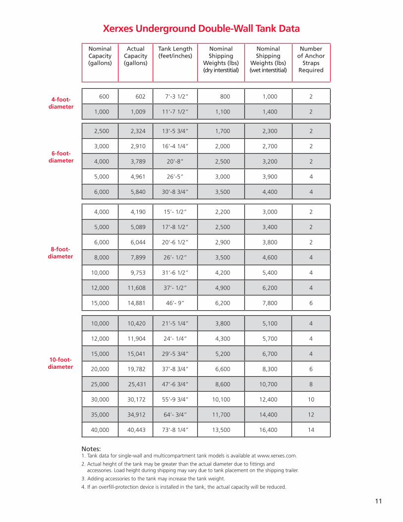
Xerxes Underground Double-Wall Tank Data
11
Nominal Capacity (gallons)
Actual Capacity (gallons)
Tank Length (feet/inches)
Nominal Shipping
Weights (lbs)(dry interstitial)
Nominal Shipping
Weights (lbs)(wet interstitial)
Number of Anchor
Straps Required
600 602 7’-3 1/2” 800 1,000 2
1,000 1,009 11’-7 1/2” 1,100 1,400 2
4-foot-diameter
2,500 2,324 13’-5 3/4” 1,700 2,300 2
3,000 2,910 16’-4 1/4” 2,000 2,700 2
4,000 3,789 20’-8” 2,500 3,200 2
5,000 4,961 26’-5” 3,000 3,900 4
6,000 5,840 30’-8 3/4” 3,500 4,400 4
6-foot-diameter
4,000 4,190 15’- 1/2” 2,200 3,000 2
5,000 5,089 17’-8 1/2” 2,500 3,400 2
6,000 6,044 20’-6 1/2” 2,900 3,800 2
8,000 7,899 26’- 1/2” 3,500 4,600 4
10,000 9,753 31’-6 1/2” 4,200 5,400 4
12,000 11,608 37’- 1/2” 4,900 6,200 4
15,000 14,881 46’- 9” 6,200 7,800 6
8-foot-diameter
10,000 10,420 21’-5 1/4” 3,800 5,100 4
12,000 11,904 24’- 1/4” 4,300 5,700 4
15,000 15,041 29’-5 3/4” 5,200 6,700 4
20,000 19,782 37’-8 3/4” 6,600 8,300 6
25,000 25,431 47’-6 3/4” 8,600 10,700 8
30,000 30,172 55’-9 3/4” 10,100 12,400 10
35,000 34,912 64’- 3/4” 11,700 14,400 12
40,000 40,443 73’-8 1/4” 13,500 16,400 14
10-foot-diameter
Notes:1. Tank data for single-wall and multicompartment tank models is available at www.xerxes.com.
2. Actual height of the tank may be greater than the actual diameter due to fittings and accessories. Load height during shipping may vary due to tank placement on the shipping trailer.
3. Adding accessories to the tank may increase the tank weight.
4. If an overfill-protection device is installed in the tank, the actual capacity will be reduced.

(Xerxes O�ce)
&
North American Manufacturing Facilities
XPB10/12pp© 2012 ZCL Composites Inc.
Xerxes Corporation7901 Xerxes Avenue SouthMinneapolis, MN 55431 USA952-887-1890www.xerxes.com
ZCL®, Xerxes®, Parabeam®, ZCL Phoenix System®, The Prezerver® System and TRUCHEK® are registered trademarks of ZCL Composites Inc.Vi
ZCL Composites Inc.1420 Parsons Road SWEdmonton, AB, T6X 1M5 Canada 780-466-6648www.zcl.com
Xerxes Manufacturing FacilitiesZCL Manufacturing Facilities
Anaheim, CAHagerstown, MD
Seguin, TXTipton, IA
Edmonton, ABDrummondville, QC


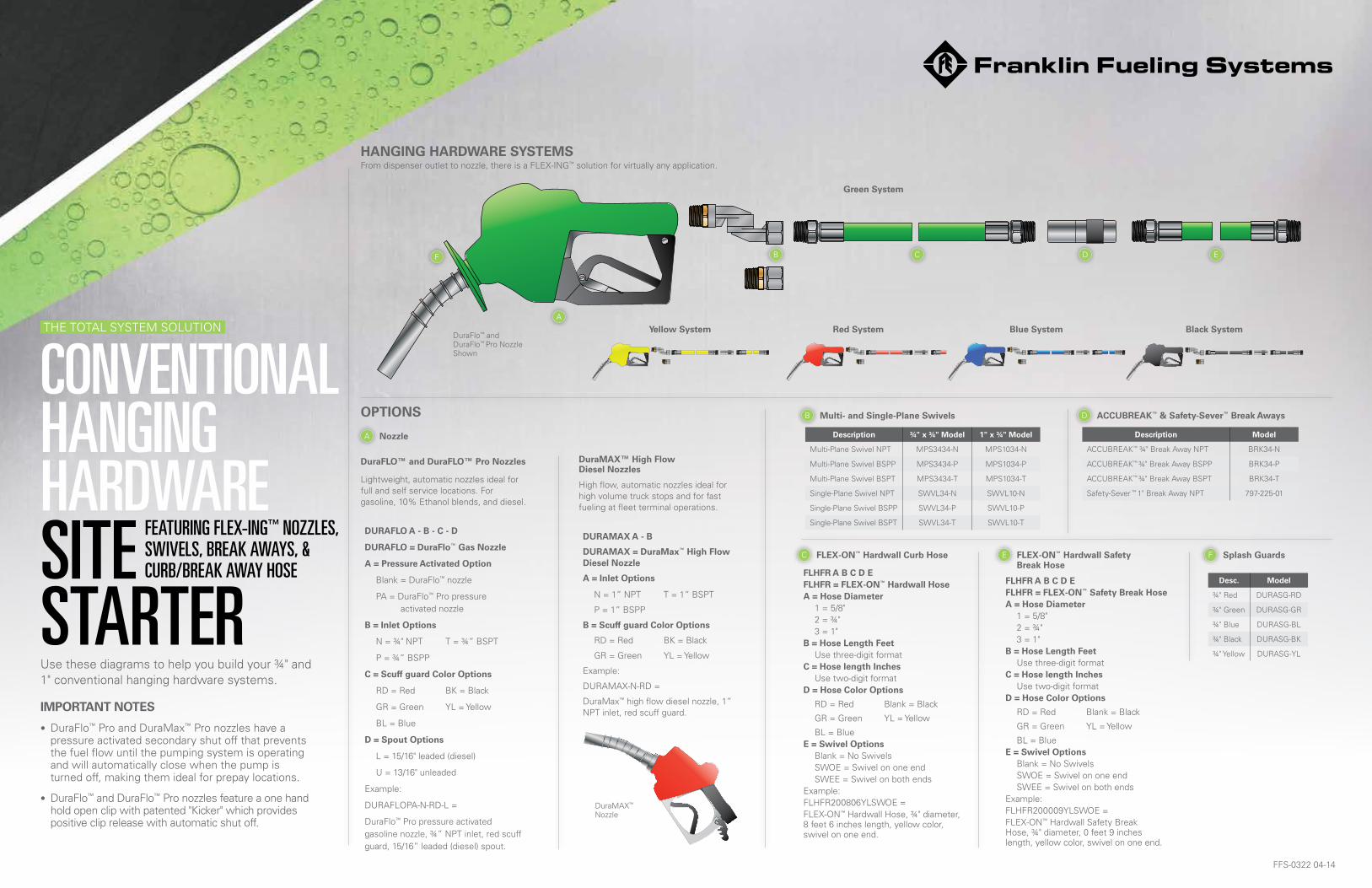
CONVENTIONAL HANGING HARDWARESITESTARTERUse these diagrams to help you build your ¾" and 1" conventional hanging hardware systems.
SUBMERSIBLE PUMPING SYSTEMSTHE TOTAL SYSTEM SOLUTION
FEATURING FLEX-ING™ NOZZLES, SWIVELS, BREAK AWAYS, & CURB/BREAK AWAY HOSE
FFS-0322 04-14
Nozzle
OPTIONS
From dispenser outlet to nozzle, there is a FLEX-ING™ solution for virtually any application.HANGING HARDWARE SYSTEMS
Lightweight, automatic nozzles ideal for full and self service locations. For gasoline, 10% Ethanol blends, and diesel.
A
B C D E
A
IMPORTANT NOTES
• DuraFlo™ Pro and DuraMax™ Pro nozzles have a pressure activated secondary shut off that prevents the fuel flow until the pumping system is operating and will automatically close when the pump is turned off, making them ideal for prepay locations.
• DuraFlo™ and DuraFlo™ Pro nozzles feature a one hand hold open clip with patented "Kicker" which provides positive clip release with automatic shut off.
Green System
Black SystemBlue SystemRed SystemYellow System
DURAFLO A - B - C - D
DURAFLO = DuraFlo™ Gas Nozzle
A = Pressure Activated Option
Blank = DuraFlo™ nozzle
PA = DuraFlo™ Pro pressure activated nozzle
B = Inlet Options
N = ¾" NPT T = ¾” BSPT
P = ¾” BSPP
C = Scuff guard Color Options
RD = Red BK = Black
GR = Green YL = Yellow
BL = Blue
D = Spout Options
L = 15/16" leaded (diesel)
U = 13/16" unleaded
Example:
DURAFLOPA-N-RD-L =
DuraFlo™ Pro pressure activated gasoline nozzle, ¾” NPT inlet, red scuff guard, 15/16” leaded (diesel) spout.
DuraFLO™ and DuraFLO™ Pro Nozzles
High flow, automatic nozzles ideal for high volume truck stops and for fast fueling at fleet terminal operations.
DuraMAX™ High Flow Diesel Nozzles
DURAMAX A - B
DURAMAX = DuraMax™ High Flow Diesel Nozzle
A = Inlet Options
N = 1” NPT T = 1” BSPT
P = 1” BSPP
B = Scuff guard Color Options
RD = Red BK = Black
GR = Green YL = Yellow
Example:
DURAMAX-N-RD =
DuraMax™ high flow diesel nozzle, 1” NPT inlet, red scuff guard.
DuraFlo™ and DuraFlo™ Pro Nozzle Shown
FLHFR A B C D EFLHFR = FLEX-ON™ Hardwall HoseA = Hose Diameter 1 = 5/8" 2 = ¾" 3 = 1"B = Hose Length Feet Use three-digit formatC = Hose length Inches Use two-digit formatD = Hose Color Options
RD = Red Blank = Black
GR = Green YL = Yellow
BL = BlueE = Swivel Options Blank = No Swivels SWOE = Swivel on one end SWEE = Swivel on both endsExample:FLHFR200806YLSWOE = FLEX-ON™ Hardwall Hose, ¾" diameter, 8 feet 6 inches length, yellow color, swivel on one end.
FLEX-ON™ Hardwall Curb HoseC FLEX-ON™ Hardwall Safety Break Hose
E
FLHFR A B C D EFLHFR = FLEX-ON™ Safety Break HoseA = Hose Diameter 1 = 5/8" 2 = ¾" 3 = 1"B = Hose Length Feet Use three-digit formatC = Hose length Inches Use two-digit formatD = Hose Color Options
RD = Red Blank = Black
GR = Green YL = Yellow
BL = BlueE = Swivel Options Blank = No Swivels SWOE = Swivel on one end SWEE = Swivel on both endsExample:FLHFR200009YLSWOE = FLEX-ON™ Hardwall Safety Break Hose, ¾" diameter, 0 feet 9 inches length, yellow color, swivel on one end.
Multi- and Single-Plane SwivelsB
Description ¾" x ¾" Model 1" x ¾" Model
Multi-Plane Swivel NPT MPS3434-N MPS1034-N
Multi-Plane Swivel BSPP MPS3434-P MPS1034-P
Multi-Plane Swivel BSPT MPS3434-T MPS1034-T
Single-Plane Swivel NPT SWVL34-N SWVL10-N
Single-Plane Swivel BSPP SWVL34-P SWVL10-P
Single-Plane Swivel BSPT SWVL34-T SWVL10-T
ACCUBREAK™ & Safety-Sever™ Break AwaysD
Description Model
ACCUBREAK™ ¾" Break Away NPT BRK34-N
ACCUBREAK™ ¾" Break Away BSPP BRK34-P
ACCUBREAK™ ¾" Break Away BSPT BRK34-T
Safety-Sever ™ 1" Break Away NPT 797-225-01
DuraMAX™ Nozzle
F
F Splash Guards
Desc. Model
¾" Red DURASG-RD
¾" Green DURASG-GR
¾" Blue DURASG-BL
¾" Black DURASG-BK
¾" Yellow DURASG-YL
579393 Princeton-Glendale Road Hamilton, Ohio USA 45011 Phone: (800) 422-2525 Fax: (800) 421-3297
www.opwglobal.com
©2013 OPW Fueling Components 579393 Princeton-Gllendale Road Hamilton, OOhio USA 45011 Phone: ((8800) 422-2525 Fax: (8000) 421-3297©©222013 OOPW Fueling Components
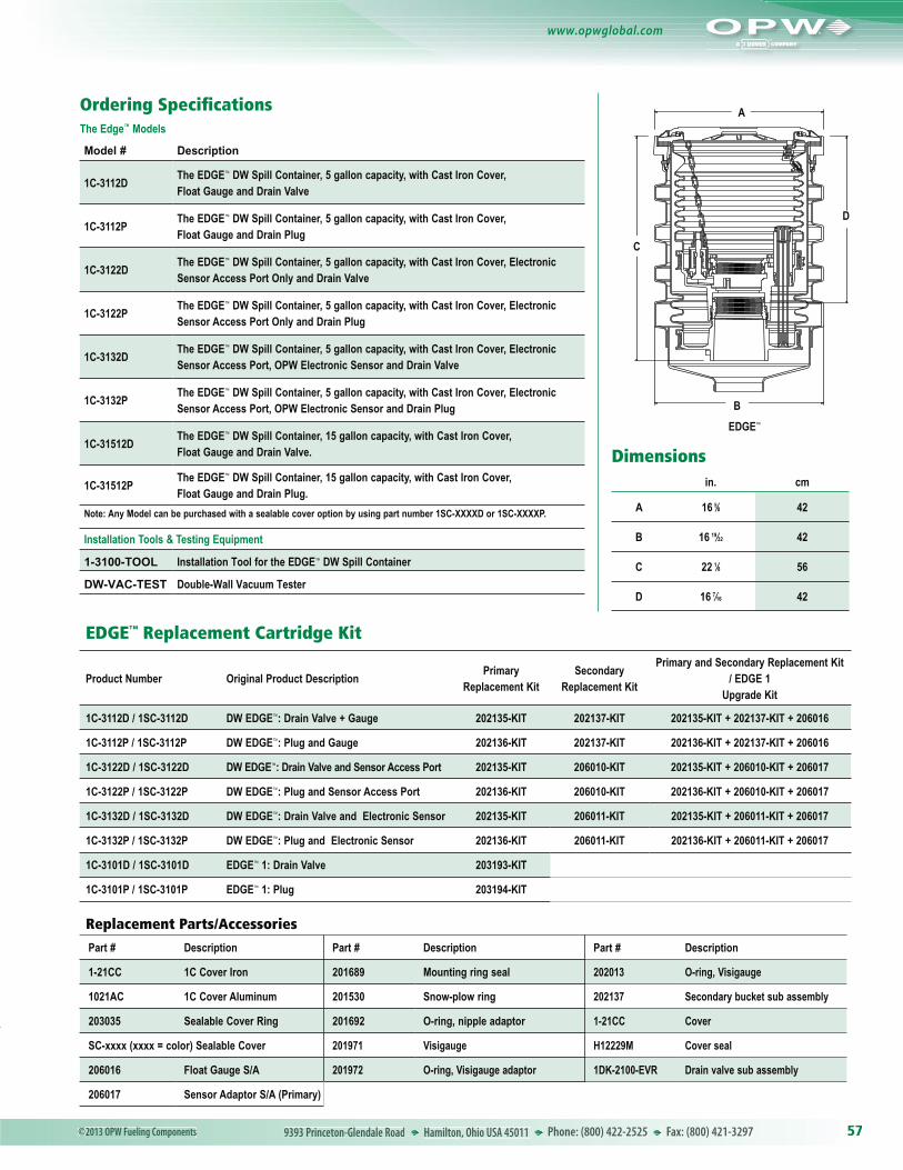
Ordering Specifications
EDGE™
Dimensionsin. cm
A 16 5⁄8 42
B 16 19⁄32 42
C 22 1⁄8 56
D 16 7⁄16 42
A
B
C
D
EDGE™ Replacement Cartridge Kit
Product Number Original Product DescriptionPrimary
Replacement KitSecondary
Replacement Kit
Primary and Secondary Replacement Kit / EDGE 1
Upgrade Kit
1C-3112D / 1SC-3112D DW EDGE™: Drain Valve + Gauge 202135-KIT 202137-KIT 202135-KIT + 202137-KIT + 206016
1C-3112P / 1SC-3112P DW EDGE™: Plug and Gauge 202136-KIT 202137-KIT 202136-KIT + 202137-KIT + 206016
1C-3122D / 1SC-3122D DW EDGE™: Drain Valve and Sensor Access Port 202135-KIT 206010-KIT 202135-KIT + 206010-KIT + 206017
1C-3122P / 1SC-3122P DW EDGE™: Plug and Sensor Access Port 202136-KIT 206010-KIT 202136-KIT + 206010-KIT + 206017
1C-3132D / 1SC-3132D DW EDGE™: Drain Valve and Electronic Sensor 202135-KIT 206011-KIT 202135-KIT + 206011-KIT + 206017
1C-3132P / 1SC-3132P DW EDGE™: Plug and Electronic Sensor 202136-KIT 206011-KIT 202136-KIT + 206011-KIT + 206017
1C-3101D / 1SC-3101D EDGE™ 1: Drain Valve 203193-KIT
1C-3101P / 1SC-3101P EDGE™ 1: Plug 203194-KIT
The Edge™ Models
Model # Description
1C-3112DThe EDGE™ DW Spill Container, 5 gallon capacity, with Cast Iron Cover, Float Gauge and Drain Valve
1C-3112PThe EDGE™ DW Spill Container, 5 gallon capacity, with Cast Iron Cover, Float Gauge and Drain Plug
1C-3122DThe EDGE™ DW Spill Container, 5 gallon capacity, with Cast Iron Cover, Electronic Sensor Access Port Only and Drain Valve
1C-3122PThe EDGE™ DW Spill Container, 5 gallon capacity, with Cast Iron Cover, Electronic Sensor Access Port Only and Drain Plug
1C-3132DThe EDGE™ DW Spill Container, 5 gallon capacity, with Cast Iron Cover, Electronic Sensor Access Port, OPW Electronic Sensor and Drain Valve
1C-3132PThe EDGE™ DW Spill Container, 5 gallon capacity, with Cast Iron Cover, Electronic Sensor Access Port, OPW Electronic Sensor and Drain Plug
1C-31512DThe EDGE™ DW Spill Container, 15 gallon capacity, with Cast Iron Cover, Float Gauge and Drain Valve.
1C-31512PThe EDGE™ DW Spill Container, 15 gallon capacity, with Cast Iron Cover, Float Gauge and Drain Plug.
Note: Any Model can be purchased with a sealable cover option by using part number 1SC-XXXXD or 1SC-XXXXP.
Installation Tools & Testing Equipment
1-3100-TOOL Installation Tool for the EDGE™ DW Spill Container
DW-VAC-TEST Double-Wall Vacuum Tester
Replacement Parts/Accessories
Part # Description Part # Description Part # Description
1-21CC 1C Cover Iron 201689 Mounting ring seal 202013 O-ring, Visigauge
1021AC 1C Cover Aluminum 201530 Snow-plow ring 202137 Secondary bucket sub assembly
203035 Sealable Cover Ring 201692 O-ring, nipple adaptor 1-21CC Cover
SC-xxxx (xxxx = color) Sealable Cover 201971 Visigauge H12229M Cover seal
206016 Float Gauge S/A 201972 O-ring, Visigauge adaptor 1DK-2100-EVR Drain valve sub assembly
206017 Sensor Adaptor S/A (Primary)
Related Documents