TRAINING GUIDE MILL-LESSON-15 CORE ROUGHING, WATERLINE, AND SURFACE FINISH LEFTOVER Sample Only not to be used for training

Welcome message from author
This document is posted to help you gain knowledge. Please leave a comment to let me know what you think about it! Share it to your friends and learn new things together.
Transcript

TRAINING
GUIDE
MILL-LESSON-15
CORE ROUGHING, WATERLINE, AND
SURFACE FINISH LEFTOVER
Sample
Only
not to
be us
ed
for tra
ining

Mastercam Training Guide
Mill-Lesson-15 - 1
Objectives You will use a provided model for Mill-Lesson-15, then generate the toolpaths to machine the part on a CNC vertical milling machine. This Lesson covers the following topics: � Establish Stock Setup settings: Stock size using Bounding Box. Material for the part. Feed calculation. � Generate 3-dimensional milling toolpaths consisting of: Core Roughing Waterline Surface Finish Leftover � Inspect the toolpath using Mastercam’s Verify by: Launching the Verify function to machine the part on the screen. Comparing a verified part to the original stock stl file. Generating the NC- code.
Sample
Only
not to
be us
ed
for tra
ining

Mill-Lesson-15
Mill-Lesson-15 - 2
TOOL LIST � 1.000 diameter flat end mill to rough and finish machine. � .500 diameter ballnose to finish machine � .125 diameter ballnose to finish machine � .0313 diameter ballnose to finish machine
Sam
ple O
nly
not to
be us
ed
for tra
ining

Mastercam Training Guide
Mill-Lesson-15 - 3
MILL-LESSON-15 - THE PROCESS
Toolpath Creation TASK 1: Setting the environment TASK 2: Open existing file from the multimedia CD TASK 3: Define the rough stock using stock setup TASK 4: Rough mold core using Surface High Speed (Core Roughing) TASK 5: Finish profile surfaces using Surface High Speed (Waterline) TASK 6: Finish all remaining stock using Surface Finish Leftover TASK 7: Verify the toolpath and compare to STL file TASK 8: Save the updated MCX file TASK 9: Post and create the CNC code file TASK 10: Create ActiveReport
Sample
Only
not to
be us
ed
for tra
ining

Mill-Lesson-15
Mill-Lesson-15 - 4
TASK 1: SETTING THE ENVIRONMENT Before starting the geometry creation you should set up the grid, toolbars and machine type as outlined in the Setting the environment section at the beginning of this text: 1. Set up the Grid. This will help identify the location of the origin. 2. Customize the toolbars to machine a 3D part. 3. Set the machine type to a Haas Vertical Spindle CNC machine.
Toolpath Creation TASK 2: OPEN EXISTING FILE FROM THE MULTIMEDIA CD � On the multimedia CD that came with this text is a folder called Mastercam-Files. The file
is in inch units and contains the wireframe and surface (solid) geometry of the part. � The part is already setup for a: GENERIC HAAS 4 – AXIS VMC. 1. Select File>Open> Mill-Lesson-15.MCX. 2. If confronted with the System Configuration dialog box activate the radio button for All
settings.
� System Configuration (switch units) dialog box � When you open a part file that uses different units (English or metric) from those currently in
use, Mastercam automatically displays this dialog box, which informs you that Mastercam is switching units and loading an alternate default configuration file. In order to complete the operation, select one of the following options:
� Units: Tells Mastercam to use only the units from the new configuration file. (default) � All settings: Tells Mastercam to load all settings from the new configuration file.
3. Select the OK button to exit the System Configuration dialog box. 4. Activate a shaded view by selecting the icon at the top of the screen.
Sample
Only
not to
be us
ed
for tra
ining

Mastercam Training Guide
Mill-Lesson-15 - 5
TASK 3: DEFINE THE ROUGH STOCK USING STOCK SETUP 1. Click on the Toolpaths Tab as shown below: Note; Alt-O will Show/hide the Operations
Manager pane.
2. Select the + in front of Properties to expand the Toolpaths Group Properties. Select Stock
setup in the toolpath manager window. Select the Bounding box button:
3. Set the parameters to match the Bounding Box screenshot in the left image below, then
select the OK button .
4. Set the parameters to match the Stock Setup screenshot shown in the above right image.
Since the expand option in the bounding box window increased the size of the stock in both the negative and positive directions, the Z dimension needs to be reduced by 0.1. Simply select the Z dimension and add – 0.1 and hit enter.
Sample
Only
not to
be us
ed
for tra
ining

Mill-Lesson-15
Mill-Lesson-15 - 6
5. Select the Tool Settings tab and change the parameters to match the Tool Settings screenshot below. Note: The Feed Calculation is set to From material. To change the Material type follow the instructions below:
To change the Material type to Aluminium 6061 pick the Select button at the bottom of the Tool Settings page. At the Material List dialog box open the Source drop down list and select Mill – library. From the Default Materials list select ALUMINIUM inch - 6061 and then select the
OK button .
6. Select the Edit button to enter the material definition. At this time we will not make any
changes to Mastercam’s defaults, but it is important to know how this function works.
Sample
Only
not to
be us
ed
for tra
ining
Mastercam Training Guide
Mill-Lesson-15 - 7
Material Definition allows the user to enter the Base cutting speed (Surface Feet per Minute) and Base feed per tooth/revolution (Chip Load). These base values can be arrived at based on the material used. Mastercam’s default values are very conservative so we will use them for safety purposes during this tutorial. % of Base by Operation Type allows the user to specify a variation in SFM based on the operation type. Eg, face milling will have a much higher SFM than profile milling. % of Base by Tool Type allows the user to vary feed per tooth by the tool. Eg. endmills will typically have a much higher feed per tooth (FPT) than a ballnose tool will. Allowable tool materials and additional speed/feed percentages allows the user to further customize based on the tool type. The user can further adjust SFM and chip load percentages in each tool definition. This is demonstrated during the first operation in TASK 3. If cutting on a machine, it is extremely important that you research recommended SFM and FPT for your tools and material and make the appropriate settings in Mastercam.
7. Select the OK button again to complete this function.
8. Select the OK button again to exit the Machine Group Properties.
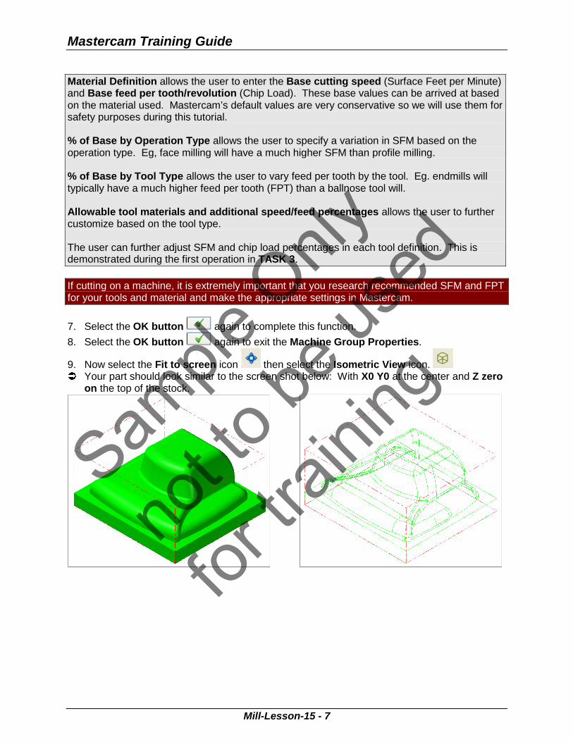
9. Now select the Fit to screen icon then select the Isometric View icon. � Your part should look similar to the screen shot below: With X0 Y0 at the center and Z zero
on the top of the stock.
Sample
Only
not to
be us
ed
for tra
ining

Mill-Lesson-15
Mill-Lesson-15 - 8
TASK 4: ROUGH OUT MOLD CORE USING SURFACE HIGH SPEED (CORE ROUGHING) TOOLPATH � In this task you will use a 1.000 diameter end mill to rough the part. 1. From the bottom Status menu bar open the Level Manager and ensure level 1 and level 2
are turned on. 2. From the menu bar select Toolpaths>Surface High Speed… 3. If prompted with the New 3D Advanced Toolpath Refinement Feature window, select
Yes, I want to activate. Show me this dialog again. 4. When prompted to Enter new NC name ensure Mill-LESSON-15 is visible and then select
the OK button . 5. You are first prompted to Select Drive surfaces, window select all of the entities on the
screen.
6. Click the End Selection icon . 7. Click on the Containment Button.
8. Select C-plane in the Chaining window as shown in the left image below. Then select the
chain around the top of the mold base as shown in the right image below:
Sample
Only
not to
be us
ed
for tra
ining

Mastercam Training Guide
Mill-Lesson-15 - 9
9. Click on OK to exit Chaining and then confirm the number of drive surfaces as shown below:
10. Click the OK button to enter the toolpath parameters. 11. Select the Toolpath Type tab and activate the Roughing radio button, and then select the
Core Roughing toolpath. 12. Next, select the Tool tab. In the lower left corner of the page select the Select library
tool… button. 13. Select the Filter button and then select None. Now select only the Endmill1 Flat icon:
14. Select the OK button to exit the Tool List Filter. 15. Use the scroll bar on the right of this dialog box to locate and select the 1 Inch Flat Endmill.
16. Select the OK button to complete the selection of this tool.
Sample
Only
not to
be us
ed
for tra
ining

Mill-Lesson-15
Mill-Lesson-15 - 10
17. Make changes to the Tool parameters page as shown below:
By clicking on the tool on this page, you will automatically load the values for FPT (feed per tooth) and SFM (surface feet per minute). This is because we selected From Material on the Tool Settings tab of the Machine Group Properties.
18. Right Click on the tool, select Edit Tool. Then go to the Parameters tab.
% of matl cutting speed allows the user a further adjustment of SFM based on the particular tool. % of matl feed per tooth allows the user a further adjustment of FPT based on the particular tool. Refer to TASK 2 for material library information.
19. Click the OK button to return to the Tool Parameters page.
Sample
Only
not to
be us
ed
for tra
ining

Mastercam Training Guide
Mill-Lesson-15 - 11
20. Make the selections shown below on the Cut Parameters page:
21. Move to the Transitions page and make the following selections:
Sample
Only
not to
be us
ed
for tra
ining

Mill-Lesson-15
Mill-Lesson-15 - 12
22. On the Steep/Shallow page set the Minimum Depth of the cut to 0.1 (this is the top of stock). Right click in the Maximum Depth then select Z = Z coordinate of a point.
23. Select the Z at the top of the mold base as shown below:
24. The resulting Steep/Shallow page values should match the following image:
Sample
Only
not to
be us
ed
for tra
ining

Mastercam Training Guide
Mill-Lesson-15 - 13
25. Make the following selections on the Linking Parameters page: Open up the top drop down menu first and select Minimum Distance.
26. Go to the Arc Filter/Tolerance page and make the following selections:
Profile Tolerance must always be set at least as tight as the stock to leave value. For the purposes of this tutorial we will do all roughing at .005 overall tolerance to speed calculation times.
If cutting on a CNC machine, typical tolerance selections would range from .001 to .0001.
Sample
Only
not to
be us
ed
for tra
ining

Mill-Lesson-15
Mill-Lesson-15 - 14
27. Select the Refine Toolpath button and make the following selections:
28. Select the OK button to exit the Refine Toolpath window. 29. Finally, move to the Coolant tab and turn Flood coolant on.
30. Select the OK button to complete the toolpath. 31. Verify the new toolpath.
Sample
Only
not to
be us
ed
for tra
ining

Mastercam Training Guide
Mill-Lesson-15 - 15
TASK 5: FINISH PROFILE SURFACES USING SURFACE HIGH SPEED (WATERLINE) � Next you will finish the flat portions of the part using the Surface High Speed (Waterline)
toolpath. � You may find it useful to toggle the display of toolpaths on and off during this lesson. Do
this by selecting Alt-T on your keyboard to hide/show the toolpath display. For programming, it is efficient to use Mastercam’s various functions such as Horizontal, Waterline and Rest Material to isolate part features and machine them with the best strategy and tools. Waterline toolpaths are best suited for surfaces whose angles are between 30 and 90 degrees. This is because the distance between passes is measured along the tool axis. Where the surfaces are shallower, material typically won't be removed as efficiently. However, you can configure the toolpath to generate extra cuts in shallow or flat areas. 1. In the Operations Manager confirm that the red arrow used to locate new operations is in
the Finishing Toolpath Group, just after the first operation. If it is not, simply grab it with the left mouse button, and drag it to the desired location.
2. Create a new operation, by right clicking in the Operations Manager window, select Mill toolpaths>Surface high speed toolpath....
3. Window select all elements on the screen when prompted to Select Drive Surfaces and
click on End Selection . 4. Select the Check Surfaces button and select the base solid as shown below. Solid
Selection turned on.
5. Click on End Selection .
Sample
Only
not to
be us
ed
for tra
ining

Mill-Lesson-15
Mill-Lesson-15 - 16
6. Now select the Containment button and select C-plane in the Chaining window. Next add the top edge of the mold base as the Containment Boundary.
7. Select the OK button to exit Chaining and select the OK button to exit Toolpath/surface selection.
8. Change the Toolpath Type to Finishing and select Waterline.
Sam
ple O
nly
not to
be us
ed
for tra
ining

Mastercam Training Guide
Mill-Lesson-15 - 17
9. Navigate to the Tool page and use the Select Library tool... icon to select a 0.500 Ball Endmill.
10. Make the appropriate selections on the Cut Parameters page shown below. Note that the
Stock to leave for all finishing toolpaths will be 0:
Sample
Only
not to
be us
ed
for tra
ining

Mill-Lesson-15
Mill-Lesson-15 - 18
11. Set the Transitions parameters as shown below:
12. Select Steep/Shallow and select the Detect limits button to fill in the Minimum and
Maximum depth:
Sample
Only
not to
be us
ed
for tra
ining

Mastercam Training Guide
Mill-Lesson-15 - 19
13. Set the Linking Parameters as shown below:
14. Set the Arc Filter/Tolerance values as shown below:
15. Navigate to the Coolant tab and turn the Flood coolant on.
16. Select the OK button to complete the toolpath.
Sample
Only
not to
be us
ed
for tra
ining

Mill-Lesson-15
Mill-Lesson-15 - 20
17. Review Operation 2 using Backplot. The results are shown below:
Sample
Only
not to
be us
ed
for tra
ining

Mastercam Training Guide
Mill-Lesson-15 - 21
TASK 6: FINISH ALL REMAINING STOCK USING SURFACE FINISH LEFTOVER � Next you will finish leftover stock with a 0.125” ballnose tool. Great care must be taken to run the next toolpath on a machine. The toolpath uses a very small ballnose tool which is difficult to setup and machine due to tool length, rigidity, and strength. 1. Select Toolpaths>Surface Finish>Leftover. 2. Select the mold core solid on level 1 as the drive surface, leaving the base unselected.
3. Click on End Selection . 4. Select the Check select button and add the lower mold base solid on level 1 as a check
surface.
5. Click on End Selection .
6. Select the OK button to continue. 7. Select a 1/8 Ball Endmill from the tool library and turn on the Flood coolant on.
Sample
Only
not to
be us
ed
for tra
ining

Mill-Lesson-15
Mill-Lesson-15 - 22
8. Make the selections indicated on Surface parameters page shown below:
9. Select the Finish Leftover Parameters tab and adjust the parameters as shown below:
Sample
Only
not to
be us
ed
for tra
ining

Mastercam Training Guide
Mill-Lesson-15 - 23
10. Select the Leftover Material Parameters tab and set the parameters as shown below:
Similar to the Surface High Speed toolpaths this tab is used as a rough way of determining the stock left for machining. The Overlap distance is used to calculate the stock based on a larger tool size to make the computed stock to machine increase.
11. Select OK to create the toolpath then Backplot after generation is complete. The
results are shown below. If a warning dialog box appears select the OK to exit.
� Typically a final toolpath would be required to finish the smallest fillets. The process would
require a smaller tool, and processing the toolpath with a tighter tolerance to get the desired results. As processing time will be high, please view the creation of this next toolpath as an optional exercise.
12. Copy the last toolpath, Operation 3, and paste it below in the Operations Manager creating
Operation 4. 13. Select the Parameters option for Operation 4. 14. Change the tool to a 1/32 Ball Endmill.
Sample
Only
not to
be us
ed
for tra
ining

Mill-Lesson-15
Mill-Lesson-15 - 24
15. Adjust the surface Finish Leftover parameters page as shown below:
16. Setup the Leftover material parameters to reflect the size of the previous tool used:
17. Select OK to exit the Toolpath Parameters.
Sample
Only
not to
be us
ed
for tra
ining

Mastercam Training Guide
Mill-Lesson-15 - 25
18. Regenerate the toolpath by clicking on the Regenerate all dirty operations and Backplot
the operation: If a warning dialog box appears select the OK to exit.
Sample
Only
not to
be us
ed
for tra
ining

Mill-Lesson-15
Mill-Lesson-15 - 26
TASK 7: VERIFY THE TOOLPATH AND COMPARE TO STL FILE Using Mastercam’s Compare to STL file function will allow us to identify areas on the part that require further machining as well as areas that may have been gouged. It is important to keep in mind that tolerances play a very large role in the use of this function. Accuracy of a comparison can only be as accurate as your machining tolerance. 1. Use the Alt+Z shortcut to get to the Level Manager, turn on level 1, make all other levels
invisible, exit the manager. 2. In the top menu bar, select File>Save Some. You will be prompted to Select entities to
save. Select the two solids (the main part and the base).
3. Click on End Selection . 4. The Save As dialogue box will open. Browse to your Mastercam install directory, then the
data sub directory. 5. For Save as type select .STL file then save the file with the name MILL-LESSON-15.STL.
6. Select the Options button and make the selections below.
7. Select OK to exit Options.
8. Select OK to exit Save As
9. Select all of the operations you have completed so far by picking the Select All icon .
Sample
Only
not to
be us
ed
for tra
ining

Mastercam Training Guide
Mill-Lesson-15 - 27
10. Select the Verify selected operations button circled below:
11. Select the Turbo button. Turbo does not display the tool or holder and does not perform live
updates of the stock, which is updated at the end of the verification. Turbo is generally the fastest option for verification.
12. Check mark Stop on collision and set values as shown below:
Sam
ple O
nly
not to
be us
ed
for tra
ining

Mill-Lesson-15
Mill-Lesson-15 - 28
13. Select the Options button then make the following selections:
14. Accept the selections by pressing the OK button then select the machine button to verify the toolpath. The verified part is shown below:
Sample
Only
not to
be us
ed
for tra
ining

Mastercam Training Guide
Mill-Lesson-15 - 29
15. The STL Compare dialogue box is now open. Select the File button and select the .stl file that you saved in the earlier step.
16. The comparison stock model is now loaded. Select the Compare the machined stock and the STL file. The computed results are shown below:
Compare the colours on the model with those on the chart at the left. The light to dark blue shaded areas indicate additional stock to remove. The finishing tolerance was .001 so anything between light blue and yellow will be acceptable and considered complete. Purple to red shaded areas would indicate part gouges and areas in previous toolpaths that need to be addressed!
17. Exit the STL Compare and Verify functions by clicking on the OK button . TASK 8: SAVE THE UPDATED MCX FILE
10. Select the save icon from the toolbar .
Sample
Only
not to
be us
ed
for tra
ining

Mill-Lesson-15
Mill-Lesson-15 - 30
TASK 9: POST AND CREATE THE CNC CODE FILE
1. Ensure all the operations are selected by picking the Select All icon from the Toolpath manager.
2. Select the Post selected operations button from the Toolpath manager. Please Note: If you cannot see G1 click on the right pane of the Toolpath manger window and expand the window to the right.
3. In the Post processing window, make the necessary changes as shown below:
4. Select the OK button to continue. 5. Enter the same name as your Mastercam part file name in the NC File name field Mill-
Lesson-15. 6. Select the Save button. 7. The CNC code file opens up in the default editor.
8. Select the in the top right corner to exit the CNC editor
Sample
Only
not to
be us
ed
for tra
ining

Mastercam Training Guide
Mill-Lesson-15 - 31
TASK 10: CREATE ACTIVEREPORT � Finally, you will create a report to help with part setup at the machine. 1. In the top menu bar, select Settings>Configuration>Toolpaths then change the Setup
Sheet program to ActiveReport.
2. Select the OK button to exit. 3. Setup the screen so level 1 is the main and no other levels are visible. Exit the Level
Manager and shade the solid. 4. Right click inside the Operations Manager window and select Setup Sheet....
5. Select the OK button to generate the report. 6. The ActiveReports Viewer will load automatically. Note it may take a while to load. 7. Print the report and go through the various pages comparing the report information to the
toolpaths in the Operations Manager. 8. You have the option of saving the report as any of the following file formats.
This completes Mill-Lesson-15.
Sample
Only
not to
be us
ed
for tra
ining

Mill-Lesson-15
Mill-Lesson-15 - 32
MILL–LESSON-15 EXERCISE � The Mill-Lesson-15-Exercise file can be found on the accompanying DVD in the
Mastercam-Files folder and is called Mill-Lesson-15-Exercise.mcx. Use the information learned in Lesson 15 to create a toolpath for the Mill-Lesson-15-Exercise.
Sam
ple O
nly
not to
be us
ed
for tra
ining
Related Documents


![Concept MILL 250 EN - Festo · PDF file · 2009-04-09CONCEPT MILL 250 CNC training with industrial performance E[M] ... Crane loading possible ... Concept MILL 250_EN](https://static.cupdf.com/doc/110x72/5ab11a827f8b9aea528bf82f/concept-mill-250-en-festo-2009-04-09concept-mill-250-cnc-training-with-industrial.jpg)