BUILDING LOW CARBON HOMES Copyright © Richards Partington Architects 2010. Richards Partington Architects www.rparchitects.co.uk www.zerocarbonhub.org commissioned by: www.rparchitects.co.uk Richards Partington Architects written by: www.concretecentre.com in association with: Guide 3: INSULATING CONCRETE FORMWORK (ICF)

Welcome message from author
This document is posted to help you gain knowledge. Please leave a comment to let me know what you think about it! Share it to your friends and learn new things together.
Transcript
Before:
After:
Key Issues
BUILDING LOW CARBON HOMESCopyright © Richards Partington Architects 2010.
Richards Partington Architectswww.rparchitects.co.uk
www.zerocarbonhub.org
commissioned by:
www.rparchitects.co.uk
Richards Partington Architects
written by:
www.concretecentre.com
in association with:
Guide 3:
INSULATING CONCRETE FORMWORK (ICF)
Metal fixings are cast into the concrete core. Care must be taken to replace insulation where it has been cut out.
Floor beams are cast onto polystyrene panels and the reinforcement is tied into the concrete core.
Concrete is poured into the insulating formwork in 0.5 m high ‘ribbons’ on a continuous basis up to 3 m.
The building was clad in stone to satisfy planning policies. Thermal bridging was avoided by fixing ties to the plastic webs.
© A
rthur
Bla
nd
© A
rthur
Bla
nd
© A
rthur
Bla
nd
© A
rthur
Bla
nd
CASE STUDY: Chewton Mendip, SomersetProject InformationThree terraced cottages in an area of outstanding natural beauty in Somerset.Completed in 2009.Developer/Contractor: Arthur Bland. Research: Arthur Bland, Logix, DH Architecture.
Specification:External wall: U-value 0.14 W/m2KRoof: U-value 0.09 W/m2KFloor: U-value 0.13 W/m2KWindows: U-value 0.96 W/m2KDoors: U-value 1.18 W/m2KThermal bridging: y-value = 0.05 W/mKAirtightness: 1.5 m3/(h.m2)Heating: Mechanical Ventilation with Heat Recovery (MVHR)
Ambition & ResearchLocal planning policies dictated that no renewable energy sources could be used. The focus was therefore to reduce the energy demand as much as possible by providing the most thermally efficient building envelope.Together the developer and the architect researched the most appropriate materials and details in order to reduce workmanship issues and thermal bridging.
Key Design Criteria• High thermal performance that exceeds
2006 Building Regulation levels by more than 50%.
• High thermal mass structure to keep internal temperatures stable.
• Very high airtightness target.
• Heat demand reduces substantially to remove the need for central heating system.
Design & Construction• Thermal performance: Although the
concrete in the walls is isolated by the ICF system and so cannot provide thermal mass, the use of concrete floors does provide mass to help regulate internal temperatures. Main living spaces and glazing areas face south and west to maximise solar gain.
• Thermal bridging: Used with rendered or adhered finishes, ICF has almost no non-repeating thermal bridges as there are no fixings or lintels that go through the outer insulation layer. However, this project
required a stone external facing and the fixings and stone cills for this created
some thermal bridges. These are of varying significance for different proprietary systems. Calculations carried out indicate a thermal bridging value of 0.05.
• Thermal bypass: Risk is significantly reduced by the absence of a cavity in ICF construction. Structurally Insulated Panels (SIPs) are a complementary solution and were used for the roof. This avoids the airtightness problems associated with trussed rafters and also allows full use of the roof space. Fillets of insulation and expanding foam were used to seal the roof/wall junction to avoid thermal bridging and bypass.
• Airtightness : ICF walls and concrete floors provide a robust airtightness barrier. Additional sealant tapes are needed at junctions with floors and roofs. For the ground floor an integral insulated formwork system that creates insulated in-situ suspended concrete ground floor slabs was used.
• Sequencing: The contractor constantly monitored the work on site to ensure that the design was strictly followed, a process that was made easier by the simplicity of the ICF system.
To reinforce the message to all tradespeople on site, design targets were posted on the walls. Some details were also amended during construction, for example reducing tolerances around window and door openings to ensure a tight fit.
Testing and MonitoringThe air-permeability tests confirmed results of 1.5 had been achieved across the development. A single test carried out before plastering and without tapes and flexible sealant achieved a value of 1.38. The main cause of the air leakage was found to be the opening lights of windows and the rooflight seals.
SummaryThis project demonstrates that ICF can deliver high levels of efficiency without the need for specialist installers, given good design and on-site guidance. It also shows that a requirement for a traditional-looking design does not compromise reduced energy demand. Sensible choices of materials, careful design and good project planning have resulted in a robust and energy efficient building that should perform well for many years to come.
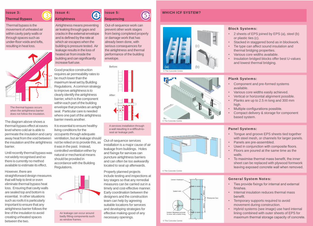
General System Notes: Ties provide fixings for internal and external • finishes.Internal insulation reduces thermal mass • benefit.Temporary supports required to avoid • movement during construction.Hybrid systems (see image) use hard internal • lining combined with outer sheets of EPS for maximum thermal storage capacity of concrete.
WHICH ICF SYSTEM?
Out-of-sequence services installation is a major cause of air leakage from buildings. Holes and fixings for services can puncture airtightness barriers and can often be too awkwardly located to seal up afterwards.
Properly planned projects include testing and inspections at key stages so that any remedial measures can be carried out in a timely and cost-effective manner. Early coordination between the designers and the construction team can help by agreeing suitable locations for services and developing strategies for effective making-good of any necessary openings.
A services installation through a wall resulting in a difficult-to-seal air leakage path.
Out-of-sequence work can prevent other work stages from being completed properly or damage work that has already been done, with serious consequences for the airtightness and thermal performance of the building envelope.
Issue 5:
Sequencing
Air leakage can occur around badly fitting components such as window frames.
Good practice construction requires air permeability rates to be much lower than the maximum level set by Building Regulations. A common strategy to improve airtightness is to clearly identify the airtightness barrier, which is the component within each part of the building envelope that provides an airtight seal. Particular care is needed where one part of the airtightness barrier meets another.
It is essential to ensure healthy living conditions for the occupants through adequate ventilation, but air leakage should not be relied on to provide this, as it was in the past. Instead, controlled ventilation either by natural or mechanical means should be provided in accordance with the Building Regulations.
Airtightness means preventing air leaking through gaps and cracks in the external envelope and is defined by the rate at which air escapes when the building is pressure tested. Air leakage results in the loss of heated air from inside the building and can significantly increase fuel use.
Issue 4:
Airtightness
The diagram above shows a thermal bypass effect at eaves level where cold air is able to permeate the insulation and carry away heat from the void between the insulation and the airtightness barrier.
Until recently thermal bypass was not widely recognised and so there is currently no method available to estimate its effect.
However, there are straightforward design measures that will help to limit or even eliminate thermal bypass heat loss. Ensuring that cavity walls are sealed top and bottom is essential. In other situations such as roofs it is particularly important to ensure that any airtightness barrier follows the line of the insulation to avoid creating unheated spaces between the two.
The thermal bypass occurs when the airtightness barrier does not follow the insulation.
Thermal bypass is the movement of unheated air within cavity party walls or through spaces such as under-floor voids and lofts, resulting in heat loss.
Issue 3:
Thermal Bypass
To conserve energy and to prevent cold spots where condensation and mould can form, thermal bridges need to be minimised. It is not possible to avoid all thermal bridging, but the effect can be minimised with careful detailing. It is more difficult to avoid thermal bridging caused by poor workmanship, for example mortar snots in the cavity or missing insulation. Even if thermal imaging cameras are used to detect the problem, it will often be too late to avoid expensive remedial works.
Thermal bridging through a standard steel lintel.
There are two main types:
Non-repeating thermal bridges include items such as cills, lintels and jambs, which typically span between the inner and outer skins of a wall.
Geometrical thermal bridges occur at junctions between building elements, such as between the walls and roof, and at changes of geometry, for example a corner in a wall or a hip in a roof.
Heat loss through a wall. Increased levels of insulation will reduce the rate of loss.
The insulating effect of a building’s external envelope is normally the most important aspect of its thermal performance, since more heat is lost through the fabric than in any other way.
When U-values are calculated, the thicknesses and insulating properties for each of the different layers of material that make up the building element are taken into account, including fixings such as wall ties.
The phrase ‘thermal mass’ has become increasingly common in the context of best practice construction. It refers to the ability of materials to absorb and store heat. Heavy materials such as concrete, brick and stone have high thermal mass, which can help to stabilise internal room temperatures by absorbing excess heat from the air and releasing it slowly when conditions are cooler.
InsulationAirtightness zone
Air flow
Thermal bridgeHeat transfer
KEY
The key issues affecting good practice construction are:
Thermal Performance
Thermal Bridging
Thermal Bypass
Airtightness
Sequencing
* ‘Lessons from Stamford Brook - Understanding the Gap between Designed and Real Performance’ by Leeds Metropolitan University and UCL, 2007.
Thermal bridges or cold bridges are weak points in the building envelope where heat loss is worse than through the main building elements. In a well insulated building thermal bridges can account for up to 50% of all heat loss.
Issue 2:
Thermal Bridging
Issue 1:
Thermal Performance
Each ‘element’ of the building envelope – a wall, a roof, a floor, a window or a door – has a role to play in minimising heat loss. The insulating effect of each of these elements is measured by its U-value; the lower the U-value, the better its thermal performance.
Houses built today have high levels of insulation, double glazed windows and often highly efficient heating systems. However, new houses are not often tested to see whether they are as energy efficient as predicted.
Research* has indicated that some new homes do not always meet the required standard in practice. So what can be done to close this performance gap?
The answer lies partly in better detailing and good quality workmanship, but above all it requires everyone involved in the project to be sufficiently aware of the issues to enable them to do their job well.
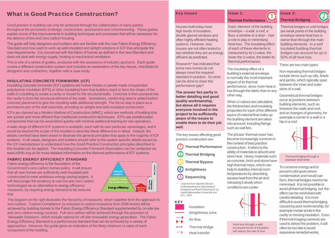
FABRIC ENERGY EFFICIENCY STANDARDFabric energy efficiency is the foundation of the Government’s zero carbon homes policy. It will ensure that all new homes are sufficiently well insulated and constructed to meet ambitious energy saving targets. It will discourage the tendency to use low and zero carbon technologies as an alternative to energy efficiency measures, by requiring energy demand to be reduced first.The diagram on the right illustrates the hierarchy of measures, which together form the approach to zero carbon. ‘Carbon Compliance’ (a reduction in carbon emissions from 2006 levels) will be achieved by building homes to the Fabric Energy Efficiency Standard supplemented by on-site low and zero carbon energy sources. Full zero carbon will be achieved through the provision of ‘Allowable Solutions’, which include options for off-site renewable energy generation. The Fabric Energy Efficiency Standard is a performance standard that can be achieved by a variety of approaches. However, the guide gives an indication of the likely minimum U-value of each component of the building.
What is Good Practice Construction?
Good practice in building can only be achieved through the collaboration of many parties throughout the processes of design, construction, assessment and commissioning. These guides explain some of the improvements in building techniques and processes that will be necessary for the delivery of low and zero carbon housing.The guide will help designers and builders who are familiar with the new Fabric Energy Efficiency Standard and now want to work up well-insulated and airtight solutions in ICF that anticipate the new requirements. It is concerned with the fabric of homes as defined in the new Standard and does not deal with energy supply, heating or mechanical ventilation. This is one of a series of guides, produced with the assistance of industry sponsors. Each guide covers a different construction system and includes an explanation of the key issues, checklists for designers and contractors, together with a case study.
INSULATING CONCRETE FORMWORK (ICF)Insulating concrete formwork (ICF) systems are hollow blocks or panels made of expanded polystyrene insulation (EPS) or other insulating foam that builders stack to form the shape of the walls of a building to create a cavity or mould for the structural walls. Concrete is then pumped into the cavity to form the structural element of the walls. Sometimes, reinforcing steel is added before concrete placement to give the resulting walls additional strength. The forms stay in place as a permanent part of the wall assembly, providing an airtight and well-insulated construction.ICFs are classed as a Modern Method of Construction (MMC), which are methods of building that are quicker and more efficient than traditional construction techniques. ICFs use prefabricated components that can be assembled quickly with minimal additional training for site operatives.A wide range of different ICF systems is available; each with its own particular advantages, and it would be beyond the scope of this booklet to describe these differences in detail. Instead, the details overleaf have been drawn to illustrate the general principles that apply to the majority of ICF systems. In all cases, designers and builders should refer to the system specific details issued by the ICF manufacturer to understand how the Good Practice Construction principles described in this booklet can be applied. The Insulating Concrete Formwork Association can be contacted via www.icfinfo.org.uk for more detailed information on the thermal performance of ICF systems.
Panel Systems: Tongue and groove EPS sheets tied together • with steel mesh, or channels for larger panels.Panels are pre-assembled. • Used in conjunction with composite floors. • Floors are poured at the same time as the • walls.To maximise thermal mass benefit, the inner • sheet can be replaced with plywood formwork leaving exposed concrete wall when removed.
Plank Systems:Component and pre-formed systems • available.Various core widths easily achieved. • Vertical or horizontal alignment possible. • Planks are up to 2.5 m long and 300 mm • high.Multiple configurations possible. • Compact delivery & storage for component • based system.
Block Systems: 2 sheets of EPS joined by EPS (a), steel (b) • or plastic ties (c). Stacked in staggered bond as in blockwork. • Tie type can affect sound insulation and • thermal bridging properties.Various core widths available. • Insulation bridged blocks offer best U-values • and lowest thermal bridging.
(c)
(b) (a)© The Concrete Centre
© The Concrete Centre
© The Concrete Centre
© The Concrete Centre
Before:
After:
Key Issues
BUILDING LOW CARBON HOMESCopyright © Richards Partington Architects 2010.
Richards Partington Architectswww.rparchitects.co.uk
www.zerocarbonhub.org
commissioned by:
www.rparchitects.co.uk
Richards Partington Architects
written by:
www.concretecentre.com
in association with:
Guide 3:
INSULATING CONCRETE FORMWORK (ICF)
Metal fixings are cast into the concrete core. Care must be taken to replace insulation where it has been cut out.
Floor beams are cast onto polystyrene panels and the reinforcement is tied into the concrete core.
Concrete is poured into the insulating formwork in 0.5 m high ‘ribbons’ on a continuous basis up to 3 m.
The building was clad in stone to satisfy planning policies. Thermal bridging was avoided by fixing ties to the plastic webs.
© A
rthur Bland
© A
rthur Bland
© A
rthur Bland
© A
rthur Bland
CASE STUDY: Chewton Mendip, SomersetProject InformationThree terraced cottages in an area of outstanding natural beauty in Somerset.Completed in 2009.Developer/Contractor: Arthur Bland. Research: Arthur Bland, Logix, DH Architecture.
Specification:External wall: U-value 0.14 W/m2KRoof: U-value 0.09 W/m2KFloor: U-value 0.13 W/m2KWindows: U-value 0.96 W/m2KDoors: U-value 1.18 W/m2KThermal bridging: y-value = 0.05 W/mKAirtightness: 1.5 m3/(h.m2)Heating: Mechanical Ventilation with Heat Recovery (MVHR)
Ambition & ResearchLocal planning policies dictated that no renewable energy sources could be used. The focus was therefore to reduce the energy demand as much as possible by providing the most thermally efficient building envelope.Together the developer and the architect researched the most appropriate materials and details in order to reduce workmanship issues and thermal bridging.
Key Design Criteria• High thermal performance that exceeds
2006 Building Regulation levels by more than 50%.
• High thermal mass structure to keep internal temperatures stable.
• Very high airtightness target.
• Heat demand reduces substantially to remove the need for central heating system.
Design & Construction• Thermal performance: Although the
concrete in the walls is isolated by the ICF system and so cannot provide thermal mass, the use of concrete floors does provide mass to help regulate internal temperatures. Main living spaces and glazing areas face south and west to maximise solar gain.
• Thermal bridging: Used with rendered or adhered finishes, ICF has almost no non-repeating thermal bridges as there are no fixings or lintels that go through the outer insulation layer. However, this project
required a stone external facing and the fixings and stone cills for this created
some thermal bridges. These are of varying significance for different proprietary systems. Calculations carried out indicate a thermal bridging value of 0.05.
• Thermal bypass: Risk is significantly reduced by the absence of a cavity in ICF construction. Structurally Insulated Panels (SIPs) are a complementary solution and were used for the roof. This avoids the airtightness problems associated with trussed rafters and also allows full use of the roof space. Fillets of insulation and expanding foam were used to seal the roof/wall junction to avoid thermal bridging and bypass.
• Airtightness : ICF walls and concrete floors provide a robust airtightness barrier. Additional sealant tapes are needed at junctions with floors and roofs. For the ground floor an integral insulated formwork system that creates insulated in-situ suspended concrete ground floor slabs was used.
• Sequencing: The contractor constantly monitored the work on site to ensure that the design was strictly followed, a process that was made easier by the simplicity of the ICF system.
To reinforce the message to all tradespeople on site, design targets were posted on the walls. Some details were also amended during construction, for example reducing tolerances around window and door openings to ensure a tight fit.
Testing and MonitoringThe air-permeability tests confirmed results of 1.5 had been achieved across the development. A single test carried out before plastering and without tapes and flexible sealant achieved a value of 1.38. The main cause of the air leakage was found to be the opening lights of windows and the rooflight seals.
SummaryThis project demonstrates that ICF can deliver high levels of efficiency without the need for specialist installers, given good design and on-site guidance. It also shows that a requirement for a traditional-looking design does not compromise reduced energy demand. Sensible choices of materials, careful design and good project planning have resulted in a robust and energy efficient building that should perform well for many years to come.
General System Notes: Ties provide fixings for internal and external • finishes.Internal insulation reduces thermal mass • benefit.Temporary supports required to avoid • movement during construction.Hybrid systems (see image) use hard internal • lining combined with outer sheets of EPS for maximum thermal storage capacity of concrete.
WHICH ICF SYSTEM?
Out-of-sequence services installation is a major cause of air leakage from buildings. Holes and fixings for services can puncture airtightness barriers and can often be too awkwardly located to seal up afterwards.
Properly planned projects include testing and inspections at key stages so that any remedial measures can be carried out in a timely and cost-effective manner. Early coordination between the designers and the construction team can help by agreeing suitable locations for services and developing strategies for effective making-good of any necessary openings.
A services installation through a wall resulting in a difficult-to-seal air leakage path.
Out-of-sequence work can prevent other work stages from being completed properly or damage work that has already been done, with serious consequences for the airtightness and thermal performance of the building envelope.
Issue 5:
Sequencing
Air leakage can occur around badly fitting components such as window frames.
Good practice construction requires air permeability rates to be much lower than the maximum level set by Building Regulations. A common strategy to improve airtightness is to clearly identify the airtightness barrier, which is the component within each part of the building envelope that provides an airtight seal. Particular care is needed where one part of the airtightness barrier meets another.
It is essential to ensure healthy living conditions for the occupants through adequate ventilation, but air leakage should not be relied on to provide this, as it was in the past. Instead, controlled ventilation either by natural or mechanical means should be provided in accordance with the Building Regulations.
Airtightness means preventing air leaking through gaps and cracks in the external envelope and is defined by the rate at which air escapes when the building is pressure tested. Air leakage results in the loss of heated air from inside the building and can significantly increase fuel use.
Issue 4:
Airtightness
The diagram above shows a thermal bypass effect at eaves level where cold air is able to permeate the insulation and carry away heat from the void between the insulation and the airtightness barrier.
Until recently thermal bypass was not widely recognised and so there is currently no method available to estimate its effect.
However, there are straightforward design measures that will help to limit or even eliminate thermal bypass heat loss. Ensuring that cavity walls are sealed top and bottom is essential. In other situations such as roofs it is particularly important to ensure that any airtightness barrier follows the line of the insulation to avoid creating unheated spaces between the two.
The thermal bypass occurs when the airtightness barrier does not follow the insulation.
Thermal bypass is the movement of unheated air within cavity party walls or through spaces such as under-floor voids and lofts, resulting in heat loss.
Issue 3:
Thermal Bypass
To conserve energy and to prevent cold spots where condensation and mould can form, thermal bridges need to be minimised. It is not possible to avoid all thermal bridging, but the effect can be minimised with careful detailing. It is more difficult to avoid thermal bridging caused by poor workmanship, for example mortar snots in the cavity or missing insulation. Even if thermal imaging cameras are used to detect the problem, it will often be too late to avoid expensive remedial works.
Thermal bridging through a standard steel lintel.
There are two main types:
Non-repeating thermal bridges include items such as cills, lintels and jambs, which typically span between the inner and outer skins of a wall.
Geometrical thermal bridges occur at junctions between building elements, such as between the walls and roof, and at changes of geometry, for example a corner in a wall or a hip in a roof.
Heat loss through a wall. Increased levels of insulation will reduce the rate of loss.
The insulating effect of a building’s external envelope is normally the most important aspect of its thermal performance, since more heat is lost through the fabric than in any other way.
When U-values are calculated, the thicknesses and insulating properties for each of the different layers of material that make up the building element are taken into account, including fixings such as wall ties.
The phrase ‘thermal mass’ has become increasingly common in the context of best practice construction. It refers to the ability of materials to absorb and store heat. Heavy materials such as concrete, brick and stone have high thermal mass, which can help to stabilise internal room temperatures by absorbing excess heat from the air and releasing it slowly when conditions are cooler.
InsulationAirtightness zone
Air flow
Thermal bridgeHeat transfer
KEY
The key issues affecting good practice construction are:
Thermal Performance
Thermal Bridging
Thermal Bypass
Airtightness
Sequencing
* ‘Lessons from Stamford Brook - Understanding the Gap between Designed and Real Performance’ by Leeds Metropolitan University and UCL, 2007.
Thermal bridges or cold bridges are weak points in the building envelope where heat loss is worse than through the main building elements. In a well insulated building thermal bridges can account for up to 50% of all heat loss.
Issue 2:
Thermal Bridging
Issue 1:
Thermal Performance
Each ‘element’ of the building envelope – a wall, a roof, a floor, a window or a door – has a role to play in minimising heat loss. The insulating effect of each of these elements is measured by its U-value; the lower the U-value, the better its thermal performance.
Houses built today have high levels of insulation, double glazed windows and often highly efficient heating systems. However, new houses are not often tested to see whether they are as energy efficient as predicted.
Research* has indicated that some new homes do not always meet the required standard in practice. So what can be done to close this performance gap?
The answer lies partly in better detailing and good quality workmanship, but above all it requires everyone involved in the project to be sufficiently aware of the issues to enable them to do their job well.
FABRIC ENERGY EFFICIENCY STANDARDFabric energy efficiency is the foundation of the Government’s zero carbon homes policy. It will ensure that all new homes are sufficiently well insulated and constructed to meet ambitious energy saving targets. It will discourage the tendency to use low and zero carbon technologies as an alternative to energy efficiency measures, by requiring energy demand to be reduced first.The diagram on the right illustrates the hierarchy of measures, which together form the approach to zero carbon. ‘Carbon Compliance’ (a reduction in carbon emissions from 2006 levels) will be achieved by building homes to the Fabric Energy Efficiency Standard supplemented by on-site low and zero carbon energy sources. Full zero carbon will be achieved through the provision of ‘Allowable Solutions’, which include options for off-site renewable energy generation. The Fabric Energy Efficiency Standard is a performance standard that can be achieved by a variety of approaches. However, the guide gives an indication of the likely minimum U-value of each component of the building.
What is Good Practice Construction?
Good practice in building can only be achieved through the collaboration of many parties throughout the processes of design, construction, assessment and commissioning. These guides explain some of the improvements in building techniques and processes that will be necessary for the delivery of low and zero carbon housing.The guide will help designers and builders who are familiar with the new Fabric Energy Efficiency Standard and now want to work up well-insulated and airtight solutions in ICF that anticipate the new requirements. It is concerned with the fabric of homes as defined in the new Standard and does not deal with energy supply, heating or mechanical ventilation. This is one of a series of guides, produced with the assistance of industry sponsors. Each guide covers a different construction system and includes an explanation of the key issues, checklists for designers and contractors, together with a case study.
INSULATING CONCRETE FORMWORK (ICF)Insulating concrete formwork (ICF) systems are hollow blocks or panels made of expanded polystyrene insulation (EPS) or other insulating foam that builders stack to form the shape of the walls of a building to create a cavity or mould for the structural walls. Concrete is then pumped into the cavity to form the structural element of the walls. Sometimes, reinforcing steel is added before concrete placement to give the resulting walls additional strength. The forms stay in place as a permanent part of the wall assembly, providing an airtight and well-insulated construction.ICFs are classed as a Modern Method of Construction (MMC), which are methods of building that are quicker and more efficient than traditional construction techniques. ICFs use prefabricated components that can be assembled quickly with minimal additional training for site operatives.A wide range of different ICF systems is available; each with its own particular advantages, and it would be beyond the scope of this booklet to describe these differences in detail. Instead, the details overleaf have been drawn to illustrate the general principles that apply to the majority of ICF systems. In all cases, designers and builders should refer to the system specific details issued by the ICF manufacturer to understand how the Good Practice Construction principles described in this booklet can be applied. The Insulating Concrete Formwork Association can be contacted via www.icfinfo.org.uk for more detailed information on the thermal performance of ICF systems.
Panel Systems: Tongue and groove EPS sheets tied together • with steel mesh, or channels for larger panels.Panels are pre-assembled.• Used in conjunction with composite floors.• Floors are poured at the same time as the • walls.To maximise thermal mass benefit, the inner • sheet can be replaced with plywood formwork leaving exposed concrete wall when removed.
Plank Systems:Component and pre-formed systems • available.Various core widths easily achieved.• Vertical or horizontal alignment possible.• Planks are up to 2.5 m long and 300 mm • high.Multiple configurations possible.• Compact delivery & storage for component • based system.
Block Systems: 2 sheets of EPS joined by EPS (a), steel (b) • or plastic ties (c). Stacked in staggered bond as in blockwork.• Tie type can affect sound insulation and • thermal bridging properties.Various core widths available.• Insulation bridged blocks offer best U-values • and lowest thermal bridging.
(c)
(b)(a)© The Concrete Centre
© The Concrete Centre
© The Concrete Centre
© The Concrete Centre

Before:
After:
Key Issues
BUILDING LOW CARBON HOMESCopyright © Richards Partington Architects 2010.
Richards Partington Architectswww.rparchitects.co.uk
www.zerocarbonhub.org
commissioned by:
www.rparchitects.co.uk
Richards Partington Architects
written by:
www.concretecentre.com
in association with:
Guide 3:
INSULATING CONCRETE FORMWORK (ICF)
Metal fixings are cast into the concrete core. Care must be taken to replace insulation where it has been cut out.
Floor beams are cast onto polystyrene panels and the reinforcement is tied into the concrete core.
Concrete is poured into the insulating formwork in 0.5 m high ‘ribbons’ on a continuous basis up to 3 m.
The building was clad in stone to satisfy planning policies. Thermal bridging was avoided by fixing ties to the plastic webs.
© A
rthur
Bla
nd
© A
rthur
Bla
nd
© A
rthur
Bla
nd
© A
rthur
Bla
nd
CASE STUDY: Chewton Mendip, SomersetProject InformationThree terraced cottages in an area of outstanding natural beauty in Somerset.Completed in 2009.Developer/Contractor: Arthur Bland. Research: Arthur Bland, Logix, DH Architecture.
Specification:External wall: U-value 0.14 W/m2KRoof: U-value 0.09 W/m2KFloor: U-value 0.13 W/m2KWindows: U-value 0.96 W/m2KDoors: U-value 1.18 W/m2KThermal bridging: y-value = 0.05 W/mKAirtightness: 1.5 m3/(h.m2)Heating: Mechanical Ventilation with Heat Recovery (MVHR)
Ambition & ResearchLocal planning policies dictated that no renewable energy sources could be used. The focus was therefore to reduce the energy demand as much as possible by providing the most thermally efficient building envelope.Together the developer and the architect researched the most appropriate materials and details in order to reduce workmanship issues and thermal bridging.
Key Design Criteria• High thermal performance that exceeds
2006 Building Regulation levels by more than 50%.
• High thermal mass structure to keep internal temperatures stable.
• Very high airtightness target.
• Heat demand reduces substantially to remove the need for central heating system.
Design & Construction• Thermal performance: Although the
concrete in the walls is isolated by the ICF system and so cannot provide thermal mass, the use of concrete floors does provide mass to help regulate internal temperatures. Main living spaces and glazing areas face south and west to maximise solar gain.
• Thermal bridging: Used with rendered or adhered finishes, ICF has almost no non-repeating thermal bridges as there are no fixings or lintels that go through the outer insulation layer. However, this project
required a stone external facing and the fixings and stone cills for this created
some thermal bridges. These are of varying significance for different proprietary systems. Calculations carried out indicate a thermal bridging value of 0.05.
• Thermal bypass: Risk is significantly reduced by the absence of a cavity in ICF construction. Structurally Insulated Panels (SIPs) are a complementary solution and were used for the roof. This avoids the airtightness problems associated with trussed rafters and also allows full use of the roof space. Fillets of insulation and expanding foam were used to seal the roof/wall junction to avoid thermal bridging and bypass.
• Airtightness : ICF walls and concrete floors provide a robust airtightness barrier. Additional sealant tapes are needed at junctions with floors and roofs. For the ground floor an integral insulated formwork system that creates insulated in-situ suspended concrete ground floor slabs was used.
• Sequencing: The contractor constantly monitored the work on site to ensure that the design was strictly followed, a process that was made easier by the simplicity of the ICF system.
To reinforce the message to all tradespeople on site, design targets were posted on the walls. Some details were also amended during construction, for example reducing tolerances around window and door openings to ensure a tight fit.
Testing and MonitoringThe air-permeability tests confirmed results of 1.5 had been achieved across the development. A single test carried out before plastering and without tapes and flexible sealant achieved a value of 1.38. The main cause of the air leakage was found to be the opening lights of windows and the rooflight seals.
SummaryThis project demonstrates that ICF can deliver high levels of efficiency without the need for specialist installers, given good design and on-site guidance. It also shows that a requirement for a traditional-looking design does not compromise reduced energy demand. Sensible choices of materials, careful design and good project planning have resulted in a robust and energy efficient building that should perform well for many years to come.
General System Notes: Ties provide fixings for internal and external • finishes.Internal insulation reduces thermal mass • benefit.Temporary supports required to avoid • movement during construction.Hybrid systems (see image) use hard internal • lining combined with outer sheets of EPS for maximum thermal storage capacity of concrete.
WHICH ICF SYSTEM?
Out-of-sequence services installation is a major cause of air leakage from buildings. Holes and fixings for services can puncture airtightness barriers and can often be too awkwardly located to seal up afterwards.
Properly planned projects include testing and inspections at key stages so that any remedial measures can be carried out in a timely and cost-effective manner. Early coordination between the designers and the construction team can help by agreeing suitable locations for services and developing strategies for effective making-good of any necessary openings.
A services installation through a wall resulting in a difficult-to-seal air leakage path.
Out-of-sequence work can prevent other work stages from being completed properly or damage work that has already been done, with serious consequences for the airtightness and thermal performance of the building envelope.
Issue 5:
Sequencing
Air leakage can occur around badly fitting components such as window frames.
Good practice construction requires air permeability rates to be much lower than the maximum level set by Building Regulations. A common strategy to improve airtightness is to clearly identify the airtightness barrier, which is the component within each part of the building envelope that provides an airtight seal. Particular care is needed where one part of the airtightness barrier meets another.
It is essential to ensure healthy living conditions for the occupants through adequate ventilation, but air leakage should not be relied on to provide this, as it was in the past. Instead, controlled ventilation either by natural or mechanical means should be provided in accordance with the Building Regulations.
Airtightness means preventing air leaking through gaps and cracks in the external envelope and is defined by the rate at which air escapes when the building is pressure tested. Air leakage results in the loss of heated air from inside the building and can significantly increase fuel use.
Issue 4:
Airtightness
The diagram above shows a thermal bypass effect at eaves level where cold air is able to permeate the insulation and carry away heat from the void between the insulation and the airtightness barrier.
Until recently thermal bypass was not widely recognised and so there is currently no method available to estimate its effect.
However, there are straightforward design measures that will help to limit or even eliminate thermal bypass heat loss. Ensuring that cavity walls are sealed top and bottom is essential. In other situations such as roofs it is particularly important to ensure that any airtightness barrier follows the line of the insulation to avoid creating unheated spaces between the two.
The thermal bypass occurs when the airtightness barrier does not follow the insulation.
Thermal bypass is the movement of unheated air within cavity party walls or through spaces such as under-floor voids and lofts, resulting in heat loss.
Issue 3:
Thermal Bypass
To conserve energy and to prevent cold spots where condensation and mould can form, thermal bridges need to be minimised. It is not possible to avoid all thermal bridging, but the effect can be minimised with careful detailing. It is more difficult to avoid thermal bridging caused by poor workmanship, for example mortar snots in the cavity or missing insulation. Even if thermal imaging cameras are used to detect the problem, it will often be too late to avoid expensive remedial works.
Thermal bridging through a standard steel lintel.
There are two main types:
Non-repeating thermal bridges include items such as cills, lintels and jambs, which typically span between the inner and outer skins of a wall.
Geometrical thermal bridges occur at junctions between building elements, such as between the walls and roof, and at changes of geometry, for example a corner in a wall or a hip in a roof.
Heat loss through a wall. Increased levels of insulation will reduce the rate of loss.
The insulating effect of a building’s external envelope is normally the most important aspect of its thermal performance, since more heat is lost through the fabric than in any other way.
When U-values are calculated, the thicknesses and insulating properties for each of the different layers of material that make up the building element are taken into account, including fixings such as wall ties.
The phrase ‘thermal mass’ has become increasingly common in the context of best practice construction. It refers to the ability of materials to absorb and store heat. Heavy materials such as concrete, brick and stone have high thermal mass, which can help to stabilise internal room temperatures by absorbing excess heat from the air and releasing it slowly when conditions are cooler.
InsulationAirtightness zone
Air flow
Thermal bridgeHeat transfer
KEY
The key issues affecting good practice construction are:
Thermal Performance
Thermal Bridging
Thermal Bypass
Airtightness
Sequencing
* ‘Lessons from Stamford Brook - Understanding the Gap between Designed and Real Performance’ by Leeds Metropolitan University and UCL, 2007.
Thermal bridges or cold bridges are weak points in the building envelope where heat loss is worse than through the main building elements. In a well insulated building thermal bridges can account for up to 50% of all heat loss.
Issue 2:
Thermal Bridging
Issue 1:
Thermal Performance
Each ‘element’ of the building envelope – a wall, a roof, a floor, a window or a door – has a role to play in minimising heat loss. The insulating effect of each of these elements is measured by its U-value; the lower the U-value, the better its thermal performance.
Houses built today have high levels of insulation, double glazed windows and often highly efficient heating systems. However, new houses are not often tested to see whether they are as energy efficient as predicted.
Research* has indicated that some new homes do not always meet the required standard in practice. So what can be done to close this performance gap?
The answer lies partly in better detailing and good quality workmanship, but above all it requires everyone involved in the project to be sufficiently aware of the issues to enable them to do their job well.
FABRIC ENERGY EFFICIENCY STANDARDFabric energy efficiency is the foundation of the Government’s zero carbon homes policy. It will ensure that all new homes are sufficiently well insulated and constructed to meet ambitious energy saving targets. It will discourage the tendency to use low and zero carbon technologies as an alternative to energy efficiency measures, by requiring energy demand to be reduced first.The diagram on the right illustrates the hierarchy of measures, which together form the approach to zero carbon. ‘Carbon Compliance’ (a reduction in carbon emissions from 2006 levels) will be achieved by building homes to the Fabric Energy Efficiency Standard supplemented by on-site low and zero carbon energy sources. Full zero carbon will be achieved through the provision of ‘Allowable Solutions’, which include options for off-site renewable energy generation. The Fabric Energy Efficiency Standard is a performance standard that can be achieved by a variety of approaches. However, the guide gives an indication of the likely minimum U-value of each component of the building.
What is Good Practice Construction?
Good practice in building can only be achieved through the collaboration of many parties throughout the processes of design, construction, assessment and commissioning. These guides explain some of the improvements in building techniques and processes that will be necessary for the delivery of low and zero carbon housing.The guide will help designers and builders who are familiar with the new Fabric Energy Efficiency Standard and now want to work up well-insulated and airtight solutions in ICF that anticipate the new requirements. It is concerned with the fabric of homes as defined in the new Standard and does not deal with energy supply, heating or mechanical ventilation. This is one of a series of guides, produced with the assistance of industry sponsors. Each guide covers a different construction system and includes an explanation of the key issues, checklists for designers and contractors, together with a case study.
INSULATING CONCRETE FORMWORK (ICF)Insulating concrete formwork (ICF) systems are hollow blocks or panels made of expanded polystyrene insulation (EPS) or other insulating foam that builders stack to form the shape of the walls of a building to create a cavity or mould for the structural walls. Concrete is then pumped into the cavity to form the structural element of the walls. Sometimes, reinforcing steel is added before concrete placement to give the resulting walls additional strength. The forms stay in place as a permanent part of the wall assembly, providing an airtight and well-insulated construction.ICFs are classed as a Modern Method of Construction (MMC), which are methods of building that are quicker and more efficient than traditional construction techniques. ICFs use prefabricated components that can be assembled quickly with minimal additional training for site operatives.A wide range of different ICF systems is available; each with its own particular advantages, and it would be beyond the scope of this booklet to describe these differences in detail. Instead, the details overleaf have been drawn to illustrate the general principles that apply to the majority of ICF systems. In all cases, designers and builders should refer to the system specific details issued by the ICF manufacturer to understand how the Good Practice Construction principles described in this booklet can be applied. The Insulating Concrete Formwork Association can be contacted via www.icfinfo.org.uk for more detailed information on the thermal performance of ICF systems.
Panel Systems: Tongue and groove EPS sheets tied together • with steel mesh, or channels for larger panels.Panels are pre-assembled. • Used in conjunction with composite floors. • Floors are poured at the same time as the • walls.To maximise thermal mass benefit, the inner • sheet can be replaced with plywood formwork leaving exposed concrete wall when removed.
Plank Systems:Component and pre-formed systems • available.Various core widths easily achieved. • Vertical or horizontal alignment possible. • Planks are up to 2.5 m long and 300 mm • high.Multiple configurations possible. • Compact delivery & storage for component • based system.
Block Systems: 2 sheets of EPS joined by EPS (a), steel (b) • or plastic ties (c). Stacked in staggered bond as in blockwork. • Tie type can affect sound insulation and • thermal bridging properties.Various core widths available. • Insulation bridged blocks offer best U-values • and lowest thermal bridging.
(c)
(b) (a)© The Concrete Centre
© The Concrete Centre
© The Concrete Centre
© The Concrete Centre
CO
MM
ON
ISS
UE
S:
PR
OM
PT
S KEY:
a
b
c
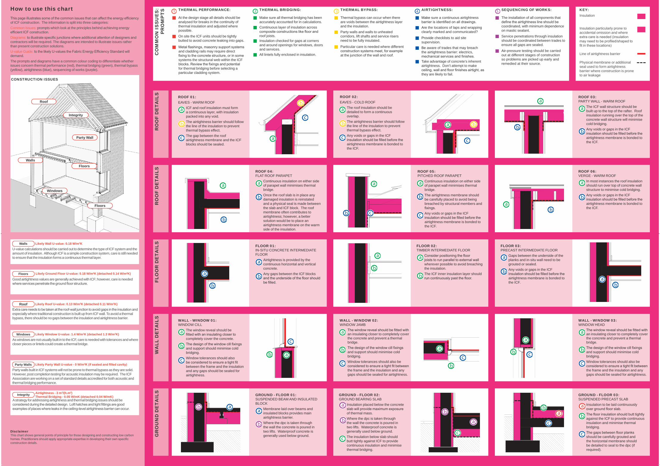
How to use this chart
Likely Roof U-value: 0.13 W/m2K (detached 0.11 W/m2K)
Likely Wall U-value: 0.18 W/m2K
Party walls built in ICF systems will not be prone to thermal bypass as they are solid. However, post completion testing for acoustic insulation may be required. The ICF Association are working on a set of standard details accredited for both acoustic and thermal bridging performance.
A strategy for addressing airtightness and thermal bridging issues should be considered during the detailed design. Loft hatches and light fittings are good examples of places where leaks in the ceiling-level airtightness barrier can occur.
Likely Ground Floor U-value: 0.18 W/m2K (detached 0.14 W/m2K)
U-value calculations should be carried out to determine the type of ICF system and the amount of insulation. Although ICF is a simple construction system, care is still needed to ensure that the insulation forms a continuous thermal layer.
This page illustrates some of the common issues that can affect the energy efficiency of ICF construction. The information is split into three categories: Common Issues: prompts which look at the principles behind achieving energy efficient ICF construction.Diagrams: to illustrate specific junctions where additional attention of designers and contractors will be required. The diagrams are intended to illustrate issues rather than present construction solutions.U-value Guide: to the likely U-values the Fabric Energy Efficiency Standard will demand.The prompts and diagrams have a common colour coding to differentiate whether issues concern thermal performance (red), thermal bridging (green), thermal bypass (yellow), airtightness (blue), sequencing of works (purple).
Walls
Floors
Roof
Windows
Party Walls
Integrity
DisclaimerThis chart shows general points of principle for those designing and constructing low carbon homes. Practitioners should apply appropriate expertise in developing their own specific construction details.
Airtightness - 3 m3/(h.m2) Thermal Bridging - 0.05 W/mK (detached 0.04 W/mK)
Likely Party Wall U-value - 0 W/m2K (if sealed and filled cavity)
Likely Window U-value: 1.4 W/m2K (detached 1.3 W/m2K)
As windows are not usually built in to the ICF, care is needed with tolerances and where closer pieces or lintels could create a thermal bridge.
Extra care needs to be taken at the roof-wall junction to avoid gaps in the insulation and especially where traditional construction is built up from ICF wall. To avoid a thermal bypass, there should be no gaps between the insulation and airtightness barrier.
Good airtightness values are generally achieved with ICF; however, care is needed where services penetrate the ground floor structure.
RO
OF
DE
TAIL
SR
OO
F D
ETA
ILS
FLO
OR
DE
TAIL
SW
ALL
DE
TAIL
SG
RO
UN
D D
ETA
ILS
Air-pressure testing should be carried out at different stages of construction so problems are picked up early and remedied at their source.
Service penetrations through insulation should be coordinated between trades to ensure all gaps are sealed.
The installation of all components that define the airtightness line should be coordinated, with minimum dependence on mastic sealant.
SEQUENCING OF WORKS:
Take advantage of concrete’s inherent airtightness. Don’t attempt to make ceiling, wall and floor finishes airtight, as they are likely to fail.
Be aware of trades that may breach the airtightness barrier: electrics, mechanical services and finishes.
Provide checklists to aid site supervision.
Are the locations of laps and wrapping clearly marked and communicated?
Make sure a continuous airtightness barrier is identified on all drawings.
AIRTIGHTNESS:
Particular care is needed where different construction systems meet, for example at the junction of the wall and roof.
Party walls and walls to unheated corridors, lift shafts and service risers need to be fully insulated.
Thermal bypass can occur when there are voids between the airtightness layer and the insulation.
THERMAL BYPASS:
Insulation checked for gaps at corners and around openings for windows, doors and services.
Continuous layer of insulation across composite constructions like floor and roof joists.
Make sure all thermal bridging has been accurately accounted for in calculations.
THERMAL BRIDGING:THERMAL PERFORMANCE:
Metal flashings, masonry support systems and cladding rails may require direct fixing to the concrete structure, or in some systems the structural web within the ICF blocks. Review the fixings and potential for thermal bridging before selecting a particular cladding system.
On site the ICF units should be tightly butted to avoid concrete leaking into gaps.
At the design stage all details should be analysed for breaks in the continuity of thermal insulation and adjusted where possible.
GROUND - FLOOR 03:SUSPENDED PRECAST SLAB
Insulation to be laid continuously over ground floor slab.The floor insulation should butt tightly against the ICF to provide continuous insulation and minimise thermal bridging.The gaps between floor planks should be carefully grouted and the horizontal membrane should be detailed to seal to the dpc (if required).
GROUND - FLOOR 02:GROUND BEARING SLAB
Insulation placed below the concrete slab will provide maximum exposure of thermal mass.Where the dpc is taken through the wall the concrete is poured in two lifts. Waterproof concrete is generally used below ground. The insulation below slab should butt tightly against ICF to provide continuous insulation and minimise thermal bridging.
GROUND - FLOOR 01:SUSPENDED BEAM AND INSULATED BLOCK
Membrane laid over beams and insulated blocks provides main airtightness barrier.Where the dpc is taken through the wall the concrete is poured in two lifts. Waterproof concrete is generally used below ground.
WALL - WINDOW 01:WINDOW CILL
The window reveal should be fitted with an insulating closer to completely cover the concrete.The design of the window cill fixings and support should minimise cold bridging.Window tolerances should also be considered to ensure a tight fit between the frame and the insulation and any gaps should be sealed for airtightness.
FLOOR 03:PRECAST INTERMEDIATE FLOOR
Gaps between the underside of the planks and in-situ wall need to be grouted or sealed.Any voids or gaps in the ICF insulation should be filled before the airtightness membrane is bonded to the ICF.
FLOOR 02:TIMBER INTERMEDIATE FLOOR
Consider positioning the floor joists to run parallel to external wall wherever possible to avoid breaching the insulation.The ICF inner insulation layer should run continuously past the floor.
ROOF 06:VERGE - WARM ROOF
In most instances the roof insulation should run over top of concrete wall structure to minimise cold bridging.Any voids or gaps in the ICF insulation should be filled before the airtightness membrane is bonded to the ICF.
ROOF 05: PITCHED ROOF PARAPET
Continuous insulation on either side of parapet wall minimises thermal bridge.The airtightness membrane should be carefully placed to avoid being breached by structural members and fixings.Any voids or gaps in the ICF insulation should be filled before the airtightness membrane is bonded to the ICF.
ROOF 04:FLAT ROOF PARAPET
Continuous insulation on either side of parapet wall minimises thermal bridge.Once the roof slab is in place any damaged insulation is reinstated and a physical seal is made between the slab and ICF block. The roof membrane often contributes to airtightness; however, a better solution would be to place an airtightness membrane on the warm side of the insulation.
b
ROOF 03:PARTY WALL - WARM ROOF
The ICF wall structure should be built up to the top of the rafter. Roof insulation running over the top of the concrete wall structure will minimise cold bridging.Any voids or gaps in the ICF insulation should be filled before the airtightness membrane is bonded to the ICF.
ROOF 01: EAVES - WARM ROOF
ICF and roof insulation must form a continuous layer, with insulation packed into any void.The airtightness barrier should follow the line of the insulation to prevent thermal bypass effect.The gap between the roof airtightness membrane and the ICF blocks should be sealed.
FLOOR 01:IN-SITU CONCRETE INTERMEDIATE FLOOR
Airtightness is provided by the continuous horizontal and vertical concrete.Any gaps between the ICF blocks and the underside of the floor should be filled.
a
WALL - WINDOW 02:WINDOW JAMB
The window reveal should be fitted with an insulating closer to completely cover the concrete and prevent a thermal bridge.The design of the window cill fixings and support should minimise cold bridging.Window tolerances should also be considered to ensure a tight fit between the frame and the insulation and any gaps should be sealed for airtightness.
WALL - WINDOW 03:WINDOW HEAD
The window reveal should be fitted with an insulating closer to completely cover the concrete and prevent a thermal bridge.The design of the window cill fixings and support should minimise cold bridging.Window tolerances should also be considered to ensure a tight fit between the frame and the insulation and any gaps should be sealed for airtightness.
Line of airtightness barrier
Physical membrane or additional seal used to form airtightness barrier where construction is prone to air leakage
Insulation
Insulation particularly prone to accidental omission and where extra care is needed (insulation may need to be profiled/shaped to fit in these locations)
All lintels fully enclosed in insulation.
ROOF 02: EAVES - COLD ROOF
The roof insulation should be detailed to form a continuous overlap.The airtightness barrier should follow the line of the insulation to prevent thermal bypass effect.Any voids or gaps in the ICF insulation should be filled before the airtightness membrane is bonded to the ICF.
c
b
a
b
ca
c
b a
c
b
aa
b
a
b
a
b
a
c
a
b c
ba
a
b
b
a
a
b
a
b
a
bb
a
ab
a
b
cab
c
a
b
c
a
b
c
a
b
c
a
b c
a
bb
bab a
a
cc
a
b
c
ab
c
CONSTRUCTION ISSUES
Walls
Floors
Roof
Floors
Windows
Party Wall
Integrity
b
Related Documents