GUIDANCE NOTES ON LIFE EXTENSION METHODOLOGY FOR FLOATING PRODUCTION INSTALLATIONS MAY 2021 American Bureau of Shipping Incorporated by Act of Legislature of the State of New York 1862 © 2021 American Bureau of Shipping. All rights reserved. 1701 City Plaza Drive Spring, TX 77389 USA

Welcome message from author
This document is posted to help you gain knowledge. Please leave a comment to let me know what you think about it! Share it to your friends and learn new things together.
Transcript

GUIDANCE NOTES ON
LIFE EXTENSION METHODOLOGY FOR FLOATINGPRODUCTION INSTALLATIONSMAY 2021
American Bureau of ShippingIncorporated by Act of Legislature ofthe State of New York 1862
© 2021 American Bureau of Shipping. All rights reserved.1701 City Plaza DriveSpring, TX 77389 USA

Foreword (1 May 2021)The Guidance Notes on Life Extension Methodology for Floating Production Installations have beendeveloped to provide guidance for assessment of existing floating production installations when theintended period of operation at the original site or the cumulated operating time at both the original andrelocated sites is extended beyond the original design life period. These Guidance Notes supplement therequirements for life extension and relocation of floating production installations in accordance with theABS Rules for Building and Classing Floating Production Installations (FPI Rules).
These Guidance Notes outline the life extension process that includes a reassessment of the structure,mooring system, stability, and machinery and systems, etc., for the entire installation. This reassessmentincludes engineering and survey activities.
In the May 2021 edition, a new Appendix 3 introduces a methodology for addressing Remaining FatigueLife for FPSOs based on Loading Historical Data acquired on board during the vessel’s Service Life.
These Guidance Notes become effective on the first day of the month of publication.
Users are advised to check periodically on the ABS website www.eagle.org to verify that this version ofthese Guidance Notes is the most current.
We welcome your feedback. Comments or suggestions can be sent electronically by email [email protected].
Terms of Use
The information presented herein is intended solely to assist the reader in the methodologies and/ortechniques discussed. These Guidance Notes do not and cannot replace the analysis and/or advice of aqualified professional. It is the responsibility of the reader to perform their own assessment and obtainprofessional advice. Information contained herein is considered to be pertinent at the time of publicationbut may be invalidated as a result of subsequent legislations, regulations, standards, methods, and/or moreupdated information and the reader assumes full responsibility for compliance. This publication may not becopied or redistributed in part or in whole without prior written consent from ABS.
ABS GUIDANCE NOTES ON LIFE EXTENSION METHODOLOGY FOR FLOATING PRODUCTIONINSTALLATIONS • 2021
ii
GUIDANCE NOTES ON
LIFE EXTENSION METHODOLOGY FOR FLOATINGPRODUCTION INSTALLATIONS
CONTENTSSECTION 1 Introduction.......................................................................................... 7
1 General...........................................................................................7
SECTION 2 Life Extension Process Overview...................................................... 81 General...........................................................................................83 Life Extension of Floating Production Installations......................... 8
3.1 Procedure for Life Extension up to 5 Years at theSame Location...................................................................9
3.3 Procedure for Life Extension Over 5 Years at theSame Location................................................................. 11
3.5 Life Extension Procedure for an InstallationRelocating to a New Location.......................................... 13
3.7 Remaining Fatigue Life....................................................143.9 Remaining Fatigue Life Procedure based on
Historical Loading Data ...................................................14
FIGURE 1A Life Extension Process Flow Chart Based on Phases...........9FIGURE 1B Life Extension Process Abbreviated Procedure (For life
extension up to 5 years at the same location)......................11FIGURE 1C Life Extension Process (For life extension over 5 years
at the same location)............................................................13
SECTION 3 Baseline Information......................................................................... 151 General.........................................................................................15
1.1 Documentation to be Provided during Life ExtensionProcess............................................................................15
1.3 Initial Assessment of Baseline Information...................... 16
SECTION 4 Baseline Survey................................................................................. 171 General.........................................................................................173 Structures..................................................................................... 175 Mooring Systems..........................................................................177 Tendons........................................................................................ 189 Machinery and Systems............................................................... 18
ABS GUIDANCE NOTES ON LIFE EXTENSION METHODOLOGY FOR FLOATING PRODUCTIONINSTALLATIONS • 2021
iii

11 Outfitting....................................................................................... 1913 Additional Scope of Survey and Analysis..................................... 19
SECTION 5 Reassessment....................................................................................201 General.........................................................................................203 Environmental Conditions.............................................................205 Hull Structures ............................................................................. 20
5.1 Ship-Type Installations.....................................................205.3 Non-Ship Type Installations............................................. 215.5 Cathodic Protection Reassessment.................................225.7 Stability Reassessment................................................... 235.9 Review of Reassessment Results................................... 23
7 Hull Interface Structures............................................................... 237.1 Strength Reassessment.................................................. 237.3 Remaining Fatigue Strength Assessment....................... 237.5 Review of Reassessment Results................................... 24
9 Topside Structures........................................................................249.1 Strength Reassessment.................................................. 249.3 Remaining Fatigue Strength Assessment for Non-
Ship Type Installations.....................................................249.5 Review of Reassessment Results................................... 24
11 Mooring Systems..........................................................................2411.1 Reassessment Analysis...................................................2411.3 Cathodic Protection Reassessment.................................2511.5 Review of Reassessment Results................................... 25
13 TLP Tendons and Tendon Connectors......................................... 2513.1 Reassessment Analysis...................................................2513.3 Cathodic Protection Reassessment.................................2613.5 Tendon Connectors with Nonmetallic Components......... 2613.7 Tendon Tension Monitoring Systems............................... 2613.9 Review of Reassessment Results................................... 26
15 Marine and Industrial Machinery and Systems.............................26
TABLE 1 Extent of Strength and Fatigue Analysis Scenarios forLife Extension.......................................................................21
SECTION 6 Additional Survey/Repairs/ISIP........................................................ 271 General.........................................................................................273 Additional Surveys........................................................................275 Repairs and Modifications............................................................ 277 Revision of In-Service Inspection Plan (ISIP) ..............................27
SECTION 7 Asset Integrity Management (AIM) .................................................. 29
ABS GUIDANCE NOTES ON LIFE EXTENSION METHODOLOGY FOR FLOATING PRODUCTIONINSTALLATIONS • 2021
iv

1 General.........................................................................................293 AIM Process................................................................................. 295 Life Extension in AIM Process......................................................29
FIGURE 1 Assessment for Life Extension within the AIM Process....... 30
SECTION 8 Risk Assessment............................................................................... 311 Risk Assessment.......................................................................... 31
APPENDIX 1 Procedure for Fatigue Reassessment of Floating ProductionInstallations (Except for Hull Structures of Ship-TypeInstallations).......................................................................................321 Remaining Fatigue Strength of Hull Structures and Hull
Interface Structures – Non-Ship Type Installations.......................321.1 Accumulated Fatigue Damage D p..................................321.3 Safety Factors for Fatigue Life of the Accumulated
Damages......................................................................... 321.5 Predicted Damage for Life Extension.............................. 331.7 Remaining Fatigue Strength Check.................................331.9 Calculation Example of Non-inspectable Critical Areas...34
3 Remaining Fatigue Strength of Topside Structures – All FPIsand Major Hull Interface Structures – Ship-Type Installations......34
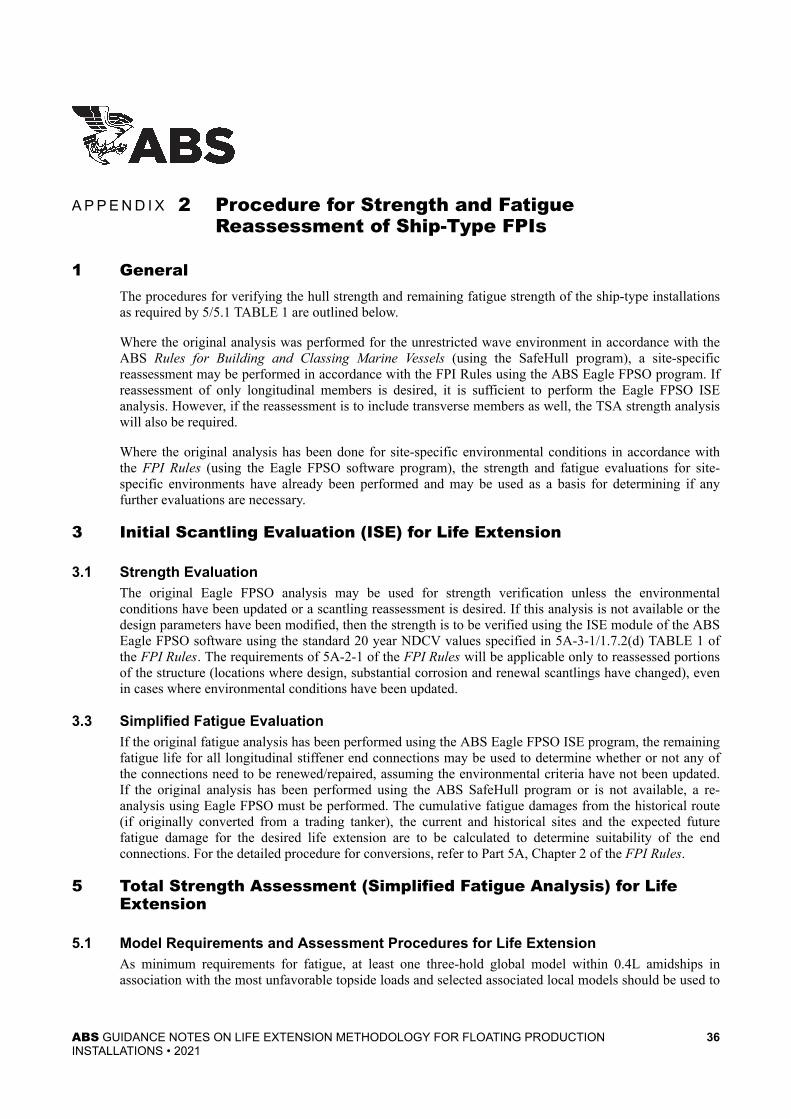
APPENDIX 2 Procedure for Strength and Fatigue Reassessment of Ship-Type FPIs............................................................................................ 361 General.........................................................................................363 Initial Scantling Evaluation (ISE) for Life Extension......................36
3.1 Strength Evaluation......................................................... 363.3 Simplified Fatigue Evaluation.......................................... 36
5 Total Strength Assessment (Simplified Fatigue Analysis) forLife Extension............................................................................... 365.1 Model Requirements and Assessment Procedures
for Life Extension............................................................. 365.3 Use of As-gauged Scantlings.......................................... 375.5 Loads and Load Cases....................................................375.7 Fatigue Acceptance Criteria............................................ 38
7 Dynamic Loading Approach and Spectral Fatigue Analysesfor Life Extension..........................................................................387.1 Model Requirements and Reassessment Procedures.... 387.3 Loads and Load Cases....................................................387.5 Acceptance Criteria......................................................... 38
APPENDIX 3 Procedure for Fatigue Reassessment of Ship-Type FPIsConsidering Onboard Validated Historical Loading Information.. 391 General.........................................................................................39
ABS GUIDANCE NOTES ON LIFE EXTENSION METHODOLOGY FOR FLOATING PRODUCTIONINSTALLATIONS • 2021
v

3 Application of Environmental Severity Factors............................. 395 Identification of Relevant Onboard Historical Loading Data ........ 407 Identification of Dynamic Loading Parameters Affected by
Onboard Historical Data............................................................... 419 Procedure for Adjustment of Fatigue Strength Assessment of
Ship-Type Installations..................................................................42
TABLE 2A Example of Modified Design Fatigue Load Cases forFatigue Strength Assessment..............................................45
TABLE 2B Example of Modified Design Fatigue Load Cases forFatigue Strength Assessment..............................................46
TABLE 2C Example of Modified Design Fatigue Load Cases forFatigue Strength Assessment..............................................47
TABLE 2D Example of Modified Design Fatigue Load Cases forFatigue Strength Assessment..............................................48
FIGURE 2A Loading Conditions for Fatigue Strength Assessment –Double Hull and Double Side Single Bottom FPSO/FSOwith Loading History Data Submitted...................................43
FIGURE 2B Loading Conditions for Fatigue Strength Assessment –Single Hull FPSO/FSO with Loading History DataSubmitted.............................................................................44
APPENDIX 4 References..........................................................................................501 Application of Codes and Standards............................................ 50
ABS GUIDANCE NOTES ON LIFE EXTENSION METHODOLOGY FOR FLOATING PRODUCTIONINSTALLATIONS • 2021
vi

S E C T I O N 1 Introduction
1 General (1 May 2021)Floating production installations (FPIs) are facilities designed for site-specific application based on adesign life usually defined by the Owner/Operator. A typical default structural design life is 20 years,though there are installations with other specified design lives. For different reasons, Owner/Operatorsmay seek to keep the unit in operation beyond the original design life, either in the same location or at adifferent site. In these instances, the Owner/Operator is advised to initiate a life extension process with theassistance of the Classification Society. This process includes a reassessment of the structure, mooring,tendon systems, stability, machinery and systems, etc., for the entire installation. This reassessmentincludes engineering and survey activities as outlined in Section 2 of this document.
These Guidance Notes highlighting the process and methodology for life extension are applicable tofloating production installations of all hull forms (i.e., ship-type installations, column stabilizedinstallations, tension leg platforms (TLPs), Spar Installations (Spars) and hybrid designs, etc.) with theFloating Production and Storage System, Floating Production, Storage and OffloadingSystem, Floating Storage and Offloading System and Floating Offshore Installationnotations. It is not applicable to mobile offshore drilling units.
These Guidance Notes cover the following life extension scenarios:
i) Life extension for continued services at the same location
● Option 1: Life extension of up to five years for an installation remaining at the same location.This option presents an abbreviated procedure per 2/3.1.
● Option 2: Life extension of over five years for an installation remaining at the same location.This procedure is presented in 2/3.3.
ii) Life extension procedure for continued services at a different area of operation (See 2/3.5)
iii) Life extension procedure for continued services based on historical loading information regularlyacquired on board from operational data (See Appendix 3)
The requirements for the Life Extension of an installation that remains at the same site are specified in1-1-2/5.11.5 of the ABS Rules for Building and Classing Floating Production Installations (FPI Rules).The procedure in these Guidance Notes provides further details regarding the steps to be followed in orderto assess an installation for a possible life extension, and also covers those cases where there are changes inthe original design parameters or arrangements, for continued operations at the same location.
These Guidance Notes are not intended to serve as a design standard, but rather to highlight the primaryactivities relating to the life extension procedure for floating production installations.
These Guidance Notes present a methodology that can be applied in the life extension for continuedservices process. As such, it may be applied to units classed by ABS, not classed by ABS or without class.
ABS GUIDANCE NOTES ON LIFE EXTENSION METHODOLOGY FOR FLOATING PRODUCTIONINSTALLATIONS • 2021
7

S E C T I O N 2 Life Extension Process Overview
1 GeneralFloating installations designed and built to the requirements in the Rules and maintained in accordancewith the applicable ABS requirements are typically intended to have a structural design life of 20 years.Many are designed for uninterrupted operation onsite without any dry docking. When a floatinginstallation exceeds the original design life, an evaluation is to be made and appropriate actions are to betaken to extend the life up to the new operating life of the installation under the site-specific environmentalconditions.
3 Life Extension of Floating Production Installations (1 May 2017)The requirements for the life extension of an installation that remains in the same site are given in1-1-2/5.11.5 of the FPI Rules. In general, the classification or continuance of classification of an existinginstallation for extension of service beyond the design life requires special considerations with respect tothe review, surveys and structural analyses in order to re-verify the adequacy of the installation for itsextended services. The following procedure will provide more details regarding the steps to be followed inorder to assess an installation for a possible life extension, in particular for those cases where there arechanges in the original design parameters and/or arrangements. The general reviews and surveysprocedures are described in 2/3.1 and 2/3.3.
The life extension process generally follows the three phases listed below and is also shown in Section 2,Figure 1A:
i) Investigation phase
● Data collection and engineering assessment
● Baseline survey
ii) Determination phase
● Reassessment
● Provision of conditions for life extension
iii) Implementation phase
● Conditions implemented
The detailed life extension process is shown in Section 2, Figures 1B and 1C. Details pertaining to the lifeextension process are given in Sections 3 through 8.
ABS GUIDANCE NOTES ON LIFE EXTENSION METHODOLOGY FOR FLOATING PRODUCTIONINSTALLATIONS • 2021
8

FIGURE 1A Life Extension Process Flow Chart Based on Phases (1 May 2017)
3.1 Procedure for Life Extension up to 5 Years at the Same Location (1 May 2021)If the first life extension request for an installation remaining at the same location is five years or less, thefollowing abbreviated approval procedure is to be followed. If a baseline survey is performed and allrequired structural repairs are completed, the life extension may be granted without the need for datacollection. The life extension process is shown in Section 2, Figure 1B.
To be granted life extension under these terms, the following conditions are to be satisfied:
● Any modifications to the structure have class approval.
● Critical areas of the original design have been re-examined using NDT techniques and verified to besatisfactory.
● Additional items to be determined on a case-by-case basis during the life extension process have beenresolved.
Section 2 Life Extension Process Overview 2
ABS GUIDANCE NOTES ON LIFE EXTENSION METHODOLOGY FOR FLOATING PRODUCTIONINSTALLATIONS • 2021
9

Life extension is a continuous process that extends the original life. This abbreviated process can only beapplied once in the lifecycle of a Floating Production Installation. Once a unit has been granted lifeextension under this option (abbreviated process), additional requests for life extension will be consideredas the total additional life beyond the original design life in accordance with the full procedure as describedin 2/3.3. For example, if the design life of an installation is 20 years and it receives a life extension of fiveyears, a second five-year life extension will be a ten-year extension to the original design life.
If FL or RFL notation was granted for the unit under consideration, to use this abbreviate procedure, theoriginal fatigue analysis is to show that the fatigue lives of all joints/critical details are sufficient to coverthe extension of use. When the original fatigue analysis shows insufficient remaining fatigue life for therequested extension, the FL or RFL notation needs to be specially considered.
Section 2 Life Extension Process Overview 2
ABS GUIDANCE NOTES ON LIFE EXTENSION METHODOLOGY FOR FLOATING PRODUCTIONINSTALLATIONS • 2021
10

FIGURE 1B Life Extension Process Abbreviated Procedure (For life extension up to 5
years at the same location)
3.3 Procedure for Life Extension Over 5 Years at the Same Location (1 May 2021)The general procedure, which is shown in Section 2, Figure 1C, for the classification of an existinginstallation for extended service is as follows:
i) For life extension, the operator collects and reviews original design documentation, plans,modification records, if any, and In-Service Inspection Plan (ISIP), onboard operation historicalloading and environmental data, Risk Based Inspection (RBI), survey reports, etc. Asset Integrity
Section 2 Life Extension Process Overview 2
ABS GUIDANCE NOTES ON LIFE EXTENSION METHODOLOGY FOR FLOATING PRODUCTIONINSTALLATIONS • 2021
11

Management (AIM) document, if available, can be submitted in lieu of a data collection, baselinesurvey, and reassessment for the following items: hull structure, hull interface structure, topside,mooring, riser, systems, and machinery.
ii) ABS performs a baseline survey of the structure, mooring and machinery to establish condition ofinstallation. The structural surfaces are to be made accessible and cleaned to the Surveyor'ssatisfaction to enable inspection.
iii) If the baseline survey is acceptable, a reassessment is performed.
iv) ABS reviews the submitted AIM documents or the results of the reassessment utilizing results ofsurvey, original plans, metocean data, onboard historical operational data when available, andproposed modifications which affect the dead, live, and environmental loads, if applicable, on thestructures.
v) ABS surveys the installation to verify that any item identified during the review of the AIMdocuments or reassessment has been addressed.
vi) If the review and additional survey are satisfactory, the operator makes any required repairs andmodification for extending the service of the installation.
vii) ABS verifies completion of conditions for granting the life extension. The operator revises therequired documents to reflect any changes for approval (i.e., ISIP, AIM, RBI, Survey Plan,operations manual, loading manual, etc.).
viii) ABS reviews the scope of the ISIP, AIM or RBI program to verify the plan modifications asnecessary to address results obtained in ii) through v) above that may be necessary to verify theadequacy of the continued service of the installation.
ABS records including ISIP, AIM or RBI are to be updated to reflect the extended life condition. Classcertificate is to be issued for life extension. Where applicable, the existing spectral fatigue analysis (SFA),fatigue life (FL) or remaining fatigue life (RFL) notation with year of maturation is to be updatedaccordingly.
ABS has a tiered set of Structural Integrity Management software tools included in Nautical System (NS)Hull Manager (HM), which allows the operator to manage the condition data of their asset. NS HullManager fully integrates structural integrity management into the maintenance, purchasing and repairplanning or drydock process. The software has capability of inspection scheduling, anomaly reporting,trending future condition, rapid assessment of hull structures, etc. While the purpose of Hull Manager is toprovide lifecycle management, this tool will help and benefit the life extension process for the unit underconsideration, since it contains asset specific information required for baseline information and survey,reassessment and re-inspection for hull structures.
Section 2 Life Extension Process Overview 2
ABS GUIDANCE NOTES ON LIFE EXTENSION METHODOLOGY FOR FLOATING PRODUCTIONINSTALLATIONS • 2021
12

FIGURE 1C Life Extension Process (For life extension over 5 years at the same location)
(1 May 2017)
3.5 Life Extension Procedure for an Installation Relocating to a New Location(1 May 2017)If an installation is intended to remain in service beyond its original design life and also be relocated to anew site, the requirements for life extension described in 2/3.3 are to be applied in addition to therequirements for relocation of the unit contained in the FPI Rules as follows:
● 1-1-2/5.9.3 for strength requirements for ship-shaped FPIs
Section 2 Life Extension Process Overview 2
ABS GUIDANCE NOTES ON LIFE EXTENSION METHODOLOGY FOR FLOATING PRODUCTIONINSTALLATIONS • 2021
13

● 1-1-2/5.10.2 for strength requirements for other types of offshore installations
● 1-1-2/5.11.4 for fatigue requirements for all types of FPIs
● 1-1-2/15 for significant changes to the operating conditions
3.7 Remaining Fatigue Life (1 May 2017)The remaining fatigue life can be calculated by means of an analysis as described in A2. This analysis issensitive to waves encountered and operating loads during the past service and future prediction, thereforethe long-term environmental data are to be properly represented.
One or more of the following conditions are to be satisfied by the fatigue assessment:
i) The original fatigue analysis indicates that the fatigue lives of all joints/critical details aresufficient to cover the extension of use.
ii) The fatigue environmental data used in the original fatigue analysis remain valid or are deemed tobe more conservative.
iii) No cracks are found during the condition survey or damaged joints, members, and theirconnections are being repaired.
iv) Marine growth has been cleaned to the surveyor’s satisfaction and corrosion is found to be withinthe allowable design limits.
A critical area or critical detail is defined in 5A-3-A5/5 and 5A-3-A5/7 of the FPI Rules.
3.9 Remaining Fatigue Life Procedure based on Historical Loading Data (1 May 2021)Accurate and continuous onboard data of historical hydrostatic loading conditions and associatedenvironmental conditions for 5 years or more can be considered for reassessing the Remaining Fatigue Life(RFL), as described in 5A-1-3/3.9.3 of the FPI Rules. The ABS Advisory on Fatigue Monitoring ofFloating Production Installations provides guidance on data acquisition.
Section 2 Life Extension Process Overview 2
ABS GUIDANCE NOTES ON LIFE EXTENSION METHODOLOGY FOR FLOATING PRODUCTIONINSTALLATIONS • 2021
14

S E C T I O N 3 Baseline Information
1 GeneralFloating production installation design and operational information is to be collected to allow anengineering assessment of an installation’s overall structural integrity. It is essential to have the originaldesign reports, documents, original and as-is plans, specifications, survey records during fabrication,installation and past service. The operator should ensure that any assumptions made are reasonable andinformation gathered is both accurate and representative of actual conditions at the time of the assessment.If the information cannot be provided, reassessment of the installation is to be required. Actualmeasurements or testing may be utilized for the reassessment.
1.1 Documentation to be Provided during Life Extension Process (1 May 2021)The documentation listed below is recommended to be provided in order to proceed with the life extensionprocess. The procedure and result of life extension are based on availability and quality of the submitteddocumentation.
i) Drawings
● General arrangements, tank capacity plan, key structural plans, machinery diagrams andsystem drawings, foundations connected to hull structure along with associated underdeckreinforcement if added, tank vents and overflow arrangement, corrosion protection plan, T &S Booklets and Loading Manuals.
● Drawings for mooring system and all components, including ropes, chains, connectors andanchoring system (piles or anchors) and mechanical components.
ii) Design basis containing an assessment of existing design, additional engineering analysisperformed in service, and proposed future plan/schedule for life extension, including equipmentchange out (e.g., mooring chains replacement).
iii) Existing analyses
● Scantling calculations, global and local strength analyses, fatigue analyses, stability analysis
● Mooring analysis, including individual components
● Tendon analysis if applicable, including individual components
iv) Existing ISIP or Survey Plan and results/findings, including revision history
v) Survey and gauging reports
vi) Owners/Operators reports covering repairs, replacements and operational history
vii) Record of modifications, including updated drawings
viii) Records of installation (piles orientation, inclination, etc.)
ix) Metocean data
● Updated metocean data of site (if available), metocean history (normal and extreme events)from monitoring system or hindcast analysis
x) Measured load history of mooring, risers, tendons, etc.
ABS GUIDANCE NOTES ON LIFE EXTENSION METHODOLOGY FOR FLOATING PRODUCTIONINSTALLATIONS • 2021
15

xi) Measured historical loading data, and hydrostatic properties applicable to RFL assessments,gathered continuously throughout the vessel's operational life. Owner/Operator should alsoprovide assurance of the data quality which should be validated by ABS.
1.3 Initial Assessment of Baseline Information (1 May 2017)The following procedure is to be applied for Initial assessment of baseline information:
i) Review completeness and extent of original design analyses and determine need for furtheranalyses.
ii) Assess condition of the FPI from documentation, ISIP, Survey Plan, survey reports, design basis,or existing analyses, etc.
iii) Based on review of data, develop additional items for Survey Plan over and above normal SpecialSurvey activity, including the need of weight verification (deadweight survey or equivalent).
Section 3 Baseline Information 3
ABS GUIDANCE NOTES ON LIFE EXTENSION METHODOLOGY FOR FLOATING PRODUCTIONINSTALLATIONS • 2021
16

S E C T I O N 4 Baseline Survey
1 General (1 May 2017)Surveying an existing installation witnessed and monitored by an ABS Surveyor is necessary to determinea baseline condition upon which justification of continued service can be made. The baseline Survey willinclude the following activities:
i) Review of reports of previous surveys and maintenance,
ii) Development of an inspection procedure, and
iii) Complete inspection (including underwater inspection) to verify that an accurate assessment of theinstallation’s condition is obtained.
The scope of baseline survey is to be not less than the next upcoming Special Survey.
The baseline survey information can be collected from the surveys leading up to the expiration of thedesign life. All survey items are to be up to date and examined within the previous 5 years. All anomaliesare to be resolved or accounted for in the life extension plan.
3 Structures (1 May 2017)The baseline survey for structures will follow the same scope as the next upcoming Special Survey forHull.
For additional items from initial review of collected data in Section 3, General Visual Inspection (GVI),Close Visual Inspection (CVI) or Nondestructive Testing (NDT) may be required, as appropriate.
Substantial corrosion areas identified are to be either cropped and renewed or reinforced or have adequatecorrosion arresting measures approved and implemented prior to life extension.
The corrosion protection system is to be re-evaluated to verify that existing anodes are capable of servingthe extended design life of the installation. If found necessary by the re-evaluation, replacement of theexisting anodes or installation of additional new anodes are to be carried out. The condition of protectivecoatings in the splash zone, if found deficient, are to be rectified and maintained in satisfactory condition.
Nondestructive Examination (NDE) (i.e., thickness measurement and crack detection) is to be carried outaccording to the survey requirements to establish an accurate assessment of the current condition.
Areas originally designed as non-inspectable are not required to be inspected at this time. At Owner/Operator’s request, ABS may consider the reduction of safety factors for fatigue life for past service life ifa single inspection is carried out. Extent of such inspection is to be agreed upon between Class and Owner/Operator.
New technologies such as Unmanned Aerial Vehicles (UAV) can be used for baseline survey for structures.Reference can be made to the ABS Guidance Notes on Using Unmanned Aerial Vehicles.
5 Mooring Systems (1 May 2017)The scope and schedule of survey as described in 4/1 is applicable to mooring baseline survey. Thefollowing steps may be followed for the mooring baseline survey:
ABS GUIDANCE NOTES ON LIFE EXTENSION METHODOLOGY FOR FLOATING PRODUCTIONINSTALLATIONS • 2021
17

i) Inspect using applicable sections of 7-2-6 of the ABS FPI Rules and/or API RP 2I as reference.
ii) Inspect for cracks, corrosion, dimensional checks, and wear, as accessible. A reasonable length ofeach mooring chain is to be cleaned to ensure the overall condition of each chain can besatisfactorily verified.
iii) Inspect wire ropes and synthetic ropes for mechanical damage, twist and sheathing conditions,including anodes, on wire sockets (if installed).
iv) Carry out general visual inspection (GVI) of mooring components and connectors, and top ofpiles.
v) Verify plan for monitoring changes in length of synthetic fiber rope (if applicable) is in place.
vi) Carry out GVI of fairleads and mooring equipment (i.e., windlasses, chain jacks, chain stoppers,etc.). Additional inspections such as close up visual inspection (CVI) and/or NDE (wet magneticparticle inspection (MPI) or similar) may be applicable for suspect areas identified by the GVI.
vii) Carry out general visual inspection of turret bearings, bogies, and wear pads. If accessible,bearings and races are to be inspected. Additional/alternative inspection methods can be approvedon a case-by-case basis.
Non-accessible areas are to be discussed and agreed upon between Class and Owner/Operator.
7 Tendons (1 May 2017)The scope and schedule of survey as described in 4/3 is applicable to tendon baseline survey. Thefollowing procedure may be followed for Tendon baseline survey:
i) Visually inspect entire length of all tendons using as appropriate divers/remotely operated vehicles(ROVs).
ii) Verify condition of coating and anodes.
iii) Check for flooded tendon sections for entire length of all tendons.
iv) Carry out visual inspections and surface flaw detection to extent specified by ABS on tendonjoints as well as top and bottom tendon connectors.
v) Carry out thickness measurement of tendons to extent specified by ABS.
Non-accessible areas are to be discussed and agreed upon between Class and Owner/Operator.
9 Machinery and Systems (1 May 2017)The scope and schedule of survey as described in 4/1 is applicable to machinery baseline survey and maybe conducted using the following procedure:
i) Identify any modifications that were not reviewed/approved.
ii) Survey non-accessible pipes, valves and cables to the greatest extent possible and practical.
iii) Survey pipes and valves for critical systems including ballast, bilge, venting, soundings, andfirefighting systems.
iv) Survey critical machinery and electrical system including fire pumps, emergency power, sensors,and alarms. Surveys for ship-type or barge-type installations are to comply with applicablerequirements of 7-6-2/1 of the ABS Rules for Survey After Construction (Part 7). Surveys forcolumn-stabilized installations are to comply with applicable requirements of 7-2-4/3 of the ABSMOU Rules.
Section 4 Baseline Survey 4
ABS GUIDANCE NOTES ON LIFE EXTENSION METHODOLOGY FOR FLOATING PRODUCTIONINSTALLATIONS • 2021
18

11 Outfitting (1 May 2017)The scope and schedule of the survey as described in Subsection 4/1 is applicable to the outfitting baselinesurvey. Personnel access and egress including walkways, gratings and handrails are to be addressed for thebaseline survey.
13 Additional Scope of Survey and AnalysisThe additional scope of survey and analysis are determined based on reviewing data from existingengineering analyses and surveys and discussing between Class and Owner/Operator.
Any additional analysis to be performed at this stage is to address changes in the original design conditions(loading, structural modifications or significant condition changes such as material loss, etc.).
The extent of any additional analysis in general reflects the extent of the analysis performed at the time ofthe construction/conversion.
Each request for life extension will be treated on a case-by-case basis and the final extent of the analysiswill need to be clarified for each specific project; in some cases the extent of analysis may be increased orreduced.
Section 4 Baseline Survey 4
ABS GUIDANCE NOTES ON LIFE EXTENSION METHODOLOGY FOR FLOATING PRODUCTIONINSTALLATIONS • 2021
19

S E C T I O N 5 Reassessment
1 General (1 May 2017)The reassessment of an existing installation is to incorporate the results of the baseline survey in Section 4.Specifically, deck loads, wastage, marine growth, scour, and any modifications and damages are to beincorporated into the reassessment. Where available, the original fabrication materials and fit-up details areto be established such that proper material characteristics are used in the reassessment and any stressconcentrations are accounted for. Where applicable, the pile driving records are to be made available sothat the foundation can be accurately reassessed.
The results of the reassessment are considered to be an indicator of areas needing careful inspection.Possible modifications of structural components to allow continued service of the installation are to bedeveloped.
Strength and/or fatigue reassessment, design review and surveys, when necessary, will be based on thefollowing:
● For structures, systems or equipment not modified and maintained per original design:
Design review will be based on the design codes used in the original design with current environmentaldata.
● For added or modified structures, systems or equipment:
Design review will be based on the design codes at the time of the contract for the life extension withcurrent environmental data.
● Surveys will be based on the current ABS requirements at the time of the life extension.
3 Environmental Conditions (1 May 2017)If the current site-specific environmental conditions are more severe than the original designenvironmental condition, the current site-specific environmental conditions are to be applied.
5 Hull Structures
5.1 Ship-Type Installations (1 May 2017)Hull structural reassessment of ship-type installations may include strength, fatigue and stability analysis.
5/5.1 TABLE 1 is intended to give an indication of the extent of the strength and fatigue analysis requiredin case of Life Extension under different scenarios.
Each request for Life Extension will be treated on a case-by-case basis and the final extent of the analysiswill need to be clarified for each specific project; in some cases the extent of analysis may be increased orreduced. The decision will be based on extent of life extension, extent of reassessment, condition of thevessel/survey history as well as scope of life extension with respect hull, topsides and position mooringsystems, etc.
ABS GUIDANCE NOTES ON LIFE EXTENSION METHODOLOGY FOR FLOATING PRODUCTIONINSTALLATIONS • 2021
20

TABLE 1Extent of Strength and Fatigue Analysis Scenarios for Life Extension
Basis of Original Design/Conversion
No Changes onDesign Parameters
Change of DesignParameters (2)
Reassess scantlings(3) (Longitudinalmembers only)
Reassess scantlings(3) (Includingtransversemembers)
Tanker Requirement with/without fatigue analysis
Original Rules (1, 4) ISE (4) ISE (4) ISE & TSA
SafeHull Phase A Original Rules (4) ISE (4) ISE (4) ISE & TSA
SafeHull Phase A & B Original Rules ISE & TSA ISE & TSA ISE & TSA
Eagle FPSO ISE & TSA Original Rules ISE & TSA ISE & TSA ISE & TSA
Notes:
1 In case no fatigue life was assigned during the original conversion, ISE may be required to establish the remainingfatigue life.
2 Renewal assessments as per original Rules
3 “Reassess Scantlings” involves establishing new Rule required/renewal scantlings due to changes in Rulerequirements, or design parameters. Reassess Scantlings is optional and may be performed when requested by theclients.
4 Any findings in the baseline surveys for critical areas might require investigation using TSA.
Design parameters include environmental conditions, geographical location of the unit, loading conditions,external loads, pressures, temperatures, etc.
Wastages are to be incorporated into the reassessment model. Detailed procedures for establishing grossand net scantlings taking consideration of wastages are specified in Appendix A2. Detailed procedures forinitial scantling evaluation (ISE) and total strength assessment (TSA) are outlined in Appendix A2.Dynamic loading approach (DLA) and/or spectral-based fatigue analysis (SFA) may be performed inaccordance with 5A-2-1/5.6.1 of the FPI Rules, in addition to TSA. In case of life extension of convertedunits (where a TSA analysis was performed either during new construction as tanker or duringconversion), a cargo block model analysis as defined in 5A-2-1/5.6.1 of the FPI Rules or an SFA/DLA canbe performed in lieu of TSA.
The possible fatigue-prone areas introduced by modifications are to be identified and assessed.
New critical areas identified based on the reassessment are to be included for additional survey.Furthermore, the ISIP or Survey Plan is to be revised accordingly.
If the fatigue reassessment is not satisfied for the requested years of life extension, the following mitigationmeasures may be considered on a case-by-case basis:
● Fatigue improvements, if feasible, in accordance with ABS requirements or other recognized standards
● Increased inspection frequency
● Modification of design loading conditions, particularly if the original metocean data has been updated
● Make the originally non-inspectable structure accessible for inspection
5.3 Non-Ship Type Installations (1 May 2017)Reassessment for non-ship type installations includes global strength, local strength and fatigue strength,corrosion protection and stability analysis.
Section 5 Reassessment 5
ABS GUIDANCE NOTES ON LIFE EXTENSION METHODOLOGY FOR FLOATING PRODUCTIONINSTALLATIONS • 2021
21

Structural models for assessing the structural strengths are to be updated to incorporate wastages andchanges in configuration and weights.
5.3.1 Strength ReassessmentThe global strength reassessment of hull structures is performed for the environment conditions in5/3.
For US GOM Installations, API Bul. 2Int-Ex (Interim Guidance for Assessment of ExistingOffshore Structures for Hurricane Condition) is applied to:
● Design level check
● Survival level check
● Robustness check for critical components.
Alternative approaches such as non-linear FEA for local strength may be considered acceptable ona case-by-case basis.
5.3.2 Remaining Fatigue Strength Reassessment (1 May 2017)The remaining fatigue strength should be greater than the requested years (L) for life extensionmultiplied by the safety factors for fatigue life.
The Safety Factors for Fatigue Life are to be as required by the Rules. However, if a Safety Factorfor Fatigue Life greater than the Rule requirement was used in the original design, the SafetyFactor for Fatigue Life can be reassessed based on the actual criticality and inspectability.
A detailed procedure for remaining fatigue strength assessment can be found in Appendix A1which includes an example of calculations for non-inspectable critical areas.
If the fatigue reassessment is not satisfied for the requested years of life extension, the followingmitigation measures may be considered on a case-by-case basis:
● Fatigue improvements, if feasible, in accordance with ABS requirements or other recognizedstandards
● Increased inspection frequency
● Modification of loading conditions, particularly if the original metocean data has beenupdated
● Make the originally non-inspectable structure accessible for inspection
Alternative approaches such as fracture mechanics may be considered acceptable on a case-by-case basis.
The possible fatigue-prone areas introduced by modifications are to be identified and assessed.
5.5 Cathodic Protection ReassessmentIf survey shows that anode replacement is required, a plan for replacement is to be submitted for reviewand approval. Installation is to be surveyed in accordance with Section 6.
If an alternative to anodes is selected (e.g., impressed current), the system details are to be submitted forreview and installation is to be surveyed in accordance with Section 6.
Section 5 Reassessment 5
ABS GUIDANCE NOTES ON LIFE EXTENSION METHODOLOGY FOR FLOATING PRODUCTIONINSTALLATIONS • 2021
22

5.7 Stability ReassessmentAn updated stability analysis is to be carried out using the Rules in effect when the installation was classedwith the current deadweight, lightship and loadings. However, if the unit has undergone a majormodification during its service, the Rules in effect at the time of major modification are to be applied. TheOperations Manual is to be updated accordingly.
5.9 Review of Reassessment ResultsIf result of reassessment identifies required repairs and/or modifications to achieve life extension, theOwner/Operator is to be advised.
Owner/Operator is to develop and submit such plans required for review and approval.
Alternative approaches (i.e., risk assessment, etc.) may be discussed with ABS on a case-by-case basis.
7 Hull Interface Structures (1 May 2017)When design loads or modifications have been identified, such as increased weights, metoceanenvironmental condition changes, structural modifications, etc., hull interface structures under as-iscondition are to be reassessed.
Reassessment is to include strength, fatigue strength and corrosion protection analysis.
Structural models for assessing the hull interface structural strengths are to be updated to incorporatewastages and changes in configuration and weights (as-is condition).
7.1 Strength ReassessmentThe global strength reassessment of hull interface structures is performed for the environment conditionsin 5/3.
For US GOM Installations, API Bul. 2Int-Ex (Interim Guidance for Assessment of Existing OffshoreStructures for Hurricane Condition) is applied to:
● Design level check
● Survival level check
● Robustness check for critical components.
Alternative approaches such as non-linear FEA for local strength may be considered acceptable on a case-by-case basis.
7.3 Remaining Fatigue Strength Assessment (1 May 2021)Detailed procedure for remaining fatigue strength assessment can be found in Appendices 1, 2 and 3. Theremaining fatigue life should be greater than the requested years for life extension multiplied by the SafetyFactor for Fatigue Life. The Safety Factors for Fatigue Life are to be established based on the proceduregiven in 5/5.3.2.
If the fatigue reassessment is not satisfied for the requested years of life extension, the followingimprovements may be performed:
● Fatigue improvements, if feasible, to be in accordance with ABS or other recognized standards
● Increase inspection frequency
● Change loading conditions
● Apply enhanced inspection techniques
● Make the originally non-inspectable structure accessible for inspection
Section 5 Reassessment 5
ABS GUIDANCE NOTES ON LIFE EXTENSION METHODOLOGY FOR FLOATING PRODUCTIONINSTALLATIONS • 2021
23

Alternative approaches such as fracture mechanics may be considered acceptable on a case-by-case basis.
The areas possibly prone to fatigue that are introduced by modifications are to be identified and assessed.
7.5 Review of Reassessment ResultsThe review of assessment results follows the procedure given in 5/5.9.
9 Topside StructuresA weight control document reflecting changes in module weights over the unit’s service history is to besubmitted, if applicable. Topside structures are to be reassessed based on new data including increasedweights, metocean environmental condition changes, structural modifications, etc., and incorporating thesignificant wastages and configuration changes in the structural model.
9.1 Strength ReassessmentThe structural strength reassessment of topside structures is performed for the environmental conditions inaccordance with 5/3.
Data analysis and reassessment may identify additional review and survey requirements.
9.3 Remaining Fatigue Strength Assessment for Non-Ship Type InstallationsThe remaining fatigue strength assessment for non-ship type installations follows the procedure given in5/7.3.
9.5 Review of Reassessment ResultsThe review of assessment results follows the procedure given in 5/5.9.
11 Mooring SystemsWhen design loads or modifications have been identified, such as mooring components updates, metoceanenvironmental condition changes, possible seabed changes, any possible changes affecting the mooringresponses, etc., mooring systems are to be reassessed.
11.1 Reassessment Analysis (1 May 2017)Mooring system models are to be developed and updated incorporating wastage in the model whileassessing mooring strength and remaining fatigue life.
The mooring strength reassessment is performed for the environmental conditions in accordance with 5/3.For the extended life, the Safety Factors for mooring strength are to be in accordance with 6-1-1/Table 1 ofthe FPI Rules.
Global performance/mooring analysis, with new metocean data and other changes are to be submitted forreview. Global performance response such as motion, acceleration, offset, air gap, etc., are to be within theoriginal design criteria.
Applying same corrosion verified for chains to components, detailed calculations for individualcomponents using as-is conditions and actual loads are to be carried out and to be submitted for review.
The Safety Factors for Fatigue Life are to be as required by the Rules. In calculating the accumulateddamages or used-up fatigue life, the original Safety Factors for Fatigue Life may be reduced providing thatthe technical justifications submitted by the Owner/Operator reflect a reduction of the uncertainty in theoriginal design and subject to the following conditions:
● No past findings
● Corrosion rate to be within the original design assumption
Section 5 Reassessment 5
ABS GUIDANCE NOTES ON LIFE EXTENSION METHODOLOGY FOR FLOATING PRODUCTIONINSTALLATIONS • 2021
24

● Reliable load/metocean history
However, the Safety Factors for Fatigue Life for the accumulated damage are to be not less than three. Forthe extended life, the Safety Factors for Fatigue Life are to be in accordance with 6-1-1/5 TABLE 1 of theFPI Rules and Section 3, Table 1 of the ABS Guidance Notes on the Application of Fiber Rope forOffshore Mooring.
Alternative methodology may be accepted in a case-by-case basis, such as fatigue testing of mooringchain.
For mooring systems with steel wire ropes and polyester ropes, if the life extension period exceeds thewarranty period provided by the steel wire rope and polyester rope manufacturer, the requirement ofreassessment and in-situ inspection method of the steel wire rope may be considered on a case by casebasis.
Where single point mooring systems are installed, mechanical components such as, but not limited to,turret and swivel bearings, driving arms/mechanisms, structural connectors between swivels, and fluidswivels are to follow the same procedure for fatigue analysis. The components may be analyzed usingrecognized industry standards and published recommended practices such as ISO 281 for bearings, theABS Guide for Fatigue Assessment of Offshore Structures, and ASME Boiler and Pressure Vessel Code.
The anchoring point, such as torpedo piles, are to be re-evaluated in case the mooring lines loads areincreased.
11.3 Cathodic Protection ReassessmentThe cathodic protection assessment follows the procedure given in 5/5.5.
11.5 Review of Reassessment ResultsThe review of assessment results follows the procedure given in 5/5.9.
13 TLP Tendons and Tendon ConnectorsWhen design loads or modifications have been identified, such as tendon components updates, metoceanenvironmental condition changes, possible seabed changes, any possible changes affecting the tendonresponses, etc., tendons and tendon connectors are to be reassessed.
13.1 Reassessment AnalysisTendon system models are to be developed and updated incorporating wastage in the model whileassessing tendon strength and remaining fatigue life. The strength and fatigue reassessments of tendons,including fracture mechanics, are to be carried out using as-is conditions.
The environmental conditions in accordance with Subsection 5/3 are applied to verify the adequacy of thetendon system based on the design code used for the original design. Robustness check of tendons as per5B-2-4/1.5 of the ABS FPI Rules and or API RP 2T, latest edition is carried out and to be submitted forreview.
Global performance/tendon analysis with new metocean data and other changes are to be submitted forreview.
Due to the degree of inspectability of tendons and the consequence of tendon failure, tendon fatigue lifecan only be extended by the fatigue life gained by adjusting the spent fatigue life based on actual serviceconditions versus the design condition. The fatigue safety factors are to be in accordance with the Rulerequirement for both past and future lives.If the fatigue safety factor specified in the Rules cannot be met, areduced safety factor may be applied to the past fatigue life on a case-by-case basis based on the quality/completeness of the inspection.
Section 5 Reassessment 5
ABS GUIDANCE NOTES ON LIFE EXTENSION METHODOLOGY FOR FLOATING PRODUCTIONINSTALLATIONS • 2021
25

In the tendon reassessment, inadvertent disconnect in storm conditions is to be addressed, and consequenceanalysis of component failure is to be carried out. Alternative methodology may be accepted on a case-by-case basis.
13.3 Cathodic Protection ReassessmentThe cathodic protection assessment follows the procedure given in 5/5.5.
13.5 Tendon Connectors with Nonmetallic Components (1 May 2017)For connectors containing non-metallic components, Owner/Operator is to approach original equipmentmanufacturer (OEM) to ascertain the following:
● Component original design life
● Expected types of degradation failure (progressive or sudden), and performance consequences
● Possible methods for testing or observing in situ
● Current condition
OEM to demonstrate components suitable for continued use for requested life extension period.
For flex elements, visual examination is to be performed. Owner/Operator needs to prove that the actualconditons of these elements are acceptable to ABS surveyors.
13.7 Tendon Tension Monitoring Systems (1 May 2017)Tendon tension monitoring system is to be fitted if not currently installed or repaired if not in workingorder. The requirement for the tendon tension monitoring system follows API RP 2T recommendations.
13.9 Review of Reassessment ResultsThe review of assessment results follows the procedure given in 5/5.9.
15 Marine and Industrial Machinery and SystemsPrevious modifications, if any identified, are to be reviewed along with any upgrades, additions andchanges planned during life extension activities.
Section 5 Reassessment 5
ABS GUIDANCE NOTES ON LIFE EXTENSION METHODOLOGY FOR FLOATING PRODUCTIONINSTALLATIONS • 2021
26

S E C T I O N 6 Additional Survey/Repairs/ISIP
1 General (1 May 2017)The initial condition survey in conjunction with structural analysis will form the basis for determining theextent of repairs/alterations which will be necessary to class the platform for continued operation.
A second survey is necessary to further inspect areas which the analysis results indicate locations as beinghighly stressed regions of the structure. Members and connections found overstressed should bestrengthened. Connections with low fatigue lives may be improved either by strengthening or grinding thewelds. If grinding is used, the details of the grinding are to be submitted to ABS for review and approval.Interval of future periodic surveys should be determined based on the remaining fatigue lives of theseconnections.
3 Additional Surveys (1 May 2017)The new critical areas for inspection are to be identified by comparing the analysis results from the lifeextension calculation against the critical area locations identified in the previous ISIP or Survey Plan.
The additional survey requirements as a result of the reassessment will be carried out based on thecomparison and all outstanding items from the baseline survey are to be completed.
The upgrades, additions and modifications to the marine and industrial machinery and systems are to be re-surveyed.
Non-inspectable areas are to be discussed and agreed upon.
Need for additional or enhanced surveys are to be defined on a case-by-case basis.
5 Repairs and ModificationsWhere repairs to the floating production installation or its elements identified by life extensionreassessment are planned, a complete repair procedure, including the extent of the proposed repair and theneed for the surveyor’s attendance, is to be submitted to and agreed upon by the Surveyor reasonably inadvance. All repairs found necessary by the Surveyor are to be completed to his/her satisfaction.
Plans of any proposed alteration or modification are to be submitted and approved by an ABS technicaloffice before the work is commenced, and such work, when approved, is to be performed to the satisfactionof the Surveyor.
7 Revision of In-Service Inspection Plan (ISIP) (1 May 2017)In-Service Inspection Program (ISIP) is a comprehensive program that outlines the procedures to befollowed and the inspection frequency of the hull and mooring system of a floating facility. ISIP is to bedeveloped or revised to incorporate the results from surveys, engineering analyses, corrosion protectionevaluation and mitigation of structural and equipment damage and/or deficiency.
Upon conclusion of the life extension process, the ISIP needs to be revised and submitted for approvalcontaining the conditions for continued services:
● New inspection intervals
● New critical inspection points identified
ABS GUIDANCE NOTES ON LIFE EXTENSION METHODOLOGY FOR FLOATING PRODUCTIONINSTALLATIONS • 2021
27

● Additional structural elements not previously included in the plan
● Other inspection requirements identified during the process.
Section 6 Additional Survey/Repairs/ISIP 6
ABS GUIDANCE NOTES ON LIFE EXTENSION METHODOLOGY FOR FLOATING PRODUCTIONINSTALLATIONS • 2021
28

S E C T I O N 7 Asset Integrity Management (AIM) (1 May 2017)
1 GeneralAsset Integrity Management (AIM) is an ongoing lifecycle process to verify that the hull structure, hullinterface structure, topside, mooring and riser have adequate strength to resist the imposed assessmentloads. Life extension in AIM is integrated as part of the ongoing maintenance routine for operationalinstallations.
If the installation is under an AIM program, and the AIM report demonstrate that the condition of theinstallation is fit for service for requested life extension, the process for life extension assessmentdescribed in Section 3 to Section 5 for the AIM covered components (hull, hull interface, topside, mooringand riser systems) may be skipped.
To grant life extension for installation under AIM, AIM reports are to be submitted for ABS approval inlieu of reassessment of the hull, hull interface, topside, mooring system and riser system.
3 AIM ProcessThe purpose of AIM is to provide a link between the assessment, inspection and maintenance of theinstallation. The AIM program should follow recognized industry standards. Reference may be made toAPI documents, such as API RP 2FSIM (when published), API RP 2MIM and API RP 2RIM, whichprovide recommended practice for the evaluation, assessment, and inspection of floating installations,including structures, mooring system and riser system, to demonstrate their fitness-for-service.
The AIM process consists of four key components:
i) Data Management System. Create and manage the systems for archiving and retrieving AIM dataand other relevant records.
ii) Integrity Evaluation of Installations. Evaluate installation, fitness-for-purpose and propose repairs/modifications if necessary.
iii) Integrity Strategy of Installation. Develop an inspection strategy and metrics for in-serviceinspection.
iv) Inspection Program. Develop detailed inspection plans and a process for collecting quality data.
5 Life Extension in AIM ProcessSince life extension process is integrated within AIM, the following process as shown in Section 7, Figure1 is to be used in lieu of Section 2, Figures 1B and 1C:
i) When the remaining design life of an installation is less than or equal to the time before the nextspecial survey and life extension is requested, integrity of an installation is to be confirmed asfollows:
a) Establishment of the current configuration and physical condition of an installation usingexisting AIM
b) Identification of all hazards and threats to the installation’s integrity relevant to extendedlife using existing AIM
ABS GUIDANCE NOTES ON LIFE EXTENSION METHODOLOGY FOR FLOATING PRODUCTIONINSTALLATIONS • 2021
29

c) An assessment of an installation for extended service life is to fully account for identifiedhazards including aging effects such as fatigue, corrosion, and any other issues whichmay affect the fitness for service of the considered installation. Information from previousassessments and verification reviews should be utilized in planning the assessmentprocess.
d) Review the assessment and survey the installation including updates on critical areas andstructural modifications deemed necessary based on any assessment performed
e) If the review and survey are satisfactory, the operator makes any required repairs andmodifications for extending the service life of the installation
ii) Revision of the inspection strategy based on 7/5i)
iii) Revision of the detailed work scopes for inspection activities
iv) Continue to manage the integrity of the installation in accordance with the revised AIM plan untilthe end of operation or when a further life extension is required
FIGURE 1Assessment for Life Extension within the AIM Process
Section 7 Asset Integrity Management (AIM) 7
ABS GUIDANCE NOTES ON LIFE EXTENSION METHODOLOGY FOR FLOATING PRODUCTIONINSTALLATIONS • 2021
30

S E C T I O N 8 Risk Assessment (1 May 2017)
1 Risk AssessmentRisk assessment may be used to supplement the procedure described in previous sections. The risksaddressed are primarily those affecting the safety of an installation, facility or operation, but the methodsdiscussed can also be applied to other categories of risk. Risk assessment may be used to identify thevarious issues and their risk severity associated with a life extension of the asset. Based on the level of riskassigned, a mitigating approach is to be applied in terms of the level of robustness in the approach. TheABS Guidance Notes on Risk Assessment Applications for the Marine and Offshore Industries provides theguidelines for defining the concept of risk, describing the methods available to assess risk associated withlife extension, and in setting up and conducting successful risk studies.
Risk assessment techniques may be used to demonstrate that alternatives and novel features provideacceptable levels of safety in line with current offshore and marine industry practice. The ABS GuidanceNotes on Risk Assessment Applications for the Marine and Offshore Industries provides guidance to ABSclients on how to prepare a risk evaluation to demonstrate equivalency or acceptability for a proposed lifeextension of floating production installation.
Risk evaluations for the justification of alternative arrangements or novel features may be applicable eitherto the installation as a whole, or to individual systems, subsystems or components. ABS will consider theapplication of risk evaluations for alternative arrangements and novel features in the life extension of thefloating production installations, verification surveys during construction, and surveys for maintenance ofclass.
ABS GUIDANCE NOTES ON LIFE EXTENSION METHODOLOGY FOR FLOATING PRODUCTIONINSTALLATIONS • 2021
31

A P P E N D I X 1 Procedure for Fatigue Reassessment of FloatingProduction Installations (Except for HullStructures of Ship-Type Installations)
1 Remaining Fatigue Strength of Hull Structures and Hull InterfaceStructures – Non-Ship Type Installations
1.1 Accumulated Fatigue Damage DpThe accumulated fatigue damage, Dp, that has occurred based on the past service history:
i) Transit
ii) Past services
iii) Site-specific operation at the current environmental criteria
is to be calculated as follows:Dp = ∑inDpiwhere Dpi is the accumulated fatigue damage at the ith past service condition.
1.3 Safety Factors for Fatigue Life of the Accumulated Damages (1 May 2017)The safety factors for fatigue life of the accumulated damages are determined in the following conditions:
i) Safety factors for fatigue life (FDF) for the requested extended life (L years) should be taken thesame as that used in the original design according to the FPI Rules and the ABS Guide for FatigueAssessment of Offshore Structures.
For example:
Safety Factor for Fatigue Life (FDF)
Structure Inspectable Non-inspectable
Non-Critical 3 5
Critical 5 10
ii) In calculating the accumulated damages or used-up fatigue life, the original safety factor forfatigue life (FDF) may be reduced provided that the technical justifications submitted by theOwner/Operator reflect a reduction of the uncertainty in the original design and subject to thefollowing conditions:
● No past findings
● Corrosion rate to be within the original design assumption
● Reliable load/metocean history
ABS GUIDANCE NOTES ON LIFE EXTENSION METHODOLOGY FOR FLOATING PRODUCTIONINSTALLATIONS • 2021
32

Original safety factor for fatigue life (FDF) for an inspectable critical structure and a non-inspectablestructuremay may be reduced if inspection can be performed examining the current condition of thestructure to confirm its structural integrity. The reduction in safety factor will depend on the results of theinspection. Reduced safety factor (α) which reflects a certain extent of the uncertainty in the originaldesign having been removed due to the inspection and thus, is less than the original safety factor forfatigue life (FDF), should be in accordance with the following table:
Visual Inspection Nondestructive TestReduced Safety Factor (α)
General Close Magnetic Particle or Dye Penetrant Test, ACFM, UT, etc.(1)
100% - - 9
- 100% - 8
- 100% 20% 7
- 100% 50% 6
- 100% 100% 5
Notes:
1 NDT types to be agreed upon on a case-by-case basis.
2 % means percent of total weld length.
The reduced safety factor (α) for the accumulated damage is to be not less than the values in the tablebelow:
Reduced Safety Factor (α)
Structure Inspectable Non-inspectable (1)
Non-Critical 2 3
Critical 3(2) 5
Notes:
1 Reduced Safety Factor, α, can be used
● If non-inspectable area is checked during Drydocking Survey or Underwater Inspection in lieu of Drydocking(UWILD),
● For a non-inspectable area if AIM data is available to confirm its current condition and structural integrity.
2 Original safety factor for fatigue life (FDF) for an inspectable critical structure can be reduced if inspection can beperformed examining the current condition of the structure to confirm its structural integrity.
However, α is to be taken the same as the original safety factor for fatigue life FDF for tendons, tendonporches and tendon connectors.
1.5 Predicted Damage for Life ExtensionThe predicted annual fatigue damage De of the structure in “as-is” condition (as gauged) for the requestedextended life is to be calculated at the current site-specific condition using the original wave scatterdiagram, or updated scatter diagram if more severe than the original design environmental criteria.
1.7 Remaining Fatigue Strength CheckThe remaining fatigue strength is evaluated by using one of the following criteria:
i) The total factored damage including the accumulated fatigue damage for the past service and thepredicted damage for life extension should be less than 1.0:
Appendix 1 Procedure for Fatigue Reassessment of Floating Production Installations (Except forHull Structures of Ship-Type Installations)
A1
ABS GUIDANCE NOTES ON LIFE EXTENSION METHODOLOGY FOR FLOATING PRODUCTIONINSTALLATIONS • 2021
33

Dp · α+ De · FDF · L ≤ 1ii) The requested life extension L at the current site is to be less than the remaining fatigue life (RFL):L ≤ RFL = 1− Dp · α / De · FDFIf the remaining fatigue strength is not satisfied, the following improvements may be performed:
● Fatigue improvements, if feasible, in accordance with ABS requirements or other recognized standards
● Increased inspection frequency
● Modification to the loading condition
● Making the non-inspectable structure accessible for inspection
1.9 Calculation Example of Non-inspectable Critical Areasi) For non-inspectable critical areas, after a one-time inspection, Reduced Safety Factor (α), ranging
from five to ten, can be considered for determining the accumulated fatigue damage based on thetype (visual, diver, ROV, NDT, etc.) and extent of the one-time inspection.
ii) Fatigue Reassessment Example
● The original Safety Factor for Fatigue Life (FDF) is 10 for non-inspectable critical areas.
● Assume that the Reduced Safety Factor (α) is five based on the one-time inspection and thatthe calculated accumulated fatigue damage (Dp) for the past service is 0.075.
● Assume that the predicted annual fatigue damage (De) for the requested fatigue life is 0.005.
● Assume a life extension (L) of 12 years is requested.
● Fatigue Safety Check:Dp · α+ De · FDF · L = 0 . 075 × 5 + 0 . 005 × 10 × 12 = 0 . 975 ≤ 1OrL = 12 ≤ RFL = 1− Dp · α / De · FDF = 1− 0 . 075 × 5 / 0 . 005 × 10 = 12 . 5
● The fatigue safety check is satisfied for the requested extended life of 12 years for the checkarea at the current site.
3 Remaining Fatigue Strength of Topside Structures – All FPIs andMajor Hull Interface Structures – Ship-Type Installations (1 May 2017)The same methodology and procedure for remaining fatigue strength of hull structures in A1/1 of thisAppendix is applied for the remaining fatigue strength assessment of topside structures and other majorhull structures as identified in 5A-1-4/1 of the FPI Rules, except for the original Safety Factors for FatigueLife (FDFs) in the table below in accordance with the FPI Rules.
Safety Factor for Fatigue Life (FDF)
Structure Inspectable Non-inspectable
Non-Critical 2 5
Critical 3 10
The reduced safety factors (α) for fatigue life are to be not less than the values in the table below.
Appendix 1 Procedure for Fatigue Reassessment of Floating Production Installations (Except forHull Structures of Ship-Type Installations)
A1
ABS GUIDANCE NOTES ON LIFE EXTENSION METHODOLOGY FOR FLOATING PRODUCTIONINSTALLATIONS • 2021
34

Reduced Safety Factor (α)
Structure Inspectable Non-inspectable (1)
Non-Critical 1.5 3
Critical 2(2) 5
Notes:
1 Reduced Safety Factor, α, can be used for a non-inspectable area if AIM is available to confirm its currentcondition and structural integrity.
2 Original safety factor for fatigue life (FDF) for an inspectable critical structure can be reduced if inspection can beperformed examining the current condition of the structure to confirm its structural integrity.
Appendix 1 Procedure for Fatigue Reassessment of Floating Production Installations (Except forHull Structures of Ship-Type Installations)
A1
ABS GUIDANCE NOTES ON LIFE EXTENSION METHODOLOGY FOR FLOATING PRODUCTIONINSTALLATIONS • 2021
35
A P P E N D I X 2 Procedure for Strength and FatigueReassessment of Ship-Type FPIs
1 GeneralThe procedures for verifying the hull strength and remaining fatigue strength of the ship-type installationsas required by 5/5.1 TABLE 1 are outlined below.
Where the original analysis was performed for the unrestricted wave environment in accordance with theABS Rules for Building and Classing Marine Vessels (using the SafeHull program), a site-specificreassessment may be performed in accordance with the FPI Rules using the ABS Eagle FPSO program. Ifreassessment of only longitudinal members is desired, it is sufficient to perform the Eagle FPSO ISEanalysis. However, if the reassessment is to include transverse members as well, the TSA strength analysiswill also be required.
Where the original analysis has been done for site-specific environmental conditions in accordance withthe FPI Rules (using the Eagle FPSO software program), the strength and fatigue evaluations for site-specific environments have already been performed and may be used as a basis for determining if anyfurther evaluations are necessary.
3 Initial Scantling Evaluation (ISE) for Life Extension
3.1 Strength EvaluationThe original Eagle FPSO analysis may be used for strength verification unless the environmentalconditions have been updated or a scantling reassessment is desired. If this analysis is not available or thedesign parameters have been modified, then the strength is to be verified using the ISE module of the ABSEagle FPSO software using the standard 20 year NDCV values specified in 5A-3-1/1.7.2(d) TABLE 1 ofthe FPI Rules. The requirements of 5A-2-1 of the FPI Rules will be applicable only to reassessed portionsof the structure (locations where design, substantial corrosion and renewal scantlings have changed), evenin cases where environmental conditions have been updated.
3.3 Simplified Fatigue EvaluationIf the original fatigue analysis has been performed using the ABS Eagle FPSO ISE program, the remainingfatigue life for all longitudinal stiffener end connections may be used to determine whether or not any ofthe connections need to be renewed/repaired, assuming the environmental criteria have not been updated.If the original analysis has been performed using the ABS SafeHull program or is not available, a re-analysis using Eagle FPSO must be performed. The cumulative fatigue damages from the historical route(if originally converted from a trading tanker), the current and historical sites and the expected futurefatigue damage for the desired life extension are to be calculated to determine suitability of the endconnections. For the detailed procedure for conversions, refer to Part 5A, Chapter 2 of the FPI Rules.
5 Total Strength Assessment (Simplified Fatigue Analysis) for LifeExtension
5.1 Model Requirements and Assessment Procedures for Life ExtensionAs minimum requirements for fatigue, at least one three-hold global model within 0.4L amidships inassociation with the most unfavorable topside loads and selected associated local models should be used to
ABS GUIDANCE NOTES ON LIFE EXTENSION METHODOLOGY FOR FLOATING PRODUCTIONINSTALLATIONS • 2021
36

assess the hull structure fatigue remaining life, according to 5A-3-2 and 5A-3-4/11.5 of the FPI Rules. Thefollowing steps are to be taken:
i) For conversions, build Tanker net scantlings model using as-built scantlings and current rulesnominal design corrosion values (NDCV) for 20 year period – get stresses ranges for originaltanker conditions and obtain fatigue damage due to past service history as tanker;
ii) Build or modify existing Tanker model considering net scantlings based on as-built or reassessedscantlings at conversion and NDCV from Rules in effect at the construction/conversion. In theabsence of those requirements, the NDCV is to be considered not less than the ones indicated in5A-3-1/1.7.2(d) TABLE 1 of the FPI Rules (for a 20-year period) – get stresses ranges and fatiguedamage for past service history as a ship-type FPI;
iii) Incorporate the latest thickness measurements*, and take into consideration topside weightupdates and other modifications. The lesser of as-gauged and reassessed scantlings at conversionis to be used as gross scantlings and define net scantlings based on the current Rules NDCV, thencalculate the remaining fatigue life. Alternatively the model can be built using the reassessed netscantlings at the life extension. Special attention is to be paid to screening locations according tobaseline survey.
Note: * Average of the gauging over each strake for a global model, other methods may be applied.
5.3 Use of As-gauged ScantlingsWhen considering the use of as-gauged scantlings, it is important to apply the gauging informationavailable to also represent the structures that have not been gauged so as to best represent the hull in itspresent condition. Several approaches can be used to accomplish this:
i) Average wastage by zone. Take an average value of wastage by zone representing upper/middle/lower thirds of vertical structures, plus added zones for bottom and deck. Apply this informationas a wastage percentage to all structures within the zone.
ii) Refinement of i) above. Take same approach as above but apply separate values to plate, stiffenerand brackets and also divide the vertical and horizontal zones into groups of three bays each.
iii) Use a “gauged neighbor ” approach which can be applied to varying levels of granularity (plate,strake, bay, zone, etc…). This is applied by denoting the wastage levels of a non-gauged plate orcomponent’s neighbor and taking the average of all adjacent neighbors. For example, if plates oneither side of a non-gauged plate have gauged wastages of 5% and 10% respectively, then the non-gauged plate receives a wastage of 7.5%.
iv) Apply a known corrosion rate based on a particular service. In short, this method can be used ifan operator is using gauging information to determine wastage rates. In this regard, a total loss canbe applied conservatively as the given wastage rate multiplied by x-years of past service andsubtracted from the as-built thickness. In this way, future condition can also be predicted for theend of life extension period.
The local fine mesh fatigue models must be built using actual (not averaged) gaugings.
5.5 Loads and Load Casesi) For model built in above A2/5.1.i: TSA loads and load cases for trading tankers are to be
considered. The client is to provide trading history. In the absence of such information, theprevious fatigue damage is to be calculated based on unrestricted service environment.
ii) For model built in above A2/5.1.ii: TSA loads and load cases for FPSO are to be applied; ifavailable, the measured environmental condition and the wave heading may be utilized.
iii) For life extension model in above A2/5.1.iii: TSA loads and load cases for FPSO are to beconsidered. The updated environmental condition and the wave heading are to be taken into
Appendix 2 Procedure for Strength and Fatigue Reassessment of Ship-Type FPIs A2
ABS GUIDANCE NOTES ON LIFE EXTENSION METHODOLOGY FOR FLOATING PRODUCTIONINSTALLATIONS • 2021
37

account. Changes/ restrictions in loading conditions about the design draft, permissible still waterbending moments and still water shear forces, etc. can be considered on client’s request.
5.7 Fatigue Acceptance CriteriaThe fatigue acceptance criteria should follow 5A-3-A2 of the FPI Rules. When required, strengthreassessment is to be in accordance with 5A-3-4/3 and 5A-3-4/5 of the FPI Rules.
7 Dynamic Loading Approach and Spectral Fatigue Analyses for LifeExtension
7.1 Model Requirements and Reassessment ProceduresOn client’s request, a full length ship model can be used to reassess the hull structure and fatigue remaininglife instead of total strength assessment (TSA), according to 5A-2-1/5.6.1 of the FPI Rules. The followingsteps are to be taken:
i) For conversions, build tanker as-built model.
ii) Build or modify existing tanker model to consider: reassessed scantlings at conversion andadditions (turret/mooring, topsides modules, cranes, etc.).
iii) Incorporate life extension gauging* into scantlings, the lesser of the as-gauged and the reassessedscantlings at life extension (gross or net depending on the methodology used), topside weightupdates and other modification (turret/mooring, topsides modules, cranes, etc.). Special attentionis to be paid to screening locations according to baseline survey.
Note: * Average of the gauging over each strake for a global model, other methods may be applied.
7.3 Loads and Load Casesi) Tanker as-built model in above A2/5.1.i: The client is to provide the trim and stability booklet for
tanker and trade route history for the accumulative fatigue damage calculation for trading tanker.In the absence of such information, the previous fatigue damage is to be calculated based onunrestricted service environment.
ii) Reassessed scantlings model at conversion built in above A2/5.1.ii: The client is to provide thetrim and stability booklet for existing FPSO operation and transit cases. The measuredenvironmental condition and the wave heading can be taken into account.
iii) Life extension model in above A2/5.1.iii: The client is to provide the trim and stability booklet forFPSO operation. The updated environmental condition and the wave heading are to be taken intoaccount. Changes/restrictions in loading conditions can be considered on client’s request.
7.5 Acceptance CriteriaWhen required, the strength reassessment is to be in accordance with ABS Guide for Dynamic LoadingApproach for Floating, Production, Storage and Offloading (FPSO) Installations.
The fatigue acceptance criteria should follow Section 9 of the ABS Guide for Spectral-Based FatigueAnalysis for Floating, Production, Storage and Offloading (FPSO) Installations.
Appendix 2 Procedure for Strength and Fatigue Reassessment of Ship-Type FPIs A2
ABS GUIDANCE NOTES ON LIFE EXTENSION METHODOLOGY FOR FLOATING PRODUCTIONINSTALLATIONS • 2021
38

A P P E N D I X 3 Procedure for Fatigue Reassessment of Ship-Type FPIs Considering Onboard ValidatedHistorical Loading Information (1 May 2021)
1 GeneralThe procedures for verifying the hull remaining fatigue strength of a permanently moored ship-typeinstallation as required by Section 5/Table 1 by using validated historical operational and environmentalloading parameters are outlined below. Please refer to the ABS Advisory on Fatigue Monitoring ofFloating Production Installations and the ABS Advisory on Data Quality for Marine and OffshoreApplication.
Where the original analysis has been done for site-specific environmental conditions in accordance withthe FPI Rules (using the Eagle FPSO software program), the fatigue evaluations for site-specificenvironments have already been performed and may be used as a basis for determining whether any furtherevaluations are necessary in association with the consideration of actual operational historical loadinginformation.
3 Application of Environmental Severity FactorsThis section relates to the use of the onboard data acquired for historical loading in the determination ofEnvironmental Severity Factors (ESF) defined in 5A-3-2/1 of the FPI Rules.
The proposed adoption of the acquired data impacts the Initial Scantling Evaluation (ISE) phase, addressedin Section 5A-3-2 of the FPI Rules, and Total Strength Assessment (TSA), governed by the criteriaspecified in Section 5A-3-4 of the FPI Rules, since it affects the determination of the ESF alpha and betafactors, in accordance with Appendix 5A-3-A1 of the FPI Rules. For estimation of Remaining FatigueLife, only ESF alpha factors are relevant and will be addressed in this Section.
The determination of the environmental severity factors is to be carried out in accordance with Appendix5A-3-A1 of the FPI Rules using the ABS Eagle FPSO SEAS program. The following design input data isneeded in order to determine ESF factors:
● Main particulars of the hull
● Draft aft and forward (initially for full load condition)
● Metacentric height
● Radii of gyration
● Critical roll damping
● Mass distribution along hull length
● Hull shape
● Environmental Data
The Initial Scantling Evaluation (ISE) of the FPI Rules was based on the 1990´s Rules for Tankers(Section 5/2A of the ABS Rules for Building and Classing Steel Vessels), and mimics a tanker’s operationconditions (i.e., mainly sailing fully loaded on inbound trips and ballasted on outbound trips). Generally,normal ballast loads are defined between 40 and 60% of the fully loaded draft for regular environmental
ABS GUIDANCE NOTES ON LIFE EXTENSION METHODOLOGY FOR FLOATING PRODUCTIONINSTALLATIONS • 2021
39

conditions, and a deeper draft is designed for heavy weather ballast conditions, in order to contain the hullmotions in lower drafts with severe weather conditions.
However, this is not the usual operation conditions of a ship-shaped FPSO unit. In order to facilitate theestimation of extreme loads and stresses on the hull, as well as the daily operational ones, somecoefficients have been provided in FPI Rules to adjust the global behavior of the FPI when in lower drafts.This way, the FPI is designed to operate with a large flexibility of draft range and cargo distribution alongcargo tanks but considering the simultaneous action of maximum expected hull girder loads, hull motions,acceleration, and pressures.
While this flexibility is positive for the initial design and building stages of an FPSO, it is a conservativeapproach to the estimation of the Remaining Fatigue Life. These adopted contingencies impose high stressranges applied to the hull structure, which results in a greater impact on the fatigue damage and RFL, sincethe fatigue damage is related to stresses on the hull by a power of 4.5 to 7.5 (m/0.65), depending on the S-N curve adopted.
In addition, the absence of data on simultaneous loads occurrence leads to the assumption of maximumpositive and negative loadings acting in each of the Dynamic Loading Parameters (DLPs) that are relevantto fatigue calculations, which may lead to a significant increase in damage.
5 Identification of Relevant Onboard Historical Loading DataWhen the FPI operates under a regular loading and unloading sequence, the main Static LoadingParameters (SLPs) related to stresses acting on the hull can be identified, regularly measured, validated,and compiled to be considered in the life extension fatigue calculations instead of combining maximumvalues.
For ready reference, the relevant SLPs are:
● Mean value of minimum, intermediate, and maximum operational draft
● Metacentric height in longitudinal and transverse directions (can be obtained from hydrostatic tablesfor measured drafts, and tanks sounding/ullage)
● Still Water Hull Girder Bending Moment at each section of the cargo block
● Still Water Hull Girder Shear Forces at each section of the cargo block
● Cargo and ballast tanks filling level – sounding/ullage
● Deadweight mass distribution
● Daily production rate
● Offloading operation start and end time, and offloading volume/weight
The SLPs above mentioned should be measured at the same time, and in a time interval not greater thanthe following, so that the intermediate filling of each cargo tank can be adequately considered:tinterval = vsmallest *γcargo * 6/dpwheretinterval = time interval for cargo tanks sounding/ullage measurement (hours)vsmallest = smallest cargo tank volume, in m3 (m3, ft3)γcargo = cargo density, in kN/m3 (tf/m3, Ltf/ft3)dp = daily production, in kN/day (tf/day, Ltf/day)
Appendix 3 Procedure for Fatigue Reassessment of Ship-Type FPIs Considering OnboardValidated Historical Loading Information
A3
ABS GUIDANCE NOTES ON LIFE EXTENSION METHODOLOGY FOR FLOATING PRODUCTIONINSTALLATIONS • 2021
40

Additionally, the SLPs data should accumulate continuously for at least five years so that the regularoperational loading/unloading sequence can be identified.
From the above data, the maximum and minimum operational drafts can be identified as the average valuesof associated drafts at the start and end of offloading operations.
Two intermediate drafts should be considered, as close as possible to an even distribution betweenmaximum and minimum operational drafts.
The offloading cycle period can be defined as the average of the different periods between two offloadings,for all the range of time for which the onboard data has been submitted. Then, the total number ofoffloading cycles for the entire service life of the FPI can be estimated based on this offloading period.
Based on these defined drafts, the other associated SLPs may also be obtained as the average of values forthe mean drafts defined as minimum, maximum, and intermediate operational drafts.
7 Identification of Dynamic Loading Parameters Affected by OnboardHistorical DataFor the determination of high cycle fatigue stress range loads in the hull structure, the following dynamicloading parameters (DLPs) related to stresses acting on the hull can be identified based on the FPI Rulesand the ABS Guide for Spectral-Based Fatigue Analysis for Floating Production, Storage and Offloading(FPSO) Installations (SFA Guide), as affected by onboard historical operational and environmental data:
● Environmental wave conditions and relative heading to FPI bow (Subsection 5/3 of the SFA Guide and5A-3-A2/5.7 of the FPI Rules)
● Roll and pitch motions, if available (Subsection 5/3 of the SFA Guide and 5A-3-2/5.7.1(a) and5A‑3‑2/5.7.1(b) of the FPI Rules)
● Acceleration at one defined point at main deck level, if available (Subsection 5/3 of the SFA Guide and5A-3-2/5.7.1(c) of the FPI Rules)
● Hull girder longitudinal and vertical stresses/deflections at locations along cargo block previouslydefined as target for allowable Stillwater Values, when available (Subsection 4/3 of the SFA Guide and5A-3-2/3.1, 5A-3-2/5.1 and 5A-3-2/5.2 of the FPI Rules).
The above listed information may be derived from hydrodynamic analysis based on the hydrostaticproperties calibrated from SLPs identified in A3/5 or can also be obtained from onboard measurements. Ifonboard measurements are to be used, the method and frequency for taking the measurements along withthe data collection and analysis should be agreed to with ABS prior to the start of the measurementprogram.
If the owner/operator intends to consider the same historical operational and environmental data or anyoptimized specific loading sequence as applicable to the Remaining Fatigue Life of the unit, the indicationof the estimated operational loading sequence should be clearly identified in the Loading Manual, providedthat this preferential loading sequence has been successfully implemented into practice by Owner/Operatorover the vessel´s past operational life, and it is very likely to occur over the vessel´s remaining operationallife (probability of occurrence over 90%).
The above information should also be measured at the same time, and time interval associated with therelative expected natural period of response. These periods may be obtained from the Response AmplitudeOperators, generated by SEAS module of FPSO Eagle Software, or equivalent.
All the associated DLPs peaks’ magnitudes may be obtained as the average of observed values for each ofthe drafts defined as minimum, maximum, and intermediate operational drafts.
Appendix 3 Procedure for Fatigue Reassessment of Ship-Type FPIs Considering OnboardValidated Historical Loading Information
A3
ABS GUIDANCE NOTES ON LIFE EXTENSION METHODOLOGY FOR FLOATING PRODUCTIONINSTALLATIONS • 2021
41

9 Procedure for Adjustment of Fatigue Strength Assessment of Ship-Type InstallationsThe connections to be considered for the Fatigue Strength Assessment are the same ones identified in5A‑3‑A2/3 of the FPI Rules. Other additional locations may be selected by the client.
The Long Term Stress Distribution Parameter, identified in 5A-3-A2/5 of the FPI Rules, may be replacedby a long term parameter calculated based on measurements and/or hydrodynamic simulations for thespecified maximum, minimum, and intermediate operational drafts and conditions, for a probability ofoccurrence of 1 × 10⁻⁴, according to 5A-1-1/7.5.3 of the FPI Rules.
Usually, the typical loading patterns from 5A-3-A2/Figure 2A of the FPI Rules for double hulls and5A‑3‑A2/Figure 2B of the FPI Rules for single hulls should be used. However, for specified regularloading sequences, the designer may submit special loading patterns based on onboard data for thehistorical loading sequence of each tank and provide an estimation of the Remaining Fatigue Life (RFL)for each tank portion, along with the specific DLPs for the region.
When using historical loading or future planned loading information, namely using the modified loadingpatterns in Appendix 3, Figure 2A for double hulls and Appendix 3, Figure 2B for single hulls, the loadcombination factors given in Appendix 3, Tables 2A to 2D can be developed through hydrodynamicanalysis for the loading conditions specified in Appendix 3, Figures 2A and 2B. SEAS database and ESFbeta and alpha definitions, one single database can still be considered for maximum scantling draftassociated with the modified load combination factors in Appendix 3, Tables 2A to 2D below as anexample. However, additional SEAS analyses for the specific intermediate drafts can also be processed,and each one can be associated with coefficients for 5A-3-2/Table 1A, as calibrated by the FPI Rules formaximum ESF betas and alphas related to maximum draft (requires SEAS analyses). This option, althoughextensive in hydrodynamic calculations leads to a more accurate remaining fatigue life. The developedTables 2A to 2D are to be reviewed and approved by ABS.
For computation of percentage of time in each draft, the total time is to be computed based on acquireddata on board and submitted for review.
Appendix 3 Procedure for Fatigue Reassessment of Ship-Type FPIs Considering OnboardValidated Historical Loading Information
A3
ABS GUIDANCE NOTES ON LIFE EXTENSION METHODOLOGY FOR FLOATING PRODUCTIONINSTALLATIONS • 2021
42

FIGURE 2A Loading Conditions for Fatigue Strength Assessment – Double Hull and
Double Side Single Bottom FPSO/FSO with Loading History Data Submitted
Notes:
1 Minimum operation condition draft – average minimum operational draft of all regular offladings performed (4).
2 Intermediate drafts – draft equally divided between Loading Conditions 1 and 4 drafts
3 Maximum operation condition draft – average maximum operational draft of all regular offladings performed (4).
4 Any abnormal offlaoding operations, that have resulted in premautre offloading or abortion of the regularoffloading, should be identified during the historical data capture and submittal.
Appendix 3 Procedure for Fatigue Reassessment of Ship-Type FPIs Considering OnboardValidated Historical Loading Information
A3
ABS GUIDANCE NOTES ON LIFE EXTENSION METHODOLOGY FOR FLOATING PRODUCTIONINSTALLATIONS • 2021
43
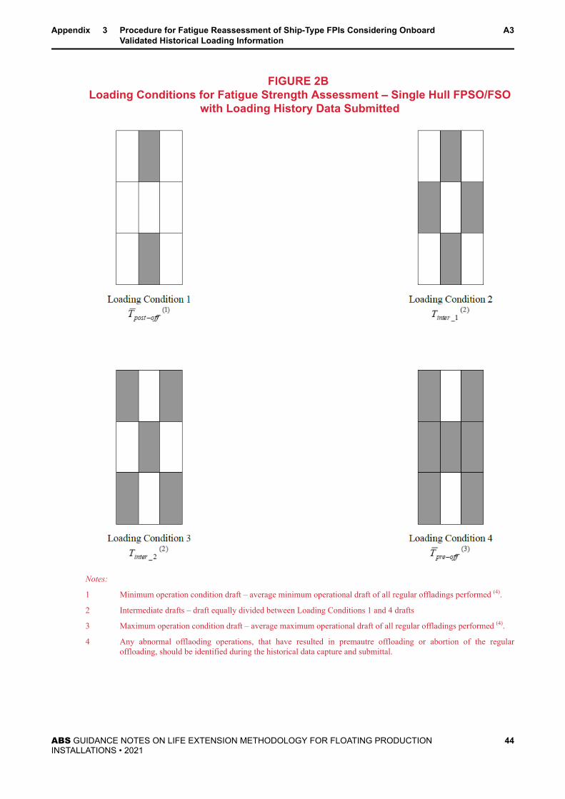
FIGURE 2B Loading Conditions for Fatigue Strength Assessment – Single Hull FPSO/FSO
with Loading History Data Submitted
Notes:
1 Minimum operation condition draft – average minimum operational draft of all regular offladings performed (4).
2 Intermediate drafts – draft equally divided between Loading Conditions 1 and 4 drafts
3 Maximum operation condition draft – average maximum operational draft of all regular offladings performed (4).
4 Any abnormal offlaoding operations, that have resulted in premautre offloading or abortion of the regularoffloading, should be identified during the historical data capture and submittal.
Appendix 3 Procedure for Fatigue Reassessment of Ship-Type FPIs Considering OnboardValidated Historical Loading Information
A3
ABS GUIDANCE NOTES ON LIFE EXTENSION METHODOLOGY FOR FLOATING PRODUCTIONINSTALLATIONS • 2021
44

TABLE 2A Example of Modified Design Fatigue Load Cases
for Fatigue Strength Assessment
(Load Combination Factors for Dynamic Load Components for Loading Condition 1)
FLC1 FLC2 FLC3 FLC4 FLC5 FLC6 FLC7 FLC8
A. Hull Girder Loads
Vertical B.M. Sag (-) Hog (+) Sag (-) Hog (+) Sag (-) Hog (+) Sag (-) Hog (+)kc 0.90 0.90 0.15 0.15 0.70 0.70 0.80 0.80
Vertical S.F. (+) (-) (+) (-) (+) (-) (+) (-)kc 0.55 0.55 0.20 0.20 0.40 0.40 0.50 0.50
Horizontal B.M. (-) (+) (-) (+)kc 0.00 0.00 0.10 0.10 0.55 0.55 0.45 0.45
Horizontal S.F. (+) (-) (+) (-)kc 0.00 0.00 0.10 0.10 0.55 0.55 0.45 0.45
B. External Pressurekc 0.50 0.50 0.85 0.85 0.85 0.85 0.85 0.85kf0 -1.00 1.00 -1.00 1.00 -1.00 1.00 -1.00 1.00
C. Internal Tank Pressurekc 0.40 0.40 1.00 1.00 0.75 0.75 0.40 0.40wv 0.50 -0.50 0.75 -0.75 0.75 -0.75 0.75 -0.75wℓ Fwd Bhd0.20
Fwd Bhd-0.20
— — Fwd Bhd0.40
Fwd Bhd-0.40
Fwd Bhd0.80
Fwd Bhd-0.80
Aft Bhd-0.20
Aft Bhd0.20
— — Aft Bhd-0.40
Aft Bhd0.40
Aft Bhd-0.80
Aft Bhd0.80wt — — Port Bhd
-0.75Port Bhd
0.75Port Bhd
-0.75Port Bhd
0.75Port Bhd
-0.75Port Bhd
0.75
— — Stbd Bhd0.75
Stbd Bhd-0.75
Stbd Bhd0.75
Stbd Bhd-0.75
Stbd Bhd0.75
Stbd Bhd-0.75cϕ, Pitch -0.15 0.15 -0.10 0.10 -0.30 0.30 -0.45 0.45cθ, Roll 0.00 0.00 1.00 -1.00 1.15 -1.15 1.00 -1.00
D. Reference Wave Heading and Motion of Installation
Heading Angle 0 0 90 90 60 60 30 30
Heave Down Up Down Up Down Up Down Up
Pitch BowDown
BowUp
BowDown
BowUp
BowDown
BowUp
BowDown
BowUp
Roll — — StbdDown
StbdUp
StbdDown
StbdUp
StbdDown
StbdUp
Appendix 3 Procedure for Fatigue Reassessment of Ship-Type FPIs Considering OnboardValidated Historical Loading Information
A3
ABS GUIDANCE NOTES ON LIFE EXTENSION METHODOLOGY FOR FLOATING PRODUCTIONINSTALLATIONS • 2021
45

Notes:
1 Rule vertical bending moment range = Mws−Mwℎ (see 5A-3-2/5.2 of the FPI Rules for Mws and Mwℎ)
2 Rule horizontal bending moment range = 2 × Mℎ (see 5A-3-2/5.3 of the FPI Rules for Mℎ)
3 For each load condition pair, the stress range due to local pressure is the difference between the stress values forLocal Pressure Load Conditions. For example, for Load Condition Pair FLC1 & FLC2, the stress range due tolocal pressure is the difference between the stress values for FLC1 and FLC2.
4 For each load condition pair, the stress range is the sum of the absolute stress range values due to Vertical BM,Horizontal BM, and Local Pressure Load Conditions.
TABLE 2B Example of Modified Design Fatigue Load Cases
for Fatigue Strength Assessment
(Load Combination Factors for Dynamic Load Components for Loading Condition 2)
FLC1 FLC2 FLC3 FLC4 FLC5 FLC6 FLC7 FLC8
A. Hull Girder Loads
Vertical B.M. Sag (-) Hog (+) Sag (-) Hog (+) Sag (-) Hog (+) Sag (-) Hog (+)kc 0.95 0.95 0.25 0.25 0.95 0.95 0.85 0.85
Vertical S.F. (+) (-) (+) (-) (+) (-) (+) (-)kc 0.55 0.55 0.25 0.25 0.40 0.40 0.50 0.50
Horizontal B.M. (-) (+) (-) (+)kc 0.00 0.00 0.20 0.20 0.70 0.70 0.60 0.60
Horizontal S.F. (+) (-) (+) (-)kc 0.00 0.00 0.20 0.20 0.70 0.70 0.60 0.60
B. External Pressurekc 0.50 0.50 0.90 0.90 0.90 0.90 0.90 0.90kf0 -1.00 1.00 -1.00 1.00 -1.00 1.00 -1.00 1.00
C. Internal Tank Pressurekc 0.55 0.55 0.70 0.70 0.20 0.20 0.40 0.40wv 0.50 -0.50 0.75 -0.75 0.75 -0.75 0.75 -0.75wℓ Fwd Bhd0.20
Fwd Bhd-0.20
— — Fwd Bhd0.40
Fwd Bhd-0.40
Fwd Bhd0.80
Fwd Bhd-0.80
Aft Bhd-0.20
Aft Bhd0.20
— — Aft Bhd-0.40
Aft Bhd0.40
Aft Bhd-0.80
Aft Bhd0.80wt — — Port Bhd
-0.75Port Bhd
0.75Port Bhd
-0.75Port Bhd
0.75Port Bhd
-0.75Port Bhd
0.75
— — Stbd Bhd0.75
Stbd Bhd-0.75
Stbd Bhd0.75
Stbd Bhd-0.75
Stbd Bhd0.75
Stbd Bhd-0.75cϕ, Pitch -0.20 0.20 -0.05 0.05 -0.10 0.10 -0.35 0.35
Appendix 3 Procedure for Fatigue Reassessment of Ship-Type FPIs Considering OnboardValidated Historical Loading Information
A3
ABS GUIDANCE NOTES ON LIFE EXTENSION METHODOLOGY FOR FLOATING PRODUCTIONINSTALLATIONS • 2021
46

FLC1 FLC2 FLC3 FLC4 FLC5 FLC6 FLC7 FLC8cθ, Roll 0.00 0.00 1.00 -1.00 1.15 -1.15 1.00 -1.00
D. Reference Wave Heading and Motion of Installation
Heading Angle 0 0 90 90 60 60 30 30
Heave Down Up Down Up Down Up Down Up
Pitch BowDown
BowUp
BowDown
BowUp
BowDown
BowUp
BowDown
BowUp
Roll — — StbdDown
StbdUp
StbdDown
StbdUp
StbdDown
StbdUp
Notes:
1 Rule vertical bending moment range = Mws−Mwℎ (see 5A-3-2/5.2 of the FPI Rules for Mws and Mwℎ)
2 Rule horizontal bending moment range = 2 × Mℎ (see 5A-3-2/5.3 of the FPI Rules for Mℎ)
3 For each load condition pair, the stress range due to local pressure is the difference between the stress values forLocal Pressure Load Conditions. For example, for Load Condition Pair FLC1 & FLC2, the stress range due tolocal pressure is the difference between the stress values for FLC1 and FLC2.
4 For each load condition pair, the stress range is the sum of the absolute stress range values due to Vertical BM,Horizontal BM, and Local Pressure Load Conditions.
TABLE 2C Example of Modified Design Fatigue Load Cases
for Fatigue Strength Assessment
(Load Combination Factors for Dynamic Load Components for Loading Condition 3)
FLC1 FLC2 FLC3 FLC4 FLC5 FLC6 FLC7 FLC8
A. Hull Girder Loads
Vertical B.M. Sag (-) Hog (+) Sag (-) Hog (+) Sag (-) Hog (+) Sag (-) Hog (+)kc 0.95 0.95 0.25 0.25 0.75 0.75 0.85 0.85
Vertical S.F. (+) (-) (+) (-) (+) (-) (+) (-)kc 0.55 0.55 0.25 0.25 0.40 0.40 0.50 0.50
Horizontal B.M. (-) (+) (-) (+)kc 0.00 0.00 0.20 0.20 0.85 0.85 0.70 0.70
Horizontal S.F. (+) (-) (+) (-)kc 0.00 0.00 0.25 0.25 0.90 0.90 0.75 0.75
B. External Pressurekc 0.50 0.50 0.95 0.95 0.95 0.95 0.95 0.95kf0 -1.00 1.00 -1.00 1.00 -1.00 1.00 -1.00 1.00
C. Internal Tank Pressurekc 0.55 0.55 0.75 0.75 0.10 0.10 0.40 0.40wv 0.50 -0.50 0.75 -0.75 0.75 -0.75 0.75 -0.75
Appendix 3 Procedure for Fatigue Reassessment of Ship-Type FPIs Considering OnboardValidated Historical Loading Information
A3
ABS GUIDANCE NOTES ON LIFE EXTENSION METHODOLOGY FOR FLOATING PRODUCTIONINSTALLATIONS • 2021
47

FLC1 FLC2 FLC3 FLC4 FLC5 FLC6 FLC7 FLC8wℓ Fwd Bhd0.20
Fwd Bhd-0.20
— — Fwd Bhd0.40
Fwd Bhd-0.40
Fwd Bhd0.80
Fwd Bhd-0.80
Aft Bhd-0.20
Aft Bhd0.20
— — Aft Bhd-0.40
Aft Bhd0.40
Aft Bhd-0.80
Aft Bhd0.80wt — — Port Bhd
-0.75Port Bhd
0.75Port Bhd
-0.75Port Bhd
0.75Port Bhd
-0.75Port Bhd
0.75
— — Stbd Bhd0.75
Stbd Bhd-0.75
Stbd Bhd0.75
Stbd Bhd-0.75
Stbd Bhd0.75
Stbd Bhd-0.75cϕ, Pitch -0.15 0.15 -0.15 0.15 -0.20 0.20 -0.45 0.45cθ, Roll 0.00 0.00 1.00 -1.00 1.15 -1.15 1.00 -1.00
D. Reference Wave Heading and Motion of Installation
Heading Angle 0 0 90 90 60 60 30 30
Heave Down Up Down Up Down Up Down Up
Pitch BowDown
BowUp
BowDown
BowUp
BowDown
BowUp
BowDown
BowUp
Roll — — StbdDown
StbdUp
StbdDown
StbdUp
StbdDown
StbdUp
Notes:
1 Rule vertical bending moment range = Mws−Mwℎ (see 5A-3-2/5.2 of the FPI Rules for Mws and Mwℎ)
2 Rule horizontal bending moment range = 2 × Mℎ (see 5A-3-2/5.3 of the FPI Rules for Mℎ)
3 For each load condition pair, the stress range due to local pressure is the difference between the stress values forLocal Pressure Load Conditions. For example, for Load Condition Pair FLC1 & FLC2, the stress range due tolocal pressure is the difference between the stress values for FLC1 and FLC2.
4 For each load condition pair, the stress range is the sum of the absolute stress range values due to Vertical BM,Horizontal BM, and Local Pressure Load Conditions.
TABLE 2D Example of Modified Design Fatigue Load Cases
for Fatigue Strength Assessment
(Load Combination Factors for Dynamic Load Components for Loading Condition 4)
FLC1 FLC2 FLC3 FLC4 FLC5 FLC6 FLC7 FLC8
A. Hull Girder Loads
Vertical B.M. Sag (-) Hog (+) Sag (-) Hog (+) Sag (-) Hog (+) Sag (-) Hog (+)kc 1.00 1.00 0.30 0.30 0.80 0.80 0.90 0.90
Vertical S.F. (+) (-) (+) (-) (+) (-) (+) (-)kc 0.55 0.55 0.25 0.25 0.40 0.40 0.50 0.50
Horizontal B.M. (-) (+) (-) (+)kc 0.00 0.00 0.25 0.25 0.90 0.90 0.75 0.75
Appendix 3 Procedure for Fatigue Reassessment of Ship-Type FPIs Considering OnboardValidated Historical Loading Information
A3
ABS GUIDANCE NOTES ON LIFE EXTENSION METHODOLOGY FOR FLOATING PRODUCTIONINSTALLATIONS • 2021
48

FLC1 FLC2 FLC3 FLC4 FLC5 FLC6 FLC7 FLC8
Horizontal S.F. (+) (-) (+) (-)kc 0.00 0.00 0.25 0.25 0.90 0.90 0.75 0.75
B. External Pressurekc 0.50 0.50 1.00 1.20 1.00 1.00 1.00 1.00kf0 -1.00 1.00 -1.00 1.00 -1.00 1.00 -1.00 1.00
C. Internal Tank Pressurekc 0.75 0.75 0.80 0.80 0.10 0.10 0.50 0.50wv 0.50 -0.50 0.75 -0.75 0.75 -0.75 0.75 -0.75wℓ Fwd Bhd0.20
Fwd Bhd-0.20
— — Fwd Bhd0.40
Fwd Bhd-0.40
Fwd Bhd0.80
Fwd Bhd-0.80
Aft Bhd-0.20
Aft Bhd0.20
— — Aft Bhd-0.40
Aft Bhd0.40
Aft Bhd-0.80
Aft Bhd0.80wt — — Port Bhd
-0.75Port Bhd
0.75Port Bhd
-0.75Port Bhd
0.75Port Bhd
-0.75Port Bhd
0.75
— — Stbd Bhd0.75
Stbd Bhd-0.75
Stbd Bhd0.75
Stbd Bhd-0.75
Stbd Bhd0.75
Stbd Bhd-0.75cϕ, Pitch -0.30 0.30 -0.15 0.15 -0.10 0.10 -0.80 0.80cθ, Roll 0.00 0.00 1.00 -1.00 1.15 -1.15 1.00 -1.00
D. Reference Wave Heading and Motion of Installation
Heading Angle 0 0 90 90 60 60 30 30
Heave Down Up Down Up Down Up Down Up
Pitch BowDown
BowUp
BowDown
BowUp
BowDown
BowUp
BowDown
BowUp
Roll — — StbdDown
StbdUp
StbdDown
StbdUp
StbdDown
StbdUp
Notes:
1 Rule vertical bending moment range = Mws−Mwℎ (see 5A-3-2/5.2 of the FPI Rules for Mws and Mwℎ)
2 Rule horizontal bending moment range = 2 × Mℎ (see 5A-3-2/5.3 of the FPI Rules for Mℎ)
3 For each load condition pair, the stress range due to local pressure is the difference between the stress values forLocal Pressure Load Conditions. For example, for Load Condition Pair FLC1 & FLC2, the stress range due tolocal pressure is the difference between the stress values for FLC1 and FLC2.
4 For each load condition pair, the stress range is the sum of the absolute stress range values due to Vertical BM,Horizontal BM, and Local Pressure Load Conditions.
Appendix 3 Procedure for Fatigue Reassessment of Ship-Type FPIs Considering OnboardValidated Historical Loading Information
A3
ABS GUIDANCE NOTES ON LIFE EXTENSION METHODOLOGY FOR FLOATING PRODUCTIONINSTALLATIONS • 2021
49

A P P E N D I X 4 References
1 Application of Codes and Standards (1 May 2017)Use of national or international standards or codes other than those listed herein in the life extension offloating production installations is subject to prior approval and acceptance by ABS. The standards orcodes being applied are to be adhered to in their entirety.
ABS:
FPI Rules Rules for Building and Classing Floating Production Installations
MOU Rules Rules for Building and Classing Mobile Offshore Units
Risk Guidance Notes Guidance Notes on Risk Assessment Applications for the Marine and Offshore Industries
RCM Guide Guide for Surveys Based Reliability Centered Maintenance
UAV Guidance Notes Guidance Notes on Using Unmanned Aerial Vehicles
American Petroleum Institute:
API 2A-WSD Recommended Practice for Planning, Designing and Constructing Fixed Offshore Platforms –Working Stress Design – Twenty-First Edition, 2007
API Bulletin 2INT-EX Interim Guidance for Assessment of Existing Offshore Structures for Hurricane Conditions, 2007
API RP 2MET Derivation of Metocean Design and Operating Conditions, 2014
API RP 2FPS Planning, Designing, and Constructing Floating Production Systems, Second Edition – 2011
API RP 2SIM Recommended Practice for the Structural Integrity Management of Fixed Offshore Structures,2014
API RP 2I In-service Inspection of Mooring Hardware for Floating Structures, 2015
API RP 2FSIM Recommended Practice for Floating Systems Integrity Management, 2017
API RP 2RIM Recommended Practice for Risers Integrity Management, 2017
API RP 2MIM Recommended Practice for Mooring Integrity Management, 2017
API RP 2T Recommended Practice for Planning, Designing, and Construction Tension Leg Platforms, ThirdEdition - 2010
International Organization for Standardization:
ISO 19902 Petroleum and natural gas industries – Fixed steel offshore structures, first edition, 2007
NORSOK Standard:
NORSOK standardN-006
Assessment of structural integrity for existing offshore load-bearing structure, Edition 1, 2009
NORSOK standardU-009
Life extension for subsea systems, Edition 1, 2011
ABS GUIDANCE NOTES ON LIFE EXTENSION METHODOLOGY FOR FLOATING PRODUCTIONINSTALLATIONS • 2021
50

Norwegian Oil and Gas Association:
122 Norwegian Oil and Gas Association recommended guideline for the Assessment andDocumentation of Service Life Extension of Facilities, Revision 1, 2012
Oil and Gas UK:
Guidance on the Management of Ageing and Life Extension for UKCS Oil and Gas Installation,Issue 1, 2012
United Kingdom's Health and Safety Executive:
HSE KP4 Ageing and life extension, an interim report by the Offshore Division of HSE’s HazardousInstallations Directorate, 2012
Appendix 4 References A4
ABS GUIDANCE NOTES ON LIFE EXTENSION METHODOLOGY FOR FLOATING PRODUCTIONINSTALLATIONS • 2021
51
Related Documents