2022 Guidance for Ships for Navigation in Ice GC-14-E KR

Welcome message from author
This document is posted to help you gain knowledge. Please leave a comment to let me know what you think about it! Share it to your friends and learn new things together.
Transcript

2022
Guidance for Ships for Navigation in Ice
GC-14-E KR

- i -
APPLICATION OF "GUIDANCE FOR SHIPS FOR NAVIGATION IN ICE"
1. Unless expressly specified otherwise, the requirements in the Guidance apply to ships for navigation in ice for which contracts for construction are signed on or after 1 July 2022.
2. The amendments to the Guidance for 2020 edition and their effective date are as fol-lows;
Effective Date : 1 July 2022
CHAPTER 1 STRENGTHENING FOR NAVIGATION IN ICE
Section 6 Propulsion Machinery- 606. Table 1.23 has been amended.
- iii -
CONTENTS
CHAPTER 1 STRENGTHENING FOR NAVIGATION IN ICE ············································ 1Section 1 General ············································································································ 1Section 2 Ice Strengthening ·························································································· 1Section 3 Hull Structural Design ·················································································· 4Section 4 Rudder and Steering Arrangements ······················································· 15Section 5 Engine Output ····························································································· 16Section 6 Propulsion Machinery ················································································· 21Section 7 Miscellaneous Machinery Requirements ················································ 50
CHAPTER 2 SHIPS FOR NAVIGATION IN POLAR WATERS ······································ 53Section 1 Polar Class Descriptions and Application ··········································· 53Section 2 Structural Requirements for Polar Class Ships ·································· 56Section 3 Machinery Requirements for Polar Class Ships ··································· 75
CHAPTER 3 SHIPS WITH ICE BREAKING CAPABILITY FOR NAVIGATION IN POLAR WATERS ······················································································ 87
Section 1 General ········································································································ 87Section 2 Strengthening of Arctic class ships and Icebreakers ························· 89Section 3 Rudder ········································································································· 124Section 4 Machinery installations ············································································· 125Section 5 Subdivision and Stability ·········································································· 138
CHAPTER 4 Winterization ······························································································· 141Section 1 General ······································································································ 141Section 2 Winterization H - Materials for hull construction at low
temperatures ······························································································ 144Section 3 Winterization M - Materials for equipment and components at low temperatures ················································································ 149Section 4 Winterization E3(t) - Main component and sub-component ········· 154Section 5 Winterization E2(t) - Main component and sub-component ········· 169Section 6 Winterization E1(t) - Main component and sub-component ········· 171Section 7 Winterization S - Stability due to ice accretion ································ 172Section 8 Winterization D - Alternative design ··················································· 173Section 9 Winterization IR - Ice removal arrangements ··································· 173Section 10 Ship specific requirements ··································································· 177
<ANNEX>ANNEX 1 Strengthening for navigation in ice ······················································ 179ANNEX 2 Load cases for propeller and the shape of the propeller ice torque
excitation for the ships strengthened for navigation in ice and Polar Class ships ······················································································· 183

Ch 1 Strengthening for Navigation in Ice Ch 1
Guidance for Ships for Navigation in Ice 2022 1
CHAPTER 1 STRENGTHENING FOR NAVIGATION IN ICE
Section 1 General
101. Application1. The requirements in this Chapter are applied to the hull structure, equipment, machinery and etc. of
ice strengthened ships.
2. The ships intended to navigate in ice are to be in accordance with the requirements in this Chapter in addition to the Rules for the Classification of Steel Ships.
3. In principle, the requirements in this chapter are applied to the ice strengthening of ships which are intended to navigate in the Northern Baltic that are subject to the Finnish-Swedish Ice class Rules 2017 or in the Canadian Arctic that are subject to the Arctic Shipping Pollution Prevention Regulations(see Annex 1, 101).
4. The low air temperature of the ship's ambience in the navigational waters is to be considered for fittings of structures and equipment that are important for navigation and the safety of the ship which is subject to the requirements of this Chapter. In particular, special consideration should be given towards the functioning of hydraulic systems, hazards of freezing of water pipings and tanks and starting of emergency diesel engines, etc.
5. In ships that have unusual proportions, hull form or propulsion arrangements, etc, the Society may impose special requirements.
102. Documentation1. Forward region, midship region, aft region, ice belt, UIWL and LIWL defined in 202. are to be
specified in the Shell Expansion.
2. The engine output defined in 501, the displacement defined in 203.3 and the dimensions necessary for the engine output calculation required in 502. are to be specified in the General Arrangement. And the engine output calculation is to be submitted in addition to drawing and data for reference in accordance with the Pt 5 of the Rules for the Classification of Steel Ships.
Section 2 Ice Strengthening
201. Classification of Ice Strengthening1. Strengthening for navigation in ice is classified into the following 6 class notations dependent on the
degree of reinforcement and engine output of the ship(see Annex 1, 102).(1) IA Super : ships with such structure, engine output and other properties that they are normally
capable of navigating in difficult ice conditions without the assistance of Icebreakers(2) IA : ships with such structure, engine output and other properties that they are capable of navi-
gating in difficult ice conditions, with the assistance of Icebreakers when necessary(3) IB : ships with such structure, engine output and other properties that they are capable of navi-
gating in moderate ice conditions, with the assistance of Icebreakers when necessary(4) IC : ships with such structure, engine output and other properties that they are capable of navi-
gating in light ice conditions, with the assistance of Icebreakers when necessary(5) ID : ships with such structure, engine output and other properties that are capable of navigating
in light ice conditions(6) II : ships complying with a standard deemed appropriate by the Society and that are capable of
navigating in very light ice conditions2. It is the responsibility of the Owner to determine which class in Par 1 is most suitable for this
requirement.

Ch 1 Strengthening for Navigation in Ice Ch 1
2 Guidance for Ships for Navigation in Ice 2022
202. DefinitionsThe definitions of terms which appear in this Chapter are to be specified as the following, unless otherwise specified elsewhere.
1. Area of Ice Strengthening The bow, midbody, and stern regions in way of hull part are defined for ships of Ice classes IA
Super, IA, IB and IC and the bow region is defined for ships of Ice class ID as follows:(1) Bow region: From the stem to a line parallel to and 0.04 aft of the bow borderline of the part
of the hull where the waterlines run parallel to the centerline. For Ice classes IA Super and IA the overlap over the borderline need not exceed 6 m, and for Ice classes IB, IC and ID this overlap need not exceed 5 m.
(2) Midbody region: From the aft boundary of the bow region to a line parallel to and 0.04 aft of the aft borderline of the part of the hull where the waterlines run parallel to the centreline. For Ice classes IA Super and IA the overlap over the borderline need not exceed 6 m, and for Ice classes IB and IC this overlap need not exceed 5 m.
(3) Stern region: From the aft boundary of the midbody region to the stern.2. The ice belt is the part of the shell plating which has to be reinforced. (see Fig 1.1 and 303.1)
Fig 1.1 Ice Belt at each region
3. The upper ice waterline (UIWL) shall be the envelop of the highest points of the waterline at which the ship is intended to operate in ice. The line may be a broken line.
4. The lower ice waterline (LIWL) shall be the envelop of the lowest points of the waterline at which the ship is intended to operate in ice.
5. The maximum and minimum Ice class draughts at fore and aft perpendiculars shall be determined in accordance with the upper and lower ice waterlines.
203. Operational Requirements1. The draught of the ship at fore and aft perpendiculars, when operating in ice shall always be be-
tween the UIWL and LIWL.
2. Restrictions on draughts when operating in ice shall be documented and kept on board readily avail-able to the master.
3. The maximum and minimum Ice class draughts fore, amidships and aft shall be indicated in the classification certificate.
4. For ships built("Built" means the keel of ships has been laid or which has been at a similar stage of construction) on or after 1 July 2007, if the summer load line in fresh water is anywhere located at a higher level than the UIWL, the ship’s sides are to be provided with a warning triangle and with an Ice class draught mark at the maximum permissible Ice class draught amidships. Ships built be-

Ch 1 Strengthening for Navigation in Ice Ch 1
Guidance for Ships for Navigation in Ice 2022 3
fore 1 July 2007 shall be provided with such a marking, if the UIWL is below the summer load line, not later than the first scheduled dry docking after 1 July 2007 (see Annex 1, 103). Ships built be-fore 1 July 2007 shall be provided with such a marking, if the UIWL is below the summer load line, not later than the first scheduled dry docking after 1 July 2007.
5. The draught and trim, limited by UIWL, must not be exceeded when the ship is navigating in ice. The salinity of sea water along the intended route shall be taken into account when loading the ship. The ship shall always be loaded down at least to the LIWL when navigating in ice.
204. Security of Minimum Draught
1. Prevention of the water from freezing
Any ballast tank, situated above the LIWL and needed to load down the ship to this water line is to be equipped with proper devices to prevent the water from freezing.
2. In determining the LIWL, regard shall be paid to the need for ensuring a reasonable degree of ice-going capability in ballast.
3. The propeller is to be fully submerged, if possible, entirely below the ice.
4. Minimum forward draught
The minimum forward draught is not to be less than that obtained from the following formula, which need not exceed
(m)
: the maximum displacement (t) of the ship determined from the waterline on the UIWL (see 202. 3). Where multiple waterlines are used for determining the UIWL, the displacement is to be determined from the waterline corresponding to the greatest displacement.
= level ice thickness given in Table 1.1
Table 1.1 Level ice thickness
Ice class (m)
IA Super 1.0
IA 0.8
IB 0.6
IC 0.4
ID 0.4

Ch 1 Strengthening for Navigation in Ice Ch 1
4 Guidance for Ships for Navigation in Ice 2022
Section 3 Hull Structural Design
301. Design ice pressures1. Design ice pressure is not to be less than that obtained from the following formula:
(MPa)
= a factor which takes account of the influence of the size and engine output of the ship.
( ≤ )
= the displacement (ton) of ship on the maximum ice-class draught according to 202. 3
= is the actual continuous engine output of the ship (kW) available when sailing in ice. If additional power sources are available for propulsion power (e.g. shaft mo-tors), in addition to the power of the main engine (s), they shall also be included in the total engine output used as the basis for hull scantling calculations. The engine output used for calculation of the hull scantlings shall be clearly stated on the shell expansion drawing
and = as given in Table 1.2 according to the region under consideration and the value of
= hull region factor that reflects the magnitude of the load expected in that hull area relative to the bow area. (see Table 1.3)
= the nominal ice pressure; the value 5.6 MPa is to be used. = a factor which takes account of the probability that the full length of the area under con-
sideration will be under pressure at the same time, as given by the following formula.
(0.35≤ ≤ 1.0)
= to be taken as specified in Table 1.4 according to the structural member under consideration.
Bow Midbody and Stern region
≤ ≤
30 6 8 12
230 518 214 286
Table 1.2 Value of and

Ch 1 Strengthening for Navigation in Ice Ch 1
Guidance for Ships for Navigation in Ice 2022 5
Table 1.3 Coefficient
Ice class Bow Midbody Stern
IA Super 1.00 1.00 0.75
IA 1.00 0.85 0.65
IB 1.00 0.70 0.45
IC 1.00 0.50 0.25
ID 1.00 - -
Table 1.4 Value of
Structure Type of framing
(m)
ShellTransverse Frame Spacing
Longitudinal 1.7 frame Spacing
FramesTransverse Frame Spacing
Longitudinal span of frame
ice stringer - span of stringer
web frame - 2-spacing of web frames
2. The is the height of the area under the ice pressure specified in 1 and is to be as given in Table 1.5 according to the Ice class.
Table 1.5 Value of
Ice class (m)
IA Super 0.35
IA 0.30
IB 0.25
IC 0.22
ID 0.22
302. General of Structure1. The formulae and values given in this section may be substituted by direct analysis if they are
deemed by the Society to be invalid or inapplicable for a given structural arrangement or detail. Otherwise, direct analysis is not to be utilized as an alternative to the analytical procedures pre-scribed by explicit requirements in sections
2. If scantlings derived from these regulations are less than those required by the Society for a not an ice strengthened ship, the latter shall be used.
3. For curved members the span (or spacing) is defined as the chord length between span (or spacing) points. The span points are defined by the intersection between the flange or upper edge of the member and the supporting structural element (stringer, web frame, deck or bulkhead). (see Fig 1.2)
Fig 1.2 Definition of the frame span(left) and frame spacing (right) for curved members.
4. The effective breadth of the attached plate to be used for calculating the section modulus of the stiffener is to comply with Pt 3, Ch 1, 602. of the Rules for the Classification of Steel Ships.
Ch 1 Strengthening for Navigation in Ice Ch 1
6 Guidance for Ships for Navigation in Ice 2022
5. For such cases where the member is not normal to the plating (the angle between plating and stiff-eners is less than 75°), the section properties (section modulus and shear area) are to be calculated in accordance with the Pt 13, Ch 3, Sec 7 1.4 of the Rules for the Classification of Steel Ships.
303. Shell plating
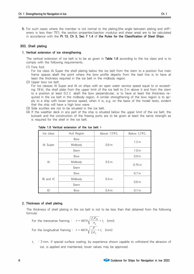
1. Vertical extension of ice strengthening
The vertical extension of ice belt is to be as given in Table 1.6 according to the Ice class and is to comply with the following requirements.(1) Fore foot
For Ice class IA Super the shell plating below the ice belt from the stem to a position five main frame spaces abaft the point where the bow profile departs from the keel line is to have at least the thickness required in the ice belt in the midbody region.
(2) Upper bow ice beltFor Ice classes IA Super and IA on ships with an open water service speed equal to or exceed-ing 18 kt, the shell plate from the upper limit of the ice belt to 2 m above it and from the stem to a position at least 0.2 abaft the bow perpendicular, is to have at least the thickness re-quired in the ice belt in the midbody region. A similar strengthening of the bow region is to ap-ply to a ship with lower service speed, when it is, e.g. on the basis of the model tests, evident that the ship will have a high bow wave.
(3) Side scuttles are not to be situated in the ice belt.(4) If the weather deck in any part of the ship is situated below the upper limit of the ice belt, the
bulwark and the construction of the freeing ports are to be given at least the same strength as is required for the shell in the ice belt.
Table 1.6 Vertical extension of the Ice belt
Ice class Hull Region Above UIWL Below LIWL
IA Super
Bow
0.6 m1.2 m
Midbody
Stern 1.0 m
IA
Bow
0.5 m
0.9 m
Midbody0.75 m
Stern
IB and IC
Bow
0.4 m
0.7 m
Midbody0.6 m
Stern
ID Bow 0.4 m 0.7 m
2. Thickness of shell plating
The thickness of shell plating in the ice belt is not to be less than that obtained from the following formula:
For the transverse framing :
(mm)
For the longitudinal framing :
(mm)
: 2 mm, if special surface coating, by experience shown capable to withstand the abrasion of ice, is applied and maintained, lower values may be approved.

Ch 1 Strengthening for Navigation in Ice Ch 1
Guidance for Ships for Navigation in Ice 2022 7
: frame spacing (m) : 0.75 (MPa) : as specified in 301.1 : as given in the following formula. Where, however, is greater than 1.0, is to be tak-
en as 1.0
: as given by the following formula depending on the value of
Where :
Where ≤ :
: as specified in Table 1.5.
: yield stress of the material of the member considered, which are given as follows (N/mm2)235 : for mild steels as specified in Pt 2, Ch 1 of the Rules for the Classification of Steel
Ships315 : for high tensile steels AH 32, DH 32, EH 32 or FH 32 as specified in Pt 2, Ch 1 of
the Rules for the Classification of Steel Ships355 : for high tensile steels AH 36, DH 36, EH 36 or FH 36 as specified in Pt 2, Ch 1 of
the Rules for the Classification of Steel Ships390 : for high tensile steels AH 40, DH 40, EH 40 or FH 40 as specified in Pt 2, Ch 1 of
the Rules for the Classification of Steel Ships
304. Frames
1. Vertical extension of ice strengthening(1) The vertical extension of ice strengthening of the framing is to be at least as given in Table 1.7
according to the respective Ice classes and regions. (2) For Ice classes IA Super and IA on ships with an open water service speed equal to or exceed-
ing 18 kt, the ice strengthening part of the framing is to be extended to the top of this ice belt of 303.1 (2).
(3) Where the ice strengthening would go beyond a deck or a tanktop (or tank bottom) by no more than 250 mm, it can be terminated at that deck or tanktop (or tank bottom).
(4) For this reason, the vertical extension of the ice strengthening of the longitudinal frames should be extended up to and including the next frame up from the upper edge (frame 3 in Fig 1.3) of the ice belt as defined in 303.1. Additionally the frame spacing of the longitudinal frames just above and below the edge of the ice belt should be the same as the frame spacing in the ice belt (spacing between frames 2 and 3 should be the same as between frames 1 and 2 in Fig 1.3).
(5) If, however, the first frame in the area above the ice belt (frame 3 in area 2 in Fig 1.3) is closer than about s/2 to the edge of the icebelt, then the same frame spacing as in the icebelt should be used above the edge of the ice belt i.e in the spacing between frames 3 and 4.

Ch 1 Strengthening for Navigation in Ice Ch 1
8 Guidance for Ships for Navigation in Ice 2022
UIWL
UIWL+HU
UIWL+HUF
Ice framesLongitudinal frameat which the transverseframes terminate
The ice belt
All transverse andlowermost longitudinalframe ice-strengthened
Open waterdesign
Main frames
1
2
3
4
5
Area 1
Area 2
Area 3
Transverse framing Longitudinal framing
Fig 1.3 The different ice strengthening areas at and above the UIWL.
Table 1.7 Vertical extension of the ice strengthening of framing
Ice class Region Above UIWL (m) Below LIWL (m)
IA Super
Bow
1.2
to double bottom or below top of floors
Midbody 2.0
Stern 1.6
IAIBIC
Bow 1.0 1.6
Midbody 1.0 1.3
Stern 1.0 1.0
ID Bow 1.0 1.6
2. General of Frames(1) Within the ice strengthening area all frames are to be effectively attached to all the supporting
structures. A longitudinal frame is to be attached to all the supporting web frames and bulk-heads by brackets. When a transverse frame terminates at a stringer or deck, a bracket or sim-ilar construction is to be fitted. When a frame is running through the supporting structure, both sides of the web plate of the frame are to be connected to the structure by direct welding, col-lar plate or lug. When a bracket is installed, it is to have at least the same thickness as the web plate of the frame and the edge is to be appropriately stiffened against buckling.
(2) The frames shall be attached to the shell by double continuous weld. No scalloping is allowed (except when crossing shell plate butts)
(3) The web thickness of the frames shall be at least the maximum of the following:
(a) , is the web height
= 805 for profiles and = 282 for flat bars
(b) half of the net thickness of the shell plating, . For the purpose of calculating the web thickness of frames, the required thickness of the shell plating is to be calculated according to 303.2 using the yield strength of the frames;
(c) 9 mm(4) Where there is a deck, tank top (or tank bottom) or bulkhead in lieu of a frame, the plate thick-
Ch 1 Strengthening for Navigation in Ice Ch 1
Guidance for Ships for Navigation in Ice 2022 9
ness of this is to be as per the preceding in (3), to a depth corresponding to the height of adjacent frames and constant C is to be taken as 805.
(5) Asymmetrical frames and frames which are not at right angles to the shell (web less than 75 degrees to the shell) shall be supported against tripping by brackets, intercoastals, stringers or similar, at a distance not exceeding 1.3 m.
(6) For frames with spans greater than 4 m, the extent of antitripping supports is to be applied to all regions and for all ice classes.
(7) For frames with spans less than or equal to 4 m the extent of antitripping supports is to be ap-plied to following regions
- IA Super All hull regions- IA Bow and midbody regions- IB, IC and ID Bow region.
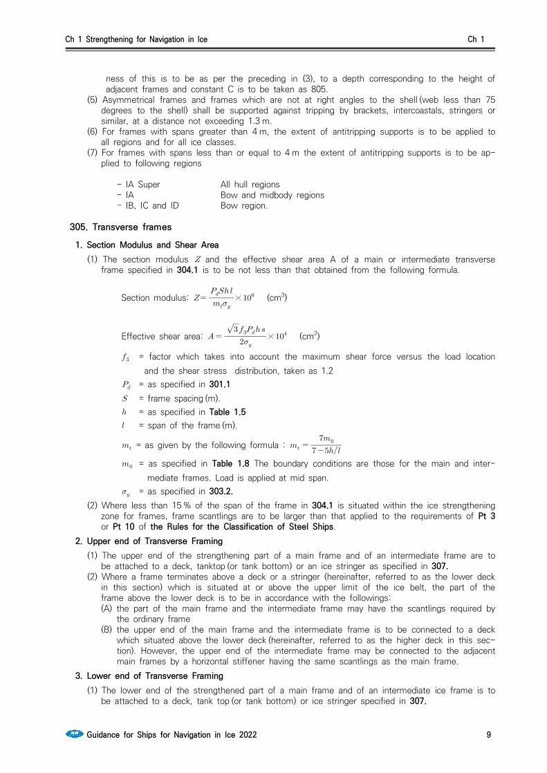
305. Transverse frames
1. Section Modulus and Shear Area (1) The section modulus and the effective shear area A of a main or intermediate transverse
frame specified in 304.1 is to be not less than that obtained from the following formula.
Section modulus:
× (cm3)
Effective shear area:
× (cm2)
= factor which takes into account the maximum shear force versus the load location and the shear stress distribution, taken as 1.2
= as specified in 301.1 = frame spacing (m). = as specified in Table 1.5 = span of the frame (m).
= as given by the following formula :
= as specified in Table 1.8 The boundary conditions are those for the main and inter-mediate frames. Load is applied at mid span.
= as specified in 303.2.(2) Where less than 15 % of the span of the frame in 304.1 is situated within the ice strengthening
zone for frames, frame scantlings are to be larger than that applied to the requirements of Pt 3 or Pt 10 of the Rules for the Classification of Steel Ships.
2. Upper end of Transverse Framing (1) The upper end of the strengthening part of a main frame and of an intermediate frame are to
be attached to a deck, tanktop (or tank bottom) or an ice stringer as specified in 307. (2) Where a frame terminates above a deck or a stringer (hereinafter, referred to as the lower deck
in this section) which is situated at or above the upper limit of the ice belt, the part of the frame above the lower deck is to be in accordance with the followings:(A) the part of the main frame and the intermediate frame may have the scantlings required by
the ordinary frame(B) the upper end of the main frame and the intermediate frame is to be connected to a deck
which situated above the lower deck (hereinafter, referred to as the higher deck in this sec-tion). However, the upper end of the intermediate frame may be connected to the adjacent main frames by a horizontal stiffener having the same scantlings as the main frame.
3. Lower end of Transverse Framing(1) The lower end of the strengthened part of a main frame and of an intermediate ice frame is to
be attached to a deck, tank top (or tank bottom) or ice stringer specified in 307.

Ch 1 Strengthening for Navigation in Ice Ch 1
10 Guidance for Ships for Navigation in Ice 2022
(2) Where an intermediate frame terminates below a deck, tank top (or tank bottom) or ice stringer which is situated at or below the lower limit of the ice belt, the lower end may be connected to the adjacent main frames by a horizontal member of the same scantlings as the frames.
(3) the main frames below the lower edge of ice belt must be ice strengthened. (see 304.1)
Table 1.8 Value of
Boundary condition Example
Both ends fixed
7.0Frames in a bulkcarrier with top
side tanks
One side fixed and one side simple support
6.0Frames extendingfrom the tank topto a single deck
Multi point simple support
5.7Continuous framesbetween several
decks or stringers
Both ends simple support
5.0Frames extending
between twodecks only
306. Longitudinal framesThe section modulus and effective shear area of a longitudinal frame in the extension specified in 303.1 are not to be less than that obtained from the following formula. However in calculating the actual shear area of the frames, the shear area of the brackets is not to be taken into account.
× (cm3),
× (cm2)
= factor which takes account of the load distribution to adjacent frames given by following formula:
= as specified in Table 1.5 = frame spacing (m).
= as specified in 301.1 = span of the longitudinal frame (m).
Ch 1 Strengthening for Navigation in Ice Ch 1
Guidance for Ships for Navigation in Ice 2022 11
= as specified in 303.2 = factor which takes account the maximum shear force versus load location and the
shear stress distribution ( = 2.16) is boundary condition factor and = 13.3 for a continuous beam with brackets; where
the boundary conditions deviate significantly from those of a continuous beam with brackets, e.g. in an end field, a smaller boundary condition factor may be required
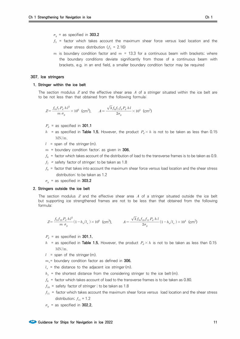
307. Ice stringers
1. Stringer within the ice belt
The section modulus and the effective shear area of a stringer situated within the ice belt are to be not less than that obtained from the following formula:
× (cm3),
× (cm2)
= as specified in 301.1 = as specified in Table 1.5. However, the product × is not to be taken as less than 0.15
MNm. = span of the stringer (m). = boundary condition factor; as given in 306. = factor which takes account of the distribution of load to the transverse frames is to be taken as 0.9. = safety factor of stringer: to be taken as 1.8 = factor that takes into account the maximum shear force versus load location and the shear stress
distribution: to be taken as 1.2 = as specified in 303.2
2. Stringers outside the ice belt
The section modulus and the effective shear area of a stringer situated outside the ice belt but supporting ice strengthened frames are not to be less than that obtained from the following formula:
× (cm3),
× (cm2)
= as specified in 301.1. = as specified in Table 1.5. However, the product × is not to be taken as less than 0.15
MNm. = span of the stringer (m).= boundary condition factor as defined in 306. = the distance to the adjacent ice stringer (m). = the shortest distance from the considering stringer to the ice belt (m). = factor which takes account of load to the transverse frames is to be taken as 0.80. = safety factor of stringer ; to be taken as 1.8 = factor which takes account the maximum shear force versus load location and the shear stress
distribution; = 1.2 = as specified in 302.2.

Ch 1 Strengthening for Navigation in Ice Ch 1
12 Guidance for Ships for Navigation in Ice 2022
3. Deck Strips(1) Narrow deck strips abreast of hatches and serving as ice stringers are to comply with the sec-
tion modulus and shear area requirements in 1 and 2 respectively. (2) In the case of very long hatches, the product × may be taken as less than 0.15 MNm but
in no case less than 0.1 MNm. (3) Regard is to be paid to the deflection of the ship's sides due to ice pressure in way of very
long(more than B/2) hatch openings, when designing weather deck hatch covers and their fittings.
308. Web Frames
1. Ice Load
The ice load transferred to a web frame from an ice stringer or from longitudinal framing is not to be less than that obtained by the following formula. However, In case the supported stringer is outside the ice belt, the load may be reduced by multiplying .
(MN)
= ice pressure (MPa) as specified in 301.1 in calculating however, is to be taken as 2. = safety factor of web frames; to be taken as 1.8. = as specified in Table 1.5. However, the product × is to be more than 0.15MNm. = web frame spacing (m). : As specified in 307.2.
2. Section Modulus and Shear Area
The section modulus and effective shear area of web frame may be obtained from the follow-ing formula:
× (cm3),
× (cm2)
= span of web frame (m). = maximum calculated shear force under the ice load , as given in Par 1 = factor that takes into account the shear force distribution, = 1.1 = maximum calculated bending moment under the ice load ; to be taken as . and = as given in Table 1.9. For intermediate values of is to be obtained by linear
interpolation. = as specified in 307.2. = required shear area (cm2) = actual cross sectional area of the web frame (cm2)

Ch 1 Strengthening for Navigation in Ice Ch 1
Guidance for Ships for Navigation in Ice 2022 13
Table 1.9 Value of and
0.00 0.20 0.40 0.60 0.80 1.00 1.20 1.40 1.60 1.80 2.00
1.50 1.50 1.23 1.16 1.11 1.09 1.07 1.06 1.05 1.05 1.04
0.00 0.44 0.62 0.71 0.76 0.80 0.83 0.85 0.87 0.88 0.89
Note: = actual cross section area of free flange (cm2) = actual effective cross section area of web plate (cm2)
3. Direct Analysis
The scantlings of web frames may be calculated by direct analyses where deemed appropriate by the Society. In this case, the following are to be complied with;
(1) The pressure according to 301.1. and height of load area according to 301.2. are to be used in direct calculation.
(2) The pressure to be used is 1.8 (MPa).(3) The load patch is to be applied at locations where the capacity of the structure under the
combined effects of bending and shear are minimized. (4) The structure is to be checked with load centered at follow location;
(A) Vertical location(a) at the UIWL, (b) 0.5 (m) below the LIWL, and ( see Table 1.1)(c) positioned several vertical locations in between.
(B) Several horizontal locations which are the locations centered at the mid-span or spacing(C) If the load length cannot be determined directly from the arrangement of the struc-
ture, several values of may be checked using corresponding values for .
(5) Allowable stress are as follows;․ Bending stress : ․ Shear stress :
․ Equivalent stress :
309. Bow
1. Stem(1) The stem shall be made of rolled, cast or forged steel or of shaped steel plates as shown in
Fig 1.4.
Fig 1.4 Examples of suitable stems
(2) The plate thickness of a shaped plate stem and in the case of a blunt bow, any part of the shell where angle and as specified in 502.1 are respectively not less than 30 degrees and 75 degrees, is to be obtained from the formula in 301.2 using the following values ; = spacing of elements supporting the plate (m). = ice pressure () as specified in 301 (MPa). = spacing of vertical supporting elements (m).

Ch 1 Strengthening for Navigation in Ice Ch 1
14 Guidance for Ships for Navigation in Ice 2022
(3) The stem and the part of a blunt bow specified in (2) is to be supported by floors or brackets spaced not more than 0.6 m apart and having a thickness of at least half the plate thickness.
(4) The reinforcement of the stem is to be extended from the keel to a point 0.75 m above UIWL or, in case an upper forward ice belt is required in 303.1 (3) to the upper limit of this.
2. Arrangements for towingTowing arrangements are normally as follows; (see Fig 1.5)(1) The towing arrangement usually uses a thick wire which is split into two slightly thinner wires,
shown in Fig 1.5. (2) Two fairleads must be fitted symmetrically off the centreline with one bollard each.(3) The distance of the bollards from the centreline is approximately 3 m. The bollards shall be
aligned with the fairleads allowing the towlines to be fastened straight onto them.(4) A bollard or other means for securing a towline, structurally designed to withstand the breaking
force of the towline of the ship, shall also be fitted.
Fig 1.5 The typical towing arrangement
310. Stern1. The clearance between the propeller blade tip and hull, including the stern frame is not to be less
than as specified 203. to prevent from occurring high loads on the blade tip.2. On twin and triple screw ships, the ice strengthening of the shell and framing are to be extended
to the double bottom for 1.5 m forward and aft of the side propellers.3. On twin and triple screw ships, the shafting and stern tubes of side propellers are to be normally
enclosed within plated bossings. If detached struts are used, their design, strength and attachment to the hull are to be duly considered.
4. The introduction of new propulsion arrangements with azimuth thrusters or podded propellers, which provide an improved maneuverability, will result in increased ice loading of the stern region and the stern area. This fact is to be considered in the design of the aft/stern structure.
311. Bilge keel1. The connection of bilge keels to the hull shall be so designed that the risk of damage to the hull,
in case a bilge keel is damaged, is minimized.2. A construction of bilge keels as Fig 1.6 is recommended for strength.3. To limit damage when a bilge keel is partly damaged, it is recommended that bilge keels are cut up
into several shorter independent lengths.
Fig 1.6 An example of typical type bilge keel construction
Ch 1 Strengthening for Navigation in Ice Ch 1
Guidance for Ships for Navigation in Ice 2022 15
Section 4 Rudder and Steering Arrangements
401. Rudder and steering arrangements1. The scantlings of rudder post, rudder stock, pintles and steering gear, etc. are to comply with re-
quirements in Pt 4, Ch 1 and Pt 5, Ch 7 of the Rules for the Classification of Steel Ships. The maximum service speed of the ship to be used in these calculations shall, however, not be taken as less than stated below:
IA Super 20 knots
IA 18 knots
IB 16 knots
IC 14 knots
If the actual maximum service speed of the ship is higher, that speed shall be used.
2. The local scantling of rudders are to be determined assuming that the whole rudder belongs to the ice belt. The rudder plating and frames are to be designed using the ice pressure for the plating and frames in the midbody region.
3. For the Ice classes IA Super and IA, the rudder stock and the upper part of the rudder are to be protected from direct contact with intact ice by either an ice knife that extends below the LIWL or by equivalent means. Special consideration is to be given to the design of the rudder and the ice knife for ships with flap-type rudders.
4. For ships of Ice classes IA Super and IA, the rudders and steering arrangements are to be designed as follows to endure the loads that work on the rudders by the ice when backing into an ice ridge.(1) Relief valves for hydraulic pressure is to be installed(2) The components of the steering gear are to be dimensioned to stand the yield torque of the
rudder stock.(3) Suitable arrangements such as rudder stoppers are to be installed.
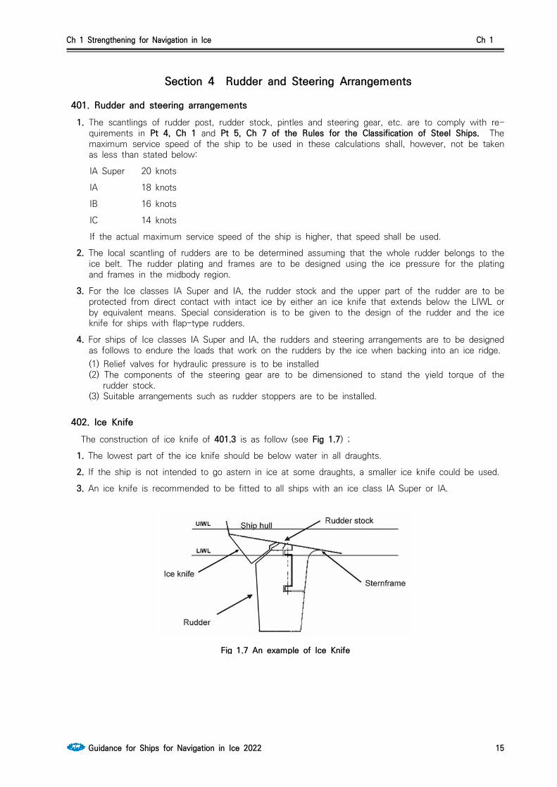
402. Ice Knife The construction of ice knife of 401.3 is as follow (see Fig 1.7) ;
1. The lowest part of the ice knife should be below water in all draughts.
2. If the ship is not intended to go astern in ice at some draughts, a smaller ice knife could be used.
3. An ice knife is recommended to be fitted to all ships with an ice class IA Super or IA.
Fig 1.7 An example of Ice Knife

Ch 1 Strengthening for Navigation in Ice Ch 1
16 Guidance for Ships for Navigation in Ice 2022
Section 5 Engine Output
501. Definition of engine output (2018)The engine output is the total maximum output the propulsion machinery can continuously deliver to the propeller(s). If the output of the machinery is restricted by technical means or by any regu-lations applicable to the ship, shall be taken as the restricted output. If additional power sources are available for propulsion power (e.g. shaft motors), in addition to the power of the main en-gine(s), they shall also be included in the total engine output.
502. Required engine output for Ice classes IA Super, IA, IB, IC and IDThe engine output shall not be less than that determined by the formula below and in no case less than 1,000 kW for Ice class IA, IB, IC and ID, and not less than 2800 kW for IA Super.
1. Definitions
The dimensions of the ship and some other parameters are defined below: = length of the ship between the perpendiculars (m) = length of the bow (m) = length of the parallel midship body (m) = maximum breadth of the ship (m) = actual Ice class draughts of the ship according to 202. 2 (m) = area of the waterline of the bow (m2) = the angle of the waterline at B/4 (deg) = degree the rake of the stem at the centerline (deg) = degree the rake of the bow at B/4 (deg) = diameter of the propeller (m) = thickness of the brash ice in mid channel (m) = thickness of the brash ice layer displaced by the bow (m)
Fig 1.8 Determination of the geometric quantities of the hull. If the ship has a bulbous bow, then = 90°.

Ch 1 Strengthening for Navigation in Ice Ch 1
Guidance for Ships for Navigation in Ice 2022 17
2. New ships
To be entitled to Ice class IA Super, IA, IB, IC or ID a ship the keel of which is laid or which is at a similar stage of construction on or after 1 September 2003 is to comply with the following re-quirements regarding its engine output. The engine output requirement is to be calculated for two draughts. Draughts to be used are the maximum draught amidship referred to as UIWL and the minimum draught referred to as LIWL, as defined in 202. In the calculations the ship's parameters which depend on the draught are to be determined at the appropriate draught, but L and B are to be determined only at the UIWL. The engine output is not to be less than the greater of these two outputs.
[kW],
where : as given in Table 1.10
Table 1.10 Values of constant
Number of Propeller CP or electric or hydraulic propulsion machinery FP propeller
1 propeller 2.03 2.26
2 propellers 1.44 1.60
3 propellers 1.18 1.31
These values apply for conventional propulsion systems. Other methods may be used for de-termining the required power for advanced propulsion systems (see Par 5).
RCH is the resistance in Newton of the ship in a channel with brash ice and a consolidated surface layer:
where cossinsin, is to be taken equal or larger than 0.45. , and = 0 if ≤ .
= 1.0 for Ice class IA and IA Super = 0.8 for Ice class IB = 0.6 for Ice class IC
= 0.5 for Ice class ID and = coefficients obtained by taking into account a consolidated upper layer of the brash
ice
For ships of Ice classes IA, IB, IC and ID : ,
For ships of Ice classes IA Super

Ch 1 Strengthening for Navigation in Ice Ch 1
18 Guidance for Ships for Navigation in Ice 2022
For a ship with a bulbous bow, is to be taken as 90°. and = values given in Table 1.11
= arctantansin
is not to be taken as less than 5 and not to be taken as more than 20.
Further information on the validity of the above formulas can be found in Annex I together with sample data for the verification of powering calculations. If the ship’s parameter values are beyond the ranges defined in Table 1.1 of Annex I, other methods for determining shall be used as defined in Par 5.
Table 1.11 and
(Nm) 23 (N) 1530 (kg/(ms)) 845
(Nm) 45.8 (Nm) 170 (kg/(ms)) 42
(Nm) 14.7 (Nm) 400 (kg/s) 825
(Nm) 29
3. Existing ships of Ice class IB or IC
To be entitled to retain Ice class IB or IC a ship, the keel of which has been laid or which has been at a similar stage of construction before 1 September 2003, is to comply with the following requirements regarding its engine output. The engine output is not to be less than that determined by the formula below and in no case less than 740 kW.
∙∙∆ [kW]
where for a fixed pitch propeller for a controllable pitch propeller but not more than 1.1 and 1.1 for a bulbous bow
where, is the rake of the stem at the centerline [degrees] (see Fig 1.8)
The product X shall not be taken as less than 0.85. ∆but not less than 1.0 and shall be taken as follows:

Ch 1 Strengthening for Navigation in Ice Ch 1
Guidance for Ships for Navigation in Ice 2022 19
Ice class IB IC IB IC
Displacement < 30000 ≥ 30000
0.22 0.18 0.13 0.11
370 0 3070 2100
NOTE: is displacement [t] of the ship on the maximum Ice class draught according to 202. 1.It need not be taken as greater than 80,000 t.
Table 1.12 Value or
4. Existing ships of Ice class IA Super or IA
To be entitled to retain Ice class IA Super or IA a ship, the keel of which has been laid or which has been at a similar stage of construction before 1 September 2003, shall comply with the re-quirements in Par 2 above at the following dates:
- 1 January 2005 or- 1 January in the year when 20 years has elapsed since the year the ship was delivered,
whichever occurs the latest.When, for an existing ship, values for some of the hull form parameters required for the calculation method in section Par 2 are difficult to obtain, the following alternative formulae can be used:
Where, For ships of Ice classes IA,
For ships of Ice classes IA Super without a bulbous bow, and is to be calculated as fol-lows;
For ships of Ice classes IA Super with a bulbous bow, and is to be calculated as follows;
and = values given in Table 1.13
is not to be taken as less than 5 and not to be taken as more than 20.

Ch 1 Strengthening for Navigation in Ice Ch 1
20 Guidance for Ships for Navigation in Ice 2022
Table 1.13 Values of and
(Nm) 10.3 (N) 1530 (kg/(ms)) 460
(Nm) 45.8 (Nm) 172 (kg/(ms)) 18.7
(Nm) 2.94 (Nm) 400 (kg/s) 825
(Nm) 5.8
5. Other methods of determining or
For an individual ship, in lieu of the or values defined in Par 2 and 3, the use of or values based on more exact calculations or values based on model tests may be approved. Such an approval will be given on the understanding that it can be revoked if experience of the ship’s performance in practice motivates this.
The design requirement for Ice classes is a minimum speed of 5 knots in the following brash ice channels:
IA Super = 1.0 m and a 0.1 m thick consolidated layer of iceIA = 1.0 mIB = 0.8 mIC = 0.6 mID = 0.5 m
Ch 1 Strengthening for Navigation in Ice Ch 1
Guidance for Ships for Navigation in Ice 2022 21
Section 6 Propulsion Machinery (2018)
601. Application1. The requirements in this Section apply to propulsion machinery covering open- and ducted-type
propellers with controllable pitch or fixed pitch design for the Ice classes IA Super, IA, IB, IC and ID.
2. The given propeller loads are the expected ice loads for the whole ship’s service life under normal operational conditions, including loads resulting from the changing rotational direction of FP propellers. However, these loads do not cover off-design operational conditions, for example when a stopped propeller is dragged through ice. Also, the load models in the strength calculation of this Section do not include propeller/ice interaction loads when ice enters the propeller of a turned azi-muth thruster from the side (radially).
3. This requirements also apply to azimuth and fixed thrusters for main propulsion, considering loads resulting from propeller-ice interaction and loads on the thruster body/ice interaction. The given azimuthing thruster body loads are the expected ice loads for the ship’s service life under normal operational conditions. The local strength of the thruster body shall be sufficient to withstand the local ice pressure when the thruster body is designed for the extreme loads.
4. The thruster global vibrations caused by blade order excitation at the propeller may cause significant vibratory loads. A simplified methodology to estimate the load amplitude is given in 10.4 of the Guidelines for the Application of the Finnish-Swedish Ice Class Rules.
602. Symbols = chord length of blade section (m)
= chord length of blade section at 0.7R propeller radius (m)
CP = controllable pitch
= propeller diameter (m)
= external diameter of propeller hub (at propeller plane) (m)
lim = limit value for propeller diameter (m)
= expanded blade area ratio
= maximum backward blade force for the ship’s service life (kN)
= ultimate blade load resulting from blade loss through plastic bending (kN)
= maximum forward blade force for the ship’s service life (kN)
= ice load (kN) max= maximum ice load for the ship’s service life (kN)
FP = fixed pitch
= depth of the propeller centerline from lower ice waterline (m)
= thickness of maximum design ice block entering to propeller (m)
= equivalent mass moment of inertia of all parts on engine side of component under consid-eration (kgm2)
= equivalent mass moment of inertia of the whole propulsion system (kgm2)
= shape parameter for Weibull distribution
LIWL = lower ice waterline (m)
= slope for S-N curve in log/log scale
= blade bending moment (kNㆍm)
= maximum continuous rating

Ch 1 Strengthening for Navigation in Ice Ch 1
22 Guidance for Ships for Navigation in Ice 2022
= propeller rotational speed (rev./s)
= nominal propeller rotational speed at in free running condition (rev./s)
= reference number of impacts per propeller rotational speed per ice class
= total number of ice loads on propeller blade for the ship’s service life
= reference number of load for equivalent fatigue stress (108 cycles)
= number of propeller revolutions during a milling sequence
= propeller pitch at 0.7R radius (m)
= propeller pitch at 0.7R radius at in free running condition (m)
= propeller pitch at 0.7R radius at in bollard condition (m)
= Torque (kNㆍm)
= maximum engine torque (kNㆍm)
max = maximum torque on the propeller resulting from propeller-ice inter action (kNㆍm)
= electric motor peak torque (kNㆍm)
= nominal torque at in free running condition (kNㆍm)
= response torque along the propeller shaft line (kNㆍm)
= maximum of the response torque (kNㆍm)
= maximum spindle torque of the blade for the ship’s service life (kNㆍm)
= maximum spindle torque due to blade failure by plastic bending (kNㆍm)
= Vibratory torque at considered component, taken from frequency domain open water TVC (kNㆍm)
= propeller radius (m)
= blade section radius (m)
= propeller thrust (kN)
= maximum backward propeller ice thrust for the ship’s service life (kN)
= maximum forward propeller ice thrust for the ship’s service life (kN)
= propeller thrust at in free running condition (kN)
= maximum response thrust along the shaft line (kN)
= maximum blade section thickness (m)
= number of propeller blades
= duration of propeller blade/ice interaction expressed in rotation angle (deg)
= phase angle of propeller ice torque for blade order excitation component (deg)
= phase angle of propeller ice torque for twice the blade order excitation com ponent (deg)
= the reduction factor for fatigue; scatter effect
= the reduction factor for fatigue; test specimen size effect
= the reduction factor for fatigue; variable amplitude loading effect
= the reduction factor for fatigue; variable amplitude loading effect
= the reduction factor for fatigue; mean stress effect
= a reduction factor for fatigue correlating the maximum stress amplitude to the equivalent fa-tigue stress for 108 stress cycles
= proof yield strength (at 0.2% offset) of blade material (MPa)
exp = mean fatigue strength of blade material at 108 cycles to failure in sea water (MPa)

Ch 1 Strengthening for Navigation in Ice Ch 1
Guidance for Ships for Navigation in Ice 2022 23
= equivalent fatigue ice load stress amplitude for 108 stress cycles (MPa)
= characteristic fatigue strength for blade material (MPa)
= reference strength ∙∙ (MPa)
= reference strength (MPa)
∙ or ∙ ∙ whichever is less
= maximum stress resulting from or (MPa)
= ultimate tensile strength of blade material (MPa)= principal stress caused by the maximum backward propeller ice load (MPa)= principal stress caused by the maximum forward propeller ice load (MPa)max = maximum ice load stress amplitude (MPa)
Ch 1 Strengthening for Navigation in Ice Ch 1
24 Guidance for Ships for Navigation in Ice 2022
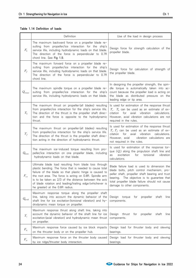
Definition Use of the load in design process
The maximum backward force on a propeller blade re-sulting from propeller/ice interaction for the ship’s service life, including hydrodynamic loads on that blade. The direction of the force is perpendicular to 0.7R chord line. See Fig 1.9.
Design force for strength calculation of the propeller blade.
The maximum forward force on a propeller blade re-sulting from propeller/ice interaction for the ship’s service life, including hydrodynamic loads on that blade. The direction of the force is perpendicular to 0.7R chord line.
Design force for calculation of strength of the propeller blade.
The maximum spindle torque on a propeller blade re-sulting from propeller/ice interaction for the ship’s service life, including hydrodynamic loads on that blade.
In designing the propeller strength, the spin-dle torque is automatically taken into ac-count because the propeller load is acting on the blade as distributed pressure on the leading edge or tip area.
The maximum thrust on propeller (all blades) resulting from propeller/ice interaction for the ship’s service life. The direction of the thrust is the propeller shaft direc-tion and the force is opposite to the hydrodynamic thrust.
Is used for estimation of the response thrust . can be used as an estimate of ex-citation for axial vibration calculations. However, axial vibration calculations are not required in the rules.
The maximum thrust on propeller (all blades) resulting from propeller/ice interaction for the ship’s service life. The direction of the thrust is the propeller shaft direc-tion acting in the direction of hydrodynamic thrust.
Is used for estimation of the response thrust . can be used as an estimate of ex-citation for axial vibration calculations. However, axial vibration calculations are not required in the rules.
max
The maximum ice-induced torque resulting from pro-peller/ice interaction on one propeller blade, including hydrodynamic loads on that blade.
Is used for estimation of the response tor-que () along the propulsion shaft line and as excitation for torsional vibration calculations.
Ultimate blade load resulting from blade loss through plastic bending. The force that is needed to cause total failure of the blade so that plastic hinge is caused to the root area. The force is acting on 0.8R. Spindle arm is to be taken as 2/3 of the distance between the axis of blade rotation and leading/trailing edge (whichever is he greater) at the 0.8R radius.
Blade failure load is used to dimension the blade bolts, pitch control mechanism, pro-peller shaft, propeller shaft bearing and trust bearing. The objective is to guarantee that total propeller blade failure should not cause damage to other components.
Maximum response torque along the propeller shaft line, taking into account the dynamic behavior of the shaft line for ice excitation (torsional vibration) and hy-drodynamic mean torque on propeller.
Design torque for propeller shaft line components.
Maximum response thrust along shaft line, taking into account the dynamic behavior of the shaft line for ice excitation (axial vibration) and hydrodynamic mean thrust on propeller.
Design thrust for propeller shaft line components.
Maximum response force caused by ice block impacts on the thruster body or on the propeller hub.
Design load for thruster body and slewing bearings.
Maximum response force on the thruster body caused by ice ridge/thruster body interaction.
Design load for thruster body and slewing bearings.
Table 1.14 Definition of loads

Ch 1 Strengthening for Navigation in Ice Ch 1
Guidance for Ships for Navigation in Ice 2022 25
Fig 1.9 Direction of the backward blade force resultant taken perpendicular to chord line at radius 0.7R. (Ice contact pressure at leading edge is shown with small arrows)
603. Design ice conditionsIn estimating the ice loads of the propeller for Ice classes, different types of operation as given in Table 1.15 were taken into account. For the estimation of design ice loads, a maximum ice block size is determined. The maximum design ice block entering the propeller is a rectangular ice block with the dimensions ∙∙. The thickness of the ice block () is given in Table 1.16.
Ice class Operation of the ship
IA Super Operation in ice channels and in level ice. The ship may proceed by ramming
IA, IB, IC, ID Operation in ice channels
Table 1.15 Type of operation of the ship per Ice classes
Ice class IA Super IA IB IC
Thickness of the design maximum ice block entering the propeller ()
1.75 m 1.5 m 1.2 m 1.0 m
Table 1.16 The thickness of the ice block ()
604. Materials
1. Materials exposed to sea water
Materials of components exposed to sea water, such as propeller blades, propeller hubs, and thrust-er body, are to have an elongation of not less than 15 % on a test specimen, the gauge length of which is five times the diameter. A Charpy V impact test is to be carried out for materials other than bronze and austenite steel. An average impact energy value of 20 J taken from three tests is to be obtained at minus 10 ºC. For nodular cast iron the average impact energy of 10 J at minus 10ºC is required accordingly.

Ch 1 Strengthening for Navigation in Ice Ch 1
26 Guidance for Ships for Navigation in Ice 2022
2. Materials exposed to sea water temperature
Materials exposed to sea water temperature are to be of steel or other ductile material. An average impact energy value of 20 J taken from three tests is to be obtained at minus 10 ºC. This require-ment applies to propeller shafts, blade bolts, CP mechanisms, shaft bolts, strut-pod connecting bolts etc. This does not apply to surface hardened components, such as bearings and gear teeth. Nodular cast iron of ferrite structure type may be used for other relevant parts than bolts. Average impact energy for nodular cast iron is to be minimum 10 J at minus 10 ºC.
605. Design loads1. The given loads are intended for component strength calculations only and are total loads including
ice-induced loads and hydrodynamic loads during propeller/ice interaction. The presented maximum loads are based on worst case scenario that occurs once during the service life of the ship. Thus, load level for higher number of loads is lower.
2. The values of the parameters in the formulae in this Section is to be given in the units shown in 602.
3. If the propeller is not fully submerged when the ship is in ballast condition, the propulsion system is to be designed according to Ice class IA for Ice classes IB, IC and ID.
4. Design loads on propeller blades
is the maximum force experienced during the ship’s service life that bends a propeller blade backwards when the propeller mills an ice block while rotating ahead. is the maximum force ex-perienced during the ship’s service life that bends a propeller blade forwards when the propeller mills an ice block while rotating ahead. and originate from different propeller/ice interaction phenomena, not acting simultaneously. Hence they are to be applied to one blade separately. (1) Maximum backward blade force for open propellers
when ≤lim, ∙ ∙∙
∙ (kN)
when lim, ∙ ∙∙
∙∙
(kN)
where,
lim∙ (m)
is the nominal rotational speed (at free running condition) for a CP propeller and 85 % of the nominal rotational speed (at free running condition) for a FP propeller.
(2) Maximum forward blade force for open propellers
when ≤lim, ∙
∙ (kN)
when lim, ∙
∙∙
∙ (kN)
where,
lim
∙ (m).

Ch 1 Strengthening for Navigation in Ice Ch 1
Guidance for Ships for Navigation in Ice 2022 27
(3) Loaded area on the blade for open propellersLoad cases 1-4 have to be covered, as given in Table 2.1 of Annex 2, for CP and FP propellers. In order to obtain blade ice loads for a reversing propeller, load case 5 also has to be covered for FP propellers.
(4) Maximum backward blade force for ducted propellers
when ≤lim, ∙
∙ ∙∙ (kN)
when lim, ∙
∙ ∙ ∙ ∙ (kN)
where,lim∙
is the nominal rotational speed (at MCR in free running condition) for a CP propeller and 85 % of the nominal rotational speed (at MCR in free running condition) for an FP propeller
(5) Maximum forward blade force for ducted propellers
when ≤lim, ∙
∙ (kN)
when lim, ∙
∙∙
∙ (kN)
where,
lim
∙ (m)
(6) Loaded area on the blade for ducted propellers Load cases 1 and 3 have to be covered as given in Table 2.2 of Annex 2 for all propellers, and an additional load case (load case 5) for an FP propeller, to cover ice loads when the propeller is reversed.
(7) Maximum blade spindle torque for open or ducted propellersThe spindle torque around the axis of the blade fitting is to be determined both for the maximum backward blade force and forward blade force , which are applied as in Table 2.1 and 2.2 of Annex 2. The larger of the obtained torques is used as the dimensioning torque. If the above method gives a value which is less than the default value given by the formula be-low, the default value is to be used.
Default Value ㆍㆍ (kNㆍm)
where,
7.0c is the chord length of the blade section at 0.7R radius and is either or , whichever has the greater absolute value.
(8) Load distributions for blade loadsThe Weibull-type distribution (probability that exceeds max), as given in Fig 1.10, is used for the fatigue design of the blade.
max
≥max
max
∙ ln

Ch 1 Strengthening for Navigation in Ice Ch 1
28 Guidance for Ships for Navigation in Ice 2022
where is the shape parameter of the spectrum, is the number of load cycles in the spec-trum, and is the random variable for ice loads on the blade, ≤ ≤ max. The shape parameter = 0.75 is to be used for the ice force distribution of an open propeller blade and the shape parameter = 1.0 for that of a ducted propeller blade.
Fig 1.10 The Weibull-type distribution (probability that (Fice exceeds (Fice)max) that is used for fatigue design.
(9) Number of ice loadsThe number of load cycles per propeller blade in the load spectrum is to be determined accord-ing to the formula:
∙∙∙,
where,Reference number of loads for Ice classes
Class IA Super IA IB IC
impacts for the ship’s service life / ∙ ∙ ∙ ∙
Propeller location factor
Location Center propellerBow first operation
Wing propellerBow first operation
Pulling propeller (wing and center)
Bow propeller or Stern first operation
1 2 3
The submersion factor is determined from the equation
when
∙ when ≤ ≤
∙ when ≤
when

Ch 1 Strengthening for Navigation in Ice Ch 1
Guidance for Ships for Navigation in Ice 2022 29
where the immersion function is:
where is the depth of the propeller centerline at the lower ice waterline (LIWL) of the ship.
Propulsion type factor
type fixed azimuthing
1 1.2
For components that are subject to loads resulting from propeller/ice interaction with all the propeller blades, the number of load cycles () is to be multiplied by the number of pro-peller blades ( ).
5. Axial design loads for propellers(1) Maximum ice thrust on propeller and for propellers
The maximum forward and backward ice thrusts are:
∙ (kN) ∙ (kN)
(2) Design thrust along the propulsion shaft line for propellersThe design thrust along the propeller shaft line is to be calculated with the formulae below. The greater absolute value of the forward and backward direction loads is to be taken as the design load for both directions. The factors 2.2 and 1.5 take into account the dynamic magnification re-sulting from axial vibration.
In a forward direction ∙ (kN)In a backward direction ∙ (kN)
If hydrodynamic bollard thrust, , is not known, is to be taken as follows:
Table 1.17 Propeller bollard thrust
Propeller Type
CP propellers (open) ∙
CP propellers (ducted) ∙
FP propellers driven by turbine or electric motor
FP propellers driven by diesel engine (open) ∙
FP propellers driven by diesel engine (ducted) ∙
NOTE: = nominal propeller thrust at MCR at free running open water conditions

Ch 1 Strengthening for Navigation in Ice Ch 1
30 Guidance for Ships for Navigation in Ice 2022
6. Torsional design loads(1) Design ice torque on propeller max for open propellers
max is the maximum torque on a propeller resulting from ice/propeller interaction during the service life of the ship.
when ≤lim , max ∙∙
∙ ∙ (kNㆍm)
when lim , max ∙∙
∙ ∙ ∙
(kNㆍm)
where lim∙ (m). is the rotational propeller speed at MCR in bollard condition. If not known, n is to be
taken as follows:
Table 1.18 The rotational propeller speed at bollard condition value
Propeller type Rotational speed
CP propellers
FP propellers driven by turbine or electric motor
FP propellers driven by diesel engine ∙
NOTE:Here, is the nominal rotational speed at MCR in free running condition.
For CP propellers, propeller pitch, is to correspond to MCR in bollard condition. If not known, is to be taken as ∙, where is propeller pitch at MCR in free running condition.
(2) Design ice torque on propeller max for ducted propellers max is the maximum torque on a propeller during the service life of the ship resulting from ice/propeller interaction.
when ≤lim , max ∙∙
∙ ∙ (kNㆍm)
when lim , max ∙∙
∙ ∙ ∙
(kNㆍm)
where lim∙ (m) is the rotational propeller speed at MCR in bollard condition. If not known, n is to be
taken as follows:

Ch 1 Strengthening for Navigation in Ice Ch 1
Guidance for Ships for Navigation in Ice 2022 31
Table 1.19 The rotational propeller speed at bollard condition value
Propeller type Rotational speed
CP propellers
FP propellers driven by turbine or electric motor
FP propellers driven by diesel engine ∙
NOTE:Here, is the nominal rotational speed at MCR in free running condition.
For CP propellers, propeller pitch, is to correspond to MCR in bollard condition. If not known, is to be taken as ∙, where is propeller pitch at MCR in free running condition.
(3) Design torque for non-resonant shaft line If there is not any relevant first blade order torsional resonance in the operational speed range or in the range 20% above and 20% below the maximum operating speed (bollard condition), the following estimation of the maximum torque can be used.
Directly coupled two stroke diesel engines without flexible coupling:
max∙
(kNㆍm)
Other plants:
max∙
(kNㆍm)
Where, is equivalent mass moment of inertia of all parts on engine side of component under con-sideration and, is equivalent mass moment of inertia of the whole propulsion system
All the torques and the inertia moments are to be reduced to the rotation speed of the compo-nent being examined. If the maximum torque, , is not known, it is to be taken as given in Table 1.20.
Table 1.20 the maximum torque
Propeller type
Propellers driven by electric motor(FP and CP)
CP propellers driven by prime movers other than electric mo-tor
FP propellers driven by turbine
FP propellers driven by diesel engine ∙
NOTE:Here, is the electric motor peak torque.
(4) Design torque for shaft line having resonancesIf there is a first blade order torsional resonance in the operational speed range or in the range
Ch 1 Strengthening for Navigation in Ice Ch 1
32 Guidance for Ships for Navigation in Ice 2022
20% above and 20% below the maximum operating speed (bollard condition), the design torque of the shaft component is to be determined by means of torsional vibration analysis of the propulsion line. There are two alternative ways to make the dynamic analysis.
- Time domain calculation for estimated milling sequence excitation- Frequency domain calculation for blade orders sinusoidal excitation
The frequency domain analysis is generally considered as conservative compared to the time do-main simulation provided there is a first blade order resonance in the considered speed range.(A) Time domain calculation of torsional response
Time domain calculations shall be calculated for MCR condition, MCR bollard conditions and for blade order resonant rotational speeds so that the resonant vibration responses can be obtained.The load sequence given in below for a case where propeller is milling an ice block shall be used for strength evaluation of the propulsion line. The given load sequence is not intended for propulsion system stalling analyses.The following load cases are intended to reflect the operational loads on the propulsion sys-tem, when the propeller interacts with ice, and the respective reaction of the complete system. The ice impact and system response causes loads in the individual shaft line components. The ice torque max may be taken as a constant value in the complete speed range. When considerations at specific shaft speeds are performed a relevant max may be calculated using the relevant speed according to (1), (2).Diesel engine plants without an elastic coupling shall be calculated at the least favourable phase angle for ice versus engine excitation, when calculated in the time domain. The en-gine firing pulses shall be included in the calculations and their standard steady state har-monics can be used.If there is a blade order resonance just above the MCR speed, calculations shall cover the rotational speeds up to 105 % of the MCR speed. The propeller ice torque excitation for shaft line transient dynamic analysis in time domain is defined as a sequence of blade impacts which are of half sine shape. The excitation fre-quency shall follow the propeller rotational speed during the ice interaction sequence. The torque due to a single blade ice impact as a function of the propeller rotation angle is then defined using the formula:
when rotates from 0 to plus integer revolutions.
∙max∙ sin
when rotates from to 360 plus integer revolutions.
where, is rotation angle starting when the first impact occurs and and parameters are given in Table 1.21. is duration of propeller blade/ice interaction expressed in term of propeller rotation angle as following picture.

Ch 1 Strengthening for Navigation in Ice Ch 1
Guidance for Ships for Navigation in Ice 2022 33
Schematic ice torque due to a single blade ice impact as a function of the propeller rotation angle
Table 1.21 Ice impact magnification and duration factors for different blade num-bers
Torque excitation Propeller-ice interaction
[deg.]
Z=3 Z=4 Z=5 Z=6
Excitation Case 1 Single ice block 0.75 90 90 72 60
Excitation Case 2 Single ice block 1.0 135 135 135 135
Excitation Case 3
Two ice blocks(phase shift 360/2∙Z deg.) 0.5 45 45 36 30
Excitation Case 4 Single ice block 0.5 45 45 36 30
The total ice torque is obtained by summing the torque of single blades, taking into account the phase shift 360 deg./Z. See Fig 2.1 of Annex 2. At the beginning and at the end of the milling sequence (within calculated duration) linear ramp functions shall be used to increase to its maximum within one propeller revolution and vice versa to decrease it to zero.The number of propeller revolutions during a milling sequence is to be obtained from the formula:
∙
The number of impacts is ∙ for blade order excitation. An illustration of all excitation cases for different blade numbers is given in Fig 2.1 of Annex 2.The dynamic simulation has to be performed for all excitation cases at the operational rota-tional speed range. For a fixed pitch propeller propulsion plant the dynamic simulation shall also cover bollard pull condition with a corresponding rotational speed assuming maximum possible output of the engine. If a speed drop occurs down to stand still of the main en-gine, it indicates that the engine may not be sufficiently powered for the intended service task. For the consideration of loads, the maximum occurring torque during the speed drop process has to be taken. For the time domain calculation the simulated response torque typ-ically include the engine mean torque and the propeller mean torque. If this is not the case, response torques is to be obtained using the following formula.
is the maximum simulated torque obtained from the time domain analysis.

Ch 1 Strengthening for Navigation in Ice Ch 1
34 Guidance for Ships for Navigation in Ice 2022
(B) Frequency domain calculation of torsional responseFor frequency domain calculations blade order and twice the blade order excitation may be used. The amplitudes for blade order and twice the blade order sinusoidal excitation have been derived based on the assumption that the time domain half sine impact sequences were continuous, and the Fourier series components for blade order and twice the blade or-der components have been derived. The propeller ice torque is then:
max∙∙ sin∙∙∙ sin∙∙∙ (kNm)
where, is mean torque parameter is first blade order excitation parameter is second blade order excitation parameter, are phase angles of excitation component is angle of rotation is number of ice blocks in contactAbove coefficients for frequency domain excitation calculation are to be taken as given in Table 1.22.
Design torque for the frequency domain excitation case is to be obtained using the formula:
max ∙
Where,max
is the maximum propeller ice torque at the operation speed in consideration is the mean static torque coefficient from Table 1.22 is the blade order torsional response from the frequency domain analysis is the second order blade torsional response from the frequency domain analysis
If the prime mover maximum torque, , is not known, it shall be taken as given in Table 1.20. All the torque values have to be scaled to the shaft revolutions for the component in question.

Ch 1 Strengthening for Navigation in Ice Ch 1
Guidance for Ships for Navigation in Ice 2022 35
Table 1.22 Coefficients for frequency domain excitation calculation
Torque excitation Z=3
Excitation Case 1 0.375 0.36 -90 0 0 1
Excitation Case 2 0.7 0.33 -90 0.05 -45 1
Excitation Case 3 0.25 0.25 -90 0 0 2
Excitation Case 4 0.2 0.25 0 0.05 -90 1
Torque excitation Z=4
Excitation Case 1 0.45 0.36 -90 0.06 -90 1
Excitation Case 2 0.9375 0 -90 0.0625 -90 1
Excitation Case 3 0.25 0.25 -90 0 0 2
Excitation Case 4 0.2 0.25 0 0.05 -90 1
Torque excitation Z=5
Excitation Case 1 0.45 0.36 -90 0.06 -90 1
Excitation Case 2 1.19 0.17 -90 0.02 -90 1
Excitation Case 3 0.3 0.25 -90 0.048 -90 2
Excitation Case 4 0.2 0.25 0 0.05 -90 1
Torque excitation Z=6
Excitation Case 1 0.45 0.36 -90 0.05 -90 1
Excitation Case 2 1.435 0.1 -90 0 0 1
Excitation Case 3 0.3 0.25 -90 0.048 -90 2
Excitation Case 4 0.2 0.25 0 0.05 -90 1
(C) Guidance for torsional vibration calculationThe aim of time domain torsional vibration simulations is to estimate the extreme torsional load for ship’s lifespan. The simulation model can be taken from the normal lumped mass elastic torsional vibration model including damping. For time domain analysis the model should include the ice excitation at propeller, other relevant excitations and the mean torques provided by the prime mover and hydrodynamic mean torque in the propeller. The calcu-lations should cover variation of phase between the ice excitation and prime mover excitation. This is extremely relevant to propulsion lines with direct driven combustion engines. Time domain calculations shall be calculated for MCR condition, MCR bollard con-ditions and for resonant speed so that the resonant vibration responses can be obtained. For frequency domain calculations the load should be estimated as Fourier component analy-sis of the continuous sequence of half sine load sequences. The first and second order blade components should be used for excitation. The calculation should cover the whole rel-evant rpm range and simulation of responses at the torsional vibration resonances.
Ch 1 Strengthening for Navigation in Ice Ch 1
36 Guidance for Ships for Navigation in Ice 2022
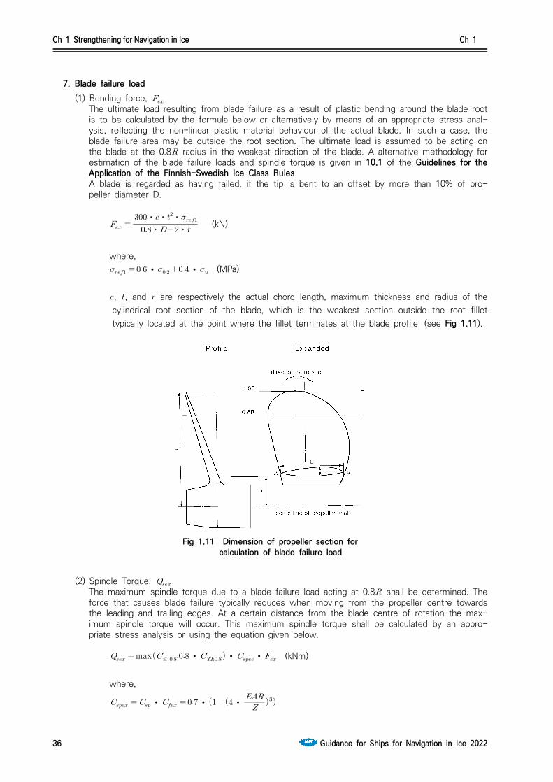
7. Blade failure load(1) Bending force,
The ultimate load resulting from blade failure as a result of plastic bending around the blade root is to be calculated by the formula below or alternatively by means of an appropriate stress anal-ysis, reflecting the non-linear plastic material behaviour of the actual blade. In such a case, the blade failure area may be outside the root section. The ultimate load is assumed to be acting on the blade at the 0.8 radius in the weakest direction of the blade. A alternative methodology for estimation of the blade failure loads and spindle torque is given in 10.1 of the Guidelines for the Application of the Finnish-Swedish Ice Class Rules.A blade is regarded as having failed, if the tip is bent to an offset by more than 10% of pro-peller diameter D.
ㆍㆍ
ㆍㆍㆍ (kN)
where, ∙∙ (MPa)
, , and are respectively the actual chord length, maximum thickness and radius of the cylindrical root section of the blade, which is the weakest section outside the root fillet typically located at the point where the fillet terminates at the blade profile. (see Fig 1.11).
c
Fig 1.11 Dimension of propeller section for calculation of blade failure load
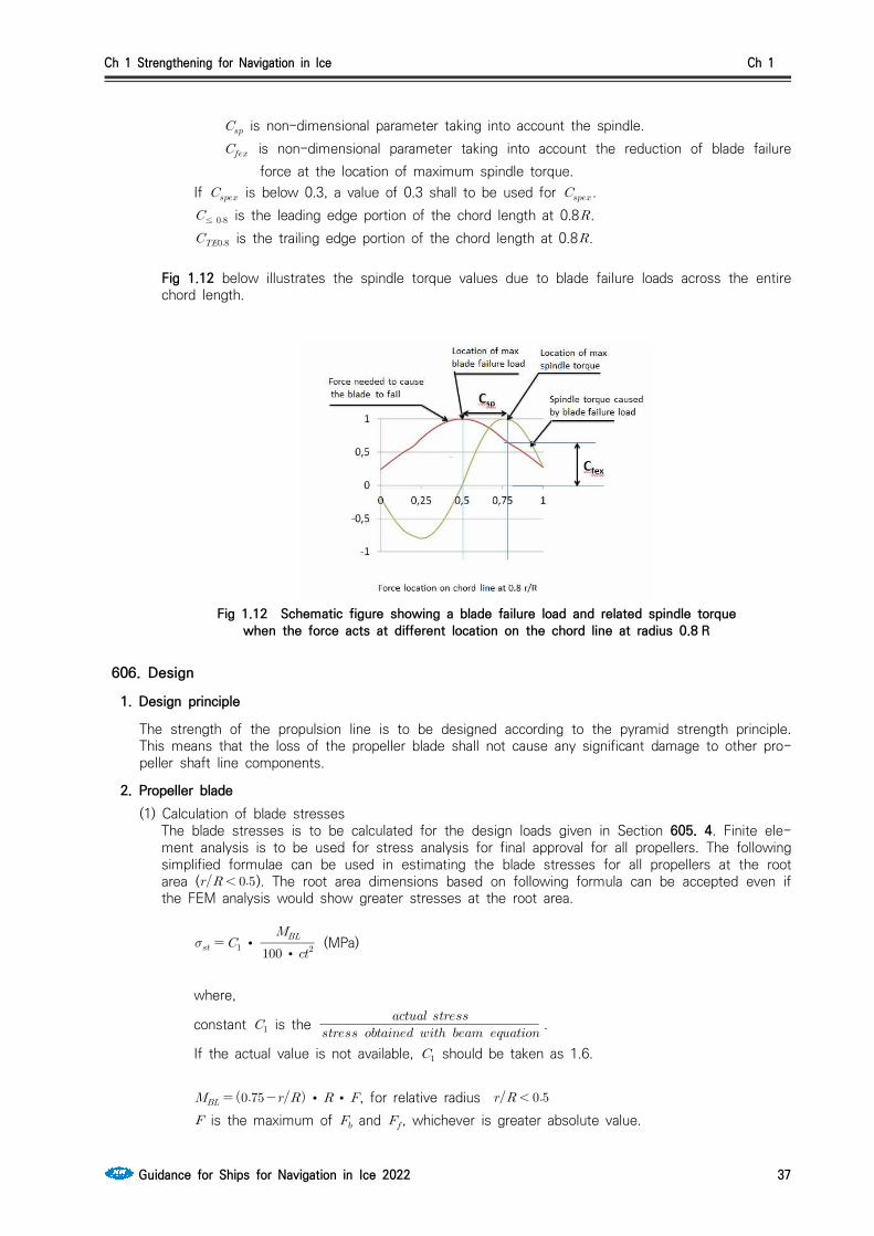
(2) Spindle Torque,
The maximum spindle torque due to a blade failure load acting at 0.8 shall be determined. The force that causes blade failure typically reduces when moving from the propeller centre towards the leading and trailing edges. At a certain distance from the blade centre of rotation the max-imum spindle torque will occur. This maximum spindle torque shall be calculated by an appro-priate stress analysis or using the equation given below.
max≤ ∙∙∙ (kNm)
where,
∙ ∙∙
Ch 1 Strengthening for Navigation in Ice Ch 1
Guidance for Ships for Navigation in Ice 2022 37
is non-dimensional parameter taking into account the spindle. is non-dimensional parameter taking into account the reduction of blade failure
force at the location of maximum spindle torque.If is below 0.3, a value of 0.3 shall to be used for .≤ is the leading edge portion of the chord length at 0.8. is the trailing edge portion of the chord length at 0.8.
Fig 1.12 below illustrates the spindle torque values due to blade failure loads across the entire chord length.
Fig 1.12 Schematic figure showing a blade failure load and related spindle torque when the force acts at different location on the chord line at radius 0.8 R
606. Design
1. Design principle
The strength of the propulsion line is to be designed according to the pyramid strength principle. This means that the loss of the propeller blade shall not cause any significant damage to other pro-peller shaft line components.
2. Propeller blade (1) Calculation of blade stresses
The blade stresses is to be calculated for the design loads given in Section 605. 4. Finite ele-ment analysis is to be used for stress analysis for final approval for all propellers. The following simplified formulae can be used in estimating the blade stresses for all propellers at the root area ( ). The root area dimensions based on following formula can be accepted even if the FEM analysis would show greater stresses at the root area.
∙∙ (MPa)
where,
constant is the
.
If the actual value is not available, should be taken as 1.6.
∙∙, for relative radius
is the maximum of and , whichever is greater absolute value.

Ch 1 Strengthening for Navigation in Ice Ch 1
38 Guidance for Ships for Navigation in Ice 2022
(2) Acceptability criterion The following criterion for calculated blade stresses has to be fulfilled.
≥
where, is the calculated stress for the design loads. If FEM analysis is used in estimating the
stresses, von Mises stresses are to be used. is the reference stress, defined as:
∙ or ∙∙, whichever is less.
(3) Fatigue design of propeller bladeThe fatigue design of the propeller blade is based on an estimated load distribution for the serv-ice life of the ship and the S-N curve for the blade material. An equivalent stress that produces the same fatigue damage as the expected load distribution shall be calculated and the accept-ability criterion for fatigue should be fulfilled as given in this Section. The equivalent stress is normalized for 108 cycles.For materials having two slope S-N curve (See Fig 1.13) fatigue calculations according to this sub-paragraph are not required if the following criterion is fulfilled.
exp ≥∙ ∙ log
where, , and coefficients for propellers are given in the table below.
Table 1.23 , and coefficients
Open propeller Ducted propeller
0.00328 0.00223
1.0076 1.0071
2.101 2.471
For calculation of equivalent stress two types of S-N curves are available. - Two slope S-N curve (slopes 4.5 and 10), see Fig 1.13. - One slope S-N curve (the slope can be chosen), see Fig 1.14.
The type of the S-N curve is to be selected to correspond to the material properties of the blade. If S-N curve is not known, the two slope S-N curve is to be used.
Fig 1.13 Two-slope S-N curve Fig 1.14 Constant-slope S-N curve
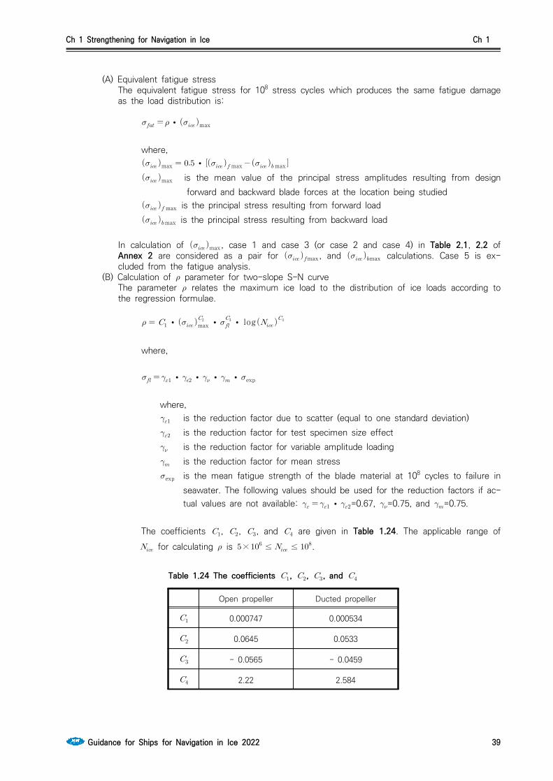
Ch 1 Strengthening for Navigation in Ice Ch 1
Guidance for Ships for Navigation in Ice 2022 39
(A) Equivalent fatigue stressThe equivalent fatigue stress for 108 stress cycles which produces the same fatigue damage as the load distribution is:
∙max
where, max ∙max max
max is the mean value of the principal stress amplitudes resulting from design forward and backward blade forces at the location being studied
max is the principal stress resulting from forward load max is the principal stress resulting from backward load
In calculation of max, case 1 and case 3 (or case 2 and case 4) in Table 2.1, 2.2 of Annex 2 are considered as a pair for max, and max calculations. Case 5 is ex-cluded from the fatigue analysis.
(B) Calculation of parameter for two-slope S-N curveThe parameter relates the maximum ice load to the distribution of ice loads according to the regression formulae.
∙max ∙
∙ log
where,
∙∙∙∙exp
where, is the reduction factor due to scatter (equal to one standard deviation) is the reduction factor for test specimen size effect is the reduction factor for variable amplitude loading is the reduction factor for mean stressexp is the mean fatigue strength of the blade material at 108 cycles to failure in
seawater. The following values should be used for the reduction factors if ac-tual values are not available: ∙=0.67, =0.75, and =0.75.
The coefficients , , , and are given in Table 1.24. The applicable range of for calculating is × ≤ ≤.
Open propeller Ducted propeller
0.000747 0.000534
0.0645 0.0533
- 0.0565 - 0.0459
2.22 2.584
Table 1.24 The coefficients , , , and

Ch 1 Strengthening for Navigation in Ice Ch 1
40 Guidance for Ships for Navigation in Ice 2022
(C) Calculation of parameter for constant-slope S-N curveFor materials with a constant-slope S-N curve(see Fig 1.14), the factor is to be calculated with the following formula:
∙
ln
where, is the shape parameter of the Weibull distribution = 1.0 for ducted propellers
and = 0.75 for open propellers. is the reference number of load cycles (=108)Values for the parameter are given in Table 1.25.Linear interpolation may be used to calculate the value for other ratios than given in the Table 1.25.
3 6 5.5 287.9 8 40320 10.5 11.899E6
3.5 11.6 6 720 8.5 119292 11 39.917E6
4 24 6.5 1871 9 362880 11.5 136.843E6
4.5 52.3 7 5040 9.5 1.133E6 12 479.002E6
5 120 7.5 14034 10 3.623E6
Table 1.25 Value for the parameter for different ratios
(4) Acceptability criterion for fatigueThe equivalent fatigue stress at all locations on the blade has to fulfil the following acceptability criterion.
≥
where, ∙∙∙∙exp
where, is the reduction factor due to scatter (equal to one standard deviation) is the reduction factor for test specimen size effect is the reduction factor for variable amplitude loading is the reduction factor for mean stressexp is the mean fatigue strength of the blade material at cycles to failure in
seawater. The following values should be used for the reduction factors if actual values are not available: ∙ = 0.67, = 0.75, and = 0.75.
3. Propeller bossing and CP mechanism
The blade bolts, the CP mechanism, the propeller boss, and the fitting of the propeller to the pro-

Ch 1 Strengthening for Navigation in Ice Ch 1
Guidance for Ships for Navigation in Ice 2022 41
peller shaft is to be designed to withstand the maximum and fatigue design loads, as defined in 605. The safety factor against yielding is to be greater than 1.3 and that against fatigue greater than 1.5. In addition, the safety factor for loads resulting from loss of the propeller blade through plastic bending as defined in 605. 7 is to be greater than 1.0 against yielding.
4. Propulsion shaft line
The shafts and shafting components, such as the thrust and stern tube bearings, couplings, flanges and sealings, are to be designed to withstand the propeller/ice interaction loads as given in 605. The safety factor is to be at least 1.3 against yielding for extreme operational loads, 1.5 for fatigue loads and 1.0 against yielding for the blade failure load.(1) Shafts and shafting components
The ultimate load resulting from total blade failure as defined in 605. 7 should not cause yielding in shafts and shaft components. The loading shall consist of the combined axial, bending, and torsion loads, wherever this is significant. The minimum safety factor against yielding is to be 1.0 for bending and torsional stresses.
5. Azimuth main propulsors (1) Design principle
In addition to the above requirements considering propeller blade dimensioning, the azimuth thrusters have to be designed for the thruster body/ice interaction loads. The load formulae are given to estimate the once a lifetime extreme loads on the thruster body basing on estimated ice condition and ship operational parameters. Two main ice load scenarios have been selected to define the extreme ice loads. The examples of loads are illustrated in Fig 1.15. In addition, blade order thruster body vibration responses may be estimated for propeller excitation.- Ice block impact to the thruster body or propeller hub- Thruster penetration into an ice ridge that has a thick consolidated layer.- Vibratory response of the thruster at blade order frequency
Impact on thruster body Impact on propeller hub
Thruster penetration to the ice ridgeFig 1.15 Examples of load scenario to types
The steering mechanism, the fitting of the unit, and the body of the thruster shall be designed to withstand the plastic bending of a blade without damage. The loss of a blade shall be con-sidered for the propeller blade orientation which causes the maximum load on the component being studied. Typically, top-down blade orientation places the maximum bending loads on the thruster body.
(2) Extreme ice impact loadsWhen the ship is operated in ice conditions the ice blocks formed in channel side walls or from the ridge consolidated layer may impact on the thruster body and also on the propeller hub. The exposure to ice impact is very much dependent on the ship size and ship hull design as well as

Ch 1 Strengthening for Navigation in Ice Ch 1
42 Guidance for Ships for Navigation in Ice 2022
location of the thruster. The contact force will grow on the thruster/ice contact until the ice block will reach the ship speed.The thruster has to withstand the loads obtained when the maximum ice blocks, which are given in 603., hit the thruster body when the ship is sailing at a typical ice operating speed. Load cases for impact loads are given in Table 1.26. The contact geometry is estimated to be hemi-sphere in shape. If the actual contact geometry differs from the shape of hemisphere a sphere radius has to be estimated so that the growth of the contact area as a function of penetration to ice corresponds as close as possible to the actual geometrical shape penetration.
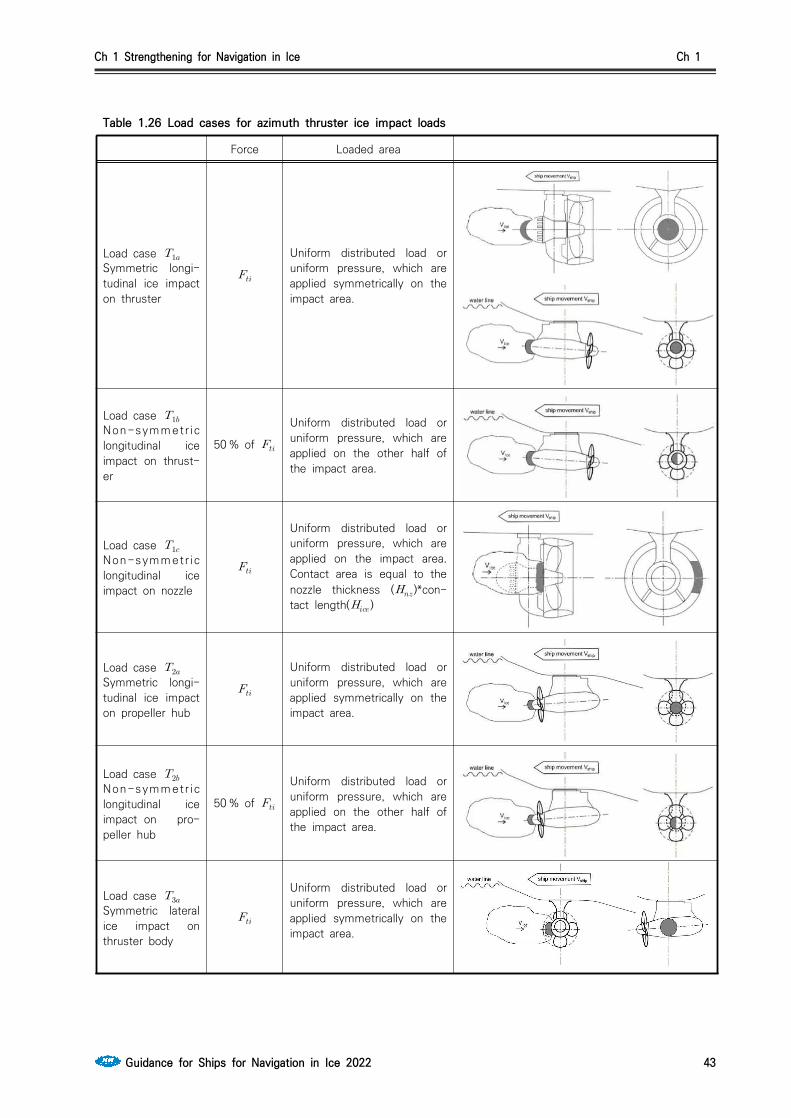
Ch 1 Strengthening for Navigation in Ice Ch 1
Guidance for Ships for Navigation in Ice 2022 43
Table 1.26 Load cases for azimuth thruster ice impact loads
Force Loaded area
Load case
Symmetric longi-tudinal ice impact on thruster
Uniform distributed load or uniform pressure, which are applied symmetrically on the impact area.
Load case
Non-symmetr ic longitudinal ice impact on thrust-er
50 % of
Uniform distributed load or uniform pressure, which are applied on the other half of the impact area.
Load case
Non-symmetr ic longitudinal ice impact on nozzle
Uniform distributed load or uniform pressure, which are applied on the impact area. Contact area is equal to the nozzle thickness ()*con-tact length()
Load case
Symmetric longi-tudinal ice impact on propeller hub
Uniform distributed load or uniform pressure, which are applied symmetrically on the impact area.
Load case
Non-symmetr ic longitudinal ice impact on pro-peller hub
50 % of
Uniform distributed load or uniform pressure, which are applied on the other half of the impact area.
Load case
Symmetric lateral ice impact on thruster body
Uniform distributed load or uniform pressure, which are applied symmetrically on the impact area.

Ch 1 Strengthening for Navigation in Ice Ch 1
44 Guidance for Ships for Navigation in Ice 2022
Table 1.26 Load cases for azimuth thruster ice impact loads (continued)Force Loaded area
Load case
Non-symmetric lateral ice im-pact on thruster body or nozzle
Uniform distributed load or uniform pressure, which are applied on the impact area. Nozzle contact radius to be taken from the nozzle length ()
The ice impact contact load has to be calculated with the following formula. The related parame-ter values are given in Table 1.27. The design operation speed in ice can be derived from the Table 1.28 and Table 1.29, or the ship in question’s actual design operation speed in ice can be used. The longitudinal impact speed in Table 1.28 and Table 1.29 refers to the impact in the thruster’s main operational direction. For the pulling propeller configuration, the longitudinal impact speed is used for load case , impact on hub; and for the pushing propeller unit, the longi-tudinal impact speed is used for load case , impact on thruster end cap. For the opposite di-rection, the impact speed for transversal impact is applied.
(kN)
where, is impacting part sphere radius, see Fig. 1.16 (m) is ice block mass (kg) is ship speed at the time of contact (m/s) is the dynamic magnification factor for impact loads. is to be taken from Table
1.27 if unknown.
For impacts on non-hemispherical areas, such as the impact on the nozzle, the equivalent im-pact sphere radius is to be estimated using the equation below.
(m)
If the ∙ is greater than the ice block thickness, the radius is set to half of the ice block thickness. For the impact on the thruster side, the pod body diameter can be used as a basis for determining the radius. For the impact on the propeller hub, the hub diameter can be used as a basis for the radius.

Ch 1 Strengthening for Navigation in Ice Ch 1
Guidance for Ships for Navigation in Ice 2022 45
Fig 1.16 Dimensions used for
Table 1.27 Parameter values for ice dimensions and dynamic magnificationIA Super IA IB IC
Thickness of the design ice block impacting thruster (2/3 of )
1.17 m 1.0 m 0.8 m 0.67 m
Extreme ice block mass () 8670 kg 5460 kg 2800 kg 1600 kg
(if not known) 1.3 1.2 1.1 1
Table 1.28 Impact speeds for aft centerline thrusterIA Super IA IB IC
Longitudinal impact in main operational direc-tion 6 m/s 5 m/s 5 m/s 5 m/s
Longitudinal impact in reversing direction (pushing unit propeller hub or pulling unit cover end cap impact)
4 m/s 3 m/s 3 m/s 3 m/s
Transversal impact in bow first operation 3 m/s 2 m/s 2 m/s 2 m/s
Transversal impact in stern first operation (double acting ship) 4 m/s 3 m/s 3 m/s 3 m/s
Table 1.29 Impact speeds for aft wing, bow centerline and bow wing thrustersIA Super IA IB IC
Longitudinal impact in main operational direc-tion 6 m/s 5 m/s 5 m/s 5 m/s
Longitudinal impact in reversing direction (pushing unit propeller hub or pulling unit cover end cap impact)
4 m/s 3 m/s 3 m/s 3 m/s
Transversal impact 4 m/s 3 m/s 3 m/s 3 m/s
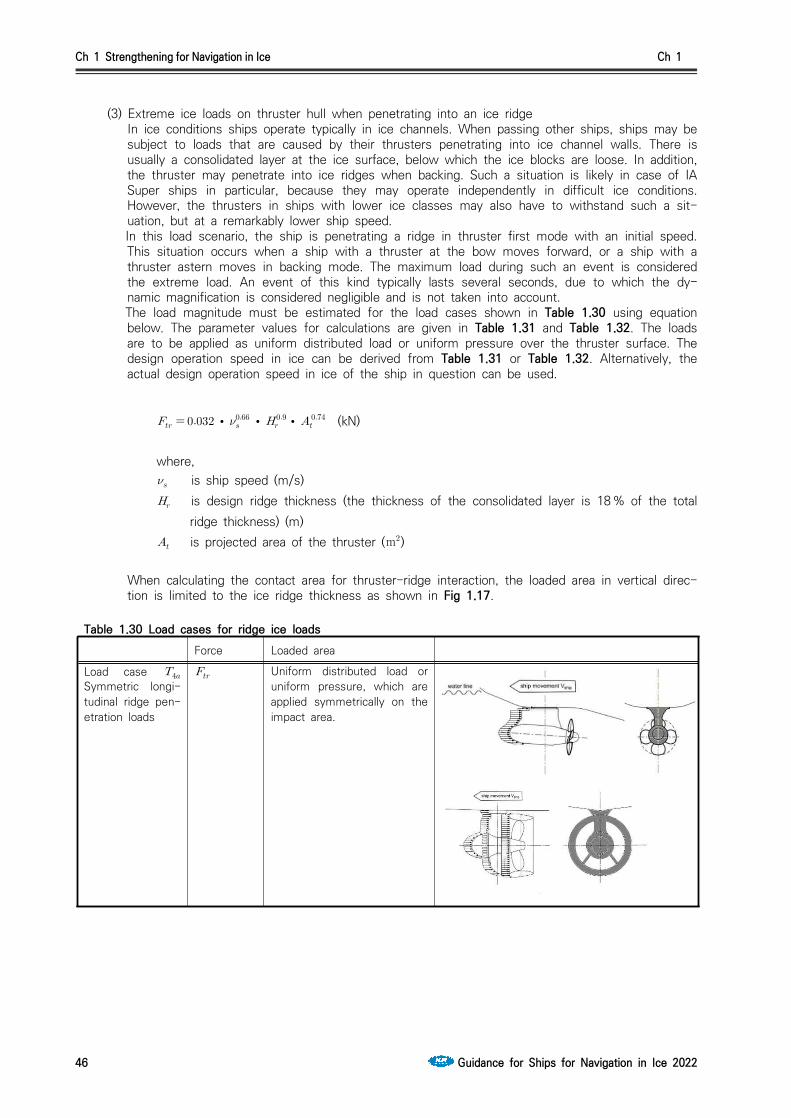
Ch 1 Strengthening for Navigation in Ice Ch 1
46 Guidance for Ships for Navigation in Ice 2022
(3) Extreme ice loads on thruster hull when penetrating into an ice ridgeIn ice conditions ships operate typically in ice channels. When passing other ships, ships may be subject to loads that are caused by their thrusters penetrating into ice channel walls. There is usually a consolidated layer at the ice surface, below which the ice blocks are loose. In addition, the thruster may penetrate into ice ridges when backing. Such a situation is likely in case of IA Super ships in particular, because they may operate independently in difficult ice conditions. However, the thrusters in ships with lower ice classes may also have to withstand such a sit-uation, but at a remarkably lower ship speed.
In this load scenario, the ship is penetrating a ridge in thruster first mode with an initial speed. This situation occurs when a ship with a thruster at the bow moves forward, or a ship with a thruster astern moves in backing mode. The maximum load during such an event is considered the extreme load. An event of this kind typically lasts several seconds, due to which the dy-namic magnification is considered negligible and is not taken into account.
The load magnitude must be estimated for the load cases shown in Table 1.30 using equation below. The parameter values for calculations are given in Table 1.31 and Table 1.32. The loads are to be applied as uniform distributed load or uniform pressure over the thruster surface. The design operation speed in ice can be derived from Table 1.31 or Table 1.32. Alternatively, the actual design operation speed in ice of the ship in question can be used.
∙∙
∙ (kN)
where, is ship speed (m/s) is design ridge thickness (the thickness of the consolidated layer is 18 % of the total
ridge thickness) (m) is projected area of the thruster (m)
When calculating the contact area for thruster-ridge interaction, the loaded area in vertical direc-tion is limited to the ice ridge thickness as shown in Fig 1.17.
Table 1.30 Load cases for ridge ice loadsForce Loaded area
Load case Symmetric longi-tudinal ridge pen-etration loads
Uniform distributed load or uniform pressure, which are applied symmetrically on the impact area.
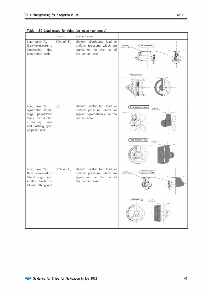
Ch 1 Strengthening for Navigation in Ice Ch 1
Guidance for Ships for Navigation in Ice 2022 47
Table 1.30 Load cases for ridge ice loads (continued)Force Loaded area
Load case
Non-symmetr ic longitudinal ridge penetration loads
50% of Uniform distributed load or uniform pressure, which are applied on the other half of the contact area.
Load case
Symmetric lateral ridge penetration loads for ducted azimuthing unit and pushing open propeller unit
Uniform distributed load or uniform pressure, which are applied symmetrically on the contact area.
Load case
Non-symmetr ic lateral ridge pen-etration loads for all azimuthing unit
50% of Uniform distributed load or uniform pressure, which are applied on the other half of the contact area.

Ch 1 Strengthening for Navigation in Ice Ch 1
48 Guidance for Ships for Navigation in Ice 2022
Fig 1.17 Schematic figure showing the reduction of the contact area by the maximum ridge thickness
Table 1.31 Parameters for calculating maximum loads when thruster penetrates into an ice ridge. Aft thrusters. Bow first operation
IA Super IA IB IC
Thickness of the design ridge consolidated layer 1.5 m 1.5 m 1.2 m 1.0 m
Total thickness of the design ridge 8 m 8 m 6.5 m 5 m
Initial ridge penetration speed (longitudinal loads) 4 m/s 2 m/s 2 m/s 2 m/s
Initial ridge penetration speed (transversal loads) 2 m/s 1 m/s 1 m/s 1 m/s
Table 1.32 Parameters for calculating maximum loads when thruster penetrates into ice ridge. Thruster first mode such as double acting ships.
IA Super IA IB IC
Thickness of the design ridge consolidated layer 1.5 m 1.5 m 1.2 m 1.0 m
Total thickness of the design ridge 8 m 8 m 6.5 m 5 m
Initial ridge penetration speed (longitudinal loads) 6 m/s 4 m/s 4 m/s 4 m/s
Initial ridge penetration speed (transversal loads) 3 m/s 2 m/s 2 m/s 2 m/s
(4) Acceptability criterion for static loadsThe stresses on the thruster must be calculated for the extreme once in a lifetime loads de-scribed in Par 5. The nominal von Mises stresses on the thruster body must have a safety mar-gin of 1.3 against yielding strength of the material. At areas of local stress concentrations, stress must have a safety margin of 1.0 against yielding. The slewing bearing, bolt connections and other components must be able to maintain the operability without incurring damage that re-quires repair when subject to the loads given in (2), (3) multiplied by a safety factor of 1.3.
(5) Thruster body global vibrationEvaluating the global vibratory behavior of the thruster body is important, if the first blade order excitations are in the same frequency range with the thruster global modes of vibration, which

Ch 1 Strengthening for Navigation in Ice Ch 1
Guidance for Ships for Navigation in Ice 2022 49
occur when the propeller rotational speeds are in the high power range of the propulsion line. This evaluation is mandatory and it must be shown that there is either no global first blade or-der resonance at high operational propeller speeds (above 50% of maximum power) or that the structure is designed to withstand vibratory loads during resonance above 50% of maximum power.When estimating thruster global natural frequencies in the longitudinal and transverse direction, the damping and added mass due to water must be taken into account. In addition to this, the effect of ship attachment stiffness must be modelled. A methodology to estimate the vibratory loads is given in 10.4 of the Guidelines for the Application of the Finnish-Swedish Ice Class Rules.
607. Alternative design procedure
1. Scope
As an alternative to 605. and 606., a comprehensive design study may be carried out to the sat-isfaction of the society. The study has to be based on ice conditions given for different Ice classes in 603. It has to include both fatigue and maximum load design calculations and fulfil the pyramid strength principle, as given in 606. 1.
2. Loading
Loads on the propeller blade and propulsion system are to be based on an acceptable estimation of hydrodynamic and ice loads.
3. Design levels(1) The analysis is to indicate that all components transmitting random (occasional) forces, excluding
propeller blade, are not subjected to stress levels in excess of the yield stress of the compo-nent material, with a reasonable safety margin.
(2) Cumulative fatigue damage calculations are to indicate a reasonable safety factor. Due account is to be taken of material properties, stress raisers, and fatigue enhancements.
(3) Vibration analysis is to be carried out and is to indicate that the complete dynamic system is free from harmful torsional resonances resulting from propeller/ice interaction.
608. Design of propulsion shafting for Ice class ID (2020)1. Application
This regulation applies to the design of propulsion shafting for ships with Ice class ID. However, some or all of propulsion shaft design for Ice class IC in this section may be applied.
2. Propeller shaft and stern tube shaftThe diameter of propeller shaft and stern tube shaft is not to be less than 5% increased from the shaft diameter calculated in accordance with Pt 5, Ch 3, 204. of the Rules for the Classification of Steel Ships.
3. Thickness of Propeller Blade(1) The thickness of propeller blade is not to be less than 8% increased from the blade thickness
calculated in accordance with Pt 5, Ch 3, 303. of the Rules for the Classification of Steel Ships.(2) The thickness of propeller blades at a radius of 0.95 is not to be less than that obtained
from the following formula.
: Thickness of propeller blade at a radius of 0.95 (mm) : Thickness at the root of propeller blade in accordance with Pt 5, Ch 3, 303. of Rules
for the Classification of Steel Ships (solid propeller: 0.25, controllable pitch propeller: 0.35) (mm)
: Specified minimum tensile strength of propeller material (Nmm)

Ch 1 Strengthening for Navigation in Ice Ch 1
50 Guidance for Ships for Navigation in Ice 2022
4. Fitting of propellerWhere the propeller is force-fitted to the propeller shaft without the use of a key, the calculations for pull-up length and pull-up load in accordance with Pt 5, Ch 3, 305. 2 (C) of the Guidance Relating to the Rules for the Classification of Steel Ships is to be carried out using ′ of the following formula in lieu of .
′
Section 7 Miscellaneous Machinery Requirements
701. Starting arrangements 1. The capacity of the air receivers is to be sufficient to provide without reloading not less than 12
consecutive starts of the propulsion engine, if this has to be reversed for going astern, or 6 con-secutive starts if the propulsion engine does not have to be reversed for going astern.
2. If the air receivers serve any other purposes than starting the propulsion engine, in addition to the capacity required by Par 1, they are to have a sufficient capacity for these purposes.
3. The capacity of the air compressors is to be sufficient for charging the air receivers from atmos-pheric to full pressure in one (1) hour as specified in Pt 5, Ch 6, 1101. of the Rules for the Classification of Steel Ships, except for a ship with the Ice class IA Super, if its propulsion engine has to be reversed for going astern, in which case the compressor is to be able to charge the re-ceivers in half an hour.
702. Sea inlet and cooling water systems1. The cooling water system is to be designed to ensure supply of cooling water when navigating in
ice.
2. To satisfy Par 1, at least one cooling water inlet chest is to be arranged as follows. However, the ship with Ice class ID may not comply with the requirements in (2), (3) and (5). (1) The sea inlet is to be situated near the centerline of the ship and well aft if possible. (2) As guidance for design, the volume of the chest is to be about 1 m for every 750 kW engine
output of the ship including the output of auxiliary engines necessary for the ship's service.(3)The chest is to be sufficiently high to allow ice to accumulate above the inlet pipe and the
height of sea chest is not less than the value obtained from the following formula.
= volume of sea chest specified in (2) and, inlet pipe is to be not located higher than from the uppermost of sea chest.
(4) A pipe for discharge cooling water, allowing full capacity circulate, is to be connected to the chest. Here, "full capacity of cooling water" in means that the cooling water is used for the fol-lowing purposes
(1) Main propulsion system(main engine, power train, shafts) (2) prime movers for generator (3) main boiler and primary equipments of auxiliary boiler(5) The open area of the strainer plates is not to be less than four (4) times the inlet pipe sectional
area.3. If there are difficulties to meet the requirements of Par 2 (2) and (3), two smaller chests may be
arranged for alternating intake and discharge of cooling water. In this case, the requirements in Par 2 (1), (4) and (5) are to be complied with. If the volume and height are not comply with 2 (2) and (3), inlet and outlet pipes of cooling water is to be connected to sea chest.
4. Heating coils may be installed in the upper part of the sea chest.

Ch 1 Strengthening for Navigation in Ice Ch 1
Guidance for Ships for Navigation in Ice 2022 51
5. Arrangements for using ballast water for cooling purposes may be useful as a reserve in ballast condition but cannot be accepted as a substitute for sea inlet chest as described above.

Ch 2 Ships for Navigation in Polar Waters Ch 2
Guidance for Ships for Navigation in Ice 2022 53
CHAPTER 2 SHIPS FOR NAVIGATION IN POLAR WATERS
Section 1 Polar Class Descriptions and Application
101. Application1. This chapter is to apply to ships constructed of steel and intended for independent navigation in ice‐
infested polar waters.
2. Ships that comply with the requirements in Sec 2 and Sec 3 can be considered for a Polar Class notation as listed in Table 2.1. The requirements of Sec 2 and Sec 3 are in addition to the open water requirements of the Society. If the hull and machinery are constructed such as to comply with the requirements of different Polar Classes, then both the hull and machinery are to be as-signed the lower of these classes in the Certificate of Classification. Compliance of the hull or ma-chinery with the requirements of a higher Polar Class is also to be indicated in the Certificate of Classification or equivalent.
3. Ships which are assigned a Polar Class notation and complying with the relevant requirements of Sec 2 and Sec 3 may be given the additional notation “Icebreaker”. “Icebreaker" refers to any ship having an operational profile that includes escort or ice management functions, having powering and dimensions that allow it to undertake aggressive operations in ice-covered waters. (2017)
4. For ships which are assigned a Polar Class notation, the hull form and propulsion power are to be such that the ship can operate independently and at continuous speed in a representative ice con-dition, as defined in Table 2.1 for the corresponding Polar Class. For ships and ship-shaped units which are intentionally not designed to operate independently in ice, such operational intent or limi-tations are to be explicitly stated in the Certificate of Classification or equivalent. (2017)
5. For ships which are assigned a Polar Class notation PC1 through PC5, bows with vertical sides, and bulbous bows are generally to be avoided. Bow angles should in general be within the range speci-fied in 203. 1 (5). (2017)
6. For ships which are assigned a Polar Class notation PC6 and PC7, and are designed with a bow with vertical sides or bulbous bows, operational limitations (restricted from intentional ramming) in design conditions are to be stated in the Certificate of Classification or equivalent. (2017)
102. Polar Classes1. The Polar Class (PC) notations and descriptions are given in Table 2.1. It is the responsibility of the
Owner to select an appropriate Polar Class. The descriptions in Table 2.1 are intended to guide owners, designers and administrations in selecting an appropriate Polar Class to match the require-ments for the ship with its intended voyage or service.
2. The Polar Class notation is used throughout this chapter to convey the differences between classes with respect to operational capability and strength.

Ch 2 Ships for Navigation in Polar Waters Ch 2
54 Guidance for Ships for Navigation in Ice 2022
Polar Class Ice Description (based on WMO Sea Ice Nomenclature)
PC1 Year‐round operation in all Polar waters
PC2 Year‐round operation in moderate multi‐year ice conditions
PC3 Year‐round operation in second‐year ice which may include multi‐year ice inclusions.
PC4 Year‐round operation in thick first‐year ice which may include old ice inclusions
PC5 Year‐round operation in medium first‐year ice which may include old ice inclusions
PC6 Summer/autumn operation in medium first‐year ice which may include old ice in-clusions
PC7 Summer/autumn operation in thin first‐year ice which may include old ice in-clusions
Table 2.1 Polar Class descriptions
103. Upper and lower ice waterlines1. The upper and lower ice waterlines upon which the design of the ship has been based is to be in-
dicated in the Certificate of Classification. The upper ice waterline (UIWL) is to be defined by the maximum draughts fore, amidships and aft. The lower ice waterline (LIWL) is to be defined by the minimum draughts fore, amidships and aft.
2. The lower ice waterline is to be determined with due regard to the ship’s ice-going capability in the ballast loading conditions. The propeller is to be fully submerged at the lower ice waterline. (2017)
104. Subdivision and stability1. For the ships to apply this chapter, the followings are to be examined, considering the navigation
features in ice-infested polar waters within approved limitations, in addition to the requirements re-garding the stability and subdivision for the ships navigating in open waters.(1) Stability in intact conditions (2017)
(A) In order to comply with the functional requirement of this chapter, for ships operating in areas and during periods where ice accretion is likely to occur, the following icing allowance shall be made in the stability calculations:(a) 30 kgm on exposed weather decks and gangways(b) 7.5 kgm for the projected lateral area of each side of the ship above the water plane(c) the projected lateral area of discontinuous surfaces of rail, sundry booms, spars (except
masts) and rigging of ships having no sails and the projected lateral area of other small objects shall be computed by increasing the total projected area of continuous surfaces by 5% and the static moments of this area by 10%.
(B) Ships operating in areas and during periods where ice accretion is likely to occur shall be:(a) designed to minimize the accretion of ice; and(b) equipped with such means for removing ice for example, electrical and pneumatic de-
vices, and/or special tools such as axes or wooden clubs for removing ice from bul-warks, rails and erections.
(2) Damage stability to be expected when operated in ice-infested polar waters (2017)(A) The Ships shall be able to withstand flooding resulting from hull penetration due to ice
impact. The residual stability following ice damage shall be such that the factor Si, as de-fined in SOLAS regulations II-1/7-2.2 and II-1/7-2.3, is equal to one for all loading con-ditions used to calculate the attained subdivision index in SOLAS regulation II-1/7. However, for cargo ships that comply with subdivision and damage stability regulations in another in-strument developed by the Organization, as provided by SOLAS regulation II- 1/4.1, the re-sidual stability criteria of that instrument shall be met for each loading condition.
(B) The ice damage extents to be assumed shall be such that:(a) the longitudinal extent is 4.5 % of the upper ice waterline length if centred forward of
the maximum breadth on the upper ice waterline, and 1.5 % of upper ice waterline

Ch 2 Ships for Navigation in Polar Waters Ch 2
Guidance for Ships for Navigation in Ice 2022 55
length otherwise, and shall be assumed at any longitudinal position along the ship's length
(b) the transverse penetration extent is 760 mm, measured normal to the shell over the full extent of the damage
(c) the vertical extent is the lesser of 20 % of the upper ice waterline draught or the longi-tudinal extent, and shall be assumed at any vertical position between the keel and 120% of the upper ice waterline draught.
(3) Subdivision and watertightness (2017)(A) In order to comply with the functional requirements of this chapter, the following apply:
(a) for ships operating in areas and during periods where ice accretion is likely to occur, means shall be provided to remove or prevent ice and snow accretion around hatches and doors
(b) in addition, for ships intended to operate in low air temperature the following apply: (i) if the hatches or doors are hydraulically operated, means shall be provided to prevent
freezing or excessive viscosity of liquids; and (ii) watertight and weathertight doors, hatches and closing devices which are not within an
habitable environment and require access while at sea shall be designed to be oper-ated by personnel wearing heavy winter clothing including thick mittens.
(B) For ships with an aggregate oil fuel capacity of less than 600 m, all oil fuel tanks shall be separated from the outer shell by a distance of not less than 0.76 m. This provision does not apply to small oil fuel tanks with a maximum individual capacity not greater than 30 m.
(C) For ships other than oil tankers, all cargo tanks constructed and utilized to carry oil shall be separated from the outer shell by a distance of not less than 0.76 m.
(D) For oil tankers of less than 5,000 tonnes deadweight, the entire cargo tank length shall be protected with: (a) double bottom tanks or spaces complying with the applicable requirements of regulation
19.6.1 of MARPOL Annex I(b) wing tanks or spaces arranged in accordance with regulation 19.3.1 of MARPOL Annex I
and complying with the applicable requirements for distance referred to in regulation 19.6.2 of MARPOL Annex I.
(E) all oil residue (sludge) tanks and oily bilge water holding tanks shall be separated from the outer shell by a distance of not less than 0.76 m. This provision does not apply to small tanks with a maximum individual capacity not greater than 30 m.
Ch 2 Ships for Navigation in Polar Waters Ch 2
56 Guidance for Ships for Navigation in Ice 2022
Section 2 Structural Requirements for Polar Class Ships
201. General (2021)1. Application
These requirements are to be applied to ships of Polar Class mentioned in Sec 1. 2. Definitions
(1) The length LUI is the distance, in m, measured horizontally from the fore side of the stem at the intersection with the upper ice waterline (UIWL) to the after side of the rudder post, or the centre of the rudder stock if there is no rudder post. LUI is not to be less than 96%, and need not be greater than 97%, of the extreme length of the upper ice waterline (UIWL) measured horizontally from the fore side of the stem. In ships with unusual stern and bow arrangement the length LUI will be specially considered.
(2) The ship displacement DUI is the displacement, in kt, of the ship corresponding to the upper ice waterline (UIWL). Where multiple waterlines are used for determining the UIWL, the displace-ment is to be determined from the waterline corresponding to the greatest displacement.
202. Hull areas 1. The ice strengthening regions of all Polar Class ships is divided into regions reflecting the magnitude
of the loads that are expected to act upon them. In the longitudinal direction, there are four re-gions: Bow, Bow Intermediate, Midbody and Stern. The Bow Intermediate, Midbody and Stern re-gions are further divided in the vertical direction into the Bottom, Lower and Icebelt regions. The extent of each ice strengthening region is illustrated in Fig 2.1.
2. The upper ice waterline (UIWL) and lower ice waterline (LIWL) are as defined in 103. 1.3. Fig 2.1 notwithstanding, at no time is the boundary between the Bow and Bow Intermediate regions
to be forward of the intersection point of the line of the stem and the ship baseline.
4. Fig 2.1 notwithstanding, the aft boundary of the Bow region need not be more than 0.45 L aft of the fore side of the stem at the intersection with the upper ice waterline (UIWL). (2021)
5. The boundary between the bottom and lower regions is to be taken at the point where the shell is inclined 7° from horizontal.
6. If a ship is intended to operate astern in ice regions, the aft section of ships is to be designed us-ing the Bow and Bow Intermediate ice strengthening region requirements.
7. Fig 2.1 notwithstanding, if the ship is assigned the additional notation “Icebreaker”, the forward boundary of the stern region is to be at least 0.04 LUI forward of the section where the parallel ship side at the upper ice waterline (UIWL) ends. (2021)
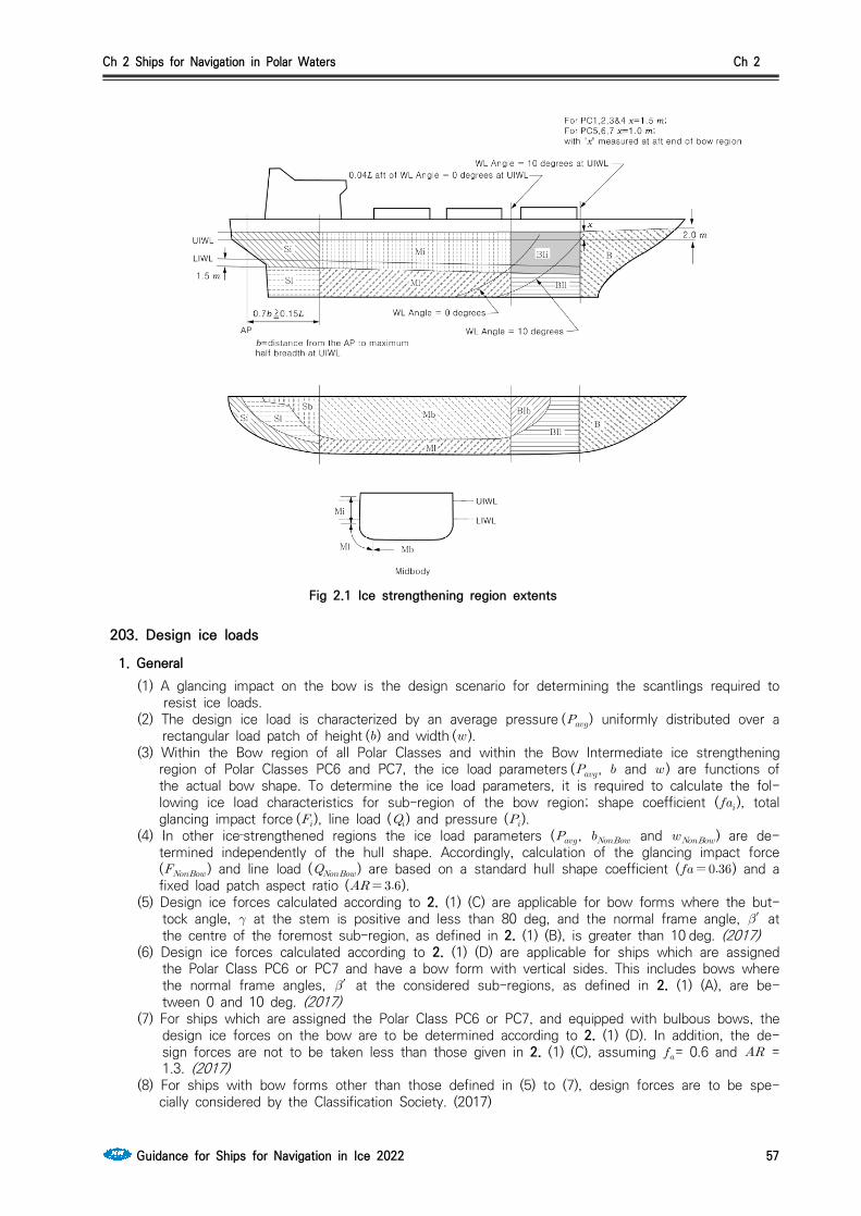
Ch 2 Ships for Navigation in Polar Waters Ch 2
Guidance for Ships for Navigation in Ice 2022 57
Fig 2.1 Ice strengthening region extents
203. Design ice loads
1. General (1) A glancing impact on the bow is the design scenario for determining the scantlings required to
resist ice loads.(2) The design ice load is characterized by an average pressure () uniformly distributed over a
rectangular load patch of height () and width ( ). (3) Within the Bow region of all Polar Classes and within the Bow Intermediate ice strengthening
region of Polar Classes PC6 and PC7, the ice load parameters (, and ) are functions of the actual bow shape. To determine the ice load parameters, it is required to calculate the fol-lowing ice load characteristics for sub-region of the bow region; shape coefficient (), total glancing impact force (), line load () and pressure ().
(4) In other ice‐strengthened regions the ice load parameters (, and ) are de-termined independently of the hull shape. Accordingly, calculation of the glancing impact force () and line load () are based on a standard hull shape coefficient ( ) and a fixed load patch aspect ratio ().
(5) Design ice forces calculated according to 2. (1) (C) are applicable for bow forms where the but-tock angle, at the stem is positive and less than 80 deg, and the normal frame angle, ′ at the centre of the foremost sub-region, as defined in 2. (1) (B), is greater than 10 deg. (2017)
(6) Design ice forces calculated according to 2. (1) (D) are applicable for ships which are assigned the Polar Class PC6 or PC7 and have a bow form with vertical sides. This includes bows where the normal frame angles, ′ at the considered sub-regions, as defined in 2. (1) (A), are be-tween 0 and 10 deg. (2017)
(7) For ships which are assigned the Polar Class PC6 or PC7, and equipped with bulbous bows, the design ice forces on the bow are to be determined according to 2. (1) (D). In addition, the de-sign forces are not to be taken less than those given in 2. (1) (C), assuming = 0.6 and = 1.3. (2017)
(8) For ships with bow forms other than those defined in (5) to (7), design forces are to be spe-cially considered by the Classification Society. (2017)

Ch 2 Ships for Navigation in Polar Waters Ch 2
58 Guidance for Ships for Navigation in Ice 2022
(9) Ship structures that are not directly subjected to ice loads may still experience inertial loads of stowed cargo and equipment resulting from ship/ice interaction. These inertial loads, based on accelerations determined by the Society, are to be considered in the design of these ship structures.
2. Glancing impact load characteristics The parameters defining the glancing impact load characteristics are reflected in the Class Factors listed in Table 2.2 and Table 2.2-1. (2017)
Polar Class
Crushing Failure Class
Factor ()
Flexural Failure
Class Factor ()
Load Patch DimensionsClass Factor
()
DisplacementClass Factor
()
Longitudinal Strength
Class Factor ()
PC1 17.69 68.60 2.01 250 7.46
PC2 9.89 46.80 1.75 210 5.46
PC3 6.06 21.17 1.53 180 4.17
PC4 4.50 13.48 1.42 130 3.15
PC5 3.10 9.00 1.31 70 2.50
PC6 2.40 5.49 1.17 40 2.37
PC7 1.80 4.06 1.11 22 1.81
Table 2.2 Class factors to be used in 203. 2.(1)(C)
Polar Class
Crushing Failure Class
Factor ()
Line Load Class Factor
()
Pressure Class Factor
()
PC6 3.43 2.82 0.65
PC7 2.60 2.33 0.65
Table 2.2-1 Class factors to be used in 203. 2.(1)(D) (2017)
(1) Bow area(A) In the Bow area, the force (), line load (), pressure () and load patch aspect ratio ()
associated with the glancing impact load scenario are functions of the hull angles measured at the upper ice waterline. The influence of the hull angles is captured through calculation of a bow shape coefficient (). The hull angles are defined in Fig 2.2.
(B) The waterline length of the bow region is generally to be divided into 4 sub-regions of equal length. The force (), line load (), pressure () and load patch aspect ratio () are to be calculated with respect to the mid-length position of each sub-region (each maximum of F, Q and P is to be used in the calculation of the ice load parameters , and ).
(C) The Bow area load characteristics for bow forms defined in 203. 1. (5) are determined as follows: (2017)
(a) Shape coefficient, , is to be taken as
min where
×
′

Ch 2 Ships for Navigation in Polar Waters Ch 2
Guidance for Ships for Navigation in Ice 2022 59
× sin′ × ×
(b) Force,
× × (MN)
(c) Load patch aspect ratio,
× sin′ ≥
(d) Line load,
×
(MNm)(e) Pressure,
×
× (MPa)
where = sub-region considered = length as defined in 201. 2 (m) = distance from the forward fore side of the stem at the intersection with
the upper ice waterline (UIWL) to station under consideration (m) = waterline angle (deg), see Fig 2.2′ = normal frame angle (deg), see Fig 2.2 = ship displacement (kt), not to be taken less than 5 kt = crushing failure class factor from Table 2.2 = flexural failure class factor from Table 2.2 = load patch dimensions class factor from Table 2.2
Note: ′ = normal frame angle at upper ice waterline [deg] = upper ice waterline angle [deg]
= buttock angle at upper ice waterline (angle of buttock line measured from vertical) [deg]
tan tan tan
tan′ tan cos
Fig 2.2 Definition of hull angles

Ch 2 Ships for Navigation in Polar Waters Ch 2
60 Guidance for Ships for Navigation in Ice 2022
(D) The Bow area load characteristics for bow forms defined in 203. 1. (6) are determined as follows: (2017) (a) Shape coefficient, , is to be taken as
(b) Force,
× × (MN)
(c) Line load,
× (MNm)
(d) Pressure,
× (MPa)
where = sub-region considered = waterline angle (deg), see Fig 2.2 = displacement (kt), not to be taken less than 5 kt = crushing failure class factor from Table 2.2-1 = flexural failure class factor from Table 2.2-1 = pressure class factor from Table 2.2-1
(2) Hull areas other than the bow (A) In the hull area other than the bow, the force () and line load () used in the
determination of the load patch dimensions (, ) and design pressure () are determined as follows: (2017)(a) Force,
× × (MN)(b) Line Load,
× × (MNm)
where = crushing failure class factor from Table 2.2 = ship displacement factor
= if ≤
= if
= ship displacement (kt), not to be taken less than 10 kt = displacement class factor from Table 2.2 = load patch dimension class factor from Table 2.2
3. Design load patch(1) In the Bow area, and the Bow Intermediate icebelts area for ships with class notation PC6 and
PC7, the design load patch has dimensions of width, , and height, , defined as follows: (2017)
(m)
(m)

Ch 2 Ships for Navigation in Polar Waters Ch 2
Guidance for Ships for Navigation in Ice 2022 61
where = maximum force in the Bow area (MN) = maximum line load in the Bow area (MNm) = maximum pressure in the Bow area (MPa)
(2) In hull areas other than those covered by (1), the design load patch has dimensions of width, , and height, , defined as follows: (2017)
(m)
(m)
where = force as defined in 2. (2) (A) (a) (MN) = line load as defined in 2. (2) (A) (b) (MNm)
4. Pressure within the design load patch(1) The average pressure, , within a design load patch is determined as follows:
× (MPa)
where = or as appropriate for the ice strengthening region under consideration
(MN) = or as appropriate for the ice strengthening region under consideration
(m) = or as appropriate for the ice strengthening region under consideration
(m)(2) Regions of higher, concentrated pressure exist within the load patch. In general, smaller regions
have higher local pressures. Accordingly, the peak pressure factors listed in Table 2.3 are used to account for the pressure concentration on localized structural members.
Structural Member Peak Pressure Factor ()
PlatingTransversely‐Framed ≥
Longitudinally‐Framed × ≥
Frames in Transverse
Framing Systems
With Stringers ≥
No Stringers ≥
Frames in Bottom Structures
Load Carrying Stringers Side Longitudinals
Web Frames
if ≥ ×
× if ×
where, = frame or longitudinal spacing (m) = web frame spacing (m) = ice load patch width (m)
Table 2.3 Peak pressure factors (2017)

Ch 2 Ships for Navigation in Polar Waters Ch 2
62 Guidance for Ships for Navigation in Ice 2022
5. Hull area factors (1) Associated with each ice strengthening region is an region Factor that reflects the relative mag-
nitude of the load expected in that region. The region Factor () for each ice strengthening region is listed in Table 2.4.
(2) In the event that a structural member spans across the boundary of a ice strengthening region, the largest ice strengthening region factor is to be used in the scantling determination of the member.
(3) Due to their increased manoeuverability, ships having propulsion arrangements with azimuth thruster (s) or “podded” propellers are to have specially considered Stern Icebelt () and Stern Lower () hull area factors.
(4) For ships assigned the additional notation ”Icebreaker”, the Area Factor (AF) for each hull area is listed in Table 2.4-1. (2017)
Ice strengthening region regionPolar Class
PC1 PC2 PC3 PC4 PC5 PC6 PC7
Bow ( ) All 1.00 1.00 1.00 1.00 1.00 1.00 1.00
Bow Intermediate ()
Icebelt 0.90 0.85 0.85 0.80 0.80 1.00* 1.00*
Lower 0.70 0.65 0.65 0.60 0.55 0.55 0.50
Bottom 0.55 0.50 0.45 0.40 0.35 0.30 0.25
Midbody ()
Icebelt 0.70 0.65 0.55 0.55 0.50 0.45 0.45
Lower 0.50 0.45 0.40 0.35 0.30 0.25 0.25
Bottom 0.30 0.30 0.25 ** ** ** **
Stern ()
Icebelt 0.75 0.70 0.65 0.60 0.50 0.40 0.35
Lower 0.45 0.40 0.35 0.30 0.25 0.25 0.25
Bottom 0.35 0.30 0.30 0.25 0.15 ** **
Note to Table 2.4: * See 203.1.(3) ** Indicates that strengthening for ice loads is not necessary.
Table 2.4 Ice strengthening region factors (AF)
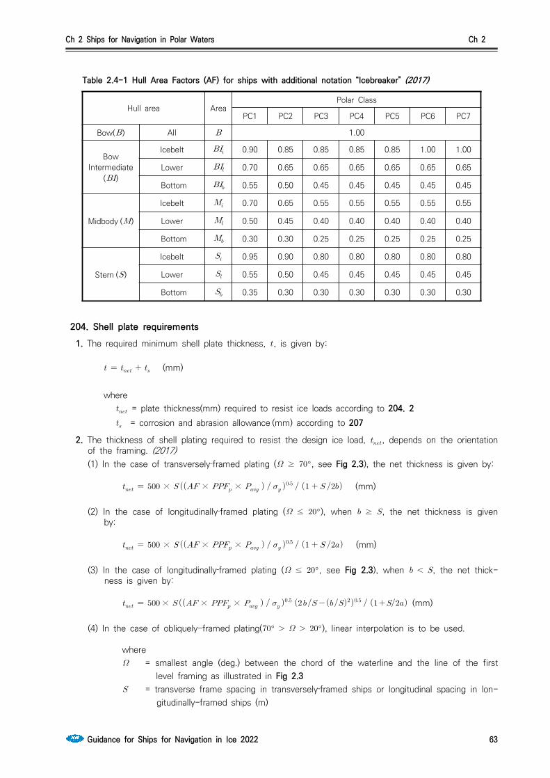
Ch 2 Ships for Navigation in Polar Waters Ch 2
Guidance for Ships for Navigation in Ice 2022 63
Hull area AreaPolar Class
PC1 PC2 PC3 PC4 PC5 PC6 PC7
Bow( ) All 1.00
Bow Intermediate
()
Icebelt 0.90 0.85 0.85 0.85 0.85 1.00 1.00
Lower 0.70 0.65 0.65 0.65 0.65 0.65 0.65
Bottom 0.55 0.50 0.45 0.45 0.45 0.45 0.45
Midbody ()
Icebelt 0.70 0.65 0.55 0.55 0.55 0.55 0.55
Lower 0.50 0.45 0.40 0.40 0.40 0.40 0.40
Bottom 0.30 0.30 0.25 0.25 0.25 0.25 0.25
Stern ( )
Icebelt 0.95 0.90 0.80 0.80 0.80 0.80 0.80
Lower 0.55 0.50 0.45 0.45 0.45 0.45 0.45
Bottom 0.35 0.30 0.30 0.30 0.30 0.30 0.30
Table 2.4-1 Hull Area Factors (AF) for ships with additional notation “Icebreaker" (2017)
204. Shell plate requirements 1. The required minimum shell plate thickness, , is given by:
(mm)
where = plate thickness(mm) required to resist ice loads according to 204. 2 = corrosion and abrasion allowance (mm) according to 207
2. The thickness of shell plating required to resist the design ice load, , depends on the orientation of the framing. (2017)(1) In the case of transversely‐framed plating ( ≥ °, see Fig 2.3), the net thickness is given by:
× × × (mm)
(2) In the case of longitudinally‐framed plating ( ≤ °), when ≥ , the net thickness is given by:
× × × (mm)
(3) In the case of longitudinally‐framed plating ( ≤ °, see Fig 2.3), when , the net thick-ness is given by:
× × × (mm)
(4) In the case of obliquely-framed plating(° °), linear interpolation is to be used.
where = smallest angle (deg.) between the chord of the waterline and the line of the first
level framing as illustrated in Fig 2.3 = transverse frame spacing in transversely‐framed ships or longitudinal spacing in lon-
gitudinally-framed ships (m)

Ch 2 Ships for Navigation in Polar Waters Ch 2
64 Guidance for Ships for Navigation in Ice 2022
= ice strengthening region factor from Table 2.4 = peak pressure factor from Table 2.3 = average patch pressure according to 203. 4 (1) (MPa) = minimum yield stress of the material (N/mm2) = height of design load patch (m), where is to be taken not greater than
in the case of determination of the net thickness for transversely framed plating = distance between frame supports, i.e. equal to the frame span as given in 205. 1
(5), but not reduced for any fitted end brackets (m). When a stringer is fitted, the need not be taken larger than the distance from the stringer to the most distant frame support.
Fig 2.3 Shell framing angle

Ch 2 Ships for Navigation in Polar Waters Ch 2
Guidance for Ships for Navigation in Ice 2022 65
205. Framing
1. General (1) Framing of Polar Class ships are to be designed to withstand the ice loads defined in 203.(2) The term "framing" refers to transverse and longitudinal local frames, load carrying stringers and
web frames in the areas of the hull exposed to ice pressure, see Fig 2.1. Where load-distribut-ing stringers have been fitted, the arrangement and scantlings of these are to be in accordance with the requirements of the Society. (2017)
(3) The strength of a framing member is dependent upon the fixity that is provided at its supports. Fixity can be assumed where framing members are either continuous through the support or at-tached to a supporting section with a connection bracket. In other cases, simple support is to be assumed unless the connection can be demonstrated to provide significant rotational restraint. Fixity is to be ensured at the support of any framing which terminates within an ice‐strengthened area.
(4) The details of framing member intersection with other framing members, including plated struc-tures, as well as the details for securing the ends of framing members at supporting sections are to be in accordance with the requirements of the Society.
(5) The effective span of a framing is to be determined on the basis of its moulded length. If brackets are fitted, the effective span may be reduced in accordance with the usual practice of the Society. Brackets are to be configured to ensure stability in the elastic and post‐yield re-sponse regions.
(6) When calculating the section modulus and shear area of a framing member, net thicknesses of the web, flange (if fitted) and attached shell plating are to be used. The shear area of a framing member may include that material contained over the full depth of the member, i.e. web area including portion of flange, if fitted, but excluding attached shell plating.
(7) The actual net effective shear area, , of a transverse or longitudial local frame is given by: (2017)
sin (cm)
where = height of stiffener including thickness of face plate (mm) (see Fig 2.4) = net web thickness (mm)
=
= as built web thickness (mm) (see Fig 2.4) = corrosion deduction (mm) to be subtracted from the web and flange thickness (as
specified the Society, but not less than as required by 207. 3). = smallest angle between shell plate and stiffener web, measured at the midspan of
the stiffener. (see Fig 2.4) The angle may be taken as 90 degrees provided the smallest angle is not less than 75 degrees.
(8) When the cross-sectional area of the attached plate exceeds the cross-sectional area of the frame, the actual net effective plastic section modulus, of transverse or longitudial frame is given by: (2017)
sin
sin cos (cm3)
where, , and are as given in 205. 1 (7) and as given in 204. 2 = net cross-sectional area of shell plating (cm2) = net shell plate thickness (mm) (complying with as required by 204. 2) = height of frame web (mm) (see Fig 2.4) = net cross-sectional area of frame flange (cm2) = height of frame measured to centre of the flange area (mm) (see Fig 2.4)

Ch 2 Ships for Navigation in Polar Waters Ch 2
66 Guidance for Ships for Navigation in Ice 2022
= distance from mid thickness plane of frame web to the centre of the flange area (mm) (see Fig 2.4)
Fig 2.4 Stiffener geometry
(9) When the cross-sectional area of the frame exceeds the cross-sectional area of the attached plate flange, the plastic neutral axis is located a distance above the shell plate, given by: (2017)
(mm)
and the net effective plastic section modulus, transverse or longitudial frame is given by:
sin
sin
sin cos (cm3)
(10) In the case of oblique framing arrangement (70 deg > > 20 deg, where is defined as given in 204. 2), linear interpolation is to be used.
2. Local frames in bottom structures and transverse local frame in side structures(1) The local frames in bottom structures (i.e. ice strengthening regions , and ) and trans-
verse frames in side structures are to be dimensioned such that the combined effects of shear and bending do not exceed the plastic strength of the member. Plastic strength is defined as the magnitude of midspan load that causes the development of a plastic collapse mechanism. For bottom structure the patch load shall be applied with the dimension (b) parallel with the frame direction. (2017)
(2) The actual net effective shear area of the frame, is shall not be less than the following cal-culation:
× × × × × × (cm)
where = length of loaded portion of span = lesser of and (m) = local frame span (m) = height of design ice load patch as defined in 203. 3 (1) or (2) (m) = local frame spacing (m) = hull area factor from Table 2.4 or Table 2.4-1= peak pressure factor, or as appropriate from Table 2.3 = average pressure within load patch as defined in 203. 4 (1) (MPa) = minimum yield stress of the material (N/mm2)
(3) The actual net effective plastic section modules of the frame, is shall not be less than the following calculation(where is to be the greater calculated on the basis of following two load
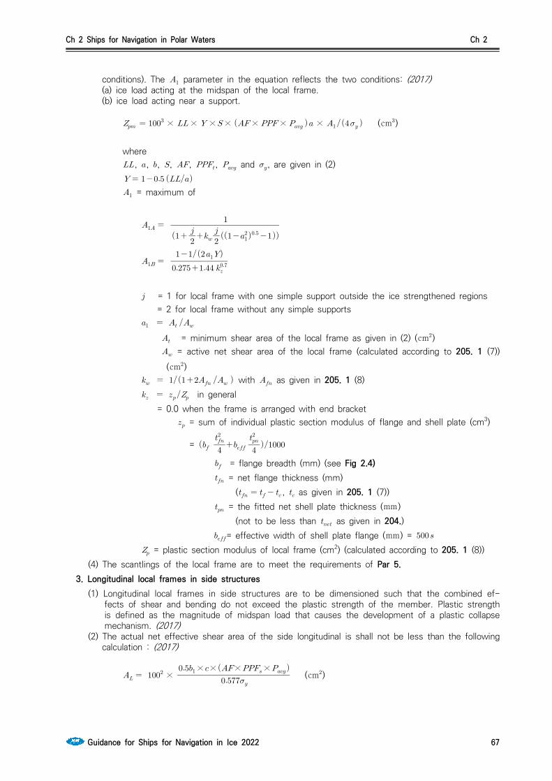
Ch 2 Ships for Navigation in Polar Waters Ch 2
Guidance for Ships for Navigation in Ice 2022 67
conditions). The parameter in the equation reflects the two conditions: (2017)(a) ice load acting at the midspan of the local frame.(b) ice load acting near a support.
× × × × × × × (cm)
where , , , , , , and , are given in (2)
= maximum of
= 1 for local frame with one simple support outside the ice strengthened regions = 2 for local frame without any simple supports = minimum shear area of the local frame as given in (2) (cm) = active net shear area of the local frame (calculated according to 205. 1 (7))
(cm) with as given in 205. 1 (8) in general = 0.0 when the frame is arranged with end bracket = sum of individual plastic section modulus of flange and shell plate (cm3)
=
= flange breadth (mm) (see Fig 2.4) = net flange thickness (mm)
( , as given in 205. 1 (7)) = the fitted net shell plate thickness (mm)
(not to be less than as given in 204.)= effective width of shell plate flange (mm) =
= plastic section modulus of local frame (cm2) (calculated according to 205. 1 (8))(4) The scantlings of the local frame are to meet the requirements of Par 5.
3. Longitudinal local frames in side structures(1) Longitudinal local frames in side structures are to be dimensioned such that the combined ef-
fects of shear and bending do not exceed the plastic strength of the member. Plastic strength is defined as the magnitude of midspan load that causes the development of a plastic collapse mechanism. (2017)
(2) The actual net effective shear area of the side longitudinal is shall not be less than the following calculation : (2017)
×
×××× (cm)
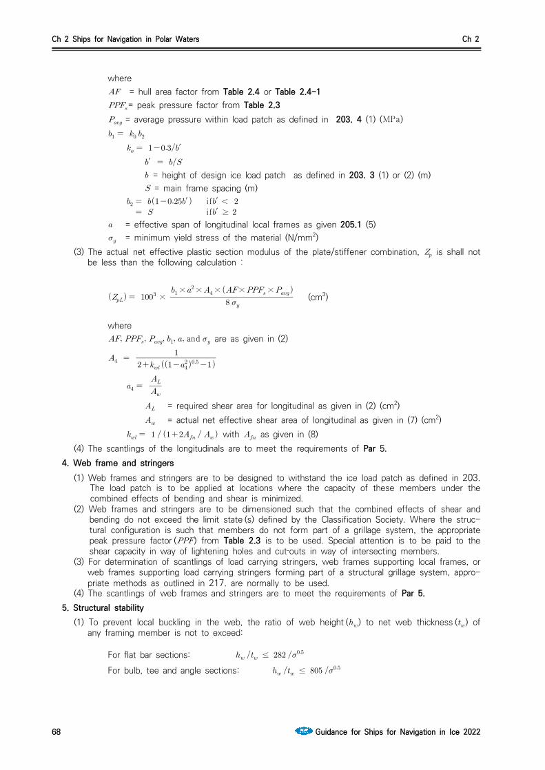
Ch 2 Ships for Navigation in Polar Waters Ch 2
68 Guidance for Ships for Navigation in Ice 2022
where = hull area factor from Table 2.4 or Table 2.4-1= peak pressure factor from Table 2.3 = average pressure within load patch as defined in 203. 4 (1) (MPa)
′′
= height of design ice load patch as defined in 203. 3 (1) or (2) (m) = main frame spacing (m)
′ if′ if′ ≥
= effective span of longitudinal local frames as given 205.1 (5) = minimum yield stress of the material (N/mm2)
(3) The actual net effective plastic section modulus of the plate/stiffener combination, is shall not be less than the following calculation :
×
××××× (cm3)
where and are as given in (2)
= required shear area for longitudinal as given in (2) (cm2) = actual net effective shear area of longitudinal as given in (7) (cm2)
with as given in (8)(4) The scantlings of the longitudinals are to meet the requirements of Par 5.
4. Web frame and stringers (1) Web frames and stringers are to be designed to withstand the ice load patch as defined in 203.
The load patch is to be applied at locations where the capacity of these members under the combined effects of bending and shear is minimized.
(2) Web frames and stringers are to be dimensioned such that the combined effects of shear and bending do not exceed the limit state (s) defined by the Classification Society. Where the struc-tural configuration is such that members do not form part of a grillage system, the appropriate peak pressure factor () from Table 2.3 is to be used. Special attention is to be paid to the shear capacity in way of lightening holes and cut‐outs in way of intersecting members.
(3) For determination of scantlings of load carrying stringers, web frames supporting local frames, or web frames supporting load carrying stringers forming part of a structural grillage system, appro-priate methods as outlined in 217. are normally to be used.
(4) The scantlings of web frames and stringers are to meet the requirements of Par 5. 5. Structural stability
(1) To prevent local buckling in the web, the ratio of web height () to net web thickness () of any framing member is not to exceed:
For flat bar sections: ≤
For bulb, tee and angle sections: ≤

Ch 2 Ships for Navigation in Polar Waters Ch 2
Guidance for Ships for Navigation in Ice 2022 69
where = web height = net web thickness = minimum yield stress of the material (N/mm2)
(2) Framing members for which it is not practicable to meet the requirements of (1) (e.g. stringers or deep web frames) are required to have their webs effectively stiffened. The scantlings of the web stiffeners are to ensure the structural stability of the framing member. The minimum net web thickness for these framing members is given by the following equation:
×
(mm)
where = net web thickness (mm) (mm) = web height of stringer / web frame (mm) (see Fig 2.5) = height of framing member penetrating the member under consideration (0 if no such
framing member) (mm) (see Fig 2.5) = spacing between supporting structure oriented perpendicular to the member under
consideration (mm) (see Fig 2.5) = minimum yield stress of the material (N/mm2)
Fig 2.5 Parameter definition for web stiffening
(3) In addition, the following is to be satisfied:
≥
where = minimum upper yield stress of the shell plate in way of the framing member
(N/mm2) = net thickness of the web = thickness of the shell plate in way the framing member
(4) To prevent local flange buckling of welded profiles, the following are to be satisfied:(a) The flange width () is not to be less than five times the net thickness of the web ().(b) The flange outstand (), is to meet the following requirement:
≤

Ch 2 Ships for Navigation in Polar Waters Ch 2
70 Guidance for Ships for Navigation in Ice 2022
where = net thickness of flange = minimum upper yield stress of the material (N/mm2)
206. Plated structures 1. Plated structures are those stiffened plate elements in contact with the hull and subject to ice
loads. These requirements are applicable to an inboard extent which is the lesser of:(1) web height of adjacent parallel web frame or stringer; or(2) 2.5 times the depth of framing that intersects the plated structure
2. The thickness of the plating and the scantlings of attached stiffeners are to be such that the de-gree of end fixity necessary for the shell framing is ensured.
3. The stability of the plated structure is to adequately withstand the ice loads defined in 203.
207. Corrosion/abrasion additions and steel renewal 1. Effective protection against corrosion and ice‐induced abrasion is recommended for all external surfa-
ces of the shell plating for all Polar Class ships.
2. The values of corrosion/abrasion additions, , to be used in determining the shell plate thickness are listed in Table 2.5.
3. Polar Class ships are to have a minimum corrosion/abrasion addition of mm applied to all internal structures within the ice‐strengthened regions, including plated members adjacent to the shell, as well as stiffener webs and flanges.
4. Steel renewal for ice strengthened structures is required when the gauged thickness is less than mm.
Hull Area
(mm)
With Effective Protection Without Effective Protection
PC1 ‐ PC3
PC4 & PC5
PC6 & PC7
PC1 ‐ PC3
PC4 & PC5
PC6 & PC7
Bow; Bow Intermediate Icebelt 3.5 2.5 2.0 7.0 5.0 4.0
Bow Intermediate Lower; Midbody & Stern Icebelt 2.5 2.0 2.0 5.0 4.0 3.0
Midbody & Stern Lower; Bottom 2.0 2.0 2.0 4.0 3.0 2.5
Table 2.5 Corrosion/Abrasion additions for shell plating
208. Materials (2017)1. Steel grades of plating for hull structures are to be not less than those given in Tables 2.7 based
on the as built thickness, the Polar Class and the material class of structural members given in 2.2. Material classes specified in Pt 3, Ch 1 of the Rules for the Classification of Steel Ships, Table 3.1.4
are applicable to Polar Class ships regardless of the ship’s length. In addition, material classes for weather and sea exposed structural members and for members attached to the weather and sea exposed shell plating of polar ships are given in Table 2.6. Where the material classes in Table 2.6, and those in Pt 3, Ch 1 Table 3.1.4 of the Rules for the Classification of Steel Ships differ, the higher material class is to be applied.
3. Steel grades for all plating and attached framing of hull structures and appendages situated below the level of 0.3 m below the lower waterline, as shown in Fig 2.6, are to be obtained from Pt 3 Ch 1, Table 3.1.9 and Table 3.1.10 of the Rules for the Classification of Steel Ships based on the ma-terial class for structural members in Table 2.6, above, regardless of Polar Class.
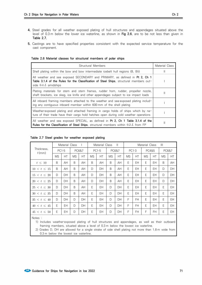
Ch 2 Ships for Navigation in Polar Waters Ch 2
Guidance for Ships for Navigation in Ice 2022 71
4. Steel grades for all weather exposed plating of hull structures and appendages situated above the level of 0.3 m below the lower ice waterline, as shown in Fig 2.6, are to be not less than given in Table 2.7.
5. Castings are to have specified properties consistent with the expected service temperature for the cast component.
Structural Members Material Class
Shell plating within the bow and bow intermediate icebelt hull regions (B, BIi) II
All weather and sea exposed SECONDARY and PRIMARY, as defined in Pt 2, Ch 1 Table 3.1.4 of the Rules for the Classification of Steel Ships, structural members out-side amidships
I
Plating materials for stem and stern frames, rudder horn, rudder, propeller nozzle, shaft brackets, ice skeg, ice knife and other appendages subject to ice impact loads II
All inboard framing members attached to the weather and sea‐exposed plating includ-ing any contiguous inboard member within 600 mm of the shell plating I
Weather‐exposed plating and attached framing in cargo holds of ships which by na-ture of their trade have their cargo hold hatches open during cold weather operations I
All weather and sea exposed SPECIAL, as defined in Pt 2, Ch 1 Table 3.1.4 of the Rules for the Classification of Steel Ships, structural members within from FP II
Table 2.6 Material classes for structural members of polar ships
Thickness, (mm)
Material Class I Material Class II Material Class III
PC1‐5 PC6&7 PC1‐5 PC6&7 PC1‐3 PC4&5 PC6&7
MS HT MS HT MS HT MS HT MS HT MS HT MS HT
≤ B AH B AH B AH B AH E EH E EH B AH
≤ B AH B AH D DH B AH E EH E EH D DH
≤ D DH B AH D DH B AH E EH E EH D DH
≤ D DH B AH D DH B AH E EH E EH D DH
≤ D DH B AH E EH D DH E EH E EH E EH
≤ D DH B AH E EH D DH E EH E EH E EH
≤ D DH D DH E EH D DH F FH E EH E EH
≤ E EH D DH E EH D DH F FH E EH E EH
≤ E EH D DH E EH D DH F FH F FH E EH
Notes :1) Includes weather‐exposed plating of hull structures and appendages, as well as their outboard
framing members, situated above a level of 0.3 m below the lowest ice waterline. 2) Grades D, DH are allowed for a single strake of side shell plating not more than 1.8 m wide from
0.3 m below the lowest ice waterline.
Table 2.7 Steel grades for weather exposed plating

Ch 2 Ships for Navigation in Polar Waters Ch 2
72 Guidance for Ships for Navigation in Ice 2022
Fig 2.6 Steel grade requirements for submerged and weather exposed shell plating
209. Longitudinal strength
1. Application(1) A ramming impact on the bow is the design scenario for the evaluation of the longitudinal
strength of the hull. (2017)(2) Intentional ramming is not considered as a design scenario for ships which are designed with
vertical or bulbous bows, (see 101. 6). Hence the longitudinal strength requirements given in 209.. is not to be considered for ships with stem angle, equal to or larger than 80 deg. (2017)
(3) Ice loads are only to be combined with still water loads. The combined stresses are to be com-pared against permissible bending and shear stresses at different locations along the ship’s length. In addition, sufficient local buckling strength is also to be verified.
2. Design vertical ice force at the bow
The design vertical ice force at the bow, , is to be taken as:
min (MN)
where
sin (MN)
(MN) = indentation parameter =
(1) for the case of a blunt bow form
tan
(2) for the case of wedge bow form ( deg ), and the above simplifies to
tantan
(MN/m) = Longitudinal Strength Class Factor from Table 2.2 = bow shape exponent which best describes the waterplane (see Fig 2.7 and 2.8) = 1.0 for a simple wedge bow form = 0.4 to 0.6 for a spoon bow form = 0 for a landing craft bow formAn approximate determined by a simple fit is acceptable.
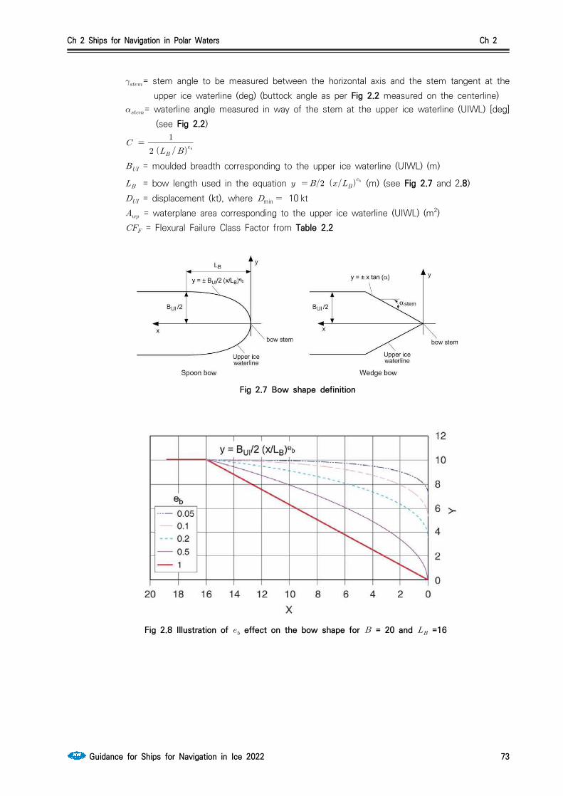
Ch 2 Ships for Navigation in Polar Waters Ch 2
Guidance for Ships for Navigation in Ice 2022 73
= stem angle to be measured between the horizontal axis and the stem tangent at the upper ice waterline (deg) (buttock angle as per Fig 2.2 measured on the centerline)
= waterline angle measured in way of the stem at the upper ice waterline (UIWL) [deg] (see Fig 2.2)
= moulded breadth corresponding to the upper ice waterline (UIWL) (m)
= bow length used in the equation (m) (see Fig 2.7 and 2.8)
= displacement (kt), where min 10 kt = waterplane area corresponding to the upper ice waterline (UIWL) (m2) = Flexural Failure Class Factor from Table 2.2
Fig 2.7 Bow shape definition
Fig 2.8 Illustration of effect on the bow shape for = 20 and =16

Ch 2 Ships for Navigation in Polar Waters Ch 2
74 Guidance for Ships for Navigation in Ice 2022
3. Design vertical ice shear force(1) The design vertical ice shear force,, along the hull girder is to be taken as:
(MN)
where = longitudinal distribution factor to be taken as follows: (a) Positive shear force
between the aft end of and from aft between from aft and the forward end of
(b) Negative shear force at the aft end of between and from aft between from aft and the forward end of
Intermediate values are to be determined by linear interpolation(2) The applied vertical shear stress, , is to be determined along the hull girder in a similar man-
ner as in Pt 2 Ch 3, 402. 2 of the Rules for the Classification of Steel Ships of the Rules by substituting the design vertical ice shear force for the design vertical wave shear force.
4. Design vertical ice bending moment (1) The design vertical ice bending moment, , along the hull girder is to be taken as:
sin (MN-m)
where = length (rule length as defined in 202. 2) (m) = stem angle to be measured between the horizontal axis and the stem tangent at the
upper ice waterline (deg) = design vertical ice force at the bow (MN) = longitudinal distribution factor for design vertical ice bending moment to be taken as
follows: at the aft end of between and from aft at from aft at the forward end of
Intermediate values are to be determined by linear interpolation(2) The applied vertical bending stress,, is to be determined along the hull girder in a similar
manner as in Pt 2, Ch 1, 402. 1 of the Rules for the Classification of Steel Ships. of the Rules, by substituting the design vertical ice bending moment for the design vertical wave bending moment. The ship still water bending moment is to be taken as the permissible still water bending moment in sagging condition.
5. Longitudinal strength criteria (1) The strength criteria provided in Table 2.9 are to be satisfied. The design stress is not to ex-
ceed the permissible stress.

Ch 2 Ships for Navigation in Polar Waters Ch 2
Guidance for Ships for Navigation in Ice 2022 75
Failure Mode Applied Stress Permissible Stress (when ≤ )
Permissible Stress (when )
Tension × ×
Shear ×
×
Buckling
for plating and for web plating of stiffeners for stiffeners
Table 2.9 Longitudinal strength criteria
where = applied vertical bending stress (N/mm2) = applied vertical shear stress (N/mm2) = minimum upper yield stress of the material (N/mm2) = ultimate tensile strength of material (N/mm2) = critical buckling stress in compression, according to Pt 3, Ch 4 of the Rules for the
Classification of Steel Ships (N/mm2) = critical buckling stress in shear, according to Pt 3, Ch 4 of the Rules for the
Classification of Steel Ships (N/mm2) = 0.8 = 0.6 for ships which are assigned the additional notation "Icebreaker"
210. Stem and stern frames The stem and stern frame are to be designed according to the requirements of the Society. For PC6/PC7 ships requiring IA SUPER/IA equivalency, the stem and stern requirements of Ch 1, 406. 1 and 407. of the Rules may need to be additionally considered.
211. Appendages (2017)1. All appendages are to be designed to withstand forces appropriate for the location of their attach-
ment to the hull structure or their position within a hull area.
2. Load definition and response criteria are to be determined by the Society.
212. Local details 1. For the purpose of transferring ice loads to supporting structure (bending moments and shear
forces), local design details are to comply with the requirements by the Society. (2017)2. The loads carried by a member in way of cut‐outs are not to cause instability. Where necessary, the
structure is to be stiffened.
213. Direct calculations (2017)1. Direct calculations are not to be utilized as an alternative to the analytical procedures for the shell
plating and local frame requirements given in 204, 205. 2, and 205. 3.2. Direct calculations are to be used for load carrying stringers and web frames forming part of a grill-
age system.
3. Where direct calculation is used to check the strength of structural systems, the load patch speci-fied in 203. is to be applied without being combined with any other loads. The load patch is to be applied at locations where the capacity of these members under the combined effects of bending

Ch 2 Ships for Navigation in Polar Waters Ch 2
76 Guidance for Ships for Navigation in Ice 2022
and shear is minimised. Special attention is to be paid to the shear capacity in way of lightening holes and cut-outs in way of intersecting members.
4. The strength evaluation of web frames and stringers may be performed based on linear or non-line-ar analysis. Recognized structural idealisation and calculation methods are to be applied, but the de-tailed requirements are to be in accordance with the discretion of the Society. In the strength eval-uation, the guidance given in 5. and 6. may generally be considered.
5. If the structure is evaluated based on linear calculation methods, the following are to be considered: (1) Web plates and flange elements in compression and shear to fulfil relevant buckling criteria as
specified by the Society (2) Nominal shear stresses in member web plates to be less than (3) Nominal von Mises stresses in member flanges to be less than
6. If the structure is evaluated based on non-linear calculation methods, the following are to be con-sidered:(1) The analysis is to reliably capture buckling and plastic deformation of the structure(2) The acceptance criteria are to ensure a suitable margin against fracture and major buckling and
yielding causing significant loss of stiffness(3) Permanent lateral and out-of plane deformation of considered member are to be minor relative
to the relevant structural dimensions(4) Detailed acceptance criteria to be in accordance with the discretion of the Society.
214. Welding 1. All welding within ice‐strengthened regions is to be of the double-sided continuous type.
2. Continuity of strength is to be ensured at all structural connections.
Section 3 Machinery Requirements for Polar Class Ships
301. ApplicationThe contents of this Section apply to main propulsion, steering gear, emergency and essential auxil-iary systems essential for the safety of the ship and the survivability of the crew.
302. Drawings & particulars to be submitted and system design
1. Drawings & particulars to be submitted (1) Details of the environmental conditions and the required ice class for the machinery, if different
from ship's ice class. (2) Detailed drawings of the main propulsion machinery. Description of the main propulsion, steering,
emergency and essential auxiliaries are to include operational limitations. Information on essential main propulsion load control functions.
(3) Description detailing how main, emergency and auxiliary systems are located and protected to prevent problems from freezing, ice and snow and evidence of their capability to operate in in-tended environmental conditions.
(4) Calculations and documentation indicating compliance with the requirements of this Section. 2. System design
(1) Machinery and supporting auxiliary systems shall be designed, constructed and maintained to comply with the requirements of "periodically unmanned machinery spaces" with respect to fire safety. Any automation plant (i.e. control, alarm, safety and indication systems) for essential sys-tems installed is to be maintained to the same standard.
(2) Systems, subject to damage by freezing, shall be drainable.(3) Single screw ships classed PC1 to PC5 inclusive shall have means provided to ensure sufficient
vessel operation in the case of propeller damage including CP-mechanism.
Ch 2 Ships for Navigation in Polar Waters Ch 2
Guidance for Ships for Navigation in Ice 2022 77
303. Materials
1. Materials exposed to sea water
Materials exposed to sea water, such as propeller blades, propeller hub and blade bolts shall have an elongation not less than 15% on a test piece the length of which is five times the diameter.
Charpy-V impact test shall be carried out for other than bronze and austenitic steel materials. Test pieces taken from the propeller castings shall be representative of the thickest section of the blade. An average impact energy value of 20 J taken from three Charpy-V tests is to be obtained at mi-nus 10℃.
2. Materials exposed to sea water temperature
Materials exposed to sea water temperature shall be of steel or other approved ductile material.
An average impact energy value of 20 J taken from three tests is to be obtained at minus 10℃.
3. Material exposed to low air temperature
Materials of essential components exposed to low air temperature shall be of steel or other approved ductile material.
An average impact energy value of 20 J taken from three Charpy-V tests is to be obtained at 10℃ below the lowest design temperature.
304. Ice interaction load
1. Propeller ice interaction
These Rules cover open and ducted type propellers situated at the stern of a vessel having control-lable pitch or fixed pitch blades. Ice loads on bow propellers and pulling type propellers shall re-ceive special consideration. The given loads are expected, single occurrence, maximum values for the whole ships service life for normal operational conditions. These loads do not cover off-design operational conditions, for example when a stopped propeller is dragged through ice. These Rules apply also for azimuth(geared and podded) thrusters considering loads due to propeller ice interaction. However, ice loads due to ice impacts on the body of azimuth thrusters have to be es-timated with suitable methods, but ice load formulae are not available in this Section.
The loads given in section 304. are total loads (unless otherwise stated) during ice interaction and are to be applied separately (unless otherwise stated) and are intended for component strength cal-culations only. The different loads given here are to be applied separately.
is a force bending a propeller blade backwards when the propeller mills an ice block while ro-tating ahead.
is a force bending a propeller blade forwards when a propeller interacts with an ice block while rotating ahead.
2. Ice class factors
The Table below lists the design ice thickness and ice strength index to be used for estimation of the propeller ice loads.
Ch 2 Ships for Navigation in Polar Waters Ch 2
78 Guidance for Ships for Navigation in Ice 2022
Table 2.10 Ice class factors Ice class [m] [-] [-]
PC1 4.0 1.2 1.15
PC2 3.5 1.1 1.15
PC3 3.0 1.1 1.15
PC4 2.5 1.1 1.15
PC5 2.0 1.1 1.15
PC6 1.75 1 1
PC7 1.5 1 1
: Ice thickness for machinery strength design : Ice strength index for blade ice force : Ice strength index for blade ice torque
3. Design ice loads for open propeller(1) Maximum backward blade force,
when lim, ∙∙ ∙
∙ (kN)
when ≥lim, ∙∙ ∙
∙ ∙ (kN)
wherelim∙
is the nominal rotational speed(at MCR free running condition) for CP-propellers and 85% of the nominal rotational speed(at MCR free running condition) for a FP-propeller (regardless driving engine type).
is to be applied as a uniform pressure distribution to an area on the back(suction) side of the blade for the following load cases. (A) Load case 1 : from 0.6 to the tip and from the blade leading edge to a value of 0.2
chord length, (B) Load case 2 : a load equal to 50 % of the is to be applied on the propeller tip area
outside of 0.9 ,(C) Load case 5 : for reversible propellers a load equal to 60% of the , is to be applied from
0.6 to the tip and from the blade trailing edge to a value of 0.2 chord length.
See load cases 1, 2, and 5 in Table 2.1 of Annex 2.(2) Maximum forward blade force,
when lim, ∙
∙ (kN)
when ≥lim, ∙
∙∙
∙ (kN)
where

Ch 2 Ships for Navigation in Polar Waters Ch 2
Guidance for Ships for Navigation in Ice 2022 79
lim
∙ (m)
= propeller hub diameter (m) = propeller diameter (m) = expanded blade area ratio = number of propeller blades
is to be applied as a uniform pressure distribution to an area on the face(pressure) side of the blade for the following load cases.
(A) Load case 3 : from 0.6 to the tip and from the blade leading edge to a value of 0.2 chord length,
(B) Load case 4 : a load equal to 50 % of the is to be applied on the propeller tip area outside of 0.9 ,
(C) Load case 5 : for reversible propellers a load equal to 60% of the , is to be applied from 0.6 to the tip and from the blade trailing edge to a value of 0.2 chord length.
See load cases 3, 4, and 5 in Table 2.1 of Annex 2.
(3) Maximum blade spindle torque
Spindle torque around the spindle axis of the blade fitting shall be calculated both for the load cases described in (1) & (2) for , . If the spindle torque values are less than the de-fault value given below, the default minimum value shall be used.
Default Value ㆍㆍ (kNㆍm)
where = the length of the blade chord at 0.7 radius (m) is either or which ever has the greater absolute value.
(4) Maximum propeller ice torque applied to the propeller
When lim,
max ∙
∙∙
∙
∙ ∙ (kNㆍm)
When ≥lim,
max ∙
∙∙
∙
∙
∙ ∙ (kNㆍm)
wherelim∙
= ice strength index for blade ice torque = propeller pitch at 0.7 (m) = max thickness at 0.7 radius is the rotational propeller speed, [rps], at bollard condition. If not known, n is to be
taken as follows:
Ch 2 Ships for Navigation in Polar Waters Ch 2
80 Guidance for Ships for Navigation in Ice 2022
Table 2.11 The rotational propeller speed at bollard condition value
Propeller type
CP propellers
FP propellers driven by turbine or electric motor
FP propellers driven by diesel engine ∙
Where is the nominal rotational speed at MCR, free running condition. For CP propellers, propeller pitch, shall correspond to MCR in bollard condition. If not known, is to be taken as ∙, where is propeller pitch at MCR free running condition.
(5) Maximum propeller ice thrust applied to the shaft
∙ (kN)
∙ (kN)
4. Design ice loads for ducted propeller(1) Maximum Backward Blade Force,
when lim, ∙∙ ∙ ∙ (kN) when ≥lim, ∙∙ ∙ ∙
(kN) wherelim∙
is to be taken as in 304. 3 (1)
is to be applied as a uniform pressure distribution to an area on the back side for the following load cases(See Table 2.2 of Annex 2) :
(A) Load case 1 : on the back of the blade from 0.6 to the tip and from the blade leading edge to a value of 0.2 chord length,
(B) Load case 5 : for reversible rotation propellers a load equal to 60% of the is applied on the blade face from 0.6 to the tip and from the blade trailing edge to a value of 0.2 chord length,
(2) Maximum forward blade force,
when ≤lim, ∙
∙ (kN)
when ≻lim, ∙ ∙∙
∙ (kN)
where
lim
∙ (m)
is to be applied as a uniform pressure distribution to an area on the face (pressure) side for the following load case (see Table 2.2 of Annex 2) :(A) Load case 3 : on the blade face from 0.6 to the tip and from the blade leading edge to
a value of 0.5 chord length(B) Load case 5 : a load equal to 60% is to be applied from 0.6 to the tip and from the
blade leading edge to a value of 0.2 chord length. (3) Maximum propeller ice torque applied to the propeller
max is the maximum torque on the propeller due to ice-propeller interaction.

Ch 2 Ships for Navigation in Polar Waters Ch 2
Guidance for Ships for Navigation in Ice 2022 81
When ≤lim,
max ∙
∙
∙
∙ ∙∙ (kNㆍm)
When ≻lim,
max ∙
∙
∙
∙ ∙∙ ∙ (kNㆍm)
wherelim∙ (m) is the rotational propeller speed [rps] at bollard condition. If not known, n is
to be taken as follows:
Table 2.12 The rotational propeller speed at bollard condition value
Propeller type
CP propellers
FP propellers driven by turbine or electric motor
FP propellers driven by diesel engine ∙
Where is the nominal rotational speed at MCR, free running condition. For CP propellers, propeller pitch, shall correspond to MCR in bollard condition. If not known, is to be taken as ∙, where is propeller pitch at MCR free running condition.
(4) Maximum blade spindle torque for CP-mechanism design,
Spindle torque around the spindle axis of the blade fitting shall be calculated for the load case described in 304. 1. If the spindle torque values are less than the default value given be-low, the default value shall be used.
Default Value ㆍㆍ (kNㆍm)
where = the length of the blade section at 0.7R radius (m) is either or which ever has the greater absolute value.
(5) Maximum propeller ice thrust (applied to the shaft at the location of the propeller)
∙
∙
5. Design loads on propulsion line(1) Torque
The propeller ice torque excitation for shaft line dynamic analysis shall be described by a se-quence of blade impacts which are of half sine shape and occur at the blade. The torque due to a single blade ice impact as a function of the propeller rotation angle is then
∙max∙ sin when when
where and parameters are given in table below.

Ch 2 Ships for Navigation in Polar Waters Ch 2
82 Guidance for Ships for Navigation in Ice 2022
Table 2.13 and parametersTorque excitation Propeller-ice interaction
Case 1 Single ice block 0.5 45
Case 2 Single ice block 0.75 90
Case 3 Single ice block 1.0 135
Case 4Two ice blocks with 45 degree phase in rotation angle
0.5 45
The total ice torque is obtained by summing the torque of single blades taking into account the phase shift 360 deg./Z. The number of propeller revolutions during a milling sequence shall be obtained with the formula :
∙
The number of impacts is ∙
See Fig 2.1 of Annex 2.Milling torque sequence duration is not valid for pulling bow propellers, which are subject to special consideration. The response torque at any shaft component shall be analysed considering excitation torque at the propeller, actual engine torque, , and mass elastic system
= actual maximum engine torque at considered speed
Design torque along propeller shaft lineThe design torque () of the shaft component shall be determined by means of torsional vi-bration analysis of the propulsion line. Calculations have to be carried out for all excitation cases given above and the response has to be applied on top of the mean hydrodynamic torque in bollard condition at considered propeller rotational speed.
(2) Maximum response thrustMaximum thrust along the propeller shaft line is to be calculated with the formula below. The factors 2.2 and 1.5 take into account the dynamic magnification due to axial vibration. Alternatively the propeller thrust magnification factor may be calculated by dynamic analysis.
Maximum Shaft Thrust Forwards ∙ (kN)
Maximum Shaft Thrust Backwards ∙ (kN)
= propeller bollard thrust (kN) = maximum forward propeller ice thrust (kN)If hydrodynamic bollard thrust, is not known, is to be taken as follows:
Table 2.14 Propeller bollard thrust
Propeller Type
CP propellers (open) ∙
CP propellers (ducted) ∙
FP propellers driven by turbine or electric motor
FP propellers driven by diesel engine (open) ∙
FP propellers driven by diesel engine (ducted) ∙

Ch 2 Ships for Navigation in Polar Waters Ch 2
Guidance for Ships for Navigation in Ice 2022 83
= nominal propeller thrust at MCR at free running open water conditions(3) Blade failure load for both open and nozzle propeller
The force is acting at 0.8 in the weakest direction of the blade and at a spindle arm of 2/3 of the distance of axis of blade rotation of leading and trailing edge which ever is the greatest.The blade failure load is:
ㆍㆍ
ㆍㆍㆍ (kN)
where ∙∙
where and are representative values for the blade material. , and (see Ch 1, Fig 1.11) are respectively the actual chord length, thickness and radi-us of the cylindrical root section of the blade at the weakest section outside root fillet. And typically will be at the termination of the fillet into the blade profile.
305. Design
1. Design principle
The strength of the propulsion line shall be designed for maximum loads in 304. such that the plastic bending of a propeller blade shall not cause damages in other propulsion line components with sufficient fatigue strength.
2. Azimuth main propulsors
In addition to the above requirements special consideration shall be given to the loading cases which are extraordinary for propulsion units when compared with conventional propellers. Estimation of the loading cases must reflect the operational realities of the ship and the thrusters. In this re-spect, for example, the loads caused by impacts of ice blocks on the propeller hub of a pulling pro-peller must be considered. Also loads due to thrusters operating in an oblique angle to the flow must be considered. The steering mechanism, the fitting of the unit and the body of the thruster shall be designed to withstand the loss of a blade without damage. The plastic bending of a blade shall be considered in the propeller blade position, which causes the maximum load on the studied component. Azimuth thrusters shall also be designed for estimated loads due to thruster body/ice interaction as per Sec.2 211.
3. Blade design (1) Maximum blade stresses
Blade stresses are to be calculated using the backward and forward loads given in section 304. 3 & 4. The stresses shall be calculated with recognised and well documented FE-analysis or other acceptable alternative method. The stresses on the blade shall not exceed the allowable stresses for the blade material given below.Calculated blade stress for maximum ice load shall comply with the following:
≺
is reference stress, defined as: ㆍ or ㆍㆍ which ever is less
Where and are representative values for the blade material.(2) Blade edge thickness
The blade edge thicknesses and tip thickness are to be greater than given by the following formula:

Ch 2 Ships for Navigation in Polar Waters Ch 2
84 Guidance for Ships for Navigation in Ice 2022
≥
= distance from the blade edge measured along the cylindrical sections from the edge and shall be 2.5% of chord length, however not to be taken greater than 45 mm.
In the tip area (above 0.975 radius) x shall be taken as 2.5% of 0.975 section length and is to be measured perpendicularly to the edge, however not to be taken greater than 45 mm.
= safety factor = 2.5 for trailing edges = 3.5 for leading edges = 5 for tip = according to 304. 2 = ice pressure 16 MPa for leading edge and tip thickness= according above Par. 3 (1)
The requirement for edge thickness has to be applied for leading edge and in case of reversible rotation open propellers also for trailing edge. Tip thickness refers to the maximum measured thickness in the tip area above 0.975 radius. The edge thickness in the area between position of maximum tip thickness and edge thickness at 0.975 radius has to be interpolated between edge and tip thickness value and smoothly distributed.
4. Prime movers(1) The Main engine is to be capable of being started and running the propeller with the CP in full
pitch.(2) Provisions shall be made for heating arrangements to ensure ready starting of the cold emer-
gency power units at an ambient temperature applicable to the Polar Class of the ship.(3) Emergency power units should be equipped with starting devices with a stored energy capability
of at least three consecutive starts at the design temperature in (2) above. The source of stor-ed energy shall be protected to preclude critical depletion by the automatic starting system, un-less a second independent means of starting is provided. A second source of energy shall be provided for an additional three starts within 30 min., unless manual starting can be demon-strated to be effective.
306. Machinery fastening loading accelerations1. Essential equipment and main propulsion machinery supports shall be suitable for the accelerations
as indicated in as follows. Accelerations are to be considered acting independently.
2. Longitudinal impact accelerations, Maximum longitudinal impact acceleration at any point along the hull girder,
△
tan
(m/s2)
3. Vertical acceleration, Combined vertical impact acceleration at any point along the hull girder,
△
(m/s2)
= 1.3 at FP = 0.2 at midships

Ch 2 Ships for Navigation in Polar Waters Ch 2
Guidance for Ships for Navigation in Ice 2022 85
= 0.4 at AP = 1.3 at AP for ships conducting ice breaking astern intermediate values to be interpo-
lated linearly
4. Transverse impact acceleration, Combined transverse impact acceleration at any point along hull girder,
△
(m/s2)
= 1.5 at FP = 0.25 at midships = 0.5 at AP = 1.5 at AP for ships conducting ice breaking astern intermediate values to be interpolated linearlywhere : maximum friction angle between steel and ice, normally taken as 10˚ [deg.] : bow stem angle at waterline [deg.]△ : displacement : length between perpendiculars (m) : distance in meters from the water line to the point being considered (m) : vertical impact force, defined in 209. 2 : total force normal to shell plating in the bow area due to oblique ice impact, defined in
209. 3
307. Auxiliary systems 1. Machinery shall be protected from the harmful effects of ingestion or accumulation of ice or snow.
Where continuous operation is necessary, means should be provided to purge the system of accu-mulated ice or snow.
2. Means should be provided to prevent damage due to freezing, to tanks containing liquids.
3. Vent pipes, intake and discharge pipes and associated systems shall be designed to prevent block-age due to freezing or ice and snow accumulation.
308. Sea chest and cooling water systems1. Cooling water systems for machinery that are essential for the propulsion and safety of the vessel,
including sea chests inlets, shall be designed for the environmental conditions applicable to the ice class.
2. At least two sea chests are to be arranged as ice boxes for class PC1 to PC5 inclusive where. The calculated volume for each of the ice boxes shall be at least 1 m3 for every 750 kW of the total in-stalled power. For PC6 and PC7 there shall be at least one ice box located preferably near center line.
3. Ice boxes are to be designed for an effective separation of ice and venting of air.
4. Sea inlet valves are to secured directly to the ice boxes. The valve shall be a full bore type.
5. Ice boxes and sea bays are to have vent pipes and are to have shut off valves connected direct to the shell.
6. Means are to be provided to prevent freezing of sea bays, ice boxes, ship side valves and fittings above the load water line.
7. Efficient means are to be provided to re-circulate cooling seawater to the ice box. Total sectional
Ch 2 Ships for Navigation in Polar Waters Ch 2
86 Guidance for Ships for Navigation in Ice 2022
area of the circulating pipes is not to be less than the area of the cooling water discharge pipe.
8. Detachable gratings or manholes are to be provided for ice boxes. Manholes are to be located above the deepest load line. Access is to be provided to the ice box from above.
9. Openings in ship sides for ice boxes are to be fitted with gratings, or holes or slots in shell plates. The net area through these openings is to be not less than 5 times the area of the inlet pipe. The diameter of holes and width of slot in shell plating is to be not less than 20 mm. Gratings of the ice boxes are to be provided with a means of clearing. Clearing pipes are to be provided with screw-down type non return valves.
309. Ballast tanks1. Efficient means are to be provided to prevent freezing in fore and after peak tanks and wing tanks
located above the water line and where otherwise found necessary.
310. Ventilation systems1. The air intakes for machinery and accommodation ventilation are to be located on both sides of the
ship.
2. Accommodation and ventilation air intakes shall be provided with means of heating.
3. The temperature of inlet air provided to machinery from the air intakes shall be suitable for the safe operation of the machinery.
311. Alternative design1. As an alternative a comprehensive design study may be submitted and may be requested to be va-
lidated by an agreed test programme.

Ch 3 Ships with Ice Breaking Capability for Navigation in Polar Waters Ch 3
Guidance for Ships for Navigation in Ice 2022 87
CHAPTER 3 SHIPS WITH ICE BREAKING CAPABILITY FOR NAVIGATION IN POLAR WATERS
Section 1 General
101. General 1. The requirements in this chapter apply to ships with ice breaking capability and Icebreakers intended
for navigation in the arctic seas.
2. For those not defined in this Chapter, the requirements of the Rules for the Classification of Steel Ships are to be applied.
102. Class of a ship and Class notation 1. Class notations are assigned to Icebreakers and Arctic class ships in compliance with the require-
ments of Par 2 to 4. At the owner's discretion, class notations of Ch 1, Ch 2 and of this chapter may be assigned simultaneously, provided such ships comply with the requirements for both.
2. If an Icebreaker complies with the requirements of this chapter, one of the class notations Icebreaker3 ∼ Icebreaker6 described below can be assigned. Icebreaker have the following charac-teristics as Table 3.1.
3. If a ship complies with the relevant requirements of this Chapter and intended for navigation in arc-tic seas, one of the Arctic7 ∼ Arctic9 class notations shall be assigned. At the owner's discretions, a ship which perform icebreaking operations periodically and complies with the relevant requirements of Icebreaker, one of Icebreaker3 or Icebreaker4 class notations may be assigned.
4. Table 3.2 shows, for Arctic class ships, limiting type and thickness of ice enabling a ship to navigate in a channel following an Icebreaker at a low speed(3 to 5 knots) without running a heightened risk of damage through contact of hull with ice. Table 3.3 shows, Arctic class ships operating in-dependently, permissible speeds which a ship under the ice conditions set out in the table may reach when navigating in fractures between floes or surmounting ice isthmuses without running a heightened risk of damage through contact of hull with ice.
Icebreaker3- Intended for ice breaking operation in harbour and roadstead water areas as well as in
non-arctic freezing seas where the ice is up to 1.5m thick.- Ice breaking capability in ice up to 1 m thick.
Icebreaker4
- Intended for ice breaking operation in the arctic seas on coastal routes during winter/spring navigation in ice up to 2.0 m thick and summer/autumn navigation in ice up to 2.5 m thick; in non-artic freezing seas and mouths of rivers flowing into arctic seas in ice up to 2.0 m thick.
- Ice breaking capability in ice up to 1.5 m thick. - The total shaft power not less than 11 MW.
Icebreaker5
- Intended for ice breaking operations in the arctic seas on coastal routes during winter/spring navigation in ice up to 3.0m thick and summer/autumn navigation without restrictions.
- Ice breaking capability in ice up to 2.0m thick. - The total shaft power not less than 22 MW.
Icebreaker6
- Intended for ice breaking operation on coastal routes in arctic seas during winter/spring navigation in ice up to 4.0 m thick and summer/autumn navigation without restrictions.
- Ice breaking capability in ice over 2.0 m thick. - The total shaft power not less than 48 MW.
Table 3.1 Characteristics of Icebreakers
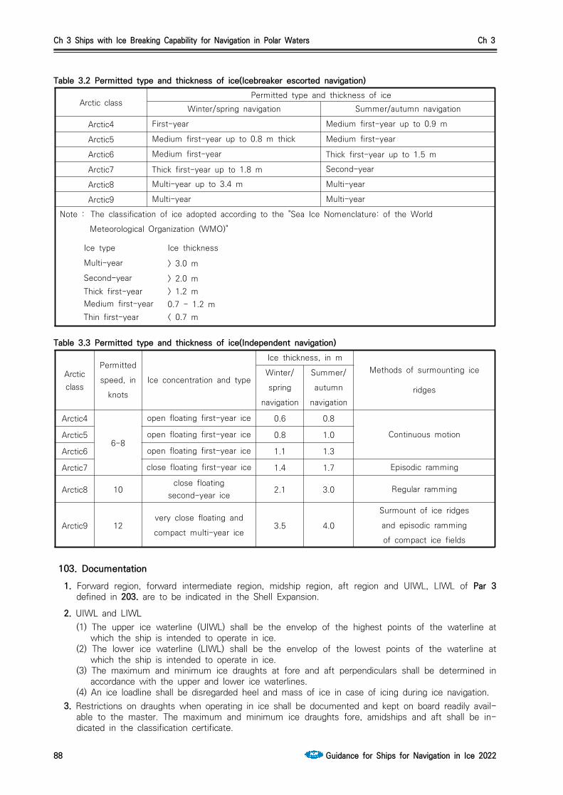
Ch 3 Ships with Ice Breaking Capability for Navigation in Polar Waters Ch 3
88 Guidance for Ships for Navigation in Ice 2022
Table 3.2 Permitted type and thickness of ice(Icebreaker escorted navigation)
Table 3.3 Permitted type and thickness of ice(Independent navigation)
103. Documentation1. Forward region, forward intermediate region, midship region, aft region and UIWL, LIWL of Par 3
defined in 203. are to be indicated in the Shell Expansion.
2. UIWL and LIWL(1) The upper ice waterline (UIWL) shall be the envelop of the highest points of the waterline at
which the ship is intended to operate in ice. (2) The lower ice waterline (LIWL) shall be the envelop of the lowest points of the waterline at
which the ship is intended to operate in ice. (3) The maximum and minimum ice draughts at fore and aft perpendiculars shall be determined in
accordance with the upper and lower ice waterlines.(4) An ice loadline shall be disregarded heel and mass of ice in case of icing during ice navigation.
3. Restrictions on draughts when operating in ice shall be documented and kept on board readily avail-able to the master. The maximum and minimum ice draughts fore, amidships and aft shall be in-dicated in the classification certificate.
Arctic classPermitted type and thickness of ice
Winter/spring navigation Summer/autumn navigation
Arctic4 First-year Medium first-year up to 0.9 m
Arctic5 Medium first-year up to 0.8 m thick Medium first-year
Arctic6 Medium first-year Thick first-year up to 1.5 m
Arctic7 Thick first-year up to 1.8 m Second-year
Arctic8 Multi-year up to 3.4 m Multi-year
Arctic9 Multi-year Multi-year
Note : The classification of ice adopted according to the "Sea Ice Nomenclature: of the World
Meteorological Organization (WMO)"
Ice type Ice thickness
Multi-year > 3.0 mSecond-year > 2.0 mThick first-year > 1.2 mMedium first-year 0.7 - 1.2 mThin first-year < 0.7 m
Arctic class
Permitted
speed, in
knots
Ice concentration and type
Ice thickness, in mMethods of surmounting ice
ridges
Winter/
spring
navigation
Summer/
autumn
navigation
Arctic4
6-8
open floating first-year ice 0.6 0.8
Continuous motionArctic5 open floating first-year ice 0.8 1.0
Arctic6 open floating first-year ice 1.1 1.3
Arctic7 close floating first-year ice 1.4 1.7 Episodic ramming
Arctic8 10close floating
second-year ice 2.1 3.0 Regular ramming
Arctic9 12very close floating and
compact multi-year ice3.5 4.0
Surmount of ice ridges
and episodic ramming
of compact ice fields

Ch 3 Ships with Ice Breaking Capability for Navigation in Polar Waters Ch 3
Guidance for Ships for Navigation in Ice 2022 89
Section 2 Strengthening of Arctic class ships and Icebreakers
201. General The requirements of this section apply to Arctic class ships and Icebreakers having standard hull form that comply with the requirements of 202. below.
202. Requirements to hull configuration 1. The hull configuration factor (deg) shall be measured in conformity with Fig 3.1 to 3.4.
Fig 3.1 Slope of UIWL at the section considerd, (deg)
Fig 3.2 Slope of frame on the level of UIWL at the section considerd, (deg)
Fig 3.3 Slope of UIWL at the fore perpendicular, (deg)
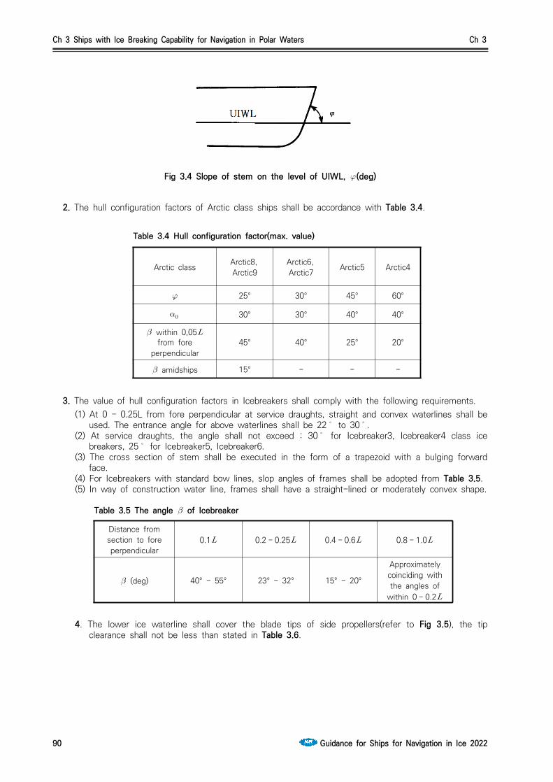
Ch 3 Ships with Ice Breaking Capability for Navigation in Polar Waters Ch 3
90 Guidance for Ships for Navigation in Ice 2022
Fig 3.4 Slope of stem on the level of UIWL, (deg)
2. The hull configuration factors of Arctic class ships shall be accordance with Table 3.4.
3. The value of hull configuration factors in Icebreakers shall comply with the following requirements. (1) At 0 - 0.25L from fore perpendicular at service draughts, straight and convex waterlines shall be
used. The entrance angle for above waterlines shall be 22 to 30.(2) At service draughts, the angle shall not exceed : 30 for Icebreaker3, Icebreaker4 class ice
breakers, 25 for Icebreaker5, Icebreaker6. (3) The cross section of stem shall be executed in the form of a trapezoid with a bulging forward
face. (4) For Icebreakers with standard bow lines, slop angles of frames shall be adopted from Table 3.5. (5) In way of construction water line, frames shall have a straight-lined or moderately convex shape.
Table 3.5 The angle of Icebreaker
4. The lower ice waterline shall cover the blade tips of side propellers(refer to Fig 3.5), the tip clearance shall not be less than stated in Table 3.6.
Arctic class Arctic8,Arctic9
Arctic6,Arctic7 Arctic5 Arctic4
25° 30° 45° 60°
30° 30° 40° 40°
within 0,05 from fore
perpendicular45° 40° 25° 20°
amidships 15° - - -
Table 3.4 Hull configuration factor(max. value)
Distance fromsection to foreperpendicular
0.1 0.2 - 0.25 0.4 - 0.6 0.8 - 1.0
(deg) 40° - 55° 23° - 32° 15° - 20°
Approximately coinciding with the angles of
within 0 - 0.2
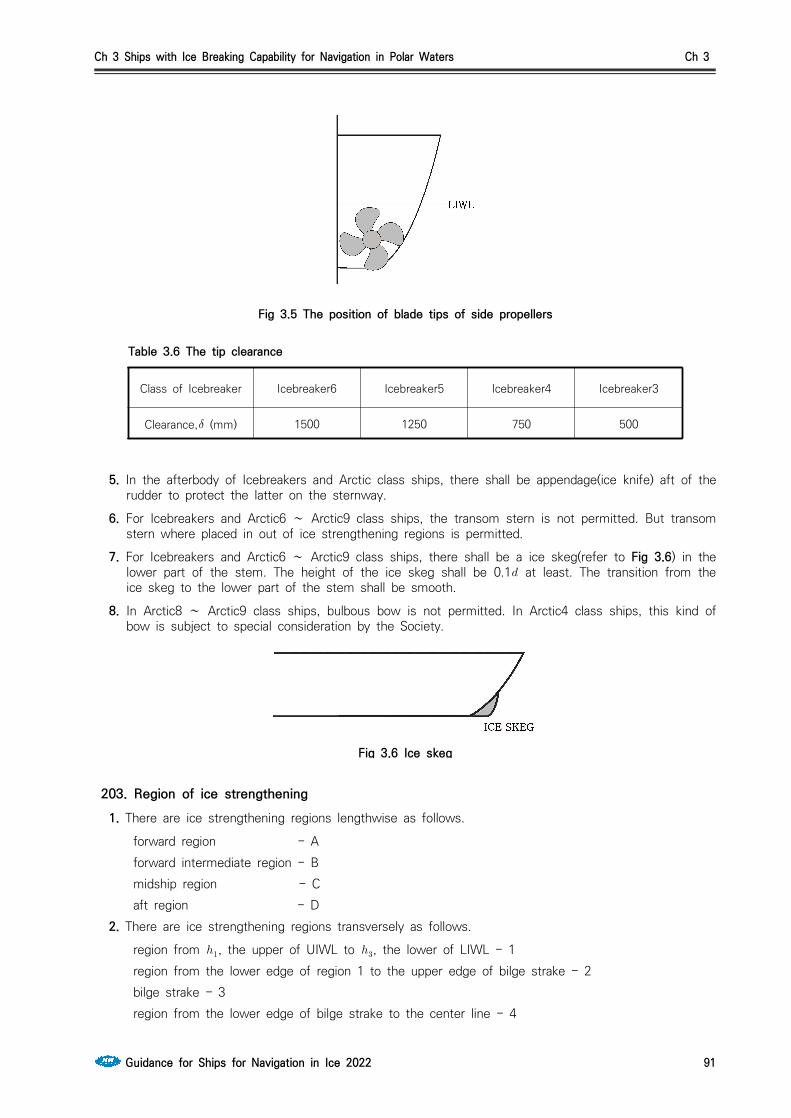
Ch 3 Ships with Ice Breaking Capability for Navigation in Polar Waters Ch 3
Guidance for Ships for Navigation in Ice 2022 91
Fig 3.5 The position of blade tips of side propellers
Class of Icebreaker Icebreaker6 Icebreaker5 Icebreaker4 Icebreaker3
Clearance, (mm) 1500 1250 750 500
Table 3.6 The tip clearance
5. In the afterbody of Icebreakers and Arctic class ships, there shall be appendage(ice knife) aft of the rudder to protect the latter on the sternway.
6. For Icebreakers and Arctic6 ∼ Arctic9 class ships, the transom stern is not permitted. But transom stern where placed in out of ice strengthening regions is permitted.
7. For Icebreakers and Arctic6 ∼ Arctic9 class ships, there shall be a ice skeg(refer to Fig 3.6) in the lower part of the stem. The height of the ice skeg shall be 0.1 at least. The transition from the ice skeg to the lower part of the stem shall be smooth.
8. In Arctic8 ∼ Arctic9 class ships, bulbous bow is not permitted. In Arctic4 class ships, this kind of bow is subject to special consideration by the Society.
Fig 3.6 Ice skeg
203. Region of ice strengthening1. There are ice strengthening regions lengthwise as follows.
forward region - A forward intermediate region - B midship region - C aft region - D 2. There are ice strengthening regions transversely as follows.
region from , the upper of UIWL to , the lower of LIWL - 1 region from the lower edge of region 1 to the upper edge of bilge strake - 2 bilge strake - 3 region from the lower edge of bilge strake to the center line - 4
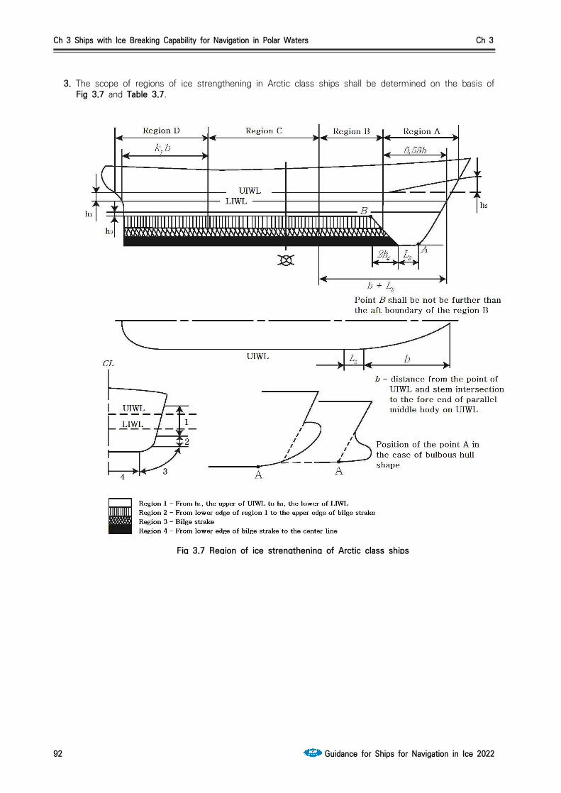
Ch 3 Ships with Ice Breaking Capability for Navigation in Polar Waters Ch 3
92 Guidance for Ships for Navigation in Ice 2022
3. The scope of regions of ice strengthening in Arctic class ships shall be determined on the basis of Fig 3.7 and Table 3.7.
Fig 3.7 Region of ice strengthening of Arctic class ships
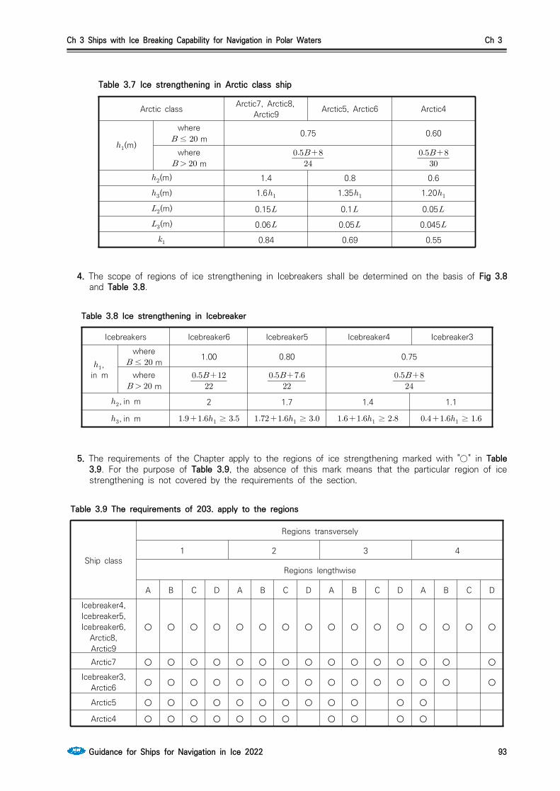
Ch 3 Ships with Ice Breaking Capability for Navigation in Polar Waters Ch 3
Guidance for Ships for Navigation in Ice 2022 93
Arctic class Arctic7, Arctic8,Arctic9 Arctic5, Arctic6 Arctic4
(m)
where≤ m 0.75 0.60
where m
(m) 1.4 0.8 0.6
(m) 1.6 1.35 1.20(m) 0.15 0.1 0.05
(m) 0.06 0.05 0.045
0.84 0.69 0.55
Table 3.7 Ice strengthening in Arctic class ship
4. The scope of regions of ice strengthening in Icebreakers shall be determined on the basis of Fig 3.8 and Table 3.8.
Icebreakers Icebreaker6 Icebreaker5 Icebreaker4 Icebreaker3
,in m
where≤ m 1.00 0.80 0.75
where m
, in m 2 1.7 1.4 1.1
, in m ≥ ≥ ≥ ≥
Table 3.8 Ice strengthening in Icebreaker
5. The requirements of the Chapter apply to the regions of ice strengthening marked with "○" in Table 3.9. For the purpose of Table 3.9, the absence of this mark means that the particular region of ice strengthening is not covered by the requirements of the section.
Ship class
Regions transversely
1 2 3 4
Regions lengthwise
A B C D A B C D A B C D A B C D
Icebreaker4,Icebreaker5,Icebreaker6,
Arctic8, Arctic9
○ ○ ○ ○ ○ ○ ○ ○ ○ ○ ○ ○ ○ ○ ○ ○
Arctic7 ○ ○ ○ ○ ○ ○ ○ ○ ○ ○ ○ ○ ○ ○ ○
Icebreaker3, Arctic6 ○ ○ ○ ○ ○ ○ ○ ○ ○ ○ ○ ○ ○ ○ ○
Arctic5 ○ ○ ○ ○ ○ ○ ○ ○ ○ ○ ○ ○
Arctic4 ○ ○ ○ ○ ○ ○ ○ ○ ○ ○ ○
Table 3.9 The requirements of 203. apply to the regions
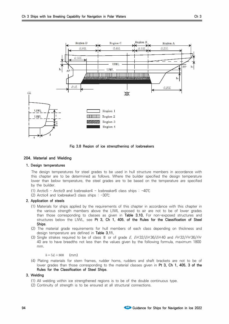
Ch 3 Ships with Ice Breaking Capability for Navigation in Polar Waters Ch 3
94 Guidance for Ships for Navigation in Ice 2022
Fig 3.8 Region of ice strengthening of Icebreakers
204. Material and Welding1. Design temperatures The design temperatures for steel grades to be used in hull structure members in accordance with
this chapter are to be determined as follows. Where the builder specified the design temperature lower than below temperature, the steel grades are to be based on the temperature are specified by the builder. (1) Arctic5 ~ Arctic9 and Icebreaker4 ~ Icebreaker6 class ships : -40℃(2) Arctic4 and Icebreaker3 class ships : -30℃
2. Application of steels(1) Materials for ships applied by the requirements of this chapter in accordance with this chapter in
the various strength members above the LIWL exposed to air are not to be of lower grades than those corresponding to classes as given in Table 3.10, For non-exposed structures and structures below the LIWL, see Pt 3, Ch 1, 405. of the Rules for the Classification of Steel Ships.
(2) The material grade requirements for hull members of each class depending on thickness and design temperature are defined in Table 3.11.
(3) Single strakes required to be of class Ⅲ or of grade E, EH 32/EH 36/EH 40 and FH 32/FH 36/FH40 are to have breadths not less than the values given by the following formula, maximum 1800mm.
(mm)(4) Plating materials for stern frames, rudder horns, rudders and shaft brackets are not to be of
lower grades than those corresponding to the material classes given in Pt 3, Ch 1, 405. 3 of the Rules for the Classification of Steel Ships.
3. Welding (1) All welding within ice strengthened regions is to be of the double continuous type.(2) Continuity of strength is to be ensured at all structural connections.
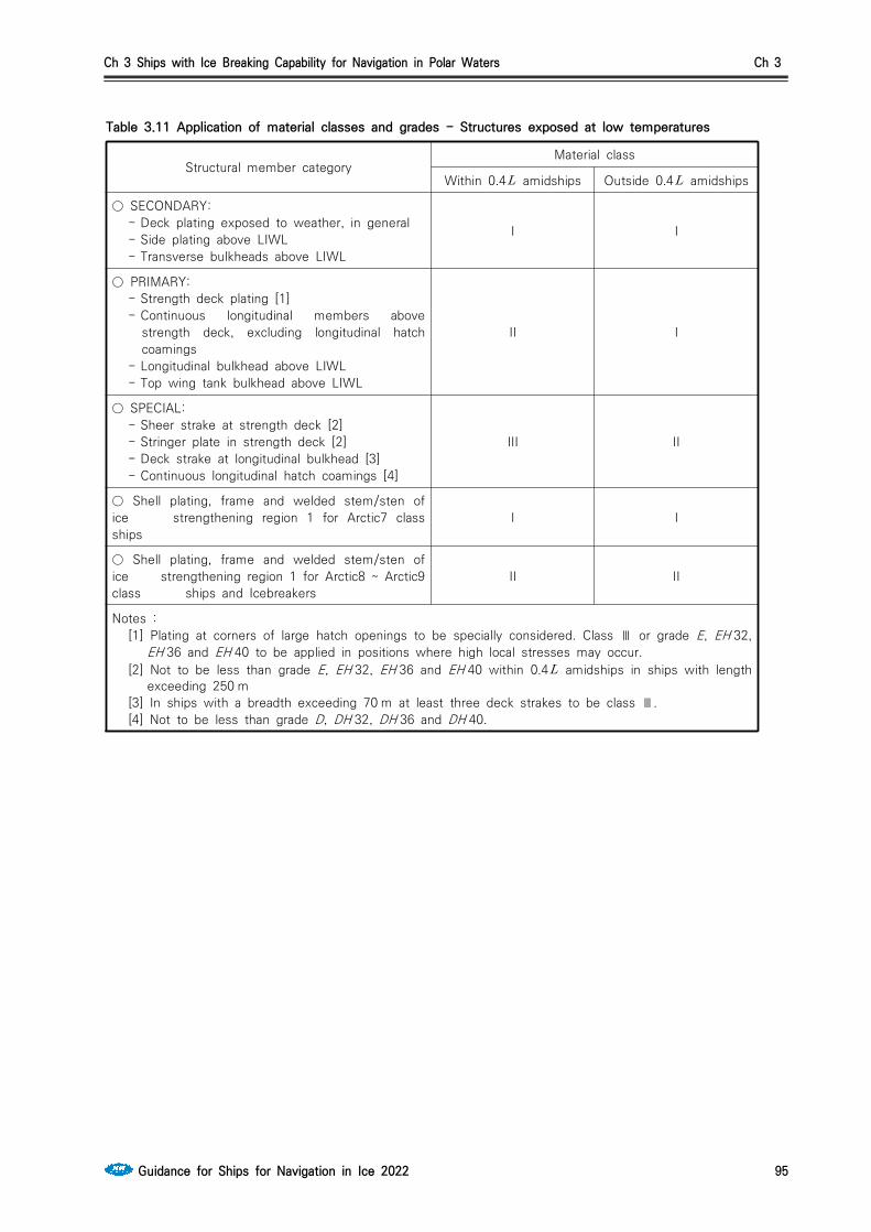
Ch 3 Ships with Ice Breaking Capability for Navigation in Polar Waters Ch 3
Guidance for Ships for Navigation in Ice 2022 95
Table 3.11 Application of material classes and grades - Structures exposed at low temperatures
Structural member categoryMaterial class
Within 0.4 amidships Outside 0.4 amidships
○ SECONDARY:- Deck plating exposed to weather, in general- Side plating above LIWL- Transverse bulkheads above LIWL
I I
○ PRIMARY:- Strength deck plating [1]- Continuous longitudinal members above
strength deck, excluding longitudinal hatch coamings
- Longitudinal bulkhead above LIWL- Top wing tank bulkhead above LIWL
II I
○ SPECIAL:- Sheer strake at strength deck [2]- Stringer plate in strength deck [2]- Deck strake at longitudinal bulkhead [3]- Continuous longitudinal hatch coamings [4]
III II
○ Shell plating, frame and welded stem/sten of ice strengthening region 1 for Arctic7 class ships
I I
○ Shell plating, frame and welded stem/sten of ice strengthening region 1 for Arctic8 ~ Arctic9 class ships and Icebreakers
II II
Notes :[1] Plating at corners of large hatch openings to be specially considered. Class Ⅲ or grade E, EH 32,
EH 36 and EH 40 to be applied in positions where high local stresses may occur.[2] Not to be less than grade E, EH 32, EH 36 and EH 40 within 0.4 amidships in ships with length
exceeding 250 m[3] In ships with a breadth exceeding 70 m at least three deck strakes to be class Ⅲ.[4] Not to be less than grade D, DH 32, DH 36 and DH 40.

Ch 3 Ships with Ice Breaking Capability for Navigation in Polar Waters Ch 3
96 Guidance for Ships for Navigation in Ice 2022
Table 3.12 Material grade requirements for classes I, II and III at low temperatures
Class I
Plate thickness in
(mm)
-20/-25 °C -26/-35 °C -36/-45 °C -46/-55 °C
MS HT MS HT MS HT MS HT
≤ A AH B AH D DH D DH
≤ B AH D DH D DH D DH
≤ B AH D DH D DH E EH
≤ D DH D DH D DH E EH
≤ D DH D DH E EH E EH
≤ D DH D DH E EH E EH
≤ D DH E EH E EH - FH
≤ E EH E EH - FH - FH
Class Ⅱ
Plate thickness in
(mm)
-20/-25 °C -26/-35 °C -36/-45 °C -46/-55 °C
MS HT MS HT MS HT MS HT
≤ B AH D DH D DH E EH
≤ D DH D DH E EH E EH
≤ D DH E EH E EH - FH
≤ E EH E EH - FH - FH
≤ E EH - FH - FH - -
≤ E EH - FH - FH - -
Class Ⅲ
Plate thickness in
(mm)
-20/-25 °C -26/-35 °C -36/-45 °C -46/-55 °C
MS HT MS HT MS HT MS HT
≤ D DH D DH E EH E EH
≤ D DH E EH E EH - FH
≤ E EH E EH - FH - FH
≤ E EH E EH - FH - FH
≤ E EH - FH - FH - -
≤ E EH - FH - FH - -
≤ - FH - FH - - - -
Notes : The symbols in the table mean the grades of steel as follows : AH : AH 32, AH 36 and AH 40, DH : DH 32, DH 36 and DH 40, EH : EH 32, EH 36 and EH 40, FH : FH 32, FH 36 and FH 40 MS : Mild steels, HT : High tensile steels

Ch 3 Ships with Ice Breaking Capability for Navigation in Polar Waters Ch 3
Guidance for Ships for Navigation in Ice 2022 97
205. Structure1. Side grillage structure transversely framed
(1) Side grillage structure transversely framed include conventional frames, deep frames and stringers.
Conventional frame are subdivided into :- main frames in plane of floors or bilge brackets- intermediate frame not in plane as floors or bilge brackets. The intermediate frames are not
mandatory within a side grillage. Not more than one intermediate frame may be fitted be-tween main frames.
Stringer are subdivided into :- side stringers by which a transition of forces is ensured from conventional frames which
directly take up the ice load to deep frames or to transverse bulkhead - intercostal stringers by which joint taking-up of local ice loads by the frames is ensured. It
is recommended that the stringer shall be inter-costal (2) Side grillage structures are permitted as follows :
- grillage with transverse main frames which is formed by conventional frames of the same section and by intercostal stringer
- grillage with transverse web frames which is formed by conventional frames, side stringers and deep frames. Intercostal stringers may be fitted together with side stringers
(3) With a double-bottom structure available, the functions of deep frames are taken over by verti-cal diaphragms, and those of the side stringers, by horizontal diaphragms.
(4) In Icebreakers and Arctic5 ~ Arctic9 class ships, frames shall be attached to decks and platforms with brackets; if a frame is intercostal in way of deck, platform or side stringer, brackets shall be fitted on both sides of it.
(5) The end attachments of main frames shall not less than their section modulus. In Icebreakers solid floors shall be fitted on each main frame. In Arctic8, Arctic9 class ships, solid floors shall be fitted on every other main frame.
(6) In Icebreakers and Arctic class ships, the bottom ends of intermediate frames shall be secured at margin plate stiffened with a lightened margin bracket(or a system of stiffeners) reaching up to longitudinal stiffeners or intercostal members and welded thereto(Fig 3.9)
Fig 3.9 - lighted margin bracket, - system of stiffeners
(7) Where there is no double bottom, the intermediate frames shall extend as far as longitudinal stiffeners or intercostal structure and welded thereto. The particular longitudinal stiffener or inter-costal structure shall be fitted not higher than the floor face-plate level.
(8) In Icebreakers and Arctic class ships, the upper ends of intermediate frames shall be secured on a deck or platform lying above the upper boundary of region I.
(9) In region I and II of Icebreakers and Arctic class ships, intercostal and/or side stringers shall be fitted the distance between which or the stringer-to-deck or platform distance shall not exceed 2 m, as measured on a chord at side.
Side stringers shall be fitted in the UIWL and LIWL regions. If there is a deck or platform lying on the same level, the side stringer may be omitted. Stringers shall be attached to bulkhead by means of brackets.
2. Supporting sections of frames in grillage with transverse framing(1) For frames, horizontal grillages(decks, platforms, bottom) are considered to be supporting
structures. A supporting structure consists of plating(decks, platforms, double bottom) and fram-ing connected thereto(beams, half-beams, floors, tank-side brackets). Where there is no double
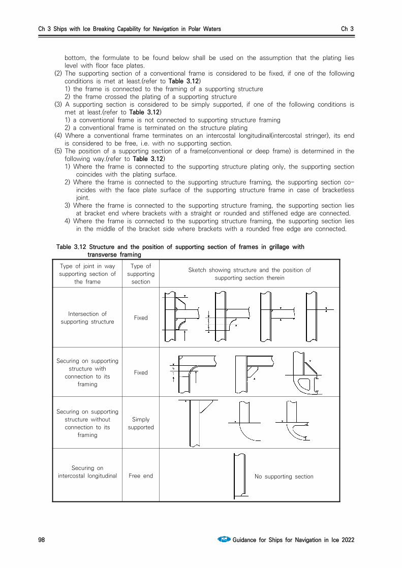
Ch 3 Ships with Ice Breaking Capability for Navigation in Polar Waters Ch 3
98 Guidance for Ships for Navigation in Ice 2022
bottom, the formulate to be found below shall be used on the assumption that the plating lies level with floor face plates.
(2) The supporting section of a conventional frame is considered to be fixed, if one of the following conditions is met at least.(refer to Table 3.12)1) the frame is connected to the framing of a supporting structure2) the frame crossed the plating of a supporting structure
(3) A supporting section is considered to be simply supported, if one of the following conditions is met at least.(refer to Table 3.12)1) a conventional frame is not connected to supporting structure framing 2) a conventional frame is terminated on the structure plating
(4) Where a conventional frame terminates on an intercostal longitudinal(intercostal stringer), its end is considered to be free, i.e. with no supporting section.
(5) The position of a supporting section of a frame(conventional or deep frame) is determined in the following way.(refer to Table 3.12)1) Where the frame is connected to the supporting structure plating only, the supporting section
coincides with the plating surface.2) Where the frame is connected to the supporting structure framing, the supporting section co-
incides with the face plate surface of the supporting structure frame in case of bracketless joint.
3) Where the frame is connected to the supporting structure framing, the supporting section lies at bracket end where brackets with a straight or rounded and stiffened edge are connected.
4) Where the frame is connected to the supporting structure framing, the supporting section lies in the middle of the bracket side where brackets with a rounded free edge are connected.
Table 3.12 Structure and the position of supporting section of frames in grillage with transverse framing
Type of joint in way supporting section of
the frame
Type of supporting
section
Sketch showing structure and the position of supporting section therein
Intersection of supporting structure Fixed
Securing on supporting structure with
connection to its framing
Fixed
Securing on supporting structure without connection to its
framing
Simplysupported
Securing on intercostal longitudinal Free end
No supporting section

Ch 3 Ships with Ice Breaking Capability for Navigation in Polar Waters Ch 3
Guidance for Ships for Navigation in Ice 2022 99
4. Plate structures(1) By plate structures, the sections of deck, platform and double bottom plating, of transverse
bulkhead plating, deep frame plates and bilge brackets which adjoin the shell plating are meant. (2) For hull members mentioned under (1), the areas to be covered by the requirements for plate
structure shall be established as Table 3.13.
Table 3.13 Application area of the requirements for plate structure
Area Ship class Distance from the shell plating
fore peak and after peak bulkheads
Icebreakers and Arctic5 ~ Arctic9 throughout their breadth
other bulkheads in region 1 and 2
Icebreakers and Arctic4 ~ Arctic9
on a breadth of 1.2m
decks and platforms
other hull members on a breadth of 0.6m
(3) In the areas of plate structures mentioned under (2), corrugated structures with corrugations ar-ranged along the shell plating(i.e. vertical corrugations on transverse bulkheads and longitudinal corrugations on decks or platforms) are not permitted.
(4) The plate structures of Icebreakers, Arctic5 ~ Arctic9 class ships and region 1 of Arctic5 class ships shall be provided with stiffeners fitted at right angles approximately to the shell plating. The stiffeners shall be spaced not farther apart than stipulated in Table 3.14.
Table 3.14 Maximum spacing of stiffeners
Orientation of main framing fitted at shell plating
Maximum spacing of stiffeners
Icebreaker, Arctic5(region 1) Arctic6 ~ Arctic9
Arctic5(except region 1),Arctic4(region 1)
Main framing lies across a plate structure , but not greater than 0.5 m , but not greater than 1.0 m
Main framing lies parallel to plate structure 0.6 m 0.8 m
Note : is the spacing of main framing girder, as measured on the shell plating.
(5) The intersections of plate structures with main framing shall be executed in accordance with Table 3.14.

Ch 3 Ships with Ice Breaking Capability for Navigation in Polar Waters Ch 3
100 Guidance for Ships for Navigation in Ice 2022
Table 3.14 The intersections of plate structures with main framing
Ship class
Sketch of structure
Icebreaker5,Icebreaker6
Fore peak, after peak, region 1, 2 with
longitudinal framing
Regions 2, A3, B3, D3, A4, B4
Other regions as per Table 3.9
Icebreaker3,Icebreaker4
Fore peak, after peak, region 1, 2 with
longitudinal framing
Regions 1 and 2 (except fore peak and after peak)
A3, B3, D3
Arctic7 ~ Arctic9 Fore peak, region 1 with longitudinal framing
Regions 1 and 2 (except fore peak), A3, A4, B3, B4
Arctic5, Arctic6Fore peak, region A1, B1,
C1 with longitudinal framing
Regions 1 (except fore peak),
2 , A3, B3
Arctic4 ㅡ Regions 1, A2, B2, A3, B3
(6) Where main framing girders are intercostal in way of the plate structure, brackets shall be fitted on both side of the structure on the same plane as each of the girders, and the girder webs shall be welded to the plate structure.
(7) The following requirements are put forward additionally for the intersections of the plate struc-tures of decks and platforms with main framing. 1) Where transverse framing is used for sides, the frames shall be attached to the beams with
brackets, In Arctic5(region 1 only), Arctic6 ~ Arctic9 class ships, the girders shall be fitted on the same plane as each of the frames.
2) In Arctic5(except region 1) and Arctic4(region 1) class ships, the frame on whose plane no beam is fitted shall be secured to the plate structure with brackets which shall terminate on the intercostal stiffener.
3) Where longitudinal framing is used for sides, the beams shall be attached to the shell plating with brackets reaching as far as the nearest side longitudinal.
(8) The distance from the edge of opening or manhole to the shell plating shall not be less than 0.5m in a plate structure. The distance from the edge of opening or manhole in a plate struc-ture to the edge of opening for the passage of a girder through the plate structure shall not be less than the height of that girder.
5. Fore peak and after peak structure(1) A longitudinal bulkhead welded to the stem or sternframe shall be fitted on the centerline of the
ship in the fore peak and after peak of Icebreakers and Arctic8, Arctic9 class ships, and the lower ends of all frames shall be connected to floors or brackets.
(2) In the fore peak of Icebreakers and Arctic8 ~ Arctic9 class ships, platforms with lightening holes shall be fitted instead of stringers and panting beams, the distance between platforms measured along a chord at side, shall not exceed 2.0m. This structure is recommended for Arctic4 class ships as well.
(3) In the after peak of Icebreakers and Arctic8 ~ Arctic9 class ships, side stringers and panting beams shall be fitted so that the distance between the stringers as measured along a chord at side, would not be greater than 2.0m. The dimensions of stringer webs shall not be less than determined by the formulae.
depth d = 5L + 400 (mm)thickness t = 0.05L + 7 (mm) where , L : length of ship (m)
Platform with lightening holes are recommended instead of panting beams and stringers.

Ch 3 Ships with Ice Breaking Capability for Navigation in Polar Waters Ch 3
Guidance for Ships for Navigation in Ice 2022 101
(4) In Icebreakers and Arctic6 ~ Arctic9 class ships, the side stringers in the fore peak and after peak shall generally be a continuation of those fitted in the region A and D(refer to 203. 1)
(5) In the case of Arctic4 class ships, the area and inertia moment of panting beams shall be in-creased by 25 per cent as compared to those required for non-Arctic class ships. The dimension of stringer webs shall not be less than given by the formula.
depth d = 3L + 400 (mm)thickness t = 0.04L + 6.5 (mm)where , L : length of ship (m)
(6) In the fore peak and after peak, the free edge of side stringers shall be stiffened with face plates having a thickness not less than the web thickness and a width not less than ten thickness. The interconnections of frames with side stringers shall be in accordance with Table 3.14, and brackets shall be carried to the face plates of the stringers.
6. Stem and sternframe construction (1) Arctic6 ~ Arctic9 class ships shall have a solid section stem made of steel(cast steel is recom-
mended). The stems and sternframes of Icebreakers, as well as the sternframes of Arctic5 ~ Arctic9 class ships, shall be made of forged or cast steel. Stems and sternframes welded of cast or forged parts are admissible.
(2) In Arctic4, Arctic5 class ships, a stern of combined structure(a bar with thickened plates welded thereto) or plate structure may be used, and where the ship length is under 150m with a sharp-lined bow, the stem design shown in Fig 3.10 may be used.
Fig 3.10 Stem for ship length is under 150m
(3) In Arctic4 ~ Arctic7 class ships, the stem shall, where practicable, be strengthened by a center line web having its section depth equal to at least(refer to Table 3.35) with a face plate along its free edge or a longitudinal bulkhead fitted on the ship centerline, on the entire stem length from the keel plate to the nearest deck or platform situated above the level referred to in 216. and in Table 3.35. The thickness of this plate shall not be less than that of the brackets. In Icebreakers and Arctic8, Arctic9 class ships, a longitudinal bulkhead may be substituted for the center line web.
(4) Within the vertical extent defined in (3), the stem shall be strengthened by horizontal webs at least 0.6m in depth and spaced not more than 0.6m apart. The webs shall be carried to the nearest frames and connected thereto. Where in line with side stringers, the webs shall be at-tached to them. In stems of combined or plate type, the webs shall be extended beyond the welded butts of the stem and shell plating.
(5) Above the deck or platform located, by the value of at least, higher than the upper boundary of region 1, the spacing of horizontal webs may gradually increase to 1.2m in Icebreakers and Arctic7 ~ Arctic9 class ships, and to 1.5m in ships of other classes. The web thickness shall be adopted not less than half the stem plate thickness. In Icebreakers and Arctic class ships, the free edges of webs shall be strengthened with face plates welded to the frames at their ends. The side stringers of the fore peak shall be connected to the webs fitted in line with them.
(6) Where the stern frame has an appendage(ice knife), the clearance between the latter and the rudder plate shall not exceed 100mm. The appendage shall be reliably connected to the stern frame. Securing the appendage to plate structure is not permitted.
(7) In Icebreakers, the lower edge of sole-piece shall be constructed with a slope of 1:8 beginning from the propeller post.
Ch 3 Ships with Ice Breaking Capability for Navigation in Polar Waters Ch 3
102 Guidance for Ships for Navigation in Ice 2022
7. Bottom structure(1) In Icebreakers and Arctic5 ~ Arctic9 class ships, double bottom shall be provided between the
fore peak bulkhead and the after peak bulkhead.(2) In Icebreakers, provision shall be made for solid floors at each main frame, and in Arctic8,
Arctic9 class ships, at every other main frame.(3) In regions of ice strengthening in way of bottom, as established in accordance with Table 3.9,
bracket floors are not permitted. (4) In Icebreaker and Arctic8, Arctic9 class ships the center-line girder height shall not be less than
determined by the formula.
(mm)
where , = 0.8 for Arctic8 class ships 0.9 for Arctic9 class ships 1.0 for Icebreakers
(5) In Icebreakers and Arctic8, Arctic9 class ships, the spacing of bottom stringers shall not exceed 3.0m.
8. Special requirements(1) In Icebreakers, double side structure shall generally be provided between the fore peak bulkhead
and the after peak bulkhead.(2) In Arctic7 ~ Arctic9 class ships double side structure is necessary for engine room, and for the
region mentioned in (1) it is recommended. (3) Where the web plate of a girder of a plate structure is considerably inclined to the shell plating,
the framing normal to the shell plating or an inclined plate structure is recommended.
206. Ice load 1. Where using the ice load parameters for strength estimation on the basis of other procedures and
programs are to be specially approved by the Society.
2. The ice-load parameters to be determined according to Par 3 to 8 apply to Arctic class ships and Icebreakers with hull shape complying with the requirements of 202. 2. and 202.3 .
3. Ice load for Arctic class ships For Arctic class ships, the ice load(kPa), shall be determined by Table 3.16.

Ch 3 Ships with Ice Breaking Capability for Navigation in Polar Waters Ch 3
Guidance for Ships for Navigation in Ice 2022 103
Ice strengthening region and Arctic class Ice load (kPa)
A1
All class
B1
C1
D1
Arctic4, Arctic5, Arctic6
Arctic7, Arctic8, Arctic9
2, 3, 4 All classthe ice load is determined as follow formula a part of the ice load in region 1 at considered section ∙
Where, , , = factor as specified in Table 3.17 proceeding from the Arctic class = displacement(t) correspond to UIWL = value of the shape factor which is the maximum one for the region, as at considered sections on the ice loadline level. The value shall be determined by the formula.
where ≤
where
= the distance between the considered section and the forward perpendicular(m) = angles(deg) of summer load waterline inclination which shall be measured in accordance with Fig 3.1 and 3.3 (where ) = angles(deg) of frame inclination on UIWL level which shall be measured in accordance with Fig
3.2. Where the frame is concave in a section, a minimal angle shall be chosen for in the case of Arctic4 ~ Arctic9 class ships which is measured on all waterlines of ice navigation
= as specified in Table 3.18. is A, B, C, D for region lengthwise of ice strengthening, is 2, 3, 4 for region transversly of ice strengthening.
Table 3.16 Ice load for Arctic class ships
Arctic class Arctic4 Arctic5 Arctic6 Arctic7 Arctic8 Arctic9
0.79 1.15 1.89 2.95 5.3 7.9
0.80 1.17 1.92 3.06 5.75 8.95
0.50 0.78 1.2 1.2 3.7 5.6
0.75 0.87 1.0 - - -
Table 3.17 The value of , , ,

Ch 3 Ships with Ice Breaking Capability for Navigation in Polar Waters Ch 3
104 Guidance for Ships for Navigation in Ice 2022
Arcticclass
Region lengthwise
forward and intermediate regions (A and B)
midship region(C) aft region(D)
Region vertically
2 3 4 2 3 4 2 3 4
Arctic4Arctic5Arctic6Arctic7Arctic8Arctic9
0.50.650.650.650.70.7
0.40.650.650.650.650.65
0.350.450.50.50.50.5
0.40.50.50.50.550.55
-0.40.450.450.450.45
----
0.250.3
-0.50.50.50.550.55
--
0.350.40.40.4
--
0.150.20.30.35
Table 3.18 The value of
4. The vertical distribution height of ice load for Arctic class ships The vertical distribution height(m) of ice load shall be determined by the following Table 3.19.
Ice strengthening region and Arctic class Vertical distribution height
A
All class
B Max. : Min. :
C
D
Arctic4, Arctic5, Arctic6
Arctic7, Arctic8, Arctic9
Where, , = factor as specified in Table 3.20 proceeding from the Arctic class = factor as specified in Table 3.21 proceeding from the minimal side inclination angle in the midship re-gion of ice strengthening on UWIL
∆
∆ , but not greater than 3.5
= refer to Par 3 = value of the shape factor which is the maximum one for the region, as at considered sections on the ice loadline level. The value shall be determined by the formula.
, where ≤
, where
, where ≥
, where ≺
= refer to Par 3, , = refer to Par 3
Table 3.19 The vertical distribution height of ice load for Arctic class ships

Ch 3 Ships with Ice Breaking Capability for Navigation in Polar Waters Ch 3
Guidance for Ships for Navigation in Ice 2022 105
Arctic class Arctic4 Arctic5 Arctic6 Arctic7, Arctic8, Arctic9
C1C2C3
0.490.550.34
0.60.70.40
0.620.730.47
0.640.750.50
Table 3.20 The value of , ,
Angle of side slope amidships(deg) ≤6 8 10 12 14 16 18
1.00 0.81 0.68 0.54 0.52 0.47 0.44
Table 3.21 The value of
5. The horizontal distribution length of ice load for Arctic class shipsHorizontal distribution length(m) of ice load, shall be determined by the following Table 3.22.
Ice strengthening region Horizontal distribution length
A sin , but not less than
B sin, but not less than
C but not less than
D but not less than
Where, , , , ∆ = refer to Par 4 = angle in the design section of region A for which the value of the parameter is maximum = angle in the design section of region B for which the value of the parameter is maximum = refer to Par 4
Table 3.22 The horizontal distribution length of ice load for Arctic class ships
6. Ice load for Icebreakers
For Icebreakers, the ice load shall be determined by the following Table 3.23.

Ch 3 Ships with Ice Breaking Capability for Navigation in Polar Waters Ch 3
106 Guidance for Ships for Navigation in Ice 2022
Region Ice load
A1
B1, C1, D1
2, 3, 4
Where = ice load in region A1, to be determined in accordance with Par 3 as in the case of a ship whose ice class number coincides with the class of the Icebreaker = 1, where ∑ ≤
∑, where ≻
= propeller shaft output(MW)(MW) = as specified in Table 3.24 = factor as specified in Table 3.25 proceeding from the region of the ship length and class of Icebreaker = ice load in region 1 proceeding from the region lengthwise, , , , = parameter as specified in Table 3.26, is A, B, C, D for region lengthwise of ice strengthening is 2,3,4 for region transversly of ice strengthening.
Table 3.23 The ice load for Icebreakers
Icebreakers
Icebreaker3Icebreaker4Icebreaker5Icebreaker6
10204060
Table 3.24 The value of
RegionIcebreakers
Icebreaker3 Icebreaker4 Icebreaker5 Icebreaker6
B1C1D1
0.650.60.75
0.750.650.75
0.850.70.75
0.850.750.75
Table 3.25 The value of
Region vertically and region lengthwise A2 A3 A4 B2 B3 B4 C2 C3 C4 D2 D3 D4
0.7 0.65 0.5 0.6 0.55 0.45 0.55 0.45 0.35 0.55 0.40 0.30
Table 3.26 The value of
7. As far as Icebreakers are concerned, the vertical distribution height of ice pressure shall be adopted equal for all regions and shall be determined in accordance with Par 4, i.e. when determining , the values of shall be calculated for those sections only which are included in the forward region A of ice strengthening of the Icebreaker.
8. As far as Icebreakers are concerned, the horizontal distribution length of ice pressure shall be adopted equal for all regions are shall be determined in accordance with Par 5, i.e. when determin-ing , the values of shall be calculated for those sections only which are included in the for-ward region A of ice strengthening of the Icebreaker.
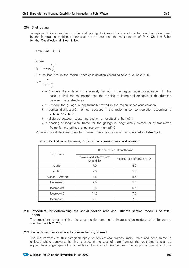
Ch 3 Ships with Ice Breaking Capability for Navigation in Polar Waters Ch 3
Guidance for Ships for Navigation in Ice 2022 107
207. Shell plating
In regions of ice strengthening, the shell plating thickness (mm), shall not be less than determined by the formula. In addition, (mm) shall not be less than the requirements of Pt 4, Ch 4 of Rules for the Classificaion of Steel Ships.
(mm)
where
= ice load(kPa) in the region under consideration according to 206. 3. or 206. 6.
= where the grillage is transversely framed in the region under consideration. In this case, shall not be greater than the spacing of intercostal stringers or the distance between plate structures
= where the grillage is longitudinally framed in the region under consideration = vertical distribution(m) of ice pressure in the region under consideration according to
206. 4. or 206. 7. = distance between supporting section of longitudinal frame(m) = spacing of longitudinal frame for the grillage is longitudinally framed or of transverse
frame for the grillage is transversely framed(m)∆ = additional thickness(mm) for corrosion wear and abrasion, as specified in Table 3.27.
Ship classRegion of ice strengthening
forward and intermediate(A and B) midship and after(C and D)
Arctic4 7.0 5.0
Arctic5 7.0 5.5
Arctic6 ~ Arctic9 7.5 5.5
Icebreaker3 7.5 5.5
Icebreaker4 9.5 6.5
Icebreaker5 11.5 7.5
Icebreaker6 13.0 7.5
Table 3.27 Additional thickness, ∆ for corrosion wear and abrasion
208. Procedure for determining the actual section area and ultimate section modulus of stiff-eners
The procedure for determining the actual section area and ultimate section modulus of stiffeners are specified in Ch 2, 205.
209. Conventional frames where transverse framing is used The requirements of this paragraph apply to conventional frames, main frame and deep frame in
grillages where transverse framing is used. In the case of main framing, the requirements shall be applied to a single span of a conventional frame which lies between the supporting sections of the

Ch 3 Ships with Ice Breaking Capability for Navigation in Polar Waters Ch 3
108 Guidance for Ships for Navigation in Ice 2022
frame on the upper and lower supporting structures. In the case of web frames, the requirements shall be applied to all the spans of a conventional frame.
1. The ultimate section modulus (cm3), of a conventional frame shall not be less than determined by the formula.
(cm3) where
= 1 with
= 0.5 with < 4 = refer to Table 3.28 for grillage with main framing = 4 for grill ages with web framing = factor equal to : the number of fixed supporting sections of two adjacent frames ≤
as far as grillage with main framing are concerned, in the case of grillage with web framing, refer to Table 3.28
= ice load(kPa) in the region under consideration in accordance with 206. 3. or 206. 6. where the lower boundary of region 1 is included in the grillage and this requirements cover region of ice strengthening 1 and 2, the following values of shall be adopted , if the distance from the plating of the upper supporting structure of the grillage to the lower boundary of region 1 is greater than 1.2b, other wise =
, = ice load in regions 1 and 2(refer to 206. 3.) = vertical distribution(m) of ice load in the region under consideration in accordance with 206.
3. or 206. 6. if b > l, b = 1 shall be adopted for the purpose of determining and = conventional frame spacing(m) as measured at side = considered frame span(m) to be determined in accordance with Table 3.28 in the case of
main framing and with Table 3.29 in the case of web framing
= factor equal to 0.9 for conventional frames joined with knees to bearing stringers in a side grillage with deep frames, and equal to 1.0 in other cases
E = factor equal to :
with
with ≥
where = section of the span length (m) overlapped by the region of ice strengthening

Ch 3 Ships with Ice Breaking Capability for Navigation in Polar Waters Ch 3
Guidance for Ships for Navigation in Ice 2022 109
Parameter
Type of intermediate frame end fixation
both endssupported
one end supported,the other free
(attached to an intercostal member)
both ends free(attached to an
inter costal member)
4 3 2
Half the sum ofdistances between
the supportingsections of twoadjacent frames
Distance between the supportingsections of main frame
Table 3.28 The parameter and
Position of conventional frame zone under consideration
Between side stringers Distance between side stringers 4
Between upper (lower) supporting structure and the nearest side
stringer
Half the sum of distances between supporting sections on supporting
structure and the nearest side stringer for two adjacent frames
where ≤ is the number of fixed supporting sections on the
supporting structure for two adjacent frames
Table 3.29 The parameter and
2. The web area (cm2) of a conventional frame shall not be less than determined by the formula.
(cm2)
where
or whichever is greater.
= refer to Par 1, the values of and adopted shall not exceed he distance between bracket ends
= 1 - where no side stringer is provided 0.9 - where there is a side stringer in the span = frame web height(cm), for symmetric bulb and for asymmetric bulb = rolled profile height(cm)∆= additional thickness(mm) for corrosion wear, 2.5 for deep tanks and 1.5 for other regions
3. The actual web area (cm2), shall be determined in accordance with Ch 2, 205.
4. The web thickness (mm), of a conventional frame shall be adopted not less than the greater of

Ch 3 Ships with Ice Breaking Capability for Navigation in Polar Waters Ch 3
110 Guidance for Ships for Navigation in Ice 2022
the following values.
(mm) or
(mm) Where
= , but not less than = 1.0
= actual ultimate section modulus(cm3), of a conventional frame, to be determined in accordance with 208.
, = refer to Par 1 , ∆ = refer to Par 2
5. The face plate breadth (mm), of a conventional frame shall not be less than the greater one of the following values.
(mm) or
(mm) or
(mm)
where , = refer to Par 1 = refer to Par 4 = actual web thickness of a conventional frame(mm) = face plate breadth(mm) of a conventional frame(for beams made of bulbs, shall be
adopted) = refer to Par 2
, but not less than = 0.055
= the greatest spacing(m), of adjacent stringers crossing the frame span or the greatest distance(m) between the stringer and the supporting section
, but not less than = 1
= actual shell plating thickness(mm)
6. Where the face plate breadth is not in accordance with Par 5, the height of a conventional frame shall not be less than determined by the formula. A distance between side stringers or a side stringer and a supporting structure for conventional frames shall not exceed 1.3 m.
(cm)
where = refer to Par 5 ∆ = refer to Par 2

Ch 3 Ships with Ice Breaking Capability for Navigation in Polar Waters Ch 3
Guidance for Ships for Navigation in Ice 2022 111
210. Side and intercostal stringers as part of transverse framing with deep frames1. The ultimate section modulus (cm3) of a bearing side stringer shall not be less than determined by
the formula.
∙ (cm3)
where
(cm3)
= refer to 209. 1. = deep frame spacing(m) as measured along the side ≥ with ≥
≥ with ≺
= refer to 206. 5.
with
with ≥
m = number of side stringers in a grillage = refer to 209. 1.
2. The web area (cm2), of a side stringer shall not be less than determined by the formula.
(cm2)
where = refer to 209. 1. = number of frames fitted between considered side stringers, = refer to Par 1 = web height of a side stringer(cm) = refer to 209. 2.
3. The actual web area (cm2), of a side stringer shall be determined in accordance with Ch 2, 205.
4. The web thickness (mm), of a side stringer shall not be less than determined by the formula
(mm)
where the shorter and longer side, in m, of the panels into which the stringer web is divided
by its stiffeners for an unstiffened web,
= refer to Par 2 = refer to 209. 2. = refer to Par 1
Ch 3 Ships with Ice Breaking Capability for Navigation in Polar Waters Ch 3
112 Guidance for Ships for Navigation in Ice 2022
, = Par 2, 3 = refer to 209. 2.
5. The web height (cm), of a side stringer shall not be less than determined by the formula
(cm)
where = refer to 209. 2.
6. The face plate thickness of a side stringer shall not be less than its actual web thickness. The side stringer without face plate is not permitted.
7. The face plate breadth (mm), of a side stringer shall not be less than the greater of the following values
(mm) or
(mm)
where = refer to Par 1 = actual ultimate section modulus (cm3) of aside stringer, to be determined in accordance
with Ch 2, 205. = face plate thickness (mm) of a stringer = actual web thickness of a stringer = refer to Par 2
8. The web height (cm), of an intercostal stringer in way of a conventional frame shall not be less than determined by the formula
(cm)
where = refer to 209. 2.
9. The web thickness of an intercostal stringer shall not be less than that of a conventional frame, as required in accordance with 209. 4.
211. Deep frames as part of transverse framing1. The ultimate section modulus (cm3) of a deep frame shall not be less than determined by the
formula.
∙ (cm3)
where
= refer to Table 3.31 = number of frames fitted between considered deep frames

Ch 3 Ships with Ice Breaking Capability for Navigation in Polar Waters Ch 3
Guidance for Ships for Navigation in Ice 2022 113
with
with
, = factors to be determined from Table 3.32 = refer to 210. 1. = factor to be adopted equal to the lesser of the following
or
= refer to 209. 1. = refer to 209. 4.
≥ with ≥
≥ with ≺
= refer to 206. 5. = refer to 210. 1. = refer to 209. 1. = span(mm) between supporting section of a deep frames
1 2 3 4 5 6
1.0 1.33 2.0 2.4 3.0 3.43
Table 3.31 The value of
3 4 5 6
0.5 0.417 0.333 0.292
0.25 0.167 0.111 0.083
Table 3.32 The value of ,
2. The web area (cm2) of a deep frame shall not be less than determined by the formula.
(cm2)
where = refer to 209. 1., = refer to Par 1 = refer to 210. 1. = deep frame web depth (cm)∆ = refer to 209. 2.
3. The actual web area (cm2) of a deep frame shall be determined in accordance with Ch 2, 205.4. The web thickness (mm) shall be adopted not less than the greater of the following values.
(mm) or
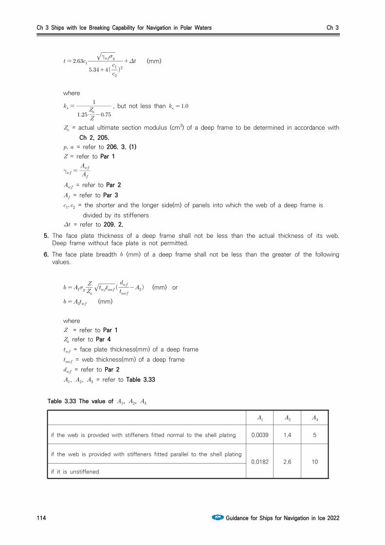
Ch 3 Ships with Ice Breaking Capability for Navigation in Polar Waters Ch 3
114 Guidance for Ships for Navigation in Ice 2022
(mm)
where
, but not less than
= actual ultimate section modulus (cm3) of a deep frame to be determined in accordance with Ch 2, 205.
= refer to 206. 3. (1) = refer to Par 1
= refer to Par 2 = refer to Par 3 = the shorter and the longer side(m) of panels into which the web of a deep frame is divided by its stiffeners = refer to 209. 2.
5. The face plate thickness of a deep frame shall not be less than the actual thickness of its web. Deep frame without face plate is not permitted.
6. The face plate breadth (mm) of a deep frame shall not be less than the greater of the following values.
(mm) or
(mm)
where = refer to Par 1 refer to Par 4 = face plate thickness(mm) of a deep frame = web thickness(mm) of a deep frame = refer to Par 2, , = refer to Table 3.33
if the web is provided with stiffeners fitted normal to the shell plating 0.0039 1.4 5
if the web is provided with stiffeners fitted parallel to the shell plating0.0182 2.6 10
if it is unstiffened
Table 3.33 The value of , ,

Ch 3 Ships with Ice Breaking Capability for Navigation in Polar Waters Ch 3
Guidance for Ships for Navigation in Ice 2022 115
212. Side and bottom longitudinals as part of longitudinal framing1. The ultimate section modulus (cm3) of a longitudinal shall not be less than determined by the
formula.
∙ (cm3)
where
(cm3)
, = refer to 209. 1. = spacing(m) of deep frames or floors
with
with ≥
= spacing(m) of longitudinals = 1, for bottom longitudinals and for side longitudinals where no panting frames are fitted
, for side longitudinals where panting frames are fitted
2. The web area (cm2) of a longitudinal shall not be less than determined by the formula.
(cm2)
where = refer to 209. 1. = refer to Par 1 = factor to be adopted as the greater of the following
, or
= web height (cm) of a longitudinal∆ = refer to 209. 2.
3. The actual web area (cm2) of a longitudinal shall be determined in accordance with Ch 2, 205.
4. The web area (mm) of a longitudinal shall be adopted not less than the greater one of the follow-ing values.
(mm) or
(mm)
where

Ch 3 Ships with Ice Breaking Capability for Navigation in Polar Waters Ch 3
116 Guidance for Ships for Navigation in Ice 2022
, but not less than
= refer to Par 1 = actual ultimate section modulus (cm3) of a longitudinal, to be determined in accordance with
Ch 2, 205. = refer to 209. 1. = refer to Par 1 = refer to Par 2∆ = refer to 209. 2.
5. The face plate breadth (mm) of a longitudinal shall not be less than the greater of the following values.
(mm) or
(mm) or
(mm)
where = refer to Par 1 = refer to Par 4 = actual web thickness(mm) of a longitudinal face plate thickness(mm) of a longitudinal(for longitudinals of bulb, shall be
adopted) = refer to Par 2
, but not less than
, but not less than
= actual shell plating thickness(mm) = refer to Par 1 = span(m) of a longitudinal
6. Where the face plate breadth is not in accordance with Par 5, the height of a longitudinal shall not be less than the value determined by 209. 6.(where shall be assumed equal to ). A distance between deep frames or a deep frame and a supporting structure for longitudinals without face plates shall not exceed 1.3 m.
213. Deep frames as part of longitudinal framing1. The ultimate section modulus (cm3) of a deep frame shall not be less than determined by the
formula.
∙ (cm3)
where
, = refer to 209. 1.
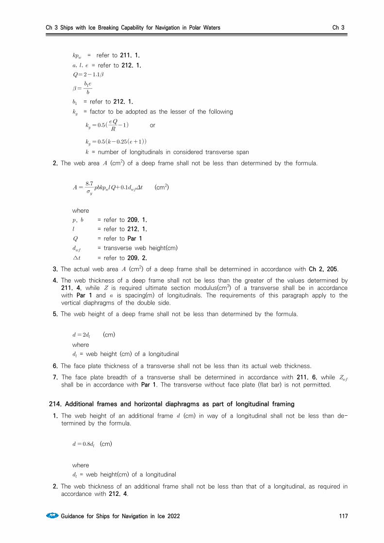
Ch 3 Ships with Ice Breaking Capability for Navigation in Polar Waters Ch 3
Guidance for Ships for Navigation in Ice 2022 117
= refer to 211. 1. = refer to 212. 1.
= refer to 212. 1. = factor to be adopted as the lesser of the following
or
= number of longitudinals in considered transverse span
2. The web area (cm2) of a deep frame shall not be less than determined by the formula.
(cm2)
where , = refer to 209. 1. = refer to 212. 1. = refer to Par 1 = transverse web height(cm)∆ = refer to 209. 2.
3. The actual web area (cm2) of a deep frame shall be determined in accordance with Ch 2, 205.
4. The web thickness of a deep frame shall not be less than the greater of the values determined by 211. 4, while is required ultimate section modulus(cm3) of a transverse shall be in accordance with Par 1 and is spacing(m) of longitudinals. The requirements of this paragraph apply to the vertical diaphragms of the double side.
5. The web height of a deep frame shall not be less than determined by the formula.
(cm)where = web height (cm) of a longitudinal
6. The face plate thickness of a transverse shall not be less than its actual web thickness.
7. The face plate breadth of a transverse shall be determined in accordance with 211. 6. while shall be in accordance with Par 1. The transverse without face plate (flat bar) is not permitted.
214. Additional frames and horizontal diaphragms as part of longitudinal framing1. The web height of an additional frame (cm) in way of a longitudinal shall not be less than de-
termined by the formula.
(cm)
where = web height(cm) of a longitudinal
2. The web thickness of an additional frame shall not be less than that of a longitudinal, as required in accordance with 212. 4.
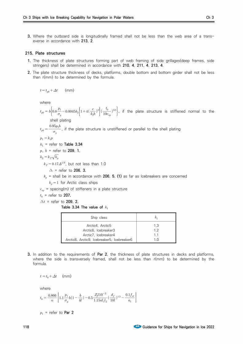
Ch 3 Ships with Ice Breaking Capability for Navigation in Polar Waters Ch 3
118 Guidance for Ships for Navigation in Ice 2022
3. Where the outboard side is longitudinally framed shall not be less than the web area of a trans-everse in accordance with 213. 2.
215. Plate structures1. The thickness of plate structures forming part of web framing of side grillages(deep frames, side
stringers) shall be determined in accordance with 210. 4, 211. 4, 213. 4.
2. The plate structure thickness of decks, platforms, double bottom and bottom girder shall not be less than (mm) to be determined by the formula.
(mm) where
, if the plate structure is stiffened normal to the
shell plating
, if the plate structure is unstiffened or parallel to the shell plating
= refer to Table 3.34, = refer to 209. 1.
, but not less than 1.0 ∆ = refer to 206. 3. = shall be in accordance with 206. 5. (1) as far as Icebreakers are concerned for Arctic class ships = spacing(m) of stiffeners in a plate structure = refer to 207. ∆ = refer to 209. 2.
3. In addition to the requirements of Par 2, the thickness of plate structures in decks and platforms, where the side is transversely framed, shall not be less than (mm) to be determined by the formula.
(mm)
where
= refer to Par 2
Ship class
Arctic4, Arctic5Arctic6, Icebreaker3Arctic7, Icebreaker4
Arctic8, Arctic9, Icebreaker5, Icebreaker6
1.31.21.11.0
Table 3.34 The value of

Ch 3 Ships with Ice Breaking Capability for Navigation in Polar Waters Ch 3
Guidance for Ships for Navigation in Ice 2022 119
= refer to 209. 1. = length(m) of unstiffened section of opening in plate structure for the passage of a
conventional frame, as measured on the shell plating
= distance(m) from the plate structure under consideration to the nearest plate structures (decks, platforms, side stringers, inner bottom plating) on both sides
= spacing(m) of plate structure stiffeners fitted approximately normal to shell plating = cross-sectional area of stiffener(cm2) without effective flange where stiffeners are fitted
parallel to the shell plating or snipped, shall be adopted = refer to 209. 4. = refer to 209. 2. ∆ = refer to 209. 2.
4. Transverse bulkhead plating thickness where the side is longitudinally framed and the floor and bilge bracket thickness where the bottom is longitudinally framed shall not be less than (mm) to be de-termined by the formula.
(mm)
where
, = refer to Par 2 but not greater than
= spacing(m) of side (bottom) longitudinals = refer to 209. 1. = refer to 207. ∆ = refer to 209. 2.
5. The plate structure thickness of transverse bulkheads in a transversely framed side, and of floors in a transversely framed bottom shall not be less than (mm) to be determined by the formula.
(mm)
where
but not greater than
= refer to 209. 1., = refer to Par 2 = refer to Par 4 = spacing(m) of conventional frames (for p1ate structures of bulkheads) or floors (for p1ate
structures of floors) = refer to 207.

Ch 3 Ships with Ice Breaking Capability for Navigation in Polar Waters Ch 3
120 Guidance for Ships for Navigation in Ice 2022
∆ = refer to 209. 2.6. In any case, the plate thickness of decks and platforms, transverse bulkheads, inner bottom, floors
and bilge brackets, bottom stringers and centre girder shall not be less than (mm) to be de-termined by the formula.
(mm)
where
with ≤
,
with
,
with ≥
, for plate structures of, decks and platforms, inner bottom, bottom stringers
and centre girder in a longitudinally framed side or bottom , for the rest of plate structures where the bottom is transversely framed and for all
plate structures where the bottom and side are framed transversely = refer to Par 2 = refer to Par 4 = refer to 209. 1. = spacing(m) of main framing girders of shell plating
where the longer side of plate structure panel adjoins the shell plating
4 where the shorter side of plate structure panel adjoins the shell plating the shorter and longer sides(m) of pane1s into which a p1ate structure is divided by its
stiffeners ∆ = refer to 209. 2.
7. The inertia moment (cm4) of stiffeners by which the plate structures are structures and which are fitted normal to the shell plating shell not be less than determined by the formula.
(cm4)
where span length(m) of stiffener, not greater than
= thickness(mm) of p1ate structure being strengthened spacing(m) of stiffeners sectional area of stiffener(cm2) without effective flange
8. A horizontal grillage adjoining the shell plating in an region of ice strengthening, but not reaching from side to side (deck or platform in way of large openings, horizontal diaphragm of double side, etc.) may be considered a platform if the sectional area of its plating (on one side) is not less than (cm2) to be determined by the formula.

Ch 3 Ships with Ice Breaking Capability for Navigation in Polar Waters Ch 3
Guidance for Ships for Navigation in Ice 2022 121
(cm2)
where , = refer to 209. 1. = design distribution length(m) for the load taken up by the transverse main framing of side,
to be adopted equal to , or to or whichever is less, in the case of framing (transverse or longitudinal) including deep frames
= refer to 206. 5. = refer to 210. 1. = refer to Par 3
Otherwise, such a structure shall be considered a bearing side stringer. Structure considered to be a platform shall comply with the requirements of 215. for the plate structures of platforms, and one considered to be a stringer, with the requirements of 210.
216. Stems and sternframes
1. Stems
(1) The requirements of this paragraph for the section modulus and plate thickness of stem shall be complied on the stem span from the keel to a level extending above the upper boundary of the ice strake by a value of (refer to Table 3.35). In the case of Icebreaker, this stem shall extend up to the nearest deck or platform lying higher than this level.
(2) The cross sectional area (cm2) of stem shall not be less than determined by the formula. (cm2)
where refer to Table 3.35 (cm2) with
(cm2) with ≥
(3) The stem above the borders of the area considered (1), the scantlings may gradually reduce and shall not be less than determined by the formula.
The cross sectional area : (cm2)The thickness : ∙ (mm)
where = The shell plating thickness of region A1 = refer to Table 3.35

Ch 3 Ships with Ice Breaking Capability for Navigation in Polar Waters Ch 3
122 Guidance for Ships for Navigation in Ice 2022
Ship ClassArctic
4Arctic
5Arctic
6Arctic
7Arctic
8Arctic
9
Icebreaker
3
Icebreaker
4
Icebreaker
5
Icebreaker
6
Section (m) above the up-per boundary of the ice strengthening of the stem
0.7 0.8 0.9 1.0 1.1 1.2 1.0 1.5 1.75 2.0
Factor of stem plate thick-ening above the upper boun-dary of strengthening
1.1 1.1 1.05 1 1 1 1 1 1 1
Factor 0.54 0.66 1.02 1.25 1.4 1.55 1.43 1.75 1.96 2.17
Depth of girder, (m) by which the stem is strength-ened
0.6 1.0 1.3 1.5 Longitudinal bulkhead in fore peak centerline
Table 3.35
(4) For strengthened stem, the depth, (m) of vertical girder on centerline shall not be less than the value obtained from Table 3.35. For Icebreakers and Arctic8, Arctic9 class ships, the longitudinal bulkheads are to be fitted on the ceterline.
(5) The section modulus (cm3) of the stem cross sectional area about an axis perpendicular the cen-terline shall not be less than determined by the formula
(cm3)
where , = refer to 209. 1. as far as region of ice strengthening 1 is concerned
(6) Where calculated the area of stem, the cross-sectional area of shell plates and centerline girder or of longitudinal bulkhead on a breadth not exceeding ten times the thickness of relevant plates shall be included.
(7) The plate thickness (mm) of combined and plate stems, as well as of the structure shown in Fig 3.8, shall not be less than determined by the formula.
(mm)
where, = refer to 207. as far as the region of ice strengthening A1 is concerned = spacing(m) of transverse brackets of stem = main framing spacing(m) in the region of ice strengthening A1 = tensile strength(MPa) of shell plating material = tensile strength(MPa) of stem plate material
2. Sternframe The sectional area (cm2) of propeller post and rudder post shall be as given by the formula.
∙ (cm2)
where factor to be adopted from Table 3.36 = sectional area of propeller post or rudder post(cm2) as required for a non-Arctic class ship
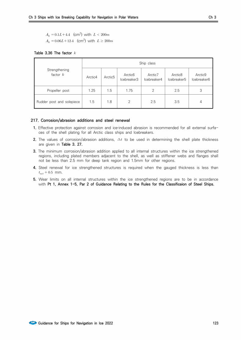
Ch 3 Ships with Ice Breaking Capability for Navigation in Polar Waters Ch 3
Guidance for Ships for Navigation in Ice 2022 123
(cm2) with ≺ (cm2) with ≥
Strengtheningfactor
Ship class
Arctic4 Arctic5 Arctic6Icebreaker3
Arctic7Icebreaker4
Arctic8Icebreaker5
Arctic9Icebreaker6
Propeller post 1.25 1.5 1.75 2 2.5 3
Rudder post and solepiece 1.5 1.8 2 2.5 3.5 4
Table 3.36 The factor
217. Corrosion/abrasion additions and steel renewal 1. Effective protection against corrosion and ice‐induced abrasion is recommended for all external surfa-
ces of the shell plating for all Arctic class ships and Icebreakers.
2. The values of corrosion/abrasion additions, ∆ to be used in determining the shell plate thickness are given in Table 3. 27.
3. The minimum corrosion/abrasion addition applied to all internal structures within the ice strengthened regions, including plated members adjacent to the shell, as well as stiffener webs and flanges shall not be less than 2.5 mm for deep tank region and 1.5mm for other regions.
4. Steel renewal for ice strengthened structures is required when the gauged thickness is less than mm.
5. Wear limits on all internal structures within the ice strengthened regions are to be in accordance with Pt 1, Annex 1-5, Par 2 of Guidance Relating to the Rules for the Classificaion of Steel Ships.

Ch 3 Ships with Ice Breaking Capability for Navigation in Polar Waters Ch 3
124 Guidance for Ships for Navigation in Ice 2022
Section 3 Rudder
301. General1. The rudder stock and upper edge of the rudder are to be effectively protected against ice pressure.
2. Plating materials in rudders and rudder horns are to be in accordance with 204.
3. In Icebreakers and Arctic7 ~ Arctic9 class ships the nozzle rudders shall not be fitted. In Arctic4 ~ Arctic6 class ships the arrangement of the nozzle rudder without the lower pintle in the solepiece is not permitted.
302. The requirements of Rudder 1. The rudder force (kN) are to be in accordance with Pt 4, Ch 1, 201. of the Rules for the
Classificaion of Steel Ships and shall not be less than determined by the formula.
(kN)
where = factor of rudder force, refer to Table 3.37 = rudder area (m2)
Ship class
Arctic4 53
Arctic5 66
Arctic6 75
Arctic7 81
Arctic8 95
Arctic9, Icebreaker3 110
Icebreaker4 130
Icebreaker5 150
Icebreaker6 171
Table 3.37 The factor of rudder force,
2. The ships that are subject to this chapter are to be in accordance with the requirements of rudder of Pt 4, Ch 1 of the Rules for the Classificaion of Steel Ships with rudder force (kN) determined by Par 1.

Ch 3 Ships with Ice Breaking Capability for Navigation in Polar Waters Ch 3
Guidance for Ships for Navigation in Ice 2022 125
Section 4 Machinery installations
401. Power of main machinery1. The requirements to the minimum required power min delivered to the propeller shaft of
Icebreakers and Arctic class ships are given in from (1) to (4) depending on their class. (1) The minimum required power delivered to the propeller shaft of Icebeakers shall be consistent
with their class according to Sec. 1(2) The minimum required power delivered to the propeller shaft of Arctic4 class ship shall not be
less than the lesser of values determined according to (3), (4). The minimum required power delivered to the propeller shaft of Arctic5 ~ Arctic9 class ships shall be determined according to (3).
(3) Minimum required power min shall be determined by formula below.
min ∙∙∆
where, min = minimum required power (kW) = 1.0 for a fixed pitch propeller for propulsion plants with controllable pitch propeller or electric drive but not more than 1. is the rake of the stem at the centerline(degrees) (see Ch 1, Fig 1.8) for a bulbous bowThe product × shall be taken as not less than 0.85. but not less than 1.0
= maximum breadth of the ship (m) = displacement [t] of the ship on the maximum ice draught according to Ch 1,
202. 3 and are given in Table 3.38
Irrespective of the results obtained in calculating the power as per formula above, the minimum power, kW, shall not be less than
10,000 kW for Arctic9 class ship 7,200 kW for Arctic8 class ship 5,000 kW for Arctic7 class ship 3,500 kW for Arctic6 class ship 2,600 kW for Arctic5 class ship 1,000 kW for Arctic4 class ship
Displacement , t ValueArctic class
Arctic4 Arctic5 Arctic6 Arctic7 Arctic8 Arctic9
0.26 0.3 0.36 0.42 0.47 0.5
, kW 740 2200 3100 4000 5300 7500
≥ 0.15 0.2 0.22 0.24 0.25 0.26
, kW 4040 5200 7300 9400 11600 14700
Table 3.38 Value and
(4) The Minimum required power min for Arctic4 class ship, shall be determined as the maximum val-ue calculated as per the formula given in Ch 1, 302. 2 for the upper ice waterline (UIWL) and lower

Ch 3 Ships with Ice Breaking Capability for Navigation in Polar Waters Ch 3
126 Guidance for Ships for Navigation in Ice 2022
ice waterline (LIWL) as indicated in Ch 1, 202. However, the value of , , shall be taken as below.
= 1.0 for Arctic4 class ship = 0 and = 0
(5) The reduction of the required output may be considered for a vessel having design features im-proving performance in ice conditions. Such features are to be documented, either by means of model tests or full scale measurements.
2. In Icebreakers and Arctic6 ~ Arctic9 class ship, turbines and internal combustion engines with me-chanical transmission of power to the propeller may be utilized as main engines, provided use is made of the devices to protect turbines, reduction gears of gas turbine geared sets and die-sel-engine geared sets against the loads exceeding the design torque determined with regard to operation of such ships under ice conditions in compliance with the requirements of 404. 2.
402. Shafting
1. GeneralIn Icebreakers and Arctic class ships, the propeller shafts shall be protected from ice effects.
2. Diameters of shaftsThe diameters of shafts in Icebreakers and Arctic class ships shall exceed the design diameters by value indicated in Table 3.39. The diameter of propeller shafts, in mm, for Icebreakers and Arctic class ships shall, besides, meet the following condition in way of aft bearings.
≥
where, = factor equal to
10.8 for propeller boss diameter equal or less than 0.25D (D is the propeller diameter) 11.5 for propeller boss diameter greater than 0.25D
= actual width of expanded cylindrical section of the blade on the radius of 0.25R for unit-cast propellers and of 0.35R for controllable pitch propeller (m)
= maximum thickness of expanded cylindrical section of the blade on the radii given for (mm)
= tensile strength of the blade material (MPa) = yield stress of propeller shaft material (MPa)
ShaftArctic class Icebreakers
Arctic4 Arctic5 Arctic6 Arctic7 Arctic8, Arctic9
Center shaft Side shaft
Intermediate and thrust 8 12 13.5 15 (1) 18 20
Propeller 15 20 25 30 (1) 45 50
Note: (1) Subject to special consideration by the Society in each particular case.
Table 3.39 Increase of shaft diameter, %
3. Keyless fitting of propellers and shaft couplings (1) When fitting the keyless shrunk assembly, the axial pull-up of the boss in relation to the shaft

Ch 3 Ships with Ice Breaking Capability for Navigation in Polar Waters Ch 3
Guidance for Ships for Navigation in Ice 2022 127
or intermediate sleeve, as soon as the contact area between mating surfaces is checked after eliminating the clearance, shall be determined by the following formula.
where, = axial pull-up of the boss in the course of fitting (cm) = material and shape factor of the assembly (MPa-1), determined by the following for-
mula,
For assemblies with a steel shaft having no axial bore, the factor may be obtainedfrom Table 3.40 using linear interpolation.
= modulus of elasticity of the boss material (MPa) = modulus of elasticity of the shaft material (MPa) = Poisson's ratio for the boss material = Poisson's ratio for the shaft material (for steel =0.3) = mean factor of outside boss diameter = mean factor of shaft bore = mean outside shaft diameter in way of contact with the boss or intermediate sleeve
(cm) = mean internal boss diameter in way of contact with the shaft or intermediate sleeve
(cm), refer to Fig 3.11 without intermediate sleeve, , , therefore
with intermediate sleeve, ≠, ≠, ≠ therefore ≠
for the boss
for the shaft
= active length of the shaft cone or sleeve at the contact with the boss (cm) = taper of the boss = power transmitted by assembly (kW) = speed (rpm) = factor for ice strengthening according to Table 3.41 = propeller thrust at ahead speed (kW) = thermal coefficient of liner expansion of the boss material (℃) = thermal coefficient of liner expansion of the shaft material (℃) = temperature of the assembly in service conditions (℃) = temperature of the assembly in the course of fitting (℃)

Ch 3 Ships with Ice Breaking Capability for Navigation in Polar Waters Ch 3
128 Guidance for Ships for Navigation in Ice 2022
= 1 for assemblies without intermediate sleeve = 1.1 for assemblies with the use of intermediate sleeve
For Arctic class ships, the value shall be chosen as the greater of the results obtained from calculations for extreme service temperatures, i.e:
℃ for
℃ for
Factor × , MPa-1, Steel shaft w=0, × MPa,
Factor
y
Copper alloy boss with , MPa Steel boss with ×
MPa× × × × × × ×
1.2
1.3
1.4
1.5
1.6
1.7
1.8
1.9
2.0
2.1
2.2
2.3
2.4
6.34
4.66
3.83
3.33
3.01
2.78
2.62
2.49
2.39
2.30
2.23
2.18
2.13
5.79
4.26
3.52
3.07
2.77
2.48
2.38
2.29
2.20
2.13
2.06
2.01
1.97
5.34
3.95
3.25
2.83
2.57
2.38
2.23
2.13
2.05
1.98
1.92
1.88
1.84
4.96
3.66
3.03
2.64
2.40
2.22
2.09
1.99
1.92
1.86
1.79
1.75
1.72
4.63
3.43
2.83
2.48
2.24
2.09
1.97
1.88
1.80
1.74
1.69
1.65
1.62
4.34
3.22
2.67
2.34
2.12
1.97
1.86
1.77
1.70
1.65
1.60
1.57
1.54
4.09
3.04
2.52
2.21
2.01
1.87
1.76
1.68
1.62
1.57
1.53
1.49
1.46
3.18
2.38
1.98
1.74
1.59
1.49
1.41
1.35
1.29
1.25
1.22
1.19
1.17
Table 3.40 Factor
Table 3.41 Factor
AssemblyArctic class Icebreakers
Arctic4 Arctic5 Arctic6 Arctic7 Arctic8,Arctic9
Centre shaft
Sideshaft
Propeller with shaft
Coupling with shaft
1.15
1.08
1.20
1.12
1.25
1.135
1.30
1.15
(1)
(1)
1.45
1.18
1.50
1.20
Note:
(1) Subject to special consideration by the Society in each particular case.
(2) When assembling steel couplings and shafts with cylindrical mating surfaces, the interference fit (, cm) shall be determined by the following formula.
Other terms are as defined in (1).(3) For propeller bosses and half-couplings in keyless assemblies with the shafts, the following con-
dition shall be met.
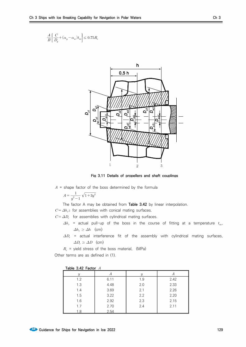
Ch 3 Ships with Ice Breaking Capability for Navigation in Polar Waters Ch 3
Guidance for Ships for Navigation in Ice 2022 129
≤
Fig 3.11 Details of propellers and shaft couplings
= shape factor of the boss determined by the formula
The factor A may be obtained from Table 3.42 by linear interpolation. for assemblies with conical mating surfaces. for assemblies with cylindrical mating surfaces.
= actual pull-up of the boss in the course of fitting at a temperature , ≥ (cm)
= actual interference fit of the assembly with cylindrical mating surfaces, ≥ (cm)
= yield stress of the boss material, (MPa)Other terms are as defined in (1).
Table 3.42 Factor
1.21.31.41.51.61.71.8
6.114.483.693.222.922.702.54
1.92.02.12.22.32.4
2.422.332.262.202.152.11
Ch 3 Ships with Ice Breaking Capability for Navigation in Polar Waters Ch 3
130 Guidance for Ships for Navigation in Ice 2022
403. Propellers
1. Materials of propellersCopper alloys of Type CU3 and Type CU4 are not admitted for propellers in Icebreakers and Arctic7 ~ Arctic9 class ships.
2. Propellers blade thickness(1) Propeller blade thickness is checked in the design root section and in the blade section at the
radius r = 0.6R where R is propeller radius. The location of the design root section is adopted as follows. (A) Solid propellers - At the radius 0.2R where the propeller boss radius is smaller than 0.2R,
and at the radius 0.25R where the propeller boss radius is greater than or equal to 0.2R.(B) Detachable blade propellers - At the radius 0.3R, the values of the factors and being
adopted as in the case of r = 0.25R.(C) CPP - At the radius 0.35R.
In solid propellers, detachable-blade propellers and CPP, the maximum thickness , in mm, of an expanded cylindrical section shall not be less than following formula.
where, = coefficient to be determined from the nomograph in Fig 3.12 depending on the
relative radius r/R of design section and the pitch ratio H/D at this radius (for a CP-propeller, take the pitch ratio of the basic design operating condition)
= coefficient obtained from Table 3.43 = shaft power at the rated output of the main propulsion engine (kW) = number of blades = width of the expanded cylindrical section of the blade on the design radius (m) , but not more than 570 MPa for steels and not more than 610
MPa for copper alloys = tensile strength of blade material (MPa)
= speed at the rated output (rpm) = coefficient of centrifugal stresses to be determined from Table 3.44 = blade rake (mm) = propeller diameter (m)
Table 3.43 Coefficient Arctic class Icebreakers
Arctic4 Arctic5 Arctic6 Arctic7 Arctic8,Arctic9
Centre propeller
Sidepropeller
11.2 12.5 13.2 14 (1) 16
Notes 1. If reciprocating engines with less than four cylinders are installed in the ship, shall be increased by 7 per
cent.2. For reciprocating engines fitted with hydraulic or electromagnetic couplings, may be reduced by 5 per
cent.3. (1) through (2) in this table are subject to the following
(1) Subject to special consideration by the Society in each case.(2) = shaft power, kW.
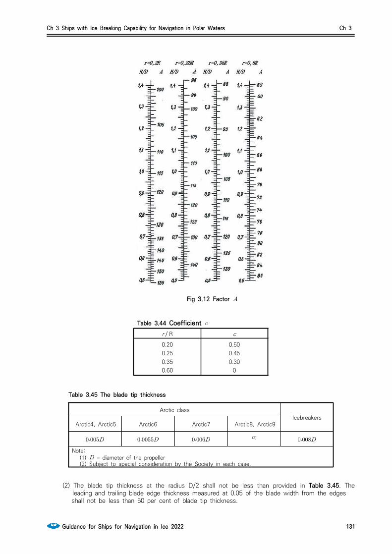
Ch 3 Ships with Ice Breaking Capability for Navigation in Polar Waters Ch 3
Guidance for Ships for Navigation in Ice 2022 131
Fig 3.12 Factor
Table 3.44 Coefficient r / R c0.200.250.350.60
0.500.450.30
0
Arctic classIcebreakers
Arctic4, Arctic5 Arctic6 Arctic7 Arctic8, Arctic9
(2)
Note: (1) = diameter of the propeller (2) Subject to special consideration by the Society in each case.
Table 3.45 The blade tip thickness
(2) The blade tip thickness at the radius D/2 shall not be less than provided in Table 3.45. The leading and trailing blade edge thickness measured at 0.05 of the blade width from the edges
shall not be less than 50 per cent of blade tip thickness.

Ch 3 Ships with Ice Breaking Capability for Navigation in Polar Waters Ch 3
132 Guidance for Ships for Navigation in Ice 2022
(3) The blade thickness calculated in accordance with (1) and (2) may be reduced (e.g. for blades of particular shape), provided a detailed strength calculation is submitted for consideration to the Society.
(4) In Icebreakers and Arctic class ships, the stresses in the most loaded parts of pitch control gear shall not exceed yield stress of the material, if the blade is broken in direction of the weakest section by a force applied along the blade axis over 2/3 of its length from the boss and laterally over 2/3 from the blade spindle axis to the leading edge.
3. Propeller boss and blade fastening parts (1) Fillet radii of the transition from the root of a blade to the boss shall not be less than 0.04D on
the suction side of the blade and shall not be less than 0.03D on the pressure side. If the blade has no rake, the fillet radius on both sides shall be at least 0.03D. Smooth transition from the blade to the boss using a variable radius may be permitted.
(2) The propeller boss shall be provided with holes through which the empty spaces between the boss and shaft cone are filled with non-corrosive mass; the latter shall also fill the space inside the propeller cap.
(3) The diameter of the bolts (studs), by which the blades are secured to the propeller boss or the internal diameter of the thread of such bolts (studs), whichever is less, shall not be less than that determined by the following formula.
where, k = 0.33, in case of three bolts in blade flange, at thrust surface 0.30, in case of four bolts in blade flange, at thrust surface 0.28, in case of five bolts in blade flange, at thrust surfaces = the maximum actual thickness of the blade at design root section (refer to 2. (1)) (mm)b = width of expanded cylindrical section of the blade at the design root section (m) = tensile strength of blade material (MPa) = tensile strength of bolt/stud material (MPa)d = diameter of bolt pitch circle; with other arrangement of bolts, where = the
distance between the most distant bolts (m)(4) The securing devices of the bolts(studs), by which the blades are fastened to the detach-
able-blade propellers of Arctic class ships, shall be recessed in the blade flange. 4. Controllable pitch propellers
(1) The pitch control unit shall be designed so as to enable turning the blades into ahead speed position, shall the hydraulic power system fail. In multi-screw ships with Arctic class of Arctic7, this requirement need not be satisfied.
(2) In ships with a CP-propeller, in which the main engine may become overloaded due to particular service conditions, it is recommended that automatic protection against overloading be used for the main engine.
(3) The time required for the blades to be turned over from full ahead to full astern speed position with main machinery inoperative shall not exceed 20 s for CP-propellers up to 2 m in diameter including, and 30s for CP-propellers with diameters over 2 m.
(4) In the gravity lubrication systems of CP-propellers, the gravity tanks shall be installed above the deepest load waterline and be provided with level indicators and low level alarms.
(5) The sealings fitted to the cone and flange casing of the propeller shaft (if such method of con-nection with the propeller boss is used)shall be tested to a pressure of at least 0,2 MPa after the propeller is fitted in place. If the above sealings are under pressure of oil from the sterntube or the propeller boss, they shall be tested in conjunction with testing of the sterntubes or pro-peller boss.
(6) After being assembled with the blades the boss of a CP-propeller shall be tested by internal pressure equal to a head up to the working level of oil in gravity tank, or by a pressure created by the lubricating pump of the boss. In general, the test shall be made during blade adjustment.

Ch 3 Ships with Ice Breaking Capability for Navigation in Polar Waters Ch 3
Guidance for Ships for Navigation in Ice 2022 133
404. Power transmission system1. In the strength calculation for gear of Pt 5, Annex 5-4 of the Guidance Relating to the Rules for
the Classification of Steel Ships, the application factor , which accounts for externally generated overloads on the gearing, is chosen from Table 3.46 in the absence of special procedures for its determination.
Type of gearing Engine Type of coupling on input shaft max
Main propulsion
Electric motor Any type 1.0 1.1
Turbine Any type 1.0 1.1
Internal com-bustion en-gine
Hydraulic or equivalent coupling 1.0 1.1
High elastic (flexible) coupling 1.3 1.4
Other types 1.5 1.6
Auxiliary
Electric motor Any type 1.0 1.1
Turbine Any type 1.0 1.1
Internal com-bustion en-gine
Hydraulic or equivalent coupling 1.0 1.1
High elastic (flexible) coupling 1.2 1.3
Other types 1.4 1.5
Table 3.46 Application factor
For ships strengthened for ice navigation, the factor for main gearing is determined as a product of ∙ ′ where ′ is obtained from Table 3.47.
2. For Arctic class ships, the torque of the shafts, pinions, wheels of main gearing, shall be calculated by formula below.
′
Where, ′ = refer to Table 3.47 = torque of pinion at the maximum longacting load (Nㆍm)
Factor
Ship class
Arctic4 Arctic5 Arctic6
Arctic7 ~ Arctic9,
Icebreaker3,Icebreaker4
Icebreaker5,Icebreaker6
′ 1.25 1.5 1.75 2.0 2.5
Table 3.47 Factor ′
3. The elastic and disengaging couplings intended for Arctic class ships shall satisfy the requirements of Par 2.
405. Steering gear Main steering gear of Icebreakers and Arctic class ships shall be provided with a device to prevent the ice overload of turning mechanism.

Ch 3 Ships with Ice Breaking Capability for Navigation in Polar Waters Ch 3
134 Guidance for Ships for Navigation in Ice 2022
406. Torsional vibration
1. Torsional vibration calculations
Torsional vibration calculations shall be prepared both for the basic variant and for other variants and conditions possible in the operation of the installation, as follows. (1) Maximum power take-off and idling speed (with the propeller blades at zero position)for in-
stallations comprising CP-propellers or vertical axis propellers.(2) Individual and simultaneous operation of main engines with a common reduction gear.(3) Reverse gear.(4) Connection of additional power consumers if their moments of inertia are commensurate with
the inertia moments of the working cylinder.(5) Running with one cylinder missfiring, for installations containing flexible couplings and reduction
gear; to be assumed not firing is the cylinder the disconnection of which accounts to the great-est degree for the increase of stresses and alternating torques.
(6) Damper jammed or removed where single main engine installations are concerned.(7) Flexible coupling blocked due to breakage of its elastic components (where single main engine
installations are concerned). 2. Permissible stresses for crankshafts
(1) total stresses due to torsional vibration under conditions of continuous running shall not exceed the values determined by the following formulas.
For main engine crankshafts of Icebreakers and of Arctic class ships within the speed range (0.7 ~ 1.05) , and the crankshafts of engines driving generators and other auxiliary machinery for essential services within the speed range (0.9 ~ 1.05) ,When calculating a crankshaft in accord-ance with Pt 5, Annex 5-3 of Guidance Relating to the Rules for the Classification of Steel Ships,
± ------------------------------------------ (1)
When calculating a crankshaft by another method,
±
-------------------------- (2)
For main engine crankshafts of Icebreakers and of Arctic class ships within the speed range lower than 0.7, and the crankshafts of engines driving generators and other auxiliary machi-nery for essential services within the speed range lower than 0.9,
±
-------------------------- (3)
Or, ±
--------------- (4)
where, = permissible stresses (MPa) = the maximum alternating torsional stress determined during crankshaft calcu-
lation from Pt 5, Annex 5-3, Par 2, (2) of Guidance Relating to the Rules for the Classification of Steel Ships.
= tensile strength of shaft material (MPa). When using materials with the ten-sile strength above 800 MPa, = 800 MPa shall be adopted for calculation purposes.
= speed under consideration (rpm). For tugs, trawlers and other ships which main engines run continuously under conditions of maximum torque at

Ch 3 Ships with Ice Breaking Capability for Navigation in Polar Waters Ch 3
Guidance for Ships for Navigation in Ice 2022 135
speeds below the rated speed throughout the speed range, shall be adopted and formulas (1) and (2) shall be used. For the main diesel gen-erators of ships with electric propulsion plants, all the specified values of shall, by turn, be adopted as , and in each of the ranges (0.9 ~ 1.05) , formulas (3) and (4) shall be used for partial loads.
= rated speed (rpm) : scale factor.
where, = shaft diameter (mm)
(2) The total stresses due to torsional vibration within speed ranges prohibited for continuous run-ning, but which may only be rapidly passed through shall not exceed the values determined by the following formulas.
For the crankshafts of main engines,
For the crankshafts of engines driving generators or other auxiliary machinery for essential services,
----------------------------------------- (5)
where, = permissible stresses for speed ranges to be rapidly passed through (MPa) = permissible stresses determined by one of formulas (1) to (4) of (1).
3. Permissible stresses for intermediate, thrust, propeller shafts and generator shafts(1) Under conditions of continuous running, the total stresses due to torsional vibration shall not ex-
ceed the values determined by the following formulas.
For the shafts of Icebreakers and of Arctic class ships within the speed range (0.7 ~ 1.05) , and generator shafts within the speed range (0.9 ~ 1.05) .
±
For the shafts of Icebreakers and of Arctic class ships within the speed range lower than 0.7 , and generator shafts within the speed range lower than 0.9 ,
±
where, = tensile strength of the shaft material (MPa). When using the material with
the tensile strength over 800 MPa (for intermediate and thrust shafts of al-loyed steel) and over 600 MPa (for intermediate and thrust shafts of carbon and carbon-manganese steel, as well as for propeller shaft) = 800 MPa

Ch 3 Ships with Ice Breaking Capability for Navigation in Polar Waters Ch 3
136 Guidance for Ships for Navigation in Ice 2022
and = 600 MPa shall be assumed in the calculations accordingly. = factor obtained from Pt 5, Ch 4, Table 5.4.1 of Rules for the Classification of
Steel Ships. = refer to Par 2. (1)
(2) The total stresses due to torsional vibration within speed ranges prohibited for continuous run-ning, but which may only be rapidly passed through shall not exceed.
For intermediate, thrust, propeller shafts and shafts of generators driven by the main engine
For the shafts of generators driven by auxiliary engines, refer to formula (5) of Par 2, (2).
4. Permissible torque in reduction gear(1) For the case of continuous running or rapid passage, the alternating torques in any reduction
gear step shall not exceed the permissible values established for the operating conditions by the manufacturer.
(2) Where the values mentioned under (1) are not available, the alternating torque in any reduction gear step for the case of continuous running shall satisfy the following conditions.
Within the speed range (0.7 ~ 1.05) for the main propulsion plants of Icebreakers and of Arctic class ships,
≤
Within speed ranges lower than 0.7, the permissible value of alternating torque will be specially considered by the Society in each case, but, in any case.
≤
where, = average torque in the step under consideration at nominal speed (Nㆍm) = average torque at the speed under consideration (Nㆍm)
For the case of rapid passage, the alternating torque value is subject to special consideration by the Society in each case.
5. Permissible torque and temperature of flexible couplings(1) For the case of continuous running or rapid passage, the alternating torque in a coupling, rele-
vant stresses in and temperatures of the flexible component material due to torsional vibration shall not exceed the permissible values established for the operating conditions by the manufacturer.
(2) Where the values mentioned under (1) are not available, the torque, stress and temperature val-ues permissible for continuous running and rapid passage shall be determined by the procedures approved by the Society.
6. Other installation components(1) Under conditions of continuous running, the total torque (average torque plus alternating tor-
que)shall not exceed the frictional torque in the keyless fitting of the propeller and shaft or shafting couplings.
(2) Where, for generator rotors, the Manufacturer's permissible values are not available, the alternat-ing torque shall not exceed twice, in the case of continuous running, or six times, in the case of rapid passage, the nominal generator torque.

Ch 3 Ships with Ice Breaking Capability for Navigation in Polar Waters Ch 3
Guidance for Ships for Navigation in Ice 2022 137
7. Torsional vibration measurement(1) Data obtained from torsional vibration calculations for machinery installations with the main en-
gines shall be confirmed by measurements. The measurements shall cover all the variants and operation conditions of the installation, for which calculations were made in accordance with Par 1, except emergency operation conditions listed in (6) and (7).
(2) The results of measurement obtained on the first ship (unit)of a series apply to all the ships (units) of that series, provided their engine-shafting-propeller(driven machinery) systems are identical.
(3) The free resonance vibration frequencies obtained as a result of measurement shall not differ from the design values by more than 5 per cent. Otherwise, the calculation shall be corrected accordingly.
8. Restricted speed ranges(1) Where the shaft stresses, torques in some installation components or temperature of the rubber
components of flexible couplings arising due to torsional vibration exceed the relevant permissible values for continuous running determined, restricted speed ranges are assigned.
(2) No restricted speed ranges are permitted for the speeds equal to or greater than 0.7 with re-spect to Icebreakers and of Arctic class ships, and for (0.9~1.05) with respect to diesel gen-erators and other auxiliary diesel machinery for essential services. Where the main diesel gen-erators of ships with electric propulsion plants are concerned, all the fixed speed values corre-sponding to the specified conditions of partial loading shall alternately be adopted for .
In icebreakers and ships with ice categories Arctic7 to Arctic9 fitted with a FPP, blade frequency resonance shall be avoided within the range (0.5~0.8) .
(3) For Icebreakers and of Arctic class ships within the main engine speed range (0.7~1.05), and for diesel generators within the speed range (0.9~1.05) vibration dampers or antivibrators may be used to eliminate restricted speed ranges subject to special consideration by the Society in each case.
407. Spare partsTwo spare propeller blades per one propeller completed with securing items for detachable propeller and controllable pitch propeller are to be provided that are necessary for the case of eventual re-placement by the crew when afloat.
408. Seachests and ice boxes1. Number and arrangement of seachests for the cooling water system shall comply with Pt 5, Ch 6,
703. of Rules for the Classificaion of Steel Ships. In Arctic4 and Arctic5 class ships, one of the sea chests shall function as an ice box. In Icebreakers and Arctic6 ~ Arctic9 class ships, at least two sea chests shall be ice boxes. In Icebreakers and Arctic class ships, the ice box design shall allow for an effective separation of ice and removal of air from the ice box to ensure reliable operation of the seawater system. Sea inlet valves shall be secured directly to seachests or ice boxes.
2. In Icebreakers and Arctic class ships, provision shall be made for the heating of the seachests and ice boxes as well as of the ship side valves and fittings above the load waterline. For this purpose cooling water recirculation shall be used for ice boxes and sea chests. Ship side valves and fittings shall be supplied with heating medium through a non-return shut-off valve. The heating arrange-ments shall be so designed as to prevent the side valves and fittings and shell plating from being damaged under the influence of lowest temperatures. Electric heating systems with special heating cables may be used for valves heating. For ice boxes the recirculated water pipes shall be laid to the upper and lower part of the box, and the total sectional area of these pipes shall not be less than the area of the cooling water discharge pipe. For seachests, the diameter of the water re-circulating pipe shall not be less than 0.85 of the discharge pipe diameter.
409. Flexible hosesSleeves for cargo and fuel oil hoses of Arctic class ships shall be subjected to cold endurance type tests. For this purpose samples of the hoses shall be kept at the temperature of -40 °C during 4 hour and be tested for elasticity by means of bending for 180° two times in the opposite directions around the adapter with a diameter of R, where R is a minimum bending radius; whereupon a visu-al examination is carried out. After freezing and bending no cracks shall appear on the internal and
Ch 3 Ships with Ice Breaking Capability for Navigation in Polar Waters Ch 3
138 Guidance for Ships for Navigation in Ice 2022
external surfaces of the sample. Where necessary, the sample may be cut along the axis for the internal surface inspection. On agreement with the Society, another method for freeze resistance test with allowance made for special structural features may be accepted.
410. Ballast, heel and trim systems In Icebreakers and Arctic class ships, the fore and after peaks, as well as structural wing tanks for water ballast, located above the waterline and in way of cargo holds, shall be provided with heating arrangements. The double bottom tanks in way of cargo holds, intended for water ballast, are rec-ommended to be fitted with heating coils.
411. Ventilation systemIn Icebreakers and Arctic class ships, precautions shall be taken to prevent admission of snow into the ventilation ducts. It is recommended to arrange the air intakes on both sides of the ship and to provide for heating arrangements.
412. Compressed air systemFor Icebreakers and Arctic6 ~ Arctic9 class ships the total capacity of air receivers and the number of compressors for starting and reversing of the main engines is subject to special consideration by the Society in each case.
Section 5 Subdivision and Stability
501. General 1. The ships that are subject to this chapter are to be accordance with the requirements of relevant
international conventions in addition to the requirements of this section.
502. Documentation1. Documentation for approval
- preliminary damage stability calculations - final damage stability calculations
(not required in case of approved limit curves, or if approved lightweight data are not less fa-vourable than estimated lightweight data).
2. Documentation for information - internal watertight integrity plan.
3. Other plans and documents deemed necessary by the Society
503. Intact stability1. Under all loading conditions to be encountered in service and which are in agreement with the pur-
pose of the ship, the intact stability shall be sufficient for satisfying damage stability requirements.
2. The requirements of intact stability are to be in accordance with Ch 2, 104. 1 (1)
504. Arctic class ships1. For the purpose of damage stability calculations, the following extent of ice damage shall be as-
sumed(a) longitudinal extent 0.045 of upper ice waterline length if centered forward of the point of max-
imum beam on the waterline, and 0.015 of upper ice waterline length otherwise(b) depth 760 mm measured normal to the shell over the full extent of the damage and(c) vertical extent the lesser of 0.2 of upper ice draft, or of longitudinal extent.(4) location of ice damage from the keel to the level of 1.2 and within (5) the vertical extent of damage may be assumed from the keel to the level of 1.2
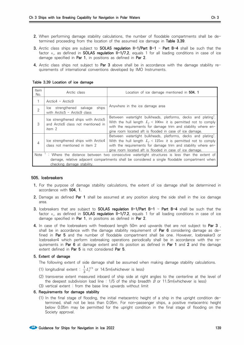
Ch 3 Ships with Ice Breaking Capability for Navigation in Polar Waters Ch 3
Guidance for Ships for Navigation in Ice 2022 139
2. When performing damage stability calculations, the number of floodable compartments shall be de-termined proceeding from the location of the assumed ice damage in Table 3.39.
3. Arctic class ships are subject to SOLAS regulation II-1/Part B-1 ~ Part B-4 shall be such that the factor , as defined in SOLAS regulation II-1/7.2, equals 1 for all loading conditions in case of ice damage specified in Par 1, in positions as defined in Par 2.
4. Arctic class ships not subject to Par 3 above shall be in accordance with the damage stability re-quirements of international conventions developed by IMO Instruments.
ItemNo. Arctic class Location of ice damage mentioned in 504. 1
1 Arctic4 ~ Arctic9Anywhere in the ice damage area
2 Ice strengthened salvage ships with Arctic5 ~ Arctic9 class
3Ice strengthened ships with Arctic5 and Arctic6 class not mentioned in item 2
Between watertight bulkheads, platforms, decks and plating1. With the hull length ≺ it is permitted not to comply with the requirements for damage trim and stability where en-gine room located aft is flooded in case of ice damage.
4 Ice strengthened ships with Arctic4 class not mentioned in item 2
Between watertight bulkheads, platforms, decks and plating1. With the hull length ≺ it is permitted not to comply with the requirements for damage trim and stability where en-gine room located aft is flooded in case of ice damage.
Note 1 : Where the distance between two consecutive watertight structures is less than the extent of damage, relative adjacent compartments shall be considered a single floodable compartment when checking damage stability.
Table 3.39 Location of ice damage
505. Icebreakers 1. For the purpose of damage stability calculations, the extent of ice damage shall be determined in
accordance with 504. 1.
2. Damage as defined Par 1 shall be assumed at any position along the side shell in the ice damage area.
3. Icebreakers that are subject to SOLAS regulation II-1/Part B-1 ~ Part B-4 shall be such that the factor , as defined in SOLAS regulation II-1/7.2, equals 1 for all loading conditions in case of ice damage specified in Par 1, in positions as defined in Par 2.
4. In case of the Icebreakers with freeboard length 50m and upwards that are not subject to Par 3 , shall be in accordance with the damage stability requirement of Par 6 considering damage as de-fined in Par 5 and the number of floodable compartment shall be one. However, Icebreaker3 or Icebreaker4 which perform icebreaking operations periodically shall be in accordance with the re-quirements in Par 6 at damage extent and its position as defined in Par 1 and 2 and the damage extent defined in Par 5 is not considered Par 5.
5. Extent of damage The following extent of side damage shall be assumed when making damage stability calculations. (1) longitudinal extent :
or 14.5m(whichever is less)
(2) transverse extent measured inboard of ship side at right angles to the centerline at the level of the deepest subdivision load line : 1/5 of the ship breadth B or 11.5m(whichever is less)
(3) vertical extent : from the base line upwards without limit6. Requirements for damage stability
(1) In the final stage of flooding, the initial metacentric height of a ship in the upright condition de-termined, shall not be less than 0.05m. For non-passenger ships, a positive metacentric height below 0.05m may be permitted for the upright condition in the final stage of flooding on the Society approval.

Ch 3 Ships with Ice Breaking Capability for Navigation in Polar Waters Ch 3
140 Guidance for Ships for Navigation in Ice 2022
(2) For unsymmetric flooding the angle of heel shall not exceed 20˚ before equalization measures and cross-flooding fitting being used, 12˚ after equalization measures and cross-flooding fittings being used.
(3) The static stability curve of a damaged ships shall have a sufficient positive lever arm section. In the final stage of flooding and after the equalization of the ship, a length of positive lever arm curve, flooding angle considered, shall be ensured not less than 20˚.
(4) The angle of submersion of the opening which are not equipped with watertight or weathertight covers through which water may spread to intact compartments may be taken as flooding angle.
(5) The maximum lever arm shall be at least 0.1m within this length, i.e. within the heel angel equal to the static one plus 20˚. The positive lever arm section within the said extant shall not be less than 0.0175m·rad.
(6) In the intermediate stages of flooding, the maximum lever arm of the static stability curve shall be at least 0.05m, and the length of its positive section shall not be less than 7˚.
(7) The damage waterline shall be at least 0.3m or (whichever is less) below the opening in the bulkheads, decks and sides through which progressive flooding could take place. Such opening include the outlets of air and vent pipes and those which are closed by means of weathertight doors and covers. These do not necessarily include :(a) non-opening side and deck scuttles(b) manholes having covers with closely space bolts(c) cargo tank hatchway in tankers(d) remotely controlled sliding doors, watertight doors with indication systems and access hatch
normally closed at sea
506. Requirements to watertight integrity 1. As far as practicable, tunnels, ducts or pipes which may cause progressive flooding in case of dam-
age, are to be avoided in the damage penetration zone.
2. The scantlings of tunnels, ducts, pipes, doors, staircases, bulkheads and decks, forming watertight boundaries, are to be adequate to withstand pressure heights corresponding to the deepest equili-brium waterline in damaged condition.
3. Excluding cases that comply with Par 4, no Arctic class ships and Icebreakers should carry any pol-lutant directly against the outer shell. Any pollutant should be separated from the outer shell of the ship by double skin construction of at least 760 mm in width.
4. All Arctic class ships and Icebreakers should have double bottoms over the breadth and the length between forepeak and after peak bulkheads. Double bottom height should be in accordance with the rules of the Classification Societies in force. Double bottoms should not be used for the carriage of pollutants except where a double skin construction complying with Par 3 is provided, or where working liquids, are carried in way of main machinery spaces in tanks not exceeding 20 m3 individual volume.
5. All Arctic class ships and Icebreakers with icebreaking bow forms and short forepeaks may dispense with double bottoms up to the forepeak bulkhead in the area of the inclined stem, provided that the watertight compartments between the forepeak bulkhead and the bulkhead at the junction between the stem and the keel are not used to carry pollutants.

Ch 4 Winterization Ch 4
Guidance for Ships for Navigation in Ice 2022 141
CHAPTER 4 Winterization
Section 1 General
101. Scope The requirements of this chapter apply to ships intended to navigate in cold climates and may be exposed to low temperatures that may cause equipment to freeze due to ice accretion from atmos-pheric icing or sea spray, or due to freezing of liquid within a system. Protection measures are to be provided and operational procedures are to be specified to ensure that equipment is suitably protected to enable operation in low temperatures.
102. Application 1. Compliance with this chapter is optional and the requirements are additional to those subject to the
Rules for the Classification of Steel Ships.
2. Where a class notation of Ch 1 or Ch 2 or Ch 3 is to be assigned in addition to Winterization nota-tion, the requirement of Ch 1 or Ch 2 or Ch 3 are to be applied additionally.
3. It is the responsibility of the Owner to determine design air temperatures, are most suitable for a particular ship's operational requirements.
4. Application of this Chapter is to be based on the lowest external design air temperature, refer to 104. This temperature does not apply to continuous operation, but is based on a distribution of op-erational time around an average temperature, assumed to be -10°C for normal worldwide operation. Therefore, the duration of time for ship operations at temperatures below the average temperature will decrease to a minimum at the lowest temperature, and thus the operating time at the lowest temperature is assumed to be minimal
5. Ships complying with the requirements of this Chapter may be eligible for one or more of the fol-lowing notations. Where applicable, these winterization notations are specified in below (1), (2) may be assigned one or a combination of them, e.g. Winterization E2(-35) S(A). (2017)(1) Winterization H(t) : Where materials for hull construction are in compliance with Sec. 2 in asso-
ciation with an external design air temperature of t degrees Celsius.(2) Winterization M(t) : Where materials for hull equipments and system are in compliance with Sec.
3 in association with an external design air temperature of t degrees Celsius.(3) Winterization E1(t), Winterization E2(t) or Winterization E3(t) : Where equipment and systems are
in compliance with Sec. 4 ~ 6 in association with an external design air temperature of T degrees Celsius.
(4) Winterization S(A), Winterization S(B) or Winterization S(C) : Where stability are in compliance with Sec. 7 in association with the specified ice accretion values.
(5) Winterization D(t) : Where alternative designs, compliance with Sec. 8 in association with an external design air temperature of T degrees Celsius are applied.
(6) Winterization IR : Where ice removals are compliance with Sec. 9.6. Information for selection of a suitable winterization level is given in Table 4.1. This is based on the
intended operational scenarios for Winterization E1(t), Winterization E2(t) and Winterization E3(t) lev-els and in association with the average and lowest external design air temperatures.
7. For the assignment of Winterization E1(t), it is in subject to the requirements of this Chapter and where applicable, to be in accordance with the IMO Guidelines for Ships Operating in Arctictic Ice-Covered Waters : MSC/Circ. 1056 MEPC/Circ. 399.

Ch 4 Winterization Ch 4
142 Guidance for Ships for Navigation in Ice 2022
Winterization level Description External designair temperature (°C) operational scenario
Winterization E3(t) Mild Down to -30°C
Short transits in low temperatures - for example, ships loading or discharging in low temperatures then sailing to discharge or load in warmer regions
Winterization E2(t) Moderate -31°C to -45°C
Seasonal operation in cold temperatures - for example, ships operating continuously in low temperatures during the winter months
Winterization E1(t) Severe -46°C and below
Prolonged operation in extreme low temperatures - for example, ships operating year round in the Arctic or Antarctic
Table 4.1 Operational scenario for winterization requirements (2017)
103. Information required (2017)1. For Winterisation H(t), details of material grades are to be included on the hull structure plans re-
quired for submission.
2. For Winterization levels E1(t), E2(t) and E3(t) a Winterization Manual is to be submitted. The Winterization Manual is to contain the following detailed information in order to demonstrate that the design and installation of winterization features of the ship complies with Sec. 4 ~ Sec. 6. (1) General arrangement highlighting winterization features and design temperatures.(2) List of winterization equipment and systems.(3) Details of tank heating, see 410.(4) Details of heating arrangements for spaces, see 408. (5) Inventory and locations of ice removal measures, see 411.(6) Details of accommodation and escape route arrangements, see 409.(7) Details of anchoring/mooring and deck crane arrangements, see 405.(8) Details of main/auxiliary engines arrangements, see 402 and 403.(9) Details of materials specification/heating arrangements for exposed pipework/components, see
404.(10) Details of materials specification/heating arrangements for exposed electrical cables/components,
see 406.(11) Details of winterization of emergency appliances, see 407.(12) Details of operational and maintenance procedures e.g.
• Continuous circulation of fluids and/or heating media.• Use of heating arrangements in sub-zero temperatures.• Application of silicone spray or other suitable low temperature films to door/hatch seals.• Application of low temperature lubricants.• Use of antifreeze in liquid filled pressure/vacuum breakers in inert gas lines on tankers.• Use of antifreeze in emergency generators and lifeboat /rescue boat engines.• Use of oil fuel for emergency generators and lifeboat /rescue boat engines that is suitable for low temperature conditions.• Use of low temperature grease for lifeboat/rescue boat davits/sheaves/release hooks and for radar motors.• Use of suitable antifreeze solutions for bridge window cleaning.• Steam heating coil condensate evacuation (draining) if and when heating coils are redundant.
3. For Winterization S(A), S(B) and S(C), details of the trim and stability conditions, and calculations, are to be submitted in order to demonstrate that the design of the ship complies with Sec.7.
4. Where an alternative design is used for Winterization D(t), as described in Sec.8, the Winterization Manual is to be submitted based on an agreed specification list confirmed by the Builder Shipbuilder

Ch 4 Winterization Ch 4
Guidance for Ships for Navigation in Ice 2022 143
and Owner with reference to the intended operation, ship type and arrangement.
5. Details of the average design external air temperature, lowest design external temperature and de-sign internal air temperature/ambient conditions for spaces within the ship are to be agreed with the Owner and Builder and submitted Shipbuilder. These details are to include machinery spaces, habitable spaces, those commonly accessed and any other spaces where the temperature will differ. Temperatures are to be rounded down to the nearest integer, e.g. -21.5°C is to be -22°C.
6. A copy of the Winterization Manual is to be placed on board the ship.
104. Definitions (2017)1. Mean Daily Low Temperature
The MDLT() is to be taken as the lowest mean daily average low air temperature in the area of operation. For seasonally restricted service the lowest value within the period of operation applies.
Where Mean = statistical mean over a minimum of 10 yearsAverage = average during one day and one nightLowest = lowest during the year or seasonMDHT = Mean Daily High TemperatureMDAT = Mean Daily Average TemperatureMDLT = Mean Daily Low Temperature
Fig 4.1 Average external design air temperature
2. External design air temperatureThe external design air temperature () is to be taken as the lowest mean daily low air temperature in the area of operation for the season of operation () minus 10 degrees Celsius ( ). For example: = -20℃, = -30℃. Where a Polar Service Temperature is defined for compliance with the IMO Polar Code, the external design air temperature () used in this chapter is to be taken as the Polar Service Temperature. Where reliable environmental records for contemplated operational areas exist, the lowest external design air temperature may be obtained after the exclusions of all recorded values having a probability of occurrence of less than 3 per cent.
3. Design internal air temperature / ambient conditionsThe design parameters for the heating systems for accommodation and heated spaces(to be defined for each individual space). See 103. 5.
4. CoversMaterials and arrangements used to protect items or equipment. These may be fixed type, such as mild steel, or removable, such as PVC coated nylon or other water-resistant material and are to completely cover the item of equipment without impairing its function.

Ch 4 Winterization Ch 4
144 Guidance for Ships for Navigation in Ice 2022
5. Heating arrangementsEquipment and systems used to provide heat by means of electrical, steam, oil or other means
6. Ice removal measuresShip services or tools used to facilitate the removal of ice by means of steam, hot water or hot air, manual tools, de-icing compounds or other means.
7. Protected locationsLocation behind walls, screens, bulkheads and equipment, located inboard and recessed, onboard the ship and providing protection from icing.
Section 2 Winterization H - Materials for hull construction at low temperatures (2017)
201. Hull construction materials 1. The requirements in this section are to provide steel grades with suitable notch toughness based on
the thickness of the material and the location of the material.
2. The hull construction materials of exposed members identified in Table 4.2 and Fig. 4.2 are to com-ply with Table 4.3.
3. Where the material class in Pt 3, Ch 1 of the Rules is higher than in Table 4.2 and Fig. 4.2, the higher material class is to be applied.
4. In addition to the requirements of Table 4.2 and Fig. 4.2, miscellaneous attachments are to comply with Table 4.4.
5. Welding consumables are to comply with the requirements of Pt 2, Ch 2, Sec. 6 of the Rules for the Classification of Steel Ships.
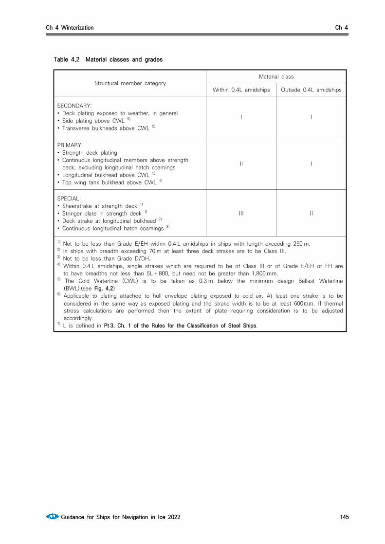
Ch 4 Winterization Ch 4
Guidance for Ships for Navigation in Ice 2022 145
Structural member categoryMaterial class
Within 0.4L amidships Outside 0.4L amidships
SECONDARY:• Deck plating exposed to weather, in general• Side plating above CWL 5)
• Transverse bulkheads above CWL 5)
I I
PRIMARY:• Strength deck plating• Continuous longitudinal members above strength
deck, excluding longitudinal hatch coamings• Longitudinal bulkhead above CWL 5)
• Top wing tank bulkhead above CWL 5)
II I
SPECIAL:• Sheerstrake at strength deck 1)
• Stringer plate in strength deck 1)
• Deck strake at longitudinal bulkhead 2)
• Continuous longitudinal hatch coamings 3)
III II
1) Not to be less than Grade E/EH within 0.4 L amidships in ships with length exceeding 250 m.2) In ships with breadth exceeding 70 m at least three deck strakes are to be Class III.3) Not to be less than Grade D/DH.4) Within 0.4 L amidships, single strakes which are required to be of Class III or of Grade E/EH or FH are
to have breadths not less than 5L + 800, but need not be greater than 1,800 mm.5) The Cold Waterline (CWL) is to be taken as 0.3 m below the minimum design Ballast Waterline
(BWL).(see Fig. 4.2)6) Applicable to plating attached to hull envelope plating exposed to cold air. At least one strake is to be
considered in the same way as exposed plating and the strake width is to be at least 600mm. If thermal stress calculations are performed then the extent of plate requiring consideration is to be adjusted accordingly.
7) L is defined in Pt 3, Ch. 1 of the Rules for the Classification of Steel Ships.
Table 4.2 Material classes and grades
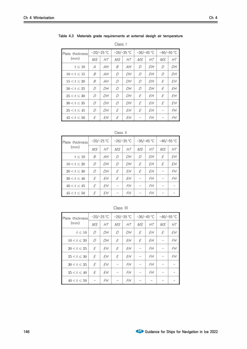
Ch 4 Winterization Ch 4
146 Guidance for Ships for Navigation in Ice 2022
Table 4.3 Materials grade requirements at external desigh air temperature
Class I
Plate thickness (mm)
-20/-25 °C -26/-35 °C -36/-45 °C -46/-55 °C
MS HT MS HT MS HT MS HT
≤ A AH B AH D DH D DH
≤ B AH D DH D DH D DH
≤ B AH D DH D DH E EH
≤ D DH D DH D DH E EH
≤ D DH D DH E EH E EH
≤ D DH D DH E EH E EH
≤ D DH E EH E EH - FH
≤ E EH E EH - FH - FH
Class II
Plate thickness (mm)
-20/-25 °C -26/-35 °C -36/-45 °C -46/-55 °C
MS HT MS HT MS HT MS HT
≤ B AH D DH D DH E EH
≤ D DH D DH E EH E EH
≤ D DH E EH E EH - FH
≤ E EH E EH - FH - FH
≤ E EH - FH - FH - -
≤ E EH - FH - FH - -
Class III
Plate thickness (mm)
-20/-25 °C -26/-35 °C -36/-45 °C -46/-55 °C
MS HT MS HT MS HT MS HT
≤ D DH D DH E EH E EH
≤ D DH E EH E EH - FH
≤ E EH E EH - FH - FH
≤ E EH E EH - FH - FH
≤ E EH - FH - FH - -
≤ E EH - FH - FH - -
≤ - FH - FH - - - -

Ch 4 Winterization Ch 4
Guidance for Ships for Navigation in Ice 2022 147
Fig. 4.2 Distribution of material classes for cold weather
Structural member Reference temperature °C 1) Material class
Exposed structures of length greater than 0.09 L and subjected to hull girder stress
t
Constructed of the same material class to that of the material to which they are attached, however need not be greater than class II
Hatch coamings, hatch covers, crane pedestals and windlass seats
t + 5
Constructed of the same material class to that of the material to which they are attached, or class II, whichever is the greater
Forecastle deck t+ 10 II
External bulkheads of accommodation block
t+ 20 II
Forecastle side shell plating
Plating and stiffeners attached and contiguous to the exposed boundary plating distance 'x', see Fig. 4.2 Distribution of material classes for cold weather 2)
t+ 10 Class I, but need not be taken greater than D or DH
Other exposed structures of length less than 0.09 L, e.g. bul-warks, water-breakers, unlagged gas turbine intake structures, side screens, etc.
Need not be taken lower than -33 I
Stern frames, rudders, rudder horns, shaft brackets and stem(including the strake of shell plat-ing to which the item is attached)
Fully immersed t + 20IIPeriodically im-
mersed or exposed t
1) For built-up stiffeners within the distance ‘x’, the web and flange are considered to be a single stiffening member and both members are to comply with the material requirements. For bulb stiffeners and stiffeners with the flange outside the distance ‘x’, the web only may be required to comply with the material requirements.
Table 4.4 Material classes and grades
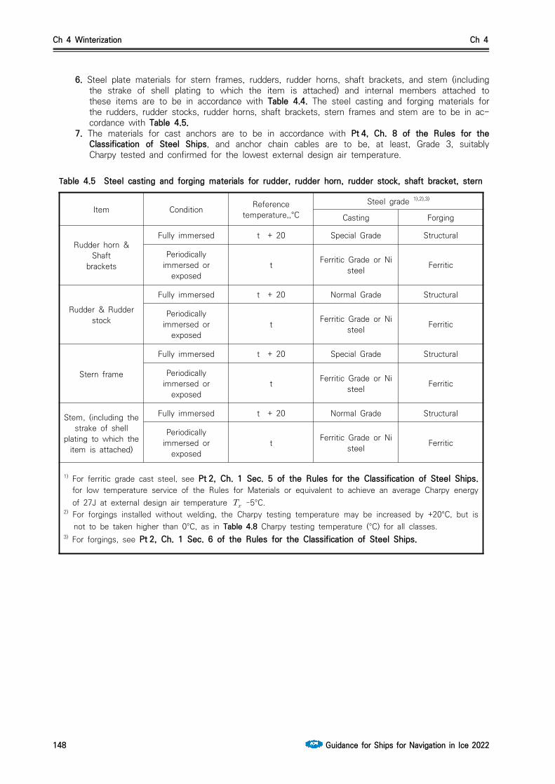
Ch 4 Winterization Ch 4
148 Guidance for Ships for Navigation in Ice 2022
6. Steel plate materials for stern frames, rudders, rudder horns, shaft brackets, and stem (including the strake of shell plating to which the item is attached) and internal members attached to these items are to be in accordance with Table 4.4. The steel casting and forging materials for the rudders, rudder stocks, rudder horns, shaft brackets, stern frames and stem are to be in ac-cordance with Table 4.5.
7. The materials for cast anchors are to be in accordance with Pt 4, Ch. 8 of the Rules for the Classification of Steel Ships, and anchor chain cables are to be, at least, Grade 3, suitably Charpy tested and confirmed for the lowest external design air temperature.
Item Condition Reference temperature,,°C
Steel grade 1),2),3)
Casting Forging
Rudder horn & Shaft
brackets
Fully immersed t + 20 Special Grade Structural
Periodically immersed or
exposedt Ferritic Grade or Ni
steel Ferritic
Rudder & Rudder stock
Fully immersed t + 20 Normal Grade Structural
Periodically immersed or
exposedt Ferritic Grade or Ni
steel Ferritic
Stern frame
Fully immersed t + 20 Special Grade Structural
Periodically immersed or
exposedt Ferritic Grade or Ni
steel Ferritic
Stem, (including the strake of shell
plating to which the item is attached)
Fully immersed t + 20 Normal Grade Structural
Periodically immersed or
exposedt Ferritic Grade or Ni
steel Ferritic
1) For ferritic grade cast steel, see Pt 2, Ch. 1 Sec. 5 of the Rules for the Classification of Steel Ships. for low temperature service of the Rules for Materials or equivalent to achieve an average Charpy energy of 27J at external design air temperature –5°C.
2) For forgings installed without welding, the Charpy testing temperature may be increased by +20°C, but is not to be taken higher than 0°C, as in Table 4.8 Charpy testing temperature (°C) for all classes.
3) For forgings, see Pt 2, Ch. 1 Sec. 6 of the Rules for the Classification of Steel Ships.
Table 4.5 Steel casting and forging materials for rudder, rudder horn, rudder stock, shaft bracket, stern
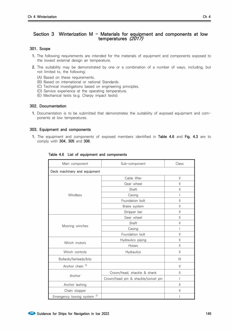
Ch 4 Winterization Ch 4
Guidance for Ships for Navigation in Ice 2022 149
Section 3 Winterization M - Materials for equipment and components at low temperatures (2017)
301. Scope1. The following requirements are intended for the materials of equipment and components exposed to
the lowest external design air temperature.
2. The suitability may be demonstrated by one or a combination of a number of ways, including, but not limited to, the following:(A) Based on these requirements.(B) Based on international or national Standards.(C) Technical investigations based on engineering principles.(D) Service experience at the operating temperature.(E) Mechanical tests (e.g. Charpy impact tests).
302. Documentation1. Documentation is to be submitted that demonstrates the suitability of exposed equipment and com-
ponents at low temperatures.
303. Equipment and components1. The equipment and components of exposed members identified in Table 4.6 and Fig. 4.3 are to
comply with 304, 305 and 306.
Main component Sub-component Class
Deck machinery and equipment
Windlass
Cable lifter IIGear wheel II
Shaft IICasing I
Foundation bolt IIBrake system IIStripper bar II
Mooring winches
Gear wheel IIShaft II
Casing IFoundation bolt II
Winch motorsHydraulics piping II
Hoses II
Winch controls Hydraulics II
Bollards/fairleads/bits III
Anchor chain 3) II
AnchorCrown/head, shackle & shank II
Crown/head pin & shackle/swivel pin IAnchor lashing IIChain stopper II
Emergency towing system 2) I
Table 4.6 List of equipment and components

Ch 4 Winterization Ch 4
150 Guidance for Ships for Navigation in Ice 2022
Main component Sub-component Class
Cargo handling systems
Cargo lines
Pipe IIFlange IIValve II
Gaskets IBolts I
Cargo loading manifold I
Cargo heating steam line
Pipe IIFlange IIValve IIBolts I
Hydraulic oil pipes for cargo valve remote control II
Inert gas piping IHull piping systems
Bunker lines to engine room
Pipe IFlange IValve IBolts I
Control air pipes IFire-fighting systems
Fire main
Pipe IFlange IValve IBolts I
Water spray systemsPipe II
Flange IIValve II
Foam systems IEmergency fire pump I
Hydrants IHydrant pipes II
Fire flaps IAccess on deck
Handrails I
Structures on deck to provide shelter from
seas/weather when working on deck during passage (excluding
deckhouses and forecastles)
I
Access doors and hatches–hinges/dogs, etc.
to ccommodation and forecastle
Dogs/hinges I
Seals I
Stairs I
Note 1. Additional sub-components associated with the main component, which are not specified, are to be of a similar class to an equivalent sub-component which is specified.
Note 2. Where the ETA is integrated with the bollards/fairleads/bits, the higher class is to be applied.
Note 3. Anchor chain cables are to be, at least, grade 3.
Table 4.6 List of equipment and components(continue)

Ch 4 Winterization Ch 4
Guidance for Ships for Navigation in Ice 2022 151
Fig. 4.3 Mooring and anchoring sub-components
304. Plating1. The following requirements are to provide steel grades with suitable notch toughness based on the
thickness of the material and the lowest external design air temperature. As an alternative for Classes I and II, steel may be to a national or international Standard showing equivalence to the Rules for the Classification of Steel Ships.
2. Table 4.3 Class I are to be used for determining the material grades for steel plates, strips, sections and bars used in machinery and systems components.
305. Piping, valves and fittings1. Table 4.7 are to be used for determining the Charpy testing temperature for steel piping, valves and
fittings used in machinery and systems components, in association with Pt 5, Ch 6 of the Rules for the Classification of Steel Ships. As an alternative for Class I, steel may be to a national or interna-tional Standard showing equivalence to the Rules for Materials.
2. For the application of Table 4.7 Class I, as given in Pt 5, Ch 6 are to be reversed, e.g. Class 3 is to be taken as Class I.
3. In general, the minimum average Charpy impact average energy (J) is to be 10 per cent of the specified minimum yield strength (Nmm) up to a maximum of 50 J.
Thickness(mm)
External design air temperature
–30°C ~ –34°C
–35°C ~ –39°C
–40°C ~ –45°C
–46°C ~ –55°C
–56°C ~ –65°C
–66°C ~ –75°C
t ≤10 +20 +20 +20 0 -20 -20
10<t≤15 +20 +20 0 -20 -20 -20
15<t≤20 0 0 -20 -20 -20 -20
20<t≤25 0 0 -20 -20 -20 -40
25<t≤30 0 -20 -20 -20 -40 -40
30<t≤35 -20 -20 -20 -20 -40 -40
35<t≤45 -20 -20 -20 -40 -40 -60
45<t≤50 -20 -20 -40 -40 -60 -60
Table 4.7 Charpy testing temperature (°C) for Class I

Ch 4 Winterization Ch 4
152 Guidance for Ships for Navigation in Ice 2022
Thickness(mm)
External design air temperature
–30°C ~ –34°C
–35°C ~ –39°C
–40°C ~ –45°C
–46°C ~ –55°C
–56°C ~ –65°C
–66°C ~ –75°C
t ≤10 +20 +20 0 -20 -20 -40
10<t≤20 0 0 -20 -20 -40 -40
20<t≤30 0 -20 -20 -40 -40 -60
30<t≤40 -20 -20 -40 -40 -60 -60
40<t≤45 -20 -20 -40 -60 -60 n/a
45<t≤50 -40 -40 -40 -60 -60 n/a
Charpy testing temperature (°C) for Class II
Thickness(mm)
External design air temperature
–30°C ~ –34°C
–35°C ~ –39°C
–40°C ~ –45°C
–46°C ~ –55°C
–56°C ~ –65°C
–66°C ~ –75°C
t ≤10 0 0 -20 -20 -40 -40
10<t≤20 0 -20 -20 -40 -40 -60
20<t≤25 -20 -20 -40 -40 -60 -60
25<t≤30 -20 -40 -40 -40 -60 -60
30<t≤35 -40 -40 -40 -60 -60 n/a
35<t≤40 -40 -40 -40 -60 -60 n/a
40<t≤50 -40 -40 -60 -60 n/a n/a
Charpy testing temperature (°C) for Class III
306. Forging and castings1. Table 4.8 is to be used for determining the Charpy testing temperature for steel forgings and cast-
ings used in exposed machinery and systems components
Material classExternal design air temperature
–30°C ~ –34°C –35°C ~ –39°C –40°C ~ –45°C –46°C and below
Class I or II 0 -20 -20 To be specially consideredClass III -20 -40 -40
Note For components manufactured and installed without welding, the test temperature may be increased by +20°C, but is not to be taken higher than 0°C.
Table 4.8 Charpy testing temperature (°C) for all classes
2. In general, the minimum average Charpy impact energy is to be greater than (E + f) in Joules (J),where

Ch 4 Winterization Ch 4
Guidance for Ships for Navigation in Ice 2022 153
E is the minimum average energy value:27J for steels with specified minimum yield strength less than 300 Nmm
34J for steels with specified minimum yield strength equal to or greater than 300 Nmm
f is m multiplied by the difference between the required test temperature as given in Table 4.9 Example of required test criteria and the certified test temperature to be shown on the test certificate
m is the slope of the transition curve; for steels, m is taken as a value of 3.
An alternative value of m may be used where material impact transition properties have been demonstrated from either a single supplier of known consistency or a number of suppliers (minimum of three) For example, for steel with a specified minimum yield strength less than 300 Nmm and where the lowest external design air temperature is equal to –40°C for a Class III component, the Charpy test-ing temperature and criteria may be taken as shown in Table 4.9 Example of required test criteria
Required Charpy test temperature
°C
Minimum energy
value, E,J
Certified Charpy
test temperature
°C
Transition slopevalue, m
Difference in test
temperature multiplied
by m, f, °C
Criteria forCharpy impact
energy,J
-40 27 -40 3 0 27
-40 27 -20 3 60 87
-40 27 +0 3 120 147
Table 4.9 Example of required test criteria
3. Ihere a component has dedicated heating arrangements that protect the entire component, the Charpy testing temperature may be taken as having a lowest external design air temperature of –0°C and as a Class I/II component.
4. Cast iron is not permitted.
5. The requirements in 305. are to be used for determining the material certification for forgings and castings used in machinery and systems components.
307. Other materials1. The testing requirements for piping, valves and fittings used in machinery and systems components
of other materials will be specially considered in accordance with the manufacturer’s recommendations.
2. Exposed components of electrical cabling are to be suitable for operation at the average external design air temperature.
Ch 4 Winterization Ch 4
154 Guidance for Ships for Navigation in Ice 2022
Section 4 Winterization E3(t) - Main component and sub-component (2017)
401. General1. All items such as pipework, components and cables are to be located inside spaces as far as prac-
ticable to minimize exposure to low temperatures and icing.
2. Each item of equipment and system on the ship is to be protected against the effects of low tem-peratures and build up of ice with the selection of appropriate protection methods. Methods for pro-tecting the equipment and systems include the following:(1) Heating (space and dedicated arrangements for equipment / systems).(2) Ice removal equipment.(3) Covers.(4) Drainage.(5) Insulation.(6) Selection of materials.(7) Selection of lubricants, oils, hydraulics and greases.
3. Where heating arrangements are provided, they are to be fitted with the following: (2017)(1) Means for ascertaining the temperature.(2) For systems where heating arrangements could result in excessively high temperatures or pres-
sures being generated, that may cause damage, malfunction, loss of effective lubrication or brak-ing of equipment, arrangements are to be provide which will cut off the heating.
(3) Suitable control arrangements.(4) Indication that the system(s) are in use or not. (5) Where failure of a heating arrangement could result in a hazardous situation, an alarm in accord-
ance with the alarm system required by Pt 6, Ch 2, 201. of the Rules for the Classification of Steel Ships is to be activated to allow responsible personnel to prevent the hazardous situation occurring.
For use of electrical heating in dangerous zones, see Pt 6, Ch 1, Sec. 9 of the Rules for the Classification of Steel Ships.
4. Where PVC covers or other water resistant materials are used, they are to be well fitting with suit-able fixing to prevent unintended removal in severe weather.
402. Winterization of machinery –General requirements1. Main and essential auxiliary machinery and equipment installed on the open deck is to be capable of
operating satisfactorily under the conditions of the lowest external design air temperature.
2. Main and essential auxiliary machinery and equipment installed in spaces is to be capable of operat-ing satisfactorily under the conditions of the design internal air temperature/ambient conditions for that space.
3. Dedicated heating arrangements may be provided to ensure the satisfactory operation of equipment and machinery required by Par 1 and 2.
4. The requirements of Par 1 and 2 are to include machinery and equipment for emergency appliances, including navigational aids required by statutory regulations.
403. Winterization of main propulsion and essential auxiliary engines1. The arrangements for air supply to main propulsion and essential auxiliary engines are to ensure that
the engine manufacturer's specification for minimum air intake temperature is complied with. Such arrangements may comprise pre-heating at the air intakes or use of heated engine room air, or other means such as scavenge air cooler bypass or exhaust gas bypass. The main engine lubrication oil is to be maintained at a minimum temperature in accordance with the manufacturer’'s specification.
2. The Sea inlets for the cooling water system is are to be provided with arrangements to maintain ice free cooling water arrangements as given by IMO Guidance on Design and Construction of Sea Inlets under Slush Ice Conditions MSC/Circ.504 or in accordance with Ch 1, 702. Alternative ar-rangements will be considered, such as by circulating engine cooling water via designated tanks

Ch 4 Winterization Ch 4
Guidance for Ships for Navigation in Ice 2022 155
where heat balance calculations have demonstrated that the engines are capable of operating at their maximum continuous rating.
3. Electrical and hydraulic systems for podded or azimuth propulsion systems are to be provided with suitable provisions to prevent freezing. Heating arrangements and/or suitable lubrication oils, hydraul-ic oils and anti-freeze are also to be provided.
4. Steering gear components are to be provided with suitable low temperature greases and lubrication oils.
404. Winterization of auxiliary machinery systems and deck working areas (2017)1. Materials for components of exposed pipe work on deck are to be suitable for operation at the
average external design air temperature or the components are to be provided with suitable heating arrangements.
2. Systems are to be arranged to ensure they can be drained to protect against fluids freezing in pipes. Drainage valves are to be provided and pipe work included to ensure drainage of fluids is possible under all normal angles of list and trim. As a minimum, drain valves are to be provided at forward, aft, port and starboard locations. Additional shut off valves are to be installed on the branch pipes (and as close to the main line as practicable) to allow drainage and protection against freezing in branch pipes when the main line is under pressure and branch lines are not in use.
3. Measures for protection against freezing of condensate in exposed steam pipe work are to be fitted with thermal insulation and/or connections for dry air to be blown through. Steam deck machinery is to be provided with measures for the continuous circulation of steam.
4. Valves, gauges, indicators and monitoring equipment for essential services are to be protected from icing and provided with ice removal measures or by covers where ice removal measures are not suitable. Exposed valves at inaccessible locations are to be provided with covers or positioned in heated cabinets (by means of a heated frame or internal space heating). Gauges, indicators and monitoring equipment which are sited in exposed locations but are unsuitable for removal of ice are to be positioned in heated cabinets. Valve actuators, solenoids and pressure gauge transmitters for essential services are to be provided with heating arrangements.
5. Where no heating arrangements are provided, valves, gauges, indicators and monitoring equipment for essential services are to be suitable for the lowest external design air temperature.
6. Exposed control stand valves for hydraulic oil lines used for remote control are to be provided with heating arrangements to protect against freezing of the mechanism.
7. As far as practicable, hydraulic oil power packs are to be sited in heated enclosed spaces. Where this is not practicable, the hydraulic fluid and pipework system materials are to be suitable for oper-ation at the lowest design external air temperature.
8. Measures to protect against water freezing in exposed fresh water and sea water pipes and valves are to be fitted. Exposed sections of seawater and freshwater lines are to be fitted with an isolat-ing valve located inside a heated space such that the exposed length may be drained. Alternatively, a drain valve is to be provided at the lowest position on deck, and an air blow connection provided at the furthest forward end to keep the line dry after use. Alternatively, heating arrangements or continuous circulation is to be provided.
9. Measures are to be provided to protect against humidity freezing the supply of air to pneumatic de-vices used on deck. They are to be designed for specified dew point appropriate to the external design air temperature, or be provided with air driers, or suitable heating arrangements. A drain valve is to be provided at the lowest point of the line on the exposed deck.
10. Where sea chests are fitted other than for the main propulsion system as specified in 403., such as ballast sea chests located in the pump room, these are to be provided with a sea bay and heat-ing arrangements, for ice clearing. Steam blowing may be used or similar arrangements as given in 403.
11. The sea inlet and overboard discharge valves are to be provided with low pressure steam con-nection for clearing purposes. Pt 5, Ch 6, Sec 3 of the Rules for the Classification of Steel Ships. Alternatively, arrangements are to be made for supplying water for machinery cooling purposes by circulating from ballast tanks(s) or those situated in the double bottom. Such tank(s) must be used

Ch 4 Winterization Ch 4
156 Guidance for Ships for Navigation in Ice 2022
only for storage of water ballast or fresh water.
12. Overboard discharge valves at or below the waterline are to be provided with low pressure steam connections for clearing purposes.
13. Where observation/security cabins are fitted, suitable heating arrangements are to be provided for the internal space and also for windows. Ice removal measures are to be provided to protect against icing forming on the windows.
14. The equipment and systems for accommodation and pilot ladders are to comply with the require-ments in 408.
15. To protect against freezing, the Oil Discharge Monitoring Equipment (ODME) is to be provided with heating arrangements on exposed supply/discharge lines and with steam blowing on the overboard discharge.
405. Winterization of anchoring/mooring equipment and deck cranes 1. Anchor windlass and mooring winches are to be protected from icing by means of suitable covers.
Alternatively, a sheltered deck area is to be provided. See also 411.2. Exposed control panels are to be provided with suitable steel covers to protect against icing. (2017)3. Measures are to be provided to protect against freezing of fluids, such as lubricants and hydraulic
oil. The fluids are to be suitable for low temperature operation, and heating arrangements are to be provided where appropriate.
4. Hydraulic control systems are to comply with 404.5. Electrical installations are to comply with 406.6. The hawse pipe is to be sited in a heated space or provided with suitable heating arrangements and
deck steam connection valve(s) located within the vicinity to protect against icing.
7. For hydraulically operated equipment and systems, steam ice removal measures are to be provided for protection against icing.
8. Hawse pipe wash lines are to be provided with continuous circulation or heating arrangements to protect against waterin the pipes freezing. A steam connection on deck for ice removal is to be lo-cated within the vicinity.
9. Means are to be provided for habitable working conditions in crane cabs, where fitted, by providing internal space heating arrangements. Cab windows are to be provided with heating arrangements to protect from the build up of ice, see 408. 9. Ice removal measures are to be provided to protect against icing. Window wiper operating devices are to be arranged inside the cab or to be provided with heating arrangements.
10. Suitable provisions for cold start arrangements for exposed deck cranes are to be provided. Suitable lubrication oils and greases, circulation facilities for hydraulic oils and a flushing system for the hy-draulic oil are to be provided.
11. Material grades for lifting appliances are to be in accordance with th Pt 9, Ch 2, Sec 1 of the Rules for Classification of Steel Ships and suitable for operation at the average external design air temperature.
12. Material grades for towing and mooring equipment, fittings and components are to be suitable for operation at the average external design air temperature.
406. Winterization of electrical installations 1. Electrical power used for heating purposes in cold climates is to be included in the schedule of op-
erating loads required by Pt 6, Ch 1, 1.2 of the Rules for the Classification of Steel Ships.2. The schedule of loads is to include operation in cold climates as a separate Winterization condition.
(2017)3. Emergency generators are to be capable of operating at the lowest external design air temperature
and are to be provided in a heated room and/or are to be suitable for using fuel oil specified for

Ch 4 Winterization Ch 4
Guidance for Ships for Navigation in Ice 2022 157
low temperature conditions, and provided with protection or heating arrangements on the air intake. Suitable antifreeze or heating arrangements are to be used in the cooling system with a dew point appropriate to the external design air temperature. Where an air start system is installed the air is to be dried.
4. The emergency generator room air intakes are to be provided with protection from icing by ice re-moval measures or heating arrangements. In addition, the air intake is to be provided with an auto-matic louver which closes whilst the generator is inactive (to reduce heat loss), and open when staring.
5. Exposed electric motors installed on equipment are to be provided with covers or ice removal measures to aid the removal of ice. Measures are to be provided to protect against humidity and condensation freezing in the motor and to achieve this they are to be provided with suitable heating arrangements.
6. Exposed components of electrical cabling are to be suitable for operation at the lowest external de-sign air temperature. (2017)
7. Measures to protect exposed cables from manual ice removal methods are to be provided. Penetrations in exposed decks for electrical cables are to be enclosed in protective steel covers ex-tending 0.5 m from the penetration or to the item if this is closer.
8. Switch boxes and control panels in unheated areas are to be fitted with heating arrangements or be sealed units suitable for operation at the lowest design air temperature, to prevent condensation freezing.
9. For navigation aids and equipment, the temperature for use as stated by the manufacturer is to be suitable for the lowest external design air temperature.
10. Protection measures are to be fitted for the continuous operation of the radar motors against the humidity and icing freezing the motor. Radar motors are to be provided with heating arrangements and with the provision for suitable use of low temperature grease.
11. Measures for continuous operation of the navigation air horn, where fitted, are to be provided to protect against humidity freezing in components and icing. Dry air is to be used and suitable heat-ing arrangements are to be provided. Air pipe lines for the navigation air horn are to be arranged in heated compartments as far as practicable, see also 404.
12. Remotely controlled and focused seArctich lights are to be provided at the bow and the bridge wings to combat reduced daylight hours and aid navigation in ice infested waters. The search lights are to be fitted with trace heating on the lens or provided with a cover, and with heating arrange-ments for the directional motor.
13. Exposed magnetic compasses, where fitted, are to be protected by covers from icing.
14. Where closed circuit television systems are fitted in exposed locations, these are to be provided with heating arrangements or covers, and ice removal measures to protect against icing and freezing of the motors, wipers and screen.
15. Satellite/GPS motors are to be provided with suitable low temperature grease. Antenna systems are to be protected from icing.
16. Lighting arrangements in working areas on the deck, and in particular the forecastle, are to be lo-cated at accessible positions to facilitate ice removal. Exposed lights are to be suitable for the low-est external design air temperature and with due regard being given to changes in illumination values.
17. Navigation lights are to be of a type tested with the intended light source to demonstrate that they are suitable for the lowest design air temperature, such that illumination will not be reduced or obscured.
407. Winterization of emergency appliances 1. Fire pumps and the emergency fire pump are to be located in heated spaces to protect against
freezing components and fluids.
2. The fire main in exposed positions (including the main deck line and accommodation) is to be pro-

Ch 4 Winterization Ch 4
158 Guidance for Ships for Navigation in Ice 2022
tected against freezing in the line and hydrants. Isolating valves are to be located in a heated space and arranged such that the exposed part may be drained. Alternatively, means are to be provided to ensure the isolating valve is dry before closing, continuously circulated and with thermal insulation or provided with heating arrangements. (2017)
3. The exposed fire main is to be routed through internal heated spaces as far as practicable consider-ing particular ship arrangements.
4. Sea water suctions for fire pumps are to be provided with heating arrangements for ice cleaning. Steam blowing is to be provided or means of using the engine room sea chest.
5. Water spray lines, where fitted, are to be designed to protect against the lines freezing and the nozzles clogging with ice. They are to be located inside and have external nozzles of a design to minimize freezing, or provided with drainage facilities and arranged to be blowing through with dry air, or provided with heating arrangements.
6. Foam and CO2 systems and monitoring equipment are to comply with the applicable requirements of Par 2 and 3.
7. For fire extinguishing media, such as foam systems, the temperature for use as stated by the man-ufacturer is to be suitable for the lowest design external air temperature. Extinguishers are to be suitable for low temperature use or located in heated spaces.
8. Arrangements are to be provided such that after use, the fire hoses can be drained and dried to protect from freezing. Stowage arrangements are to be provided with heating arrangements or at least two additional hose provided to enable wet hoses to be replaced whilst drying.
9. As far as practicable, lifeboats and liferafts are to be located in protected locations(recesses or ga-rages) to provide protection from icing.
10. Lifeboats are to be of totally enclosed type and provided with internal space heaters to maintain a habitable temperature. Adjacent receptacles for electrical heating arrangements are to be supplied from the emergency switchboard.
11. The lifeboat coxswain’s control panel is to be provided with heating arrangements. Ice removal measures to remove icing from windows are to be provided.
12. Lifeboat engines are to be provided with suitable low temperature grades of fuel oil and lubrication oil to protect against the effects of freezing. The cooling system for the engines is to be provided with suitable anti-freeze.
13. Lifeboat engine batteries are to be suitable for low temperature conditions, or a flexible lead for battery charging and a means of safe heating is to be provided.
14. Lifeboat winches, where fitted, are to be provided with suitable covers or ice removal measures. The operating devices (brake(s)) are to be protected from icing by ice removal measures, suitable grease and lubricants with covers or heating arrangements. Hydraulic systems, including tanks, pipes and mechanisms, are to be provided with suitable steam ice-removal measures, suitable grease and lubricants or heating arrangements.
15. Lifeboat davits/sheaves/release hooks are to have provision for the use of suitable low temperature grease, covers or and heating arrangements, to protect the mechanisms from becoming fixed by icing.
16. To protect from icing, the embarkation (lifeboat rope) ladders are to be provided with covers in the stowed position.
17. Lifeboat water spray lines, where fitted, are to be located inside and have external nozzles of a design to minimize freezing or to have drainage facilities and arranged to be blown through with dry air. In addition, the water intake is to be protected from ice build up.
18. Liferafts are to be suitable for the lowest external design air temperature. A steam connection for ice removal measures is to be provided for protection against icing of the liferaft. (2017)
19. For life saving equipment, the temperature for use as stated by the manufacturer is to be suitable for the lowest external design air temperature. Measures are to be provided for lifeboat contents (including flares and torch batteries) for low temperature operation. Ice removal measures are to be provided for the EPIRB/SART. (2017)
Ch 4 Winterization Ch 4
Guidance for Ships for Navigation in Ice 2022 159
20. Rescue boats are to be provided with systems which are similar to those for lifeboats.
21. Means are to be provided to protect fluids within exposed pipes for decontamination showers and eyewash systems from freezing, where fitted. Heating arrangements are to be provided in the water tank and exposed sections of piping are to be provided with insulation or trace heating arrangements. Alternatively, these are to be sited in a heated room/compartment. Additional eye-wash fluids are to be stored in an alternative heated space.
22. The materials used for exposed components, including steel davits, hydraulics and rubber compo-nents, are to be suitable for operation at the average external design air temperature.
23. Immersion suits are to be suitable for low temperature operation and stored in heated spaces or containers in locations with suitable ice removal measures.
408. Winterization of spaces/compartments 1. Accommodation heating/air conditioning systems are to be capable of maintaining internal design air
temperature in all spaces normally occupied when the ship is at sea, based on the lowest external design air temperature. This may be achieved by controlling the number of air changes providing acceptable levels of fresh air required for personnel efficiency, combustion or other oxidation processes. (2017)
2. The requirements in 303. 1. are intended to mitigate risks associated with the failure to maintain suitable (see 103. 104.) temperatures associated with the defined spaces, and do not cover air-con-ditioning arrangements, air distribution ductwork, heating systems, chilled water systems or the cal-culation and verification of air flow rates and cooling/heating loads within the air-conditioned spaces. The method used to calculate the capacity of the air-conditioning, refrigeration and heating equip-ment is the responsibility of the Shipbuilder and Owner and should be in accordance with a recog-nised code or standard such as ISO 7547:2002 Ships and marine technology - Air conditioning and ventilation of accommodation spaces - Design conditions and basis of calculations, or ASHRAE 26- 1996(RA2006) Mechanical refrigeration and air-conditioning installations aboard ship.
3. Heating arrangements (in addition to, and not necessarily serviced by, the air-conditioning system as specified in 408. are to be provided for spaces containing machinery and equipment for essential or emergency services and for spaces accessed during ship operation in order that equipment may be maintained. Heating arrangements are to be included in, but not limited to, the spaces as given in Table 4.10 (where fitted): The heating of each space is to be capable of maintaining its internal de-sign air temperature based on the lowest external design air temperature, insulation and the volume of air in each space. The internal temperature, and lowest limit for alarms, for each space is to be provided (and agreed with the Owner and Shipbuilder), but is to be a minimum of zero degrees Celsius at the lowest external design air temperature. (2017)
4. Means of regulating the engine room temperature are to be provided. Where machinery space fun-nel louvers are fitted, these are to be capable of being adjusted to different open positions. The means of regulating temperature is not to prevent air supply or exhaust to machinery or machinery spaces required for operation.
5. Pipework and electrical components in and passing through spaces and tanks, without space heating and which are exposed to low temperatures, such as void spaces and underdeck passageways, are to be suitable for the lowest external design air temperature or have suitable heating arrangements to protect against the low temperatures, see also 304.
6. The air intakes and exhaust louvres for accommodation and machinery spaces are to be provided with protection from icing by ice removal measures and heating arrangements.
7. All cargo control room windows are to be fitted with heating arrangements to provide protection against the formation of ice obscuring visibility during discharging/loading operations. Ice removal measures are to be provided. See 408. (2017)
8. All bridge windows (excluding door windows) are to be fitted with heating arrangements to provide protection against the build up of ice obscuring visibility. The use of hot air blowers on the inside is to be provided for all windows. Consideration is to be given to fitting double glazed windows in or-der to provide protection against cold water cracking glass which is exposed to warm internal conditions. (2017)

Ch 4 Winterization Ch 4
160 Guidance for Ships for Navigation in Ice 2022
9. The system for window cleaning is to be protected against freezing in the lines and clogging of the nozzles with frequent operation. Cold fresh water systems with heated spray nozzles, or hot water systems designed are to be drained and dry air blown through after use, are to be provided. Window wiper operating devices are to be arranged inside the bridge or to be provided with heating arrangements. Safe access is to be provided externally for ice removal.
10. Measures to protect personnel operating on the bridge from cold temperatures are to be provided. Where ships have exposed bridge wings, the wing controls/ equipment are to be provided with heating arrangements and covers. (2017)
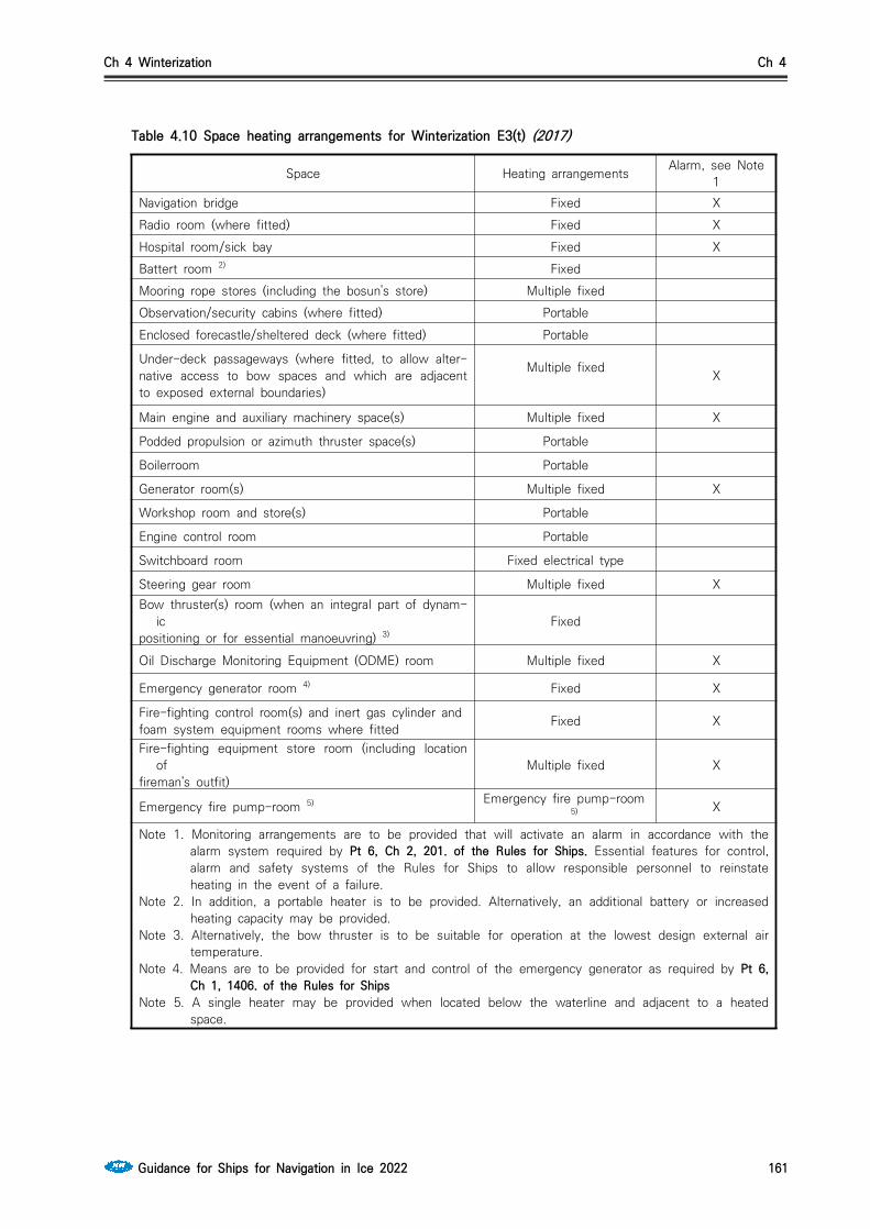
Ch 4 Winterization Ch 4
Guidance for Ships for Navigation in Ice 2022 161
Space Heating arrangements Alarm, see Note 1
Navigation bridge Fixed XRadio room (where fitted) Fixed XHospital room/sick bay Fixed XBattert room 2) FixedMooring rope stores (including the bosun's store) Multiple fixedObservation/security cabins (where fitted) PortableEnclosed forecastle/sheltered deck (where fitted) Portable
Under-deck passageways (where fitted, to allow alter-native access to bow spaces and which are adjacent to exposed external boundaries)
Multiple fixed X
Main engine and auxiliary machinery space(s) Multiple fixed X
Podded propulsion or azimuth thruster space(s) Portable
Boilerroom Portable
Generator room(s) Multiple fixed X
Workshop room and store(s) Portable
Engine control room Portable
Switchboard room Fixed electrical type
Steering gear room Multiple fixed XBow thruster(s) room (when an integral part of dynam-
icpositioning or for essential manoeuvring) 3)
Fixed
Oil Discharge Monitoring Equipment (ODME) room Multiple fixed X
Emergency generator room 4) Fixed X
Fire-fighting control room(s) and inert gas cylinder andfoam system equipment rooms where fitted Fixed X
Fire-fighting equipment store room (including location of
fireman’s outfit)Multiple fixed X
Emergency fire pump-room 5) Emergency fire pump-room5) X
Note 1. Monitoring arrangements are to be provided that will activate an alarm in accordance with the alarm system required by Pt 6, Ch 2, 201. of the Rules for Ships. Essential features for control, alarm and safety systems of the Rules for Ships to allow responsible personnel to reinstate heating in the event of a failure.
Note 2. In addition, a portable heater is to be provided. Alternatively, an additional battery or increased heating capacity may be provided.
Note 3. Alternatively, the bow thruster is to be suitable for operation at the lowest design external air temperature.
Note 4. Means are to be provided for start and control of the emergency generator as required by Pt 6, Ch 1, 1406. of the Rules for Ships
Note 5. A single heater may be provided when located below the waterline and adjacent to a heated space.
Table 4.10 Space heating arrangements for Winterization E3(t) (2017)
Ch 4 Winterization Ch 4
162 Guidance for Ships for Navigation in Ice 2022
409. Winterization of accommodation and escape routes 1. Measures are to be provided to assist in the opening of doors when covered in ice and to protect
seals against freezing. External doors are to be positioned in protected locations or recessed as far as practicable to provide protection from icing. The enclosed space adjacent to external doors on escape routes is to be fitted with heating arrangements.(2017)
2. Suitable changing rooms are to be arranged to provide adequate space for changing into and out of cold weather working clothing adjacent to the entrance door. A heated space is to be provided for drying and storing cold weather working clothing.
3. Measures are to be provided to reduce the likelihood of damage to insulation fitted to exposed ex-ternal boundaries caused by humidity freezing within it. In particular the accommodation bulk-head/deck insulation is to be fitted with a protective vapour barrier such as aluminium foil or equiv-alent means.(2017)
4. To protect against fluids freezing, cabin bathrooms are not to be located adjacent to exposed ex-ternal boundaries, as far as practicable.
5. Insulation and heating arrangements are to be provided for all exposed external boundaries in bath-rooms and washrooms to prevent freezing of water in these spaces.
6. Means such as a gutter and drainage on the deck below to collect condensed water are to be pro-vided adjacent to external boundaries.
410. Winterization of tanks 1. Fresh water and sea-water ballast tanks, the tops of which are situated above the design ballast
waterline and adjacent to the shell, which are intended to be used in ice and cold navigating con-ditions, are to be provided with means to prevent freezing. Measures are to be provided to demon-strate that they protect against the following:(2017)(1) hull structural damage from pumping water creating a vacuum beneath a layer of ice across the
top of the water in the tank;(2) hull structural damage from ice expansion;(3) engineering systems damage from ice expansion or ice blockage; and(4) engineering systems damage from ice pieces melting or dislodging from upper sections of the tank.Heating coils are considered an effective means for tanks entirely above the waterline. Heating coils or other effective means such as continuous circulation, air bubbling and/or tank pressure/engineer-ing systems alarms are considered effective for tanks partially below the waterline. Alternatively, demonstration that the above hazards have been mitigated is to be submitted through theoretical calculations, service experience, experimental tests, or a combination thereof.
2. For tank heating required by 410. monitoring arrangements are to be provided that will activate an alarm in accordance with the alarm system required by Pt 6, Ch 2, 201. of the Rules for the Classification of Steel Ships to allow responsible personnel to reinstate heating in the event of a failure.
3. Tank systems and components for monitoring and alarms(1st and 2nd stage high level alarm sys-tems, gas detection system etc.) are to be suitable for the lowest design external air temperature. (2017)
4. The sewage tanks and associated pipe systems, where located adjacent to external ship boundaries, are to be located in heated compartments or provided with heating arrangement.
5. Measures to provide protection from icing and blockage by ice formation resulting from humidity in tanks are to be fitted. Exposed air vent pipe heads of tanks are to be readily accessible, positioned in protected locations as far as practicable and fitted with covers to limit build up of ice. The covers are not to interfere with the free flow of air through the vent openings. (2017)
6. Where ballast tank heating coils are provided as given in 410., a section of the heating coil is to be positioned below the air pipe vent, as far as practicable, to provide protection against freezing of the pipe and vent.
7. The overboard ballast discharge line located above the waterline is to be provided with suitable heating arrangements.

Ch 4 Winterization Ch 4
Guidance for Ships for Navigation in Ice 2022 163
411. Ice removal and prevention measures 1. The following areas of exposed decks are to be provided with ice prevention measures one of heat-
ed decks, gratings, checkered plate, welded studs or non-slip decking with coarse sand embedded into the paint. In addition ice removal measures are to be installed, of either steam or hot water types, with a fixed pipe line on the deck with connection valves for hoses in the following areas (2017)(1) Gangways and stairways for safe access to bow, lifeboats, rescue boats and pilot boarding loca-
tions, see also 507.(2) Areas adjacent to escape exits.(3) Areas in way of lifeboats/rescue boats, davits, and liferafts including launching areas.(4) Adjacent to storage facilities for fire fighting equipment.(5) Areas in way of anchoring and mooring operations (including windlass, chain and hawse pipe).(6) Areas for open navigation and lookout.(7) Helicopter deck areas, where fitted.(8) Working areas on the open deck (including ice removal measures for hatch covers, containers
and grain loading covers).2. To aid the removal of ice and protect against the ingress of water into components that may sub-
sequently freeze and result in damage, mechanical and electrical equipment and control panels that may be exposed to icing are to be provided with suitable covers, as far as practicable, and unless other arrangements are specified in these Rules.(2017)
3. A minimum of the following manual tools for removing ice are to be provided, provided, with at least one set of tools at each storage location. Storage locations should be as given in 511. A set of tools is to comprise at least the following:(1) shovels(2) hammers or mallets(3) scrapers.Storage facilities for the manual tools are to be provided and sited in protected areas, as far as practicable, to provide access and protection from icing behind bulwarks and accommodation walls.
4. Containers for the storage of de-icing compounds are to be provided at the following locations as a minimum:(1) Bow area(2) Close to midships with port and starboard access, and close to the boarding area(3) Stern area (close to the life saving launching areas)Containers are to be sited in protected areas, as far as practicable, to provide access and protection from icing behind bulwarks and accommodation walls.
412. Bow loading systems (2017)1. In general, bow loading systems are to comply with Table 4.12 Bow loading systems - System with
valve coupling connection overboard or Table 4.12.
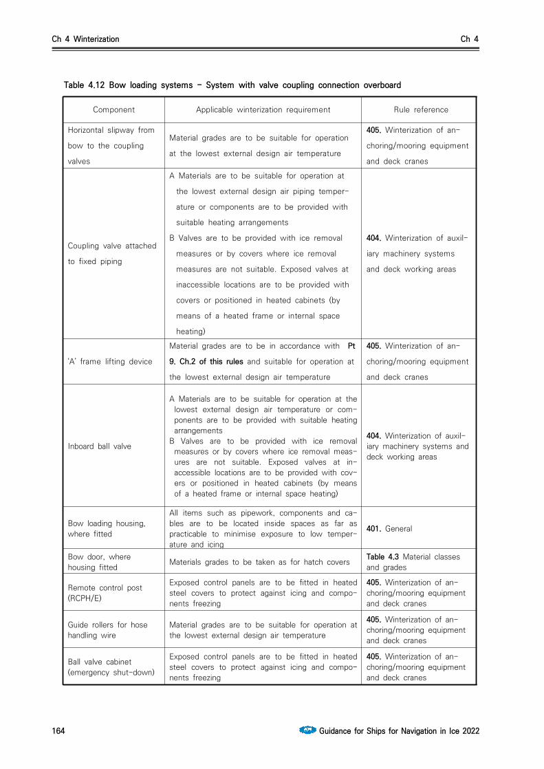
Ch 4 Winterization Ch 4
164 Guidance for Ships for Navigation in Ice 2022
Component Applicable winterization requirement Rule reference
Horizontal slipway from
bow to the coupling
valves
Material grades are to be suitable for operation
at the lowest external design air temperature
405. Winterization of an-
choring/mooring equipment
and deck cranes
Coupling valve attached
to fixed piping
A Materials are to be suitable for operation at
the lowest external design air piping temper-
ature or components are to be provided with
suitable heating arrangements
B Valves are to be provided with ice removal
measures or by covers where ice removal
measures are not suitable. Exposed valves at
inaccessible locations are to be provided with
covers or positioned in heated cabinets (by
means of a heated frame or internal space
heating)
404. Winterization of auxil-
iary machinery systems
and deck working areas
‘A’ frame lifting device
Material grades are to be in accordance with Pt
9. Ch.2 of this rules and suitable for operation at
the lowest external design air temperature
405. Winterization of an-
choring/mooring equipment
and deck cranes
Inboard ball valve
A Materials are to be suitable for operation at the lowest external design air temperature or com-ponents are to be provided with suitable heating arrangements
B Valves are to be provided with ice removal measures or by covers where ice removal meas-ures are not suitable. Exposed valves at in-accessible locations are to be provided with cov-ers or positioned in heated cabinets (by means of a heated frame or internal space heating)
404. Winterization of auxil-iary machinery systems and deck working areas
Bow loading housing, where fitted
All items such as pipework, components and ca-bles are to be located inside spaces as far as practicable to minimise exposure to low temper-ature and icing
401. General
Bow door, where housing fitted Materials grades to be taken as for hatch covers Table 4.3 Material classes
and grades
Remote control post (RCPH/E)
Exposed control panels are to be fitted in heated steel covers to protect against icing and compo-nents freezing
405. Winterization of an-choring/mooring equipment and deck cranes
Guide rollers for hose handling wire
Material grades are to be suitable for operation at the lowest external design air temperature
405. Winterization of an-choring/mooring equipment and deck cranes
Ball valve cabinet (emergency shut-down)
Exposed control panels are to be fitted in heated steel covers to protect against icing and compo-nents freezing
405. Winterization of an-choring/mooring equipment and deck cranes
Table 4.12 Bow loading systems - System with valve coupling connection overboard

Ch 4 Winterization Ch 4
Guidance for Ships for Navigation in Ice 2022 165
Component Applicable winterization requirement Rule reference
Hydraulic power packs
Hydraulic oil power packs are to be sited in heat-ed enclosed spacesWhere this is not practicable, the hydraulic fluid and pipework system materials are to be suitable for operation at the lowest design external air temperature
404. Winterization of auxil-iary machinerysystems and deck working areas
Electro Hydraulic mainpump
Exposed electric motors installed on equipment are to be provided with covers or ice removal measures.Measures are to be provided to protect against the humidity and condensation freezing in the motor, and are to be provided with suitable heat-ing arrangements
406. Winterization of elec-trical installations
Hydraulic oil tank
Heating is to be provided under the bottom of the hydraulic oil tankA Materials are to be suitable for operation at the
lowest external design air temperature or com-ponents are to be provided with suitable heat-ing arrangement
B Valves are to be provided with ice removal measures or by covers where ice removal measures are not suitable. Exposed valves at inaccessible locations are to be provided with covers or positioned in heated cabinets (by means of a heated frame or internal space heating)
404. Winterization of auxil-iary machinery systems and deck working areas
Auxiliary and starter cabinet to prevent condensation
Where located in unheated areas, are to be fit-ted with heating arrangements to prevent con-densation
406. Winterization of elec-trical installations
Electric equipment cabinet
Where located in unheated areas, are to be fit-ted with heating arrangements to prevent con-densation
406. Winterization of elec-trical installations
Table 4.12 Bow loading systems - System with valve coupling connection overboard (continue)

Ch 4 Winterization Ch 4
166 Guidance for Ships for Navigation in Ice 2022
Component Applicable winterization requirement See also Rule reference
Moment free’ bow loading coupler with a ship valve
A. Materials are to be suitable for operation at the lowest external design air temperature or com-ponents are to be provided with suitable heat-ing arrangements
B. Valves are to be provided with ice removal measures or by covers where ice removal measures are not suitable. Exposed valves at inaccessible locations are to be provided with covers or positioned in heated cabinets (by means of a heated frame or internal space heating)
404. Winterisation of auxiliary machinery systems and deck working areas
Adjustable roller fairlead for chafe chain
Material grades are to be suitable for operation at the lowest external design air temperature
405. Winterisation of anchoring/mooring equipment and deck cranes
Mooring chain stopper Material grades are to be suitable for operation at the lowest external design air temperature
405. Winterisation of anchoring/mooring equipment and deck cranes
Horizontal guide roller for mooring hawser messenger
Material grades are to be suitable for operation at the lowest external design air temperature
405. Winterisation of anchoring/mooring equipment and deck cranes
Guide roller with load cell for mooring hawser messenger
Material grades are to be suitable for operation at the lowest external design air temperature
405. Winterisation of anchoring/mooring equipment and deck cranes
Chain for emergency towing system
Material grades are to be suitable for operation at the lowest external design air temperature
405. Winterisation of anchoring/mooring equipment and deck cranes
Guide rollers for hose handling wire
Material grades are to be suitable for operation at the lowest external design air temperature
405. Winterisation of anchoring/mooring equipment and deck cranes
Mooring hawser messenger traction winch
Winches are to be protected from icing by means of suitable covers, alternatively a sheltered deck area is to be provided
405. Winterisation of anchoring/mooring equipment and deck cranes
Drum winch for hose wire winch (this may be common with hydraulic power pack for the above)
Winches are to be protected from icing by means of suitable covers, alternatively a sheltered deck area is to be provided
405. Winterisation of anchoring/mooring equipment and deck cranes
Guide roller for mooring hawser messenger rope storage unit
Material grades are to be suitable for operation at the lowest external design air temperature
405. Winterisation of anchoring/mooring equipment and deck cranes
Mooring hawser messenger rope storage unit
Winches are to be protected from icing by means of suitable covers, alternatively a sheltered deck area is to be provided
405. Winterisation of anchoring/mooring equipment and deck cranes
Bow door Materials grades to be taken as for hatch covers Table 4.3 Material classes and grades
Table 4.13 Bow loading systems - System with valve coupling connection inboard

Ch 4 Winterization Ch 4
Guidance for Ships for Navigation in Ice 2022 167
Component Applicable winterization requirement See also Rule reference
Inboard cargo lines
Arrangements are to be provided to protect against car-go fluids within exposed pipes from freezing. The ex-posed deck cargo and stripping lines are to be fittedwith thermal insulation and suitable trace heating ar-rangements
1002. Winterisation of oil and/or chemical tankers
Drain line
Systems are to be arranged to ensure that they can be drained to protect against fluids freezing in pipes.Drainage valves are to be provided and pipework inclined to ensure that drainage of fluids is possibleunder all normal angles of list and trim. As a minimum, drain valves are to be provided at forward, aft, port and starboard locations. Additional shut-off valves are to be installed on the branch pipes (and as close to the main line as practicable) to allow drainage and protection against freezing in branch pipes when the main line is under pressure and branch lines are not in use
404. Winterisation of auxiliary machinery systems and deck workingareas
Inboard ball valve
A Materials are to be suitable for operation at thelowest external design air temperature or components are to be provided with suitable heating arrangementsB Valves are to be provided with ice removal measures or by covers where ice removal measures are not suitable. Exposed valves at inaccessible locations are to be provided with covers or positioned in heated cabinets (by means of a heated frame or internal space heating)
404. Winterisation of auxiliary machinery systems and deck working areas
Inboard pressure transmitter
Exposed lines are to be provided with heating arrange-ments
1002. Winterisation of oil and/or chemical tankers
Remote control post (RCPH/E)
Exposed control panels are to be fitted in heated steel covers to protect against icing and components freezing
405. Winterisation of anchoring/mooring equipment and deck cranes
Ball valve cabinet (emergencyshut-down)
Exposed control panels are to be fitted in heated steel covers to protect against icing and components freezing
405. Winterisation of anchoring/mooring equipment and deck cranes
Hose handling bow roller
Material grades are to be suitable for operation at the lowest external design air temperature
405. Winterisation of anchoring/mooring equipment and deck cranes
Hydraulic pipes with accessories
Hydraulic oil power packs are to be sited in heated en-closed spaces. Where this is not practicable, thehydraulic fluid and pipework system materials are to be suitable for operation at the lowest design external air temperature
405. Winterisation of anchoring/mooring equipment and deck cranes
Hydraulic valves
A. Materials are to be suitable for operation at the low-est external design air temperature or components are to be provided with suitable heating arrangementsB. Valves are to be provided with ice removal measures or by covers where ice removal measures are not suitable. Exposed valves at inaccessible locations are to be provided with covers or positioned in heated cabinets (by means of a heated frame or internal space heating
404. Winterisation of auxiliary machinery systems and deck working areas
Table 4.13 Bow loading systems - System with valve coupling connection inboard (continue)
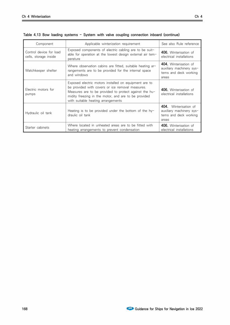
Ch 4 Winterization Ch 4
168 Guidance for Ships for Navigation in Ice 2022
Component Applicable winterization requirement See also Rule reference
Control device for load cells, storage inside
Exposed components of electric cabling are to be suit-able for operation at the lowest design external air tem-perature
406. Winterisation of electrical installations
Watchkeeper shelterWhere observation cabins are fitted, suitable heating ar-rangements are to be provided for the internal space and windows
404. Winterisation of auxiliary machinery sys-tems and deck working areas
Electric motors for pumps
Exposed electric motors installed on equipment are to be provided with covers or ice removal measures.Measures are to be provided to protect against the hu-midity freezing in the motor, and are to be provided with suitable heating arrangements
406. Winterisation of electrical installations
Hydraulic oil tank Heating is to be provided under the bottom of the hy-draulic oil tank
404. Winterisation of auxiliary machinery sys-tems and deck working areas
Starter cabinets Where located in unheated areas are to be fitted with heating arrangements to prevent condensation
406. Winterisation of electrical installations
Table 4.13 Bow loading systems - System with valve coupling connection inboard (continue)

Ch 4 Winterization Ch 4
Guidance for Ships for Navigation in Ice 2022 169
Section 5 Winterization E2(t) - Main component and sub-component (2017)
501. General1. In addition to the requirements in Sec. 4 Winterization E3(t), the following requirements are to be
complied with.
502. Winterization of auxiliary machinery systems and deck working areas1. In conjunction with 404. Winterization of auxiliary machinery systems and deck working areas, heat-
ing is to be provided under the bottom of the hydraulic oil tanks.
2. Arrangements are to be provided to protect fuel oil within exposed pipes against freezing. The ex-posed fuel oil filling and transfer lines, and any sludge transfer lines, are to be fitted with thermal insulation and trace heating arrangements.
3. In conjunction with 404. Winterization of auxiliary machinery systems and deck working areas, the air supply is to be both dry, with a dew point appropriate to the external design air temperature, and heated.
4. Exposed expansion pieces, where fitted, are to be protected from the build-up of ice by the provi-sion of approved bellows units.
503. Winterization of anchoring/mooring and deck cranes1. Exposed control panels are to be fitted in heated steel covers to protect against icing and compo-
nents freezing.
504. Winterization of electrical installations1. In conjunction with 406. Winterization of electrical installations, emergency generators are to be fit-
ted with electrical heating arrangements for the cooling and lubricating oil systems.
2. Satellite/GPS motors and exposed speaker systems are to be provided with heating arrangements.
3. The navigation lights on the forward mast are to be provided with heating arrangements and ice re-moval measures to protect against icing.
505. Winterization of emergency appliances1. The lifeboat access doors are to be provided with trace heating arrangements.
2. The liferafts are to be covered with thermal blankets and monitoring arrangements are to be pro-vided that will activate an alarm in accordance with the alarm system required by Pt 6, Ch 2, 201. of the Rules for the Classification of Steel Ships to allow responsible personnel to reinstate heating in the event of a failure.
3. The EPIRB/SART is to be provided with heating arrangements on the release mechanism. The heat-ing arrangements are not to interfere with the function of the mechanism.
506. Winterization of spaces/compartments1. Space heating is regarded as an essential service and requires two heating sources.
2. In conjunction with Table 4.11 Space heating arrangements for Winterization E3(t), the heating re-quirements in Table 4.14 Space heating arrangements for Winterization E2(t) are to be complied with.

Ch 4 Winterization Ch 4
170 Guidance for Ships for Navigation in Ice 2022
Space Heating arrangements Alarm, see Note 1)
Observation/security cabins(where fitted) Fixed
Enclosed forecastle/sheltereddeck (where fitted) Multiple fixed
Main engine and auxiliary machinery space(s)
Multiple fixed andportable X
Podded propulsion or azimuth thruster space(s)
Multiple fixed andportable X
1) Monitoring arrangements are to be provided that will activate an alarm in ac-cordance with the alarm system required by Pt 6, Ch 2, 201 of the Rules for the Classification of Steel Ships to allow responsible personnel to reinstate heat-ing in the event of a failure.
Table 4.14 Space heating arrangements for Winterization B(t)
3. In conjunction with 408. Winterization of spaces/compartments, all cargo control room windows are to be fitted with thermally heated glass to provide protection against the formation of ice obscuring visibility during discharging/loading operations.
4. In conjunction with 408. Winterization of spaces/compartments, all bridge windows (excluding door windows) are to be fitted with thermally heated glass. Where it can be demonstrated that the build-up of ice on the outside and inside surfaces of deck-house windows obstructing visibility can be effectively prevented by adopting only one means of heating, i.e. heating with filament or hot air blowers, the provision of one means only may be specially considered.
5. In conjunction with 408., bridge wings are to be fully enclosed.
507. Winterization of accommodation and escape routes1. In conjunction with 409. Winterization of accommodation and escape routes, a dedicated heated air-
lock space or heating around the door frame is to be provided and the door seals are to be suitable for low temperature conditions.
2. Above-deck walkways, where fitted, are to be provided with heating arrangements, as far as practi-cable, to allow alternative access to bow spaces.
3. External handrails on routes as given in 411. Ice removal and prevention measures, stairways and ladders are to be fitted with trace heating arrangements to provide access to main working areas and escape routes. Arrangements are to be fitted to cut off automatically in the event of ex-cessively high temperatures to prevent injury when in contact, see 401 General.
508. Winterization of tanks1. In conjunction with 410. Winterization of tanks, exposed air vent pipe heads are to be of a dedi-
cated type suitable for the lowest external design air temperature (with internal heating arrange-ments).
509. Ice removal equipment and prevention measures1. In conjunction with 411. Ice removal and prevention measures, mechanical and electrical control
panels are to be provided with steel covers, as far as practicable
Ch 4 Winterization Ch 4
Guidance for Ships for Navigation in Ice 2022 171
Section 6 Winterization E1(t) - Main component and sub-component (2017)
601. General1. In addition to the requirements in Sec.5 Winterization E2(t), the following requirements are to be
complied with.
602. Winterization of auxiliary machinery systems and deck working areas1. Hydraulic piping at exposed locations is to be protected against the fluid freezing in the piping by
thermal insulation or provided with heating arrangements.
603. Winterization of electrical installations1. In conjunction with 406. Winterization of electrical installations, all exposed cables are to be provided
with steel covers, including cabling to the equipment or component. All cable covers are to be ar-ranged so they can be drained of condensate, see 404. Winterization of auxiliary machinery systems and deck working areas.
604. Winterization of emergency appliances1. In conjunction with 407. Winterization of emergency appliances, heating arrangements are to be pro-
vided for hydrants in exposed locations and the fire main is to be arranged to provide continuous circulation.
2. In conjunction with 407. Winterization of emergency appliances, lifeboat windows are to be provided with heating arrangements.
3. In conjunction with 407. Winterization of emergency appliances, the cooling system for the lifeboat engines is to be provided with suitable anti-freeze and heating arrangements.
605. Winterization of spaces/compartments1. In addition to Table 4.5 6 and Table 4.910, an additional heater(s) is to be provided from a separate
system, e.g. a steam and an electric heating system, or two electric (or steam) heating systems, with separate cabling (piping) and source, in the following spaces:(1) under-deck passageways (where fitted, to allow alternative access to bow spaces which are ad-
jacent to exposed external boundaries);(2) generator room(s);(3) steering gear room;(4) cargo pump-room;(5) oil discharge monitoring equipment (ODME) room;(6) compressor and motor rooms (where fitted);(7) fire-fighting equipment store room (including location of the fireman’s outfit); and(8) emergency fire pump-room.
2. A centralised location, for congregation of the crew during a prolonged emergency situation such as ice entrapment, is to be provided with heating arrangements powered by the emergency source.
3. For the main engine and auxiliary machinery spaces, as well as podded propulsion or azimuth thruster space(s), one of the following is to be complied with:(a) heating arrangements are to be powered from the emergency source (to provide for start-up of
the main engine systems);(b) means are to be provided for starting and control of the main propulsion system at the lowest
internal air temperature;(c) two boilers, main engines or main propulsion systems are to be provided in separate
compartments.4. The Master’s and Senior Officer’s cabin windows are to have heating arrangements if they have a
view over the cargo deck.

Ch 4 Winterization Ch 4
172 Guidance for Ships for Navigation in Ice 2022
606. Winterization of tanks1. In conjunction with 410. Winterization of tanks, the tank heating is to be considered an essential
service. Electrical arrangements are to be duplicated such that a failure will not result in the loss of the ability to provide heating required for safety of the ship. (see Pt 6, Ch 1, 201. and 204.)Where a power driven motor pump is provided for transferring the heating medium, a standby pump is to be provided and connected for ready use or, alternatively, emergency connections may be made to one of the unit pumps or another suitable power driven pump.
Section 7 Winterization S - Stability due to ice accretion701. Stability calculations and criteria
1. The effect of icing is to be considered in the stability calculations and is to comply with the International Code on Intact Stability Resolution MSC.267(85), as amended - Chapter 6 - Icing considerations. The ice accretion values are to be taken as an additional mass per unit area, as giv-en in Table 4.15.
Winterization levelHorizontal deck
kgm
Vertical sidekgm
Winterization S(C) Winterization S(B) Winterization S(A)
3060
100
7.51520
Table 4.15 Ice accretion values
2. Where surfaces are inclined or shaped, e.g. spherical covers or deck-houses, the most onerous condition from the projected horizontal or vertical area is to be taken in conjunction with the asso-ciated ice accretion value given in Table 4.9. All areas above the design waterline are to be in-cluded, e.g. side shell, deck-house sides and projected areas of deck cargo.
3. The stability criteria as given in the International Code on Intact Stability Resolution A.749(18) - Chapter 3.1 General intact stability criteria, are to be complied with, see 101. and 102.
4. Stability calculations are to include the effects of ice accretion on the loading conditions specified in the International Code on Intact Stability Resolution on intact stability. In addition, stability calcu-lations are to be provided for the most onerous conditions and, at least, the following conditions:(1) Establish specific winterization conditions of loading and ballasting corresponding to the limits
of compliance with the criteria, taking into account ice accretion as follows:(a) Design draught condition.(b) Minimum design ballast condition.(c) Seagoing conditions, including both departure and arrival conditions: • homogeneous loading conditions • alternate and part load conditions, where applicable • normal ballast condition • heavy ballast condition • any specified non-uniform distribution of loading • for oil and chemical tankers, conditions with high density cargo • mid-voyage conditions relating to tank cleaning or other operations where these differ
significantly from the ballast conditions and • conditions covering ballast water exchange procedures
(2) Establish ice accretion compliant conditions and limits for specified harbour/sheltered water con- ditions as follows:(a) conditions representing typical loading and unloading operations;(b) docking afloat condition; and(c) propeller inspection afloat condition.

Ch 4 Winterization Ch 4
Guidance for Ships for Navigation in Ice 2022 173
Section 8 Winterization D - Alternative design (2017)
801. Alternative design1. Consideration may be given to alternative designs which do not comply with the requirements of
Sec 3 on the basis of equivalency and agreement between the Owner and Builder Shipbuilder.
2. Consideration may be given to a specification agreed by the Builder Shipbuilder and Owner for a given specific trading route based on the environmental conditions for the intended operation, e.g. temperatures and sea states, and any operational considerations, e.g. specific ship arrangements.
3. For ships where alternative designs are to be applied, the Winterization D(t) notation may be assigned. The lowest external design air temperature is to be included in the Winterization notation in brackets, e.g. Winterization D(-25).
4. The design air temperature is to be stated in association with the lowest external design air tem-perature in degrees Celsius for the assessment of hull construction materials and, equipment and systems where applicable.
Section 9 Winterization IR - Ice removal arrangements (2017)
901. Application1. The following requirements are intended to provide protection from ice accretion through the provi-
sion of additional measures such as heating and covers.
902. Information required1. Details of the heating arrangements and ice removal measures, as well as any operational proce-
dures, are to be submitted, see 103.
2. An ice removal manual is to be placed on board the ship highlighting the equipment and features installed and any operational procedures.
903. Definitions1. Ice removal measures. In addition to the measures in 104., heating arrangements, as given in 104.,
are to be considered in conjunction with the requirements of this Section.
904. Ice removal provisions1. Where heating arrangements are provided, they are to comply with the requirements in 401.
General.
2. The items as given in Table 4.16 Ice removal arrangements are to be complied with, considering the ship type and arrangement.
905. Requirements for oil and/or chemical tankers, LNG and LPG carriers1. Ice removal measures are to be installed of either steam or hot water types with a fixed pipeline
on the deck with connection valves for hoses in areas designated for control of cargo loading and unloading (including high walkways).
906. Requirements for offshore supply vessels1. For vessels with a rescue zone, the requirements of 1003. Winterization of offshore supply vessels
are to be complied with.

Ch 4 Winterization Ch 4
174 Guidance for Ships for Navigation in Ice 2022
907. Requirements for LNG and LPG carriers1. The air intakes and exhaust louvres are to be provided with protection from icing by ice removal
measures and heating arrangements.
Component Applicable Winterization requirement See Rule reference
Winterization of main propulsion and essential auxiliary enginesAir intakes and exhaust louvres
The air intakes and exhaust louvres for machinery spaces are to be provided with protection from icing by ice removal measures and heating arrangements
408. Winterization of spaces/compartments
Winterization of auxiliary machinery systems and deck
Exposed fittings
Valves, gauges, indicators and monitoring equipment for essential services are to be protected from icing and provided with ice re-moval measures or by covers where ice removal measures are not suitable. Exposed valves at inaccessible locations are to be provided with covers or positioned in heated cabinets (by means of a heated frame or internal space heating). Gauges, indicators and monitoring equipment which are sited in exposed locations but are unsuitable for removal of ice are to be positioned in heated cabinets. Valve actuators, solenoids and pressure gauge transmitters for essential services are to be provided with heating arrangements
408. Winterization of spaces/compartments
Winterization of anchoring/mooring
ProtectionAnchor windlass and mooring winches are to be protected from icing by means of suitable covers. Alternatively, a sheltered deck area is to be provided
405. Winterization of anchoring/mooring equipment and deck cranes
Control panels
Exposed control panels are to be provided with suitable steel covers to protect against icing
405. Winterization of anchoring/mooring equipment and deck cranes
Hydraulic equipment
For hydraulically operated equipment and systems, steam ice re-moval measures are to be provided for protection against icing
405. Winterization of anchoring/mooring equipment and deck cranes
Hawse pipeThe hawse pipe is to be sited in a heated space or provided with suitable heating arrangements and deck steam connection valve(s) located within the vicinity to protect against icing
405. Winterization of anchoring/mooring equipment and deck cranes
Winterization of electrical installations
Emergency generator
The emergency generator room air intakes are to be provided with protection from icing by ice removal measures or heating arrangements. In addition, the air intake is to be provided with an automatic louvre which closes whilst the generator is inactive (to reduce heat loss), and opens when starting
406. Winterization of electrical installations
Radar
Protection measures are to be fitted for the continuous operation of the radar motors against the humidity and icing freezing the motor. Radar motors are to be provided with heating arrangements and with the provision for suitable use of low temperature grease
406. Winterization of electrical installations
Air horn
Measures for continuous operation of the navigation air horn, where fitted, are to be provided to protect against humidity freezing in components and icing and suitable heating arrangements are to be provided. Air pipe lines for the navigation air horn are to be ar-ranged in heated compartments as far as practicable
406. Winterization of electrical installations
Antenna systems Antenna systems are to be protected from icing 406. Winterization of
electrical installations
Table 4.16 Ice removal arrangements

Ch 4 Winterization Ch 4
Guidance for Ships for Navigation in Ice 2022 175
Component Applicable Winterization requirement See Rule reference
Winterization of electrical installations
Fire-fighting Isolating valves and hydrants are to be provided with ice removal measures
407. Winterization of emergency appliances
Protected locations
As far as practicable, lifeboats and liferafts are to be located in pro-tected locations (recesses or garages) to provide protection from icing
407. Winterization of emergency appliances
Lifeboat winches
Lifeboat winches, where fitted, are to be provided with suitable covers or ice removal measures. The operating devices (brake(s)) are to be protected from icing by ice removal measures, suitable grease and lubricants with covers or heating arrangements. Hydraulic systems, including tanks, pipes and mechanisms, are to be provided with suitable steam ice removal measures, suitable grease and lubricants or heating arrangements
407. Winterization of emergency appliances
Lifeboat davits
Lifeboat davits/sheaves/release hooks are to have provision for the use of suitable low temperature grease, covers and heating arrange-ments, to protect the mechanisms from icing
407. Winterization of emergency appliances
Life raftsA steam connection for ice removal measures is to be provided for protection against icing of the life raft. Davit-launched life rafts are to comply with 407. 14
407. Winterization of emergency appliances
EPIRB Ice removal measures are to be provided for the EPIRB/SART407. Winterization of emergency appliances
Winterization of spaces/compartments
Air intakes and exhaust louvres
The air intakes and exhaust louvres for accommodation spaces are to be provided with protection from icing by ice removal measures and heating arrangements
408. Winterization of spaces/compartments
Bridge windows
All bridge windows (excluding door windows) are to be fitted with heating arrangements to provide protection against the build-up of ice obscuring visibility. The use of hot air blowers inside is to be provided for all windows. Consideration is to be given to fitting dou-ble-glazed windows in order to provide protection against cold water cracking glass which is exposed to warm internal conditions
408. Winterization of spaces/compartments
Bridge window cleaning system
The system for window cleaning is to be protected against freezing in the lines and clogging of the nozzles with frequent operation.Cold fresh water systems with heated spray nozzles, or hot water systems which can be drained and dry air blown through after use, are to be provided. Window wiper operating devices are to be ar-ranged inside the bridge or to be provided with heating arrangements. Safe access is to be provided externally for ice re-moval
408. Winterization of spaces/compartments
Bridge wing controls
Measures to protect personnel operating on the bridge from cold temperatures are to be provided. Where ships have exposed bridge wings, the wing controls/equipment are to be provided with heating arrangements and covers
408. Winterization of spaces/compartments
Table 4.16 Ice removal arrangements (continue)

Ch 4 Winterization Ch 4
176 Guidance for Ships for Navigation in Ice 2022
Component Applicable Winterization requirement See Rule reference
Winterization of accommodation and escape routes
Accommodation and escaperoutes
Measures are to be provided to assist in the opening of doors when covered in ice and to protect seals against freezing. External doors are to be positioned in protected locations or ecessed as far as practicable to provide protection from icing. The enclosed space ad-jacent to external doors on escape routes is to be fitted with heat-ing arrangements
409. Winterization of accommodation and escape routes
Winterization of tanks
Tanks vent pipe heads
Measures to provide protection from icing and blockage by ice for-mation resulting from humidity in tanks are to be fitted. Exposed air vent pipe heads of tanks are to be readily accessible, positioned in protected locations as far as practicable and fitted with covers to limit build-up of ice. The covers are not to interfere with the free flow of air through the vent openings
410. Winterization of tanks
Ice removal equipment and prevention measures
Ice removal
The following areas of exposed decks are to be provided with: (a) heated decks;(b) gratings;(c) checkered plate;(d) non-slip decking with coarse sand embedded into the paint.
In addition, ice removal measures are to be installed of either steam or hot water types with a fixed pipeline on the deck with con-nection valves for hoses in the following areas:(1) Gangways and stairways for safe access to bow, lifeboats, res-
cue boats and pilot boarding locations;(2) Areas adjacent to escape exits;(3) Areas in way of lifeboats/rescue boats, davits, and life rafts in-
cluding launching areas;(4) Adjacent to storage facilities for fire-fighting equipment;(5) Areas in way of anchoring and mooring operations (including
windlass, chain and hawse pipe);(6) Areas in way of anchoring and mooring operations (including
windlass, chain and hawse pipe);(7) Areas for open navigation and lookout;(8) Helicopter deck areas, where fitted;(9) Working areas on the open deck (including ice removal measures
for hatch covers, containers and grain loading covers)
411. Ice removal and prevention measures
Protective covers
To aid the removal of ice and protect against the ingress of water into components that may subsequently freeze and result in dam-age, mechanical and electrical equipment and control panels that may be exposed to icing are to be provided with suitable covers, as far as practicable, and unless other arrangements are specified in these Rules
411. Ice removal and prevention measures
Manual tools
A minimum of the following manual tools for removing ice are to be provided, with at least one set of tools at each storage location. Storage locations should be as given in 411. A set of tools is to comprise at least the following:(1) 3 shovels;(2) 3 hammers or mallets; and(3) 3 scrapers.Storage facilities for the manual tools are to be provided and sited in protected areas, as far as practicable, to provide access and pro-tection from icing behind bulwarks and accommodation walls
411. Ice removal and prevention measures
Table 4.16 Ice removal arrangements (continue)
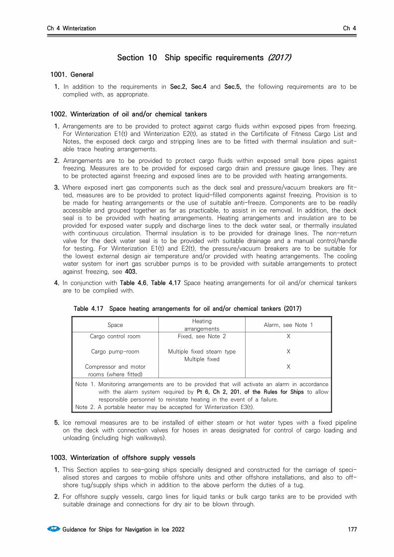
Ch 4 Winterization Ch 4
Guidance for Ships for Navigation in Ice 2022 177
Section 10 Ship specific requirements (2017)
1001. General1. In addition to the requirements in Sec.2, Sec.4 and Sec.5, the following requirements are to be
complied with, as appropriate.
1002. Winterization of oil and/or chemical tankers1. Arrangements are to be provided to protect against cargo fluids within exposed pipes from freezing.
For Winterization E1(t) and Winterization E2(t), as stated in the Certificate of Fitness Cargo List and Notes, the exposed deck cargo and stripping lines are to be fitted with thermal insulation and suit-able trace heating arrangements.
2. Arrangements are to be provided to protect cargo fluids within exposed small bore pipes against freezing. Measures are to be provided for exposed cargo drain and pressure gauge lines. They are to be protected against freezing and exposed lines are to be provided with heating arrangements.
3. Where exposed inert gas components such as the deck seal and pressure/vacuum breakers are fit-ted, measures are to be provided to protect liquid-filled components against freezing. Provision is to be made for heating arrangements or the use of suitable anti-freeze. Components are to be readily accessible and grouped together as far as practicable, to assist in ice removal. In addition, the deck seal is to be provided with heating arrangements. Heating arrangements and insulation are to be provided for exposed water supply and discharge lines to the deck water seal, or thermally insulated with continuous circulation. Thermal insulation is to be provided for drainage lines. The non-return valve for the deck water seal is to be provided with suitable drainage and a manual control/handle for testing. For Winterization E1(t) and E2(t), the pressure/vacuum breakers are to be suitable for the lowest external design air temperature and/or provided with heating arrangements. The cooling water system for inert gas scrubber pumps is to be provided with suitable arrangements to protect against freezing, see 403.
4. In conjunction with Table 4.6, Table 4.17 Space heating arrangements for oil and/or chemical tankers are to be complied with.
Space Heatingarrangements Alarm, see Note 1
Cargo control room
Cargo pump-room
Compressor and motorrooms (where fitted)
Fixed, see Note 2
Multiple fixed steam type Multiple fixed
X
X
X
Note 1. Monitoring arrangements are to be provided that will activate an alarm in accordance with the alarm system required by Pt 6, Ch 2, 201. of the Rules for Ships to allow responsible personnel to reinstate heating in the event of a failure.
Note 2. A portable heater may be accepted for Winterization E3(t).
Table 4.17 Space heating arrangements for oil and/or chemical tankers (2017)
5. Ice removal measures are to be installed of either steam or hot water types with a fixed pipeline on the deck with connection valves for hoses in areas designated for control of cargo loading and unloading (including high walkways).
1003. Winterization of offshore supply vessels1. This Section applies to sea-going ships specially designed and constructed for the carriage of speci-
alised stores and cargoes to mobile offshore units and other offshore installations, and also to off-shore tug/supply ships which in addition to the above perform the duties of a tug.
2. For offshore supply vessels, cargo lines for liquid tanks or bulk cargo tanks are to be provided with suitable drainage and connections for dry air to be blown through.

Ch 4 Winterization Ch 4
178 Guidance for Ships for Navigation in Ice 2022
3. For vessels with a rescue zone, suitable arrangements are to be provided to protect against ice freezing:(1) on a cross-deck area between the rescue zones port and starboard;(2) the sides and railings in the rescue zone; and(3) routes to the accommodation/treatment areas.
4. In conjunction with 411. Ice removal and prevention measures, heating arrangements are to be pro-vided for escape routes and access to emergency systems, including access and areas around life-boats, liferafts, rescue boats and rescue zones, walkways on the aft deck, emergency generator and the fire-fighting platform.
1004. Winterization of LNG and LPG carriers1. The air intakes and exhaust louvres for the spaces are to be provided with protection from icing by
ice removal measures and heating arrangements.
Space Heating arrangements Alarm, see Note 1
Cargo control room
Cargo pump-room
Compressor and motor rooms (where fitted)
Fixed, see Note 2
Multiple fixed steam type
Multiple fixed
X
X
X
Note 1. Monitoring arrangements are to be provided that will activate an alarm in ac-cordance with the alarm system required by Pt 6, Ch 2, 201 of the Rules for Ships to allow responsible personnel to reinstate heating in the event of a failure.
Note 2. A portable heater may be accepted for Winterization E3(t).
Table 4.18 Space heating arrangements for LNG and LPG carriers
2. In conjunction with Table 4.6, the heating requirements in Table 4.18 Space heating arrangements for LNG and LPG carriers are to be complied with.
3. Ice removal measures are to be installed of either steam or hot water types with a fixed pipeline on the deck with connection valves for hoses in areas designated for control of cargo loading and unloading (including high walkways).
1005. Winterization of bulk carriers and container ships1. To prevent freezing of exposed cargo securing arrangements, they are to be of suitable material for
the lowest design air temperature, provided with suitable low temperature grease and with ice re-moval measures.
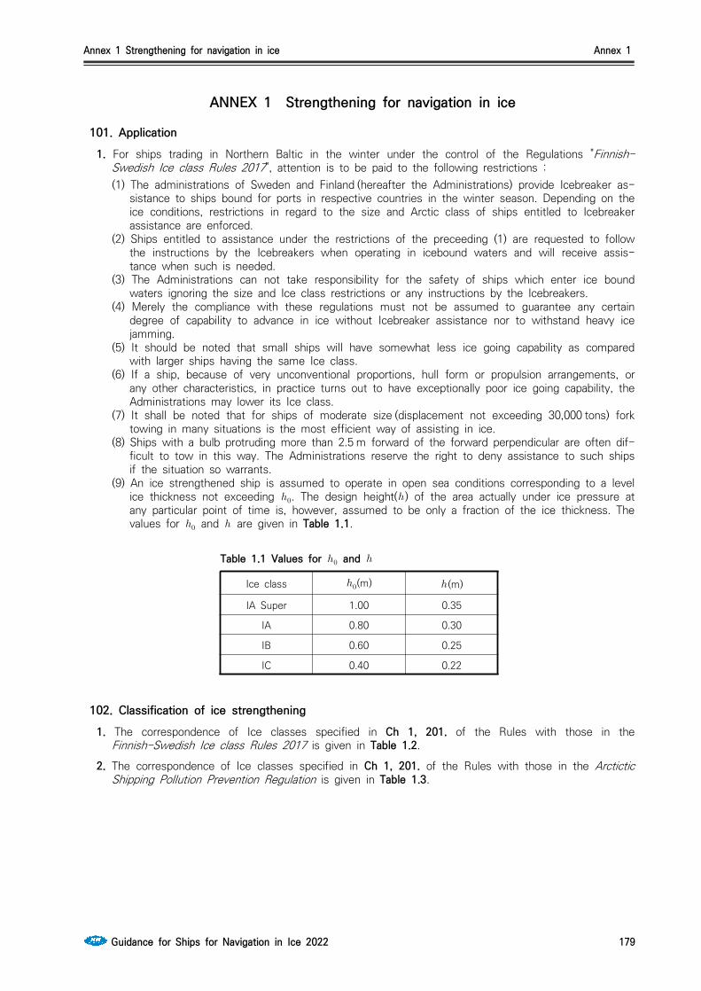
Annex 1 Strengthening for navigation in ice Annex 1
Guidance for Ships for Navigation in Ice 2022 179
ANNEX 1 Strengthening for navigation in ice
101. Application1. For ships trading in Northern Baltic in the winter under the control of the Regulations "Finnish-
Swedish Ice class Rules 2017", attention is to be paid to the following restrictions :(1) The administrations of Sweden and Finland (hereafter the Administrations) provide Icebreaker as-
sistance to ships bound for ports in respective countries in the winter season. Depending on the ice conditions, restrictions in regard to the size and Arctic class of ships entitled to Icebreaker assistance are enforced.
(2) Ships entitled to assistance under the restrictions of the preceeding (1) are requested to follow the instructions by the Icebreakers when operating in icebound waters and will receive assis-tance when such is needed.
(3) The Administrations can not take responsibility for the safety of ships which enter ice bound waters ignoring the size and Ice class restrictions or any instructions by the Icebreakers.
(4) Merely the compliance with these regulations must not be assumed to guarantee any certain degree of capability to advance in ice without Icebreaker assistance nor to withstand heavy ice jamming.
(5) It should be noted that small ships will have somewhat less ice going capability as compared with larger ships having the same Ice class.
(6) If a ship, because of very unconventional proportions, hull form or propulsion arrangements, or any other characteristics, in practice turns out to have exceptionally poor ice going capability, the Administrations may lower its Ice class.
(7) It shall be noted that for ships of moderate size (displacement not exceeding 30,000 tons) fork towing in many situations is the most efficient way of assisting in ice.
(8) Ships with a bulb protruding more than 2.5 m forward of the forward perpendicular are often dif-ficult to tow in this way. The Administrations reserve the right to deny assistance to such ships if the situation so warrants.
(9) An ice strengthened ship is assumed to operate in open sea conditions corresponding to a level ice thickness not exceeding . The design height() of the area actually under ice pressure at any particular point of time is, however, assumed to be only a fraction of the ice thickness. The values for and are given in Table 1.1.
Table 1.1 Values for and
Ice class (m) (m)
IA Super 1.00 0.35
IA 0.80 0.30
IB 0.60 0.25
IC 0.40 0.22
102. Classification of ice strengthening1. The correspondence of Ice classes specified in Ch 1, 201. of the Rules with those in the
Finnish-Swedish Ice class Rules 2017 is given in Table 1.2.
2. The correspondence of Ice classes specified in Ch 1, 201. of the Rules with those in the Arctictic Shipping Pollution Prevention Regulation is given in Table 1.3.
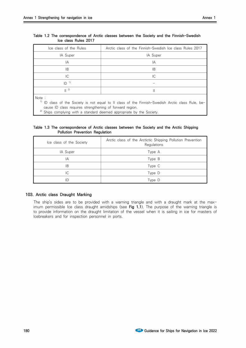
Annex 1 Strengthening for navigation in ice Annex 1
180 Guidance for Ships for Navigation in Ice 2022
Table 1.2 The correspondence of Arctic classes between the Society and the Finnish-Swedish Ice class Rules 2017
Ice class of the Rules Arctic class of the Finnish-Swedish Ice class Rules 2017
IA Super IA Super
IA IA
IB IB
IC IC
ID 1) -
II 2) II
Note :1) ID class of the Society is not equal to II class of the Finnish-Swedish Arctic class Rule, be-
cause ID class requires strengthening of forward region.2) Ships complying with a standard deemed appropriate by the Society.
Table 1.3 The correspondence of Arctic classes between the Society and the Arctic Shipping Pollution Prevention Regulation
Ice class of the Society Arctic class of the Arctictic Shipping Pollution Prevention Regulations
IA Super Type A
IA Type B
IB Type C
IC Type D
ID Type D
103. Arctic class Draught Marking The ship's sides are to be provided with a warning triangle and with a draught mark at the max-
imum permissible Ice class draught amidships (see Fig 1.1). The purpose of the warning triangle is to provide information on the draught limitation of the vessel when it is sailing in ice for masters of Icebreakers and for inspection personnel in ports.

Annex 1 Strengthening for navigation in ice Annex 1
Guidance for Ships for Navigation in Ice 2022 181
Fig 1.1 Arctic class draught marking(1) The upper edge of the Warning Triangle is to be located vertically above the “ICE” mark, 1000
mm higher than the Summer Load Line in fresh water but in no case higher than the deck line. The sides of the triangle are to be 300 mm in length.
(2) The Ice class draught mark is to be located 540 mm abaft the centre of the load line ring or 540 mm abaft the vertical line of the timber load line mark, if applicable.
(3) The marks and figures are to be cut out of 5 - 8 mm plate and then welded to the ship's side. The marks and figures are to be painted in a red or yellow reflecting colour in order to make the marks and figures plainly visible even in ice conditions.
(4) The dimensions of all figures are to be the same as those used in the load line mark.
104. ValidityThe validity of the powering requirement in Ch 1, 502. for Ice classes IA Super, IA, IB and IC, and verification of calculated powering requirements, is as following.
1. Range of validity The range of validity of the formulae for powering requirements in Ch 1, 502. is presented in Table
1.4. When calculating the parameter DP/T, T shall be measured at the largest draught amidships.
Parameter Minimum Maximum
(deg) 15 55
(deg) 25 90
(deg) 10 90
(m) 65.0 250.0
(m) 11.0 40.0
(m) 4.0 15.0
0.15 0.40
0.25 0.75
0.45 0.75
∙ 0.09 0.27
Table 1.4 The range of parameters used for validation of the powering requirement

Annex 1 Strengthening for navigation in ice Annex 1
182 Guidance for Ships for Navigation in Ice 2022
2. Verification of calculated powering requirements To check the results of calculated powering requirements, Table 1.5 is presented with input data for
a number of sample ships.
Sample ship No. 1 2 3 4 5 6 7 8 9
Arctic classIA
SuperIA IB IC
IA Super
IA Super
IA IA IB
(deg) 24 24 24 24 24 24 36 20 24
(deg) 90 90 90 90 30 90 30 30 90
(deg) 30 30 30 30 30 30 30 30 30
(m) 150 150 150 150 150 150 150 150 150
(m) 25 25 25 25 25 25 25 25 25
(m) 9 9 9 9 9 9 9 9 9
45 45 45 45 45 45 45 45 45
70 70 70 70 70 70 70 70 70
500 500 500 500 500 500 500 500 500
5 5 5 5 5 5 5 5 5
Prop. No. / Type 1/CP 1/CP 1/CP 1/CP 1/CP 1/CP 1/CP 1/CP 1/FPNew Ship(kW)
(see Ch 1, 502. 2)7840 4941 3478 2253 6799 6406 5343 5017 3872
Existing ships(kW)(see Ch 1, 502. 3 and 4)
9192 6614 8466 7645 6614 6614
Table 1.5 Parameters and calculated minimum engine power of sample ships

Annex 2 Load Cases for Propeller and the Shape of the Propeller Ice Torque Excitation for the Ships Strengthened for Navigation in Ice and Polar Class Ships Annex 2
Guidance for Ships for Navigation in Ice 2022 183
ANNEX 2 Load cases for propeller and the shape of the propeller ice torque excitation for the ships strengthened for
navigation in ice and Polar Class ships
Table 2.1 Load cases for open propeller
Load case Force Loaded area Right handed propeller blade seen from back
Load case 1
Uniform pressure applied on the back of the blade(suction side) to an area from 0.6 to the tip and from the leading edge to 0.2 times the chord length
Load case 2 50% of
Uniform pressure applied on the back of the blade(suction side) on the propeller tip area outside of 0.9 radius
Load case 3
Uniform pressure applied on the blade face (pressure side) to an area from 0.6 to the tip and from the leading edge to 0.2 times the chord length
Load case 4 50% of
Uniform pressure applied on the pro-peller face (pressure side) on the propeller tip area outside of 0.9 radius
Load case 5 60% of or which is greater
Uniform pressure applied on the pro-peller face (pressure side) to an area from 0.6 to the tip and from the trailing edge to 0.2 times the chord length
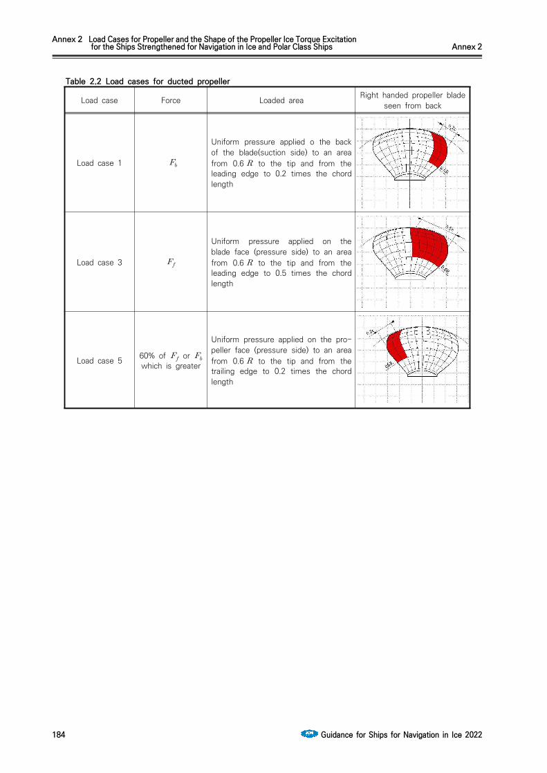
Annex 2 Load Cases for Propeller and the Shape of the Propeller Ice Torque Excitation for the Ships Strengthened for Navigation in Ice and Polar Class Ships Annex 2
184 Guidance for Ships for Navigation in Ice 2022
Table 2.2 Load cases for ducted propeller
Load case Force Loaded area Right handed propeller blade seen from back
Load case 1
Uniform pressure applied o the back of the blade(suction side) to an area from 0.6 to the tip and from the leading edge to 0.2 times the chord length
Load case 3
Uniform pressure applied on the blade face (pressure side) to an area from 0.6 to the tip and from the leading edge to 0.5 times the chord length
Load case 5 60% of or which is greater
Uniform pressure applied on the pro-peller face (pressure side) to an area from 0.6 to the tip and from the trailing edge to 0.2 times the chord length

Annex 2 Load Cases for Propeller and the Shape of the Propeller Ice Torque Excitation for the Ships Strengthened for Navigation in Ice and Polar Class Ships Annex 2
Guidance for Ships for Navigation in Ice 2022 185
Fig 2.1 The shape of the propeller ice torque excitation sequences for propellers having 3, 4, 5 or 6 blades.

GUIDANCE FOR SHIPS FOR NAVIGATION IN ICE
Published byKR
36, Myeongji ocean city 9-ro, Gangseo-gu,BUSAN, KOREA
TEL : +82 70 8799 7114FAX : +82 70 8799 8999
Website : http://www.krs.co.kr
CopyrightⒸ 2022, KRReproduction of this Rules and Guidance in whole or inn parts is prohibited without permission of the publisher.
Related Documents