190-01007-C1 January 2020 Revision 1 GTN Xi Part 23 AML STC Maintenance Manual Contains Instructions for Continued Airworthiness for STC SA02019SE-D Aircraft make, model, registration number, and serial number, along with the applicable STC configuration information, must be completed in Appendix A and saved with aircraft permanent records.

Welcome message from author
This document is posted to help you gain knowledge. Please leave a comment to let me know what you think about it! Share it to your friends and learn new things together.
Transcript

190-01007-C1 January 2020 Revision 1
GTN Xi Part 23 AML STCMaintenance Manual
Contains Instructions for Continued Airworthinessfor STC SA02019SE-D
Aircraft make, model, registration number, and serial number, along with the applicable STC configuration information, must be completed in Appendix A and
saved with aircraft permanent records.

190-01007-C1 GTN Xi Part 23 AML STC Maintenance ManualRev. 1 Page A
© 2020Garmin International, Inc., or its subsidiaries
All Rights Reserved
Except as expressly provided herein, no part of this manual may be reproduced, copied, transmitted, disseminated, downloaded or stored in any storage medium, for any purpose without the express prior written consent of Garmin. Garmin hereby grants permission to download a single copy of this manual and of any revision to this manual onto a hard drive or other electronic storage medium to be viewed and to print one copy of this manual or of any revision hereto, provided that such electronic or printed copy of this manual or revision must contain the complete text of this copyright notice and provided further that any unauthorized commercial distribution of this manual or any revision hereto is strictly prohibited.Adobe® is a registered trademark of Adobe Systems Incorporated. All rights reserved.
© 2020 The Bluetooth® word mark and logos are registered trademarks owned by Bluetooth SIG, Inc. and any use of such marks by Garmin is under license. Other trademarks and trade names are those of their respective owners.
© 2020 Sirius XM Radio Inc. Sirius, XM and all related marks and logos are trademarks of Sirius XM Radio Inc. All other marks and logos are property of their respective owners. All rights reserved.
Garmin®, FliteCharts®, and SafeTaxi® are registered trademarks of Garmin International or its subsidiaries. Connext™, Garmin Pilot™, GDU™, GTN™, and Telligence™ are trademarks of Garmin International or its subsidiaries. These trademarks may not be used without the express permission of Garmin.
Skywatch® and Stormscope® are registered trademarks of L-3 Communications.
Visit flyGarmin.com for aviation product support.

190-01007-C1 GTN Xi Part 23 AML STC Maintenance ManualRev. 1 Page B
RECORD OF REVISIONSRevision Revision Date Description
1 01/03/20 Initial release.

190-01007-C1 GTN Xi Part 23 AML STC Maintenance ManualRev. 1 Page i
INFORMATION SUBJECT TO EXPORT CONTROL LAWSThis document may contain information that is subject to the Export Administration Regulations (EAR) issued by the United States Department of Commerce (15 Code of Federal Regulations (CFR), Chapter VII, Subchapter C) and may not be exported, released, or disclosed to foreign nationals inside or outside of the United States without first obtaining an export license. Include this notice with any reproduced portion of this document.
The information in this document is subject to change without notice. Visit Garmin’s Dealer Resource Center for current updates and supplemental information concerning the operation of Garmin products.
DEFINITIONS OF WARNINGS, CAUTIONS, AND NOTES
WARNINGThis product, its packaging, and its components contain chemicals known to the State of California to cause cancer, birth defects, or reproductive harm. This notice is being provided in accordance with California’s Proposition 65. If you have any questions, or would like additional information, please refer to our website at www.garmin.com/prop65.
CAUTIONGTN Xi units have a special anti-reflective coated display that is sensitive to waxes and abrasive cleaners. CLEANERS CONTAINING AMMONIA WILL HARM THE ANTI-REFLECTIVE COATING. It is important to clean the display using a clean, lint-free cloth with a cleaner that is safe for anti-reflective coatings.
NOTEAll screen shots used in this document are current at the time of publication. Screen shots are intended to provide visual reference only. All information depicted in screen shots, including software file names, versions, and part numbers, is subject to change and may not be up-to-date.
WARNINGWarnings indicate that injury or death is possible if the instructions are disregarded.
CAUTIONCautions indicate that damage to the equipment is possible.
NOTENotes provide additional information.

190-01007-C1 GTN Xi Part 23 AML STC Maintenance ManualRev. 1 Page ii
TABLE OF CONTENTS
1 INTRODUCTION............................................................................................................................. 1-11.1 Content, Scope, and Purpose .............................................................................................. 1-21.2 Organization ....................................................................................................................... 1-21.3 Definitions and Abbreviations............................................................................................ 1-31.4 Publications......................................................................................................................... 1-41.5 Distribution ......................................................................................................................... 1-4
2 SYSTEM DESCRIPTION................................................................................................................ 2-12.1 Equipment Descriptions...................................................................................................... 2-22.2 Backplate Connectors ......................................................................................................... 2-42.3 GTN Xi Optional Interfaces ............................................................................................... 2-62.4 GTN Block Diagram........................................................................................................... 2-7
3 CONTROL AND OPERATION...................................................................................................... 3-13.1 GTN Xi Normal Mode Overview....................................................................................... 3-23.2 GTN Xi Configuration Mode Overview............................................................................. 3-33.3 Database Updates.............................................................................................................. 3-21
4 INSTRUCTIONS FOR CONTINUED AIRWORTHINESS........................................................ 4-14.1 Airworthiness Limitations .................................................................................................. 4-24.2 Servicing Information......................................................................................................... 4-24.3 Maintenance Intervals......................................................................................................... 4-34.4 Visual Inspection ................................................................................................................ 4-54.5 Electrical Bonding Test ...................................................................................................... 4-64.6 Transient Voltage Suppressor (TVS) (If Installed) ............................................................ 4-9
5 TROUBLESHOOTING ................................................................................................................... 5-15.1 GTN Xi General Troubleshooting ...................................................................................... 5-25.2 GTN Xi Failure Annunciations .......................................................................................... 5-65.3 GTN Xi System Messages.................................................................................................. 5-75.4 Flight Stream Troubleshooting ......................................................................................... 5-225.5 GMA 35 Troubleshooting................................................................................................. 5-245.6 GMA 35 Failure Annunciations ....................................................................................... 5-255.7 GMA 35 System Messages............................................................................................... 5-25
6 EQUIPMENT REMOVAL AND RE-INSTALLATION.............................................................. 6-16.1 GTN Xi ............................................................................................................................... 6-26.2 GMA 35 .............................................................................................................................. 6-66.3 Data Card/Flight Stream 510 .............................................................................................. 6-96.4 Flight Stream 210 ............................................................................................................. 6-106.5 NAV Antenna Cable Diplexer.......................................................................................... 6-116.6 NAV Antenna Cable Splitter ............................................................................................ 6-116.7 Configuration Module (P1001 Only)................................................................................ 6-126.8 GTN Xi Fan ...................................................................................................................... 6-156.9 TVS and Fuse (Nonmetallic Aircraft Only) ..................................................................... 6-186.10 Instrument Panel Bonding Strap....................................................................................... 6-226.11 Flight Stream 210 Bonding Strap ..................................................................................... 6-236.12 Interfaced Equipment Bonding Strap ............................................................................... 6-25
7 EQUIPMENT CONFIGURATION AND TESTING.................................................................... 7-17.1 GTN Xi ............................................................................................................................... 7-27.2 GMA 35 .............................................................................................................................. 7-77.3 Interfaced Equipment........................................................................................................ 7-117.4 Enabled Features............................................................................................................... 7-23
190-01007-C1 GTN Xi Part 23 AML STC Maintenance ManualRev. 1 Page iii
7.5 Configuration Module ...................................................................................................... 7-238 RETURN TO SERVICE PROCEDURE ........................................................................................ 8-1
8.1 Maintenance Records.......................................................................................................... 8-1APPENDIX A AIRCRAFT-SPECIFIC INFORMATION ................................................................ A-1

190-01007-C1 GTN Xi Part 23 AML STC Maintenance ManualRev. 1 Page iv
LIST OF FIGURES
Figure 2-1 GMA 35 Connector Layout Detail - Rear View .................................................................2-4Figure 2-2 GMA 35c Bluetooth Connector Layout Detail - Front View ..............................................2-4Figure 2-3 GTN 6XX Xi Connector Layout Detail - Rear View ..........................................................2-5Figure 2-4 GTN 7XX Xi Connector Layout Detail - Rear View ..........................................................2-5Figure 2-5 GTN System Interface Diagram ..........................................................................................2-7Figure 3-1 GTN 650Xi Normal Mode Screen ......................................................................................3-2Figure 3-2 GTN 750Xi Normal Mode Screen ......................................................................................3-2Figure 3-3 GTN 6XX Xi and GTN 7XX Xi Configuration Mode Pages .............................................3-3Figure 3-4 Software Update Installer ....................................................................................................3-5Figure 3-5 System and Software Version .............................................................................................3-5Figure 3-6 Software Loader Card License Agreement .........................................................................3-6Figure 3-7 Software Loader Card Drive ...............................................................................................3-6Figure 3-8 Software Loader Card Progress Window ............................................................................3-7Figure 3-9 Software Loader Card Completion ......................................................................................3-7Figure 3-10 System Information Page ..................................................................................................3-11Figure 3-11 GTN Setup Page ................................................................................................................3-12Figure 3-12 GTN Options Pages ...........................................................................................................3-14Figure 3-13 Terrain Configuration Page ...............................................................................................3-15Figure 3-14 Chart Configuration Page ..................................................................................................3-16Figure 3-15 COM Transmit Power Configuration Page .......................................................................3-16Figure 3-16 Weather Radar Page ..........................................................................................................3-17Figure 3-17 Search and Rescue Configuration Page .............................................................................3-18Figure 3-18 GTN 6XX Xi and GTN 7XX Xi GTN Diagnostics Pages ................................................3-19Figure 4-1 TVS Assembly Check .......................................................................................................4-10Figure 5-1 Failure Example ..................................................................................................................5-6Figure 5-2 GMA 35 Failure Annunciation ..........................................................................................5-25Figure 6-1 GTN 6XX Mounting Rack Assembly .................................................................................6-3Figure 6-2 GTN 7XX Mounting Rack Assembly .................................................................................6-4Figure 6-3 GMA 35 Mounting Rack Assembly Overview ...................................................................6-7Figure 6-4 GMA 35c Mounting Rack Assembly Overview .................................................................6-8Figure 6-5 Flight Stream 210 Assembly Overview ............................................................................6-10Figure 6-6 Backshell Assembly (Potted Configuration Module) .......................................................6-13Figure 6-7 Backshell Assembly (Configuration Module with Spacer) ...............................................6-14Figure 6-8 Fan/Backplate Orientation (GTN 7XX Xi) .......................................................................6-15Figure 6-9 Fan Wiring Replacement ...................................................................................................6-17Figure 6-10 TVS/Fuse Replacement (TVS1/F1) ..................................................................................6-19Figure 6-11 Detail of TVS Pin Assembly .............................................................................................6-20Figure 6-12 TVS2 Assembly ................................................................................................................6-21Figure 6-13 Instrument Panel Bonding .................................................................................................6-22Figure 6-14 Flight Stream Bonding ......................................................................................................6-24Figure 6-15 Interfaced Equipment Bonding Strap (Metal Connectors) ................................................6-26Figure 6-16 Interfaced Equipment Bonding Strap (Non-Metal Connectors) ........................................6-26

190-01007-C1 GTN Xi Part 23 AML STC Maintenance ManualRev. 1 Page v
LIST OF TABLE
Table 1-1 Recommended Documents ...................................................................................................1-4Table 3-1 GTN Xi Database Summary ...............................................................................................3-21Table 4-1 Periodic Maintenance ...........................................................................................................4-3Table 5-1 GTN Xi Troubleshooting Guide ...........................................................................................5-2Table 5-2 Alert Text Troubleshooting Guide ........................................................................................5-7Table 5-3 COM Alert Troubleshooting Guide ....................................................................................5-11Table 5-4 GPS/SBAS Alert Troubleshooting Guide ..........................................................................5-13Table 5-5 VLOC/GS Alert Troubleshooting Guide ............................................................................5-14Table 5-6 Remote Transponder Alert Troubleshooting Guide ...........................................................5-15Table 5-7 GAD 42 Alert Troubleshooting Guide ...............................................................................5-16Table 5-8 Traffic Alert Troubleshooting Guide ..................................................................................5-16Table 5-9 Weather Radar Alert Troubleshooting Guide .....................................................................5-17Table 5-10 Datalink Alert Troubleshooting Guide ...............................................................................5-18Table 5-11 TAWS Alert Troubleshooting Guide ..................................................................................5-20Table 5-12 Third-Party Sensor Alert Troubleshooting Guide ..............................................................5-21Table 5-13 Flight Stream Troubleshooting ...........................................................................................5-22Table 5-14 GMA 35 Troubleshooting ...................................................................................................5-24Table 5-15 Remote Audio Panel Alert Troubleshooting Guide ............................................................5-25Table 6-1 Self-Test Values ....................................................................................................................6-5Table 6-2 Configuration Module Wire Color Reference Chart ..........................................................6-12Table 6-3 Configuration Module Kit P/N 011-00979-03 (P1001) ......................................................6-13Table 6-4 Configuration Module Kit P/N 011-00979-00 (P1001) ......................................................6-14Table 6-5 Fan Kit ................................................................................................................................6-16Table 6-6 Fan Cable Wire Color Reference Chart ..............................................................................6-16Table 6-7 Instrument Panel Bonding Hardware ..................................................................................6-22Table 6-8 Flight Stream Bonding Hardware .......................................................................................6-24Table 7-1 Configuration and Checkout Procedures ..............................................................................7-2Table 7-2 Summary of COM RX Squelch Settings and Auto Squelch Levels .....................................7-5Table 7-3 COM Carrier Squelch Selections ..........................................................................................7-6Table 7-4 COM Carrier Squelch Selections ..........................................................................................7-6

190-01007-C1 GTN Xi Part 23 AML STC Maintenance ManualRev. 1 Page 1-1
1 INTRODUCTION
1.1 Content, Scope, and Purpose ............................................................................................................1-21.2 Organization......................................................................................................................................1-21.3 Definitions and Abbreviations ..........................................................................................................1-31.4 Publications.......................................................................................................................................1-41.5 Distribution .......................................................................................................................................1-4

190-01007-C1 GTN Xi Part 23 AML STC Maintenance ManualRev. 1 Page 1-2
1.1 Content, Scope, and PurposeThis document provides Instructions for Continued Airworthiness (ICA) and Maintenance Manual (MM) for the GTN Xi and GMA 35/35c as installed under STC SA02019SE-D. This document satisfies the requirements for continued airworthiness, as defined by 14 CFR Part 23.1529 and 14 CFR Part 23 Appendix G. Information in this document is required to maintain the continued airworthiness of the GTN Xi, GMA 35/35c, Flight Stream 210, and Flight Stream 510.
1.2 OrganizationThe following outline briefly describes the organization of this manual:
Section 2: System DescriptionProvides a description of the equipment installed by STC SA02019SE-D. An overview of the GTN Xi, GMA 35/35c, Flight Stream 210, and Flight Stream 510 system interfaces are provided.
Section 3: Control and OperationPresents basic control and operation information related to maintenance of the GTN Xi, GMA 35/35c, Flight Stream 210, and Flight Stream 510.
Section 4: Instructions for Continued AirworthinessProvides Instructions for Continued Airworthiness of the GTN Xi, GMA 35/35c, Flight Stream 210, and Flight Stream 510 systems.
Section 5: TroubleshootingProvides troubleshooting information to aid in diagnosing and resolving potential problems with the GTN Xi, GMA 35/35c, Flight Stream 210, and Flight Stream 510 equipment.
Section 6: Equipment Removal and Re-installationProvides instructions for the removal and re-installation of the GTN Xi, GMA 35/35c, Flight Stream 210, and Flight Stream 510 equipment.
Section 7: Equipment Configuration and TestingProvides instructions for configuration and testing of the GTN Xi, GMA 35/35c, Flight Stream 210, and Flight Stream 510 equipment.
Section 8: Return to Service ProcedureSpecifies return to service procedures required after completion of maintenance of the GTN Xi, GMA 35/35c, Flight Stream 210, and Flight Stream 510 equipment.
Appendix A: Aircraft-Specific InformationProvides a form to record aircraft-specific installation and configuration data for the GTN Xi, GMA 35/35c, Flight Stream 210, and Flight Stream 510 equipment.

190-01007-C1 GTN Xi Part 23 AML STC Maintenance ManualRev. 1 Page 1-3
1.3 Definitions and AbbreviationsExcept where specifically noted, references made to GMA 35 will apply equally to GMA 35 and GMA 35c.
The following terminology is used within this document:
AC Alternating Current LOI Loss of IntegrityADS-B Automatic Dependent Surveillance
BroadcastLRU Line Replaceable Unit
AGC Automatic Gain Control MHz Mega-HertzAGCS Automatic Ground Clutter Suppression NAV NavigationAHRS Altitude and Heading Reference System OBS Omni Bearing Selector
AML Approved Model List PA Passenger AddressBIT Built-In Test PED Portable Electronic DeviceCDI Course Deviation Indicator PTC Push-to-Command
CFR Code of Federal Regulations PTT Push-to-TalkCOM Communications PVT Position, Velocity, TimeCRG Cockpit Reference Guide R/T Radar TransceiverCSA Conflict Situational Awareness RF Radio FrequencyDME Distance Measuring Equipment RMI Radio Magnetic IndicatorEFIS Electronic Flight Instrument System RX ReceiveEHSI Electronic Horizontal Situation Indicator SAR Search and RescueFIS-B Flight Information Services Broadcast SBAS Satellite Based Augmentation SystemFPGA Field-Programmable Gate Array SDI Source/Destination Identifiers
GS Glideslope SSM Sign/Status MatrixGAD Garmin Interface Adapter STC Supplemental Type CertificateGDL Garmin Datalink TAS Traffic Advisory SystemGMA Garmin Audio Panel TCAS Traffic Collision Avoidance SystemGNS Garmin Navigation System TAWS Terrain Awareness SystemGPS Global Position System TCAD Traffic Collision Avoidance DeviceGSR Garmin Services TIS Traffic Information ServiceGTN Garmin Touch Navigator TSO Technical Standard OrderGWX Garmin Weather Radar TVS Transient Voltage Suppressor
HSDB High-Speed Data Bus TX TransmitICA Instructions for Continued Airworthiness UTC Coordinated Universal TimeICS Intercom System VDC Volts Direct CurrentIFR Instrument Flight Rules VFR Visual Flight RulesILS Instrument Landing System VHF Very High FrequencyIRU Inertial Reference Unit VOR VHF Omni-Directional RangeLED Light Emitting Diode WAAS Wide Area Augmentation SystemLOC Localizer WXR Weather Radar
XPDR Transponder

190-01007-C1 GTN Xi Part 23 AML STC Maintenance ManualRev. 1 Page 1-4
1.4 PublicationsWhen performing system maintenance on the GTN Xi, GMA 35, or Flight Stream 210/510, it is recommended that the following documents be made available:
Table 1-1 Recommended Documents
Notes:[1] Contact Garmin technical support for a copy of this document.
1.5 DistributionThis document is required for maintaining the continued airworthiness of the aircraft. When this document is revised, every page will be revised to indicate current revision level. Garmin dealers may obtain the latest revision of this document at the Garmin Dealer Resource website.
Dealers are notified of manual revision changes via a Garmin Service Bulletin.
Owner/operators may obtain the latest revision of this document at flyGarmin.com or by contacting a Garmin dealer. Garmin contact information is available at flyGarmin.com.
Garmin Document Part Number
Master Drawing List, GTN 6XX/7XX Part 23 AML STC 005-00533-C0
Equipment List, GTN Xi Part 23 AML STC 005-00533-L1
GTN Xi Series Pilot’s Guide 190-02327-03
AFMS or SAFM Garmin GTN Xi GPS/SBAS Navigation System 190-01007-C2
Installation Manual, GTN Xi Part 23 AML STC 190-01007-C0
Guideline for GTN Flight Plan and User Waypoint Files 190-01007-F0 [1]

190-01007-C1 GTN Xi Part 23 AML STC Maintenance ManualRev. 1 Page 2-1
2 SYSTEM DESCRIPTION
2.1 Equipment Descriptions....................................................................................................................2-22.1.1 GTN Xi Navigators and GMA 35 ..............................................................................................2-22.1.2 NAV Antenna Cable Splitter......................................................................................................2-32.1.3 NAV Antenna Cable Diplexer ...................................................................................................2-3
2.2 Backplate Connectors .......................................................................................................................2-42.3 GTN Xi Optional Interfaces .............................................................................................................2-62.4 GTN Block Diagram.........................................................................................................................2-7

190-01007-C1 GTN Xi Part 23 AML STC Maintenance ManualRev. 1 Page 2-2
2.1 Equipment Descriptions2.1.1 GTN Xi Navigators and GMA 35
NOTEFor pinouts and wiring diagrams, refer to GTN Xi Part 23 AML STC Installation Manual (P/N 190-01007-C0).
The GTN Xi SBAS navigators are a family of aviation panel-mounted retrofit products. The following sections will describe the available functions for each unit in the GTN Xi family.
2.1.1.1 GTN 6XX XiThe GTN 6XX Xi navigators are a family of panel-mounted GPS/NAV/COM navigators that include the GTN 625Xi, GTN 635Xi, and GTN 650Xi. GTN 6XX Xi units are 6.25 inches wide and 2.65 inches tall. They feature an 834 × 370 pixel color LCD touchscreen.
The GTN 625Xi is a GPS/SBAS unit that meets the requirements of TSO-C146c and may be approved for IFR en route, terminal, oceanic, non-precision, and precision approach operations when installed in accordance with the instructions in the manuals referenced in the GTN AML STC. The GTN 635Xi includes all of the features of the GTN 625Xi in addition to an airborne VHF/COM transceiver. The GTN 650Xi includes all of the features of the GTN 635Xi in addition to an airborne VOR/localizer (LOC) receiver and glideslope (G/S) receiver.
2.1.1.2 GTN 7XX XiThe GTN 7XX Xi navigators are a family of panel-mounted GPS/NAV/COM navigators that include the GTN 725Xi and GTN 750Xi. GTN 7XX Xi units are 6.25 inches wide and 6.00 inches tall. They feature an 834 × 986 pixel color LCD touchscreen.
The GTN 725Xi is a GPS/SBAS unit that meets the requirements of TSO-C146c and may be approved for IFR en route, terminal, oceanic, non-precision, and precision approach operations when installed in accordance with the instructions in the manuals referenced in the GTN AML STC. The GTN 750Xi includes all of the features of the GTN 725Xi in addition to an airborne VHF communications transceiver and airborne VOR/localizer (LOC) and glideslope (G/S) receivers. Additionally, GTN 7XX Xi units have the capability to remotely control GMA 35 audio panel functions.
2.1.1.3 GMA 35 Audio PanelThe GMA 35 Audio Panel is a remote-mounted marker beacon receiver and audio panel with a six-position intercom system (ICS) that interfaces to the communications and navigation radios, headsets, microphones, and speakers. The ICS includes electronic cabin noise de-emphasis, two stereo music inputs, and independent pilot/co-pilot/passenger volume controls. The intercom provides three selectable isolation modes. A pilot-selectable cabin speaker output can be used to listen to the selected aircraft radios or to broadcast PA announcements.
The audio panel relies on a GTN 7XX Xi to control and display the audio functions. The GMA 35 interfaces to the GTN 7XX Xi through RS-232 for control and display of audio panel functions.
The GMA 35c provides the functionality of the GMA 35, with the capability to pair Bluetooth™ audio sources. This enables the distribution of audio to ICS positions when using a compatible iOS or Android™ device. The GMA 35c supports up to ten stored devices and one active Bluetooth device.

190-01007-C1 GTN Xi Part 23 AML STC Maintenance ManualRev. 1 Page 2-3
2.1.1.4 Flight Stream 210
NOTEOnly one Flight Stream system should be installed per aircraft.
NOTEFlight Stream supports connection to one navigator at a time.
The Flight Stream 210 interfaces to the GTN Xi through RS-232 for attitude information, flight plan information, and GPS PVT. The information displays on a portable electronic device (PED). The Flight Stream interfaces to the GDL 88 through RS-422 and the GDL 69 through RS-232.
2.1.1.5 Flight Stream 510The Flight Stream 510 is a wireless-enabled data card that is inserted into the GTN data card slot.
The Flight Stream 510 interfaces to the GTN Xi by replacing the front-loaded data card to allow wireless database synchronization with PEDs. Synchronized information is then disseminated to various LRUs through their existing GTN interface connections.
2.1.2 NAV Antenna Cable SplitterThe navigation antenna cable splitter (Garmin P/N 013-00112-00) is used for installations involving dual VHF navigation capable GTNs or a single VHF navigation capable GTN installation with a secondnon-Garmin aviation unit.
2.1.3 NAV Antenna Cable DiplexerGTN 650Xi/750Xi navigation units have a single navigation antenna port and require a composite signal for installations that include separate VOR/LOC and G/S antennas. The navigation diplexer (Comant diplexer VOR/GS, Model CI-507) is used for these installations.
190-01007-C1 GTN Xi Part 23 AML STC Maintenance ManualRev. 1 Page 2-4
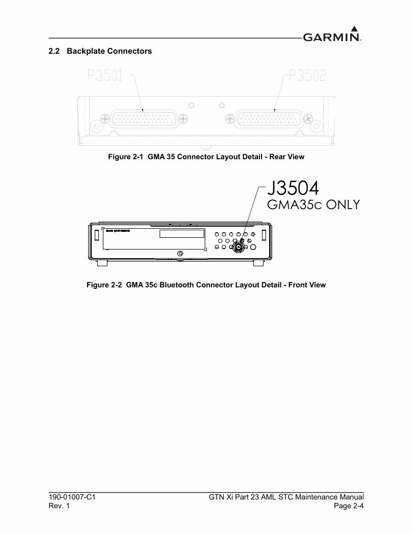
2.2 Backplate Connectors
Figure 2-1 GMA 35 Connector Layout Detail - Rear View
Figure 2-2 GMA 35c Bluetooth Connector Layout Detail - Front View
J3504GMA35c ONLY

190-01007-C1 GTN Xi Part 23 AML STC Maintenance ManualRev. 1 Page 2-5
Figure 2-3 GTN 6XX Xi Connector Layout Detail - Rear View
Figure 2-4 GTN 7XX Xi Connector Layout Detail - Rear View

190-01007-C1 GTN Xi Part 23 AML STC Maintenance ManualRev. 1 Page 2-6
2.3 GTN Xi Optional InterfacesOptional equipment interfaces include: Audio panel Air data computer Altitude serializer or fuel/air data computers Autopilot EFIS displays EHSI displays IRU/AHRS Navigation indicators Weather, traffic, terrain systems DME CDI/HSI source selection annunciators TAWS annunciator panels Multifunction displays Interface adapters Synchro heading sources Weather radar Garmin Iridium transceiver Garmin ADS-B traffic and FIS-B weather sources Garmin Flight Stream

190-01007-C1 GTN Xi Part 23 AML STC Maintenance ManualRev. 1 Page 2-7
2.4 GTN Block Diagram
Figure 2-5 GTN System Interface Diagram
GTN XiCONNECTOR P1001
POWER & GROUND
MAIN CDI/HSI(GPS/VOR/ILS)
SWITCHES/ANNUNCIATORS
EXTERNAL MAP DISPLAY
CDI/HSI(VOR/ILS ONLY)
KING SERIALTUNED DME
PARALLEL TUNEDDME
ARINC 429EFIS/EHSI
RMI
AUDIO PANEL(GMA 35 ONLY)
FLIGHT CONTROL SYSTEM
FUEL/AIR DATAOR
SERIALIZER
GARMIN GTN Xior GTN 6XX/7XX
(CROSSFILL)
LIGHTING BUS
TIME MARK OUT
ETHERNET IN
ETHERNET OUT
RS-232 IN
ARINC 429 IN
ARINC 429 OUT
ILS/GPS APPROACH
LAT DEVIATION & FLAGS
TO/FROM
VERT DEVIATION & FLAGS
SUPERFLAGS
MAIN OBS
SWITCHES
ANNUNCIATORS
RS-232 OUT
EXTERNAL INSTRUMENTATION
AIRCRAFT POWER & GROUND
AIRCRAFT LIGHTING BUS
GTN XiCONNECTOR P1002
COM MIC KEY
COM MIC AUDIO
GTN 635Xi/650Xi/750XiCONNECTOR P1003
GTN 650 Xi/750XiCONNECTOR P1004
COM REMOTE TRANSFER COM REMOTE TRANSFER SWITCH
COM REMOTE TUNE UP COM REMOTE TUNE SWITCHESCOM REMOTE TUNE DOWN
COM AUDIO
VLOC AUDIO
POWER & GROUNDAIRCRAFT POWER & GROUND
VOR OBI
NAV ARINC 429 IN
NAV ARINC 429 OUT
POWER & GROUNDAIRCRAFT POWER & GROUND
PARALLEL DME TUNING
NAV DME COMMON
NAV REMOTE TRANSFER NAV REMOTE TRANSFER SWITCH
LAT DEVIATION & FLAGS
TO/FROM
VERT DEVIATION & FLAGS
SUPERFLAGS
VOR OBS
VLOC COMPOSITE OUT
NAV ILS ENERGIZE
SERIAL DME CLOCK /DATA
DME REQUEST COMMON
GTN XiCONNECTOR P1006
GPS/SBAS ANTENNA
GTN 635Xi/650Xi/750XiCONNECTOR P1007
COM ANTENNA
GTN 650 Xi/750XiCONNECTOR P1008
NAV ANTENNA
TRAFFICARINC 429 IN
DISCRETES
STORMSCOPE RS-232 IN
RS-232 OUT
GSR 56
RS-232 IN
RS-232 OUT
GNS 400W/500W SERIES CROSSFILL
RS-232 IN
RS-232 OUT
ANALOG AUDIO
GARMINWEATHER RADAR(GTN 7XX Xi ONLY)
ETHERNET INETHERNET OUT
OTHERGARMIN LRUs
ETHERNET INETHERNET OUT
DISCRETES
LAT DEVIATION & FLAGS
VERT DEVIATION & FLAGS
SUPERFLAGSTRANSPONDERRS-232 IN
RS-232 OUT
RS-232 INRS-232 OUT
FLIGHT STREAM 210
RS-232 IN
RS-232 OUT
GTN XiDATA CARD SLOT
FLIGHT STREAM 510(INSERTED)

190-01007-C1 GTN Xi Part 23 AML STC Maintenance ManualRev. 1 Page 3-1
3 CONTROL AND OPERATION
3.1 GTN Xi Normal Mode Overview.....................................................................................................3-23.2 GTN Xi Configuration Mode Overview...........................................................................................3-3
3.2.1 Updates.......................................................................................................................................3-43.2.2 System Information ..................................................................................................................3-113.2.3 GTN Setup................................................................................................................................3-123.2.4 GTN Options ............................................................................................................................3-143.2.5 GTN Diagnostics......................................................................................................................3-19
3.3 Database Updates............................................................................................................................3-21

190-01007-C1 GTN Xi Part 23 AML STC Maintenance ManualRev. 1 Page 3-2
3.1 GTN Xi Normal Mode Overview
Figure 3-1 GTN 650Xi Normal Mode Screen
Figure 3-2 GTN 750Xi Normal Mode Screen
Photocell
HOME key
Direct-To Key
Large and Small Knobs
Transponder Panel Controls
Annunciations
LockingScrew
SD Card
Volume, Squelch, and NAV ID
Function Keys
Active COM Frequency
Standby COM Frequency
Message Annunciation
Photocell
HOME key
Direct-To Key
Large and Small Knobs
Transponder Panel Controls
Annunciations
LockingScrew
SD Card
Volume, Squelch, and NAV ID
Audio Panel Controls
Active NAV Frequency
Standby NAV Frequency
Function Keys
Active COM Frequency
Standby COM Frequency
Message Annunciation

190-01007-C1 GTN Xi Part 23 AML STC Maintenance ManualRev. 1 Page 3-3
3.2 GTN Xi Configuration Mode Overview
NOTEWhen configuring the GTN Xi, ensure that configuration module service messages are not displayed in the message queue. This indicates an improperly wired or damaged configuration module.
Configuration mode is used to configure the GTN Xi settings for each specific installation. To access Configuration mode, perform the following steps:
1. Remove power from the GTN Xi by opening the circuit breaker.2. Press and hold the HOME key and re-apply power to the GTN Xi.3. Release the HOME key when the display activates and “Garmin” appears fully lit on the screen.
The Configuration mode home page is the first page displayed. For detailed information regarding how to configure the GTN Xi, refer to GTN Xi Part 23 AML STC Installation Manual. While in Configuration mode, select pages by touching the desired key on the display. Some pages may require page scrolling to view all of the information and keys. Scrolling is done by touching the screen and dragging the page in the desired direction or by touching the Up or Down keys.
NOTEThe configuration pages shown reflect main software version 20.00. Some differences in operation may be observed when comparing information in this manual to later software versions.
Figure 3-3 GTN 6XX Xi and GTN 7XX Xi Configuration Mode Pages

190-01007-C1 GTN Xi Part 23 AML STC Maintenance ManualRev. 1 Page 3-4
3.2.1 UpdatesThe GTN Xi comes pre-loaded with software. However, to make sure it is loaded with the software that is applicable to this STC, a GTN Xi Software Loader Card must be created. For dual GTN Xi installations, the software loading procedures in Section 3.2.1.2 must be carried out on each GTN Xi; however, the same GTN Xi Software Loader Card created in Section 3.2.1.1 may be used.
NOTEPrior to installing a version of the GTN Xi main board software that is older than the currently installed version, all RS-232 and ARINC 429 ports should be configured Off.
NOTEScreen shots in this section are provided for reference only. Refer to Equipment List, GTN Xi Part 23 AML STC for actual GTN Xi software versions.
3.2.1.1 GTN Xi Software Loader CardA GTN Xi Software Loader Card may be created using a GTN Xi Downloadable Software SD Card (P/N 010-01000-00) in conjunction with a GTN xi software application downloaded from the Dealer Resource Center on Garmin’s website. As an alternative, a pre-programmed software loader card may be purchased from Garmin. Refer to Equipment List, GTN Xi Part 23 AML STC (P/N 005-00533-L1) for the correct part number of the pre-programmed GTN Xi Software Loader Card.
NOTEThe downloadable application to create the GTN Xi Software Loader Card only runs on Windows PCs (Windows 2000, XP, Vista, Windows 7, and Windows 10 are supported). There is no Mac support at this time.
NOTEAn SD card reader is needed to create the GTN Xi Software Loader Card using the application that is downloaded from Garmin. The approved readers are SanDisk® SDDR-999 and SDDR-93, although other SD card readers may work.
CAUTIONIt is recommended to use an SD card with capacity of 2 GB or smaller for loading software. If a card larger than 2 GB is used, a version mismatch error will display after files have finished loading. Load software again after cycling power on the unit or the update may be incomplete.

190-01007-C1 GTN Xi Part 23 AML STC Maintenance ManualRev. 1 Page 3-5
Create a GTN Xi Software Loader Card as follows:1. Go to the Dealer Resource Center on Garmin’s website.2. Download the GTN Software Loader Image. Refer to Equipment List, GTN Xi Part 23 AML STC
for the correct Software Loader Image part number.3. Run the executable file. The window shown in Figure 3-4 will appear. Click Setup.
Figure 3-4 Software Update Installer
4. The window shown in Figure 3-5 will appear to guide you through the software loader card creation process.
Figure 3-5 System and Software Version
5. Make sure you have an SD card reader connected to the PC. Insert the GTN Downloadable Software SD Card (P/N 010-01000-00) into the card reader. Click Next.

190-01007-C1 GTN Xi Part 23 AML STC Maintenance ManualRev. 1 Page 3-6
6. Read and accept the license agreement, as shown in Figure 3-6. Click Next when finished.
Figure 3-6 Software Loader Card License Agreement
7. Click Find Drive or select the correct drive from the drop-down menu. Click Next.
CAUTION In order to create a GTN Xi Software Loader Card, the drive that you select will be completely erased.
Figure 3-7 Software Loader Card Drive

190-01007-C1 GTN Xi Part 23 AML STC Maintenance ManualRev. 1 Page 3-7
8. The progress window shown in Figure 3-8 will appear while the card is being created.
Figure 3-8 Software Loader Card Progress Window
9. After the card has been created, the window shown in Figure 3-9 will appear. Click Finish to complete the update process.
Figure 3-9 Software Loader Card Completion10. Eject the card from the card reader (or stop the card reader in Windows). The GTN Xi Software
Loader Card is now ready to use.

190-01007-C1 GTN Xi Part 23 AML STC Maintenance ManualRev. 1 Page 3-8
3.2.1.2 GTN Xi Software LoadingTo update the GTN Xi software, perform the following steps:
1. Remove power from the GTN Xi by opening the circuit breaker.2. Remove the database card and insert the correct GTN Xi Software Loader Card created in
Section 3.2.1.1 into the data card slot.3. Restore power to the GTN Xi by closing the circuit breaker.4. The GTN Xi will automatically power on in Configuration mode. Touch Updates to display the
available software updates.5. Ensure the software version being loaded to the GTN Xi matches the software version listed in
Equipment List, GTN Xi Part 23 AML STC. The Updates page displays the version that is installed on the unit and the version installed on the loader card.
6. Ensure the available GTN Xi software updates are displaying by ensuring that GTN Software Updates key is highlighted in the upper-left corner (upper-right for GTN 6XX Xi) of the display.
7. To update the GTN Xi with all available software, touch Select All. Alternatively, individual updates can be manually selected by touching them. A green checkmark will appear when selected.
8. To begin the software update, touch Update on the bottom of the display.9. The GTN Xi will display “Start GTN Software Updates?”10. Touch OK to allow the GTN Xi to begin the update process.11. When the updates are complete, the GTN Xi will display “Update Complete!”.12. When finished, remove power from the GTN Xi and remove the Software Loader Card. Re-insert
the database card into the data card slot.13. Power on the GTN Xi in Configuration mode and ensure the software was correctly updated by
touching System Information and verifying the software version. Refer to Section 3.2.2 for more information on the System Information page.

190-01007-C1 GTN Xi Part 23 AML STC Maintenance ManualRev. 1 Page 3-9
3.2.1.3 GMA 35 Software Loading
NOTEThe GMA 35 software will be present on the SD card when creating a GTN Xi Software Loader Card. A separate card is not required to perform GMA 35 software updates. Refer to Section 3.2.1.1.
1. Remove power from the GTN 7XX Xi by opening the circuit breaker. 2. Insert the GTN Xi Software Loader Card into the GTN Xi data card slot.3. Apply power to the GTN Xi. It will automatically power on in Configuration mode. 4. Ensure the GMA 35 circuit breaker is closed. 5. Touch the Updates key to display available software. 6. To select GMA 35 software updates, touch the GTN Software Updates key and select GMA 35
Software Updates. 7. To update the GMA 35 with all available software, touch Select All. Alternatively, individual
updates can be manually selected by touching them. A green checkmark will appear when selected.
8. Touch the Update key on the bottom of the display. 9. The GTN Xi will display “Start GMA 35 Software Updates?” 10. Touch OK to allow the GTN Xi to update the GMA 35. 11. When the updates are complete, the GTN Xi will display “Update Complete!”.12. Power off the GTN Xi and GMA 35 (i.e., open the circuit breaker) and remove the Software
Loader Card. 13. Re-insert the database card in the data card slot. 14. Power on the GTN Xi in Configuration mode by holding the HOME button while closing the
circuit breaker. 15. Power on the GMA 35 by closing the circuit breaker.16. Verify the software was updated correctly by going to the System Information page and selecting
the GMA 35. Refer to Section 3.2.2 for more information on the System Information page.
190-01007-C1 GTN Xi Part 23 AML STC Maintenance ManualRev. 1 Page 3-10
3.2.1.4 GMA 35 Boot Block Loading
NOTEThe GMA 35 Boot Block Loader Card is separate from the GMA 35 Software Loader Card and is required to update Boot Block software to v4.10.
1. Remove power from the GTN 7XX Xi.2. Insert the GTN Boot Block Loader Card into the GTN 7XX Xi data card slot. For instructions on
how to create a GTN Boot Block Loader Card, refer to Section 3.2.1.1. 3. Apply power to the GTN Xi unit. The GTN Xi will automatically power on in Configuration
mode.4. Ensure the GMA 35 circuit breaker is closed.5. Select all GMA 35 Boot Block updates.6. To begin the software update, touch the Update key on the bottom of the display.7. The GTN Xi will display the prompt, “Start GMA 35 Software Updates?”8. To allow the GTN Xi to update the GMA 35, touch OK.9. When updates complete, the GTN Xi will display, “Update Complete!”10. Power off the GTN Xi and GMA 35 by opening the circuit breaker.11. Remove the Boot Block Loader Card. 12. Re-insert the database card in the data card slot. 13. Restore power on the GTN Xi and GMA 35 by closing the circuit breakers. 14. To ensure the software correctly updated, go to the System Information page and select the
GMA 35. Refer to Section 3.2.2 for more information on the System Information page.

190-01007-C1 GTN Xi Part 23 AML STC Maintenance ManualRev. 1 Page 3-11
3.2.2 System InformationView the System Information page by touching the System Information key on the Configuration mode home page. The System Information page displays the unit type, serial number, and System ID for the GTN Xi unit. It contains the software and hardware versions of the Main, I/O, Display, Keypad, LED, GPS/WAAS, COM, and NAV boards. System information is available for certain other LRUs connected to the GTN Xi. Touch the key at the top of the screen and choose which LRU to display. Touch UP or DOWN to view all the information.
Figure 3-10 System Information Page

190-01007-C1 GTN Xi Part 23 AML STC Maintenance ManualRev. 1 Page 3-12
3.2.3 GTN SetupThis section provides a brief overview of the pages that are accessed from the GTN Setup page. To access the GTN Setup page, touch the GTN Setup key from the Configuration mode home page.
Figure 3-11 GTN Setup Page
ARINC 429 Configures the ARINC 429 input and output ports. ARINC 429 formats and bus speeds are set from this configuration page.
RS-232 Configures the RS-232 input and output ports.
HSDB (Ethernet) Configures which Ethernet ports are connected.
Interfaced Equipment Configures which LRUs are installed and interfaced to the GTN Xi. The Transponder #1 selection is automatically configured when a valid transponder configuration is selected on the RS-232 Configuration page.
Main Indicator (Analog) Calibrates the OBS resolver and configure the CDI key, selected course for GPS, VLOC, and the V-Flag state.
Lighting Sets the backlight and key lighting brightness display parameters.

190-01007-C1 GTN Xi Part 23 AML STC Maintenance ManualRev. 1 Page 3-13
Enhanced LightingReplaces the Lighting page when enabled on the Main System Configuration page. This page sets the backlight and key lighting brightness display parameters. Enhanced lighting is used to configure separate Day/Night lighting curves.
Audio Configures the aural alert volume.
Traffic Configures the traffic intruder symbol color and configures whether or not the GTN Xi controls the traffic system.
Main SystemDisplays miscellaneous configuration options for the GTN Xi. Page settings include the following: Air/Ground Threshold Air/Ground Discrete Fuel Type Heading Source Input Altitude Source Input
COMConfigures the RX squelch volume, Mic 1 Gain, and sidetone volume. The COM page is only available on the GTN 635Xi/650Xi/750Xi.
VOR/LOC/GS Checks the CDI outputs from the VOR/LOC/GS receiver and the OBS resolver input to the VOR receiver. Used to format the DME tuning data. The VOR/LOC/GS page is only available on the GTN 650Xi/750Xi.
ARINC 708 Configures the GTN Xi ARINC 708 input port. Selection of one of the approved ARINC 708 weather radars is only possible if the digital radar enablement is active. The ARINC 708 page is only available on the GTN 7XX Xi.
DiscretesConfigures discrete inputs and outputs on the J1001 and J1002 connectors.
Navigation FeaturesThese settings are not used under this STC.
OwnshipSelects the displayed ownship icon from a list.
Flight StreamThese settings are not used under this STC.
Update Config ModuleUpdates the configuration module with the current configuration settings.

190-01007-C1 GTN Xi Part 23 AML STC Maintenance ManualRev. 1 Page 3-14
3.2.4 GTN Options
NOTEFor first time feature enablement, refer to GTN Xi Part 23 AML STC Installation Manual for additional requirements and checkout procedures. This manual only describes the necessary steps to re-enable the feature for existing installations. All re-enablements use the feature enablement card from initial installation.
NOTEFeature enablement cards should be provided to the customer after service has been completed.
Figure 3-12 GTN Options Pages

190-01007-C1 GTN Xi Part 23 AML STC Maintenance ManualRev. 1 Page 3-15
3.2.4.1 Terrain
NOTEWhen the Terrain Alerting feature is enabled, the GTN Xi will provide a subset of the TAWS B functionality that does not meet the requirements of TSO-C151c.
When the optional TAWS feature is enabled, the GTN Xi will provide Class B TAWS functionality. This section describes how to reactivate the TAWS feature.
1. Power off the GTN Xi by opening the NAV/GPS circuit breaker.
2. Remove the database SD card from the data card slot and insert the TAWS Enablement Card(P/N 010-00878-01).
3. Power on the GTN Xi in Configuration mode by applying power (i.e., closing the circuit breaker) to the GTN Xi while holding the HOME key.
4. Navigate to the Terrain Configuration page from the GTN Options page. Touch the TAWS B key.
5. When the TAWS feature is activated, the TAWS B key will be lit green, as shown in Figure 3-13.
3.2.4.1.1 TAWS-B Configuration OptionsWhen TAWS B is enabled, as shown in Figure 3-13, the following configuration settings may be accessed.
Audio ClipsSelects aural alert messages for various caution and warning types.
Alert SettingsThe GTN Xi TAWS alerting algorithm adapts the terrain alerting criteria based on nearby airports. The Alert Settings configuration options selects the minimum criteria that the airport must meet to be considered as a nearby airport for the purpose of TAWS alerting. Refer to Section 7.4.1 for additional details.
Figure 3-13 Terrain Configuration Page

190-01007-C1 GTN Xi Part 23 AML STC Maintenance ManualRev. 1 Page 3-16
3.2.4.2 Charts (GTN 7XX Xi Only)The GTN 7XX Xi displays Jeppesen charts using the optional Chart feature. To configure which charts to display, touch either None, FliteCharts, or ChartView. If ChartView is selected, it must be enabled as described below:
1. Power off the GTN Xi by opening the NAV/GPS circuit breaker.
2. Remove the database SD card from the data card slot and insert the ChartView Enablement Card (P/N 010-00878-40).
3. Power on the GTN Xi in Configuration mode by applying power (i.e., closing the circuit breaker) while holding the HOME key.
4. Navigate to the Charts Configuration page from the GTN Options page and touch the ChartView key.
5. When the ChartView feature is activated, the ChartView key will be lit green, as shown in Figure 3-14.
3.2.4.3 COM Transmit Power (GTN 635Xi/650Xi/750Xi Only)When the optional 16W COM power is configured, the GTN Xi VHF COM transciever will transmit with 16 watts rather than the standard 10 watts. This section describes how to re-enable the 16W COM transmit power.
1. Power off the GTN Xi by opening the NAV/GPS circuit breaker.
2. Remove the database SD card from the data card slot and insert the 16W Enablement Card (P/N 010-00878-40).
3. Power on the GTN Xi in Configuration mode by applying power (i.e., closing the circuit breaker) while holding the HOME key.
4. Navigate to the COM Transmit Power Configuration page from the GTN Options page and touch the 16W key.
5. When the 16W COM feature is activated, the 16W key will be lit green, as shown in Figure 3-15.
Figure 3-14 Chart Configuration Page
Figure 3-15 COM Transmit Power Configuration Page

190-01007-C1 GTN Xi Part 23 AML STC Maintenance ManualRev. 1 Page 3-17
3.2.4.4 Weather Radar (GTN 7XX Xi Only)This section describes how to re-enable the Digital Radar feature, which allows approved ARINC 708 weather radars to be interfaced with the GTN 7XX Xi.
1. Power off the GTN Xi by opening the NAV/GPS circuit breaker.
2. Remove the database SD card from the data card slot and insert the Digital Radar Enablement Card (P/N 010-00878-42).
3. Power on the GTN Xi in Configuration mode by applying power (i.e., closing the circuit breaker) while holding the HOME key.
4. Navigate to the Weather Radar page from the GTN Options page and touch the Digital Radar key, as shown in Figure 3-16.
5. When prompted, touch Yes to enable Digital Weather Radars. When the feature is activated, the Digital Radar key will be lit green.
3.2.4.4.1 GWX Advanced Features (GTN 7XX Xi Only)The GTN 7XX Xi can enable two Doppler radar features for the GWX 70/75. A Radar Turbulence Detection Card (P/N 010-00878-45 or P/N 010-00878-47 (dual install)) is needed for Turbulence Detection and a Radar Automatic Ground Clutter Suppression Enablement Card (P/N 010-00878-44 or P/N 010-00878-46 (dual install)) is needed for Ground Clutter Suppression.
To enable Radar Turbulence Detection:1. Power off the GTN Xi by opening the NAV/GPS circuit breaker.2. Remove the database SD card from the data card slot and insert the Radar Turbulence Detection
Enablement Card (P/Ns 010-00878-45 or 010-00878-47).3. Power on the GTN Xi in Configuration mode by applying power (i.e., closing the circuit breaker)
while holding the HOME key.4. Navigate to the Weather Radar page from the GTN Options page. Touch the Turbulence
Detection key, as shown in Figure 3-16.5. When prompted, touch Yes to enable Turbulence Detection. When the feature is activated, the
Turbulence Detection key will be lit green.
To enable Ground Clutter Suppression: 1. Power off the GTN Xi by opening the NAV/GPS circuit breaker.2. Remove the database SD card from the data card slot and insert the Radar AGCS Enablement Card
(P/Ns 010-00878-44 or 010-00878-46).3. Power on the GTN Xi in Configuration mode by applying power (i.e., closing the circuit breaker)
while holding the HOME key.4. Navigate to the Weather Radar page from the GTN Options page. Touch the Ground Clutter
Suppression key, as shown in Figure 3-16.5. When prompted, touch Yes to enable Ground Clutter Suppression. When the feature is activated,
the Ground Clutter Suppression key will be lit green.
Figure 3-16 Weather Radar Page

190-01007-C1 GTN Xi Part 23 AML STC Maintenance ManualRev. 1 Page 3-18
3.2.4.5 Search and RescueThe GTN Xi can enable Search and Rescue features. A Search and Rescue Enablement Card (P/N 010-00878-03) is needed for enablement.
To enable Search and Rescue features:1. Power off the GTN Xi by opening the NAV/GPS circuit breaker.2. Remove the database SD card from the data card slot and insert the Search and Rescue Enablement
Card (P/N 010-00878-03).3. Power on the GTN Xi in Configuration mode by applying power (i.e., closing the circuit breaker)
while holding the HOME key.4. Navigate to the Search and Rescue Configuration page from the GTN Options page. Touch the
Search and Rescue key, as shown in Figure 3-17.5. When prompted, touch the Yes key to enable Search and Rescue.6. Select the Search and Rescue (SAR) patterns desired in the SAR patterns section of the options
page, as shown in Figure 3-17.
Figure 3-17 Search and Rescue Configuration Page

190-01007-C1 GTN Xi Part 23 AML STC Maintenance ManualRev. 1 Page 3-19
3.2.5 GTN DiagnosticsThe GTN Diagnostics page is accessed from the Configuration mode home page and is a useful tool for diagnosing issues and troubleshooting problems. Ground checks are performed using the tools on this page.
Figure 3-18 GTN 6XX Xi and GTN 7XX Xi GTN Diagnostics Pages
ARINC Inputs Displays the ARINC 429 data being received over each ARINC 429 port. This is useful for determining if the expected labels are being received and for troubleshooting incorrect or swapped wiring to the input ports. Each port is chosen for display by touching the Port key and selecting between the input ports. The GTN Xi will display the label, SSM, Data, and SDI for the selected ARINC 429 input port. The data log can be paused by toggling the Pause/Unpause key. Clear the data log by touching the Clear Log key.
Serial InputsDisplays the serial data being received. This is useful for determining if the GTN Xi is receiving data on each connected port. Select the desired port by touching the Port key and selecting the RS-232 channel from the list. The data log can be paused by toggling the Pause/Unpause key. Clear the data log by touching the Clear Log key.
Discrete InputsDisplays the state of each discrete input. This page is useful for troubleshooting discrete wiring issues.
Discrete OutputsDisplays the state of each discrete output and allows them to be toggled between Active and Inactive. This is useful for ensuring that annunciator and signal outputs are properly connected to annunciator lights or other LRUs, and that they are receiving the signal.

190-01007-C1 GTN Xi Part 23 AML STC Maintenance ManualRev. 1 Page 3-20
HSDB (Ethernet)Displays the status of each HSDB (ethernet) port, whether or not each port is receiving data, and whether the port is connected or not connected. The communication status of each installed HSDB LRU is displayed.
Main Indicator (Analog)Displays the CDI connected to the main board (P1001) to be ground checked. This allows the interface to be verified.
Analog InputsDisplays the bus voltage setting for Lighting Bus 1 and Lighting Bus 2 and the input voltage setting for each bus. This page also displays synchro heading input diagnostics information, such as heading angle, heading valid status, AC voltage, and AC frequency.
Power StatsDisplays the number of times the GTN Xi has powered up and the total elapsed operating hours for the GTN Xi.
WAASDisplays the WAAS engine status, including UTC date/time, current latitude/longitude, overall navigation status, oscillator temperature, and AGC voltage. The GPS/WAAS engine can be reset on this page.
TempsDisplays the current, minimum, maximum, and average board temperatures for the LED Board, Main Board, Display Interface Board, GPS/WAAS Board, COM Board, and COM Oscillator.
LogsAllows the error log, connection log, WAAS diagnostic log, or flight data log to be written to an SD card in the data card slot. The error log can be cleared on this page.
Main Data InputsAllows the data on ARINC 429, RS-232, and other electrical inputs to be monitored. This is used for checking electrical interfaces during installation and troubleshooting. Information that is not being received by the GTN Xi is dashed out.
VOR/ILS Indicator (Analog)Allows the CDI connected to the NAV board (P1004) to be ground checked and allows the NAV indicator interface to be verified.
COM BoardDisplays status of the FPGA, flash, non-volatile memory, synthesizer lock, calibration, and reversionary, as well as the transmitter power limit.
Clear Config Settings
CAUTIONThis key should only be pressed if the intent is to clear all configuration settings. Touching the Clear Config Settings key opens a confirmation window to reset all of the settings stored in the configuration module to their defaults.

190-01007-C1 GTN Xi Part 23 AML STC Maintenance ManualRev. 1 Page 3-21
3.3 Database Updates
CAUTIONThe databases on the GTN Database Card are locked to specific GTN Xi installations. The first time the GTN Database Card is inserted into a GTN Xi, it associates exclusively with that particular unit and will not work in other installations.
The GTN Xi utilizes various databases. All databases are loaded to the unit through the single data card that is inserted into the vertical slot on the left side of the GTN Xi. All databases are stored internally on the GTN Xi. Database updates can be applied in Normal mode at power-up. Alternatively, the databases can be updated in Configuration mode through the Updates page. The GTN Xi, by default, will only update to effective databases. If loading databases that are not yet effective, or if the GTN Xi GPS time is out-of-date, press and hold the dual-concentric knob during power-up to install all database updates from the data card.
Databases are updated by removing the database card from the GTN Xi, updating the database on the card, and re-inserting the card. Databases can also be updated using a Flight Stream 510 wireless data card and a portable device. When powering on in Normal mode with a Flight Stream 510 inserted into the data card slot, the GTN Xi will provide on-screen instructions on how to transfer databases from a portable device (with a compatible application) over Wi-Fi.
Database cards and the Flight Stream 510 should not be swapped between GTN Xi units if multiple GTN Xi units are installed.
Database cards can be updated by purchasing database subscription updates from Garmin. Contact Garmin at (866) 739-5687 or go to flyGarmin.com for more information and instructions.
For a summary of the database location and update rate, refer to Table 3-1. The GTN Xi Series Database Card (Garmin P/N 010-02044-XX) includes: Basemap Obstacle SafeTaxi FliteCharts Navigation
Table 3-1 GTN Xi Database SummaryDatabase Update Rate Stored Location
Terrain Database Periodic (when available) InternalFliteCharts Database 28 Days InternalChartView Database 14 Days InternalObstacle Database with Hotlines 56 Days InternalSafeTaxi Database 56 Days InternalBasemap Database Periodic (when available) InternalNavigation Database 28 Days Internal

190-01007-C1 GTN Xi Part 23 AML STC Maintenance ManualRev. 1 Page 4-1
4 INSTRUCTIONS FOR CONTINUED AIRWORTHINESS
4.1 Airworthiness Limitations ................................................................................................................4-24.2 Servicing Information .......................................................................................................................4-2
4.2.1 Periodic Maintenance.................................................................................................................4-24.2.2 Special Tools ..............................................................................................................................4-2
4.3 Maintenance Intervals.......................................................................................................................4-34.4 Visual Inspection ..............................................................................................................................4-54.5 Electrical Bonding Test ....................................................................................................................4-6
4.5.1 GTN Xi Bonding Check (Metallic or Tube-and-Fabric Aircraft)..............................................4-64.5.2 GTN Xi Bonding Check (Composite Aircraft) ..........................................................................4-64.5.3 GMA 35 Bonding Check (Metallic or Tube-and-Fabric Aircraft).............................................4-74.5.4 GMA 35 Bonding Check (Composite Aircraft) .........................................................................4-74.5.5 Flight Stream 210 Bonding Check (Metallic or Tube-and-Fabric Aircraft) ..............................4-84.5.6 Flight Stream 210 Bonding Check (Composite Aircraft) ..........................................................4-8
4.6 Transient Voltage Suppressor (TVS) (If Installed)...........................................................................4-94.6.1 GTN Xi TVS1 Check (GTN Xi #1 Only) ..................................................................................4-94.6.2 GTN Xi TVS2 Assembly Check (GTN Xi #1 Only) ...............................................................4-10


190-01007-C1 GTN Xi Part 23 AML STC Maintenance ManualRev. 1 Page 4-3
4.3 Maintenance IntervalsTable 4-1 Periodic Maintenance
Item Description/Procedure Interval
Equipment Removal and Replacement
Removal and replacement of the following items. Refer to Section 6 of this document for instructions.
• GTN Xi, Flight Stream 210, Flight Stream 510, or GMA 35• NAV antenna cable splitter • NAV antenna cable diplexer• Fan
On Condition
Cleaning the Front Panel
The front bezel, keypad, and display can be cleaned with a soft cotton cloth dampened with clean water. DO NOT use any chemical cleaning agents. Care should be taken to avoid scratching the surface of the display.
On Condition
Display Backlight
The display backlight LEDs are rated by the manufacturer as having a usable life of at least 36,000 hours. This life may be more or less than the rated time depending on the operating conditions of the GTN Xi. Over time, the backlight may dim and the display may not perform as well in direct sunlight conditions. The user must determine by observation when the display brightness is not suitable for its intended use. Contact the Garmin factory repair station when the backlight requires service.
On Condition
Battery Replacement
The GTN Xi has an internal keep-alive battery that will last about 10 years. The battery is used for GPS system information. Regular planned replacement is not necessary. The GTN Xi will display a “low battery” message when replacement is required. Once the low battery message is displayed, the battery should be replaced within 1 to 2 months.If the battery is not replaced and becomes totally discharged, the GTN Xi will remain fully operational, but the GPS signal acquisition time may be increased. There is no loss of function or accuracy of the GTN Xi with a dead battery.The battery must be replaced by the Garmin factory repair station or factory authorized repair station.
On Condition
Test - Bonding Check
Perform an electrical bonding check of the GTN Xi, GMA 35 (if installed), and Flight Stream 210 (if installed) per Section 4.5.
Every 10 years or 2000 flight hours, whichever comes first
Test TVS Lightning Protection
The GTN Xi #1 main power input has a TVS located at the LRU for IFR non-metallic aircraft only. TVS1 and TVS2 must be checked or replaced in accordance with Section 4.6.
24 Calendar Months
Test Lightning Protection
The GTN Xi #1 main power input and NAV power input will have a TVS located at the LRU for IFR non-metallic aircraft only. TVS1 and TVS2 must be replaced in accordance with Section 6.9.
After a suspected or actual lightning strike

190-01007-C1 GTN Xi Part 23 AML STC Maintenance ManualRev. 1 Page 4-4
Visual Inspection
The GTN Xi, GMA 35 (if installed), Flight Stream 210 (if installed), Flight Stream 510 (if installed), switches, and wiring harnesses should be inspected to ensure continued integrity of the installation. These items must be inspected in accordance with Section 4.4.
12 Calendar Months
Item Description/Procedure Interval

190-01007-C1 GTN Xi Part 23 AML STC Maintenance ManualRev. 1 Page 4-5
4.4 Visual Inspection
CAUTIONTake care when tightening the mounting screws of the Flight Stream 210. Excessive tightening may damage the mounting flange.
Conduct a visual check of the GTN Xi, switches, GMA 35 (if installed), Flight Stream 210 (if installed), Flight Stream 510 (if installed), and their wiring harnesses to ensure they continue to comply with STC SA02019SE-D.
1. Inspect the GTN Xi, GMA 35, and Flight Stream 210 for security of attachment, including visual inspection of mounting racks and other supporting structure attaching the racks to aircraft instrument panel. GTN Xi - Verify the countersunk fastener heads are in full contact with the unit mounting rack
holes. Re-torque the mounting screws 12 to 15 in-lbf, if required GMA 35 - If the GMA 35 is installed, verify the countersunk fastener heads are in full contact
with the unit mounting rack holes. Re-torque the GMA 35 mounting screws 8.5 to 9.5 in-lbf, if required. For installations that use a hook and loop fastener to secure the GMA 35c Bluetooth antenna mount, ensure the hook and loop bond is firm. If the hook and loop fastener is worn, replace it
Flight Stream 210 - If the Flight Stream 210 is installed, and screws are not securely attached, tighten any loose mounting screws to snug plus one-quarter turn. If required, re-torque bonding strap hardware to 12 to 15 in-lbf
Flight Stream 510 - Ensure the data card is properly oriented (label facing right), fully inserted, and locked into position in the card slot on the front-left side of the GTN Xi.
2. Inspect for corrosion.3. Inspect switches, knobs, and buttons for damage.4. Inspect condition of wiring, shield terminations, routing, and attachment/clamping.5. Check the fan intake slots on the sides and bottom of the GTN Xi unit’s bezel for dust, dirt, or
obstructions. Clean as needed.6. Conduct a visual check of any bonding strap or conductive tape used for electrical bonding or RF
ground plane (if installed). 7. Replace any damaged or torn strap. Refer to Section 6.10 or Section 6.11 for details. 8. Replace any torn bonding tape using a heavy duty aluminum foil tape, such as 3M P/N 436 or 438
or another foil with aluminum that is 7.2 mils thick or greater. If strap termination hardware is loose, tighten and re-test bonding. Refer to Section 4.5 for details.

190-01007-C1 GTN Xi Part 23 AML STC Maintenance ManualRev. 1 Page 4-6
4.5 Electrical Bonding Test4.5.1 GTN Xi Bonding Check (Metallic or Tube-and-Fabric Aircraft)
NOTEIf the GMA 35 is installed (GTN 7XX Xi only), it must be removed from its rack and the GMA 35 backplate assembly must be removed prior to performing step 3. When a GMA 35 bonding check is planned, perform the GMA 35 bonding check prior to re-installing the GTN Xi backplate assembly to the rack.
NOTEA bonding test failure may occur if a fastener is not secured to the specified torque value. For installations that use screws in lieu of rivets to secure the rack to the surrounding structure, verify that the screws are torqued to the appropriate value before proceeding to remove the rack. Refer to Section 4.4 for torque values.
Perform an electrical bonding check as follows:1. Remove the GTN Xi unit from the mounting rack.2. Remove the backplate assembly from the rack.3. Measure the resistance between the mounting rack and nearby exposed portion of aircraft metallic
structure and verify it is less than or equal to 5 mΩ.
In the event of bonding test failure, remove the GTN Xi rack, clean the attachment points with a bonding brush at both the rack and the aircraft, and re-attach the rack to the rails in the panel. Measure the resistance between the mounting rack and nearby exposed portion of aircraft metallic structure and ensure that the resistance is less than or equal to 2.5 mΩ.
4. Re-install the backplate assembly and re-install the GTN Xi unit in the mounting rack.
4.5.2 GTN Xi Bonding Check (Composite Aircraft)
NOTEIf the GMA 35 is installed (GTN 7XX Xi only), it must be removed from its rack and the GMA 35 backplate assembly must be removed prior to performing step 3. When a GMA 35 bonding check is planned, perform the GMA 35 bonding check prior to re-installing the GTN backplate assembly to the rack.
NOTEA bonding test failure may occur if a fastener is not secured to the specified torque value. For installations that use screws in lieu of rivets to secure the rack to surrounding structure, verify that the screws are torqued to the appropriate value before proceeding to remove the rack. Refer to Section 4.4 for torque values.
Perform an electrical bonding check as follows:1. Remove the GTN Xi unit from the mounting rack.2. Remove the backplate assembly from the rack. 3. Measure the resistance between the mounting rack and the instrument panel, and verify that it is
less than or equal to 10 mΩ.

190-01007-C1 GTN Xi Part 23 AML STC Maintenance ManualRev. 1 Page 4-7
In the event of bonding test failure, remove the GTN Xi rack, clean the attachment points with a bonding brush at both the rack and the aircraft, and re-attach the rack to the rails in the panel. Measure the resistance between the mounting rack and the instrument panel and ensure that the resistance is less than or equal to 5 mΩ.
4. Re-install the backplate assembly and re-install the GTN Xi unit in the mounting rack.
4.5.3 GMA 35 Bonding Check (Metallic or Tube-and-Fabric Aircraft)
NOTEA bonding test failure may occur if a fastener is not secured to the specified torque value. For installations that use screws in lieu of rivets to secure the rack to surrounding structure, verify that the screws are torqued to the appropriate value before proceeding to remove the rack. Refer to Section 4.4 for torque values.
NOTEThe GTN 7XX Xi backplate assembly must be removed from the GTN Xi rack prior to performing step 4.
A bonding check is required for the GMA 35. Perform an electrical bonding check as follows:1. Gain access to the GMA 35 by removing the GTN 7XX Xi unit.2. Remove the GMA 35 unit from the mounting rack.3. Remove backplate assembly from the rack.4. Measure the resistance between the mounting rack and nearby exposed portion of aircraft metallic
structure, and verify that it is less than or equal to 5 mΩ.
In the event of bonding test failure, remove the GMA 35 rack and clean the attachment points with a bonding brush at both the rack and the aircraft attachment points. Measure the resistance between the mounting rack and nearby exposed portion of aircraft metallic structure and ensure that the resistance is less than or equal to 2.5 mΩ.
5. Re-install the backplate assembly and re-install the GMA 35 unit in the mounting rack.
4.5.4 GMA 35 Bonding Check (Composite Aircraft)
NOTEA bonding test failure may occur if a fastener is not secured to the specified torque value. For installations that use screws in lieu of rivets to secure the rack to surrounding structure, verify that the screws are torqued to the appropriate value before proceeding to remove the rack. Refer to Section 4.4 for torque values.
NOTEThe GTN 7XX Xi backplate assembly must be removed from the GTN Xi rack prior to performing step 4.
1. Gain access to the GMA 35 by removing the GTN 7XX Xi unit. 2. Remove the GMA unit from the mounting rack.3. Remove the backplate assembly from the rack.

190-01007-C1 GTN Xi Part 23 AML STC Maintenance ManualRev. 1 Page 4-8
4. Measure the resistance between the mounting rack and the instrument panel, and verify that it is less than or equal to 10 mΩ.
In the event of bonding test failure, remove the GMA 35 rack and clean the attachment points with a bonding brush at both the rack and the aircraft attachment points. Re-verify the resistance between the mounting rack and the instrument panel and ensure that the resistance is less than or equal to 5 mΩ.
5. Re-install the backplate assembly and re-install the GMA unit in the mounting rack.
4.5.5 Flight Stream 210 Bonding Check (Metallic or Tube-and-Fabric Aircraft)1. Disconnect the shield terminations from the Flight Stream connector backshell.2. Measure the resistance between the connector and nearby exposed portion of aircraft metallic
structure and check that it is less than or equal to 20 mΩ.
In the event of bonding test failure, remove the Flight Stream 210 connector bonding strap from the aircraft ground plane and clean the attachment point with a bonding brush. Re-attach the bonding strap to the aircraft ground plane, and torque to 12 to 15 in-lbf. Measure the resistance between the Flight Stream 210 connector and aircraft structure, ensuring that the resistance is less than or equal to 10 mΩ. If cleaning the far side of the strap is not enough, remove, clean, and re-attach on the Flight Stream 210 side.
3. Connect the shield terminations to the Flight Stream 210 connector backshell.
4.5.6 Flight Stream 210 Bonding Check (Composite Aircraft)1. Disconnect the shield terminations from the Flight Stream 210 connector backshell.2. Measure the resistance between the connector and instrument panel (or other aircraft ground) and
check that it is less than or equal to 20 mΩ.
In the event of bonding test failure, remove the Flight Stream 210 connector bonding strap from the aircraft ground plane and clean the attachment point with a bonding brush. Re-attach the bonding strap to the aircraft ground plane, and torque to 12 to 15 in-lbf. Measure the resistance between the Flight Stream 210 connector and aircraft ground, ensuring that the resistance is less than or equal to 10 mΩ. If cleaning the far side of the strap is not enough, remove, clean, and re-attach on the Flight Stream 210 side.
3. Connect the shield terminations to the Flight Stream connector backshell.

190-01007-C1 GTN Xi Part 23 AML STC Maintenance ManualRev. 1 Page 4-9
4.6 Transient Voltage Suppressor (TVS) (If Installed)After a suspected lightning strike, each TVS and TVS assembly (if installed) must be replaced. Refer to Section 6.9 for information on installing in-line TVSs.
4.6.1 GTN Xi TVS1 Check (GTN Xi #1 Only)
NOTEThe GTN Xi should be the only LRU connected to the NAV/GPS circuit breaker. If other equipment is connected to the NAV/GPS circuit breaker, it must be disconnected prior to conducting the following check. No other TVS devices should be on this circuit. If the TVS being checked is not isolated, erroneous readings may result.
For a dual GTN Xi installation, only GTN Xi #1 will have the TVS protection. The following checks will only apply to GTN Xi #1. Refer to the appropriate GTN Xi power interconnect drawings. To check the TVS on the GTN Xi power inputs, the following steps should be followed:
1. Remove the GTN Xi unit as described in Section 6.1.2. Open the GTN Xi unit’s circuit breaker and use a multimeter to perform a diode check between
P1001-19 and ground:a. The meter should indicate open with the red lead on P1001-19 and the black lead on ground.
b. The meter should indicate a diode drop of 2.0V-2.5V for 30KPA48A diodes and a drop of 1.5V-2.0V for 15KPA84A diodes with the red lead on ground and the black lead on P1001-19.
i) If the diode drop is outside of the above range, replace the TVS.
ii) If the meter indicates a short during steps 2a or 2b, replace the TVS.
iii) If the meter indicates an open in both directions, check the continuity of the fuse.
iv) If the fuse is open, replace the fuse and repeat the check.
v) If the fuse is good, check the wiring for faults. If the wiring is good, replace the TVS.
3. Verify continuity between P1001-19 and P1001-20.4. Re-install the GTN Xi unit as described in Section 6.1 and reset the GTN Xi unit’s circuit breaker.

190-01007-C1 GTN Xi Part 23 AML STC Maintenance ManualRev. 1 Page 4-10
4.6.2 GTN Xi TVS2 Assembly Check (GTN Xi #1 Only)The TVS assembly (refer to Section 6.9) and fuse on the power bus side of GTN Xi #1 must be inspected. Verify operation of all four TVSs prior to replacing any failed TVS.
Figure 4-1 TVS Assembly Check
Check the TVS assembly (TVS2) as follows:1. Ensure that the power to the bus is off and disconnect the connector in the TVS assembly.2. Use a multimeter to perform a diode check between the first connector contact (socket contact on
the first TVS) and ground. Refer to Figure 4-1 for additional details.3. The meter should indicate open with the red lead on the connector socket contact and the black
lead on ground.a. The meter should indicate a diode drop of between 2.0V and 2.5V with the red lead on ground
and the black lead on the connector socket contact.
i) If the diode drop is outside of the above range, replace the TVS diode corresponding to the contact being checked.
ii) If the meter indicates a short, replace the TVS diode corresponding to the contact being checked.
iii) If the meter indicates an open, check the wiring for faults. If the wiring is good, replace the TVS diode corresponding to the contact being checked.
4. Repeat checks in the previous step for each of the three remaining contacts/TVS diodes.5. On the other connector, verify continuity between each of the four contacts and the power bus.
a. If there is no continuity between the power bus and all four contacts, check the continuity of the fuse.
b. If there is continuity between the power bus and some contacts, but not others, check the wiring to the open contacts and repair as necessary.
6. Reconnect the connector in the TVS assembly.
5A
TVS DIODE CHECKSTRIPE ON TVS INDICATES CATHODE SIDE
TO GTN Xi #1
TVS
TVS
TVS
TVS
1 2 3 4
1 2 3 4
TVS ASSEMBLY CONNECTOR
CONTINUITY CHECK

190-01007-C1 GTN Xi Part 23 AML STC Maintenance ManualRev. 1 Page 5-1
5 TROUBLESHOOTING
5.1 GTN Xi General Troubleshooting ....................................................................................................5-25.2 GTN Xi Failure Annunciations.........................................................................................................5-65.3 GTN Xi System Messages................................................................................................................5-7
5.3.1 GTN Xi System Related Alerts..................................................................................................5-75.4 Flight Stream Troubleshooting .......................................................................................................5-225.5 GMA 35 Troubleshooting...............................................................................................................5-245.6 GMA 35 Failure Annunciations .....................................................................................................5-255.7 GMA 35 System Messages.............................................................................................................5-25

190-01007-C1 GTN Xi Part 23 AML STC Maintenance ManualRev. 1 Page 5-2
5.1 GTN Xi General TroubleshootingThis section provides information to assist troubleshooting if problems occur after completing the maintenance. Refer to the GTN Xi System Configuration Log retained in the aircraft permanent records for a list of the interfaced equipment and system configuration data. When troubleshooting the GTN Xi/GMA system, refer to the wire routing drawings and interconnect wiring diagrams that are retained in the aircraft permanent records.
Table 5-1 GTN Xi Troubleshooting GuideProblem Possible Cause Corrective Action
The GTN Xi does not power on.
The unit is not getting power to the main connector P1001.
Ensure power is connected to the main 78-pin connector P1001, pins 19 and 20, and ground to P1001, pins 77 and 78. Check circuit breakers and main avionics switch.
The GTN Xi does not compute a position.
Not receiving adequate GPS signals.
Check the GPS antenna connections. Make sure the aircraft is clear of hangars, buildings, trees, etc.
Wait 20 minutes for GTN Xi to download full GPS almanac and acquire position.
GPS signal levels drop when avionics are turned on.
Noise interference from other avionics.
Turn all avionics off, then turn on each piece one at a time to isolate the source of the interference. Route GPS cable and locate GPS antenna away from sources of interference.
The GPS signal levels are very low.
Improper antenna installation or coaxial routing.
Check GPS antenna installation, connections, and cable routing. The GPS antenna must be mounted on the top of the aircraft.
Antenna shaded from satellites. Make sure the aircraft is clear of hangars, buildings, trees, etc.
RF interference at 1575.42 MHz from VHF COM.
Add a 1575.42 MHz notch filter in COM coaxial.
Fix or replace the COM.
Disconnect the ELT antenna coaxial to check for possible re-radiation.
Move GPS antenna further from the COM antenna.

190-01007-C1 GTN Xi Part 23 AML STC Maintenance ManualRev. 1 Page 5-3
The GTN Xi COM does not transmit.
The PTT input is not being pulled low.
Check that the MIC 1 Transmit (P1003-11) input is pulled low for transmit. The state of this discrete input can be monitored on the Discrete Inputs page found on the GTN Diagnostics page. Refer to Section 3.2.5.
No transmit power to COM.
Make sure power input is connected to the COM 44-pin connector P1003-30, -43, and -44, and ground to P1003-37, -38, and -40.
The input voltage is too low. Increase input supply voltage to >11VDC.
The COM sidetone level is too low or too high.
Wrong type of headsets or sidetone level needs adjustment.
If necessary, adjust the sidetone level. Sidetone adjustment is found on the COM Setup Config Mode page.
OBS Resolver won’t calibrate.
Incompatible resolver or improper connection.
Check the resolver specifications and wiring.
OBS indication on GTN Xi does not agree with OBS setting.
GTN Xi resolver input not calibrated correctly. Check wiring and calibration.Resolver has not been calibrated.
GTN Xi Terrain Audio not heard.
Terrain audio volume level set too low. Increase Terrain audio volume level.
Check wiring.Check audio panel volume and audio wiring.
Main software version has just been updated.
Allow up to 5 minutes for the Terrain audio clips to load. Cycle power on the GTN Xi and verify that Terrain audio is working properly.
GTN Xi is not receiving heading from compass system (ARINC 429 heading input used).
ARINC 429 input port speed not correct.
Check ARINC 429 input port speed setting for port that the device is connected to and verify that the speed is correct for that device.
Wiring connections are incorrect.
The raw data being received by the GTN Xi can be monitored on the ARINC Inputs page found on the GTN Diagnostics page. Refer to Section 3.2.5. Check wiring.
Problem Possible Cause Corrective Action

190-01007-C1 GTN Xi Part 23 AML STC Maintenance ManualRev. 1 Page 5-4
Autopilot is not getting GPSS/Roll Steering data from the GTN Xi (ARINC 429 Roll Steering used).
GTN Xi does not have a position or flight plan entered.
Acquire GPS position and enter a flight plan.
GTN Xi ARINC 429 output not configured correctly.
Check ARINC 429 output port setting for port to which the autopilot is connected.
ARINC 429 output port speed not correct.
Check ARINC 429 output port speed setting for port that autopilot is connected to and verify that the speed is correct for autopilot.
Wiring connections are incorrect. Check wiring.
Certain autopilots require groundspeed for GPSS to be enabled.
Ensure that groundspeed is provided if required by the autopilot. This can be accomplished using GTN Xi Demo mode.
Tuning data not updating DME.
Incorrect configuration. Check the DME Channel Mode on the VOR/LOC/GS CDI page.
Wiring connections are incorrect.Check wiring.
Output not configured correctly.
ARINC 429 device is not receiving data from the GTN Xi.
GTN Xi ARINC 429 output not configured correctly.
Check ARINC 429 output port setting for port that device is connected to.
Receiving LRU ARINC 429 input port speed not correct.
Check ARINC 429 input port speed setting for the port that the device is connected to and verify that the speed is correct for that device.
Wiring connections are incorrect. Check wiring.
RS-232 device is not communicating with the GTN Xi.
GTN Xi RS-232 port not configured correctly.
Check RS-232 port setting for the port that the device is connected to.
Improper setup on the remote device.
Verify the configuration of the other device.
Device not compatible or improper connection.
Verify GTN Xi RX is connected to remote device TX and GTN Xi TX is connected to remote device RX.
Multiple TX lines connected together.
Verify that there is only one TX source per RX port.
Wiring connections are incorrect. Check wiring.
Baud rate and parity settings not set correctly.
Ensure the correct baud rate and parity settings are selected in Configuration mode.
CDI scaling on EFS 40/50 is not correct.
On EFS 40/50, (prior to SG465 software version 1501) FMS #1/#2 configuration is not set toKLN 90-GPS.
Reconfigure EFS 40/50 for KLN 90-GPS on FMS #1/#2 inputs as appropriate.
Problem Possible Cause Corrective Action

190-01007-C1 GTN Xi Part 23 AML STC Maintenance ManualRev. 1 Page 5-5
GTN Xi boots into Configuration mode rather than Normal mode.
Software Loader Card is inserted into SD card slot.
Remove Software Loader Card and insert database card. Ensure GTN Xi powers up in Normal mode after this.
Reload software into the GTN Xi. Refer to Section 3.2.1. Ensure the GTN Xi powers up in Normal mode after this.
Problem Possible Cause Corrective Action
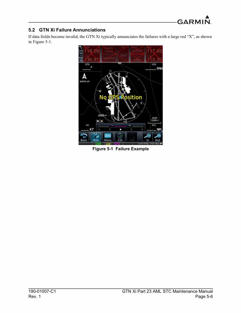
190-01007-C1 GTN Xi Part 23 AML STC Maintenance ManualRev. 1 Page 5-6
5.2 GTN Xi Failure AnnunciationsIf data fields become invalid, the GTN Xi typically annunciates the failures with a large red “X”, as shown in Figure 5-1.
Figure 5-1 Failure Example

190-01007-C1 GTN Xi Part 23 AML STC Maintenance ManualRev. 1 Page 5-7
5.3 GTN Xi System Messages5.3.1 GTN Xi System Related Alerts
Table 5-2 Alert Text Troubleshooting Guide
Alert Text Possible Cause Corrective Action
CROSSFILL ERROR - Crossfill is inoperative. See CRG for crossfilled items.
An error was detected during unit-to-unit communication of data. This can be caused by problems with HSDB wiring or by either GTN Xi (or GTN 6XX/7XX) needing service. Refer to the Cockpit Reference Guide (CRG) for crossfilled items.
Start both units in Configuration mode and ensure that both units are configured for crossfill. Check J1002 connection on crossfilled GTN Xi units.
Ensure that P1002-10 of GTN Xi #2 is connected to ground.
DEMO MODE - Demo mode is active. Do not use for navigation.
The GTN Xi is in Demo mode and must not be used for actual navigation.
Check that the DEMO MODE SELECT* input (P1002-1) is not tied to ground.
Ensure that the Direct-To key is not stuck.
CDI/HSI FLAG - Main lateral/vertical flag on CDI/HSI is inoperative.
The main lateral or vertical superflag has been turned off due to an overcurrent condition.
Check the GTN Xi main lateral and vertical superflag connections to the CDI/HSI for correct wiring, shorts to ground, and overcurrent. Superflags should not drive more than 320 mA.
GTN - GTN needs service.
The GTN Xi has detected an internal failure. Contact Garmin Technical Support.
COOLING - GTN overtemp. Reducing backlight brightness.
The GTN Xi has detected excessive display backlight temperature. The backlight has been automatically dimmed to reduce the unit temperature.
Check for adequate ventilation or check cooling airflow.
Ensure the cooling fan is operating and is unobstructed.
KEY STUCK - HOME key is stuck.
The bezel’s Home key is stuck in the enabled or pressed state.
Press the Home key again to cycle its operation. If the message persists, contact Garmin technical support.
KEY STUCK - Direct-to key is stuck.
The bezel’s Direct-To key is stuck in the enabled or pressed state.
Press the Direct-To key again to cycle its operation. If the message persists, contact Garmin technical support.
KNOB STUCK - Dual concentric inner knob is stuck in the pressed position.
The inner large knob push-key is stuck in the enabled or pressed state. Knob is located on the right side of the unit.
Press the knob to cycle its operation. If the message persists, contact Garmin technical support.
KNOB STUCK - Volume knob is stuck in the pressed position.
The small knob push-key is stuck in the enabled or pressed state. Knob is located on the left side of the unit.
Press the knob to cycle its operation. If the message persists, contact Garmin technical support.

190-01007-C1 GTN Xi Part 23 AML STC Maintenance ManualRev. 1 Page 5-8
CROSSFILL ERROR - GTN software mismatch. See CRG for crossfilled items.
The software does not match between GTN Xi units (or GTN 6XX/7XX). Crossfill disabled. Refer to the Cockpit Reference Guide (CRG) for crossfilled items.
Check the software version of both units and ensure they match. Update the software if needed.
CROSSFILL ERROR - GTN Navigation DB mismatch. See CRG for crossfilled items.
GTN Xi #1 and GTN Xi #2 (or GTN 6XX/7XX) have different cycles of the navigation database.
If it is desired to utilize the crossfill function, load the most current cycles of the navigation database to both units.
CONFIGURATION MODULE - GTN configuration module needs service.
The GTN Xi configuration module has failed. Verify the configuration module wiring is
correct.Replace the configuration module. The GTN Xi configuration
module is incorrectly wired.
DATABASE - Chart function unavailable.
The GTN Xi is configured for ChartView or FliteCharts and chart verification has failed.
Re-install charts onto data card. Verify correct chart type is selected in the configuration options. If problem persists, contact Garmin technical support for service.
DATABASE - Terrain database is not installed, is corrupt, or is not valid for this system
The Terrain database is not available, which could result from the database not being present at start-up or the database being corrupt.
Re-install the Terrain database onto the card. If problem persists, contact Garmin technical support for service.
DATACARD ERROR - Data card is invalid or failed.
The data card is not being properly read by the GTN Xi.
Load the Terrain database and any charts databases to a new data card. Replace the failed data card.
DATACARD REMOVED - Reinsert data card.
External data card was removed. Re-insert data card.
DATA LOST - Pilot stored data was lost. Recheck settings.
User settings, such as map detail level, NAV range ring on/off, traffic overlay on/off, and alert settings, have been lost.
Re-check pilot-configurable settings.
FLIGHT PLAN IMPORT - Flight plan import failed.
The requested flight plan could not be imported because the GTN Xi was unable to decode the contents of the flight plan.
If importing flight plan from an SD card, ensure flight plan is properly formatted per Guideline for GTN Flight Plan and User Waypoint Files. If the problem persists, contact Garmin technical support for service.
Alert Text Possible Cause Corrective Action

190-01007-C1 GTN Xi Part 23 AML STC Maintenance ManualRev. 1 Page 5-9
REMOTE KEY STUCK - Remote OBS key is stuck.
The remote OBS switch is stuck in the enabled or pressed state.
Press the switch again to cycle its operation.Go to the GTN Diagnostics > Discrete Inputs page in Configuration mode and check that the state of the input changes when the OBS switch is pressed and released.Verify that the remote OBS switch wiring is correct.Contact Garmin technical support.
REMOTE KEY STUCK - Remote CDI key is stuck.
The remote CDI key is stuck in the enabled or pressed state.
Press the switch again to cycle its operation.Go to the GTN Diagnostics > Discrete Inputs page in Configuration mode and check that the state of the input changes when the CDI switch is pressed and released.Verify that the CDI switch wiring is correct.Contact Garmin technical support.
REMOTE KEY STUCK - Remote go around key is stuck.
The remote Go Around switch is stuck in the enabled or pressed state.
Press the switch again to cycle its operation.Go to the GTN Diagnostics > Discrete Inputs page in Configuration mode and check that the state of the input changes when the Go Around switch is pressed and released.If the state still shows as active, inspect the wiring to ensure that it is not loose or shorting to ground.
COOLING FAN - The cooling fan has failed.
The wiring to the fan may be faulty, the fan connector may be unplugged, or the fan may have failed.
• Check the wires between P1001-43, -58, and -59 and the fan to ensure they are not cut, damaged, or broken
• Check that the fan connector is completely engaged
• Check that the fan blades are not obstructed and they can rotate freely
• Check P1001 for ground lugs pushing on fan
The fan does not turn on if the unit is cool.GNS CROSSFILL - GTN user waypoint(s) replaced with GNS user waypoint(s).
A user waypoint from the GNS replaced one or more existing waypoints on the GTN Xi.
Ensure that the waypoints on the GNS have unique names before transferring to the GTN Xi to avoid overwriting existing waypoints.
Alert Text Possible Cause Corrective Action

190-01007-C1 GTN Xi Part 23 AML STC Maintenance ManualRev. 1 Page 5-10
GNS CROSSFILL - Catalog full; not all GNS waypoint(s) transferred.
A user waypoint from the GNS could not be created because the user waypoint catalog is full.
Remove some of the waypoints from the catalog to make room for the waypoints from the GNS.
GNS CROSSFILL - Waypoint transfer failed.
Waypoint transfer failed/incomplete. The data transfer should be reattempted.
INTERNAL SD CARD ERROR - GTN needs service.
The GTN Xi unit’s internal data storage has become corrupt or nonfunctional.
Contact Garmin technical support.
INTERNAL SD CARD REMOVED - GTN needs service.
The GTN Xi unit’s internal data storage has been removed or has become nonfunctional.
Contact Garmin technical support.
USER WAYPOINT IMPORT - User waypoint import failed.
User Waypoint import failed due to improper format.
Ensure the media has the correct file format. Refer to Guideline for GTN Flight Plan and User Waypoint Files. If the problem persists, contact Garmin technical support for service.
Waiting to receive information from unit...
The GTN Xi is not communicating with the remote LRU.
Ensure remote LRU is powered on. Check wiring and configuration.
Alert Text Possible Cause Corrective Action

190-01007-C1 GTN Xi Part 23 AML STC Maintenance ManualRev. 1 Page 5-11
5.3.1.1 COM Related AlertsTable 5-3 COM Alert Troubleshooting Guide
Alert Text Possible Cause Corrective Action
COM RADIO - COM radio needs service.
A failure has been detected in the COM transceiver. The transceiver may still be usable.
This message may appear after operations in Configuration mode. Cycle power to the entire GTN Xi (both GPS/NAV and COM circuit breakers) and see if the message has cleared.Contact Garmin technical support.
COM RADIO - COM radio may be inoperative.
The GTN Xi is not able to communicate with its COM transceiver.
Verify that COM connector pins P1003-43 and P1003-44 are receiving aircraft power.Verify that COM connector pins P1003-37 and P1003-38 are connected to aircraft ground.If the message persists, contact Garmin technical support.
REMOTE KEY STUCK - COM push-to-talk key is stuck.
The COM push-to-talk switch is stuck in the enabled or pressed state.
Press the PTT switch to cycle its operation.Navigate to the GTN Diagnostics > Discrete Inputs page in Configuration mode and check that the state of the input changes when the PTT switch is pressed and released.Verify that the PTT switch wiring is correct.If the message persists, contact Garmin technical support.
REMOTE KEY STUCK - COM remote transfer key is stuck.
The COM remote transfer key is stuck in the enabled or pressed state.
Press the COM remote transfer switch to cycle its operation.Navigate to the GTN Diagnostics > Discrete Inputs page in Configuration mode and check that the state of the input changes when the COM remote transfer switch is pressed and released.Verify that the COM remote transfer switch wiring is correct.If the problem persists, contact Garmin technical support.
REMOTE KEY STUCK - COM remote frequency increment key is stuck.
The COM remote frequency increment key is stuck in the enabled or pressed state.
Press the COM remote frequency increment key to cycle its operation.Navigate to the GTN Diagnostics > Discrete Inputs page in Configuration mode and check that the state of the input changes when the COM remote frequency increment switch is pressed and released.Verify that the COM remote frequency increment switch wiring is correct.If the problem persists, contact Garmin technical support.

190-01007-C1 GTN Xi Part 23 AML STC Maintenance ManualRev. 1 Page 5-12
REMOTE KEY STUCK - COM remote frequency decrement key is stuck.
COM remote frequency decrement key is stuck in the enabled or pressed state.
Press the COM remote frequency decrement key to cycle its operation.Navigate to the GTN Diagnostics > Discrete Inputs page in Configuration mode and check that the state of the input changes when the COM remote frequency decrement switch is pressed and released.Verify that the COM remote frequency decrement switch wiring is correct.If the problem persists, contact Garmin technical support.
COM RADIO - COM overtemp or undervoltage. Reducing transmitter power.
The COM is reporting a high temperature.
Ensure the fan is functioning properly and check for adequate airflow around the unit.
Ensure that the COM radio is receiving adequate input voltage (11-33 VDC).
COM RADIO - COM locked to 121.5 MHz. Hold remote COM transfer key to exit.
The COM remote transfer switch has been pressed for at least 2 seconds.
In Lockout mode, the COM will tune the active frequency to 121.5 MHz and not allow the frequency to be changed. COM Lockout mode can be exited by pressing the COM remote transfer switch for at least 2 seconds.
Alert Text Possible Cause Corrective Action

190-01007-C1 GTN Xi Part 23 AML STC Maintenance ManualRev. 1 Page 5-13
5.3.1.2 GPS/SBAS Related AlertsTable 5-4 GPS/SBAS Alert Troubleshooting Guide
Alert Text Possible Cause Corrective ActionGPS RECEIVER - GPS receiver has failed. Check GPS coaxial for electrical short.
A failure has been detected in the GPS/SBAS receiver.
Verify that the center conductor is not shorted to the braid in the coaxial cable.Contact Garmin technical support for assistance.
GPS antenna cable may be shorted to ground.
GPS RECEIVER - GPS receiver needs service.
The GTN Xi has detected an internal failure in the GPS/SBAS receiver.
Contact Garmin technical support.
LOSS OF INTEGRITY (LOI) - Verify GPS position with other navigation equipment.
Improper antenna installation or coaxial routing.
Check GPS antenna installation, connections, and cable routing. The GPS antenna must be mounted on top of the aircraft.
Antenna shaded from satellites.
Make sure the aircraft is clear of hangars, buildings, trees, etc.
RF interference at 1575.42 MHz from VHF COM.
Move GPS antenna further from the COM antenna. Add a 1575.42 MHz notch filter in COM coaxial. Fix or replace the COM. Disconnect the ELT antenna coaxial to check for possible re-radiation.
GPS NAVIGATION LOST - Insufficient satellites. Use other navigation source.
There is no GPS fix available or the system is in Dead Reckoning mode.
Wait for GPS satellite geometry to improve.
Ensure the aircraft has a clear view of the sky.
GPS NAVIGATION LOST - Erroneous position. Use other navigation source.
An internal position warning has occurred.
RAIM has determined that the info from one or more GPS satellites may be in error.
Ensure the aircraft has a clear view of the sky.
GPS RECEIVER - Low internal clock battery.
The GTN Xi has detected a low battery. Almanac data may have been lost.
Replace the battery.
MARK ON TARGET - Waypoint creation has failed. MOT requires GPS position.
Mark on target waypoint creation has failed because of missing GPS position.
Wait for GPS satellite geometry to improve. Ensure the aircraft has a clear view of the sky. Re-attempt waypoint creation.
SEARCHING SKY - Search-the-sky in progress.
The GTN Xi is searching the sky for GPS satellites.
Wait 20 minutes for the unit to complete the cycle or until the current position is located.

190-01007-C1 GTN Xi Part 23 AML STC Maintenance ManualRev. 1 Page 5-14
5.3.1.3 VLOC/GS Related AlertsTable 5-5 VLOC/GS Alert Troubleshooting Guide
Alert Text Possible Cause Corrective Action
VLOC RECEIVER - Navigation receiver needs service.
The GTN 650Xi/750Xi has detected a failure in its navigation receiver.
Contact Garmin technical support.
VLOC RECEIVER - Navigation receiver has failed.
The GTN 650Xi/750Xi has detected an internal failure in its VLOC receiver.
Contact Garmin technical support.
GLIDESLOPE - Glideslope receiver needs service.
The GTN 650Xi/750Xi has detected an internal failure in its glideslope receiver.
Contact Garmin technical support.
GLIDESLOPE - Glideslope receiver has failed.
The GTN Xi has detected an internal failure in its glideslope receiver.
Contact Garmin technical support.
REMOTE KEY STUCK - NAV remote transfer key is stuck.
NAV remote transfer key is stuck in the enabled or pressed state.
Press the NAV remote transfer switch to cycle its operation.Go to the GTN Diagnostics > Discrete Inputs page in Configuration mode and check that the state of the input changes when the NAV remote transfer switch is pressed and released.Verify that the NAV remote transfer switch wiring is correct.If the problem persists, contact Garmin technical support.

190-01007-C1 GTN Xi Part 23 AML STC Maintenance ManualRev. 1 Page 5-15
5.3.1.4 Remote Transponder Related AlertsTable 5-6 Remote Transponder Alert Troubleshooting Guide
Alert Text Possible Cause Corrective ActionTRANSPONDER 1 OR 2 - ADS-B Out system fault. Pressure altitude source inoperative or connection lost.
The transponder has lost communication with the pressure altitude source.
Verify wiring between the transponder and the pressure altitude source. If problem persists, contact Garmin technical support for service.
TRANSPONDER 1 OR 2 - Transponder has failed.
The transponder has detected an internal fault and transponder functionality may be unavailable.
Return unit to Garmin technical support for service.
TRANSPONDER 1 OR 2 - Transponder is in ground test mode.
The transponder is operating in a mode intended for ground testing.
Cycle the power to the transponder.
TRANSPONDER 1 OR 2 - Transponder overtemp.
The transponder is reporting that its internal temperature is above upper operating limits.
Check for adequate ventilation around the transponder.
TRANSPONDER 1 OR 2 - Transponder undertemp.
The transponder is reporting that its internal temperature is below lower operating limits.
Contact Garmin technical support for service if this message persists.
TRANSPONDER 1 - Transponder 1 needs service.
The transponder is reporting a system failure.
Refer to the transponder installation manual.
TRANSPONDER 2 - Transponder 2 needs service.
The transponder is reporting a system failure.
Refer to the transponder installation manual.
TRANSPONDER 1 - Transponder 1 is inoperative or connection to GTN is lost.
The GTN Xi cannot communicate with the transponder or the transponder is reporting a system failure.
If two transponders are present, ensure that both GTN Xi units are powered on.Check for proper configuration of the GTN Xi and transponder RS-232 ports.Check for correct wiring.Refer to the transponder installation manual.
TRANSPONDER 2 - Transponder 2 is inoperative or connection to GTN is lost.
The GTN Xi cannot communicate with the transponder or the transponder is reporting a system failure.
Ensure that both GTN Xi units are powered on.Check for proper configuration of the GTN Xi and transponder RS-232 ports.Check for correct wiring.Refer to the transponder installation manual.
TRANSPONDER - Transponder 1 and 2 Mode S addresses do not match.
The transponders are configured for different Mode S addresses.
Check the Mode S address for each transponder and verify that they match.

190-01007-C1 GTN Xi Part 23 AML STC Maintenance ManualRev. 1 Page 5-16
5.3.1.5 GAD 42 AlertsTable 5-7 GAD 42 Alert Troubleshooting Guide
5.3.1.6 Traffic Related AlertsTable 5-8 Traffic Alert Troubleshooting Guide
TRANSPONDER 1 – ADS-B is not transmitting position.
The transponder has insufficient data to support ADS-B.
Ensure the aircraft has a clear view of the sky.Refer to the transponder installation manual.
TRANSPONDER 2 - ADS-B is not transmitting position.
The transponder has insufficient data to support ADS-B.
Ensure the aircraft has a clear view of the sky.Refer to the transponder installation manual.
Alert Text Possible Cause Corrective Action
GAD 42 - GAD 42 configuration needs service.
GAD 42 not powered up.Ensure that the GAD 42 is receiving power and is connected to ground.
GTN Xi is not receiving data from GAD 42.
Verify wiring between the GTN Xi and the GAD 42.
GAD 42 - GAD 42 needs service.
GAD 42 is reporting an internal failure.
Contact Garmin technical support.
Alert Text Possible Cause Corrective Action
TRAFFIC - Traffic device is inoperative or connection to GTN is lost.
Traffic device is not powered up.
Ensure the traffic device is receiving power and is connected to ground.Verify the wiring between the GTN Xi and the traffic device.Raw ARINC 429 data can be viewed on the GTN Diagnostics > ARINC Inputs page in Configuration mode.
Traffic device has failed.
TRAFFIC - Traffic device battery low. Traffic device user config settings not saved.
The connected traffic system is reporting that it has a low battery.
Traffic system may require service. Refer to external traffic system maintenance manual for additional details.
TRAFFIC - TAS/TCAS has been in standby for more than 60 seconds.
GTN Xi is in the airborne state and the traffic device has been in standby for more than 60 seconds.
Troubleshoot the traffic system. Refer to traffic system installation manual.
Alert Text Possible Cause Corrective Action

190-01007-C1 GTN Xi Part 23 AML STC Maintenance ManualRev. 1 Page 5-17
5.3.1.7 Weather Radar AlertsTable 5-9 Weather Radar Alert Troubleshooting Guide
Alert Text Possible Cause Corrective Action
WX RADAR FAIL – Weather radar is inoperative.
GTN ARINC 708 input port or ARINC 429 output not configured correctly.
Check ARINC 708 port setting for port 1. Raw ARINC 708 data can be viewed on the GTN Diagnostics > ARINC Inputs page in Configuration mode.Verify that ARINC 429 Out 3 is configured for Radar Format 1.
Improper setup on the weather radar.
Verify the configuration of the weather radar.
Wiring connections are incorrect. Check wiring.
Weather radar is reporting a system fault.
Check weather radar status page on the GTN Xi in Configuration mode.Refer to the weather radar installation manual.
WX RADAR SERVICE – Weather radar needs service. Return unit for repair.
Weather radar is reporting a system failure.
Refer to the weather radar installation manual for troubleshooting.

190-01007-C1 GTN Xi Part 23 AML STC Maintenance ManualRev. 1 Page 5-18
5.3.1.8 Datalink Related AlertsTable 5-10 Datalink Alert Troubleshooting Guide
Alert Text Possible Cause Corrective Action
DATALINK - FIS-B weather has failed.
The FIS-B receiver is reporting that it has failed. The display of FIS-B products may be unavailable.
Check wiring to ADS-B In source. Check for internal faults in the ADS-B equipment. If problem persists, contact Garmin technical support for service.
DATALINK – GDL 69 is inoperative or connection to GTN is lost.
The GTN Xi cannot communicate with the GDL 69.
Check for proper configuration.Ensure the GDL 69 is powered up.Verify that the GDL 69 Ethernet ports are enabled. HSDB data from the GDL 69 can be routed to the GTN Xi through other Garmin LRUs. Ensure that all Garmin LRUs are powered up.
DATALINK – GDL 88 is inoperative or connection to GTN is lost.
The GTN Xi cannot communicate with the GDL 88.
Check for proper configuration.Ensure the GDL 88 is powered up.HSDB data from the GDL 69 can be routed to the GTN Xi through other Garmin LRUs. Ensure that all Garmin LRUs are powered up.
DATALINK - GDL 88 ADS-B failure. Unable to transmit ADS-B messages.
GDL 88 is not able to transmit an ADS-B message due to a failure with the GDL 88 system or antenna(s).
Check the GDL 88 Fault page in Configuration mode on the GTN Xi.Refer to the GDL 88 STC Installation Manual.
DATALINK – GDL 88 ADS-B fault.
The GDL 88 has detected a fault with one of the GDL 88 UAT/1090 antennas.
Refer to the GDL 88 STC Installation Manual.
DATALINK – ADS-B fault: UAT receiver.
The GDL 88 has detected a UAT receiver fault.
Refer to the GDL 88 STC Installation Manual.
DATALINK – ADS-B fault: 1090 receiver.
The GDL 88 has detected a 1090 receiver fault.
Refer to the GDL 88 STC Installation Manual.
DATALINK - GDL 88 ADS-B is not transmitting position. Check GPS devices.
The GDL 88 has detected a position input fault.
Refer to the GDL 88 STC Installation Manual.
DATALINK - GDL 88 control panel input fault. Check transponder is in correct mode.
The GDL 88 has lost communication with the transponder.
Refer to the GDL 88 STC Installation Manual.

190-01007-C1 GTN Xi Part 23 AML STC Maintenance ManualRev. 1 Page 5-19
DATALINK - GDL 88 ADS-B fault. Pressure altitude input is invalid.
The GDL 88 has lost communication with the pressure altitude source.
Refer to the GDL 88 STC Installation Manual.
DATALINK - GDL 88 ADS-B traffic has failed.
GDL 88 may have lost GPS position.The GDL 88 has detected an internal failure.
Check the GDL 88 Fault page in Configuration mode on the GTN Xi.Refer to the GDL 88 STC Installation Manual.
DATALINK - GDL 88 CSA Failure
The GDL 88 is reporting to the GTN that the CSA application has failed. Traffic alerting on ADS-B traffic is unavailable.
Ensure the aircraft has a clear view of the sky. If the problem persists, contact Garmin technical support.
DATALINK – GDL 88 external traffic system inoperative or connection lost.
The GDL 88 has detected a TAS/TCAS input fault.
Refer to the GDL 88 STC Installation Manual.
DATALINK - GDL 88 external traffic system has a low battery.
The GDL 88 is reporting that the external traffic system has a low battery.
Refer to the GDL 88 STC Installation Manual.
DATALINK – GDL 88 configuration module needs service.
The GDL 88 has detected a configuration module fault.
Refer to the GDL 88 STC Installation Manual.
DATALINK – GDL 88 needs service.
GDL 88 has detected an internal fault.
Check the GDL 88 Fault page in Configuration mode on the GTN Xi.Refer to the GDL 88 STC Installation Manual.
DATALINK - GSR 56 is inoperative or connection to GTN is lost.
The GTN Xi is not able to communicate with the GSR 56 Iridium transceiver.
Verify that the GTN Xi is configured correctly for the GSR 56.Check the RS-232 wiring between the GTN Xi and GSR 56.Check that the GSR 56 is receiving aircraft power and is connected to aircraft ground.
DATALINK – GSR 56 data services inoperative; registration required.
Registration settings have been altered or deleted.
In Normal mode, select System > External LRUs. Select the More Info button next to the GSR 56 LRU. Select Connext Registration and re-enter the access code.
Account has been deactivated. Reactivate account.
Alert Text Possible Cause Corrective Action

190-01007-C1 GTN Xi Part 23 AML STC Maintenance ManualRev. 1 Page 5-20
5.3.1.9 TAWS Related AlertsTable 5-11 TAWS Alert Troubleshooting Guide
Alert Text Possible Cause Corrective ActionDATABASE- Terrain or Obstacle database not available.
The terrain or obstacle database is missing or corrupt.
Reload these databases on the external data card.
REMOTE KEY STUCK - TAWS inhibit key is stuck.
The TAWS Inhibit input is stuck in the enabled or pressed state.
Press the TAWS Inhibit key to cycle its operation.
Navigate to the GTN Diagnostics > Discrete Inputs page in Configuration mode and check that the state of the input changes when the TAWS Inhibit switch is pressed and released.
Verify wiring to the switch.
If the problem persists, contact Garmin technical support.
TAWS AUDIO INHIBITED - The TAWS Audio Inhibit discrete has been active for at least 30 seconds.
There is a wiring problem or a problem with the remote LRU that is connected to the GTN Xi audio inhibit input.
Verify wiring to the TAWS Audio Inhibit input.
Navigate to the GTN Diagnostics > Discrete Inputs page in Configuration mode and check the state of the discrete input.
If the problem persists, contact Garmin technical support.
CONFIGURATION – Terrain/TAWS configuration is invalid. GTN needs service.
The TAWS configuration is invalid due to a loss or corrupted registry.
The TAWS/terrain configuration setting must be reselected. Reselect the TAWS or terrain selection and cycle power to the GTN Xi.
If the problem persists, contact Garmin technical support.
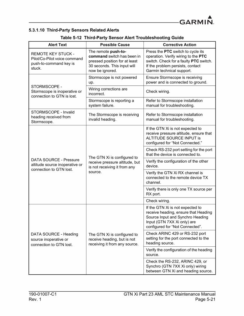
190-01007-C1 GTN Xi Part 23 AML STC Maintenance ManualRev. 1 Page 5-21
5.3.1.10 Third-Party Sensors Related AlertsTable 5-12 Third-Party Sensor Alert Troubleshooting Guide
Alert Text Possible Cause Corrective Action
REMOTE KEY STUCK - Pilot/Co-Pilot voice command push-to-command key is stuck.
The remote push-to-command switch has been in pressed position for at least 30 seconds. This input will now be ignored.
Press the PTC switch to cycle its operation. Verify wiring to the PTC switch. Check for a faulty PTC switch. If the problem persists, contact Garmin technical support.
STORMSCOPE - Stormscope is inoperative or connection to GTN is lost.
Stormscope is not powered up.
Ensure Stormscope is receiving power and is connected to ground.
Wiring corrections are incorrect. Check wiring.
Stormscope is reporting a system failure.
Refer to Stormscope installation manual for troubleshooting.
STORMSCOPE - Invalid heading received from Stormscope.
The Stormscope is receiving invalid heading.
Refer to Stormscope installation manual for troubleshooting.
DATA SOURCE - Pressure altitude source inoperative or connection to GTN lost.
The GTN Xi is configured to receive pressure altitude, but is not receiving it from any source.
If the GTN Xi is not expected to receive pressure altitude, ensure that ALTITUDE SOURCE INPUT is configured for “Not Connected.”Check RS-232 port setting for the port that the device is connected to.Verify the configuration of the other device.Verify the GTN Xi RX channel is connected to the remote device TX channel.Verify there is only one TX source per RX port.Check wiring.
DATA SOURCE - Heading source inoperative or connection to GTN lost.
The GTN Xi is configured to receive heading, but is not receiving it from any source.
If the GTN Xi is not expected to receive heading, ensure that Heading Source Input and Synchro Heading Input (GTN 7XX Xi only) are configured for “Not Connected”.Check ARINC 429 or RS-232 port setting for the port connected to the heading source. Verify the configuration of the heading source.Check the RS-232, ARINC 429, or Synchro (GTN 7XX Xi only) wiring between GTN Xi and heading source.

190-01007-C1 GTN Xi Part 23 AML STC Maintenance ManualRev. 1 Page 5-22
5.4 Flight Stream TroubleshootingTable 5-13 Flight Stream Troubleshooting
Problem Possible Cause Corrective Action
Unable to pair PED to Flight Stream 210/510.
Trying to pair with the device while not on the Bluetooth Pairing page.
Access the Connext Bluetooth Pairing page by pressing Home > System > Connext Setup > Flight Stream 210. If Flight Stream 210 is the only Bluetooth device, touching Connext Setup will automatically open the Flight Stream 210 page.
Flight Stream paired device storage is full.
Refer to the list of paired devices and verify that the queue is not full. If 13 devices have been previously paired with the Flight Stream, remove a device from the list to pair the new device with the Flight Stream.
Ensure that the Flight Stream has the latest certified software version.
Check software version and update if there is a newer approved version.
Flight Stream 210 is connected but Connext Setup page is grayed out.
Flight Stream 210 has lost communication with the GTN Xi.
Check that the Flight Stream 210 connector is fully seated.Check RS-232 wires and connections between the GTN Xi and Flight Stream 210.Check power and ground wires and connections to the Flight Stream 210.
PED is not receiving any data from Flight Stream 210/510.
Devices need to be re-synced with each other.
1. Access the Connext Bluetooth Pairing page by pressing Home > System > Connext Setup.
2. Remove the PED from the list of paired devices on the GTN Xi.
3. Remove the list of Bluetooth devices on the PED.
4. Re-pair the devices.
PED is not receiving data from the GDL 88 (e.g., ADS-B traffic and FIS-B).
Flight Stream 210 has lost communication with the GDL 88.
Check that PED is paired to Flight Stream 210. Refer to the steps above for details.Check that the Flight Stream 210 connector is fully seated.Check RS-422 wires and connections between the GDL 88 and Flight Stream 210.Check power and ground wires and connections to the Flight Stream 210.Check that the GDL 88 RS-422 port is configured for Connext Format 1.

190-01007-C1 GTN Xi Part 23 AML STC Maintenance ManualRev. 1 Page 5-23
PED is not receiving data from the GDL 69 (e.g., datalink weather). Flight Stream 210 has lost
communication with the GDL 69.
Check that PED is paired to Flight Stream 210. Refer to the previous steps for details.Check that the Flight Stream 210 connector is fully seated.
PED will not control GDL 69 Sirius XM audio.
Check RS-232 wires and connections between the GDL 69 and Flight Stream 210.Check power and ground wires and connections to the Flight Stream 210.
Problem Possible Cause Corrective Action

190-01007-C1 GTN Xi Part 23 AML STC Maintenance ManualRev. 1 Page 5-24
5.5 GMA 35 TroubleshootingThis section provides information to assist troubleshooting if problems occur after completing maintenance. Refer to the system configuration log retained in the aircraft permanent records for a list of interfaced equipment and system configuration data.
Table 5-14 GMA 35 TroubleshootingProblem Possible Cause Corrective Action
Audio volume, audio routing, music, marker beacon status, or intercom are not working properly.
GMA 35 is not configured properly.
Check the configuration against the configuration log to ensure that the GMA 35 is configured properly.
Audio panel operates only in Failsafe mode (pilot headset connected to one COM radio, red “X” over the audio panel control field).
GMA 35 is disconnected from aircraft power or ground.
Ensure power is connected to P3502, pins 8 and 9, and ground is connected to P3502, pins 10 and 11.
Check circuit breakers and avionics switch.
GMA 35 is not seated correctly.
Verify that the GMA 35 is fully seated.
Verify that counter-sunk flathead screws are used to secure the GMA 35 connectors to the backplate.
RS-232 communication between the GTN 7XX Xi and the GMA 35 is not functioning correctly.
Check for proper configuration of the GTN Xi and GMA 35 RS-232 ports.
Check for correct wiring between the audio panel and the GTN 7XX Xi.
Bluetooth isn’t working.
SMA cable loose at antenna or on back of GMA 35c.
Ensure cable is tight at antenna and back of GMA 35c.
Bluetooth disabled. Enable Bluetooth under Connext Setup > GMA 35c.
Unable to pair PED to GMA 35c.
Trying to pair with the device while not on the GMA 35c Pairing page.
Access the GMA 35c Pairing page by touching Home > System > Connext Setup > GMA 35c. If GMA 35c is the only Bluetooth device, touching Connext Setup will automatically open GMA 35c page.

190-01007-C1 GTN Xi Part 23 AML STC Maintenance ManualRev. 1 Page 5-25
5.6 GMA 35 Failure AnnunciationsFigure 5-2 depicts a typical failure indication of the GMA 35 audio panel.
Figure 5-2 GMA 35 Failure Annunciation
5.7 GMA 35 System MessagesTable 5-15 Remote Audio Panel Alert Troubleshooting Guide
Alert Text Possible Cause Corrective ActionAUDIO PANEL - Audio panel needs service.
Audio panel should be serviced.
Return audio panel to Garmin for service.
AUDIO PANEL - Audio panel is inoperative or connection to GTN is lost.
Audio panel is not powered up.Ensure the audio panel is receiving power and connected to ground.
Audio panel has failed.Verify the wiring from the audio panel to the GTN Xi.Wiring connections are
incorrect.

190-01007-C1 GTN Xi Part 23 AML STC Maintenance ManualRev. 1 Page 6-1
6 EQUIPMENT REMOVAL AND RE-INSTALLATION
6.1 GTN Xi .............................................................................................................................................6-26.1.1 Display of Self-Test Data...........................................................................................................6-5
6.2 GMA 35 ............................................................................................................................................6-66.3 Data Card/Flight Stream 510 ............................................................................................................6-96.4 Flight Stream 210............................................................................................................................6-106.5 NAV Antenna Cable Diplexer........................................................................................................6-116.6 NAV Antenna Cable Splitter ..........................................................................................................6-116.7 Configuration Module (P1001 Only)..............................................................................................6-126.8 GTN Xi Fan ....................................................................................................................................6-156.9 TVS and Fuse (Nonmetallic Aircraft Only) ...................................................................................6-18
6.9.1 Fuse ..........................................................................................................................................6-186.9.2 TVS ..........................................................................................................................................6-18
6.10 Instrument Panel Bonding Strap .....................................................................................................6-226.11 Flight Stream 210 Bonding Strap ...................................................................................................6-236.12 Interfaced Equipment Bonding Strap .............................................................................................6-25
This section describes how to remove and replace equipment associated with this STC. After removal and re-installation, LRUs must be configured and tested as described in Section 7.
CAUTIONWhen removing and/or replacing a GTN Xi, GMA 35, or any other item under the scope of the STC installation, always ensure that the aircraft power is off. Unplug any auxiliary power supply.

190-01007-C1 GTN Xi Part 23 AML STC Maintenance ManualRev. 1 Page 6-2
6.1 GTN XiRemoval
1. Locate and open the GTN Xi GPS/NAV and COM (GTN 635Xi/650Xi/750Xi only) circuit breakers.
2. Locate the unit retention mechanism access hole at the bottom-left corner of the unit face.3. Insert a 3/32" hex tool into the access hole and turn the fastener counterclockwise until the unit is
forced out about 3/8 inches and can be freely pulled from the rack.4. Slide the GTN Xi unit out of the rack.
Re-installation
NOTEIt may be necessary to insert the hex drive tool into the access hole and turn the cam mechanism 90° counterclockwise to ensure correct position prior to placing the unit in the rack.
CAUTIONBe sure not to overtighten the unit into the rack. The application of hex drive tool torque exceeding 15 in-lbf can damage the locking mechanism.
CAUTIONThe Bluetooth antenna port on the GMA 35c has a tight clearance from the GTN Xi. Ensure the GMA 35c and antenna cable are fully seated before inserting the GTN Xi. The face of the GMA 35c should be flush with the mounting rack when fully seated.
1. Ensure that the GTN Xi GPS/NAV and COM circuit breakers are open.2. Slide the GTN Xi straight into the rack until it stops about 1 inch short of the fully seated position.3. Insert a 3/32" hex drive into the unit retention mechanism access hole at the bottom of the unit face
and turn the tool clockwise while pressing the bezel until the unit is firmly seated in the rack.4. Once the unit is re-installed, verify that the unit power-up self-test sequence is successfully
completed and no failure messages or configuration error messages are annunciated. Section 6.1.1 outlines the power-up self-test sequence.

190-01007-C1 GTN Xi Part 23 AML STC Maintenance ManualRev. 1 Page 6-3
NOTES
Figure 6-1 GTN 6XX Mounting Rack Assembly
PART OF P/N 011-02245-00 (GTN 625), P/N 011-02245-01 (GTN 635), AND P/N 011-02245-02 (GTN 650) BACKPLATE ASSEMBLY KITS. REFER TO TABLE BELOW KIT CONTENT DIFFERENCES.
TORQUE TO 4.5 - 5.2 IN-LBF.
INSTALLATION KITS CONTAIN THE UNIT, CONNECTOR KIT, BACKPLATE ASSEMBLY KIT, MOUNTING RACK, AND CONFIGURATION MODULE.
BACKPLATE KIT CONTENT DIFFERENCES
UNIT DESCRIPTION
INSTALL KIT P/N
CONNECTOR KIT P/N
MOUNTING RACK P/N
BACKPLATE KIT P/N WASHER QTY BNC CONN QTY
GTN 625Xi, Black 010-01997-01 011-02325-00 115-01293-00 011-02245-00
212-00022-00
1
330-00053-01
0
GTN 635Xi, Black 010-01998-01 011-02325-01 115-01293-00 011-02245-01 2 1
GTN 650Xi, Black 010-01999-01 011-02325-02 115-01293-00 011-02245-02 3 2
GTN 650Xi, Gray 010-01999-31 011-02325-02 115-01293-00 011-02245-02 3 2
211-60234-08SCREW, 4-40 x .25 (4X) 1
330-00053-02BNC/TNC CONNECTOR 1
330-00053-01BNC CONNECTOR 1
212-00022-00SHOULDER WASHER 1
211-60234-23SCREW, 4-40 x 1.375 (4X) 1
115-01293-00GTN 6XX MOUNTING RACK
253-00421-00CHASSIS GASKET1
330-00053-01BNC CONNECTOR1
125-00220-10GTN 6XX BACKPLATE1
371-00014-01FAN1
011-02325-0XCONNECTOR KIT
1
2
3

190-01007-C1 GTN Xi Part 23 AML STC Maintenance ManualRev. 1 Page 6-4
NOTES
Figure 6-2 GTN 7XX Mounting Rack Assembly
PART OF P/N 011-02246-00 (GTN 725) AND P/N 011-02246-02 (GTN 750) BACKPLATE ASSEMBLY KITS. REFER TO TABLE BELOW KIT CONTENT DIFFERENCES.
TORQUE TO 4.5 - 5.2 IN-LBF.
INSTALLATION KITS CONTAIN THE UNIT, CONNECTOR KIT, BACKPLATE ASSEMBLY KIT, MOUNTING RACK, AND CONFIGURATION MODULE.
BACKPLATE KIT CONTENT DIFFERENCES
UNIT DESCRIPTION
INSTALL KIT P/N
CONNECTOR KIT P/N
MOUNTING RACK P/N
BACKPLATE KIT P/N WASHER QTY BNC CONN QTY
GTN 725Xi, Black 010-02000-01 011-02326-00 115-01294-00 011-02246-00
212-00022-00
1
330-00053-01
1
GTN 750Xi, Black 010-02002-01 011-02326-02 115-01294-00 011-02246-02 3 2
GTN 750Xi, Gray 010-02002-31 011-02326-02 115-01294-00 011-02246-02 3 2
211-60234-08SCREW, 4-40 x .25 (4X) 1
330-00053-02BNC/TNC CONNECTOR 1
330-00053-01BNC CONNECTOR 1
212-00022-00SHOULDER WASHER 1
211-60234-23SCREW, 4-40 x 1.375 (4X)1
115-01294-00GTN 7XX MOUNTING RACK
253-00421-00CHASSIS GASKET1
330-00053-01BNC CONNECTOR1
125-00221-10GTN 7XX BACKPLATE1
371-00014-01FAN1
011-02326-0XCONNECTOR KIT
1
2
3
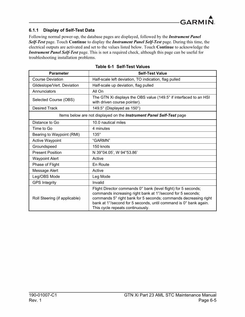
190-01007-C1 GTN Xi Part 23 AML STC Maintenance ManualRev. 1 Page 6-5
6.1.1 Display of Self-Test DataFollowing normal power-up, the database pages are displayed, followed by the Instrument Panel Self-Test page. Touch Continue to display the Instrument Panel Self-Test page. During this time, the electrical outputs are activated and set to the values listed below. Touch Continue to acknowledge the Instrument Panel Self-Test page. This is not a required check, although this page can be useful for troubleshooting installation problems.
Table 6-1 Self-Test ValuesParameter Self-Test Value
Course Deviation Half-scale left deviation, TO indication, flag pulledGlideslope/Vert. Deviation Half-scale up deviation, flag pulledAnnunciators All On
Selected Course (OBS) The GTN Xi displays the OBS value (149.5° if interfaced to an HSI with driven course pointer).
Desired Track 149.5° (Displayed as 150°)
Items below are not displayed on the Instrument Panel Self-Test page
Distance to Go 10.0 nautical milesTime to Go 4 minutesBearing to Waypoint (RMI) 135°Active Waypoint “GARMN”Groundspeed 150 knotsPresent Position N 39°04.05’, W 94°53.86’Waypoint Alert ActivePhase of Flight En RouteMessage Alert ActiveLeg/OBS Mode Leg ModeGPS Integrity Invalid
Roll Steering (if applicable)
Flight Director commands 0° bank (level flight) for 5 seconds; commands increasing right bank at 1°/second for 5 seconds; commands 5° right bank for 5 seconds; commands decreasing right bank at 1°/second for 5 seconds, until command is 0° bank again. This cycle repeats continuously.

190-01007-C1 GTN Xi Part 23 AML STC Maintenance ManualRev. 1 Page 6-6
6.2 GMA 35Removal
1. Locate and open the audio panel circuit breaker. 2. Ensure that the GTN 7XX Xi(s) are not receiving power prior to removal of the audio panel.3. Remove the GTN Xi unit.4. GMA 35c only: Remove the Bluetooth antenna cable.5. Locate the GMA 35 retention mechanism access hole at the bottom-center of the unit face.6. Insert a 3/32" hex tool into the access hole and turn the fastener counterclockwise until the unit is
forced out about 3/8 inches and can be freely pulled from the rack.7. Slide the GMA 35 unit out of the rack.
Re-installation
NOTEBe sure not to overtighten the unit into the rack. The application of hex drive tool torque exceeding 15 in-lbf can damage the locking mechanism.
1. Ensure that the audio panel circuit breaker is open and the GTN 7XX Xi is not receiving power.2. Slide the GMA 35 straight into the rack until it stops.3. Insert a 3/32" hex drive into the unit retention mechanism access hole at the bottom of the unit face
and turn the tool clockwise while pressing on the face of the unit until the GMA 35 is firmly seated in the rack.
4. GMA 35c only: Re-install the Bluetooth antenna cable. Torque 8 to 10 in-lbf using a 5/16 SMA torque wrench.
5. Ensure the face of the GMA 35 is flush with the edge of the GMA 35 installation rack when seated.
6. Re-install the GTN 7XX Xi.7. Verify that there are no failure messages or annunciations when the GTN Xi and audio panel are
powered on.

190-01007-C1 GTN Xi Part 23 AML STC Maintenance ManualRev. 1 Page 6-7
NOTES
Figure 6-3 GMA 35 Mounting Rack Assembly Overview
INCLUDED IN BACKPLATE KIT.
INCLUDED IN CONNECTOR KIT
INCLUDED IN INSTALLATION KIT.
TORQUE 4.5 - 5.2 IN-LBF.
INSTALLATION KITS CONTAIN THE UNIT, CONNECTOR KIT, BACKPLATE ASSEMBLY KIT, AND MOUNTING RACK.
Unit DESCRIPTION INSTALLATION KIT CONNECTOR KIT BACKPLATE KITGMA 35 010-00831-21 011-02302-00 011-02300-00GMA 35c 010-00831-41 011-02302-00 011-02300-00
211-60234-08SCREW, 4-40 X .250
115-01464-00GMA 35 MOUNTING RACK
011-00950-02 BACKSHELL (2X)011-01169-00 GROUND ADAPTER (4X)
330-00185-44 CONNECTOR (2X)336-00021-00 PINS (A/R)
125-00040-00GMA 35 BACKPLATE
211-63234-11SCREW, 4-40 X .437
2
1
1
2
3
4
4
1
2
3
4
5
3 4

190-01007-C1 GTN Xi Part 23 AML STC Maintenance ManualRev. 1 Page 6-8
Figure 6-4 GMA 35c Mounting Rack Assembly Overview
011-02299-()
700-00076-00325-00458-()
211-60234-084 PLACES125-00040-00
115-01464-00
211-63234-114 PLACES
330-00185-442 PLACES011-00950-022 PLACE
011-01169-00
BLUETOOTH ANTENNA/CABLE KIT011-03909-00GMA35c ONLY
GMA35 BACK PLATE KIT011-02300-00
GMA 35 CONNECTOR KIT011-02302-00

190-01007-C1 GTN Xi Part 23 AML STC Maintenance ManualRev. 1 Page 6-9
6.3 Data Card/Flight Stream 510
CAUTIONHandle the data cards carefully. Do not touch the connector edge of the data card.
NOTEA data card or Flight Stream 510 containing databases is required for full system functionality. One of the two must be installed.
Removal1. Ensure that the GTN Xi unit is powered off.2. Remove the data card/Flight Stream 510 by pressing the card until it disengages and then pulling
the card to extract it from the unit.
Re-installation1. With the label facing right, insert the new data card/Flight Stream 510 into the data card slot on the
front-left of the GTN Xi by pushing the card straight into the slot.2. Press until it is fully inserted and locked into position.

190-01007-C1 GTN Xi Part 23 AML STC Maintenance ManualRev. 1 Page 6-10
6.4 Flight Stream 210Refer to Figure 6-5 when performing the following steps:
Removal1. Locate and open the BT Link circuit breaker.2. Unscrew the two jackscrews on the Flight Stream 210 connector and remove it.3. Locate the four #6 mounting screws for the Flight Stream 210 and unscrew them.4. Remove the unit.
Re-installation1. Ensure that the BT Link circuit breaker is open.
NOTEEnsure that the Flight Stream 210 is mounted with the arrow pointing in the direction of flight.
2. Re-install the Flight Stream 210 using the four previously removed #6 mounting screws. Tighten fasteners until snug and turn an additional one-quarter turn.
3. Attach the connector, tightening the two jackscrews.4. Close the BT Link circuit breaker.
Figure 6-5 Flight Stream 210 Assembly Overview(Bonding Strap Not Shown)
DIRECTION OF FLIGHT
FLIGHT STREAM 210: P/N 011-03257-40
CONNECTOR KIT ASSEMBLY: P/N 011-03258-00

190-01007-C1 GTN Xi Part 23 AML STC Maintenance ManualRev. 1 Page 6-11
6.5 NAV Antenna Cable DiplexerRemoval
1. Disconnect the coaxial connectors from diplexer, taking note of which coaxial connectors are connected to each port on the diplexer.
2. Remove the mounting screws and diplexer.
Re-installation1. Re-install the diplexer over the existing hole pattern and re-install fasteners. Torque fasteners
22 to 25 in-lbf. Diplexer fasteners are standard steel fasteners with 0.1900-32UNF-2A thread. Refer to aircraft parts catalog or standard practices manual for recommendations.
2. Reconnect the coaxial connectors to the diplexer.
6.6 NAV Antenna Cable SplitterRemoval
1. Disconnect the coaxial connectors from the splitter, taking note of which coaxial connectors are connected to each port on the splitter.
2. Remove the mounting screws and splitter.
Re-installation1. Re-install the splitter over the existing hole pattern and re-install fasteners. Torque fasteners
5 to 6 in-lbf. Splitter fasteners are standard steel fasteners with 0.1380-40UNF-2A thread. Refer to aircraft parts catalog or standard practices manual for recommendations.
2. Reconnect the coaxial connectors to the splitter.

190-01007-C1 GTN Xi Part 23 AML STC Maintenance ManualRev. 1 Page 6-12
6.7 Configuration Module (P1001 Only)The GTN Xi P1001 connector assembly serves as the housing for a configuration module. This section lists configuration module assemblies.
Table 6-2 Configuration Module Wire Color Reference Chart
NOTEThe pin contacts supplied with the GTN Xi configuration module are specifically made to accommodate 28 AWG wire. The crimp tool should have the indenter set to the correct setting when crimping these contacts to the configuration module harness.
Configuration modules are located within the GTN Xi harness connector backshell (item 6, Figure 6-6). There are two configuration module kits that have been approved for use with GTN Xi. The P/N 011-00979-00 configuration module kit has a spacer (Figure 6-7). The P/N 011-00979-03 configuration module kit does not use a spacer (Figure 6-6). The P/N 011-00979-03 configuration module kit is included with the GTN Xi installation kits and is recommended for all replacements. The instructions for removal/replacement of a configuration module apply equally to either part number. Unless otherwise noted, refer to the corresponding backshell assembly drawing when performing the following removal and re-installation steps.
Color Function P1001 ContactRed Vcc 65Black Ground 64Yellow Data 62White Clock 63
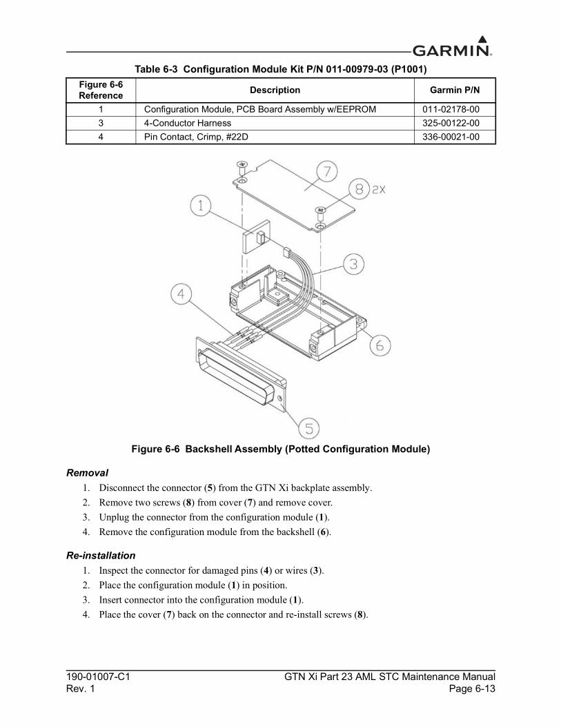
190-01007-C1 GTN Xi Part 23 AML STC Maintenance ManualRev. 1 Page 6-13
Table 6-3 Configuration Module Kit P/N 011-00979-03 (P1001)
Figure 6-6 Backshell Assembly (Potted Configuration Module)
Removal1. Disconnect the connector (5) from the GTN Xi backplate assembly.2. Remove two screws (8) from cover (7) and remove cover.3. Unplug the connector from the configuration module (1).4. Remove the configuration module from the backshell (6).
Re-installation1. Inspect the connector for damaged pins (4) or wires (3).2. Place the configuration module (1) in position.3. Insert connector into the configuration module (1).4. Place the cover (7) back on the connector and re-install screws (8).
Figure 6-6 Reference Description Garmin P/N
1 Configuration Module, PCB Board Assembly w/EEPROM 011-02178-003 4-Conductor Harness 325-00122-004 Pin Contact, Crimp, #22D 336-00021-00

190-01007-C1 GTN Xi Part 23 AML STC Maintenance ManualRev. 1 Page 6-14
Table 6-4 Configuration Module Kit P/N 011-00979-00 (P1001)
Figure 6-7 Backshell Assembly (Configuration Module with Spacer)
Removal1. Disconnect the connector from the GTN Xi backplate assembly.2. Remove two screws (5) from cover (6) and remove cover. 3. Unplug the connector from the configuration module (1).4. Remove the configuration module from the backshell (7).
Re-installation1. Inspect the connector for damaged pins (4) or wires (3).2. Apply spacer (2) by wrapping it around the PCB board (1) making sure to insert the plastic
connector mounted on the board into the hole provided in the spacer.3. Place the configuration module (1) in position.4. Insert connector into the configuration module (1).5. Place the cover (6) back on the connector and re-install screws (5).
Figure 6-7Reference Description Garmin P/N
1 Configuration Module, PCB Board Assembly w/EEPROM 012-00605-002 Spacer, Configuration Module 213-00043-003 4-Conductor Harness 325-00122-004 Pin Contact, Crimp, #22D 336-00021-00
5 x2
6
1
2
4
3
7

190-01007-C1 GTN Xi Part 23 AML STC Maintenance ManualRev. 1 Page 6-15
6.8 GTN Xi Fan
CAUTIONTo avoid damage to the GTN Xi, take precautions to prevent Electro-Static Discharge (ESD) when handling the GTN Xi, connectors, fan, and associated wiring. ESD damage can be prevented by touching an object that is of the same electrical potential as the GTN Xi before handling the GTN Xi itself.
The GTN Xi cooling fan assembly is located behind the unit rack. Fan removal and replacement details for specific installations fall outside the scope of this manual.
Removal1. Remove power from aircraft.2. Remove the GTN Xi from the rack. Refer to Section 6.1.3. Loosen the four 4-40 x 0.25" panhead screws at each corner of the inside rear wall of the rack.4. While depressing the metal spring at the lower-left corner of the rack’s rear face, slide the
connector backplate to the left. The connector backplate is now free of the rack.5. Disconnect the fan power connector. Be careful to avoid damaging the fan wires.6. Remove the four 4-40 x 1.375" panhead screws attaching the fan to the backplate.
Re-installation1. Position the fan on the backplate with the fan connector pigtail oriented along the left edge of the
backplate, as shown in Figure 6-8.2. Re-install screws.3. Connect fan power connector.
Figure 6-8 Fan/Backplate Orientation (GTN 7XX Xi)

190-01007-C1 GTN Xi Part 23 AML STC Maintenance ManualRev. 1 Page 6-16
Table 6-5 lists part numbers for the fan kit that are used with P1001 only.
Table 6-5 Fan Kit
Table 6-6 Fan Cable Wire Color Reference Chart
Fan Wiring Harness Replacement1. Strip 0.17 inches of insulation from each wire prior to crimping. Crimp socket contacts onto each
wire of the 3-conductor wire harness. Insert newly crimped socket contacts and wires into the appropriate connector housing location, as shown in Figure 6-9.
2. Plug the 3-conductor wire harness connector into the connector on the fan.
Figure 6-9 Ref Description Garmin P/N1 Fan Cable Assembly, 3-Conductor Harness 320-00600-002 Pin Contact, Crimp, #22D 336-00021-003 Silicone Fusion Tape 249-00114-00
Color Function P1001 ContactRed Power 59Black Ground 43Yellow Fan tach 58

190-01007-C1 GTN Xi Part 23 AML STC Maintenance ManualRev. 1 Page 6-17
Figure 6-9 Fan Wiring Replacement

190-01007-C1 GTN Xi Part 23 AML STC Maintenance ManualRev. 1 Page 6-18
6.9 TVS and Fuse (Nonmetallic Aircraft Only)This section applies to IFR nonmetallic aircraft only. VFR, nonmetallic aircraft do not require the use of TVSs or fuses.
Certain nonmetallic aircraft will require TVSs at the main power input of the GTN Xi.
The following materials are used to construct TVS1 and TVS2:
Transient Voltage Suppression Materials Transient voltage suppressor 30KPA48A (TVS1 and/or TVS2) Transient voltage suppressor 15KPA48A (TVS1 only) Fuse, 3AG, fast-acting, 4A Littelfuse, P/N 0312004 (TVS1 assembly) Fuse, 10A Littelfuse, P/N 0312010 (TVS2 assembly) Fuse holder, inline, Cooper Bussman, P/N HFB (TVS1 and TVS2) Connector, 4-pin plug (socket housing) and cap (pin housing) (TVS2) Tyco electronics P/Ns 1-480424-0 and 1-480426-0 (TVS2) Sockets, qty. 4, Tyco Electronics, P/N 60617-1 or 60619-1 (TVS2) Pins, qty. 4, Tyco Electronics, P/N 60618-1 or 60620-1 (TVS2) Electrical tie-down strap, MS3367-1-X
6.9.1 FuseRemoval
1. Open the fuse holder and remove the fuse.
Re-installation or Replacement1. If the fuse continuity checks good, re-install fuse and close the fuse holder. If the fuse is open,
replace the fuse and close the fuse holder.
The fuse for TVS1 is a 3AG fast-acting, 4A Littelfuse (P/N 0312004). The fuse for TVS2 is a 10A Littelfuse (P/N 0312010).
6.9.2 TVSThe 15KPA48A or the 30KPA48A can be used for TVS1, but only the 30KPA48A can be used for TVS2.
TVS1 Removal1. Remove the shield block grounding screw and remove the ring terminal from the backshell of the
connector, as shown in Figure 6-10.2. Open the fuse holder and remove the fuse.3. Carefully remove heat shrink from the TVS ensuring not to cut the insulation on the wire under the
heat shrink.4. On the fuse end of the TVS, use a soldering iron to heat the solder joint to remove the TVS.

190-01007-C1 GTN Xi Part 23 AML STC Maintenance ManualRev. 1 Page 6-19
TVS1 Replacement
CAUTIONBe aware of the orientation of the TVS during replacement. Refer to Figure 6-10 for proper alignment of the TVS.
1. Solder new TVS onto the exposed wire from the fuse holder.2. Solder a small piece of wire to the opposite end of the TVS. The total wire length to the
environmental splice is not to exceed 6 inches.3. Install heat shrink over the exposed TVS and solder joints.4. Attach the ring terminal to the new lead, as shown in Figure 6-10.5. Place the fuse back into the fuse holder and close the holder.6. Re-attach the ring terminal to the backshell of the connector.
Figure 6-10 TVS/Fuse Replacement (TVS1/F1)

190-01007-C1 GTN Xi Part 23 AML STC Maintenance ManualRev. 1 Page 6-20
TVS2 Removal1. Remove the ring terminal from ground, as shown in Figure 6-12.2. Carefully remove heat shrink from the TVS assembly, ensuring not to cut the insulation on the
wire under the heat shrink.3. If replacing the entire TVS assembly, unplug the 4-pin connector and proceed to step 1 of the
replacement. If it is not necessary to replace all of the TVSs, carefully unpin the failed TVS(s).4. Apply heat with a soldering iron to the opposite end of the TVS assembly so that the bad TVS(s)
can be removed. Use caution when applying heat to the solder joint to ensure that the remaining TVSs aren’t damaged.
TVS2 Replacement1. When installing new TVSs, cut the leads to 0.75 +0.00/-0.10 inches on both sides.2. Crimp and solder each of the TVS banded side (cathode) leads to their specific sockets. Refer to
Figure 6-11. 3. Insert sockets into the 4-pin connector.4. Install heat shrink around the four TVSs – this will help to hold them in place during the following
steps.5. Solder the un-banded end of the TVS assembly together, as shown in Figure 6-12, onto a length of
18 AWG wire. Attach a terminal lug onto the wire end.6. Carefully remove heat shrink installed in step 3 from the TVS, ensuring not to cut the insulation on
the wire under the heat shrink.7. Attach an appropriately sized section of heat shrink to cover the soldered TVS leads and four TVS
pieces. A second appropriately sized (larger) section of heat shrink should then be attached to shrink over the 4-pin connector with sockets and back over the four TVSs. These two pieces of heat shrink should overlap along the entire length of the TVSs.
8. Mate the 4-pin connector together. 9. Reconnect the power end of the assembly to the power bus.10. Reconnect the ground end of the assembly to ground.11. Perform a polarity check per Section 6.9.2.1.
Figure 6-11 Detail of TVS Pin Assembly
0.5"MAX
SOCKET CONTACT
CRIMP AND SOLDER

190-01007-C1 GTN Xi Part 23 AML STC Maintenance ManualRev. 1 Page 6-21
Figure 6-12 TVS2 Assembly
6.9.2.1 TVS2 Assembly Polarity CheckUsing a multimeter that is set to the diode mode, check conductivity across the entire TVS2 assembly. In one direction, the meter should read open, and in the other direction, it should read 2.0 to 2.5 volts. When installed in the aircraft, the TVS assembly should be oriented so that it does not normally conduct from power to ground. The meter should indicate open when the red lead is attached to the power bus terminal lug and the black lead is attached to the ground terminal lug. The meter should indicate 2.0 to 2.5 volts when the red lead is attached to the ground terminal lug and the black lead is attached to the power bus terminal lug.
HEAT SHRINK
FUSE HOLDER
TVS (Qty. 4)
0.44"Max
0.75"Max
SOLDER
TOGROUND
TO POWERBUS
ANODECATHODE
DETAIL OF TVS
12.0" Max
4 Pin Connector
Environmental Splice
NOTE:All four TVSs must be installed with the cathode facing the connector.

190-01007-C1 GTN Xi Part 23 AML STC Maintenance ManualRev. 1 Page 6-22
6.10 Instrument Panel Bonding StrapThe following steps are provided as guidance for replacing a damaged instrument panel bonding strap. Reference the bonding strap hardware stack up in Figure 6-13.
RemovalThe bonding strap is attached in two locations. The terminal lug is secured with a lock nut. To remove the strap, access both sides of the instrument panel and the nearby structure and unbolt the hardware.
Replacement
NOTEThe instrument panel bonding strap should be as short as practical and must not exceed 6 inches in length.
1. Construct a bonding strap by attaching 5/16" inside diameter insulated terminal lugs (MS20659-131) to both ends of the braid (3/4" tinned copper flat braid (QQB575F36T781) may be used).
2. If needed, clean the attachment locations with a bonding brush.3. Secure each end of the bonding strap to the previously installed locations. Ensure that the strap
does not loop back on itself and that the hardware is as shown in Figure 6-13. The washers must seat fully against the aircraft metallic structure, without overhang or interference from other hardware.
4. Using a milliohm meter, verify that the resistance between the connected structure is less than 2.5 mΩ.
Figure 6-13 Instrument Panel Bonding
Table 6-7 Instrument Panel Bonding HardwareHardware Part Number
Bolt AN5-XAWasher 1 (5/16" lock washer) NASM35338-45Washer 2 (5/16" flat washer) NAS1149F0532PWasher 3 (0.063" thick flat washer) NASM970-5 or AN970-5Locknut (5/16") MS21042, MS20364, MS21045, or MS20365
BOLT
WASHER 1
WASHER 2
WASHER 3
WASHER 3
LOCK NUT
LUG
INSTRUMENT PANEL

190-01007-C1 GTN Xi Part 23 AML STC Maintenance ManualRev. 1 Page 6-23
6.11 Flight Stream 210 Bonding StrapThe following removal and replacement steps are provided as guidance for replacing the Flight Stream 210 bonding strap. The bonding strap assembly drawing is shown in Figure 6-14.
NOTEThe aircraft structure side of the bonding strap may be mounted using a nut in lieu of a nut plate. If a nut was used in lieu of a nut plate, further disassembly of the aircraft may be required to gain access to the nut.
Removal1. Disconnect one end of the bonding strap from the aircraft ground location.2. Disconnect the other end of the bonding strap from the shield block on the Flight Stream 210
connector backshell.3. Remove the bonding strap.
Replacement
NOTEThe Flight Stream 210 bonding strap should be as short as practical and must not exceed 20 inches. When installed, the bonding strap must not loop back on itself.
1. Construct a bonding strap no longer than 20 inches by attaching 10 AWG terminal lugs to both ends of 1/4" braid (QQB575R36T0250) or wider.
2. If needed, clean the attachment locations with a bonding brush.3. Secure each end of the bonding strap to the previously installed locations. Ensure that the strap
does not loop back on itself and that the hardware is as shown in Figure 6-14. The washers must seat fully against the aircraft metallic structure without overhang or interference from other hardware.
4. Using a milliohm meter, verify that the bonding resistance is less than or equal to 10 mΩ.
In the event of a bonding test failure, remove the bonding strap from the aircraft ground point and clean the attachment point with a bonding brush. Re-install the bonding strap and perform the electrical bonding test in accordance with Section 4.5 again.

190-01007-C1 GTN Xi Part 23 AML STC Maintenance ManualRev. 1 Page 6-24
Figure 6-14 Flight Stream Bonding
Table 6-8 Flight Stream Bonding HardwareRefer to
Figure 6-14 Hardware Part Number
1 Screw AN515, AN515B, or AN515C
2 Lock washer MS35338-137
3 Flat washer NAS1149CN832R or AN960C-8
4 Terminal Lugs (7 AWG or 10 AWG depending on size of braid) MS25036
5 Screw MS51957-42
6 Braid QQB575R36T0250
3
31
2
4
5
2
46
3

190-01007-C1 GTN Xi Part 23 AML STC Maintenance ManualRev. 1 Page 6-25
6.12 Interfaced Equipment Bonding StrapThe following removal and replacement steps are provided as guidance for replacing the interfaced equipment bonding strap. The bonding strap assembly drawing is shown in Figure 6-15 for equipment with metal connectors and in Figure 6-16 for equipment with non-metal connectors.
Removal1. Disconnect one end of the bonding strap from the aircraft ground location.2. Disconnect the other end of the bonding strap from the interfaced equipment connector backshell
or shield drain. 3. Remove the bonding strap.
Replacement
NOTEThe interfaced equipment bonding strap should be as short as practical and must not exceed 6 inches.
1. Construct a bonding strap no longer than 6 inches by attaching terminal lugs (P/N MS20659-130) to both ends of a 7/16" or wider tubular braid (P/N QQB575R30T437).
2. If needed, clean the attachment locations with a bonding brush.3. Secure each end of the bonding strap to the previously installed locations. Ensure that the strap
does not loop back on itself and that the hardware is as shown in Figure 6-15 or Figure 6-16. The washers must seat fully against the aircraft metallic structure without overhang or interference from other hardware.
4. Using a milliohm meter, verify that the resistance between the connected structure is less than 2.5 mΩ.

190-01007-C1 GTN Xi Part 23 AML STC Maintenance ManualRev. 1 Page 6-26
Figure 6-15 Interfaced Equipment Bonding Strap (Metal Connectors)
Figure 6-16 Interfaced Equipment Bonding Strap (Non-Metal Connectors)
MS21044N08
NAS1149FN832P
NAS1149F0316P
AIRCRAFT STRUCTURE
NAS1149F0316P
BONDING STRAP
MS35206-245
MS35333-38B
NAS1149FN832P

190-01007-C1 GTN Xi Part 23 AML STC Maintenance ManualRev. 1 Page 7-1
7 EQUIPMENT CONFIGURATION AND TESTING
7.1 GTN Xi .............................................................................................................................................7-27.1.1 GTN Xi Configuration Steps......................................................................................................7-47.1.2 GTN Xi Ground Checks.............................................................................................................7-4
7.2 GMA 35 ............................................................................................................................................7-77.2.1 GMA 35 Audio Panel Configuration (GTN 7XX Xi Only).......................................................7-77.2.2 GMA 35 Audio Panel Checkout (GTN 7XX Xi Only)..............................................................7-7
7.3 Interfaced Equipment......................................................................................................................7-117.3.1 Navigation Indicator.................................................................................................................7-117.3.2 Serial Tuned DME ...................................................................................................................7-137.3.3 Displays....................................................................................................................................7-137.3.4 Transponder..............................................................................................................................7-177.3.5 Traffic or Weather System .......................................................................................................7-187.3.6 Weather Radar..........................................................................................................................7-207.3.7 GDL 88.....................................................................................................................................7-217.3.8 Fan Interface Check .................................................................................................................7-217.3.9 Flight Stream 210/510 Interface Checks..................................................................................7-21
7.4 Enabled Features.............................................................................................................................7-237.4.1 Terrain Configuration and Checks (For Units with Terrain Alerting/TAWS Only)................7-23
7.5 Configuration Module.....................................................................................................................7-23
This section provides procedures to be followed after an LRU is replaced. At the beginning of each LRU section, instructions are given to guide the technician for various removal and replacement scenarios. These instructions define necessary procedures to be followed for situations in which original equipment was re-installed, as well as for situations in which new equipment (i.e., new serial number) is installed.

190-01007-C1 GTN Xi Part 23 AML STC Maintenance ManualRev. 1 Page 7-2
7.1 GTN XiOriginal GTN Xi Re-installedIf the removed GTN Xi is installed in its original position, no software loading or configuration setting changes are required. This does not include units that were returned for repair, as their software and configuration files are deleted during the repair testing progress. It is recommended to perform the Connector Engagement Check (refer to Section 7.1.2.1) to ensure proper seating of the connectors.
New, Repaired, or Exchanged GTN Xi InstalledIf a new, repaired, or exchanged GTN Xi is installed, the correct software must be loaded to the unit. Some configuration files must be set. Refer to the summary in Table 7-1. Any enabled features, such as TAWS B or ChartView, will not need to be re-enabled if the configuration module was not replaced.
This section covers the necessary steps to configure and test a replacement GTN Xi. The steps provided in this section are only applicable for replacement of an equivalent GTN Xi (e.g., 750 for 750). If wiring updates are needed, or the configuration module is being replaced simultaneously, refer to GTN Xi Part 23 AML STC Installation Manual for installation and configuration instructions.
Table 7-1 Configuration and Checkout Procedures Modification Required Action Affected Models
Replacing GTN 6XX/7XX with equivalent GTN Xi unit
Refer to GTN Xi Part 23 AML STC Installation Manual for instructions on replacing GTN 6XX/7XX unit with equivalent GTN Xi unit.
GTN Xi
Replacing GTN Xi with equivalent GTN Xi unit
Repeat configuration steps described in Section 7.1.1.1 (COM Configuration).
GTN Xi
Repeat configuration steps described in Section 7.3.1.1.2 (VOR/LOC/GS Configuration) and Section 7.3.2.1 (Serial Tuned DME Configuration).Perform ground checks per Section 7.1.2 (GTN Xi Ground Checks), Section 7.3.1.2.2 (VOR/ILS/GS Indicator) and Section 7.3.2.2 (Interface Check).Ensure that the GTN Xi software is the version specified on Equipment List GTN Xi Part 23 AML STC (P/N 005-00533-L1). Ensure that the Basemap, Navigation, SafeTaxi, and Obstacle databases are up-to-date per Section 3.3 and insert SD card from previous GTN 6XX/7XX into the replacement unit.
Replacing configuration module with new module
Database cards need to be recreated when updating the configuration module. Refer to Section 3.3 for instructions regarding database updates.
GTN XiFeature enablements must be reactivated. A new feature enablement card is required. Contact Garmin for a new feature enablement card.
Replacing navigation indicator
Repeat calibration per section Section 7.3.1.1.1.1 (OBS Resolver Calibration) (if using GPS) or Section 7.3.1.1.2.1 (Calibrate Resolver) if using VOR/LOC/GS receiver.
GTN Xi

190-01007-C1 GTN Xi Part 23 AML STC Maintenance ManualRev. 1 Page 7-3
Replacing GMA 35
Refer to Section 7.2.1 for configuration steps.
GMA 35Perform checkout procedures per Section 7.2.2. Ensure that the GMA 35 software is the specified version on Equipment List GTN Xi Part 23 AML STC (P/N 005-00533-L1).
Replacing GMA 35c
Refer to Section 7.2.1 for configuration steps.
GMA 35c
Perform checkout procedures per Section 7.2.2.Perform the Connector Engagement Check in Section 7.1.2.1.Ensure that the GMA 35c software is the specified version on Equipment List GTN Xi Part 23 AML STC (P/N 005-00533-L1).
Replacing a serial tuned DME
Perform interface check per Section 7.3.2.2 (Interface Check). GTN 650Xi/750Xi
Replacing a display Perform the appropriate interface check per Section 7.3.3 (Displays). GTN Xi
Replacing a transponder
Configure remote transponder per Section 7.3.4.1 (Remote Transponder Configuration).
GTN XiPerform interface check per Section 7.3.2.2 (Interface Check).
Replacing altitude encoders, air data computers, or fuel-air data computers
No action required. GTN Xi
Replacing traffic system or weather system
Perform the appropriate interface check per Section 7.3.5. GTN Xi
Replacing weather radar Perform the appropriate interface check per Section 7.3.6. GTN 725Xi/750Xi
Replacing fan Perform the Fan Interface Check per Section 7.3.8. GTN XiReplacing a Flight Stream 210
No configuration/interface checkout procedures are required to return to service. Flight Stream 210
Replacing a Flight Stream 510
Update databases as necessary, as described in Section 3.3. Flight Stream 510
Modification Required Action Affected Models

190-01007-C1 GTN Xi Part 23 AML STC Maintenance ManualRev. 1 Page 7-4
7.1.1 GTN Xi Configuration Steps7.1.1.1 COM Configuration Page (GTN 635Xi/650Xi/750Xi Only) Select the COM Configuration page from the GTN Setup page. These values are set at the factory and rarely require calibration.
To enable or disable the COM radio, touch the COM key to toggle between Enabled and Disabled. The COM radio defaults to the enabled state.
Review the COM configuration settings on the GTN Xi and compare them against the GTN Xi Configuration Log. A copy of the GTN Xi Configuration Log form may be found in Appendix A of this document. If any of the settings differ from the log, update the settings to the correct value. For information regarding individual settings, refer to GTN Xi Part 23 AML STC Installation Manual.
7.1.1.2 Enabled FeaturesRefer to Section 7.4 for instructions on feature enablement. If the configuration module is not replaced, the enabled features will be retained on the replacement GTN Xi.
7.1.2 GTN Xi Ground ChecksGround checks of the GTN Xi require the GTN Xi to be powered on in Configuration mode, as described in Section 3.2.2.
7.1.2.1 Connector Engagement CheckPrior to configuration and checkout of the GTN Xi, the connector engagement should be checked as described below:
1. Ensure that the GTN Xi GPS/NAV and COM circuit breakers are open.2. Slide the GTN Xi straight into the rack until it stops about 1 inch short of the fully seated position.3. Insert a 3/32" hex drive into the unit retention mechanism access hole at the bottom of the unit face
and turn the tool clockwise while pressing the bezel until the unit is firmly seated in the rack.4. With the GTN Xi seated, reapply power by closing the circuit breakers and turning on the avionics
master switch (if installed).5. Insert the hex drive into the unit retention mechanism access hole. Turn the tool counterclockwise
to back out the retention mechanism. Ensure that three complete revolutions of the Allen screw can be performed without a red “X” indication or loss of power to the GTN Xi.
NOTEIf power is lost, or the red “X” condition occurs with fewer than three turns, ensure there are no obstructions to the unit fully seating in the rack. The mounting rack may need to be moved aft (i.e., toward the pilot) such that the aircraft panel does not obstruct the unit from properly engaging in the rack.
6. Open the circuit breakers to remove power from the unit and re-seat the GTN Xi per step 3. Close the breakers to restore power to the unit.
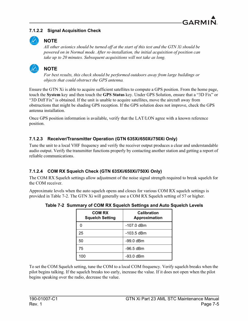
190-01007-C1 GTN Xi Part 23 AML STC Maintenance ManualRev. 1 Page 7-5
7.1.2.2 Signal Acquisition Check
NOTEAll other avionics should be turned off at the start of this test and the GTN Xi should be powered on in Normal mode. After re-installation, the initial acquisition of position can take up to 20 minutes. Subsequent acquisitions will not take as long.
NOTEFor best results, this check should be performed outdoors away from large buildings or objects that could obstruct the GPS antenna.
Ensure the GTN Xi is able to acquire sufficient satellites to compute a GPS position. From the home page, touch the System key and then touch the GPS Status key. Under GPS Solution, ensure that a “3D Fix” or “3D Diff Fix” is obtained. If the unit is unable to acquire satellites, move the aircraft away from obstructions that might be shading GPS reception. If the GPS solution does not improve, check the GPS antenna installation.
Once GPS position information is available, verify that the LAT/LON agree with a known reference position.
7.1.2.3 Receiver/Transmitter Operation (GTN 635Xi/650Xi/750Xi Only)Tune the unit to a local VHF frequency and verify the receiver output produces a clear and understandable audio output. Verify the transmitter functions properly by contacting another station and getting a report of reliable communications.
7.1.2.4 COM RX Squelch Check (GTN 635Xi/650Xi/750Xi Only)The COM RX Squelch settings allow adjustment of the noise signal strength required to break squelch for the COM receiver.
Approximate levels when the auto squelch opens and closes for various COM RX squelch settings is provided in Table 7-2. The GTN Xi will generally use a COM RX Squelch setting of 57 or higher.
Table 7-2 Summary of COM RX Squelch Settings and Auto Squelch Levels
To set the COM Squelch setting, tune the COM to a local COM frequency. Verify squelch breaks when the pilot begins talking. If the squelch breaks too early, increase the value. If it does not open when the pilot begins speaking over the radio, decrease the value.
COM RX Squelch Setting
Calibration Approximation
0 -107.0 dBm
25 -103.5 dBm
50 -99.0 dBm
75 -96.5 dBm
100 -93.0 dBm

190-01007-C1 GTN Xi Part 23 AML STC Maintenance ManualRev. 1 Page 7-6
COM Carrier Squelch Check (COM Software v2.30 or Later)COM carrier squelch settings allow adjustment of the carrier signal strength required to break squelch for the COM receiver.
The COM carrier squelch level adjustment reduces the sensitivity of the COM receiver. Elevated, ambient RF interference levels in certain flight environments, such as aircraft operating busy airport environments or aircraft with equipment installed that interferes with the COM radio, may require adjustment of the COM carrier squelch to reduce undesired squelch breaks.
Table 7-3 COM Carrier Squelch Selections
Table 7-4 lists approximate levels when the carrier squelch opens for various COM Carrier Squelch settings. Installations requiring adjustment generally use a COM carrier squelch setting of 33 or higher for 25 kHz spacing and 0 for 8.33 kHz spacing.
Table 7-4 COM Carrier Squelch Selections
Notes:[1] The COM carrier squelch range (0-100) is a linear response.
Selection Description
Basic Applies a COM carrier squelch value of 0 to 25 kHz and 8.33 kHz spacing.
Advanced Allows the adjustment of COM carrier squelch values.
Spacing Allows the adjustment of COM carrier squelch values for 25 kHz and 8.33 kHz spacing separately.
SquelchThe COM carrier squelch is adjustable in the range of 0 to 100. The default value is 0. Decreasing the value allows the carrier squelch to be broken with low signal levels. Increasing the value requires higher signal levels to break carrier squelch.
COM RF Squelch Setting [1]
Carrier Squelch Open Approximation
0 -87.0 dBm
25 -84.5 dBm
50 -82.0 dBm
75 -79.5 dBm
100 -77.0 dBm

190-01007-C1 GTN Xi Part 23 AML STC Maintenance ManualRev. 1 Page 7-7
7.2 GMA 35The following steps must be performed when replacing a GMA 35 Audio Panel:
1. Configure audio panel per Section 7.2.1.2. Perform ground check per Section 7.2.2.
7.2.1 GMA 35 Audio Panel Configuration (GTN 7XX Xi Only)In Configuration mode, touch the External Systems key followed by the Audio Panel key. The Audio Panel page will be displayed. Touch the Configure key to access configuration settings for audio routing, volume, and miscellaneous options. Touch Back to return to the Audio Panel page.
Touch the Connected Radios key to set the status (Present or Not Present) of COM 2, COM 3, NAV 1, NAV 2, RCVR 3, RCVR 4, RCVR 5, TEL, Music 1, Music 2, and Marker Beacon. Touch Back to return to the Audio Panel page.
Review the GMA 35 Audio Panel configuration settings on the GTN Xi and compare them against the GTN Xi Configuration Log. A copy of the GTN Xi Configuration Log form may be found in Appendix A of this document. If any of the settings differ from the log, update the settings to the correct value. For information regarding individual settings, refer to GTN Xi Part 23 AML STC Installation Manual.
7.2.2 GMA 35 Audio Panel Checkout (GTN 7XX Xi Only)
NOTEIn the following procedural steps, allow for variation in the configuration settings for the particular installation under test.
7.2.2.1 GMA 35 Interface Check (GTN 7XX Xi Only)1. With the GTN Xi and GMA 35 powered on, ensure that a red “X” is not displayed over the Audio
Panel key on the home page.2. Touch the Audio Panel key.
After configuring the audio panel, an in-aircraft checkout may be performed with a good microphone, headset, speaker, and avionics receivers. For testing the marker beacon, use a ramp tester that transmits a 75 MHz marker beacon test signal.
For instructions on how to operate the GMA 35 in Normal mode during checkout procedures, refer to GTN Xi Series Pilot’s Guide.
7.2.2.2 GMA 35c Bluetooth Audio CheckWhile on the ground, power on the GTN 7XX Xi and GMA 35c. A compatible Bluetooth-capable device is required.
NOTETo verify telephone audio, a Bluetooth-compatible phone is required.
1. Navigate to the GMA 35c page by touching System → Connext Setup → GMA 35c.2. Ensure Bluetooth is enabled.

190-01007-C1 GTN Xi Part 23 AML STC Maintenance ManualRev. 1 Page 7-8
3. On the PED, view the list of available Bluetooth devices.4. Select the device that matches the Bluetooth name shown on the GTN Xi screen.5. Verify the PED is paired with the GTN Xi. A green check mark is displayed by the paired device.6. Touch Intercom on the GTN Xi.7. Touch Bluetooth Audio and set distribution to Pilot, Co-pilot, and Passenger.8. Touch Radio to mute Bluetooth during radio transmissions.9. Touch Intercom to mute Bluetooth during intercom transmissions.10. Verify audio from PED is distributed to the selected positions.11. Tune and monitor a COM frequency to ensure communications over the radio are easily heard
over the audio.
NOTEIf different values are used for the telephone and audio volume settings, repeat this procedure while making a call from a Bluetooth-compatible phone.
12. Adjust the Bluetooth volume as necessary.
7.2.2.3 Failsafe Operation Check1. Power off the GMA 35 by opening the audio panel circuit breaker. 2. Check the failsafe operation by exercising the COM 1 microphone, microphone key, and audio
over the pilot’s headphones.
NOTEUse of a true mono headset is required for this test to ensure proper wiring, even if a stereo jack is provided in the installation. Wiring left channel (tip contact) and right channel (ring contact) backwards will cause Failsafe mode not to function with mono headsets. Use of a true mono headset is required for this test (not a stereo headset with a mono/stereo switch because headset manufactures differ on how they accomplish this switching). This will guarantee the condition of the right channel (ring terminal) being shorted to the return (sleeve terminal) by the mono headset’s plug. During power-on operation, this short will not damage the audio panel.
3. Verify that COM 1 can key and transmit the pilot’s mic audio by verifying received sidetone or checking reception of the transmission with another radio tuned to receive this transmission (verify Pilot PTT and mic operation is delivered to this transceiver).
4. Turn the unit back on to continue testing.
NOTEIf the configuration setting COM 1 is Connected as COM 2 is set to True, then the COM 2 microphone should be exercised rather than COM 1.
190-01007-C1 GTN Xi Part 23 AML STC Maintenance ManualRev. 1 Page 7-9
7.2.2.4 COM Transceiver Operational Check1. Connect a headset to the pilot’s headset output and mic input jack. 2. Verify that each installed transceiver (COM) can be heard when selected.
NOTEDepending on configuration settings, the mic selected COM may mute audio from other COMs.
3. Verify that each installed transceiver keys for transmission and transmits clear audio from the pilot’s mic when selected for transmission and the pilot PTT key is pressed. Verifying transmission with a separate radio that is not in the system is recommended because the audio panel can be configured to simulate received sidetone internally.
NOTEDepending on configuration settings, other transceivers may be muted during transmit. The audio panel may mute the speaker during PTT.
4. Move the headset to the co-pilot’s headset jacks and verify that any one of the installed transceivers (testing each is not necessary) receives and transmits copilot mic properly as above.
7.2.2.5 NAV Audio CheckEnsure the GMA 35 and each installed NAV receiver is powered on.
1. Tune the NAV receiver to a local VOR station. 2. Ensure the Morse code identifier is being received over the crew headsets. 3. If the audio is not heard, verify the wiring to the audio panel. 4. Ensure the audio volume is sufficient for all anticipated cockpit noise conditions.
Repeat steps for each installed NAV receiver.
7.2.2.6 Alert Audio CheckIf there is an alert audio source connected to the GMA 35, the interface should be verified as described below:
1. Cause the alert audio source to produce audio (e.g., if a traffic system is installed, command the traffic system into Self-Test mode; if a TAWS system is installed, command the TAWS system into Self-Test mode).
2. Verify that the alert audio source is heard in the pilot and co-pilot headsets and that the audio volume is sufficient for all anticipated cockpit noise conditions. Adjust the audio volume level as needed. For modification of configuration settings, refer to GTN Xi Part 23 AML STC Installation Manual.
3. If the alert audio source is not heard in the crew headsets, check the wiring from the source to the GMA 35 alert audio inputs.
Repeat steps for each alert audio source connected to the GMA 35.

190-01007-C1 GTN Xi Part 23 AML STC Maintenance ManualRev. 1 Page 7-10
7.2.2.7 Receiver Audio CheckIf there are receiver audio sources connected to the GMA 35, the interface should be verified as described below. Ensure the GMA 35, as well as each interfaced receiver (e.g., DME, ADF, etc.), is powered on.
1. Plug in a headset at pilot and co-pilot position. 2. Tune the installed receiver to a valid station. 3. Ensure audio is being received over the crew headsets. 4. Ensure the audio volume is sufficient for all anticipated cockpit noise conditions. Adjust the audio
output level as needed at the receiver.
Repeat steps 2 through 4 for each installed receiver.
7.2.2.8 Intercom System (ICS) Check
NOTEIf a mono headset is plugged into a stereo phone jack position, damage will not occur to the GMA 35. If a passenger plugs a mono headset in any passenger position, stereo listeners will lose one channel.
1. Place the audio panel into ALL ICS mode (refer to GTN Xi Series Pilot’s Guide) so that all ICS positions hear all others.
2. De-select or turn off other audio sources (e.g., MKR, transceivers, receivers, alerts). Some configurations may mute passenger intercom audio to crew when aircraft audio is present.
3. From the pilot headset position, verify the pilot, co-pilot, and all passenger mic inputs can be heard in the pilot’s headset when speaking into the mic input under test (adjust pilot ICS volume, if necessary).
4. Speak into the pilot’s mic and verify that pilot mic audio is heard in the co-pilot headset (adjust co-pilot ICS volume, if necessary) and in each passenger headset (adjust passenger ICS volume, if necessary).
7.2.2.9 Music System Check (If Installed)1. Set the intercom to the ALL mode. 2. Connect a stereo audio source to MUSIC 1 or MUSIC 2. Verify that stereo audio is heard over the
pilot headset position. 3. Tune a station on COM 1 and verify that the sound is muted by active COM 1 audio (break squelch
on COM 1, if necessary). 4. Verify that stereo audio is heard in the passenger headsets.

190-01007-C1 GTN Xi Part 23 AML STC Maintenance ManualRev. 1 Page 7-11
7.3 Interfaced EquipmentThis manual does not cover the removal/replacement of the following interfaced equipment. However, the following procedures are required to ensure proper functionality with the interfaced equipment. Perform the following calibration procedures and interface checks after re-installing or replacing any of the optionally interfaced equipment.
7.3.1 Navigation Indicator1. Perform calibration per Section 7.3.1.1.1.1 (if using GPS) or Section 7.3.1.1.2.1 (GTN 650/750
only) if using VOR/LOC/GS receiver.2. Perform ground checks per Section 7.3.1.2 and the appropriate interface check.
7.3.1.1 Navigation Indicator Calibration7.3.1.1.1 Main Indicator (Analog) Configuration PageIn Configuration mode, select the Main Indicator (Analog) Configuration page from the GTN Setup page. This page allows you to calibrate the OBS resolver, configure the CDI key, selected course for GPS and VLOC, as well as the V-Flag state. Configurable fields are described in the following sections.
7.3.1.1.1.1 Main Indicator OBS Resolver Calibration To calibrate the OBS resolver from the Main Indicator (Analog) Configuration page:
1. Touch the Calibrate key on the under Calibrate OBS Resolver. 2. Select 150˚ on the External CDI/HSI, then touch the OK key, as prompted on the display. 3. After the OBS resolver has completed calibrating, the GTN Xi will display, “OBS Resolver
Calibration Complete!” Touch OK after the calibration is complete. 4. Verify OBS operation by checking that the selected course displayed at the top of the page is
within 2° of the selected course.
The Main Indicator (Analog) Configuration page allows the CDI connected to the NAV board (P1001) to be ground checked and allows the NAV indicator interface to be verified. Refer to Section 7.3.1.2.1 for the ground check.
7.3.1.1.2 VOR/LOC/GS Configuration Page (GTN 650Xi/750Xi Only)Select the VOR/LOC/GS key on the GTN Setup page. This page allows you to verify the CDI outputs from the VOR/LOC/GS receiver as well as the OBS resolver input to the VOR receiver. It allows you to select the format for the DME tuning data.
7.3.1.1.2.1 Calibrate OBS ResolverTo calibrate the OBS resolver from the VOR/LOC/GS Configuration page:
1. Touch the Calibrate key from the under Calibrate OBS Resolver. 2. Select 150˚ on the external CDI/HSI, then touch the OK key when prompted by the display. 3. Touch OK after calibration is complete. 4. Verify OBS operation by checking that the selected course displayed at the top of the page is
within 2° of the selected course.

190-01007-C1 GTN Xi Part 23 AML STC Maintenance ManualRev. 1 Page 7-12
7.3.1.2 Navigation Indicator Ground Checks (Configuration Mode)7.3.1.2.1 Main Indicator Check (Analog Only)
NOTEIf the GTN Xi is interfaced to an electronic HSI/EFIS, and the main indicator analog output is not used, this check is not required.
NOTETo verify if the indicator is interfaced with the GTN Xi on the main connector (P1001), examine the response of the indicator during the GTN Xi self-test upon power-up. If the indicator responds according to the values described on the screen, then it is connected to the main connector.
If the GTN Xi is interfaced to an analog indicator on the main connector (P1001), perform the following steps in Configuration mode. Refer to Section 3.2.2.
1. From the Configuration Mode home page, touch the GTN Diagnostics key.2. Touch the Main Indicator (Analog) key. 3. Verify correct operation of the lateral deviation, flag, and TO/FROM flag using the corresponding
selections. 4. Verify correct operation of the vertical deviation and flag using the corresponding selections. 5. Verify correct operation of the OBS knob using the OBS Resolver Setting display.
a. At 30° increments around the OBS card, ensure that the indicated value is within 2° of the value set on the indicator.
b. If the resolver is not within 2°, calibrate the resolver as described in Section 7.3.1.1.1.1.
7.3.1.2.2 VOR/LOC/GS IndicatorIf the GTN Xi is interfaced to an analog indicator on the VOR/ILS connector (P1004), perform the following steps:
1. From the Configuration mode home page, touch the GTN Diagnostics key. 2. Touch the VOR/ILS Indicator (Analog) key. 3. Verify correct operation of the lateral deviation, flag, and TO/FROM flag using the corresponding
selections. 4. Verify correct operation of the vertical deviation and flag using the corresponding selections.5. Verify correct operation of the OBS knob using the Selected Course display.
a. At 30° increments around the OBS card, ensure that the indicated value is within 2° of the value set on the indicator.
b. If the resolver is not within 2°, calibrate the resolver as described in Section 7.3.1.1.2.1.

190-01007-C1 GTN Xi Part 23 AML STC Maintenance ManualRev. 1 Page 7-13
7.3.2 Serial Tuned DME7.3.2.1 Serial Tuned DME ConfigurationOn the VOR/LOC/GS Configuration page, set the DME mode and DME Channel mode to the values specified in the configuration log. Configuration of these settings is required if exchanging GTN 650Xi/750Xi units, but is not required if replacing a DME with an equivalent unit.
7.3.2.2 Interface Check (GTN 650Xi/750Xi Only)Verify the interface performing the following steps:
1. Select a VOR/ILS channel that corresponds to (1) a DME station within a 40 nautical mile range or (2) the frequency of a DME ground tester.
2. Verify that the DME locks on to the signal and a valid distance is displayed. 3. Tune an invalid VOR station. Verify that the DME data is flagged. 4. If multiple GTN Xi units are set up to remotely channel a DME, repeat steps 1-3 using the other
GTN Xi.
7.3.3 DisplaysPerform the appropriate interface check for the replaced EHSI, EFIS, PFD, or MFD. No additional configuration on the GTN Xi is required when replacing a display with an equivalent unit.
7.3.3.1 Honeywell (Bendix/King) EFS 40/50 Interface CheckIf a Honeywell EFS 40/50 has been connected to the GTN Xi, the interface should be verified as described in this section.
1. Cycle power to GTN Xi #1 and acknowledge the prompts until the Instrument Panel Self-Test page is displayed (refer to Section 6.1.1).
2. Ensure that GPS1 data displays by pressing the 1-2 key on the EFS 40/50 control panel. 3. While the GTN Xi displays the Instrument Panel Self-Test page, verify that the EFS 40/50
displays data from the GPS source: Course Deviation: Half-scale left deviation, TO indication, flag pulled Active Waypoint: GARMN Vertical Deviation: Half-scale up deviation (only if installation is setup to display GPS vertical
deviation) 4. On the GTN Xi, verify that an OBS value displays and is not dashed out. 5. Using a VOR test set, verify that the CDI deviation on the EFS 40/50 displays correctly. 6. Cycle power to GTN Xi #2 and acknowledge the prompts until on the Instrument Panel Self-Test
page. 7. If a second GTN Xi is installed, switch to GPS2 data by pressing the 1-2 key on the EFS 40/50
control panel and repeat steps 3 through 5 with GTN Xi #2.

190-01007-C1 GTN Xi Part 23 AML STC Maintenance ManualRev. 1 Page 7-14
7.3.3.2 Sandel SN3308 Interface CheckIf a Sandel EHSI has been connected to the GTN Xi, the interface should be verified as described in one of the following sections, as appropriate for the installation.
7.3.3.2.1 Single GTN Xi/Single SN33081. Cycle power to the GTN Xi and acknowledge the prompts until on the Instrument Panel Self-Test
page (refer to Section 6.1.1). 2. Ensure that the SN3308 receives valid heading.
NOTEThe Vertical Deviation Indication will not be displayed unless the SN3308 is receiving valid heading.
3. While the GTN Xi is displaying the Instrument Panel Self-Test page, verify that the SN3308 displays the following data from the GPS source: Course Deviation: Half-scale left deviation, TO indication, flag pulled Vertical Deviation: Half-scale up deviation, flag pulled Active Waypoint: GARMN
4. On the GTN Xi, verify that an OBS value displays and is not dashed out. 5. Acknowledge the self-test on the GTN Xi by touching the Continue key. 6. Select VLOC on the GTN Xi and verify that the SN3308 displays NAV 1 or NAV 2 (depending on
the GTN Xi navigation source configuration). 7. Using a VOR test set, verify that the CDI deviation on the SN3308 displays correctly.
7.3.3.2.2 Dual GTN Xi Units/Single SN33081. Remove power from GTN Xi #2 by opening up the circuit breaker. 2. Cycle power to GTN Xi #1 and acknowledge the prompts until on the Instrument Panel Self-Test
page (refer to Section 6.1.1). 3. Select GPS1 as the navigation source by pressing the NAV key on the SN3308. Verify that “GPS1”
displays on the SN3308. 4. Ensure that the SN3308 receives valid heading. The Vertical Deviation Indication will not display
unless the SN3308 receives valid heading.5. While GTN Xi #1 displays the Instrument Panel Self-Test page, verify that the SN3308 displays
the following data from GPS1: Course Deviation: Half-scale left deviation, TO indication, flag pulled Vertical Deviation: Half-scale up deviation, flag pulled Active Waypoint: GARMN
6. On GTN Xi #1, verify that an OBS value displays and is not dashed out. 7. Acknowledge the self-test on GTN Xi #1 by touching the Continue key. 8. Select VLOC on GTN Xi #1 and verify that the SN3308 displays “NAV 1” or “NAV 2” depending
on which navigation source the GTN Xi is. 9. Using a VOR test set, verify that the CDI deviation on the SN3308 displays correctly.

190-01007-C1 GTN Xi Part 23 AML STC Maintenance ManualRev. 1 Page 7-15
10. Remove power from GTN Xi #1 and apply power to GTN Xi #2. Acknowledge the prompts until the Instrument Panel Self-Test page displays. Refer to Section 6.1.1. Select GPS2 by pressing the NAV key on the SN3308.
11. Repeat steps 5 through 9 with GTN Xi #2.
7.3.3.2.3 Dual GTN Xi Units/Dual SN3308s1. Remove power from GTN Xi #2. 2. Cycle power to GTN Xi #1 and acknowledge the prompts until on the Instrument Panel Self- Test
page (refer to Section 6.1.1). Select GPS1 as the navigation source by pressing the NAV key on the SN3308 #1. Verify that “GPS1” displays on the SN3308.
3. Ensure that the SN3308 receives valid heading. The Vertical Deviation Indication will not display unless the SN3308 receives valid heading.
4. While GTN Xi #1 displays the Instrument Panel Self-Test page, verify that the SN3308 displays the following data from GPS1: Course Deviation: Half-scale left deviation, TO indication, flag pulled Vertical Deviation: Half-scale up deviation, flag pulled Active Waypoint: GARMN
5. On GTN Xi #1, verify that an OBS value displays and is not dashed out. 6. Acknowledge the self-test on GTN Xi #1 by touching the Continue key. 7. Select VLOC on GTN Xi #1 and verify that the SN3308 displays “NAV 1” or “NAV 2” depending
on which navigation source the GTN Xi is. 8. Using a VOR test set, verify that the CDI deviation on the SN3308 displays correctly. 9. Remove power from GTN Xi #1 and apply power to GTN Xi #2. Acknowledge the prompts until
the Instrument Panel Self-Test page displays (refer to Section 6.1.1). 10. Select GPS2 by pressing the NAV key on the SN3308. 11. Repeat steps 4 through 8 with GTN Xi #2.
Perform the same procedure for the second SN3308. Ensure that SN3308 #2 receives valid heading by ensuring the vertical deviation indication displays.

190-01007-C1 GTN Xi Part 23 AML STC Maintenance ManualRev. 1 Page 7-16
7.3.3.3 Sandel SN3500/4500 Interface CheckIf a Sandel SN3500/4500 EHSI has been connected to the GTN Xi, the interface should be verified as described in this section.
1. Cycle power to the GTN Xi and acknowledge the prompts until on the Instrument Panel Self-Test page (refer to Section 6.1.1).
2. Ensure that the SN3500/4500 receives valid heading. The Vertical Deviation Indication will not display unless the SN3500/4500 is receiving valid heading.
3. While the GTN Xi displays the Instrument Panel Self-Test page, verify that the SN3500/4500 displays data from the GPS source: Course Deviation: Half-scale left deviation, TO indication, flag pulled Vertical Deviation: Half-scale up deviation, flag pulled Active Waypoint: GARMN
4. On the GTN Xi, verify that an OBS value displays and is not dashed out. 5. Acknowledge the self-test on the GTN Xi by touching the Continue key. 6. Select VLOC on the GTN Xi and verify that the SN3500/4500 displays “NAV 1” or “NAV 2”
depending on which navigation source the GTN xi is. 7. Ensure that the NAV1 (or NAV2) indication does not have a red line through it. 8. Repeat steps 3 through 7 for GTN Xi #2, if installed.
7.3.3.4 EHSI Deviation Scaling for HSI/CDI Driven by GTN through ARINC 429 DataIf the GTN Xi has a serial connection to an EFIS display, proper scaling of the EFIS CDI and VDI must be verified.
1. Cycle power to the GTN Xi and acknowledge the prompts until on the Instrument Panel Self-Test page (refer to Section 6.1.1).
2. With the Instrument Panel Self-Test page displayed on the GTN Xi, look on the EHSI/EFIS and verify that the lateral deviation is half-scale left and not flagged.
3. With the Instrument Panel Self-Test page displayed on the GTN Xi, look on the EHSI/EFIS and verify that the vertical deviation is half-scale up and not flagged.
7.3.3.5 GMX200/MX20 Interface CheckThe Garmin GMX 200 or MX20 interface should be verified as described in this section.
1. Ensure that the GTN Xi has a 3-D position fix. 2. Create and activate a flight plan on the GTN Xi by touching the Direct-To key and entering a
waypoint. 3. Verify that the RTE and POS data flags does not display on the GMX 200/MX20. 4. Verify that the flight plan displays on the GMX 200/MX20 using the flight plan (FPL) function.

190-01007-C1 GTN Xi Part 23 AML STC Maintenance ManualRev. 1 Page 7-17
7.3.4 Transponder1. For remote transponders, configure transponder per Section 7.3.4.1.2. Perform interface check per Section 7.3.4.2.
7.3.4.1 Remote Transponder ConfigurationA remote transponder can be configured by the GTN Xi through RS-232 if a transponder is configured for one of the RS-232 ports. To configure the transponder, it must first be selected as Present and the type of transponder installed must be specified. To do this, access the Interfaced Equipment page on the GTN Setup page. Next, go to the External Systems page and touch the XPDR key. This displays the XPDR( ) page, which allows the remote transponder to be configured. The remote transponder should be configured in accordance with the installation manual for that specific transponder.
NOTEIf the GTN Xi controls any transponder (GTX 3XX/3XXR), then that transponder will boot into the same mode (Normal or Configuration) as the GTN Xi.
NOTEIf the GTN Xi is not communicating with the GTX transponder, all of the editable fields for the setup items shown in the following sections will be dashed out. If the fields are dashed out, check the wiring and pin connections from the GTN Xi to the transponder.
NOTEThe GTX 335R/345R must be configured through the GTX 3X5 Install Tool. Refer to GTX 3X5 TSO Installation Manual for more information.
NOTEThe GTN Xi can interface to the GTX 3XX; however, configuration of the panel-mounted GTX 3XX is not supported. These transponders should be configured per their installation manuals rather than through the GTN Xi.
7.3.4.2 Transponder Interface CheckIf the GTN Xi is interfaced to a GTX 32/33/3X5R remote transponder, or a GTX 3XX configured as a remote transponder, the following checks must be completed:
1. With the GTN Xi in Normal mode, and the transponder powered on, go to the home page and ensure there is not a red “X” over the transponder data field on the screen.
2. Check that a code can be entered into the Code field. Enter a code using the keypad and then touch the Enter key. Check that the code that was entered is displayed in the Transponder Data field.
3. If dual transponders are installed, select Transponder 2 and perform steps 1 and 2 for the second transponder as well.
4. To verify wiring is not crossed, open the Transponder 1 circuit breaker and verify the Transponder 1 data field has a red “X”.
5. Repeat the steps 1 through 3 for GTN Xi #2.

190-01007-C1 GTN Xi Part 23 AML STC Maintenance ManualRev. 1 Page 7-18
7.3.5 Traffic or Weather SystemPerform the appropriate interface check for the traffic or weather system. Additional GTN Xi configuration steps are not required for replacing a traffic or weather device with an equivalent unit.
7.3.5.1 Ryan TCAD Traffic System Interface CheckIf a Ryan TCAD has been connected to the GTN Xi, the traffic interface should be verified as described in this section.
1. Navigate to the Traffic page on the GTN Xi from the home page.2. Verify that “NO DATA” is not displayed in yellow in the center of the Traffic page.3. Using the SHIELD SETUP under the Traffic menu, verify that the shield mode can be changed.
7.3.5.2 ARINC 429 Traffic System Interface CheckIf a Garmin GTS 8XX Traffic system, L-3 Communications SKY497/SKY899 SkyWatch® sensor, or a Honeywell (Bendix/King) KTA 810 TAS/KMH 820 IHAS has been connected to the GTN Xi through ARINC 429, the traffic interface should be verified as described in this section.
1. Navigate to the Traffic page on the GTN Xi from the home page.2. Verify that “NO DATA” is not displayed in yellow in the center of the Traffic page.3. If the GTN Xi is configured to control the traffic system, verify that the traffic system mode can be
changed from STBY to OPER.4. Switch the traffic system mode to STBY, and then run the traffic self-test from the menu.5. Verify that the traffic system executes a self-test and that a self-test pattern is displayed on the
GTN Xi traffic display.6. Restart the GTN Xi in Configuration mode.7. On the Traffic page in the External Systems page group, verify that there is data displayed in the
Altitude field.
7.3.5.3 Stormscope® Interface CheckIf an L-3 Communications WX-500 Stormscope has been connected to the GTN Xi, the Stormscope interface should be verified as described in this section.
1. Navigate to the Lightning page on the GTN Xi.2. Verify that “STORMSCOPE FAILED” is not displayed in yellow in the center of the Lightning
page.3. Verify that the Stormscope mode can be changed from Strike to Cell, and vice versa.

190-01007-C1 GTN Xi Part 23 AML STC Maintenance ManualRev. 1 Page 7-19
7.3.5.4 TIS (Garmin GTX 33X) Interface CheckIf a Garmin GTX 33/33D/330/330D/335/335D/335R/335DR transponder has been connected to the GTN Xi as a TIS traffic source, the traffic interface should be verified as described in this section.
1. Navigate to the Traffic page from the GTN Xi home page.2. Verify that “TIS FAIL” is not displayed in the upper-left corner under Traffic Status, and that “NO
DATA” (yellow) is not displayed over the ownship symbol.3. In the upper-left corner of the Traffic page, verify that the status of the traffic system is either “TIS
Standby” or “TIS Operating/Unavailable” (i.e., “TAS” should not be displayed).
The following additional steps should only be completed if the GTN Xi is controlling the traffic system:1. Open the transponder circuit breaker and verify the Air Data fields have a red “X”.2. If a squat switch (or airspeed switch) is connected to the GTX 33X, ensure that it is in AIR mode.3. Alternately, touch the Standby key and Operate key to change the mode of the traffic system. It
may take several seconds for the traffic system to change modes.4. Verify that the mode of the traffic system can be changed.
7.3.5.5 GTX 345 Interface CheckWhen testing the GTX 345/345D/345R/345DR, the aircraft must be located outside and have an unobstructed view of the sky. If the GTX is installed and connected to the GTN Xi as the ADS-B In source, check the operation as follows:
1. With the GTN Xi in Normal mode, and the transponder powered on, press the System key from the home page.
2. Press the External LRUs key and make sure that the status for the GTX is a green checkmark.3. Press the More Info key for the GTX and make sure that the GPS status and software versions are
reported.4. Repeated the preceding steps for GTN Xi #2.

190-01007-C1 GTN Xi Part 23 AML STC Maintenance ManualRev. 1 Page 7-20
7.3.6 Weather RadarPerform the appropriate interface check for the weather radar. No additional GTN Xi configuration steps are required for replacing a weather radar with an equivalent unit.
7.3.6.1 GWX 68/70/75 Weather Radar Interface CheckThis section verifies that the interface between the GTN 7XX Xi and the GWX 68/70/75 weather radar is functional.
1. Power on the GTN Xi in Normal mode.2. On the home page, touch the Weather key and then the Radar key.3. Touch the Mode key and select Standby mode and wait for the warm-up to complete.4. Touch the Mode key again and select Test mode.5. Verify that the GWX 68/70/75 begins sweeping and the test pattern is shown.6. If supported by the installation, verify that stabilization is on (“STAB On” is displayed in the
upper-right corner of the radar display).7. Touch the Mode key, set the mode to Off.8. Repeat steps 1 through 7 for the second GTN 7XX Xi, if installed.
7.3.6.2 ARINC 708 Weather Radar Interface CheckThis section verifies that the interface between the GTN 7XX Xi and ARINC 708 weather radar is functional.
WARNINGAircraft should be outdoors and personnel should not be in front of the weather radar when it is radiating (i.e., when Weather or Ground mode is selected on the GTN Xi).
1. Power on the GTN Xi in Normal mode. If there are dual GTN 7XX Xi units, power on both in Normal mode.
2. On each GTN Xi, touch Weather from the home page and then Radar.3. On GTN Xi #1, touch the Mode key and select Standby Mode and wait for the warm-up to
complete.4. Touch the Mode key again and select Test Mode.5. Verify that the radar begins sweeping and the test pattern is shown.6. If stabilization is supplied to the radar, turn the radar to Weather mode and turn stabilization on in
the weather menu. Verify that “STAB On” is displayed in the upper-right corner or the radar display. If “STAB INOP” is displayed, verify that stabilization is being supplied to the weather radar R/T.
7. Touch the Mode key to set the mode to Off.
NOTEIf only one GTN 7XX Xi is installed, the following steps do not have to be carried out.
8. Repeat steps 1 through 7 for GTN Xi #2.

190-01007-C1 GTN Xi Part 23 AML STC Maintenance ManualRev. 1 Page 7-21
9. On each GTN Xi, touch the Mode key and select Standby mode and wait for the warm-up to complete.
10. On each GTN Xi, touch the Mode key again and select Test mode.11. On GTN Xi #1, touch the Zoom Out key to increase the range of the radar display. Verify that the
range on GTN Xi #1 changes and the range on GTN Xi #2 does not change.12. On GTN Xi #2, touch the Zoom Out key to increase the range of the radar display. Select a
different zoom level than GTN Xi #1. Verify that the range on GTN Xi #2 changes and the range on GTN Xi #1 does not change.
13. On each GTN Xi, use the Mode key to set the mode to Off.
7.3.7 GDL 88When testing the GDL 88, the aircraft must be located outside and have an unobstructed view of the sky. If the GDL 88 is installed and connected to the GTN Xi, perform the following steps. No additional configuration steps are required when replacing the GDL 88 with an equivalent unit.
1. Power on all GTN Xi units in Configuration mode as described in Section 3.2.2. 2. Touch the External Systems key.3. Touch the GDL 88 key.4. Touch Diagnostics and then the GPS/SBAS Data key. 5. Verify that the GDL 88 is receiving valid position source data. 6. Verify that the status of the External PPS connection(s) is valid.
7.3.8 Fan Interface CheckThe fan that is mounted to the GTN Xi backplate should be checked after replacing the fan. With the GTN Xi powered on in Normal mode and the fan powered on and running, navigate to the home page and touch the Message Queue key. Ensure that the “COOLING FAN- the cooling fan has failed” message is not displayed. Note that the fan may take a few minutes to power on if the unit is below normal operating temperature.
7.3.9 Flight Stream 210/510 Interface Checks7.3.9.1 Bluetooth SetupWhen the Flight Stream 210 device is powered on or the Flight Stream 510 inserted in the data card slot, pairing mode will not be enabled until the Connext Setup page is opened on the GTN Xi.
The default Flight Stream 210/510 Bluetooth name is “Flight Stream” followed by the three-digit model number (i.e., “210” or “510”) and then the last four digits of the MAC address (e.g., Flight Stream 210 4000). A pop-up will appear on the GTN Xi screen asking for confirmation of the new Bluetooth pairing. Select Yes to finish pairing the device.
Bluetooth setup only needs to be run when pairing with a device for the first time. Once a connection is established with a Bluetooth device, the Flight Stream 210/510 will automatically connect to the Bluetooth device upon power-up. The Flight Stream may be connected to up to four Bluetooth devices simultaneously. The Flight Stream 210/510 will also save up to thirteen Bluetooth device pairings.
1. Enable Bluetooth connectivity on the PED. Once enabled, Flight Stream 210/510 will be viewable in the list of available devices.

190-01007-C1 GTN Xi Part 23 AML STC Maintenance ManualRev. 1 Page 7-22
2. Select the Flight Stream 210/510 from the list of available Bluetooth devices on the PED.
After pairing the Flight Stream 210/510 with the PED, make sure the device is communicating with the GTN Xi, GDL 88 (if installed), and GDL 69A (if installed). This test should be performed outside, away from buildings and large obstructions. If any of the tests below are unsuccessful, refer to Section 6 for troubleshooting information.
7.3.9.2 Flight Stream 210 Interface Checks:GTN Xi Interface Check
1. On the Garmin Pilot application, navigate to the Flight Plan page and create a flight plan. 2. Select the Connext icon at the top of the page. 3. Next select the option to send the flight plan to the GTN Xi. If successful, a message will be
available on the GTN Xi.
GDL 88 Interface Check (If Installed) 1. Navigate to the Traffic page on the GTN Xi. 2. Navigate to the Traffic page on the Garmin Pilot application. 3. On the GTN Xi Traffic page, touch the Menu key. 4. Touch the Test key. If the Test key is unavailable, ADS-B Status must be turned off first. 5. Make sure the traffic targets are displayed on the PED.
GDL 69/69A Interface Check (If Installed) 1. On the Garmin Pilot application, navigate to the Connext page. 2. Select SiriusXM under Status and make sure weather data is available.
7.3.9.3 Flight Stream 510 Interface Checks:GTN Xi Interface Check
1. On the Garmin Pilot application, navigate to the Flight Plan page and create a flight plan. 2. Select the Connext icon at the top of the page. 3. Next, select the option to send the flight plan to the GTN Xi. If successful, a message will be
available on the GTN Xi.

190-01007-C1 GTN Xi Part 23 AML STC Maintenance ManualRev. 1 Page 7-23
7.4 Enabled Features Refer to Section 3.2.4 for guidance on enabling features.
7.4.1 Terrain Configuration and Checks (For Units with Terrain Alerting/TAWS Only)Reconfigure terrain settings per the configuration checkout log. The terrain configuration settings are located under the GTN Options menu.
7.4.1.1 Terrain System Check While on the ground, power on the GTN Xi following normal power-up procedures. Power on the audio panel.
NOTEA 3D GPS position fix is required to conduct the check.
1. Navigate to the Terrain page from the Normal mode home page. 2. Touch the Menu key. 3. Touch the Test Terrain or Test TAWS key. 4. Wait until the Terrain Alerting/TAWS self-test completes (10-15 seconds) to hear the Terrain/
TAWS system status aural message. The aural message “Terrain System Test OK” or “TAWS System Test OK” will be annunciated
if the Terrain/TAWS system is functioning properly The aural message “Terrain System Failure” or “TAWS System Failure” will be annunciated if
the Terrain/TAWS system is NOT functioning properly. “Terrain Fail” or “TAWS FAIL” will appear in amber on the screen
If no audio message is heard, then a fault exists within the audio system or associated wiring and the Terrain/TAWS capability must be considered non-functional. Verify continuity of wiring from GTN Xi to audio panel as specified in GTN Xi Part 23 AMC STC Installation Manual (P/N 190-01007-C0).
7.5 Configuration ModuleUpon replacing a configuration module with a new configuration module unit, no further action is required. Installation of a used configuration module is not recommended.

190-01007-C1 GTN Xi Part 23 AML STC Maintenance ManualRev. 1 Page 8-1
8 RETURN TO SERVICE PROCEDURE
8.1 Maintenance RecordsAfter conducting required return to service procedures in accordance with Table 7-1 and updating aircraft records in accordance with this section and in compliance with 14 CFR 43.9 and 14 CFR 91.417, the aircraft may be returned to service.
Record the following information in the appropriate aircraft maintenance logs: Software versions loaded during maintenance Part and serial numbers of any LRU replaced Any other applicable information related to the maintenance work performed on the aircraft
Verify that replacement LRUs’ software and/or FPGA versions match those in the configuration log from Appendix A in the aircraft records.

190-01007-C1 GTN Xi Part 23 AML STC Maintenance ManualRev. 1 Page A-1
APPENDIX A AIRCRAFT-SPECIFIC INFORMATION
Acrobat Reader 8.0 or later is necessary to view and fill out the form. You can download Acrobat Reader by visiting www.adobe.com.
When updating software, it is unnecessary to fill out a new configuration log. Fill out the applicable pages and append them to the back of the existing configuration log.

GENERAL INFORMATION
Date: / / By:
AIRCRAFT:
AIRCRAFT MAKE:
AIRCRAFT MODEL:
AIRCRAFT SERIAL #:
AIRCRAFT REG. #:
Mod Level:
Serial #:
GTN Xi #1:
Unit P/N:
Unit Model:
GPS Antenna P/N #: GPS Antenna Model:
Mod Level:
Serial #:
GTN Xi #2: [N/A]
Unit P/N:
Unit Model:
GPS Antenna P/N #: GPS Antenna Model:
Mod Level:
GMA 35: [N/A]
Unit P/N:
Unit Model: Serial #:
Mod Level:
FLIGHT STREAM: [N/A]
Unit P/N:
Unit Model: Serial #:
190-01007-C1Rev. 1
GTN Xi Part 23 AML STC Maintenance ManualPage A-2

GTN Xi PART 23 CONFIGURATION LOG – GTN Xi #1SYSTEM INFORMATION
GTN Xi SOFTWARE VERSIONS
Boot Code: FPGA:
Boot Code:
Boot Code: FPGA:
Main BoardSoftware:
Touch Controller Board Software:
GPS/WAAS Board Software:
NAV Board [N/A] Software:
COM Board [N/A] Software: Boot Code: FPGA:
GTN SETUP MENU
ARINC 429 CONFIGURATION
In 1: High Low Out 1: High Low
In 2: High Low Out 2: High Low
In 3: High Low Out 3: High Low
In 4: High Low SDI: Common LNAV 1 LNAV 2
RS-232 CONFIGURATION
In 1: Out 1:
In 2: Out 2:
In 3: Out 3:
In 4: Out 4:
In 5: Out 5:
In 6: Out 6:
190-01007-C1Rev. 1
GTN Xi Part 23 AML STC Maintenance ManualPage A-3
MORE RS-232 SETUP
Forward ALT to GTX Enabled Disabled
This setting is only available if a transponder is configured on a RS-232 port.

GTN Xi PART 23 CONFIGURATION LOG – GTN Xi #1 - CONTINUEDGTN SETUP MENU - CONTINUED
HSDB (ETHERNET) CONFIGURATION Port 1: Connected Not Connected Port 3: Connected Not Connected
Port 2: Connected Not Connected Port 4: Connected Not Connected
INTERFACED EQUIPMENT CONFIGURATIONCross-Side Navigator:
GDL 69/69A: GDL 88/88D:
ADS-B In Source: GDU #1: GDU #2: GDU #3:GDU #4:
Transponder #1: Transponder #2:
GSR 56: GWX:
Present Not Present Type:
Present Not Present Type:
Present Not Present Type:
Present Not Present Type:
Present Not Present Type:
Present Not Present Type:
Present Not Present Type:
Present Not Present Type:
Present Not Present Type:
Present Not Present Type:
Present Not Present
Present Not Present Type:
MAIN INDICATOR (ANALOG) CONFIGURATIONCDI Key: Enabled Disabled
Selected Course for GPS: Allowed Ignored
Selected Course for VLOC: Allowed Ignored
V-Flag State: Normal Declutter
LIGHTING CONFIGURATION (IF ENHANCED LIGHTING IS DISABLED)Lighting Configuration: [N/A]
Display Source: Photocell Lighting Bus 1 Keys Source: Photocell Lighting Bus 1 Lighting Bus 2
Display Minimum Level: % Keys Minimum Level: %
Configure Photocell: [N/A]
Response Time: sec Slope: Offset:
Photocell Override
Key Backlight Cutoff: % Photocell Transition:
Configure Lighting Bus: [N/A]
Lighting Bus 1: 14 VDC 28 VDC 5 VDC 5VAC
Response Time: sec Slope: Offset:
Lighting Bus 2: [N/A] 14 VDC 28 VDC 5 VDC 5VAC
Response Time: sec Slope: Offset:
190-01007-C1Rev. 1
GTN Xi Part 23 AML STC Maintenance ManualPage A-4
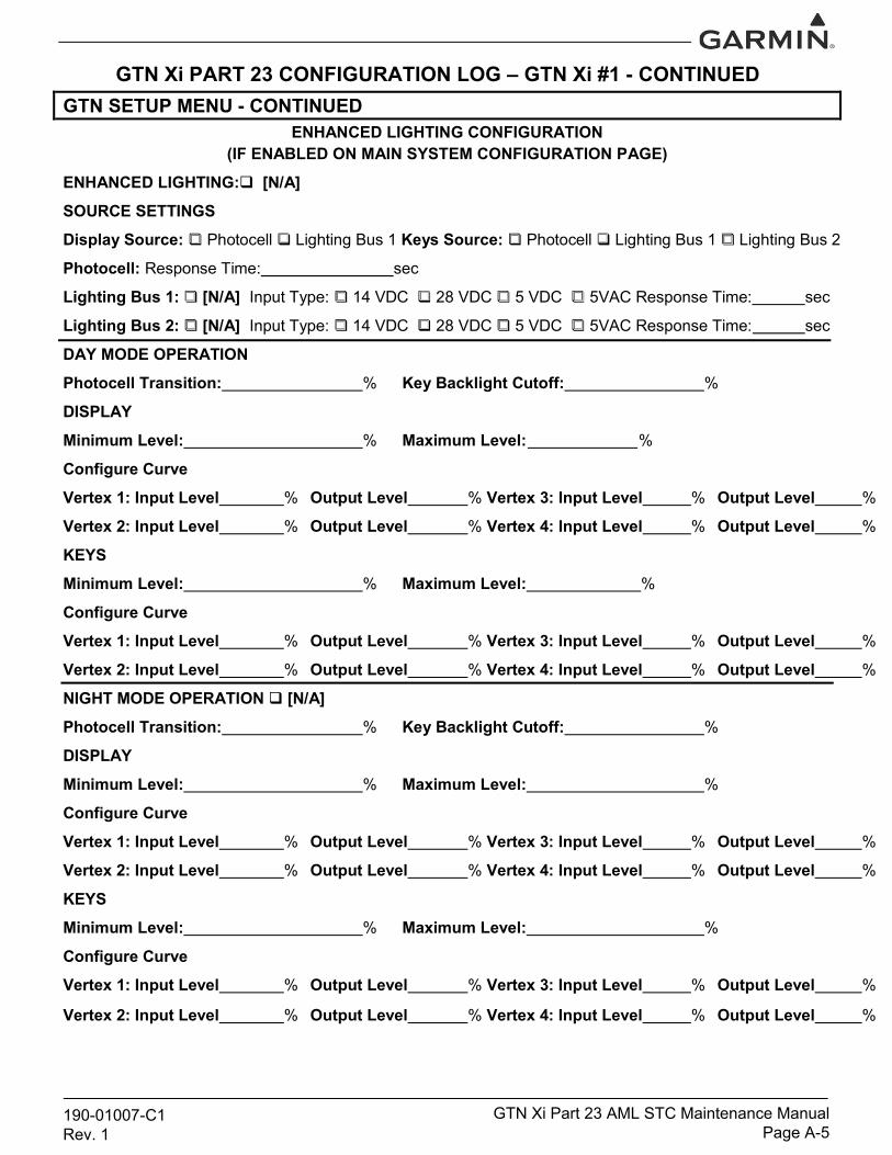
GTN Xi PART 23 CONFIGURATION LOG – GTN Xi #1 - CONTINUEDGTN SETUP MENU - CONTINUED
ENHANCED LIGHTING CONFIGURATION(IF ENABLED ON MAIN SYSTEM CONFIGURATION PAGE)
ENHANCED LIGHTING:[N/A]
SOURCE SETTINGS
Display Source: Photocell Lighting Bus 1 Keys Source: Photocell Lighting Bus 1 Lighting Bus 2
Photocell: Response Time: sec
Lighting Bus 1: [N/A] Input Type: 14 VDC 28 VDC 5 VDC 5VAC Response Time: sec
Lighting Bus 2: [N/A] Input Type: 14 VDC 28 VDC 5 VDC 5VAC Response Time: sec
DAY MODE OPERATION
Photocell Transition: % Key Backlight Cutoff: %
DISPLAY
Minimum Level: % Maximum Level: %
Configure Curve
Vertex 1: Input Level % Output Level % Vertex 3: Input Level % Output Level %
Vertex 2: Input Level % Output Level % Vertex 4: Input Level % Output Level %
KEYS
Minimum Level: % Maximum Level: %
Configure Curve
Vertex 1: Input Level % Output Level % Vertex 3: Input Level % Output Level %
Vertex 2: Input Level % Output Level % Vertex 4: Input Level % Output Level %
NIGHT MODE OPERATION [N/A]
Photocell Transition: % Key Backlight Cutoff: %
DISPLAY
Minimum Level: % Maximum Level: %
Configure Curve
Vertex 1: Input Level % Output Level % Vertex 3: Input Level % Output Level %
Vertex 2: Input Level % Output Level % Vertex 4: Input Level % Output Level %
KEYS
Minimum Level: % Maximum Level: %
Configure Curve
Vertex 1: Input Level % Output Level % Vertex 3: Input Level % Output Level %
Vertex 2: Input Level % Output Level % Vertex 4: Input Level % Output Level %
190-01007-C1Rev. 1
GTN Xi Part 23 AML STC Maintenance ManualPage A-5

GTN Xi PART 23 CONFIGURATION LOG – GTN Xi #1 - CONTINUED GTN SETUP MENU - CONTINUED
AUDIO CONFIGURATION Alert Volume Level: %
VOICE COMMAND CONFIGURATION Voice Commands: “Say…” Commands:
TRAFFIC CONFIGURATIONTraffic Intruder Symbol Color: Cyan White GTN Control of Traffic System: Yes No
MAIN SYSTEM CONFIGURATION
Heading Source Input: Connected Not Connected
Radio Altimeter Input: Connected ( Radio Altimeter not approved under this STC)
Not Connected
Airframe Type: Fixed-Wing Rotorcraft
Air/Ground Threshold: KT
Air/Ground Discrete: Active for Airborne Active for Ground
GPS Antenna Height Above Ground:______FT
Fuel Type: AV Gas Jet A Jet B
Enhanced Lighting Mode: Enabled Disabled
Pilot Position: Right Left
Synchro Heading Input: Connected Not Connected
GPS Select: Auto Prompt
Crossfill Status Alert: Enabled Disabled (Crossfill Status Alert not approved under this STC)
System ID: GTN 1 GTN 2
Database SYNC: Pilot Control Enabled Disabled
Airspace Labels: Enabled Disabled
Checklist Page Title: Checklist Task List
Blackout Mode: Enabled Disabled
External Flight Plan: Enabled Disabled
Remote Database Confirmation: Enabled Disabled
COM CONFIGURATION (GTN 635Xi/650Xi/750Xi ONLY)
VOR/LOC/GS CONFIGURATION (GTN 650Xi/750Xi ONLY)
Enabled Disabled DME Mode: Standby Directed Freq. 1 Directed Freq. 2
High LowDME Channel Mode:
NAV Radio: ARINC 429 TX Speed:
ARINC 429 SDI: Common VOR/ILS 1 VOR/ILS 2
190-01007-C1Rev. 1
GTN Xi Part 23 AML STC Maintenance ManualPage A-6
Off On Mute Tone: Off Off On
COM Radio: Enabled Disabled RX Squelch Mode: Basic Advanced
Spacing Squelch
COM RX Squelch: %MIC 1 Gain: dB
Sidetone Source: External Internal
Sidetone Volume: dB
Sidetone Pilot Control: Enabled Disabled
TCAS Display Output: Select TCAS ControllerRange Set:
Format 1 Format 2
Altitude Source Input: Connected Not Connected
Filtered LOC/GS: Enabled Disabled(Filtered LOC/GS is not approved under this STC)
NAV Radio Display Timeout: Enabled Disabled

GTN Xi PART 23 CONFIGURATION LOG – GTN Xi #1 - CONTINUED GTN SETUP MENU - CONTINUED
DISCRETES CONFIGURATION
J1001-16: J1001-52: VLOC Annunciate
J1001-36: J1001-53:
J1001-37: J1001-54:
J1001-38: J1001-55:
J1001-39: J1001-56: ILS/GPS Approach Annunciate
J1001-57:
J1001-71:
J1001-72:
J1001-73:
J1001-74:
J1001-75:
J1002-76:
J1002-03:
J1002-12:
J1005-13*:
J1005-34*:
J1002-01: Demo Mode Select
J1002-10:
J1002-11:
J1005-33*: Synchro Valid - Low
J1005-53*:
J1005-54*: Synchro Valid - High
J1001-14:
J1001-15: GPS Annunciate
J1001-33:
J1001-34:
J1001-35:
*Available only on GTN 725Xi/750Xi units.
NAVIGATION FEATURESMark on Target: (Mark on Target not approved under this STC)
Enabled Disabled
RF Procedure Legs: Enabled Disabled
OWNSHIP CONFIGURATION Ownship Configuration: __________________________________________________ (Selection of ownship color magenta is not covered under this STC)
190-01007-C1Rev. 1
GTN Xi Part 23 AML STC Maintenance ManualPage A-7
ARINC 453/708 CONFIGURATIONPort 1: External Weather Radar: Off On
VERTICAL NAVIGATION
Vertical Navigation Type: VCALC VNAV
Transition to Approach: Enabled Disabled
Transition Altitude:
VDI Scale: 500 FT 1000 FT
FLIGHT STREAMStream Active Flight Data: Enabled Disabled Transfer Past FD Logs: Enabled Disabled
Device:

GTN Xi PART 23 CONFIGURATION LOG – GTN Xi #1 - CONTINUED GTN OPTIONS MENU TERRAIN CONFIGURATIONTerrain Mode: Terrain Proximity TAWS A TAWS B Terrain Alerting (TAWS A is not approved under this STC)
TAWS Audio Clips
FT
Terrain Alert Settings
Runway Surface: Any Hard Only Hard/Soft Water
Minimum Runway Length:
Alert Voice: Female Male
190-01007-C1Rev. 1
GTN Xi Part 23 AML STC Maintenance ManualPage A-8
NCR Caution: "Don't Sink"
"Too Low Terrain"
EDR Caution: "Sink Rate"
PDA Caution: "Too Low Terrain"
IOI Caution: "Obstacle Ahead" x2
"Caution Obstacle" x2
ROC Caution: "Obstacle Ahead" x2
"Caution Obstacle" x2
ILI Caution: "Wire Ahead" x2
"Caution Wire" x2
RLC Caution: "Wire Ahead" x2
"Caution Wire" x2
ITI Caution: "Terrain Ahead" x2
"Caution Terrain" x2
RTC Caution: "Terrain Ahead" x2
"Caution Terrain" x2
IOI Warning: "Obstacle Ahead Pull Up" x2
"Obstacle" x2 "Pull Up" x2
ROC Warning: "Obstacle Ahead Pull Up" x2
"Obstacle" x2 "Pull Up" x2
ILI Warning: "Wire Ahead Pull Up" x2
"Wire" x2 "Pull Up" x2
RLC Warning: "Wire Ahead Pull Up" x2
"Wire" x2 "Pull Up" x2
ITI Warning: "Terrain Ahead Pull Up" x2
"Terrain" x2 "Pull Up" x2
RTC Warning: "Terrain Ahead Pull Up" x2
"Terrain" x2 "Pull Up" x2
EDR Warning: "Pull Up"
500 FT: "Five Hundred"
CHARTSCharts Configured: None FliteCharts ChartView
COM TRANSMIT POWERCom Transmit Power: Normal 16W

GTN Xi PART 23 CONFIGURATION LOG – GTN Xi #1 – CONTINUEDGTN OPTIONS MENU - CONTINUED
WEATHER RADARDigital Radar:
Turbulence Detection:
Ground Clutter Suppression:
N/A Enabled
N/A Enabled
N/A Enabled
SEARCH AND RESCUE Search and Rescue: N/A Enabled
SAR PatternsParallel Track: N/A Enabled
Sector Search: N/A Enabled
Expanding Square: N/A Enabled
Orbit: N/A Enabled
190-01007-C1Rev. 1
GTN Xi Part 23 AML STC Maintenance ManualPage A-9
FLIGHT SIMULATORFlight Simulator: N/A Enabled

NOTES
GTN Xi PART 23 CONFIGURATION LOG – GTN Xi #1 – CONTINUED
190-01007-C1Rev. 1
GTN Xi Part 23 AML STC Maintenance ManualPage A-10

GTN Xi PART 23 CONFIGURATION LOG – GTN Xi #2SYSTEM INFORMATION
GTN Xi SOFTWARE VERSIONS
Boot Code: FPGA:
Boot Code:
Boot Code: FPGA:
Main BoardSoftware:
Touch Controller Board Software:
GPS/WAAS Board Software:
NAV Board [N/A] Software:
COM Board [N/A] Software: Boot Code: FPGA:
GTN SETUP MENU
ARINC 429 CONFIGURATION
In 1: High Low Out 1: High Low
In 2: High Low Out 2: High Low
In 3: High Low Out 3: High Low
In 4: High Low SDI: Common LNAV 1 LNAV 2
RS-232 CONFIGURATION
In 1: Out 1:
In 2: Out 2:
In 3: Out 3:
In 4: Out 4:
In 5: Out 5:
In 6: Out 6:
190-01007-C1Rev. 1
GTN Xi Part 23 AML STC Maintenance Manual Page A-11
MORE RS-232 SETUP
Forward ALT to GTX Enabled Disabled
This setting is only available if a transponder is configured on a RS-232 port.

GTN Xi PART 23 CONFIGURATION LOG – GTN Xi #2 - CONTINUEDGTN SETUP MENU - CONTINUED
HSDB (ETHERNET) CONFIGURATION Port 1: Connected Not Connected Port 3: Connected Not Connected
Port 2: Connected Not Connected Port 4: Connected Not Connected
INTERFACED EQUIPMENT CONFIGURATIONCross-Side Navigator:
GDL 69/69A: GDL 88/88D:
ADS-B In Source: GDU #1: GDU #2: GDU #3:GDU #4:
Transponder #1: Transponder #2:
GSR 56: GWX:
Present Not Present Type:
Present Not Present Type:
Present Not Present Type:
Present Not Present Type:
Present Not Present Type:
Present Not Present Type:
Present Not Present Type:
Present Not Present Type:
Present Not Present Type:
Present Not Present Type:
Present Not Present
Present Not Present Type:
MAIN INDICATOR (ANALOG) CONFIGURATIONCDI Key: Enabled Disabled
Selected Course for GPS: Allowed Ignored
Selected Course for VLOC: Allowed Ignored
V-Flag State: Normal Declutter
LIGHTING CONFIGURATION (IF ENHANCED LIGHTING IS DISABLED)Lighting Configuration: [N/A]
Display Source: Photocell Lighting Bus 1 Keys Source: Photocell Lighting Bus 1 Lighting Bus 2
Display Minimum Level: % Keys Minimum Level: %
Configure Photocell: [N/A]
Response Time: sec Slope: Offset:
Photocell Override
Key Backlight Cutoff: % Photocell Transition:
Configure Lighting Bus: [N/A]
Lighting Bus 1: 14 VDC 28 VDC 5 VDC 5VAC
Response Time: sec Slope: Offset:
Lighting Bus 2: [N/A] 14 VDC 28 VDC 5 VDC 5VAC
Response Time: sec Slope: Offset:
190-01007-C1Rev. 1
GTN Xi Part 23 AML STC Maintenance Manual Page A-12

GTN Xi PART 23 CONFIGURATION LOG – GTN Xi #2 - CONTINUEDGTN SETUP MENU - CONTINUED
ENHANCED LIGHTING CONFIGURATION(IF ENABLED ON MAIN SYSTEM CONFIGURATION PAGE)
ENHANCED LIGHTING:[N/A]
SOURCE SETTINGS
Display Source: Photocell Lighting Bus 1 Keys Source: Photocell Lighting Bus 1 Lighting Bus 2
Photocell: Response Time: sec
Lighting Bus 1: [N/A] Input Type: 14 VDC 28 VDC 5 VDC 5VAC Response Time: sec
Lighting Bus 2: [N/A] Input Type: 14 VDC 28 VDC 5 VDC 5VAC Response Time: sec
DAY MODE OPERATION
Photocell Transition: % Key Backlight Cutoff: %
DISPLAY
Minimum Level: % Maximum Level: %
Configure Curve
Vertex 1: Input Level % Output Level % Vertex 3: Input Level % Output Level %
Vertex 2: Input Level % Output Level % Vertex 4: Input Level % Output Level %
KEYS
Minimum Level: % Maximum Level: %
Configure Curve
Vertex 1: Input Level % Output Level % Vertex 3: Input Level % Output Level %
Vertex 2: Input Level % Output Level % Vertex 4: Input Level % Output Level %
NIGHT MODE OPERATION [N/A]
Photocell Transition: % Key Backlight Cutoff: %
DISPLAY
Minimum Level: % Maximum Level: %
Configure Curve
Vertex 1: Input Level % Output Level % Vertex 3: Input Level % Output Level %
Vertex 2: Input Level % Output Level % Vertex 4: Input Level % Output Level %
KEYS
Minimum Level: % Maximum Level: %
Configure Curve
Vertex 1: Input Level % Output Level % Vertex 3: Input Level % Output Level %
Vertex 2: Input Level % Output Level % Vertex 4: Input Level % Output Level %
190-01007-C1Rev. 1
GTN Xi Part 23 AML STC Maintenance Manual Page A-13

GTN Xi PART 23 CONFIGURATION LOG – GTN Xi #2 - CONTINUED GTN SETUP MENU - CONTINUED
AUDIO CONFIGURATION Alert Volume Level: %
VOICE COMMAND CONFIGURATION Voice Commands: “Say…” Commands:
TRAFFIC CONFIGURATIONTraffic Intruder Symbol Color: Cyan White GTN Control of Traffic System: Yes No
MAIN SYSTEM CONFIGURATION
Heading Source Input: Connected Not Connected
Radio Altimeter Input: Connected ( Radio Altimeter not approved under this STC)
Not Connected
Airframe Type: Fixed-Wing Rotorcraft
Air/Ground Threshold: KT
Air/Ground Discrete: Active for Airborne Active for Ground
GPS Antenna Height Above Ground:______FT
Fuel Type: AV Gas Jet A Jet B
Enhanced Lighting Mode: Enabled Disabled
Pilot Position: Right Left
Synchro Heading Input: Connected Not Connected
GPS Select: Auto Prompt
Crossfill Status Alert: Enabled Disabled (Crossfill Status Alert not approved under this STC)
System ID: GTN 1 GTN 2
Database SYNC: Pilot Control Enabled Disabled
Airspace Labels: Enabled Disabled
Checklist Page Title: Checklist Task List
Blackout Mode: Enabled Disabled
External Flight Plan: Enabled Disabled
Remote Database Confirmation: Enabled Disabled
COM CONFIGURATION (GTN 635Xi/650Xi/750Xi ONLY)
VOR/LOC/GS CONFIGURATION (GTN 650Xi/750Xi ONLY)
Enabled Disabled DME Mode: Standby Directed Freq. 1 Directed Freq. 2
High LowDME Channel Mode:
NAV Radio: ARINC 429 TX Speed:
ARINC 429 SDI: Common VOR/ILS 1 VOR/ILS 2
190-01007-C1Rev. 1
GTN Xi Part 23 AML STC Maintenance Manual Page A-14
Off On Mute Tone: Off Off On
COM Radio: Enabled Disabled RX Squelch Mode: Basic Advanced
Spacing Squelch
COM RX Squelch: %MIC 1 Gain: dB
Sidetone Source: External Internal
Sidetone Volume: dB
Sidetone Pilot Control: Enabled Disabled
TCAS Display Output: Select TCAS ControllerRange Set:
Format 1 Format 2
Altitude Source Input: Connected Not Connected
Filtered LOC/GS: Enabled Disabled(Filtered LOC/GS not approved under this STC)
NAV Radio Display Timeout: Enabled Disabled

GTN Xi PART 23 CONFIGURATION LOG – GTN Xi #2 - CONTINUED GTN SETUP MENU - CONTINUED
DISCRETES CONFIGURATION
J1001-16: J1001-52: VLOC Annunciate
J1001-36: J1001-53:
J1001-37: J1001-54:
J1001-38: J1001-55:
J1001-39: J1001-56: ILS/GPS Approach Annunciate
J1001-57:
J1001-71:
J1001-72:
J1001-73:
J1001-74:
J1001-75:
J1002-76:
J1002-03:
J1002-12:
J1005-13*:
J1005-34*:
J1002-01: Demo Mode Select
J1002-10:
J1002-11:
J1005-33*: Synchro Valid - Low
J1005-53*:
J1005-54*: Synchro Valid - High
J1001-14:
J1001-15: GPS Annunciate
J1001-33:
J1001-34:
J1001-35:
*Available only on GTN 725Xi/750Xi units.
NAVIGATION FEATURESMark on Target: (Mark on Target not approved under this STC)
Enabled Disabled
RF Procedure Legs: Enabled Disabled
OWNSHIP CONFIGURATION Ownship Configuration: __________________________________________________ (Selection of ownship color magenta is not covered under this STC)
190-01007-C1Rev. 1
GTN Xi Part 23 AML STC Maintenance Manual Page A-15
ARINC 453/708 CONFIGURATIONPort 1: External Weather Radar: Off On
VERTICAL NAVIGATION
Vertical Navigation Type: VCALC VNAV
Transition to Approach: Enabled Disabled
Transition Altitude:
VDI Scale: 500 FT 1000 FT
FLIGHT STREAMStream Active Flight Data: Enabled Disabled Transfer Past FD Logs: Enabled Disabled
Device:

GTN Xi PART 23 CONFIGURATION LOG – GTN Xi #2 - CONTINUED GTN OPTIONS MENU TERRAIN CONFIGURATIONTerrain Mode: Terrain Proximity TAWS A TAWS B Terrain Alerting (TAWS A is not approved under this STC)
TAWS Audio Clips
FT
Terrain Alert Settings
Runway Surface: Any Hard Only Hard/Soft Water
Minimum Runway Length:
Alert Voice: Female Male
190-01007-C1Rev. 1
GTN Xi Part 23 AML STC Maintenance Manual Page A-16
NCR Caution: "Don't Sink"
"Too Low Terrain"
EDR Caution: "Sink Rate"
PDA Caution: "Too Low Terrain"
IOI Caution: "Obstacle Ahead" x2
"Caution Obstacle" x2
ROC Caution: "Obstacle Ahead" x2
"Caution Obstacle" x2
ILI Caution: "Wire Ahead" x2
"Caution Wire" x2
RLC Caution: "Wire Ahead" x2
"Caution Wire" x2
ITI Caution: "Terrain Ahead" x2
"Caution Terrain" x2
RTC Caution: "Terrain Ahead" x2
"Caution Terrain" x2
IOI Warning: "Obstacle Ahead Pull Up" x2
"Obstacle" x2 "Pull Up" x2
ROC Warning: "Obstacle Ahead Pull Up" x2
"Obstacle" x2 "Pull Up" x2
ILI Warning: "Wire Ahead Pull Up" x2
"Wire" x2 "Pull Up" x2
RLC Warning: "Wire Ahead Pull Up" x2
"Wire" x2 "Pull Up" x2
ITI Warning: "Terrain Ahead Pull Up" x2
"Terrain" x2 "Pull Up" x2
RTC Warning: "Terrain Ahead Pull Up" x2
"Terrain" x2 "Pull Up" x2
EDR Warning: "Pull Up"
500 FT: "Five Hundred"
CHARTSCharts Configured: None FliteCharts ChartView
COM TRANSMIT POWERCom Transmit Power: Normal 16W

GTN Xi PART 23 CONFIGURATION LOG – GTN Xi #2 – CONTINUEDGTN OPTIONS MENU - CONTINUED
WEATHER RADARDigital Radar:
Turbulence Detection:
Ground Clutter Suppression:
N/A Enabled
N/A Enabled
N/A Enabled
SEARCH AND RESCUE Search and Rescue: N/A Enabled
SAR PatternsParallel Track: N/A Enabled
Sector Search: N/A Enabled
Expanding Square: N/A Enabled
Orbit: N/A Enabled
190-01007-C1Rev. 1
GTN Xi Part 23 AML STC Maintenance Manual Page A-17
FLIGHT SIMULATORFlight Simulator: N/A Enabled

NOTES
GTN Xi PART 23 CONFIGURATION LOG – GTN Xi #2 – CONTINUED
190-01007-C1Rev. 1
GTN Xi Part 23 AML STC Maintenance Manual Page A-18
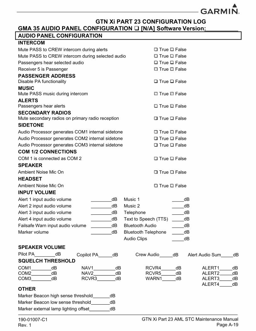
GTN Xi PART 23 CONFIGURATION LOGGMA 35 AUDIO PANEL CONFIGURATION [N/A] Software Version: AUDIO PANEL CONFIGURATION
True FalseTrue FalseTrue FalseTrue False
True False
True False
True False
True False
True FalseTrue FalseTrue False
True False
True False
True False
INTERCOMMute PASS to CREW intercom during alerts Mute PASS to CREW intercom during selected audio Passengers hear selected audio Receiver 5 is Passenger PASSENGER ADDRESSDisable PA functionality MUSICMute PASS music during intercom ALERTSPassengers hear alerts SECONDARY RADIOSMute secondary radios on primary radio reception SIDETONEAudio Processor generates COM1 internal sidetone Audio Processor generates COM2 internal sidetone Audio Processor generates COM3 internal sidetone COM 1/2 CONNECTIONSCOM 1 is connected as COM 2 SPEAKERAmbient Noise Mic On HEADSETAmbient Noise Mic On INPUT VOLUME
dB dB dB dB dB dB dB dB dB dB dB
Music 1 Music 2 TelephoneText to Speech (TTS)Bluetooth Audio Bluetooth Telephone Audio Clips
dB
dB Copilot PA dB Alert Audio Sum dB
Alert 1 input audio volume Alert 2 input audio volume Alert 3 input audio volume Alert 4 input audio volume Failsafe Warn input audio volume Marker volume
SPEAKER VOLUMEPilot PA dB Crew Audio SQUELCH THRESHOLDCOM1 dB NAV1 dB RCVR4 dB ALERT1 dB COM2 dB NAV2 dB RCVR5 dB ALERT2 dB COM3 dB RCVR3 dB WARN1 dB ALERT3 dB
ALERT4 dB OTHERMarker Beacon high sense threshold dB Marker Beacon low sense threshold dB Marker external lamp lighting offset dB
190-01007-C1Rev. 1
GTN Xi Part 23 AML STC Maintenance Manual Page A-19
dB

GTN Xi PART 23 CONFIGURATION LOG
GMA 35 AUDIO PANEL CONFIGURATION – CONTINUED AUDIO PANEL DISCRETESJ3501-16:
J3502-14:
J3502-30:
AUDIO PANEL CONNECTED RADIOS
COM 2: Present Not Present
COM 3: Present Not Present
NAV 1: Present Not Present
NAV 2: Present Not Present
RCVR 3: Present Not Present Type:
RCVR 4: Present Not Present Type:
RCVR 5: Present Not Present Type:
TEL: Present Not Present
MUSIC 1: Present Not Present
MUSIC 2: Present Not Present
MARKER BEACON: Present Not Present
190-01007-C1Rev. 1
GTN Xi Part 23 AML STC Maintenance Manual Page A-20

Wire RoutingSingle EngineThe following diagram depicts approximate location of all LRUs and antenna(s) along with the wire routing for
the GTN Xi, GMA 35, and Flight Stream 210 throughout the aircraft structure for a single-engine aircraft.
190-01007-C1Rev. 1
GTN Xi Part 23 AML STC Maintenance Manual Page A-21
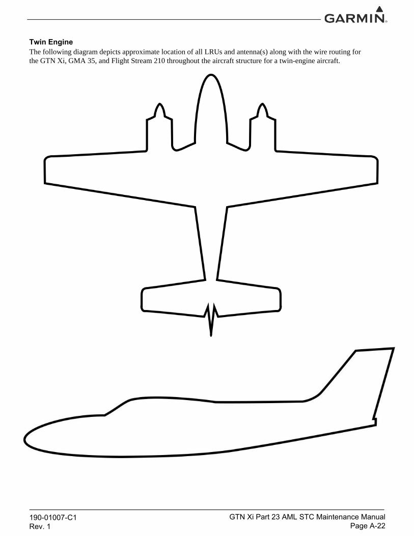
Twin EngineThe following diagram depicts approximate location of all LRUs and antenna(s) along with the wire routing for
the GTN Xi, GMA 35, and Flight Stream 210 throughout the aircraft structure for a twin-engine aircraft.
190-01007-C1Rev. 1
GTN Xi Part 23 AML STC Maintenance Manual Page A-22

Aircraft Wiring DiagramsAttach the aircraft wiring diagrams showing the equipment installed by this STC or a markup of the interconnect
diagrams from the STC installation manual detailing which equipment was installed and how it was connected.
NOTE
Electrical loads for equipment installed by this STC are listed in GTN Xi Part 23 AML STC
Installation Manual.
Check all that apply and add a brief description of the
location.
SPLITTER
Included in Installation: Yes No
Description of Location:
DIPLEXER
Included in Installation: Yes No
Description of Location:
190-01007-C1Rev. 1
GTN Xi Part 23 AML STC Maintenance Manual Page A-23

Equipment Interfaced to the GTN XiThe purpose of the GTN Xi Interfaced Equipment Lists (GTN Xi #1 and GTN Xi #2 (if applicable)) is to document the
equipment that is interfaced to the GTN Xi. Use the following guidance when filling out these tables:
Installed?: Check “Yes” if the equipment is installed in the aircraft and interfaced to the GTN Xi. If the
equipment is not installed in the aircraft, check “No.” If the equipment is installed in the aircraft but not
interfaced to the GTN Xi, check “No.”
Model(s): Enter the model number or numbers of the equipment that is interfaced to the GTN Xi.
Interface(s): Enter the type of interface used to connect to the GTN Xi.
GTN Port Numbers: When applicable, enter the GTN Xi port number or numbers used for the interface. This
column is generally applicable only to serial ports such as RS-232 and ARINC 429.
Covered by GTN Xi Part 23 AML STC Installation Manual?: Refer to Section 3. Check “Yes” if the
equipment is listed in Appendix C of GTN Xi Part 23 AML STC Installation Manual. Check “No” if the
equipment is not listed in Appendix C of GTN Xi Part 23 AML STC Installation Manual.
NOTE
This information is optional and is not required to be completed or maintained with the aircraft
records.
190-01007-C1Rev. 1
GTN Xi Part 23 AML STC Maintenance Manual Page A-24

GTN Xi #1 Interfaced Equipment ListEquipment Type
COM Antenna NAV AntennaInstalled: Yes No Installed: Yes No
AUDIO PANEL
Installed: Yes No
Model(s):
Interface(s) (Analog, RS-232, ARINC 429, etc.):
GTN Xi Port Number(s) (if applicable):
Covered by GTN Xi STC Installation Manual? Yes No
AIR DATA COMPUTER(S)
Installed: Yes No
Model(s):
Interface(s) (Analog, RS-232, ARINC 429, etc.):
GTN Xi Port Number(s) (if applicable):
Covered by GTN Xi STC Installation Manual? Yes No
ALTITUDE SERIALIZER OR FUEL/AIR DATA
Installed: Yes No
Model(s):
Interface(s) (Analog, RS-232, ARINC 429, etc.):
GTN Xi Port Number(s) (if applicable):
Covered by GTN Xi STC Installation Manual? Yes No
AUTOPILOT
Installed: Yes No
Model(s):
Interface(s) (Analog, RS-232, ARINC 429, etc.):
GTN Xi Port Number(s) (if applicable):
Covered by GTN Xi STC Installation Manual? Yes No
190-01007-C1Rev. 1
GTN Xi Part 23 AML STC Maintenance Manual Page A-25

GTN Xi #1 Interfaced Equipment List - CONTINUED
AUTOPILOT ROLL STEERING CONVERTER
Installed: Yes No
Model(s):
Interface(s) (Analog, RS-232, ARINC 429, etc.):
GTN Xi Port Number(s) (if applicable):
Covered by GTN Xi STC Installation Manual? Yes No
EFIS DISPLAY(S)
Installed: Yes No
Model(s):
Interface(s) (Analog, RS-232, ARINC 429, etc.):
GTN Xi Port Number(s) (if applicable):
Covered by GTN Xi STC Installation Manual? Yes No
EHSI(S)
Installed: Yes No
Model(s):
Interface(s) (Analog, RS-232, ARINC 429, etc.):
GTN Xi Port Number(s) (if applicable):
Covered by GTN Xi STC Installation Manual? Yes No
GSR 56
Installed: Yes No
Model(s):
Interface(s) (Analog, RS-232, ARINC 429, etc.):
GTN Xi Port Number(s) (if applicable):
Covered by GTN Xi STC Installation Manual? Yes No
190-01007-C1Rev. 1
GTN Xi Part 23 AML STC Maintenance Manual Page A-26

GTN Xi #1 Interfaced Equipment List - CONTINUED
GDL 88
Installed: Yes No
Model(s):
Interface(s) (Analog, RS-232, ARINC 429, etc.):
GTN Xi Port Number(s) (if applicable):
Covered by GTN Xi STC Installation Manual? Yes No
IRU/AHRS UNIT(S)
Installed: Yes No
Model(s):
Interface(s) (Analog, RS-232, ARINC 429, etc.):
GTN Xi Port Number(s) (if applicable):
Covered by GTN Xi STC Installation Manual? Yes No
TRANSPONDER(S)
Installed: Yes No
Model(s):
Interface(s) (Analog, RS-232, ARINC 429, etc.):
GTN Xi Port Number(s) (if applicable):
Covered by GTN Xi STC Installation Manual? Yes No
NAV INDICATORS
Installed: Yes No
Model(s):
Interface(s) (Analog, RS-232, ARINC 429, etc.):
GTN Xi Port Number(s) (if applicable):
Covered by GTN Xi STC Installation Manual? Yes No
190-01007-C1Rev. 1
GTN Xi Part 23 AML STC Maintenance Manual Page A-27

GTN Xi #1 Interfaced Equipment List - CONTINUED
TRAFFIC SOURCE
Installed: Yes No
Model(s):
Interface(s) (Analog, RS-232, ARINC 429, etc.):
GTN Xi Port Number(s) (if applicable):
Covered by GTN Xi STC Installation Manual? Yes No
TAWS (EXTERNAL TO GTN Xi)
Installed: Yes No
Model(s):
Interface(s) (Analog, RS-232, ARINC 429, etc.):
GTN Xi Port Number(s) (if applicable):
Covered by GTN Xi STC Installation Manual? Yes No
WEATHER SOURCE: WX-500 STORMSCOPE
Installed: Yes No
Model(s):
Interface(s) (Analog, RS-232, ARINC 429, etc.):
GTN Xi Port Number(s) (if applicable):
Covered by GTN Xi STC Installation Manual? Yes No
WEATHER SOURCE: GDL 69/69A
Installed: Yes No
Model(s):
Interface(s) (Analog, RS-232, ARINC 429, etc.):
GTN Xi Port Number(s) (if applicable):
Covered by GTN Xi STC Installation Manual? Yes No
190-01007-C1Rev. 1
GTN Xi Part 23 AML STC Maintenance Manual Page A-28

GTN Xi #1 Interfaced Equipment List - CONTINUED
DME
Installed: Yes No
Model(s):
Interface(s) (Analog, RS-232, ARINC 429, etc.):
GTN Xi Port Number(s) (if applicable):
Covered by GTN Xi STC Installation Manual? Yes No
CDI/HSI SOURCE SELECTION ANNUNCIATOR
Installed: Yes No
Model(s):
Interface(s) (Analog, RS-232, ARINC 429, etc.):
GTN Xi Port Number(s) (if applicable):
Covered by GTN Xi STC Installation Manual? Yes No
TAWS ANNUNCIATOR PANEL
Installed: Yes No
Model(s):
Interface(s) (Analog, RS-232, ARINC 429, etc.):
GTN Xi Port Number(s) (if applicable):
Covered by GTN Xi STC Installation Manual? Yes No
MULTIFUNCTION DISPLAY(S)
Installed: Yes No
Model(s):
Interface(s) (Analog, RS-232, ARINC 429, etc.):
GTN Xi Port Number(s) (if applicable):
Covered by GTN Xi STC Installation Manual? Yes No
190-01007-C1Rev. 1
GTN Xi Part 23 AML STC Maintenance Manual Page A-29

GTN Xi #1 Interfaced Equipment List - CONTINUED
INTERFACE ADAPTER(S) (E.G., GAD 42)
Installed: Yes No
Model(s):
Interface(s) (Analog, RS-232, ARINC 429, etc.):
GTN Xi Port Number(s) (if applicable):
Covered by GTN Xi STC Installation Manual? Yes No
SYNCHRO HEADING SOURCE
Installed: Yes No
Model(s):
Interface(s) (Analog, RS-232, ARINC 429, etc.):
GTN Xi Port Number(s) (if applicable):
Covered by GTN Xi STC Installation Manual? Yes No
WEATHER RADAR
Installed: Yes No
Model(s):
Interface(s) (Analog, RS-232, ARINC 429, etc.):
GTN Xi Port Number(s) (if applicable):
Covered by GTN Xi STC Installation Manual? Yes No
If a second GTN Xi is not installed in the aircraft, check this box and do not fill out the following table.
[GTN Xi #2 Not Installed]
190-01007-C1Rev. 1
GTN Xi Part 23 AML STC Maintenance Manual Page A-30

GTN Xi #2 Interfaced EquipmentEquipment Type
COM Antenna NAV AntennaInstalled: Yes No Installed: Yes No
AUDIO PANEL
Installed: Yes No
Model(s):
Interface(s) (Analog, RS-232, ARINC 429, etc.):
GTN Xi Port Number(s) (if applicable):
Covered by GTN Xi STC Installation Manual? Yes No
Installed: Yes No
Model(s):
Interface(s) (Analog, RS-232, ARINC 429, etc.):
GTN Xi Port Number(s) (if applicable):
Covered by GTN Xi STC Installation Manual? Yes No
ALTITUDE SERIALIZER OR FUEL/AIR DATA
Installed: Yes No
Model(s):
Interface(s) (Analog, RS-232, ARINC 429, etc.):
GTN Xi Port Number(s) (if applicable):
Covered by GTN Xi STC Installation Manual? Yes No
AUTOPILOTInstalled: Yes No
Model(s):
Interface(s) (Analog, RS-232, ARINC 429, etc.):
GTN Xi Port Number(s) (if applicable):
Covered by GTN Xi STC Installation Manual? Yes No
190-01007-C1Rev. 1
GTN Xi Part 23 AML STC Maintenance Manual Page A-31
AIR DATA COMPUTER(S)

GTN Xi #2 Interfaced Equipment - CONTINUED
AUTOPILOT ROLL STEERING CONVERTER
Installed: Yes No
Model(s):
Interface(s) (Analog, RS-232, ARINC 429, etc.):
GTN Xi Port Number(s) (if applicable):
Covered by GTN Xi STC Installation Manual? Yes No
EFIS DISPLAY(s)
Installed: Yes No
Model(s):
Interface(s) (Analog, RS-232, ARINC 429, etc.):
GTN Xi Port Number(s) (if applicable):
Covered by GTN Xi STC Installation Manual? Yes No
EHSI(s)
Installed: Yes No
Model(s):
Interface(s) (Analog, RS-232, ARINC 429, etc.):
GTN Xi Port Number(s) (if applicable):
Covered by GTN Xi STC Installation Manual? Yes No
GSR 56
Installed: Yes No
Model(s):
Interface(s) (Analog, RS-232, ARINC 429, etc.):
GTN Xi Port Number(s) (if applicable):
Covered by GTN Xi STC Installation Manual? Yes No
190-01007-C1Rev. 1
GTN Xi Part 23 AML STC Maintenance Manual Page A-32

GTN Xi #2 Interfaced Equipment - CONTINUED
GDL 88
Installed: Yes No
Model(s):
Interface(s) (Analog, RS-232, ARINC 429, etc.):
GTN Xi Port Number(s) (if applicable):
Covered by GTN Xi STC Installation Manual? Yes No
IRU/AHRS UNIT(s)
Installed: Yes No
Model(s):
Interface(s) (Analog, RS-232, ARINC 429, etc.):
GTN Xi Port Number(s) (if applicable):
Covered by GTN Xi STC Installation Manual? Yes No
TRANSPONDER(s)
Installed: Yes No
Model(s):
Interface(s) (Analog, RS-232, ARINC 429, etc.):
GTN Xi Port Number(s) (if applicable):
Covered by GTN Xi STC Installation Manual? Yes No
NAV INDICATORS
Installed: Yes No
Model(s):
Interface(s) (Analog, RS-232, ARINC 429, etc.):
GTN Xi Port Number(s) (if applicable):
Covered by GTN Xi STC Installation Manual? Yes No
190-01007-C1Rev. 1
GTN Xi Part 23 AML STC Maintenance Manual Page A-33

GTN Xi #2 Interfaced Equipment - CONTINUED
TRAFFIC SOURCE
Installed: Yes No
Model(s):
Interface(s) (Analog, RS-232, ARINC 429, etc.):
GTN Xi Port Number(s) (if applicable):
Covered by GTN Xi STC Installation Manual? Yes No
TAWS (EXTERNAL TO GTN Xi)
Installed: Yes No
Model(s):
Interface(s) (Analog, RS-232, ARINC 429, etc.):
GTN Xi Port Number(s) (if applicable):
Covered by GTN Xi STC Installation Manual? Yes No
WEATHER SOURCE: WX-500 STORMSCOPE
Installed: Yes No
Model(s):
Interface(s) (Analog, RS-232, ARINC 429, etc.):
GTN Xi Port Number(s) (if applicable):
Covered by GTN Xi STC Installation Manual? Yes No
WEATHER SOURCE: GDL 69/69A
Installed: Yes No
Model(s):
Interface(s) (Analog, RS-232, ARINC 429, etc.):
GTN Xi Port Number(s) (if applicable):
Covered by GTN Xi STC Installation Manual? Yes No
190-01007-C1Rev. 1
GTN Xi Part 23 AML STC Maintenance Manual Page A-34

GTN Xi #2 Interfaced Equipment - CONTINUED
DME
Installed: Yes No
Model(s):
Interface(s) (Analog, RS-232, ARINC 429, etc.):
GTN Xi Port Number(s) (if applicable):
Covered by GTN Xi STC Installation Manual? Yes No
CDI/HSI SOURCE SELECTION ANNUNCIATOR
Model(s):
Interface(s) (Analog, RS-232, ARINC 429, etc.):
GTN Xi Port Number(s) (if applicable):
Covered by GTN Xi STC Installation Manual? Yes No
TAWS ANNUNCIATOR PANEL
Installed: Yes No
Model(s):
Interface(s) (Analog, RS-232, ARINC 429, etc.):
GTN Xi Port Number(s) (if applicable):
Covered by GTN Xi STC Installation Manual? Yes No
MULTIFUNCTION DISPLAY(s)
Installed: Yes No
Model(s):
Interface(s) (Analog, RS-232, ARINC 429, etc.):
GTN Xi Port Number(s) (if applicable):
Covered by GTN Xi STC Installation Manual? Yes No
190-01007-C1Rev. 1
GTN Xi Part 23 AML STC Maintenance Manual Page A-35
Installed: Yes No

GTN Xi #2 Interfaced Equipment - CONTINUED
INTERFACE ADAPTER(S) (E.G., GAD 42)
Installed: Yes No
Model(s):
Interface(s) (Analog, RS-232, ARINC 429, etc.):
GTN Xi Port Number(s) (if applicable):
Covered by GTN Xi STC Installation Manual? Yes No
SYNCHRO HEADING SOURCE
Installed: Yes No
Model(s):
Interface(s) (Analog, RS-232, ARINC 429, etc.):
GTN Xi Port Number(s) (if applicable):
Covered by GTN Xi STC Installation Manual? Yes No
WEATHER RADAR
Installed: Yes No
Model(s):
Interface(s) (Analog, RS-232, ARINC 429, etc.):
GTN Xi Port Number(s) (if applicable):
Covered by GTN Xi STC Installation Manual? Yes No
190-01007-C1Rev. 1
GTN Xi Part 23 AML STC Maintenance Manual Page A-36

Equipment Interfaced to the GMA 35The purpose of the GMA 35 Interfaced Equipment List is to document the equipment that is interfaced to the
GTN Xi. Use the following guidance when filling out these tables:
Installed?: Check “Yes” if the equipment is installed in the aircraft and interfaced to the GTN Xi. If the
equipment is not installed in the aircraft, check “No.” If the equipment is installed in the aircraft but not
interfaced to the GTN Xi, check “No.”
Model(s): Enter the model number or numbers of the equipment that is interfaced to the GTN Xi.
Interface(s): Enter the type of interface used to connect to the GTN Xi.
If a GMA 35 audio panel is not installed in the aircraft, check this box and do not fill out the following table.
[GMA 35 Not Installed]
NOTE
This information is optional and is not required to be completed or maintained with the aircraft
records.Equipment Type
COM RADIO #1Installed: Yes No
Model(s): COM RADIO #2Installed: Yes No
Model(s): COM RADIO #3Installed: Yes No
Model(s): NAV RADIO #1Installed: Yes No
Model(s): NAV RADIO #2Installed: Yes No
Model(s): NAV RADIO #3Installed: Yes No
Model(s): NAV RADIO #4Installed: Yes No
Model(s): Marker Beacon Antenna Installed: Yes No
190-01007-C1Rev. 1
GTN Xi Part 23 AML STC Maintenance Manual Page A-37

Related Documents