Openmoko Phoenux (GTA04) "Upgrade board for the Openmoko Smartphones" System Manual For updates, errata and more information, please refer to www.gta04.org Copyright: Golden Delicious Computers 2011-2012. This document is licensed under the Creative Commons Attribution-NonCommercial-Share Alike 3.0 Unported License. To view a copy of this license, visit http:// creativecommons.org/licenses/by-nc-sa/3.0/ or send a letter to Creative Commons, 444 Castro Street, Suite 900, Mountain View, California 94140, USA. All derivative works are to be attributed to Golden Delicious Computers GmbH&Co. KG. For more information, see http://creativecommons.org/license/results- one? license_code=by-nc-sa For commercial use, please contact Golden Delicious Computers GmbH&Co. KG for a license. Openmoko Phoenux GTA04 System Manual GTA04A4-4 ©Golden Delicious Computers, 2011-2012. License: CC-BY-NC-SA. Page 1 of 89

GTA04A4-4 System Manual Complete
Oct 25, 2015
Welcome message from author
This document is posted to help you gain knowledge. Please leave a comment to let me know what you think about it! Share it to your friends and learn new things together.
Transcript

Openmoko Phoenux (GTA04)"Upgrade board for the Openmoko Smartphones"
System Manual
For updates, errata and more information, please refer to www.gta04.org
Copyright: Golden Delicious Computers 2011-2012.This document is licensed under the Creative Commons Attribution-NonCommercial-Share Alike 3.0 Unported License. To view a copy of this license, visit http://creativecommons.org/licenses/by-nc-sa/3.0/ or send a letter to Creative Commons, 444 Castro Street, Suite 900, Mountain View, California 94140, USA.All derivative works are to be attributed to Golden Delicious Computers GmbH&Co. KG. For more information, see http://creativecommons.org/license/results-one?license_code=by-nc-saFor commercial use, please contact Golden Delicious Computers GmbH&Co. KG for a license.
Openmoko Phoenux GTA04 System Manual! GTA04A4-4
©Golden Delicious Computers, 2011-2012. License: CC-BY-NC-SA.! Page 1 of 89

Table of Contents1. Important Information! 6
1.1. Acknowledgement! 61.2. Product Safety ! 71.3. Copyright! 7
2. Welcome! 92.1. Feature comparison! 92.2. Device options ! 10
2.2.1. GTA04! 102.2.2. GTA04 Custom! 10
3. Package Contents! 124. Replacing the Motherboard! 13
4.1. Preparation! 134.2. Opening the GTA! 144.3. Removing the GTA PCB ! 154.4. Removing the Touch&LCD module from the old PCB! 204.5. Glueing the Touch&LCD module onto the GTA04 PCB! 244.6. Installing the GTA04 PCB in the case! 254.7. Testing the installation! 284.8. Closing the Cover! 284.9. What could go wrong?! 29
5. Installing the optional Camera module! 305.1. Tools and Components! 30
6. Hardware description! 416.1. Data Sheets! 416.2. Processor and Power! 426.3. RS232, DC-In and IrDA! 46
6.3.1. RS232 connector! 466.3.2. Building a cable! 476.3.3. DC-In! 486.3.4. IrDA! 48
6.4. WWAN (GSM, GPRS, EDGE, UMTS)! 486.4.1. Power on/off and Reset ! 48
6.5. GPS! 496.5.1. Receiver! 496.5.2. External antenna and switch! 496.5.3. Power on/off and Reset ! 49
6.6. WLAN & Bluetooth! 496.6.1. WLAN ! 496.6.2. Bluetooth! 496.6.3. Power on/off and Reset ! 49
6.7. FM Receiver / Transmitter with RDS! 496.8. Touch Screen and LCD! 50
6.8.1. LCD DSS! 506.8.2. LCD controller! 506.8.3. Touch screen! 506.8.4. Ambient Light Sensor (DIY)! 50
Openmoko Phoenux GTA04 System Manual! GTA04A4-4
©Golden Delicious Computers, 2011-2012. License: CC-BY-NC-SA.! Page 2 of 89
6.9. Sensors! 506.10. Headset Jack 2.5mm! 51
6.10.1.Pin layout! 516.10.2.Microphone Current Sensor! 526.10.3.Composite-Video Out ! 536.10.4.AUX-In! 53
6.11. Phone Peripherals! 536.12. OTG-USB ! 536.13. Memory Cards! 536.14. Buttons and LEDs! 53
6.14.1.AUX Button! 546.14.2.Power Button! 546.14.3.LEDs! 546.14.4.Torch and Flashlight LED (optional)! 546.14.5.Keyboard controller (optional)! 54
6.15. RFID-EEPROM (optional)! 546.16. Camera (optional)! 556.17. Test Pads! 556.18. Battery holder (optional)! 576.19. Expansion Connector (optional)! 57
6.19.1.Connecting an external LCD ! 596.19.2.Part numbers! 596.19.3.Mounting material! 596.19.4.Position of the connectors and mounting holes! 606.19.5.Pin numbers! 606.19.6.Signal assignment! 616.19.7.General Recommendations! 636.19.8.Power demand estimates! 63
7. Booting the device! 657.1. Boot process! 65
7.1.1. Choosing boot mode by AUX button! 657.1.2. Choose boot options by GUI! 667.1.3. Multi-Boot! 667.1.4. How to boot from RS232! 67
7.2. How to format a bootable SD/MMC card! 677.3. Project and Bug Reports! 67
8. U-Boot! 688.1. New commands ! 688.2. Configuring the Splash Screen! 688.3. Configuring the Boot Menu! 688.4. Memory layout! 688.5. How to flash the NAND ! 698.6. Tips & Tricks ! 69
8.6.1. Clearing the environment in NAND ! 698.6.2. Bootdelay has been set to 0! 69
8.7. Building from Source code! 698.8. Project and Bug Reports! 70
9. Linux Kernel! 719.1. Machine ID ! 719.2. Kernel bootargs! 71
Openmoko Phoenux GTA04 System Manual! GTA04A4-4
©Golden Delicious Computers, 2011-2012. License: CC-BY-NC-SA.! Page 3 of 89
9.3. Drivers! 719.4. Kernel Modules! 719.5. Root-Filesystem! 729.6. Building from Source code! 729.7. Project and Bug Reports! 72
10. Device Drivers! 7310.1. GPS! 7310.2. Bluetooth! 7310.3. WLAN ! 7310.4. WWAN ! 73
10.4.1.Driver! 7310.4.2.AT commands! 73
10.5. Audio / Voice! 7910.6. I2C1 devices! 7910.7. I2C2 devices! 7910.8. GPIO assignment! 8010.9. Board version encoding! 8110.10.Significant Hardware changes! 81
10.10.1.GTA04A1 to GTA04A2! 8210.10.2.GTA04A2 to GTA04A3! 8210.10.3.GTA04A3 to GTA04A4! 82
11. Legal Info! 8311.1. Safety Instructions! 8311.2. CE - Conformity ! 8311.3. FCC! 8311.4. Allowed WLAN frequency range! 8411.5. ROHS! 8411.6. Recycling / WEEE (ID: DE80183434)! 8411.7. US-EAR! 8411.8. GPL! 8411.9. Trademarks ! 8411.10.Copyright! 8411.11.Limitation of Liability ! 85
12. Warranty! 8613. Change History! 8714. Schematics! 88
14.1. Page 1 Block Diagram! 8814.2. Page 2 Display, Touch Controller, Backlight! 8814.3. Page 3 CPU, SD-Card, PCB-Version, Boot options! 8814.4. Page 4 CPU-TPS, Vibra, LEDs, Misc! 8814.5. Page 5 Clock, Charging, Battery ! 8814.6. Page 6 TPS/OMAP Power! 8814.7. Page 7 Audio Codec, Video! 8814.8. Page 8 USB-OTG! 8814.9. Page 9 internal WWAN-USB ! 8814.10.Page 10 WWAN/UMTS Modem + SIM! 8814.11.Page 11 WLAN/BT! 8814.12.Page 12 GPS! 88
Openmoko Phoenux GTA04 System Manual! GTA04A4-4
©Golden Delicious Computers, 2011-2012. License: CC-BY-NC-SA.! Page 4 of 89

14.13.Page 13 Sensors (Accelerometer, Barometer, Compass, ...)! 8814.14.Page 14 FM-TRX, RFID-EEPROM ! 8814.15.Page 15 RS232, IrDA! 8814.16.Page 16 (Keypad Controller option)! 8814.17.Page 17 Camera! 8914.18.Page 18 (VGA, DVI option)! 8914.19.Page 19 B2B Connectors! 8914.20.Component placement Top! 8914.21.Component placement Bottom! 89
Openmoko Phoenux GTA04 System Manual! GTA04A4-4
©Golden Delicious Computers, 2011-2012. License: CC-BY-NC-SA.! Page 5 of 89

1. Important Information
1.1. AcknowledgementThis work would not have been possible without numerous contributors behind the scene. The first and most important to mention is of course „Openmoko, Inc.“, headed by Sean Moss-Pultz, who had the idea of an updatable smartphone, running a completely free software stack, in 2006.He gathered a core team that consisted of Harald 'LaForge' Welte, Michael 'Mickey' Lauer, and Werner Almesberger - and together with a bunch of taiwanese engineers, the first product (back then still under the housing of FIC Computers) appeared in 2007: the Neo 1973 (GTA01).Right after the launch of GTA01, a grown team (too many to mention) developed an improved version - the Openmoko Freerunner (GTA02) - which added WiFi and LEDs and substituted the Neo's GPS chip (which still required a non-free driver to operate) with a FOSS-friendly one. This product arrived 2008 and was an immediate success, despite the iPhone already becoming very popular (but not that open as the community had hoped).Around these hardware efforts (where many well known people from the Open Source world also have contributed), the OpenMoko Community was founded (www.openmoko.org). A lot of important software projects started in this ecosystem, perhaps most notably the freesmartphone.org middleware and custom Linux Distributions for Smartphones, such as SHR, Aurora, QtMoko, and hackable:1.Unfortunately, together with the rising popularity of Android and the economic downturn late 2008 forced Openmoko, Inc. to abandon all ongoing smartphone projects (i.e. the almost finished GTA03 project) early 2009 - leaving a huge gap in the department of FOSS friendly hardware.It was then, that a small team1 from Munich, taken under the wings of Golden Delicious Computers, started to think about filling that gap. Just in that timeframe, the BeagleBoard had appeared. Thanks to the openness of both projects (schematics and component lists are public and the BeagleBoard components are relatively easily to purchase), it appeared feasible to develop new hardware for the existing GTA02 case. Starting with small quantities and ignoring plastics case production helped to keep the investment low.After learning details of the TI OMAP3 SoC it was decided in Summer 2009 to start development of the GTA04. And after many months of work (with ups and downs), we did see the first Linux boot prompt on battery powered real hardware. And now, again several months later, we have got production started.
! ! ! ! ! Here it is!
Openmoko Phoenux GTA04 System Manual! GTA04A4-4
©Golden Delicious Computers, 2011-2012. License: CC-BY-NC-SA.! Page 6 of 891 Rene Leitner, Christoph Mair, Nikolaus Schaller

1.2. Product Safety1. Before entering an area where Mobile Phones are prohibited (e.g. Airplane, Hospital),
remove the battery! The hardware+software canʻt guarantee that the mobile phone transmitter is switched completely off.
2. Keep away from liquids.3. Do not operate above 35 degrees surrounding temperature (inside temperature may be
20-30 degrees above outside temperature).4. Donʻt heat up the battery above 80 degrees.5. Donʻt expose to direct sunlight even if switched off.6. Only use the provided charging unit or use the USB socket of a computer.7. Use only safe and correctly installed power outlets.8. This device emits GSM/UMTS as well as other radio waves. A medical risk has neither
been proven nor disproven so far. Certification/Approval requires to keep the antennas at least 20cm away from persons.
9. The Emergency call (112 / 911) capability may be limited by your installed software. So, please carry a working mobile phone with you for placing emergency calls.
10.This device can create audible sounds through the built-in speaker or a connected headset. If the acoustic waves are too powerful and/or for a long duration, this may cause hearing damage.
11.The device can be used as a recorder and player device. This requires to comply to intellectual property laws.
12.Let repairs and maintanance be done only by qualified service persons.
1.3. CopyrightThis document including the schematics are under Copyright protection. This includes translation of the Schematics into a CAD tool.This work is licensed under the Creative Commons Attribution-NonCommercial-Share Alike 3.0 Unported License. To view a copy of this license, visit http://creativecommons.org/licenses/by-nc-sa/3.0/ or send a letter to Creative Commons, 444 Castro Street, Suite 900Mountain View, CA 94041, USA.All derivative works are to be attributed to Golden Delicious Computers GmbH&Co. KG.For commercial use of this document, please contact Golden Delicious Computers GmbH&Co. KG for a license.
The full licence text can be found at:http://creativecommons.org/licenses/by-nc-sa/3.0/legalcode
Openmoko Phoenux GTA04 System Manual! GTA04A4-4
©Golden Delicious Computers, 2011-2012. License: CC-BY-NC-SA.! Page 7 of 89

Here is a summary (http://creativecommons.org/licenses/by-nc-sa/3.0/):
Openmoko Phoenux GTA04 System Manual! GTA04A4-4
©Golden Delicious Computers, 2011-2012. License: CC-BY-NC-SA.! Page 8 of 89

2. WelcomeWith this Openmoko GTA04 „new personality board“ you have choosen a bright future for your existing Openmoko Freerunner (or Neo 1973) by simply swapping the motherboard and reviving it like a „Phoenux“.
2.1. Feature comparisonThere may be GTA04 variants that donʻt have all features installed.
Feature GTA02 / GTA01 GTA04
Display VGA (touch screen) same VGA (touch screen, single touch with pressure detection)
Processor 400 MHz, S3C2442 (GTA01: S3C2410)
800 MHz, DM3730
Processor Functions
ARM v4 ARMv7 (Cortex A8), NEON, integrated DSP (TMS320C64x)
GPU GTA02: Smedia Glamo OpenGL© ES 2.0 capable 2D/3D graphics accelerator (SGX530)
RAM 128 MB 512 MB
Flash 256 MB (GTA01: 64 MB) 512 MB
ext. Memory
microSDHC microSDHC (up to 32 GB)
WAN Triple-Band GSM (2 versions 850/900), GPRS
Quad-Band GSM, EDGE, UMTS HSDPA 14.4 MBit/s, HSUPA 5.76 MBit/s
GPS 16 channel, int/ext. Antenna 20 channel, int/ext. Antenna
FM Radio - FM receiver and transmitter, both with RDS
LAN 802.11b/g (GTA02 only), Bluetooth
802.11b/g, Bluetooth
USB 1.1: Client, Charger, (inofficial Host mode)
2.0: full OTG (Client, Charger, Host)
Camera - 1.3 Mpx (optional)
Sensors 1 or 2 Accelerometers 3-axis Accelerometer3-axis Compass3-axis GyroscopeBarometer/ThermometerAmbient Light (optional)
Openmoko Phoenux GTA04 System Manual! GTA04A4-4
©Golden Delicious Computers, 2011-2012. License: CC-BY-NC-SA.! Page 9 of 89

Feature GTA02 / GTA01 GTA04
Audio / Video
Ear, Microphone, Handsfree speaker (GTA01: Stereo), 2.5mm 4pin Audio Headset Jack
Ear, Microphone, (Stereo) Handsfree, 2.5mm 4pin AV Jack (Composite-Video-Out, Audio in/out, Remote Control)
Battery replaceable 3.7 V LiIon, 1200 mAh
replaceable 3.7 V LiIon, 1200 mAh
Others 2 Buttons, 3 LEDs (GTA01 no LEDs)
2 Buttons, 4 LEDsRS232 (full level, RX/TX/RTS/CTS)Expansion connectors (internal)Torch/Flash controllerRFID tag chip with EEPROM
Debugging JTAG Debug Board RS232 console
2.2. Device optionsThere may be different device options where we have added or removed some internal components. So not all components described in this manual need to be in your specific device. For other options, please contact us.
2.2.1. GTA04this variant comes with UMTS, WLAN, Bluetooth and GPS and has all sensors (Compass, Altimeter, Gyroscope, ...) installed.
2.2.2. GTA04 Customwe can produce customized variants which have board to board connectors on the display side. Typically they donʻt include:• display connector• headset jack• pogo pins for speakers• microphone• battery connector• backup battery/capacitor• AUX and Power buttons• LEDs• RS232• accelerometer
An example of such a module to plug into a motherboard which can carry a larger display is shown below:
Openmoko Phoenux GTA04 System Manual! GTA04A4-4
©Golden Delicious Computers, 2011-2012. License: CC-BY-NC-SA.! Page 10 of 89

Openmoko Phoenux GTA04 System Manual! GTA04A4-4
©Golden Delicious Computers, 2011-2012. License: CC-BY-NC-SA.! Page 11 of 89

3. Package Contents
• GTA04 mother board• optional: RS232 cable• optional: camera module
Openmoko Phoenux GTA04 System Manual! GTA04A4-4
©Golden Delicious Computers, 2011-2012. License: CC-BY-NC-SA.! Page 12 of 89

4. Replacing the MotherboardThis section is about self-installation of the new motherboard into an existing Freerunner (or Neo 1973) case. If you donʻt feel comfortable to do it yourself after reading this section, please contact your vendor for a PCB-swapping service.
Please also refer to: http://wiki.openmoko.org/wiki/Disassembling_Neo1973#Display
4.1. PreparationYou will need:! 1x Flat and clean working surface! 1x Openmoko Neo Freerunner (GTA02) or Openmoko Neo1973 (GTA01)2
! 1x GTA04 mother board! 1x Screwdriver with Torx T5 head! 1x Small flat-head screwdriver! 1x Guitar pick 0.73 mm (smallest M size) or similar thin tool3! 1x Swiss Army Knife (or similar)! 1x Telephone / Credit / Debit or similar card! 1x optionally a blow dryer! 1x Towel
Openmoko Phoenux GTA04 System Manual! GTA04A4-4
©Golden Delicious Computers, 2011-2012. License: CC-BY-NC-SA.! Page 13 of 89
2 The photos show a Neo Freerunner. For the Neo1973 the procedure is identical although the inner parts of the device look slightly different.
3 Fingernails may be sufficient but arenʻt recommended.

4.2. Opening the GTA1. Please ground yourself to avoid electrostatic discharge by touching a grounded
conductor. If available, use an antistatic wrist strap, pad or other ESD-safe environment.
2. Remove battery cover.3. Remove battery (if present).4. Remove SIM and SD (if present) and close the SD and SIM Slot:
5. Open the two Torx screws:
Openmoko Phoenux GTA04 System Manual! GTA04A4-4
©Golden Delicious Computers, 2011-2012. License: CC-BY-NC-SA.! Page 14 of 89

6. Take the guitar pick and insert it between middle and front cover at the side where the Torx screws had been:
7. Carefully open the snap-fits around the front cover.8. Remove the Front cover (take care that the GPS antenna does not fall out).
4.3. Removing the GTA PCB1. Place the Freerunner or Neo1973 in front of you with the headset jack pointing to you
as shown on the photo:
Openmoko Phoenux GTA04 System Manual! GTA04A4-4
©Golden Delicious Computers, 2011-2012. License: CC-BY-NC-SA.! Page 15 of 89

2. Hold the device as shown below. Bend out the plastic case a little by moving your thumbs outwards while pressing from the backside with the left index finger. Then, the headset jack snaps out of its hole
3. this is the position of the left index finger
Openmoko Phoenux GTA04 System Manual! GTA04A4-4
©Golden Delicious Computers, 2011-2012. License: CC-BY-NC-SA.! Page 16 of 89

3. Headset jack and snap-fit snapped out
4. Snap out the AUX button
Openmoko Phoenux GTA04 System Manual! GTA04A4-4
©Golden Delicious Computers, 2011-2012. License: CC-BY-NC-SA.! Page 17 of 89

5. Lift up the PCB so that the headset jack is outside the case (but don't slant more than shown since it may break the USB and MMCX sockets at the other side of the PCB)
6. pull out the PCB to the left side (do not bend or pull upwards)
Openmoko Phoenux GTA04 System Manual! GTA04A4-4
©Golden Delicious Computers, 2011-2012. License: CC-BY-NC-SA.! Page 18 of 89

7. Take out the GPS antenna and the PCB (carefully so that you donʻt break the cable connecting both):
8. Carefully unplug the GPS antenna from the U.FL socket:
Take care that the plastic parts for the buttons donʻt come out of the middle cover.You do not need to remove the GSM antenna.
Openmoko Phoenux GTA04 System Manual! GTA04A4-4
©Golden Delicious Computers, 2011-2012. License: CC-BY-NC-SA.! Page 19 of 89
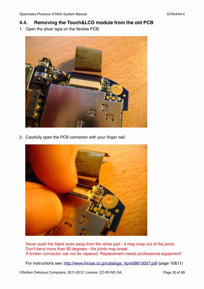
4.4. Removing the Touch&LCD module from the old PCB1. Open the silver tape on the flexible PCB:
2. Carefully open the PCB connector with your finger nail:
Never push the black lever away from the white part - it may snap out of the joints.Donʻt bend more than 90 degrees - the joints may break. A broken connector can not be repaired. Replacement needs professional equipment!
For instructions see: http://www.hirose.co.jp/cataloge_hp/e58613007.pdf (page 10&11)
Openmoko Phoenux GTA04 System Manual! GTA04A4-4
©Golden Delicious Computers, 2011-2012. License: CC-BY-NC-SA.! Page 20 of 89

3. The display module is mounted by 3 stripes of double-sided transparent tape. There are also 4 conducting silver pads only glued to the PCB as shown in the photo below (after removing the display). They should not become damaged as shown in this example:
Be very careful not to damage the flexible PCB cables (there is one for connecting the touch screen to the module that you can see only after removing the display module; on the left side of the next picture).
Openmoko Phoenux GTA04 System Manual! GTA04A4-4
©Golden Delicious Computers, 2011-2012. License: CC-BY-NC-SA.! Page 21 of 89

4. Now carefully insert the Telephone Card between the LCD and the black mat on the PCB:
Start with the top right corner (opposite of the flexible cable) and insert between silver pad and display backplane.
5. Using a blow dryer to warm/heat up the display softens the glue and makes it less likely to damage the display module.
6. Carefully push in the card and move it between LCD module and black mat to remove the LCD (donʻt bend the LCD module as it may break the glass):
Openmoko Phoenux GTA04 System Manual! GTA04A4-4
©Golden Delicious Computers, 2011-2012. License: CC-BY-NC-SA.! Page 22 of 89

Finally, lift off the display module.
Openmoko Phoenux GTA04 System Manual! GTA04A4-4
©Golden Delicious Computers, 2011-2012. License: CC-BY-NC-SA.! Page 23 of 89

7. Peel off any remaining double-sided tape (photo) from the backside of the LCD
8. Carefully stow away the Freerunner PCB in some anti-static bag or package (in case you may want to reuse it in the future)
4.5. Glueing the Touch&LCD module onto the GTA04 PCB1. Peel off the plastic cover on the double-sided tape of the GTA04 PCB.2. Take your GTA04 board and close the SD and SIM card slots completely.3. Carefully position and glue the Module to the new PCB:
Openmoko Phoenux GTA04 System Manual! GTA04A4-4
©Golden Delicious Computers, 2011-2012. License: CC-BY-NC-SA.! Page 24 of 89

4. Open the LCD connector and carefully insert the flexible PCB completely
5. Close the LCD connector
6. Glue the silver tape over the connector.
4.6. Installing the GTA04 PCB in the case1. take the middle case part and cut out the corners of the USB connector hole. The
GTA04 has a real OTG socket (right side) which is slightly larger than the GTA01/2 (left side):
Openmoko Phoenux GTA04 System Manual! GTA04A4-4
©Golden Delicious Computers, 2011-2012. License: CC-BY-NC-SA.! Page 25 of 89

Now start cutting:
How it should look after this procedure:
Check if it fits smoothly without force by trying to insert the USB socket from the outside
Openmoko Phoenux GTA04 System Manual! GTA04A4-4
©Golden Delicious Computers, 2011-2012. License: CC-BY-NC-SA.! Page 26 of 89

2. Carefully connect the GPS antenna to the U.FL plug3. Place the middle cover in front of you in the orientation as shown:
4. Carefully insert the internal GPS antenna into the middle cover5. Insert the PCB at the USB and GPS antenna side into the holes.6. Lower the PCB on the Headset Jack side (should not need any brute force).7. Bend away the middle cover part at the headset connector so that the PCB can be fully
lowered down:
Openmoko Phoenux GTA04 System Manual! GTA04A4-4
©Golden Delicious Computers, 2011-2012. License: CC-BY-NC-SA.! Page 27 of 89

8. Now, check that all snap-fits are engaged properly:
4.7. Testing the installationNow test the device as follows:1. Insert a SD card with u-boot, kernel and rootfs.2. Insert a charged battery.3. The GTA04 should boot.4. Check if the LCD and Touch are working - if not, check the Touch&LCD connector.
4.8. Closing the Cover1. Place the front cover on the middle case part.2. Close the snap-fits from microphone side to top.3. Turn around the Freerunner and insert and close the Torx screws.4. Check that the AUX and Power buttons are working mechanically.5. Remove the old Openmoko sticker in the battery compartment (you can keep it if you
ever want to replace the old PCB back).6. Glue the new GTA04 sticker in the battery compartment (it shows the new branding,
IMEI and certifications). This is required by laws before operating the device.Golden Delicious Computers GmbH&Co. KGModel: OpenPhoenux / GTA04 0890!S/N:IMEI:WLAN-MAC:BT-MAC:
5295-001935415404003085700:19:88:23:F7:EC00:19:88:1A:56:17
Complies with Part 15 of the FCC Rules Contains: FCC ID: NCMOMO6012 FCC ID: U9R-W2CBW003 IC: 2734A-MO6012 IC: 7089A-W2CBW003Made in Bavaria
7. Install SIM, SD and Battery and close the Battery cover.8. Test the device.9. Take the towel to dub your forehead.10.Go scream your success on the Openmoko mailing lists and IRC!
Openmoko Phoenux GTA04 System Manual! GTA04A4-4
©Golden Delicious Computers, 2011-2012. License: CC-BY-NC-SA.! Page 28 of 89

4.9. What could go wrong?Please check the mailing lists / wiki4 and share your experiences.
Openmoko Phoenux GTA04 System Manual! GTA04A4-4
©Golden Delicious Computers, 2011-2012. License: CC-BY-NC-SA.! Page 29 of 894 see www.gta04.org

5. Installing the optional Camera module
5.1. Tools and ComponentsWe recommend these tools:• vernier slide gauge• plectrum• sharp knife• small screwdriver• 2.5mm and a 8.5 mm drill plus drilling machine(s)
1. mark 12.5 mm on from the wall to the SD card compartment
Openmoko Phoenux GTA04 System Manual! GTA04A4-4
©Golden Delicious Computers, 2011-2012. License: CC-BY-NC-SA.! Page 30 of 89

2. predrill the hole with 2.5mm in the middle of the compartment
Openmoko Phoenux GTA04 System Manual! GTA04A4-4
©Golden Delicious Computers, 2011-2012. License: CC-BY-NC-SA.! Page 31 of 89

3. drill the 8.5mm hole from inside out
Openmoko Phoenux GTA04 System Manual! GTA04A4-4
©Golden Delicious Computers, 2011-2012. License: CC-BY-NC-SA.! Page 32 of 89
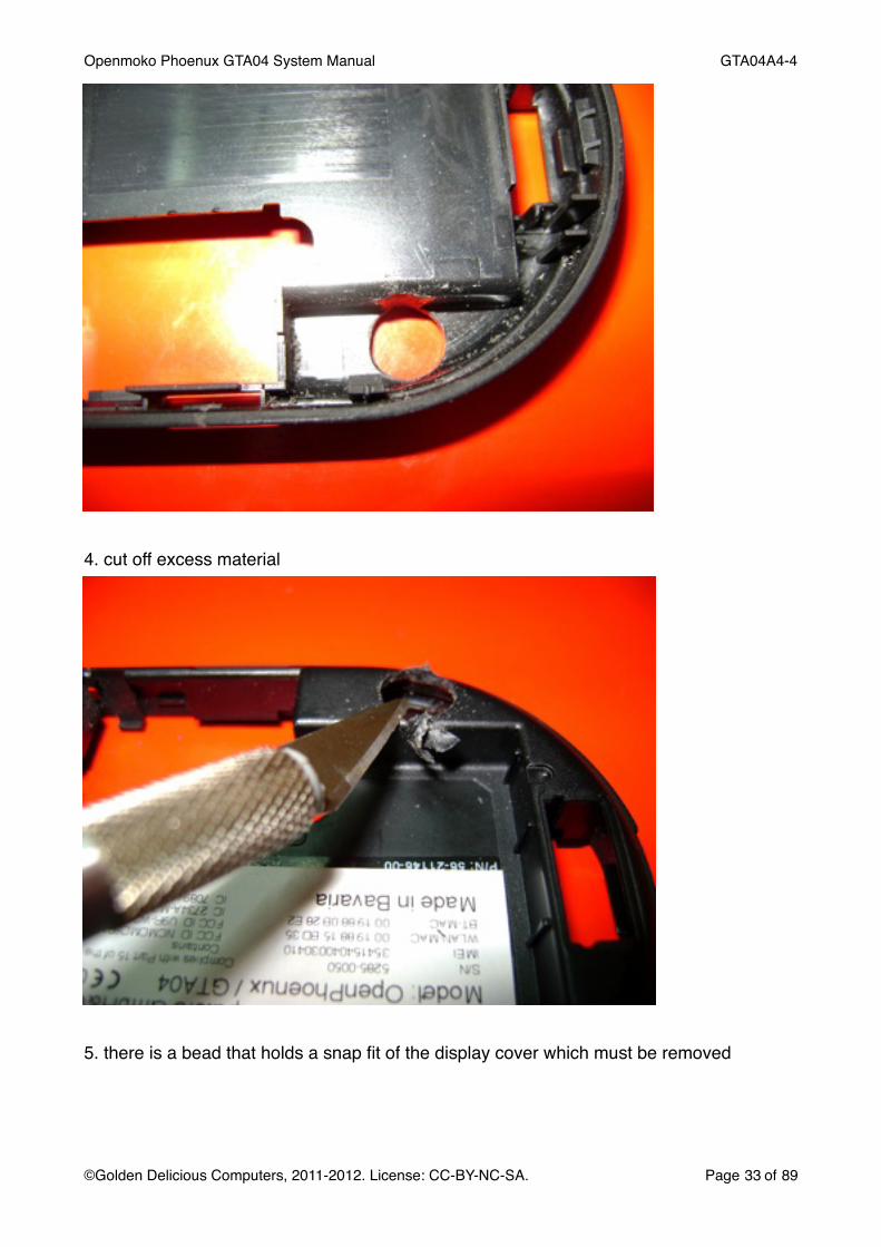
4. cut off excess material
5. there is a bead that holds a snap fit of the display cover which must be removed
Openmoko Phoenux GTA04 System Manual! GTA04A4-4
©Golden Delicious Computers, 2011-2012. License: CC-BY-NC-SA.! Page 33 of 89

take the knife and cut it off
6. on the display cover, trim the corresponding snap fit
Openmoko Phoenux GTA04 System Manual! GTA04A4-4
©Golden Delicious Computers, 2011-2012. License: CC-BY-NC-SA.! Page 34 of 89

7. carefully open the camera connector (take care of the resistors between socket and the “Wi2Wi“ GPS module!)
Openmoko Phoenux GTA04 System Manual! GTA04A4-4
©Golden Delicious Computers, 2011-2012. License: CC-BY-NC-SA.! Page 35 of 89
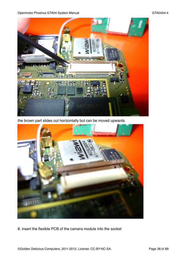
the brown part slides out horizontally but can be moved upwards
8. insert the flexible PCB of the camera module into the socket
Openmoko Phoenux GTA04 System Manual! GTA04A4-4
©Golden Delicious Computers, 2011-2012. License: CC-BY-NC-SA.! Page 36 of 89

9. start to close the brown lever
close it completely (by using fingers and not a tool)
Openmoko Phoenux GTA04 System Manual! GTA04A4-4
©Golden Delicious Computers, 2011-2012. License: CC-BY-NC-SA.! Page 37 of 89

10. this picture shows how the PCB will be mounted
take care of the GPS antenna cable - it must pass between the GPS module (silver box) and the external antenna plug (golden)
Openmoko Phoenux GTA04 System Manual! GTA04A4-4
©Golden Delicious Computers, 2011-2012. License: CC-BY-NC-SA.! Page 38 of 89

11. insert the camera first (left), then the MMCX and finaly the USB socket (right). This must be done more careful than without camera or you may break off the MMCX socket.
12. finally insert the GPS antenna and check that the cable is not squeezed
Openmoko Phoenux GTA04 System Manual! GTA04A4-4
©Golden Delicious Computers, 2011-2012. License: CC-BY-NC-SA.! Page 39 of 89

Openmoko Phoenux GTA04 System Manual! GTA04A4-4
©Golden Delicious Computers, 2011-2012. License: CC-BY-NC-SA.! Page 40 of 89
6. Hardware description
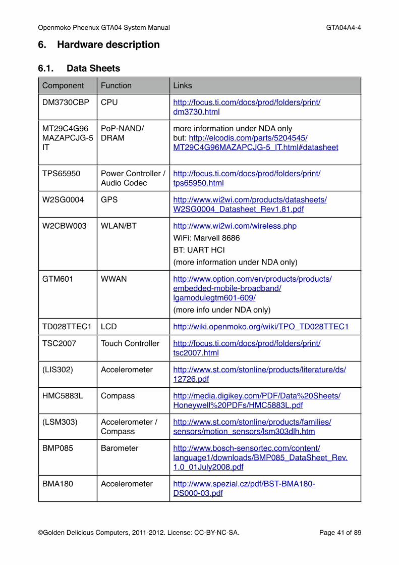
6.1. Data SheetsComponent Function Links
DM3730CBP CPU http://focus.ti.com/docs/prod/folders/print/dm3730.html
MT29C4G96MAZAPCJG-5IT
PoP-NAND/DRAM
more information under NDA onlybut: http://elcodis.com/parts/5204545/MT29C4G96MAZAPCJG-5_IT.html#datasheet
TPS65950 Power Controller / Audio Codec
http://focus.ti.com/docs/prod/folders/print/tps65950.html
W2SG0004 GPS http://www.wi2wi.com/products/datasheets/W2SG0004_Datasheet_Rev1.81.pdf
W2CBW003 WLAN/BT http://www.wi2wi.com/wireless.phpWiFi: Marvell 8686BT: UART HCI(more information under NDA only)
GTM601 WWAN http://www.option.com/en/products/products/embedded-mobile-broadband/lgamodulegtm601-609/(more info under NDA only)
TD028TTEC1 LCD http://wiki.openmoko.org/wiki/TPO_TD028TTEC1
TSC2007 Touch Controller http://focus.ti.com/docs/prod/folders/print/tsc2007.html
(LIS302) Accelerometer http://www.st.com/stonline/products/literature/ds/12726.pdf
HMC5883L Compass http://media.digikey.com/PDF/Data%20Sheets/Honeywell%20PDFs/HMC5883L.pdf
(LSM303) Accelerometer / Compass
http://www.st.com/stonline/products/families/sensors/motion_sensors/lsm303dlh.htm
BMP085 Barometer http://www.bosch-sensortec.com/content/language1/downloads/BMP085_DataSheet_Rev.1.0_01July2008.pdf
BMA180 Accelerometer http://www.spezial.cz/pdf/BST-BMA180-DS000-03.pdf
Openmoko Phoenux GTA04 System Manual! GTA04A4-4
©Golden Delicious Computers, 2011-2012. License: CC-BY-NC-SA.! Page 41 of 89

Component Function Links
OV9655 Camera http://www.surveyor.com/blackfin/OV9655-datasheet.pdf
ITG-3200 Gyroscope http://invensense.com/mems/gyro/documents/PS-ITG-3200-00-01.4.pdf
Si4705/4721 FM Receiver/Transceiver
http://www.silabs.com/pages/DownloadDoc.aspx?FILEURL=Support%20Documents/TechnicalDocs/Si4704-05-C40.pdf
TCA6507 LED driver http://focus.ti.com/docs/prod/folders/print/tca6507.html
TFDU6301 IrDA http://docs-europe.electrocomponents.com/webdocs/0ed1/0900766b80ed1faa.pdf
USB3322 USB-PHY http://www.smsc.com/media/Downloads_Public/Data_Sheets/3320.pdf
6.2. Processor and PowerThe processor part consists of a OMAP3530 + Package-on-Package RAM/Flash and the TPS 65950 Power Controller.
Chip Interface Connected to
OMAP Camera Camera Module and Test Points
DSS LCD (R=23-18, G=15-10, B=7-2, DE=0)
RFBI n/a
S-Video out Headset Jack (Composite only)
HDQ/1-Wire Battery ID
I2C1 TPS65950 CNTL
I2C2 Touch Screen, Sensors, FM Receiver
I2C3 Test Points (reserved for DVI control)
I2C4 TPS65950 Smart Reflex
McBSP1 FM Transceiver PCM
McBSP2 Audio TPS 65950 I2S
McBSP3 Bluetooth PCM
McBSP4 WWAN PCM
McBSP5 LCD control (in GPIO bit-bang mode)
Openmoko Phoenux GTA04 System Manual! GTA04A4-4
©Golden Delicious Computers, 2011-2012. License: CC-BY-NC-SA.! Page 42 of 89
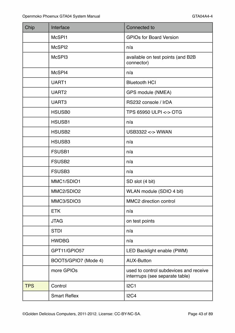
Chip Interface Connected to
McSPI1 GPIOs for Board Version
McSPI2 n/a
McSPI3 available on test points (and B2B connector)
McSPI4 n/a
UART1 Bluetooth HCI
UART2 GPS module (NMEA)
UART3 RS232 console / IrDA
HSUSB0 TPS 65950 ULPI <-> OTG
HSUSB1 n/a
HSUSB2 USB3322 <-> WWAN
HSUSB3 n/a
FSUSB1 n/a
FSUSB2 n/a
FSUSB3 n/a
MMC1/SDIO1 SD slot (4 bit)
MMC2/SDIO2 WLAN module (SDIO 4 bit)
MMC3/SDIO3 MMC2 direction control
ETK n/a
JTAG on test points
STDI n/a
HWDBG n/a
GPT11/GPIO57 LED Backlight enable (PWM)
BOOT5/GPIO7 (Mode 4) AUX-Button
more GPIOs used to control subdevices and receive interrrups (see separate table)
TPS Control I2C1
Smart Reflex I2C4
Openmoko Phoenux GTA04 System Manual! GTA04A4-4
©Golden Delicious Computers, 2011-2012. License: CC-BY-NC-SA.! Page 43 of 89

Chip Interface Connected to
JTAG on test points
TDM Codec Interface (I2S) McBSP2
Voice PCM Interface WWAN PCM/McBSP4
Bluetooth PCM Interface n/a
OTG HSUSB0-ULPI
Keyboard n/a
MIC.Main (2.2k bias) Microphone
MIC.Sub, AUX n/a
HS.MIC (2.7k bias) Headset jack
EAR Earspeaker
HSOR/HSOL Headset jack
IHF.LEFT/IHF.RIGHT Music speakers (left channel only for Neo1973)
VIBRA (LEDA, LEDB) Vibramotor
ADC7 Headset Mic / Remote Control current sense
PWRON PWR-Button, WWAN-Wakeup, PENIRQ
GPIO0,1,16,17 n/a
VMMC1 (3.15 V, 220 mA) SD power
VMMC2 (3.15 V, 100 mA) n/a
VAUX1 (3 V, 200 mA) not used (available Extension)
VAUX2 (2.8 V, 100 mA) for Sensors
VAUX3 (2.5 V, 200 mA) Camera
VAUX4 (3.15 V, 100 mA) WLAN / Bluetooth power
VSIM (2.8 V) int/ext. GPS antenna
BT PCM McBSP3 (I2S mode)
UART UART1
USB (Test Points)
Openmoko Phoenux GTA04 System Manual! GTA04A4-4
©Golden Delicious Computers, 2011-2012. License: CC-BY-NC-SA.! Page 44 of 89

Chip Interface Connected to
Power (3 - 3.6 V, 55 mA) VAUX4
WLAN SDIO/GSPI MMC2/3 (4 bit)
Power (2.7 - 3.3 V, 240 mA) a LDO controlled by VAUX4
WWAN PCM McBSP4 (I2S mode)
USB HSUSB2
Wakeup Module -
Wakeup CPU GPIO176
Power VBAT
LCD RGB, SYNC DSS
Control Interface McBSP5 (GPIO bitbang mode)
Power (2.8 - 3.3 V, 20 mA) 3.3V LDO (controlled by SYSEN)
Backlight Enable/PWM GPT11 (GPIO57)
Touch I2C I2C2
PENIRQ GPIO160
AUX (ADC channel 6) Ambient Light Sensor
Power (2,7 - 5,5 V, 3 mA) 3.3V LDO (controlled by REGEN)
SD/SIM SD MMC1
Power (SD) VMMC1 (3.15V, 220 mA)
SIM WWAN
Power (SIM) WWAN
Memory on SIM (1-bit SD) n/a
GPS Serial UART2
Power Up GPIO145 (RTS inverted)
INT/EXT-Antenna Status GPIO144 (CTS)
Power (3.25 - 3.6 V, 50 mA) 3.3V LDO (controlled by REGEN)
int/ext. Antenna (3 V, 20 mA) VSIM
LED Aux, Power LEDs I2C2
RS232 RX, TX, CTS, RTS UART3
Openmoko Phoenux GTA04 System Manual! GTA04A4-4
©Golden Delicious Computers, 2011-2012. License: CC-BY-NC-SA.! Page 45 of 89

Chip Interface Connected to
Power 3.3V LDO (controlled by REGEN)
IrDA RX, TX UART3 (needs to be programmed to IrDA mode for correct pulse shaping)
On/Off GPIO13
FIR mode GPIO21
Power (2.7 - 3.6 V, 5 mA) 3.3V LDO (controlled by REGEN)
LED Power (400 mA peak) VBAT
FM Receiver
Control I2C2
Voice McBSP1
Sensors Accelerator, Compass, Barometer, Gyroscope
I2C2
Interrupts GPIOs (see table)
Power (2.5 - 3.3 V, 2.5 mA) VAUX2
6.3. RS232, DC-In and IrDA6.3.1. RS232 connectorThe RS232 includes a 3-15 V level shifter. It supports RX, TX, CTS, RTS of UART3 (compatible to BeagleBoard and the-ROM boot loader).The RS232 connector is located at the top end of the PCB. It has been designed that you can connect even to a running device after removing the battery cover (but not the battery), opening the Torx screws and removing the front cover:
NOTE: the interface is named as a DCE (Modem)! Therefore you should connect a DB9f (officially called DE9) socket that directly plugs into a DTE (Terminal/Computer).NOTE: This assignment does not require a Null-Modem cable.
Openmoko Phoenux GTA04 System Manual! GTA04A4-4
©Golden Delicious Computers, 2011-2012. License: CC-BY-NC-SA.! Page 46 of 89

Pin location and signals:
Pin DCE pin name
UART3(mode0)
GPIO(mode4)
Dir. Color (in our presoldered cable)
DB9f pin number
1 GND - - - brown 5
2 EXT - 21 Out red 1 (DCD) or4 (DTR) or9 RI (our cable)
3 CTS RTS 164 Out orange 8
4 TX RX 166 In yellow 3
5 RTS CTS 163 In green 7
6 RX TX 165 Out blue 2
7 GND - - - purple -
8 DCIN - - In grey -
6.3.2. Building a cableThe connector on the GTA04 is a “Molex Pico blade“ with 8 pins (53261-0871). We recommed that you get a plug where a cable is already crimped since doing that manually requires quite expensive tools.
On the other end you need to solder to a DB-9f socket.
Openmoko Phoenux GTA04 System Manual! GTA04A4-4
©Golden Delicious Computers, 2011-2012. License: CC-BY-NC-SA.! Page 47 of 89

There is an additional signal line EXT which can be connected to DCD, DTR or RI to indicate modem status by software. Which one you choose depends on your application. It is controlled by GPIO21.
6.3.3. DC-InThe DC power supply pins (see section 5.14) are not connected by default but you can wire them for a Y cable by soldering a plug of your choice. Please make sure that you donʻt swap DCIN and GND as it will damage the device.DCIN power input is rated 3.2 V - 6.8 V (absolute maximum).
6.3.4. IrDAThere is an IrDA transceiver capable of 4 MBit/s that can be used alternatively with the RS232 port and must be switched on by software.To generate IrDA transmit impulses, firstly switch the PinMux to IrDA mode and place UART3 into IrDA mode. To generate arbitrary infrared impulses, place the TX line (GPIO166) into GPIO mode (4).Receiver speed (SIR/MIR vs. FIR) controlled through a specific sequence of TX and IrDA enable (see data sheet of the IrDA module).
6.4. WWAN (GSM, GPRS, EDGE, UMTS)The WWAN and Telephony module is a Option GTM601W UMTS & GSM.It is connected to the internal USB for control channels (AT command interface) and WWAN data.Telephony voice is transmitted digitally through a PCM interface (module generates 2.048 MHz clock and 8kHz frame sync) connected to McBSP4.A GPL Driver is avaliable by Option and is part of the mainstream Linux kernel since 2.6.31.
6.4.1. Power on/off and ResetPower is controlled through GPIO186. Setting the GPIO to “1“ (for at least 200 ms) turns the module on and it will register itself on the internal USB port. Setting the GPIO to 0 and 1 again prepares for power-down5 and the final edge going to 0 turns the module off. In that state it draws <100 uA and can be waked up by another switch to 1.
Openmoko Phoenux GTA04 System Manual! GTA04A4-4
©Golden Delicious Computers, 2011-2012. License: CC-BY-NC-SA.! Page 48 of 895 in this case the “1“ disables the PA (similar to airplane mode) but the module remains active through USB.

Therefore these pulses should be 0-1-0 for approx. 300 ms.If the USB interface is shut down but remains active, the module goes to low power mode (typically 3-10 mA) and can wake up the CPU through a 3G_WOE interrupt.Note: if the CPU is powered down through the emergency function (Power button pressed for >8 seconds) the module may remain powered on, although everything else is off. Although it typically draws only 3-10 mA it may try to re-register to the network and in certain conditions (signal received from the base station is better than the own transmitted signal) it may draw up to 100 mA and send GSM bursts while unsuccessfully trying to re-register to base stations.It should be possible to handle that by some U-Boot hack (U-Boot starts but shuts down after release of the Power button).
6.5. GPS6.5.1. ReceiverThe GPS receiver is a Wi2Wi W2SG0004 module connected to UART2 (/dev/ttyO1).The data rate (after reset): 9600 bit/s, 8 bit, no parity, 1 stop bit; range: 1200 - 115200 bit/sData formats are NMEA (default), SiRFBINARY™ and AI3/F.
6.5.2. External antenna and switchThe device automatically switches between internal and external antenna. The selection of the active antenna can be read through GPIO144 (0=int, 1=ext).The external antenna connector is a MMCX type plug. Please make sure that your antenna has the correct type (or you need an adapter).The device provides 3 V up to 25 mA for an external active antenna. The antenna must draw at least 10 mA for correct detection.
6.5.3. Power on/off and ResetReset (and power down) is controlled by GPIO145. A first impulse powers on and a second impulse powers down.
6.6. WLAN & BluetoothWLAN and Bluetooth are provided by a Wi2Wi W2CBW003-003.
6.6.1. WLANis connected to MMC2 (4 bit SDIO interface).
6.6.2. Bluetoothis connected to UART1 (/dev/ttyO0). The PCM channel is connected to McBSP3.
6.6.3. Power on/off and ResetPower is supplied for both parts through VAUX4.Reset is controlled by the LED6 port of the TCA6507 connected to I2C2. You should issue a reset before switching on power.
6.7. FM Receiver / Transmitter with RDSThere is a FM Receiver Si4705 (or combined receiver/transmitter Si4721) available.
Openmoko Phoenux GTA04 System Manual! GTA04A4-4
©Golden Delicious Computers, 2011-2012. License: CC-BY-NC-SA.! Page 49 of 89

The shield cable of the headset is used as the FM receiver antenna.The transmitter needs a separate antenna.It is controlled through I2C2.Digital audio is provided through McBSP1.
6.8. Touch Screen and LCD6.8.1. LCD DSSThe LCD module is a Toppoly TD028TTEC1 connected to the DSS port.
DSS signal Display
DSS2-7 Blue (6 bit)
DSS10-15 Green (6 bit)
DSS17-23 Red (6 bit)
PCLK shall be 22 MHz
6.8.2. LCD controllerThe display module contains an integrated Toshiba JBT6K74 display controller for which no detailled information is available. Its control port is connected to McBSP5 which is used as GPIO.Our U-boot and Linux kernel include drivers to control the McBSP5 in GPIO-bitbang mode. This has been ported from the GTA01/GTA02 kernel source code and just works.
6.8.3. Touch screenThe resistive touch screen is controlled by TSC2007 that is connected to I2C2.The TSC2007 can measure the touch screen position and pressure, as well as battery voltage and chip temperature (see data sheet). It includes a Median Filter to reduce jitter.
6.8.4. Ambient Light Sensor (DIY)there is room for an optional ambient light sensor connected to the.AUX input (ADC channel 6) of the TSC2007 can be used to read out the ambient light level. Installation of such a sensor requires drilling a hole into the case.NOTE: the solder pads have a 2mm distance which is quite rare but saves space. Please be careful when soldering a sensor, especially if it has 2.54mm pin distanceSome sensors (not tested for mechanical fit):Vishay TEPT4400! 3mmVishay TEPT5500! 5mmVishay TEPT5700! 5mmPanasonic AMS104Y
6.9. Sensorsare connected to the I2C2 bus.
Openmoko Phoenux GTA04 System Manual! GTA04A4-4
©Golden Delicious Computers, 2011-2012. License: CC-BY-NC-SA.! Page 50 of 89

There is either mounted a LSM303DLH or both HMC5883+BMA180, never all of them. Otherwise there would be address conflicts and multiple drivers for the interrupt lines. Which devices are available may change.The table below shows the I2C addresses and the interrupt GPIOs. It also includes other devices on the I2C2 bus (although they are not sensors):
Sensor Type Bus address Interrupt
optional Accelerometer (bottom) LIS302 0x1D GPIO114
Barometer/Thermometer BMP085 0x77 GPIO113
Gyroscope ITG3200 0x68 GPIO56
FM Transceiver Si4705/4721 0x11 GPIO156
Touch Screen Controller, Ambient Light TSC2007 0x48 GPIO160
Accelerometer (top) BMA180 0x41 GPIO115
Compass HMC5883L 0x1E GPIO112
optional Combined Accelerometer LSM303DLH 0x19 GPIO115
optional Combined Compass
LSM303DLH
0x1E GPIO112
LED driver TCA6507 0x45 -
Torch/Flash LED driver TPS61050 0x33 -
Camera module OV9655 0x30 -
RFID-EEPROM MT24LR64 0x50 -
optional Keypad controller TCA8418 0x34 GPIO10
6.10. Headset Jack 2.5mm6.10.1. Pin layout
The pin assignment (not necessarily the diameter) we have choosen is compatible to e.g.:• Sharp Zaurus SL860
Openmoko Phoenux GTA04 System Manual! GTA04A4-4
©Golden Delicious Computers, 2011-2012. License: CC-BY-NC-SA.! Page 51 of 89
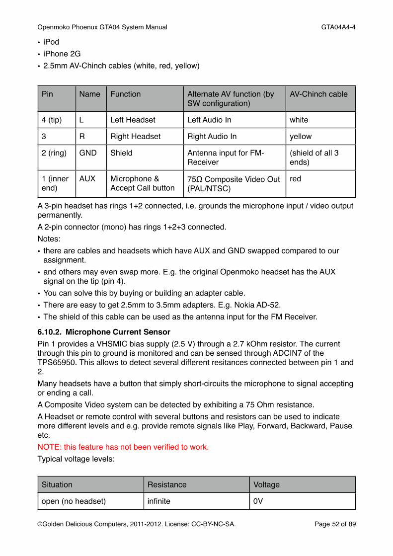
• iPod• iPhone 2G• 2.5mm AV-Chinch cables (white, red, yellow)
Pin Name Function Alternate AV function (by SW configuration)
AV-Chinch cable
4 (tip) L Left Headset Left Audio In white
3 R Right Headset Right Audio In yellow
2 (ring) GND Shield Antenna input for FM-Receiver
(shield of all 3 ends)
1 (inner end)
AUX Microphone & Accept Call button
75Ω Composite Video Out (PAL/NTSC)
red
A 3-pin headset has rings 1+2 connected, i.e. grounds the microphone input / video output permanently.A 2-pin connector (mono) has rings 1+2+3 connected.Notes:• there are cables and headsets which have AUX and GND swapped compared to our
assignment.• and others may even swap more. E.g. the original Openmoko headset has the AUX
signal on the tip (pin 4).• You can solve this by buying or building an adapter cable.• There are easy to get 2.5mm to 3.5mm adapters. E.g. Nokia AD-52.• The shield of this cable can be used as the antenna input for the FM Receiver.
6.10.2. Microphone Current SensorPin 1 provides a VHSMIC bias supply (2.5 V) through a 2.7 kOhm resistor. The current through this pin to ground is monitored and can be sensed through ADCIN7 of the TPS65950. This allows to detect several different resitances connected between pin 1 and 2.Many headsets have a button that simply short-circuits the microphone to signal accepting or ending a call.A Composite Video system can be detected by exhibiting a 75 Ohm resistance.A Headset or remote control with several buttons and resistors can be used to indicate more different levels and e.g. provide remote signals like Play, Forward, Backward, Pause etc.NOTE: this feature has not been verified to work.Typical voltage levels:
Situation Resistance Voltage
open (no headset) infinite 0V
Openmoko Phoenux GTA04 System Manual! GTA04A4-4
©Golden Delicious Computers, 2011-2012. License: CC-BY-NC-SA.! Page 52 of 89

Situation Resistance Voltage
3-pin headset 0 Ohm (permanent) 2.5V
4-pin headset 2.2 kOhm (Microphone)
button on 4-pin headset pressed
0 Ohm (temporary) 2.5V
AV-monitor on red cable 75 Ohm
buttons/keys 100 Ohm .. 2 kOhm or 3 kOhm ... 50 kOhm
6.10.3. Composite-Video OutThe composite out is driven by a OPA362 video amplifier with a series 75 Ohm resistor. This gives a standard FBAS / CVBS output signal with approx. 1.25 V amplitude.The TV out can be enabled through the DSS2 system. It is important that the TV_OUT_BYPASS is enabled.The output amplifier can be switched to High-Z by setting GPIO 23 to 0.
6.10.4. AUX-InIt is possible to switch off the Headset audio out drivers by setting GPIO55 to 0. In this situation, you can feed a stereo audio signals through the headset jack into the device for recording.NOTE: this feature has not been tested.
6.11. Phone PeripheralsSpeakers, Microphone, and Vibracall are connected directly to the Codec part of the TPS65950.
6.12. OTG-USBis a USB OTG 5 pin connector and connected to the TPS65950. The OMAP3 CPU uses the MUSB controller HSUSB0 and ULPI to drive the TPS.The socket is used to• charge battery in Client mode• supply 5V, up to 100 mA in Host mode
6.13. Memory CardsMMC1 interface (data bits 0-3) is connected to the SD card slot and supports SDHC up to 32 GByteMMC2 interface (data bits 0-3) is connected to the WLAN module (SDIO mode)MMC3 interface is not available (pins are used for the MMC2 SDIO driver)
6.14. Buttons and LEDs
Openmoko Phoenux GTA04 System Manual! GTA04A4-4
©Golden Delicious Computers, 2011-2012. License: CC-BY-NC-SA.! Page 53 of 89
6.14.1. AUX Buttonis connected to BOOT5 so that pressing the button while booting modifies the boot sequence of the built-in boot loader. I.e. NAND is tried last.You can detect the state by programming the BOOT5 pin to mode 4 (GPIO7) and reading its value.
6.14.2. Power Buttonis connected to PWRON of the TPS65950.The TPS65960 detects and debounces this signal and can either generate interrupts on pressing or releasing, or wake up a sleeping CPU or force power-off when pressed for more than 8 seconds (emergency shut-down).The current state can be read throgh I2C1 from the STS_HW_CONDITIONS register of the TPS65950.
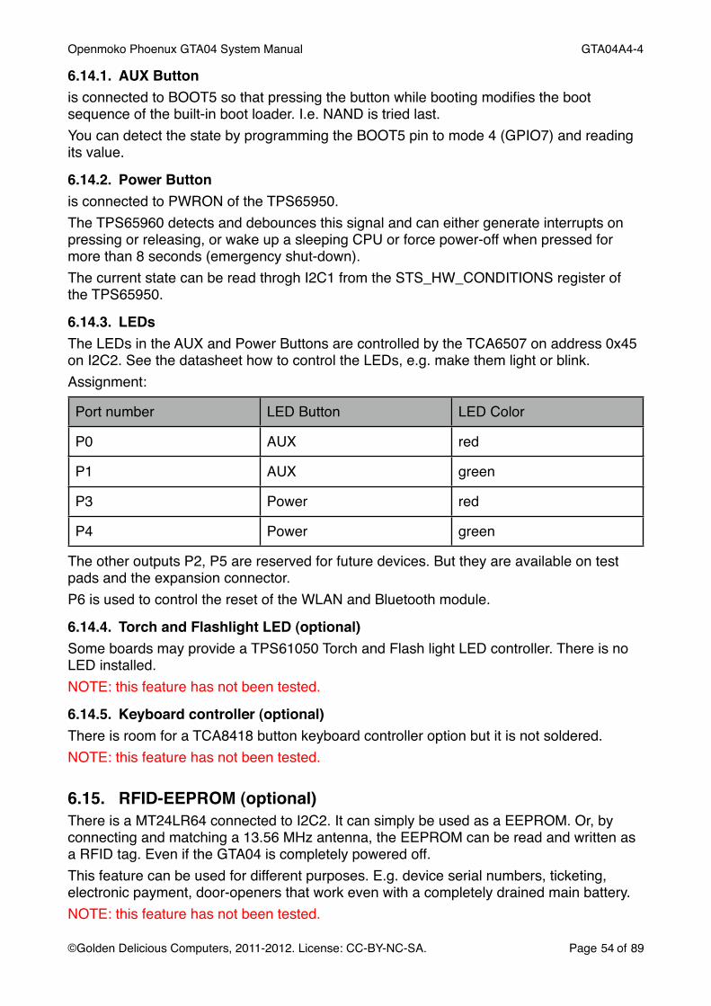
6.14.3. LEDsThe LEDs in the AUX and Power Buttons are controlled by the TCA6507 on address 0x45 on I2C2. See the datasheet how to control the LEDs, e.g. make them light or blink.Assignment:
Port number LED Button LED Color
P0 AUX red
P1 AUX green
P3 Power red
P4 Power green
The other outputs P2, P5 are reserved for future devices. But they are available on test pads and the expansion connector.P6 is used to control the reset of the WLAN and Bluetooth module.
6.14.4. Torch and Flashlight LED (optional)Some boards may provide a TPS61050 Torch and Flash light LED controller. There is no LED installed.NOTE: this feature has not been tested.
6.14.5. Keyboard controller (optional)There is room for a TCA8418 button keyboard controller option but it is not soldered.NOTE: this feature has not been tested.
6.15. RFID-EEPROM (optional)There is a MT24LR64 connected to I2C2. It can simply be used as a EEPROM. Or, by connecting and matching a 13.56 MHz antenna, the EEPROM can be read and written as a RFID tag. Even if the GTA04 is completely powered off.This feature can be used for different purposes. E.g. device serial numbers, ticketing, electronic payment, door-openers that work even with a completely drained main battery.NOTE: this feature has not been tested.
Openmoko Phoenux GTA04 System Manual! GTA04A4-4
©Golden Delicious Computers, 2011-2012. License: CC-BY-NC-SA.! Page 54 of 89

6.16. Camera (optional)The camera connector is designed to connect a OmniVision OV9655 camera module.NOTE: this feature is not completely supported by the kernel.
6.17. Test PadsNote: adding electronic circuits in this area will most likely void the CE, R&TTE and FCC approvals, so you may operate the device only in a development environment or you have to recertificate the device yourself.
Openmoko Phoenux GTA04 System Manual! GTA04A4-4
©Golden Delicious Computers, 2011-2012. License: CC-BY-NC-SA.! Page 55 of 89

Please be aware that logic levels are 1.8V! Applying 3.3V signals may damage the OMAP subsystem beyond repair!Pin description:
Name Use for Comment
VBUS measurement USB (0V or 5V)
VDD2 measurement powers CPU core
1V8 supply 1.8 V
VDD1 measurement powers CPU core
VMMC2
VBAT battery voltage donʻt short circuit!
3V3 supply 3.3V
VAUX1 free to use
VAUX3 Camera voltage should be 2.5V
VMMC1 measurement controlled by MMC driver
LOOP+, LOOP- FM TX antenna only useful for Si4721
VSIM supply ext. GPS antenna
VAUX2 used as secondary supply of Compass and Gyroscope chip
Never switch below 1.8V or the ITG3200 may be damaged.
VAUX4 WLAN/BT voltage
VID2, VIDGND donʻt connect
R0-R7, C0-C7 optional keypad needs keypad controller chip
STARTADC2, ADC2 ADC input grounded by 0R! see TPS65950
I2C2D, I2C2C additional I2C devices Bus is already crowded!
I2C3D, I2C3D additional I2C devices completely unused
J.* if you ever need JTAG 1.8V logic!
J.TDO1, J.TMS GPIO or Card Detect GPIOs of the TPS65950 (needs I2C1 commands to control them)
NRESWARM reset external devices 1.8V logic!
Openmoko Phoenux GTA04 System Manual! GTA04A4-4
©Golden Delicious Computers, 2011-2012. License: CC-BY-NC-SA.! Page 56 of 89

Name Use for Comment
KEYIRQ connect external interrrupt
1.8V logic! GPIO176
MCSPI3-* connect external SPI device
1.8V logic!
6.18. Battery holder (optional)For experiments it is sometimes necessary to operate the device completely without a case. This setup does not provide a battery bay and the spring loaded battery contacts will push away the battery. We have added two holes where you can simply insert a bent paper clip as shown in the photo. This will keep the battery in place.
6.19. Expansion Connector (optional)There is space on the Display side where two Board-2-Board connectors can be installed - if there is no display.
Openmoko Phoenux GTA04 System Manual! GTA04A4-4
©Golden Delicious Computers, 2011-2012. License: CC-BY-NC-SA.! Page 57 of 89

Please contact us if you want to get boards with these connectors installed and some other components not populated (e.g. microphone, display connector, headset jack, USB-OTG port, battery connector).These connectors allow to replace the original display and install an adapter board for a different display. These connectors also provide other signals so that the GTA04 board can be used as a module to design your own phone (will have to be larger of course). A cross section showing how to mount the GTA04 onto an adapter board with display is shown here:
Openmoko Phoenux GTA04 System Manual! GTA04A4-4
©Golden Delicious Computers, 2011-2012. License: CC-BY-NC-SA.! Page 58 of 89

6.19.1. Connecting an external LCDNote that your display may need level shifters from 1.8V logic to 3.3V levels. This can be done e.g. with a set of SN74LVC8T245 chips.You also have to design your own backlight converter (TPS61041) and touch screen controller (e.g. TSC2007).Some more signals and interfaces are available depending on population of components on the module.
6.19.2. Part numbersThe GTA04 board can be equipped with two receptacles Hirose DF40-60DS-0.4V.NOTE: it is quite impossible to retrofit the expansion connector. And, it can also only be used if some other components (especially the display) are not populated. So please contact us for get this variant from the factory.The matching Header is the Hirose DF40-60DP-0.4V (e.g. DigiKey H11839CT-ND). They come in either 1.5 mm or 2.0 mm or 2.5 mm matching height so that you can adjust the distance to your display board.
NOTE: this connector is specified for only 10 insertion cycles (gold plating wears out)!
6.19.3. Mounting materialIt is recommended to use 3x M2x5 mm (or 4/6mm) plastic screws and M2 nuts. Depending on the B2B connector height, distance rings of 1.5 / 2 / 2.5 mm and 2.1-2.3 mm diameter should be used.
Openmoko Phoenux GTA04 System Manual! GTA04A4-4
©Golden Delicious Computers, 2011-2012. License: CC-BY-NC-SA.! Page 59 of 89
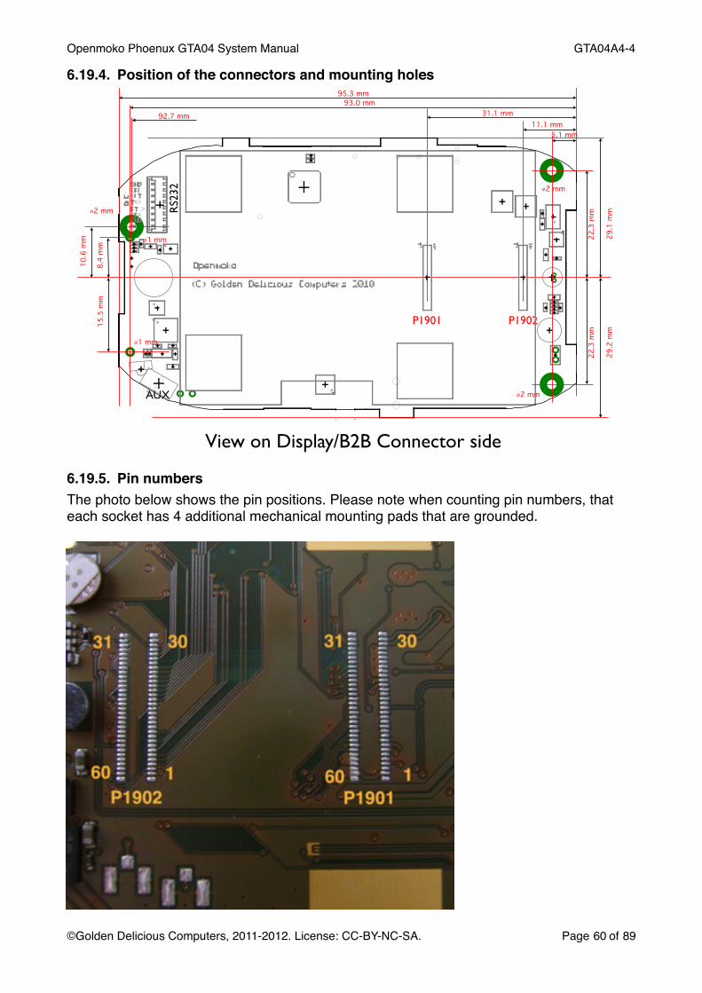
6.19.4. Position of the connectors and mounting holes
View on Display/B2B Connector side
P1901 P1902
2 mm
2 mm
1 mm
1 mm
AUX
RS2
32
95.3 mm93.0 mm
31.1 mm11.1 mm
5.1 mm
8.4
mm
15.5
mm
22.3
mm
22.3
mm
29.2
mm
29.1
mm
10.6
mm
2 mm
92.7 mm
6.19.5. Pin numbersThe photo below shows the pin positions. Please note when counting pin numbers, that each socket has 4 additional mechanical mounting pads that are grounded.
Openmoko Phoenux GTA04 System Manual! GTA04A4-4
©Golden Delicious Computers, 2011-2012. License: CC-BY-NC-SA.! Page 60 of 89

6.19.6. Signal assignmentP1901 (middle)
Level Pin Pin Level
VAC 4-6 V 1 60 4-6 V VAC
McBSP4-CLKX (GPIO152) 1.8 V 2 59 4-6 V VAC
McBSP4-FSX (GPIO155) 1.8 V 3 58 5V VBUS
McBSP4-DX (GPIO154) 1.8 V 4 57 5V VBUS
McBSP4-DR (GPIO153) 1.8 V 5 56 5V VBUS
VIB- analog 6 55 analog OTG ID
VIB+ analog 7 54 GND
GND 8 53 3.3 V 3V3
Ear+ analog 9 52 3.3 V LED6 (3.3V-Reset)
Ear- analog 10 51 GND
GND 11 50 analog BATTEMP
HS/AUX-R analog 12 49 analog BATID
HS/AUX-L analog 13 48 analog ADCIN2
GND 14 47 GND
USB-OTG D+ analog 15 46 1.8 V KEYIRQ (GPIO10)
USB-OTG D- analog 16 45 1.8 V STARTADC
GND 17 44 GND
HDQ digital 18 43 1.8 V UART2-RTS (GPIO145)
GND 19 42 1.8 V UART2-CTS (GPIO144)
RS- analog 20 41 1.8 V PENIRQ (GPIO160)
RS+ analog 21 40 1.8 V NRESPWRON
VBATT 3.6 V 22 39 1.8 V REGEN
VBATT 3.6 V 23 38 1.8 V I2C3-SDA
VBATT 3.6 V 24 37 1.8 V I2C3-SCL
VBATT 3.6 V 25 36 1.8 V UART3-TX (GPIO166)
VBATT 3.6 V 26 35 1.8V UART3-RX (GPIO165)
VBATT 3.6 V 27 34 1.8 V UART3-RTS (GPIO164)
VBATT 3.6 V 28 33 1.8 V UART3-CTS (GPIO163)
LS- analog 29 32 GND
LS+ analog 30 31 analog MIC/AV
Openmoko Phoenux GTA04 System Manual! GTA04A4-4
©Golden Delicious Computers, 2011-2012. License: CC-BY-NC-SA.! Page 61 of 89

P1902 (bottom)
Level Pin Pin Level
BKBATT VBATT 1 60 GND
PWRON button (to GND) VBATT 4 57 OC LED5
McSPI3-CLK (GPIO17) 1.8V 5 56 OC LED4
McSPI3-SIMO (GPIO14) 1.8V 4 57 OC LED3
McSPI3-SOMI (GPIO15) 1.8V 5 56 OC LED2
McSPI3-CS (GPIO16) 1.8V 6 55 OC USB-WWAN-D-
AUX / USER button to 1V8 (GPIO7) 1.8V 7 54 OC USB-WWAN-D+
1V8 1.8 V 8 53 3.3 V 3V3
I2C2-SDA 1.8V 9 52 1.8V McBSP5-CLKX (GPIO12)
I2C2-SCL 1.8V 10 51 1.8V McBSP5-FSX (GPIO19)
LED1 OC 11 50 1.8V McBSP5-DX (GPIO20)
LED0 OC 12 49 1.8V McBSP5-DR (GPIO18)
NRESWARM 1.8V 13 48 1.8V GPT11_PWM (GPIO57)
UART2-RX (GPIO147) 1.8V 14 47 1.8V DSS7 (GPIO77)
UART2-TX (GPIO146) 1.8V 15 46 1.8V DSS8
GND 16 45 1.8V DSS9
DSS23 1.8V 17 44 1.8V DSS10
DSS22 1.8V 18 43 1.8V DSS11
DSS6 (GPIO76) 1.8V 19 42 1.8V DSS12
DSS5 1.8V 20 41 1.8V DSS13
DSS4 1.8V 21 40 1.8V DSS14
DSS3 1.8V 22 39 1.8V DSS15
DSS2 1.8V 23 38 1.8V DSS16
DSS1 1.8V 24 37 1.8V DSS17
DSS0 (GPIO70) 1.8V 25 36 1.8V DSS18
DE 1.8V 26 35 1.8V DSS19
VSYNC 1.8V 27 34 1.8V DSS20
HSYNC 1.8V 28 33 1.8V DSS21
PCLK 1.8V 29 32 GND
GND 30 31 1.8V MIC+
Openmoko Phoenux GTA04 System Manual! GTA04A4-4
©Golden Delicious Computers, 2011-2012. License: CC-BY-NC-SA.! Page 62 of 89

6.19.7. General RecommendationsPlease follow these recommendations when designing a display board:• Make the traces for power supply and battery connection as wide as possible.• Connect all GND pins, as well as VAC and VBATT.• The 1V8 and 3V3 lines can supply only some mA e.g. for level shifters or low power
devices (e.g. touch screen controller). If you need more, use your own LDO.• Shield the sensitive signals (BATTEMP, BATTID, ADCIN, Mic+/-, MIC/AV, etc.).• Try to achieve 45/90 Ohm impedance for USB wires. This most likely needs to use a 4
layer design or you would get too wide traces (approx. 180% of the FR4 thickness).• Keep traces for DSS short and approx. same length.
6.20.Power demand estimatesThe exact current drawn by the submodules of the GTA04 board depends on the regulator type. For DC/DC regulators with approx. 95 % efficiency, the device draws less current for higher battery voltage. For LDO type regulators, the current is constant and may even drop for a very low battery (<3.4 V).Most functional areas can be shut down completely. A standby current specification describes a state where the function is still operational or can be brought to operation within very short time.NOTE: This table gives a preliminary overview and is not yet complete:
Unit Standby (still active) typ. Current / Voltage typ. Power
CPU uA 100 - 400 mA @ VBATT = 3.5V; depends on CPU clock
MMC card uA 50-100 mA @ 3.3V
WLAN 10 mA 100-240 mA @ 3.3V
BT 10 mA 30-50 mA @ 3.3V
WWAN 3-10 mA 2 A @ VBATT
Backlight uA 100 mA @ VBATT 300 mW
GPS 50 mA @ 3.3V
LCD 15 mA @ 3.3V 50 mW
IrDA uA 150 mA @ VBATT (Tx)2-3 mA @ 3.3V
RS232 uA 10 mA
TV out - 50 mA
Sensors uA uA
Openmoko Phoenux GTA04 System Manual! GTA04A4-4
©Golden Delicious Computers, 2011-2012. License: CC-BY-NC-SA.! Page 63 of 89

Unit Standby (still active) typ. Current / Voltage typ. Power
Gyroscope uA 6.5 mA
Camera 10 uA 20 mA @ 2.5V
Openmoko Phoenux GTA04 System Manual! GTA04A4-4
©Golden Delicious Computers, 2011-2012. License: CC-BY-NC-SA.! Page 64 of 89

7. Booting the device
7.1. Boot processWhen power is applied, the OMAP processor starts a first stage bootloader from a built-in ROM. This ROM tries to load a secondard bootloader (X-Loader) from several sources. The order can be changed by the AUX (User) button which makes the ROM check external sources (RS232, USB, MMC) before checking NAND flash.The next stage boot-loader is the X-Loader (also called MLO if it loads U-Boot from MMC/SD). It runs from the (small) 64k SRAM built into the CPU.Usually, the X-Loader fetches the thrid stage U-Boot from the same source as the X-Loader was found. I.e. there is a X-Loader in NAND flash that loads U-Boot from NAND flash. On a MMC card there is a file called MLO in the first FAT partition. A special X-Loader variant that can load U.Boot through the RS232 interface by using the Kermit protocol is also available.Anyway, U-Boot is loaded into the (big) SDRAM.Finally, U-Boot determines where to fetch the Linux kernel from. Usually it looks at NAND flash and MMC and finally on the UART. This order can be modified by pressing the AUX button to check the NAND flash as the last step. This is good to „unbrick“ a device where the NAND flash image is broken or damaged.Our U-Boot loads a splash image from MMC or NAND:
7.1.1. Choosing boot mode by AUX buttonThe AUX button is used to switch to „peripheral boot“ mode, i.e. all boot loaders try external media (MMC, USB, UART) before looking for a image in NAND flash.In our U-Boot version, the AUX button also makes U-Boot load a different splash image showing several boot options. Boot order summary:
AUX not pressed NAND -> USB -> UART -> MMC
AUX pressed USB -> UART -> MMC -> NAND
Openmoko Phoenux GTA04 System Manual! GTA04A4-4
©Golden Delicious Computers, 2011-2012. License: CC-BY-NC-SA.! Page 65 of 89

7.1.2. Choose boot options by GUIBy pressing on the touch screen while in AUX boot mode, our U-Boot allows to choose from several boot options:
The image and the actions can be configured by the boot.scr script and by providing a different bitmap in RGB16 (565) format.
7.1.3. Multi-BootUsing the boot options it is possible to have several different systems (e.g. QtMoko, SHR) on a single SD card.The first 4 options select the kernel search order. E.g. SD:2 means that it is searched in partitions 2, 3, 4, 1 and finally falls back to NAND.The logic is in pseudo-code
initialize bootargs for jffs2/NAND
for partition in bootorder
! if partition/ext/boot/uImage then assume rootfs! ! on this partition and load kernel
! else if partition/FAT/uImage then assume rootfs! ! on this partition and load kernel
! if partition/ext/boot/bootargs.scr then execute script
! else if partition/FAT/uImage then execute script
! if any was found then break
if no kernel loaded then load from NAND
boot kernel
This means a partition is bootable if it either has a uImage at the right place and/or a bootargs.scr (which can modify the bootargs variable passed to the kernel).If you choose “NAND“, the bootorder list is empty, i.e. the SD card is skipped.If a partition has neither a kernel nor a bootargs.scr it is skipped.If no bootargs.scr are found the default is to assume that the root file system resides in the same partition as the kernel.
Openmoko Phoenux GTA04 System Manual! GTA04A4-4
©Golden Delicious Computers, 2011-2012. License: CC-BY-NC-SA.! Page 66 of 89

You can define a partition that boots with the kernel in NAND if you only provide bootargs.scr. This is needed for some special device variants where only the kernel in NAND knows how to correctly control the hardware.A SD card with split FAT/ext partitions can still boot if the bootargs.scr tells the kernel (coming from the first FAT partition) to get the root file system from the second EXT partition.
7.1.4. How to boot from RS232As a last resort, you can boot through RS232. Please see instructions on the wiki.
7.2. How to format a bootable SD/MMC cardmust be 3.3 V compatible and 4 bit card1. create partitions (ext3 recommended)2. unpack your root-file-system3. then copy a kernel (uImage.bin) and optionally bootargs.scr to /boot in the partition
It is not necessary to copy MLO, X-Loader, U-Boot etc. onto a SD card to make it bootable as long as the boot system in NAND is intact. If not, please search for the latest hw-validation image and place it on a SD card as described there. This may require a special formatting for the number of heads and cylinders.Booting from this SD card with pressed AUX button will restore the boot system in NAND to a known state (but leaves the kernel and jffs2 in NAND unchanged).
7.3. Project and Bug ReportsThere is a GTA04-X-Loader project hosted on our servers. Please look there for the latest overviews, documentation and source codes.
http://projects.goldelico.com/p/gta04-xloader
Please report Issues through:
http://projects.goldelico.com/p/gta04-xloader/issues/create/
Openmoko Phoenux GTA04 System Manual! GTA04A4-4
©Golden Delicious Computers, 2011-2012. License: CC-BY-NC-SA.! Page 67 of 89

8. U-BootWe provide our own variant of U-Boot but you can easily replace it. So this description is only valid if you have installed our U-Boot in NAND or on SD card.You can access U-Boot through the RS232 console in 115200 bit/s 8N1 mode.Note, you must interrupt U-Boot by pressing the Return key before it starts executing the automatic boot commands.
8.1. New commandsTo simplify testing and to provide the graphical boot menu we have added some new commands to U-Boot. Please use the help command to identify them.
8.2. Configuring the Splash ScreenWe have added a command to U-Boot by which you can map a memory area to the LCD. The area is rectagular 640x480 and is encoded in RGB565 (rgb16) format. I.e. you just need to load a file of 600 KBytes from the boot partition and set the framebuffer base address.
mmc init 0fatload mmc 0 0x81000000 splash.rgb16lcm fb 0x81000000
8.3. Configuring the Boot Menu1. create a (new) RGB565 splash image2. modify the if-decoder ladder in boot.txt3. convert boot.txt to boot.scr by mkimage (part of u-boot source tree)
8.4. Memory layoutHere is a list showing which memory areas as they are seen from the U-Boot console.
from to size
0x0000 0000 0x0fff ffff 256 MB (2 GBit) NAND
0x0000 0000 0x0007 ffff 512 KB X-Loader (flash image)
0x0008 0000 0x0025 ffff 2 MB U-Boot (flash image)
0x0026 0000 0x0027 ffff 128 KB U-Boot parameters written by saveenv
0x0028 0000 0x0067 ffff 4 MB Kernel (flash image loaded by nandboot)
0x0068 0000 0x0fff ffff 250 MB file system (jffs) etc.
0x4800 0000 internal peripheral registers
0x8000 0000 0x9fff ffff 512 MB (4 GBit) RAM
Openmoko Phoenux GTA04 System Manual! GTA04A4-4
©Golden Delicious Computers, 2011-2012. License: CC-BY-NC-SA.! Page 68 of 89

from to size
0x8200 0000 default Linux kernel load address
8.5. How to flash the NANDOur U-Boot loads a boot.scr from NAND or MMC that has a special feature to flash the NAND:1. copy the files (uboot.bin, uImage.bin, x-load.ift) to a MMC card2. insert the SD3. boot and break into U-Boot4. start writing flash by this command
flash=yes; run bootcmd
The latest boot.scr automatically tracks its version number and flashes MLO and U-Boot if the version number has changed.
8.6. Tips & Tricks8.6.1. Clearing the environment in NANDSometimes, you may want to wipe out the U.Boot environment so that it is reinitialized to the default in U-Boot on the next reboot:
nand erase 260000 20000Then, do
halt
and reboot the device (donʻt issue a savenev!).
8.6.2. Bootdelay has been set to 0in that case you have no time to break into U-Boot.Solution: Press a key on the RS232 console while the X-Loader message is starting and before U-Boot has been loaded.
8.7. Building from Source codeGet sources by:
git clone http://git.goldelico.com/gta04-uboot.git
cd gta04-uboot
Build:export ARCH=arm
make config_omap3_gta04
make
The result will be the file boot/u-boot.bin. Copy this file to the FAT partition of your SD card.
Openmoko Phoenux GTA04 System Manual! GTA04A4-4
©Golden Delicious Computers, 2011-2012. License: CC-BY-NC-SA.! Page 69 of 89
8.8. Project and Bug ReportsThere is a GTA04-U-Boot project hosted on our servers. Please look there for the latest overviews, documentation and source codes.
http://projects.goldelico.com/p/gta04-uboot/
Please report Issues through:
http://projects.goldelico.com/p/gta04-uboot/issues/create/
Openmoko Phoenux GTA04 System Manual! GTA04A4-4
©Golden Delicious Computers, 2011-2012. License: CC-BY-NC-SA.! Page 70 of 89

9. Linux KernelWe support two Linux Kernel variants:a) hw-validation kernel based on 2.6.32 - aims at implementing and testing all hardware featuresb) mainstream kernel (currently) on 3.4 - aims at upstreaming all necessary driversKernels include all configuration and drivers for the GTA04.For details see:http://projects.goldelico.com/p/gta04-kernel/
9.1. Machine IDThe GTA04 has a official ARM machine ID:http://www.arm.linux.org.uk/developer/machines/list.php?id=3019
Type ID:! ! 3019Machine name:! GTA04Machine type:! gta04Type macro:! ! machine_is_gta04()Kconfig macro:! CONFIG_MACH_GTA04Type identifier:! MACH_TYPE_GTA04Directory suffix:! gta04
9.2. Kernel bootargsThe most confusing is the console argument.The console UART is called ttyO2 (letter O).
9.3. DriversSome devices need special drivers that are not (yet) part of the mainline kernel. And, they may not be part of a standard configuration:TCA6507! ! LED driverDisplay! ! needs a panel driver in the OMAP/DSS subsystemTSC2007! ! touch screenPower Button! a special TWL4030 driverAUX Button! ! a GPIO keyboard driver with just one keyBattery Charging! a special TWL4030 BCI driverWWAN-USB !! the PHY chip needs a special initialization patchOV9655! ! camera driverALSA SoC ! ! drivers for GTM601W, Si4721 PCMNOTE: this list is not complete and may change
9.4. Kernel Modules
Openmoko Phoenux GTA04 System Manual! GTA04A4-4
©Golden Delicious Computers, 2011-2012. License: CC-BY-NC-SA.! Page 71 of 89

A kernel that builds in all required modules is approx. 3 MByte. This is no problem for the OMAP architecture and a fast MMC. But if you want to save some space, you can make more modules loadable.NOTE: the USB ethernet gadget driver works only if compiled into the kernel
9.5. Root-FilesystemWe provide a Debian root file system with some preconfiguration (e.g. inittab, fstab, X11, touch screen, LXDE).Please see:
http://projects.goldelico.com/p/gta04-rootfs/
You can also to configure and generate a matching Angstrom rootfs through Narcissus.And the Openmoko Systems like SHR, QtMoko etc. are already being ported.
9.6. Building from Source codeCurrently we have two branches:hw-validation!! a 2.6.32 kernel based on beagleboard code to address all! ! ! hardware functions so that we know the hardware works.master! ! a 3.x kernel aiming at making all our changes accepted by Linux.
Get sources by:git clone git://projects.goldelico.com/gta04-kernel.git
cd linux-omap-2.6Build:
export ARCH=arm export CROSS_COMPILE=arm-angstrom-linux-gnueabi- # adapt to your toolchain
make distclean make omap3_gta04_defconfig make menuconfig # only needed if you want to change the default configuration make uImage
The result will be the file arch/arm/boot/uImage. Copy this file to the FAT partition of your SD card.
9.7. Project and Bug ReportsThere is a GTA04-Kernel project hosted on our servers. Please look there for the latest overviews, documentation and source codes.
http://projects.goldelico.com/p/gta04-kernel/
Please report Issues through:
http://projects.goldelico.com/p/gta04-kernel/issues/create/
Openmoko Phoenux GTA04 System Manual! GTA04A4-4
©Golden Delicious Computers, 2011-2012. License: CC-BY-NC-SA.! Page 72 of 89

10. Device Drivers
10.1. GPSuse a serial driver on UART2 (/dev/ttyO1) with 9600 bit/s to see NMEA records.
10.2. Bluetoothuse serial interface based driver (HCI) on UART1 (/dev/ttyO0).
hciattach -n -s 3000000 /dev/ttyO0 any 3000000 noflow &
10.3. WLANneeds an SDIO driver for the Marvel 88W8686 chipset. The libertas driver is compatible.For Debian systems, add the contrib non-free archive and
apt-get install libertas-firmware wireless-tools
Please note that Debian Lenny does not provide the firmware (Squeeze and later does). Therefore, you have to download it directly from Marvell:! http://elinux.org/Libertas_SDIO
10.4. WWAN10.4.1. Driverneeds an Option Globetrotter HSO driver which is now in Linux kernel (since 2.6.31) in drivers/net/usb/hso.c. To enable, set CONFIG_USB_HSO.And make sure that your driver is new enough to support the module. To verify check for this line in drivers/net/usb/hso.c:
USB_DEVICE(0x0af0, 0x8800),
If not there, please add.On some systems you have to
ln -s /usr/src /lib/modules/$(boardname -r)/build
The driver provides several communication channels as /dev/ttyHS0 ... ttyHS4. You can connect through e.g. minicom and issue AT commands. Usually, /dev/ttyHS3 accepts AT commands to control the modem.
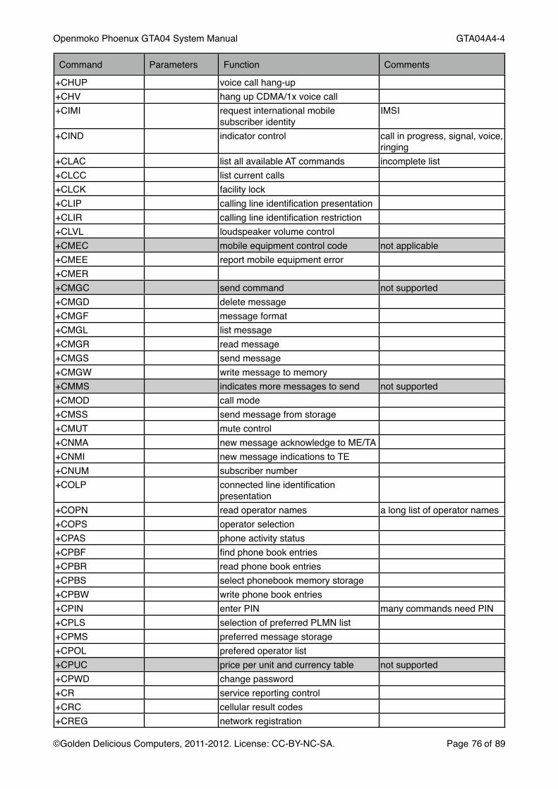
10.4.2. AT commandsThe basic AT command interface has been defined in GSM 07.07 (http://www.ctiforum.com/standard/standard/etsi/0707.pdf).AT+CLAC lists most of the commands plus vendor specific extensions.
Command Parameters Function Comments
_OAIR aircraft mode same function as +CFUN_OBLS show SIM, Call Lists and SMS status_OBSI show base station information_OCHAP enable/disable CHAP_OCTI unsolicited reporting of cell type
indicator
Openmoko Phoenux GTA04 System Manual! GTA04A4-4
©Golden Delicious Computers, 2011-2012. License: CC-BY-NC-SA.! Page 73 of 89

Command Parameters Function Comments
_OEANT unsolicited reporting of antenna signal strength
0-5
_OEMM check emergency mode status initiated by AT+CDV=911_OERCN get PIN/PUK retry counter_OGSN product serial number same as +CGSN_OHCIP report HSDPA call in progress_OHWV hardware version_ONCI get neighbour cell information list of nearby base stations_OPATEMP unsolicited reporting of power
amplifier temperature_OPBM enable/disable frequency bands_OPCMENABLE enable voice PCM interface for voicecalls_OPCMPROF 0: handset
1: headset2: speakerphone3: bluetooth hs
PCM audio profile controls internal filters
_OPDPP set PAP/CHAP Security Parameters_OPON prioritized operator name_OPONI unsolicited reporting of prioritized
operator name_OPSYS choose GSM and or W(C)DMA
acquistion order_ORESET soft reset /dev/ttyHS* may change!_OSIMOP show HPLNM operator name_OSQI unsolicited reporting of signal quality
indication2*n-113 dBm
_OSRPE show SIM status_OSSYS unsolicited reporting of service GSM / UTRAN / no service_OUHCIP unsolicited reporting of HSDPA call in
progress_OUWCTI unsolicited reporting of WCDMA cell
type indicator_OWANCALL start/stop data call connect: =1,1,1 / disconnect:
=1,0,1; HSO driver will automatically create/destroy an interface
_OWANDATA get network data result: IP, Gateway, DNS1, DNS2, NBS1, NBS2, Speed; should be used for an ifconfig
_OWANNWERROR get WWAN network errors_OWCTI WCDMA cell type indicator_OWIND unsolicited reporting of W_DISABLE enable unsolicited notification*CNTI\Q\S print AT command settings\V enable extended data call result code&C circuit 109 behaviour&D circuit 108 behaviour
Openmoko Phoenux GTA04 System Manual! GTA04A4-4
©Golden Delicious Computers, 2011-2012. License: CC-BY-NC-SA.! Page 74 of 89

Command Parameters Function Comments
&E control display of data rate either serial rate or wireless connection speed
&F reset to factory defined configuration&K&S DSR control management always on&V dump configuration parameters&W store V250 and S-registers to non-
volatile memory%V request revision information+CACM accumulated call meter not supported+CAMM accumulated call meter maximum not supported+CAOC advice of charge+CBC battery charge not applicable+CBST select bearer service type+CCFC call forwarding number and
conditions+CCLK clock not applicable+CCUG closed user group+CCWA call waiting+CDIP called line identification presentation+CDV initiate CDMA/1x voice call+CEER extended error report+CFUN set phone functionality+CGACT PDP context activate or deactivate+CGATT PS attach or detach+CGCLASS GPRS mobile station class GPRS only+CGCMOD PDP context modify not supported+CGDATA enters data state not supported+CGDCONT define PDP context+CGDSCONT define secondary PDP context not supported+CGEQMIN minimum acceptable 3G quality of
service profiledoes nothing
+CGEQREQ requested 3G quality of service profile+CGEREP packet domain event reporting does nothing+CGMI request manufacturer idenfitication+CGMM request model identification+CGMR request revision identification+CGPADDR show PDP address not supported+CGQMIN minimum acceptable quality of
service profiledoes nothing
+CGQREQ requested quality of service profile+CGREG GPRS network registration status+CGSMS select service for MO SMS messages+CGSN request product serial number
identificationIMEI
+CGTFT traffic flow template not supported+CHLD call related supplementary services+CHSN
Openmoko Phoenux GTA04 System Manual! GTA04A4-4
©Golden Delicious Computers, 2011-2012. License: CC-BY-NC-SA.! Page 75 of 89
Command Parameters Function Comments
+CHUP voice call hang-up+CHV hang up CDMA/1x voice call+CIMI request international mobile
subscriber identityIMSI
+CIND indicator control call in progress, signal, voice, ringing
+CLAC list all available AT commands incomplete list+CLCC list current calls+CLCK facility lock+CLIP calling line identification presentation+CLIR calling line identification restriction+CLVL loudspeaker volume control+CMEC mobile equipment control code not applicable+CMEE report mobile equipment error+CMER+CMGC send command not supported+CMGD delete message+CMGF message format+CMGL list message+CMGR read message+CMGS send message+CMGW write message to memory+CMMS indicates more messages to send not supported+CMOD call mode+CMSS send message from storage+CMUT mute control+CNMA new message acknowledge to ME/TA+CNMI new message indications to TE+CNUM subscriber number+COLP connected line identification
presentation+COPN read operator names a long list of operator names+COPS operator selection+CPAS phone activity status+CPBF find phone book entries+CPBR read phone book entries+CPBS select phonebook memory storage+CPBW write phone book entries+CPIN enter PIN many commands need PIN+CPLS selection of preferred PLMN list+CPMS preferred message storage+CPOL prefered operator list+CPUC price per unit and currency table not supported+CPWD change password+CR service reporting control+CRC cellular result codes+CREG network registration
Openmoko Phoenux GTA04 System Manual! GTA04A4-4
©Golden Delicious Computers, 2011-2012. License: CC-BY-NC-SA.! Page 76 of 89

Command Parameters Function Comments
+CRES restore SMS settings from nonvolatile memory
not supported
+CRLP radio link protocol+CRSM restriced SIM access+CSAS save SMS settings into nonvolatile
memorynot supported
+CSCA service center address+CSCB set cell broadcast message types+CSCS select TE character set+CSDH show text mode parameters+CSIM generic SIM access+CSMP set text mode paramters+CSMS select message service+CSQ signal quality+CSSN supplementary service notifications+CSTA select type of address+CTFR call deflection+CTZR time zone reporting+CTZU automatic time zone update+CUSD unstructured supplementary services+CV120+CVHU voice hang-up control+DR data compression reporting+DS data compression+ES enable synchronous mode+ESA preferred message storage+FCLASS select FAX class+GCAP request complete capabilities list+GMI request manufacturer idenfitication+GMM request manufacturer idenfitication+GMR request revision identification+GSN request revision identification+ICCID+ICF DTE-DCE character framing+IFC DTE-DCE local flow control+IPR fixed DTE rate+PACSP get ENS PLNM mode bit+VIP set PCM interface mode use mode 0+VTD DTMF tone duration 0.1 sec steps+VTS =[0-9][A-D]#* DTMF tone generator supply digit by digit+WS46 select wireless network$BREW$CCLK$CREG$CSQ$QCAGC$QCBANDPREF
Openmoko Phoenux GTA04 System Manual! GTA04A4-4
©Golden Delicious Computers, 2011-2012. License: CC-BY-NC-SA.! Page 77 of 89

Command Parameters Function Comments
$QCBOOTVER$QCCLR$QCCNMI$QCCTM$QCDGEN$QCDMG$QCDMR$QCDNSP$QCDNSS$QCHWREV$QCPDPLT$QCPDPP set PAP/CHAP Security Parameters$QCPINSTAT$QCPWRDN$QCSIMSTAT$QCSLIP$QCSLOT$QCSYSMODE$QCTER$QCVOLTA answerD >: dial from
phonebookI/i: override CLIRG/g: conrol CUG; initiate voice call
dial ; is mandatory for a voice call
E command echo echo AT commandsH hook control H0 to hang upI request identification information print modem identificationL monitor speaker loudness does nothingM monitor speaker mode does nothingO return to online data stateP select pulse dialing does nothingQ result code suppression suppress “OK“S0 automatic answerS10 automatic connect delay does nothingS103S104S11S2S3 command line termination parameterS30 data inactivity timer for disconnect does nothingS4 response formatting characterS5 command line editing characterS6 pause before blind dialing does nothingS7 connection completion timeout does nothing
Openmoko Phoenux GTA04 System Manual! GTA04A4-4
©Golden Delicious Computers, 2011-2012. License: CC-BY-NC-SA.! Page 78 of 89

Command Parameters Function Comments
S8 comma dialer modifier time does nothingS9T select tone dialing does nothingV DCE response formatX result code selection and call
progress monitoring controlZ reset to detault configuration
10.5. Audio / VoiceThere is a ALSA driver for the TPS65950 (twl4030). It allows to control all mixer settings described in the TPS65950 Technical Reference Manual (SWCU050 (Figures 14-6 and 14-7 - which option is available can also be changed through amixer).Telephony Voice is presented on McBSP4. PCM clock and sync is generated by the GTM601 module. 2MHz clock, 8kHz sync (mode 0 of AT+VIP=0).Issue the AT_OPCMENABLE=1 command to the module and choose the profile by AT_OPCMPROF.Dial a number through ATD. Append a semicolon (;) to initiate a voice call.
10.6. I2C1 devicesI2C1 is connected to the TPS65950. It provides the four functional blocks at addresses 0x48, 0x49, 0x4a, 0x4b. For details refer to the TPS65950 documentation.
10.7. I2C2 devicesThis bus connects all sensors and controllers. Not all chips are necessarily installed.
Address Device Type Function
0x1C LIS302 Accelerometer (BOTTOM)
0x77 BMP085 Barometer, Thermometer
0x1E HMC5883L Digital Compass
0x41 BMA180 Accelerometer (BOTTOM)
0x48 TSC2007 Touch Screen, Chip Temperature, Ambient Light (AUX channel)
0x11 Si4705/Si4721
FM Receiver with RDS
0x45 TCA6507 LED driver
0x33 TPS61050 Torch/Flash LED driver
0x30 OV9655 Camera
Openmoko Phoenux GTA04 System Manual! GTA04A4-4
©Golden Delicious Computers, 2011-2012. License: CC-BY-NC-SA.! Page 79 of 89

Address Device Type Function
0x50 MT24LR64 RFID-EEPROM
0x34 TCA8418 Keypad controller
10.8. GPIO assignmentThis table lists the GPIOs that can and or should reasonably be switched to GPIO mode (4). Please be aware that you do switch input/output direction through PINMUX. And additionaly have to choose the direction of a GPIO between input and bidirectional.
GPIO Number Mode 0 Pin Name Function (if used as GPIO)
54 connected to temperature sensor of PoP memory. Goes to 1 if chip temperatore > 85 °C; should generate an interrupt and reduce power
57 GPT11_PWM switch on/off LCD backlight; should be used in PWM mode
19 McBSP5_FSX Chip-Select for LCD serial interface
12 McBSP5_CLKX LCD serial clock
20 McBSP5_DX LCD serial data output (protected)
18 McBSP5_DR LCD serial data input
23 Enable TV-Out for MIC/AV on headset jack
55 Enable Headset Jack left&right output
171 McSPI1_CLK sense board version (R307)
172 McSPI1_SIMO sense board version (R306)
173 McSPI1_SOMI sense board version (R305)
174 McSPI1_CS Reset for USB3322 ULPI-PHY to interface with WWAN module
145 UART2_RTS GPS-ON/OFF
144 UART2_CTS internal/external Antenna sense
7 SYS_BOOT5 read state of AUX button (1=pressed)
170 HDQ read/write HDQ protocol
114 LIS302/BMA180 INT1
115 LSM303 INT1 (Accelerometer)
162 LSM303 DRDY (Compass)
Openmoko Phoenux GTA04 System Manual! GTA04A4-4
©Golden Delicious Computers, 2011-2012. License: CC-BY-NC-SA.! Page 80 of 89

GPIO Number Mode 0 Pin Name Function (if used as GPIO)
56 ITG3200 INT
113 BMP085 INT
160 TSC2007 PENIRQ
156 Si47xx INT
13 RS232/IrDA selection
21 RS232 EXT
176 Keyboard INT
10 3G-WAKE (impulse on AT_ORESET, incoming call or incoming SMS)
186 start/stop UMTS module
10.9. Board version encodingGPIO171, 172, and 173 allow to distinguish between board versions by populating 0 Ohm resitors or leaving them out. The GPIO pins are switched to pull-up mode so leaving out a resistor reads the GPIO as a high level.
R305 R306 R307 GPIO173 GPIO172 GPIO171 Version
- - - 1 1 1 GTA04A2
X - - 0 1 1 GTA04A3
- X - 1 0 1 GTA04A4
- - X 1 1 0 GTA04A5
X X - 0 0 1 GTA04A6
X - X 0 1 0 GTA04A7
- X X 1 0 0 GTA04A8
X X X 0 0 0 GTA04A9
10.10. Significant Hardware changesThis section describes the hardware changes that are significant to know when writing low-level software.
Openmoko Phoenux GTA04 System Manual! GTA04A4-4
©Golden Delicious Computers, 2011-2012. License: CC-BY-NC-SA.! Page 81 of 89
10.10.1.GTA04A1 to GTA04A2GTA04A1 („Openmoko Beagle Hybrid“) was an adapter board to connect an Openmoko touchscreen and a GPS receiver to a Beagleboard. Main differences are in GPIO and signal assigments. And the lack of many functions of later versions.
10.10.2.GTA04A2 to GTA04A3Major reassignment of some GPIOs and other interface. Since only a single GTA04A2 board was ever built, these changes are not documented here in any detail.
10.10.3.GTA04A3 to GTA04A4The LIS302 and LSM303 are not installed.All sensors are installed.The test points (expansion connections) are rearranged and extended.The UMTS module does no longer power on automatically. It needs an on/off impulse (>200 mS) on GPIO186.The UMTS module can generate a 3G-Wakeup interrupt on GPIO10.The test points of the GTM601W have been removed.The UMTS voice PCM is additionally connected to the TPS65950 PCM voice channel. This requires to properly tri-state the McBSP4/TPS-PCM interface!McSPI3 is no longer connected to the GTM601W. McSPI3 is still available on the B2B connector and in addition on easily accessible test points.The KEYIRQ has been moved from GPIO10 to GPIO176.WLAN and Bluetooth power is no longer fed to separate test points (since this voltage is easily accessed on some components).There is a separate LDO that is controlled by VAUX4.The WLAN/BT module has been replaced by Firmware variant W2CBW003C-001/003. This has the UART interface for Bluetooth pre-initialized for 3 Mbit/s instead of 115200 kbit/s. This needs to install a special OMAP UART driver to program the prescalers as needed. Since Linux 2.6.34 this appears to be the default (/dev/ttyO0 instead of /dev/ttyS0).
Openmoko Phoenux GTA04 System Manual! GTA04A4-4
©Golden Delicious Computers, 2011-2012. License: CC-BY-NC-SA.! Page 82 of 89
11. Legal InfoThe responsible manufacturer according to EU laws (e.g. WEEE, CE, product liability etc.) is Golden Delicious Computers GmbH&Co. KG, Oberhaching, Germany.
11.1. Safety Instructions1. Before entering an area where Mobile Phones are prohibited (e.g. Airplane, Hospital),
remove the battery! The hardware+software canʻt guarantee that the mobile phone transmitter is switched completely off.
2. Keep away from liquids.3. Do not operate above 35 degrees surrounding temperature (inside temperature may be
20-30 degrees above outside temperature).4. Donʻt heat up the battery above 80 degrees.5. Donʻt expose to direct sunlight even if switched off.6. Only use the provided charging unit or use the USB socket of a computer.7. Use only safe and correctly installed power outlets.8. This device emits GSM/UMTS as well as other radio waves. A medical risk has neither
been proven nor disproven so far. Certification/Approval requires to keep the antennas at least 20cm away from persons.
9. The Emergency call (112 / 911) capability may be limited by your installed software. So, please carry a working mobile phone with you for placing emergency calls.
10.This device can create audible sounds through the built-in speaker or a connected headset. If the acoustic waves are too powerful and/or for a long duration, this may cause hearing damage.
11.The device can be used as a recorder and player device. This requires to comply to intellectual property laws.
12.Let repairs and maintanance be done only by qualified service persons.
11.2. CE - ConformityThe Openphoenux GTA04 has been measured by Schwille Elektronik GmbH that it conforms to the European standards:• DIN EN 55022; VDE 0878-22:2008-07 Einrichtungen der Informationstechnik -
Funkstöreigenschaften - Grenzwerte und Messverfahren (IEC/CISPR 22:2005, modifiziert + A1:2005); Deutsche Fassung EN 55022:2006 + A1:2007
The UMTS module GTM601W has been assessed as model MO6012 by SGS UK Ltd. They are a BIS appointed notified body (0890) The serial number is GSM139580.The WLAN/Bluetooth transmitters fall under the unlicenced operation rules.The device falls in Equipment Class II.You can find a copy of the test reports here:http://download.goldelico.com/gta04/Certificates/
11.3. FCCThe device has no individual FCC approval but complies with Part 15 of the FCC rules.The device contains:
Openmoko Phoenux GTA04 System Manual! GTA04A4-4
©Golden Delicious Computers, 2011-2012. License: CC-BY-NC-SA.! Page 83 of 89
FCC-ID: NCMOMO6012FCC-ID: U9R-W2CBW003IC: 2734A-MO6012IC: 7089A-W2CBW003
11.4. Allowed WLAN frequency rangeEurope/ETSI:! ! Channel 01 - 13North America:! ! Channel 01 - 11In some areas of France, there are additional limitations:10mW for all channels, 100mW only for channel 10-13Please refer to local information at www.art-telecom.fr
11.5. ROHSThis device is in compliance with EC Directive 2002/95/EC.
11.6. Recycling / WEEE (ID: DE80183434)Electronical devices are not allowed to be put into household waste. Please bring it to an appropriate recycling collection system.Never put the battery into fire.
This device contains a LiIon battery. It is not allowed to be put into household waste. Please bring the device and the battery to an appropriate recycling collection system or return them to us.
11.7. US-EARThis devices contains components classified as US technology in groups 3A, 5A, 7A. The device itself is classified as 5A992 and therefore falls under the „mass market encryption rules“. This means that it can not be (re-)exported to embargoed countries. Refer to the latest EAR tables, definitions and laws.
11.8. GPLThe product may contain software that is licenced according to the (L)GPL. Since we consider printing the full licence text here as an ecological waste of paper, please refer to it online: http://www.gnu.org/licenses/gpl.html
11.9. TrademarksLinux is a registered trademark of Linus Torvalds. Openmoko is a registered trademark of FIC/Openmoko, Inc., Golden Delicious is a registered trademark of Golden Delicious Computers GmbH&Co. KG.All other products, brand names, company names and trademarks are property and trademark of the particular owners and are used here for referential purposes only.
11.10. Copyright
Openmoko Phoenux GTA04 System Manual! GTA04A4-4
©Golden Delicious Computers, 2011-2012. License: CC-BY-NC-SA.! Page 84 of 89

This document is authored by employees of Golden Delicious Computers GmbH&Co. KG. Copying without appropriate permission (see license) is prohibited.
11.11. Limitation of LiabilityThe liability is limited as far as possible to the sales price of the device. Golden Delicious Computers GmbH&Co. KG is never liable for loss of data or recordings and for consequential losses, such as loss of use, production and loss of profits.
Openmoko Phoenux GTA04 System Manual! GTA04A4-4
©Golden Delicious Computers, 2011-2012. License: CC-BY-NC-SA.! Page 85 of 89

12. WarrantyThis device has 24 months warranty according to the rules of the EU.Up to 2 bad pixels are not covered by warranty.In case of technical problems, please contact your retail shop.
Golden Delicious Computers GmbH&Co. KGBuchenstr. 3
82041 OberhachingGermany
Amtsgericht München, HRA 89571http://www.goldelico.com
[email protected] +49 (89) 5429 0367Fax +49 (89) 5429 0377
Openmoko Phoenux GTA04 System Manual! GTA04A4-4
©Golden Delicious Computers, 2011-2012. License: CC-BY-NC-SA.! Page 86 of 89

13. Change History
new Version Changes
GTA04A4-3 Change history addedwarning for handling display connectorwarning to never switch off VAUX2address of TAC8418 fixed to 0x34ttyS* replaced by ttyO*Bluetooth UART now preconfigured for 3 MBit/s
GTA04A4-4 Fixed typo for P1902 [McBSP5-CLKX is GPIO12 and not GPIO17]fixed description of swapped pin 7&8 of RS232 DB9fMultiboot description added
Openmoko Phoenux GTA04 System Manual! GTA04A4-4
©Golden Delicious Computers, 2011-2012. License: CC-BY-NC-SA.! Page 87 of 89
14. SchematicsThe following pages show the schematics and the PCB placement as current when this manual was printed. They are subject to change. And, not all components are necessarily available or installed in your device.
Please note the Creative Commons Licence for the Schematics. I.e. if you derive work on it you are required to share it under the same licence and attribute to the original authors.
If you need a different licence, please contact us for written permission.
14.1. Page 1 Block Diagram
14.2. Page 2 Display, Touch Controller, Backlight
14.3. Page 3 CPU, SD-Card, PCB-Version, Boot options
14.4. Page 4 CPU-TPS, Vibra, LEDs, Misc
14.5. Page 5 Clock, Charging, Battery
14.6. Page 6 TPS/OMAP Power
14.7. Page 7 Audio Codec, Video
14.8. Page 8 USB-OTG
14.9. Page 9 internal WWAN-USB
14.10. Page 10 WWAN/UMTS Modem + SIM
14.11. Page 11 WLAN/BT
14.12. Page 12 GPS
14.13. Page 13 Sensors (Accelerometer, Barometer, Compass, ...)
14.14. Page 14 FM-TRX, RFID-EEPROM
14.15. Page 15 RS232, IrDA
14.16. Page 16 (Keypad Controller option)
Openmoko Phoenux GTA04 System Manual! GTA04A4-4
©Golden Delicious Computers, 2011-2012. License: CC-BY-NC-SA.! Page 88 of 89

14.17. Page 17 Camera
14.18. Page 18 (VGA, DVI option)
14.19. Page 19 B2B Connectors
14.20. Component placement Top
14.21. Component placement Bottom
Openmoko Phoenux GTA04 System Manual! GTA04A4-4
©Golden Delicious Computers, 2011-2012. License: CC-BY-NC-SA.! Page 89 of 89


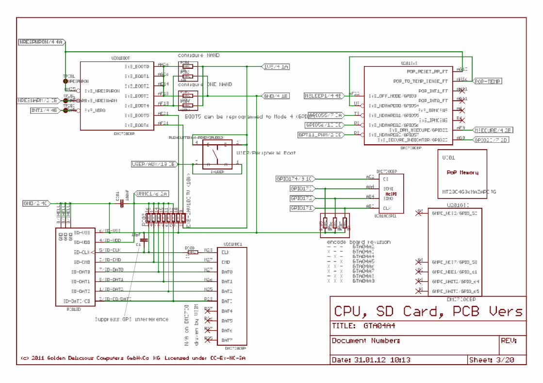
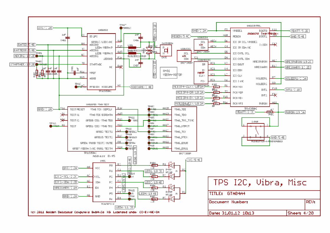


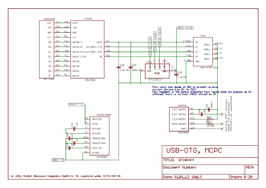


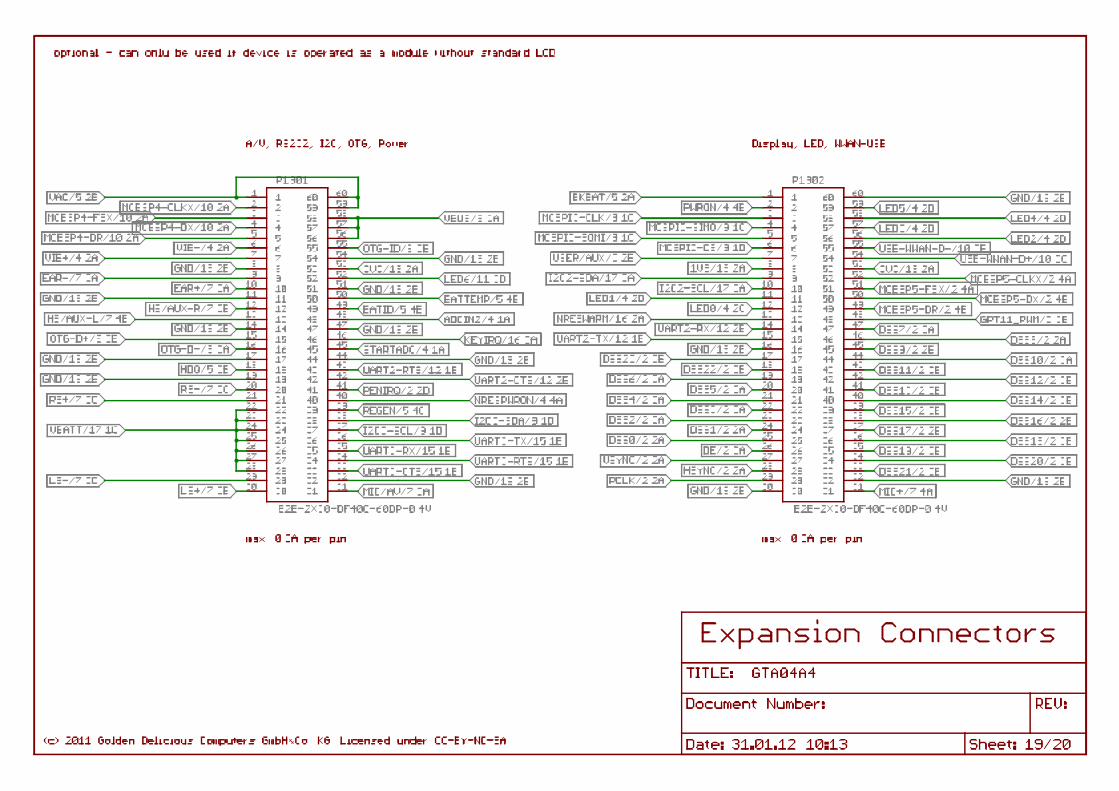
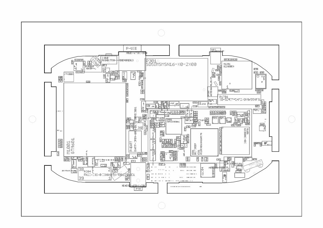

Related Documents


