GSWP300W-EVBPA GaN E-HEMT Wireless Power Transfer Evaluation Board User’s Guide _____________________________________________________________________________________________________________________ GSWP300W-EVBPA Rev 180614 © 2018 GaN Systems Inc. www.gansystems.com 1 Please refer to the Evaluation Board/Kit Important Notice on page 27 GSWP300W-EVBPA 300W GaN E-HEMT Wireless Power Transfer Evaluation Board, Optimized for Class EF2 Amplifiers User’s Guide Visit www.gansystems.com for the latest version of this user’s guide.

Welcome message from author
This document is posted to help you gain knowledge. Please leave a comment to let me know what you think about it! Share it to your friends and learn new things together.
Transcript

GSWP300W-EVBPA GaN E-HEMT Wireless Power Transfer Evaluation Board
User’s Guide _____________________________________________________________________________________________________________________
GSWP300W-EVBPA Rev 180614 © 2018 GaN Systems Inc. www.gansystems.com 1
Please refer to the Evaluation Board/Kit Important Notice on page 27
GSWP300W-EVBPA
300W GaN E-HEMT Wireless Power Transfer Evaluation Board, Optimized for Class EF2 Amplifiers User’s Guide
Visit www.gansystems.com for the latest version of this user’s guide.

GSWP300W-EVBPA GaN E-HEMT Wireless Power Transfer Evaluation Board
User’s Guide _____________________________________________________________________________________________________________________
GSWP300W-EVBPA Rev 180614 © 2018 GaN Systems Inc. www.gansystems.com 2
Please refer to the Evaluation Board/Kit Important Notice on page 27
DANGER!
Electrical Shock Hazard - Hazardous high voltage may be present on the board during the test and even brief contact during operation may result in severe injury or death. Follow all locally approved safety procedures when working around high voltage.
Never leave the board operating unattended. After it is de-energized, always wait until all capacitors are discharged before touching the board.
This board should be handled by qualified personnel ONLY.
PCB surface and devices can become hot. Contact may cause burns. Do not touch!
CAUTION
This product contains parts that are susceptible to damage by electrostatic discharge (ESD) or exposure to voltages in excess of the specified voltage. Always follow ESD prevention procedures when handling the product. Avoid applying excessive voltages to the power supply terminals or signal inputs or outputs, always connected to the load during the test on-going.

GSWP300W-EVBPA GaN E-HEMT Wireless Power Transfer Evaluation Board
User’s Guide _____________________________________________________________________________________________________________________
GSWP300W-EVBPA Rev 180614 © 2018 GaN Systems Inc. www.gansystems.com 3
Please refer to the Evaluation Board/Kit Important Notice on page 27
Introduction to Magnetic Resonant Wireless Power Transfer Recent technological advances in power semiconductors are enabling Wireless Power Transfer (WPT) as a technically and commercially viable option for charging and powering equipment across a wide range of markets, applications, and power levels.
Inductive charging has been in use for a number of years, however, it’s burdened with limitations that restrict it to low power applications with tightly controlled alignment between the transmitter and receiver.
A more advantageous approach, magnetic resonant charging, addresses these shortcomings by using a high frequency oscillating magnetic field to transfer energy. The benefits that magnetic resonant charging offers include variable spacing between the transmitter and receiver, the ability to charge through materials such as a desk or an enclosure, one-to-many charging, ease of installation, suitability for high power levels, and fast charging. Table 1 provides a comparison between inductive charging and magnetic resonant charging.
GaN E-HEMTS are a key enabler of magnetic resonant charging because their extremely fast switching speeds, on the order of a few nanoseconds, result in very low switching losses. This allows them to operate efficiently at very high frequencies, such as the 6.78MHz that is commonly used for magnetic resonant charging.
Table 1 A comparison of Inductive charging and Magnetic Resonant charging
Charging technology Inductive Magnetic Resonant
Frequency range 80-300kHz 6.78MHz
Max transfer range 5mm 50mm
Multi-device No Yes, at different power levels
Spatial Freedom Low High
Power Range Low & limited 30W max
Broad & versatile 50W to 20kW+
Efficiency Limited to 80% High: up to 95%
A high-level block diagram of a resonant wireless power transfer system is shown in Figure 1. The transmit section is composed of a power amplifier, an impedance matching circuit and a transmit coil. High frequency energy is transferred wirelessly at 6.78MHz to the receive circuit which is comprised of a receive coil, an impedance matching circuit and a rectifier.
The GSWP300W-EVBPA evaluation board is designed to support and expedite the innovation of WPT systems by providing the Power Amplifier, the most challenging aspect of the system design.

GSWP300W-EVBPA GaN E-HEMT Wireless Power Transfer Evaluation Board
User’s Guide _____________________________________________________________________________________________________________________
GSWP300W-EVBPA Rev 180614 © 2018 GaN Systems Inc. www.gansystems.com 4
Please refer to the Evaluation Board/Kit Important Notice on page 27
Figure 1 - A magnetic resonant wireless power transfer design.
Evaluation board overview The GSWP300W-EVBPA uses GaN Systems’ GS66508B E-HEMTs in a 6.78MHz Class EF2 power amplifier. The GS66508Bs are used with the integrated high-speed pSemi PE29102 gate driver in a push-pull configuration. The outputs of the PE29102 are capable of providing switching transition speeds in the nano-seconds range for hard switching applications.
This User’s Guide includes a circuit description, a quick-start guide and measurement results.
Evaluation Kit Contents and Requirements
Kit Contents The GSWP300W-EVBPA includes the following hardware for evaluating the GaN E-HEMT 300W power amplifier.
Table 2 GSWP300W-EVBPA Evaluation Kit Contents
Quantity Description
1 GaN E-HEMT GS66508B WPT PA evaluation board assembly
1 WPT PA heatplate
1 WPT PA EMC shield
2 2 pins DC cord

GSWP300W-EVBPA GaN E-HEMT Wireless Power Transfer Evaluation Board
User’s Guide _____________________________________________________________________________________________________________________
GSWP300W-EVBPA Rev 180614 © 2018 GaN Systems Inc. www.gansystems.com 5
Please refer to the Evaluation Board/Kit Important Notice on page 27
Hardware Requirements In order to evaluate the performance of the evaluation board, the following equipment is required:
• DC power supply 100V/15A
• TEK scope with current probe TCM0030A
• Fluke 87 multimeter for input current
• 50dB 500W attenuator as load
• Spectrum analyzer
• Power meter
• Thermal meter
Evaluation Board Assembly Overview
The evaluation board (EVB) is assembled with two GS66508B E-HEMT transistors and two PE29102 GaN E-HEMT drivers. Headers are included for monitoring the signal input, signal output, power connections and detection monitoring signals. Probe points are included for waveform measurements. Provision has been made for a single, suitable heatsink to be fastened against the two E-HEMTs, using the two holes in the center of the bottom heatplate.
Figure 2 • Top side of GSWP300W-EVBPA Evaluation Board Assembly

GSWP300W-EVBPA GaN E-HEMT Wireless Power Transfer Evaluation Board
User’s Guide _____________________________________________________________________________________________________________________
GSWP300W-EVBPA Rev 180614 © 2018 GaN Systems Inc. www.gansystems.com 6
Please refer to the Evaluation Board/Kit Important Notice on page 27
Figure 3 • Bottom side of GSWP300W-EVBPA Evaluation Board Assembly, showing copper coins
GSWP300W-EVBPA GaN E-HEMT Wireless Power Transfer Evaluation Board
User’s Guide _____________________________________________________________________________________________________________________
GSWP300W-EVBPA Rev 180614 © 2018 GaN Systems Inc. www.gansystems.com 7
Please refer to the Evaluation Board/Kit Important Notice on page 27
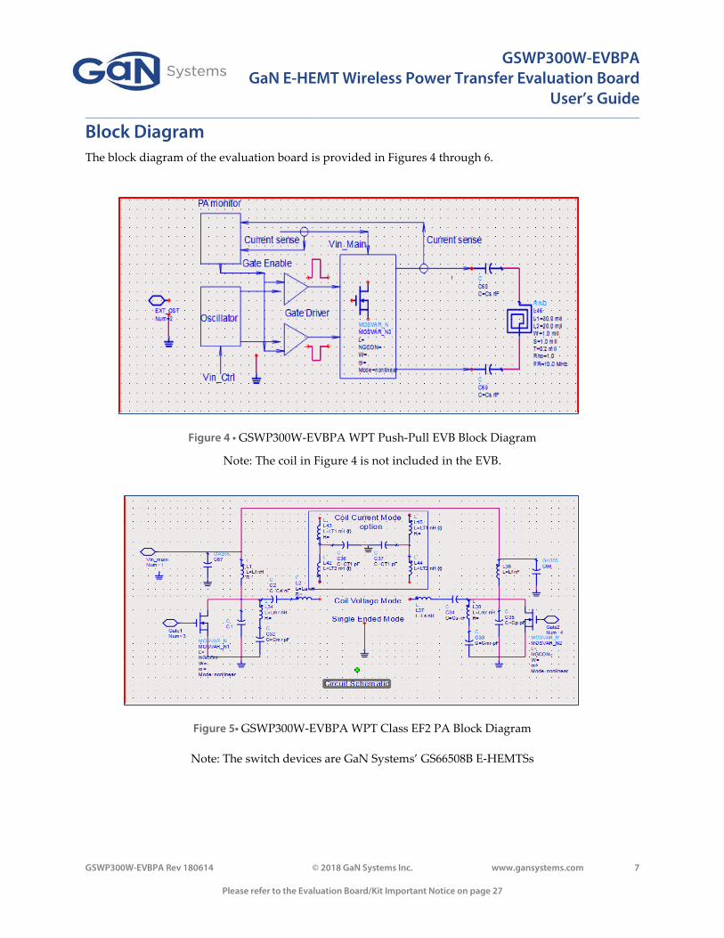
Block Diagram The block diagram of the evaluation board is provided in Figures 4 through 6.
Figure 4 • GSWP300W-EVBPA WPT Push-Pull EVB Block Diagram
Note: The coil in Figure 4 is not included in the EVB.
Figure 5• GSWP300W-EVBPA WPT Class EF2 PA Block Diagram
Note: The switch devices are GaN Systems’ GS66508B E-HEMTSs
GSWP300W-EVBPA GaN E-HEMT Wireless Power Transfer Evaluation Board
User’s Guide _____________________________________________________________________________________________________________________
GSWP300W-EVBPA Rev 180614 © 2018 GaN Systems Inc. www.gansystems.com 8
Please refer to the Evaluation Board/Kit Important Notice on page 27
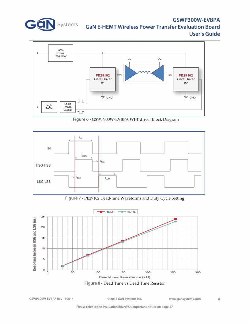
Figure 6 • GSWP300W-EVBPA WPT driver Block Diagram
Figure 7 • PE29102 Dead-time Waveforms and Duty Cycle Setting
Figure 8 • Dead Time vs Dead Time Resistor

GSWP300W-EVBPA GaN E-HEMT Wireless Power Transfer Evaluation Board
User’s Guide _____________________________________________________________________________________________________________________
GSWP300W-EVBPA Rev 180614 © 2018 GaN Systems Inc. www.gansystems.com 9
Please refer to the Evaluation Board/Kit Important Notice on page 27
Circuit Description The Push-Pull circuit is comprised of two single ended PAs which share a common supply, however; the impedance matching and EMI filters are separated.
The high-side E-HEMTs are powered by a DC source, referred to as the HV supply. It is connected through J32 or J28. The voltage of this source not exceed 100VDC.
The low-voltage logic circuitry runs off a 3.3VDC voltage regulator, U88, which is powered from a +5VDC source connected through JP35 or J28. The +5VDC rail also feeds two PE29102 drivers U86 and U90, which are driven independently by U87, a common logic D-type flip/flop. U87 has a frequency divider configuration, which is driven by a crystal oscillator Y8 at a frequency of 13.56MHz. The two PE29102 gate drives are capable of 6V operation.
The PA can be configured to operate in a number of different modes, which include
• Push-pull configuration with an EMI filter
• Single ended mode
• Operation without an EMI filter
• Operation with an external oscillator signal input. Users can run multiple PAs together at the same frequency for high power operation.
Detailed operation procedures and setup for these alternative configurations are provided in the section titled “quick start guide”.
The PA includes an over-temperature protection circuit. Temperature sensor U9, placed close to the GS66508B E-HEMTs, monitors their temperature. In an over-temperature condition, the PE29102A driver will be disabled through U133 and stop driving the E-HEMTs. The design also includes circuitry to protect against over-current, and load mismatch.
The evaluation board includes an EMI filter, comprised of one low pass filter and one notch filter. The output of PA can be configured, through jumpers, to operate either with or without an EMI filter. The detailed jumper and SMA connector configurations are listed in Table 4
For convenience, test points are provided to monitor and measure the electrical signals. A description of the test points and diagram of their location is provided in Table 5.
The PA also includes a Micro Controller Unit (MCU) monitor interface header, J1. The signals available through J1 can be used to control the PA system for close loop in the WPT system. A definition of the signals available on header J1 is provided in Figure 9.

GSWP300W-EVBPA GaN E-HEMT Wireless Power Transfer Evaluation Board
User’s Guide _____________________________________________________________________________________________________________________
GSWP300W-EVBPA Rev 180614 © 2018 GaN Systems Inc. www.gansystems.com 10
Please refer to the Evaluation Board/Kit Important Notice on page 27
Figure 9 • MCU interface definition. Signals on J1
The PA connectivity is depicted in Figure 10 and includes the RF input and output, the DC biases and the MCU monitor interface.
Figure 10 • Circuit Connectivity
Protection Circuit The PA includes circuitry to protect against input DC overcurrent, device over temperature, output RF overvoltage and Voltage Standing Wave Ratio (VSWR) protection. The protection signals are combined by U133, a 3 inputs OR gate logic chip, and will shut the driver down under a fault condition.
Input DC overcurrent protection (OCP): U91 is the DC current sensor chip, which can handle a maximum of 10A. The output of the current sensor ship is a current sense signal that goes thru buffer OP U122 and is compared to a reference voltage. The reference voltage is set with R101 and
• Monitor signals on J1. • Pin1: PA GND • Pin2: 5V Input • Pin3: output voltage detection • Pin4: PA HV DC current • Pin5: 3.3V DC • Pin6: over voltage and current • Pin7: output power detection • Pin8: Temperature sensor voltage • Pin9: PA HV DC input • Pin10: Fan control enable

GSWP300W-EVBPA GaN E-HEMT Wireless Power Transfer Evaluation Board
User’s Guide _____________________________________________________________________________________________________________________
GSWP300W-EVBPA Rev 180614 © 2018 GaN Systems Inc. www.gansystems.com 11
Please refer to the Evaluation Board/Kit Important Notice on page 27
R177. Upon an over current event, a signal is generated to signal OCP_TRIG.
Overvoltage protection (OVP): The design includes overvoltage protection circuitry for both the high side and the low side. The high side voltage sensor is comprised of C276, C277, and two Schottky diodes; D52 and D44. C276/C277 form a voltage divider, the ratio of which can be changed. Two diodes rectify the RF signal to DC thru C278/C22 and R111 and the resulting voltage represents the high side output. The low side circuit is similar. It’s comprised of C270, C280, and two diode D50, D53. These two voltage detection signals go to a two-channel comparator U68 and are combined with OR gate U70 into one overvoltage trigger, OVP_TRIG.
The OVP and OCP go into a hard combine circuit D45, which a dual diode in one. To generate an overcurrent / overvoltage protection trigger signal.
Standing Wave Ratio (SWR) detection: two of coupler, T2, T83, comprise of the board band bidirectional coupler. The reflection signal goes thru D75, C722, C721, it turns into DC signal which goes thru the buffer OP U132 into comparator U130, of which the reference voltage is set by the R936/R937, the trigger point can be set by the reference voltage, which is refer the SWR. The direction of the coupler is around 15dB at 6.78MHz.
Figure 11 • Connectivity locations
Thermal Management Thermal management of the GaN E-HEMTs in this RF power system is a critical aspect of the
J56 RF output before EMI filter J28
HV DC Input J31 & J33
RF output before EMI Single ended
J1 MCU interface
J57 RF Out
Push pull SMA pSemi
PE29102A GaN Systems
GS66508B J34
SMA external input

GSWP300W-EVBPA GaN E-HEMT Wireless Power Transfer Evaluation Board
User’s Guide _____________________________________________________________________________________________________________________
GSWP300W-EVBPA Rev 180614 © 2018 GaN Systems Inc. www.gansystems.com 12
Please refer to the Evaluation Board/Kit Important Notice on page 27
design. Maintaining low device temperatures through proper thermal management enhances the system reliability and extends the range of operating temperature.
The GS66508B are bottom-side cooled devices that use GaNPX® packaging, designed for optimal thermal performance. For effective thermal management, a hole is cut out of the PCB to permit access to the copper coins. The two GS66508Bs’ bottom side thermal pads are soldered directly onto the copper coins on the bottom side of the PCB and the Gate, Drain and Source signals are routed on the top side of the PCB. This set up provides an ultra-low thermal impedance from the die to the copper coins.
Figure 12 • Copper coins soldered beneath PCB and devices top PCB
Figure 13 • Aluminum heatplate with housing for two copper coins.
Heatplate

GSWP300W-EVBPA GaN E-HEMT Wireless Power Transfer Evaluation Board
User’s Guide _____________________________________________________________________________________________________________________
GSWP300W-EVBPA Rev 180614 © 2018 GaN Systems Inc. www.gansystems.com 13
Please refer to the Evaluation Board/Kit Important Notice on page 27
Quick Start Guide The GSWP300W-EVBPA EVB is designed to as a platform for evaluating the GS66508B E-HEMTs in a Push-Pull Class EF2 PA for WPT. This chapter will guide the user through the evaluation board overview, PA operation, bench setup and test results.
Evaluation Board Overview
Kit Contents
The GSWP300W-EVBPA evaluation kit contains:
• Power Amplifier evaluation board assembly
• PA heatplate
• PA EMC shield
• 4 pins DC cord
Evaluation board specifications
Table 3: EVB specifications:
PARAMETER SPECS
Input Voltage range 100VDC max
Tx output power 300W
Tx efficiency (peak) 88%
Topology/Class EF2
Frequency 6.78 MHz
Switching type Push/Pull
GaN Systems part number GS66508B
Number of GS devices 2
Optimized RL (load) 30Ω
Constant current mode optional
The maximum operating specifications of the evaluation board are as follows:
• Maximum HV supply input operating voltage of 100VDC. The 100VDC limit is based on capacitor selection. Operation at a higher power level can be achieved if the capacitors are replaced with ones having a higher voltage rating.

GSWP300W-EVBPA GaN E-HEMT Wireless Power Transfer Evaluation Board
User’s Guide _____________________________________________________________________________________________________________________
GSWP300W-EVBPA Rev 180614 © 2018 GaN Systems Inc. www.gansystems.com 14
Please refer to the Evaluation Board/Kit Important Notice on page 27
• Maximum LV supply input operating voltage of 7VDC • Frequency of operation of 6.78MHz. • Maximum output power of 300W (default setting, adjustable)
Note: * The maximum output power depends on the input voltage, as shown in Figures 19 and 22
Configurations
The PA can be configured into three different operating options: voltage mode, current mode, and single ended. Table 4 describes how to configure the board using the jumpers provided.
Table 4: Configuration options
Jumper Option Jumper on/off
JP51 Internal oscillator (default) JP51 on / JP52 off
JP52 External oscillator JP51 off / JP52 on
Voltage mode (without EMI filter) Voltage mode JP5/JP43/JP6/JP44 off
Current mode (with EMI filter) Current mode JP5/JP43/JP6/JP44 on
Voltage mode output RF output JP56
Current mode output RF output JP57

GSWP300W-EVBPA GaN E-HEMT Wireless Power Transfer Evaluation Board
User’s Guide _____________________________________________________________________________________________________________________
GSWP300W-EVBPA Rev 180614 © 2018 GaN Systems Inc. www.gansystems.com 15
Please refer to the Evaluation Board/Kit Important Notice on page 27
Test points
To monitor the performance of PA, test points are provided and as described in Table 5. All test points are available on the top side of the board, none are on the bottom side. The test points locations are silkscreened on the PCB.
Table 5: Test point description
Test point Description
TP197 U90 input (PE29102 driver)
TP76 U6 input (PE29102 driver)
TP8 Q77 Gate voltage
TP81 Q76 Gate voltage
TP189 Q77 Drain voltage
TP82 Q76 Drain voltage
TP176 60V DC current detection
TP194 External oscillator monitor
Evaluation Bench Test Setup The test bench setup for the GSWP300W-EVBPA EVB is shown in Figure 14. Ensure that the safety precautions mentioned on page 2 are followed.
Figure 14 • Bench setup
A recommended list equipment is provided below. Equipment with equivalent performance specifications can be substituted. In all cases, ensure that it is well calibration.
• DC power supply 100V/15A
• TEK scope with current probe TCM0030A

GSWP300W-EVBPA GaN E-HEMT Wireless Power Transfer Evaluation Board
User’s Guide _____________________________________________________________________________________________________________________
GSWP300W-EVBPA Rev 180614 © 2018 GaN Systems Inc. www.gansystems.com 16
Please refer to the Evaluation Board/Kit Important Notice on page 27
• Fluke 87 multimeter for input current
• 50dB 500W attenuator as load
• Spectrum analyzer: RIGOL DSA 815
• Power meter: GiGa 8542C
• Thermal meter, sensor is located at screw of copper coin
Note: The WPT test setup is normally a non-50Ω system. If the PA is tested under a non-50Ω system, the measurement results may not correlate with 50Ω system due to the mismatch.
Hardware Operation The following steps provide a guideline for proper hardware operation and configuration.
1) First, set the current limit to 0.3A for the +5VDC supply feeding JP35 or JP28.
2) Set the current limit to 1A for the HV DC supply feeding JP32 or JP28 at a voltage of between +20VDC and +50VDC.
3) Verify that all DC power supplies are turned off.
4) Make sure the load is connected to JP56 or JP57.
5) Verify the Class EF2 waveform via test points TP8, TP81 with JP32 +5VDC.
6) Connect the VDD power supply to JP32 or JP28. Apply between +4V to +20VDC to JP32. Read the output power at JP56 or JP57.
7) Turn on the HV supply to the desired value. Do not exceed the absolute maximum voltage of +100VDC. Keep the JP32 +5VDC on.
8) To power the evaluation board down, reverse the steps above.
Measurement Technique
When measuring the high frequency content switch node, care must be taken to avoid long ground leads. Measure the switch node by placing the oscilloscope probe tip at JP192 and JP193 (designed for this purpose) or to the closest ground screws. Refer to Figure 15 for the proper probe technique.

GSWP300W-EVBPA GaN E-HEMT Wireless Power Transfer Evaluation Board
User’s Guide _____________________________________________________________________________________________________________________
GSWP300W-EVBPA Rev 180614 © 2018 GaN Systems Inc. www.gansystems.com 17
Please refer to the Evaluation Board/Kit Important Notice on page 27
Figure 15 • Proper oscilloscope probe measurement technique
PA Performance without EMI filter
Power-on Procedure without EMI filter • An additional heatsink may be required. The PA heatplate is provided with threaded hole
locations that can be used to attach the heatsink to the heatplate with 4-40 screws. To ensure excellent thermal conduction, apply thermal grease to the PA / heatsink interface before screwing the units together. Enough thermal grease should be applied so that a small amount extrudes on all four sides as the screws are tightened. Wipe the assembly clean.
• Make sure jumpers JP5/JP43/JP6/JP44 are off
• Solder the wires with the SMA connector to JP56.
• Connect the load to JP56
• Plug the 5VDC supply into JP35. Pin 1: positive. Pin 2: negative. Turn the supply on and set the DC input voltage to 5V
• Plug the HV supply into JP32. Pin 1: positive. Pin 2: negative. Turn the supply on and ramp the voltage from 0V to 20V.
• Monitor the test point voltage by comparing the power meter measurement to GaN Systems’ test data which is available in Appendix A.
• If the measurements correlate, increase the HV supply to 60VDC.
• IMPORTANT: Ensure the 5VDC supply does not exceed 6V during testing.
GSWP300W-EVBPA GaN E-HEMT Wireless Power Transfer Evaluation Board
User’s Guide _____________________________________________________________________________________________________________________
GSWP300W-EVBPA Rev 180614 © 2018 GaN Systems Inc. www.gansystems.com 18
Please refer to the Evaluation Board/Kit Important Notice on page 27
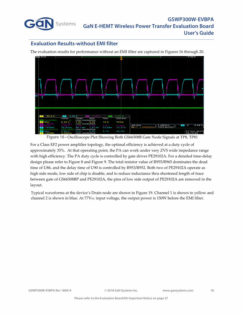
Evaluation Results-without EMI filter The evaluation results for performance without an EMI filter are captured in Figures 16 through 20.
Figure 16 • Oscilloscope Plot Showing Both GS66508B Gate Node Signals at TP8, TP81
For a Class EF2 power amplifier topology, the optimal efficiency is achieved at a duty cycle of approximately 35%. At that operating point, the PA can work under very ZVS wide impedance range with high efficiency. The PA duty cycle is controlled by gate driver PE29102A. For a detailed time-delay design please refer to Figure 8 and Figure 9. The total resistor value of R955/R965 dominates the dead time of U86, and the delay time of U90 is controlled by R953/R952. Both two of PE29102A operate as high side mode, low side of chip is disable, and to reduce inductance thru shortened length of trace between gate of GS66508BP and PE29102A, the pins of low side output of PE29102A are removed in the layout.
Typical waveforms at the device’s Drain node are shown in Figure 19. Channel 1 is shown in yellow and channel 2 is shown in blue. At 77VDC input voltage, the output power is 150W before the EMI filter.

GSWP300W-EVBPA GaN E-HEMT Wireless Power Transfer Evaluation Board
User’s Guide _____________________________________________________________________________________________________________________
GSWP300W-EVBPA Rev 180614 © 2018 GaN Systems Inc. www.gansystems.com 19
Please refer to the Evaluation Board/Kit Important Notice on page 27
Figure 17 • Oscilloscope Plot Showing Both GS66508B Drain Node Signals, without EMI filter
The ratio of maximum Drain voltage and input DC voltage is 2.33 which is ideal for a class EF2 amplifier. This operating condition eliminates voltage stress on the transistors and has low second harmonics. The output current shown in green, is not a perfect sinewave due to high order harmonics on the output load.
Switch mode Power Amplifiers have a lot of harmonics at the output. One significant advantage of the Class EF2 topology is that it has a lower 2nd harmonic when compared to other PA topologies. This advantage results in a Class EF2 PA with much better EMI performance.
Figure 18 shows the spectrum of the PA at 70W output power without an EMI filter. Compared to the fundamental frequency, the 2nd harmonic is -35dBc, the 3rd harmonic is -20dBc, and the 4th harmonic is -34dBc. This extremely low 2nd harmonic performance makes it much easier to filter out the PA’s high order harmonic. This allows designers to meet EMI specifications and regulations without additional cost.
The PA’s output power and efficiency are shown in Figure 19. This PA delivers 93% efficiency at 70W output power and 27VDC input voltage. This remarkable efficiency performance makes PA the best candidate of the WPT systems, and particularly advantageous for high power applications such as drone, autonomous robot and E-bike charging.

GSWP300W-EVBPA GaN E-HEMT Wireless Power Transfer Evaluation Board
User’s Guide _____________________________________________________________________________________________________________________
GSWP300W-EVBPA Rev 180614 © 2018 GaN Systems Inc. www.gansystems.com 20
Please refer to the Evaluation Board/Kit Important Notice on page 27
Figure 18 • Spectrum Plot of output terminal JP56 SMA after 49.66dB attenuation at 300W output power.
Operation without an EMI filter.
Figure 19 • Output power and efficiency of PA without EMI filter at JP56 SMA

GSWP300W-EVBPA GaN E-HEMT Wireless Power Transfer Evaluation Board
User’s Guide _____________________________________________________________________________________________________________________
GSWP300W-EVBPA Rev 180614 © 2018 GaN Systems Inc. www.gansystems.com 21
Please refer to the Evaluation Board/Kit Important Notice on page 27
Note: With the EMI filter, the maximum power level is limited to 300W, due to the 50Ω test.
The PA’s system reliability is optimized when the temperature rise of each device is kept to a minimum, including that of the GaN E-HEMTs. The GS66508Bs are especially well suited in this regard, for a number of reasons. First, they have very low switching losses which allows them to operate at high efficiency and a low temperature rise at 6.78MHz, the common frequency used for resonant wireless power transfer. Secondly, the bottom-side cooled GaNPX® packaging provides an extremely low thermal impedance for efficient heat transfer to the heatsink, thereby drawing heat out of the device. This GaN based design is able to operate over a wide ambient temperature and with convection cooling, eliminating the need for cooling fans. These advantages support a PA design with excellent thermal performance up to 300W output power.
The temperature plot of the PA design was measured and captured with a SEEK thermal camera and is shown in Figure 20. The hottest devices are the first inductors, with the hottest inductor recording 35˚C above ambient. The temperature rise of the GaN E-HEMTs, by comparison, is only 3˚C. Because the GaN E-HEMTs run very cool, this allows operation over a very wide temperature range and extends operation to a higher power level while simultaneously simplifying the cooling system design and reducing the cost.
Figure 20 • Thermal measurement of PA without EMI filter at 300W output power

GSWP300W-EVBPA GaN E-HEMT Wireless Power Transfer Evaluation Board
User’s Guide _____________________________________________________________________________________________________________________
GSWP300W-EVBPA Rev 180614 © 2018 GaN Systems Inc. www.gansystems.com 22
Please refer to the Evaluation Board/Kit Important Notice on page 27
PA Performance with EMI filter Power-on Procedure with EMI filter
• An additional heatsink may be required. The PA heatplate is provided with threaded hole locations that can be used to attach the heatsink to the heatplate with 4-40 screws. To ensure excellent thermal conduction, apply thermal grease to the PA / heatsink interface before screwing the units together. Enough thermal grease should be applied so that a small amount extrudes on all four sides as the screws are tightened. Wipe the assembly clean.
• Make sure jumpers JP5/JP43/JP6/JP44 are on
• Do not attach a cable or wire to JP56.
• Connect the load to JP57.
• Plug 5VDC supply into JP35. Pin 1: positive. Pin 2: negative. Adjust the voltage to 5V.
• Plug the HV supply into JP32. Pin 1: positive. Pin 2: negative. Turn the supply on and ramp the voltage from 0V to 20V
• Monitor the test point voltage by comparing the power meter measurement to GaN Systems’ test data which is available in Appendix A.
• If the measurements correlate, increase the HV supply to 60VDC.
• IMPORTANT: Ensure the 5VDC supply does not exceed 6V during testing.
• The optimized impedance of the current mode PA is around 30Ω. Using a 50Ω load will not cause damage, however, the system will operate at a lower efficiency.
Evaluation Results-with EMI filter For improved EMI performance, a filter can be used to reduce the higher order harmonics in each side of the push-pull arm. Also, the addition of an EMI filter converts the PA from operating in voltage mode to current mode, which provides a constant current for the WPT system.
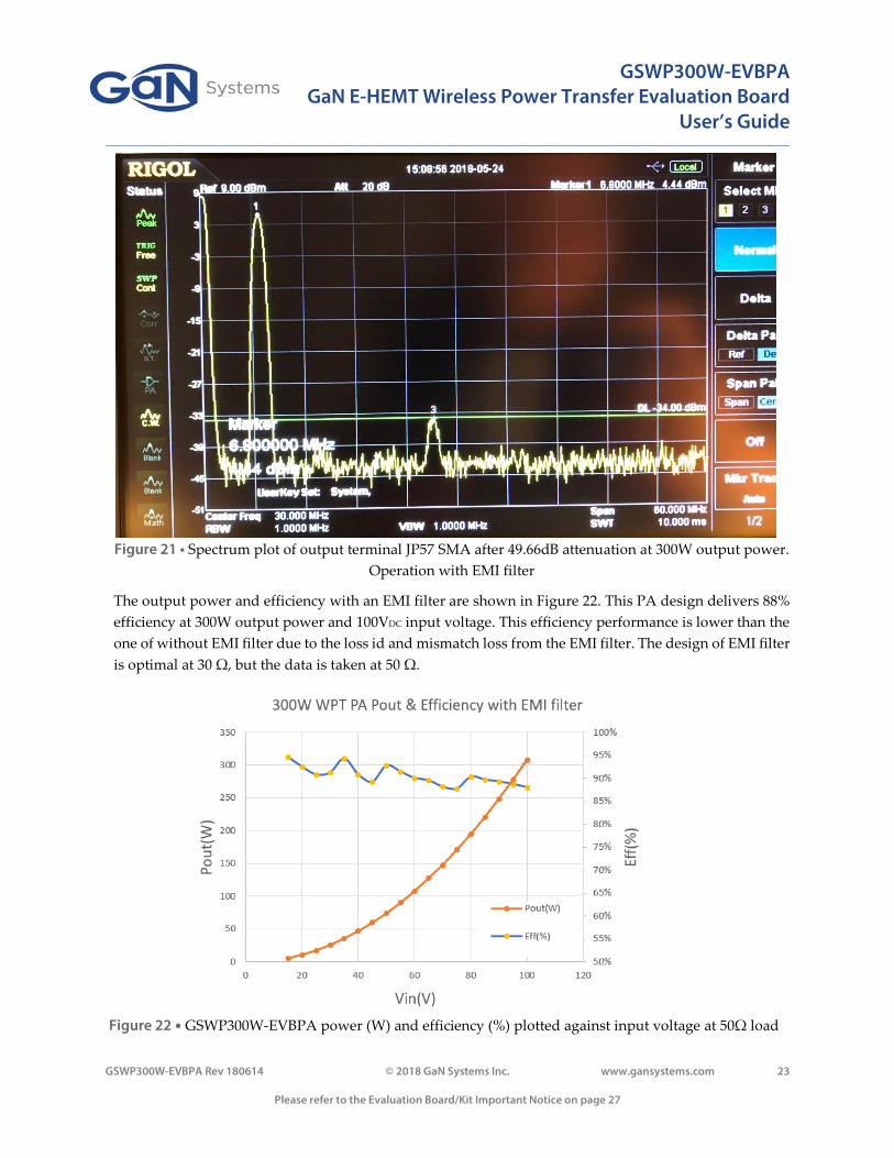
The frequency spectrum of the PA is depicted in Figure 21. The 3rd harmonic rejection is around -58dBc, with more than -60dBc rejection on high order harmonics. This outstanding performance will greatly help the WPT system level EMI performance.
GSWP300W-EVBPA GaN E-HEMT Wireless Power Transfer Evaluation Board
User’s Guide _____________________________________________________________________________________________________________________
GSWP300W-EVBPA Rev 180614 © 2018 GaN Systems Inc. www.gansystems.com 23
Please refer to the Evaluation Board/Kit Important Notice on page 27
Figure 21 • Spectrum plot of output terminal JP57 SMA after 49.66dB attenuation at 300W output power. Operation with EMI filter
The output power and efficiency with an EMI filter are shown in Figure 22. This PA design delivers 88% efficiency at 300W output power and 100VDC input voltage. This efficiency performance is lower than the one of without EMI filter due to the loss id and mismatch loss from the EMI filter. The design of EMI filter is optimal at 30 Ω, but the data is taken at 50 Ω.
Figure 22 • GSWP300W-EVBPA power (W) and efficiency (%) plotted against input voltage at 50Ω load

GSWP300W-EVBPA GaN E-HEMT Wireless Power Transfer Evaluation Board
User’s Guide _____________________________________________________________________________________________________________________
GSWP300W-EVBPA Rev 180614 © 2018 GaN Systems Inc. www.gansystems.com 24
Please refer to the Evaluation Board/Kit Important Notice on page 27
The SEEK thermal camera photo of the PA is depicted in Figure 23. The thermal performance with EMI filter is very impressive. The hottest points of the circuit are the two 2nd harmonics shunt inductors which have a temperature rise of 35˚C. The temperature rise of the GaN devices is a modest 3˚C.
Figure 23 • Thermal measurement of PA with EMI filter at 300W output power

GSWP300W-EVBPA GaN E-HEMT Wireless Power Transfer Evaluation Board
User’s Guide _____________________________________________________________________________________________________________________
GSWP300W-EVBPA Rev 180614 © 2018 GaN Systems Inc. www.gansystems.com 25
Please refer to the Evaluation Board/Kit Important Notice on page 27
Technical Resources This document and additional technical resources are available for download from www.gansystems.com.
GSWP300W-EVBPA GaN E-HEMT Wireless Power Transfer Evaluation Board
User’s Guide _____________________________________________________________________________________________________________________
GSWP300W-EVBPA Rev 180614 © 2018 GaN Systems Inc. www.gansystems.com 26
Please refer to the Evaluation Board/Kit Important Notice on page 27
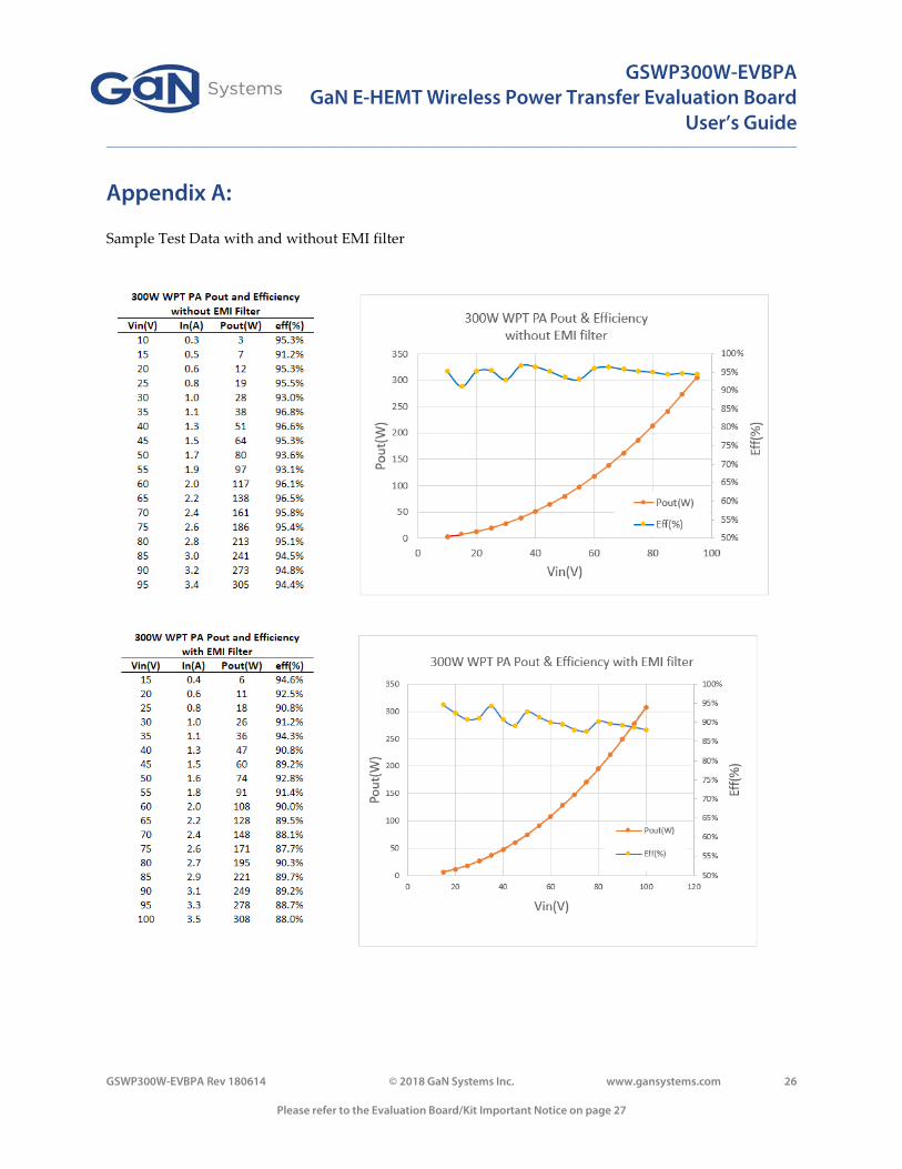
Appendix A: Sample Test Data with and without EMI filter

GSWP300W-EVBPA GaN E-HEMT Wireless Power Transfer Evaluation Board
User’s Guide _____________________________________________________________________________________________________________________
GSWP300W-EVBPA Rev 180614 © 2018 GaN Systems Inc. www.gansystems.com 27
Please refer to the Evaluation Board/Kit Important Notice on page 27
Evaluation Board/kit Important Notice GaN Systems Inc. (GaN Systems) provides the enclosed product(s) under the following AS IS conditions: This evaluation board/kit being sold or provided by GaN Systems is intended for use for ENGINEERING DEVELOPMENT, DEMONSTRATION, and OR EVALUATION PURPOSES ONLY and is not considered by GaN Systems to be a finished end-product fit for general consumer use. As such, the goods being sold or provided are not intended to be complete in terms of required design-, marketing-, and/or manufacturing-related protective considerations, including but not limited to product safety and environmental measures typically found in end products that incorporate such semiconductor components or circuit boards. This evaluation board/kit does not fall within the scope of the European Union directives regarding electromagnetic compatibility, restricted substances (RoHS), recycling (WEEE), FCC, CE or UL, and therefore may not meet the technical requirements of these directives, or other related regulations. If this evaluation board/kit does not meet the specifications indicated in the User’s Guide, the board/kit may be returned within 30 days from the date of delivery for a full refund. THE FOREGOING WARRANTY IS THE EXCLUSIVE WARRANTY MADE BY THE SELLER TO BUYER AND IS IN LIEU OF ALL OTHER WARRANTIES, EXPRESSED, IMPLIED, OR STATUTORY, INCLUDING ANY WARRANTY OF MERCHANTABILITY OR FITNESS FOR ANY PARTICULAR PURPOSE. EXCEPT TO THE EXTENT OF THIS INDEMNITY, NEITHER PARTY SHALL BE LIABLE TO THE OTHER FOR ANY INDIRECT, SPECIAL, INCIDENTAL, OR CONSEQUENTIAL DAMAGES. The user assumes all responsibility and liability for proper and safe handling of the goods. Further, the user indemnifies GaN Systems from all claims arising from the handling or use of the goods. Due to the open construction of the product, it is the user’s responsibility to take any and all appropriate precautions with regard to electrostatic discharge. No License is granted under any patent right or other intellectual property right of GaN Systems whatsoever. GaN Systems assumes no liability for applications assistance, customer product design, software performance, or infringement of patents or any other intellectual property rights of any kind. GaN Systems currently services a variety of customers for products around the world, and therefore this transaction is not exclusive. Please read the User’s Guide and, specifically, the Warnings and Restrictions notice in the User’s Guide prior to handling the product. Persons handling the product(s) must have electronics training and observe good engineering practice standards. This notice contains important safety information about temperatures and voltages. For further safety concerns, please contact a GaN Systems’ application engineer.

GSWP300W-EVBPA GaN E-HEMT Wireless Power Transfer Evaluation Board
User’s Guide _____________________________________________________________________________________________________________________
GSWP300W-EVBPA Rev 180614 © 2018 GaN Systems Inc. www.gansystems.com 28
Please refer to the Evaluation Board/Kit Important Notice on page 27
In Canada:
GaN Systems Inc. 1145 Innovation Drive Suite 101 Ottawa, Ontario, Canada K2K 3G8 T +1 613-686-1996
In Europe:
GaN Systems Ltd., German Branch Terminalstrasse Mitte 18, 85356 München, Germany T +49 (0) 8165 9822 7260
In the United States:
GaN Systems Corp. 2723 South State Street, Suite 150, Ann Arbor, MI. USA 48104 T +1 248-609-7643
www.gansystems.com Important Notice – Unless expressly approved in writing by an authorized representative of GaN Systems, GaN Systems components are not designed, authorized or warranted for use in lifesaving, life sustaining, military, aircraft, or space applications, nor in products or systems where failure or malfunction may result in personal injury, death, or property or environmental damage. The information given in this document shall not in any event be regarded as a guarantee of performance. GaN Systems hereby disclaims any or all warranties and liabilities of any kind, including but not limited to warranties of non-infringement of intellectual property rights. All other brand and product names are trademarks or registered trademarks of their respective owners. Information provided herein is intended as a guide only and is subject to change without notice. The information contained herein or any use of such information does not grant, explicitly, or implicitly, to any party any patent rights, licenses, or any other intellectual property rights. General Sales and Terms Conditions apply. © 2009-2015 GaN Systems Inc. All rights reserved.
Related Documents