L143.A (02/13) 1 pulseelectronics.com/products/antennas GSM/3G Penta Band Hybrid PCB Antenna Pulse Part Number W3544A / 3544B San Diego, CA 858 674 8100 Vancouver, WA 360 944 7551 Europe 49 7032 7806 0 Asia 86 755 33966678 North Asia 886 3 4356768 China 86 512 6807 9998 Pulse introduces the small hybrid surface mount pick- and-place W3544X family of GSM/3G antennas. Board connection is via 6 SMD connection points underneath the antenna. Antennas are delivered in tape and reel packaging for use in automatic SMD pick-and-place. Each antenna measures 7.65 x 26 x 3 mm and requires ground clearance on the PCB. The W3544A is optimized for a corner board location while the W3544B is for use at the end of a narrow PCB. Frequency bands are 824- 960 and 1710-2170 MHz with a target of minimum 50% ef- ficiency in all bands offering a compact high performance solution for GSM/3G applications Features - Frequency bands 824-960 and 1710-2170 MHz - SMD solution - Compact antenna size of 7.65 x 26 x 3 mm - RoHS Compliant Product Applications - GSM/3G routers - Femto Cell modems - Industrial wireless machine to machine - Smart Grid devices - Mobile Hotspots Part Number Positioning W3544A Vertically mounted at board edge W3544B Horizontally mounted at board edge

Welcome message from author
This document is posted to help you gain knowledge. Please leave a comment to let me know what you think about it! Share it to your friends and learn new things together.
Transcript
L143.A (02/13)1 pulseelectronics.com/products/antennas
GSM/3G Penta Band Hybrid PCB Antenna
Pulse Part Number W3544A / 3544B
San Diego, CA 858 674 8100 Vancouver, WA 360 944 7551 Europe 49 7032 7806 0 Asia 86 755 33966678 North Asia 886 3 4356768 China 86 512 6807 9998
Pulse introduces the small hybrid surface mount pick-and-place W3544X family of GSM/3G antennas. Board connection is via 6 SMD connection points underneath the antenna. Antennas are delivered in tape and reel packaging for use in automatic SMD pick-and-place. Each antenna measures 7.65 x 26 x 3 mm and requires ground clearance on the PCB. The W3544A is optimized for a corner board location while the W3544B is for use at the end of a narrow PCB. Frequency bands are 824-960 and 1710-2170 MHz with a target of minimum 50% ef-ficiency in all bands offering a compact high performance solution for GSM/3G applications
Features- Frequency bands 824-960 and 1710-2170 MHz- SMD solution- Compact antenna size of 7.65 x 26 x 3 mm- RoHS Compliant Product
Applications- GSM/3G routers- Femto Cell modems- Industrial wireless machine to machine- Smart Grid devices- Mobile Hotspots
Part Number Positioning
W3544A Vertically mounted at board edge
W3544B Horizontally mounted at board edge
2 pulseelectronics.com/products/antennas
GSM/3G Penta Band Hybrid PCB Antenna
Pulse Part Number W3544A / 3544B
L143.A (02/13)2 pulseelectronics.com/products/antennas
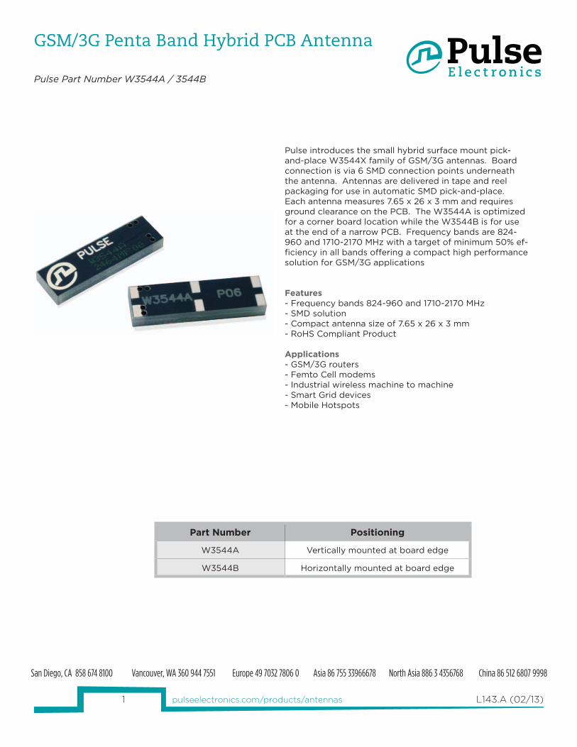
Mechanical Specifications Weight [oz/g] .04 / 1.11
Dimensions [Inches/mm] .38 x 1.02 x .12 /9.65 x 26 x 3
Mounting SMD
Environmental Specifications
Operating Temperature [°C] -45 to +85
Storage Temperature [°C] -45 to +85
Electrical Specifications
W3544A W3544B
Frequency 1 [MHz] 824 - 960 824 - 960
Frequency 2 [MHz] 1710 - 1880 1710 - 1880
Frequency 3 [MHz] 1850 - 1990 1850 - 1990
Frequency 4 [MHz] 1920 - 2170 1920 - 2170
Nominal Impedance [Ω] 50 50
Gai
n
Freq 1 [dBi avg] -1.9 65% -1.5 70%
Freq 2 [dBi avg] -1.3 74% -1.1 77%
Freq 3 [dBi avg] -1.3 74% -1.1 77%
Freq 4 [dBi avg] -1.66 68% -1.5 71%
Ret
urn
Loss
Frequency 1 [dB] -4.1 -6.5
Frequency 2 [dB] -4.6 -5.7
Frequency 3 [dB] -16.3 -18.5
Frequency 4 [dB] -12.3 -13
Note:
Gain: Frequency detail above is all peak and given in dBi first, then efficiency.
Antenna Dimensions
3 pulseelectronics.com/products/antennas
GSM/3G Penta Band Hybrid PCB Antenna
Pulse Part Number W3544A / 3544B
L143.A (02/13)3 pulseelectronics.com/products/antennas
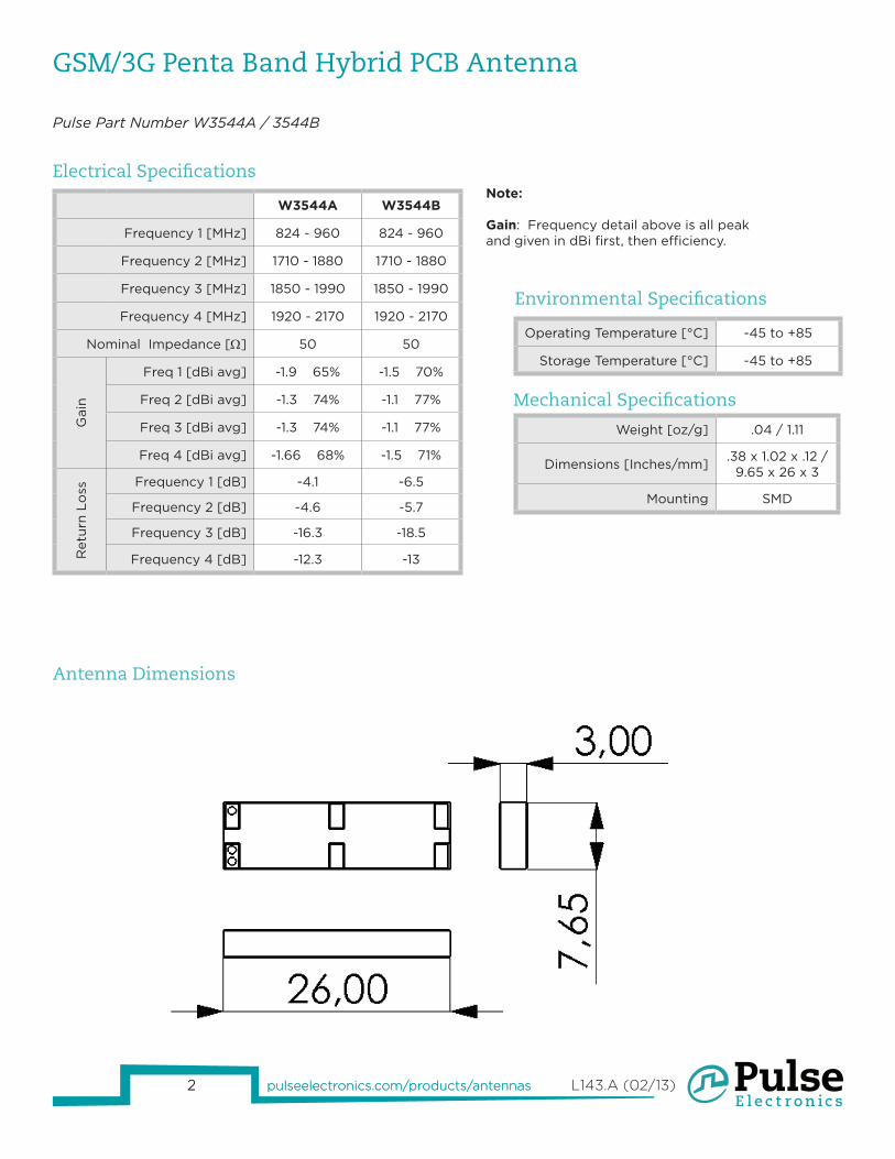
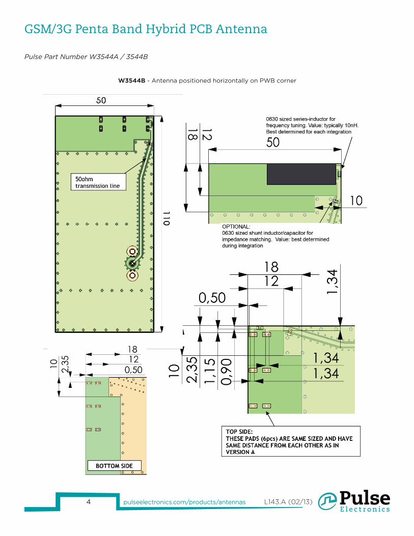
Test Setup for Electrical Measurements Recommended test board layout for electrical characteristic measurement. Test board outline size 110 mm x 50 mm. Ground cleared under antenna.
NOTE: All measurements are in mm.
W3544A - Antenna positioned vertically on PWB corner
4 pulseelectronics.com/products/antennas
GSM/3G Penta Band Hybrid PCB Antenna
Pulse Part Number W3544A / 3544B
L143.A (02/13)4 pulseelectronics.com/products/antennas
W3544B - Antenna positioned horizontally on PWB corner
5 pulseelectronics.com/products/antennas
GSM/3G Penta Band Hybrid PCB Antenna
Pulse Part Number W3544A / 3544B
L143.A (02/13)5 pulseelectronics.com/products/antennas5 pulseelectronics.com/products/antennas
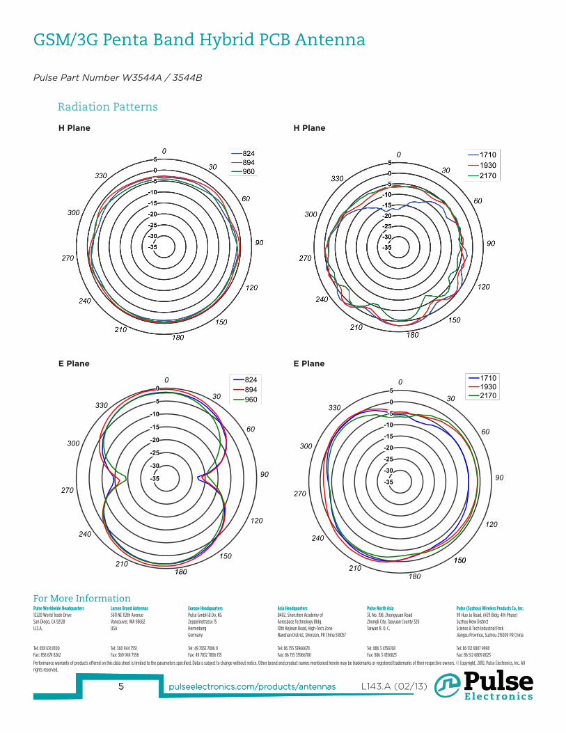
Radiation Patterns
For More InformationPulse Worldwide Headquarters12220 World Trade DriveSan Diego, CA 92128U.S.A.
Tel: 858 674 8100Fax: 858 674 8262
Larsen Brand Antennas3611 NE 112th AvenueVancouver, WA 98682USA
Tel: 360 944 7551Fax: 369 944 7556
Europe HeadquartersPulse GmbH & Do, KGZeppelinstrasse 15HerrenbergGermany
Tel: 49 7032 7806 0Fax: 49 7032 7806 135
Asia HeadquartersB402, Shenzhen Academy of Aerospace Technology Bldg.10th Kejinan Road, High-Tech ZoneNanshan District, Shenzen, PR China 518057
Tel: 86 755 33966678 Fax: 86 755 33966700
Pulse North Asia3F, No. 198, Zhongyuan RoadZhongli City, Taoyuan County 320Taiwan R. O. C.
Tel: 886 3 4356768Fax: 886 3 4356823
Pulse (Suzhou) Wireless Products Co, Inc.99 Huo Ju Road, (#29 Bldg, 4th Phase)Suzhou New DistrictScience & Tech Industrial ParkJiangsu Province, Suzhou 215009 PR China
Tel: 86 512 6807 9998Fax: 86 512 6809 8023
Performance warranty of products offered on this data sheet is limited to the parameters specified. Data is subject to change without notice. Other brand and product names mentioned herein may be trademarks or registered trademarks of their respective owners. © Copyright, 2010. Pulse Electronics, Inc. All rights reserved.
E Plane E Plane
H Plane
-35
-30
-25
-20
-15
-10
-5
00
30
60
90
120
150
180210
240
270
300
330
824894960
180
-35
-30
-25
-20
-15
-10
-5
0
50
30
60
90
120
150210
240
270
300
330
171019302170
150
180210
H Plane
Related Documents