© Copyright 2012 by e-Gizmo Mechatronix Central All Rights Reserved GSM/GPRS Modem (Shield) Hardware Manual Page 1 of 9 GSM GPRS SHIELD / FEATURES & SPECIFICATIONS • Industry proven SIMCOM SIM900D Module • Buffered UART provides addional layer of protecon • Fused power input • On board LDO voltage regulator • UART/SUART switch selectable port (gizDuino) • On board manual power switch • SIM Card Holder GENERAL SPECIFICATIONS Power Input: 5V-7.5VDC @ 1.5A I/O Interface: UART 3.3V Logic 5V Tolerant LED Indicators: Power Network Status PCB Dimensions: 53.5W x 69L mm

Welcome message from author
This document is posted to help you gain knowledge. Please leave a comment to let me know what you think about it! Share it to your friends and learn new things together.
Transcript
© Copyright 2012by e-Gizmo Mechatronix Central
All Rights ReservedGSM/GPRS Modem (Shield) Hardware Manual Page 1 of 9
GSM GPRS SHIELD/
FEATURES & SPECIFICATIONS
• Industry proven SIMCOM SIM900D Module • Buffered UART provides additional layer of protection • Fused power input • On board LDO voltage regulator • UART/SUART switch selectable port (gizDuino) • On board manual power switch • SIM Card Holder
GENERAL SPECIFICATIONS
Power Input: 5V-7.5VDC @ 1.5A I/O Interface: UART 3.3V Logic 5V Tolerant LED Indicators: Power Network Status PCB Dimensions: 53.5W x 69L mm
© Copyright 2012by e-Gizmo Mechatronix Central
All Rights ReservedGSM/GPRS Modem (Shield) Hardware Manual Page 2 of 9
Major Components Presentation
Figure 1. GSM/GPRS Major Parts ID & Presentation (Top & Bottom).
Bottom
Top
We develop a GSM/GPRS modem circuit board that is compatible with Arduino™ or on our own version of Arduino™, the gizDuino™. These kinds of circuit is known as “Shields”, an easy to install and compatible pins that fits to gizDuino™ or any other Arduino™ compatible clones. With the power of SIM900D (the module that was used to our GSM/GPRS modem (Shield)), the utilization of SMS and voice can be initi-ate a remote control command from any range that the network service provider covers.
Not all the pins of sim900d was used to inline the compatibility of the shield to any gizDuino™ compatible controllers, but the unused pins of SIM900d may yet be used because we put the uncommitted ports to each pin that is ready for interfacing and soldering. We also imple-ment a mini SIM card slot & holder for (ISO/IEC 7810:2003, ID-000) SIM cards, that will act as the medium in connecting to a network provider. , We also attached 3 LED indicators for easy power, command status, & network status checking, UART – SUART switch for, a built in Antenna slot for wider signal range, and a jamming port for controlling the power switch of the shield through codes or command.
© Copyright 2012by e-Gizmo Mechatronix Central
All Rights ReservedGSM/GPRS Modem (Shield) Hardware Manual Page 3 of 9
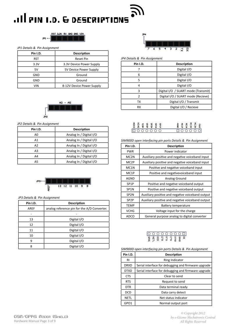
Pin I.D. & Descriptions
Pin I.D. DescriptionRST Reset Pin3.3V 3.3V Device Power Supply5V 5V Device Power Supply
GND GroundGND GroundVIN 8-12V Device Power Supply
JP1 Details & Pin Assignment
Pin I.D. DescriptionA0 Analog In / Digital I/OA1 Analog In / Digital I/OA2 Analog In / Digital I/OA3 Analog In / Digital I/OA4 Analog In / Digital I/OA5 Analog In / Digital I/O
JP2 Details & Pin Assignment
Pin I.D. DescriptionAREF analog reference pin for the A/D Converter.
- -13 Digital I/O12 Digital I/O11 Digital I/O10 Digital I/O9 Digital I/O8 Digital I/O
JP3 Details & Pin Assignment
Pin I.D. Description7 Digital I/O6 Digital I/O5 Digital I/O4 Digital I/O3 Digital I/O / SUART mode (Transmit)2 Digital I/O / SUART mode (Recieve)
TX Digital I/O / TransmitRX Digital I/O / Recieve
JP4 Details & Pin Assignment
Pin I.D. DescriptionPWR Power indicator
MC2N Auxiliary positive and negative voiceband inputMC2P Auxiliary positive and negative voiceband inputMC1N Positive and negative voiceband inputMC1P Positive and negativevoiceband inputAGND Analog GroundSP1P Positive and negative voiceband outputSP1N Positive and negative voiceband outputSP2N Auxiliary positive and negative voiceband outputSP2P Auxiliary positive and negative voiceband outputTEMP Battery temperatureVCHG Voltage input for the chargeADCO General purpose analog to digital converter
SIM900D open interfacing pin ports Details & Pin Assignment
Pin I.D. DescriptionRI Ring Indicator
DRXD Serial interface for debugging and firmware upgradeDTXD Serial interface for debugging and firmware upgradeCTS Clear to sendRTS Request to sendDTR Data terminal readyDCD Data carry detectNETL Net status indicatorGPO1 Normal output port
SIM900D open interfacing pin ports Details & Pin Assignment
© Copyright 2012by e-Gizmo Mechatronix Central
All Rights ReservedGSM/GPRS Modem (Shield) Hardware Manual Page 4 of 9
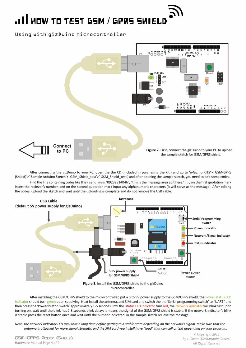
How to test GSM / GPRS ShieldUsing with gizDuino microcontroller
Figure 2. First, connect the gizDuino to your PC to upload the sample sketch for GSM/GPRS shield.
After connecting the gizDuino to your PC, open the the CD (included in purchasing the kit.) and go to ‘e-Gizmo KITS‘>’ GSM-GPRS (Shield)’>’ Sample Arduino Sketch’>’ GSM_Shield_test’>’ GSM_Shield_test’, and after opening the sample sketch, you need to edit some codes. Find the line containing codes like this ( send_msg(“09232814046”, “this is the message area edit here.”); ) , on the first quotation mark insert the reciever’s number, and on the second quotation mark input any alphanumeric characters (it will serve as the message). After editing the codes, upload the sketch and wait until the uploading is complete and do not remove the USB cable.
Figure 3. Install the GSM/GPRS shield to the gizDuino microcontroller..
After installing the GSM/GPRS shield to the microcontroller, put a 5 to 9V power supply to the GSM/GPRS shield, the Power status LED Indicator should turn green upon supplying. Next install the antenna, and SIM card and switch the the ‘Serial programming switch‘ to “UART“ and then press the ‘Power button switch’ approximately 1-5 seconds until the status LED indicator turn red, the Network indicator will blink fast upon turning on, wait until the blink has 2-3 seconds blink delay; it means the signal of the GSM/GPRS shield is stable. if the network indicator’s blink is stable press the reset button once and wait until the number indicated in the sample sketch recieve the message.
Note: the network indicator LED may take a long time before getting to a stable state depending on the network’s signal, make sure that the antenna is attached for more signal strength, and the SIM card you install have “load” that can call or text depending on your program.
© Copyright 2012by e-Gizmo Mechatronix Central
All Rights ReservedGSM/GPRS Modem (Shield) Hardware Manual Page 5 of 9
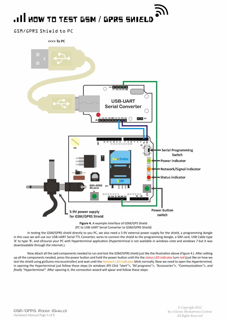
GSM/GPRS Shield to PC
How to test GSM / GPRS Shield
Figure 4. A example Interface of GSM/GPS Shield(PC to USB-UART Serial Converter to GSM/GPRS Shield)
In testing the GSM/GPRS shield directly to you PC, we also need a 5-9V external power supply for the shield, a programming dongle in this case we will use our USB-UART Serial TTL Converter, wires to connect the shield to the programming dongle, a SIM card, USB Cable type ‘A’ to type ‘B’, and ofcourse your PC with Hyperterminal application (Hyperterminal is not available in windows vista and windows 7 but it was downloadable through the internet.). Now attach all the said components needed to run and test the GSM/GPRS shield just like the illustration above (Figure 4.). After setting up all the components needed, press the power button and hold the power button until the the status LED indicator turn red (just like on how we test the shield using gizDuino microcontroller) and wait until the Network LED indicator blink normally. Now we need to open the Hyperterminal, in opening the Hyperterminal just follow these steps (in windows XP) Click “start”>, ”All programs”>, “Accessories“>, “Communications“>, and finally “Hyperterminal“. After opening it, the connection wizard will apear and follow these steps:
© Copyright 2012by e-Gizmo Mechatronix Central
All Rights ReservedGSM/GPRS Modem (Shield) Hardware Manual Page 6 of 9
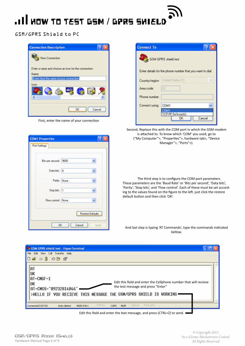
GSM/GPRS Shield to PC
How to test GSM / GPRS Shield
First, enter the name of your connection
Second, Replace this with the COM port in which the GSM modemis attached to. To know which ‘COM’ you used, go to
(“My Computer”>, “Properties“>, hardware tab>, “DeviceManager”>, “Ports”>).
The third step is to configure the COM port parameters. These parameters are the ‘Baud Rate’ or ‘Bits per second’, ‘Data bits’, ‘Parity’, ‘Stop bits’, and ‘Flow control’. Each of these must be set accord-ing to the values found on the figure to the left. just click the restore default button and then click ‘OK‘.
And last step is typing ‘AT Commands’, type the commands indicated bellow.
Edit this field and enter the Cellphone number that will recieve the test message and press “Enter“
Edit this field and enter the text message, and press (CTRL+Z) to send.
© Copyright 2012by e-Gizmo Mechatronix Central
All Rights ReservedGSM/GPRS Modem (Shield) Hardware Manual Page 7 of 9
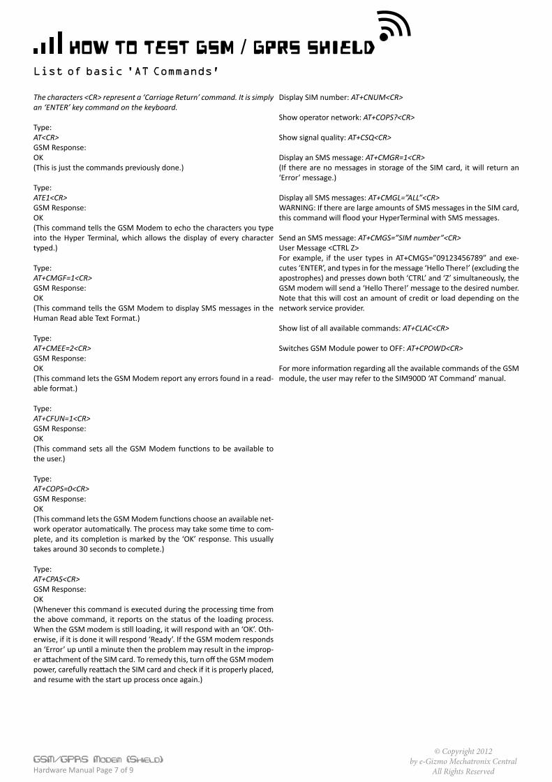
How to test GSM / GPRS ShieldList of basic 'AT Commands’
The characters <CR> represent a ‘Carriage Return’ command. It is simply an ‘ENTER’ key command on the keyboard.
Type:AT<CR>GSM Response:OK(This is just the commands previously done.)
Type:ATE1<CR>GSM Response:OK(This command tells the GSM Modem to echo the characters you type into the Hyper Terminal, which allows the display of every character typed.)
Type:AT+CMGF=1<CR>GSM Response:OK(This command tells the GSM Modem to display SMS messages in the Human Read able Text Format.)
Type:AT+CMEE=2<CR>GSM Response:OK(This command lets the GSM Modem report any errors found in a read-able format.)
Type:AT+CFUN=1<CR>GSM Response:OK(This command sets all the GSM Modem functions to be available to the user.)
Type:AT+COPS=0<CR>GSM Response:OK(This command lets the GSM Modem functions choose an available net-work operator automatically. The process may take some time to com-plete, and its completion is marked by the ‘OK’ response. This usually takes around 30 seconds to complete.)
Type:AT+CPAS<CR>GSM Response:OK(Whenever this command is executed during the processing time from the above command, it reports on the status of the loading process. When the GSM modem is still loading, it will respond with an ‘OK’. Oth-erwise, if it is done it will respond ‘Ready’. If the GSM modem responds an ‘Error’ up until a minute then the problem may result in the improp-er attachment of the SIM card. To remedy this, turn off the GSM modem power, carefully reattach the SIM card and check if it is properly placed, and resume with the start up process once again.)
Display SIM number: AT+CNUM<CR>
Show operator network: AT+COPS?<CR>
Show signal quality: AT+CSQ<CR>
Display an SMS message: AT+CMGR=1<CR>(If there are no messages in storage of the SIM card, it will return an ‘Error’ message.)
Display all SMS messages: AT+CMGL=”ALL”<CR>WARNING: If there are large amounts of SMS messages in the SIM card, this command will flood your HyperTerminal with SMS messages.
Send an SMS message: AT+CMGS=”SIM number”<CR>User Message <CTRL Z>For example, if the user types in AT+CMGS=”09123456789” and exe-cutes ‘ENTER’, and types in for the message ‘Hello There!’ (excluding the apostrophes) and presses down both ‘CTRL’ and ‘Z’ simultaneously, the GSM modem will send a ‘Hello There!’ message to the desired number. Note that this will cost an amount of credit or load depending on the network service provider.
Show list of all available commands: AT+CLAC<CR>
Switches GSM Module power to OFF: AT+CPOWD<CR>
For more information regarding all the available commands of the GSM module, the user may refer to the SIM900D ‘AT Command’ manual.
© C
opyr
ight
201
2by
e-G
izm
o M
echa
troni
x Ce
ntra
lAl
l Rig
hts R
eser
ved
GSM/GPRS Modem (S
hield)
Hard
war
e M
anua
l Pag
e 8
of 9
schematic diagram
CLOCK
RESET
Vcc
DATA
GND
1 2
3 4
5 6
CON1
SIM
DBG_RXD1
DBG_TXD2
RXD3
TXD4
STATUS5
SIM_DATA6
SIM_CLK7
SIM_RST8
SIM_VDD9
KBR010
RI11
PWRKEY12
DISP_CLK13
DISP_DATA14
VRTC15
DISP_D/C16
GND17
MIC
2P18
MIC
2N19
MIC
1N20
MIC
1P21
AG
ND
22
SPK
1P23
SPK
1N24
SPK
2N25
SPK
2P26
TEM
P_B
AT
27
VC
HG
28
AD
C0
29
GN
D30
GN
D31
GN
D32
AN
TEN
NA
33G
ND
34
GN
D35
GN
D36
GN
D37
VB
AT
38V
BA
T39
GPO
140
NET
LIG
HT
41D
CD
42D
TR43
RTS
44C
TS45
DIS
P_C
S46
NC
47G
ND
48
Module1SIM340D
R7
22
R6
10 K
R9
22
R8
22
1 23 45 67 89 10
JP7
HEADER 5X2
12
JP5
HEADER 2
Vin3
AD
J1
+Vout 2
U1EZ1086CM
+ C3100u
+ C2
100uR4RES1
R5RES1
C1100n
C4
224
S2
SW-PB Q3
NPN 1 23 45 67 89 10
JP8
HEADER 5X2
Q2
NPN
Q1
NPN
D4
DIODE
R2
RES1
R1
RES1
D1LED
D2
LED
VBAT
VBAT
VBAT
VBAT
R3RES1
D3
LED
F1
FUSE1D5DIODE
1 23 45 67 89 1011 12
JP6
HEADER 6X2
PowerON
PowerON
12345678
JP3
HEADER 8
12345678
JP4
HEADER 8
01234567
8910111213
123456
JP2
HEADER 6
123456
JP1
HEADER 6
VIN
S1
Reset
GNDGND+5V
RESET
A0A1A2A3A4A5
AREF
+3.3V
RXTX
1
2 4
35
U2
74LVC1G125
TX
C6
100n
1
24
35
U3
74LVC1G125
RXC5
100n
S3
SW DPDT2
3
VBAT
VBAT
RXDTXD
RXD
TXD
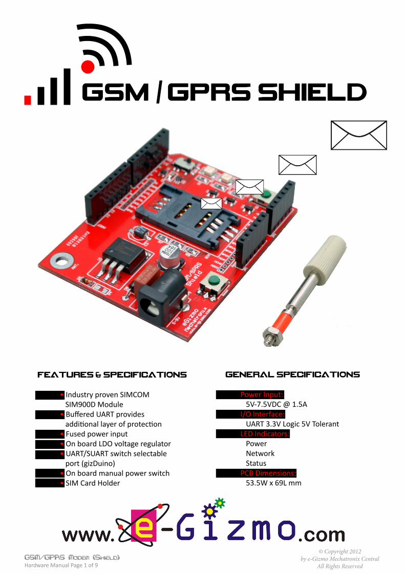
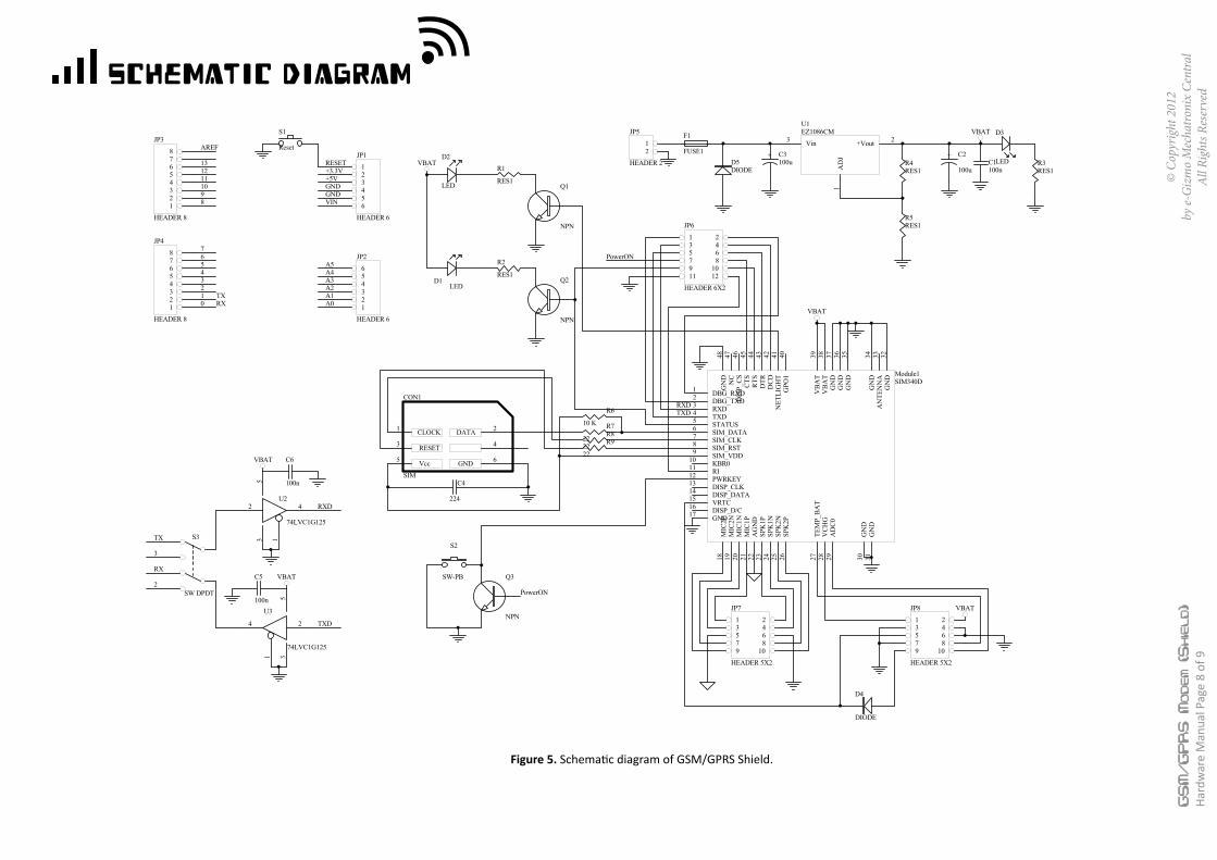
Figure 5. Schematic diagram of GSM/GPRS Shield.
© Copyright 2012by e-Gizmo Mechatronix Central
All Rights ReservedGSM/GPRS Modem (Shield) Hardware Manual Page 9 of 9
PCB LAYOUT
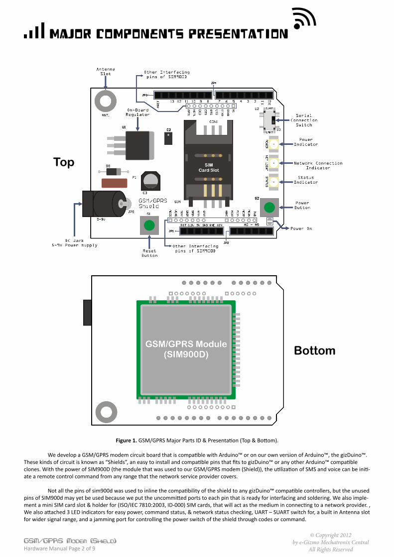
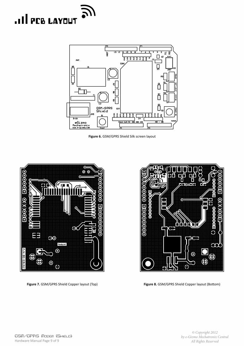
Figure 6. GSM/GPRS Shield Silk screen layout
Figure 7. GSM/GPRS Shield Copper layout (Top) Figure 8. GSM/GPRS Shield Copper layout (Bottom)
Related Documents