MINOR PROJECT On GSM based Home Security System By Lakshay Arora (1403221052) Submitted to the Department of Electrical and Electronics Engineering in partial fulfillment of the requirements for the degree, of Bachelor of Technology in Electrical and Electronics Engineering ABES Engineering College, Ghaziabad Dr. A.P.J Abdul Kalam Technical University, Uttar Pradesh, Lucknow April, 2017

Welcome message from author
This document is posted to help you gain knowledge. Please leave a comment to let me know what you think about it! Share it to your friends and learn new things together.
Transcript
MINOR PROJECT
On
GSM based Home Security SystemBy
Lakshay Arora (1403221052)
Submitted to the Department of Electrical and Electronics Engineering
in partial fulfillment of the requirements
for the degree, of
Bachelor of Technology
in
Electrical and Electronics Engineering
ABES Engineering College, Ghaziabad
Dr. A.P.J Abdul Kalam Technical University, Uttar Pradesh, Lucknow
April, 2017

ACKNOWLEDGEMENTIt gives us a great sense of pleasure to present the report of the B. Tech Project undertakenduring B. Tech. Third Year. We owe special debt of gratitude to Professor Dr. Javed Dhillon,Department of Electrical and Electronics Engineering, ABES College of Engineering, for hisconstant support and guidance throughout the course of our work. His sincerity,thoroughness and perseverance have been a constant source of inspiration for us. It is onlyhis cognizant efforts that our endeavors have seen light of the day.
We also take the opportunity to acknowledge the contribution of Professor HemantAhujaHead of Department of Electrical and Electronics Engineering, ABES College ofEngineering, for his full support and assistance during the development of the project.
We also do not like to miss the opportunity to acknowledge the contribution of all facultymembers of the department for their kind assistance and corporation during thedevelopment of our project. Last but not the least, we acknowledge our friends for theircontribution in the completion of the project.
Name: Lakshay Arora
Roll No: 1403221052
CANDIDATE’S DECLARATION
We hereby declare that the work which is being presented in this Project entitled, “GSM
based Home Security System "submitted Dr. A.P.J. Abdul Kalam Technical University,
Uttar Pradesh, Lucknow in the partial fulfillment of the requirements for the
award of the degree of BEACHLOR OF TECHNOLOGY in ELECTRICAL &
ELECTRONICS ENGINEERING, is an authentic record of my own work carried out from
Jan, 2017 to April, 2017 under the supervision of Dr. Javed Dhillon, Asstt. Professor in EN
Dept., ABES-EC, GHAZIABAD.
TABLE OF CONTENTS
ABSTRACT ………………………………………………………………. I
List of Figures ………………………………………………………………. II
1 (Introduction) ……………………………………………………................. 1
1.1 Overview ……………………………………………………… 1
1.1.1 Hardware Required ………………………………………. 1
1.2 Component Description ………………………………………. 1
1.2.1 PIR Motion Detection Sensor ……………………………. 1
1.2.2 GSM Module (SIM 900A) ………………………………. 2
1.2.3 Arduino UNO ……………………………………………. 3
2(GSM Based Home Security System) …………………………………. 6
2.1 Circuit Diagram ………………………………………………... 6
2.2 Working ………………………………………………………... 7
2.3 Arduino code …………………………………………………. 8
3(Conclusion and Future Scope) ………………………………………………. 10
3.1 Conclusion ………………………………………………….... 10
3.2 Future Scope …………………………………………………. 10
REFRENCES…………………………………………………………………... 11
ABSTRACT
Home Security Systems are an important feature of modern residential and office setups.
Home security systems must be affordable, reliable and effective.
Modern complex home security systems include several security features like fire, intruders,
electronic door lock, heat, smoke, temperature, etc. Some security systems may be a
combination of all the security measures.
In this project, we designed a simple but very efficient home security that has a function of
calling the homeowner on his/her mobile number in case of an intruder alert, the working of
the project is explained below.
PIR sensor detects motion by sensing the difference in infrared or radiant heat levels emitted
by surrounding objects. The output of the PIR sensor goes high when it detects any motion.
The range of a typical PIR sensor is around 6 meters or about 30 feet. When the PIR sensor
detects any motion, the output of the sensor is high. This is detected by the Arduino. Arduino
then communicates with the GSM module via serial communication to make a call to the
preprogrammed mobile number.
List of Figures
Sr. No. Name of figure Page No.
1. PIR Sensor 1
2. GSM Module SIM 900A 2
3. ARDUINO UNO 3
4. Circuit Diagram 6
5. GSM based Security System 7
CHAPTER 1
Introduction
1.1 Overview
Security is a big challenge everywhere because thefts are increasing day by day owing to the
unsafe and insecure security systems in homes, commercial complexes and industries. Several
conventional technologies are available to keep home properties safe from intruders, but most
common smart home security systems work on wireless GSM communication. Such systems
provide security from natural, incidental, intended, unintended, accidental and human made
problems by continuously monitoring homes with different sensory systems like motion, smoke,
gas, temperature, glass break or door break detectors and fire alarm systems.
The project is based on Arduino, PIR motion detection sensor and GSM Module.
1.1.1 Hardware Required
Arduino UNO
PIR Motion Detection Sensor
SIM 900A (or any other) GSM Module with SIM inserted
1.2 Component Description
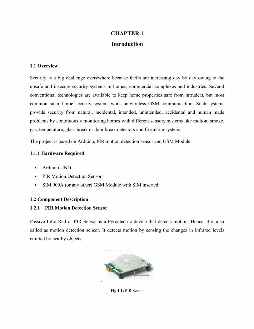
1.2.1 PIR Motion Detection Sensor
Passive Infra-Red or PIR Sensor is a Pyroelectric device that detects motion. Hence, it is also
called as motion detection sensor. It detects motion by sensing the changes in infrared levels
emitted by nearby objects
.
Fig 1.1: PIR Sensor
An individual PIR sensor detects changes in the amount of infrared radiation impinging upon it,
which varies depending on the temperature and surface characteristics of the objects in front of
the sensor. When an object, such as a human, passes in front of the background, such as a wall,
the temperature at that point in the sensor's field of view will rise from room temperature to body
temperature, and then back again. The sensor converts the resulting change in the incoming
infrared radiation into a change in the output voltage, and this triggers the detection. Objects of
similar temperature but different surface characteristics may also have a different infrared
emission pattern, and thus moving them with respect to the background may trigger the detector
as well.
PIRs come in many configurations for a wide variety of applications. The most common models
have numerous Fresnel lenses or mirror segments, an effective range of about ten meters (thirty
feet), and a field of view less than 180 degrees. Models with wider fields of view, including 360
degrees, are available—typically designed to mount on a ceiling. Some larger PIRs are made
with single segment mirrors and can sense changes in infrared energy over thirty meters (one
hundred feet) away from the PIR. There are also PIRs designed with reversible orientation
mirrors which allow either broad coverage (110° wide) or very narrow "curtain" coverage, or
with individually selectable segments to "shape" the coverage.
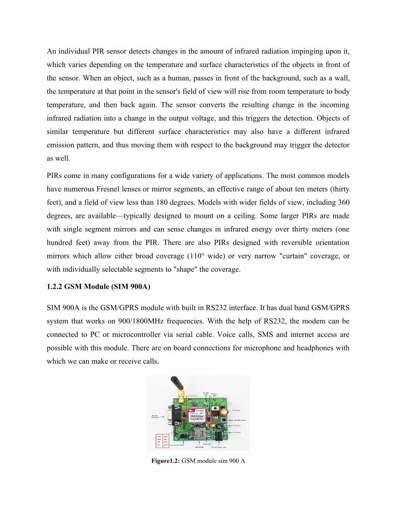
1.2.2 GSM Module (SIM 900A)
SIM 900A is the GSM/GPRS module with built in RS232 interface. It has dual band GSM/GPRS
system that works on 900/1800MHz frequencies. With the help of RS232, the modem can be
connected to PC or microcontroller via serial cable. Voice calls, SMS and internet access are
possible with this module. There are on board connections for microphone and headphones with
which we can make or receive calls.
Figure1.2: GSM module sim 900 A
The modem needed only 3 wires (Tx, Rx, GND) except Power supply to interface with
microcontroller/Host PC. The built in Low Dropout Linear voltage regulator allows you to
connect wide range of unregulated power supply (4.2V -13V). Yes, 5 V is in between. Using this
modem, you will be able to send & Read SMS, connect to internet via GPRS through simple AT
commands.
The GSM module is designed as a DCE (Data Communication Equipment), following the
traditional DCE-DTE (Data Terminal Equipment) connection. The GSM Modem and the client
(DTE) are connected through the following signal (as following figure shows). Auto bauding
supports baud rate from 1200bps to 57600bps. Serial port • TXD: Send data to the RXD signal
line of the DTE • RXD: Receive data from the TXD signal line of the DTE serial port of the
GSM engine supports auto bauding for the following baud rates: 1200, 2400, 4800, 9600,
19200,38400 and 57600bps. Factory setting is auto bauding enabled. This gives you the
flexibility to put the GSM engine into operation no matter what baud rate your host application is
configured to.
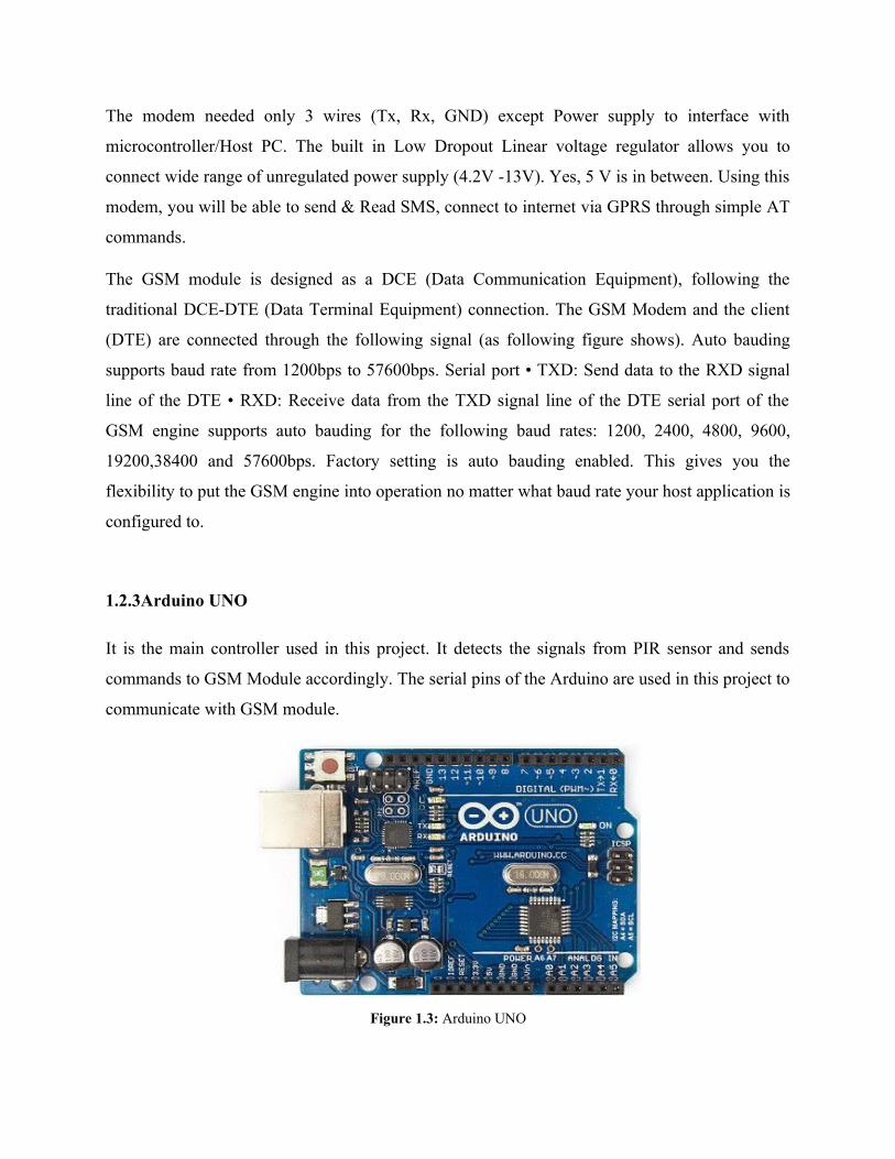
1.2.3Arduino UNO
It is the main controller used in this project. It detects the signals from PIR sensor and sends
commands to GSM Module accordingly. The serial pins of the Arduino are used in this project to
communicate with GSM module.
Figure 1.3: Arduino UNO

Arduino is open-source hardware. The hardware reference designs are distributed under
a Creative Commons Attribution Share-Alike 2.5 license and are available on the Arduino
website. Layout and production files for some versions of the hardware are also available. The
source code for the IDE is released under the GNU General Public License, version
2.Nevertheless, an official Bill of Materials of Arduino boards has never been released by
Arduino staff.
Although the hardware and software designs are freely available under copyleft licenses, the
developers have requested that the name Arduino be exclusive to the official product and not be
used for derived works without permission. The official policy document on use of the Arduino
name emphasizes that the project is open to incorporating work by others into the official
product.[9] Several Arduino-compatible products commercially released have avoided the project
name by using various names ending in -duino.
Arduino microcontrollers are pre-programmed with a boot loader that simplifies uploading of
programs to the on-chip flash memory. The default bootloader of the Arduino UNO is the opt
boot bootloader. Boards are loaded with program code via a serial connection to another
computer. Some serial Arduino boards contain a level shifter circuit to convert between RS-
232 logic levels and transistor–transistor logic (TTL) level signals. Current Arduino boards are
programmed via Universal Serial Bus (USB), implemented using USB-to-serial adapter chips
such as the FTDI FT232. Some boards, such as later-model Uno boards, substitute the FTDI chip
with a separate AVR chip containing USB-to-serial firmware, which is reprogrammable via its
own ICSP header. Other variants, such as the Arduino Mini and the unofficial Boarduino, use a
detachable USB-to-serial adapter board or cable, Bluetooth or other methods, when used with
traditional microcontroller tools instead of the Arduino IDE, standard AVR in-system
programming (ISP) programming is used.
The Arduino board exposes most of the microcontroller's I/O pins for use by other circuits.
The Diecimila, Duemilanove, and current Uno provide 14 digital I/O pins, six of which can
produce pulse-width modulated signals, and six analog inputs, which can also be used as six
digital I/O pins. These pins are on the top of the board, via female 0.1-inch (2.54 mm) headers.
Several plug-in application shields are also commercially available. The Arduino Nano, and
Arduino-compatible Bare Bones Board and Boarduino boards may provide male header pins on
the underside of the board that can plug into solderless breadboards.
Many Arduino-compatible and Arduino-derived boards exist. Some are functionally equivalent
to an Arduino and can be used interchangeably. Many enhance the basic Arduino by adding
output drivers, often for use in school-level education, to simplify making buggies and small
robots. Others are electrically equivalent but change the form factor, sometimes retaining
compatibility with shields, sometimes not. Some variants use different processors, of varying
compatibility.
CHAPTER 2
GSM Based Home Security System
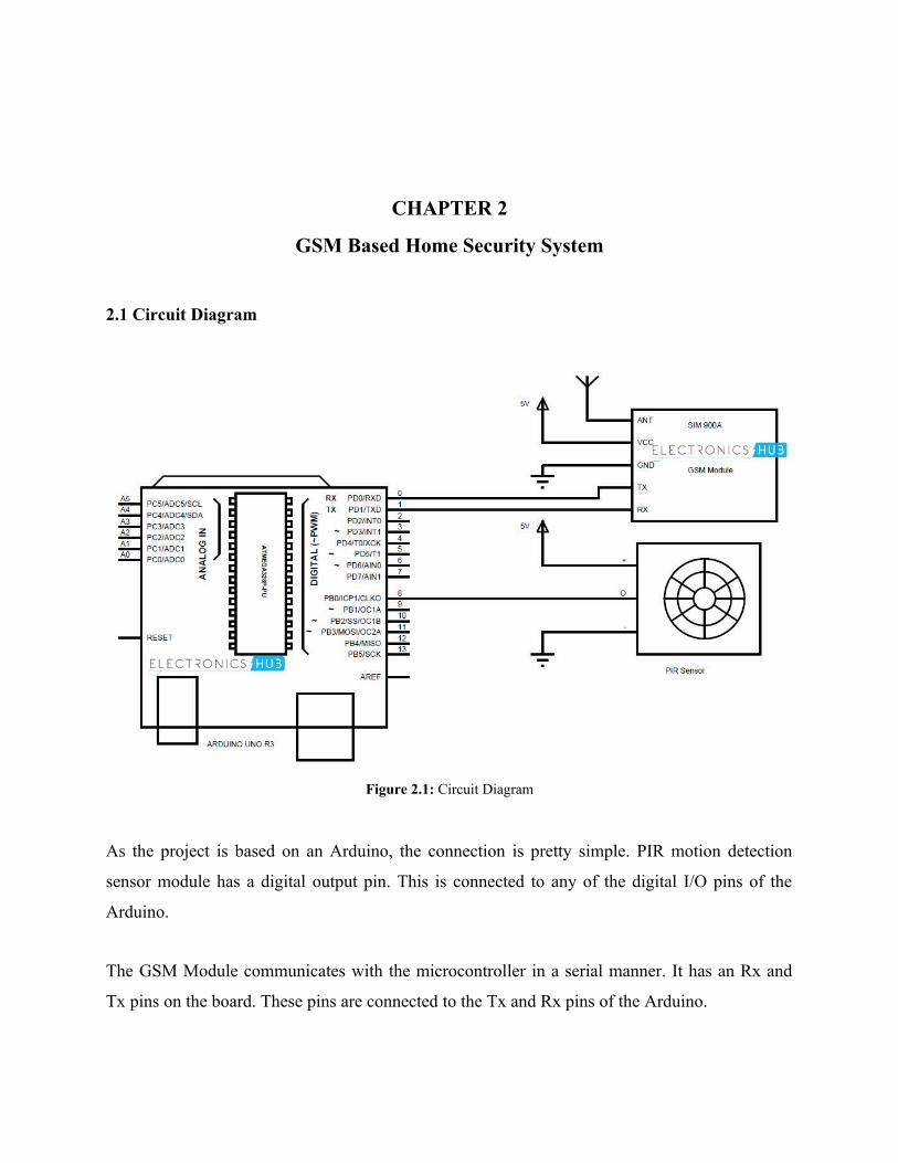
2.1 Circuit Diagram
Figure 2.1: Circuit Diagram
As the project is based on an Arduino, the connection is pretty simple. PIR motion detection
sensor module has a digital output pin. This is connected to any of the digital I/O pins of the
Arduino.
The GSM Module communicates with the microcontroller in a serial manner. It has an Rx and
Tx pins on the board. These pins are connected to the Tx and Rx pins of the Arduino.
It is important to note that while uploading the program (sketch) to Arduino, the GSM module
must be disconnected as it might interfere with the serial communication with the Arduino IDE.
2.2Working
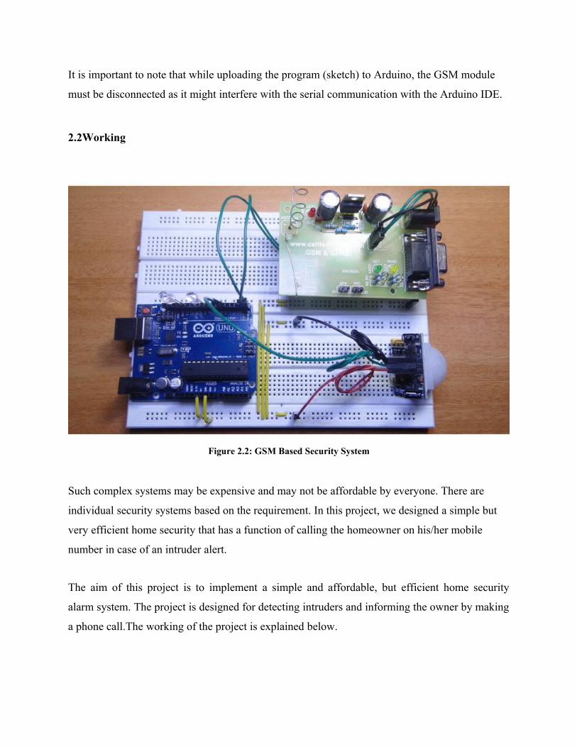
Figure 2.2: GSM Based Security System
Such complex systems may be expensive and may not be affordable by everyone. There are
individual security systems based on the requirement. In this project, we designed a simple but
very efficient home security that has a function of calling the homeowner on his/her mobile
number in case of an intruder alert.
The aim of this project is to implement a simple and affordable, but efficient home security
alarm system. The project is designed for detecting intruders and informing the owner by making
a phone call.The working of the project is explained below.
PIR sensor detects motion by sensing the difference in infrared or radiant heat levels emitted by
surrounding objects. The output of the PIR sensor goes high when it detects any motion. The
range of a typical PIR sensor is around 6 meters or about 30 feet.
For proper operation of PIR sensor, it requires a warm up time of 20 to 60 seconds. This is
required because, the PIR sensor has a settling time during which it calibrates its sensor
according to the environment and stabilizes the infrared detector.
During this time, there should be very little to no motion in front of the sensor. If the sensor is
not given enough calibrating time, the output of the PIR sensor may not be reliable.
When the PIR sensor detects any motion, the output of the sensor is high. This is detected by the
Arduino. Arduino then communicates with the GSM module via serial communication to make a
call to the preprogrammed mobile number.
An important point to be noted about PIR sensors is that the output will be high when it detects
motion. The output of the sensor goes low from time to time, even when there is motion which
may mislead the microcontroller into considering that there is no motion.
This issue must be dealt with in the programming of Arduino by ignoring the low output signals
that have a shorter duration than a predefined time. This is done by assuming that the motion in
front of PIR sensor is present continuously.
2.3 Arduino Code Used
pinMode(GND1,OUTPUT);
pinMode(LED2,OUTPUT);
pinMode(GND2,OUTPUT);
pinMode(pirOutput,INPUT);
digitalWrite(pirOutput,LOW);
digitalWrite(GND1,LOW);
digitalWrite(GND2,LOW);
digitalWrite(LED1,LOW);
digitalWrite(LED2,LOW);
delay(15000);
digitalWrite(LED1,HIGH);
}
void loop()
{
if(digitalRead(pirOutput)==HIGH)
{
digitalWrite(LED2,HIGH);
Serial.println("OK");
delay(1000);
Serial.println("ATD+91xxxxxxxxxx;");//add target mobile number in place of xxxxxxxxxx
delay(15000);
Serial.println("ATH");
digitalWrite(LED2,LOW);
delay(1000);
}
CHAPTER 3
CONCLUSION AND FUTURE SCOPE
3.1 Conclusion
A GSM based home security alarm system is designed using Arduino, PIR motion
detection sensor and a GSM module.
When the system is activated, it continuously checks for motion and when the motion is
detected, it make a phone call to the owner.
Only intruder alert is present in this system and can be upgraded to other security alert
systems like fire, smoke etc.
3.2 Future Scope
GSM is one of the latest mobile technologies using smart MODEM, which can easily have
interfaced to embedded microcontrollers. Now everything is going to be automated using this
technology, using this technology we can access the devices remotely. Using GSM and GPS now
we can identify the people, vehicles etc. in anywhere of the world.
MODEM is communicating with the microcontroller using AT commands, for example if we
want to send an SMS to number +919828379647, the commands we have to send is
AT+CMGS=” <+919828379647>”, <enter>, <message>, <ctrl-Z>.
In this project, it is used to make call to the owners mobile when somebody entered the home
without permission.
In this project in future we can add a multimedia camera to see what is going inside the home by
sitting in office or somewhere.
REFRENCES
Websites Referred -:
www.electronicshub.org
https://en.wikipedia.org
www.arduino.cc
www.engineersgarage.com
Books referred -:
Programming Arduino: Getting Started
Smart Sensor Systems
Related Documents