International Journal of Recent Technology and Engineering (IJRTE) ISSN: 2277-3878, Volume-2, Issue-2, May 2013 33 Abstract— The main objective of this paper is to focus on a system which is developed using GSM module, KEIL software and PROTEUS software to work as a wireless vehicle engine igniter for various vehicle engine based application. Through this application we can take control over every module inside the vehicle which depends upon the ignition of engine .One of the application focused in this paper is ignition of Air Conditioning system using GSM module. The A.C inside the car usually takes ten to fifteen minutes to maintain the normal temperature. By using this GSM module we turn ON the Vehicle A.C before a required specific time. This is done in two simple steps-Firstly ignition of vehicle engine and Secondly ignition of A.C inside the vehicle by sending SMS by owner’s mobile. The proceeding content will reveal a general outlook to achieve the foresaid objectives. Key Words:- GSM, Microcontroller, Relay, Proteus , Keil. I. INTRODUCTION The young and revolutionary ever growing field of telecommunication has urged a need to experiment in different aspects interfacing electronic devices with wireless systems. In the past decade, the telecommunication research areas have created opportunities for engineers to acquaint user friendly features. The chapter introduces key areas of research within the field of telecommunication that pertain to work presented in the thesis. The interfaced system is presented of origin of main areas of research like GSM, broadcasting. II. WORKING & CIRCUIT DIAGRAM This project is powered by an on-board power supply that drives the car power and converts it into suitable DC power, that is fed to on-board devices and integrated circuits. When the user sends the message from the mobile, it is received and retrieved by the GSM modem. It is then sent to the microcontroller that further process the data according to the program fed inside it. For example, if the received message is for engine ignition then it ignite the engine. Similarly different command messages can be send to activate different functions inside the vehicle. The project mainly focuses on transmission of textual data through air interface by the use of GSM through asynchronous serial communication .The data will be processed by the microcontroller on both ends. Manuscript received on May, 2013. Mrs. Aditi Sandhu, Electronics & Telecommunication Engineering, Mumbai University/ Theem College of Engineering, Boisar, Thane, India. Mr. Prashant Priyadarshi, Electronics & Telecommunication Engineering, Mumbai University/ Theem College of Engineering, Boisar, Thane, India. Ms. Shalini Tiwari, Electronics Engineering, Mumbai University/ Theem College of Engineering, Boisar, Thane, India. In this project we not only send the data but send the data with pass code also, which enables us to prevent the unauthorized use and only the person who have pass code can have access to his/her vehicle. The main components of the kit includes microcontroller, GSM modem. The GSM modem receives the SMS. The AT commands are serially transferred to the modem through MAX232. In return the modem transmits the stored message through the COM port. The microcontroller validates the SMS and then perform the task as programmed. In this project we are using AT89S52 microcontroller which consist of 40 pins. For that microcontroller we are providing on board power supply system which can provide +5v to microcontroller consisting of step down transformer, bridge rectifier, filter and voltage regulator. Here we are using level shifter IC MAX232 to interface microcontroller and GSM modem. 11 & 12th pin MAX232 of is connected to 10 & 11th pin of microcontroller. 13pin & 14th pin of MAX232 is connected to 2nd& 3rd pin of DB9 connector. Whereas 5th, 6th, 7th pin of J1 CONN-DB9M is connected to GSM modem. 38th & 39th pin of microcontroller is connected with pull up resistors of 10k each. These two pins are then connected to starter relay circuit and A.C of vehicle in order to ignite both the system concurrently. To understand the proper functioning we have connected two LED with pin no.38 and 39 of microcontroller. Fig.1 Circuit Diagram III. ENGINE STARTING/IGNITION SYSTEM When we turn the ignition key to the Start position, the battery voltage goes through the starter control circuit and activates the starter solenoid, which in turn energizes the starter motor. At the same time, the starter solenoid pushes the starter gear forward to mesh it with the engine flywheel. The flywheel is attached to the engine crankshaft. The starter motor spins, turning the engine crankshaft allowing the engine to start. GSM Based Engine & A.C Control System for Vehicles Aditi Sandhu, Prashant Priyadarshi, Shalini Tiwari

Welcome message from author
This document is posted to help you gain knowledge. Please leave a comment to let me know what you think about it! Share it to your friends and learn new things together.
Transcript
International Journal of Recent Technology and Engineering (IJRTE) ISSN: 2277-3878, Volume-2, Issue-2, May 2013
33
Abstract— The main objective of this paper is to focus on a
system which is developed using GSM module, KEIL software and PROTEUS software to work as a wireless vehicle engine igniter for various vehicle engine based application. Through this application we can take control over every module inside the vehicle which depends upon the ignition of engine .One of the application focused in this paper is ignition of Air Conditioning system using GSM module. The A.C inside the car usually takes ten to fifteen minutes to maintain the normal temperature. By using this GSM module we turn ON the Vehicle A.C before a required specific time. This is done in two simple steps-Firstly ignition of vehicle engine and Secondly ignition of A.C inside the vehicle by sending SMS by owner’s mobile. The proceeding content will reveal a general outlook to achieve the foresaid objectives.
Key Words:- GSM, Microcontroller, Relay, Proteus , Keil.
I. INTRODUCTION
The young and revolutionary ever growing field of telecommunication has urged a need to experiment in different aspects interfacing electronic devices with wireless systems. In the past decade, the telecommunication research areas have created opportunities for engineers to acquaint user friendly features. The chapter introduces key areas of research within the field of telecommunication that pertain to work presented in the thesis. The interfaced system is presented of origin of main areas of research like GSM, broadcasting.
II. WORKING & CIRCUIT DIAGRAM
This project is powered by an on-board power supply that drives the car power and converts it into suitable DC power, that is fed to on-board devices and integrated circuits. When the user sends the message from the mobile, it is received and retrieved by the GSM modem. It is then sent to the microcontroller that further process the data according to the program fed inside it. For example, if the received message is for engine ignition then it ignite the engine. Similarly different command messages can be send to activate different functions inside the vehicle. The project mainly focuses on transmission of textual data through air interface by the use of GSM through asynchronous serial communication .The data will be processed by the microcontroller on both ends. Manuscript received on May, 2013.
Mrs. Aditi Sandhu, Electronics & Telecommunication Engineering, Mumbai University/ Theem College of Engineering, Boisar, Thane, India.
Mr. Prashant Priyadarshi, Electronics & Telecommunication Engineering, Mumbai University/ Theem College of Engineering, Boisar, Thane, India.
Ms. Shalini Tiwari, Electronics Engineering, Mumbai University/ Theem College of Engineering, Boisar, Thane, India.
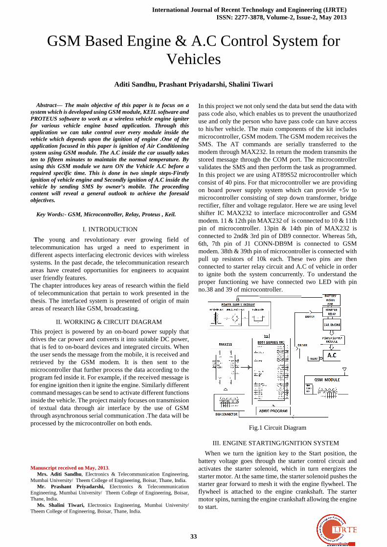
In this project we not only send the data but send the data with pass code also, which enables us to prevent the unauthorized use and only the person who have pass code can have access to his/her vehicle. The main components of the kit includes microcontroller, GSM modem. The GSM modem receives the SMS. The AT commands are serially transferred to the modem through MAX232. In return the modem transmits the stored message through the COM port. The microcontroller validates the SMS and then perform the task as programmed. In this project we are using AT89S52 microcontroller which consist of 40 pins. For that microcontroller we are providing on board power supply system which can provide +5v to microcontroller consisting of step down transformer, bridge rectifier, filter and voltage regulator. Here we are using level shifter IC MAX232 to interface microcontroller and GSM modem. 11 & 12th pin MAX232 of is connected to 10 & 11th pin of microcontroller. 13pin & 14th pin of MAX232 is connected to 2nd& 3rd pin of DB9 connector. Whereas 5th, 6th, 7th pin of J1 CONN-DB9M is connected to GSM modem. 38th & 39th pin of microcontroller is connected with pull up resistors of 10k each. These two pins are then connected to starter relay circuit and A.C of vehicle in order to ignite both the system concurrently. To understand the proper functioning we have connected two LED with pin no.38 and 39 of microcontroller.
Fig.1 Circuit Diagram
III. ENGINE STARTING/IGNITION SYSTEM
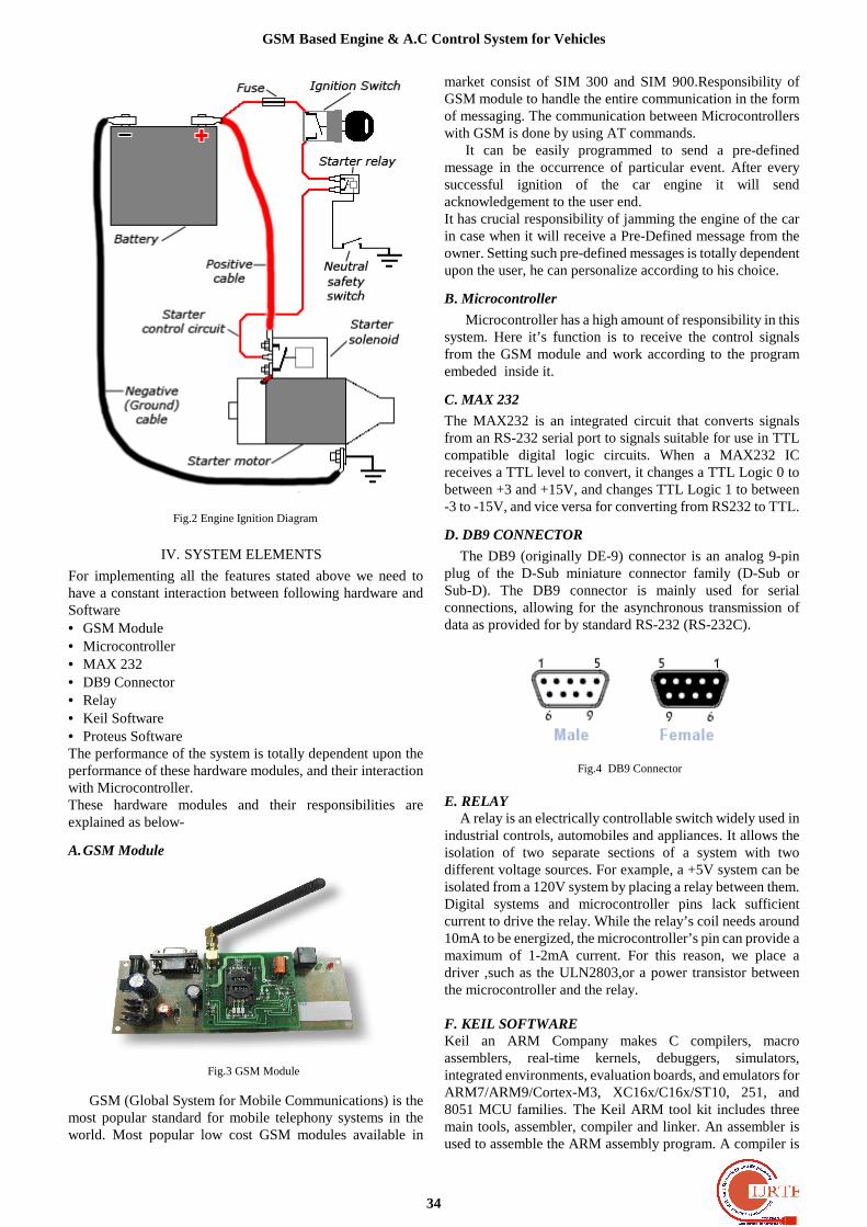
When we turn the ignition key to the Start position, the battery voltage goes through the starter control circuit and activates the starter solenoid, which in turn energizes the starter motor. At the same time, the starter solenoid pushes the starter gear forward to mesh it with the engine flywheel. The flywheel is attached to the engine crankshaft. The starter motor spins, turning the engine crankshaft allowing the engine to start.
GSM Based Engine & A.C Control System for Vehicles
Aditi Sandhu, Prashant Priyadarshi, Shalini Tiwari
GSM Based Engine & A.C Control System for Vehicles
34
Fig.2 Engine Ignition Diagram
IV. SYSTEM ELEMENTS
For implementing all the features stated above we need to have a constant interaction between following hardware and Software • GSM Module • Microcontroller • MAX 232 • DB9 Connector • Relay • Keil Software • Proteus Software The performance of the system is totally dependent upon the performance of these hardware modules, and their interaction with Microcontroller. These hardware modules and their responsibilities are explained as below-
A. GSM Module
Fig.3 GSM Module
GSM (Global System for Mobile Communications) is the most popular standard for mobile telephony systems in the world. Most popular low cost GSM modules available in
market consist of SIM 300 and SIM 900.Responsibility of GSM module to handle the entire communication in the form of messaging. The communication between Microcontrollers with GSM is done by using AT commands.
It can be easily programmed to send a pre-defined message in the occurrence of particular event. After every successful ignition of the car engine it will send acknowledgement to the user end. It has crucial responsibility of jamming the engine of the car in case when it will receive a Pre-Defined message from the owner. Setting such pre-defined messages is totally dependent upon the user, he can personalize according to his choice.
B. Microcontroller
Microcontroller has a high amount of responsibility in this system. Here it’s function is to receive the control signals from the GSM module and work according to the program embeded inside it.
C. MAX 232
The MAX232 is an integrated circuit that converts signals from an RS-232 serial port to signals suitable for use in TTL compatible digital logic circuits. When a MAX232 IC receives a TTL level to convert, it changes a TTL Logic 0 to between +3 and +15V, and changes TTL Logic 1 to between -3 to -15V, and vice versa for converting from RS232 to TTL.
D. DB9 CONNECTOR
The DB9 (originally DE-9) connector is an analog 9-pin plug of the D-Sub miniature connector family (D-Sub or Sub-D). The DB9 connector is mainly used for serial connections, allowing for the asynchronous transmission of data as provided for by standard RS-232 (RS-232C).
Fig.4 DB9 Connector E. RELAY
A relay is an electrically controllable switch widely used in industrial controls, automobiles and appliances. It allows the isolation of two separate sections of a system with two different voltage sources. For example, a +5V system can be isolated from a 120V system by placing a relay between them. Digital systems and microcontroller pins lack sufficient current to drive the relay. While the relay’s coil needs around 10mA to be energized, the microcontroller’s pin can provide a maximum of 1-2mA current. For this reason, we place a driver ,such as the ULN2803,or a power transistor between the microcontroller and the relay. F. KEIL SOFTWARE Keil an ARM Company makes C compilers, macro assemblers, real-time kernels, debuggers, simulators, integrated environments, evaluation boards, and emulators for ARM7/ARM9/Cortex-M3, XC16x/C16x/ST10, 251, and 8051 MCU families. The Keil ARM tool kit includes three main tools, assembler, compiler and linker. An assembler is used to assemble the ARM assembly program. A compiler is
International Journal of Recent Technology and Engineering (IJRTE) ISSN: 2277-3878, Volume-2, Issue-2, May 2013
35
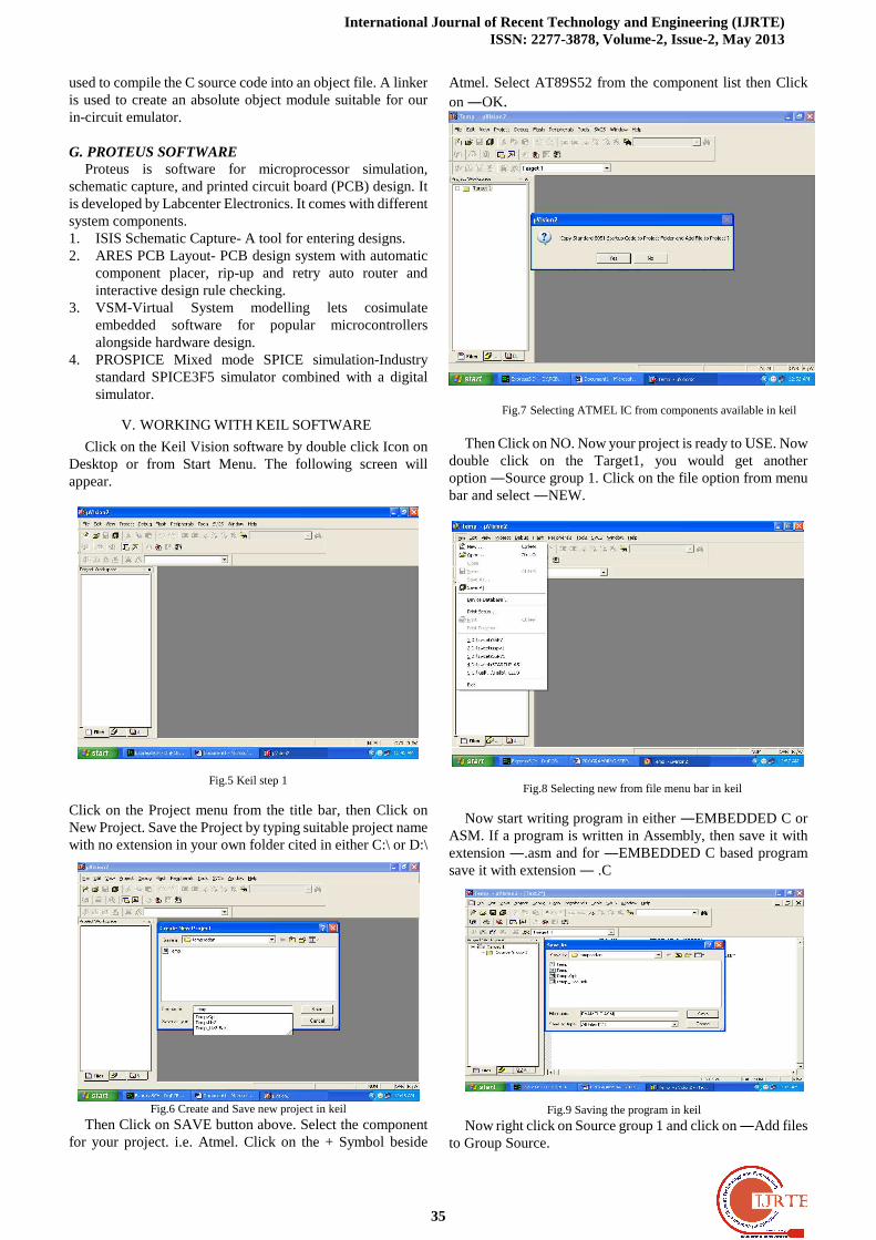
used to compile the C source code into an object file. A linker is used to create an absolute object module suitable for our in-circuit emulator. G. PROTEUS SOFTWARE
Proteus is software for microprocessor simulation, schematic capture, and printed circuit board (PCB) design. It is developed by Labcenter Electronics. It comes with different system components. 1. ISIS Schematic Capture- A tool for entering designs. 2. ARES PCB Layout- PCB design system with automatic
component placer, rip-up and retry auto router and interactive design rule checking.
3. VSM-Virtual System modelling lets cosimulate embedded software for popular microcontrollers alongside hardware design.
4. PROSPICE Mixed mode SPICE simulation-Industry standard SPICE3F5 simulator combined with a digital simulator.
V. WORKING WITH KEIL SOFTWARE
Click on the Keil Vision software by double click Icon on Desktop or from Start Menu. The following screen will appear.
Fig.5 Keil step 1
Click on the Project menu from the title bar, then Click on New Project. Save the Project by typing suitable project name with no extension in your own folder cited in either C:\ or D:\
Fig.6 Create and Save new project in keil
Then Click on SAVE button above. Select the component for your project. i.e. Atmel. Click on the + Symbol beside
Atmel. Select AT89S52 from the component list then Click on ―OK.
Fig.7 Selecting ATMEL IC from components available in keil
Then Click on NO. Now your project is ready to USE. Now
double click on the Target1, you would get another option ―Source group 1. Click on the file option from menu bar and select ―NEW.
Fig.8 Selecting new from file menu bar in keil
Now start writing program in either ―EMBEDDED C or ASM. If a program is written in Assembly, then save it with extension ―.asm and for ―EMBEDDED C based program save it with extension ― .C
Fig.9 Saving the program in keil
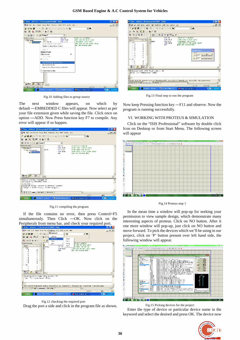
Now right click on Source group 1 and click on ―Add files to Group Source.
GSM Based Engine & A.C Control System for Vehicles
36
Fig.10 Adding files to group source
The next window appears, on which by default ―EMBEDDED C files will appear. Now select as per your file extension given while saving the file. Click once on option ―ADD. Now Press function key F7 to compile. Any error will appear if so happen.
Fig.11 compiling the program
If the file contains no error, then press Control+F5 simultaneously. Then Click ―OK. Now click on the Peripherals from menu bar, and check your required port.
Fig.12 checking the required port Drag the port a side and click in the program file as shown.
Fig.13 Final step to run the program
Now keep Pressing function key ―F11 and observe. Now the program is running successfully.
VI. WORKING WITH PROTEUS & SIMULATION
Click on the “ISIS Professional” software by double click Icon on Desktop or from Start Menu. The following screen will appear
Fig.14 Proteus step 1
In the mean time a window will pop-up for seeking your permission to view sample design, which demonstrate many interesting aspects of proteus. Click on NO button. After it one more window will pop-up, just click on NO button and move forward. To pick the devices which we’ll be using in our project, click on ‘P’ button present over left hand side, the following window will appear.
Fig.15 Picking devices for the project
Enter the type of device or particular device name in the keyword and select the desired and press OK. The device now
International Journal of Recent Technology and Engineering (IJRTE) ISSN: 2277-3878, Volume-2, Issue-2, May 2013
37
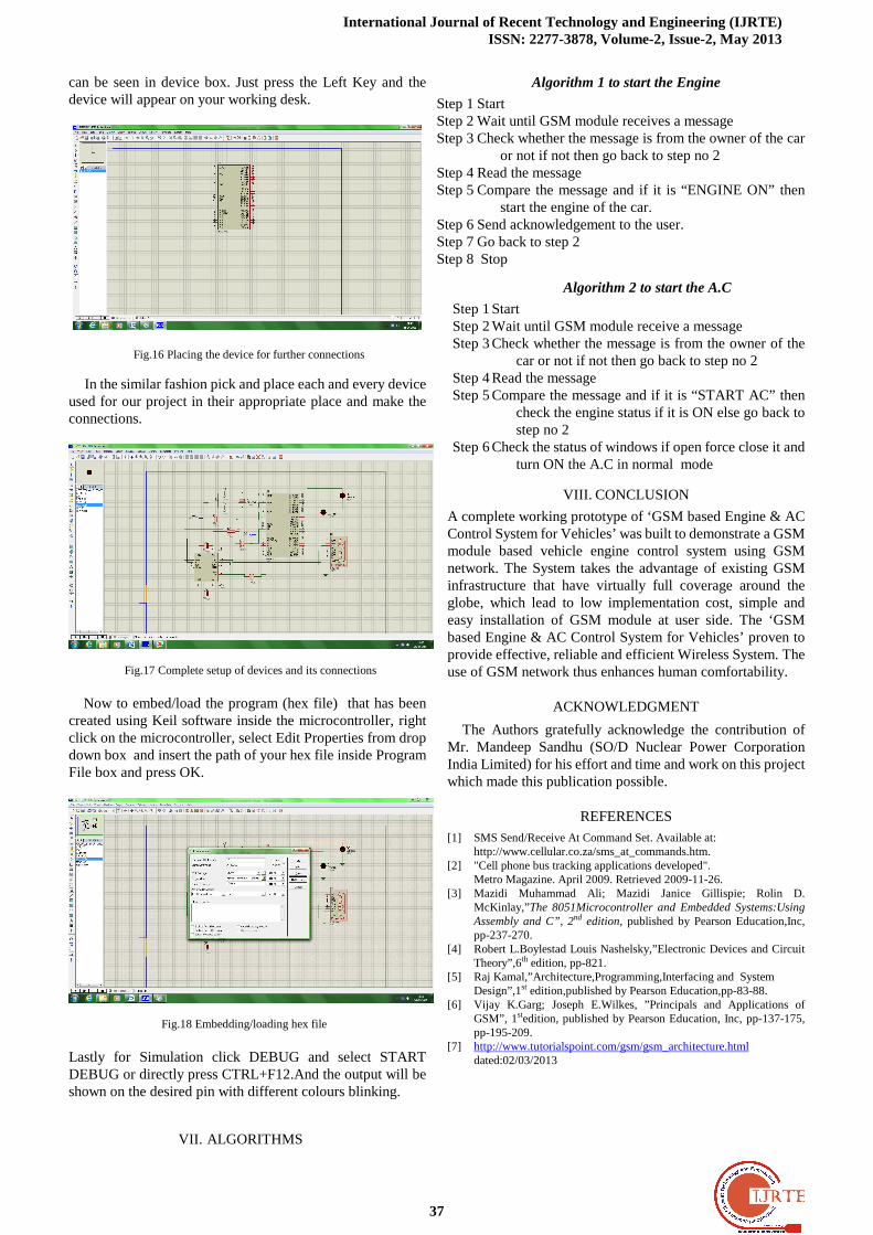
can be seen in device box. Just press the Left Key and the device will appear on your working desk.
Fig.16 Placing the device for further connections
In the similar fashion pick and place each and every device used for our project in their appropriate place and make the connections.
Fig.17 Complete setup of devices and its connections
Now to embed/load the program (hex file) that has been created using Keil software inside the microcontroller, right click on the microcontroller, select Edit Properties from drop down box and insert the path of your hex file inside Program File box and press OK.
Fig.18 Embedding/loading hex file Lastly for Simulation click DEBUG and select START DEBUG or directly press CTRL+F12.And the output will be shown on the desired pin with different colours blinking.
VII. ALGORITHMS
Algorithm 1 to start the Engine
Step 1 Start Step 2 Wait until GSM module receives a message Step 3 Check whether the message is from the owner of the car
or not if not then go back to step no 2 Step 4 Read the message Step 5 Compare the message and if it is “ENGINE ON” then
start the engine of the car. Step 6 Send acknowledgement to the user. Step 7 Go back to step 2 Step 8 Stop
Algorithm 2 to start the A.C
Step 1 Start Step 2 Wait until GSM module receive a message Step 3 Check whether the message is from the owner of the
car or not if not then go back to step no 2 Step 4 Read the message Step 5 Compare the message and if it is “START AC” then
check the engine status if it is ON else go back to step no 2
Step 6 Check the status of windows if open force close it and turn ON the A.C in normal mode
VIII. CONCLUSION
A complete working prototype of ‘GSM based Engine & AC Control System for Vehicles’ was built to demonstrate a GSM module based vehicle engine control system using GSM network. The System takes the advantage of existing GSM infrastructure that have virtually full coverage around the globe, which lead to low implementation cost, simple and easy installation of GSM module at user side. The ‘GSM based Engine & AC Control System for Vehicles’ proven to provide effective, reliable and efficient Wireless System. The use of GSM network thus enhances human comfortability.
ACKNOWLEDGMENT
The Authors gratefully acknowledge the contribution of Mr. Mandeep Sandhu (SO/D Nuclear Power Corporation India Limited) for his effort and time and work on this project which made this publication possible.
REFERENCES
[1] SMS Send/Receive At Command Set. Available at: http://www.cellular.co.za/sms_at_commands.htm.
[2] "Cell phone bus tracking applications developed". Metro Magazine. April 2009. Retrieved 2009-11-26.
[3] Mazidi Muhammad Ali; Mazidi Janice Gillispie; Rolin D. McKinlay,”The 8051Microcontroller and Embedded Systems:Using Assembly and C”, 2nd edition, published by Pearson Education,Inc, pp-237-270.
[4] Robert L.Boylestad Louis Nashelsky,”Electronic Devices and Circuit Theory”,6th edition, pp-821.
[5] Raj Kamal,”Architecture,Programming,Interfacing and System Design”,1st edition,published by Pearson Education,pp-83-88.
[6] Vijay K.Garg; Joseph E.Wilkes, ”Principals and Applications of GSM”, 1stedition, published by Pearson Education, Inc, pp-137-175, pp-195-209.
[7] http://www.tutorialspoint.com/gsm/gsm_architecture.html dated:02/03/2013
GSM Based Engine & A.C Control System for Vehicles
38
Mrs. Aditi Sandhu has received her degree in Diploma Engineering in Electronics & Communication from K.C.Government Polytechnic,Ambala in 2008. After she received her B.Tech in Electronics & Communication from Kurukshetra University in 2011. Presentlly she is pursuing her M.E in Electronics & Teleommunication
from North Maharastra University,Maharastra.
Mr. Prashant Priyadarshi has received his B.Tech in Electronics & Communication from B.M.University in 2009.He has worked with Alcatel Lucent Managed Solution for 02 years.
Ms. Shalini Tiwari has received her degree in Electronics from BAMU,Aurangabad in 2010.presently she is pursuing M.Tech in Digital Communication from RGYU,Bhopal.
Related Documents