Grandstream Networks, Inc. GSC3570 HD Intercom & Facility Control Station User Manual

Welcome message from author
This document is posted to help you gain knowledge. Please leave a comment to let me know what you think about it! Share it to your friends and learn new things together.
Transcript
Grandstream Networks, Inc.
GSC3570
HD Intercom & Facility Control Station
User Manual

P a g e | 1
GSC3570 User Manual Version 1.0.5.17
COPYRIGHT
©2021 Grandstream Networks, Inc. https://www.grandstream.com
All rights reserved. Information in this document is subject to change without notice. Reproduction or
transmittal of the entire or any part, in any form or by any means, electronic or print, for any purpose without
the express written permission of Grandstream Networks, Inc. is not permitted.
The latest electronic version of this guide is available for download here:
https://www.grandstream.com/support
Grandstream is a registered trademark and Grandstream logo is trademark of Grandstream Networks, Inc.
in the United States, Europe, and other countries.
CAUTION
Changes or modifications to this product not expressly approved by Grandstream, or operation of this
product in any way other than as detailed by this guide, could void your manufacturer warranty.
WARNING
Please do not use a different power adaptor with devices as it may cause damage to the products and void
the manufacturer warranty.
P a g e | 2
GSC3570 User Manual Version 1.0.5.17
GNU GPL INFORMATION
GSC3570 firmware contains third-party software licensed under the GNU General Public License (GPL).
Grandstream uses software under the specific terms of the GPL. Please see the GNU General Public
License (GPL) for the exact terms and conditions of the license.
Grandstream GNU GPL related source code can be downloaded from Grandstream web site from:
https://www.grandstream.com/support/faq/gnu-general-public-license/gnu-gpl-information-download
P a g e | 3
GSC3570 User Manual Version 1.0.5.17
Regulatory Information
Common part
This equipment complies with radiation exposure limits set forth for an uncontrolled environment.
This transmitter must not be co-located or operating in conjunction with any other antenna or transmitter.
This equipment should be installed and operated with minimum distance 20cm between the radiator&
your body.
Après examen de ce matériel aux conformités ou aux limites d’intensité de champ RF, les utilisateurs
peuvent sur l’exposition aux radiofréquences et la conformité and compliance d’acquérir les informations
correspondantes. La distance minimale du corps à utiliser le dispositif est de 20cm.
U.S. FCC Part 15 Regulatory Information
This device complies with part 15 of the FCC Rules. Operation is subject to the following two conditions:
(1) this device may not cause harmful interference, and
(2) this device must accept any interference received, including interference that may cause undesired
operation.
Any Changes or modifications not expressly approved by the party responsible for compliance could void
the user's authority to operate the equipment.
Note: This equipment has been tested and found to comply with the limits for a Class B digital device,
pursuant to part 15 of the FCC Rules. These limits are designed to provide reasonable protection against
harmful interference in a residential installation. This equipment generates, uses, and can radiate radio
frequency energy and, if not installed and used in accordance with the instructions, may cause harmful
interference to radio communications. However, there is no guarantee that interference will not occur in an
installation. If this equipment does cause harmful interference to radio or television reception, which can be
determined by turning the equipment off and on, the user is encouraged to try to correct the interference by
one or more of the following measures:
• Reorient or relocate the receiving antenna.
• Increase the separation between the equipment and receiver.
• Connect the equipment into an outlet on a circuit different from that to which the receiver is
connected.
• Consult the dealer or an experienced radio/TV technician for help.

P a g e | 4
GSC3570 User Manual Version 1.0.5.17
Canada Regulatory Information
Radio equipment
Operation of 5150-5250 MHz is restricted to indoor use only.
This device contains license-exempt transmitter(s)/receiver(s) that comply with Innovation, Science and
Economic Development Canada’s license-exempt RSS(s).
Operation is subject to the following two conditions:
(1) This device may not cause interference.
(2) This device must accept any interference, including interference that may cause undesired operation
of the device.
L’émetteur/récepteur exempt de licence contenu dans le présent appareil est conforme aux CNR
d’Innovation, Sciences et Développement économique Canada applicables aux appareils radio exempts
de licence. L’exploitation est autorisée aux deux conditions suivantes :
1) L’appareil ne doit pas produire de brouillage ;
2) L’appareil doit accepter tout brouillage radioélectrique subi, même si le brouillage est susceptible d’en
compromettre le fonctionnement.
CAN ICES-3 (B)/NMB-3(B)
U.S. FCC Part 15 Regulatory Information
Support Frequency Bands and Power:
WLAN/BT 2.4 GHz < 20 dBm;
WLAN 5.2 GHz < 23 dBm;
WLAN 5.3/ 5.6 GHz < 20 dBm;
The simplified EU declaration of conformity referred to in Article 10(9) shall be provided as follows:
Hereby, [Grandstream Networks, Inc.] declares that the radio equipment type [GSC3570] is in compliance
with Directive 2014/53/EU.
The full text of the EU declaration of conformity is available at the following internet address:
www.grandstream.com
P a g e | 5
GSC3570 User Manual Version 1.0.5.17
Table of Content
DOCUMENT PURPOSE ............................................................................................... 11
CHANGE LOG .............................................................................................................. 12
Firmware Version 1.0.5.17 ................................................................................................................... 12
Firmware Version 1.0.5.12 ................................................................................................................... 12
Firmware Version 1.0.5.9 ..................................................................................................................... 12
Firmware Version 1.0.5.4 ..................................................................................................................... 12
Firmware Version 1.0.3.1 ..................................................................................................................... 13
WELCOME ................................................................................................................... 14
PRODUCT OVERVIEW ................................................................................................ 15
Feature Highlights ................................................................................................................................ 15
GSC3570 Technical Specifications ...................................................................................................... 15
GETTING STARTED ..................................................................................................... 17
Equipment Packaging .......................................................................................................................... 17
GSC3570 Wiring Connection ............................................................................................................... 18
GSC3570 Setup ................................................................................................................................... 19
On-Wall Mounting ......................................................................................................................... 20
In-Wall Mounting ........................................................................................................................... 20
Connecting the GSC3570 .................................................................................................................... 21
Alarm IN/OUT ...................................................................................................................................... 22
Connection Examples .......................................................................................................................... 23
GSC3570 Connection & Wiring Diagrams – “Fail Secure” Electric Strike, POE Power Supply ... 23
GSC3570 Connection & Wiring Diagrams – “Fail Safe” Electric lock, 3rd Party Power Supply ... 24
GSC3570 Connection & Wiring Diagrams – “Fail Safe” Electric lock, Power Supply and Wi-Fi .. 24
Connecting GSC3570 with GDS37xx .................................................................................................. 25
Secure Open Door Peering with GDS37xx .................................................................................. 27
Connecting GSC3570 with 3rd Party Door Access Systems ................................................................ 28
Using GSC3570 as Doorbell and Door opener ................................................................................... 28
Open Door via GDS37xx with or without a SIP Call ............................................................................ 32
RTSP Audio Volume Control ................................................................................................................ 34
P a g e | 6
GSC3570 User Manual Version 1.0.5.17
Screen Snapshot During RTSP Streaming or SIP Video Call ............................................................. 34
HTTP GET Request ............................................................................................................................. 35
H.265 RTSP Stream ............................................................................................................................ 36
Connecting IP Camera with GSC3570 ................................................................................................ 37
Switching to RTSP Monitor during an active SIP call ................................................................... 38
Arming Mode ........................................................................................................................................ 40
Alarm & SOS Calling ............................................................................................................................ 42
GSC3570 LCD SETTINGS ........................................................................................... 46
Access LCD Settings ........................................................................................................................... 47
Idle Screen ........................................................................................................................................... 47
Status ................................................................................................................................................... 50
Account Status .............................................................................................................................. 50
Network Status ............................................................................................................................. 50
System Info ................................................................................................................................... 50
Storage Info .................................................................................................................................. 50
Network ................................................................................................................................................ 51
Ethernet Settings .......................................................................................................................... 51
Wi-Fi.............................................................................................................................................. 51
General Networking Settings ........................................................................................................ 51
Features ............................................................................................................................................... 51
Auto-Answer ................................................................................................................................. 51
DND .............................................................................................................................................. 52
Arming mode ................................................................................................................................ 52
Zone Settings ................................................................................................................................ 52
FTP Server Settings ..................................................................................................................... 52
Basic .................................................................................................................................................... 53
Sound ........................................................................................................................................... 53
Display .......................................................................................................................................... 54
Language ...................................................................................................................................... 54
Date & Time .................................................................................................................................. 54
Weather Settings .......................................................................................................................... 54
P a g e | 7
GSC3570 User Manual Version 1.0.5.17
Desktop Settings ........................................................................................................................... 55
Reboot .......................................................................................................................................... 55
Screen Lock .................................................................................................................................. 55
Advanced ............................................................................................................................................. 55
Accounts ....................................................................................................................................... 55
Monitor .......................................................................................................................................... 56
Alarm Settings .............................................................................................................................. 56
SD Card ........................................................................................................................................ 56
SOS Settings ................................................................................................................................ 56
Syslog ........................................................................................................................................... 57
System Update ............................................................................................................................. 57
Reset ............................................................................................................................................ 57
CONFIGURATION VIA WEB BROWSER .................................................................... 58
Definitions ............................................................................................................................................ 59
Status Page Definitions ................................................................................................................ 60
Accounts Page Definitions ............................................................................................................ 61
Settings Page Definitions ............................................................................................................. 72
Network Page Definitions ............................................................................................................. 78
Maintenance Page Definitions ...................................................................................................... 82
Directory Page Definitions ............................................................................................................ 91
NAT Settings ........................................................................................................................................ 94
Dial Plan Configuration ........................................................................................................................ 95
Phonebook - Immediate Download ...................................................................................................... 97
Saving Configuration Changes ............................................................................................................ 98
Rebooting from Remote Locations ...................................................................................................... 98
Packet Capture .................................................................................................................................... 98
UPGRADING AND PROVISIONING .......................................................................... 100
Upgrade via LCD Menu ..................................................................................................................... 100
Upgrade via Web GUI ........................................................................................................................ 101
No Local TFTP/FTP/HTTP Servers ................................................................................................... 101
Configuration File Download .............................................................................................................. 101
P a g e | 8
GSC3570 User Manual Version 1.0.5.17
No Touch Provisioning ....................................................................................................................... 102
RESTORE FACTORY DEFAULT SETTINGS ............................................................. 103
Restore to factory using Web GUI ..................................................................................................... 103
Restore to factory using LCD menu ................................................................................................... 103
EXPERIENCING GSC3570 ........................................................................................ 105
Table of Tables
Table 1: GSC3570 Features in a Glance .................................................................................................... 15
Table 2: GSC3570 Technical Specifications ............................................................................................... 15
Table 3: Equipment Packaging ................................................................................................................... 17
Table 4: GSC3570 Wiring Connection ........................................................................................................ 18
Table 5: GSC3570 LCD Menu .................................................................................................................... 46
Table 6: Status Page Definitions ................................................................................................................. 60
Table 7: Account Page Definitions .............................................................................................................. 61
Table 8: Settings Page Definitions .............................................................................................................. 72
Table 9: Network Page Definitions .............................................................................................................. 78
Table 10: Maintenance Page Definitions ..................................................................................................... 82
Table 11: Directory Page Definitions ........................................................................................................... 91
Table of Figures
Figure 1: GSC3570 Package Content ........................................................................................................ 17
Figure 2: GSC3570 Wiring Connection ....................................................................................................... 18
Figure 3: Built in Stand and Mounting Slots on The GSC3570. .................................................................. 19
Figure 4: On-Wall Mounting ........................................................................................................................ 20
Figure 5: In-Wall Mounting .......................................................................................................................... 21
Figure 6: GSC3570 web interface ............................................................................................................... 21
Figure 7: Alarm_In/Out Circuit for GDS3710 ............................................................................................... 22
Figure 8: Fail Secure” Electric Strike, POE Power Supply ......................................................................... 23
Figure 9: Fail Safe” Electric lock, 3rd Party Power Supply .......................................................................... 24
Figure 10: Fail Safe” Electric lock, 3rd Party Power Supply, Wi-Fi .............................................................. 24
Figure 11: External Service: Web Configuration ......................................................................................... 25
Figure 12: LCD Access: Door settings ........................................................................................................ 25
Figure 13: External Service: LCD Configuration ......................................................................................... 26
P a g e | 9
GSC3570 User Manual Version 1.0.5.17
Figure 14: Open door on the GSC3570 idle screen ................................................................................... 27
Figure 15: Secure Open Door Peering with GDS37xx ............................................................................... 27
Figure 16: External Service 3rd Party Door Control Systems: Web Configuration ..................................... 28
Figure 17: GSC3570 as Digital Doorbell and door opener example .......................................................... 29
Figure 18: GSC3570 as Digital Doorbell and door opener wiring example ................................................ 29
Figure 19: DO mode set to “Alarm out” or “Open door ............................................................................... 30
Figure 20: Zone setting for Doorbell ........................................................................................................... 31
Figure 21: Arming mode .............................................................................................................................. 31
Figure 22: Alarm flashing icon and open door button ................................................................................. 31
Figure 23: Alarm Messages ........................................................................................................................ 32
Figure 24: GDS37XX Configuration Example ............................................................................................. 32
Figure 25: GSC3570 Configuration Example .............................................................................................. 33
Figure 26: Open Door with SIP Call ............................................................................................................ 33
Figure 27: Open Door without SIP Call ....................................................................................................... 33
Figure 28: Open Door without SIP Call ....................................................................................................... 34
Figure 29: RTSP Audio volume control ....................................................................................................... 34
Figure 30: RTSP Snapshot ......................................................................................................................... 35
Figure 31: SIP Video Call Snapshot ............................................................................................................ 35
Figure 32: Videoshot folder ......................................................................................................................... 35
Figure 33: HTTP GET request .................................................................................................................... 36
Figure 34: GSC36XX Configuration Example ............................................................................................. 36
Figure 35: GSC3570 Configuration Example .............................................................................................. 36
Figure 36: IPC: Web Configuration ............................................................................................................. 37
Figure 37: IPC: LCD Configuration ............................................................................................................. 38
Figure 38: Video Monitor Switching During an Active SIP Call ................................................................... 38
Figure 39: GSC3570 Switching to RTSP stream during an active SIP call ................................................ 39
Figure 40: GSC3570 – Selecting RTSP video stream for IP camera ......................................................... 40
Figure 41: Features: Zone Settings ............................................................................................................ 41
Figure 42: Features: Arming Mode ............................................................................................................. 41
Figure 43: Features: Arming Status ............................................................................................................ 42
Figure 44: SOS: Web Configuration............................................................................................................ 43
Figure 45: SOS: LCD Configuration ............................................................................................................ 43
Figure 46: Alarm: Web Configuration .......................................................................................................... 44
Figure 47: Alarm: LCD Configuration .......................................................................................................... 45
Figure 48: Idle home Screen-1 ................................................................................................................... 47
Figure 49: Idle home Screen-2 ................................................................................................................... 48
Figure 50: MENU Configuration .................................................................................................................. 49
Figure 51: GSC3570 System Settings ........................................................................................................ 50
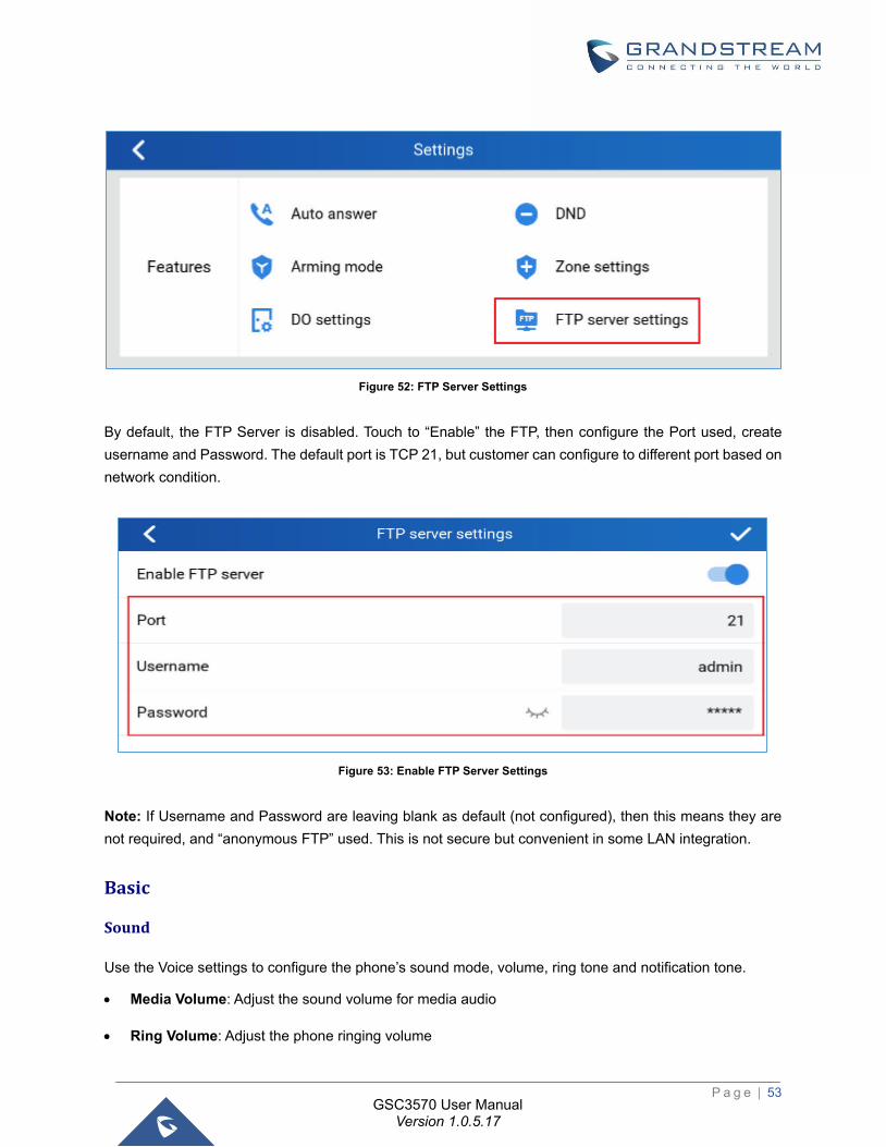
Figure 52: FTP Server Settings ................................................................................................................... 53
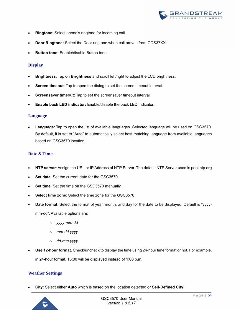
Figure 53: Enable FTP Server Settings ...................................................................................................... 53
Figure 54: Change Password ..................................................................................................................... 59
Figure 55: Dial Plan Configuration .............................................................................................................. 95
Figure 56: Edit contacts .............................................................................................................................. 97
P a g e | 10
GSC3570 User Manual Version 1.0.5.17
Figure 57: Download XML phonebook ........................................................................................................ 98
Figure 58: Packet Capture .......................................................................................................................... 99
Figure 59: LCD upgrade ............................................................................................................................ 100
Figure 60: Factory Reset from web GUI ................................................................................................... 103
Figure 61: Factory Reset from LCD .......................................................................................................... 104
P a g e | 11
GSC3570 User Manual Version 1.0.5.17
DOCUMENT PURPOSE
This document describes how to configure the GSC3570 features via LCD menu and Web GUI menu.
To learn the basic functions of GSC3570, please visit https://www.grandstream.com/support to download
the latest User Manual.
This guide covers the following topics:
• Product Overview
• Getting Started
• GSC3570 LCD Settings
• Configuration via Web interface
• Upgrading and Provisioning
• Restore Factory Default Settings
• Experiencing GSC3570
P a g e | 12
GSC3570 User Manual Version 1.0.5.17
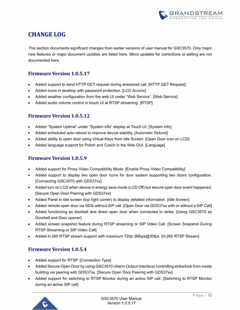
CHANGE LOG
This section documents significant changes from earlier versions of user manual for GSC3570. Only major
new features or major document updates are listed here. Minor updates for corrections or editing are not
documented here.
Firmware Version 1.0.5.17
• Added support to send HTTP GET request during answered call. [HTTP GET Request]
• Added icons in desktop with password protection. [LCD Access]
• Added weather configuration from the web UI under “Web Service”. [Web Service]
• Added audio volume control in touch UI at RTSP streaming. [RTSP]
Firmware Version 1.0.5.12
• Added “System Uptime” under “System info” display at Touch UI. [System Info]
• Added scheduled auto reboot to improve device stability. [Automatic Reboot]
• Added ability to open door using Virtual Keys from Idle Screen. [Open Door icon on LCD]
• Added language support for Polish and Czech in the Web GUI. [Language]
Firmware Version 1.0.5.9
• Added support for Proxy Video Compatibility Mode. [Enable Proxy Video Compatibility]
• Added support to display two open door icons for door system supporting two doors configuration.
[Connecting GSC3570 with GDS37xx]
• Added turn on LCD when device in energy save mode (LCD Off) but secure open door event happened.
[Secure Open Door Peering with GDS37xx]
• Added Panel in idle screen (top right corner) to display detailed information. [Idle Screen]
• Added remote open door via GDS without SIP call. [Open Door via GDS37xx with or without a SIP Call]
• Added functioning as doorbell and direct open door when connected to strike. [Using GSC3570 as
Doorbell and Door opener]
• Added screen snapshot feature during RTSP streaming or SIP Video Call. [Screen Snapshot During
RTSP Streaming or SIP Video Call]
• Added H.265 RTSP stream support with maximum 720p 3Mbps@30fps. [H.265 RTSP Stream]
Firmware Version 1.0.5.4
• Added support for RTSP. [Connection Type]
• Added Secure Open Door by using GSC3570 (Alarm Output Interface) controlling strike/lock from inside
building via peering with GDS37xx. [Secure Open Door Peering with GDS37xx]
• Added support for switching to RTSP Monitor during an active SIP call. [Switching to RTSP Monitor
during an active SIP call]
P a g e | 13
GSC3570 User Manual Version 1.0.5.17
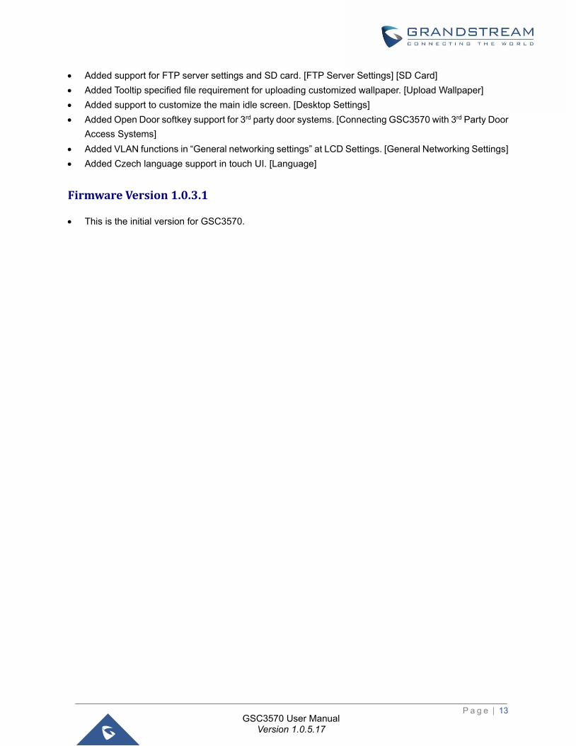
• Added support for FTP server settings and SD card. [FTP Server Settings] [SD Card]
• Added Tooltip specified file requirement for uploading customized wallpaper. [Upload Wallpaper]
• Added support to customize the main idle screen. [Desktop Settings]
• Added Open Door softkey support for 3rd party door systems. [Connecting GSC3570 with 3rd Party Door
Access Systems]
• Added VLAN functions in “General networking settings” at LCD Settings. [General Networking Settings]
• Added Czech language support in touch UI. [Language]
Firmware Version 1.0.3.1
• This is the initial version for GSC3570.

P a g e | 14
GSC3570 User Manual Version 1.0.5.17
WELCOME
Thank you for purchasing Grandstream GSC3570 Integrated SIP Intercom Phone. The GSC3570 is a
powerful Intercom phone for door control and 2-way intercom. It features a 7” 1024x600 touch screen LCD,
integrated dual-band 802.11ac Wi-Fi, 100M network port with PoE, full duplex 2-way HD audio with
advanced AEC, and innovative telephony functionalities. The GSC3570 is fully interoperable with nearly all
major SIP platforms on the market and can be seamlessly integrated with Grandstream’s entire range of
UC product lines including SIP based door systems, security cameras, IP PBXs, and video conferencing
systems and services. This Intercom phone is the perfect choice for users looking for an integrated video
control and two-way voice communication solution for their wall-mount.
P a g e | 15
GSC3570 User Manual Version 1.0.5.17
PRODUCT OVERVIEW
Feature Highlights
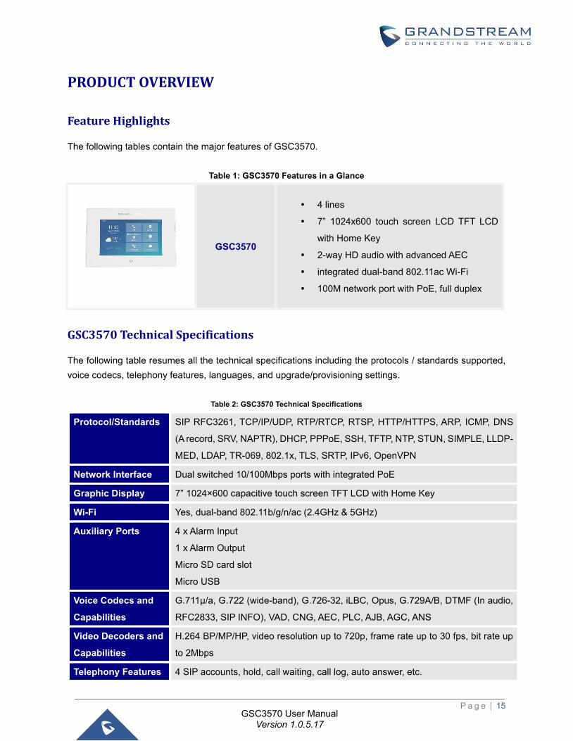
The following tables contain the major features of GSC3570.
Table 1: GSC3570 Features in a Glance
GSC3570
4 lines
7” 1024x600 touch screen LCD TFT LCD
with Home Key
2-way HD audio with advanced AEC
integrated dual-band 802.11ac Wi-Fi
100M network port with PoE, full duplex
GSC3570 Technical Specifications
The following table resumes all the technical specifications including the protocols / standards supported,
voice codecs, telephony features, languages, and upgrade/provisioning settings.
Table 2: GSC3570 Technical Specifications
Protocol/Standards SIP RFC3261, TCP/IP/UDP, RTP/RTCP, RTSP, HTTP/HTTPS, ARP, ICMP, DNS
(A record, SRV, NAPTR), DHCP, PPPoE, SSH, TFTP, NTP, STUN, SIMPLE, LLDP-
MED, LDAP, TR-069, 802.1x, TLS, SRTP, IPv6, OpenVPN
Network Interface Dual switched 10/100Mbps ports with integrated PoE
Graphic Display 7” 1024×600 capacitive touch screen TFT LCD with Home Key
Wi-Fi Yes, dual-band 802.11b/g/n/ac (2.4GHz & 5GHz)
Auxiliary Ports 4 x Alarm Input
1 x Alarm Output
Micro SD card slot
Micro USB
Voice Codecs and
Capabilities
G.711µ/a, G.722 (wide-band), G.726-32, iLBC, Opus, G.729A/B, DTMF (In audio,
RFC2833, SIP INFO), VAD, CNG, AEC, PLC, AJB, AGC, ANS
Video Decoders and
Capabilities
H.264 BP/MP/HP, video resolution up to 720p, frame rate up to 30 fps, bit rate up
to 2Mbps
Telephony Features 4 SIP accounts, hold, call waiting, call log, auto answer, etc.
P a g e | 16
GSC3570 User Manual Version 1.0.5.17
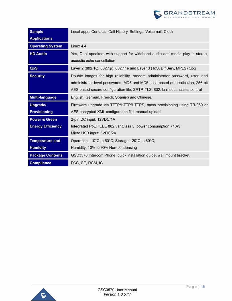
Sample
Applications
Local apps: Contacts, Call History, Settings, Voicemail, Clock
Operating System Linux 4.4
HD Audio Yes, Dual speakers with support for wideband audio and media play in stereo,
acoustic echo cancellation
QoS Layer 2 (802.1Q, 802.1p), 802.11e and Layer 3 (ToS, DiffServ, MPLS) QoS
Security Double images for high reliability, random administrator password, user, and
administrator level passwords, MD5 and MD5-sess based authentication, 256-bit
AES based secure configuration file, SRTP, TLS, 802.1x media access control
Multi-language English, German, French, Spanish and Chinese.
Upgrade/
Provisioning
Firmware upgrade via TFTP/HTTP/HTTPS, mass provisioning using TR-069 or
AES encrypted XML configuration file, manual upload
Power & Green
Energy Efficiency
2-pin DC input: 12VDC/1A
Integrated PoE: IEEE 802.3af Class 3, power consumption <10W
Micro USB input: 5VDC/2A
Temperature and
Humidity
Operation: -10°C to 50°C, Storage: -20°C to 60°C,
Humidity: 10% to 90% Non-condensing
Package Contents GSC3570 Intercom Phone, quick installation guide, wall mount bracket.
Compliance FCC, CE, RCM, IC
P a g e | 17
GSC3570 User Manual Version 1.0.5.17
GETTING STARTED
This chapter provides basic installation instructions including the list of the packaging contents and
information for obtaining the best performance with the GSC3570.
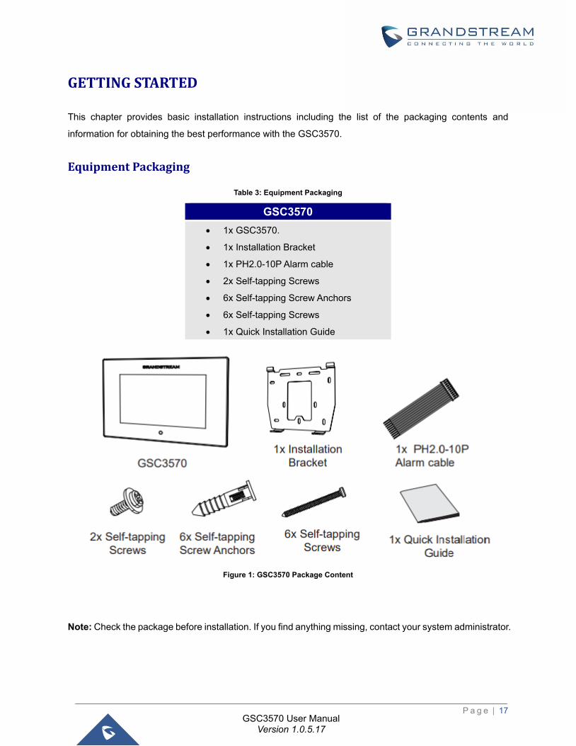
Equipment Packaging
Table 3: Equipment Packaging
Figure 1: GSC3570 Package Content
Note: Check the package before installation. If you find anything missing, contact your system administrator.
GSC3570
• 1x GSC3570.
• 1x Installation Bracket
• 1x PH2.0-10P Alarm cable
• 2x Self-tapping Screws
• 6x Self-tapping Screw Anchors
• 6x Self-tapping Screws
• 1x Quick Installation Guide
P a g e | 18
GSC3570 User Manual Version 1.0.5.17
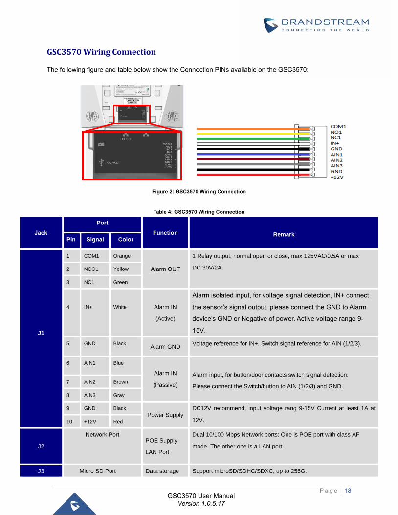
GSC3570 Wiring Connection
The following figure and table below show the Connection PINs available on the GSC3570:
Figure 2: GSC3570 Wiring Connection
Table 4: GSC3570 Wiring Connection
Jack
Port
Function
Remark Pin Signal Color
J1
1 COM1 Orange
Alarm OUT
1 Relay output, normal open or close, max 125VAC/0.5A or max
DC 30V/2A. 2 NCO1 Yellow
3 NC1 Green
4
IN+
White Alarm IN
(Active)
Alarm isolated input, for voltage signal detection, IN+ connect
the sensor’s signal output, please connect the GND to Alarm
device’s GND or Negative of power. Active voltage range 9-
15V.
5 GND Black Alarm GND
Voltage reference for IN+, Switch signal reference for AIN (1/2/3).
6 AIN1 Blue
Alarm IN
(Passive)
Alarm input, for button/door contacts switch signal detection.
Please connect the Switch/button to AIN (1/2/3) and GND. 7 AIN2 Brown
8 AIN3 Gray
9 GND Black
Power Supply DC12V recommend, input voltage rang 9-15V Current at least 1A at
12V. 10 +12V Red
J2
Network Port POE Supply
LAN Port
Dual 10/100 Mbps Network ports: One is POE port with class AF
mode. The other one is a LAN port.
J3 Micro SD Port Data storage Support microSD/SDHC/SDXC, up to 256G.
P a g e | 19
GSC3570 User Manual Version 1.0.5.17
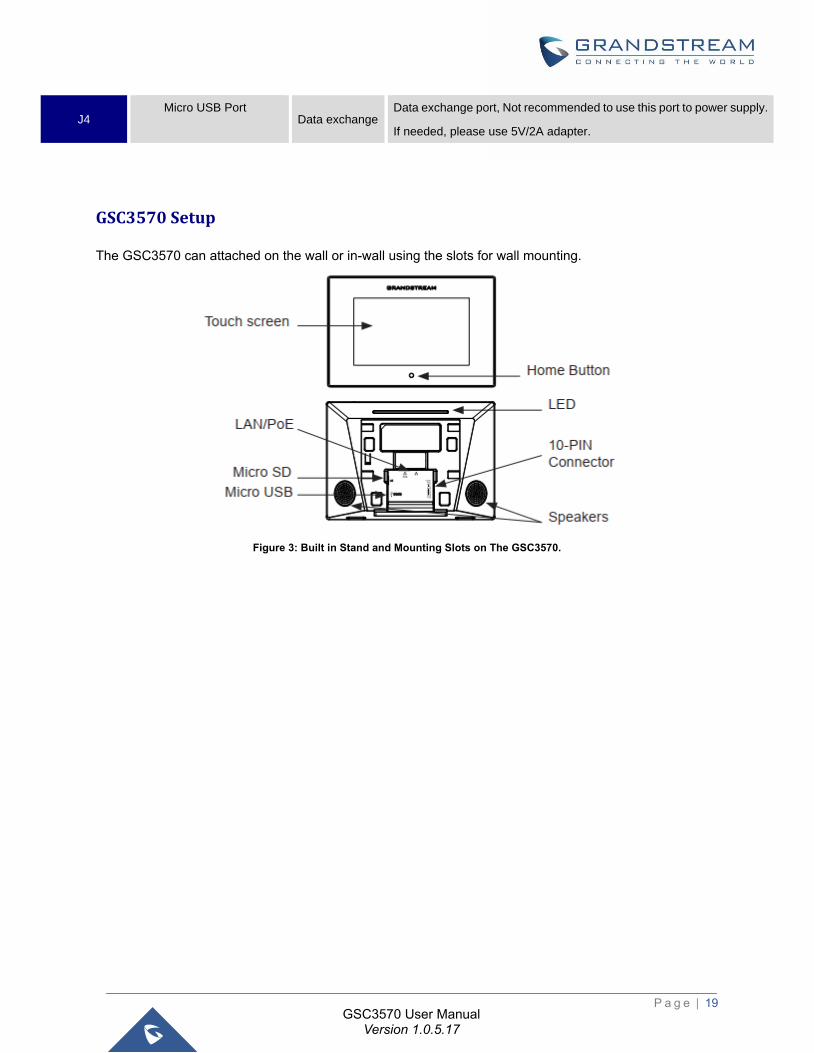
J4 Micro USB Port
Data exchange Data exchange port, Not recommended to use this port to power supply.
If needed, please use 5V/2A adapter.
GSC3570 Setup
The GSC3570 can attached on the wall or in-wall using the slots for wall mounting.
Figure 3: Built in Stand and Mounting Slots on The GSC3570.
P a g e | 20
GSC3570 User Manual Version 1.0.5.17
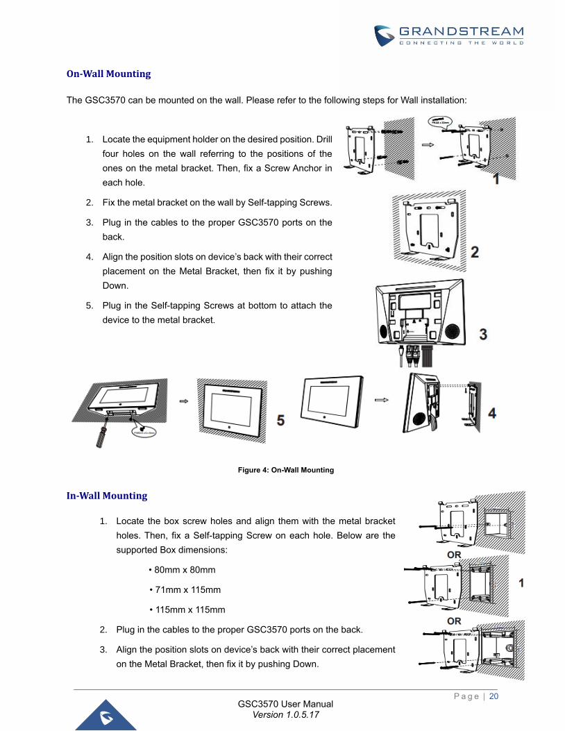
On-Wall Mounting
The GSC3570 can be mounted on the wall. Please refer to the following steps for Wall installation:
In-Wall Mounting
1. Locate the box screw holes and align them with the metal bracket
holes. Then, fix a Self-tapping Screw on each hole. Below are the
supported Box dimensions:
• 80mm x 80mm
• 71mm x 115mm
• 115mm x 115mm
2. Plug in the cables to the proper GSC3570 ports on the back.
3. Align the position slots on device’s back with their correct placement
on the Metal Bracket, then fix it by pushing Down.
1. Locate the equipment holder on the desired position. Drill
four holes on the wall referring to the positions of the
ones on the metal bracket. Then, fix a Screw Anchor in
each hole.
2. Fix the metal bracket on the wall by Self-tapping Screws.
3. Plug in the cables to the proper GSC3570 ports on the
back.
4. Align the position slots on device’s back with their correct
placement on the Metal Bracket, then fix it by pushing
Down.
5. Plug in the Self-tapping Screws at bottom to attach the
device to the metal bracket.
Figure 4: On-Wall Mounting
P a g e | 21
GSC3570 User Manual Version 1.0.5.17
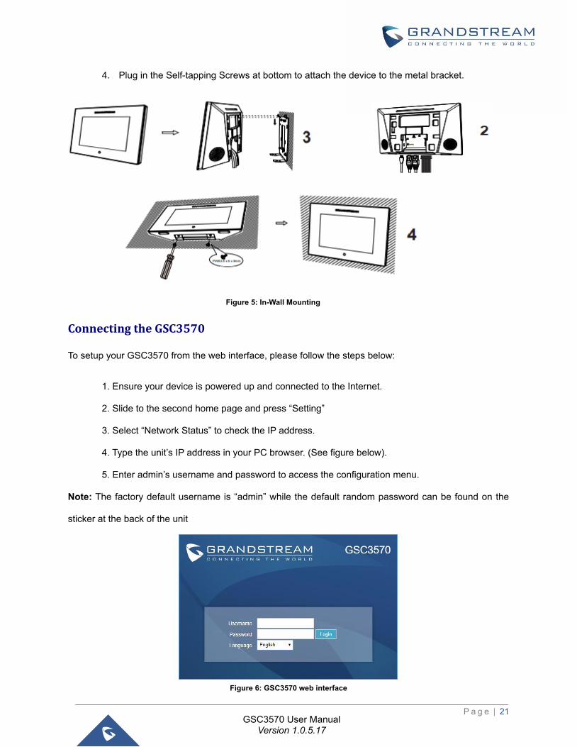
4. Plug in the Self-tapping Screws at bottom to attach the device to the metal bracket.
Connecting the GSC3570
To setup your GSC3570 from the web interface, please follow the steps below:
1. Ensure your device is powered up and connected to the Internet.
2. Slide to the second home page and press “Setting”
3. Select “Network Status” to check the IP address.
4. Type the unit’s IP address in your PC browser. (See figure below).
5. Enter admin’s username and password to access the configuration menu.
Note: The factory default username is “admin” while the default random password can be found on the
sticker at the back of the unit
Figure 6: GSC3570 web interface
Figure 5: In-Wall Mounting
P a g e | 22
GSC3570 User Manual Version 1.0.5.17
To setup your GSC3570 from the LCD, please follow the steps below:
1. Make sure the device is idle.
2. Slide to the second home page and press “Setting”. Browse the GSC3570
MENU for Status, Network information, Features and Basic/Advanced Settings…
3. Press “Home” Button to go back to idle screen.
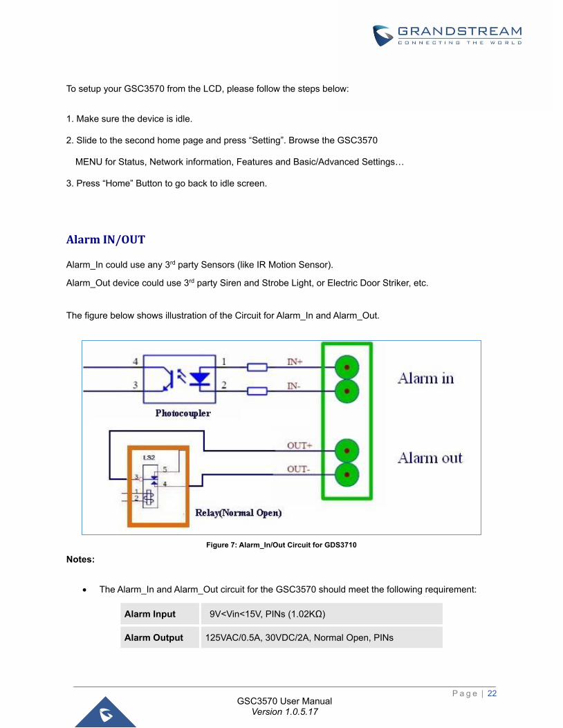
Alarm IN/OUT
Alarm_In could use any 3rd party Sensors (like IR Motion Sensor).
Alarm_Out device could use 3rd party Siren and Strobe Light, or Electric Door Striker, etc.
The figure below shows illustration of the Circuit for Alarm_In and Alarm_Out.
Figure 7: Alarm_In/Out Circuit for GDS3710
Notes:
• The Alarm_In and Alarm_Out circuit for the GSC3570 should meet the following requirement:
Alarm Input 9V<Vin<15V, PINs (1.02KΩ)
Alarm Output 125VAC/0.5A, 30VDC/2A, Normal Open, PINs
P a g e | 23
GSC3570 User Manual Version 1.0.5.17
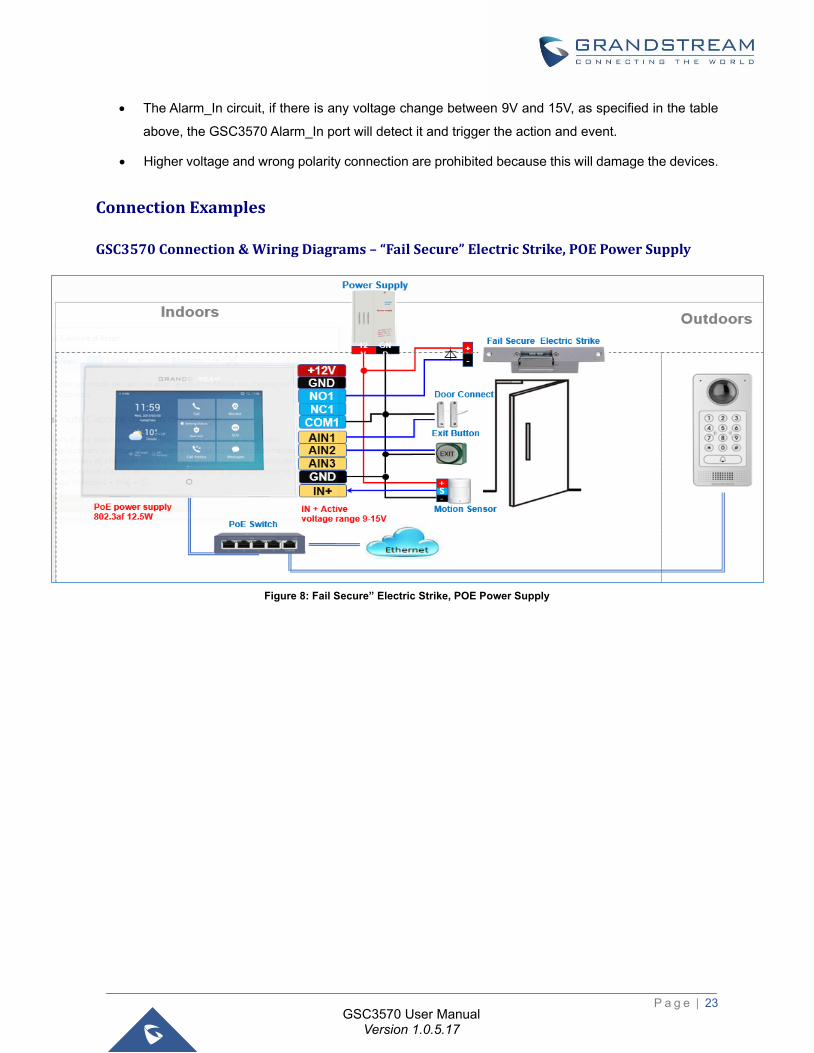
• The Alarm_In circuit, if there is any voltage change between 9V and 15V, as specified in the table
above, the GSC3570 Alarm_In port will detect it and trigger the action and event.
• Higher voltage and wrong polarity connection are prohibited because this will damage the devices.
Connection Examples
GSC3570 Connection & Wiring Diagrams – “Fail Secure” Electric Strike, POE Power Supply
Figure 8: Fail Secure” Electric Strike, POE Power Supply

P a g e | 24
GSC3570 User Manual Version 1.0.5.17
GSC3570 Connection & Wiring Diagrams – “Fail Safe” Electric lock, 3rd Party Power Supply
Figure 9: Fail Safe” Electric lock, 3rd Party Power Supply
GSC3570 Connection & Wiring Diagrams – “Fail Safe” Electric lock, Power Supply and Wi-Fi
Figure 10: Fail Safe” Electric lock, 3rd Party Power Supply, Wi-Fi
P a g e | 25
GSC3570 User Manual Version 1.0.5.17
Connecting GSC3570 with GDS37xx
The GSC3570 can be configured with up to 10 GDS37xx devices allowing two doors remote control per
GDS, the configuration is done as follow:
Web interface configuration:
1. Access Settings→ External Service.
2. Select the Service Type, it could be GDS or Others in case you want to integrate GSC3570 with
3rd party Door Access Control system
3. Select Account on which the remote door opening with softkey will be applied on.
4. Enter name of the GDS unit in System Identification. (not a mandatory field)
5. Set GDS SIP Number (or IP address in case of the peering scenario) on System Number.
6. Enter Door 1 name. (not a mandatory field)
7. Enter the Remote PIN to Open Door 1 configured in the GDS in Door 1 Access Password.
8. Enter the Remote PIN to Open Door 2 configured in the GDS in Door 2 Access Password.
9. Click on Save and Apply.
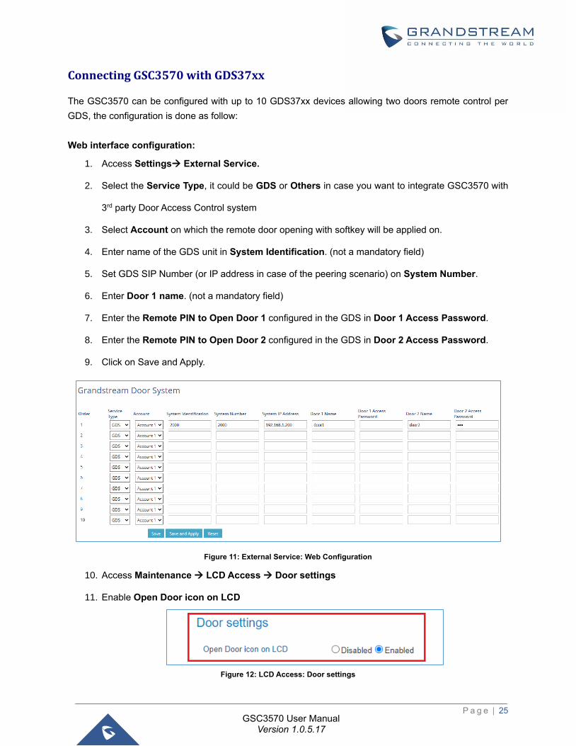
Figure 11: External Service: Web Configuration
10. Access Maintenance → LCD Access → Door settings
11. Enable Open Door icon on LCD
Figure 12: LCD Access: Door settings
P a g e | 26
GSC3570 User Manual Version 1.0.5.17
LCD configuration:
1. Tap the menu button if GSC3570 is in idle state.
2. On the first screen menu, tap Monitor→ Door System.
3. Press the ADD or + button to add a new GDS.
4. Enter the GDS Name in Device Name field.
5. Select the Account which will have the remote door opening feature and enter GDS SIP extension
(or IP address in case of peering scenario) in Device Number field.
6. Enter the Door Name for Door 1 and Remote PIN to Open Door 1 configured in the GDS in
Password Field.
7. Enter the Door Name for Door 2 and Remote PIN to Open Door 2 configured in the GDS in
Password Field.
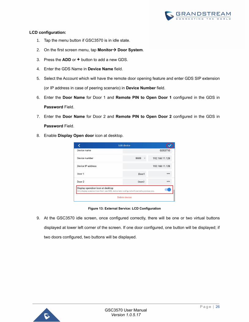
8. Enable Display Open door icon at desktop.
Figure 13: External Service: LCD Configuration
9. At the GSC3570 idle screen, once configured correctly, there will be one or two virtual buttons
displayed at lower left corner of the screen. If one door configured, one button will be displayed; if
two doors configured, two buttons will be displayed.
P a g e | 27
GSC3570 User Manual Version 1.0.5.17
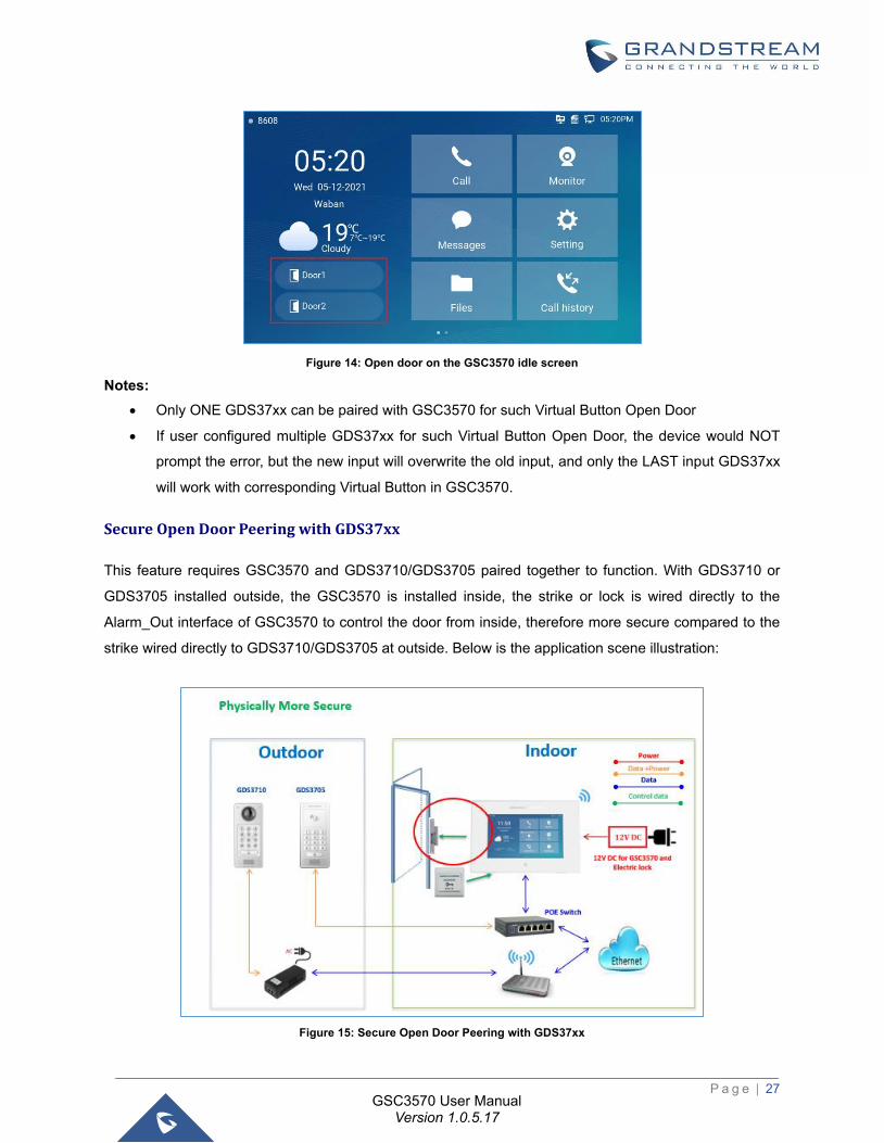
Figure 14: Open door on the GSC3570 idle screen
Notes:
• Only ONE GDS37xx can be paired with GSC3570 for such Virtual Button Open Door
• If user configured multiple GDS37xx for such Virtual Button Open Door, the device would NOT
prompt the error, but the new input will overwrite the old input, and only the LAST input GDS37xx
will work with corresponding Virtual Button in GSC3570.
Secure Open Door Peering with GDS37xx
This feature requires GSC3570 and GDS3710/GDS3705 paired together to function. With GDS3710 or
GDS3705 installed outside, the GSC3570 is installed inside, the strike or lock is wired directly to the
Alarm_Out interface of GSC3570 to control the door from inside, therefore more secure compared to the
strike wired directly to GDS3710/GDS3705 at outside. Below is the application scene illustration:
Figure 15: Secure Open Door Peering with GDS37xx
P a g e | 28
GSC3570 User Manual Version 1.0.5.17
Notes:
• GDS3710 firmware 1.0.7.19 or above / GDS3705 firmware 1.0.1.13 or above, are required to work
with GSC3570.
• Only one door can be controlled due to GSC3570 only has one Relay Control circuit.
• If multiple doors need to be controlled by GSC3570, SIP call is required, and the door strike/relay
should be controlled by related GDS37xx directly.
• The GSC3570 will turn on LCD when device in energy save mode (LCD Off) when secure open
door event happened.
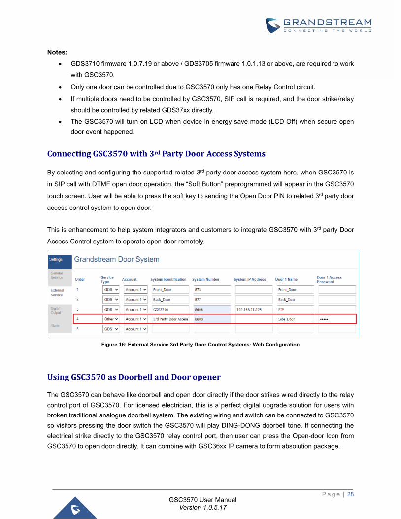
Connecting GSC3570 with 3rd Party Door Access Systems
By selecting and configuring the supported related 3rd party door access system here, when GSC3570 is
in SIP call with DTMF open door operation, the “Soft Button” preprogrammed will appear in the GSC3570
touch screen. User will be able to press the soft key to sending the Open Door PIN to related 3rd party door
access control system to open door.
This is enhancement to help system integrators and customers to integrate GSC3570 with 3rd party Door
Access Control system to operate open door remotely.
Figure 16: External Service 3rd Party Door Control Systems: Web Configuration
Using GSC3570 as Doorbell and Door opener
The GSC3570 can behave like doorbell and open door directly if the door strikes wired directly to the relay
control port of GSC3570. For licensed electrician, this is a perfect digital upgrade solution for users with
broken traditional analogue doorbell system. The existing wiring and switch can be connected to GSC3570
so visitors pressing the door switch the GSC3570 will play DING-DONG doorbell tone. If connecting the
electrical strike directly to the GSC3570 relay control port, then user can press the Open-door Icon from
GSC3570 to open door directly. It can combine with GSC36xx IP camera to form absolution package.
P a g e | 29
GSC3570 User Manual Version 1.0.5.17
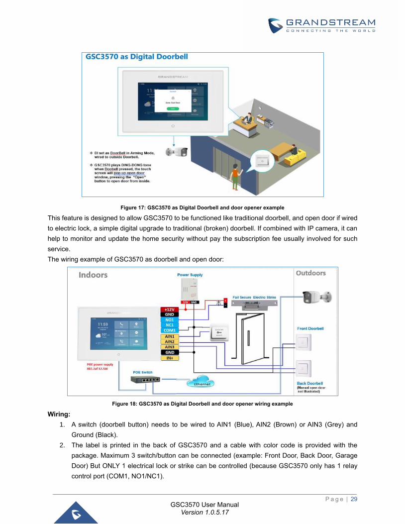
Figure 17: GSC3570 as Digital Doorbell and door opener example
This feature is designed to allow GSC3570 to be functioned like traditional doorbell, and open door if wired
to electric lock, a simple digital upgrade to traditional (broken) doorbell. If combined with IP camera, it can
help to monitor and update the home security without pay the subscription fee usually involved for such
service.
The wiring example of GSC3570 as doorbell and open door:
Figure 18: GSC3570 as Digital Doorbell and door opener wiring example
Wiring:
1. A switch (doorbell button) needs to be wired to AIN1 (Blue), AIN2 (Brown) or AIN3 (Grey) and
Ground (Black).
2. The label is printed in the back of GSC3570 and a cable with color code is provided with the
package. Maximum 3 switch/button can be connected (example: Front Door, Back Door, Garage
Door) But ONLY 1 electrical lock or strike can be controlled (because GSC3570 only has 1 relay
control port (COM1, NO1/NC1).
P a g e | 30
GSC3570 User Manual Version 1.0.5.17
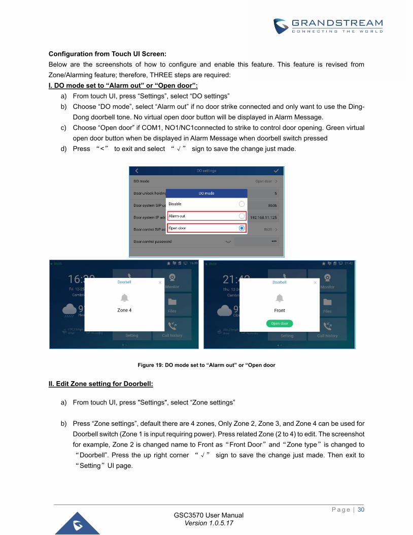
Configuration from Touch UI Screen:
Below are the screenshots of how to configure and enable this feature. This feature is revised from
Zone/Alarming feature; therefore, THREE steps are required:
I. DO mode set to “Alarm out” or “Open door”:
a) From touch UI, press “Settings”, select “DO settings”
b) Choose “DO mode”, select “Alarm out” if no door strike connected and only want to use the Ding-
Dong doorbell tone. No virtual open door button will be displayed in Alarm Message.
c) Choose “Open door” if COM1, NO1/NC1connected to strike to control door opening. Green virtual
open door button when be displayed in Alarm Message when doorbell switch pressed
d) Press “<” to exit and select “√” sign to save the change just made.
Figure 19: DO mode set to “Alarm out” or “Open door
II. Edit Zone setting for Doorbell:
a) From touch UI, press "Settings", select “Zone settings”
b) Press “Zone settings”, default there are 4 zones, Only Zone 2, Zone 3, and Zone 4 can be used for
Doorbell switch (Zone 1 is input requiring power). Press related Zone (2 to 4) to edit. The screenshot
for example, Zone 2 is changed name to Front as“Front Door”and“Zone type”is changed to
“Doorbell”. Press the up right corner “√” sign to save the change just made. Then exit to
“Setting”UI page.

P a g e | 31
GSC3570 User Manual Version 1.0.5.17
Figure 20: Zone setting for Doorbell
III. Enable the Arming mode to enable the doorbell:
a) Press “Arming mode” to enable the change in above Step I.
b) Select the Arming mode used. For example, “Outdoor” is selected because the doorbell is located
at outside. Swipe the grey button to enable the feature, the button will become blue when enabled.
c) Press “<” icon to exist the configuration to idle screen.
The “Arming status” icon will change color (green). To show the device is “Armed”, or the feature is
enabled.
Figure 21: Arming mode
Now press the doorbell or switch (AIN1and GND short-circuit), “DING DONG” doorbell tone will be played
at GSC3570, a green open door virtual button will be displayed in the screen (if configured and wired the
strike). Press the green “Open door” virtual button, the relay will take reaction to open the door. The
GSC3570 top right corner will also display a door opened icon and an “alarm” icon and “Message” will be
displayed with front and back red LED flashing, reminding there is an open door (alarming) event happened.
Press the “Messages” icon to check what the message is then exit the UI, the alarm message and the
flashing LEDs will disappear.
Figure 22: Alarm flashing icon and open door button
P a g e | 32
GSC3570 User Manual Version 1.0.5.17
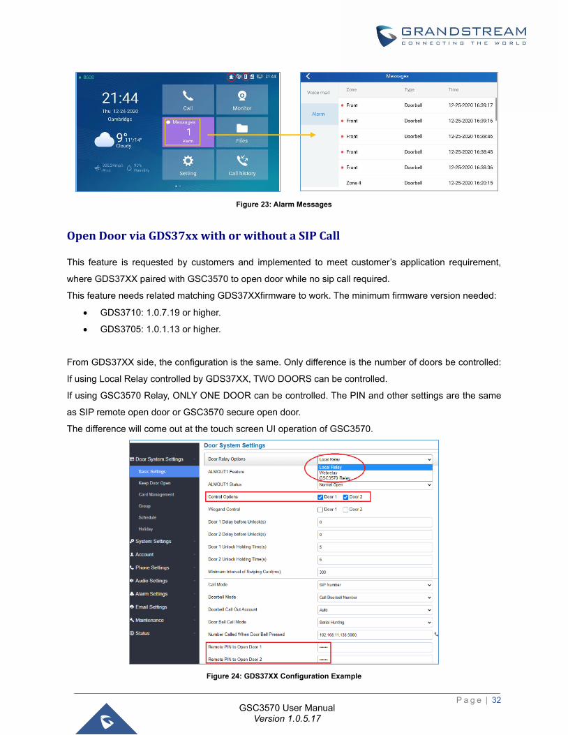
Figure 23: Alarm Messages
Open Door via GDS37xx with or without a SIP Call
This feature is requested by customers and implemented to meet customer’s application requirement,
where GDS37XX paired with GSC3570 to open door while no sip call required.
This feature needs related matching GDS37XXfirmware to work. The minimum firmware version needed:
• GDS3710: 1.0.7.19 or higher.
• GDS3705: 1.0.1.13 or higher.
From GDS37XX side, the configuration is the same. Only difference is the number of doors be controlled:
If using Local Relay controlled by GDS37XX, TWO DOORS can be controlled.
If using GSC3570 Relay, ONLY ONE DOOR can be controlled. The PIN and other settings are the same
as SIP remote open door or GSC3570 secure open door.
The difference will come out at the touch screen UI operation of GSC3570.
Figure 24: GDS37XX Configuration Example
P a g e | 33
GSC3570 User Manual Version 1.0.5.17
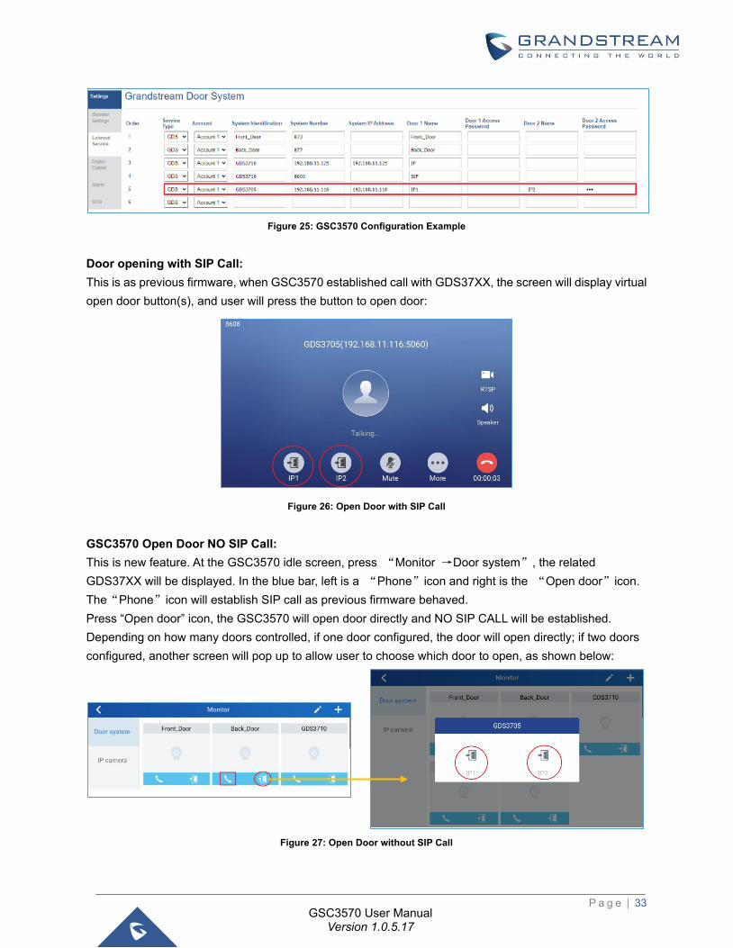
Figure 25: GSC3570 Configuration Example
Door opening with SIP Call:
This is as previous firmware, when GSC3570 established call with GDS37XX, the screen will display virtual
open door button(s), and user will press the button to open door:
Figure 26: Open Door with SIP Call
GSC3570 Open Door NO SIP Call:
This is new feature. At the GSC3570 idle screen, press “Monitor →Door system”, the related
GDS37XX will be displayed. In the blue bar, left is a “Phone”icon and right is the “Open door”icon.
The“Phone”icon will establish SIP call as previous firmware behaved.
Press “Open door” icon, the GSC3570 will open door directly and NO SIP CALL will be established.
Depending on how many doors controlled, if one door configured, the door will open directly; if two doors
configured, another screen will pop up to allow user to choose which door to open, as shown below:
Figure 27: Open Door without SIP Call
P a g e | 34
GSC3570 User Manual Version 1.0.5.17
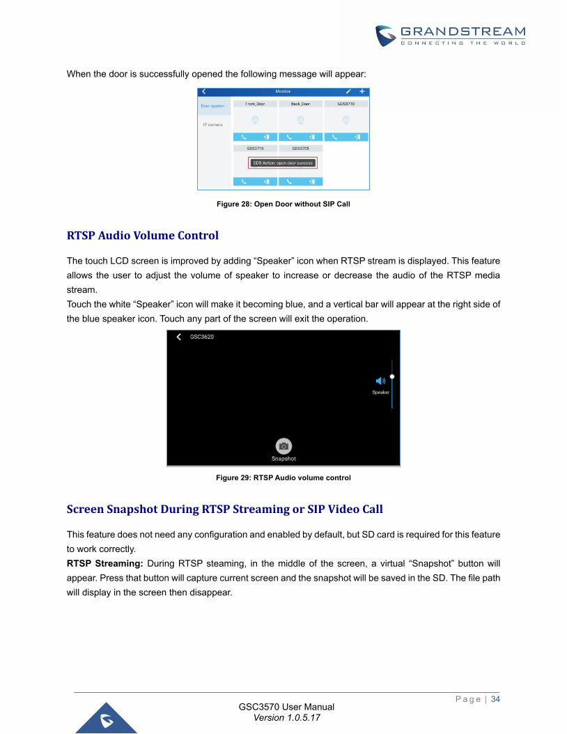
When the door is successfully opened the following message will appear:
Figure 28: Open Door without SIP Call
RTSP Audio Volume Control
The touch LCD screen is improved by adding “Speaker” icon when RTSP stream is displayed. This feature
allows the user to adjust the volume of speaker to increase or decrease the audio of the RTSP media
stream.
Touch the white “Speaker” icon will make it becoming blue, and a vertical bar will appear at the right side of
the blue speaker icon. Touch any part of the screen will exit the operation.
Figure 29: RTSP Audio volume control
Screen Snapshot During RTSP Streaming or SIP Video Call
This feature does not need any configuration and enabled by default, but SD card is required for this feature
to work correctly.
RTSP Streaming: During RTSP steaming, in the middle of the screen, a virtual “Snapshot” button will
appear. Press that button will capture current screen and the snapshot will be saved in the SD. The file path
will display in the screen then disappear.
P a g e | 35
GSC3570 User Manual Version 1.0.5.17
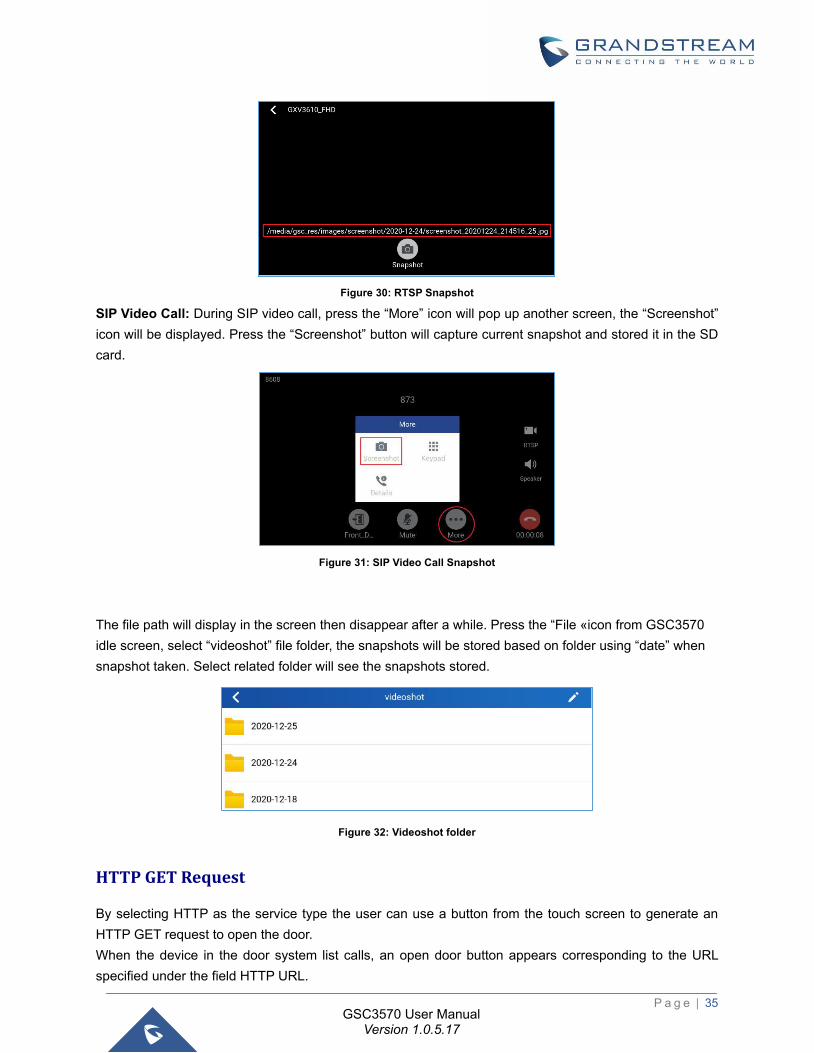
Figure 30: RTSP Snapshot
SIP Video Call: During SIP video call, press the “More” icon will pop up another screen, the “Screenshot”
icon will be displayed. Press the “Screenshot” button will capture current snapshot and stored it in the SD
card.
Figure 31: SIP Video Call Snapshot
The file path will display in the screen then disappear after a while. Press the “File «icon from GSC3570
idle screen, select “videoshot” file folder, the snapshots will be stored based on folder using “date” when
snapshot taken. Select related folder will see the snapshots stored.
Figure 32: Videoshot folder
HTTP GET Request
By selecting HTTP as the service type the user can use a button from the touch screen to generate an
HTTP GET request to open the door.
When the device in the door system list calls, an open door button appears corresponding to the URL
specified under the field HTTP URL.
P a g e | 36
GSC3570 User Manual Version 1.0.5.17
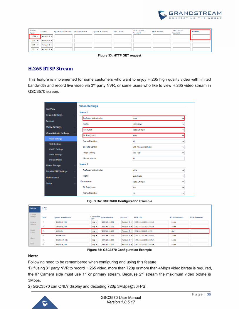
Figure 33: HTTP GET request
H.265 RTSP Stream
This feature is implemented for some customers who want to enjoy H.265 high quality video with limited
bandwidth and record live video via 3rd party NVR, or some users who like to view H.265 video stream in
GSC3570 screen.
Figure 34: GSC36XX Configuration Example
Figure 35: GSC3570 Configuration Example
Note:
Following need to be remembered when configuring and using this feature:
1) If using 3rd party NVR to record H.265 video, more than 720p or more than 4Mbps video bitrate is required,
the IP Camera side must use 1st or primary stream. Because 2nd stream the maximum video bitrate is
3Mbps.
2) GSC3570 can ONLY display and decoding 720p 3MBps@30FPS.
P a g e | 37
GSC3570 User Manual Version 1.0.5.17
3) If H.265 is used as 2ndstream for RTSP, then SIP Video Call will not display video because H.265 is
NOT supported by SIP Video Call device.
4) Suggested to use 1st or primary stream for H.265 (recording) and 2nd stream for H.264, so both H.265
recording and SIP Video Call can work at the same configuration.
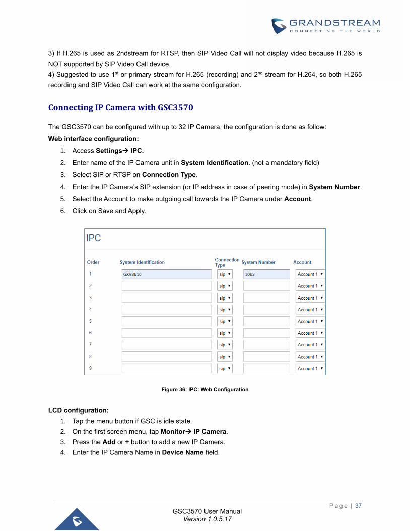
Connecting IP Camera with GSC3570
The GSC3570 can be configured with up to 32 IP Camera, the configuration is done as follow:
Web interface configuration:
1. Access Settings→ IPC.
2. Enter name of the IP Camera unit in System Identification. (not a mandatory field)
3. Select SIP or RTSP on Connection Type.
4. Enter the IP Camera’s SIP extension (or IP address in case of peering mode) in System Number.
5. Select the Account to make outgoing call towards the IP Camera under Account.
6. Click on Save and Apply.
Figure 36: IPC: Web Configuration
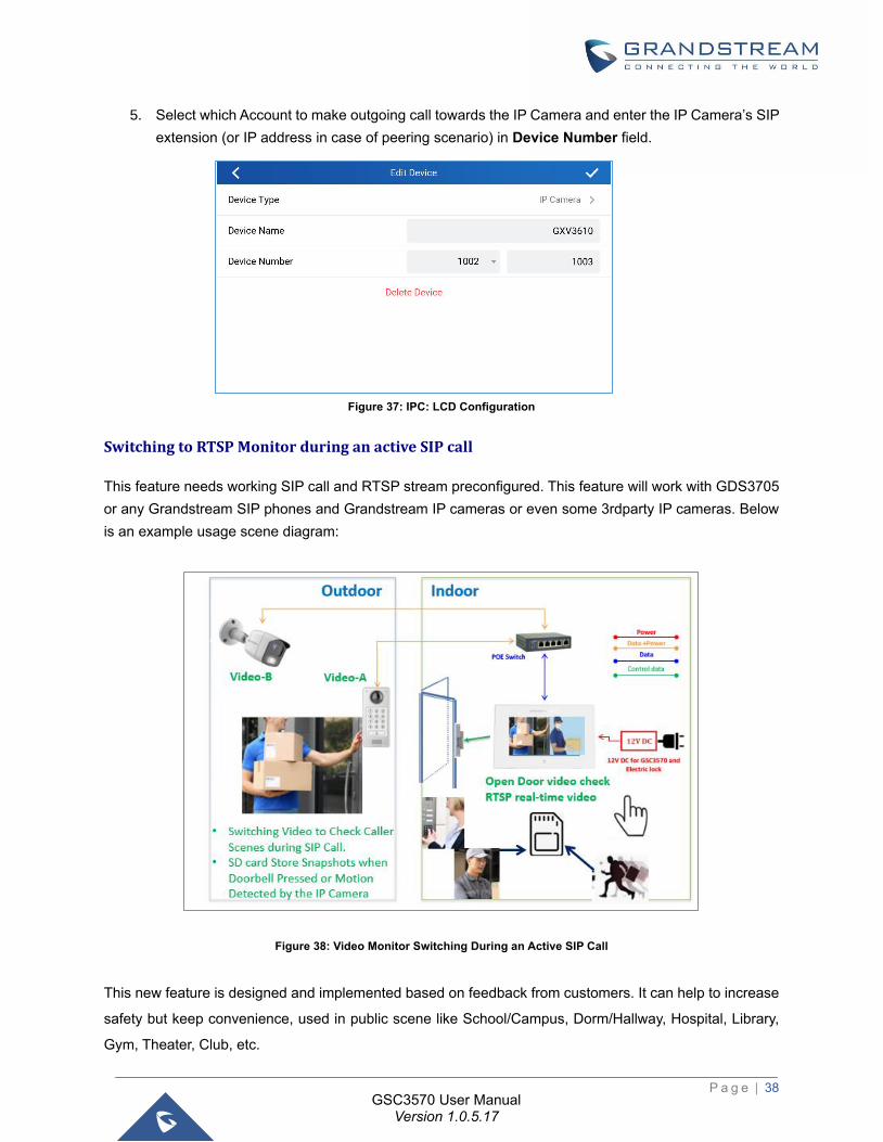
LCD configuration:
1. Tap the menu button if GSC is idle state.
2. On the first screen menu, tap Monitor→ IP Camera.
3. Press the Add or + button to add a new IP Camera.
4. Enter the IP Camera Name in Device Name field.
P a g e | 38
GSC3570 User Manual Version 1.0.5.17
5. Select which Account to make outgoing call towards the IP Camera and enter the IP Camera’s SIP
extension (or IP address in case of peering scenario) in Device Number field.
Figure 37: IPC: LCD Configuration
Switching to RTSP Monitor during an active SIP call
This feature needs working SIP call and RTSP stream preconfigured. This feature will work with GDS3705
or any Grandstream SIP phones and Grandstream IP cameras or even some 3rdparty IP cameras. Below
is an example usage scene diagram:
Figure 38: Video Monitor Switching During an Active SIP Call
This new feature is designed and implemented based on feedback from customers. It can help to increase
safety but keep convenience, used in public scene like School/Campus, Dorm/Hallway, Hospital, Library,
Gym, Theater, Club, etc.
P a g e | 39
GSC3570 User Manual Version 1.0.5.17
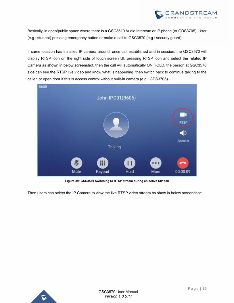
Basically, in open/public space where there is a GSC3510 Audio Intercom or IP phone (or GDS3705), User
(e.g.: student) pressing emergency button or make a call to GSC3570 (e.g.: security guard).
If same location has installed IP camera around, once call established and in session, the GSC3570 will
display RTSP icon on the right side of touch screen UI, pressing RTSP icon and select the related IP
Camera as shown in below screenshot, then the call will automatically ON HOLD, the person at GSC3570
side can see the RTSP live video and know what is happening, then switch back to continue talking to the
caller, or open door if this is access control without built-in camera (e.g.: GDS3705).
Figure 39: GSC3570 Switching to RTSP stream during an active SIP call
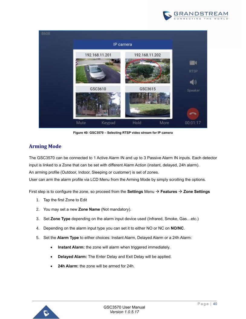
Then users can select the IP Camera to view the live RTSP video stream as show in below screenshot:
P a g e | 40
GSC3570 User Manual Version 1.0.5.17
Figure 40: GSC3570 – Selecting RTSP video stream for IP camera
Arming Mode
The GSC3570 can be connected to 1 Active Alarm IN and up to 3 Passive Alarm IN inputs. Each detector
input is linked to a Zone that can be set with different Alarm Action (instant, delayed, 24h alarm).
An arming profile (Outdoor, Indoor, Sleeping or customer) is set of zones.
User can arm the alarm profile via LCD Menu from the Arming Mode by simply scrolling the options.
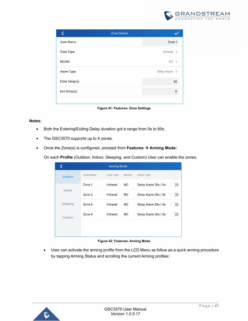
First step is to configure the zone, so proceed from the Settings Menu → Features → Zone Settings
1. Tap the first Zone to Edit
2. You may set a new Zone Name (Not mandatory).
3. Set Zone Type depending on the alarm input device used (Infrared, Smoke, Gas…etc.)
4. Depending on the alarm input type you can set it to either NO or NC on NO/NC.
5. Set the Alarm Type to either choices: Instant Alarm, Delayed Alarm or a 24h Alarm:
• Instant Alarm: the zone will alarm when triggered immediately.
• Delayed Alarm: The Enter Delay and Exit Delay will be applied.
• 24h Alarm: the zone will be armed for 24h.
P a g e | 41
GSC3570 User Manual Version 1.0.5.17
Figure 41: Features: Zone Settings
Notes:
• Both the Entering/Exiting Delay duration got a range from 0s to 60s.
• The GSC3570 supports up to 4 zones.
• Once the Zone(s) is configured, proceed from Features → Arming Mode:
On each Profile (Outdoor, Indoor, Sleeping, and Custom) User can enable the zones.
Figure 42: Features: Arming Mode
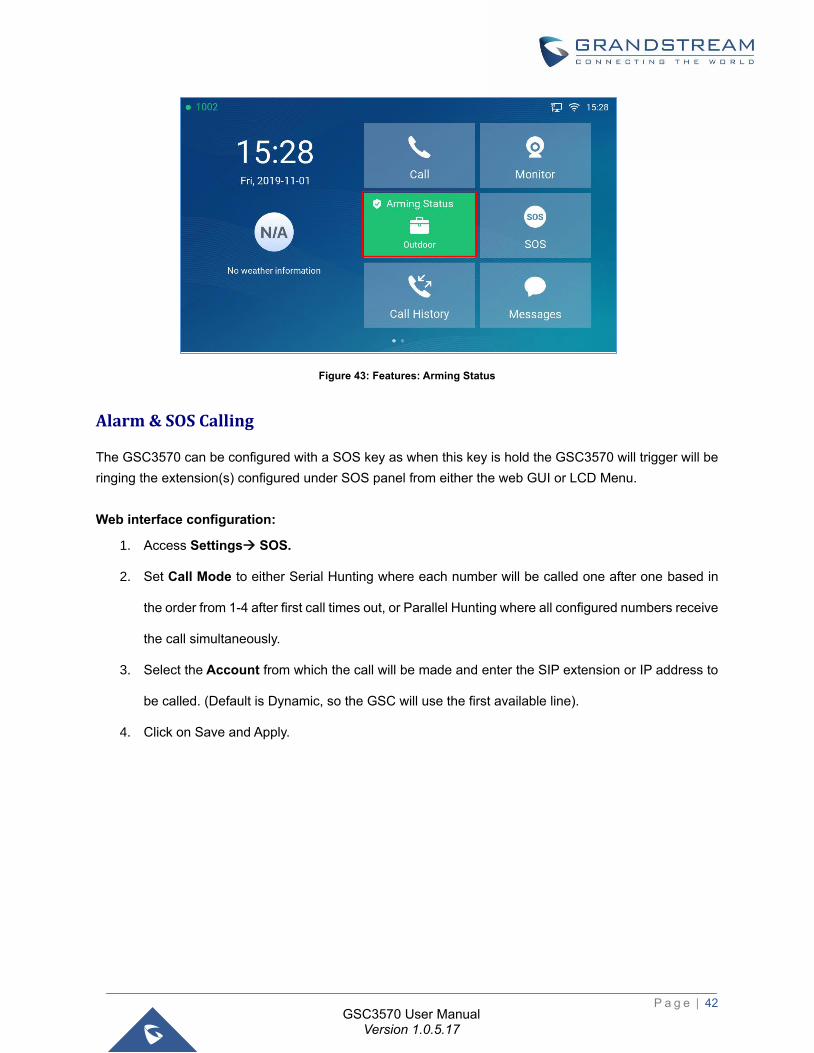
• User can activate the arming profile from the LCD Menu as follow as a quick arming procedure
by tapping Arming Status and scrolling the current Arming profiles:
P a g e | 42
GSC3570 User Manual Version 1.0.5.17
Figure 43: Features: Arming Status
Alarm & SOS Calling
The GSC3570 can be configured with a SOS key as when this key is hold the GSC3570 will trigger will be
ringing the extension(s) configured under SOS panel from either the web GUI or LCD Menu.
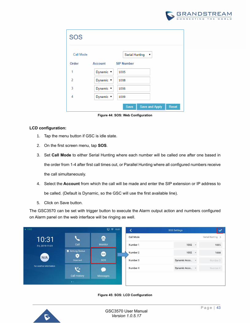
Web interface configuration:
1. Access Settings→ SOS.
2. Set Call Mode to either Serial Hunting where each number will be called one after one based in
the order from 1-4 after first call times out, or Parallel Hunting where all configured numbers receive
the call simultaneously.
3. Select the Account from which the call will be made and enter the SIP extension or IP address to
be called. (Default is Dynamic, so the GSC will use the first available line).
4. Click on Save and Apply.
P a g e | 43
GSC3570 User Manual Version 1.0.5.17
Figure 44: SOS: Web Configuration
LCD configuration:
1. Tap the menu button if GSC is idle state.
2. On the first screen menu, tap SOS.
3. Set Call Mode to either Serial Hunting where each number will be called one after one based in
the order from 1-4 after first call times out, or Parallel Hunting where all configured numbers receive
the call simultaneously.
4. Select the Account from which the call will be made and enter the SIP extension or IP address to
be called. (Default is Dynamic, so the GSC will use the first available line).
5. Click on Save button.
The GSC3570 can be set with trigger button to execute the Alarm output action and numbers configured
on Alarm panel on the web interface will be ringing as well.
Figure 45: SOS: LCD Configuration
P a g e | 44
GSC3570 User Manual Version 1.0.5.17
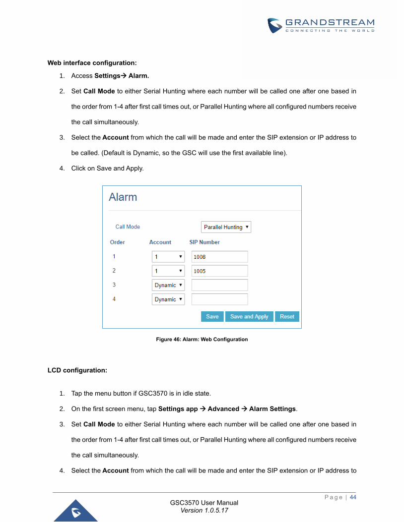
Web interface configuration:
1. Access Settings→ Alarm.
2. Set Call Mode to either Serial Hunting where each number will be called one after one based in
the order from 1-4 after first call times out, or Parallel Hunting where all configured numbers receive
the call simultaneously.
3. Select the Account from which the call will be made and enter the SIP extension or IP address to
be called. (Default is Dynamic, so the GSC will use the first available line).
4. Click on Save and Apply.
Figure 46: Alarm: Web Configuration
LCD configuration:
1. Tap the menu button if GSC3570 is in idle state.
2. On the first screen menu, tap Settings app → Advanced → Alarm Settings.
3. Set Call Mode to either Serial Hunting where each number will be called one after one based in
the order from 1-4 after first call times out, or Parallel Hunting where all configured numbers receive
the call simultaneously.
4. Select the Account from which the call will be made and enter the SIP extension or IP address to
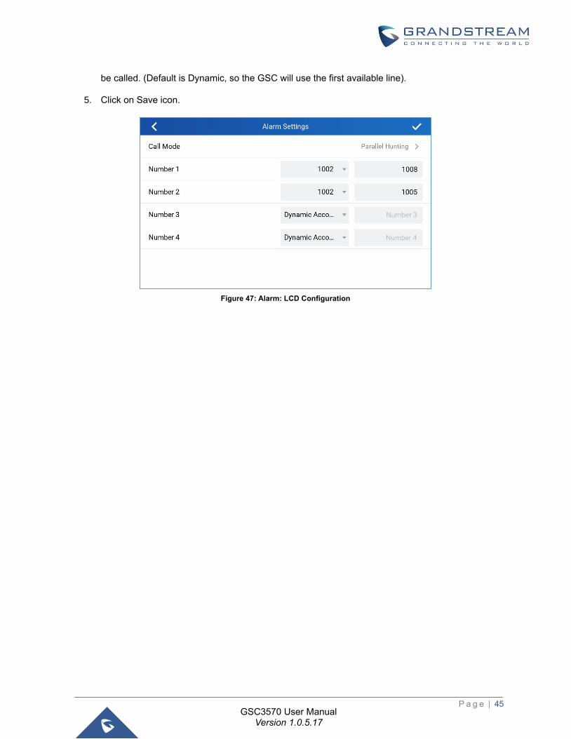
P a g e | 45
GSC3570 User Manual Version 1.0.5.17
be called. (Default is Dynamic, so the GSC will use the first available line).
5. Click on Save icon.
Figure 47: Alarm: LCD Configuration
P a g e | 46
GSC3570 User Manual Version 1.0.5.17
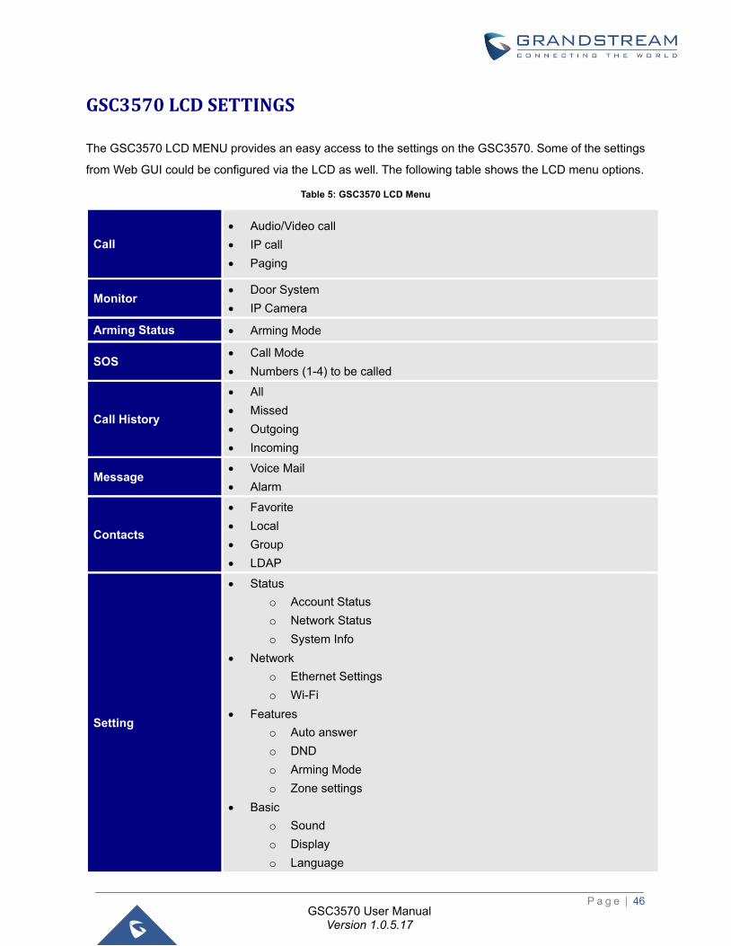
GSC3570 LCD SETTINGS
The GSC3570 LCD MENU provides an easy access to the settings on the GSC3570. Some of the settings
from Web GUI could be configured via the LCD as well. The following table shows the LCD menu options.
Table 5: GSC3570 LCD Menu
Call
• Audio/Video call
• IP call
• Paging
Monitor • Door System
• IP Camera
Arming Status • Arming Mode
SOS • Call Mode
• Numbers (1-4) to be called
Call History
• All
• Missed
• Outgoing
• Incoming
Message • Voice Mail
• Alarm
Contacts
• Favorite
• Local
• Group
• LDAP
Setting
• Status
o Account Status
o Network Status
o System Info
• Network
o Ethernet Settings
o Wi-Fi
• Features
o Auto answer
o DND
o Arming Mode
o Zone settings
• Basic
o Sound
o Display
o Language
P a g e | 47
GSC3570 User Manual Version 1.0.5.17
o Date & Time
o Weather settings
o Desktop settings
o Reboot
• Advanced
o Accounts
o Monitor
o Alarm settings
o SOS settings
o Syslog
o System updates
o Reset
Access LCD Settings
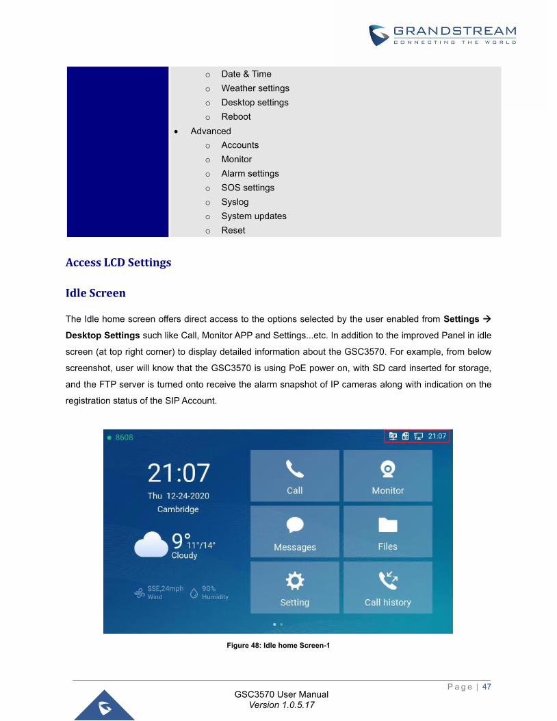
Idle Screen
The Idle home screen offers direct access to the options selected by the user enabled from Settings →
Desktop Settings such like Call, Monitor APP and Settings...etc. In addition to the improved Panel in idle
screen (at top right corner) to display detailed information about the GSC3570. For example, from below
screenshot, user will know that the GSC3570 is using PoE power on, with SD card inserted for storage,
and the FTP server is turned onto receive the alarm snapshot of IP cameras along with indication on the
registration status of the SIP Account.
Figure 48: Idle home Screen-1
P a g e | 48
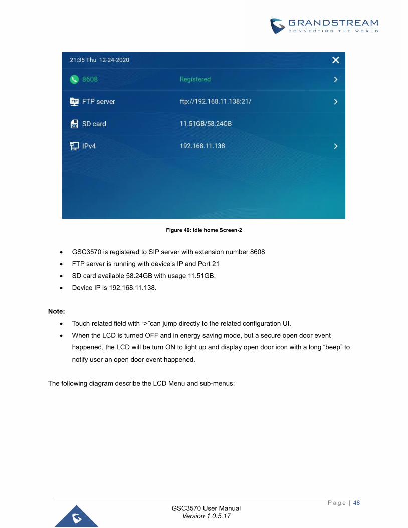
GSC3570 User Manual Version 1.0.5.17
Figure 49: Idle home Screen-2
• GSC3570 is registered to SIP server with extension number 8608
• FTP server is running with device’s IP and Port 21
• SD card available 58.24GB with usage 11.51GB.
• Device IP is 192.168.11.138.
Note:
• Touch related field with “>”can jump directly to the related configuration UI.
• When the LCD is turned OFF and in energy saving mode, but a secure open door event
happened, the LCD will be turn ON to light up and display open door icon with a long “beep” to
notify user an open door event happened.
The following diagram describe the LCD Menu and sub-menus:
P a g e | 49
GSC3570 User Manual Version 1.0.5.17
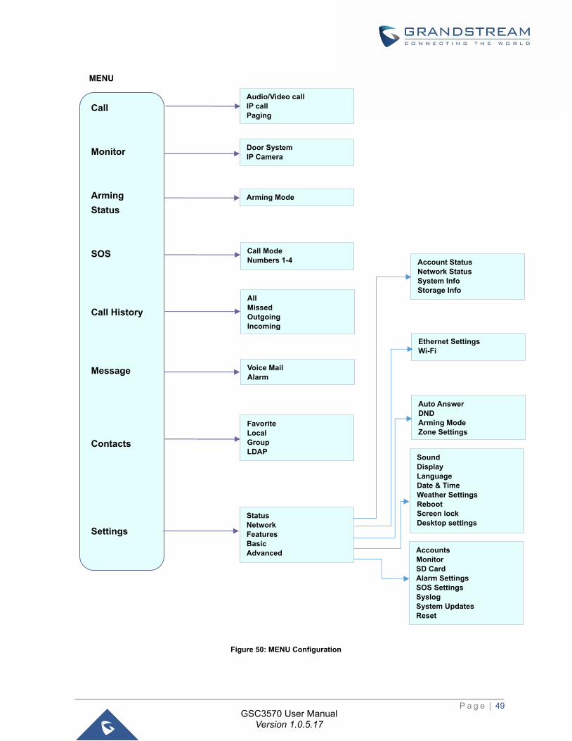
Figure 50: MENU Configuration
Call
Monitor
Arming
Status
SOS
Call History
Message
Contacts
Settings
MENU
Door System
IP Camera
Voice Mail
Alarm
Favorite
Local
Group
LDAP
Arming Mode
All
Missed
Outgoing
Incoming
Call Mode
Numbers 1-4
Audio/Video call
IP call
Paging
Status Network Features Basic Advanced
Ethernet Settings
Wi-Fi
Auto Answer DND
Arming Mode
Zone Settings
Sound
Display
Language
Date & Time
Weather Settings
Reboot
Screen lock
Desktop settings
Accounts
Monitor
SD Card
Alarm Settings
SOS Settings
Syslog
System Updates
Reset
Account Status Network Status System Info Storage Info
P a g e | 50
GSC3570 User Manual Version 1.0.5.17
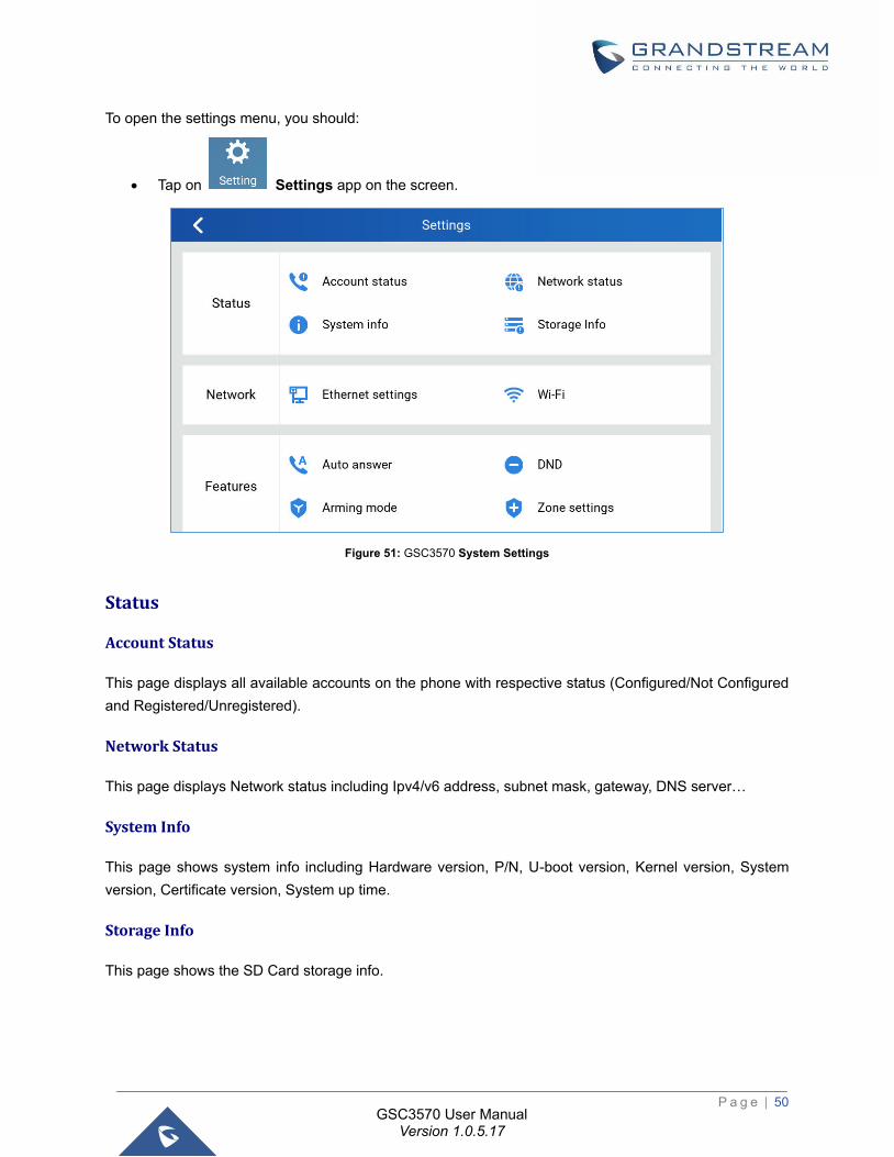
To open the settings menu, you should:
• Tap on Settings app on the screen.
Figure 51: GSC3570 System Settings
Status
Account Status
This page displays all available accounts on the phone with respective status (Configured/Not Configured
and Registered/Unregistered).
Network Status
This page displays Network status including Ipv4/v6 address, subnet mask, gateway, DNS server…
System Info
This page shows system info including Hardware version, P/N, U-boot version, Kernel version, System
version, Certificate version, System up time.
Storage Info
This page shows the SD Card storage info.
P a g e | 51
GSC3570 User Manual Version 1.0.5.17
Network
Users can configure Ethernet settings and Wi-Fi settings here.
Ethernet Settings
• Ipv4 Settings: Here user can configure the Ipv4 address type for both data and VoIP calls. For network
configuration of data, if DHCP is selected, the phone will get an IP address automatically from the
DHCP server in the network. This is the default mode. If Static IP is selected, manually enter the
information for IP Address, Subnet Mask, Default Gateway, DNS Server, and Alternative DNS server.
• 802.1x mode: This option allows the user to enable/disable 802.1x mode on the phone. The default
setting is disabled. To enable 802.1x mode, select the 802.1x mode and enter the required configuration
depending on the 802.1x mode chosen. The available modes are EAP-MD5, EAP-TLS and EAP-PEAP
Wi-Fi
• Tap on “Wi-Fi” to turn on/off Wi-Fi connection. By default, it is turned off.
• Add Network. If the Wi-Fi network SSID doesn’t show up in the list, or users would like to set up
advanced options for the Wi-Fi network, roll to the end of the Wi-Fi list and select “Add Network”. Then
Enter SSID, Security type, password and set up address type (DHCP/Static IP) in the prompt dialog.
The phone will reboot with Wi-Fi network connected.
General Networking Settings
This feature is implemented based on request for customers in field, to help system administrators or
customers to configure and adjust the VLAN parameters conveniently from touch screen.
Features
In this menu, users can configure different features related to each account of the active accounts:
Auto-Answer
- If Enabled and set to “Always”, the phone will automatically turn on the speaker phone to answer all
incoming calls.
- If enabled and set to “Enable Intercom/Paging”, the phone will answer the call based on the SIP info
header sent from the server/proxy.
- By default, it is turned off.
P a g e | 52
GSC3570 User Manual Version 1.0.5.17
DND
Enable/Disable the DND mode. When enabled, all incoming calls are rejected.
Arming mode
Enable/Disable the Arming mode on configured zones (Zone 1- 4) per profile (Outdoor, Indoor, Sleeping or
Custom.)
The zones are configured under Settings→ Zone Settings.
Zone Settings
Tap the zone to be edited and set Zone Name, Zone Type along with the alarm type…Etc.
- Zone Name: Enter the name of the zone.
- Zone Type: Select the Type of the Zone:
Infrared
Smoke
Gas
Dragnets (door lock)
Urgency
Others
- NO/NC: Match the alarm type:
NO: Normally Open device
NC: Normally Close device
- Alarm Type: Select the Type of the Alarm arming:
Delay Alarm: Enter the Enter Delay/Exit Delay (Duration between 0-60 seconds)
Instant Alarm: Alarm is armed instantly when triggered.
24h Alarm: Alarm is always armed when triggered.
FTP Server Settings
The GSC3570 now has built-in FTP server (like all other Grandstream GXV3xxx video IP phones).
Press “Setting” on the touch screen, get into the “Settings” screen, then touch the “FTP server settings” to
configure the FTP server parameters, as shown in below screenshot:
P a g e | 53
GSC3570 User Manual Version 1.0.5.17
Figure 52: FTP Server Settings
By default, the FTP Server is disabled. Touch to “Enable” the FTP, then configure the Port used, create
username and Password. The default port is TCP 21, but customer can configure to different port based on
network condition.
Figure 53: Enable FTP Server Settings
Note: If Username and Password are leaving blank as default (not configured), then this means they are
not required, and “anonymous FTP” used. This is not secure but convenient in some LAN integration.
Basic
Sound
Use the Voice settings to configure the phone’s sound mode, volume, ring tone and notification tone.
• Media Volume: Adjust the sound volume for media audio
• Ring Volume: Adjust the phone ringing volume
P a g e | 54
GSC3570 User Manual Version 1.0.5.17
• Ringtone: Select phone’s ringtone for incoming call.
• Door Ringtone: Select the Door ringtone when call arrives from GDS37XX.
• Button tone: Enable/disable Button tone.
Display
• Brightness: Tap on Brightness and scroll left/right to adjust the LCD brightness.
• Screen timeout: Tap to open the dialog to set the screen timeout interval.
• Screensaver timeout: Tap to set the screensaver timeout interval.
• Enable back LED indicator: Enable/disable the back LED indicator.
Language
• Language: Tap to open the list of available languages. Selected language will be used on GSC3570.
By default, it is set to “Auto” to automatically select best matching language from available languages
based on GSC3570 location.
Date & Time
• NTP server: Assign the URL or IP Address of NTP Server. The default NTP Server used is pool.ntp.org
• Set date: Set the current date for the GSC3570.
• Set time: Set the time on the GSC3570 manually.
• Select time zone: Select the time zone for the GSC3570.
• Date format. Select the format of year, month, and day for the date to be displayed. Default is “yyyy-
mm-dd”. Available options are:
o yyyy-mm-dd
o mm-dd-yyyy
o dd-mm-yyyy
• Use 12-hour format. Check/uncheck to display the time using 24-hour time format or not. For example,
in 24-hour format, 13:00 will be displayed instead of 1:00 p.m.
Weather Settings
• City: Select either Auto which is based on the location detected or Self-Defined City:
P a g e | 55
GSC3570 User Manual Version 1.0.5.17
Self-Defined City: Enter the city name manually.
• Temperature Settings: Set to either Auto or Manually to either °C or °F.
• Automatic Update: Enable the weather update feature.
• Update Interval: Configure the weather update interval in minutes. Default is 15 minutes.
Desktop Settings
This option allows users to customize the desktop icons in the “Home” screen.
• Select “-“ or “+” from touch screen to do the operation.
Reboot
• Reboot the GSC3570.
Screen Lock
• Enable/Disable screen lock and define the 6-digits password.
Advanced
Accounts
Set up to 4 SIP accounts. Account Settings page allows to configure SIP settings for each account. Tap on
Account# to access the settings, when configured press sign (on the top right corner) to confirm the
changes or press back button to cancel them. Users can press Empty configuration on the bottom of the
page to clear all the settings. Following settings can be configured for each account. Refer to
[Account/General Settings] for description of each option.
• Account Activation: activate/deactivate the current SIP account.
• SIP Server: enter the SIP server FQDN or IP.
• SIP User ID: Set the SIP Account User ID.
• SIP Authentication ID: Set the SIP Account Authentication ID.
• SIP Authentication Password: Set the SIP Account Authentication Password.
• Account Name: Enter the Account Name.
• Display Name: Enter the extension name to be displayed on LCD.
• Outbound Proxy: Enter the Outbound Proxy URL.
• Voicemail Access Number: Configure the Voicemail access number.
P a g e | 56
GSC3570 User Manual Version 1.0.5.17
Monitor
• Door System: Add/Edit or delete the GDS37xx’s configuration. Make Call to GDS37xx.
Device Type: Select either Door System or IP Camera.
Device Name: Set the device name.
Device Number: Set the SIP extension or the IP address of the Door System.
Door 1/2: Enter the DTMF PIN to open the door remotely.
• IP Camera: Add/Edit or delete the IP Camera’s configuration. Make Call to IP Camera.
Device Type: Select either Door System or IP Camera.
Device Name: Set the device name.
Device Number: Set the SIP extension or the IP address of the IP Camera.
Alarm Settings
• Select the Call Mode and configured from which account to make calls when alarm is triggered as well
as the receiving numbers.
Call Mode: Select between Serial or Parallel Hunting.
Number 1-4: Set the Account from which the outgoing call will be made and towards which Number.
SD Card
SD card inserted into the SD card slot can be used to store snapshots triggered by motion detection alarm
of IP cameras, or snapshots of doorbell call or open-door events.
Format: Touch “Format” to perform SD card initialization and mount.
Uninstall: Uninstall the SD card.
Notes:
- The maximum SD/TF card supported is 256G.
- The SD card must be formatted by GSC3570 before usage.
SOS Settings
• Select the Call Mode and configured from which account to make calls when SOS key is pressed as
well as the receiving numbers.
Call Mode: Select between Serial or Parallel Hunting.
Number 1-4: Set the Account from which the outgoing call will be made and towards which Number.
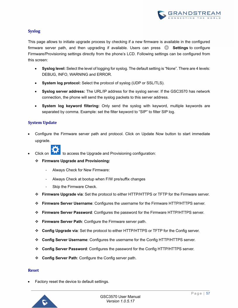
P a g e | 57
GSC3570 User Manual Version 1.0.5.17
Syslog
This page allows to initiate upgrade process by checking if a new firmware is available in the configured
firmware server path, and then upgrading if available. Users can press Settings to configure
Firmware/Provisioning settings directly from the phone’s LCD. Following settings can be configured from
this screen:
• Syslog level: Select the level of logging for syslog. The default setting is “None”. There are 4 levels:
DEBUG, INFO, WARNING and ERROR.
• System log protocol: Select the protocol of syslog (UDP or SSL/TLS).
• Syslog server address: The URL/IP address for the syslog server. If the GSC3570 has network
connection, the phone will send the syslog packets to this server address.
• System log keyword filtering: Only send the syslog with keyword, multiple keywords are
separated by comma. Example: set the filter keyword to “SIP” to filter SIP log.
System Update
• Configure the Firmware server path and protocol. Click on Update Now button to start immediate
upgrade.
• Click on to access the Upgrade and Provisioning configuration:
Firmware Upgrade and Provisioning:
- Always Check for New Firmware:
- Always Check at bootup when F/W pre/suffix changes
- Skip the Firmware Check.
Firmware Upgrade via: Set the protocol to either HTTP/HTTPS or TFTP for the Firmware server.
Firmware Server Username: Configures the username for the Firmware HTTP/HTTPS server.
Firmware Server Password: Configures the password for the Firmware HTTP/HTTPS server.
Firmware Server Path: Configure the Firmware server path.
Config Upgrade via: Set the protocol to either HTTP/HTTPS or TFTP for the Config server.
Config Server Username: Configures the username for the Config HTTP/HTTPS server.
Config Server Password: Configures the password for the Config HTTP/HTTPS server.
Config Server Path: Configure the Config server path.
Reset
• Factory reset the device to default settings.
P a g e | 58
GSC3570 User Manual Version 1.0.5.17
CONFIGURATION VIA WEB BROWSER
The GSC3570 embedded Web server responds to HTTP/HTTPS GET/POST requests. Embedded HTML
pages allow a user to configure the GSC3570 through a Web browser such as Google Chrome, Mozilla
Firefox, and Microsoft’s IE.
To access the Web GUI:
1. Connect the computer to the same network as the GSC3570.
2. Make sure the GSC3570 is turned on and shows its IP address. You may check the IP from the LCD
Menu →Settings →Status →Network Status.
3. Open a Web browser on your computer.
4. Enter the GSC3570’s IP address in the address bar of the browser.
5. Enter the administrator’s login and password available on the MAC sticker to access the Web
Configuration Menu.
Notes:
• The computer must be connected to the same sub-network as the GSC3570. This can be easily done
by connecting the computer to the same hub or switch as the GSC3570 connected to. In absence of a
hub/switch (or free ports on the hub/switch), please connect the computer directly to the PC port on the
back of the GSC3570.
• If the GSC3570 is properly connected to a working Internet connection, the IP address of the GSC3570
will display in MENU→Status→Network Status. This address has the format: xxx.xxx.xxx.xxx, where
xxx stands for a number from 0-255. Users will need this number to access the Web GUI. For example,
if the GSC3570 has IP address 192.168.40.154, please enter “http://192.168.40.154” in the address
bar of the browser.
• There are two default passwords for the login page:
User Level User Password Web Pages Allowed
End User Level user 123 Only Status and Basic Settings
Administrator Level admin Random
Password Browse all pages
• When accessing the GSC3570, user can then change the default administrator password when
proceeding from the web interface→Maintenance→Web Access.
• The new password field is case sensitive with a maximum length of 25 characters. Using strong
password including letters, digits and special characters is recommended for better security.
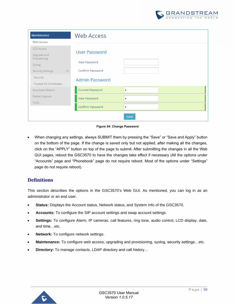
P a g e | 59
GSC3570 User Manual Version 1.0.5.17
Figure 54: Change Password
• When changing any settings, always SUBMIT them by pressing the “Save” or “Save and Apply” button
on the bottom of the page. If the change is saved only but not applied, after making all the changes,
click on the “APPLY” button on top of the page to submit. After submitting the changes in all the Web
GUI pages, reboot the GSC3570 to have the changes take effect if necessary (All the options under
“Accounts” page and “Phonebook” page do not require reboot. Most of the options under “Settings”
page do not require reboot).
Definitions
This section describes the options in the GSC3570’s Web GUI. As mentioned, you can log in as an
administrator or an end user.
• Status: Displays the Account status, Network status, and System Info of the GSC3570.
• Accounts: To configure the SIP account settings and swap account settings.
• Settings: To configure Alarm, IP cameras, call features, ring tone, audio control, LCD display, date,
and time…etc.
• Network: To configure network settings.
• Maintenance: To configure web access, upgrading and provisioning, syslog, security settings…etc.
• Directory: To manage contacts, LDAP directory and call history…
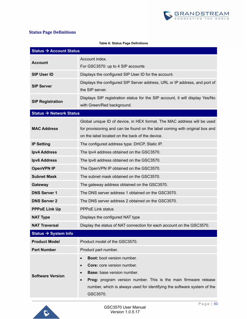
P a g e | 60
GSC3570 User Manual Version 1.0.5.17
Status Page Definitions
Table 6: Status Page Definitions
Status → Account Status
Account Account index.
For GSC3570: up to 4 SIP accounts
SIP User ID Displays the configured SIP User ID for the account.
SIP Server Displays the configured SIP Server address, URL or IP address, and port of
the SIP server.
SIP Registration Displays SIP registration status for the SIP account, it will display Yes/No
with Green/Red background.
Status → Network Status
MAC Address
Global unique ID of device, in HEX format. The MAC address will be used
for provisioning and can be found on the label coming with original box and
on the label located on the back of the device.
IP Setting The configured address type: DHCP, Static IP.
Ipv4 Address The Ipv4 address obtained on the GSC3570.
Ipv6 Address The Ipv6 address obtained on the GSC3570.
OpenVPN IP The OpenVPN IP obtained on the GSC3570.
Subnet Mask The subnet mask obtained on the GSC3570.
Gateway The gateway address obtained on the GSC3570.
DNS Server 1 The DNS server address 1 obtained on the GSC3570.
DNS Server 2 The DNS server address 2 obtained on the GSC3570.
PPPoE Link Up PPPoE Link status
NAT Type Displays the configured NAT type
NAT Traversal Display the status of NAT connection for each account on the GSC3570.
Status → System Info
Product Model Product model of the GSC3570.
Part Number Product part number.
Software Version
• Boot: boot version number.
• Core: core version number.
• Base: base version number.
• Prog: program version number. This is the main firmware release
number, which is always used for identifying the software system of the
GSC3570.
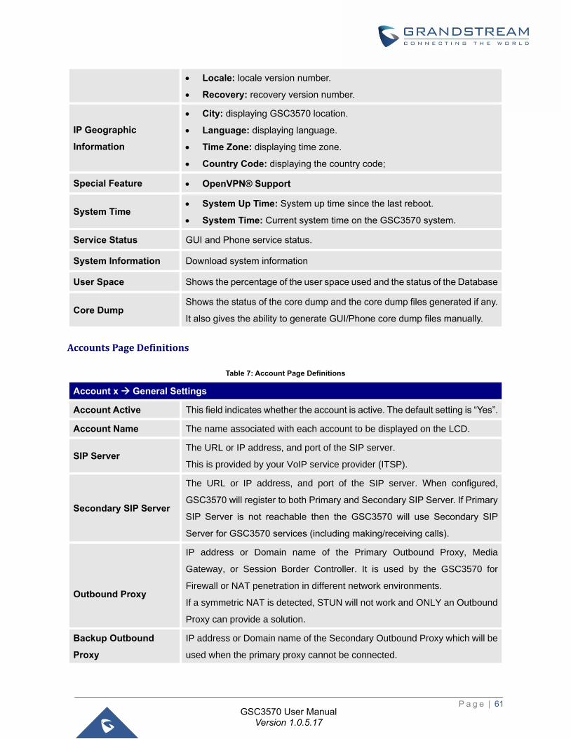
P a g e | 61
GSC3570 User Manual Version 1.0.5.17
• Locale: locale version number.
• Recovery: recovery version number.
IP Geographic
Information
• City: displaying GSC3570 location.
• Language: displaying language.
• Time Zone: displaying time zone.
• Country Code: displaying the country code;
Special Feature • OpenVPN® Support
System Time • System Up Time: System up time since the last reboot.
• System Time: Current system time on the GSC3570 system.
Service Status GUI and Phone service status.
System Information Download system information
User Space Shows the percentage of the user space used and the status of the Database
Core Dump Shows the status of the core dump and the core dump files generated if any.
It also gives the ability to generate GUI/Phone core dump files manually.
Accounts Page Definitions
Table 7: Account Page Definitions
Account x → General Settings
Account Active This field indicates whether the account is active. The default setting is “Yes”.
Account Name The name associated with each account to be displayed on the LCD.
SIP Server The URL or IP address, and port of the SIP server.
This is provided by your VoIP service provider (ITSP).
Secondary SIP Server
The URL or IP address, and port of the SIP server. When configured,
GSC3570 will register to both Primary and Secondary SIP Server. If Primary
SIP Server is not reachable then the GSC3570 will use Secondary SIP
Server for GSC3570 services (including making/receiving calls).
Outbound Proxy
IP address or Domain name of the Primary Outbound Proxy, Media
Gateway, or Session Border Controller. It is used by the GSC3570 for
Firewall or NAT penetration in different network environments.
If a symmetric NAT is detected, STUN will not work and ONLY an Outbound
Proxy can provide a solution.
Backup Outbound
Proxy
IP address or Domain name of the Secondary Outbound Proxy which will be
used when the primary proxy cannot be connected.
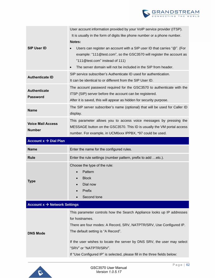
P a g e | 62
GSC3570 User Manual Version 1.0.5.17
SIP User ID
User account information provided by your VoIP service provider (ITSP).
It is usually in the form of digits like phone number or a phone number.
Notes:
• Users can register an account with a SIP user ID that carries “@”. (For
example: “[email protected]”, so the GSC3570 will register the account as
“[email protected]” instead of 111)
• The server domain will not be included in the SIP from header.
Authenticate ID SIP service subscriber’s Authenticate ID used for authentication.
It can be identical to or different from the SIP User ID.
Authenticate
Password
The account password required for the GSC3570 to authenticate with the
ITSP (SIP) server before the account can be registered.
After it is saved, this will appear as hidden for security purpose.
Name The SIP server subscriber’s name (optional) that will be used for Caller ID
display.
Voice Mail Access
Number
This parameter allows you to access voice messages by pressing the
MESSAGE button on the GSC3570. This ID is usually the VM portal access
number. For example, in UCM6xxx IPPBX, *97 could be used.
Account x → Dial Plan
Name Enter the name for the configured rules.
Rule Enter the rule settings (number pattern, prefix to add …etc.).
Type
Choose the type of the rule:
• Pattern
• Block
• Dial now
• Prefix
• Second tone
Account x → Network Settings
DNS Mode
This parameter controls how the Search Appliance looks up IP addresses
for hostnames.
There are four modes: A Record, SRV, NATPTR/SRV, Use Configured IP.
The default setting is “A Record”.
If the user wishes to locate the server by DNS SRV, the user may select
“SRV” or “NATPTR/SRV”.
If “Use Configured IP” is selected, please fill in the three fields below:
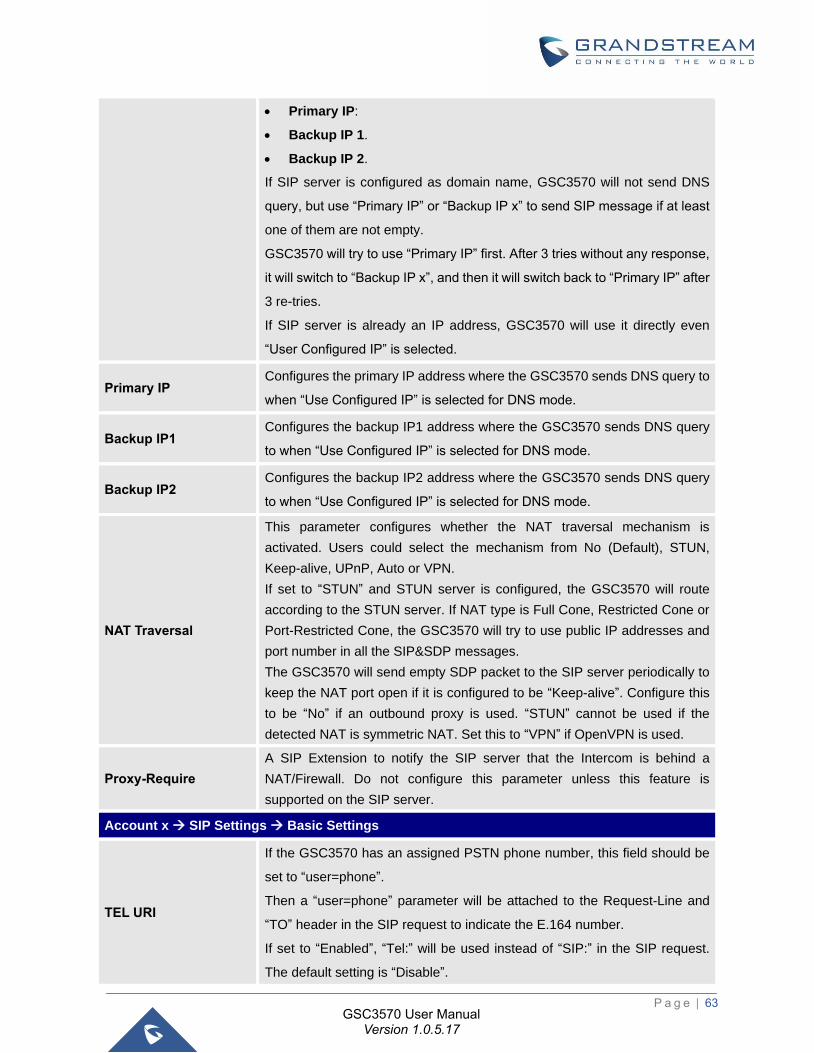
P a g e | 63
GSC3570 User Manual Version 1.0.5.17
• Primary IP:
• Backup IP 1.
• Backup IP 2.
If SIP server is configured as domain name, GSC3570 will not send DNS
query, but use “Primary IP” or “Backup IP x” to send SIP message if at least
one of them are not empty.
GSC3570 will try to use “Primary IP” first. After 3 tries without any response,
it will switch to “Backup IP x”, and then it will switch back to “Primary IP” after
3 re-tries.
If SIP server is already an IP address, GSC3570 will use it directly even
“User Configured IP” is selected.
Primary IP Configures the primary IP address where the GSC3570 sends DNS query to
when “Use Configured IP” is selected for DNS mode.
Backup IP1 Configures the backup IP1 address where the GSC3570 sends DNS query
to when “Use Configured IP” is selected for DNS mode.
Backup IP2 Configures the backup IP2 address where the GSC3570 sends DNS query
to when “Use Configured IP” is selected for DNS mode.
NAT Traversal
This parameter configures whether the NAT traversal mechanism is
activated. Users could select the mechanism from No (Default), STUN,
Keep-alive, UPnP, Auto or VPN.
If set to “STUN” and STUN server is configured, the GSC3570 will route
according to the STUN server. If NAT type is Full Cone, Restricted Cone or
Port-Restricted Cone, the GSC3570 will try to use public IP addresses and
port number in all the SIP&SDP messages.
The GSC3570 will send empty SDP packet to the SIP server periodically to
keep the NAT port open if it is configured to be “Keep-alive”. Configure this
to be “No” if an outbound proxy is used. “STUN” cannot be used if the
detected NAT is symmetric NAT. Set this to “VPN” if OpenVPN is used.
Proxy-Require
A SIP Extension to notify the SIP server that the Intercom is behind a
NAT/Firewall. Do not configure this parameter unless this feature is
supported on the SIP server.
Account x → SIP Settings → Basic Settings
TEL URI
If the GSC3570 has an assigned PSTN phone number, this field should be
set to “user=phone”.
Then a “user=phone” parameter will be attached to the Request-Line and
“TO” header in the SIP request to indicate the E.164 number.
If set to “Enabled”, “Tel:” will be used instead of “SIP:” in the SIP request.
The default setting is “Disable”.
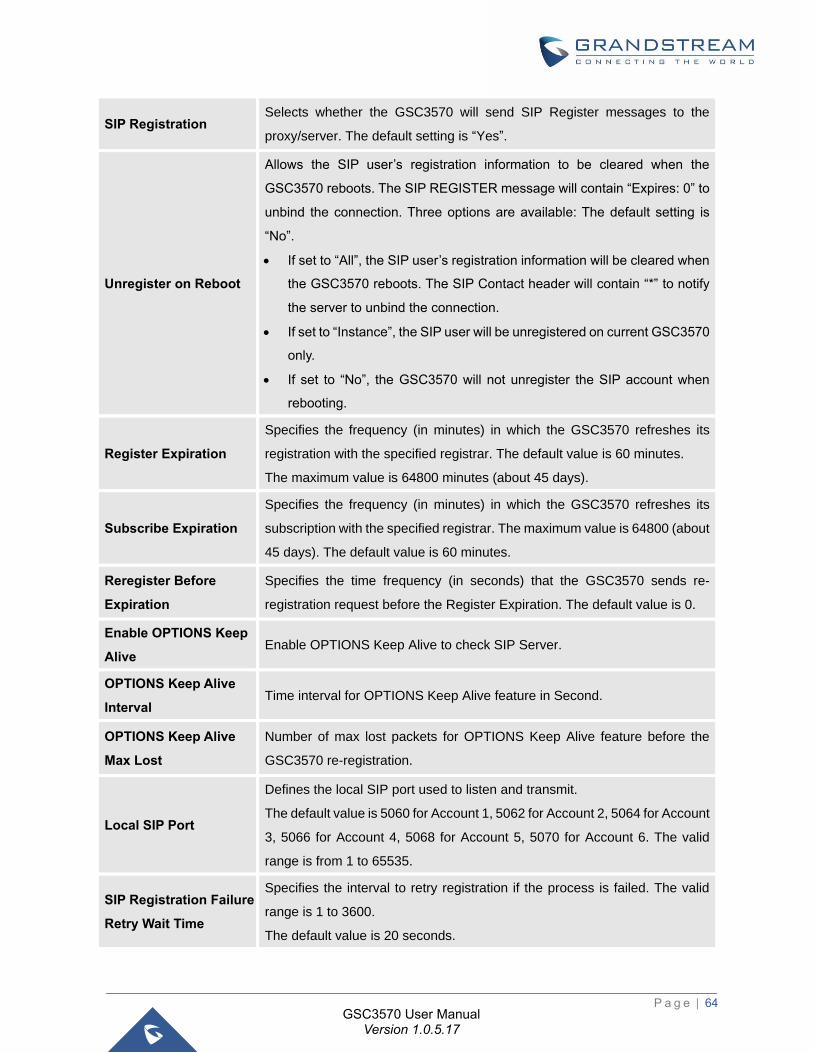
P a g e | 64
GSC3570 User Manual Version 1.0.5.17
SIP Registration Selects whether the GSC3570 will send SIP Register messages to the
proxy/server. The default setting is “Yes”.
Unregister on Reboot
Allows the SIP user’s registration information to be cleared when the
GSC3570 reboots. The SIP REGISTER message will contain “Expires: 0” to
unbind the connection. Three options are available: The default setting is
“No”.
• If set to “All”, the SIP user’s registration information will be cleared when
the GSC3570 reboots. The SIP Contact header will contain “*” to notify
the server to unbind the connection.
• If set to “Instance”, the SIP user will be unregistered on current GSC3570
only.
• If set to “No”, the GSC3570 will not unregister the SIP account when
rebooting.
Register Expiration
Specifies the frequency (in minutes) in which the GSC3570 refreshes its
registration with the specified registrar. The default value is 60 minutes.
The maximum value is 64800 minutes (about 45 days).
Subscribe Expiration
Specifies the frequency (in minutes) in which the GSC3570 refreshes its
subscription with the specified registrar. The maximum value is 64800 (about
45 days). The default value is 60 minutes.
Reregister Before
Expiration
Specifies the time frequency (in seconds) that the GSC3570 sends re-
registration request before the Register Expiration. The default value is 0.
Enable OPTIONS Keep
Alive Enable OPTIONS Keep Alive to check SIP Server.
OPTIONS Keep Alive
Interval Time interval for OPTIONS Keep Alive feature in Second.
OPTIONS Keep Alive
Max Lost
Number of max lost packets for OPTIONS Keep Alive feature before the
GSC3570 re-registration.
Local SIP Port
Defines the local SIP port used to listen and transmit.
The default value is 5060 for Account 1, 5062 for Account 2, 5064 for Account
3, 5066 for Account 4, 5068 for Account 5, 5070 for Account 6. The valid
range is from 1 to 65535.
SIP Registration Failure
Retry Wait Time
Specifies the interval to retry registration if the process is failed. The valid
range is 1 to 3600.
The default value is 20 seconds.
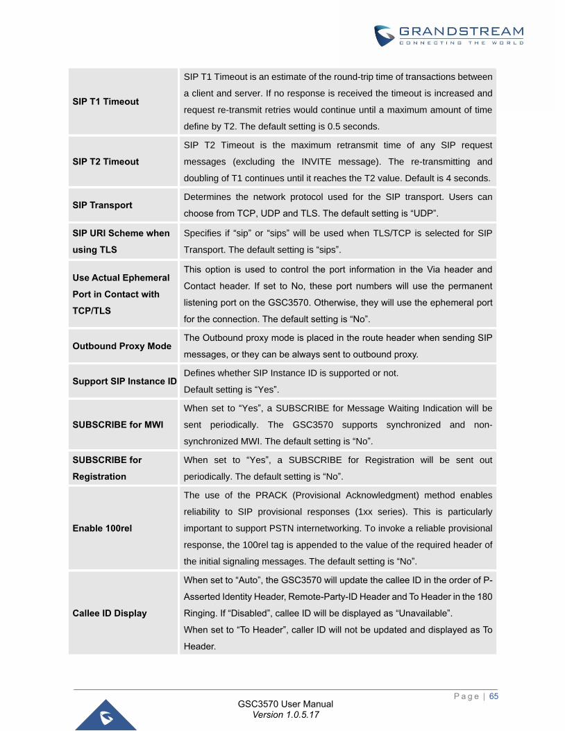
P a g e | 65
GSC3570 User Manual Version 1.0.5.17
SIP T1 Timeout
SIP T1 Timeout is an estimate of the round-trip time of transactions between
a client and server. If no response is received the timeout is increased and
request re-transmit retries would continue until a maximum amount of time
define by T2. The default setting is 0.5 seconds.
SIP T2 Timeout
SIP T2 Timeout is the maximum retransmit time of any SIP request
messages (excluding the INVITE message). The re-transmitting and
doubling of T1 continues until it reaches the T2 value. Default is 4 seconds.
SIP Transport Determines the network protocol used for the SIP transport. Users can
choose from TCP, UDP and TLS. The default setting is “UDP”.
SIP URI Scheme when
using TLS
Specifies if “sip” or “sips” will be used when TLS/TCP is selected for SIP
Transport. The default setting is “sips”.
Use Actual Ephemeral
Port in Contact with
TCP/TLS
This option is used to control the port information in the Via header and
Contact header. If set to No, these port numbers will use the permanent
listening port on the GSC3570. Otherwise, they will use the ephemeral port
for the connection. The default setting is “No”.
Outbound Proxy Mode The Outbound proxy mode is placed in the route header when sending SIP
messages, or they can be always sent to outbound proxy.
Support SIP Instance ID Defines whether SIP Instance ID is supported or not.
Default setting is “Yes”.
SUBSCRIBE for MWI
When set to “Yes”, a SUBSCRIBE for Message Waiting Indication will be
sent periodically. The GSC3570 supports synchronized and non-
synchronized MWI. The default setting is “No”.
SUBSCRIBE for
Registration
When set to “Yes”, a SUBSCRIBE for Registration will be sent out
periodically. The default setting is “No”.
Enable 100rel
The use of the PRACK (Provisional Acknowledgment) method enables
reliability to SIP provisional responses (1xx series). This is particularly
important to support PSTN internetworking. To invoke a reliable provisional
response, the 100rel tag is appended to the value of the required header of
the initial signaling messages. The default setting is “No”.
Callee ID Display
When set to “Auto”, the GSC3570 will update the callee ID in the order of P-
Asserted Identity Header, Remote-Party-ID Header and To Header in the 180
Ringing. If “Disabled”, callee ID will be displayed as “Unavailable”.
When set to “To Header”, caller ID will not be updated and displayed as To
Header.
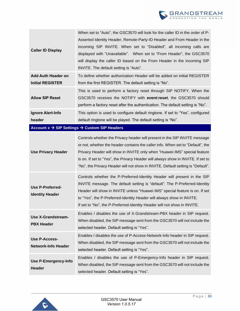
P a g e | 66
GSC3570 User Manual Version 1.0.5.17
Caller ID Display
When set to “Auto”, the GSC3570 will look for the caller ID in the order of P-
Asserted Identity Header, Remote-Party-ID Header and From Header in the
incoming SIP INVITE. When set to “Disabled”, all incoming calls are
displayed with “Unavailable”. When set to “From Header”, the GSC3570
will display the caller ID based on the From Header in the incoming SIP
INVITE. The default setting is “Auto”.
Add Auth Header on
Initial REGISTER
To define whether authorization Header will be added on initial REGISTER
from the first REGISTER. The default setting is “No”.
Allow SIP Reset
This is used to perform a factory reset through SIP NOTIFY. When the
GSC3570 receives the NOTIFY with event:reset, the GSC3570 should
perform a factory reset after the authentication. The default setting is “No”.
Ignore Alert-Info
header
This option is used to configure default ringtone. If set to “Yes”, configured
default ringtone will be played. The default setting is “No”.
Account x → SIP Settings → Custom SIP Headers
Use Privacy Header
Controls whether the Privacy header will present in the SIP INVITE message
or not, whether the header contains the caller info. When set to “Default”, the
Privacy Header will show in INVITE only when “Huawei IMS” special feature
is on. If set to “Yes”, the Privacy Header will always show in INVITE. If set to
“No”, the Privacy Header will not show in INVITE. Default setting is “Default”.
Use P-Preferred-
Identity Header
Controls whether the P-Preferred-Identity Header will present in the SIP
INVITE message. The default setting is “default”: The P-Preferred-Identity
Header will show in INVITE unless “Huawei IMS” special feature is on. If set
to “Yes”, the P-Preferred-Identity Header will always show in INVITE.
If set to “No”, the P-Preferred-Identity Header will not show in INVITE.
Use X-Grandstream-
PBX Header
Enables / disables the use of X-Grandstream-PBX header in SIP request.
When disabled, the SIP message sent from the GSC3570 will not include the
selected header. Default setting is “Yes”.
Use P-Access-
Network-Info Header
Enables / disables the use of P-Access-Network-Info header in SIP request.
When disabled, the SIP message sent from the GSC3570 will not include the
selected header. Default setting is “Yes”.
Use P-Emergency-Info
Header
Enables / disables the use of P-Emergency-Info header in SIP request.
When disabled, the SIP message sent from the GSC3570 will not include the
selected header. Default setting is “Yes”.
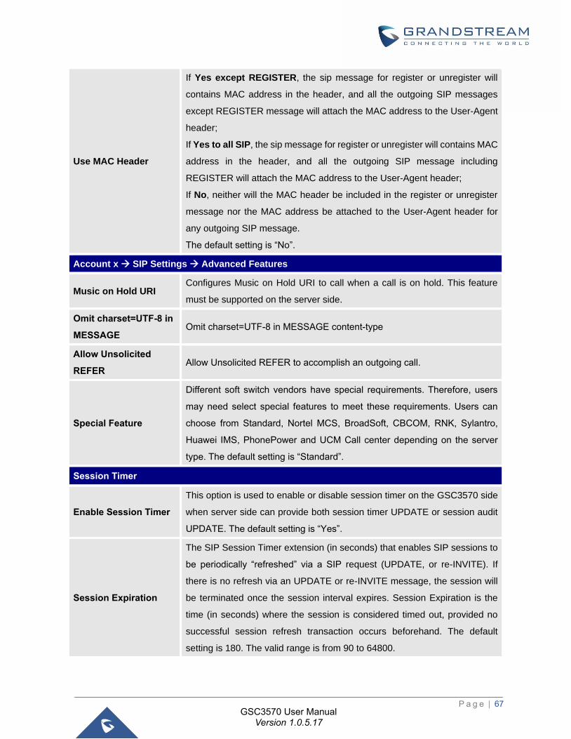
P a g e | 67
GSC3570 User Manual Version 1.0.5.17
Use MAC Header
If Yes except REGISTER, the sip message for register or unregister will
contains MAC address in the header, and all the outgoing SIP messages
except REGISTER message will attach the MAC address to the User-Agent
header;
If Yes to all SIP, the sip message for register or unregister will contains MAC
address in the header, and all the outgoing SIP message including
REGISTER will attach the MAC address to the User-Agent header;
If No, neither will the MAC header be included in the register or unregister
message nor the MAC address be attached to the User-Agent header for
any outgoing SIP message.
The default setting is “No”.
Account x → SIP Settings → Advanced Features
Music on Hold URI Configures Music on Hold URI to call when a call is on hold. This feature
must be supported on the server side.
Omit charset=UTF-8 in
MESSAGE Omit charset=UTF-8 in MESSAGE content-type
Allow Unsolicited
REFER Allow Unsolicited REFER to accomplish an outgoing call.
Special Feature
Different soft switch vendors have special requirements. Therefore, users
may need select special features to meet these requirements. Users can
choose from Standard, Nortel MCS, BroadSoft, CBCOM, RNK, Sylantro,
Huawei IMS, PhonePower and UCM Call center depending on the server
type. The default setting is “Standard”.
Session Timer
Enable Session Timer
This option is used to enable or disable session timer on the GSC3570 side
when server side can provide both session timer UPDATE or session audit
UPDATE. The default setting is “Yes”.
Session Expiration
The SIP Session Timer extension (in seconds) that enables SIP sessions to
be periodically “refreshed” via a SIP request (UPDATE, or re-INVITE). If
there is no refresh via an UPDATE or re-INVITE message, the session will
be terminated once the session interval expires. Session Expiration is the
time (in seconds) where the session is considered timed out, provided no
successful session refresh transaction occurs beforehand. The default
setting is 180. The valid range is from 90 to 64800.
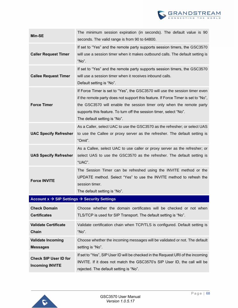
P a g e | 68
GSC3570 User Manual Version 1.0.5.17
Min-SE The minimum session expiration (in seconds). The default value is 90
seconds. The valid range is from 90 to 64800.
Caller Request Timer
If set to “Yes” and the remote party supports session timers, the GSC3570
will use a session timer when it makes outbound calls. The default setting is
“No”.
Callee Request Timer
If set to “Yes” and the remote party supports session timers, the GSC3570
will use a session timer when it receives inbound calls.
Default setting is “No”.
Force Timer
If Force Timer is set to “Yes”, the GSC3570 will use the session timer even
if the remote party does not support this feature. If Force Timer is set to “No”,
the GSC3570 will enable the session timer only when the remote party
supports this feature. To turn off the session timer, select “No”.
The default setting is “No”.
UAC Specify Refresher
As a Caller, select UAC to use the GSC3570 as the refresher; or select UAS
to use the Callee or proxy server as the refresher. The default setting is
“Omit”.
UAS Specify Refresher
As a Callee, select UAC to use caller or proxy server as the refresher; or
select UAS to use the GSC3570 as the refresher. The default setting is
“UAC”.
Force INVITE
The Session Timer can be refreshed using the INVITE method or the
UPDATE method. Select “Yes” to use the INVITE method to refresh the
session timer.
The default setting is “No”.
Account x → SIP Settings → Security Settings
Check Domain
Certificates
Choose whether the domain certificates will be checked or not when
TLS/TCP is used for SIP Transport. The default setting is “No”.
Validate Certificate
Chain
Validate certification chain when TCP/TLS is configured. Default setting is
“No”.
Validate Incoming
Messages
Choose whether the incoming messages will be validated or not. The default
setting is “No”.
Check SIP User ID for
Incoming INVITE
If set to “Yes”, SIP User ID will be checked in the Request URI of the incoming
INVITE. If it does not match the GSC3570’s SIP User ID, the call will be
rejected. The default setting is “No”.
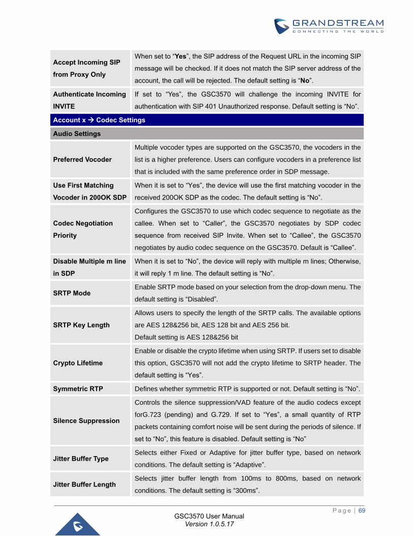
P a g e | 69
GSC3570 User Manual Version 1.0.5.17
Accept Incoming SIP
from Proxy Only
When set to “Yes”, the SIP address of the Request URL in the incoming SIP
message will be checked. If it does not match the SIP server address of the
account, the call will be rejected. The default setting is “No”.
Authenticate Incoming
INVITE
If set to “Yes”, the GSC3570 will challenge the incoming INVITE for
authentication with SIP 401 Unauthorized response. Default setting is “No”.
Account x → Codec Settings
Audio Settings
Preferred Vocoder
Multiple vocoder types are supported on the GSC3570, the vocoders in the
list is a higher preference. Users can configure vocoders in a preference list
that is included with the same preference order in SDP message.
Use First Matching
Vocoder in 200OK SDP
When it is set to “Yes”, the device will use the first matching vocoder in the
received 200OK SDP as the codec. The default setting is “No”.
Codec Negotiation
Priority
Configures the GSC3570 to use which codec sequence to negotiate as the
callee. When set to “Caller”, the GSC3570 negotiates by SDP codec
sequence from received SIP Invite. When set to “Callee”, the GSC3570
negotiates by audio codec sequence on the GSC3570. Default is “Callee”.
Disable Multiple m line
in SDP
When it is set to “No”, the device will reply with multiple m lines; Otherwise,
it will reply 1 m line. The default setting is “No”.
SRTP Mode Enable SRTP mode based on your selection from the drop-down menu. The
default setting is “Disabled”.
SRTP Key Length
Allows users to specify the length of the SRTP calls. The available options
are AES 128&256 bit, AES 128 bit and AES 256 bit.
Default setting is AES 128&256 bit
Crypto Lifetime
Enable or disable the crypto lifetime when using SRTP. If users set to disable
this option, GSC3570 will not add the crypto lifetime to SRTP header. The
default setting is “Yes”.
Symmetric RTP Defines whether symmetric RTP is supported or not. Default setting is “No”.
Silence Suppression
Controls the silence suppression/VAD feature of the audio codecs except
forG.723 (pending) and G.729. If set to “Yes”, a small quantity of RTP
packets containing comfort noise will be sent during the periods of silence. If
set to “No”, this feature is disabled. Default setting is “No”
Jitter Buffer Type Selects either Fixed or Adaptive for jitter buffer type, based on network
conditions. The default setting is “Adaptive”.
Jitter Buffer Length Selects jitter buffer length from 100ms to 800ms, based on network
conditions. The default setting is “300ms”.
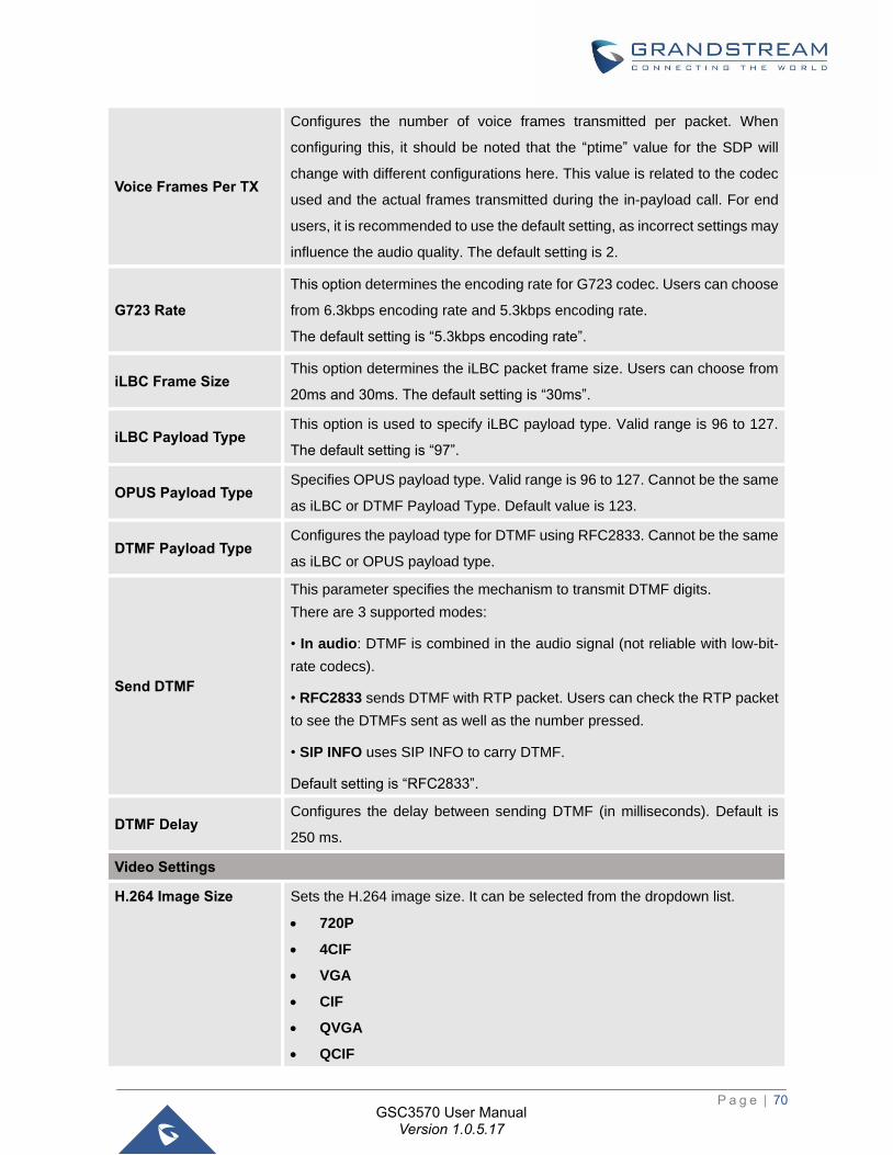
P a g e | 70
GSC3570 User Manual Version 1.0.5.17
Voice Frames Per TX
Configures the number of voice frames transmitted per packet. When
configuring this, it should be noted that the “ptime” value for the SDP will
change with different configurations here. This value is related to the codec
used and the actual frames transmitted during the in-payload call. For end
users, it is recommended to use the default setting, as incorrect settings may
influence the audio quality. The default setting is 2.
G723 Rate
This option determines the encoding rate for G723 codec. Users can choose
from 6.3kbps encoding rate and 5.3kbps encoding rate.
The default setting is “5.3kbps encoding rate”.
iLBC Frame Size This option determines the iLBC packet frame size. Users can choose from
20ms and 30ms. The default setting is “30ms”.
iLBC Payload Type This option is used to specify iLBC payload type. Valid range is 96 to 127.
The default setting is “97”.
OPUS Payload Type Specifies OPUS payload type. Valid range is 96 to 127. Cannot be the same
as iLBC or DTMF Payload Type. Default value is 123.
DTMF Payload Type Configures the payload type for DTMF using RFC2833. Cannot be the same
as iLBC or OPUS payload type.
Send DTMF
This parameter specifies the mechanism to transmit DTMF digits.
There are 3 supported modes:
• In audio: DTMF is combined in the audio signal (not reliable with low-bit-
rate codecs).
• RFC2833 sends DTMF with RTP packet. Users can check the RTP packet
to see the DTMFs sent as well as the number pressed.
• SIP INFO uses SIP INFO to carry DTMF.
Default setting is “RFC2833”.
DTMF Delay Configures the delay between sending DTMF (in milliseconds). Default is
250 ms.
Video Settings
H.264 Image Size Sets the H.264 image size. It can be selected from the dropdown list.
• 720P
• 4CIF
• VGA
• CIF
• QVGA
• QCIF

P a g e | 71
GSC3570 User Manual Version 1.0.5.17
Note: For some network environment, the default setting “720P” might be
too high that causes no video or video quality issue during video call. In this
case, please change “H.264 Image Size” to “VGA” or “CIF” and change
“Video Bit Rate” to “384kbps” or lower.
The default setting is 720P.
H.264 Profile Type
Selects the H.264 profile type from the dropdown list.
• Baseline Profile
• Main Profile
• High Profile
• BP/MP/HP (Default Setting)
Note: Lower levels are easier to decode, but higher levels offer better
compression. Usually, for the best compression quality, choose “High
Profile”; for playback on low-CPU machines or mobile devices, choose
“Baseline Profile”.
If “BP/MP/HP” is selected, all three profiles “Baseline Profile” “Main Profile”
and “High Profile” will be used for negotiation during video decoding to
achieve the best result. This is usually used in video conference when there
is higher requirement on the video.
Video Bit Rate
Configures the bit rate for video call. It can be selected from the dropdown
list. The default setting is 2048 kbps. The valid range is from 32 – 2048 kbps.
Note: The video bit rate can be adjusted based on the network environment.
Increasing the video bit rate may improve video quality if the bandwidth is
permitted. If the bandwidth is not permitted, the video quality will decrease
due to packet loss.
For some network environment, the default setting “720P” might be too high
that causes no video or video quality issue during video call. In this case,
please change “H.264 Image Size” to “VGA” or “CIF” and change “Video Bit
Rate” to “384kbps” or lower.
H264 Payload Type
Specifies the H.264 codec message payload type format. The default setting
is 99.
The valid range is from 96 to 127.
Enable Proxy Video
Compatibility
This feature enhancement is designed for some ITSP customers that
providing video phone call service.
Because GSC3570 does not have camera, this enhancement will improve
the video call by sending some fake video packets to notify the proxy then
displaying black screen on the other side of the video phone.
Default is set to No.
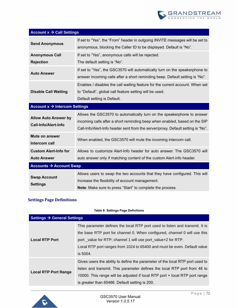
P a g e | 72
GSC3570 User Manual Version 1.0.5.17
Account x → Call Settings
Send Anonymous If set to “Yes”, the “From” header in outgoing INVITE messages will be set to
anonymous, blocking the Caller ID to be displayed. Default is “No”.
Anonymous Call
Rejection
If set to “Yes”, anonymous calls will be rejected.
The default setting is “No”.
Auto Answer If set to “Yes”, the GSC3570 will automatically turn on the speakerphone to
answer incoming calls after a short reminding beep. Default setting is “No”.
Disable Call Waiting
Enables / disables the call waiting feature for the current account. When set
to “Default”, global call feature setting will be used.
Default setting is Default.
Account x → Intercom Settings
Allow Auto Answer by
Call-Info/Alert-Info
Allows the GSC3570 to automatically turn on the speakerphone to answer
incoming calls after a short reminding beep when enabled, based on the SIP
Call-Info/Alert-Info header sent from the server/proxy. Default setting is “No”.
Mute on answer
Intercom call When enabled, the GSC3570 will mute the incoming intercom call.
Custom Alert-Info for
Auto Answer
Allows to customize Alert-Info header for auto answer. The GSC3570 will
auto answer only if matching content of the custom Alert-info header.
Accounts → Account Swap
Swap Account
Settings
Allows users to swap the two accounts that they have configured. This will
Increase the flexibility of account management.
Note: Make sure to press “Start” to complete the process.
Settings Page Definitions
Table 8: Settings Page Definitions
Settings → General Settings
Local RTP Port
This parameter defines the local RTP port used to listen and transmit. It is
the base RTP port for channel 0. When configured, channel 0 will use this
port _value for RTP; channel 1 will use port_value+2 for RTP.
Local RTP port ranges from 1024 to 65400 and must be even. Default value
is 5004.
Local RTP Port Range
Gives users the ability to define the parameter of the local RTP port used to
listen and transmit. This parameter defines the local RTP port from 48 to
10000. This range will be adjusted if local RTP port + local RTP port range
is greater than 65486. Default setting is 200.
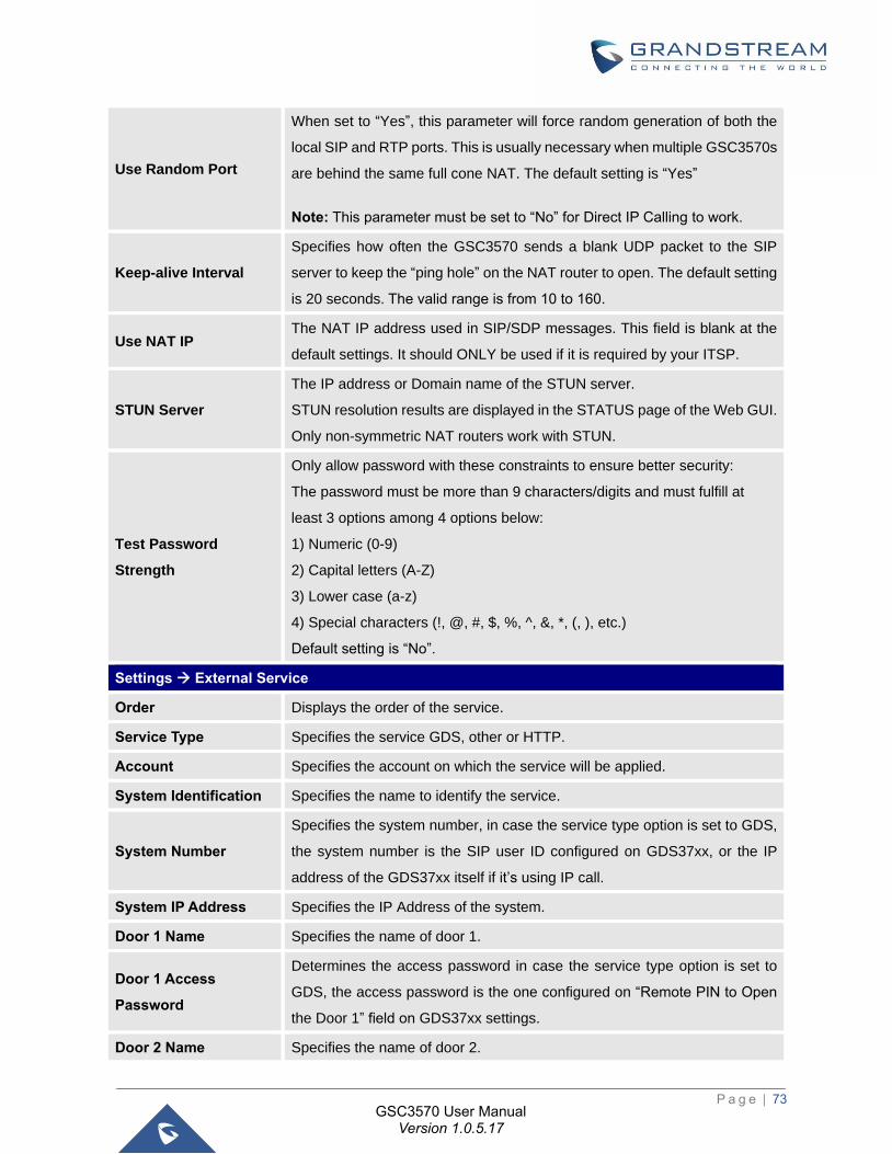
P a g e | 73
GSC3570 User Manual Version 1.0.5.17
Use Random Port
When set to “Yes”, this parameter will force random generation of both the
local SIP and RTP ports. This is usually necessary when multiple GSC3570s
are behind the same full cone NAT. The default setting is “Yes”
Note: This parameter must be set to “No” for Direct IP Calling to work.
Keep-alive Interval
Specifies how often the GSC3570 sends a blank UDP packet to the SIP
server to keep the “ping hole” on the NAT router to open. The default setting
is 20 seconds. The valid range is from 10 to 160.
Use NAT IP The NAT IP address used in SIP/SDP messages. This field is blank at the
default settings. It should ONLY be used if it is required by your ITSP.
STUN Server
The IP address or Domain name of the STUN server.
STUN resolution results are displayed in the STATUS page of the Web GUI.
Only non-symmetric NAT routers work with STUN.
Test Password
Strength
Only allow password with these constraints to ensure better security:
The password must be more than 9 characters/digits and must fulfill at
least 3 options among 4 options below:
1) Numeric (0-9)
2) Capital letters (A-Z)
3) Lower case (a-z)
4) Special characters (!, @, #, $, %, ^, &, *, (, ), etc.)
Default setting is “No”.
Settings → External Service
Order Displays the order of the service.
Service Type Specifies the service GDS, other or HTTP.
Account Specifies the account on which the service will be applied.
System Identification Specifies the name to identify the service.
System Number
Specifies the system number, in case the service type option is set to GDS,
the system number is the SIP user ID configured on GDS37xx, or the IP
address of the GDS37xx itself if it’s using IP call.
System IP Address Specifies the IP Address of the system.
Door 1 Name Specifies the name of door 1.
Door 1 Access
Password
Determines the access password in case the service type option is set to
GDS, the access password is the one configured on “Remote PIN to Open
the Door 1” field on GDS37xx settings.
Door 2 Name Specifies the name of door 2.
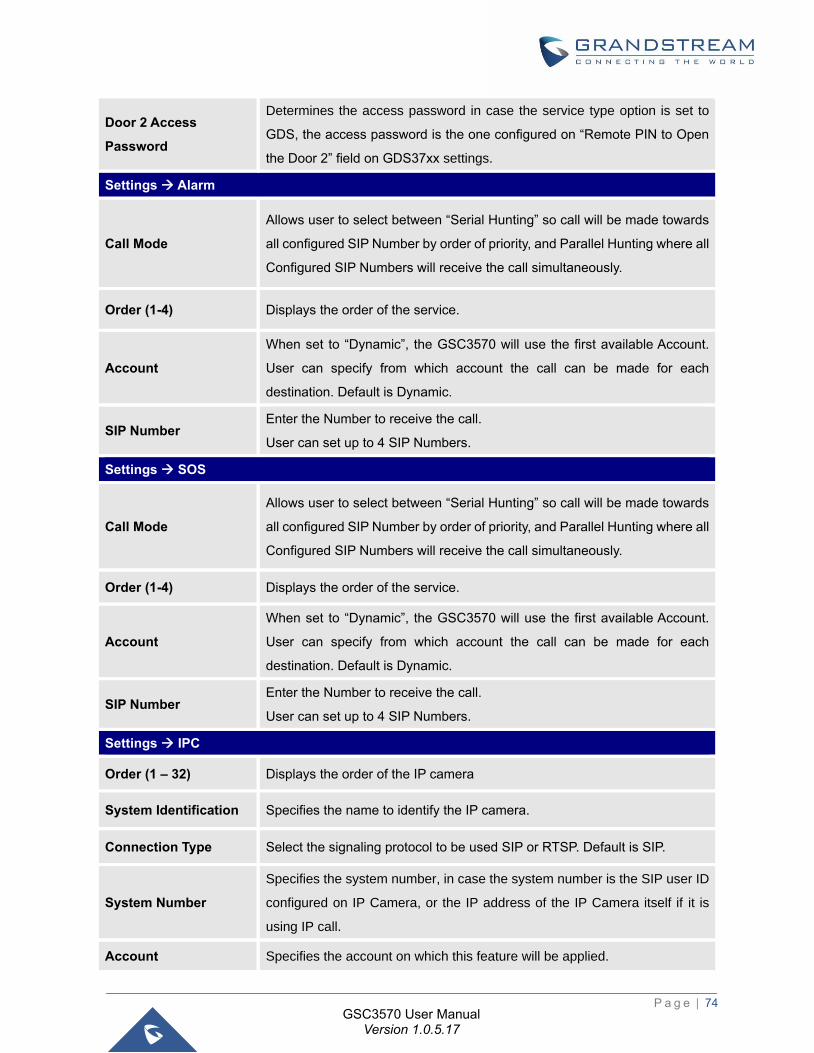
P a g e | 74
GSC3570 User Manual Version 1.0.5.17
Door 2 Access
Password
Determines the access password in case the service type option is set to
GDS, the access password is the one configured on “Remote PIN to Open
the Door 2” field on GDS37xx settings.
Settings → Alarm
Call Mode
Allows user to select between “Serial Hunting” so call will be made towards
all configured SIP Number by order of priority, and Parallel Hunting where all
Configured SIP Numbers will receive the call simultaneously.
Order (1-4) Displays the order of the service.
Account
When set to “Dynamic”, the GSC3570 will use the first available Account.
User can specify from which account the call can be made for each
destination. Default is Dynamic.
SIP Number Enter the Number to receive the call.
User can set up to 4 SIP Numbers.
Settings → SOS
Call Mode
Allows user to select between “Serial Hunting” so call will be made towards
all configured SIP Number by order of priority, and Parallel Hunting where all
Configured SIP Numbers will receive the call simultaneously.
Order (1-4) Displays the order of the service.
Account
When set to “Dynamic”, the GSC3570 will use the first available Account.
User can specify from which account the call can be made for each
destination. Default is Dynamic.
SIP Number Enter the Number to receive the call.
User can set up to 4 SIP Numbers.
Settings → IPC
Order (1 – 32) Displays the order of the IP camera
System Identification Specifies the name to identify the IP camera.
Connection Type Select the signaling protocol to be used SIP or RTSP. Default is SIP.
System Number
Specifies the system number, in case the system number is the SIP user ID
configured on IP Camera, or the IP address of the IP Camera itself if it is
using IP call.
Account Specifies the account on which this feature will be applied.
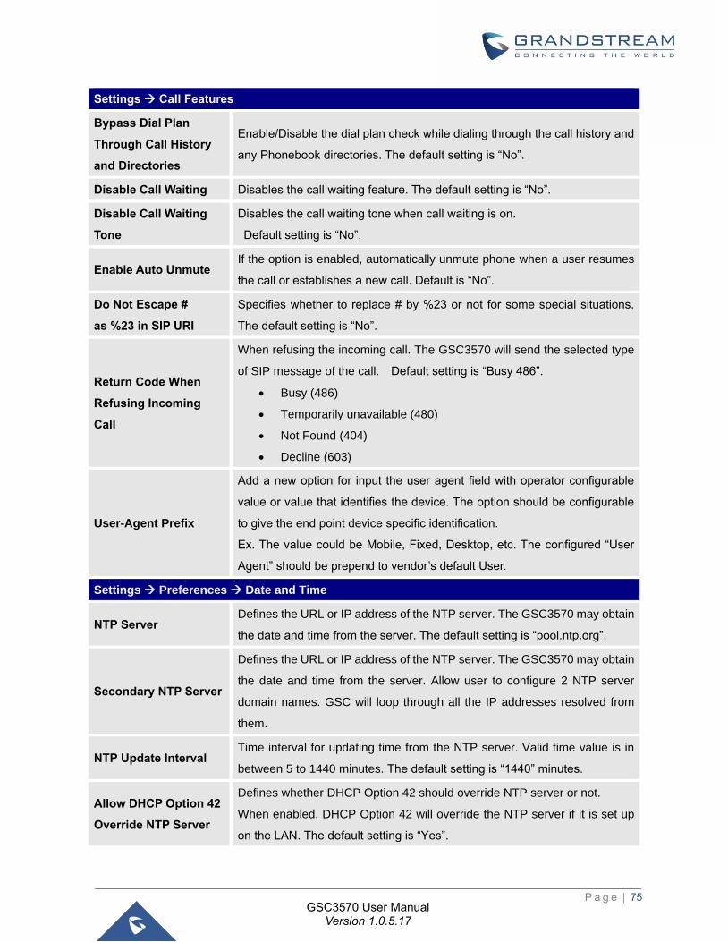
P a g e | 75
GSC3570 User Manual Version 1.0.5.17
Settings → Call Features
Bypass Dial Plan
Through Call History
and Directories
Enable/Disable the dial plan check while dialing through the call history and
any Phonebook directories. The default setting is “No”.
Disable Call Waiting Disables the call waiting feature. The default setting is “No”.
Disable Call Waiting
Tone
Disables the call waiting tone when call waiting is on.
Default setting is “No”.
Enable Auto Unmute If the option is enabled, automatically unmute phone when a user resumes
the call or establishes a new call. Default is “No”.
Do Not Escape #
as %23 in SIP URI
Specifies whether to replace # by %23 or not for some special situations.
The default setting is “No”.
Return Code When
Refusing Incoming
Call
When refusing the incoming call. The GSC3570 will send the selected type
of SIP message of the call. Default setting is “Busy 486”.
• Busy (486)
• Temporarily unavailable (480)
• Not Found (404)
• Decline (603)
User-Agent Prefix
Add a new option for input the user agent field with operator configurable
value or value that identifies the device. The option should be configurable
to give the end point device specific identification.
Ex. The value could be Mobile, Fixed, Desktop, etc. The configured “User
Agent” should be prepend to vendor’s default User.
Settings → Preferences → Date and Time
NTP Server Defines the URL or IP address of the NTP server. The GSC3570 may obtain
the date and time from the server. The default setting is “pool.ntp.org”.
Secondary NTP Server
Defines the URL or IP address of the NTP server. The GSC3570 may obtain
the date and time from the server. Allow user to configure 2 NTP server
domain names. GSC will loop through all the IP addresses resolved from
them.
NTP Update Interval Time interval for updating time from the NTP server. Valid time value is in
between 5 to 1440 minutes. The default setting is “1440” minutes.
Allow DHCP Option 42
Override NTP Server
Defines whether DHCP Option 42 should override NTP server or not.
When enabled, DHCP Option 42 will override the NTP server if it is set up
on the LAN. The default setting is “Yes”.
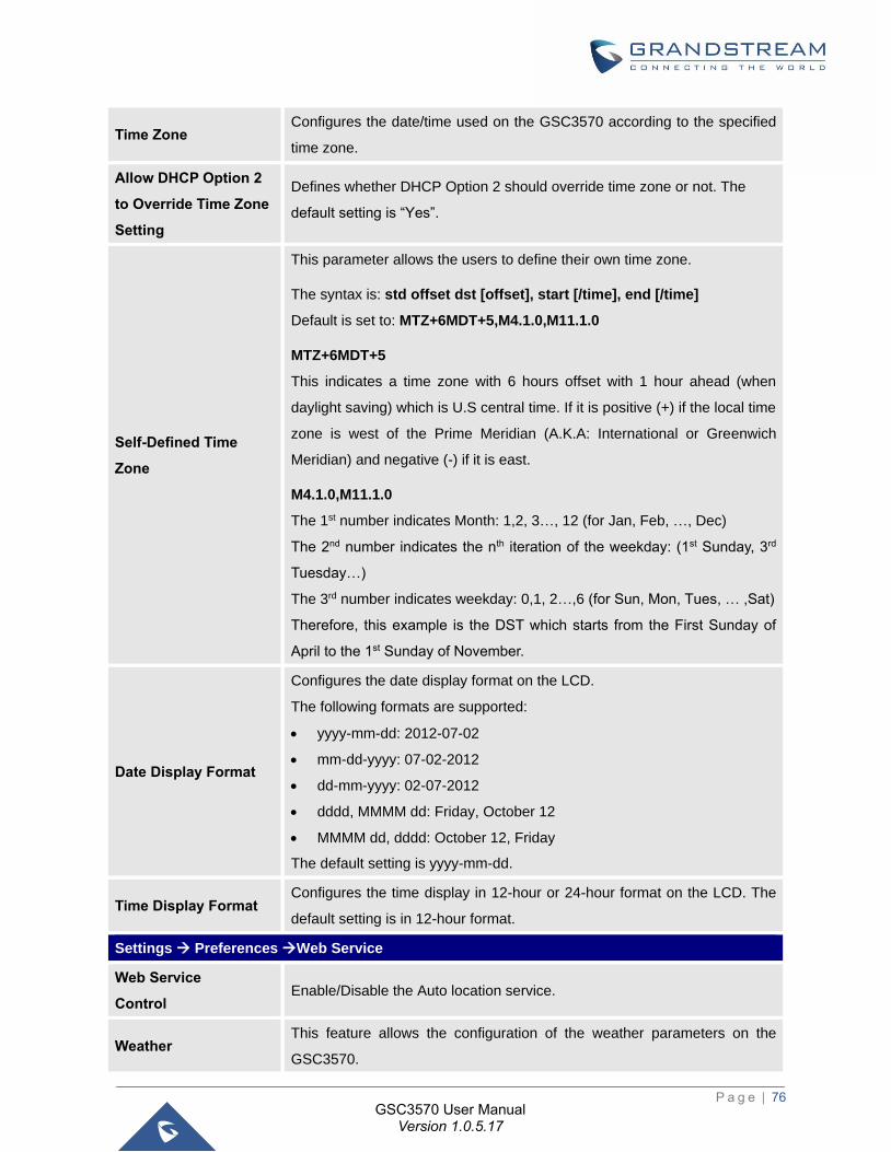
P a g e | 76
GSC3570 User Manual Version 1.0.5.17
Time Zone Configures the date/time used on the GSC3570 according to the specified
time zone.
Allow DHCP Option 2
to Override Time Zone
Setting
Defines whether DHCP Option 2 should override time zone or not. The
default setting is “Yes”.
Self-Defined Time
Zone
This parameter allows the users to define their own time zone.
The syntax is: std offset dst [offset], start [/time], end [/time]
Default is set to: MTZ+6MDT+5,M4.1.0,M11.1.0
MTZ+6MDT+5
This indicates a time zone with 6 hours offset with 1 hour ahead (when
daylight saving) which is U.S central time. If it is positive (+) if the local time
zone is west of the Prime Meridian (A.K.A: International or Greenwich
Meridian) and negative (-) if it is east.
M4.1.0,M11.1.0
The 1st number indicates Month: 1,2, 3…, 12 (for Jan, Feb, …, Dec)
The 2nd number indicates the nth iteration of the weekday: (1st Sunday, 3rd
Tuesday…)
The 3rd number indicates weekday: 0,1, 2…,6 (for Sun, Mon, Tues, … ,Sat)
Therefore, this example is the DST which starts from the First Sunday of
April to the 1st Sunday of November.
Date Display Format
Configures the date display format on the LCD.
The following formats are supported:
• yyyy-mm-dd: 2012-07-02
• mm-dd-yyyy: 07-02-2012
• dd-mm-yyyy: 02-07-2012
• dddd, MMMM dd: Friday, October 12
• MMMM dd, dddd: October 12, Friday
The default setting is yyyy-mm-dd.
Time Display Format Configures the time display in 12-hour or 24-hour format on the LCD. The
default setting is in 12-hour format.
Settings → Preferences →Web Service
Web Service
Control Enable/Disable the Auto location service.
Weather This feature allows the configuration of the weather parameters on the
GSC3570.
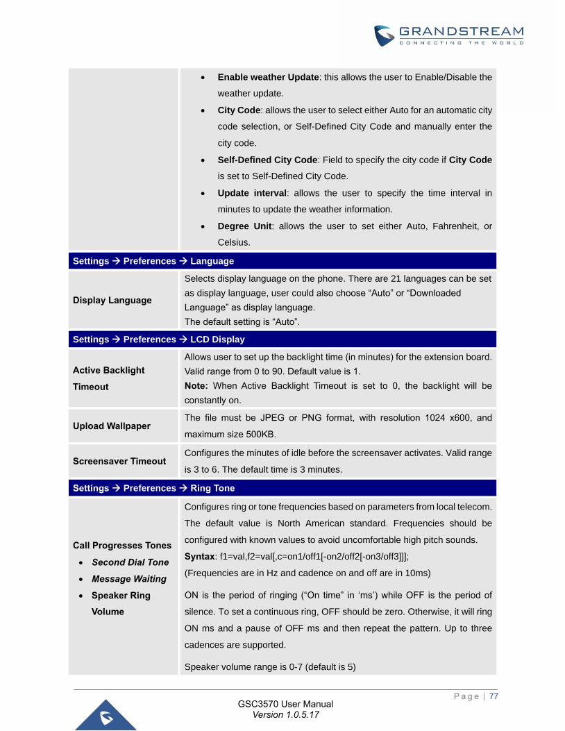
P a g e | 77
GSC3570 User Manual Version 1.0.5.17
• Enable weather Update: this allows the user to Enable/Disable the
weather update.
• City Code: allows the user to select either Auto for an automatic city
code selection, or Self-Defined City Code and manually enter the
city code.
• Self-Defined City Code: Field to specify the city code if City Code
is set to Self-Defined City Code.
• Update interval: allows the user to specify the time interval in
minutes to update the weather information.
• Degree Unit: allows the user to set either Auto, Fahrenheit, or
Celsius.
Settings → Preferences → Language
Display Language
Selects display language on the phone. There are 21 languages can be set
as display language, user could also choose “Auto” or “Downloaded
Language” as display language.
The default setting is “Auto”.
Settings → Preferences → LCD Display
Active Backlight
Timeout
Allows user to set up the backlight time (in minutes) for the extension board.
Valid range from 0 to 90. Default value is 1.
Note: When Active Backlight Timeout is set to 0, the backlight will be
constantly on.
Upload Wallpaper The file must be JPEG or PNG format, with resolution 1024 x600, and
maximum size 500KB.
Screensaver Timeout Configures the minutes of idle before the screensaver activates. Valid range
is 3 to 6. The default time is 3 minutes.
Settings → Preferences → Ring Tone
Call Progresses Tones
• Second Dial Tone
• Message Waiting
• Speaker Ring
Volume
Configures ring or tone frequencies based on parameters from local telecom.
The default value is North American standard. Frequencies should be
configured with known values to avoid uncomfortable high pitch sounds.
Syntax: f1=val,f2=val[,c=on1/off1[-on2/off2[-on3/off3]]];
(Frequencies are in Hz and cadence on and off are in 10ms)
ON is the period of ringing (“On time” in ‘ms’) while OFF is the period of
silence. To set a continuous ring, OFF should be zero. Otherwise, it will ring
ON ms and a pause of OFF ms and then repeat the pattern. Up to three
cadences are supported.
Speaker volume range is 0-7 (default is 5)
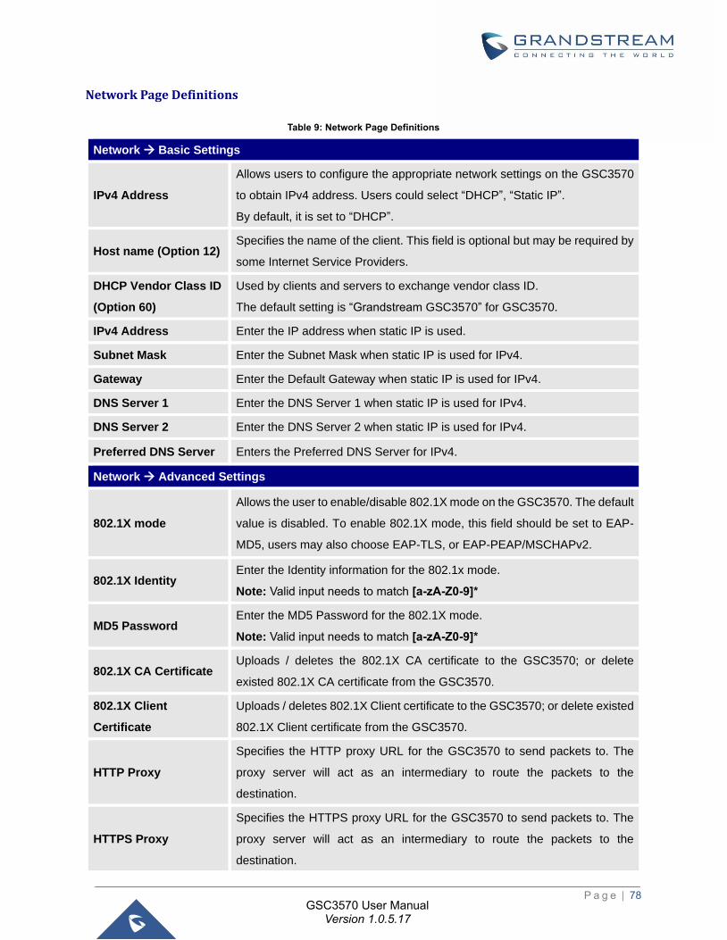
P a g e | 78
GSC3570 User Manual Version 1.0.5.17
Network Page Definitions
Table 9: Network Page Definitions
Network → Basic Settings
IPv4 Address
Allows users to configure the appropriate network settings on the GSC3570
to obtain IPv4 address. Users could select “DHCP”, “Static IP”.
By default, it is set to “DHCP”.
Host name (Option 12) Specifies the name of the client. This field is optional but may be required by
some Internet Service Providers.
DHCP Vendor Class ID
(Option 60)
Used by clients and servers to exchange vendor class ID.
The default setting is “Grandstream GSC3570” for GSC3570.
IPv4 Address Enter the IP address when static IP is used.
Subnet Mask Enter the Subnet Mask when static IP is used for IPv4.
Gateway Enter the Default Gateway when static IP is used for IPv4.
DNS Server 1 Enter the DNS Server 1 when static IP is used for IPv4.
DNS Server 2 Enter the DNS Server 2 when static IP is used for IPv4.
Preferred DNS Server Enters the Preferred DNS Server for IPv4.
Network → Advanced Settings
802.1X mode
Allows the user to enable/disable 802.1X mode on the GSC3570. The default
value is disabled. To enable 802.1X mode, this field should be set to EAP-
MD5, users may also choose EAP-TLS, or EAP-PEAP/MSCHAPv2.
802.1X Identity Enter the Identity information for the 802.1x mode.
Note: Valid input needs to match [a-zA-Z0-9]*
MD5 Password Enter the MD5 Password for the 802.1X mode.
Note: Valid input needs to match [a-zA-Z0-9]*
802.1X CA Certificate Uploads / deletes the 802.1X CA certificate to the GSC3570; or delete
existed 802.1X CA certificate from the GSC3570.
802.1X Client
Certificate
Uploads / deletes 802.1X Client certificate to the GSC3570; or delete existed
802.1X Client certificate from the GSC3570.
HTTP Proxy
Specifies the HTTP proxy URL for the GSC3570 to send packets to. The
proxy server will act as an intermediary to route the packets to the
destination.
HTTPS Proxy
Specifies the HTTPS proxy URL for the GSC3570 to send packets to. The
proxy server will act as an intermediary to route the packets to the
destination.
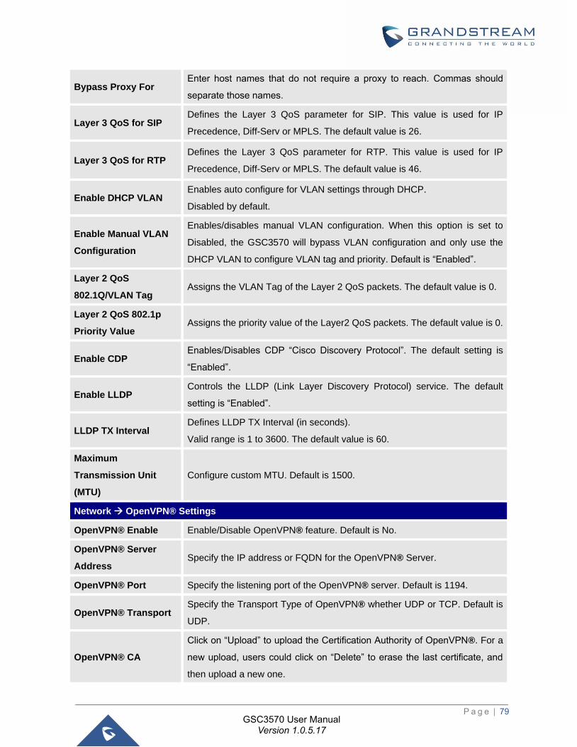
P a g e | 79
GSC3570 User Manual Version 1.0.5.17
Bypass Proxy For Enter host names that do not require a proxy to reach. Commas should
separate those names.
Layer 3 QoS for SIP Defines the Layer 3 QoS parameter for SIP. This value is used for IP
Precedence, Diff-Serv or MPLS. The default value is 26.
Layer 3 QoS for RTP Defines the Layer 3 QoS parameter for RTP. This value is used for IP
Precedence, Diff-Serv or MPLS. The default value is 46.
Enable DHCP VLAN Enables auto configure for VLAN settings through DHCP.
Disabled by default.
Enable Manual VLAN
Configuration
Enables/disables manual VLAN configuration. When this option is set to
Disabled, the GSC3570 will bypass VLAN configuration and only use the
DHCP VLAN to configure VLAN tag and priority. Default is “Enabled”.
Layer 2 QoS
802.1Q/VLAN Tag Assigns the VLAN Tag of the Layer 2 QoS packets. The default value is 0.
Layer 2 QoS 802.1p
Priority Value Assigns the priority value of the Layer2 QoS packets. The default value is 0.
Enable CDP Enables/Disables CDP “Cisco Discovery Protocol”. The default setting is
“Enabled”.
Enable LLDP Controls the LLDP (Link Layer Discovery Protocol) service. The default
setting is “Enabled”.
LLDP TX Interval Defines LLDP TX Interval (in seconds).
Valid range is 1 to 3600. The default value is 60.
Maximum
Transmission Unit
(MTU)
Configure custom MTU. Default is 1500.
Network → OpenVPN® Settings
OpenVPN® Enable Enable/Disable OpenVPN® feature. Default is No.
OpenVPN® Server
Address Specify the IP address or FQDN for the OpenVPN® Server.
OpenVPN® Port Specify the listening port of the OpenVPN® server. Default is 1194.
OpenVPN® Transport Specify the Transport Type of OpenVPN® whether UDP or TCP. Default is
UDP.
OpenVPN® CA
Click on “Upload” to upload the Certification Authority of OpenVPN®. For a
new upload, users could click on “Delete” to erase the last certificate, and
then upload a new one.
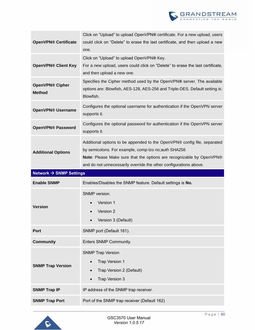
P a g e | 80
GSC3570 User Manual Version 1.0.5.17
OpenVPN® Certificate
Click on “Upload” to upload OpenVPN® certificate. For a new upload, users
could click on “Delete” to erase the last certificate, and then upload a new
one.
OpenVPN® Client Key
Click on “Upload” to upload OpenVPN® Key.
For a new upload, users could click on “Delete” to erase the last certificate,
and then upload a new one.
OpenVPN® Cipher
Method
Specifies the Cipher method used by the OpenVPN® server. The available
options are: Blowfish, AES-128, AES-256 and Triple-DES. Default setting is:
Blowfish.
OpenVPN® Username Configures the optional username for authentication if the OpenVPN server
supports it.
OpenVPN® Password Configures the optional password for authentication if the OpenVPN server
supports it.
Additional Options
Additional options to be appended to the OpenVPN® config file, separated
by semicolons. For example, comp-lzo no;auth SHA256
Note: Please Make sure that the options are recognizable by OpenVPN®
and do not unnecessarily override the other configurations above.
Network → SNMP Settings
Enable SNMP Enables/Disables the SNMP feature. Default settings is No.
Version
SNMP version.
• Version 1
• Version 2
• Version 3 (Default)
Port SNMP port (Default 161).
Community Enters SNMP Community.
SNMP Trap Version
SNMP Trap Version
• Trap Version 1
• Trap Version 2 (Default)
• Trap Version 3
SNMP Trap IP IP address of the SNMP trap receiver.
SNMP Trap Port Port of the SNMP trap receiver (Default 162)
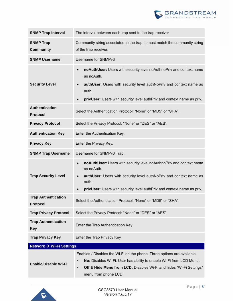
P a g e | 81
GSC3570 User Manual Version 1.0.5.17
SNMP Trap Interval The interval between each trap sent to the trap receiver
SNMP Trap
Community
Community string associated to the trap. It must match the community string
of the trap receiver.
SNMP Username Username for SNMPv3
Security Level
• noAuthUser: Users with security level noAuthnoPriv and context name
as noAuth.
• authUser: Users with security level authNoPriv and context name as
auth.
• privUser: Users with security level authPriv and context name as priv.
Authentication
Protocol Select the Authentication Protocol: “None” or “MD5” or “SHA”.
Privacy Protocol Select the Privacy Protocol: “None” or “DES” or “AES”.
Authentication Key Enter the Authentication Key.
Privacy Key Enter the Privacy Key.
SNMP Trap Username Username for SNMPv3 Trap.
Trap Security Level
• noAuthUser: Users with security level noAuthnoPriv and context name
as noAuth.
• authUser: Users with security level authNoPriv and context name as
auth.
• privUser: Users with security level authPriv and context name as priv.
Trap Authentication
Protocol Select the Authentication Protocol: “None” or “MD5” or “SHA”.
Trap Privacy Protocol Select the Privacy Protocol: “None” or “DES” or “AES”.
Trap Authentication
Key Enter the Trap Authentication Key
Trap Privacy Key Enter the Trap Privacy Key.
Network → Wi-Fi Settings
Enable/Disable Wi-Fi
Enables / Disables the Wi-Fi on the phone. Three options are available:
• No: Disables Wi-Fi. User has ability to enable Wi-Fi from LCD Menu.
• Off & Hide Menu from LCD: Disables Wi-Fi and hides “Wi-Fi Settings”
menu from phone LCD.
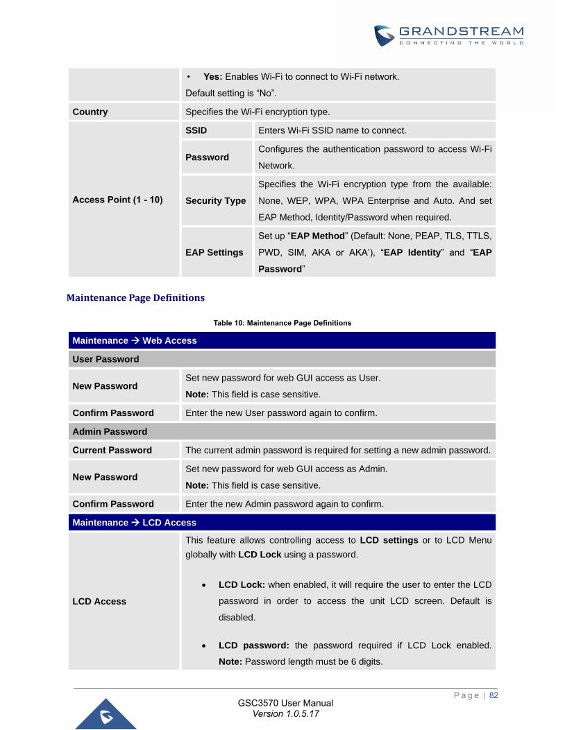
P a g e | 82
GSC3570 User Manual Version 1.0.5.17
• Yes: Enables Wi-Fi to connect to Wi-Fi network.
Default setting is “No”.
Country Specifies the Wi-Fi encryption type.
Access Point (1 - 10)
SSID Enters Wi-Fi SSID name to connect.
Password Configures the authentication password to access Wi-Fi
Network.
Security Type
Specifies the Wi-Fi encryption type from the available:
None, WEP, WPA, WPA Enterprise and Auto. And set
EAP Method, Identity/Password when required.
EAP Settings
Set up “EAP Method” (Default: None, PEAP, TLS, TTLS,
PWD, SIM, AKA or AKA’), “EAP Identity” and “EAP
Password”
Maintenance Page Definitions
Table 10: Maintenance Page Definitions
Maintenance → Web Access
User Password
New Password Set new password for web GUI access as User.
Note: This field is case sensitive.
Confirm Password Enter the new User password again to confirm.
Admin Password
Current Password The current admin password is required for setting a new admin password.
New Password Set new password for web GUI access as Admin.
Note: This field is case sensitive.
Confirm Password Enter the new Admin password again to confirm.
Maintenance → LCD Access
LCD Access
This feature allows controlling access to LCD settings or to LCD Menu
globally with LCD Lock using a password.
• LCD Lock: when enabled, it will require the user to enter the LCD
password in order to access the unit LCD screen. Default is
disabled.
• LCD password: the password required if LCD Lock enabled.
Note: Password length must be 6 digits.
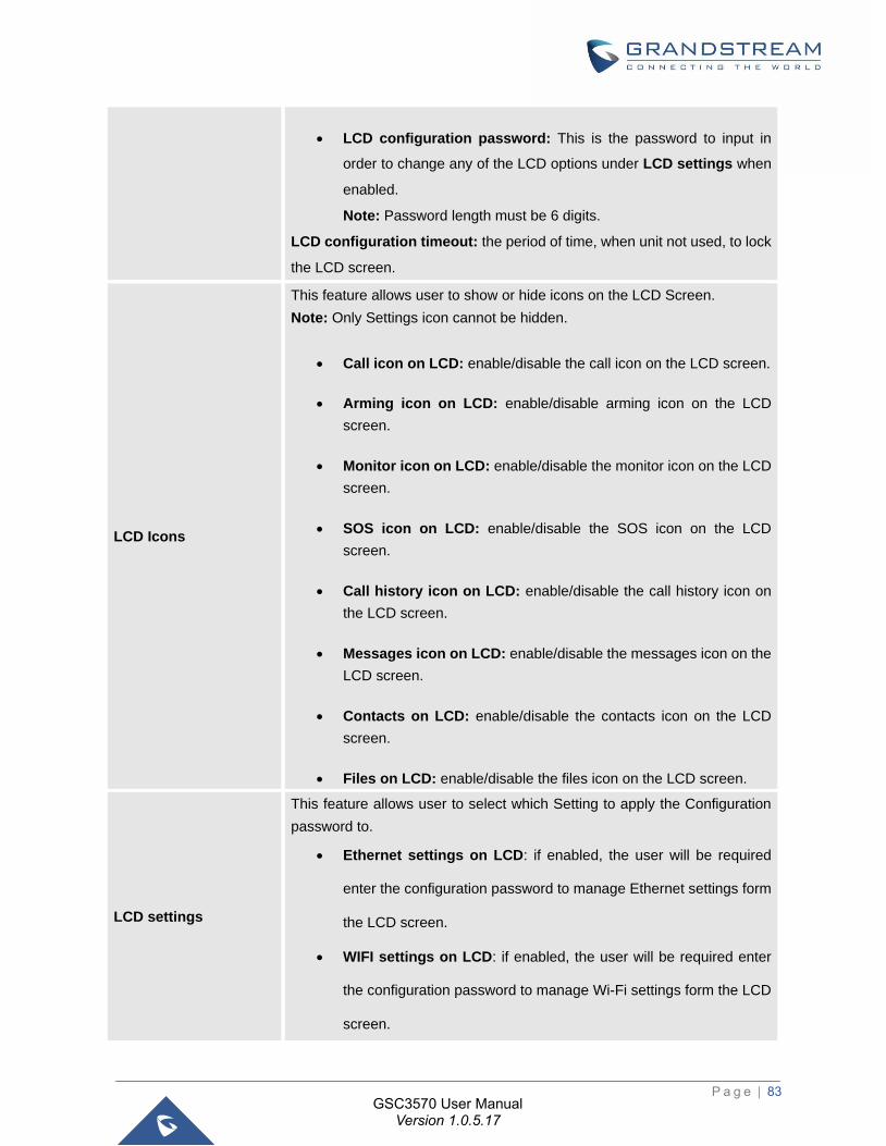
P a g e | 83
GSC3570 User Manual Version 1.0.5.17
• LCD configuration password: This is the password to input in
order to change any of the LCD options under LCD settings when
enabled.
Note: Password length must be 6 digits.
LCD configuration timeout: the period of time, when unit not used, to lock
the LCD screen.
LCD Icons
This feature allows user to show or hide icons on the LCD Screen.
Note: Only Settings icon cannot be hidden.
• Call icon on LCD: enable/disable the call icon on the LCD screen.
• Arming icon on LCD: enable/disable arming icon on the LCD
screen.
• Monitor icon on LCD: enable/disable the monitor icon on the LCD
screen.
• SOS icon on LCD: enable/disable the SOS icon on the LCD
screen.
• Call history icon on LCD: enable/disable the call history icon on
the LCD screen.
• Messages icon on LCD: enable/disable the messages icon on the
LCD screen.
• Contacts on LCD: enable/disable the contacts icon on the LCD
screen.
• Files on LCD: enable/disable the files icon on the LCD screen.
LCD settings
This feature allows user to select which Setting to apply the Configuration
password to.
• Ethernet settings on LCD: if enabled, the user will be required
enter the configuration password to manage Ethernet settings form
the LCD screen.
• WIFI settings on LCD: if enabled, the user will be required enter
the configuration password to manage Wi-Fi settings form the LCD
screen.
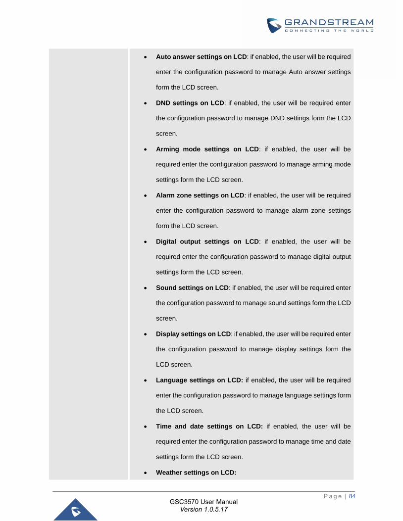
P a g e | 84
GSC3570 User Manual Version 1.0.5.17
• Auto answer settings on LCD: if enabled, the user will be required
enter the configuration password to manage Auto answer settings
form the LCD screen.
• DND settings on LCD: if enabled, the user will be required enter
the configuration password to manage DND settings form the LCD
screen.
• Arming mode settings on LCD: if enabled, the user will be
required enter the configuration password to manage arming mode
settings form the LCD screen.
• Alarm zone settings on LCD: if enabled, the user will be required
enter the configuration password to manage alarm zone settings
form the LCD screen.
• Digital output settings on LCD: if enabled, the user will be
required enter the configuration password to manage digital output
settings form the LCD screen.
• Sound settings on LCD: if enabled, the user will be required enter
the configuration password to manage sound settings form the LCD
screen.
• Display settings on LCD: if enabled, the user will be required enter
the configuration password to manage display settings form the
LCD screen.
• Language settings on LCD: if enabled, the user will be required
enter the configuration password to manage language settings form
the LCD screen.
• Time and date settings on LCD: if enabled, the user will be
required enter the configuration password to manage time and date
settings form the LCD screen.
• Weather settings on LCD:
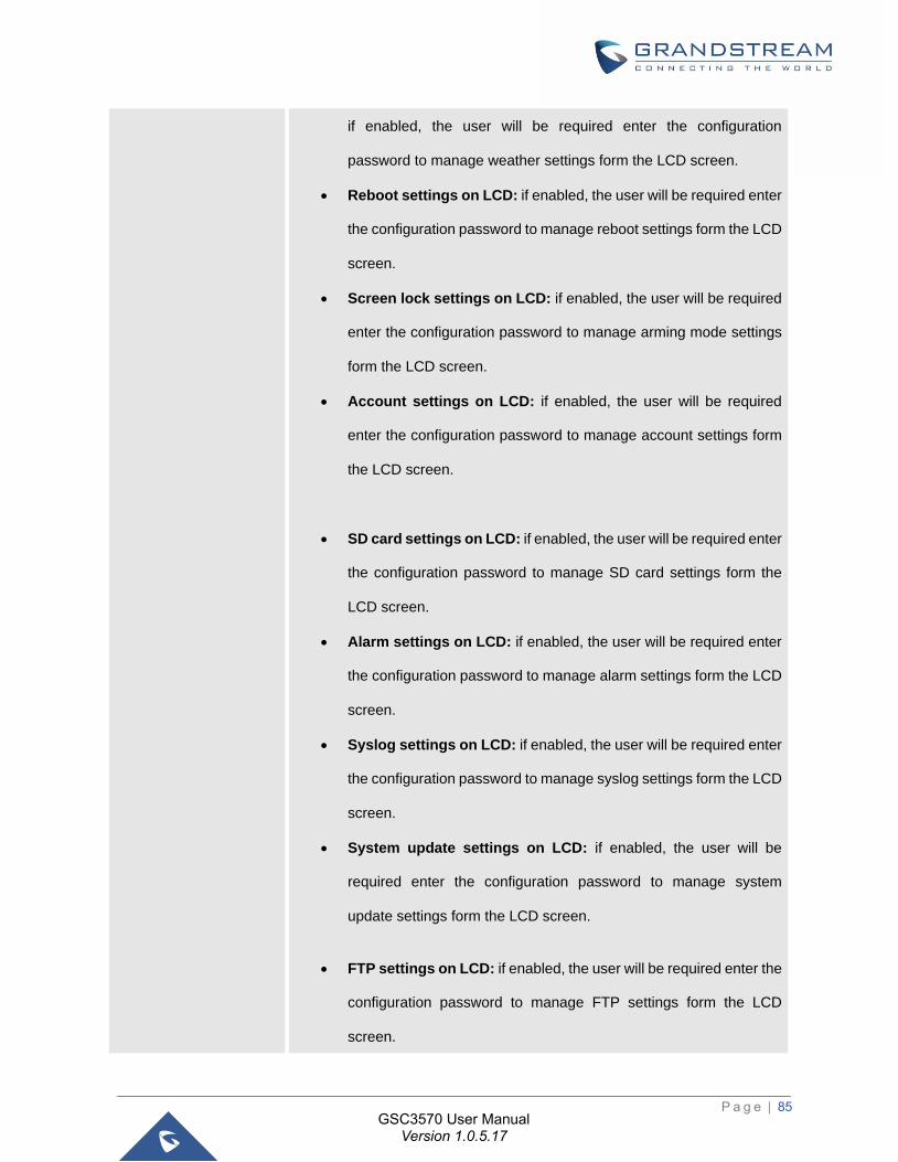
P a g e | 85
GSC3570 User Manual Version 1.0.5.17
if enabled, the user will be required enter the configuration
password to manage weather settings form the LCD screen.
• Reboot settings on LCD: if enabled, the user will be required enter
the configuration password to manage reboot settings form the LCD
screen.
• Screen lock settings on LCD: if enabled, the user will be required
enter the configuration password to manage arming mode settings
form the LCD screen.
• Account settings on LCD: if enabled, the user will be required
enter the configuration password to manage account settings form
the LCD screen.
• SD card settings on LCD: if enabled, the user will be required enter
the configuration password to manage SD card settings form the
LCD screen.
• Alarm settings on LCD: if enabled, the user will be required enter
the configuration password to manage alarm settings form the LCD
screen.
• Syslog settings on LCD: if enabled, the user will be required enter
the configuration password to manage syslog settings form the LCD
screen.
• System update settings on LCD: if enabled, the user will be
required enter the configuration password to manage system
update settings form the LCD screen.
• FTP settings on LCD: if enabled, the user will be required enter the
configuration password to manage FTP settings form the LCD
screen.
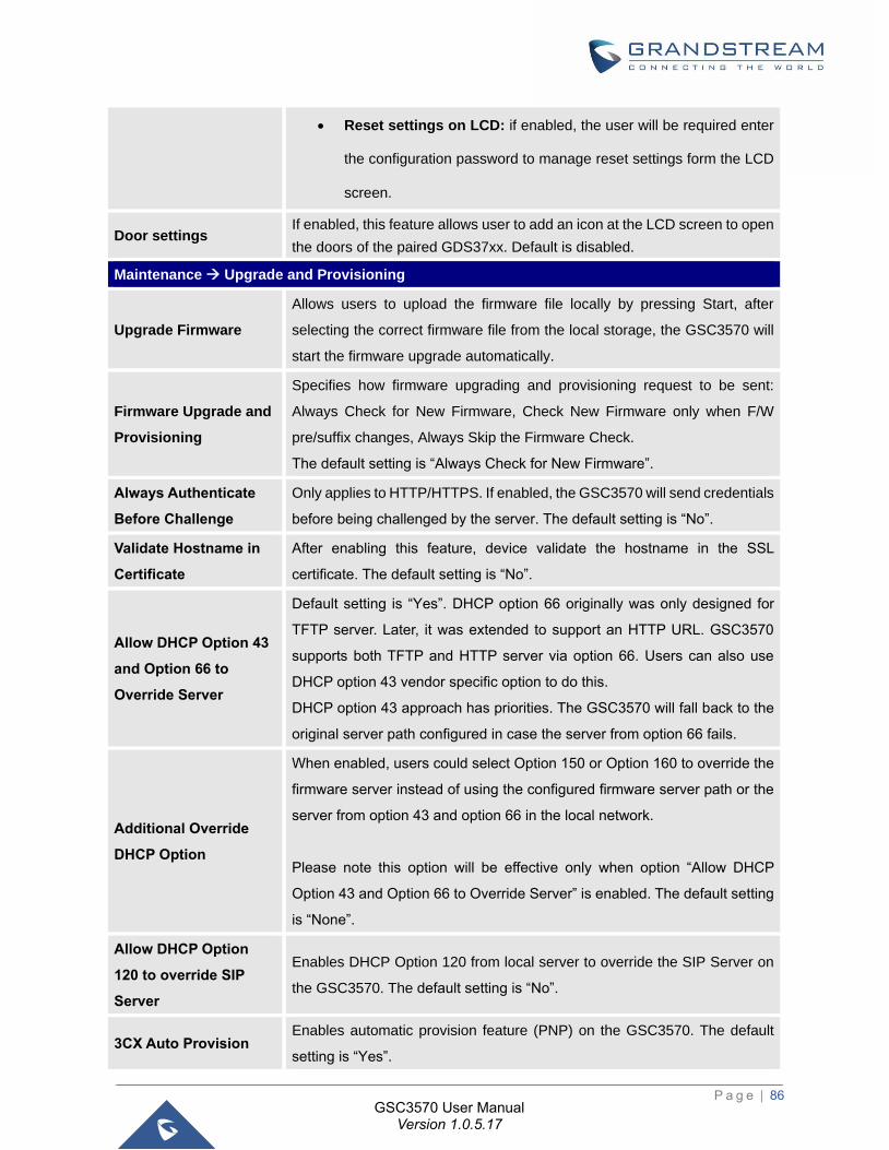
P a g e | 86
GSC3570 User Manual Version 1.0.5.17
• Reset settings on LCD: if enabled, the user will be required enter
the configuration password to manage reset settings form the LCD
screen.
Door settings If enabled, this feature allows user to add an icon at the LCD screen to open
the doors of the paired GDS37xx. Default is disabled.
Maintenance → Upgrade and Provisioning
Upgrade Firmware
Allows users to upload the firmware file locally by pressing Start, after
selecting the correct firmware file from the local storage, the GSC3570 will
start the firmware upgrade automatically.
Firmware Upgrade and
Provisioning
Specifies how firmware upgrading and provisioning request to be sent:
Always Check for New Firmware, Check New Firmware only when F/W
pre/suffix changes, Always Skip the Firmware Check.
The default setting is “Always Check for New Firmware”.
Always Authenticate
Before Challenge
Only applies to HTTP/HTTPS. If enabled, the GSC3570 will send credentials
before being challenged by the server. The default setting is “No”.
Validate Hostname in
Certificate
After enabling this feature, device validate the hostname in the SSL
certificate. The default setting is “No”.
Allow DHCP Option 43
and Option 66 to
Override Server
Default setting is “Yes”. DHCP option 66 originally was only designed for
TFTP server. Later, it was extended to support an HTTP URL. GSC3570
supports both TFTP and HTTP server via option 66. Users can also use
DHCP option 43 vendor specific option to do this.
DHCP option 43 approach has priorities. The GSC3570 will fall back to the
original server path configured in case the server from option 66 fails.
Additional Override
DHCP Option
When enabled, users could select Option 150 or Option 160 to override the
firmware server instead of using the configured firmware server path or the
server from option 43 and option 66 in the local network.
Please note this option will be effective only when option “Allow DHCP
Option 43 and Option 66 to Override Server” is enabled. The default setting
is “None”.
Allow DHCP Option
120 to override SIP
Server
Enables DHCP Option 120 from local server to override the SIP Server on
the GSC3570. The default setting is “No”.
3CX Auto Provision Enables automatic provision feature (PNP) on the GSC3570. The default
setting is “Yes”.
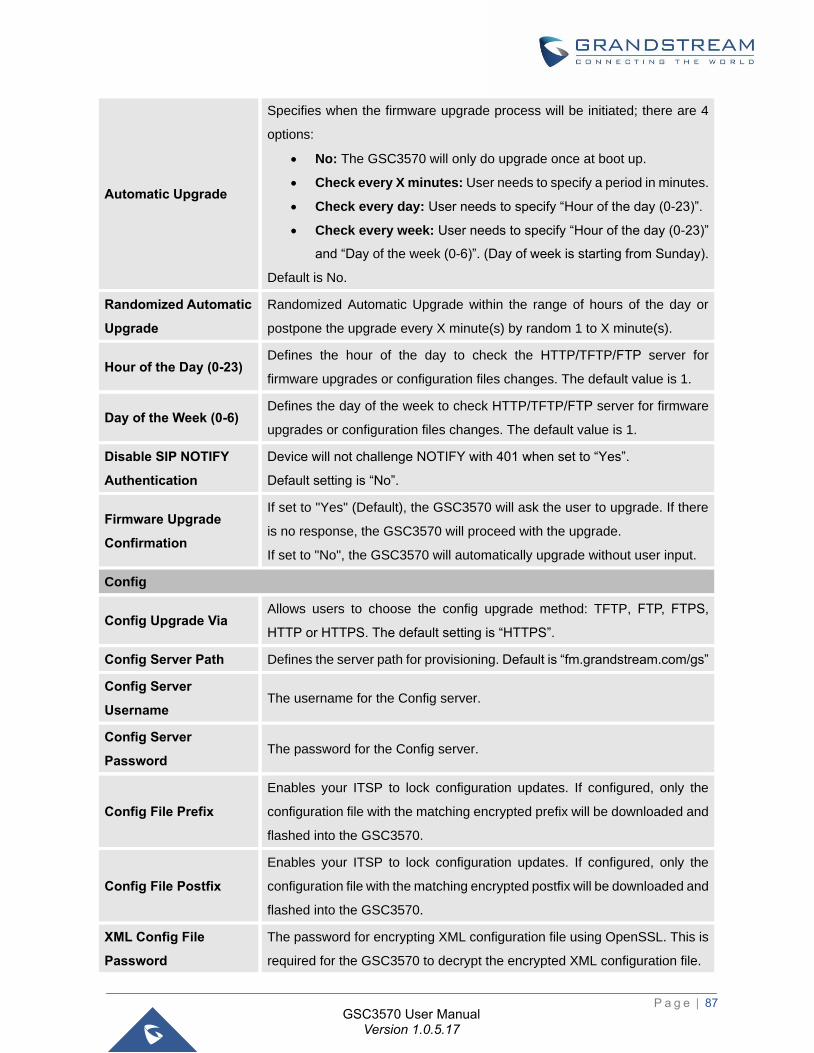
P a g e | 87
GSC3570 User Manual Version 1.0.5.17
Automatic Upgrade
Specifies when the firmware upgrade process will be initiated; there are 4
options:
• No: The GSC3570 will only do upgrade once at boot up.
• Check every X minutes: User needs to specify a period in minutes.
• Check every day: User needs to specify “Hour of the day (0-23)”.
• Check every week: User needs to specify “Hour of the day (0-23)”
and “Day of the week (0-6)”. (Day of week is starting from Sunday).
Default is No.
Randomized Automatic
Upgrade
Randomized Automatic Upgrade within the range of hours of the day or
postpone the upgrade every X minute(s) by random 1 to X minute(s).
Hour of the Day (0-23) Defines the hour of the day to check the HTTP/TFTP/FTP server for
firmware upgrades or configuration files changes. The default value is 1.
Day of the Week (0-6) Defines the day of the week to check HTTP/TFTP/FTP server for firmware
upgrades or configuration files changes. The default value is 1.
Disable SIP NOTIFY
Authentication
Device will not challenge NOTIFY with 401 when set to “Yes”.
Default setting is “No”.
Firmware Upgrade
Confirmation
If set to "Yes" (Default), the GSC3570 will ask the user to upgrade. If there
is no response, the GSC3570 will proceed with the upgrade.
If set to "No", the GSC3570 will automatically upgrade without user input.
Config
Config Upgrade Via Allows users to choose the config upgrade method: TFTP, FTP, FTPS,
HTTP or HTTPS. The default setting is “HTTPS”.
Config Server Path Defines the server path for provisioning. Default is “fm.grandstream.com/gs”
Config Server
Username The username for the Config server.
Config Server
Password The password for the Config server.
Config File Prefix
Enables your ITSP to lock configuration updates. If configured, only the
configuration file with the matching encrypted prefix will be downloaded and
flashed into the GSC3570.
Config File Postfix
Enables your ITSP to lock configuration updates. If configured, only the
configuration file with the matching encrypted postfix will be downloaded and
flashed into the GSC3570.
XML Config File
Password
The password for encrypting XML configuration file using OpenSSL. This is
required for the GSC3570 to decrypt the encrypted XML configuration file.
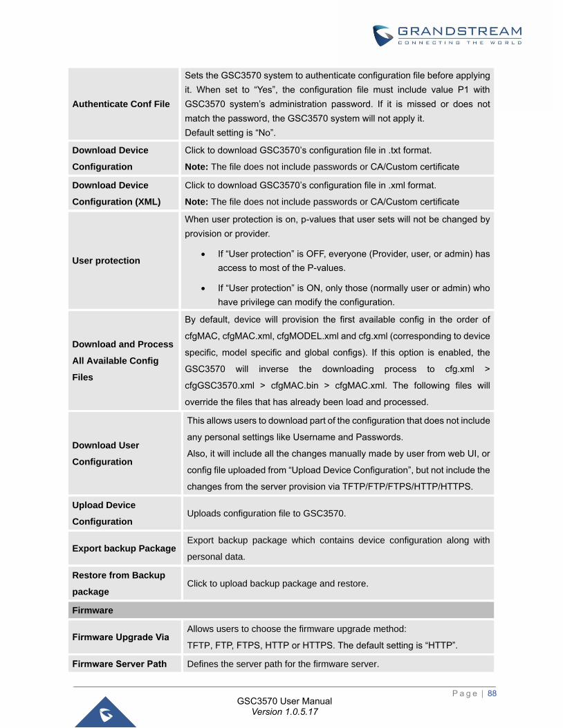
P a g e | 88
GSC3570 User Manual Version 1.0.5.17
Authenticate Conf File
Sets the GSC3570 system to authenticate configuration file before applying
it. When set to “Yes”, the configuration file must include value P1 with
GSC3570 system’s administration password. If it is missed or does not
match the password, the GSC3570 system will not apply it.
Default setting is “No”.
Download Device
Configuration
Click to download GSC3570’s configuration file in .txt format.
Note: The file does not include passwords or CA/Custom certificate
Download Device
Configuration (XML)
Click to download GSC3570’s configuration file in .xml format.
Note: The file does not include passwords or CA/Custom certificate
User protection
When user protection is on, p-values that user sets will not be changed by
provision or provider.
• If “User protection” is OFF, everyone (Provider, user, or admin) has
access to most of the P-values.
• If “User protection” is ON, only those (normally user or admin) who
have privilege can modify the configuration.
Download and Process
All Available Config
Files
By default, device will provision the first available config in the order of
cfgMAC, cfgMAC.xml, cfgMODEL.xml and cfg.xml (corresponding to device
specific, model specific and global configs). If this option is enabled, the
GSC3570 will inverse the downloading process to cfg.xml >
cfgGSC3570.xml > cfgMAC.bin > cfgMAC.xml. The following files will
override the files that has already been load and processed.
Download User
Configuration
This allows users to download part of the configuration that does not include
any personal settings like Username and Passwords.
Also, it will include all the changes manually made by user from web UI, or
config file uploaded from “Upload Device Configuration”, but not include the
changes from the server provision via TFTP/FTP/FTPS/HTTP/HTTPS.
Upload Device
Configuration Uploads configuration file to GSC3570.
Export backup Package Export backup package which contains device configuration along with
personal data.
Restore from Backup
package Click to upload backup package and restore.
Firmware
Firmware Upgrade Via Allows users to choose the firmware upgrade method:
TFTP, FTP, FTPS, HTTP or HTTPS. The default setting is “HTTP”.
Firmware Server Path Defines the server path for the firmware server.
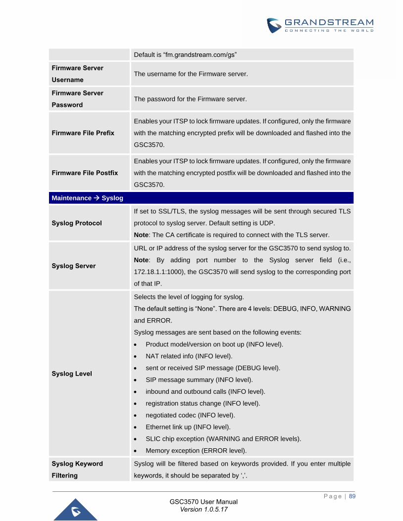
P a g e | 89
GSC3570 User Manual Version 1.0.5.17
Default is “fm.grandstream.com/gs”
Firmware Server
Username The username for the Firmware server.
Firmware Server
Password The password for the Firmware server.
Firmware File Prefix
Enables your ITSP to lock firmware updates. If configured, only the firmware
with the matching encrypted prefix will be downloaded and flashed into the
GSC3570.
Firmware File Postfix
Enables your ITSP to lock firmware updates. If configured, only the firmware
with the matching encrypted postfix will be downloaded and flashed into the
GSC3570.
Maintenance → Syslog
Syslog Protocol
If set to SSL/TLS, the syslog messages will be sent through secured TLS
protocol to syslog server. Default setting is UDP.
Note: The CA certificate is required to connect with the TLS server.
Syslog Server
URL or IP address of the syslog server for the GSC3570 to send syslog to.
Note: By adding port number to the Syslog server field (i.e.,
172.18.1.1:1000), the GSC3570 will send syslog to the corresponding port
of that IP.
Syslog Level
Selects the level of logging for syslog.
The default setting is “None”. There are 4 levels: DEBUG, INFO, WARNING
and ERROR.
Syslog messages are sent based on the following events:
• Product model/version on boot up (INFO level).
• NAT related info (INFO level).
• sent or received SIP message (DEBUG level).
• SIP message summary (INFO level).
• inbound and outbound calls (INFO level).
• registration status change (INFO level).
• negotiated codec (INFO level).
• Ethernet link up (INFO level).
• SLIC chip exception (WARNING and ERROR levels).
• Memory exception (ERROR level).
Syslog Keyword
Filtering
Syslog will be filtered based on keywords provided. If you enter multiple
keywords, it should be separated by ‘,’.
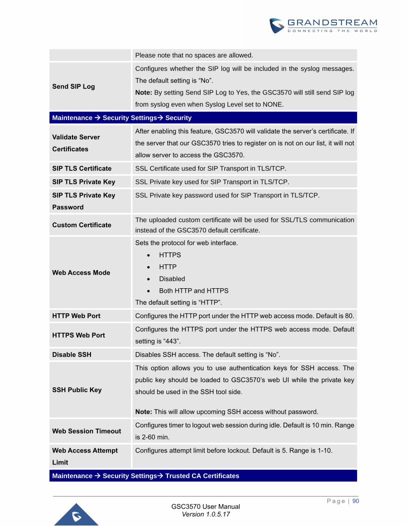
P a g e | 90
GSC3570 User Manual Version 1.0.5.17
Please note that no spaces are allowed.
Send SIP Log
Configures whether the SIP log will be included in the syslog messages.
The default setting is “No”.
Note: By setting Send SIP Log to Yes, the GSC3570 will still send SIP log
from syslog even when Syslog Level set to NONE.
Maintenance → Security Settings→ Security
Validate Server
Certificates
After enabling this feature, GSC3570 will validate the server’s certificate. If
the server that our GSC3570 tries to register on is not on our list, it will not
allow server to access the GSC3570.
SIP TLS Certificate SSL Certificate used for SIP Transport in TLS/TCP.
SIP TLS Private Key SSL Private key used for SIP Transport in TLS/TCP.
SIP TLS Private Key
Password
SSL Private key password used for SIP Transport in TLS/TCP.
Custom Certificate The uploaded custom certificate will be used for SSL/TLS communication
instead of the GSC3570 default certificate.
Web Access Mode
Sets the protocol for web interface.
• HTTPS
• HTTP
• Disabled
• Both HTTP and HTTPS
The default setting is “HTTP”.
HTTP Web Port Configures the HTTP port under the HTTP web access mode. Default is 80.
HTTPS Web Port Configures the HTTPS port under the HTTPS web access mode. Default
setting is “443”.
Disable SSH Disables SSH access. The default setting is “No”.
SSH Public Key
This option allows you to use authentication keys for SSH access. The
public key should be loaded to GSC3570’s web UI while the private key
should be used in the SSH tool side.
Note: This will allow upcoming SSH access without password.
Web Session Timeout Configures timer to logout web session during idle. Default is 10 min. Range
is 2-60 min.
Web Access Attempt
Limit
Configures attempt limit before lockout. Default is 5. Range is 1-10.
Maintenance → Security Settings→ Trusted CA Certificates
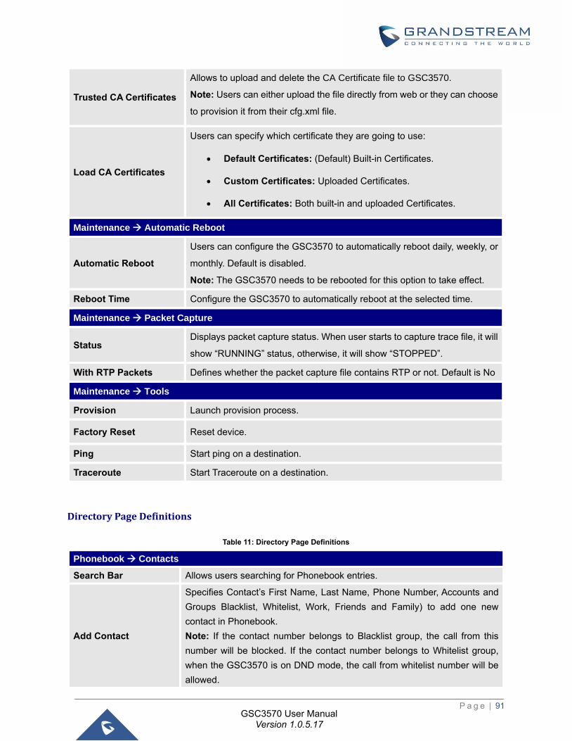
P a g e | 91
GSC3570 User Manual Version 1.0.5.17
Trusted CA Certificates
Allows to upload and delete the CA Certificate file to GSC3570.
Note: Users can either upload the file directly from web or they can choose
to provision it from their cfg.xml file.
Load CA Certificates
Users can specify which certificate they are going to use:
• Default Certificates: (Default) Built-in Certificates.
• Custom Certificates: Uploaded Certificates.
• All Certificates: Both built-in and uploaded Certificates.
Maintenance → Automatic Reboot
Automatic Reboot
Users can configure the GSC3570 to automatically reboot daily, weekly, or
monthly. Default is disabled.
Note: The GSC3570 needs to be rebooted for this option to take effect.
Reboot Time Configure the GSC3570 to automatically reboot at the selected time.
Maintenance → Packet Capture
Status Displays packet capture status. When user starts to capture trace file, it will
show “RUNNING” status, otherwise, it will show “STOPPED”.
With RTP Packets Defines whether the packet capture file contains RTP or not. Default is No
Maintenance → Tools
Provision Launch provision process.
Factory Reset Reset device.
Ping Start ping on a destination.
Traceroute Start Traceroute on a destination.
Directory Page Definitions
Table 11: Directory Page Definitions
Phonebook → Contacts
Search Bar Allows users searching for Phonebook entries.
Add Contact
Specifies Contact’s First Name, Last Name, Phone Number, Accounts and
Groups Blacklist, Whitelist, Work, Friends and Family) to add one new
contact in Phonebook.
Note: If the contact number belongs to Blacklist group, the call from this
number will be blocked. If the contact number belongs to Whitelist group,
when the GSC3570 is on DND mode, the call from whitelist number will be
allowed.
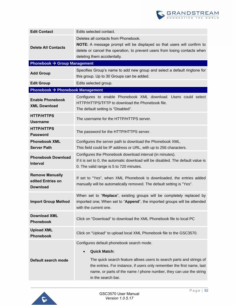
P a g e | 92
GSC3570 User Manual Version 1.0.5.17
Edit Contact Edits selected contact.
Delete All Contacts
Deletes all contacts from Phonebook.
NOTE: A message prompt will be displayed so that users will confirm to
delete or cancel the operation, to prevent users from losing contacts when
deleting them accidentally.
Phonebook → Group Management
Add Group Specifies Group’s name to add new group and select a default ringtone for
this group. Up to 30 Groups can be added.
Edit Group Edits selected group.
Phonebook → Phonebook Management
Enable Phonebook
XML Download
Configures to enable Phonebook XML download. Users could select
HTTP/HTTPS/TFTP to download the Phonebook file.
The default setting is "Disabled".
HTTP/HTTPS
Username The username for the HTTP/HTTPS server.
HTTP/HTTPS
Password The password for the HTTP/HTTPS server.
Phonebook XML
Server Path
Configures the server path to download the Phonebook XML.
This field could be IP address or URL, with up to 256 characters.
Phonebook Download
Interval
Configures the Phonebook download interval (in minutes).
If it is set to 0, the automatic download will be disabled. The default value is
0. The valid range is 5 to 720 minutes.
Remove Manually
edited Entries on
Download
If set to "Yes", when XML Phonebook is downloaded, the entries added
manually will be automatically removed. The default setting is "Yes".
Import Group Method
When set to “Replace”, existing groups will be completely replaced by
imported one; When set to “Append”, the imported groups will be attended
with the current one.
Download XML
Phonebook Click on "Download" to download the XML Phonebook file to local PC
Upload XML
Phonebook Click on "Upload" to upload local XML Phonebook file to the GSC3570.
Default search mode
Configures default phonebook search mode.
• Quick Match:
The quick search feature allows users to search parts and strings of
the entries. For instance, if users only remember the first name, last
name, or parts of the name / phone number, they can use the string
in the search bar.
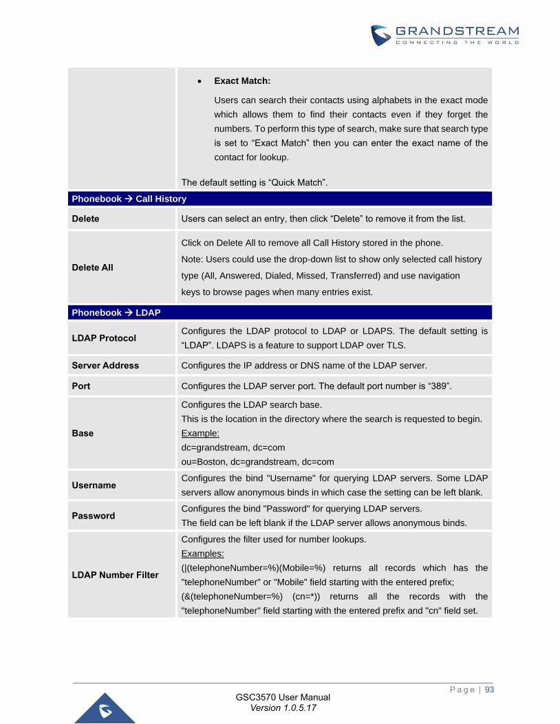
P a g e | 93
GSC3570 User Manual Version 1.0.5.17
• Exact Match:
Users can search their contacts using alphabets in the exact mode
which allows them to find their contacts even if they forget the
numbers. To perform this type of search, make sure that search type
is set to “Exact Match” then you can enter the exact name of the
contact for lookup.
The default setting is “Quick Match”.
Phonebook → Call History
Delete Users can select an entry, then click “Delete” to remove it from the list.
Delete All
Click on Delete All to remove all Call History stored in the phone.
Note: Users could use the drop-down list to show only selected call history
type (All, Answered, Dialed, Missed, Transferred) and use navigation
keys to browse pages when many entries exist.
Phonebook → LDAP
LDAP Protocol Configures the LDAP protocol to LDAP or LDAPS. The default setting is
“LDAP”. LDAPS is a feature to support LDAP over TLS.
Server Address Configures the IP address or DNS name of the LDAP server.
Port Configures the LDAP server port. The default port number is “389”.
Base
Configures the LDAP search base.
This is the location in the directory where the search is requested to begin.
Example:
dc=grandstream, dc=com
ou=Boston, dc=grandstream, dc=com
Username Configures the bind "Username" for querying LDAP servers. Some LDAP
servers allow anonymous binds in which case the setting can be left blank.
Password Configures the bind "Password" for querying LDAP servers.
The field can be left blank if the LDAP server allows anonymous binds.
LDAP Number Filter
Configures the filter used for number lookups.
Examples:
(|(telephoneNumber=%)(Mobile=%) returns all records which has the
"telephoneNumber" or "Mobile" field starting with the entered prefix;
(&(telephoneNumber=%) (cn=*)) returns all the records with the
"telephoneNumber" field starting with the entered prefix and "cn" field set.
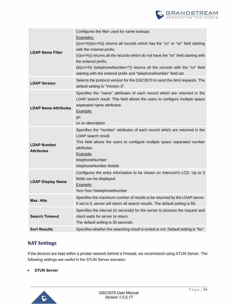
P a g e | 94
GSC3570 User Manual Version 1.0.5.17
LDAP Name Filter
Configures the filter used for name lookups.
Examples:
(|(cn=%)(sn=%)) returns all records which has the "cn" or "sn" field starting
with the entered prefix;
(!(sn=%)) returns all the records which do not have the "sn" field starting with
the entered prefix;
(&(cn=%) (telephoneNumber=*)) returns all the records with the "cn" field
starting with the entered prefix and "telephoneNumber" field set.
LDAP Version Selects the protocol version for the GSC3570 to send the bind requests. The
default setting is "Version 3".
LDAP Name Attributes
Specifies the "name" attributes of each record which are returned in the
LDAP search result. This field allows the users to configure multiple space
separated name attributes.
Example:
gn
cn sn description
LDAP Number
Attributes
Specifies the "number" attributes of each record which are returned in the
LDAP search result.
This field allows the users to configure multiple space separated number
attributes.
Example:
telephoneNumber
telephoneNumber Mobile
LDAP Display Name
Configures the entry information to be shown on Intercom's LCD. Up to 3
fields can be displayed.
Example:
%cn %sn %telephoneNumber
Max. Hits Specifies the maximum number of results to be returned by the LDAP server.
If set to 0, server will return all search results. The default setting is 50.
Search Timeout
Specifies the interval (in seconds) for the server to process the request and
client waits for server to return.
The default setting is 30 seconds.
Sort Results Specifies whether the searching result is sorted or not. Default setting is "No".
NAT Settings
If the devices are kept within a private network behind a Firewall, we recommend using STUN Server. The
following settings are useful in the STUN Server scenario:
• STUN Server
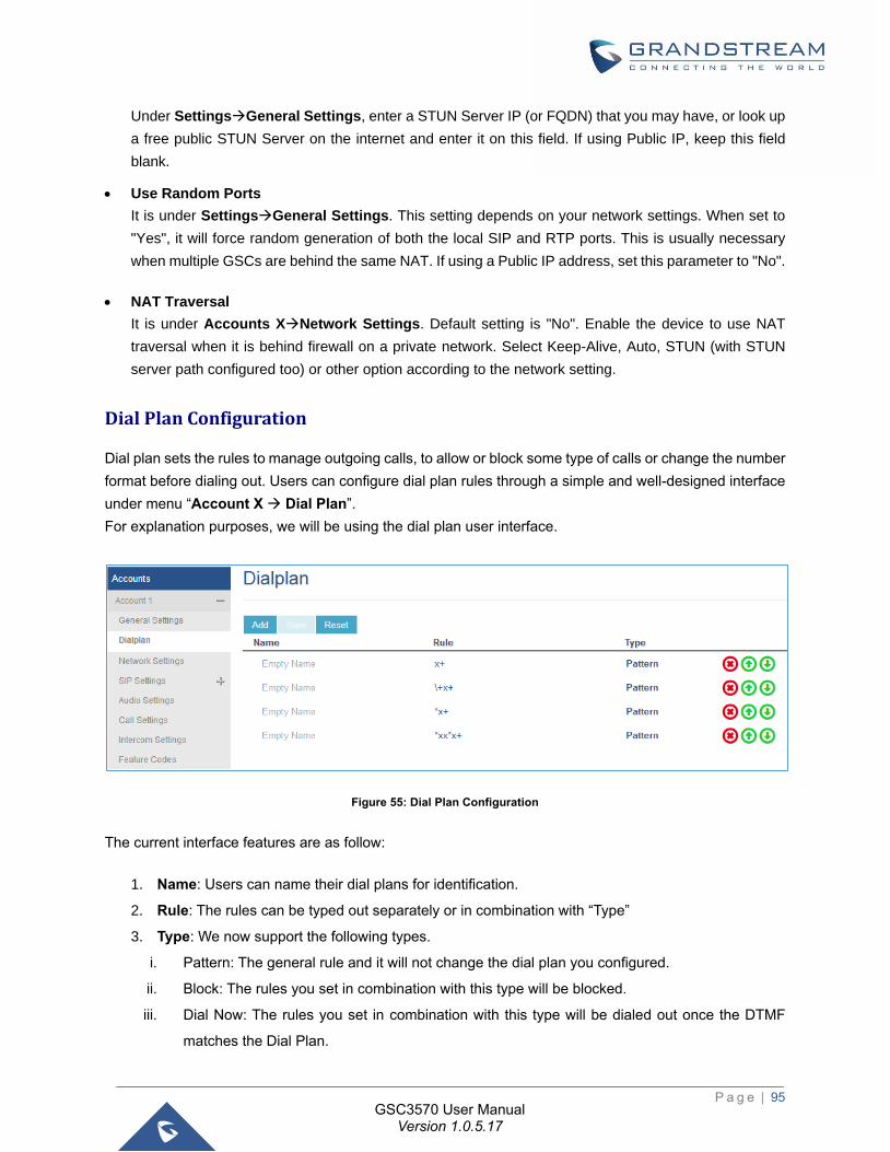
P a g e | 95
GSC3570 User Manual Version 1.0.5.17
Under Settings→General Settings, enter a STUN Server IP (or FQDN) that you may have, or look up
a free public STUN Server on the internet and enter it on this field. If using Public IP, keep this field
blank.
• Use Random Ports
It is under Settings→General Settings. This setting depends on your network settings. When set to
"Yes", it will force random generation of both the local SIP and RTP ports. This is usually necessary
when multiple GSCs are behind the same NAT. If using a Public IP address, set this parameter to "No".
• NAT Traversal
It is under Accounts X→Network Settings. Default setting is "No". Enable the device to use NAT
traversal when it is behind firewall on a private network. Select Keep-Alive, Auto, STUN (with STUN
server path configured too) or other option according to the network setting.
Dial Plan Configuration
Dial plan sets the rules to manage outgoing calls, to allow or block some type of calls or change the number
format before dialing out. Users can configure dial plan rules through a simple and well-designed interface
under menu “Account X → Dial Plan”.
For explanation purposes, we will be using the dial plan user interface.
Figure 55: Dial Plan Configuration
The current interface features are as follow:
1. Name: Users can name their dial plans for identification.
2. Rule: The rules can be typed out separately or in combination with “Type”
3. Type: We now support the following types.
i. Pattern: The general rule and it will not change the dial plan you configured.
ii. Block: The rules you set in combination with this type will be blocked.
iii. Dial Now: The rules you set in combination with this type will be dialed out once the DTMF
matches the Dial Plan.
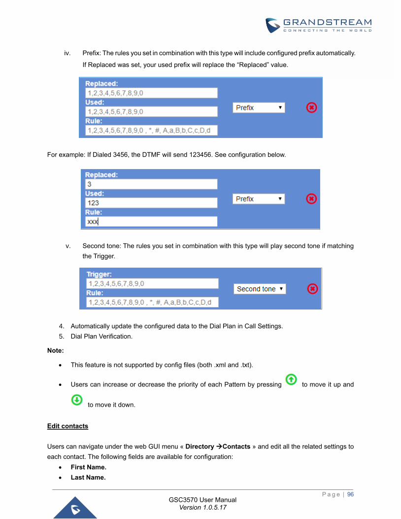
P a g e | 96
GSC3570 User Manual Version 1.0.5.17
iv. Prefix: The rules you set in combination with this type will include configured prefix automatically.
If Replaced was set, your used prefix will replace the “Replaced” value.
For example: If Dialed 3456, the DTMF will send 123456. See configuration below.
v. Second tone: The rules you set in combination with this type will play second tone if matching
the Trigger.
4. Automatically update the configured data to the Dial Plan in Call Settings.
5. Dial Plan Verification.
Note:
• This feature is not supported by config files (both .xml and .txt).
• Users can increase or decrease the priority of each Pattern by pressing to move it up and
to move it down.
Edit contacts
Users can navigate under the web GUI menu « Directory →Contacts » and edit all the related settings to
each contact. The following fields are available for configuration:
• First Name.
• Last Name.
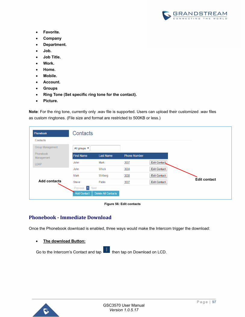
P a g e | 97
GSC3570 User Manual Version 1.0.5.17
• Favorite.
• Company
• Department.
• Job.
• Job Title.
• Work.
• Home.
• Mobile.
• Account.
• Groups
• Ring Tone (Set specific ring tone for the contact).
• Picture.
Note: For the ring tone, currently only .wav file is supported. Users can upload their customized .wav files
as custom ringtones. (File size and format are restricted to 500KB or less.)
Figure 56: Edit contacts
Phonebook - Immediate Download
Once the Phonebook download is enabled, three ways would make the Intercom trigger the download:
• The download Button:
Go to the Intercom’s Contact and tap then tap on Download on LCD.
Add contacts Edit contact
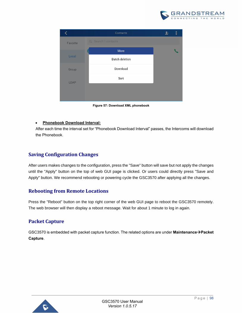
P a g e | 98
GSC3570 User Manual Version 1.0.5.17
Figure 57: Download XML phonebook
• Phonebook Download Interval:
After each time the interval set for “Phonebook Download Interval” passes, the Intercoms will download
the Phonebook.
Saving Configuration Changes
After users makes changes to the configuration, press the "Save" button will save but not apply the changes
until the "Apply" button on the top of web GUI page is clicked. Or users could directly press "Save and
Apply" button. We recommend rebooting or powering cycle the GSC3570 after applying all the changes.
Rebooting from Remote Locations
Press the "Reboot" button on the top right corner of the web GUI page to reboot the GSC3570 remotely.
The web browser will then display a reboot message. Wait for about 1 minute to log in again.
Packet Capture
GSC3570 is embedded with packet capture function. The related options are under Maintenance→Packet
Capture.
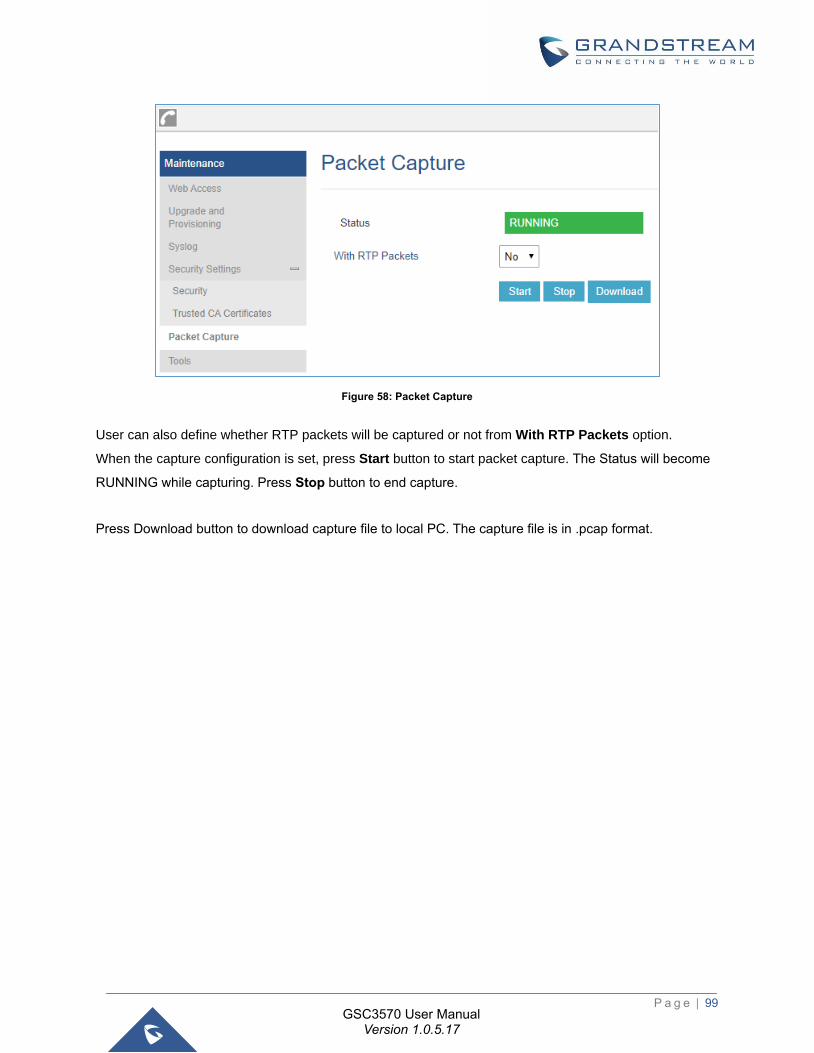
P a g e | 99
GSC3570 User Manual Version 1.0.5.17
Figure 58: Packet Capture
User can also define whether RTP packets will be captured or not from With RTP Packets option.
When the capture configuration is set, press Start button to start packet capture. The Status will become
RUNNING while capturing. Press Stop button to end capture.
Press Download button to download capture file to local PC. The capture file is in .pcap format.
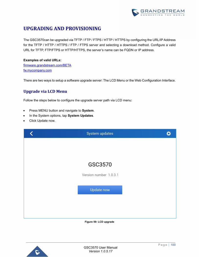
P a g e | 100
GSC3570 User Manual Version 1.0.5.17
UPGRADING AND PROVISIONING
The GSC3570can be upgraded via TFTP / FTP / FTPS / HTTP / HTTPS by configuring the URL/IP Address
for the TFTP / HTTP / HTTPS / FTP / FTPS server and selecting a download method. Configure a valid
URL for TFTP, FTP/FTPS or HTTP/HTTPS, the server’s name can be FQDN or IP address.
Examples of valid URLs:
firmware.grandstream.com/BETA
fw.mycompany.com
There are two ways to setup a software upgrade server: The LCD Menu or the Web Configuration Interface.
Upgrade via LCD Menu
Follow the steps below to configure the upgrade server path via LCD menu:
• Press MENU button and navigate to System.
• In the System options, tap System Updates.
• Click Update now.
Figure 59: LCD upgrade
P a g e | 101
GSC3570 User Manual Version 1.0.5.17
Upgrade via Web GUI
Open a web browser on PC and enter the IP address of the GSC3570. Then, login with the administrator
username and password. Go to Maintenance→Upgrade and Provisioning page, enter the IP address or the
FQDN for the upgrade server in "Firmware Server Path" field and choose to upgrade via TFTP or
HTTP/HTTPS or FTP/FTPS. Update the change by clicking the "Save and Apply" button. Then "Reboot" or
power cycle the GSC3570 to update the new firmware.
When upgrading starts, the screen will show upgrading progress. When done you will see the GSC3570
restart again. Please do not interrupt or power cycle the GSC3570 when the upgrading process is on.
Firmware upgrading takes around 60 seconds in a controlled LAN or 5-10 minutes over the Internet. We
recommend completing firmware upgrades in a controlled LAN environment whenever possible.
No Local TFTP/FTP/HTTP Servers
For users that would like to use remote upgrading without a local TFTP/FTP/HTTP server, Grandstream
offers a NAT-friendly HTTP server. This enables users to download the latest software upgrades for their
GSC3570 via this server. Please refer to the webpage:
https://www.grandstream.com/support/firmware
Alternatively, users can download a free TFTP, FTP or HTTP server and conduct a local firmware upgrade.
A free window version TFTP server is available for download from:
http://www.solarwinds.com/products/freetools/free_tftp_server.aspx
http://tftpd32.jounin.net/.
Instructions for local firmware upgrade via TFTP:
1. Unzip the firmware files and put all of them in the root directory of the TFTP server.
2. Connect the PC running the TFTP server and the GSC3570 to the same LAN segment.
3. Launch the TFTP server and go to the File menu→Configure→Security to change the TFTP server's
default setting from "Receive Only" to "Transmit Only" for the firmware upgrade.
4. Start the TFTP server and configure the TFTP server in the GSC3570’s web configuration interface.
5. Configure the Firmware Server Path to the IP address of the PC.
6. Update the changes and reboot the GSC3570.
End users can also choose to download a free HTTP server from http://httpd.apache.org/ or use
Microsoft IIS web server.
Configuration File Download
Grandstream SIP Devices can be configured via the Web Interface as well as via a Configuration File
(binary or XML) through TFTP, FTP/FTPS or HTTP/HTTPS. The "Config Server Path" is the TFTP,
FTP/FTPS or HTTP/HTTPS server path for the configuration file.
P a g e | 102
GSC3570 User Manual Version 1.0.5.17
It needs to be set to a valid URL, either in FQDN or IP address format. The "Config Server Path" can be
the same or different from the "Firmware Server Path".
A configuration parameter is associated with each field in the web configuration page. A parameter consists
of a Capital letter P and 2 to 5-digit numeric numbers. i.e., P2 is associated with the "New Password" in the
Web GUI→Maintenance→Web Access page→Admin Password. For a detailed parameter list, please
refer to the corresponding configuration template.
When the GSC3570 boots up or reboots, it will issue a request to download a configuration file named
"cfgxxxxxxxxxxxx" followed by an XML file named "cfgxxxxxxxxxxxx.xml", where "xxxxxxxxxxxx" is the MAC
address of the GSC3570, i.e., "cfg000b820102ab" and "cfg000b820102ab.xml". If the download of
"cfgxxxxxxxxxxxx.xml" file is not successful, the GSC3570 will issue a request to download a specific model
configuration file “cfg<model>.xml”, where <model> is the GSC3570 model, i.e., “cfgGSC3570.xml” for the
GSC3570, “cfgGSC3570” for the GSC3570. If this file is not available, the GSC3570 will issue a request to
download the generic “cfg.xml” file. The configuration file name should be in lower case letters.
For more details on XML provisioning, please refer to:
https://www.grandstream.com/sites/default/files/Resources/gs_provisioning_guide.pdf
No Touch Provisioning
After the GSC3570 sends, config file request to the BroadSoft provisioning server via HTTP/HTTPS, if the
provisioning server responds “401 Unauthorized” asking for authentication, the GSC3570’s LCD will prompt
a window for user to enter username and password. Once correct username and password are entered,
the GSC3570 will send config file request again with authentication. Then the GSC3570 will receive the
config file to download and get provisioned automatically.
Besides manually entering the username and password in LCD prompt, users can save the login credentials
for provisioning process as well. The username and password configuration are under GSC3570’s web
UI→Maintenance→Upgrade and provisioning page: “HTTP/HTTPS Username” and “HTTP/HTTPS
Password”. If the saved username and password saved are correct, login window will be skipped. Otherwise,
login window will be popped up to prompt users to enter correct username and password again.
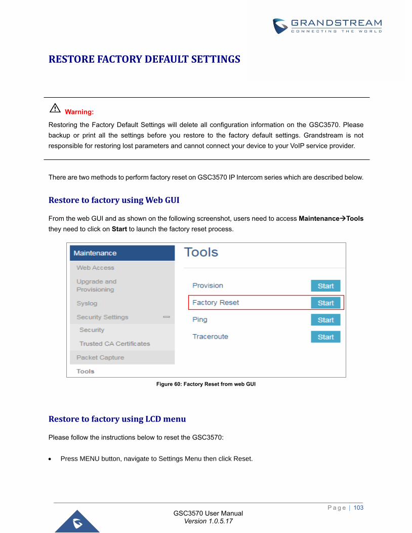
P a g e | 103
GSC3570 User Manual Version 1.0.5.17
RESTORE FACTORY DEFAULT SETTINGS
Warning:
Restoring the Factory Default Settings will delete all configuration information on the GSC3570. Please
backup or print all the settings before you restore to the factory default settings. Grandstream is not
responsible for restoring lost parameters and cannot connect your device to your VoIP service provider.
There are two methods to perform factory reset on GSC3570 IP Intercom series which are described below.
Restore to factory using Web GUI
From the web GUI and as shown on the following screenshot, users need to access Maintenance→Tools
they need to click on Start to launch the factory reset process.
Figure 60: Factory Reset from web GUI
Restore to factory using LCD menu
Please follow the instructions below to reset the GSC3570:
• Press MENU button, navigate to Settings Menu then click Reset.
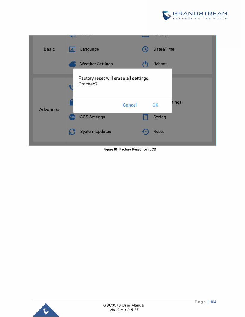
P a g e | 104
GSC3570 User Manual Version 1.0.5.17
Figure 61: Factory Reset from LCD
P a g e | 105
GSC3570 User Manual Version 1.0.5.17
EXPERIENCING GSC3570
Please visit our website: https://www.grandstream.com to receive the most up- to-date updates on firmware
releases, additional features, FAQs, documentation, and news on new products.
We encourage you to browse our product related documentation, FAQs and User and Developer Forum
for answers to your general questions. If you have purchased our products through a Grandstream
Certified Partner or Reseller, please contact them directly for immediate support.
Our technical support staff is trained and ready to answer all your questions. Contact a technical support
member or submit a trouble ticket online to receive in-depth support.
Thank you again for purchasing Grandstream GSC3570 IP Intercom, it will be sure to bring convenience
and color to both your business and personal life.
Related Documents