Foreword Thank you for choosing the vehicle from GAC Motor Co., Ltd. (GAC Motor for short). To better enjoy the driving pleasure, please carefully read this User's Manual. The use instructions in this Manual will allow you to fully understand the operations and important notes. Proper use of the vehicle will improve driving safety and increase service life. The on-board Warranty Manual describes the warranty services provided by GAC MOTOR which you can enjoy, as well as regular maintenance of your GAC vehicle. Read this Manual thoroughly so that you can understand your rights and responsibilities. Please keep this Manual in your vehicle for reference. Our dealer is dedicated to your satisfaction and will be pleased to answer any questions and concerns. If you have any advice or comments, welcome to call GAC MOTOR customer service hotline: +86-400-158-9999. Thank you for your support and great kindness to GAC MOTOR. Have a nice ride!

Welcome message from author
This document is posted to help you gain knowledge. Please leave a comment to let me know what you think about it! Share it to your friends and learn new things together.
Transcript
Foreword
Thank you for choosing the vehicle from GAC Motor Co., Ltd. (GAC Motor for short). To better enjoy the driving pleasure, please carefully read this User's Manual. The use instructions in this Manual will allow you to fully understand the operations and important notes. Proper use of the vehicle will improve driving safety and increase service life.
The on-board Warranty Manual describes the warranty services provided by GAC MOTOR which you can enjoy, as well as regular maintenance of your GAC vehicle. Read this Manual thoroughly so that you can understand your rights and responsibilities.
Please keep this Manual in your vehicle for reference.
Our dealer is dedicated to your satisfaction and will be pleased to answer any questions and concerns.
If you have any advice or comments, welcome to call GAC MOTOR customer service hotline: +86-400-158-9999. Thank you for your support and great kindness to GAC MOTOR. Have a nice ride!
Reading Instructions
Your safety and the safety of passengers are very important. Therefore, operating this vehicle safely is an important responsibility.
To help you be familiar with relevant safety notes, we have provided operating steps and other instructions on signboards of the vehicle and in this Manual. These instructions alert you to warn potential hazards that could hurt you or passengers.
Of course, it is not practical or possible to list all the hazards associated with operating or maintaining your vehicle. You must use your own good judgment.
You will find these important safety instructions in a variety of forms, including:
• Safety Signboards— Attached to the vehicle.
• Safety Information— Words preceded by a safety warning symbol and one of the three signal words:"Warning", "Caution" or "Hint".
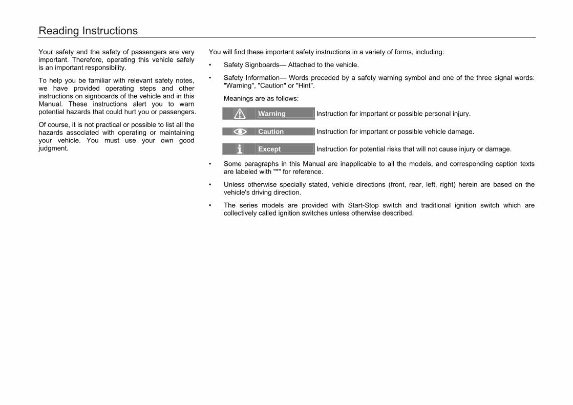
Meanings are as follows:
Warning Instruction for important or possible personal injury.
Caution Instruction for important or possible vehicle damage.
Except Instruction for potential risks that will not cause injury or damage.
• Some paragraphs in this Manual are inapplicable to all the models, and corresponding caption textsare labeled with "*" for reference.
• Unless otherwise specially stated, vehicle directions (front, rear, left, right) herein are based on thevehicle's driving direction.
• The series models are provided with Start-Stop switch and traditional ignition switch which arecollectively called ignition switches unless otherwise described.
Contents
I
1. Important Safety Precautions ....................................................................... 1 2. Pictorial References...................................................................................... 3
2.1 Exterior .............................................................................................. 3 2.2 Interior ............................................................................................... 6
3. Safety Operating Instructions ..................................................................... 11 3.1 Safe Driving ..................................................................................... 11
3.1.1 General Instructions ......................................................... 11 3.1.2 Correct Sitting Position of Passengers............................. 12
3.2 Seat Belts ........................................................................................ 13 3.2.1 Why Wear Seat Belts ....................................................... 13 3.2.2 Seat Belt ........................................................................... 15
3.3 SRS System .................................................................................... 19 3.3.1 Cases When Airbags Could Deploy ................................. 24 3.3.2 Cases When Airbags Could Not Deploy .......................... 25
3.4 Safety Rules for Children ................................................................ 27 3.4.1 General Instructions ......................................................... 27 3.4.2 Child Safety Seat ............................................................. 28 3.4.3 Information about Child Safety Seat ................................ 29 3.4.4 Install a Child Seat Properly ............................................. 31
3.5 Dangerous Exhaust Gases ............................................................. 35 3.6 Safety Labels ................................................................................... 36
4. Operating System and Equipment .............................................................. 37 4.1 Cab .................................................................................................. 37
4.1.1 Steering Wheel ................................................................. 37 4.1.2 Indicator Light ................................................................... 44
4.2 Vehicle Opening and Closing .......................................................... 48 4.2.1 Smart Key ......................................................................... 48 4.2.2 Mechanical Key ................................................................ 53 4.2.3 Locking System ................................................................ 54 4.2.4 Door .................................................................................. 61
4.2.5 Hatchback Door ................................................................ 62 4.2.6 Engine Hood ..................................................................... 68 4.2.7 Electric Windows .............................................................. 69 4.2.8 Electric Sunroof ................................................................ 71 4.2.9 Basic Operations of Anti-Theft on Vehicle Body............... 76
4.3 Lights and Visual Field ..................................................................... 77 4.3.1 Exterior Lights ................................................................... 77 4.3.2 Interior Lights .................................................................... 84 4.3.3 Wiper Combination Switch ................................................ 87 4.3.4 Windshields....................................................................... 91 4.3.5 Rear-View Mirror ............................................................... 92 4.3.6 Sun Visor ........................................................................ ..97
4.4 Seats and Storage Devices ............................................................. 98 4.4.1 Headrest ........................................................................... 98 4.4.2 Front Seats ....................................................................... 99 4.4.3 Rear Seats ...................................................................... 104 4.4.4 Storage Devices ............................................................. 105 4.4.5 Power Outlet ................................................................... 110 4.4.6 Mobile Phone Wireless Charging System* ..................... 112 4.4.7 Trunk ............................................................................... 115 4.4.8 Luggage Rack ................................................................. 118 4.4.9 Accessories and Modifications ....................................... 119
4.5 A/C System .................................................................................... 121 4.5.1 General Instructions ........................................................ 121 4.5.2 Auto A/C System* ........................................................... 122 4.5.3 Manual A/C System* ....................................................... 129 4.5.4 Air Outlets ....................................................................... 134
4.6 AUDIO System ............................................................................... 135 4.6.1 Control Panel .................................................................. 135 4.6.2 Control Buttons on the Steering Wheel .......................... 137 4.6.3 Basic Operations ............................................................ 139
Contents
II
4.6.4 Radio .............................................................................. 140 4.6.5 USB Play ........................................................................ 142 4.6.6 Bluetooth ........................................................................ 143 4.6.7 System Setting ............................................................... 145 4.6.8 Vehicle Setting ............................................................... 147
5. Driving Directions ...................................................................................... 149 5.1 Starting and Driving ....................................................................... 149
5.1.1 Ignition Switch ................................................................ 149 5.1.2 Engine Stop .................................................................... 151 5.1.3 Gear Instructions ............................................................ 153
5.2 Brake System ................................................................................ 158 5.2.1 Service Brake ................................................................. 158 5.2.2 Electronic Parking Brake (EPB) System ........................ 161
5.3 Service Electronic Brake System .................................................. 166 5.3.1 Anti-Lock Braking System (ABS) ................................... 166 5.3.2 Electronic Brakeforce Distribution System (EBD) .......... 169 5.3.3 Electronic Stability Program (ESP) ................................ 170 5.3.4 Traction Control System (TCS) ...................................... 173 5.3.5 Hydraulic Brake Assist (HBA) ........................................ 174 5.3.6 Hill Hold Control (HHC) .................................................. 175 5.3.7 Hill Descent Control (HDC) ............................................ 176
5.4 Driver Assistance System ............................................................. 178 5.4.1 Smart Start/Stop System ................................................ 178 5.4.2 Cruise Control System * ................................................. 183 5.4.3 Tire Pressure Monitoring System* .................................. 185
5.5 Reversing Assist System ............................................................... 187 5.5.1 Reversing Radar System* .............................................. 187 5.5.2 Reversing Rear-view System * ....................................... 191 5.5.3 Panoramic Parking System* ........................................... 193
5.6 Electric Power Steering (EPS) System .......................................... 194 5.7 Driving Skills................................................................................... 198
5.7.1 Safety Check for Driving ................................................. 198 5.7.2 Driving during Running-in Period .................................... 199 5.7.3 Important Tips for Driving ............................................... 201 5.7.4 High-efficiency Use of Vehicle ........................................ 202 5.7.5 Fire Prevention ............................................................... 203
6. Usage and Maintenance ........................................................................... 204 6.1. Maintenance Instructions ............................................................... 204 6.2 Interior Maintenance ...................................................................... 205 6.3 Exterior Maintenance ..................................................................... 207 6.4 Checking and Adding Fluids .......................................................... 213
6.4.1 Fuel Oil ............................................................................ 213 6.4.2 Engine Oil ....................................................................... 215 6.4.3 Coolant ............................................................................ 218 6.4.4 Windshield Washing Liquid and Wiper Blade ................. 221 6.4.5 Brake Fluid ...................................................................... 223 6.4.6 Battery ............................................................................. 226
6.5 A/C Filter ........................................................................................ 228 6.6 Replacing Bulbs ............................................................................. 230 6.7 Wheels ........................................................................................... 236 6.8 Tire Chain ....................................................................................... 242
Contents
III
7.2 Vehicle Parameters ....................................................................... 245 7.3 Vehicle Parameters ....................................................................... 247 7.4 Vehicle Parameters ....................................................................... 251
8. Handling of Accident ................................................................................. 255 8.1 Vehicle Tools and Spare Tire ........................................................ 255 8.2 Usage of Warning Triangle ............................................................ 256 8.3 Replacing the Flat Tire .................................................................. 257 8.4 Fuse ............................................................................................... 260
8.4.1 Fuses in the Instrument Panel Fuse Box ....................... 262 8.4.2 Fuse in Engine Compartment Fuse Box ........................ 265 8.4.3 Fuse in Battery Box ........................................................ 268
8.5 Emergency Start ............................................................................ 269 8.6 Emergency Towing ........................................................................ 271
9. Environmental Protection Information ...................................................... 275 9.1. Environmental Protection Information No. .................................... 275 9.2. Environmental Protection Information ........................................... 276
7. Technical Data .......................................................................................... 243 7.1 Vehicle Identification Numbers ...................................................... 243

1. Important Safety Precautions
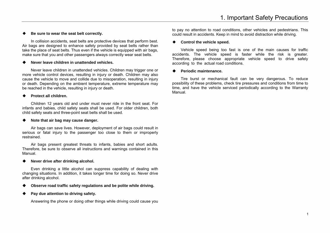
◆ Be sure to wear the seat belt correctly.
In collision accidents, seat belts are protective devices that perform best.Air bags are designed to enhance safety provided by seat belts rather than take the place of seat belts. Thus even if the vehicle is equipped with air bags, make sure that you and other passengers always correctly wear seat belts.
◆ Never leave children in unattended vehicles.
Never leave children in unattended vehicles. Children may trigger one ormore vehicle control devices, resulting in injury or death. Children may also cause the vehicle to move and collide due to misoperation, resulting in injury or death. Depending on the ambient temperature, extreme temperature may be reached in the vehicle, resulting in injury or death.
◆ Protect all children.
Children 12 years old and under must never ride in the front seat. Forinfants and babies, child safety seats shall be used. For older children, both child safety seats and three-point seat belts shall be used.
◆ Note that air bag may cause danger.
Air bags can save lives. However, deployment of air bags could result inserious or fatal injury to the passenger too close to them or improperly restrained.
Air bags present greatest threats to infants, babies and short adults. Therefore, be sure to observe all instructions and warnings contained in this Manual.
◆ Never drive after drinking alcohol.
Even drinking a little alcohol can suppress capability of dealing withchanging situations. In addition, it takes longer time for doing so. Never drive after drinking alcohol.
◆ Observe road traffic safety regulations and be polite while driving.
◆ Pay due attention to driving safety.
Answering the phone or doing other things while driving could cause you
to pay no attention to road conditions, other vehicles and pedestrians. This could result in accidents. Keep in mind to avoid distraction while driving.
◆ Control the vehicle speed.
Vehicle speed being too fast is one of the main causes for trafficaccidents. The vehicle speed is faster while the risk is greater. Therefore, please choose appropriate vehicle speed to drive safely according to the actual road conditions.
◆ Periodic maintenance.
Tire burst or mechanical fault can be very dangerous. To reducepossibility of these problems, check tire pressures and conditions from time to time, and have the vehicle serviced periodically according to the Warranty Manual.
1 1
1. Important Safety Precautions
Accident data recorder
Equipped with relevant equipment of accident data recorder, the vehicle can record the real-time data of certain collision (such as airbag deployment or collision with obstacles) to help better understand the collision and injury. Such data shall be owned by the vehicle owner.
If necessary, GAC Motor Automobile Sales Co., Ltd. or its authorized representative shall have the right to obtain data of the accident data recorder, but only for technical diagnosis, research and development of vehicle.
Service diagnosis recorder
Equipped with relevant equipment of service diagnosis recorder, the vehicle can record the power system performance and the driving condition. Such data can assist technicians in diagnosis, repair and maintenance of the vehicle.
Such data shall be owned by the vehicle owner. If necessary, GAC Motor Automobile Sales Co., Ltd. or its authorized representative shall have the right to obtain data of the service diagnosis recorder, but only for technical diagnosis, research and development of vehicle.
2 2
2. Pictorial References2. Pictorial References
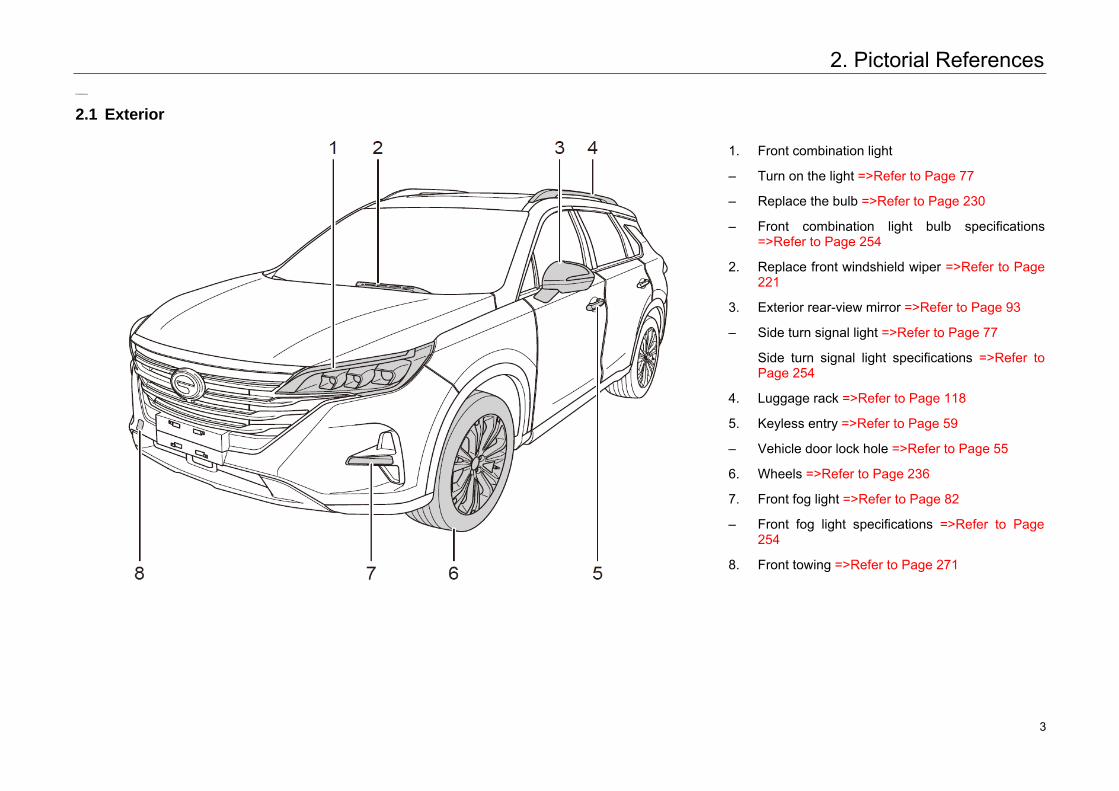
2.1 Exterior
1. Front combination light
– Turn on the light =>Refer to Page 77
– Replace the bulb =>Refer to Page 230
– Front combination light bulb specifications =>Refer to Page 254
2. Replace front windshield wiper =>Refer to Page 221
3. Exterior rear-view mirror =>Refer to Page 93
– Side turn signal light =>Refer to Page 77
Side turn signal light specifications =>Refer to Page 254
4. Luggage rack =>Refer to Page 118
5. Keyless entry =>Refer to Page 59
– Vehicle door lock hole =>Refer to Page 55
6. Wheels =>Refer to Page 236
7. Front fog light =>Refer to Page 82
– Front fog light specifications =>Refer to Page254
8. Front towing =>Refer to Page 271
3 3
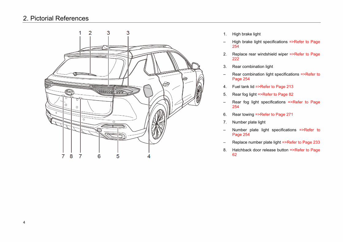
2. Pictorial References
1. High brake light
– High brake light specifications =>Refer to Page254
2. Replace rear windshield wiper =>Refer to Page 222
3. Rear combination light
– Rear combination light specifications =>Refer toPage 254
4. Fuel tank lid =>Refer to Page 213
5. Rear fog light =>Refer to Page 82
– Rear fog light specifications =>Refer to Page254
6. Rear towing =>Refer to Page 271
7. Number plate light
– Number plate light specifications =>Refer to Page 254
– Replace number plate light =>Refer to Page 233
8. Hatchback door release button =>Refer to Page62
4 4
2. Pictorial References
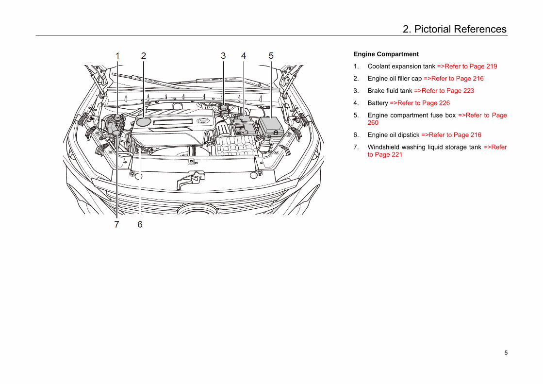
Engine Compartment
1. Coolant expansion tank =>Refer to Page 219
2. Engine oil filler cap =>Refer to Page 216
3. Brake fluid tank =>Refer to Page 223
4. Battery =>Refer to Page 226
5. Engine compartment fuse box =>Refer to Page 260
6. Engine oil dipstick =>Refer to Page 216
7. Windshield washing liquid storage tank =>Refer to Page 221
5 5
2. Pictorial References
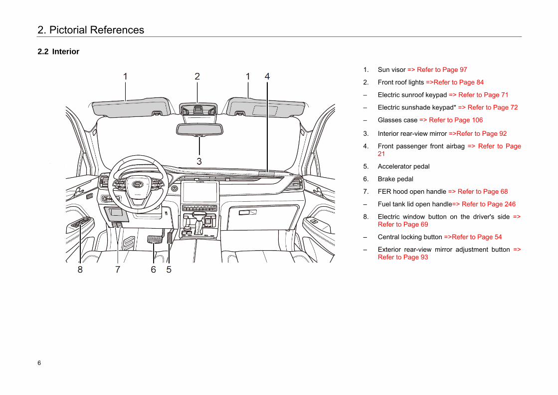
2.2 Interior
1. Sun visor => Refer to Page 97
2. Front roof lights =>Refer to Page 84
– Electric sunroof keypad => Refer to Page 71
– Electric sunshade keypad* => Refer to Page 72
– Glasses case => Refer to Page 106
3. Interior rear-view mirror =>Refer to Page 92
4. Front passenger front airbag => Refer to Page 21
5. Accelerator pedal
6. Brake pedal
7. FER hood open handle => Refer to Page 68
– Fuel tank lid open handle=> Refer to Page 246
8. Electric window button on the driver's side =>Refer to Page 69
– Central locking button =>Refer to Page 54
– Exterior rear-view mirror adjustment button => Refer to Page 93
6 6
2. Pictorial References
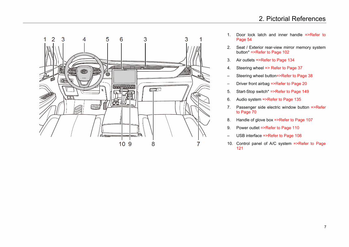
1. Door lock latch and inner handle =>Refer to Page 54
2. Seat / Exterior rear-view mirror memory system button* =>Refer to Page 102
3. Air outlets =>Refer to Page 134
4. Steering wheel => Refer to Page 37
– Steering wheel button=>Refer to Page 38
– Driver front airbag =>Refer to Page 20
5. Start-Stop switch* =>Refer to Page 149
6. Audio system =>Refer to Page 135
7. Passenger side electric window button =>Refer to Page 70
8. Handle of glove box =>Refer to Page 107
9. Power outlet =>Refer to Page 110
– USB interface =>Refer to Page 108
10. Control panel of A/C system =>Refer to Page121
7 7
2. Pictorial References
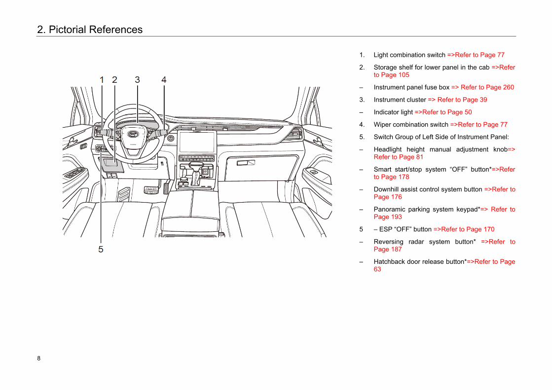
1. Light combination switch =>Refer to Page 77
2. Storage shelf for lower panel in the cab =>Refer to Page 105
– Instrument panel fuse box => Refer to Page 260
3. Instrument cluster => Refer to Page 39
– Indicator light =>Refer to Page 50
4. Wiper combination switch =>Refer to Page 77
5. Switch Group of Left Side of Instrument Panel:
– Headlight height manual adjustment knob=> Refer to Page 81
– Smart start/stop system “OFF” button*=>Refer to Page 178
– Downhill assist control system button =>Refer to Page 176
– Panoramic parking system keypad*=> Refer to Page 193
5 – ESP “OFF” button =>Refer to Page 170
– Reversing radar system button* =>Refer to Page 187
– Hatchback door release button*=>Refer to Page 63
8 8
2. Pictorial References
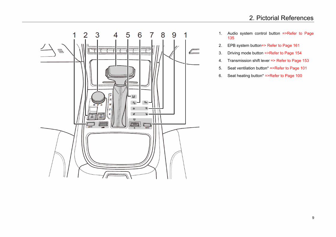
1. Audio system control button =>Refer to Page 135
2. EPB system button=> Refer to Page 161
3. Driving mode button =>Refer to Page 154
4. Transmission shift lever => Refer to Page 153
5. Seat ventilation button* =>Refer to Page 101
6. Seat heating button* =>Refer to Page 100
9 9
2. Pictorial References
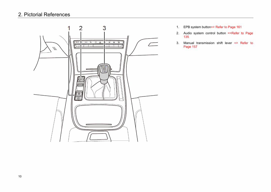
1. EPB system button=> Refer to Page 161
2. Audio system control button =>Refer to Page 135
3. Manual transmission shift lever => Refer to Page 157
10 10
3. Safety Operating Instructions3. Safety Operating Instructions
3.1 Safe Driving
3.1.1 General Instructions
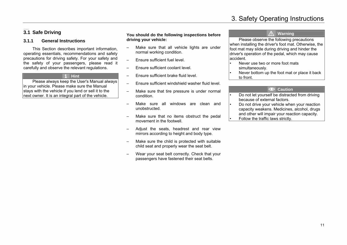
This Section describes important information, operating essentials, recommendations and safety precautions for driving safety. For your safety and the safety of your passengers, please read it carefully and observe the relevant regulations.
Hint Please always keep the User's Manual always
in your vehicle. Please make sure the Manual stays with the vehicle if you lend or sell it to the next owner. It is an integral part of the vehicle.
You should do the following inspections before driving your vehicle:
– Make sure that all vehicle lights are undernormal working condition.
– Ensure sufficient fuel level.
– Ensure sufficient coolant level.
– Ensure sufficient brake fluid level.
– Ensure sufficient windshield washer fluid level.
– Make sure that tire pressure is under normalcondition.
– Make sure all windows are clean andunobstructed.
– Make sure that no items obstruct the pedalmovement in the footwell.
– Adjust the seats, headrest and rear viewmirrors according to height and body type.
– Make sure the child is protected with suitablechild seat and properly wear the seat belt.
– Wear your seat belt correctly. Check that yourpassengers have fastened their seat belts.
Warning Please observe the following precautions
when installing the driver's foot mat. Otherwise, the foot mat may slide during driving and hinder the driver's operation of the pedal, which may cause accident. • Never use two or more foot mats
simultaneously.• Never bottom up the foot mat or place it back
to front.
Caution • Do not let yourself be distracted from driving
because of external factors.• Do not drive your vehicle when your reaction
capacity weakens. Medicines, alcohol, drugsand other will impair your reaction capacity.
• Follow the traffic laws strictly.
11 11
3. Safety Operating Instructions
3.1.2 Correct Sitting Position of Passengers
Correct Sitting Position of the Driver
Correct driving position has a direct influence on driving safety and fatigue. The driver shall perform as follows before driving:
– Sit up straight and adjust the seat backrest to proper position, so that your back can fully contact with the seat backrest.
– Adjust the driver's seat, so that you can effectively operate all pedals with legs bent slightly.
– Adjust the headrest properly. => Refer to Page 98
– Wear the seat belt correctly. => Refer to Page 17
– Steering wheel position adjustment. => Refer to Page 37
Warning During driving, the driver must not adjust the
seat, headrest or steering wheel, otherwise the vehicle may be out of control and accidents may occur.
Correct Sitting Position of Passengers
To ensure the safety of passengers and reduce the risk of accidental injury and death, passengers should do the following operations:
– Sit upright, and adjust the headrest properly. => Refer to Page 98
– The passengers should adjust the seat, leave suitable distance between his/her chest and the instrument panel, so as to get the most safety protection when airbag is triggered.
– The front passenger should adjust the seat backrest to proper position, so that your back can fully contact with the seat backrest.
– Wear the seat belt correctly. => Refer to Page 17
– Put the feet on the floor.
– Whenever an infant or child rides in your vehicle, be sure to use suitable child safety seat to protect the infant or child in accordance with the relevant provisions.=>Refer to Page 28.
Warning • If the front passenger sits too close to the
instrument panel, he/ she cannot get effective protection from airbags.
• While driving, do not allow the front passenger to put his/her feet on the instrument panel, outside the window or on the seat. But alwayskeep his/her feet on the floor. Otherwise, he/she may be injured easily during emergency braking or in a crash.
• While driving, keep correct sitting position and wear the seat belt correctly to avoid injury caused by emergency braking or a crash.
12 12
3. Safety Operating Instructions
3.2 Seat Belts
3.2.1 Why Wear Seat Belts
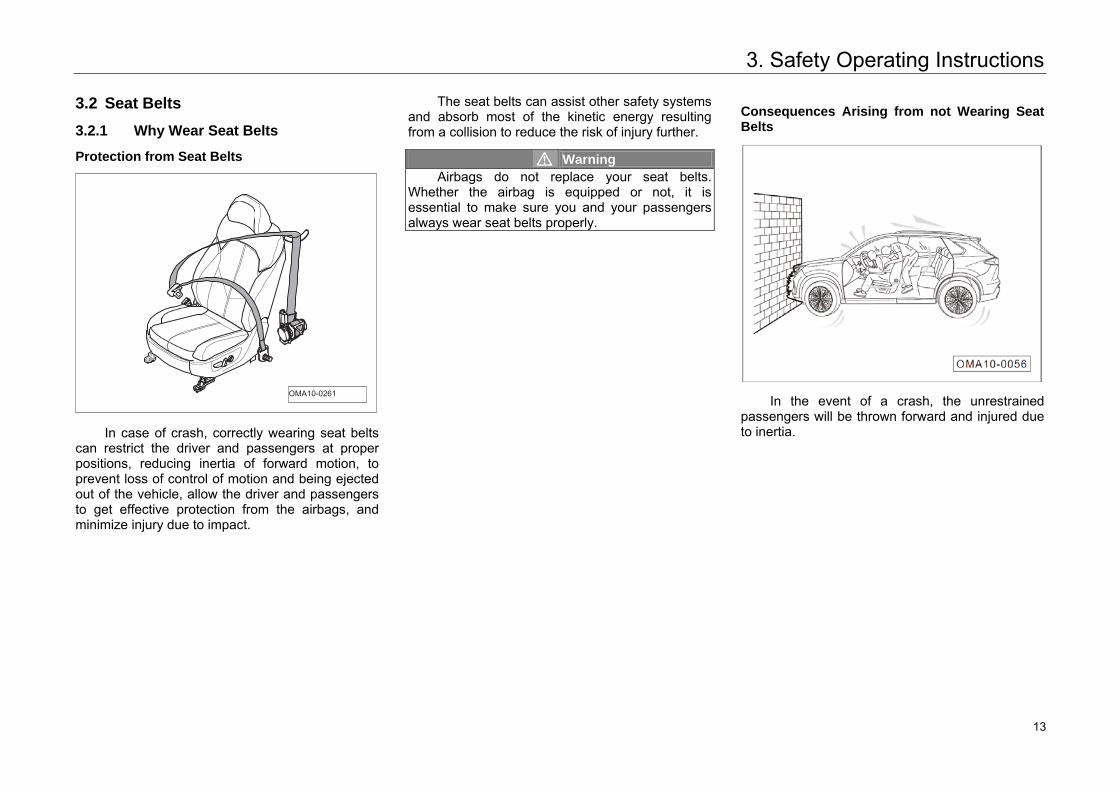
Protection from Seat Belts
In case of crash, correctly wearing seat belts can restrict the driver and passengers at proper positions, reducing inertia of forward motion, to prevent loss of control of motion and being ejected out of the vehicle, allow the driver and passengers to get effective protection from the airbags, and minimize injury due to impact.
The seat belts can assist other safety systems and absorb most of the kinetic energy resulting from a collision to reduce the risk of injury further.
Warning Airbags do not replace your seat belts.
Whether the airbag is equipped or not, it is essential to make sure you and your passengers always wear seat belts properly.
Consequences Arising from not Wearing Seat Belts
In the event of a crash, the unrestrained passengers will be thrown forward and injured due to inertia.
OMA10-0261
13 13
3. Safety Operating Instructions
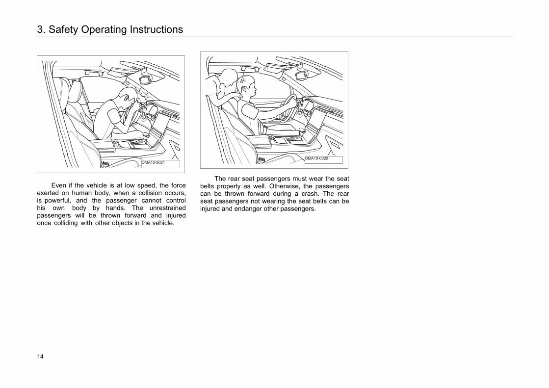
Even if the vehicle is at low speed, the force exerted on human body, when a collision occurs, is powerful, and the passenger cannot control his own body by hands. The unrestrained passengers will be thrown forward and injured once colliding with other objects in the vehicle.
The rear seat passengers must wear the seat belts properly as well. Otherwise, the passengers can be thrown forward during a crash. The rear seat passengers not wearing the seat belts can be injured and endanger other passengers.
OMA10-0021 OMA10-0020
14 14
3. Safety Operating Instructions
3.2.2 Seat Belt
Seat Belt Indicator Light
1 :Driver seat belt indicator light.
2 :Front passenger seat belt indicator light
When the ignition switch is at the "ON" position, if the driver or front passenger does not fasten the seat belt, the corresponding indicator light on the instrument cluster will turn on with alarm message.
Caution Before starting driving, check whether there
are any heavy on the seat to prevent the system from mistaking that there is passenger on it and giving a false alarm.
When the ignition switch is at the "ON" position, there are the following alarm messages:
– When the vehicle speed is less than 20km/h, ifthe driver or front passenger does not fastenhis/her seat belt, the corresponding indicatorlight on the instrument cluster will flash about6s and then stay on.
– When the vehicle speed is less than 20km/h, ifthe driver or front passenger does not fastenhis/her seat belt, the corresponding indicatorlight on the instrument cluster will flash about20s and then stay on, and the beeper alsosounds continuously.
Caution If the above alarm messages appear when the
seat belts are fastened correctly, the seat belt device may fail. Please go to an authorized GAC Motor's dealer timely to have your vehicle checked and repaired.
3. : Rear seat belt indicator light*
If the rear seat belt indicator light turns white,it indicates that the seat belts are fastened; while if it turns red, it indicates that the seat belts are not fastened or the safety belt system fails. If the indicator light still stays red when the seat belts are fastened correctly, the seat belt device may fail. Please go to an authorized GAC Motor's dealer timely to have your vehicle checked and repaired.
The rear seat belt indicator light goes off after 35s, and goes on again in the following cases:
– When the engine starts, the rear passengersdo not wear the seat belts.
– When the rear doors are opened/closed, therear passengers do not wear the seat belts.
– The rear passengers wear or unbuckle theseat belts.
15 15
3. Safety Operating Instructions
Seat Belt Pretensioner Equipment
The seat belt pretensioner equipment can reduce the pressure exerted by the seat belt on the chest and improve the protection performance.
– The seat belt restrains the driver andpassengers to sit in a suitable position,preventing the body over tilting forward beforethe collision.
– The seat belt pretensioner equipment will beactivated by the electronic control unit in theevent of a severe collision, and then thepretensioner equipment will drive the seatbeltwebbing tighten by immediate pulling back.
– In the event of collision, the driver's body willmove forward then the seat belt pretensionersactivate, to make the restraining force to thebody at a certain range, preventing a furtherinjury towards the driver; at the same time, theseat belt pretensioners activate in conjunctionwith the airbag to provide an optimalprotection.
Hint • When being initiated, the seat belt
pretensioner equipment releases littleharmless smoke and generates sound, whichis normal.
• After collision, initiated pretensioner cannot bereused, and indicator light of thesupplemental restraint system (SRS) will stayon. Please contact an authorized GACMotor's dealer for replacement.
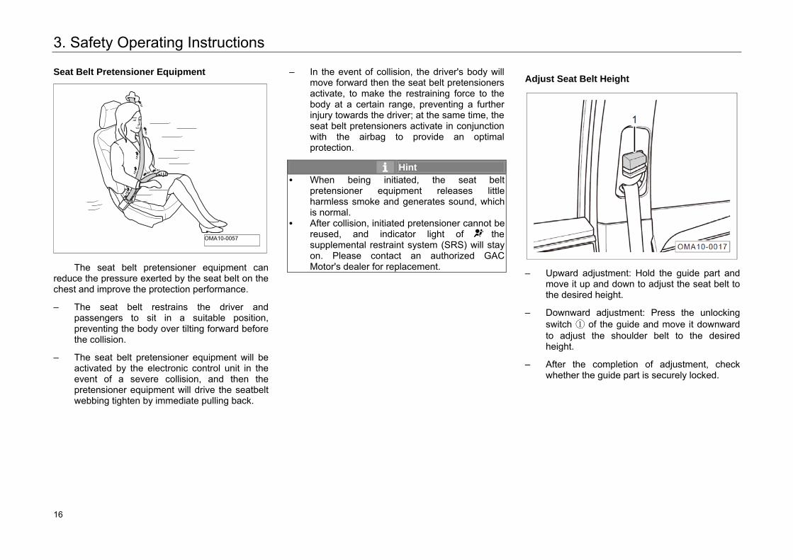
Adjust Seat Belt Height
– Upward adjustment: Hold the guide part andmove it up and down to adjust the seat belt tothe desired height.
– Downward adjustment: Press the unlockingswitch ① of the guide and move it downwardto adjust the shoulder belt to the desiredheight.
– After the completion of adjustment, checkwhether the guide part is securely locked.
OMA10-0057
16 16
3. Safety Operating Instructions
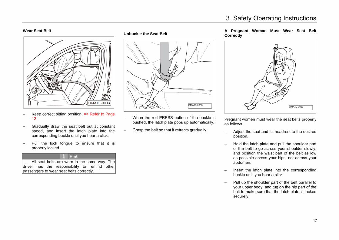
Wear Seat Belt
– Keep correct sitting position. => Refer to Page12
– Gradually draw the seat belt out at constantspeed, and insert the latch plate into thecorresponding buckle until you hear a click.
– Pull the lock tongue to ensure that it isproperly locked.
Hint All seat belts are worn in the same way. The
driver has the responsibility to remind other passengers to wear seat belts correctly.
Unbuckle the Seat Belt
– When the red PRESS button of the buckle ispushed, the latch plate pops up automatically.
– Grasp the belt so that it retracts gradually.
A Pregnant Woman Must Wear Seat Belt Correctly
Pregnant women must wear the seat belts properly as follows.
– Adjust the seat and its headrest to the desiredposition.
– Hold the latch plate and pull the shoulder partof the belt to go across your shoulder slowly,and position the waist part of the belt as lowas possible across your hips, not across yourabdomen.
– Insert the latch plate into the correspondingbuckle until you hear a click.
– Pull up the shoulder part of the belt parallel toyour upper body, and tug on the hip part of thebelt to make sure that the latch plate is lockedsecurely.
OMA10-0058 OMA10-0059
17 17
3. Safety Operating Instructions
Warning To reduce injury risk of the passengers in
case of emergency braking or accident, please observe the following precautions: • Be sure you and your passengers wear seat
belts properly before driving.• Never share the seat belt. Two people
(including children) should never use the same seat belt.
• Never excessively incline the front seat backrest for comfort.
• Never put the shoulder part of the seat belt below or behind the arm.
• Be sure to insert the latch plate into its own buckle. Never insert it into other buckles.
• Do not unfasten the seat belt until the vehicleis completely stationary.
18 18
3. Safety Operating Instructions
3.3 SRS System
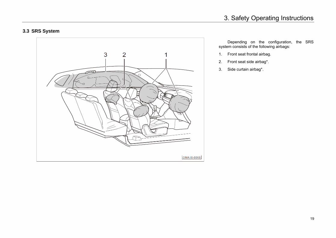
Depending on the configuration, the SRS system consists of the following airbags:
1. Front seat frontal airbag.
2. Front seat side airbag*.
3. Side curtain airbag*.
19 19
3. Safety Operating Instructions
Supplemental restraint system (SRS) indicator light
Switch the Start or Ignition switch to the "ON" position, the indicator light illuminates for a few seconds then extinguishes after self-checking.
The indicator light indicates a fault developing in the system in one of the following conditions:
1. After the Start switch is switched to "ON"position, the indicator light does not illuminate.
2. After the ignition switch is switched to the"ON" position, the indicator light does not gooff after self-check of the system.
3. After the ignition switch is switched to "ON"position, the indicator light illuminates againafter turning off.
4. When the vehicle is running, the indicator lightwill be illuminated or flash.
Warning • Do not repair, adjust or modify any airbags by
yourself without authorization.• An airbag inflates only once. If the airbag ever
inflates during a crash, it must be replaced byan authorized GAC Motor's dealer.
• If the SRS system fails, go to your authorizedGAC Motor's dealer immediately to havethe system checked/repaired. Otherwise, thecontrol unit system may not trigger theairbags or trigger the airbags abnormallyduring a collision.
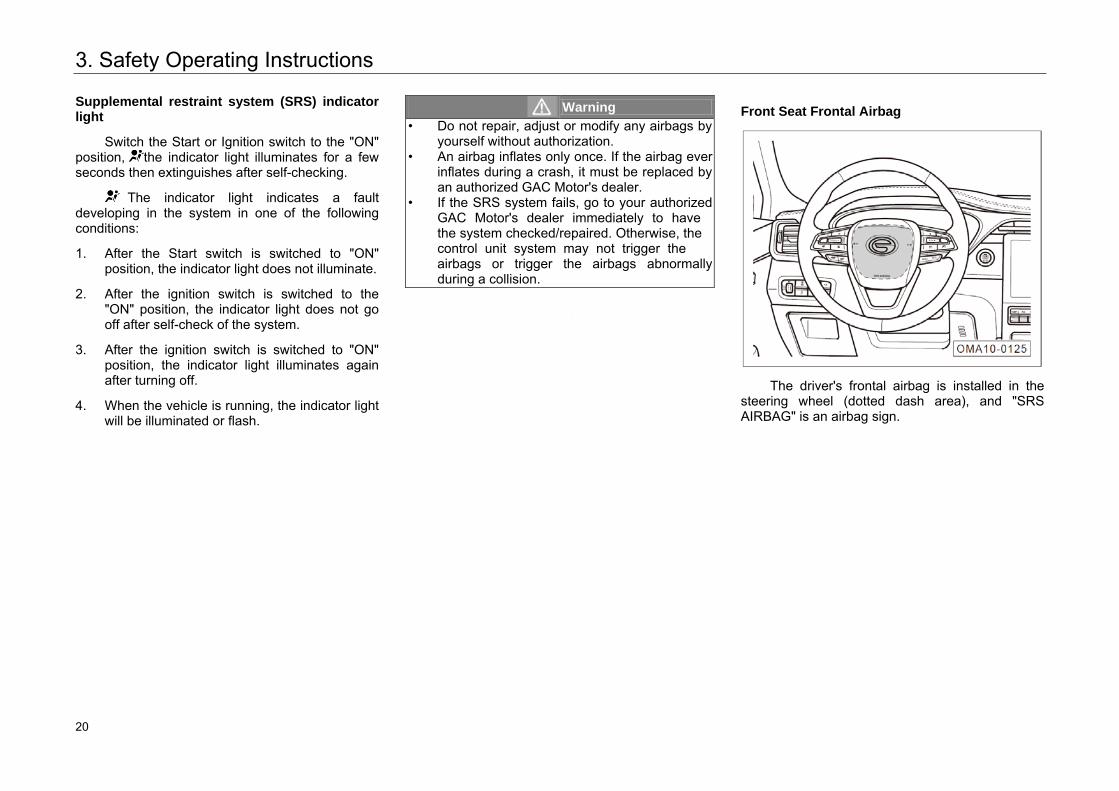
Front Seat Frontal Airbag
The driver's frontal airbag is installed in the steering wheel (dotted dash area), and "SRS AIRBAG" is an airbag sign.
20 20
3. Safety Operating Instructions
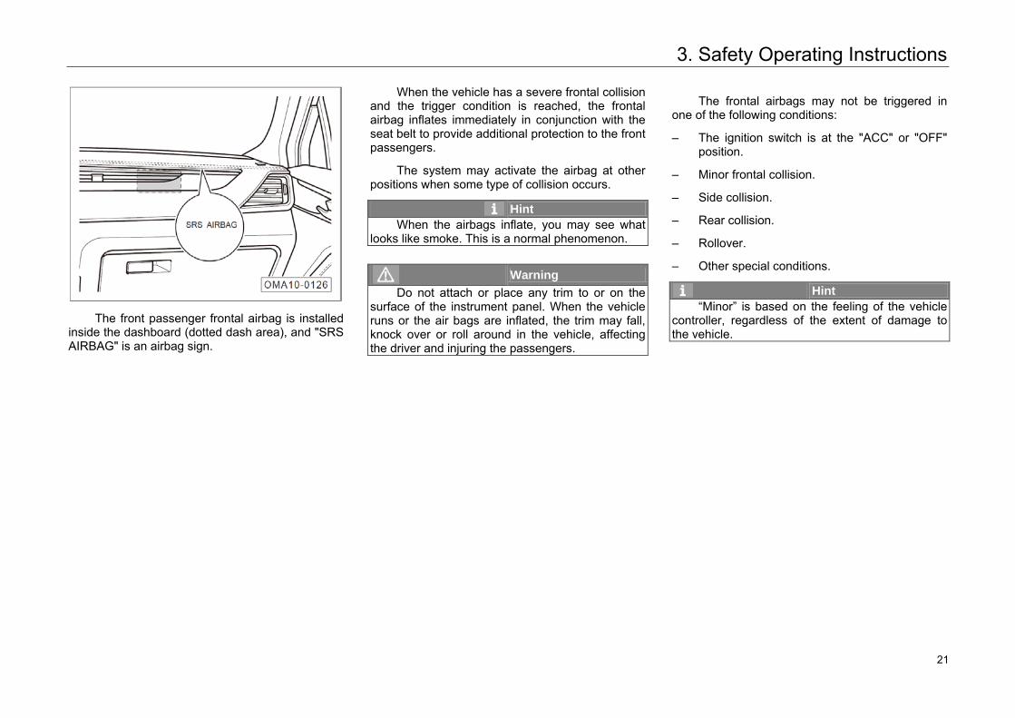
The front passenger frontal airbag is installed inside the dashboard (dotted dash area), and "SRS AIRBAG" is an airbag sign.
When the vehicle has a severe frontal collision and the trigger condition is reached, the frontal airbag inflates immediately in conjunction with the seat belt to provide additional protection to the front passengers.
The system may activate the airbag at other positions when some type of collision occurs.
Hint When the airbags inflate, you may see what
looks like smoke. This is a normal phenomenon.
Warning Do not attach or place any trim to or on the
surface of the instrument panel. When the vehicle runs or the air bags are inflated, the trim may fall, knock over or roll around in the vehicle, affecting the driver and injuring the passengers.
The frontal airbags may not be triggered in one of the following conditions:
– The ignition switch is at the "ACC" or "OFF"position.
– Minor frontal collision.
– Side collision.
– Rear collision.
– Rollover.
– Other special conditions.
Hint “Minor” is based on the feeling of the vehicle
controller, regardless of the extent of damage to the vehicle.
21 21
3. Safety Operating Instructions
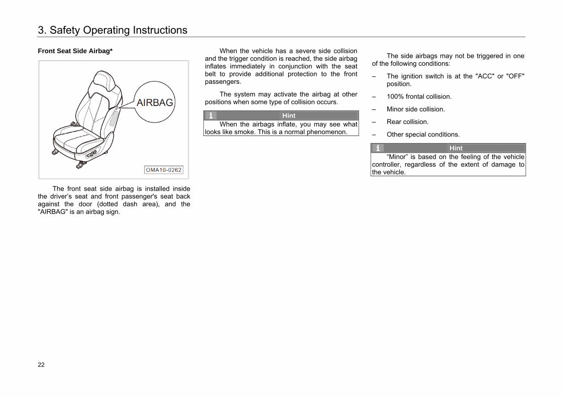
Front Seat Side Airbag*
The front seat side airbag is installed inside the driver’s seat and front passenger's seat back against the door (dotted dash area), and the "AIRBAG" is an airbag sign.
When the vehicle has a severe side collision and the trigger condition is reached, the side airbag inflates immediately in conjunction with the seat belt to provide additional protection to the front passengers.
The system may activate the airbag at other positions when some type of collision occurs.
Hint When the airbags inflate, you may see what
looks like smoke. This is a normal phenomenon.
The side airbags may not be triggered in one of the following conditions:
– The ignition switch is at the "ACC" or "OFF"position.
– 100% frontal collision.
– Minor side collision.
– Rear collision.
– Other special conditions.
Hint “Minor” is based on the feeling of the vehicle
controller, regardless of the extent of damage to the vehicle.
22 22
3. Safety Operating Instructions
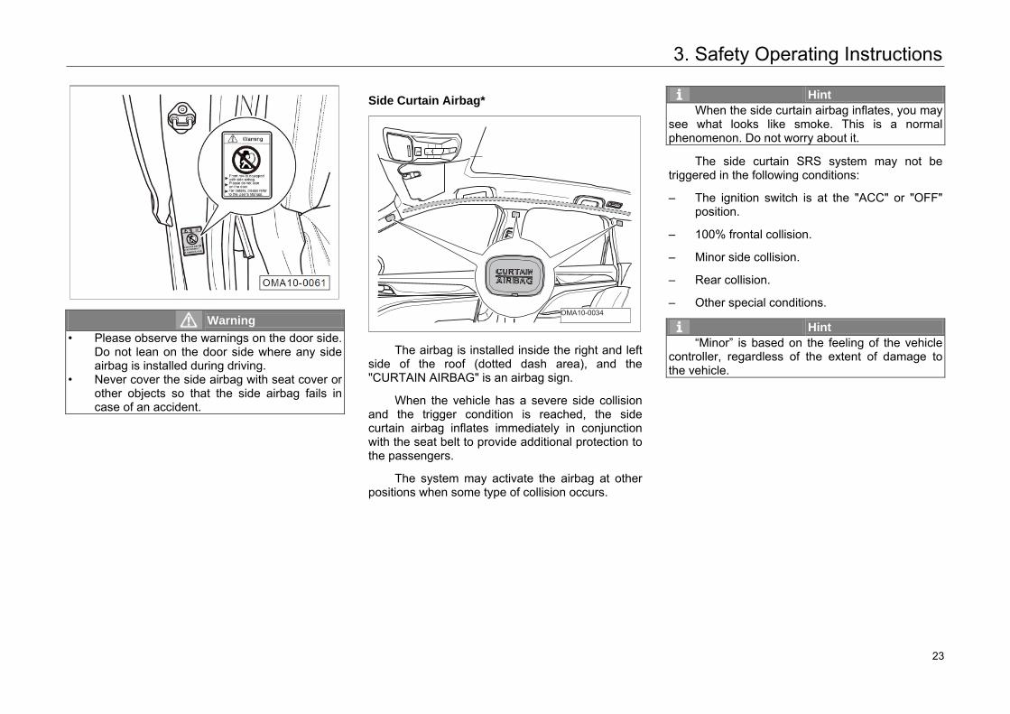
Warning • Please observe the warnings on the door side.
Do not lean on the door side where any side airbag is installed during driving.
• Never cover the side airbag with seat cover or other objects so that the side airbag fails in case of an accident.
Side Curtain Airbag*
The airbag is installed inside the right and left side of the roof (dotted dash area), and the "CURTAIN AIRBAG" is an airbag sign.
When the vehicle has a severe side collision and the trigger condition is reached, the side curtain airbag inflates immediately in conjunction with the seat belt to provide additional protection to the passengers.
The system may activate the airbag at other positions when some type of collision occurs.
Hint When the side curtain airbag inflates, you may
see what looks like smoke. This is a normal phenomenon. Do not worry about it.
The side curtain SRS system may not be triggered in the following conditions:
– The ignition switch is at the "ACC" or "OFF"position.
– 100% frontal collision.
– Minor side collision.
– Rear collision.
– Other special conditions.
Hint “Minor” is based on the feeling of the vehicle
controller, regardless of the extent of damage to the vehicle.
OMA10-0034
23 23
3. Safety Operating Instructions
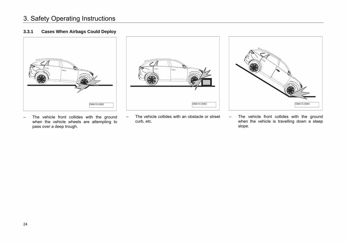
3.3.1 Cases When Airbags Could Deploy
– The vehicle front collides with the ground
when the vehicle wheels are attempting to pass over a deep trough.
– The vehicle collides with an obstacle or street
curb, etc.
– The vehicle front collides with the ground
when the vehicle is travelling down a steep slope.
OMA10-0062 OMA10-0063 OMA10-0064
24 24
3. Safety Operating Instructions
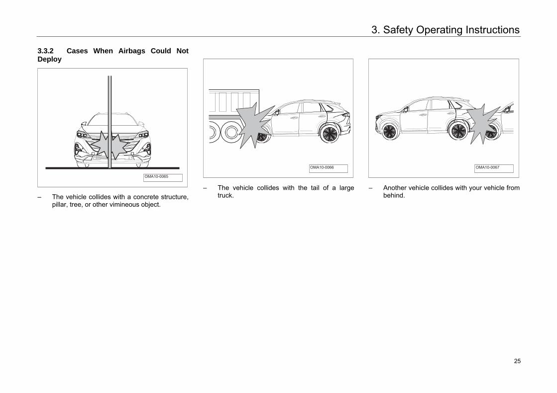
3.3.2 Cases When Airbags Could Not Deploy
– The vehicle collides with a concrete structure,pillar, tree, or other vimineous object.
– The vehicle collides with the tail of a largetruck.
– Another vehicle collides with your vehicle frombehind.
OMA10-0065
OMA10-0066 OMA10-0067
25 25
3. Safety Operating Instructions
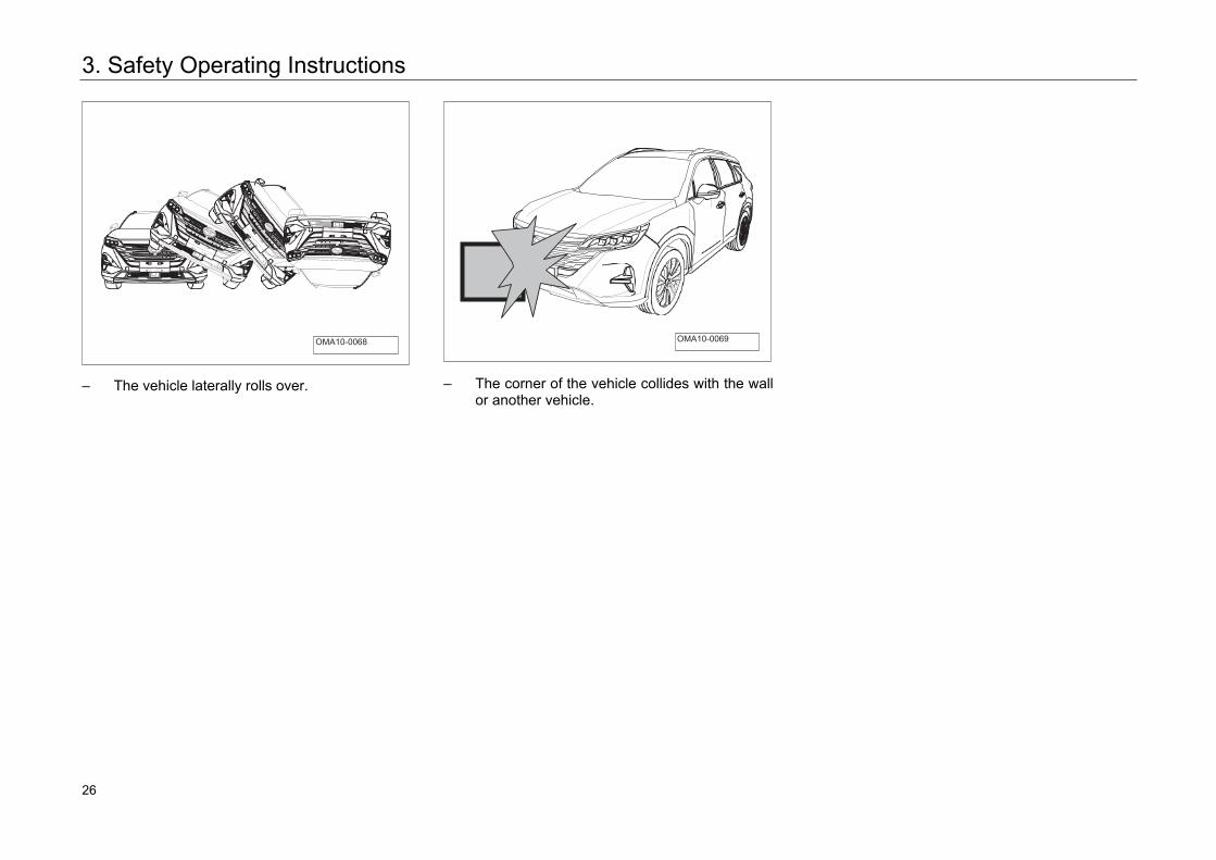
– The vehicle laterally rolls over. – The corner of the vehicle collides with the wallor another vehicle.
OMA10-0068 OMA10-0069
26 26
3. Safety Operating Instructions
3.4 Safety Rules for Children
3.4.1 General Instructions
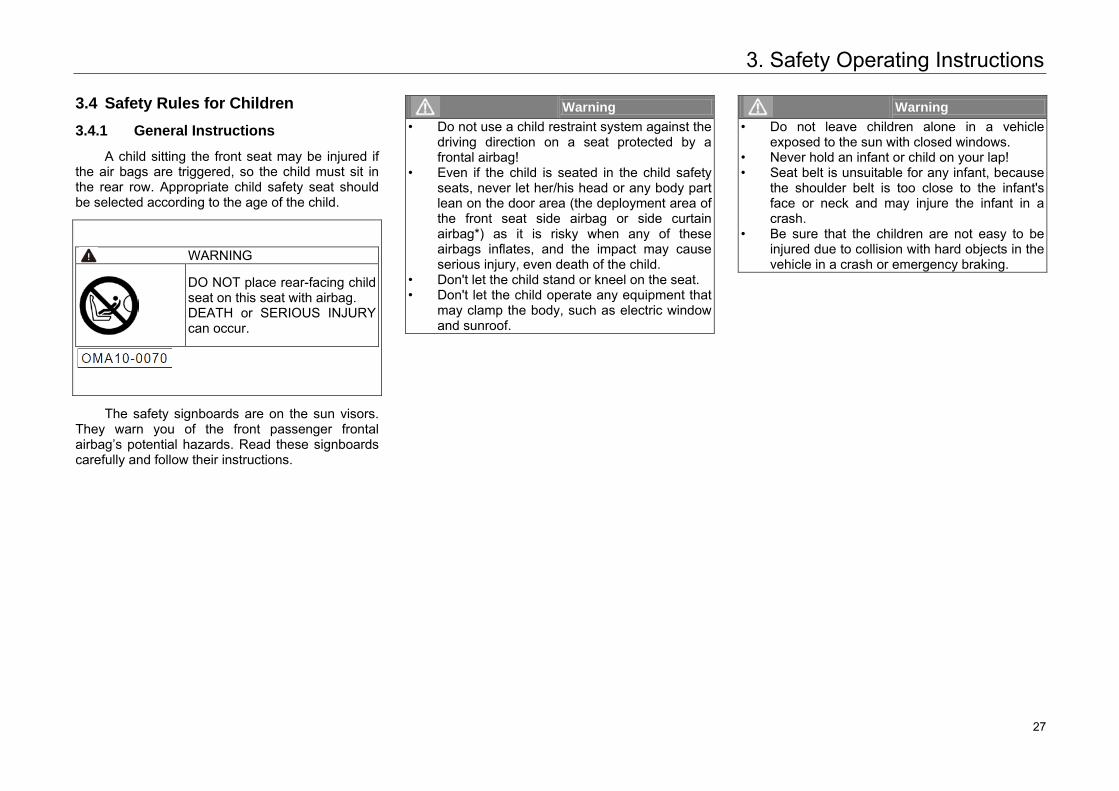
A child sitting the front seat may be injured if the air bags are triggered, so the child must sit in the rear row. Appropriate child safety seat should be selected according to the age of the child.
WARNING
DO NOT place rear-facing child seat on this seat with airbag. DEATH or SERIOUS INJURY can occur.
The safety signboards are on the sun visors. They warn you of the front passenger frontal airbag’s potential hazards. Read these signboards carefully and follow their instructions.
Warning • Do not use a child restraint system against the
driving direction on a seat protected by afrontal airbag!
• Even if the child is seated in the child safety seats, never let her/his head or any body part lean on the door area (the deployment area ofthe front seat side airbag or side curtain airbag*) as it is risky when any of these airbags inflates, and the impact may cause serious injury, even death of the child.
• Don't let the child stand or kneel on the seat.• Don't let the child operate any equipment that
may clamp the body, such as electric windowand sunroof.
Warning • Do not leave children alone in a vehicle
exposed to the sun with closed windows.• Never hold an infant or child on your lap!• Seat belt is unsuitable for any infant, because
the shoulder belt is too close to the infant'sface or neck and may injure the infant in acrash.
• Be sure that the children are not easy to be injured due to collision with hard objects in the vehicle in a crash or emergency braking.
27 27
3. Safety Operating Instructions
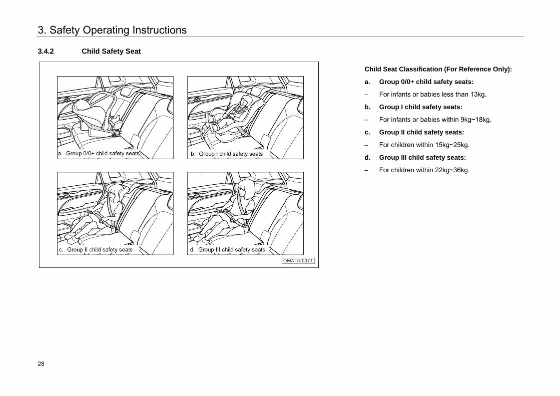
3.4.2 Child Safety Seat
Child Seat Classification (For Reference Only):
a. Group 0/0+ child safety seats:
– For infants or babies less than 13kg.
b. Group I child safety seats:
– For infants or babies within 9kg~18kg.
c. Group II child safety seats:
– For children within 15kg~25kg.
d. Group III child safety seats:
– For children within 22kg~36kg.
28 28
3. Safety Operating Instructions
3.4.3 Information about Child Safety Seat
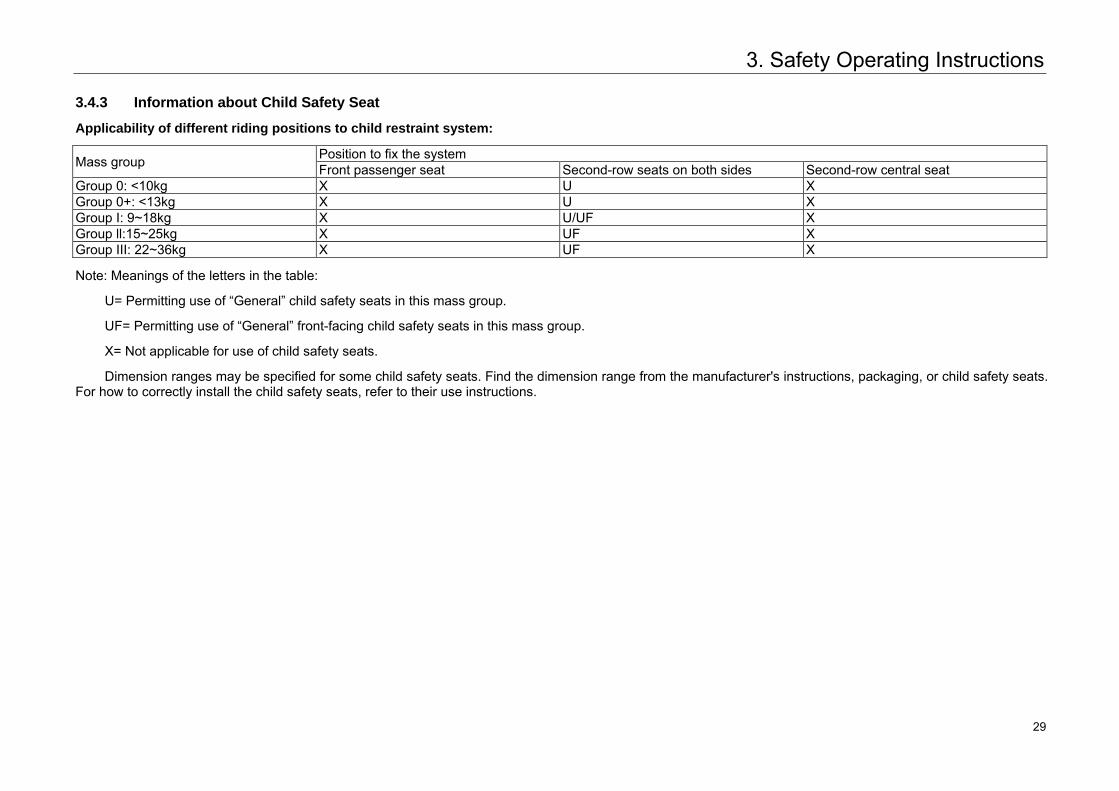
Applicability of different riding positions to child restraint system:
Mass group Position to fix the system Front passenger seat Second-row seats on both sides Second-row central seat
Group 0: <10kg X U X Group 0+: <13kg X U X Group I: 9~18kg X U/UF X Group ll:15~25kg X UF X Group III: 22~36kg X UF X
Note: Meanings of the letters in the table:
U= Permitting use of “General” child safety seats in this mass group.
UF= Permitting use of “General” front-facing child safety seats in this mass group.
X= Not applicable for use of child safety seats.
Dimension ranges may be specified for some child safety seats. Find the dimension range from the manufacturer's instructions, packaging, or child safety seats. For how to correctly install the child safety seats, refer to their use instructions.
29 29
3. Safety Operating Instructions
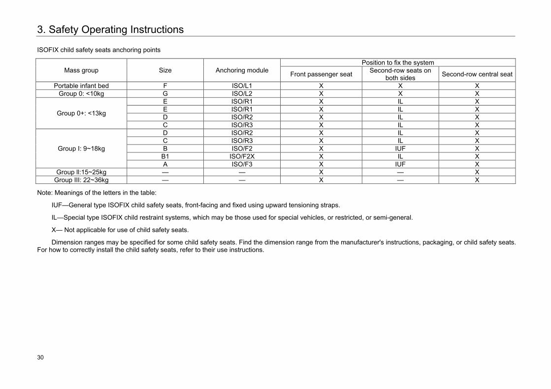
ISOFIX child safety seats anchoring points
Mass group Size Anchoring module Position to fix the system
Front passenger seat Second-row seats on both sides Second-row central seat
Portable infant bed F ISO/L1 X X X Group 0: <10kg G ISO/L2 X X X
Group 0+: <13kg
E ISO/R1 X IL X E ISO/R1 X IL X D ISO/R2 X IL X C ISO/R3 X IL X
Group I: 9~18kg
D ISO/R2 X IL X C ISO/R3 X IL X B ISO/F2 X IUF X
B1 ISO/F2X X IL X A ISO/F3 X IUF X
Group ll:15~25kg — — X — X Group III: 22~36kg — — X — X
Note: Meanings of the letters in the table:
IUF—General type ISOFIX child safety seats, front-facing and fixed using upward tensioning straps.
IL—Special type ISOFIX child restraint systems, which may be those used for special vehicles, or restricted, or semi-general.
X— Not applicable for use of child safety seats.
Dimension ranges may be specified for some child safety seats. Find the dimension range from the manufacturer's instructions, packaging, or child safety seats. For how to correctly install the child safety seats, refer to their use instructions.
30 30
3. Safety Operating Instructions
3.4.4 Install a Child Seat Properly
Child seat generally has three types of installations, i.e. three-point seat belt, ISOFIX system, and LATCH system. The installation of three-point seat belt is that using its own seat belts to tighten the child seat, as shown in the figure "Child Seat Classifications". Installation of ISOFIX and LATCH system is that using the child seat fixing device to fasten and lock with the remaining anchor points in the vehicle.
Hint Method for installing a certain kind of child
safety seats is introduced here only for reference purpose. When installing child safety seats, be sure to refer to their use instructions and observe the installation instructions provided by the manufacturer.
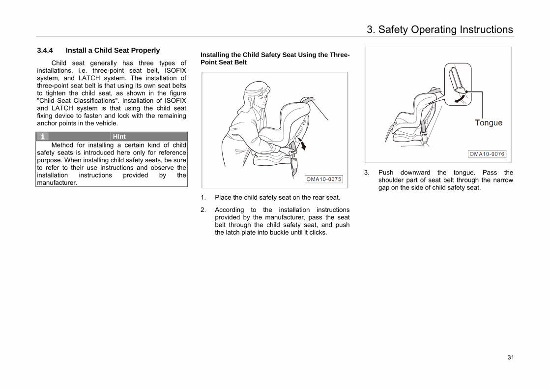
Installing the Child Safety Seat Using the Three-Point Seat Belt
1. Place the child safety seat on the rear seat.
2. According to the installation instructionsprovided by the manufacturer, pass the seatbelt through the child safety seat, and pushthe latch plate into buckle until it clicks.
3. Push downward the tongue. Pass theshoulder part of seat belt through the narrowgap on the side of child safety seat.
31 31
3. Safety Operating Instructions
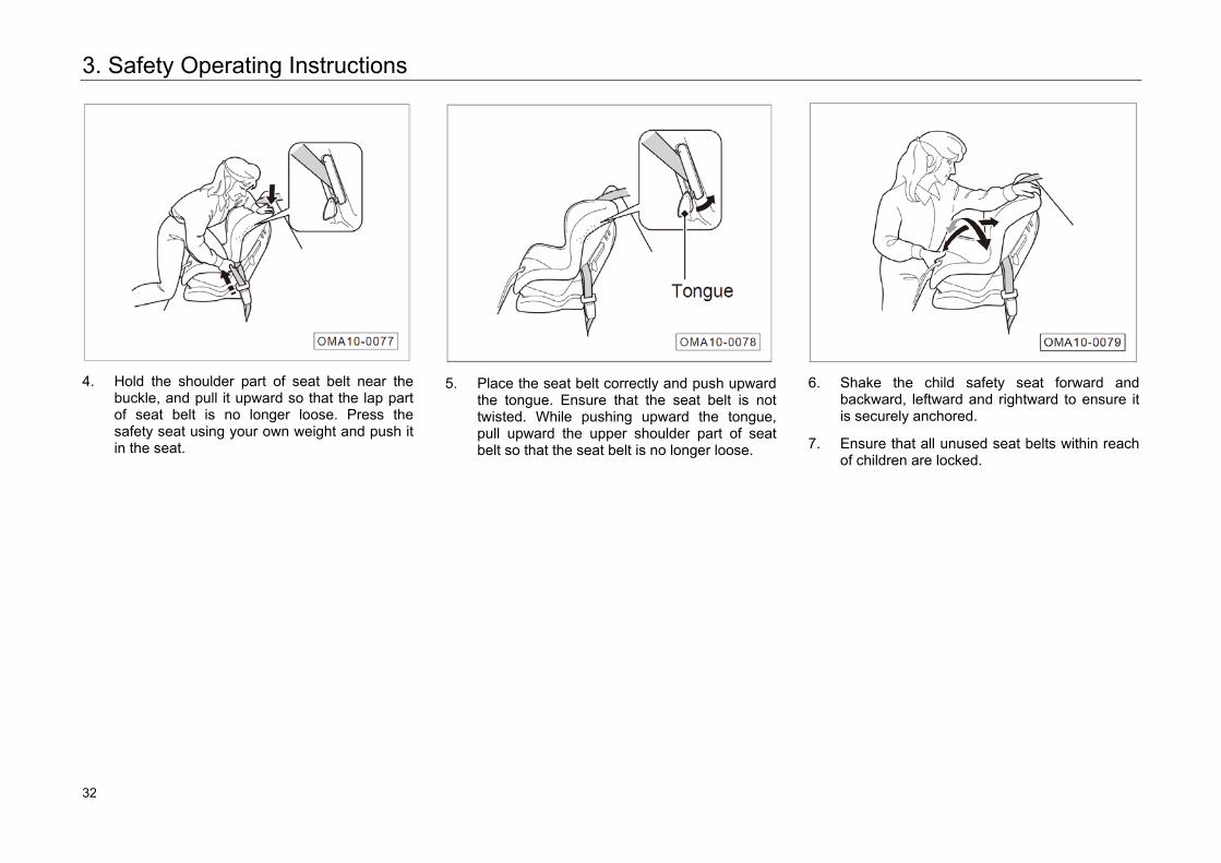
4. Hold the shoulder part of seat belt near the
buckle, and pull it upward so that the lap part of seat belt is no longer loose. Press the safety seat using your own weight and push it in the seat.
5. Place the seat belt correctly and push upward
the tongue. Ensure that the seat belt is not twisted. While pushing upward the tongue, pull upward the upper shoulder part of seat belt so that the seat belt is no longer loose.
6. Shake the child safety seat forward and
backward, leftward and rightward to ensure it is securely anchored.
7. Ensure that all unused seat belts within reach of children are locked.
32 32
3. Safety Operating Instructions
If the child safety seat has no means for fixing the seat belt, install a locking clip to the seat belt.
– With steps 1 and 2 completed, pull upward theshoulder part of seat belt so that the lap part ofseat belt is no longer loose.
– Tightly hold the seat belt near the latch plate.Hold together the two parts of seat belt so that theycannot slide out of the latch plate. Release the seatbelt from the buckle.
Install the locking clip as shown in the figure. With the clip as close to the latch plate as possible, insert the latch plate in the buckle. Perform steps 6 and 7.
Install the ISOFIX System or LATCH System
The installing methods for both ISOFIX system and LATCH system are similar, LATCH system has one more anchor point than ISOFIX system, but the lower anchor point for both systems can be interchangeable. The seats in the rear row for this vehicle are equipped with LATCH system. Therefore, both LATCH and ISOFIX child seat can be installed.
Warning
When driving, be sure to restrain the child in the child seat suitable for the child's weight and body type.
• The anchoring device for child seat of this vehicle can only be used to fix the child seat.
• Do not connect any other things like fastening belt, hard or sharp objects or other things other than child seat items to the anchoring device. Otherwise, it may endanger the child’slife when accident occurs.
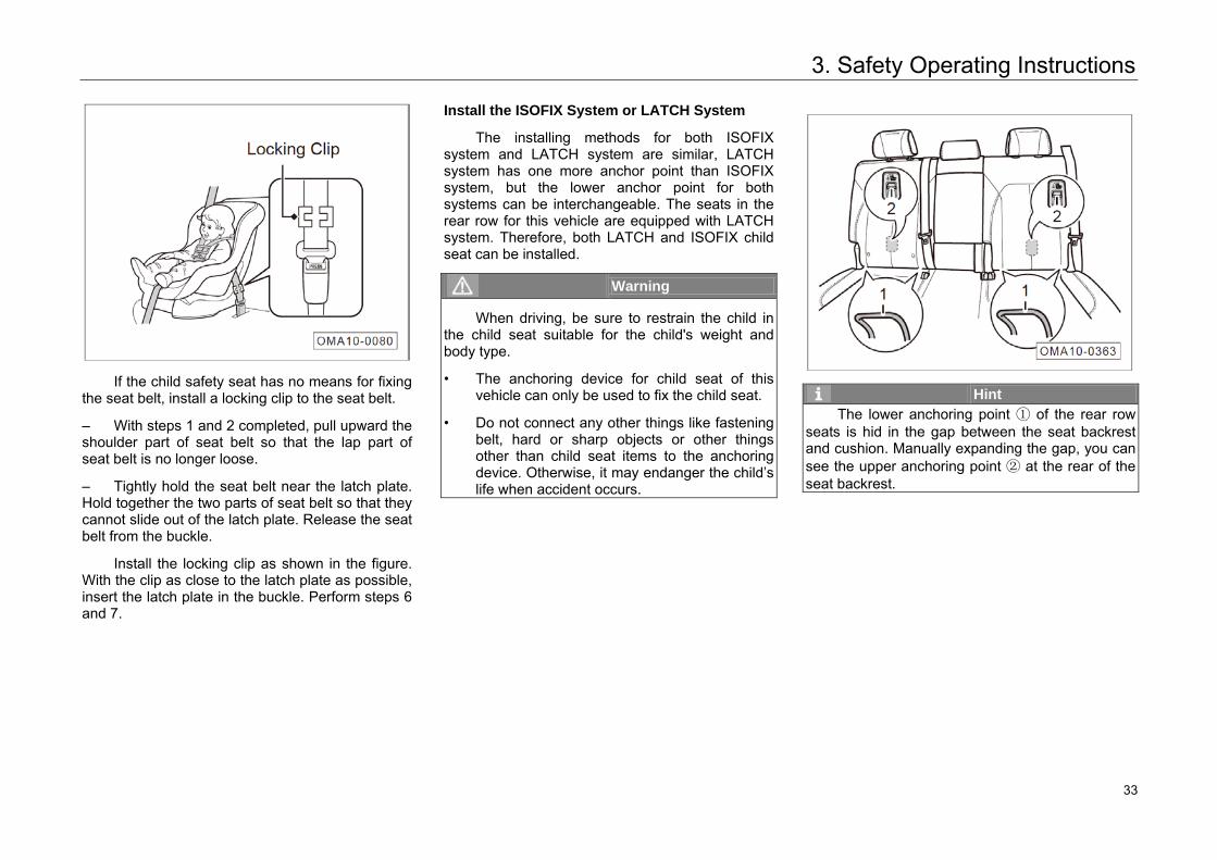
Hint The lower anchoring point ① of the rear row
seats is hid in the gap between the seat backrest and cushion. Manually expanding the gap, you can see the upper anchoring point ② at the rear of the seat backrest.
33 33
3. Safety Operating Instructions
2
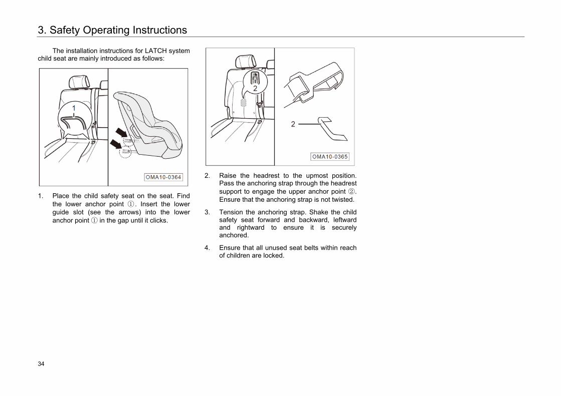
The installation instructions for LATCH system child seat are mainly introduced as follows:
1. Place the child safety seat on the seat. Find
the lower anchor point ① . Insert the lower guide slot (see the arrows) into the lower anchor point ① in the gap until it clicks.
2. Raise the headrest to the upmost position.
Pass the anchoring strap through the headrest support to engage the upper anchor point ②. Ensure that the anchoring strap is not twisted.
3. Tension the anchoring strap. Shake the child safety seat forward and backward, leftward and rightward to ensure it is securely anchored.
4. Ensure that all unused seat belts within reach of children are locked.
34 34
3. Safety Operating Instructions
3.5 Dangerous Exhaust Gases
Carbon Monoxide
Exhaust gases from the engine contains carbon monoxide, a toxic gas. Please use the vehicle properly to prevent carbon monoxide from entering the vehicle.
Please go to your authorized GAC Motor's dealer to check whether the exhaust system is normal under the following circumstances:
– Abnormal noise coming out of exhaust system.
– Abnormal color of exhaust gases coming outof exhaust system.
Driving with the trunk open can cause exhaust gases entering the vehicle resulting in danger. If you have to drive with the trunk open, open all windows and turn on the air conditioning system.
1. Select the external air circulation mode.
2. Select the mode.
3. Set the fan speed to maximum.
If you sit in the vehicle with the engine running,operate the air conditioning system in the same manner.
Warning • Inhaling carbon monoxide can cause
unconsciousness, even death.• Running the engine in confined areas (such
as garage) can cause rapid accumulation of carbon monoxide. Do not run the engine in confined areas, which will result in high content of carbon monoxide inside the vehicle. Even if the garage door is open, drive away immediately after the engine is started.
35 35
3. Safety Operating Instructions
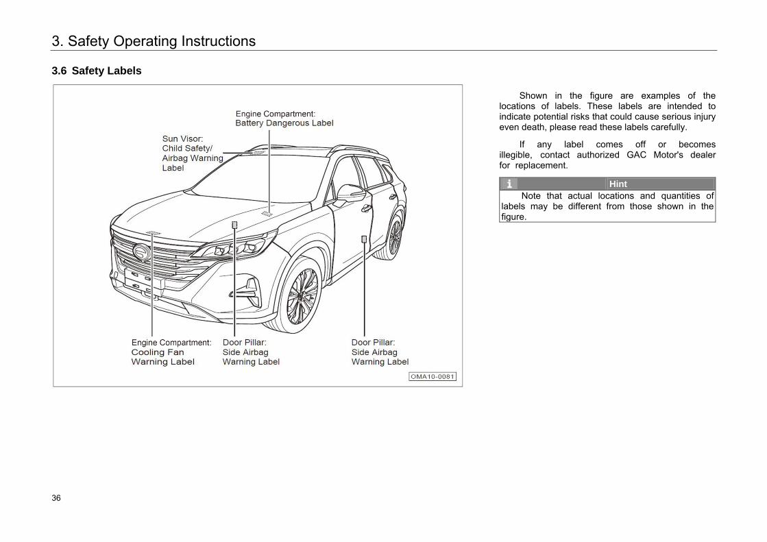
3.6 Safety Labels
Shown in the figure are examples of the locations of labels. These labels are intended to indicate potential risks that could cause serious injury even death, please read these labels carefully.
If any label comes off or becomes illegible, contact authorized GAC Motor's dealer for replacement.
Hint Note that actual locations and quantities of
labels may be different from those shown in the figure.
36 36
4. Operating System and Equipment
4.1 Cab
4.1.1 Steering Wheel
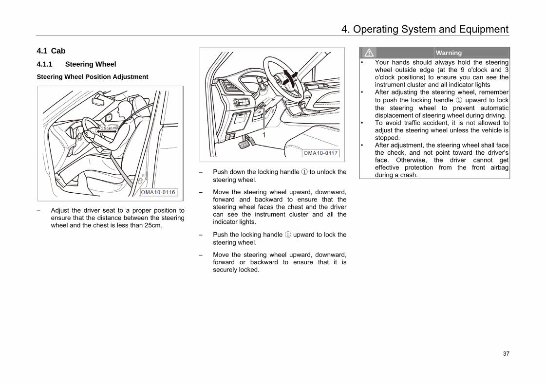
Steering Wheel Position Adjustment
– Adjust the driver seat to a proper position toensure that the distance between the steeringwheel and the chest is less than 25cm.
– Push down the locking handle ① to unlock thesteering wheel.
– Move the steering wheel upward, downward,forward and backward to ensure that thesteering wheel faces the chest and the drivercan see the instrument cluster and all theindicator lights.
– Push the locking handle ① upward to lock thesteering wheel.
– Move the steering wheel upward, downward,forward or backward to ensure that it issecurely locked.
Warning • Your hands should always hold the steering
wheel outside edge (at the 9 o'clock and 3 o'clock positions) to ensure you can see the instrument cluster and all indicator lights
• After adjusting the steering wheel, rememberto push the locking handle ① upward to lockthe steering wheel to prevent automaticdisplacement of steering wheel during driving.
• To avoid traffic accident, it is not allowed to adjust the steering wheel unless the vehicle isstopped.
• After adjustment, the steering wheel shall face the check, and not point toward the driver'sface. Otherwise, the driver cannot get effective protection from the front airbag during a crash.
37 37
4. Operating System and Equipment
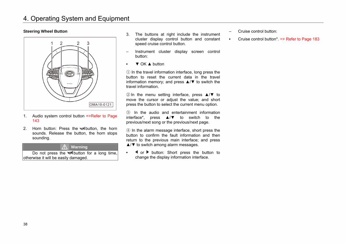
Steering Wheel Button
1. Audio system control button =>Refer to Page143
2. Horn button: Press the button, the hornsounds. Release the button, the horn stopssounding.
Warning Do not press the button for a long time,
otherwise it will be easily damaged.
3. The buttons at right include the instrumentcluster display control button and constantspeed cruise control button.
– Instrument cluster display screen controlbutton:
• ▼ OK ▲ button
① In the travel information interface, long press thebutton to reset the current data in the travelinformation memory; and press ▲/▼ to switch thetravel information.
② In the menu setting interface, press ▲/▼ tomove the cursor or adjust the value; and shortpress the button to select the current menu option.
③ In the audio and entertainment informationinterface*, press ▲/▼ to switch to theprevious/next song or the previous/next page.
④ In the alarm message interface, short press thebutton to confirm the fault information and thenreturn to the previous main interface; and press▲/▼ to switch among alarm messages.
• or button: Short press the button to change the display information interface.
– Cruise control button:
• Cruise control button*. => Refer to Page 183
38 38
4. Operating System and Equipment
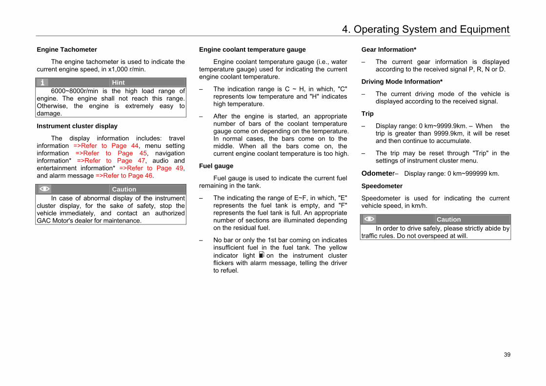
Engine Tachometer
The engine tachometer is used to indicate the current engine speed, in x1,000 r/min.
Hint 6000~8000r/min is the high load range of
engine. The engine shall not reach this range. Otherwise, the engine is extremely easy to damage.
Instrument cluster display
The display information includes: travel information =>Refer to Page 44, menu setting information =>Refer to Page 45, navigation information* =>Refer to Page 47, audio and entertainment information* =>Refer to Page 49, and alarm message =>Refer to Page 46.
Caution In case of abnormal display of the instrument
cluster display, for the sake of safety, stop the vehicle immediately, and contact an authorized GAC Motor's dealer for maintenance.
Engine coolant temperature gauge
Engine coolant temperature gauge (i.e., water temperature gauge) used for indicating the current engine coolant temperature.
– The indication range is C ~ H, in which, "C"represents low temperature and "H" indicateshigh temperature.
– After the engine is started, an appropriatenumber of bars of the coolant temperaturegauge come on depending on the temperature.In normal cases, the bars come on to themiddle. When all the bars come on, thecurrent engine coolant temperature is too high.
Fuel gauge
Fuel gauge is used to indicate the current fuel remaining in the tank.
– The indicating the range of E~F, in which, "E"represents the fuel tank is empty, and "F"represents the fuel tank is full. An appropriatenumber of sections are illuminated dependingon the residual fuel.
– No bar or only the 1st bar coming on indicatesinsufficient fuel in the fuel tank. The yellowindicator light on the instrument clusterflickers with alarm message, telling the driverto refuel.
Gear Information*
– The current gear information is displayedaccording to the received signal P, R, N or D.
Driving Mode Information*
– The current driving mode of the vehicle isdisplayed according to the received signal.
Trip
– Display range: 0 km~9999.9km. – When thetrip is greater than 9999.9km, it will be resetand then continue to accumulate.
– The trip may be reset through "Trip" in thesettings of instrument cluster menu.
Odometer– Display range: 0 km~999999 km.
Speedometer
Speedometer is used for indicating the current vehicle speed, in km/h.
Caution In order to drive safely, please strictly abide by
traffic rules. Do not overspeed at will.
43 39
4. Operating System and Equipment
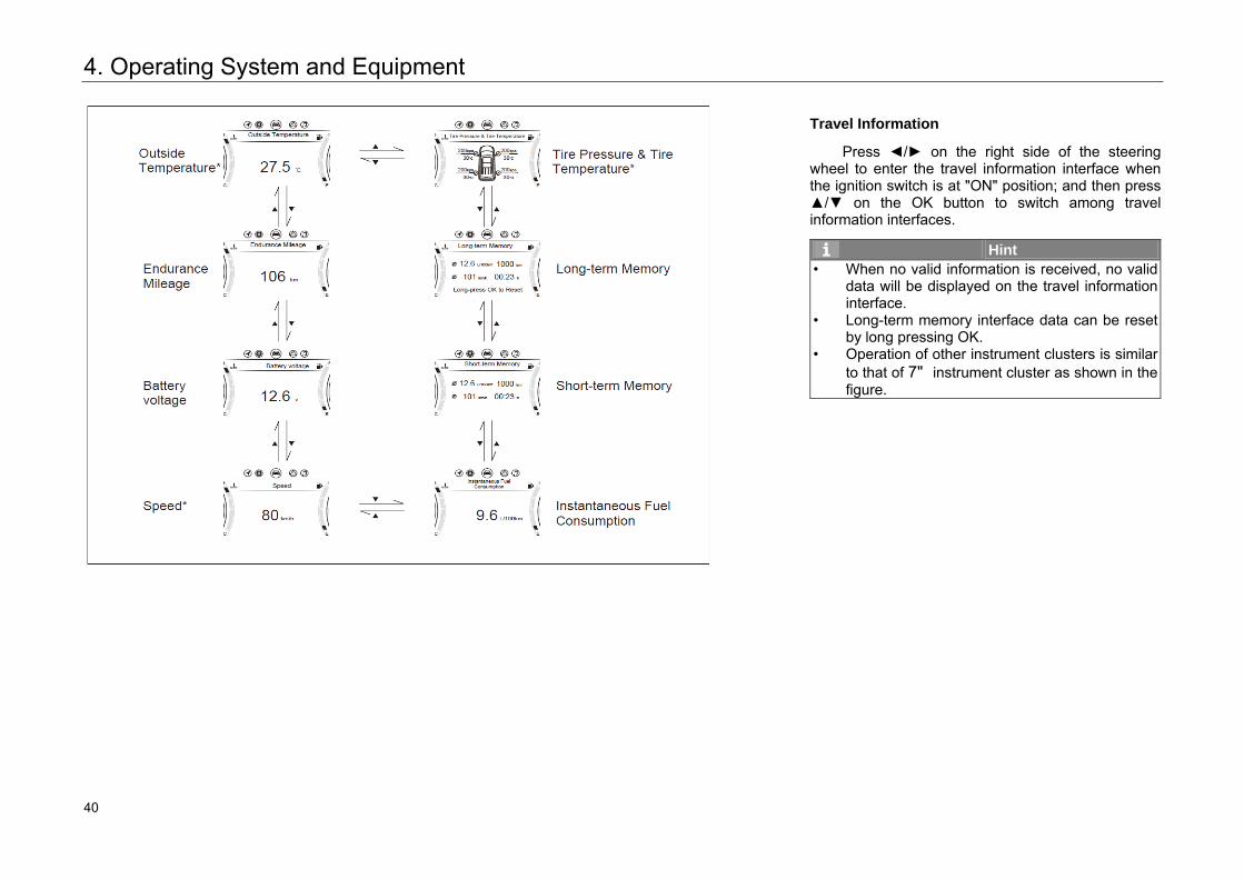
Travel Information
Press ◄/► on the right side of the steering wheel to enter the travel information interface when the ignition switch is at "ON" position; and then press ▲/▼ on the OK button to switch among travelinformation interfaces.
Hint • When no valid information is received, no valid
data will be displayed on the travel information interface.
• Long-term memory interface data can be reset by long pressing OK.
• Operation of other instrument clusters is similar to that of 7" instrument cluster as shown in the figure.
44 40
4. Operating System and Equipment
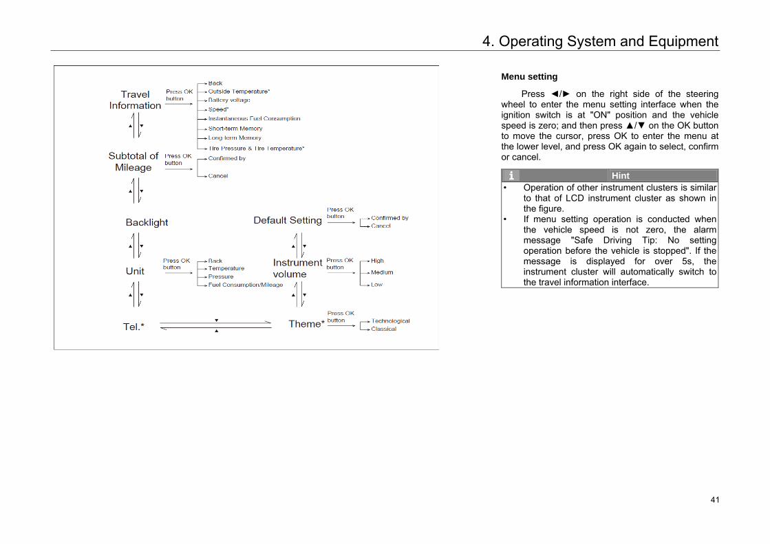
Menu setting
Press ◄/► on the right side of the steering wheel to enter the menu setting interface when the ignition switch is at "ON" position and the vehicle speed is zero; and then press ▲/▼ on the OK button to move the cursor, press OK to enter the menu at the lower level, and press OK again to select, confirm or cancel.
Hint • Operation of other instrument clusters is similar
to that of LCD instrument cluster as shown in the figure.
• If menu setting operation is conducted when the vehicle speed is not zero, the alarm message "Safe Driving Tip: No setting operation before the vehicle is stopped". If themessage is displayed for over 5s, the instrument cluster will automatically switch to the travel information interface.
45 41
4. Operating System and Equipment
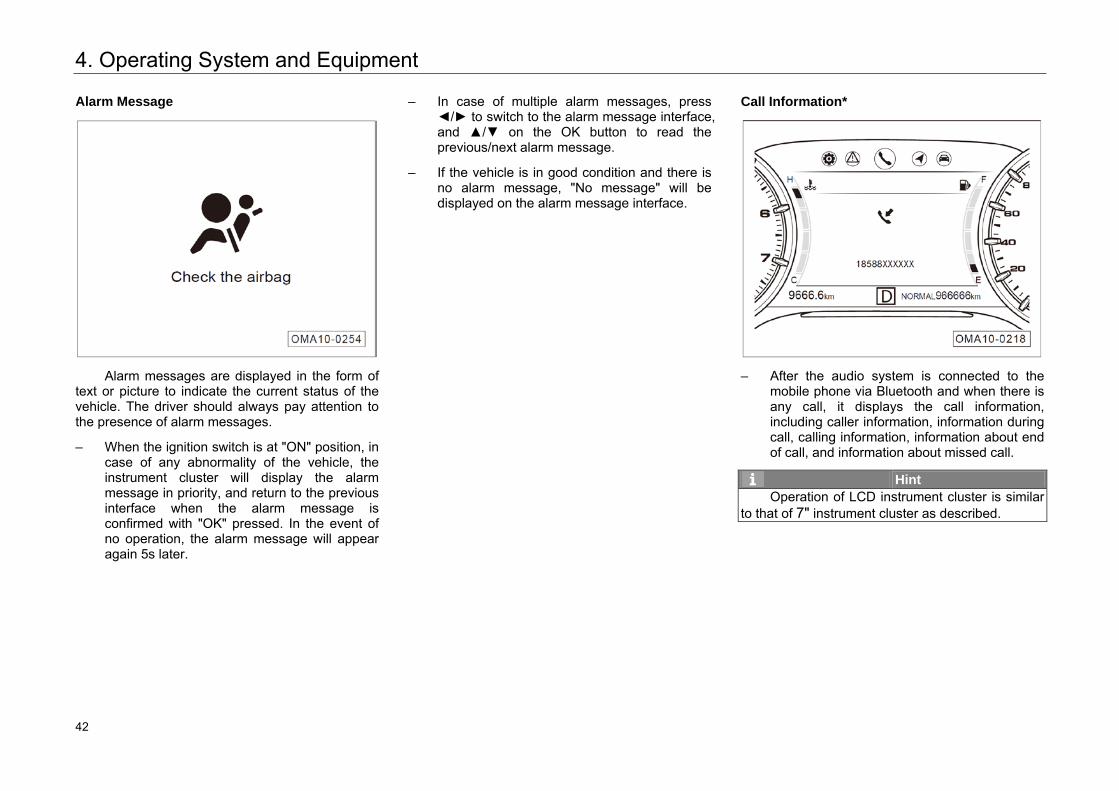
Alarm Message
Alarm messages are displayed in the form of text or picture to indicate the current status of the vehicle. The driver should always pay attention to the presence of alarm messages.
– When the ignition switch is at "ON" position, incase of any abnormality of the vehicle, theinstrument cluster will display the alarmmessage in priority, and return to the previousinterface when the alarm message isconfirmed with "OK" pressed. In the event ofno operation, the alarm message will appearagain 5s later.
– In case of multiple alarm messages, press◄/► to switch to the alarm message interface,and ▲/▼ on the OK button to read theprevious/next alarm message.
– If the vehicle is in good condition and there isno alarm message, "No message" will bedisplayed on the alarm message interface.
Call Information*
– After the audio system is connected to themobile phone via Bluetooth and when there isany call, it displays the call information,including caller information, information duringcall, calling information, information about endof call, and information about missed call.
Hint Operation of LCD instrument cluster is similar
to that of 7" instrument cluster as described.
46 42
4. Operating System and Equipment
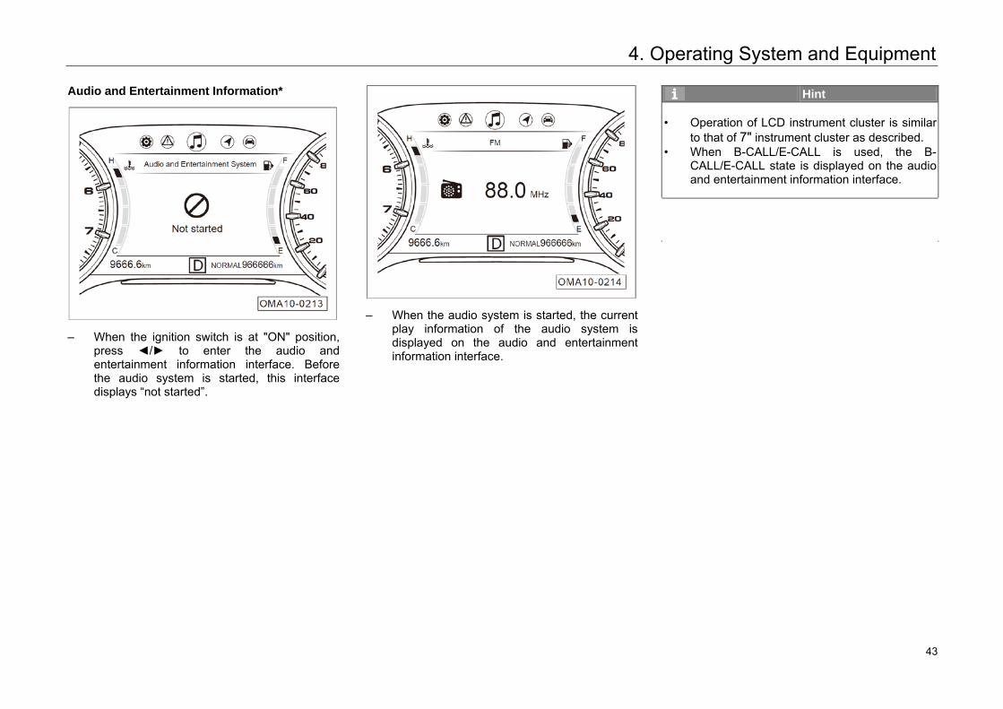
Audio and Entertainment Information*
– When the ignition switch is at "ON" position,press ◄/► to enter the audio andentertainment information interface. Beforethe audio system is started, this interfacedisplays “not started”.
– When the audio system is started, the currentplay information of the audio system isdisplayed on the audio and entertainmentinformation interface.
Hint
• Operation of LCD instrument cluster is similarto that of 7" instrument cluster as described.
• When B-CALL/E-CALL is used, the B-CALL/E-CALL state is displayed on the audioand entertainment information interface.
49 43
4. Operating System and Equipment
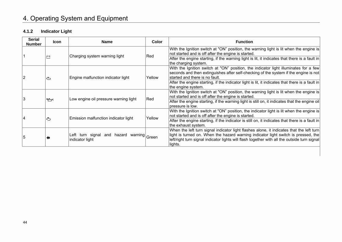
4.1.2 Indicator Light
Serial Number Icon Name Color Function
1 Charging system warning light Red
With the Ignition switch at "ON” position, the warning light is lit when the engine is not started and is off after the engine is started. After the engine starting, if the warning light is lit, it indicates that there is a fault in the charging system.
2 Engine malfunction indicator light Yellow
With the Ignition switch at "ON” position, the indicator light illuminates for a few seconds and then extinguishes after self-checking of the system if the engine is not started and there is no fault. After the engine starting, if the indicator light is lit, it indicates that there is a fault in the engine system.
3 Low engine oil pressure warning light Red
With the Ignition switch at "ON” position, the warning light is lit when the engine is not started and is off after the engine is started. After the engine starting, if the warning light is still on, it indicates that the engine oil pressure is low.
4 Emission malfunction indicator light Yellow
With the Ignition switch at "ON” position, the indicator light is lit when the engine is not started and is off after the engine is started. After the engine starting, if the indicator is still on, it indicates that there is a fault in the exhaust system.
5 Left turn signal and hazard warning indicator light Green
When the left turn signal indicator light flashes alone, it indicates that the left turn light is turned on. When the hazard warning indicator light switch is pressed, the left/right turn signal indicator lights will flash together with all the outside turn signal lights.
50 44
4. Operating System and Equipment
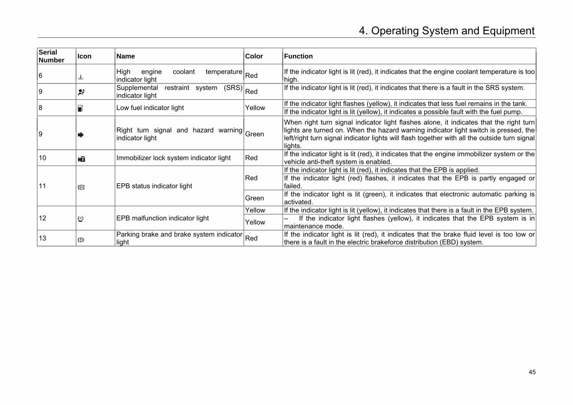
Serial Number Icon Name Color Function
6 High engine coolant temperature indicator light Red If the indicator light is lit (red), it indicates that the engine coolant temperature is too
high.
9 Supplemental restraint system (SRS) indicator light Red If the indicator light is lit (red), it indicates that there is a fault in the SRS system.
8 Low fuel indicator light Yellow If the indicator light flashes (yellow), it indicates that less fuel remains in the tank. If the indicator light is lit (yellow), it indicates a possible fault with the fuel pump.
9 Right turn signal and hazard warning indicator light Green
When right turn signal indicator light flashes alone, it indicates that the right turn lights are turned on. When the hazard warning indicator light switch is pressed, the left/right turn signal indicator lights will flash together with all the outside turn signal lights.
10 Immobilizer lock system indicator light Red If the indicator light is lit (red), it indicates that the engine immobilizer system or the vehicle anti-theft system is enabled.
11 EPB status indicator light Red
If the indicator light is lit (red), it indicates that the EPB is applied. If the indicator light (red) flashes, it indicates that the EPB is partly engaged or failed.
Green If the indicator light is lit (green), it indicates that electronic automatic parking is activated.
12 EPB malfunction indicator light Yellow If the indicator light is lit (yellow), it indicates that there is a fault in the EPB system.
Yellow – If the indicator light flashes (yellow), it indicates that the EPB system is inmaintenance mode.
13 Parking brake and brake system indicator light Red If the indicator light is lit (red), it indicates that the brake fluid level is too low or
there is a fault in the electric brakeforce distribution (EBD) system.
51 45
4. Operating System and Equipment
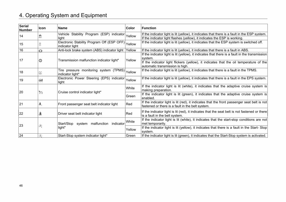
Serial Number Icon Name Color Function
14 Vehicle Stability Program (ESP) indicator light Yellow If the indicator light is lit (yellow), it indicates that there is a fault in the ESP system.
If the indicator light flashes (yellow), it indicates the ESP is working.
15 Electronic Stability Program Off (ESP OFF) indicator light Yellow If the indicator light is lit (yellow), it indicates that the ESP system is switched off.
16 Anti-lock brake system (ABS) indicator light Yellow If the indicator light is lit (yellow), it indicates that there is a fault in ABS.
17 Transmission malfunction indicator light* Yellow
If the indicator light is lit (yellow), it indicates that there is a fault in the transmission system. If the indicator light flickers (yellow), it indicates that the oil temperature of the automatic transmission is high.
18 Tire pressure monitoring system (TPMS) indicator light* Yellow If the indicator light is lit (yellow), it indicates that there is a fault in the TPMS.
19 Electronic Power Steering (EPS) indicator light Yellow If the indicator light is lit (yellow), it indicates that there is a fault in the EPS system.
20 Cruise control indicator light* White If the indicator light is lit (white), it indicates that the adaptive cruise system is
making preparation.
Green If the indicator light is lit (green), it indicates that the adaptive cruise system is enabled.
21 Front passenger seat belt indicator light Red If the indicator light is lit (red), it indicates that the front passenger seat belt is not fastened or there is a fault in the belt system.
22 Driver seat belt indicator light Red If the indicator light is lit (red), it indicates that the seat belt is not fastened or there is a fault in the belt system.
23 Start/Stop system malfunction indicator light*
White If the indicator light is lit (white), it indicates that the start-stop conditions are not met temporarily.
Yellow If the indicator light is lit (yellow), it indicates that there is a fault in the Start- Stop system.
24 Start-Stop system indicator light* Green If the indicator light is lit (green), it indicates that the Start-Stop system is activated.
52 46
4. Operating System and Equipment
Serial Number Icon Name Color Function
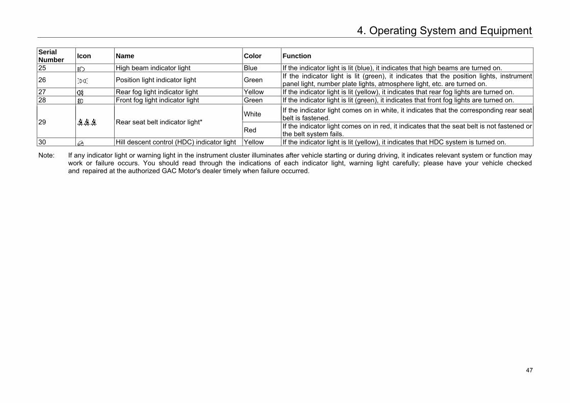
25 High beam indicator light Blue If the indicator light is lit (blue), it indicates that high beams are turned on.
26 Position light indicator light Green If the indicator light is lit (green), it indicates that the position lights, instrument panel light, number plate lights, atmosphere light, etc. are turned on.
27 Rear fog light indicator light Yellow If the indicator light is lit (yellow), it indicates that rear fog lights are turned on. 28 Front fog light indicator light Green If the indicator light is lit (green), it indicates that front fog lights are turned on.
29 Rear seat belt indicator light* White If the indicator light comes on in white, it indicates that the corresponding rear seat
belt is fastened.
Red If the indicator light comes on in red, it indicates that the seat belt is not fastened or the belt system fails.
30 Hill descent control (HDC) indicator light Yellow If the indicator light is lit (yellow), it indicates that HDC system is turned on.
Note: If any indicator light or warning light in the instrument cluster illuminates after vehicle starting or during driving, it indicates relevant system or function may work or failure occurs. You should read through the indications of each indicator light, warning light carefully; please have your vehicle checked and repaired at the authorized GAC Motor's dealer timely when failure occurred.
53 47
4. Operating System and Equipment
4.2 Vehicle Opening and Closing
4.2.1 Smart Key
Models with Start-Stop switch* are provided with smart keys (containing emergency mechanical keys =>Refer to Page 53) and key bar codes. Models with traditional ignition switch* are provided with common keys (containing mechanical keys =>Refer to Page 53) and key bar codes. If you need to re-customize the key or the key bar code is lost, contact an authorized GAC Motor's dealer.
Low Signal Intensity of Smart Key
In following cases, it may be impossible or difficult to operate by pressing the key buttons:
– The equipment nearby is emitting strongwireless electric wave.
– The smart key is carried together withtelecommunication equipment, laptop, mobilephone or wireless signal transmitter.
– The smart key is contacted with covered byany metallic objects.
Caution There is an electric loop inside the smart key
to trigger the immobilizer system. If this loop is damaged, it may fail to start the engine. Thus: • The smart key shall be protected from direct
sunlight, high temperature and high humidity.• Dropping the smart key from a high place or
crushed with a heavy thing shall be avoided.• Contacting the smart key with fluids shall be
avoided. Please dry it immediately when got wet.
Operation of Buttons
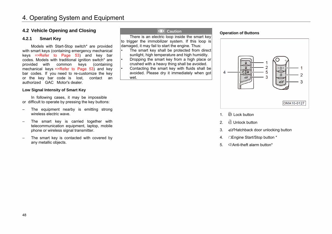
1. : Lock button
2. : Unlock button
3. Hatchback door unlocking button
4. Engine Start/Stop button *
5. Anti-theft alarm button*
54 48
4. Operating System and Equipment
Hint • The standard remote control distance is 15m,
and the longest remote control distance is 50m.
• When the ignition switch is at "ACC" or "ON" position, the operation of any button on thesmart key is not available.
• Quickly press the buttons on the key shortly for 3 times to recover its function when the lock or unlock function is failed.
1 Button
– Short pressing this button once within theeffective range, all doors will be locked;pressing this button and hold for 2s, thewindow will close automatically; pressing thisbutton and hold for 3s, the sunroof will closeautomatically. If this button is released whilethe window or sunroof is closing automatically,the closing will be stopped.
– Pressing this button twice continuously within0.5s, the vehicle locating function can beactivated, and the turn signal light will flashquickly for 3 times.
Hint • Pressing and holding this button for 2s, only
the driver side window will close automatically for some models and all the four windows will close automatically for some models. Please refer to the actual vehicle configuration.
• Activate or deactivate remote control of window and sunroof via "Vehicle Setting →Smart Body → Remote Control of Windowand Sunroof" in the audio system.
• When doors are locked, the turn signals flicker 1 time and the horn sounds 1 time. Activate or deactivate the horn beeping via "Settings →Sound → Unlock/Lock Horn Beeping" in theaudio system.
55 49
4. Operating System and Equipment
2 Button
– Short pressing this button once within theeffective range, all doors will be unlocked; pressingthis button and hold for 2s, the window will openautomatically; pressing this button and hold for 3s,the sunroof will open automatically. If this button isreleased while the window or sunroof is openingautomatically, the opening will be stopped.
Hint • Pressing and holding this button for 2s, only
the driver side window will open automatically for some models and all the four windows will open automatically for some models. Please refer to the actual vehicle configuration.
• When doors are unlocked, the turn signal lights flicker twice and the horn sounds twice. Activate or deactivate the horn beeping via "Settings → Sound → Unlock/Lock HornBeeping" in the audio system.
Hint • Windows and sunroof can open or close
remotely via "Vehicle Setting → Smart Body→ Remote Control of Window and Sunroof"under the audio system.
• Via "Vehicle Setting → Smart Body → Remote Unlocking" under the audio system, press the
button to unlock all the doors or only the leftfront door.
Caution
After pressing the button to unlock the door, the system will lock the door again if it is not opened within about 30s.
3 Button
– Within effective range, long pressing thisbutton for 2s, the hatchback door can beunlocked.
– For models equipped with electric hatchbackdoor, long press to open or close the electrichatchback door, and short press to pauseactuation of the electric hatchback door.
4 Button*
– In the effective range, press once, and thenlong press within 2s until the turn signals flashwhen the engine can be started remotely.
– With the engine remotely started, press thebutton and hold for 3s. You can remotely stop theengine.
56 50
4. Operating System and Equipment
Hint • Before remote shutdown of the engine,
confirm whether the vehicle is locked. If thiscannot be confirmed, press button once andthen long press button before shutting downthe engine.
• In remote startup of the engine, stay withineffective range. Otherwise, it is possible totrigger the unlock function but fail in startup.
• The function of remotely starting engineremains on at a time for at most 5 minutes indefault. To change the period, contactauthorized GAC Motor's dealer.
5. Button*
– Long pressing and holding this button formore than 3s activates anti-theft alarm, withthe horn sounding and the turn signalsflashing 30s. Short pressing or can stopanti-theft alarm.
Switch between "Sound and Flash" and "Flash" Alarm Modes
The "light" alarm indicates the vehicle warns the driver only with light, while the "sound and flash" alarm mode indicates the vehicle warns the driver both with light and horn sound.
When the ignition switch is at "OFF" position, press the button and button on the remote key at the same time for 2s to switch between the "flash" alarm mode and "sound and flash" alarm mode. If the switching is successful, the turn signals will flash at the same time 3 times (only applicable to electronic anti-theft alarm).
Battery Replacement
The indicator light of the key flashes once every time the button on the key is pressed. If it does not flash when the key is pressed, or if the button has to be pressed several times to lock or unlock the door, the battery could be run out or nearly run out. In this case, it is recommended to replace the battery at authorized GAC Motor's dealer as required.
Caution • Be sure to use a new battery with the same
rated voltage and size for replacement.• Using of improper battery may damage the
smart key.• Used batteries must be disposed as per
relevant regulations and laws for environment protection.
57 51
4. Operating System and Equipment
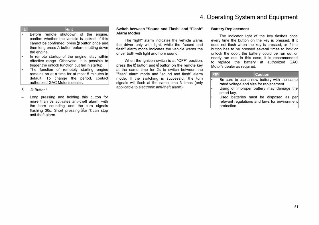
Steps to Replace Battery
– Key for models with Start-Stop switch*: Movethe switch in the direction of arrow A and pullout the emergency mechanical key in directionof arrow B.
– Key for models with traditional ignition switch*:Press the button indicated by the arrow toeject the mechanical key.
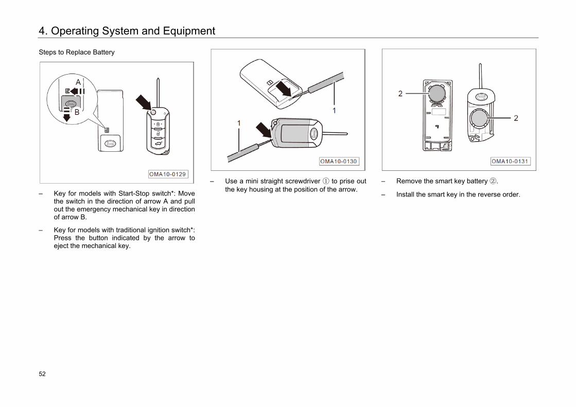
– Use a mini straight screwdriver ① to prise outthe key housing at the position of the arrow.
– Remove the smart key battery ②.
– Install the smart key in the reverse order.
58 52
4. Operating System and Equipment
4.2.2 Mechanical Key
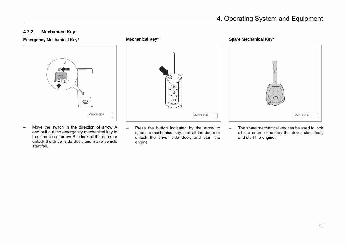
Emergency Mechanical Key*
– Move the switch in the direction of arrow Aand pull out the emergency mechanical key inthe direction of arrow B to lock all the doors orunlock the driver side door, and make vehiclestart fail.
Mechanical Key*
– Press the button indicated by the arrow toeject the mechanical key, lock all the doors orunlock the driver side door, and start theengine.
Spare Mechanical Key*
– The spare mechanical key can be used to lockall the doors or unlock the driver side door,and start the engine.
A
B
OMA10-0137 OMA10-0132 OMA10-0133
59 53
4. Operating System and Equipment
4.2.3 Locking System
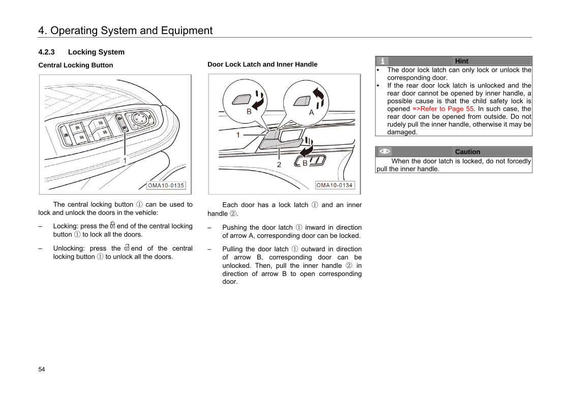
Central Locking Button
The central locking button ① can be used to lock and unlock the doors in the vehicle:
– Locking: press the end of the central lockingbutton ① to lock all the doors.
– Unlocking: press the end of the centrallocking button ① to unlock all the doors.
Door Lock Latch and Inner Handle
Each door has a lock latch ① and an inner handle ②.
– Pushing the door latch ① inward in directionof arrow A, corresponding door can be locked.
– Pulling the door latch ① outward in directionof arrow B, corresponding door can beunlocked. Then, pull the inner handle ② indirection of arrow B to open correspondingdoor.
Hint • The door lock latch can only lock or unlock the
corresponding door.• If the rear door lock latch is unlocked and the
rear door cannot be opened by inner handle, a possible cause is that the child safety lock is opened =>Refer to Page 55. In such case, the rear door can be opened from outside. Do not rudely pull the inner handle, otherwise it may be damaged.
Caution When the door latch is locked, do not forcedly
pull the inner handle.
60 54
4. Operating System and Equipment
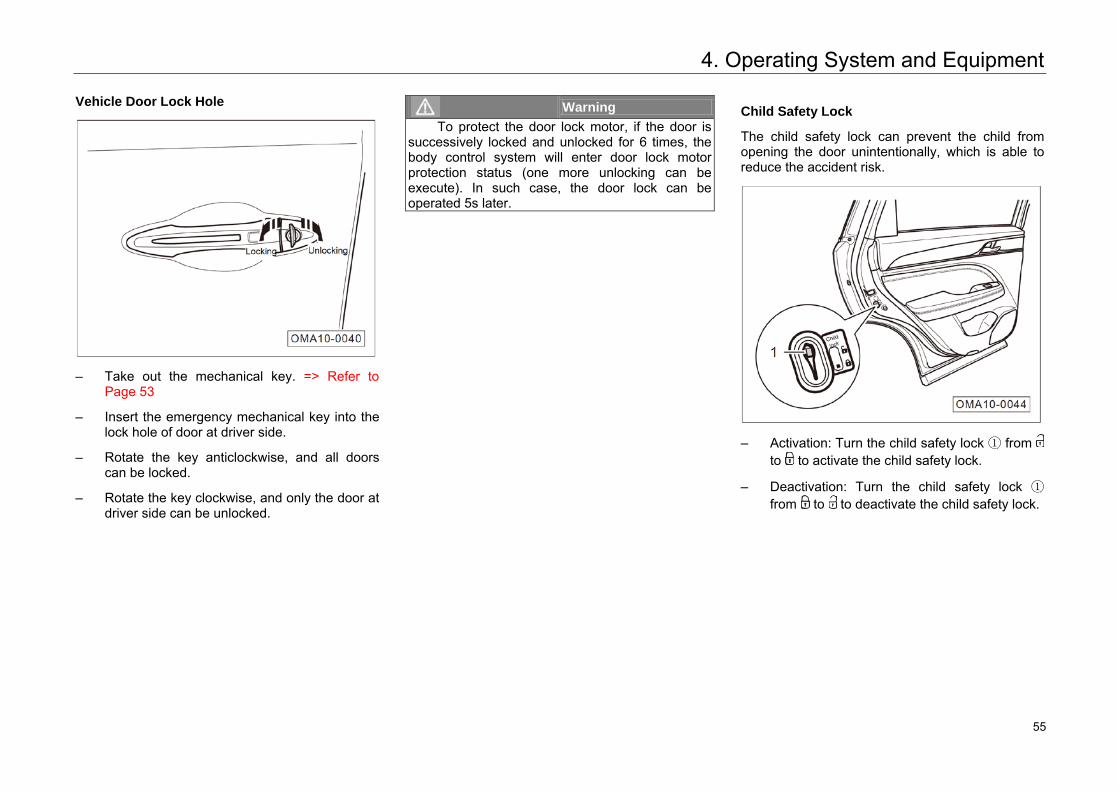
Vehicle Door Lock Hole
– Take out the mechanical key. => Refer to Page 53
– Insert the emergency mechanical key into the lock hole of door at driver side.
– Rotate the key anticlockwise, and all doors can be locked.
– Rotate the key clockwise, and only the door at driver side can be unlocked.
Warning To protect the door lock motor, if the door is
successively locked and unlocked for 6 times, the body control system will enter door lock motor protection status (one more unlocking can be execute). In such case, the door lock can be operated 5s later.
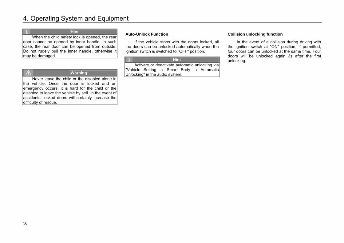
Child Safety Lock
The child safety lock can prevent the child from opening the door unintentionally, which is able to reduce the accident risk.
– Activation: Turn the child safety lock ① fromto to activate the child safety lock.
– Deactivation: Turn the child safety lock ①from to to deactivate the child safety lock.
61 55
4. Operating System and Equipment
Hint When the child safety lock is opened, the rear
door cannot be opened by inner handle. In such case, the rear door can be opened from outside. Do not rudely pull the inner handle, otherwise it may be damaged.
Warning Never leave the child or the disabled alone in
the vehicle. Once the door is locked and an emergency occurs, it is hard for the child or the disabled to leave the vehicle by self. In the event of accidents, locked doors will certainly increase the difficulty of rescue.
Auto-Unlock Function
If the vehicle stops with the doors locked, all the doors can be unlocked automatically when the ignition switch is switched to "OFF" position.
Hint Activate or deactivate automatic unlocking via
"Vehicle Setting → Smart Body → Automatic Unlocking" in the audio system.
Collision unlocking function
In the event of a collision during driving with the ignition switch at "ON" position, if permitted, four doors can be unlocked at the same time. Four doors will be unlocked again 3s after the first unlocking.
62 56
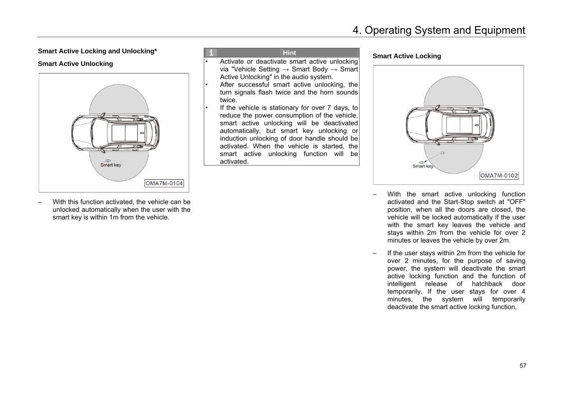
4. Operating System and Equipment
Smart Active Locking and Unlocking*
Smart Active Unlocking
– With this function activated, the vehicle can beunlocked automatically when the user with thesmart key is within 1m from the vehicle.
Hint • Activate or deactivate smart active unlocking
via "Vehicle Setting → Smart Body → SmartActive Unlocking" in the audio system.
• After successful smart active unlocking, the turn signals flash twice and the horn soundstwice.
• If the vehicle is stationary for over 7 days, toreduce the power consumption of the vehicle, smart active unlocking will be deactivatedautomatically, but smart key unlocking orinduction unlocking of door handle should be activated. When the vehicle is started, thesmart active unlocking function will be activated.
Smart Active Locking
– With the smart active unlocking functionactivated and the Start-Stop switch at "OFF"position, when all the doors are closed, thevehicle will be locked automatically if the userwith the smart key leaves the vehicle andstays within 2m from the vehicle for over 2minutes or leaves the vehicle by over 2m.
– If the user stays within 2m from the vehicle forover 2 minutes, for the purpose of savingpower, the system will deactivate the smartactive locking function and the function ofintelligent release of hatchback doortemporarily. If the user stays for over 4minutes, the system will temporarilydeactivate the smart active locking function,
63 57
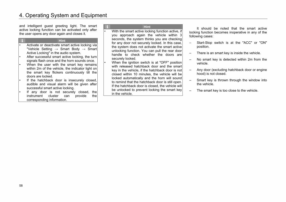
4. Operating System and Equipment
and intelligent guest greeting light. The smart active locking function can be activated only after the user opens any door again and closes it.
Hint • Activate or deactivate smart active locking via
"Vehicle Setting → Smart Body → SmartActive Locking" in the audio system.
• After successful smart active locking, the turnsignals flash once and the horn sounds once.
• When the user with the smart key remainswithin 2m of the vehicle, the indicator light on the smart key flickers continuously till thedoors are locked.
• If the hatchback door is insecurely closed, audible and visual alarm will be given aftersuccessful smart active locking.
• If any door is not securely closed, the instrument cluster can provide the corresponding information.
Hint • With the smart active locking function active, if
you approach again the vehicle within 3seconds, the system thinks you are checking for any door not securely locked. In this case, the system does not activate the smart active unlocking function. You can pull the rear door handle to check whether the doors are securely locked.
• When the ignition switch is at "OFF" position with released hatchback door and the smart key in the vehicle, if the hatchback door is not closed within 10 minutes, the vehicle will belocked automatically and the horn will sound to remind that the hatchback door is still open. If the hatchback door is closed, the vehicle will be unlocked to prevent locking the smart key in the vehicle.
It should be noted that the smart active locking function becomes inoperative in any of the following cases:
– Start-Stop switch is at the "ACC" or "ON"position.
– There is an smart key is inside the vehicle.
– No smart key is detected within 2m from thevehicle.
– Any door (excluding hatchback door or enginehood) is not closed.
– Smart key is thrown through the window intothe vehicle.
– The smart key is too close to the vehicle.
64 58
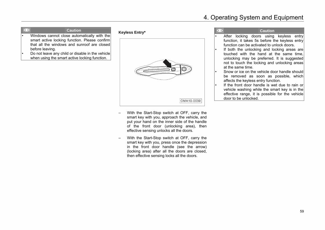
4. Operating System and Equipment
Caution • Windows cannot close automatically with the
smart active locking function. Please confirm that all the windows and sunroof are closed before leaving.
• Do not leave any child or disable in the vehicle when using the smart active locking function.
Keyless Entry*
– With the Start-Stop switch at OFF, carry thesmart key with you, approach the vehicle, andput your hand on the inner side of the handleof the front door (unlocking area), theneffective sensing unlocks all the doors.
– With the Start-Stop switch at OFF, carry thesmart key with you, press once the depressionin the front door handle (see the arrow)(locking area) after all the doors are closed,then effective sensing locks all the doors.
Caution • After locking doors using keyless entry
function, it takes 5s before the keyless entry function can be activated to unlock doors.
• If both the unlocking and locking areas are touched with the hand at the same time, unlocking may be preferred. It is suggested not to touch the locking and unlocking areasat the same time.
• Snow or ice on the vehicle door handle should be removed as soon as possible, which affects the keyless entry function.
• If the front door handle is wet due to rain orvehicle washing while the smart key is in the effective range, it is possible for the vehicle door to be unlocked.
65 59
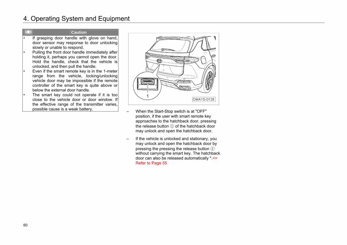
4. Operating System and Equipment
Caution • If grasping door handle with glove on hand,
door sensor may response to door unlocking slowly or unable to respond.
• Pulling the front door handle immediately after holding it, perhaps you cannot open the door. Hold the handle, check that the vehicle is unlocked, and then pull the handle.
• Even if the smart remote key is in the 1-meterrange from the vehicle, locking/unlocking vehicle door may be impossible if the remote controller of the smart key is quite above orbelow the external door handle.
• The smart key could not operate if it is too close to the vehicle door or door window. Ifthe effective range of the transmitter varies, possible cause is a weak battery. – When the Start-Stop switch is at "OFF"
position, if the user with smart remote key approaches to the hatchback door, pressing the release button ① of the hatchback door may unlock and open the hatchback door.
– If the vehicle is unlocked and stationary, you may unlock and open the hatchback door by pressing the pressing the release button ① without carrying the smart key. The hatchback door can also be released automatically *.=> Refer to Page 55
66 60
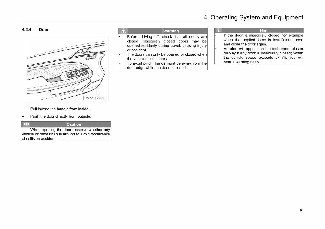
4. Operating System and Equipment
4.2.4 Door
– Pull inward the handle from inside.
– Push the door directly from outside.
Caution When opening the door, observe whether any
vehicle or pedestrian is around to avoid occurrence of collision accident.
Warning • Before driving off, check that all doors are
closed. Insecurely closed doors may be opened suddenly during travel, causing injury or accident.
• The doors can only be opened or closed when the vehicle is stationary.
• To avoid pinch, hands must be away from the door edge while the door is closed.
Hint • If the door is insecurely closed, for example
when the applied force is insufficient, open and close the door again.
• An alert will appear on the instrument clusterdisplay if any door is insecurely closed; When the vehicle speed exceeds 5km/h, you will hear a warning beep.
67 61
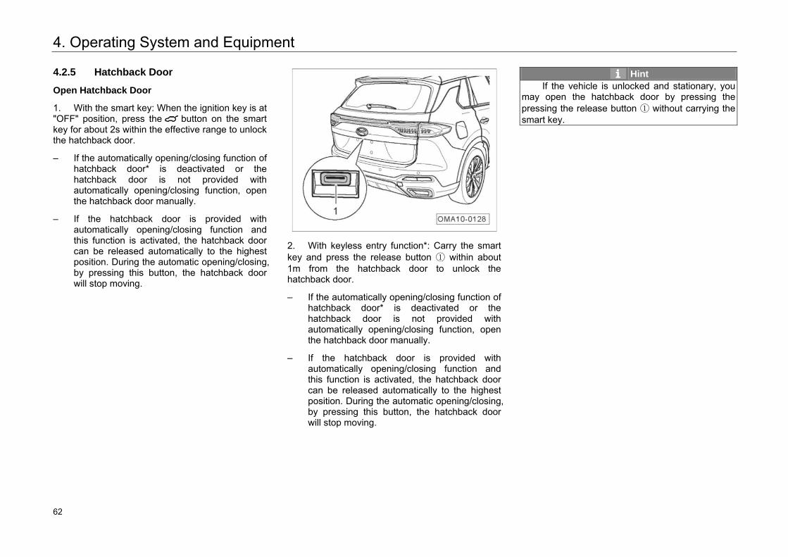
4. Operating System and Equipment
4.2.5 Hatchback Door
Open Hatchback Door
1. With the smart key: When the ignition key is at"OFF" position, press the button on the smartkey for about 2s within the effective range to unlockthe hatchback door.
– If the automatically opening/closing function ofhatchback door* is deactivated or thehatchback door is not provided withautomatically opening/closing function, openthe hatchback door manually.
– If the hatchback door is provided withautomatically opening/closing function andthis function is activated, the hatchback doorcan be released automatically to the highestposition. During the automatic opening/closing,by pressing this button, the hatchback doorwill stop moving.
2. With keyless entry function*: Carry the smartkey and press the release button ① within about1m from the hatchback door to unlock thehatchback door.
– If the automatically opening/closing function ofhatchback door* is deactivated or thehatchback door is not provided withautomatically opening/closing function, openthe hatchback door manually.
– If the hatchback door is provided withautomatically opening/closing function andthis function is activated, the hatchback doorcan be released automatically to the highestposition. During the automatic opening/closing,by pressing this button, the hatchback doorwill stop moving.
Hint If the vehicle is unlocked and stationary, you
may open the hatchback door by pressing the pressing the release button ① without carrying the smart key.
68 62
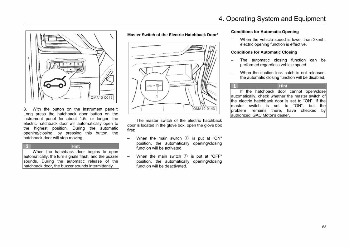
4. Operating System and Equipment
3. With the button on the instrument panel*:Long press the hatchback door button on theinstrument panel for about 1.5s or longer, theelectric hatchback door will automatically open tothe highest position. During the automaticopening/closing, by pressing this button, thehatchback door will stop moving.
Hint When the hatchback door begins to open
automatically, the turn signals flash, and the buzzer sounds. During the automatic release of the hatchback door, the buzzer sounds intermittently.
Master Switch of the Electric Hatchback Door*
The master switch of the electric hatchback door is located in the glove box, open the glove box first:
– When the main switch ① is put at "ON"position, the automatically opening/closingfunction will be activated.
– When the main switch ① is put at "OFF"position, the automatically opening/closingfunction will be deactivated.
Conditions for Automatic Opening
– When the vehicle speed is lower than 3km/h,electric opening function is effective.
Conditions for Automatic Closing
– The automatic closing function can beperformed regardless vehicle speed.
– When the suction lock catch is not released,the automatic closing function will be disabled.
Hint If the hatchback door cannot open/close
automatically, check whether the master switch of the electric hatchback door is set to “ON”. If the master switch is set to “ON”. but the problem remains there, have checked by authorized GAC Motor's dealer.
69 63
4. Operating System and Equipment
Height Setting of Electric Hatchback Door*
The opening height can be set when the electric hatchback door opens to above half height.
Opening Height Setting
Open the hatchback door to desired height. Long press the hatchback door Close button and hold for more than 2s, and release after the alert from the buzzer is heard. The height setting is hence completed.
Canceling Height Setting
Manually open the hatchback door to above the set height, this cancels the height setting.
Hint • With the height setting completed, the buzzer
sounds intermittently twice.• When height setting is canceled, the buzzer
sounds once for a long time.
Anti-Pinch Function of Electric Hatchback Door*
1. Anti-Pinch of Anti-pinch Strip
This feature remains effective while the hatchback door is automatically closing:
– If the feature is triggered while the hatchbackdoor is automatically closing, the hatchbackdoor stops closing and automatically opens toinitial position.
Hint In case of abnormal anti-pinch strip signal, the
automatic closing function of the hatchback door fails.
2. Obstacle Detection
This feature remains effective while the hatchback door is automatically opening or closing:
– If the feature is triggered while the hatchbackdoor is automatically closing, the hatchbackdoor stops closing and automatically opens toinitial position.
– If the feature is triggered while the hatchbackdoor is automatically opening, the hatchbackdoor stops opening, closes slightly then stopsmoving.
Hint With the anti-pinch function triggered, the
buzzer sounds intermittently three times.
70 64
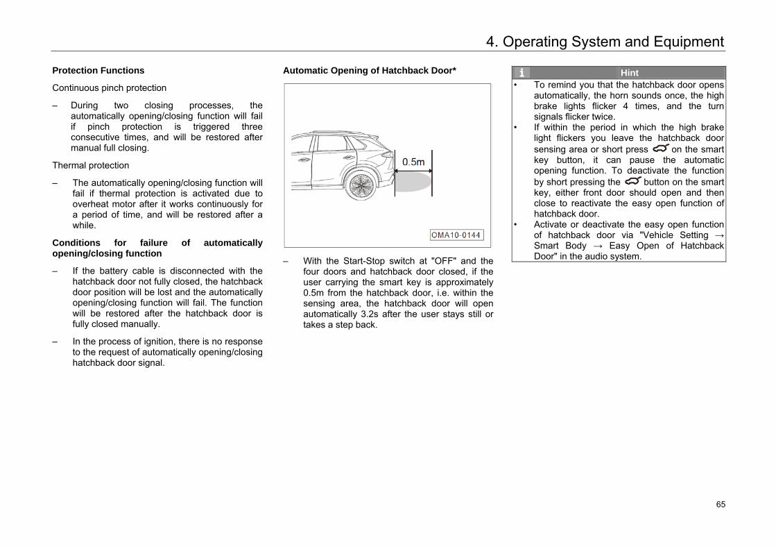
4. Operating System and Equipment
Protection Functions
Continuous pinch protection
– During two closing processes, theautomatically opening/closing function will failif pinch protection is triggered threeconsecutive times, and will be restored aftermanual full closing.
Thermal protection
– The automatically opening/closing function willfail if thermal protection is activated due tooverheat motor after it works continuously fora period of time, and will be restored after awhile.
Conditions for failure of automatically opening/closing function
– If the battery cable is disconnected with thehatchback door not fully closed, the hatchbackdoor position will be lost and the automaticallyopening/closing function will fail. The functionwill be restored after the hatchback door isfully closed manually.
– In the process of ignition, there is no responseto the request of automatically opening/closinghatchback door signal.
Automatic Opening of Hatchback Door*
– With the Start-Stop switch at "OFF" and thefour doors and hatchback door closed, if theuser carrying the smart key is approximately0.5m from the hatchback door, i.e. within thesensing area, the hatchback door will openautomatically 3.2s after the user stays still ortakes a step back.
Hint • To remind you that the hatchback door opens
automatically, the horn sounds once, the high brake lights flicker 4 times, and the turn signals flicker twice.
• If within the period in which the high brake light flickers you leave the hatchback door sensing area or short press on the smartkey button, it can pause the automaticopening function. To deactivate the function by short pressing the button on the smart key, either front door should open and then close to reactivate the easy open function of hatchback door.
• Activate or deactivate the easy open function of hatchback door via "Vehicle Setting →Smart Body → Easy Open of HatchbackDoor" in the audio system.
71 65
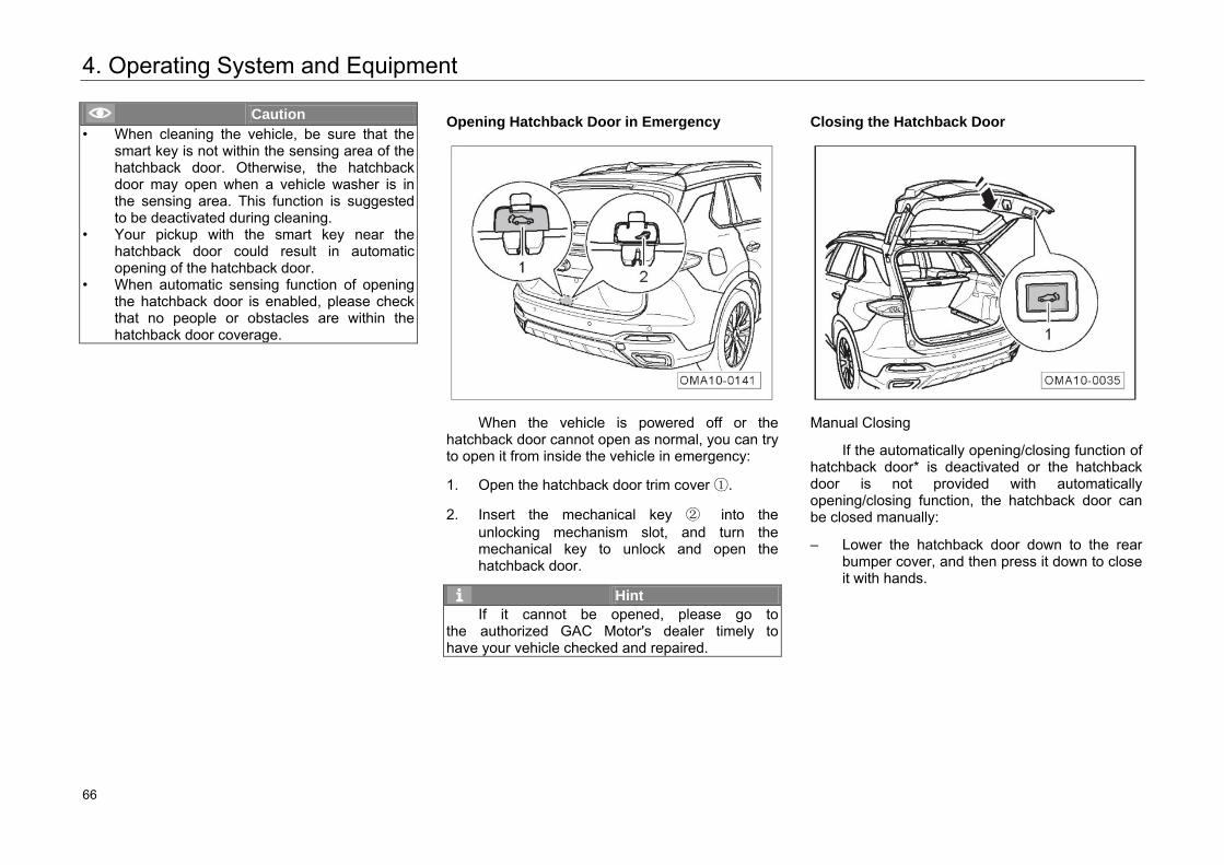
4. Operating System and Equipment
Caution • When cleaning the vehicle, be sure that the
smart key is not within the sensing area of thehatchback door. Otherwise, the hatchbackdoor may open when a vehicle washer is in the sensing area. This function is suggested to be deactivated during cleaning.
• Your pickup with the smart key near the hatchback door could result in automaticopening of the hatchback door.
• When automatic sensing function of opening the hatchback door is enabled, please checkthat no people or obstacles are within the hatchback door coverage.
Opening Hatchback Door in Emergency
When the vehicle is powered off or the hatchback door cannot open as normal, you can try to open it from inside the vehicle in emergency:
1. Open the hatchback door trim cover ①.
2. Insert the mechanical key ② into theunlocking mechanism slot, and turn themechanical key to unlock and open thehatchback door.
Hint If it cannot be opened, please go to
the authorized GAC Motor's dealer timely to have your vehicle checked and repaired.
Closing the Hatchback Door
Manual Closing
If the automatically opening/closing function of hatchback door* is deactivated or the hatchback door is not provided with automatically opening/closing function, the hatchback door can be closed manually:
– Lower the hatchback door down to the rearbumper cover, and then press it down to closeit with hands.
72 66
4. Operating System and Equipment
Automatic Closing*
– After the close button ① of hatchback door is pressed, the electric hatchback door will automatically lower to close. If the button is pressed again during closing, the electric hatchback door will stop closing.
– With the ignition key at "OFF" position, if the button on the smart key is long pressed
for about 2s within the effective range, the electric hatchback door will automatically lower to close. If the button is pressed again during closing, the electric hatchback door will stop closing.
– If the hatchback door button on the instrument panel is long pressed for over 1.5s, the electric hatchback door will automatically lower to close. If the button is pressed again during closing, the electric hatchback door will stop closing.
Hint • When the stationary electric hatchback door
begins to close automatically, the turn signals flash.
• While the electric hatchback door is closing automatically, the buzzer sounds intermittently.
• An alert will appear on the instrument cluster display if the hatchback door is insecurely closed; When the vehicle speed exceeds 5km/h, you will hear a warning beep.
Caution • Always check that the hatchback door is
closed securely. Otherwise, it can cause accidents easily.
• Before closing the hatchback door, please check that no people or animals are within the hatchback door coverage.
• Check that the hatchback door is locked. Otherwise, it could open accidentally while the vehicle is traveling.
73 67
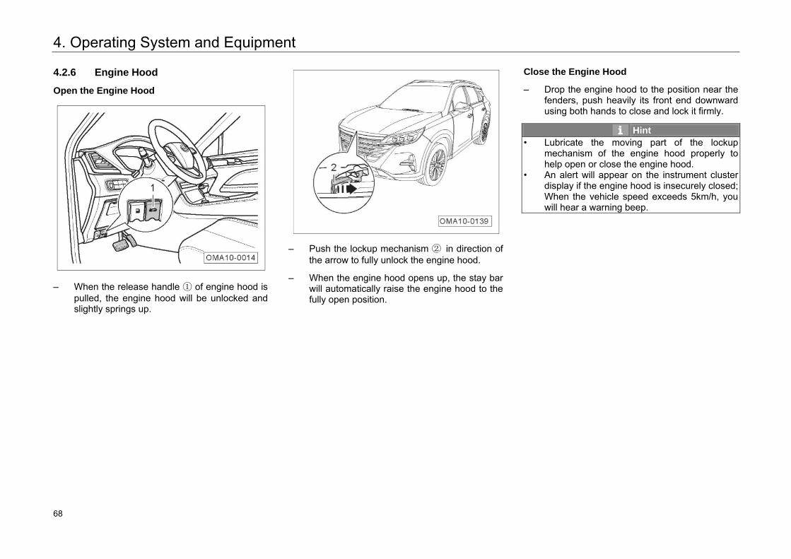
4. Operating System and Equipment
4.2.6 Engine Hood
Open the Engine Hood
– When the release handle ① of engine hood ispulled, the engine hood will be unlocked andslightly springs up.
– Push the lockup mechanism ② in direction ofthe arrow to fully unlock the engine hood.
– When the engine hood opens up, the stay barwill automatically raise the engine hood to thefully open position.
Close the Engine Hood
– Drop the engine hood to the position near thefenders, push heavily its front end downwardusing both hands to close and lock it firmly.
Hint • Lubricate the moving part of the lockup
mechanism of the engine hood properly to help open or close the engine hood.
• An alert will appear on the instrument clusterdisplay if the engine hood is insecurely closed; When the vehicle speed exceeds 5km/h, youwill hear a warning beep.
74 68
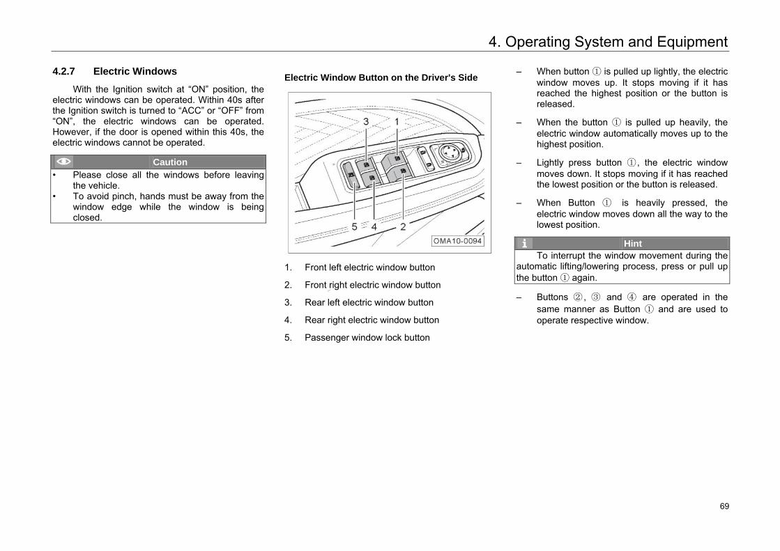
4. Operating System and Equipment
4.2.7 Electric Windows
With the Ignition switch at “ON” position, the electric windows can be operated. Within 40s after the Ignition switch is turned to “ACC” or “OFF” from “ON”, the electric windows can be operated. However, if the door is opened within this 40s, the electric windows cannot be operated.
Caution • Please close all the windows before leaving
the vehicle.• To avoid pinch, hands must be away from the
window edge while the window is beingclosed.
Electric Window Button on the Driver's Side
1. Front left electric window button
2. Front right electric window button
3. Rear left electric window button
4. Rear right electric window button
5. Passenger window lock button
– When button ① is pulled up lightly, the electricwindow moves up. It stops moving if it hasreached the highest position or the button isreleased.
– When the button ① is pulled up heavily, theelectric window automatically moves up to thehighest position.
– Lightly press button ① , the electric windowmoves down. It stops moving if it has reachedthe lowest position or the button is released.
– When Button ① is heavily pressed, theelectric window moves down all the way to thelowest position.
Hint To interrupt the window movement during the
automatic lifting/lowering process, press or pull up the button ① again.
– Buttons ② , ③ and ④ are operated in thesame manner as Button ① and are used tooperate respective window.
75 69
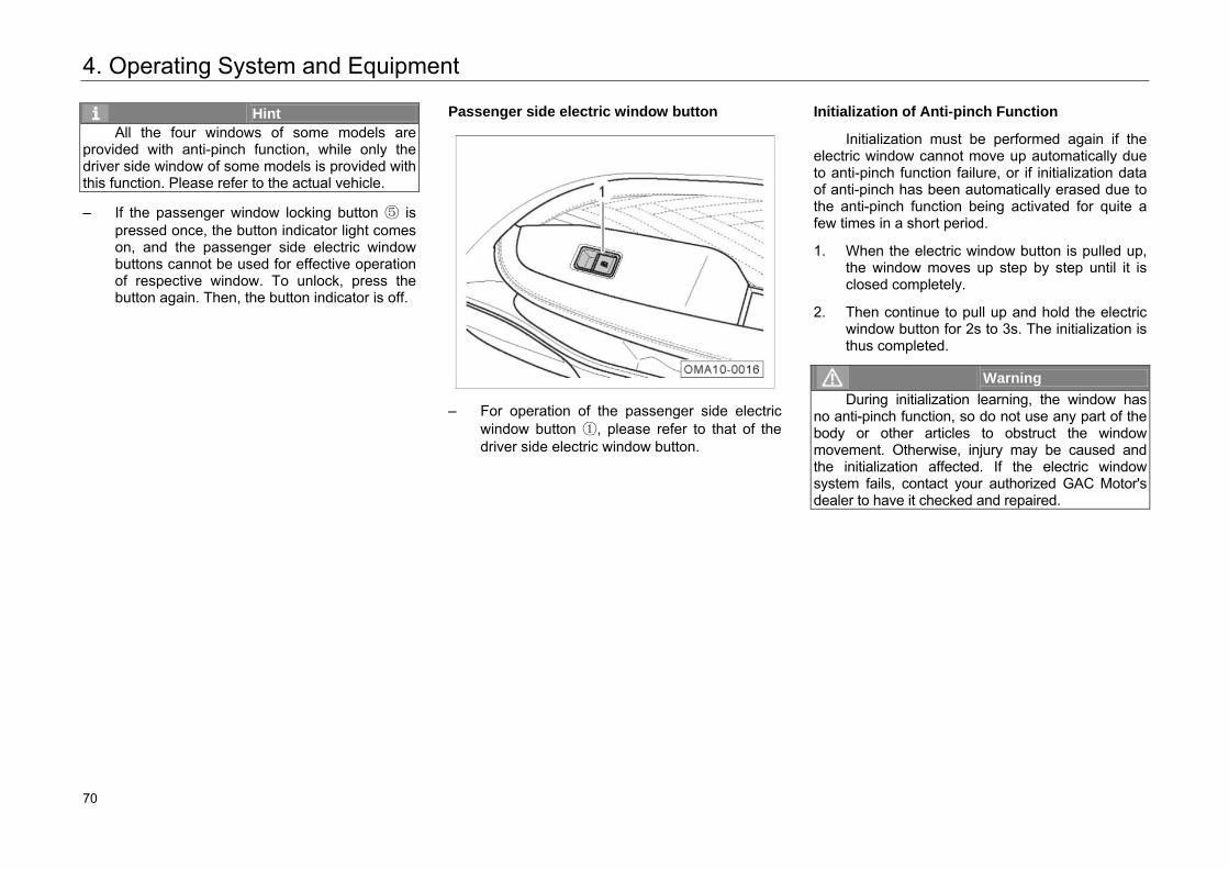
4. Operating System and Equipment
Hint All the four windows of some models are
provided with anti-pinch function, while only the driver side window of some models is provided with this function. Please refer to the actual vehicle.
– If the passenger window locking button ⑤ ispressed once, the button indicator light comeson, and the passenger side electric windowbuttons cannot be used for effective operationof respective window. To unlock, press thebutton again. Then, the button indicator is off.
Passenger side electric window button
– For operation of the passenger side electricwindow button ①, please refer to that of thedriver side electric window button.
Initialization of Anti-pinch Function
Initialization must be performed again if the electric window cannot move up automatically due to anti-pinch function failure, or if initialization data of anti-pinch has been automatically erased due to the anti-pinch function being activated for quite a few times in a short period.
1. When the electric window button is pulled up,the window moves up step by step until it isclosed completely.
2. Then continue to pull up and hold the electricwindow button for 2s to 3s. The initialization isthus completed.
Warning During initialization learning, the window has
no anti-pinch function, so do not use any part of the body or other articles to obstruct the window movement. Otherwise, injury may be caused and the initialization affected. If the electric window system fails, contact your authorized GAC Motor's dealer to have it checked and repaired.
76 70
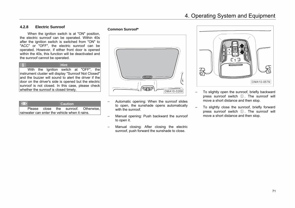
4. Operating System and Equipment
4.2.8 Electric Sunroof
When the ignition switch is at "ON" position, the electric sunroof can be operated. Within 40s after the ignition switch is switched from "ON" to "ACC" or "OFF", the electric sunroof can be operated. However, if either front door is opened within the 40s, this function will be deactivated and the sunroof cannot be operated.
Hint With the Ignition switch at "OFF", the
instrument cluster will display "Sunroof Not Closed" and the buzzer will sound to alert the driver if the door on the driver's side is opened but the electric sunroof is not closed. In this case, please check whether the sunroof is closed timely.
Caution Please close the sunroof. Otherwise,
rainwater can enter the vehicle when it rains.
Common Sunroof*
– Automatic opening: When the sunroof slides
to open, the sunshade opens automatically with the sunroof.
– Manual opening: Push backward the sunroof to open it.
– Manual closing: After closing the electric sunroof, push forward the sunshade to close.
– To slightly open the sunroof, briefly backward
press sunroof switch ① . The sunroof will move a short distance and then stop.
– To slightly close the sunroof, briefly forward press sunroof switch ① . The sunroof will move a short distance and then stop.
77 71
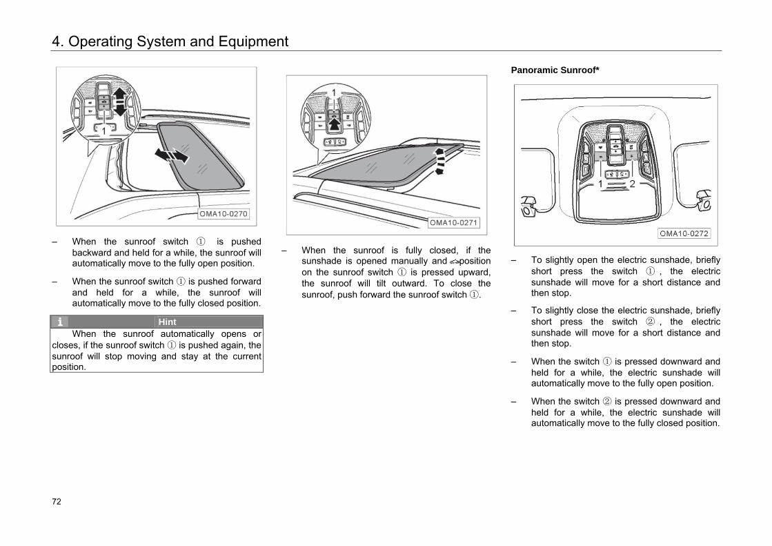
4. Operating System and Equipment
– When the sunroof switch ① is pushedbackward and held for a while, the sunroof willautomatically move to the fully open position.
– When the sunroof switch ① is pushed forwardand held for a while, the sunroof willautomatically move to the fully closed position.
Hint When the sunroof automatically opens or
closes, if the sunroof switch ① is pushed again, the sunroof will stop moving and stay at the current position.
– When the sunroof is fully closed, if thesunshade is opened manually and positionon the sunroof switch ① is pressed upward,the sunroof will tilt outward. To close thesunroof, push forward the sunroof switch ①.
Panoramic Sunroof*
– To slightly open the electric sunshade, brieflyshort press the switch ① , the electricsunshade will move for a short distance andthen stop.
– To slightly close the electric sunshade, brieflyshort press the switch ② , the electricsunshade will move for a short distance andthen stop.
– When the switch ① is pressed downward andheld for a while, the electric sunshade willautomatically move to the fully open position.
– When the switch ② is pressed downward andheld for a while, the electric sunshade willautomatically move to the fully closed position.
78 72
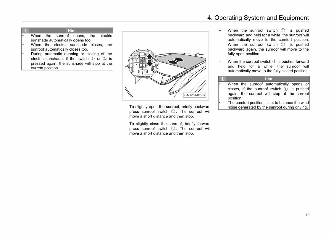
4. Operating System and Equipment
Hint • When the sunroof opens, the electric
sunshade automatically opens too. • When the electric sunshade closes, the
sunroof automatically closes too. • During automatic opening or closing of the
electric sunshade, if the switch ① or ② is pressed again, the sunshade will stop at the current position.
– To slightly open the sunroof, briefly backward
press sunroof switch ① . The sunroof will move a short distance and then stop.
– To slightly close the sunroof, briefly forward press sunroof switch ① . The sunroof will move a short distance and then stop.
– When the sunroof switch ① is pushed backward and held for a while, the sunroof will automatically move to the comfort position. When the sunroof switch ① is pushed backward again, the sunroof will move to the fully open position.
– When the sunroof switch ① is pushed forward and held for a while, the sunroof will automatically move to the fully closed position.
Hint • When the sunroof automatically opens or
closes, if the sunroof switch ① is pushed again, the sunroof will stop at the current position.
• The comfort position is set to balance the wind noise generated by the sunroof during driving.
79 73
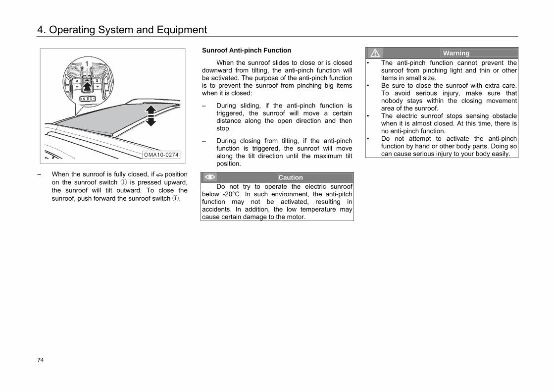
4. Operating System and Equipment
– When the sunroof is fully closed, if positionon the sunroof switch ① is pressed upward,the sunroof will tilt outward. To close thesunroof, push forward the sunroof switch ①.
Sunroof Anti-pinch Function
When the sunroof slides to close or is closed downward from tilting, the anti-pinch function will be activated. The purpose of the anti-pinch function is to prevent the sunroof from pinching big items when it is closed:
– During sliding, if the anti-pinch function istriggered, the sunroof will move a certaindistance along the open direction and thenstop.
– During closing from tilting, if the anti-pinchfunction is triggered, the sunroof will movealong the tilt direction until the maximum tiltposition.
Caution Do not try to operate the electric sunroof
below -20°C. In such environment, the anti-pitch function may not be activated, resulting in accidents. In addition, the low temperature may cause certain damage to the motor.
Warning • The anti-pinch function cannot prevent the
sunroof from pinching light and thin or otheritems in small size.
• Be sure to close the sunroof with extra care. To avoid serious injury, make sure that nobody stays within the closing movement area of the sunroof.
• The electric sunroof stops sensing obstacle when it is almost closed. At this time, there isno anti-pinch function.
• Do not attempt to activate the anti-pinch function by hand or other body parts. Doing so can cause serious injury to your body easily.
80 74
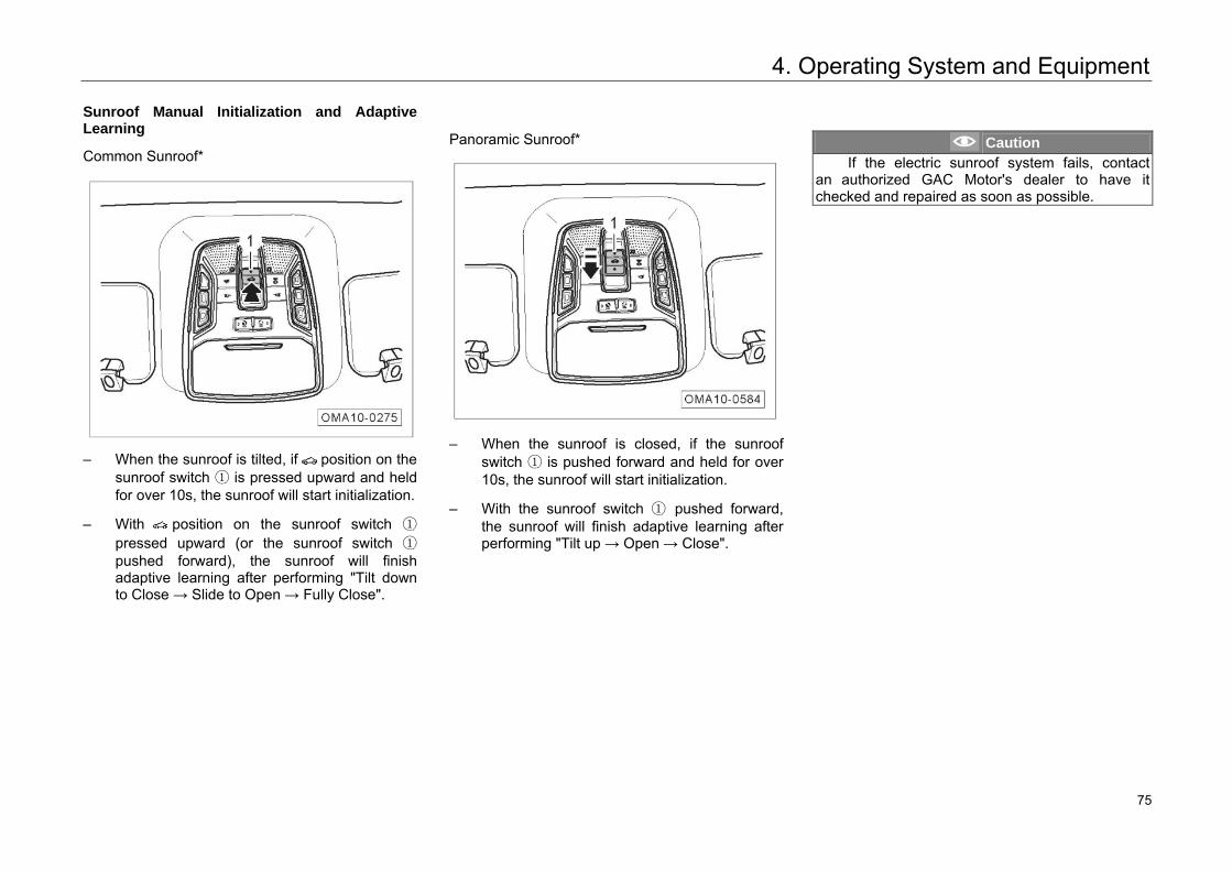
4. Operating System and Equipment
Sunroof Manual Initialization and Adaptive Learning
Common Sunroof*
– When the sunroof is tilted, if position on thesunroof switch ① is pressed upward and heldfor over 10s, the sunroof will start initialization.
– With position on the sunroof switch ①
pressed upward (or the sunroof switch ①pushed forward), the sunroof will finishadaptive learning after performing "Tilt downto Close → Slide to Open → Fully Close".
Panoramic Sunroof*
– When the sunroof is closed, if the sunroofswitch ① is pushed forward and held for over10s, the sunroof will start initialization.
– With the sunroof switch ① pushed forward,the sunroof will finish adaptive learning afterperforming "Tilt up → Open → Close".
Caution If the electric sunroof system fails, contact
an authorized GAC Motor's dealer to have it checked and repaired as soon as possible.
81 75
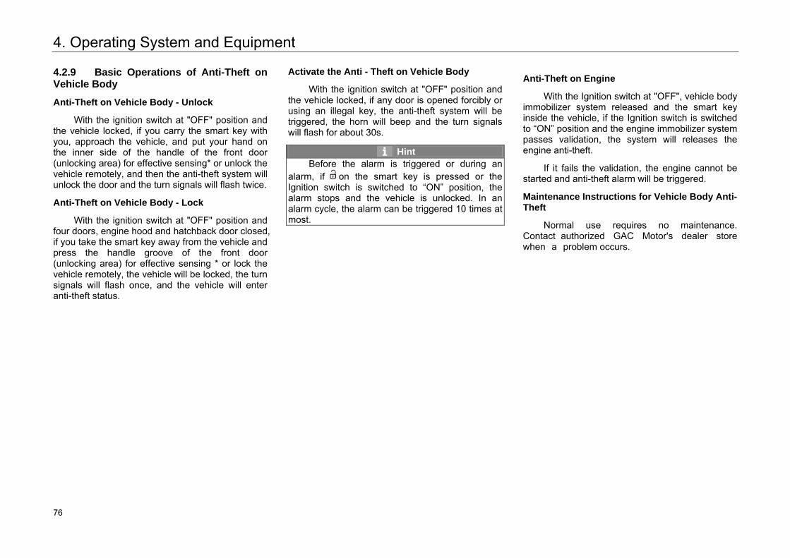
4. Operating System and Equipment
4.2.9 Basic Operations of Anti-Theft on Vehicle Body
Anti-Theft on Vehicle Body - Unlock
With the ignition switch at "OFF" position and the vehicle locked, if you carry the smart key with you, approach the vehicle, and put your hand on the inner side of the handle of the front door (unlocking area) for effective sensing* or unlock the vehicle remotely, and then the anti-theft system will unlock the door and the turn signals will flash twice.
Anti-Theft on Vehicle Body - Lock
With the ignition switch at "OFF" position and four doors, engine hood and hatchback door closed, if you take the smart key away from the vehicle and press the handle groove of the front door (unlocking area) for effective sensing * or lock the vehicle remotely, the vehicle will be locked, the turn signals will flash once, and the vehicle will enter anti-theft status.
Activate the Anti - Theft on Vehicle Body
With the ignition switch at "OFF" position and the vehicle locked, if any door is opened forcibly or using an illegal key, the anti-theft system will be triggered, the horn will beep and the turn signals will flash for about 30s.
Hint Before the alarm is triggered or during an
alarm, if on the smart key is pressed or the Ignition switch is switched to “ON” position, the alarm stops and the vehicle is unlocked. In an alarm cycle, the alarm can be triggered 10 times at most.
Anti-Theft on Engine
With the Ignition switch at "OFF", vehicle body immobilizer system released and the smart key inside the vehicle, if the Ignition switch is switched to “ON” position and the engine immobilizer system passes validation, the system will releases the engine anti-theft.
If it fails the validation, the engine cannot be started and anti-theft alarm will be triggered.
Maintenance Instructions for Vehicle Body Anti-Theft
Normal use requires no maintenance. Contact authorized GAC Motor's dealer store when a problem occurs.
82 76
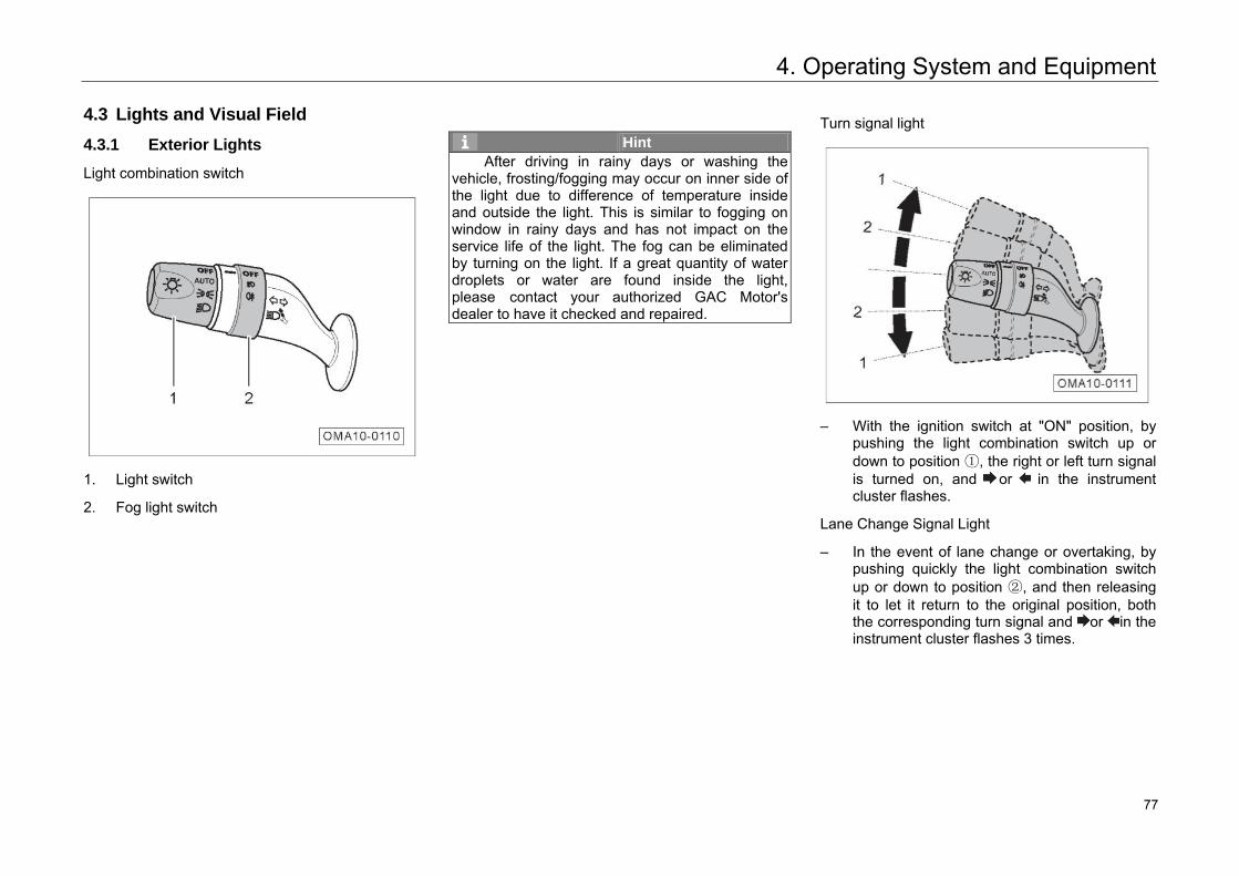
4. Operating System and Equipment
4.3 Lights and Visual Field
4.3.1 Exterior Lights
Light combination switch
1. Light switch
2. Fog light switch
Hint After driving in rainy days or washing the
vehicle, frosting/fogging may occur on inner side of the light due to difference of temperature inside and outside the light. This is similar to fogging on window in rainy days and has not impact on the service life of the light. The fog can be eliminated by turning on the light. If a great quantity of water droplets or water are found inside the light, please contact your authorized GAC Motor's dealer to have it checked and repaired.
Turn signal light
– With the ignition switch at "ON" position, bypushing the light combination switch up ordown to position ①, the right or left turn signalis turned on, and or in the instrumentcluster flashes.
Lane Change Signal Light
– In the event of lane change or overtaking, bypushing quickly the light combination switchup or down to position ②, and then releasingit to let it return to the original position, boththe corresponding turn signal and or in theinstrument cluster flashes 3 times.
83 77
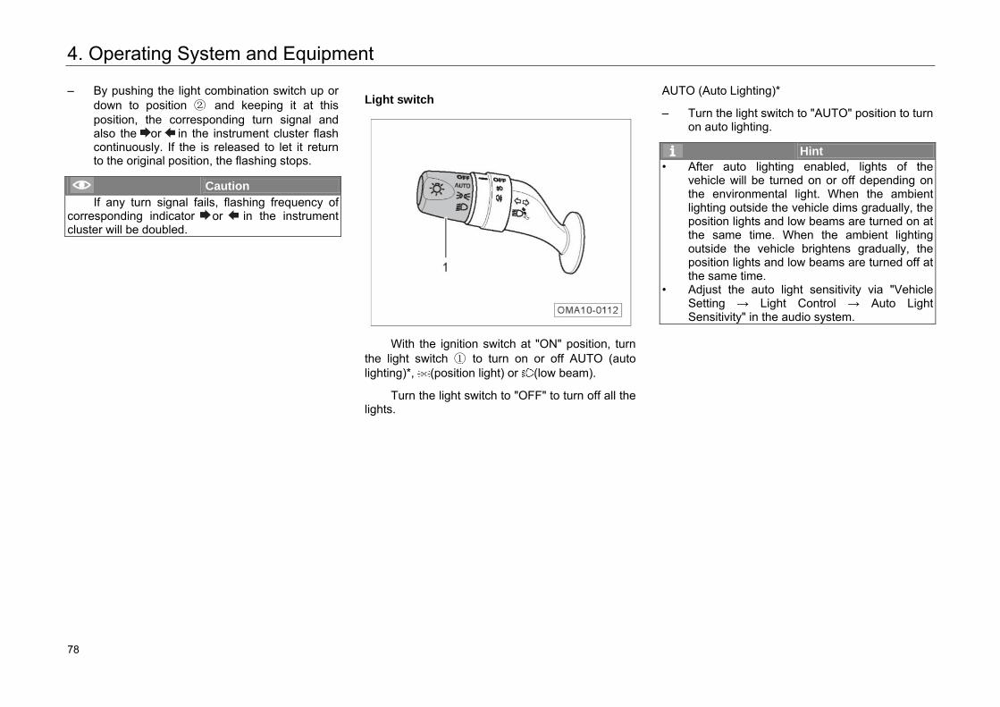
4. Operating System and Equipment
– By pushing the light combination switch up or down to position ② and keeping it at this position, the corresponding turn signal and also the or in the instrument cluster flash continuously. If the is released to let it return to the original position, the flashing stops.
Caution If any turn signal fails, flashing frequency of
corresponding indicator or in the instrument cluster will be doubled.
Light switch
With the ignition switch at "ON" position, turn
the light switch ① to turn on or off AUTO (auto lighting)*, (position light) or (low beam).
Turn the light switch to "OFF" to turn off all the lights.
AUTO (Auto Lighting)*
– Turn the light switch to "AUTO" position to turn on auto lighting.
Hint • After auto lighting enabled, lights of the
vehicle will be turned on or off depending on the environmental light. When the ambient lighting outside the vehicle dims gradually, the position lights and low beams are turned on at the same time. When the ambient lighting outside the vehicle brightens gradually, the position lights and low beams are turned off at the same time.
• Adjust the auto light sensitivity via "Vehicle Setting → Light Control → Auto Light Sensitivity" in the audio system.
84 78
4. Operating System and Equipment
Caution •
•
If the instrument cluster display "The sensor fails, please control the lighting manually", for the sake of safety, the system will keep low beams turned on. In this case, you should control the lighting manually, and go to an authorized GAC Motor's dealer to have your vehicle checked and repaired.Auto lighting may fail in heavily foggy or misty weather. Manually turn on the lights then.
Daytime Running Light
– With the engine started and the position lampis not turned on, the daytime running lightscan be automatically turned on. When theposition lights are off or the engine stops work,the daytime running lights will be automaticallyturned off.
Hint Activate or deactivate daytime running light
via "Vehicle Setting → Light Control → Daytime Running Light" in the audio system.
Position light
– By turning the light switch to position toturn on position lights, the position lights,instrument panel lighting lamp, number platelights are turned on and in the instrumentcluster is on accordingly.
Hint If you forget to turn off the position lights,
when the ignition switch is put at "OFF" position, the position lights will be turned off automatically to save battery power in the following cases: • If the vehicle is locked, the position lights will
be turned off immediately.• If the vehicle is not locked, the position lights
will be turned off 15 later.
85 79
4. Operating System and Equipment
Warning Never turn on the position light alone when
driving at night or in other road environment of low visibility. Otherwise, it can cause accidents easily.
Low beams
– Turn the light switch to position to turn on the low beams.
High beams
– Turn the light switch to position to turn on the low beams.
– By pushing forward direction of the vehicle the light combination switch to position, high beams are turned on and in the instrument cluster flashes.
– By pulling backward the light combination switch to the original position, high beams are turned off.
High Beam Flashing
– By pulling backward the light combination switch to position, the high and low beams are turned on.
– By releasing the light combination switch, it returns to the original position automatically and the high and low beams are turned off.
Hint • High beams will dazzle the drivers of other
vehicles nearby and result in accidents. Please use them properly.
• When all the lights are turned off and the light combination switch is pulled in the backward direction of the vehicle, the high and low beams will be turned on and corresponding in the instrument cluster will come on.
86 80
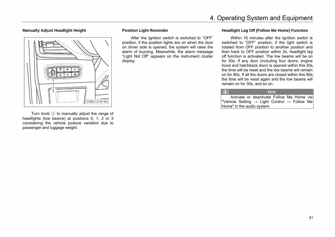
4. Operating System and Equipment
Manually Adjust Headlight Height
Turn knob ① to manually adjust the range of headlights (low beams) at positions 0, 1, 2 or 3 considering the vehicle posture variation due to passenger and luggage weight.
Position Light Reminder
After the Ignition switch is switched to “OFF” position, if the position lights are on when the door on driver side is opened, the system will raise the alarm of buzzing. Meanwhile, the alarm message “Light Not Off” appears on the instrument cluster display.
Headlight Lag Off (Follow Me Home) Function
Within 10 minutes after the Ignition switch is switched to “OFF” position, if the light switch is rotated from OFF position to another position and then back to OFF position within 2s, headlight lag off function is activated. The low beams will be on for 30s. If any door (including four doors, engine hood and hatchback door) is opened within this 30s, the time will be reset and the low beams will remain on for 80s. If all the doors are closed within this 80s, the time will be reset again and the low beams will remain on for 30s, and so on.
Hint Activate or deactivate Follow Me Home via
"Vehicle Setting → Light Control → Follow Me Home" in the audio system.
87 81
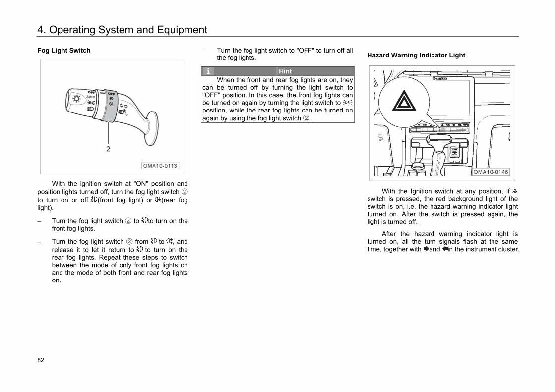
4. Operating System and Equipment
Fog Light Switch
With the ignition switch at "ON" position and position lights turned off, turn the fog light switch ② to turn on or off (front fog light) or (rear fog light).
– Turn the fog light switch ② to to turn on thefront fog lights.
– Turn the fog light switch ② from to , andrelease it to let it return to to turn on therear fog lights. Repeat these steps to switchbetween the mode of only front fog lights onand the mode of both front and rear fog lightson.
– Turn the fog light switch to "OFF" to turn off allthe fog lights.
Hint When the front and rear fog lights are on, they
can be turned off by turning the light switch to "OFF" position. In this case, the front fog lights can be turned on again by turning the light switch to position, while the rear fog lights can be turned on again by using the fog light switch ②.
Hazard Warning Indicator Light
With the Ignition switch at any position, if switch is pressed, the red background light of the switch is on, i.e. the hazard warning indicator light turned on. After the switch is pressed again, the light is turned off.
After the hazard warning indicator light is turned on, all the turn signals flash at the same time, together with and in the instrument cluster.
88 82
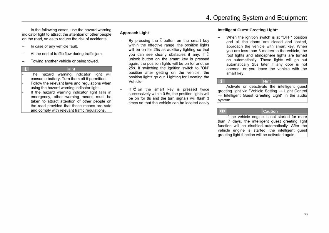
4. Operating System and Equipment
In the following cases, use the hazard warning indicator light to attract the attention of other people on the road, so as to reduce the risk of accidents:
– In case of any vehicle fault.
– At the end of traffic flow during traffic jam.
– Towing another vehicle or being towed.
Hint • The hazard warning indicator light will
consume battery. Turn them off if permitted.• Follow the relevant laws and regulations when
using the hazard warning indicator light.• If the hazard warning indicator light fails in
emergency, other warning means must be taken to attract attention of other people on the road provided that these means are safe and comply with relevant traffic regulations.
Approach Light
– By pressing the button on the smart keywithin the effective range, the position lightswill be on for 25s as auxiliary lighting so thatyou can see clearly obstacles if any. Ifunlock button on the smart key is pressedagain, the position lights will be on for another25s. If switching the Ignition switch to "ON"position after getting on the vehicle, theposition lights go out. Lighting for Locating theVehicle
– If on the smart key is pressed twicesuccessively within 0.5s, the position lights willbe on for 8s and the turn signals will flash 3times so that the vehicle can be located easily.
Intelligent Guest Greeting Light*
– When the ignition switch is at "OFF" positionand all the doors are closed and locked,approach the vehicle with smart key. Whenyou are less than 3 meters to the vehicle, theroof lights and atmosphere lights are turnedon automatically. These lights will go outautomatically 25s later if any door is notopened, or you leave the vehicle with thesmart key.
Hint Activate or deactivate the intelligent guest
greeting light via "Vehicle Setting → Light Control → Intelligent Guest Greeting Light" in the audiosystem.
Caution If the vehicle engine is not started for more
than 7 days, the intelligent guest greeting light function will be disabled automatically. After the vehicle engine is started, the intelligent guest greeting light function will be activated again.
89 83
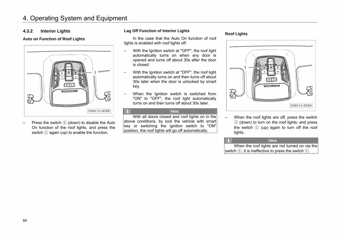
4. Operating System and Equipment
4.3.2 Interior Lights
Auto on Function of Roof Lights
– Press the switch ① (down) to disable the AutoOn function of the roof lights, and press theswitch ① again (up) to enable the function.
Lag Off Function of Interior Lights
In the case that the Auto On function of roof lights is enabled with roof lights off:
– With the Ignition switch at "OFF", the roof lightautomatically turns on when any door isopened and turns off about 30s after the dooris closed.
– With the Ignition switch at "OFF", the roof lightautomatically turns on and then turns off about30s later when the door is unlocked by smartkey.
– When the Ignition switch is switched from"ON" to "OFF", the roof light automaticallyturns on and then turns off about 30s later.
Hint With all doors closed and roof lights on in the
above conditions, by lock the vehicle with smart key or switching the ignition switch to "ON" position, the roof lights will go off automatically.
Roof Lights
– When the roof lights are off, press the switch① (down) to turn on the roof lights; and pressthe switch ① (up) again to turn off the rooflights.
Hint When the roof lights are not turned on via the
switch ①, it is ineffective to press the switch ①.
90 84
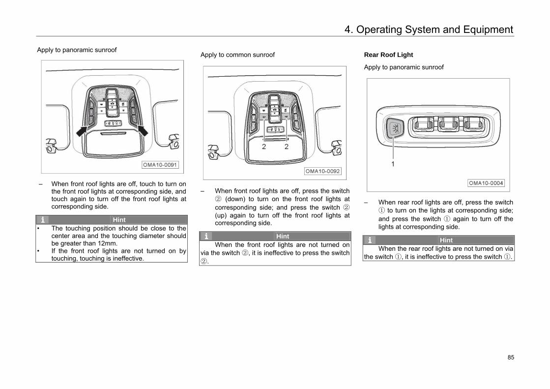
4. Operating System and Equipment
Apply to panoramic sunroof
– When front roof lights are off, touch to turn on
the front roof lights at corresponding side, and touch again to turn off the front roof lights at corresponding side.
Hint • The touching position should be close to the
center area and the touching diameter should be greater than 12mm.
• If the front roof lights are not turned on by touching, touching is ineffective.
Apply to common sunroof
– When front roof lights are off, press the switch
② (down) to turn on the front roof lights at corresponding side; and press the switch ② (up) again to turn off the front roof lights at corresponding side.
Hint When the front roof lights are not turned on
via the switch ②, it is ineffective to press the switch ②.
Rear Roof Light
Apply to panoramic sunroof
– When rear roof lights are off, press the switch
① to turn on the lights at corresponding side; and press the switch ① again to turn off the lights at corresponding side.
Hint When the rear roof lights are not turned on via
the switch ①, it is ineffective to press the switch ①.
91 85
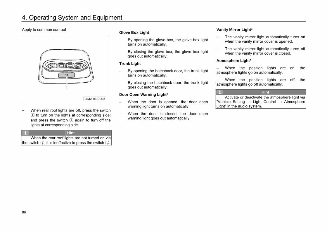
4. Operating System and Equipment
Apply to common sunroof
– When rear roof lights are off, press the switch
① to turn on the lights at corresponding side; and press the switch ① again to turn off the lights at corresponding side.
Hint When the rear roof lights are not turned on via
the switch ①, it is ineffective to press the switch ①.
Glove Box Light
– By opening the glove box, the glove box light turns on automatically.
– By closing the glove box, the glove box light goes out automatically.
Trunk Light
– By opening the hatchback door, the trunk light turns on automatically.
– By closing the hatchback door, the trunk light goes out automatically.
Door Open Warning Light*
– When the door is opened, the door open warning light turns on automatically.
– When the door is closed, the door open warning light goes out automatically.
Vanity Mirror Light*
– The vanity mirror light automatically turns on when the vanity mirror cover is opened.
– The vanity mirror light automatically turns off when the vanity mirror cover is closed.
Atmosphere Light*
– When the position lights are on, the atmosphere lights go on automatically.
– When the position lights are off, the atmosphere lights go off automatically.
Hint Activate or deactivate the atmosphere light via
"Vehicle Setting → Light Control → Atmosphere Light" in the audio system.
92 86
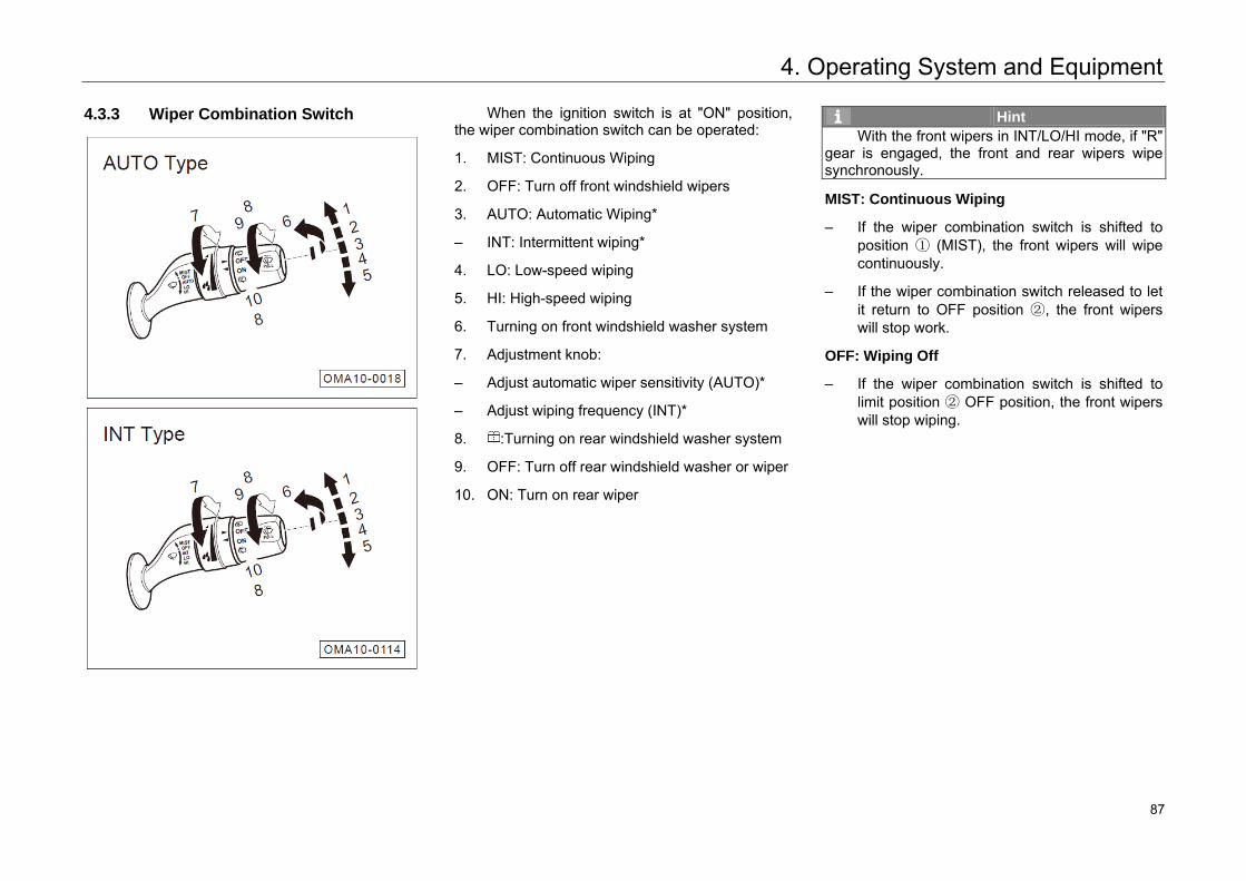
4. Operating System and Equipment
4.3.3 Wiper Combination Switch
When the ignition switch is at "ON" position, the wiper combination switch can be operated:
1. MIST: Continuous Wiping
2. OFF: Turn off front windshield wipers
3. AUTO: Automatic Wiping*
– INT: Intermittent wiping*
4. LO: Low-speed wiping
5. HI: High-speed wiping
6. Turning on front windshield washer system
7. Adjustment knob:
– Adjust automatic wiper sensitivity (AUTO)*
– Adjust wiping frequency (INT)*
8. :Turning on rear windshield washer system
9. OFF: Turn off rear windshield washer or wiper
10. ON: Turn on rear wiper
Hint With the front wipers in INT/LO/HI mode, if "R"
gear is engaged, the front and rear wipers wipe synchronously.
MIST: Continuous Wiping
– If the wiper combination switch is shifted to position ① (MIST), the front wipers will wipe continuously.
– If the wiper combination switch released to let it return to OFF position ②, the front wipers will stop work.
OFF: Wiping Off
– If the wiper combination switch is shifted to limit position ② OFF position, the front wipers will stop wiping.
93 87
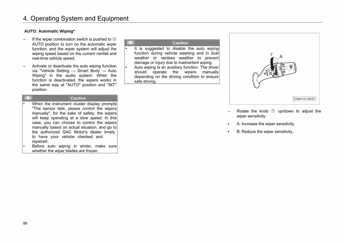
4. Operating System and Equipment
AUTO: Automatic Wiping*
– If the wiper combination switch is pushed to ③AUTO position to turn on the automatic wiperfunction, and the wiper system will adjust thewiping speed based on the current rainfall andreal-time vehicle speed.
– Activate or deactivate the auto wiping functionvia "Vehicle Setting → Smart Body → AutoWiping" in the audio system. When thefunction is deactivated, the wipers works inthe same way at "AUTO" position and "INT"position.
Caution • When the instrument cluster display prompts
"The sensor fails, please control the wipers manually", for the sake of safety, the wipers will keep operating at a slow speed. In this case, you can choose to control the wipers manually based on actual situation, and go to the authorized GAC Motor's dealer timely to have your vehicle checked and repaired.
• Before auto wiping in winter, make sure whether the wiper blades are frozen.
Caution • It is suggested to disable the auto wiping
function during vehicle washing and in dust weather or rainless weather to prevent damage or injury due to inadvertent wiping.
• Auto wiping is an auxiliary function. The driver should operate the wipers manually depending on the driving condition to ensure safe driving.
– Rotate the knob ⑦ up/down to adjust thewiper sensitivity.
• A: Increase the wiper sensitivity.
• B: Reduce the wiper sensitivity.
94 88
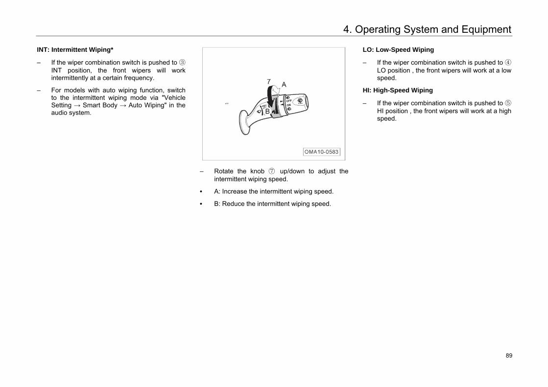
4. Operating System and Equipment
INT: Intermittent Wiping*
– If the wiper combination switch is pushed to ③INT position, the front wipers will work intermittently at a certain frequency.
– For models with auto wiping function, switch to the intermittent wiping mode via "Vehicle Setting → Smart Body → Auto Wiping" in the audio system.
– Rotate the knob ⑦ up/down to adjust the intermittent wiping speed.
• A: Increase the intermittent wiping speed.
• B: Reduce the intermittent wiping speed.
LO: Low-Speed Wiping
– If the wiper combination switch is pushed to ④LO position , the front wipers will work at a low speed.
HI: High-Speed Wiping
– If the wiper combination switch is pushed to ⑤ HI position , the front wipers will work at a high speed.
95 89
4. Operating System and Equipment
Turning on Front Windshield Washer System
– If the wiper combination switch is pulled in the backward direction of the vehicle to position ⑥, the front washer starts to jet water and the front wipers wipe a little later.
– If the wiper combination switch is released to let it return to the original position, the front windshield washer system is off and the front wipers wipe once after 6s.
– After a pause of 6 seconds, the front wipers operate once to remove residual water stains on the glass.
Turning on Rear Windshield Washer System
– When the hatchback door is closed and the rear wiper knob is rotated up/down to position ⑧ , the washer starts to jet water and the rear wiper stars to wipe. When the rear washer is switched off, the rear wiper stops wiping and wipe once after 6s.
ON: Rear Wiper On
– When hatchback door is closed, if the rear wiper knob is turned to ⑩ ON, the rear wipers begin to work.
OFF: Rear Windshield Washer or Rear Wiper Off
– If the rear wiper knob is turned to position ⑨ OFF, the rear windshield washer system will be closed, or the rear wipers will stop work.
Front Wiper Maintenance
– Within 10s after the Ignition switch is switched to “OFF” position, if the wiper combination switch lever is pushed to MIST and then pulled back rapidly, the front wipers will move to the highest positions and then stop.
Hint Activate or deactivate the front wiper
maintenance function via "Vehicle Setting → Smart Body → Front Wiper Maintenance" in the audio system.
96 90
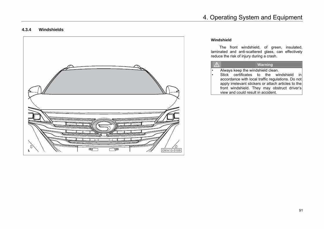
4. Operating System and Equipment
4.3.4 Windshields
Windshield
The front windshield, of green, insulated, laminated and anti-scattered glass, can effectively reduce the risk of injury during a crash.
Warning • Always keep the windshield clean. • Stick certificates to the windshield in
accordance with local traffic regulations. Do not apply irrelevant stickers or attach articles to the front windshield. They may obstruct driver’s view and could result in accident.
97 91
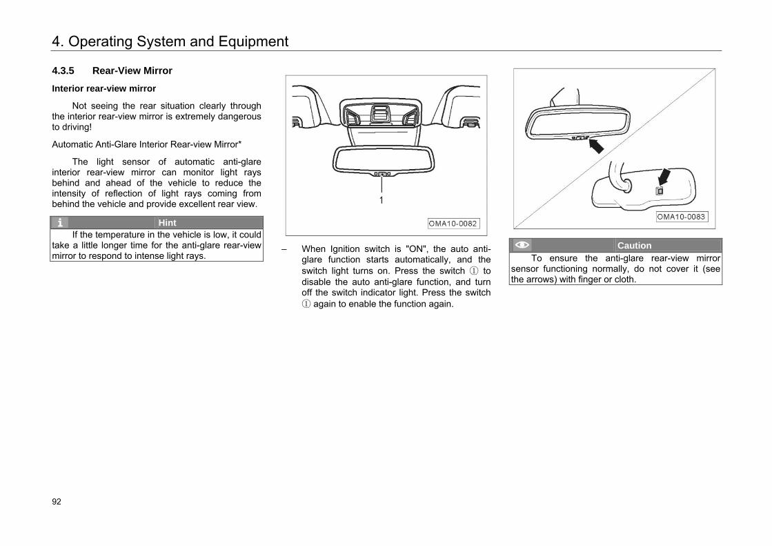
4. Operating System and Equipment
4.3.5 Rear-View Mirror
Interior rear-view mirror
Not seeing the rear situation clearly through the interior rear-view mirror is extremely dangerous to driving!
Automatic Anti-Glare Interior Rear-view Mirror*
The light sensor of automatic anti-glare interior rear-view mirror can monitor light rays behind and ahead of the vehicle to reduce the intensity of reflection of light rays coming from behind the vehicle and provide excellent rear view.
Hint If the temperature in the vehicle is low, it could
take a little longer time for the anti-glare rear-view mirror to respond to intense light rays.
– When Ignition switch is "ON", the auto anti-
glare function starts automatically, and the switch light turns on. Press the switch ① to disable the auto anti-glare function, and turn off the switch indicator light. Press the switch ① again to enable the function again.
Caution To ensure the anti-glare rear-view mirror
sensor functioning normally, do not cover it (see the arrows) with finger or cloth.
98 92
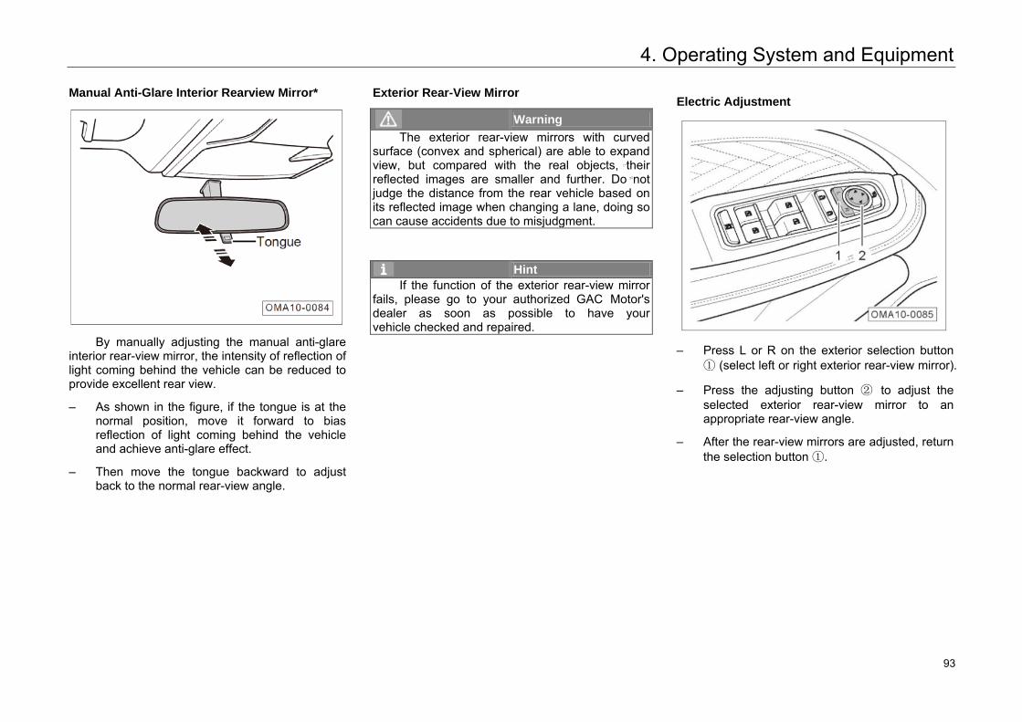
4. Operating System and Equipment
Manual Anti-Glare Interior Rearview Mirror*
By manually adjusting the manual anti-glare interior rear-view mirror, the intensity of reflection of light coming behind the vehicle can be reduced to provide excellent rear view.
– As shown in the figure, if the tongue is at thenormal position, move it forward to biasreflection of light coming behind the vehicleand achieve anti-glare effect.
– Then move the tongue backward to adjustback to the normal rear-view angle.
Exterior Rear-View Mirror
Warning The exterior rear-view mirrors with curved
surface (convex and spherical) are able to expand view, but compared with the real objects, their reflected images are smaller and further. Do not judge the distance from the rear vehicle based on its reflected image when changing a lane, doing so can cause accidents due to misjudgment.
Hint If the function of the exterior rear-view mirror
fails, please go to your authorized GAC Motor's dealer as soon as possible to have your vehicle checked and repaired.
Electric Adjustment
– Press L or R on the exterior selection button① (select left or right exterior rear-view mirror).
– Press the adjusting button ② to adjust theselected exterior rear-view mirror to anappropriate rear-view angle.
– After the rear-view mirrors are adjusted, returnthe selection button ①.
99 93
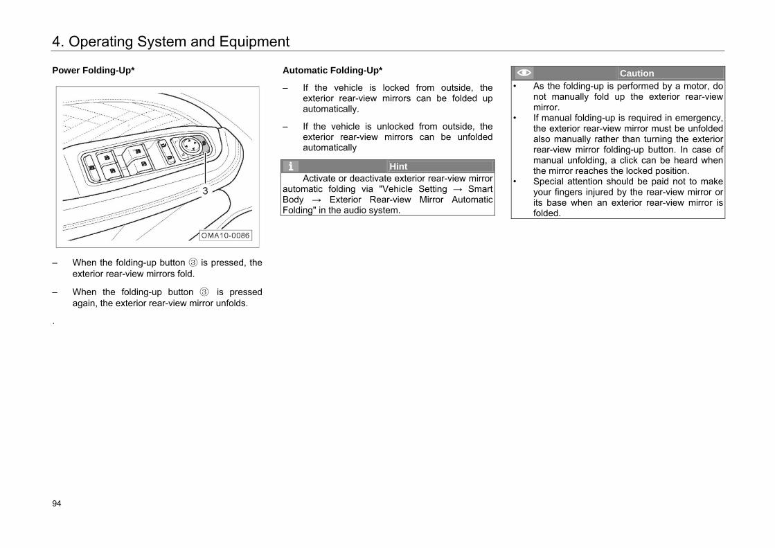
4. Operating System and Equipment
Power Folding-Up*
– When the folding-up button ③ is pressed, the exterior rear-view mirrors fold.
– When the folding-up button ③ is pressed again, the exterior rear-view mirror unfolds.
.
Automatic Folding-Up*
– If the vehicle is locked from outside, the exterior rear-view mirrors can be folded up automatically.
– If the vehicle is unlocked from outside, the exterior rear-view mirrors can be unfolded automatically
Hint Activate or deactivate exterior rear-view mirror
automatic folding via "Vehicle Setting → Smart Body → Exterior Rear-view Mirror Automatic Folding" in the audio system.
Caution • As the folding-up is performed by a motor, do
not manually fold up the exterior rear-view mirror.
• If manual folding-up is required in emergency, the exterior rear-view mirror must be unfolded also manually rather than turning the exterior rear-view mirror folding-up button. In case of manual unfolding, a click can be heard when the mirror reaches the locked position.
• Special attention should be paid not to make your fingers injured by the rear-view mirror or its base when an exterior rear-view mirror is folded.
100 94
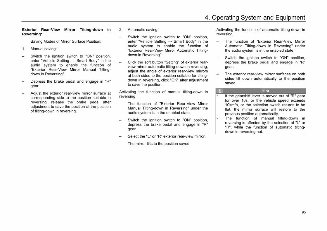
4. Operating System and Equipment
Exterior Rear-View Mirror Tilting-down in Reversing*
Saving Modes of Mirror Surface Position:
1. Manual saving:
– Switch the ignition switch to "ON" position, enter "Vehicle Setting → Smart Body" in the audio system to enable the function of "Exterior Rear-View Mirror Manual Tilting-down in Reversing".
– Depress the brake pedal and engage in "R" gear.
– Adjust the exterior rear-view mirror surface at corresponding side to the position suitable in reversing, release the brake pedal after adjustment to save the position at the position of tilting-down in reversing.
2. Automatic saving:
– Switch the ignition switch to "ON" position, enter "Vehicle Setting → Smart Body" in the audio system to enable the function of "Exterior Rear-View Mirror Automatic Tilting-down in Reversing".
– Click the soft button "Setting" of exterior rear-view mirror automatic tilting-down in reversing, adjust the angle of exterior rear-view mirrors at both sides to the position suitable for tilting-down in reversing, click "OK" after adjustment to save the position.
Activating the function of manual tilting-down in reversing
– The function of "Exterior Rear-View Mirror Manual Tilting-down in Reversing" under the audio system is in the enabled state.
– Switch the ignition switch to "ON" position, depress the brake pedal and engage in "R" gear.
– Select the "L" or "R" exterior rear-view mirror.
– The mirror tilts to the position saved.
Activating the function of automatic tilting-down in reversing
– The function of "Exterior Rear-View Mirror Automatic Tilting-down in Reversing" under the audio system is in the enabled state.
– Switch the ignition switch to "ON" position, depress the brake pedal and engage in "R" gear.
– The exterior rear-view mirror surfaces on both sides tilt down automatically to the position saved.
Hint • If the gearshift lever is moved out of "R" gear
for over 10s, or the vehicle speed exceeds 10km/h, or the selection switch returns to be flat, the mirror surface will restore to the previous position automatically.
• The function of manual tilting-down in reversing is affected by the selection of "L" or "R", while the function of automatic tilting-down in reversing not.
101 95
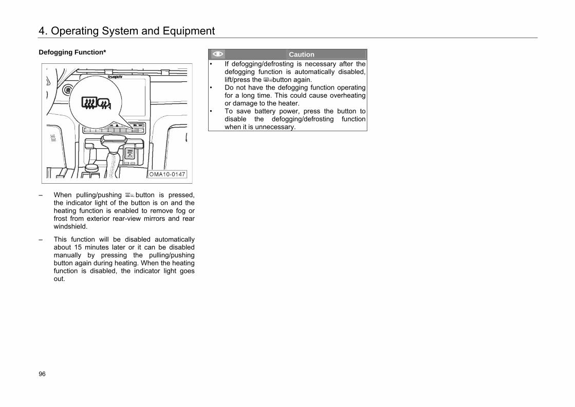
4. Operating System and Equipment
Defogging Function*
– When pulling/pushing button is pressed,
the indicator light of the button is on and the heating function is enabled to remove fog or frost from exterior rear-view mirrors and rear windshield.
– This function will be disabled automatically about 15 minutes later or it can be disabled manually by pressing the pulling/pushing button again during heating. When the heating function is disabled, the indicator light goes out.
Caution • If defogging/defrosting is necessary after the
defogging function is automatically disabled, lift/press the button again.
• Do not have the defogging function operating for a long time. This could cause overheating or damage to the heater.
• To save battery power, press the button to disable the defogging/defrosting function when it is unnecessary.
102 96
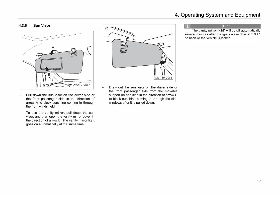
4. Operating System and Equipment
4.3.6 Sun Visor
– Pull down the sun visor on the driver side or
the front passenger side in the direction of arrow A to block sunshine coming in through the front windshield.
– To use the vanity mirror, pull down the sun visor, and then open the vanity mirror cover in the direction of arrow B. The vanity mirror light goes on automatically at the same time.
– Draw out the sun visor on the driver side or
the front passenger side from the movable support on one side in the direction of arrow C to block sunshine coming in through the side windows after it is pulled down.
Hint The vanity mirror light* will go off automatically
several minutes after the ignition switch is at "OFF" position or the vehicle is locked.
103 97
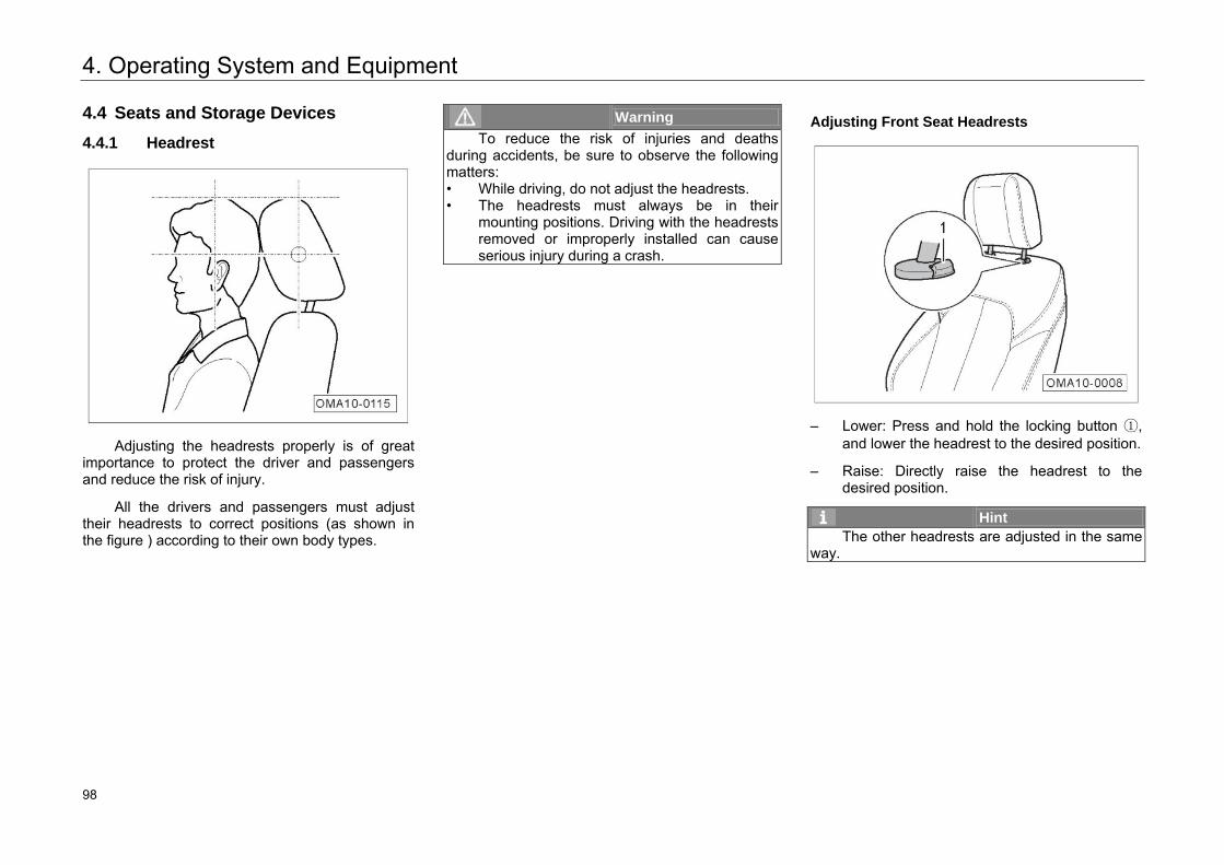
4. Operating System and Equipment
4.4 Seats and Storage Devices
4.4.1 Headrest
Adjusting the headrests properly is of great
importance to protect the driver and passengers and reduce the risk of injury.
All the drivers and passengers must adjust their headrests to correct positions (as shown in the figure ) according to their own body types.
Warning To reduce the risk of injuries and deaths
during accidents, be sure to observe the following matters: • While driving, do not adjust the headrests. • The headrests must always be in their
mounting positions. Driving with the headrests removed or improperly installed can cause serious injury during a crash.
Adjusting Front Seat Headrests
– Lower: Press and hold the locking button ①, and lower the headrest to the desired position.
– Raise: Directly raise the headrest to the desired position.
Hint The other headrests are adjusted in the same
way.
104 98
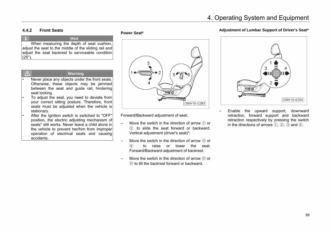
4. Operating System and Equipment
4.4.2 Front Seats
Hint When measuring the depth of seat cushion,
adjust the seat to the middle of the sliding rail and adjust the seat backrest to serviceable condition (25°).
Warning • Never place any objects under the front seats.
Otherwise, these objects may be jammed between the seat and guide rail, hindering seat locking.
• To adjust the seat, you need to deviate from your correct sitting posture. Therefore, front seats must be adjusted when the vehicle is stationary.
• After the Ignition switch is switched to "OFF" position, the electric adjusting mechanism of seats* still works. Never leave a child alone in the vehicle to prevent her/him from improper operation of electrical seats and causing accidents.
Power Seat*
Forward/Backward adjustment of seat:
– Move the switch in the direction of arrow ① or ② to slide the seat forward or backward. Vertical adjustment (driver's seat)*:
– Move the switch in the direction of arrow ③ or ④ to raise or lower the seat. Forward/Backward adjustment of backrest:
– Move the switch in the direction of arrow ⑤ or ⑥ to tilt the backrest forward or backward.
Adjustment of Lumbar Support of Driver's Seat*
– Enable the upward support, downward
retraction, forward support and backward retraction respectively by pressing the switch in the directions of arrows ①, ②, ③ and ④.
105 99
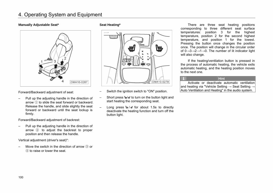
4. Operating System and Equipment
Manually Adjustable Seat*
Forward/Backward adjustment of seat:
– Pull up the adjusting handle in the direction of arrow ① to slide the seat forward or backward. Release the handle, and slide slightly the seat forward or backward until the seat lockup is firmly.
Forward/Backward adjustment of backrest:
– Pull up the adjusting handle in the direction of arrow ② to adjust the backrest to proper position and then release the handle.
Vertical adjustment (driver's seat)*:
– Move the switch in the direction of arrow ③ or ④ to raise or lower the seat.
Seat Heating*
– Switch the ignition switch to "ON" position.
– Short press / to turn on the button light and start heating the corresponding seat.
– Long press / for about 1.5s to directly deactivate the heating function and turn off the button light.
There are three seat heating positions corresponding to three different seat surface temperatures: position 3 for the highest temperature, position 2 for the second highest temperature, and position 1 for the lowest. Pressing the button once changes the position once. The position will change in the circular order of 0→3→2→1→0. The number of lit indicator light will also change.
If the heating/ventilation button is pressed in the process of automatic heating, the vehicle exits automatic heating, and the heating position moves to the next one.
Hint Activate or deactivate automatic ventilation
and heating via "Vehicle Setting → Seat Setting → Auto Ventilation and Heating" in the audio system.
106 100
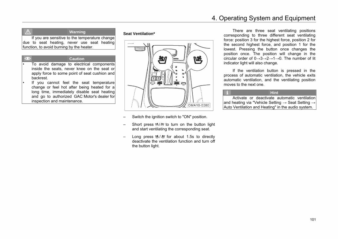
4. Operating System and Equipment
Warning If you are sensitive to the temperature change
due to seat heating, never use seat heating function, to avoid burning by the heater.
Caution • To avoid damage to electrical components
inside the seats, never knee on the seat or apply force to some point of seat cushion and backrest.
• If you cannot feel the seat temperature change or feel hot after being heated for a long time, immediately disable seat heating and go to authorized GAC Motor's dealer for inspection and maintenance.
Seat Ventilation*
– Switch the ignition switch to "ON" position.
– Short press / to turn on the button lightand start ventilating the corresponding seat.
– Long press / for about 1.5s to directlydeactivate the ventilation function and turn offthe button light.
There are three seat ventilating positions corresponding to three different seat ventilating force: position 3 for the highest force, position 2 for the second highest force, and position 1 for the lowest. Pressing the button once changes the position once. The position will change in the circular order of 0→3→2→1→0. The number of lit indicator light will also change.
If the ventilation button is pressed in the process of automatic ventilation, the vehicle exits automatic ventilation, and the ventilating position moves to the next one.
Hint Activate or deactivate automatic ventilation
and heating via "Vehicle Setting → Seat Setting → Auto Ventilation and Heating" in the audio system.
107 101
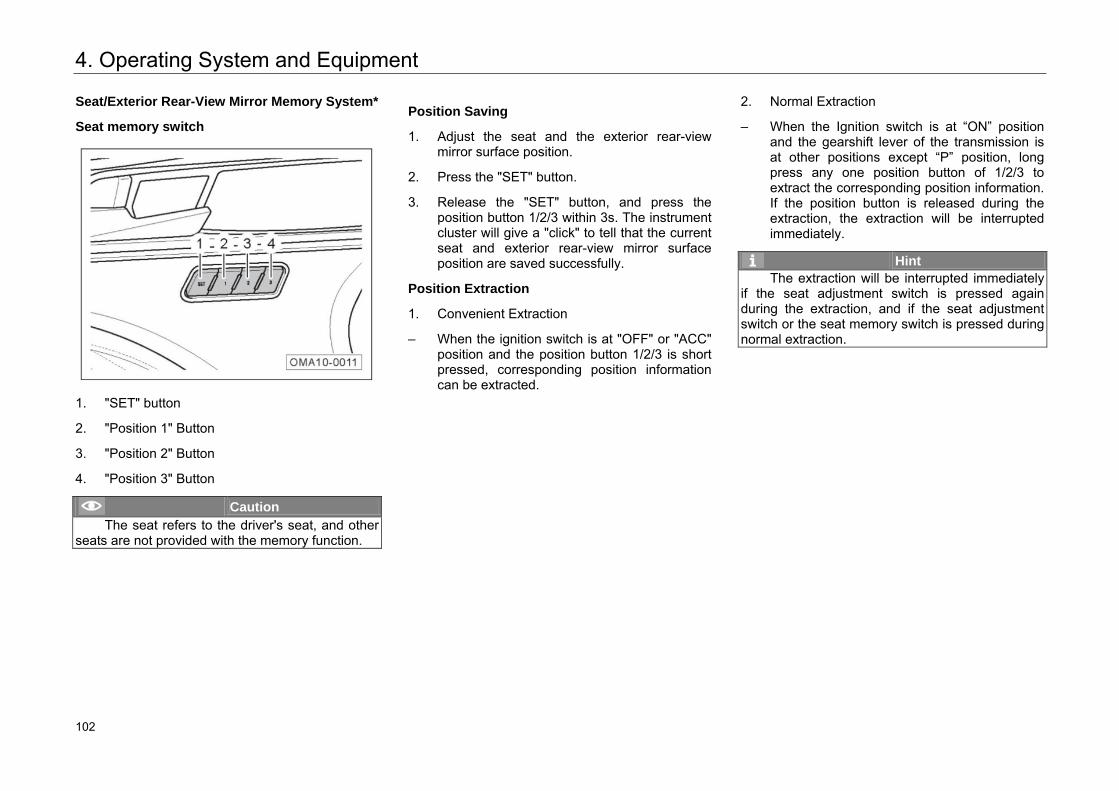
4. Operating System and Equipment
Seat/Exterior Rear-View Mirror Memory System*
Seat memory switch
1. "SET" button
2. "Position 1" Button
3. "Position 2" Button
4. "Position 3" Button
Caution The seat refers to the driver's seat, and other
seats are not provided with the memory function.
Position Saving
1. Adjust the seat and the exterior rear-view mirror surface position.
2. Press the "SET" button.
3. Release the "SET" button, and press the position button 1/2/3 within 3s. The instrument cluster will give a "click" to tell that the current seat and exterior rear-view mirror surface position are saved successfully.
Position Extraction
1. Convenient Extraction
– When the ignition switch is at "OFF" or "ACC" position and the position button 1/2/3 is short pressed, corresponding position information can be extracted.
2. Normal Extraction
– When the Ignition switch is at “ON” position and the gearshift lever of the transmission is at other positions except “P” position, long press any one position button of 1/2/3 to extract the corresponding position information. If the position button is released during the extraction, the extraction will be interrupted immediately.
Hint The extraction will be interrupted immediately
if the seat adjustment switch is pressed again during the extraction, and if the seat adjustment switch or the seat memory switch is pressed during normal extraction.
108 102
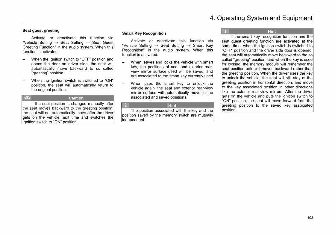
4. Operating System and Equipment
Seat guest greeting
Activate or deactivate this function via "Vehicle Setting → Seat Setting → Seat Guest Greeting Function" in the audio system. When this function is activated:
– When the Ignition switch to “OFF” position and opens the door on driver side, the seat will automatically move backward to so called “greeting” position.
– When the Ignition switch is switched to "ON" position, the seat will automatically return to the original position.
Caution If the seat position is changed manually after
the seat moves backward to the greeting position, the seat will not automatically move after the driver gets on the vehicle next time and switches the Ignition switch to “ON” position.
Smart Key Recognition
Activate or deactivate this function via "Vehicle Setting → Seat Setting → Smart Key Recognition" in the audio system. When this function is activated:
– When leaves and locks the vehicle with smart key, the positions of seat and exterior rear-view mirror surface used will be saved, and are associated to the smart key currently used.
– When uses the smart key to unlock the vehicle again, the seat and exterior rear-view mirror surface will automatically move to the associated and saved positions.
Hint The position associated with the key and the
position saved by the memory switch are mutually independent.
Hint If the smart key recognition function and the
seat guest greeting function are activated at the same time, when the ignition switch is switched to "OFF" position and the driver side door is opened, the seat will automatically move backward to the so called "greeting" position, and when the key is used for locking, the memory module will remember the seat position before it moves backward rather than the greeting position. When the driver uses the key to unlock the vehicle, the seat will still stay at the greeting position in horizontal direction, and move to the key associated position in other directions like the exterior rear-view mirrors. After the driver gets on the vehicle and puts the ignition switch to "ON" position, the seat will move forward from the greeting position to the saved key associated position.
109 103
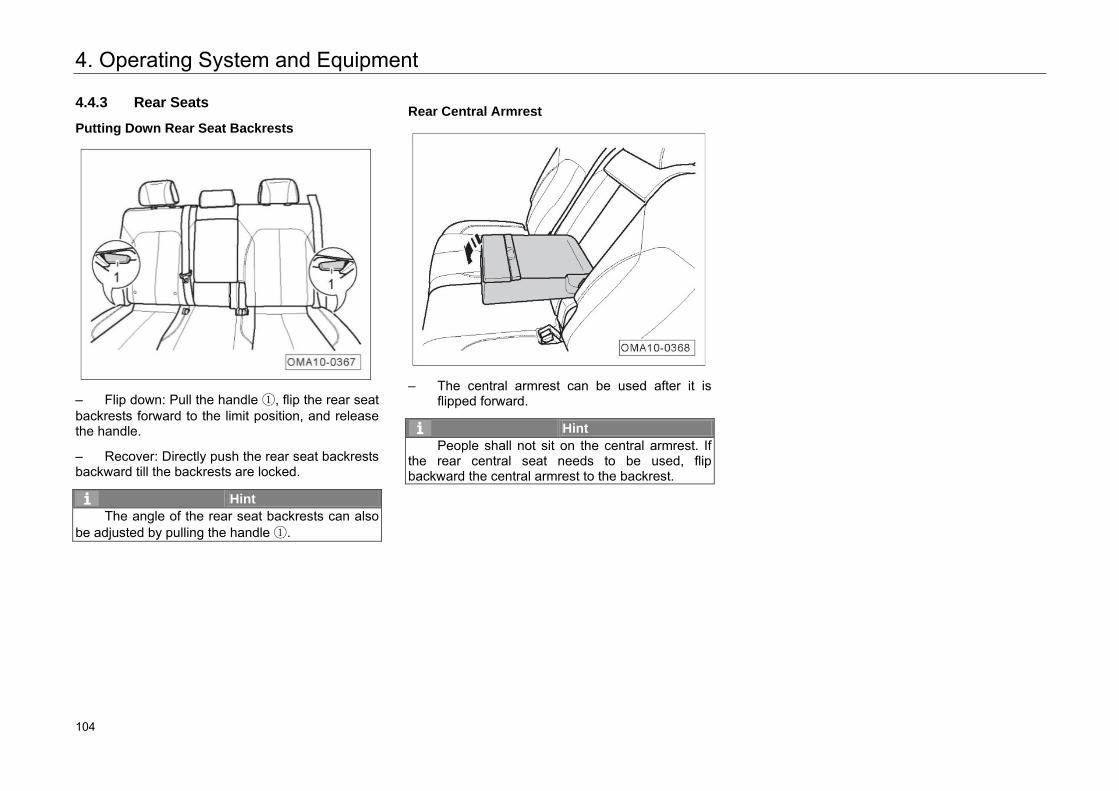
4. Operating System and Equipment
4.4.3 Rear Seats
Putting Down Rear Seat Backrests
– Flip down: Pull the handle ①, flip the rear seat backrests forward to the limit position, and release the handle.
– Recover: Directly push the rear seat backrests backward till the backrests are locked.
Hint The angle of the rear seat backrests can also
be adjusted by pulling the handle ①.
Rear Central Armrest
– The central armrest can be used after it is
flipped forward.
Hint People shall not sit on the central armrest. If
the rear central seat needs to be used, flip backward the central armrest to the backrest.
110 104
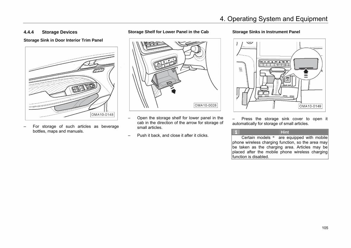
4. Operating System and Equipment
4.4.4 Storage Devices
Storage Sink in Door Interior Trim Panel
– For storage of such articles as beverage bottles, maps and manuals.
Storage Shelf for Lower Panel in the Cab
– Open the storage shelf for lower panel in the cab in the direction of the arrow for storage of small articles.
– Push it back, and close it after it clicks.
Storage Sinks in Instrument Panel
– Press the storage sink cover to open it automatically for storage of small articles.
Hint Certain models * are equipped with mobile
phone wireless charging function, so the area may be taken as the charging area. Articles may be placed after the mobile phone wireless charging function is disabled.
111 105
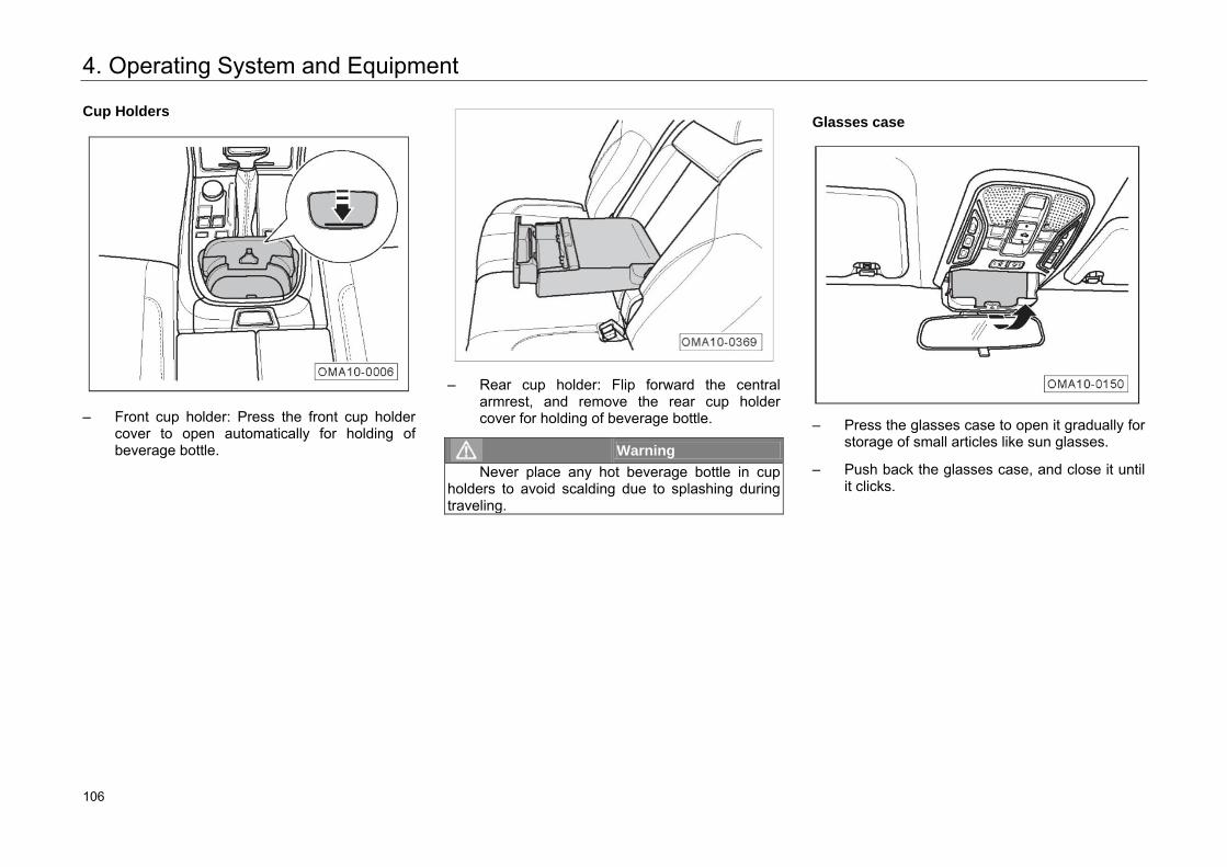
4. Operating System and Equipment
Cup Holders
– Front cup holder: Press the front cup holder
cover to open automatically for holding of beverage bottle.
– Rear cup holder: Flip forward the central
armrest, and remove the rear cup holder cover for holding of beverage bottle.
Warning Never place any hot beverage bottle in cup
holders to avoid scalding due to splashing during traveling.
Glasses case
– Press the glasses case to open it gradually for storage of small articles like sun glasses.
– Push back the glasses case, and close it until it clicks.
112 106
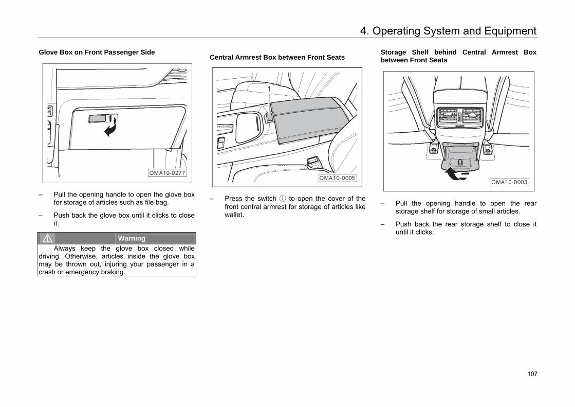
4. Operating System and Equipment
Glove Box on Front Passenger Side
– Pull the opening handle to open the glove box
for storage of articles such as file bag.
– Push back the glove box until it clicks to close it.
Warning Always keep the glove box closed while
driving. Otherwise, articles inside the glove box may be thrown out, injuring your passenger in a crash or emergency braking.
Central Armrest Box between Front Seats
– Press the switch ① to open the cover of the front central armrest for storage of articles like wallet.
Storage Shelf behind Central Armrest Box between Front Seats
– Pull the opening handle to open the rear
storage shelf for storage of small articles.
– Push back the rear storage shelf to close it until it clicks.
113 107
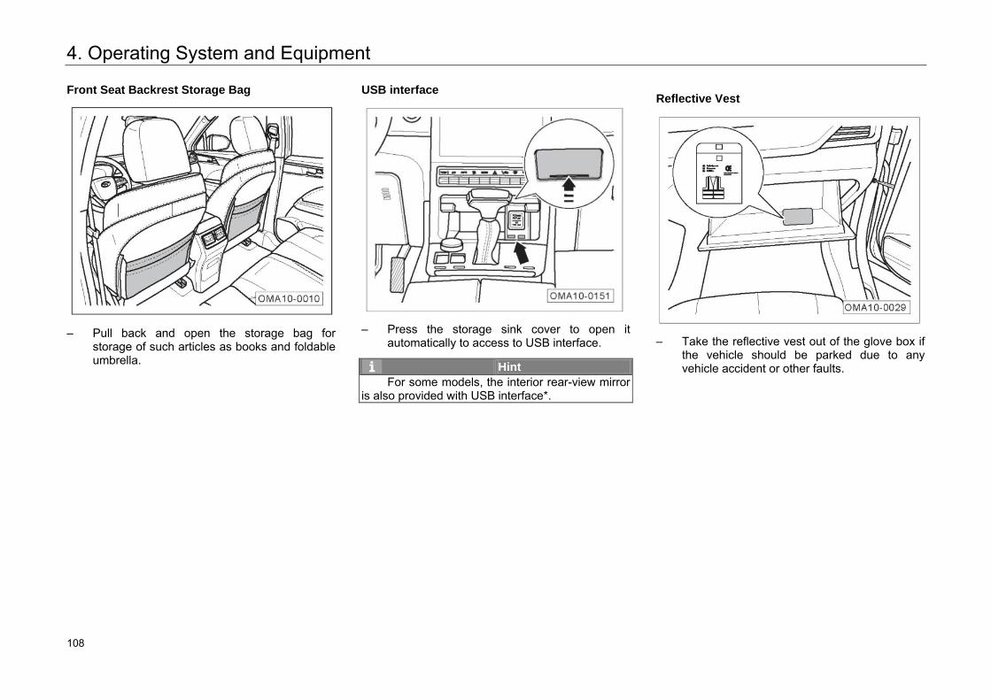
4. Operating System and Equipment
Front Seat Backrest Storage Bag
– Pull back and open the storage bag for storage of such articles as books and foldable umbrella.
USB interface
– Press the storage sink cover to open it automatically to access to USB interface.
Hint For some models, the interior rear-view mirror
is also provided with USB interface*.
Reflective Vest
– Take the reflective vest out of the glove box if
the vehicle should be parked due to any vehicle accident or other faults.
114 108
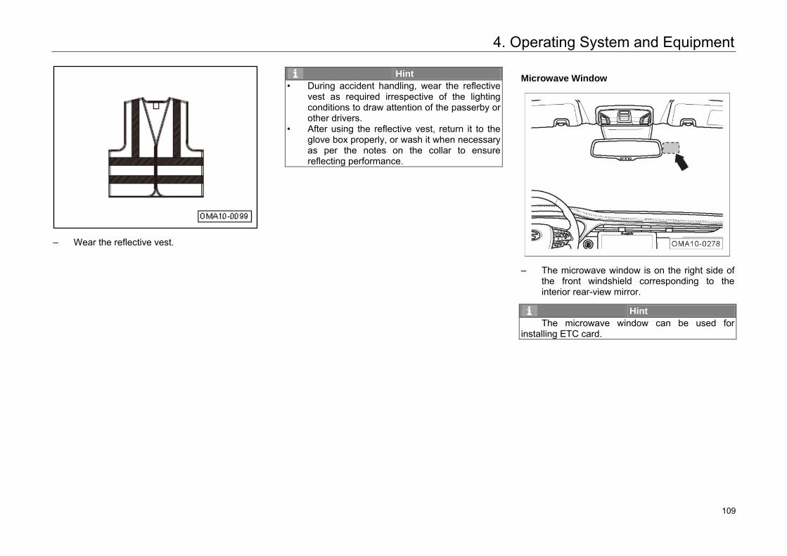
4. Operating System and Equipment
– Wear the reflective vest.
Hint • During accident handling, wear the reflective
vest as required irrespective of the lighting conditions to draw attention of the passerby or other drivers.
• After using the reflective vest, return it to the glove box properly, or wash it when necessary as per the notes on the collar to ensure reflecting performance.
Microwave Window
– The microwave window is on the right side of the front windshield corresponding to the interior rear-view mirror.
Hint The microwave window can be used for
installing ETC card.
115 109
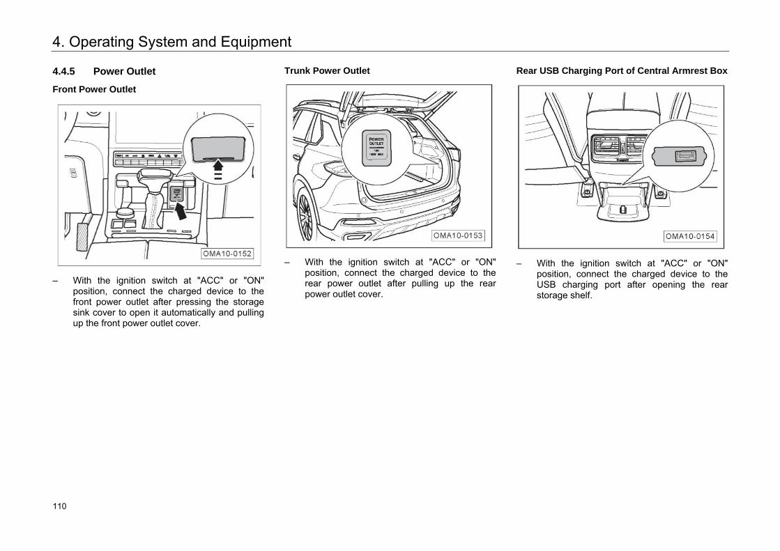
4. Operating System and Equipment
4.4.5 Power Outlet
Front Power Outlet
– With the ignition switch at "ACC" or "ON" position, connect the charged device to the front power outlet after pressing the storage sink cover to open it automatically and pulling up the front power outlet cover.
Trunk Power Outlet
– With the ignition switch at "ACC" or "ON" position, connect the charged device to the rear power outlet after pulling up the rear power outlet cover.
Rear USB Charging Port of Central Armrest Box
– With the ignition switch at "ACC" or "ON" position, connect the charged device to the USB charging port after opening the rear storage shelf.
116 110
4. Operating System and Equipment
Warning Improper use of power outlet can cause fire.
Do not let a child to operate a power outlet.
Caution • To avoid damage to the electrical system, do
not connect any generating equipment to the power outlet.
• Use only electrical equipment in line with the national electromagnetic compatibility norms.
• To switch the ignition switch to "ON" or "OFF", disconnect the charged device from the power outlet to avoid damage to electrical equipment due to voltage fluctuation.
• Do not use overpowered electrical equipment.
117 111
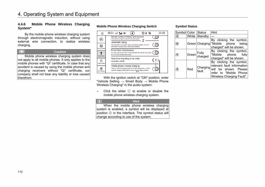
4. Operating System and Equipment
4.4.6 Mobile Phone Wireless Charging System*
By the mobile phone wireless charging system through electromagnetic induction, without using external wire connection, to realize wireless charging.
Caution Mobile phone wireless charging system does
not apply to all mobile phones. It only applies to the mobile phones with “Qi” certificate. In case that any accident is caused by using the mobile phones and charging receivers without “Qi” certificate, our company shall not bear any liability or loss caused therefrom.
Mobile Phone Wireless Charging Switch
With the ignition switch at "ON" position, enter
"Vehicle Setting → Smart Body → Mobile Phone Wireless Charging" in the audio system:
– Click the slider ① to enable or disable the mobile phone wireless charging system.
Hint When the mobile phone wireless charging
system is enabled, a symbol will be displayed at position ② in the interface. The symbol status will change according to use of the system.
Symbol Status
Symbol Color Status Hint White Standby —
Green Charging By clicking the symbol, "Mobile phone being charged" will be shown.
Green Fully charged
By clicking the symbol, "Mobile phone fully charged" will be shown.
Red Charging fault
By clicking the symbol, relevant fault information will be shown. Please refer to "Mobile Phone Wireless Charging Fault".
118 112
4. Operating System and Equipment
Mobile Phone Wireless Charging Fault
Abnormal Scenario Content of Prompt Internal over-temperature of wireless charging module
Over-temperature, please remove your phone and try again later
Existence of foreign metal article in the placement area of wireless charging module
Foreign metal article existing, please remove it and place your mobile phone again
Power supply voltage of wireless charging module too low or too high
Abnormal voltage, please remove your phone and try again later
Charging power requested by the receiving end too high, or transmitting power of wireless charging module too high
Abnormal power, please remove your phone and try again later
Abnormal status at the receiving end
Charging interrupted, please remove your phone and try again later
Hint • Only one mobile phone can be charged at a
time. • To ensure normal charging of mobile phone,
make sure that the center of the mobile phone is aligned with the Qi logo in the front storage box as far as possible.
• For AT models, opening a door will interrupt the charging function. Make sure that all the doors are closed during charging.
• While the vehicle is running on a bumpy road, mobile phone wireless charging could interrupt intermittently then resume. If the charging stops due to mobile phone departure from the charging area, move the mobile phone back to the charging area.
• Any fault of the system or the mobile phone may result in a failure to charge.
• The mobile phone charging may stop at too high temperature, and resume charging after the temperature drops.
Caution • Do not place anything between the mobile
phone and the charging panel during charging. Non-metallic articles may degrade the charging performance. Articles such as magnetic cards or chip cards may be damaged. Foreign metal articles such as keys and coins may be heated, posing a driving safety hazard.
• Disable the wireless charging function before placement of any foreign metal article in the front storage box. Otherwise, the metal article may slide into the charging area and be heated during driving, posing a safety hazard.
• During mobile phone wireless charging, if any foreign metal article is found between the mobile phone and the rubber pad, do not remove it immediately to prevent finger burning. In this case, immediately disable the system, and remove the article after cooling.
• Please never sprinkle water in charging area, lest the water enters wireless charger module through the clearance of rubber pad to cause wireless charger module faults.
119 113
4. Operating System and Equipment
Warning • When driver is not in the vehicle, please do
not place mobile phone inside for charging, so as not to cause potential safety hazards.
• Please do not check the mobile phone charging status frequently in driving, to avoid potential traffic danger.
• Please do not place weight in charging area to avoid damage to the mobile phone wireless charging system.
• If there is any problem in the product and it cannot be used normally, please stop operation and go to the authorized GAC Motor's dealer to have it checked and repaired.
• Our company shall not be liable for any problem due to abnormal operation (e.g., connection to external wireless charging coil). If the product has ever been unpacked or modified, free warranty service will be terminated.
120 114
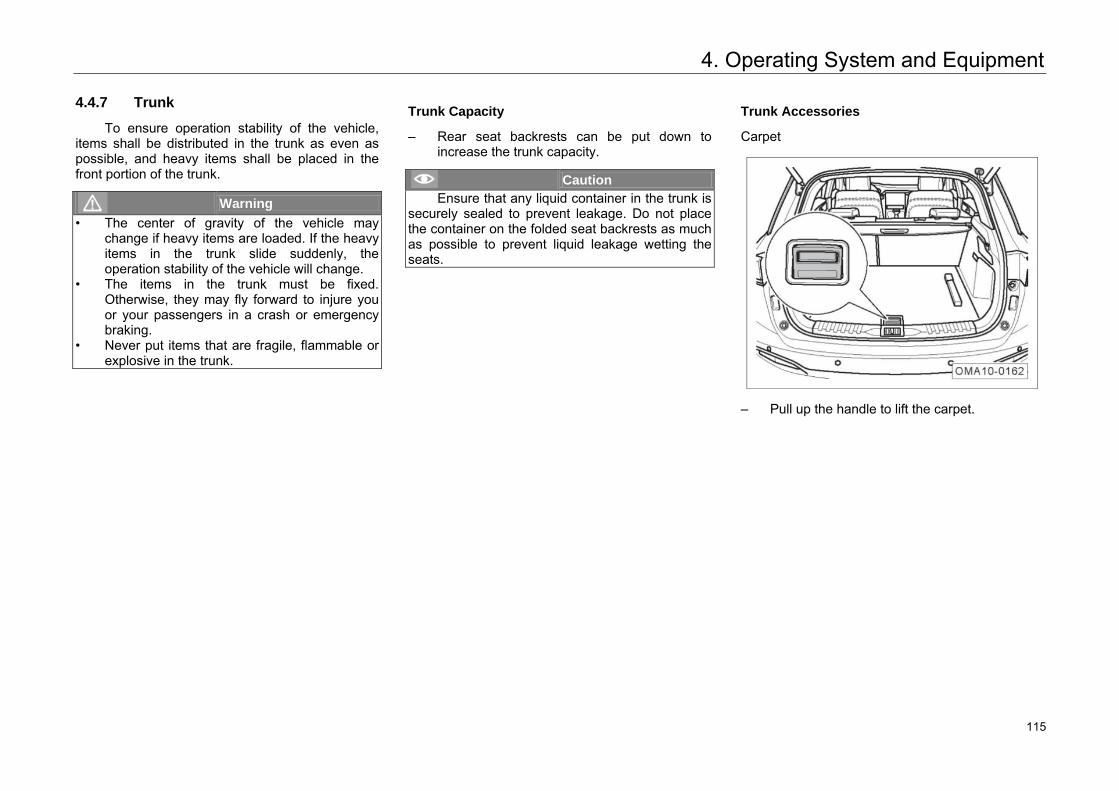
4. Operating System and Equipment
4.4.7 Trunk
To ensure operation stability of the vehicle, items shall be distributed in the trunk as even as possible, and heavy items shall be placed in the front portion of the trunk.
Warning • The center of gravity of the vehicle may
change if heavy items are loaded. If the heavy items in the trunk slide suddenly, the operation stability of the vehicle will change.
• The items in the trunk must be fixed. Otherwise, they may fly forward to injure you or your passengers in a crash or emergency braking.
• Never put items that are fragile, flammable or explosive in the trunk.
Trunk Capacity
– Rear seat backrests can be put down to increase the trunk capacity.
Caution Ensure that any liquid container in the trunk is
securely sealed to prevent leakage. Do not place the container on the folded seat backrests as much as possible to prevent liquid leakage wetting the seats.
Trunk Accessories
Carpet
– Pull up the handle to lift the carpet.
121 115
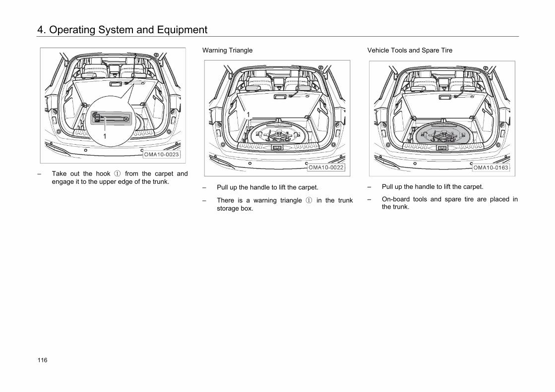
4. Operating System and Equipment
– Take out the hook ① from the carpet and engage it to the upper edge of the trunk.
Warning Triangle
– Pull up the handle to lift the carpet.
– There is a warning triangle ① in the trunk storage box.
Vehicle Tools and Spare Tire
– Pull up the handle to lift the carpet.
– On-board tools and spare tire are placed in the trunk.
122 116
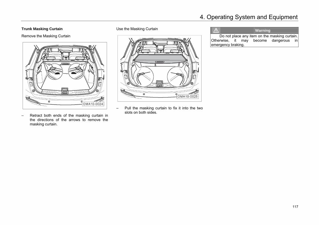
4. Operating System and Equipment
Trunk Masking Curtain
Remove the Masking Curtain
– Retract both ends of the masking curtain in
the directions of the arrows to remove the masking curtain.
Use the Masking Curtain
– Pull the masking curtain to fix it into the two
slots on both sides.
Warning Do not place any item on the masking curtain.
Otherwise, it may become dangerous in emergency braking.
123 117
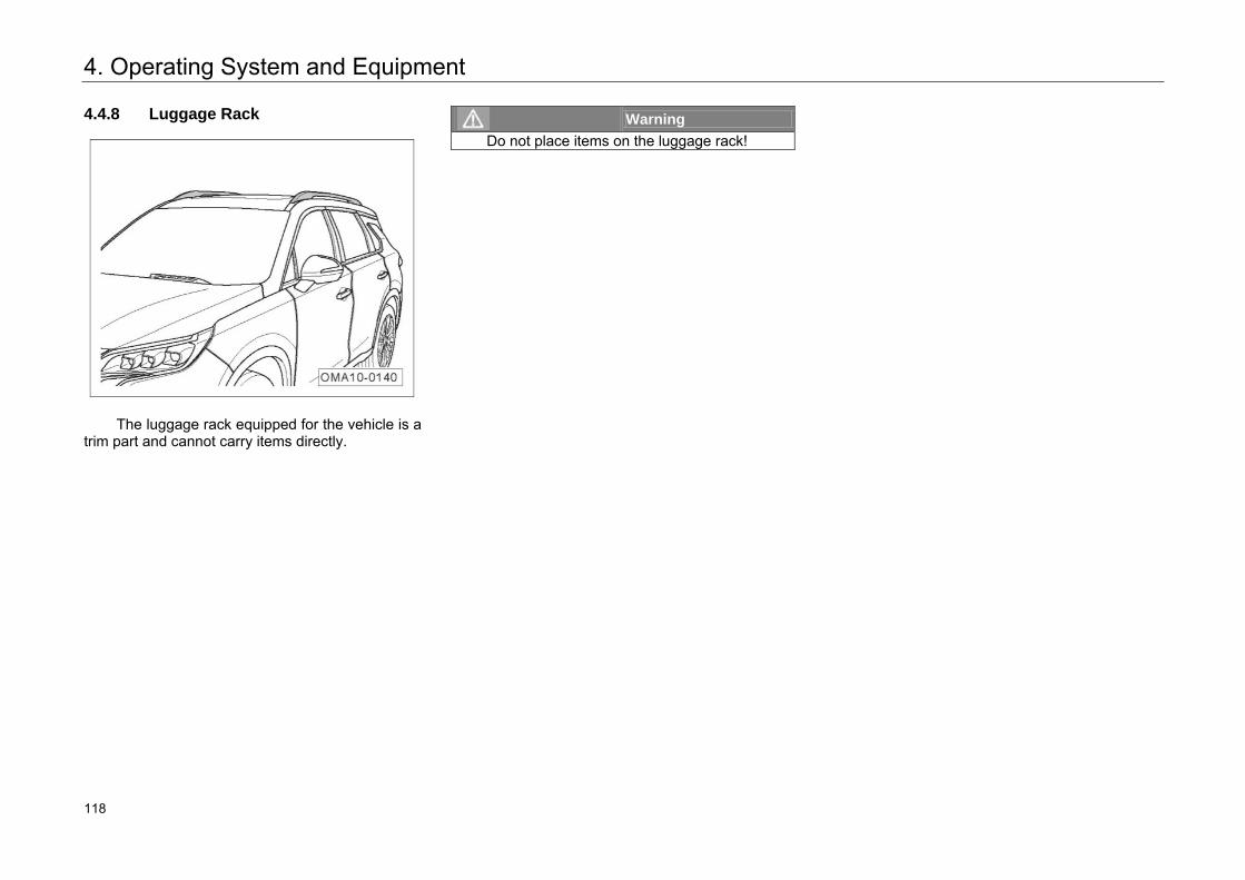
4. Operating System and Equipment
4.4.8 Luggage Rack
The luggage rack equipped for the vehicle is a
trim part and cannot carry items directly.
Warning Do not place items on the luggage rack!
124 118
4. Operating System and Equipment
4.4.9 Accessories and Modifications
The data labels and signboards attached to the fuel tank lid, engine hood lock rack and other vehicle components of the vehicle, when delivered, contain important data and information on vehicle operation. Do not remove or damage such labels and signboards. Always keep the data and information on the labels and signboards clear and readable.
This vehicle is designed with the latest safety technique to ensure excellent active safety and passive safety. Therefore, to maintain the vehicle's excellent features, before installing accessories or replacing components, be sure to consult authorized GAC Motor's dealer.
We recommend you always use the accessories and components which have been designed and approved for your vehicle. We are not responsible for any component not manufactured by us.
Warning Improper accessories or modifications may
affect your car's operation stability and other performance, and may lead to severe injury or death.
If vehicle phone, alarm device, two-way radio equipment, and low-power AUDIO system need to be installed, they should not interfere with your car's computer control system, such as Anti-lock Brake System (ABS).
Before installing any accessory:
1. Make sure that the accessory does not dimany light, or affect normal operation orperformance of the vehicle.
2. Do not install accessories on the B pillar oracross the rear windows for vehicles equippedwith integrated side airbag curtain, becauseaccessories installed in these areas mayinterfere with normal operation of side airbagcurtain.
Hint For installation of boutiques (such as
headrest, seat cover, foot mat and sun cover pad), inferior boutiques may influence the air quality in the vehicle due to VOC not complying with national standards and emission of abnormal odor. It is suggested to select high-quality OEM parts to ensure a comfortable driving environment.
125 119
4. Operating System and Equipment
Modifying Your Car
Removing components from your vehicle, or replacing components with non-GAC MOTOR model components could seriously affect your car's operation stability and reliability. For example:
– Installing larger or smaller wheels and tires can interfere with normal operation of ABS and other systems.
– Modifying the steering wheel or any other safety facility may lead to system failure.
Warning • Improper accessories or modifications can
easily cause faults and accidents. We recommend you always use the approved accessories and components with strictly-verified adaptability, reliability and safety by GAC MOTOR.
• Improper maintenance or modifications can weaken the protection from airbags, and cause system failure and fatal accidents. Do not install or connect the beverage cup holder, phone holder and other accessories onto the cover of airbag assembly or in the range of action of airbags.
• Improper operation or modifications (modification of the engine, brake system or components affecting the performance of the wheels and tires) can affect the function of the SRS system, resulting in serious injury or death.
• Do not install wheels and tires not approved by GAC MOTOR.
Warning • Modifying the front part of the vehicle and the
engine compartment can deteriorate pedestrian protection performance of the vehicle and violates the road regulations.
126 120
4. Operating System and Equipment
4.5 A/C System
4.5.1 General Instructions
The A/C filter can filter the pollen and dust brought in from the inlet of the A/C system.
The A/C filter must be cleaned and replaced regularly in accordance with the regulations in "Regular Maintenance Schedule" in the Warranty Manual.
If the vehicle often runs in areas with poor air quality, the replacement interval of the A/C filter shall be shortened. If the air flow from the A/C air outlet is not smooth as usual, the A/C filter may be blocked. Clean or replace the A/C filter as soon as possible.
Warning Turbid air in the vehicle will make the driver
fatigued, depressed and distracted, resulting in accidents and casualties easily. The air circulation mode shall be selected according to the actual situation.
Caution If the A/C system has any fault (such as
refrigeration failure and outlet air with abnormal odor), please go to any authorized GAC Motor's dealer for maintenance.
Hint • Water drops from the bottom of the vehicle
when the A/C is turned on, and wateraccumulates at the bottom of the vehicle when the vehicle is parked for long with A/C on.These phenomena are normal.
• The air inlet at the bottom of the front windshield should be unblocked, and not clogged by snow, ice and leaves to ensure normal air inlet of the A/C system.
• All the windows and the sunroof must be closed for the A/C system to play a maximum effect. If the vehicle has been exposed to theburning sun and it is very hot in the vehicle, you should open the windows for a short time to dissipate the heat before using the A/C forcooling.
127 121
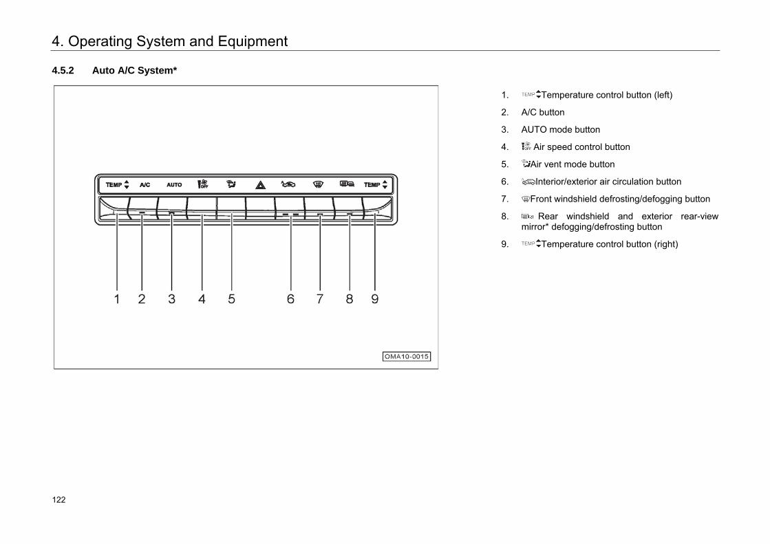
4. Operating System and Equipment
4.5.2 Auto A/C System*
1. Temperature control button (left)
2. A/C button
3. AUTO mode button
4. Air speed control button
5. Air vent mode button
6. Interior/exterior air circulation button
7. Front windshield defrosting/defogging button
8. Rear windshield and exterior rear-view mirror* defogging/defrosting button
9. Temperature control button (right)
128 122
4. Operating System and Equipment
Hint The A/C system can also be controlled by
switched the audio system display interface to the A/C system control interface.
Temperature Setting
– Pull/push the button to raise/lower the temperature at a step of 0.5°C.
– The adjusted temperature value is shown on the audio display. The temperature is adjustable within 18.5℃~31.5℃. When the set temperature is lower than 18.5°C, LO is shown; and when the set temperature is higher than 31.5°C, HI is shown.
In AUTO mode, LO/HI is reached, the system will keep operating in a large air supply state.
In AUTO mode, in order to obtain the most ideal interior temperature, we recommend that the set temperature is 25.0°C. If necessary, you can adjust the temperature by yourself.
Hint The temperature value on the display is the
target value of the set temperature, instead of the measured value of the interior temperature.
A/C Button
When pulling/pushing A/C button is pressed, the button light will be on and the refrigeration function of the A/C system will be enabled. When the refrigeration function is enabled:
– This mean refrigeration / dehumidification is needed, but the compressor is not necessary to run.
– If the outside temperature is below 0°C, the button light will be on, but the compressor may not work.
When pulling/pushing A/C button is pressed again, the button light will be off and the refrigeration function will be disabled.
129 123
4. Operating System and Equipment
AUTO Mode
When AUTO button is pulled/pushed, the button light is on, the A/C system enters the AUTO mode, and the following items are controlled automatically as per respective set value:
– Air vent temperature
– Air volume at the air outlet
– Air Vent Mode
– Air circulation mode
– Working conditions of A/C.
– Working conditions of anion purifier
By operating or button, the indicator light of AUTO button goes off, and the A/C system exits the auto mode.
Air Speed Setting
In the auto mode, the A/C system controls the air speed automatically. By operating button, the system switches from the auto mode to the manual mode.
There are seven air speed scales (1~7). When button is operated to control the air speed, the
corresponding air speed scale will be shown on the display:
– By pulling/pushing button, the air speed increases/decreases by one scale.
In AUTO mode, the air speed is a part of the automatic control logic. The air speed is not limited to 7-scale control in manual state, but there are only 7-scale indicating bars on the display, so the number of the indicating bars shown is the proximate one. To achieve the target interior temperature, the air speed will be adjusted automatically.
A/C Off
When the air speed of the blow is Scale 1, press button to turn off the A/C system with an air speed of 0.
After the A/C system is turned off, button, button and button* can be operated effectively
without turning on the A/C system. It is ineffective to operate button. The A/C system can be turned on by operating AUTO button, A/C button,
button or button.
Hint When the air speed is greater than Scale 1,
long press button to turn off the A/C system.
130 124
4. Operating System and Equipment
Air Circulation
Pull/push button to switch among AUTO interior/exterior circulation, interior circulation and exterior circulation.
AUTO Interior/Exterior Circulation
– Pull/push button. When the left button light goes on, the system will enter AUTO control mode of interior/exterior circulation.
In this mode, the air inlet mode is controlled automatically according to the exterior air quality. In case of poor exterior air quality, the air inlet mode is interior circulation in case of poor exterior quality and exterior circulation in case of good exterior air quality.
Interior Circulation
– Pull/push button. When the right button light goes on, the system will enter interior circulation mode.
In case of poor exterior air quality, this mode can prevent exterior air from entering the vehicle to form interior circulation of the interior air.
Hint In AUTO mode, the system will strengthen the
refrigeration effect with interior air circulation mode.
External Circulation
– Pull/push button. When all the button lights go off, the system will enter exterior circulation mode.
In case of good exterior air quality, this mode can prevent exterior air from entering the vehicle and keep the interior air fresh.
Caution • Prolonged interior air circulation will cause
accumulation of carbon dioxide in the vehicle, and it is not conducive to keep the driver awake.
• Using the interior air circulation mode in cold or rainy weather is easy to cause fogging of window, affecting the driver's vision.
Front Windshield Defrosting
Press pulling/pushing button to light on the button light and enable the front windshield defrosting function. The system will perform the following settings automatically:
– Increase the air vent temperature.
– Turn on the A/C.
– Enter front windshield blowing mode.
– Enter exterior circulation mode.
Pull/push button again to light off the button light, disable the front windshield defrosting function, and return to the state before the defrosting action; or pull/push AUTO button to directly enter the AUTO mode and disable the front windshield defrosting function.
131 125
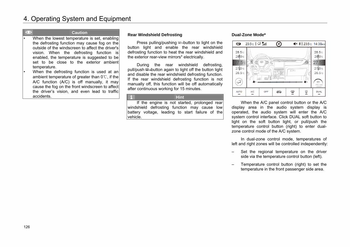
4. Operating System and Equipment
Caution • When the lowest temperature is set, enabling
the defrosting function may cause fog on the outside of the windscreen to affect the driver's vision. When the defrosting function is enabled, the temperature is suggested to be set to be close to the exterior ambient temperature.
• When the defrosting function is used at an ambient temperature of greater than 0℃, if the A/C function (A/C) is off manually, it may cause the fog on the front windscreen to affect the driver’s vision, and even lead to traffic accidents.
Rear Windshield Defrosting
Press pulling/pushing button to light on the button light and enable the rear windshield defrosting function to heat the rear windshield and the exterior rear-view mirrors* electrically.
During the rear windshield defrosting, pull/push button again to light off the button light and disable the rear windshield defrosting function. If the rear windshield defrosting function is not manually off, this function will be off automatically after continuous working for 15 minutes.
Hint If the engine is not started, prolonged rear
windshield defrosting function may cause low battery voltage, leading to start failure of the vehicle.
Dual-Zone Mode*
When the A/C panel control button or the A/C
display area in the audio system display is operated, the audio system will enter the A/C system control interface. Click DUAL soft button to light on the soft button light, or pull/push the temperature control button (right) to enter dual-zone control mode of the A/C system.
In dual-zone control mode, temperatures of left and right zones will be controlled independently:
– Set the regional temperature on the driver side via the temperature control button (left).
– Temperature control button (right) to set the temperature in the front passenger side area.
132 126
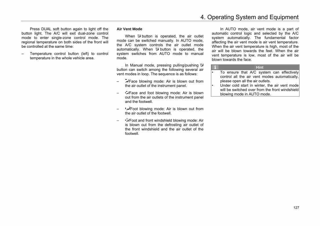
4. Operating System and Equipment
Press DUAL soft button again to light off the button light. The A/C will exit dual-zone control mode to enter single-zone control mode. The regional temperature on both sides of the front will be controlled at the same time:
– Temperature control button (left) to control temperature in the whole vehicle area.
Air Vent Mode
When button is operated, the air outlet mode can be switched manually. In AUTO mode, the A/C system controls the air outlet mode automatically. When button is operated, the system switches from AUTO mode to manual mode.
In Manual mode, pressing pulling/pushing button can switch among the following several air vent modes in loop. The sequence is as follows:
– Face blowing mode: Air is blown out from the air outlet of the instrument panel.
– Face and foot blowing mode: Air is blown out from the air outlets of the instrument panel and the footwell.
– Foot blowing mode: Air is blown out from the air outlet of the footwell.
– Foot and front windshield blowing mode: Air is blown out from the defrosting air outlet of the front windshield and the air outlet of the footwell.
In AUTO mode, air vent mode is a part of automatic control logic and selected by the A/C system automatically. The fundamental factor affecting the air vent mode is air vent temperature. When the air vent temperature is high, most of the air will be blown towards the feet. When the air vent temperature is low, most of the air will be blown towards the face.
Hint • To ensure that A/C system can effectively
control all the air vent modes automatically, please open all the air outlets.
• Under cold start in winter, the air vent mode will be switched over from the front windshield blowing mode in AUTO mode.
133 127
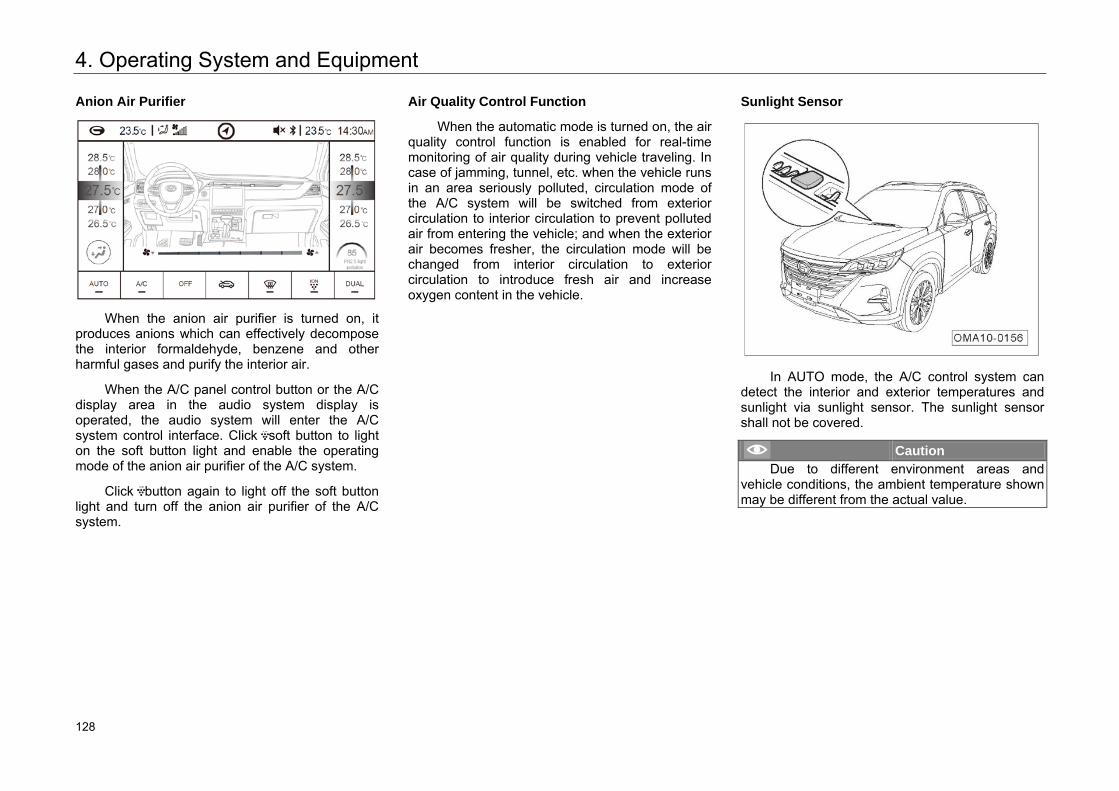
4. Operating System and Equipment
Anion Air Purifier
When the anion air purifier is turned on, it
produces anions which can effectively decompose the interior formaldehyde, benzene and other harmful gases and purify the interior air.
When the A/C panel control button or the A/C display area in the audio system display is operated, the audio system will enter the A/C system control interface. Click soft button to light on the soft button light and enable the operating mode of the anion air purifier of the A/C system.
Click button again to light off the soft button light and turn off the anion air purifier of the A/C system.
Air Quality Control Function
When the automatic mode is turned on, the air quality control function is enabled for real-time monitoring of air quality during vehicle traveling. In case of jamming, tunnel, etc. when the vehicle runs in an area seriously polluted, circulation mode of the A/C system will be switched from exterior circulation to interior circulation to prevent polluted air from entering the vehicle; and when the exterior air becomes fresher, the circulation mode will be changed from interior circulation to exterior circulation to introduce fresh air and increase oxygen content in the vehicle.
Sunlight Sensor
In AUTO mode, the A/C control system can
detect the interior and exterior temperatures and sunlight via sunlight sensor. The sunlight sensor shall not be covered.
Caution Due to different environment areas and
vehicle conditions, the ambient temperature shown may be different from the actual value.
134 128
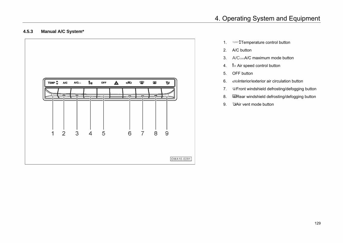
4. Operating System and Equipment
4.5.3 Manual A/C System*
1. Temperature control button
2. A/C button
3. A/C maximum mode button
4. Air speed control button
5. OFF button
6. Interior/exterior air circulation button
7. Front windshield defrosting/defogging button
8. Rear windshield defrosting/defogging button
9. Air vent mode button
135 129
4. Operating System and Equipment
Hint The A/C system can also be controlled by
switched the audio system display interface to the A/C system control interface.
Temperature Setting
– Pull/push the button to raise/lower the temperature at a step of 0.5°C.
– The adjusted temperature value is shown on the audio display. The temperature is adjustable within 18.5℃~31.5℃. When the set temperature is lower than 18.5°C, LO is shown; and when the set temperature is higher than 31.5°C, HI is shown.
Hint The temperature value on the display is the
target value of the set temperature, instead of the measured value of the interior temperature.
A/C Button
When pulling/pushing A/C button is pressed, the button light will be on and the refrigeration function of the A/C system will be enabled. When the refrigeration function is enabled:
– This mean refrigeration / dehumidification is needed, but the compressor is not necessary to run.
– If the outside temperature is below 0°C, the button light will be on, but the compressor may not work.
When pulling/pushing A/C button is pressed again, the button light will be off and the refrigeration function will be disabled.
136 130
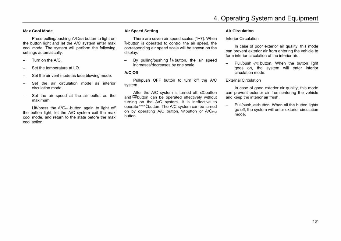
4. Operating System and Equipment
Max Cool Mode
Press pulling/pushing button to light on the button light and let the A/C system enter max cool mode. The system will perform the following settings automatically:
– Turn on the A/C.
– Set the temperature at LO.
– Set the air vent mode as face blowing mode.
– Set the air circulation mode as interior circulation mode.
– Set the air speed at the air outlet as the maximum.
Lift/press the button again to light off the button light, let the A/C system exit the max cool mode, and return to the state before the max cool action.
Air Speed Setting
There are seven air speed scales (1~7). When button is operated to control the air speed, the
corresponding air speed scale will be shown on the display:
– By pulling/pushing button, the air speed increases/decreases by one scale.
A/C Off
Pull/push OFF button to turn off the A/C system.
After the A/C system is turned off, button and button can be operated effectively without turning on the A/C system. It is ineffective to operate button. The A/C system can be turned on by operating A/C button, button or button.
Air Circulation
Interior Circulation
In case of poor exterior air quality, this mode can prevent exterior air from entering the vehicle to form interior circulation of the interior air.
– Pull/push button. When the button light goes on, the system will enter interior circulation mode.
External Circulation
In case of good exterior air quality, this mode can prevent exterior air from entering the vehicle and keep the interior air fresh.
– Pull/push button. When all the button lights go off, the system will enter exterior circulation mode.
137 131
4. Operating System and Equipment
Caution • Prolonged interior air circulation will cause
accumulation of carbon dioxide in the vehicle, and it is not conducive to keep the driver awake.
• Using the interior air circulation mode in cold or rainy weather is easy to cause fogging of window, affecting the driver's vision.
Front Windshield Defrosting
Press pulling/pushing button to light on the button light and enable the front windshield defrosting function. The system will perform the following settings automatically:
– Increase the air vent temperature.
– Turn on the A/C.
– Enter front windshield blowing mode.
– Enter exterior circulation mode.
Pull/push button again to light off the button light, disable the front windshield defrosting function, and return to the state before the defrosting action.
Caution • When the lowest temperature is set, enabling
the defrosting function may cause fog on the outside of the windscreen to affect the driver's vision. When the defrosting function is enabled, the temperature is suggested to be set to be close to the exterior ambient temperature.
• When the defrosting function is used at an ambient temperature of greater than 0℃, if the A/C function (A/C) is off manually, it may cause the fog on the front windscreen to affect the driver’s vision, and even lead to traffic accidents.
138 132
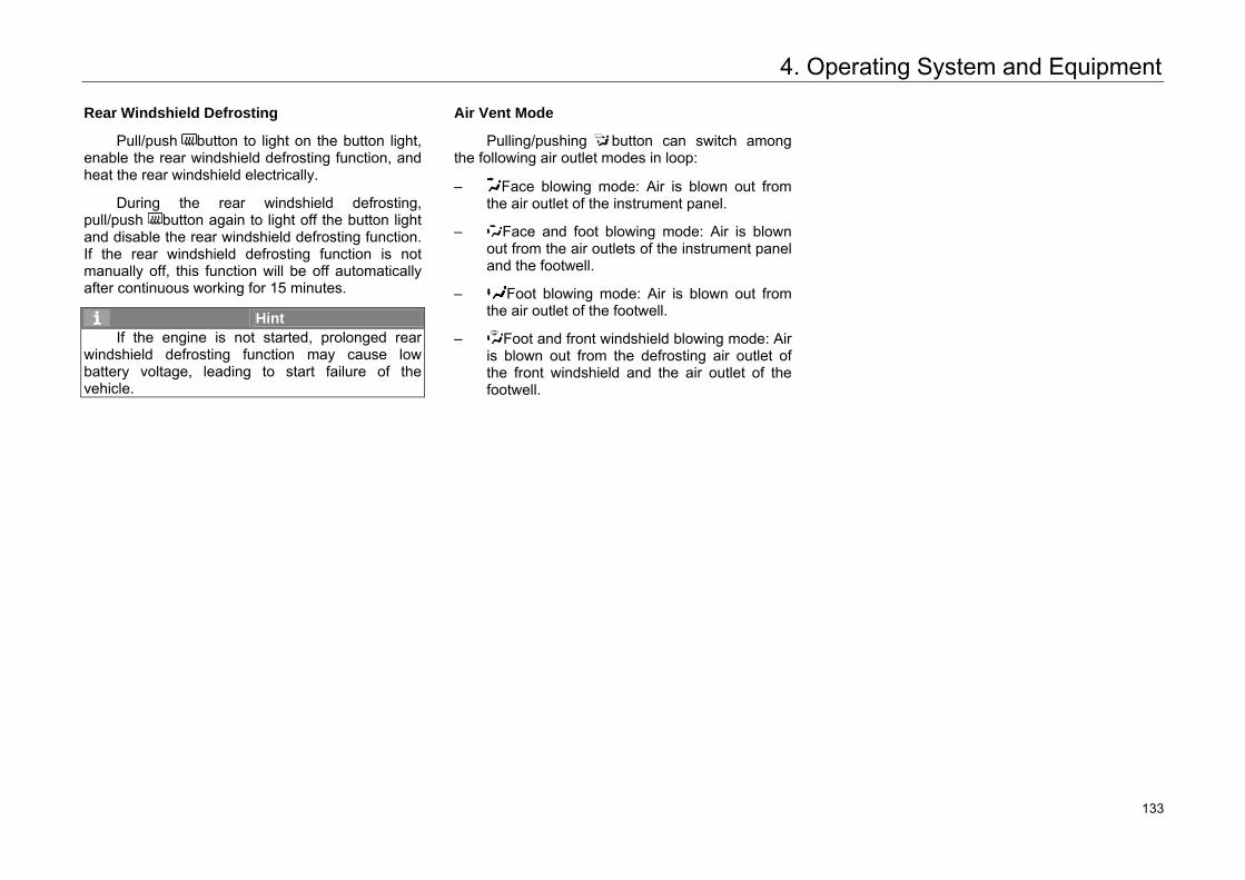
4. Operating System and Equipment
Rear Windshield Defrosting
Pull/push button to light on the button light, enable the rear windshield defrosting function, and heat the rear windshield electrically.
During the rear windshield defrosting, pull/push button again to light off the button light and disable the rear windshield defrosting function. If the rear windshield defrosting function is not manually off, this function will be off automatically after continuous working for 15 minutes.
Hint If the engine is not started, prolonged rear
windshield defrosting function may cause low battery voltage, leading to start failure of the vehicle.
Air Vent Mode
Pulling/pushing button can switch among the following air outlet modes in loop:
– Face blowing mode: Air is blown out from the air outlet of the instrument panel.
– Face and foot blowing mode: Air is blown out from the air outlets of the instrument panel and the footwell.
– Foot blowing mode: Air is blown out from the air outlet of the footwell.
– Foot and front windshield blowing mode: Air is blown out from the defrosting air outlet of the front windshield and the air outlet of the footwell.
139 133
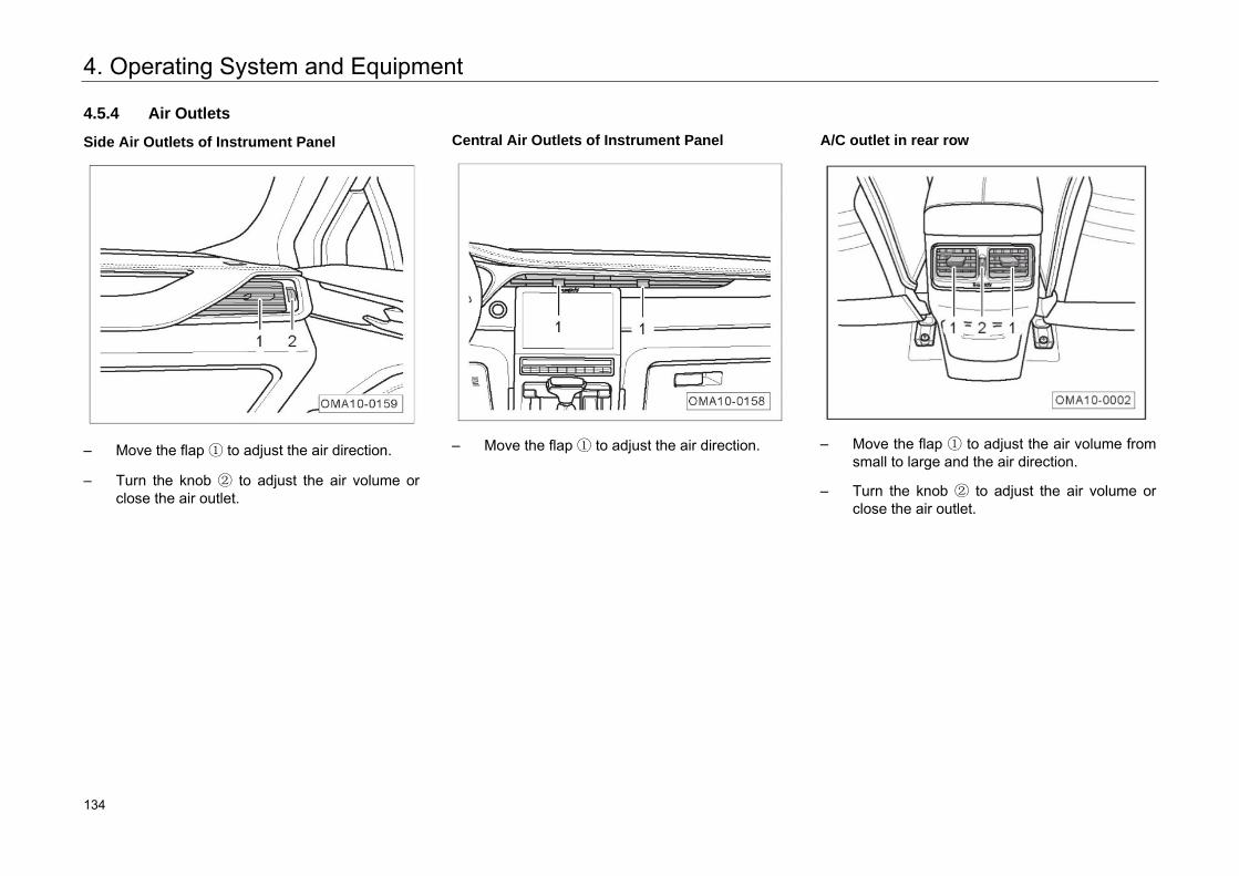
4. Operating System and Equipment
4.5.4 Air Outlets
Side Air Outlets of Instrument Panel
– Move the flap ① to adjust the air direction.
– Turn the knob ② to adjust the air volume orclose the air outlet.
Central Air Outlets of Instrument Panel
– Move the flap ① to adjust the air direction.
A/C outlet in rear row
– Move the flap ① to adjust the air volume fromsmall to large and the air direction.
– Turn the knob ② to adjust the air volume orclose the air outlet.
140 134
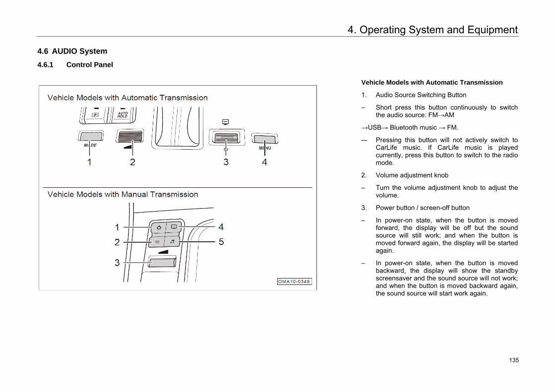
4. Operating System and Equipment
4.6 AUDIO System
4.6.1 Control Panel
Vehicle Models with Automatic Transmission
1. Audio Source Switching Button
– Short press this button continuously to switch the audio source: FM→AM
→USB→ Bluetooth music → FM.
-– Pressing this button will not actively switch to CarLife music. If CarLife music is played currently, press this button to switch to the radio mode.
2. Volume adjustment knob
– Turn the volume adjustment knob to adjust the volume.
3. Power button / screen-off button
– In power-on state, when the button is moved forward, the display will be off but the sound source will still work; and when the button is moved forward again, the display will be started again.
– In power-on state, when the button is moved backward, the display will show the standby screensaver and the sound source will not work; and when the button is moved backward again, the sound source will start work again.
141 135
4. Operating System and Equipment
4. Main interface button
– –Short press this button on other media interfaces to back to the main interface of card mode.
Vehicle Models with Manual Transmission
1. Power button
– In power-on state, when the button is short pressed, the display will show the standby screensaver and the sound source will not work; and when the button is short pressed again, the sound source will start work again.
2. Main interface button
– Short press this button on other interfaces to back to the main interface of card mode.
3. Volume adjustment knob
– Turn the volume adjustment knob to adjust the volume.
4. Screen-off button
– In power-on state, when the button is short pressed, the display will be off but the sound source will still work; and when the button is short pressed again, the display will be started again.
5. Audio Source Switching Button
– Short press this button continuously to switch: FM → AM → USB → Bluetooth music → FM.
– Pressing this button will not actively switch to CarLife music. If CarLife music is played currently, press this button to switch to the radio mode.
Hint The interface or function of AUDIO system
introduced in the User's Manual may differ due to different vehicle configurations, i.e. it is for reference only. Please refer to the actual vehicle.
142 136
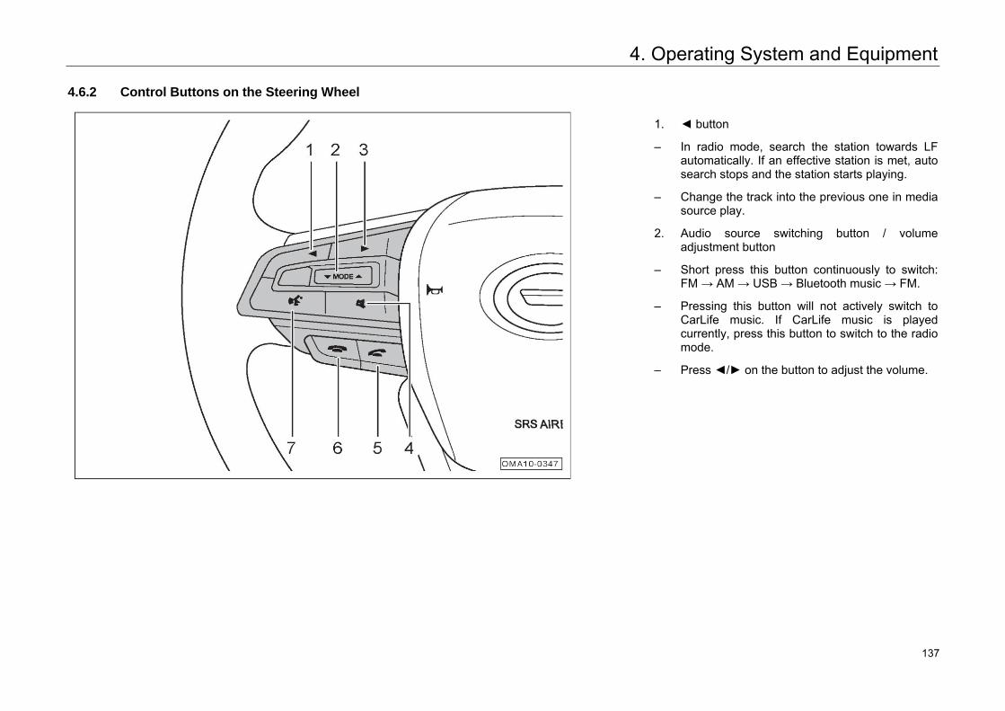
4. Operating System and Equipment
4.6.2 Control Buttons on the Steering Wheel
1. ◄ button
– In radio mode, search the station towards LFautomatically. If an effective station is met, autosearch stops and the station starts playing.
– Change the track into the previous one in mediasource play.
2. Audio source switching button / volumeadjustment button
– Short press this button continuously to switch:FM → AM → USB → Bluetooth music → FM.
– Pressing this button will not actively switch toCarLife music. If CarLife music is playedcurrently, press this button to switch to the radiomode.
– Press ◄/► on the button to adjust the volume.
143 137
4. Operating System and Equipment
3. ► button
– In radio mode, search the station towards HF automatically. If an effective station is met, auto search stops and the station starts playing.
– Change the track into the next one in media source play.
4. Mute Button
– Short press this button to mute the media source.
– After muting, press again to unmute.
5. Answer Call Button
– When an incoming call is in the Bluetooth Phone system, press this button to answer.
– When there is no incoming call in the Bluetooth phone system, you can press this button to enter the "Bluetooth Call" interface.
– When there is no incoming call in the Bluetooth phone system and Bluetooth is not connected, you can press this button to enter the "Bluetooth Setting" interface.
6. Hang-up Button
– When an incoming call is in the Bluetooth Phone system, press this button to reject.
– Press this button to end the current call in the call process.
7. Voice Button*
– Short press this button to start or end local voice.
– Connect the mobile phone with the head unit, start the CarLife function, and then short press this button to start or end CarLife voice.
144 138
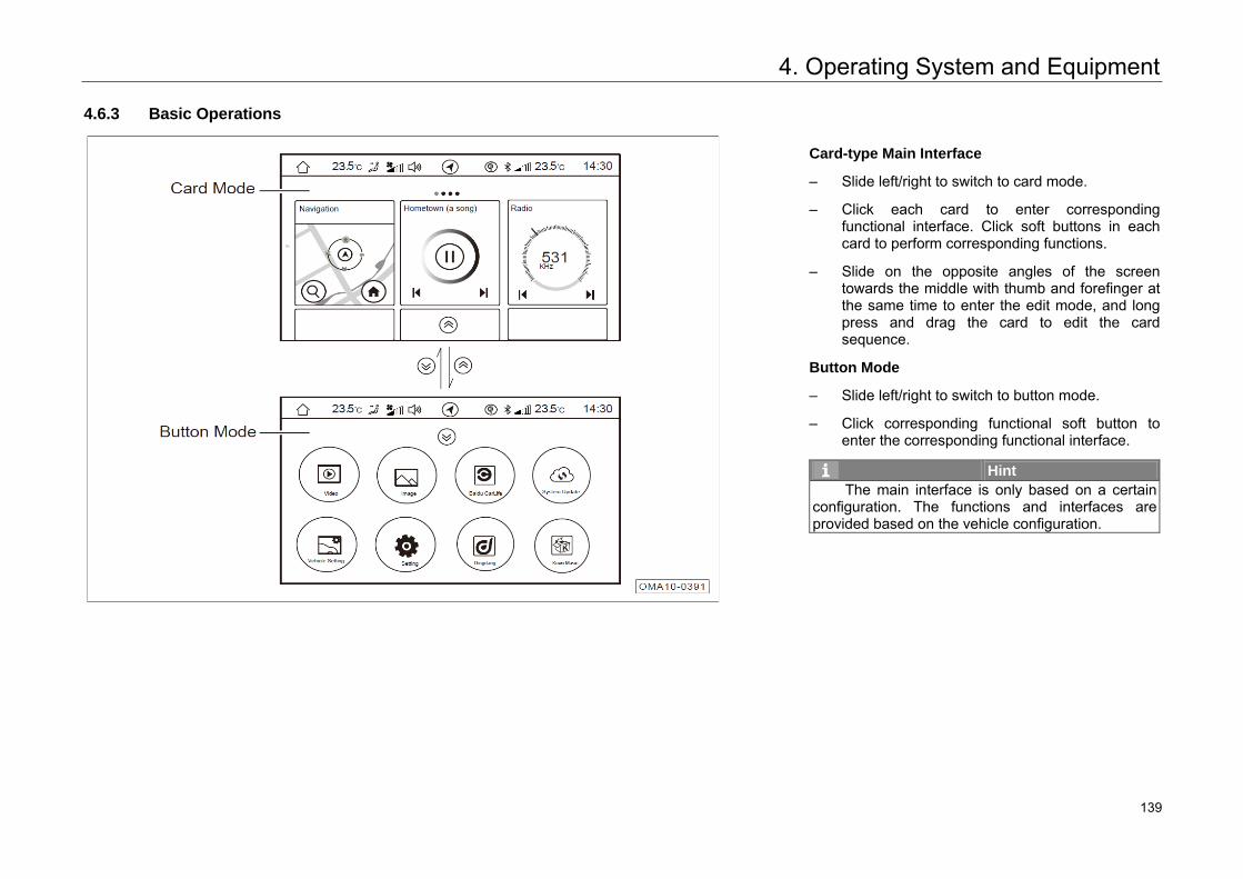
4. Operating System and Equipment
4.6.3 Basic Operations
Card-type Main Interface
– Slide left/right to switch to card mode.
– Click each card to enter corresponding functional interface. Click soft buttons in each card to perform corresponding functions.
– Slide on the opposite angles of the screen towards the middle with thumb and forefinger at the same time to enter the edit mode, and long press and drag the card to edit the card sequence.
Button Mode
– Slide left/right to switch to button mode.
– Click corresponding functional soft button to enter the corresponding functional interface.
Hint The main interface is only based on a certain
configuration. The functions and interfaces are provided based on the vehicle configuration.
145 139
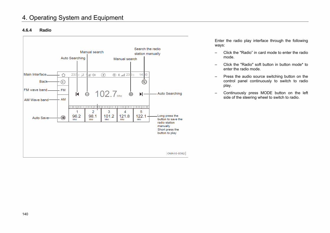
4. Operating System and Equipment
4.6.4 Radio
Enter the radio play interface through the following ways:
– Click the "Radio” in card mode to enter the radiomode.
– Click the "Radio" soft button in button mode* toenter the radio mode.
– Press the audio source switching button on thecontrol panel continuously to switch to radioplay.
– Continuously press MODE button on the leftside of the steering wheel to switch to radio.
148 140
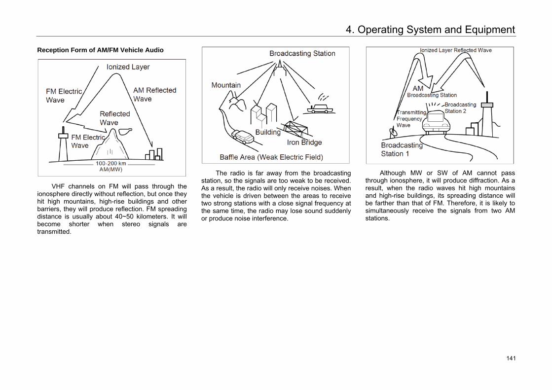
4. Operating System and Equipment
Reception Form of AM/FM Vehicle Audio
VHF channels on FM will pass through the ionosphere directly without reflection, but once they hit high mountains, high-rise buildings and other barriers, they will produce reflection. FM spreading distance is usually about 40~50 kilometers. It will become shorter when stereo signals are transmitted.
The radio is far away from the broadcasting station, so the signals are too weak to be received. As a result, the radio will only receive noises. When the vehicle is driven between the areas to receive two strong stations with a close signal frequency at the same time, the radio may lose sound suddenly or produce noise interference.
Although MW or SW of AM cannot pass through ionosphere, it will produce diffraction. As a result, when the radio waves hit high mountains and high-rise buildings, its spreading distance will be farther than that of FM. Therefore, it is likely to simultaneously receive the signals from two AM stations.
149 141
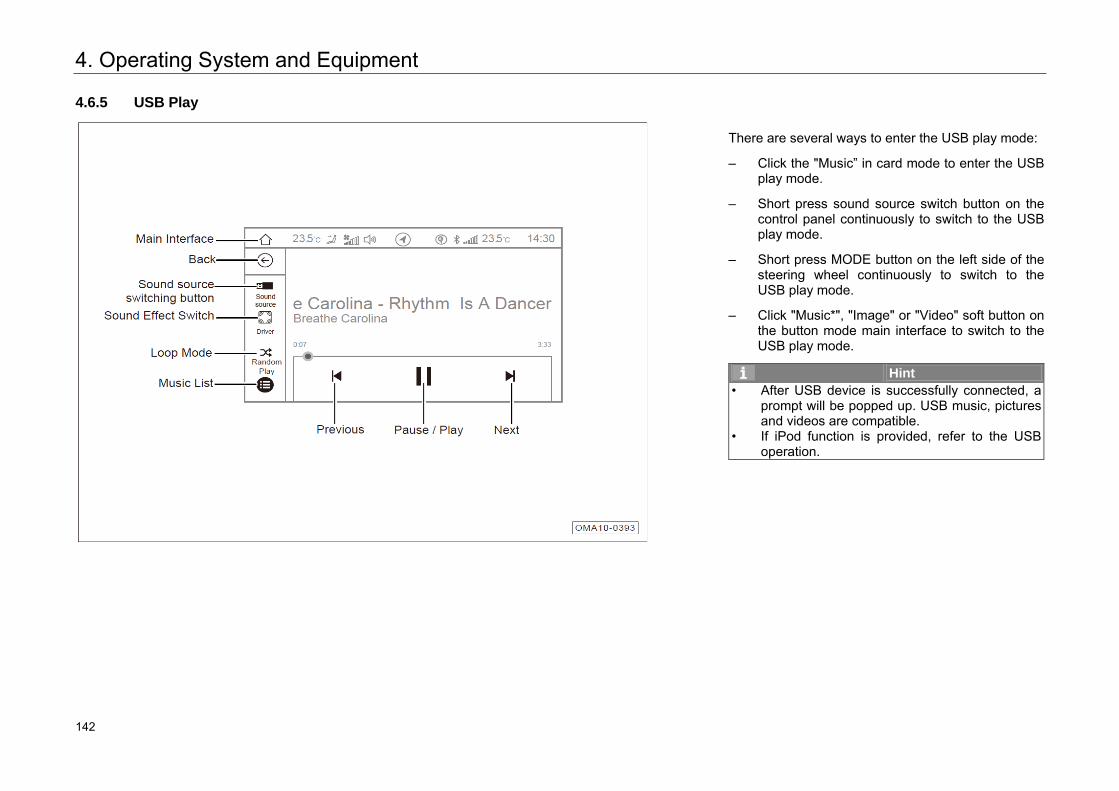
4. Operating System and Equipment
4.6.5 USB Play
There are several ways to enter the USB play mode:
– Click the "Music” in card mode to enter the USBplay mode.
– Short press sound source switch button on thecontrol panel continuously to switch to the USBplay mode.
– Short press MODE button on the left side of thesteering wheel continuously to switch to theUSB play mode.
– Click "Music*", "Image" or "Video" soft button onthe button mode main interface to switch to theUSB play mode.
Hint • After USB device is successfully connected, a
prompt will be popped up. USB music, pictures and videos are compatible.
• If iPod function is provided, refer to the USB operation.
150 142
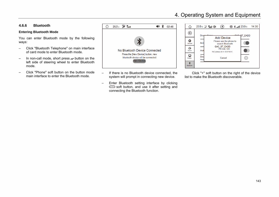
4. Operating System and Equipment
4.6.6 Bluetooth
Entering Bluetooth Mode
You can enter Bluetooth mode by the following ways:
– Click "Bluetooth Telephone" on main interface of card mode to enter Bluetooth mode.
– In non-call mode, short press button on the left side of steering wheel to enter Bluetooth mode.
– Click "Phone" soft button on the button mode main interface to enter the Bluetooth mode.
– If there is no Bluetooth device connected, the
system will prompt in connecting new device.
– Enter Bluetooth setting interface by clicking soft button, and use it after setting and
connecting the Bluetooth function.
Click "+" soft button on the right of the device
list to make the Bluetooth discoverable.
151 143
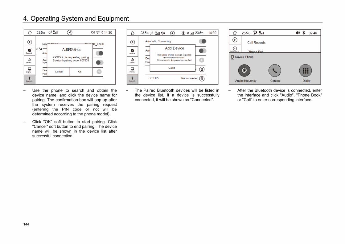
4. Operating System and Equipment
– Use the phone to search and obtain the
device name, and click the device name for pairing. The confirmation box will pop up after the system receives the pairing request (entering the PIN code or not will be determined according to the phone model).
– Click "OK" soft button to start pairing. Click "Cancel" soft button to end pairing. The device name will be shown in the device list after successful connection.
– The Paired Bluetooth devices will be listed in
the device list. If a device is successfully connected, it will be shown as "Connected".
– After the Bluetooth device is connected, enter
the interface and click "Audio", "Phone Book" or "Call" to enter corresponding interface.
152 144
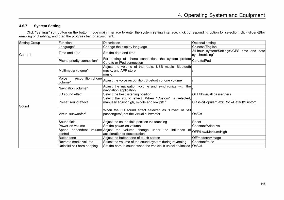
4. Operating System and Equipment
4.6.7 System Setting
Click "Settings" soft button on the button mode main interface to enter the system setting interface: click corresponding option for selection, click slider for enabling or disabling, and drag the progress bar for adjustment.
Setting Group Function Description Optional setting
General
Language* Change the display language Chinese/English
Time and date Set the date and time 24-hour system/Settings*/GPS time and date synchronizing*
Phone priority connection* For setting of phone connection, the system prefers CarLife or iPod connection CarLife/iPod
Sound
Multimedia volume* Adjust the volume of the radio, USB music, Bluetooth music, and APP store music
/
Voice recognition/phone volume* Adjust the voice recognition/Bluetooth phone volume /
Navigation volume* Adjust the navigation volume and synchronize with the navigation application /
3D sound effect Select the best listening position OFF/driver/all passengers
Preset sound effect Select the sound effect. When "Custom" is selected, manually adjust high, middle and low pitch
Classic/Popular/Jazz/Rock/Default/Custom
Virtual subwoofer* When the 3D sound effect selected as "Driver" or "All passengers", set the virtual subwoofer
On/Off
Sound field Adjust the sound field position via touching Reset Power-on volume Set the power-on volume Constant/Adaptive Speed dependent volume control
Adjust the volume change under the influence of acceleration or deceleration OFF/Low/Medium/High
Button tone Adjust the button tone of touch screen Off/modern/vintage Reverse media volume Select the volume of the sound system during reversing Constant/mute Unlock/Lock horn beeping Set the horn to sound when the vehicle is unlocked/locked On/Off
153 145
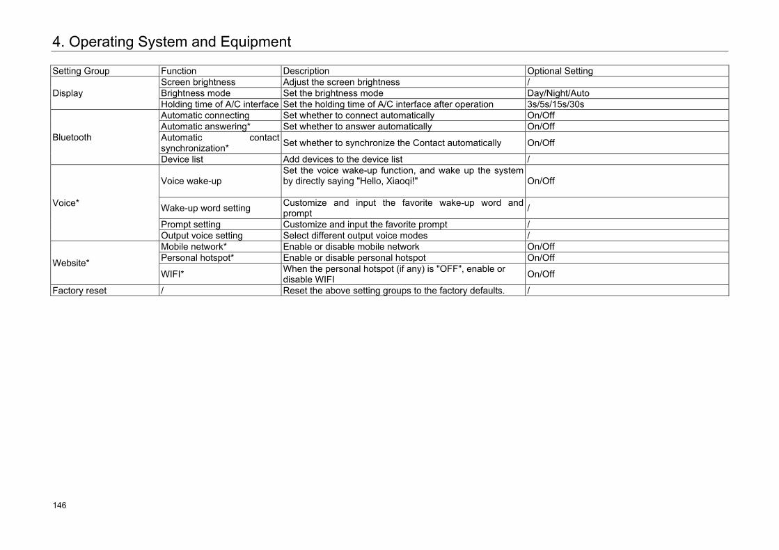
4. Operating System and Equipment
Setting Group Function Description Optional Setting
Display Screen brightness Adjust the screen brightness / Brightness mode Set the brightness mode Day/Night/Auto Holding time of A/C interface Set the holding time of A/C interface after operation 3s/5s/15s/30s
Bluetooth
Automatic connecting Set whether to connect automatically On/Off Automatic answering* Set whether to answer automatically On/Off Automatic contact synchronization* Set whether to synchronize the Contact automatically On/Off
Device list Add devices to the device list /
Voice*
Voice wake-up Set the voice wake-up function, and wake up the system by directly saying "Hello, Xiaoqi!"
On/Off
Wake-up word setting Customize and input the favorite wake-up word and prompt /
Prompt setting Customize and input the favorite prompt / Output voice setting Select different output voice modes /
Website*
Mobile network* Enable or disable mobile network On/Off Personal hotspot* Enable or disable personal hotspot On/Off
WIFI* When the personal hotspot (if any) is "OFF", enable or disable WIFI On/Off
Factory reset / Reset the above setting groups to the factory defaults. /
154 146
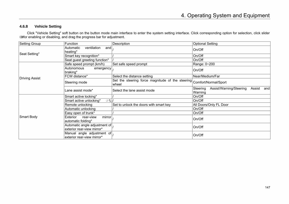
4. Operating System and Equipment
4.6.8 Vehicle Setting
Click "Vehicle Setting" soft button on the button mode main interface to enter the system setting interface. Click corresponding option for selection, click slider for enabling or disabling, and drag the progress bar for adjustment.
Setting Group Function Description Optional Setting
Seat Setting*
Automatic ventilation and heating* / On/Off
Smart key recognition* / On/Off Seat guest greeting function* / On/Off
Driving Assist
Safe speed prompt (km/h) Set safe speed prompt Range: 0~200 Autonomous emergency braking* / On/Off
FCW distance* Select the distance setting Near/Medium/Far
Steering mode Set the steering force magnitude of the steering wheel Comfort/Normal/Sport
Lane assist mode* Select the lane assist mode Steering Assist/Warning/Steering Assist and Warning
Smart Body
Smart active locking* / On/Off Smart active unlocking* / On/Off Remote unlocking Set to unlock the doors with smart key All Doors/Only FL Door Automatic unlocking / On/Off Easy open of trunk* / On/Off Exterior rear-view mirror automatic folding* / On/Off
Automatic angle adjustment of exterior rear-view mirror* / On/Off
Manual angle adjustment of exterior rear-view mirror* / On/Off
155 147
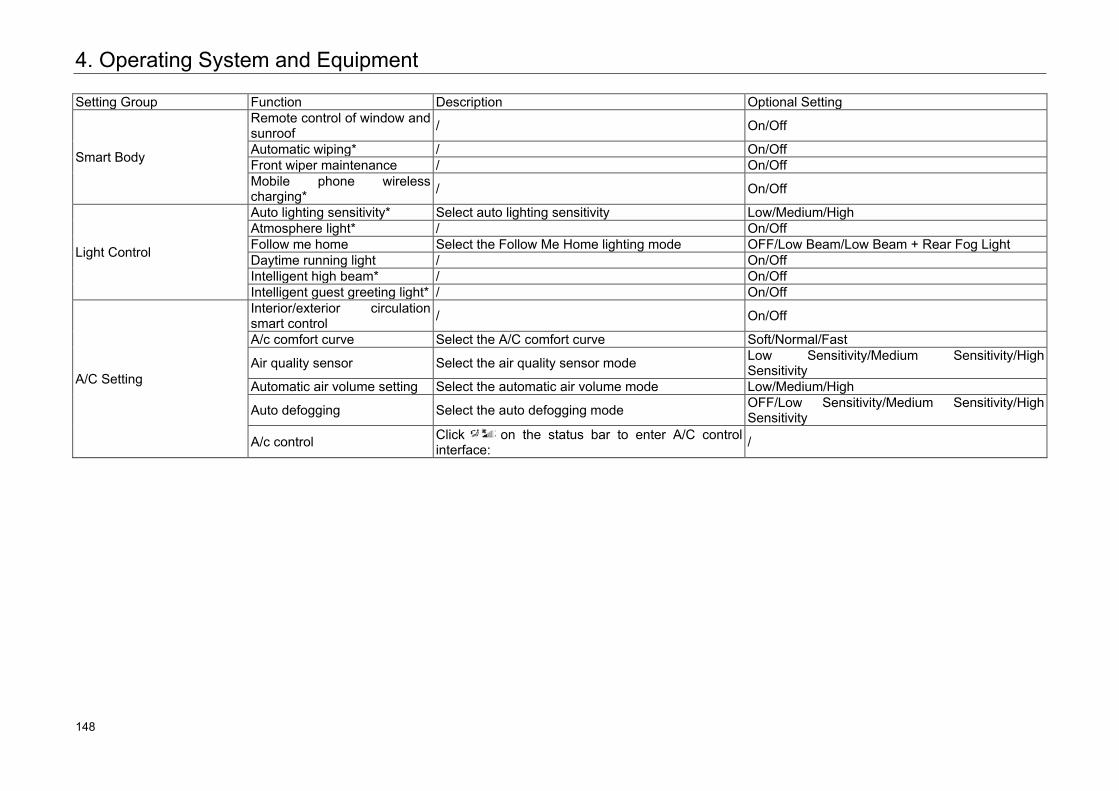
4. Operating System and Equipment
Setting Group Function Description Optional Setting
Smart Body
Remote control of window and sunroof / On/Off
Automatic wiping* / On/Off Front wiper maintenance / On/Off Mobile phone wireless charging* / On/Off
Light Control
Auto lighting sensitivity* Select auto lighting sensitivity Low/Medium/High Atmosphere light* / On/Off Follow me home Select the Follow Me Home lighting mode OFF/Low Beam/Low Beam + Rear Fog Light Daytime running light / On/Off Intelligent high beam* / On/Off Intelligent guest greeting light* / On/Off
A/C Setting
Interior/exterior circulation smart control / On/Off
A/c comfort curve Select the A/C comfort curve Soft/Normal/Fast
Air quality sensor Select the air quality sensor mode Low Sensitivity/Medium Sensitivity/High Sensitivity
Automatic air volume setting Select the automatic air volume mode Low/Medium/High
Auto defogging Select the auto defogging mode OFF/Low Sensitivity/Medium Sensitivity/High Sensitivity
A/c control Click on the status bar to enter A/C control interface: /
156 148
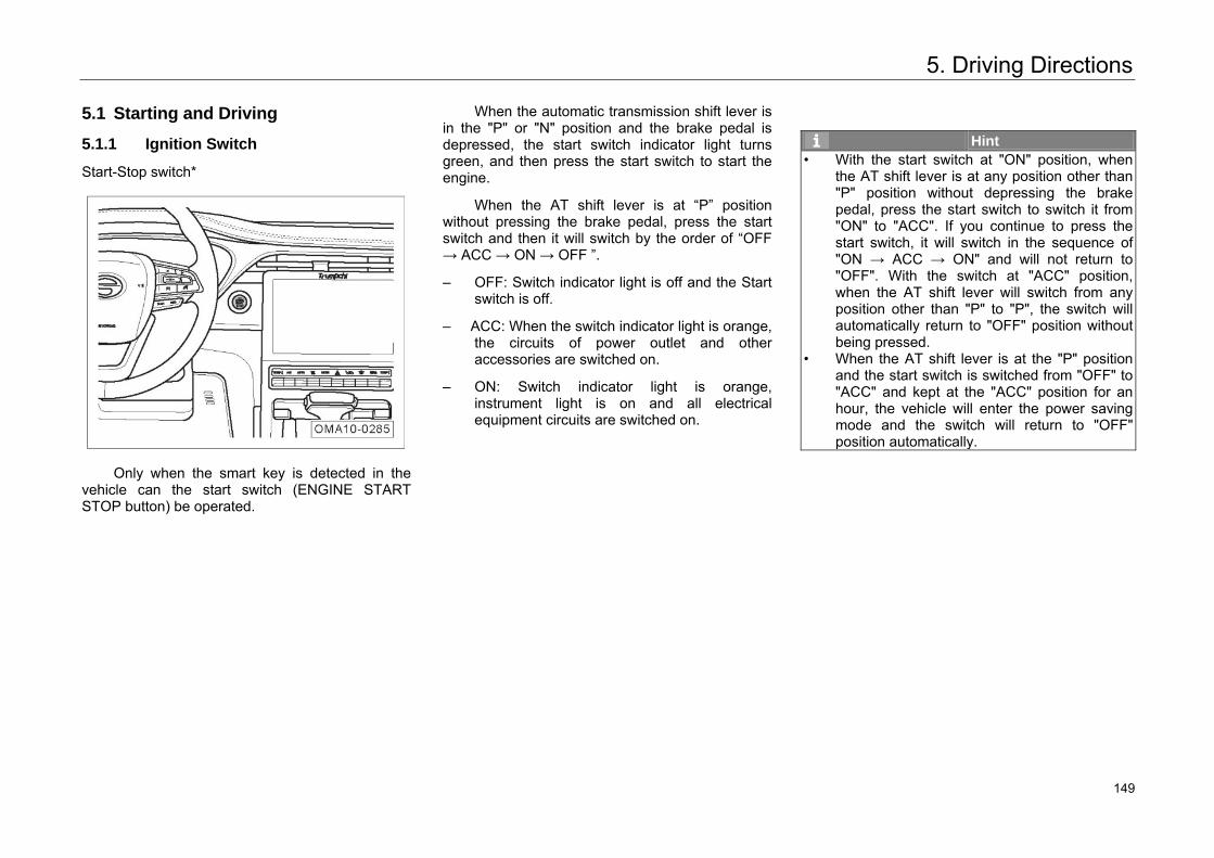
5. Driving Directions
5.1 Starting and Driving
5.1.1 Ignition Switch
Start-Stop switch*
Only when the smart key is detected in the vehicle can the start switch (ENGINE START STOP button) be operated.
When the automatic transmission shift lever is in the "P" or "N" position and the brake pedal is depressed, the start switch indicator light turns green, and then press the start switch to start the engine.
When the AT shift lever is at “P” position without pressing the brake pedal, press the start switch and then it will switch by the order of “OFF → ACC → ON → OFF ”.
– OFF: Switch indicator light is off and the Startswitch is off.
– ACC: When the switch indicator light is orange,the circuits of power outlet and otheraccessories are switched on.
– ON: Switch indicator light is orange,instrument light is on and all electricalequipment circuits are switched on.
Hint • With the start switch at "ON" position, when
the AT shift lever is at any position other than "P" position without depressing the brake pedal, press the start switch to switch it from "ON" to "ACC". If you continue to press thestart switch, it will switch in the sequence of "ON → ACC → ON" and will not return to"OFF". With the switch at "ACC" position,when the AT shift lever will switch from anyposition other than "P" to "P", the switch will automatically return to "OFF" position without being pressed.
• When the AT shift lever is at the "P" positionand the start switch is switched from "OFF" to"ACC" and kept at the "ACC" position for anhour, the vehicle will enter the power saving mode and the switch will return to "OFF" position automatically.
157 149
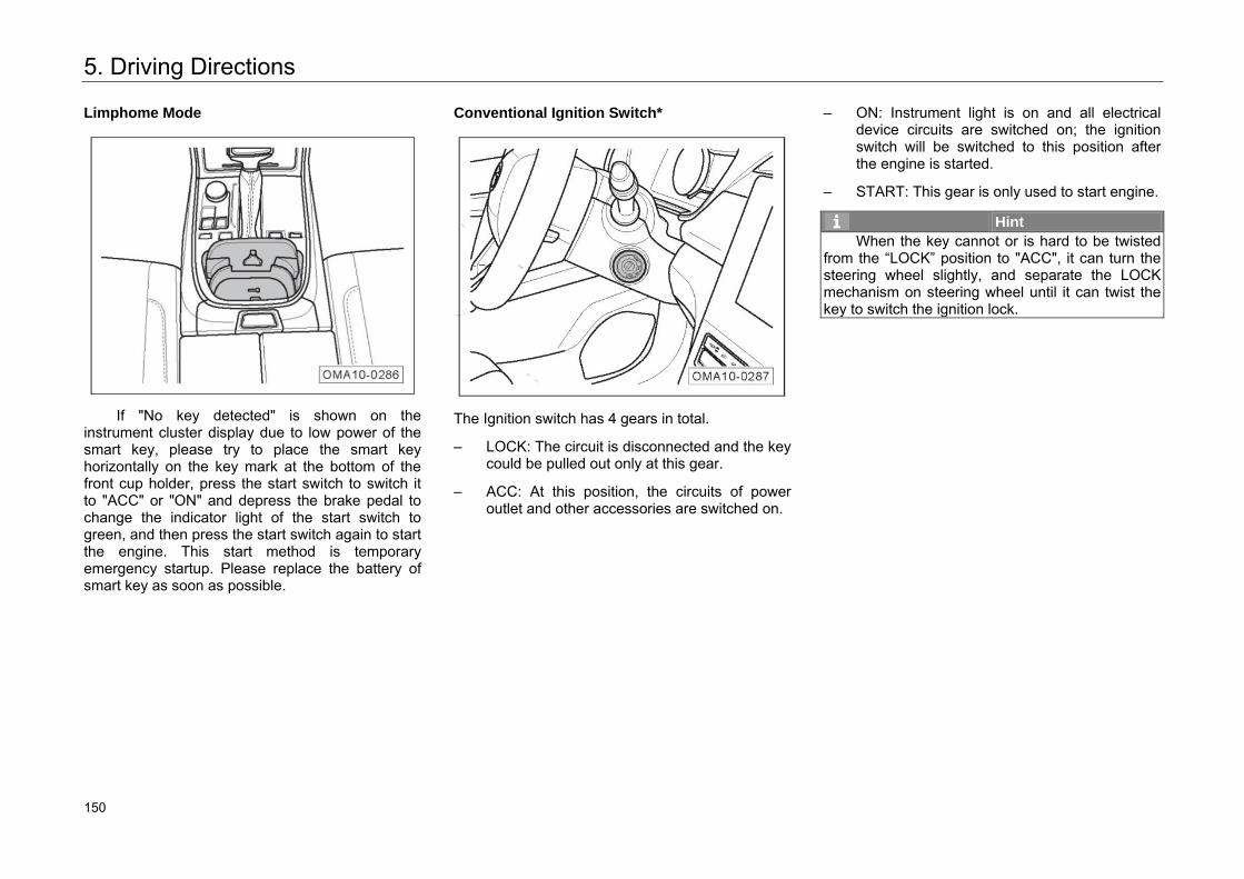
5. Driving Directions
Limphome Mode
If "No key detected" is shown on the
instrument cluster display due to low power of the smart key, please try to place the smart key horizontally on the key mark at the bottom of the front cup holder, press the start switch to switch it to "ACC" or "ON" and depress the brake pedal to change the indicator light of the start switch to green, and then press the start switch again to start the engine. This start method is temporary emergency startup. Please replace the battery of smart key as soon as possible.
Conventional Ignition Switch*
The Ignition switch has 4 gears in total.
– LOCK: The circuit is disconnected and the key could be pulled out only at this gear.
– ACC: At this position, the circuits of power outlet and other accessories are switched on.
– ON: Instrument light is on and all electrical device circuits are switched on; the ignition switch will be switched to this position after the engine is started.
– START: This gear is only used to start engine.
Hint When the key cannot or is hard to be twisted
from the “LOCK” position to "ACC", it can turn the steering wheel slightly, and separate the LOCK mechanism on steering wheel until it can twist the key to switch the ignition lock.
158 150
5. Driving Directions
5.1.2 Engine Stop
Vehicle Models with Manual Transmission
– Stop the vehicle steadily, and apply parkingbrake.
– Switch the shift lever to neutral gear.
– Turn the mechanical key to switch the Ignitionswitch to LOCK position, and thus shut downthe engine.
Vehicle Models with Automatic Transmission
– Stop the vehicle steadily, and apply parkingbrake.
– Put the shift lever at “P” gear.
– Turn the mechanical key to switch the Ignitionswitch to LOCK position, and thus shut downthe engine. (Apply to models withconventional ignition switch)
– Press the Start switch to shut down the engine.(Apply to models with Start-Stop switch)
Hint The radiator fan may still run for some time
after the engine is shut down.
Caution • During driving, long press the Start switch or
press the Start switch three timescontinuously, then the Start switch will switch from "ON" to "ACC" position to stop theengine and achieve emergency flameout. Theengine can be restarted a few of seconds afteremergency flameout.
• During driving, in case of automatic engine shutdown or emergency flameout, put the transmission shift lever at the “N” position and press the Start switch again to restart the engine.
161 151
5. Driving Directions
Warning • When the engine stops and the brake booster
does not work, a greater force shall be applied on the brake pedal when braking to stop the vehicle. If the steering booster does not work, a greater force must be applied to turn the steering wheel.
• When driving, do not turn off the engine in case of emergency. Otherwise, the airbag will not work.
Precautions for Parking
When parking, put the shift lever to the "P" gear or the neutral gear and pay attention to the following matters:
– Pay attention to the vehicle parking directionand do not make the exhaust discharged tothe plant to damage the green belt.
– Try to park on a straight road and avoid asteep slope.
– When parking, no matter the vehicle faces thetop or base of a slope, the front wheels shouldface curb.
– The vehicle should be applied with the parkingbrake. Shut down the engine, and turn off alllights and other electrical equipment.
– When leaving the vehicle, be sure to bringyour valuables and vehicle keys with you, andconfirm that the skylight, window, door andhatchback door are locked.
– Check whether the anti-theft start lockingsystem indicator light on the instrumentcluster is on, and confirm that the anti-theftsystem has been activated.
Warning • When leaving the vehicle, shut down the
engine, apply the parking brake, and carry the vehicle keys with you.
• Do not leave any person in the vehicle. Otherwise, person in the confined vehicle islikely to lose consciousness or even die due to suffocation.
• Do not park vehicles near flammable and explosive items.
162 152
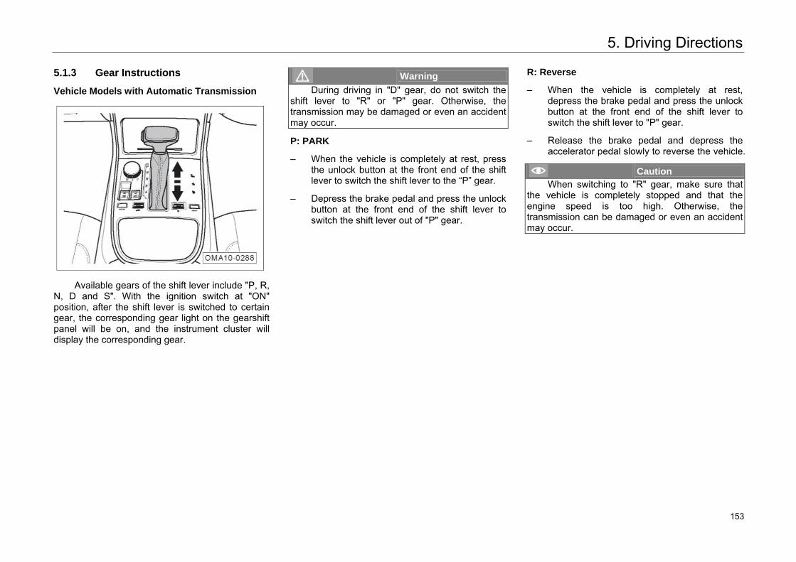
5. Driving Directions
5.1.3 Gear Instructions
Vehicle Models with Automatic Transmission
Available gears of the shift lever include "P, R, N, D and S". With the ignition switch at "ON" position, after the shift lever is switched to certain gear, the corresponding gear light on the gearshift panel will be on, and the instrument cluster will display the corresponding gear.
Warning During driving in "D" gear, do not switch the
shift lever to "R" or "P" gear. Otherwise, the transmission may be damaged or even an accident may occur.
P: PARK
– When the vehicle is completely at rest, pressthe unlock button at the front end of the shiftlever to switch the shift lever to the “P” gear.
– Depress the brake pedal and press the unlockbutton at the front end of the shift lever toswitch the shift lever out of "P" gear.
R: Reverse
– When the vehicle is completely at rest,depress the brake pedal and press the unlockbutton at the front end of the shift lever toswitch the shift lever to "P" gear.
– Release the brake pedal and depress theaccelerator pedal slowly to reverse the vehicle.
Caution When switching to "R" gear, make sure that
the vehicle is completely stopped and that the engine speed is too high. Otherwise, the transmission can be damaged or even an accident may occur.
163 153
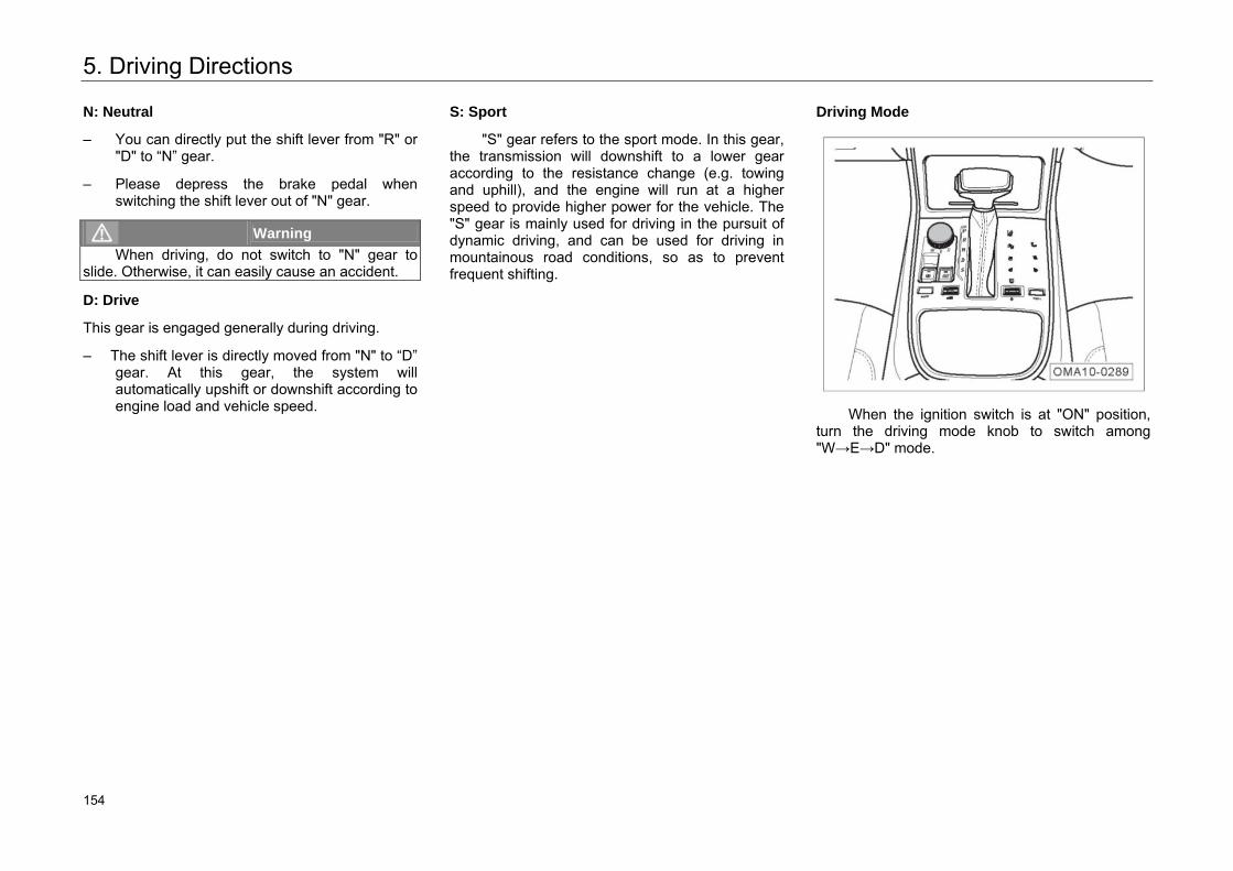
5. Driving Directions
N: Neutral
– You can directly put the shift lever from "R" or"D" to “N” gear.
– Please depress the brake pedal whenswitching the shift lever out of "N" gear.
Warning When driving, do not switch to "N" gear to
slide. Otherwise, it can easily cause an accident.
D: Drive
This gear is engaged generally during driving.
– The shift lever is directly moved from "N" to “D”gear. At this gear, the system willautomatically upshift or downshift according toengine load and vehicle speed.
S: Sport
"S" gear refers to the sport mode. In this gear, the transmission will downshift to a lower gear according to the resistance change (e.g. towing and uphill), and the engine will run at a higher speed to provide higher power for the vehicle. The "S" gear is mainly used for driving in the pursuit of dynamic driving, and can be used for driving in mountainous road conditions, so as to prevent frequent shifting.
Driving Mode
When the ignition switch is at "ON" position, turn the driving mode knob to switch among "W→E→D" mode.
164 154
5. Driving Directions
"W" Mode
"W" mode refers to the winter mode. When the vehicle is in this mode, the transmission will control the starting gear automatically to ensure more stable and softer torque output of the vehicle to avoid slipping of the vehicle on road with ice and snow or other slippery roads and help the driver control the vehicle in snowfield more easily.
Hint Winter mode will limit the PTO of the engine,
so that it is suggested that the winter mode should only be used when driving on road with ice and snow or other slippery roads; while on other roads, the winter mode is not recommended, so as to avoid influencing the drivability and fuel economy.
"E" Mode
The "E" mode is ECO mode. When the vehicle is in this mode, not only the fuel saving strategy is applied for the TCU, but the corresponding economic strategy is adopted for the A/C.
Hint • When the vehicle enters ECO mode, the
"ECO" indicator light on the instrument clusteris on.
• ECO mode can be applied when the shift lever is at "P, R, N, D" gear, but only works at “D” gear.
• The ECO mode has a memory function, thatis, when the engine is restarted after flameout, the transmission will remain in ECO mode.
“D” Mode
In general, the transmission is in the "D" mode by default.
"M" Mode
"M" mode refers to the manual mode. When the shift lever is at "S" gear, press "+/-" in the side face of the shift lever for upshift/downshift to enter manual mode. When transmission is running in this mode, the driver can improve the driving enjoyment according to road conditions and driving habits.
165 155
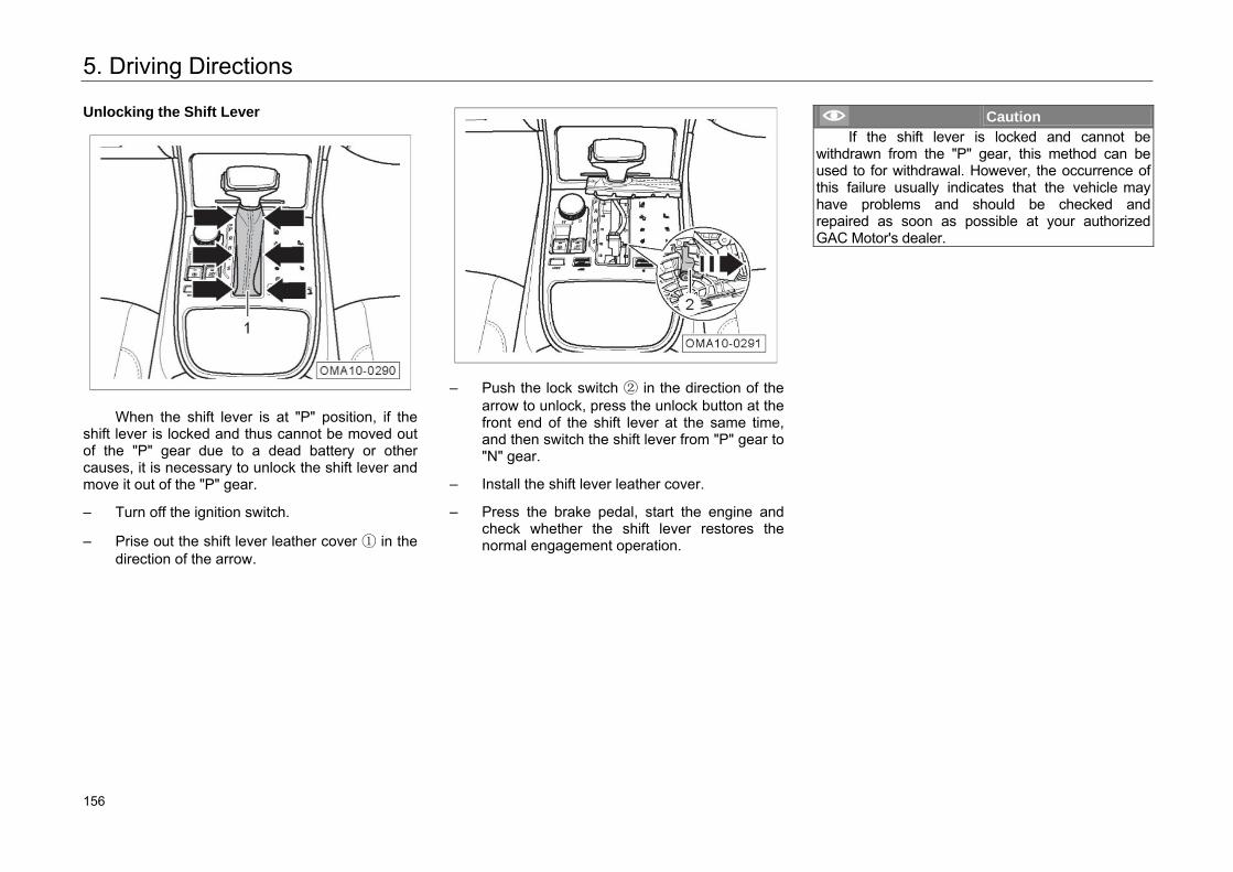
5. Driving Directions
Unlocking the Shift Lever
When the shift lever is at "P" position, if the shift lever is locked and thus cannot be moved out of the "P" gear due to a dead battery or other causes, it is necessary to unlock the shift lever and move it out of the "P" gear.
– Turn off the ignition switch.
– Prise out the shift lever leather cover ① in thedirection of the arrow.
– Push the lock switch ② in the direction of thearrow to unlock, press the unlock button at thefront end of the shift lever at the same time,and then switch the shift lever from "P" gear to"N" gear.
– Install the shift lever leather cover.
– Press the brake pedal, start the engine andcheck whether the shift lever restores thenormal engagement operation.
Caution If the shift lever is locked and cannot be
withdrawn from the "P" gear, this method can be used to for withdrawal. However, the occurrence of this failure usually indicates that the vehicle may have problems and should be checked and repaired as soon as possible at your authorized GAC Motor's dealer.
166 156
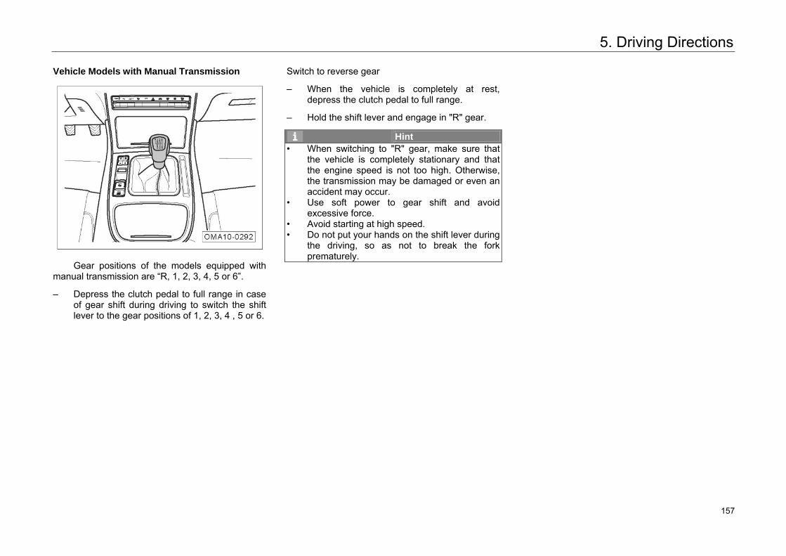
5. Driving Directions
Vehicle Models with Manual Transmission
Gear positions of the models equipped with manual transmission are “R, 1, 2, 3, 4, 5 or 6”.
– Depress the clutch pedal to full range in caseof gear shift during driving to switch the shiftlever to the gear positions of 1, 2, 3, 4 , 5 or 6.
Switch to reverse gear
– When the vehicle is completely at rest,depress the clutch pedal to full range.
– Hold the shift lever and engage in "R" gear.
Hint • When switching to "R" gear, make sure that
the vehicle is completely stationary and that the engine speed is not too high. Otherwise, the transmission may be damaged or even an accident may occur.
• Use soft power to gear shift and avoid excessive force.
• Avoid starting at high speed.• Do not put your hands on the shift lever during
the driving, so as not to break the forkprematurely.
167 157
5. Driving Directions
5.2 Brake System
5.2.1 Service Brake
When you press down or slightly press the brake pedal for the first time under some driving or weather conditions, you may hear the brake squeaking or screaming, or other noise. Or you may hear braking noise occasionally during mild or moderate braking, especially in a new vehicle (without brake running-in). It is normal and not an indication that the brake system is faulty or that the brake safety and performance are affected.
Caution • If there is any metal-to-metal sharp friction
sound, the brake lining may be close to itswear limit. You should go to any authorizedGAC Motor's dealer for maintenance as soonas possible.
• If the steering wheel keeps vibrating oroscillating during braking of the vehicle, youshould go to any authorized GAC Motor'sdealer for maintenance as soon aspossible
Hint • Do not put your foot on the brake pedal to rest
when driving. Otherwise, the temperature of the brake may rise abnormally, resulting in excessive wear of the brake lining and brake pad and longer braking distance.
• When driving down a long or steep slope, set the transmission to a lower gear to avoidcontinuous use of the brake, make full use of the engine to brake and reduce the load of the brake.
• Continuous use of the brake may result in overheating of the brake and temporary lossof brake performance.
Hint • Brake dust may accumulate on the wheel
under normal driving conditions due to thewear of the brake. It is inevitable. A small amount of brake dust will not affect the brakeperformance.
• If the brake lining and brake disc are rusty because they are not used or they are used at a low rate, the brake may make a noise when it is pressed for the first time. It is normal. It isrecommended to brake the vehicle several times in a safe area or on a safe road to clean the brake lining and brake disc.
168 158
5. Driving Directions
Brake Booster
Brake boosters are used to increase the pressure that the driver applies on the brake pedal, but they do not work until the engine is running.
If a brake booster cannot work properly due to any fault or the vehicle is being towed, the pressure on the brake pedal should be increased to compensate the boosting effect of the brake booster.
Warning • Do not make your vehicle slide under
inertia with the engine off. Otherwise, it is easy to cause accidents because the brake booster will not function and the braking distance will be much longer.
• If the brake booster does not work (for instance, when the vehicle is being towed), press the brake pedal with much greater force than normally required.
Braking Effect and Braking Distance
The braking effect and braking distance depend on driving environments, road conditions and driving styles.
A worn brake pad cannot provide effective braking. The wear speed of a brake lining mainly depends on service conditions and driving styles. For a vehicle for frequent urban driving, short drive or racing, it is recommended to check the thickness of the brake pad more frequently within the maintenance cycle specified in the Maintenance Manual.
The brake pad may become damp or icy in winter after wading, rainstorm or vehicle washing, reducing brake effect. In this case, press down the brake pedal slightly to heat the brake by friction to make water evaporate and restore the braking effects. Replace the brake fluid once every two years. If the brake fluid is left in the brake system for a too long time, air resistance may be generated in the pipe of the brake, degrading braking effects.
Warning The best adhesion and friction characteristics
cannot be realized for new tires and braking pad without running-in. • As new tires do not yet have the best traction,
you must drive carefully for the first 500 km to avoid accidents!
• As a new brake pad does not yet have the best friction feature for the first 200-300 km, reducing the braking effects, it must go through a running-in. An increased force on the brake pedal can compensate the braking effect. After replacement, the new brake pad shall also go through running-in.
• Do not drive too close to other vehicles or in situations where emergency braking is likely to occur. Drive carefully especially when new tires or brake pads without running-in are used. Avoid the above mentioned situations and prevent accidents.
169 159
5. Driving Directions
Warning The braking may be delayed if the brake is
damp or icy or when the vehicle passes a road with salt. Drive carefully in such cases to prevent accidents. • A longer braking distance or a faulty braking
system may increase the accident rate. • Press the brake pedal slightly to check it. • Press the brake pedal slightly to dry it and
remove the ice or anti-skid salt on it.
Warning An overheated brake will reduce braking
effects and lengthen the braking distance. • Take care to avoid overheating the brake. • The brake load will increase when the vehicle
is driven down a slope, leading to overheating easily.
• It is recommended to shift to a low gear when the vehicle is driven down on a long slope to decelerate the vehicle, make full use of the braking effects of the engine and reduce the load of the brake.
• Do not press the brake pedal continuously. Otherwise, the brake may be overheated and the braking distance may be longer. Brake the vehicle intermittently based on road and traffic conditions.
• Do not make your vehicle slide under inertia. with the engine off. Otherwise, it is easy to cause accidents because the brake booster will not function and the braking distance will be much longer.
Warning • Replace the brake fluid once every two years.
If the brake fluid is left in the brake system for a too long time, air resistance may be generated in the pipe of the brake, degrading braking effects and driving safety or even leading to a failure of the brake system. It is easy to cause accidents in such conditions.
• Both the non-standard front spoiler or damaged spoiler may block the cooling air to the brake, resulting in brake overheating and degrading braking effects.
170 160
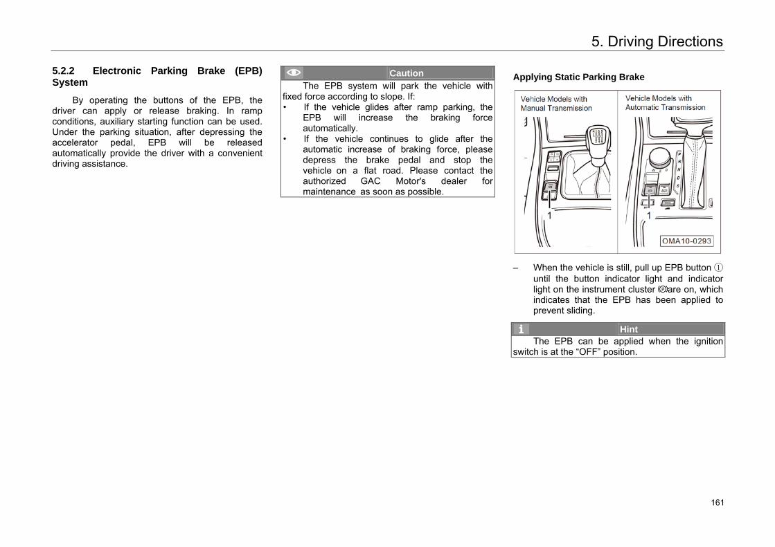
5. Driving Directions
5.2.2 Electronic Parking Brake (EPB) System
By operating the buttons of the EPB, the driver can apply or release braking. In ramp conditions, auxiliary starting function can be used. Under the parking situation, after depressing the accelerator pedal, EPB will be released automatically provide the driver with a convenient driving assistance.
Caution The EPB system will park the vehicle with
fixed force according to slope. If: • If the vehicle glides after ramp parking, the
EPB will increase the braking force automatically.
• If the vehicle continues to glide after the automatic increase of braking force, please depress the brake pedal and stop the vehicle on a flat road. Please contact the authorized GAC Motor's dealer for maintenance as soon as possible.
Applying Static Parking Brake
– When the vehicle is still, pull up EPB button ①until the button indicator light and indicatorlight on the instrument cluster are on, whichindicates that the EPB has been applied toprevent sliding.
Hint The EPB can be applied when the ignition
switch is at the “OFF” position.
171 161
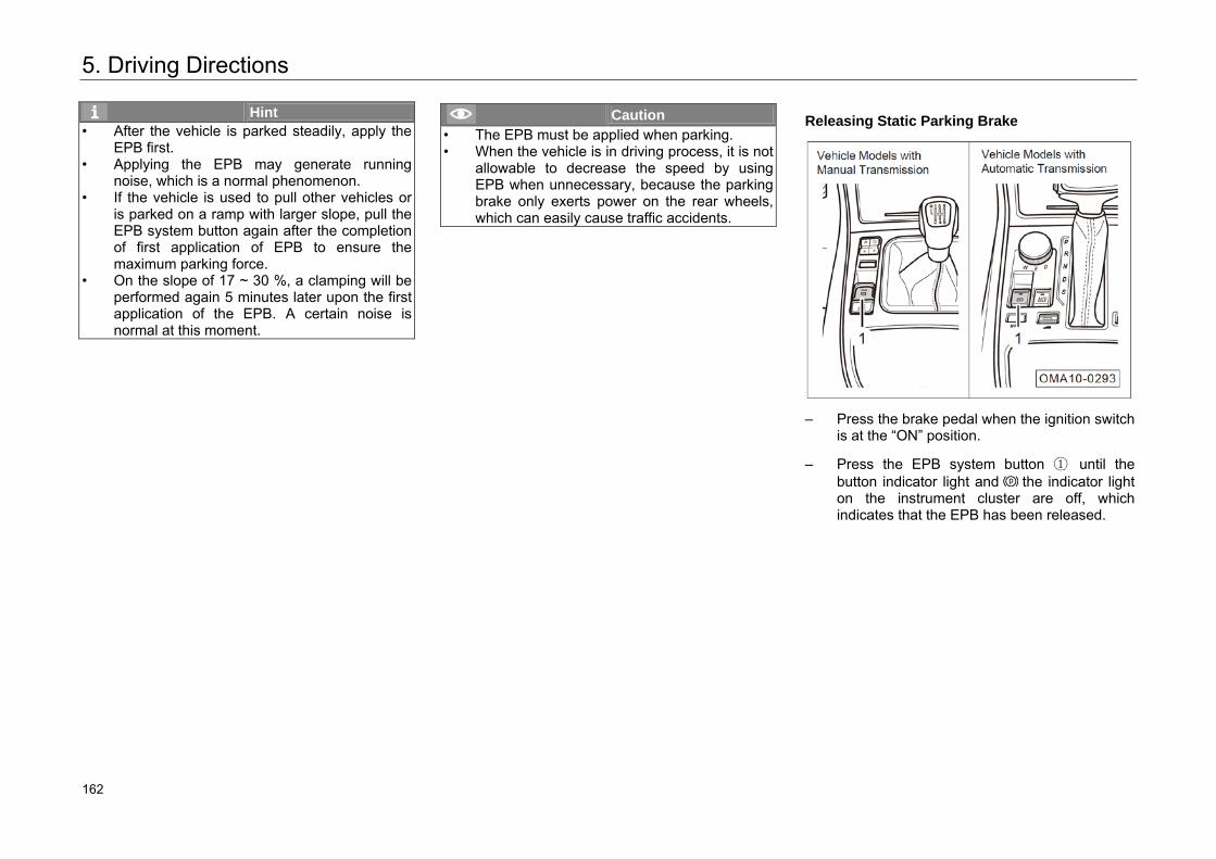
5. Driving Directions
Hint • After the vehicle is parked steadily, apply the
EPB first. • Applying the EPB may generate running
noise, which is a normal phenomenon. • If the vehicle is used to pull other vehicles or
is parked on a ramp with larger slope, pull the EPB system button again after the completion of first application of EPB to ensure the maximum parking force.
• On the slope of 17 ~ 30 %, a clamping will be performed again 5 minutes later upon the first application of the EPB. A certain noise is normal at this moment.
Caution • The EPB must be applied when parking. • When the vehicle is in driving process, it is not
allowable to decrease the speed by using EPB when unnecessary, because the parking brake only exerts power on the rear wheels, which can easily cause traffic accidents.
Releasing Static Parking Brake
– Press the brake pedal when the ignition switch
is at the “ON” position.
– Press the EPB system button ① until the button indicator light and the indicator light on the instrument cluster are off, which indicates that the EPB has been released.
172 162
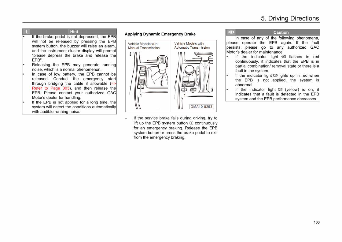
5. Driving Directions
Hint • If the brake pedal is not depressed, the EPB
will not be released by pressing the EPB system button, the buzzer will raise an alarm, and the instrument cluster display will prompt "please depress the brake and release the EPB".
• Releasing the EPB may generate running noise, which is a normal phenomenon.
• In case of low battery, the EPB cannot be released. Conduct the emergency start through bridging the cable if allowable (=> Refer to Page 303), and then release the EPB. Please contact your authorized GAC Motor's dealer for handling.
• If the EPB is not applied for a long time, the system will detect the conditions automatically with audible running noise.
Applying Dynamic Emergency Brake
– If the service brake fails during driving, try tolift up the EPB system button ① continuouslyfor an emergency braking. Release the EPBsystem button or press the brake pedal to exitfrom the emergency braking.
Caution In case of any of the following phenomena,
please operate the EPB again. If the fault persists, please go to any authorized GAC Motor's dealer for maintenance. • If the indicator light flashes in red
continuously, it indicates that the EPB is inpartial combination/ removal state or there is a fault in the system.
• If the indicator light lights up in red whenthe EPB is not applied, the system isabnormal.
• If the indicator light (yellow) is on, itindicates that a fault is detected in the EPBsystem and the EPB performance decreases.
173 163
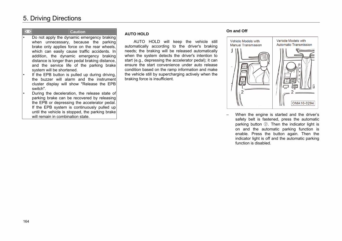
5. Driving Directions
Caution • Do not apply the dynamic emergency braking
when unnecessary, because the parking brake only applies force on the rear wheels, which can easily cause traffic accidents. In addition, the dynamic emergency braking distance is longer than pedal braking distance, and the service life of the parking brake system will be shortened.
• If the EPB button is pulled up during driving, the buzzer will alarm and the instrument cluster display will show "Release the EPB switch".
• During the deceleration, the release state of parking brake can be recovered by releasing the EPB or depressing the accelerator pedal. If the EPB system is continuously pulled up until the vehicle is stopped, the parking brake will remain in combination state.
AUTO HOLD
AUTO HOLD will keep the vehicle still automatically according to the driver's braking needs; the braking will be released automatically when the system detects the driver's intention to start (e.g., depressing the accelerator pedal); it can ensure the start convenience under auto release condition based on the ramp information and make the vehicle still by supercharging actively when the braking force is insufficient.
On and Off
– When the engine is started and the driver’s
safety belt is fastened, press the automatic parking button ②. Then the indicator light is on and the automatic parking function is enable. Press the button again. Then the indicator light is off and the automatic parking function is disabled.
174 164
5. Driving Directions
Activation
After being activated, the function supports the auto holding and releasing of brake in moving and stopping conditions. When the driver stops the vehicle by using brake, the vehicle will be parked automatically to avoid the sliding at starting.
Deactivation
The AUTO HOLD function will be deactivated and the parking brake will not be locked in following conditions:
1. The accelerator pedal is depressed at starting.
2. The engine is shut down during driving.
3. The EPB is released manually.
4. Press the automatic parking button when depressing the brake pedal.
In order to ensure safety, the AUTO HOLD function activated will be disabled and the parking brake will be locked in the following conditions:
1. The engine is shut down.
2. The driver side door is opened or the seat belt is unbuckled in stop state.
3. Press the automatic parking button to disable automatic parking function.
Caution When the vehicle is transferred via conveyor
belt to cleaning device and other devices, the AUTO HOLD function must be disabled. Otherwise, the vehicle cannot move or may deviate from the driving track.
EPB Adaptive Learning
In some cases (e.g. the battery suffers power failure suddenly, or the vehicle has not been used for a long time), the red indicator light will flicker, and manually pulling the EPB button will cause EPB unable to work. In this case, the driver shall depress the brake pedal and press EPB button to make EPB execute adaptive learning, enabling EPB to work normally.
175 165
5. Driving Directions
5.3 Service Electronic Brake System
5.3.1 Anti-Lock Braking System (ABS)
Anti-lock braking system (ABS) is an important part of active safety system.
When ABS works, the friction between the wheel and the road is rolling friction and favorable for braking by making use of the maximum adhesion between the wheel and road, thereby improving the braking deceleration, shortening the braking distance, and ensuring the direction stability during braking.
The ABS operation is equivalent to snubbing at a high frequency. The driver will feel the vibration of brake pedal accompanied by the “tick” sound produced by brake master cylinder operation when depressing the brake pedal in emergency. In this case, the ABS is in normal working state. Since the brake master cylinder adjusts the brake pressure constantly, a force will be fed back to the brake pedal continuously. Therefore, in this case, it is required to depress the brake pedal to the end, and it is forbidden to depress the brake pedal repeatedly.
As ABS is only the safety assistant system, its function is very limited. For example, when making a brake on sand and stone road or snowy road, it may have a longer braking distance compared with braking on concrete road or dry road. Don't take it for granted that ABS can get ideal brake performance in any situation. Therefore, do not rely on these systems too much. Only safe driving is the most important.
Under the following conditions, ABS will be activated by depressing the brake pedal. It is normal to feel vibration:
– When shifting gears.
– During emergency braking.
– When turning at high speed.
– When driving on slippery road.
– When driving on projected or pit road.
– When making sudden start after the vehicle isstarted.
176 166
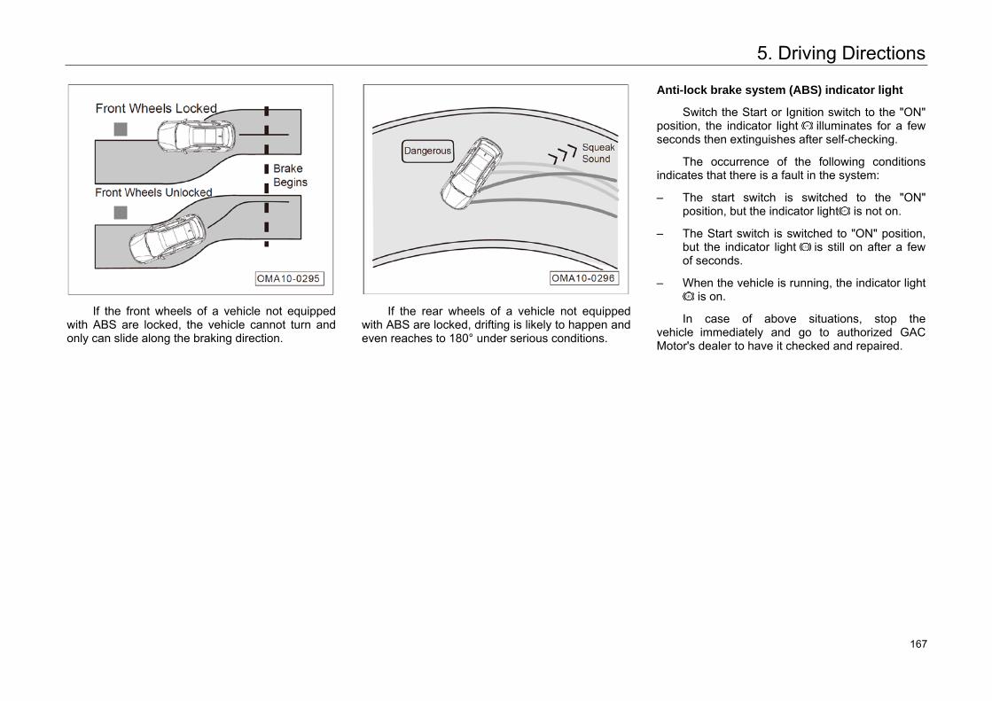
5. Driving Directions
If the front wheels of a vehicle not equipped with ABS are locked, the vehicle cannot turn and only can slide along the braking direction.
If the rear wheels of a vehicle not equipped with ABS are locked, drifting is likely to happen and even reaches to 180° under serious conditions.
Anti-lock brake system (ABS) indicator light
Switch the Start or Ignition switch to the "ON" position, the indicator light illuminates for a few seconds then extinguishes after self-checking.
The occurrence of the following conditions indicates that there is a fault in the system:
– The start switch is switched to the "ON"position, but the indicator light is not on.
– The Start switch is switched to "ON" position,but the indicator light is still on after a fewof seconds.
– When the vehicle is running, the indicator light is on.
In case of above situations, stop the vehicle immediately and go to authorized GAC Motor's dealer to have it checked and repaired.
177 167
5. Driving Directions
Warning Always adjust the speed according to the
weather, road and traffic conditions. To avoid accidents, don't take a risk to drive just depending on the limited safety functions provided by the system. • The ABS cannot go beyond the kinematic law.
It is still dangerous for a vehicle with ABS todrive on slippery road. While driving, if theABS is adjusting the brake pressure, immediately slow down to adapt to the road and traffic conditions.
• Improper operation or modification (such asmodification of parts of braking system, or wheels and tires) may affect the functions of ABS, EBD and ESP.
• Specified size of tires must be used. If thevehicle is installed with tires in improper sizeor non-uniform size, ABS can't work normally.
Warning
• If the indicator lights and are onsimultaneously, stop the vehicle immediatelyand check the brake fluid level => Refer toPage 272.
• If the brake fluid level is normal, the failure ofthe braking system may be caused by theabnormal ABS control function. When brakingin this case, the rear wheel may be lockedsoon, resulting in drifting and side sliding.Please go to your authorized GAC Motor'sdealer for maintenance as soon aspossible.
178 168
5. Driving Directions
5.3.2 Electronic Brakeforce Distribution System (EBD)
EBD system is a part of ABS and used for balancing the brakeforce distribution on front and rear wheels according to the vehicle load in conventional vehicle braking.
EBD exerts more brakeforce on the rear wheel through adjusting slip rate to obtain the shortest braking distance under the premise of ensuring braking stability. In particular, the stability and maneuverability of vehicle braking are improved when driving on a road with poor conditions or a slippery road.
179 169
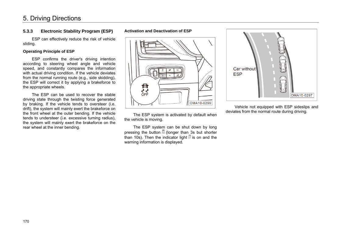
5. Driving Directions
5.3.3 Electronic Stability Program (ESP)
ESP can effectively reduce the risk of vehicle sliding.
Operating Principle of ESP
ESP confirms the driver's driving intention according to steering wheel angle and vehicle speed, and constantly compares the information with actual driving condition. If the vehicle deviates from the normal running route (e.g., side skidding), the ESP will correct it by applying a brakeforce to the appropriate wheels.
The ESP can be used to recover the stable driving state through the twisting force generated by braking. If the vehicle tends to oversteer (i.e. drift), the system will mainly exert the brakeforce on the front wheel at the outer bending. If the vehicle tends to understeer (i.e. excessive turning radius), the system will mainly exert the brakeforce on the rear wheel at the inner bending.
Activation and Deactivation of ESP
The ESP system is activated by default when
the vehicle is moving.
The ESP system can be shut down by long pressing the button (longer than 3s but shorter than 10s). Then the indicator light is on and the warning information is displayed.
Vehicle not equipped with ESP sideslips and
deviates from the normal route during driving.
180 170
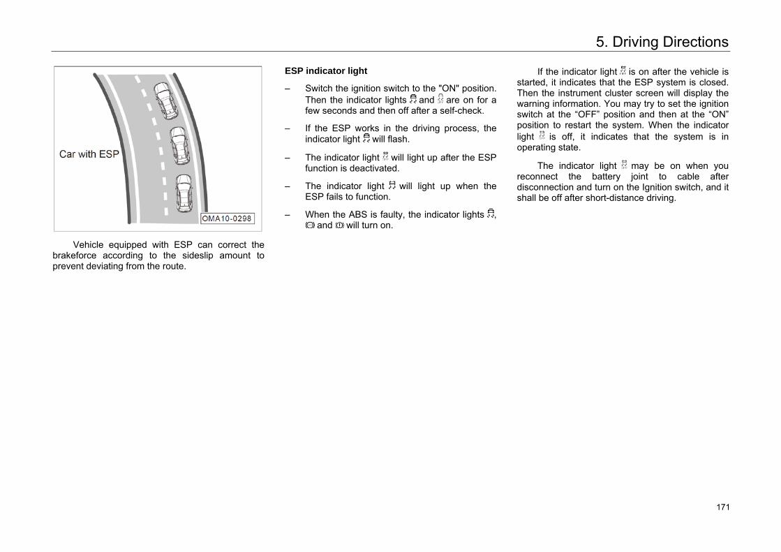
5. Driving Directions
Vehicle equipped with ESP can correct the
brakeforce according to the sideslip amount to prevent deviating from the route.
ESP indicator light
– Switch the ignition switch to the "ON" position. Then the indicator lights and are on for a few seconds and then off after a self-check.
– If the ESP works in the driving process, the indicator light will flash.
– The indicator light will light up after the ESP function is deactivated.
– The indicator light will light up when the ESP fails to function.
– When the ABS is faulty, the indicator lights , and will turn on.
If the indicator light is on after the vehicle is started, it indicates that the ESP system is closed. Then the instrument cluster screen will display the warning information. You may try to set the ignition switch at the “OFF” position and then at the “ON” position to restart the system. When the indicator light is off, it indicates that the system is in operating state.
The indicator light may be on when you reconnect the battery joint to cable after disconnection and turn on the Ignition switch, and it shall be off after short-distance driving.
181 171
5. Driving Directions
Warning You must adjust your vehicle speed according
to the weather, road and traffic conditions. To avoid traffic accident, don't take a risk to drive your vehicle just depending on additional safety functions provided by the systems. • Remember: ESP cannot go beyond the
physical limit of road adhesion. Be sure to drive on slippery road or drive while towing a trailer with extra care.
• The driver must adjust the driving mode according to the road and traffic conditions.
• ESP cannot reduce the risk of accidents caused by improper driving such as excessive high driving speed or too close distance to the front vehicle.
• Improper operation or modification (such as modification of parts of braking system, or wheels and tires) may affect the functions of ABS, EBD and ESP.
The ESP will work only when the engine is running. The ESP function can be released under special conditions. For example:
– The vehicle is running with tire chain.
– The vehicle is running on deep snowy or spongy road.
– The vehicle gets stuck in muddy road or other roads, and needs to be moved back and forth.
In the absence of such conditions, the ESP should be activated for driving safety.
182 172
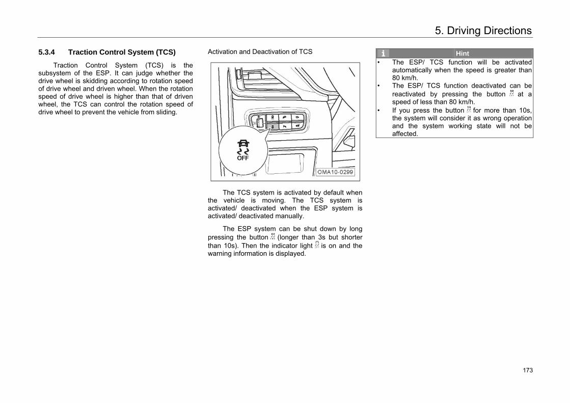
5. Driving Directions
5.3.4 Traction Control System (TCS)
Traction Control System (TCS) is the subsystem of the ESP. It can judge whether the drive wheel is skidding according to rotation speed of drive wheel and driven wheel. When the rotation speed of drive wheel is higher than that of driven wheel, the TCS can control the rotation speed of drive wheel to prevent the vehicle from sliding.
Activation and Deactivation of TCS
The TCS system is activated by default when
the vehicle is moving. The TCS system is activated/ deactivated when the ESP system is activated/ deactivated manually.
The ESP system can be shut down by long pressing the button (longer than 3s but shorter than 10s). Then the indicator light is on and the warning information is displayed.
Hint • The ESP/ TCS function will be activated
automatically when the speed is greater than 80 km/h.
• The ESP/ TCS function deactivated can be reactivated by pressing the button at a speed of less than 80 km/h.
• If you press the button for more than 10s, the system will consider it as wrong operation and the system working state will not be affected.
183 173
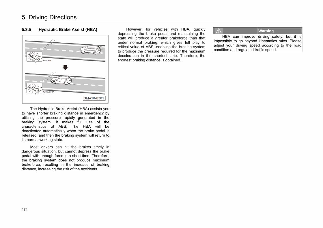
5. Driving Directions
5.3.5 Hydraulic Brake Assist (HBA)
The Hydraulic Brake Assist (HBA) assists you to have shorter braking distance in emergency by utilizing the pressure rapidly generated in the braking system. It makes full use of the characteristics of ABS. The HBA will be deactivated automatically when the brake pedal is released, and then the braking system will return to its normal working state.
Most drivers can hit the brakes timely in dangerous situation, but cannot depress the brake pedal with enough force in a short time. Therefore, the braking system does not produce maximum brakeforce, resulting in the increase of braking distance, increasing the risk of the accidents.
However, for vehicles with HBA, quickly depressing the brake pedal and maintaining the state will produce a greater brakeforce than that under normal braking, which gives full play to critical value of ABS, enabling the braking system to produce the pressure required for the maximum deceleration in the shortest time. Therefore, the shortest braking distance is obtained.
Warning HBA can improve driving safety, but it is
impossible to go beyond kinematics rules. Please adjust your driving speed according to the road condition and regulated traffic speed.
184 174
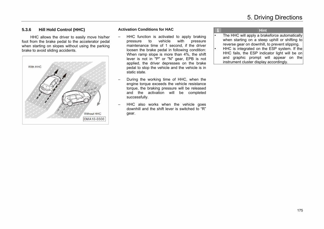
5. Driving Directions
5.3.6 Hill Hold Control (HHC)
HHC allows the driver to easily move his/her foot from the brake pedal to the accelerator pedal when starting on slopes without using the parking brake to avoid sliding accidents.
Activation Conditions for HAC
– HHC function is activated to apply brakingpressure to vehicle with pressuremaintenance time of 1 second, if the driverloosen the brake pedal in following condition:When ramp slope is more than 4%, the shiftlever is not in "P" or "N" gear, EPB is notapplied, the driver depresses on the brakepedal to stop the vehicle and the vehicle is instatic state.
– During the working time of HHC, when theengine torque exceeds the vehicle resistancetorque, the braking pressure will be releasedand the activation will be completedsuccessfully.
– HHC also works when the vehicle goesdownhill and the shift lever is switched to “R”gear.
Hint • The HHC will apply a brakeforce automatically
when starting on a steep uphill or shifting to reverse gear on downhill, to prevent slipping.
• HHC is integrated on the ESP system. If theHHC fails, the ESP indicator light will be on and graphic prompt will appear on the instrument cluster display accordingly.
185 175
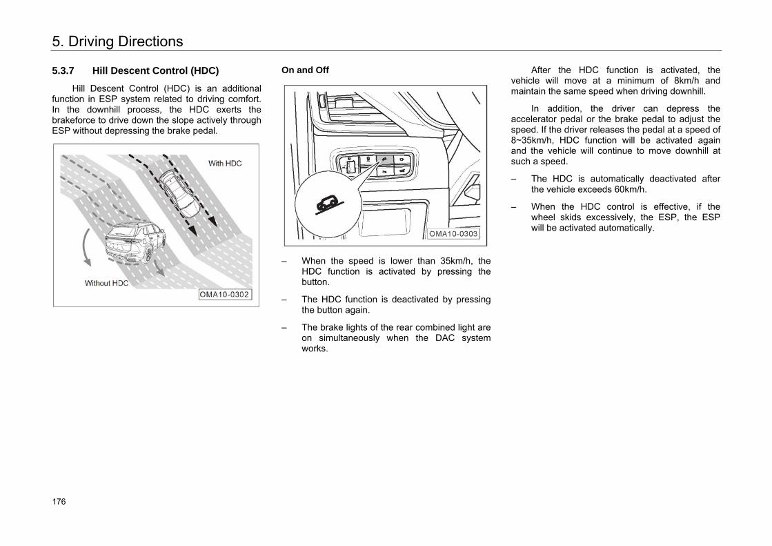
5. Driving Directions
5.3.7 Hill Descent Control (HDC)
Hill Descent Control (HDC) is an additional function in ESP system related to driving comfort. In the downhill process, the HDC exerts the brakeforce to drive down the slope actively through ESP without depressing the brake pedal.
On and Off
– When the speed is lower than 35km/h, the
HDC function is activated by pressing the button.
– The HDC function is deactivated by pressing the button again.
– The brake lights of the rear combined light are on simultaneously when the DAC system works.
After the HDC function is activated, the vehicle will move at a minimum of 8km/h and maintain the same speed when driving downhill.
In addition, the driver can depress the accelerator pedal or the brake pedal to adjust the speed. If the driver releases the pedal at a speed of 8~35km/h, HDC function will be activated again and the vehicle will continue to move downhill at such a speed.
– The HDC is automatically deactivated after the vehicle exceeds 60km/h.
– When the HDC control is effective, if the wheel skids excessively, the ESP, the ESP will be activated automatically.
186 176
5. Driving Directions
Hint • When the DAC system fails, the function will
be deactivated, the instrument cluster displaywill show graphic prompt accordingly, and anaudible alarm of about 5s will appear. In thiscase, the HDC system will not work properly.The driver should not use the system fordownhill driving forcefully, instead he/she shalldepress the brake pedal, and go to authorizedGAC Motor's dealer for maintenance as soonas possible.
• Under some special circumstances, HDC willbe in thermal protection mode due to highbraking temperature. For example, if thesystem is used for a long time at relativelyhigh ambient temperature, the temperature ofbraking system will increase constantly due tofriction; when the limit value is reached, HDCwill enter thermal protection mode: thisfunction is activated but does not work. HDCwill lose its function temporarily, and thevehicle will show acceleration sign; HDC willwork again when the temperature of brakingsystem drops to effective workingtemperature.
187 177
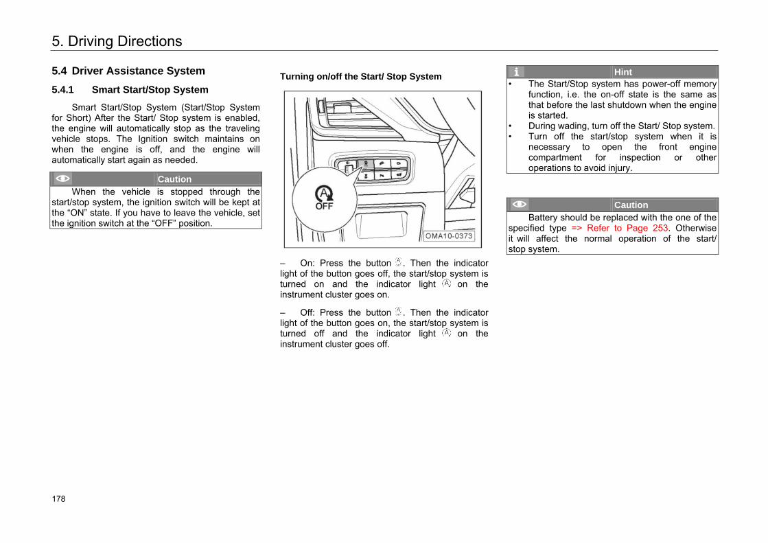
5. Driving Directions
5.4 Driver Assistance System
5.4.1 Smart Start/Stop System
Smart Start/Stop System (Start/Stop System for Short) After the Start/ Stop system is enabled, the engine will automatically stop as the traveling vehicle stops. The Ignition switch maintains on when the engine is off, and the engine will automatically start again as needed.
Caution When the vehicle is stopped through the
start/stop system, the ignition switch will be kept at the “ON” state. If you have to leave the vehicle, set the ignition switch at the “OFF” position.
Turning on/off the Start/ Stop System
– On: Press the button . Then the indicatorlight of the button goes off, the start/stop system isturned on and the indicator light on theinstrument cluster goes on.
– Off: Press the button . Then the indicatorlight of the button goes on, the start/stop system isturned off and the indicator light on theinstrument cluster goes off.
Hint • The Start/Stop system has power-off memory
function, i.e. the on-off state is the same asthat before the last shutdown when the engine is started.
• During wading, turn off the Start/ Stop system.• Turn off the start/stop system when it is
necessary to open the front engine compartment for inspection or otheroperations to avoid injury.
Caution Battery should be replaced with the one of the
specified type => Refer to Page 253. Otherwise it will affect the normal operation of the start/stop system.
188 178
5. Driving Directions
Basic Service Conditions of the Start/ Stop System
The start/stop system can function normally only after the following conditions are met:
1. The start/stop system is turned on.
2. The driver sits on the seat and fastens the seat belt and the door on the driver side is closed.
3. Engine hood must be closed.
4. Engine water temperature exceeds 54°C (after the engine operates normally for a while).
5. The speed has exceeded 8 km/h since the last stop.
Hint If the speed remains below 8 km/h, the engine
will not be turned off by the Start/ Stop system.
Working Process of the Start/ Stop System of MT Model
– When basic conditions for the start/stop system to work are met, park the vehicle till it is still, shift to the neutral gear and release the clutch. Then the start/stop system will shut down the engine automatically and the indicator light on the instrument cluster will go on.
– As the engine is off and the ignition switch is on, press the clutch pedal or the brake pedal at the neutral gear. Then the engine will automatically start and the indicator light on the instrument cluster will go off and the indicator light will go on in white.
Hint If the diver takes no action for a certain period
after the engine is started, the start/stop system will shut down the engine again.
Under the condition that the start/stop system shuts down the engine automatically, the following operations can start the engine as well:
– Turning the steering wheel to a certain angle.
– Operate the ignition switch.
– Press the button .
189 179
5. Driving Directions
Working Process of the Start/ Stop System of AT Model
– When basic conditions for the start/stopsystem to work are met, park the vehicle till itis still and press and hold the brake pedal.Then the start/stop system will shut down theengine automatically and the indicator lighton the instrument cluster will go on.
– As the engine is off and the Ignition switch ison, release the brake pedal. Then the enginewill automatically start and the indicator light(white) on the instrument cluster will be offand is on.
Hint If the diver takes no action for a certain period
after the engine is started, the start/stop system will shut down the engine again.
Under the condition that the start/stop system shuts down the engine automatically, the following operations can start the engine as well:
– Turning the steering wheel to a certain angle.
– Operate the ignition switch.
– Press the button .
– Put the shift lever at the “D” gear and releasethe brake pedal.
– Put the shift lever at the “D” gear, press thebrake pedal and put the shift lever at the “S”gear.
– If the shift lever is in the "N" gear, the start willnot be triggered by releasing the brake pedalunless you press the brake pedal again.
– Put the shift lever at the “N” gear withoutreleasing the brake pedal. Then put it at the“R” or “D” gear.
Hint • The process shifting to “P” gear from other
gears than “R” gear will go through “R” gear. Do not stay at the “R” gear. Otherwise, the engine will be started.
• When “D” gear is shifted from “R” gear, the start/stop system can shut down the engine only after the vehicle is driven at 15km/h.
190 180
5. Driving Directions
Conditions for Operation Failure of Start/Stop system
The following conditions will disable the start/stop system:
– The water temperature of the engine does notreach the lowest temperature under the basicservice conditions of the start-stop system.
– Brake booster vacuum is insufficient.
– The internal temperature set by the A/C is notreached.
– The external temperature is too high or toolow.
– The defrosting function of the front windshieldis enabled.
– Battery voltage too low.
– Altitude is too high.
– The steering wheel suffers a substantialdeflection.
– The shift lever is put at “R” gear.
– The slope is too steep.
– The start/stop system is turned off.
Automatic Restart of Engine
When the start/stop system shuts down the engine automatically, the following operations will interrupt the normal operation of the start/stop system and result in automatic start of the engine without any operation of the driver:
– The vehicle is sliding on a slope.
– Internal temperature deviates from the valueset by the A/C.
– Front windshields are in the deforesting state.
– Brake booster vacuum is insufficient.
– Battery voltage too low.
Automatic Start Failure Description
When the start/stop system automatically shuts down the engine and the following operations cause the automatic start to fail, the instrument cluster will display “the start/stop system is turned off. Please start the engine manually” and the driver has to start the engine manually:
– The start/stop system fails.
– The engine fails to automatically start morethan three times.
– The engine hood or any door is open.
– The driver unfastens the seat belt.
Hint • When the engine hood or any door is open,
the automatic start will not be triggered even after the engine hood or the door is close.
• When the driver unfastens the seat belt, theautomatic start will not be triggered even after the driver fastens the seat belt.
191 181
5. Driving Directions
Adaptive Learning after Battery Power-Off
In case of battery power-off or replacement, the adaptive learning operation of the Start/Stop system shall be conducted according to the following steps after power restoration:
1. Turn off the Ignition switch and all theelectrical equipment of the vehicle and keepthe stationary state for at least 4 hours.
2. Start the engine for 3 times and make itoperate continually for at least 1 minute eachtime.
192 182
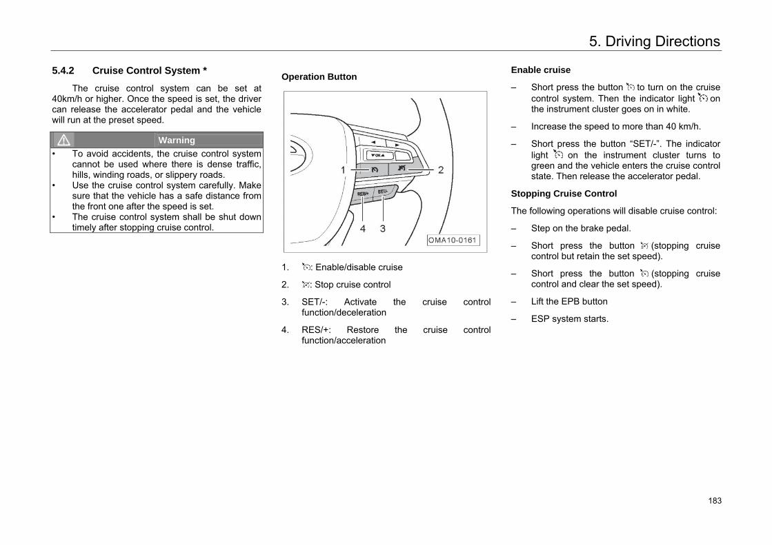
5. Driving Directions
5.4.2 Cruise Control System *
The cruise control system can be set at 40km/h or higher. Once the speed is set, the driver can release the accelerator pedal and the vehicle will run at the preset speed.
Warning • To avoid accidents, the cruise control system
cannot be used where there is dense traffic, hills, winding roads, or slippery roads.
• Use the cruise control system carefully. Makesure that the vehicle has a safe distance from the front one after the speed is set.
• The cruise control system shall be shut down timely after stopping cruise control.
Operation Button
1. : Enable/disable cruise
2. : Stop cruise control
3. SET/-: Activate the cruise controlfunction/deceleration
4. RES/+: Restore the cruise controlfunction/acceleration
Enable cruise
– Short press the button to turn on the cruisecontrol system. Then the indicator light onthe instrument cluster goes on in white.
– Increase the speed to more than 40 km/h.
– Short press the button “SET/-”. The indicatorlight on the instrument cluster turns togreen and the vehicle enters the cruise controlstate. Then release the accelerator pedal.
Stopping Cruise Control
The following operations will disable cruise control:
– Step on the brake pedal.
– Short press the button (stopping cruisecontrol but retain the set speed).
– Short press the button (stopping cruisecontrol and clear the set speed).
– Lift the EPB button
– ESP system starts.
193 183
5. Driving Directions
Restoring Cruise Control
When cruise control is disabled by pressing the brake pedal or short pressing the button , the indicator light on the instrument cluster will turn to white. Short press the button “RES/+” to restore.
– When the speed is above 40 km/h with short pressing of the button “RES/+”, the indicator light on the instrument cluster will turn to green from white and the speed will restore to the previously set cruise speed.
Increasing Cruising Speed
– Short press the RES/+ button to increase the speed by 1km/h each time.
– Long press the RES/+ button to increase the speed continuously until the button is released.
Hint • The allowable maximum cruising speed is
140km/h. The speed above 140km/h cannot be adjusted through pressing the RES/+ button.
• The vehicle exits the cruise control mode as the accelerator is stepped on and then runs at the accelerated speed; after the accelerator pedal is released, the vehicle will restore the cruise control.
Decreasing Cruising Speed
– Short press the SET/- button to decrease the speed by 1km/h each time.
– Long press the SET/- button to decrease the speed continuously until the button is released.
Hint The speed below 40 km/h cannot be adjusted
through pressing the SET/- button again.
194 184
5. Driving Directions
5.4.3 Tire Pressure Monitoring System *
The tire pressure monitoring system monitors the tire pressure and temperature and has current tire pressure and temperature shown on the instrument cluster. In case of low/high tire pressure, fast air leakage and over-temperature, the instrument cluster will display the warning information.
When the Ignition switch is at “ON” position, if the vehicle does not move or moves at a speed lower than 25 km/h, the pressure and temperature values are both displayed as “---” on the instrument cluster. After the speed is higher than 25 km/h, the instrument cluster displays current tire pressure and temperature.
– If the tire pressure is higher than 330kPa, theTPMS indicator light will be on, and the textalarm on the instrument cluster display will bedisplayed as high tire pressure.
– If the tire pressure is lower than 165kPa, theTPMS indicator light will be on, and the textalarm on the instrument cluster will bedisplayed as low tire pressure.
– If the tire pressure continuously decreasesbelow a specified value, the indicator light oftire pressure monitoring system will be on,and the text alarm on the instrument clusterdisplay screen will be displayed as tireleakage.
– If the tire temperature exceeds 85°C, theTPMS indicator light will be on, and the textalarm on the instrument cluster display screenwill show over-temperature.
Caution • Some added electronic equipment may cause
the abnormal operation of TPMS.• If it is necessary to replace the tire pressure
sensor inside the tire, or replace orreposition the tire, one should learn thematching of sensors in four tires again.Please go to your authorized GACMotor's dealer for replacement.
227 185
5. Driving Directions
Hint • The standard half-load tire pressure is used
as the normal setting for alarm reference of the TPMS.
• If the tire suffers high temperature, high pressure, low pressure, or rapid air leakage, the instrument cluster will give early warning, with position of the corresponding failed tiredisplayed in circular manner. If the TPMS fails, the instrument cluster will give early warning, with “Please check the TPMS”displayed in circular manner.
• Where there is high temperature alarm, it isrecommended to stop the vehicle and wait until the tires cool.
• The traveling alarm not handled until the vehicle stops will remain when the vehicle starts again, with pressure and temperature displayed as “---”. But when the speedexceeds 25 km/h, the receiver will receive updated data and update relevant data, and then the alarm disappears.
Hint After replacing with a spare tire or with a new
tire in some other places, the low tire pressure alarm lasts during traveling because of the missing tire sensor. Do not mistake this as abnormal tire pressure signal.
228 186
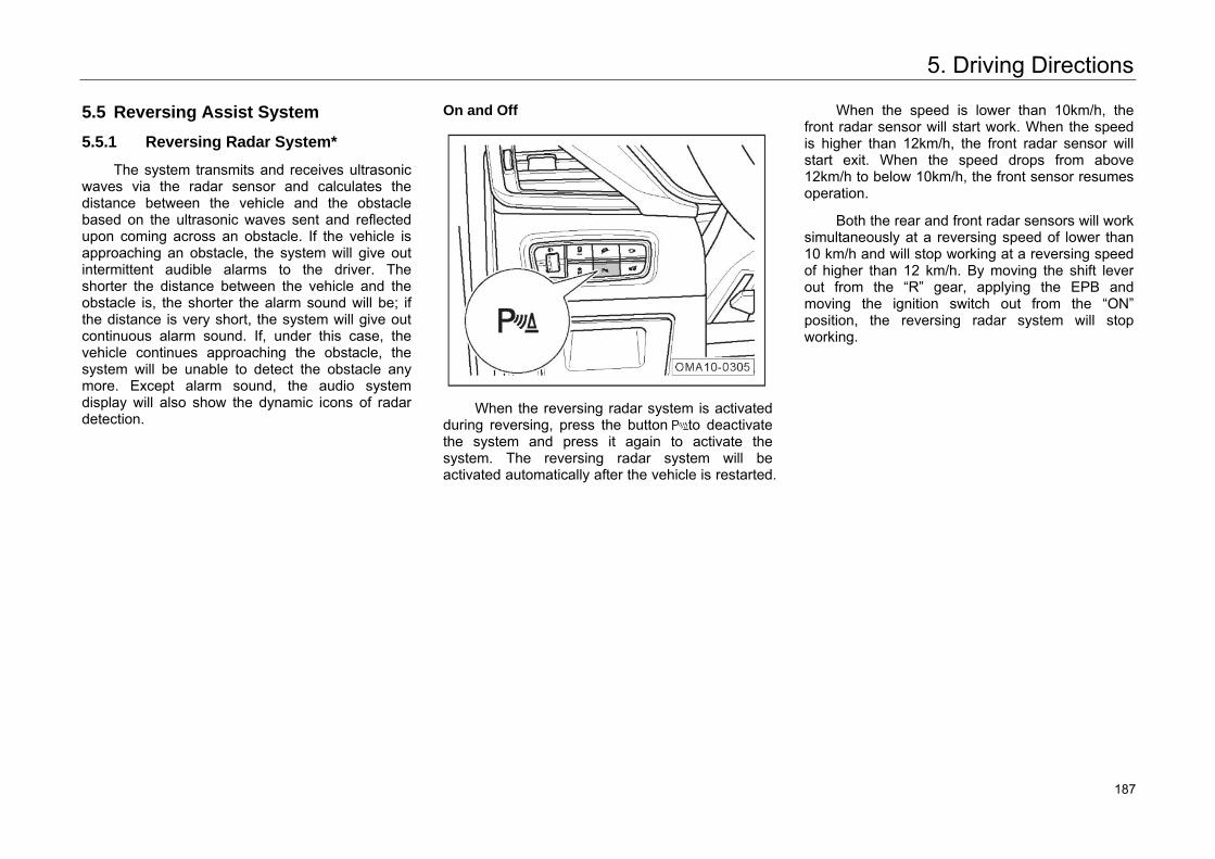
5. Driving Directions
5.5 Reversing Assist System
5.5.1 Reversing Radar System*
The system transmits and receives ultrasonic waves via the radar sensor and calculates the distance between the vehicle and the obstacle based on the ultrasonic waves sent and reflected upon coming across an obstacle. If the vehicle is approaching an obstacle, the system will give out intermittent audible alarms to the driver. The shorter the distance between the vehicle and the obstacle is, the shorter the alarm sound will be; if the distance is very short, the system will give out continuous alarm sound. If, under this case, the vehicle continues approaching the obstacle, the system will be unable to detect the obstacle any more. Except alarm sound, the audio system display will also show the dynamic icons of radar detection.
On and Off
When the reversing radar system is activated
during reversing, press the button to deactivate the system and press it again to activate the system. The reversing radar system will be activated automatically after the vehicle is restarted.
When the speed is lower than 10km/h, the front radar sensor will start work. When the speed is higher than 12km/h, the front radar sensor will start exit. When the speed drops from above 12km/h to below 10km/h, the front sensor resumes operation.
Both the rear and front radar sensors will work simultaneously at a reversing speed of lower than 10 km/h and will stop working at a reversing speed of higher than 12 km/h. By moving the shift lever out from the “R” gear, applying the EPB and moving the ignition switch out from the “ON” position, the reversing radar system will stop working.
229 187
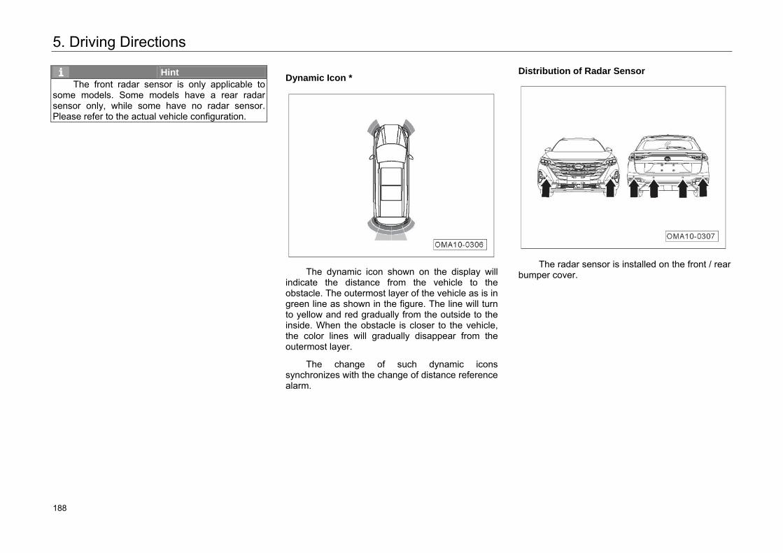
5. Driving Directions
Hint The front radar sensor is only applicable to
some models. Some models have a rear radar sensor only, while some have no radar sensor. Please refer to the actual vehicle configuration.
Dynamic Icon *
The dynamic icon shown on the display will indicate the distance from the vehicle to the obstacle. The outermost layer of the vehicle as is in green line as shown in the figure. The line will turn to yellow and red gradually from the outside to the inside. When the obstacle is closer to the vehicle, the color lines will gradually disappear from the outermost layer.
The change of such dynamic icons synchronizes with the change of distance reference alarm.
Distribution of Radar Sensor
The radar sensor is installed on the front / rear
bumper cover.
230 188
5. Driving Directions
Caution • Always keep the radar sensor surface clean,
and do not cover the radar sensor.• Keep the radar sensor on the bumper clean
and avoid icing to ensure its function.• Clean the radar sensor surface with soft wet
cloth to avoid surface scratching.
Warning • The reversing radar system does not take the
place of the driver’s observation to the surrounding environment, so the driver shall focus attention on reversing safely andadjusting parking position according to actual conditions.
• There may be blind spot when the radar sensor is detecting obstacles, so the driver must observe carefully during reversing, to avoid scraping or collision.
• During reversing in a narrow space or on uphill, the radar sensor may detect railings, trees or slope, which is considered normal.
• At fast reversing speed, the detection accuracy of the radar sensor may decrease somewhat. It is suggested that the reversing speed should not exceed 10km/h. The continuous alarm sound from the revising radar system indicates that the vehicle is very close to the obstacles. The driver shall stop revising immediately to avoid accident.
Warning • Clean the radar sensor with high pressure
cleaning device in a short time and in gentle manner; keep at least 10 cm between the nozzle and the sensor.
• Water drops on the radar sensor of the rearbumper can influence sensitivity of the sensor. To restore sensitivity, wipe off the waterdrops.
• Surfaces of certain materials cannot reflect the signals from the radar sensor, so that thesensor cannot detect such objects or personsin clothes made of such materials.
• The radar sensor may not detect the objects if interfered by outside noise.
• The radar sensor is a precision part. Do not dismantle or repair it by yourself. Damage caused by such dismantling or repairing is not covered in the warranty of GAC MOTOR.
231 189
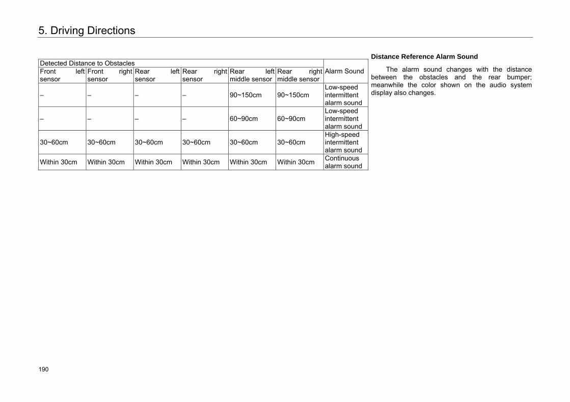
5. Driving Directions
Detected Distance to Obstacles Alarm Sound Front left
sensor Front right sensor
Rear left sensor
Rear right sensor
Rear left middle sensor
Rear right middle sensor
– – – – 90~150cm 90~150cm Low-speed intermittent alarm sound
– – – – 60~90cm 60~90cm Low-speed intermittent alarm sound
30~60cm 30~60cm 30~60cm 30~60cm 30~60cm 30~60cm High-speed intermittent alarm sound
Within 30cm Within 30cm Within 30cm Within 30cm Within 30cm Within 30cm Continuous alarm sound
Distance Reference Alarm Sound
The alarm sound changes with the distance between the obstacles and the rear bumper; meanwhile the color shown on the audio system display also changes.
232 190
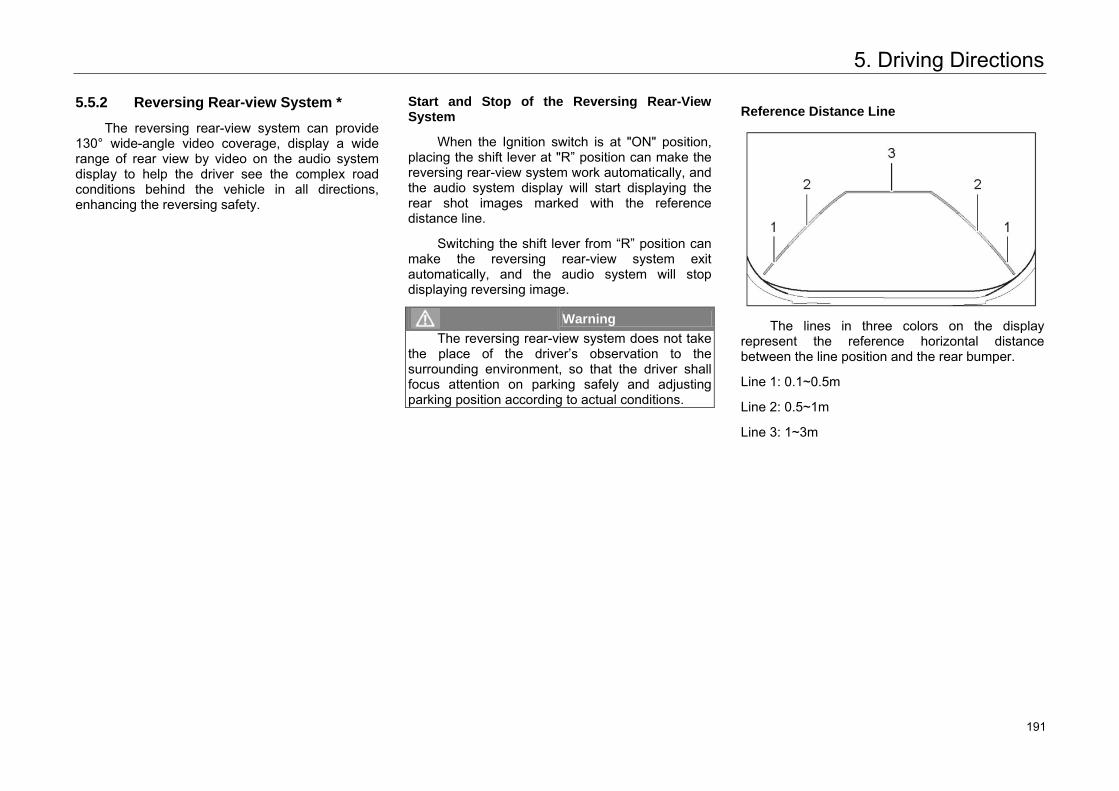
5. Driving Directions
5.5.2 Reversing Rear-view System *
The reversing rear-view system can provide 130° wide-angle video coverage, display a wide range of rear view by video on the audio system display to help the driver see the complex road conditions behind the vehicle in all directions, enhancing the reversing safety.
Start and Stop of the Reversing Rear-View System
When the Ignition switch is at "ON" position, placing the shift lever at "R” position can make the reversing rear-view system work automatically, and the audio system display will start displaying the rear shot images marked with the reference distance line.
Switching the shift lever from “R” position can make the reversing rear-view system exit automatically, and the audio system will stop displaying reversing image.
Warning The reversing rear-view system does not take
the place of the driver’s observation to the surrounding environment, so that the driver shall focus attention on parking safely and adjusting parking position according to actual conditions.
Reference Distance Line
The lines in three colors on the display
represent the reference horizontal distance between the line position and the rear bumper.
Line 1: 0.1~0.5m
Line 2: 0.5~1m
Line 3: 1~3m
233 191
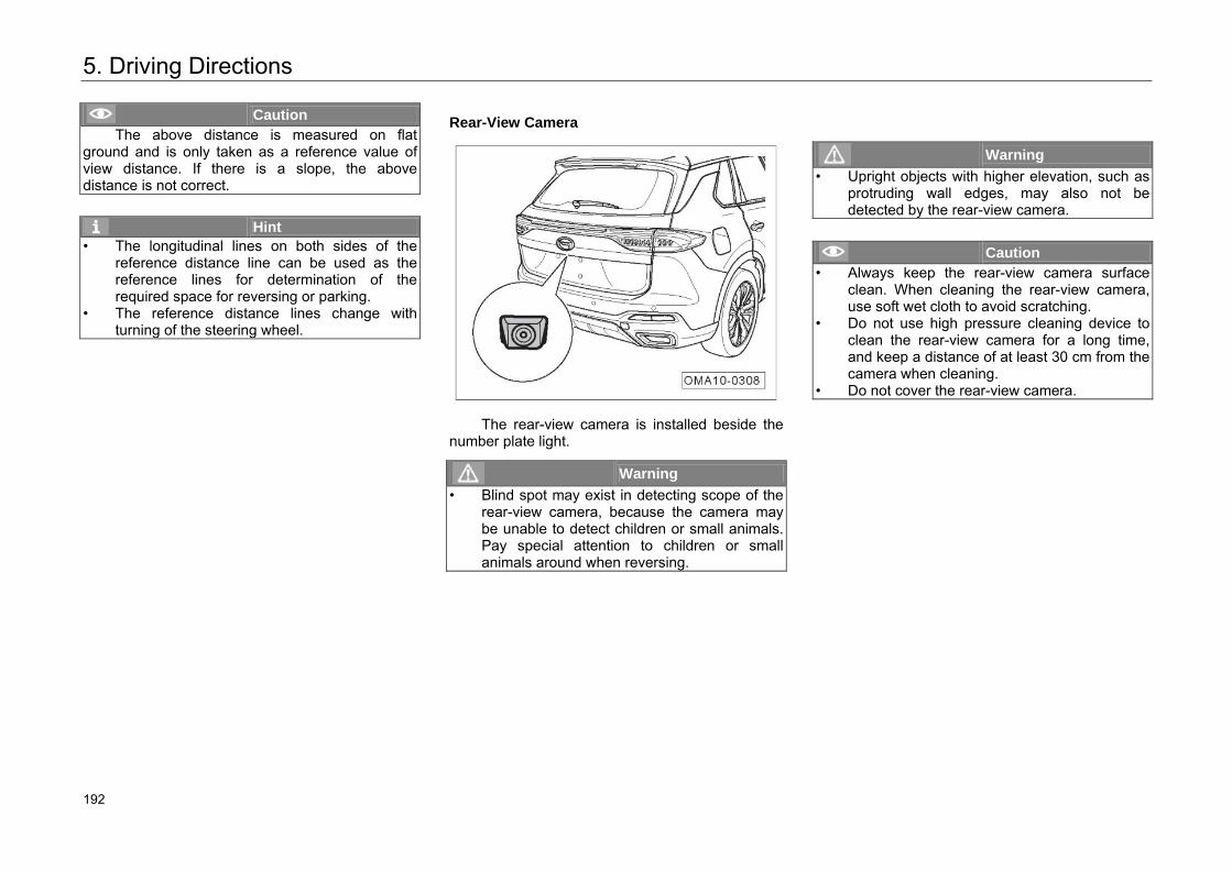
5. Driving Directions
Caution The above distance is measured on flat
ground and is only taken as a reference value of view distance. If there is a slope, the above distance is not correct.
Hint • The longitudinal lines on both sides of the
reference distance line can be used as the reference lines for determination of therequired space for reversing or parking.
• The reference distance lines change with turning of the steering wheel.
Rear-View Camera
The rear-view camera is installed beside the number plate light.
Warning • Blind spot may exist in detecting scope of the
rear-view camera, because the camera may be unable to detect children or small animals. Pay special attention to children or small animals around when reversing.
Warning • Upright objects with higher elevation, such as
protruding wall edges, may also not be detected by the rear-view camera.
Caution • Always keep the rear-view camera surface
clean. When cleaning the rear-view camera, use soft wet cloth to avoid scratching.
• Do not use high pressure cleaning device to clean the rear-view camera for a long time, and keep a distance of at least 30 cm from the camera when cleaning.
• Do not cover the rear-view camera.
234 192
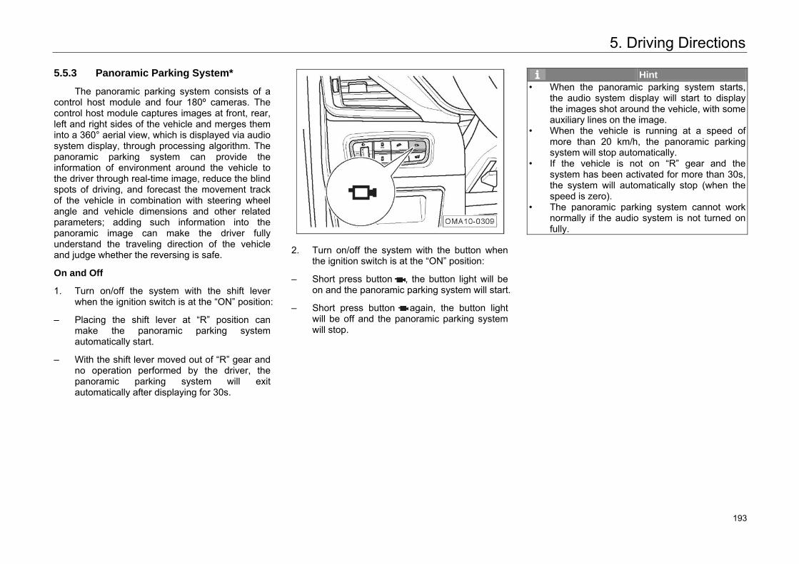
5. Driving Directions
5.5.3 Panoramic Parking System*
The panoramic parking system consists of a control host module and four 180º cameras. The control host module captures images at front, rear, left and right sides of the vehicle and merges them into a 360° aerial view, which is displayed via audio system display, through processing algorithm. The panoramic parking system can provide the information of environment around the vehicle to the driver through real-time image, reduce the blind spots of driving, and forecast the movement track of the vehicle in combination with steering wheel angle and vehicle dimensions and other related parameters; adding such information into the panoramic image can make the driver fully understand the traveling direction of the vehicle and judge whether the reversing is safe.
On and Off
1. Turn on/off the system with the shift lever when the ignition switch is at the “ON” position:
– Placing the shift lever at “R” position can make the panoramic parking system automatically start.
– With the shift lever moved out of “R” gear and no operation performed by the driver, the panoramic parking system will exit automatically after displaying for 30s.
2. Turn on/off the system with the button when
the ignition switch is at the “ON” position:
– Short press button , the button light will be on and the panoramic parking system will start.
– Short press button again, the button light will be off and the panoramic parking system will stop.
Hint • When the panoramic parking system starts,
the audio system display will start to display the images shot around the vehicle, with some auxiliary lines on the image.
• When the vehicle is running at a speed of more than 20 km/h, the panoramic parking system will stop automatically.
• If the vehicle is not on “R” gear and the system has been activated for more than 30s, the system will automatically stop (when the speed is zero).
• The panoramic parking system cannot work normally if the audio system is not turned on fully.
235 193
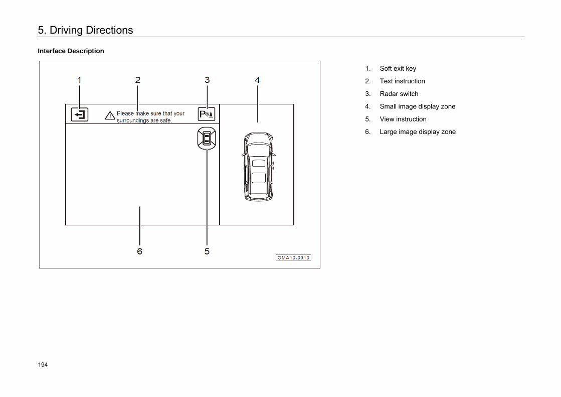
5. Driving Directions
Interface Description
1. Soft exit key
2. Text instruction
3. Radar switch
4. Small image display zone
5. View instruction
6. Large image display zone
236 194
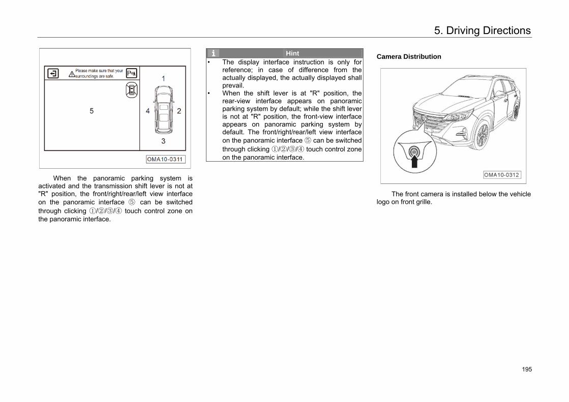
5. Driving Directions
When the panoramic parking system is activated and the transmission shift lever is not at "R" position, the front/right/rear/left view interface on the panoramic interface ⑤ can be switched through clicking ①/②/③/④ touch control zone on the panoramic interface.
Hint • The display interface instruction is only for
reference; in case of difference from the actually displayed, the actually displayed shall prevail.
• When the shift lever is at "R" position, the rear-view interface appears on panoramicparking system by default; while the shift leveris not at "R" position, the front-view interface appears on panoramic parking system by default. The front/right/rear/left view interface on the panoramic interface ⑤ can be switched through clicking ①/②/③/④ touch control zone on the panoramic interface.
Camera Distribution
The front camera is installed below the vehicle logo on front grille.
237 195
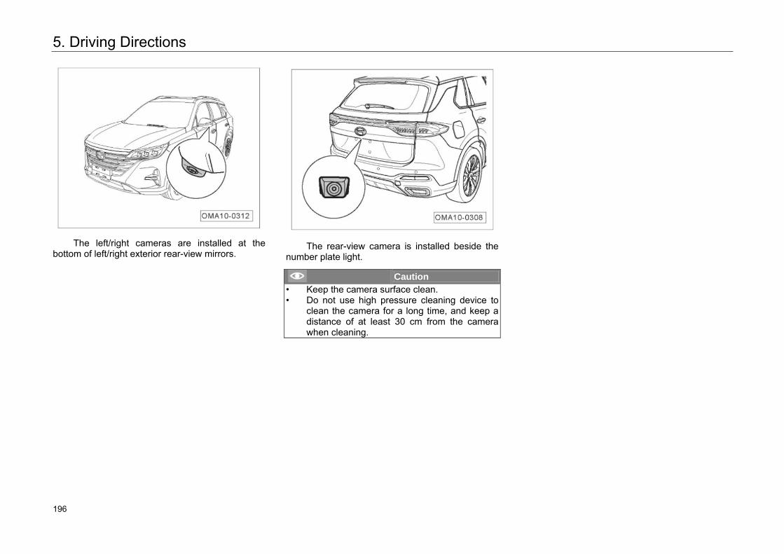
5. Driving Directions
The left/right cameras are installed at the bottom of left/right exterior rear-view mirrors.
The rear-view camera is installed beside the number plate light.
Caution • Keep the camera surface clean.• Do not use high pressure cleaning device to
clean the camera for a long time, and keep adistance of at least 30 cm from the camera when cleaning.
238 196
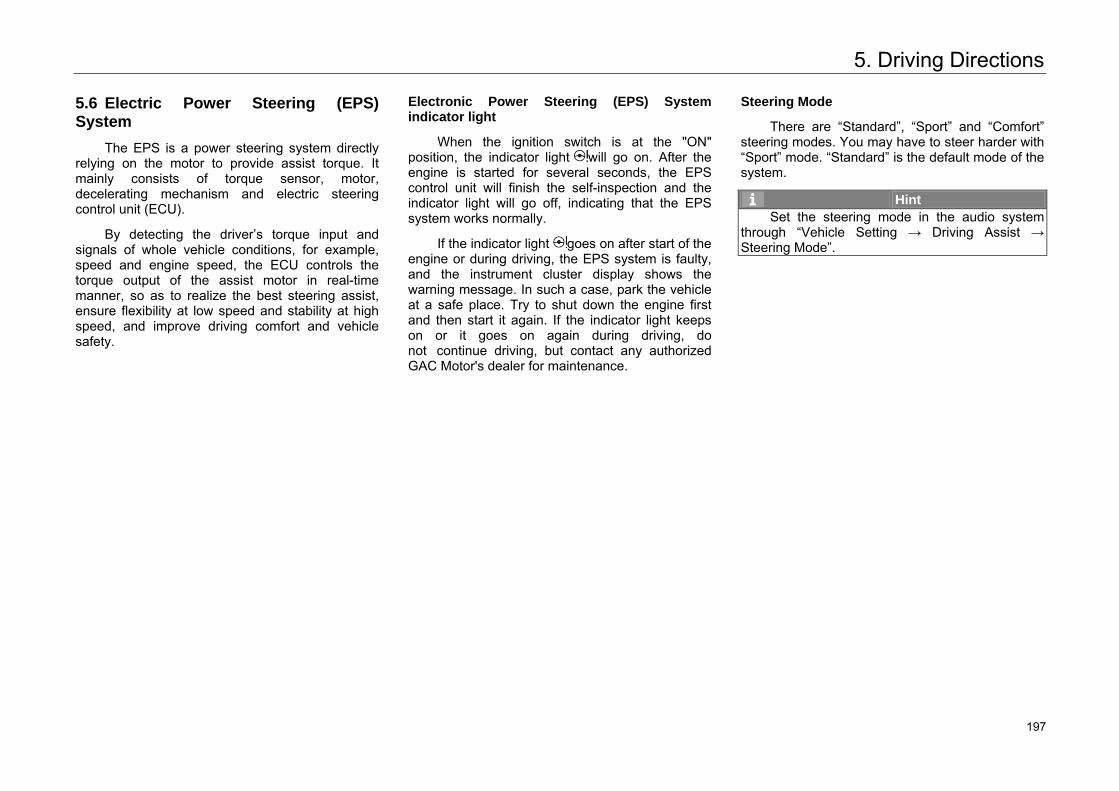
5. Driving Directions
5.6 Electric Power Steering (EPS) System
The EPS is a power steering system directly relying on the motor to provide assist torque. It mainly consists of torque sensor, motor, decelerating mechanism and electric steering control unit (ECU).
By detecting the driver’s torque input and signals of whole vehicle conditions, for example, speed and engine speed, the ECU controls the torque output of the assist motor in real-time manner, so as to realize the best steering assist, ensure flexibility at low speed and stability at high speed, and improve driving comfort and vehicle safety.
Electronic Power Steering (EPS) System indicator light
When the ignition switch is at the "ON" position, the indicator light will go on. After the engine is started for several seconds, the EPS control unit will finish the self-inspection and the indicator light will go off, indicating that the EPS system works normally.
If the indicator light goes on after start of the engine or during driving, the EPS system is faulty, and the instrument cluster display shows the warning message. In such a case, park the vehicle at a safe place. Try to shut down the engine first and then start it again. If the indicator light keeps on or it goes on again during driving, do not continue driving, but contact any authorized GAC Motor's dealer for maintenance.
Steering Mode
There are “Standard”, “Sport” and “Comfort” steering modes. You may have to steer harder with “Sport” mode. “Standard” is the default mode of the system.
Hint Set the steering mode in the audio system
through “Vehicle Setting → Driving Assist → Steering Mode”.
239 197
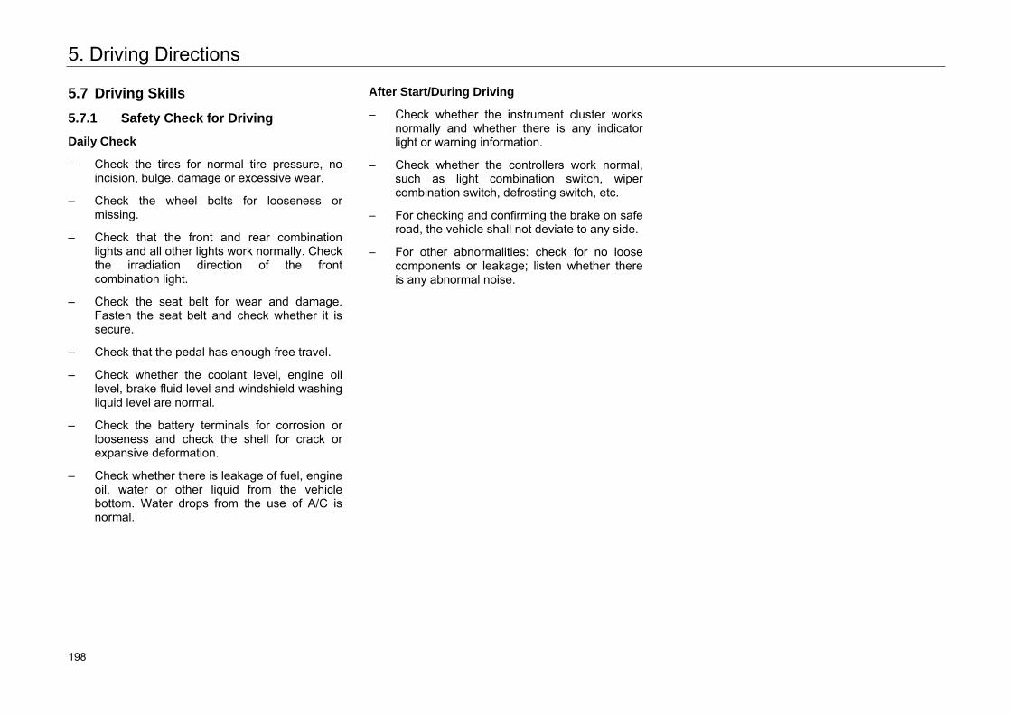
5. Driving Directions
5.7 Driving Skills
5.7.1 Safety Check for Driving
Daily Check
– Check the tires for normal tire pressure, noincision, bulge, damage or excessive wear.
– Check the wheel bolts for looseness ormissing.
– Check that the front and rear combinationlights and all other lights work normally. Checkthe irradiation direction of the frontcombination light.
– Check the seat belt for wear and damage.Fasten the seat belt and check whether it issecure.
– Check that the pedal has enough free travel.
– Check whether the coolant level, engine oillevel, brake fluid level and windshield washingliquid level are normal.
– Check the battery terminals for corrosion orlooseness and check the shell for crack orexpansive deformation.
– Check whether there is leakage of fuel, engineoil, water or other liquid from the vehiclebottom. Water drops from the use of A/C isnormal.
After Start/During Driving
– Check whether the instrument cluster worksnormally and whether there is any indicatorlight or warning information.
– Check whether the controllers work normal,such as light combination switch, wipercombination switch, defrosting switch, etc.
– For checking and confirming the brake on saferoad, the vehicle shall not deviate to any side.
– For other abnormalities: check for no loosecomponents or leakage; listen whether thereis any abnormal noise.
240 198
5. Driving Directions
5.7.2 Driving during Running-in Period
To ensure your car’s service life, you have to run it in at the initial stage before putting it into normal use. When your vehicle is in running-in period, please observe the following requirements:
– The mileage of running-in period is 1,500 km.
– Drive on good roads under reduced load atlimited speed.
– Avoid full-accelerator starting or rapidacceleration.
– Avoid emergency braking for the first 300km.
– Strictly follow the operating instructions andkeep the normal operating temperature of theengine. Do not change the engine oil beforethe regular maintenance.
– Carefully do routine maintenance; frequentlycheck and fasten the external bolts and nuts;pay attention to the changes of sounds andtemperature of each assembly during running,and adjust timely.
Running-in of the Engine
You have to run a new engine in for 1500km. Within 1000km of traveling mileage of the vehicle:
– The speed shall not exceed 3/4 of themaximum speed.
– Avoid full-accelerator driving.
– Avoid high engine speed.
– Do not tow a trailer.
When the traveling mileage is within 1000km-1500 km, the engine speed and speed can be gradually increased to the maximum allowable range.
At the early stage of running-in period, the internal frictional resistance of the engine is much greater than that after the running-in. All the moving components of the engine coordinate well only after running-in.
Full running-in of the engine can increase the service life and reduce fuel consumption.
Running-in of Tires and Braking Pads
Drive the new vehicle at a moderate speed for the first 500 km of the mileage to properly run the new tires in.
Drive the new vehicle at a moderate or low speed and avoid emergency braking as much as possible within the first 200-300 km of the mileage as the new braking pad cannot realize the optimal friction status.
241 199
5. Driving Directions
Warning • The best adhesion and friction cannot be
realized for new tires and braking pad without running-in. Therefore, drive carefully for the first 500km to run in the tires well and avoid accidents.
• After replacement, the new braking pad shall also go through running-in period in accordance with the above requirements.
• Keep an appropriate distance with other vehicles during driving to prevent emergency braking, because at that time, both the new tires and braking pad are not fully run-in, and emergency braking may cause trafficaccident.
• If the brake is damped or frozen, or the vehicle is running on salt spreading road, the braking effect weakens.
Warning • Heavy work load of the brake during running
downhill makes it prone to overheat. It is recommended to slow down by shifting to a lower gear and fully use engine braking toreduce its work load.
• Always brake the vehicle according to the road and traffic conditions. Avoid unnecessary press of brake pedal. Doing so can make thebrake overheating, resulting in a longerbraking distance and excessive wear.
• Do not let your vehicle coast with the engine off, because as the brake booster is disabled, the braking distance will be much longer, making the situation accident-prone.
242 200
5. Driving Directions
5.7.3 Important Tips for Driving
Precautions for Various Road Conditions
– Decelerate the vehicle in advance and controlthe speed and steering wheel well whendriving on a road full of crosswind and gust.
– Avoid passing through sharp objects or otherroad barriers, or otherwise it may cause tireburst or serious damage.
– Drive the vehicle at a low speed on a bumpyor uneven road to avoid scratching thechassis and damaging the vehicle.
– Decelerate and shift down (manual mode orMT model) the vehicle in advance whendriving down a slope and avoid the brakesystem overheating or wearing too fast due toany emergency braking.
– Be careful to accelerate, shift up/down(manual mode or MT model) and brake thevehicle when driving on a slippery road. Sharpacceleration or emergency braking may resultin wheel slip.
– Drive the vehicle at a low and even speed andavoid sharp acceleration or emergencybraking on an ice snow covered pavement.Install nonskid chain as necessary.
Precautions for Driving through Ponding Road:
1. Before driving through a waterlogged roadsection, find out the ponding depth which shallnot exceed the lower edge of vehicle body.
2. In case of driving through water, turn off theair conditioner before starting; drive slowly;slightly step on the accelerator pedal and donot release; drive through the waterloggedsection at a stable and low speed.
3. Do not park your vehicle in water, nor reverseor turn off the engine.
4. After passing the waterlogged section, slightlystep on the brake pedal for several times toevaporate water on the braking disc, so as torecover braking performance as soon aspossible.
Hint After the vehicle is washed or driven through a
road with deep ponding and the braking pads and brake disc are soaked, the braking effects will be significantly weakened, the braking distance will be much longer than normal and the vehicle may be deflected to one side. At this time, drive at a low speed and slightly press down the brake pedal for several times to eliminate water drops on the brakes, and then drive normally as the braking effects resume.
243 201
5. Driving Directions
5.7.4 High-efficiency Use of Vehicle
– Before driving, make sure the parking brake isreleased fully and its indicator light is off.
– Keep sufficient tire pressure. Insufficient tirepressure will result in tire wear and fuel waste.
– Make sure wheels are accurately positioned.Inaccurate positioning makes the tires wearout faster, increases engine load and wastesfuel.
– Do not overload the vehicle. Unloadunnecessary articles from the vehicle.Overload will increase the load of the engineand waste fuel.
– Accelerate the vehicle slowly and evenly, butnot sharply. For MT models, shift the gearbased on the speed as soon as possible.
– Avoid traffic jams, which will waste fuel, as faras possible.
– Drive according to traffic signal lights or keepa safe distance from other vehicles, and avoidunnecessary park or emergency braking tosave fuel and reduce wear of the brakesystem.
– Do not put the food on the brake pedal duringdriving to prevent untimely wear andoverheating the brake pad and waste of fuel.
– Select good pavement when driving. Whendriving on an uneven road, control the speedwell to avoid collision or scratch.
– Remove mud or other foreign matters stuckon chassis to reduce vehicle weight andprevent corrosion.
– Maintain the vehicle regularly to keep it underbest operating conditions. Dirty air filters,unclean spark plugs, polluted engine oil andgrease will weaken engine performance andwaste fuel.
– Drive slowly for several minutes after startingat low temperature, and then accelerate afterthe engine warms.
– Do not open windows when driving at highspeed.
– Use the AC and other devices properly.
– Shut off the engine for long-time parking andavoid wasting fuel by long-time running at idlespeed.
245 202
5. Driving Directions
5.7.5 Fire Prevention
In order to prevent vehicle fire, the following notices shall be kept in mind:
1. Flammables and explosives shall not bestored in your vehicle.
– In hot summer, the internal temperature ofvehicle parking in the sun can reach higherthan 70 °C. If there is lighter, detergent,perfume, and other flammables andexplosives in your vehicle, it is very easy tocause fire or even explosion.
– When there is no person in the vehicle, thelithium battery, power bank and other articlesthat have fire risk in the vehicle may alsocause fire.
2. After smoking, confirm the cigarette end goesout completely.
– Cigarette not put out completely may causefire.
3. Please go to your authorized GAC Motor'sdealer for check regularly.
– Regularly check the circuits of the wholevehicle to make sure connectors, insulationand fixing positions of all electric appliancesand harness are in good condition. Onceproblems are found, troubleshoot timely.
4. Refitting the vehicle circuits or addingelectrical components is prohibited:
– Adding other electric appliances (e.g. high-power audio device and xenon headlights) willoverload the circuit, and the harness will beprone to heat and cause fire.
– It is strictly prohibited to use fuse out of therated specifications of electric appliance, oruse other metal wire to substitute fuse.
5. Precautions for driving:
– During driving and parking, especially insummer, be sure to check whetherflammables exist under your vehicle, such ashay, deadwood, leaves, or wheat straw,because the temperature of engine exhaustpipe or other components increase after long-time running, and flammables under thevehicle may cause fire.
– Do not park your vehicle at scrap heaps orother rat-infested places or store anything thatappeals to rats, like snacks. The rats may bitethrough the harness, leading to fire.
6. Portable fire extinguisher shall always be kepton your vehicle, and you should know how touse it:
– In order to guarantee safety, fire extinguishershall be kept on your vehicle and also bechecked and replaced periodically. Youshould know how to use a fire extinguisher, soas to be prepared for accident.
7. During maintenance, disconnect the negativewire of battery.
8. Please use the cigarette lighter * provided onthis vehicle. Do not use inverter to takeelectricity from cigarette lighter.
246 203
6. Usage and Maintenance
6.1. Maintenance Instructions
Safety Precautions
To avoid potential hazards, please read this chapter and make sure you have tools and technology required before maintenance.
– Make sure your vehicle is parked on levelground, the engine is off, and the parkingbrake is applied.
– Use degreasant or detergent to clean partsand do not use gasoline.
– To reduce the possibility of fire or explosion,keep cigarettes, sparks, and flames awayfrom the battery and all fuel-related parts.
– Wear goggles and protective clothing whenworking with the battery or compressed air.
Warning Driving after incorrect maintenance or before
solving safety related failures may cause traffic accidents and lead to severe injury or death.
Potential Hazards
– Carbon monoxide: Carbon monoxide fromengine exhaust is poisonous. Be sure there isadequate ventilation whenever you operatethe engine.
– Scald: the engine and exhaust system willproduce high temperature when working,which is very easy to cause scald. Therefore,do not touch any components until the enginehas been stopped for at least 30 minutes andthe engine system and exhaust system hascooled down.
Caution Some of the most important safety precautions
are given in this chapter. However, we cannot warn you of every conceivable hazard that can be raised in maintenance.
247 204
6. Usage and Maintenance
6.2 Interior Maintenance
Cleaning and Maintaining the Instrument and Plastic Parts
Clean the surfaces of the instrument and plastic parts with a clean soft cloth and fresh water.
Otherwise, use the special solvent-free plastic cleaning agent to clean them.
Caution Cleaning agent with solvent may damage the
plastic parts.
Warning Do not use any driver's compartment spray or
cleaning agent with solvent to clean the surfaces of the instrument panel and airbag module. Doing so could loosen the surfaces and trigger the airbags, resulting in serious personal injury.
Cleaning and Maintaining the Carpet
Remove dust on the carpet with a vacuum cleaner regularly. Clean the carpet with cleaner regularly to keep it clean.
Caution Follow the instructions of the detergent to do
the cleaning work.
Warning It is strictly forbidden to add water into foam-
type cleaner. Make sure that the carpet is dry.
Cleaning and Maintaining the Leather*
– Vacuum dirt and dust from the leatherfrequently.
– Clean the leather with a soft cloth dampenedwith clear water.
– Then, buff it with a clean, dry cloth.
– If further cleaning is needed, use specialsaddle soap or detergent to clean it.
Caution After you wipe the leather using the special
detergent, wipe it dry as soon as possible with a soft, dry cloth.
Warning Do not place soft cloth soaked with detergent
on any interior parts for a long time, to avoid discoloration or breakage to the resin or fiber of the interior braided fabrics.
248 205
6. Usage and Maintenance
Cleaning and Maintaining the Seat Belts
– Pull out each belt slowly and hold it there.
– Use a soft brush and neutral soap water toclean dirt.
– Let the seat belts dry completely beforeretracting them.
Caution • Do not retract the seat belts until they are completely dry. Otherwise, the seat belt retractormay be damaged.• Check all seat belts in the vehicle regularly and keep them clean to ensure their proper operation.
Warning • Please contact the authorized GAC MOTORspecial store for replacement in case of anydamage to the base, connection unit, retractor orbuckle of the seat belt.• Whether damaged or not, be sure to replace the seat belts after a collision.• When replacing the belt, be sure to use a new belt of the same model and structure. • Prevent foreign matters or liquids from entering the seat belt buckles. Failure to do so can cause the buckles and the belts to function abnormally.• Do not remove or transform the belts in any case by yourself.• Do not use chemical cleaning agents to clean the seat belts to avoid damaging the seat belt base, thus affecting its function.
Cleaning and Replacing Filters
The vehicle is equipped with air filter, air conditioner filter, oil filter and fuel filter, which play a role in filtering gas or oil. If the filter is too dirty or blocked, the normal work of the corresponding system will be influenced, so it is recommended that the user should go to authorized GAC Motor's dealer periodically to clean or replace the filter according to the provisions of the Warranty Manual.
249 206
6. Usage and Maintenance
6.3 Exterior Maintenance
Vehicle Washing
Frequent washing helps preserve your car’s appearance.
Wash your vehicle in a shady area, not in direct sunlight. If your vehicle is exposed to the sun for a long time, wait until the exterior cools down before washing.
Follow the instructions of the operator when using an automatic vehicle washer.
Warning Switch the Start switch off before washing the
vehicle.
Caution Although the body paint is strong enough to
withstand the flushing from the automatic vehicle washer, pay attention to its impact on the paint. The washer structure, used cleaner, filtration state of fresh water, and type of wax solvent which do not meet the specified requirements are likely to damage the paint.
Manual Washing
– Rinse the vehicle thoroughly with clean water to remove floating dust.
– Prepare a bucket of clear water and mix the water with special washing cleaner.
– Wash the vehicle gently with soft cloth, sponge or a bristle brush and rinse it from top to bottom frequently.
– Finally, rinse the wheels, doorsills and others. Remember to replace the sponge or soft cloth during washing.
– Then rinse the vehicle thoroughly with a plenty of water.
– Then, dry it with a chamois or soft towel.
250 207
6. Usage and Maintenance
Caution If there is asphalt or other dirts on the car’s
body, special cleaner needs to be used. Then rinse the body with water to avoid damage to the finish. As drying the vehicle, check it for chips and scratches. If any, go to authorized GAC Motor's dealer for repair.
Be careful when washing the vehicle with a steam washer or a high pressure washer. Follow the instructions and requirements of the steam washer or the high-pressure washer when doing so and pay attention to operation pressure, temperature and washing distance.
– When washing the vehicle with a steamwasher or a high-pressure washer, keepenough spraying distance with the vehicle andkeep the temperature not greater than 60℃ .
– Keep a spraying distance of more than 80 cmwhen washing the vehicle with an electricsunroof. Short distance between the high-pressure washer and the vehicle or excessivehigh temperature or pressure may damageyour vehicle.
– Do not face the high-pressure washer to theradar sensor or the parking camera for a longtime when washing the vehicle. When washingthe radar sensor or the parking camera, keepa spraying distance of more than 30 cm.
Warning • Pay attention to personal safety and avoid
being scratched by angular parts under the bottom of the vehicle during manual washing.
• Pay special attention to the bottom of thevehicle and the inside part of the wheel coverduring washing and prevent your hand andarm from being hurt by sharp parts.
• Do not directly spray water into the front compartment when washing the vehicle. Otherwise, the service life of parts in the frontcompartment may be affect.
251 208
6. Usage and Maintenance
Waxing
Regular waxing helps protect vehicle body’s paint and keep the body bright and clean. In order to protect body paint surface, it is suggested to apply high quality hard wax every year to protect the paint surface from being corroded due to poor environment and withstand light mechanical scratch.
The waxing operation must be executed after the surface of the whole vehicle is wiped dry. High quality paint protective wax shall be used. In general, there are two types of products:
– Body wax: A wax coats the finish and protectsit from the damage by exposure to sunlight, airpollution, and other poor external environment.It always apply to new vehicles.
– Polishing wax: Polishing wax can restore theluster of oxidized paint or the paint withoutgloss. It is mainly used to restore the luster topaint.
Cleaning and Maintaining the External Plastic Parts
In general, clean the external plastic parts with fresh water, soft cloth and bristle brush. If further cleaning is needed, use the special solvent-free plastic cleaning agent recommended by GAC MOTOR.
Caution Do not use any cleaning agent with solvent to
clean the plastic parts. Doing so can cause damage to the plastic parts.
Cleaning the Windows and Exterior Rear-View Mirror
Clean the window glass and rear-view mirrors with alcoholic glass cleaner, and then dry glass surface with a clean, lint-free, soft cloth or antelope skin.
After maintaining the vehicle body surface, the wax remaining on the glass shall be removed by special cleanser and cleaning cloth. So as to prevent scratching the windscreen wiper.
Remove the snow accumulated on the windows and rear-view mirrors in snowy weather with a bristle brush.
Remove ice on the window (if any) with a special deicing spray, or remove it with a scraper, but be very careful to avoid damage to the components. Ensure to scrape the ice in the same direction.
252 209
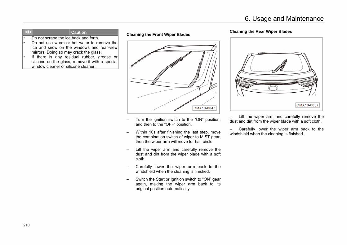
6. Usage and Maintenance
Caution • Do not scrape the ice back and forth.• Do not use warm or hot water to remove the
ice and snow on the windows and rear-viewmirrors. Doing so may crack the glass.
• If there is any residual rubber, grease or silicone on the glass, remove it with a special window cleaner or silicone cleaner.
Cleaning the Front Wiper Blades
– Turn the ignition switch to the “ON” position,and then to the “OFF” position.
– Within 10s after finishing the last step, movethe combination switch of wiper to MIST gear,then the wiper arm will move for half circle.
– Lift the wiper arm and carefully remove thedust and dirt from the wiper blade with a softcloth.
– Carefully lower the wiper arm back to thewindshield when the cleaning is finished.
– Switch the Start or Ignition switch to “ON” gearagain, making the wiper arm back to itsoriginal position automatically.
Cleaning the Rear Wiper Blades
– Lift the wiper arm and carefully remove thedust and dirt from the wiper blade with a soft cloth.
– Carefully lower the wiper arm back to thewindshield when the cleaning is finished.
253 210
6. Usage and Maintenance
Caution • When lifting the wiper arm, grasp the hard
support by hand, and do not grasp soft wiperblade.
• Carefully lower the wiper arm to prevent striking the windscreen due to instantaneousdrop.
• Replace the damaged blade in time.• A new wiper blade surface is coated with a
layer of graphite which can make the wiperblade move smoothly without scratching noise.Damaged graphite layer may increase scratching noises. Be sure to repair it orreplace new timely.
Caution • Cleaner with solvent, hard sponge and sharp
tools will damage the graphite layer.• In winter or cold weather, check whether the
wiper blades are frozen with the windshield before operating them. If so, remove the ice from the wiper blades firstly. Failure to do so may cause damage to the wiper blades and the wiper motor.
Maintaining the Sealing Strips
Frequent and appropriate protection of the rubber sealing strips for the doors, windows and other parts can maintain their flexibility, prolong their service life. Such action can improve the leakproofness, making the doors easier to open and reducing the closing sound and it's difficult to get frozen in winter.
When maintaining the sealing strip, use soft cloth to remove the surface dust and dirt. Apply the special protective agent to the rubber sealing strips regularly.
254 211
6. Usage and Maintenance
Cleaning and Maintaining the Wheels
Regular wheel maintenance can keep the wheel artistic, and periodically removing the antiskid salt and brake lining abrasive dust on the wheel can maintain the surface smoothness of the wheel and increase the service life. In order to protect your vehicle, it is suggested that the following operations should be executed periodically:
– Use acid-free cleanser to remove the antiskidsalt and brake lining abrasive dust on thewheel every two weeks.
– Wax the alloy wheels with high-quality hardwax every three months.
Caution • Be sure to clean the alloy wheels with acid-
free cleaner.• Do not clean the wheels surface with the
vehicle polishing agent or other grinding agents.
• If the protective layer of the wheels isdamaged, be sure to repair it in time.
• The high-pressure washer may cause permanent visible or invisible damage to thewheels, resulting serious injury or death.
• Never spray the tires with the cluster nozzles. Even a short-time long-distance cleaning may cause damage to the tires, causing trafficaccidents.
255 212
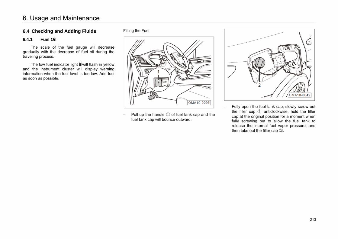
6. Usage and Maintenance
6.4 Checking and Adding Fluids
6.4.1 Fuel Oil
The scale of the fuel gauge will decrease gradually with the decrease of fuel oil during the traveling process.
The low fuel indicator light will flash in yellow and the instrument cluster will display warning information when the fuel level is too low. Add fuel as soon as possible.
Filling the Fuel
– Pull up the handle ① of fuel tank cap and thefuel tank cap will bounce outward.
– Fully open the fuel tank cap, slowly screw outthe filler cap ② anticlockwise, hold the fillercap at the original position for a moment whenfully screwing out to allow the fuel tank torelease the internal fuel vapor pressure, andthen take out the filler cap ②.
256 213
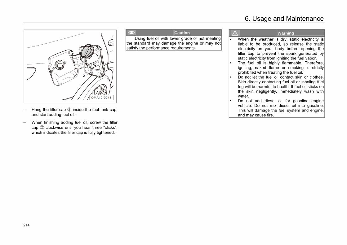
6. Usage and Maintenance
– Hang the filler cap ② inside the fuel tank cap, and start adding fuel oil.
– When finishing adding fuel oil, screw the filler cap ② clockwise until you hear three "clicks", which indicates the filler cap is fully tightened.
Caution Using fuel oil with lower grade or not meeting
the standard may damage the engine or may not satisfy the performance requirements.
Warning • When the weather is dry, static electricity is
liable to be produced, so release the static electricity on your body before opening the filler cap to prevent the spark generated by static electricity from igniting the fuel vapor.
• The fuel oil is highly flammable. Therefore, igniting, naked flame or smoking is strictly prohibited when treating the fuel oil.
• Do not let the fuel oil contact skin or clothes. Skin directly contacting fuel oil or inhaling fuel fog will be harmful to health. If fuel oil sticks on the skin negligently, immediately wash with water.
• Do not add diesel oil for gasoline engine vehicle. Do not mix diesel oil into gasoline. This will damage the fuel system and engine, and may cause fire.
257 214
6. Usage and Maintenance
6.4.2 Engine Oil
Function of Engine Oil
Engine oil contributes to engine’s lubrication, sealing, cooling, anti-corrosion, cleaning, etc.
Engine Oil Specification
High-quality engine oil, which can be used throughout the year, except for extreme cold weather, has been filled into the engine when the vehicle is delivered.
Check whether the specifications of the oil are applicable to your engine when purchasing.
Hint • Engine oil specification: SN class and above.• Engine oil viscosity: SAE 5W-30.
Warning • Be sure to use the engine oil applicable to the
engine of your vehicle.• Using the engine oil of other specifications
may damage the engine.
Hint • Replace engine oil in intervals specified in the
Warranty Manual at the authorized GACMotor's dealer.
• If the vehicle is used under severe conditions,fuel with higher sulfur content is used, thevehicle has to idle for a long time (e.g. Taxi),be driven in dusty area or alpine regions or ithas to drag trailers frequently, increase thetimes of maintenance or shorten themaintenance interval.
Low engine oil pressure warning light
If the warning light goes on during driving, park the vehicle at a safe place and shut down the engine. Check the engine oil level after the engine has cooled down.
If the engine oil is at normal level and the warning light is still on after the engine is started, do not start the engine any more but contact the authorized GAC Motor's dealer for repair in time.
Warning • Ignoring the warning light and relevant
warnings may damage the engine.• The low engine oil pressure warning light
cannot indicate the engine oil level. Ensure to check the oil level regularly.
258 215
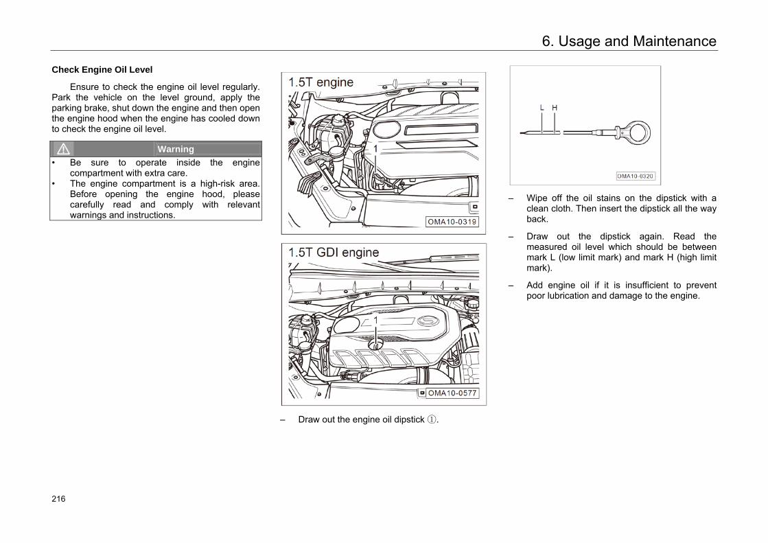
6. Usage and Maintenance
Check Engine Oil Level
Ensure to check the engine oil level regularly. Park the vehicle on the level ground, apply the parking brake, shut down the engine and then open the engine hood when the engine has cooled down to check the engine oil level.
Warning • Be sure to operate inside the engine
compartment with extra care.• The engine compartment is a high-risk area.
Before opening the engine hood, please carefully read and comply with relevant warnings and instructions.
– Draw out the engine oil dipstick ①.
– Wipe off the oil stains on the dipstick with aclean cloth. Then insert the dipstick all the wayback.
– Draw out the dipstick again. Read themeasured oil level which should be betweenmark L (low limit mark) and mark H (high limitmark).
– Add engine oil if it is insufficient to preventpoor lubrication and damage to the engine.
259 216
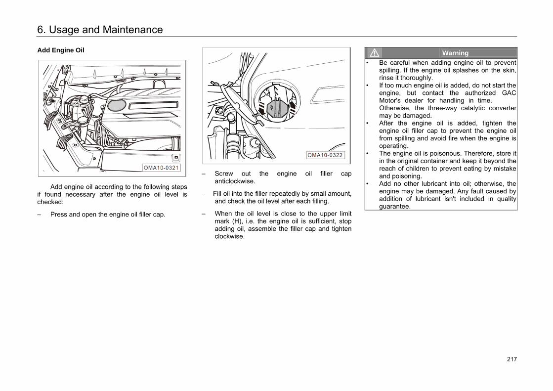
6. Usage and Maintenance
Add Engine Oil
Add engine oil according to the following steps if found necessary after the engine oil level is checked:
– Press and open the engine oil filler cap.
– Screw out the engine oil filler capanticlockwise.
– Fill oil into the filler repeatedly by small amount,and check the oil level after each filling.
– When the oil level is close to the upper limitmark (H), i.e. the engine oil is sufficient, stopadding oil, assemble the filler cap and tightenclockwise.
Warning • Be careful when adding engine oil to prevent
spilling. If the engine oil splashes on the skin,rinse it thoroughly.
• If too much engine oil is added, do not start theengine, but contact the authorized GACMotor's dealer for handling in time.Otherwise, the three-way catalytic convertermay be damaged.
• After the engine oil is added, tighten theengine oil filler cap to prevent the engine oilfrom spilling and avoid fire when the engine isoperating.
• The engine oil is poisonous. Therefore, store itin the original container and keep it beyond thereach of children to prevent eating by mistakeand poisoning.
• Add no other lubricant into oil; otherwise, theengine may be damaged. Any fault caused byaddition of lubricant isn't included in qualityguarantee.
260 217
6. Usage and Maintenance
6.4.3 Coolant
Function of Coolant
The coolant possesses cooling, anti-freezing, and anti-corrosion functions.
Specification of Coolant
When delivery, the cooling system of this vehicle has been added with coolant, the coolant can be used throughout the year except for extreme cold weather, prevent the alloy components of cooling system from corrosion and the system from scaling.
Hint Specification of coolant: DF-6, -35℃ coolant.
Hint • Replace coolant in intervals specified in the
Warranty Manual at the authorized GACMotor's dealer.
• Shorten the maintenance interval and changethe coolant at the authorized GAC Motor'sdealer if the coolant is discolored.
High engine coolant temperature indicator light
Check the indication of the engine coolant temperature gauge frequently and get the coolant temperature during driving.
When the coolant temperature is too high, the indicator light on the instrument cluster will go on in red and a warming message will be shown to remind the driver. At this moment, stop the vehicle and shut the engine down. Then check the coolant level after the engine has cooled down.
If the coolant is at normal level and the indicator light is still on after the engine is started, do not start the engine any more but contact the authorized GAC Motor's dealer for repair in time.
261 218
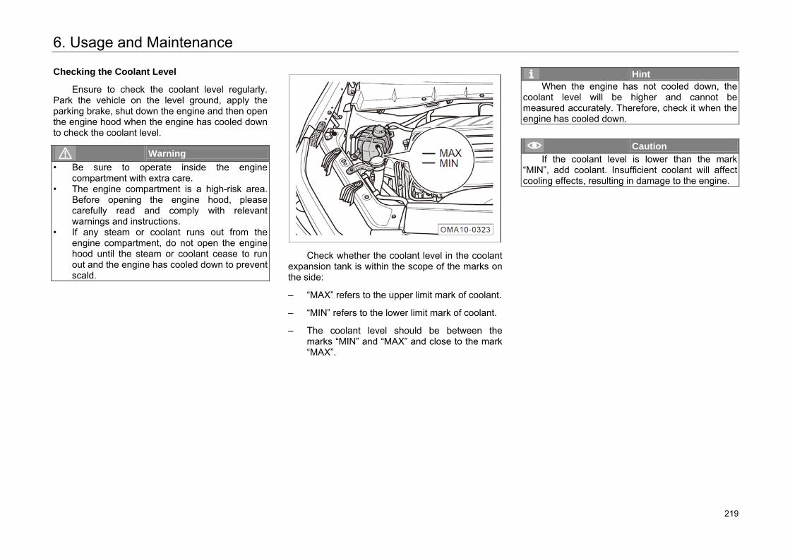
6. Usage and Maintenance
Checking the Coolant Level
Ensure to check the coolant level regularly. Park the vehicle on the level ground, apply the parking brake, shut down the engine and then open the engine hood when the engine has cooled down to check the coolant level.
Warning • Be sure to operate inside the engine
compartment with extra care.• The engine compartment is a high-risk area.
Before opening the engine hood, please carefully read and comply with relevant warnings and instructions.
• If any steam or coolant runs out from the engine compartment, do not open the engine hood until the steam or coolant cease to runout and the engine has cooled down to prevent scald.
Check whether the coolant level in the coolant expansion tank is within the scope of the marks on the side:
– “MAX” refers to the upper limit mark of coolant.
– “MIN” refers to the lower limit mark of coolant.
– The coolant level should be between themarks “MIN” and “MAX” and close to the mark“MAX”.
Hint When the engine has not cooled down, the
coolant level will be higher and cannot be measured accurately. Therefore, check it when the engine has cooled down.
Caution If the coolant level is lower than the mark
“MIN”, add coolant. Insufficient coolant will affect cooling effects, resulting in damage to the engine.
262 219
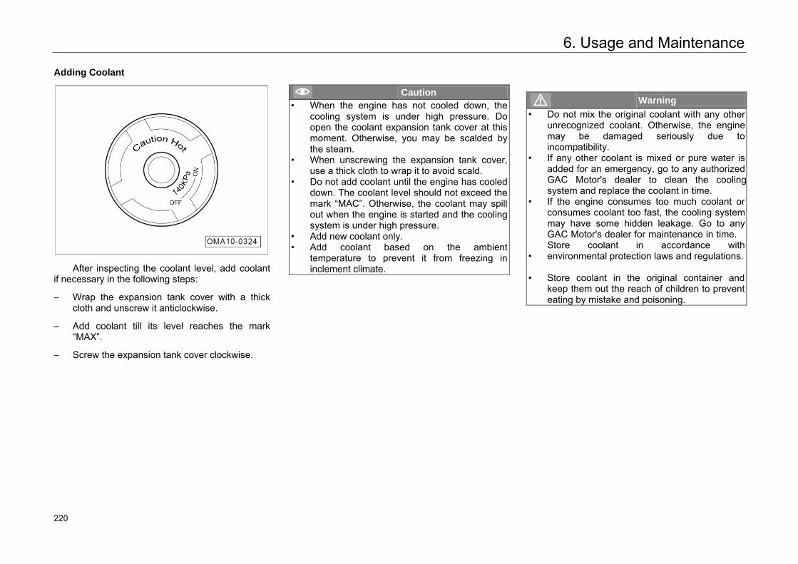
6. Usage and Maintenance
Adding Coolant
After inspecting the coolant level, add coolant if necessary in the following steps:
– Wrap the expansion tank cover with a thickcloth and unscrew it anticlockwise.
– Add coolant till its level reaches the mark“MAX”.
– Screw the expansion tank cover clockwise.
Caution • When the engine has not cooled down, the
cooling system is under high pressure. Do open the coolant expansion tank cover at thismoment. Otherwise, you may be scalded by the steam.
• When unscrewing the expansion tank cover, use a thick cloth to wrap it to avoid scald.
• Do not add coolant until the engine has cooled down. The coolant level should not exceed themark “MAC”. Otherwise, the coolant may spillout when the engine is started and the cooling system is under high pressure.
• Add new coolant only.• Add coolant based on the ambient
temperature to prevent it from freezing ininclement climate.
Warning • Do not mix the original coolant with any other
unrecognized coolant. Otherwise, the engine may be damaged seriously due to incompatibility.
• If any other coolant is mixed or pure water is added for an emergency, go to any authorized GAC Motor's dealer to clean the cooling system and replace the coolant in time.
•
•
If the engine consumes too much coolant or consumes coolant too fast, the cooling system may have some hidden leakage. Go to any GAC Motor's dealer for maintenance in time.Store coolant in accordance with environmental protection laws and regulations.
• Store coolant in the original container andkeep them out the reach of children to preventeating by mistake and poisoning.
263 220
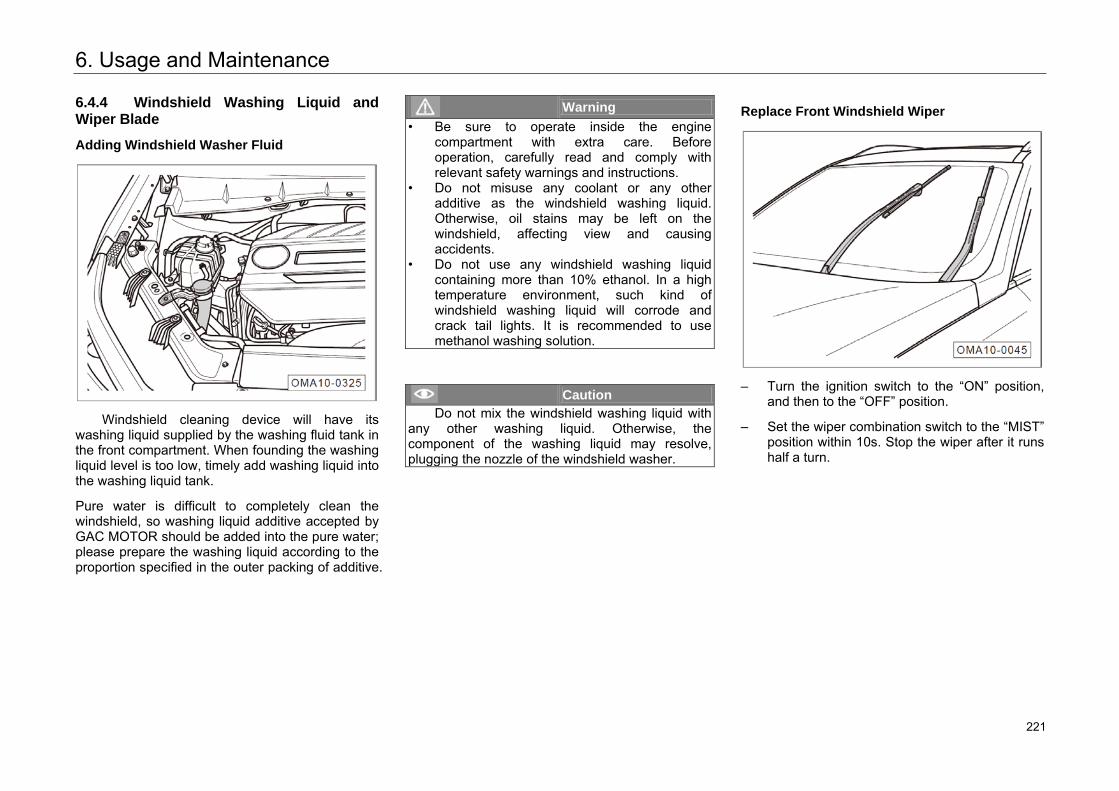
6. Usage and Maintenance
6.4.4 Windshield Washing Liquid and Wiper Blade
Adding Windshield Washer Fluid
Windshield cleaning device will have its washing liquid supplied by the washing fluid tank in the front compartment. When founding the washing liquid level is too low, timely add washing liquid into the washing liquid tank.
Pure water is difficult to completely clean the windshield, so washing liquid additive accepted by GAC MOTOR should be added into the pure water; please prepare the washing liquid according to the proportion specified in the outer packing of additive.
Warning • Be sure to operate inside the engine
compartment with extra care. Before operation, carefully read and comply withrelevant safety warnings and instructions.
• Do not misuse any coolant or any otheradditive as the windshield washing liquid. Otherwise, oil stains may be left on the windshield, affecting view and causing accidents.
• Do not use any windshield washing liquid containing more than 10% ethanol. In a high temperature environment, such kind of windshield washing liquid will corrode and crack tail lights. It is recommended to usemethanol washing solution.
Caution Do not mix the windshield washing liquid with
any other washing liquid. Otherwise, the component of the washing liquid may resolve, plugging the nozzle of the windshield washer.
Replace Front Windshield Wiper
– Turn the ignition switch to the “ON” position,and then to the “OFF” position.
– Set the wiper combination switch to the “MIST”position within 10s. Stop the wiper after it runshalf a turn.
264 221
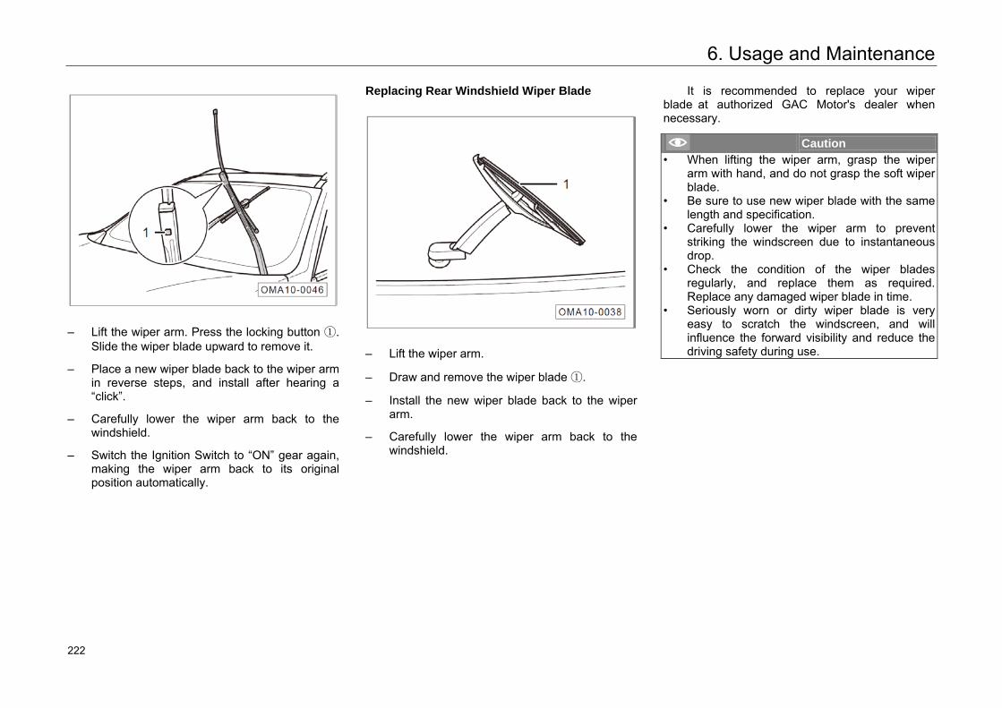
6. Usage and Maintenance
– Lift the wiper arm. Press the locking button ①.Slide the wiper blade upward to remove it.
– Place a new wiper blade back to the wiper armin reverse steps, and install after hearing a“click”.
– Carefully lower the wiper arm back to thewindshield.
– Switch the Ignition Switch to “ON” gear again,making the wiper arm back to its originalposition automatically.
Replacing Rear Windshield Wiper Blade
– Lift the wiper arm.
– Draw and remove the wiper blade ①.
– Install the new wiper blade back to the wiperarm.
– Carefully lower the wiper arm back to thewindshield.
It is recommended to replace your wiper blade at authorized GAC Motor's dealer when necessary.
Caution • When lifting the wiper arm, grasp the wiper
arm with hand, and do not grasp the soft wiper blade.
• Be sure to use new wiper blade with the same length and specification.
• Carefully lower the wiper arm to prevent striking the windscreen due to instantaneousdrop.
• Check the condition of the wiper bladesregularly, and replace them as required.Replace any damaged wiper blade in time.
• Seriously worn or dirty wiper blade is very easy to scratch the windscreen, and will influence the forward visibility and reduce the driving safety during use.
265 222
6. Usage and Maintenance
6.4.5 Brake Fluid
Function of Brake Fluid
The brake fluid is used to transfer power in the hydraulic brake system.
The brake fluid used for the vehicle is specially developed by GAC MOTOR. To ensure normal operation of the brake system, only the brake fluid recommended by GAC MOTOR can be used.
The brake fluid is water-absorbing. It can absorb moisture from the air around constantly in the process of usage. If the brake fluid stays inside the system for a too long time and thus absorbs too much water, air lock will be produced inside the pipeline of braking system, reducing brake effect and driving safety, and even causing complete failure of the braking system and accidents. Check the brake fluid level or replace the brake fluid regularly in an interval specified by the Warranty Manual at any authorized GAC Motor's dealer.
Hint Specification of brake fluid: DOT4.
Warning
• Using waste brake fluid or brake fluid notsuitable for this vehicle will greatly decreasethe braking effect, or even cause failure of thebrake system. GAC MOTOR will assume no responsibility to any fault or damage raisedtherefrom, including warranties.
• Use the brake fluid that conforms to thestandard and is unused.
• The brake fluid container is labeled with the specifications. Always use the brake fluid withcorrect specifications.
Brake system indicator light
If the indicator light goes on in red and the instrument cluster displays the message “Please add brake fluid” when driving, park the vehicle at a safe place immediately and check whether the fluid level is normal.
266 223
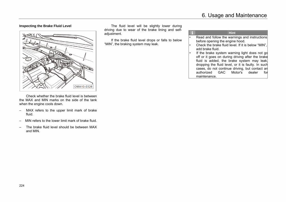
6. Usage and Maintenance
Inspecting the Brake Fluid Level
Check whether the brake fluid level is between the MAX and MIN marks on the side of the tank when the engine cools down.
– MAX refers to the upper limit mark of brakefluid.
– MIN refers to the lower limit mark of brake fluid.
– The brake fluid level should be between MAXand MIN.
The fluid level will be slightly lower during driving due to wear of the brake lining and self-adjustment.
If the brake fluid level drops or falls to below “MIN”, the braking system may leak.
Hint • Read and follow the warnings and instructions
before opening the engine hood.• Check the brake fluid level. If it is below “MIN”,
add brake fluid.• If the brake system warning light does not go
off or it goes on during driving after the brakefluid is added, the brake system may leak,dropping the fluid level, or it is faulty. In suchcases, do not continue driving, but contact anauthorized GAC Motor's dealer formaintenance.
267 224
6. Usage and Maintenance
Fill the brake fluid.
Add the brake fluid of specified specification to ensure the brake system to operate properly:
– Unscrew the brake fluid storage tank capanticlockwise.
– Add unused brake fluid till the level reached“MAX”.
– Screw the brake fluid storage tank capclockwise.
Caution • The brake fluid is corrosive to the body paint. If
you get brake fluid on the body paint, wipe itoff timely.
• Using waste brake fluid or brake fluid not suitable for this vehicle will greatly decreasethe braking effect due to incompatibility., oreven cause failure of the brake system.
Warning • Store the brake fluid in its original sealed
container and put it in a safe place as it ispoisonous. Keep the container away fromchildren to avoid eating by mistake and poisoning.
• Store brake fluid in accordance with environmental protection laws.
268 225
6. Usage and Maintenance
6.4.6 Battery
Alert Symbols and Descriptions of Battery Operation
Always wear goggles when operating! The electrolyte of storage battery belongs to a strong corrosive material, so that protective gloves and goggles must be worn when operating! Make sure the workplace is free of open flames, sparks, naked lights and smoke! Highly explosive mixed gas will be generated when the battery is charged! Children must keep away from the electrolyte and vehicle battery!
Do not perform any operation on the electrical system but have an authorized GAC Motor's dealer to complete relevant operations if you are not familiar with the operational process or do not have proper equipment.
Warning • Before operation, carefully read and comply
with relevant safety warnings and instructionsabout the operation of the battery.
• Do not perform operation on the battery unlessyou have enough expertise.
• Do not remove the battery. Beware of chemical bums and battery explosion.
• Damaged or leaked battery isn't allowed to use. It should be recycled and disposed according to laws and regulations ofenvironmental protection.
• Make sure the workplace is free of openflames, sparks, naked lights and smoke. When operating the cables and electrical equipment, be sure to prevent sparks and static electricity.Do not allow the battery terminals to be short-circuited. Otherwise, the high energy spark from short circuit may injure the operator.
Charging System Warning Light
This warning light indicates the generator fault.
Set the ignition switch to the "ON" position. The warning light will go on if the engine is not started and it should go off when the engine is started.
If the warning light comes on when the vehicle is moving, it indicates that the generator cannot charge the battery any more. Go to an authorized GAC Motor's dealer to check the vehicle as soon as possible.
269 226
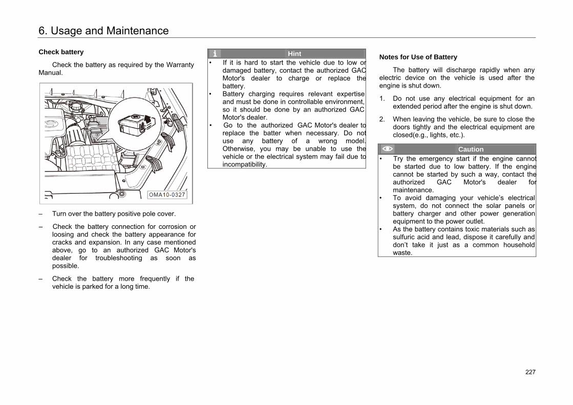
6. Usage and Maintenance
Check battery
Check the battery as required by the Warranty Manual.
– Turn over the battery positive pole cover.
– Check the battery connection for corrosion or loosing and check the battery appearance for cracks and expansion. In any case mentioned above, go to an authorized GAC Motor's dealer for troubleshooting as soon as possible.
– Check the battery more frequently if the vehicle is parked for a long time.
Hint • If it is hard to start the vehicle due to low or
damaged battery, contact the authorized GAC Motor's dealer to charge or replace the battery.
• Battery charging requires relevant expertise and must be done in controllable environment, so it should be done by an authorized GAC Motor's dealer.
• Go to the authorized GAC Motor's dealer to replace the batter when necessary. Do not use any battery of a wrong model. Otherwise, you may be unable to use the vehicle or the electrical system may fail due to incompatibility.
Notes for Use of Battery
The battery will discharge rapidly when any electric device on the vehicle is used after the engine is shut down.
1. Do not use any electrical equipment for anextended period after the engine is shut down.
2. When leaving the vehicle, be sure to close thedoors tightly and the electrical equipment areclosed(e.g., lights, etc.).
Caution • Try the emergency start if the engine cannot
be started due to low battery. If the engine cannot be started by such a way, contact the authorized GAC Motor's dealer for maintenance.
• To avoid damaging your vehicle’s electrical system, do not connect the solar panels or battery charger and other power generation equipment to the power outlet.
• As the battery contains toxic materials such as sulfuric acid and lead, dispose it carefully and don’t take it just as a common household waste.
270 227
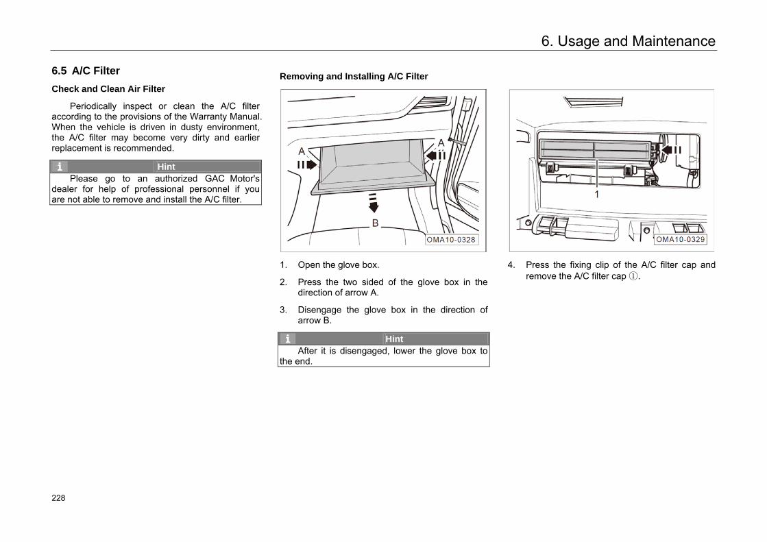
6. Usage and Maintenance
6.5 A/C Filter
Check and Clean Air Filter
Periodically inspect or clean the A/C filter according to the provisions of the Warranty Manual. When the vehicle is driven in dusty environment, the A/C filter may become very dirty and earlier replacement is recommended.
Hint Please go to an authorized GAC Motor's
dealer for help of professional personnel if you are not able to remove and install the A/C filter.
Removing and Installing A/C Filter
1. Open the glove box.
2. Press the two sided of the glove box in thedirection of arrow A.
3. Disengage the glove box in the direction ofarrow B.
Hint After it is disengaged, lower the glove box to
the end.
4. Press the fixing clip of the A/C filter cap andremove the A/C filter cap ①.
271 228
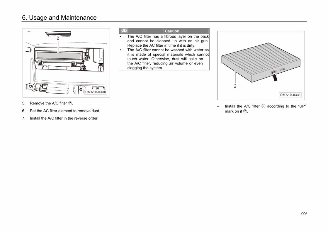
6. Usage and Maintenance
5. Remove the A/C filter ②.
6. Pat the AC filter element to remove dust.
7. Install the A/C filter in the reverse order.
Caution • The A/C filter has a fibrous layer on the back
and cannot be cleaned up with an air gun.Replace the AC filter in time if it is dirty.
• The A/C filter cannot be washed with water asit is made of special materials which cannottouch water. Otherwise, dust will cake onthe A/C filter, reducing air volume or evenclogging the system.
– Install the A/C filter ② according to the “UP”mark on it ②.
272 229
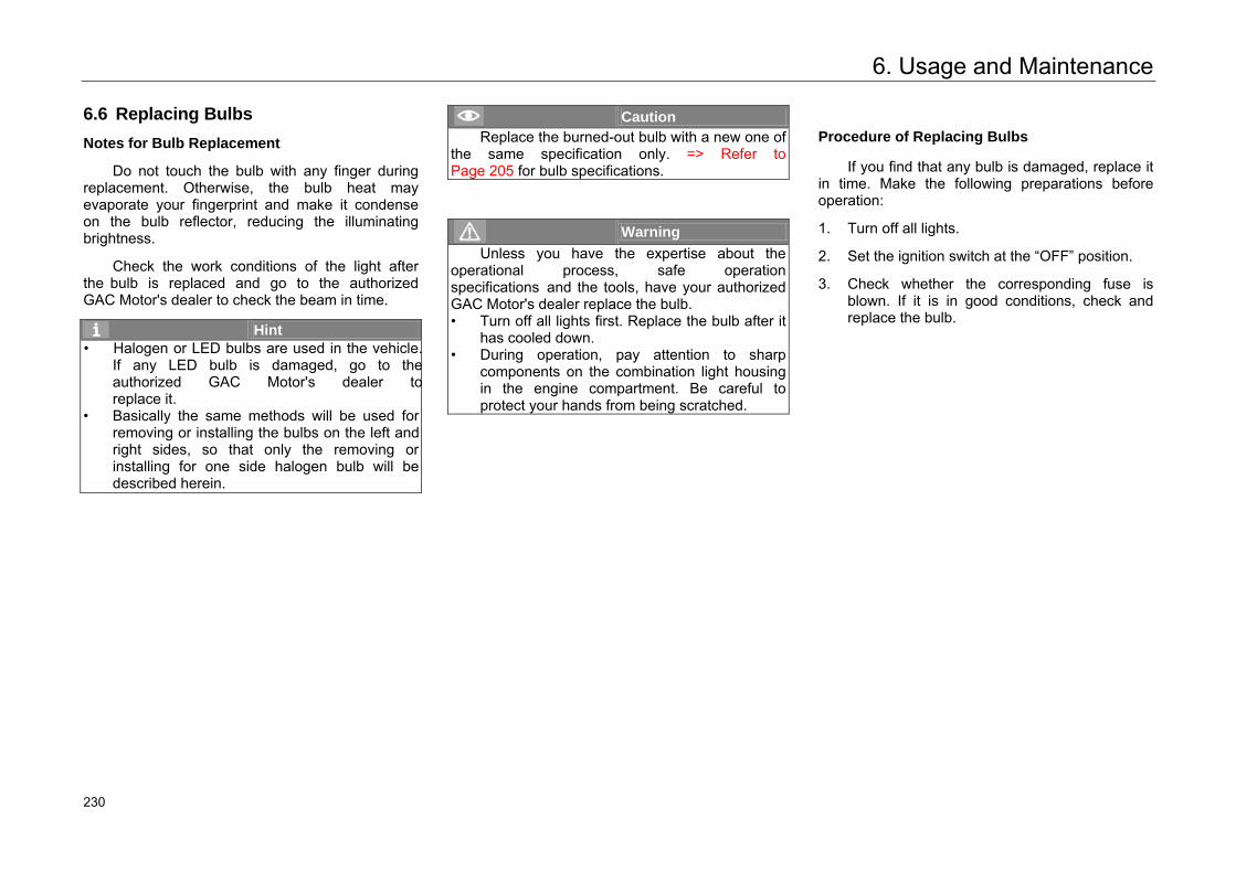
6. Usage and Maintenance
6.6 Replacing Bulbs
Notes for Bulb Replacement
Do not touch the bulb with any finger during replacement. Otherwise, the bulb heat may evaporate your fingerprint and make it condense on the bulb reflector, reducing the illuminating brightness.
Check the work conditions of the light after the bulb is replaced and go to the authorized GAC Motor's dealer to check the beam in time.
Hint • Halogen or LED bulbs are used in the vehicle.
If any LED bulb is damaged, go to theauthorized GAC Motor's dealer toreplace it.
• Basically the same methods will be used forremoving or installing the bulbs on the left andright sides, so that only the removing orinstalling for one side halogen bulb will bedescribed herein.
Caution Replace the burned-out bulb with a new one of
the same specification only. => Refer to Page 205 for bulb specifications.
Warning Unless you have the expertise about the
operational process, safe operation specifications and the tools, have your authorized GAC Motor's dealer replace the bulb. • Turn off all lights first. Replace the bulb after it
has cooled down.• During operation, pay attention to sharp
components on the combination light housing in the engine compartment. Be careful to protect your hands from being scratched.
Procedure of Replacing Bulbs
If you find that any bulb is damaged, replace it in time. Make the following preparations before operation:
1. Turn off all lights.
2. Set the ignition switch at the “OFF” position.
3. Check whether the corresponding fuse isblown. If it is in good conditions, check andreplace the bulb.
273 230
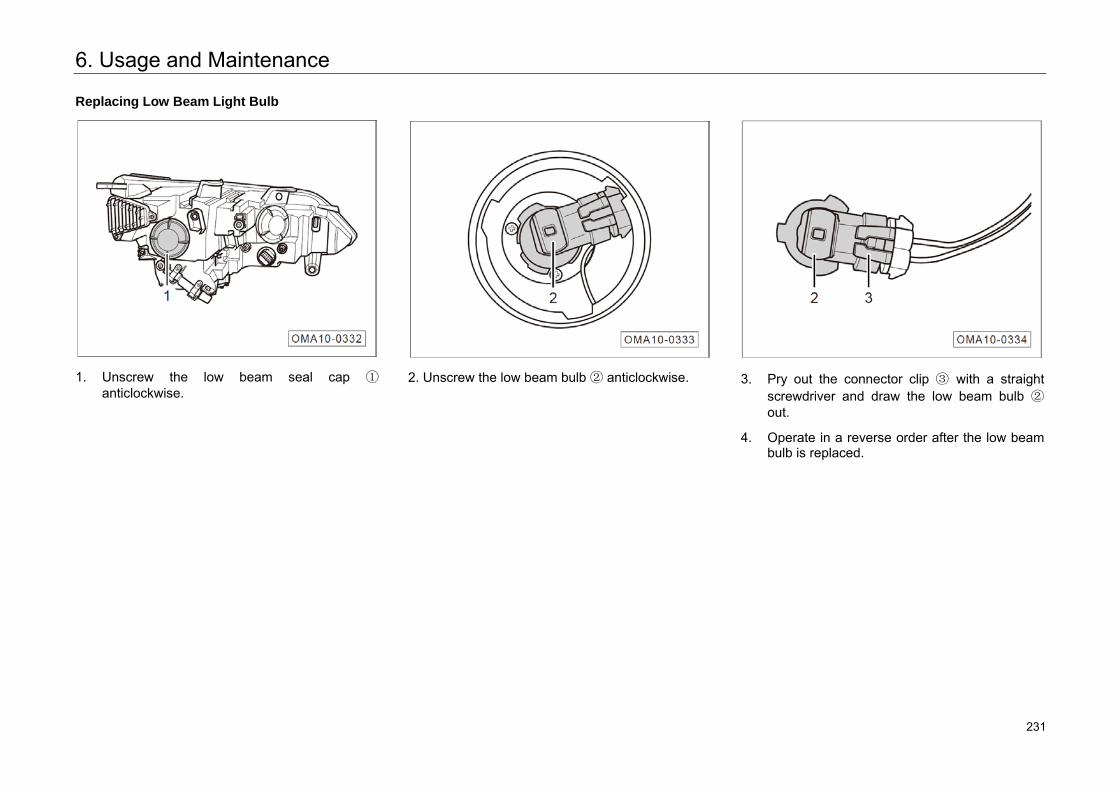
6. Usage and Maintenance
Replacing Low Beam Light Bulb
1. Unscrew the low beam seal cap ①anticlockwise.
2. Unscrew the low beam bulb ② anticlockwise. 3. Pry out the connector clip ③ with a straightscrewdriver and draw the low beam bulb ②out.
4. Operate in a reverse order after the low beambulb is replaced.
274 231
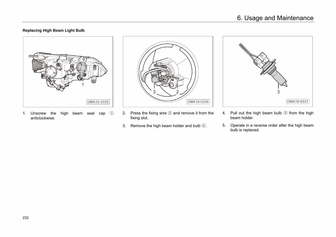
6. Usage and Maintenance
Replacing High Beam Light Bulb
1. Unscrew the high beam seal cap ①anticlockwise.
2. Press the fixing wire ② and remove it from thefixing slot.
3. Remove the high beam holder and bulb ③.
4. Pull out the high beam bulb ③ from the highbeam holder.
5. Operate in a reverse order after the high beambulb is replaced.
275 232
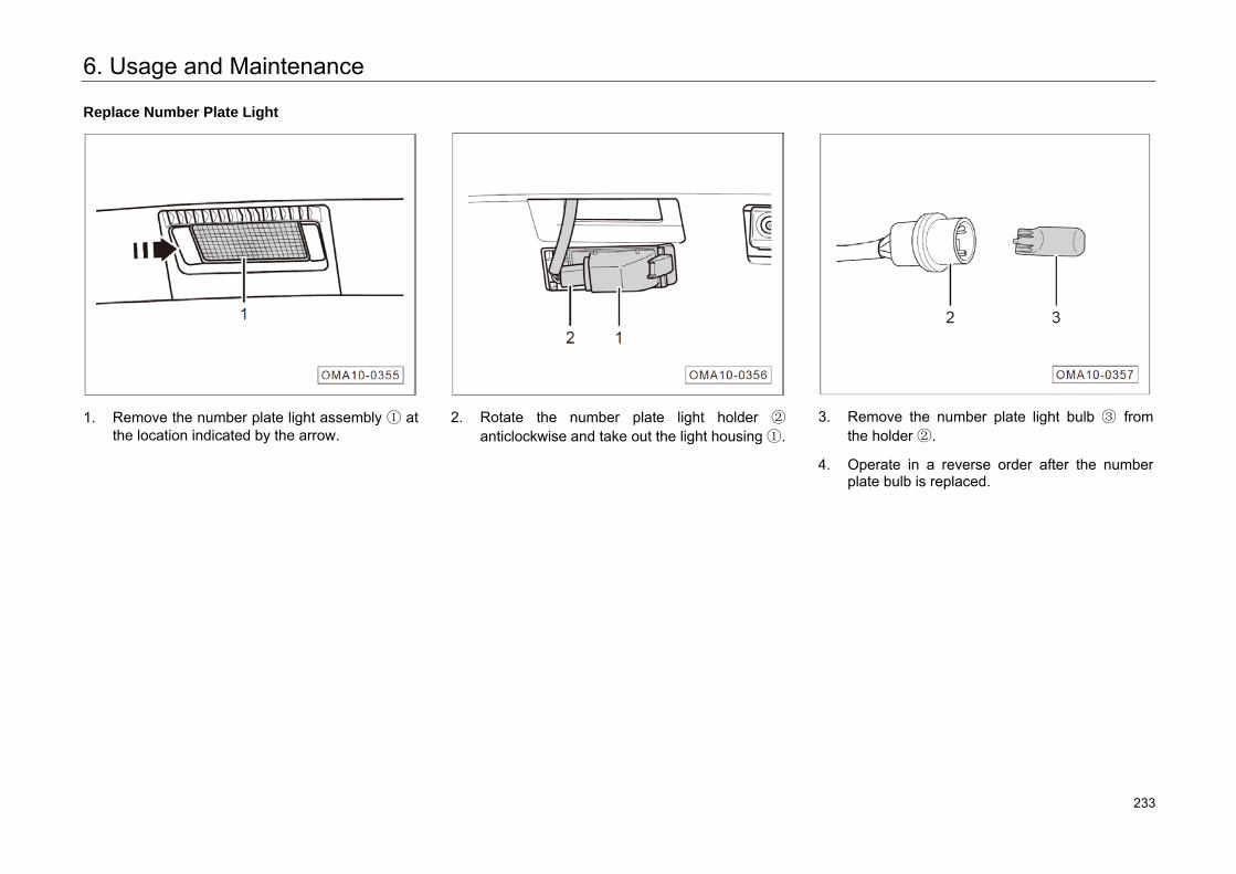
6. Usage and Maintenance
Replace Number Plate Light
1. Remove the number plate light assembly ① atthe location indicated by the arrow.
2. Rotate the number plate light holder ②
anticlockwise and take out the light housing ①.3. Remove the number plate light bulb ③ from
the holder ②.
4. Operate in a reverse order after the numberplate bulb is replaced.
276 233
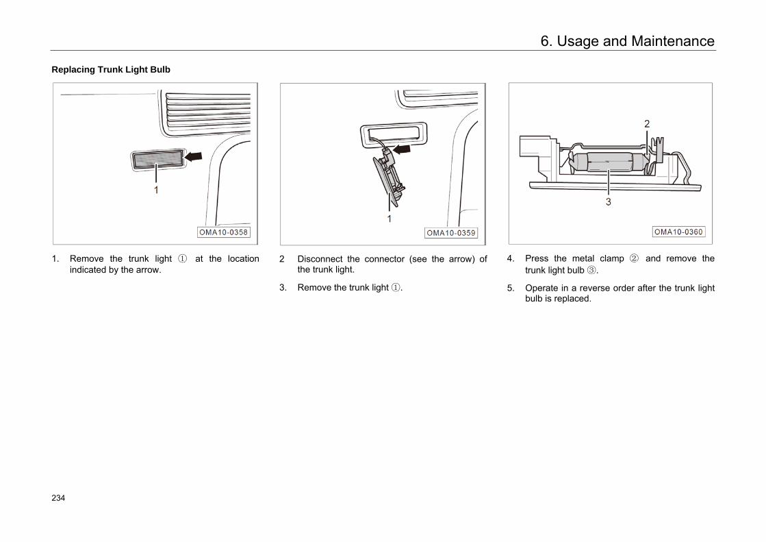
6. Usage and Maintenance
Replacing Trunk Light Bulb
1. Remove the trunk light ① at the location indicated by the arrow.
2 Disconnect the connector (see the arrow) of
the trunk light.
3. Remove the trunk light ①.
4. Press the metal clamp ② and remove the trunk light bulb ③.
5. Operate in a reverse order after the trunk light bulb is replaced.
277 234
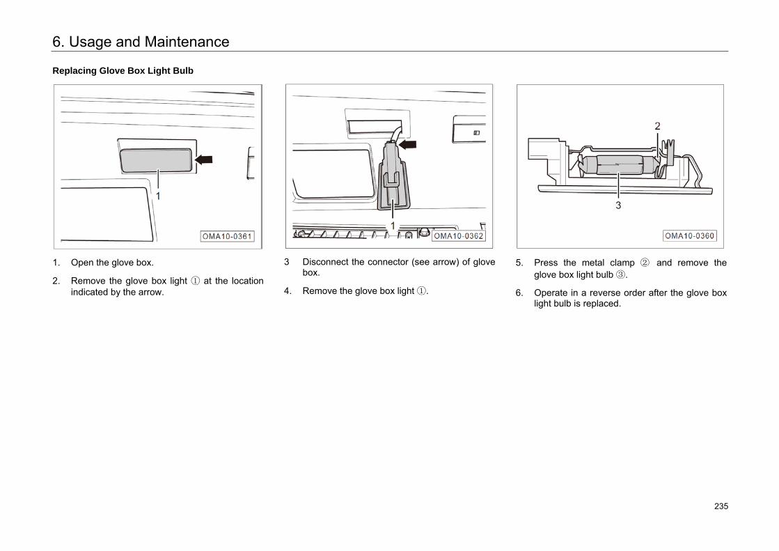
6. Usage and Maintenance
Replacing Glove Box Light Bulb
1. Open the glove box.
2. Remove the glove box light ① at the locationindicated by the arrow.
3 Disconnect the connector (see arrow) of glove box.
4. Remove the glove box light ①.
5. Press the metal clamp ② and remove theglove box light bulb ③.
6. Operate in a reverse order after the glove boxlight bulb is replaced.
278 235
6. Usage and Maintenance
6.7 Wheels
Warning You cannot get the best adhesion from a new
tire during the first 500km, so drive your vehicle at a moderate speed with care to avoid accidents. • The tire which has not been run in or has been
overworn provides insufficient adhesion, directly affecting the braking effect.
• If the vehicle vibrates abnormally or departures, stop the vehicle at a safe place immediately and check the tires for damage.
• If uneven excessive wear of the tires is found, go to an authorized GAC Motor's dealer for inspection as soon as possible.
Warning Tire burst or air leakage during traveling can
cause serious traffic accidents. • Do not drive with damaged tires or wheels or
tires worn to the wear mark of tread pattern. Otherwise, it may cause accidents. Because the damaged tires may explode duringtraveling and cause traffic accidents and injure persons. replace such tires and wheels timely.
• Tire pressure must comply with specifications. Otherwise it may cause accidents. If the tirepressure is insufficient, constant high-speed driving will cause tire deflection, resulting intire overheating which may lead to tire shelling or burst.
• Always prevent the tires from touching chemicals, oil, grease, fuel and brake fluid.
Warning • Try to avoid using a tire more than six years
old. If no other choice, be sure to drive at a low speed with extra care.
• Do not use any old wheels and tires with dubious background under any circumstances. Such wheels and tires which may be already damaged invisibly will cause the vehicle out ofcontrol while driving, resulting in accidents.
• It is not recommended to use reclaimed tires,of which the carcass may change with timeand the service life may be limited, affecting driving safety.
279 236
6. Usage and Maintenance
Prevention Measures for Wheel Fault
– To cross over curbs or similar obstacles, slowdown your vehicle and drive in the verticaldirection of the obstacle as far as possible.
– Prevent the tires from touching grease, oil andfuel.
– Periodically inspect the tire damage state (e.g.tire cut, wear, crack, peeling off, deformation,bump and other damages).
– Periodically remove sundries embedded in thetire tread grooves.
Notice of Tire Storage
– Make a mark on the tire to indicate thedirection of rotation before removing the tire.Re-install the tire according to the mark tokeep the direction of rotation and the dynamicbalance state of the wheel unchanged.
– Store any removed wheel or tire at a cool, dryand preferably dark place.
– The tire installed on the rim should not bestored upright.
New Tires and Wheels
– Select appropriate wheels and tires with care.Ensure that the new wheels and tires aremuch the same as the original one indimensions, load range, rated speed andstructure.
– Do not to replace one tire only. At least the twotires on the same axle shall be replacedsimultaneously.
– Do not use any tire that its effective size is notrecognized for relevant models by GACMOTOR. Otherwise, accidents may occur dueto envelope interference or collision of thevehicle body.
– Do not confuse tires of different dimensions ortypes, such as summer tire, all season tire andwinder tire.
– It is recommended to use the tires or wheelcombination recognized for relevant models byGAC MOTOR. For those unrecognized, GACMOTOR cannot make any judgment andcannot ensure safe driving.
– Each time after a wheel is installed, checkwhether the tightening torque of wheel boltsreaches 120±10N·m as required.
Non-full Size Tire
The spare tire is different from the standard tire in such aspects as structure, pattern, speed grade and load index. Therefore, the spare tire cannot replace the standard tire.
After a spare tire is used in emergency, go to the authorized GAC Motor's dealer or a wheel repair store to replace the main tire to avoid potential safety hazards due to long time use of the spare tire.
Warning • The spare tire can only be used temporarily in
emergency and its maximum speed is less than 80 km/h.
• The storage life of a spare tire is 6 years. Donot use any spare tire beyond the storage lift.
280 237
6. Usage and Maintenance
Summer Tire
As it rains a lot in summer, the depth of tread directly relates to the safety of driving in rainy days. In summer, a very high risk of hydroplaning exists when the tread depth is less than 3mm.
Winter Tire
The winter tire has good holding performance on the icy and snow-covered pavement. Benefiting from special tread rubber design, the winter tire is not likely to be affected much by the low temperature environment and it has excellent brake performance to ensure driving safety.
– Winter tires shall be used on all four wheels.
– It is recommended to use winter tires in snowydays in winter or when the temperature isbelow 7°C.
– Only use the recognized radial winter tires forthe vehicle with the same dimension, loadrange and rated speed as the original ones.
– It should be noted that sufficient tread depthshall be reserved on the tread of winter tire(The tread depth shall not be less than 4mm,otherwise the winter applicability will berestricted).
– After installing the tire, inspect the inflationpressure of the tire.
Warning • The winter and summer tires are designed
according to the traveling conditions on their respective typical lanes under correspondingseason conditions. Winter tire is recommended in winter. At low temperature, the adaptabilityof summer tire is obviously poor, and it maylose adhesive force and braking capacity.
• Under severe cold conditions, if a summer tire is used, crack may appear on the tire, which will damage the tire completely, and causeexcessive tire noise and out of balance.
Warning • Winter tires may reduce the traveling traction
on dry roads, increase noise and reduce theservice life of the tread. When using the wintertires, pay attention to changes in operation and control.
• The maximum speed applicable to winter tire is relatively low. Do not drive at a speed beyond the allowable speed of the winter tires.
• Replace the winter tires with the summer tiresafter the temperature rises back to above 7°Cto ensure driving safety and performance.
• When winter tires and a spare tire are used atthe same time, the vehicle is less stable during turning and traveling. Adjust driving mode and drive carefully.
281 238
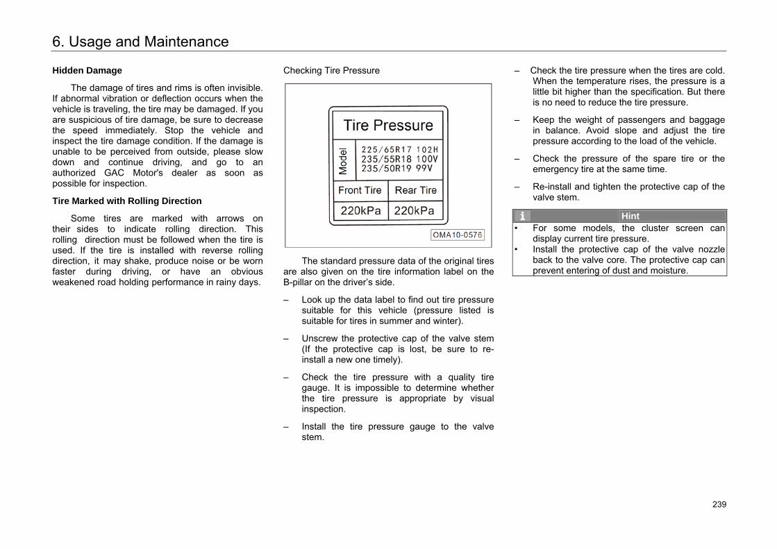
6. Usage and Maintenance
Hidden Damage
The damage of tires and rims is often invisible. If abnormal vibration or deflection occurs when the vehicle is traveling, the tire may be damaged. If you are suspicious of tire damage, be sure to decrease the speed immediately. Stop the vehicle and inspect the tire damage condition. If the damage is unable to be perceived from outside, please slow down and continue driving, and go to an authorized GAC Motor's dealer as soon as possible for inspection.
Tire Marked with Rolling Direction
Some tires are marked with arrows on their sides to indicate rolling direction. This rolling direction must be followed when the tire is used. If the tire is installed with reverse rolling direction, it may shake, produce noise or be worn faster during driving, or have an obvious weakened road holding performance in rainy days.
Checking Tire Pressure
The standard pressure data of the original tires are also given on the tire information label on the B-pillar on the driver’s side.
– Look up the data label to find out tire pressuresuitable for this vehicle (pressure listed issuitable for tires in summer and winter).
– Unscrew the protective cap of the valve stem(If the protective cap is lost, be sure to re-install a new one timely).
– Check the tire pressure with a quality tiregauge. It is impossible to determine whetherthe tire pressure is appropriate by visualinspection.
– Install the tire pressure gauge to the valvestem.
– Check the tire pressure when the tires are cold.When the temperature rises, the pressure is alittle bit higher than the specification. But thereis no need to reduce the tire pressure.
– Keep the weight of passengers and baggagein balance. Avoid slope and adjust the tirepressure according to the load of the vehicle.
– Check the pressure of the spare tire or theemergency tire at the same time.
– Re-install and tighten the protective cap of thevalve stem.
Hint • For some models, the cluster screen can
display current tire pressure.• Install the protective cap of the valve nozzle
back to the valve core. The protective cap can prevent entering of dust and moisture.
282 239
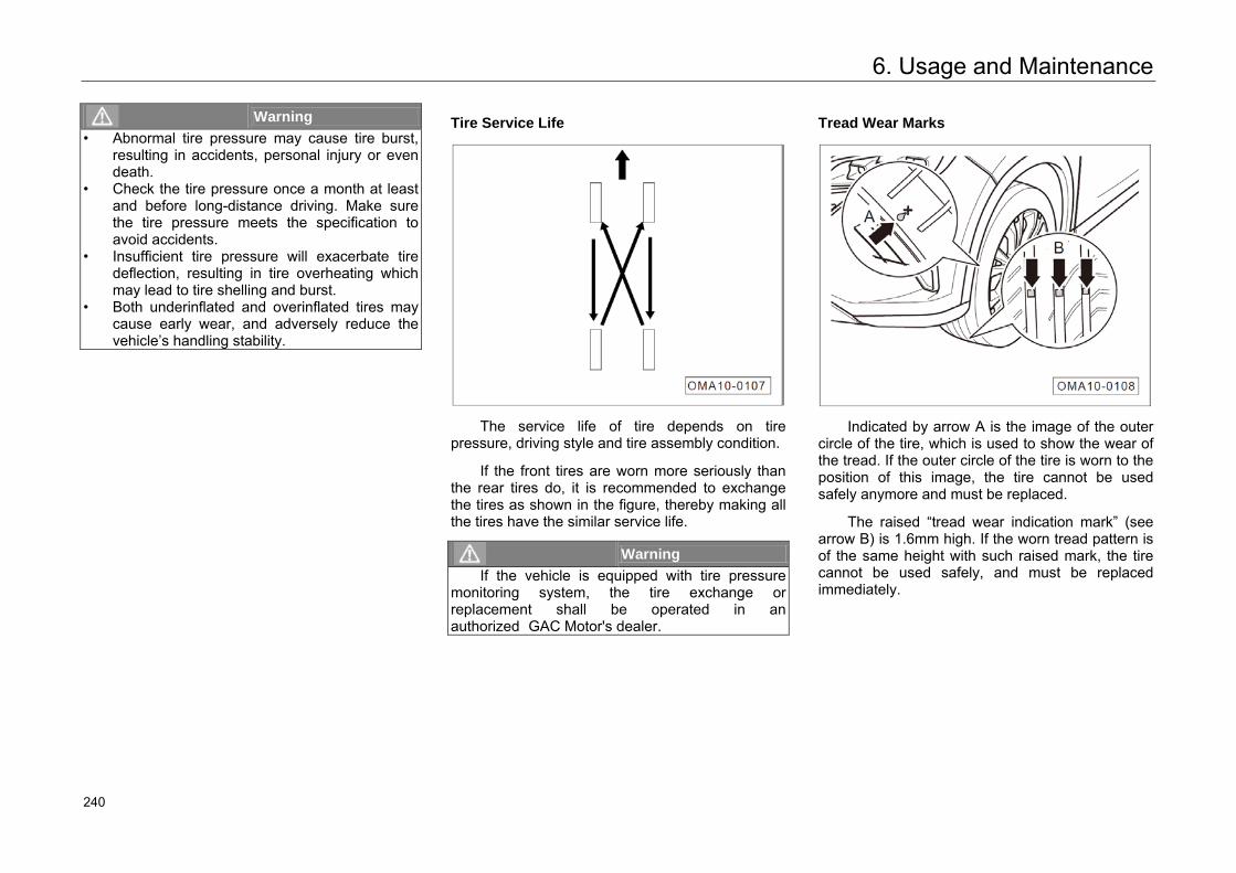
6. Usage and Maintenance
Warning • Abnormal tire pressure may cause tire burst,
resulting in accidents, personal injury or even death.
• Check the tire pressure once a month at leastand before long-distance driving. Make sure the tire pressure meets the specification toavoid accidents.
• Insufficient tire pressure will exacerbate tire deflection, resulting in tire overheating whichmay lead to tire shelling and burst.
• Both underinflated and overinflated tires maycause early wear, and adversely reduce the vehicle’s handling stability.
Tire Service Life
The service life of tire depends on tire pressure, driving style and tire assembly condition.
If the front tires are worn more seriously than the rear tires do, it is recommended to exchange the tires as shown in the figure, thereby making all the tires have the similar service life.
Warning If the vehicle is equipped with tire pressure
monitoring system, the tire exchange or replacement shall be operated in an authorized GAC Motor's dealer.
Tread Wear Marks
Indicated by arrow A is the image of the outer circle of the tire, which is used to show the wear of the tread. If the outer circle of the tire is worn to the position of this image, the tire cannot be used safely anymore and must be replaced.
The raised “tread wear indication mark” (see arrow B) is 1.6mm high. If the worn tread pattern is of the same height with such raised mark, the tire cannot be used safely, and must be replaced immediately.
283 240
6. Usage and Maintenance
Wheel Balance
The wheels of a new vehicle have been balanced, however, during the running process, the wheels may be out of balance due to various influences, which can be perceived from the shaking of steering mechanism.
The imbalance of wheel will cause excessive wear of steering system, wheel suspension mechanism and tire, so that the wheel shall be rebalanced.
In addition, if a new tire is installed or the tire is repaired, the wheel must also be rebalanced.
Incorrect Wheel Alignment
The misalignment of wheels will cause uneven excessive wear of tires, and affect the traveling safety; if uneven excessive wear of tires is found, go to an authorized GAC Motor's dealer to inspect the wheel alignment as soon as possible.
284 241
6. Usage and Maintenance
6.8 Tire Chain
When driving on snow or ice road or in other severe environments in winter, the tire wear degree may increase or other failure may occur. The following suggestions must be observed in order to reduce the failure in winter:
– When driving in deep snow, it is necessary to install tire chain. If a tire chain is to be installed, an equivalent product with its size and type conforming to the tire specification must be selected. Otherwise, the vehicle performance and safety will be adversely affected. High risk exists for such operations as full-load, speeding, emergency acceleration, emergency braking and emergency steering.
– When decelerating, make the best of the braking function of the engine. Emergency braking on roads with snow or ice will cause vehicle drifting or slipping. Keep a safe distance with the front vehicle, slightly tread the brake pedal, and note that the tire chain installed can provide certain force of friction but cannot prevent the occurrence of sideslip.
Hint Different countries and regions have different
laws and regulations on tire chain, which shall be referenced before a tire chain is assembled. Do not install a tire chain without understanding the laws and regulations of a country or region, which may restrict the use of tire chain.
Caution • Installing tire chain on all tires shall guarantee
the balanced driving under various weather conditions. Keep in mind that the vehicle may be short of power after being installed with tire chain. Drive with care even if the road condition is good. The driving speed shall not exceed the specified speed for tire chain, nor exceed 50km/h, whichever is smaller.
Caution • If a tire chain is to be installed, make sure that
the size and type of the tire chain are consistent with those of the standard tire. Otherwise, the safety and controllability of the vehicle will be adversely affected.
• Install tire chains in pair and do not install them on the rear wheels.
• Do not install any tire chain on a spare tire. If one of the front tires is a spare tire, replace the spare tire with a rear tire.
• Do not use tire chains on dry roads. Remove the tire chains when driving to a road without snow.
• Install the tire chains close to the front tire as much as possible. Tighten them after driving for 0.5~1.0 km.
285 242
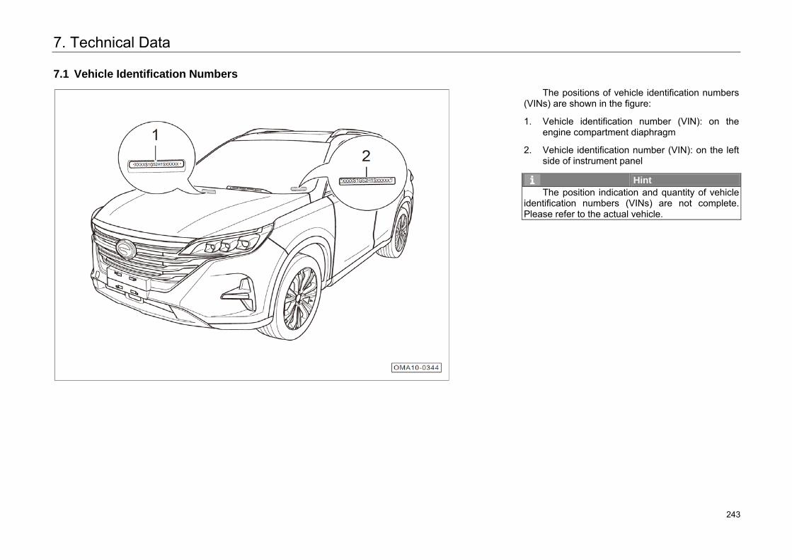
7. Technical Data
7.1 Vehicle Identification Numbers
The positions of vehicle identification numbers (VINs) are shown in the figure:
1. Vehicle identification number (VIN): on theengine compartment diaphragm
2. Vehicle identification number (VIN): on the leftside of instrument panel
Hint The position indication and quantity of vehicle
identification numbers (VINs) are not complete. Please refer to the actual vehicle.
286 243
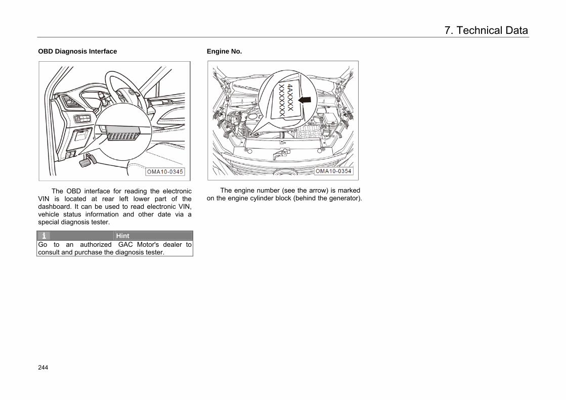
7. Technical Data
OBD Diagnosis Interface
The OBD interface for reading the electronic VIN is located at rear left lower part of the dashboard. It can be used to read electronic VIN, vehicle status information and other date via a special diagnosis tester.
Hint Go to an authorized GAC Motor's dealer to consult and purchase the diagnosis tester.
Engine No.
The engine number (see the arrow) is marked on the engine cylinder block (behind the generator).
287 244
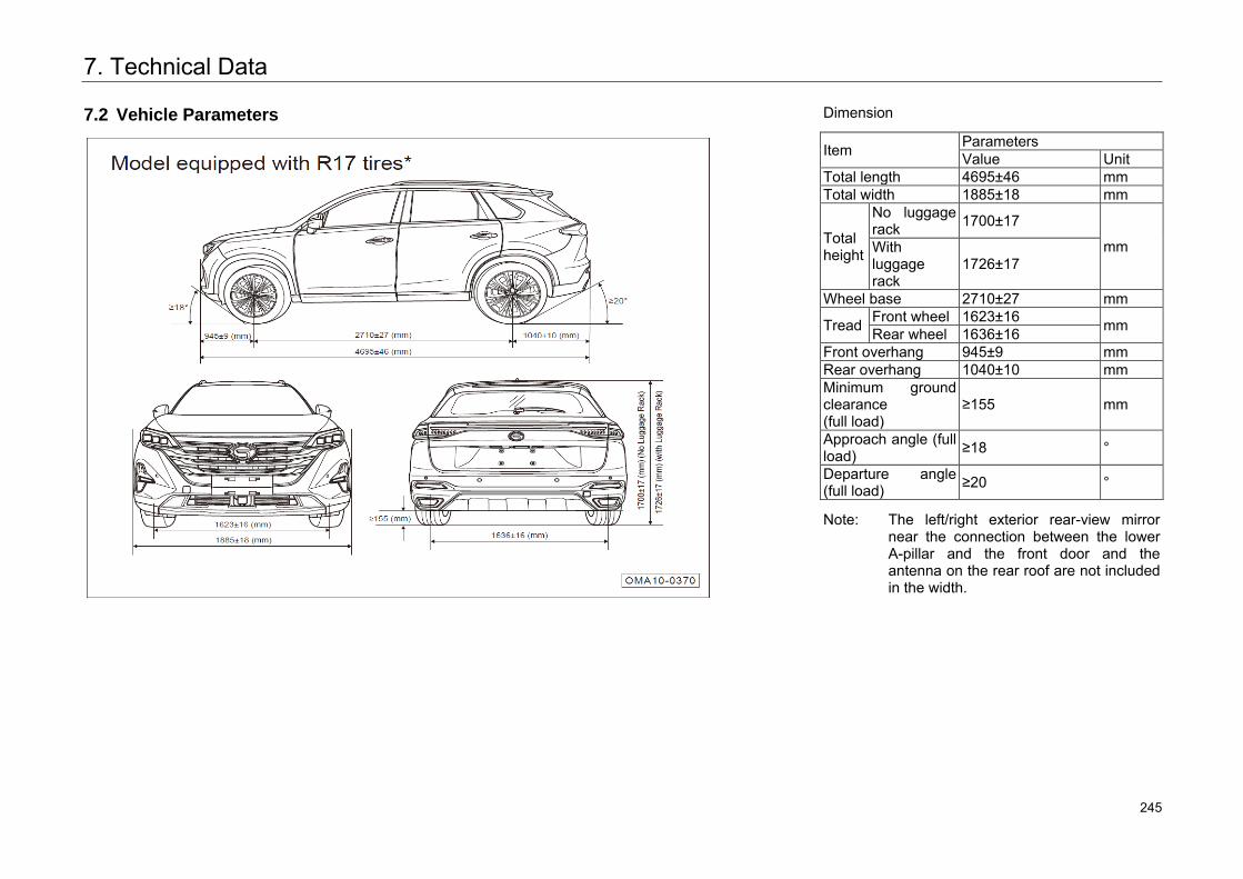
7. Technical Data
7.2 Vehicle Parameters
Dimension
Item Parameters Value Unit
Total length 4695±46 mm Total width 1885±18 mm
Total height
No luggage rack 1700±17
mm With luggage rack
1726±17
Wheel base 2710±27 mm
Tread Front wheel 1623±16 mm Rear wheel 1636±16 Front overhang 945±9 mm Rear overhang 1040±10 mm Minimum ground clearance (full load)
≥155 mm
Approach angle (full load) ≥18 °
Departure angle (full load) ≥20 °
Note: The left/right exterior rear-view mirror near the connection between the lower A-pillar and the front door and the antenna on the rear roof are not included in the width.
288 245
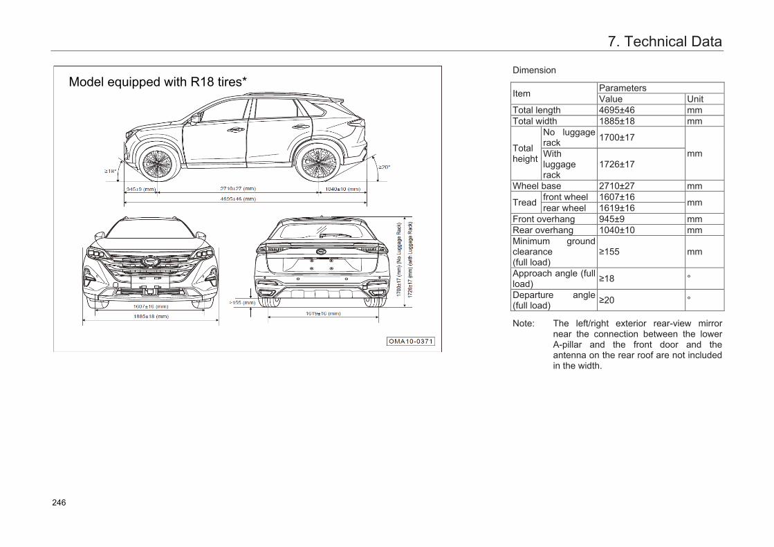
7. Technical Data
Dimension
Item ParametersValue Unit
Total length 4695±46 mmTotal width 1885±18 mm
Total height
No luggage rack 1700±17
mmWith luggage rack
1726±17
Wheel base 2710±27 mm
Tread front wheel 1607±16 mmrear wheel 1619±16Front overhang 945±9 mmRear overhang 1040±10 mmMinimum ground clearance(full load)
≥155 mm
Approach angle (full load) ≥18 °
Departure angle (full load) ≥20 °
Note: The left/right exterior rear-view mirror near the connection between the lower A-pillar and the front door and theantenna on the rear roof are not includedin the width.
289
Model equipped with R18 tires*
246
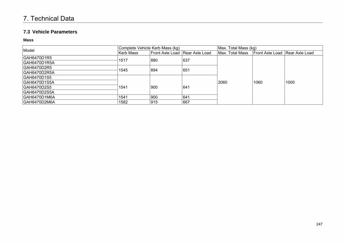
7. Technical Data
7.3 Vehicle Parameters
Mass
Model Complete Vehicle Kerb Mass (kg) Max. Total Mass (kg) Kerb Mass Front Axle Load Rear Axle Load Max. Total Mass Front Axle Load Rear Axle Load
GAH6470D1R5 1517 880 637
2060
1060
1000
GAH6470D1R5A GAH6470D2R5 1545 894 651 GAH6470D2R5A GAH6470D1S5
1541
900
641
GAH6470D1S5A GAH6470D2S5 GAH6470D2S5A GAH6470D1M6A 1541 900 641 GAH6470D2M6A 1582 915 667
290 247
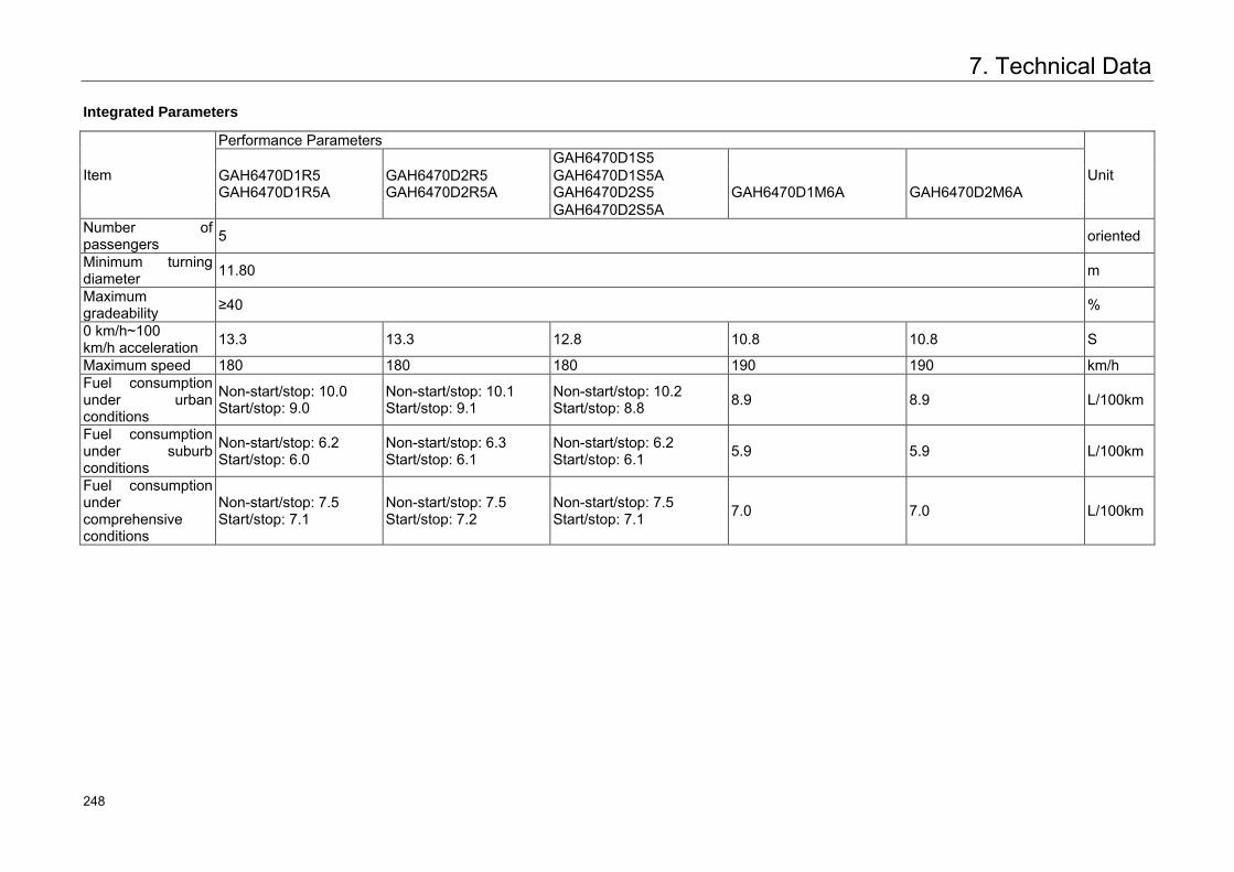
7. Technical Data
Integrated Parameters
Item
Performance Parameters
Unit GAH6470D1S5 GAH6470D1R5 GAH6470D1R5A
GAH6470D2R5 GAH6470D2R5A
GAH6470D1S5A GAH6470D2S5
GAH6470D1M6A
GAH6470D2M6A
GAH6470D2S5A Number of passengers 5 oriented
Minimum turning diameter 11.80 m
Maximum gradeability ≥40 %
0 km/h~100 km/h acceleration 13.3 13.3 12.8 10.8 10.8 S
Maximum speed 180 180 180 190 190 km/h Fuel consumption under urban conditions
Non-start/stop: 10.0 Start/stop: 9.0
Non-start/stop: 10.1 Start/stop: 9.1
Non-start/stop: 10.2 Start/stop: 8.8 8.9 8.9 L/100km
Fuel consumption under suburb conditions
Non-start/stop: 6.2 Start/stop: 6.0
Non-start/stop: 6.3 Start/stop: 6.1
Non-start/stop: 6.2 Start/stop: 6.1 5.9 5.9 L/100km
Fuel consumption under comprehensive conditions
Non-start/stop: 7.5 Start/stop: 7.1
Non-start/stop: 7.5 Start/stop: 7.2
Non-start/stop: 7.5 Start/stop: 7.1 7.0 7.0 L/100km
291 248
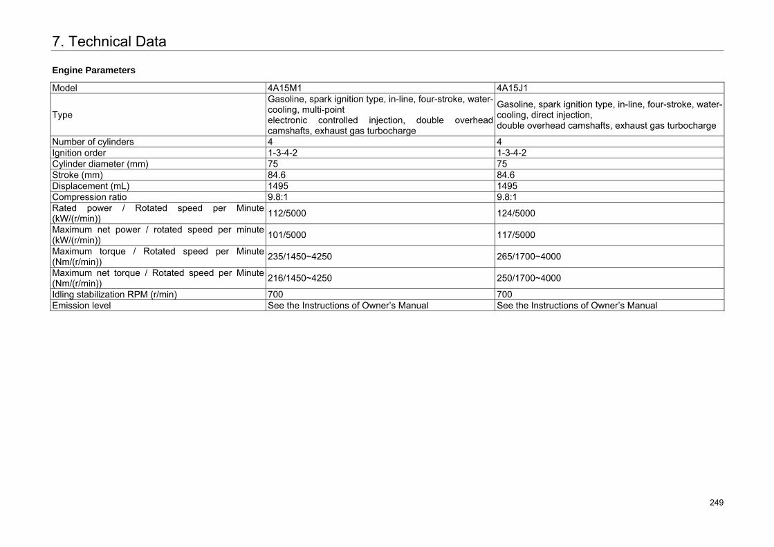
7. Technical Data
Engine Parameters
Model 4A15M1 4A15J1
Type
Gasoline, spark ignition type, in-line, four-stroke, water-cooling, multi-point electronic controlled injection, double overhead camshafts, exhaust gas turbocharge
Gasoline, spark ignition type, in-line, four-stroke, water-cooling, direct injection, double overhead camshafts, exhaust gas turbocharge
Number of cylinders 4 4 Ignition order 1-3-4-2 1-3-4-2Cylinder diameter (mm) 75 75 Stroke (mm) 84.6 84.6 Displacement (mL) 1495 1495 Compression ratio 9.8:1 9.8:1 Rated power / Rotated speed per Minute (kW/(r/min)) 112/5000 124/5000
Maximum net power / rotated speed per minute (kW/(r/min)) 101/5000 117/5000
Maximum torque / Rotated speed per Minute (Nm/(r/min)) 235/1450~4250 265/1700~4000
Maximum net torque / Rotated speed per Minute (Nm/(r/min)) 216/1450~4250 250/1700~4000
Idling stabilization RPM (r/min) 700 700 Emission level See the Instructions of Owner’s Manual See the Instructions of Owner’s Manual
292 249
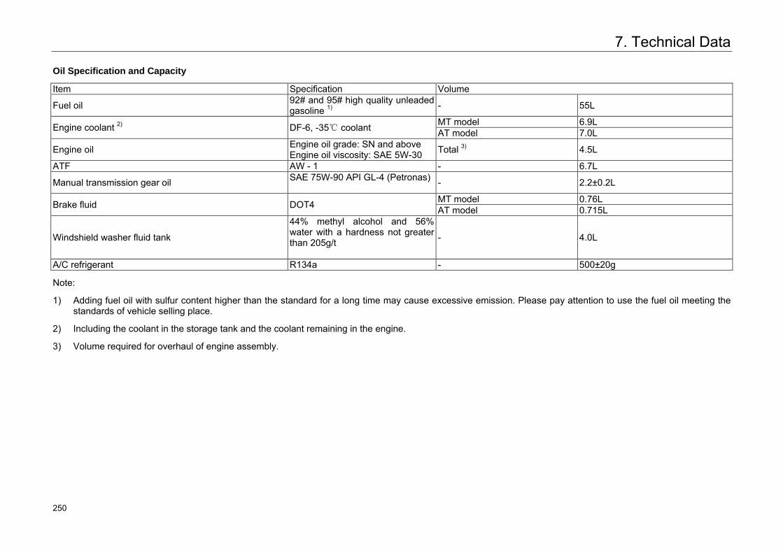
7. Technical Data
Oil Specification and Capacity
Item Specification Volume
Fuel oil 92# and 95# high quality unleaded gasoline 1) - 55L
Engine coolant 2) DF-6, -35℃ coolant MT model 6.9L AT model 7.0L
Engine oil Engine oil grade: SN and above Engine oil viscosity: SAE 5W-30 Total 3) 4.5L
ATF AW - 1 - 6.7L
Manual transmission gear oil SAE 75W-90 API GL-4 (Petronas) - 2.2±0.2L
Brake fluid DOT4 MT model 0.76L AT model 0.715L
Windshield washer fluid tank
44% methyl alcohol and 56% water with a hardness not greater than 205g/t
- 4.0L
A/C refrigerant R134a - 500±20g
Note:
1) Adding fuel oil with sulfur content higher than the standard for a long time may cause excessive emission. Please pay attention to use the fuel oil meeting the standards of vehicle selling place.
2) Including the coolant in the storage tank and the coolant remaining in the engine.
3) Volume required for overhaul of engine assembly.
293 250
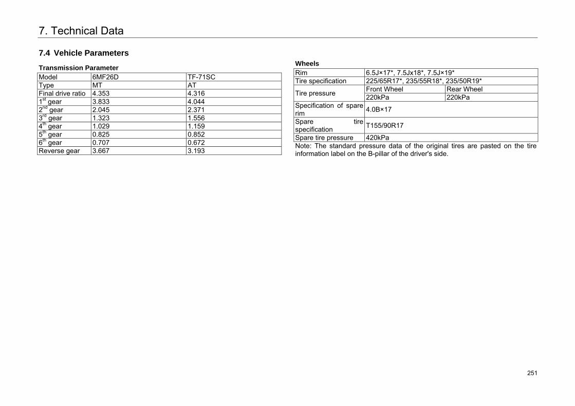
7. Technical Data
7.4 Vehicle Parameters
Transmission Parameter Model 6MF26D TF-71SC Type MT AT Final drive ratio 4.353 4.316 1st gear 3.833 4.044 2nd gear 2.045 2.371 3rd gear 1.323 1.556 4th gear 1.029 1.159 5th gear 0.825 0.852 6th gear 0.707 0.672 Reverse gear 3.667 3.193
Wheels Rim 6.5J×17*, 7.5Jx18*, 7.5J×19* Tire specification 225/65R17*, 235/55R18*, 235/50R19*
Tire pressure Front Wheel Rear Wheel 220kPa 220kPa
Specification of spare rim 4.0B×17
Spare tire specification T155/90R17
Spare tire pressure 420kPa Note: The standard pressure data of the original tires are pasted on the tire information label on the B-pillar of the driver's side.
294 251
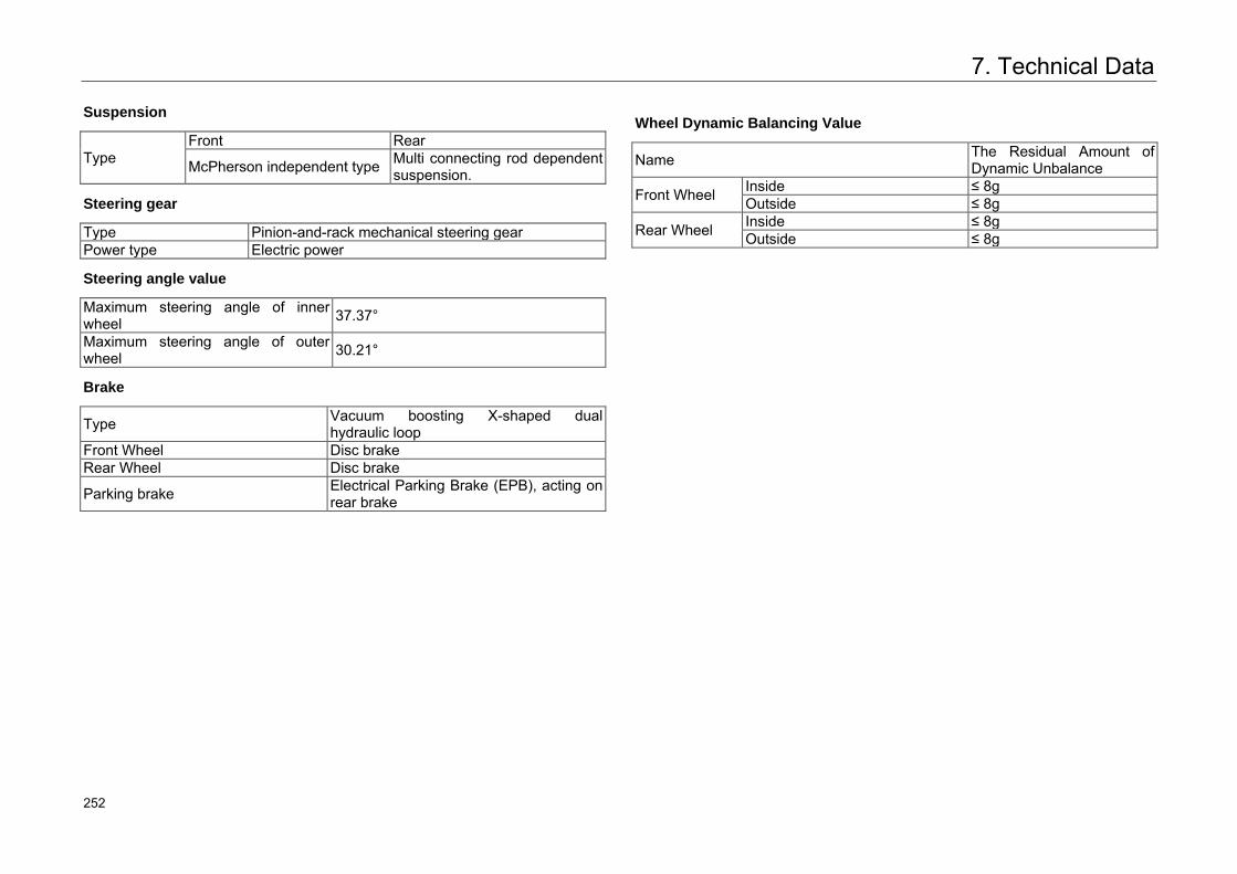
7. Technical Data
Suspension
Type Front Rear
McPherson independent type Multi connecting rod dependent suspension.
Steering gear
Type Pinion-and-rack mechanical steering gear Power type Electric power
Steering angle value
Maximum steering angle of inner wheel 37.37°
Maximum steering angle of outer wheel 30.21°
Brake
Type Vacuum boosting X-shaped dual hydraulic loop
Front Wheel Disc brake Rear Wheel Disc brake
Parking brake Electrical Parking Brake (EPB), acting on rear brake
Wheel Dynamic Balancing Value
Name The Residual Amount of Dynamic Unbalance
Front Wheel Inside ≤ 8g Outside ≤ 8g
Rear Wheel Inside ≤ 8g Outside ≤ 8g
295 252
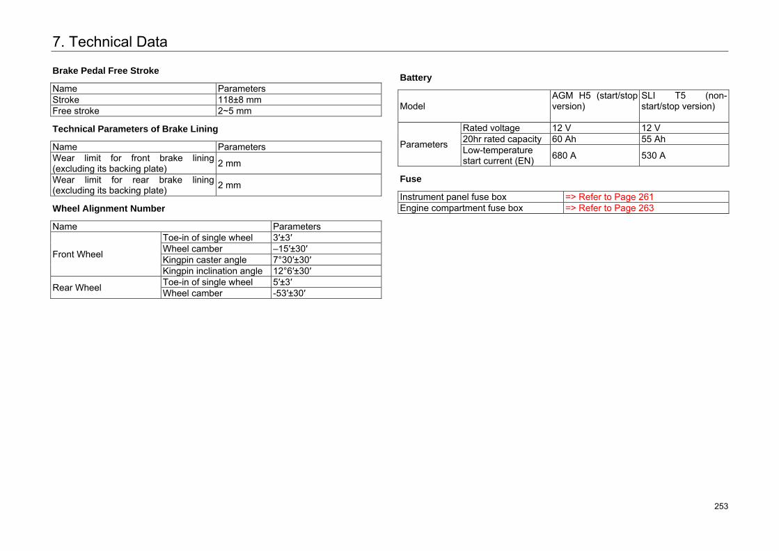
7. Technical Data
Brake Pedal Free Stroke
Name Parameters Stroke 118±8 mm Free stroke 2~5 mm
Technical Parameters of Brake Lining
Name Parameters Wear limit for front brake lining (excluding its backing plate) 2 mm
Wear limit for rear brake lining (excluding its backing plate) 2 mm
Wheel Alignment Number
Name Parameters
Front Wheel
Toe-in of single wheel 3′±3′ Wheel camber –15′±30′Kingpin caster angle 7°30′±30′ Kingpin inclination angle 12°6′±30′
Rear Wheel Toe-in of single wheel 5′±3′ Wheel camber -53′±30′
Battery
Model AGM H5 (start/stop version)
SLI T5 (non-start/stop version)
Parameters
Rated voltage 12 V 12 V 20hr rated capacity 60 Ah 55 Ah Low-temperature start current (EN) 680 A 530 A
Fuse
Instrument panel fuse box => Refer to Page 261 Engine compartment fuse box => Refer to Page 263
296 253
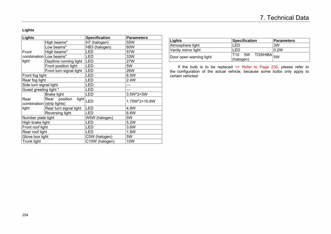
7. Technical Data
Lights
Lights Specification Parameters
Front combination light
High beams* H7 (halogen) 55W Low beams* HB3 (halogen) 60W High beams* LED 57W Low beams* LED 33W Daytime running light LED 27W Front position light LED 5W Front turn signal light LED 26W
Front fog light LED 8.5W Rear fog light LED 2.4W Side turn signal light LED — Guest greeting light * LED —
Rear combination light
Brake light LED 3.5W*2+5W Rear position light (strip lights) LED 1.75W*2+10.8W
Rear turn signal light LED 4.9W Reversing light LED 6.6W
Number plate light W5W (halogen) 5W High brake light LED 5.2W Front roof light LED 3.6W Rear roof light LED 1.8W Glove box light C5W (halogen) 5W Trunk light C10W (halogen) 10W
Lights Specification Parameters Atmosphere light LED 3W Vanity mirror light LED 0.2W
Door open warning light T10 5W TOSHIBA (halogen) 5W
If the bulb is to be replaced => Refer to Page 230, please refer to the configuration of the actual vehicle, because some bulbs only apply to certain vehicles!
297 254
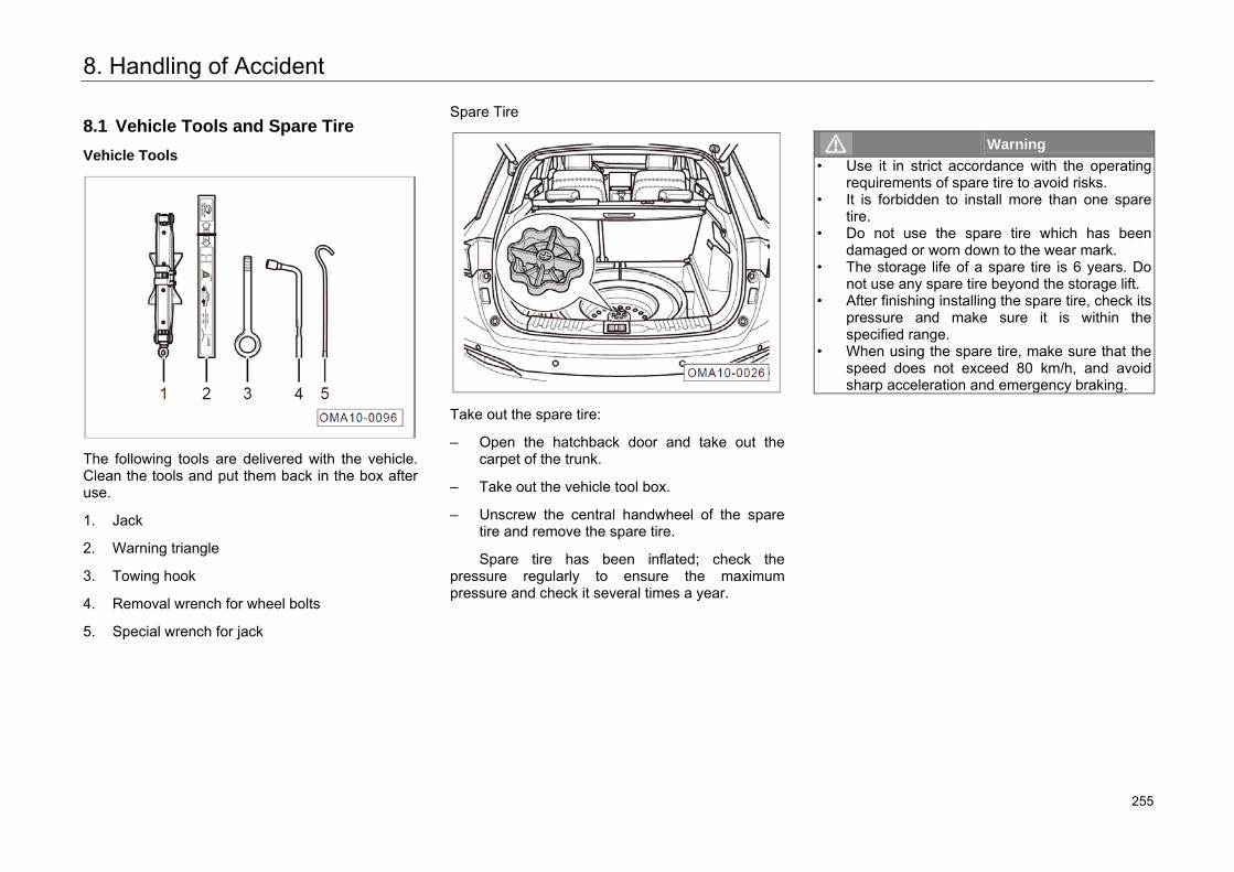
8. Handling of Accident
8.1 Vehicle Tools and Spare Tire
Vehicle Tools
The following tools are delivered with the vehicle. Clean the tools and put them back in the box after use.
1. Jack
2. Warning triangle
3. Towing hook
4. Removal wrench for wheel bolts
5. Special wrench for jack
Spare Tire
Take out the spare tire:
– Open the hatchback door and take out thecarpet of the trunk.
– Take out the vehicle tool box.
– Unscrew the central handwheel of the sparetire and remove the spare tire.
Spare tire has been inflated; check thepressure regularly to ensure the maximum pressure and check it several times a year.
Warning • Use it in strict accordance with the operating
requirements of spare tire to avoid risks.• It is forbidden to install more than one spare
tire.• Do not use the spare tire which has been
damaged or worn down to the wear mark.• The storage life of a spare tire is 6 years. Do
not use any spare tire beyond the storage lift.• After finishing installing the spare tire, check its
pressure and make sure it is within thespecified range.
• When using the spare tire, make sure that thespeed does not exceed 80 km/h, and avoid sharp acceleration and emergency braking.
298 255
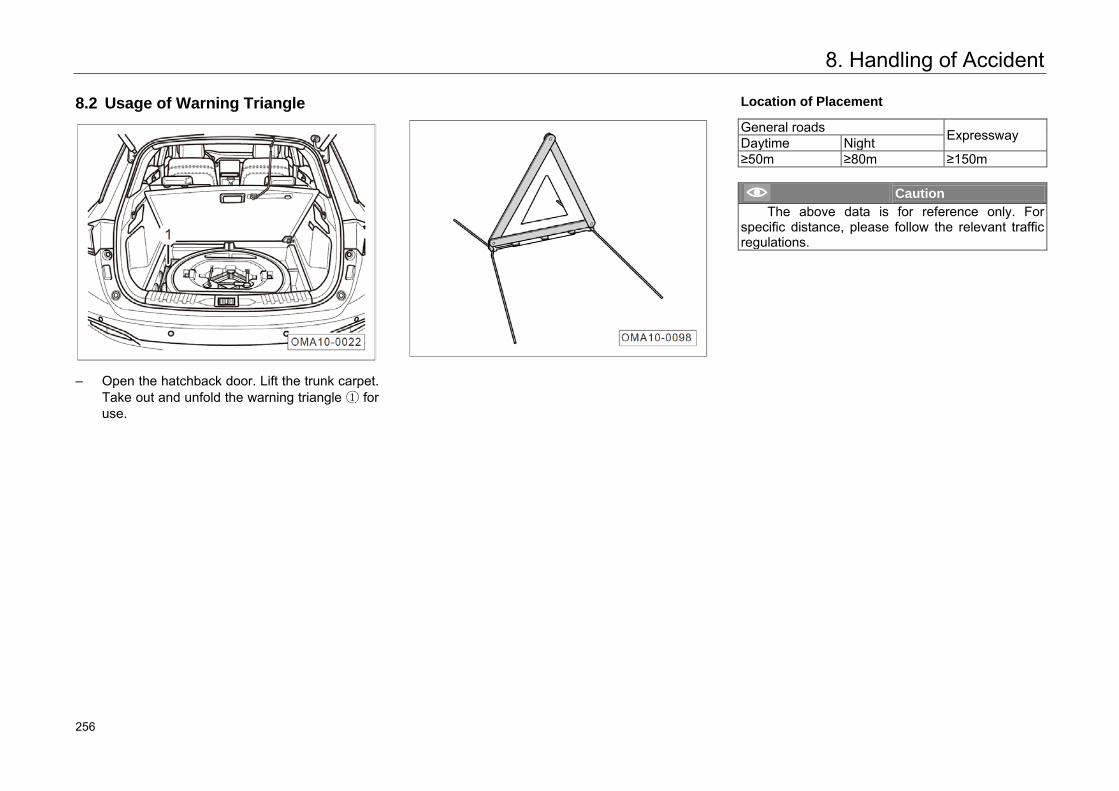
8. Handling of Accident
8.2 Usage of Warning Triangle
– Open the hatchback door. Lift the trunk carpet.Take out and unfold the warning triangle ① foruse.
Location of Placement
General roads Expressway Daytime Night ≥50m ≥80m ≥150m
Caution The above data is for reference only. For
specific distance, please follow the relevant traffic regulations.
299 256
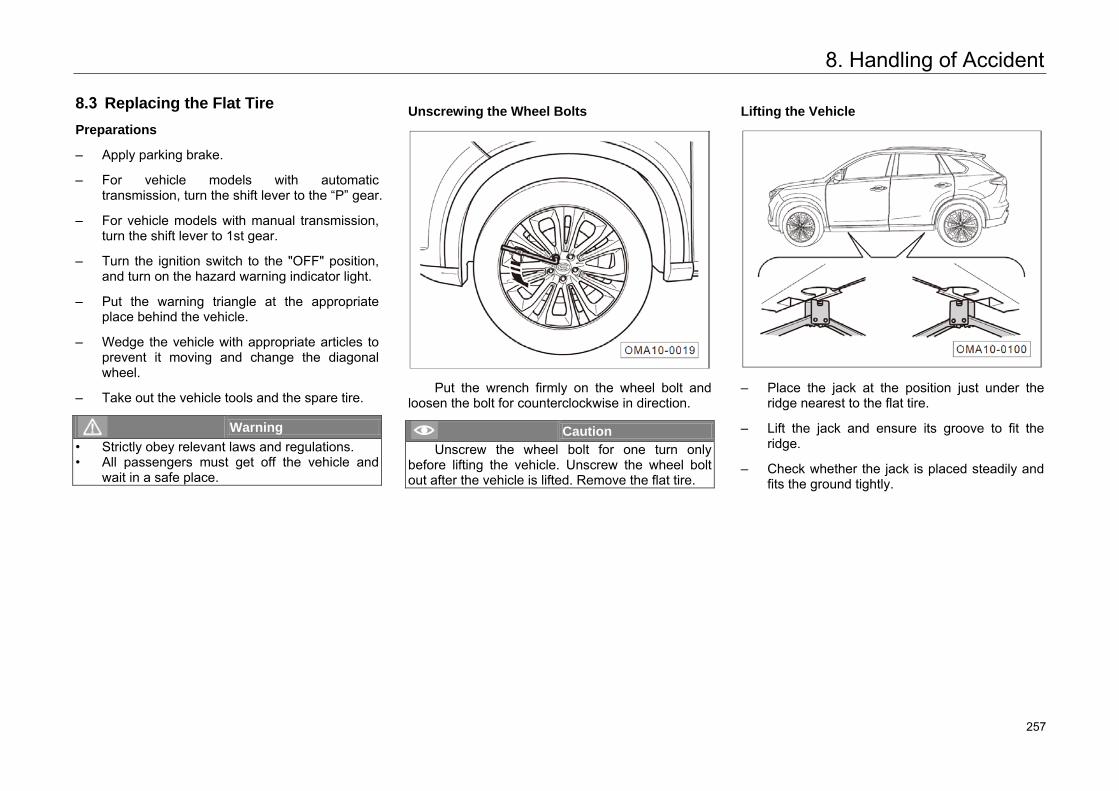
8. Handling of Accident
8.3 Replacing the Flat Tire
Preparations
– Apply parking brake.
– For vehicle models with automatictransmission, turn the shift lever to the “P” gear.
– For vehicle models with manual transmission,turn the shift lever to 1st gear.
– Turn the ignition switch to the "OFF" position,and turn on the hazard warning indicator light.
– Put the warning triangle at the appropriateplace behind the vehicle.
– Wedge the vehicle with appropriate articles toprevent it moving and change the diagonalwheel.
– Take out the vehicle tools and the spare tire.
Warning • Strictly obey relevant laws and regulations.• All passengers must get off the vehicle and
wait in a safe place.
Unscrewing the Wheel Bolts
Put the wrench firmly on the wheel bolt and loosen the bolt for counterclockwise in direction.
Caution Unscrew the wheel bolt for one turn only
before lifting the vehicle. Unscrew the wheel bolt out after the vehicle is lifted. Remove the flat tire.
Lifting the Vehicle
– Place the jack at the position just under theridge nearest to the flat tire.
– Lift the jack and ensure its groove to fit theridge.
– Check whether the jack is placed steadily andfits the ground tightly.
301 257
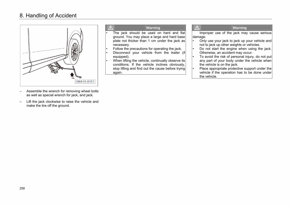
8. Handling of Accident
– Assemble the wrench for removing wheel boltsas well as special wrench for jack, and jack.
– Lift the jack clockwise to raise the vehicle andmake the tire off the ground.
Warning • The jack should be used on hard and flat
ground. You may place a large and hard base plate not thicker than 1 cm under the jack asnecessary.
• Follow the precautions for operating the jack.• Disconnect your vehicle from the trailer (if
equipped).• When lifting the vehicle, continually observe its
conditions. If the vehicle inclines obviously,stop lifting and find out the cause before tryingagain.
Warning Improper use of the jack may cause serious
damage. • Only use your jack to jack up your vehicle and
not to jack up other weights or vehicles.• Do not start the engine when using the jack.
Otherwise, an accident may occur.• To avoid the risk of personal injury, do not put
any part of your body under the vehicle when the vehicle is on the jack.
• Place appropriate protective support under the vehicle if the operation has to be done underthe vehicle.
302 258
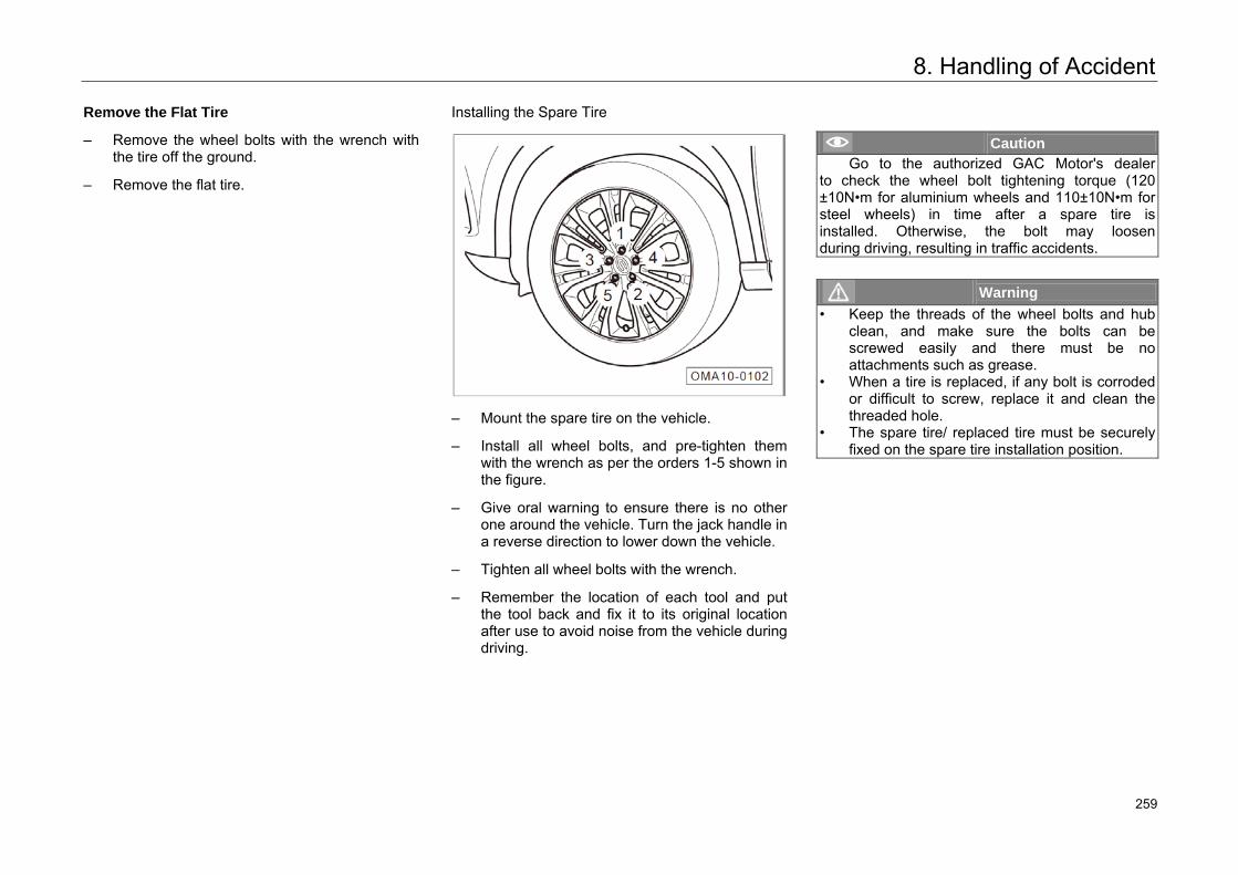
8. Handling of Accident
Remove the Flat Tire
– Remove the wheel bolts with the wrench withthe tire off the ground.
– Remove the flat tire.
Installing the Spare Tire
– Mount the spare tire on the vehicle.
– Install all wheel bolts, and pre-tighten themwith the wrench as per the orders 1-5 shown inthe figure.
– Give oral warning to ensure there is no otherone around the vehicle. Turn the jack handle ina reverse direction to lower down the vehicle.
– Tighten all wheel bolts with the wrench.
– Remember the location of each tool and putthe tool back and fix it to its original locationafter use to avoid noise from the vehicle duringdriving.
Caution Go to the authorized GAC Motor's dealer
to check the wheel bolt tightening torque (120±10N•m for aluminium wheels and 110±10N•m for steel wheels) in time after a spare tire is installed. Otherwise, the bolt may loosen during driving, resulting in traffic accidents.
Warning • Keep the threads of the wheel bolts and hub
clean, and make sure the bolts can be screwed easily and there must be no attachments such as grease.
• When a tire is replaced, if any bolt is corroded or difficult to screw, replace it and clean the threaded hole.
• The spare tire/ replaced tire must be securely fixed on the spare tire installation position.
303 259
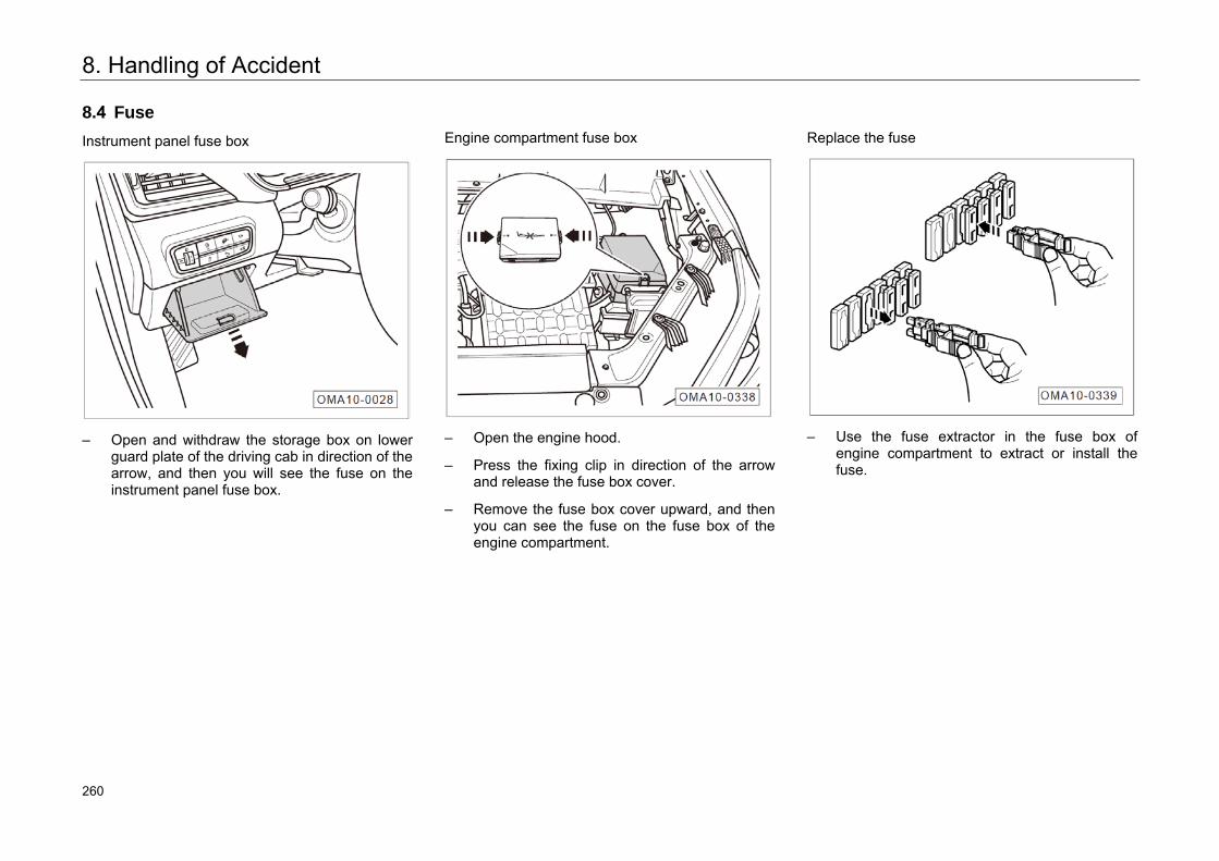
8. Handling of Accident
8.4 Fuse
Instrument panel fuse box
– Open and withdraw the storage box on lowerguard plate of the driving cab in direction of thearrow, and then you will see the fuse on theinstrument panel fuse box.
Engine compartment fuse box
– Open the engine hood.
– Press the fixing clip in direction of the arrowand release the fuse box cover.
– Remove the fuse box cover upward, and thenyou can see the fuse on the fuse box of theengine compartment.
Replace the fuse
– Use the fuse extractor in the fuse box ofengine compartment to extract or install thefuse.
304 260
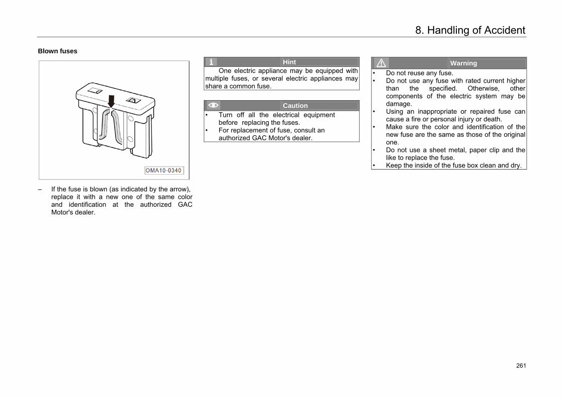
8. Handling of Accident
Blown fuses
– If the fuse is blown (as indicated by the arrow),replace it with a new one of the same color and identification at the authorized GAC Motor's dealer.
Hint One electric appliance may be equipped with
multiple fuses, or several electric appliances may share a common fuse.
Caution • Turn off all the electrical equipment
before replacing the fuses.• For replacement of fuse, consult an
authorized GAC Motor's dealer.
Warning • Do not reuse any fuse.• Do not use any fuse with rated current higher
than the specified. Otherwise, othercomponents of the electric system may bedamage.
• Using an inappropriate or repaired fuse can cause a fire or personal injury or death.
• Make sure the color and identification of thenew fuse are the same as those of the original one.
• Do not use a sheet metal, paper clip and thelike to replace the fuse.
• Keep the inside of the fuse box clean and dry.
305 261
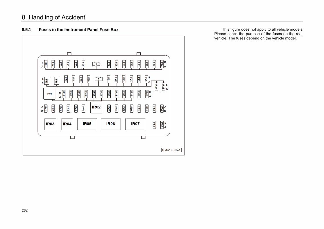
8. Handling of Accident
8.5.1 Fuses in the Instrument Panel Fuse Box This figure does not apply to all vehicle models. Please check the purpose of the fuses on the real vehicle. The fuses depend on the vehicle model.
306 262
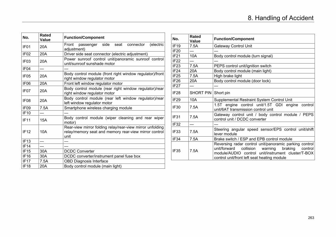
8. Handling of Accident
No. Rated Value Function/Component
IF01 20A Front passenger side seat connector (electric adjustment)
IF02 20A Driver side seat connector (electric adjustment)
IF03 20A Power sunroof control unit/panoramic sunroof control unit/sunroof sunshade motor
IF04 — —
IF05 20A Body control module (front right window regulator)/front right window regulator motor
IF06 20A Front left window regulator motor
IF07 20A Body control module (rear right window regulator)/rear right window regulator motor
IF08 20A Body control module (rear left window regulator)/rear left window regulator motor
IF09 7.5A Smartphone wireless charging module IF10 — —
IF11 15A Body control module (wiper cleaning and rear wiper motor)
IF12 10A Rear-view mirror folding relay/rear-view mirror unfolding relay/memory seat and memory rear-view mirror control unit
IF13 — — IF14 — — IF15 30A DCDC Converter IF16 30A DCDC converter/instrument panel fuse box IF17 7.5A OBD Diagnosis Interface IF18 20A Body control module (main light)
No. Rated Value Function/Component
IF19 7.5A Gateway Control Unit IF20 — — IF21 10A Body control module (turn signal) IF22 — — IF23 7.5A PEPS control unit/ignition switch IF24 20A Body control module (main light) IF25 7.5A High brake light IF26 20A Body control module (door lock) IF27 — —
IF28 SHORT PIN Short pin
IF29 10A Supplemental Restraint System Control Unit
IF30 7.5A 1.5T engine control unit/1.5T GDI engine control unit/6AT transmission control unit
IF31 7.5A Gateway control unit / body control module / PEPS control unit / DCDC converter
IF32 — —
IF33 7.5A Steering angular speed sensor/EPS control unit/shift lever module
IF34 7.5A Brake switch / ESP and EPB control module
IF35 7.5A
Reversing radar control unit/panoramic parking control unit/forward collision warning braking control module/AUDIO control unit/instrument cluster/T-BOX control unit/front left seat heating module
307 263
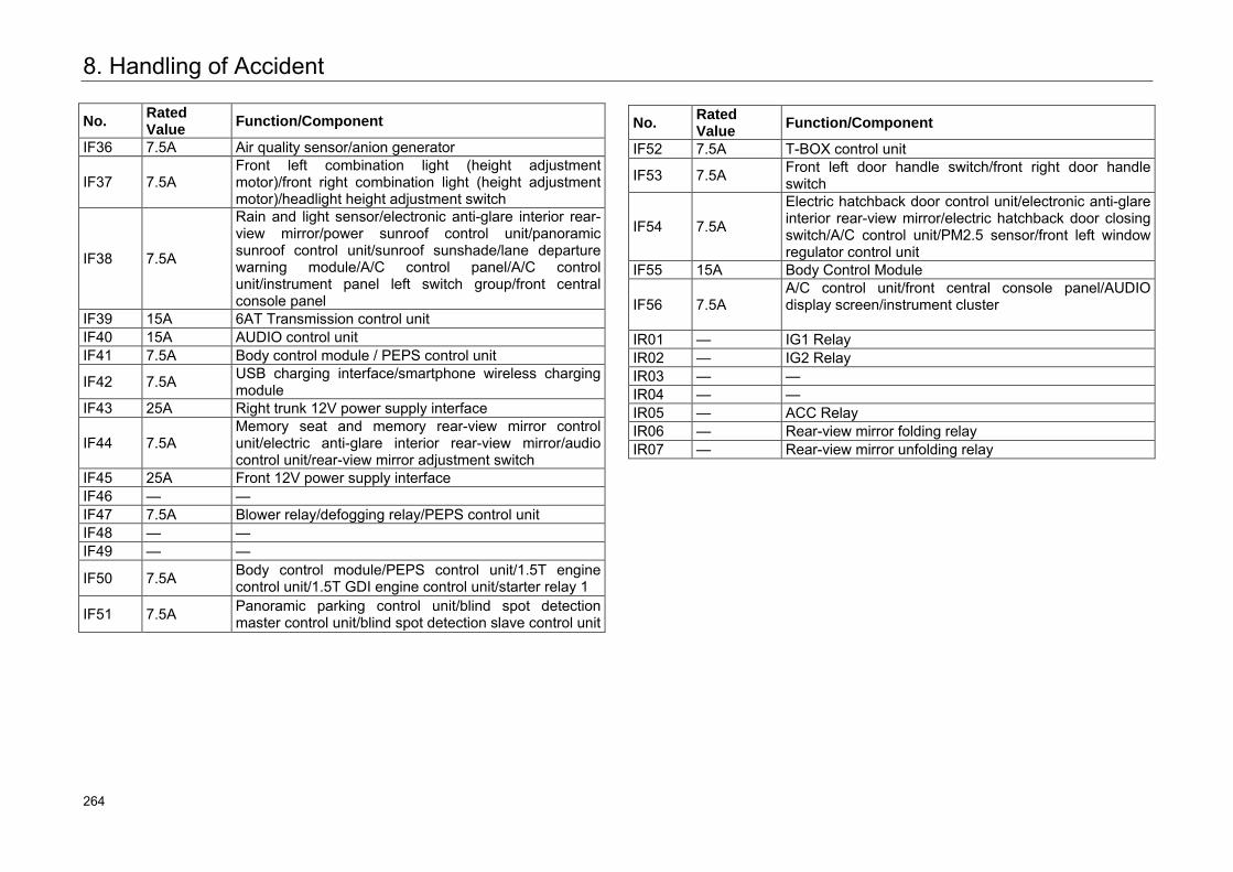
8. Handling of Accident
No. Rated Value Function/Component
IF36 7.5A Air quality sensor/anion generator
IF37 7.5A Front left combination light (height adjustment motor)/front right combination light (height adjustment motor)/headlight height adjustment switch
IF38 7.5A
Rain and light sensor/electronic anti-glare interior rear-view mirror/power sunroof control unit/panoramic sunroof control unit/sunroof sunshade/lane departure warning module/A/C control panel/A/C control unit/instrument panel left switch group/front central console panel
IF39 15A 6AT Transmission control unit IF40 15A AUDIO control unit IF41 7.5A Body control module / PEPS control unit
IF42 7.5A USB charging interface/smartphone wireless charging module
IF43 25A Right trunk 12V power supply interface
IF44 7.5A Memory seat and memory rear-view mirror control unit/electric anti-glare interior rear-view mirror/audio control unit/rear-view mirror adjustment switch
IF45 25A Front 12V power supply interface IF46 — — IF47 7.5A Blower relay/defogging relay/PEPS control unit IF48 — — IF49 — —
IF50 7.5A Body control module/PEPS control unit/1.5T engine control unit/1.5T GDI engine control unit/starter relay 1
IF51 7.5A Panoramic parking control unit/blind spot detection master control unit/blind spot detection slave control unit
No. Rated Value Function/Component
IF52 7.5A T-BOX control unit
IF53 7.5A Front left door handle switch/front right door handle switch
IF54 7.5A
Electric hatchback door control unit/electronic anti-glare interior rear-view mirror/electric hatchback door closing switch/A/C control unit/PM2.5 sensor/front left window regulator control unit
IF55 15A Body Control Module
IF56 7.5A A/C control unit/front central console panel/AUDIO display screen/instrument cluster
IR01 — IG1 Relay IR02 — IG2 Relay IR03 — — IR04 — — IR05 — ACC Relay IR06 — Rear-view mirror folding relay IR07 — Rear-view mirror unfolding relay
308 264
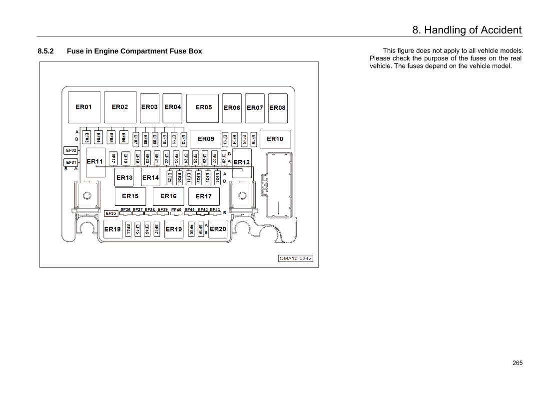
8. Handling of Accident
8.5.2 Fuse in Engine Compartment Fuse Box
This figure does not apply to all vehicle models. Please check the purpose of the fuses on the real vehicle. The fuses depend on the vehicle model.
309 265
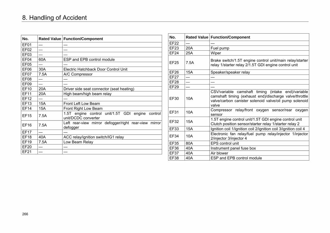
8. Handling of Accident
No. Rated Value Function/Component
EF01 — — EF02 — — EF03 — — EF04 60A ESP and EPB control module EF05 — — EF06 30A Electric Hatchback Door Control Unit EF07 7.5A A/C Compressor EF08 — — EF09 — — EF10 20A Driver side seat connector (seat heating) EF11 20A High beam/high beam relay EF12 — — EF13 15A Front Left Low Beam EF14 15A Front Right Low Beam
EF15 7.5A 1.5T engine control unit/1.5T GDI engine control unit/DCDC converter
EF16 7.5A Left rear-view mirror defogger/right rear-view mirror defogger
EF17 — — EF18 40A ACC relay/ignition switch/IG1 relay EF19 7.5A Low Beam Relay EF20 — — EF21 — —
No. Rated Value Function/Component
EF22 — — EF23 20A Fuel pump EF24 25A Wiper
EF25 7.5A Brake switch/1.5T engine control unit/main relay/starter relay 1/starter relay 2/1.5T GDI engine control unit
EF26 15A Speaker/speaker relay EF27 — — EF28 — — EF29 — —
EF30 10A
CSV/variable camshaft timing (intake end)/variable camshaft timing (exhaust end)/discharge valve/throttle valve/carbon canister solenoid valve/oil pump solenoid valve
EF31 10A Compressor relay/front oxygen sensor/rear oxygen sensor
EF32 15A 1.5T engine control unit/1.5T GDI engine control unit Clutch position sensor/starter relay 1/starter relay 2
EF33 15A Ignition coil 1/ignition coil 2/ignition coil 3/ignition coil 4
EF34 10A Electronic fan relay/fuel pump relay/injector 1/injector 2/injector 3/injector 4
EF35 80A EPS control unit EF36 40A Instrument panel fuse box EF37 40A Air blower EF38 40A ESP and EPB control module
310 266
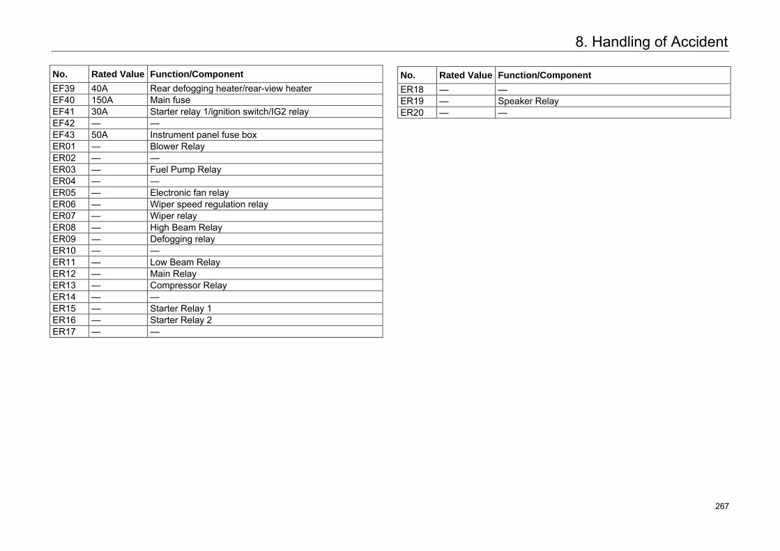
8. Handling of Accident
No. Rated Value Function/Component
EF39 40A Rear defogging heater/rear-view heater EF40 150A Main fuse EF41 30A Starter relay 1/ignition switch/IG2 relay EF42 — — EF43 50A Instrument panel fuse box ER01 — Blower Relay ER02 — — ER03 — Fuel Pump Relay ER04 — — ER05 — Electronic fan relay ER06 — Wiper speed regulation relay ER07 — Wiper relay ER08 — High Beam Relay ER09 — Defogging relay ER10 — — ER11 — Low Beam Relay ER12 — Main Relay ER13 — Compressor Relay ER14 — — ER15 — Starter Relay 1 ER16 — Starter Relay 2 ER17 — —
No. Rated Value Function/Component
ER18 — — ER19 — Speaker Relay ER20 — —
311 267
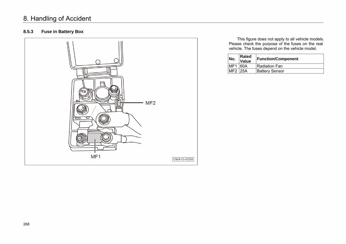
8. Handling of Accident
8.5.3 Fuse in Battery Box
This figure does not apply to all vehicle models. Please check the purpose of the fuses on the real vehicle. The fuses depend on the vehicle model.
No. Rated Value Function/Component
MF1 60A Radiation Fan MF2 25A Battery Sensor
312 268
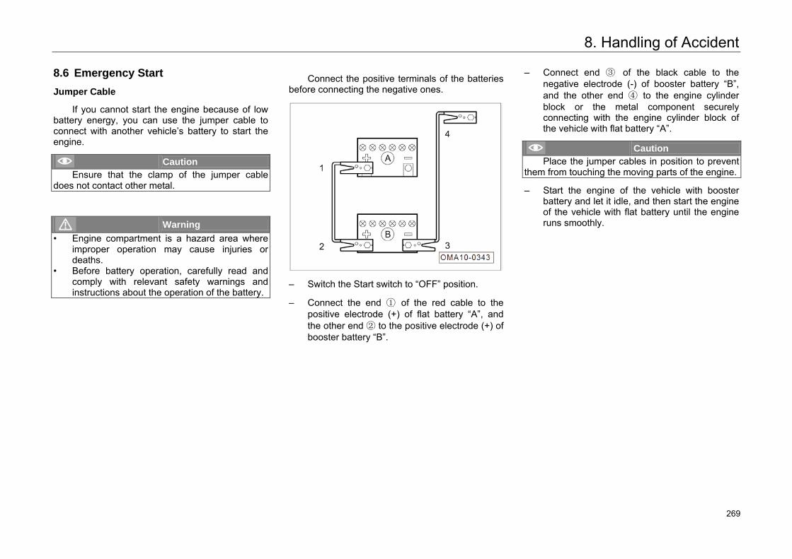
8. Handling of Accident
8.6 Emergency Start
Jumper Cable
If you cannot start the engine because of low battery energy, you can use the jumper cable to connect with another vehicle’s battery to start the engine.
Caution Ensure that the clamp of the jumper cable
does not contact other metal.
Warning • Engine compartment is a hazard area where
improper operation may cause injuries or deaths.
• Before battery operation, carefully read and comply with relevant safety warnings and instructions about the operation of the battery.
Connect the positive terminals of the batteries before connecting the negative ones.
– Switch the Start switch to “OFF” position.
– Connect the end ① of the red cable to the positive electrode (+) of flat battery “A”, and the other end ② to the positive electrode (+) of booster battery “B”.
– Connect end ③ of the black cable to the negative electrode (-) of booster battery “B”, and the other end ④ to the engine cylinder block or the metal component securely connecting with the engine cylinder block of the vehicle with flat battery “A”.
Caution Place the jumper cables in position to prevent
them from touching the moving parts of the engine.
– Start the engine of the vehicle with booster battery and let it idle, and then start the engine of the vehicle with flat battery until the engine runs smoothly.
313 269
8. Handling of Accident
Warning • Do not remove the jumper cables until the
headlights have been turned off.• Turn on the air blower and rear windshield
heater in the vehicle with flat battery to reduce the voltage peak resulting from removing the cables.
• Once your engine is running, disconnect thejumper cable in reverse sequence.
Warning A battery can explode if you cannot use the
jumper cable properly, seriously injuring anyone nearby. • Make sure the voltage of the booster battery is
equal to that of the flat battery, and the capacity of the booster battery is similar to thatof the flat battery. Otherwise, it may causeexplosion.
• Keep open flames away from the battery to avoid explosion.
• Do not connect the negative cable to thenegative electrode of the flat battery directly.Make sure there is no static near the battery.Otherwise, combustible gas produced by thebattery can be ignited by sparks, causingexplosion.
• Do not connect the negative cable to the fuelsystem component or brake pipe. During operation, do not face the battery to avoid acid burns.
314 270
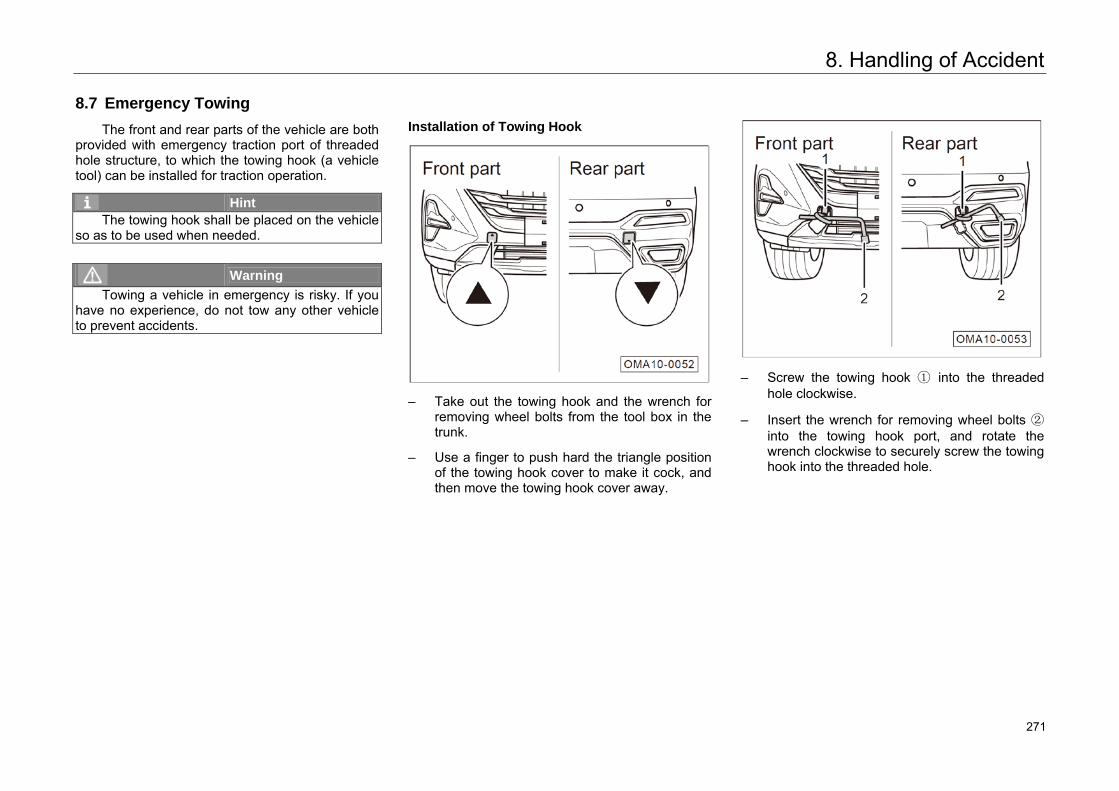
8. Handling of Accident
8.7 Emergency Towing
The front and rear parts of the vehicle are both provided with emergency traction port of threaded hole structure, to which the towing hook (a vehicle tool) can be installed for traction operation.
Hint The towing hook shall be placed on the vehicle
so as to be used when needed.
Warning Towing a vehicle in emergency is risky. If you
have no experience, do not tow any other vehicle to prevent accidents.
Installation of Towing Hook
– Take out the towing hook and the wrench forremoving wheel bolts from the tool box in thetrunk.
– Use a finger to push hard the triangle positionof the towing hook cover to make it cock, andthen move the towing hook cover away.
– Screw the towing hook ① into the threadedhole clockwise.
– Insert the wrench for removing wheel bolts ②into the towing hook port, and rotate thewrench clockwise to securely screw the towinghook into the threaded hole.
315 271
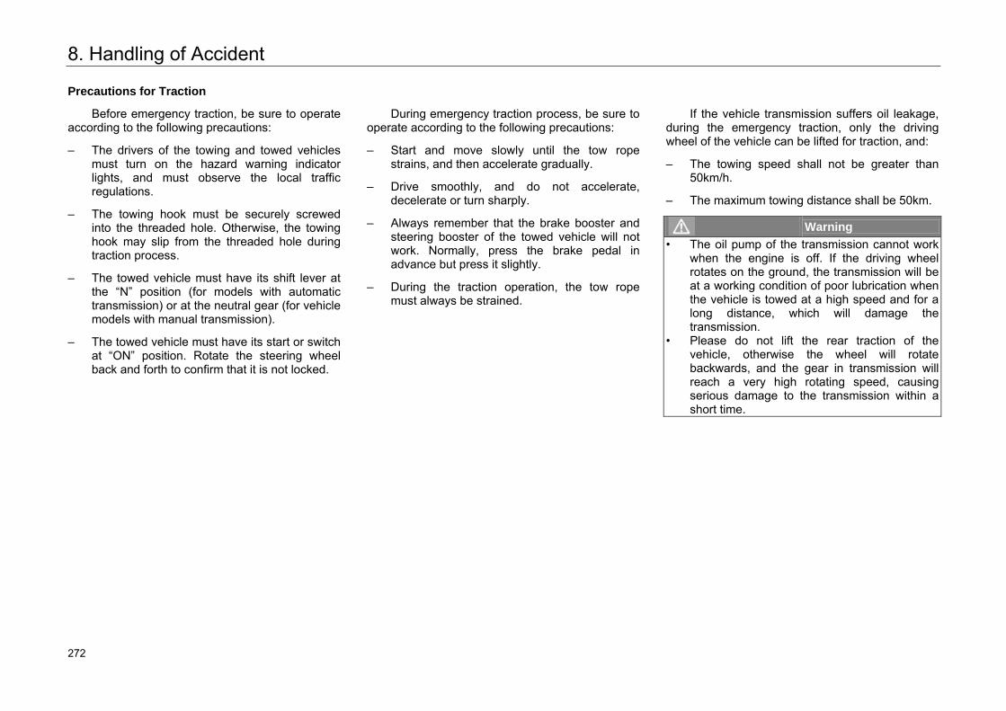
8. Handling of Accident
Precautions for Traction
Before emergency traction, be sure to operate according to the following precautions:
– The drivers of the towing and towed vehiclesmust turn on the hazard warning indicatorlights, and must observe the local trafficregulations.
– The towing hook must be securely screwedinto the threaded hole. Otherwise, the towinghook may slip from the threaded hole duringtraction process.
– The towed vehicle must have its shift lever atthe “N” position (for models with automatictransmission) or at the neutral gear (for vehiclemodels with manual transmission).
– The towed vehicle must have its start or switchat “ON” position. Rotate the steering wheelback and forth to confirm that it is not locked.
During emergency traction process, be sure to operate according to the following precautions:
– Start and move slowly until the tow ropestrains, and then accelerate gradually.
– Drive smoothly, and do not accelerate,decelerate or turn sharply.
– Always remember that the brake booster andsteering booster of the towed vehicle will notwork. Normally, press the brake pedal inadvance but press it slightly.
– During the traction operation, the tow ropemust always be strained.
If the vehicle transmission suffers oil leakage, during the emergency traction, only the driving wheel of the vehicle can be lifted for traction, and:
– The towing speed shall not be greater than50km/h.
– The maximum towing distance shall be 50km.
Warning • The oil pump of the transmission cannot work
when the engine is off. If the driving wheelrotates on the ground, the transmission will be at a working condition of poor lubrication when the vehicle is towed at a high speed and for along distance, which will damage the transmission.
• Please do not lift the rear traction of thevehicle, otherwise the wheel will rotatebackwards, and the gear in transmission will reach a very high rotating speed, causing serious damage to the transmission within a short time.
316 272
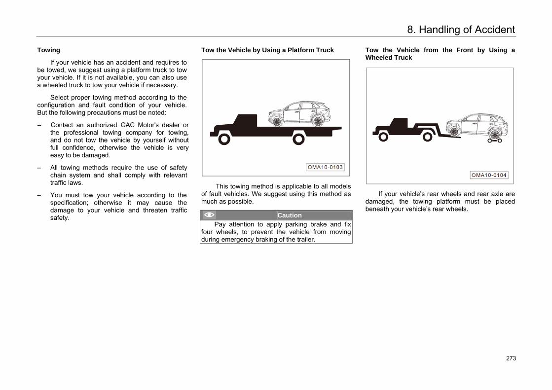
8. Handling of Accident
Towing
If your vehicle has an accident and requires to be towed, we suggest using a platform truck to tow your vehicle. If it is not available, you can also use a wheeled truck to tow your vehicle if necessary.
Select proper towing method according to the configuration and fault condition of your vehicle. But the following precautions must be noted:
– Contact an authorized GAC Motor's dealer orthe professional towing company for towing,and do not tow the vehicle by yourself withoutfull confidence, otherwise the vehicle is veryeasy to be damaged.
– All towing methods require the use of safetychain system and shall comply with relevanttraffic laws.
– You must tow your vehicle according to thespecification; otherwise it may cause thedamage to your vehicle and threaten trafficsafety.
Tow the Vehicle by Using a Platform Truck
This towing method is applicable to all models of fault vehicles. We suggest using this method as much as possible.
Caution Pay attention to apply parking brake and fix
four wheels, to prevent the vehicle from moving during emergency braking of the trailer.
Tow the Vehicle from the Front by Using a Wheeled Truck
If your vehicle’s rear wheels and rear axle are damaged, the towing platform must be placed beneath your vehicle’s rear wheels.
317 273
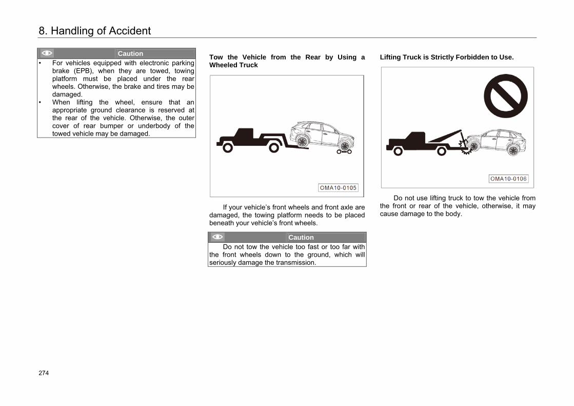
8. Handling of Accident
Caution • For vehicles equipped with electronic parking
brake (EPB), when they are towed, towingplatform must be placed under the rearwheels. Otherwise, the brake and tires may be damaged.
• When lifting the wheel, ensure that anappropriate ground clearance is reserved atthe rear of the vehicle. Otherwise, the outer cover of rear bumper or underbody of thetowed vehicle may be damaged.
Tow the Vehicle from the Rear by Using a Wheeled Truck
If your vehicle’s front wheels and front axle are damaged, the towing platform needs to be placed beneath your vehicle’s front wheels.
Caution Do not tow the vehicle too fast or too far with
the front wheels down to the ground, which will seriously damage the transmission.
Lifting Truck is Strictly Forbidden to Use.
Do not use lifting truck to tow the vehicle from the front or rear of the vehicle, otherwise, it may cause damage to the body.
318 274
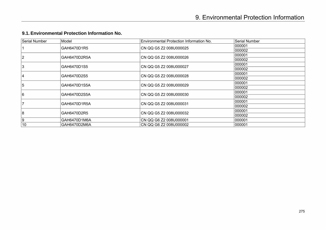
9. Environmental Protection Information
9.1. Environmental Protection Information No.
Serial Number Model Environmental Protection Information No. Serial Number
1 GAH6470D1R5 CN QQ G5 Z2 008U000025 000001 000002
2 GAH6470D2R5A CN QQ G5 Z2 008U000026 000001 000002
3 GAH6470D1S5 CN QQ G5 Z2 008U000027 000001 000002
4 GAH6470D2S5 CN QQ G5 Z2 008U000028 000001 000002
5 GAH6470D1S5A CN QQ G5 Z2 008U000029 000001 000002
6 GAH6470D2S5A CN QQ G5 Z2 008U000030 000001 000002
7 GAH6470D1R5A CN QQ G5 Z2 008U000031 000001 000002
8 GAH6470D2R5 CN QQ G5 Z2 008U000032 000001 000002
9 GAH6470D1M6A CN QQ G6 Z2 008U000001 000001 10 GAH6470D2M6A CN QQ G6 Z2 008U000002 000001
319 275
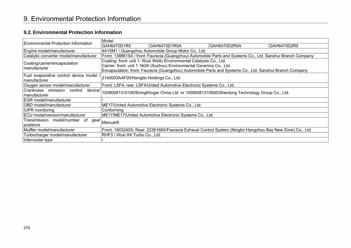
9. Environmental Protection Information
9.2. Environmental Protection Information
Environmental Protection Information Model GAH6470D1R5 GAH6470D1R5A GAH6470D2R5A GAH6470D2R5
Engine model/manufacturer 4A15M1 / Guangzhou Automobile Group Motor Co., Ltd. Catalytic converter model/manufacturer Front: 1388615X / front: Faurecia (Guangzhou) Automobile Parts and Systems Co., Ltd. Sanshui Branch Company
Coating/carrier/encapsulation manufacturer
Coating: front: unit 1: Wuxi Weifu Environmental Catalysts Co., Ltd. Carrier: front: unit 1: NGK (Suzhou) Environmental Ceramics Co., Ltd. Encapsulation: front: Faurecia (Guangzhou) Automobile Parts and Systems Co., Ltd. Sanshui Branch Company
Fuel evaporative control device model / manufacturer 2140003AAF00/Hengbo Holdings Co., Ltd.
Oxygen sensor model/manufacturer Front: LSF4; rear: LSF4/United Automotive Electronic Systems Co., Ltd. Crankcase emission control device/ manufacturer 10090081310100/ElringKlinger China Ltd. or 10090081310000/Shentong Technology Group Co., Ltd.
EGR model/manufacturer / OBD model/manufacturer ME17/United Automotive Electronic Systems Co., Ltd. IUPR monitoring Conforming ECU model/version/manufacturer ME17/ME17/United Automotive Electronic Systems Co., Ltd. Transmission model/number of gear positions Manual/6
Muffler model/manufacturer Front: 1903240X; Rear: 2236168X/Faurecia Exhaust Control System (Ningbo Hangzhou Bay New Zone) Co., Ltd. Turbocharger model/manufacturer RHF3 / Wuxi IHI Turbo Co., Ltd. Intercooler type /
320 276
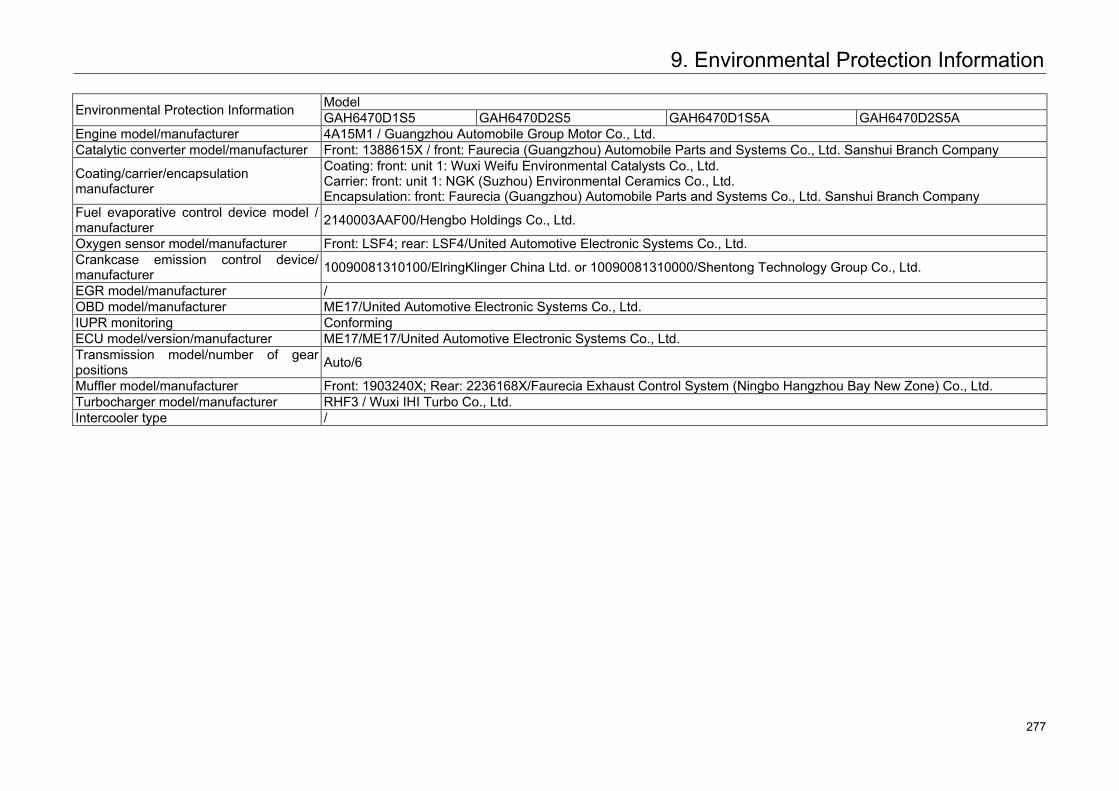
9. Environmental Protection Information
Environmental Protection Information Model GAH6470D1S5 GAH6470D2S5 GAH6470D1S5A GAH6470D2S5A
Engine model/manufacturer 4A15M1 / Guangzhou Automobile Group Motor Co., Ltd. Catalytic converter model/manufacturer Front: 1388615X / front: Faurecia (Guangzhou) Automobile Parts and Systems Co., Ltd. Sanshui Branch Company
Coating/carrier/encapsulation manufacturer
Coating: front: unit 1: Wuxi Weifu Environmental Catalysts Co., Ltd. Carrier: front: unit 1: NGK (Suzhou) Environmental Ceramics Co., Ltd. Encapsulation: front: Faurecia (Guangzhou) Automobile Parts and Systems Co., Ltd. Sanshui Branch Company
Fuel evaporative control device model / manufacturer 2140003AAF00/Hengbo Holdings Co., Ltd.
Oxygen sensor model/manufacturer Front: LSF4; rear: LSF4/United Automotive Electronic Systems Co., Ltd. Crankcase emission control device/ manufacturer 10090081310100/ElringKlinger China Ltd. or 10090081310000/Shentong Technology Group Co., Ltd.
EGR model/manufacturer / OBD model/manufacturer ME17/United Automotive Electronic Systems Co., Ltd. IUPR monitoring Conforming ECU model/version/manufacturer ME17/ME17/United Automotive Electronic Systems Co., Ltd. Transmission model/number of gear positions Auto/6
Muffler model/manufacturer Front: 1903240X; Rear: 2236168X/Faurecia Exhaust Control System (Ningbo Hangzhou Bay New Zone) Co., Ltd. Turbocharger model/manufacturer RHF3 / Wuxi IHI Turbo Co., Ltd. Intercooler type /
321 277
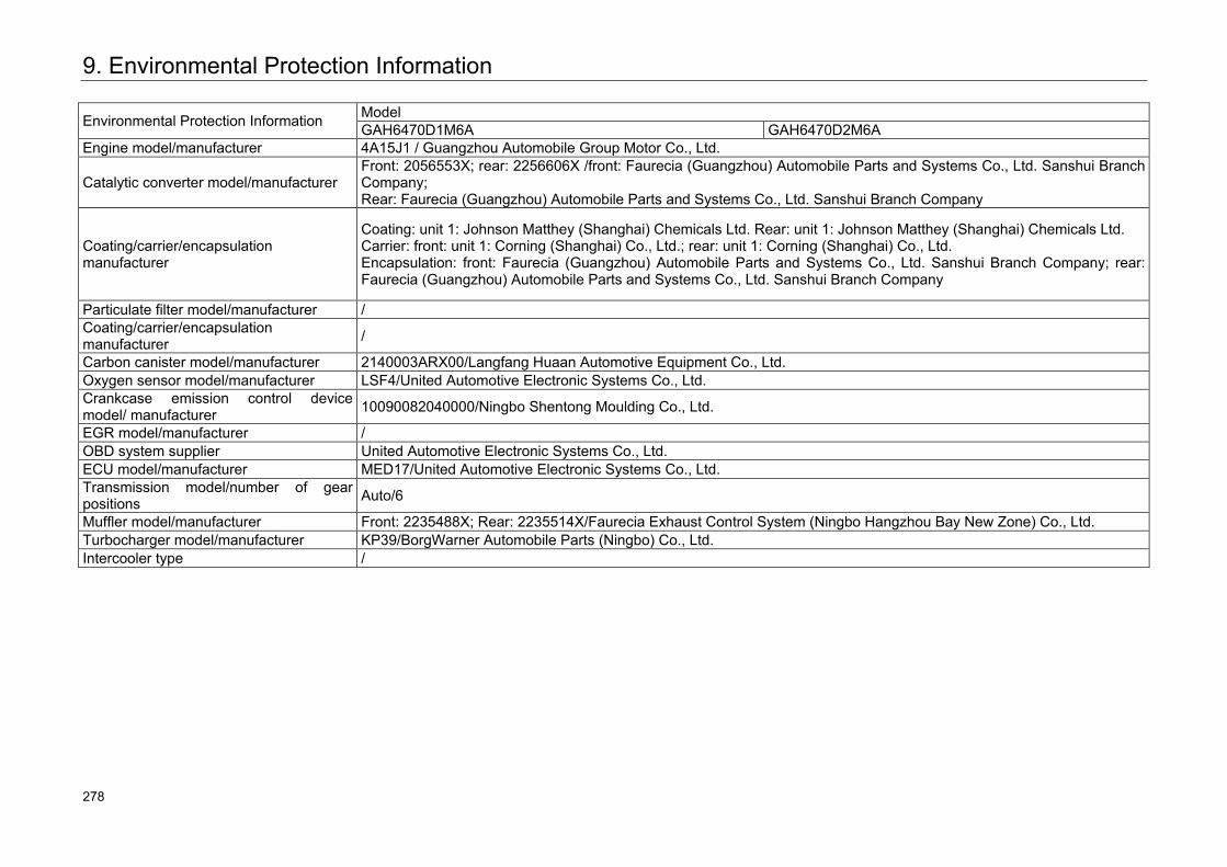
9. Environmental Protection Information
Environmental Protection Information Model GAH6470D1M6A GAH6470D2M6A
Engine model/manufacturer 4A15J1 / Guangzhou Automobile Group Motor Co., Ltd.
Catalytic converter model/manufacturer Front: 2056553X; rear: 2256606X /front: Faurecia (Guangzhou) Automobile Parts and Systems Co., Ltd. Sanshui Branch Company; Rear: Faurecia (Guangzhou) Automobile Parts and Systems Co., Ltd. Sanshui Branch Company
Coating/carrier/encapsulation manufacturer
Coating: unit 1: Johnson Matthey (Shanghai) Chemicals Ltd. Rear: unit 1: Johnson Matthey (Shanghai) Chemicals Ltd. Carrier: front: unit 1: Corning (Shanghai) Co., Ltd.; rear: unit 1: Corning (Shanghai) Co., Ltd. Encapsulation: front: Faurecia (Guangzhou) Automobile Parts and Systems Co., Ltd. Sanshui Branch Company; rear: Faurecia (Guangzhou) Automobile Parts and Systems Co., Ltd. Sanshui Branch Company
Particulate filter model/manufacturer / Coating/carrier/encapsulation manufacturer /
Carbon canister model/manufacturer 2140003ARX00/Langfang Huaan Automotive Equipment Co., Ltd. Oxygen sensor model/manufacturer LSF4/United Automotive Electronic Systems Co., Ltd. Crankcase emission control device model/ manufacturer 10090082040000/Ningbo Shentong Moulding Co., Ltd.
EGR model/manufacturer / OBD system supplier United Automotive Electronic Systems Co., Ltd. ECU model/manufacturer MED17/United Automotive Electronic Systems Co., Ltd. Transmission model/number of gear positions Auto/6
Muffler model/manufacturer Front: 2235488X; Rear: 2235514X/Faurecia Exhaust Control System (Ningbo Hangzhou Bay New Zone) Co., Ltd. Turbocharger model/manufacturer KP39/BorgWarner Automobile Parts (Ningbo) Co., Ltd. Intercooler type /
322 278
This Manual describes information related to configurations, functions, performance parameters and product schematic drawings of vehicles from GAC MOTOR. Its contents are effective when printing is allowed. But actual vehicle configurations and functions are subject to actually delivered vehicles. If there is any difference between the product schematic drawing and actual vehicle, the actual one should prevail.
GAC MOTOR reserves the right to alter, supplement or terminate the contents or technical specifications in this Manual without further notification.
All copyright is reserved by GAC MOTOR. Without written permission by GAC MOTOR, no printing and extracting of all or part contents of this Manual is allowed.
279
Related Documents