March 2021 – Rev. 1.001 GROWLINK™ CENTRAL FEED SYSTEM MANUAL

Welcome message from author
This document is posted to help you gain knowledge. Please leave a comment to let me know what you think about it! Share it to your friends and learn new things together.
Transcript

March 2021 – Rev. 1.001
GROWLINK™ CENTRAL FEED SYSTEM
MANUAL

©2021 Growlink This document contains information that is proprietary Growlink.
Information contained herein may be used only for the benefit of Growlink Duplication or dissemination for any other purpose is prohibited.

i Growlink™ CFS Installation Manual May 6, 2020 – Rev.1.001
TABLE OF CONTENTS
Introduction ......................................................................................................................................1
Automated Plug & Play Fertigation ......................................................................................................... 1
General Instructions ................................................................................................................................. 1
Safety Instructions .................................................................................................................................... 1
Using Acid/Chemicals ............................................................................................................................... 2
On Site Preparation ............................................................................................................................3
Electrical Preparation ............................................................................................................................... 3
System Requirements ............................................................................................................................... 3
Equipment & Materials Included ............................................................................................................. 3
Installation ........................................................................................................................................4
Unpacking and Placement ........................................................................................................................ 4
Mounting Equipment................................................................................................................................ 4
System Components ..........................................................................................................................6
Input .......................................................................................................................................................... 6
Flow Meter ................................................................................................................................................ 7
Injectors & Pumps ..................................................................................................................................... 7
Check Valves ............................................................................................................................................. 8
Maintenance ............................................................................................................................................. 9
Sensors ...................................................................................................................................................... 9
Fertigation System Description ......................................................................................................... 11
Dosing Pumps ......................................................................................................................................... 11
Features .................................................................................................................................................. 12
How to Prime the Dosing Pumps ........................................................................................................... 14
Control Panel ................................................................................................................................... 14
Create Account/Download Application ............................................................................................. 16
Create Account ....................................................................................................................................... 16
Growlink portal ....................................................................................................................................... 17

ii Growlink™ CFS System Installation Manual March 2021 – Rev. 1.001
Dashboard ............................................................................................................................................... 17
Calibration ............................................................................................................................................... 20
Configure Modules ................................................................................................................................. 24
Dosing Recipes ........................................................................................................................................ 25
Rules ........................................................................................................................................................ 26
Manual Task ............................................................................................................................................ 28
Using The Growlink™ Application ..................................................................................................... 30

1 Growlink™ CFS System Installation Manual May 6, 2020 – Rev. 100.1
INTRODUCTION
AUTOMATED PLUG & PLAY FERTIGATION
The Growlink™ Fertigation Skid comes pre-assembled and is easy to use. It features an in-line injection
system for both direct feeds, and batch tank applications. Our upgraded fertigation system allows you to
prepare, stabilize, and deliver user-defined recipes direct to plants or to specific batch tanks while
enabling you to automate this process with tank level sensors, moisture sensors and batch schedules.
Systems are customized to customer specific flow rates, and feed times.
GENERAL INSTRUCTIONS
• Fertigation System will be shipped pre-assembled.
• Installation is done by the customer provided electricians and plumbers.
• Install on a wall mount by using standard Unistrut. Refer to Mounting Equipment section.
• It can take up to two to three technicians to lift the fertigation system from the palette and to
hang on the wall.
• Refer to your supervisor if problems occur during installation procedure.
• Do not apply force or pressure on components during the installation procedure.
• Verify that field components work properly.
• Perform manual test to make sure that all elements (valves, pumps, filters, sensors, etc.)
function properly.
Electricity
• Conduit is run directly into the side or bottom of the panel to bring in the power directly to the
electrical connections.
• The Growlink™ CFS skid requires a 120V 20A dedicated circuit.
SAFETY INSTRUCTIONS
• All safety regulations must be applied.
• Electrical installation must be performed by a licensed electrician only.
• The electrical installation must comply with the local safety standards and regulations.
• Protection provided by the equipment can be impaired if the equipment is used in a manner
other than that specified by the manufacturer.
WARNING
In agricultural environment – always wear protective footwear.

2 Growlink™ CFS System Installation Manual March 2021 – Rev. 1.001
USING ACID/CHEMICALS
ACID HAZARD
When using acid, always observe the acid manufacturer’s safety instructions!
CAUTION
Always use protective equipment, gloves, and goggles when handling fertilizers, acid, and other
chemicals!
ATTENTION
When dosing acid, respect the concentration of the acid used*. Refer to Table 1 - Dosing Acid.
WARNING
Exceeding the recommended acid concentrations will damage the dosing channels.
WARNING
Substances such as chemicals for pest/disease control might be corrosive and damage the Growlink™
fertigation system. When using any substance other than fertilizers or acids, always observe the
manufacturer’s instructions for corrosivity. In case of any doubt, consult your Growlink™ representative.

3 Growlink™ CFS System Installation Manual March 2021 – Rev. 1.001
ON SITE PREPARATION
ELECTRICAL PREPARATION
CAUTION
Only licensed electricians are permitted to perform electrical installations.
ATTENTION
Make sure the electrical supply capacity is in accordance with the electrical characteristics of the
Growlink™ CFS system.
Have a licensed electrician check that electricity is being supplied to the Growlink™ fertigation system
and that all the electrical components are properly connected. Refer to the Control Panel section.
System Requirements
System Requirements include: • Electrical - 120VAC 20Amp service • Flow Rate specified per customer site. • Water pressure 35-65 PSI
EQUIPMENT & MATERIALS INCLUDED
• Growlink™ Fertigation System (pre-assembled)
o Components include:
▪ In-line Injector ports
▪ High Resolution Flow Meter
▪ Mixing Chambers
▪ Manual Ball Valves
▪ Sensors (pH x 2, TDS)
▪ Dosing Pumps
• Antennas – Wi-Fi and local RF
• Growlink™ CFS System Installation Manual
• pH Probe Data Sheet
• Signet EC Probe Data Sheet
• HE Anderson pneumatic driven injection pumps
• Growlink™ Core Controller
• Nutrient Expansion Board
• 16-Channel Expansion Board

4 Growlink™ CFS System Installation Manual March 2021 – Rev. 1.001
INSTALLATION
UNPACKING AND PLACEMENT
Place the Growlink™ CFS system close to the irrigation system install area and carefully open the
packaging.
Screw the antennas onto the threaded SMA cable ends on top of the Growlink™ panel
MOUNTING EQUIPMENT
Fertigation Skid Mounting Instructions
Parts Used In Installation:
2x Unistrut Bars (6.5’ long) Home Depot: SKU #: 235918
3x Strut Channel Brackets McMaster-Carr: Item #: 33125T435
3x Nylon Strut Cone Nuts (1/2” thread) Home Depot: SKU #: 1002151010
3x Bolts (1/2” thread) Home Depot: SKU #: 356297
Directions:
1. The CFS mounting height recommendation is 2’ to 4’ off the ground. Using a piece of standard Unistrut (1 5/8” x 1 5/8”), cut it to a length of 6.5 feet long. This length matches the fertigation skid’s top wall support bar. Identify the vertical mounting position on the wall for the Unistrut, keeping in mind that the fertigation skid’s upper support bar is going to be resting on top of this. You also need to make sure the Unistrut is mounted to at least 4x wall studs – the more the better. Use 3/8” lag bolts (3.5” long minimum), along with fender washers to secure the Unistrut to wood studs. If mounting to metal studs, you will need to use large toggle bolts instead.

5 Growlink™ CFS System Installation Manual March 2021 – Rev. 1.001
2. Bolt a minimum of 3x strut channel brackets to the Unistrut using ½” bolts and ½” nylon strut cone nuts:
3. With the help of several people, lift the fertigation skid so the upper wall mount bar goes up and over the brackets, and rests on top of the Unistrut. Once you are happy with the horizontal position of the frame, you can then slide the outside brackets outwards until touching the sides of the support frame and re-tighten. This will prevent horizontal movement of the fertigation skid.
4. For additional support, mount a 2nd Unistrut under the fertigation skids bottom wall support bar, in the same way as described above:

6 Growlink™ CFS System Installation Manual March 2021 – Rev. 1.001
.
CAUTION
Failure to provide adequate structural strength for this mounting system can result in serious personal
injury or damage to equipment. It is the installer’s responsibility to make sure the structure to which this
mounting system is attached can support five times the combined weight of equipment.
Using two or three technicians, lift the frame from the pallet and place on the support brackets
anchored to the wall.
Weight
The weight of the Growlink feed system varies according selected pump system. The total weight of the
complete system is approximately 500-700 LBS depending on how many injectors are in place. This does
not include water weight.
FERTIGATION SYSTEM OPERATION
INPUT
Fresh water is brought into the top of the 1”-1.5” inlet.
Make certain the union seal is properly secure from the water supply, to prevent leaks.

7 Growlink™ CFS System Installation Manual March 2021 – Rev. 1.001
FLOW METER
A flow meter measures the amount of flow.
Growlink™ uses the Signet 2536 Rotor-X model.
Based on the manufacturer, the flow meter requires a straight run of 30” of pipe (no
elbows)installed directly before the flow meter.
CAUTION
EC and pH sensors must never be exposed to pressure greater than 6 bars (87PSI).
INJECTORS & PUMPS
A
B
C

8 Growlink™ CFS System Installation Manual March 2021 – Rev. 1.001
A Injectors This is where each of the nutrients are injected inline.
B Pumps Refer to CFS System Description – Dosing Pumps section.
C Mixing Chambers
As the water flows through, it goes around and passes through the mixing chambers to homogenize the various nutrients.
D Shut Off Valve Used to shut off water to Fertigation skid during maintenance, service, and/or calibration of probes when needed
E Drain Valve Used to drain the water to take out, service and calibrate the sensors when needed.
CHECK VALVES
Check valves are used to ensure pressurized water does not flow back into the pumps.
The suction line connected to the bottom of the dosing pumps goes into the stock nutrient tanks.
WARNING
D
E

9 Growlink™ CFS System Installation Manual March 2021 – Rev. 1.001
Increasing the water pressure is not an automatic solution for all irrigation coverage problems. Your
irrigation system must also be able to handle the increased water pressure and flow as well. Creating
too much water pressure can do serious and expensive damage to an irrigation system.
The recommended water pressure is under 35-65 PSI.
MAINTENANCE
To prevent failures and extend the life cycle of the Growlink™ fertigation system, regular maintenance
must be carried out by the user, such as flushing the system with fresh water, periodic rinsing of
chambers and calibration of the EC and PH sensors. Calibrating the pH probe every 3-6 months and the
EC probe every year are the suggested regular maintenance intervals.
CAUTION
Make sure to shut off the water valves before removing the Mixing Chambers. When removing, be
mindful of the water stored inside the chambers.
Pump Maintenance
Normally the pumps should require little maintenance. This, however, depends on the quality and
cleanliness of the chemical being pumped.
● The pumper should be inspected at regular intervals for proper operation and leaks.
● Check the suction and discharge valves for cleanliness, chemical attack, and scale build-up.
● At some time the elastomer parts(O-rings and diaphragms) will have to be replaced.
● Periodically shut off the water and remove and inspect the injection point fitting. Reaction of the
chemical being injected with the chemicals already in the water can sometimes cause scale to form. This
can restrict or even completely stop chemical flow. If scale is found, clean it off thoroughly and establish
a regular schedule for checking the fittings.
● Check to be sure all pumpers are properly primed after completing these checks and putting the
feeder back into service.
SENSORS
The Growlink™ CFS uses the Signet 2850 Conductivity/Resistivity Sensor & the Signet 2751 pH/ORP
Smart Sensor

10 Growlink™ CFS System Installation Manual March 2021 – Rev. 1.001
• EC (total dissolve solvent) sensors measure the concentration of nutrients.
• Two pH sensors indicate the pH level of the water. Two pH probes are for redundancy, as pH
probes can fail, and it is important to have the correct pH water going to the plants.
Safety Information
1. Depressurize and vent system prior to installation or removal.
2. Confirm chemical compatibility before use.
3. Do not exceed maximum temperature/pressure specifications. Refer to the Signet EC Probe
Data Sheet.
4. Wear safety goggles or face shield during installation/service.
5. Do not alter product construction.
6. When using chemicals or solvents, care should be taken and appropriate eye, face, hand, body,
and/or respiratory protection should be used.
Operating Range
The 2850 is capable of measuring conductivity and resistivity values between 0-10 EC. Refer to the
Signet EC Probe Data Sheet for the Operating Range Chart and the Field Selectable Ranges.
Specifications
For General, Materials, Electrical, Max. Temperature/Pressure Rating, Shipping Weight, and Standards
and Approvals specifications, refer to Signet EC Probe Data Sheet.
Maintenance
The 2850 requires periodic maintenance.
EC pH 1 pH 2

11 Growlink™ CFS System Installation Manual March 2021 – Rev. 1.001
• Coatings on the electrode may cause slow response or drift.
• Clean surfaces with a mild detergent and a non-abrasive brush or cotton swab.
FERTIGATION SYSTEM DESCRIPTION
DOSING PUMPS
A,P & H are the range of innovative skid mounted pneumatic driven dosing pumps that HE Anderson
has designed following many years of experience working with its customers worldwide. These
multifunctional pneumatic driven dosing pumps maintain outstanding precision, reliability, versatility,
and performance.
• The dosing pumps are pre-wired.
• Acid or nutrients are pumped into the water from the dosing pumps. Generally, the first set of
dosing pumps are acid, which control the pH up or pH down.
• System pressure, line pressure at 40-65 PSI is recommended.

12 Growlink™ CFS System Installation Manual March 2021 – Rev. 1.001
AIR COMPRESSOR
H.E Anderson pumpers are pneumatically powered. This requires a customer provided air compressor.
Recommended model: Ingersoll Rand Ingersoll Rand 48671770 SS5L5 High Capacity Air
Compressor.
Note: Make sure to check oil/lubricant levels of compressor before, and during operation.
Specification Description
Brand Ingersoll Rand – SS5L5, 5 HP, 60 Gal.
Product Weight 310 lb.
Product Length 20 in.
Air Outlet Size ½ in.
CFM @ 90 PSI 18.1
Compressor Type Oil Lubricated
Drain System Manual
Duty Cycle 100%
Grade Commercial
Lubrication Type Oil
Max. Operating Pressure 135 PSI
Phase Single
Power Type Electric
Product Height 71 in.
Product Width 30 in.
Running HP 5 HP
Tank Capacity 60 Gal.
Voltage 230v
Oil Type Ingersoll Rand OEM All Season Select Synthetic

13 Growlink™ CFS System Installation Manual March 2021 – Rev. 1.001
PUMP FEATURES
A brass casing contains 4 different models with flow rates ranging from 1.9mL to 25.4mL per stroke.
Output
The output for the four dosing pump models are as follows:
Model Max. Stroke Capacity Max. Stroke Rate Output GPD Output GPH
A3 3mL Per Stroke 40 str/min. 45.6 1.9
P1 10mL Per Stroke 40 str/min. 152 6.3
P2 20mL Per Stroke 40 str/min. 304 12.7
H4 40mL Per Stroke 40 str/min. 609 25.4
Standard and High Capacity Operating Pressure 30 to 125 psi

14 Growlink™ CFS System Installation Manual March 2021 – Rev. 1.001
HOW TO PRIME THE DOSING PUMPS
Suggested priming steps based for H.E. Anderson pumps:
1. Make sure that each pump dial is set to 10 on the dial scale while priming. 2. Connect suction line and weighted strainer to pump inlet. 3. Place suction strainer at the bottom of a container of the desired stock solution. 4. Connect the provided bleeder hose to the bleeder valve barb on diaphragm. 5. Open bleeder valve fully. 6. Using the Growlink™ App, turn the desired pump on at 100% under the Devices list. 7. Close bleeder valve when liquid starts to pump out of it. Note: If the stock solution is not rising
past a certain point in the suction line while priming, use a syringe plunger to siphon the attached bleeder line until solution starts to pump out of bleeder valve.
8. Once the outlet line and injector fitting have filled completely with solution and is pumping into the water line, turn the pump back to the Auto setting in the App which will turn it off.
CONTROL PANEL
The control panel consists of the main controller, the Growlink™ Core. The pumps and sensors are pre-
wired into the expansion board. Note: All Growlink™ panels are custom built. There may be variation in
your panel configuration.

15 Growlink™ CFS System Installation Manual March 2021 – Rev. 1.001
A Growlink™ Core 16 Channels are used to activate injection pumps/16 Channel outputs
B Zones 16 Zone Valves (16 Channels terminate here) See Terminals below.
C Nutrient Expansion Module The following connect to the Nutrient Expansion Module:
• Two pH sensors
• EC sensors
• Flow meter
• Temperature probe
• 5 Analog inputs – used for level sensors for the tanks
D Main Power Supply Main power brought into the main controller
E 12 Volt Power Supply Powers all the circuit boards
F 24 Volt Transformer Provides 24VAC to all outputs
G Circuit Breakers Used to cut the power, 4 circuit breakers used for: From left to right
• 1A Breaker for 120VAC going in to Mean Well DC power supply
• 2A Breaker for 120VAC going to HPS transformer
• 8A Breaker for 12VDC coming from Mean Well power supply to control boards
• 2A Breaker for 24VAC coming from transformer to switches 1-16 on 16-Channel Expansion
H Power Distribution Distributes power to the pumps/Irrigation zones. A circuit breaker is located on the power distribution and can be used to shut off power to the pumps. ( May not be present with H.E. Anderson Models)
Terminals
The main terminals are labeled 17-O through 32-O and are used to:
• Terminate signal wires for irrigation valves.
• Terminate the other wire for the solenoid valves (NEU terminals)
Growlink™ supports only 24VAC solenoid valve control in the standard panel. The 24VAC is the industry standard control voltage. There may be an occasion to have a valve with a voltage other than 24VAC, in that case it is recommended to specify the alternate voltage during the design process, to custom build the panel. Note: The use of voltage other than 24VAC is not common.
Watch Dog
The watch dog is built into the controller. The purpose of the watchdog functionality is to add an
additional level of safety to the system. This includes the ability for the system to recover from a glitch
(software, hardware, building power anomaly, etc.), and to have a backup/failsafe if the system is
unable to recover.

16 Growlink™ CFS System Installation Manual March 2021 – Rev. 1.001
As soon as the system is up and running and all testing has been completed, it is time to turn the
watchdog functionality on. The watchdog functionality is configured on the Core circuit board with 1 pin
jumper. This area is in the lower right corner of the circuit board. By default, the watchdog functionality
is turned off. When bringing the system online, place the Watchdog jumper pin in the On position.
CREATE ACCOUNT/DOWNLOAD APPLICATION
CREATE ACCOUNT
The next step to installing the Growlink™ CFS is to create an account and connect it to the main
controller to the network via WiFi or adapter for Ethernet.
To Create an Account:
1. Navigate to the Growlink Portal by typing portal.growlink.com/login.
2. Enter your Email and Password and click LOGIN.
3. Click the Email Username on the top right corner.
The users associated to the account displays.
4. Click Create.
A pop-up window displays.
5. Complete all required fields and set a password.
6. A user can be assigned administrative access, where they can make changes to controllers and
rules, or a user can be assigned "Read-Only" access, where they can monitor controllers but not
interact with controllers.

17 Growlink™ CFS System Installation Manual March 2021 – Rev. 1.001
GROWLINK PORTAL
Logging In
1. Navigate to the Growlink Portal by typing portal.growlink.com/login.
2. Enter your Email and Password and click LOGIN.
The Organization Dashboard displays. Here you can view the Sensor Readings.
DASHBOARD
All dashboards are setup during commissioning with the same standard configuration. The Dashboard
displays detailed information about the Sensors, Devices and Manual Tasks.
Sensors
The Nutrient Controller includes pH, conductivity, reservoir temperature and reservoir level sensors.

18 Growlink™ CFS System Installation Manual March 2021 – Rev. 1.001
The Nutrient Controller Expansion
• Temperature
• Flow Rate
• TDS
• pH01 & pH02
• 4-20 mA Input
4-20 mA Current Loop Output Expansion
This section displays the pump alarm information.

19 Growlink™ CFS System Installation Manual March 2021 – Rev. 1.001
Devices
The Devices section on the Dashboard shows the Device type (rule stated) information. A device is an
external device that is controlled by a Growlink Controller. Devices connect onboard I/O ports
(depending on your model). Examples of devices are fans, lights, pumps, and humidifiers.
A Auto-On Valve is open - Click the OFF icon to force off.
B Auto-Off Valve is closed - Click the ON icon to force on.
Note: Devices will NOT follow rules when forced On, or Off.
Always have devices in the Auto position to follow rules and schedules.
4-20 mA Current Loop Output Expansion
The Output Expansion on the Dashboard displays the Dosing information.
A Dosing Type of dosing based on the rule, i.e., Grow NPK.
B Auto-On Active - The rule is instructing the dosing to turn on. Click the OFF icon to force off.
C Auto-Off Not active. The rule is instructing the dosing to turn off. Click the ON
icon to force on.

20 Growlink™ CFS System Installation Manual March 2021 – Rev. 1.001
D Flow Rate Percentage Pump is running at a certain throttle, i.e., 20%
Manual Tasks
The Dashboard allows the manual tasks that are set to play. Press the Stop button to stop the manual
task.
CALIBRATION
How to Calibrate Your pH Sensor
Required Equipment:
• 2751-2 with built-in EasyCal or Any 2751 with 8050-2 or 8052-2 junction box with EasyCal
• Standard pH buffers (pH 4.01, 7.00 or 10.00)
• Quinhydrone saturated standard pH buffers (pH 4.01, or pH 7.00) or Light's Solution, 469 mV
EasyCal Procedure:
The first step (Reset) is recommended each time an electrode is replaced but is NOT necessary upon
initial installation or periodic calibration.

21 Growlink™ CFS System Installation Manual March 2021 – Rev. 1.001
In fact, for periodic calibration it is best for the electrode/sensor assembly to remain intact to minimize
the possibility of moisture or other contamination entering the electrical interconnection area. The
electrode/sensor connection must remain dry and clean at all times.
1. Only If replacing electrode: Reset the 2751 pH/ORP Smart Sensor Electronics to factory calibration:
With no electrode connected to the Sensor, press and hold SW1 until the LED (D1) comes on steady then
goes off again (approx. 10 seconds). When the LED goes off, one blink will occur. This indicates the reset
was successful. Release SW1; reset is complete.
2. Connect an electrode to the 2751 pH/ORP Smart Sensor Electronics.
3. Place the electrode/sensor assembly into a calibration solution as follows: (If the electrode is
“healthy”, then the 2751 will automatically recognize the solution. The order in which the solutions are
used during the calibration procedure is of no consequence). The 2751 ORP EasyCal is a single point
calibration.
• For pH calibration, use any two of these international standards: pH 4.01, 7.00 or 10.00
buffer solutions. (Signet part number 3-0700.390 contains one capsule of each value)
• To produce standards for ORP calibration, mix the chemical Quinhydrone into pH 7.00 and
4.01 buffers to saturation (1/8g per 50 ml). The 2751 can also use Light's Solution (469 mV), a
commercial ORP calibration solution, for ORP calibration. The 2751 offers a one point ORP
calibration, for this reason only a single buffer near your operating point is required for
EasyCal.
• Regardless of the size of the container used for calibration, one inch of solution is adequate
to completely submerge the tip of the electrode.
• Allow at least 30 seconds for the electrode response to stabilize before calibration.
4. Press and hold SW1 for approximately 8 to 10 seconds. During this time, the LED (D1) will come on
steady then go back off. Release SW1 (If the LED blinks several times rapidly, the calibration was not
successful. See the troubleshooting section in included GF/Signet manual)
5. Remove the electrode/sensor assembly from the first calibration solution, rinse the electrode with
clean water, and place it in the second solution.
NOTE: If using the 2751 Smart Sensor Electronics, only a single point is used to calibrate the 2751 and
ORP electrode.
• Allow at least 30 seconds for the electrode response to stabilize before calibration.
6. Press and hold SW1 for approximately 8 to 10 seconds. During this time, the LED will come on steady
then go back off. Release SW1. (If the LED blinks several times rapidly, the calibration was not successful.
See the troubleshooting section in the included GF/Signet manual.)
Calibration is complete. Return the system to service.

22 Growlink™ CFS System Installation Manual March 2021 – Rev. 1.001
How to calibrate Electrical Conductivity (EC/TDS)
EasyCal is a single-point calibration system. During this procedure, if the measured value is within ±10%
of any of the test values listed below, the 2850 will automatically recognize the test value and calibrate
the output to that value.
NOTE: The first step (Reset) is recommended each time an electrode is replaced, but is NOT necessary
upon initial installation or periodic calibration.
1. Only If replacing probe: Reset the 2850 Sensor to factory calibration: Set all switches on SW3 (and
SW4 for Dual Input) to OPEN. Apply power, wait at least 3 seconds, then press and hold SW1 until the
LED (D3) comes on steady then goes off again (approx. 10 seconds). When the LED goes off, release
SW1; reset is complete. Reset SW3 and SW4 to the proper settings.
2. Place the electrode/sensor assembly into the conductivity test solution appropriate to your operating
range. Shake the electrode to dislodge any air bubbles visible on the surface of the electrode.
23 Growlink™ CFS System Installation Manual March 2021 – Rev. 1.001
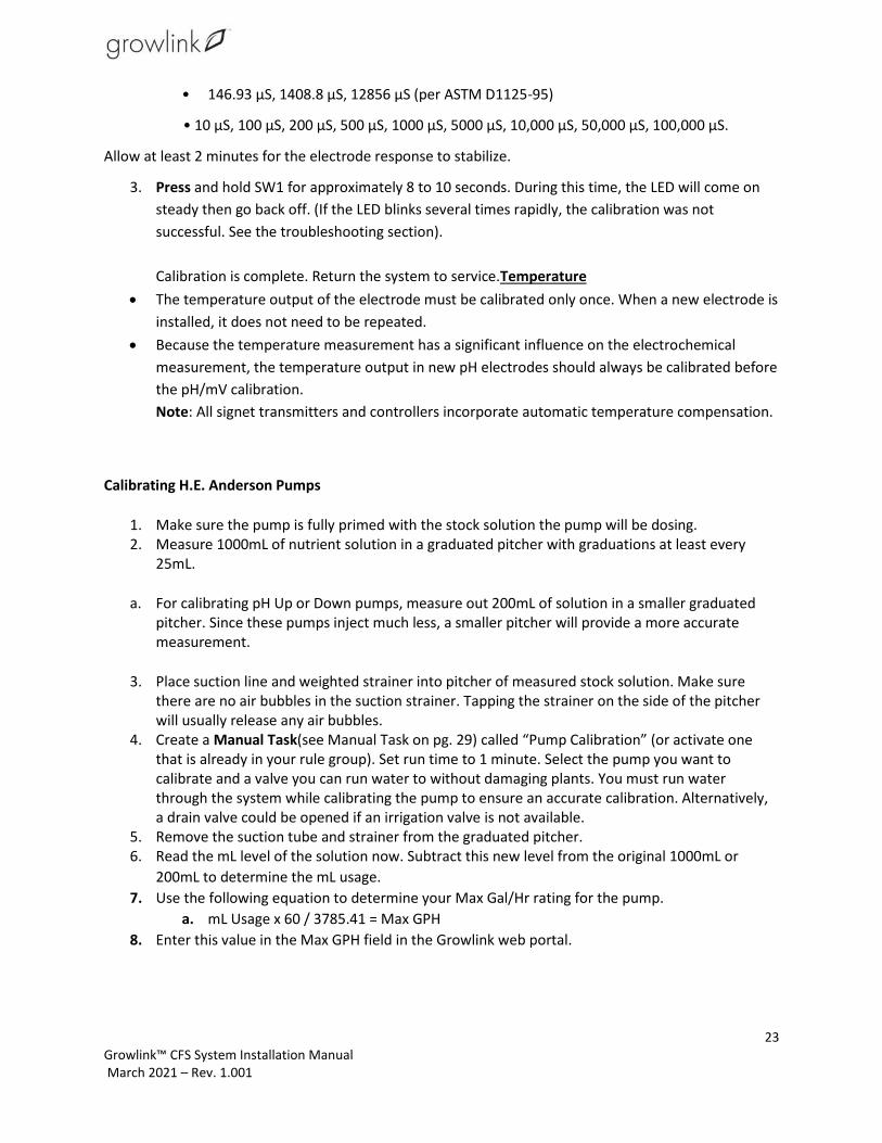
• 146.93 μS, 1408.8 μS, 12856 μS (per ASTM D1125-95)
• 10 μS, 100 μS, 200 μS, 500 μS, 1000 μS, 5000 μS, 10,000 μS, 50,000 μS, 100,000 μS.
Allow at least 2 minutes for the electrode response to stabilize.
3. Press and hold SW1 for approximately 8 to 10 seconds. During this time, the LED will come on
steady then go back off. (If the LED blinks several times rapidly, the calibration was not
successful. See the troubleshooting section).
Calibration is complete. Return the system to service.Temperature
• The temperature output of the electrode must be calibrated only once. When a new electrode is
installed, it does not need to be repeated.
• Because the temperature measurement has a significant influence on the electrochemical
measurement, the temperature output in new pH electrodes should always be calibrated before
the pH/mV calibration.
Note: All signet transmitters and controllers incorporate automatic temperature compensation.
Calibrating H.E. Anderson Pumps
1. Make sure the pump is fully primed with the stock solution the pump will be dosing. 2. Measure 1000mL of nutrient solution in a graduated pitcher with graduations at least every
25mL.
a. For calibrating pH Up or Down pumps, measure out 200mL of solution in a smaller graduated pitcher. Since these pumps inject much less, a smaller pitcher will provide a more accurate measurement.
3. Place suction line and weighted strainer into pitcher of measured stock solution. Make sure there are no air bubbles in the suction strainer. Tapping the strainer on the side of the pitcher will usually release any air bubbles.
4. Create a Manual Task(see Manual Task on pg. 29) called “Pump Calibration” (or activate one that is already in your rule group). Set run time to 1 minute. Select the pump you want to calibrate and a valve you can run water to without damaging plants. You must run water through the system while calibrating the pump to ensure an accurate calibration. Alternatively, a drain valve could be opened if an irrigation valve is not available.
5. Remove the suction tube and strainer from the graduated pitcher. 6. Read the mL level of the solution now. Subtract this new level from the original 1000mL or
200mL to determine the mL usage.
7. Use the following equation to determine your Max Gal/Hr rating for the pump.
a. mL Usage x 60 / 3785.41 = Max GPH
8. Enter this value in the Max GPH field in the Growlink web portal.

24 Growlink™ CFS System Installation Manual March 2021 – Rev. 1.001
To do this, go to the Central Feed System controller Modules 16 Channel
Expansion and click the “Edit” icon next to the device/pump that is being calibrated.
Enter the new Max GPH value from the equation above in this field. Then Save Changes and
Update Controller.
CONFIGURE MODULES
After calibrating the EC and pH Sensors, the next step is to assign (configure) modules. On the Main
Controller there are 16 different channels used to open the 16 zone valves. Configuring modules is how
you name the 16 different channels.
Steps to Configure Modules:
Main Controller
1. Go to the Navigation menu on the left, click Modules.
2. Click the Main Controller located on the Name Board at the top of the screen, i.e., EC-6.
3. Click the Device Name field and type the name of the valve. This is to designate where the water
will be sent.
4. Click the Device Type drop down and select the desired option, i.e., Valve for Fertigation
System.
Note: Valve is preconfigured as the Device Type.
Device Type - Valve (Exclusive) - Only one rule can launch at one time. For example, if you have
two different rules with two different valves, the system will only allow one valve to operate.
This prevents two different rooms with two different recipes from being blended at the same
time.

25 Growlink™ CFS System Installation Manual March 2021 – Rev. 1.001
Nutrient Controller
1. Click the Nutrient Controller Expansion on the Name Board at the top of the screen.
2. Click the Name and rename the sensor, if needed.
DOSING RECIPES
After configuring modules, the next step is to create Dosing Recipes.
1. Go to the Navigation menu on the left and click Dosing Recipes. The Dosing Recipe window
displays.
2. Type the Recipe Name.
3. Enter the Target Tds. This is the Tds (Total Dissolved Solids) sensor indicating how strong to add
the mix, i.e., 1000 ppm.
4. To program the recipe, enter the pH Up in the ml/gal field, if needed.

26 Growlink™ CFS System Installation Manual March 2021 – Rev. 1.001
5. Select the pH Down, in the ml/gal field if needed.
6. Click Add Recipe. The Dosing Recipes results displays.
7. Click Update Controller to send the configuration to the controller.
Note: Refer to the Nutrient Manufacturer for the amount to inject per gallon of water.
RULES
Rules are created to feed the rooms. In rules, timers are used most of the time for feeding.
Add Device Timer
1. Go to the Navigation menu on the left and click Rules. The Default Rule Group displays.
2. Click the Timers section.

27 Growlink™ CFS System Installation Manual March 2021 – Rev. 1.001
3. Click the Add Timer button. The Device Timer window displays.
4. From the Display Name field, type the desired name, i.e., Feed Room 01.
5. Click Devices drop down and select the desired valve.
6. Click the Dosing Recipe drop down and select the desired recipe.
7. Click the Time of Day drop down and select the desired day. Note: The day is previously set in
the Profile. Hint: The suggested time to feed is when the lights are on, Day only.
8. Set the Frequency Hrs, Mins, Secs.
9. Set the Duration Hrs, Mins, Secs.
10. Click the Add Timer button.

28 Growlink™ CFS System Installation Manual March 2021 – Rev. 1.001
11. Click the Update Controller button. The timer is created for the room.
Multiple Timers can be created as needed for all the different rooms. Repeat steps 1 -10 to create
additional Device Timers.
MANUAL TASK
The Manual Task is used to add a play button on the Dashboard. For example, use the manual task to
add 5 minutes of extra water to the plants.
Add Manual Task
1. Navigate to Rules.
2. Click Manual Tasks at the bottom of the screen.
3. Click the Add Manual Task button. The Manual Task window displays.
4. From the Display Name field, type the desired name, i.e., Manual Water Room 01.
5. Click Devices drop down and select the desired valve.
6. Click the Dosing Recipe drop down and select the desired recipe.
7. Set the Duration to the default run time of 10 mins.
8. Click the Add Manual Task button. The Added New Manual Task message displays.
9. Click the Update Controller button. The Controller Update Pushed message displays.
View the Dashboard
1. Go to the Navigation menu and click Dashboard to view the manual tasks.
2. Scroll to the bottom of the screen to the Manual Tasks section.
3. Locate the added manual task Display Name, i.e., Manual Water Room 01.
4. Set the desired extra Min using the up or down arrow and click the Play button.

29 Growlink™ CFS System Installation Manual March 2021 – Rev. 1.001
The room will receive the extra watering time set.

30 Growlink™ CFS System Installation Manual March 2021 – Rev. 1.001
USING THE GROWLINK™ APPLICATION
You can manage your facility from anywhere with a mobile device.
Install the Growlink Application
1. Open the Google Play Store or the App Store on your phone.
2. Find the Growlink app and tap the Install button.
3. Sign in and open the app.
4. Read the Terms of Service and tap the Accept button.
The Account Setup screen displays.
5. Fill out all the fields and tap the Create Account button.
WIFI Setup for Android and iOS
Important: Device must be in listening mode. To place the controller into listening mode. press and hold
the bottom button and wait until the LED flashes blue.
1. Navigate to the app and tap Settings on the top right corner.
2. Go to the Settings menu and select Connect to Controller.

31 Growlink™ CFS System Installation Manual March 2021 – Rev. 1.001
The Connect to Controller Hub screen displays. Next, Open the Wi-Fi settings on your hand-held
device.
3. Connect to the Wi-Fi network that matches your SSID for the controller's enclosure.

32 Growlink™ CFS System Installation Manual March 2021 – Rev. 1.001
4. Switch back to the Growlink App. Once you are connected, the Setup Controller Hub screen displays. This confirms you are successfully connected to your Growlink Controller Hub. At the bottom of the screen tap Next.
7. Select your Wi-Fi network from the list of networks and enter your Wi-Fi password. Then tap on
Set Access Point.

33 Growlink™ CFS System Installation Manual March 2021 – Rev. 1.001
After you have connected your Wi-Fi, the LEDs on your Controller will flash. When it is
connected it will breathe green.
The Setup Complete screen displays. You can now name your controller i.e. “My Farm
controller”. Next, you can set the time zone and country for your controller by tapping Go To
Settings. After entering desired settings, tap Save.

34 Growlink™ CFS System Installation Manual March 2021 – Rev. 1.001
8. Setup is now complete and you can view your controller from the main Dashboard
Related Documents