Group M3 Craig LeVan Jacob Thomas Nick Marwaha Darren Shultz Project Manager: Zachary Menegakis February 14, 2005 MILESTONE 4 Gate Level Design DSP 'Swiss Army Knife' erall Project Objective: General Purpose Digital Signal Processing C

Group M3 Craig LeVan Jacob Thomas Nick Marwaha Darren Shultz Project Manager: Zachary Menegakis February 14, 2005 MILESTONE 4 Gate Level Design DSP 'Swiss.
Dec 21, 2015
Welcome message from author
This document is posted to help you gain knowledge. Please leave a comment to let me know what you think about it! Share it to your friends and learn new things together.
Transcript

Group M3Craig LeVanJacob ThomasNick MarwahaDarren ShultzProject Manager: Zachary Menegakis February 14, 2005
MILESTONE 4 Gate Level Design
DSP 'Swiss Army Knife'
Overall Project Objective: General Purpose Digital Signal Processing Chip
STATUS Design Proposal (Done) Architecture (Done) Size Estimates/Floorplan/Verilog (66%) Gate Level Design (80% - Debugging) To Be Done
Comb Reengineering• Current design causes errors due to the mantissa• Current prototype solution is ENORMOUS!!!• Affects four of the fifteen functions of the chip
Schematic• Convert few remaining Verilog blocks• Make comb adjustments
Verification• Retest for comb functions
Layout (0%)
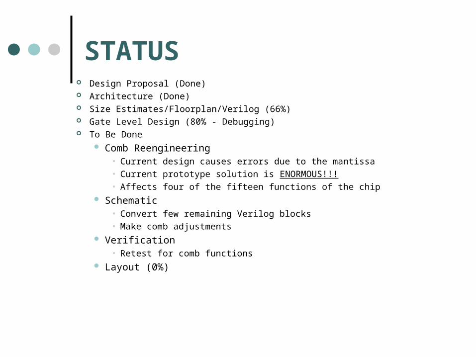
DESIGN DECISIONS Circuit Speed Goal
Most audio signals played at ~44 kHz Motorola’s audio super chip operates at 120 MIPS (performs functions such as
Dolby Digital) Use Motorola as benchmark which equals 120 MHz for us However, want to keep power as a focus as well
Type of Multiplier (for mantissa within floating point multiply) Chose matrix multiply since easy to implement Others such as Wallace offer no real advantage at 6 bits, while are more difficult
to layout Comparator
Using carryout of subtractor (also used in previous projects) Shifting Logic
Using combinational barrel shifter for adder and normalization Comb Solution
Alternative B

COMB FILTER
Assumptions about Floating point operation of x-n proved incorrect
Initial re-design is unrealistic

DESIGN DECISIONS cont
Name a0 a1 a2 b0 b1 b2 c1 N
1 Differencer 1 0 0 1 -1 0 0 x
2 Integrator 1 1 0 1 0 0 0 x
3 Leaky Integrator 1 1 0 1 0 0 0 x
4 Comb Filter 1 0 0 1 0 0 1 8
5 Bandpass Filter 1 0 -1 1 0 0 1 16
6 CIC Interpolation Filter 1 1 0 1 0 0 1 8
7 dc Bias Removal 1 a.b 0 1 -1 0 0 x
8 First-Order Equalizer 1 a.b 0 a.b 1 0 0 x
9 Audio Comb 1 0 a.b 1 0 0 0 x
10 Moving Averager 1 1 0 1/N 0 0 1 8
11 Second-Order IIR Filter 1 a.bbb a.bbb a.bbb a.bbb a.bbb 0 x
12 First-Order Delay Network 1 a.bbb a.bbb a.bbb a.bbb 1 0 x
13 Second-Order Delay Network 1 a.bbb a.bbb a.bbb a.bbb 1 0 x
14 Real Oscillator 1 2cos(x) -1 1 0 -1 x x
15 Second-Order Equalizer 1 a.b*cos(x) a.b 1 a.b*cos(x) 1/a.b 0 x
The Affected Functions

DESIGN DECISIONS cont
Alternative B
(not what we want)
Can remove while only eliminating 1
function, and significantly reduce
transistor count
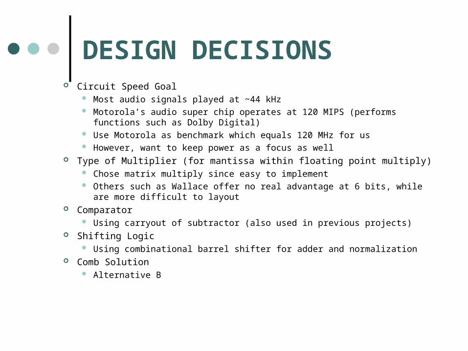
UPDATED DATA FLOW
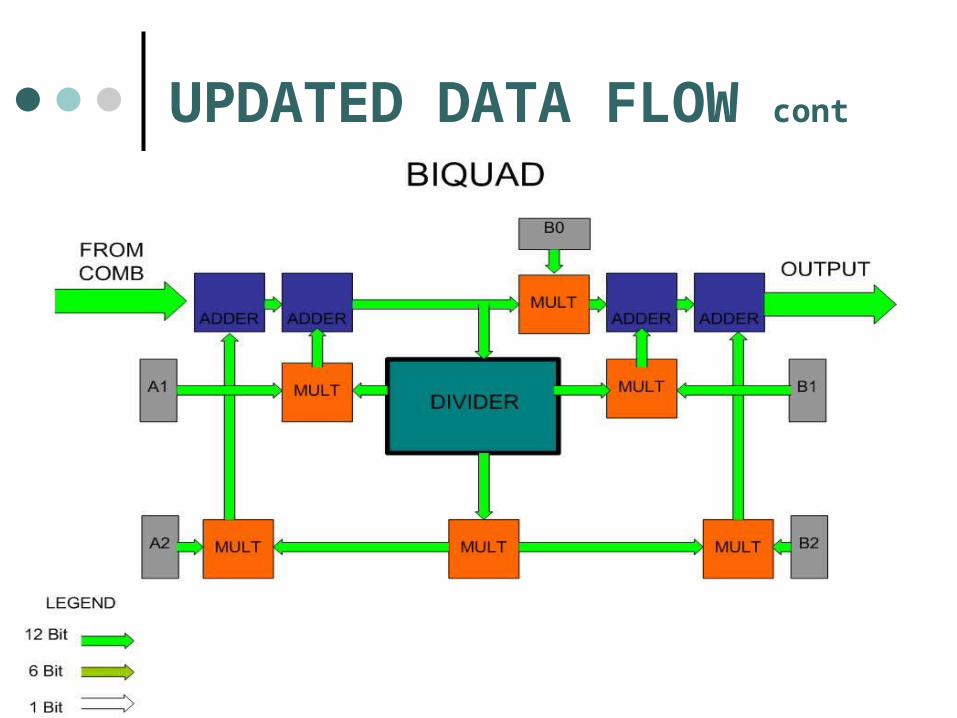
UPDATED DATA FLOW cont
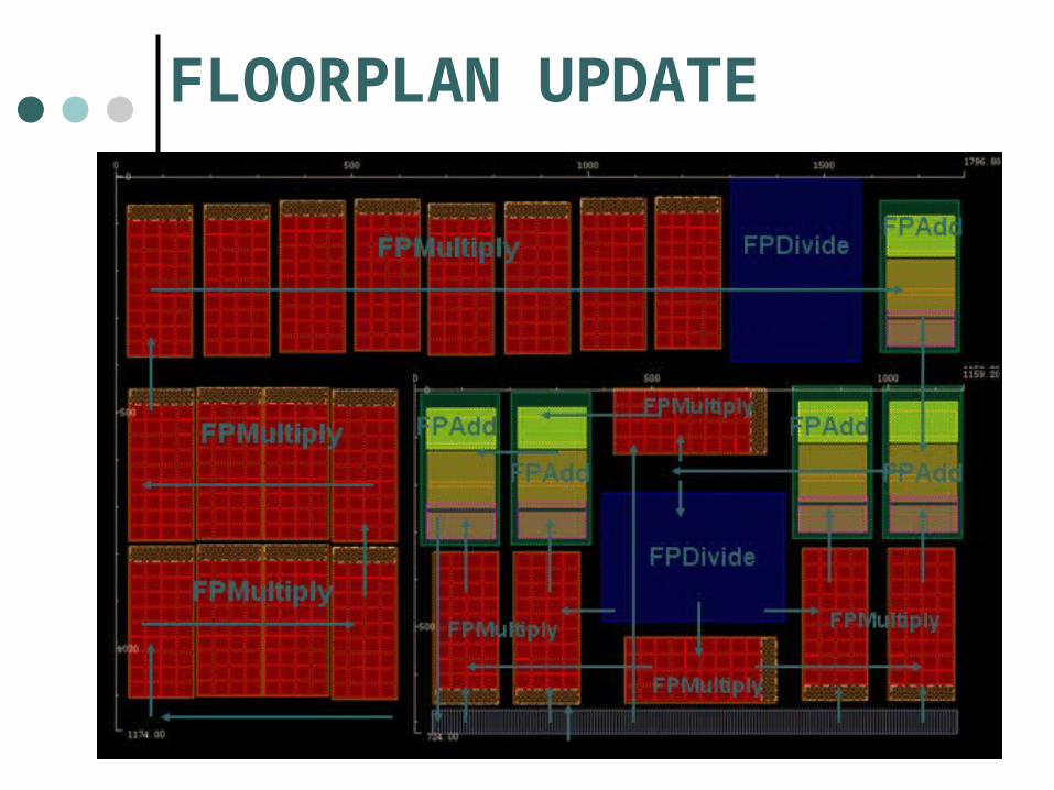
FLOORPLAN UPDATE

SIZE ESTIMATES

SCHEMATICBiquad Top Level
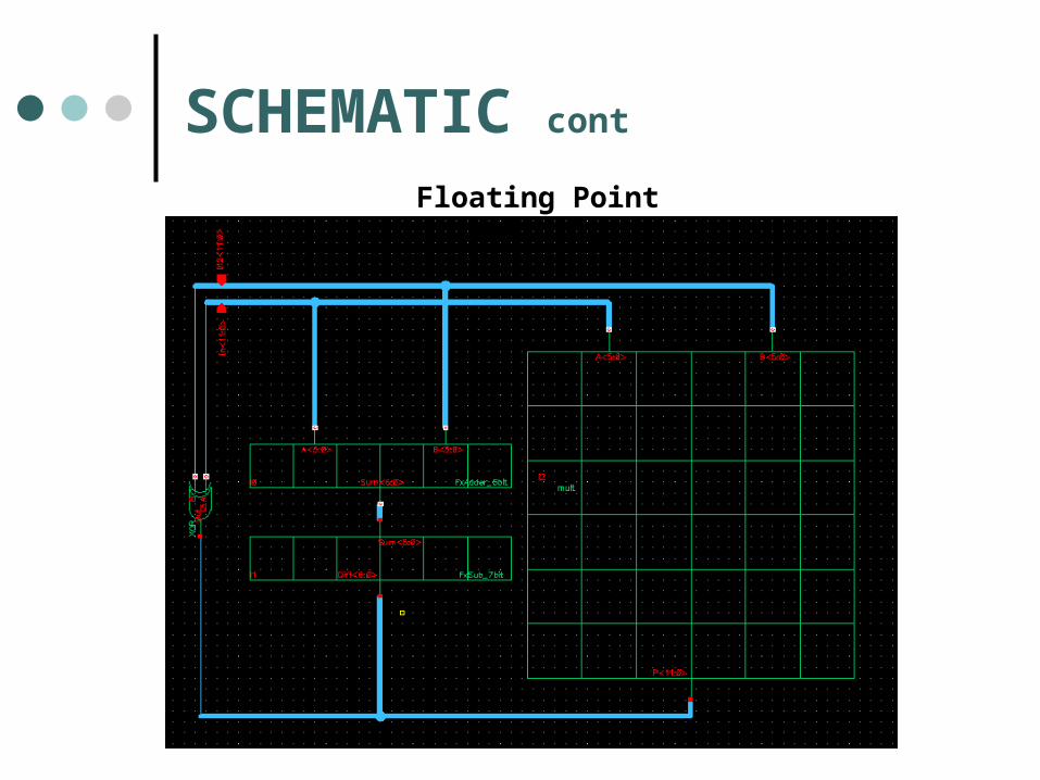
SCHEMATIC cont
Floating Point Multiply
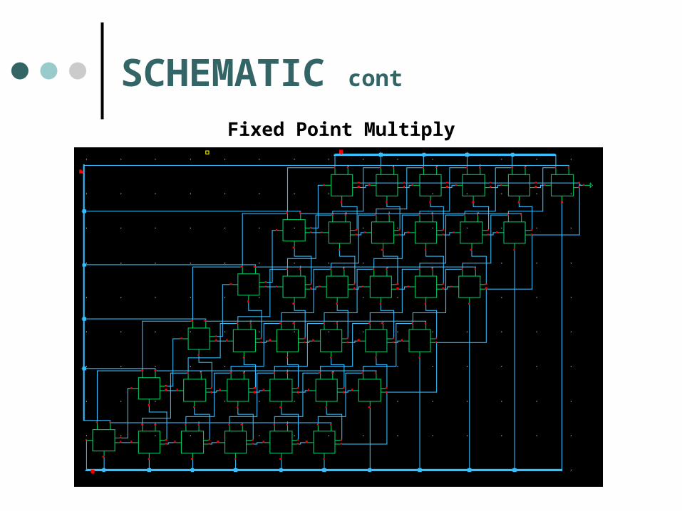
SCHEMATIC cont
Fixed Point Multiply

VERIFICATIONVSIM 1> run # x xxxxxx xxxxx * x xxxxxx xxxxx = x xxxxxx xxxxx # 0 000000 00000 * 0 000000 00000 = 0 000000 00000 # 0 011110 00000 * 1 011101 11000 = 1 011100 11000 # 0 100001 00100 * 0 100000 01000 = 0 100010 01101 # 0 100001 01110 * 0 100000 00001 = 0 100010 01111 # 0 100001 11100 * 0 100000 11110 = 0 100011 11010 # 0 100100 11110 * 0 100010 11000 = 0 101000 10110 # 1 100100 11110 * 1 100010 11000 = 0 101000 10110 # 0 100001 00010 * 0 100001 11110 = 0 100100 00000 # ** Note: $finish : fp_mult_tb0.v(41) # Time: 9 ns Iteration: 0 Instance: /tester
VERIFICATION cont
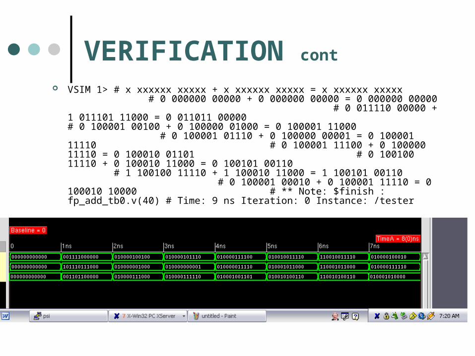
VSIM 1> # x xxxxxx xxxxx + x xxxxxx xxxxx = x xxxxxx xxxxx # 0 000000 00000 + 0 000000 00000 = 0 000000 00000 # 0 011110 00000 + 1 011101 11000 = 0 011011 00000 # 0 100001 00100 + 0 100000 01000 = 0 100001 11000 # 0 100001 01110 + 0 100000 00001 = 0 100001 11110 # 0 100001 11100 + 0 100000 11110 = 0 100010 01101 # 0 100100 11110 + 0 100010 11000 = 0 100101 00110 # 1 100100 11110 + 1 100010 11000 = 1 100101 00110 # 0 100001 00010 + 0 100001 11110 = 0 100010 10000 # ** Note: $finish : fp_add_tb0.v(40) # Time: 9 ns Iteration: 0 Instance: /tester
CRITICAL PATH
When Comb is being used N = 16 (especially with alternative B) Biquad is always used
There are no specific operation codes Function being performed is based on
coefficient values

PROBLEMS & QUESTIONS
Comb MUST find an Alternative A to keep size down OR should we eliminate Comb???
Efficient Comparator Is there any method better than using the
carryout of a subtractor? Structural
Barrel Shifter / Divider Schematic wiring
Related Documents