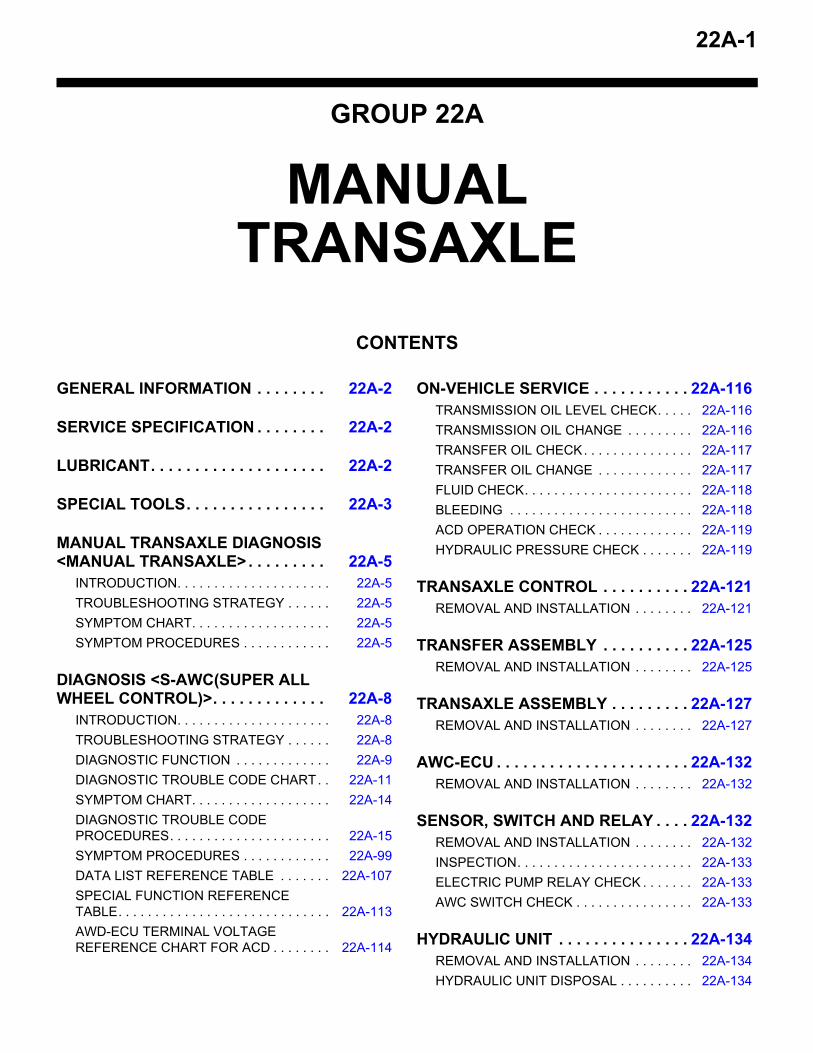
22A-1 GROUP 22A MANUAL TRANSAXLE CONTENTS GENERAL INFORMATION . . . . . . . . 22A-2 SERVICE SPECIFICATION . . . . . . . . 22A-2 LUBRICANT . . . . . . . . . . . . . . . . . . . . 22A-2 SPECIAL TOOLS . . . . . . . . . . . . . . . . 22A-3 MANUAL TRANSAXLE DIAGNOSIS <MANUAL TRANSAXLE> . . . . . . . . . 22A-5 INTRODUCTION. . . . . . . . . . . . . . . . . . . . . 22A-5 TROUBLESHOOTING STRATEGY . . . . . . 22A-5 SYMPTOM CHART. . . . . . . . . . . . . . . . . . . 22A-5 SYMPTOM PROCEDURES . . . . . . . . . . . . 22A-5 DIAGNOSIS <S-AWC(SUPER ALL WHEEL CONTROL)>. . . . . . . . . . . . . 22A-8 INTRODUCTION. . . . . . . . . . . . . . . . . . . . . 22A-8 TROUBLESHOOTING STRATEGY . . . . . . 22A-8 DIAGNOSTIC FUNCTION . . . . . . . . . . . . . 22A-9 DIAGNOSTIC TROUBLE CODE CHART . . 22A-11 SYMPTOM CHART. . . . . . . . . . . . . . . . . . . 22A-14 DIAGNOSTIC TROUBLE CODE PROCEDURES. . . . . . . . . . . . . . . . . . . . . . 22A-15 SYMPTOM PROCEDURES . . . . . . . . . . . . 22A-99 DATA LIST REFERENCE TABLE . . . . . . . 22A-107 SPECIAL FUNCTION REFERENCE TABLE. . . . . . . . . . . . . . . . . . . . . . . . . . . . . 22A-113 AWD-ECU TERMINAL VOLTAGE REFERENCE CHART FOR ACD . . . . . . . . 22A-114 ON-VEHICLE SERVICE . . . . . . . . . . . 22A-116 TRANSMISSION OIL LEVEL CHECK. . . . . 22A-116 TRANSMISSION OIL CHANGE . . . . . . . . . 22A-116 TRANSFER OIL CHECK . . . . . . . . . . . . . . . 22A-117 TRANSFER OIL CHANGE . . . . . . . . . . . . . 22A-117 FLUID CHECK. . . . . . . . . . . . . . . . . . . . . . . 22A-118 BLEEDING . . . . . . . . . . . . . . . . . . . . . . . . . 22A-118 ACD OPERATION CHECK . . . . . . . . . . . . . 22A-119 HYDRAULIC PRESSURE CHECK . . . . . . . 22A-119 TRANSAXLE CONTROL . . . . . . . . . . 22A-121 REMOVAL AND INSTALLATION . . . . . . . . 22A-121 TRANSFER ASSEMBLY . . . . . . . . . . 22A-125 REMOVAL AND INSTALLATION . . . . . . . . 22A-125 TRANSAXLE ASSEMBLY . . . . . . . . . 22A-127 REMOVAL AND INSTALLATION . . . . . . . . 22A-127 AWC-ECU . . . . . . . . . . . . . . . . . . . . . . 22A-132 REMOVAL AND INSTALLATION . . . . . . . . 22A-132 SENSOR, SWITCH AND RELAY . . . . 22A-132 REMOVAL AND INSTALLATION . . . . . . . . 22A-132 INSPECTION. . . . . . . . . . . . . . . . . . . . . . . . 22A-133 ELECTRIC PUMP RELAY CHECK . . . . . . . 22A-133 AWC SWITCH CHECK . . . . . . . . . . . . . . . . 22A-133 HYDRAULIC UNIT . . . . . . . . . . . . . . . 22A-134 REMOVAL AND INSTALLATION . . . . . . . . 22A-134 HYDRAULIC UNIT DISPOSAL . . . . . . . . . . 22A-134

Welcome message from author
This document is posted to help you gain knowledge. Please leave a comment to let me know what you think about it! Share it to your friends and learn new things together.
Transcript
22A-1
GROUP 22A
MANUAL TRANSAXLE
CONTENTS
GENERAL INFORMATION . . . . . . . . 22A-2
SERVICE SPECIFICATION . . . . . . . . 22A-2
LUBRICANT. . . . . . . . . . . . . . . . . . . . 22A-2
SPECIAL TOOLS. . . . . . . . . . . . . . . . 22A-3
MANUAL TRANSAXLE DIAGNOSIS <MANUAL TRANSAXLE>. . . . . . . . . 22A-5
INTRODUCTION. . . . . . . . . . . . . . . . . . . . . 22A-5TROUBLESHOOTING STRATEGY . . . . . . 22A-5SYMPTOM CHART. . . . . . . . . . . . . . . . . . . 22A-5SYMPTOM PROCEDURES . . . . . . . . . . . . 22A-5
DIAGNOSIS <S-AWC(SUPER ALL WHEEL CONTROL)>. . . . . . . . . . . . . 22A-8
INTRODUCTION. . . . . . . . . . . . . . . . . . . . . 22A-8TROUBLESHOOTING STRATEGY . . . . . . 22A-8DIAGNOSTIC FUNCTION . . . . . . . . . . . . . 22A-9DIAGNOSTIC TROUBLE CODE CHART. . 22A-11SYMPTOM CHART. . . . . . . . . . . . . . . . . . . 22A-14DIAGNOSTIC TROUBLE CODE PROCEDURES. . . . . . . . . . . . . . . . . . . . . . 22A-15SYMPTOM PROCEDURES . . . . . . . . . . . . 22A-99DATA LIST REFERENCE TABLE . . . . . . . 22A-107SPECIAL FUNCTION REFERENCE TABLE. . . . . . . . . . . . . . . . . . . . . . . . . . . . . 22A-113AWD-ECU TERMINAL VOLTAGE REFERENCE CHART FOR ACD . . . . . . . . 22A-114
ON-VEHICLE SERVICE . . . . . . . . . . . 22A-116TRANSMISSION OIL LEVEL CHECK. . . . . 22A-116TRANSMISSION OIL CHANGE . . . . . . . . . 22A-116TRANSFER OIL CHECK. . . . . . . . . . . . . . . 22A-117TRANSFER OIL CHANGE . . . . . . . . . . . . . 22A-117FLUID CHECK. . . . . . . . . . . . . . . . . . . . . . . 22A-118BLEEDING . . . . . . . . . . . . . . . . . . . . . . . . . 22A-118ACD OPERATION CHECK . . . . . . . . . . . . . 22A-119HYDRAULIC PRESSURE CHECK . . . . . . . 22A-119
TRANSAXLE CONTROL . . . . . . . . . . 22A-121REMOVAL AND INSTALLATION . . . . . . . . 22A-121
TRANSFER ASSEMBLY . . . . . . . . . . 22A-125REMOVAL AND INSTALLATION . . . . . . . . 22A-125
TRANSAXLE ASSEMBLY . . . . . . . . . 22A-127REMOVAL AND INSTALLATION . . . . . . . . 22A-127
AWC-ECU . . . . . . . . . . . . . . . . . . . . . . 22A-132REMOVAL AND INSTALLATION . . . . . . . . 22A-132
SENSOR, SWITCH AND RELAY . . . . 22A-132REMOVAL AND INSTALLATION . . . . . . . . 22A-132INSPECTION. . . . . . . . . . . . . . . . . . . . . . . . 22A-133ELECTRIC PUMP RELAY CHECK . . . . . . . 22A-133AWC SWITCH CHECK . . . . . . . . . . . . . . . . 22A-133
HYDRAULIC UNIT . . . . . . . . . . . . . . . 22A-134REMOVAL AND INSTALLATION . . . . . . . . 22A-134HYDRAULIC UNIT DISPOSAL . . . . . . . . . . 22A-134

GENERAL INFORMATIONMANUAL TRANSAXLE22A-2
GENERAL INFORMATIONM1221000101067
Item SpecificationTransaxle model W5M6ATransaxle type 5-speed forward, 1-speed reverse constant meshGear ratio 1st 2.857
2nd 1.9503rd 1.4444th 1.0965th 0.761Reverse 2.892
Final gear ratio 4.687Helical gear LSD (front differential) PresentTransfer Reduction
ratio0.302
Differential gear unit
Hydraulic pressure multiplate clutch (ACD)
SERVICE SPECIFICATIONM1221000300165
Item Standard valueHydraulic unit generation oil pressure MPa (psi) 0.9 − 1.1 (130 − 159)
LUBRICANTM1221000400678
Item Brand Capacity
Transmission oil dm3 (qt) Mitsubishi genuine Dia-Queen new multi gear oil SAE 75W-80 (GL-3)
2.5 (2.6)
Transfer oil dm3 (qt) Mitsubishi genuine Dia-Queen LSD Gear Oil
0.8 (0.9)
AWC fluid dm3 (qt) Mitsubishi genuine Dia-Queen ATF SPIII 1.0 (1.1)
Front propeller shaft
Sleeve yoke section Mitsubishi genuine Dia-Queen Super Hypoid Gear Oil SAE 90 (GL-5)
Adequate amount
Transfer O-ring Mitsubishi genuine Dia-Queen ATF SPIIIClutch release cylinder
Push rod section 0101011 or equivalent
Transaxle assembly
Spline sections of input shaft and clutch disk
TSB Revision
SPECIAL TOOLSMANUAL TRANSAXLE 22A-3
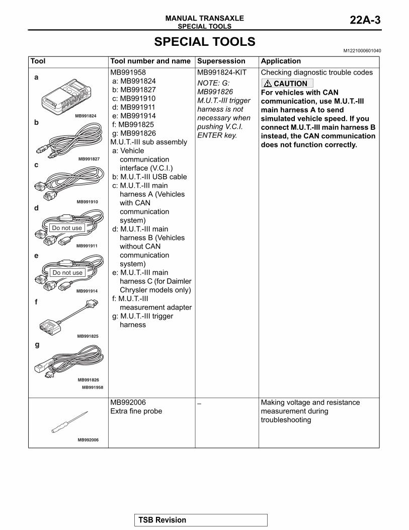
SPECIAL TOOLSM1221000601040
Tool Tool number and name Supersession Application
MB991910
MB991826
MB991958
MB991911
MB991914
MB991824
MB991827
MB991825
Do not use
a
b
c
d
e
f
g
Do not use
MB991958a: MB991824b: MB991827c: MB991910d: MB991911e: MB991914f: MB991825g: MB991826M.U.T.-III sub assemblya: Vehicle
communication interface (V.C.I.)
b: M.U.T.-III USB cablec: M.U.T.-III main
harness A (Vehicles with CAN communication system)
d: M.U.T.-III main harness B (Vehicles without CAN communication system)
e: M.U.T.-III main harness C (for Daimler Chrysler models only)
f: M.U.T.-III measurement adapter
g: M.U.T.-III trigger harness
MB991824-KITNOTE: G: MB991826 M.U.T.-III trigger harness is not necessary when pushing V.C.I. ENTER key.
Checking diagnostic trouble codesCAUTION
For vehicles with CAN communication, use M.U.T.-III main harness A to send simulated vehicle speed. If you connect M.U.T.-III main harness B instead, the CAN communication does not function correctly.
MB992006
MB992006Extra fine probe
− Making voltage and resistance measurement during troubleshooting
TSB Revision
SPECIAL TOOLSMANUAL TRANSAXLE22A-4
AC103525
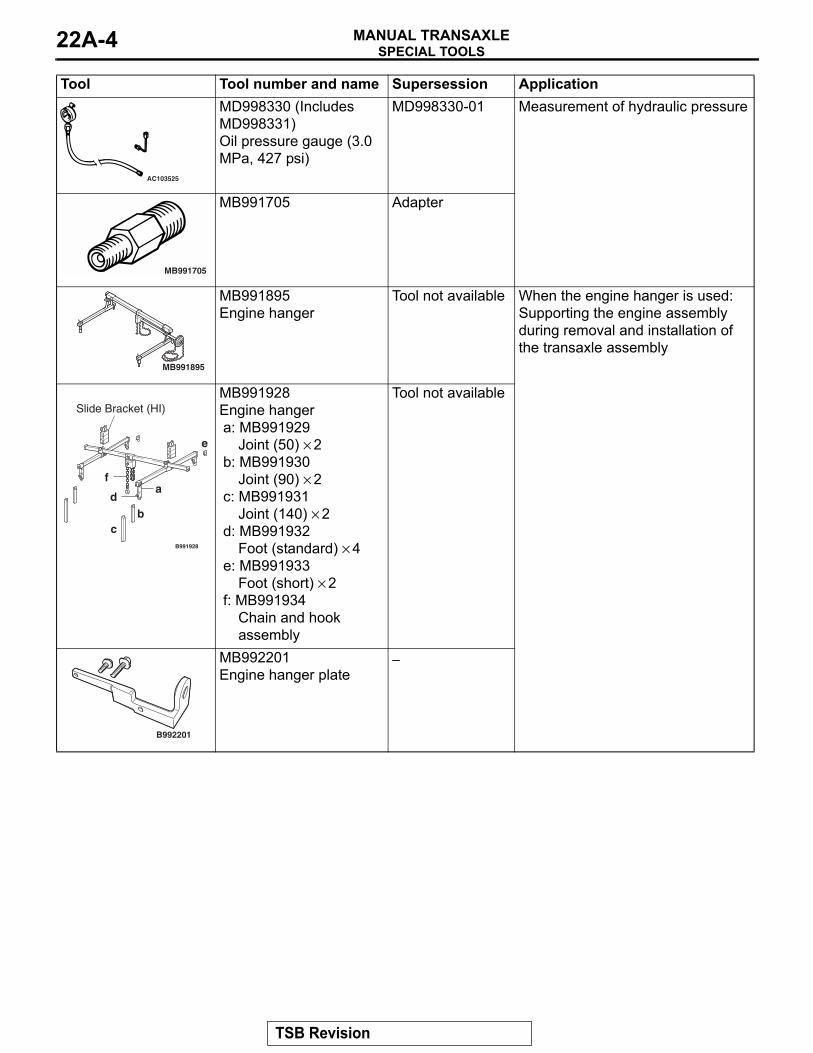
MD998330 (Includes MD998331)Oil pressure gauge (3.0 MPa, 427 psi)
MD998330-01 Measurement of hydraulic pressure
MB991705
MB991705 Adapter
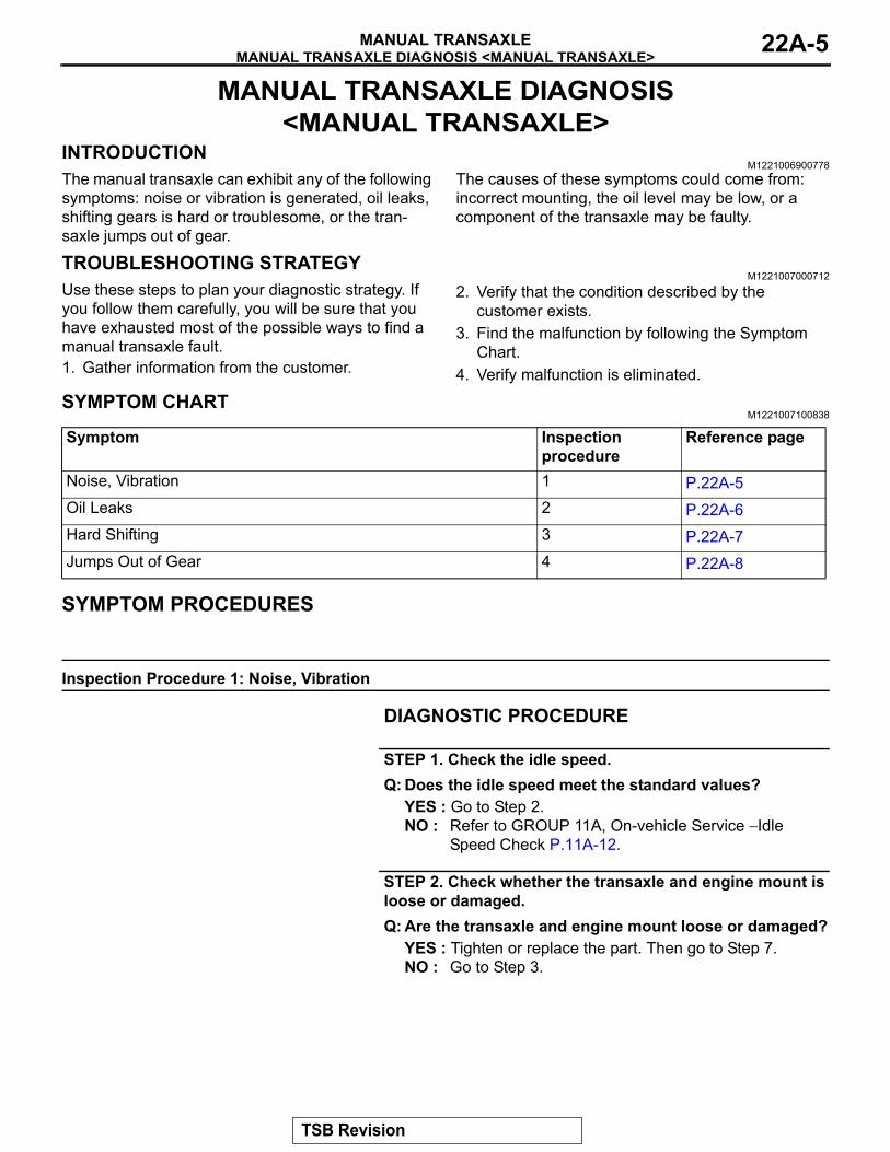
MB991895
MB991895Engine hanger
Tool not available When the engine hanger is used: Supporting the engine assembly during removal and installation of the transaxle assembly
B991928
a
bc
d
e
f
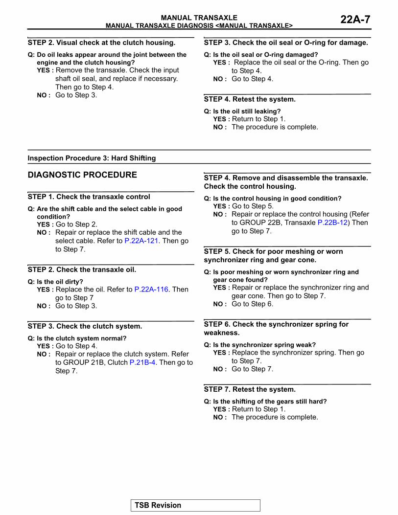
Slide Bracket (HI)MB991928Engine hangera: MB991929
Joint (50) × 2b: MB991930
Joint (90) × 2c: MB991931
Joint (140) × 2d: MB991932
Foot (standard) × 4e: MB991933
Foot (short) × 2f: MB991934
Chain and hook assembly
Tool not available
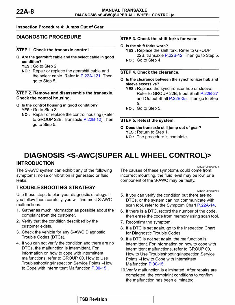
B992201
MB992201Engine hanger plate
−
Tool Tool number and name Supersession Application
TSB Revision
MANUAL TRANSAXLE DIAGNOSIS <MANUAL TRANSAXLE>MANUAL TRANSAXLE 22A-5
MANUAL TRANSAXLE DIAGNOSIS <MANUAL TRANSAXLE>
INTRODUCTIONM1221006900778
The manual transaxle can exhibit any of the following symptoms: noise or vibration is generated, oil leaks, shifting gears is hard or troublesome, or the tran-saxle jumps out of gear.
The causes of these symptoms could come from: incorrect mounting, the oil level may be low, or a component of the transaxle may be faulty.
TROUBLESHOOTING STRATEGYM1221007000712
Use these steps to plan your diagnostic strategy. If you follow them carefully, you will be sure that you have exhausted most of the possible ways to find a manual transaxle fault.1. Gather information from the customer.
2. Verify that the condition described by the customer exists.
3. Find the malfunction by following the Symptom Chart.
4. Verify malfunction is eliminated.
SYMPTOM CHARTM1221007100838
Symptom Inspection procedure
Reference page
Noise, Vibration 1 P.22A-5Oil Leaks 2 P.22A-6Hard Shifting 3 P.22A-7Jumps Out of Gear 4 P.22A-8
SYMPTOM PROCEDURES
Inspection Procedure 1: Noise, Vibration
DIAGNOSTIC PROCEDURE
STEP 1. Check the idle speed.Q: Does the idle speed meet the standard values?
YES : Go to Step 2.NO : Refer to GROUP 11A, On-vehicle Service − Idle
Speed Check P.11A-12.
STEP 2. Check whether the transaxle and engine mount is loose or damaged.Q: Are the transaxle and engine mount loose or damaged?
YES : Tighten or replace the part. Then go to Step 7.NO : Go to Step 3.
TSB Revision

MANUAL TRANSAXLE DIAGNOSIS <MANUAL TRANSAXLE>MANUAL TRANSAXLE22A-6
STEP 3. Check that the oil level is up to the lower edge of the filler plug hole.
AC700330AE
Gasket
Transmission oil
Filler plug hole
Oil filler plug
Q: Is the oil level up to the lower edge of the filler plug hole?YES : Go to Step 4.NO : Refill DiaQueen NEW MULTI GEAR OIL API
classification GL-3, SAE 75W-80. Then go to Step 7.
STEP 4. Check for the specified oil.Q: Is the specified oil DiaQueen NEW MULTI GEAR OIL API
classification GL-3, SAE 75W-80?YES : Go to Step 5.NO : If in doubt, replace the oil. Refer to P.22A-116. Then
go to Step 7.
STEP 5. Remove the transaxle. Check the end play of the input and output shafts.Q: Does the end play of the input and output shafts meet
the standard value?YES : Go to Step 6.NO : Adjust the end play of the input and output shafts.
Then go to Step 7.
STEP 6. Disassemble the transaxle. Check the gears for wear and damage.Q: Are the gears worn or damaged?
YES : Replace the gears. Go to Step 7.NO : Go to Step 7.
STEP 7. Retest the systems.Q: Is the noise or vibration still there?
YES : Return to Step 1.NO : The procedure is complete.
Inspection Procedure 2: Oil Leaks
DIAGNOSTIC PROCEDURE
STEP 1. Visual check.Raise the vehicle, and check for oil leaks. If oil leak is difficult to locate, steam clean the transaxle and drive the vehicle for at 10 minutes. Then check the leak again.
Q: Is the oil leak(s) found?YES : Go to Step 2.NO : Check for the oil leaks around the engine.
Then go to Step 4.
TSB Revision
MANUAL TRANSAXLE DIAGNOSIS <MANUAL TRANSAXLE>MANUAL TRANSAXLE 22A-7
STEP 2. Visual check at the clutch housing.Q: Do oil leaks appear around the joint between the
engine and the clutch housing?YES : Remove the transaxle. Check the input
shaft oil seal, and replace if necessary. Then go to Step 4.
NO : Go to Step 3.
STEP 3. Check the oil seal or O-ring for damage.Q: Is the oil seal or O-ring damaged?
YES : Replace the oil seal or the O-ring. Then go to Step 4.
NO : Go to Step 4.
STEP 4. Retest the system.Q: Is the oil still leaking?
YES : Return to Step 1.NO : The procedure is complete.
Inspection Procedure 3: Hard Shifting
DIAGNOSTIC PROCEDURE
STEP 1. Check the transaxle controlQ: Are the shift cable and the select cable in good
condition?YES : Go to Step 2.NO : Repair or replace the shift cable and the
select cable. Refer to P.22A-121. Then go to Step 7.
STEP 2. Check the transaxle oil.Q: Is the oil dirty?
YES : Replace the oil. Refer to P.22A-116. Then go to Step 7
NO : Go to Step 3.
STEP 3. Check the clutch system.Q: Is the clutch system normal?
YES : Go to Step 4.NO : Repair or replace the clutch system. Refer
to GROUP 21B, Clutch P.21B-4. Then go to Step 7.
STEP 4. Remove and disassemble the transaxle. Check the control housing.Q: Is the control housing in good condition?
YES : Go to Step 5.NO : Repair or replace the control housing (Refer
to GROUP 22B, Transaxle P.22B-12) Then go to Step 7.
STEP 5. Check for poor meshing or worn synchronizer ring and gear cone.Q: Is poor meshing or worn synchronizer ring and
gear cone found?YES : Repair or replace the synchronizer ring and
gear cone. Then go to Step 7.NO : Go to Step 6.
STEP 6. Check the synchronizer spring for weakness.Q: Is the synchronizer spring weak?
YES : Replace the synchronizer spring. Then go to Step 7.
NO : Go to Step 7.
STEP 7. Retest the system.Q: Is the shifting of the gears still hard?
YES : Return to Step 1.NO : The procedure is complete.
TSB Revision
DIAGNOSIS <S-AWC(SUPER ALL WHEEL CONTROL)>MANUAL TRANSAXLE22A-8
Inspection Procedure 4: Jumps Out of Gear
DIAGNOSTIC PROCEDURE
STEP 1. Check the transaxle controlQ: Are the gearshift cable and the select cable in good
condition?YES : Go to Step 2.NO : Repair or replace the gearshift cable and
the select cable. Refer to P.22A-121. Then go to Step 5.
STEP 2. Remove and disassemble the transaxle. Check the control housing.Q: Is the control housing in good condition?
YES : Go to Step 3.NO : Repair or replace the control housing (Refer
to GROUP 22B, Transaxle P.22B-12) Then go to Step 5.
STEP 3. Check the shift forks for wear.Q: Is the shift forks worn?
YES : Replace the shift fork. Refer to GROUP 22B, transaxle P.22B-12. Then go to Step 5.
NO : Go to Step 4.
STEP 4. Check the clearance.Q: Is the clearance between the synchronizer hub and
sleeve excessive?YES : Replace the synchronizer hub or sleeve.
Refer to GROUP 22B, Input Shaft P.22B-27 and Output Shaft P.22B-35. Then go to Step 5.
NO : Go to Step 5.
STEP 5. Retest the system.Q: Does the transaxle still jump out of gear?
YES : Return to Step 1.NO : The procedure is complete.
DIAGNOSIS <S-AWC(SUPER ALL WHEEL CONTROL)>INTRODUCTION
M1221006900831The S-AWC system can exhibit any of the following symptoms: noise or vibration is generated or fluid leaks.
The causes of these symptoms could come from: incorrect mounting, the fluid level may be low, or a component of the S-AWC may be faulty.
TROUBLESHOOTING STRATEGYM1221007000790
Use these steps to plan your diagnostic strategy. If you follow them carefully, you will find most S-AWC malfunctions.1. Gather as much information as possible about the
complaint from the customer.2. Verify that the condition described by the
customer exists.3. Check the vehicle for any S-AWC Diagnostic
Trouble Codes (DTCs).4. If you can not verify the condition and there are no
DTCs, the malfunction is intermittent. For information on how to cope with intermittent malfunctions, refer to GROUP 00, How to Use Troubleshooting/Inspection Service Points − How to Cope with Intermittent Malfunction P.00-15.
5. If you can verify the condition but there are no DTCs, or the system can not communicate with scan tool, refer to the Symptom Chart P.22A-14.
6. If there is a DTC, record the number of the code, then erase the code from memory using scan tool.
7. Reconfirm the symptom.8. If a DTC is set again, go to the Inspection Chart
for Diagnostic Trouble Codes.9. If a DTC is not set again, the malfunction is
intermittent. For information on how to cope with intermittent malfunctions, refer to GROUP 00, How to Use Troubleshooting/Inspection Service Points − How to Cope with Intermittent Malfunction P.00-15.
10.Verify malfunction is eliminated. After repairs are completed, the complaint conditions to confirm the malfunction has been eliminated.
TSB Revision
DIAGNOSIS <S-AWC(SUPER ALL WHEEL CONTROL)>MANUAL TRANSAXLE 22A-9
PRECAUTIONS FOR DIAGNOSISBefore diagnosis, check that all the following items are normal.• A normal steering wheel is installed correctly to
the neutral position of steering column shaft assembly.
• The size of tire and wheel, specification, tire pres-sure, balance, and wear status are normal.
• The wheel alignment is normal.• No modifications to the engine, suspension, or
others, which can affect the S-AWC system, is implemented.
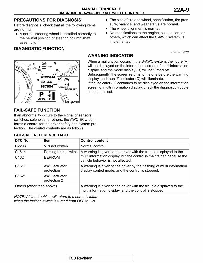
DIAGNOSTIC FUNCTIONM1221007700078
WARNING INDICATOR
AC710447AB
(B) (C)
(A)
SERVICE REQUIRED
When a malfunction occurs in the S-AWC system, the figure (A) will be displayed on the information screen of multi information display, and the mode display (B) will be turned off.Subsequently, the screen returns to the one before the warning display, and then "!" indicator (C) will illuminate.If the indicator (C) continues to be displayed on the information screen of multi information display, check the diagnostic trouble code that is set.
FAIL-SAFE FUNCTIONIf an abnormality occurs to the signal of sensors, switches, solenoids, or others, the AWC-ECU per-forms a control for the driver safety and system pro-tection. The control contents are as follows.
FAIL-SAFE REFERENCE TABLEDTC No. Item Control contentC2203 VIN not written Normal controlC1614 Parking brake switch A warning is given to the driver with the trouble displayed to the
multi information display, but the control is maintained because the vehicle behavior is not affected.
C1624 EEPROM
C161F AWC actuator protection 1
A warning is given to the driver by the flashing of multi information display control mode, and the control is stopped.
C1621 AWC actuator protection 2
Others (other than above) A warning is given to the driver with the trouble displayed to the multi information display, and the control is stopped.
NOTE: All the troubles will return to a normal status when the ignition switch is turned from OFF to ON.
TSB Revision
DIAGNOSIS <S-AWC(SUPER ALL WHEEL CONTROL)>MANUAL TRANSAXLE22A-10
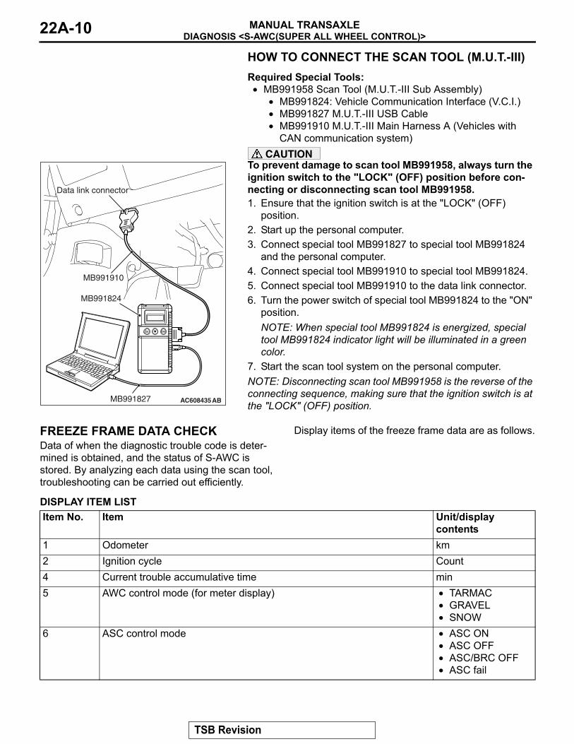
HOW TO CONNECT THE SCAN TOOL (M.U.T.-III)Required Special Tools:• MB991958 Scan Tool (M.U.T.-III Sub Assembly)
• MB991824: Vehicle Communication Interface (V.C.I.)• MB991827 M.U.T.-III USB Cable•
AC608435
Data link connector
MB991827
MB991824
MB991910
AB
MB991910 M.U.T.-III Main Harness A (Vehicles with CAN communication system)
CAUTIONTo prevent damage to scan tool MB991958, always turn the ignition switch to the "LOCK" (OFF) position before con-necting or disconnecting scan tool MB991958.1. Ensure that the ignition switch is at the "LOCK" (OFF)
position.2. Start up the personal computer.3. Connect special tool MB991827 to special tool MB991824
and the personal computer.4. Connect special tool MB991910 to special tool MB991824.5. Connect special tool MB991910 to the data link connector.6. Turn the power switch of special tool MB991824 to the "ON"
position.NOTE: When special tool MB991824 is energized, special tool MB991824 indicator light will be illuminated in a green color.
7. Start the scan tool system on the personal computer.NOTE: Disconnecting scan tool MB991958 is the reverse of the connecting sequence, making sure that the ignition switch is at the "LOCK" (OFF) position.
FREEZE FRAME DATA CHECKData of when the diagnostic trouble code is deter-mined is obtained, and the status of S-AWC is stored. By analyzing each data using the scan tool, troubleshooting can be carried out efficiently.
Display items of the freeze frame data are as follows.
DISPLAY ITEM LISTItem No. Item Unit/display
contents1 Odometer km2 Ignition cycle Count4 Current trouble accumulative time min5 AWC control mode (for meter display) • TARMAC
• GRAVEL• SNOW
6 ASC control mode • ASC ON• ASC OFF• ASC/BRC OFF• ASC fail
TSB Revision
DIAGNOSIS <S-AWC(SUPER ALL WHEEL CONTROL)>MANUAL TRANSAXLE 22A-11
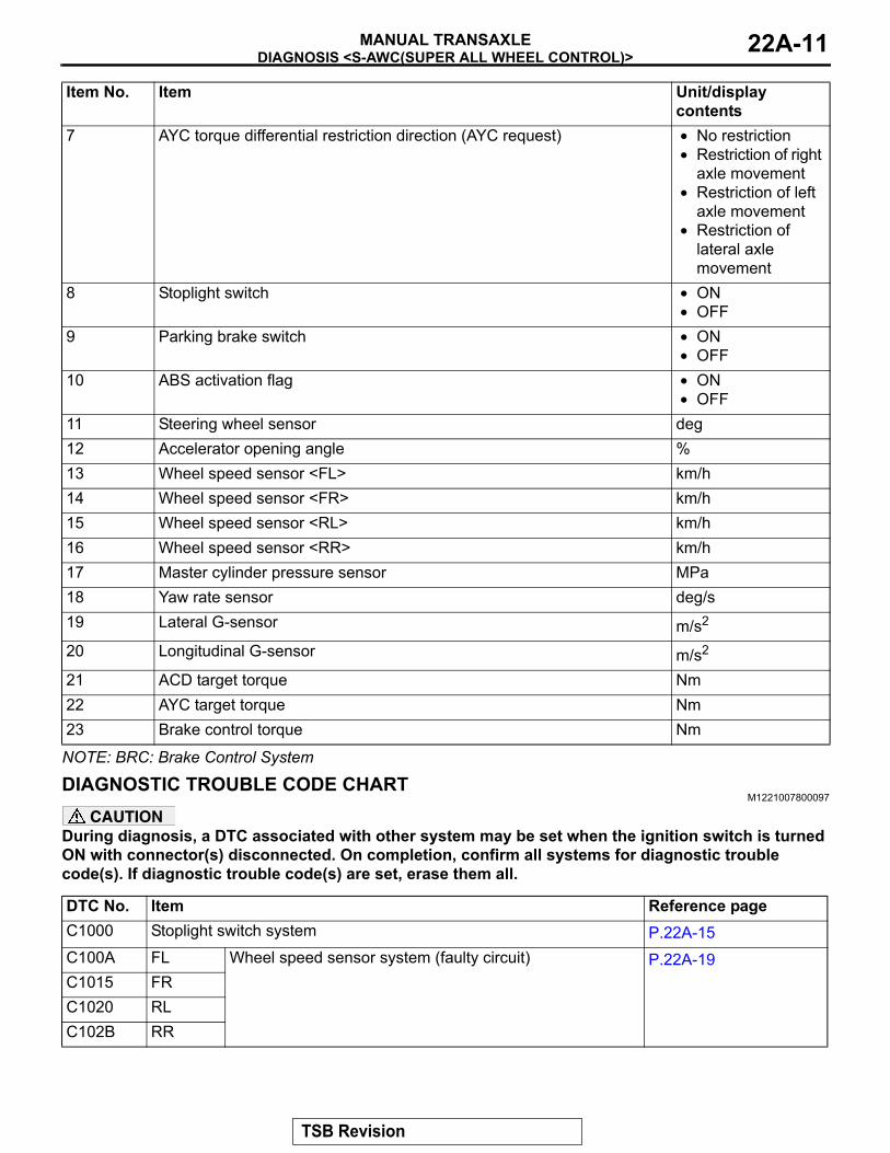
NOTE: BRC: Brake Control System
DIAGNOSTIC TROUBLE CODE CHARTM1221007800097
CAUTIONDuring diagnosis, a DTC associated with other system may be set when the ignition switch is turned ON with connector(s) disconnected. On completion, confirm all systems for diagnostic trouble code(s). If diagnostic trouble code(s) are set, erase them all.
7 AYC torque differential restriction direction (AYC request) • No restriction• Restriction of right
axle movement• Restriction of left
axle movement• Restriction of
lateral axle movement
8 Stoplight switch • ON• OFF
9 Parking brake switch • ON• OFF
10 ABS activation flag • ON• OFF
11 Steering wheel sensor deg12 Accelerator opening angle %13 Wheel speed sensor <FL> km/h14 Wheel speed sensor <FR> km/h15 Wheel speed sensor <RL> km/h16 Wheel speed sensor <RR> km/h17 Master cylinder pressure sensor MPa18 Yaw rate sensor deg/s19 Lateral G-sensor m/s2
20 Longitudinal G-sensor m/s2
21 ACD target torque Nm22 AYC target torque Nm23 Brake control torque Nm
Item No. Item Unit/display contents
DTC No. Item Reference pageC1000 Stoplight switch system P.22A-15C100A FL Wheel speed sensor system (faulty circuit) P.22A-19C1015 FRC1020 RLC102B RR
TSB Revision

DIAGNOSIS <S-AWC(SUPER ALL WHEEL CONTROL)>MANUAL TRANSAXLE22A-12
C1011 FL Wheel speed sensor system (faulty signal) P.22A-20C101C FRC1027 RLC1032 RRC1014 FL Wheel speed sensor system (characteristics abnormality) P.22A-21C101F FRC102A RLC1035 RRC1078 Tire turning malfunction P.22A-22C1219 Steering wheel sensor system (faulty signal) P.22A-24C121A Steering wheel sensor system (neutral learning abnormality) P.22A-26C123C G and yaw rate sensor system (faulty signal) P.22A-27C1242 G and yaw rate sensor system (abnormality of longitudinal G sensor
output signal)P.22A-29
C1610 Electronic relay abnormality of AWC actuator power supply P.22A-31C1611 AWC pressure sensor system (low voltage) P.22A-33C1612 AWC pressure sensor system (high voltage) P.22A-35C1613 AWC switch system (ON sticking) P.22A-37 <Vehicles with
steering wheel audio remote control switch>
P.22A-40 <Vehicles without steering wheel audio remote control switch>
C1614 Parking brake switch system (ON sticking) P.22A-43C1615 Brake control prohibition request P.22A-45C1616 Cranking signal system (ON sticking) P.22A-46C1617 AWC CAN main data system (data not received) P.22A-49C1618 AWC CAN local data system (data not received) P.22A-50C1619 AYC current value (abnormal) Refer to GROUP 27 −
Troubleshooting P.27-8.C161A AYC direction valve (right) system (output abnormality) Refer to GROUP 27 −
Troubleshooting P.27-8.C161B AYC direction valve (left) system (output abnormality) Refer to GROUP 27 −
Troubleshooting P.27-8.C161C ACD proportioning valve system (malfunction) P.22A-53C161D Electric pump relay system (faulty circuit) P.22A-56C161E Electric pump system P.22A-59
DTC No. Item Reference page
TSB Revision
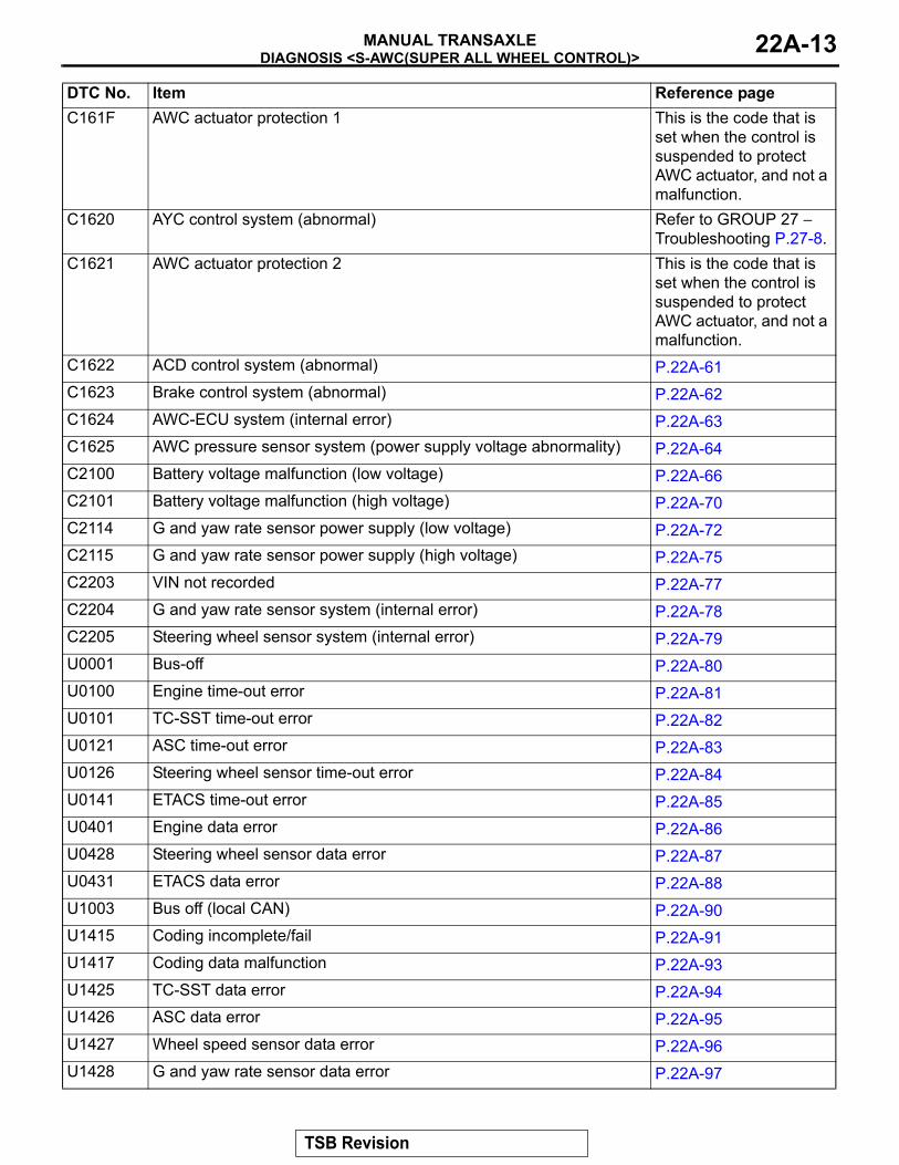
DIAGNOSIS <S-AWC(SUPER ALL WHEEL CONTROL)>MANUAL TRANSAXLE 22A-13
C161F AWC actuator protection 1 This is the code that is set when the control is suspended to protect AWC actuator, and not a malfunction.
C1620 AYC control system (abnormal) Refer to GROUP 27 − Troubleshooting P.27-8.
C1621 AWC actuator protection 2 This is the code that is set when the control is suspended to protect AWC actuator, and not a malfunction.
C1622 ACD control system (abnormal) P.22A-61C1623 Brake control system (abnormal) P.22A-62C1624 AWC-ECU system (internal error) P.22A-63C1625 AWC pressure sensor system (power supply voltage abnormality) P.22A-64C2100 Battery voltage malfunction (low voltage) P.22A-66C2101 Battery voltage malfunction (high voltage) P.22A-70C2114 G and yaw rate sensor power supply (low voltage) P.22A-72C2115 G and yaw rate sensor power supply (high voltage) P.22A-75C2203 VIN not recorded P.22A-77C2204 G and yaw rate sensor system (internal error) P.22A-78C2205 Steering wheel sensor system (internal error) P.22A-79U0001 Bus-off P.22A-80U0100 Engine time-out error P.22A-81U0101 TC-SST time-out error P.22A-82U0121 ASC time-out error P.22A-83U0126 Steering wheel sensor time-out error P.22A-84U0141 ETACS time-out error P.22A-85U0401 Engine data error P.22A-86U0428 Steering wheel sensor data error P.22A-87U0431 ETACS data error P.22A-88U1003 Bus off (local CAN) P.22A-90U1415 Coding incomplete/fail P.22A-91U1417 Coding data malfunction P.22A-93U1425 TC-SST data error P.22A-94U1426 ASC data error P.22A-95U1427 Wheel speed sensor data error P.22A-96U1428 G and yaw rate sensor data error P.22A-97
DTC No. Item Reference page
TSB Revision
DIAGNOSIS <S-AWC(SUPER ALL WHEEL CONTROL)>MANUAL TRANSAXLE22A-14
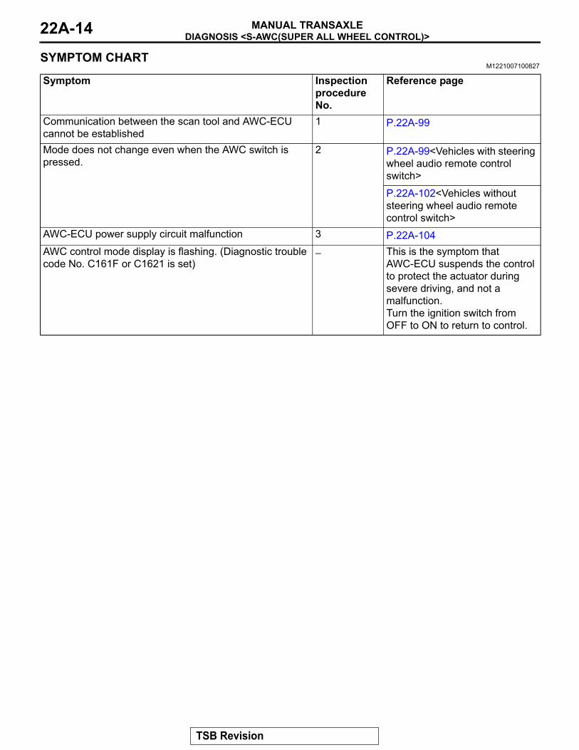
SYMPTOM CHARTM1221007100827
Symptom Inspection procedure No.
Reference page
Communication between the scan tool and AWC-ECU cannot be established
1 P.22A-99
Mode does not change even when the AWC switch is pressed.
2 P.22A-99<Vehicles with steering wheel audio remote control switch>
P.22A-102<Vehicles without steering wheel audio remote control switch>
AWC-ECU power supply circuit malfunction 3 P.22A-104AWC control mode display is flashing. (Diagnostic trouble code No. C161F or C1621 is set)
− This is the symptom that AWC-ECU suspends the control to protect the actuator during severe driving, and not a malfunction.Turn the ignition switch from OFF to ON to return to control.
TSB Revision

DIAGNOSIS <S-AWC(SUPER ALL WHEEL CONTROL)>MANUAL TRANSAXLE 22A-15
DIAGNOSTIC TROUBLE CODE PROCEDURES
DTC C1000: Stoplight Switch System
ETACS-ECU
STOPLIGHT SWITCH
FUSIBLELINK 34
JOINTCONNECTOR (4)
Stoplight switch system circuit
AC708950
Connectors: C-43, C-47, C-48
AI
C-43 (B)
C-47
C-48
AC708972BH
Connectors: C-304, C-309, C-312
C-304
C-312
ETACS-ECU
C-309 (B)
TSB Revision

DIAGNOSIS <S-AWC(SUPER ALL WHEEL CONTROL)>MANUAL TRANSAXLE22A-16
CAUTION• If there is any problem in the CAN bus lines,
an incorrect diagnostic trouble code may be set. Prior to this diagnosis, diagnose the CAN bus lines.
• Whenever the ECU is replaced, ensure that the CAN bus lines are normal.
.
OPERATIONAWC-ECU receives signals of stoplight switch from ETACS-ECU via the CAN bus lines..
DTC SET CONDITIONSThis diagnostic trouble code is set when the abnor-mality below is detected:
• The vehicle has run for a long time with the stop light switch turned ON.
• With the stoplight switch OFF, the vehicle speed is decelerated suddenly.
.
PROBABLE CAUSES• Incorrect adjustment of stoplight switch position• Malfunction of stoplight switch• Stoplight malfunction• Damaged harness wires and connectors• Malfunction of the ETACS-ECU• Malfunction of AWC-ECU
DIAGNOSTIC PROCEDURE
STEP 1. Scan tool CAN bus diagnosticsUsing scan tool MB991958, diagnose the CAN bus lines.Q: Is the check result normal?
YES : Go to Step 3.NO : Repair the CAN bus lines. (Refer to GROUP 54C −
Troubleshooting P.54C-14.) After repairing the CAN bus line, go to Step 2.
STEP 2. Check whether the DTC is reset.Q: Is DTC No. C1000 set?
YES : Go to Step 3.NO : This diagnosis is complete.
STEP 3. Check of the stoplight on and offCheck that the stoplight illuminates when the brake pedal is depressed, and the stoplight goes out when the brake pedal is released.Q: Is the check result normal?
YES : Go to Step 16.NO : Go to Step 4.
STEP 4. Stop light switch installation status checkRefer to GROUP 35A − On-vehicle Service P.35A-12.Q: Is the check result normal?
YES : Go to Step 5.NO : Install the stop light switch correctly. Then go to Step
21.
TSB Revision

DIAGNOSIS <S-AWC(SUPER ALL WHEEL CONTROL)>MANUAL TRANSAXLE 22A-17
STEP 5. Check the stop light switch.Refer to GROUP 35A − Brake Pedal P.35A-26.Q: Is the check result normal?
YES : Go to Step 6.NO : Replace the stoplight switch. (Refer to GROUP 35A −
Brake Pedal P.35A-25.) Then go to Step 21.
STEP 6. ETACS-ECU connector check: C-304Q: Is the check result normal?
YES : Go to Step 7.NO : Repair the defective connector. Then go to Step 21.
STEP 7. Measure the voltage at the C-304 ETACS-ECU connector.With C-304 ETACS-ECU connector connected, measure the voltage between the terminal No. 1 and the body ground.
OK: Battery voltage (when the brake pedal is released)Q: Is the check result normal?
YES : Go to Step 10.NO : Go to Step 8.
STEP 8. ETACS-ECU fuse No. 2 checkQ: Is the check result normal?
YES : Replace the ETACS-ECU. (Refer to GROUP 54A − ETACS-ECU P.54A-676.) Then go to Step 21.
NO : Replace fuse No. 2. Then go to Step 9.
STEP 9. Check the wiring harness between C-304 ETACS-ECU connector terminal No. 1 and C-48 stoplight switch connector terminal No. 2.Check that the wiring harness is not shorted (short to ground).Q: Is the check result normal?
YES : Go to Step 21.NO : Repair the wiring harness. Then go to Step 21.
STEP 10. Stop light switch connector check: C-48Q: Is the check result normal?
YES : Go to Step 11.NO : Repair the defective connector. Then go to Step 21.
STEP 11. Voltage measurement at the C-48 stoplight switch connectorDisconnect the connector, and measure the voltage between terminal No. 2 and ground at the wiring harness side.
OK: Battery positive voltageQ: Is the check result normal?
YES : Go to Step 13.NO : Go to Step 12.
TSB Revision
DIAGNOSIS <S-AWC(SUPER ALL WHEEL CONTROL)>MANUAL TRANSAXLE22A-18
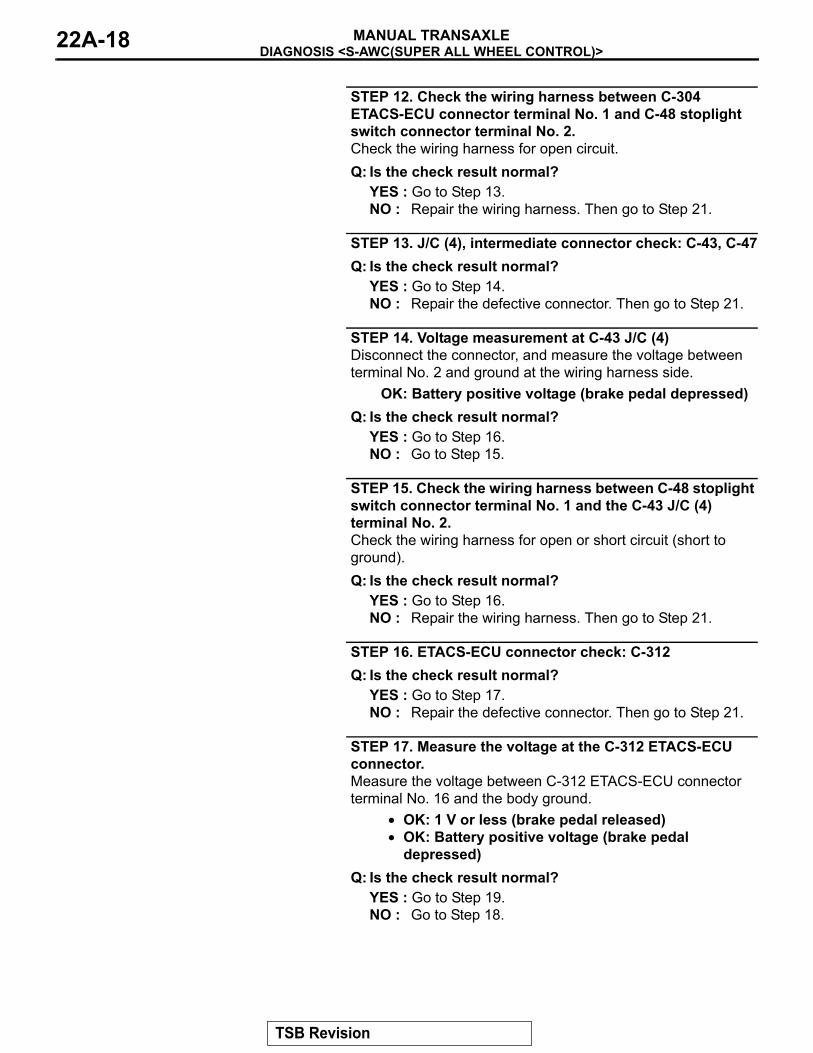
STEP 12. Check the wiring harness between C-304 ETACS-ECU connector terminal No. 1 and C-48 stoplight switch connector terminal No. 2.Check the wiring harness for open circuit.Q: Is the check result normal?
YES : Go to Step 13.NO : Repair the wiring harness. Then go to Step 21.
STEP 13. J/C (4), intermediate connector check: C-43, C-47Q: Is the check result normal?
YES : Go to Step 14.NO : Repair the defective connector. Then go to Step 21.
STEP 14. Voltage measurement at C-43 J/C (4)Disconnect the connector, and measure the voltage between terminal No. 2 and ground at the wiring harness side.
OK: Battery positive voltage (brake pedal depressed)Q: Is the check result normal?
YES : Go to Step 16.NO : Go to Step 15.
STEP 15. Check the wiring harness between C-48 stoplight switch connector terminal No. 1 and the C-43 J/C (4) terminal No. 2.Check the wiring harness for open or short circuit (short to ground).Q: Is the check result normal?
YES : Go to Step 16.NO : Repair the wiring harness. Then go to Step 21.
STEP 16. ETACS-ECU connector check: C-312Q: Is the check result normal?
YES : Go to Step 17.NO : Repair the defective connector. Then go to Step 21.
STEP 17. Measure the voltage at the C-312 ETACS-ECU connector.Measure the voltage between C-312 ETACS-ECU connector terminal No. 16 and the body ground.
• OK: 1 V or less (brake pedal released)• OK: Battery positive voltage (brake pedal
depressed)Q: Is the check result normal?
YES : Go to Step 19.NO : Go to Step 18.
TSB Revision
DIAGNOSIS <S-AWC(SUPER ALL WHEEL CONTROL)>MANUAL TRANSAXLE 22A-19
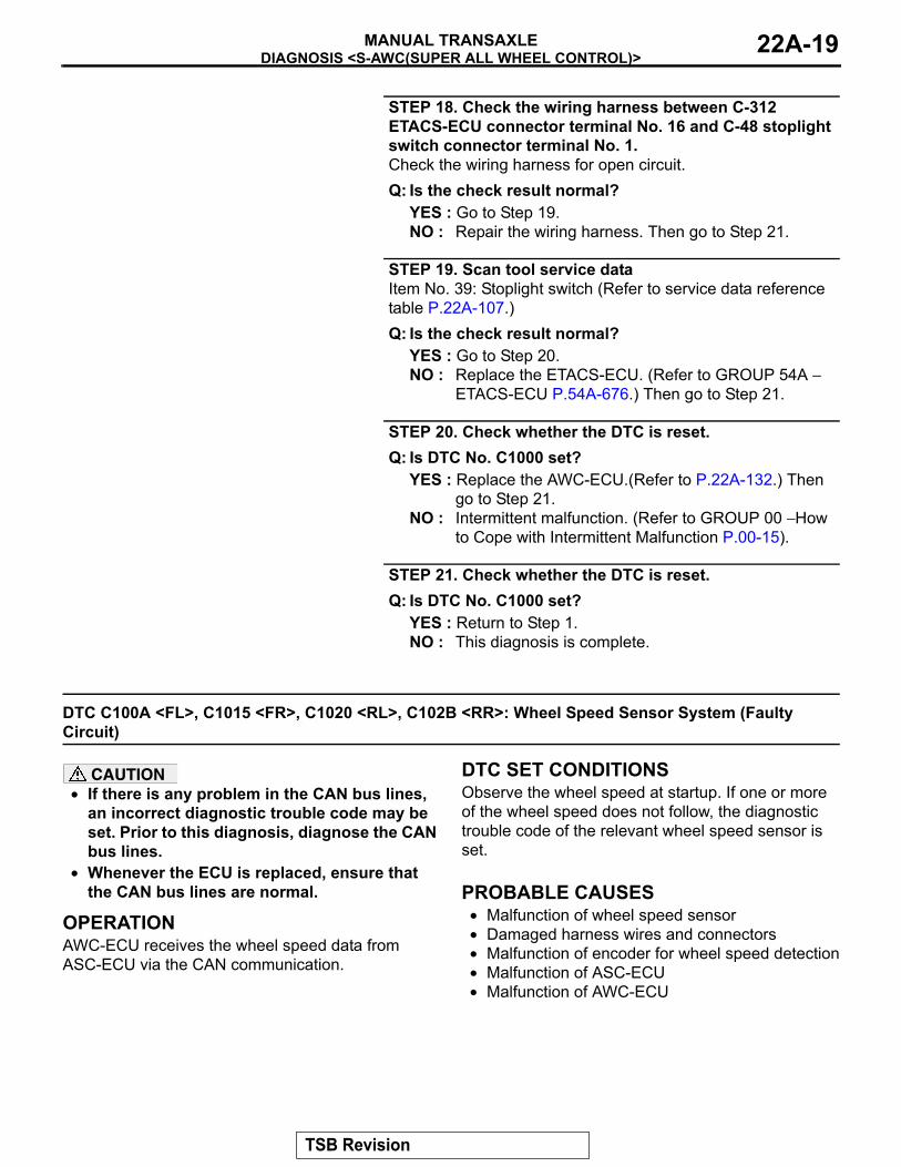
STEP 18. Check the wiring harness between C-312 ETACS-ECU connector terminal No. 16 and C-48 stoplight switch connector terminal No. 1.Check the wiring harness for open circuit.Q: Is the check result normal?
YES : Go to Step 19.NO : Repair the wiring harness. Then go to Step 21.
STEP 19. Scan tool service dataItem No. 39: Stoplight switch (Refer to service data reference table P.22A-107.)Q: Is the check result normal?
YES : Go to Step 20.NO : Replace the ETACS-ECU. (Refer to GROUP 54A −
ETACS-ECU P.54A-676.) Then go to Step 21.
STEP 20. Check whether the DTC is reset.Q: Is DTC No. C1000 set?
YES : Replace the AWC-ECU.(Refer to P.22A-132.) Then go to Step 21.
NO : Intermittent malfunction. (Refer to GROUP 00 − How to Cope with Intermittent Malfunction P.00-15).
STEP 21. Check whether the DTC is reset.Q: Is DTC No. C1000 set?
YES : Return to Step 1.NO : This diagnosis is complete.
DTC C100A <FL>, C1015 <FR>, C1020 <RL>, C102B <RR>: Wheel Speed Sensor System (Faulty Circuit)
CAUTION• If there is any problem in the CAN bus lines,
an incorrect diagnostic trouble code may be set. Prior to this diagnosis, diagnose the CAN bus lines.
• Whenever the ECU is replaced, ensure that the CAN bus lines are normal.
.
OPERATIONAWC-ECU receives the wheel speed data from ASC-ECU via the CAN communication..
DTC SET CONDITIONSObserve the wheel speed at startup. If one or more of the wheel speed does not follow, the diagnostic trouble code of the relevant wheel speed sensor is set..
PROBABLE CAUSES• Malfunction of wheel speed sensor• Damaged harness wires and connectors• Malfunction of encoder for wheel speed detection• Malfunction of ASC-ECU• Malfunction of AWC-ECU
TSB Revision

DIAGNOSIS <S-AWC(SUPER ALL WHEEL CONTROL)>MANUAL TRANSAXLE22A-20
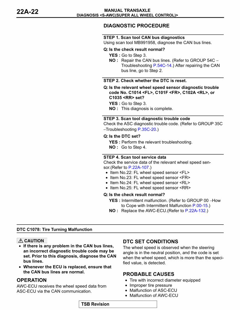
DIAGNOSTIC PROCEDURE
STEP 1. Scan tool CAN bus diagnosticsUsing scan tool MB991958, diagnose the CAN bus lines.Q: Is the check result normal?
YES : Go to Step 3.NO : Repair the CAN bus lines. (Refer to GROUP 54C −
Troubleshooting P.54C-14.) After repairing the CAN bus line, go to Step 2.
STEP 2. Check whether the DTC is reset.Q: Is the relevant wheel speed sensor diagnostic trouble
code No. C100A <FL>, C1015 <FR>, C1020 <RL>, or C102B <RR> set?YES : Go to Step 3.NO : This diagnosis is complete.
STEP 3. Scan tool diagnostic trouble codeCheck the ASC diagnostic trouble code. (Refer to GROUP 35C − Troubleshooting P.35C-20.)Q: Is the DTC set?
YES : Perform the relevant troubleshooting.NO : Go to Step 4.
STEP 4. Scan tool service dataCheck the service data of the relevant wheel speed sen-sor.(Refer to P.22A-107.)• Item No.22: FL wheel speed sensor <FL>• Item No.23: FL wheel speed sensor <FR>• Item No.24: FL wheel speed sensor <RL>• Item No.25: FL wheel speed sensor <RR>
Q: Is the check result normal?YES : Intermittent malfunction. (Refer to GROUP 00 − How
to Cope with Intermittent Malfunction P.00-15.)NO : Replace the AWC-ECU.(Refer to P.22A-132.)
DTC C1011 <FL>, C101C <FR>, C1027 <RL>, C1032 <RR>: Wheel Speed Sensor System (Faulty Signal)
CAUTION• If there is any problem in the CAN bus lines,
an incorrect diagnostic trouble code may be set. Prior to this diagnosis, diagnose the CAN bus lines.
• Whenever the ECU is replaced, ensure that the CAN bus lines are normal.
.
OPERATIONAWC-ECU receives the wheel speed data from ASC-ECU via the CAN communication.
.
DTC SET CONDITIONSWhen an irregular change in the wheel speed sensor is detected, the diagnostic trouble code of the rele-vant wheel speed sensor is set..
PROBABLE CAUSES• Malfunction of wheel speed sensor• Damaged harness wires and connectors• Malfunction of encoder for wheel speed detection• Malfunction of ASC-ECU• Malfunction of AWC-ECU
TSB Revision

DIAGNOSIS <S-AWC(SUPER ALL WHEEL CONTROL)>MANUAL TRANSAXLE 22A-21
DIAGNOSTIC PROCEDURE
STEP 1. Scan tool CAN bus diagnosticsUsing scan tool MB991958, diagnose the CAN bus lines.Q: Is the check result normal?
YES : Go to Step 3.NO : Repair the CAN bus lines. (Refer to GROUP 54C −
Troubleshooting P.54C-14.) After repairing the CAN bus line, go to Step 2.
STEP 2. Check whether the DTC is reset.Q: Is the relevant wheel speed sensor diagnostic trouble
code No. C1011 <FL>, C101C <FR>, C1027 <RL>, or C1032 <RR> set?YES : Go to Step 3.NO : This diagnosis is complete.
STEP 3. Scan tool diagnostic trouble codeCheck the ASC diagnostic trouble code. (Refer to GROUP 35C − Troubleshooting P.35C-20.)Q: Is the DTC set?
YES : Perform the relevant troubleshooting.NO : Go to Step 4.
STEP 4. Scan tool service dataCheck the service data of the relevant wheel speed sen-sor.(Refer to P.22A-107.)• Item No.22: FL wheel speed sensor <FL>• Item No.23: FL wheel speed sensor <FR>• Item No.24: FL wheel speed sensor <RL>• Item No.25: FL wheel speed sensor <RR>
Q: Is the check result normal?YES : Intermittent malfunction. (Refer to GROUP 00 − How
to Cope with Intermittent Malfunction P.00-15.)NO : Replace the AWC-ECU.(Refer to P.22A-132.)
DTC C1014 <FL>, C101F <FR>, C102A <RL>, C1035 <RR>: Wheel speed sensor system (characteristics abnormality)
CAUTION• If there is any problem in the CAN bus lines,
an incorrect diagnostic trouble code may be set. Prior to this diagnosis, diagnose the CAN bus lines.
• Whenever the ECU is replaced, ensure that the CAN bus lines are normal.
.
OPERATIONAWC-ECU receives the wheel speed data from ASC-ECU via the CAN communication.
.
DTC SET CONDITIONSIf one or more of the wheel speed is out of the range of the specified value, the diagnostic trouble code of the relevant wheel speed sensor is set..
PROBABLE CAUSES• Malfunction of wheel speed sensor• Damaged harness wires and connectors• Malfunction of encoder for wheel speed detection• Malfunction of ASC-ECU• Malfunction of AWC-ECU
TSB Revision
DIAGNOSIS <S-AWC(SUPER ALL WHEEL CONTROL)>MANUAL TRANSAXLE22A-22
DIAGNOSTIC PROCEDURE
STEP 1. Scan tool CAN bus diagnosticsUsing scan tool MB991958, diagnose the CAN bus lines.Q: Is the check result normal?
YES : Go to Step 3.NO : Repair the CAN bus lines. (Refer to GROUP 54C −
Troubleshooting P.54C-14.) After repairing the CAN bus line, go to Step 2.
STEP 2. Check whether the DTC is reset.Q: Is the relevant wheel speed sensor diagnostic trouble
code No. C1014 <FL>, C101F <FR>, C102A <RL>, or C1035 <RR> set?YES : Go to Step 3.NO : This diagnosis is complete.
STEP 3. Scan tool diagnostic trouble codeCheck the ASC diagnostic trouble code. (Refer to GROUP 35C − Troubleshooting P.35C-20.)Q: Is the DTC set?
YES : Perform the relevant troubleshooting.NO : Go to Step 4.
STEP 4. Scan tool service dataCheck the service data of the relevant wheel speed sen-sor.(Refer to P.22A-107.)• Item No.22: FL wheel speed sensor <FL>• Item No.23: FL wheel speed sensor <FR>• Item No.24: FL wheel speed sensor <RL>• Item No.25: FL wheel speed sensor <RR>
Q: Is the check result normal?YES : Intermittent malfunction. (Refer to GROUP 00 − How
to Cope with Intermittent Malfunction P.00-15.)NO : Replace the AWC-ECU.(Refer to P.22A-132.)
DTC C1078: Tire Turning Malfunction
CAUTION• If there is any problem in the CAN bus lines,
an incorrect diagnostic trouble code may be set. Prior to this diagnosis, diagnose the CAN bus lines.
• Whenever the ECU is replaced, ensure that the CAN bus lines are normal.
.
OPERATIONAWC-ECU receives the wheel speed data from ASC-ECU via the CAN communication.
.
DTC SET CONDITIONSThe wheel speed is observed when the steering angle is in the neutral position, and the code is set when the wheel speed, which is more than the speci-fied value, is detected..
PROBABLE CAUSES• Tire with incorrect diameter equipped• Improper tire pressure• Malfunction of ASC-ECU• Malfunction of AWC-ECU
TSB Revision
DIAGNOSIS <S-AWC(SUPER ALL WHEEL CONTROL)>MANUAL TRANSAXLE 22A-23
DIAGNOSTIC PROCEDURE
STEP 1. Scan tool CAN bus diagnosticsUsing scan tool MB991958, diagnose the CAN bus lines.Q: Is the check result normal?
YES : Go to Step 3.NO : Repair the CAN bus line (Refer to GROUP 54C −
Troubleshooting P.54C-14). After repairing the CAN bus line, go to Step 2.
STEP 2. Check whether the DTC is reset.Q: Is DTC No. C1078 set?
YES : Go to Step 3.NO : This diagnosis is complete.
STEP 3. Check the tiresCheck that the wheels/tires with the identical size are installed, and that each tire pressure is within the value specified on the tire pressure label.Q: Is the check result normal?
YES : Go to Step 4.NO : Install the wheels/tires with the identical size, or adjust
the tire pressure. Then go to Step 5.
STEP 4. Scan tool diagnostic trouble codeCheck the ASC diagnostic trouble code. (Refer to GROUP 35C − Troubleshooting P.35C-20.)Q: Is the DTC set?
YES : Perform the relevant troubleshooting.NO : Go to Step 5.
STEP 5. Scan tool service dataCheck the following service data. (Refer to P.22A-107.)• Item No.22: FL wheel speed sensor <FL>• Item No.23: FL wheel speed sensor <FR>• Item No.24: FL wheel speed sensor <RL>• Item No.25: FL wheel speed sensor <RR>
Q: Is the check result normal?YES : Intermittent malfunction. (Refer to GROUP 00 − How
to Cope with Intermittent Malfunction P.00-15.)NO : Replace the AWC-ECU.(Refer to P.22A-132.)
TSB Revision
DIAGNOSIS <S-AWC(SUPER ALL WHEEL CONTROL)>MANUAL TRANSAXLE22A-24
DTC C1219: Steering Wheel Sensor System (Faulty Signal)
CAUTION• If there is any problem in the CAN bus lines,
an incorrect diagnostic trouble code may be set. Prior to this diagnosis, diagnose the CAN bus lines.
• Whenever the ECU is replaced, ensure that the CAN bus lines are normal.
• When the steering wheel sensor is replaced, calibrate the steering wheel sensor (refer to GROUP 35C − On-vehicle Service P.35C-267), and initialize the steering angle correction amount stored in AWC-ECU. (Item No.09: Steering angle correction amount initializa-tion P.22A-113.)
• Do not drop the G and yaw rate sensor or sub-ject it to a shock.
• When G and yaw rate sensor is replaced, cali-brate G and yaw rate sensor (refer to GROUP 35C − On-vehicle Service P.35C-266), and ini-tialize the lateral/longitudinal acceleration correction amount stored in AWC-ECU. (Refer to item No.10: Lateral acceleration correction amount initialization, and No. 11: Longitudinal acceleration correction amount initialization P.22A-113.)
.
OPERATIONAWC-ECU receives steering wheel data from the steering wheel sensor via CAN communication..
DTC SET CONDITIONSThis diagnostic trouble code is set when the abnor-mality below is detected:
• The tolerance of neutral position of steering wheel sensor exceeds the specified range.
• Abnormality in steering wheel sensor output value
• Abnormality is detected by a comparison of out-put value from the steering wheel sensor with the output values from wheel speed sensor and G and yaw rate sensor.
.
PROBABLE CAUSES• Improper installation of steering wheel sensor• Malfunction of steering wheel sensor• Malfunction of G and yaw rate sensor• Malfunction of wheel speed sensor• Malfunction of AWC-ECU• Vehicle straight-ahead position and steering
wheel neutral position is not matched.
DIAGNOSTIC PROCEDURE
STEP 1. Scan tool CAN bus diagnosticsUsing scan tool MB991958, diagnose the CAN bus lines.Q: Is the check result normal?
YES : Go to Step 3.NO : Repair the CAN bus lines. (Refer to GROUP 54C −
Troubleshooting P.54C-14.) After repairing the CAN bus line, go to Step 2.
STEP 2. Check whether the DTC is reset.Q: Is DTC No. C1219 set?
YES : Go to Step 3.NO : This diagnosis is complete.
STEP 3. Scan tool diagnostic trouble codeQ: Is DTC No. C2205 set?
YES : Perform the relevant troubleshooting.NO : Go to Step 4.
TSB Revision
DIAGNOSIS <S-AWC(SUPER ALL WHEEL CONTROL)>MANUAL TRANSAXLE 22A-25
STEP 4. Scan tool diagnostic trouble codeCheck if the wheel speed sensor-related, G and yaw rate sen-sor-related, or steering wheel sensor-related diagnostic trouble code is set.Q: Is the DTC set?
YES : Carry out the appropriate troubleshooting. Then go to Step 9.
NO : Go to Step 5.
STEP 5. Check of steering wheel sensor installation statusCheck that the steering wheel sensor is installed correctly. (Refer to GROUP 35C − Steering Wheel Sensor P.35C-279.)Q: Is the check result normal?
YES : Go to Step 6.NO : Install the steering wheel sensor correctly. Then go to
Step 6.
STEP 6. Wheel alignment checkQ: Is the check result normal?
YES : After checking the wheel alignment, calibrate the steering wheel sensor (refer to GROUP 35C − On-vehicle Service P.35C-267,) and initialize AWC-ECU steering angle correction amount (refer to P.22A-113.) Then, go to Step 7.
NO : After adjusting the wheel alignment, calibrate the steering wheel sensor (refer to GROUP 35C − On-vehicle Service P.35C-267,) and initialize AWC-ECU steering angle correction amount (refer to P.22A-113.) Then, go to Step 7.
STEP 7. Scan tool service dataItem 11: Steering wheel sensor (refer to P.22A-107.)Q: Is the check result normal?
YES : Go to Step 8.NO : Replace the steering wheel sensor. (Refer to GROUP
35C − Steering Wheel Sensor P.35C-279.) Then, go to Step 9.
STEP 8. Check whether the DTC is reset.Q: Is DTC No. C1219 set?
YES : Replace the AWC-ECU.(Refer to P.22A-132.) Then, go to Step 9.
NO : Intermittent malfunction. (Refer to GROUP 00 − How to Cope with Intermittent Malfunction P.00-15.)
STEP 9. Check whether the DTC is reset.Q: Is DTC No. C1219 set?
YES : Return to Step 1.NO : This diagnosis is complete.
TSB Revision
DIAGNOSIS <S-AWC(SUPER ALL WHEEL CONTROL)>MANUAL TRANSAXLE22A-26
DTC C121A: Steering Wheel Sensor System (neutral learning abnormality)
CAUTION• If there is any problem in the CAN bus lines,
an incorrect diagnostic trouble code may be set. Prior to this diagnosis, diagnose the CAN bus lines.
• Whenever the ECU is replaced, ensure that the CAN bus lines are normal.
• When the steering wheel sensor is replaced, calibrate the steering wheel sensor (refer to GROUP 35C − On-vehicle Service P.35C-267), and initialize the steering angle correction amount stored in AWC-ECU. (Item No.09: Steering angle correction amount initializa-tion P.22A-113.)
.
OPERATIONSteering wheel sensor stores the neutral position learned by the scan tool. When the neutral position has not been learned, the steering wheel sensor out-puts the signal indicating that the learning has not been performed..
DTC SET CONDITIONSThis DTC is set when it is detected that the steering wheel sensor has not learned the neutral position..
PROBABLE CAUSES• Steering wheel sensor neutral point not learned• Malfunction of steering wheel sensor• Malfunction of AWC ECU
DIAGNOSTIC PROCEDURE
STEP 1. Scan tool CAN bus diagnosticsUsing scan tool MB991958, diagnose the CAN bus lines.Q: Is the check result normal?
YES : Go to Step 3.NO : Repair the CAN bus lines. (Refer to GROUP 54C −
Troubleshooting P.54C-14.) After repairing the CAN bus line, go to Step 2.
STEP 2. Check whether the DTC is reset.Q: Is DTC No. C121A set?
YES : Go to Step 3.NO : This diagnosis is complete.
STEP 3. Steering wheel sensor calibrationPerform calibration of the steering wheel sensor. (Refer to GROUP 35C − On-vehicle Service P.35C-267.)Q: Has the calibration succeeded?
YES : Go to Step 4.NO : Replace the steering wheel sensor. (Refer to GROUP
35C − Steering Wheel Sensor P.35C-279.) Then, go to Step 4.
STEP 4. Check whether the DTC is reset.Q: Is DTC No. C121A set?
YES : Replace the AWC-ECU.(Refer to P.22A-132.) Then, go to Step 5.
NO : Intermittent malfunction. (Refer to GROUP 00 − How to Cope with Intermittent Malfunction P.00-15.)
TSB Revision
DIAGNOSIS <S-AWC(SUPER ALL WHEEL CONTROL)>MANUAL TRANSAXLE 22A-27
STEP 5. Check whether the DTC is reset.Q: Is DTC No. C121A set?
YES : Return to Step 1.NO : This diagnosis is complete.
DTC C123C: G and Yaw Rate Sensor (Faulty Signal)
CAUTION• If there is any problem in the CAN bus lines,
an incorrect diagnostic trouble code may be set. Prior to this diagnosis, diagnose the CAN bus lines.
• Whenever the ECU is replaced, ensure that the CAN bus lines are normal.
• When the steering wheel sensor is replaced, calibrate the steering wheel sensor (refer to GROUP 35C − On-vehicle Service P.35C-267), and initialize the steering angle correction amount stored in AWC-ECU. (Item No.09: Steering angle correction amount initializa-tion P.22A-113.)
• Do not drop the G and yaw rate sensor or sub-ject it to a shock.
• When G and yaw rate sensor is replaced, cali-brate G and yaw rate sensor (refer to GROUP 35C − On-vehicle Service P.35C-266), and ini-tialize the lateral/longitudinal acceleration correction amount stored in AWC-ECU. (Refer to item No.10: Lateral acceleration correction amount initialization, and No. 11: Longitudinal acceleration correction amount initialization P.22A-113.)
.
OPERATIONThe G and yaw rate sensor outputs the signal to ASC-ECU and AWC-ECU via the special CAN bus lines..
DTC SET CONDITIONSThis diagnostic trouble code is set when the abnor-mality below is detected:
• Abnormality in G and yaw rate sensor output value
• This diagnostic trouble code is set when AWC-ECU determines that an abnormality is present by comparing the measurement values of G and yaw rate sensor with the calculation value of G and yaw rate calculated by the measure-ment values of the wheel speed sensor and steering wheel sensor.
.
PROBABLE CAUSES• Improper installation of G and yaw rate sensor• Malfunction of G and yaw rate sensor• Malfunction of wheel speed sensor• Malfunction of steering wheel sensor• Malfunction of AWC-ECU
DIAGNOSTIC PROCEDURE
STEP 1. Scan tool CAN bus diagnosticsUsing scan tool MB991958, diagnose the CAN bus lines.Q: Is the check result normal?
YES : Go to Step 3.NO : Repair the CAN bus lines. (Refer to GROUP 54C −
Troubleshooting P.54C-14.) After repairing the CAN bus line, go to Step 2.
STEP 2. Check whether the DTC is reset.Q: Is DTC No. C123C set?
YES : Go to Step 3.NO : This diagnosis is complete.
TSB Revision
DIAGNOSIS <S-AWC(SUPER ALL WHEEL CONTROL)>MANUAL TRANSAXLE22A-28
STEP 3. Scan tool diagnostic trouble codeQ: Is DTC No. C2204 set?
YES : Perform the relevant troubleshooting.NO : Go to Step 4.
STEP 4. Scan tool diagnostic trouble codeCheck if the local CAN communication-related, wheel speed sensor-related, or steering wheel sensor-related diagnostic trouble code is set.Q: Is the DTC set?
YES : Perform the relevant troubleshooting.NO : Go to Step 5.
STEP 5. Check of G and yaw rate sensor installation statusCheck that the G and yaw rate sensor is installed correctly. (Refer to GROUP 35C − G and Yaw Rate Sensor P.35C-278.)Q: Is the check result normal?
YES : Go to Step 6.NO : Reinstall the G and yaw rate sensor correctly. Then
go to Step 6.
STEP 6. Scan tool service dataCheck the following service data. (Refer to P.22A-107.)• Item No. 26: Yaw rate sensor• Item No. 29: Lateral G sensor
Q: Is the check result normal?YES : Go to Step 7.NO : Replace the G and yaw rate sensor. (Refer to
GROUP 35C − G and Yaw Rate Sensor P.35C-278.) Then go to Step 11.
STEP 7. Check of steering wheel sensor installation statusCheck that the steering wheel sensor is installed correctly. (Refer to GROUP 35C − Steering Wheel Sensor P.35C-279.)Q: Is the check result normal?
YES : Go to Step 8.NO : Install the steering wheel sensor correctly. Then go to
Step 8.
TSB Revision
DIAGNOSIS <S-AWC(SUPER ALL WHEEL CONTROL)>MANUAL TRANSAXLE 22A-29
STEP 8. Wheel alignment checkQ: Is the check result normal?
YES : After checking the wheel alignment, calibrate the steering wheel sensor (refer to GROUP 35C − On-vehicle Service P.35C-267,) and initialize AWC-ECU steering angle correction amount (refer to P.22A-113.) Then go to Step 9.
NO : After adjusting the wheel alignment, calibrate the steering wheel sensor (refer to GROUP 35C − On-vehicle Service P.35C-267,) and initialize AWC-ECU steering angle correction amount (refer to P.22A-113.) Then go to Step 9.
STEP 9. Scan tool service dataItem 11: Steering wheel sensor (refer to P.22A-107.)Q: Is the check result normal?
YES : Go to Step 10.NO : Replace the steering wheel sensor. (Refer to GROUP
35C − Steering Wheel Sensor P.35C-279.) Then go to Step 10.
STEP 10. Check whether the DTC is reset.Q: Is DTC No. C123C set?
YES : Replace the AWC-ECU.(Refer to P.22A-132.) Then go to Step 11.
NO : Intermittent malfunction. (Refer to GROUP 00 − How to Cope with Intermittent Malfunction P.00-15.)
STEP 11. Check whether the DTC is reset.Q: Is DTC No. C123C set?
YES : Return to Step 1.NO : This diagnosis is complete.
DTC C1242: G and Yaw Rate Sensor (Longitudinal G Output Data Error)
CAUTION• If there is any problem in the CAN bus lines,
an incorrect diagnostic trouble code may be set. Prior to this diagnosis, diagnose the CAN bus lines.
• Whenever the ECU is replaced, ensure that the CAN bus lines are normal.
• Do not drop the G and yaw rate sensor or sub-ject it to a shock.
• When G and yaw rate sensor is replaced, cali-brate G and yaw rate sensor (refer to GROUP 35C − On-vehicle Service P.35C-266), and ini-tialize the lateral/longitudinal acceleration correction amount stored in AWC-ECU. (Refer
to item No.10: Lateral acceleration correction amount initialization, and No. 11: Longitudinal acceleration correction amount initialization P.22A-113.)
.
OPERATIONThe G and yaw rate sensor outputs the signal to ASC-ECU and AWC-ECU via the special CAN bus lines..
DTC set conditionsThis diagnostic trouble code is set when the abnor-mality below is detected:
TSB Revision
DIAGNOSIS <S-AWC(SUPER ALL WHEEL CONTROL)>MANUAL TRANSAXLE22A-30
• Abnormality in G and yaw rate sensor output value
• This diagnostic trouble code is set when AWC-ECU determines that an abnormality is present by comparing the longitudinal G that is output from the G and yaw rate sensor during braking with the calculation value calculated by the data from the wheel speed sensor.
.
PROBABLE CAUSES• Improper installation of G and yaw rate sensor• Malfunction of G and yaw rate sensor• Malfunction of wheel speed sensor• Malfunction of stoplight switch• Malfunction of AWC-ECU• Malfunction of ASC-ECU
Diagnostic procedure
STEP 1. Scan tool CAN bus diagnosticsUsing scan tool MB991958, diagnose the CAN bus lines.Q: Is the check result normal?
YES : Go to Step 3.NO : Repair the CAN bus lines. (Refer to GROUP 54C −
Troubleshooting P.54C-14.) After repairing the CAN bus line, go to Step 2.
STEP 2. Check whether the DTC is reset.Q: Is DTC No. C1242 set?
YES : Go to Step 3.NO : This diagnosis is complete.
STEP 3. Scan tool diagnostic trouble codeCheck the ASC diagnostic trouble code. (Refer to GROUP 35C − Troubleshooting P.35C-20.)Q: Is the DTC set?
YES : Perform the relevant troubleshooting.NO : Go to Step 4.
STEP 4. Scan tool diagnostic trouble codeQ: Is DTC No. C2204 set?
YES : Perform the relevant troubleshooting.NO : Go to Step 5.
STEP 5. Scan tool diagnostic trouble codeCheck if the local CAN communication-related, stoplight switch-related, or wheel speed sensor-related diagnostic trou-ble code is set.Q: Is the DTC set?
YES : Perform the relevant troubleshooting.NO : Go to Step 6.
TSB Revision
DIAGNOSIS <S-AWC(SUPER ALL WHEEL CONTROL)>MANUAL TRANSAXLE 22A-31
STEP 6. Check of G and yaw rate sensor installation statusCheck that the G and yaw rate sensor is installed correctly. (Refer to GROUP 35C − G and Yaw Rate Sensor P.35C-278.)Q: Is the check result normal?
YES : Go to Step 7.NO : Reinstall the G and yaw rate sensor correctly. Then
go to Step 7.
STEP 7. Scan tool service dataItem No. 31: Longitudinal G sensor (refer to P.22A-107.)Q: Is the check result normal?
YES : Go to Step 8.NO : Replace the G and yaw rate sensor. (Refer to
GROUP 35C − G and Yaw Rate Sensor P.35C-278.) Then go to Step 8.
STEP 8. Check whether the DTC is reset.Q: Is DTC No. C1242 set?
YES : Replace the AWC-ECU.(Refer to P.22A-132.) Then go to Step 9.
NO : Intermittent malfunction. (Refer to GROUP 00 − How to Cope with Intermittent Malfunction P.00-15.)
STEP 9. Check whether the DTC is reset.Q: Is DTC No. C1242 set?
YES : Return to Step 1.NO : This diagnosis is complete.
DTC C1610: AWC Actuator Power Supply Electronic Relay Malfunction
CAUTION• If there is any problem in the CAN bus lines,
an incorrect diagnostic trouble code may be set. Prior to this diagnosis, diagnose the CAN bus lines.
• Whenever the ECU is replaced, ensure that the CAN bus lines are normal.
.
OPERATIONA relay is incorporated in AWC-ECU, and the power is supplied to the actuator via this relay..
DTC SET CONDITIONSWhen the actuator power supply relay in AWC-ECU is seized, the code is set..
PROBABLE CAUSES• Malfunction of AWC-ECU
TSB Revision

DIAGNOSIS <S-AWC(SUPER ALL WHEEL CONTROL)>MANUAL TRANSAXLE22A-32
DIAGNOSTIC PROCEDURE
STEP 1. Scan tool CAN bus diagnosticsUsing scan tool MB991958, diagnose the CAN bus lines.Q: Is the check result normal?
YES : Go to Step 3.NO : Repair the CAN bus lines. (Refer to GROUP 54C −
Troubleshooting P.54C-14.) After repairing the CAN bus line, go to Step 2.
STEP 2. Check whether the DTC is reset.Q: Is DTC No. C1610 set?
YES : Replace the AWC-ECU.(Refer to P.22A-132.)NO : This diagnosis is complete.
STEP 3. Check whether the DTC is reset.Q: Is DTC No. C1610 set?
YES : Replace the AWC-ECU.(Refer to P.22A-132.)NO : Intermittent malfunction. (Refer to GROUP 00 − How
to Cope with Intermittent Malfunction P.00-15.)
TSB Revision
DIAGNOSIS <S-AWC(SUPER ALL WHEEL CONTROL)>MANUAL TRANSAXLE 22A-33
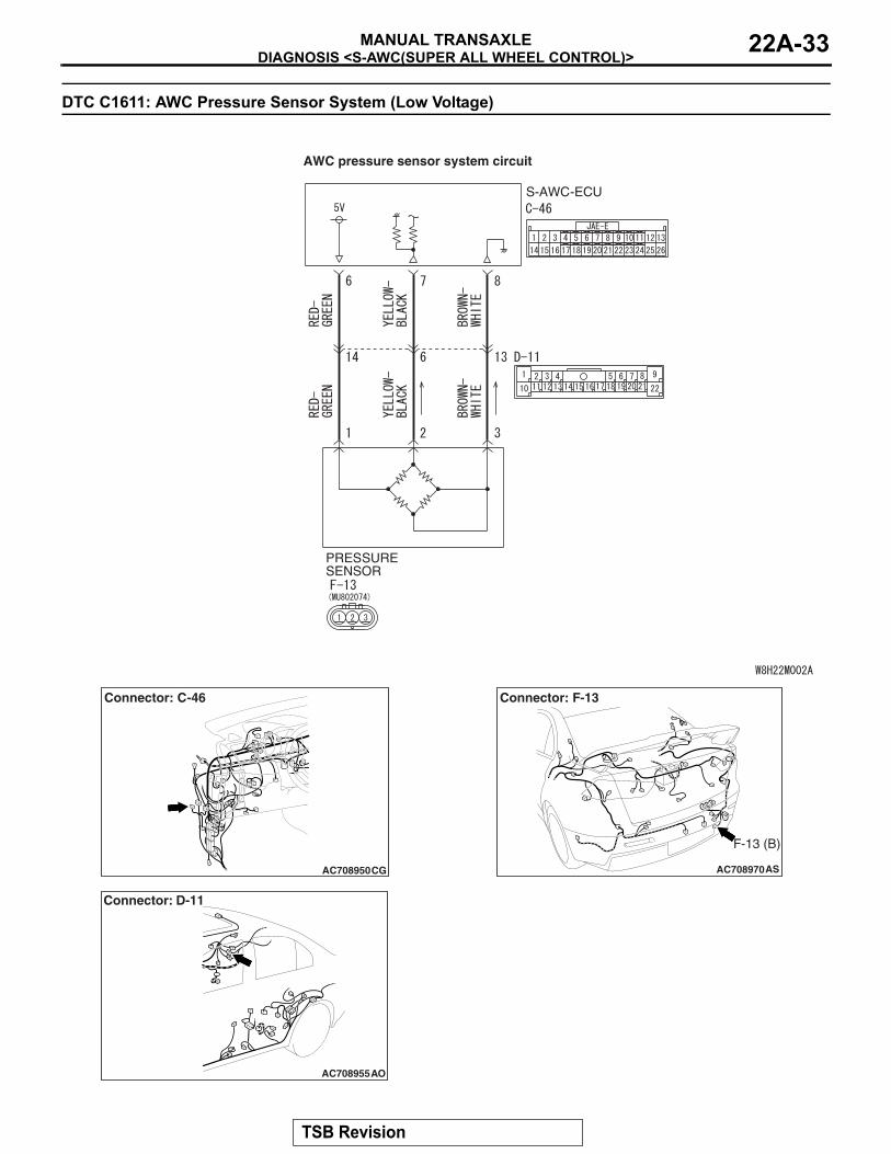
DTC C1611: AWC Pressure Sensor System (Low Voltage)
PRESSURE SENSOR
S-AWC-ECU
AWC pressure sensor system circuit
AC708950CG
Connector: C-46
AC708955
Connector: D-11
AO
AC708970AS
Connector: F-13
F-13 (B)
TSB Revision

DIAGNOSIS <S-AWC(SUPER ALL WHEEL CONTROL)>MANUAL TRANSAXLE22A-34
CAUTION• If there is any problem in the CAN bus lines,
an incorrect diagnostic trouble code may be set. Prior to this diagnosis, diagnose the CAN bus lines.
• Whenever the ECU is replaced, ensure that the CAN bus lines are normal.
.
OPERATIONAWC-ECU controls the electric pump by the informa-tion from AWC pressure sensor..
DTC SET CONDITIONSThe code is set when AWC pressure sensor output voltage is 0.2 V or less..
PROBABLE CAUSES• AWC pressure sensor malfunction• Damaged harness wires and connectors• Malfunction of AWC-ECU
DIAGNOSTIC PROCEDURE
STEP 1. Scan tool CAN bus diagnosticsUsing scan tool MB991958, diagnose the CAN bus lines.Q: Is the check result normal?
YES : Go to Step 3.NO : Repair the CAN bus lines. (Refer to GROUP 54C −
Troubleshooting P.54C-14.) After repairing the CAN bus line, go to Step 2.
STEP 2. Check whether the DTC is reset.Q: Is DTC No. C1611 set?
YES : Go to Step 3.NO : This diagnosis is complete.
STEP 3. AWC-ECU connector, intermediate connector, AWC pressure sensor connector check: C-46, D-11, F-13Q: Is the check result normal?
YES : Go to Step 4.NO : Repair the defective connector. Then go to Step 7.
STEP 4. Check the wiring harness between C-46 AWC-ECU connector terminal No. 7 and F-13 AWC pressure sensor connector terminal No. 2.Check the wiring harness for short circuit.Q: Is the check result normal?
YES : Go to Step 5.NO : Repair the wiring harness. Then go to Step 7.
STEP 5. Scan tool service dataItem No. 87: Pressure sensor output voltage (Refer to service data reference table P.22A-107.)Q: Is the check result normal?
YES : Go to Step 6.NO : Replace the hydraulic unit. (Refer to GROUP 27 −
Hydraulic Unit P.27-58.) Then go to Step 6.
TSB Revision
DIAGNOSIS <S-AWC(SUPER ALL WHEEL CONTROL)>MANUAL TRANSAXLE 22A-35
STEP 6. Check whether the DTC is reset.Q: Is DTC No. C1611 set?
YES : Replace the AWC-ECU.(Refer to P.22A-132.) Then, go to Step 7.
NO : Intermittent malfunction. (Refer to GROUP 00 − How to Cope with Intermittent Malfunction P.00-15.)
STEP 7. Check whether the DTC is reset.Q: Is DTC No. C1611 set?
YES : Return to Step 1.NO : This diagnosis is complete.
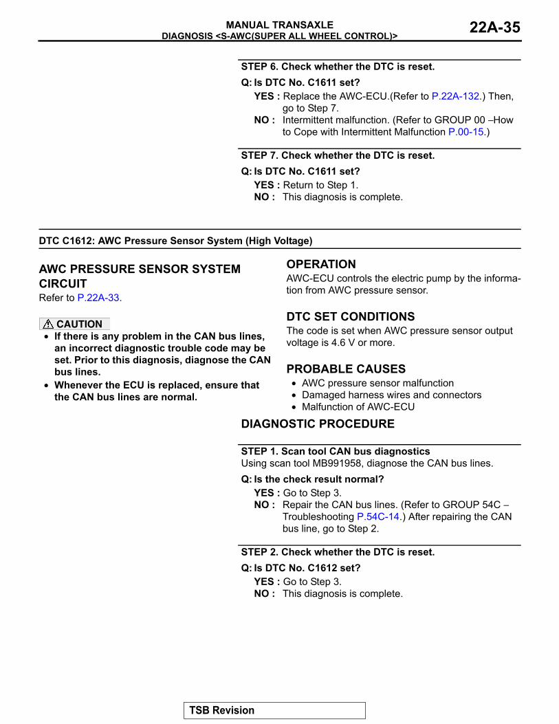
DTC C1612: AWC Pressure Sensor System (High Voltage)
.
AWC PRESSURE SENSOR SYSTEM CIRCUITRefer to P.22A-33.
CAUTION• If there is any problem in the CAN bus lines,
an incorrect diagnostic trouble code may be set. Prior to this diagnosis, diagnose the CAN bus lines.
• Whenever the ECU is replaced, ensure that the CAN bus lines are normal.
.
OPERATIONAWC-ECU controls the electric pump by the informa-tion from AWC pressure sensor..
DTC SET CONDITIONSThe code is set when AWC pressure sensor output voltage is 4.6 V or more..
PROBABLE CAUSES• AWC pressure sensor malfunction• Damaged harness wires and connectors• Malfunction of AWC-ECU
DIAGNOSTIC PROCEDURE
STEP 1. Scan tool CAN bus diagnosticsUsing scan tool MB991958, diagnose the CAN bus lines.Q: Is the check result normal?
YES : Go to Step 3.NO : Repair the CAN bus lines. (Refer to GROUP 54C −
Troubleshooting P.54C-14.) After repairing the CAN bus line, go to Step 2.
STEP 2. Check whether the DTC is reset.Q: Is DTC No. C1612 set?
YES : Go to Step 3.NO : This diagnosis is complete.
TSB Revision
DIAGNOSIS <S-AWC(SUPER ALL WHEEL CONTROL)>MANUAL TRANSAXLE22A-36
STEP 3. Scan tool diagnostic trouble codeCheck if the AWC-related DTC No. C1625 is set.(Refer to P.22A-11.)Q: Is the DTC set?
YES : Perform the relevant troubleshooting. Then go to Step 9.
NO : Go to Step 4.
STEP 4. AWC-ECU connector, intermediate connector, AWC pressure sensor connector check: C-46, D-11, F-13Q: Is the check result normal?
YES : Go to Step 5.NO : Repair the defective connector. Then go to Step 9.
STEP 5. Check the wiring harness between C-46 AWC-ECU connector terminal No. 7 and F-13 AWC pressure sensor connector terminal No. 2.Check the wiring harness for open or short circuit (short to power supply).Q: Is the check result normal?
YES : Go to Step 6.NO : Repair the wiring harness. Then go to Step 9.
STEP 6. Check the wiring harness between C-46 AWC-ECU connector terminal No. 8 and F-13 AWC pressure sensor connector terminal No. 3.Check the wiring harness for open circuit.Q: Is the check result normal?
YES : Go to Step 7.NO : Check D-11 intermediate connector. When no
problem is found, repair the wiring harness. Then go to Step 9.
STEP 7. Scan tool service dataItem No. 87: Pressure sensor output voltage (Refer to service data reference table P.22A-107.)Q: Is the check result normal?
YES : Go to Step 8.NO : Replace the hydraulic unit. (Refer to GROUP 27 −
Hydraulic Unit P.27-58.) Then go to Step 8.
STEP 8. Check whether the DTC is reset.Q: Is DTC No. C1612 set?
YES : Replace the AWC-ECU.(Refer to P.22A-132.) Then go to Step 9.
NO : Intermittent malfunction. (Refer to GROUP 00 − How to Cope with Intermittent Malfunction P.00-15.)
TSB Revision
DIAGNOSIS <S-AWC(SUPER ALL WHEEL CONTROL)>MANUAL TRANSAXLE 22A-37
STEP 9. Check whether the DTC is reset.Q: Is DTC No. C1612 set?
YES : Return to Step 1.NO : This diagnosis is complete.
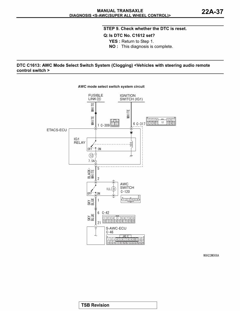
DTC C1613: AWC Mode Select Switch System (Clogging) <Vehicles with steering audio remote control switch >
ETACS-ECU
IGNITIONSWITCH (IG1)
FUSIBLELINK 34
S-AWC-ECU
AWC SWITCH
IG1RELAY
AWC mode select switch system circuit
TSB Revision
DIAGNOSIS <S-AWC(SUPER ALL WHEEL CONTROL)>MANUAL TRANSAXLE22A-38
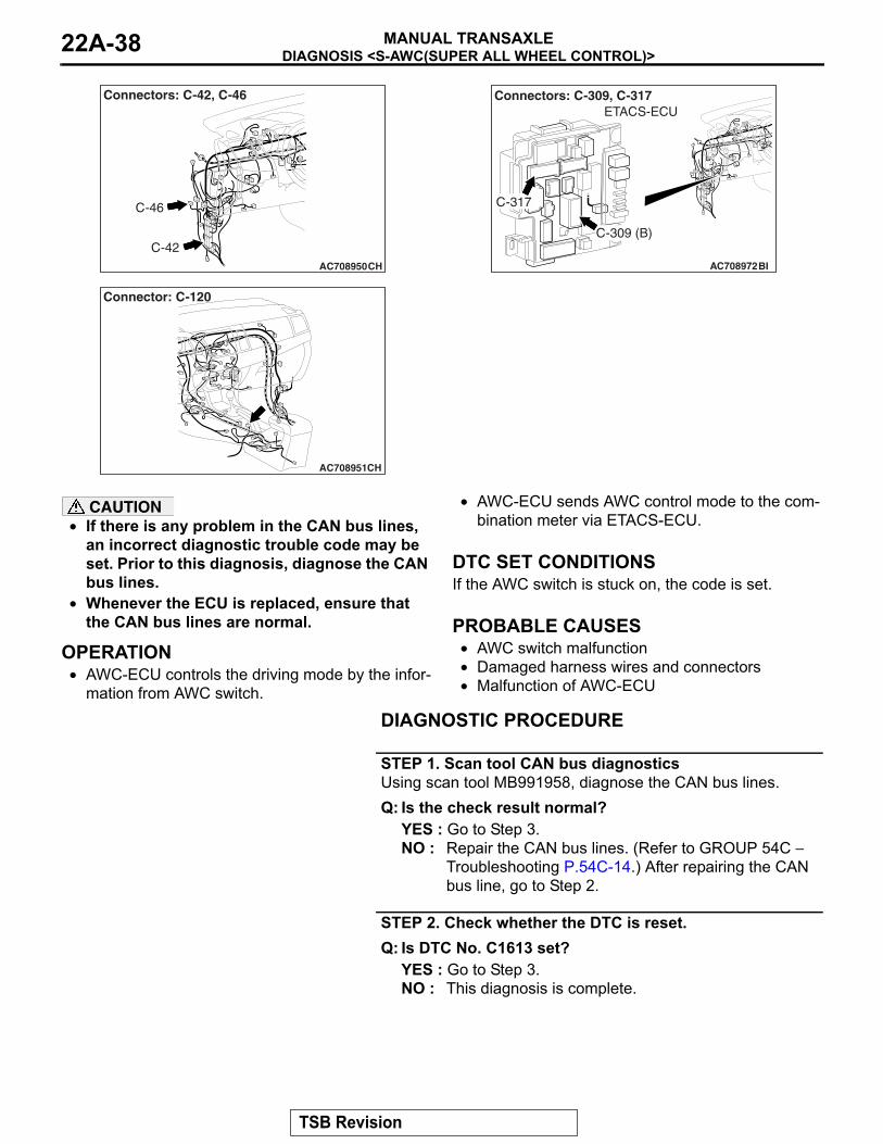
AC708950CH
C-42
Connectors: C-42, C-46
C-46
AC708951CH
Connector: C-120
AC708972BI
Connectors: C-309, C-317
C-309 (B)
C-317
ETACS-ECU
CAUTION• If there is any problem in the CAN bus lines,
an incorrect diagnostic trouble code may be set. Prior to this diagnosis, diagnose the CAN bus lines.
• Whenever the ECU is replaced, ensure that the CAN bus lines are normal.
.
OPERATION• AWC-ECU controls the driving mode by the infor-
mation from AWC switch.
• AWC-ECU sends AWC control mode to the com-bination meter via ETACS-ECU.
.
DTC SET CONDITIONSIf the AWC switch is stuck on, the code is set..
PROBABLE CAUSES• AWC switch malfunction• Damaged harness wires and connectors• Malfunction of AWC-ECU
DIAGNOSTIC PROCEDURE
STEP 1. Scan tool CAN bus diagnosticsUsing scan tool MB991958, diagnose the CAN bus lines.Q: Is the check result normal?
YES : Go to Step 3.NO : Repair the CAN bus lines. (Refer to GROUP 54C −
Troubleshooting P.54C-14.) After repairing the CAN bus line, go to Step 2.
STEP 2. Check whether the DTC is reset.Q: Is DTC No. C1613 set?
YES : Go to Step 3.NO : This diagnosis is complete.
TSB Revision
DIAGNOSIS <S-AWC(SUPER ALL WHEEL CONTROL)>MANUAL TRANSAXLE 22A-39
STEP 3. Intermediate connector, AWC-ECU connector, AWC switch connector check: C-42, C-46, C-120Q: Is the check result normal?
YES : Go to Step 4.NO : Repair the defective connector. Then go to Step 8.
STEP 4. Wiring harness check between C-46 AWC-ECU connector terminal No. 21 and C-120 AWC switch connector terminal No. 1Check the wiring harness for short circuit (short to power sup-ply).Q: Is the check result normal?
YES : Go to Step 5.NO : Repair the wiring harness. Then go to Step 8.
STEP 5. Scan tool service dataItem No. 89: AWC switch (Refer to service data reference table P.22A-107.)Q: Is the check result normal?
YES : Go to Step 7.NO : Go to Step 6.
STEP 6. AWC switch single unit checkCheck the AWC switch.(Refer to P.22A-133.)Q: Is the check result normal?
YES : Go to Step 7.NO : Replace the AWC switch.(Refer to P.22A-132.) Then
go to Step 8.
STEP 7. Check whether the DTC is reset.Q: Is DTC No. C1613 set?
YES : Replace the AWC-ECU.(Refer to P.22A-132.) Then go to Step 8.
NO : Intermittent malfunction. (Refer to GROUP 00 − How to Cope with Intermittent Malfunction P.00-15.)
STEP 8. Check whether the DTC is reset.Q: Is DTC No. C1613 set?
YES : Return to Step 1.NO : This diagnosis is complete.
TSB Revision
DIAGNOSIS <S-AWC(SUPER ALL WHEEL CONTROL)>MANUAL TRANSAXLE22A-40
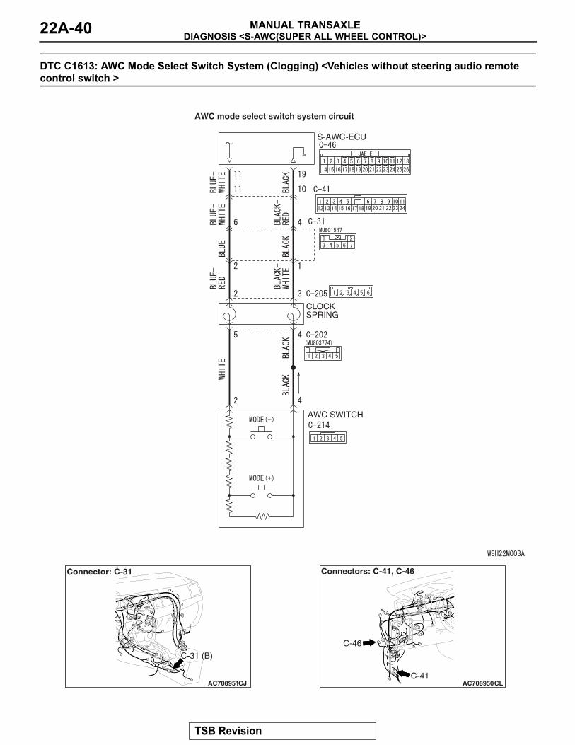
DTC C1613: AWC Mode Select Switch System (Clogging) <Vehicles without steering audio remote control switch >
AWC SWITCH
S-AWC-ECU
CLOCK SPRING
AWC mode select switch system circuit
AC708951CJ
Connector: C-31
C-31 (B)
AC708950CLC-41
C-46
Connectors: C-41, C-46
TSB Revision
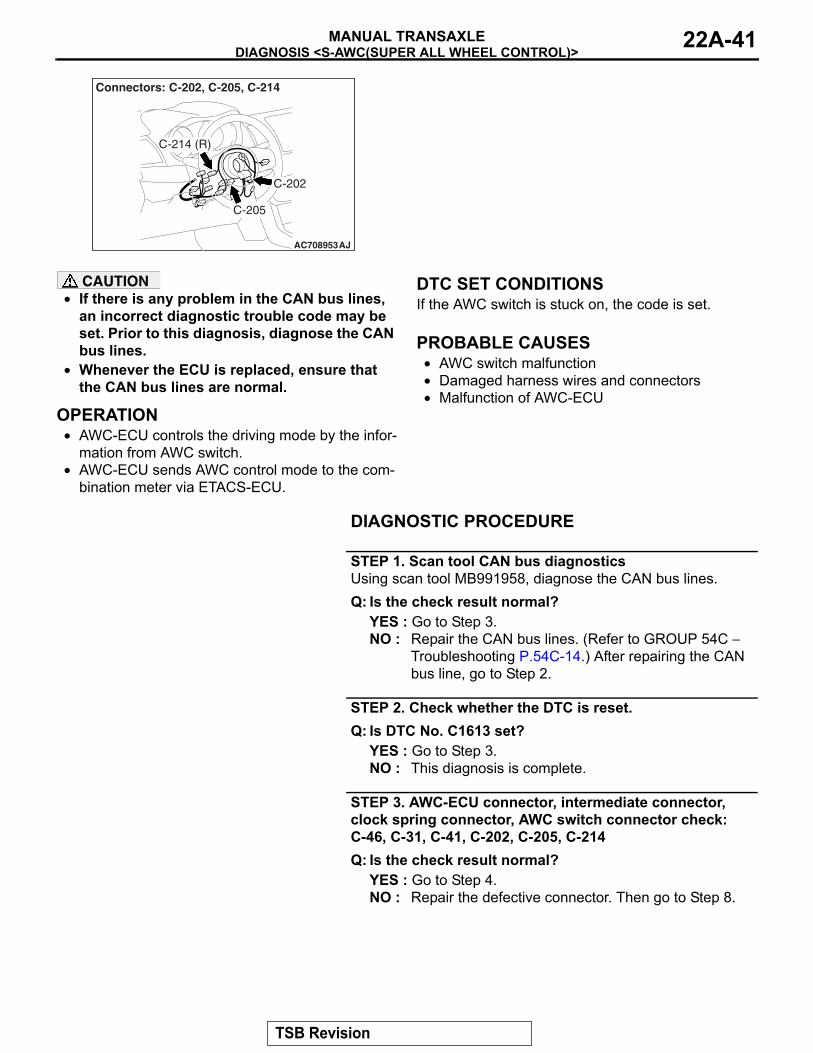
DIAGNOSIS <S-AWC(SUPER ALL WHEEL CONTROL)>MANUAL TRANSAXLE 22A-41
AC708953AJ
Connectors: C-202, C-205, C-214
C-205
C-202
C-214 (R)
CAUTION• If there is any problem in the CAN bus lines,
an incorrect diagnostic trouble code may be set. Prior to this diagnosis, diagnose the CAN bus lines.
• Whenever the ECU is replaced, ensure that the CAN bus lines are normal.
.
OPERATION• AWC-ECU controls the driving mode by the infor-
mation from AWC switch.• AWC-ECU sends AWC control mode to the com-
bination meter via ETACS-ECU.
.
DTC SET CONDITIONSIf the AWC switch is stuck on, the code is set..
PROBABLE CAUSES• AWC switch malfunction• Damaged harness wires and connectors• Malfunction of AWC-ECU
DIAGNOSTIC PROCEDURE
STEP 1. Scan tool CAN bus diagnosticsUsing scan tool MB991958, diagnose the CAN bus lines.Q: Is the check result normal?
YES : Go to Step 3.NO : Repair the CAN bus lines. (Refer to GROUP 54C −
Troubleshooting P.54C-14.) After repairing the CAN bus line, go to Step 2.
STEP 2. Check whether the DTC is reset.Q: Is DTC No. C1613 set?
YES : Go to Step 3.NO : This diagnosis is complete.
STEP 3. AWC-ECU connector, intermediate connector, clock spring connector, AWC switch connector check: C-46, C-31, C-41, C-202, C-205, C-214Q: Is the check result normal?
YES : Go to Step 4.NO : Repair the defective connector. Then go to Step 8.
TSB Revision
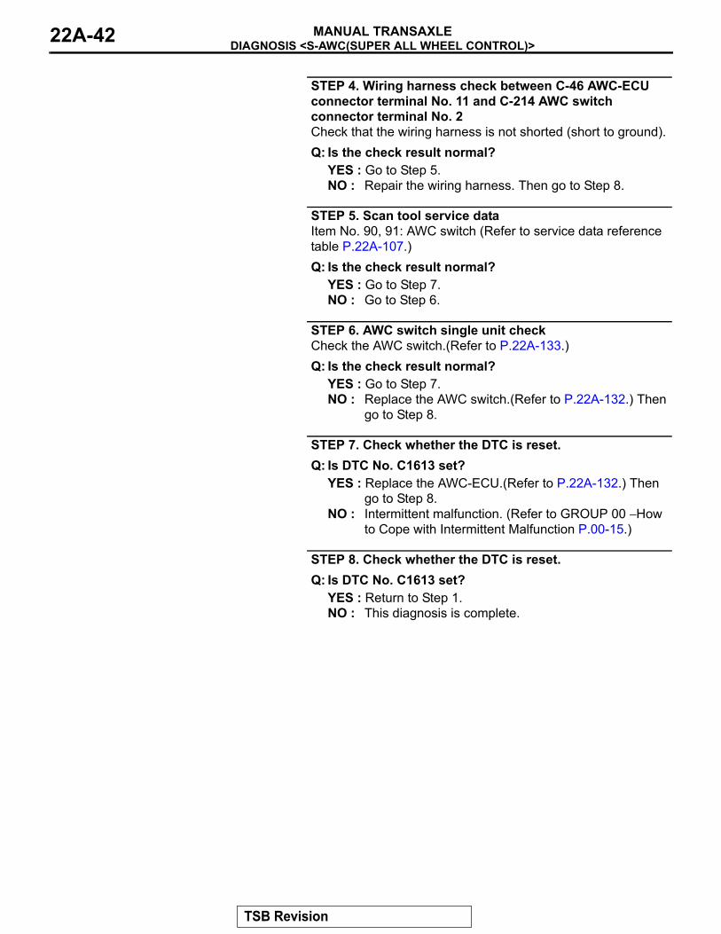
DIAGNOSIS <S-AWC(SUPER ALL WHEEL CONTROL)>MANUAL TRANSAXLE22A-42
STEP 4. Wiring harness check between C-46 AWC-ECU connector terminal No. 11 and C-214 AWC switch connector terminal No. 2Check that the wiring harness is not shorted (short to ground).Q: Is the check result normal?
YES : Go to Step 5.NO : Repair the wiring harness. Then go to Step 8.
STEP 5. Scan tool service dataItem No. 90, 91: AWC switch (Refer to service data reference table P.22A-107.)Q: Is the check result normal?
YES : Go to Step 7.NO : Go to Step 6.
STEP 6. AWC switch single unit checkCheck the AWC switch.(Refer to P.22A-133.)Q: Is the check result normal?
YES : Go to Step 7.NO : Replace the AWC switch.(Refer to P.22A-132.) Then
go to Step 8.
STEP 7. Check whether the DTC is reset.Q: Is DTC No. C1613 set?
YES : Replace the AWC-ECU.(Refer to P.22A-132.) Then go to Step 8.
NO : Intermittent malfunction. (Refer to GROUP 00 − How to Cope with Intermittent Malfunction P.00-15.)
STEP 8. Check whether the DTC is reset.Q: Is DTC No. C1613 set?
YES : Return to Step 1.NO : This diagnosis is complete.
TSB Revision
DIAGNOSIS <S-AWC(SUPER ALL WHEEL CONTROL)>MANUAL TRANSAXLE 22A-43
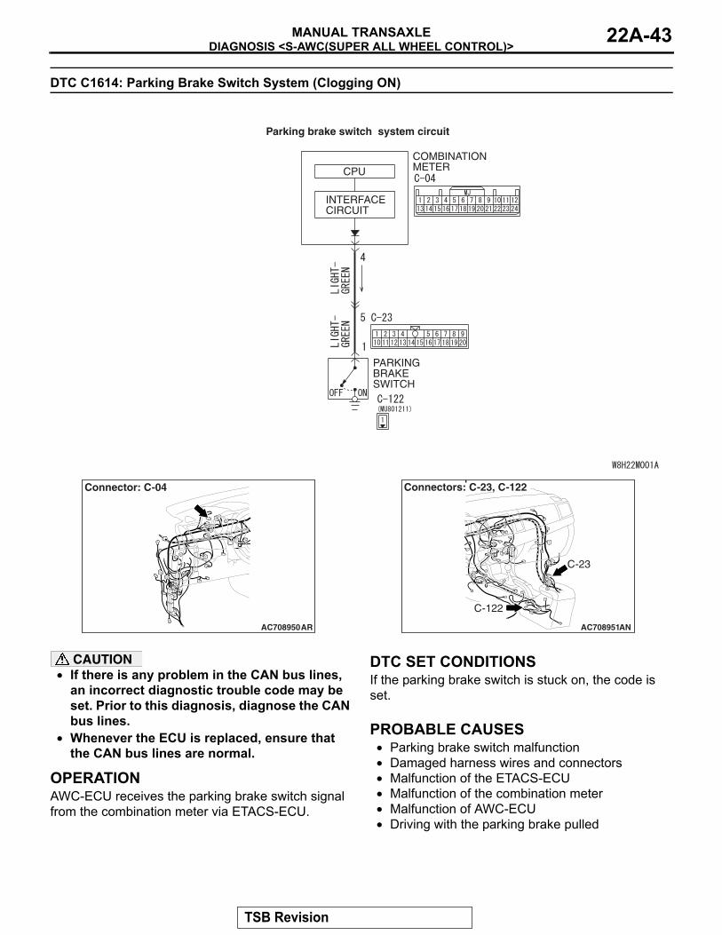
DTC C1614: Parking Brake Switch System (Clogging ON)
INTERFACECIRCUIT
CPUCOMBINATIONMETER
PARKING BRAKE SWITCH
Parking brake switch system circuit
AC708950
Connector: C-04
AR AC708951AN
C-23
C-122
Connectors: C-23, C-122
CAUTION• If there is any problem in the CAN bus lines,
an incorrect diagnostic trouble code may be set. Prior to this diagnosis, diagnose the CAN bus lines.
• Whenever the ECU is replaced, ensure that the CAN bus lines are normal.
.
OPERATIONAWC-ECU receives the parking brake switch signal from the combination meter via ETACS-ECU.
.
DTC SET CONDITIONSIf the parking brake switch is stuck on, the code is set..
PROBABLE CAUSES• Parking brake switch malfunction• Damaged harness wires and connectors• Malfunction of the ETACS-ECU• Malfunction of the combination meter• Malfunction of AWC-ECU• Driving with the parking brake pulled
TSB Revision
DIAGNOSIS <S-AWC(SUPER ALL WHEEL CONTROL)>MANUAL TRANSAXLE22A-44
DIAGNOSTIC PROCEDURE
STEP 1. Scan tool CAN bus diagnosticsUsing scan tool MB991958, diagnose the CAN bus lines.Q: Is the check result normal?
YES : Go to Step 3.NO : Repair the CAN bus lines. (Refer to GROUP 54C −
Troubleshooting P.54C-14.) After repairing the CAN bus line, go to Step 2.
STEP 2. Check whether the DTC is reset.Q: Is DTC No. C1614 set?
YES : Go to Step 3.NO : This diagnosis is complete.
STEP 3. Scan tool service dataItem 40: Parking brake switch (Refer to service data reference table P.22A-107.)Q: Is the check result normal?
YES : Go to Step 9.NO : Go to Step 4.
STEP 4. Scan tool diagnostic trouble code• Check whether the combination meter-related DTC is set.
(Refer to GROUP 54A − Troubleshooting P.54A-28.)• Check the ETACS diagnostic trouble code. (Refer to
GROUP 54A − Troubleshooting P.54A-582.)Q: Is the DTC set?
YES : Perform the relevant troubleshooting.NO : Go to Step 5.
STEP 5. Check the parking brake switch as single unit.Check the parking brake switch. (Refer to GROUP 36 − On-vehicle Service P.36-12.)Q: Is the check result normal?
YES : Go to Step 6.NO : Replace the parking brake switch. (Refer to GROUP
36 − Parking Brake Lever P.36-13.) Then go to Step 9.
STEP 6. Combination meter connector, intermediate connector, and parking brake switch connector check: C-04, C-23, C-122Q: Is the check result normal?
YES : Go to Step 7.NO : Repair the defective connector. Then go to Step 9.
TSB Revision
DIAGNOSIS <S-AWC(SUPER ALL WHEEL CONTROL)>MANUAL TRANSAXLE 22A-45
STEP 7. Check the wiring harness between C-04 combination meter connector terminal No. 4 and C-122 parking brake switch connector terminal No. 1.Check that the wiring harness is not shorted (short to ground).Q: Is the check result normal?
YES : Replace the combination meter. (Refer to GROUP 54A − Combination Meter P.54A-101.) Then go to Step 8.
NO : Repair the wiring harness. Then go to Step 8.
STEP 8. Check whether the DTC is reset.Q: Is DTC No. C1614 set?
YES : Replace the AWC-ECU.(Refer to P.22A-132.) Then go to Step 9.
NO : Intermittent malfunction. (Refer to GROUP 00 − How to Cope with Intermittent Malfunction P.00-15.)
STEP 9. Check whether the DTC is reset.Q: Is DTC No. C1614 set?
YES : Return to Step 1.NO : This diagnosis is complete.
DTC C1615: Brake control prohibition request
CAUTION• If there is any problem in the CAN bus lines,
an incorrect diagnostic trouble code may be set. Prior to this diagnosis, diagnose the CAN bus lines.
• Whenever the ECU is replaced, ensure that the CAN bus lines are normal.
.
OPERATIONAWC-ECU receives brake control signal from ASC-ECU via the CAN communication.
.
DTC SET CONDITIONSThe code is set when brake control prohibition request is received from ASC-ECU..
PROBABLE CAUSES• Malfunction of ASC-ECU• Malfunction of AWC-ECU
DIAGNOSTIC PROCEDURE
STEP 1. Scan tool CAN bus diagnosticsUsing scan tool MB991958, diagnose the CAN bus lines.Q: Is the check result normal?
YES : Go to Step 3.NO : Repair the CAN bus lines. (Refer to GROUP 54C −
Troubleshooting P.54C-14.) After repairing the CAN bus line, go to Step 2.
TSB Revision
DIAGNOSIS <S-AWC(SUPER ALL WHEEL CONTROL)>MANUAL TRANSAXLE22A-46
STEP 2. Check whether the DTC is reset.Q: Is DTC No. C1615 set?
YES : Go to Step 3.NO : This diagnosis is complete.
STEP 3. Scan tool diagnostic trouble codeCheck if the ASC diagnostic trouble code No. U0251, U0435, or U0440 is set. (Refer to GROUP 35C − Troubleshooting P.35C-20.)Q: Is the DTC set?
YES : Perform the relevant troubleshooting.NO : Go to Step 4.
STEP 4. Scan tool diagnostic trouble codeCheck other AWC diagnostic trouble code.(Refer to P.22A-11.)Q: Is the DTC set?
YES : Perform the relevant troubleshooting.NO : Go to Step 5.
STEP 5. Check whether the DTC is reset.Q: Is DTC No. C1615 set?
YES : Replace the AWC-ECU.(Refer to P.22A-132.)NO : Intermittent malfunction. (Refer to GROUP 00 − How
to Cope with Intermittent Malfunction P.00-15.)
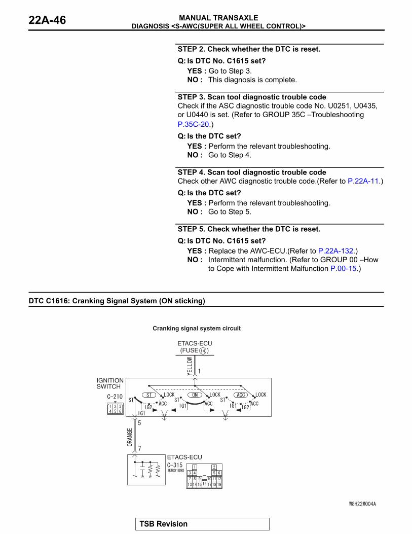
DTC C1616: Cranking Signal System (ON sticking)
IGNITIONSWITCH
ETACS-ECU(FUSE )14
ETACS-ECU
Cranking signal system circuit
TSB Revision
DIAGNOSIS <S-AWC(SUPER ALL WHEEL CONTROL)>MANUAL TRANSAXLE 22A-47
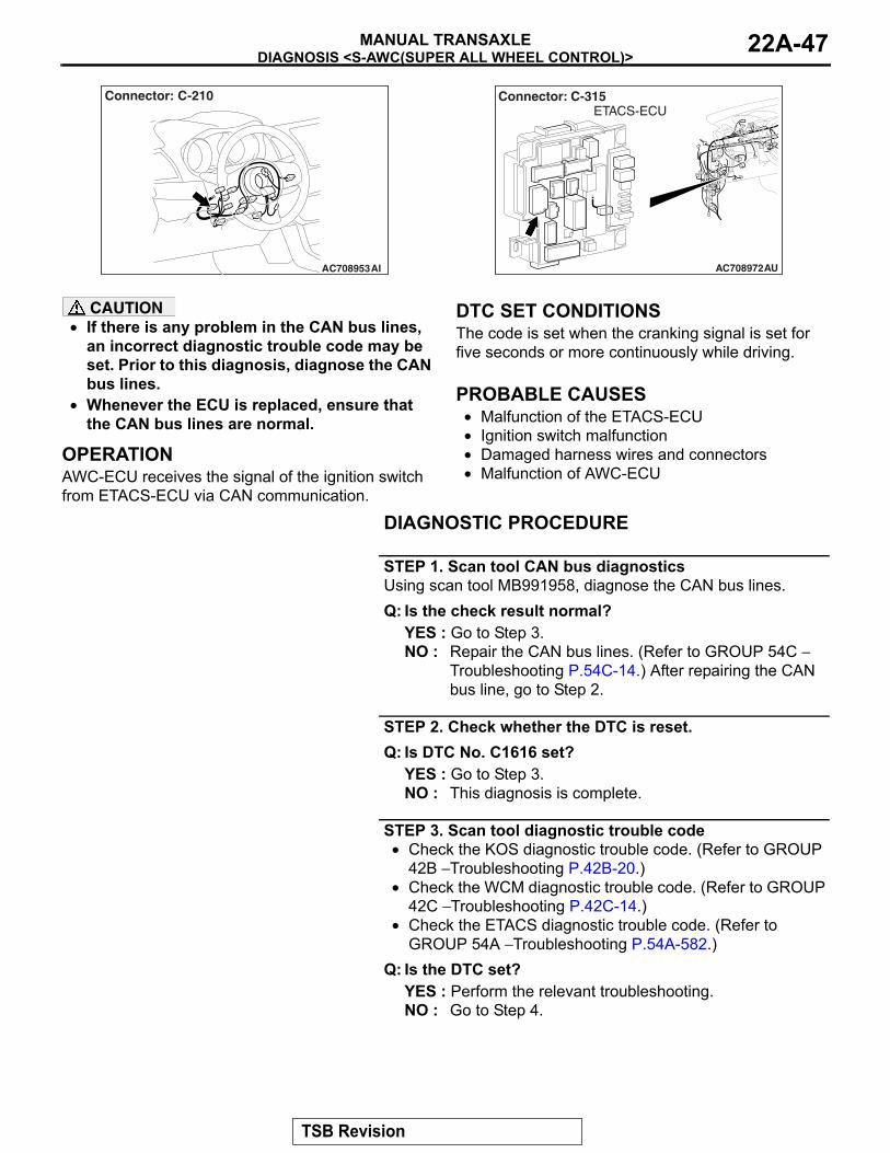
AC708953AI
Connector: C-210
AC708972AU
Connector: C-315ETACS-ECU
CAUTION• If there is any problem in the CAN bus lines,
an incorrect diagnostic trouble code may be set. Prior to this diagnosis, diagnose the CAN bus lines.
• Whenever the ECU is replaced, ensure that the CAN bus lines are normal.
.
OPERATIONAWC-ECU receives the signal of the ignition switch from ETACS-ECU via CAN communication.
.
DTC SET CONDITIONSThe code is set when the cranking signal is set for five seconds or more continuously while driving..
PROBABLE CAUSES• Malfunction of the ETACS-ECU• Ignition switch malfunction• Damaged harness wires and connectors• Malfunction of AWC-ECU
DIAGNOSTIC PROCEDURE
STEP 1. Scan tool CAN bus diagnosticsUsing scan tool MB991958, diagnose the CAN bus lines.Q: Is the check result normal?
YES : Go to Step 3.NO : Repair the CAN bus lines. (Refer to GROUP 54C −
Troubleshooting P.54C-14.) After repairing the CAN bus line, go to Step 2.
STEP 2. Check whether the DTC is reset.Q: Is DTC No. C1616 set?
YES : Go to Step 3.NO : This diagnosis is complete.
STEP 3. Scan tool diagnostic trouble code• Check the KOS diagnostic trouble code. (Refer to GROUP
42B − Troubleshooting P.42B-20.)• Check the WCM diagnostic trouble code. (Refer to GROUP
42C − Troubleshooting P.42C-14.)• Check the ETACS diagnostic trouble code. (Refer to
GROUP 54A − Troubleshooting P.54A-582.)Q: Is the DTC set?
YES : Perform the relevant troubleshooting.NO : Go to Step 4.
TSB Revision
DIAGNOSIS <S-AWC(SUPER ALL WHEEL CONTROL)>MANUAL TRANSAXLE22A-48
STEP 4. Scan tool service dataItem 42: Ignition switch (Refer to Service Data Reference Table P.22A-107.)Q: Is the check result normal?
YES : Go to Step 9.NO : Go to Step 5.
STEP 5. Ignition switch check(1) Disconnect C-210 ignition switch connector, and check the
continuity between the terminals No. 1 and No. 5 at the ignition switch side.
(2) Turn the ignition switch to the "ON" position.OK: No continuity
Q: Is the check result normal?YES : Go to Step 6.NO : Replace the ignition switch. (Refer to GROUP 54A −
Ignition Switch P.54A-19.) Then go to Step 10.
STEP 6. Ignition switch connector, ETACS-ECU connector check: C-210, C-315Q: Is the check result normal?
YES : Go to Step 7.NO : Repair the defective connector. Then go to Step 10.
STEP 7. Check the wiring harness between C-210 ignition switch connector terminal No. 5 and C-315 ETACS-ECU connector terminal No. 7.Check the wiring harness for short circuit (short to power sup-ply).Q: Is the check result normal?
YES : Go to Step 8.NO : Repair the wiring harness. Then go to Step 10.
STEP 8. Scan tool service dataETACS item No. 287: Starter switch (Refer to GROUP 54A − ETACS P.54A-630.)Q: Is the check result normal?
YES : Go to Step 9.NO : Replace the ETACS-ECU. (Refer to GROUP 54A −
ETACS-ECU P.54A-676.) Then go to Step 9.
STEP 9. Check whether the DTC is reset.Q: Is DTC No. C1616 set?
YES : Replace the AWC-ECU.(Refer to P.22A-132.) Then go to Step 10.
NO : Intermittent malfunction. (Refer to GROUP 00 − How to Cope with Intermittent Malfunction P.00-15.)
TSB Revision
DIAGNOSIS <S-AWC(SUPER ALL WHEEL CONTROL)>MANUAL TRANSAXLE 22A-49
STEP 10. Check whether the DTC is reset.Q: Is DTC No. C1616 set?
YES : Return to Step 1.NO : This diagnosis is complete.
DTC C1617: AWC CAN Main Data System (data not received)
CAUTION• If there is any problem in the CAN bus lines,
an incorrect diagnostic trouble code may be set. Prior to this diagnosis, diagnose the CAN bus lines.
• Whenever the ECU is replaced, ensure that the CAN bus lines are normal.
.
OPERATIONAWC-ECU receives various data from ECU via CAN communication..
DIAGNOSTIC TROUBLE CODE SET CONDITIONSThe code is set when the signal necessary for AWC control cannot be received..
PROBABLE CAUSES• The CAN bus line is defective.• Malfunction of engine control module• Malfunction of ASC-ECU• Malfunction of steering wheel sensor• Malfunction of the ETACS-ECU• Malfunction of AWC-ECU
DIAGNOSTIC PROCEDURE
STEP 1. Scan tool CAN bus diagnosticsUsing scan tool MB991958, diagnose the CAN bus lines.Q: Is the check result normal?
YES : Go to Step 3.NO : Repair the CAN bus lines. (Refer to GROUP 54C −
Troubleshooting P.54C-14.) After repairing the CAN bus line, go to Step 2.
STEP 2. Check whether the DTC is reset.Q: Is DTC No. C1617 set?
YES : Go to Step 3.NO : This diagnosis is complete.
STEP 3. Scan tool diagnostic trouble codeCheck if the AWC-related DTC No. U0100, U0101, U0121, U0126, or U0141 is set.(Refer to P.22A-11.)Q: Is the DTC set?
YES : Perform the relevant troubleshooting.NO : Go to Step 4.
TSB Revision
DIAGNOSIS <S-AWC(SUPER ALL WHEEL CONTROL)>MANUAL TRANSAXLE22A-50
STEP 4. Scan tool diagnostic trouble code• Check the engine diagnostic trouble code. (Refer to
GROUP 13A − Troubleshooting P.13A-44.)• Check the ASC diagnostic trouble code. (Refer to GROUP
35C − Troubleshooting P.35C-20.)• Check the ETACS diagnostic trouble code. (Refer to
GROUP 54A − Troubleshooting P.54A-582.)Q: Is the DTC set?
YES : Perform the relevant troubleshooting.NO : Go to Step 5.
STEP 5. Check whether the DTC is reset.Q: Is DTC No. C1617 set?
YES : Replace the AWC-ECU.(Refer to P.22A-132.) Then go to Step 6.
NO : Intermittent malfunction. (Refer to GROUP 00 − How to Cope with Intermittent Malfunction P.00-15.)
STEP 6. Check whether the DTC is reset.Q: Is DTC No. C1613 set?
YES : Return to Step 1.NO : This diagnosis is complete.
DTC C1618: AWC CAN Local Data System (data not received)
.
G AND YAW RATE SENSOR POWER SUPPLYRefer to P.22A-72.
CAUTION• If there is any problem in the CAN bus lines,
an incorrect diagnostic trouble code may be set. Prior to this diagnosis, diagnose the CAN bus lines.
• Whenever the ECU is replaced, ensure that the CAN bus lines are normal.
• Do not drop the G and yaw rate sensor or sub-ject it to a shock.
• When G and yaw rate sensor is replaced, cali-brate G and yaw rate sensor (refer to GROUP 35C − On-vehicle Service P.35C-266), and ini-tialize the lateral/longitudinal acceleration correction amount stored in AWC-ECU. (Refer to item No.10: Lateral acceleration correction amount initialization, and No. 11: Longitudinal acceleration correction amount initialization P.22A-113.)
.
OPERATIONAWC-ECU receives various data from ASC-ECU, G and yaw rate sensor via the local CAN communica-tion..
DTC SET CONDITIONSThe code is set when the signal necessary for AWC control cannot be received..
PROBABLE CAUSES• The CAN bus line is defective.• Malfunction of local CAN bus line• Malfunction of ASC-ECU• Malfunction of G and yaw rate sensor• Malfunction of AWC-ECU
TSB Revision
DIAGNOSIS <S-AWC(SUPER ALL WHEEL CONTROL)>MANUAL TRANSAXLE 22A-51
DIAGNOSTIC PROCEDURE
STEP 1. Scan tool CAN bus diagnosticsUsing scan tool MB991958, diagnose the CAN bus lines.Q: Is the check result normal?
YES : Go to Step 3.NO : Repair the CAN bus lines. (Refer to GROUP 54C −
Troubleshooting P.54C-14.) After repairing the CAN bus line, go to Step 2.
STEP 2. Check whether the DTC is reset.Q: Is DTC No. C1618 set?
YES : Go to Step 3.NO : This diagnosis is complete.
STEP 3. Scan tool diagnostic trouble codeCheck if the AWC diagnostic trouble code No. U1003 is set.(Refer to P.22A-11.)Q: Is the DTC set?
YES : Perform the relevant troubleshooting.NO : Go to Step 4.
STEP 4. Scan tool diagnostic trouble codeCheck the ASC diagnostic trouble code. (Refer to GROUP 35C − Troubleshooting P.35C-20.)Q: Is the DTC set?
YES : Perform the relevant troubleshooting.NO : Go to Step 5.
STEP 5. ASC-ECU connector, G and yaw rate sensor connector, AWC-ECU connector, intermediate connector, J/C (7) check: A-05, C-38, C-46, C-47, C-50Q: Is the check result normal?
YES : Go to Step 6.NO : Repair the defective connector. Then go to Step 10.
STEP 6. Check the wiring harness between C-46 AWC-ECU connector terminal No. 9, 10 and C-38 G and yaw rate sensor connector terminal No. 2, 3, and between C-46 AWC-ECU connector terminal No. 9, 10 and A-05 ASC-ECU connector terminal No. 18, 19.Check the wiring harness for open and short circuit (to ground, to power supply, or line-to line).Q: Is the check result normal?
YES : Go to Step 7.NO : Repair the wiring harness. Then go to Step 9.
TSB Revision
DIAGNOSIS <S-AWC(SUPER ALL WHEEL CONTROL)>MANUAL TRANSAXLE22A-52
STEP 7. Scan tool service dataCheck the following service data. (Refer to P.22A-107.)• Item No. 26: Yaw rate sensor• Item No. 29: Lateral G sensor• Item No. 31: Longitudinal G sensor
Q: Is the check result normal?YES : Go to Step 9.NO : Go to Step 8.
STEP 8. Check the wiring harness between A-05 ASC-ECU connector terminal No. 22 and C-38 G and yaw rate sensor connector terminal No. 1, and between A-05 ASC-ECU connector terminal No. 29 and C-38 G and yaw rate sensor connector terminal No. 5.Check the wiring harness for open or short circuit (short to ground).Q: Is the check result normal?
YES : Replace the G and yaw rate sensor. (Refer to GROUP 35C − G and Yaw Rate Sensor P.35C-278.) Then go to Step 9.
NO : Repair the wiring harness. Then go to Step 10.
STEP 9. Check whether the DTC is reset.Q: Is DTC No. C1618 set?
YES : Replace the AWC-ECU.(Refer to P.22A-132.) Then go to Step 10.
NO : Intermittent malfunction. (Refer to GROUP 00 − How to Cope with Intermittent Malfunction P.00-15.)
STEP 10. Check whether the DTC is reset.Q: Is DTC No. C1618 set?
YES : Return to Step 1.NO : This diagnosis is complete.
TSB Revision
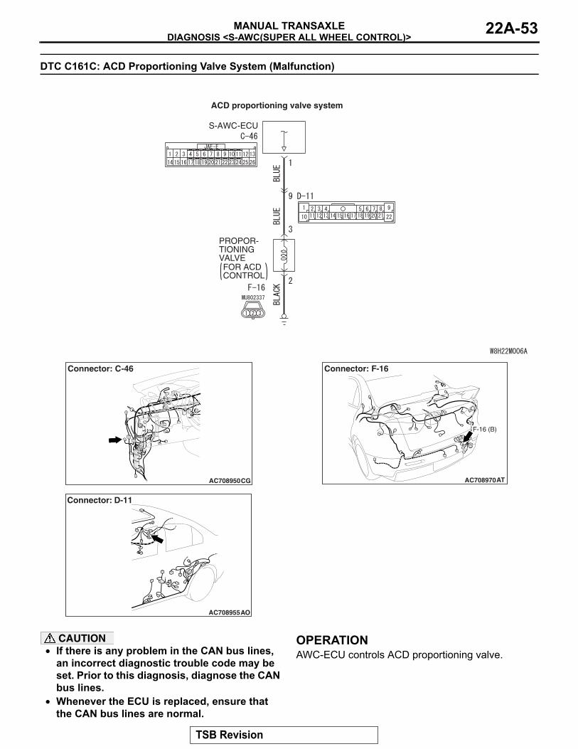
DIAGNOSIS <S-AWC(SUPER ALL WHEEL CONTROL)>MANUAL TRANSAXLE 22A-53
DTC C161C: ACD Proportioning Valve System (Malfunction)
PROPOR-TIONING VALVEFOR ACD CONTROL
S-AWC-ECU
ACD proportioning valve system
AC708950CG
Connector: C-46
AC708955
Connector: D-11
AO
AC708970AT
Connector: F-16
F-16 (B)
CAUTION• If there is any problem in the CAN bus lines,
an incorrect diagnostic trouble code may be set. Prior to this diagnosis, diagnose the CAN bus lines.
• Whenever the ECU is replaced, ensure that the CAN bus lines are normal.
.
OPERATIONAWC-ECU controls ACD proportioning valve..
TSB Revision
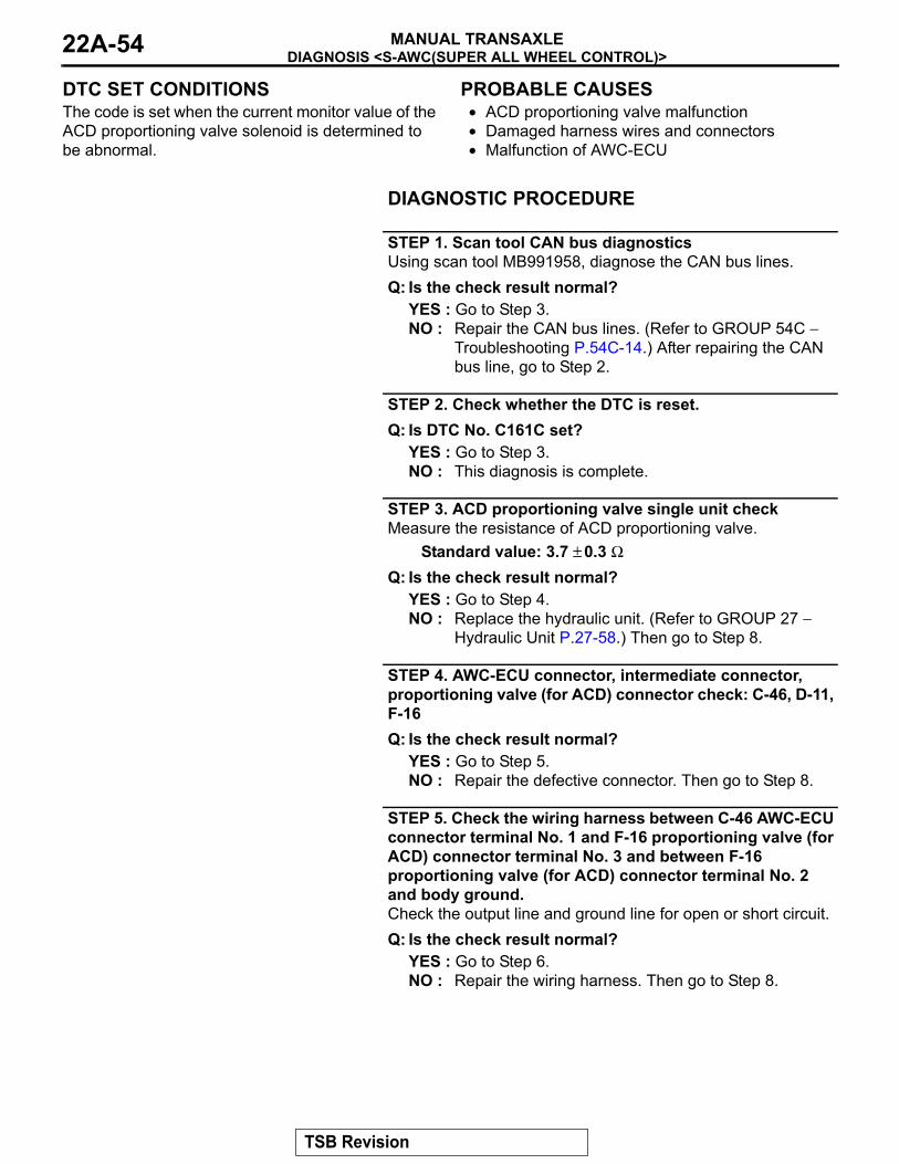
DIAGNOSIS <S-AWC(SUPER ALL WHEEL CONTROL)>MANUAL TRANSAXLE22A-54
DTC SET CONDITIONSThe code is set when the current monitor value of the ACD proportioning valve solenoid is determined to be abnormal..
PROBABLE CAUSES• ACD proportioning valve malfunction• Damaged harness wires and connectors• Malfunction of AWC-ECU
DIAGNOSTIC PROCEDURE
STEP 1. Scan tool CAN bus diagnosticsUsing scan tool MB991958, diagnose the CAN bus lines.Q: Is the check result normal?
YES : Go to Step 3.NO : Repair the CAN bus lines. (Refer to GROUP 54C −
Troubleshooting P.54C-14.) After repairing the CAN bus line, go to Step 2.
STEP 2. Check whether the DTC is reset.Q: Is DTC No. C161C set?
YES : Go to Step 3.NO : This diagnosis is complete.
STEP 3. ACD proportioning valve single unit checkMeasure the resistance of ACD proportioning valve.
Standard value: 3.7 ± 0.3 ΩQ: Is the check result normal?
YES : Go to Step 4.NO : Replace the hydraulic unit. (Refer to GROUP 27 −
Hydraulic Unit P.27-58.) Then go to Step 8.
STEP 4. AWC-ECU connector, intermediate connector, proportioning valve (for ACD) connector check: C-46, D-11, F-16Q: Is the check result normal?
YES : Go to Step 5.NO : Repair the defective connector. Then go to Step 8.
STEP 5. Check the wiring harness between C-46 AWC-ECU connector terminal No. 1 and F-16 proportioning valve (for ACD) connector terminal No. 3 and between F-16 proportioning valve (for ACD) connector terminal No. 2 and body ground.Check the output line and ground line for open or short circuit.Q: Is the check result normal?
YES : Go to Step 6.NO : Repair the wiring harness. Then go to Step 8.
TSB Revision

DIAGNOSIS <S-AWC(SUPER ALL WHEEL CONTROL)>MANUAL TRANSAXLE 22A-55
STEP 6. Scan tool service dataItem 92: ACD proportional valve indicator current (Refer to ser-vice data reference table P.22A-107.)Q: Is the check result normal?
YES : Go to Step 7.NO : Replace the AWC-ECU.(Refer to P.22A-132.) Then
go to Step 7.
STEP 7. Check whether the DTC is reset.Q: Is DTC No. C161C set?
YES : Replace the AWC-ECU.(Refer to P.22A-132.) Then go to Step 8.
NO : Intermittent malfunction. (Refer to GROUP 00 − How to Cope with Intermittent Malfunction P.00-15.)
STEP 8. Check whether the DTC is reset.Q: Is DTC No. C161C set?
YES : Return to Step 1.NO : This diagnosis is complete.
TSB Revision
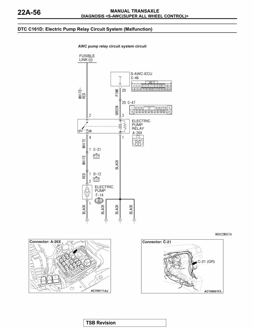
DIAGNOSIS <S-AWC(SUPER ALL WHEEL CONTROL)>MANUAL TRANSAXLE22A-56
DTC C161D: Electric Pump Relay Circuit System (Malfunction)
FUSIBLELINK 35
ELECTRIC PUMP RELAY
ELECTRIC PUMP
S-AWC-ECU
AWC pump relay circuit system circuit
AC709111
Connector: A-26X
AJ AC708951CL
Connector: C-21
C-21 (GR)
TSB Revision
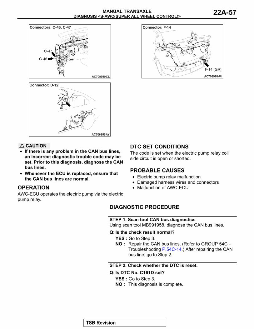
DIAGNOSIS <S-AWC(SUPER ALL WHEEL CONTROL)>MANUAL TRANSAXLE 22A-57
AC708950CL
C-46
C-47
Connectors: C-46, C-47
AC708955
Connector: D-12
AY
AC708970AU
Connector: F-14
F-14 (GR)
CAUTION• If there is any problem in the CAN bus lines,
an incorrect diagnostic trouble code may be set. Prior to this diagnosis, diagnose the CAN bus lines.
• Whenever the ECU is replaced, ensure that the CAN bus lines are normal.
.
OPERATIONAWC-ECU operates the electric pump via the electric pump relay.
.
DTC SET CONDITIONSThe code is set when the electric pump relay coil side circuit is open or shorted..
PROBABLE CAUSES• Electric pump relay malfunction• Damaged harness wires and connectors• Malfunction of AWC-ECU
DIAGNOSTIC PROCEDURE
STEP 1. Scan tool CAN bus diagnosticsUsing scan tool MB991958, diagnose the CAN bus lines.Q: Is the check result normal?
YES : Go to Step 3.NO : Repair the CAN bus lines. (Refer to GROUP 54C −
Troubleshooting P.54C-14.) After repairing the CAN bus line, go to Step 2.
STEP 2. Check whether the DTC is reset.Q: Is DTC No. C161D set?
YES : Go to Step 3.NO : This diagnosis is complete.
TSB Revision
DIAGNOSIS <S-AWC(SUPER ALL WHEEL CONTROL)>MANUAL TRANSAXLE22A-58
STEP 3. Scan tool actuator testOK: Operating sound of the electric pump can be heard.
Q: Is the check result normal?YES : Go to Step 8.NO : Go to Step 4.
STEP 4. Electric pump relay single unit checkCheck the electric pump relay.(Refer to P.22A-133.)Q: Is the check result normal?
YES : Go to Step 5.NO : Replace the electric pump relay. (Refer to
P.22A-132.) Then go to Step 9.
STEP 5. Electric pump relay connector, AWC-ECU connector check: A-26X, C-46Q: Is the check result normal?
YES : Go to Step 6.NO : Repair the defective connector. Then go to Step 9.
STEP 6. Check the wiring harness between A-26X electric pump relay connector terminal No. 3 and C-46 AWC-ECU connector terminal No. 20.Check the power supply line for short or open circuit.Q: Is the check result normal?
YES : Go to Step 7.NO : Check C-47 intermediate connector. When no
problem is found, repair the wiring harness. Then go to Step 9.
STEP 7. Check the wiring harness between A-26X electric pump relay connector terminal No. 1 and body ground.Check the ground line for open circuit.Q: Is the check result normal?
YES : Go to Step 8.NO : Repair the wiring harness. Then go to Step 9.
STEP 8. Check whether the DTC is reset.Q: Is DTC No. C161D set?
YES : Replace the AWC-ECU.(Refer to P.22A-132.) Then go to Step 9.
NO : Intermittent malfunction. (Refer to GROUP 00 − How to Cope with Intermittent Malfunction P.00-15.)
STEP 9. Check whether the DTC is reset.Q: Is DTC No. C161D set?
YES : Return to Step 1.NO : This diagnosis is complete.
TSB Revision
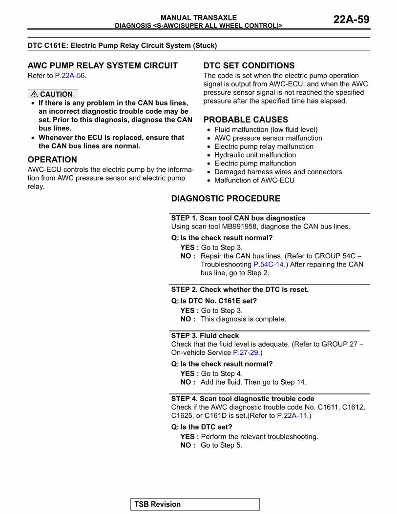
DIAGNOSIS <S-AWC(SUPER ALL WHEEL CONTROL)>MANUAL TRANSAXLE 22A-59
DTC C161E: Electric Pump Relay Circuit System (Stuck)
.
AWC PUMP RELAY SYSTEM CIRCUITRefer to P.22A-56.
CAUTION• If there is any problem in the CAN bus lines,
an incorrect diagnostic trouble code may be set. Prior to this diagnosis, diagnose the CAN bus lines.
• Whenever the ECU is replaced, ensure that the CAN bus lines are normal.
.
OPERATIONAWC-ECU controls the electric pump by the informa-tion from AWC pressure sensor and electric pump relay.
.
DTC SET CONDITIONSThe code is set when the electric pump operation signal is output from AWC-ECU, and when the AWC pressure sensor signal is not reached the specified pressure after the specified time has elapsed..
PROBABLE CAUSES• Fluid malfunction (low fluid level)• AWC pressure sensor malfunction• Electric pump relay malfunction• Hydraulic unit malfunction• Electric pump malfunction• Damaged harness wires and connectors• Malfunction of AWC-ECU
DIAGNOSTIC PROCEDURE
STEP 1. Scan tool CAN bus diagnosticsUsing scan tool MB991958, diagnose the CAN bus lines.Q: Is the check result normal?
YES : Go to Step 3.NO : Repair the CAN bus lines. (Refer to GROUP 54C −
Troubleshooting P.54C-14.) After repairing the CAN bus line, go to Step 2.
STEP 2. Check whether the DTC is reset.Q: Is DTC No. C161E set?
YES : Go to Step 3.NO : This diagnosis is complete.
STEP 3. Fluid checkCheck that the fluid level is adequate. (Refer to GROUP 27 − On-vehicle Service P.27-29.)Q: Is the check result normal?
YES : Go to Step 4.NO : Add the fluid. Then go to Step 14.
STEP 4. Scan tool diagnostic trouble codeCheck if the AWC diagnostic trouble code No. C1611, C1612, C1625, or C161D is set.(Refer to P.22A-11.)Q: Is the DTC set?
YES : Perform the relevant troubleshooting.NO : Go to Step 5.
TSB Revision
DIAGNOSIS <S-AWC(SUPER ALL WHEEL CONTROL)>MANUAL TRANSAXLE22A-60
STEP 5. Scan tool actuator testOK: Operating sound of the electric pump can be heard.
Q: Is the check result normal?YES : Go to Step 13.NO : Go to Step 6.
STEP 6. Electric pump relay single unit checkCheck the electric pump relay.(Refer to P.22A-133.)Q: Is the check result normal?
YES : Go to Step 7.NO : Replace the electric pump relay. (Refer to
P.22A-132.) Then go to Step 14.
STEP 7. Electric pump relay connector check: A-26XQ: Is the check result normal?
YES : Go to Step 8.NO : Repair the defective connector. Then go to Step 14.
STEP 8. Check the wiring harness between A-26X electric pump relay connector terminal No. 2 and fusible link (35).Check the power supply line for short or open circuit.Q: Is the check result normal?
YES : Go to Step 9.NO : Repair the wiring harness. Then go to Step 14.
STEP 9. Electric pump connector check: F-14Q: Is the check result normal?
YES : Go to Step 10.NO : Repair the defective connector. Then go to Step 14.
STEP 10. Check the wiring harness between A-26X electric pump relay connector terminal No. 4 and F-14 electric pump connector terminal No. 2.Check the power supply line for short or open circuit.Q: Is the check result normal?
YES : Go to Step 11.NO : Check C-21 and D-12 intermediate connectors. When
no problem is found, repair the wiring harness. Then go to Step 14.
STEP 11. Check the wiring harness between F-14 electric pump connector terminal No. 1 and body ground.Check the ground line for open circuit.Q: Is the check result normal?
YES : Go to Step 12.NO : Repair the wiring harness. Then go to Step 14.
TSB Revision
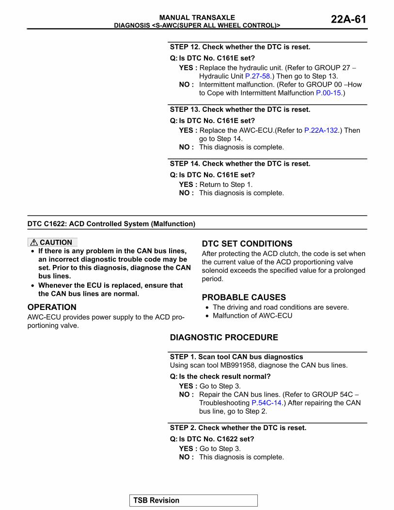
DIAGNOSIS <S-AWC(SUPER ALL WHEEL CONTROL)>MANUAL TRANSAXLE 22A-61
STEP 12. Check whether the DTC is reset.Q: Is DTC No. C161E set?
YES : Replace the hydraulic unit. (Refer to GROUP 27 − Hydraulic Unit P.27-58.) Then go to Step 13.
NO : Intermittent malfunction. (Refer to GROUP 00 − How to Cope with Intermittent Malfunction P.00-15.)
STEP 13. Check whether the DTC is reset.Q: Is DTC No. C161E set?
YES : Replace the AWC-ECU.(Refer to P.22A-132.) Then go to Step 14.
NO : This diagnosis is complete.
STEP 14. Check whether the DTC is reset.Q: Is DTC No. C161E set?
YES : Return to Step 1.NO : This diagnosis is complete.
DTC C1622: ACD Controlled System (Malfunction)
CAUTION• If there is any problem in the CAN bus lines,
an incorrect diagnostic trouble code may be set. Prior to this diagnosis, diagnose the CAN bus lines.
• Whenever the ECU is replaced, ensure that the CAN bus lines are normal.
.
OPERATIONAWC-ECU provides power supply to the ACD pro-portioning valve.
.
DTC SET CONDITIONSAfter protecting the ACD clutch, the code is set when the current value of the ACD proportioning valve solenoid exceeds the specified value for a prolonged period..
PROBABLE CAUSES• The driving and road conditions are severe.• Malfunction of AWC-ECU
DIAGNOSTIC PROCEDURE
STEP 1. Scan tool CAN bus diagnosticsUsing scan tool MB991958, diagnose the CAN bus lines.Q: Is the check result normal?
YES : Go to Step 3.NO : Repair the CAN bus lines. (Refer to GROUP 54C −
Troubleshooting P.54C-14.) After repairing the CAN bus line, go to Step 2.
STEP 2. Check whether the DTC is reset.Q: Is DTC No. C1622 set?
YES : Go to Step 3.NO : This diagnosis is complete.
TSB Revision
DIAGNOSIS <S-AWC(SUPER ALL WHEEL CONTROL)>MANUAL TRANSAXLE22A-62
STEP 3. Scan tool diagnostic trouble codeCheck other AWC diagnostic trouble code.(Refer to P.22A-11.)Q: Is the DTC set?
YES : Perform the relevant troubleshooting.NO : Go to Step 4.
STEP 4. Check whether the DTC is reset.Q: Is DTC No. C1622 set?
YES : Replace the AWC-ECU.(Refer to P.22A-132.) Then go to Step 5.
NO : This diagnosis is complete. (The clutch protection activated in such driving or road condition as ACD control is applied for a prolonged period.)
STEP 5. Check whether the DTC is reset.Q: Is DTC No. C1622 set?
YES : Return to Step 1.NO : This diagnosis is complete.
DTC C1623: Brake Controlled System (Malfunction)
CAUTION• If there is any problem in the CAN bus lines,
an incorrect diagnostic trouble code may be set. Prior to this diagnosis, diagnose the CAN bus lines.
• Whenever the ECU is replaced, ensure that the CAN bus lines are normal.
.
OPERATIONAWC-ECU controls brakes for AYC control..
DTC SET CONDITIONSThe code is set when the AYC brake control oper-ates for a prolonged period..
PROBABLE CAUSES• Malfunction of AWC-ECU
DIAGNOSTIC PROCEDURE
STEP 1. Scan tool CAN bus diagnosticsUsing scan tool MB991958, diagnose the CAN bus lines.Q: Is the check result normal?
YES : Go to Step 3.NO : Repair the CAN bus lines. (Refer to GROUP 54C −
Troubleshooting P.54C-14.) After repairing the CAN bus line, go to Step 2.
STEP 2. Check whether the DTC is reset.Q: Is DTC No. C1623 set?
YES : Go to Step 3.NO : This diagnosis is complete.
TSB Revision

DIAGNOSIS <S-AWC(SUPER ALL WHEEL CONTROL)>MANUAL TRANSAXLE 22A-63
STEP 3. Scan tool diagnostic trouble codeCheck other AWC diagnostic trouble code.(Refer to P.22A-11.)Q: Is the DTC set?
YES : Perform the relevant troubleshooting.NO : Go to Step 4.
STEP 4. Check whether the DTC is reset.Q: Is DTC No. C1623 set?
YES : Replace the AWC-ECU.(Refer to P.22A-132.) Then go to Step 5.
NO : Intermittent malfunction. (Refer to GROUP 00 − How to Cope with Intermittent Malfunction P.00-15.)
STEP 5. Check whether the DTC is reset.Q: Is DTC No. C1623 set?
YES : Return to Step 1.NO : This diagnosis is complete.
DTC C1624: AWC-ECU System (Internal Malfunction)
CAUTION• If there is any problem in the CAN bus lines,
an incorrect diagnostic trouble code may be set. Prior to this diagnosis, diagnose the CAN bus lines.
• Whenever the ECU is replaced, ensure that the CAN bus lines are normal.
.
OPERATIONAWC-ECU monitors the malfunction in the ECU..
DTC SET CONDITIONSThe code is set when a malfunction is found in AWC-ECU..
PROBABLE CAUSES• Malfunction of AWC-ECU
DIAGNOSTIC PROCEDURE
STEP 1. Scan tool CAN bus diagnosticsUsing scan tool MB991958, diagnose the CAN bus lines.Q: Is the check result normal?
YES : Go to Step 3.NO : Repair the CAN bus lines. (Refer to GROUP 54C −
Troubleshooting P.54C-14.) After repairing the CAN bus line, go to Step 2.
STEP 2. Check whether the DTC is reset.Q: Is DTC No. C1624 set?
YES : Go to Step 3.NO : This diagnosis is complete.
TSB Revision
DIAGNOSIS <S-AWC(SUPER ALL WHEEL CONTROL)>MANUAL TRANSAXLE22A-64
STEP 3. Scan tool diagnostic trouble codeCheck other AWC diagnostic trouble code.(Refer to P.22A-11.)Q: Is the DTC set?
YES : Perform the relevant troubleshooting.NO : Go to Step 4.
STEP 4. Check whether the DTC is reset.Q: Is DTC No. C1624 set?
YES : Replace the AWC-ECU.(Refer to P.22A-132.) Then go to Step 5.
NO : Intermittent malfunction. (Refer to GROUP 00 − How to Cope with Intermittent Malfunction P.00-15.)
STEP 5. Check whether the DTC is reset.Q: Is DTC No. C1624 set?
YES : Return to Step 1.NO : This diagnosis is complete.
DTC C1625: AWC Pressure Sensor System (Abnormal Power Supply Voltage)
.
AWC PRESSURE SENSOR SYSTEM CIRCUITRefer to P.22A-33.
CAUTION• If there is any problem in the CAN bus lines,
an incorrect diagnostic trouble code may be set. Prior to this diagnosis, diagnose the CAN bus lines.
• Whenever the ECU is replaced, ensure that the CAN bus lines are normal.
.
OPERATIONAWC-ECU monitors the AWC pressure sensor power supply voltage..
DTC SET CONDITIONSThe code is set when the power supply voltage to the AWC pressure sensor is outside the specified value..
PROBABLE CAUSES• AWC pressure sensor malfunction• Damaged harness wires and connectors• Malfunction of AWC-ECU
DIAGNOSTIC PROCEDURE
STEP 1. Scan tool CAN bus diagnosticsUsing scan tool MB991958, diagnose the CAN bus lines.Q: Is the check result normal?
YES : Go to Step 3.NO : Repair the CAN bus lines. (Refer to GROUP 54C −
Troubleshooting P.54C-14.) After repairing the CAN bus line, go to Step 2.
STEP 2. Check whether the DTC is reset.Q: Is DTC No. C1625 set?
YES : Go to Step 3.NO : This diagnosis is complete.
TSB Revision
DIAGNOSIS <S-AWC(SUPER ALL WHEEL CONTROL)>MANUAL TRANSAXLE 22A-65
STEP 3. Voltage measurement at F-13 AWC pressure sensor connector(1) Disconnect the connector, and measure the voltage
between the terminal No. 1 and the body ground.(2) Turn the ignition switch to the "ON" position.
OK: Approx. 5 VQ: Is the check result normal?
YES : Go to Step 6.NO : Go to Step 4.
STEP 4. AWC-ECU connector, AWC pressure sensor connector check: C-46, F-13Q: Is the check result normal?
YES : Go to Step 5.NO : Repair the defective connector. Then go to Step 8.
STEP 5. Check the wiring harness between C-46 AWC-ECU connector terminal No. 6 and F-13 AWC pressure sensor connector terminal No. 1.Check the power supply line for short or open circuit.Q: Is the check result normal?
YES : Go to Step 6.NO : Check D-11 intermediate connector. When no
problem is found, repair the wiring harness. Then go to Step 8.
STEP 6. Scan tool service dataItem No. 86: Pressure sensor power supply voltage (Refer to service data reference table P.22A-107.)Q: Is the check result normal?
YES : Go to Step 7.NO : Replace the hydraulic unit. (Refer to GROUP 27 −
Hydraulic Unit P.27-58.) Then go to Step 7.
STEP 7. Check whether the DTC is reset.Q: Is DTC No. C1625 set?
YES : Replace the AWC-ECU.(Refer to P.22A-132.) Then go to Step 8.
NO : Intermittent malfunction. (Refer to GROUP 00 − How to Cope with Intermittent Malfunction P.00-15.)
STEP 8. Check whether the DTC is reset.Q: Is DTC No. C1625 set?
YES : Return to Step 1.NO : This diagnosis is complete.
TSB Revision
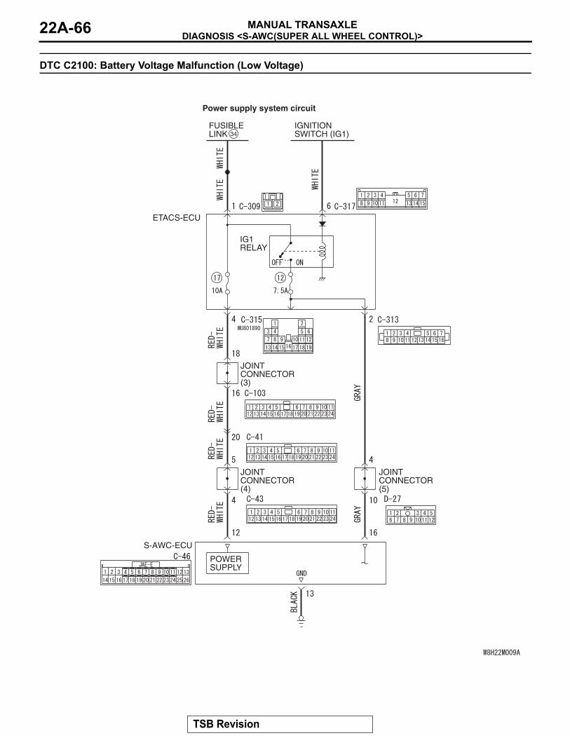
DIAGNOSIS <S-AWC(SUPER ALL WHEEL CONTROL)>MANUAL TRANSAXLE22A-66
DTC C2100: Battery Voltage Malfunction (Low Voltage)
ETACS-ECU
IGNITIONSWITCH (IG1)
FUSIBLELINK 34
IG1 RELAY
JOINTCONNECTOR (3)
JOINTCONNECTOR (5)
JOINTCONNECTOR (4)
POWER SUPPLY
S-AWC-ECU
Power supply system circuit
TSB Revision
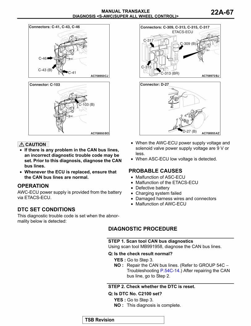
DIAGNOSIS <S-AWC(SUPER ALL WHEEL CONTROL)>MANUAL TRANSAXLE 22A-67
AC708950CJC-41
C-46
C-43 (B)
Connectors: C-41, C-43, C-46
AC708950
Connector: C-103
BO
C-103 (B)
AC708972BJ
Connectors: C-309, C-313, C-315, C-317ETACS-ECU
C-315
C-317C-309 (B)
C-313 (BR)
AC708955AZD-27 (B)
Connector: D-27
CAUTION• If there is any problem in the CAN bus lines,
an incorrect diagnostic trouble code may be set. Prior to this diagnosis, diagnose the CAN bus lines.
• Whenever the ECU is replaced, ensure that the CAN bus lines are normal.
.
OPERATIONAWC-ECU power supply is provided from the battery via ETACS-ECU..
DTC SET CONDITIONSThis diagnostic trouble code is set when the abnor-mality below is detected:
• When the AWC-ECU power supply voltage and solenoid valve power supply voltage are 9 V or less.
• When ASC-ECU low voltage is detected..
PROBABLE CAUSES• Malfunction of ASC-ECU• Malfunction of the ETACS-ECU• Defective battery• Charging system failed• Damaged harness wires and connectors• Malfunction of AWC-ECU
DIAGNOSTIC PROCEDURE
STEP 1. Scan tool CAN bus diagnosticsUsing scan tool MB991958, diagnose the CAN bus lines.Q: Is the check result normal?
YES : Go to Step 3.NO : Repair the CAN bus lines. (Refer to GROUP 54C −
Troubleshooting P.54C-14.) After repairing the CAN bus line, go to Step 2.
STEP 2. Check whether the DTC is reset.Q: Is DTC No. C2100 set?
YES : Go to Step 3.NO : This diagnosis is complete.
TSB Revision
DIAGNOSIS <S-AWC(SUPER ALL WHEEL CONTROL)>MANUAL TRANSAXLE22A-68
STEP 3. Scan tool diagnostic trouble codeCheck the ASC diagnostic trouble code. (Refer to GROUP 35C − Troubleshooting P.35C-20.)Q: Is the DTC set?
YES : Perform the relevant troubleshooting.NO : Go to Step 4.
STEP 4. Scan tool diagnostic trouble codeCheck the ETACS diagnostic trouble code. (Refer to GROUP 54A − Troubleshooting P.54A-582.)Q: Is the DTC set?
YES : Perform the relevant troubleshooting.NO : Go to Step 5.
STEP 5. Check the battery.Refer to GROUP 54A − Battery Test P.54A-9.Q: Is the check result normal?
YES : Go to Step 7.NO : Charge or replace the battery. Then go to Step 6.
STEP 6. Check the charging system.Refer to GROUP 16 − Charging System P.16-7.Q: Is the check result normal?
YES : Go to Step 7.NO : Repair or replace the charging system component(s).
STEP 7. Voltage measurement at C-46 AWC-ECU connectorMeasure the voltage between C-46 AWC-ECU connector ter-minal No.12 − and the body ground.
OK: Battery positive voltageQ: Is the check result normal?
YES : Go to Step 11.NO : Go to Step 8.
STEP 8. AWC-ECU connector, ETACS-ECU connector check: C-46, C-315Q: Is the check result normal?
YES : Go to Step 9.NO : Repair the defective connector. Then go to Step 14.
TSB Revision
DIAGNOSIS <S-AWC(SUPER ALL WHEEL CONTROL)>MANUAL TRANSAXLE 22A-69
STEP 9. Check the wiring harness between C-46 AWC-ECU connector terminal No. 12 and C-315 ETACS-ECU connector terminal No.4.Check the wiring harness for open or short circuit (short to ground).Q: Is the check result normal?
YES : Go to Step 10.NO : Check C-41 intermediate connector, C-43 J/C (4),
C-103 J/C (3). When no problem is found, repair the wiring harness. Then go to Step 14.
STEP 10. Scan tool service dataItem No. 43: Battery voltage (Refer to service data reference table P.22A-107.)Q: Is the check result normal?
YES : Intermittent malfunction. (Refer to GROUP 00 − How to Cope with Intermittent Malfunction P.00-15.)
NO : Replace the ETACS-ECU. (Refer to GROUP 54A − ETACS-ECU P.54A-676.) Then go to Step 14.
STEP 11. AWC-ECU connector check: C-46Q: Is the check result normal?
YES : Go to Step 12.NO : Repair the defective connector. Then go to Step 14.
STEP 12. Check the wiring harness between C-46 AWC-ECU connector terminal No. 13 and body ground.Check the wiring harness for open circuit.Q: Is the check result normal?
YES : Go to Step 13.NO : Repair the wiring harness. Then go to Step 14.
STEP 13. Scan tool service dataItem No. 43: Battery voltage (Refer to service data reference table P.22A-107.)Q: Is the check result normal?
YES : Intermittent malfunction. (Refer to GROUP 00 − How to Cope with Intermittent Malfunction P.00-15.)
NO : Replace the AWC-ECU.(Refer to P.22A-132.) Then go to Step 14.
STEP 14. Check whether the DTC is reset.Q: Is DTC No. C2100 set?
YES : Return to Step 1.NO : This diagnosis is complete.
TSB Revision
DIAGNOSIS <S-AWC(SUPER ALL WHEEL CONTROL)>MANUAL TRANSAXLE22A-70
DTC C2101: Battery Voltage Malfunction (High Voltage)
.
BATTERY VOLTAGE SYSTEM CIRCUITRefer to P.22A-66.
CAUTION• If there is any problem in the CAN bus lines,
an incorrect diagnostic trouble code may be set. Prior to this diagnosis, diagnose the CAN bus lines.
• Whenever the ECU is replaced, ensure that the CAN bus lines are normal.
.
OPERATIONAWC-ECU power supply is provided from the battery via ETACS-ECU.
.
DTC SET CONDITIONSThe code is set when the AWC-ECU power supply voltage and solenoid valve power supply voltage are 18 V or more..
PROBABLE CAUSES• Loose battery terminal• Defective battery• Charging system failed• Malfunction of the ETACS-ECU• Damaged harness wires and connectors• Malfunction of AWC-ECU
DIAGNOSTIC PROCEDURE
STEP 1. Scan tool CAN bus diagnosticsUsing scan tool MB991958, diagnose the CAN bus lines.Q: Is the check result normal?
YES : Go to Step 3.NO : Repair the CAN bus lines. (Refer to GROUP 54C −
Troubleshooting P.54C-14.) After repairing the CAN bus line, go to Step 2.
STEP 2. Check whether the DTC is reset.Q: Is DTC No. C2101 set?
YES : Go to Step 3.NO : This diagnosis is complete.
STEP 3. Scan tool diagnostic trouble codeCheck the ETACS diagnostic trouble code. (Refer to GROUP 54A − Troubleshooting P.54A-582.)Q: Is the DTC set?
YES : Perform the relevant troubleshooting.NO : Go to Step 4.
STEP 4. Battery terminal checkCheck that the battery terminal is not loose.Q: Is the check result normal?
YES : Go to Step 5.NO : Securely install the battery terminal. Then go to Step
5.
STEP 5. Check the battery.Refer to GROUP 54A − Battery Test P.54A-9.Q: Is the check result normal?
YES : Go to Step 7.NO : Charge or replace the battery. Then go to Step 6.
TSB Revision
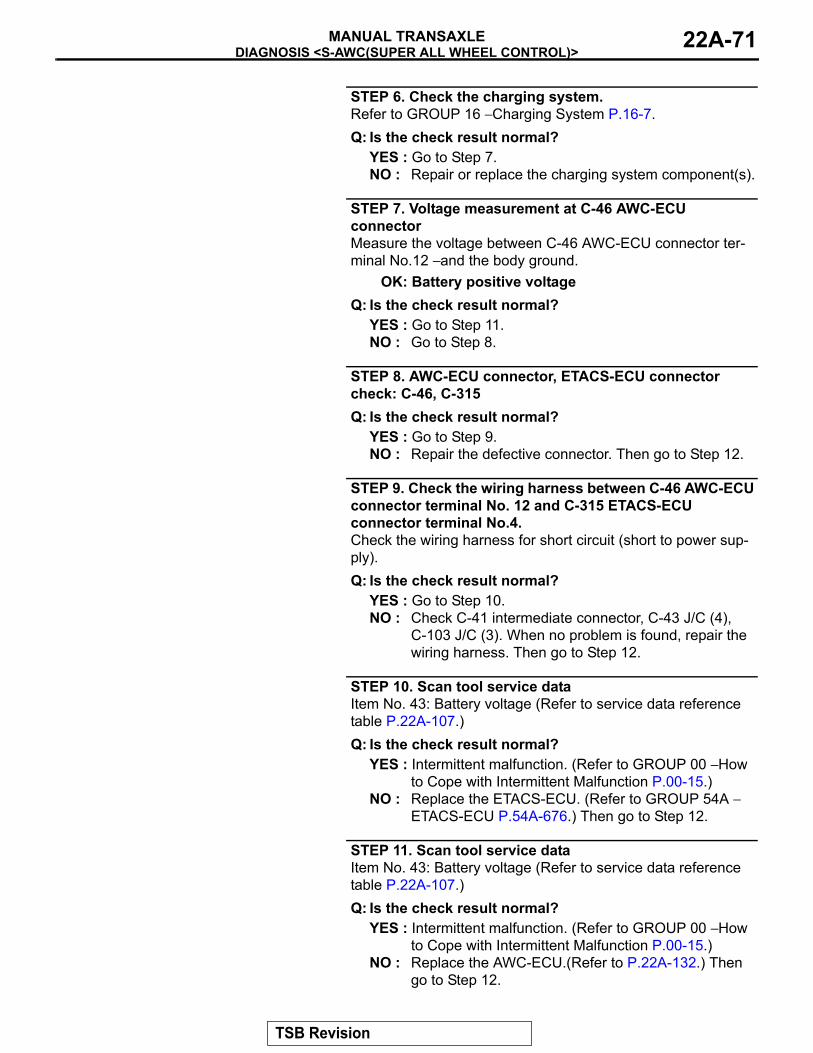
DIAGNOSIS <S-AWC(SUPER ALL WHEEL CONTROL)>MANUAL TRANSAXLE 22A-71
STEP 6. Check the charging system.Refer to GROUP 16 − Charging System P.16-7.Q: Is the check result normal?
YES : Go to Step 7.NO : Repair or replace the charging system component(s).
STEP 7. Voltage measurement at C-46 AWC-ECU connectorMeasure the voltage between C-46 AWC-ECU connector ter-minal No.12 − and the body ground.
OK: Battery positive voltageQ: Is the check result normal?
YES : Go to Step 11.NO : Go to Step 8.
STEP 8. AWC-ECU connector, ETACS-ECU connector check: C-46, C-315Q: Is the check result normal?
YES : Go to Step 9.NO : Repair the defective connector. Then go to Step 12.
STEP 9. Check the wiring harness between C-46 AWC-ECU connector terminal No. 12 and C-315 ETACS-ECU connector terminal No.4.Check the wiring harness for short circuit (short to power sup-ply).Q: Is the check result normal?
YES : Go to Step 10.NO : Check C-41 intermediate connector, C-43 J/C (4),
C-103 J/C (3). When no problem is found, repair the wiring harness. Then go to Step 12.
STEP 10. Scan tool service dataItem No. 43: Battery voltage (Refer to service data reference table P.22A-107.)Q: Is the check result normal?
YES : Intermittent malfunction. (Refer to GROUP 00 − How to Cope with Intermittent Malfunction P.00-15.)
NO : Replace the ETACS-ECU. (Refer to GROUP 54A − ETACS-ECU P.54A-676.) Then go to Step 12.
STEP 11. Scan tool service dataItem No. 43: Battery voltage (Refer to service data reference table P.22A-107.)Q: Is the check result normal?
YES : Intermittent malfunction. (Refer to GROUP 00 − How to Cope with Intermittent Malfunction P.00-15.)
NO : Replace the AWC-ECU.(Refer to P.22A-132.) Then go to Step 12.
TSB Revision
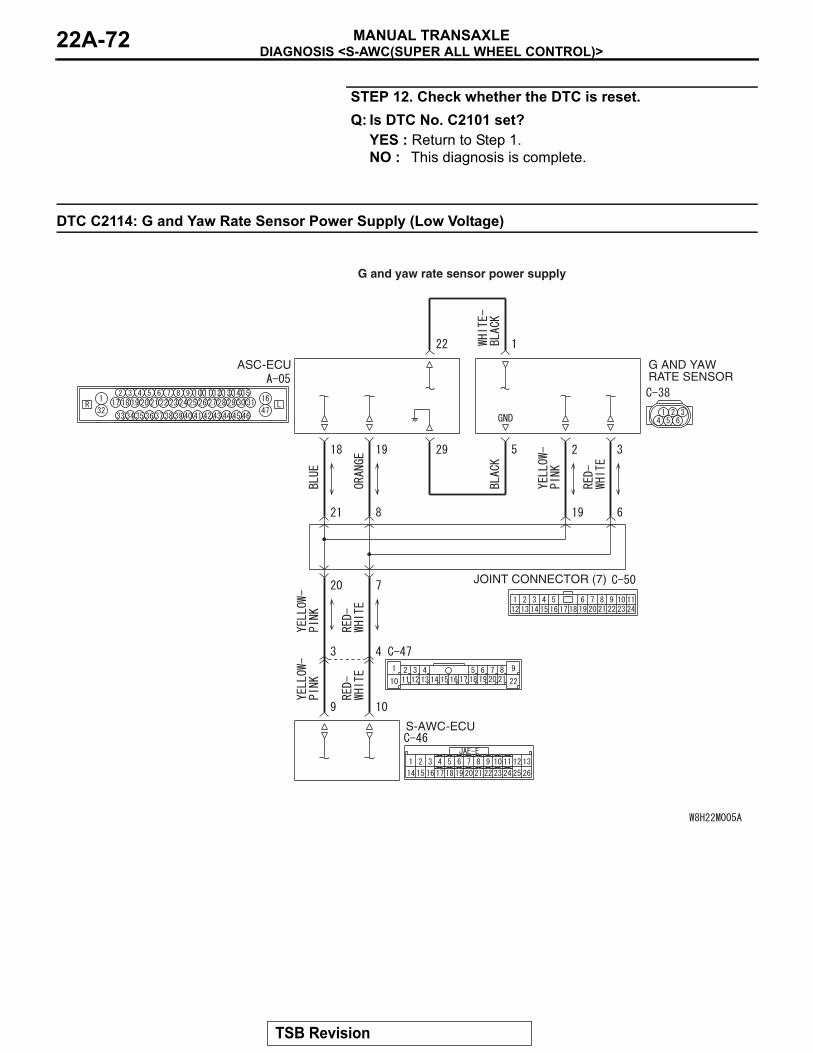
DIAGNOSIS <S-AWC(SUPER ALL WHEEL CONTROL)>MANUAL TRANSAXLE22A-72
STEP 12. Check whether the DTC is reset.Q: Is DTC No. C2101 set?
YES : Return to Step 1.NO : This diagnosis is complete.
DTC C2114: G and Yaw Rate Sensor Power Supply (Low Voltage)
S-AWC-ECU
JOINT CONNECTOR (7)
G AND YAW RATE SENSOR
ASC-ECU
G and yaw rate sensor power supply
TSB Revision

DIAGNOSIS <S-AWC(SUPER ALL WHEEL CONTROL)>MANUAL TRANSAXLE 22A-73
AC708948
Connector: A-05
A-05 (B)
AB
AC708951AG
C-38 (B)
Connector: C-38
AC708950CK
C-46
C-47
C-50 (B)
Connectors: C-46, C-47, C-50
CAUTION• If there is any problem in the CAN bus lines,
an incorrect diagnostic trouble code may be set. Prior to this diagnosis, diagnose the CAN bus lines.
• Whenever the ECU is replaced, ensure that the CAN bus lines are normal.
• Do not drop the G and yaw rate sensor or sub-ject it to a shock.
• When G and yaw rate sensor is replaced, cali-brate G and yaw rate sensor (refer to GROUP 35C − On-vehicle Service P.35C-266), and ini-tialize the lateral/longitudinal acceleration correction amount stored in AWC-ECU. (Refer to item No.10: Lateral acceleration correction amount initialization, and No. 11: Longitudinal acceleration correction amount initialization P.22A-113.)
.
OPERATIONAWC-ECU receives the self-diagnosis status of G and yaw rate sensor..
DTC SET CONDITIONSThe code is set when low voltage status information of G and yaw rate sensor power supply is received..
PROBABLE CAUSES• Malfunction of G and yaw rate sensor• Malfunction of ASC-ECU• Damaged harness wires and connectors• Malfunction of AWC-ECU
DIAGNOSTIC PROCEDURE
STEP 1. Scan tool CAN bus diagnosticsUsing scan tool MB991958, diagnose the CAN bus lines.Q: Is the check result normal?
YES : Go to Step 3.NO : Repair the CAN bus lines. (Refer to GROUP 54C −
Troubleshooting P.54C-14.) After repairing the CAN bus line, go to Step 2.
TSB Revision
DIAGNOSIS <S-AWC(SUPER ALL WHEEL CONTROL)>MANUAL TRANSAXLE22A-74
STEP 2. Check whether the DTC is reset.Q: Is DTC No. C2114 set?
YES : Go to Step 3.NO : This diagnosis is complete.
STEP 3. Scan tool diagnostic trouble codeCheck the ASC diagnostic trouble code. (Refer to GROUP 35C − Troubleshooting P.35C-20.)Q: Is the DTC set?
YES : Perform the relevant troubleshooting.NO : Go to Step 4.
STEP 4. ASC-ECU connector, G and yaw rate sensor connector check: A-05, C-38Q: Is the check result normal?
YES : Go to Step 5.NO : Repair the defective connector. Then go to Step 10.
STEP 5. Voltage measurement at the C-38 G and yaw rate sensor connector(1) Disconnect the connector, and measure the voltage
between terminal No. 1 and ground at the harness side.(2) Turn the ignition switch to the "ON" position.
OK: Battery positive voltageQ: Is the check result normal?
YES : Go to Step 7.NO : Go to Step 6.
STEP 6. Check the wiring harness between A-05 ASC-ECU connector terminal No. 22 and C-38 G and yaw rate sensor connector terminal No. 1.Check the wiring harness for open or short circuit (short to ground).Q: Is the check result normal?
YES : Replace the ASC-ECU. (Refer to GROUP 35C − Hydraulic Unit P.35C-272.) Then go to Step 10.
NO : Repair the wiring harness. Then go to Step 10.
STEP 7. Check the wiring harness between A-05 ASC-ECU connector terminal No. 29 and C-38 G and yaw rate sensor connector terminal No. 5.Check the wiring harness for open circuit.Q: Is the check result normal?
YES : Go to Step 8.NO : Repair the wiring harness. Then go to Step 10.
TSB Revision
DIAGNOSIS <S-AWC(SUPER ALL WHEEL CONTROL)>MANUAL TRANSAXLE 22A-75
STEP 8. Scan tool service dataCheck the following service data. (Refer to P.22A-107.)• Item No. 26: Yaw rate sensor• Item No. 29: Lateral G sensor• Item No. 31: Longitudinal G sensor• Item No. 75: G and yaw rate sensor low voltage abnormality
flagQ: Is the check result normal?
YES : Go to Step 9.NO : Replace the G and yaw rate sensor. (Refer to
GROUP 35C − G and Yaw Rate Sensor P.35C-278.) Then go to Step 9.
STEP 9. Check whether the DTC is reset.Q: Is DTC No. C2114 set?
YES : Replace the AWC-ECU.(Refer to P.22A-132.) Then go to Step 10.
NO : Intermittent malfunction. (Refer to GROUP 00 − How to Cope with Intermittent Malfunction P.00-15.)
STEP 10. Check whether the DTC is reset.Q: Is DTC No. C2114 set?
YES : Return to Step 1.NO : This diagnosis is complete.
DTC C2115: G and Yaw Rate Sensor Power Supply (High Voltage)
.
G AND YAW RATE SENSOR POWER SUPPLYRefer to P.22A-72.
CAUTION• If there is any problem in the CAN bus lines,
an incorrect diagnostic trouble code may be set. Prior to this diagnosis, diagnose the CAN bus lines.
• Whenever the ECU is replaced, ensure that the CAN bus lines are normal.
• Do not drop the G and yaw rate sensor or sub-ject it to a shock.
• When G and yaw rate sensor is replaced, cali-brate G and yaw rate sensor (refer to GROUP 35C − On-vehicle Service P.35C-266), and ini-tialize the lateral/longitudinal acceleration correction amount stored in AWC-ECU. (Refer to item No.10: Lateral acceleration correction amount initialization, and No. 11: Longitudinal acceleration correction amount initialization P.22A-113.)
.
TSB Revision
DIAGNOSIS <S-AWC(SUPER ALL WHEEL CONTROL)>MANUAL TRANSAXLE22A-76
OPERATIONAWC-ECU receives the self-diagnosis status of G and yaw rate sensor..
DTC SET CONDITIONSThe code is set when high voltage status information of G and yaw rate sensor power supply is received.
.
PROBABLE CAUSES• Malfunction of G and yaw rate sensor• Malfunction of ASC-ECU• Damaged harness wires and connectors• Malfunction of AWC-ECU
DIAGNOSTIC PROCEDURE
STEP 1. Scan tool CAN bus diagnosticsUsing scan tool MB991958, diagnose the CAN bus lines.Q: Is the check result normal?
YES : Go to Step 3.NO : Repair the CAN bus lines. (Refer to GROUP 54C −
Troubleshooting P.54C-14.) After repairing the CAN bus line, go to Step 2.
STEP 2. Check whether the DTC is reset.Q: Is DTC No. C2115 set?
YES : Go to Step 3.NO : This diagnosis is complete.
STEP 3. Scan tool diagnostic trouble codeCheck the ASC diagnostic trouble code. (Refer to GROUP 35C − Troubleshooting P.35C-20.)Q: Is the DTC set?
YES : Perform the relevant troubleshooting.NO : Go to Step 4.
STEP 4. ASC-ECU connector, G and yaw rate sensor connector check: A-05, C-38Q: Is the check result normal?
YES : Go to Step 5.NO : Repair the defective connector. Then go to Step 8.
STEP 5. Voltage measurement at the C-38 G and yaw rate sensor connector(1) Disconnect the connector, and measure the voltage
between terminal No. 1 and ground at the harness side.(2) Turn the ignition switch to the "ON" position.
OK: Battery positive voltageQ: Is the check result normal?
YES : Go to Step 8.NO : Go to Step 6.
TSB Revision
DIAGNOSIS <S-AWC(SUPER ALL WHEEL CONTROL)>MANUAL TRANSAXLE 22A-77
STEP 6. Scan tool service dataCheck the following service data. (Refer to P.22A-107.)• Item No. 26: Yaw rate sensor• Item No. 29: Lateral G sensor• Item No. 31: Longitudinal G sensor• Item No. 76: G and yaw rate sensor high voltage abnormal-
ity flagQ: Is the check result normal?
YES : Go to Step 7.NO : Replace the G and yaw rate sensor. (Refer to
GROUP 35C − G and Yaw Rate Sensor P.35C-278.) Then go to Step 7.
STEP 7. Check whether the DTC is reset.Q: Is DTC No. C2115 set?
YES : Replace the AWC-ECU.(Refer to P.22A-132.) Then go to Step 8.
NO : Intermittent malfunction. (Refer to GROUP 00 − How to Cope with Intermittent Malfunction P.00-15.)
STEP 8. Check whether the DTC is reset.Q: Is DTC No. C2115 set?
YES : Return to Step 1.NO : This diagnosis is complete.
DTC C2203: VIN not Recorded
CAUTION• If there is any problem in the CAN bus lines,
an incorrect diagnostic trouble code may be set. Prior to this diagnosis, diagnose the CAN bus lines.
• Whenever the ECU is replaced, ensure that the CAN bus lines are normal.
.
OPERATIONAWC-ECU receives chassis number information from the engine control module. (AWC-ECU receives chassis number information from the engine control module via CAN, and writes to AWC-ECU.))
.
DTC SET CONDITIONSWhen the chassis number is not written..
PROBABLE CAUSES• The CAN bus line is defective.• Malfunction of engine control module• VIN not written• Malfunction of AWC-ECU
DIAGNOSTIC PROCEDURE
STEP 1. Scan tool CAN bus diagnosticsUsing scan tool MB991958, diagnose the CAN bus lines.Q: Is the check result normal?
YES : Go to Step 2.NO : Repair the CAN bus lines. (Refer to GROUP 54C −
Troubleshooting P.54C-14.) After repairing the CAN bus line, go to Step 2.
TSB Revision
DIAGNOSIS <S-AWC(SUPER ALL WHEEL CONTROL)>MANUAL TRANSAXLE22A-78
STEP 2. Scan tool diagnostic trouble codeCheck the engine diagnostic trouble code. (Refer to GROUP 13A − Troubleshooting P.13A-44.)Q: Is the DTC set?
YES : Perform the relevant troubleshooting.NO : Go to Step 3.
STEP 3. Check whether the DTC is reset.Q: Is DTC No. C2203 set?
YES : Replace the AWC-ECU.(Refer to P.22A-132.) Then go to Step 4.
NO : Intermittent malfunction. (Refer to GROUP 00 − How to Cope with Intermittent Malfunction P.00-15).
STEP 4. Check whether the DTC is reset.Q: Is DTC No. C2203 set?
YES : Return to Step 1.NO : This diagnosis is complete.
DTC C2204: G and Yaw Rate Sensor System (Internal Malfunction)
CAUTION• If there is any problem in the CAN bus lines,
an incorrect diagnostic trouble code may be set. Prior to this diagnosis, diagnose the CAN bus lines.
• Whenever the ECU is replaced, ensure that the CAN bus lines are normal.
• Do not drop the G and yaw rate sensor or sub-ject it to a shock.
• When G and yaw rate sensor is replaced, cali-brate G and yaw rate sensor (refer to GROUP 35C − On-vehicle Service P.35C-266), and ini-tialize the lateral/longitudinal acceleration correction amount stored in AWC-ECU. (Refer to item No.10: Lateral acceleration correction amount initialization, and No. 11: Longitudinal acceleration correction amount initialization P.22A-113.)
.
OPERATIONAWC-ECU receives the self-diagnosis status of G and yaw rate sensor..
DTC SET CONDITIONSThe code is set when abnormality is detected by the self-diagnosis of the G and yaw rate sensor..
PROBABLE CAUSES• Malfunction of G and yaw rate sensor• Malfunction of AWC-ECU
DIAGNOSTIC PROCEDURE
STEP 1. Scan tool CAN bus diagnosticsUsing scan tool MB991958, diagnose the CAN bus lines.Q: Is the check result normal?
YES : Go to Step 3.NO : Repair the CAN bus lines. (Refer to GROUP 54C −
Troubleshooting P.54C-14.) After repairing the CAN bus line, go to Step 2.
TSB Revision
DIAGNOSIS <S-AWC(SUPER ALL WHEEL CONTROL)>MANUAL TRANSAXLE 22A-79
STEP 2. Check whether the DTC is reset.Q: Is DTC No. C2204 set?
YES : Go to Step 3.NO : This diagnosis is complete.
STEP 3. Scan tool diagnostic trouble codeCheck the ASC diagnostic trouble code. (Refer to GROUP 35C − Troubleshooting P.35C-20.)Q: Is the DTC set?
YES : Perform the relevant troubleshooting.NO : Go to Step 4.
STEP 4. Scan tool service dataCheck the following service data. (Refer to P.22A-107.)• Item No. 26: Yaw rate sensor• Item No. 29: Lateral G sensor• Item No. 31: Longitudinal G sensor
Q: Is the check result normal?YES : Go to Step 5.NO : Replace the G and yaw rate sensor. (Refer to
GROUP 35C − G and Yaw Rate Sensor P.35C-278.) Then go to Step 5.
STEP 5. Check whether the DTC is reset.Q: Is DTC No. C2204 set?
YES : Replace the AWC-ECU.(Refer to P.22A-132.) Then go to Step 6.
NO : Intermittent malfunction. (Refer to GROUP 00 − How to Cope with Intermittent Malfunction P.00-15.)
STEP 6. Check whether the DTC is reset.Q: Is DTC No. C2204 set?
YES : Return to Step 1.NO : This diagnosis is complete.
DTC C2205: Steering Wheel Sensor System (Internal Malfunction)
CAUTION• If there is any problem in the CAN bus lines,
an incorrect diagnostic trouble code may be set. Prior to this diagnosis, diagnose the CAN bus lines.
• Whenever the ECU is replaced, ensure that the CAN bus lines are normal.
• When the steering wheel sensor is replaced, calibrate the steering wheel sensor (refer to GROUP 35C − On-vehicle Service P.35C-267), and initialize the steering angle correction amount stored in AWC-ECU. (Item No.09:
Steering angle correction amount initializa-tion P.22A-113.)
.
OPERATIONAWC-ECU receives the self-diagnosis status of steering wheel sensor..
DTC SET CONDITIONSThe code is set when abnormality is detected by the self-diagnosis of the steering wheel sensor..
TSB Revision
DIAGNOSIS <S-AWC(SUPER ALL WHEEL CONTROL)>MANUAL TRANSAXLE22A-80
PROBABLE CAUSES• Malfunction of steering wheel sensor• Malfunction of AWC-ECU
DIAGNOSTIC PROCEDURE
STEP 1. Scan tool CAN bus diagnosticsUsing scan tool MB991958, diagnose the CAN bus lines.Q: Is the check result normal?
YES : Go to Step 3.NO : Repair the CAN bus lines. (Refer to GROUP 54C −
Troubleshooting P.54C-14.) After repairing the CAN bus line, go to Step 2.
STEP 2. Check whether the DTC is reset.Q: Is DTC No. C2205 set?
YES : Go to Step 3.NO : This diagnosis is complete.
STEP 3. Scan tool service dataItem 13: Steering wheel sensor (refer to P.22A-107.)Q: Is the check result normal?
YES : Go to Step 4.NO : Replace the steering wheel sensor. (Refer to GROUP
35C − Steering Wheel Sensor P.35C-279.) Then go to Step 5.
STEP 4. Check whether the DTC is reset.Q: Is DTC No. C2205 set?
YES : Replace the AWC-ECU.(Refer to P.22A-132.) Then go to Step 5.
NO : Intermittent malfunction. (Refer to GROUP 00 − How to Cope with Intermittent Malfunction P.00-15.)
STEP 5. Check whether the DTC is reset.Q: Is DTC No. C2205 set?
YES : Return to Step 1.NO : This diagnosis is complete.
DTC U0001: Bus Off
CAUTION• If there is any problem in the CAN bus lines,
an incorrect diagnostic trouble code may be set. Prior to this diagnosis, diagnose the CAN bus lines.
• Whenever the ECU is replaced, ensure that the CAN bus lines are normal.
.
DTC SET CONDITIONSThe code is set when AWC-ECU ceases (bus-off)..
PROBABLE CAUSES• The CAN bus line is defective.• Malfunction of AWC-ECU• ECU malfunction of other system
TSB Revision
DIAGNOSIS <S-AWC(SUPER ALL WHEEL CONTROL)>MANUAL TRANSAXLE 22A-81
DIAGNOSTIC PROCEDURE
STEP 1. Scan tool CAN bus diagnosticsUsing scan tool MB991958, diagnose the CAN bus lines.Q: Is the check result normal?
YES : Go to Step 2.NO : Repair the CAN bus lines. (Refer to GROUP 54C −
Troubleshooting P.54C-14.) After repairing the CAN bus line, go to Step 2.
STEP 2. Check whether the DTC is reset.Q: Is DTC No. U0001 set?
YES : Replace the AWC-ECU.(Refer to P.22A-132.) Then go to Step 3.
NO : Intermittent malfunction. (Refer to GROUP 00 − How to Cope with Intermittent Malfunction P.00-15.)
STEP 3. Check whether the DTC is reset.Q: Is DTC No. U0001 set?
YES : Return to Step 1.NO : This diagnosis is complete.
DTC U0100: Engine Time-out Error
CAUTION• If there is any problem in the CAN bus lines,
an incorrect diagnostic trouble code may be set. Prior to this diagnosis, diagnose the CAN bus lines.
• Whenever the ECU is replaced, ensure that the CAN bus lines are normal.
.
OPERATIONAWC-ECU communicates with the engine control module via the CAN bus lines.
.
DTC SET CONDITIONSThe code is set when the signal sent from the engine ECU cannot be received for a certain period..
PROBABLE CAUSES• The CAN bus line is defective.• Malfunction of engine control module• Malfunction of AWC-ECU
DIAGNOSTIC PROCEDURE
STEP 1. Scan tool CAN bus diagnosticsUsing scan tool MB991958, diagnose the CAN bus lines.Q: Is the check result normal?
YES : Go to Step 2.NO : Repair the CAN bus lines. (Refer to GROUP 54C −
Troubleshooting P.54C-14.) After repairing the CAN bus line, go to Step 2.
TSB Revision
DIAGNOSIS <S-AWC(SUPER ALL WHEEL CONTROL)>MANUAL TRANSAXLE22A-82
STEP 2. Scan tool diagnostic trouble codeCheck the engine diagnostic trouble code. (Refer to GROUP 13A − Troubleshooting P.13A-44.)Q: Is the DTC set?
YES : Perform the relevant troubleshooting.NO : Go to Step 3.
STEP 3. Check whether the DTC is reset.Q: Is DTC No. U0100 set?
YES : Replace the AWC-ECU.(Refer to P.22A-132.) Then go to Step 4.
NO : Intermittent malfunction. (Refer to GROUP 00 − How to Cope with Intermittent Malfunction P.00-15.)
STEP 4. Check whether the DTC is reset.Q: Is DTC No. U0100 set?
YES : Return to Step 1.NO : This diagnosis is complete.
DTC U0101: TC-SST Time-out Error
CAUTION• If there is any problem in the CAN bus lines,
an incorrect diagnostic trouble code may be set. Prior to this diagnosis, diagnose the CAN bus lines.
• Whenever the ECU is replaced, ensure that the CAN bus lines are normal.
.
OPERATIONAWC-ECU communicates with TC-SST-ECU via the CAN bus lines.
.
DTC SET CONDITIONSThe code is set when the signal sent from the TC-SST-ECU cannot be received for a certain period..
PROBABLE CAUSES• The CAN bus line is defective.• Malfunction of TC-SST-ECU• ETACS coding data error• Malfunction of AWC-ECU
DIAGNOSTIC PROCEDURE
STEP 1. Scan tool CAN bus diagnosticsUsing scan tool MB991958, diagnose the CAN bus lines.Q: Is the check result normal?
YES : Go to Step 2.NO : Repair the CAN bus lines. (Refer to GROUP 54C −
Troubleshooting P.54C-14.)
STEP 2. Scan tool diagnostic trouble codeCheck the TC-SST diagnostic trouble code. (Refer to GROUP 22C − Troubleshooting P.22C-10.)Q: Is the DTC set?
YES : Perform the relevant troubleshooting.NO : Go to Step 3.
TSB Revision
DIAGNOSIS <S-AWC(SUPER ALL WHEEL CONTROL)>MANUAL TRANSAXLE 22A-83
STEP 3. ETACS-ECU coding data checkCheck the transaxle coding data stored in ETACS-ECU for any abnormality. (Refer to GROUP 00 − Coding Reference Table P.00-39.)Q: Is the check result normal?
YES : Go to Step 4.NO : Replace the ETACS-ECU. (Refer to GROUP 54A −
ETACS-ECU P.54A-676.) Then go to Step 5.
STEP 4. Check whether the DTC is reset.Q: Is DTC No. U0101 set?
YES : Replace the AWC-ECU.(Refer to P.22A-132.) Then go to Step 5.
NO : Intermittent malfunction. (Refer to GROUP 00 − How to Cope with Intermittent Malfunction P.00-15.)
STEP 5. Check whether the DTC is reset.Q: Is DTC No. U0101 set?
YES : Return to Step 1.NO : This diagnosis is complete.
DTC U0121: ASC Time-out Error
CAUTION• If there is any problem in the CAN bus lines,
an incorrect diagnostic trouble code may be set. Prior to this diagnosis, diagnose the CAN bus lines.
• Whenever the ECU is replaced, ensure that the CAN bus lines are normal.
.
OPERATIONAWC-ECU communicates with the ASC-ECU via the CAN bus lines.
.
DTC SET CONDITIONSThe code is set when the signal sent from the ASC-ECU cannot be received for a certain period..
PROBABLE CAUSES• The CAN bus line is defective.• Malfunction of ASC-ECU• Malfunction of AWC-ECU
DIAGNOSTIC PROCEDURE
STEP 1. Scan tool CAN bus diagnosticsUsing scan tool MB991958, diagnose the CAN bus lines.Q: Is the check result normal?
YES : Go to Step 2.NO : Repair the CAN bus lines. (Refer to GROUP 54C −
Troubleshooting P.54C-14.)
TSB Revision
DIAGNOSIS <S-AWC(SUPER ALL WHEEL CONTROL)>MANUAL TRANSAXLE22A-84
STEP 2. Scan tool diagnostic trouble codeCheck the ASC diagnostic trouble code. (Refer to GROUP 35C − Troubleshooting P.35C-20.)Q: Is the DTC set?
YES : Perform the relevant troubleshooting.NO : Go to Step 3.
STEP 3. Check whether the DTC is reset.Q: Is DTC No. U0121 set?
YES : Replace the AWC-ECU. (Refer to P.22A-132.) Then go to Step 4.
NO : Intermittent malfunction. (Refer to GROUP 00 − How to Cope with Intermittent Malfunction P.00-15.)
STEP 4. Check whether the DTC is reset.Q: Is DTC No. U0121 set?
YES : Return to Step 1.NO : This diagnosis is complete.
DTC U0126: Steering Wheel Sensor Time-out Error
CAUTION• If there is any problem in the CAN bus lines,
an incorrect diagnostic trouble code may be set. Prior to this diagnosis, diagnose the CAN bus lines.
• Whenever the ECU is replaced, ensure that the CAN bus lines are normal.
• When the steering wheel sensor is replaced, calibrate the steering wheel sensor (refer to GROUP 35C − On-vehicle Service P.35C-267), and initialize the steering angle correction amount stored in AWC-ECU. (Item No.09: Steering angle correction amount initializa-tion P.22A-113.)
.
OPERATIONAWC-ECU communicates with the steering wheel sensor via the CAN bus lines..
DTC SET CONDITIONSThe code is set when the signal sent from the steer-ing wheel sensor cannot be received for a certain period..
PROBABLE CAUSES• The CAN bus line is defective.• Malfunction of steering wheel sensor• Malfunction of AWC-ECU
DIAGNOSTIC PROCEDURE
STEP 1. Scan tool CAN bus diagnosticsUsing scan tool MB991958, diagnose the CAN bus lines.Q: Is the check result normal?
YES : Go to Step 2.NO : Repair the CAN bus lines. (Refer to GROUP 54C −
Troubleshooting P.54C-14.)
TSB Revision
DIAGNOSIS <S-AWC(SUPER ALL WHEEL CONTROL)>MANUAL TRANSAXLE 22A-85
STEP 2. Scan tool service dataItem No.11: Steering wheel sensor (Refer to service data refer-ence table P.22A-107.)Q: Is the check result normal?
YES : Intermittent malfunction. (Refer to GROUP 00 − How to Cope with Intermittent Malfunction P.00-15.)
NO : Replace the steering wheel sensor. (Refer to GROUP 35C − Steering Wheel Sensor P.35C-279.) Then go to Step 3.
STEP 3. Check whether the DTC is reset.Q: Is DTC No. U0126 set?
YES : Replace the AWC-ECU. (Refer to P.22A-132.) Then go to Step 4.
NO : Intermittent malfunction. (Refer to GROUP 00 − How to Cope with Intermittent Malfunction P.00-15.)
STEP 4. Check whether the DTC is reset.Q: Is DTC No. U0126 set?
YES : Return to Step 1.NO : This diagnosis is complete.
DTC U0141: ETACS Time-out Error
CAUTION• If there is any problem in the CAN bus lines,
an incorrect diagnostic trouble code may be set. Prior to this diagnosis, diagnose the CAN bus lines.
• Whenever the ECU is replaced, ensure that the CAN bus lines are normal.
.
OPERATIONAWC-ECU communicates with the ETACS-ECU via the CAN bus lines.
.
DTC SET CONDITIONSThe code is set when the signal sent from the ETACS-ECU cannot be received for a certain period..
PROBABLE CAUSES• The CAN bus line is defective.• Malfunction of the ETACS-ECU• Malfunction of AWC-ECU
DIAGNOSTIC PROCEDURE
STEP 1. Scan tool CAN bus diagnosticsUsing scan tool MB991958, diagnose the CAN bus lines.Q: Is the check result normal?
YES : Go to Step 2.NO : Repair the CAN bus lines. (Refer to GROUP 54C −
Troubleshooting P.54C-14.)
TSB Revision
DIAGNOSIS <S-AWC(SUPER ALL WHEEL CONTROL)>MANUAL TRANSAXLE22A-86
STEP 2. Scan tool diagnostic trouble codeCheck the ETACS diagnostic trouble code. (Refer to GROUP 54A − Troubleshooting P.54A-582.)Q: Is the DTC set?
YES : Perform the relevant troubleshooting.NO : Go to Step 3.
STEP 3. Check whether the DTC is reset.Q: Is DTC No. U0141 set?
YES : Replace the AWC-ECU.(Refer to P.22A-132.) Then go to Step 4.
NO : Intermittent malfunction. (Refer to GROUP 00 − How to Cope with Intermittent Malfunction P.00-15.)
STEP 4. Check whether the DTC is reset.Q: Is DTC No. U0141 set?
YES : Return to Step 1.NO : This diagnosis is complete.
DTC U0401: Engine Data Error
CAUTION• If there is any problem in the CAN bus lines,
an incorrect diagnostic trouble code may be set. Prior to this diagnosis, diagnose the CAN bus lines.
• Whenever the ECU is replaced, ensure that the CAN bus lines are normal.
.
OPERATIONAWC-ECU communicates with the engine control module via the CAN bus lines.
.
DTC SET CONDITIONSThe code is set when abnormality is detected in the signal received from the engine control module..
PROBABLE CAUSES• The CAN bus line is defective.• Engine malfunction• Malfunction of AWC-ECU
DIAGNOSTIC PROCEDURE
STEP 1. Scan tool CAN bus diagnosticsUsing scan tool MB991958, diagnose the CAN bus lines.Q: Is the check result normal?
YES : Go to Step 2.NO : Repair the CAN bus lines. (Refer to GROUP 54C −
Troubleshooting P.54C-14.)
STEP 2. Scan tool diagnostic trouble codeCheck the engine diagnostic trouble code. (Refer to GROUP 13A − Troubleshooting P.13A-44.)Q: Is the DTC set?
YES : Perform the relevant troubleshooting.NO : Go to Step 3.
TSB Revision
DIAGNOSIS <S-AWC(SUPER ALL WHEEL CONTROL)>MANUAL TRANSAXLE 22A-87
STEP 3. Scan tool service dataCheck the following service data. (Refer to service data refer-ence table P.22A-107.)• Item No.15: Engine speed• Item No. 16: Engine torque (Driver request value)
Q: Is the check result normal?YES : Intermittent malfunction. (Refer to GROUP 00 − How
to Cope with Intermittent Malfunction P.00-15.)NO : Go to Step 4.
STEP 4. Check whether the DTC is reset.Q: Is DTC No. U0401 set?
YES : Replace the AWC-ECU. (Refer to P.22A-132.) Then go to Step 5.
NO : Intermittent malfunction. (Refer to GROUP 00 − How to Cope with Intermittent Malfunction P.00-15.)
STEP 5. Check whether the DTC is reset.Q: Is DTC No. U0401 set?
YES : Return to Step 1.NO : This diagnosis is complete.
DTC U0428: Steering Wheel Sensor Data Error
CAUTION• If there is any problem in the CAN bus lines,
an incorrect diagnostic trouble code may be set. Prior to this diagnosis, diagnose the CAN bus lines.
• Whenever the ECU is replaced, ensure that the CAN bus lines are normal.
• When the steering wheel sensor is replaced, calibrate the steering wheel sensor (refer to GROUP 35C − On-vehicle Service P.35C-267), and initialize the steering angle correction amount stored in AWC-ECU. (Item No.09: Steering angle correction amount initializa-tion P.22A-113.)
.
OPERATIONAWC-ECU communicates with the steering wheel sensor via the CAN bus lines..
DTC SET CONDITIONSThe code is set when abnormality is detected in the signal received from the steering wheel sensor..
PROBABLE CAUSES• The CAN bus line is defective.• Malfunction of steering wheel sensor• Malfunction of AWC-ECU
DIAGNOSTIC PROCEDURE
STEP 1. Scan tool CAN bus diagnosticsUsing scan tool MB991958, diagnose the CAN bus lines.Q: Is the check result normal?
YES : Go to Step 2.NO : Repair the CAN bus lines. (Refer to GROUP 54C −
Troubleshooting P.54C-14.)
TSB Revision
DIAGNOSIS <S-AWC(SUPER ALL WHEEL CONTROL)>MANUAL TRANSAXLE22A-88
STEP 2. Scan tool service dataItem No.11: Steering wheel sensor (refer to P.22A-107.)Q: Is the check result normal?
YES : Intermittent malfunction. (Refer to GROUP 00 − How to Cope with Intermittent Malfunction P.00-15.)
NO : Replace the steering wheel sensor. (Refer to GROUP 35C − Steering Wheel Sensor P.35C-279.) Then go to Step 3.
STEP 3. Check whether the DTC is reset.Q: Is DTC No. U0428 set?
YES : Replace the AWC-ECU.(Refer to P.22A-132.) Then go to Step 4.
NO : Intermittent malfunction. (Refer to GROUP 00 − How to Cope with Intermittent Malfunction P.00-15.)
STEP 4. Check whether the DTC is reset.Q: Is DTC No. U0428 set?
YES : Return to Step 1.NO : This diagnosis is complete.
DTC U0431: ETACS Data Error
CAUTION• If there is any problem in the CAN bus lines,
an incorrect diagnostic trouble code may be set. Prior to this diagnosis, diagnose the CAN bus lines.
• Whenever the ECU is replaced, ensure that the CAN bus lines are normal.
.
OPERATIONAWC-ECU communicates with the ETACS-ECU via the CAN bus lines.
.
DTC SET CONDITIONSThe code is set when abnormality is detected in the signal received from the ETACS-ECU..
PROBABLE CAUSES• The CAN bus line is defective.• Malfunction of the ETACS-ECU• Malfunction of AWC-ECU
DIAGNOSTIC PROCEDURE
STEP 1. Scan tool CAN bus diagnosticsUsing scan tool MB991958, diagnose the CAN bus lines.Q: Is the check result normal?
YES : Go to Step 2.NO : Repair the CAN bus lines. (Refer to GROUP 54C −
Troubleshooting P.54C-14.)
TSB Revision
DIAGNOSIS <S-AWC(SUPER ALL WHEEL CONTROL)>MANUAL TRANSAXLE 22A-89
STEP 2. Scan tool diagnostic trouble codeCheck the ETACS diagnostic trouble code. (Refer to GROUP 54A − Troubleshooting P.54A-582.)Q: Is the DTC set?
YES : Perform the relevant troubleshooting.NO : Go to Step 3.
STEP 3. Scan tool service dataCheck the following service data. (Refer to service data refer-ence table P.22A-107.)• Item No. 39: Stoplight switch• Item No. 43: Battery positive voltage
Q: Is the check result normal?YES : Intermittent malfunction. (Refer to GROUP 00 − How
to Cope with Intermittent Malfunction P.00-15.)NO : Go to Step 4.
STEP 4. Check whether the DTC is reset.Q: Is DTC No. U0431 set?
YES : Replace the AWC-ECU.(Refer to P.22A-132.) Then go to Step 5.
NO : Intermittent malfunction. (Refer to GROUP 00 − How to Cope with Intermittent Malfunction P.00-15.)
STEP 5. Check whether the DTC is reset.Q: Is DTC No. U0431 set?
YES : Return to Step 1.NO : This diagnosis is complete.
TSB Revision
DIAGNOSIS <S-AWC(SUPER ALL WHEEL CONTROL)>MANUAL TRANSAXLE22A-90
DTC U1003: Bas-off (Local CAN)
.
G AND YAW RATE SENSOR POWER SUPPLYRefer to P.22A-72.
CAUTION• If there is any problem in the CAN bus lines,
an incorrect diagnostic trouble code may be set. Prior to this diagnosis, diagnose the CAN bus lines.
• Whenever the ECU is replaced, ensure that the CAN bus lines are normal.
• Do not drop the G and yaw rate sensor or sub-ject it to a shock.
• When G and yaw rate sensor is replaced, cali-brate G and yaw rate sensor (refer to GROUP 35C − On-vehicle Service P.35C-266), and ini-tialize the lateral/longitudinal acceleration correction amount stored in AWC-ECU. (Refer to item No.10: Lateral acceleration correction amount initialization, and No. 11: Longitudinal acceleration correction amount initialization P.22A-113.)
.
OPERATIONAWC-ECU communicates with ASC-ECU and G and yaw rate sensor via the local CAN..
DTC SET CONDITIONSThe code is set when local CAN ceases (bus-off)..
PROBABLE CAUSES• Malfunction of the CAN bus line (local)• Malfunction of ASC-ECU• Malfunction of G and yaw rate sensor• Malfunction of AWC-ECU
DIAGNOSTIC PROCEDURE
STEP 1. Scan tool CAN bus diagnosticsUsing scan tool MB991958, diagnose the CAN bus lines.Q: Is the check result normal?
YES : Go to Step 2.NO : Repair the CAN bus lines. (Refer to GROUP 54C −
Troubleshooting P.54C-14.)
STEP 2. Scan tool diagnostic trouble codeCheck the ASC diagnostic trouble code. (Refer to GROUP 35C − Troubleshooting P.35C-20.)Q: The diagnostic trouble code is set.
YES : Perform the relevant troubleshooting.NO : Go to Step 3.
STEP 3. ASC-ECU connector, G and yaw rate sensor connector, AWC-ECU connector, intermediate connector, J/C (7) check: A-05, C-38, C-46, C-47, C-50Q: Is the check result normal?
YES : Go to Step 4.NO : Repair the defective connector. Then go to Step 7.
TSB Revision
DIAGNOSIS <S-AWC(SUPER ALL WHEEL CONTROL)>MANUAL TRANSAXLE 22A-91
STEP 4. Check the wiring harness between C-46 AWC-ECU connector terminal No. 9, 10 and C-38 G and yaw rate sensor connector terminal No. 2, 3, and between C-46 AWC-ECU connector terminal No. 9, 10 and A-05 ASC-ECU connector terminal No. 18, 19.Check the wiring harness for open and short circuit (to ground, to power supply, or line-to-line).Q: Is the check result normal?
YES : Go to Step 5.NO : Repair the wiring harness. Then go to Step 7.
STEP 5. Scan tool service dataCheck the following service data. (Refer to P.22A-107.)• Item No. 26: Yaw rate sensor• Item No. 29: Lateral G sensor• Item No. 31: Longitudinal G sensor
Q: Is the check result normal?YES : Go to Step 6.NO : Replace the G and yaw rate sensor. (Refer to
GROUP 35C − G and Yaw Rate Sensor P.35C-278.) Then go to Step 6.
STEP 6. Check whether the diagnostic trouble code is reset.Q: Is DTC No. U1003 set?
YES : Replace the AWC-ECU.(Refer to P.22A-132.) Then go to Step 7.
NO : Intermittent malfunction. (Refer to GROUP 00 − How to Cope with Intermittent Malfunction P.00-15.)
STEP 7. Check whether the DTC is reset.Q: Is DTC No. U1003 set?
YES : Return to Step 1.NO : This diagnosis is complete.
DTC U1415: Coding incomplete/fail
CAUTION• If there is any problem in the CAN bus lines,
an incorrect diagnostic trouble code may be set. Prior to this diagnosis, diagnose the CAN bus lines.
• Whenever the ECU is replaced, ensure that the CAN bus lines are normal.
• When the diagnostic trouble code No. U1415 is set in AWC-ECU, the diagnostic trouble code may also be set in ETACS-ECU. When the diagnostic trouble code is set in ETACS-ECU, perform the diagnosis of the
diagnostic trouble code for ETACS-ECU first..
OPERATIONAWC-ECU receives the vehicle information stored in ETACS-ECU via CAN bus lines..
DTC SET CONDITIONSThe diagnostic trouble code is set when the AWC-ECU coding has not been performed..
TSB Revision
DIAGNOSIS <S-AWC(SUPER ALL WHEEL CONTROL)>MANUAL TRANSAXLE22A-92
PROBABLE CAUSES• Variant coding for ETACS-ECU has not been
implemented.• Malfunction of AWC-ECU
DIAGNOSTIC PROCEDURE
STEP 1. Scan tool CAN bus diagnosticsUsing scan tool MB991958, diagnose the CAN bus lines.Q: Is the check result normal?
YES : Go to Step 2.NO : Repair the CAN bus lines. (Refer to GROUP 54C −
Troubleshooting P.54C-14.)
STEP 2. Scan tool diagnostic trouble codeCheck the ETACS diagnostic trouble code. (Refer to GROUP 54A − Troubleshooting P.54A-582.)Q: Is the DTC set?
YES : Perform the relevant troubleshooting.NO : Go to Step 3.
STEP 3. ETACS-ECU coding data checkUsing the scan tool, check if there is any abnormality to the coding data stored in the ETACS-ECU. (Refer to GROUP 00 − Coding Reference Table P.00-39.)Q: Is the check result normal?
YES : Go to Step 4.NO : Replace the ETACS-ECU. (Refer to GROUP 54A −
ETACS-ECU P.54A-676.) Then go to Step 5.
STEP 4. Check whether the DTC is reset.Q: Is DTC No. U1415 set?
YES : Replace the AWC-ECU.(Refer to P.22A-132.) Then go to Step 5.
NO : Intermittent malfunction. (Refer to GROUP 00 − How to Cope with Intermittent Malfunction P.00-15.)
STEP 5. Check whether the DTC is reset.Q: Is DTC No. U1415 set?
YES : Return to Step 1.NO : This diagnosis is complete.
TSB Revision
DIAGNOSIS <S-AWC(SUPER ALL WHEEL CONTROL)>MANUAL TRANSAXLE 22A-93
DTC U1417: Coding Data Malfunction
CAUTION• If there is any problem in the CAN bus lines,
an incorrect diagnostic trouble code may be set. Prior to this diagnosis, diagnose the CAN bus lines.
• Whenever the ECU is replaced, ensure that the communication circuit is normal.
• When the diagnostic trouble code No. U1417 is set in AWC-ECU, the diagnostic trouble code may also be set in ETACS-ECU. When the diagnostic trouble code is set in ETACS-ECU, perform the diagnosis of the diagnostic trouble code for ETACS-ECU first.
.
OPERATIONAWC-ECU receives the vehicle information stored in ETACS-ECU via CAN bus lines..
DTC SET CONDITIONSThe code is set when the vehicle information received from ETACS-ECU is not correct..
PROBABLE CAUSES• The CAN bus line is defective.• Malfunction of the ETACS-ECU• Malfunction of AWC-ECU• ETACS-ECU has been interchanged between
two vehicles.
DIAGNOSTIC PROCEDURE
STEP 1. Scan tool CAN bus diagnosticsUsing scan tool MB991958, diagnose the CAN bus lines.Q: Is the check result normal?
YES : Go to Step 2.NO : Repair the CAN bus lines. (Refer to GROUP 54C −
Troubleshooting P.54C-14.)
STEP 2. Scan tool diagnostic trouble codeCheck the ETACS diagnostic trouble code. (Refer to GROUP 54A − Troubleshooting P.54A-582.)Q: Is the DTC set?
YES : Perform the relevant troubleshooting.NO : Go to Step 3.
STEP 3. ETACS-ECU coding data checkUsing the scan tool, check if there is any abnormality to the coding data stored in the ETACS-ECU. (Refer to GROUP 00 − Coding Reference Table P.00-39.)Q: Is the check result normal?
YES : Go to Step 4.NO : Repair the coding data or replace ETACS-ECU.
(Refer to GROUP 54A − ETACS-ECU P.54A-676.) Then go to Step 5.
STEP 4. Check whether the DTC is reset.Q: Is DTC No. U1417 set?
YES : Replace the AWC-ECU.(Refer to P.22A-132.) Then go to Step 5.
NO : Intermittent malfunction. (Refer to GROUP 00 − How to Cope with Intermittent Malfunction P.00-15.)
TSB Revision
DIAGNOSIS <S-AWC(SUPER ALL WHEEL CONTROL)>MANUAL TRANSAXLE22A-94
STEP 5. Check whether the DTC is reset.Q: Is DTC No. U1417 set?
YES : Return to Step 1.NO : This diagnosis is complete.
DTC U1425: TC-SST Data Error
CAUTION• If there is any problem in the CAN bus lines,
an incorrect diagnostic trouble code may be set. Prior to this diagnosis, diagnose the CAN bus lines.
• Whenever the ECU is replaced, ensure that the CAN bus lines are normal.
.
OPERATIONAWC-ECU communicates with TC-SST-ECU via the CAN bus lines.
.
DTC SET CONDITIONSThe code is set when abnormality is detected in the signal received from the TC-SST-ECU..
PROBABLE CAUSES• The CAN bus line is defective.• Malfunction of TC-SST-ECU• Malfunction of AWC-ECU
DIAGNOSTIC PROCEDURE
STEP 1. Scan tool CAN bus diagnosticsUsing scan tool MB991958, diagnose the CAN bus lines.Q: Is the check result normal?
YES : Go to Step 2.NO : Repair the CAN bus lines. (Refer to GROUP 54C −
Troubleshooting P.54C-14.)
STEP 2. Scan tool diagnostic trouble codeCheck the TC-SST diagnostic trouble code. (Refer to GROUP 22C − Troubleshooting P.22C-10.)Q: Is the DTC set?
YES : Perform the relevant troubleshooting.NO : Go to Step 3.
STEP 3. Scan tool service dataItem No. 17: T/M shift range (Refer to P.22A-107.)Q: Is the check result normal?
YES : Intermittent malfunction. (Refer to GROUP 00 − How to Cope with Intermittent Malfunction P.00-15.)
NO : Go to Step 4.
STEP 4. Check whether the DTC is reset.Q: Is DTC No. U1425 set?
YES : Replace the AWC-ECU.(Refer to P.22A-132.) Then go to Step 5.
NO : Intermittent malfunction. (Refer to GROUP 00 − How to Cope with Intermittent Malfunction P.00-15.)
TSB Revision
DIAGNOSIS <S-AWC(SUPER ALL WHEEL CONTROL)>MANUAL TRANSAXLE 22A-95
STEP 5. Check whether the DTC is reset.Q: Is DTC No. U1425 set?
YES : Return to Step 1.NO : This diagnosis is complete.
DTC U1426: ASC Data Error
CAUTION• If there is any problem in the CAN bus lines,
an incorrect diagnostic trouble code may be set. Prior to this diagnosis, diagnose the CAN bus lines.
• Whenever the ECU is replaced, ensure that the CAN bus lines are normal.
.
OPERATIONAWC-ECU communicates with the ASC-ECU via the CAN bus lines.
.
DTC SET CONDITIONSThe code is set when abnormality is detected in the signal received from the ASC-ECU..
PROBABLE CAUSES• The CAN bus line is defective.• Malfunction of ASC-ECU• Malfunction of AWC-ECU
DIAGNOSTIC PROCEDURE
STEP 1. Scan tool CAN bus diagnosticsUsing scan tool MB991958, diagnose the CAN bus lines.Q: Is the check result normal?
YES : Go to Step 2.NO : Repair the CAN bus lines. (Refer to GROUP 54C −
Troubleshooting P.54C-14.)
STEP 2. Scan tool diagnostic trouble codeCheck the ASC diagnostic trouble code. (Refer to GROUP 35C − Troubleshooting P.35C-20.)Q: Is the DTC set?
YES : Perform the relevant troubleshooting.NO : Go to Step 3.
STEP 3. Scan tool service dataItem No. 38: Master cylinder pressure sensor (Refer to P.22A-107.)Q: Is the check result normal?
YES : Intermittent malfunction. (Refer to GROUP 00 − How to Cope with Intermittent Malfunction P.00-15.)
NO : Go to Step 4.
STEP 4. Check whether the DTC is reset.Q: Is DTC No. U1426 set?
YES : Replace the AWC-ECU.(Refer to P.22A-132.) Then go to Step 5.
NO : Intermittent malfunction. (Refer to GROUP 00 − How to Cope with Intermittent Malfunction P.00-15.)
TSB Revision
DIAGNOSIS <S-AWC(SUPER ALL WHEEL CONTROL)>MANUAL TRANSAXLE22A-96
STEP 5. Check whether the DTC is reset.Q: Is DTC No. U1415 set?
YES : Return to Step 1.NO : This diagnosis is complete.
DTC U1427: Wheel Speed Sensor Data Error
CAUTION• If there is any problem in the CAN bus lines,
an incorrect diagnostic trouble code may be set. Prior to this diagnosis, diagnose the CAN bus lines.
• Whenever the ECU is replaced, ensure that the CAN bus lines are normal.
.
OPERATIONAWC-ECU communicates with the ASC-ECU via the CAN bus lines.
.
DTC SET CONDITIONSThe code is set when abnormality is detected in the signal received from the wheel speed sensor..
PROBABLE CAUSES• The CAN bus line is defective.• Malfunction of the CAN bus line (local)• Malfunction of ASC-ECU• Malfunction of wheel speed sensor• Malfunction of AWC-ECU
DIAGNOSTIC PROCEDURE
STEP 1. Scan tool CAN bus diagnosticsUsing scan tool MB991958, diagnose the CAN bus lines.Q: Is the check result normal?
YES : Go to Step 2.NO : Repair the CAN bus lines. (Refer to GROUP 54C −
Troubleshooting P.54C-14.)
STEP 2. Scan tool diagnostic trouble codeCheck if the AWC diagnostic trouble code No. U1003 is set.(Refer to P.22A-11.)Q: Is the DTC set?
YES : Perform the relevant troubleshooting.NO : Go to Step 3.
STEP 3. Scan tool diagnostic trouble codeCheck the ASC diagnostic trouble code. (Refer to GROUP 35C − Troubleshooting P.35C-20.)Q: Is the DTC set?
YES : Perform the relevant troubleshooting.NO : Go to Step 4.
TSB Revision

DIAGNOSIS <S-AWC(SUPER ALL WHEEL CONTROL)>MANUAL TRANSAXLE 22A-97
STEP 4. Scan tool service dataCheck the service data below.(Refer to P.22A-107.)• Item No.22: FL wheel speed sensor <FL>• Item No.23: FL wheel speed sensor <FR>• Item No.24: FL wheel speed sensor <RL>• Item No.25: FL wheel speed sensor <RR>
Q: Is the check result normal?YES : Intermittent malfunction. (Refer to GROUP 00 − How
to Cope with Intermittent Malfunction P.00-15.)NO : Go to Step 5.
STEP 5. Check whether the DTC is reset.Q: Is DTC No. U1427 set?
YES : Replace the AWC-ECU.(Refer to P.22A-132.) Then go to Step 6.
NO : Intermittent malfunction. (Refer to GROUP 00 − How to Cope with Intermittent Malfunction P.00-15.)
STEP 6. Check whether the DTC is reset.Q: Is DTC No. U1415 set?
YES : Return to Step 1.NO : This diagnosis is complete.
DTC U1428: G and Yaw Rate Sensor Data Error
CAUTION• If there is any problem in the CAN bus lines,
an incorrect diagnostic trouble code may be set. Prior to this diagnosis, diagnose the CAN bus lines.
• Whenever the ECU is replaced, ensure that the CAN bus lines are normal.
• Do not drop the G and yaw rate sensor or sub-ject it to a shock.
• When G and yaw rate sensor is replaced, cali-brate G and yaw rate sensor (refer to GROUP 35C − On-vehicle Service P.35C-266), and ini-tialize the lateral/longitudinal acceleration correction amount stored in AWC-ECU. (Refer to item No.10: Lateral acceleration correction amount initialization, and No. 11: Longitudinal acceleration correction amount initialization P.22A-113.)
.
OPERATIONAWC-ECU communicates with the G and yaw rate sensor via the CAN bus lines..
DTC SET CONDITIONSThe code is set when abnormality is detected in the signal received from the G and yaw rate sensor..
PROBABLE CAUSES• Malfunction of the CAN bus line (local)• Malfunction of G and yaw rate sensor• Malfunction of AWC-ECU
TSB Revision
DIAGNOSIS <S-AWC(SUPER ALL WHEEL CONTROL)>MANUAL TRANSAXLE22A-98
DIAGNOSTIC PROCEDURE
STEP 1. Scan tool CAN bus diagnosticsUsing scan tool MB991958, diagnose the CAN bus lines.Q: Is the check result normal?
YES : Go to Step 2.NO : Repair the CAN bus lines. (Refer to GROUP 54C −
Troubleshooting P.54C-14.)
STEP 2. Scan tool diagnostic trouble codeCheck if the AWC diagnostic trouble code No. U1003 is set.(Refer to P.22A-11.)Q: Is the DTC set?
YES : Perform the relevant troubleshooting.NO : Go to Step 3.
STEP 3. Scan tool diagnostic trouble codeCheck if the AWC diagnostic trouble code No. C123C, C1242, C2114, C2115, or C2204 is set.(Refer to P.22A-11.)Q: Is the DTC set?
YES : Perform the relevant troubleshooting.NO : Go to Step 4.
STEP 4. Scan tool service dataCheck the service data below.(Refer to P.22A-107.)• Item No. 26: Yaw rate sensor• Item No. 29: Lateral G sensor• Item No. 31: Longitudinal G sensor
Q: Is the check result normal?YES : Go to Step 5.NO : Replace the G and yaw rate sensor. (Refer to
GROUP 35C − G and Yaw Rate Sensor P.35C-278.) Then go to Step 6.
STEP 5. Check whether the DTC is reset.Q: Is DTC No. U0428 set?
YES : Replace the AWC-ECU.(Refer to P.22A-132.) Then go to Step 6.
NO : Intermittent malfunction. (Refer to GROUP 00 − How to Cope with Intermittent Malfunction P.00-15.)
STEP 6. Check whether the DTC is reset.Q: Is DTC No. U0428 set?
YES : Return to Step 1.NO : This diagnosis is complete.
TSB Revision
DIAGNOSIS <S-AWC(SUPER ALL WHEEL CONTROL)>MANUAL TRANSAXLE 22A-99
SYMPTOM PROCEDURES
INSPECTION PROCEDURE 1: Communication between the scan tool and AWC-ECU cannot be established
CAUTION• If there is any problem in the CAN bus lines,
an incorrect trouble symptom may occur. Prior to this diagnosis, always diagnose the CAN bus lines.
• Whenever the ECU is replaced, ensure that the CAN bus lines are normal.
.
COMMENTS ON TROUBLE SYMPTOMCAN bus line, AWC-ECU power supply circuit, or AWC-ECU may have a problem..
PROBABLE CAUSES• Wrong M.U.T.-III wiring harness• The CAN bus line is defective.• AWC-ECU power supply circuit malfunction• Malfunction of AWC-ECU• ECU malfunction of other system
STEP 1. Scan tool CAN bus diagnosticsUsing scan tool MB991958, diagnose the CAN bus lines.Q: Is the check result normal?
YES : Check/repair the AWC-ECU power supply circuit.(Refer to P.22A-104.)
NO : Repair the CAN bus lines. (Refer to GROUP 54C − Troubleshooting P.54C-14.)
INSPECTION PROCEDURE 2: Mode does not change even when the AWC switch is pressed <Vehicles with steering wheel audio remote control switch>
.
AWC MODE SELECT SWITCH SYSTEM CIRCUITRefer to P.22A-37.
CAUTION• If there is any problem in the CAN bus lines,
an incorrect trouble symptom may occur. Prior to this diagnosis, always diagnose the CAN bus lines.
• Whenever the ECU is replaced, ensure that the CAN bus lines are normal.
.
COMMENTS ON TROUBLE SYMPTOMAWC switch or AWC-ECU may have a problem..
PROBABLE CAUSES• AWC switch malfunction• Malfunction of the ETACS-ECU• Malfunction of the combination meter• Damaged harness wires and connectors• Malfunction of AWC-ECU
TSB Revision
DIAGNOSIS <S-AWC(SUPER ALL WHEEL CONTROL)>MANUAL TRANSAXLE22A-100
DIAGNOSTIC PROCEDURE
STEP 1. Scan tool CAN bus diagnosticsUsing scan tool MB991958, diagnose the CAN bus lines.Q: Is the check result normal?
YES : Go to Step 3.NO : Repair the CAN bus lines. (Refer to GROUP 54C −
Troubleshooting P.54C-14.) After repairing the CAN bus line, go to Step 2.
STEP 2. Retest the system.Q: Is the check result normal?
YES : Intermittent malfunction. (Refer to GROUP 00 − How to Cope with Intermittent Malfunction P.00-15.)
NO : Go to Step 3.
STEP 3. Scan tool service dataItem No. 89: AWC switch (Refer to service data reference table P.22A-107.)Q: Is the check result normal?
YES : Go to Step 11.NO : Go to Step 4.
STEP 4. AWC switch single unit checkCheck the AWC switch.(Refer to P.22A-133.)Q: Is the check result normal?
YES : Go to Step 5.NO : Replace the AWC switch.(Refer to P.22A-132.) Then
go to Step 13.
STEP 5. Measure the voltage at C-120 AWC switch connector.(1) Disconnect the connector, and measure the voltage
between terminal No.2 and ground at the harness side.(2) Turn the ignition switch to the "ON" position.
OK: Battery positive voltageQ: Is the check result normal?
YES : Go to Step 8.NO : Go to Step 6.
STEP 6. AWC switch connector, ETACS-ECU connector check: C-120, C-317Q: Is the check result normal?
YES : Go to Step 7.NO : Repair the defective connector. Then go to Step 13.
TSB Revision

DIAGNOSIS <S-AWC(SUPER ALL WHEEL CONTROL)>MANUAL TRANSAXLE 22A-101
STEP 7. Check the wiring harness between C-120 AWC switch connector terminal No. 2 and C-317 ETACS-ECU connector terminal No. 5.Check the wiring harness for open or short circuit (short to ground).Q: Is the check result normal?
YES : Replace the ETACS-ECU. (Refer to GROUP 54A − ETACS-ECU P.54A-676.) Then go to Step 12.
NO : Repair the wiring harness. Then go to Step 13.
STEP 8. Voltage measurement at C-46 AWC-ECU connector(1) With C-46 AWC-ECU connector connected, measure the
voltage between terminal No. 21 and ground at the harness side.
(2) Turn the ignition switch to the "ON" position.OK: Battery voltage (Press and hold the AWC
switch)OK: 1 V or less (Release the AWC switch)
Q: Is the check result normal?YES : Go to Step 11.NO : Go to Step 9.
STEP 9. Intermediate connector, AWC-ECU connector, AWC switch connector check: C-42, C-46, C-120Q: Is the check result normal?
YES : Go to Step 10.NO : Repair the defective connector. Then go to Step 13.
STEP 10. Wiring harness check between C-46 AWC-ECU connector terminal No. 21 and C-120 AWC switch connector terminal No. 1Check the wiring harness for open or short circuit (short to ground).Q: Is the check result normal?
YES : Replace the AWC-ECU.(Refer to P.22A-132.) Then go to Step 13.
NO : Repair the wiring harness. Then go to Step 11.
STEP 11. Scan tool service dataCombination meter item No. F13, F14, F15: Mode display (Refer to GROUP 54A − Combination Meter P.54A-78.)Q: Is the check result normal?
YES : Go to Step 12.NO : Replace the combination meter. (Refer to GROUP
54A − Combination Meter P.54A-101.) Then go to Step 12.
TSB Revision
DIAGNOSIS <S-AWC(SUPER ALL WHEEL CONTROL)>MANUAL TRANSAXLE22A-102
STEP 12. Retest the system.Q: Is the check result normal?
YES : Intermittent malfunction. (Refer to GROUP 00 − How to Cope with Intermittent Malfunction P.00-15.)
NO : Replace the AWC-ECU.(Refer to P.22A-132.) Then go to Step 13.
STEP 13. Retest the system.Q: Is the check result normal?
YES : Return to Step 1.NO : This diagnosis is complete.
INSPECTION PROCEDURE 2: Mode does not change even when the AWC switch is pressed <Vehicles without steering wheel audio remote control switch>
.
POWER SUPPLY SYSTEM CIRCUITRefer to P.22A-66.
CAUTION• If there is any problem in the CAN bus lines,
an incorrect trouble symptom may occur. Prior to this diagnosis, always diagnose the CAN bus lines.
• Whenever the ECU is replaced, ensure that the CAN bus lines are normal.
.
COMMENTS ON TROUBLE SYMPTOMAWC switch or AWC-ECU may have a problem..
PROBABLE CAUSES• AWC switch malfunction• Malfunction of the combination meter• Damaged harness wires and connectors• Malfunction of AWC-ECU
DIAGNOSTIC PROCEDURE
STEP 1. Scan tool CAN bus diagnosticsUsing scan tool MB991958, diagnose the CAN bus lines.Q: Is the check result normal?
YES : Go to Step 3.NO : Repair the CAN bus lines. (Refer to GROUP 54C −
Troubleshooting P.54C-14.) After repairing the CAN bus line, go to Step 2.
STEP 2. Retest the system.Q: Is the check result normal?
YES : Intermittent malfunction. (Refer to GROUP 00 − How to Cope with Intermittent Malfunction P.00-15.)
NO : Go to Step 3.
TSB Revision
DIAGNOSIS <S-AWC(SUPER ALL WHEEL CONTROL)>MANUAL TRANSAXLE 22A-103
STEP 3. Scan tool service dataItem No. 90, 91: AWC switch (Refer to service data reference table P.22A-107.)Q: Is the check result normal?
YES : Go to Step 11.NO : Go to Step 4.
STEP 4. AWC switch single unit checkCheck the AWC switch.(Refer to P.22A-133.)Q: Is the check result normal?
YES : Go to Step 5.NO : Replace the AWC switch.(Refer to P.22A-132.) Then
go to Step 13.
STEP 5. Measure the voltage at C-214 AWC switch connector.(1) Disconnect the connector, and measure the voltage
between terminal No.2 and ground at the harness side.(2) Turn the ignition switch to the "ON" position.
OK: Battery positive voltageQ: Is the check result normal?
YES : Go to Step 9.NO : Go to Step 6.
STEP 6. Voltage measurement at C-46 AWC-ECU connector(1) With C-46 AWC-ECU connector connected, measure the
voltage between terminal No. 11 and ground at the harness side.
(2) Turn the ignition switch to the "ON" position.OK: battery voltage
Q: Is the check result normal?YES : Go to Step 7.NO : Go to Step 12.
STEP 7. AWC-ECU connector, intermediate connector, clock spring connector, AWC switch connector check: C-46, C-31, C-41, C-202, C-205, C-214Q: Is the check result normal?
YES : Go to Step 8.NO : Repair the defective connector. Then go to Step 13.
STEP 8. Wiring harness check between C-46 AWC-ECU connector terminal No. 11 and C-214 AWC switch connector terminal No. 2Check the wiring harness for open or short circuit (short to ground).Q: Is the check result normal?
YES : Go to Step 12.NO : Repair the wiring harness. Then go to Step 13.
TSB Revision
DIAGNOSIS <S-AWC(SUPER ALL WHEEL CONTROL)>MANUAL TRANSAXLE22A-104
STEP 9. AWC-ECU connector, intermediate connector, clock spring connector, AWC switch connector check: C-46, C-31, C-41, C-202, C-205, C-214Q: Is the check result normal?
YES : Go to Step 10.NO : Repair the defective connector. Then go to Step 13.
STEP 10. Wiring harness check between C-46 AWC-ECU connector terminal No. 19 and C-214 AWC switch connector terminal No. 4Check the wiring harness for open circuit.Q: Is the check result normal?
YES : Go to Step 11.NO : Repair the wiring harness. Then go to Step 13.
STEP 11. Scan tool service dataCombination meter item No. F13, F14, F15: Mode display (Refer to GROUP 54A − Combination Meter P.54A-78.)Q: Is the check result normal?
YES : Go to Step 12.NO : Replace the combination meter. (Refer to GROUP
54A − Combination Meter P.54A-101.) Then go to Step 12.
STEP 12. Retest the system.Q: Is the check result normal?
YES : Intermittent malfunction. (Refer to GROUP 00 − How to Cope with Intermittent Malfunction P.00-15.)
NO : Replace the AWC-ECU.(Refer to P.22A-132.) Then go to Step 13.
STEP 13. Retest the system.Q: Is the check result normal?
YES : Return to Step 1.NO : This diagnosis is complete.
INSPECTION PROCEDURE 3: AWC-ECU power supply circuit malfunction
.
POWER SUPPLY SYSTEM CIRCUITRefer to P.22A-66.
CAUTION• If there is any problem in the CAN bus lines,
an incorrect trouble symptom may occur. Prior to this diagnosis, always diagnose the CAN bus lines.
• Whenever the ECU is replaced, ensure that the CAN bus lines are normal.
.
COMMENTS ON TROUBLE SYMPTOMIf the S-AWC system does not work, or does not communicate with the scan tool, AWC-ECU power supply circuit, ground circuit, or AWC-ECU may have a problem..
PROBABLE CAUSES• Malfunction of the ETACS-ECU• Damaged harness wires and connectors• Malfunction of AWC-ECU
TSB Revision
DIAGNOSIS <S-AWC(SUPER ALL WHEEL CONTROL)>MANUAL TRANSAXLE 22A-105
DIAGNOSTIC PROCEDURE
STEP 1. Scan tool CAN bus diagnosticsUsing scan tool MB991958, diagnose the CAN bus lines.Q: Is the check result normal?
YES : Go to Step 3.NO : Repair the CAN bus lines. (Refer to GROUP 54C −
Troubleshooting P.54C-14.) After repairing the CAN bus line, go to Step 2.
STEP 2. Retest the system.Q: Is the check result normal?
YES : Intermittent malfunction. (Refer to GROUP 00 − How to Cope with Intermittent Malfunction P.00-15.)
NO : Go to Step 3.
STEP 3. Voltage measurement at C-46 AWC-ECU connectorMeasure the voltage between C-46 AWC-ECU connector ter-minal No.12 − and the body ground.
OK: Battery positive voltageQ: Is the check result normal?
YES : Go to Step 6.NO : Go to Step 4.
STEP 4. AWC-ECU connector, ETACS-ECU connector check: C-46, C-315Q: Is the check result normal?
YES : Go to Step 5.NO : Repair the defective connector. Then go to Step 13.
STEP 5. Check the wiring harness between C-46 AWC-ECU connector terminal No. 12 and C-315 ETACS-ECU connector terminal No.4.Check the wiring harness for open circuit.Q: Is the check result normal?
YES : Go to Step 12.NO : Check C-41 intermediate connector, C-43 J/C (4),
C-103 J/C (3). When no problem is found, repair the wiring harness. Then go to Step 12.
STEP 6. Voltage measurement at C-46 AWC-ECU connector(1) With C-46 AWC-ECU connector connected, measure the
voltage between the terminal No. 16 and the body ground.(2) Turn the ignition switch to the "ON" position.
OK: Battery positive voltageQ: Is the check result normal?
YES : Go to Step 9.NO : Go to Step 7.
TSB Revision
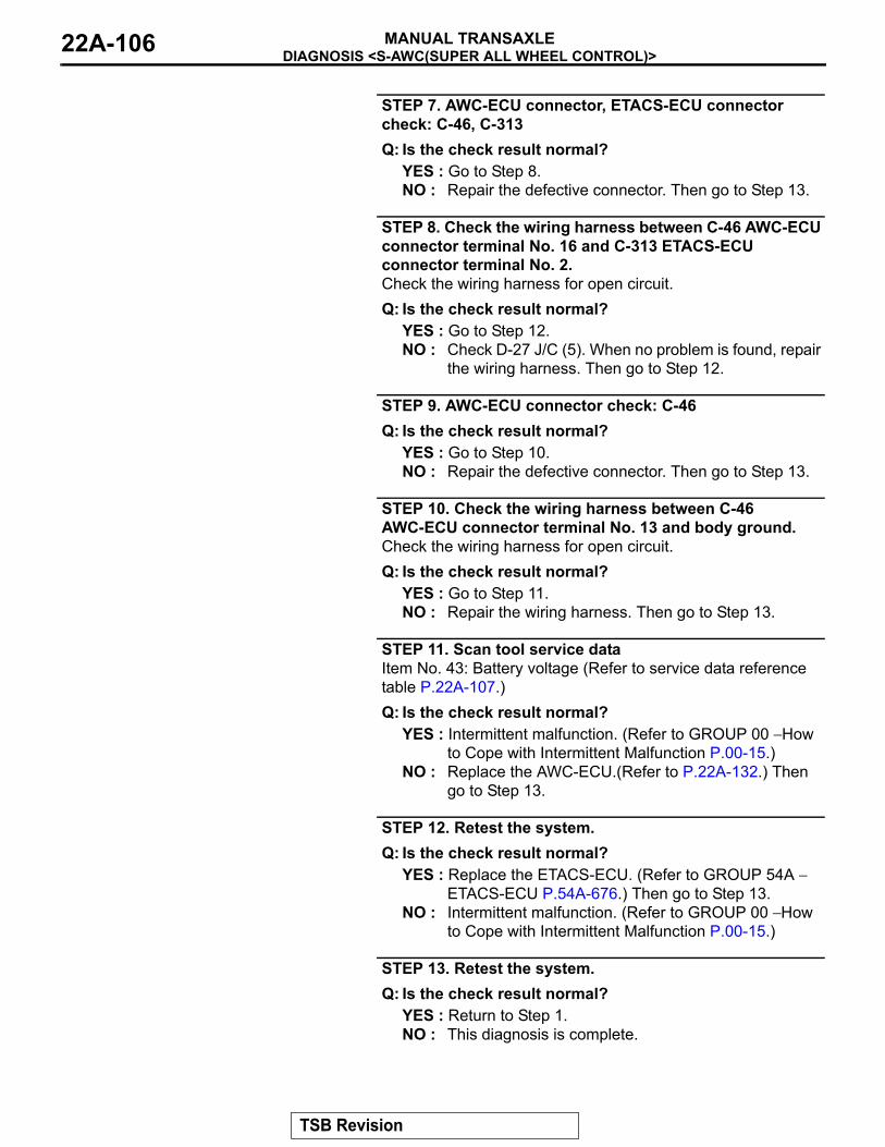
DIAGNOSIS <S-AWC(SUPER ALL WHEEL CONTROL)>MANUAL TRANSAXLE22A-106
STEP 7. AWC-ECU connector, ETACS-ECU connector check: C-46, C-313Q: Is the check result normal?
YES : Go to Step 8.NO : Repair the defective connector. Then go to Step 13.
STEP 8. Check the wiring harness between C-46 AWC-ECU connector terminal No. 16 and C-313 ETACS-ECU connector terminal No. 2.Check the wiring harness for open circuit.Q: Is the check result normal?
YES : Go to Step 12.NO : Check D-27 J/C (5). When no problem is found, repair
the wiring harness. Then go to Step 12.
STEP 9. AWC-ECU connector check: C-46Q: Is the check result normal?
YES : Go to Step 10.NO : Repair the defective connector. Then go to Step 13.
STEP 10. Check the wiring harness between C-46 AWC-ECU connector terminal No. 13 and body ground.Check the wiring harness for open circuit.Q: Is the check result normal?
YES : Go to Step 11.NO : Repair the wiring harness. Then go to Step 13.
STEP 11. Scan tool service dataItem No. 43: Battery voltage (Refer to service data reference table P.22A-107.)Q: Is the check result normal?
YES : Intermittent malfunction. (Refer to GROUP 00 − How to Cope with Intermittent Malfunction P.00-15.)
NO : Replace the AWC-ECU.(Refer to P.22A-132.) Then go to Step 13.
STEP 12. Retest the system.Q: Is the check result normal?
YES : Replace the ETACS-ECU. (Refer to GROUP 54A − ETACS-ECU P.54A-676.) Then go to Step 13.
NO : Intermittent malfunction. (Refer to GROUP 00 − How to Cope with Intermittent Malfunction P.00-15.)
STEP 13. Retest the system.Q: Is the check result normal?
YES : Return to Step 1.NO : This diagnosis is complete.
TSB Revision
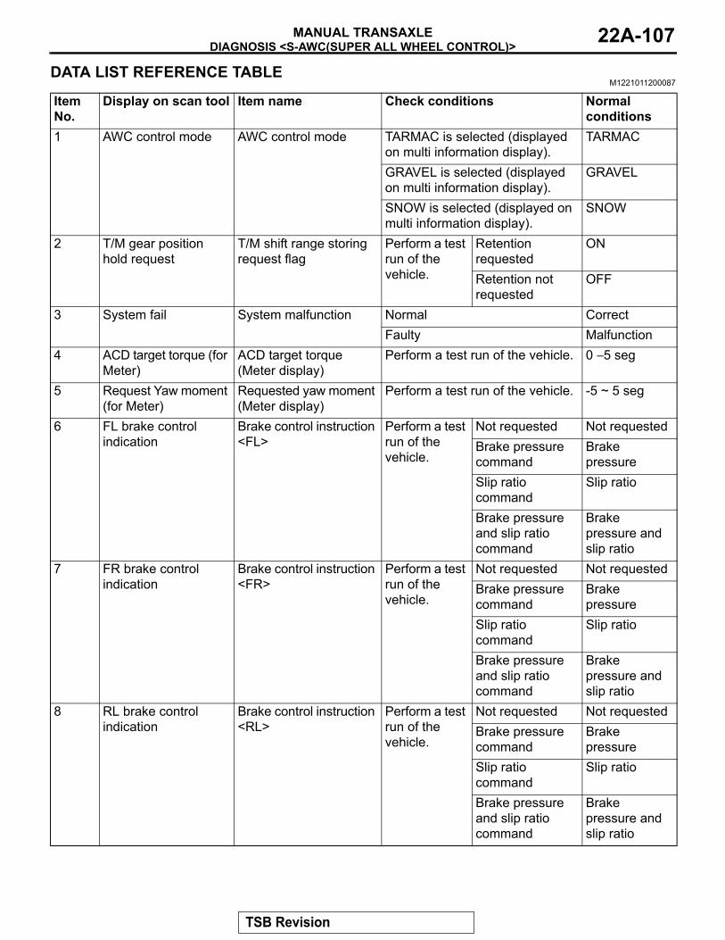
DIAGNOSIS <S-AWC(SUPER ALL WHEEL CONTROL)>MANUAL TRANSAXLE 22A-107
DATA LIST REFERENCE TABLEM1221011200087
Item No.
Display on scan tool Item name Check conditions Normal conditions
1 AWC control mode AWC control mode TARMAC is selected (displayed on multi information display).
TARMAC
GRAVEL is selected (displayed on multi information display).
GRAVEL
SNOW is selected (displayed on multi information display).
SNOW
2 T/M gear position hold request
T/M shift range storing request flag
Perform a test run of the vehicle.
Retention requested
ON
Retention not requested
OFF
3 System fail System malfunction Normal CorrectFaulty Malfunction
4 ACD target torque (for Meter)
ACD target torque (Meter display)
Perform a test run of the vehicle. 0 − 5 seg
5 Request Yaw moment (for Meter)
Requested yaw moment (Meter display)
Perform a test run of the vehicle. -5 ~ 5 seg
6 FL brake control indication
Brake control instruction <FL>
Perform a test run of the vehicle.
Not requested Not requestedBrake pressure command
Brake pressure
Slip ratio command
Slip ratio
Brake pressure and slip ratio command
Brake pressure and slip ratio
7 FR brake control indication
Brake control instruction <FR>
Perform a test run of the vehicle.
Not requested Not requestedBrake pressure command
Brake pressure
Slip ratio command
Slip ratio
Brake pressure and slip ratio command
Brake pressure and slip ratio
8 RL brake control indication
Brake control instruction <RL>
Perform a test run of the vehicle.
Not requested Not requestedBrake pressure command
Brake pressure
Slip ratio command
Slip ratio
Brake pressure and slip ratio command
Brake pressure and slip ratio
TSB Revision
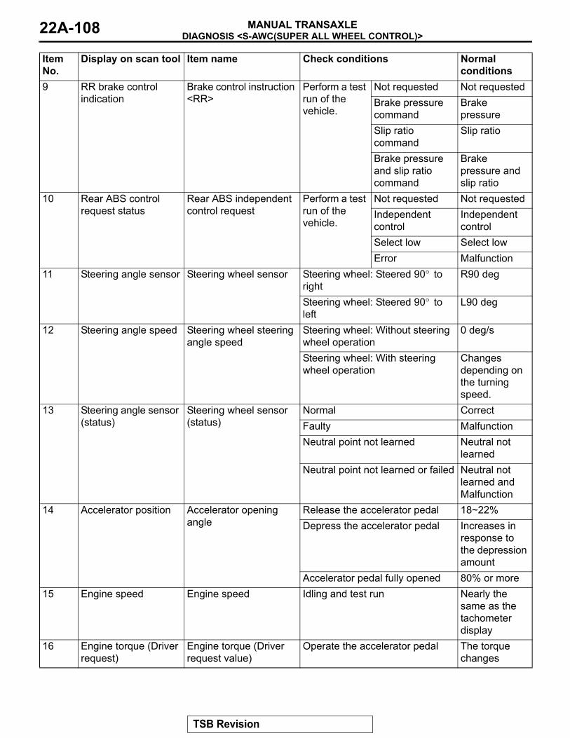
DIAGNOSIS <S-AWC(SUPER ALL WHEEL CONTROL)>MANUAL TRANSAXLE22A-108
9 RR brake control indication
Brake control instruction <RR>
Perform a test run of the vehicle.
Not requested Not requestedBrake pressure command
Brake pressure
Slip ratio command
Slip ratio
Brake pressure and slip ratio command
Brake pressure and slip ratio
10 Rear ABS control request status
Rear ABS independent control request
Perform a test run of the vehicle.
Not requested Not requestedIndependent control
Independent control
Select low Select lowError Malfunction
11 Steering angle sensor Steering wheel sensor Steering wheel: Steered 90° to right
R90 deg
Steering wheel: Steered 90° to left
L90 deg
12 Steering angle speed Steering wheel steering angle speed
Steering wheel: Without steering wheel operation
0 deg/s
Steering wheel: With steering wheel operation
Changes depending on the turning speed.
13 Steering angle sensor (status)
Steering wheel sensor (status)
Normal CorrectFaulty MalfunctionNeutral point not learned Neutral not
learnedNeutral point not learned or failed Neutral not
learned and Malfunction
14 Accelerator position Accelerator opening angle
Release the accelerator pedal 18~22%Depress the accelerator pedal Increases in
response to the depression amount
Accelerator pedal fully opened 80% or more15 Engine speed Engine speed Idling and test run Nearly the
same as the tachometer display
16 Engine torque (Driver request)
Engine torque (Driver request value)
Operate the accelerator pedal The torque changes
Item No.
Display on scan tool Item name Check conditions Normal conditions
TSB Revision
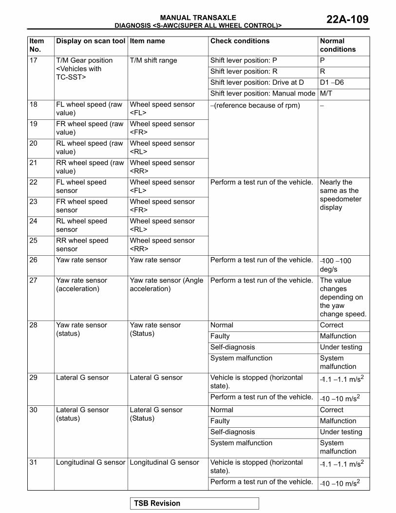
DIAGNOSIS <S-AWC(SUPER ALL WHEEL CONTROL)>MANUAL TRANSAXLE 22A-109
17 T/M Gear position <Vehicles with TC-SST>
T/M shift range Shift lever position: P P Shift lever position: R RShift lever position: Drive at D D1 − D6Shift lever position: Manual mode M/T
18 FL wheel speed (raw value)
Wheel speed sensor <FL>
− (reference because of rpm) −
19 FR wheel speed (raw value)
Wheel speed sensor <FR>
20 RL wheel speed (raw value)
Wheel speed sensor <RL>
21 RR wheel speed (raw value)
Wheel speed sensor <RR>
22 FL wheel speed sensor
Wheel speed sensor <FL>
Perform a test run of the vehicle. Nearly the same as the speedometer display
23 FR wheel speed sensor
Wheel speed sensor <FR>
24 RL wheel speed sensor
Wheel speed sensor <RL>
25 RR wheel speed sensor
Wheel speed sensor <RR>
26 Yaw rate sensor Yaw rate sensor Perform a test run of the vehicle. −100 − 100 deg/s
27 Yaw rate sensor (acceleration)
Yaw rate sensor (Angle acceleration)
Perform a test run of the vehicle. The value changes depending on the yaw change speed.
28 Yaw rate sensor (status)
Yaw rate sensor (Status)
Normal CorrectFaulty MalfunctionSelf-diagnosis Under testingSystem malfunction System
malfunction29 Lateral G sensor Lateral G sensor Vehicle is stopped (horizontal
state).−1.1 − 1.1 m/s2
Perform a test run of the vehicle. −10 − 10 m/s2
30 Lateral G sensor (status)
Lateral G sensor (Status)
Normal CorrectFaulty MalfunctionSelf-diagnosis Under testingSystem malfunction System
malfunction31 Longitudinal G sensor Longitudinal G sensor Vehicle is stopped (horizontal
state).−1.1 − 1.1 m/s2
Perform a test run of the vehicle. −10 − 10 m/s2
Item No.
Display on scan tool Item name Check conditions Normal conditions
TSB Revision
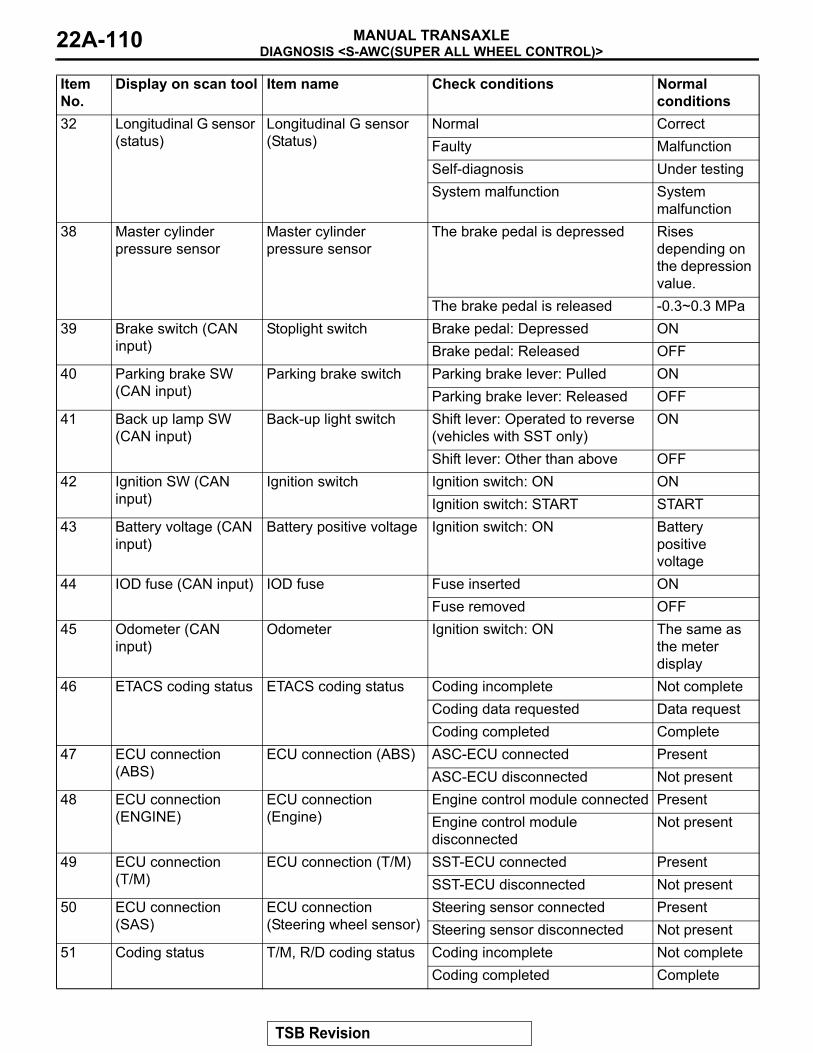
DIAGNOSIS <S-AWC(SUPER ALL WHEEL CONTROL)>MANUAL TRANSAXLE22A-110
32 Longitudinal G sensor (status)
Longitudinal G sensor (Status)
Normal CorrectFaulty MalfunctionSelf-diagnosis Under testingSystem malfunction System
malfunction38 Master cylinder
pressure sensorMaster cylinder pressure sensor
The brake pedal is depressed Rises depending on the depression value.
The brake pedal is released -0.3~0.3 MPa39 Brake switch (CAN
input)Stoplight switch Brake pedal: Depressed ON
Brake pedal: Released OFF40 Parking brake SW
(CAN input)Parking brake switch Parking brake lever: Pulled ON
Parking brake lever: Released OFF41 Back up lamp SW
(CAN input)Back-up light switch Shift lever: Operated to reverse
(vehicles with SST only)ON
Shift lever: Other than above OFF42 Ignition SW (CAN
input)Ignition switch Ignition switch: ON ON
Ignition switch: START START43 Battery voltage (CAN
input)Battery positive voltage Ignition switch: ON Battery
positive voltage
44 IOD fuse (CAN input) IOD fuse Fuse inserted ONFuse removed OFF
45 Odometer (CAN input)
Odometer Ignition switch: ON The same as the meter display
46 ETACS coding status ETACS coding status Coding incomplete Not completeCoding data requested Data requestCoding completed Complete
47 ECU connection (ABS)
ECU connection (ABS) ASC-ECU connected PresentASC-ECU disconnected Not present
48 ECU connection (ENGINE)
ECU connection (Engine)
Engine control module connected PresentEngine control module disconnected
Not present
49 ECU connection (T/M)
ECU connection (T/M) SST-ECU connected PresentSST-ECU disconnected Not present
50 ECU connection (SAS)
ECU connection (Steering wheel sensor)
Steering sensor connected PresentSteering sensor disconnected Not present
51 Coding status T/M, R/D coding status Coding incomplete Not completeCoding completed Complete
Item No.
Display on scan tool Item name Check conditions Normal conditions
TSB Revision
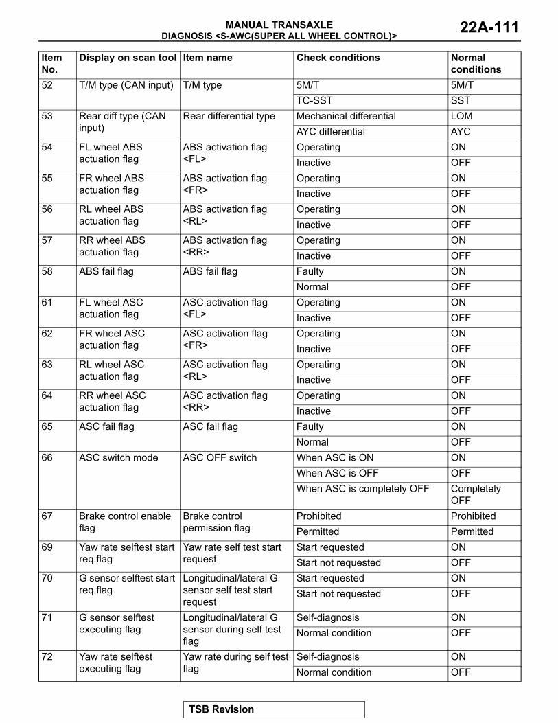
DIAGNOSIS <S-AWC(SUPER ALL WHEEL CONTROL)>MANUAL TRANSAXLE 22A-111
52 T/M type (CAN input) T/M type 5M/T 5M/TTC-SST SST
53 Rear diff type (CAN input)
Rear differential type Mechanical differential LOMAYC differential AYC
54 FL wheel ABS actuation flag
ABS activation flag <FL>
Operating ONInactive OFF
55 FR wheel ABS actuation flag
ABS activation flag <FR>
Operating ONInactive OFF
56 RL wheel ABS actuation flag
ABS activation flag <RL>
Operating ONInactive OFF
57 RR wheel ABS actuation flag
ABS activation flag <RR>
Operating ONInactive OFF
58 ABS fail flag ABS fail flag Faulty ONNormal OFF
61 FL wheel ASC actuation flag
ASC activation flag <FL>
Operating ONInactive OFF
62 FR wheel ASC actuation flag
ASC activation flag <FR>
Operating ONInactive OFF
63 RL wheel ASC actuation flag
ASC activation flag <RL>
Operating ONInactive OFF
64 RR wheel ASC actuation flag
ASC activation flag <RR>
Operating ONInactive OFF
65 ASC fail flag ASC fail flag Faulty ONNormal OFF
66 ASC switch mode ASC OFF switch When ASC is ON ONWhen ASC is OFF OFFWhen ASC is completely OFF Completely
OFF67 Brake control enable
flagBrake control permission flag
Prohibited ProhibitedPermitted Permitted
69 Yaw rate selftest start req.flag
Yaw rate self test start request
Start requested ONStart not requested OFF
70 G sensor selftest start req.flag
Longitudinal/lateral G sensor self test start request
Start requested ONStart not requested OFF
71 G sensor selftest executing flag
Longitudinal/lateral G sensor during self test flag
Self-diagnosis ONNormal condition OFF
72 Yaw rate selftest executing flag
Yaw rate during self test flag
Self-diagnosis ONNormal condition OFF
Item No.
Display on scan tool Item name Check conditions Normal conditions
TSB Revision
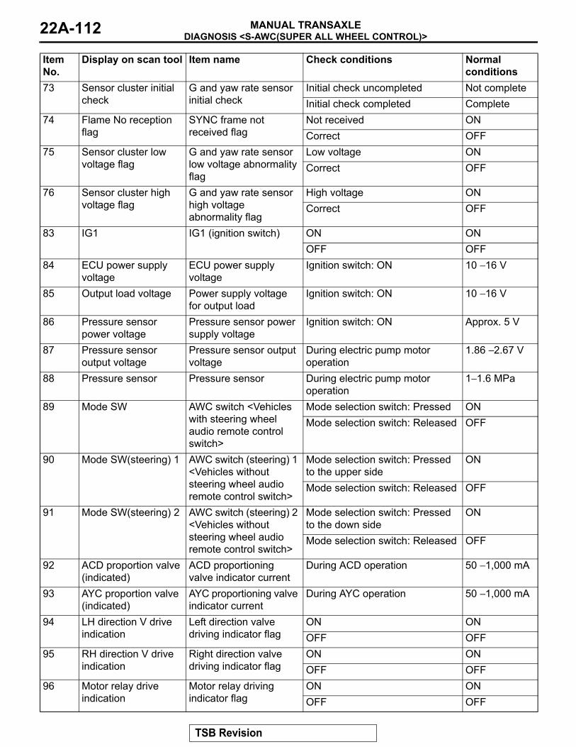
DIAGNOSIS <S-AWC(SUPER ALL WHEEL CONTROL)>MANUAL TRANSAXLE22A-112
73 Sensor cluster initial check
G and yaw rate sensor initial check
Initial check uncompleted Not completeInitial check completed Complete
74 Flame No reception flag
SYNC frame not received flag
Not received ONCorrect OFF
75 Sensor cluster low voltage flag
G and yaw rate sensor low voltage abnormality flag
Low voltage ONCorrect OFF
76 Sensor cluster high voltage flag
G and yaw rate sensor high voltage abnormality flag
High voltage ONCorrect OFF
83 IG1 IG1 (ignition switch) ON ONOFF OFF
84 ECU power supply voltage
ECU power supply voltage
Ignition switch: ON 10 − 16 V
85 Output load voltage Power supply voltage for output load
Ignition switch: ON 10 − 16 V
86 Pressure sensor power voltage
Pressure sensor power supply voltage
Ignition switch: ON Approx. 5 V
87 Pressure sensor output voltage
Pressure sensor output voltage
During electric pump motor operation
1.86 − 2.67 V
88 Pressure sensor Pressure sensor During electric pump motor operation
1− 1.6 MPa
89 Mode SW AWC switch <Vehicles with steering wheel audio remote control switch>
Mode selection switch: Pressed ONMode selection switch: Released OFF
90 Mode SW(steering) 1 AWC switch (steering) 1 <Vehicles without steering wheel audio remote control switch>
Mode selection switch: Pressed to the upper side
ON
Mode selection switch: Released OFF
91 Mode SW(steering) 2 AWC switch (steering) 2 <Vehicles without steering wheel audio remote control switch>
Mode selection switch: Pressed to the down side
ON
Mode selection switch: Released OFF
92 ACD proportion valve (indicated)
ACD proportioning valve indicator current
During ACD operation 50 − 1,000 mA
93 AYC proportion valve (indicated)
AYC proportioning valve indicator current
During AYC operation 50 − 1,000 mA
94 LH direction V drive indication
Left direction valve driving indicator flag
ON ONOFF OFF
95 RH direction V drive indication
Right direction valve driving indicator flag
ON ONOFF OFF
96 Motor relay drive indication
Motor relay driving indicator flag
ON ONOFF OFF
Item No.
Display on scan tool Item name Check conditions Normal conditions
TSB Revision

DIAGNOSIS <S-AWC(SUPER ALL WHEEL CONTROL)>MANUAL TRANSAXLE 22A-113
SPECIAL FUNCTION REFERENCE TABLEM1221011300062
ACTUATOR TEST TABLE
97 Yaw rate sensor (adjusted value)
Yaw rate sensor (Correction amount)
Ignition switch: ON −6 − 6 deg/s
98 SAS (adjusted value) Steering sensor (Correction amount)
Ignition switch: ON −15 − 15 deg
99 Lateral G sensor(adjusted value)
Lateral G sensor (Correction amount)
Ignition switch: ON −1.7 − 1.7 m/s2
100 Longitudinal G (adjusted value)
Longitudinal G sensor (Correction amount)
Ignition switch: ON −3 − 3 m/s2
101 Chassis Number writing counter
Chassis number writing count
Ignition switch: ON Writing count
102 Chassis Number (original) lock
Chassis number (original) lock
Ignition switch: ON
Locked LockUnlocked Unlock
103 Mileage counter Mileage counter Ignition switch: ON Counter value104 Coding counter Coding count Ignition switch: ON Coding count
Item No.
Display on scan tool Item name Check conditions Normal conditions
Item No.
Display on scan tool
Check items Test content Normal conditions
1 ACD air bleeding
Air bleeding <ACD>
According to the steering angle of steering wheel, energize the proportioning valve, and operate the proportioning valve for 5 minutes.
No air comes out from the bleeder screw established to the transfer.
2 AYC air bleeding
Air bleeding <AYC>
According to the steering angle of steering wheel, energize the proportioning valve, and operate the direction valve for 5 minutes.
No air comes out from the bleeder screw established to the torque transfer differential.
3 Oil level check
Oil level check
Operate the direction valve to left and right for 20 seconds.
Oil level of reservoir tank is adequate.
4 Motor drive Electric pump operation
Operate the electric pump for 3 seconds.
Operating sound of the electric pump can be heard.
5 ACD operation check
ACD operation check
Operate the proportioning valve <ACD>, and supply the maximum hydraulic pressure to the multiplate clutch.
The tight corner braking phenomenon occurs.
6 AYC operation check (left)
Clutch operation check <left side>
Operate the direction valve, and supply the maximum hydraulic pressure to the left clutch.
With the wheels lifted, a speed difference is generated between left and right rear wheels.
7 AYC operation check (right)
Clutch operation check <right side>
Operate the direction valve, and supply the maximum hydraulic pressure to the right clutch.
With the wheels lifted, a speed difference is generated between left and right rear wheels.
TSB Revision
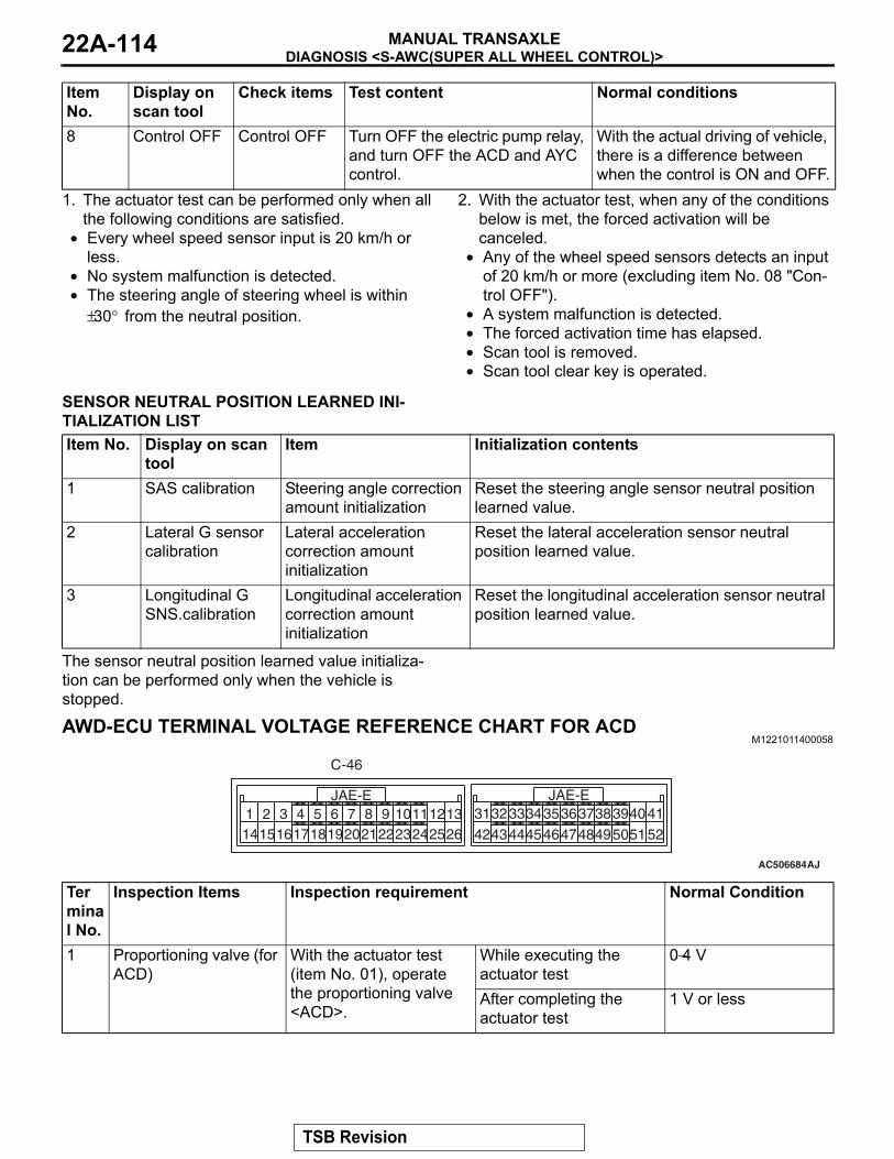
DIAGNOSIS <S-AWC(SUPER ALL WHEEL CONTROL)>MANUAL TRANSAXLE22A-114
1. The actuator test can be performed only when all the following conditions are satisfied.
• Every wheel speed sensor input is 20 km/h or less.
• No system malfunction is detected.• The steering angle of steering wheel is within
±30° from the neutral position.
2. With the actuator test, when any of the conditions below is met, the forced activation will be canceled.
• Any of the wheel speed sensors detects an input of 20 km/h or more (excluding item No. 08 "Con-trol OFF").
• A system malfunction is detected.• The forced activation time has elapsed.• Scan tool is removed.• Scan tool clear key is operated.
SENSOR NEUTRAL POSITION LEARNED INI-TIALIZATION LISTItem No. Display on scan
toolItem Initialization contents
1 SAS calibration Steering angle correction amount initialization
Reset the steering angle sensor neutral position learned value.
2 Lateral G sensor calibration
Lateral acceleration correction amount initialization
Reset the lateral acceleration sensor neutral position learned value.
3 Longitudinal G SNS.calibration
Longitudinal acceleration correction amount initialization
Reset the longitudinal acceleration sensor neutral position learned value.
The sensor neutral position learned value initializa-tion can be performed only when the vehicle is stopped.
AWD-ECU TERMINAL VOLTAGE REFERENCE CHART FOR ACDM1221011400058
AC506684
229
16152
141 3
196
18174 5
207
218
2512
2310
2411
2613
JAE-E3950444243
3231 33JAE-E
4736
45463435
49483738
52514041
C-46
AJ
8 Control OFF Control OFF Turn OFF the electric pump relay, and turn OFF the ACD and AYC control.
With the actual driving of vehicle, there is a difference between when the control is ON and OFF.
Item No.
Display on scan tool
Check items Test content Normal conditions
Terminal No.
Inspection Items Inspection requirement Normal Condition
1 Proportioning valve (for ACD)
With the actuator test (item No. 01), operate the proportioning valve <ACD>.
While executing the actuator test
0−4 V
After completing the actuator test
1 V or less
TSB Revision
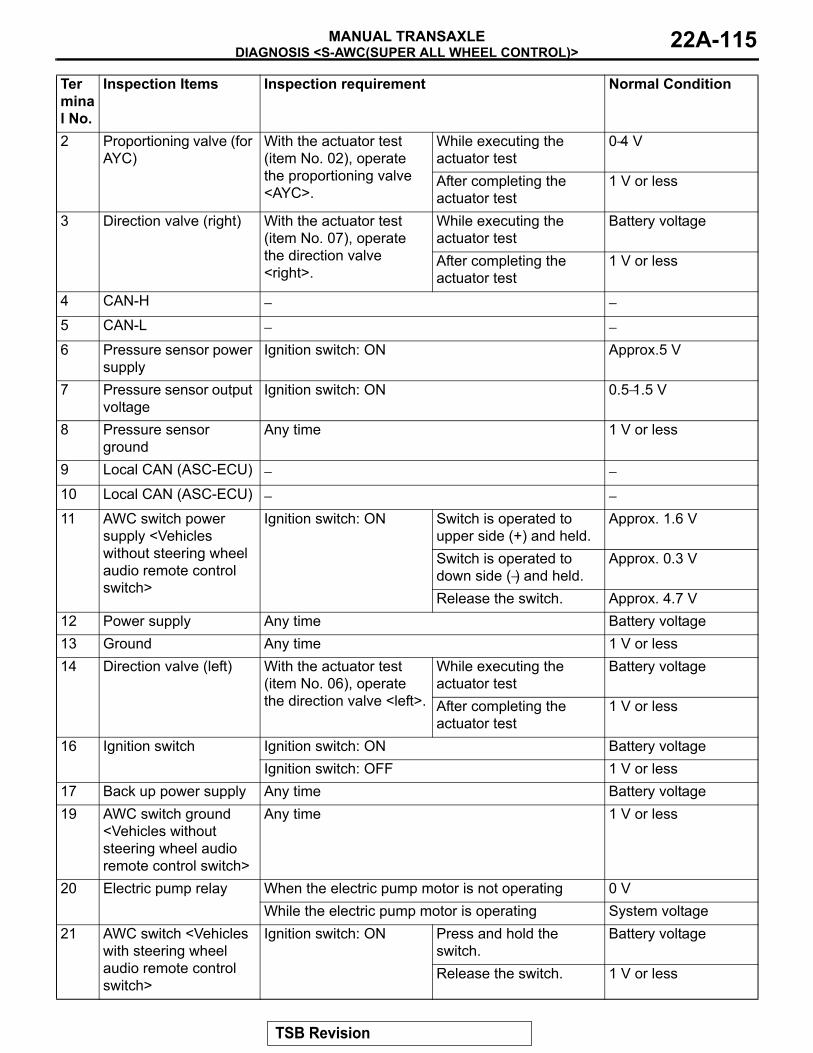
DIAGNOSIS <S-AWC(SUPER ALL WHEEL CONTROL)>MANUAL TRANSAXLE 22A-115
2 Proportioning valve (for AYC)
With the actuator test (item No. 02), operate the proportioning valve <AYC>.
While executing the actuator test
0−4 V
After completing the actuator test
1 V or less
3 Direction valve (right) With the actuator test (item No. 07), operate the direction valve <right>.
While executing the actuator test
Battery voltage
After completing the actuator test
1 V or less
4 CAN-H − −5 CAN-L − −6 Pressure sensor power
supplyIgnition switch: ON Approx.5 V
7 Pressure sensor output voltage
Ignition switch: ON 0.5−1.5 V
8 Pressure sensor ground
Any time 1 V or less
9 Local CAN (ASC-ECU) − −10 Local CAN (ASC-ECU) − −11 AWC switch power
supply <Vehicles without steering wheel audio remote control switch>
Ignition switch: ON Switch is operated to upper side (+) and held.
Approx. 1.6 V
Switch is operated to down side (−) and held.
Approx. 0.3 V
Release the switch. Approx. 4.7 V12 Power supply Any time Battery voltage13 Ground Any time 1 V or less14 Direction valve (left) With the actuator test
(item No. 06), operate the direction valve <left>.
While executing the actuator test
Battery voltage
After completing the actuator test
1 V or less
16 Ignition switch Ignition switch: ON Battery voltageIgnition switch: OFF 1 V or less
17 Back up power supply Any time Battery voltage19 AWC switch ground
<Vehicles without steering wheel audio remote control switch>
Any time 1 V or less
20 Electric pump relay When the electric pump motor is not operating 0 VWhile the electric pump motor is operating System voltage
21 AWC switch <Vehicles with steering wheel audio remote control switch>
Ignition switch: ON Press and hold the switch.
Battery voltage
Release the switch. 1 V or less
Terminal No.
Inspection Items Inspection requirement Normal Condition
TSB Revision
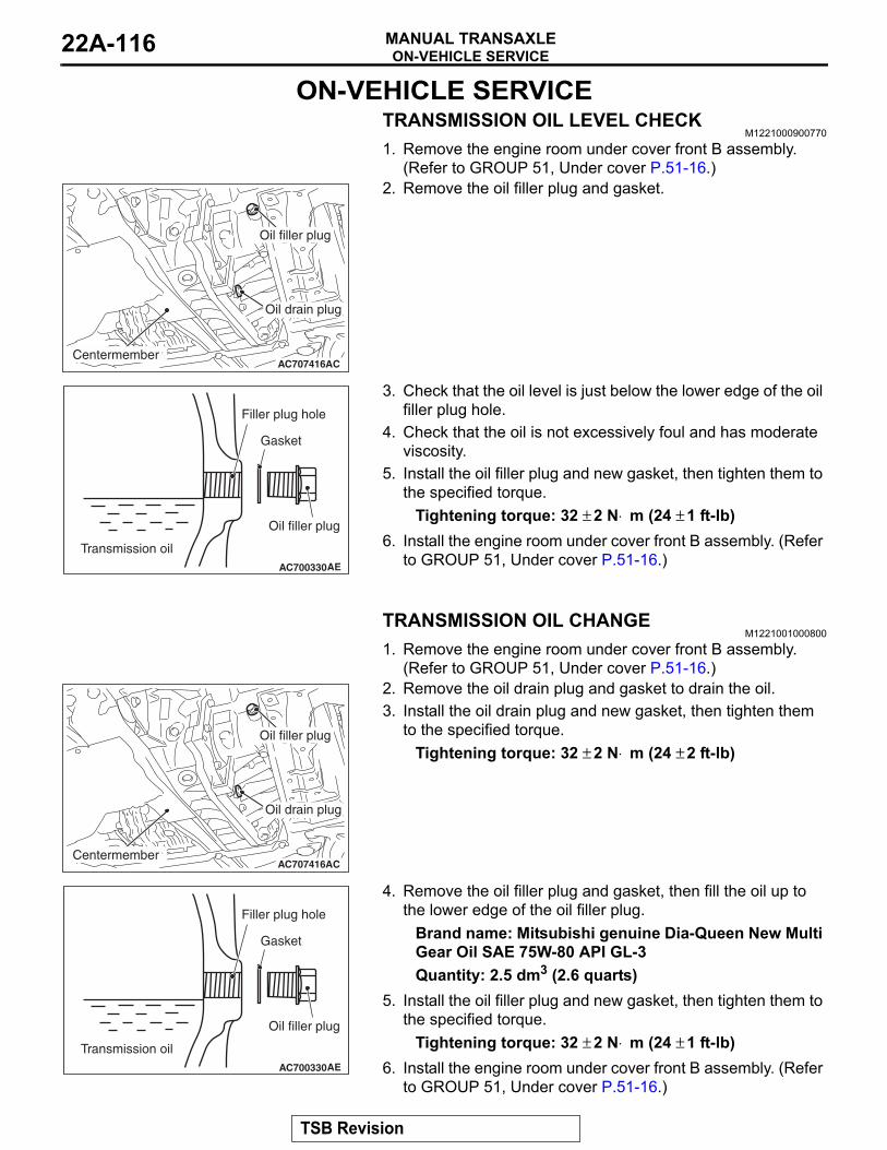
ON-VEHICLE SERVICEMANUAL TRANSAXLE22A-116
ON-VEHICLE SERVICETRANSMISSION OIL LEVEL CHECK
M1221000900770
1. Remove the engine room under cover front B assembly. (Refer to GROUP 51, Under cover P.51-16.)
AC707416ACCenter memberCentermember
Oil filler plug
Oil drain plug
2. Remove the oil filler plug and gasket.
AC700330AE
Gasket
Transmission oil
Filler plug hole
Oil filler plug
3. Check that the oil level is just below the lower edge of the oil filler plug hole.
4. Check that the oil is not excessively foul and has moderate viscosity.
5. Install the oil filler plug and new gasket, then tighten them to the specified torque.
Tightening torque: 32 ± 2 N⋅ m (24 ± 1 ft-lb)6. Install the engine room under cover front B assembly. (Refer
to GROUP 51, Under cover P.51-16.)
TRANSMISSION OIL CHANGEM1221001000800
1. Remove the engine room under cover front B assembly. (Refer to GROUP 51, Under cover P.51-16.)
AC707416ACCenter memberCentermember
Oil filler plug
Oil drain plug
2. Remove the oil drain plug and gasket to drain the oil.3. Install the oil drain plug and new gasket, then tighten them
to the specified torque.Tightening torque: 32 ± 2 N⋅ m (24 ± 2 ft-lb)
AC700330AE
Gasket
Transmission oil
Filler plug hole
Oil filler plug
4. Remove the oil filler plug and gasket, then fill the oil up to the lower edge of the oil filler plug.
Brand name: Mitsubishi genuine Dia-Queen New Multi Gear Oil SAE 75W-80 API GL-3Quantity: 2.5 dm3 (2.6 quarts)
5. Install the oil filler plug and new gasket, then tighten them to the specified torque.
Tightening torque: 32 ± 2 N⋅ m (24 ± 1 ft-lb)6. Install the engine room under cover front B assembly. (Refer
to GROUP 51, Under cover P.51-16.)
TSB Revision
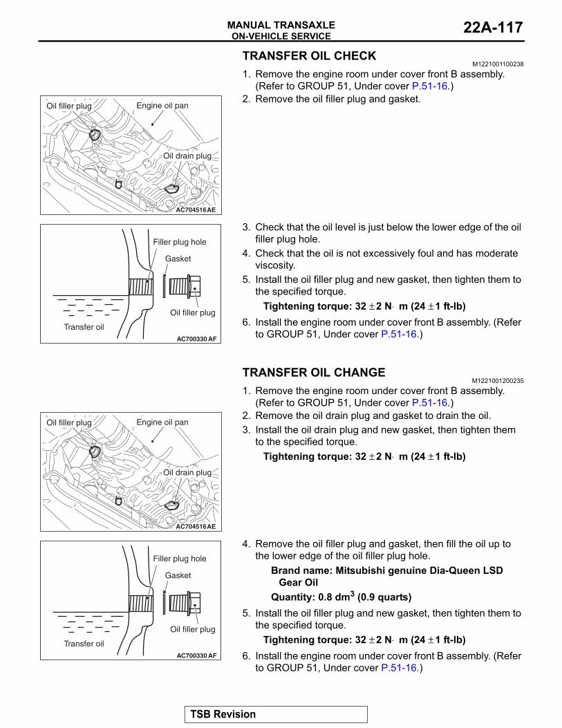
ON-VEHICLE SERVICEMANUAL TRANSAXLE 22A-117
TRANSFER OIL CHECKM1221001100238
1. Remove the engine room under cover front B assembly. (Refer to GROUP 51, Under cover P.51-16.)
AC704516AE
Oil filler plug
Oil drain plug
Engine oil pan2. Remove the oil filler plug and gasket.
AC700330 AF
Gasket
Transfer oil
Filler plug hole
Oil filler plug
3. Check that the oil level is just below the lower edge of the oil filler plug hole.
4. Check that the oil is not excessively foul and has moderate viscosity.
5. Install the oil filler plug and new gasket, then tighten them to the specified torque.
Tightening torque: 32 ± 2 N⋅ m (24 ± 1 ft-lb)6. Install the engine room under cover front B assembly. (Refer
to GROUP 51, Under cover P.51-16.)
TRANSFER OIL CHANGEM1221001200235
1. Remove the engine room under cover front B assembly. (Refer to GROUP 51, Under cover P.51-16.)
AC704516AE
Oil filler plug
Oil drain plug
Engine oil pan2. Remove the oil drain plug and gasket to drain the oil.3. Install the oil drain plug and new gasket, then tighten them
to the specified torque.Tightening torque: 32 ± 2 N⋅ m (24 ± 1 ft-lb)
AC700330 AF
Gasket
Transfer oil
Filler plug hole
Oil filler plug
4. Remove the oil filler plug and gasket, then fill the oil up to the lower edge of the oil filler plug hole.
Brand name: Mitsubishi genuine Dia-Queen LSD Gear Oil
Quantity: 0.8 dm3 (0.9 quarts)5. Install the oil filler plug and new gasket, then tighten them to
the specified torque.Tightening torque: 32 ± 2 N⋅ m (24 ± 1 ft-lb)
6. Install the engine room under cover front B assembly. (Refer to GROUP 51, Under cover P.51-16.)
TSB Revision
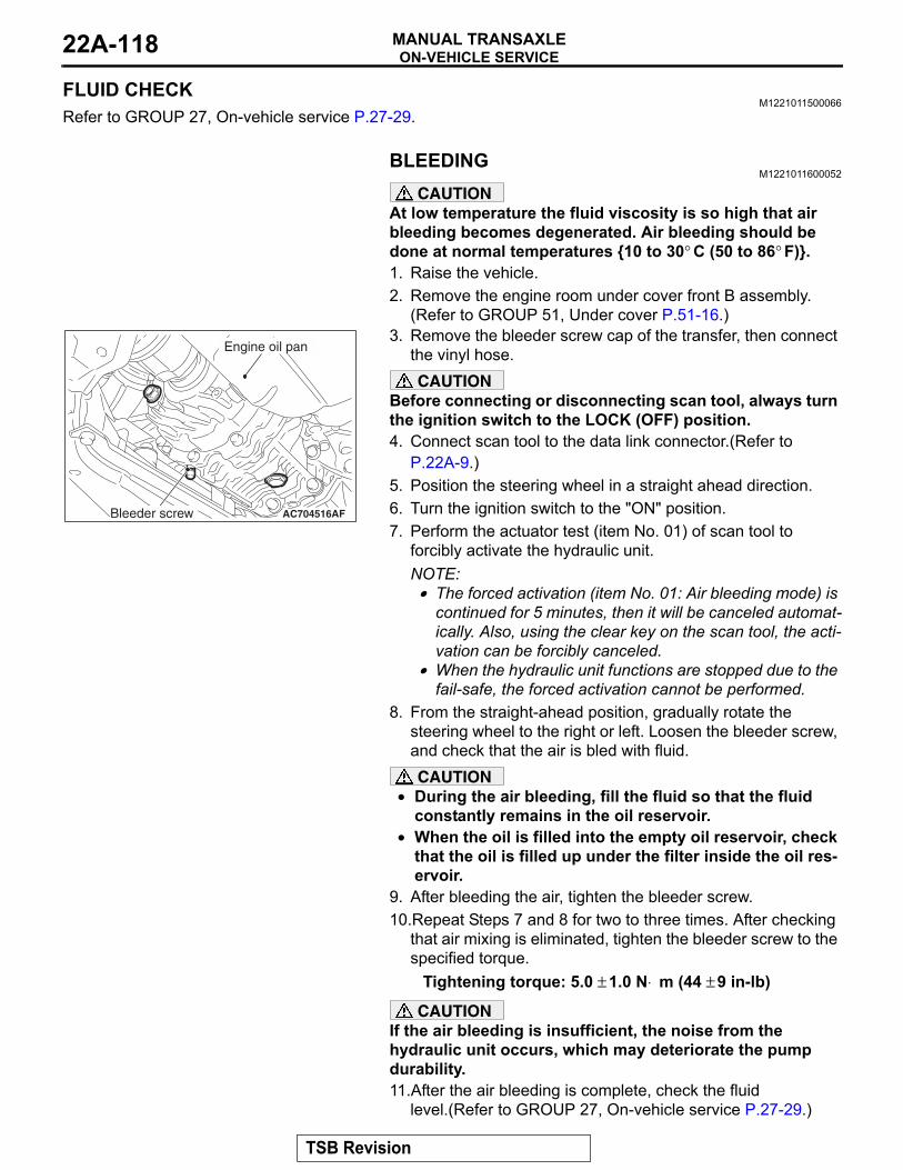
ON-VEHICLE SERVICEMANUAL TRANSAXLE22A-118
FLUID CHECKM1221011500066
Refer to GROUP 27, On-vehicle service P.27-29.
BLEEDINGM1221011600052
CAUTIONAt low temperature the fluid viscosity is so high that air bleeding becomes degenerated. Air bleeding should be done at normal temperatures 10 to 30° C (50 to 86° F). 1. Raise the vehicle.2. Remove the engine room under cover front B assembly.
(Refer to GROUP 51, Under cover P.51-16.)
AC704516
Engine oil pan
AFBleeder screw
3. Remove the bleeder screw cap of the transfer, then connect the vinyl hose.CAUTION
Before connecting or disconnecting scan tool, always turn the ignition switch to the LOCK (OFF) position.4. Connect scan tool to the data link connector.(Refer to
P.22A-9.)5. Position the steering wheel in a straight ahead direction.6. Turn the ignition switch to the "ON" position.7. Perform the actuator test (item No. 01) of scan tool to
forcibly activate the hydraulic unit.NOTE: .• The forced activation (item No. 01: Air bleeding mode) is
continued for 5 minutes, then it will be canceled automat-ically. Also, using the clear key on the scan tool, the acti-vation can be forcibly canceled.
• When the hydraulic unit functions are stopped due to the fail-safe, the forced activation cannot be performed.
8. From the straight-ahead position, gradually rotate the steering wheel to the right or left. Loosen the bleeder screw, and check that the air is bled with fluid.CAUTION
• During the air bleeding, fill the fluid so that the fluid constantly remains in the oil reservoir.
• When the oil is filled into the empty oil reservoir, check that the oil is filled up under the filter inside the oil res-ervoir.
9. After bleeding the air, tighten the bleeder screw.10.Repeat Steps 7 and 8 for two to three times. After checking
that air mixing is eliminated, tighten the bleeder screw to the specified torque.
Tightening torque: 5.0 ± 1.0 N⋅ m (44 ± 9 in-lb)
CAUTIONIf the air bleeding is insufficient, the noise from the hydraulic unit occurs, which may deteriorate the pump durability.11.After the air bleeding is complete, check the fluid
level.(Refer to GROUP 27, On-vehicle service P.27-29.)
TSB Revision
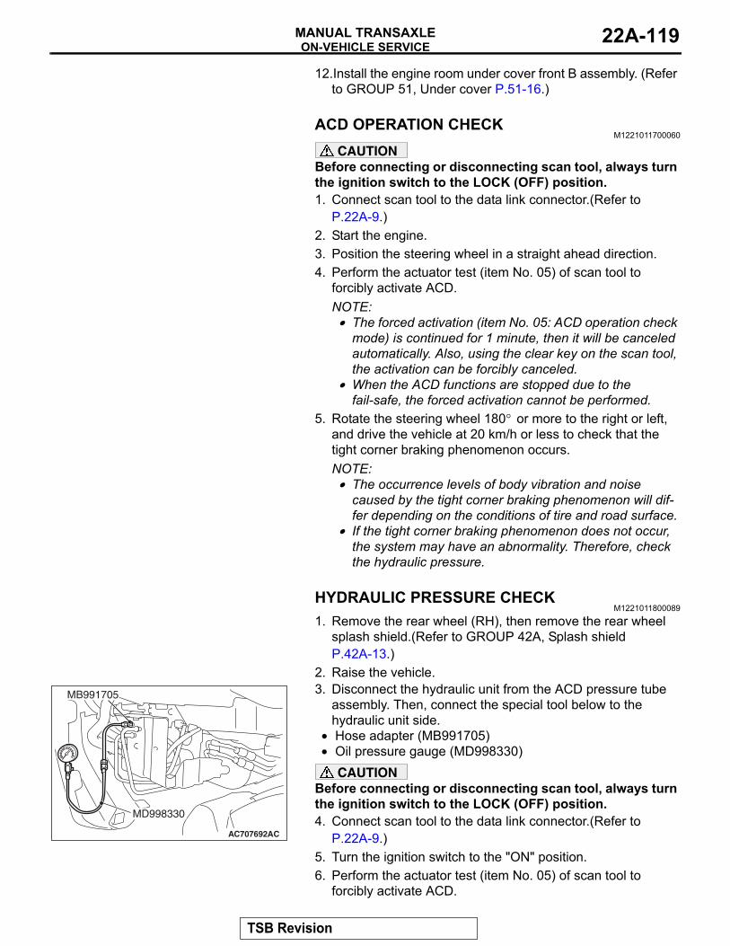
ON-VEHICLE SERVICEMANUAL TRANSAXLE 22A-119
12.Install the engine room under cover front B assembly. (Refer to GROUP 51, Under cover P.51-16.)
ACD OPERATION CHECKM1221011700060
CAUTIONBefore connecting or disconnecting scan tool, always turn the ignition switch to the LOCK (OFF) position.1. Connect scan tool to the data link connector.(Refer to
P.22A-9.)2. Start the engine.3. Position the steering wheel in a straight ahead direction.4. Perform the actuator test (item No. 05) of scan tool to
forcibly activate ACD.NOTE: .• The forced activation (item No. 05: ACD operation check
mode) is continued for 1 minute, then it will be canceled automatically. Also, using the clear key on the scan tool, the activation can be forcibly canceled.
• When the ACD functions are stopped due to the fail-safe, the forced activation cannot be performed.
5. Rotate the steering wheel 180° or more to the right or left, and drive the vehicle at 20 km/h or less to check that the tight corner braking phenomenon occurs.NOTE: .• The occurrence levels of body vibration and noise
caused by the tight corner braking phenomenon will dif-fer depending on the conditions of tire and road surface.
• If the tight corner braking phenomenon does not occur, the system may have an abnormality. Therefore, check the hydraulic pressure.
HYDRAULIC PRESSURE CHECKM1221011800089
1. Remove the rear wheel (RH), then remove the rear wheel splash shield.(Refer to GROUP 42A, Splash shield P.42A-13.)
2. Raise the vehicle.
AC707692AC
MB991705
MD998330
3. Disconnect the hydraulic unit from the ACD pressure tube assembly. Then, connect the special tool below to the hydraulic unit side.
• Hose adapter (MB991705)• Oil pressure gauge (MD998330)
CAUTIONBefore connecting or disconnecting scan tool, always turn the ignition switch to the LOCK (OFF) position.4. Connect scan tool to the data link connector.(Refer to
P.22A-9.)5. Turn the ignition switch to the "ON" position.6. Perform the actuator test (item No. 05) of scan tool to
forcibly activate ACD.
TSB Revision
ON-VEHICLE SERVICEMANUAL TRANSAXLE22A-120
NOTE: .• The forced activation (item No. 05: ACD operation check
mode) is continued for 1 minute, then it will be canceled automatically. Also, using the clear key on the scan tool, the activation can be forcibly canceled.
• When the ACD functions are stopped due to the fail-safe, the forced activation cannot be performed.
CAUTIONDuring the hydraulic pressure check, fill the fluid so that the fluid constantly remains in the oil reservoir.7. Check that the generated hydraulic pressure of the hydraulic
unit is within the standard value.Standard valve: 0.9 − 1.1 MPa (130 − 159 psi)
8. If the measured value exceeds the standard value, replace the hydraulic unit.
9. After applying oil to the flare nut thread of ACD pressure tube assembly, connect the assembly to the hydraulic unit, then tighten to the specified torque.
Tightening torque: 26 ± 4 N⋅ m (19 ± 3 ft-lb)10.Perform the air bleeding. (Refer to P.22A-118.)
TSB Revision
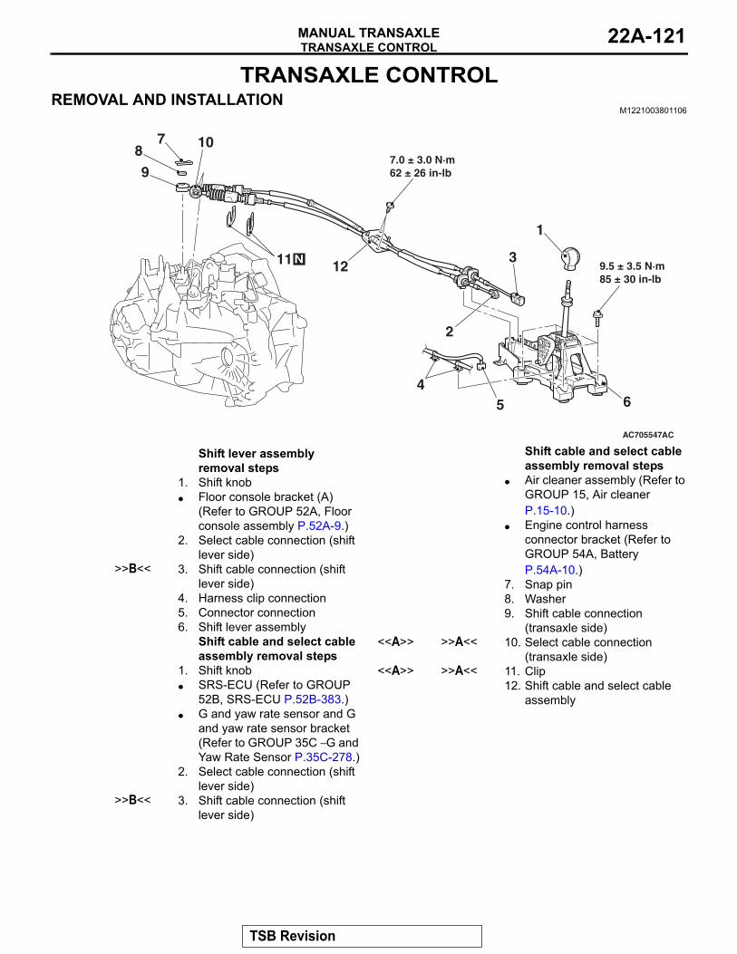
TRANSAXLE CONTROLMANUAL TRANSAXLE 22A-121
TRANSAXLE CONTROLREMOVAL AND INSTALLATION
M1221003801106
AC705547
N
1
2
1211
10
3
45
9
6
AC
87
7.0 ± 3.0 N·m62 ± 26 in-lb
9.5 ± 3.5 N·m85 ± 30 in-lb
Shift lever assembly removal steps
1. Shift knob• Floor console bracket (A)
(Refer to GROUP 52A, Floor console assembly P.52A-9.)
2. Select cable connection (shift lever side)
>>B<< 3. Shift cable connection (shift lever side)
4. Harness clip connection5. Connector connection6. Shift lever assembly
Shift cable and select cable assembly removal steps
1. Shift knob• SRS-ECU (Refer to GROUP
52B, SRS-ECU P.52B-383.)• G and yaw rate sensor and G
and yaw rate sensor bracket (Refer to GROUP 35C − G and Yaw Rate Sensor P.35C-278.)
2. Select cable connection (shift lever side)
>>B<< 3. Shift cable connection (shift lever side)
• Air cleaner assembly (Refer to GROUP 15, Air cleaner P.15-10.)
• Engine control harness connector bracket (Refer to GROUP 54A, Battery P.54A-10.)
7. Snap pin8. Washer9. Shift cable connection
(transaxle side)<<A>> >>A<< 10. Select cable connection
(transaxle side)<<A>> >>A<< 11. Clip
12. Shift cable and select cable assembly
Shift cable and select cable assembly removal steps
TSB Revision
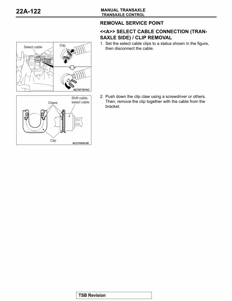
TRANSAXLE CONTROLMANUAL TRANSAXLE22A-122
REMOVAL SERVICE POINT.
<<A>> SELECT CABLE CONNECTION (TRAN-SAXLE SIDE) / CLIP REMOVAL
AC707727
ClipSelect cable
AC
1. Set the select cable clips to a status shown in the figure, then disconnect the cable.
AC210556Clip
Shift cable, select cableClaws
AE
2. Push down the clip claw using a screwdriver or others. Then, remove the clip together with the cable from the bracket.
TSB Revision
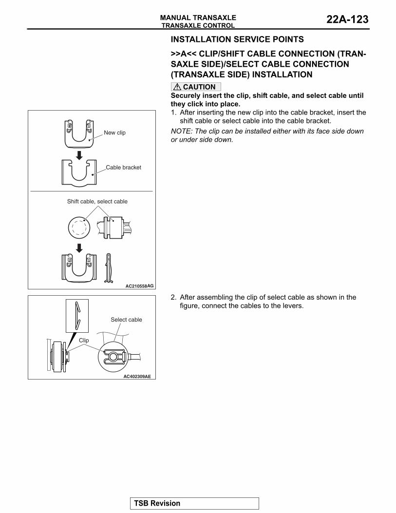
TRANSAXLE CONTROLMANUAL TRANSAXLE 22A-123
INSTALLATION SERVICE POINTS.
>>A<< CLIP/SHIFT CABLE CONNECTION (TRAN-SAXLE SIDE)/SELECT CABLE CONNECTION (TRANSAXLE SIDE) INSTALLATION
CAUTIONSecurely insert the clip, shift cable, and select cable until they click into place.
AC210558
Shift cable, select cable
New clip
Cable bracket
AG
1. After inserting the new clip into the cable bracket, insert the shift cable or select cable into the cable bracket.
NOTE: The clip can be installed either with its face side down or under side down.
AC402309
Clip
AE
Select cable
2. After assembling the clip of select cable as shown in the figure, connect the cables to the levers.
.
TSB Revision

TRANSAXLE CONTROLMANUAL TRANSAXLE22A-124
>>B<< SHIFT CABKE CONNECTION (SHIFT LEVER SIDE)
AC607793Shift cable
Shift lever assembly
AD
To the area of shift lever assembly shown in the figure, securely insert the shift cable tip until it clicks into place.
TSB Revision
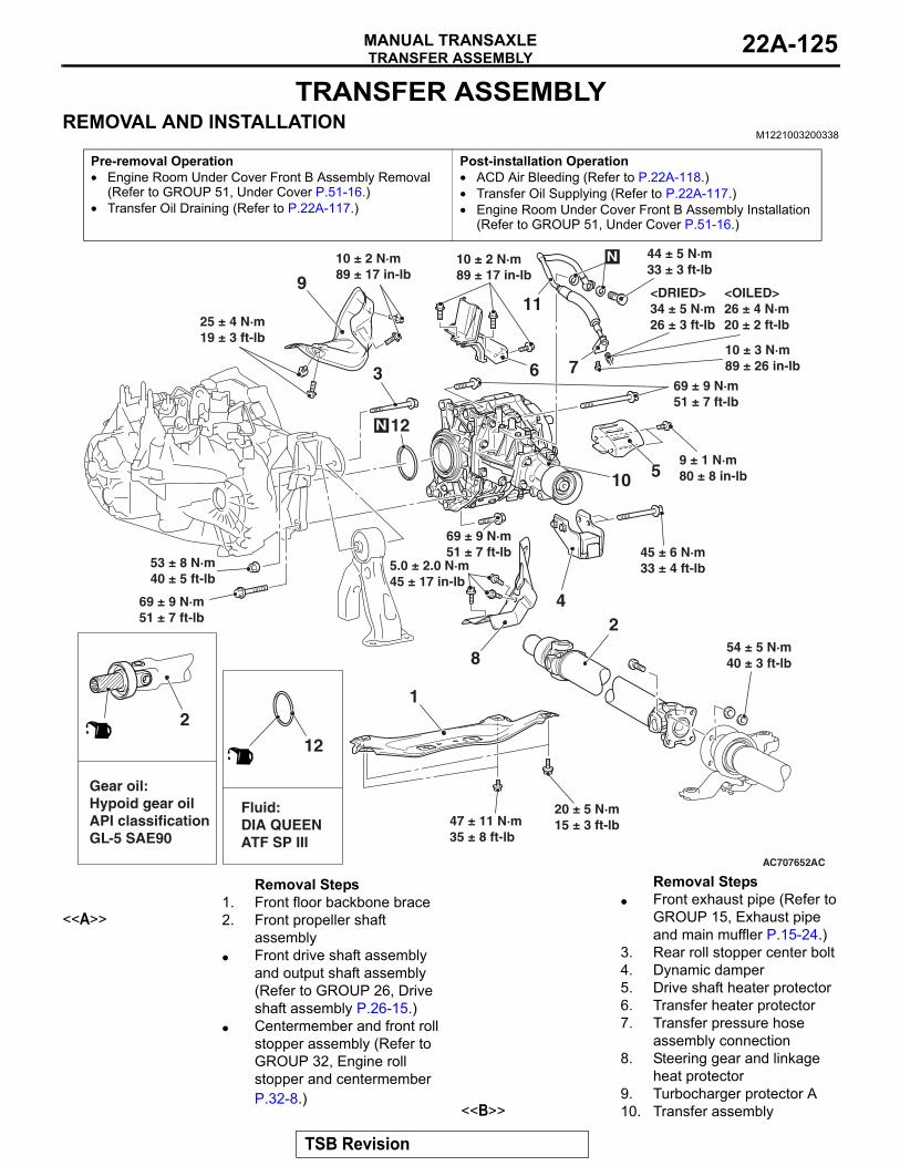
TRANSFER ASSEMBLYMANUAL TRANSAXLE 22A-125
TRANSFER ASSEMBLYREMOVAL AND INSTALLATION
M1221003200338
Pre-removal Operation• Engine Room Under Cover Front B Assembly Removal
(Refer to GROUP 51, Under Cover P.51-16.)• Transfer Oil Draining (Refer to P.22A-117.)
Post-installation Operation• ACD Air Bleeding (Refer to P.22A-118.)• Transfer Oil Supplying (Refer to P.22A-117.)• Engine Room Under Cover Front B Assembly Installation
(Refer to GROUP 51, Under Cover P.51-16.)
AC707652
4
3
12
5
11
6
9
8
10
1
2
AC
Gear oil:Hypoid gear oilAPI classificationGL-5 SAE90
2
Fluid:DIA QUEENATF SP III
12
N
N
7
25 ± 4 N·m19 ± 3 ft-lb
10 ± 2 N·m89 ± 17 in-lb
10 ± 2 N·m89 ± 17 in-lb
9 ± 1 N·m80 ± 8 in-lb
10 ± 3 N·m89 ± 26 in-lb
5.0 ± 2.0 N·m45 ± 17 in-lb
20 ± 5 N·m15 ± 3 ft-lb
45 ± 6 N·m33 ± 4 ft-lb
54 ± 5 N·m40 ± 3 ft-lb
47 ± 11 N·m35 ± 8 ft-lb
53 ± 8 N·m40 ± 5 ft-lb
69 ± 9 N·m51 ± 7 ft-lb
69 ± 9 N·m51 ± 7 ft-lb
69 ± 9 N·m51 ± 7 ft-lb
<OILED>26 ± 4 N·m20 ± 2 ft-lb
<DRIED>34 ± 5 N·m26 ± 3 ft-lb
44 ± 5 N·m33 ± 3 ft-lb
Removal Steps 1. Front floor backbone brace
<<A>> 2. Front propeller shaft assembly
• Front drive shaft assembly and output shaft assembly (Refer to GROUP 26, Drive shaft assembly P.26-15.)
• Centermember and front roll stopper assembly (Refer to GROUP 32, Engine roll stopper and centermember P.32-8.)
• Front exhaust pipe (Refer to GROUP 15, Exhaust pipe and main muffler P.15-24.)
3. Rear roll stopper center bolt4. Dynamic damper5. Drive shaft heater protector6. Transfer heater protector7. Transfer pressure hose
assembly connection8. Steering gear and linkage
heat protector9. Turbocharger protector A
<<B>> 10. Transfer assembly
Removal Steps
TSB Revision
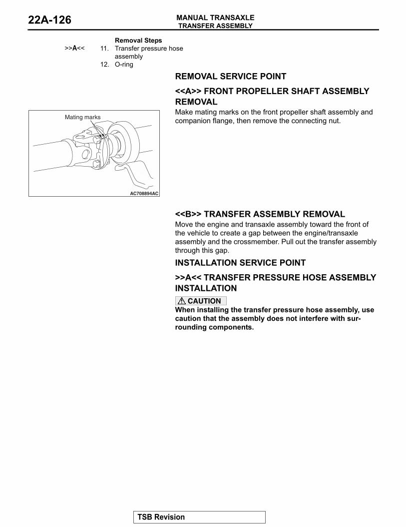
TRANSFER ASSEMBLYMANUAL TRANSAXLE22A-126
REMOVAL SERVICE POINT.
<<A>> FRONT PROPELLER SHAFT ASSEMBLY REMOVAL
AC708894AC
Mating marksMake mating marks on the front propeller shaft assembly and companion flange, then remove the connecting nut.
.
<<B>> TRANSFER ASSEMBLY REMOVALMove the engine and transaxle assembly toward the front of the vehicle to create a gap between the engine/transaxle assembly and the crossmember. Pull out the transfer assembly through this gap.
INSTALLATION SERVICE POINT.
>>A<< TRANSFER PRESSURE HOSE ASSEMBLY INSTALLATION
CAUTIONWhen installing the transfer pressure hose assembly, use caution that the assembly does not interfere with sur-rounding components.
>>A<< 11. Transfer pressure hose assembly
12. O-ring
Removal Steps
TSB Revision
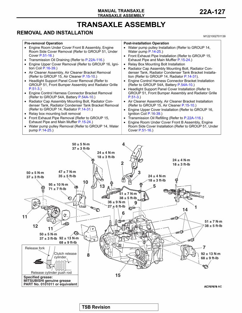
TRANSAXLE ASSEMBLYMANUAL TRANSAXLE 22A-127
TRANSAXLE ASSEMBLYREMOVAL AND INSTALLATION
M1221002701139
Pre-removal Operation• Engine Room Under Cover Front B Assembly, Engine
Room Side Cover Removal (Refer to GROUP 51, Under Cover P.51-16.)
• Transmission Oil Draining (Refer to P.22A-116.)• Engine Upper Cover Removal (Refer to GROUP 16, Igni-
tion Coil P.16-39.)• Air Cleaner Assembly, Air Cleaner Bracket Removal
(Refer to GROUP 15, Air Cleaner P.15-10.)• Headlight Support Panel Cover Removal (Refer to
GROUP 51, Front Bumper Assembly and Radiator Grille P.51-3.)
• Engine Control Harness Connector Bracket Removal (Refer to GROUP 54A, Battery P.54A-10.)
• Radiator Cap Assembly Mounting Bolt, Radiator Con-denser Tank, Radiator Condenser Tank Bracket Removal (Refer to GROUP 14, Radiator P.14-31.)
• Relay box mounting bolt removal• Front Exhaust Pipe Removal (Refer to GROUP 15,
Exhaust Pipe and Main Muffler P.15-24.)• Water pump pulley Removal (Refer to GROUP 14, Water
pump P.14-25.)
Post-installation Operation• Water pump pulley Installation (Refer to GROUP 14,
Water pump P.14-25.)• Front Exhaust Pipe Installation (Refer to GROUP 15,
Exhaust Pipe and Main Muffler P.15-24.)• Relay Box Mounting Bolt Installation• Radiator Cap Assembly Mounting Bolt, Radiator Con-
denser Tank, Radiator Condenser Tank Bracket Installa-tion (Refer to GROUP 14, Radiator P.14-31).
• Engine Control Harness Connector Bracket Installation (Refer to GROUP 54A, Battery P.54A-10.)
• Headlight Support Panel Cover Installation (Refer to GROUP 51, Front Bumper Assembly and Radiator Grille P.51-3.)
• Air Cleaner Assembly, Air Cleaner Bracket Installation (Refer to GROUP 15, Air Cleaner P.15-10.)
• Engine Upper Cover Installation (Refer to GROUP 16, Ignition Coil P.16-39.)
• Transmission Oil Refilling (Refer to P.22A-116.)• Engine Room Under Cover Front B Assembly, Engine
Room Side Cover Installation (Refer to GROUP 51, Under Cover P.51-16.)
AC707678
92 ± 13 N·m68 ± 9 ft-lb
AC707678
2
7
8
1
11
11
9
13
3
12
AC
5
4
14
15
10
6
Release fork
Release cylinder push rod
95 ± 10 N·m71 ± 7 ft-lb
51 ± 7 N·m38 ± 5 ft-lb
50 ± 5 N·m37 ± 3 ft-lb
50 ± 5 N·m37 ± 3 ft-lb
47 ± 7 N·m35 ± 5 ft-lb
50 ± 5 N·m37 ± 3 ft-lb
24 ± 4 N·m18 ± 3 ft-lb
24 ± 4 N·m18 ± 3 ft-lb
24 ± 4 N·m18 ± 3 ft-lb
Clutch releasecylinder
51 ± 7 N·m38 ± 5 ft-lb
92 ± 13 N·m68 ± 9 ft-lb
36 ± 9 N·m27 ± 6 ft-lb
Specified grease:MITSUBISHI genuine greasePART No. 0101011 or equivalent
TSB Revision

TRANSAXLE ASSEMBLYMANUAL TRANSAXLE22A-128
Removal steps <<A>> • Strut tower bar (Refer to
GROUP 42A − Strut Tower Bar P.42A-15.)
• Front driveshaft assembly, output shaft assembly (Refer to GROUP 26, Driveshaft assembly P.26-15.)
<<B>> >>C<< 1. Shift cable, select cable assembly and cable bracket connection
2. Backup light switch connector connection
3. 1− 2nd rail switch connector connection
4. Control harness connection5. Connection of clutch release
cylinder and clutch tube assembly B
<<C>> 6. Starter mounting bolt<<D>> • Clutch release bearing
connection
• Front axle crossmember assembly (Refer to GROUP 32 − Crossmember P.32-10.)
• Transfer assembly (Refer to P.22A-125.)
7. Rear roll stopper bracket8. Front roll stopper bracket
<<E>> 9. Transaxle assembly upper part coupling bolt
<<F>> 10. Transaxle mounting bracket>>B<< 11. Transaxle mounting
insulator stopper12. Transaxle mounting
insulator13. Stud adapter
<<G>> • Engine assembly support14. Transaxle assembly lower
part coupling bolt>>A<< 15. Transaxle assembly
REMOVAL SERVICE POINTS.
<<A>> STRUT TOWER BAR REMOVALAfter removing the strut tower bar, temporarily install the strut assembly..
<<B>> SHIFT CABLE/SELECT CABLE ASSEMBLY AND CABLE BRACKET REMOVAL
AC707727
ClipSelect cable
AC
Set the select cable clips to a status shown in the figure, then disconnect the cable.
.
<<C>> STARTER MOUNTING BOLT REMOVALRemove the starter with its connector connected. Keep the starter fixed to the engine side..
Removal steps
TSB Revision

TRANSAXLE ASSEMBLYMANUAL TRANSAXLE 22A-129
<<D>> CLUTCH RELEASE BEARING DISCONNECTION
AC707417
AC707946AC
AB
Wedge collar Release bearing
Service hole cover
Release fork
1. Remove the service hole cover of the clutch housing part.CAUTION
• Do not insert the flat-tipped screwdriver before moving the release fork toward direction A.
• Do not mistakenly insert a flat-tipped screwdriver between the wedge collar and the wave spring.
2. Move the release fork slightly toward direction A with hand, and while holding the release fork, insert a flat-tipped screwdriver between the release bearing and the wedge collar.CAUTION
If the flat-tipped screwdriver cannot be turned easily (release bearing cannot be disengaged), remove the screw driver, and move the release fork toward direction A for two or three times. Then, repeat the procedure. If the screwdriver is turned forcibly, the release bearing may be damaged.3. (Disconnect the release bearing from the wedge collar by
twisting the flat-tipped screw driver slightly (twist the handle 90° ).NOTE: When the release bearing is disconnected, the release fork moves to the direction B by the return spring.
.
<<E>> TRANSAXLE ASSEMBLY UPPER PART MOUNTING BOLT REMOVALOnly loosen the bolts from the engine and transaxle assembly (do not remove)..
<<F>>TRANSAXLE MOUNTING BRACKET INSTALLATION1. Place a garage jack against the transaxle case with a piece
of wood in between to support the engine and transaxle assembly.
2. Operate the garage jack so that the engine and transaxle assembly weight is not applied to the transaxle mounting insulator, and remove the transaxle mounting bracket.
.
<<G>> ENGINE ASSEMBLY SUPPORT
AC706007AC
MB992201
Thermostat case
1. Remove the vacuum pipe assembly (refer to GROUP 14 − Water Hose and Water Pipe P.14-26), and install the engine hanger plate (Special tool: MB992201), then tighten the bolts to the specified torque.
Tightening torque: 11 ± 1 N⋅ m (8 ± 1 ft-lb)2. <When engine hanger (special tool MB991928) is used>
(1) Assemble the engine hanger (special tool MB991928). (Set following parts to the base hanger.)
• Slide bracket (HI)• Foot x 4 (standard) (MB991932)• Joint x 2 (90) (MB991930)
TSB Revision
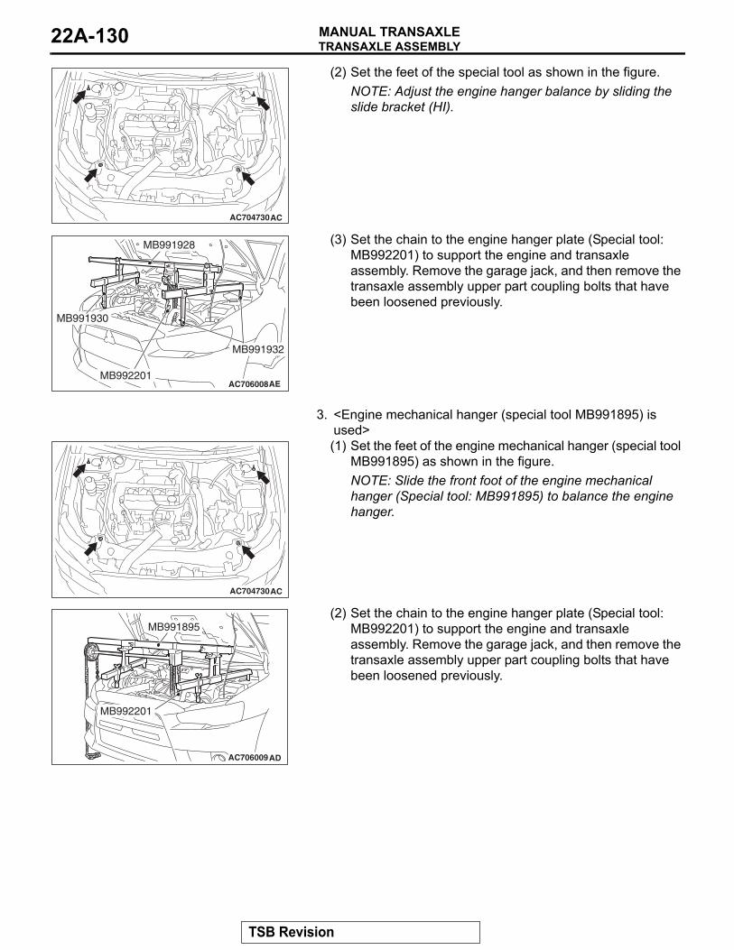
TRANSAXLE ASSEMBLYMANUAL TRANSAXLE22A-130
AC704730AC
(2) Set the feet of the special tool as shown in the figure.NOTE: Adjust the engine hanger balance by sliding the slide bracket (HI).
AC706008AE
MB991928
MB992201
MB991930
MB991932
(3) Set the chain to the engine hanger plate (Special tool: MB992201) to support the engine and transaxle assembly. Remove the garage jack, and then remove the transaxle assembly upper part coupling bolts that have been loosened previously.
3. <Engine mechanical hanger (special tool MB991895) is used>
AC704730AC
(1) Set the feet of the engine mechanical hanger (special tool MB991895) as shown in the figure.NOTE: Slide the front foot of the engine mechanical hanger (Special tool: MB991895) to balance the engine hanger.
AC706009AD
MB991895
MB992201
(2) Set the chain to the engine hanger plate (Special tool: MB992201) to support the engine and transaxle assembly. Remove the garage jack, and then remove the transaxle assembly upper part coupling bolts that have been loosened previously.
TSB Revision
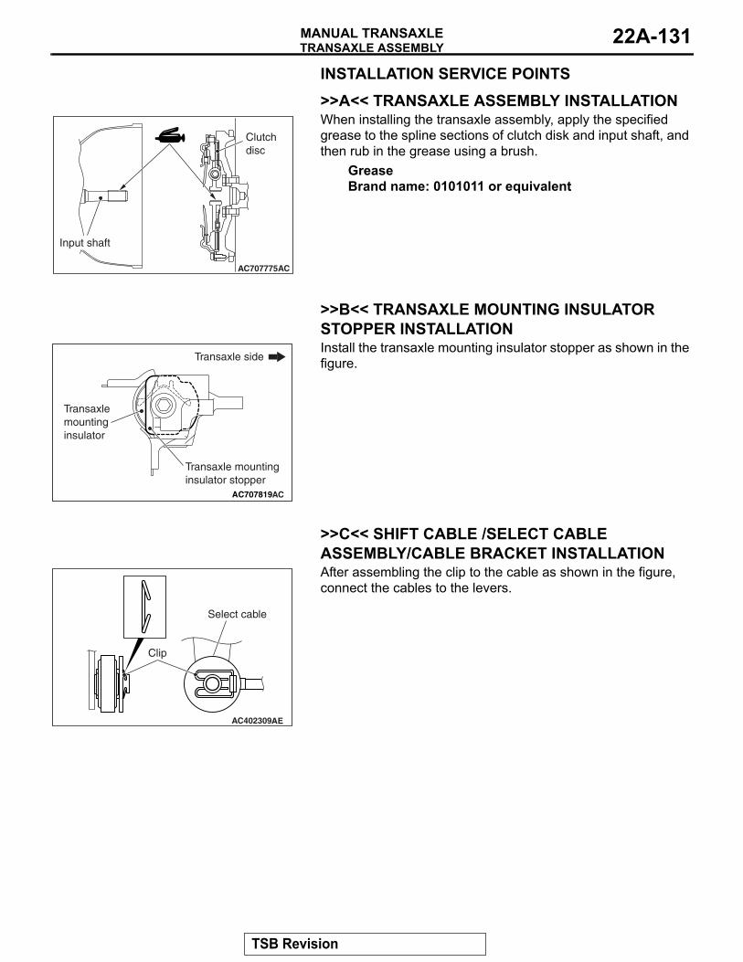
TRANSAXLE ASSEMBLYMANUAL TRANSAXLE 22A-131
INSTALLATION SERVICE POINTS.
>>A<< TRANSAXLE ASSEMBLY INSTALLATION
AC707775AC
Input shaft
Clutch disc
When installing the transaxle assembly, apply the specified grease to the spline sections of clutch disk and input shaft, and then rub in the grease using a brush.
GreaseBrand name: 0101011 or equivalent
.
>>B<< TRANSAXLE MOUNTING INSULATOR STOPPER INSTALLATION
AC707819
Transaxle side
Transaxle mounting insulator
Transaxle mounting insulator stopper
AC
Install the transaxle mounting insulator stopper as shown in the figure.
.
>>C<< SHIFT CABLE /SELECT CABLE ASSEMBLY/CABLE BRACKET INSTALLATION
AC402309
Clip
AE
Select cable
After assembling the clip to the cable as shown in the figure, connect the cables to the levers.
TSB Revision
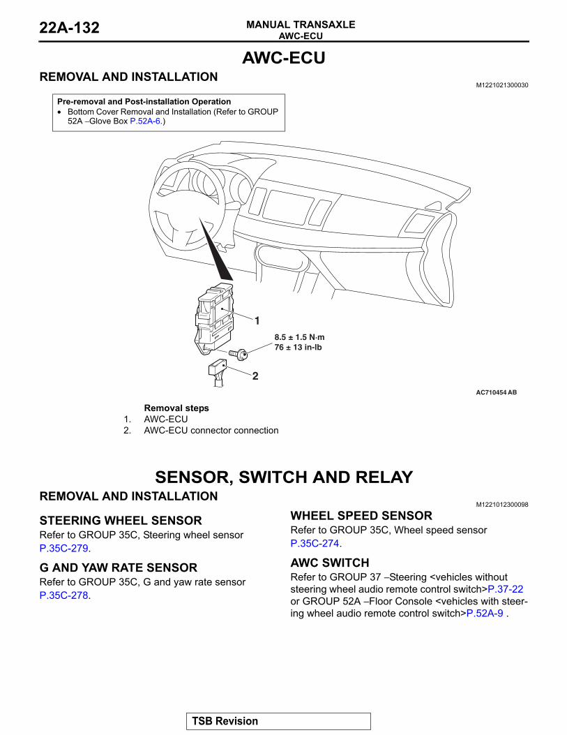
AWC-ECUMANUAL TRANSAXLE22A-132
AWC-ECUREMOVAL AND INSTALLATION
M1221021300030
Pre-removal and Post-installation Operation• Bottom Cover Removal and Installation (Refer to GROUP
52A − Glove Box P.52A-6.)
AC710454 AB
2
18.5 ± 1.5 N·m76 ± 13 in-lb
Removal steps 1. AWC-ECU2. AWC-ECU connector connection
SENSOR, SWITCH AND RELAYREMOVAL AND INSTALLATION
M1221012300098.
STEERING WHEEL SENSORRefer to GROUP 35C, Steering wheel sensor P.35C-279..
G AND YAW RATE SENSORRefer to GROUP 35C, G and yaw rate sensor P.35C-278..
WHEEL SPEED SENSORRefer to GROUP 35C, Wheel speed sensor P.35C-274..
AWC SWITCHRefer to GROUP 37 − Steering <vehicles without steering wheel audio remote control switch>P.37-22 or GROUP 52A − Floor Console <vehicles with steer-ing wheel audio remote control switch>P.52A-9 ..
TSB Revision
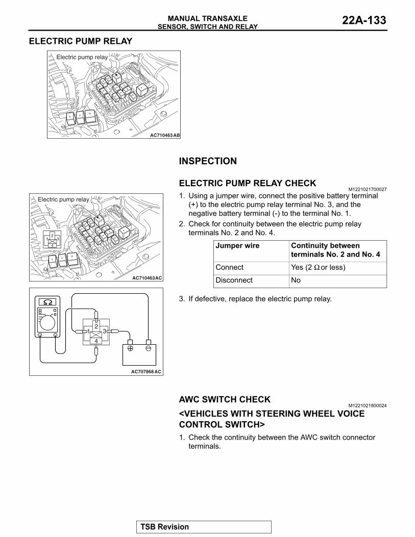
SENSOR, SWITCH AND RELAYMANUAL TRANSAXLE 22A-133
ELECTRIC PUMP RELAY
AC710463AB
Electric pump relay
INSPECTION
ELECTRIC PUMP RELAY CHECKM1221021700027
AC710463
31
4
2
AC
Electric pump relay
AC707868
31
4
2
AC
1. Using a jumper wire, connect the positive battery terminal (+) to the electric pump relay terminal No. 3, and the negative battery terminal (-) to the terminal No. 1.
2. Check for continuity between the electric pump relay terminals No. 2 and No. 4.
Jumper wire Continuity between terminals No. 2 and No. 4
Connect Yes (2 Ω or less)
Disconnect No
3. If defective, replace the electric pump relay.
AWC SWITCH CHECKM1221021800024
<VEHICLES WITH STEERING WHEEL VOICE CONTROL SWITCH>1. Check the continuity between the AWC switch connector
terminals.
TSB Revision
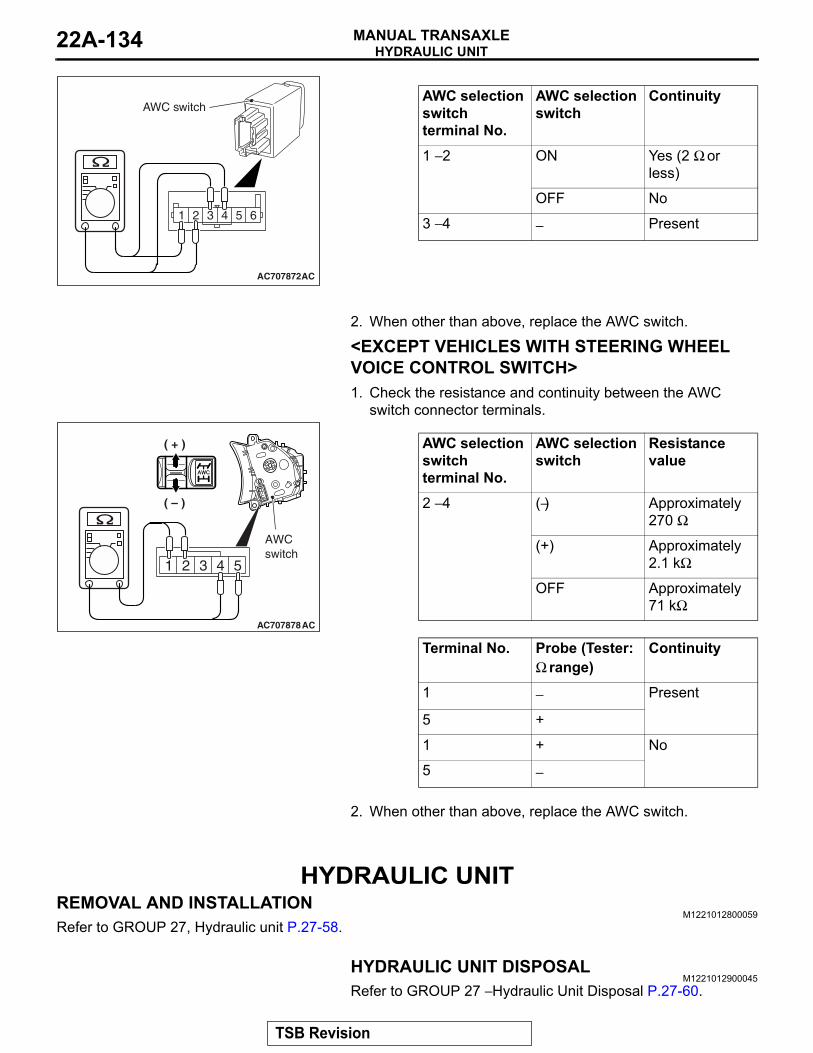
HYDRAULIC UNITMANUAL TRANSAXLE22A-134
AC707872
1 2 3 54 6
AC
AWC switchAWC selection switch terminal No.
AWC selection switch
Continuity
1 − 2 ON Yes (2 Ω or less)
OFF No
3 − 4 − Present
2. When other than above, replace the AWC switch.
<EXCEPT VEHICLES WITH STEERING WHEEL VOICE CONTROL SWITCH>1. Check the resistance and continuity between the AWC
switch connector terminals.
AC707878AC
AWCswitch
( – )
( + ) AWC selection switch terminal No.
AWC selection switch
Resistance value
2 − 4 (−) Approximately 270 Ω
(+) Approximately 2.1 kΩ
OFF Approximately 71 kΩ
Terminal No. Probe (Tester: Ω range)
Continuity
1 − Present
5 +
1 + No
5 −
2. When other than above, replace the AWC switch.
HYDRAULIC UNITREMOVAL AND INSTALLATION
M1221012800059Refer to GROUP 27, Hydraulic unit P.27-58.
HYDRAULIC UNIT DISPOSALM1221012900045
Refer to GROUP 27 − Hydraulic Unit Disposal P.27-60.
TSB Revision
Related Documents