13-1 PART 13-1 PAGE GENERAL CHARGING SYSTEM SERVICE 13-1 PART 13-2 AUTO LITE ALTERNATORS .13-13 PART 13-3 AUTOLITE ALTERNATOR REGULATORS 13-16 PART 13-4 53-AMPERE LEECE NEVILLE ALTERNATOR 13-21 PART 13-5 PAGE LEECENEVILLE ALTERNATOR REGULATORS 13-23 PART 13-6 SPECIFICATIONS 13-25 GENERAL CHARGING SYSTEM SERVICE Section Page 1 Diagnosis 13-1 BatteryLow In Charge, Headlights Dim at Idle 13-2 ChargeIndicator Gauge-No Readingor Gauge Operates in Reverse .13-2 Charge Indicator Light StaysOn .13-2 Charge Indicator Gauge Indicates Constant Discharge 13-2 Battery Will Not Hold Charge. . . . . . . . . . . . .13-2 Alternator Has No Output. . . . . . . . . . . . . . . . .13-2 Alternator Has Low Output. . . . . . . . . . . . . . . 13-2 Lights and Fuses, Fail Prematurely, Short Battery Life 13-4 Battery Uses Excessive Amount of Water .13-4 Section Page Burning of Distributor Points, Ignition ResistorWire,orCoil 13-4 High Battery Charging Rate. .. . ... . . . .. .. .13-4 Alternator Noisy 13-4 Charge IndicatorGauge Fluctuates or Warning Light Flickers. . . . . . . . . . . . . . . . .13-5 2 Testing 13-5 Alternator Test 13-5 Alternator Regular and Circuit Tests 13-7 Battery Tests and Conclusions. . . . . . . . . . . . . .13-8 3 Common Adjustments and Repairs. . . . . . . . . .13-12 Belt Adjustment 13-12 4 Cleaningand Inspection. . . . . . . . . . . . . . . . . .13-12 ble reasons which should be consid- ered when a battery is run down or low in charge. Charging system troubles such as low alternator output, no alternator output (indicated by the indicator light being on or the indicator gauge showing discharge while the engine is running), or alternator output volt- age too high, require testing of both the alternator and the alternator regulator. Alternator regulator failures are usually not recognized except by the direct effect on the alternator output and, of course, eventual battery dis- charge. As the regulator is the con- trol valve for the alternator, it acts to protect the battery by preventing excessive voltage output. Discharge of the battery to ground through the alternator is prevented by the diodes of the alternator which permit cur- rent flow in one direction (to 'tJte battery) only. Proper adjustment of the two units in the alternator regu- lator (field relay and voltage lim- iter), is very important. The road map type of procedures which follow will assist in a logical The charging system consists of an alternator, alternator regulator, battery, charge indicator light or gauge, and the necessary wiring to connect the components (Figs. 1 and 2). Battery discharge is not always due to charging system defects. Ex- cessive use of lights and accessories while the engine is either off or run- ning at low idle; corroded battery cables and connectors; low water level in the battery; or prolonged disuse of the battery, which would permit self-discharge; are all possi-

Welcome message from author
This document is posted to help you gain knowledge. Please leave a comment to let me know what you think about it! Share it to your friends and learn new things together.
Transcript

13-1
PART 13-1 PAGEGENERAL CHARGING SYSTEM
SERVICE 13-1
PART 13-2AUTO LITE ALTERNATORS .13-13
PART 13-3AUTOLITE ALTERNATOR REGULATORS 13-16
PART 13-453-AMPERE LEECE NEVILLE
ALTERNATOR 13-21
PART 13-5 PAGELEECE NEVILLE ALTERNATOR
REGULATORS 13-23
PART 13-6SPECIFICATIONS 13-25
GENERAL CHARGING SYSTEM SERVICE
Section Page1 Diagnosis 13-1
Battery Low In Charge, Headlights Dimat Idle 13-2
Charge Indicator Gauge-No Reading orGauge Operates in Reverse .13-2
Charge Indicator Light Stays On .13-2Charge Indicator Gauge Indicates Constant
Discharge 13-2Battery Will Not Hold Charge. . . . . . . . . . . . .13-2Alternator Has No Output. . . . . . . . . . . . . . . . .13-2Alternator Has Low Output. . . . . . . . . . . . . . . 13-2Lights and Fuses, Fail Prematurely, Short
Battery Life 13-4Battery Uses Excessive Amount of Water .13-4
Section PageBurning of Distributor Points, Ignition
ResistorWire,orCoil 13-4High Battery Charging Rate. .. . ... . . . .. .. .13-4Alternator Noisy 13-4Charge Indicator Gauge Fluctuates or
Warning Light Flickers. . . . . . . . . . . . . . . . .13-52 Testing 13-5
Alternator Test 13-5Alternator Regular and Circuit
Tests 13-7Battery Tests and Conclusions. . . . . . . . . . . . . .13-8
3 Common Adjustments and Repairs. . . . . . . . . .13-12Belt Adjustment 13-12
4 Cleaning and Inspection. . . . . . . . . . . . . . . . . .13-12
ble reasons which should be consid-ered when a battery is run down orlow in charge.
Charging system troubles such aslow alternator output, no alternatoroutput (indicated by the indicatorlight being on or the indicator gaugeshowing discharge while the engine isrunning), or alternator output volt-age too high, require testing of boththe alternator and the alternatorregulator.
Alternator regulator failures areusually not recognized except by thedirect effect on the alternator output
and, of course, eventual battery dis-charge. As the regulator is the con-trol valve for the alternator, it actsto protect the battery by preventingexcessive voltage output. Dischargeof the battery to ground through thealternator is prevented by the diodesof the alternator which permit cur-rent flow in one direction (to 'tJtebattery) only. Proper adjustment ofthe two units in the alternator regu-lator (field relay and voltage lim-iter), is very important.
The road map type of procedureswhich follow will assist in a logical
The charging system consists ofan alternator, alternator regulator,battery, charge indicator light orgauge, and the necessary wiring toconnect the components (Figs. 1and 2).
Battery discharge is not alwaysdue to charging system defects. Ex-cessive use of lights and accessorieswhile the engine is either off or run-ning at low idle; corroded batterycables and connectors; low waterlevel in the battery; or prolongeddisuse of the battery, which wouldpermit self-discharge; are all possi-
13-2 GROUP 13 - CHARGING SYSTEM
with no physical connection to thegauge. The other type gauge usesexternal terminal post connections.In this case, the gauge wire is con-nected to the terminal posts.
To test the charge indicator gauge,turn the headlights ON with the en-gine off. The indicator pointer shouldmove toward the D or dischargeportion of the scale. The test for in-dication in the charge direction ismade by first turning on the lightsfor about two minutes and then run-ning the engine at about 1500 rpm.Turn the lights off and observe thepointer travel. If charge is indicated,the indicator is satisfactory.
If no movement of the needle isobtained, check the loop (or connec-tions) on the rear of the gauge tosee if the battery to alternator wirepasses inside the loop (or the con-nections are tight). If the wire is inthe loop (or the connections aretight) and the gauge does not indi-cate a charge or discharge, the gaugeis inoperative.
If the pointer moves toward the Cor charge portion of the scale whenthe headlights are first turned ON,the wire passes through the loop inthe wrong direction (or the wireconnections are reversed). Feed thewire through the loop in the oppo-site direction (or reverse the wireson the terminals), observing the pre-caution of disconnecting the batterybefore working under the instrumentpanel.
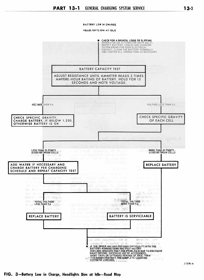
CHARGE INDICATOR LIGHTSTAYS ON
Refer to Fig 4 for this symptom.Other symptoms covered under thisheading are: charge indicator gaugeindicates constant discharge; batterywill not hold charge; alternator hasno output; alternator has low output.
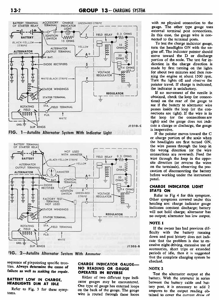
sequence of pinpointing specific trou-bles. Always determine the cause offailure as weD as making the repair.
NOTE!If the owner has had previous dif-
ficulty with the battery runningdown and past history does not indi-cate that the problem is due to ex-cessive night driving, excessive use ofaccessories, short trips or extendedperiods of idle, then it is suggestedthat the complete charging system bechecked.
NOTE 2Test the alternator output at the
battery. With the ammeter in seriesbetween the battery cable and bat-tery post, it is necessary to add 2amperes to the output reading ob-tained to cover the current. draw nf
CHARGE INDICATOR GAUGE-NO READING OR GAUGEOPERATES IN REVERSE
Either of two different type indi-cator gauges may be encountered.One type of gauge has external loopson the back of the gauge. The gaugewire is routed through these loops
BATTERY LOW IN CHARGE,HEADLIGHTS DIM AT IDLE
Refer to Fig. 3 for these symp-toms.
PART 13-1 GENERAL CHARGING SYSTEM SERVICE 13-3
BATTERY LOWIN CHARGE
HEADLIGHTS DIM AT IDLE
* CHECK FOR A BROKEN, LOO$E OR SLIPPINGI GENERATOR (OR ALTERNATOR DRIVE BELT).
INSPECT BATTERY. CABLES AND CHAf!GINGSYSTEM WIRING FOR GOOD ELECTRICALCONTACT. CLEAN THE BATTERY TERMINALSAND TIGHTEN ALL CONNECTIONS AS NECESSARY
VOLTAGE-OVER 9.6 VOLTAGEL
CHECK SPECIFIC GRAVITY.CHARGE BATTERY, IF BELOW 1.230.OTHERWISE BATTERY IS OK
J 1318-A
FIG. 3-Battery Low in Charge, Headlights Dim at Idle-Road Map

13-4 GROUP 13 CHARGING SYSTEM
CHARGE INDICATDR LIGHT STAYS DNCHARGE INDICATDR GAUGE INDICATES CDNSTANT DISCHARGE
BATTERY WILL NOT HOLD CHARGEALTERNATOR HAS NO OUTPUT
AlTERNATOR HAS LOW OUTPUT
CHECK FOR A BROKEN, LOOSE OR SLIPPING DRIVE BELT.INSPECT BATTERY, CABLES, AND CHARGING SYSTEM WIRINGFOR GOOD ELECTRICAL CONTACT. CLEAN THE BATTERYTERMINALS AND TIGHTEN ALL CONNECTIONS AS NECESSARY.CHECK THE BATTERY SPECIFIC GRAVITY, CHARGE THEBATTERY AND PERFORM THE BATTERY TESTS. SEE NOTE NO.
'REPLACE $ATTERY.
TESTAL TERNA TOR OUTPUTSEE NOTE NO.2.
(1) PERFORM THECHARGING CIRCUITRESISTANCE TESTS.(2) REMOVE THE ALTER.NA TOR AND PERFORMTHE BENCH TESTS.SEE NOTE NO.4
(I) CHECK THE BATTERYTO FIELO WIRING.SEE NOTE NO.. 5.(2) REMOVE THEAL tERNATOR ANOPERFORM THE BENCHTE5TS. J1319.A
CHECK THE O~ERAT'ON OFTHE VOLTAGE REGULATORSEE NOTE NO; 3
FIG. 4-Charge Indicator light Stays On-Road Map
the standard ignition system and 6amperes for the transistor ignitionsystem.
der this heading are: battery usesexcessive amount of water; burningof distributor points, ignition resistorwire, or coil; high battery chargingrate.
voltage produced at the STA termi-nal of the alternator should be 6volts or more. A voltage less than 6volts may be caused by an opennegative diode.
NOTE 4An output of 2 to 5 amperes less
than that specified usually indicatesan open diode. An output of approx-imately 10 amperes less than thatspecified usually indicates a shorteddiode.
ALTERNATOR NOISYWhen investigating the complaint
of alternator noise, first try to local-ize the noise area to make sure thatthe alternator is a fault rather thanthe alternator belt, water pump, oranother part of the vehicle. Start theengine and use a stethoscope or simi-lar sound detector instrument to lo-calize the noise. An alternator bear-ing, water pump bearing or beltnoise is usually evidenced by asquealing sound.
An alternator with a shorteddiode will normally whine (magneticnoise) and will be most noticeableat idle speeds. Perform the alterna-tor output test. If the output is ap-proximately 10 amperes less thanthat specified, a shorted diode isusually indicated.
To eliminate the belt(s) as thecause of noise, check the belt(s) forbumps, apply a light amount of beltdressing to the belt(s). If the alter-nator belt is at fault, adjust the beltto specification, or replace the belt ifnecessary.
NOTESTo check the battery to field wir-
ing, connect the field rheostat be-tween the battery positive terminaland the alternator FLD terminal andrepeat the alternator output test. Ifthe alternator now has good outputthe wire from the battery terminalof the starter relay to the FLD ter-minal of the alternator is defective.If the alternator still has no outputit is defective. Remove the alterna-tor and perform the bench tests. Re-place defective parts.
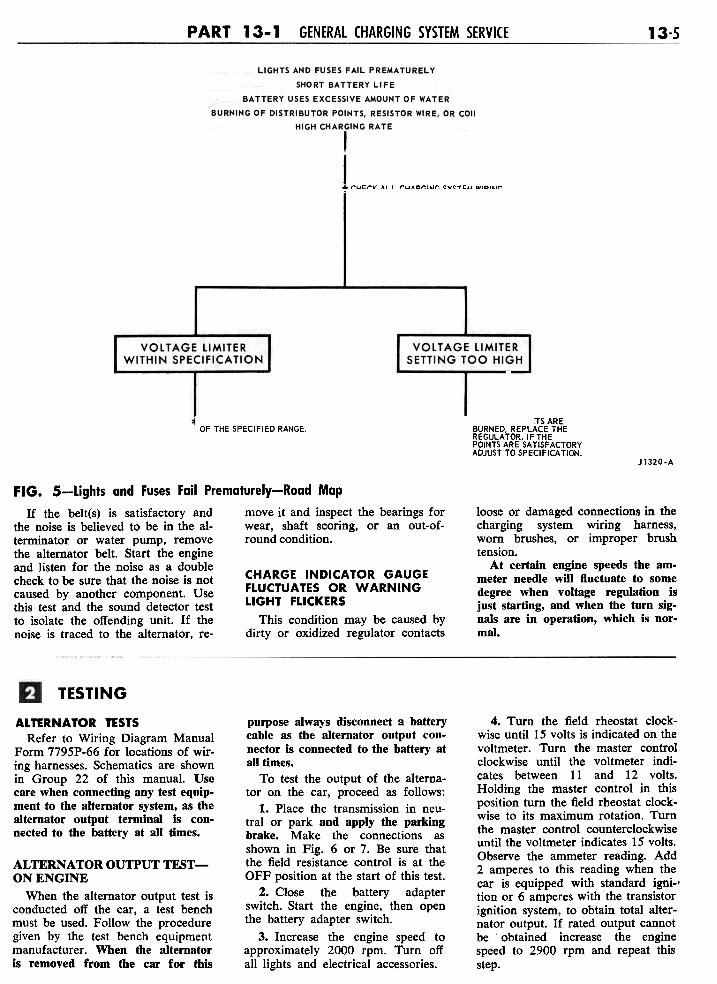
LIGHTS AND FUSES FAILPREMATURELY, SHORTBATTERY LIFE
Refer to Fig. 5 for these symp-toms. Other symptoms covered un-
NOTE 3Check the voltage limiter setting,
and check the closing voltage of thefield relay (the voltage at which thefield relay contacts just make con-tact). Adjust the voltage limiter ifnecessary. Adjust the field relay if itssetting is out of specification.
On some cars the location of theregulator may prevent adjustment onthe car. Remove the regulator to analternator-regulator test stand if ad-justment is necessary.
The field relay used with thetransistorized voltage regulator is asealed unit and is not to be adjusted.To determine its closing voltage, fol-low the procedure given in Section 2Testing, under Autolite Regulatorand Circuit Tests.
If the regulator was adjustedproperly, check the green-red wirefrom the accessory terminal of theignition switch through the chargeindicator light and 15-ohm resistorto the voltage regulator, and thewhite-black wire from the voltageregulator to the alternator. Repair orreplace as necessary.
With the engine at 1000 rpm, the
PART 13-1 GENERAL CHARGING SYSTEM SERVICE 13-5
.* CHECK ALL CHARGING SYSTEM WIRING
CONNECTIONS INCLUOING THE REGULATORGROUNO WIRE. TIGHTEN OR REPAIR ASREQUIRED. CHECK THE ALTERNATORVOLTAGE LIMITER SETTING. IF THECONTACTS ARE BURNED, REPLACE THEREGULATOR.
~ ADJUST TO THE LOW ENDOF THE SPECIFIED RANGE.
*IF THE CONTACTS AREBURNED, REPLACE THEREGULATDR.IFTHEPOINTS ARE SATISFACTORY,ADJUST TO SPECIFICATION.
J1320-A
FIG. 5-Lights and Fuses Fail Prematurely-Road Map
If the belt(s) is satisfactory and move it and inspect the bearings forthe noise is believed to be in the al- wear, shaft scoring, or an out-of-terminator or water pump, remove round condition.the alternator belt. Start the engineand listen for the noise as a doublecheck to be sure that the noise is not CHARGE INDICATOR GAUGEcaused by another component. Use FLUCTUATES OR WARNINGthis test and the sound detector test LIGHT FLICKERSto isolate the offending unit. If the This condition may be caused bynoise is traced to the alternator, re- dirty or oxidized regulator contacts
loose or damaged connections in thecharging system wiring harness,worn brushes, or improper brushtension.
At certain engine speeds the am.meter needle wlll fluctuate to somedegree when voltage regulation isjust starting, and when the turn sig-nals are in operation, which is nor-mal.
TESTING
4. Turn the field rheostat clock-wise until 15 volts is indicated on thevoltmeter. Turn the master controlclockwise until the voltmeter indi-cates between 11 and 12 volts.Holding the master control in thisposition turn the field rheostat clock-wise to its maximum rotation. Turnthe master control counterclockwiseuntil the voltmeter indicates 15 volts.Observe the ammeter reading. Add2 amperes to this reading when thecar is equipped with standard igni-.tion or 6 amperes with the transistorignition system, to obtain total alter-nator output. If rated output cannotbe obtained increase the enginespeed to 2900 rpm and repeat thisstep.
ALTERNATOR TESTSRefer to Wiring Diagram Manual
Form 7795P-66 for locations of wir-ing harnesses. Schematics are shownin Group 22 of this manual. Usecare when connecting any test equip-ment to the alternator system, as thealternator output terminal is con-nected to the battery at all times.
ALTERNATOR OUTPUT TEST-ON ENGINE
When the alternator output test isconducted off the car, a test benchmust be used. Follow the proceduregiven by the test bench equipmentmanufacturer. When the alternatoris removed from the car for this
purpose always disconnect a batterycable as the alternator output con-nector is connected to the battery ataU times.
To test the output of the alterna-tor on the car, proceed as follows:
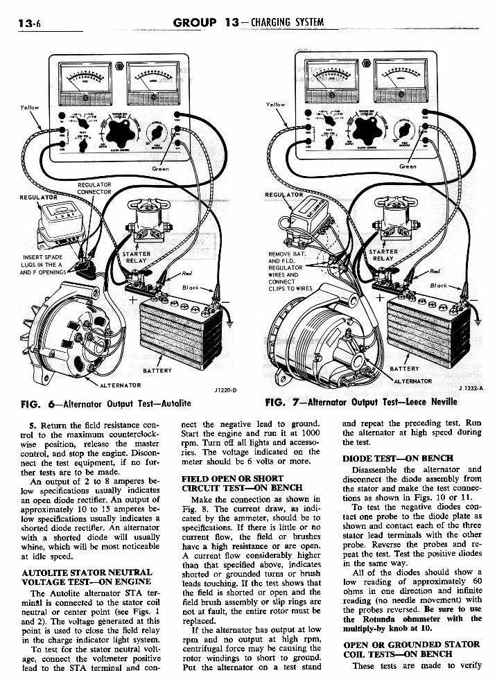
1. Place the transmission in neu-tral or park and apply the parkingbrake. Make the connections asshown in Fig. 6 or 7. Be sure thatthe field resistance control is at theOFF position at the start of this test.
2. Close the battery adapterswitch. Start the engine, then openthe battery adapter switch.
3. Increase the engine speed toapproximately 2000 rpm. Turn offall lights and electrical accessories.
GROUP 13 - CHARGING SYSTEM13-6
FIG. 6-Alternator Output Test-Autolite
and repeat the preceding test. Runthe alternator at high speed duringthe test.
nect the negative lead to ground.Start the engine and run it at 1000rpm. Turn off all lights and accesso-ries. The voltage indicated on themeter should be 6 volts or more.
5. Return the field resistance con-trol to the maximum counterclock-wise position, release the mastercontrol, and stop the engine. Discon-nect the test equipment, if no fur-ther tests are to be made.
An output of 2 to 8 amperes be-low specifications usually indicatesan open diode rectifier. An output ofapproximately 10 to 15 amperes be-low specifications usually indicates ashorted diode rectifier. An alternatorwith a shorted diode will usuallywhine, which will be most noticeableat idle speed.
AUTOLITE STATOR NEUTRALVOLTAGE TEST-ON ENGINE
The Autolite alternator ST A ter-min!l is connected to the stator coilneutral or center point (see Figs. 1and 2). The voltage generated at thispoint is used to close the field relayin the charge indicator light system.
To test for the stator neutral volt-age, connect the voltmeter positivelead to the STA terminal and con-
FIELD OPEN OR SHORTCIRCUIT TEST-ON BENCH
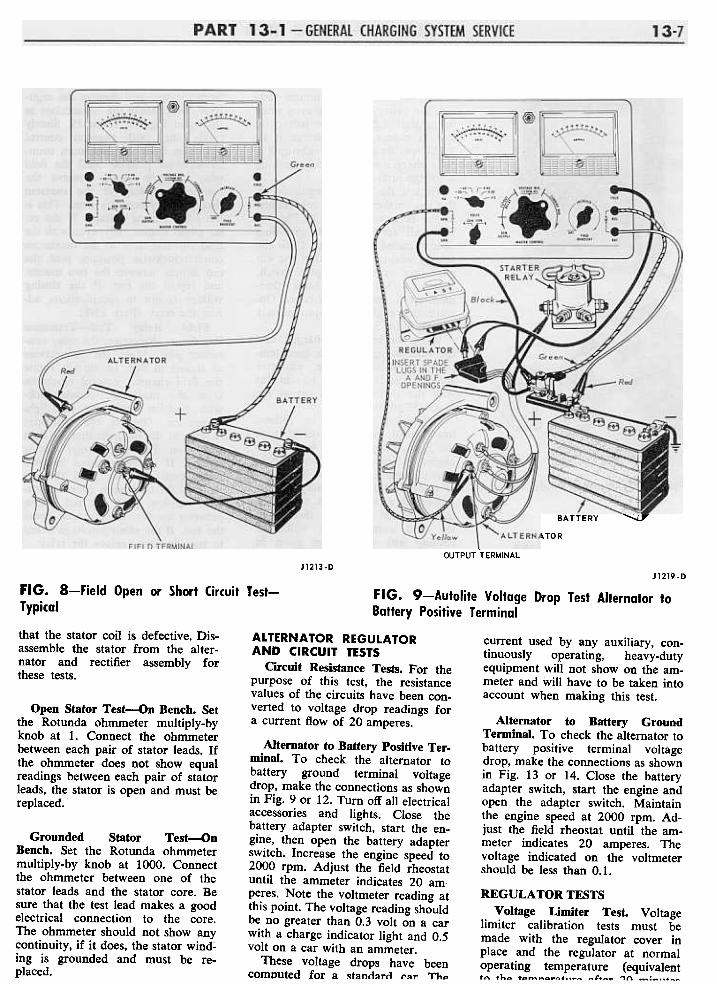
Make the connection as shown inFig. 8. The current draw, as indi-cated by the ammeter, should be tospecifications. If there is little or nocurrent flow, the field or brusheshave a high resistance or are open.A current flow considerably higherthan that specified above, indicatesshorted or grounded turns or brushleads touching. If the test shows thatthe field is shorted or open and thefield brush assembly or slip rings arenot at fault, the entire rotor must bereplaced.
If the alternator has output at lowrpm and no output at high rpm,centrifugal force may be causing therotor windings to short to ground.Put the alternator on a test stand
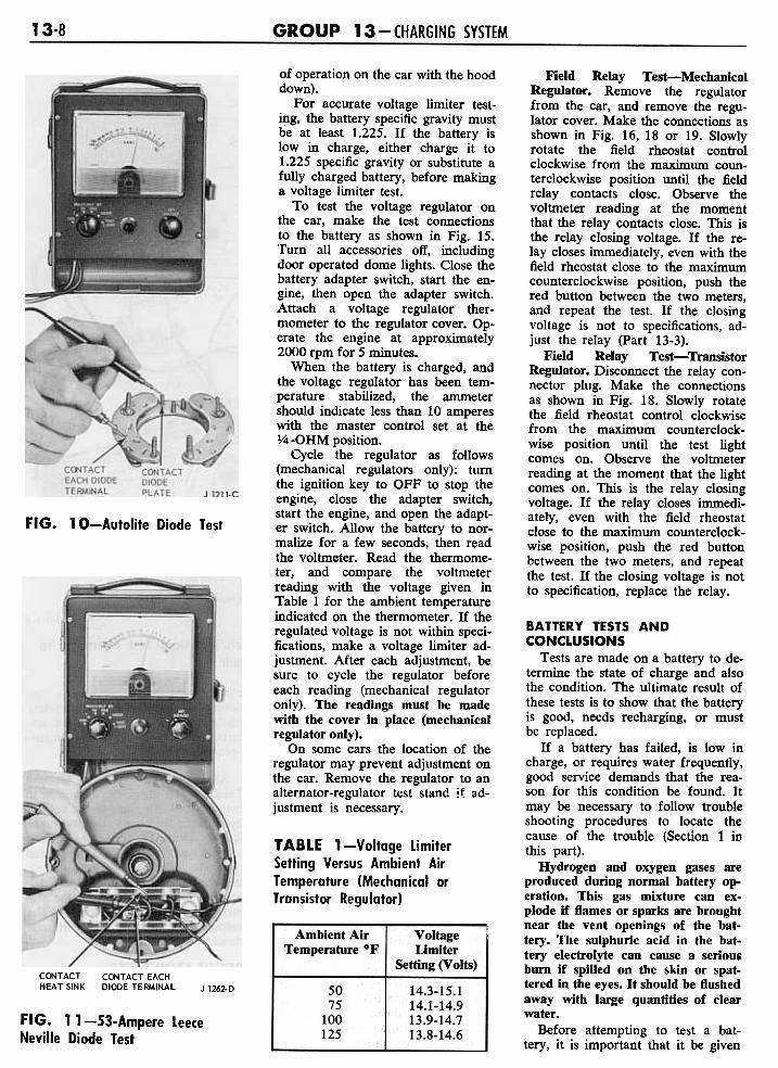
DIODE TEST-ON BENCHDisassemble the alternator and
disconnect the diode assembly fromthe stator and make the test connec-tions as shown in Figs. 10 or 11.
To test the negative diodes con-tact one probe to the diode plate asshown and contact each of the threestator lead terminals with the otherprobe. Reverse the probes and re-peat the test. Test the positive diodesin the same way.
All of the diodes should show alow reading of approximately 60ohms in one direction and infinitereading (no needle movement) withthe probes reversed. Be sure to usethe Rotunda ohmmeter with themultiply-by knob at 10.
OPEN OR GROUNDED STATORCOIL TESTs-ON BENCH
These tests are made to verify
.~~=~~~~:rr__=,,_~,,"""=-31
.' '.".'~.~'.*..-"~
l~:g~~~~:. -0 '0 '-.~ -, 'r"
" -,~" ~ """ ~] .;;~':.. ~" {,) f~(l~:-~ L o:i:., ;;..~ .I L-=~~ ~,:-:-:":" " ,
~~\ ,~"-":~~
~
Black
l..:...~~~(9~'
-+
Green
LU-GSINTHE-A AND F Red
)~c
\'r "'--~-
~~~'.;
~~l---#';:
/ BATTERY
rei'-J.':::/ Yeilow "ALTERNATOR
OUTPUT TERMINAL
~
J1213-DJ1219.D
FIG. 8-Field Open or Short Circuit Test-Typical
FIG. 9-Autolite Voltage Drop Test Alternator toBattery Positive Terminal
that the stator coil is defective. Dis-assemble the stator from the alter-nator and rectifier assembly forthese tests.
current used by any auxiliary, con-tinuously operating, heavy-dutyequipment will not show on the am-meter and will have to be taken intoaccount when making this test.
Open Stator Test-On Bench. Setthe Rotunda ohmmeter multiply-byknob at 1. Connect the ohmmeterbetween each pair of stator leads. Ifthe ohmmeter does not show equalreadings between each pair of statorleads, the stator is open and must bereplaced.
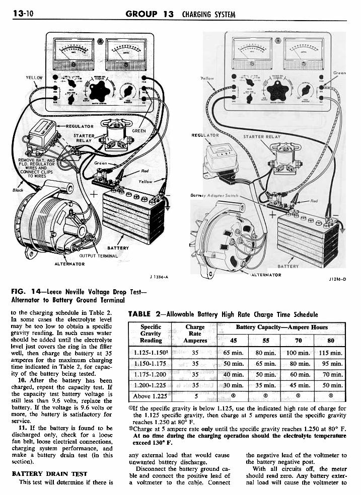
Alternator to Battery GroundTerminal. To check the alternator tobattery positive terminal voltagedrop, make the connections as shownin Fig. 13 or 14. Close the batteryadapter switch, start the engine andopen the adapter switch. Maintainthe engine speed at 2000 rpm. Ad-just the field rheostat until the am-meter indicates 20 amperes. Thevoltage indicated on the voltmetershould be less than 0.1.
ALTERNATOR REGULATORAND CIRCUIT TESTS
Circuit Resistance Tests. For thepurpose of this test, the resistancevalues of the circuits have been con-verted to voltage drop readings fora current flow of 20 amperes.
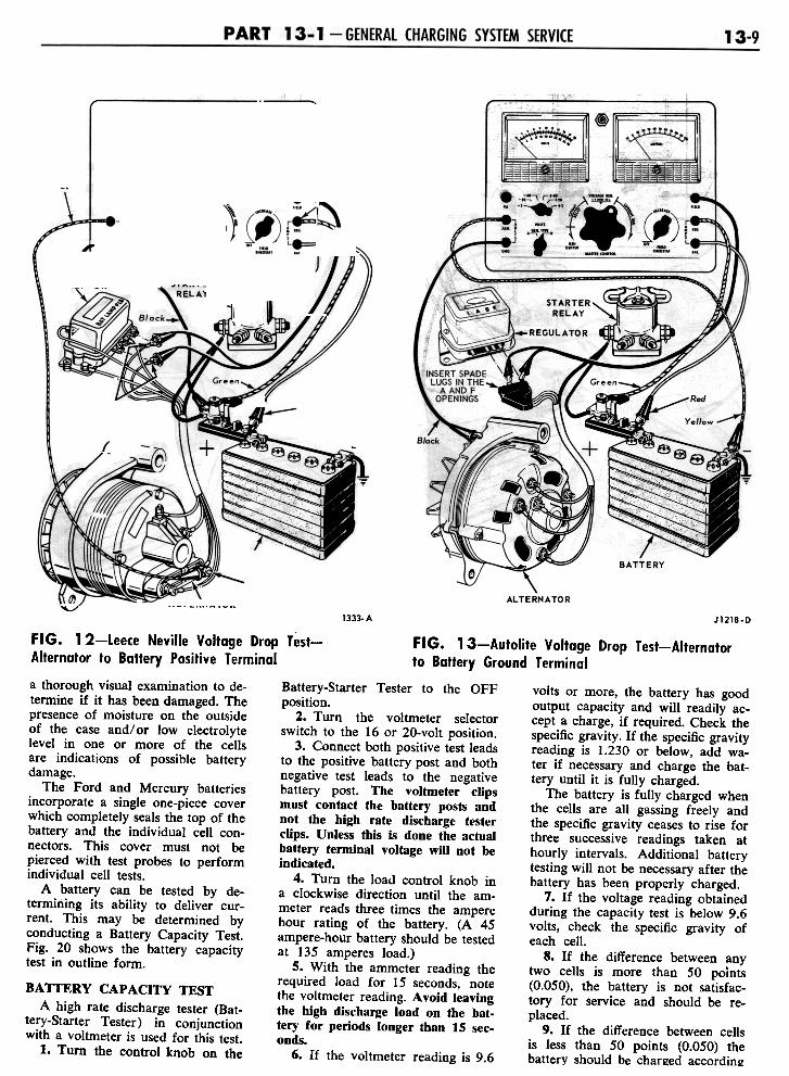
Alternator to Battery Positive Ter-minal. To check the alternator tobattery ground terminal voltagedrop, make the connections as shownin Fig. 9 or 12. Turn off all electricalaccessories and lights. Close thebattery adapter switch, start the en-gine, then open the battery adapterswitch. Increase the engine speed to2000 rpm. Adjust the field rheostatuntil the ammeter indicates 20 am.peres. Note the voltmeter reading atthis point. The voltage reading shouldbe no greater than 0.3 volt on a carwith a charge indicator light and 0.5volt on a car with an ammeter.
These voltage drops have beencomputed for a ~tanclaTrl r"T Th..
Grounded Stator Test'--'onBench. Set the Rotunda ohmmetermultiply-by knob at 1000. Connectthe ohmmeter between one of thestator leads and the stator core. Besure that the test lead makes a goodelectrical connection to the core.The ohmmeter should not show anycontinuity, if it does, the stator wind;'ing is grounded and must be re-placed.
REGULATOR TESTSVoltage Limiter Test. Voltage
limiter calibration tests must bemade with the regulator cover inplace and the regulator at normaloperating temperature {equivalenttn th.. t..~~..~~...~~ ~4'+~~ '"1(\ -:-..+-"
13-8 GROUP 13 - CHARGING SYSTEM
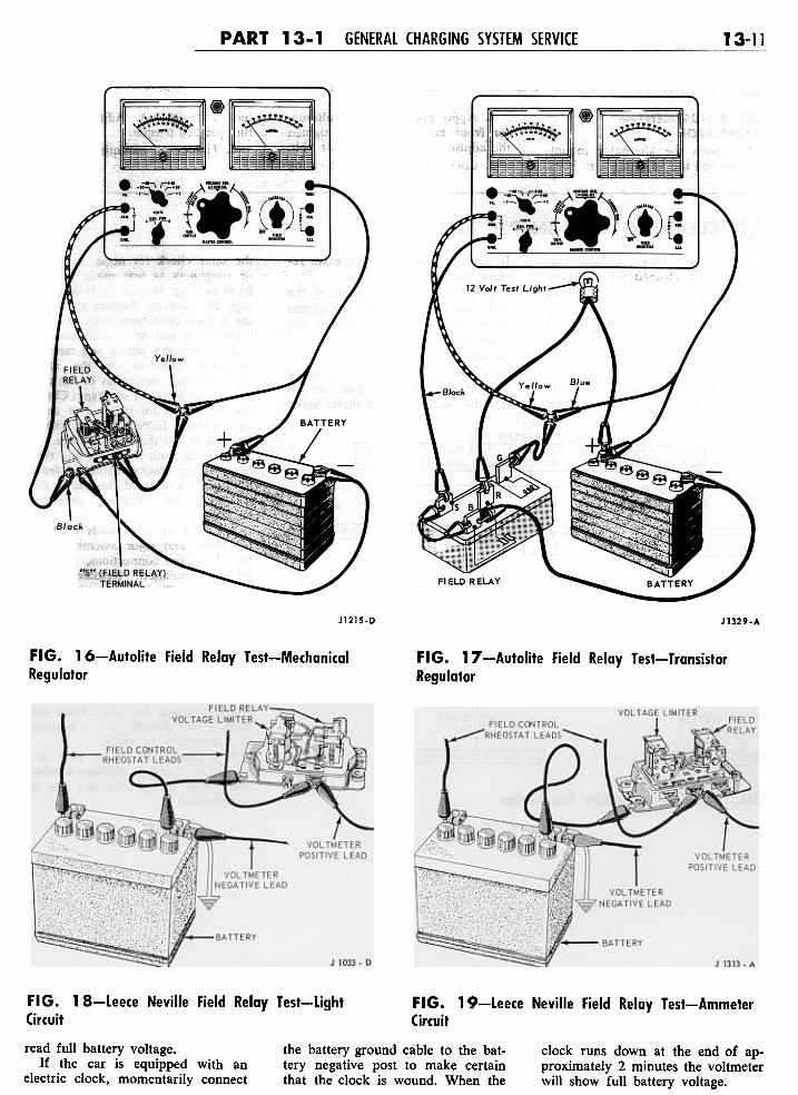
Field Relay Test-MechanicalRegulator. Remove the regulatorfrom the car, and remove the regu-lator cover. Make the connections asshown in Fig. 16, 18 or 19. Slowlyrotate the field rheostat controlclockwise from the maximum coun-terclockwise position until the fieldrelay contacts close. Observe thevoltmeter reading at the momentthat the relay contacts close. This isthe relay closing voltage. If the re-lay closes immediately, even with thefield rheostat close to the maximumcounterclockwise position, push thered button between the two meters,and repeat the test. If the closingvoltage is not to specifications, ad-just the relay (Part 13-3).
Field Relay Test-TransistorRegulator. Disconnect the relay con-nector plug. Make the connectionsas shown in Fig. 18. Slowly rotatethe field rheostat control clockwisefrom the maximum counterclock-wise position until the test lightcomes on. Observe the voltmeterreading at the moment that the lightcomes on. This is the relay closingvoltage. If the relay closes immedi-ately, even with the field rheostatclose to the maximum counterclock-wise position, push the red buttonbetween the two meters, and repeatthe test. If the closing voltage is notto specification, replace the relay.
FIG. 10-Autolite Diode Test
of operation on the car with the hooddown).
For accurate voltage limiter test-ing, the battery specific gravity mustbe at least 1.225. If the battery islow in charge, either charge it to1.225 specific gravity or substitute afully charged battery, before makinga voltage limiter test.
To test the voltage regulator onthe car, make the test connectionsto the battery as shown in Fig. 15.Turn all accessories off, includingdoor operated dome lights. Close thebattery adapter switch, start the en-gine, then open the adapter switch.Attach a voltage regulator ther-mometer to the regulator cover. Op-erate the engine at approximately2000 rpm for 5 minutes.
When the battery is charged, andthe voltage regulator has been tem-perature stabilized, the ammetershould indicate less than 10 ampereswith the master control set at the1/4 -OHM position.
Cycle the regulator as follows(mechanical regulators only): turnthe ignition key to OFF to stop theengine, close the adapter switch,start the engine, and open the adapt-er switch. Allow the battery to nor-malize for a few seconds, then readthe voltmeter. Read the thermome-ter, and compare the voltmeterreading with the voltage given inTable 1 for the ambient temperatureindicated on the thermometer. If theregulated voltage is not within speci-fications, make a voltage limiter ad-justment. After each adjustment, besure to cycle the regulator beforeeach reading (mechanical regulatoronly). The readings must be madewith the cover in place (mechanicalregulator ouly).
On some cars the location of theregulator may prevent adjustment onthe car. Remove the regulator to analternator-regulator test stand if ad-justment is necessary.
TABLE l-Voltage limiterSetting Versus Ambient AirTemperature (Mechanical orTransistor Regulator)
Ambient AirTemperature of
VoltageLimiter
Setting (Volts)C~TACTHEAT SINK
CONTACT EACHDIDDE TERMINAL J 1262-D 50
75100125
14.3-15.114.1-14.913.9-14.713.8-14.6
FIG. 11-S3-Ampere LeeceNeville Diode Test
BATTERY TESTS ANDCONCLUSIONS
Tests are made on a battery to de-termine the state of charge and alsothe condition. The ultimate result ofthese tests is to show that the batteryis good, needs recharging, or mustbe replaced.
If a battery has failed, is low incharge, or requires water frequently,good service demands that the rea-son for this condition be found. Itmay be necessary to follow troubleshooting procedures to locate thecause of the trouble (Section 1 inthis part).
Hydrogen and oxygen gases areproduced during normal battery op-eration. This gas mixture can ex-plode if flames or sparks are broughtnear the vent openings of the bat-tery. The sulphuric acid in the bat-tery electrolyte can cause a seriousbum if spilled on the skin or spat-tered in the eyes. It should be flushedaway with large quantities of clearwater.
Before attempting to test a bat-tery, it is important that it be given
[~~~~~~1,"'.'.. ~
T ~~~=~"';~. -" '. , -
YEII.OW
! ,:,~~~:::"
-j .;::., .
c-e! J .t. .'::.. -- -"- .-(l -.. -- - ~
REGUL~~~ ~T'RT~R@~~~~",;:;,
j,REMOVE BAT. ANDFLD. REGULATOR
WIRES AND CONNECTCLIPS TO WIRES--
Red
~
BATTERY
rERMINAI
ALTERNATOR~1333-A J1218-D
FIG. 1 2-Leece Neville Voltage Drop Test- FIG. 13-Autolite Voltage Drop Test-AlternatorAlternator to Battery Positive Terminal to Battery Ground Terminal
a thorough visual examination to de- Battery-Starter Tester to the OFFtermine if it has been damaged. The position.presence of moisture on the outside 2.. Turn the voltmeter selectorof the case and/or low electrolyte switch to the 16 or 20-volt position.level in one or more of the cells 3. Connect both positive test leadsare indications of possible battery to the positive battery post and bothdamage. negative test leads to the negative
The Ford and Mercury batteries battery post. The voltmeter clipsincorporate a single one-piece cover must contact the battery posts andwhich completely seals the top of the not the high rate discharge testerbattery and the individual cell con- clips. Unless this is done the actualnectors. This cover must not be battery terminal voltage will not bepierced with test probes to perform indicated.individual cell tests. 4. Turn the load control knob in
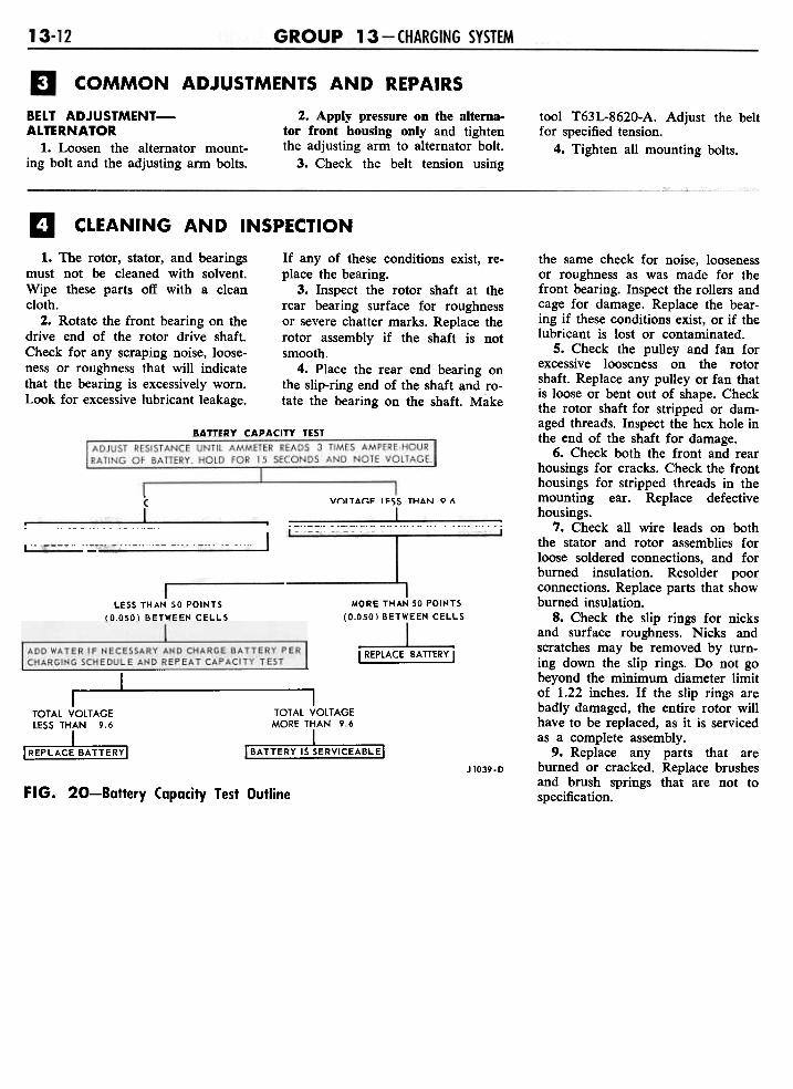
A battery can be tested by de- a clockwise direction until the am-termining its ability to deliver cur- meter reads three times the ampererent. This may be determined by hour rating of the battery. (A 45conducting a Battery Capacity Test. ampere-hour battery should be testedFig. 20 shows the battery capacity at 135 amperes load.)test in outline form. 5. With the ammeter reading the
required load for 15 seconds, notethe voltmeter reading. Avoid leavingthe high discharge load on the bat-tery for periods longer than 15 sec-onds.
6. If the voltmeter reading is 9.6
BATTERY CAPACITY TESTA high rate discharge tester (Bat-
tery-Starter Tester) in conjunctionwith a voltmeter is used for this test.
1. Turn the control knob on the
volts or more, the battery has goodoutput capacity and will readily ac-cept a charge, if required. Check thespecific gravity. If the specific gravityreading is 1.230 or below, add wa-ter if necessary and charge the bat-tery until it is fully charged.
The battery is fully charged whenthe cells are all gassing freely andthe specific gravity ceases to rise forthree successive readings taken athourly intervals. Additional batterytesting will not be necessary after thebattery has been properly charged.
7. If the voltage reading obtainedduring the capacity test is below 9.6volts, check the specific gravity ofeach cell.
8. If the difference between anytwo cells is more than 50 points(0.050), the battery is not satisfac-tory for service and should be re-placed.
9. If the difference between cellsis less than 50 points (0.050) thebattery should be charged according
~ ~EEN
1 3-10 GROUP 13 CHARGING SYSTEM
~rE:::::::=-
..x~
ng:;3~~-~~1)~~~~~I.. -,;-, r;,:... '
-, ;;!
Yellow , ,;;;
I .~..." - £IJ ~, --, . ', ;:;J .t. .::~, ;';:;,;;;;;;{ I --'-::,./ L!~ \ r ... '::' I ' - N' '
_m,;;;;;;{ L-, -""M'..,.., "7
REGULATOR"""'"
/1" "-~ -r-
~
J~~
\ / BATTERY--
'ALTERNATORllo/J 1334.AJ1216-D
FIG. 15-Voltage limiter Test-TypicalFIG. 14-Leece Neville Voltage Drop Test-Alternator to Battery Ground Terminal
to the charging schedule in Table 2. , ABLE 2-Allowable Battery High Rate Charge Time ScheduleIn some cases the electrolyte levelmay be too low to obtain a specificgravity reading. In such cases watershould be added until the electrolytelevel just covers the ring in the fillerwell, then charge the battery at 35amperes for the maximum chargingtime indicated in Table 2, for capac-ity of the battery being tested.
10. After the battery has beencharged, repeat the capacity test. Ifthe capacity test battery voltage isstill less than 9.6 volts, replace thebattery. If the voltage is 9.6 volts ormore, the battery is satisfactory forservice.
11. If the battery is found to bedischarged only, check for a loosefan belt, loose electrical connections,charging system performance, andmake a battery drain test (in thissection).
ChargeRate
Amperes
Battery Capacity-Ampere Hours
45 55 70 80
SpecificGravityReading
1.125-1.1501
1.150-1.175
1.175-1.200
1.200-1.225
Above 1.225
35
35
35
35
5
65 min.
50 min.
40 min.
30 min.
@
80 min.
65 min.
50 min.
35 min.
(!)
100 min.
gO min.
60 min.
45 min.
(!)
115 min.
95 min.
70 min.
50 min.
(i)
(j)If the specific gravity is below 1.125, use the indicated high rate of charge forthe 1.125 specific gravity, then charge at 5 amperes until the specific gravityreaches 1.250 at 80° F.
(!)Charge at 5 ampere rate only until the specific gravity reaches 1.250 at 80° F.At no time during the charging operation should the electrolyte temperatureexceed 1300 F.
any external load that would causeunwanted battery discharge.
Disconnect the battery ground ca-ble and connect the positive lead ofa voltmeter to the cabJ~, Connect
the negative lead of the voltmeter tothe battery negative post.
With all circuits off, the metershould read zero. Any battery exter-nal load will cause the voltmeter to
BATTERY DRAIN TESTThis test will determine if there is
Battery Adapter Switch
t==::::-
PART 13-1 GENERAL CHARGING SYSTEM SERVICE 13-11
J1215.D J1329.A
FIG. 16-Autolite Field Relay Test-Mechanical
RegulatorFIG. 17-Autolite Field Relay Test-Transistor
Regulator
FIG. 18-Leece Neville Field Relay Test-LightCircuit
FIG. 19-Leece Neville Field Relay Test-AmmeterCircuit
the battery ground cable to the bat-tery negative post to make certainthat the clock is wound. When the
clock runs down at the end of ap-proximately 2 minutes the voltmeterwill show full battery voltage.
read full battery voltage.If the car is equipped with an
electric clock, momentarily connect
COMMON ADJUSTMENTS AND REPAIRS
2. Apply pressure on the alterna-tor front housing only and tightenthe adjusting arm to alternator bolt.
3. Check the belt tension using
BELT ADJU5TMENT-AL TERNA TOR
1. Loosen the alternator mount-ing bolt and the adjusting arm bolts.
tool T63L-8620-A. Adjust the beltfor specified tension.
4. Tighten all mounting bolts.
CLEANING AND INSPECTION
1. The rotor, stator, and bearingsmust not be cleaned with solvent.Wipe these parts off with a cleancloth.
2. Rotate the front bearing on thedrive end of the rotor drive shaft.Check for any scraping noise, loose-ness or roughness that will indicatethat the bearing is excessively worn.Look for excessive lubricant leakage.
If any of these conditions exist, re-place the bearing.
3. Inspect the rotor shaft at therear bearing surface for roughnessor severe chatter marks. Replace therotor assembly if the shaft is notsmooth.
4. Place the rear end bearing onthe slip-ring end of the shaft and ro-tate the bearing on the shaft. Make
BATTERY CAPACITY TEST
I ADJUST RESISTANCE UNTIL AMMETER READS 3 TIMES AMPERE-HOURRATING OF BATTERY. HOLD FOR 15 SECONDS AND NOTE VOLTAGE.
VOLTAGE LE$~ THAN 9.6VOLTAGE
rcHECKSPECIFIC GRAVITY OF EACH CELLII CHECK SPECIFIC GRAVITY. CHARGE BATTERY,'
IF RFLOW 1230- OTHERWISE BATTERY IS O.K.
MORE THAN SO POINTS
(0.050) BETWEEN CELLSLESS THAN SO POINTS
(O.OSO) BETWEEN CELLS
ADD WATER IF NECESSARY AND CHARGE BATTERY PERCHARGING SCHEDULE AND REPEAT CAPACITY TEST
I REPLACE BATTERY I
I I ITOTAL VOLTAGE TOTAL VOLTAGELESS THAN 9.6 MORE THAN 9.6
IREPLACJBATTERYI I BATTERY IS~ERVICEABLEI
the same check for noise, loosenessor roughness as was made for thefront bearing. Inspect the rollers andcage for damage. Replace the bear-ing if these conditions exist, or if thelubricant is lost or contaminated.
5. Check the pulley and fan forexcessive looseness on the rotorshaft. Replace any pulley or fan thatis loose or bent out of shape. Checkthe rotor shaft for stripped or dam-aged threads. Inspect the hex hole inthe end of the shaft for damage.
6. Check both the front and rearhousings for cracks. Check the fronthousings for stripped threads in themounting ear. Replace defectivehousings.
7. Check all wire leads on boththe stator and rotor assemblies forloose soldered connections, and forburned insulation. Resolder poorconnections. Replace parts that showburned insulation.
8. Check the slip rings for nicksand surface roughness. Nicks andscratches may be removed by turn-ing down the slip rings. Do not gobeyond the minimum diameter limitof 1.22 inches. If the slip rings arebadly damaged, the entire rotor willhave to be replaced, as it is servicedas a complete assembly.
9. Replace any parts that areburned or cracked. Replace brushesand brush springs that are not tospecification.
Jl039-D
FIG. 20-Battery Capacity Test Outline
1 3-13
AUTOLITE ALTERNATORS
Page13-1313-1.1
Page13-14
Section1 Description and Operation2 Removal and Installation
Section3 Major Repair Operations
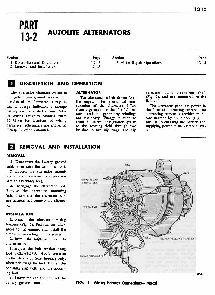
DESCRIPTION AND OPERATION
The alternator charging system isa negative (-) ground system, andconsists of an alternator, a regula-tor, a charge indicator, a storagebattery and associated wiring. Referto Wiring Diagram Manual Form7795P-66 for locations of wiringharnesses. Schematics are shown inGroup 22 of this manual.
ALTERNATORThe alternator is belt driven from
the engine. The mechanical con-struction of the alternator differsfrom a generator in that the field ro-tates, and the generating windingsare stationary. Energy is. suppliedfrom the alternator-regulator systemto the rotating field through twobrushes to two slip rings. The slip
rings are mounted on the rotor shaft(Fig. 2), and are connected to thefield coil.
The alternator produges power inthe form of alternating current. Thealternating current is rectified to di-rect current by six diodes (Fig. 6)for use in charging the battery andsupplying power to the electrical sys-tem.
REMOVAL AND INSTAllATION
REMOVAL
1. Disconnect the battery groundcable, then raise the car on a hoist.
2. Loosen the alternator mount-ing bolts and remove the adjustmentarm to alternator bolt.
3. Disengage the alternator belt.Remove "the alternator mountingbolt, disconnect the alternator wir-ing harness and remove the alterna-tor.
J 1312-8
INSTAllATION1. Attach the alternator wiring
harness (Fig. 1). Position the alter-nator to the engine, and install thealternator mounting bolt finger-tight.
2. Install the adjustment arm toalternator bolt.
3. Adjust the belt tension usingtool T63L-8620-A. Apply pressureon the alternator front housing only,when tightening the belt. Tighten theadjusting arm bolts and the mount-ing bolt.
4. Lower the car and connect thebattery ground cable. FIG. 1 -Wiring Harness Connections-Typical
13-14 GROUP 13 CHARGING SYSTEM
MAJOR REPAIR OPERA nONS
field open or short circuit test (Part13-1).
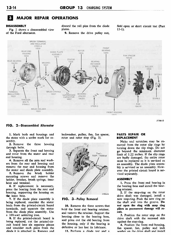
DISASSEMBLYFig. 2 shows a disassembled view
of the Ford alternator.
discard the roll pins from the diodeplates.
9. Remove the drive pulley nut,
JII66-D
FIG. 2-Disassembled Alternator
lockwasher, pulley, fan, fan spacer,rotor and rotor stop (Fig. 3).
FIG. 3-Pulley Removal
10. Remove the three screws thathold the front end bearing retainer,and remove the retainer. Support thehousing close to the bearing boss,and press out the old bearing fromthe housing, only if the bearing isdefective or has lost its lubricant.
11. Perform a dinde te~t and II
1. Mark both end housings andthe stator with a scribe mark for as-sembly.
2. Remove the three housingthrough bolts.
3. Separate the front end housingand rotor from the stator and rearend housing.
4. Remove all the nuts and wash-ers from the rear end housing andremove the rear end housing fromthe stator and diode plate assembly.
5. Remove the brush holdermounting screws and remove theholder, brushes, brush springs, insu-lator and terminal.
6. If replacement is necessary,press the bearing from the rear endhousing, supporting the housing ontl8e inner boss.
7. If the diode plate assembly isbeing replaced, unsolder the statorleads from the printed-circuit boardterminals, and separate the statorfrom the diode plate assembly. Usea IOO-watt soldering iron.
8. If the printed-circuit board isbeing replaced, cut the printed-cir-cuit board into six separate piecesand unsolder each piece from thediode it is attached to. Remove and
PARTS REPAIR ORREPLACEMENT
Nicks and scratches may be re-moved from the rotor slip rings byturning down the slip rings. Do notgo beyond the minimum diameterlimit of 1.22 inches. If the slip ringsare badly damaged, the entire rotormust be replaced as it is serviced asan assembly. The diode plate assem-bly is serviced as an assembly. How-ever the printed circuit board is ser-viced separately.
ASSEMBLY1. Press the front end bearing in
the bearing boss and install the bear-ing retainer.
2. If the stop-ring on the rotordrive shaft was damaged, install anew stop-ring. Push the new ring onthe shaft and into the groove. Donot open the ring with snap ringpliers as permanent damage will re-sult.
3. Position the rotor stop on thedrive shaft with the recessed sideagainst the stop-ring.
4. Position the front end housing,fan spacer, fan, pulley and lockU/~~hp" nn thp ti..ivp ~h~ft ~nti in~t~11

the retaining nut (Fig. 3), to speci-fied torque.
5. If the rear end housing bearingwas removed, support the housingon the inner boss and press in a newbearing flush with the outer end sur-face.
6. Place the brush springs,brushes, brush terminal and terminalinsulator in the brush holder andhold the brushes in position by in-serting a piece of stiff wire in thebrush holder as shown in Fig. 4.
J 1167-C
FIG. 6-Slalor Lead Connections~ ~~ ~ Jl203-B
FIG. 4-Brush Holder Assembly
7. Position the brush holder as-sembly in the rear end housing andinstall the mounting screws. Positionthe brush leads in the brush holderas shown in Fig. 5.
8. If a new diode plate or printed-circuit board is being installed, po-sition the diode plate so that thediode leads go through the threeholes in the printed-circuit board.Install the terminal bolt and insula-tor. Install new roll pins to main-tain the 1/2 -inch insulator spacingbetween the printed-circuit boardand the diod.. plate. Install a smalltinned washer and a solder ring on
FIG. 5-Brush Lead Positions
each diode lead and solder the diodeleads to the printed-circuit board.Use a IOO-watt iron. Avoid excessheat on the printed-circuit board soas not to loosen the printed-circuitwiring from the board.
9. Wrap the three stator windingleads around the printed-circuitboard terminals and solder them.Use a IOO-watt soldering iron androsin-core solder. Position the statorneutral lead eyelet on the stator ter-minal insulators (Fig. 6). Positionthe diode assembly (Fig. 6).
10. Install the STA and BAT ter-minal insulators (Fig. 6). Positionthe stator and diode plate assemblyin the rear end housing. Position theSTA (black), BAT (red) and FLD(white) insulators, on the terminalbolts, and install five retaining nuts(Fig. 7).
11. Wipe the rear end bearingsurface of the rotor shaft with aclean lint-free rag.
12. Position the rear end housingand stator assembly over the rotorand align the scribe marks madeduring disassembly. Seat the ma-chined portion of the stator core intothe step in both end housings. Installthe housing through bolts. Removethe brush retracting rod, and put adaub of waterproof cement over thehole to seal it.
FIG. 7-Alternator TerminalLocations

1 3-16
AUTOLITE ALTERNATOR REGULATORS
Section Page1 Description and Operation. . . . . . . . . . . . . . . .13-16
Mechanical Voltage Regulator .13-16Transistorized Voltage Regulator .13-16
2 In-Car Adjustments and Repairs. . . . . . . .. .13-17
Page
.13-17. . . . .13-20. . . . .13-20
SectionMechanical Regulator Adjustments.Transistorized Regulator Adjustments
3 Removal and Installation. . . . . . . . . .
DESCRIPTION AND OPERATION
MECHANICAL VOLTAGEREGULATOR
The alternator regulator is com-posed of two control units, a fieldrelay and a voltage limiter, mountedas an assembly (Fig. 1). Because thereverse current through the rectifieris small, a reverse current cutout re-lay is not needed. The alternator isself current limiting, thus a currentlimiter is not needed. Refer to Wir-ing Diagram Manual Form 7795P-66 for locations of wiring harnesses.Schematics are shown in Group 22of this manual.
the field coil. This small current isenough to allow the alternator tostart generating, and is necessary, asresidual magnetism in the alternatoris usually too small to start voltagebuild-up. The charge indicator lightis shunted with a 15-ohm resistor tosupply adequate starting field cur-rent.
When the alternator builds upenough voltage to close the field re-lay contacts, full voltage is appliedto the field, and the charge indicatorlight goes out.
,VOLTAGELIMITERFIELD RELAY
'\
unit. Limiting is accomplished bycontrolling the amount of currentsupplied to the rotating field.
When the upper contacts areclosed, full system voltage is ap-plied to the field and maximum fieldcurrent will flow. When the limiterarmature floats between the con-tacts, field current is reduced byflowing through the field resistor.When the limiter lower contacts areclosed, zero current flows to thefield. At low engine speed and witha load applied, the armature vibrateson the upper contact. At high en-gine speed and light or no load thearmature vibrates on the lower con-tact.
A 50-ohm resistor is connectedfrom the field terminal to ground toabsorb electrical surges in the alter-nator circuits as the voltage limiterarmature vibrates on the contacts.
~
FIELDTERMINAL
FIELD RELAYTERMINAL
-- LIGHT TERMINAL
.;BATTERY TERMINAL FORFIELD SUPPLY VOLTAGE J1214-D
FIG. 1-Alternator Regulator
FIELD RELAYThe field relay serves to connect
charging system voltage to the fieldcircuit when the engine is running.
CHARGE INDICATOR CIRCUIT-AMMETER
When the ignition switch is closed,the field relay is energized. Closingof the relay contacts connects thebattery and alternator output to thefield through the voltage limitercontacts.
TRANSISTORIZED VOLTAGEREGULATOR
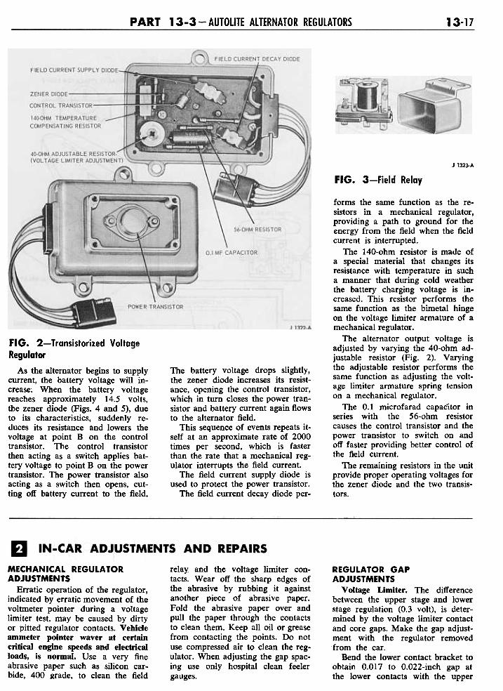
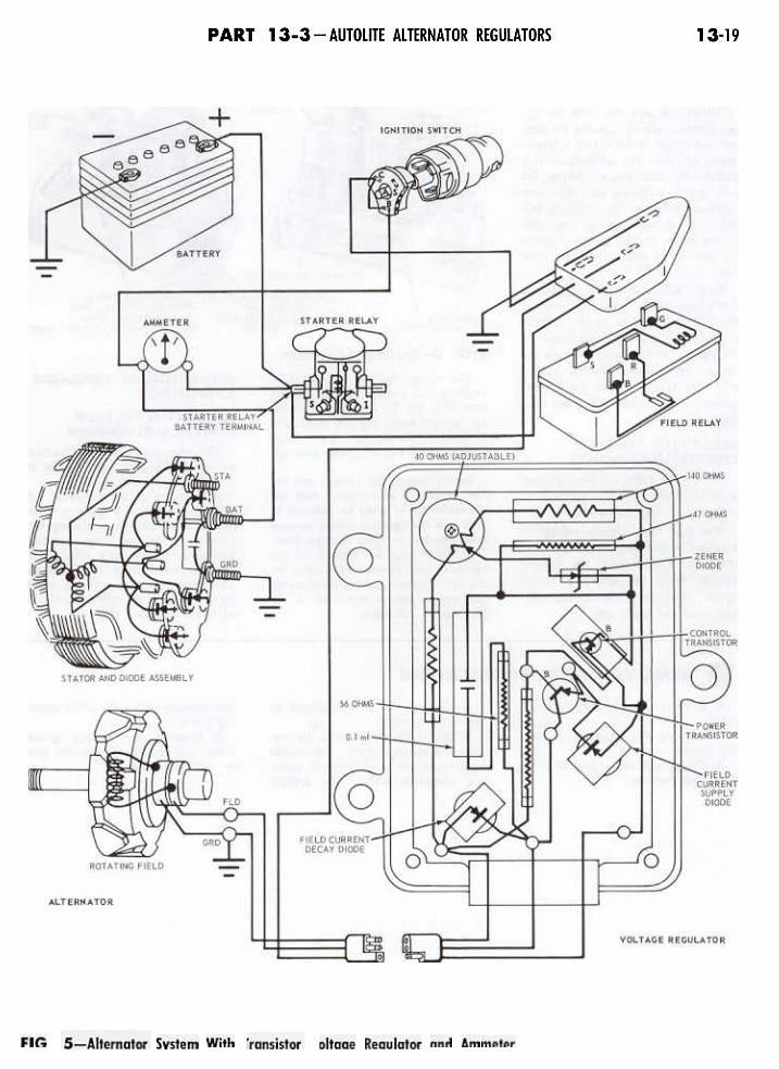
The transistorized voltage regula-tor (Fig. 2), controls the alternatorvoltage output in a similar mannerto a mechanical voltage regulator,by regulating the alternator field cur-rent. The regulation is accomplishedelectronically with the use of tran-sistors and diodes rather than by avibrating armature relay. The volt-age sensing element is a zener diodewhich has the characteristic of sud-denly changing its resistance when aspecified voltage is reached. The fieldrelay (Fig. 3) is still used, but it ismounted separately from the voltageregulator.
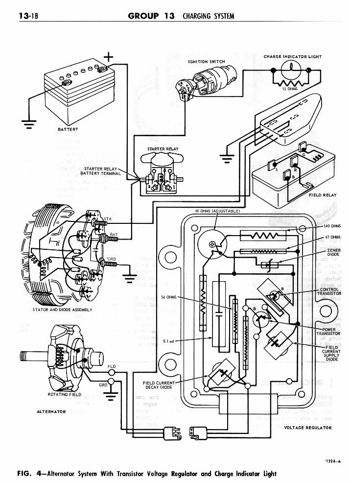
Figs. 4 and 5 show schematics ofthe transistorized voltage regulatorsystem. When the engine is started,battery current is supplied to thefield through the field relay, fieldcurrent supply diode, and the powertransistor.
CHARGE INDICATORCIRCUIT-LIGHT
When the ignition switch is closed,battery current flows through thecharge indicator light and IS-ohmparallel resistor, and through theregulator voltage limiter contacts to
VOLTAGE LIMITERThe temperature compensated
voltage limiter is a double contact
PART 13-3 - AUTOLITE ALTERNATOR REGULATORS 1 3-17
J 1323-A
FIG. 3-Field Relay
FIG. 2-Transistorized Voltage
Regulator
As the alternator begins to supplycurrent, the battery voltage will in-crease. When the battery voltagereaches approximately 14.5 volts,the zener diode (Figs. 4 and 5), dueto its characteristics, suddenly re-duces its resistance and lowers thevoltage at point B on the controltransistor. The control transistorthen acting as a switch applies bat-tery voltage to point B on the powertransistor. The power transistor alsoacting as a switch then opens, cut-ting off battery current to the field.
The battery voltage drops slightly,the zener diode increases its resist-ance, opening the control transistor,which in turn closes the power tran-sistor and battery current again flowsto the alternator field.
This sequence of events repeats it-self at an approximate rate of 2000times per second, which is fasterthan the rate that a mechanical reg-ulator interrupts the field current.
The field current supply diode isused to protect the power transistor.
The field current decay diode per-
forms the same function as the re-sistors in a mechanical regulator,providing a path to ground for theenergy from the field when the fieldcurrent is interrupted.
The 140-ohm resistor is made ofa special material that changes itsresistance with temperature in sucha manner that during cold weatherthe battery charging voltage is in-creased. This resistor performs thesame function as the bimetal hingeon the voltage limiter armature of amechanical regulator.
The alternator output voltage isadjusted by varying the 40-ohm ad-justable resistor (Fig. 2). Varyingthe adjustable resistor performs thesame function as adjusting the volt-age limiter armature spring tensionon a mechanical regulator.
The 0.1 microfarad capacitor inseries with the 56-ohm resistorcauses the control transistor and thepower transistor to switch on andoff faster providing better control ofthe field current.
The remaining resistors in the unitprovide proper operating voltages forthe zener diode and the two transis-tors.
relay and the voltage limiter con-tacts. Wear off the sharp edges ofthe abrasive by rubbing it againstanother piece of abrasive paper.Fold the abrasive paper over andpull the paper through the contactsto clean them. Keep all oil or greasefrom contacting the points. Do notuse compressed air to clean the reg-ulator. When adjusting the gap spac-ing use only hospital clean feelergauges.
REGULATOR GAPADJUSTMENTS
Voltage Limiter. The differencebetween the upper stage and lowerstage regulation (0.3 volt), is deter-mined by the voltage limiter contactand core gaps. Make the gap adjust-ment with the regulator removedfrom the car.
Bend the lower contact bracket toobtain 0.017 to 0.022-inch gap atthe lower contacts with the upper
MECHANICAL REGULATORADJUSTMENTS
Erratic operation of the regulator,indicated by erratic movement of thevoltmeter pointer during a voltagelimiter test, may be caused by dirtyor pitted regulator contacts. Vehicleammeter pointer waver at certaincritical engine speeds and electricalloads, is normal. Use a very fineabrasive paper such as silicon car-bide, 400 grade, to clean the field
13-18 GROUP 13 CHARGING SYSTEM
11326-A
FIG. 4-Alternator System With Transistor Voltage Regulator and Charge Indicator Light
13-20 GROUP 13 - CHARGING SYSTEM
GAP ADJUSTMENTS
VOLTAGE LIMITER-
VOLTAGE ADJUSTMENTSBEND ARM TD ADJUST
CONTACT GAP
I VOLTAGE LIMITER
~~ ~~FIELD;;r RELAYFIELD"
R~I.AY
,,.v' ;,'cd
,~
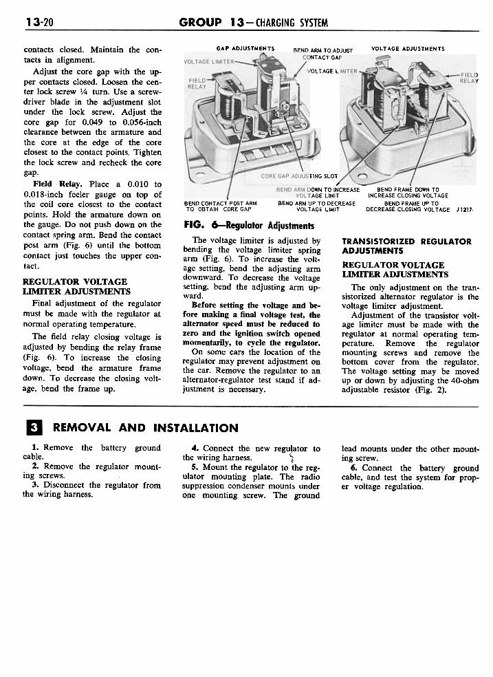
contacts closed. Maintain the con-tacts in alignment.
Adjust the core gap with the up-per contacts closed. Loosen the cen-ter lock screw Y4 turn. Use a screw-driver blade in the adjustment slotunder the lock screw. Adjust thecore gap for 0.049 to 0.056-inchclearance between the armature andthe core at the edge of the coreclosest to the contact points. Tightenthe lock screw and recheck the coregap.
Field Relay. Place a 0.010 to0.018-inch feeler gauge on top ofthe coil core closest to the contactpoints. Hold the armature down onthe gauge. Do not push down on thecontact spring arm. Bend the contactpost arm (Fig. 6) until the bottomcontact just touches the upper con-tact.
~~~
- "'\~--'
JUSTING SLO
JBEND ARM DOWN TO INCREASE BEND FRAME DOWN TO. VOLTAGE LIMIT INCREASE CLOSING VOLTAGE
BEND CONTACT POST ARM BEND ARM UP TO DECREASE BEND FRAME UP TOTO OBTAIN CORE GAP VOLTAGE LIMIT DECREASE CLOSING VOLTAGE J1217-
FIG. 6-Regulator Adjustments
The voltage limiter is adjusted bybending the voltage limiter springarm (Fig. 6). To increase the volt-age setting, bend the adjusting armdownward. To decrease the voltagesetting, bend the adjusting arm up-ward.
Before setting the voltage and be-fore making a final voltage test, thealternator speed must be reduced tozero and the ignition switch openedmomentarily, to cycle the regulator.
On some cars the location of theregulator may prevent adjustment onthe car. Remove the regulator to analternator-regulator test stand if ad-justment is necessary.
REGULATOR VOLTAGELIMITER ADJUSTMENTS
Final adjustment of the regulatormust be made with the regulator atnormal operating temperature.
The field relay closing voltage isadjusted by bending the relay frame(Fig. 6). To increase the closingvoltage, bend the armature framedown. To decrease the closing volt-age, bend the frame up.
TRANSISTORIZED REGULATORADJUSTMENTS
REGULATOR VOLTAGELIMITER ADJUSTMENTS
The only adjustment on the tran-sistorized alternator regulator is thevoltage limiter adjustment.
Adjustment of the transistor volt-age limiter must be made with theregulator at normal operating tem-perature. Remove the regulatormounting screws and remove thebottom cover from the regulator.The voltage setting may be movedup or down by adjusting the 40-ohmadjustable resistor (Fig. 2).
REMOVAL AND INSTAllATION
4. Connect the new regu.\ator tothe wiring harness. 1
5. Mount the regulator to the reg-ulator mounting plate. The radiosuppression condenser mounts underone mounting screw. The ground
lead mounts under the other mount-ing screw.
6. Connect the battery groundcable, and test the system for prop-er voltage regulation.
1. Remove the battery groundcable.
2. Remove the regulator mount-ing screws.
3. Disconnect the regulator fromthe wiring harness.
13-21
53-AMPERE LEECE NEVILLE ALTERNATOR
Page. . . . .. . .. . .13-21.. . ., . . .. . .13-21
Page.13-21
Section1 Description and Operation. . . .2 Removal and Installation. . . . .
Section3 Major Repair Operations. .
While OR ~ - Black-Red Stripe
Black-Red StripeSIX v-a~
/' White,OR ' ,.-
Black- White Stripe
Iff!It¥
~~,Yellow-Block. Stripe
c ""-
Black- Yellow Stripe
k~ ~ Yel/ow-Block Stripe-
- . IJ Black- Yel/ow Stripe.
.. ;::::::~::~:--- -'
~ Green-Red Stripe
Black-Red Stripe~-rn44-A
FIG. 1-Alternator Mounting-Typical
bolt, disconnect the alternator wir-ing and remove the alternator.
INSTALLATION1. At.tach the alternator wiring.
Position the alternator to the engine,and install the alternator mountingbolt finger-tight (Fig. 1).
2. Install the adjustment arm toalternator bolt.
3. Adjust the belt tension usingtool T63L-8620-A. Apply pressureon the alternator drive end housing'Jnly. Tighten the adjusting arm boltsand the mounting bolt.
4. Connect the battery ground ca."Ie
the drive end housing. Remove thebearing only if replacement is re-quired.
5. Remove the BT, Neut., andground terminal nuts and washers,and remove the brush end housingfrom the stator and diode rectifierassembly.
3. Press the rotor shaft out of thedrive end housing only if the rotoror bearing are being replaced. Re-move the bearing spacer.
4. Remove the bearing retainer,support the housing around the bear-ing pocket to prevent damage to thehousing, and press the be~ring from
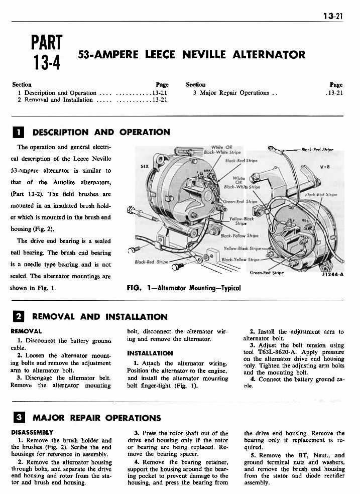
The operation and general electri-
cal description of the Leece Neville
53-ampere alternator is similar to
that of the Autolite alternators,
(Part 13-2). The field brushes are
mounted in an insulated brush hold-
er which is mounted in the brush end
housing (Fig. 2).
The drive end bearing is a sealed
ball bearing. The brush end bearing
is a needle type bearing and is not
sealed. The alternator mountings are
shown in Fig. 1.
REMOVAL
1. Disconnect the battery grounGcable.
2. Loosen the alternator mount-ing bolts and remove the adjustmentarm to alternator bolt.
3. Disengage the alternator belt.Remov" the alternator mounting
DISASSEMBLY1. Remove the brush holder and
the brushes (Fig. 2). Scribe the endhousings for reference in assembly.
2. Remove the alternator housingthrough bolts, and separate the driveend housing and rotor from the sta-tor and brush end housing.

13-22 GROUP 13 - CHARGING SYSTEM
2. Place the bearing spacer on thedrive end shaft and press the driveend bearing on the shaft tight againstthe spacer. Put pressure on the innerrace only.
3. If the brush end housing bear~ing was removed, press a new bear-ing into the housing flush with theouter surface of the housing.
4. Position the two diode plateassemblies together with the insula-tors and terminal bolts as shown inFig. 3. The positive diode plate ispositioned closest to the outside.
5. Position the eyelets over thediode leads, insert the three statorleads in the eyelets and solder themin position.
6. Position the brush end housingover the diode plate assembly andinstall the insulators, washers andterminal nuts. The condenser groundlug is mounted under the groundterminal nut. Make certain that thestator leads are positioned out of theway of the rotor (Fig. 4).
7. Position the rotor and driveend housing and the stator and brushend housing together. Align thehousing scribe marks and install thehousing through bolts.
8. Install the slip rings brushesand brush holder.
FIG. 2-Disassembled 53-Ampere Leece Neville Alternator
6. If the diode plates or stator are moved from the rotor slip rings bybeing replaced, carefully unsolder turning down the slip rings. Removethe three stator leads from the diode only enough to clean up the surface.connector eyelets, and separate the If the slip rings are badly damaged,leads from each other. Clean the they should be replaced. Repair anysolder from the eyelets. broken lead wires.
7. Press the brush end housingbearing from the housing only if it ASSEMBLYis being replaced. 1. If the drive end bearing was
removed, press the new bearing intoPARTS REPAIR the drive end housing putting pres-OR REPLACEMENT sure on the outer race only. Install
Nicks and scratches may be re- the bearing retainer.
J1243-B
3-Diode Plate and Stator Assembly FIG. 4-Stator Lead Dress
13-23
LEECE NEVILLE ALTERNATOR REGULATORS
Page. . . . .13-24
Page. .13-23. .13-23
Section3 Removal and Installation
Section
1 Description and Operation 2 In-Car Adjustments and Repairs
DESCRIPTION AND OPERATION
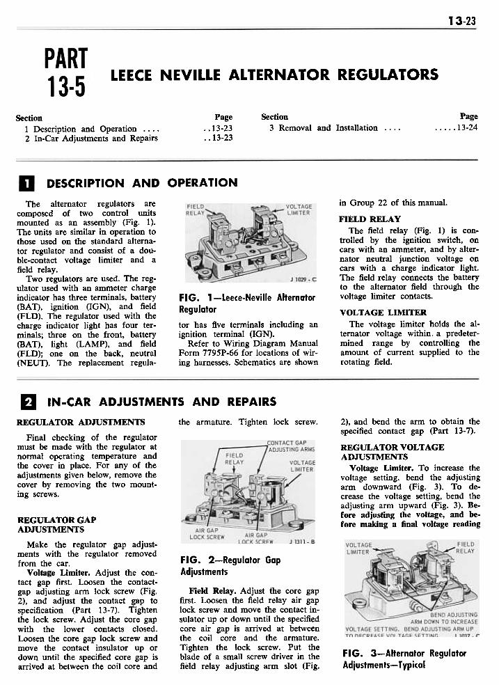
The alternator regulators arecomposed of two control unitsmounted as an assembly (Fig. 1).The units are similar in operation tothose used on the standard alterna-tor regulator and consist of a dou-ble-contact voltage limiter and afield relay.
Two regulators are used. The reg-ulator used with an ammeter chargeindicator has three terminals, battery(BAT), ignition (IGN), and field(FLD). The regulator used with thecharge indicator light has four ter-minals; three on the front, battery(BAT), light (LAMP), and field(FLD); one on the back, neutral(NEUT). The replacement regula-
FIG. 1-Leece-Neville Alternator
Regulatortor has five terminals including anignition terminal (IGN).
Refer to Wiring Diagram ManualForm 7795P-66 for locations of wir-ing harnesses. Schematics are shown
in Group 22 of this manual.
FIELD RELAYThe field relay (Fig. 1) is con-
trolled by the ignition switch, oncars with an ammeter, and by alter-nator neutral junction voltage oncars with a charge indicator light.The field relay connects the batteryto the alternator field througn thevoltage limiter contacts.
VOLTAGE LIMITERThe voltage limiter holds the al-
ternator voltage within. a predeter-mined range by controlling theamount of current supplied to therotating field.
IN-CAR ADJUSTMENTS AND REPAIRS
REGULATOR ADJUSTMENTS
Final checking of the regulatormust be made with the regulator atnormal operating temperature andthe cover in place. For any of theadjustments given below, remove thecover by removing the two mount-ing screws.
the armature. Tighten lock screw. 2), and bend the arm to obtain thespecified contact gap (Part 13-7).
REGULATOR VOLTAGEADJUSTMENTS
Voltage Limiter. To increase thevoltage setting, bend the adjustingarm downward (Fig. 3). To de-crease the voltage setting, bend theadjusting arm upward (Fig. 3). Be-fore adjusting the voltage, and be-fore making a final voltage readingREGULATOR GAP
ADJUSTMENTS
Make the regulator gap adjust-ments with the regulator removedfrom the car.
Voltage Limiter. Adjust the con-tact gap first. Loosen the contact-gap adjusting arm lock screw (Fig.2), and adjust the contact gap tospecification (Part 13- 7). Tightenthe lock screw. Adjust the core gapwith the lower contacts closed.Loosen the core gap lock screw andmove the contact insulator up ordown until the specified core gap isarrived at between the coil core and
FIG. 2-Regulator Gap
Adjustments
Field Relay. Adjust the core gapfirst. Loosen the field relay air gaplock screw and move the contact in-sulator up or down until the specifiedcore air gap is arrived at betweenthe coil core and the armature.Tighten the lock screw. Put theblade of a small screw driver in thefield relay adjusting arm slot (Fig.
FIG. 3-Alternator RegulatorAdjustments- Typical
13-24 GROUP 13 - CHARGING SYSTEM
with the cover in place, cycle the al-ternator. Reduce the alternatorspeed to zero and turn the ignitionswitch to OFF momentarily. This
procedure must be repeated eachtime an adjustment is made.
Field Relay. The field relay cut-involtage is increased by bending the
adjusting arm downward, or de-
creased by bending the adjusting
arm upward (Fig. 3).
1. Disconnect the battery groundcable.
2. Remove the wires from theregulator.
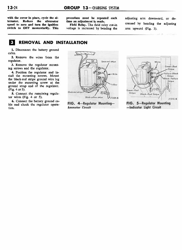
3. Remove the regulator mount-ing screws and the regulator.
4. Position the regulator and in-stall the mounting screws. Mountthe black-red stripe ground wire lugunder the mounting screw at theground strap end of the regulator.(Fig. 4 or 5).
5. Connect the remaining regula-tor wires (Fig. 4 or 5).
6. Connect the battery ground ca-ble and check the regulator opera-tion.
13-25
SPECIFICATIONS
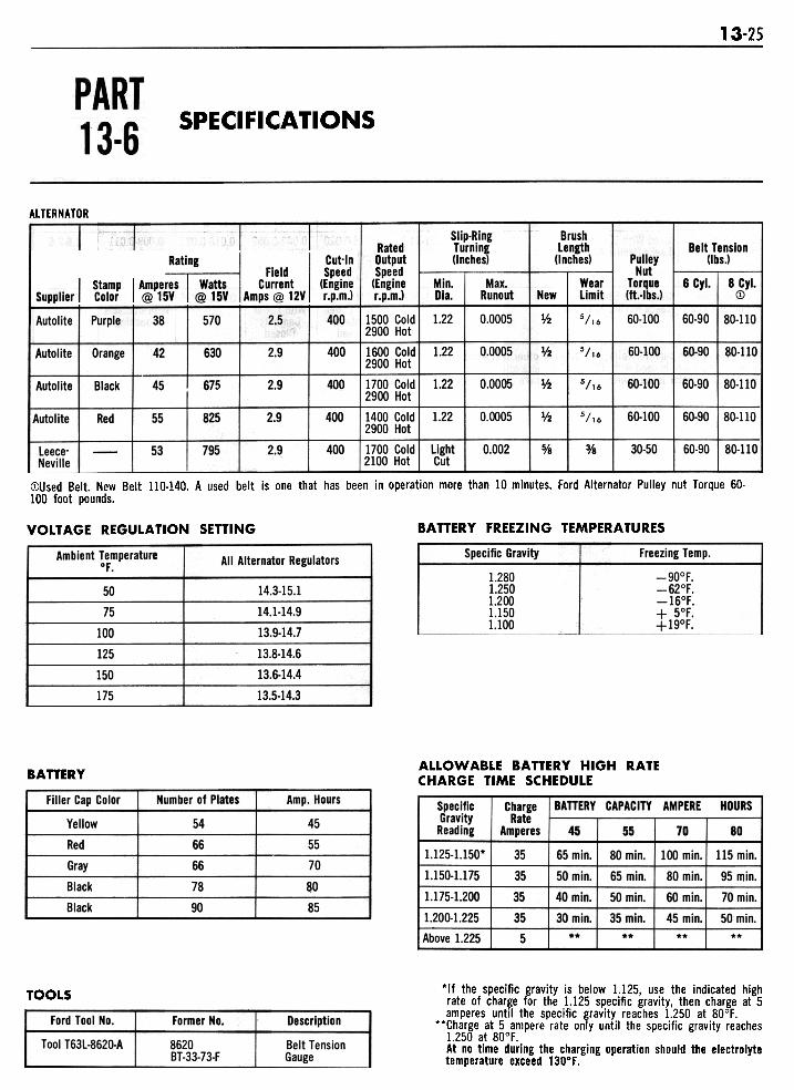
ALTERNATOR
Slip-RingTurning(Inches)
Brush
Length(Inches)
Belt Tension(lbs.J
RatedOutputSpeed(Enginer.p.m.1
Min.Dia.
1.22
Max.Runout
0.0005
WearLimit
5/'6
6 Cyl. 8 Cyl.(D
80-110
New
Vz400 1 1500 Cold2900 Hot
PulleyNut
Torque(ft.-lbs.J
60-100 60-90Autolite Purple 38 570 2.5- -400 1600 Cold I 1.22
2900 Hot
0.0005 lf2 5/16 60-100-60-90
-80-110Autolite Orange 42 630 2.9
40011700 ColdI 2900 Hot-1.22 0.0005 III 5/16 60-100 60-90 80-110Autolite Black 45 675 2.9
-400 1400 Cold
2900 Hot1.22 0.0005 l/2 5/,6 60-100 60-90 80-110
-~ Autolite
-Red 55 825 2.9
400 1 1700 cold lLight2100 Hot Cut
0.002 0/8 0/8 30-50 60-90-80-110
-53
-
795 2.9Leece-Neville
CDUsed Belt. New Belt 110-140. A used belt is one that has been in operation more than 10 minutes. Ford Alternator Pulley nut Torque 60-100 foot pounds.
BATTERY FREEZING TEMPERATURESVOLTAGE REGULATION SETTING
Specific Gravity
1.2801.2501.2001.1501.100
Freezing Temp.
-90°F.-62°F.-16°F.+ 5°F.+19°F.
Ambient Temperatureof.
All Alternator Regulators
50
75
100
125
150
175
14.3-15.1
14.1-14.9
13.9-14.7
13.8-14.6
13.6-14.4
13.5-14.3
ALLOWABLE BATTERY HIGH RATECHARGE TIME SCHEDULEBATTERY
Filler Cap Color
Yellow
Red
Gray
Black
Black
Number of Plates
54
66
66
78
90
Amp. Hours
45
55
70
80
85
BATTERY CAPACITY AMPERE HOURSChargeRate
Amperes 70 80
SpecificGravityReading
1.125-1.150*
1.150-1.175
1.175-1.200
1.200-1.225
Above 1.225
35
35
35
35
5
45
65 min.
50 min.
40 min.
30 min...
55
80 min.
65 min.
50 min.
35 min...
100 min. I 115 min.
80 min.
60 min.
45 min...
95 min.
70 min.
50 min.**
"If the specific gravity is below 1.125, use the indicated highrate of charge for the 1.125 specific gravity, then charge at 5amperes until the specific gravity reaches 1.250 at 80°F.
""Charge at 5 ampere rate only until the specific gravity reaches1.250 at 80°F.At no time during the charging operation should the electrolytetemperature exceed 130°F.
TOOLS
Ford Tool No.
Tool T63L-8620-A
Former No.
8620BT-33-73-F
Description
Belt TensionGauge
13-26 GROUP 13 CHARGING SYSTEM
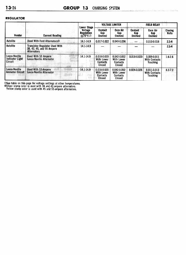
REGULATOR
VOLTAGE LIMITER FIELD RELAY
Core AirGap
(Inches)
0.010-0.018
ContactGap
(Inches)
ClosingVolts
Vendor Current Reading
Used With Ford Alternators<Y
Transistor Regulator Used With38, 42, 45, and 55 AmpereAlternators
~
Lower StageVoltage
I Regulation
@75°F.CD
I . - - - - -I 14.1-14.9i, 14.1-14.9
ContactGap
(Inches)
0.017-0.022
Core AirGap
!Inches)
0.049-0.056 2.5-4
2.5-4
Leece.NevilleIndicator LightCircuit
Used With 53 AmpereLeece-Neville Alternator
14.1-14.9 0.018-0.020With LowerContactsClosed
0.042-0.052With LowerContactsClosed
0.018-0.0200.009-0.011With Contacts
Touching
-1.6-2.6
leece-Neville IAmmeter Circuit
-Used With 53.AmpereLeece.Neville Alternator
14.1-14.9 0.018-0.020With LowerContactsClosed
0.042-0.052With LowerContactsClosed
0.024.0.026 0.011-0.013With Contacts
Touching
-6.2-7.2
<DSee table on this page for voltage settings at other temperatures.(!)Silver stamp color is used with 38 and 42-ampere alternators.
Yellow stamp color is used with 45 and 55-ampere alternators.
Related Documents