UCF Senior Design 1 LED Board Game Fall 2017 Group 1 Kevin Cochran - Electrical Engineer Noah Thering - Computer Engineer Taylor Grubbs - Computer Engineer Zachery Dunlop - Electrical Engineer 12/04/2017

Welcome message from author
This document is posted to help you gain knowledge. Please leave a comment to let me know what you think about it! Share it to your friends and learn new things together.
Transcript

UCF Senior Design 1 LED Board Game
Fall 2017 Group 1
Kevin Cochran - Electrical Engineer Noah Thering - Computer Engineer Taylor Grubbs - Computer Engineer Zachery Dunlop - Electrical Engineer
12/04/2017

I
Table of Contents
1. Executive Summary 1
2. Project Description 3
2.1 Goal and Objective 3
2.2 Existing Similar Projects or Products 4
2.1.1 LED coffee table: 4
2.1.2 Project 64/64 Buttons: 5
2.1.3 Arbalet 6
2.2 Engineering Specifications 7
2.3 General Architecture 9
2.4 Game Logic and Explanation 10
2.4.1 Go 11
2.4.1.1 Rules and Implementation: 11
2.4.1.2 Programming Challenges and Strategies: 14
2.4.2 American Checkers 16
2.4.2.1 Rules and Implementation: 16
2.4.2.2 Programming Challenges and Strategies: 17
2.4.3.1 Rules and Implementation: 18
2.4.3.2 Programming Challenges and Strategies: 18
2.4.4 Line of Four 19
2.4.4.1 Rules and Implementation: 19
2.4.4.2 Programming Challenges and Strategies: 20
2.4.5 Popout 20
2.4.5.1 Rules and Implementation: 20
2.4.5.2 Programming Challenges and Strategies: 21
2.4.6 Square Chinese Checkers 21
2.4.6.1 Rules and Implementation: 21
2.4.7 Light Sequence 23
2.4.7.1 Rules and Implementation: 23
2.4.7.2 Programming Challenges and Strategies: 24
2.4.8 Tile Flip 25
2.4.8.1 Rules and Implementation: 25
2.4.8.2 Programming Challenges and Strategies: 26
3. Research Related to Project Definition 27
3.1 Relevant Technologies 27
3.1.1 Powering LEDS (specifically addressable LED strips) 27

II
3.1.3 Choosing Battery Power Source 28
3.1.4 AA batteries 28
3.1.5 Rechargeable Lithium-Ion-Batteries and Lithium-Polymer Batteries29
3.1.6 Voltage Regulators and Heatsinking 31
3.1.7 Piezoelectricity 32
3.2 Strategic Components and Part Selections 33
3.2.1 Microcontroller: 33
3.2.4 MSP432P401R: 35
3.2.2 Atmel ATmega 2560: 36
3.3 Liquid Crystal Display: 37
3.3.2 Monochrome Graphic Display With OLED Pixels (Figure 21, B): 38
3.3.3 Full Color TFT Display: (Figure 21, C) 39
3.3.4 Graphic ST7565 Positive LCD (Figure 21, D): 39
3.3.5 RGB Backlight 16x2 negative LCD display (Figure 21, E): 40
3.3.6 5110 LCD module (Figure 21, A): 40
3.3.7 2.2” 18-BIT Color TFT display with MicroSD Card Breakout 41
3.4.1 74LVC245 Logic Level Shifter 43
3.4.2 USB Interface 43
3.4.3 Diodes 44
3.4.4 Rectifier Diodes 45
3.4.5 NeoPixel 5050 RGB LED with Integrated Driver (10 pack): 45
3.4.6 Alitove 16.4ft WS2812B Individually Addressable LED Strip light 5050 RGB SMD 150 Pixels: 46
3.4.7 Large Enclosed Piezo Element with Wires (Buzzer) 46
3.5 Development Tools 47
3.5.1 Software IDE: 47
3.5.2 Custom Board Emulator: 49
3.6 Comparison of Electronic Design Automation (EDA) Software: 50
3.6.1 Kicad: 50
3.6.2 Eagle: 51
3.6.3 Diptrace: 51
3.6.4 Altium Circuit Maker: 51
3.6.5 Fritzing: 52
3.6.6 Upverter: 52
3.6.7 3D Printer and CAD Software: 52
3.7 Possible Architectures 52
3.7.1 Communication Layer: 52
3.7.2 Management Layer: 53

III
3.7.3 Game Layer: 54
3.8 Parts Selection Summary 54
4. Related Design Standards and Constraints 57
4.1 Soldering Standards 57
4.1.1 U.S. Department of Defense Soldering Standards: 57
4.1.2 NASA Soldering Standards: 59
4.2 Programming Standards 60
4.2.1 C Programming Standards and Best Practices: 60
4.3 Electrical Engineering Safety Standards 63
4.3.1 Electrical Safety Standards: 63
4.4 Lead Solder Safety Standards 66
4.4.1 Carnegie Mellon University Lead Solder Safety Guidelines: 66
4.5 USB Standards 68
4.6 RoHS Compliance (Reduction of Hazardous Substances) 70
5. Project Hardware Design Details 73
5.1 Interface Design: 73
5.1.1 Game Buttons: 73
5.1.2 Housing: 75
5.1.3 Settings Buttons: 76
5.2 Printed Circuit Board: 76
5.2.1 Composition of a PCB: 77
5.3 PCB fabrication: 77
5.3.1 Designing for professional assembly: 77
5.3.2 Circuit board etching: 78
5.3.3 Ordering a PCB: 78
5.3.4 Comparison of PCB fabrication services: 79
5.3.4.1 Oshpark 79
5.3.4.2 Dirty PCBs 79
5.3.4.3 PCBway 79
5.3.4.4 Elecrow 80
5.4 I/O list: 80
5.5 Design Philosophy: 81
5.6 Power 81
5.6.1 AA Battery Power Source: 81
5.6.2 Battery Choice 4 NiMH Rechargeable Batteries in Series: 82
5.6.3 Rechargeable Lithium-Ion-Batteries and Lithium Polymer Batteries:82
5.6.4 Voltage Regulators 83

IV
5.6.4.1 Linear Voltage Regulators 84
5.6.4.2 Switching Voltage Regulators 84
5.6.4.3 Comparing Linear and Switching Regulators 85
5.7 LED Implementations 86
5.7.1 74HC595 Shift Register: 86
5.7.2 Charlieplexing: 86
5.7.3 TLC5958 LED Driver: 88
5.7.4 individually Addressable RGB LED Strips: 90
5.8 Schematics 91
5.8.1 Schematics 91
6. Project Software Design Details 95
6.1 Overall System Design 95
6.2 Communication Layer 96
6.2.1 Emulator Communication 96
6.2.2 LED Communication 96
6.2.3 LCD Communication 99
6.2.4 Game Button Communication 100
6.2.5 Settings Button Communication 100
6.2.6 Speaker Communication 101
6.3 Management Layer 102
6.3.1 Menu System: 102
6.3.2 LCD Message Queue: 103
6.3.3 LED Queue: 103
6.3.4 Management Layer IO Restrictions: 104
6.3.5 Timer System 104
6.3.7 Highscores: 106
6.3.8 Game History: 106
6.3.9 Game Help: 106
6.3.10 Management Layer API: 107
6.3.11 API Functions: 107
6.3.12 API Callbacks: 109
6.4 Game Layer 111
7.Testing 111
7.1 Microcontroller Testing 112
7.2 LED Testing 112
7.3 Button Testing 112
7.4 LCD Testing 113

V
7.5 SD Card Testing 113
7.6 Power Testing 114
7.7 Material Testing 114
7.8 Final Test 114
7.9 Initial Parts Testing 115
8. Administrative 117
8.1 Team Organization 117
8.1.1 Team Roles 117
8.1.2 Management Strategies 117
8.2 Time Management Strategies 118
8.2.1 Parallelization 118
8.2.2 Schedule 119
8.2.3 Weekly Meetings 120
8.2.4 Budget 121
9. Conclusion 122
VI
Table of Figures
Figure 1: Possible Games 2
Figure 2: LED Coffee Table 4
Figure 3: 64 Button Matrix 5
Figure 4: House of Quality 8
Figure 5: Hardware Flow Chart 9
Figure 6: Software Flow Chart 10
Figure 7: Go Liberties 12
Figure 8: Proper Strings 12
Figure 9: No Liberty Plays 13
Figure 10: Deception of Eyes 13
Figure 11: Ko Problem 14
Figure 12: Checker Starting Position 16
Figure 13: Checkers Jumps 17
Figure 14: Tic-Tac-Toe 18
Figure 15: Line of Four 19
Figure 16: Chinese Checkers 22
Figure 17: Traditional Simon 24
Figure 18: Tile Flip 25
Figure 19: Lithium Ion Rechargeable Battery 30
Figure 20: Voltage Regulator 32
Figure 21: LCD Displays 37
Figure 22: Reset Circuit 44
Figure 23: Rectifier Diode 45
Figure 24: Arduino IDE 47
Figure 25: Visual Micro 48
Figure 26: Gameboard Emulator 49
Figure 27: Board Size Conversion Illustration 53
Figure 28: Parts Selection 1 55
Figure 29: Parts Selection 2 55
Figure 30: Solder Joint 1 58
Figure 31: Solder Joint 2 58
Figure 32: Optimal Soldering Conditions 59
Figure 33: Comment Importance 61
Figure 34: Brace Practices 61
Figure 35: Bad Brace Practices 61
Figure 36: Proper Variable Declaration 62
Figure 37: Improper Variable Declaration 62
Figure 38: Exposed Conductors 64

VII
Figure 39: Short Circuit 65
Figure 40: Open Circuit 65
Figure 41: Horrendous Soldering Practices 67
Figure 42: USB Connectors 69
Figure 43: RoHS Compliance Logo 71
Figure 44: RoHS Website Product Overview 72
Figure 45: Button Exterior Appearance 74
Figure 46: Possible Internal Button Layout 75
Figure 47: Possible Board Case Design 75
Figure 48: Regulator Power Saving 85
Figure 49: Opposite LEDs in Parallel 87
Figure 50: Minimum Charlieplex Matrix 87
Figure 51: LED Daisy Chain Circuit 89
Figure 52: Individually Addressable LED Strip 90
Figure 53: Cherry MX Key Switch and Diode 91
Figure 54: ATmega 2560 MCU Schematic 92
Figure 55: ATmega 162U MCU Schematic 92
Figure 56: LCD and SD Card Schematic 93
Figure 57: Power Delivery Schematic 94
Figure 58: Voltage Boost Schematic 94
Figure 59: Overall System Design and Alternate Platform Implementation 95
Figure 60: FastLED State Machine 97
Figure 61: Different LED Organization Strategies 98
Figure 62: Advantages of Procedural Generation 99
Figure 63: Speaker Waveform 101
Figure 64: Menu System State Machine 102
Figure 65: Message Display State Machine 103
Figure 66: Event State Machine 104
Figure 67: Scoreboard Architecture 105
Figure 68: Possible Layout for the Light Sequence Help Panel 107
Figure 69: Possible Interrupt Queue State 110
Figure 70: Nokia 5110 LCD Module Backlight Test 115
Figure 71: Initial LED Test & Initial Battery Test 115
Figure 72: LCD Breakout Board Test 115

VIII
Table of Tables Table 1: Comparison of considered microcontrollers 1 Table 2: LCD module/breakout Comparison table 42 Table 3: Table detailing concentrations of materials for RoHS compliance 71 Table 4: Team Roles 117 Table 5: Senior Design I milestones 119 Table 6: Senior Design II milestones 120

1. Executive Summary Everybody knows about the frustrations of buying or owning a board game, but then somewhere down the line, a piece or two falls through the woodwork, never to be seen again. Our design implements an electronically enhanced “smart” game board. This board will be the size of a chess board but with multitudes more functionality. Featuring a matrix of multicolored square buttons, the board will have the potential to play a number of classic, and not so classic, tabletop games. This idea draws inspiration from various restaurants and other establishments which provide their customers with games or puzzles to pass the time. For example, Cracker barrel with their “peg-jumping” game and Chilli's with their interactive tablet at every table. Before the modern rise of electronics, tabletop games and board games ruled the market for family entertainment. Nowadays, these games are still enjoyed around the world, but many have thrown this concept to the wayside in lieu of portable, electronic games or flashy console games. The game board's design combines the simplistic tabletop aesthetic with the flashiness and practicality of the modern electronic age.
Our “flagship” game for this system is going to be the ancient Chinese tabletop game, Go. In its original state, this game features a large tiled board and white and black playing pieces that resemble small stones. Recently publicized when Google's DeepMind artificial intelligence beat one of the greatest players of all time, Go is a deceptively simplistic game. This deceptive simplicity attracts many players who end up only getting discouraged by the daunting difficulty of the game. In Go, two players fight for “territory” of the board. Eventually, it can become difficult to track who controls what territory. This is where the modern design comes in handy.
Using multicolored LED's under the game tiles, the board will be able to show the players what territory they control, along with every possible tile they can make a play on. This visible territory control not only creates a flashy and more modern tabletop experience, it also attracts the newer, more hesitant player to try and stick with the game. The tiles on the game board also act as buttons, completely eliminating the use for game pieces.
It wouldn't be feasible to launch and market this design with just one semi-obscure board game, but thanks to its versatile design, the game board can be used to play a multitude of games and puzzles. Games like Checkers, Tic-Tac-Toe, Chinese Checkers, and many more can be supported by this type of tabletop board. Something like this could be marketed to restaurants; one at every table to entertain their paying customers while they wait for entrees. Toy
Page 1

stores and supermarkets could sell them to people for use on their long car rides or family time. The device is planned to be battery powered so it can be taken anywhere at any time without needing to worry about parts or pieces being lost. A simple LCD screen will display games and options so starting up a game will be as quick as the touch of a button. Figure 1 shows various possible games.
Figure 1: Possible Games, From Left to Right: Go, Checkers, Popout, Light Sequence In a world that's over saturated by touch screens, this game board will feature a more affordable and satisfying alternative. All the various tiles on the board will be able to be pressed down, creating a more satisfying aesthetic experience compared to the tactile or “haptic” vibration of modern touch screens. This physical feedback ties into the “old-school feel” that the game board brings to the household or business.
It is our aim to create a truly accessible tabletop gaming experience that strikes the balance between the modern flash of electronic games and the classic nostalgia of board games. Something that attracts people of all generations to physically play board games together, as some may very fondly remember. It's this nostalgic bond of casual enjoyment that inspires this design more than anything. The desire to share with people that fond memory that we have, sitting across from each other, playing games.
Page 2

2. Project Description This section covers the design and specifications of the LED board game. The description is split up into various groups such as hardware, software and marketing and others. The description and specifications of this project directed the team to the problems that needed solving in the implementation of the LED board game.
2.1 Goal and Objective Our project aims to create a fun to use standalone game platform, sporting many features designed to aid new players and enhance enjoyability for veterans. There have been many products to this effect over the years, but most either focus on a single game or lack tactile feedback and input mechanisms. Our objective is to include as many games as possible while making each of them fun and interesting to play. Another goal is to make this system portable for on-the-go use and enjoyment. To this end we’ll be focusing on reducing power consumption where possible and using rechargeable batteries to power the system. This lets people take the board to public places to enjoy with their friends, or businesses to use them flexibly. The battery will be provided with an external charging port for easy recharging. As stated before, one primary goal for the project is accessibility to new players. To achieve this objective we will restrict each game’s inputs to the legal moves for that game. This will prevent new players from making illegal moves or being fooled when their opponent does so. It will also eliminate any confusion as to the rules of the game being played. The final goal is the enhancement of game enjoyment and feedback. To hit this goal, we’ll be making each square an actual button that can be pressed down. This makes it feel like you’re actually interacting with the game and that your inputs have weight. The buttons will also light up as they are pressed, or a buzzer will sound to indicate an illegal move. Victory can be accompanied by a sound and board animation as well. Overall, having an actual response to your game actions will certainly improve the feeling of playing it.
Page 3

2.2 Existing Similar Projects or Products There are many different projects and similar designs that utilize LEDs in a game. Several of these various projects were researched and looked at during the design process of the LED board game. Considering these other projects gave the team many ideas of potential issues in the design of the LED board game and potential solutions to these problems that were then expanded upon to be utilized in the LED board game. This section contains:
● A brief overview of various designs and projects similar to the LED game board that were researched.
● Considerations of various design elements of these similar products that could be used and improved upon for the LED game board
2.1.1 LED coffee table: Key component of this project to note are the physical layout/design of the housing for the LEDS of the table, see Figure 1. Laser cut parts were used to create a grid for the LEDs to create a defined pixel [3]. The grid was made out of two separate pieces. One piece crosses the rows of LEDs and the other piece runs along the row of LEDs [3]. The piece that crosses the rows of LEDs has a small gap on the bottom side to let the wires pass under the grid [3]. The grid was then painted white to improve the brightness of the LEDs. The physical layout of the final product of this table is similar to the desired finished product of the LED game board. The main difference for the desired final product of the LED game board is the implementation of push buttons as an interactive input for the games.
A B
Figure 2: A) The finished product of the LED coffee table. B) The LED housing grid.
Page 4

A similar grid like housing of the above figure 2-B will be implemented in the LED board game to concentrate the light that is displayed by the LEDs
2.1.2 Project 64/64 Buttons: This project was specifically made to obtain a specific button press from a 8x8 matrix of push buttons. Key factors of this project to note are the matrix connections of the buttons and the priority encoding used. To connect each individual push button, 64 input/output pins would be required on the microcontroller. Instead of using the large number of 64 input/output pins to connect each individual push button, this project divides up the 8x8 push button matrix into A rows and B columns requiring the use of only 16 input/output pins displayed in Figure 3 [2].
Figure 3: 64 button matrix composed of B columns and A rows. To do this, the pins on port A are pulled high using a pull-up resistor. When no buttons are pressed and port A is read, all eight pins of row A would be high [2]. Instead of having the microcontroller continually checking row A for a button press, whenever any pin on port A is pulled down, a button is pressed, an interrupt occurs [2]. One method of sensing a button press is using the microcontroller to sense and handle pin interrupts [2]. Initially all the pins of the B port are set low. After the interrupt from port A, the microcontroller then searches
Page 5

through each pin of port B for the push button that is pressed which gives the row and column of the button that was pressed [2]. Another method of sensing a button press is to check each column once every cycle through the program. In the program, the pins of port B are initialized to logic low one at a time [2]. Every time the program runs, the pins of port B are checked for a button push ( logic high port B pin). When an interrupt is enacted (a button is pushed) the specific button that was pushed is obtained from the column which is already known from which pin of port B was being searched when the interrupt occurred, and row A is then read to obtain the row the button is on [2]. Another component of note in this project is the way coding priority is handled. This project gives priority to the leftmost button that is pushed [2]. The search for a pushed button starts at the leftmost column [2]. As soon as a button press is sensed, the search for pressed buttons is stopped [2]. Anymore buttons pressed to the right will be disregarded because the microcontroller is not searching for anymore pushed buttons [2]. If more than one button in a column is pressed, this is viewed as an error and is disregarded as an input [2]. A similar design of connecting the 9x9 grid of buttons to the microcontroller using the least number of required input/output pins will be implemented in the LED board game.
2.1.3 Arbalet Arbalet is a LED interactive table. Arbalet is implemented using LED strips connected to and controlled by an Arduino microcontroller [1]. The LED strips come equipped with an integrated driver that controls the color and brightness of each specific LED [1]. Key components to note of this project are the LED strips that are used. Using a LED strip significantly reduces the amount of soldering required to connect all the LEDs to the microcontroller saving both soldering time and decreasing the possible error due to a failed solder joint [1]. Also using a LED strip with built in drivers requires the use of a small number of Input/output pins on the microcontroller [1]. Using individual LEDs connected to the microcontroller, requires the use of a large number of input/output pins on the microcontroller. Using the LED strips with integrated drivers only requires the use of one data pin of the microcontroller [1].
Page 6

2.2 Engineering Specifications This section includes the hardware, software and marketing requirements for the LED board game.
Hardware: This section contains the hardware requirements that the physical components of the LED board game must meet.
● The system shall include up to 81 squares on the board. Each square will
have a push button and led mounted on an individual pcb. ● The system shall include an LCD display for selection of up to 10 games.
Example Games include Go and Checkers. ● The system will have a speaker or buzzer that alerts the player when an
invalid move is made ● The system shall be battery power with a lifespan of at least 4 hours. ● The system will include one pcb for a controller that takes all the input
from the buttons and outputs to the LEDs and the LCD display. ● All switch pcbs will be wired to the controller pcb. ● The board shall have dimensions of between 1 ft x 1 ft and 1.5 ft x 1.5 ft
and weigh less than 5 lbs. ● The border of the playing field with house the display, microcontroller, and
battery. ● The Squares of the game board will be travel linearly when depressed. ● The system will require no configuration or programming from the user.
Software: This section contains the software requirements that the software of the project must meet
● 100 KB flash memory per game ● interface layer for addressing LED component of game board and
assigning different colors to individual LEDs ● interface layer for receiving and identifying input from game buttons, and
settings buttons/switches ● interface layer for LCD
microcontroller:
○ capable of executing the most complex algorithms required for each game in a time interval that feels quick and responsive
○ supports power saving features like interrupts
● some way to program the microcontroller's memory on the final board
Page 7

Figure 4: House of Quality Marketing:
This section names the various requirements that are placed on the project by the market that the LED board game will reach
● Supports a moderate amount of different games that can be played with
the light up buttons ● The system is meant to be played on the go or in public. Because of this,
there shall be no pieces that could be lost or stolen. ● User can provide game input through the buttons that compose the game
grid, or control game settings using a LCD display and extra buttons ● game grid buttons light up X different colors to portray multiple different
relevant game states
Page 8

● game goes into low power mode after X minutes of inactivity ● Marketing specifications to be balanced through the use of the House of
Quality in figure 4. -For further information on how the hardware and software interact, see figures 5 and 6.
2.3 General Architecture This section covers the general structure of our project, mainly through block diagrams. The overall project architecture is important to detail because it greatly affects project responsibilities and workflow. Hardware Diagram: The following diagram depicts how the high level hardware components / assemblies interact with each other
Figure 5: Hardware flow chart
Page 9

Software Diagram: The following diagram, Figure 6, displays the high level components of the software of the LED board game and how they will interface with each other and the hardware of the system.
Figure 6: Software flow chart
2.4 Game Logic and Explanation In this section, all of our included games will be ‘described. This includes their rules, logic, and information on relevant programming techniques and strategies. The section will also include our reasoning for choosing these specific games
Page 10

and how they fit into our design. This section will also provide an overview of programming challenges for each game. Details on the programming of the games will not be discussed in this section
2.4.1 Go Go is a tabletop strategy game created in ancient China at least 2500 years ago. Despite its simple rules, many state that Go can be very complex, even more so than Chess. Because of this, Go becomes a great game for our design. Using the electronically enhanced game board, we can display proper moves/improper moves as well as the territory owned by each player. This makes Go a lot more accessible to novice players who are just starting out. Due to its complexity and its strength in utilizing our board's features, Go is going to be the “flagship” game of our design. As such, it will most likely be the hardest to implement and the most demanding on our system. The explanation of the game along with details on its electronic implementation will be described below.
2.4.1.1 Rules and Implementation: Go is a game about territory control. The Chinese name for Go, roughly translated, literally means “encircling game”. This is due to the fact that territory is captured by surrounding vacant space on the board. In general it seems simple enough, but there are many sub-rules that complicate things further. Each player starts with an effectively infinite amount of pieces they can play. In our case, placing a piece will be as simple as pressing one of the button-tiles down on the board. Traditionally, one player uses black stones and the other uses white stones. While territory can be captured as vacant space, a player can also surround enemy stones and take their territory. When this happens, the enemy stone is taken and kept as a “prisoner' by the capturing player. Score is totaled at the end of the game with one point counted for each vacant point inside a player's territory, and one point for each “prisoner” stone captured as well. The player with the largest total score wins. That is the general idea of the rules, but there are many specific interactions and guidelines that ensure that ownership of territory is not ambiguous. The empty playing areas horizontal and vertical to a piece are known as that pieces “liberties”. For example, a piece played in the center of the board has four liberties. Those being left, right, up, and down. A piece in the corner will only have two liberties. Figure 7 below is shown to describe this. Due to the limitations and functionality of our board, there must be a small change to playing pieces. Because the board is solely made up of tiled buttons, players will not be able to play at the intersection points as if it were a traditional Go board. This is alleviated by having the board size be 9x9 with regards to the
Page 11

number of tiles. With that format, players will simply have to press down a tile for them to play a “piece”. Scoring also changes from counting the captured intersections to counting the captured squares. The only difference here is cosmetic and will not affect the core gameplay of Go.
Figure 7: Picture depicting three pieces and their “liberties”. The X's show the liberties.
(Permission requested of [email protected] to use these pictures) Liberties are important to understand because to capture a piece, you need to cover every one of its liberties with your own pieces. This can extend to solid strings of stones as well. If a player can cover every liberty of a solid string of enemy stones, they will capture the entire string. A string is specifically defined by the rules as a group of stones that occupy adjacent points. Pieces connected diagonally do not form a string. If a player has several strings close together, it is commonly referred to as a “group”.
Figure 8: Picture depicting two proper strings and one improper string marked by triangles.
Based on the above figure 8, one would be able to capture the whole entire string in the upper right but they would have to capture the two pieces in the upper left individually. Another rule that is determined by liberties is the rule of “self-capture”. It states that one cannot play a piece in a position such that it would have no liberties. For example if one had a 3x3 square of pieces with a vacant space in the middle, the enemy player could not play a piece in that middle spot. The only time a piece can be played with no liberties is if it completes an incomplete string that is surrounding enemy pieces. Because a
Page 12

play like this captures an enemy string, it is not considered self-capture. An example of this is shown below.
Figure 9: Picture depicting white plays “i” and “j”. These are the only kind of plays that can be
made with no liberties. Once the logic of self-capture and the situation described in the above figure 9 is programmed, most of the other rules will fall into place. An example of this is the “eyes” concept. The eyes concept is when a player has a string similar to the black strings in the above figure. To have “eyes” the string would need to have two vacant spaces in it instead of just the singular one. When a string has these two “eyes”, it becomes safe from the above situation and any captures henceforth. This is due to the fact that the enemy player would have to fill two space to capture the string and because they can only play one piece per turn, the first play will end up being self-capture so it is not allowed. An example of this situation is shown below.
Figure 10: Depiction of “eyes” in a string.
Because of the two 'm' and 'n' spaces shown in figure 10, this string is safe from capture for the rest of the game. A safe string is known as a “live” string or group. A string that cannot form two eyes and is surrounded by live enemy strings though, is known as a “dead” string. A string can be dead without it being captured. These “hopeless” strings are typically left until the end of the game where they are finally counted for points, as proceeding with the capture only wastes turns at that point. From a programming perspective, the concepts of life,
Page 13

death, and eyes don't necessarily matter. Once the logic of self capture is implemented, these concepts exist. Another rule that must be programmed into the game logic is the “ko” rule. There is a specific pattern of played stones, called a ko, that creates a repetitive situation. It creates an opportunity for capture, but once that capture is done, the other player can capture the previously played piece, reverting it back to the original situation. Below are two pictures describing this situation.
Figure 11: Depiction of the ko problem. In the upper right of the first picture in figure 11, black can play in the 'r' position and capture a white piece. However, white can then play in the 'u' position, capturing the new black piece. This reverts it right back to the original picture. The ko rule is used to avoid this situation. The rule states that after the initial capture of the ko (play 'r'), the other player must first make a move elsewhere before retaking the ko. This gives the original player, black in this situation, the chance to fill the ko with another of their pieces, removing the opportunity for retaking. It basically forces the captured player in this situation to have a one turn “delay” before retaking. Any further stalemates and situations can be determined by all these core rules. Once the logic of these rules is implemented, the game will be playable. This brings us to the end of the game. The game only ends when there are two consecutive passes. A pass entails giving a piece to the other player and relinquishing your turn. Both players have to agree on all the dead/alive strings to decide the final scoring. If they cannot come to a decision, they must continue playing.
2.4.1.2 Programming Challenges and Strategies: Go is, by far, going to be the most complicated game to program. Programming the rules themselves may be straightforward but always checking for valid moves and territory control may prove to be very complicated. Our main resource
Page 14
concern with regards to programming is going to be memory. The ATmega2560 chip only has 256 kBytes of flash memory available. To avoid surpassing this limit, we have to make sure our programs are very memory-efficient. This is going to be a major concern with Go, as the board state will have to be checked at regular intervals. Checking the board state often may lead to many large dynamic arrays (9x9) being utilized which will eat up a lot of memory. The goal here will be to find the most efficient way of checking the current state of the board. Territory calculations are essential to the implementation of the game, and as the territory display is meant to update after each move is made it is essential that it is efficient. In order for a square to be considered territory, it must be surrounded by tiles of the same color, or tiles of the same color and the edges of the board. It is possible to perform intensive checks on each individual tile to determine if it is part of a player’s territory, but a more efficient method would be to scan the entire board doing the following: -Initialize an array that represents each square, having all indexes marked as uninitialized. Then start enumerating through the array with the following logic: - If the square is occupied by a player’s piece, continue to the next square - If the square has been marked as neutral, continue to the next square - If the square is marked as part of a player’s territory, continue to the next square - If the square is uninitialized, scan outward until you hit the edges of its area. Pieces and the edges of the board can make up the edges. Every square scanned should be tracked in an array. - Once you’ve confirmed the edges of the square’s zone and can’t spread out anymore, check the edges for pieces of either color. If only one color is found, the territory belongs to that color and the tracked squares should be set to that owner. If both colors, or no colors, are found then the territory belongs to no-one. Territory calculations should not be done on the first two moves to prevent one player from owning the entire board on their first move. - After the end of the board is hit, we’ve tracked all the territory! This method will work okay for a game in-progress, but each individual zone of territory can be tracked continuously and re-processed if one of its member squares has a move made into it. This way, the entire board does not need to be scanned at all and only a zone of territory affected by a move will need to be reprocessed.
Page 15
2.4.2 American Checkers Checkers is a quintessential board game in the United States. Everyone who has grown up in the country has more than likely played the game growing up. This familiarity coupled with the ease of playing makes checkers a great pick for our game board. The explanation of the game along with details on its electronic implementation will be described below.
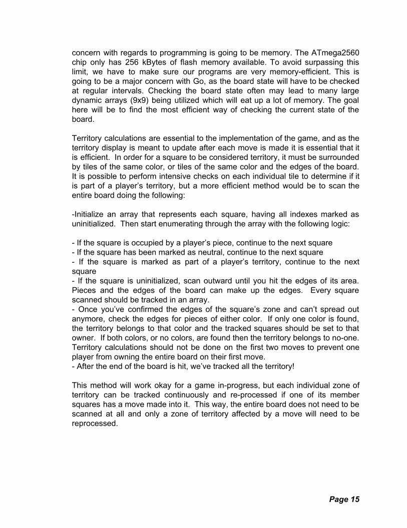
2.4.2.1 Rules and Implementation: Very much unlike Go, checkers has a simple rule set. Each player starts with twelve pieces (or “checkers”) on each side. They are arranged on an 8x8 board in such a way that they only sit on the same diagonals. An example of the starting position is shown below.
Figure 12: Illustration of the checker's starting positions
These starting positions, shown in figure 12, will be hard coded into the logic of the program, as the start of the game is the same every time. The player can only move one checker per turn and that checker can only move diagonally forward until it becomes a King. Once a checker reaches an enemy piece, and that enemy piece has a blank space behind its diagonal, the original checker can “jump” that piece, removing it from the board. If another jump is available, the checker is able to take it as well during that same turn. If a checker has a jump, it is required to take it. An example of jumping is shown below in figure 13.
Page 16

Figure 13: Example of two jumps in succession. Using logic within the checkers program, it will be impossible to continue the game if a player does not take a jump when there is one available to them. We may implement some kind of indicator of an improper move as additional information to the player. If multiple pieces can make a jump at the start of the player’s turn, he may choose which piece does its jump. Once a piece makes it to the very end row of the board, it becomes a “King”. When a piece is a King, it can move backwards as well as forwards. This makes it much more valuable than a regular checker. When a player makes it to the end of our electronic board, we can denote a king by changing that tile to a different color state. This color state will most likely be a different shade of the same color it previously was to keep the “pieces” intuitive to the players. The game ends when one player has removed all the other player’s pieces, or if a player makes it impossible for the other player to have any available moves. This means that two possible win conditions must be programmed into this game.
2.4.2.2 Programming Challenges and Strategies: This game will be relatively simple to program compared to Go. Instead of needing multiple game states to check, it will be possible to simply have one ever-changing game state. Electronically, this game will still be demanding of power but it will not have to utilize every square of the game board. That means that only the inner 8x8 block of the board will need to be activated as opposed to the entire 9x9 grid. Because the checkers can only move in a diagonal direction, there must be some kind of control implemented that either displays the correct moves or notifies the player when an incorrect move cannot be made. This adds slightly more complexity to the code but will not make a big difference overall. It may be desirable to users to add “auto-jumping” because if a jump is available, it must be made.
Page 17
2.4.3 Tic-Tac-Toe Tic-Tac-Toe is an extremely simple strategy game that is played on a 3x3 game board. This is another game we chose due to its simplicity and well known rules. The explanation of the game along with details on its electronic implementation will be described below.
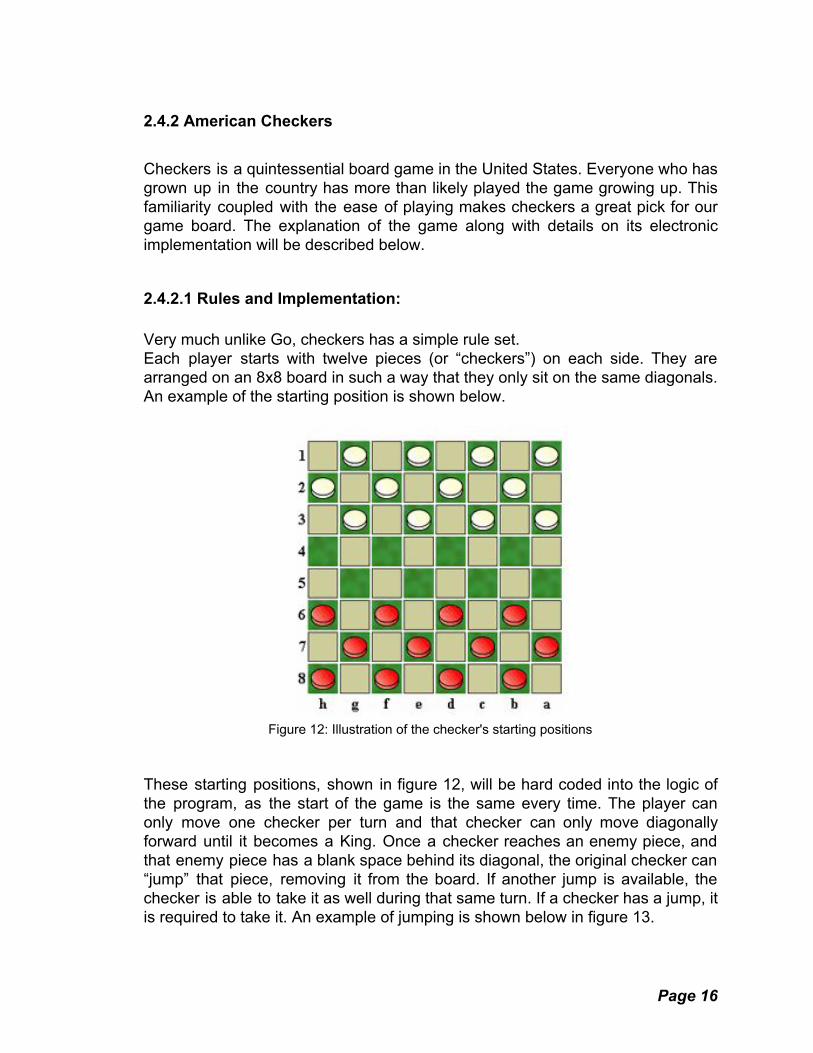
2.4.3.1 Rules and Implementation: The overall goal is to get three symbols in a row on the board. Traditionally, one player places X's and the other places O's. A game board is shown in Figure 14.
Figure 14: Depiction of a Tic-Tac-Toe board (left) and a complete game (right)
On our board, we won't have the capability to display symbols on our tiles so we instead represent each player's “symbols” as different color states. Each player takes turns making one move per turn. You cannot place your own symbol over where another player has played. The program will have functionality to notify a player if an incorrect move has been made. The game ends when a player gets three symbols in a row (diagonally or otherwise) or when the entire board is filled up. The second ending results in a stalemate while the first one results in a win for that player. Just like checkers, this will require two win conditions to be programmed.
2.4.3.2 Programming Challenges and Strategies: Tic-Tac-Toe will most likely be the easiest game to program for our board as well as the least intensive on our resources. The program will be simple, with only one ever-changing board state to be checked. Resources wise, we will only need to activate the center 3x3 grid within our 9x9 board, which is the smallest possible grid the board can create. Something that may be intensive about Tic-Tac-Toe is that the algorithm will most likely have to check for a win after every move is made. To save some processing power, we can start checking
Page 18

only after a player has made their third move, as any moves before then will never result in a win. We can also only check combinations that involve the newest move, as any winning combinations that exist without using it would imply that a player has already won the game.
2.4.4 Line of Four Line of Four is an implementation of yet another classic childhood game for many Americans known as Connect 4. The game itself is traditionally played on a very strange grid. Having the game played on an electronic board makes it more accessible than if they had to find the unique game board themselves. The explanation of the game along with details on its electronic implementation will be described below.
Figure 15: Depiction of a Line of Four game in progress.
2.4.4.1 Rules and Implementation: Line of Four is a simple strategy game in the same vein as Tic-Tac-Toe, although instead of three in a row, you need to get four in a row. It's traditionally played by using a vertical 6x7 board. Each player has their own set of tokens that they drop into the top of the grid. This effectively means that one can only play at the lowest point in each “column”. Below is an example of a Line of Four game in progress. To win the game, a player needs to connect four of their “tokens” in a row. They can be connected horizontally, vertically, or diagonally. The game can also end in a draw if the entire board becomes filled without anyone getting four in a row.
Page 19

Again, we will need two win conditions for this game. Figure 15 shows an example of a Line of Four game in progress. Because we obviously cannot use gravity to place pieces on our board, we must think of a slightly different format for the game. Assuming the players sit on opposite sides of the board, we can have the columns of the board run perpendicular to the direction they are facing so each player has an even view of the board. From there, game play will be as simple as selecting the column you want to play in and the bottom-most unlit tile will light up with that player's color. We may even implement an animation for the play as if it were “dropped” into that specific column. By just having the player select a column, we eliminate potential complications of players selecting incorrect tiles. With the perpendicular configuration, we also take advantage of the LED layout and only ever have to interact with one row of LEDs at a time. Once the logic detects there are four tiles of the same color in a row, or the entire board is full, the game will end.
2.4.4.2 Programming Challenges and Strategies: Like the other non-Go games, Line of Four will not utilize the entire game board, which saves on resources and memory. The algorithm for this game will be similar to that of Tic-Tac-Toe but on a larger scale. After each player makes a move, it will edit the board state and then check for four of one player's color in a row. This should be relatively inexpensive when it comes to memory. Similar to Tic-Tac-Toe, the algorithm only needs to start checking for a win condition once a player has played their fourth piece. Win condition checking, with the most basic implementation checking the entire board after each move, can reach O(n^2) time. For this reason it is important to be efficient where possible. One simple way to reduce the CPU burden substantially is to only check for connections adjacent to the piece that was just placed. If there was 4 consecutive pieces on the board that did not include the newest piece, the player would have already won. For this reason, we can get away with only checking the area around a single piece and not worry about checking the entire board or using fancy strategies to eliminate redundant checks.
2.4.5 Popout Popout is a very slight variation on the Connect Four style game. Because some may prefer one to the other, we decided to make Popout and Line of Four two different games on our design.
Page 20

2.4.5.1 Rules and Implementation: Every single rule from Line of Four applies perfectly. That also means that, in general, we will apply the same algorithm used to this game. The only difference here is that instead of playing a piece, you can pop one of their pieces already on the board out from the bottom. This just adds another layer of strategy to a simple game which some may find appealing. The implementation of the game will be slightly different than Line of Four because now the players need the capability to designate a column to perform a popout on. Because of this, a player may make an improper move, which they will be notified of should they try it.
2.4.5.2 Programming Challenges and Strategies: This variation of Line of Four will be slightly more complicated than the original. As stated before, players now have an option of what kind of move they want to make. This means they can no longer arbitrarily select any tile in a column they'd like to play on. While this is a simple change, it may lead to complications that do not exist in the original implementation. One of these is the need to constantly rewrite several elements in the array when a popout is performed. One way to avoid this, given the FIFO nature of the popout columns, is to implement a queue data structure. The tail of the queue will form the bottom of the board and pop operations will be performed each popout operation. However, given that each array is only 9 indexes long, there is little need to implement an actual queue data structure. Simply simulating one with the array will make implementation easier while also avoiding committing unnecessary resources to optimization. 2.4.6 Square Chinese Checkers Chinese Checkers is less common and more complicated than American checkers. Despite its name, it did not originate in China, nor is it even a variation of checkers. It usually involved a triangular or star-shaped board, but there are variations for a square board. The explanation of the game along with details on its electronic implementation will be described below.
2.4.6.1 Rules and Implementation: The game begins with the player's pieces in opposite corners. Usually, there are six corners on the board to allow for a maximum of six players. Due to the size constraint of our board, we will only allow for a one versus one game type. Both players start with their corners filled with pieces. In our case we are going to use
Page 21

different LED color states. In image of the starting state of a square Chinese Checkers board is shown below in figure 16.
Figure 16: Picture of a square Chinese Checkers board.
The goal of Chinese Checkers is for each player to get every one of their pieces into the opposite enemy corner. This desired corner is referred to as “home”. Each player takes turns moving a single piece. When moving their piece, the player can decide whether he wants to simply move it to an adjacent spot or if he wants to hop a piece. Not unlike checkers, when a player hops a piece, he can continue hopping if there are pieces available that let him do so. Unlike checkers however, you cannot capture enemy pieces, only use them for extra mobility. The implementation on the electronic board will entail first pressing the tile (or “piece”) the player wishes to move and then either pressing a non-lit tile adjacent to it or a non-lit tile on the other side of another adjacent piece tile. The algorithm is going to need to be able to tell the difference between the two moves, for the jump move can be done multiple times while the adjacent move will end their turn after one. The end of the game is signified by one player getting every one of their pieces to the enemy corner. The pieces must be formatted the same as they were when the game started, only mirrored. Once this occurs, the game will end and the one who makes the winning move is crowned victor. 2.4.6.2 Programming Challenges and Strategies:
Page 22

With regards to resource use, Chinese Checkers will use a little more than traditional Checkers. They both utilize the 8x8 board although there are more pieces in Chinese Checkers. With Checkers, as the game goes on, there are less and less pieces which means less LEDs constantly on. In Chinese Checkers, you can't take your opponent's pieces which means there will be the same amount of LEDs constantly on no matter how late in the game it goes. Keeping track of more pieces also means more memory usage, though this may be negligible in the end. The logic in the game will need to be slightly more complex as well compared to Checkers because the player can make two different kinds of move on their turn and the algorithm needs to account for that. There is also a design concern in figuring out how to properly interpret player intentions for a given move without indicating possible moves they may not have been aware of. If a player makes a jump and has other jumps available, how should the game handle this situation? Not switching to the other player’s turn indicates that the current player still has moves available, while switching early may bar the player from making all the moves they want. One solution is to have the player first tap the piece they want to move, then tap each square they want to move through, ending with a double tap on the square they want to land on. This ensures that the player has to have a solid idea of what move they want to make without being too unintuitive. Notifications for improper moves will also have to be implemented. All in all, it could be said that Chinese Checkers is the second most complex game for our board.
2.4.7 Light Sequence Light Sequence is a memory game that one plays by themselves, in the same vein as the popular Simon game. Ever since the age of electronics, Simon has been on shelves and people have been playing it. Despite it being a very simple game, it becomes very difficult after many successful rounds. The explanation of the game along with details on its electronic implementation will be described below.
2.4.7.1 Rules and Implementation: Light Sequence is a game of remembering an order of button presses. Typically the game is played on a circular disk-like game board that typically has four buttons. It starts out by lighting up one of the buttons and then waiting for user input. The player must then press that same button for it to continue. Then it adds another button to the order and the process proceeds again. This keeps going on until the player messes up the order of the button presses. See figure 17 below for a picture of what the traditional Simon game looks like.
Page 23

Figure 17: Picture of a traditional Simon game.
Each of the buttons chosen in the “Simon” cycle is seemingly random and as such will be chosen with a random number generator in our code. Another important part of Light Sequence is that when the buttons are lit up randomly or by the player pressing them, they each play a pitch specific to that button. This allows the player to associate another form of feedback with the different buttons other than color. Using different buzzer-speakers and Arduino libraries that support them, we will implement that feature into our board. The game ends when a player messes up a single time with regards to the order of button presses. When that happens, the program will end and a score will be displayed on the LCD screen.
2.4.7.2 Programming Challenges and Strategies: If we were following the traditional Simon rules, we would only use four buttons on our board which can effectively be a 2x2 grid. This will be a very small power draw on our system depending on the power draw of the buzzers. Despite this, we may add a difficulty selector that allows the player to expand the 2x2 grid to a 3x3 or larger. This could mean extra logic with regards to game selection as well as extra power draw and more unique pitches for the buzzer to create. The game itself will utilize a single array that must be dynamically allocated because the game never ends. The array will continue to have elements added to it as each new round proceeds. Somehow, user input needs to be compared to the correct elements of the array to determine if they correctly copied the computer pattern.
Page 24

Logging a high score may also be troublesome as it would need to be logged in permanent memory. One data structure well suited to the task of tracking the game sequence and matching user input to it is the linked list. The main limitation of a linked list is the difficulty of accessing a specific index. However, it boasts cheap memory allocation and cheap iteration. As the game sequence is always played forwards, and the player’s input is always matched to it the same way, stepping forward through the linked list is the natural way to do both things. When the next node is null, the sequence has finished and the game can either generate an additional node if its playing the sequence to the player, or start the next sequence if the player has entered all inputs correctly.
2.4.8 Tile Flip Lights out is an electronic puzzle released by Tiger electronics in 1995. It is a single player brain-teaser style game. It has been developed and marketed under many different names and more recently been developed as a mobile game. Due to its simple and addictive style, it will be added to our game board as Tile Flip. The explanation of the game along with details on its electronic implementation will be described below.
2.4.8.1 Rules and Implementation: Traditionally, the game is played on a 5x5 grid of lights. For our purposes we can change the size of the grid to whatever we desire, as the size of the grid does not change how the game is played. The idea is that the grid will start with a random number of the lights turned on in random places. The goal is to turn every light off. The only move a player can do is press one of the tiles. Pressing a tile reverses the state of it (on/off) as well as the states of the adjacent tiles horizontal and vertical to it. Figure 18 below shows a picture of how selecting tiles works.
Figure 18: Picture depicting how the player interacts with the board
Page 25

We can choose to implement preset light configurations that are rated by difficulty. It is also usually desired when playing this game to finish it within the minimum amount of button presses. This means that we need to implement a scoring system similar to Light Sequence, although this scoring system will be based off the number of moves it took to turn out all the lights.
2.4.8.2 Programming Challenges and Strategies: With regards to resource management, the power draw from this game depends on a lot of factors. The size of the grid we intend to implement is one of those factors. That, along with how long the player takes to complete the puzzle will change what kind of power we need to expect from it. Programming wise, this game will be simple. It will mostly involve just changing values in a 2-D array and then displaying the new grid again. The high score system can face similar problems to the Light Sequence high score, but overall it will not be very complicated. One notable consideration is that certain light configurations can never be solved. Impossible solutions can be determined mathematically, but that can be intensive as far as processing power is concerned. A more novel approach would be to start with a known solvable board state, and then make several random moves. This is easy to implement, guarantees a solvable board state,
and does not take too much processor power.
Page 26

3. Research Related to Project Definition In all research and design, innovation is a key factor and must be present in a design project. With all of today's technology in the form of almost unlimited online resources, the ability to expand upon current designs and technology that have already been implemented and improve upon these designs, through innovation, is a key component in all modern design and engineering. There are currently many different products and technologies available that make use of LEDs to implement various games.
3.1 Relevant Technologies The implementation of this project requires the use of many established technologies. This section covers the various already established designs and technologies that are used and innovated upon in the implementation of the LED board game. This project will use components common to commercial products. Microswitches, LEDs, Microcontrollers, and LCDs are some of the components used on the project.
3.1.1 Powering LEDS (specifically addressable LED strips) When powering a lot of LEDs special care must be taken to supply enough power so that all the LEDs light up with the desired light intensity and that not too much voltage is applied to an LED permanently damaging it [7]. While single LEDs in an individually addressable RGB LED strips do not heat up very much or require a lot of power they can use up to 60mA from a 5V power supply [7]. Single LEDs pulling 60mA could potentially draw up to 2 Amps in a meter long strip, depending on the number of LEDs per meter [7]. Operating at 60mA an LED is lit at its full brightness [7]. If the majority of the LEDs in a LED strip were kept at a low level of brightness, this would decrease the required current for the LEDs [7]. For a large strip of LEDs, to prevent the LEDs near the end of the strip from being dim, the power should be shared and applied about every meter of LEDs [7]. When using individually addressable RGB LED strips, another factor to note is that the LEDs that are off still use up a small amount of current for the driver chips [13]. If in a one meter strip of LEDs all the LEDs are turned off, approximately 50mA is used across the entire strip due to the LED drivers still requiring power [13].
Page 27

3.1.2 Calculating Current To determine the power required to light each LED several factors must be taken into account. These factors are:
● The length of LED strips used ● The number of LEDs per meter of strip ● The current draw or power consumption for each individual LED ● The operating voltage of each LED [16]
This information for a specific LED can be found on the datasheet of the LED strip. from this data, the required current to power a specific LED strip [16] can be found using one of the following equations: Equation (1) length of LED strip) X (LEDs per meter) X (LED current draw)( Or Equation (2) operation voltage
(length of LED strip) X (LEDs per meter) X (LED power)
3.1.3 Choosing Battery Power Source After determine the specific parameters for powering LEDs, special care must be taken when choosing the power source for the LEDs so that the power source is not outputting more current than the maximum safe current rating [18]. The value of maximum safe current for a battery is closely connected to the capacity (C) of the battery [18]. If a battery has double the capacity of another battery, the battery with double capacity will be able to provide double the maximum output current of the other battery [18]. Using the voltage and amp-hours (Ah) of a battery, the team can calculate the capacity [18].
3.1.4 AA batteries A set of four AA batteries connected in series can power approximately 25 full power 12mm pixels for several hours [12]. Connecting multiple batteries in series the voltage of each battery is added up to obtain the total voltage output of the cell [18]. When connected in series, 4 NiMH, rechargeable battery cells have a combined output of 4.8V [12]. If 5V RGB LED strips are being used, this output voltage of 4.8V is of the correct magnitude for a LED strip with an operating voltage of 5V. If 4 regular, non-rechargeable, alkaline AA batteries are connected in series they produce an output voltage of 6.0V [12]. If 5V RGB LED strips are being used, this output voltage is too large and will burn the LEDs [12]. To prevent the LEDs from being damaged, the output voltage from the 4 series connected AA batteries needs to be brought down near to 5V. To do this, a diode such as the
Page 28

1N4001, which has a voltage drop of approximately 0.7V can be connected to the battery pack [12]. A voltage regulator can also be used to get an output voltage of 5.0V. With this diode connected to the battery pack, the output voltage is dropped down to 5.3V which is within a 5V +- 10% percent error [12]. One limitation of using this 4 pack of AA batteries and 1N4001 diode as a power source is that the batteries and 1N4001 diode are rated for only 1 amp continuous output current [12]. One meter of LEDs operating at their maximum brightness can require approximately 2 Amps of current, which is out of the rating for this AA battery diode power source [12]. One solution to this limitation is to program the software on the microcontroller to operate the LEDs at lower brightness so that they never exceed the rating of the battery diode power source [12]. When using long strands of LEDs or a large number of individual LEDs connected together, the voltage drops slightly across each LED [12]. When too much voltage drops, the brightness of the LEDs will diminish and the color of the LEDs will become less crisp or muddy [13]. To prevent this, another extra power source must be added at every 25 pixels to keep the voltage from dropping below 5V [12].
3.1.5 Rechargeable Lithium-Ion-Batteries and Lithium-Polymer Batteries Rechargeable lithium-ion and lithium polymer batteries are made up of cells that create power [8]. There are generally two types of batteries; there are regular/normal and RC (radio control) [9]. Regular/normal lithium-ion batteries are used in everyday items, phones, iPods..etc) [9]. RC lithium-ion batteries are designed to deliver a large amount of power at one instant and then never turn off due to preventing damage to the battery [9]. They are created for use in radio controlled cars, planes, drones..etc) [9]. Each lithium-ion battery cell is made up of three parts: a positive electrode, a negative electrode and in the middle of them, an electrolyte [8]. The positive electrode is generally composed of a chemical called lithium-cobalt oxide or a chemical called lithium iron phosphate [8]. The negative electrode is normally a carbon graphite [8]. The electrolyte is different from battery to battery [8]. Looking at the figure 19 below, when a lithium ion-battery charges, the positive electrode of lithium-cobalt oxide (the cathode) releases its lithium ions [8]. These lithium ions go through the electrolyte to the negative electrode of carbon graphite (the anode) and stay on the negative electrode [8]. When the battery is being used or releasing energy, the reverse occurs [8]. The lithium ions move from the negative electrode through the electrolyte to the positive electrode, generating the power of the battery [8]. When the battery is charging or discharging, the electrons go the opposite direction to the ions through the outer circuit [8]. The electrolyte acts as an insulator; therefore the electrons cannot flow through it forcing the electrons to flow through the outer circuit creating the current that powers a load [8]. The flow
Page 29

of electrons is a result of the ions moving [8]. When the ions move, the electrons are forced to move; their movement is an intertwined process [8]. Similarly, when the ions stop moving through the electrolyte due to the battery being out of charge, no more ions are left to flow from the negative electrode to the positive electrode, thus, electrons also stop moving and the battery stops generating power [8]. In the same way, if the load the battery is generating power for is shut off, the movement of electrons is stopped and consequently the ions stop moving [8].
Figure 19: Lithium-ion rechargeable battery being charged [81] If lithium-ion or lithium polymer batteries are overcharged or discharged below the safe charge of the battery, they can explode [8]. To prevent this, lithium-ion and lithium polymer batteries are built with a controller that monitors and regulates how much the battery charges and discharges [8]. When using lithium-ion or lithium polymer batteries, special care must be taken when charging or discharging the cells so that the battery does not explode destroying the battery and damaging any components that are near the battery [9]. The following criteria must be noted when charging or discharging lithium-ion cells [9].
● A cell must not be charged above the maximum safe voltage; the protection controller of the cell should prevent this [9].
● A cell must not be charged below the minimum safe voltage; the protection controller of the cell should prevent this [9].
Page 30

● More current that what the battery cell can provide must not be drawn from the cell; the on-cell protection controller should prevents this [9].
● The cell must not be charged with more current than the current the battery can handle [9]. This is generally protected by the protection controller on the cell but is also protected by the cell charger [9].
● The battery cell must not be charged when the temperature is above or below certain temperatures, generally between 0 to 50 degrees Celsius [9].
The exact values of the maximum and minimum safe voltages, currents and temperatures are obtained from the datasheet of the cell [9]. While lithium-ion and lithium-polymer batteries use the same theory to generate power, there are some differences between them with the largest difference being the electrolyte chemical that is used between the positive and negative electrodes [19]. In lithium-ion batteries the electrolyte is generally a liquid; but in a Lipo batteries, the most used electrolyte is an almost gel-like electrolyte [19].
3.1.6 Voltage Regulators and Heatsinking When using voltage regulators, as power consumption goes up the voltage regulator will start to heat up. A small amount of heat is acceptable and will not damage the components of a circuit board, but as more voltage is input into the voltage regulator, the heat from the components will start to heat up more to the point that it will affect the efficiency of the regulator and cause damage to the voltage regulator and the other components that are in the circuit [89]. When the component is uncomfortable to the touch, it is likely that the components efficiency will increase with the addition of an efficient way to remove the heat to a different component called a heat sink [89]. Most heat sinks consist of a piece of metal that is connected in such a way that heat is transferred from the component that is heating up to the metal [89]. The larger surface area that a heat sink has the more heat it will be able to dissipate, cooling the component that is heating up [89]. Figure 20 shows a voltage regulator on a PCB with a heatsink. While a larger heat sink can dissipate more heat, the amount of space that the heat sink takes up on a PCB must be taken into account when choosing the size of the heat sink. In addition to this, to obtain efficient heat transfer, the implementation of a heat sink compound or thermal tape as a physical layer for contact between the component and the heat sink can be used [89]. To decrease the area that a heat sink occupies, the copper of a PCB can be utilized as a heat sink [89].
Page 31

Figure 20: Voltage regulator with a heat sink [89] The implementation of heat sinks on the PCB of the LED board game will be considered in the PCB design and testing. There are few components that would require a heatsink on the project. The voltage regulators for the power distribution system and the microcontroller are the only 2 components that could require it.
3.1.7 Piezoelectricity Piezoelectricity is largely used in a wide variety of products. Piezoelectricity is “pressing electricity”; in other words, it is the use of crystals to convert physical energy into electricity or electricity into physical energy [90]. Examples of the implementation of Piezoelectricity includes: keeping time on a quartz watch or the conversion of spoken words to letters or text in a voice recognition software [90]. Piezoelectricity is implemented through squeezing particular crystals, like quartz. When crystals are compressed, electricity will flow through them [90]. Likewise, if electricity is passed through them, the crystals compress themselves by oscillating back and forth [90]. In essence, the crystal acts as a tiny battery with a positive charge on one side and a negative charge on the other. When we connect the two sides together, a circuit is created and current flows through it. Similarly, when the opposite occurs, the crystals are compressed or change in shape when a voltage is applied to the other side [90]. The cause of this property of the crystals is a result of the crystals molecular composition [90]. A crystal as used in this description, is any solid whose atoms are configured in such a way that an endless repetition of the same arrangement
Page 32

of atoms making a symmetric structure [90]. This structure of atoms or building blocks is called a unit cell. In Piezoelectric crystals, the structure of their atoms is not symmetrical, but the crystals are electrically neutral, meaning the electric charges in the crystal are perfectly balanced [90]. When a piezoelectric crystal is compressed or stretched, the structure of the atoms is distorted or changes in shape moving the individual atoms creating an imbalance in electrical charge [90]. In the reverse of this, when a voltage is applied across the piezoelectric crystal, the atoms of the crystal experience electrical pressure, and the atoms then move to fix the imbalance in charge changing or deforming the shape of the crystal [90]. Piezoelectricity implemented in a buzzer is of interest to the LED board game.
3.2 Strategic Components and Part Selections This section discusses the various parts and components that were considered for implementation in the LED board game and the final choice of the parts and components that were used in the creation of this project. Some of the components initially chosen for the project were unavailable or no longer manufactured. This lead to choosing new components for the final design.
3.2.1 Microcontroller: This section discusses various microcontrollers that were considered to implement the LED game board. The game-board will utilize one microcontroller to handle the execution of the code for the project. The second microcontroller will be used to interface to a personal computer via USB. The main microcontroller will have to handle all of the general purpose input and output and execute all of the code for the project. The microcontroller will have 81 buttons, 81 LEDs, and an LCD screen attached via the General Purpose Input/Output pins. The buttons will be wired in a keyboard matrix circuit which will utilise only 18 I/O pins instead of using an IO pin for each individual button. The LEDs will have a driver chip that will allow them to be individually addressable while using a minimal amount of IO. The “pieces” of the game board will be represented by the LEDs. The microcontroller needs to be able to control each LED’s color and be able to toggle them on or off individually. Different LCDs will utilize different amounts of IO. The main considerations when choosing the microcontroller are the design requirements specified above and the cost of the microcontroller.
Page 33

3.2.3 Atmel ATmega328P: The first microcontroller that was considered for the LED game board was the Atmel ATmega328P. This microcontroller is a high performance low power CMOS 8-bit controller. The ATmega328P has the following features/specifications:
● 0-20MHz ● 23 programmable I/O lines ● 32 kB of flash memory ● 2 kB of SRam ● 1 kB of EEPROM ● 32 general purpose working registers ● 2 SPI interfaces ● 1 UART interface ● 1 I2C interface ● External and Internal Interrupt Sources ● Six Sleep Modes that include: Idle, ADC Noise Reduction, Power-save,
Power-down, Standby, and Extended Standby [71]. The Atmega328P comes in a 28 pin DIP package. This makes it easier to solder to a pcb as the pins are through hole. To further simplify the soldering, A 28 pin socket could also be used resulting in the microcontroller being removable which would be useful in the event of the microcontroller being damaged by a short circuit or a surge in power. The microcontroller can be purchased with the arduino bootloader pre-loaded. The Atmel ATmega328p is the microcontroller for the arduino uno development board. The arduino uno is a ‘user friendly’ development board in that there are numerous libraries written for the arduino uno platform that can be used as reference material for many different projects, and there are many support forums for the arduino uno. This database of usable information for the microcontroller was one factor that was very attractive for its use in the LED game board. While this was one large advantage of using this microcontroller, there were several disadvantages of using this microcontroller that had to be addressed. The first is that the ATmega328P only has 23 I/O lines. A 9 by 9 array of buttons will need 18 I/O pins when connected [71]. This will leave us with only 5 I/O pins left to connect the LEDs and LCD display. One solution for this is to use multiple microcontrollers that are connected via the I2C bus. Implementing two microcontrollers in this way would allow for one ATmega328P to control I/O from the buttons while a secondary ATmega328P could control the rest of the systems of the LED game board. Another issue that had to be considered was the size of memory. With 32 kB of flash memory, an external memory source such as a micro sd card, will be needed to store all of the games that the LED game board will implement. The price of an Atmel Atmega328P from digikey website is $2.18
Page 34

for one microcontroller. Even using two microcontrollers as described above, the cost for the microcontrollers is still well within the estimated budget of the microcontroller for the LED board game. While the Atmel ATmega328p is within the estimated budget and can meet the design requirements for the LED game board with adding another microcontroller and external memory storage, this microcontroller was passed over as the choice for the microcontroller of this project. The main reason for this, was to simplify the layout and design of the PCB and coding for the project as well as minimize the area the microcontroller uses on the PCB.
3.2.4 MSP432P401R: The next microcontroller that was considered for implementation in the LED game board was the MSP432P401R. This microcontroller from Texas Instruments has the following features/specifications:
● 48 MHz clock speed ● 256 kB flash memory ● 64 kB of RAM ● 48, 64, 84 GPIO ● Ability to receive interrupts and wake-up capability from pins ● 4 i2c ● 8 SPI ● 4 UART [72]
Coming in packages with 48, 64 or 84 GPIO the MSP432P401R has more than enough pins than what is needed for the implementation of the LED game board. In addition to this, the 256 kB of flash memory and 64 kB of RAM should be a sufficient amount of memory for the implementation of this project, testing of the microcontroller would have to be used to fully determine this. With the four I2C, eight SPI and 4 Uart interfaces, the MSP432P401R has many different interfaces that are not needed for the LED board game; of these interfaces, the only one that might be of use is the serial peripheral interface that could potentially be used to interface with an LCD display or external memory [72]. While the MSP432P401R with its sufficient number of pins and memory does meet the design requirements of the project, one disadvantage of using it is that the microcontroller does not have as many libraries or support forums that could be used as reference material as there are for the above discussed Atmel ATmega328p. The price of the MSP432P401R from digikey is $7.72 which is within the estimated budget of the microcontroller for the project. Even though the MSP432P401R meets the design requirements and budget requirements, this specific microcontroller was passed over as the choice for the LED board game for the reason of a lack of libraries and support forums for the
Page 35

microcontroller.
3.2.2 Atmel ATmega 2560: The final microcontroller candidate that was considered for implementation for the project was the Atmel ATmega2560. This microcontroller has the following features:
● 16MHz Clock speed ● 256KB of Flash Memory ● 4kB EEPROM ● 8kB internal SRAM ● 32 x 8 general purpose working registers ● 54 Digital I/O ● 16 analog inputs ● 5V logic ● SPI ● Ability to receive interrupts and wake up from pins ● External and Internal interrupt sources ● Six sleep modes including: idle, ADC noise reduction, power-save,
power-down, standby and extended standby. The ATmega2560 is used as the microcontroller for the Arduino mega 2560 R3. being used as the microcontroller for an arduino, there are a multitude of existing libraries for games available that can be used on the ATmega2560 and many support forums for use of the ATmega 2560. This ‘user friendly’ feature of the microcontroller makes it a good candidate for use in the LED board game. With 54 digital I/O and 16 analog inputs, the ATmega2560 has ample digital I/O for all the buttons, LCD, and LEDs. In addition to this, we will not need any external hardware to interface with them. We will be able to read and write from an sd card as well. Analog inputs are possible due to the 16 ADC channels that are present on the ATmega2560 microcontroller [70]. The 256kB of flash memory may not be enough to hold all 10 proposed games. If that is the case an external memory expansion solution may be necessary. Of the 256kB of on board memory 8kB are used for the boot loader. From Digikey, the Atmel ATmega2560 costs $12.44, which is within the estimated budget for the microcontroller for the LED board game. One disadvantage of the Atmel ATmega2560 compared to the Atmel ATmega328p is that the ATmega 2560 is only available in a surface mount package meaning that it cannot be attached and removed from a PCB with a socket. Using the information from Table 1, it can be seen that each microcontroller can be used for the implementation of the LED board game with certain added components for the ATmega328p. Even though each microcontroller can be
Page 36

used for the project and the ATmega2560 is almost double the size of the ATmega328P, the Atmel ATmega2560 was chosen as the microcontroller for the LED board game. The main reasons for this choice are that the ATmega2560 is able to implement the project with the least number of external components and that the microcontroller has many libraries and user forums that can be used as reference material for the implementation of the LED board game. Microcontroller Comparisons
Atmel ATmega 2560
Atmel ATmega328P
MSP432P401R
Clock Speed 16 MHz 0-20 MHz 48 MHz
Flash Memory 256 kB 32 kB 256 kB
I/O lines 54 23 48, 64, 84
RAM or SRAM 8 kB SRAM 3 kB RAM 64 kB RAM
Cost $12.44 $2.18 $7.72
Size 0.56”x0.56”x0.04” 0.3”x0.3" 0.55”x0.55” [72]
Table 1: Comparison of considered microcontrollers
3.3 Liquid Crystal Display: A LCD display module is needed for the LED game board. In researching various LCD displays, the following requirements and criteria were considered:
● The LCD display must be able to display the names of the games that the LED game board implements in a numbered list
● Be able to easily interface with various microcontrollers ● Cost
Figure 21, A: Nokia 5110 LCD Figure 21, B: Monochrome LCD display
Page 37

Figure 21, C : Full color TFT display Figure 21, D: Graphic LCD
Figure 21, E: RGB backlight text display Figure 21, F: 2.2” 18-bit TFT display
3.3.2 Monochrome Graphic Display With OLED Pixels (Figure 21, B): The monochrome graphic display uses OLED pixels. It can communicate through I2C or SPI. The I2C bus is 7 bit addressable. It has a resolution of 128x64 pixels, and draws on average 40mA of current [63]. The display is designed for common cathode OLED panels. The display is controlled by the ssd1306 driver. The ssd1306 utilizes 3V meaning the digital logic from the MCU needs to be logic level shifted. If a logic level shifter is utilized, the LCD display is compatible with 5V logic and not just 3V logic [63]. The OLEDs require a 3.3V power source, but a 3.3V voltage regulator is included in the driver chip making the display compatible with a 5V power source. The frame rate and multiplexing ratio are programmable. There are 256 levels for brightness and contrast current control. The ssd1306 has an embedded SRAM display buffer and an on-ship oscillator is provided on the ssd1306 [63]. The price of the monochrome graphic display with OLED pixels is $19.95 [63].
Page 38

With the 128x64 pixels, the monochrome graphic display with OLED pixels meets the design requirements for the LED game board. While this LCD display meets the design requirements for the project, the cost of $19.95 is more than what was budgeted for the LCD display. For these reasons, the monochrome graphic display with OLED pixels was passed over as the choice for the LCD display of the LED game board.
3.3.3 Full Color TFT Display: (Figure 21, C) The 1.8” full color TFT display has 128x128 color pixels with 18 bit color. With the 18 bit color, it can display up to 262,144 colors. Using full backlight, max current draw is about 25mA. The display uses a ST7735R LCD driver IC [64] . The TFT ST7735R driver that is implemented in this LCD module, uses TFT to display a high color resolution and to implement a fast refresh rate is. The driver is soldered onto the display with the addition of a low droputout 3.3V voltage regulator that allows the use of a 3.3V or 5V power source and ⅗V logic level shifter that allows the use of either 3.3V or 5V logic [64]. The ST7735R driver is built up of 396 source line and 162 gate line driving circuits. The display can store data in the onboard chip RAM of 132 x 132 x 18 bits. With the onboard components/chip, the display can execute read/write operations on the display from the data on the RAM without an external operation clock, minimizing the power consumption of the display. With the addition of the power supply circuitry needed to drive a liquid crystal, a display assembly can be made with fewer external components [68]. Various Interfaces to a microcontroller are provided with the ST7735R driver: parallel 8080-series MCU Interface (8-bit, 9-bit, 16-bit & 18-bit), parallel 6800-series MCU Interface (8-bit, 9-bit, 16-bit & 18-bit), 3-line serial interface, and 4-line serial interface. The cost of the 1.8” color TFT LCD display with ST7735R driver is $14.95 [64]. While the full color TFT display with ST7735R driver meets the design needs of the LED game board and with the cost of 19.95 is withing budget for the project. The LCD display was passed over for the selection of the LCD display for the LED game board for another display that will be discussed in the other LCD display modules below.
3.3.4 Graphic ST7565 Positive LCD (Figure 21, D): The graphic ST7565 positive LCD display has a resolution of 128x64 pixels [65]. One of the features of this LCD display is that the display is visible in daylight without backlight. In addition to this, there is a full RGB LED backlight that is controllable via PWM [65]. using the PWM, it is possible to change the back lighting to nearly any color. The LCD display uses SPI interface. The display requires a power source of 3.3V and 3.3V logic. Using a logic level shifter, the
Page 39
LCD display can be made compatible for 5V logic. The cost for the graphic ST7565 positive LCD display is $17.95 [65]. With the 128x64 pixels, the graphic ST7565 positive LCD display meets the requirements for the LCD display of the project. While the LCD display meets the design requirements, the cost of $17.95 is more than the desired amount for a LCD display. For these reasons, this LCD display was passed over as the choice for the LCD display of the LED game board.
3.3.5 RGB Backlight 16x2 negative LCD display (Figure 21, E): The RGB backlight text display has a resolution of 16x2 characters [66]. The text of the LCD display can be displayed in multiple colors. The background is black and the backlight can be dimmed via a potentiometer or via PWM. The backlight consists of a single RGB LED that can display 3 colors for a composite color. The LCD display has the HD44780 LCD driver [66]. With the HD44780 driver, the LCD can display English and Japanese text. The HD44780 driver has a power operation voltage of 2.7V to 5.5V, and can drive an LCD display within a voltage range of 3.0V to 11V [69]. The driver has a 4-bit or 8-bit MPU interface enabled to connect to a microcontroller. The HD44780 has a 9920-bit character generator ROM that can create 240 different character fonts. The driver also has a 64 x 8 bit character generator RAM. In addition to this, the HD44780 driver has the following instructions:
● Display clear ● Cursor home ● Display on/off ● Cursor on/off ● Display character blink ● Cursor shift ● Display shift
The price of the RGB back light 16x2 negative LCD display is $13.95 [66]. The RGB back light 16x2 negative LCD display meets the design requrements of the LED game board, and the price of $13.95 is within the estimated budget of $10 to $15. Although this LCD display does meet the design and cost requirements, this LCD display was passed over for a less expensive LCD display that will be considered as the next choice of the LCD display for the LED game board.
3.3.6 5110 LCD module (Figure 21, A): The next candidate for the LCD display of the LED game board was the 5110 LCD module. This LCD display has a resolution of 84x48 pixels and a white LED backlight to make the text visible in the dark [67]. The display communicates to
Page 40

the microcontroller via the Serial Peripheral Interface. The LCD Uses 10mA of current on a 3.3V power supply [67]. This display natively uses a 3.3V power supply with 3.3V logic, but with the use of a logic level shifter the display can operate with 5V logic. The LCD display requires the use of 3 to 5 digital i/o pins to operate. The display uses a PCD8544 chip [67]. The PCD8544 is a low power CMOS LCD driver that was created to drive a display of 48 rows by 84 columns [67]. All The required functions for display are implemented on a single chip; these functions include: the generation of LCD bias and supply voltages [67]. With these on chip functions, the number of needed external components is minimized and the power consumption is lowered. The operating voltage of the 5110 LCD module is 2.7V to 3.3V with the backlight requiring 3.3V Max. The price of the 5110 LCD module is $9.95 [67]. With a resolution of 84 x 84, the 5110 LCD module meets the design requirements of the LED game board. In addition to, this the price of $3.98 cheaper than the above mentioned RGB backlight 16x2 negative LCD display. With these factors taken into consideration, the 5110 LCD module was chosen as the LCD display for the LED game board. One this part was received, the team proceeded to test the unit. During testing, the 5110 LCD module did not display text. The backlight turned on, but the team was unable to get the LCD module to display any text. The potential cause of this could be that the team accidently burned the LCD when the LCD was being wired or the particular unit could of had a malfunction in manufacturing.
3.3.7 2.2” 18-BIT Color TFT display with MicroSD Card Breakout After the failed 5110 LCD module, the following microcontroller was researched for implementation in the LED board game. This microcontroller has a display of 320 x 240 color pixels (see figure 21,F) [86]. To interface with a microcontroller, the 18-BIT color TFT LCD module has a four wire SPI and is also pixel-addressable via the frame buffer that it has [86]. Another feature of this LCD display module is that Instead of using a CSTN type driver and having low color resolution and a slow refresh rate, this LCD module uses a TFT driver [86]. This 18-BIT TFT LCD screen uses the ILI9340 TFT driver and can also be used with several other compatible drivers [86]. This LCD breakout contains a low-dropout 3.3V voltage regulator and a 3V to 5V logic level shifter that makes the LCD module able to operate with either 3.3V or 5V power and logic [86]. One key feature of this particular LCD breakout board, that is of interest to the LED game board, is the addition of a microSD card holder that is capable of having full color bitmaps downloaded onto a microSD card [86]. The reason that this feature is of great value to the LED game board is that a microSD card can be used to hold the various output displays that are desired. With the memory of
Page 41
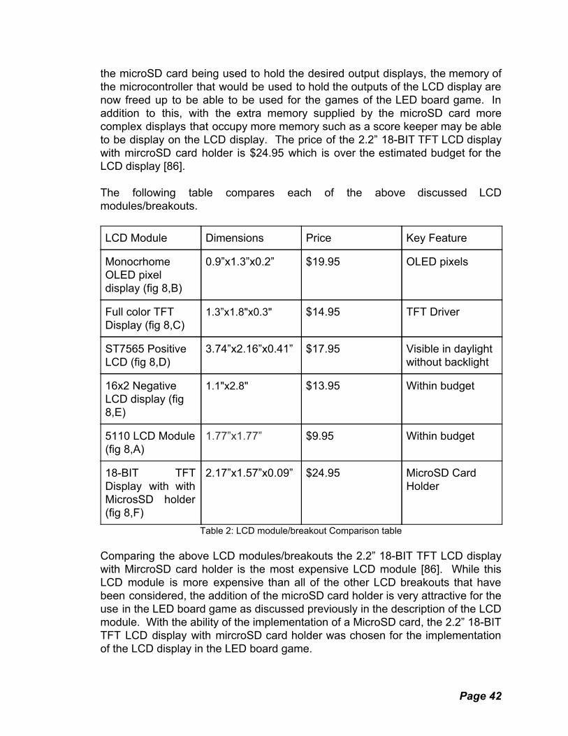
the microSD card being used to hold the desired output displays, the memory of the microcontroller that would be used to hold the outputs of the LCD display are now freed up to be able to be used for the games of the LED board game. In addition to this, with the extra memory supplied by the microSD card more complex displays that occupy more memory such as a score keeper may be able to be display on the LCD display. The price of the 2.2” 18-BIT TFT LCD display with mircroSD card holder is $24.95 which is over the estimated budget for the LCD display [86]. The following table compares each of the above discussed LCD modules/breakouts. LCD Module Dimensions Price Key Feature
Monocrhome OLED pixel display (fig 8,B)
0.9”x1.3”x0.2” $19.95 OLED pixels
Full color TFT Display (fig 8,C)
1.3”x1.8"x0.3" $14.95 TFT Driver
ST7565 Positive LCD (fig 8,D)
3.74”x2.16”x0.41” $17.95 Visible in daylight without backlight
16x2 Negative LCD display (fig 8,E)
1.1"x2.8" $13.95 Within budget
5110 LCD Module (fig 8,A)
1.77”x1.77” $9.95 Within budget
18-BIT TFT Display with with MicrosSD holder (fig 8,F)
2.17”x1.57”x0.09” $24.95 MicroSD Card Holder
Table 2: LCD module/breakout Comparison table Comparing the above LCD modules/breakouts the 2.2” 18-BIT TFT LCD display with MircroSD card holder is the most expensive LCD module [86]. While this LCD module is more expensive than all of the other LCD breakouts that have been considered, the addition of the microSD card holder is very attractive for the use in the LED board game as discussed previously in the description of the LCD module. With the ability of the implementation of a MicroSD card, the 2.2” 18-BIT TFT LCD display with mircroSD card holder was chosen for the implementation of the LCD display in the LED board game.
Page 42

3.4 Individual Parts In this section we will discuss various individual components that are required for the implementation of the LED board game. For this section, several different restrictions and constraints were taken into account, these include the following:
● Price ● Meets the design requirements.
3.4.1 74LVC245 Logic Level Shifter The 5110 LCD display natively requires 3.3V power source and logic. The microcontroller chosen for the LED game board has 5V output and logic, therefore to interface with the microcontroller, a logic level shifter is required to convert the 5V logic to 3.3V logic. The 74LVC245 is a logic level shifter that can interface 3.3V logic devices to a 5.0V microcontroller. The 74LVC245 can operate at a low voltage of 1.8V and still be able to accept a 5V signal from a microcontroller. While this particular logic level shifter cannot convert analog signals, it can convert digital signals. The logic level shifter has eight pins that can each receive a signal to convert. The shifter cannot receive bi-directional/pull-up devices such as I2C or 1-Wire but it can convert the following signals:
● SPI ● Serial ● Parallel bus
The ability to receive SPI (serial peripheral interface) signals meets the design requirements to interface with the a 5V logic LCD module. The price of the 74LVC245 logic level shifter is $1.50 which makes the LCD module assembly a total of $5.48 which is well within the estimated budget for the LCD module of the LED game board. With these factors into consideration, the 74LVC245 was chosen for the logic level shifter for the LCD assembly.
3.4.2 USB Interface To make the Atmel ATmega2560 programmable through a USB connection to a computer, an interface between the USB connector and the microcontroller’s serial port is needed. A simple serial interface could be used to connect the computer to the ATmega2560, but most computers don’t come equipped with a serial port anymore [75]. To overcome this obstacle, The ATmega16U2 can be used. The ATmega16U2 is a high performance, low power microcontroller with 16 kB ISP flash memory [74]. The ATmega16U2 has firmware that acts as an interface between the ATmega2560 [76]. The ATmega16U2 recieves information from the computer via USB connection and interfaces with the bootloader on the ATmega2560; the bootloader then programs the ATmega2560
Page 43
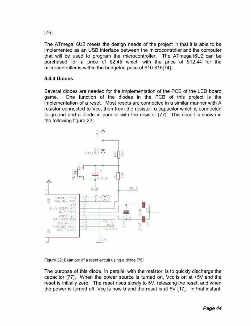
[76]. The ATmega16U2 meets the design needs of the project in that it is able to be implemented as an USB interface between the microcontroller and the computer that will be used to program the microcontroller. The ATmega16U2 can be purchased for a price of $2.45 which with the price of $12.44 for the microcontroller is within the budgeted price of $10-$15[74].
3.4.3 Diodes Several diodes are needed for the implementation of the PCB of the LED board game. One function of the diodes in the PCB of this project is the implementation of a reset. Most resets are connected in a similar manner with A resistor connected to Vcc, then from the resistor, a capacitor which is connected to ground and a diode in parallel with the resistor [77]. This circuit is shown in the following figure 22:
Figure 22: Example of a reset circuit using a diode [78] The purpose of this diode, in parallel with the resistor, is to quickly discharge the capacitor [77]. When the power source is turned on, Vcc is on at +5V and the reset is initially zero. The reset rises slowly to 5V, releasing the reset, and when the power is turned off, Vcc is now 0 and the reset is at 5V [17]. In that instant,
Page 44
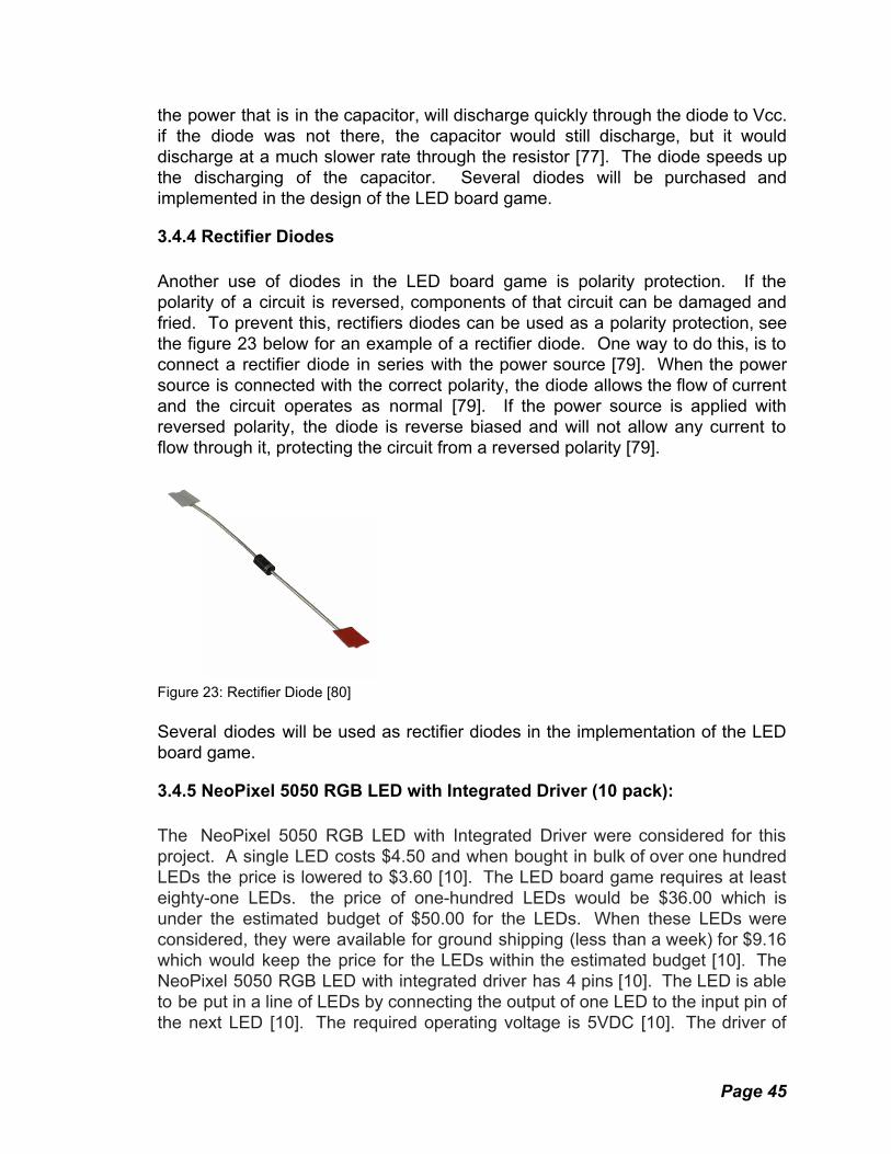
the power that is in the capacitor, will discharge quickly through the diode to Vcc. if the diode was not there, the capacitor would still discharge, but it would discharge at a much slower rate through the resistor [77]. The diode speeds up the discharging of the capacitor. Several diodes will be purchased and implemented in the design of the LED board game.
3.4.4 Rectifier Diodes Another use of diodes in the LED board game is polarity protection. If the polarity of a circuit is reversed, components of that circuit can be damaged and fried. To prevent this, rectifiers diodes can be used as a polarity protection, see the figure 23 below for an example of a rectifier diode. One way to do this, is to connect a rectifier diode in series with the power source [79]. When the power source is connected with the correct polarity, the diode allows the flow of current and the circuit operates as normal [79]. If the power source is applied with reversed polarity, the diode is reverse biased and will not allow any current to flow through it, protecting the circuit from a reversed polarity [79].
Figure 23: Rectifier Diode [80] Several diodes will be used as rectifier diodes in the implementation of the LED board game.
3.4.5 NeoPixel 5050 RGB LED with Integrated Driver (10 pack): The NeoPixel 5050 RGB LED with Integrated Driver were considered for this project. A single LED costs $4.50 and when bought in bulk of over one hundred LEDs the price is lowered to $3.60 [10]. The LED board game requires at least eighty-one LEDs. the price of one-hundred LEDs would be $36.00 which is under the estimated budget of $50.00 for the LEDs. When these LEDs were considered, they were available for ground shipping (less than a week) for $9.16 which would keep the price for the LEDs within the estimated budget [10]. The NeoPixel 5050 RGB LED with integrated driver has 4 pins [10]. The LED is able to be put in a line of LEDs by connecting the output of one LED to the input pin of the next LED [10]. The required operating voltage is 5VDC [10]. The driver of
Page 45

the LED produces a 18mA constant current drive making the color of the LED be stable even if the input voltage varies; in addition to this, the LED does not require an external voltage current control resistor further simplifying the design [10]. While these specific LEDs meet the design requirements of the LED board game and are within the estimated budget for the LEDs, they were passed over as the choice for the LEDs of the LED board game. The reason the NeoPixel 5050 RGB LED with Integrated Driver was passed over as the choice of LEDs for the project is that using single LEDs for the LED game board requires a large amount of soldering. With 4 pins on 81 LEDs just to connect the LEDs would require 324 solder joints. While this amount of soldering is possible to implement, it would take time that could be used in the design process of this project.
3.4.6 Alitove 16.4ft WS2812B Individually Addressable LED Strip light 5050 RGB SMD 150 Pixels: The next LEDs that were considered for implementation in the LED board game is are the Alitove 16.4 WS2812B individually addressable LED strip. The price for these LEDs, is $27.99 which is under the estimated budget for LEDs [11]. When these LEDs were considered for the LED game board, they were in stock with free shipping available which is desirable for keeping within the estimated budget [11]. These LEDs are 256 brightness display and 24-bit color display with each LED being able to have its own color and brightness [11]. The required operating voltage is +3.5VDC to +5.3VDC [17]. They have a 3 pin connection which significantly decreases the amount of required solder needed for connecting the LEDs [11]. They are able to be cut and separated individually without damaging any LEDs which meets the design requirements of making a 9X9 LED matrix [11]. Taking all the above discussed specifications of this LED strip, The Alitove 16.5ft WS2812B Individually Addressable LED Strip light 5050 RGB SMD 150 Pixels were chosen for the LEDs of the LED game board.
3.4.7 Large Enclosed Piezo Element with Wires (Buzzer) For the implementation of the speaker/buzzer that is required in the LED board game, the large enclosed Piezo element with wires was considered. This product is a 1.18” in diameter Piezo element enclosed in a housing that has mounting holes for easily mounting to a PCB [87]. A Piezo is a product that can convert voltage into vibration or vibration into voltage [87]. Piezo elements are mainly used for two purposes [87]. The first is as a sensor that detects quick movements such as the hitting drumstick on a drum or the impact of a crash sensor (converting vibration into a voltage signal) [87]. The second purpose that most Piezos are used for is as a buzzer that can making different tones and sound alerts (the conversion of voltage into a vibration, sound) [87].
Page 46

For the LED board game, an alert is required when a player makes an invalid move. The Piezo element can easily meet this requirement. The price of this particular large enclosed Piezo element with wires costs $0.95 which is a small amount when considering the impact of its implementation [87]. For these reasons, the large enclosed Piezo element with wires was chosen for the implementation of an alert for an invalid move in the LED board game.
3.5 Development Tools This section addresses the tools we will be using to build our project. A project with so many different components will need a wide variety of tools, and the specific tools used can have a large impact on the direction the project takes. For these reasons careful tool selection is important.
3.5.1 Software IDE:
Page 47
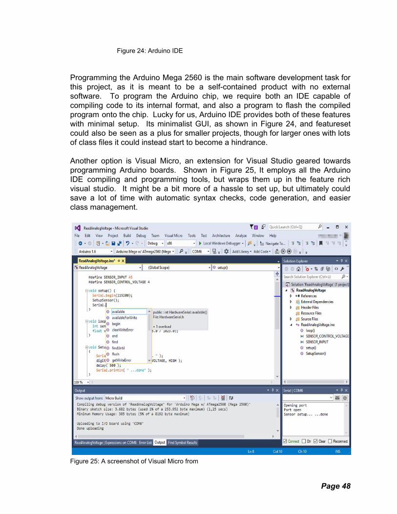
Figure 24: Arduino IDE Programming the Arduino Mega 2560 is the main software development task for this project, as it is meant to be a self-contained product with no external software. To program the Arduino chip, we require both an IDE capable of compiling code to its internal format, and also a program to flash the compiled program onto the chip. Lucky for us, Arduino IDE provides both of these features with minimal setup. Its minimalist GUI, as shown in Figure 24, and featureset could also be seen as a plus for smaller projects, though for larger ones with lots of class files it could instead start to become a hindrance. Another option is Visual Micro, an extension for Visual Studio geared towards programming Arduino boards. Shown in Figure 25, It employs all the Arduino IDE compiling and programming tools, but wraps them up in the feature rich visual studio. It might be a bit more of a hassle to set up, but ultimately could save a lot of time with automatic syntax checks, code generation, and easier class management.
Figure 25: A screenshot of Visual Micro from
Page 48

https://playground.arduino.cc/Code/VisualMicro Ultimately the choice between these IDEs comes down to the complexity of the project, but visual micro offers a lot more in terms of flexibility and extensive class management. As the code for this project is composed of many layers with many custom API calls, the benefits of having automatic syntax checks, class management, and function lookups cannot be ignored. A good IDE can double productivity by cutting out common mistakes and tedious tasks that would otherwise need to be performed manually. Were this a smaller task, the Arduino IDE would be ideal, but for something on this scale a fully fledged IDE is the only real option
3.5.2 Custom Board Emulator:
Figure 26: Game Board Emulator The software architecture will employ an API that serves as the communication point between the board and the game software. As all interactions with the board will happen through this API, this opens up the possibility of having an emulator with the same API. Doing so offers a number of advantages, mainly quicker development and easier bug fixing. Being able to test in a desktop environment without needing to program the board for testing allows games to be more quickly experimented with and developed. In addition to this, if any bugs arise on the board that don't occur on the emulator, the game software can be eliminated as a potential cause. This will no doubt save countless hours of
Page 49

development time, even though it may cost a fair amount up front. The emulator will have an interactive GUI that encapsulates all the functional board components. This includes the LED buttons, LCD Buttons, and LCD itself. Interacting with the emulator will ideally be the same as interacting with the board, making the game logic easily portable between the two. The emulator will attempt to replicate the limitations of the board, but of course may not do so perfectly which is why many other systems in the management layer are important to ensure proper functionality in the face of resource constraints. If the emulator and these routines are implemented properly, the software for the board can be developed alongside the board itself, and be ready the moment the board is ready to host it. Figure 26 shows the design and layout of the Emulator GUI.
3.6 Comparison of Electronic Design Automation (EDA) Software: This section discusses the positives and negatives of various Electronic Design Automation software. EDA software has been available for as almost as long as there has been personal computers. One of the earliest EDA software packages was AutoTRAX developed by Protel. Protel was eventually bought by a company named Altium. Altium continues to develop EDA software to this day. There are numerous EDA programs for modern Operating Systems.
3.6.1 Kicad: Kicad is a free and open source EDA. Jean-Pierre Charras, the author of Kicad, began development in 1992. CERN, European Organization for Nuclear Research, has been contributing to Kicad since 2013 in an effort to help open hardware development by making Kicad to be comparable to commercial EDA software. There are three ways to view a project in Kicad. The schematic capture allows the user to draw a schematic of the circuit. Within the schematic capture, there is an option to perform electrical rules check to insure that there are no unconnected inputs or shorted output pins. The PCB layout will allow the user to position parts on the pcb in the location they need to go. Design rules check can be performed during the pcb layout stage. DRC checks that a PCB layout is realizable and will function properly when fabricated. The 3D viewer gives the user the ability to inspect the PCB in 3D to be able to see things that may be hard to notice in 2D. Users can define symbols and create footprints within Kicad. This means that if a component is not listed in the component library of Kicad it can be added by the user. To get a PCB fabricated a Gerber file must be generated and given to a PCB fabrication service. A Gerber is used to describe things on the PCB like copper layers and solder mask. Kicad can produce gerbers without the need for 3rd party software. Kicad is available for Windows, Mac OSX, and Linux. Kicad has a large hobbyist/beginner community. There is no shortage of tutorials to help the unfamiliar become accustomed to not only
Page 50

Kicad, but PCB design in general. A python script is available that will generate a bill of materials for all the components on a PCB design.
3.6.2 Eagle: Like Kicad, Autodesk Eagle has schematic design and pcb layout design. Eagle is also available for most modern operating systems including Windows, Mac OSX, and Linux. Eagle can also perform electrical rules checks and verify there are no shorts in the circuit. DRC is another feature of Eagle. Eagle is a popular EDA among hobbyist electronics sellers. Sparkfun, Adafruit, element14 and even Arduino provides Eagle schematic and pcb board files for their products. Existing products or schematics will not be used in this project so this is not a concern. Eagle requires that the user signup in order to download the free version of the software. An active internet connection is required because Autodesk uses a subscription model for Eagle. The PCBs made in Eagle are limited to 80cm2 and 2 layer boards only.
3.6.3 Diptrace: Diptrace is an EDA developed by Novarm Ltd. It is only available for windows. It runs in Linux under wine. It offers both Schematic design and PCB layout design. PCB designs can be viewed in both 2D and 3D. Models rendered in 3D with Diptrace can be imported into solidworks. This would help with designing the physical project. DRC and ERC are included with the software. Schematics can be exported to be simulated in SPICE. Diptrace can export Gerber files. The pattern editor can import dxf files from autocad for easier creation of complex layouts. The freeware version is limited to 300 pins per board.
3.6.4 Altium Circuit Maker: Altium Circuit Maker is a free EDA software. It uses the same engine that is in Altium Designer. Part footprints are developed by the community and can be downloaded from the internet. This reduces the need to make a footprint for a part. Altium Circuit Maker features an internal Git engine. All schematics are uploaded to a server and are viewable by others. This means Circuit Maker requires an account to download and an active internet connection to start and use the program. There is no limit to the amount of projects that can be made and stored on the server. Version control is enabled by default for all projects. Circuit Maker has Schematic design and PCB layout tools. PCBs can be exported as 3d models. Circuit Maker allows for the export of Gerber files. There is no limit to the size or complexity of the board. Circuit Maker runs only on the Windows OS. There is no simulation support within Circuit Maker. There is no way to view the gerbers generated from within Circuit Maker. Designs made in Circuit Maker cannot be exported for use in other EDA software.
Page 51
3.6.5 Fritzing: Fritzing is an open source EDA software. Fritzing allows the user to create a prototype on a simulated breadboard before designing a schematic for pcb manufacture. Fritzing was developed with beginners in mind, meaning it is easy to use. Fritzing is available for Windows, Mac, and Linux. Fritzing does not make 3d renders of the finished PCB. Fritzing also cannot perform ERC or DRC.
3.6.6 Upverter: Upverter is a web-based EDA software. It was one of the first entirely web-based EDA Software. It is targeted toward students. There is a free version of Upverter, but the paid version includes CAM export and 3D preview of the PCB.
3.6.7 3D Printer and CAD Software: Fabrication and assembly of the project will require more than the basic handheld tools. There are a number of physical pieces that must be fabricated precisely and cheaply. To this end, we will be using one of UCF's 3D printers to fabricate STL files produced with Blender or Solidworks. Blender is a free, open source 3D modeling suite with STL support. This makes it ideal for hobbyist and student projects. Solidworks is a professional CAD suite built for the purpose, and is made available through UCF's facilities. We might not be able to secure regular access to Solidworks, or might find that Blender is not viable for whatever reason, so having two options is certainly preferable. The STL files will be designed to minimize print time and material usage, to be as cost-effective as possible. We will also plan our designs around using other materials, like acrylic, wherever possible. A Solidworks or Blender file will still be ideal to have for the full board layout, however, because we will need to know the exact measurements of these pieces to ensure they all fit together properly even if we're fabricating them by hand.
3.7 Possible Architectures This section details possible ways of organizing the software component of the project.
3.7.1 Communication Layer: This layer of the architecture is composed of all the explicit communication protocols and standards the microcontroller uses to communicate with other parts of the board. Interpreting button input, setting the color of LEDs, detecting
Page 52

the state of settings switches, and setting the cells on the LCD display are the main functions of this layer. It will consist of publicly available libraries like FastLED where possible, and custom routines where no such libraries exist.
3.7.2 Management Layer: The nature of the project requires a sizable number of games to be supported. These games may have vastly different rules, but ultimately will share a lot of code and interact with the board in the same ways. To minimize the amount of space taken up in memory by each game, and to simplify development, a management layer with an API will be developed for the games to use when interfacing with the game board's functions. This API will a clean and intuitive way to interact with each part of the game board, and take care of certain standard behavior. One example of this is handling games with different tile widths; the game programming can simply specify its board size, address tiles in local space, and let the API handle the actual tiles used. This would allow us to be consistent in how smaller games are handled, save development time, and eliminate a possible source of mistakes to simplify debugging. An example of this system is shown in Figure 27.
Figure 27: Board Size Conversion Illustration As can be easily seen, the game logic for this game of Tic-Tac-Toe needs to only keep track of the tiles it actually uses and express them in its own local coordinate system. The API will translate its outputs to the board's actual coordinate system and center the smaller board as appropriate. It will also translate all button presses to the game's local coordinate system. This layer of abstraction could also provide flexibility in development, if we ever decide to change the positioning routine. The management layer will also mediate interactions with the game software and the board. Providing an easy-to-use interface for things like the switches and LCD display, which might have things like implementation details and timing considerations that shouldn't have to be considered for each and every game.
Page 53

The management layer will do its best to allocate resources and juggle priorities so that the game logic can be kept as simple as possible. The management layer will also control the states where a game has yet to be selected, is starting, or has just finished. Possible features like high scores, timers, and power management will also be handled by this layer.
3.7.3 Game Layer: This is where the fun comes from. The Game Layer is the highest level layer, built directly on the Management Layer. All game actions visible to the end user are controlled through this layer, using the others as intermediaries. Due to the flexibility of the Management Layer, it can host an arbitrary number of games and puzzles, but we're designing the hardware around 10. Games can have rather complex logic, but this layer is responsible for implementing all of it in a resource efficient manner. Games like Go and Checkers will have their logic studied in intimate detail so they can be implemented here.
3.8 Parts Selection Summary This section contains a summary of the parts and components that were chosen and purchased for the implementation of the LED game board. For most of the parts, extras were purchased in the event that the component fails or there is an error in the design of the part. Ordering extra parts is an added layer of redundancy. Three items were ordered for all major components in the case of damage. Figure 28 shows the initial selected and ordered parts for the project. Figure 29 is a image of the final selection of parts. LED Board Game Components List:
● Atmel Atmega 2560 ● 2.2” 18-BIT TFT LCD display with mircroSD card holder ● 74LVC245 (Logic Level Shifter) ● ATmega 16U2 (USB Interface) ● 16Mhz Crystal ● 2.2" 18-bit color TFT LCD Display with MicroSD Card Breakout (LCD
Screen) ● LMV358IDGKR (Amplifier) ● LP2985-33DBVR (Voltage Regulator) ● NCP1117ST50T3G (Voltage Regulator) ● micro usb ● ALITOVE 16.4ft WS2812B Individually Addressable LED Strip Light 5050
RGB ● Large Enclosed Piezo Element w/Wires (Buzzer) ● Lithium Polymer battery
Page 54

● 16MHz Resonator ● MF-MSMF050-2CT -ND (fuse) ● FDN340P (MOSFET)
Figure 28: Initially selected parts A:Atmel ATmega 2560 microcontroller B: Atmel ATmega 16u2 microcontroller C: Power boost circuit D: Nokia 5110 LCD E: Gateron microswitch F: LED strip G: Arduino mega 2560 for initial testing
Figure 29: Final Parts Selection
Page 55

A: Atmel ATmega 2560 microcontroller B: Atmel ATmega 16u2 microcontroller C: TFT LCD display D: 6600mAh battery E: Piezo Buzzer F: Gateron microswitch G: Power charge circuit H: LED strip The final components selected were chosen after extensive research and experimentation. The chosen components will allow for both initial testing and PCB population for the final design. The software and hardware teams will have plenty of work to do to fully integrate the chosen components into a functioning game board. The components were purchased and tested during the first semester of Senior Design. The chosen components have been verified to work as described in the testing section. All the components needed to populate the PCBs have been ordered.
Page 56

4. Related Design Standards and Constraints At the professional level, design constraints are identified in a preliminary manner. To streamline the design process and make sure these constraints aren't violated, many developers create general standards that are to be adhered to. These standards can create a safer and more efficient design environment. Standards can be very broad in definition. They can range from simple safety precautions to more detailed programming or circuit design practices. What's important is that one adheres to at least a rudimentary set of standards when designing and developing as it makes for a much more straightforward and safe process. This section is going to explore standards that are related to our specific design constraints and view how they apply to our development process. Because of this, only the standards that have some sort of application to our design will be chosen for analysis.
4.1 Soldering Standards In the below section, relevant soldering standards will be discussed. Soldering the process of mechanically connecting two pieces of metal, i.e. a wire and a copper pad on a PCB. Soldering will be necessary for assembling the final project. These standards have been developed to ensure consistent soldering techniques throughout a workplace. They will be important when major soldering work is done on our design.
4.1.1 U.S. Department of Defense Soldering Standards: In 1989, the U.S. Department of defense published a paper (the MIL-STD-2000A) on the correct and safe way to solder electronic devices. Still today it is used as one of the “Military Standards”. While some of the information in the document is outdated, a good portion of it is useful when designing electronics today. The goal when observing this document is to identify what standards and different soldering connections can be applied to our specific design. The basic materials are first listed. These being the soldering iron, lead solder, flux, and a soldering mask for the printed circuit board (PCB). One of the first standards listed is with regards to component selection and mounting. It stresses the need for all the mounted components to be capable of sustaining their integrity through and vibration, shock, or other environmental factors such as humidity and temperature. This standard changes depending on the kind of environmental hazards that one's design will be subjected to. This document also specifies that when soldering, the finished solder should not have any scratches or sharp edges, as these abrasive sections may collect dust or other contaminants. It's listed that the solder should have no fractures, voids, and fully
Page 57

cover the elements of the connection. Whenever a lead or wire is inserted into a hole in the board, it is said that the hole must be filled completely with solder. This ensures a fully conductive surface with no gaps in the solder. The document mentions that when soldering a chip, the chip should be soldered onto a section of the board that is specifically designed to accept the connections of said chip. This will be useful to us when we order our printed circuit board, as we must solder our mega chip somewhere on to our board. When explaining good soldering practice with regards to terminals, this document gives mention of “fillets”. Soldering fillets are concave bands of solder that lead from the surface of the board to a component. For example, the list of standards explains that when soldering a wire to a terminal, the solder MUST form a fillet with the wire in contact with the terminal. Below (figures 30/31) are pictures of a correct soldering fillet.
Figure 30: Abstract solder joint example
Figure 31: Realistic solder joint example. (permission requested from Circuit Technology Center Inc.) The MIL-STD-2000A heavily stresses the use of components that can withstand the cleaning and soldering processes. Not only should the components be
Page 58

durable, but the person doing the soldering must be precise and careful wit the component connections. With regards to cooling, the document states that after a connection has been soldered, the component should be left alone until completely cooled and no other action (other than using a heat sink) should be taken to externally cool the solder. Cooling methods may weaken the solder in the long run. Another important factor this document mentions is workstation cleanliness. Any dust, oils, or grease may contaminate the solder on contact, leading to solder that is altered when used. This creates weaker and more brittle connections.
4.1.2 NASA Soldering Standards: In 1997, the National Aeronautics and Space Administration's, or NASA, published its own standard on soldering practices (the NASA-STD-8739.3). The key to this standard, as stated at the beginning of the document, is to provide guidance for the creation of reliable and long-lasting soldered connections. All of the standards seem to be a reflection of that goal. This standard, much like the last one, stresses the importance of a clean facility as well as goes beyond by explaining the need for a climate-controlled environment. Below is a chart from the NASA-STD-8739.3 showing the optimal temperature-to-humidity ratio for soldering connections.
Figure 32: Optimal temperature and humidity of environment for soldering When discussing general parts mounting, this document mentions the use of “stress relief”. This basically means that when soldering a component, the component should not be placed under any kind of spring-back or tension. This may cause the solder joint to be under stress as well, creating a non-reliable connection. Also with regards to mounting, it's stated that parts and components
Page 59

should be placed in such a way that they do not overlap or obscure other parts. This streamlines the mounting process and prevents future mounting problems. This document also goes more into detail on the quality assurance aspect of soldering. It recommends inspection on every soldered connection to ensure a uniformed and reliable design. Visual inspection may be aided by the use of magnification aids, such as a magnifying glass.
4.2 Programming Standards Below, relevant programming standards are discussed in detail. Programming standards are used to make sure all developers are using the same good programming practices throughout software development. This ensures more readable and modular code.
4.2.1 C Programming Standards and Best Practices: There are virtually no widely defined standards for C programming. Despite this, there are still plenty of resources online that describe proper and readable programming practices within C. Through research, I discovered a helpful list of C programming standards used for developing EMBOSS, a collective suite of microbiology software. They go over basic programming practice from ease of reading to code organization in an in depth manner. While these standards weren't written for microcontroller programming, they still heavily apply. With regards to readability, this standard mentions putting a limit on line length. This is due to the fact that line-wrap, the process of a line of code overflowing onto another line in the block, heavily hurts readability and even disappears on code print-outs. Because of this, the standard recommends a limit of 79/80 characters per line. The limit can change depending on how one wants their code to be read. Another thing that contributes to the ease of code reading is comments. Comments are a virtual necessity when developing with others as they give insight to one's programming decisions and explain more ambiguous blocks of code. The standard mentions that while comments are a necessity, overused or poorly formatted comments can be very detrimental to readability. When formatted incorrectly, comments can obscure the view of code and make the screen seem cluttered and unorganized. Good places to put comments as described by the standard: ● at the very beginning of a program to give a broad overview ● when defining specific data structures ● a description at the beginning of a function ● within a function to describe the more ambiguous/tricky steps
Page 60

The standard mentions the use of differentiation between regular single-line comments and more important single-line comments. Figure 33 below is an example of what this looks like.
Figure 33: Differentiation of comment importance The opening forward slash is also said to be needed on the same indentation as the level of code to which the comment applies. To avoid clutter, the standard mentions only commenting a snippet of code if its purpose is not 100% straightforward. Another factor that was said to help (or hurt) readability is variable names. The standard invokes a strategy of “not to short and not too long” with regards to naming. While i, j, and k are suitable for loop iterations, everything else must fall into that “sweet spot”. A name should only include information that it absolutely has to. This keeps the variables succinct and easy to read. The standard explains that in general, variables with a large scope should have longer names than variable with a smaller scope. This is an intuitive solution that causes the code to be more easily understandable. For readability, the standard specifies the need for matching open and closed braces to appear on the same column. While this is usually automatically done by most modern IDE's, it is still necessary to include. For example, when creating a for loop, a programmer with good standards will put the open brace on a new line following the declaration of the loop parameters. This is opposed to one putting the open brace on the same line as the loop declaration, making the code seem more asymmetrical and harder to read. Another good programming practice with regards to braces is to never use braces if you don't have to. Figure 34 below is an example of this practice along with another example (figure 35) of incorrect usage.
Figure 34: good practice of not using braces when they are unnecessary
Figure 35 : bad practice of using braces when they are not needed
Page 61

Neither of these create a huge difference on their own, but in a program with many lines of code and many instances of incorrect brace usage, the code can become very cluttered and hard to read. Even worse than the secondary cluttered example, is when you don't use the unnecessary braces but place the loop body on the same line as the loop declaration. This creates an ugly, confusing line of code that ends up making the program borderline unreadable when used many times. Another technique to make code more readable is proper indentation. This standard recommends an indentation of four characters. While this creates a cleaner and tighter block of code, it does not have to be exactly four. As long as it is no less than four, the code will still seem readable. The important part is making sure to indent after every scope declaration (function declaration, loop nesting, etc.). Like the braces being on the same column, this too is usually handled by most modern IDE's. While it may seem like common sense, this standard also explains the proper positioning of the main() function. The document describes the main() function needing to be placed as the first function after the preamble section of code. This saves co-developers and instructors from having to wade through lines of code just to find out how the code executes. Aside from the naming, the actual variable declaration is very important with regards to how readable the code is. This standards recommends that all variables be declared at the very top of the function they are within. This is similar to the effect of placing one's main() function at the top of the program with regards to the fact that one is displaying the critical information foremost. With the declarations at the top, the code flows much better for the observer. Also mentioned is the need to place each declaration on their own line. Below is an example of proper (figure 36), and improper (figure 37) variable declaration as described by the standard.
Figure 36: Proper variable declaration
Figure 37: Improper variable declaration The declarations are easier to read when both the data values and the variable names line up. It is also stressed that using a function to initialize a declaration should never be done. The function should always be used after the declaration to get the variable value. This insures the code is more modular and easily editable. When using operators, the standard mentions the use of parentheses to
Page 62

avoid confusion. This is the difference between a = b*c+1; and a = (b*c)+1;. The latter is much less confusing and provides a better looking code. While C has the capability to use global variable, this standard vehemently denies the use of them. It's stated that they should never be used under any circumstance. Similarly, constant variables are said to never be used unless outside of a function scope. This ensures that the constant is information that applies to the entire program, avoiding confusion on its use. In the same vein, the standard mentioned that the Goto() function should never under any circumstances be used. If one wants their code to be readable, then it should be so in a linear manner. Goto() forgoes that and makes your code flow jump around to different section, severely hindering readability.
4.3 Electrical Engineering Safety Standards The section below describes various electronic safety standards. Electronic safety standards were developed to reduce the risk of workplace injury during design and construction of electronics. They will help us create a more safe working environment for our design. Following proper electronic safety standards will also help ensure proper functionality of all assembled electronics.
4.3.1 Electrical Safety Standards: The U.S. Department of Health and Human Services published a standard for electrical safety for engineers in 1993 (An Introduction to Electrical Safety for Engineers). This document was made to simply familiarize engineers with basic safety concerns that are a part of every electronic environment. It is mainly targeted at accident/hazard prevention and provides our group with helpful harm prevention information. The first hazard described by this module is electric shock. It describes electric shock as “a sudden stimulation of the body's nervous system by an electric current, which can cause, pain, injury, or death.”. Usually electric shock is not attributed to actual harm done to the body tissues. Many describe it as a stabbing or numbing pain. This standard provides the “five principal ways that people experience electrical shock”: ● contact with a normally bare energized conductor ● contact with a normally insulated conductor on which the insulation has deteriorated or been damaged so that it is no longer protective ● equipment failure that results in an open or short-circuit, which, in turn causes the current to flow in an unexpected manner ● static electricity discharge
Page 63

● lightning strike An example given for the “normally bare energized conductor” is overhead power lines coming in contact with machinery used by someone. This isn't something we would specifically have to worry about for our design but we do have to be wary of uninsulated wires or other conductors. The second principal hazard is likely the most dangerous for us. People usually expect insulated wires to be safe to handle but the safety document mentions that insulation can be defective or deteriorated to the point of non-functionality. This can cause electronic failure in the best case scenario or an electric shock injury in the worst case scenario. Insulators can fail for many reasons but the document lists the main ones. Mechanical stress can cause insulation failure through friction, tearing, and crushing. Mechanical stress can be avoided by careful component and wire placement to make sure that the insulation isn't in tension or compressed up against any objects. Ironically enough, electrical stress can damage the insulation when the voltage levels end up being much higher than intended. High voltages can cause temporary electrical arcs or other discharges along the length of the insulation. These discharges cause high temperatures and ozone that weaken the materials. Temperature, whether too low or too high, can cause expansion and contraction of the insulator, leading to physical stress on the material. This can be avoided by making sure one's design is in a relatively climate-controlled area at all times.
Figure 38: Damaged insulation and exposed conductors Making sure that insulation isn't placed next to components that give off excess heat can prevent expansion of the insulation. Finally, chemical and physical reactions can damage insulation, such as oxidation or contamination. This is shown in Figure 38. Oxidation ties into the previous explanation of high-voltage scenarios, as the ozone caused by discharges can oxidize the insulation. When
Page 64

components are enclosed, ozone has a higher chance to collect within, causing oxidation just from environmental factors. A way to prevent this is having at least rudimentary ventilation. Touching back on environmental concerns, moisture plays a large part in component lifespan and safety. Moisture, even unseen, can cause more paths for the electricity to take. This may cause electric shock to occur when one least expects it. All of these factors need to be in mind when choosing parts and materials for a design.
Figure 39: Illustration detailing a short circuit altering the flow of current
Figure 40: Illustration detailing an open circuit altering the flow of current Equipment failure that results in an open or short circuit (Figure 39) should also be one of our major concerns. The safety standard mentions that both open and short circuits can be equally dangerous. A short circuit may come about from poorly implemented insulation. When two conductive wires touch each other and they aren't supposed to, odds are there will be a short circuit. This causes the
Page 65

current to flow in unexpected ways, creating unsafe conditions. An open circuit (Figure 40) usually occurs when a conductor is severed. This causes the current to possibly increase in other parts of the circuit where it isn't supposed to, causing components to be overloaded and fail. Below is an example from the document of a short circuit affecting current flow and an open circuit affecting current flow. Static discharges and lightning bolts are not very pressing matters with regards to our own design. That being said, static discharges may cause life threatening injuries to individuals with pre existing heart conditions or heart implants. The module specifies that even a shock of 20 to 75 mA can cause potential respiratory arrest. 70 to 300 mA is a potentially fatal shock range and 2.5 A or more is fatal without immediate medical attention due to the human heart stopping completely. The most frequent injuries associated with electric current are burns. The severity of these burns can be calculated using Joule's law. This law states that the amount of heat energy in a time interval at a constant current is proportional to the square of the current: W = RI2t. The result of which is in watt-seconds. This is an important formula because it allows us to calculate the amount of risk a certain section of exposed wire may have in a worst-case scenario.
4.4 Lead Solder Safety Standards Below are the related soldering safety standards to our design. These standards are important to have because long term exposure to lead solder fumes can cause adverse health effects. Soldering is most likely going to be the most dangerous activity our group will be doing so these safety guidelines will be necessary.
4.4.1 Carnegie Mellon University Lead Solder Safety Guidelines: Through research, the following document was found, (Lead Soldering Safety Guidelines). This document details the basic guidelines or standards needed to be met for safe soldering practices. Lead in and of itself is a known neurotoxin and has many other negative health side effects. Issues such as reproductive problems, digestive problems, memory and concentration problems, and muscle and joint pain have all been attributed to lead poisoning. While contact with the skin is not inherently dangerous, lead can be ingestion through many different routes. This applies to our design because we are going to have to solder many components and we need to be certain to follow safety guidelines to do so. First of all, one needs to be sure to avoid getting burned by the soldering iron itself. It can reach heats of up to 400 degrees Celsius. It's also stated that it is important to hold the wires or components with tweezers or similar device to
Page 66

avoid burns from the heated objects. The importance of a level soldering surface is also stressed as well as returning the iron to its stand when not in use. An example of poor soldering practices is shown in Figure 41.
Figure 41: Horrendous soldering practices This woman is holding the part of the soldering iron that heats up and is pressing the iron directly into the intact motherboard in front of her. The only thing she is doing correctly is wearing safety glasses. Due to the solder “spitting”, it is very important to always be wearing eye protection when soldering. It is also recommended to use lead free or “low lead” solder whenever it is possible. Keeping cleaning solvents on hand is also important to reduce inhalation hazards. Finally, it's important to wash one's hand with soap after soldering to avoid contamination hazards. Above all, the document stresses to avoid ingestion of solder or lead contaminants. To avoid this, it is recommended to keep soldering areas clean and deal with whatever soldering waste gets generated by the processes. It is also recommended that one absolutely does not ever eat or drink near the soldering area. These are all ways that one can ingest solder or contaminants. Along with eye protection such as glasses, goggles, and face shields, it is recommended that one uses protective clothing, as well, when soldering.
Page 67

Protective clothing is this case includes long sleeve shirts (natural materials) and protective gloves. Close-toed shoes are also to be worn when soldering to avoid solder dripping onto one's feet. Another high risk of ingesting contaminants comes from inhalation of the fumes generated through soldering. Most of the smoke generated is not from the solder itself, but the use of flux. These fumes cause irritation and damage of the mucous membranes and one's respiratory system. Eyes also will quickly become irritated by the fumes. To avoid this, it's best to work in a very well-ventilated area. It's also stated that one must keep their head away or to the side of where they're working to avoid being in the straight line path of the fumes. With regards to electrical safety, it is always important to inspect the condition of a soldering iron before using it. If it appears to have any cracks in the body or frayed wires, find another soldering iron to use. Soldering irons use a dangerous amount of current and voltage so electric shocks from them can be very serious. Just in case, it must be made sure that the soldering iron is plugged into a ground outlet. It is also important to make sure no live wires are cluttering the workspace. The soldering iron can melt or damage these wires, leading to a different electrical hazard. Fire prevention is also a necessary precaution to take when soldering. It's stated that soldering should always be done on a fireproof or fire resistant surface, making sure that nothing that is flammable is crowding the work space. As stated before, clothing with natural materials (100% cotton) is fire resistant and should be worn on the torso, arms, and legs. It should also always be know where a fire extinguisher is in a room. If a burn does end up happening, the first aid response is also listed. It is said to place any burns immediately under cold water for at least fifteen minutes. If the burn is extensive or deep, a medical professional should be called; otherwise protection with a bandage is recommended. Because solder waste is considered hazardous waste, proper disposal is stressed. Waste should always be collected in a lidded container and the lid should always be replaced when the container is not in use. When the container is ready to be disposed of, it must be labeled according and disposed of as hazardous waste. Any rags or solder sponges used in the process (contaminated) should be placed in a sealed bag and disposed of as hazardous waste similarly to the solder waste itself.
4.5 USB Standards This section discusses the various versions of USB connectors and there standards that will be followed in the implementation of this project. USB was designed as a way to standardize the connection of computer
Page 68

peripherals or accessories (such as keyboards, mouse, digital cameras printers, network adapters.. etc) to personal computers to provide power and interaction between peripherals [73]. The USB standard was first implemented in the mid 1990s and, at the time this report was written, was upheld by “The USB Implementers Forum” [17]. There are generally three different types of USB; they are as follows: the default used for computers and equipment such as USB flash drives that are portable, the Mini or Mini-B which is used mostly on cameras and, the smallest, micro size that is used for smaller mobile equipment such as cell phones. The connector mounted on a host (a computer) is called the receptacle and the connector that is a part of the USB cable is called the plug. The official USB specification documents refer to the plug as ‘male’ and the receptacle as ‘female’. In the specifications document of the USB, it is stated that the USB icon must be displayed on the topside of the USB plug which gives the user easy recognition when connecting the USB plug to the receptacle [73]. It is also stated in the USB specifications that the receptacle should be designed such that the USB icon is visible when the plug is connected to the receptacle. Generally, USB connectors are designed with the intent of preventing a connection of a type-A host receptacle that supplies power and a type-B receptacle on another host that draws power. If this was allowed, the results could lead to short circuits with dangerously high current, circuit failure and at worst case a fire [73].
Figure 42: different types of USB connectors. There are several different categories of connectors. The first is known as ‘standard’ connectors . Standard connectors are further placed into two groups, type-A and type-B. As can be seen from the above figure 42, both type-A and type-B standard connectors have 4 pins. Type-A has a rectangular cross section and transmits both power and data. Type-A plugs are generally used on keyboards and mice [73]. Type-B has a square cross area. Type-B USB cables are used only for receiving power from other devices. The maximum allowed
Page 69

cross-sectional area for a standard type-A USB cable is 16 by 8 mm and the maximum allowed cross-sectional area for a standard type-B USB cable is 11.5 by 10.5 mm [73]. The next group of connectors is mini connectors (See the above figure of USB connectors). As can be seen from the above figure, Mini connectors have five pines. They are used on small devices such as smartphones, tablets and digital cameras. The mini USB connectors were originally separated into two types, type-A and type-B, but type-A has been deprecated and is discouraged from being used. Type-B mini connectors are still used but are slowing being cycled out of use. They were originally used on the first smartphones and PDAs to transfer data. The maximum allowed cross-sectional area of both mini-A and mini-B USB cables is 3 by 7 mm [73]. The next group of USB cables is the micro-A and micro-B plugs (See the above figure of USB connectors). The micro-A connector has a maximum allowed cross-sectional area of 6.85 by 1.8 mm with a maximum overmold boot size of 11.7 by 8.5 mm and the micro-B is also 6.8 by 1.8 mm with a maximum overmold size of 10.6 by 8.5 mm [73]. Looking at the above figure, micro USB have five pines. They were created to replace the mini connectors and are mainly implemented for smartphones and cameras. The micro USB is designed to withstand over 10,000 connect/disconnect cycles. The micro USB is currently the standard cable for transmitting power and data on smartphones [73]. The last category of USB connectors is the USB 3.0 which is further classified into type-A superspeed and type-B superspeed. The 3.0 receptacles are still compatible with the USB connectors that are pre 3.0 connectors. To reach the ‘superspeed’, the 3.0 USB type-A connectors must have five extra pins than the standard 4 pin USB connectors. Likewise, superspeed type-B must also have 5 extra pins making the previous versions of the USB connectors that have less pins still compatible with the receptacle of the 3.0 version of the USB.
4.6 RoHS Compliance (Reduction of Hazardous Substances) RoHS, or Reduction of hazardous substances, is a piece of legislation that originated from the European Union in 2003. Its purpose was to reduce the harm caused by dangerous and hazardous substances to people and the environment. This applies mainly to electronics and electronic equipment. While this legislation is only active in the EU, almost every single component manufacturer will make sure that their product is compliant with RoHS. This is because of the possibility of lost sales in the EU and also because it is simply an ethical standard to implement.
Page 70

Figure 43: RoHS compliance logo badge
To become RoHS compliant, a component must be tested for the presence of Lead, Cadmium, Mercury, Hexavalent chromium (Hex-Cr), Polybrominated biphenyls (PBB), and Polybrominated diphenyl ethers (PBDE). Below is a table detailing the various concentrations of hazardous materials that must be measured to ensure RoHS compliance. Substance Concentration
Cadmium and Hexavalent chromium No less than 0.01% of material used
Lead, PBB, and PBDE No more than 0.1% of material used
Mercury No more than 100 parts-per-million of material used
Table 3: Table detailing concentrations of materials for RoHS compliance For cadmium, hexavalent chromium, lead, PBB, and PBDE, materials must be tested by weighing them at the raw homogeneous materials level. Also, a caveat for mercury is that it must have been intentionally added to the component it is present in. RoHS is a purely ethical standard for electronics. It does not benefit the government that implemented it. If anything, it costs the government and businesses more money than they would be usually spending to produce electronic components. This legislation was implemented purely to improve the welfare of the environment, consumers, and manufacturers. Throughout the 20th century, various chemicals have been used in the production of many things. Due to the speed of development, many people were exposed to dangerous substances that affected their lives. These harmful effects were not widely
Page 71

understood for a very long time. It took until 2003 for the EU to start implementing safety legislation for these substances and RoHS was one of the products of that. RoHS applies directly to our design and development process. Every single part that had to be ordered was compliant with RoHS. We must be sure of this to avoid adverse health effects when handling components and developing our design. Thankfully, sites like Digikey always display if a component is RoHS compliant or not, making it easy to select non-hazardous parts. A picture of this verification is show below in Figure 44.
Figure 44: A screen-grab depicting the website’s product overview
Page 72

5. Project Hardware Design Details This section goes over the overall hardware configuration and setup of the project.
5.1 Interface Design: The user will select a game shown on the LCD. Navigating the menu shown on the LCD can be accomplished by a series of buttons or an analog joystick. Once a game has been selected any initial pieces are illuminated on the board. When a tile on the board is pressed that will select the corresponding piece. Pressing another tile will illuminate that tile with the color of the former tile if the user has input a legal move. The former tile will no longer be illuminated. In the event of an illegal move, the board will flash red and then return all LEDs to the previous state. In the event that a the user wants to select a new game the board will hold its current state until a new game is selected. After selecting a new game, the board will illuminate LEDs corresponding to the new game. In the case of a game like Tic-Tac-Toe or Go, no LEDs will be illuminated until the user presses a tile. The game board will not be able to store the positions of pieces in the event that a game is switch or power is turned off.
5.1.1 Game Buttons: The board will feature a 9x9 grid of light-up buttons, for a responsive and fun board game experience. The plastic button tops will need to be sturdy, to survive constant interactions with players, but also translucent enough to allow the light from the LED through. They will need to be able to connect with electronic buttons as well, to communicate player input to the microcontroller. These tiles can be fabricated by a 3D printer, provided the material has the right qualities. The top can be made coarse to allow the light that reaches it to be scattered in a more even, aesthetically pleasing fashion. This will also give the buttons some additional texture which will make them easier to grip and push down. Figure 45 shows what effect this texture could have on the appearance of the button. Figure 45 also demonstrates how far each button will depress relative to its neighbors.
Page 73

Figure 45: Exterior appearance of buttons, demonstrating rough surface texture and depression. The internal layout of each button is also a critical design challenge in this project. We must fit an LED, switch, and any relevant control chips/PCB below the button. We must also arrange these components in such a way that the button feels solid and supported when pressed down from the center, and the LED light can still shine through and illuminate most of the button. Given the size of the button and the size of our components relative to it, this is a challenge that will require lots of experimentation and prototyping to get correct. Figure 46 shows one possible design to try. In this design, each button’s external housing is composed of a top section which can move up and down, and a lower section which is anchored to a large grid containing all the buttons. The electronic switch is connected to the top part of the external button housing with a long support made of a clear material that allows light to shine through. Both of these components are placed slightly offset from the center to allow ample space for the LED without sacrificing too much central support. The LED itself is part of an LED strip which runs through the side of the bottom grid part of the external housing and is angled towards the center slightly. This, combined with the rough texture of the button top, will hopefully scatter the light enough to obtain a seemingly uniform distribution along the external surface of the button. If need be, the internal sections of the lower housing can be made more reflective to aid light distribution.
Page 74

Figure 46: possible internal button layout
5.1.2 Housing: The housing is what secures all the other parts into one complete, coherent unit. The housing must be light enough to be easily portable, cheap, sturdy enough to survive some moderately rough handling, and large enough to house all of the game's components. Plastic is the best bet to achieve all of these qualities, though the exact manufacturing method remains to be determined. 3D Printing the case might be the easiest option, but that may be expensive and the case may need to be made out of multiple pieces if we go this route as 3D printers have a limited volume. Constructing the case ourselves out of a suitable material like acrylic might yield a much better result, though it would of course be dependent on our craftsmanship and ultimate design. Figure 47 shows a possible basic design for the case, which would lend itself well to either method, especially the acrylic.
Figure 47: Possible board case design
Page 75

In the case that 3d printing the housing is prohibitively expensive, a sheet of acrylic or aluminum can be used as the based. The grid between the buttons can also me manufactured out of a white acrylic sheet cut to the appropriate size. The strips of acrylic would have slots cut into them to allow for joining the strips into a grid. The LCD must be positioned in such a way that it is visible from the sides of the players seating position. This would allow the players to select games and view current scores without moving. The board’s housing must contain all the parts to implement the final design. The weight distribution of the project must be deeply considered. Positioning components in the housing poorly would cause one side of the board to be significantly heavier than another. Improper weight distribution would make the project more difficult to carry due to being more difficult to balance.
5.1.3 Settings Buttons: The board will also come with a set of buttons below the LCD that are used to choose games and control game specific settings. They are as follows: Power Button: Turns the game on and off, calling the startup logic when the game is turned on and the exit logic when it is turned off. Powering the device off will simply place it in an extremely low power state; the microcontroller will be waiting for an interrupt from the power button but nothing else will be happening. Using this setup we can protect the microcontroller from unexpected shutdowns and any damage they may cause. We can also play fancy color sequences across the board during startup/shutdown that would be impossible to implement with an old-style power switch. Selection Arrows and Selection Button: These are the controls for operating the menu system. There are 3 buttons in total, one for each direction and one to confirm the selection. Settings Buttons: There is the possibility we will need a dedicated button for controlling sound, and a few more buttons for easy toggling of game features like a move timer. These are not required however, as they can be a part of the menu system instead.
5.2 Printed Circuit Board: Printed circuit boards are a way to assemble circuits quickly and cheaply. PCBs can be mass produced in a factory or produced at home via etching. Components are soldered onto conductive pads or copper lined holes. A non-conductive substrate is used to electronically isolate components. Copper traces on the PCB itself electrically connect the components.
Page 76

5.2.1 Composition of a PCB: Printed circuit boards are made of many layers. A silkscreen is the most obvious layer and is used to show helpful text such as resistor values. A silkscreen can be used to help make assembly easier by given labels to pins and solder pads. Next there is a layer of solder mask. Solder mask is used to help control where the solder can adhere to. IT is used to cover the copper layer so short circuits are prevented. Underneath the solder mask is a layer of copper. The copper layer is what electrically connects the components on the PCB. For double sided or 2 layer PCBs copper is applied to both sides of the board. PCBs can be made of as many as 16 layers. This is not needed for most products and is more often seen on more complex pcbs like a computer motherboard. The copper thickness is specified by weight, in units of ounces per square foot. One ounce of copper is most common, but high power traces may be 2 or 3 ounces of copper per square inch. The substrate beneath the copper layers is what gives the PCB its rigidity and thickness. The substrate is usually made a FR4 fiberglass. PCB comes in different thicknesses.
5.3 PCB fabrication: This section discusses the design process of the fabrication of a PCB. It includes:
● The steps in the design process ● Ways to etch PCBs, including home etching and ordering a etched PCB ● A comparison of various PCB fabrication companies
5.3.1 Designing for professional assembly: The first step to designing a pcb for professional assembly is to get the footprint of components to be in the proper orientation. The origin of the the component must be at the centroid. Pin 1 must be in the same quadrant for both the reel orientation and the footprint. Having the footprint of the component in the EDA software match the reel will help ensure that the pick and place machine can properly align the part onto the PCB. It is also necessary to provide the full part number and to indicate the package type in the event that it is offered in various packages. For polarized passive components like diodes and capacitors providing a screenshot of the proper orientation can help the assembly house
Page 77

place the component on the pcb. While it may seem obvious, it is necessary to double check that all parts actually exist and can be purchased before sending the PCB to be assembled. A bill of materials is required by the assembly house. There are 2 common ways to get the parts into the hands of the assembler. Turnkey is where the assembly house will purchase the parts for use with the board. Consignment is when parts are provided to the assembly house to be used to populate the PCB. If any pads are to be left unpopulated this should be clearly communicated to the assembler. Fiducials are indications that help the pick and place machine match the correct orientation for the PCB. They should be placed on opposite corners of the PCB. At this point it bears repeating, that footprint sizes should be checked again so that the component can be placed on the PCB.
5.3.2 Circuit board etching: PCBs can be etched at home in a workshop.[37] The process requires common chemicals and and equipment. A laser printer is used to print the traces on a magazine page. The toner is made of a plastic polymer that doesn’t adhere well to the magazine page. The toner will protect the copper from the etchant chemicals. Before the toner can be applied to the copper, the copper has to be buffed to allow for maximum adhesion. A clothes iron is then used to press the toner against the copper clad. As the copper clad heats up the toner will be transferred to the copper. Soaking the copper clad in water will help remove the paper, while leaving the toner on the copper. The etching solution is made of 2 cups of hydrogen peroxide and 1 cup of muriatic acid. The copper clad can be dunked into the etching solution or the solution can be painted on with a plastic paintbrush. After the copper has be etched away, it must be rinsed in water for a minute and dried with a paper towel. The bare copper can be tinned with solder and a soldering iron to protect it. Holes for the through hole parts can now be drilled. Silkscreen can be applied using the same method as before with the trace layer.[39] This method is useful for a quick prototype that only uses through hole components. This project will utilize surface mount components extensively. Etching a PCB this way is more time consuming and requires more hands on work than ordering one from a fabrication house.
5.3.3 Ordering a PCB: Most PCBs will be order from OSHpark as there is no need for more than 3 boards. If the buttons will be placed on PCBs they will be ordered from PCBway to save on cost. OSHpark offers as few as 3 PCBs per order. This will be sufficient for everything except for the buttons. The board will utilize 81 buttons. An order of 90 PCBs will be placed with PCBway if the buttons are placed on PCBs. The PCB must be ordered as soon as possible to guarantee the project is
Page 78

able to make all future deadlines for Senior Design 2. A shipping delay of up to three week must be accounted for each PCB order.
5.3.4 Comparison of PCB fabrication services: This section discusses the various PCB fabrication services that are available for the design of the PCB
5.3.4.1 Oshpark OSHpark is a popular PCB fabrication service located in the United States of America. They charge $5 per square inch of PCB manufactured. The Minimum quantity that can be ordered is 3 boards. This makes the price per square inch per board approximately $1.66. OSHpark doesn’t require gerber files and can make PCBs from eagles’ .brd files and kicad’s kicad_pcb files. This is convenient and will eliminate a step in the PCB design process. The only board finish offered by OSHpark is ENIG (electroless nickel immersion gold). This is more expensive than a HASL (hot air solder leveling) finish. ENIG would be needed to protect any unused solder pads on the board. The minimum trace clearance is 6 mil, likewise the minimum trace width is also 6 mil. The smallest drill size is 10 mil, and the smallest annular ring size is 5 mil. PCB fabricated by OSHpark come in 1 thickness which is 1.6mm. Purple solder mask is the only color available from OSHpark.
5.3.4.2 Dirty PCBs Dirty PCBs is a PCB fabrication service that uses a Fabrication house in china. Dirty PCBs charge $10 for approximately 10 boards at 5cm2. This means that Dirty PCBs charges $5.10 per square inch or $0.51 per square inch per board. The quantities varies when ordering the lowest price option, but approximately 10 pcbs will be received. Solder mask is offered in colors besides purple. A white solder mask on the PCBs will help reflect the light of the LEDs in the tile. PCBs can be finished in ENIG or HASL. The thickness of the PCB can be chosen to be between 0.6mm to 2.0mm.
5.3.4.3 PCBway PCBway is a PCB fabrication service run by a fab house in china. PCBway will only accept gerbers. They offer an assembly service. They can assemble a fully populated PCB and ship it to the US. A 10cm2 board costs $10. They offer up to 14 layer boards. Solder mask is offered in different colors. Boards can be 0.4mm to 2.4mm in thickness. They are the most economical for orders of 50 PCBs or more.
Page 79

5.3.4.4 Elecrow Elecrow offers PCB fabrication and assembly services. Ordering 5, 2 layer PCBs that are 5cm2 will cost $12.90. They offer PCBs in 6 colors. The surface of the PCB can be finished in HASL or ENIG. Elecrow requires Gerber files to manufacture the PCBs.
5.4 I/O list: A total of 44 GPIO pins will be used for the project. This will allow the project to interface with all the necessary components.
A. Keyboard Matrix 1. Row 1 digital input from MCU 2. Row 2 digital input from MCU 3. Row 3 digital input from MCU 4. Row 4 digital input from MCU 5. Row 5 digital input from MCU 6. Row 6 digital input from MCU 7. Row 7 digital input from MCU 8. Row 8 digital input from MCU 9. Row 9 digital input from MCU 10.Column 1 digital output from MCU 11.Column 2 digital output from MCU 12.Column 3 digital output from MCU 13.Column 4 digital output from MCU 14.Column 5 digital output from MCU 15.Column 6 digital output from MCU 16.Column 7 digital output from MCU 17.Column 8 digital output from MCU 18.Column 9 digital output from MCU 19. [Interrupt Pin] Button Press Detection
B. LED strips 1. (9 PINS) LED digital output from MCU, one for each strip of 9
C. LCD (assuming nokia 5110 display) 1. LCD Vin connected to 5V 2. LCD Backlight connected to 5V 3. LCD GND connected to ground 4. LCD D/C 5. LCD Reset 6. LCD CS 7. MOSI 8. MISO
Page 80

9. LCD SCK D. Game selection buttons
1. Up button digital input to MCU 2. Down button digital input to MCU 3. Select button digital input to MCU 4. Extra 1 button digital input to MCU 5. Extra 2 button digital input to MCU
E. SD Card 1. Data input / output.
F. Speaker 1. Tone control
5.5 Design Philosophy: The project should be easy to disassemble with only a screwdriver in the case that there is a malfunctioning component. The LED strip will be cut into segments and will have a Male JST SM plug soldered to the output terminal and a corresponding Female JST SM plug soldered the input terminals. The button matrix will have a 2 pin female JST connector on the PCB. The project will probably require more than 1 PCB. The LCD, MCU, and game selection controls will be on one PCB. Rows of the board or each individual tile could have a PCB. There will be a Power Distribution PCB. The battery will plug into the power distribution PCB with a 2 pin JST connector. Having multiple PCBs will help with rapid prototyping. A mistake in a single PCB will have no effect on the others. In the event that a part breaks, it can be replaced without needing to desolder a wire.
5.6 Power One of the key features of the LED game board is its portability. To meet this design requirement, the power source of the project has to be portable. This section discusses the various power sources that were considered to power the LED game board including rechargeable and non-rechargeable batteries, and the pros and cons of each power source.
5.6.1 AA Battery Power Source: The first power source that was considered was AA batteries. As discussed in section 1.2.3, four AA batteries connected in series have a rating of up to 1 Amps of continuous current. The required current of 4.86 Amps of the LED board game far exceeds the rating of four AA batteries connected in series. One solution to this problem would be to connect four AA batteries connected in series to every 9 LEDs on the strip strip. Plugging in the respective values into
Page 81

the above Equation 2 for power consumption, gives a required current of approximately 0.51mA for each group of 9 LEDs, which is within the rated current of four AA batteries connected in series. While this is a solution to the problem this solution requires the use of 36 AA batteries just to power the LEDs of the project. This would significantly increase the cost and upkeep of using the LED game board. With the 36 AA batteries needed to power this project, the use of AA batteries as the power source for the LED board game did not pass the planning stage of design.
5.6.2 Battery Choice 4 NiMH Rechargeable Batteries in Series: When connected in series, 4 NiMH rechargeable battery cells have a combined output of 4.8V, which meets the requirements of +3.5VDC to +5.3VDC operating voltage of the Alitove WS2812B individually addressable LED strip. Using an operating voltage of 4.8V and plugging this into the above equation, the current needed to power the 81 LEDs is calculated to be approximately 5.06 Amps. A standard AA NiMH battery has somewhere between 2000 to 3000 mAh [18]. Meaning that 1 NiMH rechargeable battery can provide 2 to 3 amps of current for one hour. To power the 81 LEDs of this project, several packs of 4 NiMH batteries connected in series would have to be connected in intervals to the LED strip. If a 4 pack of the NiMH batteries was connected every 18 LEDs, the current draw on each pack would be approximately 1.125 Amps. With this setup, 20 NiMH batteries would need to be used to power the LEDs for a time of 2-3 hours. This does not include the added power needs of powering the microcontroller. While NiMH batteries can be used to power the LED board game, they were passed over as a viable option due to the cost of the number of batteries that would be needed.
5.6.3 Rechargeable Lithium-Ion-Batteries and Lithium Polymer Batteries: The next two candidates that were considered were rechargeable lithium-ion batteries and lithium-polymer (Lipo) batteries. Both of these batteries have advantages and disadvantages to using them. For the lithium-ion battery, some of the advantages include a high power density (how much power can be stored in the battery), no memory effect (a battery becomes more difficult to charge over time) and low cost [19]. The advantages of the lithium-polymer battery include: flexibility in the their physical size and design, lightweight and low chance of an electrolyte leak [19]. While lithium-ion battery have a very high power density, they also have the potential of being catching fire [19]. If the electrolyte barrier between the positive and negative electrodes is ever damaged or broken, the resulting mix of chemicals can cause a fire to start [19]. For this reason, special care must be taken to buy lithium-ion batteries from reputable companies. The main disadvantages to lithium-polymer batteries are a high cost, a lower energy density and a lower lifetime than lithium-ion batteries [19].
Page 82

Lithium batteries, both ion and polymer, have a maximum voltage output of 3.7V or 4.2V depending on their design [9]. Starting out at full charge the batteries have 3.7 or 4.2V; and as the battery is used up, the voltage will drop to a minimum of approximately 3.0V [9]. The chosen LEDs of the LED game board have an operating voltage of +3.5VDC to +5.3VDC. If a single lithium battery was used the maximum output voltage be 3.7V, which is within the operating voltage of the LED strip, but operating the LEDs at this lower voltage of 3.7V can potentially cause the LEDs to be dim. Therefore, a voltage boost converter must be used to ramp up and regulate the voltage to 5V. Connecting batteries in series increases the voltage output of the battery [20]. connecting two lithium batteries together gives an output voltage of 7.4V [20]. Using two lithium batteries in this way, the output voltage of 7.4V is too large of a voltage for the LEDs of the LED board game. Similar to boosting and regulating the voltage when the output voltage is 3.7V, a voltage step down regulator would have to be used to step the voltage down; in addition to this, a heat sink might need to be utilized to dissipate the excess voltage that is removed via heat in the voltage regulator. One aspect of lithium-ion and lithium polymer batteries that is of interest to this project, is the amp-hours that these battery have. Lithium-ion and lithium polymer batteries can have a large amp-hour capacity, with the price of the battery increasing as the amp-hours capacity increases. With this ability of a large amp-hour capacity, unlike the power sources considered above, only one lithium-ion or lithium polymer battery is required for the power needs of the LEDs, microcontroller and LCD module of the game board. While additional components such as an over-charging protection circuit, an over-discharging protection circuit and various voltage boosting or voltage step down components with heatsinks will be needed for the implementation of a lithium-ion or lithium polymer battery, a lithium polymer battery was chosen as the portable power source of the LED board game. The main reason for this choice was the ability of the lithium polymer battery to be recharged and the amp-hour capacity of these batteries.
5.6.4 Voltage Regulators With the choice of a lithium polymer battery as the power source for the LED board game, a voltage regulator must be used either to step up the voltage if the battery has an output voltage of 3.7 or 4.2V or to step down the voltage if the battery has an output voltage of 7.4V. To do this either a linear voltage regulator or a switching voltage regulator must be used. This section considers these two different voltage regulators comparing the pros and cons of using them.
Page 83

5.6.4.1 Linear Voltage Regulators Linear voltage regulators are mainly used for regulating the voltage of low powered devices and for the regulating voltage when the input voltage is and the output voltage difference is small [91]. The power dissipation through heat is described by the following equation: Equation 3: ower Dissipation (input voltage output voltage) load currentP = − * [91]. Linear voltage regulators utilize a non-switching technique to control the voltage that is output from the input voltage [91]. As can be seen from the above equation, the resistance of the voltage regulator varies depending on the load current, giving a constant output voltage [91]. In addition to this, the efficiency of a linear regulator is dependant on the difference between the input voltage and the output voltage, decreasing when the difference between the two increases [91]. Considering this, linear regulators are only a viable voltage regulator when the difference between the input and output current is relatively small [91]. One advantage of using a linear voltage regulator is that linear regulators are low in cost compared to switching voltage regulators [91]. In addition to this linear regulators are low noise and require few external components [91]. While linear regulators do require few external components, a heatsink is normally needed to remove the power that is dissipated from the regulator as heat. One large consideration for the use of a linear voltage regulator is that they require the input voltage to be higher than the desired output voltage. This minimum required input voltage is called the low-dropout voltage.
5.6.4.2 Switching Voltage Regulators Switching voltage regulators regulator the output voltage through quickly switching a series element on and off [91]. These types of regulators can function with either a synchronous or non-synchronous switch (FET) [91]. Switching voltage regulators temporarily store the energy from the input and then release the energy at a different voltage level at the output [91]. The duty cycle of the switch determines the amount of energy that is given to the load [91]. Using this type of switching, these regulators are very efficient. The reason for this, is that the series element is either operating at full power conducting or turned off so that nearly no energy is lost; with this switching function, it is less likely that a heat sink will need to be implemented to remove dissipated power in the form of heat [91]. One of the advantages of switching voltage regulators is that they have can receive a large range of input voltages [91]. In addition to this switching
Page 84

regulators can be used to step up voltage, meaning that a switching regulator can output a voltage that is higher than the input voltage. Switching regulators can also change the polarity of the output voltage from the input voltage [91]. One disadvantage of using a switching regulator is that switching regulators cost more than a linear regulator. The reason for this is the external components that are need for the implementation of the switching regulator [91].
5.6.4.3 Comparing Linear and Switching Regulators One of the main considerations in the choice of regulator type for the LED board game is that linear voltage regulators cannot be used to step up voltage. If a lithium polymer battery with an output voltage of 3.7V or 4.2V is used, a linear regulator will not be a viable option to step up the output voltage to the needed 5V of the LEDs. Another consideration in the choice of regulator is the efficiency. The following graph shows the power savings between a linear voltage regulator and a switching voltage regulator and the efficiency curve for linear and switching regulators:
(A) (B) Figure 48: (A) Power savings versus output current between a linear and switching regulator [91]. (B) Efficiency curve of a linear and switching regulator [91]. Considering the above graphsin figure 48, switching regulators are much more efficient than linear regulators except when the difference between the input and output voltage is very small. Even though switching voltage regulators are more expensive when compared to linear voltage regulators, switching voltage regulators were chosen for implementation in the LED board game.
Page 85

5.7 LED Implementations This section discusses several possible display setups for the implementation in the LED board game and the pros and cons that come with the use of each these setups. In choosing the display assembly that will be used for the project, several factors were considered. These factors include:
● potential issues or potential sources of error in the operation of the display ● The time and energy that will be spent implementing and designing the
display.
5.7.1 74HC595 Shift Register: The question of how to connect 81 individual LEDs to a microcontroller without having to use 81 input/output pins on a microcontroller was one of the main considerations for the implementation display. The use of the 74HC595 shift register was considered as a solution to the display implementation. The 74HC595 has an 8-bit storage register and an 8-bit shift register [14]. When pin 11, called the SH_CP or SRCLK, goes from the low value (off) to the high value (on) the value that is in the data pin, pin 14 referred to as DS, is stored onto the shift register [14]. The previous values of the shift register are then shifted over to create a place for this new bit [14]. While data is being transferred to the shift register, pin 12, referred to as ST_CP or RCLK, is pulled to low [14]. When the value of pin 12 is pulled up to the on value, the values that are currently on the shift register are moved to and stored on the storage register; these values that are now on the storage register are put on pins Q0-Q7 as outputs [14]. The 74HC595 shift register requires only three pins on a microcontroller to connect eight LEDs [14]. For the LED game board, 81 LEDs need to be connected to the microcontroller. This can be accomplished by connecting multiple 74HC595 shift registers together in a daisy chain [14]. To connect the 81 LEDs, eleven 74HC595 shift registers would need to be used and seven of the output pins on the eleventh shift register would not be used [14]. While using the 74HC595 shift register is a viable option, the eleven shift registers would use up a large amount of space on the PCB. Daisy chaining the eleven shift registers would also increase the amount of soldering needed increasing the time needed to create the final project and increase the chance of a solder joint failing. Due to these complications, the use of the 74HC595 shift register for the display implementation did not pass the planning stages.
5.7.2 Charlieplexing:
Charlieplexing is a method of connecting/driving a large amount of LEDs with a small number of pins on a microcontroller [4]. Charlieplexing makes use of the
Page 86

fact that an LED is in essence a diode [4]. It makes use of this by, complementary drive, connecting a LED and a reversed LED in parallel as seen in figure 49 below[4].
Figure 49: Two images of opposite LEDs in parallel [4].
Figure 50: Minimum charlieplex matrix [4] Looking at the left image of Figure 49, when pin A has an output of 5V and pin B has an output of 0V, current flows from pin A to pin B through LED1, lighting LED1. In reference to this current, LED2 is reverse biased and therefore no current flows through LED2 making the LED2 dark or off [4]. Considering the right image of Figure 49, pin A has an output of 0V and pin B has an output of 5V. This is the reversal of the left image. Current now flows from pin B to pin A through LED2. LED1 is reverse biased and no current flows through LED1. Now LED2 is lit and LED1 is dark or off [4]. In Charlieplexing, the method of
Page 87

complementary drive is elaborated upon to drive many LEDs with only a small number of pins on a microcontroller to create a charlieplex matrix [4]. In Figure 50 six LEDs are driven with only using 3 pins [4]. Using Charlieplexing, with N pins of a microcontroller, the max number of LEDs that can be driven are N*(N-1) [4]. Similar as in Figure 49, if pin C is disconnected and pin A has an output voltage of 5V and pin B has an output voltage of 0V then the current will flow from pin A to pin B through LED1, lighting LED1 [4]. LED2 is reverse biased and will be dark or off [4]. Likewise, if the output voltages of pins A and B are reversed the current will run through LED2, lighting LED2 [4]. LED1 is reverse biased and will be dark or off [4]. When pin B is disconnected, pin A has a voltage of 5V and pin C has a voltage of 0V the current will flow from pin A to pin C through through LED5, lighting LED5 with LED6 being off; similarly if the voltages of Pins A and C are switched the current will flow through LED6, lighting LED6 with LED5 being off [4]. Considering pin A being at 5V and pin C being at 0V, in addition to the path of LED6 there is also a path for the current to flow through LED1 and LED3 [4]. While current does flow through the path of LED1 and LED3, the voltage across each LED is half of the voltage of LED5 [4]. In addition to there being half the voltage across each LED, there is also half the current flowing through each LED, and this current is not enough current to cause the LEDs to visibly emit light [4]. In this way, charlieplexing can be used to drive a large number of LEDs using a small number of a microcontroller’s pins [4]. For the LED game board 81 LEDs need to be connected to the microcontroller. Using the above mentioned equation 10 input/output pins on a microcontroller can be used to connect and drive 90 LEDs, which meets the required 81 LED connections of the project [4]. While charlieplexing does meet the design requirements for this project, there is a potential issue called ghosting that charlieplexing introduces into the project [15]. Ghosting, in reference to LEDs, is the occurrence of having more than one LED on when only one LED is intended to be lit. In light of these potential complications, the research of using charlieplexing in this project did not pass the planning phase [15].
5.7.3 TLC5958 LED Driver: The TLC5958 LED Driver was explored as a candidate for the implementation of the RGB LEDs for this project. The TLC5958 is a 48-channel constant current sink driver [13]. The following figure shows an application of using daisy chained TLC5958 drivers [13].
Page 88

Figure 51: TLC5958 LED driver application daisy chained circuit [85] As can be seen from the above figure 51, Using just two of the TLC5958 connected together 96 LEDs can be driven [13]. Using this setup, only four pins are needed on the microcontroller and only two TLC5958 drivers are needed for the implementation of the 81 LEDs for the LED game board which reduces the number of parts need for the implementation of the LEDs as compared to the above discussed 74HC595 shift register or similar products. The outputs of the driver are placed into three groups with each group having 16 channels [13]. All three groups have a 512 step color brightness control (CC) function, and every individual output of the 48 channels can be set with the 8 step global brightness control (BC) function [13]. These two functions (CC and BC) select the current programming resistor that is required for each LED current, meaning no external resistors are needed for each LED [13]. This use of current programming resistors greatly reduces the soldering required for adding external resistors for each LED. Observing the specifications of the TLC5958 and the specific application to the LED game board, the TLC5958 was largely considered for the display implementation for this project, but this specific driver was not chosen due to the discovery of a display implementation that will be considered as the next candidate.
Page 89

5.7.4 individually Addressable RGB LED Strips: The next candidate that was considered for implementation in the LED game board project was individually addressable RGB LED strips. These LED strips are lines or strands of LEDs which are capable of being lit at a particular color, see Figure 52 [5]. These strips are able to make many different color schemes by changing the level of red, green and blue per each LED [5]. In the strand, each individual LED has a controller or driver that listens to instructions or commands from the data that is given from a microcontroller [5]. Individually addressable RGB LED strips generally run on 5V or 12V and are able to be cut and split every LED or every other LED depending on whether or not each individual LED has a controller/driver [5]. The stripes of LEDs also only need three to four pins, depending on what type of controller the LEDs have in the strip, of a microcontroller [5]. With only needing three to four pins to connect to a microcontroller, individually addressable RGB LED strips were a large consideration for the display implementation of the LED game board. In addition to significantly decreasing the amount of soldering required to connect to a microcontroller with being able to be cut every LED off of the strip the, individually addressable RGB LED strips meet the design requirements of making a 9X9 LED matrix. Having the drivers connected internally to each LED decreases the price of having to buy separate LEDs and drivers as in the other considered display implementations above. With all of these above discussed considerations, the individually addressable RGB LED strips were the ideal choice for implementation in the LED game board.
Figure 52: Individually addressable LED Strip [6]
Page 90

5.8 Schematics Schematics for the project will be designed in Kicad. The schematics are needed to help generate the PCB design. Each component placed in the schematic has a footprint associated with it. This appears on in the PCB layout of the EDA software. The schematic shows all electrical connections for the PCB circuit. This allows it to be a good reference when designing the PCB.
5.8.1 Schematics The schematics shown below were generated in both the KiCad and Eagle EDA software. The design may need to be revised after further testing has been done. The schematics are the first step in making a printed circuit board.
Figure 53: Cherry MX key switch and diode for matrixing The schematic for the Cherry MX key switches will the be the simplest. This schematic contains a switch and a diode. The schematic for the switch matrix needs to be simple because there will be 81 total buttons used for the tiles in the final design. The schematic above shows not only the components, but also the input and output terminals needed to connect the tiles together.
Page 91
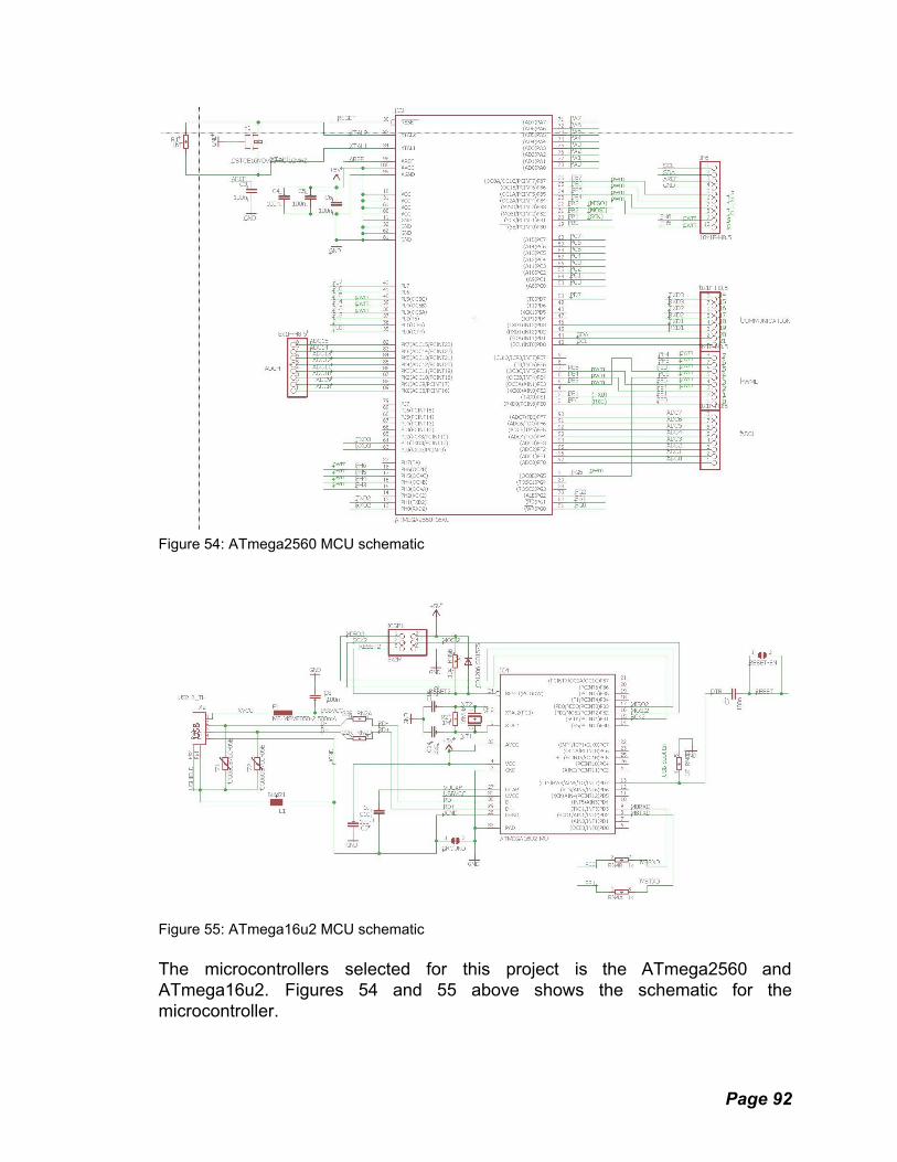
Figure 54: ATmega2560 MCU schematic
Figure 55: ATmega16u2 MCU schematic The microcontrollers selected for this project is the ATmega2560 and ATmega16u2. Figures 54 and 55 above shows the schematic for the microcontroller.
Page 92

Figure 56: LCD and SD card Schematic The above schematic , shown in Figure 56, is for the chosen LCD. The LCD will be incorporated with the final microcontroller PCB. The next schematic is the power delivery schematic, shown in Figure 57 and 58. The final power delivery electrical assembly will be on a separate pcb than the final PCB of the microcontroller and LCD module. The power pcb needs to supply power from the battery to the components of the project. Fuses will be used to ensure current draw is within reasonable levels.
Page 93

Figure 57: Power delivery schematic
Figure 58: Voltage Boost schematic
Page 94

6. Project Software Design Details This section covers the exact implementation details of different software modules, excluding logic for specific games. It covers the general architecture design, as well as any notable implementation details or sub-systems of the management or communication layers.
6.1 Overall System Design
The software architecture for implementing the final board behavior consists of 3 main layers. These are the Game Layer, the Management Layer, and the Communication Layer. The Game Layer handles the actual game logic, the Management Layer handles how tasks get addressed and translates the abstract game information into a format directly usable by the communication layer. The Communication Layer is responsible for the actual communication between the abstract game code and the physical or simulated board. As the board emulator is a critical asset for the speedy and efficient development of the project, its presence is factored into the system design and the code starts to diverge at the Communication Layer.
As communicating with a software UI is fairly different from issuing commands through GPIO pins, the logic for the communication layer will differ significantly between the Arduino implementation and the C# one. However, this is unavoidable and in general a lot of the board interfacing is accomplished with established open source libraries which will not be prone to error. The advantages to testing and development are preserved, though of course there will be extra development time both for implementing the UI and the code responsible for communicating with it. Figure 59 shows how this modular approach will work in practice.
Figure 59: the overall system design and alternate platform implementation.
Page 95
In general, the Communication Layer will be responsible for most interrupts and data export. The management layer will be responsible for managing and servicing those interrupts, and running the main execution thread. The game layer will be responsible for taking advantage of these systems to produce the actual system behavior.
6.2 Communication Layer The communication layer is responsible for communication between the management layer and the actual game board. While the management layer mediates calls to the communication layer, the communication layer actually implements the interface logic.
6.2.1 Emulator Communication For the purposes of the emulator, all 3 layers will be implemented as a DLL with the callback functions and a few extra initialization functions as exposed library functions. This allows everything to be initialized along with the GUI and allows us to avoid constructing an elaborate means of communication between two programs. Once the DLL is initialized, it communicates with the GUI using callback functions. This allows the management layer to drive the operation of the GUI even though the GUI loads the library.
6.2.2 LED Communication For this project we are making use of an individually addressable RGB LED strip. This strip has the advantage of making LED wiring and addressing easy at the cost of refresh rate. The entire strip of 81 LEDs requires only one data line, which on the surface seems impossible but the mechanism that allows this is rather simple. Each LED link is identical, and each starts off waiting for color instructions. When a link receives color instructions, it uses them and adjusts its state. Afterward the link will go into passthrough mode and relay any data coming into its input port into the output port. It will stay in this mode until a set amount of time passes without it receiving any input, after which it will start seeking instructions to implement on its own again. Figure 60 demonstrates this concept. On the first stage, Instruction 4 and Instruction 3 are in the buffer of Segment 1 and Segment 2. As these two segments have recently received color data, they pass through this new data to the next segment. In the second stage, the Arduino has output another color instruction to Segment 1, but it has recently passed through Instruction 4 and so gets ready to pass this next instruction down the chain as well. Instruction 3 arrives in Segment 3 which has not recently received an instruction and so prepares to load the data and display the new color. In the final stage, Segment 3 has loaded and displayed the new color, and thus prepares to forward Instruction 4 down the chain. Segment 1 will soon
Page 96

revert back to waiting for an instruction, as it has not received any new ones this stage.
Figure 60: FastLED state machine As can easily be inferred from this diagram, the longer a chain of LEDs becomes the longer the wait time between refreshes. However, the impact this has on the refresh rate only becomes a serious concern with chains of thousands of LEDs. For the 81 LEDs used in this project the load should be mostly manageable. It could potentially be a concern for processor management, however, as being interrupted during the transmission sequence could cause some LEDs to not be lit up as intended. Alternatively, disabling interrupts during the transmission sequence could cause some user input to be missed if not properly handled. To address these concerns, and to make implementation easier, we've opted to use the FastLED library for our LED communication needs. FastLED does disable interrupts when data transmission is occurring, but attempts to re-enable them during non-critical moments to allow for the servicing of important interrupts. As we do not have any time-sensitive input to worry about, this functionality will be enough for our purposes. FastLED is compatible with the Arduino Mega and our LED strip.
Page 97
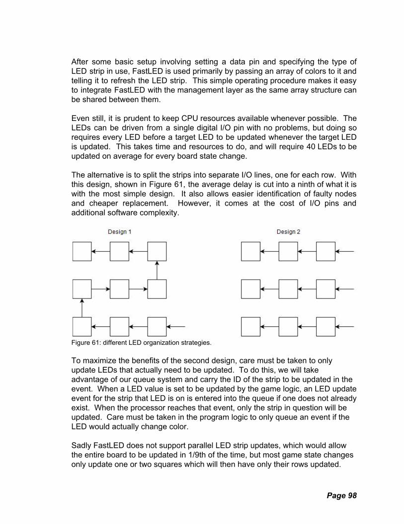
After some basic setup involving setting a data pin and specifying the type of LED strip in use, FastLED is used primarily by passing an array of colors to it and telling it to refresh the LED strip. This simple operating procedure makes it easy to integrate FastLED with the management layer as the same array structure can be shared between them. Even still, it is prudent to keep CPU resources available whenever possible. The LEDs can be driven from a single digital I/O pin with no problems, but doing so requires every LED before a target LED to be updated whenever the target LED is updated. This takes time and resources to do, and will require 40 LEDs to be updated on average for every board state change. The alternative is to split the strips into separate I/O lines, one for each row. With this design, shown in Figure 61, the average delay is cut into a ninth of what it is with the most simple design. It also allows easier identification of faulty nodes and cheaper replacement. However, it comes at the cost of I/O pins and additional software complexity.
Figure 61: different LED organization strategies. To maximize the benefits of the second design, care must be taken to only update LEDs that actually need to be updated. To do this, we will take advantage of our queue system and carry the ID of the strip to be updated in the event. When a LED value is set to be updated by the game logic, an LED update event for the strip that LED is on is entered into the queue if one does not already exist. When the processor reaches that event, only the strip in question will be updated. Care must be taken in the program logic to only queue an event if the LED would actually change color. Sadly FastLED does not support parallel LED strip updates, which would allow the entire board to be updated in 1/9th of the time, but most game state changes only update one or two squares which will then have only their rows updated.
Page 98

Even in the case of needing to update 9 seperate rows of LEDs, having each update as a separate event queue item means the queue is never stuck on LED updating for a protracted period. LED updates are easily the most demanding event as far as processor time is concerned, so splitting them up and allowing interrupts to be fully serviced and other intensive events to happen in the interim is a huge plus.
6.2.3 LCD Communication Communication with the LCD screen is done through 6 pins. To take advantage of the full capabilities of this device, we will be using Adafruit's ILI9340 Library and their GFX Library. These libraries take care of the intricacies of sending commands to the LCD screen and properly formatting text to display. We will of course have to devise our own display methods for all of our relevant game data, but having a library that correctly formats text and images is a huge asset. Using the ILI9340 Library is very straightforward, as it supports commands like println() to print out a line of text, and drawline() and similar graphics functions like drawbitmap() to produce nice looking LCD graphics. Storing bitmaps quickly consumes memory, which is in limited supply, so ideally we'd be able to construct needed graphics procedurally using the tools provided by this library.
Figure 62: Advantages of Procedural Generation Figure 62 illustrates this well. It would be possible to store the UCF image as a bitmap, using a byte for each enabled character. However, the screen has a total of 76800 pixels and we would want our logo to take up a good chunk of it. With potentially tens of thousands of pixels required for this, each pixel taking several bytes, and total system memory being 262144 bytes, we could take a
Page 99
sizable chunk out of our memory for just one image using this approach. If we get creative, like the image on the right, we can make our UCF logo out of 9 draw line commands which would take up much less space in memory. Each color represents a different draw command, with 9 colors being used in total. The end result could of course be in those colors but could just as easily be black or another color if we so chose.
6.2.4 Game Button Communication Communication with the game buttons is one of the more unique aspects of this project, and presents many difficulties. The chief of which is that Arduino does not have 81 GPIO pins, and not all of its GPIO pins support interrupts. As discussed earlier in this document, the solution to the lack of GPIO pins is to use a diode matrix circuit to reduce the needed pins from 81 to 18. At 56 GPIO pins the Arduino can easily handle this, but not all of these pins support interrupts. In fact, only 6 GPIO pins do! Without interrupt support, we will be reduced to polling every pin as often as possible to detect button presses. This is hardly ideal; it requires much more MCU power, processor time, and if the intervals are not frequent enough it will be possible to miss a button press. The solution, thankfully, is simple. Wire up the diode matrix circuit and buttons to 18 standard GPIO pins as before, but also ensure that each button is connected to one extra line that will go into one of the interrupt enabled GPIO pins. This way, every button press will trigger an interrupt. This interrupt will be the “Game Button Pressed” interrupt and will prompt the MCU to immediately scan the relevant GPIO pins to see what button was actually pressed before returning control to the main execution thread. In most cases this method will work well, but in the event that interrupts are disabled while the button interrupt is received the button press event may not get serviced fast enough to actually detect what button was pressed. For this to happen the processor must have stalled for a very long time, or the button press must have been incredibly brief. Testing will prove this for sure, but since special hardware must be implemented to guarantee this situation will not happen, and the window for it to happen is incredibly precise, we are confident in saying it will probably not be a concern for this project. In total we will use 19 GPIO pins for the game buttons, one of these being an interrupt enabled pin.
6.2.5 Settings Button Communication The situation for the setting buttons is more or less the same as the game buttons, but to keep things clean, eliminate a possible source of errors, and take advantage of the remaining interrupt pins we can use a new interrupt for settings
Page 100

buttons and one for the power button. This ensures that important inputs like the ones provided by the power button cannot be overwritten or lost in extreme circumstances, and won't compete with game button presses. As there are only 6 settings buttons total, they will not require a diode matrix circuit as it could at best save 1 pin.
In total we will use 7 GPIO pins for the settings and power buttons, two of these being interrupt enabled pins.
6.2.6 Speaker Communication For additional feedback to the player, we’ve opted to include a piezo element that can generate sounds. The speaker makes use of 1 pin on the arduino, with an additional connection to ground. The arduino connection is responsible for generating a square wave with a 50% duty cycle and a frequency that corresponds to a desired perceived frequency from the device. The amplitude of the waveform controls the volume of the speaker. To implement this behavior we will be using the arduino to generate the waveform and additional circuitry to regulate the max voltage. The principles involved and the effect of the external circuitry is illustrated in Figure 63.
Figure 63: Speaker Waveform It is notable that in order to generate this waveform the Arduino must allocate one of its timers and fire off interrupts to complete the task. This will eliminate one possible timer for the game to use and also introduce an additional, minor burden on the CPU while a sound is playing.
Page 101

Sound will only play in the event that an illegal move is attempted and at game startup. This will help to lower the CPU usage during gameplay, assuming no illegal moves are attempted.
6.3 Management Layer The management layer translates the protocols supported by the communication layer into API calls and systems usable by the game layer. These API calls, callbacks, and systems will be detailed here.
6.3.1 Menu System: The board will feature a fleshed-out menu system to be used for picking the game to play and for choosing individual game settings. The management layer will be used for controlling the game selection menu, while the games themselves will be able to register game-specific menus through the management layer's API. This ensures that the menu code can be re-used, and that critical menu functions like “Exit” are never left off the game menu. Menus are navigated with the Selection Arrows and Selection Button. As Figure 64 shows, the menu functions more like a cycle as the user moves through it. Reaching the far left/right of the menu and going further will place you at the other side. This puts Continue and Exit, the most commonly used items, right next to each-other and makes them very easy to access as “Continue” is the default option.
Figure 64: Menu System State Machine
Page 102

6.3.2 LCD Message Queue: The game and management system may try to display messages at the same time. To prevent system messages from completely overwriting game messages, the system and game have separate message queues. If a system message pops up, it will not overwrite the game message and may either hide it for a time or extend the timer so the game message displays for the intended period. Game messages cannot overwrite system messages, ensuring that any management layer messages are displayed when appropriate. Each message also has a set display time, and this system ensures that it will be able to run out its intended display time uninterrupted. If a system message has to interrupt a Game message, it will record the remaining time that the game message should be displayed for and put it at the front of the game message queue. As Figure 65 shows, many messages could potentially be queued for display, though in the ideal case this would be avoided. In Figure 65, System Message 1 would run out its display time, then the rest of the system messages would do the same, and they would be followed by the 3 game messages. In practice system messages should be very rare and brief, so game logic should only ever be concerned about its own messages. It would be surprising, but it will be possible for messages to enter this queue faster than they get displayed, introducing more and more latency between a message's registration and the time it is actually displayed. This does not appear to be an issue at this time, but it is something worth considering fail-safes for.
Figure 65: Message Display State Machine
6.3.3 LED Queue: Some resources can only be used one at a time, by implementing a queue for each one of these resources, events that must happen are guaranteed to happen eventually. Without such a queue, important display events could be dropped or overwritten by newer events. It will also ensure that events happen in the order they're registered. This will, in most cases, be implemented in the management layer in conjunction with other systems to reduce the complexity of game logic. Events can be marked as Non-Essential, meaning that the next event registered will take their spot in the queue. This allows certain superfluous behavior to be
Page 103

circumvented if it means a quicker response time on an important event. This will mainly be used for lighting up the LEDs. Latency in this queue should be fairly unnoticeable, but will go a long way towards preventing timing related issues. Figure 66 demonstrates this. At t = 0, Event 4 is in the process of being registered and has not yet entered the queue, and Event 3 is marked as unimportant. At t = 1, Event 1 has been executed and Event 4 has taken the place of Event 3 in the queue, to ensure that it gets executed as soon as possible.
Figure 66: Event State Machine
6.3.4 Management Layer IO Restrictions: In order to keep game logic considerations simple, the management layer will operate on certain IO restrictions while a game is loaded. The main one being that it will never make any changes to the board state without the appropriate function calls by the game layer. Even for things like low power states, the management layer will defer to the game logic to determine the best action to take. The management layer may take control of the LCD during gameplay to print warnings like “Low Battery”, and will take control of the board outside of gameplay for the main menu behavior.
6.3.5 Timer System The Arduino Mega supports 6 timers, 2 8 bit timers and 4 16 bit timers. The first 8 bit timer is used for internal Arduino and FastLED library functions, and so will be reserved for those functions. The rest, however, are unused and thus we can appropriate them as we see fit. Many games will need to evaluate their state on a periodic basis, a process known as a “think interval”. Some games will not require this, and will be able to turn off this feature to save processing power, but since it's such a common
Page 104

feature, and the interval is short, it only makes sense to dedicate the second 8 bit timer to it. Games will be able to designate their desired think interval, and after some sanity checks this will be the frequency the think timer raises the OnThink() interrupt. As it is in continuous use, and does not count very high, using the second 8 bit timer is the best option. This leaves the 4 16 bit timers left for the games themselves to take advantage of. They're ideal for this purpose as their ability to count to a higher number will be useful for precise but infrequent timing events. A timer will be registered for use with a Management Layer API call, and trigger the OnTimerFinished() callback when completed. These timers can be used for move timers, time sensitive game events, and whatever other purposes the game may have. Careful use of on-demand timers may allow the think interval to be disabled entirely, saving processing power for many games.
Figure 67: scoreboard architecture.
Page 105

6.3.6 Player Profiles: When players select a game, they then have the option to select a profile to play it under. Players may register a new profile or select one that already exists. Player profiles consist of a unique name and once a profile is created it can be used on any game on the board. The profile can be used for match history and high score tracking, providing one more benefit to playing games on our board. If players wish to avoid using this system or don’t want to invest the effort into it, a Guest option will also be provided which does not record highscores.
6.3.7 Highscores: A favorite feature of many game systems, each game supported by the board will have a highscore system. Single player games will track actual highscores, while multiplayer games will track player ranks based on some sort of ELO system. The ELO rating system is a method to calculate the skills of players relatively. Players can access a game’s highscore board through its settings menu or an option in the main menu. Each game has access only to its own highscore board, controlled through the management layer API. The general structure of this system looks somewhat like figure 67.
6.3.8 Game History: Player stats have been shown to boost enjoyment of games, and having such a system can provide players with an opportunity to review their play history. For multiplayer games, a record of the players who played in a match and their respective scores is shown. For single player games, just the player and their score is shown. This lets players review their match history and keep an accurate record of their past performances. If players ever wish to play a game “off the books” they can choose a Guest profile. As long as one player is using a player profile, the match will be recorded, though if a Guest is playing their entry in the table will simply show up as “Guest”. If both players are registered as Guest, the game will not be recorded at all to avoid clutter and provide an option to have non-recorded games when desired.
6.3.9 Game Help: While most games on the board are simple, well known games, there are times where specific rules may not be clear or the implementation of user input may not be immediately obvious. In cases like these, it really helps to have some sort of resource that players can use to clarify any non-obvious details of the game they want to play. It will also help new players to know what to expect when entering a new game. Help entries will consist of a game image, followed by text describing any relevant information about the game as shown in Figure 68. The game help will be available in the game menu.
Page 106

Figure 68: a possible layout for the Light Sequence help panel.
6.3.10 Management Layer API: As stated before, the Management Layer features an API that the Game Layer can use to communicate with the board itself. To properly implement this API, any function that a possible game may need MUST be accommodated by core C functionality or an API call. Substitutes for Arduino native functions that are not present in C are also required, so that the emulator and board perform the same. Given the importance of the API to the success of the project its exact details will be described here:
6.3.11 API Functions: API Functions call be called from anywhere in the game layer. They provide necessary functions for the games to be implemented. Ideally the game will never directly access the board, rather it will do so through the API using well defined behavior. With this setup, the actual board interfacing will be handled entirely through the back-end and thus the game code can exist isolated from the board. This makes it easier to find faults and also opens up the possibility of porting the game code to other platforms or emulating it on a PC. As long as all the API calls and callbacks are implemented, a given game will be playable anywhere.
Page 107

void Exit() Terminates the game and goes back to game selection. void ClearLCD() Makes the LCD Blank and terminates any PrintToLCD timers. void PrintToLCD( char *output, int duration ) Displays output on LCD for duration milliseconds. If duration is 0 it displays until cleared. Clears last PrintToLCD command if still displayed. void BlinkLCD() Makes the LCD turn on and off, to cause whatever is being displayed to blink. void StartTimer( int duration, int ID ) Supports 4 timers at once, but ID can be anything. OnTimerFinished will fire when the timer expires. Duration is in milliseconds. void DisplayTimerOnLCD( int ID ) Timer with given ID displays on LCD screen, in MM:SS format. void IlluminateButton( int x, int y, int color ) Sets the color of the button at the specified point to the given color preset. void IlluminateGrid( int grid[BoardSizeX][BoardSizeY] ) Takes a grid the size of the simulated board as an argument and sets the entire game space color to that grid for the given duration. void SetColorMode( int colorMode ) Allows the switching between standard and low power color modes as the need arises. void RegisterMenuOption( char* optionText, int ID ) Registers option for game's custom menu. Game menu always has "Exit" and "Continue" options. void SetThinkInterval( int duration ) Set how often the board calls OnThink(), in milliseconds. void SetBoardSize(int x, int y) How large the game board is. Prints error on LCD if greater than 9x9. void GetBoardSize(int &x, int &y) Writes to X and Y how large the simulated board is.
Page 108
void GetSettingStates(int &switches[SWITCHCOUNT]) Gets the state of everything in the settings setup and writes them to the given array. Int GetRandomInt(int min, int max) Returns a random integer in the range specified. void PlaySound(int tone, int duration) Plays the given tone for the given duration, if the duration is 0 the tone will play until stopped. Calls to this function while a sound is already playing will overwrite that sound or sound sequence. void PlaySoundSequence(int tones[], int durations[]) Plays the sounds given in the array for the given durations. Calls to this function while a sound is already playing will overwrite that sound or sound sequence. void StopSound() Stops any sounds and sound sequences currently playing float GetTime() Returns the time in seconds since the game has started.
6.3.12 API Callbacks: Callbacks are fired off by the management layer in response to certain game events. They let the game easily respond to relevant events without needing to worry about low level operations. The conditions a callback is fired under are very precise, allowing the logic implemented within the callback to be sure it has access to everything it needs to complete its execution. In general, the Communication Layer will notify the Management Layer when a given event fires, and the management layer will attempt to make sure that the raw data from each communication layer event is transformed into a form that the game layer will understand and then passed to it. As many game events will be done with interrupts, care must be taken to ensure that the processing of a given event is not interrupted or that incoming events are not dropped needlessly. If we attempt to fully service every interrupt as it comes up, we can easily cause system instability or logic errors as interrupts start interrupting each-other. This is easily avoided with another queue, this time for external events. Each entry in the queue stores the event type and any relevant information it might have. Entries are added to the queue from interrupts, and removed from it when they are processed by the main execution thread. By leaving execution up to the main execution thread, events will be guaranteed to happen very close to the order they came in and will not cause spontaneous state changes during the handling of other events. Even still, Care must be
Page 109

taken to ensure that one interrupt can't bisect the creation of another one and cause the event being added to the queue to become malformed. However, it is not the end of the world if interrupts are not serviced in the exact order they came in. For instance, in Figure 69 the Game Button Press and LCD Button Press events are waiting to be serviced, when another Game Button Press event is triggered and starts to be added to the queue. However, several cycles later a Timer Event also fires which causes the construction of the first event to be put on hold. As long as it's acceptable, the Timer Event can be inserted into the queue first and then the initial Game Button Press interrupt can finish being serviced, adding it to the queue in the fourth spot rather than the third. In practice, these events will be getting processed so quickly that the user will not notice any difference in response times produced by a slightly different queue order.
Figure 69: Possible Interrupt Queue state Here is a listing of each individual interrupt, and their basic implementation details: int OnGameLoaded( ) Called when all game logic is in memory. Return an int other than 0 to indicate loading error and reccomend course of action. void OnButtonPressed( int x, int y ) Called when a button press is registered to the system. void OnLCDButtonPressed( int x, int y ) Called when button below LCD is pressed. Used for control and settings changes. void OnThink( ) Called every single think interval. Use sparingly, and avoid doing complex operations unless neccecery.
Page 110
void OnTimerFinished( int ID ) Called when a timer hits 0 seconds. The ID of the timer is given in the callback. void OnMenuOptionSelected( int ID ) Called when an option in the game's custom menu is selected, does not get called when "Exit" or "Continue" are selected. void OnIdle( int reason ) Called when the board's Idle timer expires. This can happen if the board goes too long without an input. Recomended to suspend Think operations and use low power color mode at the very least. void OnExit( int reason ) Called when the game is exited for whatever reason.
6.4 Game Layer The game layer is where all the game logic itself is implemented. Logic for individual games will be detailed in section 7, but in general games will be implemented in a single class file and be implemented almost entirely through management layer callbacks and function calls. Standard C functionality may also be utilized. This allows the code to easily be transplanted between the emulator and the Arduino platform without significant development time to port individual games over. It also makes the organization of individual games much easier, as each will be kept to a single file with a common interface.
7.Testing This section contains the testing that was done once the parts were received for the LED board game. The data that was obtained from this section was used to determine if the chosen parts for the LED board game are able to be used for the implementation of the project. What follows is the description of the testing process that will be implemented for the various components of the LED board game. Initial testing will be done with a development board. The development board test is essential to help the team transition from initial testing to final design. This allows the software team to begin work on programming the project. The code will be used later when it comes to testing the final hardware designed. The development board test will also help the hardware team to decide on the final hardware required for the project. Many iterations will be necessary between the initially tested components on the breadboard and the final design. Each test will help in determining the final components.
Page 111

7.1 Microcontroller Testing The first and most important components to test, are the microcontrollers. This project uses two microcontrollers, the ATmega2560 and the ATmega16u2. The ATmega2560 will handle most of the code execution while the ATmega16u2 will be used to interface with a personal computer via USB. For the final PCB, both microcontrollers will need to be flashed with a bootloader. The team will test that the bootloader was flashed by uploading code to the microcontroller. Once the team has successfully uploaded code to the microcontroller, testing the code execution can begin. The code so execute similarly to how it behaved during the breadboard test described later in this section. The code execution test will test that button inputs are accepted, the LCD is able to display properly, and the LED are addressable individual and illuminating properly. The board will have to execute a start up sequence when powered on. The board shall have an idle state so as to conserve power when not in use. During the idle state, all LEDs will be off, the LCD will be off, and a button press will wake up the board. When the board is woken up, it will resume the game from the point before the idle state was initiated. The power consumption when the board is in the idle state shall be measured. Each game must be tested to guarantee playability. The code must be tested to determine that an illegal move does not lead to an led being illuminated. An illegal move must activate the buzzer to signal to the player that they can’t move a piece there.
7.2 LED Testing The first test to complete once the MCU is programmed is to test the LEDs. The brightness of the LEDs can be changed from the code. The LEDs must be tested under the 3d printed tile to determine what level brightness is appropriate. Power consumption of the LEDs must be tested.
7.3 Button Testing There are 81 buttons to correspond to the 81 tiles of the board. Each button will have a corresponding LED. The test will be to illuminate the LED when the associated button is pressed. This test will demonstrate that multiple key presses can register at the same time and that each button is functional. Before soldering a button it will be tested for conductivity with a multimeter. In the event that a button does not conduct electricity when pressed it will be discarded. Buttons will be multiplexed for the final project. A test of multiplexed buttons is necessary to
Page 112

ensure that a press of one button does not trigger the microcontroller to read an input on more than one button. The project will utilize interrupts on the buttons. The interrupts will allow the CPU to be disabled between button presses. If interrupts were not used the MCU would have to poll each button during operation. Polling is both slower and consumes more power. The test to determine that interrupts are functioning properly is to incrementally illuminate an LED on the LED strip. When a button is pressed the currently illuminated LED will turn off and the next LED will be illuminated. Information to be recorded during testing will be average CPU power consumption, CPU power consumption when off, and that the CPU is properly reading the interrupts.
7.4 LCD Testing The TFT full color lcd will be tested to ensure proper operation. The initial test of the LCD will cycle between colors to test that there are no dead pixels on the display. Bitmap images will be tested next. The LCD has the ability to display bitmap images. To test this feature, the team will store images onto the SD card to be displayed on the LCD. The LCD will need to display text. A small text file will be loaded onto the microcontroller to be displayed on the LCD. The LCD must be able to scroll up or down through a menu of text so the player can select a game. To test this, buttons will be used as the up arrow and down arrow to move the cursor for the menu up and down respectively. Latency between a button press and the menu cursor moving will be measured. It is desirable to lower input latency as much as possible. To conserve power the LCD must be turned off when the menu is no longer needed, such as during gameplay. A menu button press shall wake the LCD and display the starting menu to allow the user to select a new game or reset the current game. To test that the correct menu options are being displayed, the team will start a game and attempt to start a new game after a few rounds of play. This test will be conducted for each game.
7.5 SD Card Testing An external storage solution is needed for nonvolatile storage of both player scores and code to be executed. The first test of the SD card will simply be to read and write data to the SD card. A blank, freshly formatted SD card will be used for the write test. A button press will write a string of text to the SD card in either txt or csv format. To reading from the SD card, the previously written text will be displayed on the LCD when a different button is pressed. The code for game execution will have to be stored on the SD card as the 256kB of flash memory on the microcontroller will not be sufficient to store all of them. A test will be needed to verify that the code is being written to the microcontroller’s flash
Page 113

memory. The test will involve removing the sd card after it has finished reading the sd card, and then beginning to execute code from the microcontroller’s flash.
7.6 Power Testing The project will be portable and battery power. Due to this the power consumed is going to need to be limited as much as possible. The first test for power testing is to determine that the battery can supply enough current for all the components. The current draw for each component will be measured individually. The individual currents will be added together to give a rough estimate of the needed current draw for a worst case situation. Battery life is also a concern for the project. A game of go can last for several hours, and the board must be playable for the entire duration of the game. Battery life will be tested by assembling the project and having every component be active and wait for the a full charge to dissipate. This time will be recorded. The team will then try to increase the maximum battery life as much as possible. Battery Charge time will also be measured.
7.7 Material Testing The materials used for the project need to be tested for rigidity and weight. The project needs to be lightweight enough that it is easily transported. Aluminum and acrylic are possible materials to make the enclosure of the board. The lighter of the two materials will be chosen for the final project. The same size of material in aluminum and acrylic will be weighed. The tiles will be 3d printed. Both solid white and transparent 3d print filament will be tested to see which is more aesthetically pleasing. The transparent tile will need to be sanded to help diffuse the light emitted by the LEDs.
7.8 Final Test Once the final PCBs have arrived and have been assembled, the team will begin testing to determine that they are suitable for use in the final project. Input and output of the PCBs must be tested. To test input and output, once the pcb has been assembled the buttons will be pressed to determine that they work, the LCD will display a menu, and the LEDs will be illuminated. At this point it is necessary to confirm that the bootloader and the software installed on the microcontroller is functioning properly. The project will be weighed and measured after final assembly to determine if it has met the engineering specifications.
Page 114

7.9 Initial Parts Testing
Figure 70: Nokia 5110 LCD module backlight test
Figure 71: Initial LED Test and Initial Battery Test
Figure 72: LCD Breakout Board Test
Page 115

The initial parts testing was done on the development board and using components on breakout boards. The use of pre-assembled product allows the team to start developing software for the final product without having to wait for pcbs to arrive and be populated with components. Some of the parts that were ordered were not functional and had to be replaced. The below section shows the results of the test for the LCD, battery, microcontroller, and LED strips. It can be seen from Figure 70, the backlight of the nokia 5110 LCD module functioned as expected, but the team was not able to make the LCD module display any text. The two most likely reasons for this is either that the LCD module itself had a design defect or that the team had damaged the LCD module when attempting to test it. Figure 71 above shows that the development board and LEDs can be powered from the battery successfully. Figure 71 shows the LED illuminated white. The max current draw of 9 LEDs was measured to be 0.406A. With this information, the maximum possible current draw of the LEDs was estimated to be 3.6A without lowering the duty cycle. The team has decided to lower the duty cycle of the LEDs in order to conserve power. The individually addressable nature of the LEDs was also tested successfully. The second LCD was tested using the adafruit graphics library. As shown in Figure 72 above, it was able to successfully display text and graphics.
Page 116

8. Administrative This section deals with time management, budgeting, and team organization. All of these are critical to the creation of a good project, but do not usually show up directly in the final product. They do, however, have a large impact on the quality of a project so it's important that we discuss them.
8.1 Team Organization For small teams, a tried and true strategy is to have each member be in charge of a specific area of the project where possible, and have one member be in charge of coordinating them to make a cohesive final product. This creates a good chain of accountability, where the expectations of each team member are clear and for the most part members of the team can work on their individual parts autonomously. There are of course a lot of decisions to be made as to hardware choices, product design, and general product features and behavior. Everyone in the group contributes to these decisions. Everyone will also contribute to the physical design and assembly of the project.
8.1.1 Team Roles Team Member Assigned to Role Role Kevin Cochran PCB Design
Noah Thering Project Management/Software Design
Taylor Grubbs Game Design/Implementation
Zachery Dunlop Power Delivery Table 4: Team Roles
8.1.2 Management Strategies The project manager is responsible for making sure everyone works together well and the end result of the team's efforts will be cohesive. In general, this means leaving the specific implementation details of a particular module of the project to the team members in charge of that module whenever possible, and focusing on making sure that everything is going to come together to meet the end goal of the project. This mostly involves coming up with tasks and deadlines, discussions with group members to determine possible problems with the overall plan, and working with the group to come up with solutions to project-wide issues. A good project manager simply serves as a conduit for the needs and priorities for the group as a whole; making sure everyone is
Page 117

productive and happy is the top priority for a good project manager. This sometimes means compromising with other group members or doing things a different way, but the same is expected of everyone in the group. Ideally the project manager is simply another role on the project, equal to any other.
8.2 Time Management Strategies Essential to the completion of a project is the ability to effectively manage the time dedicated to it. Keeping everyone productive and on-task throughout the development of the project is a challenge, but can be accomplished with the application of some key concepts.
8.2.1 Parallelization As discussed above, everyone is assigned to a particular role on the project. This does not aim to eliminate responsibilities that must be done in a group setting, like designing the overall project or assembling it. Rather, it allows for the effective execution of tasks that would otherwise take more man-hours than needed. Where possible, it's best to leave a task to the person most qualified or most interested in it. This way they can focus on getting it done without worrying about the overhead involved with collaborating with other team members, and everyone on the project can work on something different. A key principle involved in the effective execution of this philosophy is the idea of parallelization. This is the concept of being able to work on tasks in parallel. While the ideal case is that every task would be possible to divide up in this way from the start of the project until the end of it, the reality is that many tasks have prerequisites and dependencies that are not satisfied until very late in the project, like the programming of the board. Other tasks have prerequisites that involve a lot of waiting, like the PCB designer needing to wait on the arrival and testing of individual parts before being certain those are the parts we'll be using. Eliminating these prerequisites, or circumventing them, is the top priority early in the project. Getting to the stage where everyone can work on their own parts of the project full-time is the ideal goal and if achieved can substantially reduce development time. It is even worth the investment of extra resources early on, which is why we opted to create an emulator for the board. The extra work invested into it will allow, in the ideal case, the completion of most of the code base before the board is fully assembled. Thus, once the board is assembled, we will be able to use it almost immediately afterward instead of waiting to develop and test the code. This allows faults to be found much quicker and can keep everyone productive until the product has reached completion.
Page 118

8.2.2 Schedule Having an overall team objective for each week is helpful for staying on task and making sure things are progressing on-pace. The schedule is not infallible as it can be hard to see what will ultimately take the most time over the course of a project, but it can be a good first step to keeping things on-task. Here's our current schedule: SENIOR DESIGN I
Week 1 (8/20-8/26) Meet with Team to brainstorm project
ideas
Week 2 (8/27-9/2) Senior Design Bootcamp
Week 3 (9/3-9/9) Project Delayed due to Hurricane Irma
Week 4 (9/10-9/16) Divide and Conquer
Week 5 (9/17-9/23) Mental Simulations of Product Function
Week 6 (9/24-9/30) Update Divide and conquer
Week 7 (10/1-10/7) Determine Hardware/Software Interface Standards
Week 8 (10/8-10/14) Basic Concepts Tested and Verified
Week 9 (10/15-10/21) Finalize Button Design
Week 10 (10/22-10/28) Mock Up Games on Another Platform
Week 11 (10/29-11/4) 60 page submission due
Week 12 (11/5-11/11) Finalize Physical Layout
Week 13 (11/12-11/18) 100 page submission due
Week 14 (11/19-11/25) Finalize Part Choices
Week 15 (11/26-12/2) Finalize PCB Design
12/4 Final Document Due Table 5: Senior Design I milestones
Page 119

SENIOR DESIGN II
Week 1 (1/8-1/14) Final Analysis of Project Design
Week 2 (1/15-1/21) Order Parts
Week 3 (1/22-1/28) Start Assembling Prototype Components
Week 4 (1/29-2/4) Start Assembling Full Prototype
Week 5 (2/5-2/11) Finish Assembly of Full Prototype
Week 6 (2/12-2/18) Extensive Testing Period
Week 7 (2/19-2/25) Analysis of Testing
Week 8 (2/26-3/4) Redesign of Weak Components and Bug Fixing
Week 9 (3/5-3/11) Get New Parts for Required Changes
Week 10 (3/11-3/17) Apply Needed Modifications
Week 11 (3/18-3/24) Extensive Testing Period
Week 12 (3/25-3/31) Make Minor Tweaks to Project, Order Parts
Week 13 (4/1-4/7) Finish Tweaks and Polish
Week 14 (4/8-4/14) Extensive Project Testing (Presentation to Faculty Advisors)
Week 15 (4/15-4/21) Finalize and Pack Up Project
Final Presentation
Table 6: Senior Design II milestones
8.2.3 Weekly Meetings Meeting as a group at least once a week is essential to the success of any major project. It allows the group members to touch base with each-other on how each section of the project is progressing and what the objective for the next week is. This allows everyone to get input on what they're currently doing, get any help if
Page 120

they need it, or point out any potential problems or concerns down the road. It also allows the direct application of this knowledge into the creation of new tasks for that week. Once the project progresses to the prototype stage, it becomes even more essential to have these meetings as each one can be based around a test session. During the test session, all relevant changes from that week can be examined and discussed. This keeps everyone on the same page and allows immediate and constructive feedback from everyone in the group on where they want the project to go from there. Being able to see your changes in action and share them with your group partners is also a fun and rewarding experience, which everyone contributing to a project deserves to have.
8.2.4 Budget A project cannot see completion without the effective assignment and use of resources. As we've opted to have a high quality prototype gameboard, our current budget is $350. This budget includes duplicate parts and custom PCB manufacture. If the product were to enter mass-production, the cost per unit would be substantially less. This project is funded out of our own pockets, but between 4 group members the cost is not prohibitive. We simply split the cost 4 ways, turning a $350 project into a $90 expense for each of us. At the present time, this is our budget: Switch cells: Switches = $50 (alternate $42.50) Leds = $50 Resistors = $10 Keycaps = $20-30 Brains: ATmega2560 = $15 LCD = $10 or $15 Micro SD card = $10 Case = $50-60 PCBs = $90-100 based on OSHpark Pricing Power = $15-50 Total = $350
Page 121

9. Conclusion The design stage of the project has been proceeding smoothly, though we have hit a few snags here and there. The biggest issue encountered so far is our first LCD screen choice not being the ideal one for the project. After 2 hours of testing we could not get it to run the full test sequence, and ultimately it proved to be smaller and less capable than our project demanded. With the rest of the project using fairly high-quality parts and presentation, it didn't make a ton of sense to use a $5 LCD screen as one of the main points of user interaction. For this reason we decided to move to a larger full color display. We've also decided to add more and more features over the course of development, both because we feel they're needed for proper operation and because we feel the project will be more desirable and versatile with these additions. Careful evaluation of each addition has to be done to avoid loading too many features into the project, but so far we're confident that all of them can be successfully implemented. Overall, this may not be the first digitally enhanced game board, but it will certainly match the best of them in terms of quality and execution.
Page 122

123
Sources: [1] “Touch LED Table - Retrogaming And Ambiant Light.” Arduino Project Hub, Arduino
Project Hub, 22 June 2016, create.arduino.cc/projecthub/arbalet/touch-led-table-retrogaming-
and-ambiant-light-3d3204?ref=tag&ref_id=games&offset=31. [2] “Project 64/64 Buttons.” Spikenzei Labs, Spikenzei Labs,
www.spikenzielabs.com/SpikenzieLabs/Project_64.html. [3] MarkQ8. “Bluetooth Controlled Arduino LED Coffee Table.” Instructables, Instructables, 24
Apr. 2017, www.instructables.com/id/Arduino-LED-Coffee-Table/. [4] Rgbphil. “Charlieplexing LEDs- the Theory.” Charlieplexing LEDs- the Theory, Instructables,
22 May 2017, www.instructables.com/id/Charlieplexing-LEDs--The-theory/. [5] David. “RGB LED strips: an overview - Nut & Bolt.” Nut & Bolt, Feb. 2012, nut-
bolt.nl/2012/rgb-led-strips/. [6] Alex Castle. “How To Get Started with Programmable RGB LED Strip Lighting.” Adam
Savage's Tested, 21 Feb. 2013, www.tested.com/art/makers/453665-how-get-started-
programmable-rgb-led-strip-lighting/. [7] Phillip Burgess. “Digital RGB LED Strip.” Power | Digital RGB LED Strip | Adafruit
Learning System, Adafruit, 4 May 2015, learn.adafruit.com/digital-led-strip/powering. [8] Woodford, Chris. “How do lithium-Ion batteries work?” Explain that Stuff, 14 July 2017,
www.explainthatstuff.com/how-lithium-ion-batteries-work.html. [9] Lady Ada. “Li-Ion & LiPoly Batteries.” Overview | Li-Ion & LiPoly Batteries | Adafruit
Learning System, Adafruit, learn.adafruit.com/li-ion-and-lipoly-batteries?view=all. [10] Industries, Adafruit. “NeoPixel 5050 RGB LED with Integrated Driver Chip - 10 Pack.”
Adafruit industries blog RSS, Adafruit Industries, www.adafruit.com/product/1655. [11] Amazon. “ALITOVE 16.4ft WS2812B Individually Addressable LED Strip Light 5050
RGB SMD 150 Pixels Dream Color Waterproof IP66 Black PCB 5V DC: Musical Instruments.”
Amazon.com: ALITOVE 16.4ft WS2812B Individually Addressable LED Strip Light 5050 RGB
SMD 150 Pixels Dream Color Waterproof IP66 Black PCB 5V DC: Musical Instruments,
Amazon, www.amazon.com/ALITOVE-WS2812B-Individually-Addressable-
Waterproof/dp/B00ZHB9M6A. [12] Phillip Burgess. “Battery Power for LED Pixels and Strips.” Overview | Battery Power for
LED Pixels and Strips | Adafruit Learning System, Adafruit Industries,
learn.adafruit.com/battery-power-for-led-pixels-and-strips?view=all. [13] Mike Wang. “Build High-Density, High-Refresh Rate, Multiplexing LED Panel with
TLC5958.” Build High-Density, High-Refresh Rate, Multiplexing LED Panel with TLC5958
(Application Report SLVA645–December 2014), Texas Instruments,
www.ti.com/lit/an/slva645/slva645.pdf. [14] “Introduction to 74HC595 shift register - Controlling 16 LEDs.” Protostack, Protostack, 28
May 2010, protostack.com.au/2010/05/introduction-to-74hc595-shift-register-controlling-16-
leds/. [15] kammenos. “The Charlieplexing.” The Charlieplexing, PCB Heaven, 5 Apr. 2011,
www.pcbheaven.com/wikipages/Charlieplexing/. [16] push_reset. “Intro to LED Strips.” Intro to LED Strips , Instructables, 29 Apr. 2015,
www.instructables.com/id/Intro-to-LED-Strips/. [17] “WS2812B Intelligent control LED integrated light source.” WS2812B Intelligent control
LED integrated light source, Adafruit Industries, Worldsemi, cdn-
shop.adafruit.com/datasheets/WS2812B.pdf.
124
[18] Jan. “Pololu - Understanding battery capacity: Ah is not A.” Pololu Robotics & Electronics,
Pololu, 12 Nov. 2010, www.pololu.com/blog/2/understanding-battery-capacity-ah-is-not-a. [19] RAVPower, Team. “Lithium Ion vs. Lithium Polymer Batteries – Which Is Better?”
Lithium Ion vs. Lithium Polymer Batteries – Which Is Better?, Blog.RAVPower, 20 June 2017,
blog.ravpower.com/2017/06/lithium-ion-vs-lithium-polymer-batteries/. [20] Gosselin, Brian. “Lipo Wiring.” R/C Calculations, scriptasylum.com/rc_speed/lipo.html. [21] SFUPTOWNMAKER. “PCB BASICS.” PCB Basics, Sparkfun,
learn.sparkfun.com/tutorials/pcb-basics/composition [22] “PCB Design Guidelines For Reduced EMI.” PCB Design Guidelines For Reduced EMI,
Texas Instruments, Nov. 1999, www.ti.com/lit/an/szza009/szza009.pdf. [23] “PCB Manufacturing Review.” CATSKULL.net , CATSKULL.net, 15 Nov. 2016,
catskull.net/pcb-manufacturers.html. [24] Wahby, Mahmoud. “PCB Design Basics: Example design flow.” EDN network, EDN
network, 8 Jan. 2014, www.edn.com/design/pc-board/4426878/PCB-Design-Basics--Example-
design-flow. [25] Anool Mahidharia. “KiCAD Best Practices: Library Management.” Hackaday,
HACKADAY, 19 May 2017, hackaday.com/2017/05/18/kicad-best-practises-library-
management/. [26] Elliot Williams. “A Tool For KiCad Board Renderings.” Hackaday, HACKADAY, 17 Apr.
2017, hackaday.com/2017/04/17/a-tool-for-kicad-board-renderings/. [27] Brian Benchoff. “Creating A PCB In Everything: KiCad, Part 3.” Hackaday, HACKADAY,
23 Dec. 2016, hackaday.com/2016/12/23/creating-a-pcb-in-everything-kicad-part-3/. [28] Brian Benchoff. “Creating A PCB In Everything: KiCad, Part 2.” Hackaday, HACKADAY,
9 Dec. 2016, hackaday.com/2016/12/09/creating-a-pcb-in-everything-kicad-part-2/. [29] Brian Benchoff. “Creating A PCB In Everything: KiCad, Part 1.” Hackaday, HACKADAY,
17 Nov. 2016, hackaday.com/2016/11/17/creating-a-pcb-in-everything-kicad-part-1/. [30] “MX Series Keyswitch.” MX Series Keyswitch, Digikey,
media.digikey.com/pdf/Data%20Sheets/Cherry%20PDFs/MX%20Series.pdf. [31] “Comparison of EDA software.” Wikipedia, Wikimedia Foundation,
en.wikipedia.org/wiki/Comparison_of_EDA_software.
[32] “CircuitMaker.” Wikipedia, Wikimedia Foundation, en.wikipedia.org/wiki/CircuitMaker.
[33] “KiCad.” Wikipedia, Wikimedia Foundation, en.wikipedia.org/wiki/KiCad. [34] “DipTrace.” Wikipedia, Wikimedia Foundation, en.wikipedia.org/wiki/DipTrace. [35] “EAGLE (Program).” Wikipedia, Wikimedia Foundation,
en.wikipedia.org/wiki/EAGLE_(program). [36] Lady Ada. “Nokia 5110/3310 Monochrome LCD.” Overview | Nokia 5110/3310
Monochrome LCD | Adafruit Learning System, Adafruit, learn.adafruit.com/nokia-5110-3310-
monochrome-lcd?view=all. [37] “Fritzing.” Wikipedia, Wikimedia Foundation, en.wikipedia.org/wiki/Fritzing. [38] Jenny List. “One Person’s Experience Of Having PCB Assembly Done In China.”
Hackaday, HACKADAY, 7 Aug. 2017, hackaday.com/2017/08/07/one-persons-experience-of-
having-pcb-assembly-done-in-china/. [39] Joshua Vasquez. “Designing for Fab: a Heads-Up before Designing PCBs for Professional

125
Assembly.” Hackaday, H, 10 May 2017, hackaday.com/2017/05/10/designing-for-fab-a-heads-
up-before-designing-pcbs-for-professional-assembly/. [40] “Advanced PCB Layout Course by Fedevel Academy.” HELENTRONICA, PERO, 4 May
2017, helentronica.com/2017/05/03/advanced-pcb-layout-course-by-fedevel-academy/.
[41] Brian Benchoff. “Creating A PCB In Everything: Upverter.” Hackaday, HACKADAY, 3
Feb. 2017, hackaday.com/2017/02/03/creating-a-pcb-in-everything-upverter/. [42] Brian Benchoff. “Creating A PCB In Everything: Creating A Custom Part In Fritzing.”
Hackaday, HACKADAY, 6 Jan. 2017, hackaday.com/2017/01/06/creating-a-pcb-in-everything-
creating-a-custom-part-in-fritzing/. [43] Brian Benchoff. “Creating A PCB In Everything: Creating A Custom Part In Fritzing.”
Hackaday, HACKADAY, 6 Jan. 2017, hackaday.com/2017/01/06/creating-a-pcb-in-everything-
creating-a-custom-part-in-fritzing/. [44] Brian Benchoff. “Creating A PCB In Everything: Friends Don’t Let Friends Use Fritzing.”
Hackaday, HACKADAY, 11 Oct. 2016, hackaday.com/2016/10/11/creating-a-pcb-in-
everything-friends-dont-let-friends-use-fritzing/. [45] Brian Benchoff. “Creating A PCB In Everything: Eagle DRC and Gerber Files.” Hackaday,
HACKADAY, 29 Sept. 2016, hackaday.com/2016/09/29/creating-a-pcb-in-everything-eagle-drc-
and-gerber-files/. [46] Brian Benchoff. “Creating A PCB In Everything: Eagle, Part 2.” Hackaday, HACKADAY,
23 Sept. 2016, hackaday.com/2016/09/23/making-a-pcb-eagle-part-2/. [47] Brian Benchoff. “Creating A PCB in Everything: Eagle, Part 1.” Hackaday, HACKADAY,
22 Sept. 2016, hackaday.com/2016/09/22/making-a-pcb-eagle-part-1/. [48] “Electronic Component Zero Orientation For CAD Library Construction .” Electronic
Component Zero Orientation For CAD Library Construction v, Association Connecting
Electronics Industries, IEC, PCB Libraries new dimensions for EDA ,
ohm.bu.edu/~pbohn/__Engineering_Reference/pcb_layout/pcbmatrix/Component%20Zero%20
Orientations%20for%20CAD%20Libraries.pdf. [49] “PCB Design for Manufacture in KiCad Part 1.” Rheingold Heavy, Rheingold Heavy., rheingoldheavy.com/design-assembly-kicad/. [50] “IPC-7351 Generic Requirements for Surface Mount Design and Land Pattern Standard.”
IPC-7351 Generic Requirements for Surface Mount Design and Land Pattern Standard, IPC,
pcbget.ru/Files/Standarts/IPC_7351.pdf. [51] Brian Benchoff. “Creating A PCB In Everything: Upverter.” Hackaday, HACKADAY, 3
Feb. 2017, hackaday.com/2017/02/03/creating-a-pcb-in-everything-upverter/. [52] Industries, Adafruit. “3-Pin JST SM Plug Receptacle Cable Set.” Adafruit industries blog
RSS, Adafruit Industries, www.adafruit.com/product/1663. [53] “SN74LVC245A Octal Bus Transceiver With 3-State Outputs.” Texas Instruments, Texas
Instruments, Jan. 2015, www.ti.com/lit/ds/symlink/sn74lvc245a.pdf. [54] “Printed circuit board.” Wikipedia, Wikimedia Foundation,
en.wikipedia.org/wiki/Printed_circuit_board. [55] Langster. “The Answer is 42!!” Having electronic breakout boards manufactured in China
by Elecrow, Blogspot, 24 July 2017, langster1980.blogspot.co.uk/2017/07/having-electronic-
breakout-boards.html. [56] Mike Szczys. “[Fran’s] PCB etching techniques.” Hackaday, HACKADAY, 4 Mar. 2013,
hackaday.com/2013/03/04/frans-pcb-etching-techniques/.

126
[57] Jason Rollete. “How-To: Etch a single sided PCB.” Hackaday, HACKADAY, 28 July 2008,
hackaday.com/2008/07/28/how-to-etch-a-single-sided-pcb/. [58] Mike Szczys. “[Fran’s] PCB etching techniques.” Hackaday, HACKADAY, 4 Mar. 2013,
hackaday.com/2013/03/04/frans-pcb-etching-techniques/. [59[ Brian Benchoff. “Laser Etching PCBs.” Hackaday, HACKADAY, 22 Aug. 2017,
hackaday.com/2017/08/22/laser-etching-pcbs/. [60] Phillip Burgess. “Sipping Power With NeoPixels.” Overview | Sipping Power With
NeoPixels | Adafruit Learning System, Adafruit Industries, learn.adafruit.com/sipping-power-
with-neopixels?view=all. [61] Industries, Adafruit. “Lithium Ion Battery Pack - 3.7V 6600mAh.” Adafruit Industries,
Adafruit Industries, www.adafruit.com/product/353. [62] “Atmel ATmega640/V-1280/V-1281/V-2560/V-2561/V.” Atmel ATmega640/V-1280/V-
1281/V-2560/V-2561/V, Atmel Corporation, www.atmel.com/Images/Atmel-2549-8-bit-AVR-
Microcontroller-ATmega640-1280-1281-2560-2561_datasheet.pdf. [63] Industries, Adafruit. “Monochrome 1.3" 128x64 OLED graphic display.” Adafruit
Industries, Adafruit Industries, www.adafruit.com/product/938. [64] Industries, Adafruit. “Adafruit 1.44" Color TFT LCD Display with MicroSD Card breakout.”
Adafruit Industries, Adafruit Industries, www.adafruit.com/product/2088. [65] Industries, Adafruit. “Graphic ST7565 Positive LCD (128x64) with RGB backlight extras.”
Adafruit Industries, Adafruit Industries, www.adafruit.com/product/250. [66] Industries, Adafruit. “RGB backlight negative LCD 16x2 extras.” Adafruit Industries,
Adafruit Industries, www.adafruit.com/product/399. [67] “Graphic LCD 84x48 - Nokia 5110.” LCD-10168 - SparkFun Electronics, Sparkfun
Electronics, www.sparkfun.com/products/10168. [68] “ST7735R 262K Color Single-Chip TFT Controller/Driver.” ST7735R 262K Color Single-
Chip TFT Controller/Driver, Adafruit - Setronix, cdn-
shop.adafruit.com/datasheets/ST7735R_V0.2.pdf. [69] Industries, Adafruit. “RGB backlight negative LCD 16x2 extras.” Adafruit Industries,
Adafruit Industries, www.adafruit.com/product/399. [70]“Atmel ATmega640/V-1280/V-1281/V-2560/V-2561/V.” Atmel ATmega640/V-1280/V-
1281/V-2560/V-2561/V, Atmel Corporation, www.atmel.com/Images/Atmel-2549-8-bit-AVR-
Microcontroller-ATmega640-1280-1281-2560-2561_datasheet.pdf. [71] “ ATmega328/P.” ATmega328/P, Atmel Corporation, www.atmel.com/Images/Atmel-
42735-8-bit-AVR-Microcontroller-ATmega328-328P_Datasheet.pdf. [72] “MSP432P401R, MSP432P401M SimpleLink™ Mixed-Signal Microcontrollers.” Texas
Instruments, Texas Instruments, Sept. 2017, www.ti.com/lit/ds/slas826g/slas826g.pdf. [73] “USB.” Wikipedia, Wikimedia Foundation, en.wikipedia.org/wiki/USB.
[74] “ATmega16U2 In Production.” Microchip Technology Inc, Microchip Technology Inc,
www.microchip.com/wwwproducts/en/ATMEGA16U2.
[75] LON GLAZNER. “Arduino Uno – Programming With A Serial Port.” Solutions Cubed,
Solutions Cubed, 4 July 2012, blog.solutions-cubed.com/programming-the-arduino-uno-with-a-
serial-port/. [76] “USB.” Wikipedia, Wikimedia Foundation, en.wikipedia.org/wiki/USB. [77] Miicheal Daly. “Power-on reset - diode location?” Electronics Forum (Circuits, Projects

127
and Microcontrollers), Www.electro-Tech-Online, www.electro-tech-online.com/threads/power-
on-reset-diode-location.31296/. [78] Wacker, Karl-Wilhelm. Embedded Adventures - Reset Circuitry for PIC microcontrollers
revisited, Embedded Adventures, 7ADAD, 2010,
www.embeddedadventures.com/news/articles/46. [79] Rubasinghe, Aruna. “Simple reverse-Polarity-Protection circuit has no voltage drop.” EDN
network, EDN network, 20 Oct. 2011, www.edn.com/design/analog/4368527/Simple-reverse-
polarity-protection-circuit-has-no-voltage-drop. [80] “1N4007-TP.” Micro Commercial Co | Discrete Semiconductor Products | DigiKey,
Digikey, www.digikey.com/product-detail/en/micro-commercial-co/1N4007-TP/1N4007-
TPMSCT-ND/773694. [81] Brain, Marshall. “How Lithium-Ion Batteries Work.” HowStuffWorks, HowStuffWorks, 14
Nov. 2006, electronics.howstuffworks.com/everyday-tech/lithium-ion-battery1.htm. [82] “A few simple rules ... limitless possibilities.” A few simple rules ... limitless possibilities,
GO British Association , www.britgo.org/intro/intro2.html. [83] “Checkers: American .” ItsYourTurn.com - Help Page, ItsYourTurn.com,
www.itsyourturn.com/t_helptopic2030.html. [84] Phillip Burgess. “Digital RGB LED Strip.” Overview | Digital RGB LED Strip | Adafruit
Learning System, Adafruit Industries, learn.adafruit.com/digital-led-strip/overview. [85] “TLC5958 (ACTIVE).” TLC5958 datasheet 48 Channel, 16 Bit ES-PWM, LED Driver with
Pre-Charge FET, LED Open Detection and 48k Bit Memory | TI.Com, Texas Instruments,
www.ti.com/product/TLC5958/datasheet. [86] Industries, Adafruit. “2.2" 18-Bit color TFT LCD display with microSD card breakout.”
Adafruit Industries, Adafruit Industries,
www.adafruit.com/product/1480?gclid=CjwKCAiAr_TQBRB5EiwAC_QCq8JESYsTxaEWM8
HsbbtZyx6ngqopMZK7cmOIUrk3ONFdmZUtXNg9rRoCvl8QAvD_BwE. [87] Mitchell, Robin. “What Is RoHS and Why Is It Important?” All About Circuits, EE Tech
Media, 16 Oct. 2016, www.allaboutcircuits.com/news/what-is-rohs-and-why-is-it-important/. [88] “RoHS Compliance Definition.” RoHS Compliance Definition, RoHS Compliance
Definition, www.rohscompliancedefinition.com/. [89] a1ronzo . “Power and Thermal Dissipation.” Power and Thermal Dissipation - SparkFun
Electronics, 23 Nov. 2010, www.sparkfun.com/tutorials/217. [90] Woodford, Chris. “Piezoelectricity - How does it work? | What is it used for?” Explain that
Stuff, Explain that Stuff, 11 Aug. 2017, www.explainthatstuff.com/piezoelectricity.html. [91] “Linear vs. Switching Regulators.” Linear vs. Switching Regulators | Power Management |
Intersil, Intersil A Renesas Company,
[92] “7.1.3 Solder Joint Acceptance Criteria.” Circuit Technology Center, Circuit Technology
Center, www.circuitrework.com/guides/7-1-3.html.
Permission Requests [3]

128
[2]
[81]

129
[63], [64] [65], [66] [67] [86]

130
[77]
[80]

131
[73]
[4]
[85] Texas Instruments Terms of Use

132
[6]
[89]

133
[91]

134
[82]
[92]

135
Related Documents