~ 1 ~ GROUND WATER REPLENISHER (a system to artificially recharge ground water) A THESIS SUBMITTED IN PARTIAL FULFILLMENT OF THE REQUIREMENTS FOR THE DEGREE OF Bachelor of Technology In Civil Engineering By ABHIJEET SRIVASTAVA 10501027 Department of Civil Engineering National Institute of Technology Rourkela-769008 2009

Welcome message from author
This document is posted to help you gain knowledge. Please leave a comment to let me know what you think about it! Share it to your friends and learn new things together.
Transcript

~ 1 ~
GROUND WATER REPLENISHER (a system to artificially recharge ground water)
A THESIS SUBMITTED IN PARTIAL FULFILLMENT OF THE
REQUIREMENTS FOR THE DEGREE OF
Bachelor of Technology In
Civil Engineering
By
ABHIJEET SRIVASTAVA
10501027
Department of Civil Engineering
National Institute of Technology
Rourkela-769008
2009

~ 2 ~
GROUND WATER REPLENISHER (a system to artificially recharge ground water)
A THESIS SUBMITTED IN PARTIAL FULFILLMENT OF THE
REQUIREMENTS FOR THE DEGREE OF
Bachelor of Technology
In Civil Engineering
By
ABHIJEET SRIVASTAVA
Under the Guidance of Prof. S.P.SINGH
Department of Civil Engineering
National Institute of Technology
Rourkela-769008
2009

~ 3 ~
National Institute of Technology
Rourkela
CERTIFICATE
This is to certify that the thesis entitled “GROUND WATER REPLENISHER(a system to
artificially recharge ground water) ” submitted by Sri Abhijeet Srivastava, Roll No. 10501027
in partial fulfillment of the requirements for the award of Bachelor of Technology degree in Civil
Engineering at the National Institute of Technology, Rourkela (Deemed University) is an
authentic work carried out by him under my supervision and guidance.
To the best of my knowledge, the matter embodied in the thesis has not been submitted to any
other University/Institute for the award of any Degree or Diploma.
Date: 11/05/2009 (Prof.S.P.SINGH)

~ 4 ~
ACKNOWLEDGEMENT
My heart pulsates with the thrill for tendering gratitude to those persons who helped me in
completion of the project.
The most pleasant point of presenting a thesis is the opportunity to thank those who have contributed
to it. Unfortunately, the list of expressions of thank no matter how extensive is always incomplete
and inadequate. Indeed this page of acknowledgment shall never be able to touch the horizon of
generosity of those who tendered their help to me.
First and foremost, I would like to express my gratitude and indebtedness to Prof S.P.SINGH, for his
kindness in allowing me for introducing the present topic and for his inspiring guidance, constructive
criticism and valuable suggestion throughout this project work. I am sincerely thankful to him for his
able guidance and pain taking effort in improving my understanding of this project.
I am also grateful to Prof. M PANDA (Head of the Department) for assigning me this interesting
project and for his valuable suggestions and encouragements at various stages of the work.
An assemblage of this nature could never have been attempted without reference to and inspiration
from the works of others whose details are mentioned in reference section. I acknowledge my
indebtedness to all of them.
Last but not least, my sincere thanks to all my friends who have patiently extended all sorts of help
for accomplishing this undertaking.
ABHIJEET SRIVASTAVA DATE: 11/05/2009
PLACE: Rourkela
Dept. of Civil engineering
National Institute of Technology Rourkela – 769008

~ 5 ~
CONTENTS Page No.
1. INTRODUCTION TO GROUND WATER REPLENISHER 06
2. DESIGN OF THE SYSTEM 08
3. HOW DOES THE SYSTEM WORKS 11
4. MAINTENANCE 21
5. COMMERCIAL IMPLEMENTATION 23
6. SIGNIFICANCE OF THE SYSTEM 25
7. ALTERNATIVES USED 27
8. ACTUAL EXPERIMENTAL SETUP 33
9. EXPERIMENTS CONDUCTED 40
9.1. DETERMINATION OF OIL AND GREASE 41
9.2. DETERMINATION OF ALKALINITY 43
9.3. DETERMINATION OF BOD 45
9.4. DETERMINATION OF DO 46
9.5. DETERMINATION OF ph 47
9.6. DETERMINATION OF TURBIDITY 48
10. RESULTS 49
11. CONCLUSION 56
12. REFERENCE 58
~ 6 ~
CHAPTER 1
INTRODUCTION TO GROUND WATER
REPLENISHER

~ 7 ~
INTRODUCTION TO GROUND WATER REPLENISHER
In the present scenario, talking practically, most of the residential areas, use ground water to
fulfill their day to day needs. Till now nothing significant has been done to replenish the ground
water except the „RAIN WATER HARVESTING SYSTEM‟, in which the rain water is
harvested and is then directed underground.
At present, the atmosphere has become so unpredictable that it is very difficult to consider that a
particular region will receive the normal rainfall in the rainy season, also this rainy season is
limited up to 3-4 months, so we can‟t rely only on rain, due to its high uncertainty, to replenish
the ground water. Moreover the frequency of extraction of ground water is high and the
replenishment from rain water is very limited. Thus some alternative must be thought of to
overcome this problem.
It is found that about 70-80% of the household water goes into the sewer. The sewage thus
carried to the treatment plant is treated to remove the harmful contents and the treated water is
either supplied back for household purposes or to some other place, like industries etc, depending
upon the quality of treated water. In this transportation, there is loss of water which can‟t be
ignored. Further this treated water is not used to replenish the region from which water is
extracted.
Thus in the current scenario: „ground water is extracted for household purposes,70-80% of this
water goes to the sewage treatment plant, treated water is circulated back, water is lost in
transportation, this water is not used for ground water replenishment, thus there is a net loss of
ground water‟
„GROUND WTAER REPLENISHER‟ is an effort put in a direction to control this loss.
‟GROUND WATER REPLENISHER‟ is a simple aligned system that can be laid out easily
beneath the house.
Excluding the sanitation dispose, remaining 40-50% of household water dispose - containing oil,
grease, suspended dust particles, surfactants, heavy metals and some other pollutants - can be
used effectively to replenish ground water after proper treatment, which may be carried out
effectively using „GROUND WATER REPLENISHER‟

~ 8 ~
CHAPTER 2
DESIGN OF THE SYSTEM

~ 9 ~
DESIGN OF THE SYSTEM
„GROUND WATER REPLENISHER‟ is a simple alignment that can be laid out easily beneath
the house requiring little space and a one time nominal investment. Also the house holder needs
not to go for a regular checkup and maintenance of the system. Materials used in this system are
natural and easily available, therefore it does not put an extra burden on the house holder. This
system, which is basically an assembly of filtration systems, can be characterized by the four
sections as shown in the fig.
2.1. The first section consists of a primary filtration chamber. This filtration system, also used as
primary filtration in water treatment plants, is made up of coarse gravel, pebbles and sand.
(fig 1-1)

~ 10 ~
2.2. The second section, which is an optional one, performs the task of removing extra oil present
in the house hold waste water. Installation of this section depends on the amount of oil and
grease that is normally flown out from the house as waste. Thus this section entirely depends
on the lifestyle of the house holder. (fig 1-2)
2.3. The third section can be further divided into two parts (fig 1-3)
2.3.1. The first part is a mixing chamber. This chamber is so designed as if it behaves like
a blender to mix water with the materials, required to be mixed to carry out the
filtration process successfully.
2.3.2. The second part is basically a chamber where water is allowed to stagnate, which is
an important step in the filtration process. This chamber is made up of reinforced
cement concrete structure and a special designed outlet valve to transfer water from
this section to the last section of the filtration system.
2.4. This section is again a filtration chamber where the final treatment takes place and the water
flowing out from this section is free enough from the pollutants and can be safely directed
underground.(fig 1-4)
The injection of this water is done through a pipe which is bored halfway to the level of ground
water after which water percolates of its own to the ground beneath and gets collected as ground
water.

~ 11 ~
CHAPTER 3
HOW DOES THE SYSTEM WORKS

~ 12 ~
HOW DOES THE SYSTEM WORKS
As mentioned earlier, „GROUND WATER REPLENISHER‟ is a filtration system where
sequential removal of impurities and pollutants takes place.
The first chamber which is a primary filtration chamber, removes the heavy particles such as
pieces of wood, coarse solids or some other solidified impurities, to some extent oil and grease.
This chamber aligned at an angle but not vertically. Purpose of this slanted alignment is that it
would require less vertical space, thereby reducing the overall depth of the system, thus making
the installation of the system less difficult and more cost efficient.
It comprises of sand, coarse solids such as pieces of bricks, pebbles and gravels, all arranged in
layers. Coarse solid is at the top followed by gravel, sand and finally pebbles. This layer of
pebbles is provided to prevent the sand from being washed off with the water flowing through
the system. An outlet pipe is provided to carry water to the next step o f purification.
The chamber is as shown in the fig.

~ 13 ~
Typical performance of the this primary treatment is given in the table below
AVERAGE PROCESS REMOVAL (VALUES GIVEN IN TERMS OF PERCENTAGE
REMOVAL)
CONSTITUENT
DATA SOURCE
AVERAGE A B
BOD
NH3-N
PHOSPHOROUS
ALKALINITY
OIL AND GREASE
ARSENIC
CADMIUM
CHROMIUM
COPPER
FLORIDE
IRON
LEAD
SELENIUM
ZINC
COLOR
TURBIDITY
FOAMING AGENT
48
17
27
+
67
28
30
+
40
+
43
51
0
38
18
31
30
50
19
26
+
63
40
45
44
58
X
42
53
0
34
12
30
38
42
18
27
+
65
34
38
44
49
X
43
52
0
36
15
31
34
+ = Increase
X= data inconclusive
0 = no significant removal

~ 14 ~
Though oil and grease is removed from the primary treatment section, it is not eliminated
completely. Also the amount of oil and grease flowing out as waste varies from house to house
depending upon the lifestyle and occupation of the house holder. To remove this extra oil and
grease the second section which is an optional one can be installed.
Its design is very simple. Water coming out from the primary treatment chamber is passed
through a pipe lying horizontally and a semi permeable membrane, allowing water to pass
through it but restricting oil, is installed. In place of this semi permeable membrane we can also
use a sponge having fine pores. Finally water is carried away through the pipes to the next
section.
Design of oil filter is as shown:
In this section basically coagulation and sedimentation takes place. Coagulant being used here is
ALUM. As mentioned earlier this section has two parts-a mixing chamber and a chamber where
water can stagnate for sufficient period of time.
REF : WASTE WATER REUSE AND RECYCLING TECHNOLOGY by GORDON
CULP, GEORGE WESNER, ROBERT WILLIAMS and MARK V HUGHES Jr.

~ 15 ~
As shown here, water in the mixing chamber is allowed to move to and fro on a slanting path,
having powdered ALUM at each turn. It is found that for an effective coagulation to take place
for normal house hold waste, having normal turbidity, speed of 1 foot per sec is sufficient
enough for mixing of water with the coagulant. Since the coagulant is present at each turn, their
quantity is so maintained so that after the final turn water has a coagulant concentration of 15-25
mg/lt. the amount of ALUM is maintained in the perforated alum bags by filling the coagulant
bags with powdered ALUM. As the powdered ALUM present in perforated bags gets dissolved
in water bags are refilled by their own with alum present in the alum bag.

~ 16 ~
From the mixing part water enters the chamber where water can stagnate for sufficiently enough
period of time so that the impurities can settle down. The impurities and pollutants that are
removed along with their percentage removal are listed in the table.
Whole chamber is as shown in the fig.
~ 17 ~
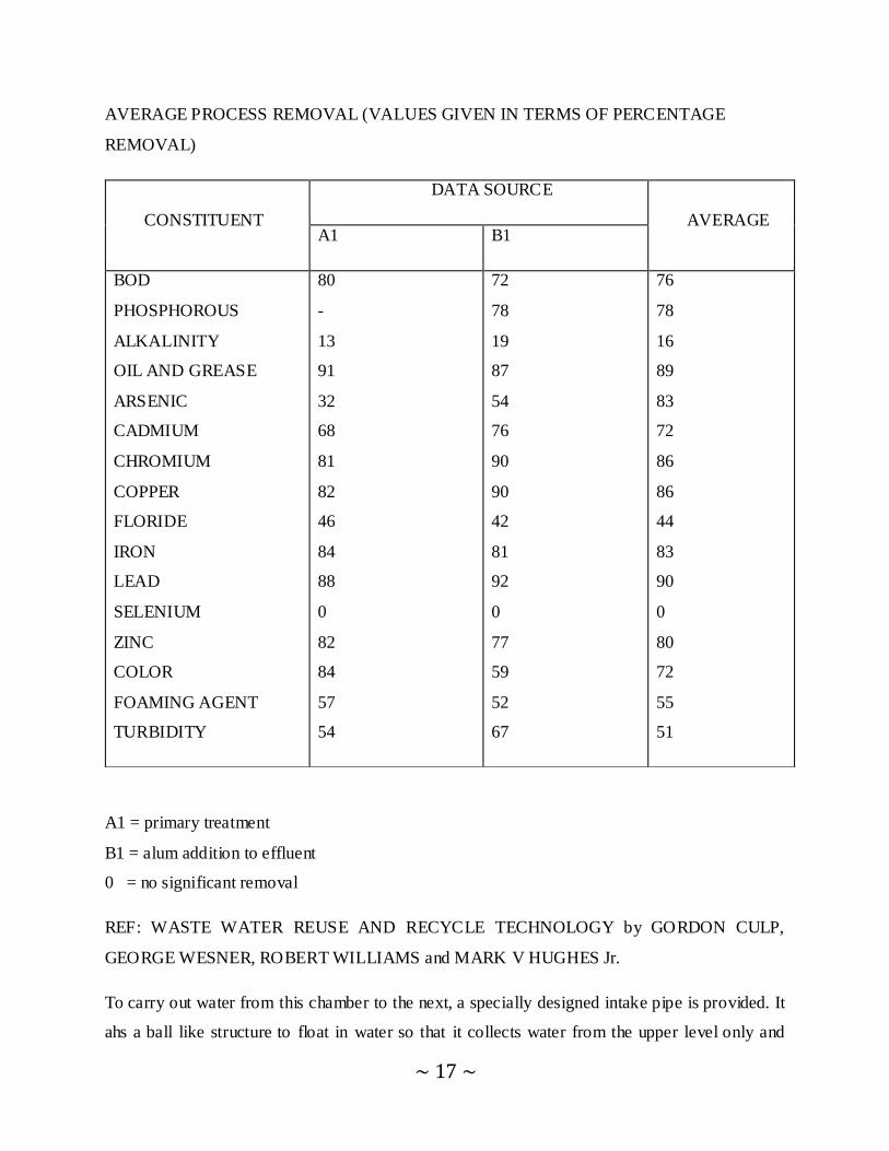
AVERAGE PROCESS REMOVAL (VALUES GIVEN IN TERMS OF PERCENTAGE
REMOVAL)
A1 = primary treatment
B1 = alum addition to effluent
0 = no significant removal
REF: WASTE WATER REUSE AND RECYCLE TECHNOLOGY by GORDON CULP,
GEORGE WESNER, ROBERT WILLIAMS and MARK V HUGHES Jr.
To carry out water from this chamber to the next, a specially designed intake pipe is provided. It
ahs a ball like structure to float in water so that it collects water from the upper level only and
CONSTITUENT
DATA SOURCE
AVERAGE A1 B1
BOD
PHOSPHOROUS
ALKALINITY
OIL AND GREASE
ARSENIC
CADMIUM
CHROMIUM
COPPER
FLORIDE
IRON
LEAD
SELENIUM
ZINC
COLOR
FOAMING AGENT
TURBIDITY
80
-
13
91
32
68
81
82
46
84
88
0
82
84
57
54
72
78
19
87
54
76
90
90
42
81
92
0
77
59
52
67
76
78
16
89
83
72
86
86
44
83
90
0
80
72
55
51

~ 18 ~
that also after filtering it so that the impurities that are skimmed can be restricted. It starts
collecting water only after water level reaches a certain height in the tank in order to assure that
proper sedimentation takes place. Through this intake pipe water is carried to the last chamber of
the filtration system. Fig. of the inlet pipe is as shown.
The last chamber, which is the most crucial one, performs the job o f removing organic soluble
substances and one of the most crucial elements present in the house hold waste that can pollute
water easily and severely. These elements are the SURFACTANTS that are present in a sound
amount in the house hold waste. Though the foaming agents are removed in the steps 1 and 3,
but it is not removed completely or to such an extent that water can be directed underground
The chamber is more or less similar to that used in 1st step except the arrangement of layers and
presence of most influencing, a natural material „SHUNGITE‟.

~ 19 ~
The chamber is as
shown.
SHUNGITE is a natural carbonaceous mineral, abundant in Russia. Their properties are current
under studies and applications are continuously growing. It is elementary Carbon with
amorphous structure. SHUNGITE contains 30% carbon (by mass) and following additional
compounds: SiO2 (60%), Al2O3 (3.5%), Fe2O3 + FeO (2%), TiO2(0.2%), MgO +CaO (1%) and
K2O + Na2O (1%). Globular and ellipsoidal multilayer nanoparticles with size between 6 – 10
nm, having inner cavities are structure forming element of SHUNGITE carbon.
SHUNGITE is elementary non crystalline carbon with a metastable structure incapable of
graphitization. It is an amorphous carbon mineral containing widely dispersed silicate gra ins.
The peculiarity of HSUNGITE carbon structure is known to be the existence of an
interpenetrating network between two phases carbon and silica, which are the main constituents
of the SHUNGITE rock. It is also used s a term to describe a sequence of metamorphic from the
Karelia region of Russia containing such carbon
A continued pollution of water is connected with the distinct colloido-chemical property of
surfactants, namely their surface activity or ability to form foams, emulsions and micelles, as
well as their ability to form structures in the volume and stabilize other pollutants in water.

~ 20 ~
Micelle forming surfactant detergents (anionic sodium dodecylsulfate SDS, cationic
cetyltrimethylammonium bromide CTAB and non- ionic Triton X-100) can be adsorbed
effectively using the SHUNGITE carbon. Specific use of SHUNGITE is due to the reason that
some other good adsorbent, such as AL2O3 is effective for adsorbing cationic CTAB, but for
SDS and TRITON X – 100, it is non-effective.
In this chamber top layer comprises of sand followed by gravel and finally by a layer of
SHUNGITE. One layer of SHUNGITE can also be provided on top for more effective
adsorption. Water is then carried away to a pipe that is bored halfway to the level of ground
water after which water is allowed for natural percolation through the layers of different types of
soil which itself is a very effective natural filter.

~ 21 ~
CHAPTER 4
MAINTENANCE

~ 22 ~
MAINTENANCE
From maintenance point of view, this system is not a hectic one and needs not require frequent
inspection. To fulfill the demand of ALUM in the system, one has to just fulfill the ALUM
BAGS with powdered alum. As the ALUM is dissolved from the perforated bag, it gets refilled
by its own with the alum lying in the ALUM BAGS.
To clean up the whole system, a process required to be done hardly twice or thrice in 6 months,
one should first direct the waste water flow to sewer with a valve that can be provided just before
the inlet point of the system.
To clean the first chamber, one can either replace whole constituents, as they are natural and
abundantly available, or can use the same material by washing it with a jet of clean water.
Similarly the membrane or the sponge, if in a condition to be reused, can be cleaned up by
applying a jet of clean water on the side opposite to that facing oily water, else it can be replaced.
To clean water tank one has to just remove the sediments deposited at the bed which can be
carried out easily using hoe. Finally cleaning of the last chamber of the system is more or less
same as that of first chamber except cleaning of SHUNGITE. The adsorbed material from the
SHUNGITE can be cleaned up by just heating the element which can be carried out artificially or
by leaving the material in Sun for a sufficient period of time. In order to run the system
continuously one would have an option of keeping two lots of SHUNGITE, so that when one lot
is removed and kept in Sun, another one could be installed at its place

~ 23 ~
CHAPTER 5
COMMERCIAL IMPLEMENTATION

~ 24 ~
COMMERCIAL IMPLEMENTATION
The system will be economically sound. There is just one time nominal investment required.
Also the maintenance cost will be so nominal that it won‟t put any extra burden on the house
holder. For a single storied building and an average sized family, the total initial cost of the
system will be about 9-10 thousand only. If this system is used, we can very easily tackle the
problem of depletion of ground water level. It is very clear that in the coming future this problem
will become more and more severe and some effective effort is needed in this direction. If we
look at other alternatives, we have a method to recharge ground water by collecting water in
some catchment area and then allowing the water to percolate by its own. But for this procedure
we need a large area for catchment of water. Availability of such large area in a residential area,
where shortage of land for more houses is itself a big problem, is practically impossible. Also we
can‟t allow the house hold waste water to percolate without any primary treatment. It can be
implemented as a law that no housing plan will be passed without the presence of this system. If
this is done, government can influence in the trading of SHUNGITE ore and thereby making it
cheaper in the Indian markets. Further the materials that are required in each chamber can be
launched in the market as a set of all constituents for a particular chamber, depending upon the
size of the chamber and that also in a very reasonable rate. Also SHUNGITE will make the cost
minimum because if we want to use the same system by replacing SHUNGITE with some other
material that is present in India, we have to go for the activated Charcoal. Major drawback of
using activated Charcoal is that once the activation is over, we have to reactivate the Charcoal,
which again is practically very difficult for normal people because the activation can‟t be done at
home and one has to go to such a place where reactivation can done.
Thus the system mentioned here is the most economical and easies way to tackle the problem
concerned with ground water and that also on a large scale.

~ 25 ~
CHAPTER 6
SIGNIFICANCE OF THE SYSTEM

~ 26 ~
SIGNIFICANCE OF THE SYSTEM
Cost will be very nominal and also the maintenance period would be sufficiently long to avoid
frequent inspection. Thus no significant effort would be required from the house holder. Further
there will be a continuous process of replenishing ground water and we need not to rely
completely on rain water. Also, this water replenishing system would be much more
economically viable and effective when employed on a scale of residential colonies as a whole.
Since there would be a recharge system working in each house in a residential area, the
continuous fall in ground water level can be effectively checked. Further this system can be
installed in apartments, colonies, bungalows etc. with some preferable changes, it could also be
installed in schools. Thus it can play a vital role in balancing the Ecosystem.

~ 27 ~
CHAPTER 7
ALTERNATIVES USED

~ 28 ~
ALTERNATIVES USED
7.1) Due to unavailability of SHUNGITE, activated charcoal was used in the fourth stage of
filtration. Activated charcoal, also called activated carbon or activated coal is a form of
carbon that has been processed to make it extremely porous and thus to have a very large
surface area available for adsorption or reaction. Due to its high degree of micro porosity,
just one gram of activated carbon has a surface area of approximately 500 square meters.
Sufficient activation for useful application may come solely from the high surface area,
though further chemical treatment often enhances the adsorption properties of the
material.
POWDERED ACTIVATED CARBON (PAC):
Traditionally, active carbons are made in particular form as powders or fine granules less than
1.0 mm in size with an average diameter between .15 and .25 mm. Thus they present a large
surface to volume ratio with a small diffusion distance. PAC is made up of crushed or ground
carbon particles, 95–100% of which will pass through a designated mesh sieve or sieve. Granular
activated carbon is defined as the activated carbon being retained on a 50-mesh sieve (0.297 mm)
and PAC material as finer material, while ASTM classifies particle sizes corresponding to an 80-
mesh sieve (0.177 mm) and smaller as PAC. PAC is generally added directly to other process
units, such as raw water intakes, rapid mix basins, clarifiers, and gravity filters.
PHYSICAL AND CHEMICAL PROPERTIES:
Appearance: Fine black powder.
Odor: Odorless.
Solubility: Insoluble in water.
Specific Gravity: 1.8 - 2.1

~ 29 ~
pH: 5.0-10.0
% Volatiles by volume @ 21C (70F): 0
Boiling Point: Sublimes.
Melting Point: 3550C (6422F)
Vapor Density (Air=1): 0.4
Vapor Pressure (mm Hg): 1 @ 3586C (6487F)
Evaporation Rate (BuAc=1): No information found.
POTENTIAL HEALTH EFFECTS:
Inhalation: No adverse effects expected. May cause mild irritation to the respiratory tract.
Ingestion: No adverse effects expected. May cause mild irritation to the gastrointestinal tract.
Skin Contact: Not expected to be a health hazard from skin exposure. May cause mild irritation
and redness.
Eye Contact: No adverse effects expected. May cause mild irritation, possible reddening.
Chronic Exposure: Prolonged inhalation of excessive dust may produce pulmonary disorders.

~ 30 ~
7.2) Sample to be tested is prepared in the laboratory instead of collecting from a suitable site.
List of chemicals added is:
Serial no. Salt Amount (gm)
1. Sodium Nitrate 100.00
2. Potassium Chromate 20.00
3. Ammonium Chloride 50.00
4. Copper II Sulfate
Pentahydrate
30.00
5. Iron (II) Sulfate hyptahydrate 30.00
6. Potassium dihydrogen
Phosphate
50.00
7. Cadmium Nitrate 20.00
8. Lead Nitrate 1.5
9. Zinc Sulfate 200.00

~ 31 ~

~ 32 ~
7.3) Second stage, which is an optional one, was not included while conducting the
experiments.
7.4) Alum was added to water manually just before stage three got started. Concentration of
alum was kept to be 20mg/l.
~ 33 ~
CHAPTER 8
ACTUAL EXPERIMENTAL SETUP

~ 34 ~
ACTUAL EXPERIMENTAL SETUP
The filter required for the first stage was assembled in a box made up of perplexes material,
which is transparent in nature. The dimension of the box was 0.5m X 0.5m X 0.6m.
The grain size of the sand used as a filtering media was taken to be in a range of 450µ-220µ, i.e.
passing from 450µ sieve but retained in 220µ sieve. For supporting media, pebb les of size
1.5cm-2.5cm were used, which were collected from the banks of the river Koel.
Amount of sand required was about 200kg (or four sand bags), whereas about half of a sandbag
of pebbles (0.0125 cubic meter) was required.
Actual setup is as shown below

~ 35 ~
Bottom most layer was made up of pebbles. Depth of this layer was kept to be about 10cm-
12cm. above it was a layer of sand which continued up to the top most level of the filter, thus
providing a sand layer of about 48cm-50cm. A sheet of filter paper was provided at the bottom
most part of the box to restrict any passage of fine sand through the holes provided at the floor of
the box to collect water from the filter.
In the third stage, alum was mixed manually to the water that has been collected after the
completion of stage one. Concentration of alum was kept to be about 20mg/l. This water was
allowed to stagnate for a few days in a tank as shown in the following picture.

~ 36 ~

~ 37 ~
In the last stage of the filter, as mentioned above, activated charcoal was used in place of
SHUNGITE. Depth of the supporting pebble layer was about 5cm, above which was a layer of
activated charcoal. About 5kg of activated charcoal was used in this stage. A layer of about
10cm-15cm of activated charcoal was required for this stage. Since the amount of activated
charcoal available was not sufficient enough to maintain a layer of such depth, the filter was
separated into three parts using thermacoal as separating medium and plastic sheets to make each
compartment water proof. Thus the effective filter was assembled in only one fourth part of the
original filter. In this part, depth of the supporting pebble layer was maintained to be 5cm-7cm.
depth of the activated charcoal layer was maintained to be about 15cm-17cm and above it was a
layer of sand of the same grade as that used in the first stage. This layer of sand continued up to
the top most level of the filter. Filter papers were provided between pebbles and activated
charcoal layer and also between sand and activated charcoal to avoid any mixing of these
materials. Also a filter paper was provided at the bottom most part of the filter to restrict any
passage of sand through the holes, which were provided at the floor of the box to collect water
from the filter.

~ 38 ~

~ 39 ~

~ 40 ~
CHAPTER 9
EXPERIMENTS CONDUCTED

~ 41 ~
9.1)
DETERMINATION OF OIL AND GREASE
Oil and grease is defined as any material recovered as a substance soluble in the solvent. It
includes other material extracted by the solvent from an acidified sample (such as sulfur
compound, certain organic dies and chlorophyll) and not volatilizes during the test.
REAGENTS:
1. Sulfuric acid (1:3) one part of sulfuric acid and three parts of water
2. Petroleum ether
3. Ethyl alcohol
PROCEDURE:
1. 200 ml of sample is taken in a separating funnel, and 10ml of sulfuric acid and 25ml of
ether was added.
2. Sample is shake properly and is kept for some time to separate the two distinct layers, the
upper one of the petroleum ether and lower one of the sample.
3. Lower layer is discarded through separating funnel.
4. A pre weighed small beaker is taken and the petroleum ether from the separating funnel
is run through a filter paper which is already been moistened with fresh petroleum ether.
5. A little more petroleum ether is added through the wall of filter paper to remove any
residual oil and grease on the filter paper.
6. Petroleum ether is evaporated on a water bath and final weight is taken, after cooling in a
desiccator.

~ 42 ~
CALCULATIONS:
Oil and Grease mg/l = ((A – B) * 1000)/V
A = final weight of disc
B = initial weight of disc
V = volume of sample in ml
OBSERVATION AND READINGS:
Sample no. Amount of
sample (ml)
Initial weight
(gm)
Final weight
(gm)
Oil and
grease (mg/l)
Percentage
removal
1. 200 33.14 33.63 2.450 -
2. 200 47.05 47.18 0.65 73.46
3. 200 64.05 64.08 0.15 76.92

~ 43 ~
9.2)
DETERMINATION OF ALKALINITY
Alkalinity of water is the capacity of water to accept protons. It may be defined as the
quantitative capacity of an aqueous medium to react with hydrogen ions..
REAGENTS:
1. Distilled water
2. Standard solution of sulfuric acid – 0.02N
3. Phenolphthalein indicator
4. Methyl orange
PROCEDURE:
1. 20ml of sample is pipette in a beaker.
2. 3 drops of phenolphthalein indicator is added. If slightly yellow color appears, sample is
titrated with standard sulfuric acid solution until the color disappears.
3. 3 drops of methyl orange is added and sample is titrated with standard sulfuric acid
solution until a tinge of pink color appears. Amount of standard sulfuric acid is noted
down.
CALCULATION:
Total alkalinity (as mg/l of CaCO3) = ((A + B)*N*5000)/V

~ 44 ~
A = ml of standard sulfuric acid used in titration in step 2.
B = ml of standard sulfuric acid used in titration in step 3.
N = normality of acid used.
V = volume of sample in ml.
OBSERVATION AND READINGS:
Sample no. A (ml) B (ml) Alkalinity mg/l
of CaCO3
% change
1 0 8.1 81 -
2 0 10.2 102 26.25 (increase)
3 0 5.5 55 46.07 (decrease)
4 0 8.9 89 61.81 (increase)

~ 45 ~
9.3)
DETERMINATION OF BOD
PROCEDURE:
1. Water is taken in an incubation bottle.
2. 4 capsules (4gm) of NaOH is kept at the neck of the bottle
3. A magnetic stirrer is kept inside the bottle which rotates continuously when kept inside
the incubator
4. Bottle is capped with an air tight cap, attached with an electronic meter which records
BOD at every 24 hours
5. Bottle is preserved in the incubator for 5 days
6. After 5 days, reading is noted down.
OBSERVATION:
Sample no. BOD
1. 19
2. 13
3. 09
4. 05

~ 46 ~
9.4)
DETERMINATION OF DO
PROCEDURE:
1. Water is taken in an incubation bottle
2. Bottle is kept in an air incubator and magnetic stirrer is put in it which rotates
continuously.
3. With the help of DO meter, readings are taken for the top, middle and bottom part of the
bottle.
4. Average of these readings is taken which gives the DO present in the sample.
OBSERVATION AND READINGS:
Sample no. DO at the top
section
DO at the
middle section
DO at the
bottom section
Average DO
1. 1.99 2.05 2.02 2.02
2. 3.65 3.71 3.68 3.68
3. 4.91 4.99 4.96 4.95
4. 6.21 6.24 6.20 6.22

~ 47 ~
9.5)
DETERMINATION OF ph
PROCEDURE:
1. Water sample is taken in a beaker.
2. This beaker is then put in the ph meter and electrodes are completely dipped in water.
3. Reading is noted down from the meter
4. Same process is repeated for other samples
OBSERVATION AND READINGS:
Sample no. Temperature ph
1. 35.4 6.19
2. 35.3 7.74
3. 35.3 4.1
4. 35.5 6.8

~ 48 ~
9.6)
DETERMINATION OF TURBIDITY
PROCEDURE:
1. Nephelo meter is adjusted to zero reading for distilled water and range of measuring
turbidity is selected.
2. Sample is taken in the small beaker provided with the nephelo meter.
3. Sample is covered with the lid provided
4. Reading is taken directly from the meter.
5. Same process is repeated for other samples.
OBSERVATION AND READINGS:
Sample no. Turbidity (in NTU) % Removal
1. >1000 -
2. 150-180 >83.50
3. 40-60 69.69
4. <8 88.00

~ 49 ~
CHAPTER 10
RESULTS

~ 50 ~
RESULTS
Percentage removal of several pollutants in the experiments conducted as compared to the
theoretical values is as follows
Constituents of the sample are
Serial no. Salt Amount (mg/l)
1. Sodium Nitrate 10.00
2. Potassium Chromate 2.00
3. Ammonium Chloride 5.00
4. Copper (II) Sulfate
Pentahydrate
3.00
5. Iron (II) Sulfate hyptahydrate 3.00
6. Potassium dihydrogen
Phosphate
5.00
7. Cadmium Nitrate 2.00
8. Lead Nitrate 0.1
9. Zinc Sulfate 15.00

~ 51 ~
Theoretical value of percentage removal in first stage is given below
+ = Increase
X= data inconclusive
0 = no significant removal
Percentage removal in the experiments conducted for the first stage
CONSTITUENT
DATA SOURCE
AVERAGE A B
BOD
NH3-N
PHOSPHOROUS
ALKALINITY
OIL AND GREASE
ARSENIC
CADMIUM
CHROMIUM
COPPER
FLORIDE
IRON
LEAD
SELENIUM
ZINC
COLOR
TURBIDITY
FOAMING AGENT
48
17
27
+
67
28
30
+
40
+
43
51
0
38
18
31
30
50
19
26
+
63
40
45
44
58
X
42
53
0
34
12
30
38
42
18
27
+
65
34
38
44
49
X
43
52
0
36
15
31
34

~ 52 ~
Serial no. Constituents Percentage Removal
1. BOD 31.57
2. NH3-N -
3. Phosphorous -
4. Alkalinity 26.25 (increase)
5. Oil and Grease 73.46
6. Arsenic NA
7. Cadmium -
8. Chromium -
9. Copper -
10. Fluoride NA
11. DO 82.18
12. Iron -
13. Lead -
14. Selenium NA
15. Zinc -
16. Color -
17. Turbidity >83.50
18. Foaming Agent -
19. ph 25.04 (increase)

~ 53 ~
Theoretical value of percentage removal in third stage is given below
A1 = primary treatment
B1 = alum addition to effluent
0 = no significant removal
Percentage removal in the experiments conducted for the third stage
CONSTITUENT
DATA SOURCE
AVERAGE A1 B1
BOD
PHOSPHOROUS
ALKALINITY
OIL AND GREASE
ARSENIC
CADMIUM
CHROMIUM
COPPER
FLORIDE
IRON
LEAD
SELENIUM
ZINC
COLOR
FOAMING AGENT
TURBIDITY
80
-
13
91
32
68
81
82
46
84
88
0
82
84
57
54
72
78
19
87
54
76
90
90
42
81
92
0
77
59
52
67
76
78
16
89
83
72
86
86
44
83
90
0
80
72
55
51

~ 54 ~
Serial no. Constituents Percentage Removal
1. BOD 30.77
2. NH3-N -
3. Phosphorous -
4. Alkalinity 46.07
5. Oil and Grease 76.92
6. Arsenic NA
7. Cadmium -
8. Chromium -
9. Copper -
10. Fluoride NA
11. DO 34.51 (increase)
12. Iron -
13. Lead -
14. Selenium NA
15. Zinc -
16. Color -
17. Turbidity 69.69
18. Foaming Agent -
19. ph 47.02

~ 55 ~
Percentage removal of some constituents in experiments conducted for stage four are
Serial no. Constituents Percentage Removal
1. BOD 44.44
2. Alkalinity 61.81 (increase)
3. Oil and Grease -
4. DO 25.65 (increase)
5. Turbidity 88.00
6. ph 65.85 (increase)

~ 56 ~
CHAPTER 11
CONCLUSION

~ 57 ~
CONCLUSION
Values obtained for percentage removal of some constituents in experiments is quiet comparable
to the theoretical values of percentage removal of those constituents.
Though the experiments were conducted only for some pollutants and about 50% were not
experimentally checked, but by taking into account the comparability between the theoretical
values and experimental values or remaining constituents, it can be concluded that the system
works quiet effectively for these constituents and if only these constituents are considered, the
filtered water has these constituents in a range that is safe enough to permit water to be directed
underground.

~ 58 ~
CHAPTER 12
REFERENCES

~ 59 ~
REFERENCES
I. Culp G., Wesner G., Williams R. and V. Hughes Mark Jr, SWaste water reuse and
recycling technology, Noyes Data Corp. Park ridge, New Jersey, U.S.A.
II. American water works association, water quality and treatment, McGraw Hills
III. http://www.rainwaterharvesting.org/Urban/Components.htm [Last viewed on
10/03/2009]
IV. http://www.brc.tamus.edu/decision-aids/tex-a-syst/hazardous-waste-management.aspx
[last viewed on 12/03/2009]
V. http://www.kcrecycling.com/household_hazards_disposal.html [last viewed on
13/03/2009]
VI. ROZHKOVA N.N. (Institute of Geology Karelian Research Centre RAS,
PETROZZAVODSK Russia), “SHUNGITE AS A NETWORK OF CARBON
NANOPARTICLES”, Vol No.185610
VII. The Journal of the Argentine Chemical Society, “CHARACTERIZATION OF
SHUNGITE BY PHYSICAL ADSOPTION OF GASES”, Vol. 92-N* 4/6, 51-58 (2004).
Related Documents