Ground Penetrating Radar

Welcome message from author
This document is posted to help you gain knowledge. Please leave a comment to let me know what you think about it! Share it to your friends and learn new things together.
Transcript
Ground Penetrating Radar

Ground Penetrating Radar• Radar electromagnetic waves (light) at radio frequencies (50 to 1000 MHz)
• Requires motion of source/receiver – Doppler Effect
• Requires a source and receiver (dipole antennae for both)
• Source transmits a single pulse:
but can transmit and receive millions of pulses per second!
• Governed by physics of the wave equation (somewhat like seismic methods: V = f!)
05x10-9 sA
mpl
itude
time
Pow
erfrequency
10 Mhz 100 1000
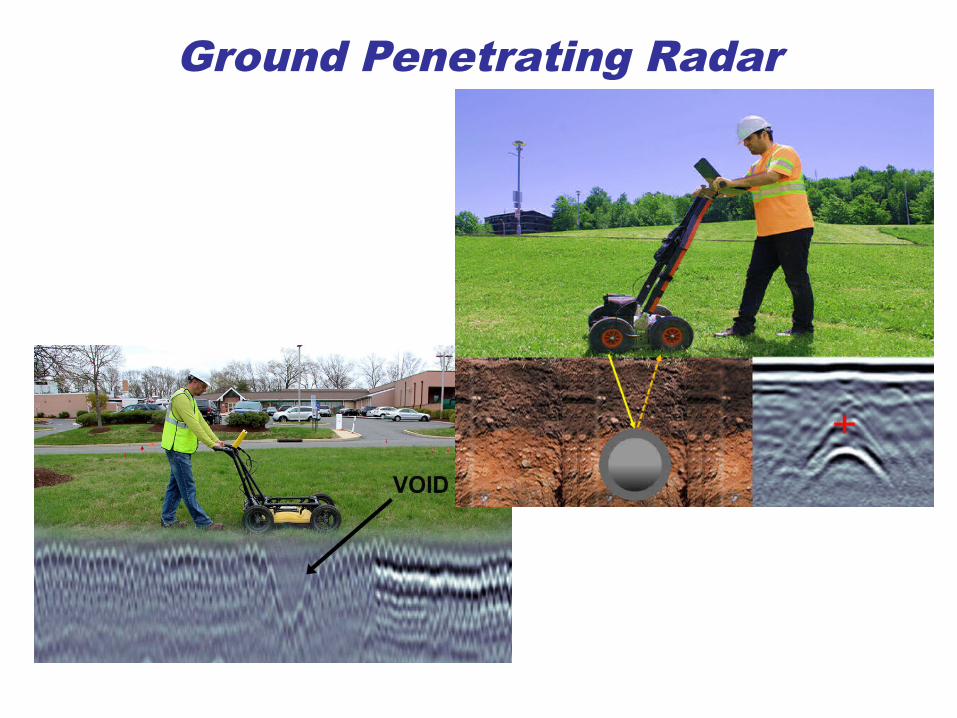
● GPR carts rely on the motion of the antenna to generate a continuous radar record of traverse distance vs. depth in the earth.
● GPR data is ordinarily recorded on video card and displayed on an LCD screen for immediate analysis.
● The successful interpretation of GPR records is an art as well as a science requiring considerable operator experience for good results.
● GPR’s are also known as “impulse radars” because the transmitted pulse is very short and is ordinarily generated by the transient voltage pulse generated from an overloaded avalanche transistor.
● The frequency used is a compromise. One desires to use the lowest possible frequency because low frequencies give reasonably high penetration depths into the earth. But a sufficiently high frequency must be selected so that the radar wavelength is short, allowing detection and resolution of small objects such as pipes.
● GPR surveys should be performed in the dry season if at all possible
Ground Penetrating Radar
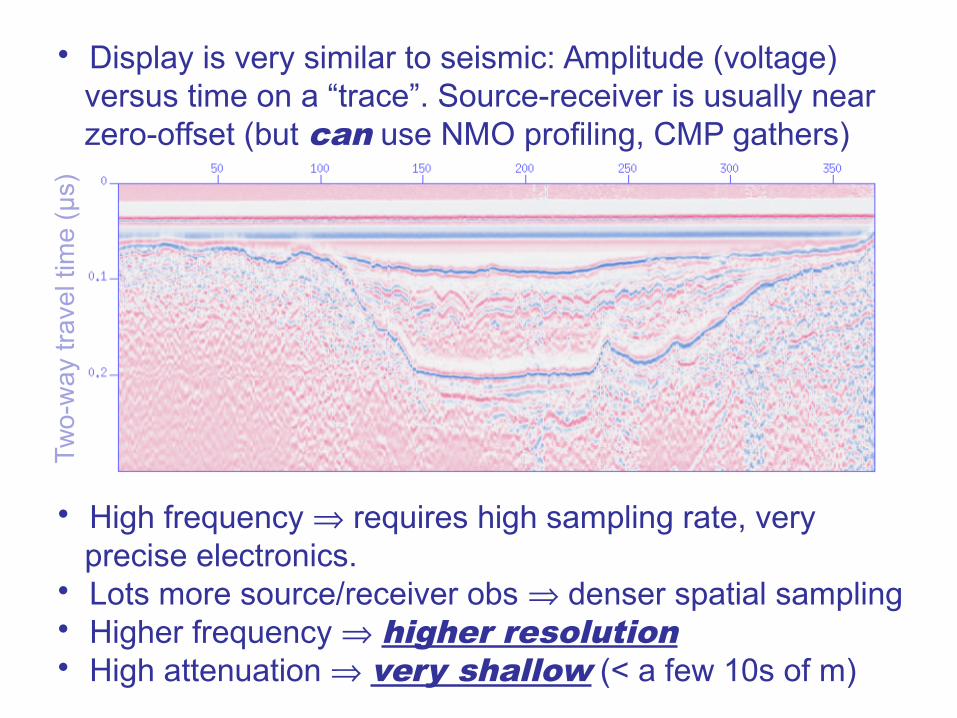
• Display is very similar to seismic: Amplitude (voltage) versus time on a “trace”. Source-receiver is usually near zero-offset (but can use NMO profiling, CMP gathers)
• High frequency requires high sampling rate, very precise electronics. • Lots more source/receiver obs denser spatial sampling• Higher frequency higher resolution• High attenuation very shallow (< a few 10s of m)
Tw
o-w
ay tr
ave
l tim
e (µ
s)

Like seismic, waves are reflected & transmitted at interfaces with differing impedance properties:
layer 1layer 2
E0 E1
E2
• Snell’s law applies. • Amplitude dependence is different (simpler) because there is only one type of wave.• Reflection R & Transmission T coefficients are identical to seismic (for 90° angle of incidence):
where Zi is the electromagnetic impedance in layer i.
E1
E0
R Z2 Z1
Z2 Z1
E2
E0
T 2Z1
Z2 Z1

Recall for seismic: Acoustic Impedance Zi = iVi
For Electromagnetic Impedance,
where: = frequency = dielectric permittivity = relative magnetic permeability = electrical resistivity = 1/ = electrical conductivity r is called the dielectric constant (or “relative permittivity”): a complex variable.
All (except frequency ) are physical properties of the medium, so like impedance & velocity in seismic studies, these contain information about the targeted volume!
Most modern radar sections are converted from two-way travel-time to depth using an assumed value for velocity… Important to note that:
Z r
2 i
i
1
i
V cr

Soil and Rock Properties:
Relative Magnetic Permeability ~ 1 for most rocks; 1.05 for hematite 5 for magnetite
Dielectric Constant r (= relative permittivity) (real part): (dry) (wet)
(defined as: )magnetic flux densitymagnetic field intensity
4 30soil
3 30sand
5 12sandstone
7 40clay
water 80 88
(fre
sh)
(brin
e)
4 8limestone
5 15shale
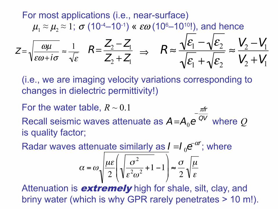
For most applications (i.e., near-surface) 1 ≈ 2 ≈ 1; (10-4–10-1) « (106–1010!), and hence
(i.e., we are imaging velocity variations corresponding tochanges in dielectric permittivity!)
For the water table, R ~ 0.1
Recall seismic waves attenuate as where Qis quality factor;
Radar waves attenuate similarly as ; where
Attenuation is extremely high for shale, silt, clay, and briny water (which is why GPR rarely penetrates > 10 m!).
R1 2
1 2
V2 V1
V2 V1
AA0e frQV
I I 0er
R Z2 Z1
Z2 Z1
Z i
1

Skin depth, or depth of penetration,is ~ 1/. Hence main applications are inarchaeology, environmental,engineeringsite investigation…
Also used for cavity detection and other verynear-surfaceapplications
GPRfreqs
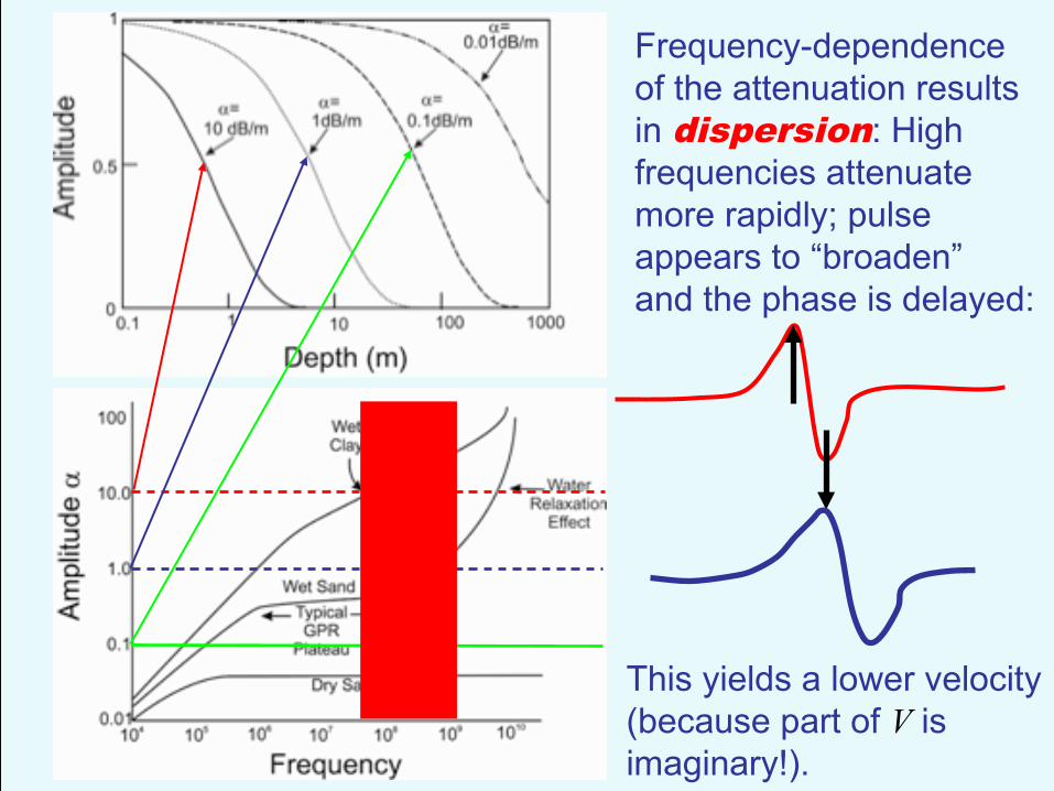
Frequency-dependenceof the attenuation resultsin dispersion: High frequencies attenuatemore rapidly; pulse appears to “broaden”and the phase is delayed:
This yields a lower velocity(because part of V isimaginary!).
GPRfreqs

V1
Alternatively can use moveout on Diffractions:
h1 h2
x
The equations are the same as they were for seismic, but sinceGPR is (usually) zero offset, xs = xg! Thus
rs
xg
tx2 4h1
2
V1
tx2 4h2
2
V1
txs
2 h12 xg
2 h12
V1
t2 x2 h1
2
V1
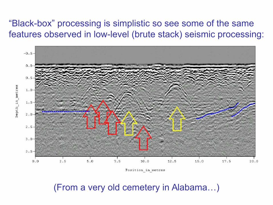
(From a very old cemetery in Alabama…)
“Black-box” processing is simplistic so see some of the samefeatures observed in low-level (brute stack) seismic processing:

Related Documents


