Ground or Strata Instability in Underground Mines and Tunnels SEPTEMBER 2016 APPROVED CODE OF PRACTICE HSWA • H E A L T H & S A F E T Y A T W O R K A C T •

Welcome message from author
This document is posted to help you gain knowledge. Please leave a comment to let me know what you think about it! Share it to your friends and learn new things together.
Transcript

Ground or Strata Instability in Underground Mines and TunnelsSEPTEMBER 2016
APPROVED CODE OF PRACTICEHSWA•
HE
ALT
H
& SAF ET Y AT W
OR
K A
CT
•

ACKNOWLEDGEMENTS
WorkSafe New Zealand (WorkSafe) would like to thank the members of the industry working group for their contribution to the development of this code. Our thanks also go to NSW Government Trade and Investment, Regional Infrastructure and Services; Safe Work Australia; Government of Western Australia Department of Mines and Petroleum; Open House Management Solutions, South Africa; Strata Control Technology, NSW, Australia; and the Health and Safety Executive (HSE), England for letting us use content from their publications.

NOTICE OF APPROVAL
The code of practice for Ground or Strata Instability in Underground Mines and Tunnels sets
out WorkSafe New Zealand’s expectations in relation to identifying and controlling the work
health and safety risks arising from mining and tunnelling operations, in order to help PCBUs
and workers achieve compliance with the Health and Safety at Work Act 2015 and the Health
and Safety at Work (Mining Operations and Quarrying Operations) Regulations 2016.
WorkSafe New Zealand developed the code with input from unions, employer organisations,
other key stakeholders and the public.
Together with the right attitudes and actions of PCBUs and workers focused on improving health
and safety practices at work places, the code will contribute to the Government’s targets of
reducing the rate of fatalities and serious injuries in the workplace by at least 25% by 2020.
Accordingly, I Michael Allan Woodhouse, being satisfied that the consultation requirements of
section 222(2) of the Health and Safety at Work Act 2015 have been met, approve the code
of practice for Ground or Strata Instability in Underground Mines and Tunnels under section 222
of the Health and Safety at Work Act 2015.
Hon Michael Woodhouse Minister for Workplace Relations and Safety
16 August 2016

FOREWORD
As the Chair of the Board of WorkSafe New Zealand, I am pleased to introduce this approved
code of practice for Ground or Strata Instability in Underground Mines and Tunnels.
It was developed with input from our social partners, industry and public consultation.
This approved code of practice will help duty holders comply with their requirement to provide
healthy and safe work for everyone who works in this industry. It will also help make sure that
other people do not have their health and safety adversely affected by the work conducted.
A healthy and safe workplace makes good sense. An organisation with health and safety systems
that involve its workers can experience higher morale, better worker retention, increased worker
attraction and – most importantly – workers who return home to their families, healthy and safe,
after they finish their work.
Organisations benefit from having less downtime from incidents and higher productivity. An
organisation known for its commitment to health and safety can benefit from its improved reputation.
We must all work together to make sure that everyone who goes to work comes home healthy
and safe. By working together, we’ll bring work-related harm down by making sure that all work
conducted is healthy and safe work.
Professor Gregor Coster, CNZM
Chair, WorkSafe New Zealand

TABLE OF CONTENTS
PART A
01 INTRODUCTION 10
1.1 What is the purpose of this code? 12
1.2 What is the legal status of this code? 12
1.3 How to use this code 13
1.4 Roles and responsibilities 14
1.5 Worker engagement, participation and representation 14
1.6 Health and safety management system 15
1.7 Hazards and risks 16
1.8 Principal hazard management plan for ground or strata instability 16
PART B
02 CAUSES OF GROUND OR STRATA INSTABILITY AT THE OPERATION 20
2.1 Identify the causes of ground or strata instability 21
03 GEOTECHNICAL ASSESSMENT 23
3.1 Requirement for a geotechnical assessment at mining and tunnelling operations 24
3.2 Site characterisation 27
3.3 Collection, analysis and interpretation of geotechnical data 27
3.4 Re-using a geotechnical assessment 28
3.5 Review of the geotechnical assessment 28
04 DESIGN OF CONTROL MEASURES/SUPPORT METHODS TO AVOID GROUND OR STRATA INSTABILITY 30
4.1 Design details and support methods 31
4.2 Design methodologies used to determine ground support needed 32
4.3 Design requirements for rock reinforcement systems 33
4.4 Stope or pillar design requirements for coal and metalliferous mines 34
4.5 Temporary and permanent ground support systems 37

4.6 Primary and secondary support systems 38
4.7 Temporary support systems 42
4.8 Shafts 45
4.9 Continuous modelling and design verification 45
PART C
05 IMPLEMENTING THE CONTROL MEASURES 49
5.1 Ground support/controls and excluded areas 50
5.2 Application for construction or permit to tunnel 50
5.3 Self-supporting mines or tunnels 51
5.4 Installation training 51
5.5 Scaling and barring down 52
5.6 Installing temporary support 52
5.7 Equipment used during installation 53
5.8 Timing of support/reinforcement installation 53
5.9 Support materials/consumable items 54
5.10 Standard operating procedures 54
5.11 Manager’s support rules for installation 56
5.12 Installing higher standards of support 59
5.13 Inadequate ground or strata support 59
5.14 Rock bolt integrity 60
5.15 Lifting and suspension of equipment in rock bolted roadways or tunnels 61
5.16 Withdrawal of support material 62
06 MONITORING, INSTRUMENTS AND REPORTING 63
6.1 Monitoring ground or strata instability 64
6.2 Benefits of monitoring 64
6.3 Monitoring plan 65
6.4 Trigger Action Response Plans (TARPs) 66
6.5 Selecting suitable monitoring methods and instrumentation 68
6.6 Monitoring bolt integrity 69
6.7 Geotechnical hazard zones – hazard plans or maps 71
6.8 Seismic monitoring 74
6.9 Measurement of loads and deformation 74
6.10 Ground or strata movement indicators 76

6.11 Crack monitoring 78
6.12 Monitoring pillar and extraction sequence design – coal mining 79
6.13 Monitoring to detect goaf/waste fall precursors 80
6.14 Monitoring for movement caused by tunnel development 80
6.15 Regular examinations and shift reports 80
07 GROUND OR STRATA FAILURE AND ACTIONS REQUIRED 82
7.1 Report actual or suspected ground or strata failure 83
08 EMERGENCY PREPAREDNESS 84
8.1 Prepare for ground or strata instability emergencies 85
PART D
09 NOTIFIABLE EVENTS 87
9.1 Notifiable events 88
10 REVIEW AND AUDIT 90
10.1 When to review the PHMP 91
10.2 Auditing the PHMP 92
10.3 Communicating changes from reviews or audits 93
PART E
11 GLOSSARY 95
12 APPENDIX 102
12.1 Example of a Trigger Action Response Plan (TARP) 103
13 REFERENCES 107

TABLES
1 Requirements in this code 13
2 Terminology used to refer to support in coal mines, metalliferous mines and tunnels 37
3 Monitoring methods 68
4 Commonly used instruments 77
5 Some of the regular examinations required to be completed at mining or tunnelling operations 81
FIGURES
1 Development and maintenance of a ground or strata instability PHMP 18
2 Components of the geotechnical assessment and design outputs 26
3 Example of inrush control zone marked on a plan 36
4 How tensioned rock bolts clamp the strata 38
5 Rock bolts in a metalliferous mine or tunnel 39
6 Code green support plan 57
7 Code red support plan 58
8 Strain gauge 70
9 Example of hazard zones shown on a hazard map 72
10 Example of a hazard map from an underground metalliferous mine 73
11 Shear indicator 76
12 Examples of convergence monitoring and measuring locations in a segmented tunnel lining and underground tunnel or roadway 78
KEY
C Coal
M Metalliferous
T Tunnels

IN THIS PART:Section 1: Introduction
APART
10
INTRODUCTION
01/PART A
IN THIS SECTION:1.1 What is the purpose
of this code? 1.2 What is the legal status
of this code? 1.3 How to use this code 1.4 Roles and responsibilities1.5 Worker engagement,
participation and representation
1.6 Health and safety management system
1.7 Hazards and risks 1.8 Principal hazard
management plan for ground or strata instability
10

SECTION 1.0 // INTRODUCTION
The legislation that applies to this section is:
Health and Safety at Work Act 2015
Section 22 Meaning of reasonably practicable
Section 30 Management of risks
Section 222 Approval of codes of practice
Section 226 Use of approved codes of practice in proceedings
Part 2 Health and safety duties
Part 3 Worker engagement, participation, and representation
Schedule 3:
Clause 1 Interpretation – mine operator
Clause 2 Meaning of mining operation
Clause 4 Meaning of tunnelling operation
Clause 8 Power of health and safety representative to give notice requiring suspension of mining operation
Clause 9 Power of health and safety representative to require mining operation to stop in case of serious risk to health and safety
Clause 11 Competency and experience requirements for exercise of powers under clauses 8 and 9
Clause 19 Functions and powers of industry health and safety representatives
Health and Safety at Work (Mining Operations and Quarrying Operations) Regulations 2016
Regulation 55 Risk assessment
Regulation 60 Engagement
Regulation 68 Content of principal hazard management plans
Regulation 71 Principal hazard management plans for ground or strata instability
Regulation 73(3) Consideration of whether inundation and inrush is a principal hazard
Regulation 109 Worker participation practices must be documented
Regulation 114 Mine operator must investigate reported hazard
Regulation 115 Mine operator must advise mine worker of result of investigation
Part 3 Health and safety management system
The Health and Safety at Work Act 2015 (HSWA) is New Zealand’s key work health and
safety legislation. It sets out work-related health and safety duties that must be complied
with. Health and safety regulations sit under HSWA, expand on the duties under HSWA and
set the requirements for managing certain risks and hazards.
11

EXTRACTIVES: GROUND OR STRATA INSTABILITY IN UNDERGROUND MINES AND TUNNELS
12
Approved codes of practice (codes) set out WorkSafe New Zealand’s (WorkSafe) expectations
about how duty holders are to comply with their legal duties under HSWA and related
regulations. The relevant legislation for this code is:
> Health and Safety at Work Act 2015 (HSWA)
> Health and Safety at Work (Mining Operations and Quarrying Operations) Regulations
2016 (the MOQO Regulations).
See WorkSafe’s special guide Introduction to the Health and Safety at Work Act 2015 for more
information on health and safety law.
1.1 WHAT IS THE PURPOSE OF THIS CODE?
This code sets out WorkSafe’s expectations for managing ground or strata instability in
underground mining and tunnelling operations. It applies to all underground mining and
tunnelling operations where ground or strata instability is a principal hazard. The code
includes information on:
> causes of ground or strata instability
> geotechnical assessment
> design and implementation of control measures
> monitoring controls
> review and audit requirements.
This information contributes to the contents of the ground or strata instability principal
hazard management plan (PHMP).
This code is for the site senior executive (SSE), mine operator, mine manager, and anyone else
at the mining or tunnelling operation involved in managing the ground or strata instability
principal hazard. This includes workers and other persons.
1.2 WHAT IS THE LEGAL STATUS OF THIS CODE?
This code has been approved under section 222 of HSWA. It can be used in court as evidence
of whether HSWA has been complied with. Courts may use this code:
> as evidence of what is known about the ground or strata instability principal hazard at
an underground mining or tunnelling operation and how those risks may be controlled
> to decide what is reasonably practicable for managing the ground or strata instability
principal hazard at an underground mining or tunnelling operation.
Following the code may not be the only way of complying with HSWA and the MOQO
Regulations. Other practices can be used as long as they provide a level of work health and safety
equivalent to or higher than in this code, and comply with HSWA and the MOQO Regulations.
For more information about the hierarchy of the legislation and the relationship with other
guidance documents, refer to WorkSafe’s special guide Introduction to the Health and Safety
at Work Act 2015. See also WorkSafe’s interpretive guidelines Developing a Ground or Strata
Instability Principal Hazard Management Plan.
12
SECTION 1.0 // INTRODUCTION
1.3 HOW TO USE THIS CODE
1.3.1 INTERPRETING THIS CODE
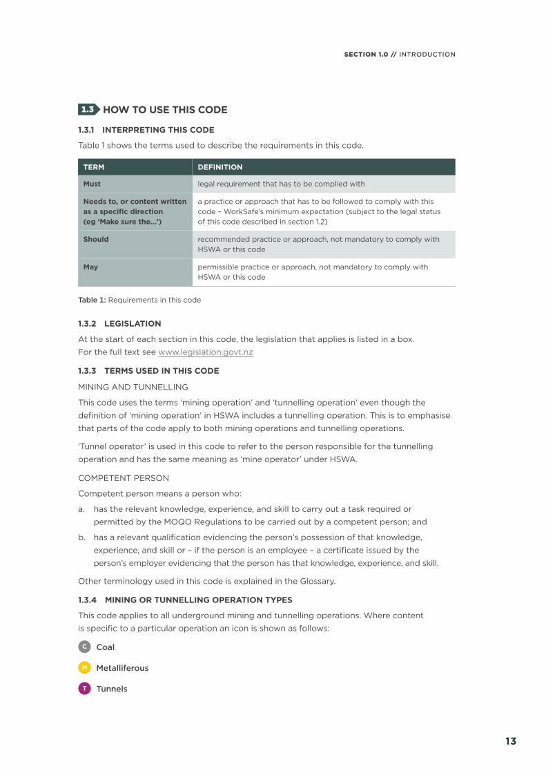
Table 1 shows the terms used to describe the requirements in this code.
TERM DEFINITION
Must legal requirement that has to be complied with
Needs to, or content written as a specific direction (eg ‘Make sure the.…’)
a practice or approach that has to be followed to comply with this code – WorkSafe’s minimum expectation (subject to the legal status of this code described in section 1.2)
Should recommended practice or approach, not mandatory to comply with HSWA or this code
May permissible practice or approach, not mandatory to comply with HSWA or this code
Table 1: Requirements in this code
1.3.2 LEGISLATION
At the start of each section in this code, the legislation that applies is listed in a box.
For the full text see www.legislation.govt.nz
1.3.3 TERMS USED IN THIS CODE
MINING AND TUNNELLING
This code uses the terms ‘mining operation’ and ‘tunnelling operation’ even though the
definition of ‘mining operation’ in HSWA includes a tunnelling operation. This is to emphasise
that parts of the code apply to both mining operations and tunnelling operations.
‘Tunnel operator’ is used in this code to refer to the person responsible for the tunnelling
operation and has the same meaning as ‘mine operator’ under HSWA.
COMPETENT PERSON
Competent person means a person who:
a. has the relevant knowledge, experience, and skill to carry out a task required or
permitted by the MOQO Regulations to be carried out by a competent person; and
b. has a relevant qualification evidencing the person’s possession of that knowledge,
experience, and skill or – if the person is an employee – a certificate issued by the
person’s employer evidencing that the person has that knowledge, experience, and skill.
Other terminology used in this code is explained in the Glossary.
1.3.4 MINING OR TUNNELLING OPERATION TYPES
This code applies to all underground mining and tunnelling operations. Where content
is specific to a particular operation an icon is shown as follows:
C Coal
M Metalliferous
T Tunnels
13

EXTRACTIVES: GROUND OR STRATA INSTABILITY IN UNDERGROUND MINES AND TUNNELS
14
1.3.5 STANDARDS
Use the most recent version of any standards referred to in this code, unless otherwise specified.
Where applicable, and provided it does not contradict the legislation or requirements of this
code, refer to BS 6164 Code of practice for health and safety in tunnelling in the construction
industry for good practices in the construction of tunnels.
1.4 ROLES AND RESPONSIBILITIES
HSWA defines the roles and responsibilities of different duty holders. These include persons
conducting a business or undertaking (PCBUs), officers, workers and other persons at
workplaces. See WorkSafe’s special guide Introduction to the Health and Safety at Work
Act 2015 for more information.
Schedule 3 of HSWA and Part 2 of the MOQO Regulations set out the specific mining sector-
related roles including mine operator, mine worker, SSE, mine manager, safety critical roles,
and industry health and safety representative.
All mine or tunnel operators must appoint a SSE and a mine or tunnel manager. The SSE is
responsible for health and safety management and the mine or tunnel manager for the daily
running of the mine or tunnel operation. Depending on the type of mining operation and the
particular principal hazards other safety critical roles are required. For underground mining
or tunnelling operations the SSE is required to appoint a number of safety critical roles.
For more details, see regulations 28, 30, and 31.
1.5 WORKER ENGAGEMENT, PARTICIPATION AND REPRESENTATION
All mining and tunnelling operators must, so far as is reasonably practicable, engage with
workers. Mining and tunnelling operations must also have effective worker participation
practices, regardless of the size, location, hours of operation, or method of mining. A safe
workplace is more easily achieved when everyone involved in the work:
> communicates with each other to identify hazards and risks
> talks about any health and safety concerns
> works together to find solutions.
1.5.1 DUTIES UNDER HSWA AND THE MOQO REGULATIONS
All PCBUs have worker engagement and participation duties under HSWA. Mine and tunnel
operators have extra duties under the MOQO Regulations, as follows:
> The SSE must engage with workers and health and safety representatives (HSRs) when
preparing and reviewing the health and safety management system (HSMS), including
principal control plans (PCPs) and PHMPs.
> Mine and tunnel operators must document worker participation practices.
> If a worker reports the existence of a hazard, the mine or tunnel operator must:
– make sure the report is investigated
– promptly advise the worker of the result of the investigation.
14

SECTION 1.0 // INTRODUCTION
1.5.2 HEALTH AND SAFETY REPRESENTATIVES
An HSR is a worker elected by the members of their work group to represent them in health
and safety matters.
An industry health and safety representative (industry HSR) may be appointed to represent
underground coal mine workers. An industry HSR is appointed by a union or by a group of
underground coal mine workers. They must meet the competency and experience requirements
for an HSR at a mining operation (see MOQO Regulation 110). As well as the functions and
powers that all HSRs have, an industry HSR has additional functions and powers.
Details of the appointment, removal or resignation of the industry HSR must be provided
to WorkSafe. WorkSafe issues an identity card to the industry HSR.
Trained health and safety representatives and industry HSRs can issue a notice to suspend
or stop a mining operation if they believe on reasonable grounds that there is a serious risk
to health and safety.
1.5.3 MORE INFORMATION ABOUT WORKER ENGAGEMENT, PARTICIPATION AND REPRESENTATION
For more information on worker engagement, participation and representation see
WorkSafe’s website and:
> good practice guidelines Worker Engagement, Participation and Representation
> interpretive guidelines Worker Representation through Health and Safety Representatives
and Health and Safety Committees.
When reading the guidelines replace the following terms with the extractive industry terms:
> replace ‘PCBU’ with ‘mine or tunnel operator’
> replace ‘work group’ or ‘members of a work group’ with ‘a group of workers who are
represented by a health and safety representative’ or ‘workers in a mining or tunnelling
operation’
> replace ‘business or undertaking’ with ‘mining or tunnelling operation’.
1.6 HEALTH AND SAFETY MANAGEMENT SYSTEM
All mining and tunnelling operations must have an HSMS. It is part of the mine or tunnelling
operation’s overall management system. The ground or strata instability PHMP is an essential
part of the HSMS.
The SSE must:
> develop, document, implement and maintain the HSMS
> make sure it is easily understood and used by all workers
> engage with workers when preparing and reviewing the HSMS and when providing
instruction before the workers start work at the mining or tunnelling operation.
15

EXTRACTIVES: GROUND OR STRATA INSTABILITY IN UNDERGROUND MINES AND TUNNELS
16
1.7 HAZARDS AND RISKS
The PCBU must eliminate risks to health and safety, so far as is reasonably practicable.
If it is not reasonably practicable to eliminate risks, they must be minimised, so far as
is reasonably practicable.
The SSE must ensure there are processes in place to:
> identify hazards (appraise risks) at the mining or tunnelling operation
> assess the risks of injury or ill-health to workers from the hazards
> identify the controls required to manage the risks.
The risk appraisal could identify principal hazards; these are hazards that can create a risk
of multiple fatalities in a single accident, or a series of recurring accidents, at the mining
or tunnelling operation. They will either be one of ten specified hazards in the MOQO
Regulations (which include ground or strata instability), or any other hazard identified during
the risk appraisal that meets the definition.
Unless hazards are identified and risks assessed properly, no amount of risk management will
ensure a safe place and system of work. Unrecognised risks can lead to serious consequences.
See section 2 where the causes of ground or strata instability are discussed.
1.8 PRINCIPAL HAZARD MANAGEMENT PLAN FOR GROUND OR STRATA INSTABILITY
The ground or strata instability PHMP describes the principal hazard, records the risks
of injury or ill-health to workers presented by ground or strata instability at the mining
or tunnelling operation, and describes the controls that have been systematically identified
to manage them. The PHMP must identify who is responsible for implementing, monitoring
and documenting these controls. For detailed information, see:
> MOQO Regulations 68 and 71
> WorkSafe’s interpretive guidelines Developing a Ground or Strata Instability Principal
Hazard Management Plan.1
A PHMP for ground or strata instability must, at a minimum, address the following:
(a) the circumstances in which ground or strata failure may occur
(b) how potential ground or strata failure could be avoided through the design of suitable
ground or strata support methods that must take into account:
(i) characteristics of the area to be supported
(ii) surrounding workings
(iii) activities to be carried out
(iv) size and geometry of the openings in underground workings
1 The interpretive guidelines include a detailed example of a format that could be used to develop a ground or strata instability PHMP.
16

SECTION 1.0 // INTRODUCTION
2 In this code, continuous means over the life of the mine or tunnel. The frequency (eg daily, weekly, or monthly intervals) will be determined by the risk assessment and the design.
(c) clear directions and diagrams for the implementation of suitable ground or strata
support methods
(d) continuous2 modelling, testing, and updating, where required, of ground or strata
support methods
(e) appropriate equipment and procedures to monitor, record, interpret, and analyse data
about seismic activity and its impact on the mining or tunnelling operation
(f) collection, analysis, and interpretation of relevant geotechnical data
(g) maintenance of the integrity of ground or strata support
(h) allowance for higher standards of support to be installed than that required by the PHMP.
Produce the PHMP in the context of the whole HSMS so that it relates to other PHMPs,
PCPs, or processes and procedures that rely on the PHMP as a control. This helps to prevent
gaps and identify overlaps in processes and information where it relates to ground or strata
instability, or where ground or strata instability may impact other PHMPs and PCPs.
Develop the PHMP using information from the geotechnical assessment gathered at the
exploration and pre-feasibility stage of a project and the subsequent design, planning and
ongoing operations.
Complete design and stability studies using an appropriate Factor of Safety (FoS) or other
appropriate risk management index or margin.
Other inputs that contribute to the PHMP include:
> a review of risk appraisals and risk assessments
> incident/near miss reports
> results of reviews or audits completed
> consultation with workers
> industry or manufacturers’ reports, where relevant.
The risk appraisal and assessment methodology used needs to be consistent with that
specified in the HSMS. The PHMP needs to include the results of the ground or strata
instability risk assessment.
Controls need to be implemented to effectively manage the risks of harm and the level of
ground support needed. The SSE must ensure the effectiveness of the controls is monitored
and corrective actions taken, if required.
The components involved in the development and maintenance of a ground or strata
instability PHMP are shown in Figure 1.
17

EXTRACTIVES: GROUND OR STRATA INSTABILITY IN UNDERGROUND MINES AND TUNNELS
18
Ris
k ap
pra
isal
of
min
ing
or
tunn
ellin
g
op
erat
ion
SUP
PO
RT
ING
DO
CU
ME
NTSGeo
tech
nica
l as
sess
men
t
Min
ing
met
hod
Min
ing
eq
uip
men
t
Ris
k as
sess
men
t
for
gro
und
or
st
rata
inst
abili
ty
Man
ager
’s
sup
po
rt
rule
s/p
lans
Trig
ger
act
ion
resp
ons
e p
lans
Trai
ning
fo
r w
ork
ers
Rev
iew
(an
d r
evis
ion)
of
the
PH
MP
Inte
rnal
or
exte
rnal
aud
it o
f th
e P
HM
P
Mo
nito
ring
p
lans
Haz
ard
p
lans
/map
s
Ap
plic
atio
n fo
r co
nstr
ucti
on
or
per
mit
to
tun
nel
Rem
edia
l su
pp
ort
pla
ns
Stan
dar
d
op
erat
ing
p
roce
dur
es
GR
OU
ND
O
R S
TRA
TA
INST
AB
ILIT
Y
PHM
P
Fig
ure
1: D
evel
op
men
t an
d m
aint
enan
ce o
f a
gro
und
or
stra
ta in
stab
ility
PH
MP
3
3 A
dap
ted
fro
m p
age
11: N
SW G
over
nmen
t|Tr
ade
& In
vest
men
t M
ine
Saf
ety.
(20
15).
NSW
Co
de
of
Pra
ctic
e|W
HS
(M
ines
) Le
gis
lati
on:
Str
ata
cont
rol i
n un
der
gro
und
co
al m
ines
. N
ew S
out
h W
ales
, Aus
tral
ia: N
SW D
epar
tmen
t o
f Tr
ade
and
Inve
stm
ent,
Reg
iona
l Inf
rast
ruct
ure
and
Ser
vice
s.
18

PART
BIN THIS PART:Section 2: Causes of ground or strata instability at the operationSection 3: Geotechnical assessmentSection 4: Design of control measures/support methods to avoid
ground or strata instability

EXTRACTIVES: GROUND OR STRATA INSTABILITY IN UNDERGROUND MINES AND TUNNELS
2020
CAUSES OF GROUND OR STRATA INSTABILITY AT THE OPERATION
02/PART B
IN THIS SECTION:2.1 Identify the causes of ground
or strata instability
20

SECTION 2.0 // CAUSES OF GROUND OR STRATA INSTABILITY AT THE OPERATION
The legislation that applies to this section is:
Health and Safety at Work Act 2015
Section 22 Meaning of reasonably practicable
Schedule 3, clause 4 Meaning of tunnelling operation
Health and Safety at Work (Mining Operations and Quarrying Operations) Regulations 2016
Regulation 3 Interpretation – competent person
Regulation 65 Meaning of principal hazard
Regulation 67 General purposes of principal hazard management plans
Regulation 68 Content of principal hazard management plans
Regulation 71 Principal hazard management plans for ground or strata instability
Regulation 73 Consideration of whether inundation and inrush is a principal hazard
Regulation 217(1)(k) Details to be included in plans (the location of inrush control zones)
2.1 IDENTIFY THE CAUSES OF GROUND OR STRATA INSTABILITY
Ground or strata instability is a principal hazard associated with mining and tunnelling
operations. Some potential causes of ground or strata instability at a mining operation
and tunnelling operation are listed below:
> inadequately designed ground support
> poor quality of ground support consumables
> poorly installed ground support
> deteriorated ground support
> mining induced seismicity
> natural seismicity
> excessive compressive stress around excavations
> excessive shear stress on discontinuities
> tensile forces around excavations resulting from strata relaxation
> ground water or artificially introduced water
> presence of adverse geological structures in immediate vicinity of excavation
> inappropriate choice of excavation or mining method
> loose blocks due to poor rock mass quality in the perimeter of the excavation
> collapse from localised or general thawing, or ineffective freeze due to moving ground
water (ground freezing)
> excessive blast damage to the perimeter of the excavation
> inappropriate shape and size of pillars, roadways or roadway alignment
> pillar failure or collapse due to undersized pillars or poor mine layout
> load transfer, abutment stress, periodic weighting, face slabbing.
Identify, assess and detail the risks in the risk appraisal and risk assessment that forms part
of the PHMP. For more information see section 1.8.
21

EXTRACTIVES: GROUND OR STRATA INSTABILITY IN UNDERGROUND MINES AND TUNNELS
22
2.1.1 STRESS
A competent person must analyse the stress environment at the mining or tunnelling
operation. This should include an assessment of the three-dimensional (3D) stress field across
the relevant extent of the mining or tunnelling operation to develop an understanding of the
magnitude and direction of the stress field, and any apparent variability present. This may
be undertaken by a programme of in situ measurements, complemented by stress change
monitoring during excavation, together with stress mapping and an awareness of stress
conditions in adjacent operations, if present. This assessment informs the excavation and
support design.
Options to measure stress in mining or tunnelling operations may include:
> in situ stress measurements
> stress change monitoring
> acoustic emission testing plus variation.
2.1.2 GEOLOGICAL HAZARDS
Some geological hazards encountered in excavations contribute to other principal hazards.
Obtain specialist advice from a competent person if there is any indication of the presence
or potential existence of one or more of the following hazards:
> significant water inflow
> gas outburst
> rock outbursts
> thermal activity
> discontinuity.
2.1.3 SEISMIC ACTIVITY
Under MOQO Regulation 71(2)(e) the PHMP must address the appropriate equipment and
procedures to monitor, record, interpret and analyse data relating to seismic activity and its
impact on the mining or tunnelling operation.
Natural seismicity is an earthquake that is caused through natural earth processes and needs
to be considered in mine or tunnel design. Understanding the location and seismic hazard
profile of major fault zones capable of producing strong ground motions at the mine
or tunnel site is important. The competent person considers this when undertaking the
geotechnical review. The potential for earthquakes may need to be factored into the design,
both during excavation and construction, as well as the final tunnel or roadway formation.
Mining-induced seismicity occurs as a result of stress redistribution around underground
openings. In some cases, such stress changes may trigger a sudden slip on a fault. This is
almost always accompanied by ground vibration which may cause considerable damage to
underground openings. In other cases, abutments or pillars may become overloaded and
yield suddenly.
During the construction of tunnels, which can be of relatively short-term duration, the seismic
risk may range from very low to moderate. When the tunnel construction, enlargement or
extension has been completed the tunnel will no longer be a tunnelling operation by definition
under HSWA Schedule 3, clause 4. The permanent tunnel must be designed for seismic loads
in accordance with the New Zealand Building Code.
22

GEOTECHNICAL ASSESSMENT
03/
23
PART B
IN THIS SECTION:3.1 Requirement for a
geotechnical assessment at mining and tunnelling operations
3.2 Site characterisation 3.3 Collection, analysis and
interpretation of geotechnical data
3.4 Re-using a geotechnical assessment
3.5 Review of the geotechnical assessment
EXTRACTIVES: GROUND OR STRATA INSTABILITY IN UNDERGROUND MINES AND TUNNELS
24
The legislation that applies to this section is:
Health and Safety at Work (Mining Operations and Quarrying Operations) Regulations 2016
Regulation 3 Interpretation – competent person
Regulation 11 Mine operator must ensure site senior executive has sufficient resources
Regulation 69 Review and revision of principal hazard management plans
Regulation 71 Principal hazard management plans for ground or strata instability
3.1 REQUIREMENT FOR A GEOTECHNICAL ASSESSMENT AT MINING AND TUNNELLING OPERATIONS
The SSE must ensure that a competent person completes a geotechnical assessment
to determine the level of ground or strata reinforcement required to safely conduct the
mining or tunnelling operation.
When completing the geotechnical assessment obtain input from the relevant technical
disciplines (eg mining engineers, geotechnical engineers, civil engineers, geophysicists,
surveyors, geologists, and hydro-geologists).
The completed geotechnical assessment should be recorded, dated and signed by the
competent person carrying out the assessment.
3.1.1 COMPONENTS OF A GEOTECHNICAL ASSESSMENT
The geotechnical assessment should cover proposed activities over the whole life of the mine
or tunnel, from the feasibility study stage, operation of the mine or tunnel, to the final closure
and abandonment of the mine or the full life of the tunnel.
The SSE needs to ensure the geotechnical assessment clearly defines the area the assessment
relates to and the resulting ground control system design limited to that area.
The components of the geotechnical assessment and the outputs of that analysis are
illustrated in Figure 2. They include:
> Site characterisation of the ground to be supported, including natural and geotechnical
features such as:
– lithology, seam thickness/orebody shape, stratigraphic variability, seam dip, depth of
cover, geological structure including faults, bedding, joints
– rock properties
– measurement or assessment of rock stress magnitude and orientation, including
excavation, pre-mining and mining-induced conditions and areas of high in situ stress
– presence of water (eg aquifers, likely heads of pressures, water quality, inflows of water)
– air temperature and humidity, gas inflows, and other variability in the rock (eg presence
of contaminated ground)
– hot groundwater or rock (geothermal)
– earthquake potential, depending on the location of the operation in relationship
to fault lines
24

SECTION 3.0 // GEOTECHNICAL ASSESSMENT
– obstructions, both man-made and natural
– information about surrounding workings, including abandoned or previously
excavated workings
> analysis and formulation of a geotechnical model, including definition of geotechnical
domains, to classify volumes of rock with similar geotechnical properties and behaviours
> identification of failure processes and mechanisms
> ground support design using an appropriate Factor of Safety (FoS) or other appropriate
risk management index or margin, including:
– design of pillar and barrier sizes
– design of mine or tunnel layouts including extraction/mining methodology
– design of ground support for all stages of the operation development, extraction,
and closure
– design of the size, shape and orientation of openings
> development of a minimum ground support standard for each excavation type and
geotechnical domain
> development of trigger action response plans (TARPs) for each excavation type
> identification of suitable monitoring systems, such as design verification monitoring
and testing, routine monitoring, and requirements for seismic activity monitoring,
where appropriate.
Consider the following in the geotechnical assessment:
> experiences from other local and/or equivalent mining or tunnelling operations, where
applicable
> the mining method, mining direction, gradients, excavation sequence
> interdependencies between ground control design issues and other key aspects of design,
such as inundation, ventilation and the management of subsidence.
The assessment may re-use relevant geological and geotechnical information previously
collected as part of the feasibility studies or previous excavations, including:
> the results of further testing
> specific assumptions about the life of the mine or tunnel
> intended mining or tunnelling methods
> existing and proposed activities
> extraction rates.
25

EXTRACTIVES: GROUND OR STRATA INSTABILITY IN UNDERGROUND MINES AND TUNNELS
26
Site Characterisation
a. Collect data (site investigation) Mapping, geophysics Drilling – logging, sampling downhole geophysics and sampling Determine in situ stress field Ground water studies (hydrogeology) Laboratory testing of samples Exploration adits
b. Process data/analyse Create geological model (seam/ore body shape, thickness, depth, dip, geological structures, lithology) Classify rock into domains (or mass types). Analyse laboratory results
Review other operations
Review relevant experience from local/equivalent mining/tunnelling operations
Dimensions of pillars/ribs/mine layout
Extraction sequence/dimensions
Level of rock reinforcement required for excavations eg bolt capacity, length, density, spacing etc. Requirements for secondary support needed before extraction or stoping
Other outputs of analysis:
> required design verification
> routine monitoring requirements – monitoring devices, appropriate triggers for TARPs
> other testing – pull testing, encapsulation testing etc
Select appropriate method of stability analysis (or design) (empirical, numerical, analytical)
Mining/Excavation method
Type of mining
Excavation dimensions
Identification of the core geotechnical risks associated with the particular method chosen
Life of mine or tunnel
Other factors
Subsidence constraints
Ventilation requirements
Flitting distances
Surrounding workings
Define abandoned/previously worked areas
GEOTECHNICAL ASSESSMENT
(Inputs and Outputs)
DES
IGN
Assess likely failure mechanisms
Define acceptable level of risk for the support/pillar design (eg FoS)
Consider acceptable stability criteria eg geological duty life-span required etc. What is the end result sought?
Figure 2: Components of the geotechnical assessment and design outputs
Pillar design Extraction/stoping design Rock reinforcement design
Outputs of analysis
Levels of ground/strata support required to safely conduct the operation
26

SECTION 3.0 // GEOTECHNICAL ASSESSMENT
3.2 SITE CHARACTERISATION
Site characterisation provides an understanding of the physical characteristics of the rock
mass to enable the design of ground support. Stages of site characterisation include:
> review of regional geology and information gathered earlier as part of feasibility studies
> site investigation
> lab testing
> preparation of a geological model
> interpretation of geotechnical and geophysical data to define soil and rock parameters
for use in ground support design
> classification of rock mass into geotechnical domains.
Characterisation data is gathered from drilling logs or cores, observation, sampling, testing
and analysis of a range of information and data about the ground, and other physical
characteristics of the natural environment of the mining or tunnelling operation. This informs
the geotechnical assessment.
Characterisation provides an estimate of rock mass strength and the in situ stress environment,
to enable the prediction of how the ground will respond to the effects of excavation. It also
provides information on the rock mass variability, including the impact of lithological changes
and geological anomalies such as faults and dykes, and risks associated with seismicity.4
Ongoing updating and recalibration of the geological/geotechnical model is required
throughout the operating stage.
The mine or tunnel operator must ensure the SSE has adequate resources for site investigations
to effectively assess ground control risks.
3.3 COLLECTION, ANALYSIS AND INTERPRETATION OF GEOTECHNICAL DATA
The PHMP must address how relevant geotechnical data will be collected, analysed and
interpreted, including the monitoring of openings and excavations, where appropriate.
The mining or tunnelling operation should have a database of geological and geotechnical
data that is regularly updated as new data is acquired. This data includes:
> geological/geotechnical logging records (eg downhole geophysics, core photographs)
> geotechnical test results and rock mass properties (eg uniaxial compressive strength,
fault/defect properties, shear strength and modulus as required).
3.3.1 GEOLOGICAL/GEOTECHNICAL MODEL
The mine or tunnel operator needs to have a geological/geotechnical model with regularly
updated information, including:
> geological structure
> geological boundaries
4 Adapted from page 11: NSW Government|Trade & Investment Mine Safety.(2015). NSW Code of Practice|WHS (Mines) Legislation: Strata control in underground coal mines. New South Wales, Australia: NSW Department of Trade and Investment, Regional Infrastructure and Services.
27

EXTRACTIVES: GROUND OR STRATA INSTABILITY IN UNDERGROUND MINES AND TUNNELS
28
> seam/ore body grid models or 3D models
> overburden/host rock grid models or 3D models
> rock mass classification.
3.3.2 GEOTECHNICAL MAPPING
Geotechnical mapping needs to be regularly done in all active and accessible excavated
areas. This includes:
> face mapping
> structural mapping
> geotechnical conditions observations or inspections
> excavation behaviour reports
> evidence of stress through deformation/failure mapping.
3.3.3 REPORTING OF GEOTECHNICAL INFORMATION
Standard operating procedures (SOPs) need to be developed to support regular reporting
of geotechnical information by the relevant workers to the mine or tunnel manager and other
workers. The mine or tunnel operator needs to retain evidence of this reporting.
3.4 RE-USING A GEOTECHNICAL ASSESSMENT
Where an existing design has already been proven, it may be used as a basis for the design
of ground control measures for a new operation in the same area, provided that:
> the ground conditions at both operations are in the same domain or are not significantly
different, and
> the excavation method is the same.
Sufficient site investigation should be carried out to confirm that the ground conditions at the
new excavation are similar to those at the previous operations. Mine or tunnel operators need
to complete a geotechnical model verification to compare old with new ground conditions.
If ground conditions are confirmed as being similar, the information from these previous
operations may be used. References to any earlier assessments must be included.
3.5 REVIEW OF THE GEOTECHNICAL ASSESSMENT
The SSE must ensure that the PHMP is reviewed at least once every two years after the date
the PHMP was initially developed, being the date it was initially approved by the SSE, or as
when required under the circumstances listed in MOQO Regulation 69(2).
Assumptions from the geotechnical assessment must be checked against what has actually
happened with the ground. See MOQO Regulations 71(2)(d),(e) and (f).
Events that can trigger a review of the geotechnical assessment and review of the ground
or strata instability PHMP include the following:
> a major change in the ground conditions encountered – conditions outside the site
characterisation or the assumptions used for the design in the geotechnical assessment
28

SECTION 3.0 // GEOTECHNICAL ASSESSMENT
> monitoring information that indicates the ground is not behaving as predicted in the
geotechnical assessment
> a change in the mining method
> a change in the mining sequence
> a major change in the mine or tunnel layout
> a major change in the equipment used to install ground support such that the design
specified in the geotechnical assessment cannot be implemented
> a major change in ground support type
> a significant accident involving ground instability.
See section 10 for information on review and audit.
29

30
DESIGN OF CONTROL MEASURES/SUPPORT METHODS TO AVOID GROUND OR STRATA INSTABILITY
04/PART B
IN THIS SECTION:4.1 Design details and
support methods 4.2 Design methodologies
used to determine ground support needed
4.3 Design requirements for rock reinforcement systems
4.4 Stope or pillar design requirements for coal and metalliferous mines
4.5 Temporary and permanent ground support systems
4.6 Primary and secondary support systems
4.7 Temporary support systems
4.8 Shafts 4.9 Continuous modelling
and design verification
30

SECTION 4.0 // DESIGN OF CONTROL MEASURES/SUPPORT METHODS TO AVOID GROUND OR STRATA INSTABILITY
The legislation that applies to this section is:
Health and Safety at Work (Mining Operations and Quarrying Operations) Regulations 2016
Regulation 3 Interpretation – shaft
Regulation 71 Principal hazard management plans for ground or strata instability
Regulation 117 Installation of ground or strata support
4.1 DESIGN DETAILS AND SUPPORT METHODS
The design details and support methods are outputs of the geotechnical assessment.
The excavation design and the systematic installation of suitable support of openings
during excavation are the primary controls to prevent ground or strata instability occurring
at a mining or tunnelling operation.
Components of the design include some or all of the following:5
> limits of extraction
> excavation dimensions
> pillar sizes
> type and spacing of support or reinforcement density; typically this will take the form
of a support plan
> specifications for any material or equipment forming part of any ground control system,
including quality and capacity verification testing
> timing of installation of the support or reinforcement
> proposed method of work (mining method and its compatibility with support systems)
> procedures for dealing with material changes in conditions (ie conditions that are more
adverse or favourable) such as TARPs
> information on other risks such as known zones of weakness or proximity to other workings
> rationale for sequencing extraction and filling (if appropriate)
> backfill that provides confinement for roof/backs and ribs.
The designed or selected control measures must be able to be implemented without unnecessary
risks to any person during the installation, operation and abandonment of the mine or tunnel.
4.1.1 DESIGN DOCUMENT
Include the geotechnical assessment in the design document. A competent person should
sign the design document. For tunnelling operations, a producer statement (PS1)6 should
be signed by the designer. These documents form the basis of the manager’s support rules.
Include the manager’s support rules as part of the PHMP.
Technical specifications need to be prepared for all ground support products or components
of the system used at the mining or tunnelling operation, such as load capacities (support
resistance) and energy absorption capacities. These technical specifications need to be
included in the PHMP.
5 Adapted from page 11: Health and Safety Executive (HSE) (2015) Guidance on Regulations: The Mines Regulations 2014. Retrieved from: www.hse.gov.uk/pubns/priced/l149.pdf
6 A PS1 (Producer Statement 1) confirms that design work has been carried out by a competent design professional and is expected to comply with the relevant legislation.
31

EXTRACTIVES: GROUND OR STRATA INSTABILITY IN UNDERGROUND MINES AND TUNNELS
32
4.2 DESIGN METHODOLOGIES USED TO DETERMINE GROUND SUPPORT NEEDED
A competent person needs to apply an appropriate design methodology (during the
geotechnical assessment) to determine the level of ground support required to safely
conduct the mining or tunnelling operation, including roadways, pillar or tunnel design
and ground reinforcement requirements.
The competent person needs to use an appropriate FoS, or other appropriate risk
management index or margin, depending on the duty and lifespan of the mine or tunnel
opening. For example, the support system for an excavation planned to be open for a short
time may be designed to a lower FoS than a roadway that needs to be stable for the entire
life of the mine or tunnel.
The design methodologies are generally empirical, analytical or numerical analyses.
These methodologies apply to both mining and tunnelling operations.
4.2.1 EMPIRICAL METHODS
Empirical design methods are design approaches and formulations developed from
statistical analysis of controlled, quantified databases of experience on ‘real-world’
projects. The approach relies on comparing the experiences of past practices to predict
future behaviour based upon the factors most critical for the design.
Empirical methods are reliant on credible databases. Note that:
> The risk-based parameters quoted for a particular database and design system are unique
to that system. They are not to be applied to other applications without due consideration.
> An understanding of the origins, nature and limitations of the database is important.
Uncertainty increases towards the boundaries of the database. Particular caution should
be adopted in attempting to apply the results of an empirical study outside the range of
the underpinning database.
An example of an empirical design method is the use of rock mass classification methods
calibrated against large databases to provide guidelines for support design or cavability.
Determining the rock class, span of the opening and rock mass quality will provide guidance
as to the reinforcement category required and, if applicable, support system for a particular
set of characteristics.
4.2.2 ANALYTICAL METHODS
Analytical design methods apply equations developed from basic mechanistic or engineering
principles to the analysis of ground behaviour, so that when controls are applied, design
outcomes can be expressed numerically (eg FoS).
These design methods typically require input parameters measured in the laboratory and/or
field. An example of an analytical design method is the calculation of a dead weight load and
the associated design of support to carry that load.
32

SECTION 4.0 // DESIGN OF CONTROL MEASURES/SUPPORT METHODS TO AVOID GROUND OR STRATA INSTABILITY
7 Adapted from page 19: NSW Government|Trade & Investment Mine Safety. (2015). NSW Code of Practice|WHS (Mines) Legislation: Strata control in underground coal mines. New South Wales, Australia: NSW Department of Trade and Investment, Regional Infrastructure and Services.
A disadvantage of analytical models is that it is rare for a design problem to involve one
mode of behaviour or failure only. Stress and deformation are generally more complex, with
multiple potential failure modes or varying ground loads. Most geotechnical design problems
have input parameters that are not fully defined, either in terms of the expected value or the
degree of variability. Engineering judgement is required, with a link to actual experience to
provide design ‘calibration’7.
4.2.3 NUMERICAL METHODS
Numerical design methods involve a range of different underpinning capabilities, referred to
as constitutive equations, used to describe the type of rock behaviour and potential failure
criteria. The numerical code selected needs to have the capabilities that are applicable to the
geotechnical environment being modelled; otherwise results will potentially be incorrect and
could be misleading.
Modelling accuracy is highly dependent on input parameters that typically require extensive,
high-quality site investigations and laboratory testing. Numerical models should address:
> calibration to ‘real-world’ experience/empirical outcomes
> sensitivity analysis to test the model’s rationale
> the results of comparisons with the outcomes of alternative design methodologies.7
4.3 DESIGN REQUIREMENTS FOR ROCK REINFORCEMENT SYSTEMS
The design of rock reinforcement systems needs to consider:
> if the design is capable of being implemented without undue risk to any worker
> the prevailing geotechnical hazards and mining abutment effects over the life of the
excavation, as well as taking account of other non-geotechnical operational constraints
> the profile, use and anticipated life cycle of the opening/roadway, leading to determination
of appropriate support methodologies, materials and installation equipment
> the timing of both primary and any secondary support installation. This needs to be
assessed relative to the prevailing geotechnical environment and likely impact on stability
> whether the support design methodologies selected and justified for each application
are applicable to the expected ground behaviour and potential failure mechanisms
> establishing the protocols for confirming appropriate quality and adequacy of support
materials and control systems for validating installation practices.
The complex nature of reinforcement design requirements means design methods should not
be relied upon in isolation but considered as interdependent on each other. Reinforcement
design should not rely on one single strategy, or expect only one single failure mode,
especially in critical excavations. Rock failure is usually multi-modal and complex.
33

EXTRACTIVES: GROUND OR STRATA INSTABILITY IN UNDERGROUND MINES AND TUNNELS
34
C M 4.4 STOPE OR PILLAR DESIGN REQUIREMENTS FOR COAL AND METALLIFEROUS MINES
Pillar dimensions need to take account of the loads expected to be imposed on the pillars,
the estimated pillar strengths and the influence of the width-to-height ratio on pillar
failure behaviour.
The SSE must ensure all pillars are designed by a competent person. The design approach
should consider the:8
> mine layout design and stope design
> type of pillar and the purpose(s) for which the pillar is to be used (eg standard roadway
support pillars [inter-room], barrier pillars to separate areas of room and pillar mining,
crown pillars used for long-term protection of specific areas of the mine, yielding and
abutment pillars)
> specific associated geotechnical duty or function that the pillar must perform (eg local
or regional load bearing, abutment stress protection, surface protection)
> pillar life expectancy
> engineering determination/judgement of the acceptable level of risk associated with the
pillar not performing each duty. Pillars may be required to perform different duties over
their lifetime, either in series or in parallel. Different duties may require different levels
of risk management.
> FoS or other appropriate risk management index or margin
> operational requirements such as travelling distances and ventilation
> design of the extraction sequence, stoping and pillar sizing for subsequent
stoping/extraction
> artificial support (backfill) requirements, if relevant
> need to have some areas unmined or to install a larger pillar where necessary.
The design document needs to detail the pillar design methodology and stope/extraction
design methodology. The pillar design calculations and stope/extraction design calculations
should be kept in a database.
It is critical to understand the relationship of mining-induced stresses on all pillars in a mining
operation. As mining progresses/advances, stress will transfer from inter-room or yielding
pillars and onto abutment pillars. Pillars should be designed taking into account the overall
mining excavation void.
4.4.1 FACTORS INFLUENCING PILLAR STABILITY
The stability of pillars is a function of the:
> depth of cover
> strength of overlying or underlying ground
> rock/ground material properties
8 Adapted from page 8: NSW Government|Trade & Investment Mine Safety.(2015). NSW Code of Practice|WHS (Mines) Legislation: Strata control in underground coal mines. New South Wales, Australia: NSW Department of Trade and Investment, Regional Infrastructure and Services.
34
SECTION 4.0 // DESIGN OF CONTROL MEASURES/SUPPORT METHODS TO AVOID GROUND OR STRATA INSTABILITY
> geometry of the pillar, including both its shape and its width-to-height relationship
– the absolute and relative dimensions
> extraction ratio
> geological structure
> confinement (eg by backfill)
> hydraulic radius
> extraction sequence
> stress regime.
The ratio of pillar width-to-height is a critical geometrical consideration in determining a
pillar’s strength and stability. For non-square shaped pillars, length is also a consideration.
Large-scale collapses of underground mining areas, or in some cases even the whole mine,
can occur due to multiple pillar failures. Such failures can occur in a domino effect if pillars
are undersized and the mine layout is poor. The main controls for these types of large-scale
failures are correct mine layout design and pillar sizing. Barrier pillars are large pillars that
will prevent a failure in one mining area being transferred to the other parts of the mine.
Geological structures, such as faults or joints in a pillar, can decrease the pillar strength and
individual pillars can fail if they have been weakened. The main controls for these types of
failure are on-site observation of conditions, leaving areas unmined, or installing a larger pillar
where necessary.
M C
Where the floor lithology, hanging wall or footwall rocks are weak relative to the pillar, a pillar
support system may fail and pillars may punch into the floor or the orebody peripheral rock.
An example of this is the punching of coal pillars into low stiffness claystone floor. This mode
of failure is comparable to the bearing capacity failure of a foundation. Signs that this may
have occurred are floor heave, or extensive fretting and collapse of rock around a pillar.
The hydraulic radius is the surface area of an opening divided by the perimeter of the
exposed area being analysed. This is commonly used as a basis for stability estimates.
4.4.2 CONSIDERATIONS FOR BARRIER PILLAR DESIGN
Water inrush is one of the major hazards in an underground mine or tunnel and needs to
be considered when designing barrier pillars. Control measures include identification of the
inrush zone. The SSE, through a competent person, must determine the thickness of the
intervening ground between the mining or tunnelling horizon and disused mine workings or
bodies of water (see MOQO Regulation 73(3)). Disused mine or tunnel workings can contain
accumulated water or material that flows when wet in underground mining or tunnelling
operations. In underground coal mines, there should be a minimum separation of 50 metres
in any plane. This measurement may be significantly more depending on the volume of
material and the pressure head that it creates. For underground metalliferous mines, the
separation distance between the mining horizon and disused mine workings or bodies
of water should be determined by the geotechnical assessment and risk assessment.
35

EXTRACTIVES: GROUND OR STRATA INSTABILITY IN UNDERGROUND MINES AND TUNNELS
36
Be cautious if referring to mine or tunnel plans or survey plans that were not drawn by a
competent person. Plans of abandoned mines or tunnels and bore hole surveys may not
be reliable.
Inrush control zones must be clearly indicated on the mine or tunnel plan as required by
MOQO Regulation 217(1)(k). Figure 3 is an example of a plan showing an inrush control zone.
Surface pitwater sump
Surface pitoutline
Portal
Inrush control zone
Inrush control zone
Figure 3: Example of inrush control zone marked on a plan
Coming into contact with unconsolidated deposits such as water bearing sands and gravels
is a hazard of near surface working. This type of material can be very difficult to control with
typical mine or tunnel support systems.
36

SECTION 4.0 // DESIGN OF CONTROL MEASURES/SUPPORT METHODS TO AVOID GROUND OR STRATA INSTABILITY
4.5 TEMPORARY AND PERMANENT GROUND SUPPORT SYSTEMS
Ground support, whether temporary or permanent, will be either local support or area support.
Local support is used to prevent smaller rocks from falling from the roof/backs, sides or ribs.
Area support is used to prevent major ground failure (total ground control).
The terminology used to refer to support systems differs between mining and tunnelling
operations. Table 2 shows these differences. All support methods need to be determined
by the geotechnical assessment and design.
TYPE OF OPERATION
COAL MINES METALLIFEROUS MINES TUNNELS
SUPPORT
Temporary Any support device that creates a physical barrier between the heading and personnel installing ground support. The support system is usually hydraulic or air-operated in combination with mesh and/or straps.
Support installed with a specified service life, typically associated with areas planned to be stoped. Examples include ungalvanised mesh and split sets.
Ground support needed immediately after excavation, or close to the excavation face, to support or stabilise the ground in order to facilitate safe construction. This is also known as initial support. Can be temporary or permanent, depending on design life (see below).
Short-term ground support has a design life equal to or greater than the construction period. Temporary support may or may not form part of the permanent support.
Permanent (Primary)
A support system to provide long-term support to a roadway or opening. Usually installed at, or close to, the working face. The primary support system is typically a combination of rock bolts, cable bolts and mesh, depending on the support design requirements established.
Primary or initial permanent ground support that has a design life equal to or greater than the operational life of the tunnel. It is usually installed at, or close to, the working face.
Permanent (Secondary)
The installation of additional support either as planned infilling or in response to deteriorating conditions of the roadway or opening. The process is iterative. If the roadway continues to deteriorate, the support installed is escalated consistent with the established TARP thresholds. Support components may consist of any combination of active and passive support types.
Secondary or final permanent ground support that has a design life equal to or greater than the operational life of the tunnel.
Table 2: Terminology used to refer to support in coal mines, metalliferous mines and tunnels
37

EXTRACTIVES: GROUND OR STRATA INSTABILITY IN UNDERGROUND MINES AND TUNNELS
38
4.6 PRIMARY AND SECONDARY SUPPORT SYSTEMS
Based on the geotechnical assessment, a competent person needs to identify appropriate
support or reinforcement appropriate to achieve the required performance during the
designed life of the mine or tunnel.
Potential corrosion of support and degradation of softer rocks is a consideration for areas
where groundwater is present in longer life roadways. Where a corrosive environment exists,
and long life is required from the support materials, consideration should be given to using
galvanised or stainless steel support materials. Double corrosion protection may be achieved
through plastic sheathed rock bolts with cement grout encapsulation inside and outside the
sheath, such as a CT-Bolt system.
C 4.6.1 ROCK BOLTS TO SUPPORT ROADWAYS
Rock bolts can be used as the principal support in an underground coal mine, provided this
is supported by the site investigation and geotechnical assessment.
The diagrams in Figure 4 illustrate the stress regime and how roof rock bolts improve stability in
an underground coal mining operation according to the four theories of roof bolting support:
a. simple skin support
b. suspension of thin roof/backs from a massive bed
c. beam building of laminated strata
d. keying of highly fractured and blocky rock mass.
Pillar/ rib
Pillar/ rib
d. Supplemental support in highly fractured and blocky rock mass
Pillar/ rib
Pillar/ rib
c. Beam building
Pillar/ rib
Pillar/ rib
b. Suspension
Pillar/ rib
Pillar/ rib
a. Simple skin support
Figure 4: How tensioned rock bolts clamp the strata
With an effective rock bolt support design, the clamping of the roof bolts mitigates
mobilisation of the rock mass and prevents the blocks from sliding past each other.
38

SECTION 4.0 // DESIGN OF CONTROL MEASURES/SUPPORT METHODS TO AVOID GROUND OR STRATA INSTABILITY
4.6.2 ROCK BOLTS IN UNDERGROUND METALLIFEROUS MINING OPERATIONS AND TUNNELLING OPERATIONS
Provided the site investigation and geotechnical assessment indicates that rock bolts
can be used as the primary support, they can be installed in:
> development backs and walls
> intersections, along with suitable secondary support
> wide spans, along with suitable secondary support
> portal face/high wall.
In an underground metalliferous mine or tunnel, rock bolts in backs and sides are usually
bolted using the pattern shown in Figure 5.
T M
Rock bolts
Bolt spacing
Surface supports(shotcrete or mesh)
Backs
Excavation
Wall
Face Plate
Floor
Figure 5: Rock bolts in a metalliferous mine or tunnel
39

EXTRACTIVES: GROUND OR STRATA INSTABILITY IN UNDERGROUND MINES AND TUNNELS
40
4.6.3 CABLE BOLTS
Cable bolts are constructed from high-strength steel rope strands wound together. Single or
double strand bird cage bolts may be used. Cable bolts can be used as part of the systematic
support. The details need to be specified in the design.
Cable bolts are flexible and can be installed in longer lengths than conventional rock bolts
or roof bolts, due to the height restriction an underground mine or tunnel roadway will have
on installing steel bolts. Cable bolts can be installed using either pumpable cement grout or
polyester resin cartridges, depending on the cable type and stiffness. They can be either fully
or partially anchored by grout/resin.
The cable(s) are usually tensioned. The steel rope may be plain strand, or modified in a way
to achieve the appropriate load transfer from the grout and the steel strand to the rock mass.
Where cable bolts are installed as a secondary support system after mesh and rock bolts, full
interaction between support elements is achieved by plating and tensioning the cable bolts.
T 4.6.4 PRECAST SEGMENTAL LININGS AND STEEL LINER PLATES
Soft ground tunnels excavated by shielded tunnel boring machines (TBMs) are often supported
by precast concrete segments. The precast segments are installed in the tail of the TBM during
a support cycle to form a ring which is connected to the ring erected in the previous excavation
cycle. For expanded segmental linings, the rings are not connected and butt against each other.
The TBM thrusts against the previously constructed ring during the excavation cycle forming
a fully supported tunnel. Workers are not exposed to unsupported ground.
Below the groundwater table, the segments are bolted with gaskets for water tightness.
Above the groundwater table, unbolted, expanded segmental linings are sometimes used,
followed by a cast in situ concrete lining, pipeline installation, or other permanent lining.
All precast linings are reinforced against bending moments in the lining using traditional steel
bars (rebar) or steel fibres. Precast linings need to be designed to withstand:
> ground loads
> groundwater loads if the lining is undrained
> construction loads, including thrust of the TBM while mining
> handling loads of the segments during the manufacturing process (precast yard) during
transport into the tunnel and during erection of the ring.
Soft ground hand-mined tunnels or tunnels excavated with open shields can be supported
by bolted steel liner plates. Steel liner plates need to be designed for ground, groundwater
(if undrained) and construction/handling loads, similar to precast concrete segmental linings.
4.6.5 STEEL ARCHES AND LATTICE GIRDERS
It is usually faster and more economical to reinforce rock with rock bolts, steel mesh or straps,
and shotcrete so the rock will support itself. If the anticipated rock loads are too great, such
as in faulted or weathered ground, more robust steel supports may be required. Steel arches
and lattice girders can be used in such rock or soil conditions.
40

SECTION 4.0 // DESIGN OF CONTROL MEASURES/SUPPORT METHODS TO AVOID GROUND OR STRATA INSTABILITY
Steel arches and lattice girders are usually installed in roadways in sections within one width
spacing of the working face. Steel arches and lattice girders are generally assembled from
the bottom up making certain that the arch/girder has adequate footing and lateral rigidity.
Lateral spacer rods (collar braces) are usually placed between arches/girders to assist in
the installation and provide continuity between ribs. During and after a steel/girder arch is
erected, it is blocked into place with wood, grout-inflated sacks as lagging, or shotcrete.
Current civil engineering tunnel practice discourages the use of wood blocking because it
is deformable and can deteriorate with time. For the arch or girder to function as an arch it
needs to be confined properly around the perimeter. Manufacturers of steel arches provide
recommendations about the spacing of blocking points that should be followed closely.
When shotcrete is used as lining, it is important to make sure that no voids or laminations
are occurring as the shotcrete spray hits the steel elements. Steel arches should be fully
embedded in the shotcrete. Lattice girders are filled in by shotcrete in addition to being
embedded in shotcrete.
Steel arches can provide localised support in areas where more robust support is required
(eg under surface water bodies, such as streams, rivers and lakes) and in zones such as at the
start of a mine where there are significant transitions from soil to competent rock, and rock
arching does not occur due to low cover and/or weak ground.
4.6.6 SHOTCRETE LININGS
Shotcrete plays a vital role in metalliferous mines, tunnels and shaft construction because
of its versatility and adaptability. Desirable characteristics of shotcrete include:
> its ability to be applied immediately to freshly excavated surfaces and to complex shapes
such as shaft and tunnel intersections, enlargements, crossovers, and bifurcations, and
> the ability to change the applied thickness and mix formulation to suit variations in
ground behaviour.
Shotcrete that is used for ground support often requires reinforcement to give it strain capacity
in tension (ie ductility) and to give it toughness. Unreinforced shotcrete can be used for ground
support if tensile capacity demand is low.
Shotcrete can be applied as a wet or dry mix, and can be reinforced with steel or plastic
fibres, or welded wire fabric (steel mesh). It is typically used to provide longer term surface
protection of large openings.
Design of a shotcrete programme should consider the following:9
> amount of shotcreting required, thickness and layers of application
> strength required including strength gain with time
> presence of ground water (eg quantity, chemistry, pressure)
> need for drainage of groundwater from behind the shotcrete
> water quality
> type of shotcrete mix (wet or dry)
> use of admixtures (plasticisers, accelerators, micro silica)
9 Adapted from pages 6-7: Mines Occupational Safety and Health Advisory Board (MOSHAB). (1999). Code of practice: Surface Rock Support for Underground Mines. Western Australia, Australia: Government of Western Australia.
41

EXTRACTIVES: GROUND OR STRATA INSTABILITY IN UNDERGROUND MINES AND TUNNELS
42
> type of fibre reinforcement
> curing requirements
> testing and monitoring
> correct spraying equipment and application
> the need to include the anticipated/estimated deformation of the opening
following excavation.
4.6.7 STEEL STRAPPING
Steel strapping panels provide surface support between rock or roof support components.
When used with rock bolts, steel strapping can be considered to provide long-term support.
Steel straps need to be designed to support the predicted rock or roof loads between rock
support components. Often these loads are from loose rock of limited size between the rock
or roof support.
Profiled steel straps (typically 2 mm thick and 20 tonnes tensile strength) with pre-drilled
holes for roof bolts can be used as a template for roof bolt installation and to support the
ground between the roof bolt positions.
4.6.8 WOOD AND STEEL PROPS, INCLUDING HYDRAULIC PROPS
Traditional wood props are used to provide temporary support. Engineered wood props are
produced with up to 50 tonnes capacity and progressive yield. Steel hydraulic props work
on the car jack principal and typically have 20-30 tonnes capacity. Single use types are also
available. They can be extended using water pressure and left in place. Steel and wood props
are designed primarily as axial support members for predicted ground loads and should not
be exposed to bending moments.
4.6.9 WOOD CRIBS OR CHOCKS
Wood cribs or chocks (also known as pigsties) are made by building up layers of horizontal
wood chock pieces between the floor and roof/backs, placing each layer at right angles to
the previous one. Wood cribs are primarily axial support members similar to props. Ensure
the correct quality, size, strength and moisture content of the wood is used for support props
or cribs.
4.7 TEMPORARY SUPPORT SYSTEMS
The mine or tunnel operator must ensure that no one enters an area of unsupported ground
which may be a hazard unless they are installing ground or strata support (or supervising that
work). See MOQO Regulation 117.
Where unsupported ground is a hazard to workers, and primary support cannot immediately
be installed, then suitable ground or strata temporary support must be designed and
implemented. This includes those areas where workers are installing or supervising the
installation of temporary support. The plans showing the ground or strata support arrangements
in areas of unsupported ground must be displayed in locations readily accessible to all
workers. See section 5 for further information on implementing the control measures.
Examples of temporary support are described below. Their use will be determined by risk
assessment or established in a TARP.
42

SECTION 4.0 // DESIGN OF CONTROL MEASURES/SUPPORT METHODS TO AVOID GROUND OR STRATA INSTABILITY
4.7.1 SPILES, CANOPY TUBES AND FOREPOLING (PRE-SUPPORT)
Sometimes, it is necessary to enhance (pre-support) the ground to provide adequate stand-
up time to accommodate mining and installation of either temporary or permanent ground
support. Pre-support can consist of driven steel rods, steel sheets or wood boards/timbers
(known as forepoling or spiles), or drilled and grouted rods and pipes (known as spiles or
canopy tubes). Pre-support is integrated into the excavation cycle, installed ahead of the next
excavation round. The heading or crown is supported on the next excavation cycle, providing
enough stand-up time to safely install the designed support system, usually in conjunction
with shotcrete support. Pre-support is usually required in soil and weak rock conditions or
when recovering fallen ground.
Design of pre-support needs to consider the excavation cycle, and provide adequate overlap
between successive installations of spiles/forepoles. Pre-support should be spaced around
the excavation perimeter so that ground instability cannot take place between individual pre-
support elements. The pre-support elements need to be designed for longitudinal bending
(ie along the axis of the roadway) considering the predicted ground loads upon excavation
of the heading.
4.7.2 GROUND MODIFICATION AND DEWATERING
Ground modification is usually implemented before mining or tunnelling begins and can include:
> grouting with cement or chemical grouts
> ground replacement with cementitious materials mixed with in situ soils
> ground freezing
> dewatering.
When used in relation to ground support, the ground modification is intended to enhance
the strength of the ground and reduce ground loads by improving the ability of the ground
to be self-supporting. Ground modification can also be used to fill voids and/or to reduce
ground permeability and thereby reduce groundwater inflows.
The design will usually target achievable ground strength after modification. In this case,
the design needs to include a verification methodology to ensure that ground improvements
have met design strength requirements prior to mining or tunnelling. Design of ground
modification as a support element needs to consider loads and bending moments in the
support system.
4.7.3 MESH CAGES
The mesh cage is a temporary support system used to protect workers when installing roof
bolts using portable hand-operated rock bolting drills. Where on-board bolter miner systems
cannot be used, a mesh cage system of temporary support is used. The mesh cage has been
adopted in most coal mines where rock bolts are used as the primary support system and in
roadways that are passively supported with steel delta type supports.
The mesh cage system enables workers to work under supported ground at all times when
at the face of the heading. Before bolt installation commences, a mesh panel is pushed to
the roof/backs using two ‘Stinger’ air leg machines and another mesh panel is hung vertically
from the roof/backs at the face. These panels hang down in front of the working position
to protect against lumps falling from the face and to act as a barrier demarcating the
C
43

EXTRACTIVES: GROUND OR STRATA INSTABILITY IN UNDERGROUND MINES AND TUNNELS
44
C unsupported area. The side mesh is unfolded from the roof mesh and draped down the rib
side and fixed to the previous panel. The roof and rib bolts are then installed. When the
bolting cycle is completed the remaining unbolted mesh panel is tied horizontally to the
roof/backs ready for the next cutting cycle.10
Steel wire mesh panels can be used with rock bolts or standing support and are used to
contain the roof/backs and ribs between the support components. When used with rock
bolts, the system becomes a permanent support.
T 4.7.4 PIPE ROOF METHODS
A pipe roof (also known as a pipe arch or cellular arch) is often installed between two shafts.
Large diameter steel pipes are installed by drilling or micro-tunnelling methods around
the periphery of the tunnel, either in an arch shape or as a flat roof (box section). Pipes
are installed adjacent to one another with both a structural and watertight seal between
each pipe. Each pipe is typically filled with concrete and the interior of the pipe arch or box
is excavated. Temporary supporting struts are sometimes required before placement of
permanent cast in situ concrete lining inside the pipe arch or box.
The pipe roof method is usually used for large span tunnels in soil in areas of very low
cover, where surface settlement needs to be kept to a minimum. It is a very robust support
system, as the pipe roof provides very stiff supports which serve as pre-support before the
interior is excavated.
4.7.5 COMPRESSED AIR TUNNELLING
The use of compressed air shields to control groundwater has decreased with the advent of
pressure-face TBM technology. Compressed air can be an effective method of stabilising soil
and controlling groundwater in open-face tunnel excavations and can be especially useful
in squeezing soft clayey (cohesive) soils.
In granular soils, compressed air can be used to offset the water pressure at the tunnel face,
preventing the flow of groundwater (and fine-grained soils) into the face. In cohesive soils,
the objective is to provide enough air pressure so that the combination of the soil’s natural
strength with the air pressure stabilises the tunnel for excavation and support operations.
Compressed air is usually limited in soil grain sizes ranging from fine silt to medium sand;
in coarse sand and gravel air losses are often unacceptably high.
Disadvantages of using compressed air include:
> The need to install air locks between the tunnel face and the construction access shaft.
In some cases, more than one airlock will need to be installed.
> Inefficient use of labour, with limited work time for workers under compressed air. It is
essential that workers undergo decompression after work periods. This further adds
inefficiencies. If the air pressure is suddenly lost, workers may experience decompression
sickness (ie ‘the bends’).
These disadvantages mean compressed air shields are often not favoured compared to
pressure-face TBMs. However, due to requirements for regular manned inspection and
maintenance of the pressure-face TBM cutterheads, compressed air support is often required
10 Adapted from page 17: Arthur, J. (2006, July). Ground Control in Coal Mines in Great Britain. Paper presented at Coal Operators’ Conference, University of Wollongong, New South Wales, Australia. Retrieved from: www.undergroundcoal.com.au/acarp_dev/Coal%2098-09/Proceedings%202006%2027-06-06VF.pdf
44

SECTION 4.0 // DESIGN OF CONTROL MEASURES/SUPPORT METHODS TO AVOID GROUND OR STRATA INSTABILITY
as a contingency. The use of compressed air for special purposes such as cutterhead
maintenance is common throughout the tunnelling industry. The compressed air pressures
used will be related to the hydrostatic groundwater heads.
Control measures need to be implemented to eliminate or minimise, so far as is reasonably
practicable, the risks associated with compressed air tunnelling.
Workers entering a compressed air environment must be suitably trained and competent.
It is essential that they have proof of hyperbaric fitness before being allowed to enter the
pressurised tunnel or cutterhead area. See WorkSafe’s code Emergency Preparedness in
Mining and Tunnelling Operations for more detailed information.
4.8 SHAFTS
A shaft is an opening or blind heading that is excavated at an angle of more than 15 degrees
below the horizontal in any underground or tunnelling operation. The general application of
ground support remains the same, but with the added complication of working close to or
at the vertical. For this reason, precast segments or poured concrete linings are often used.
Shaft construction methods and excavation techniques vary depending on conditions and
the purpose of the shaft. During construction, shafts can provide entry for people, materials,
equipment and/or ventilation to a mine or tunnel.
The competent person needs to determine the appropriate shaft lining or ground support
based on the geotechnical properties of the rock which the shaft passes through. The shaft
lining/support can perform several functions. It is a safety feature preventing loose or unstable
rock from falling into the shaft, and a place for shaft sets to bolt into to enable heavy loads to
be suspended in the shaft. It may require a smooth surface to minimise resistance to airflow
for ventilation.
Install temporary ground support to ensure the safety of persons working at the base of the
shaft using for example an artificial roof (pentice) or working stage to provide overhead cover
while permanent support is installed. Refer to section 4.7 for more information.
Shafts in soils should have systematic lining or support to safely accommodate ground
and groundwater loads and isolate workers from exposed ground.
T
4.9 CONTINUOUS MODELLING AND DESIGN VERIFICATION
The mine or tunnel operator must ensure continuous modelling of the ground or strata
support methods is undertaken. This is a requirement of MOQO Regulation 71(2)(d). The task
and frequency of continuous modelling needs to be specified in the geotechnical assessment.
This may include:
> design verification of support system
> testing of support systems
> analysis of monitoring results
> back analysis of ground failures
> reviewing the geotechnical assessment when ground conditions are encountered that
are outside the limits assumed in the geotechnical assessment
> monitoring of production blasts (for drill-and-blast) to address any rock damage at the
excavation perimeter.
45

EXTRACTIVES: GROUND OR STRATA INSTABILITY IN UNDERGROUND MINES AND TUNNELS
46
As part of the design, the geotechnical assessment needs to specify what design verification
is required. The design is verified through monitoring. This is one part of continuous updating
of the geotechnical modelling. See section 6 for more information.
The mine or tunnel operator should verify the design to ensure:
> Inspections and hazard mapping done at the mining or tunnelling operation confirm the
validity of assumptions made in the geotechnical assessment during the design of the
ground support systems.
> Sufficient investigation is undertaken during development to confirm ground conditions
particularly where roof/backs geology are subject to change. This could include drill cores
or other geological logging/mapping techniques.
> A monitoring plan is prepared. See section 6.3 for further information.
> Comprehensive monitoring of rock bolted sites, subject to local change, is undertaken
for design verification. This involves detailed measurement of roof convergence and the
performance of the bolt system. It may also involve detailed measurement of rib dilation
and roadway internal measurements.
> Measurement of roadway convergence in underground mining operations or tunnelling
operations is completed using multiple point extensometers. See section 6.5 for
information about selecting suitable monitoring methods and instrumentation.
> Resin encapsulated rock bolt loads are measured on a minimum of four rock bolts/roof
bolts distributed across the roadway section.
The results of design verification activities may require the geotechnical assessment to be
updated. Changes may then be required to the PHMP, including: updates to the manager’s
support rules, TARPs and SOPs. Provide training for workers about any changes made to
the PHMP.
4.9.1 MEASURING ROADWAY OR TUNNEL DEFORMATION BEHAVIOUR
Monitoring roadway or tunnel deformation behaviour determines potential failure modes that
are occurring around the roadway or tunnel. This involves the measurement of the timing,
style and magnitude of roof, pillar and, where required, floor deformation and convergence.
Monitoring provides an understanding of the design requirements and effectiveness of
roadway or tunnel support systems on the stability of the roadway.
When undertaking a ground support design programme, the measurement of roadway
deformation behaviour for the existing (old) support system needs to be undertaken at the
start of the design investigation programme. Monitor the roadway deformation behaviour
to optimise and verify the new design.
4.9.2 SITE SELECTION
When selecting representative monitoring sites for roadway or tunnel deformation behaviour,
consider the following:
> Monitoring sites should not be located within the transition zone between the old and new
support systems. The monitoring site should be at least 10 m from any sections supported
by different support systems.
> No major geological structures or abnormalities should be in the vicinity of the site.
46

SECTION 4.0 // DESIGN OF CONTROL MEASURES/SUPPORT METHODS TO AVOID GROUND OR STRATA INSTABILITY
> There should not be any significant variations in roof/backs lithology, unless they are
representative of the target area as a whole.
> Monitoring sites should be installed close to the excavation that is currently being
advanced or will be advanced.
> Where convenient, the site should be close to other measurement or monitoring sites
for easier data collection.
Two techniques commonly used for measuring deformation are:
> direct measurement within the strata, using extensometry
> indirect measurement of total deformation using closure around the roadway
(ie convergence measurement).
See section 6.9 for further information.
47
PART
CIN THIS PART:Section 5: Implementing the control measuresSection 6: Monitoring, instruments and reportingSection 7: Ground or strata failure and actions requiredSection 8: Emergency preparedness

IMPLEMENTING THE CONTROL MEASURES
05/
49
PART C
IN THIS SECTION:5.1 Ground support/controls
and excluded areas 5.2 Application for construction
or permit to tunnel 5.3 Self-supporting mines
or tunnels 5.4 Installation training 5.5 Scaling and barring down5.6 Installing temporary
support5.7 Equipment used during
installation5.8 Timing of support/
reinforcement installation5.9 Support materials/
consumable items
5.10 Standard operating procedures
5.11 Manager’s support rules for installation
5.12 Installing higher standards of support
5.13 Inadequate ground or strata support
5.14 Rock bolt integrity5.15 Lifting and suspension of
equipment in rock bolted roadways or tunnels
5.16 Withdrawal of support material

EXTRACTIVES: GROUND OR STRATA INSTABILITY IN UNDERGROUND MINES AND TUNNELS
50
The legislation that applies to this section is:
Health and Safety at Work (Mining Operations and Quarrying Operations) Regulations 2016
Regulation 68 Content of principal hazard management plans
Regulation 69 Review and revision of principal hazard management plans
Regulation 71 Principal hazard management plans for ground or strata instability
Regulation 117 Installation of ground or strata support
Regulation 118 Obligations relating to ground or strata support
Health and Safety at Work (General Risk and Workplace Management) Regulations 2016
Regulation 9 Duty to provide information, supervision, training and instruction
5.1 GROUND SUPPORT/CONTROLS AND EXCLUDED AREAS
The design document and the PHMP detail the control measures to be implemented to manage
the ground or strata instability hazard. Parts of the mine or tunnel may be excluded from
support system requirements and are considered unsafe to enter. These places, for which no
future access is anticipated, include waste areas, some stopes and disused areas of the mine,
and roadways leading to these areas. These areas need to be barricaded to prevent entry. Ideally,
the roadway is fully closed off with mesh if it is not stopped or sealed. Chains are not a suitable
barrier to these areas. Signs should also be in place to explain the reason for the barricade.
The mine or tunnel operator needs to have procedures for preventing unplanned access to
vertical openings and unsupported ground. Workers must be made aware of these procedures.
The procedures need to be checked by a nominated person to ensure they are being followed.
Include these procedures in the PHMP.
The SSE also needs to consider the possible effects of ground movement in these parts of the
mine and if there are any potential risks to workers working or travelling to other parts of the
mine or tunnel.
5.2 APPLICATION FOR CONSTRUCTION OR PERMIT TO TUNNEL
The SSE should ensure the PHMP includes details about the process required for the development
of the ‘application for construction’ or ‘permit to tunnel’. In coal mines in New Zealand the
term ‘authority to mine’ is used. In this section the term ‘application for construction’ includes
‘permit to tunnel’ and ‘authority to mine’.
Development of an application for construction is a process that ensures that all assessments
have been done, design completed and signed off, controls put in place, workers trained, and
equipment ready (including emergency equipment). After an application for construction
has been signed off, mining or excavations can proceed in a specified area or panel, under
a specific minimum support regime (manager’s support rules), and specified mine or tunnel
design. An application for construction is authorised by the mine or tunnel manager.
The application for construction process includes a review of the expected geotechnical
conditions for the relevant area and ensures the support plans and TARPs are prepared
for the area. A hazard plan/map will be developed for each application for construction.
See section 6.7 for information on geotechnical hazard zones.
50

SECTION 5.0 // IMPLEMENTING THE CONTROL MEASURES
Mining or excavation should cease if the observed geological/geotechnical conditions for
the area covered by the application for construction are not within the range of expected
geotechnical conditions considered during the design process. The support requirements
should be reassessed by a competent person.
The mine or tunnel manager or shift supervisor should brief the workers about the specific
area covered by the application for construction and draw their attention to any particular
hazards and risks. This ensures all workers have prior awareness of the area they are working
in, including any associated support rules and TARPs.
5.3 SELF-SUPPORTING MINES OR TUNNELS
In some circumstances, the geotechnical engineer may determine that the ground in a
particular mine or tunnel, or in a particular section/part of a mine or tunnel can be self-
supporting. Provided that the conditions of the manager’s support rules are followed this
ground is defined as supported.
These self-supporting mining or tunnelling operations will still require a monitoring plan
to check if the conditions have changed. Monitoring may later reveal that ground or strata
support is required in particular areas.
Self-supporting does not mean unsupported. Unsupported ground refers to ground that has
not been supported as per the requirements of the geotechnical design or the manager’s
support rules. A person must not enter an area of unsupported ground including an area of
unprotected, unstabilised or freshly shotcrete sprayed areas.
The mining or tunnelling operation needs to have a formalised, clear definition of ‘unsupported’
and ‘supported’ ground and a formal protocol for people working near these areas.
5.4 INSTALLATION TRAINING
Workers involved in the installation of ground support and reinforcement must, so far as is
reasonably practicable, complete training before installation commences. These workers are
required to be competent to perform their roles. They need to have an understanding of the:
> contents of the ground or strata instability PHMP
> effectiveness of ground support or ground reinforcement and how it works
> ground instability hazards at the operation
> scaling and barring down (see section 5.5)
> support installation methods and procedures outlined in the plan
> support and reinforcement components and consumables used at the operation and the
equipment involved (see section 5.9)
> importance of installing the correct support materials in accordance with the approved
support rules
> correct installation techniques
> handling, storage, application and disposal of polymeric chemicals and the personal
protective equipment (PPE) required
> monitoring arrangements and testing procedures.
SOPs need to be readily available to all workers involved in installation so they are fully
knowledgeable about the type(s) of ground support and reinforcement in use. These SOPs
must be referred to in the PHMP. See section 5.10.
51
EXTRACTIVES: GROUND OR STRATA INSTABILITY IN UNDERGROUND MINES AND TUNNELS
52
Additional training should be provided where there are changes to ground conditions or
support and/or reinforcement. Refresher training should be provided to workers when
needed. Records of training should be kept.
5.5 SCALING AND BARRING DOWN
Scaling (also known as barring down) should be done by workers before starting work, and
on an ongoing basis, to ensure that the ground, walls, face and roof/backs are made – and
kept – safe from loose and/or potentially unstable rock or coal.
No ground should be assumed to be stable until it has been sounded and scaled with a scaling
bar or drill steel. If there are any doubts about the stability of the ground, no person should
enter that area. The shift supervisor or deputy needs to be notified.
Scaling needs to be undertaken:
> for drill and blast excavation, after each blast, when the face, roof/ backs and wall areas
and spoil heap have been washed down
> before and during the installation work, and
> during the shift, in all working faces where new ground is exposed.
There should be a programme in place for check-scaling of all active travel ways. Develop
SoPs for scaling for each mine taking into account the combination of manual or mechanised
scaling, the ground conditions, drilling and blasting techniques, heading geometry, equipment,
and mining method(s).11
Scaling needs to be continued until the mine or tunnel is abandoned.
5.6 INSTALLING TEMPORARY SUPPORT
The mine or tunnel operator must ensure that workers installing or supervising the installation
of ground or strata support who are exposed to a ground or strata instability hazard are
protected with temporary support. See MOQO Regulation 117(1)(b).
The manager must ensure that plans showing the ground or strata support arrangements
for temporary support are displayed in locations readily accessible to all workers. See MOQO
Regulation 118(b).
Mine or tunnel operators need to ensure that workers installing hand-held temporary
support are:
> given relevant training
> told about restrictions on entering areas of unsupported ground
> advised that they are not to move beyond the last line of overhead support
> provided with plans of areas of unsupported ground.
Where mesh and bolts are used, the boundary between supported and unsupported ground
should not extend beyond the last complete row of rock bolts. The exception is where the
distance between the working face and the last row of bolts is less than the interval between
each row of bolts. The area between the last row of bolts to the face needs to be scaled by
workers. This must occur with appropriate temporary support provided to protect workers
from the hazard. Procedures should allow for spot bolting in this area if required.
11 Adapted from page 16: Government of Western Australia, Department of Industry and Resources. (1997). Guideline: Underground barring down and scaling. Western Australia, Australia: Author.
52

SECTION 5.0 // IMPLEMENTING THE CONTROL MEASURES
5.7 EQUIPMENT USED DURING INSTALLATION
The equipment used to install the ground support and reinforcement components needs
to be, where practicable, purpose designed and built for the particular range of components
in use at the mine or tunnel. Equipment specifications should be documented.
SOPs should cover the maintenance and operation of the equipment (according to the
manufacturer’s instructions), formal equipment inspections (including functionality), and
reporting required. SoPs may include:
> The reach and capacity of the equipment. They should be matched to the opening
dimensions.
> The placement of the support and reinforcement element(s), including mesh, on the
equipment. This should be carried out from a secure position, prior to installation.
> The correct alignment of the support or reinforcing element relative to the orientation
of the previously drilled hole.
> The appropriate operation of the insertion device (eg if a drifter is being used, the mode of
drifter operation should be ‘percussion off’ or ‘no percussion’ while travelling up the slide).
> The use of rotation only (no percussion) when tensioning threaded reinforcement
components, where appropriate.
> The required torque that needs to be applied to the rock or roof bolt or dowel nut without
damaging the individual components.
5.8 TIMING OF SUPPORT/REINFORCEMENT INSTALLATION12
The timing of the installation of ground support and reinforcement is an integral part of the
design to limit the potential for ravelling of the rock mass. In excavations requiring control,
the delay in the installation of the ground support should be minimised so far as is reasonably
practicable. It can be up to 24 hours from the firing of a development face before the heading
is clear of post-detonation explosive fumes, watered down, scaled and cleaned out ready for
the installation of ground support and reinforcement. Extended delays of weeks to months
in the installation of ground support may jeopardise the effectiveness of the ground control
because the rock mass loosens and there may be a reduction in the shear strength.
When the ground conditions are poor, there may be less than 24 hours where the excavation
will remain open and stable (the stand-up time). Special measures may be required to
promptly install ground support and reinforcement prior to the removal of broken rock
from the face. Shotcrete may be applied to the exposed roof/backs and walls before the
heading is cleaned out. This will minimise the time that the ground has to stand unsupported.
Before advancing, ground support and reinforcement should be installed and tensioned,
if appropriate, preferably on a hole-by-hole basis or at the very minimum on a row-by-row
basis. If the ground conditions are considered to be poor, or there is a high potential for
a failure of the block, use the hole-by-hole installation technique.
The timing and type of support required needs to be specified in the design document
and detailed in the manager’s support rules.
12 Adapted from pages 37-38: Government of Western Australia, Department of Industry and Resources & Mines Occupational Safety and Health Advisory Board (MOSHAB). (1997). Guideline: Geotechnical considerations in underground mines. Western Australia, Australia: Government of Western Australia.
53

EXTRACTIVES: GROUND OR STRATA INSTABILITY IN UNDERGROUND MINES AND TUNNELS
54
5.9 SUPPORT MATERIALS/CONSUMABLE ITEMS
5.9.1 SELECTION
The technical specifications from the geotechnical assessment need to be used to guide
the selection of consumables (eg bolts, cables, nuts, plates for the bolts, the resin, shotcrete,
grout, mesh, and straps). All consumable items forming part of the support system need
to be suitable for the purpose when installed according to the manufacturers’ instructions.
Consumables are suitable for use if:
> an assessment of any risk to safety and/or health has been carried out
> a reputable independent lab testing provider confirms product suitability13 for use
underground under the specific site conditions, and precautions to be taken
> field or installation trials or other procedures have validated performance
> chemicals and grout have not passed their ‘use by’ date.
5.9.2 ADEQUATE SUPPLY (QUANTITY AND QUALITY)
The mine or tunnel manager should ensure the correct support materials (quality and amounts)
are available at the right place in the mine or tunnel for workers responsible for installation.
An appropriate management process, supported by SOPs, should be implemented to ensure
the quantity and quality of support materials are:
> correctly ordered
> continuously monitored
> correctly handled
> correctly stored, according to the manufacturer’s specifications, to ensure:
– product quality is maintained with stock rotated; particularly items with a defined shelf
life (especially resins and chemical binders)
– resin cartridges are protected from direct sunlight and high temperatures and used
before the expiry date
– threaded components are protected from rain, groundwater, and contamination during
storage and general damage during transportation
– pallets of bagged cement or water-based grout materials are (ideally) shrink-wrapped.
Quality assurance checks of the support materials and consumables should be undertaken
(eg to check that the length of drill steels and bit sizes are according to specifications).
5.10 STANDARD OPERATING PROCEDURES
The mine or tunnel operator needs to ensure Standard Operating Procedures (SOPs) are in
place for the installation, maintenance, removal, and quality control of ground support and
reinforcement for each stage of mining or changed circumstances. Good quality installation
of ground support and reinforcement components is critical to ensuring that ground control
conforms with the designs developed as part of the geotechnical assessment.
Development of SOPs should take into consideration the manufacturer’s instructions for
achieving good quality installation of their components, and what is required to implement
the design safely. This information must be available to all workers involved in the installation
of support and reinforcement. SOPs should incorporate manufacturers’ specifications, where
relevant, and they should also be referred to in the PHMP.
13 Various consumables are tested in a laboratory-simulated environment (or as near as possible to an underground mine or tunnel environment) for performance, load capacities (support resistance) and energy absorption capabilities.
54

SECTION 5.0 // IMPLEMENTING THE CONTROL MEASURES
Topics for SOPs may include the following:
SCALING AND BARRING DOWN
> See section 5.5.
CONSUMABLES
> See section 5.9.
INSTALLATION
> A procedure for each component of the support system – that is, for each different
type of bolt or support being installed (incorporating the manufacturers’ instructions
for correct installation, and testing for each element type). This SOP can be referenced
in the support plan, or vice versa.
> Use of a suitable barrier or enclosure while the support is being installed, or whilst the
packing or backfilling of excavated areas is occurring. This is to safeguard against any
risks to workers’ health and safety during excavation.
> The equipment used to install each element.
> Assessment of installation standards by a competent person as ground support and
reinforcement components are being installed. This will ensure the support system is
installed correctly and follows quality control procedures.
> Maintenance of equipment used to install support.
> The actions required by the installer where there is an insufficient supply of suitable
support material.
QUALITY ASSURANCE
> Quality assurance checks of installation and maintenance, such as:
– routine inspections
– task observations
– installation audits at varying stages of installation and maintenance
– inspections to ensure the support is installed correctly, in accordance with
specifications and the SOPs, and remains effective.
> Pull testing.
> Checking that installed support is in accordance with the manager’s support rules,
TARPs and ground conditions.
> Checking length of holes drilled, spin and hold times for resin bolts.
> Borehole micrometer testing.
> Encapsulation testing for resin encapsulated bolts.
CONSULTATION AND TRAINING
> Consultation and training for workers about installation.
MONITORING
> See section 6.
REPORTING OF GEOTECHNICAL INFORMATION
> See section 3.3.3.
55

EXTRACTIVES: GROUND OR STRATA INSTABILITY IN UNDERGROUND MINES AND TUNNELS
56
5.11 MANAGER’S SUPPORT RULES FOR INSTALLATION
The manager’s support rules specify the minimum ground support requirements for individual
sections of the mine or tunnel as determined by the geotechnical assessment. Different
manager’s support rules are developed detailing the arrangements for all the various types
of ground support that are used at the mining or tunnelling operation.
The support rules need to also refer to the geotechnical hazard plans/maps and the hazard
level to which they are applicable. It is likely and appropriate to have multiple (three or more)
sets of support rules to suit different hazard levels. See section 6.7.
The manager’s support rules show the ground support requirements, with written directions
and diagrams. The manager’s support rules need to be prepared, dated and signed by the
mine or tunnel manager. These rules should be filed in the mine or tunnel records system and
readily accessible.
The following statement needs to be included in the manager’s support rules: “Nothing in this
support plan prevents a worker from installing higher standards of support than those specified.”
Manager’s support rules may include the following:
> diagrams or photographs
> excavation dimensions (including tolerance)
> maximum advance per cycle
> preferred sequence of excavation
> the support system layout, pattern and dimensions (see section 4.1):
– support materials, method of work and equipment to be used during installation
– layout pattern and dimensions of the support system, including maximum spacings
between support components and tolerances
– additional support arrangements for areas such as roadway intersections
– method of any necessary temporary support to secure safety
– method and equipment for the withdrawal of support
> monitoring arrangements using a TARP (that could include observation and
measurements, where appropriate) to ensure ongoing effectiveness of the support system
(see section 6.4)
> the area or site to which the support plan applies
> the date the plan becomes effective and when the plan is no longer valid.
If a competent geotechnical engineer has assessed ground as self-supporting (see section
5.3), and the excavation is secure without the requirement for reinforcement or support, the
manager’s support rules should include:
> preferred sequence of excavation
> excavation dimensions
> maximum advance per cycle
> procedures for scaling or barring
> procedures for dealing with abnormalities.
Examples of support plans are shown in Figures 6 and 7. The code green support plan shows
the minimum support requirements. The code red support plan shows additional support that
is required for specified circumstances. An example of a TARP is shown in the Appendix.
56

SECTION 5.0 // IMPLEMENTING THE CONTROL MEASURES
1.9 m
1.9 m
1.5 m
1.5 m
0.8
m0
.8 m
0.3
m0
.3 m
0.5
m to
0.6
m
1 m
1 m
5 m
0.3
m
0.8
m
1.5
m
1.9
m1.
9 m
1.5
m
0.8
m
0.3
m
1.2
m m
ax
3.5 m
1.8 m
0.8 m
5 m
3 m max
Pla
n V
iew
Sec
tio
n V
iew
s
Rib
bo
lts
Ro
of
bo
lts
and
rib
bo
lts
Key
: 2.1
m lo
ng x
-gra
de
roo
f b
olt
1.8
m lo
ng m
ild s
teel
ro
of
bo
lt
Co
de
Gre
en R
oo
f an
d R
Ib S
upp
ort
to
be
inst
alle
do
� a
Co
ntin
uous
Min
er in
a 5
m w
ide
road
way
Des
igne
d
Dra
wn
Che
cked
Ap
pro
ved
Dat
e
Scal
eN
RG N
o.
Ap
pro
ved
:D
ate:
Min
e M
anag
er
Dra
wn
Chk
edA
pp
Rev
Dat
eD
escr
iptio
n
1. D
imen
sio
ns-
max
imum
ro
adw
ay h
eig
ht 3
.5 m
- m
axim
um r
oad
way
wid
th 5
m
2. R
oo
f B
olt
Sta
ndar
ds
- 2.
1 m
long
24
mm
dia
met
er x
-gra
de
bo
lt-
150
x 1
50 m
m 5
mm
thi
ck s
tar
pla
te (
or
equi
vale
nt)
- 28
0 x
30
0 m
m b
utte
rfly
pla
te-
Ful
l-fa
ce s
teel
mes
h m
od
ules
- E
ncap
sula
ted
alo
ng t
he m
axim
um le
ngth
po
ssib
le w
ith
a tw
o-s
pee
d
resi
n ca
psu
le-
Min
imum
of
8 t
onn
es p
re-l
oad
- M
axim
um c
ut-o
ut d
ista
nce
inb
ye o
f la
st c
om
ple
ted
ro
w o
f su
pp
ort
3 m
3. R
ib S
upp
ort
Sta
ndar
ds
- 1.8
m lo
ng 2
4m
m d
iam
eter
mild
ste
el b
olt
- 15
0 x
150
mm
5m
m t
hick
sta
r p
late
- 28
0 x
30
0 m
m b
utte
rfly
pla
te-
All
bo
lts
to b
e in
stal
led
wit
h a
mes
h sh
eet
- E
ncap
sula
ted
alo
ng t
he m
axim
um le
ngth
po
ssib
le w
ith
a tw
o-s
pee
d r
esin
cap
sule
4. G
ener
al N
ote
s-
All
sup
po
rt t
o b
e in
stal
led
to
a t
ole
ranc
e o
f +
/- 1
00
mm
and
+/-
15
to t
he v
erti
cal
in t
he c
ase
of
roo
f su
pp
ort
and
+/-
15
to t
he h
ori
zont
al in
the
cas
e o
f ri
b s
upp
ort
- P
erso
ns a
re n
ot
per
mit
ted
to
ent
er a
ny p
lace
tha
t is
no
t su
pp
ort
ed in
acc
ord
ance
w
ith
the
Sup
po
rt P
lan
unle
ss it
is f
or
the
pur
po
ses
of
inst
allin
g s
upp
ort
- N
o p
lace
is t
o b
e m
ined
unl
ess
su�
cien
t m
ater
ial i
s av
aila
ble
fo
r th
e ar
ea t
o
be
sup
po
rted
in a
cco
rdan
ce w
ith
the
Sup
po
rt P
lan
- N
oth
ing
in t
his
pla
n sh
all p
reve
nt t
he in
stal
lati
on
of
add
itio
nal s
upp
ort
- R
efer
to
TA
RP
if a
dd
itio
nal s
upp
ort
is d
eem
ed n
eces
sary
Fig
ure
6: C
od
e g
reen
sup
po
rt p
lan14
14
Ad
apte
d f
rom
pag
e 6
0: N
SW G
over
nmen
t|Tr
ade
& In
vest
men
t M
ine
Saf
ety.
(20
15).
NSW
Co
de
of
Pra
ctic
e|W
HS
(M
ines
) Le
gis
lati
on:
Str
ata
cont
rol i
n un
der
gro
und
co
al m
ines
. New
So
uth
Wal
es, A
ustr
alia
: N
SW D
epar
tmen
t o
f Tr
ade
and
Inve
stm
ent,
Reg
iona
l Inf
rast
ruct
ure
and
Ser
vice
s.
57

EXTRACTIVES: GROUND OR STRATA INSTABILITY IN UNDERGROUND MINES AND TUNNELS
58
Fig
ure
7: C
od
e re
d s
upp
ort
pla
n15
15
Ad
apte
d fr
om
pag
e 61
: NSW
Gov
ernm
ent|
Trad
e &
Inve
stm
ent
Min
e Sa
fety
. (20
15).
NSW
Co
de
of P
ract
ice|
WH
S (M
ines
) Le
gis
latio
n: S
trat
a co
ntro
l in
und
erg
roun
d c
oal m
ines
. New
So
uth
Wal
es, A
ustr
alia
: NSW
D
epar
tmen
t o
f Tra
de
and
Inve
stm
ent,
Reg
iona
l Inf
rast
ruct
ure
and
Ser
vice
s.
0.3
m
1 m
5 m
Key
:
1 m
1.9 m
0.3
m0
.3 m
0.8
m0
.8 m
1.4 m
1.4 m
1.9 m
1.9 m
1.9 m
1.4 m
1.4 m
0.8
m0
.8 m
0.3
m0
.3 m
Max out-out distance 3 m
1.2 m
(m
ax)
5 m
1 m
3.5 m
1.8 m
0.8 m
Pla
n V
iew
Sec
tio
n V
iew
sR
oo
f b
olt
s, C
able
bo
lts
and
Rib
bo
lts
Rib
bo
lts
2.1
m lo
ng x
-gra
de
roo
f b
olt
8 m
long
60
to
nne
cap
acit
y ca
ble
to
be
inst
alle
d a
nd t
ensi
one
d
wit
hin
3 m
of
the
face
1.8 m
long
mild
ste
el r
oo
f b
olt
1. D
imen
sio
ns-
max
imum
ro
adw
ay h
eig
ht 3
.5 m
- m
axim
um r
oad
way
wid
th 5
m
2. R
oo
f B
olt
Sta
ndar
ds
- 2.
1 m
long
24
mm
dia
met
er x
-gra
de
bo
lt-
150
x 1
50 m
m d
iam
eter
5m
m t
hick
sta
r p
late
(o
r eq
uiva
lent
)-
280
x 3
00
mm
but
terfl
y p
late
if b
olt
inst
alle
d o
utsi
de
of
ove
rlap
ped
mes
h-
Ful
l-fa
ce s
teel
mes
h m
od
ules
or
shee
ts-
Enc
apsu
late
d a
long
the
max
imum
leng
th p
oss
ible
wit
h a
two
-sp
eed
res
in
cap
sule
- M
inim
um o
f 8
to
nnes
pre
-lo
ad-
Max
imum
cut
out
dis
tanc
e in
bye
of
last
co
mp
lete
d r
ow
of
sup
po
rt 3
m
3. 8
m C
able
Bo
lt S
tand
ard
s-
8 m
long
60
to
nne
cap
acit
y b
ulb
ed c
able
- A
ll ca
ble
s to
be
inst
alle
d a
nd t
ensi
one
d n
o f
urth
er t
han
3 m
out
bye
of
the
face
- A
ll ca
ble
s to
be
po
int
anch
ore
d w
ith
resi
n an
d f
ully
enc
apsu
late
d w
ith
gro
ut-
All
cab
les
to b
e p
ost
-gro
uted
no
fur
ther
tha
n 20
m o
utb
ye o
f th
e fa
ce-
All
cab
les
to b
e p
re-l
oad
ed t
o a
jack
load
of
20 t
0 2
5 to
nnes
- 30
0 x
30
0 m
m s
qua
re 1
2 m
m t
hick
fac
e p
late
and
150
x 1
50 m
m s
qua
re
bac
king
pla
te
4. R
ib S
upp
ort
Sta
ndar
ds
- 1.8
m lo
ng 2
4 m
m d
iam
eter
mild
ste
el b
olt
- 16
0 x
16
0 m
m d
iam
eter
5 m
m t
hick
Sta
r P
late
(o
r eq
uiva
lent
)-
280
x 3
00
mm
but
terfl
y p
late
if b
olt
inst
alle
d o
utsi
de
of
ove
rlap
ped
mes
h-
All
bo
lts
to b
e in
stal
led
wit
h a
mes
h sh
eet
- E
ncap
sula
ted
alo
ng t
he m
axim
um le
ngth
po
ssib
le w
ith
a tw
o-s
pee
d r
esin
cap
sule
- M
axim
um c
ut-o
ut d
ista
nce
inb
ye o
f la
st c
om
ple
ted
ro
w o
f su
pp
ort
3.5
m
5. G
ener
al N
ote
s-
All
sup
po
rt t
o b
e in
stal
led
to
a t
ole
ranc
e o
f +
/- 1
00
mm
and
+/-
15
to t
he v
erti
cal
in t
he c
ase
of
roo
f su
pp
ort
and
+/-
15
to t
he h
ori
zont
al in
the
cas
e o
f ri
b s
upp
ort
- P
erso
ns a
re n
ot
per
mit
ted
to
ent
er a
ny p
lace
tha
t is
no
t su
pp
ort
ed in
acc
ord
ance
w
ith
the
Sup
po
rt P
lan
unle
ss it
is f
or
the
pur
po
ses
of
inst
allin
g s
upp
ort
- N
o p
lace
is t
o b
e m
ined
unl
ess
su�
cien
t m
ater
ial i
s av
aila
ble
fo
r th
e ar
ea t
o
be
sup
po
rted
in a
cco
rdan
ce w
ith
the
Sup
po
rt P
lan
- N
oth
ing
in t
his
pla
n sh
all p
reve
nt t
he in
stal
liati
on
of
add
itio
nal s
upp
ort
- R
efer
to
TA
RP
if a
dd
itio
nal s
upp
ort
s is
dee
med
nec
essa
ry
Co
de
Red
Ro
of
and
Rib
Sup
po
rt t
o b
e in
stal
led
o�
a C
ont
inuo
us M
iner
in a
5 m
wid
e ro
adw
ay
Des
igne
d
Dra
wn
Che
cked
Ap
pro
ved
Dat
e
Scal
eN
RG N
o.
Ap
pro
ved
:D
ate:
Min
e M
anag
er
Dra
wn
Chk
edA
pp
Rev
Dat
eD
escr
iptio
n
58

SECTION 5.0 // IMPLEMENTING THE CONTROL MEASURES
5.11.1 DISPLAYING MANAGER’S SUPPORT RULES
The mine manager must ensure the manager’s support rules, showing the ground or strata
support arrangements to be put in place, are displayed in locations readily accessible to
all workers. For example:
> in the relevant crib rooms
> in the relevant mining or tunnelling section (eg on the continuous miner or jumbo)
> at a suitable location close to the working area that the plan applies to.
5.11.2 REVIEWING MANAGER’S SUPPORT RULES
The manager’s support rules need to be periodically reviewed and updated to reflect
any changes in:
> ground or tunnelling conditions
> consumables or equipment used
> management structure for implementing the support system.
Update the rules, where relevant, with matters arising from an audit or in response to any
risks or areas of non-compliance identified by the inspectors.
Manager’s support rules need to be reviewed after:
> any fall of ground or failure of the support system, including self-supporting roadways
> any worker involved in implementing the support system informs the mine or tunnel
manager that the support plan cannot be complied with.
5.12 INSTALLING HIGHER STANDARDS OF SUPPORT
Workers may need to install higher standards of support if they consider that the ground
needs extra support – that is, more support installed at more frequent intervals than that
required by manager’s support rules. If workers have installed higher standards of support
they are to report this to the shift supervisor. See MOQO Regulation 71(2)(h).
5.13 INADEQUATE GROUND OR STRATA SUPPORT
If any part of the roof/backs or sides has become exposed, and ground support is needed
to keep the exposed area safe, workers responsible for installing ground support need to
immediately install ground support in accordance with the manager’s support rules. If the
workers are not able to install ground support immediately they need to:
> withdraw immediately to a place of safety
> prevent access to the exposed area
> report the issue to the supervisor or underviewer.
If any installed ground support appears to be unsuitable or unstable, workers responsible for
installing ground support need to replace that ground support, or make it stable, as soon as
possible. If the workers are not able to replace or make the ground support stable as soon
as possible, they need to:
> withdraw immediately to a place of safety
> prevent access to the area where ground support is unsuitable or unstable
> report the issue to the supervisor or underviewer.
59

EXTRACTIVES: GROUND OR STRATA INSTABILITY IN UNDERGROUND MINES AND TUNNELS
60
Any supervisor or underviewer who is notified about unsuitable or unstable ground or strata
support needs to make sure that:
> anyone working in or passing the area where the ground support needs to be installed,
replaced, or made stable withdraws to a place of safety
> access to that area is prevented
> as soon as possible, ground support is installed, or the ground support which has become
unsuitable or unstable is replaced or made stable in accordance with the manager’s
support rules.
5.14 ROCK BOLT INTEGRITY
Rock bolts need to be examined, tested and monitored throughout their life cycle to ensure
they are providing the support they were designed for. Rock bolt testing and monitoring
arrangements need to be installed in accordance with the manager’s support rules. For further
information on monitoring see section 6.6.
5.14.1 PULL TESTING OF ROCK BOLTS
Rock bolt pull testing can be used to confirm the strength of the anchorage for partially
anchored rock bolting systems, unless this exceeds the strength of the rock bolt.
For fully encapsulated anchored systems it should not be possible to pull out the bolt without
breaking it. If the bolt pulls out, then this indicates a very poor rock bolt bond strength. Short
encapsulation pull testing can be used to measure the bond strength of fully encapsulated
bolt systems. This is commonly used as part of a geotechnical assessment. A similar test
method using short test bolts can also be used for friction anchored systems. The test is
performed underground and is the appropriate proof test of a bolt/resin/rock system.
It should replicate the procedures, consumables and equipment in use for the support.
To do a short encapsulation pull test, drill a series of holes to varying depths. Bolts of the
required length are installed with a short resin capsule to give an encapsulated bolt length
of not more than 300 mm. The pull test needs to be performed as soon as possible, after
allowing an initial curing period of 30 minutes. After this time an axial load is applied to the
end of the bolt using the pull testing equipment, and the bolt deflection measured. The load
is applied up to 80% of the tensile yield load of the bolt, unless the maximum system load
is achieved first. The measured anchorage or bond strength can be used by the support
designer to confirm that the bolt system is capable of providing adequate support in the
ground conditions and to help determine the number of rock bolts required.
For friction anchored bolts (split sets) the manufacturer must specify the tension (pull)
to be applied in order to test that the bolt is providing the required support.
Pull testing should be repeated at suitable intervals as part of a monitoring plan. It can be
used to check for any change in ground conditions that could reduce the anchorage or bond
strength and so invalidate the design. It should also be used for partially anchored systems
as a proof test to check installation quality.
Pull testing does not provide direct information on actual loading or adequacy of the installed
bolt pattern.
60

SECTION 5.0 // IMPLEMENTING THE CONTROL MEASURES
5.14.2 NUMBER OF TESTS
The designer should specify the required minimum number of tests to be undertaken
at a mine or tunnel in order to ensure the support system is performing to the design.
For coal mines, ideally at least four roof horizons should be chosen for testing, depending on
the planned bolt length and roof lithology. A minimum of three tests should be carried out at
each of the chosen roof horizons. For example, for a 2.4 m bolt, the horizons would normally
be at 600, 1200, 1800 and 2400 mm. If significant changes in lithology are present within
the bolted horizon, tests may need to be carried out at different horizons to determine the
influence of each lithogical unit on the bond strength of the proposed bolting system.
C
For tunnels, support strain or load monitoring may be appropriate for more complex standing
support structures and for precast concrete linings, where excessive loading is not always
evident prior to failure. Load cells can be used in some cases (for example, under a vertical
steel leg) but in general surface-mounted strain gauges are the most convenient means of
measuring strains in steel supports.
T
5.14.3 PULL TESTING OF FRICTION BOLTS
As friction bolts (split sets) or similar do not have a thread to attach, a pulling device (pull
collar) needs to be positioned onto the bolt before it is inserted in the hole. The position of
these pull test friction bolts should be shown on the manager’s support rules and sufficient
collars provided for the workers. This enables pull testing, as per the manufacturer’s or
designer’s requirements, to be undertaken at a later date.
M
5.14.4 INSTALLING CABLE BOLTS
Install cable bolts in accordance with the support rules and SOPs.
Cable bolts can be full column grouted, or partially encapsulated in certain circumstances.
This should be determined as part of the support design process.
Where cementitious grouts are used, ensure the liquid-to-solids ratio of the mixed grout
is accurately measured to achieve the correct consistency for both pumping and strength.
Recommendations on the correct liquid-to-solids ratio should be made by the grout
manufacturer. Sufficient grout should be mixed to fill the hole in one operation.
The quality of the pumped grout should be checked by sampling on a regular basis.
The uniaxial compressive strength and density of these samples are determined by mix
ratios and laboratory testing.
5.15 LIFTING AND SUSPENSION OF EQUIPMENT IN ROCK BOLTED ROADWAYS OR TUNNELS
Where rock bolts are used for lifting or suspending loads, the mine or tunnel operator needs
to ensure appropriate bolts are used, and installed using the SOP. An example of a special
purpose bolt is an anchor bolt that is used to avoid bolt breakage or a roof/backs fall.
SOPs should include the following requirements:
> An assessment of the roof/backs condition in the proposed anchor bolt location,
to ensure the ground is suitable for the proposed duty.
61

EXTRACTIVES: GROUND OR STRATA INSTABILITY IN UNDERGROUND MINES AND TUNNELS
62
16 Adapted from page 31: Health and Safety Executive (2007) Guidance on the use of rock bolts to support roadways in coal mines. Retrieved from: www.hse.gov.uk/pubns/mines01.pdf
> Any bolt used for the lifting or suspending equipment (other than as above) should
be an anchor bolt.
> Anchor bolts and their associated lifting shackles should be installed in compliance with
instructions provided by the manufacturer. They should be readily identifiable as anchor
bolts both before and after installation.
Rules covering the lifting or suspending of equipment in roadways or tunnels using rock
bolts should take into account:
> the specifications of the bolts and lifting shackles
> the weight of the equipment
> any induced load that may act on the bolts or suspension equipment (eg the dynamic
load from the inflexion point of a tensioned conveyor)
> the number and layout of the bolts to ensure stability of the equipment
> the manufacturer’s instructions for the installation and use of the bolts
> the integrity of the bolt and the effects of corrosion
> the additional imposed loading on the strata
> the need for additional roof/backs support.
Before anchor bolts are installed a competent person (appointed by the SSE, or mine or
tunnel operator) should examine and test, if necessary, the roof/backs where the bolts are
to be installed. This inspection is to ensure that the current support is adequate and the
roof/backs in a suitable condition. This inspection should also include inspection of nearby
monitoring devices.
The competent person appointed by the manager should examine the installation of the
anchor bolts before they are first used, supplemented by tests if necessary. This will confirm
that the bolts have been installed in accordance with the manager’s support rules and the
roof/backs support has not deteriorated since the previous examination.
Where anchor bolts are installed for lifting or suspending equipment, a suitable monitoring
plan for the area should be included in the manager’s support rules. Dedicated monitoring
should be installed prior to lifting. Monitoring devices should be read before and after all
lifting operations and should be monitored at regular intervals when lifting is taking place.16
5.16 WITHDRAWAL OF SUPPORT MATERIAL
The mine or tunnel operator needs to ensure the following:
> No person withdraws support material from any place in a mine or tunnel other than by
a safe method and from a position of safety.
> There are suitable rules that describe the measures to be taken in withdrawing support
materials. It is good practice to take steps to support temporarily or reinforce the ground
to facilitate the withdrawal of permanent supports.
62

MONITORING, INSTRUMENTS AND REPORTING
06/
63
PART C
IN THIS SECTION:6.1 Monitoring ground or
strata instability6.2 Benefits of monitoring6.3 Monitoring plan6.4 Trigger Action Response
Plans (TARPs)6.5 Selecting suitable
monitoring methods and instrumentation
6.6 Monitoring bolt integrity6.7 Geotechnical hazard zones
– hazard plans or maps6.8 Seismic monitoring6.9 Measurement of loads
and deformation
6.10 Ground or strata movement indicators
6.11 Crack monitoring6.12 Monitoring pillar and
extraction sequence design – coal mining
6.13 Monitoring to detect goaf/waste fall precursors
6.14 Monitoring for movement caused by tunnel development
6.15 Regular examinations and shift reports

EXTRACTIVES: GROUND OR STRATA INSTABILITY IN UNDERGROUND MINES AND TUNNELS
64
The legislation that applies to this section is:
Health and Safety at Work (Mining Operations and Quarrying Operations) Regulations 2016
Regulation 61 Maintenance of records of health and safety management system
Regulation 71 Principal hazard management plans for ground or strata instability
Regulation 117 Installation of ground or strata support
Regulation 221 Shift reports
Regulation 222 Examination of mining operations
6.1 MONITORING GROUND OR STRATA INSTABILITY
Ground or strata instability must be monitored at the underground mining or tunnelling
operation. This is to identify changes in the ground conditions or roof loading, and to ensure
the controls implemented continue to be effective in managing the hazards and potential
risks to workers. This requires accurate measurement and monitoring of different parameters,
such as rock properties, stresses, strata deformation and support behaviour.
The geotechnical assessment and design document need to be used to help to define the
monitoring and the monitoring system to be implemented. These documents reflect the risks
to ground or strata instability associated with specific excavations, mining methods, rates of
extraction and other factors.
Instrumentation, visual inspections, automated or manual recording of data may be used.
Monitoring may be required on a routine basis (daily, weekly, monthly) or on a planned
project-specific basis, such as a detailed study of all extensometers.
Monitoring methods and plans may need to be changed if there has been a change to the
support design, changes to ground conditions or work practices, new technology or equipment,
or as a result of reviews, audits or inspections.
6.2 BENEFITS OF MONITORING
Monitoring can help to explain observed ground or strata behaviour and to test theoretical
models which have been applied in the design of controls. Routine and systematic
measurement and monitoring of the ground control system achieves the following:17
> Provides geotechnical data and validates design assumptions
Geotechnical data can be obtained from monitoring and instrumentation, for example:
– recording rock strengths with pressure gauges during rock testing
– using graphical presentation to plot the fracturing pattern along an excavation
during ground
– penetration radar testing.
This data can be used to calibrate and check support designs for early detection and
prevention of ground movement or instability. The data helps to define ground or strata
17 Adapted from Open House Management Solutions. (2015). Strata Control Training Manual, unpublished manual prepared by A.P. Esterhuizen. Klerksdorp, South Africa.
64

SECTION 6.0 // MONITORING, INSTRUMENTS AND REPORTING
behaviour and the performance of installed support. If monitoring or instrumentation indicate
values different to the design assumptions, review the design and make adjustments
if required. The manager’s support rules need to be modified to reflect any changes.
> Monitors rock mass response
If rock mass characteristics change during operations, it is likely the support design will no
longer be suited to the change in characteristics. Closure meters, strain gauges and crack
meters are used to determine the response of the rock mass as a result of stress changes.
Variations in rock properties such as strengths are detected from instrumentation and
monitoring. This information is also used to calibrate and check support designs.
> Confirms layout performances
The use of suitable monitoring devices (eg tell tales) determines and defines roof/backs
behaviour trends. This information is used to check the suitability of a design or to confirm
layout performances.
> Confirms support performances
Load and closure monitors installed with support units can indicate where an adjustment
to the designed support is required.
> Assists in managing the risks associated with falls of ground and rock bursts
Accelerated movements observed through monitoring may result in the evacuation
of workers before catastrophic fall of ground or support failure.
> Identifies remedial work required
Repair or replace faulty or failed monitoring devices as soon as practicable. If monitoring
devices have been installed incorrectly, reinstall them the right way.
6.3 MONITORING PLAN
A monitoring plan or SOP needs to specify the monitoring activities. Include details about:
> areas of the underground mining or tunnelling operation that are covered by the
monitoring plan or SOP
> each monitoring station, including:
– location
– unique identification and code
– instrumentation in relation to the geological and mining features
– the type of monitoring to be carried out.
A schedule may set out details of the data to be collected, frequency, analysis methods,
reporting of monitoring data, roles and responsibilities. The mine or tunnel should be divided
into measurement zones to enable the systematic measurement, recording, and auditing of
routine monitoring devices at the prescribed frequency. For example, widened roadways and
other critical excavations may have specific monitoring frequencies, parameters and trigger
levels. The relative risks may change during the life of the excavation opening (eg due to
widening and/or stress changes associated with extraction).
65

EXTRACTIVES: GROUND OR STRATA INSTABILITY IN UNDERGROUND MINES AND TUNNELS
66
C In coal mine roadways supported by rock bolts, accurate monitoring of roof displacements
needs to be in place. Monitoring triggers should cover displacement magnitudes and
displacement rates.
A monitoring plan or SOP also needs to cover:
> training and competency requirements for all aspects of monitoring instrumentation,
including:
– installation, use, inspection frequency, readings, recording, reporting, analysis,
maintenance and replacement of monitoring instrumentation
– criteria for the replacement, how and when the replacement occurs
– who is appointed to what role and their responsibilities.
> adjustments of regular monitoring that should occur according to the varying site
geology or conditions
> investigation of any abnormalities in the monitoring results, and procedures that apply
where the potential for ground movement or failure is identified (eg changes which
require immediate attention), or if the support design is changed.
> criteria for determining when the monitoring plan must be reviewed or changed; detail
the requirements for communicating these changes to workers.
Monitoring results need to be analysed, interpreted and retained for future reference, and
held onsite. Include information about any action required to remediate any unsafe areas.
These records should be signed off when appropriate remedial work has been satisfactorily
completed.
6.4 TRIGGER ACTION RESPONSE PLANS (TARPs)
Trigger action response plans (TARPs) for ground or strata instability specify the actions
to be taken when:
> Workers observe ground conditions that have departed from normal (or from what is
expected). Conditions may be more adverse or favourable. Changes in conditions could
result in ground failure occurring.
> Planned controls are not in place, or operable, potentially leading to a major incident.
See the Appendix for an example of a TARP.
6.4.1 ROUTINE MONITORING USING TARPS
Routine monitoring checks the performance of support that has been installed. This can
be supported by TARPs.
The SSE needs to ensure that:
> all relevant workers are trained in the content of monitoring TARPS, including trigger
action levels and the appropriate remedial actions
> the results of remedial actions and continued requirements are provided to the mine
manager until a position of stability is recorded.
The TARP should provide a list of triggers (usually three or four) observable at the operator
level. The triggers range from normal to extremely abnormal. For each hazard level the
66

SECTION 6.0 // MONITORING, INSTRUMENTS AND REPORTING
appropriate support type, as defined in the manager’s support rules, and actions are
identified. The TARP may also detail when the equipment needs to be replaced.
Even in stable conditions where no excavation work is proposed (for example, at tourist
mines) the mine or tunnel operator needs to have arrangements in place to provide assurance
that any changes in the level of risks are detected and suitable measures are taken.
6.4.2 FACTORS TO CONSIDER WHEN DEVELOPING A GROUND CONTROL TARP
The SSE decides on the appropriate format of the TARP to use for the mining or tunnelling
operation. Factors to consider include:
> simplicity
– use simple visual triggers to detect any change or deterioration in ground conditions
(eg roof/backs movement, sag, faults and joint swarms)
– use commonly understood language
– be brief and use colour coding. See the Appendix.
> significant items
– TARPs should focus on the significant factors influencing ground or strata behaviour
(behaviour is influenced by a number of factors)
> clear triggers
– triggers that are easy for workers to identify and understand
> clear actions
– actions to be taken should be relevant to the trigger that initiates the action
> clear accountability
– actions should be assigned to someone who has the authority to take the appropriate
actions and who is available in an appropriate timeframe to take those actions
> communication
– there should be a clear line of communication between workers, supervisors and
engineers, and between shifts
> monitoring frequency
– risks may change during the mining or tunnelling cycle
– any changes should be reflected in monitoring frequencies and triggers for each phase
of the cycle
> empowering workers
– depending on the ground conditions, the TARP should empower operators to install
higher standards of support, install roof/backs monitoring, reassess conditions with
a supervisor, and/or stop mining and evacuate the site
– the TARP should also advise authority levels about any reduction in the level of support
TARPs should be displayed on underground noticeboards or in the control room.
Regular reviews of the risk assessments and research will ensure triggers and planned actions
within the TARPs are appropriate.18
18 Adapted from pages 33-34: NSW Government|Trade & Investment Mine Safety.(2015). NSW Code of Practice|WHS (Mines) Legislation: Strata control in underground coal mines. New South Wales, Australia: NSW Department of Trade and Investment, Regional Infrastructure and Services.
67

EXTRACTIVES: GROUND OR STRATA INSTABILITY IN UNDERGROUND MINES AND TUNNELS
68
6.5 SELECTING SUITABLE MONITORING METHODS AND INSTRUMENTATION
Show the location of all monitoring equipment on the mine plan. The location of monitors
depends on the monitoring instrument to be used and the installation and spacing requirements.
Instruments need to be checked regularly to ensure they are correctly calibrated.
Some monitoring methods are shown in Table 3.
MONITORING METHOD
Photography > take photographs of walls, roof/backs, pillars, drawpoint conditions and fragmentation
> record the date each image is captured
Convergence monitoring (see also section 6.10.2)
> measures displacement of exposed rock using tensioned wires across drive walls or 3D imaging
> examples of when it can be used include:
– in caving processing above stopes or extraction panels
– changes in mine road movement because of nearby development
– to assess the ability of stope walls to remain stable for a sufficient length of time to complete extraction and fill the stope)
Feeler gauge > two steel rods that are pushed into a hole to measure gaps or separations in the roof of a mine
> the steel rods can move independently and have small feelers that slide into a gap when pressed against the side of the hole
> when a gap is located measure its size by moving the two rods independently
> measure the gap or separation with a ruler or callipers after removing the feeler gauge from the hole
Real time seismic monitoring and associated data analysis methods (see also section 6.8)
> assists in understanding:
– the cause-effect responses to blasting
– mining in high stress conditions where potential for bump or burst conditions exists
– performance monitoring of ground support reinforcement
– site ground characteristics
Absolute and/or incremental rock stress measurement
> used at large, complex, or seismically active sites to determine the pre-mining rock stress field and changes in the rock stress field
> particularly relevant where there is the potential for rock instability involving large volumes of rock at critical locations for example:
– open stope crown pillars below filled stopes and barrier pillars
– coal pillars in access drives and extraction panels
Laser surveying > used to determine the extent of over-break, under-break and non-break in large open stopes
> can also be used to determine the 3D void shape and volume where caving or collapse voids have formed
> re-surveying on a regular basis may be required
Surface subsidence monitoring
> surveying of subsidence pegs and satellite imaging, for example
68

SECTION 6.0 // MONITORING, INSTRUMENTS AND REPORTING
MONITORING METHOD
Longitudinal projections
> used to summarise:
– stope geometry changes during blasting
– date and number of rings fired
– estimates of tonnage broken
– estimates of the extent and depth of wall sloughing (preferably using laser surveying techniques or by visual estimate
– observations of ground conditions
Comparison of observed ground conditions and numerical modelling
> verifies model results against observed ground condition
> compares ground conditions observed during monitoring with predictions from modelling
> identifies discrepancies between stope and pillar dimensions
> determines the reasons for discrepancies and identifies appropriate remedial actions
Table 3: Monitoring methods
6.6 MONITORING BOLT INTEGRITY
6.6.1 CABLE BOLT MONITORING
Various strategies have been used to try to measure the in situ performance of multi-strand
cable bolts. However, the practical challenges and the high demands on the cable bolts have
typically compromised the effectiveness of cable bolt monitoring.
6.6.2 MONITORING OF BOLT INTEGRITY – COAL MINES
Falls of ground can occasionally occur following fracturing of installed rock bolts, due to
overloading or corrosion or a combination of the two. Monitoring devices are available to
detect fractured rock bolts where this is suspected. The main risk factors are the presence
of highly saline or corrosive water in the roof, together with bolt loading by shear movements
in the immediate roof. Depending on the corrosion chemistry, galvanised bolts are not
necessarily effective in these circumstances.
Two types of monitoring bolts are available. They use an electrical resistance circuit or an
optical fibre loop built in to the bolt:
> The electrical version incorporates the rock bolt steel into one or more electrical circuits
which will be interrupted on bolt failure. The electrical bolt can be interrogated singly
using an ohmmeter, or it can be connected in a chain and interrogated manually or by
the mine’s monitoring and control system. The position of any break can be found using
a Time Domain Reflectance (TDR) meter.
> The optical fibre version incorporates a fibre optic strand inside the bolt. This can be
checked manually from below by shining a cap lamp onto the end of the bolt. If no return
is seen, the bolt is broken.
These monitoring bolts are intended to be installed on a systematic basis. For example, one
row every 20 m along a rock bolted roadway in place of the standard rock bolts that indicate
if in situ rock bolt failure is occurring.
C
69

EXTRACTIVES: GROUND OR STRATA INSTABILITY IN UNDERGROUND MINES AND TUNNELS
70
6.6.3 VIBRATING WIRE STRAIN GAUGES
Vibrating wire strain gauges (VWSGs) are suited to mining applications as they are easy to
use and relatively robust and reliable. The VWSG is composed of a tensioned wire attached
to a diaphragm or other sensing element. An integrated vibration sensing coil is used to pluck
the wire and sense the frequency at which the wire resonates.
These types of instruments are particularly suited to long-term monitoring because they have
much greater stability than equivalent systems using electrical resistance strain gauges.
6.6.4 STRAIN GAUGED ROCK BOLTS
Strain gauged rock bolts are used to measure axial and bending strains imposed on the rock
bolts when installed in a roadway. The strain gauged bolts replace some or all of the normal
bolts in the bolting pattern. See Figure 8.
Strain gauged bolts are manufactured from actual rock bolts as used in the support system.
Nine pairs of electrical resistance strain gauges are installed on each bolt in flat bottomed
grooves machined along the full length of the bolt on opposite sides. The spacing of the
strain gauges along the bolt varies with bolt length but typically ranges between 160 mm
and 250 mm for the standard 1.8 m to 2.4 m range of bolts.
Strain gauged bolts are installed as part of the normal cycle of bolting operations, using the
same equipment, consumables and bolting patterns, where practicable. A protective sleeve
at the end of the bolt is used to cover and protect the connector during installation, with an
extended installation dolly typically required. An initial set of readings is taken immediately
prior to installation so that temperature effects are minimised. The strain gauges on each bolt
are periodically recorded to measure strain changes in the bolts. Systems are available to
monitor the bolts remotely from the surface.
The bolts are subjected to testing and quality control procedures during and after manufacture.
5676
Strain bridgemonitor
Channel selector
Instrumented Rock Bolts
Mine roadway
(Reproduced with permission from Strata Control Technology, NSW, Australia)
Figure 8: Strain gauge
70

SECTION 6.0 // MONITORING, INSTRUMENTS AND REPORTING
6.7 GEOTECHNICAL HAZARD ZONES – HAZARD PLANS OR MAPS
Geotechnical hazards need to be systematically tracked and shown on geotechnical hazard
plans or maps for existing and future areas of the underground mining or tunnelling operation.
This includes areas of stoping, development, panel extraction, shafts or cross-cuts. Use the
most up-to-date data available in compiling the hazard plans or maps. This information can
come from the geotechnical assessment and the geological or geotechnical mapping.
Figure 9 shows an example of hazard zones on a hazard map and Figure 10 shows a hazard
map from an underground metalliferous mine.
Hazard plans or maps should include the following, where applicable:
> existing and planned excavation openings
> drillhole or bore hole locations
> mapped and interpreted geological features (eg faults, shear zones, dykes). This includes
features that have been mapped in excavated roadways and predicted features for future
mining areas
> mapped roadway conditions (eg fretting, spall)
> geotechnical domains
> depth of cover (if applicable)
> location of monitoring devices
> lithology
> seam or ore body thickness
> seam or ore body split areas
> presence and nature of igneous intrusions
> seam or ore body dip
> horizontal stress direction.
Regularly update the hazard plans or maps to reflect any changes in the above information.
The mine or tunnel operator needs to ensure the hazard mapping process is undertaken
by a geotechnical engineer or other competent person and includes:
> Systematic ground and support inspections carried out at suitable intervals at the site.
The frequency of the inspections is based on how quickly visual conditions change or are
expected to change. In active mining zones (eg areas affected by extraction taking place
in close proximity), weekly or daily assessments may be appropriate.
> Priority areas for inspection, such as areas within the influence of nearby mining activity,
and zones where higher risks have been previously identified.
> Inspection plans tailored to expected site conditions that provide a quantitative measure
of risk for each underground roadway, and take into account other available information
such as core logs, drill hole and monitoring data.
> Inspection plans supplemented with procedures for reporting and assessing problems
and taking appropriate actions where required (ie TARPs).
> Visual inspection data (stored and updated each time hazard mapping is completed).
Reports should be able to be generated highlighting the relative risk in each area and
reasons for any increased risk.
The SSE needs to ensure workers are aware of any changes to geological hazards.
71

EXTRACTIVES: GROUND OR STRATA INSTABILITY IN UNDERGROUND MINES AND TUNNELS
72
1211
109
87
13
600
700
800
900
1000
1100
1200
1300
1400
Go
od
ro
of
/ C
od
e g
reen
pri
mar
y ro
of
sup
po
rt (
ie s
tand
ard
pri
mar
y ro
of
bo
lt p
lus
2x 8
m m
egab
olt
s x
1 m
in in
ters
ecti
ons
)
Mo
der
ate
roo
f /
Co
de
ora
nge
pri
mar
y ro
of
sup
po
rt (
ie s
tand
pri
mar
y ro
of
bo
lts
plu
s 2
x 8
m m
egab
olt
s x
2 m
in r
oad
way
s an
d a
n ad
dit
iona
l 2x
8 m
meg
abo
lts
in in
ters
ecti
ons
)
Po
or
roo
f /
Co
de
red
pri
mar
y ro
of
sup
po
rt (
ie s
tand
ard
pri
mar
y ro
of
bo
lts
and
2x
8 m
meg
abo
lts
x 1m
)
Pre
dic
ted
bas
emen
t fa
ults
Map
ped
in-s
eam
fau
lts
Ant
icip
ated
str
uctu
res
(sea
m le
vel)
Co
nfirm
ed s
truc
ture
s (s
eam
leve
l)
Po
or
C/T
or
road
way
co
ndit
ions
ant
icip
ated
on
dev
elo
pm
ent
NO
TE
:
LEG
EN
D
-The
pro
po
sed
pri
mar
y su
pp
ort
des
igns
are
bas
ed o
n co
ndit
ions
exp
erie
nced
in p
revi
ous
pan
els
(see
min
e A
ro
adw
ay d
evel
op
men
t G
eote
chni
cal H
azar
d P
lan)
.
-The
loca
tio
n o
f al
l pre
dic
ted
str
uctu
res
is a
bes
t es
tim
ate
and
as
such
, cau
tio
n is
war
rant
ed le
adin
g u
p t
o t
hese
fea
ture
s.
-Whe
re s
truc
ture
s ar
e en
coun
tere
d t
he T
AR
P o
verr
ides
the
Ro
adw
ay D
evel
op
men
t G
eote
chni
cal H
azar
d a
nd S
upp
ort
Pla
n.
RO
AD
WA
Y D
EV
ELO
PM
EN
TG
EO
TE
CH
NIC
AL
HA
ZA
RD
AN
DP
RO
PO
SE
D P
RIM
AR
Y S
UP
PO
RT
PLA
N7
to 1
3 C
/TS
a p
anel
Dat
eS
eam
Dra
wn
Ref
eren
ce
Sca
le
PLO
TF
ILE
No
.
DR
G. N
o.
Fig
ure
9: E
xam
ple
of h
azar
d z
one
s sh
own
on
a ha
zard
map
19
19
NSW
Gov
ernm
ent|
Trad
e &
Inve
stm
ent
Min
e S
afet
y.(2
015
). N
SW C
od
e o
f P
ract
ice|
WH
S (
Min
es)
Leg
isla
tio
n: S
trat
a co
ntro
l in
und
erg
roun
d c
oal
min
es. N
ew S
out
h W
ales
, Aus
tral
ia: N
SW
Dep
artm
ent
of
Trad
e an
d In
vest
men
t, R
egio
nal I
nfra
stru
ctur
e an
d S
ervi
ces.
72

SECTION 6.0 // MONITORING, INSTRUMENTS AND REPORTING
Fig
ure
10: E
xam
ple
of a
haz
ard
map
fro
m a
n un
der
gro
und
met
allif
ero
us m
ine
Excessive drive
closure
Fau
lt
2N P
anel
(act
ive)
2M P
anel
(in
acti
ve)
2P P
anel
(Pla
nn
ed)
Bag
gin
g
in b
acks
No
En
try
2EX
3
OB
P2
Cra
cks
inS
ho
tcre
te
O
DE
2
Flo
or
Hea
ve
2L P
anel
(in
acti
ve)
??
?
?
?? ?
?
Mo
nit
ori
ng
Po
ints
Wal
l Clo
sure
>20
%
10 -
20
%
5 -
10%
1 -
5%
< 1
%
Mo
vem
ent
Rat
e
> 5
mm
/day
1 -
5mm
/day
0.5
- 1
mm
/day
0.1
- 0
.5m
m/d
ay
No
mo
vem
ent
Sto
pes
Min
e D
rive
Pla
nn
ed D
rive
Fau
ltlin
e
Fau
ltlin
e (i
nte
rp)
Sca
le:7
5mN
Und
ergr
ound
Haz
ard
Map
73
EXTRACTIVES: GROUND OR STRATA INSTABILITY IN UNDERGROUND MINES AND TUNNELS
74
6.8 SEISMIC MONITORING
Seismic monitoring data assists in understanding:
> the cause-effect responses to blasting
> mining in high stress conditions where potential for bump or burst conditions exists
> performance monitoring of ground support reinforcement
> site ground characteristics.
This is useful for mining or tunnelling operations in close proximity to buildings or people
(eg tunnelling projects within towns and cities, or underground mining operations located
close to residential areas).
Consider the following factors when designing an appropriate seismic monitoring plan:
> the capability of sensors to determine magnitude and source parameters
> the orientation of sensors within the mine or tunnel and expected sources of seismicity
> locating seismic event noise filtration and sensors away from ore passes and other sources
of background mine ‘noise’ (eg vibration from ore passes, ventilation fans and crushers)
> locating the digitiser/communications computer close to the sensors for cleaner waveforms
> the potential need for far field monitoring and redundancy in the system (ie for situations
where sensor saturation/overload occurs)
> developing a template for seismic damage investigations
> the triggers to activate the emergency management plan
> the need for suitably qualified people to operate the system and to undertake the monitoring
> the need for monthly reporting to enable comparison of periods of excavation/blasting
activities, expected behaviour and assessment of trends
> the need for power/UPS backup systems for full seismic monitoring coverage.
6.9 MEASUREMENT OF LOADS AND DEFORMATION
Monitoring tests assumptions made in the geotechnical assessment about the stress
environment (level of stress changes), such as displacements of the roof/backs or of large
blocks that will occur at the mine.
If there are differences between assumptions and the results on the ground then the design,
specified as part of the geotechnical assessment, will need to be reviewed and updated
accordingly. The controls implemented will need to be checked to ensure they are consistent
with the reviewed geotechnical assessment.
The stress environment is defined using 3D stress measurement or a monitoring programme.
6.9.1 MEASURING IN SITU STRESS
For underground mining or tunnelling operations, information on the in situ stress is a key
design consideration. It is directly relevant to mine and extraction planning, particularly with
respect to stress concentration effects during both development and extraction. Two stress
measurement techniques are:
> in situ stress measurements to define the state of stress at a particular point in time
> stress change monitoring to define the mining-induced changes in the stress field
over a period of time.
74

SECTION 6.0 // MONITORING, INSTRUMENTS AND REPORTING
6.9.2 METHODS OF IN SITU STRESS MEASUREMENT IN ROCK
Methods used to determine in situ stress in rock include:
> relief methods (overcoring)
> compensation methods (flatjack)
> fracture induction methods (hydraulic fracturing)
> acoustic emission.
The overcoring method is the most common technique currently used in underground mining
or tunnelling operations. It is based on the fact that the stress in rock cannot transmit through
a void. Stresses in a rock mass can therefore be relaxed to zero by cutting (coring) around
the rock. If a stress cell is glued within the overcored rock, the amount of stress existing in
the rock prior to relaxation can be calculated from the measured rock strain changes that
occur during relaxation (overcoring).
6.9.3 LOCATION TO MEASURE IN SITU STRESS
Measuring the in situ stress gives the magnitude and direction of in situ stress in a specific
area where the stress field has not been significantly disturbed by mining or tunnelling
activities. The results of the measurement can be used in the ground reinforcement design
for excavations that will be developed away from extraction/stoping activities and previously
extracted areas.
A suitable representative stress measurement site will have the following features:
> no major geological structures or abnormalities in the vicinity of the site
> no mining or tunnelling activity taking place near the site
> no major changes in depth of cover
> lithology that is representative for the area.
6.9.4 STRESS CHANGE MONITORING
Some roadways will be subject to excavation-induced stress changes during their lifetime
(eg entry roadways during extraction/stoping). Stress change monitoring readings should
be taken while mining is in progress nearby and adjacent to the instrumentation site.
The frequency of the readings needs to be determined by the competent person in charge
of the monitoring programme. The type of mining and the rate of mining advance influence
the required frequency of readings.
A stress change monitoring programme typically includes 3D stress cells installed in a line
across a pillar, and roof and pillar extensometers. It may include instrumented roof bolts
or shear strips.
SHEAR INDICATORS
Shear indicators are used to determine the location, displacement and direction of bedding
plane shears. They can be used in boreholes or simply attached to the side of the tunnel
or roadway.
The borehole system typically involves a 2 m long stainless steel strip with pairs of electrical
resistance strain gauges bonded on opposite sides at intervals of about 50 mm. To cover
sections of borehole more than 2 m long, it is common to drill multiple holes with overlapping
shear strips, one in each hole.
75

EXTRACTIVES: GROUND OR STRATA INSTABILITY IN UNDERGROUND MINES AND TUNNELS
76
The shear strips are commonly encapsulated in larger diameter tubes to provide shear
tolerance and extend the effective range of the instruments. These tubes are then fully
grouted in place in the borehole, typically to depths less than about 10-15 m.
These instruments provide an indication of the location, magnitude, and direction of any
shear movements. The multiple strain gauges are typically read individually and then
downloaded to a programme that can provide interpretation of the results. See Figure 11.
Logging systems are available to remote monitor shear strips from the surface.
Shearstrips
5676
Strain bridgemonitor
Channel selector
Mine roadway
(Reproduced with permission from Strata Control Technology, NSW, Australia)
Figure 11: Shear indicator
6.10 GROUND OR STRATA MOVEMENT INDICATORS
6.10.1 EXTENSOMETERS
Extensometers are used to measure the profile of deformation (expansion) in the rock around
an excavation as the rock deforms and dilates (expands) in response to the stresses acting
in the rock. Extensometers are widely used to obtain support design information and as the
basis of safety monitoring systems.
Extensometers normally comprise a series of anchors located at set intervals along the
borehole. Extensometers can be installed in different locations in the same hole to determine
differential movements in layered rocks. There may be up to 20 intermediate anchor positions
to determine the pattern of strain along the hole. The change in distance between these
anchors with respect to a datum point is measured using an appropriate readout device(s).
The datum point will typically be the last anchor:
> in an uphole, a stable reference anchor position at the far end of the borehole
> in a downhole, a stable reference anchor position at the collar of the hole.
Typically the deepest anchor is assumed not to move so that movement of the collar and
all the other anchors are referenced to this deepest anchor.
76

SECTION 6.0 // MONITORING, INSTRUMENTS AND REPORTING
Ground deformation tends to occur in close proximity to the face of an excavation or in an
area under the influence of adjacent extraction. Extensometers are therefore usually placed
as close as possible to the face in order to capture as much of this deformation as possible.
Note: Extensometers can only measure movement in the direction of the borehole in which they
are installed. Borehole orientation is therefore very important in designing a monitoring array.
If movement within the bolted horizon occurs beyond pre-defined trigger levels, additional
cables may need to be installed to control failure occurring higher into the roof. A TARP can
be used with these instruments to trigger the installation of additional support wherever it
may be required.
Multi-point wire extensometers tend to be used for routine monitoring of roadway
deformation because most systems provide a visual indication that can be easily read by
underground personnel. Some systems require a specific readout system and some systems
can be configured to be read remotely from the surface.
Sonic probe extensometers provide a means of measuring up to 20 anchor points to a
much higher resolution than wire extensometers, but the cost and availability of the readout
systems and the more complex analysis and interpretation required tends to limit their use to
specialist monitoring applications.
Ground deformations around underground excavations often involve a component of shear
across the borehole and occasionally borehole instability. These processes can compromise
the operation of extensometers by pinching the wires that leads to false and under-registered
indications of ground movement. External influences such as nearby grouting of cable bolts,
corrosion of wires, and stone dusting (in coal mines) can also compromise the effective
operation of extensometers.
The SSE must ensure a regular inspection and maintenance programme is implemented to
confirm the effective operation of these instruments.
A wide range of instruments are available, Table 4 shows the most commonly used.
INSTRUMENT
Sonic probe extensometers
> monitor movement in the roof/backs, floor and sides/ribs
> use standardised anchor spacing on all extensometer installations that allow comparisons of strains generated in the roof/backs at different horizons
> anchors can be placed up to 20 locations along a 9.5 m length hole and can be measured to accuracy of 0.1 mm
> can be installed at the excavation face, and movement can be monitored as the roadway advances
Dual or multiple height tell tales
> provide visual indication of roof/backs condition
> can be installed by ground support workers as they progress
> provide early indication of changing conditions, which allows for earlier action and therefore reduced risk and downtime
> can show roof strata movement within two or more horizons in both the bolted horizon and the strata above, giving total displacement to an accuracy of 1 mm
Strain gauges > measure strains generated in a localised area
> commonly installed as strain gauge bolts that measure the strain along the length of the bolt at up to nine locations
Table 4: Commonly used instruments
77

EXTRACTIVES: GROUND OR STRATA INSTABILITY IN UNDERGROUND MINES AND TUNNELS
78
6.10.2 CONVERGENCE MONITORING
Drive closure, or convergence, is most effectively measured with a series of convergent points
located on the surface of a drive. A convergent point is a fixed reflective surface or point that
can be accurately measured repeatedly with either a survey laser or a tape extensometer.
The fixed points can be as simple as two points on each wall or a more complex multi-point
arrangement. Figure 12 shows a segmented tunnel lining and an underground tunnel or
roadway, and the measuring points installed to measure convergence.
UNDERGROUND TUNNEL OR ROADWAYReference points and anchors installed in drillholes in rock.
SEGMENTED TUNNEL LININGReference points and anchors installed inpre-formed holes in concrete liner.
Figure 12: Examples of convergence monitoring and measuring locations in a segmented tunnel lining and underground tunnel or roadway
6.11 CRACK MONITORING
A number of techniques are available for monitoring the movement of rock blocks bounded
by joints or other discontinuities in harder rock. To monitor the movement of individual
blocks, crack monitoring devices can be used to identify any widening of discontinuities.
Techniques range from simple manual measurements, using calipers or a dial gauge between
reference points either side of the discontinuity, to automatic monitoring using electronic
sensors and data loggers. See section 6.10 for more information on ground or strata
movement indicators.
Crack monitors consisting of graduated polycarbonate slides can be used to measure rotation
as well as transverse and longitudinal displacement.
Monitoring across multiple discontinuities can be achieved using a tensioned wire installed
across them and attached to a suitable sensor.
78

SECTION 6.0 // MONITORING, INSTRUMENTS AND REPORTING
Installing wooden wedges with a piece of reflective material attached to them into cracks
can provide a simple visual alert. When the wedge falls out of the crack this could lead to
the implementation of a TARP response. For the wedges to work effectively they should
be stored in a conditioned environment close to where they will be used to either take on
or lose moisture.
6.12 MONITORING PILLAR AND EXTRACTION SEQUENCE DESIGN – COAL MINING
Pillar extraction is a relatively high risk procedure. The appropriate extraction design, equipment,
and working methods need to be used to manage the risks of harm to workers and others.
Remote monitoring of selected pillars during extraction using load cells, extensometry and
convergence measurements confirms pillar behaviour and is an effective method for verifying
pillar and extraction sequence designs.
Where monitoring is used to verify mine pillar and extraction sequence design, the mine
operator should ensure:
> All monitoring instruments are remote reading with cabling fed back to a monitoring point
located in a safe position away from the pillar extraction line.
> Changes in vertical load are monitored using a uniaxial vibrating wire stress cell or similar
device installed into horizontal boreholes within the pillars. The pillar load and deformation
measurements should be combined with pillar convergence readings to determine
effective pillar strength and failure behaviour. These cells should be placed in contact with
the borehole walls in the correct orientation to measure any increase in vertical loading.
> Extensometers installed in horizontal boreholes are used to give information on lateral
deformation of pillars and ribs under increasing load. For pillar extraction, the rate of
build-up of load within a pillar, as the extraction line draws near, should also indicate if
full caving is occurring and if the pillar is behaving as expected.
C
> Roof extensometers are installed close to selected pillars to warn of any unusual roof
movement. Very little roof movement is generally expected prior to pillar extraction.
> Floor heave is indicated using wooden props set between the roof and floor and the
collection of roof-to-floor convergence data. The development of floor heave may indicate
pillars are punching into the floor.
6.12.1 MONITORING DURING PILLAR EXTRACTION
Monitoring of roof and pillar behaviour during extraction should be supported by a monitoring
plan tailored to site conditions. There should be a separate TARP developed for use during pillar
extraction which is specific to the extraction phase.
Use tell tales in working areas to monitor the onset of roof movement. Other warning signs,
incorporated into any monitoring scheme, include deteriorating visual conditions, rock noise
and breakage of wooden props set between the roof and floor.
79

EXTRACTIVES: GROUND OR STRATA INSTABILITY IN UNDERGROUND MINES AND TUNNELS
80
20 Fowler J.C. & Hebblewhite, B. (2003, November). Managing the Hazards of Wind Blast/Air Blast in Caving Operations in Australian Underground Mines. Paper presented at the first Australian Ground Control in Mining Conference, Sydney, Australia.
6.15 REGULAR EXAMINATIONS AND SHIFT REPORTS
The mine or tunnel operator must ensure that regular examinations of the mining or tunneling
operation are undertaken at specified intervals according to the procedures in the HSMS.
These are in addition to the inspection requirements in section 6.7.
6.15.1 REGULAR EXAMINATION OF MINING OR TUNNELLING OPERATIONS
Regular inspections of the mining or tunnelling operation must be undertaken by a competent
person as determined by the mine or tunnel operator. Table 3 lists some of the examinations
required; for a full list of matters requiring regular examination see MOQO Regulation 222.
If any ground or strata hazards are identified during inspections they need to be communicated
to the geotechnical engineer (or other competent person) and the supervisor or underviewer,
and documented on the shift report. Then – so far as is reasonably practicable – these
hazards need to be eliminated or minimised.
M C 6.13 MONITORING TO DETECT GOAF/WASTE FALL PRECURSORS20
Goaf/waste falls are generally preceded by audible cracking and bumping as the rock
fractures. Microseismic monitoring may be used to help detect potential goaf/waste falls.
This form of monitoring uses the build-up of microseismic activity as an indicator of the
onset of large-scale rock failures which might ultimately result in failure of the roof/backs
and possible wind blast. It comprises a combination of seismic detectors (geophones),
seismic processes, data links and computers that enable an operator to interpret seismic
activity and issue a warning of an impending collapse.
The interpreted response provides details of the magnitude, frequency and location of
seismic events.
These parameters form the basis of a set of criteria for the prediction of major seismic events
with which a wind blast may be associated. When any of the criteria is met, an alarm is issued.
T 6.14 MONITORING FOR MOVEMENT CAUSED BY TUNNEL DEVELOPMENT
When constructing tunnels, adjacent infrastructure below and above the ground should be
monitored to ensure the tunnelling activities are not causing any movement that may disturb
or cause damage to the infrastructure. The monitoring requirements are often dictated by the
asset owner of the infrastructure. A baseline survey is usually required before any tunnelling
activities commence.
80

SECTION 6.0 // MONITORING, INSTRUMENTS AND REPORTING
WHAT NEEDS TO BE EXAMINED WHEN
Every part of the mining or tunnelling operation where a worker is or will be present.
Before the start of each shift (and at suitable times during each working shift)
Every accessible area of the mining or tunnelling operation, including every area containing, barriers, machinery, seals, underground or surface infrastructure, and ventilation stoppings.
At least weekly
Table 5: Some of the regular examinations required to be completed at mining or tunnelling operations
All work environments should be inspected at the start of each shift by the workers operating
in that location.
6.15.2 SHIFT INSPECTIONS AND REPORTS
Shift inspections must be undertaken by the underviewer at an underground coal mining
operation and the supervisor at any underground metalliferous mining or tunnelling operation.
At each shift, the shift supervisor or underviewer must identify any hazards or potential hazards
(including those related to ground or strata instability), the state of the workings and plant at
the mining or tunnelling operation, any material matters that might affect the health and safety
of workers, and the controls (if any) put in place during the shift to manage those hazards.
Written shift reports must be completed at underground mining operations or tunnelling
operations. Report the contents to the underviewer or supervisor of the following shift
and the workers.
At the end of the inspection official’s shift, include the following information in the
inspection report:
> defects or abnormalities affecting roadway stability
> defects in the monitoring system
> tell tales replaced during the shift
> remedial work carried out
> remedial work required
> changes in roadway conditions
> who has been informed of these matters.
Inform the relevant people as soon as possible if the inspection identifies any defect
or abnormalities. Discuss the relevant actions with the incoming shift of workers.
81

82
GROUND OR STRATA FAILURE AND ACTIONS REQUIRED
07/PART C
IN THIS SECTION:7.1 Report actual or suspected
ground or strata failure
82

SECTION 7.0 // GROUND OR STRATA FAILURE AND ACTIONS REQUIRED
The legislation that applies to this section is:
Health and Safety at Work (Mining Operations and Quarrying Operations) Regulations 2016
Regulation 61 Maintenance of records of health and safety management system
Regulation 131 Steps to be taken following ground or strata failure
7.1 REPORT ACTUAL OR SUSPECTED GROUND OR STRATA FAILURE
The mine or tunnel operator must ensure that the underviewer or supervisor is notified of
any actual or suspected unplanned fall of rock or coal at an underground mining operation
or tunnelling operation. See section 9.1 for more information about notifiable events.
The mine or tunnel operator must ensure that every report by a worker about an unplanned
fall of rock or coal is assessed to determine whether it could have resulted in serious harm
to a worker or any other person. If the fall of rock or coal could have resulted in serious
harm to a worker or any other person, an investigation must be carried out by the mine
or tunnel operator.
If the investigation finds the cause of the rock or strata instability was due to a ground or
strata support design fault, in part or in full, the mine or tunnel operator must ensure that
the design is reviewed by a competent person. The competent person must:
> be independent of the operation, and
> not have been involved in the development of the original ground or strata design.
Keep records of any ground or strata failure that caused or had the potential to cause serious
injury to any person (including records of the investigation into the causes of the failure).
83

84
EMERGENCY PREPAREDNESS
08/PART C
IN THIS SECTION:8.1 Prepare for ground or strata
instability emergencies
84

SECTION 8.0 // EMERGENCY PREPAREDNESS
The legislation that applies to this section is:
Health and Safety at Work (Mining Operations and Quarrying Operations) Regulations 2016
Regulation 71 Principal hazard management plans for ground or strata instability
Regulation 92 Site senior executive responsible for having principal control plans
Regulation 105 Emergency management control plan
8.1 PREPARE FOR GROUND OR STRATA INSTABILITY EMERGENCIES
The SSE needs to identify and describe the potential emergencies that can arise from the
failing of the ground or strata instability controls that have been implemented at the mining or
tunnelling operation. For example, mesh and bolts failing that may lead to roadway collapses.
The mine or tunnel emergency management PCP describes the preparation and response
to the risks from the potential ground or strata instability controls failing. Workers need to
be trained to implement the emergency management PCP.
See WorkSafe’s code Emergency Preparedness in Mining and Tunnelling Operations for more
detailed information.
85

PART
DIN THIS PART:Section 9: Notifiable eventsSection 10: Review and audit

NOTIFIABLE EVENTS
09/
87
PART D
IN THIS SECTION:9.1 Notifiable events

EXTRACTIVES: GROUND OR STRATA INSTABILITY IN UNDERGROUND MINES AND TUNNELS
88
The legislation that applies to this section is:
Health and Safety at Work Act 2015
Section 23 Meaning of notifiable injury or illness
Section 24 Meaning of notifiable incident
Section 25 Meaning of notifiable event
Section 55 Duty to preserve sites
Section 56 Duty to notify notifiable event
Section 57 Requirement to keep records
Health and Safety at Work (Mining Operations and Quarrying Operations) Regulations 2016
Regulation 225 Declaration of notifiable injury or illness and notifiable incidents
Regulation 226 Record of notifiable events
Regulation 228 Investigation of notifiable events
Regulation 229 Notification of high-risk activities
Schedule 5 Injuries, illnesses, and incidents declared to be notifiable events under Act
Schedule 6 Particulars of notifiable events
9.1 NOTIFIABLE EVENTS
The mine or tunnel operator must notify WorkSafe as soon as possible after becoming aware
that a notifiable event arising out of the conduct of the mining or tunnelling operation has
occurred. See section 56 of HSWA.
A notifiable event is when a person dies, a notifiable injury or illness occurs, or a notifiable
incident occurs, as defined in sections 23 and 24 of HSWA. In addition, the MOQO
Regulations declare certain injuries, illnesses, and incidents that relate to mining and
tunnelling operations as notifiable. See www.worksafe.govt.nz for details on how to notify
WorkSafe and the forms to use.
See WorkSafe’s special guide Introduction to the Health and Safety at Work Act 2015 and
fact sheet What Events Need to be Notified? for more information about:
> notifiable illness, injuries and incidents
> how to notify WorkSafe
> what to do after a notifiable event, including not disturbing the site
> record keeping.
88

SECTION 9.0 // NOTIFIABLE EVENTS
Schedule 5 of the MOQO Regulations lists notifiable events specific to ground or strata
instability:
> any failure of ground control that prevents persons from passing through the area or
otherwise exposes them to danger
> any ground movement of a surface slope, face, bench, or haul road that has the potential
to cause injury or death
> any movement of a surface slope or face that adversely affects any building, footpath,
waterway, public utility, or other area of public access
> in relation to the surface of a mining operation, the structural failure of any gantry, storage
bunker, tower, or other elevated structure, and
The collapse or failure of an excavation or any shoring supporting an excavation is included
as a notifiable incident within the list under section 24(i) of HSWA.
89

90
REVIEW AND AUDIT
10/PART D
IN THIS SECTION:10.1 When to review the PHMP 10.2 Auditing the PHMP 10.3 Communicating changes from
reviews or audits
90

SECTION 10.0 // REVIEW AND AUDIT
The legislation that applies to this section is:
Health and Safety at Work (Mining Operations and Quarrying Operations) Regulations 2016
Regulation 61 Maintenance of records of health and safety management system
Regulation 62 Providing health and safety management system documentation to mine workers
Regulation 63 Providing health and safety management system documentation to contractor
Regulation 69 Review and revision of principal hazard management plans
Regulation 70 Audits of principal hazard management plans
10.1 WHEN TO REVIEW THE PHMP
The SSE must ensure the PHMP is reviewed at least once every two years after it was made.
The review determines whether the controls continue to be suitable and effective in managing
the risks associated with ground or strata instability.
The PHMP must also be reviewed after:
> an accident involving ground or strata instability at the mining or tunnelling operation
> a material change in the management structure that may affect the PHMP
> a material change in plant used or installed at the mining or tunnelling operation that
may affect ground or strata instability
> the occurrence of any event specified in the PHMP as requiring a review of the PHMP.
A PHMP should also be reviewed after:
> each audit, if any non-conformances are identified
> any significant changes to the roof conditions, the geotechnical environment,
or depth of cover
> any inadequacies are found in the ground control system, or any part of it
> changes to the mine or tunnel operating system which may affect the PHMP
(eg changes proposed to roadway dimensions or methods of working)
> any significant change to the mine or tunnel layout, and/or its systems
> operations or personnel, production methods, or systems (including natural changes,
extensions or conversions)
> moving an activity and/or plant and equipment from one area of the mine or tunnel
to another
> changes being made to core systems such as bolting type.
91

EXTRACTIVES: GROUND OR STRATA INSTABILITY IN UNDERGROUND MINES AND TUNNELS
92
10.1.1 INPUTS FOR THE REVIEW
When reviewing the PHMP also review the risk assessment used and referred to within it.
There could be new risks for which controls are needed, or existing risks that have changed
meaning controls could need changing.
The SSE should consider any other relevant information gathered during:
> routine risk appraisals and assessments
> geotechnical assessments
> monitoring and results of inspections by the mine or tunnel operator or WorkSafe
> review of TARPs
> incidents or near misses
> feedback from workers, industry health and safety representatives or other health and
safety representatives
> reviews of industry safety alerts.
After the review is completed, the PHMP and supporting documents may need to be revised
and re-issued. Workers will need to be informed of any updated documents. Ensure training
or retraining is provided to workers, where required.
The mine or tunnel operator must keep records relating to the PHMP (including any reviews
and revisions as required under MOQO Regulation 61) for at least 12 months from the date the
mine or tunnel is abandoned.
Records about the PHMP and any reviews must be provided, on request, to an inspector
or a health and safety representative under clause 69 (5) of the MOQO Regulations.
10.2 AUDITING THE PHMP
Internal audits of the PHMP may be undertaken, from time to time, as required, by the mine
or tunnel operator.
Independent external audits of the PHMP must be undertaken at least once every three
years from the date the plan was made. The external audit should examine the adequacy,
implementation, and compliance with the PHMP. The following areas may be audited:
> quality and supply of consumables
> suitability and operation of drilling equipment
> selection of support regime
> knowledge and application of manager’s support rules
> knowledge and application of TARPs
> strata support installation
> deformation monitoring and interpretation
> ground condition observation skills and application.
92

SECTION 10.0 // REVIEW AND AUDIT
The final audit report will include the findings of the audit, recommendations for corrective
action, review mechanisms and who is responsible. The mine or tunnel operator should act
on the findings of the audit report, as required, to ensure the health and safety of workers.
If the operator does not fully comply with the audit recommendations, the operator should
record why the recommendation(s) have not been implemented.
Keep records of the audit of the PHMP for at least 12 months from the date the mine or tunnel
is abandoned. Records of any risk appraisals carried out to identify principal hazards must
also be kept. Ensure details of audits and the risk appraisals are available to:
> WorkSafe
> health and safety representatives
> industry health and safety representatives.
10.3 COMMUNICATING CHANGES FROM REVIEWS OR AUDITS
After a review or audit of the PHMP, communicate any changes to workers. Ensure the workers
can readily access a current version of the PHMP and any other plans or documented processes
for the management of hazards that are relevant to their work.
93

PART
EIN THIS PART:Section 11: GlossarySection 12: AppendixSection 13: References

95
GLOSSARY
11/PART E

EXTRACTIVES: GROUND OR STRATA INSTABILITY IN UNDERGROUND MINES AND TUNNELS
96
TERM EXPLANATION
Abutment The areas of unmined rock at the edges of mining excavations that may carry elevated loads resulting from redistributions of stress. Abutment is also used to refer to abutment stress, being the mining-induced stress build-up located in the abutment region of the mine, adjacent to an excavation.
Backs The roof or upper part of any underground mining excavation. In coal mines it is called the roof.
Bedding planes Planes of weakness in the rock that usually occur at the interface of parallel beds or laminae of material within the rock mass.
Cable bolts A device or method for reinforcing ground. Cable bolts can be installed as primary or secondary support elements. Cable bolts are installed using either pumpable cement grout or polyester resin cartridges, depending on the cable type and stiffness. They can be either fully or partially anchored by grout/resin.
Competent person
Competent person means a person who:
a. has the relevant knowledge, experience, and skill to carry out a task required or permitted by the MOQO Regulations to be carried out by a competent person; and
b. has a relevant qualification evidencing the person’s possession of that knowledge, experience, and skill or – if the person is an employee – a certificate issued by the person’s employer evidencing that the person has that knowledge, experience, and skill.
Continuous In this code, continuous means over the life of the mine or tunnel. The frequency (eg daily, weekly, or monthly intervals) will be determined by the risk assessment and the design.
Controlled drilling and blasting
The art of minimising rock damage during blasting. It requires the accurate drilling and placement and initiation of appropriate explosive charges in the perimeter holes to achieve efficient rock breakage with least damage to the remaining rock around an excavation.
Dip The angle a plane or stratum is inclined from the horizontal.
Discontinuity A plane of weakness in the rock mass (of comparatively low tensile strength) that separates blocks of rock from the general rock mass.
Dowel An untensioned rock bolt, anchored by full column or point anchor grouting, generally with a face plate in contact with the rock surface.
Earthquake Groups of elastic waves propagating within the earth that cause local shaking/trembling of ground. The seismic energy radiated during earthquakes is caused most commonly by sudden fault slip, volcanic activity or other sudden stress changes in the Earth’s crust.
Elastic The early stage of rock movement (strain) resulting from an applied stress which does not give permanent deformation of the rock – where the rock mass returns to its original shape or state when the applied stress is removed.
Fault A naturally occurring plane or zone of weakness in the rock along which there has been movement. The amount of movement can vary widely.
Factor of Safety (FoS)
The ratio of the average ground support strength (S) to the average stress applied to that part of the excavation ( p). It can be expressed as FoS = S/ p
96

SECTION 11.0 // GLOSSARY
TERM EXPLANATION
Fill Waste sand or rock, uncemented or cemented in any way, used either for support, to fill stope voids underground, or to provide a working platform or floor.
Geology The scientific study of the Earth, the rock of which it is composed, and the changes which it has undergone or is undergoing.
Geological structure
A general term that describes the arrangement of rock formations. Also refers to the folds, joints, faults, foliation, schistosity, bedding planes and other planes of weakness in rock.
Geotechnical engineering
The application of engineering geology, structural geology, hydrogeology, soil mechanics, rock mechanics and mining seismology to establish practical solutions to ground control challenges.
Ground Coal, rock and soil in all possible forms, from a fresh, high-strength material to a weathered, low-strength material. It also includes all fill materials, both cemented in any way or uncemented.21
Ground control The ability to predict and influence the behaviour of rock in a mining environment to eliminate or manage the risks of injury or ill-health to workers, so far as reasonably practicable, whilst having due regard for the required serviceability and design life of the mine.
Health and safety representative (HSR)
A health and safety representative (HSR) is a worker elected by the members of their work group to represent them in health and safety matters, in accordance with subpart 2 of Part 3 of HSWA.
Induced stress The stress that is due to the presence of an excavation. The level of induced stress developed depends on the level of the in situ stress and the shape and size of the excavation.
Industry health and safety representative
An industry health and safety representative (industry HSR) may be appointed to represent underground coal mine workers. The representative is appointed by a union or by a group of underground coal mine workers. An industry HSR must meet the competency and experience requirements for an HSR at a mining operation prescribed by or under regulations made under HSWA (see MOQO Regulation 110). In addition to the functions and powers conferred on other HSRs, an industry HSR has additional functions and powers. See HSWA Schedule 3, Part 1.
In situ stress The stress or pressure that exists within the rock mass before any mining has altered the stress field.
Instability Condition resulting from failure of the intact rock material or geological structure in the rock mass.
Joint A naturally occurring plane of weakness or break in the rock (generally aligned sub vertically or transverse to bedding), along which there has been no visible movement parallel to the plane.
Load in support units
The load that a support unit is carrying is monitored by means of load cells. This load is compared to the load bearing capacity of a support unit. If an elongate is designed to yield at 20 tonnes, a load cell can be used to check on the actual yield load.
Loose (rock) Rock that visually has potential to become detached and fall. In critical areas, loose rocks must be scaled to make the workplace safe.
21 Adapted from page 10: Government of Western Australia, Department of Industry and Resources & Mines Occupational Safety and Health Advisory Board (MOSHAB). (1997). Guideline: Geotechnical considerations in underground mines. Western Australia, Australia: Government of Western Australia.
97

EXTRACTIVES: GROUND OR STRATA INSTABILITY IN UNDERGROUND MINES AND TUNNELS
98
TERM EXPLANATION
Manager’s support rules
The details about the ground support that should be installed at specified places in specific circumstances at the mining or tunnelling operation. See also Support plans.
Mine worker A worker in a mining operation. Note that this includes a worker in a tunnelling operation.
Mining-induced seismicity
The occurrence of seismic events in close proximity to underground mining operations or tunnelling operations. During and following blast times there is a significant increase in the amount of seismic activity in a mine. Mining-induced seismicity is commonly associated with volumes of highly stressed rock, sudden movement on faults, or intact failure of the rock mass.
Mining operation Under HSWA, a mining operation means:
(a) the extraction of coal and minerals and the place at which the extraction is carried out; and
(b) includes any of the following activities and the place at which they are carried out:
(i) exploring for coal:
(ii) mining for coal or minerals:
(iii) processing coal or minerals associated with a mine:
(iv) producing or maintaining tailings, spoil heaps, and waste dumps:
(v) the excavation, removal, handling, transport, and storage of coal, minerals, substances, contaminants, and wastes at the place where the activities described in subparagraphs (i) to (iv) are carried out:
(vi) the construction, operation, maintenance, and removal of plant and buildings at the place where the activities described in subparagraphs (i) to (iv) are carried out:
(vii) preparatory, maintenance, and repair activities associated with the activities described in subparagraphs (i) to (iv); and
(c) includes—
(i) a tourist mining operation:
(ii) a tunnelling operation.
Old workings Workings, or any part of workings, of an abandoned or suspended mine operation that are above, below or within 200 m of a mining operation, including roadways, voids and goafs created as part of the abandoned or suspended operation.
Ore A mineral deposit that is mined in metalliferous mining operations.
Pillar An area of ground (usually ore) left within an underground mine to support the overlying rock mass or hanging wall. Pillars can be the key load bearing components of an underground mine.
PCP See Principal control plan.
PHMP See Principal hazard management plan.
Plane of weakness A naturally occurring crack or break in the rock mass along which movement can occur.
Plastic The deformation of rock under applied stress once the elastic limit is exceeded. Plastic deformation results in a permanent change in the shape of the rock mass.
98

SECTION 11.0 // GLOSSARY
TERM EXPLANATION
Principal control plan (PCP)
A plan required under MOQO Regulation 92. The plan documents systems and processes in place at the mining or tunnelling operation to manage hazards at the operation, and the measures that are necessary to manage principal hazards at the mining or tunnelling operation. See MOQO Regulation 93.
Principal hazard Any hazard arising at any mining operation (including a tunnelling operation) that could create a risk of multiple fatalities in a single accident or a series of recurring accidents at the mining operation in relation to any of the following:
i. ground or strata instability:
ii. inundation and inrush of any substance:
iii. mine shafts and winding systems:
iv. roads and other vehicle operating areas:
v. tips, ponds, and voids:
vi. air quality:
vii. fire or explosion:
viii. explosives:
ix. gas outbursts:
x. spontaneous combustion in underground coal mining operations.
It also includes any other hazard at the mining operation (including a tunnelling operation) that has been identified by the site senior executive under MOQO Regulation 66 as a hazard that could create a risk of multiple fatalities in a single accident, or a series of recurring accidents at the mining operation. See MOQO Regulation 65.
Principal hazard management plan (PHMP)
A plan required under MOQO Regulation 66. The PHMP describes a principal hazard and sets out the controls used to manage it. A PHMP must be prepared for each principal hazard identified at the mining or tunnelling operation. MOQO Regulations 68, 69 and 70 cover what needs to be included in a PHMP, and requirements for reviews, revisions and audits. MOQO Regulation 71 specifies what must be included in a PHMP for ground or strata instability.
Reinforcement The use of tensioned rock bolts, cable bolts, split sets and dowels placed inside the rock to apply large stabilising forces to the rock surface or across a joint tending to open. The aim of reinforcement is to develop the inherent strength of the rock and make it self-supporting. Reinforcement is primarily applied internally to the rock mass.
Release of load Excavation of rock during mining removes or releases the load that the rock was carrying. This allows the rock remaining to expand slightly due to the elastic properties of the rock.
Rib The sides of a roadway typically associated with coal mines.
Roadways The formed underground excavations that – once supported – provide access through an underground environment for people, equipment or services. Roadways can be a simple excavation forming one roadway, or multiple excavations forming a network of roadways. See also Tunnel.
Rock bolt A tensioned bar or hollow cylinder, usually steel, that is inserted into the rock mass, via a drill hole, and anchored either by friction or grout/polyester resin along its length and a steel face plate and a nut at the other end. The steel face plate is in contact with the rock surface.
99

EXTRACTIVES: GROUND OR STRATA INSTABILITY IN UNDERGROUND MINES AND TUNNELS
100
TERM EXPLANATION
Rock mass The sum total of the rock as it exists in place, taking into account the intact rock material, and groundwater, as well as joints, faults and other natural planes of weakness that can divide the rock into interlocking blocks of varying sizes and shapes.
Rock mass classification
Provides a means of determining the quality of the rock mass and is a way of assessing support requirements.
A rock mass is generally weaker and more deformable than the constituent rock material as it contains structural weakness planes, such as joints and faults. The stability of an excavation in a jointed rock mass is influenced by many factors including the:
> strength and weathering of rock material
> frequency and orientation of jointing
> joint strength, condition and persistence
> confining stress
> presence of water.
Rock mass strength
The overall physical and mechanical properties of a large volume of rock which is controlled by the intact rock material properties, groundwater and any joints or other planes of weakness present. One of the least well-understood aspects of geotechnical engineering.
Rock mechanics The scientific study of the mechanical behaviour of rock and rock masses under the influence of stress.
Rock noise Sounds emitted by the rock during failure, may be described as cracking, popping, tearing and banging.
Roof The roof or upper part of any coal mine operation. See Backs.
Seismic event Earthquakes or vibrations caused by sudden failure of rock. Not all seismic events produce damage to the mine.
Seismicity The geographic and historical distribution of earthquakes.
Seismology The scientific study of earthquakes by the analysis of vibrations transmitted through rock and soil materials. The study includes the dynamic analysis of forces, energy, stress, duration, location, orientation, periodicity and other characteristics.
Shear A mode of failure where two pieces of rock tend to slide past each other. The interface of the two surfaces of failed rock may represent a plane of weakness, or a line of fracture through intact rock.
Shotcrete Cement, water, sand and fine aggregate mix that is sprayed at high velocity on the rock surface at pressure and is compacted dynamically. Tends to inhibit blocks ravelling from the exposed faces of an excavation.
Standard operating procedures (SOPs)
Documented standard operating procedures for installation, maintenance, removal and quality control.
Strain The change in length per unit length of a body resulting from an applied force. Within the elastic limit, strain is proportional to stress.
Strength The maximum stress that can be carried prior to failure.
100

SECTION 11.0 // GLOSSARY
TERM EXPLANATION
Stress The internal resistance of an object to an applied load. When an external load is applied to an object, a force inside the object resists the external load. The terms stress and pressure refer to the same thing. Stress is calculated by dividing the force acting by the original area over which it acts. Stress has both magnitude and orientation.
Stress field A descriptive term to indicate the pattern of the rock stress (magnitude and orientation) in a particular area.
Stress shadow An area of low stress level due to the flow of stress around a nearby excavation, eg a large stope. May result in joints opening up causing rock falls.
Strike The bearing of a horizontal line in a plane or a joint.
Stope An excavation where ore is extracted on a large scale.
Support Steel or timber sets, concrete lining, steel liners, etc that are placed in contact with the rock surface to limit rock movement. The rock mass must move on to the support before large stabilizing forces are generated. Support is applied externally to the rock mass (although untensioned cables can be classified as ground support).
Support plans Plans detailing the support to be installed at specified places in specified circumstances at the mining or tunnelling operation. See also Manager’s support rules.
TARP See Trigger action response plan.
TBM Tunnel boring machine.
Tectonic forces Forces acting in the earth’s crust over very large areas to produce high horizontal stresses which cause can earthquakes. Tectonic forces are associated with the rock deforming processes in the Earth’s crust.
Tensile Reflects the ability of the rock or strata to stretch without breaking or fracturing.
Trigger action response plan (TARP)
A plan setting out the response required when observed conditions changes. See the Appendix.
Tunnel An excavation usually associated with civil works that – once supported – creates an underground passage for transportation, services or people.
Tunnelling operation
An operation (including the place that it occurs) involving extraction of fill with the purpose of creating a tunnel or shaft, or enlarging or extending any tunnel or shaft. It excludes certain tunnelling operations set out in MOQO Regulation 6.
Wedge A block of rock bounded by joints on three or more sides that can fall or slide out under the action of gravity, unless supported.
101

102
APPENDIX
12/PART E
IN THIS SECTION:12.1 Example of a Trigger Action
Response Plan (TARP)
102

SECTION 12.0 // APPENDIX
12.1
EX
AM
PLE
OF
A T
RIG
GER
AC
TIO
N R
ESPO
NSE
PLA
N (
TAR
P)
CO
DE
GR
EE
NC
OD
E Y
ELL
OW
CO
DE
RE
D
TRIGGER
Vis
ible
D
eter
iora
tion
>
Gen
eral
ly fl
at r
oo
f.
>R
oo
f sl
abb
ing
< 3
00 m
m.
>N
o r
oo
f b
olt
pla
te lo
adin
g (
flat
teni
ng
of
pla
tes)
or
mes
h d
efo
rmat
ion.
><
200
mm
gut
teri
ng.
>N
o t
ensi
le c
rack
ing
.
>G
ener
ally
dry
ro
of
(min
or
dri
pp
ers
fr
om
ro
of)
.
>O
ccas
iona
l jo
ints
cro
ssin
g t
he r
oad
way
at
> 2
m s
pac
ing
.
>F
ault
ing
thr
ow <
300
mm
.
>N
o d
ykes
or
sills
.
Any
of
the
follo
win
g:
>R
oo
f sl
abb
ing
> 3
00 m
m f
or
a d
ista
nce
gre
ater
tha
n 4
m a
cro
ss f
ull r
oad
way
w
idth
.
>>
200
mm
and
< 3
00 m
gut
teri
ng.
>V
isib
le r
oo
f sa
g.
>In
crea
sed
wat
er in
flow
fro
m b
olt
hole
s an
d/o
r st
ruct
ures
.
>F
ault
ing
thr
ow ≥
300
mm
but
< 1
m.
>H
igh
inte
nsit
y ne
ar v
erti
cal t
ight
join
ts
at le
ss t
han
or
equa
l to
2 m
sp
acin
g.
>O
pen
join
ts, j
oin
ts d
ipp
ing
in d
iffer
ent
dir
ecti
ons
, jo
ints
cro
ssin
g.
>A
ny g
eolo
gic
al s
truc
ture
at
inte
rsec
tio
ns.
>A
ny g
eolo
gic
al s
truc
ture
run
ning
at
a s
hallo
w a
ngle
to
the
ro
adw
ay
(< 3
0 d
egre
es).
>D
yke
and
/or
sill
pre
sent
.
>A
ny 4
-way
inte
rsec
tio
n.
Any
of
the
follo
win
g:
>R
oo
f sl
abb
ing
> 5
00 m
m f
or
a d
ista
nce
gre
ater
tha
n 4
m a
cro
ss f
ull r
oad
way
w
idth
.
>>
300
mm
gut
teri
ng.
>F
ault
ing
thr
ow ≥
1 m
.
>H
igh
inte
nsit
y ne
ar v
erti
cal t
ight
join
ts
at ≤
1 m
sp
acin
g.
>R
oo
f fa
ll.
Roa
dw
ay W
idth
≤ 5.
5 m
>
5.5
m b
ut ≤
6 m
>
6 m
Inte
rsec
tion
Sp
an≤
10 m
> 10
m b
ut ≤
11
m>
11 m
, but
less
tha
n 12
m
Inte
rsec
tio
n sp
an m
ust
not
exce
ed 1
2 m
.
Roo
f B
olt
Enc
apsu
lati
on<
300
mm
une
ncap
sula
ted
leng
th.
≥ 30
0 m
m u
nenc
apsu
late
d le
ngth
.
Mon
itor
ing
Tota
l tel
l tal
e d
isp
lace
men
t <
20 m
m.
Up
per
tel
l tal
e d
isp
lace
men
t <
5 m
m.
Tota
l tel
l tal
e d
isp
lace
men
t: ≥
20
mm
, but
<
30 m
m.
Up
per
tel
l tal
e d
isp
lace
men
t: ≥
5 m
m, b
ut
< 10
mm
.
Tota
l tel
l tal
e d
isp
lace
men
t: ≥
30
mm
Up
per
tel
l tal
e d
isp
lace
men
t: ≥
10
mm
If t
ota
l tel
l tal
e d
isp
lace
men
t >
40 m
m a
fter
TG
bo
lt in
stal
lati
on:
Sto
p m
inin
g.
103

EXTRACTIVES: GROUND OR STRATA INSTABILITY IN UNDERGROUND MINES AND TUNNELS
104
CO
DE
GR
EE
NC
OD
E Y
ELL
OW
CO
DE
RE
DACTION
Hea
din
gs
and
C
ut-t
hrou
ghs
6 x
2.1
m r
oo
f b
olt
s p
er 1
m.
Sup
po
rt P
lan
XX
X-1
.6
x 2
.1 m
ro
of
bo
lts
per
1 m
.
Plu
s 2
x 4
m p
oin
t an
cho
red
cab
le b
olt
s
per
2 m
.
Sup
po
rt P
lan
XX
X-2
.
6 x
2.1
m r
oo
f b
olt
s p
er 1
m.
Plu
s 2
x 8
m p
ost
gro
utab
le c
able
bo
lts
p
er 2
m.
Cab
le b
olt
s to
be
gro
uted
wit
hin
one
wee
k o
f in
stal
lati
on,
or
imm
edia
tely
if u
pp
er t
ell
tale
dis
pla
cem
ent ≥
10 m
m.
Sup
po
rt P
lan
XX
X-3
.
Inte
rsec
tion
s 6
x 2
.1 m
ro
of
bo
lts
per
1 m
.
Plu
s b
reak
away
bo
lts.
Sup
po
rt P
lan
XX
X-4
.
6 x
2.1
m r
oo
f b
olt
s p
er 1
m.
Plu
s 2
x 4
m p
oin
t an
cho
red
cab
le b
olt
s
per
2 m
.
Sup
po
rt P
lan
XX
X-2
.
6 x
2.1
m r
oo
f b
olt
s p
er 1
m.
Plu
s 2
x 8
m p
ost
gro
utab
le c
able
bo
lts
p
er 2
m.
Cab
le b
olt
s to
be
gro
uted
wit
hin
one
wee
k
of
inst
alla
tio
n, o
r im
med
iate
ly if
up
per
tel
l ta
le d
isp
lace
men
t ≥
10 m
m.
Sup
po
rt P
lan
XX
X-6
.
Roo
f M
onit
orin
g
Inst
rum
enta
tion
1 x
tell
tale
at
the
inte
rsec
tio
n –
hole
dri
lled
to
8 m
dep
th (
inst
alle
d p
rio
r to
inte
rsec
tio
n fo
rmat
ion,
wit
h an
cho
rs a
t 8
m a
nd 2
m).
AN
D1
x te
ll ta
le a
t in
terv
als
of ≤
25 m
– h
ole
d
rille
d t
o 8
m d
epth
(w
ith
anch
ors
at
8 m
an
d 2
m).
1 x
tell
tale
at
the
inte
rsec
tio
n –
hole
dri
lled
to
8 m
dep
th (
inst
alle
d p
rio
r to
inte
rsec
tio
n fo
rmat
ion
wit
h an
cho
rs a
t 8
m a
nd 2
m).
AN
D1
x te
ll ta
le a
t in
terv
als
of ≤
25 m
– h
ole
d
rille
d t
o 8
m d
epth
(in
stal
led
wit
hin
4 m
o
f th
e fa
ce w
ith
anch
ors
at
8 m
and
2 m
).
AN
D1
x te
ll ta
le w
ithi
n 5
m o
f th
e st
art
of
Co
de
Yello
w –
ho
le d
rille
d t
o 8
m d
epth
(in
stal
led
w
ithi
n 4
m o
f th
e fa
ce, w
ith
anch
ors
at
8 m
an
d 2
m).
1 x
4-w
ay t
ell t
ale
at t
he in
ters
ecti
on
– ho
le
dri
lled
to
8 m
dep
th (
inst
alle
d p
rio
r to
in
ters
ecti
on
form
atio
n w
ith
anch
ors
at
8 m
, 6
m, 4
m a
nd 2
m).
AN
D1
x 4
-way
tel
l tal
e at
inte
rval
s o
f ≤
25 m
–
hole
dri
lled
to
8 m
dep
th (
inst
alle
d w
ithi
n 4
m o
f th
e fa
ce w
ith
anch
ors
at
8 m
, 6 m
, 4
m a
nd 2
m).
AN
D1
x 4
-way
tel
l tal
e w
ithi
n 5
m o
f th
e st
art
of
Co
de
Red
(in
stal
led
wit
hin
4 m
of
the
face
w
ith
anch
ors
at
8 m
, 6 m
, 4 m
and
2 m
).
104

SECTION 12.0 // APPENDIX
CO
DE
GR
EE
NC
OD
E Y
ELL
OW
CO
DE
RE
DRESPONSE
Min
e w
orke
r >
Min
ing
cyc
le t
asks
and
gro
und
sup
po
rt
inst
alla
tio
n as
per
SO
Ps.
>C
heck
and
rec
ord
enc
apsu
lati
on
onc
e p
er s
hift
or
ever
y 10
m.
>D
rill
tell
tale
ho
le a
t re
qui
red
loca
tio
ns.
>M
inin
g c
ycle
tas
ks a
nd g
roun
d s
upp
ort
in
stal
lati
on
as p
er S
OP
s.
>In
stal
l and
ten
sio
n 4
m c
able
s o
n ad
vanc
e as
per
sup
po
rt p
lans
.
>C
heck
and
rec
ord
enc
apsu
lati
on
twic
e p
er s
hift
or
ever
y 5
m.
>In
stal
l tel
l tal
es a
t al
l int
erse
ctio
ns a
nd
in r
oad
way
s at
inte
rval
s o
f ≤
25 m
wit
hin
4 m
of
face
.
>M
inin
g c
ycle
tas
ks a
nd g
roun
d s
upp
ort
in
stal
lati
on
as p
er S
OP
s.
>In
stal
l and
ten
sio
n 8
m c
able
bo
lts
on
adva
nce,
as
per
sup
po
rt p
lan.
>C
heck
and
rec
ord
enc
apsu
lati
on
twic
e p
er s
hift
or
ever
y 5
m.
Dep
uty/
Sup
ervi
sor
>In
stal
l tel
l tal
es a
t re
qui
red
loca
tio
ns.
>R
ead
and
rec
ord
the
tel
l tal
es a
t ea
ch
shift
wit
hin
thei
r se
ctio
n o
r as
dir
ecte
d.
>R
evie
w b
olt
inst
alla
tio
n m
etho
d
and
ens
ure
enca
psu
lati
on
test
s ar
e p
erfo
rmed
and
rec
ord
ed a
t ea
ch s
hift
.
>In
shi
ft r
epo
rt, r
eco
rd m
inin
g c
ond
itio
ns
(inc
lud
ing
ro
of
com
po
siti
on
and
any
b
olt
ing
issu
es),
as
wel
l as
tell
tale
m
oni
tori
ng r
esul
ts a
nd a
ny a
ctio
ns
take
n.
>E
nsur
e th
at t
he s
upp
ort
is in
stal
led
as
per
sup
po
rt p
lans
.
>N
oti
fy u
nder
view
er/s
uper
viso
r w
hen
gro
und
co
ndit
ions
firs
t d
eter
iora
te f
rom
C
od
e G
reen
to
Co
de
Yello
w.
>R
ead
and
rec
ord
the
tel
l tal
es t
wic
e a
shift
wit
hin
thei
r se
ctio
n, o
r as
dir
ecte
d.
>R
evie
w p
rim
ary
bo
lt a
nd c
able
bo
lt
inst
alla
tio
n m
etho
d a
nd e
ncap
sula
tio
n tw
ice
at e
ach
shift
.
>In
shi
ft r
epo
rt, r
eco
rd m
inin
g c
ond
itio
ns
(inc
lud
ing
ro
of
com
po
siti
on
and
any
b
olt
ing
issu
es),
as
wel
l as
tell
tale
m
oni
tori
ng r
esul
ts a
nd a
ny a
ctio
ns
take
n.
>E
nsur
e th
at t
he s
upp
ort
is in
stal
led
as
per
sup
po
rt p
lans
.
>N
oti
fy u
nder
view
er/s
uper
viso
r w
hen
gro
und
co
ndit
ions
firs
t d
eter
iora
te f
rom
C
od
e Ye
llow
to
Co
de
Red
.
>R
ead
and
rec
ord
the
tel
l tal
es t
wic
e a
shift
wit
hin
thei
r se
ctio
n, o
r as
dir
ecte
d.
>R
evie
w p
rim
ary
bo
lt a
nd c
able
bo
lt
inst
alla
tio
n m
etho
d a
nd e
ncap
sula
tio
n tw
ice
at e
ach
shift
.
>In
shi
ft r
epo
rt, r
eco
rd m
inin
g c
ond
itio
ns
(inc
lud
ing
ro
of
com
po
siti
on
and
any
b
olt
ing
issu
es),
as
wel
l as
tell
tale
m
oni
tori
ng r
esul
ts a
nd a
ny a
ctio
ns
take
n.
If t
ota
l tel
l tal
e d
isp
lace
men
t ex
ceed
s 40
m
m p
ost
TG
bo
lt in
stal
lati
on:
Sto
p m
inin
g,
wit
hdra
w c
rew
and
no
tify
und
ervi
ewer
/su
per
viso
r. >
Ens
ure
that
the
sup
po
rt is
inst
alle
d a
s p
er s
upp
ort
pla
ns.
105

EXTRACTIVES: GROUND OR STRATA INSTABILITY IN UNDERGROUND MINES AND TUNNELS
106
CO
DE
GR
EE
NC
OD
E Y
ELL
OW
CO
DE
RE
DRESPONSE
Und
ervi
ewer
/Su
per
viso
r >
Ens
ure
com
plia
nce
wit
h th
is T
AR
P a
nd
sup
po
rt r
ules
and
inve
stig
ate
any
non-
com
plia
nce.
>E
nsur
e al
l tel
l tal
e m
oni
tori
ng r
esul
ts
are
bei
ng r
eco
rded
as
nece
ssar
y.
>In
spec
t ar
ea w
hen
firs
t no
tifi
ed b
y th
e d
eput
y/su
per
viso
r o
f C
od
e Ye
llow
. N
ote
co
ndit
ion
in s
hift
rep
ort
and
any
ac
tio
n ta
ken.
>N
oti
fy g
eote
chni
cal e
ngin
eer
of
chan
ge
to C
od
e Ye
llow
on
next
ava
ilab
le s
hift
.
>E
nsur
e co
mp
lianc
e w
ith
this
TA
RP
and
su
pp
ort
rul
es a
nd in
vest
igat
e an
y no
n-co
mp
lianc
e.
>In
spec
t an
d v
erify
ro
adw
ay c
ond
itio
ns
bef
ore
sup
po
rt le
vel i
s d
ecre
ased
. M
ake
note
of
any
dec
isio
n to
dec
reas
e su
pp
ort
in t
he s
hift
rep
ort
. Ens
ure
all
tell
tale
mo
nito
ring
res
ults
are
bei
ng
reco
rded
as
nece
ssar
y.
>In
spec
t ar
ea w
hen
firs
t no
tifi
ed b
y th
e d
eput
y/su
per
viso
r o
f C
od
e R
ed. N
ote
co
ndit
ion
in s
hift
rep
ort
and
any
act
ion
take
n.
>N
oti
fy g
eote
chni
cal e
ngin
eer
of
chan
ge
to C
od
e R
ed o
n ne
xt a
vaila
ble
shi
ft.
>E
nsur
e co
mp
lianc
e w
ith
this
TA
RP
and
su
pp
ort
rul
es. I
nves
tig
ate
any
non-
com
plia
nce.
>In
spec
t an
d v
erify
ro
adw
ay c
ond
itio
ns
bef
ore
the
sup
po
rt le
vel i
s d
ecre
ased
. N
ote
any
dec
isio
n to
dec
reas
e su
pp
ort
in
shi
ft r
epo
rt.
If t
ota
l tel
l tal
e d
isp
lace
men
t ex
ceed
s 40
mm
po
st T
G b
olt
inst
alla
tio
n: N
oti
fy
geo
tech
nica
l eng
inee
r.
Geo
tech
nica
l E
ngin
eer
>O
vers
ee a
ll m
oni
tori
ng r
esul
ts.
>A
naly
se m
oni
tori
ng r
esul
ts a
nd r
epo
rt t
o
min
e m
anag
emen
t in
the
mo
nthl
y S
trat
a C
om
plia
nce
Mee
ting
s o
r as
req
uire
d.
>G
eote
chni
cal m
app
ing
as
per
G
eote
chni
cal M
app
ing
of
Ro
adw
ays
SO
P_X
XX
X.
>C
om
plia
nce
aud
its
to c
heck
tha
t th
e su
pp
ort
and
mo
nito
ring
dev
ices
are
in
stal
led
as
per
sup
po
rt p
lans
.
>In
spec
t ar
ea a
nd c
onfi
rm r
oo
f co
ndit
ion
clas
sifi
cati
on.
>G
eote
chni
cal m
app
ing
as
per
G
eote
chni
cal M
app
ing
of
Ro
adw
ays
SO
P_X
XX
X.
>A
naly
se m
oni
tori
ng r
esul
ts a
nd r
epo
rt t
o
min
e m
anag
emen
t in
the
mo
nthl
y S
trat
a C
om
plia
nce
Mee
ting
s o
r as
req
uire
d.
>C
om
plia
nce
aud
its
to c
heck
tha
t th
e su
pp
ort
and
mo
nito
ring
dev
ices
are
in
stal
led
as
per
sup
po
rt p
lans
.
>In
spec
t ar
ea a
nd c
onfi
rm r
oo
f co
ndit
ion
clas
sifi
cati
on.
>In
spec
t ar
ea a
s re
qui
red
to
co
nfirm
/d
eter
min
e ad
dit
iona
l mo
nito
ring
and
su
pp
ort
req
uire
men
ts.
>D
raft
sup
po
rt p
lans
fo
r ad
dit
iona
l su
pp
ort
req
uire
men
ts.
>G
eote
chni
cal m
app
ing
as
per
G
eote
chni
cal M
app
ing
of
Ro
adw
ays
SO
P_X
XX
X.
If t
ota
l tel
l tal
e d
isp
lace
men
t ex
ceed
s 40
mm
aft
er T
G b
olt
inst
alla
tio
n:
Inst
igat
e a
Str
ata
Man
agem
ent
Team
R
evie
w. I
nves
tig
ate
wit
hin
24hr
s. A
naly
se
mo
nito
ring
res
ults
and
rep
ort
to
min
e m
anag
emen
t.
Min
e M
anag
er >
Ens
ure
adeq
uate
res
our
ces
for
this
TA
RP.
>A
pp
rove
sup
po
rt p
lans
and
TA
RP
s.
>C
hair
mo
nthl
y S
trat
a C
om
plia
nce
Mee
ting
s.
>A
pp
rove
sup
po
rt p
lans
and
TA
RP
s.
>C
hair
Str
ata
Mo
nthl
y S
trat
a C
om
plia
nce
Mee
ting
s.
>C
hair
Str
ata
Man
agem
ent
Team
rev
iew
s.
>A
pp
rove
sup
po
rt p
lans
and
TA
RP
s.
106

107
REFERENCES
13/PART E

EXTRACTIVES: GROUND OR STRATA INSTABILITY IN UNDERGROUND MINES AND TUNNELS
108
LEGISLATION
Health and Safety at Work Act 2015
Health and Safety at Work (Mining Operations and Quarrying Operations) Regulations 2016
These are available at: www.legislation.govt.nz
WORKSAFE DOCUMENTS
Approved code of practice Emergency Preparedness in Mining and Tunnelling Operations (2016)
Fact sheet What Events Need to be Notified? (2016)
Good practice guidelines Worker Engagement, Participation and Representation (2016)
Interpretive guidelines Developing a Ground or Strata Instability Principal Hazard Management
Plan (2015)
Interpretive guidelines Worker Representation through Health and Safety Representatives
and Health and Safety Committees (2016)
Special guide Introduction to the Health and Safety at Work Act 2015 (2016)
These are available at WorkSafe’s website: www.worksafe.govt.nz
FURTHER INFORMATION
Arthur, J. (2006, July). Ground Control in Coal Mines in Great Britain. Paper presented at Coal
Operators’ Conference, University of Wollongong, New South Wales, Australia. Retrieved from
www.undergroundcoal.com.au/acarp_dev/Coal%2098-09/Proceedings%202006%2027-06-
06VF.pdf
British Standards Institution. (2011). BS 6164 Code of practice for health and safety in
tunnelling in the construction industry (British Standard). London, United Kingdom: Author
Fowler J.C. & Hebblewhite, B. (2003, November). Managing the Hazards of Wind Blast/
Air Blast in Caving Operations in Australian Underground Mines. Paper presented at the 1st
Australian Ground Control in Mining Conference, Sydney, Australia.
Government of Western Australia, Department of Industry and Resources & Mines Occupational
Safety and Health Advisory Board (MOSHAB). (1997). Guideline: Geotechnical considerations
in underground mines. Western Australia, Australia: Government of Western Australia.
Government of Western Australia, Department of Industry and Resources. (1997). Guideline:
Underground barring down and scaling. Western Australia, Australia: Author
Health and Safety Executive. (2015). Guidance on regulations: The Mines Regulations 2014
Retrieved from: www.hse.gov.uk/pubns/priced/l149.pdf
Health and Safety Executive. (2007). Guidance on the use of rock bolts to support roadways
in coal mines. Retrieved from: www.hse.gov.uk/pubns/mines01.pdf
Health and Safety Executive. (2000). Handbook on ground control at small coal mines.
Contract research report 264/2000. Bootle, England: Author
Mines Occupational Safety and Health Advisory Board (MOSHAB). (1999). Code of practice:
Surface Rock Support for Underground Mines. Western Australia, Australia: Government of
Western Australia.
108

SECTION 13.0 // REFERENCES
NSW State Government, Department of Mineral Resources (1992). Manual on pillar extraction
in NSW [MDG-1005]. New South Wales, Australia: Author
NSW Government|Trade & Investment Mine Safety.(2015). NSW Code of Practice|WHS
(Mines) Legislation: Strata control in underground coal mines. New South Wales, Australia:
NSW Department of Trade and Investment, Regional Infrastructure and Services.
Open House Management Solutions. (2015). Strata Control Training Manual, unpublished
manual prepared by A.P. Esterhuizen. Klerksdorp, South Africa.
Safe Work Australia. (2011). Draft Code of Practice: Ground Control for Underground Mines.
Canberra, ACT, Australia: Author
109

Notes

ISBN: 978-0-908336-46-3 (print) ISBN: 978-0-908336-45-6 (online)
Published: September 2016
WorkSafe New Zealand PO Box 165, Wellington 6140, New Zealand
www.worksafe.govt.nz
Except for the logos of WorkSafe, this copyright work is licensed under a Creative Commons Attribution-Non-commercial 3.0 NZ licence.
To view a copy of this licence, visit http://creativecommons.org/licenses/by-nc/3.0/nz/
In essence, you are free to copy, communicate and adapt the work for non-commercial purposes, as long as you attribute the work to WorkSafe and abide by the other licence terms.
WSNZ_2263_SEPTEMBER 2016

WorkSafe New Zealand Level 6
86 Customhouse Quay
PO Box 165
Wellington 6140
Phone: +64 4 897 7699
Fax: +64 4 415 4015
0800 030 040
www.worksafe.govt.nz
@WorkSafeNZISBN: 978-0-908336-46-3 (print)
ISBN: 978-0-908336-45-6 (online)
Related Documents