J. Cent. South Univ. (2017) 24: 2092−2104 DOI: https://doi.org/10.1007/s11771-017-3618-2 Ground movement mechanism in tectonic stress metal mines with steep structure planes XIA Kai-zong(夏开宗), CHEN Cong-xin(陈从新), LIU Xiu-min(刘秀敏), ZHENG Yuan(郑元), FU Hua(付华) State Key Laboratory of Geomechanics and Geotechnical Engineering, Institute of Rock and Soil Mechanics, Chinese Academy of Sciences, Wuhan 430071, China © Central South University Press and Springer-Verlag GmbH Germany 2017 Abstract: When mining metal mines with steep structure planes by the caving method, there is a mechanical model in which the horizontal stress on the rock mass is simplified as a column before surface subsidence. The model is used to deduce critical support load and limiting column length for a given horizontal stress and support pressure. Considering the impact of the column effect, a method is proposed to determine the movement of the ground and caving area in a mine. After surface subsidence, the horizontal stress on a surrounding rock mass can be simplified to a cantilever beam mechanical model. Expressions for its bending fracture length are deduced, and a method is given to determine its stability. On this basis, an explanation for the large ground movement and subsidence scope was given. A case study shows that the damage effect of column and cantilever beam is significant for ground movement in metal-ore mine, and an appropriate correction value should be applied when designing for its angle of ground movements. Key words: mining engineering; underground mining; ground movement; horizontal stress; column; cantilever pillar 1 Introduction With rapidly increasing demand for mineral resources, the extended depth of mining operations is developing. Ground movement mechanisms caused by underground mining have become an urgent problem. Therefore, much research has been conducted [1−5]. At present, research on ground movement mechanisms is mainly concentrated in coal mines [1, 2]. However, for metal mines, ground movement is influenced by many factors, such as lithology, geological structure, in-situ stress, existence of ore body and mining method [2, 4]. At the San Manuel Mine, Arizona, USA, chimneying or piping propagated vertically above the initial drawpoints to the contact with overlying conglomerate at the San Manuel fault which halted and then deflected chimneying[5]. When the orebody is not massive and is relatively steeply dipping, caving of only the hanging wall needs to be considered, and major discontinuities such as faults may provide preferential shear planes[6]. If the orebody is vertical with a well-defined cut-off between it and the surrounding country, rock, the cave will propagate vertically to the surface, resulting in discontinuous subsidence which influences large areas at the surface [2, 7], LI et al [8] proved this viewpoint using numerical simulation. When in-situ stress in mines is released, resulting in the dilatancy of surrounding rock, the surface subsidence decreases and the horizontal movement increases [9, 10]. Hence, more complex factors influence the ground movement making this a complex physico-mechanical process in metal mine, especially the tectonic stress metal mine. As the mental mine may frequently subject to greater horizontal tectonic stress field, the mining-induced secondary stress field can significantly affect the ground movement [11, 12]. During underground mining, the angle of ground movement is often forecasted inaccurately, leading to unreasonable mine construction planning, a smaller range of land acquisition and resident relocations, and consequently, economic losses and adverse influences on safety and production [9, 12, 13]. For example, at North Bishiqiang Iron Mine, the tectonic stress increased with depth, and the allied displacement and boundary slope decreased. The angle of ground movement in hanging wall went from 73° to 58°; the angle of boundary in hanging wall changed from 66° to 37°; the angle of boundary in footwall changed from 38° to 31° and thus, surface subsidence and crack spread to the central main shaft of the whole area [9]. In the east area of Chengchao iron mine, when mining at a depth of more than 250 m, Foundation item: Project(51274188) supported by the National Natural Science Foundation of China Received date: 2015−11−06; Accepted date: 2016−05−23 Corresponding author: XIA Kai-zong, PhD, Candidate; Tel: +86−18271825180; E-mail: [email protected]

Welcome message from author
This document is posted to help you gain knowledge. Please leave a comment to let me know what you think about it! Share it to your friends and learn new things together.
Transcript
J. Cent. South Univ. (2017) 24: 2092−2104 DOI: https://doi.org/10.1007/s11771-017-3618-2
Ground movement mechanism in tectonic stress metal mines with steep structure planes
XIA Kai-zong(夏开宗), CHEN Cong-xin(陈从新), LIU Xiu-min(刘秀敏), ZHENG Yuan(郑元), FU Hua(付华)
State Key Laboratory of Geomechanics and Geotechnical Engineering, Institute of Rock and Soil Mechanics,
Chinese Academy of Sciences, Wuhan 430071, China
© Central South University Press and Springer-Verlag GmbH Germany 2017
Abstract: When mining metal mines with steep structure planes by the caving method, there is a mechanical model in which the horizontal stress on the rock mass is simplified as a column before surface subsidence. The model is used to deduce critical support load and limiting column length for a given horizontal stress and support pressure. Considering the impact of the column effect, a method is proposed to determine the movement of the ground and caving area in a mine. After surface subsidence, the horizontal stress on a surrounding rock mass can be simplified to a cantilever beam mechanical model. Expressions for its bending fracture length are deduced, and a method is given to determine its stability. On this basis, an explanation for the large ground movement and subsidence scope was given. A case study shows that the damage effect of column and cantilever beam is significant for ground movement in metal-ore mine, and an appropriate correction value should be applied when designing for its angle of ground movements. Key words: mining engineering; underground mining; ground movement; horizontal stress; column; cantilever pillar
1 Introduction
With rapidly increasing demand for mineral resources, the extended depth of mining operations is developing. Ground movement mechanisms caused by underground mining have become an urgent problem. Therefore, much research has been conducted [1−5]. At present, research on ground movement mechanisms is mainly concentrated in coal mines [1, 2]. However, for metal mines, ground movement is influenced by many factors, such as lithology, geological structure, in-situ stress, existence of ore body and mining method [2, 4]. At the San Manuel Mine, Arizona, USA, chimneying or piping propagated vertically above the initial drawpoints to the contact with overlying conglomerate at the San Manuel fault which halted and then deflected chimneying[5]. When the orebody is not massive and is relatively steeply dipping, caving of only the hanging wall needs to be considered, and major discontinuities such as faults may provide preferential shear planes[6]. If the orebody is vertical with a well-defined cut-off between it and the surrounding country, rock, the cave will propagate vertically to the surface, resulting in discontinuous subsidence which influences large areas at the surface [2, 7], LI et al [8] proved this viewpoint using
numerical simulation. When in-situ stress in mines is released, resulting in the dilatancy of surrounding rock, the surface subsidence decreases and the horizontal movement increases [9, 10].
Hence, more complex factors influence the ground movement making this a complex physico-mechanical process in metal mine, especially the tectonic stress metal mine. As the mental mine may frequently subject to greater horizontal tectonic stress field, the mining-induced secondary stress field can significantly affect the ground movement [11, 12]. During underground mining, the angle of ground movement is often forecasted inaccurately, leading to unreasonable mine construction planning, a smaller range of land acquisition and resident relocations, and consequently, economic losses and adverse influences on safety and production [9, 12, 13]. For example, at North Bishiqiang Iron Mine, the tectonic stress increased with depth, and the allied displacement and boundary slope decreased. The angle of ground movement in hanging wall went from 73° to 58°; the angle of boundary in hanging wall changed from 66° to 37°; the angle of boundary in footwall changed from 38° to 31° and thus, surface subsidence and crack spread to the central main shaft of the whole area [9]. In the east area of Chengchao iron mine, when mining at a depth of more than 250 m,
Foundation item: Project(51274188) supported by the National Natural Science Foundation of China Received date: 2015−11−06; Accepted date: 2016−05−23 Corresponding author: XIA Kai-zong, PhD, Candidate; Tel: +86−18271825180; E-mail: [email protected]
J. Cent. South Univ. (2017) 24: 2092–2104
2093
along with the appearance of the original tectonic stress field, the angle of ground movement and boundary suddenly change, resulting in well-bore crack, and damage to equipment: normal deep mining designs are then inapplicable [9]. Similar situations appear frequently in the Urals, Krivoy Rog, Australia, and Geerneisuo iron ore regions [9]. Therefore, carrying out research into ground movement mechanisms was deemed to be useful with regard to land requisition, safe production in mines. However, the research into ground movement mechanisms is still in its initial stages [14, 15].
So, taking China’s third-biggest typical tectonic stress metal mine [13], the Chengchao Iron Mine, as the research background, the mechanism of ground movement was investigated in a tectonic stress metal mines with steep structure planes. By analyzing the rock mass stress state and its failure characteristic, a mechanical model of the horizontal stress thereon was established which simplified the situation to a column before surface subsidence, and after surface subsidence, a cantilever beam, then a theoretical explanation is given for the large ground movement and subsidence. 2 Ground movement mechanism
Based on the different mechanical models of horizontal stress on the surrounding rock mass before, and after, surface subsidence, the stage before surface subsidence is called the column model: post-surface collapse, it is called the cantilever beam model. 2.1 Column model
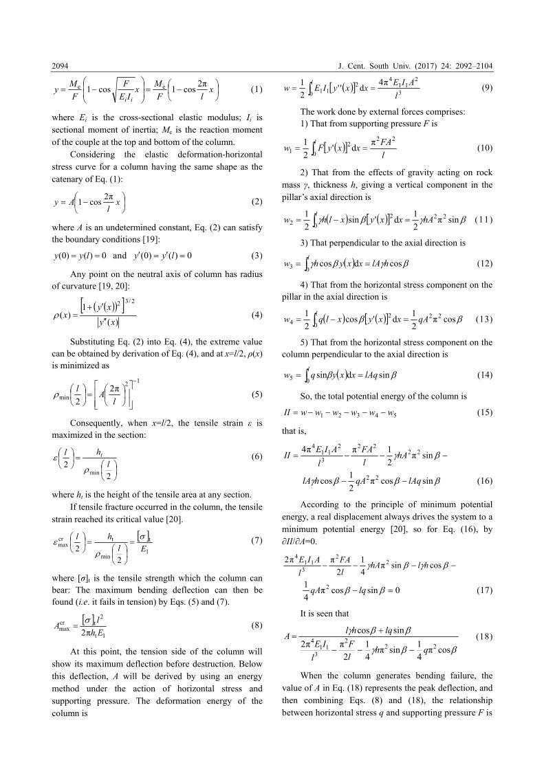
The original equilibrium of the rock mass is destroyed when the underground ore-body moves forward from the first side to the next (see Fig. 1), making the surrounding rock mass to mined-out areas subject to changing horizontal stress. In addition, due to the appearance of overhanging roof strata, the block
Fig. 1 Sketch section of mined-out area
weight thereof will be borne by the surrounding rock mass, increasing the pressure therein [16, 17]. So, the surrounding rock mass, under the action of horizontal stress and supporting pressure, will generate bending deformation and a bending moment, and then a mechanical model of a column with two ends fixed was proposed by LI [17].
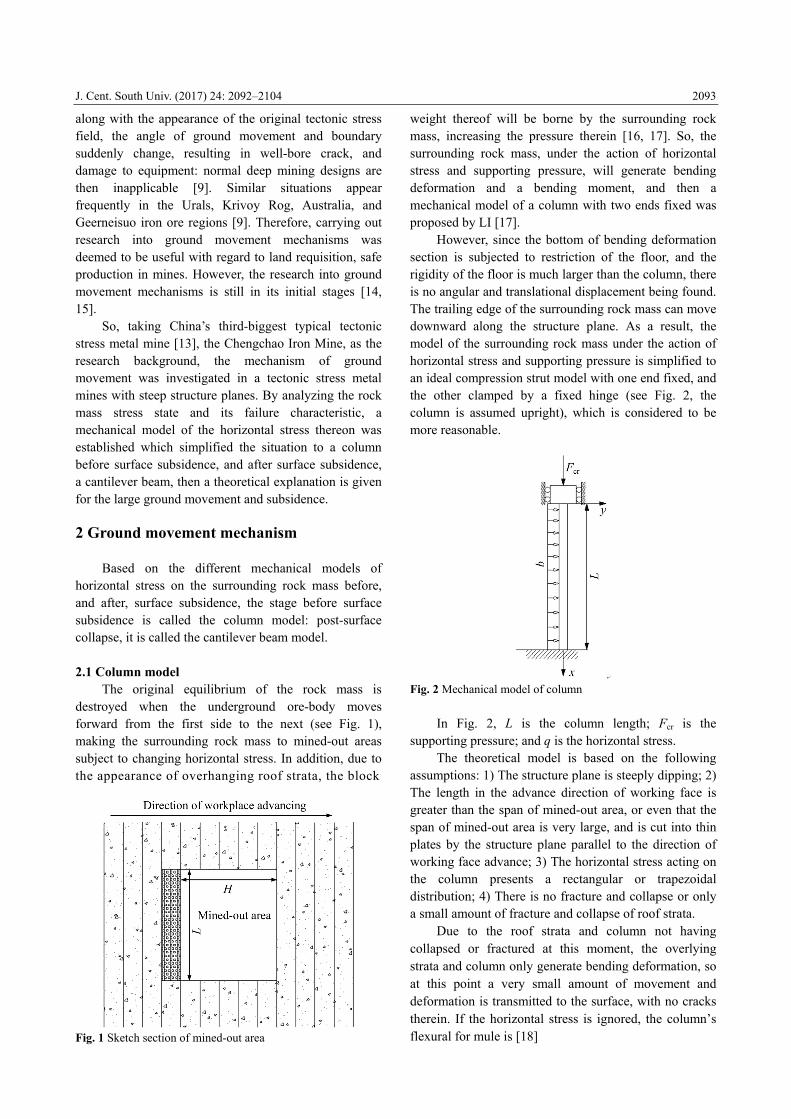
However, since the bottom of bending deformation section is subjected to restriction of the floor, and the rigidity of the floor is much larger than the column, there is no angular and translational displacement being found. The trailing edge of the surrounding rock mass can move downward along the structure plane. As a result, the model of the surrounding rock mass under the action of horizontal stress and supporting pressure is simplified to an ideal compression strut model with one end fixed, and the other clamped by a fixed hinge (see Fig. 2, the column is assumed upright), which is considered to be more reasonable.
Fig. 2 Mechanical model of column
In Fig. 2, L is the column length; Fcr is the supporting pressure; and q is the horizontal stress.
The theoretical model is based on the following assumptions: 1) The structure plane is steeply dipping; 2) The length in the advance direction of working face is greater than the span of mined-out area, or even that the span of mined-out area is very large, and is cut into thin plates by the structure plane parallel to the direction of working face advance; 3) The horizontal stress acting on the column presents a rectangular or trapezoidal distribution; 4) There is no fracture and collapse or only a small amount of fracture and collapse of roof strata.
Due to the roof strata and column not having collapsed or fractured at this moment, the overlying strata and column only generate bending deformation, so at this point a very small amount of movement and deformation is transmitted to the surface, with no cracks therein. If the horizontal stress is ignored, the column’s flexural for mule is [18]
J. Cent. South Univ. (2017) 24: 2092–2104
2094
x
lF
Mx
IE
F
F
My
ii
2πcos1cos1 ee (1)
where Ei is the cross-sectional elastic modulus; Ii is sectional moment of inertia; Me is the reaction moment of the couple at the top and bottom of the column.
Considering the elastic deformation-horizontal stress curve for a column having the same shape as the catenary of Eq. (1):
x
lAy
2πcos1 (2)
where A is an undetermined constant, Eq. (2) can satisfy the boundary conditions [19]:
0)()0( lyy and 0)()0( lyy (3)
Any point on the neutral axis of column has radius of curvature [19, 20]:
)(
1)(
2/3 2
xy
xyx
(4)
Substituting Eq. (2) into Eq. (4), the extreme value
can be obtained by derivation of Eq. (4), and at x=l/2, ρ(x) is minimized as
12
minπ2
2
lA
l (5)
Consequently, when x=l/2, the tensile strain ε is
maximized in the section:
22
minl
hl t
(6)
where ht is the height of the tensile area at any section.
If tensile fracture occurred in the column, the tensile strain reached its critical value [20].
1
t
min
tcrmax
22 El
hl
(7)
where [σ]t is the tensile strength which the column can bear: The maximum bending deflection can then be found (i.e. it fails in tension) by Eqs. (5) and (7).
1t
2tcr
max π2 Eh
lA
(8)
At this point, the tension side of the column will
show its maximum deflection before destruction. Below this deflection, A will be derived by using an energy method under the action of horizontal stress and supporting pressure. The deformation energy of the column is
3
211
42
10 1π4
d''2
1
l
AIExxyIEw
l (9)
The work done by external forces comprises: 1) That from supporting pressure F is
l
FAxxyFw
l 222
01π
d'2
1 (10)
2) That from the effects of gravity acting on rock
mass γ, thickness h, giving a vertical component in the pillar’s axial direction is
sinπ2
1d'sin
2
1 222
02 hAxxyxlhwl
(11)
3) That perpendicular to the axial direction is
cosdcos03 hlAxxyhwl
(12)
4) That from the horizontal stress component on the pillar in the axial direction is
cosπ2
1d'cos
2
1 222
04 qAxxyxlqwl
(13)
5) That from the horizontal stress component on the
column perpendicular to the axial direction is
sindsin05 lAqxxyqwl
(14)
So, the total potential energy of the column is
54321 wwwwwwII (15) that is,
sinπ2
1ππ4 2222
3
211
4
hAl
FA
l
AIEII
sincosπ2
1cos 22 lAqqAhlA (16)
According to the principle of minimum potential
energy, a real displacement always drives the system to a minimum potential energy [20], so for Eq. (16), by ∂II/∂A=0.
cossinπ4
1
2
ππ2 22
311
4
hlhAl
FA
l
AIE
0sincosπ4
1 2 lqqA (17)
It is seen that
cosπ4
1sinπ
4
1
2
ππ2
sincos
222
311
4
qhl
F
l
IE
lqhlA
(18)
When the column generates bending failure, the
value of A in Eq. (18) represents the peak deflection, and then combining Eqs. (8) and (18), the relationship between horizontal stress q and supporting pressure F is
J. Cent. South Univ. (2017) 24: 2092–2104
2095
cosπ4
1sinπ
4
1
2
ππ2
sincos
π2 222
311
41t
2t
qhl
F
l
IE
lqhl
Eh
l
(19)
Thus, the critical supporting pressure is
sincosπ
4π4 t12
112
cr qhhE
l
IEF
t
cossin2
qhl
(20)
When horizontal stress is ignored, Eq. (20) changes
to
sin
2
1
π
cos4π4 12
112
cr hlhhE
l
IEF
t
t (21)
The critical load obtained by Eq. (21) is greater than
that without horizontal stress, so this horizontal stress plays an important role in the destruction of the column. When the column is upright, i.e. at β=90°, Eq. (21) gives
hll
IEF
2
1π42
112
cr (22)
So, when horizontal stress is ignored, and the
column is upright, it matches existing research result [18, 19].
The biggest length of the column allowed can be calculated under the actions of the horizontal stress and supporting pressure by Eq. (20).
01
2max2
3max3 BlBlB (23)
where
112
1 π4 IEB ;
;sincosπ
4 12 Fqh
hEB
t
t
cossin2
13 qhB .
At lmax, Eq. (23) gives a limiting length:
3
13332
21
233
32max 912815.1 BBBBBBBBl
3
13332
21
233
32 912815.1 BBBBBBBB
32 3BB
(24)
From Fig. 1, surrounding columns in mined-out area
join to bear the supporting pressure and horizontal stress, of which the first layer of the column at the side of mined-out areas bears the greatest pressure. With the working face advancing, the action of horizontal stress and supporting pressure gradually increases, and the
columns move and bend into the side of the mined-out area. Uncontrolled deformation will result in a crack between the columns, and then inter-laminar crack renders the first layer of columns laterally unrestrained by the second layer of columns [17]. The horizontal stress reduces gradually and is shared between all columns. So the first layer of column at the side of a mined-out area bears the lowest horizontal stress.
Generally speaking, the first layer of columns suffers a larger deformation than the second, so it is easy to form a separation between the two layers of columns. Based on the maximum deflection y (horizontal deformation) between two columns as the separation criterion, the standards are as follows [19]:
,leftright yy separation
,leftright yy combination
The separation condition between the first and
second layers of columns is:
x
IE
FAx
IE
FA
22
22
11
11 cos1cos1 (25)
where A1 and A2 are undetermined constants for the first and second layers of column; E1 and E2 are cross-sectional elastic moduli of the first and second layers of columns; I1 and I2 are sectional moments of inertia of the first and second layers of columns
,12/)(( 311 bhI )12/( 3
22 bhI and F1 and F2 are supporting pressures of the first and second layers of columns. Equation (25) shows that when the supporting pressure on a column is known, the factor for separation of columns is related to elastic modulus E and the width h, of which width h is key.
1) When E is the same, it is judged by the strata thickness h.
,right left hh separation
,right left hh combination
2) When h is the same, it is judged by the modulus of elasticity E.
,right left EE separation
,right left EE combination
If the first layer of the bending columns at the side of the mined-out area separated from other columns, the horizontal stress exerted on the first layer of columns is zero [17]; However, the supporting pressure increases. With increasing mining depth, the tensile stress in a column gradually increases until reaching its tensile strength where the column begins to collapse (Fig. 3) at a critical load given by Eq. (21). At this time, the supporting pressure transfers to other columns away
J. Cent. South Univ. (2017) 24: 2092–2104
2096
from the direction of the mined-out area. The first layer of column after destruction and the second layer thereof play a protective role and result in the column effect decreasing or disappearing. The column effect, caused by large horizontal tectonic stress, leads to an increased transverse range of the underground mined-out area, which is one of the reasons for large movement and subsidence of the surface.
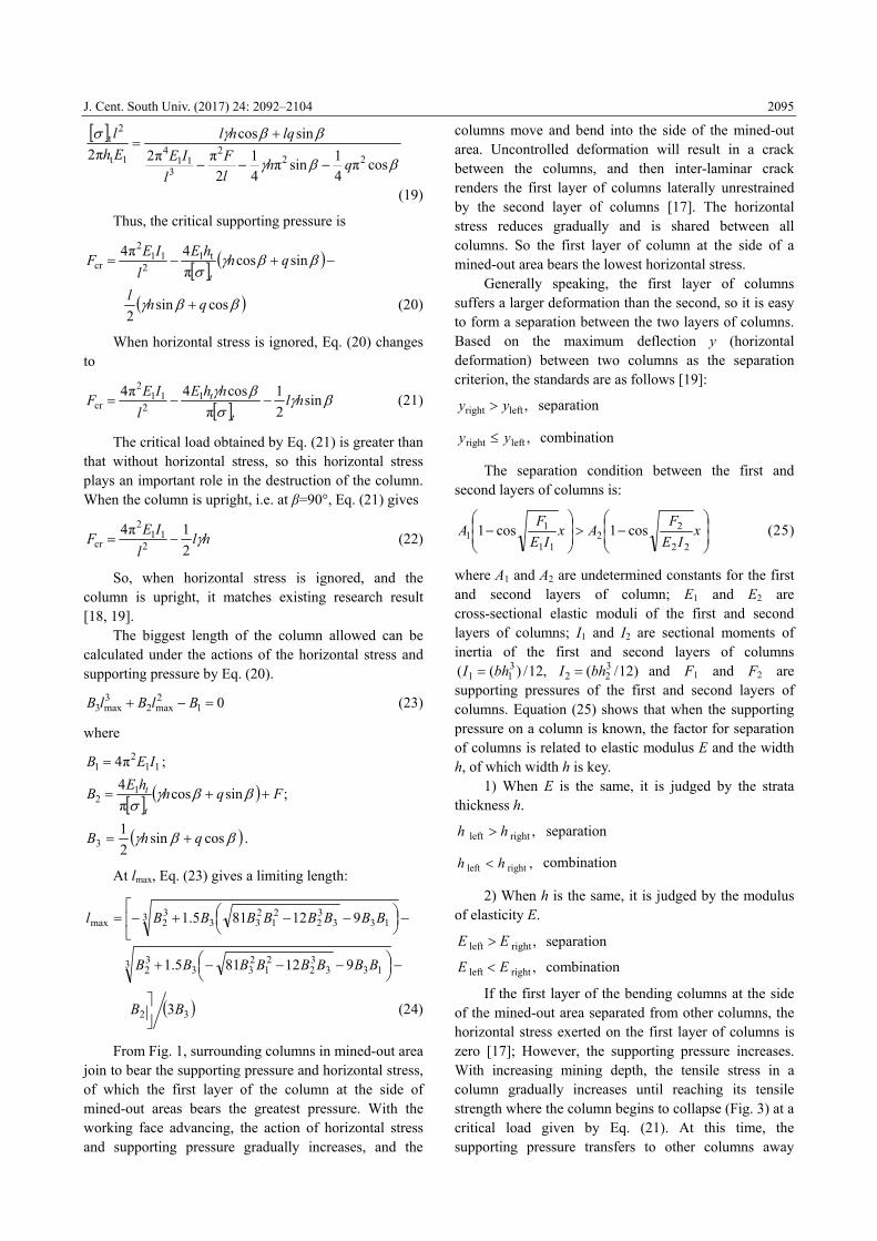
Fig. 3 Schematic diagram of column collapse
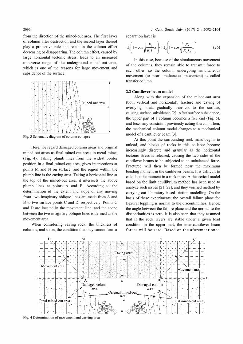
Here, we regard damaged column areas and original
mined-out areas as final mined-out areas in metal mines (Fig. 4). Taking plumb lines from the widest border position in a final mined-out area, gives intersections at points M and N on surface, and the region within the plumb line is the caving area. Taking a horizontal line at the top of the mined-out area, it intersects the above plumb lines at points A and B. According to the determination of the extent and slope of any moving front, two imaginary oblique lines are made from A and B to two surface points C and D, respectively. Points C and D are located in the movement line, and the scope between the two imaginary oblique lines is defined as the movement area.
When considering caving rock, the thickness of columns, and so on, the condition that they cannot form a
separation layer is
x
IE
FAx
IE
FA
22
22
11
11 cos1cos1 (26)
In this case, because of the simultaneous movement
of the columns, they remain able to transmit force to each other, so the column undergoing simultaneous movement (or near-simultaneous movement) is called transfer column. 2.2 Cantilever beam model
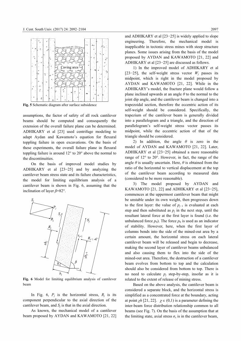
Along with the expansion of the mined-out area (both vertical and horizontal), fracture and caving of overlying strata gradually transfers to the surface, causing surface subsidence [2]. After surface subsidence, the upper part of a column becomes a free end (Fig. 5), and loses any constraint previously acting thereon. Then, the mechanical column model changes to a mechanical model of a cantilever beam [3].
At this point the surrounding rock mass begins to unload, and blocks of rocks in this collapse become increasingly discrete and granular as the horizontal tectonic stress is released, causing the two sides of the cantilever beams to be subjected to an unbalanced force. Fractured will then be formed near the maximum bending moment in the cantilever beams. It is difficult to calculate the moment in a rock mass. A theoretical model based on the limit equilibrium method has been used to analyze such issues [21, 22], and they verified method by carrying out laboratory-based friction modelling. On the basis of these experiments, the overall failure plane for flexural toppling is normal to the discontinuities. Hence, the angle between the failure plane and the normal to the discontinuities is zero. It is also seen that they assumed that if the rock layers are stable under a given load condition in the upper part, the inter-cantilever beam forces will be zero. Based on the aforementioned
Fig. 4 Determination of movement and carving area
J. Cent. South Univ. (2017) 24: 2092–2104
2097
Fig. 5 Schematic diagram after surface subsidence
assumptions, the factor of safety of all rock cantilever beams should be computed and consequently the extension of the overall failure plane can be determined. ADHIKARY et al [23] used centrifuge modeling to adapt Aydan and Kawamoto’s equation for flexural toppling failure in open excavations. On the basis of these experiments, the overall failure plane in flexural toppling failure is around 12° to 20° above the normal to the discontinuities.
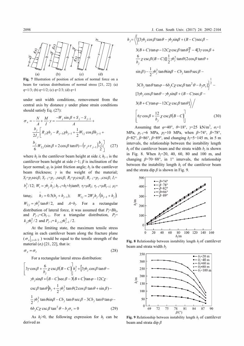
On the basis of improved model studies by ADHIKARY et al [23−25] and by analyzing the cantilever beam stress state and its failure characteristics, the model for limiting equilibrium analysis of a cantilever beam is shown in Fig. 6, assuming that the inclination of layer β=82°.
Fig. 6 Model for limiting equilibrium analysis of cantilever
beam
In Fig. 6, Pj is the horizontal stress, Rj is its component perpendicular to the axial direction of the cantilever beam, and Sj is that in the axial direction.
As known, the mechanical model of a cantilever beam proposed by AYDAN and KAWAMOTO [21, 22]
and ADHIKARY et al [23−25] is widely applied to slope engineering. Therefore, the mechanical model is inapplicable in tectonic stress mines with steep structure planes. Some issues arising from the basis of the model proposed by AYDAN and KAWAMOTO [21, 22] and ADHIKARY et al [23−25] are discussed as follows.
1) In the improved model of ADHIKARY et al [23−25], the self-weight stress vector Wj passes its midpoint, which is right in the model proposed by AYDAN and KAWAMOTO [21, 22]. While in the ADHIKARY’s model, the fracture plane would follow a plane inclined upwards at an angle θ to the normal to the joint dip angle, and the cantilever beam is changed into a trapezoidal section, therefore the eccentric action of its self-weight should be considered. Specifically, the trapezium of the cantilever beam is generally divided into a parallelogram and a triangle, and the direction of parallelogram’s self-weight stress vector passes its midpoint, while the eccentric action of that of the triangle should be considered.
2) In addition, the angle θ is zero in the model of AYDAN and KAWAMOTO [21, 22]. Later, ADHIKARY et al [23−25] obtained a more reasonable range of 12° to 20°. However, in fact, the range of the angle θ is usually uncertain. Here, θ is obtained from the ratio of the horizontal to vertical displacement at the top of the cantilever beam according to measured data (considered to be more reasonable).
3) The model proposed by AYDAN and KAWAMOTO [21, 22] and ADHIKARY et al [23−25], commences at the uppermost cantilever beam that might be unstable under its own weight, then progresses down to the first layer: the value of pj−1 is evaluated at each step and then substituted as pj in the next step, until the resultant lateral force at the first layer is found (i.e. the unbalanced force p0). The force p0 is used as an indicator of stability. However, here, when the first layer of columns bends into the side of the mined-out area by a certain amount, the horizontal stress on each lateral cantilever beam will be released and begin to decrease, making the second layer of cantilever beams unbalanced and also causing them to flex into the side of the mined-out area. Therefore, the destruction of a cantilever beam evolves from bottom to top and the calculation should also be considered from bottom to top. There is no need to calculate pj step-by-step, insofar as it is related to the extent of release of mining stress.
Based on the above analysis, the cantilever beam is considered a separate block, and the horizontal stress is simplified as a concentrated force at the boundary, acting at point χh [21, 22]. (0,1) is a parameter defining the inter-beam force distribution relationship common to all beams (see Fig. 7). On the basis of the assumption that at the limiting state, axial stress σx is in the cantilever beam,
J. Cent. South Univ. (2017) 24: 2092–2104
2098
Fig. 7 Illustration of position of action of normal force on a
beam for various distributions of normal stress [21, 22]: (a)
η=1/3; (b) η=1/2; (c) η=2/3; (d) η=1 under unit width conditions, removement from the central axis by distance y under plane strain conditions should satisfy Eq. (27):
A
SSWy
I
M
A
N jjjx
1sin
1111 cos
2
1
2 jjjjjjj
j hWhRhRI
b
2
)tancos2(sin6 12
jjjj
j bW
b (27)
where hj is the cantilever beam height at side i; hj−1 is the cantilever beam height at side i−1; β is inclination of the layer normal; φj is joint friction angle; bj is the cantilever beam thickness; γ is the weight of the material; Sj=pjsecβ; Sj−1=pj−1secβ; Rj=pjcscβ; Rj−1=pj−1cscβ; Ii=
;12/3jb ;
jji hbW hj−1=hj+bjtanθ; τj=μRj; τj−1=μRj−1; μj=
tanφj; );(5.0 1
jjj hhh ;/2 11 jjjjj hhhWW
,2/tan22 jj bW and A=bj. For a rectangular
distribution of lateral force, it was assumed that Pj=Bhj, and Pj−1=Chj−1. For a triangular distribution, Pj=
2/2jj hk and Pj−1= .2/2
11 jj hk
At the limiting state, the maximum tensile stress acting in each cantilever beam along the fracture plane ( 2/byx ) would be equal to the tensile strength of the material (σt) [21, 22], that is:
tx (28) For a rectangular lateral stress distribution:
tancos3csc
6cos3 2
jjj
bhCBb
tantan3sectansintan2
1
)sintancos2(tan2
1tancsc
12tan3secsin
2
2
jjj
jj
j
CbCbb
bh
CCBCBb
0tancsc6 2 tjj bCb (29) As hj>0, the following expression for hj can be
derived as
sec)(sintancos3[ CBbbh jjj
sectansintan2
1)sin
tancos2(tan2
1)][(csc
6
cos3[4tancsc12tan)(3
2
2
2
jj
jj
Cbb
bCBb
CCB
2
1
2 ]tancsc6tantan3 tjjj bCbCb
sec)(sintancos3[ CBbb jj
]tancsc12tan)(3 CCB
CB
b j
csc12
cos6 (30)
Assuming that φ=40°, θ=18°, γ=25 kN/m3, σt=1
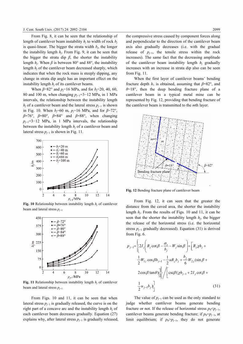
MPa, pj−1=6 MPa, pj=10 MPa, when β=74°, β=78°, β=82°, β=86°, β=89°, and changing bj=5−145 m, in 5 m intervals, the relationship between the instability length hj of the cantilever beam and the strata width bj is shown in Fig. 8. When bj=20, 40, 60, 80 and 100 m, and changing β=70−88°, in 1° intervals, the relationship between the instability length hj of the cantilever beam and the strata dip β is shown in Fig. 9.
Fig. 8 Relationship between instability length hj of cantilever beam and strata width bj
Fig. 9 Relationship between instability length hj of cantilever beam and strata dip β
J. Cent. South Univ. (2017) 24: 2092–2104
2099
From Fig. 8, it can be seen that the relationship of length of cantilever beam instability hj to width of rock bj is quasi-linear. The bigger the strata width bj, the longer the instability length hj. From Fig. 9, it can be seen that the bigger the strata dip β, the shorter the instability length hj. When β is between 80° and 88°, the instability length hj of the cantilever beam decreased sharply, which indicates that when the rock mass is steeply dipping, any change in strata dip angle has an important effect on the instability length hj of its cantilever beams.
When β=82° and pj=16 MPa, and for bj=20, 40, 60, 80 and 100 m, when changing pj−1=3−12 MPa, in 1 MPa intervals, the relationship between the instability length hj of a cantilever beam and the lateral stress pj−1 is shown in Fig. 10. When bj=60 m, pj=16 MPa, and for β=72°, β=76°, β=80°, β=84° and β=88°, when changing pj−1=3−12 MPa, in 1 MPa intervals, the relationship between the instability length hj of a cantilever beam and lateral stress pj−1 is shown in Fig. 11.
Fig. 10 Relationship between instability length hj of cantilever
beam and lateral stress pj−1
Fig. 11 Relationship between instability length hj of cantilever
beam and lateral stress pj−1
From Figs. 10 and 11, it can be seen that when lateral stress pj−1 is gradually released, the curve is on the right part of a concave arc and the instability length hj of each cantilever beam decreases gradually. Equation (27) explains why, after lateral stress pj−1 is gradually released,
the compressive stress caused by component forces along and perpendicular to the direction of the cantilever beam axis also gradually decreases (i.e. with the gradual release of pj−1, the tensile stress within the rock increases). The same fact that the decreasing amplitude of the cantilever beam instability length hj gradually increases with an increase in strata dip also can be seen from Fig. 11.
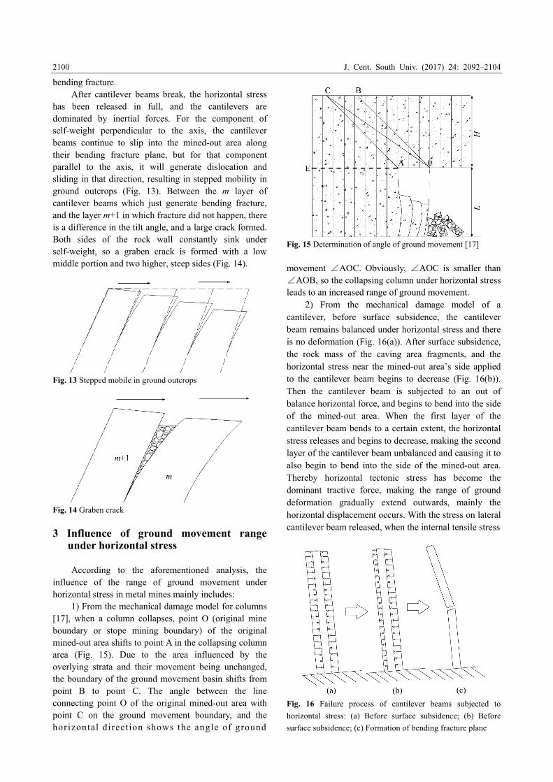
When the first layer of cantilever beams’ bending fracture depth h1 is obtained, assuming that β=82°, and θ=18°, then the deep bending fracture plane of a cantilever beam in a typical metal mine can be represented by Fig. 12, providing that bending fracture of the cantilever beam is transmitted to the mth layer.
Fig. 12 Bending fracture plane of cantilever beam
From Fig. 12, it can seen that the greater the
distance from the caved area, the shorter the instability length hj. From the results of Figs. 10 and 11, it can be seen that the shorter the instability length hj, the bigger the release of the horizontal stress (i.e. the horizontal stress pj−1 gradually decreased). Equation (31) is derived from Fig. 6.
jjj
j
tjjj hRW
bRIp sincot21
(sin62
1cos
2
1211 j
jjjjj W
bbuRhW
cot2(csc)tancos2 1 jj Ih
)2
11 jj bu (31)
The value of pj−1 can be used as the only standard to
judge whether cantilever beams generate bending fracture or not. If the release of horizontal stress p0<pj−1, cantilever beams generate bending fracture; if p0=pj−1, at limit equilibrium; if p0>pj−1, they do not generate
J. Cent. South Univ. (2017) 24: 2092–2104
2100
bending fracture. After cantilever beams break, the horizontal stress
has been released in full, and the cantilevers are dominated by inertial forces. For the component of self-weight perpendicular to the axis, the cantilever beams continue to slip into the mined-out area along their bending fracture plane, but for that component parallel to the axis, it will generate dislocation and sliding in that direction, resulting in stepped mobility in ground outcrops (Fig. 13). Between the m layer of cantilever beams which just generate bending fracture, and the layer m+1 in which fracture did not happen, there is a difference in the tilt angle, and a large crack formed. Both sides of the rock wall constantly sink under self-weight, so a graben crack is formed with a low middle portion and two higher, steep sides (Fig. 14).
Fig. 13 Stepped mobile in ground outcrops
Fig. 14 Graben crack
3 Influence of ground movement range
under horizontal stress
According to the aforementioned analysis, the influence of the range of ground movement under horizontal stress in metal mines mainly includes:
1) From the mechanical damage model for columns [17], when a column collapses, point O (original mine boundary or stope mining boundary) of the original mined-out area shifts to point A in the collapsing column area (Fig. 15). Due to the area influenced by the overlying strata and their movement being unchanged, the boundary of the ground movement basin shifts from point B to point C. The angle between the line connecting point O of the original mined-out area with point C on the ground movement boundary, and the horizontal direction shows the angle of ground
Fig. 15 Determination of angle of ground movement [17]
movement ∠AOC. Obviously, ∠AOC is smaller than ∠AOB, so the collapsing column under horizontal stress leads to an increased range of ground movement.
2) From the mechanical damage model of a cantilever, before surface subsidence, the cantilever beam remains balanced under horizontal stress and there is no deformation (Fig. 16(a)). After surface subsidence, the rock mass of the caving area fragments, and the horizontal stress near the mined-out area’s side applied to the cantilever beam begins to decrease (Fig. 16(b)). Then the cantilever beam is subjected to an out of balance horizontal force, and begins to bend into the side of the mined-out area. When the first layer of the cantilever beam bends to a certain extent, the horizontal stress releases and begins to decrease, making the second layer of the cantilever beam unbalanced and causing it to also begin to bend into the side of the mined-out area. Thereby horizontal tectonic stress has become the dominant tractive force, making the range of ground deformation gradually extend outwards, mainly the horizontal displacement occurs. With the stress on lateral cantilever beam released, when the internal tensile stress
Fig. 16 Failure process of cantilever beams subjected to
horizontal stress: (a) Before surface subsidence; (b) Before
surface subsidence; (c) Formation of bending fracture plane
J. Cent. South Univ. (2017) 24: 2092–2104
2101
was equal to the limiting tensile strength [21, 22], then the cantilever generates bending fractures (Fig. 16(c)).
As mentioned, an explanation is given for the phenomenon in which ground movement and the subsidence range of metal mines with steep structure planes become excessive. When determining the angle of ground movement, the influence of column and cantilever beam destruction should be considered, and appropriate correction factors applied thereto relate to the mine’s geological structure and the magnitude of the tectonic stress. 4 A case study 4.1 Engineering summary
A case study is western area of Chengchao Iron Mine, located in Ezhou City, Hubei Province, China. The hanging wall surrounding rock mass is hornstone, while the footwall is granite, which is also the main rock mass in the mine, and its quality is better. The surrounding rock mass from the top of ore body to its outcrop between the upper and footwall is a metamorphic belt composed of marble and diorite. According to the relative position between the orientation of the major principal stress, the strike of the major structure plane and the strike of the mined-out area, the theory mentioned above is mainly applied to the northeast part of the mine.
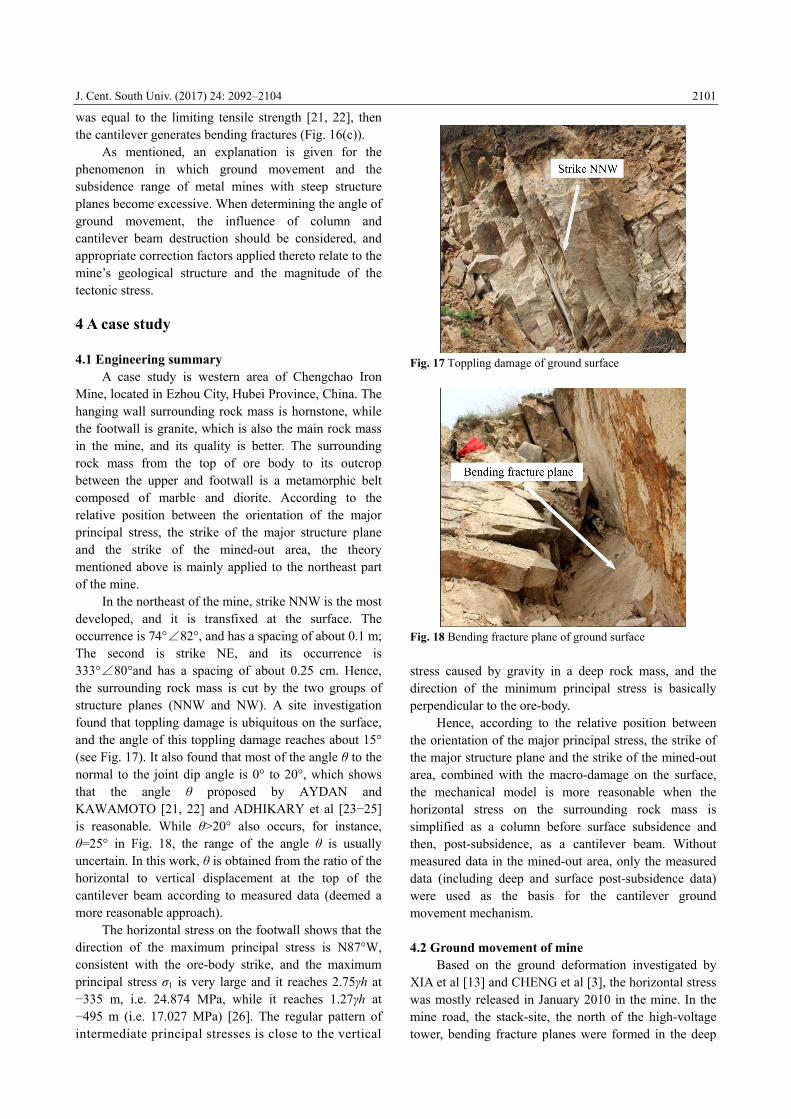
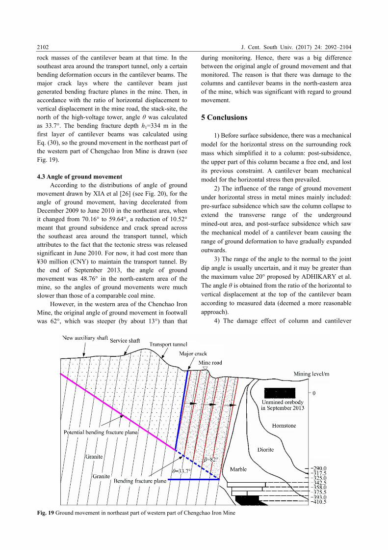
In the northeast of the mine, strike NNW is the most developed, and it is transfixed at the surface. The occurrence is 74°∠82°, and has a spacing of about 0.1 m; The second is strike NE, and its occurrence is 333°∠80°and has a spacing of about 0.25 cm. Hence, the surrounding rock mass is cut by the two groups of structure planes (NNW and NW). A site investigation found that toppling damage is ubiquitous on the surface, and the angle of this toppling damage reaches about 15° (see Fig. 17). It also found that most of the angle θ to the normal to the joint dip angle is 0° to 20°, which shows that the angle θ proposed by AYDAN and KAWAMOTO [21, 22] and ADHIKARY et al [23−25] is reasonable. While θ>20° also occurs, for instance, θ=25° in Fig. 18, the range of the angle θ is usually uncertain. In this work, θ is obtained from the ratio of the horizontal to vertical displacement at the top of the cantilever beam according to measured data (deemed a more reasonable approach).
The horizontal stress on the footwall shows that the direction of the maximum principal stress is N87°W, consistent with the ore-body strike, and the maximum principal stress σ1 is very large and it reaches 2.75γh at −335 m, i.e. 24.874 MPa, while it reaches 1.27γh at −495 m (i.e. 17.027 MPa) [26]. The regular pattern of intermediate principal stresses is close to the vertical
Fig. 17 Toppling damage of ground surface
Fig. 18 Bending fracture plane of ground surface
stress caused by gravity in a deep rock mass, and the direction of the minimum principal stress is basically perpendicular to the ore-body.
Hence, according to the relative position between the orientation of the major principal stress, the strike of the major structure plane and the strike of the mined-out area, combined with the macro-damage on the surface, the mechanical model is more reasonable when the horizontal stress on the surrounding rock mass is simplified as a column before surface subsidence and then, post-subsidence, as a cantilever beam. Without measured data in the mined-out area, only the measured data (including deep and surface post-subsidence data) were used as the basis for the cantilever ground movement mechanism. 4.2 Ground movement of mine
Based on the ground deformation investigated by XIA et al [13] and CHENG et al [3], the horizontal stress was mostly released in January 2010 in the mine. In the mine road, the stack-site, the north of the high-voltage tower, bending fracture planes were formed in the deep
J. Cent. South Univ. (2017) 24: 2092–2104
2102
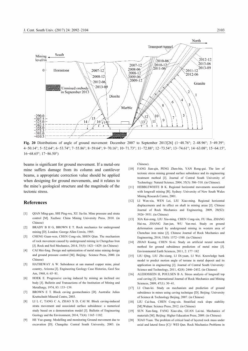
rock masses of the cantilever beam at that time. In the southeast area around the transport tunnel, only a certain bending deformation occurs in the cantilever beams. The major crack lays where the cantilever beam just generated bending fracture planes in the mine. Then, in accordance with the ratio of horizontal displacement to vertical displacement in the mine road, the stack-site, the north of the high-voltage tower, angle θ was calculated as 33.7°. The bending fracture depth h1=334 m in the first layer of cantilever beams was calculated using Eq. (30), so the ground movement in the northeast part of the western part of Chengchao Iron Mine is drawn (see Fig. 19). 4.3 Angle of ground movement
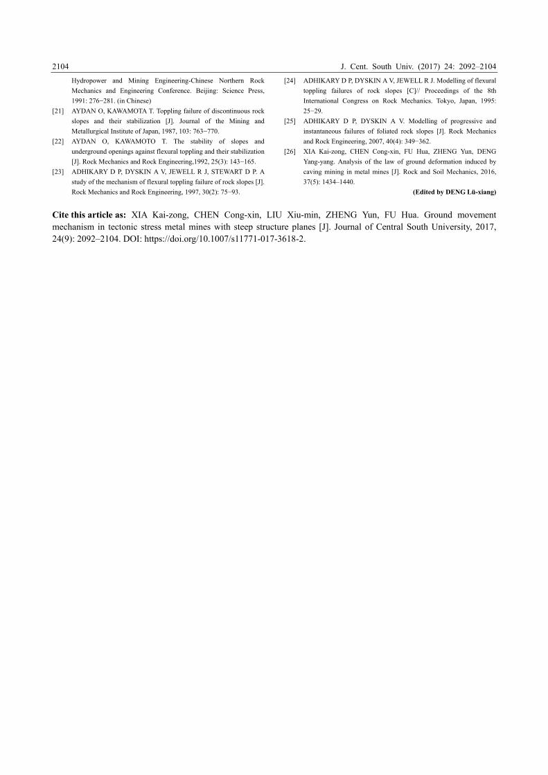
According to the distributions of angle of ground movement drawn by XIA et al [26] (see Fig. 20), for the angle of ground movement, having decelerated from December 2009 to June 2010 in the northeast area, when it changed from 70.16° to 59.64°, a reduction of 10.52° meant that ground subsidence and crack spread across the southeast area around the transport tunnel, which attributes to the fact that the tectonic stress was released significant in June 2010. For now, it had cost more than ¥30 million (CNY) to maintain the transport tunnel. By the end of September 2013, the angle of ground movement was 48.76° in the north-eastern area of the mine, so the angles of ground movements were much slower than those of a comparable coal mine.
However, in the western area of the Chenchao Iron Mine, the original angle of ground movement in footwall was 62°, which was steeper (by about 13°) than that
during monitoring. Hence, there was a big difference between the original angle of ground movement and that monitored. The reason is that there was damage to the columns and cantilever beams in the north-eastern area of the mine, which was significant with regard to ground movement.
5 Conclusions
1) Before surface subsidence, there was a mechanical model for the horizontal stress on the surrounding rock mass which simplified it to a column: post-subsidence, the upper part of this column became a free end, and lost its previous constraint. A cantilever beam mechanical model for the horizontal stress then prevailed.
2) The influence of the range of ground movement under horizontal stress in metal mines mainly included: pre-surface subsidence which saw the column collapse to extend the transverse range of the underground mined-out area, and post-surface subsidence which saw the mechanical model of a cantilever beam causing the range of ground deformation to have gradually expanded outwards.
3) The range of the angle to the normal to the joint dip angle is usually uncertain, and it may be greater than the maximum value 20° proposed by ADHIKARY et al. The angle θ is obtained from the ratio of the horizontal to vertical displacement at the top of the cantilever beam according to measured data (deemed a more reasonable approach).
4) The damage effect of column and cantilever
Fig. 19 Ground movement in northeast part of western part of Chengchao Iron Mine
J. Cent. South Univ. (2017) 24: 2092–2104
2103
Fig. 20 Distributions of angle of ground movement: December 2007 to September 2013[26] (1−48.76°; 2–48.96°; 3−49.39°;
4−50.14°; 5−52.64°; 6−53.74°; 7−55.86°; 8−59.64°; 9−70.16°; 10−71.73°; 11−72.88°; 12−73.54°; 13−74.61°; 14−63.08°; 15−64.15°,
16−68.65°; 17−86.50°)
beams is significant for ground movement. If a metal-ore mine suffers damage from its column and cantilever beams, a appropriate correction value should be applied when designing for ground movements, and it relates to the mine’s geological structure and the magnitude of the tectonic stress. References [1] QIAN Ming-gao, SHI Ping-wu, XU Jia-lin. Mine pressure and strata
control [M]. Xuzhou: China Mining University Press, 2010. (in
Chinese)
[2] BRADY B H G, BROWN E T. Rock mechanics for underground
mining [D]. London: George Allen Unwin, 1985.
[3] CHENG Guan-wen, CHEN Cong-xin, SHEN Qian. The mechanism
of rock movement caused by underground mining in Chengchao Iron
[J]. Rock and Soil Mechanics, 2014, 35(5): 1421−1429. (in Chinese)
[4] CAI Mei-feng. Design and optimization of metal mine mining design
and ground pressure control [M]. Beijing:Science Press, 2000. (in
Chinese)
[5] HATHEWAY A W. Subsidence at san manuel copper mine, pinal
country, Arizona [J]. Engineering Geology Case Histories, Geol Soc
Am, 1968, 6: 65−81.
[6] HOEK E. Progressive caving induced by mining an inclined ore
body [J]. Bulletin and Transactions of the Institution of Mining and
Metallurgy, 1974, 83: 133−139.
[7] BROWN E T. Block caving geomechanics [D]. Australia: Julius
Kruttschnitt Mineral Centre, 2003.
[8] LI L C, TANG C A, ZHAO X D, CAI M. Block caving-induced
strata movement and associated surface subsidence: a numerical
study based on a demonstration model [J]. Bulletin of Engineering
Geology and the Environment, 2014, 73(4): 1165−1182.
[9] HE Yue-guang. Modelling and monitoring Ground movement due to
excavation [D]. Changsha: Central South University, 2003. (in
Chinese).
[10] FANG Jian-qin, PENG Zhen-bin, YAN Rong-gui. The law of
tectonic stress mining ground surface subsidence and its engineering
treatment method [J]. Journal of Central South University of
Technology: Natural Science, 2004, 35(3): 506−510. (in Chinese).
[11] HEBBLEWHITE B K. Regional horizontal movements associated
with longwall mining [R]. Sydney: University of New South Wales
Mining Research Centre, 2001.
[12] LI Wen-xiu, WEN Lei, LIU Xiao-ming. Regional horizontal
displacements and its effect on shaft in mining areas [J]. Chinese
Journal of Rock Mechanics and Engineering, 2009, 28(S2):
3926−3931. (in Chinese)
[13] XIA Kai-zong, LIU Xiu-ming, CHEN Cong-xin, FU Hua, ZHANG
Hai-na, ZHANG Jian-jun, WU Yan-mei. Study on ground
deformation caused by underground mining in western area of
Chenchao iron mine [J]. Chinese Journal of Rock Mechanics and
Engineering, 2014, 33(8): 1572−1588. (in Chinese)
[14] ZHAO Kuang, CHEN Si-ni. Study on artificial neural network
method for ground subsidence prediction of metal mine [J].
Environmental Earth Sciences, 2011, 2: 177−182
[15] LIU Qing, LIU Zhi-xiang, LI Di-yuan, LI Wei. Knowledge bank
model to predict motion angle of terrane in metal deposit and its
application in engineering [J]. Journal of Central South University:
Science and Technology, 2011, 42(8): 2446−2452. (in Chinese)
[16] ALEHOSSEIN H, POULSEN B A. Stress analysis of longwall top
coal caving [J]. International Journal of Rock Mechanics and Mining
Sciences, 2009, 47(1): 30−41.
[17] LI Chun-lei. Study on mechanism and prediction of ground
subsidence in mines using caving technique [D]. Beijing: University
of Science & Technology Beijing, 2007. (in Chinese)
[18] LIU Cai-hua, CHEN Cong-xin. Stratified rock slope stability
[M].Wuhan: Science Press, 2012. (in Chinese)
[19] SUN Xun-fang, FANG Xiao-shu, GUAN Lai-tai. Mechanics of
materials [M]. Beijing: Higher Education Press, 2009. (in Chinese)
[20] XIAO Yuan. The problem of critical load of layered rock mass under
axial and lateral force [C]// WEI Qun. Rock Mechanics Problems in
J. Cent. South Univ. (2017) 24: 2092–2104
2104
Hydropower and Mining Engineering-Chinese Northern Rock
Mechanics and Engineering Conference. Beijing: Science Press,
1991: 276−281. (in Chinese)
[21] AYDAN O, KAWAMOTA T. Toppling failure of discontinuous rock
slopes and their stabilization [J]. Journal of the Mining and
Metallurgical Institute of Japan, 1987, 103: 763−770.
[22] AYDAN O, KAWAMOTO T. The stability of slopes and
underground openings against flexural toppling and their stabilization
[J]. Rock Mechanics and Rock Engineering,1992, 25(3): 143−165.
[23] ADHIKARY D P, DYSKIN A V, JEWELL R J, STEWART D P. A
study of the mechanism of flexural toppling failure of rock slopes [J].
Rock Mechanics and Rock Engineering, 1997, 30(2): 75−93.
[24] ADHIKARY D P, DYSKIN A V, JEWELL R J. Modelling of flexural
toppling failures of rock slopes [C]// Proceedings of the 8th
International Congress on Rock Mechanics. Tokyo, Japan, 1995:
25−29.
[25] ADHIKARY D P, DYSKIN A V. Modelling of progressive and
instantaneous failures of foliated rock slopes [J]. Rock Mechanics
and Rock Engineering, 2007, 40(4): 349−362.
[26] XIA Kai-zong, CHEN Cong-xin, FU Hua, ZHENG Yun, DENG
Yang-yang. Analysis of the law of ground deformation induced by
caving mining in metal mines [J]. Rock and Soil Mechanics, 2016,
37(5): 1434–1440.
(Edited by DENG Lü-xiang)
Cite this article as: XIA Kai-zong, CHEN Cong-xin, LIU Xiu-min, ZHENG Yun, FU Hua. Ground movement mechanism in tectonic stress metal mines with steep structure planes [J]. Journal of Central South University, 2017, 24(9): 2092–2104. DOI: https://doi.org/10.1007/s11771-017-3618-2.
Related Documents