www.HaywardBaker.com Ground Modification for Liquefaction Mitigation January 11, 2013 Kansas City, MO Tanner Blackburn, Ph.D., P.E. Assistant Chief Engineer

Ground Modification for Liquefaction Mitigation
Feb 26, 2016
Ground Modification for Liquefaction Mitigation. January 11, 2013 Kansas City, MO. Tanner Blackburn, Ph.D., P.E. Assistant Chief Engineer. Presentation Summary. Determining liquefaction susceptibility NCEER guidelines Mitigation methods Densification Reinforcement Drainage. - PowerPoint PPT Presentation
Welcome message from author
This document is posted to help you gain knowledge. Please leave a comment to let me know what you think about it! Share it to your friends and learn new things together.
Transcript

www.HaywardBaker.com
Ground Modification for Liquefaction
Mitigation
January 11, 2013Kansas City, MO
Tanner Blackburn, Ph.D., P.E.Assistant Chief Engineer

Presentation Summary Determining liquefaction susceptibility
NCEER guidelines
Mitigation methods Densification Reinforcement Drainage

Geotechnical Seismic Hazards
Liquefaction Bearing capacity Excessive settlement Lateral spreading
Slope Stability Cyclic shear strength Kinematic loading of slopes/earth

Liquefaction Function of:
Earthquake magnitude Distance from site Groundwater conditions (current or ‘high
water’?) Depth to ‘liquefiable’ strata (svo , rd)
Common Input Parameters: Peak Ground Acceleration (PGA) Magnitude (M)

Liquefaction National Center for Earthquake Engineering
Research (NCEER) Summary Report (1997 Meeting, published in JGGE, 2001).
Seed and Idriss (1971):
Normalized by vertical effective stress:
dvocyclic rga s max65.0
dvo
voeqeq r
ga
CSR '65.0ss

Liquefaction Resistance to liquefaction
Referred to as Cyclic Resistance Ratio (CRR) or CSRfield
Function of: Geologic history (deposit type, age, OCR) Soil structure (relative density, clay content) Groundwater conditions
Factor of Safety = CRR/CSR
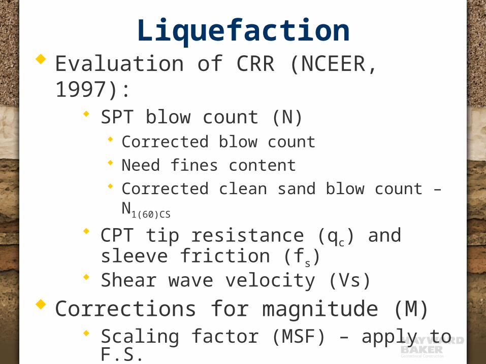
Liquefaction Evaluation of CRR (NCEER, 1997):
SPT blow count (N) Corrected blow count Need fines content Corrected clean sand blow count – N1(60)CS
CPT tip resistance (qc) and sleeve friction (fs)
Shear wave velocity (Vs) Corrections for magnitude (M)
Scaling factor (MSF) – apply to F.S.

Liquefaction – SPT Analysis

Liquefaction – CPT AnalysisTo address FC:
(qc1N)cs instead of qc1N
(qc1N)cs = Kc*qc1N
Kc = f(qc, fs, svo, s’vo)
This eliminates need for sampling to determine FC.

Liquefaction – Shear Wave

Liquefaction - MSF
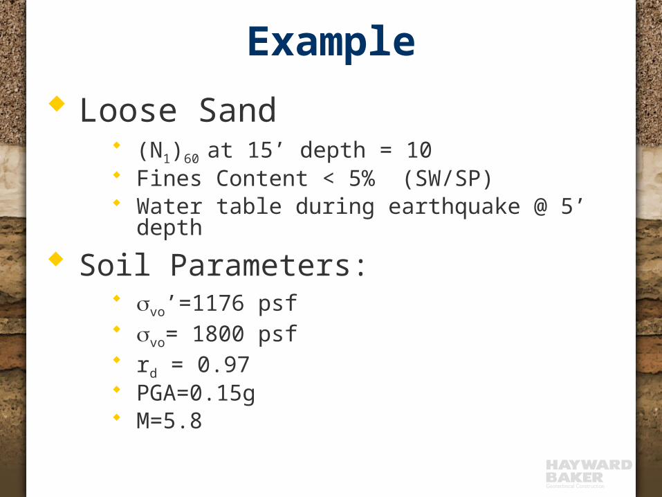
Example Loose Sand
(N1)60 at 15’ depth = 10 Fines Content < 5% (SW/SP) Water table during earthquake @ 5’ depth
Soil Parameters: svo’=1176 psf svo= 1800 psf rd = 0.97 PGA=0.15g M=5.8

Example (cont’d)
CSR = (0.65)(0.15)(1800/1176)(0.97)
CSR = 0.15 Using NCEER figure for (N1)60=
10: CRR=0.11 MSF ≈2 FS = MSF*(CRR/CSR) =
2*(0.11/0.15) = 1.47 Note the influence of MSF!
dvo
voeqeq r
ga
CSR '65.0ss
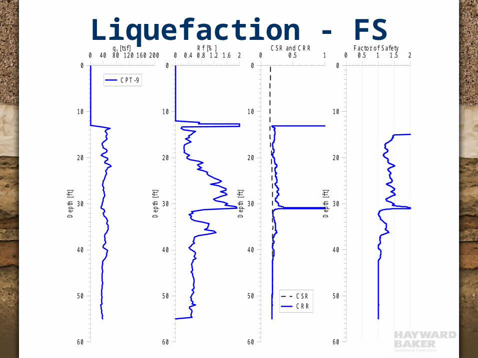
Liquefaction - FS0 0 .5 1
C S R an d C R R
60
50
40
30
20
10
0
Dep
th [f
t]
C S RC R R
0 40 80 12 0 1 60 200q t [ts f]
60
50
40
30
20
10
0D
epth
[ft]
C P T -9
0 0 .4 0 .8 1 .2 1 .6 2R f [% ]
60
50
40
30
20
10
0
Dep
th [f
t]
0 0 .5 1 1 .5 2F a c to r o f S afe ty
60
50
40
30
20
10
0
Dep
th [f
t]
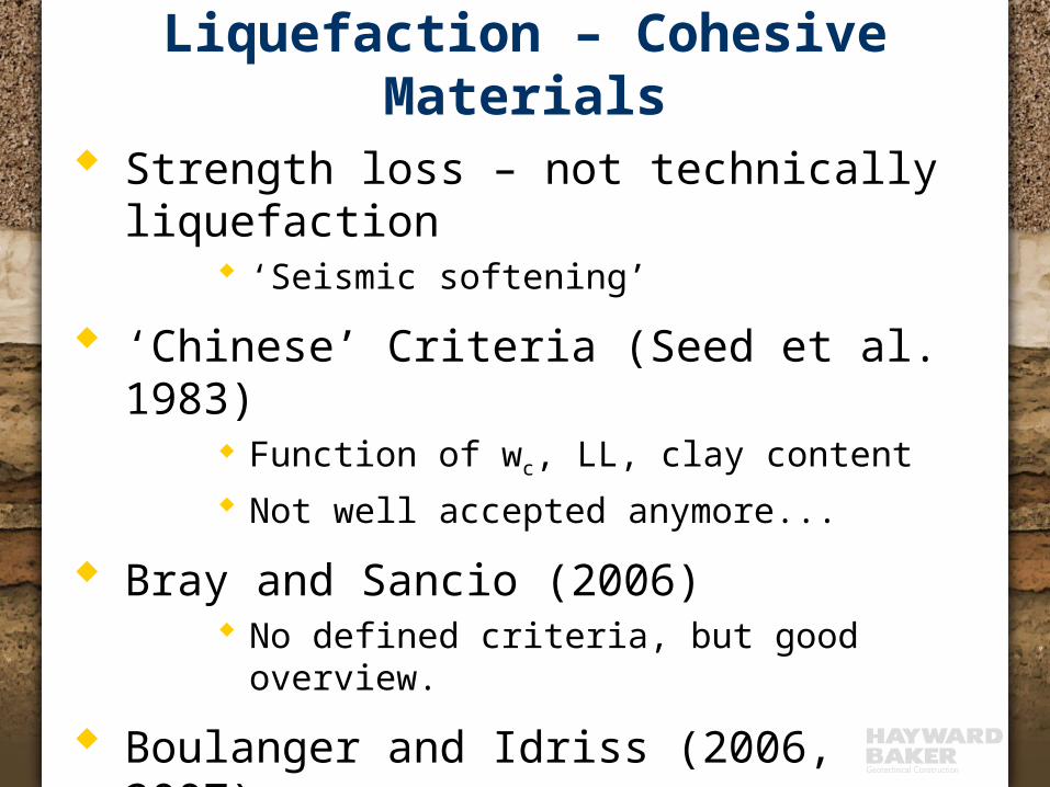
Liquefaction – Cohesive Materials
Strength loss – not technically liquefaction ‘Seismic softening’
‘Chinese’ Criteria (Seed et al. 1983) Function of wc, LL, clay content Not well accepted anymore...
Bray and Sancio (2006) No defined criteria, but good overview.
Boulanger and Idriss (2006, 2007) Chris Baxter at URI - Silts
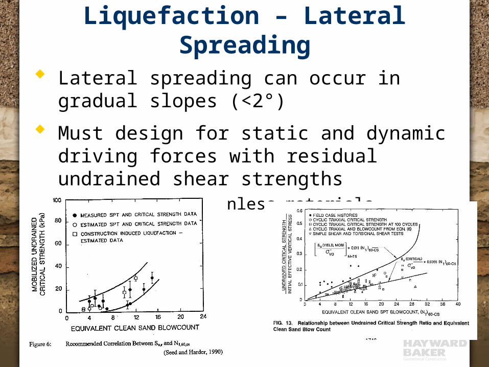
Liquefaction – Lateral Spreading
Lateral spreading can occur in gradual slopes (<2°)
Must design for static and dynamic driving forces with residual undrained shear strengths Even for cohesionless materials

Liquefaction-induced Settlement
Tokimatsu and Seed, 1987
Ishihara and Yoshimine, 1992
Zhang et al., 2002
Liquefaction Mitigation Increase strength ( CRR)
Ground improvement (densification or grouting)
Decrease driving stress ( CSR) Shear reinforcement with ‘stiffer’ elements within
soil mass
Decrease excess pore pressure quickly Reduce drainage path distance with tightly
spaced drains

Mitigation - Densification Increase cyclic shear strength (CRR) by
increasing relative density of cohesionless materials
Advantages: Field Verifiable!
Conduct field testing before and after treatment Employed for over 50 years, through several large magnitude
earthquakes. Several peer-reviewed documents describing the methods,
efficiency, and mechanics of densification. Approved by CA Office of Statewide Health Planning and
Development (OSHPD) for hospital and school construction.

Mitigation - Densification Methods:
Dynamic compaction Vibro-compaction Vibro-replacement Blast densification Compaction grouting

0 0 .5 1 1 .5C S R an d C R R
50
40
30
20
10
0
P o s t T rea tm en tP re -T rea tm en t
0 10 2 0q t [M P a]
1 4
1 2
1 0
8
6
4
2
0
Dep
th [
m]
0 1 2F ac to r o f S a fe ty
1 4
1 2
1 0
8
6
4
2
0
1 4
1 2
1 0
8
6
4
2
00 2 0 4 0S e ism ic S e ttlem en t [m m ]
T rea tm en t D ep th
Loose sand zone
Hospital site Vibro-
replacementto 45 ft.
Liquefaction Mitigation-Densification

Liquefaction Mitigation-Densification Sandy site Compaction
grouting for liquefaction mitigation
Urban site, no vibrations
0 0 .5 1C S R a n d C R R
60
50
40
30
20
10
0
Dep
th [
ft]
C S RC R R P reC R R P os t
0 4 0 8 0 1 20 1 6 0 2 00q t [ ts f]
6 0
5 0
4 0
3 0
2 0
1 0
0
Dep
th [
ft]
C P T -9
0 0 .4 0 .8 1 .2 1 .6 2R f [% ]
60
50
40
30
20
10
0
Dep
th [
ft]
0 0 .5 1 1 .5 2F ac to r o f S afe ty
6 0
5 0
4 0
3 0
2 0
1 0
0
Dep
th [
ft]

Liquefaction Mitigation Increase strength ( CRR)
Ground improvement (densification or grouting)
Decrease driving stress ( CSR) Shear reinforcement with ‘stiffer’ elements within
soil mass
Decrease excess pore pressure quickly Reduce drainage path distance with tightly
spaced drains

Mitigation - Reinforcement Reduce cyclic shear stress
applied to liquefiable soil by installing ‘stiffer’ elements within soil matrix that attract stress.
Can be used in non-densifiable soils (silts, silty sands).
Large magnitude EQs Not verifiable
Post-installation CPT or SPT results will not differ from pre-installation.
Vertical load testing of elements is not applicable.
soil soilinc
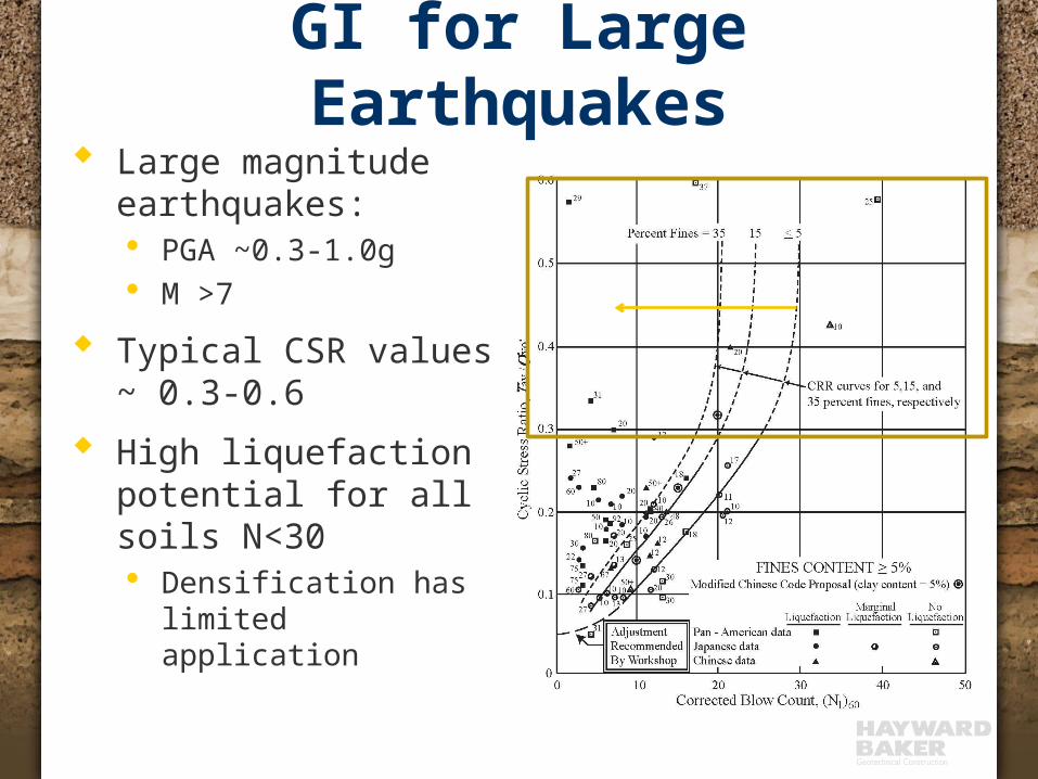
GI for Large Earthquakes Large magnitude
earthquakes:· PGA ~0.3-1.0g· M >7
Typical CSR values ~ 0.3-0.6
High liquefaction potential for all soils N<30· Densification has
limited application
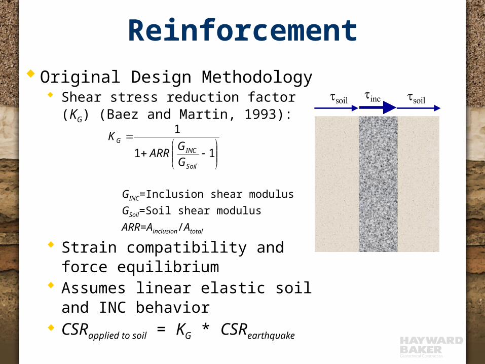
ReinforcementOriginal Design Methodology
Shear stress reduction factor (KG) (Baez and Martin, 1993):
GINC=Inclusion shear modulusGSoil=Soil shear modulusARR=Ainclusion/Atotal
Strain compatibility and force equilibrium
Assumes linear elastic soil and INC behavior
CSRapplied to soil = KG * CSRearthquake
11
1
Soil
INCG
GGARR
K

Mitigation - Reinforcement 10% Area
Replacement
GINC/GSOIL=5
KG=0.7
11
1
Soil
INCG
GGARR
K
0 0 .5C S R a n d C R R
60
50
40
30
20
10
0
Dep
th [f
t]C S R P reC S R P o s tC R R P re
0 4 0 8 0 1 2 0 16 0 20 0q t [ ts f]
60
50
40
30
20
10
0
Dep
th [f
t]
C P T -9
0 0 .4 0 .8 1 .2 1 .6 2R f [% ]
6 0
5 0
4 0
3 0
2 0
1 0
0
Dep
th [f
t]
0 0 .5 1 1 .5 2F ac to r o f S a fe ty
60
50
40
30
20
10
0
Dep
th [f
t]
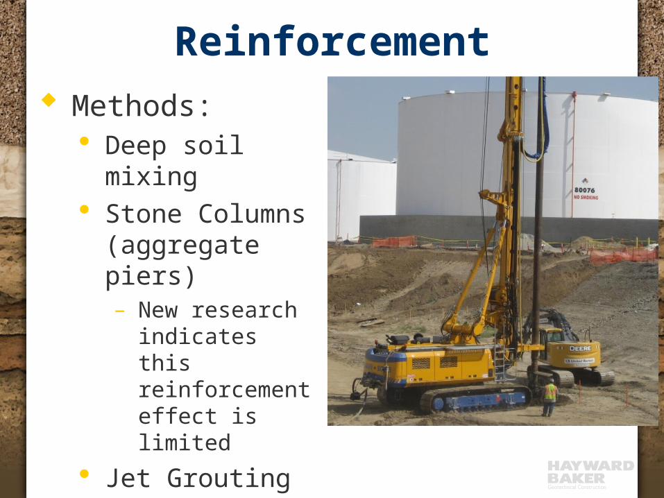
Reinforcement Methods:
· Deep soil mixing· Stone Columns
(aggregate piers)– New research
indicates this reinforcement effect is limited
· Jet Grouting

Mitigation - Reinforcement Requires engineering judgment regarding
input parameters Is there a limit to the ‘inclusion’ stiffness? What is the deformation mechanism (bending or shear)? Is there a maximum spacing that should be used? If the soil liquefies around a stone column, what is the
strength of the stone column?
Few peer-reviewed publications or references regarding use and efficiency
Vendor/contractor ‘white-papers’ do not qualify as design standards or peer-reviewed methods
State-of-the-practice is developing

Liquefaction Mitigation-Reinforcement Example of required judgment:
Say we need KG=0.8, what ARR do we need?
Stone columns? Typical GSC/Gsoil ~ 5 (Baez/Martin,
Mitchell, FHWA) ARR = 6% (11’ grid spacing-36”
columns)
11
1
Soil
INCG
GGARR
K
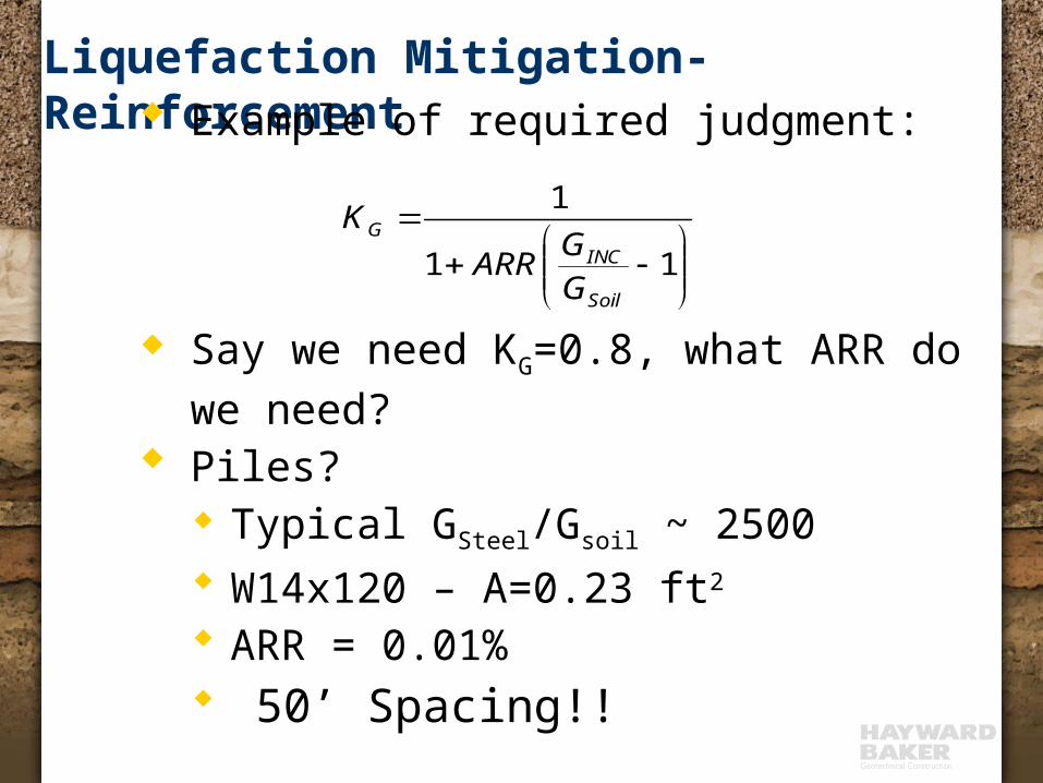
Liquefaction Mitigation-Reinforcement Example of required judgment:
Say we need KG=0.8, what ARR do we need?
Piles? Typical GSteel/Gsoil ~ 2500 W14x120 – A=0.23 ft2 ARR = 0.01% 50’ Spacing!!
11
1
Soil
INCG
GGARR
K
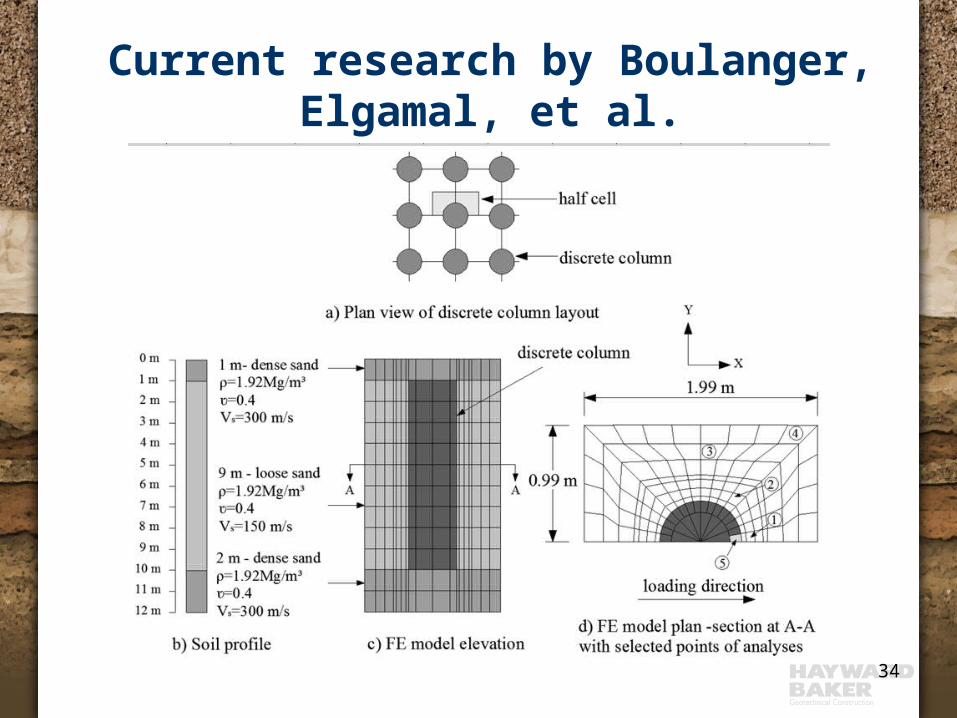
Current research by Boulanger,Elgamal, et al.
34

Spatial distribution Rrd
35

Reinforcement – Panels and Grids
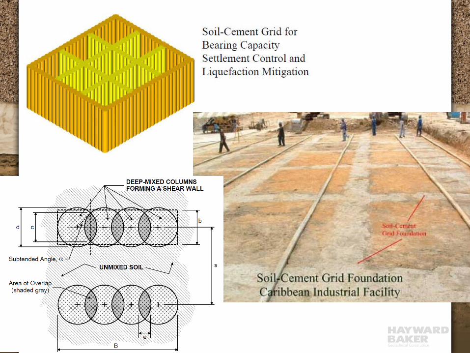
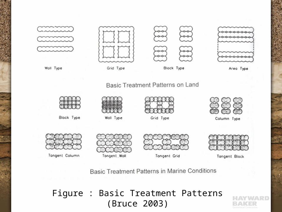
Figure : Basic Treatment Patterns (Bruce 2003)

Linear Elastic Soil Profile DSM Half Unit Cell
Linear Elastic FE DSM ModelBoulanger, Elgamal, et al.

Shear reduction - panels
Ratio of shear stress reduction coefficients; (a) Gr = 13.5, (b) Gr = 50

Conclusion – Soilcrete Grid per Boulanger, Elgamal et. al
DSM grids affect both:· seismic site response (e.g., amax)
· seismic shear stress distributions (e.g. spatially averaged Rrd)
DSM grids on seismic site response can be significant and may require site-specific FEM analyses
The reduction in seismic shear stresses by reinforcement can be significantly over-estimated by current design methods that assume shear strain compatibility.
A modified equation is proposed for estimating seismic shear stress reduction effects. The modified equations account for non-compatible shear strains and flexure in some wall panels.
The top 2m-3m of DSM wall could potentially be the critical wall section in term of tension development.

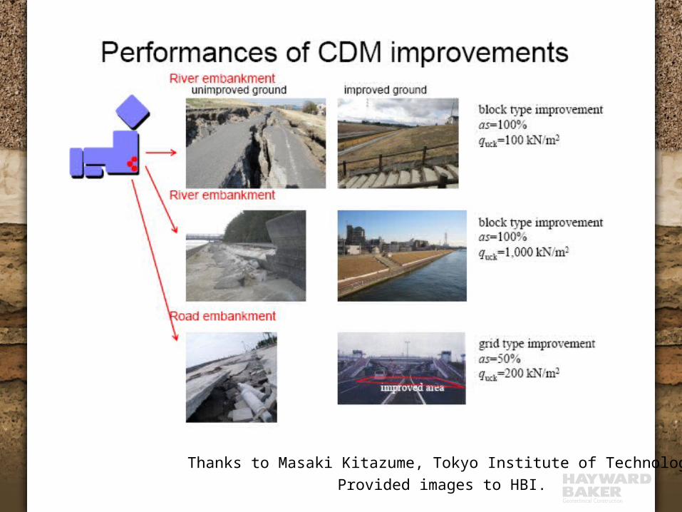
Thanks to Masaki Kitazume, Tokyo Institute of TechnologyProvided images to HBI.
Thanks to Masaki Kitazume, Tokyo Institute of TechnologyProvided images to HBI.

Thanks to Masaki Kitazume, Tokyo Institute of TechnologyProvided images to HBI.

Brunswick Nuclear PlantSouthport, NC
Batch Plant
Intake Canal
N
Spoil Deposit
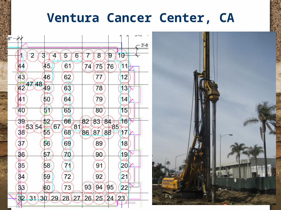
Ventura Cancer Center, CA

Liquefaction Mitigation Increase strength ( CRR)
Ground improvement (densification or grouting)
Decrease driving stress ( CSR) Shear reinforcement with ‘stiffer’ elements within
soil mass
Decrease excess pore pressure quickly Reduce drainage path distance with tightly
spaced drains

Mitigation - Drainage Limit excess pore pressure increase and duration of
increased pore pressure during cyclic shearing by providing short drainage paths in cohesionless materials.
Not verifiable with in situ testing Limited peer-reviewed publications or design standards.
Methods: EQ Drains – perforated pipe installed on tight grid Stone columns – additional feature, but not relied on for
design Permeability of stone column material Contamination with outside material.

EQ Drain Theory Reduce the excess pore pressure
accumulation during earthquake
0 5 1 0 1 5 2 0 2 5S h e ar s tre ss c y c le s
0
0 .2
0 .4
0 .6
0 .8
1
Pore
pre
ssur
e ra
tio
0 5 1 0 1 5 2 0 2 5S h e ar s tre ss c y c les
0
0 .2
0 .4
0 .6
0 .8
1
Pore
pre
ssur
e ra
tio

EQ Drain Details Typically 75-150 mm diameter Slotted PVC pipe with filter fabric Typical spacing 1-2 m triangular Installed with large steel probe with wings (densification also
intended)

EQ Drain Installation

EQ Drain Design Concept Based on radial dissipation theory (just like vertical consolidation, but
radial geometry)
tu
tum
ru
rk
rg
vw
h 1
tu
tu
ru
rrc gh
1wv
hh m
kc
2sin
2tan
testundrainedin on liquefacti causing cycles stress uniform ofNumber 7.0~
arcsin2
2
'
21
'
u
u
dl
eqog
l
lo
g
d
eq
gg
r
r
tNN
Nu
N
NNu
tN
tN
tN
Nu
tu
s
s
DeAlba et al., 1975
Assume periodic wave form
• Change in PP per cycle depends on PP of previous cycle
• NL based on CSR of soil, SPT, Fines
• Neq, td are functions of earthquake, but there are correlations to magnitude
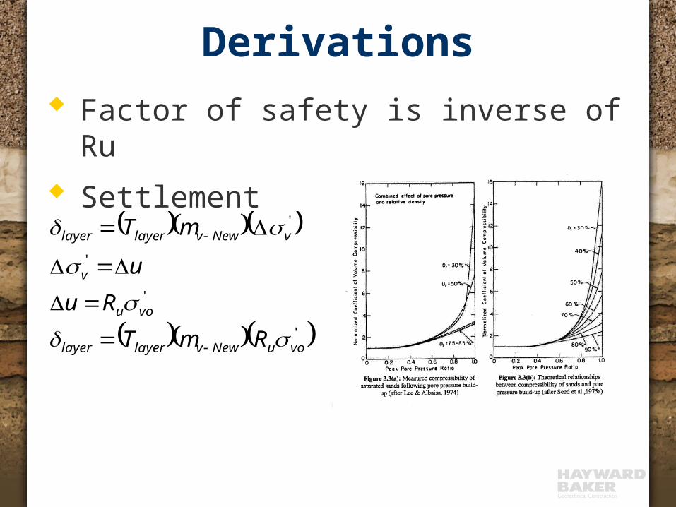
Derivations Factor of safety is inverse of Ru Settlement
'
'
'
'
vouNewvlayerlayer
vou
v
vNewvlayerlayer
RmT
Ru
u
mT
s
s
s
s

EQ Drain Design Graphical solutions to diff equation (JGS):
· Address drain size, well resistance· Provides Ru, but no settlement calculations
FEQDrain – Finite Element software program· Provides Ru and settlement calculations
Both methods need the following:· Soil permeability, kh
· Soil compressibility, mv,· Earthquake duration, td
· Number of earthquake cycles, Neq
· Drain spacing (trial values)

EQ Drain with Stone Column Installation

Stone Column Installation with EQ Drains

Liquefaction Mitigation Increase strength ( CRR)
Ground improvement (densification or grouting)
Decrease driving stress ( CSR) Shear reinforcement with ‘stiffer’ elements within
soil mass
Decrease excess pore pressure quickly Reduce drainage path distance with tightly
spaced drains

Questions
Related Documents