DEVON . OTTAWA . VARENNES - .. - -- GRID CONNECTION COMMISSIONING OF 180-KW BIOGAS GENERATOR AT TERRYLAND FARM CLEAN ENERGY TECHNOLOGIES TECHNIQUES D'ÉNERGIE ÉCOLOGIQUE ---_. -- _._- ~~ - - - ---~ -- --~-~~ ~- --~ ------~ C TEe CENTRE DE LA TECHNOLOGIE DE L'ÉNERGIE DE CANMET 1+1 Natural Resources Canada Ressources naturelles Canada Canadã

Welcome message from author
This document is posted to help you gain knowledge. Please leave a comment to let me know what you think about it! Share it to your friends and learn new things together.
Transcript

DEVON . OTTAWA . VARENNES
- .. - --
GRID CONNECTION COMMISSIONING OF180-KW BIOGAS GENERATOR AT
TERRYLAND FARM
CLEAN ENERGY TECHNOLOGIESTECHNIQUES D'ÉNERGIE ÉCOLOGIQUE
---_. -- _._- ~~ - - - ---~ -- --~-~~ ~- --~ ------~C TEe CENTRE DE LA TECHNOLOGIE DE L'ÉNERGIE DE CANMET
1+1 Natural ResourcesCanada
Ressources naturellesCanada Canadã

Report – CETC-Varennes 2007-161 (TR) September 2007

GRID CONNECTION COMMISSIONING OF 180-KW BIOGAS GENERATOR AT
TERRYLAND FARM
Prepared by:
Aidan Foss ANF Energy Solutions Inc.
4092 McBean Street, Richmond (Ottawa), Ontario, K0A 2Z0.
Presented to: Scientific Authority: Farid Katiraei Natural Resources Canada (NRCan)
CETC Varennes – Energy Technology and Programs Sector 1615 Lionel-Boulet Blvd, P.O. Box 4800
Varennes, Québec, J3X 1S6
September 16, 2007
Report – CETC-Varennes 2007-161 (TR) September 2007

CITATION
Foss, A, Grid Connection Commissioning of 180-KW Biogas Generator at Terryland Farm, report # CETC 2007-161 (TR), CANMET Energy Technology Centre – Varennes, Natural Resources Canada, September 2007, 21 pp.
DISCLAMER
This report is distributed for informational purposes and does not necessarily reflect the views of the Government of Canada nor constitute an endorsement of any commercial product or person. Neither Canada nor its ministers, officers, employees or agents makes any warranty in respect to this report or assumes any liability arising out of this report.
ACKNOWLEDGEMENT
Financial support for this project was provided in part by the Technology and Innovation Initiative as part of Canada’s climate change Program for Energy Research and Development. The government of Canada contribution is truly acknowledged.
Report – CETC-Varennes 2007-161 (TR) i September 2007

TABLE OF CONTENT
1 SUMMARY ........................................................................................................................................... 1
1 SOMMAIRE .......................................................................................................................................... 2
2 Project Background ................................................................................................................................ 5 2.1 Biogas Generator Overview ......................................................................................................... 5 2.2 Anti-Islanding Protection ............................................................................................................. 5
3 Steady-State Performance Tests ............................................................................................................. 7
4 Protection Equipments Set-up ................................................................................................................ 9 4.1 ABB T5 Circuit Breakers ............................................................................................................. 9 4.2 Beckwith M3410A Multi-functional Relay................................................................................ 10 4.3 GENCON II Controller .............................................................................................................. 10 4.4 Crompton SPR Multi-functional Relay ...................................................................................... 10
5 Protection and Synchronization Tests .................................................................................................. 12 5.1 Post-Commissioning Performance ............................................................................................. 12
6 Protection Settings Summary ............................................................................................................... 13
LIST OF FIGURES
Figure 1 (ANF_TP008/R3): Terryland SLD (Outdoor).............................................................................. 12
Figure 2 (ANF_TP009/R4): Terryland SLD (Powerhouse)........................................................................ 13
Figure 3 (ANF_TP004/R2): Terryland Protection Diagram....................................................................... 14
Figure 4 (ANF_TP017/R2): Terryland – Protection Co-ordination at LV ................................................. 15
Report – CETC-Varennes 2007-161 (TR) ii September 2007

Report – CETC-Varennes 2007-161 (TR) iii September 2007

1 SUMMARY
The grid integration group of CANMET Energy Technology Centre - Varennes as part of the R&D program on the Integration of renewable and distributed energy resources managed by Natural Resources Canada supported development and testing of an innovative anti-islanding protection scheme for a small distributed generation (DG) installed at Terryland farm. The Terryland Anaerobic Digester was developed jointly by Genesys Biogas Inc. and Keller Engineering, as a means of disposing of biowaste and producing on-site electricity at the owner’s farm (Terryland). The objective of this report is to outline project commissioning, protection system coordination, and some of the issues related to interconnection of small DG units on rural feeders.
Terryland Farms Biogas consists of a 3-phase, 180kW, 277/480V generator connecting via three 100kVA transformers to a 4.8/8.3kV utility feeder. A novel aspect of the grid interconnection was an innovative anti-islanding protection strategy involving a directional reactive power relay. Commission of the generator grid connection took place on 13/14th August 2007.
During commissioning, significant unbalance was noted. Phase A voltage from the utility was higher, and the current/power export on phase C was higher. This was attributed primarily to zero sequence voltage from the utility passing through the alternator to the alternator neutral. Significant negative sequence currents were also measured. This impacted on some of the protection settings associated with phase currents and powers. The generator supplier advised that the imbalance was within the capability of the alternator.
The new anti-islanding protection was implemented as a logical AND of an active power export limit and a reactive power export limit. The active power export limit was set to 25kW on any phase, which, in view of the imbalance, became true for generation levels above 50kW. The purpose of the active power export limit was to avoid tripping during synchronization. The reactive power export limit was set to 10kVAr on any phase, with the generator automatic voltage regulator (AVR) set for 15kVAr importing (total for three phases). Correct tripping of the new protection was demonstrated at 50kW and 150kW. Switching on of the agitator motor (15-20kW) at these power levels was demonstrated not to cause nuisance trips. However, subsequent to the commissioning tests, a nuisance trip did occur and the AVR set-point was changed to 20kVAr importing.
This report describes:
Project Background (section 2)
Steady-state Performance Tests (section 3)
Report – CETC-Varennes 2007-161 (TR) 1 September 2007

Inter-tie Protection Equipments and Settings (section 4)
Inter-tie Protections Tests (section 5)
Arising from these tests and post-commissioning experience, it is recommended that further consideration be given to:
Establishing the level of unbalance over a typical working week, and confirming that the magnitudes of current imbalance are consistent with the voltage imbalance and machine impedances.
Removing the sensitivity of the directional reactive power protection to unbalance by basing it on the total reactive power, instead of the worst individual phase reactive power.
Monitoring of the reactive power flows to quantify and further understand apparent nuisance trips of the directional reactive power protection.
Obtaining further information on the feeder load characteristic, and particularly the inductive load over a seven-day period.
1 SOMMAIRE Dans le cadre du programme de recherche et développement sur l'intégration des ressources énergétiques renouvelables et distribuées administré par Ressources naturelles Canada, le groupe d'intégration au réseau du Centre de la technologie de l'énergie CANMET – Varennes a appuyé le développement et la mise à l'essai d'un plan novateur de protection contre l’îlotage destiné à un petit dispositif de génération décentralisée installé à Terryland Farms. Le digesteur anaérobie dont s'est doté Terryland Farms a été développé conjointement par Genesys Biogas Inc. et Keller Engineering comme moyen d'élimination de déchets biologiques et de production d'électricité sur place à la ferme du propriétaire, Terryland Farms. Le présent rapport vise à donner un aperçu de la mise en service du projet, de la coordination du système de protection et de certaines questions rattachées à l'interconnexion de petits dispositifs de génération décentralisée à des lignes d'alimentation rurales.
Le projet de production de biogaz de Terryland Farms consiste en un groupe électrogène triphasé de 180 kW, 277/480 V raccordé à une ligne d'alimentation de service de 4,8/8,3 kV au moyen de trois transformateurs de 100 kVA. Un aspect inédit de l'interconnexion au réseau était la stratégie novatrice de protection contre l’îlotage faisant appel à un relais directionnel de puissance réactive. La mise en service de la connexion du groupe électrogène au réseau a eu lieu les 13 et 14 août 2007.
Report – CETC-Varennes 2007-161 (TR) 2 September 2007

Durant la mise en service, un déséquilibre significatif a été noté. La tension de la phase A fournie par la société d'électricité était plus élevée et l'exportation de courant/puissance à la phase C était plus élevée, ce qui a été attribué principalement au passage de tension homopolaire fournie par la société d'électricité dans l'alternateur en direction du point neutre de l'alternateur. Des courants inverses significatifs ont aussi été mesurés, ce qui a influé sur certains réglages de protection associés aux puissances et aux courants de phase. Le fournisseur du groupe électrogène a signalé que l'alternateur peut prendre en charge le déséquilibre.
La nouvelle protection contre l’îlotage a été installée comme porte ET logique d'une limite d'exportation de puissance active et d'une limite d'exportation de puissance réactive. La limite d'exportation de puissance active a été fixée à 25 kW pour n'importe quelle phase, ce qui, compte tenu du déséquilibre, s'est avéré exact pour des niveaux de génération au-dessus de 50 kW. La limite d'exportation de puissance active permet d'éviter le déclenchement durant la synchronisation. La limite d’exportation de puissance réactive a été fixée à 10 kvar pour n'importe quelle phase, le régulateur automatique de tension du groupe électrogène étant réglé pour l'importation de 15 kvar (en tout pour les trois phases). Le déclenchement correct de la nouvelle détection a été vérifié à 50 kW et à 150 kW. On a démontré que la mise sous tension du moteur d'agitation (15-20 kW) à ces niveaux de puissance ne cause pas de déclenchement intempestif. Toutefois, après les essais de mise en service, un déclenchement intempestif s'est produit, et le point de réglage du régulateur automatique de tension a été modifié en fonction de l'importation de 20 kvar.
Le présent rapport décrit :
le contexte du projet (section 2)
les essais de rendement à un régime établi (section 3)
les équipements de protection entre attaches et leurs réglages (section 4)
les essais de protection entre attaches (section 5)
À partir des résultats des essais et compte tenu de l'expérience acquise après la mise en service, il est recommandé de tenir également compte de ce qui suit :
établissement du niveau de déséquilibre dans une semaine de travail normale, et confirmation de la conformité des amplitudes du déséquilibre de l'intensité au déséquilibre de la tension et aux impédances des machines;
élimination de la sensibilité au déséquilibre de la détection directionnelle de la puissance réactive en la fondant sur la puissance réactive totale, plutôt que sur la pire puissance réactive de phase individuelle;
Report – CETC-Varennes 2007-161 (TR) 3 September 2007

surveillance des flux de puissance réactive en vue de la quantification et d'une meilleure compréhension des déclenchements intempestifs apparents de la détection directionnelle de la puissance réactive;
obtention de plus amples renseignements sur les caractéristiques de la charge des lignes d’alimentation, en particulier la charge inductive sur une période de sept jours.
Report – CETC-Varennes 2007-161 (TR) 4 September 2007

2 Project Background
2.1 Biogas Generator Overview
The biogas generator at Terryland farms is rated 180 kW, 225 kVA, 480/277V, 271A, p.f.=0.8, 60Hz, 1800 rpm, and employs a Stamford “HCI 434C” Alternator rated at 312.5 kVA. The generator is equipped with a “GENCON II” generator control unit, which augments governor and AVR controls and provides several generator protections. The main inter-tie protection consists of a Beckwith “M3410A” multi-functional protection unit controlling the inter-tie breaker.
Speed/frequency governing is achieved through a “GAC ESD5330” Generator Speed Control (GAC) unit, which is a Proportional + Integral + Derivative (PID) type variable speed governor with adjustable droop. When on-line, the “GENCON II” sends a frequency set-point correction to the GAC unit proportional to the active power mismatch.
Voltage control is achieved through the AVR. When on-line, the “GENCON II” sends a voltage set-point correction to the AVR proportional to the reactive power mismatch.
The biogas generator is connected to the utility via three 100-kVA transformers to a 4.8/8.3kV utility feeder; see Figure 1 (ANF_TP008) and Figure 2 (ANF_TP009). Disconnecting on fault is facilitated by four interrupting devices: (1) High voltage (HV) fuses, (2) Low voltage (LV) fuses, (3) Inter-tie circuit-breaker (52L), and (4) Generator circuit-breaker (52G).
2.2 Anti-Islanding Protection
Initial efforts to grid connect the generator highlighted a particular barrier to the connection of small-scale embedded generation. For embedded generation, one of the key concerns is the detection of loss of the grid leading to unplanned islanding of the embedded generation on the feeder. In such situations, it is important that the embedded generator is rapidly disconnected from the utility feeder.
When the generation size is small in comparison with the feeder load, conventional anti-islanding protections based on under-frequency and under/over-voltage relays are routinely used. When the generation size to feeder load ratio is higher (typically above 50%), utilities generally require a transfer trip communications system to be installed. However, the cost of utility-approved transfer trip systems (typically around C$125k-C$250k) will render most small generation systems (<500kW) uneconomic. Accordingly, it is being recognized by many as a matter of priority to establish a safe method for small synchronous generation (<500kW) to grid-connect without incurring the high cost of a transfer trip system.
Report – CETC-Varennes 2007-161 (TR) 5 September 2007

For this project, an innovative anti-islanding protection strategy was proposed and accepted, which utilized reactive power export protection. The strategy is based on the rural feeder having a resistive and inductive load characteristic at all times. With the generator set-up so that it is always a sink for reactive power when the grid is present, the loss of the grid will force the generator to begin supplying reactive power, which can then be used to detect an islanding condition.
Simulation studies of the protection concept were performed in early 20071, and were followed Field tests at Terryland Farms on 27th and 28th March 2007. Analysis of the results showed successful demonstration of concept, with all tests showing relay trip times of less than 0.25 seconds with no nuisance tripping2.
As an additional precaution, conventional anti-islanding protections were implemented with tighter-than-normal settings. It is envisaged that these settings will be relaxed from their initial conservative values as experience with the reactive power protection concept is obtained.
The implementation and commissioning of the various protections is included in this report.
1 Reference: F. Katiraei, “Computer Simulation modeling and analysis of the dynamic behaviour for a reciprocating engine base distributed generation unit during islanding transition”, CANMET Energy Technology Centre, Varennes, Natural Resources Canada, QC-Canada, Tech. Rep. 2007. 2 Reference: Katiraei, Foss, Abbey, Strehler, “Dynamic analysis and field verification of an innovative anti-islanding protection scheme based on directional reactive power detection”, in the proceeding of the IEEE EPC2007, Montreal, Oct 2007. Also available [online]: http://cetc-varennes.nrcan.gc.ca/en/er_re/inter_red/p_p.html?2007-160
Report – CETC-Varennes 2007-161 (TR) 6 September 2007

3 Steady-State Performance Tests
Steady-state measurements were taken at conditions of:
50kW, 100kW & 150kW generation,
generator at unity power factor & 15kVAr importing.
Measurements were taken using:
Fluke Power Quality recorder at the generator current transformers (CTs),
GENCON II at the generator CTs,
Beckwith M3410A at the inter-tie CTs.
For all tests, the agitator motor was running. The measurements are shown in Table 3.1. The following comments are made:
1. Phase A voltage was consistently higher. With the generator off and the generator breaker open, the following phase voltages were measured:
Phase A: 284V
Phase B: 280V
Phase C: 270V
2. Measured generator neutral current (peak) was 90-128 A (which is well within the neutral current capacity of 400A). The generator neutral was not grounded at the powerhouse, but connected to the utility neutral at the transformer pole. The ground current down this pole was measured to be 0.1 A, indicating no issues with stray ground currents. The neutral current was attributed to zero sequence voltage on the utility feeder passing through the alternator windings.
3. Phase C current was consistently higher than the phase A and B currents by 24-39 A (rms). The imbalance was attributed to negative and zero sequence voltage on the utility feeder passing through the alternator windings. The generator supplier advised that the imbalance was within the capability of the generator.
4. The difference in active powers across the inter-tie (by the Beckwith M3410A) and from the generator was 40-45kW. Approximately half of this was attributed to the agitator motor.
Report – CETC-Varennes 2007-161 (TR) 7 September 2007

Table 3.1: Steady-State Performance Measurements
kW Setpoint 50 100 150 50 100 150 KVAr Setpoint 0 0 0 -15 -15 -15
Fluke Phase A Ipeak 80 150 240 100 170 230 Fluke Phase B Ipeak 110 187 270 100 176 253 Fluke Phase C Ipeak 141 225 305 140 230 305 Fluke Neut Ipeak 90 105 100 100 128 119 Fluke Phase A kW 13 29.5 45 14 29 45 Fluke Phase B kW 18 34 50 15 30 48 Fluke Phase C kW 24 41 56 24 41 56 Fluke Total KW 55 105 151 55 101 149 Fluke Phase A kVA 14 29.5 45 18 32 47.5 Fluke Phase B kVA 19 34 50 16 31 48 Fluke Phase C kVA 24 41 57 24 40 56 Fluke Total kVA 59 105 152 61 102 152
GENCON Phase A Vrms 288 289 290 290 286 291 GENCON Phase B Vrms 283 284 284 282 281 287 GENCON Phase C Vrms 282 281 281 278 276 283 GENCON Phase A Irms 49 104 152 56 109 162 GENCON Phase B Irms 58 108 170 52 105 168 GENCON Phase C Irms 83 140 194 80 143 201 GENCON Phase A kW 13 28.5 44 12 29 45 GENCON Phase B kW 16 31 48 13 30 48 GENCON Phase C kW 23 40 54.4 22 40 57 GENCON Phase A kVAr -7 -6.5 -8 -11 -12 -12 GENCON Phase B kVAr 3 4 3 -2 -3 -3 GENCON Phase C kVAr 0.5 3 3 -2 -1 0 Beckwith Phase AB Vrms 496 494 499 490 501 Beckwith Phase BC Vrms 491 491 488.5 485 496 Beckwith Phase CA Vrms 492 491 487 485 496 Beckwith PosSeq Vrms3 492 492 489 486 498 Beckwith NegSeq Vrms 3.0 1.8 2.8 3.0 2.6 Beckwith Phase A Irms 80 135 56 100 144 Beckwith Phase B Irms 89 141 40 90 137 Beckwith Phase C Irms 120 166 63 120 178 Beckwith PosSeq Irms 90 145 50 100 148 Beckwith NegSeq Irms 8 8 7 7 10 Beckwith ZeroSeq I rms 23 16 17 23 22 Beckwith Total kW 60 111 15 58 109 Beckwith Total kVAr -25 -17 -38 -33 -38
3 The line voltages are used as inputs to the Bechwith
Report – CETC-Varennes 2007-161 (TR) 8 September 2007

4 Protection Equipments Set-up
The protection equipments are (see Figure 3 - ANF_TP004):
Device Description
HV fuses (3-phases) Positrol 25A K-speed
LV fuses (3-phases & neutral) 600V 400A RK5 speed
52L and 52G Circuit Breakers ABB T-max T5N400BW; 3-phase; 6ms opening 30kA normal break rating at 440kV;
52L and 52G Releases ABB T-max PR221DS electronic release; Short-circuit (Instantaneous or I2t); Overload (I2t)
Inter-tie multi-functional relay Beckwith M3410A with 3x 300A CT inputs and 3 voltage inputs (480V), with facility to trip 52L.
Relay for reactive power export limit protection
Crompton SPR (PR-014W-PQLS-C6-BD-12-MB) with 3x 300A CT inputs and 3 voltage inputs (120V), with facility to trip 52L.
Generator multi-functional relay GENCON II with 3x 300A CT inputs and 4 voltage inputs (277V), with facility to trip 52G.
Note: Except for synchronization, the protections provided by the GENCON II do not form part of the inter-tie protection strategy. They are primarily for generator protection and their settings are not included in this report. The GENCON II can also shut down the generator and close the main fuel valve.
4.1 ABB T5 Circuit Breakers
Owing to concerns with transient associated with synchronization, an I2t characteristic involving 400A x8 at 0.1s was used instead of fast instantaneous. See the co-ordination chart in Figure 4. (For the purposes of chart curve completion, it was assumed that 150% of 400A can be achieved for 1000s.)
Owing to concerns with the significant level of imbalance, the overload setting was increased from 240A to 256A per phase. An I2t characteristic involving x6 at 3.0s was used. See the co-ordination chart. (For the purpose of chart curve completion, it was assumed that 150% of 256A can be achieved for 1000s.)
Report – CETC-Varennes 2007-161 (TR) 9 September 2007

4.2 Beckwith M3410A Multi-functional Relay
100% current was defined to be 216A, which corresponds to 180kW at unity power factor.
The following changes were made to the proposed settings:
The under-frequency set-point was changed from 59.7Hz for 3 cycles to 59.6Hz for 4 cycles. This was done following an under-frequency trip during commissioning (at 21.41 hours on 14th August 2007). This is still significantly tighter than the normal settings required by the utility.
Added residual current protection. This was initially set to 108A (50% of 216A), but was later reset to 162A (75% of 216A) following nuisance trips. This was attributed to high levels of zero sequence current imbalance.
Added voltage-constrained phase over-current protection. This was initially set to 120% (259A at 100% voltage), but was later reset to 130% (281A at 100% voltage) following reports of nuisance trips. This was attributed to high levels of current imbalance.
Current Imbalance Protection: Owing to concerns with transients from synchronization, an I2t characteristic based on 15% (of 216A) imbalance was used instead of instantaneous based on 20% imbalance.
Synchronization parameters were set to a window of 5% voltage and 10 degrees phase for 30 cycles.
4.3 GENCON II Controller
When grid-connected, the GENCON II is used to set the active and reactive power levels. The GENCON software included a modification that provided a reactive power set-point range of 0-25kVAr importing.
GENCON II synchronization parameters were set to a window of 2.5% voltage and 10 degrees phase for 30 cycles.
4.4 Crompton SPR Multi-functional Relay
For reasons of availability, the purchased Crompton SPR unit required three 120V phase voltage inputs. Three 75VA 277/120V PT transformers connected in Yg:Yg were used to step down the voltages from 277V. The CTs were connected with the reverse polarity in order to utilize the reactive power import protection (40Q) for reactive power export protection. Thus the displayed powers on the Crompton are flows into the generator.
Report – CETC-Varennes 2007-161 (TR) 10 September 2007

The output from relay 1 only was wired to the trip coil of the inter-tie breaker. The following protection were set up on the Crompton SPR (with all delays set to 0.0s):
1. Logical AND of relays 6 and 7.
2. Under-voltage (90%) – informative only.
3. Over-voltage (110%) – informative only.
4. Under-frequency (57Hz) – informative only.
5. Over-frequency (63Hz) – informative only.
6. Reactive power export > 10 kVAr on any phase (Input to Relay 1)
7. Active power export > 25 kW on any phase (Input to Relay 1).
The active power export limit was used to avoid unwanted tripping associated with synchronization. In view of the unbalance, the active power export limit corresponded to approximately 50kW export total.
Report – CETC-Varennes 2007-161 (TR) 11 September 2007

5 Protection and Synchronization Tests
For all these tests, the generator was set to 15kVAr importing. The following were demonstrated:
1. Generator start-up and synchronization across the generator breaker.
2. Momentary loss of one phase voltage input to the Beckwith M3410A unit. This resulted in the Beckwith tripping on under-voltage and voltage imbalance, followed by stable islanded operation of the generator. After 5 minutes, the generator re-synchronized across the inter-tie breaker
3. Voltage under-frequency based on system occurrence at 21.41 hours on 14th August 2007. This resulted in the Beckwith tripping on under-frequency, followed by stable islanded operation of the generator. After 5 minutes, the generator re-synchronized across the inter-tie breaker
4. Tripping of the reactive power export protection. The set-point of the AVR was manually increased until the reactive power export on one phase exceeded 10kVAr, causing the inter-tie breaker to trip. This was performed at 50kW and 150kW,
5. Non-tripping of the reactive power export protection to agitator switching. Switching on of the agitator was noted to draw reactive power from the generator. Switching at 50kW and 150kW did not trip the generator.
5.1 Post-Commissioning Performance
Subsequent to commissioning, a number of nuisance trips were reported:
Residual Current Protection: The trip point for this was increased from 108A to 162A on 15th September 2007.
Voltage-Constrained Phase Over-current Protection: The trip setting for this was increased from 120% to 130% on 15th September 2007.
Reactive Power Export Protection: Shortly after commissioning, the generator owner advised of trips occurring during agitator activation. It was surmised that this was likely caused by increased levels of voltage imbalance at certain times of day, and the GENCON II set-point was changed to 20kVAr importing to provide additional margin. Following examination of the Crompton relay on 15th September 2007, it was noted that nuisance trips of this protection were continuing to occur, and this matter requires further attention.
Report – CETC-Varennes 2007-161 (TR) 12 September 2007

Report – CETC-Varennes 2007-161 (TR) 13 September 2007
6 Protection Settings Summary
Table 2 below summarizes the protection settings as of 15th September:
Table 2: Protection Settings Summary
Unit Protection # Setting TimeHV fuses Over-current 51 25 A K speed LV fuses Over-current 51 400 A RK5 speed
52L breaker Over-current 50 400 A I2t (x8 @ 0.1s) 52L breaker Overload 51 256 A I2t (x6 at 3 sec)
Beckwith M-3410A Sync Check 25 5%V, 10deg 30 cyc Beckwith M-3410A Under-voltage 1 27 88% 1.5 sec Beckwith M-3410A Under-voltage 2 27 80% 3 cyc Beckwith M-3410A Active Power Export 32 200kW 3 cyc Beckwith M-3410A Neg. Seq. Current 46 15% of 216A I2t Def Time: Dial 1.0 Beckwith M-3410A Neg. Seq. Voltage 47 6% 0.5 s Beckwith M-3410A Residual over-current 51N 75% of 216A I2t Def Time: Dial 1.0Beckwith M-3410A Over-current & Voltage Restraint 51V 130% of 216A I2t Def Time: Dial 1.0Beckwith M-3410A Over-voltage 1 59 110% 0.8 sec Beckwith M-3410A Over-voltage 2 59 115% 3 cyc Beckwith M-3410A Reconnect enable 79 - 18000 cyc Beckwith M-3410A Over-frequency 81O 60.3 Hz 3 cyc Beckwith M-3410A Under-frequency 1 81U 59.6 Hz 4 cyc
Crompton SPR Reactive/Active power export logical AND
32Q 32O
10 kVAr / phase 25 kW / phase Delay=0.0s
52G breaker Over-current 50 400 A I2t (x8 @ 0.1s) 52G breaker Overload 51 256 A I2t (x6 at 3 sec) GENCON II Sync Check 25 2.5%V, 10deg 30 cyc
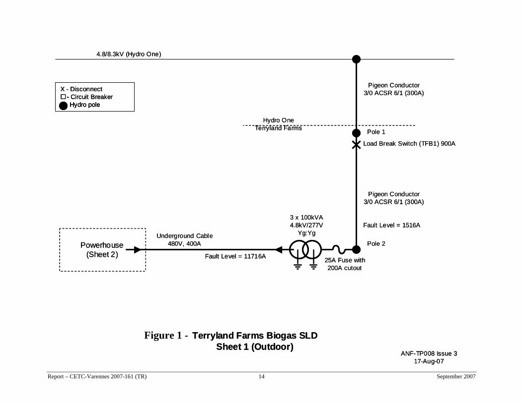
4.8/8.3kV (Hydro One)
3 x 100kVA4.8kV/277V
Yg:Yg
Terryland Farms Biogas SLDSheet 1 (Outdoor)
Load Break Switch (TFB1) 900A
X - Disconnect- Circuit BreakerHydro pole
Powerhouse(Sheet 2)
Underground Cable480V, 400A
Pigeon Conductor3/0 ACSR 6/1 (300A)
Hydro OneTerryland Farms
ANF-TP008 Issue 3
Pigeon Conductor3/0 ACSR 6/1 (300A)
17-Aug-07
Fault Level = 1516A
Fault Level = 11716A
Pole 1
Pole 2
25A Fuse with 200A cutout
4.8/8.3kV (Hydro One)
3 x 100kVA4.8kV/277V
Yg:Yg
Terryland Farms Biogas SLDSheet 1 (Outdoor)
Load Break Switch (TFB1) 900A
X - Disconnect- Circuit BreakerHydro pole
X - Disconnect- Circuit BreakerHydro pole
Powerhouse(Sheet 2)
Underground Cable480V, 400A
Pigeon Conductor3/0 ACSR 6/1 (300A)
Hydro OneTerryland Farms
ANF-TP008 Issue 3
Pigeon Conductor3/0 ACSR 6/1 (300A)
Report – CETC-Varennes 2007-161 (TR) 14 September 2007
17-Aug-07
Fault Level = 1516A
Fault Level = 11716A
Pole 1
Pole 2
25A Fuse with 200A cutout
Figure 1 -

ANF-TP009 Issue 417-Aug-07
Terryland Farms Biogas SLDSheet 2 (Powerhouse)
480V400A
Generator BreakerCabinet
Inter-tieBreakerCabinet
Outdoor(Sheet 1)
X - Disconnect- Circuit Breaker
Excitation& Governor
Control
TelephoneConnection
For Power-house
For Digester
Mixer
Metering Cabinet
UndergroundCable
480V, 400A
Neutral groundingat transformer pole
480V Splitter
52G 52L
Fault Level= 11716A
Fuses400A600VRK5
Figure 2 -
Report – CETC-Varennes 2007-161 (TR) 15 September 2007

Report – CETC-Varennes 2007-161 (TR) 16 September 2007
Figure ANF_TP004Rev 2, 31-July-07
Aidan Foss
Utility 4.8/8.3kV
3 x 100kVA8.3kV/480VYg:Yg 2.3%
Terryland Farm BiogasProtection Diagram
400A service
75kVA480V/240V
Δ :Yg
180kW 271A277/480V
20% on 312.5kVA
GENCON II 25
52L (50/51)
52G (50/51)
Beckwith M3410A25, 27, 32, 46, 47, 59, 79, 81
Crompton SPR32Q
CT 1-3
CT 4-6
V 1-3
V 4-6
V 4
V 1-2
277/120VYg:Yg
AgitatorSoft Start
30kVA480V/380V
Δ: Δ
Power-house Loads
HV disconnectwith 25A Fuses (51)
LV disconnectwith 400A Fuses (51)
400A underground cable
Figure 3 -

Terryland - Protection Co-ordination at LVFigure ANF_TP017, Rev 2, 19-Aug-07
0.01
0.1
1
10
100
1000
100 1000 10000 100000
amps
secs
HV Fuse Max HV Fuse Min Brk Fast Tx LV Fuse Brk Overload
Figure 4 -
Report – CETC-Varennes 2007-161 (TR) 17 September 2007
Related Documents


