Welcome message from author
This document is posted to help you gain knowledge. Please leave a comment to let me know what you think about it! Share it to your friends and learn new things together.
Transcript

Lecture Notes in Computer Science 3165Commenced Publication in 1973Founding and Former Series Editors:Gerhard Goos, Juris Hartmanis, and Jan van Leeuwen
Editorial Board
David HutchisonLancaster University, UK
Takeo KanadeCarnegie Mellon University, Pittsburgh, PA, USA
Josef KittlerUniversity of Surrey, Guildford, UK
Jon M. KleinbergCornell University, Ithaca, NY, USA
Friedemann MatternETH Zurich, Switzerland
John C. MitchellStanford University, CA, USA
Moni NaorWeizmann Institute of Science, Rehovot, Israel
Oscar NierstraszUniversity of Bern, Switzerland
C. Pandu RanganIndian Institute of Technology, Madras, India
Bernhard SteffenUniversity of Dortmund, Germany
Madhu SudanMassachusetts Institute of Technology, MA, USA
Demetri TerzopoulosNew York University, NY, USA
Doug TygarUniversity of California, Berkeley, CA, USA
Moshe Y. VardiRice University, Houston, TX, USA
Gerhard WeikumMax-Planck Institute of Computer Science, Saarbruecken, Germany

This page intentionally left blank
Marios D. Dikaiakos (Ed.)
Grid Computing
Second European AcrossGrids Conference, AxGrids 2004Nicosia, Cyprus, January 28-30, 2004Revised Papers
Springer

eBook ISBN: 3-540-28642-XPrint ISBN: 3-540-22888-8
©2005 Springer Science + Business Media, Inc.
Print ©2004 Springer-Verlag
All rights reserved
No part of this eBook may be reproduced or transmitted in any form or by any means, electronic,mechanical, recording, or otherwise, without written consent from the Publisher
Created in the United States of America
Visit Springer's eBookstore at: http://ebooks.springerlink.comand the Springer Global Website Online at: http://www.springeronline.com
Berlin Heidelberg
General Chairs’ Message
As conference co-chairs, we have great pleasure in writing this short foreword tothe proceedings of the 2nd European AcrossGrids Conference (AxGrids 2004).The conference clearly demonstrated the need in Europe for an annual event thatbrings together the grid research community to share experiences and learn aboutnew developments. This year, in addition to the large number of attendees fromacross the 25 member states of the European Union, we were especially pleasedto welcome fellow researchers from the Americas and the Asia – Pacific region.Only by talking and working together will we realize our vision of building trulyglobal grids.
In addition to the main AxGrids 2004 conference, and thanks to the largenumber of researchers from European Commission-funded projects who werepresent, we were able to run a series of GRIDSTART Technical Working Groupmeetings and we are indebted to the conference organizers for helping with thelogistics of this parallel activity.
In particular we would like to express our gratitude to Marios Dikaiakos andhis team for working tirelessly over many months to make the conference thesmooth-running success that it was. Of course, no conference is complete withoutspeakers and an audience and we would like to thank everyone for their interestand engagement in the many sessions over the three days of the event.
AxGrids 2004 once again demonstrated the need in Europe for an event tobring together the research community. As we move forward into Framework 6we look forward to its continuation and expansion to represent all of the gridresearch community in Europe.
June 2004 Mark ParsonsMichal Turala
Editor’s Preface
The 2nd European AcrossGrids Conference (AxGrids 2004) aimed to examinethe state of the art in research and technology developments in Grid Computing,and provide a forum for the presentation and exchange of views on the latestgrid-related research results and future work. The conference was organized byCrossGrid, a European Union-funded project on Grid research, GRIDSTART,the EU-sponsored initiative for consolidating technical advances in grids in Eu-rope, and the University of Cyprus. It continued on from the successful 1stEuropean Across Grids Conference, held in Santiago de Compostela, Spain, inFebruary 2003. AxGrids 2004 was run in conjunction with the 2nd IST Concer-tation Meeting on Grid Research, which brought together representatives fromall EU-funded projects on Grid research for an exchange of experiences and ideasregarding recent developments in European grid research.
The conference was hosted in Nicosia, the capital of Cyprus, and attracted au-thors and attendees from all over Europe, the USA, and East Asia. The ProgramCommittee of the conference consisted of 37 people from both academia and in-dustry, and there were 13 external reviewers. Overall, AxGrids 2004 attracted57 paper submissions (42 full papers and 15 short posters). Papers underwenta thorough review by several Program Committee members and external re-viewers. After the review, the Program Chair decided to accept 26 papers (outof 42) for regular presentations, 8 papers for short presentations, and 13 pa-pers for poster presentations. Accepted papers underwent a second review forinclusion this postproceedings volume, published as part of Springer’s LectureNotes in Computer Science series. Eventually, we decided to include 27 long and3 short papers, which cover a range of important topics of grid research, fromcomputational and data grids to the Semantic Grid and grid applications.
Here, we would like to thank the Program Committee members, the exter-nal reviewers, and the conference session chairs for their excellent work, whichcontributed to the high-quality technical program of the conference. We wouldalso like to thank the University of Cyprus, IBM, GRIDSTART, and the CyprusTelecommunications Authority (CYTA) for making possible the organizationof this event through their generous sponsorship. Special thanks go to MariaPoveda for handling organizational issues, to Dr. Pedro Trancoso for setting upand running the Web management system at the Computer Science Departmentat the University of Cyprus, and to Kyriacos Neocleous for helping with thepreparation of the proceedings.
I hope that you find this volume interesting and useful.
Nicosia, Cyprus, June 2004 Marios D. Dikaiakos

Organizing Committee
Conference General Chairs
Michal TuralaMark Parsons
ACC Cyfronet & INP, Krakow, PolandEPCC, Univ. of Edinburgh, UK
Program Committee Chair
Marios Dikaiakos University of Cyprus
Posters and Demos Chair
Jesus Marco
Website Chair
Pedro Trancoso
Publicity Chair
George Papadopoulos
Local Organizing Committee
Marios DikaiakosNikos NikolaouMaria Poveda
CSIC, Santander, Spain
University of Cyprus
University of Cyprus
University of CyprusCyprus Telecom. AuthorityUniversity of Cyprus

VIII Organization
Steering Committee
Bob BentleyMarian BubakMarios DikaiakosDietmar ErwinFabrizio GagliardiMax LemkeJesus MarcoHolger MartenNorbert MeyerMatthias MuellerJarek NabrzyskiMark ParsonsYannis PerrosPeter SlootMichal Turala
University College London, UKInst. of Comp. Science & ACC Cyfronet, PolandUniv. of CyprusForschungszentrum Jülich GmbH, GermanyCERN, Geneva, SwitzerlandEuropean CommissionCSIC, SpainForschungszentrum Karlsruhe GmbH, GermanyPSNC, PolandHLRS, GermanyPSNC, PolandEPCC, Univ. of Edinburgh, UKAlgosystems, GreeceUniv. of Amsterdam, The NetherlandsACC Cyfronet & INP, Poland

Organization IX
Program Committee
A. BogdanovM. BubakB. CoghlanM. CosnardY. CotronisJ. CunhaE. DeelmanM. DelfinoM. DikaiakosB. DiMartinoJ. DongarraT. FahringerI. FosterG. FoxW. GentzschM. GerndtA. GomezA. HoekstraE. HoustisB. JonesP. KacsukJ. LabartaD. LaforenzaE. MarkatosL. MatyskaN. MeyerB. MillerL. MoreauT. PriolD. ReedR. SakellariouM. SenarP. SlootL. SnyderP. TrancosoD. WalkerR. Wismüller
Inst. for HPCDB, Russian FederationInst. of Comp. Sci. & Cyfronet, PolandTrinity College Dublin, IrelandINRIA, FranceUniv. of Athens, GreeceNew University of Lisbon, PortugalISI, Univ. Southern California, USAUniv. Autònoma de Barcelona, SpainUniv. of CyprusSecond University of Naples, ItalyUniv. of Tennessee, USAUniversity of Innsbruck, AustriaANL and Univ. of Chicago, USAUniv. of Indiana, USASun Europe, GermanyTU Munchen, GermanyCESGA, SpainUniv. of Amsterdam, The NetherlandsUniversity of Thessaly, GreeceCERN, SwitzerlandSztaki, HungaryUniv. Polytechnica Catalunya, SpainCNR, ItalyICS-FORTH & Univ. of Crete, GreeceMasaryk University, Czech RepublicPoznan Supercomputing Center, PolandUniv. of Wisconsin, USAUniv. of Southampton, UKINRIA/IRISA, FranceUniv. of Illinois, Urbana-Champaign, USAUniv. of Manchester, UKUniv. Autònoma de Barcelona, SpainUniv. of Amsterdam, The NetherlandsUniv. of Washington, USAUniv. of CyprusUniv. of Wales, UKTU Munchen, Germany

X Organization
Referees
Gabriel AntoniuVaggelis FlorosMarilena GeorgiadouAnastasios GounarisAlexandru Jugravu
Juri PapayChristian PerezNorbert PodhorszkiGergely SiposNicola Tonellotto
Eleni TsiakkouriGeorge TsouloupasAlex Villazon
Sponsoring Institutions
University of CyprusIBMGRIDSTARTCyprus Telecommunications Authority
Table of Contents
EU Funded Grid Development in EuropeP. Graham, M. Heikkurinen, J. Nabrzyski, A. Oleksiak, M. Parsons,H. Stockinger, K. Stockinger, and
Pegasus: Mapping Scientific Workflows onto the GridE. Deelman, J. Blythe, Y. Gil, C. Kesselman, G. Mehta, S. Patil,M.-H. Su, K. Vahi, and M. Livny
A Low-Cost Rescheduling Policy for Dependent Taskson Grid Computing Systems
H. Zhao and R. Sakellariou
An Advanced Architecture for a Commercial Grid InfrastructureA. Litke, A. Panagakis, A. Doulamis, N. Doulamis, T. Varvarigou,and E. Varvarigos
Managing MPI Applications in Grid EnvironmentsE. Heymann, M.A. Senar, E. Fernández, A. Fernández, and J. Salt
Flood Forecasting in CrossGrid ProjectL. Hluchy, V.D. Tran, O. Habala, B. Simo, E. Gatial, J. Astalos,and M. Dobrucky
MPICH-G2 Implementationof an Interactive Artificial Neural Network Training
D. Rodríguez, J. Gomes, J. Marco, R. Marco, and C. Martínez-Rivero
OpenMolGRID, a GRID Based Systemfor Solving Large-Scale Drug Design Problems
F. Darvas, Á. Papp, I. Bágyi, G. Ambrus, and L. Ürge
Integration of Blood Flow Visualization on the Grid:The FlowFish/GVK Approach
A. Tirado-Ramos, H. Ragas, D. Shamonin, H. Rosmanith,and D. Kranzmueller
A Migration Framework for Executing Parallel Programs in the GridJ. Kovács and P. Kacsuk
Implementations of a Service-Oriented Architectureon Top of Jini, JXTA and OGSI
N. Furmento, J. Hau, W. Lee, S. Newhouse, and J. Darlington
1
11
21
32
42
51
61
69
77
80
90
XII Table of Contents
Dependable Global Computing with JaWS++G. Kakarontzas and S. Lalis
Connecting Condor Pools into Computational Grids by JiniG. Sipos and P. Kacsuk
Overview of an Architecture Enabling GridBased Application Service Provision
S. Wesner, B. Serhan, T. Dimitrakos, D. Mac Randal, P. Ritrovato,and G. Laria
A Grid-Enabled Adaptive Problem Solving EnvironmentY. Kim, I. Ra, S. Hariri, and Y. Kim
Workflow Support for Complex Grid Applications:Integrated and Portal Solutions
R. Lovas, G. Dózsa, P. Kacsuk, N. Podhorszki, and D. Drótos
Debugging MPI Grid Applications Using Net-dbxP. Neophytou, N. Neophytou, and P. Evripidou
Towards an UML Based Graphical Representationof Grid Workflow Applications
S. Pllana, T. Fahringer, J. Testori, S. Benkner, and I. Brandic
Support for User-Defined Metricsin the Online Performance Analysis Tool G-PM
R. Wismüller, M. Bubak, W. Funika, and M. Kurdziel
Software Engineering in the EU CrossGrid ProjectM. Bubak, M. Malawski, P. Nowakowski,K. Rycerz, and
Monitoring Message-Passing Parallel Applicationsin the Grid with GRM and Mercury Monitor
N. Podhorszki, Z. Balaton, and G. Gombás
Lhcmaster – A System for Storage and Analysis of Data Comingfrom the ATLAS Simulations
M. Malawski, M. Wieczorek, M. Bubak, and
Using Global Snapshots to Access Data Streams on the GridB. Plale
SCALEA-G: A Unified Monitoring and Performance Analysis Systemfor the Grid
H.-L. Truong and T. Fahringer
Application Monitoring in CrossGrid and Other Grid ProjectsM. Bubak, M. Radecki, T. Szepieniec, and R. Wismüller
100
110
113
119
129
139
149
159
169
179
182
191
202
212
Table of Contents XIII
Grid Infrastructure Monitoring as Reliable Information ServiceP. Holub, M. Kuba, L. Matyska, and M. Ruda
Towards a Protocol for the Attachment of Semantic Descriptionsto Grid Services
S. Miles, J. Papay, T. Payne, K. Decker, and L. Moreau
Semantic Matching of Grid Resource DescriptionsJ. Brooke, D. Fellows, K. Garwood, and C. Goble
Enabling Knowledge Discovery Services on GridsA. Congiusta, C. Mastroianni, A. Pugliese, D. Talia, and P. Trunfio
A Grid Service Framework for Metadata Managementin Self-e-Learning Networks
G. Samaras, K. Karenos, and E. Christodoulou
Author Index
220
230
240
250
260
271

This page intentionally left blank
EU Funded Grid Development in Europe
Paul Graham3, Matti Heikkurinen1, Jarek Nabrzyski2, Ariel Oleksiak2,Mark Parsons3, Heinz Stockinger1, Kurt Stockinger1,
2, and 2
1 CERN, European Organization for Nuclear Research, Switzerland2 PSNC, Poznan Supercomputing and Networking Center, Poland
3 EPCC, Edinburgh Parallel Computing Centre, Scotland
Abstract. Several Grid projects have been established that deploy a“first generation Grid”. In order to categorise existing projects in Eu-rope, we have developed a taxonomy and applied it to 20 European Gridprojects funded by the European Commission through the Framework5 IST programme. We briefly describe the projects and thus provide anoverview of current Grid activities in Europe. Next, we suggest futuretrends based on both the European Grid activities as well as progress ofthe world-wide Grid community. The work we present here is a source ofinformation that aims to help to promote European Grid development.
1 Introduction
Since the term “Grid” was first introduced, the Grid community has expandedgreatly in the last five years. Originally, only a few pioneering projects such asGlobus, Condor, Legion and Unicore provided Grid solutions. Now, however,many countries have their own Grid projects that provide specific Grid middle-ware and infrastructure.
In this paper, in order to give a comprehensive overview of existing technolo-gies and projects in Europe, we establish a general taxonomy for categorisingGrid services, tools and projects. This taxonomy is then applied to existingprojects in Europe. In particular, within the GRIDSTART [5] framework wehave analysed 20 representative Grid projects funded by the European Com-mission in order to highlight current European trends in Grid computing. Theguiding principle behind this taxonomy is to enable the identification of trends inEuropean Grid development and to find out where the natural synergies betweenprojects exist.
Since the need for this taxonomy was practical – and relatively urgent –a certain amount of guidance in the form of “pre-classification” was deemednecessary in the information gathering phase. This meant that rather than askingopen questions about the activities of the projects and creating the classificationbased on the answers, the projects themselves were asked to identify which layersand areas (see later) they worked on according to a classification presented tothem in a series of questionnaires. Thus, it is likely that this taxonomy will evolveas the contacts and collaboration between projects increases.
M. Dikaiakos (Ed.): AxGrids 2004, LNCS 3165, pp. 1–10, 2004.© Springer-Verlag Berlin Heidelberg 2004
2 P. Graham et al.
This taxonomy is based on the IST Grid Projects Inventory and Roadmap [4](a 215 page document). In this paper we extract the key aspects of the datapresented in that document and refer to the original document for further details.
The paper should also prove of interest to the broader distributed computingcommunity since the results presented provide a clear overview of how EuropeanGrid activities are evolving. The paper supersedes previous work reported in [7](describing the initial work towards this survey) and [1] (reporting on a prelimi-nary overview). The more up-to-date overview provided in this paper covers newtrends and Grid services which are rapidly evolving from standardisation workas well as benefiting from insight into the latest developments in the variousprojects, that have occurred since the initial overviews were prepared.
2 TaxonomyDevelopment of Grid environments requires effort in a variety of disciplines,from preparing sufficient network infrastructure, through the design of reliablemiddleware, to providing applications and tailored to the end users.
The comparison of Grid projects is made according to three different categori-sation schemes. The first is by different technological layers [2, 3] that separatethe Grid user from the underlying hardware:
Applications and Portals. Applications such as parameter simulations,and grand-challenge problems, often require considerable computing power,access to remote data sets, and may need to interact with scientific instru-ments. Grid portals offer web-enabled application services, i.e. users cansubmit and collect results for their jobs on remote resources through a webinterface.Application Environment and Tools. These offer high-level services thatallow programmers to develop applications and test their performance andreliability. Users can then make use of these applications in an efficient andconvenient way.Middleware (Generic and Application Specific Services). This layeroffers core services such as remote process management, co-allocation ofresources, storage access, information (registry), security, data access andtransfer, and Quality of Service (QoS) such as resource reservation and trad-ing.Fabric and Connectivity. Connectivity defines core communication pro-tocols required for Grid-specific network transactions. The fabric comprisesthe resources geographically distributed and accessible on the Internet.
The second categorisation scheme concerns technical areas, which includetopics such as dissemination and testbeds and which address the wider issuesthe impact of Grid technology. All areas with their projects are listed in Figure 2which categorises different the aspects of Grid projects.
The third main categorisation scheme in this article focuses on the scien-tific domain of applications as well as the computational approaches used (seeSection 3.3). Further related work on an earlier taxonomy of Grid resource man-agement can be found in [6].

EU Funded Grid Development in Europe 3
3 Major Trends in Grid Development
In the Grid inventory report we analysed the major Grid projects in Europe thatare referred to as Wave 1 (“older” projects that received funding prior to 2001)and Wave 2 (“younger” projects). Links to all project web-sites can be foundat [5].
Wave 1 projects are formally part of the EU-funded GRIDSTART projectand are as follows: AVO, CrossGrid, DAMIEN, DataGrid, DataTAG, EGSO,EUROGRID, GRIA, GridLab and GRIP.Wave 2 projects are informal partners of the GRIDSTART project and are asfollows: BioGrid, COG, FlowGrid, GEMSS, GRACE, GRASP, MammoGrid,MOSES, OpenMolGRID, SeLeNe.
Apart from these EU-funded projects, there are several other national andmulti-national Grid initiatives like INFN Grid (Italy), NorduGrid (Northern Eu-ropean countries) and the e-Science Programme (UK) that each encompasses arange of projects. Most of these projects have informal ties with one or moreGRIDSTART projects, but the analysis of these ties is beyond the scope of thisdocument.
The analysis presented in this document is based on a survey, categorised byGrid areas, that has been submitted to each of the projects. For further detailson the analysis methodology we refer to [4].
3.1 Development in Grid Layers
Generally, one can observe the following trend: projects which started later arebiased towards the development of higher-level tools and applications (this trendis continued by Wave 2 projects). This is justified since several projects (suchas DataGrid and EuroGrid) are preparing a good basis for further work by de-veloping low-level tools in the Fabric and Middleware layer. However, it is nota general rule. For instance, projects such as DataGrid, DataTAG and Cross-Grid, which are co-operating with each other in order to prepare an environmentfor data-intensive applications, work on Fabric layer components although theystarted at different times. This complementary work is beneficial, since the ap-plication domains of the projects are different.
In the GRIDSTART cluster there are large projects with activities coveringmany Grid layers (DataGrid, GridLab, CrossGrid: these projects work on compli-mentary aspects in the specific layer) and smaller projects focused on particularlayers (DataTAG, DAMIEN). All Wave 2 projects belong to this second group.Many of them focus on the highest layer and/or on a single application domain(e.g., COG, OpenMolGRID, SeLeNe). Wave 2 projects rarely work on the fabriclayer.
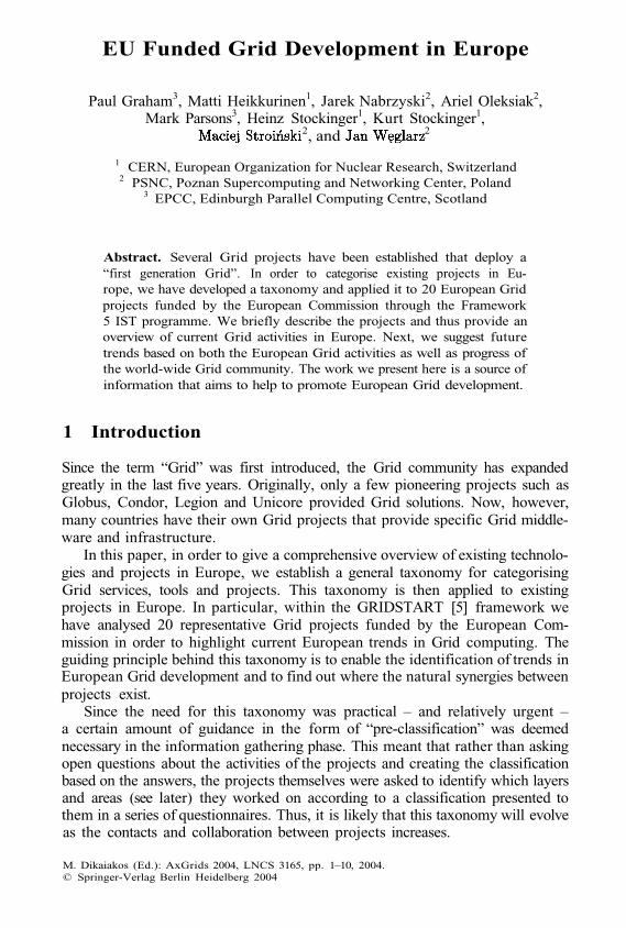
The choice of the underlying Grid system obviously influences the architec-ture of projects too. The two principle Grid toolkits in this study, Globus andUNICORE, are used (see Figure 1). Globus is a more “horizontal” solution in the
4 P. Graham et al.
form of a toolkit offering much necessary functionality while UNICORE is more“vertical” and provides software up to the Graphical User Interface. The influ-ence of these characteristics on project architecture can be noted, for example,in the case of EUROGRID and GRIP. These projects “Grid-enable” applicationsthrough preparing application-specific UNICORE plug-ins. They also add moredynamic functionality through extending the UNICORE system itself.
Fig. 1. Generic Grid middleware used by projects analysed in this paper divided intoWave1/Wave2 projects. “Not decided” concerns projects that were in an early stage ofdevelopment and various solutions were tested. “None” concerns ontology Grid projectsand therefore no need for submission of computation jobs has been identified
Generally, one notice that differences between project architectures resultfrom the different types of Grids that are being developed. Although the layersdefined in Section 2 can still be distinguished, in Data and Information Grids,replication or data search services are placed above various data archives while,in the case of Computational Grids, the global scheduler and job submissionsystems are built on top of local resource management systems. The next majordifference that occurs in the architectures of Grid projects results from the trendtowards a service-oriented model. Some projects (GEMSS, GRASP, GRIA) rep-resent the service-oriented approach. The difference here is that the stress is puton services (and their performance) rather than specific hardware resources, ora specific scientific application.
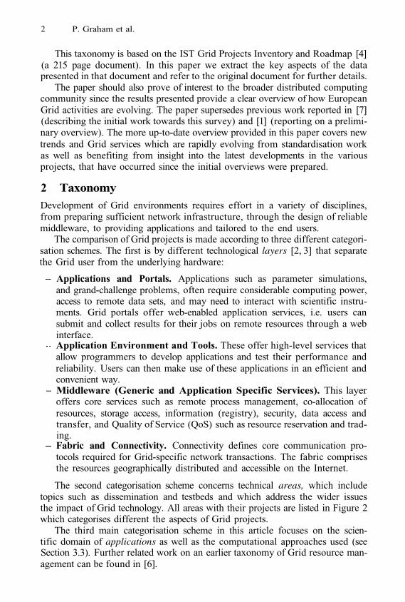
3.2 Development in Areas
Development in particular areas is given in Figure 2 which displays the numberof projects putting significant effort into a given area. For example, 7 projectsdevelop portals, 17 projects deal with applications, 11 out of the 20 projectsfocus on Resource Management (for more details see [4]).
EU Funded Grid Development in Europe 5
Fig. 2. Areas developed by analysed projects divided into Wave1/Wave2 projects
We also distinguish between Wave 1 and Wave 2 projects in order to indicatethe directions and trends of both groups of projects. We can observe the followingphenomena:
Focus on some areas is significantly less for Wave 2 projects, e.g. ResourceManagement, Information Services, Application Development Environmentand Tools, possibly due to the existence of solutions in previous projects.Although the scope of development in a certain area in Wave 2 projects maybe similar to the one of Wave 1 projects, there is a different level of abstrac-tion. For example, in the case of data management, Wave 2 projects maywork on knowledge management rather than low level data access techniques.Although Wave 2 projects are more oriented towards high-level Grid func-tionality, there has been little concentrated, cross-project effort in the de-velopment of user friendly access methods such as portals or mobile access.Instead the emphasis is placed on techniques that add semantics to data(and in consequence facilitate access for end users).
Figure 2 does not communicate exactly to the extent of developments in givenareas, since projects put different emphasis on specific areas. Furthermore, sometechnologies belonging to a specific area may be developed to a greater extentthan in others.
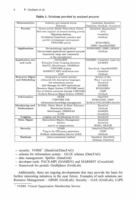
In Table 1 we give a summary of different solutions provided by the projects.For many of the areas analysed, there are now existing tools that can be incor-porated into other projects. Possible examples of existing solutions that may be(or may already have been) applied by other Grid initiatives in order to profitfrom synergies are:
6 P. Graham et al.
security: VOMS1 (DataGrid/DataTAG)schema for information system : GLUE schema (DataTAG)data management: Spitfire (DataGrid)developer tools: PACX-MPI (DAMIEN) and MARMOT (CrossGrid)framework for portals: GridSphere (GridLab)
Additionally, there are ongoing developments that may provide the basis forfurther interesting initiatives in the near future. Examples of such solutions are:Resource Management – GRMS (GridLab); Security – GAS (GridLab), CoPS
1 VOMS: Virtual Organization Membership Service
EU Funded Grid Development in Europe 7
(AVO); Application Development Environments and Tools – UNICORE plugins(EUROGRID, GRIP), GAT2 (GridLab); Accounting – Accounting and Billingservices (EUROGRID, GRASP).
Despite all these solutions there are several problems yet to be overcomewhich include:
Transfer of current solution components to a service based approach.Focus on learning from mistakes to build what will become the first reliable,resilient and robust “production” Grids.
3.3 Development in Applications
This section is devoted to applications, as they are the main stimulators of Gridinfrastructure development. Their domains, requirements and user communitieshave a great influence on the structure of many of the current projects.
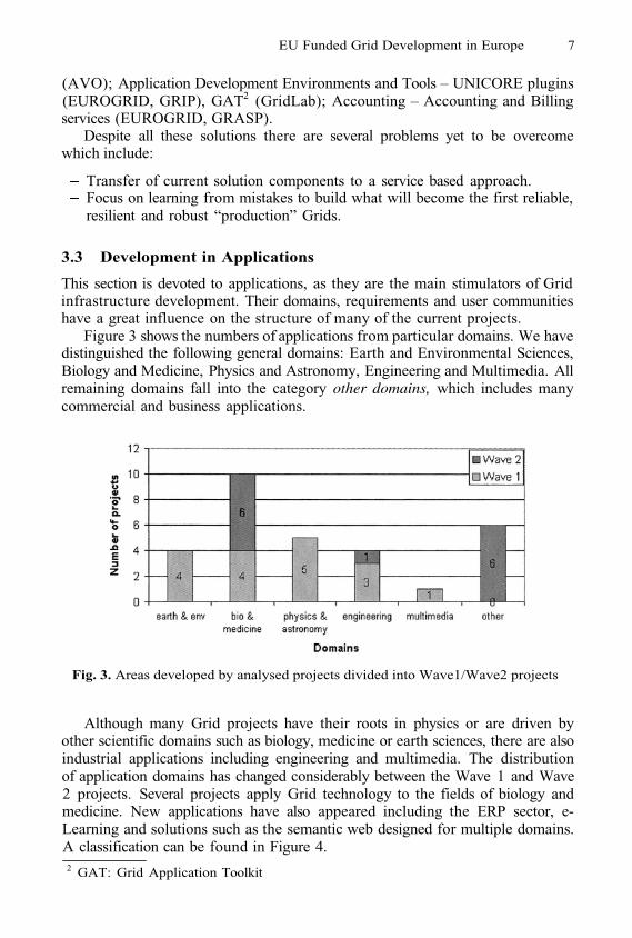
Figure 3 shows the numbers of applications from particular domains. We havedistinguished the following general domains: Earth and Environmental Sciences,Biology and Medicine, Physics and Astronomy, Engineering and Multimedia. Allremaining domains fall into the category other domains, which includes manycommercial and business applications.
Fig. 3. Areas developed by analysed projects divided into Wave1/Wave2 projects
Although many Grid projects have their roots in physics or are driven byother scientific domains such as biology, medicine or earth sciences, there are alsoindustrial applications including engineering and multimedia. The distributionof application domains has changed considerably between the Wave 1 and Wave2 projects. Several projects apply Grid technology to the fields of biology andmedicine. New applications have also appeared including the ERP sector, e-Learning and solutions such as the semantic web designed for multiple domains.A classification can be found in Figure 4.2 GAT: Grid Application Toolkit
8 P. Graham et al.
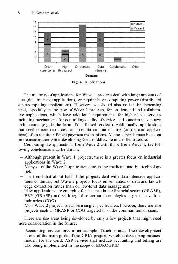
Fig. 4. Applications
The majority of applications for Wave 1 projects deal with large amounts ofdata (data intensive applications) or require huge computing power (distributedsupercomputing applications). However, we should also notice the increasingneed, especially in the case of Wave 2 projects, for on demand and collabora-tive applications, which have additional requirements for higher-level servicesincluding mechanisms for controlling quality of service, and sometimes even newarchitectures (e.g. in the form of distributed services). Additionally, applicationsthat need remote resources for a certain amount of time (on demand applica-tions) often require efficient payment mechanisms. All these trends must be takeninto consideration while developing Grid middleware and infrastructure.
Comparing the applications from Wave 2 with those from Wave 1, the fol-lowing conclusions may be drawn:
Although present in Wave 1 projects, there is a greater focus on industrialapplications in Wave 2.Many of of the Wave 2 applications are in the medicine and bio-technologyfield.The trend that about half of the projects deal with data-intensive applica-tions continues, but Wave 2 projects focus on semantics of data and knowl-edge extraction rather than on low-level data management.New applications are emerging for instance in the financial sector (GRASP),ERP (GRASP) and with regard to corporate ontologies targeted to variousindustries (COG).Most Wave 2 projects focus on a single specific area, however, there are alsoprojects such as GRASP or COG targeted to wider communities of users.
There are also areas being developed by only a few projects that might needmore consideration in the future:
Accounting services serve as an example of such an area. Their developmentis one of the main goals of the GRIA project, which is developing businessmodels for the Grid. ASP services that include accounting and billing arealso being implemented in the scope of EUROGRID.
EU Funded Grid Development in Europe 9
Mobile access is another example of an activity specific to some of projects.This is one of the objectives of both GridLab and CrossGrid.Activities such as knowledge management and semantic Grids do not belongto the goals of “older” Wave 1 projects; however, there are projects concerningthese areas in the scope of several Wave 2 projects such as COG, MOSESor BioGrid.
Real industrial applications are being used even in the early Grid projects,which is quite unusual for an emerging technology and demonstrates the validityof the IST funding model. Overall, there is a strong requirement for businessinvolvement since it is increasing the speed of Grid development and is attractingbroad communities of end users.
4 Conclusion and Future Trends
In this paper we presented a simple taxonomy of Grid projects based on aninventory of Grid projects in Europe funded in part by the European Union.The main trend is for more recent Wave 2 projects to focus on the high layers oftechnology, and on biomedical applications in particular. On the other hand, dis-tributed supercomputing and its application has been deemphasised in Wave 2.Based on the current status, we foresee the following future trends:
International and inter-project collaborations and interoperability will gainmore importance. Strong working groups – and organisational support fortheir work on all the levels involved in the European Grid research – arerequired in order to profit from synergies and to deal with interoperability.There is a strong requirement for quality, reliability, security and above allinteroperability for Grid systems. As a result, web services and in particularOGSA will most probably “dominate” the Grid “market” in the short tomedium term: we see this tendency already in the newer projects of oursurvey.
Acknowledgements. This work was partially funded by the European Com-mission program IST-2001-34808 through the EU GRIDSTART Project. Wethank: F. Grey; M. Dolensky, P. Quinn; P. Nowakowski, B. Krammer; R. Badia,P. Lindner, M. Mueller; R. Barbera, F. Bonnassieux, J. van Eldik, S. Fisher, A.Frohner, D. Front, F. Gagliardi, A. Guarise, R. Harakaly, F. Harris, B. Jones,E. Laure, J. Linford, C. Loomis, M. B. Lopez, L. Momtahan, R. Mondardini,J. Montagnat, F. Pacini, M. Reale, T. Roeblitz, Z. Salvet, M. Sgaravatto, J.Templon; R. Cecchini, F. Donno, JP Martin-Flatin, O. Martin, C. Vistoli; R.Bentley, G. Piccinelli; HC Hoppe, D. Breuer, D. Fellows, KD Oertel, R. Ra-tering; M. Surridge; M. Adamski, M. Chmielewski, Z. Balaton, M. Cafaro, K.Kurowski, J. Novotny, T. Ostwald, T. Schuett, I. Taylor; P. Wieder; E. v.d. Horst;M. Christostalis, K. Votis; N. Baltas, N. F. Diaz; J. Fingberg, G. Lonsdale; M.Cecchi; S. Wesner, K. Giotopulos, T. Dimitrakos, B. Serhan; A. Ricchi; S. Sild,D. McCourt, J. Jing, W. Dubitzky, I. Bagyi and M. Karelson; A. Poulovassilis,P. Wood.
10 P. Graham et al.
References
Marian Bubak, Piotr Nowakowski and Robert Pajak. An Overview of EU-FundedGrid Projects. 1st European Across Grids Conference, Santiago de Compostella,Spain, February 2003.Desplat J.C., Hardy J., Antonioletti M., Nabrzyski J., Stroinski M., Meyer N. GridService Requirements, ENACTS report, January 2002.Ian Foster, Carl Kesselman, Steve Tuecke. The Anatomy of the Grid: EnablingScalable Virtual Organizations, Intl. J. Supercomputer Applications, 15(3), 2001.Fabrizio Gagliardi, Paul Graham, Matti Heikkurinen, Jarek Nabrzyski, Ariel Olek-siak, Mark Parsons, Heinz Stockinger, Kurt Stockinger, Maciej Stroinski, JanWeglarz. IST Grid Projects Inventory and Roadmap, GRIDSTART-IR-D2.2.1.2-V1.3, 14 August 2003.GRIDSTART project website: http://www.gridstart.orgKlaus Krauter, Rajkumar Buyya, and Muthucumaru Maheswaran, A Taxonomyand Survey of Grid Resource Management Systems for Distributed Computing,International Journal of Software: Practice and Experience (SPE), ISSN: 0038-0644,Volume 32, Issue 2, 2002, Wiley Press, USA, February 2002.Jarek Nabrzyski, Ariel Oleksiak. Comparison of Grid Middleware in European GridProjects, 1st European Across Grids Conference, Santiago de Compostella, Spain,February 2003.
1.
2.
3.
4.
5.6.
7.
Pegasus:Mapping Scientific Workflows onto the Grid*
Ewa Deelman1, James Blythe1, Yolanda Gil1, Carl Kesselman1,Gaurang Mehta1, Sonal Patil1, Mei-Hui Su1, Karan Vahi1, and Miron Livny2
1 USC Information Sciences Institute, Marina Del Rey, CA 90292{deelman,blythe,gil,carl,gmehta,mei,vahi}@isi.edu
2 Computer Sciences Department, University of Wisconsin, Madison, WI [email protected]
Abstract. In this paper we describe the Pegasus system that can mapcomplex workflows onto the Grid. Pegasus takes an abstract descrip-tion of a workflow and finds the appropriate data and Grid resources toexecute the workflow. Pegasus is being released as part of the GriPhyNVirtual Data Toolkit and has been used in a variety of applications rang-ing from astronomy, biology, gravitational-wave science, and high-energyphysics. A deferred planning mode of Pegasus is also introduced.
1 Introduction
Grid technologies are changing the way scientists conduct research, fosteringlarge-scale collaborative endeavors where scientists share their resources, data,applications, and knowledge to pursue common goals. These collaborations, de-fined as Virtual Organizations (VOs) [17], are formed by many scientists invarious fields, from high-energy physics, to gravitational-wave physics to biol-ogists. For example, the gravitational-wave scientists from LIGO and GEO [2]have formed a VO that consists of scientists in the US and Europe, as wellas compute, storage and network resources on both continents. As part of thiscollaboration, the data produced by the LIGO and GEO instruments and cali-brated by the scientists are being published to the VO using Grid technologies.Collaborations also extend to Virtual Data, where data refers not only to rawpublished data, but also data that has been processed in some fashion. Sincedata processing can be costly, sharing these data products can save the expenseof performing redundant computations. The concept of Virtual Data was first in-troduced within the GriPhyN project (www.griphyn.org). An important aspectof Virtual Data are the applications that produce the desired data products. Inorder to discover and evaluate the validity of the Virtual Data products, theapplications are also published within the VO.
Taking a closer look at the Grid applications, they are no longer monolithiccodes, rather they are being built from existing application components. In gen-eral, we can think of applications as being defined by workflows, where the
* This research was supported in part by the National Science Foundation under grantsITR-0086044(GriPhyN) and EAR-0122464 (SCEC/ITR).
M. Dikaiakos (Ed.): AxGrids 2004, LNCS 3165, pp. 11–20, 2004.© Springer-Verlag Berlin Heidelberg 2004
12 E. Deelman et al.
activities in the workflow are individual application components and the depen-dencies between the activities reflect the data and/or control flow dependenciesbetween components.
A workflow can be described in an abstract form, in which the workflowactivities are independent of the Grid resources used to execute the activities.We denote this workflow an abstract workflow. Abstracting away the resourcedescriptions allows the workflows to be portable. One can describe the workflowin terms of computations that need to take place without identifying particularresources that can perform this computation. Clearly, in a VO environment, thislevel of abstraction allows for easy sharing of workflow descriptions between VOparticipants. Abstraction also enables the workflows to be efficiently mappedonto the existing Grid resources at the time that the workflow activities can beexecuted. It is possible that users may develop workflows ahead of a particularexperiment and then execute them during the run of the experiment. Since theGrid environment is very dynamic, and the resources are shared among manyusers, it is difficult to optimize the workflow from the point of view of executionahead of time. In fact, one may want to make decisions about the executionlocations and the access to a particular (possibly replicated) data set as late aspossible.
In this work we refer to the executable workflow as the concrete workflow(CW). In the CW the workflow activities are bound to specific Grid resources.CW also includes the necessary data movement to stage data in and out of thecomputations. Other nodes in the CW may also include data publication activi-ties, where newly derived data products are published into the Grid environment.
In the paper we focus on the process of mapping abstract workflows to theirconcrete forms. In particular, we describe Pegasus, which stands for Planning forExecution in Grids. We present the current system and the applications that useit. The current system is semi-dynamic in that the workflows are fully mappedto their concrete form when they are given to Pegasus. We also explore a fullydynamic mode of mapping workflows (termed deferred planning) using a combi-nation of technologies such as Pegasus and the Condor’s workflow executioner,DAGMan [19].
2 Pegasus
Pegasus is designed to map abstract workflows onto the Grid environment [15,14]. The abstract workflows can be constructed by using Chimera [16] or canbe written directly by the user. The inputs to the Chimera system are partialworkflow descriptions that describe the logical input files, the logical transfor-mations (application components) and their parameters, as well as the logicaloutput files produced by these transformations. The specifications are writtenin Chimera’s Virtual Data Language (VDL). Given a set of partial workflowdescriptions and a desired set of logical output filenames, Chimera produces anabstract workflow by matching the names of the input and output files, startingfrom the user-specified output filenames. An example abstract workflow is shown
Pegasus: Mapping Scientific Workflows onto the Grid 13
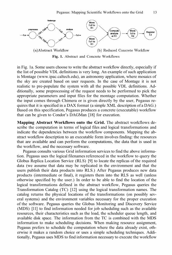
Fig. 1. Abstract and Concrete Workflows
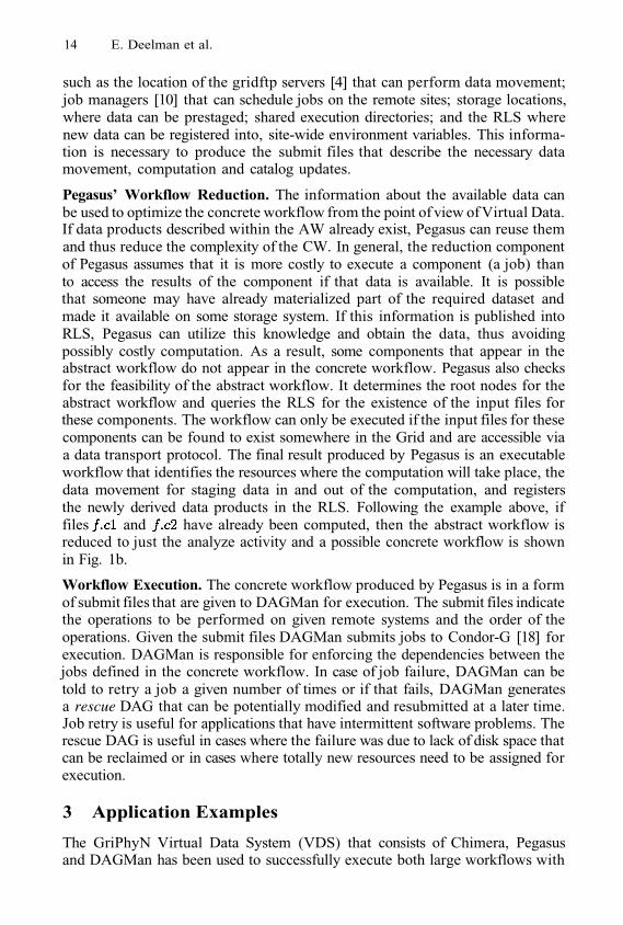
in Fig. 1a. Some users choose to write the abstract workflow directly, especially ifthe list of possible VDL definitions is very long. An example of such applicationis Montage (www.ipac.caltech.edu), an astronomy application, where mosaics ofthe sky are created based on user requests. In the case of Montage it is notrealistic to pre-populate the system with all the possible VDL definitions. Ad-ditionally, some preprocessing of the request needs to be performed to pick theappropriate parameters and input files for the montage computation. Whetherthe input comes through Chimera or is given directly by the user, Pegasus re-quires that it is specified in a DAX format (a simple XML description of a DAG.)Based on this specification, Pegasus produces a concrete (executable) workflowthat can be given to Condor’s DAGMan [18] for execution.
Mapping Abstract Workflows onto the Grid. The abstract workflows de-scribe the computation in terms of logical files and logical transformations andindicate the dependencies between the workflow components. Mapping the ab-stract workflow description to an executable form involves finding: the resourcesthat are available and can perform the computations, the data that is used inthe workflow, and the necessary software.
Pegasus consults various Grid information services to find the above informa-tion. Pegasus uses the logical filenames referenced in the workflow to query theGlobus Replica Location Service (RLS) [9] to locate the replicas of the requireddata (we assume that data may be replicated in the environment and that theusers publish their data products into RLS.) After Pegasus produces new dataproducts (intermediate or final), it registers them into the RLS as well (unlessotherwise specified by the user.) In order to be able to find the location of thelogical transformations defined in the abstract workflow, Pegasus queries theTransformation Catalog (TC) [12] using the logical transformation names. Thecatalog returns the physical locations of the transformations (on possibly sev-eral systems) and the environment variables necessary for the proper executionof the software. Pegasus queries the Globus Monitoring and Discovery Service(MDS) [11] to find information needed for job scheduling such as the availableresources, their characteristics such as the load, the scheduler queue length, andavailable disk space. The information from the TC is combined with the MDSinformation to make scheduling decisions. When making resource assignment,Pegasus prefers to schedule the computation where the data already exist, oth-erwise it makes a random choice or uses a simple scheduling techniques. Addi-tionally, Pegasus uses MDS to find information necessary to execute the workflow
14 E. Deelman et al.
such as the location of the gridftp servers [4] that can perform data movement;job managers [10] that can schedule jobs on the remote sites; storage locations,where data can be prestaged; shared execution directories; and the RLS wherenew data can be registered into, site-wide environment variables. This informa-tion is necessary to produce the submit files that describe the necessary datamovement, computation and catalog updates.
Pegasus’ Workflow Reduction. The information about the available data canbe used to optimize the concrete workflow from the point of view of Virtual Data.If data products described within the AW already exist, Pegasus can reuse themand thus reduce the complexity of the CW. In general, the reduction componentof Pegasus assumes that it is more costly to execute a component (a job) thanto access the results of the component if that data is available. It is possiblethat someone may have already materialized part of the required dataset andmade it available on some storage system. If this information is published intoRLS, Pegasus can utilize this knowledge and obtain the data, thus avoidingpossibly costly computation. As a result, some components that appear in theabstract workflow do not appear in the concrete workflow. Pegasus also checksfor the feasibility of the abstract workflow. It determines the root nodes for theabstract workflow and queries the RLS for the existence of the input files forthese components. The workflow can only be executed if the input files for thesecomponents can be found to exist somewhere in the Grid and are accessible viaa data transport protocol. The final result produced by Pegasus is an executableworkflow that identifies the resources where the computation will take place, thedata movement for staging data in and out of the computation, and registersthe newly derived data products in the RLS. Following the example above, iffiles and have already been computed, then the abstract workflow isreduced to just the analyze activity and a possible concrete workflow is shownin Fig. 1b.
Workflow Execution. The concrete workflow produced by Pegasus is in a formof submit files that are given to DAGMan for execution. The submit files indicatethe operations to be performed on given remote systems and the order of theoperations. Given the submit files DAGMan submits jobs to Condor-G [18] forexecution. DAGMan is responsible for enforcing the dependencies between thejobs defined in the concrete workflow. In case of job failure, DAGMan can betold to retry a job a given number of times or if that fails, DAGMan generatesa rescue DAG that can be potentially modified and resubmitted at a later time.Job retry is useful for applications that have intermittent software problems. Therescue DAG is useful in cases where the failure was due to lack of disk space thatcan be reclaimed or in cases where totally new resources need to be assigned forexecution.
3 Application Examples
The GriPhyN Virtual Data System (VDS) that consists of Chimera, Pegasusand DAGMan has been used to successfully execute both large workflows with
Pegasus: Mapping Scientific Workflows onto the Grid 15
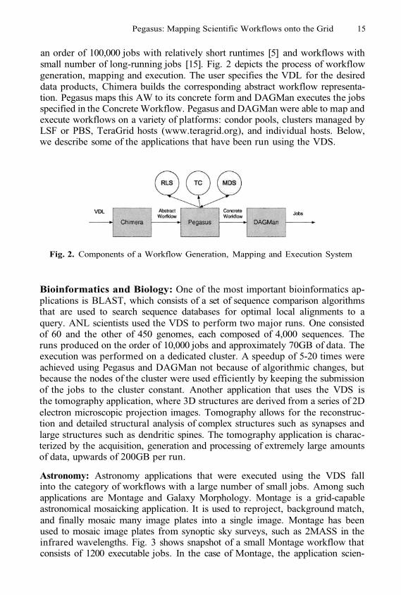
an order of 100,000 jobs with relatively short runtimes [5] and workflows withsmall number of long-running jobs [15]. Fig. 2 depicts the process of workflowgeneration, mapping and execution. The user specifies the VDL for the desireddata products, Chimera builds the corresponding abstract workflow representa-tion. Pegasus maps this AW to its concrete form and DAGMan executes the jobsspecified in the Concrete Workflow. Pegasus and DAGMan were able to map andexecute workflows on a variety of platforms: condor pools, clusters managed byLSF or PBS, TeraGrid hosts (www.teragrid.org), and individual hosts. Below,we describe some of the applications that have been run using the VDS.
Fig. 2. Components of a Workflow Generation, Mapping and Execution System
Bioinformatics and Biology: One of the most important bioinformatics ap-plications is BLAST, which consists of a set of sequence comparison algorithmsthat are used to search sequence databases for optimal local alignments to aquery. ANL scientists used the VDS to perform two major runs. One consistedof 60 and the other of 450 genomes, each composed of 4,000 sequences. Theruns produced on the order of 10,000 jobs and approximately 70GB of data. Theexecution was performed on a dedicated cluster. A speedup of 5-20 times wereachieved using Pegasus and DAGMan not because of algorithmic changes, butbecause the nodes of the cluster were used efficiently by keeping the submissionof the jobs to the cluster constant. Another application that uses the VDS isthe tomography application, where 3D structures are derived from a series of 2Delectron microscopic projection images. Tomography allows for the reconstruc-tion and detailed structural analysis of complex structures such as synapses andlarge structures such as dendritic spines. The tomography application is charac-terized by the acquisition, generation and processing of extremely large amountsof data, upwards of 200GB per run.
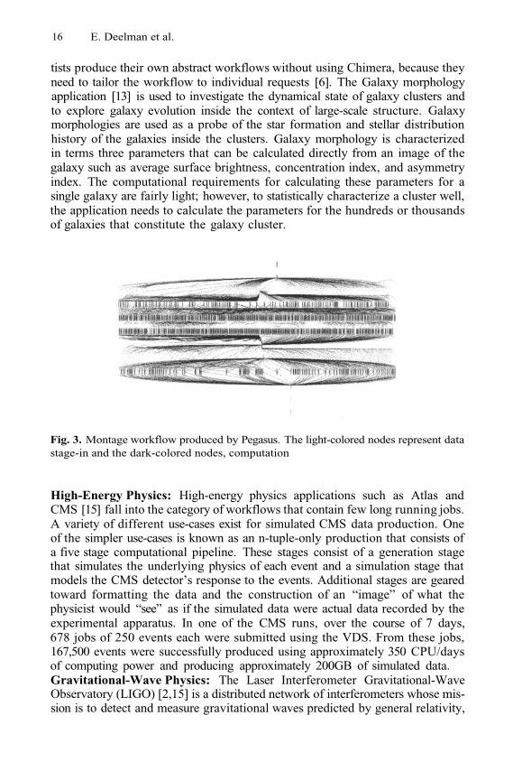
Astronomy: Astronomy applications that were executed using the VDS fallinto the category of workflows with a large number of small jobs. Among suchapplications are Montage and Galaxy Morphology. Montage is a grid-capableastronomical mosaicking application. It is used to reproject, background match,and finally mosaic many image plates into a single image. Montage has beenused to mosaic image plates from synoptic sky surveys, such as 2MASS in theinfrared wavelengths. Fig. 3 shows snapshot of a small Montage workflow thatconsists of 1200 executable jobs. In the case of Montage, the application scien-
16 E. Deelman et al.
tists produce their own abstract workflows without using Chimera, because theyneed to tailor the workflow to individual requests [6]. The Galaxy morphologyapplication [13] is used to investigate the dynamical state of galaxy clusters andto explore galaxy evolution inside the context of large-scale structure. Galaxymorphologies are used as a probe of the star formation and stellar distributionhistory of the galaxies inside the clusters. Galaxy morphology is characterizedin terms three parameters that can be calculated directly from an image of thegalaxy such as average surface brightness, concentration index, and asymmetryindex. The computational requirements for calculating these parameters for asingle galaxy are fairly light; however, to statistically characterize a cluster well,the application needs to calculate the parameters for the hundreds or thousandsof galaxies that constitute the galaxy cluster.
Fig. 3. Montage workflow produced by Pegasus. The light-colored nodes represent datastage-in and the dark-colored nodes, computation
High-Energy Physics: High-energy physics applications such as Atlas andCMS [15] fall into the category of workflows that contain few long running jobs.A variety of different use-cases exist for simulated CMS data production. Oneof the simpler use-cases is known as an n-tuple-only production that consists ofa five stage computational pipeline. These stages consist of a generation stagethat simulates the underlying physics of each event and a simulation stage thatmodels the CMS detector’s response to the events. Additional stages are gearedtoward formatting the data and the construction of an “image” of what thephysicist would “see” as if the simulated data were actual data recorded by theexperimental apparatus. In one of the CMS runs, over the course of 7 days,678 jobs of 250 events each were submitted using the VDS. From these jobs,167,500 events were successfully produced using approximately 350 CPU/daysof computing power and producing approximately 200GB of simulated data.Gravitational-Wave Physics: The Laser Interferometer Gravitational-WaveObservatory (LIGO) [2,15] is a distributed network of interferometers whose mis-sion is to detect and measure gravitational waves predicted by general relativity,
Pegasus: Mapping Scientific Workflows onto the Grid 17
Einstein’s theory of gravity. Gravitational waves interact extremely weakly withmatter, and the measurable effects produced in terrestrial instruments by theirpassage are expected to be miniscule. In order to establish a confident detec-tion or measurement, a large amount of auxiliary data is acquired and analyzedalong with the strain signal that measures the passage of gravitational waves.The LIGO workflows aimed at detecting gravitational waves emitted by pulsarsare characterized by many medium and small jobs. In a Pegasus run conductedat SC 2002, over 58 pulsar searches were performed resulting in a total of 330tasks, 469 data transfers executed and 330 output files. The total runtime wasover 11 hours.
4 Deferred Planning
In the Grid, resources are often shared between users within a VO and acrossVOs as well. Additionally, resources can come and go, because of failure or localpolicy changes. Therefore, the Grid is a very dynamic environment, where theavailability of the resources and their load can change dramatically from onemoment to the next. Even if a particular environment is changing slowly, theduration of the execution of the workflow components can be quite large and bythe time a component finishes execution, the data locations may have changedas well as the availability of the resources. Choices made ahead of time even ifstill feasible may be poor. Clearly, software that deals with executing jobs on theGrid needs to be able to adjust to the changes in the environment. In this work,we focus on providing adaptivity at the level of workflow activities. We assumethat once an activity is scheduled on a resource, it will not be preempted andits execution will either fail or succeed.
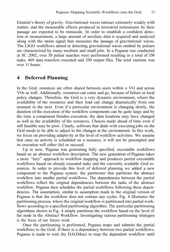
Up to now, Pegasus was generating fully specified, executable workflowsbased on an abstract workflow description. The new generation of Pegasus takesa more “lazy” approach to workflow mapping and produces partial executableworkflows based on already executed tasks and the currently available Grid re-sources. In order to provide this level of deferred planning we added a newcomponent to the Pegasus system: the partitioner that partitions the abstractworkflow into smaller partial workflows. The dependencies between the partialworkflows reflect the original dependencies between the tasks of the abstractworkflow. Pegasus then schedules the partial workflows following these depen-dencies. The assumption, similar to assumption made in the original version ofPegasus is that the workflow does not contain any cycles. Fig. 4 illustrates thepartitioning process, where the original workflow is partitioned into partial work-flows according to a specified partitioning algorithm. The particular partitioningalgorithms shown in Fig. 4 simply partitions the workflow based on the level ofthe node in the Abstract Workflow. Investigating various partitioning strategiesis the focus of our future work.
Once the partitioning is performed, Pegasus maps and submits the partialworkflows to the Grid. If there is a dependency between two partial workflows,Pegasus is made to wait (by DAGMan) to map the dependent workflow until
18 E. Deelman et al.
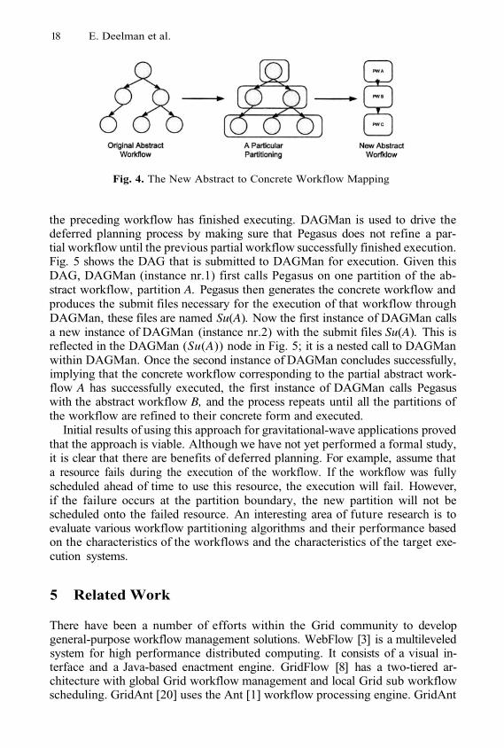
Fig. 4. The New Abstract to Concrete Workflow Mapping
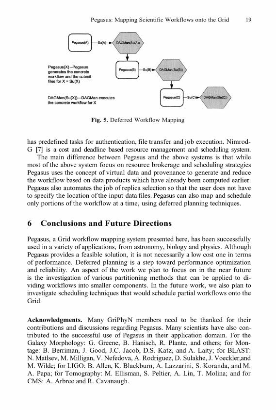
the preceding workflow has finished executing. DAGMan is used to drive thedeferred planning process by making sure that Pegasus does not refine a par-tial workflow until the previous partial workflow successfully finished execution.Fig. 5 shows the DAG that is submitted to DAGMan for execution. Given thisDAG, DAGMan (instance nr.1) first calls Pegasus on one partition of the ab-stract workflow, partition A. Pegasus then generates the concrete workflow andproduces the submit files necessary for the execution of that workflow throughDAGMan, these files are named Su(A). Now the first instance of DAGMan callsa new instance of DAGMan (instance nr.2) with the submit files Su(A). This isreflected in the DAGMan (Su(A)) node in Fig. 5; it is a nested call to DAGManwithin DAGMan. Once the second instance of DAGMan concludes successfully,implying that the concrete workflow corresponding to the partial abstract work-flow A has successfully executed, the first instance of DAGMan calls Pegasuswith the abstract workflow B, and the process repeats until all the partitions ofthe workflow are refined to their concrete form and executed.
Initial results of using this approach for gravitational-wave applications provedthat the approach is viable. Although we have not yet performed a formal study,it is clear that there are benefits of deferred planning. For example, assume thata resource fails during the execution of the workflow. If the workflow was fullyscheduled ahead of time to use this resource, the execution will fail. However,if the failure occurs at the partition boundary, the new partition will not bescheduled onto the failed resource. An interesting area of future research is toevaluate various workflow partitioning algorithms and their performance basedon the characteristics of the workflows and the characteristics of the target exe-cution systems.
5 Related Work
There have been a number of efforts within the Grid community to developgeneral-purpose workflow management solutions. WebFlow [3] is a multileveledsystem for high performance distributed computing. It consists of a visual in-terface and a Java-based enactment engine. GridFlow [8] has a two-tiered ar-chitecture with global Grid workflow management and local Grid sub workflowscheduling. GridAnt [20] uses the Ant [1] workflow processing engine. GridAnt
Pegasus: Mapping Scientific Workflows onto the Grid 19
Fig. 5. Deferred Workflow Mapping
has predefined tasks for authentication, file transfer and job execution. Nimrod-G [7] is a cost and deadline based resource management and scheduling system.
The main difference between Pegasus and the above systems is that whilemost of the above system focus on resource brokerage and scheduling strategiesPegasus uses the concept of virtual data and provenance to generate and reducethe workflow based on data products which have already been computed earlier.Pegasus also automates the job of replica selection so that the user does not haveto specify the location of the input data files. Pegasus can also map and scheduleonly portions of the workflow at a time, using deferred planning techniques.
6 Conclusions and Future Directions
Pegasus, a Grid workflow mapping system presented here, has been successfullyused in a variety of applications, from astronomy, biology and physics. AlthoughPegasus provides a feasible solution, it is not necessarily a low cost one in termsof performance. Deferred planning is a step toward performance optimizationand reliability. An aspect of the work we plan to focus on in the near futureis the investigation of various partitioning methods that can be applied to di-viding workflows into smaller components. In the future work, we also plan toinvestigate scheduling techniques that would schedule partial workflows onto theGrid.
Acknowledgments. Many GriPhyN members need to be thanked for theircontributions and discussions regarding Pegasus. Many scientists have also con-tributed to the successful use of Pegasus in their application domain. For theGalaxy Morphology: G. Greene, B. Hanisch, R. Plante, and others; for Mon-tage: B. Berriman, J. Good, J.C. Jacob, D.S. Katz, and A. Laity; for BLAST:N. Matlsev, M. Milligan, V. Nefedova, A. Rodriguez, D. Sulakhe, J. Voeckler,andM. Wilde; for LIGO: B. Allen, K. Blackburn, A. Lazzarini, S. Koranda, and M.A. Papa; for Tomography: M. Ellisman, S. Peltier, A. Lin, T. Molina; and forCMS: A. Arbree and R. Cavanaugh.
20 E. Deelman et al.
References
Ant: http://ant.apache.orgA. Abramovici et al. LIGO: The Laser Interferometer Gravitational- Wave Obser-vatory (in Large Scale Measurements). Science, 256(5055), 1992.E. Akarsu et al. Webflow - high-level programming environment and visual author-ing toolkit for high performance distributed computing. In Sc’98, 1998.B. Allcock et al. Data management and transfer in high performance computationalgrid environments, Parallel Computing Journal, 28, 5, 2002a, 749-771, 2002.J. Annis and others. Applying Chimera Virtual Data Concepts to Cluster Findingin the Sloan Sky Survey, in Supercomputing. 2002. Baltimore, MD, 2002.B. Berriman et al. Montage: A grid-enabled image mosaic service for the nvo. InAstronomical Data Analysis Software & Systems (ADASS) XIII, October 2003.R. Buyya et al. Nimrod/G: An Architecture for a Resource Management andScheduling System in a Global Computational Grid,. HPC Asia, 2000.J. Cao et al. Gridflow: Workflow management for grid computing. In 3rd Int.Symposium on Cluster Computing and the Grid, pages 198–205, 2003.A. Chervenak et al. Giggle: A framework for constructing scalable replica locationservices, Proceedings of Supercomputing 2002 (SC2002), November 2002.K. Czajkowski et al. A resource management architecture for metacom-puting sys-tems. Workshop on Job Scheduling Strategies for Parallel Processing, 1998.K. Czajkowski et al. Grid information services for distributed resource sharing.HPDC, 2001.E. Deelman et al. Transformation catalog design for griphyn, prototype of trans-formation catalog schema. Technical Report 2001-17, GRIPHYN, 2001.E. Deelman et al. Grid-based galaxy morphology analysis for the national virtualobservatory. In SC 2003, 2003.E. Deelman et al. The Grid Resource Management, chapter Workflow Managementin GriPhyN. Kluwer, J. Jabrzyski and J. Schopf and J. Weglarz (eds.), 2003.E. Deelman et al. Mapping abstract complex workflows onto grid environments.Journal of Grid Computing, 1, 2003.I. Foster et al. Chimera: A Virtual Data System for Representing, Querying, andAutomating Data Derivation. SSDBM, 2002.I. Foster, C. Kesselman, and S. Tuecke. The Anatomy of the Grid: Enabling ScalableVirtual Organizations. Intl. Journal of High Performance Computing Applications,15(3):200-222, 2001. http://www.globus.org/-research/papers/anatomy.pdf, 2001.J. Frey et al. Condor-G: A Computation Managament Agent for Multi-InstitutionalGrids. In Proceedings of the Tenth IEEE Symposium on High Performance Dis-tributed Computing (HPDC10), 2001.Condor Team. The directed acyclic graph manager,http://www.cs.wisc.edu/condor/dagman, 2002.G. von Laszewski et al. Gridant-client-side management with ant. Whitepaper,2002.
1.2.
3.
4.
5.
6.
7.
8.
9.
10.
11.
12.
13.
14.
15.
16.
17.
18.
19.
20.
A Low-Cost Rescheduling Policy for DependentTasks on Grid Computing Systems
Henan Zhao and Rizos Sakellariou
Department of Computer Science, University of ManchesterOxford Road, Manchester M13 9PL, UK
{hzhao,rizos}@cs.man.ac.uk
Abstract. A simple model that can be used for the representation ofcertain workflows is a directed acyclic graph. Although many heuristicshave been proposed to schedule such graphs on heterogeneous environ-ments, most of them assume accurate prediction of computation andcommunication costs; this limits their direct applicability to a dynami-cally changing environment, such as the Grid. To deal with this, run-tunerescheduling may be needed to improve application performance. Thispaper presents a low-cost rescheduling policy, which considers reschedul-ing at a few, carefully selected points in the execution. Yet, this policyachieves performance results, which are comparable with those achievedby a policy that dynamically attempts to reschedule before the executionof every task.
1 Introduction
Many use cases of Grid computing relate to applications that require complexworkflows to be mapped onto a range of distributed resources. Although thecharacteristics of workflows may vary, a simple approach to model a workflowis by means of a directed acyclic graph (DAG) [8]. This model provides an easyway of addressing the mapping problem; a schedule is built by assigning thenodes (the term task is used interchangeably with the term node throughout thepaper) of the graph onto resources in a way that respects task dependences andminimizes the overall execution time. In the general context of heterogeneousdistributed computing, a number of scheduling heuristics have been proposed(see [13, 15, 17] for an extensive list of references). Typically, these heuristicsassume that accurate prediction is available for both the computation and thecommunication costs. However, in a real environment and even more in the Grid,it is difficult to estimate accurately those values due to the dynamic character-istics of the environment. Consequently, an initial schedule may be built usinginaccurate predictions; even though the schedule may be optimized with respectto these predictions, real-time variations may affect the schedule’s performancesignificantly.
An obvious response to changes that may occur at run-time is to reschedule,or readjust the schedule dynamically, using additional information that becomesavailable at run-time. In the context of the Grid, rescheduling of one kind or
M. Dikaiakos (Ed.): AxGrids 2004, LNCS 3165, pp. 21–31, 2004.© Springer-Verlag Berlin Heidelberg 2004
22 H. Zhao and R. Sakellariou
the other has been considered by a number of projects, such as AppLeS [2, 6],Condor-G [7], Data Grid [9] and Nimrod-G [4, 5]. However, all these projects con-sider the dynamic scheduling of sets of independent tasks. For DAG reschedul-ing, a hybrid remapper based on list scheduling algorithms was proposed in [12].Taking a static schedule as the input, the hybrid remapper uses the run-timeinformation that obtained from the execution of precedence nodes to make aprediction for subsequent nodes that is used for remapping.
Generally speaking, rescheduling adds an extra overhead to the schedulingand execution process. This may be related to the cost of reevaluating the sched-ule as well as the cost of transferring tasks across machines (in this paper, we donot consider pre-emptive policies at the task execution level). This cost may beoffset by gains in the execution of the schedule; however, what appears to givean indication of a gain at a certain stage in the execution of a schedule (whichmay trigger a rescheduling), may not be good later in the schedule. In this pa-per, we attempt to strike a balance between the cost of rescheduling and theperformance of the schedule. We propose a novel, low-cost, rescheduling policy,which improves the initial static schedule of a DAG, by considering only selec-tive tasks for rescheduling based on measurable properties; as a result, we callthis policy Selective Rescheduling (SR). Based on preliminary simulation experi-ments, this policy gives equally good performance with policies that consider forrescheduling every task of the DAG, at a much lower cost; in our experiments,SR considers less than 20% of the tasks of the DAG for rescheduling.
The remainder of this paper is organized as follows. Section 2 defines twocriteria to represent the robustness of a schedule, spare time and the slack. Weuse these two criteria to make decisions for the Selective Rescheduling policy,presented in Section 3. Section 4 evaluates the performance of the policy and,finally, Section 5 concludes the paper.
2 Preliminaries
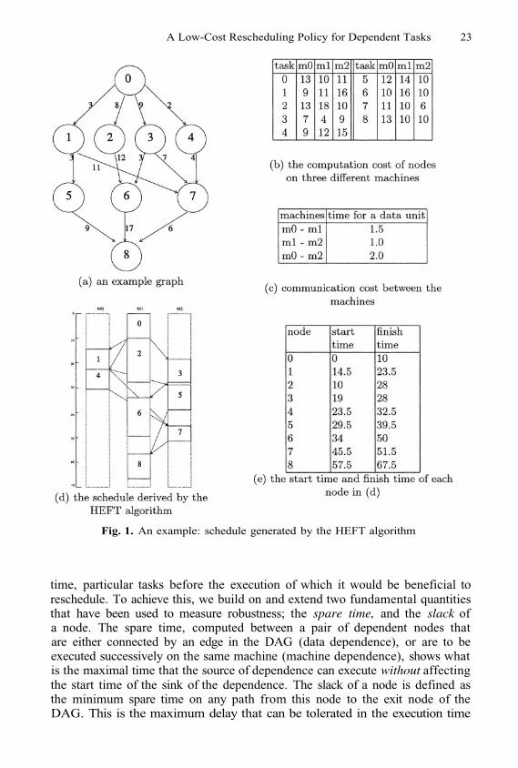
The model used in this paper to represent an application is the directed acyclicgraph (DAG), where nodes (or tasks) represent computation and edges representcommunication (data flow) between nodes. The DAG has a single entry node anda single exit node. There is also a set of machines on which nodes can execute(with a different execution cost on each machine) and which need different timeto transmit data. A machine can execute only one task at a time, and a taskcannot start execution until all data from its parent nodes is available. Thescheduling problem is to assign the tasks onto machines so that precedenceconstraints are respected and the makespan is minimized. For an example, seeFigure 1, and parts (a), (b), and (c).
Previous work has attempted to characterize the robustness of a schedule; inother words, how robust the schedule would be if variations in the estimates usedto build the schedule were to occur at run-time [1,3]. Although the robustnessmetric might be useful in evaluating overall different schedules, it has little directvalue for our purposes; here, we wish to use specific criteria to select, at run-
A Low-Cost Rescheduling Policy for Dependent Tasks 23
Fig. 1. An example: schedule generated by the HEFT algorithm
time, particular tasks before the execution of which it would be beneficial toreschedule. To achieve this, we build on and extend two fundamental quantitiesthat have been used to measure robustness; the spare time, and the slack ofa node. The spare time, computed between a pair of dependent nodes thatare either connected by an edge in the DAG (data dependence), or are to beexecuted successively on the same machine (machine dependence), shows whatis the maximal time that the source of dependence can execute without affectingthe start time of the sink of the dependence. The slack of a node is defined asthe minimum spare time on any path from this node to the exit node of theDAG. This is the maximum delay that can be tolerated in the execution time
24 H. Zhao and R. Sakellariou
of the node without affecting the overall schedule length. If the slack of a nodeis zero, the node is called critical; any delay on the execution time of this nodewill affect the makespan of the application.
A formal definition and an example follow below; we note that the definitionsin [3] do not take into account the communication cost between data dependenttasks, thereby limiting their applicability. Our definitions are augmented to takeinto account communication.
2.1 Spare Time
Consider a schedule for a given DAG; the spare time between a node and animmediate successor is defined as
where is the expected start time of node (on the machine where it hasbeen scheduled to), and is the time that all the data required by node
from node will arrive on the machine where node executes. To illustratethis with an example, consider Figure 1 and the schedule in Figure 1(d) (derivedusing the HEFT heuristic [17]). In this example, the finish time of task 4 is 32.5and the data transfer time from task 4 (on machine 0) to task 7 (on machine2) is 8 time units, hence the arrival time of the data from task 4 totask 7 is 40.5. The start time of task 7 is 45.5, therefore, the spare time betweentask 4 and task 7 is 5. This is the maximal value that the finish time of task 4can be delayed at machine 0 without changing the start time of task 7.
In addition, for tasks and which are adjacent in the execution order of aparticular machine (and task executes first), the spare time is defined as
where is the finish time of node in the given schedule. In Figure 1, forexample, task 3 finishes at time 28, and task 5 starts at time 29.5; both onmachine 2. The spare time between them is 1.5. In this case, if the executiontime of task 3 delays for no more than 1.5 , the start time of task 5 will not beaffected. However, one may notice that even a delay of less than 1.5 may causesome delay in the start time of task 6; to take this into account, we introduceone more parameter.
To represent the minimal spare time for each node, i.e., the maximal delay inthe execution of the node that will not affect the start time of any of its dependentnodes (both on the DAG or on the machine), we introduce MinSpare, which isdefined as
where is the set of the tasks that includes the immediate successors oftask in the DAG and the next task in the execution order of the machinewhere task is executed, and is the minimum of and
A Low-Cost Rescheduling Policy for Dependent Tasks 25
2.2 The Slack of a Node
In a similar way to the definition in [3], the slack of a node is computed asthe minimum spare time on any path from this node to the exit node. This isrecursively computed, in an upwards fashion (i.e., starting from the exit node)as follows:
The slack for the exit node is set equal to
The slack of each task indicates the maximal value that can be added tothe execution time of this task without affecting the overall makespan of theschedule. Considering again the example in Figure 1, the slack of node 8 is 0;the slack of node 7 is also zero (computed as the slack of node 8 plus the sparetime between 7 and 8, which is zero). Node 5 has a spare time of 6 with node 7and 9 with node 8 (its two immediate successors in the DAG and the machinewhere it is executing); since the slack of both nodes 7 and 8 is 0, then the slackof node 5 is 6. Indeed, this is the maximal time that the finish time of node 5can be delayed without affecting the schedule’s makespan.
Clearly, if the execution of a task will start at a time which is greater than thestatically estimated starting time plus the slack, the overall makespan (assumingthe execution time of all other tasks that follow remains the same) will change.Our rescheduling policy is based on this observation and will selectively applyrescheduling based on the values of slack (and the spare time). This is presentedin the next section.
3 A Selective Rescheduling Policy
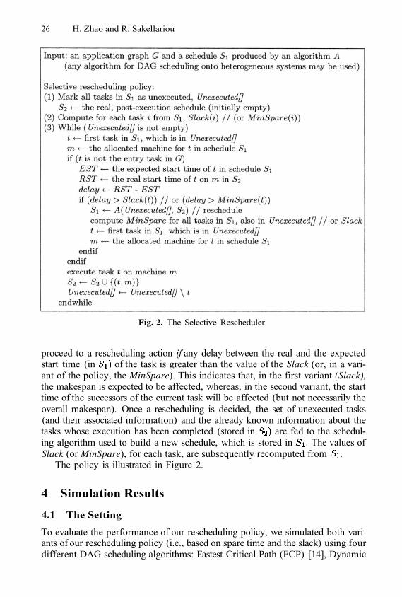
The key idea of the selective rescheduling policy is to evaluate, at run-time,before each task starts execution, the starting time of each node against itsestimated starting time in the static schedule and the slack (or the minimal sparetime), in order to make a decision for rescheduling. The input of this rescheduleris a DAG, with its associated values, and a static schedule computed by anyscheduling algorithm. The objective of the policy is to optimize the makespanof the schedule while minimizing the frequency of rescheduling attempts.
As the tasks of the DAG are executed, the rescheduler maintains two sched-ules, and is based on the static construction of the schedule usingestimated values; keeps track of what the schedule looked like for the tasksthat have been executed (i.e., it contains information about only the tasks thathave finished execution). Before each task (except the entry node) can start ex-ecution, its (real) start time can be considered as known. Comparing the starttime that was statically estimated in the construction of and the slack (orthe minimal spare time), a decision for rescheduling is taken. The algorithm will
26 H. Zhao and R. Sakellariou
Fig. 2. The Selective Rescheduler
proceed to a rescheduling action if any delay between the real and the expectedstart time (in of the task is greater than the value of the Slack (or, in a vari-ant of the policy, the MinSpare). This indicates that, in the first variant (Slack),the makespan is expected to be affected, whereas, in the second variant, the starttime of the successors of the current task will be affected (but not necessarily theoverall makespan). Once a rescheduling is decided, the set of unexecuted tasks(and their associated information) and the already known information about thetasks whose execution has been completed (stored in are fed to the schedul-ing algorithm used to build a new schedule, which is stored in The values ofSlack (or MinSpare), for each task, are subsequently recomputed from
The policy is illustrated in Figure 2.
4 Simulation Results
4.1 The Setting
To evaluate the performance of our rescheduling policy, we simulated both vari-ants of our rescheduling policy (i.e., based on spare time and the slack) using fourdifferent DAG scheduling algorithms: Fastest Critical Path (FCP) [14], Dynamic
A Low-Cost Rescheduling Policy for Dependent Tasks 27
Level Scheduling (DLS) [16], Heterogeneous Earliest Finish Time (HEFT) [17]and Levelized-Min Time (LMT) [10]. Each algorithm provides the initial staticschedule and is called again when the rescheduler decides to remap tasks.
We have evaluated, separately, the behaviour of our rescheduling policy witheach of the four different algorithms, both in terms of the performance of the finalschedule and in terms of the running time. We used randomly generated DAGs,each consisting of 50 to 100 tasks, following the approach described in [18], andwe tried to schedule them on 3 to 8 machines (randomly chosen with equalprobability for each machine). The estimated execution of each task on each dif-ferent machine is randomly generated from a uniform distribution in the interval[50,100], while the communication-to-computation ratio (CCR) is randomly cho-sen from the interval [0.1,1]. For the actual execution time of each task we adoptthe approach in [6], and we use the notion of Quality of Information (QoI). Thisrepresents an upper bound on the percentage of error that the static estimatemay have with respect to the actual execution time. So, for example, a percent-age error of 10% would indicate that the (simulated) run-time execution time ofa task will be within 10% (plus or minus) of the static estimate for the task. Inour experiments we consider an error of up to 50%.
4.2 Scheduling Performance
In order to evaluate the performance of our rescheduling policy, in terms ofoptimising the length of the schedule produced, we implemented both the sparetime and the slack variants, and compared the schedule length they generatewith three other approaches; these are denoted by static, ideal, and always.Static refers to the actual run-time performance of the original schedule (whichwas constructed using the static performance estimates); that is, no change inthe original static schedule takes place at run-time. Ideal refers to a schedule,which is built post mortem; that is, the schedule is built after the run-timeexecution of each task is known. This serves as a reasonable lower bound to theperformance that rescheduling can achieve. Finally, always refers to a schemethat re-schedules all remaining non-executed tasks each time a task is about tostart execution.
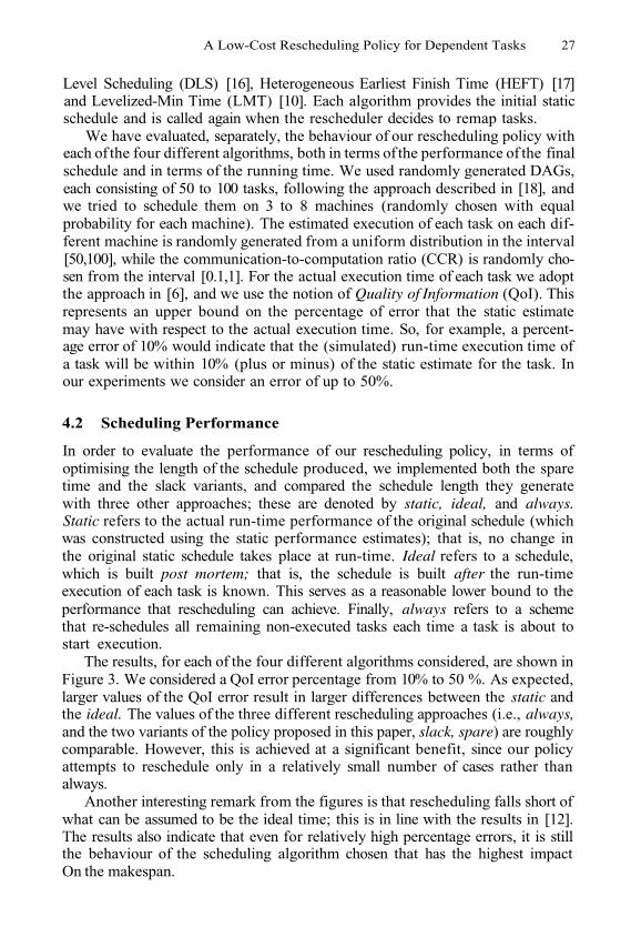
The results, for each of the four different algorithms considered, are shown inFigure 3. We considered a QoI error percentage from 10% to 50 %. As expected,larger values of the QoI error result in larger differences between the static andthe ideal. The values of the three different rescheduling approaches (i.e., always,and the two variants of the policy proposed in this paper, slack, spare) are roughlycomparable. However, this is achieved at a significant benefit, since our policyattempts to reschedule only in a relatively small number of cases rather thanalways.
Another interesting remark from the figures is that rescheduling falls short ofwhat can be assumed to be the ideal time; this is in line with the results in [12].The results also indicate that even for relatively high percentage errors, it is stillthe behaviour of the scheduling algorithm chosen that has the highest impactOn the makespan.
28 H. Zhao and R. Sakellariou
Fig. 3. Average makespan (over 100 runs on randomly generated DAGs) for variouslevels of QoI with four scheduling algorithms
4.3 Running Time
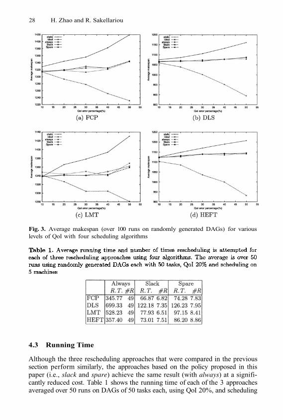
Although the three rescheduling approaches that were compared in the previoussection perform similarly, the approaches based on the policy proposed in thispaper (i.e., slack and spare) achieve the same result (with always) at a signifi-cantly reduced cost. Table 1 shows the running time of each of the 3 approachesaveraged over 50 runs on DAGs of 50 tasks each, using QoI 20%, and scheduling
A Low-Cost Rescheduling Policy for Dependent Tasks 29
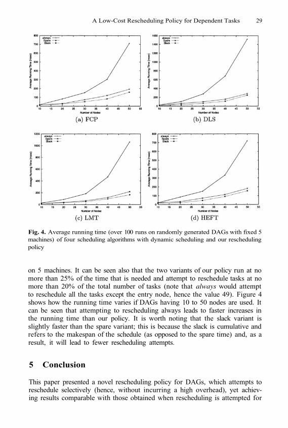
Fig. 4. Average running time (over 100 runs on randomly generated DAGs with fixed 5machines) of four scheduling algorithms with dynamic scheduling and our reschedulingpolicy
on 5 machines. It can be seen also that the two variants of our policy run at nomore than 25% of the time that is needed and attempt to reschedule tasks at nomore than 20% of the total number of tasks (note that always would attemptto reschedule all the tasks except the entry node, hence the value 49). Figure 4shows how the running time varies if DAGs having 10 to 50 nodes are used. Itcan be seen that attempting to rescheduling always leads to faster increases inthe running time than our policy. It is worth noting that the slack variant isslightly faster than the spare variant; this is because the slack is cumulative andrefers to the makespan of the schedule (as opposed to the spare time) and, as aresult, it will lead to fewer rescheduling attempts.
5 Conclusion
This paper presented a novel rescheduling policy for DAGs, which attempts toreschedule selectively (hence, without incurring a high overhead), yet achiev-ing results comparable with those obtained when rescheduling is attempted for
30 H. Zhao and R. Sakellariou
every task of the DAG. The approach is based on evaluating two metrics, theminimal spare time and the slack, and is general, in that it can be applied toany scheduling algorithm.
Although there has been significant work in static scheduling heuristics, lim-ited work exists in trying to understand how dynamic, run-time changes can af-fect a statically predetermined schedule. The emergence of important use cases inGrid computing, such as workflows, as well as new ideas and approaches relatedto scheduling [11] are expected to motivate further and more elaborate researchinto different aspects related to the management of run-time information.
References
S. Ali, A. A. Maciejewski, H. J. Siegel and J-K. Kim. Definition of a RobustnessMetric for Resource Allocation. In Proceedings of IPDPS 2003, 2003.F. Berman, and R. Wolski. The AppLeS project: a status report. Proceedings of8th NEC Research Symposium, Berlin, Germany, 1997.L. Boloni, and D. C. Marinescu. Robust scheduling of metaprograms. In Journalof Scheduling, 5:395-412, 2002.R. Buyya, D. Abramson and J. Giddy. Nimrod-G: an architecture for a resourcemanagement and scheduling system in a global Computational Grid. In Interna-tional Conference on High Performance Computing in Asia-Pacific Region (HPCAsia 2000), Beijing, China.R. Buyya, J. Giddy and D. Abramson. An evaluation of economy-based resourcetrading and scheduling on computational power Grids for parameter sweep ap-plications. In 2nd International Workshop on Active Middleware Service (AMS2000), USA, 2000.H. Casanova, A. Legrand, D. Zagorodnov and F. Berman. Heuristics for schedulingparameter sweep applications in Grid environments. In 9th Heterogeneous Com-puting Workshop (HCW’00), 2000.J. Frey, T. Tannenbaum, I. Foster, M. Livny and S. Tuecke. Condor-G: a compu-tation management agent for multi-institutional Grids. Journal of Cluster Com-puting, 5:237-246, 2002.A. Hoheisel and U. Der. An XML-Based Framework for Loosely Coupled Applica-tions on Grid Environments. In Proceedings of ICCS 2003, Springer-Verlag, LNCS2657, 2003.H. Hoschek, J. J. Martinez, A. Samar, H. Stockinger and K. Stockinger. Datamanagement in an international Data Grid project. Proceedings of the FirstIEEE/ACM International Workshop on Grid Computing, India, 2000.M. Iverson, F. Ozguner, and G. Follen. Parallelizing existing applications in a dis-tributed heterogeneous environment. In 4th Heterogeneous Computing Workshop(HCW’95), pp. 93-100, 1995.J. MacLaren, R. Sakellariou, J. Garibaldi and D. Ouelhadj. Towards Service LevelAgreement Based Scheduling on the Grid. Proceedings of the 2nd Across GridsConference, Cyprus, 2004.M. Maheswaran and H. J. Siegel. A dynamic matching and scheduling algorithmfor heterogeneous computing systems. In 7th Heterogeneous Computing Work-shop(HCW’98), March 1998.
1.
2.
3.
4.
5.
6.
7.
8.
9.
10.
11.
12.
A Low-Cost Rescheduling Policy for Dependent Tasks 31
A. Radulescu and A.J.C. van Gemund. Low-Cost Task Scheduling for Distributed-Memory Machines. IEEE Transactions on Parallel and Distributed Systems, 13(6),pp. 648-658, June 2002.A. Radulescu and A. J. C. van Gemund. On the complexity of list schedulingalgorithms for distributed memory systems. In ACM International Conference onSupercomputing, 1999.R. Sakellariou and H. Zhao. A Hybrid Heuristic for DAG Scheduling on Het-erogeneous Systems. In 13th International Heterogeneous Computing Workshop(HCW’04), 2004 (to appear).G. C. Sih and E. A. Lee. A compile-time scheduling heuristic for interconnection-constrained heterogeneous processor architecture. IEEE Transactions on Paralleland Distributed Systems, 4(2):175–187, February 1993.H. Topcuoglu, S. Hariri, and M. Wu. Performance-effective and low-complexitytask scheduling for heterogeneous computing. IEEE Transactions on Parallel andDistributed Systems, 13(3):260–274, March 2002.H. Zhao and R. Sakellariou. An experimental investigation into the rank functionof the heterogeneous earliest finish time scheduling algorithm. In Euro-Par 2003.Springer-Verlag, LNCS 2790, 2003.
13.
14.
15.
16.
17.
18.
An Advanced Architecturefor a Commercial Grid Infrastructure
Antonios Litke1, Athanasios Panagakis1, Anastasios Doulamis1,Nikolaos Doulamis1, Theodora Varvarigou1, and Emmanuel Varvarigos2
1 Electrical and Computer Engineering Dept.National Technical University of Athens
[email protected] Computer Engineering and Informatics Dept., University of Patras
Abstract. Grid Infrastructures have been used to solve large scale sci-entific problems that do not have special requirements on QoS. However,the introduction and success of the Grids in commercial applications aswell, entails the provision of QoS mechanisms which will allow for meet-ing the special requirements of the users-customers. In this paper wepresent an advanced Grid Architecture which incorporates appropriatemechanisms so as to allow guarantees of the diverse and contradictoryusers’ QoS requirements. We present a runtime estimation model, whichis the heart of any scheduling and resource allocation algorithm, and wepropose a scheme able to predict the runtime of submitted jobs for anygiven application on any computer by introducing a general predictionmodel. Experimental results are presented which indicate the robustnessand reliability of the proposed architecture. The scheme has been im-plemented in the framework of GRIA IST project (Grid Resources forIndustrial Applications).
1 Introduction
Grid computing is distinguished from conventional distributed computing byits focus on large-scale resource sharing, innovative applications, and, in somecases, high-performance orientation. It supports the sharing, interconnection anduse of diverse resources in dynamic computing systems that can be sufficientlyintegrated to deliver computational power to applications that need it in a trans-parent way [1], [2].
However, until now grid infrastructure has been used to solve large-scale sci-entific problems that are of known or open source code and do not have specificQuality of Service (QoS) requirements [1], [3]. For example, in the current Gridarchitecture, there is no guarantee that particular users’ demands, such as thedeadlines of the submitted tasks, are always satisfied. This means that the cur-rent Grid architecture can not provide an agreed upon QoS, which is importantfor the success of the Grid, especially in commercial applications. Users of theGrid are not willing to pay for Grid services or contribute resources to Grids,if there are not appropriate mechanisms able to guarantee the negotiated QoS
M. Dikaiakos (Ed.): AxGrids 2004, LNCS 3165, pp. 32–41, 2004.© Springer-Verlag Berlin Heidelberg 2004
An Advanced Architecture for a Commercial Grid Infrastructure 33
users’ requirements. This need has been confirmed by the Global Grid Forum(GGF) in the special working group dealing with “scheduling and resource man-agement” for Grid computing [4].
Scheduling and resource allocation is of vital important in the commercial-ization of Grid, since it allows management of the contradictory and diverseQoS requirements. Furthermore, scheduling and resource allocation is stronglyrelated with the adopted charging policy. More resources of the Grid should begiven to users that are willing to pay more. However, efficient scheduling andresource allocation requires estimation of the runtime of each task requesting forservice in the Grid, which in the sequel requires prediction of the task workloadas well as task modeling. Different applications are characterized by differentproperties and thus require different modeling and prediction schemes.
In this paper, we enhance the current Grid architecture by incorporating allthe aforementioned described mechanisms so as to allow guarantees of the diverseand contradictory users’ QoS requirements. Our focus is oriented on developinga proper runtime estimation model, which is the heart of any scheduling andresource allocation algorithm. In particular, we propose a scheme able to predictthe runtime of submitted jobs for any given application on any given computer byintroducing a general prediction model. The model is applied to any applicationusing features derived from the task modeling module. To achieve this goal, aset of common parameters is defined, which affect the runtime and are the samefor any application.
The proposed runtime estimation model is separated in two parts. The partof the consumer’s (client’s) side, which is responsible for workload estimationand the supplier’s part, which evaluates the resource performance. The resourceperformance parameters are designed so that they can be applied to heteroge-neous platforms, while the workload performance parameters are designed to bethe same for every application.
The workload parameters are classified into a) computation, b) communi-cation and c) availability parameters. Computation parameters are associatedwith the task execution. These are: the number of float point operations pertask, the number of exchanged memory I/O messages per task and the numberof exchanged disk I/O messages per task. The communication parameters areseparated in the two parts; the send and the receive part. In this analysis weassume that the amount of bytes which is sent and received are used as commu-nication parameters. Finally, the availability parameters are the minimum freememory (i.e., the sum of available minimum free memory, which is allocated bythe system during processing), the minimum disk space (i.e., the sum of storagespace, which is allocated by the resource during processing), and the queue timeinterval (i.e., the total waiting time in the queue for a newly arrived job).
As far as the resource performance parameters are concerned, the CPUspeed (expressed as the MFLOPs rate), the average memory I/O bandwidth (inMbytes/sec) and the average disk I/O bandwidth (in Kbytes/sec) are selected.The choice of these parameters is due to the fact that they are measurable inany heterogeneous platform and characterize the performance of a system [5].
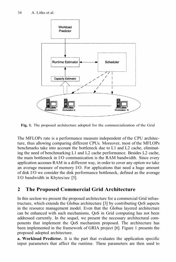
34 A. Litke et al.
Fig. 1. The proposed architecture adopted for the commercialization of the Grid
The MFLOPs rate is a performance measure independent of the CPU architec-ture, thus allowing comparing different CPUs. Moreover, most of the MFLOPsbenchmarks take into account the bottleneck due to L1 and L2 cache, eliminat-ing the need of benchmarking L1 and L2 cache performance. Besides L2 cache,the main bottleneck in I/O communication is the RAM bandwidth. Since everyapplication accesses RAM in a different way, in order to cover any option we takean average measure of memory I/O. For applications that need a huge amountof disk I/O we consider the disk performance bottleneck, defined as the averageI/O bandwidth in Kbytes/sec [5].
2 The Proposed Commercial Grid Architecture
In this section we present the proposed architecture for a commercial Grid infras-tructure, which extends the Globus architecture [3] by contributing QoS aspectsin the resource management model. Even that the Globus layered architecturecan be enhanced with such mechanisms, QoS in Grid computing has not beenaddressed currently. In the sequel, we present the necessary architectural com-ponents that implement the QoS mechanism proposed. The architecture hasbeen implemented in the framework of GRIA project [6]. Figure 1 presents theproposed adopted architecture.a. Workload Predictor. It is the part that evaluates the application specificinput parameters that affect the runtime. These parameters are then used to
An Advanced Architecture for a Commercial Grid Infrastructure 35
predict the workload performance parameters that are needed for the runtimeestimation. It estimates a set of workload parameters for a given set of applicationspecific input parameters. These are passed to the Runtime Estimator in orderto be used for further processing so as to estimate the execution time of the job.The Workload Predictors are each one dedicated for each different applicationthat is incorporated on the system.
b. Capacity Estimator. It calculates the resource performance parameters foreach different resource of the supplier. The Capacity Estimator should calculatethe resource performance parameters of the runtime estimation model, througha benchmarking process that is the same for every heterogeneous resource plat-form, thus providing a way to compare heterogeneous resource performance. Byusing the same parameters for every heterogeneous resource platform we canincorporate different platforms on the system and we can define a cost of useper performance unit.
c. Runtime Estimator. It uses a mathematical model to combine the workloadparameter set from the Workload Predictor, with the resource parameter setfrom the Capacity Estimator to give estimation about the execution time of thespecific job on the specific resource.
d. Scheduler. It is the main module that applies the scheduling policy andprocedure based on the Runtime Estimator, and according to the deadlines ofthe jobs as they are given by the customer.
3 Runtime Estimation Model
3.1 Resource Performance Parameters for Heterogeneous Platforms
A generic PC architecture consists of a CPU, L1, L2 cache and RAM (memoryhierarchy) and the hard disk. There are several different architectures for eachof the above components and different operating systems. For the CPU perfor-mance the most suitable generic measurement is the MFLOPS benchmark [5].Since the majority of the MFLOPS benchmarks take into account the L1 and L2cache rates, we can assume that the only suitable measurement for the memoryperformance is the average RAM I/O bandwidth. Also for the hard disk perfor-mance we consider as suitable performance measurement the average read/writedisk I/O bandwidth.
We now see that the achieved application performance can be expressedin conjunction with these three values. Therefore, we denote as r, the resourceparameter vector, the elements of which correspond to the CPU speed(in MFLOPS/sec), average memory I/O (in MB/sec) and average disk I/O (inKB/sec).
The resource parameter vector can be calculated for each resource through abenchmarking process. In this study we assume that the resources that are takeninto consideration are limited to standalone PC platforms and not clusters or
36 A. Litke et al.
batch systems. Thus we consider a Grid infrastructure with single node taskson single PCs. The important thing about the runtime estimation model is thaton every resource that we want to have runtime estimation we have to use thesame benchmarks. Since the benchmarks can be compiled for different operatingsystems and platforms, we can use the same r vector for any heterogeneousplatform, thus having the capability of incorporating any heterogeneous resourceon the Grid infrastructure using the same resource performance description.
Equation (1) refers to the computational resource parameters. Concerningthe communication parameters, we use the Send Communication Bandwidth andthe Receive Communication Bandwidth both measured in Kbytes/sec. For theavailability resource parameters we use the Minimum Free Memory (in MB)and Minimum Free Disk Space (in KB) of the resource where the task will beallocated. However these additional parameters are not being taken into consid-eration within the scope of this paper, since the work presented in this paperis focused on the Runtime Estimation model. The overall system that has beendesigned and implemented within the framework of GRIA project [6] uses theaforementioned parameters to calculate a Remote Runtime that consists ad-ditionally of the communication time (send and receive time intervals of theapplication data) and the queue time interval that is the waiting time for theapplication to start execution on the selected resource. However the scope of thispaper is to propose and validate a new model of Grid architecture incorporat-ing QoS aspects, and thus it is focused on proving the validity of the proposedRuntime Estimation model, which is used to calculate the execution time only.
The proposed scheme is not used for application tasks that run in parallel.Thus the latency factor has not been taken into consideration because there areno continuous transaction between the individual resources during the executionphase of a job.
3.2 Definition of Application Workload Parameters
The workload parameters must be defined in conjunction with the resource pa-rameters, in order to use the same runtime estimation model for every applica-tion. In this paper we have used for the resource parameters the MFLOPS/sec,the average memory I/O and the average disk I/O (see section 3.1), and thusthe workload parameters are defined only by the computational parameters. Ex-tension of our study for including the affect of the other workload parameterscan be performed in a similar way.
To estimate the workload of a task we need a) to extract features whichdescribe the specific application from which the task derive and b) to define aset of parameters which are in conjunction with the three resource performancevalues [see equation (1)].
Let us first denote as x a vector which describes the “computational load” ofa task derived from an application. We call vector x workload parameter vector.In our paper and without loss of generality we assume that vector x consists ofthree elements
An Advanced Architecture for a Commercial Grid Infrastructure 37
where the elements correspond to the CPU instructions per task (inMFLO), the average memory I/O amount per task (in MB) and the average diskI/O amount (in KB).
To estimate vector x, we need to extract for each specific application thosefeatures which affect the respective workload. Let us denote as s the descriptorparameters vector
the elements of which correspond to the individual application de-scriptors. The descriptors are independent of the execution environment. Forexample, in case we refer to 3D rendering applications the descriptors are theimage resolution, number of polygons, number of light sources and so on. It isclear that for different applications different descriptors are required [7], [8], [9].So, for each application incorporated to the system we must construct a differentpredictor for estimating vector x.
3.3 Workload Prediction
Vector s is used as input to the Workload Predictor module, which is responsiblefor estimating vector x from s, through a non-linear model Generally,the function is unknown and thus it can not be estimated in a straightfor-ward way. For this reason, modeling of function is required for predictingvector x from vector s. Usually, linear models cannot effectively estimate theapplication workload. This is caused since usually there does not exist a simplelinear relation, which maps the specific input parameters (e.g., vector s) withthe corresponding workload parameters (e.g. vector x). Alternatively, modelingcan be performed using simplified non-linear mathematical models (such as ex-ponential and/or logarithmic functions) and applying estimation techniques [10]for predicting the vector x. However, these approaches present satisfactory re-sults only in case of data that follow the adopted pre-determined function type,which is not be extended to any type of application.
In order to have a generic workload prediction module, which can be appliedto any type of application, modeling of the unknown is performedthrough a neural network architecture. This is due to the fact that neural net-works are capable of estimating any continuous non-linear function with anydegree of accuracy [11]. In particular, neural networks provide an approximationof function say through a training set of samples consisting of appropri-ate selected vectors and the respective vectors Training is performed basedon a Least Squares algorithms, such as the Marquardt-Levenberg algorithm [11].
3.4 The Runtime Estimation Model
As already mentioned, the amount of workload that is served per second is givenby the resource capability. We recall that is the workload of the i-th task beingexecuted on a resource characterized by a resource parameter We denote as
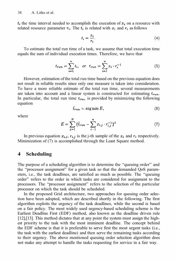
38 A. Litke et al.
the time interval needed to accomplish the execution of on a resource withrelated resource parameter The is related with and as follows
To estimate the total run time of a task, we assume that total execution timeequals the sum of individual execution times. Therefore, we have that
However, estimation of the total run time based on the previous equation doesnot result in reliable results since only one measure is taken into consideration.To have a more reliable estimate of the total run time, several measurementsare taken into account and a linear system is constructed for estimatingIn particular, the total run time is provided by minimizing the followingequation
where
In previous equation is the j-th sample of the and respectively.Minimization of (7) is accomplished through the Least Square method.
4 Scheduling
The purpose of a scheduling algorithm is to determine the “queuing order” andthe “processor assignment” for a given task so that the demanded QoS param-eters, i.e., the task deadlines, are satisfied as much as possible. The “queuingorder” refers to the order in which tasks are considered for assignment to theprocessors. The “processor assignment” refers to the selection of the particularprocessor on which the task should be scheduled.
In the proposed Grid architecture, two approaches for queuing order selec-tion have been adopted, which are described shortly in the following. The firstalgorithm exploits the urgency of the task deadlines, while the second is basedon a fair policy. The most widely used urgency-based scheduling scheme is theEarliest Deadline First (EDF) method, also known as the deadline driven rule[12],[13]. This method dictates that at any point the system must assign the high-est priority to the task with the most imminent deadline. The concept behindthe EDF scheme is that it is preferable to serve first the most urgent tasks (i.e.,the task with the earliest deadline) and then serve the remaining tasks accordingto their urgency. The above mentioned queuing order selection algorithm doesnot make any attempt to handle the tasks requesting for service in a fair way.
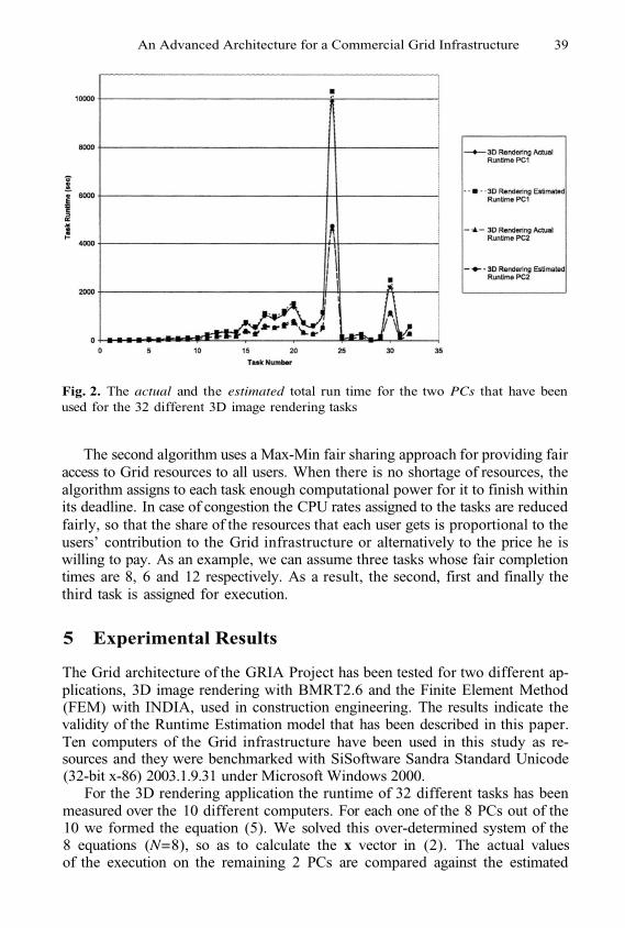
An Advanced Architecture for a Commercial Grid Infrastructure 39
Fig. 2. The actual and the estimated total run time for the two PCs that have beenused for the 32 different 3D image rendering tasks
The second algorithm uses a Max-Min fair sharing approach for providing fairaccess to Grid resources to all users. When there is no shortage of resources, thealgorithm assigns to each task enough computational power for it to finish withinits deadline. In case of congestion the CPU rates assigned to the tasks are reducedfairly, so that the share of the resources that each user gets is proportional to theusers’ contribution to the Grid infrastructure or alternatively to the price he iswilling to pay. As an example, we can assume three tasks whose fair completiontimes are 8, 6 and 12 respectively. As a result, the second, first and finally thethird task is assigned for execution.
5 Experimental Results
The Grid architecture of the GRIA Project has been tested for two different ap-plications, 3D image rendering with BMRT2.6 and the Finite Element Method(FEM) with INDIA, used in construction engineering. The results indicate thevalidity of the Runtime Estimation model that has been described in this paper.Ten computers of the Grid infrastructure have been used in this study as re-sources and they were benchmarked with SiSoftware Sandra Standard Unicode(32-bit x-86) 2003.1.9.31 under Microsoft Windows 2000.
For the 3D rendering application the runtime of 32 different tasks has beenmeasured over the 10 different computers. For each one of the 8 PCs out of the10 we formed the equation (5). We solved this over-determined system of the8 equations (N=8), so as to calculate the x vector in (2). The actual valuesof the execution on the remaining 2 PCs are compared against the estimated
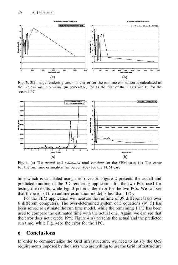
40 A. Litke et al.
Fig. 3. 3D image rendering case - The error for the runtime estimation is calculated asthe relative absolute error (in percentage) for a) the first of the 2 PCs and b) for thesecond PC
Fig. 4. (a) The actual and estimated total runtime for the FEM case; (b) The errorfor the run time estimation (in percentage) for the FEM case
time which is calculated using this x vector. Figure 2 presents the actual andpredicted runtime of the 3D rendering application for the two PCs used fortesting the results, while Fig. 3 presents the error for the two PCs. We can seethat the error of the runtime estimation model is less than 13%.
For the FEM application we measure the runtime of 39 different tasks over6 different computers. The over-determined system of 5 equations (N=5) hasbeen solved to estimate the run time model, while the remaining 1 PC has beenused to compare the estimated time with the actual one. Again, we can see thatthe error does not exceed 19%. Figure 4(a) presents the actual and the predictedrun time, while Fig. 4(b) the error for the 1PC.
6 Conclusions
In order to commercialize the Grid infrastructure, we need to satisfy the QoSrequirements imposed by the users who are willing to use the Grid infrastructure
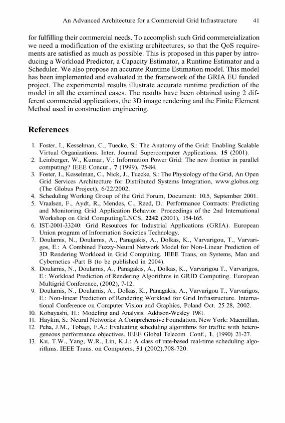
An Advanced Architecture for a Commercial Grid Infrastructure 41
for fulfilling their commercial needs. To accomplish such Grid commercializationwe need a modification of the existing architectures, so that the QoS require-ments are satisfied as much as possible. This is proposed in this paper by intro-ducing a Workload Predictor, a Capacity Estimator, a Runtime Estimator and aScheduler. We also propose an accurate Runtime Estimation model. This modelhas been implemented and evaluated in the framework of the GRIA EU fundedproject. The experimental results illustrate accurate runtime prediction of themodel in all the examined cases. The results have been obtained using 2 dif-ferent commercial applications, the 3D image rendering and the Finite ElementMethod used in construction engineering.
References
Foster, I., Kesselman, C., Tuecke, S.: The Anatomy of the Grid: Enabling ScalableVirtual Organizations. Inter. Journal Supercomputer Applications. 15 (2001).Leinberger, W., Kumar, V.: Information Power Grid: The new frontier in parallelcomputing? IEEE Concur., 7 (1999), 75-84.Foster, I., Kesselman, C., Nick, J., Tuecke, S.: The Physiology of the Grid, An OpenGrid Services Architecture for Distributed Systems Integration, www.globus.org(The Globus Project), 6/22/2002.Scheduling Working Group of the Grid Forum, Document: 10.5, September 2001.Vraalsen, F., Aydt, R., Mendes, C., Reed, D.: Performance Contracts: Predictingand Monitoring Grid Application Behavior. Proceedings of the 2nd InternationalWorkshop on Grid Computing/LNCS, 2242 (2001), 154-165.IST-2001-33240: Grid Resources for Industrial Applications (GRIA). EuropeanUnion program of Information Societies Technology.Doulamis, N., Doulamis, A., Panagakis, A., Dolkas, K., Varvarigou, T., Varvari-gos, E.: A Combined Fuzzy-Neural Network Model for Non-Linear Prediction of3D Rendering Workload in Grid Computing. IEEE Trans, on Systems, Man andCybernetics -Part B (to be published in 2004).Doulamis, N., Doulamis, A., Panagakis, A., Dolkas, K., Varvarigou T., Varvarigos,E.: Workload Prediction of Rendering Algorithms in GRID Computing. EuropeanMultigrid Conference, (2002), 7-12.Doulamis, N., Doulamis, A., Dolkas, K., Panagakis, A., Varvarigou T., Varvarigos,E.: Non-linear Prediction of Rendering Workload for Grid Infrastructure. Interna-tional Conference on Computer Vision and Graphics, Poland Oct. 25-28, 2002.Kobayashi, H.: Modeling and Analysis. Addison-Wesley 1981.Haykin, S.: Neural Networks: A Comprehensive Foundation. New York: Macmillan.Peha, J.M., Tobagi, F.A.: Evaluating scheduling algorithms for traffic with hetero-geneous performance objectives. IEEE Global Telecom. Conf., 1, (1990) 21-27.Ku, T.W., Yang, W.R., Lin, K.J.: A class of rate-based real-time scheduling algo-rithms. IEEE Trans. on Computers, 51 (2002),708-720.
1.
2.
3.
4.5.
6.
7.
8.
9.
10.11.12.
13.
Managing MPI Applicationsin Grid Environments*
Elisa Heymann1, Miquel A. Senar1, Enol Fernández1,Alvaro Fernández2, and José Salt2
1 Universitat Autónoma de Barcelona, Barcelona, Spain{elisa.heymann,miquelangel.senar,enol.fernandez}@uab.es
2 Institute de Física Corpuscular, Valencia, Spain{alferca,salt}@ific.uv.es
Abstract. One of the goals of the EU CrossGrid project is to providea basis for supporting the efficient execution of parallel and interactiveapplications on Grid environments. CrossGrid jobs typically consist ofcomputationally intensive simulations that are often programmed using aparallel programming model and a parallel programming library (MPI).This paper describes the key components that we have included in ourresource management system in order to provide effective and reliableexecution of parallel applications on a Grid environment. The generalarchitecture of our resource management system is briefly introducedfirst and we focus afterwards on the description of the main componentsof our system. We provide support for executing parallel applicationswritten in MPI either in a single cluster or over multiple clusters.
1 Introduction
Grid technologies started to appear in the mid-1990s. Much progress has beenmade on the construction of such an infrastructure since then, although some keychallenge problems remain to be solved. There are many Grid initiatives thatare still working in the prototype arena. And only a few attempts have beenmade to demonstrate production-level environments up to now. The CompactMuon Solenoid (CMS) Collaboration [1], which is part of several large-scale Gridprojects, including GriPhyN [2], PPDG [3] and EU DataGrid [4], is a significantexample that has demonstrated the potential value of a Grid-enabled system forMonte Carlo analysis by running a number of large production experiments butnot in a continuous way.
Fundamental to any Grid environment is the ability to discover, allocate,monitor and manage the use of resources (which traditionally refer to comput-ers, networks, or storage). The term resource management is commonly usedto describe all aspects of the process of locating various types of resources, ar-ranging these for use, utilizing them and monitoring their state. In traditional
* This work has been supported by the European Union through the IST-2001-32243project “CrossGrid” and partially supported by the Comisión Interministerial deCiencia y Tecnología (CICYT) under contract TIC2001-2592.
M. Dikaiakos (Ed.): AxGrids 2004, LNCS 3165, pp. 42–50, 2004.© Springer-Verlag Berlin Heidelberg 2004
Managing MPI Applications in Grid Environments 43
computing systems, resource management is a well-studied problem and there isa significant number of resource managers such as batch schedulers or workflowengines. These resource management systems are designed and operate under theassumption that they have complete control of a resource and thus can imple-ment mechanisms and policies for the effective use of that resource in isolation.Unfortunately, this assumption does not apply to Grid environments, in whichresources belong to separately administered domains.
Resource management in a Grid therefore has to deal with a heterogeneousmulti-site computing environment that, in general, exhibits different hardwarearchitectures, loss of centralized control, and as a result, inevitable differencesin policies. Additionally, due to the distributed nature of the Grid environment,computers, networks and storage devices can fail in various ways.
Most systems described in the literature follow a similar pattern of executionwhen scheduling a job over a Grid. There are typically three main phases, asdescribed in [5]:
Resource discovery, which generates a list of potential resources that canbe used by a given application. This phase requires the user to have ac-cess to a set of resources (i.e. he/she is authorized to use them) and hassome mechanism to specify a minimal set of application requirements. Theserequirements will be used to filter out the resources that do not meet theminimal job requirements.Information gathering on those resources and the selection of a best set.In this phase, given a group of possible resources, all of which meet theminimum requirement for the job, a single resource must be selected onwhich to schedule the job. The resource selection may be carried out by someform of heuristic mechanism that may use additional information about thedynamic state of the resources discovered in the first phase.Job execution, which includes file staging and cleanup. Once resources arechosen, the application can be submitted to them. However, due to the lackof standards for job submission, this phase can be made very complicatedbecause it may involve setup of the remote site, staging of files needed by thejob, monitoring progress of the application and, once the job is completed,retrieving of output files from the remote site, and removing temporary set-tings.
The resource management system that we are developing in the CrossGridproject follows the same approach to schedule jobs as described above. However,our system is targeted to a kind of applications that have received very littleattention up to now. Most existing systems have focussed on the execution ofsequential jobs, the Grid being a large multi-site environment where the jobs runin a batch-like way. The CMS Collaboration constitutes a remarkable example,in which research on job scheduling has also taken into account the locationand movement of data, and the coordinated execution of multiple jobs withdependencies between them (when a job X depends on job Y, this means thatX can start only when Y has completed).
CrossGrid jobs are computationally intensive applications that are mostlywritten with the MPI library. Moreover, once the job has been submitted to the
44 E. Heymann et al.
Grid and has started its execution on remote resources, the user may want tosteer its execution in an interactive way. This is required to analyze intermediateresults produced by the application and to react according to them. For instance,in the case where a simulation is not converging, the user may kill the currentjob and submit a new simulation with a different set of input parameters. Fromthe scheduling point of view, support for parallel and interactive applicationsintroduces the need for some mechanisms that are not needed when jobs aresequential or are submitted in a batch form. Basically, jobs need more than oneresource (machine) and they must start immediately, i.e. in a period of timevery close to the time of submission. Therefore, the scheduler has to search forsets of resources that are all already and wholly available at the time of thejob submission. On the other hand, if there are no available resources, somepriority and preemption mechanisms might be used to guarantee, for instance,that interactive jobs (which will have the highest priority) will preempt lowpriority jobs and run in their place.
In this paper, we focus on the description of the basic mechanisms used inour resource management system that are related to the execution of parallelapplications on a Grid environment, assuming that free resources are availableand no preemption is required. Preemption on grid environments is a complexproblem and, to the best of our knowledge, no attempts have been made toaddress this problem. We are also investigating this issue and have designedcertain preliminary mechanisms, which we plan to complete and test them inthe near future.
The rest of this paper is organized as follows: Section 2 briefly describes theoverall architecture of our resource management services, Section 3 describes theparticular services that support submission of MPI applications on a cluster ofa single site or on several clusters of multiple sites, and Section 4 summarizesthe main conclusions to this work.
2 Overall Architectureof CrossGrid Resource Management
This section briefly describes the global architecture of our scheduling approach.A more detailed explanation can be found in [6]. The scenario that we are tar-geting consists of a user who has a parallel application and wishes to execute iton grid resources. When users submit their application, our scheduling servicesare responsible for optimizing scheduling and node allocation decisions on a userbasis. Specifically, they carry out three main functions:
Select the “best” resources that a submitted application can use. This se-lection will take into account the application requirements needed for itsexecution, as well as certain ranking criteria used to sort the available re-sources in order of preference.Perform a reliable submission of the application onto the selected resources.Monitor the application execution and report on job termination.
1.
2.3.
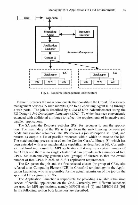
Managing MPI Applications in Grid Environments 45
Fig. 1. Resource-Management Architecture
Figure 1 presents the main components that constitute the CrossGrid resource-management services. A user submits a job to a Scheduling Agent (SA) througha web portal. The job is described by a JobAd (Job Advertisement) using theEU-Datagrid Job Description Language (JDL) [7], which has been convenientlyextended with additional attributes to reflect the requirements of interactive andparallel applications.
The SA asks the Resource Searcher (RS) for resources to run the applica-tion. The main duty of the RS is to perform the matchmaking between jobneeds and available resources. The RS receives a job description as input, andreturns as output a list of possible resources within which to execute the job.The matchmaking process is based on the Condor ClassAd library [8], which hasbeen extended with a set matchmaking capability, as described in [6]. Currently,set matchmaking is used for MPI applications that require a certain number offree CPUs and there is no single cluster that can provide such a number of freeCPUs. Set matchmaking generates sets (groups) of clusters so that the overallnumber of free CPUs in each set fulfils application requirements.
The SA passes the job and the first-selected cluster (or group of CEs), alsoreferred to as Computing Element (CE) in CrossGrid terminology, to the Appli-cation Launcher, who is responsible for the actual submission of the job on thespecified CE or groups of CEs.
The Application Launcher is responsible for providing a reliable submissionservice of parallel applications on the Grid. Currently, two different launchersare used for MPI applications, namely MPICH ch-p4 [9] and MPICH-G2 [10].In the following section both launchers are described.
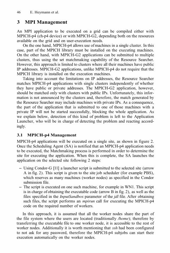
46 E. Heymann et al.
3 MPI Management
An MPI application to be executed on a grid can be compiled either withMPICH-p4 (ch-p4 device) or with MPICH-G2, depending both on the resourcesavailable on the grid and on user-execution needs.
On the one hand, MPICH-p4 allows use of machines in a single cluster. In thiscase, part of the MPICH library must be installed on the executing machines.On the other hand, with MPICH-G2 applications can be submitted to multipleclusters, thus using the set matchmaking capability of the Resource Searcher.However, this approach is limited to clusters where all their machines have publicIP addresses. MPICH-G2 applications, unlike MPICH-p4 do not require that theMPICH library is installed on the execution machines.
Taking into account the limitations on IP addresses, the Resource Searchermatches MPICH-p4 applications with single clusters independently of whetherthey have public or private addresses. The MPICH-G2 application, however,should be matched only with clusters with public IPs. Unfortunately, this infor-mation is not announced by the clusters and, therefore, the match generated bythe Resource Searcher may include machines with private IPs. As a consequence,the part of the application that is submitted to one of those machines with aprivate IP will not be started successfully, blocking the whole application. Aswe explain below, detection of this kind of problem is left to the ApplicationLauncher, who will be in charge of detecting the problem and reacting accord-ingly.
3.1 MPICH-p4 Management
MPICH-p4 applications will be executed on a single site, as shown in figure 2.Once the Scheduling Agent (SA) is notified that an MPICH-p4 application needsto be executed, the Matchmaking process is performed in order to determine thesite for executing the application. When this is complete, the SA launches theapplication on the selected site following 2 steps:
Using Condor-G [11] a launcher script is submitted to the selected site (arrowA in fig. 2). This script is given to the site job scheduler (for example PBS),which reserves as many machines (worker nodes) as specified in the Condorsubmission file.The script is executed on one such machine, for example in WN1. This scriptis in charge of obtaining the executable code (arrow B in fig. 2), as well as thefiles specified in the InputSandbox parameter of the jdl file. After obtainingsuch files, the script performs an mpirun call for executing the MPICH-p4code on the required number of workers.
In this approach, it is assumed that all the worker nodes share the part ofthe file system where the users are located (traditionally /home); therefore bytransferring the executable file to one worker node, it is accessible to the rest ofworker nodes. Additionally it is worth mentioning that ssh had been configuredto not ask for any password, therefore the MPICH-p4 subjobs can start theirexecution automatically on the worker nodes.
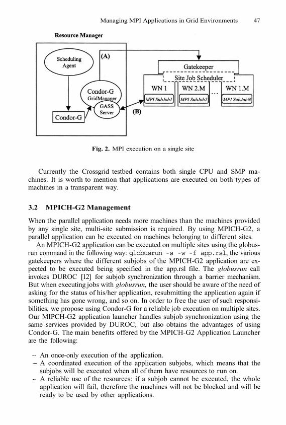
Managing MPI Applications in Grid Environments 47
Fig. 2. MPI execution on a single site
Currently the Crossgrid testbed contains both single CPU and SMP ma-chines. It is worth to mention that applications are executed on both types ofmachines in a transparent way.
3.2 MPICH-G2 Management
When the parallel application needs more machines than the machines providedby any single site, multi-site submission is required. By using MPICH-G2, aparallel application can be executed on machines belonging to different sites.
An MPICH-G2 application can be executed on multiple sites using the globus-run command in the following way: globusrun -s -w -f app.rsl, the variousgatekeepers where the different subjobs of the MPICH-G2 application are ex-pected to be executed being specified in the app.rsl file. The globusrun callinvokes DUROC [12] for subjob synchronization through a barrier mechanism.But when executing jobs with globusrun, the user should be aware of the need ofasking for the status of his/her application, resubmitting the application again ifsomething has gone wrong, and so on. In order to free the user of such responsi-bilities, we propose using Condor-G for a reliable job execution on multiple sites.Our MIPCH-G2 application launcher handles subjob synchronization using thesame services provided by DUROC, but also obtains the advantages of usingCondor-G. The main benefits offered by the MPICH-G2 Application Launcherare the following:
An once-only execution of the application.A coordinated execution of the application subjobs, which means that thesubjobs will be executed when all of them have resources to run on.A reliable use of the resources: if a subjob cannot be executed, the wholeapplication will fail, therefore the machines will not be blocked and will beready to be used by other applications.
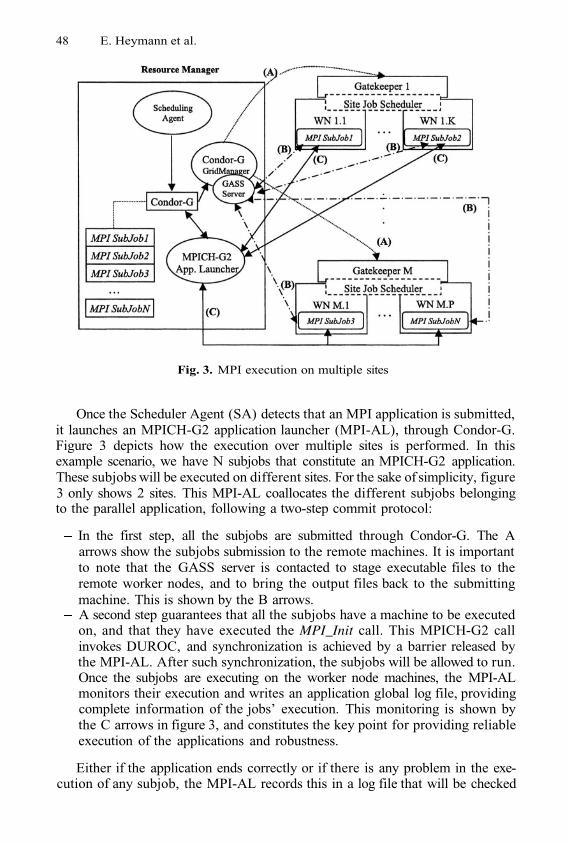
48 E. Heymann et al.
Fig. 3. MPI execution on multiple sites
Once the Scheduler Agent (SA) detects that an MPI application is submitted,it launches an MPICH-G2 application launcher (MPI-AL), through Condor-G.Figure 3 depicts how the execution over multiple sites is performed. In thisexample scenario, we have N subjobs that constitute an MPICH-G2 application.These subjobs will be executed on different sites. For the sake of simplicity, figure3 only shows 2 sites. This MPI-AL coallocates the different subjobs belongingto the parallel application, following a two-step commit protocol:
In the first step, all the subjobs are submitted through Condor-G. The Aarrows show the subjobs submission to the remote machines. It is importantto note that the GASS server is contacted to stage executable files to theremote worker nodes, and to bring the output files back to the submittingmachine. This is shown by the B arrows.A second step guarantees that all the subjobs have a machine to be executedon, and that they have executed the MPI_Init call. This MPICH-G2 callinvokes DUROC, and synchronization is achieved by a barrier released bythe MPI-AL. After such synchronization, the subjobs will be allowed to run.Once the subjobs are executing on the worker node machines, the MPI-ALmonitors their execution and writes an application global log file, providingcomplete information of the jobs’ execution. This monitoring is shown bythe C arrows in figure 3, and constitutes the key point for providing reliableexecution of the applications and robustness.
Either if the application ends correctly or if there is any problem in the exe-cution of any subjob, the MPI-AL records this in a log file that will be checked
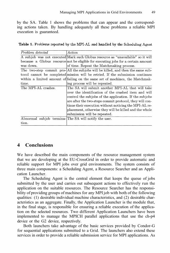
Managing MPI Applications in Grid Environments 49
by the SA. Table 1 shows the problems that can appear and the correspond-ing actions taken. By handling adequately all these problems a reliable MPIexecution is guaranteed.
4 Conclusions
We have described the main components of the resource management systemthat we are developing at the EU-CrossGrid in order to provide automatic andreliable support for MPI jobs over grid environments. The system consists ofthree main components: a Scheduling Agent, a Resource Searcher and an Appli-cation Launcher.
The Scheduling Agent is the central element that keeps the queue of jobssubmitted by the user and carries out subsequent actions to effectively run theapplication on the suitable resources. The Resource Searcher has the responsi-bility of providing groups of machines for any MPI job with both of the followingqualities: (1) desirable individual machine characteristics, and (2) desirable char-acteristics as an aggregate. Finally, the Application Launcher is the module that,in the final stage, is responsible for ensuring a reliable execution of the applica-tion on the selected resources. Two different Application Launchers have beenimplemented to manage the MPICH parallel applications that use the ch-p4device or the G2 device, respectively.
Both launchers take advantage of the basic services provided by Condor-Gfor sequential applications submitted to a Grid. The launchers also extend theseservices in order to provide a reliable submission service for MPI applications. As
50 E. Heymann et al.
a consequence, our resource management service handles resubmission of failedparallel jobs (due to crashes or failures in the network connecting, the resourcemanager or the remote resources), reliable co-allocation of resources (in the caseof MPICH-G2), and exactly-once execution (even in the case of a machine crashwhere the resource manager is running).
Our first prototype has been based on the EU-Datagrid Resource Broker (re-lease 1.4.8). However, this prototype has been mainly used for testing purposes.Our subsequent prototype is compatible with the next CrossGrid testbed de-ployment, which is based on EU-Datagrid release 2.0, and is integrated with twomiddleware services (namely, a Web Portal and a Migrating Desktop) providinga user-friendly interface to interact with the Grid.
References
K. Holtman. CMS requirements for the Grid. In Proceedings of International Con-ference on Computing in High Energy and Nuclear Physics (CHEP 2001), 2001.GriPhyN: The Grid Physics Network. http://www.griphyn.org.PPDG: Particle Physics Data Grid. http://www.ppdg.net.European DataGrid Project. http://www.eu-datagrid.orgJennifer M. Schopf, “Ten Actions When Grid Scheduling”, in Grid Resource Man-agement - State of the Art and Future Trends (Jarek Nabryzki, Jennifer Schopfand Jan Weglarz editors), Kluwer Academic Publishers, 2003.E. Heymann, M.A.Senar, A. Fernandez, J. Salt, “The Eu-Crossgrid approach forGrid Application Scheduling”, to appear in the post-proceedings of the 1st Euro-pean Across Grids Conference February, LNCS series, 2003.Fabricio Pazini, JDL Attributes - DataGrid-01-NOT-0101-0_4.pdf,http://www.infn.it/workload-grid/docs/DataGrid-01-NOT-0101-0_4-Note.pdf,December 17, 2001.Rajesh Raman, Miron Livny and Marvin Solomon, “Matchmaking: Distributed re-source management for high throughput computing”, in Proc. Of the seventh IEEEInt. Symp. On High Perfromance Distributed Computing (HPDC7), Chicago, IL,July, 1998.W. Gropp and E. Lusk and N. Doss and A. Skjellum, “A high-performance,portable implementation of the MPI message passing interface standard”, ParallelComputing, 22(6), pages 789-828, 1996.N. Karonis, B. Toonen, and I. Foster. MPICH-G2: A Grid-enabled implementationof the message passing interface. Journal of Parallel and Distributed Computing,62, pp. 551-563, 2003.James Frey, Todd Tannenbaum, Ian Foster, Miron Livny, and Steven Tuecke,“Condor-G: A Computation Management Agent for Multi-Institutional Grids”,Journal of Cluster Computing, vol. 5, pages 237-246, 2002.K. Czajkowsi, I. Foster, C. Kessekman. “Co-allocation services for computationalGrids”. Proceedings of the Eighth IEEE Symposium on High Performance Dis-tributed Computing, IEEE Computer Society Press, Silver Spring MD, 1999.
1.
2.3.4.5.
6.
7.
8.
9.
10.
11.
12.
Flood Forecasting in CrossGrid Project
L. Hluchy, V.D. Tran, O. Habala, B. Simo,E. Gatial, J. Astalos, and M. Dobrucky
Institute of Informatics – SAS, Dubravska cesta 9, 845 07 Bratislava, Slovakia
Abstract. This paper presents a prototype of flood forecasting sys-tem based on Grid technologies. The system consists of workflow sys-tem for executing simulation cascade of meteorological, hydrological andhydraulic models, data management system for storing and accessing dif-ferent computed and measured data, and web portals as user interfaces.The whole system is tied together by Grid technology and is used tosupport a virtual organization of experts, developers and users.
1 Introduction
Due to situation over the past few years in the world, modeling and simulation offloods in order to forecast and to make necessary prevention is very important.Simulating river floods is an extremely computation-intensive undertaking. Sev-eral days of CPU-time may be needed to simulate floods along large sections ofrivers. For critical situations, e.g. when an advancing flood is simulated in orderto predict which areas will be threatened so that necessary prevention measurescan be implemented in time, long computation times are unacceptable. There-fore, using high performance computing platforms to reduce the computationaltime of flood simulation is imperative.
In ANFAS project [11], several flood models have been parallelized. Remoteprocessing tools have been also created for running simulations on remote highperformance systems automatically from client system. The simulation resultscan be imported to GIS system for visualization and analysis.
In CrossGrid project [12], meteorological and hydrological simulations areintegrated into the system in order to forecast flood accurately. That requirescooperation between scientists in different areas, efficient data management sys-tem and a workflow system that can connect meteorological, hydrological andhydraulic simulations in a cascade. Therefore, Grid technologies are employedfor implementing the system.
This paper will describe the Grid-based flood forecasting system (Flood Vir-tual Organization - FloodVO) that is developed in CrossGrid project, its currentstatus and future work. Section 2 briefly describes the architecture of FloodVOand its components. Details about each component are provided in Sections 3-5.In Section 6, the future work on knowledge system is described and Section 7concludes the paper.
M. Dikaiakos (Ed.): AxGrids 2004, LNCS 3165, pp. 51–60, 2004.© Springer-Verlag Berlin Heidelberg 2004
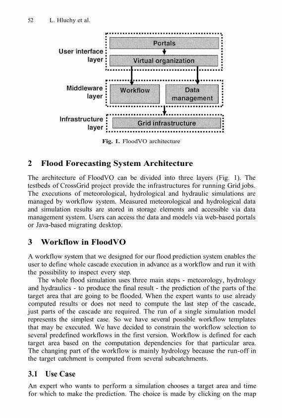
52 L. Hluchy et al.
Fig. 1. FloodVO architecture
2 Flood Forecasting System Architecture
The architecture of FloodVO can be divided into three layers (Fig. 1). Thetestbeds of CrossGrid project provide the infrastructures for running Grid jobs.The executions of meteorological, hydrological and hydraulic simulations aremanaged by workflow system. Measured meteorological and hydrological dataand simulation results are stored in storage elements and accessible via datamanagement system. Users can access the data and models via web-based portalsor Java-based migrating desktop.
3 Workflow in FloodVO
A workflow system that we designed for our flood prediction system enables theuser to define whole cascade execution in advance as a workflow and run it withthe possibility to inspect every step.
The whole flood simulation uses three main steps - meteorology, hydrologyand hydraulics - to produce the final result - the prediction of the parts of thetarget area that are going to be flooded. When the expert wants to use alreadycomputed results or does not need to compute the last step of the cascade,just parts of the cascade are required. The run of a single simulation modelrepresents the simplest case. So we have several possible workflow templatesthat may be executed. We have decided to constrain the workflow selection toseveral predefined workflows in the first version. Workflow is defined for eachtarget area based on the computation dependencies for that particular area.The changing part of the workflow is mainly hydrology because the run-off inthe target catchment is computed from several subcatchments.
3.1 Use CaseAn expert who wants to perform a simulation chooses a target area and timefor which to make the prediction. The choice is made by clicking on the map
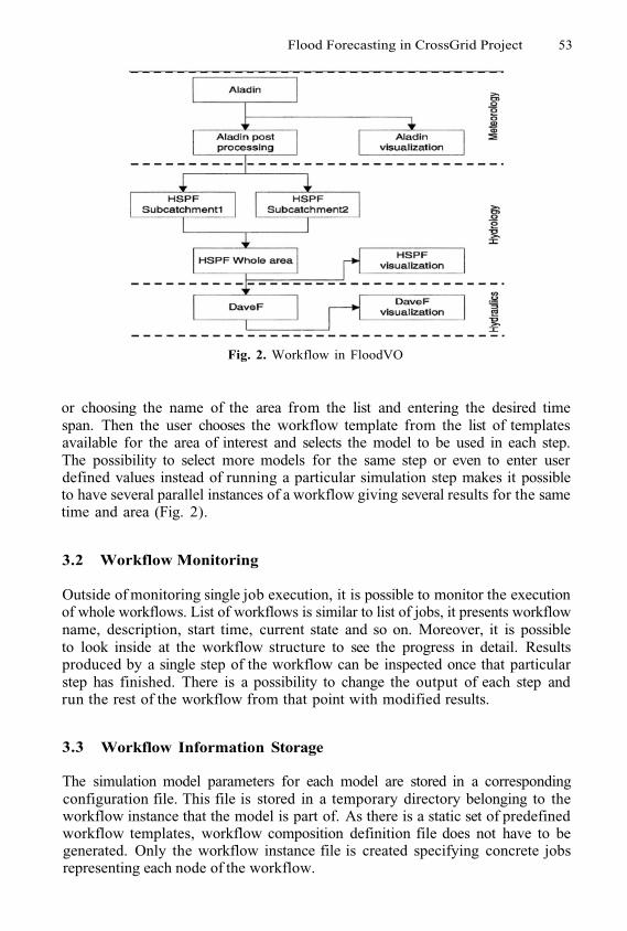
Flood Forecasting in CrossGrid Project 53
Fig. 2. Workflow in FloodVO
or choosing the name of the area from the list and entering the desired timespan. Then the user chooses the workflow template from the list of templatesavailable for the area of interest and selects the model to be used in each step.The possibility to select more models for the same step or even to enter userdefined values instead of running a particular simulation step makes it possibleto have several parallel instances of a workflow giving several results for the sametime and area (Fig. 2).
3.2 Workflow Monitoring
Outside of monitoring single job execution, it is possible to monitor the executionof whole workflows. List of workflows is similar to list of jobs, it presents workflowname, description, start time, current state and so on. Moreover, it is possibleto look inside at the workflow structure to see the progress in detail. Resultsproduced by a single step of the workflow can be inspected once that particularstep has finished. There is a possibility to change the output of each step andrun the rest of the workflow from that point with modified results.
3.3 Workflow Information Storage
The simulation model parameters for each model are stored in a correspondingconfiguration file. This file is stored in a temporary directory belonging to theworkflow instance that the model is part of. As there is a static set of predefinedworkflow templates, workflow composition definition file does not have to begenerated. Only the workflow instance file is created specifying concrete jobsrepresenting each node of the workflow.
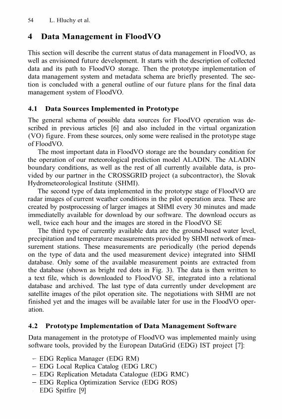
54 L. Hluchy et al.
4 Data Management in FloodVO
This section will describe the current status of data management in FloodVO, aswell as envisioned future development. It starts with the description of collecteddata and its path to FloodVO storage. Then the prototype implementation ofdata management system and metadata schema are briefly presented. The sec-tion is concluded with a general outline of our future plans for the final datamanagement system of FloodVO.
4.1 Data Sources Implemented in Prototype
The general schema of possible data sources for FloodVO operation was de-scribed in previous articles [6] and also included in the virtual organization(VO) figure. From these sources, only some were realised in the prototype stageof FloodVO.
The most important data in FloodVO storage are the boundary condition forthe operation of our meteorological prediction model ALADIN. The ALADINboundary conditions, as well as the rest of all currently available data, is pro-vided by our partner in the CROSSGRID project (a subcontractor), the SlovakHydrometeorological Institute (SHMI).
The second type of data implemented in the prototype stage of FloodVO areradar images of current weather conditions in the pilot operation area. These arecreated by postprocessing of larger images at SHMI every 30 minutes and madeimmediatelly available for download by our software. The download occurs aswell, twice each hour and the images are stored in the FloodVO SE
The third type of currently available data are the ground-based water level,precipitation and temperature measurements provided by SHMI network of mea-surement stations. These measurements are periodically (the period dependson the type of data and the used measurement device) integrated into SHMIdatabase. Only some of the available measurement points are extracted fromthe database (shown as bright red dots in Fig. 3). The data is then written toa text file, which is downloaded to FloodVO SE, integrated into a relationaldatabase and archived. The last type of data currently under development aresatellite images of the pilot operation site. The negotiations with SHMI are notfinished yet and the images will be available later for use in the FloodVO oper-ation.
4.2 Prototype Implementation of Data Management Software
Data management in the prototype of FloodVO was implemented mainly usingsoftware tools, provided by the European DataGrid (EDG) IST project [7]:
EDG Replica Manager (EDG RM)EDG Local Replica Catalog (EDG LRC)EDG Replication Metadata Catalogue (EDG RMC)EDG Replica Optimization Service (EDG ROS)EDG Spitfire [9]
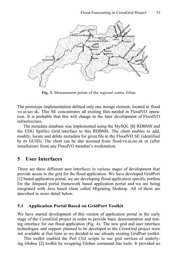
Flood Forecasting in CrossGrid Project 55
Fig. 3. Measurement points of the regional centre Zilina
The prototype implementation defined only one storage element, located at floodvo.ui.sav.sk. This SE concentrates all existing files needed in FloodVO opera-tion. It is probable that this will change in the later development of FloodVOinfrastructure.
The metadata database was implemented using the MySQL [8] RDBMS andthe EDG Spitfire Grid interface to this RDBMS. The client enables to add,modify, locate and delete metadata for given file in the FloodVO SE (identifiedby its GUID). The client can be also accessed from flood-vo.ui.sav.sk or (afterinstallation) from any FloodVO member’s workstation.
5 User Interfaces
There are three different user interfaces in various stages of development thatprovide access to the grid for the flood application. We have developed GridPort[1] based application portal, we are developing flood application specific portletsfor the Jetspeed portal framework based application portal and we are beingintegrated with Java based client called Migrating Desktop. All of them aredescribed in more detail below.
5.1 Application Portal Based on GridPort Toolkit
We have started development of this version of application portal in the earlystage of the CrossGrid project in order to provide basic demonstration and test-ing interface for our flood application (Fig. 4). The new grid and user interfacetechnologies and support planned to be developed in the CrossGrid project werenot available at that time so we decided to use already existing GridPort toolkit.
This toolkit enabled the Perl CGI scripts to use grid services of underly-ing Globus [2] toolkit by wrapping Globus command line tools. It provided no

56 L. Hluchy et al.
Fig. 4. Screenshot of our GridPort based portal
additional support for building portals nor did it provide any support for newservices being developed in the CrossGrid project.
The portal provided access to basic grid services such as authentication ofthe users, job submission and management, file management and also enabledthe user to run simulation models forming the flood application and view theirresults.
We have dropped its further development when CrossGrid user interfacesbecame available.
5.2 Application Portal Based on the Jetspeed Portal Framework
The Jetspeed [3] portal framework has been chosen in the CrossGrid project asa modern powerful platform for creating grid application portal for the appli-cations in the project (Fig. 5). This framework is also being used by other gridprojects such as Alliance portal [4] and the new version of the GridPort toolkit- GridPort 3.0 [5].
Jetspeed is implemented as a server-side Java based engine (applicationserver). Client services are plugged in using software components called portlets.Each portlet has a dedicated space on the screen, which it uses for communica-tion with users. Portlets are independent from each other and user can arrangetheir position, size and visibility.
Jetspeed, in contrast to GridPort, provides framework for building informa-tion portals (pluggable portlets mechanism, user interface management, securitymodel based on permissions, groups and roles, persistence of information etc.)
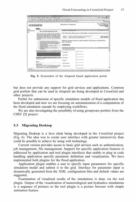
Flood Forecasting in CrossGrid Project 57
Fig. 5. Screenshot of the Jetspeed based application portal
but does not provide any support for grid services and applications. Commongrid portlets that can be used in Jetspeed are being developed in CrossGrid andother projects.
Portlet for submission of specific simulation models of flood application hasbeen developed and now we are focusing on automatization of a computation ofthe flood simulation cascade by employing workflows.
We are also investigating the possibility of using groupware portlets from theCHEF [5] project.
5.3 Migrating Desktop
Migrating Desktop is a Java client being developed in the CrossGrid project(Fig. 6). The idea was to create user interface with greater interactivity thancould be possible to achieve by using web technology.
Current version provides access to basic grid services such as authentication,job management, file management. Support for specific application features isaddressed by application and tool plugin interfaces that enable to plug in codehandling application specific parameter definition and visualization. We haveimplemented both plugins for the flood application.
Application plugin enables a user to specify input parameters for specificsimulation model and submit it to the grid. Interface for parameter input isdynamically generated from the XML configuration files and default values aresuggested.
Examination of visualized results of the simulations is done via the toolplugin. Output of the visualization of meteorological and hydraulics simulationsis a sequence of pictures so the tool plugin is a picture browser with simpleanimation feature.
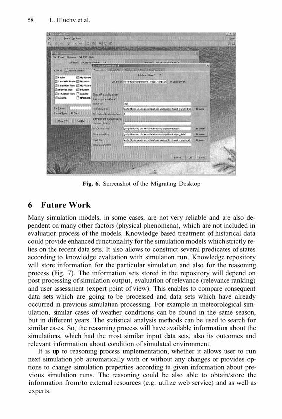
58 L. Hluchy et al.
Fig. 6. Screenshot of the Migrating Desktop
6 Future Work
Many simulation models, in some cases, are not very reliable and are also de-pendent on many other factors (physical phenomena), which are not included inevaluation process of the models. Knowledge based treatment of historical datacould provide enhanced functionality for the simulation models which strictly re-lies on the recent data sets. It also allows to construct several predicates of statesaccording to knowledge evaluation with simulation run. Knowledge repositorywill store information for the particular simulation and also for the reasoningprocess (Fig. 7). The information sets stored in the repository will depend onpost-processing of simulation output, evaluation of relevance (relevance ranking)and user assessment (expert point of view). This enables to compare consequentdata sets which are going to be processed and data sets which have alreadyoccurred in previous simulation processing. For example in meteorological sim-ulation, similar cases of weather conditions can be found in the same season,but in different years. The statistical analysis methods can be used to search forsimilar cases. So, the reasoning process will have available information about thesimulations, which had the most similar input data sets, also its outcomes andrelevant information about condition of simulated environment.
It is up to reasoning process implementation, whether it allows user to runnext simulation job automatically with or without any changes or provides op-tions to change simulation properties according to given information about pre-vious simulation runs. The reasoning could be also able to obtain/store theinformation from/to external resources (e.g. utilize web service) and as well asexperts.
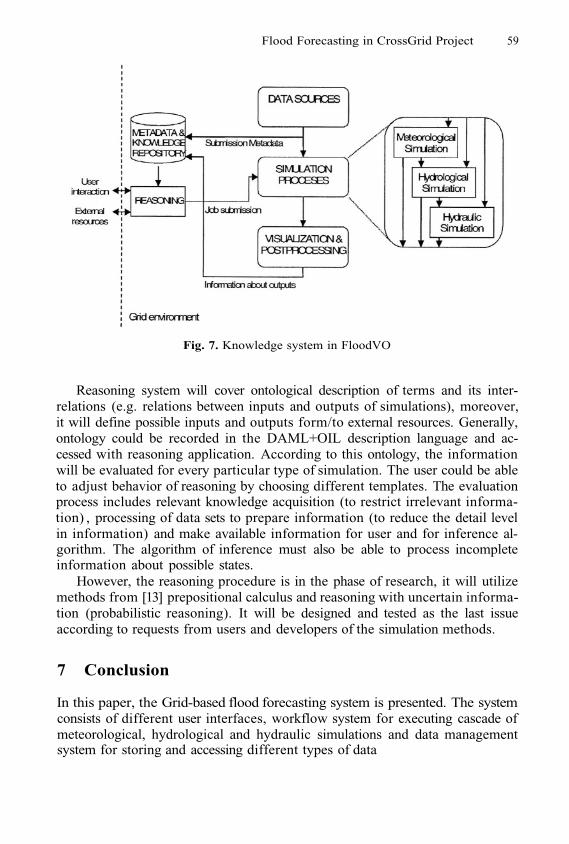
Flood Forecasting in CrossGrid Project 59
Fig. 7. Knowledge system in FloodVO
Reasoning system will cover ontological description of terms and its inter-relations (e.g. relations between inputs and outputs of simulations), moreover,it will define possible inputs and outputs form/to external resources. Generally,ontology could be recorded in the DAML+OIL description language and ac-cessed with reasoning application. According to this ontology, the informationwill be evaluated for every particular type of simulation. The user could be ableto adjust behavior of reasoning by choosing different templates. The evaluationprocess includes relevant knowledge acquisition (to restrict irrelevant informa-tion) , processing of data sets to prepare information (to reduce the detail levelin information) and make available information for user and for inference al-gorithm. The algorithm of inference must also be able to process incompleteinformation about possible states.
However, the reasoning procedure is in the phase of research, it will utilizemethods from [13] prepositional calculus and reasoning with uncertain informa-tion (probabilistic reasoning). It will be designed and tested as the last issueaccording to requests from users and developers of the simulation methods.
7 Conclusion
In this paper, the Grid-based flood forecasting system is presented. The systemconsists of different user interfaces, workflow system for executing cascade ofmeteorological, hydrological and hydraulic simulations and data managementsystem for storing and accessing different types of data
60 L. Hluchy et al.
References
GridPort toolkit. https://gridport.npaci.eduGlobus toolkit. http://www.globus.orgJetspeed. http://jakarta.apache.org/jetspeed/site/index.htmlAlliance portal. http://www.extreme.indiana.edu/alliance/Grid Port 3.0 Plans presentation. http://www.nesc.ac.uk/talks/261/Tuesday/GP3Hluchý L., Habala O., Simo B., Astalos J., Tran V.D., Dobruck M.: Problem Solv-ing Environment for Flood Forecasting. Proc. of The 7th World Multiconference onSystemics, Cybernetics and Informatics (SCI 2003), July 2003, Orlando, Florida,USA, pp. 350-355.Hoschek, W., et. al.: Data Management in the European DataGrid Project. The2001 Globus Retreat, San Francisco, August 9-10 2001.Widenius, M., Axmark, D.: MySQL Reference Manual. O’Reilly and Associates,June 2002, 814 pages.Bell, W., et. al.: Project Spitfire - Towards Grid Web Service Databases. Technicalreport, Global Grid Forum Informational Document, GGF5, Edinburgh, Scotland,July 2002WMO Core Metadata Standard - XML representation. World Weather Watch.http://www.wmo.ch/web/www/metadata/WMO-metadata-XML.htmlANFAS: Data Fusion for Flood Analysis and Decision Support. IST-1999-11676.http://www.ercim.org/anfas/Development of Grid Environment for Interactive Applications. IST-2001-32243.http://www.eu-crossgrid.org/Nilsson J. Nils, Artificial intelligence: A New Synthesis, Morgan Kaufmann Pub-lishers, Inc., San Francisco, California.
1.2.3.4.5.6.
7.
8.
9.
10.
11.
12.
13.
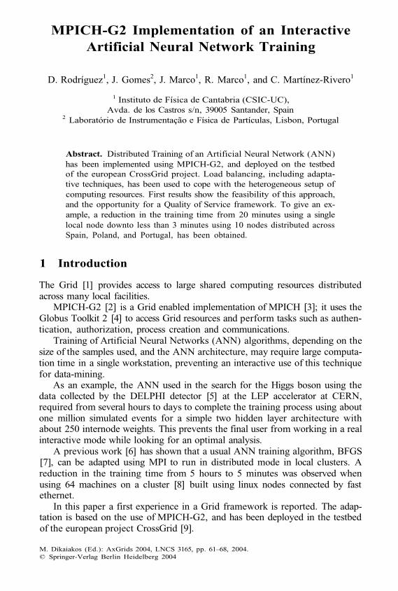
MPICH-G2 Implementation of an InteractiveArtificial Neural Network Training
D. Rodríguez1, J. Gomes2, J. Marco1, R. Marco1, and C. Martínez-Rivero1
1 Instituto de Física de Cantabria (CSIC-UC),Avda. de los Castros s/n, 39005 Santander, Spain
2 Laboratório de Instrumentação e Física de Partículas, Lisbon, Portugal
Abstract. Distributed Training of an Artificial Neural Network (ANN)has been implemented using MPICH-G2, and deployed on the testbedof the european CrossGrid project. Load balancing, including adapta-tive techniques, has been used to cope with the heterogeneous setup ofcomputing resources. First results show the feasibility of this approach,and the opportunity for a Quality of Service framework. To give an ex-ample, a reduction in the training time from 20 minutes using a singlelocal node downto less than 3 minutes using 10 nodes distributed acrossSpain, Poland, and Portugal, has been obtained.
1 Introduction
The Grid [1] provides access to large shared computing resources distributedacross many local facilities.
MPICH-G2 [2] is a Grid enabled implementation of MPICH [3]; it uses theGlobus Toolkit 2 [4] to access Grid resources and perform tasks such as authen-tication, authorization, process creation and communications.
Training of Artificial Neural Networks (ANN) algorithms, depending on thesize of the samples used, and the ANN architecture, may require large computa-tion time in a single workstation, preventing an interactive use of this techniquefor data-mining.
As an example, the ANN used in the search for the Higgs boson using thedata collected by the DELPHI detector [5] at the LEP accelerator at CERN,required from several hours to days to complete the training process using aboutone million simulated events for a simple two hidden layer architecture withabout 250 internode weights. This prevents the final user from working in a realinteractive mode while looking for an optimal analysis.
A previous work [6] has shown that a usual ANN training algorithm, BFGS[7], can be adapted using MPI to run in distributed mode in local clusters. Areduction in the training time from 5 hours to 5 minutes was observed whenusing 64 machines on a cluster [8] built using linux nodes connected by fastethernet.
In this paper a first experience in a Grid framework is reported. The adap-tation is based on the use of MPICH-G2, and has been deployed in the testbedof the european project CrossGrid [9].
M. Dikaiakos (Ed.): AxGrids 2004, LNCS 3165, pp. 61–68, 2004.© Springer-Verlag Berlin Heidelberg 2004
62 D. Rodríguez et al.
The scheme of the paper is as follows: first the computing problem is de-scribed, including a reference example, and the adaptation using MPICH-G2 ina local cluster (section 2). First results in the Grid environment are given insection 3, where the load balancing mechanism is discussed. Section 4 presentsthe conclusions and a description of the future work.
2 Distributed Training of an Artificial Neural NetworkUsing MPICH-G2 in a Local Cluster
Parallel ANN training is a topic that has been studied for a long time. A goodreview can be found in [10]. The program used in this work is based on the onealready cited before [6].
The objective of the training is the minimization of the total error, givenby the sum of errors for all events, each one defined as the quadratic differencebetween the ANN output computed corresponding to each event and the 1 or0 value corresponding to a signal or background event. The minimization pro-cedure is iterative, each iteration being called an epoch. The BFGS [7] gradientdescent method has been used in the ANN training. In this method, errors andgradients are additive in each epoch. The results obtained in each slave can beadded and transmitted to the master. This is a very good characteristic for aparallelization in data strategy.
The parallel training algorithm goes as follows:
The master node starts the work reading the input parameters for the ANNarchitecture, and setting the initial weights to random values.The training data is split into several datasets of similar size (taking intoaccount the computing power of each node to assure load balancing by datapartitioning) and distributed to each slave node.At each step, the master sends the weight values to the slaves, which com-pute the error and the gradient on the partial dataset and return them tothe master; as both are additive, total errors are calculated by the mas-ter that prepares the new weights along the corresponding direction in themultidimensional space and updates the weights. The error computed in aseparated test dataset is used to monitor the convergence.The previous step (an epoch) is repeated until a convergence criterion isfulfilled or a predetermined number of epochs is reached. The master returnsas output the ANN weights, to prepare the corresponding multidimensionalfunction.The whole training can be repeated with different initial random weights toprevent bad results due to local minima. The final error can be used to selectthe best final ANN function if different minima are found.
A first step was to move from MPICH with the ch_p4 device to MPICH-G2,i.e. MPICH with the globus2 device. This implies the use of the Globus Toolkit.The Globus Toolkit is a collection of software components for enabling Gridcomputing: security, resource allocation, etc.
1.
2.
3.
4.
5.
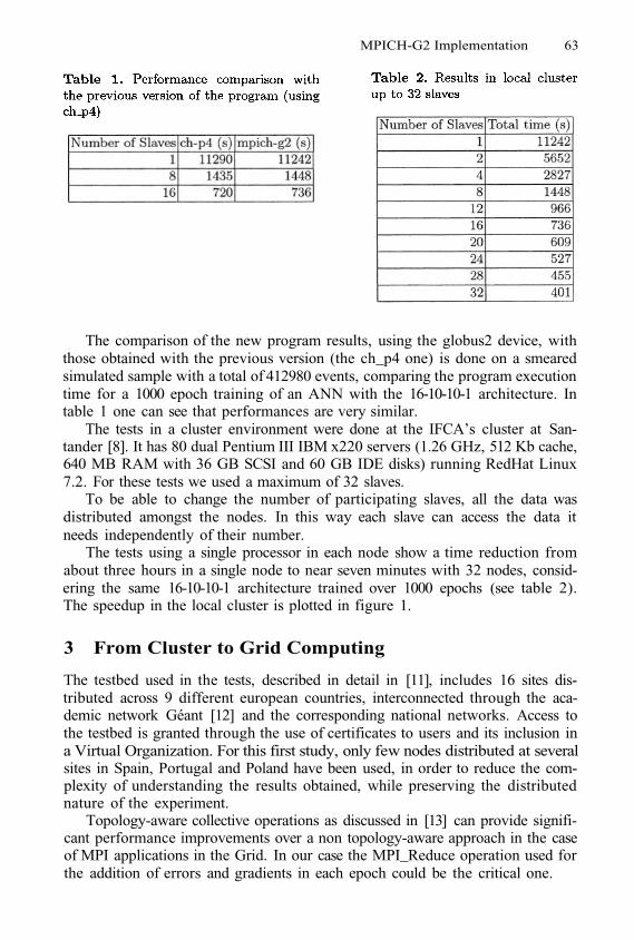
MPICH-G2 Implementation 63
The comparison of the new program results, using the globus2 device, withthose obtained with the previous version (the ch_p4 one) is done on a smearedsimulated sample with a total of 412980 events, comparing the program executiontime for a 1000 epoch training of an ANN with the 16-10-10-1 architecture. Intable 1 one can see that performances are very similar.
The tests in a cluster environment were done at the IFCA’s cluster at San-tander [8]. It has 80 dual Pentium III IBM x220 servers (1.26 GHz, 512 Kb cache,640 MB RAM with 36 GB SCSI and 60 GB IDE disks) running RedHat Linux7.2. For these tests we used a maximum of 32 slaves.
To be able to change the number of participating slaves, all the data wasdistributed amongst the nodes. In this way each slave can access the data itneeds independently of their number.
The tests using a single processor in each node show a time reduction fromabout three hours in a single node to near seven minutes with 32 nodes, consid-ering the same 16-10-10-1 architecture trained over 1000 epochs (see table 2).The speedup in the local cluster is plotted in figure 1.
3 From Cluster to Grid Computing
The testbed used in the tests, described in detail in [11], includes 16 sites dis-tributed across 9 different european countries, interconnected through the aca-demic network Géant [12] and the corresponding national networks. Access tothe testbed is granted through the use of certificates to users and its inclusion ina Virtual Organization. For this first study, only few nodes distributed at severalsites in Spain, Portugal and Poland have been used, in order to reduce the com-plexity of understanding the results obtained, while preserving the distributednature of the experiment.
Topology-aware collective operations as discussed in [13] can provide signifi-cant performance improvements over a non topology-aware approach in the caseof MPI applications in the Grid. In our case the MPI_Reduce operation used forthe addition of errors and gradients in each epoch could be the critical one.
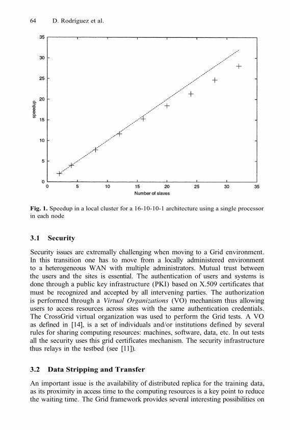
64 D. Rodríguez et al.
Fig. 1. Speedup in a local cluster for a 16-10-10-1 architecture using a single processorin each node
3.1 Security
Security issues are extremally challenging when moving to a Grid environment.In this transition one has to move from a locally administered environmentto a heterogeneous WAN with multiple administrators. Mutual trust betweenthe users and the sites is essential. The authentication of users and systems isdone through a public key infrastructure (PKI) based on X.509 certificates thatmust be recognized and accepted by all intervening parties. The authorizationis performed through a Virtual Organizations (VO) mechanism thus allowingusers to access resources across sites with the same authentication credentials.The CrossGrid virtual organization was used to perform the Grid tests. A VOas defined in [14], is a set of individuals and/or institutions defined by severalrules for sharing computing resources: machines, software, data, etc. In out testsall the security uses this grid certificates mechanism. The security infrastructurethus relays in the testbed (see [11]).
3.2 Data Stripping and Transfer
An important issue is the availability of distributed replica for the training data,as its proximity in access time to the computing resources is a key point to reducethe waiting time. The Grid framework provides several interesting possibilities on
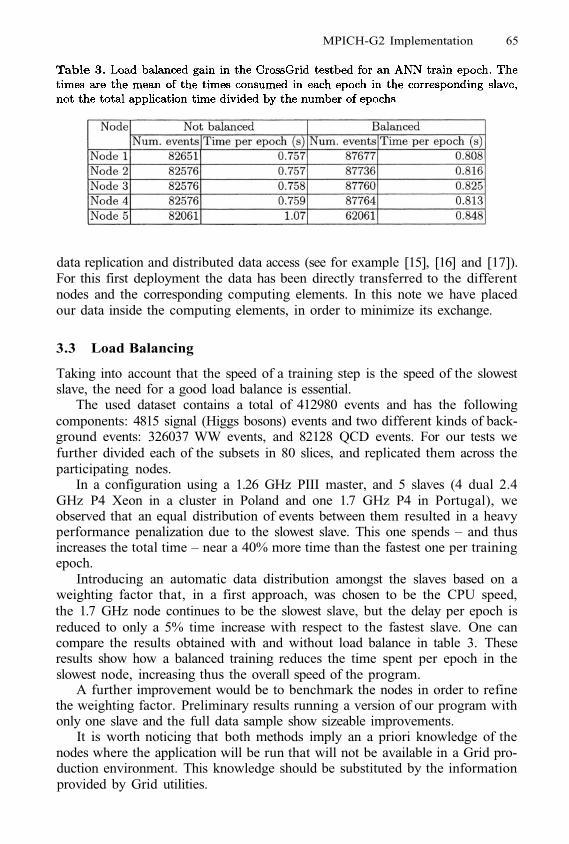
MPICH-G2 Implementation 65
data replication and distributed data access (see for example [15], [16] and [17]).For this first deployment the data has been directly transferred to the differentnodes and the corresponding computing elements. In this note we have placedour data inside the computing elements, in order to minimize its exchange.
3.3 Load Balancing
Taking into account that the speed of a training step is the speed of the slowestslave, the need for a good load balance is essential.
The used dataset contains a total of 412980 events and has the followingcomponents: 4815 signal (Higgs bosons) events and two different kinds of back-ground events: 326037 WW events, and 82128 QCD events. For our tests wefurther divided each of the subsets in 80 slices, and replicated them across theparticipating nodes.
In a configuration using a 1.26 GHz PIII master, and 5 slaves (4 dual 2.4GHz P4 Xeon in a cluster in Poland and one 1.7 GHz P4 in Portugal), weobserved that an equal distribution of events between them resulted in a heavyperformance penalization due to the slowest slave. This one spends – and thusincreases the total time – near a 40% more time than the fastest one per trainingepoch.
Introducing an automatic data distribution amongst the slaves based on aweighting factor that, in a first approach, was chosen to be the CPU speed,the 1.7 GHz node continues to be the slowest slave, but the delay per epoch isreduced to only a 5% time increase with respect to the fastest slave. One cancompare the results obtained with and without load balance in table 3. Theseresults show how a balanced training reduces the time spent per epoch in theslowest node, increasing thus the overall speed of the program.
A further improvement would be to benchmark the nodes in order to refinethe weighting factor. Preliminary results running a version of our program withonly one slave and the full data sample show sizeable improvements.
It is worth noticing that both methods imply an a priori knowledge of thenodes where the application will be run that will not be available in a Grid pro-duction environment. This knowledge should be substituted by the informationprovided by Grid utilities.
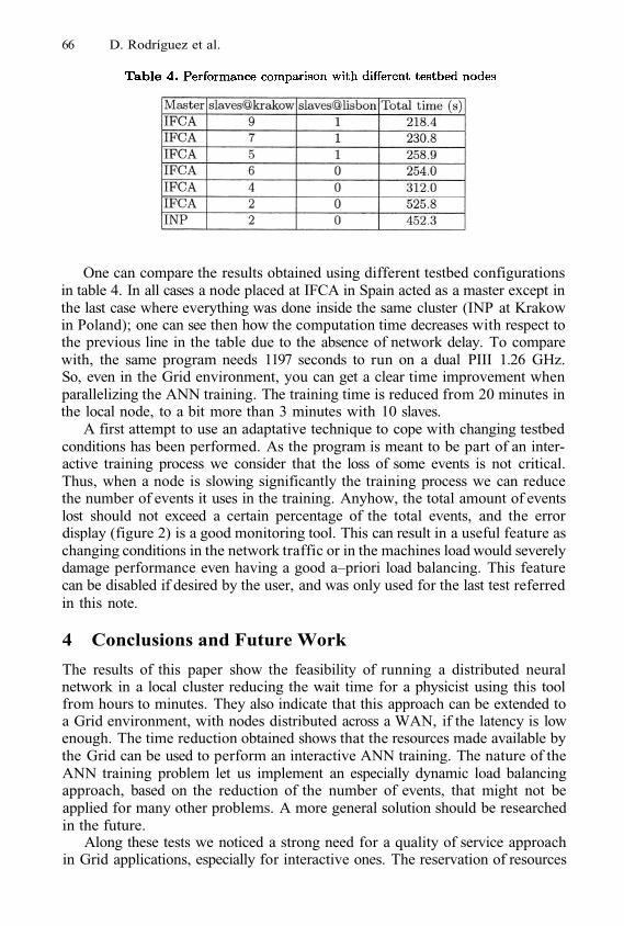
66 D. Rodríguez et al.
One can compare the results obtained using different testbed configurationsin table 4. In all cases a node placed at IFCA in Spain acted as a master except inthe last case where everything was done inside the same cluster (INP at Krakowin Poland); one can see then how the computation time decreases with respect tothe previous line in the table due to the absence of network delay. To comparewith, the same program needs 1197 seconds to run on a dual PIII 1.26 GHz.So, even in the Grid environment, you can get a clear time improvement whenparallelizing the ANN training. The training time is reduced from 20 minutes inthe local node, to a bit more than 3 minutes with 10 slaves.
A first attempt to use an adaptative technique to cope with changing testbedconditions has been performed. As the program is meant to be part of an inter-active training process we consider that the loss of some events is not critical.Thus, when a node is slowing significantly the training process we can reducethe number of events it uses in the training. Anyhow, the total amount of eventslost should not exceed a certain percentage of the total events, and the errordisplay (figure 2) is a good monitoring tool. This can result in a useful feature aschanging conditions in the network traffic or in the machines load would severelydamage performance even having a good a–priori load balancing. This featurecan be disabled if desired by the user, and was only used for the last test referredin this note.
4 Conclusions and Future Work
The results of this paper show the feasibility of running a distributed neuralnetwork in a local cluster reducing the wait time for a physicist using this toolfrom hours to minutes. They also indicate that this approach can be extended toa Grid environment, with nodes distributed across a WAN, if the latency is lowenough. The time reduction obtained shows that the resources made available bythe Grid can be used to perform an interactive ANN training. The nature of theANN training problem let us implement an especially dynamic load balancingapproach, based on the reduction of the number of events, that might not beapplied for many other problems. A more general solution should be researchedin the future.
Along these tests we noticed a strong need for a quality of service approachin Grid applications, especially for interactive ones. The reservation of resources
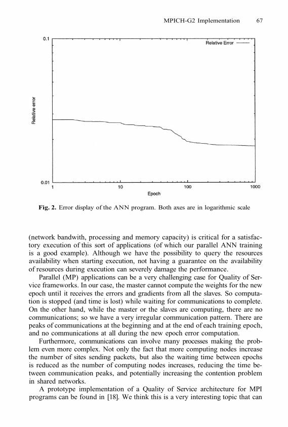
MPICH-G2 Implementation 67
Fig. 2. Error display of the ANN program. Both axes are in logarithmic scale
(network bandwith, processing and memory capacity) is critical for a satisfac-tory execution of this sort of applications (of which our parallel ANN trainingis a good example). Although we have the possibility to query the resourcesavailability when starting execution, not having a guarantee on the availabilityof resources during execution can severely damage the performance.
Parallel (MP) applications can be a very challenging case for Quality of Ser-vice frameworks. In our case, the master cannot compute the weights for the newepoch until it receives the errors and gradients from all the slaves. So computa-tion is stopped (and time is lost) while waiting for communications to complete.On the other hand, while the master or the slaves are computing, there are nocommunications; so we have a very irregular communication pattern. There arepeaks of communications at the beginning and at the end of each training epoch,and no communications at all during the new epoch error computation.
Furthermore, communications can involve many processes making the prob-lem even more complex. Not only the fact that more computing nodes increasethe number of sites sending packets, but also the waiting time between epochsis reduced as the number of computing nodes increases, reducing the time be-tween communication peaks, and potentially increasing the contention problemin shared networks.
A prototype implementation of a Quality of Service architecture for MPIprograms can be found in [18]. We think this is a very interesting topic that can
68 D. Rodríguez et al.
be critical for the success of interactive applications on the Grid. We are workingfor a Quality of Service for the network in the CrossGrid testbed.
Some further improvements that are being considered are:
Improving the event reduction mechanism.Usage of Grid information utilities.Integration in a portal.
Acknowledgements. This work has been mainly supported by the Europeanproject CrossGrid (IST-2001-32243). We would like to thank in particular allthe testbed sites for offering the possibility to run our tests.
References
I. Foster and C. Kesselman, editors. The Grid: Blueprint for a Future ComputingInfrastucture. Morgan Kaufmann Publishers, 1999.N. Karonis, B. Toonen, and I. Foster, MPICH-G2: A Grid-Enabled Implementationof the Message Passing Interface, Journal of Parallel and Distributed Computing(JPDC), to appear, 2003.MPICH. http://www-unix.mcs.anl.gov/mpi/mpichThe Globus Project, http://www.globus.orgDELPHI collaboration, http://delphiwww.cern.ch/O. Ponce et al. Training of Neural Networks: Interactive Possibilities in a Dis-tributed Framework. In D. Kranzlmüller et al. (Eds.) European PVM/MPI,Springer-Verlag, LNCS Vol. 2474, pp. 33-40, Linz, Austria, September 29-October2, 2002.Broyden, Fletcher, Goldfarb, Shanno (BFGS) method. For example in PracticalMethods of Optimization R.Fletcher. Wiley (1987)Santander Grid Wall, http://grid.ifca.unican.es/sgwCrossGrid European Project (IST-2001-32243). http://www.eu-crossgrid.orgManavendra Misra. Parallel Environments for Implementing Neural Networks.Neural Computing Survey, vol. 1., 48-60, 1997.J. Gomez et al. First Prototype of the CrossGrid Testbed. Presented at the 1stAcross Grids Conference. Santiago de Compostela Feb. 2003.Géant. http://www.dante.net/geant/N. Karonis et al. Exploiting hierarchy in parallel computer networks to optimizecollective operation performance. In Proceedings of the International Paralleland Distributed Processing Symposium, 2000.I. Foster,C. Kesselman, S. Tuecke. The Anatomy of the Grid: Enabling ScalableVirtual Organizations. International J. Supercomputer Applications, 15(3), 2001.H. Stockinger et al. File and Object Replication in Data Grids. Journal of ClusterComputing, 5(3)305-314,2002.A. Chervenak et al. Giggle: A Framework for Constructing Scalable Replica Loca-tion Services. In Proceedings of SC2002, Nov. 2002.OGSA-DAI. Open Grid Services Architecture Data Access and Integrationhttp://www.ogsadai.org.uk/A. Roy et al. MPICH-GQ: Quality-of-Service for Message Passing Programs. Pro-ceedings of SC2000. Dallas, Nov. 2000.
1.
2.
3.4.5.6.
7.
8.9.
10.
11.
12.13.
14.
15.
16.
17.
18.
OpenMolGRID, a GRID Based Systemfor Solving Large-Scale Drug Design Problems
Ferenc Darvas1, Ákos Papp1, István Bágyi1, Géza Ambrus2, and László Ürge1
1 ComGenex, Inc., Bem rkp. 33-34, H-1027 Budapest, Hungarywww.comgenex.hu
2 RecomGenex Ltd., Bem rkp. 33-34, H-1027 Budapest, Hungary
Abstract. Pharmaceutical companies are screening millions of molecules insilico. These processes require fast and accurate predictive QSAR models. Un-fortunately, nowadays these models do not include information-rich quantum-chemical descriptors, because of their time-consuming calculation procedure.Collection of experimental data is also difficult, because the sources are usuallylocated in disparate resources. These challenges make indispensable the usageof GRID systems. OpenMolGRID (Open Computing GRID for Molecular Sci-ence and Engineering) is one of the first realizations of the GRID technology indrug design. The system is designed to build QSAR models based on thousandsof different type of descriptors, and apply these models to find novel structureswith targeted properties. An implemented data warehouse technology makespossible to collect data from geographically distributed, heterogeneous re-sources. The system will be tested in real-life situations: Predictive models willbe built on in vitro human toxicity values determined for 30,000 novel and di-verse chemical structures.
1 Introduction
Molecular engineering can be applied for designing compounds with predefined targetproperties. The challenge for the industrial applications of molecular engineering is todevelop novel compounds that have not yet been discovered for the intended purposeand can be patented. This development is a multistep procedure starting with the de-sign of drug discovery compound libraries that are collecting the candidate structuresinto specific biological clusters. The so-called library design refers to this dynamicprocedure that also includes several steps from the discovery of the library core ideathrough the generation (enumeration) of compound structures to the evaluation in thepaper chemistry and medicinal chemistry/ADMETox points of view. The ADMETox(Absorption, Distribution, Metabolism, Excretion, and Toxicity) characterization ofcompounds has an extreme importance in library design, because almost 60% of drugcandidates surviving the traditional drug development process fail in the clinical trialsdue to inappropriate ADMETox properties [1], [2]. This characterization can be madeby calculation of physicochemical properties [3], [4], [5], [6], [7], [8], such as acid-ity/basicity [9], octanol-water partition coefficients (logP and logD values) [10],[11], hydrogen-bond donor and acceptor counts (HBDC and HBAC), CHI values[12], etc, and by prediction of metabolism and toxicity [13].
M. Dikaiakos (Ed.): AxGrids 2004, LNCS 3165, pp. 69–76, 2004.© Springer-Verlag Berlin Heidelberg 2004
70 F. Darvas et al.
The selection of the appropriate compounds to be synthesised is a complex deci-sion that has to be done in a relatively short time. For a single discovery library hun-dred thousands of structures are considered, and recently pharmaceutical companiesdeal with millions of candidate compound structures. To be able to deal with such alarge number of structures, the medicinal chemistry and the ADMETox evaluationrequire the implementation of in silico tools for the prediction of physicochemicalproperties applying fast predictive QSAR/QSPR (Quantitative Structure-Activity/Property Relationship) models. Unfortunately, at the moment fast models are usuallynot accurate enough, because they do not include information-rich quantum-chemicaldescriptors due to their time-consuming calculation procedure. An accurate modelregularly contains more than 100 descriptors, so altogether well over 1,000,000 datashould be calculated for each library. These challenges make indispensable the usageof large-scale molecular design techniques, especially high-performance QSAR calcu-lations.
Most companies involved in the drug design field participate in collaborative R&Dprojects consisting of multinational organizations sometimes from several continents.The communication and decision processes require the use of e-R&D tools. A com-mon task in library design procedure is to organize a meeting over the Internet withthe participation of highly specialized experts. In such a meeting, only a short discus-sion time (30-60 minutes) is available, and in many cases the next meeting can beorganized only 1-2 weeks later. The participants have to make high value decisions,which are based on the selection of structures according to their properties. The re-lated information has to be available at the time of the meeting for all experts ire-spectively of their location, and even if some structures are modified or added justduring the meeting.
The above considerations lead to the application of GRID systems. These “high-throughput” informatics systems provide the facility to develop fast and accuratepredictive QSAR models on a huge number of model compounds in a short time andapply this novel method on an unprecedently high number of molecules.
2 Overview
OpenMolGRID [14] (Open Computing GRID for Molecular Science and Engineer-ing) is going to be one of the first realizations of the GRID technology in drug design.
The system is developed in an international project (Estonia, Northern Ireland,Germany, Italy, and Hungary) partly funded by the European Commission under the5th Framework Project (IST-2001-37238).
The project goals are as follows:
Smooth integration of resourcesLarge-scale molecular calculationsReal life testingOn-site toxicity prediction for large librariesIdentification of potential anticancer drug candidatesThe OpenMolGRID system is designed to create QSPR/QSAR models and use
them to predict biological activities or ADME related properties. Most of the moderndata mining techniques (MLR, PCA, PLS, ANN, etc) and thousands of different typeof descriptors are available for model building purposes. Many of the descriptors
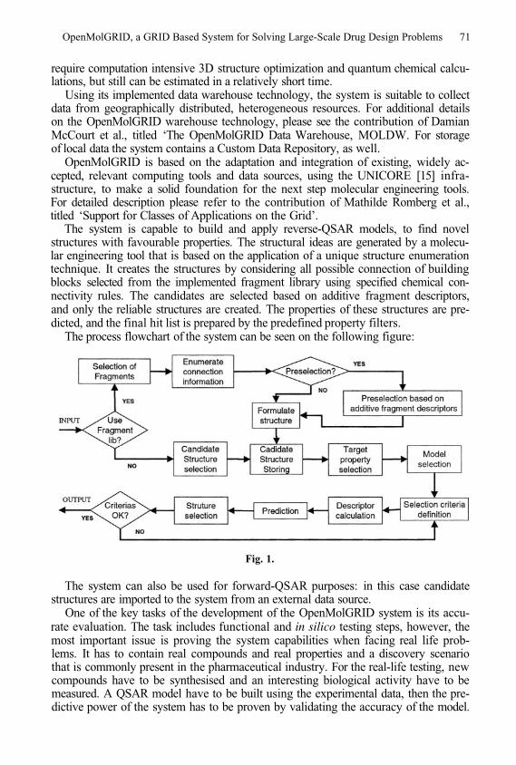
OpenMolGRID, a GRID Based System for Solving Large-Scale Drug Design Problems 71
require computation intensive 3D structure optimization and quantum chemical calcu-lations, but still can be estimated in a relatively short time.
Using its implemented data warehouse technology, the system is suitable to collectdata from geographically distributed, heterogeneous resources. For additional detailson the OpenMolGRID warehouse technology, please see the contribution of DamianMcCourt et al., titled ‘The OpenMolGRID Data Warehouse, MOLDW. For storageof local data the system contains a Custom Data Repository, as well.
OpenMolGRID is based on the adaptation and integration of existing, widely ac-cepted, relevant computing tools and data sources, using the UNICORE [15] infra-structure, to make a solid foundation for the next step molecular engineering tools.For detailed description please refer to the contribution of Mathilde Romberg et al.,titled ‘Support for Classes of Applications on the Grid’.
The system is capable to build and apply reverse-QSAR models, to find novelstructures with favourable properties. The structural ideas are generated by a molecu-lar engineering tool that is based on the application of a unique structure enumerationtechnique. It creates the structures by considering all possible connection of buildingblocks selected from the implemented fragment library using specified chemical con-nectivity rules. The candidates are selected based on additive fragment descriptors,and only the reliable structures are created. The properties of these structures are pre-dicted, and the final hit list is prepared by the predefined property filters.
The process flowchart of the system can be seen on the following figure:
Fig. 1.
The system can also be used for forward-QSAR purposes: in this case candidatestructures are imported to the system from an external data source.
One of the key tasks of the development of the OpenMolGRID system is its accu-rate evaluation. The task includes functional and in silico testing steps, however, themost important issue is proving the system capabilities when facing real life prob-lems. It has to contain real compounds and real properties and a discovery scenariothat is commonly present in the pharmaceutical industry. For the real-life testing, newcompounds have to be synthesised and an interesting biological activity have to bemeasured. A QSAR model have to be built using the experimental data, then the pre-dictive power of the system has to be proven by validating the accuracy of the model.
72 F. Darvas et al.
Finally, the most important function of the system has to be proved, the generation ofstructures with predefined properties.
In the real-life testing of OpenMolGRID the number of tested compounds is ad-justed to a typical discovery problem and a biological property with general impor-tance is selected. At ComGenex sometimes the fate of more than 100,000 compoundsshould be decided during a short meeting or net meeting that involves a number ofhighly specialized experts, sometimes from several continents. The predicted parame-ters requested for the decision are preliminary calculated, and available at the time ofthe meeting. However, in case of any modification in the building block lists, thecorresponding new structures have to be enumerated, and the necessary drug designcalculations cannot be finished during the meeting without the help of a GRID sys-tem. Presently, the cluster of more than 40 computers operating at ComGenex needsan overnight calculation time to finish the minimum necessary calculations for anaverage series of 50,000 compounds. The highly specialized discovery experts are notavailable on daily basis and the creative process that is needed to invent the new drugcandidates is effectively broken by the fact that the next meeting cannot be organizedearlier than one or more weeks.
Since the innovative creation of new molecules is an iterative procedure composedof several man/machine/man cycles, the present long response time from the com-puters effectively impedes to utilize a number of design software for large compoundssets. The practical compromise today in the industry is to use the computers forevaluation of large compound sets via batch operations, very similar to the way ascomputers were utilized twenty years ago.
Based on the above considerations, the real-life test set was decided to containcompound collection of 30,000 novel and diverse structures having experimentalhuman fibroblast toxicity data. Since activity values were not available for such alarge number of compounds in this property type, the compound libraries have beendesigned, the molecules have been synthesized, and values for in vitro humanfibroblast cytotoxicity are being determined. The real-life testing require a novel anddiverse compound set to avoid congeneric structures (including redundant informa-tion), and to cover a wide range of the chemical space. On the other hand, to prove thepredictive power of the system a critical mass for the test set is needed, which fulfilsthe diversity density criteria, i.e. a sufficient representation of the chemical clusters.Therefore the size of the test set was set to 10,000 compounds and – for proving thepredictive power of the model in extreme situations – one complete cluster independ-ent from the training set was included in it. The fact, that the size of the training sethas to be at least double of the test set for model building purposes, also underlinedthat minimum 30,000 compounds have to be included in the real-life testing. Thelibrary design procedure is detailed in Section 4.
Using the experimental data, linear and non-linear QSAR models are being devel-oped and the predictive capability of these models is going to be validated. The bestmodel will be used to generate compounds with lowest and highest cytotoxicity,which provides the possibility to identify leads for potential anticancer agents.
3 Conclusions and Future DirectionsThe system will analyze millions of structures in a considerable time using the ob-tained QSAR/QSPR equations with traditional and grid based computation proce-
OpenMolGRID, a GRID Based System for Solving Large-Scale Drug Design Problems 73
dures, and select the most promising hits from this huge virtual chemical domain.OpenMolGRID enables highly specialized experts from several continents to makeimmediate decisions in the library design phase during a net meeting.
A further development possibility is to extend the knowledge managing tools andfacilities, incorporating large discovery related knowledge management systems, likeEmil (Example-Mediated Innovation for Lead Evolution [16]).
4 Methods
4.1 Library Design Procedure
The design started with the selection of structures based on Lipinski filtering followedby a diverse selection procedure (using the Optisim diverse selection method imple-mented in the Sybyl software [17]). The normal distribution of predicted ADMEproperties was validated, and a heterogeneous target library size (300-3,000) was set.The resulted 19 synthetic libraries have novel, drug-like and diverse Markush (core)structures. The libraries were synthesized using well-defined building block pools inmultiple synthesis steps, and they represent a wide variety of chemistry. All of the30,000 compounds have high purity (>85%). The structure collection, therefore, issuitable for in vitro experiments and finally for model building purposes.
4.2 Determination of in vitro Human Fibroblast Cytotoxicity
The cytotoxicity of the compounds is expressed as values, the concentration ofthe compound that kills half of the cells within a specific time (in our case in oneday). The particular compound is added to the cell samples in 4 different concentra-tions, in duplicates. The samples are incubated for 24 hours, and then alamarBlue™ isadded in the concentration specified by the manufacturer. Subsequently, the samplesare incubated for additional 4 hours prior to fluorimetric detection. Percentage celldeath is determined for each sample, and the value is calculated using an auto-matic algorithm.
5 Case Studies for Earlier Solutions
Under the frame of a multiyear project at ComGenex 5 to 10,000 compounds had tobe synthesized per month. For this purposes every month 11 new combinatorial librar-ies in average had to be developed. The key step of the design procedure is the selec-tion of the building blocks with favourable ADME properties. There are altogether 14predicted properties taken into account, which are divided into 4 groups, as follows:
1st group: logP, logD
2nd group: metabolites, first pass effect, toxicity3rd group: MW, rotatable bonds, HBDC (Hydrogen Bond Donor Count), HBAC(Hydrogen Bond Acceptor Count), HBD groups, HBA groups4th group: solubility, CHI index
74 F. Darvas et al.
In the present case study 70,000 compounds were generated for selection of 7,000to 15,000 synthesis candidates (taking into account that the effectivity of the synthesisis ca 70%).
Actually, the building block selection is a multistep procedure, where the dragga-bility and the ADME properties have to be considered besides many other aspects(like synthesizability, potential activity, diversity, etc.). The final selection step re-quires involving experts from the different partners participating in the development.Biweekly internet-based discussion sessions are organized for this purpose, normallyscheduled for 40 Minutes. In case of any changes in the building block lists, the corre-sponding new structures have to be generated, and their properties have to be calcu-lated to be able to make the decision. If the results are not ready during the meeting, itpostpones the decision, and consequently the start of the production with at least 2weeks. There have been much effort done to develop solutions that are quick enoughto respond to this challenge; now we outline 2 of them:
5.1 Parallel Solution, 1999–2001
We used 4 high-speed computers, and each group of properties was calculated in aseparate computer. The rate limiting calculation is metabolism prediction, because inaverage 10 metabolites/parent compound is generated, so in the present case approxi-mately 700,000 metabolites were generated.
The time needed for the calculation was 4 days.
5.2 Cluster Solution, 2001–2003
In the ComGenex PC cluster we used 40 computers, and the Enterprise calculator, aninhouse software for distributed calculations. The cluster was scheduled to automaticcalculation working only at nights.
The capacity of the system is 50,000 compounds/night, so the time needed for thecalculation was 2 nights.
5.3 Conclusions of Case Studies
Before the decision making Web meeting a preliminary calculation were made on theCGX cluster. 7 experts attended the decision session from Europe and US WestCoast. They selected the appropriate building blocks, but the final collection were notenough to realize the targeted number compounds, therefore they suggested additionalbuilding blocks. Using the new building blocks a new set of structures had to be gen-erated (enumerated). 1 additional night was needed for the property prediction. As aconsequence, the meeting had to be postponed to the following week due to the lackof ADME properties.
6 Summary
The system will analyze millions of structures in a considerable time using the ob-tained QSAR/QSPR equations with traditional and grid based computation proce-
OpenMolGRID, a GRID Based System for Solving Large-Scale Drug Design Problems 75
dures, and select the most promising hits from this huge virtual chemical domain.OpenMolGRID enables highly specialized experts from several continents to makeimmediate decisions in the library design phase during a net meeting.
A further development possibility is to extend the knowledge managing tools andfacilities, incorporating large discovery related knowledge management systems, likeEmil (Example-Mediated Innovation for Lead Evolution [16]).
Acknowledgements
The development of OpenMolGRID is partially supported by the European Commis-sion under the Framework Project (IST-2001-37238).
Thanks for colleagues from the following partners involved in the project:
University of Tartu, Tartu, EstoniaUniversity of Ulster, Ulster, Northern IrelandMario Negri Institute, Milano, ItalyForschungszentrum Jülich, Jülich, Germany
References
Darvas, F.; Papp. Á.; Dormán, G.; Ürge, L.; Krajcsi, P. In Silico and ExSilico ADME Approaches for Drug Discovery, Curr. Top. in Med. Chem. 2 (2002) 1269-1277Lipinski, C. A. Drug-like properties and the causes of poor solubility and poor permeability.J Pharmacol. Toxicol. Methods. 44(1) (2000) 235-49Kramer, S. D. Absorption prediction from physicochemical parameters. Pharm. Sci. Tech-nol. Today 2 (1999) 373-380Matter, H.; Baringhaus, K.-H.; Naumann, T.; Klaubunde, T.; Pirard B. Computational Ap-proaches towards the Rational Design of Drug-like Compound Libraries. Comb. Chem &HTS 4 (2001) 453-475Ghose, A. K.; Vishwanadhan, V. N.; Wendoloshki, J. J. A Knowledge-Based Approach inDesigning Combinatorial or Medicinal Chemistry Libraries for Drug Discovery. 1. A Quali-tative and Quantitative Characterization of Known Drug Databases. J. Comb. Chem. 1(1999) 55-68van de Waterbeemd, H.; Kansy, M. Hydrogen-Bonding Capacity and Brain Penetration,Chimia 46 (1992) 299-303Palm, K.; Luthmann, K.; Ungell, A. L.; Strandlund, G.; Artursson, P. Correlation of DrugAbsorption with Molecular Surface Properties. J. Pharm. Sci. 85 (1996) 32-39Clark, D. E. Prediction of Intestinal Absorption and Blood-Brain Barrier Penetration byComputational Methods. Comb. Chem. & HT. Scr. 4 (2001) 477-496Csizmadia, F.; Szegezdi, J.; Darvas, F. Expert system approaches for predicting pKa.Trends in QSAR and Molecular Modeling 92, Escom, Leiden (1993) pp. 507-510Martin, Y. C.; Duban, M. E.; Bures, M. G.; DeLazzer, J. Virtual Screening of MolecularProperties: A Comparison of LogP Calculators. In Pharmacokinetic Optimization in DrugResearch, Official publication of the logP2000 Symposium, VHCA – VCH, Zürich (2000),pp 485Csizmadia, F.; Tsantili-Kakoulidou, A.; Panderi, I.; Darvas, F, Prediction of DistributionCoefficient from Structure 1. Estimation Method. J. Pharm. Sci., 1997, 86(7), 865-871
1.
2.
3.
4.
5.
6.
7.
8.
9.
10.
11.

76 F. Darvas et al.
Valko, K.; Bevan C.; Reynolds. Chromatographic Hydrophobicity Index by Fast-GradientRP-HPLC: A High-Throughput Alternative to logP/logD. Anal. Chem. 69 (1997) 2022-2029Darvas, F.; Marokházy, S.; Kormos, P.; Kulkarni, G.; Kalász, H.; Papp, Á. MetabolExpert:Its Use in Metabolism Research and in Combinatorial Chemistry. In: Drug Metabolism: Da-tabases and High-Throughput Screening Testing During Drug Design and Development,(Ed. Erhardt PW), Backwell Publisher (1999) pp. 237-270The project homepage can be found at www.openmolgrid.orgDetails can be found at www.unicore.orgFujita T., Concept and Features of EMIL, a System for Lead Evolution of Bioactive Com-pounds, in “Trends in QSAR and Molecular Modelling 92” (Ed. C. G. Wermuth) Escom,Leiden (1993) pp.143-159Sybyl software is a trademark of Tripos, Inc.
12.
13.
14.15.16.
17.
Integration of Blood Flow Visualizationon the Grid: The FlowFish/GVK Approach*
Alfredo Tirado-Ramos1, Hans Ragas1, Denis Shamonin1,Herbert Rosmanith2, and Dieter Kranzmueller2
1 Faculty of Sciences, Section Computational ScienceUniversity of Amsterdam
Kruislaan 403, 1098 SJ Amsterdam, The Netherlands{alf redo, jmragas, dshamoni}@science. uva.nl
2 GUP, Joh. Kepler University LinzAltenbergerstr. 69, A-4040 Linz, Austria/Europe
{rosmanith,kranzlmueller}@gup.jku.at
Abstract. We have developed the FlowFish package for blood flow visu-alization of vascular disorder simulations, such as aneurysms and steno-sis. We use a Lattice-Boltzmann solver for flow process simulation totest the efficiency of the visualization classes, and experiment with thecombination of grid applications and corresponding visualization clientson the European Crossgrid testbed, to assess grid accessability and vi-sualization data transfer performance.
Keywords: computational grids, blood flow visualization, grid-basedvisualization, blood flow simulation, problem solving environment, gridportal
1 Introduction
Experience shows that even during simple simulations of real life problems in anenvironment of reduced complexity, large amounts of computed data must beanalysed. Nevertheless, numerical or analytical analysis is not always possible.Computers can help to handle these large amounts of data by using automaticfeature extraction, but it is often hard to define exact parameters, and it isdifficult to describe an algorithm which extracts useful information from classi-fications of any kind [1]. A good example is offered by Trotts et al, who haveshown a hybrid form of critical point classification and visualization applied tothe investigation of flowfields [2].
This extended abstract briefly describes our FlowFish/Grid VisualizationKernel (GVK) approach to blood flow visualization, and then focuses on theinitial integration of this work in a PSE running on a computational Grid. GVKis a middleware developed at GUP Linz within the European CrossGrid project[3], which aims to enable the use of visualization services within computational
* This research is partly funded by the European Commission IST-2001-32243 ProjectCrossGrid.
M. Dikaiakos (Ed.): AxGrids 2004, LNCS 3165, pp. 77–79, 2004.© Springer-Verlag Berlin Heidelberg 2004
78 A. Tirado-Ramos et al.
grids [4]. Furthermore, we have extended the FlowFish/GVK functionality byintegrating it with a Grid portal provided by the CrossGrid project. We havefound during our initial integration efforts that integration of our testbed andvisualization libraries are not a trivial task, but the added functionality and se-curity infrastructure offered by grid technologies come at a minimal performancepayoff. For further information beyond the scope of this abstract, please contactthe authors.
2 FlowFish and the Grid Visualization Kernel
The FlowFish libraries for Flow visualization are developed as part of the simu-lated Virtual Radiology Explorer PSE project of the University of Amsterdam.The aim of this project is to provide a surgeon with an intuitive environmentto visualize and explore a patient’s vascular condition prior to intervention. Byplacing her in an interactive virtual simulation environment, a surgeon or radi-ologist can examine the patient’s bloodflow in a non-invasive mode. FlowFishenables the employment of investigation methods which cannot be used in theoriginal environment of the flow. To test a hypothesis, different surgical proce-dures can be applied while surgeons can monitor direction, speed and pressureof the bloodflow through the human vascular system.
Furthermore, the Grid Visualization Kernel (GVK) [5], a grid aware appli-cation built on top of the FlowFish libraries, addresses the combination of gridapplications and corresponding visualization clients on the grid. While grids of-fer a means to process large amounts of data across different, possily distantresources, visualization aids in understanding the meaning of data. For this rea-son, the visualization capabilities of GVK are implemented using Globus [6]services, thereby providing flexible grid visualization services via dedicated in-terfaces and protocols while at the same time exploiting the performance of thegrid for visualization purposes.
3 Integration with the CrossGrid ComputationalGrid Portal
We have experimented with extending our work on medical data simulation andvisualization to the Grid via the Migrating Desktop (MD) [7] grid portal. MD isan application that offers a seamless Grid portal which is independent of softwareand hardware environments, on which applications and resources may be highlydistributed. It allows users to handle Grid and local resources, run applications,manage data files, and store personal settings. The MD provides a front-endframework for embedding some of the application mechanisms and interfaces,and allows the user virtual access to Grid resources from other computationalnodes.
4 Results and Discussion
In order to integrate our visualization libraries to the computational grid testbed,we dynamically linked application XML schema for job submission to the MD
Integration of Blood Flow Visualization on the Grid 79
grid portal. We created links within the MD to initialization of both the GVKclient and server startup applications, and experimented with rendering the flowboth remotely and locally in the access storage element. This way, GVK remotevisualization and local rendering are fully linked via the MD. We integrated ourlocal desktop visualization and mesh creation application with GVK, configuringVTK and other relevant libraries, and registered Amsterdam and Leiden sitesfor testing secure grid data transfer. We experimented with the transfer of a fewsegmented medical datasets, ranging from 24252 Byte to 5555613 Byte loads.When comparing the transfer times of the data, at time steps of 20 seconds, wefound that average transfer times to both Linux and Windows roaming storageelements running nodes, once taking into account the Globus caching mechanism,did not vary much above 200 milliseconds for the smaller size files and no morethan 350 miliseconds for the larger size files. We considered these initial figuresencouraging, though we plan more extensive testing with streaming flow data.
For our next integration steps, we will work on full integration with CrossGridreplication services, as well as experiment with the advanced MPI support andmonitoring functionalities that will allow us to fine-tune, monitor on the fly, andpredict better performance results for our solver, on-line.
Acknowledgments. We would like to thank Peter Sloot, Abdel Artoli, JensVolkert, Paul Heinzlreiter, Alfons Hoekstra, Elena Zudilova, Marcin Plociennik,and Pawel Wolniewicz for their meaningful contributions to this work.
References
A. Schoneveld. Parallel Complex Systems Simulation. PhD thesis, University ofAmsterdam, Amsterdam, The Netherlands, 1999. Promotor: Prof. Dr. P.M.A.Sloot.I. Trotts, D. Kenwright, and R. Haimes. Critical points at infinity: a missing linkin vector field topology.CrossGrid - Development of Grid Environment for interactive Applications, EUProject, IST-2001-32243, http://www.eu-crossgrid.orgI. Foster, C. Kesselman, S. Tuecke. The Anatomy of the Grid: Enabling ScalableVirtual Organizations International J. Supercomputer Applications, 15(3), 2001.Sloot P.M.A., van Albada G.D., Zudilova E.V., Heinzlreiter P., Kranzlmüller D.,Rosmanith H., Volkert J. Grid-based Interactive Visualisation of Medical ImagesS. Norager, editor, Proceedings of the First European HealthGrid Conference, Jan-uary 2003, pp. 57 - 66. Commissi on of the European Communities, InformationSociety Directorate-General, Brussels, Belgium.I. Foster, C. Kesselman. Globus: A Metacomputing Infrastructure Toolkit Intl J.Supercomputer Applications, 11(2):115-128, 1997.http://ras.man.poznan.pl/crossgrid/
1.
2.
3.
4.
5.
6.
7.
A Migration Frameworkfor Executing Parallel Programs in the Grid*
József Kovács and Péter Kacsuk
MTA SZTAKI, Parallel and Distributed Systems Laboratory,1518 Budapest, P.O. Box 63, Hungary{smith,kacsuk}@sztaki.hu
Abstract. The paper describes a parallel program checkpointing mechanism andits potential application in Grid systems in order to migrate applications amongGrid sites. The checkpointing mechanism can automatically (without user inter-action) support generic PVM programs created by the PGRADE Grid program-ming environment. The developed checkpointing mechanism is general enoughto be used by any Grid job manager but the current implementation is connectedto Condor. As a result, the integrated Condor/PGRADE system can guarantee theexecution of any PVM program in the Grid. Notice that the Condor system canonly guarantee the execution of sequential jobs. Integration of the Grid migrationframework and the Mercury Grid monitor results in an observable Grid execu-tion environment where the performance monitoring and visualization of PVMapplications are supported even when the PVM application migrates in the Grid.
1 Introduction
An important aspect of executing a parallel program in the Grid [5] is job migration.The Grid is an inherently dynamic and error prone execution environment. The optimalselection of a Grid resource for a particular job does not mean that the selected re-source remains optimal for the whole execution of the job. The selected resource couldbe overloaded by newly submitted higher priority jobs or even worse, it can go downpartially or completely due to some hardware or software errors. These are situationsthat should be solved by the Grid middleware transparently to the user. Process migra-tion in distributed systems is a special event when a process running on a resource isredeployed on another one in a way that the migration does not cause any change inthe process execution. It means the process is not restarted; its execution is temporar-ily suspended and later resumed on a new resource. In order to provide this capabilityspecial techniques are necessary to save the total memory image of the target processand to reconstruct it. This technique is called checkpointing. During checkpointing atool suspends the execution of the process, collects all those internal status informationnecessary for resumption and terminates the process. Later it creates a new process andall the collected information is restored for the process to continue its execution withoutany modification.
* The work presented in this paper has been supported by the Hungarian Chemistrygrid OMFB-00580/2003 project, the Hungarian Supergrid OMFB-00728/2002 project, the Hungarian IHM4671/1/2003 project and the Hungarian Research Fund No. T042459.
M. Dikaiakos (Ed.): AxGrids 2004, LNCS 3165, pp. 80–89, 2004.© Springer-Verlag Berlin Heidelberg 2004
A Migration Framework for Executing Parallel Programs in the Grid 81
Migration mechanism can be advantageously used in several scenarios. First, in su-percomputing applications load-balancing is a crucial issue. Migration can solve theproblem of unbalanced parallel sites of the Grid. Processes on overloaded machinescan be migrated to underloaded machines without terminating the entire application.Similarly, load-balancing can be ensured among different sites of the Grid, i.e., when asite becomes overloaded complete applications can migrate to other sites. The secondsituation is related to high-throughput computing where free cycles of underloaded ma-chines are collected. In such a scenario the owner of the Grid site has got always priorityover the guest applications and hence all the guest applications should be removed fromthe site when the owner increases the usage of the site. Third, the migration module canbe used for the sake of providing fault-tolerance capability. During the execution of along-running application, one machine may be corrupted or needs system maintenance.Fourth, migration can be driven by resource needs, i.e. processes can be moved in orderto access special unmovable or local resources. For example, processes may need theusage of special equipments or huge databases existing on a dedicated machine of theGrid.
A migration tool typically consists of a checkpoint server, checkpoint informationstore and a checkpoint library. To provide fault-tolerance, application-wide checkpointsaving is performed, i.e., checkpoint information are stored into files for roll-back ifnecessary. These files are maintained by a checkpoint server and written/read by thecheckpoint library attached to the process to be migrated. There are several exist-ing libraries performing sequential program checkpointing like esky [4] libckpt [11]condor [9] or the one integrated in our system, Zandy’s ckpt library [14]. To startcheckpointing the checkpoint libraries should be notified and checkpointed/resumedprocesses need to be managed. In our proposed solution it is done by a migration co-ordination module built into the application. It checkpoints, terminates and restarts pro-cesses belonging to the application. Since this co-ordination module is responsible forkeeping the application alive at all time by reconstructing terminated processes usingavailable nodes of the cluster, this structure provides a fault-tolerant application thatadopts itself to the dynamically changing execution environment.
Beyond the execution of a parallel program another important aspect of a Grid end-user - among others - is the creation of a Grid program. Unfortunately, there are nowidely accepted graphical tools for high-level development to create parallel applica-tions. This is exactly the aim of the PGRADE (Parallel Grid Run-time and ApplicationDevelopment Environment) Grid programming environment that has been developedby MTA SZTAKI. PGRADE currently generates either PVM or MPI code from thesame graphical notation according to the users’ needs. It may also support any kindof middleware layer which is going to be released in the future, like the GAT (GridApplication Toolkit) that is under design in the EU Gridlab project.
In order to prove the concept presented in this paper it has been integrated withPGRADE. Recently, the solution has been presented in a live demonstration on theEuroPar 2003 conference.
2 Structure of the Parallel ApplicationIn order to understand the realisation of the checkpoint and migration mechanism [7],a short summary of the execution mechanism (shown in Fig. 1) is required. PGRADE
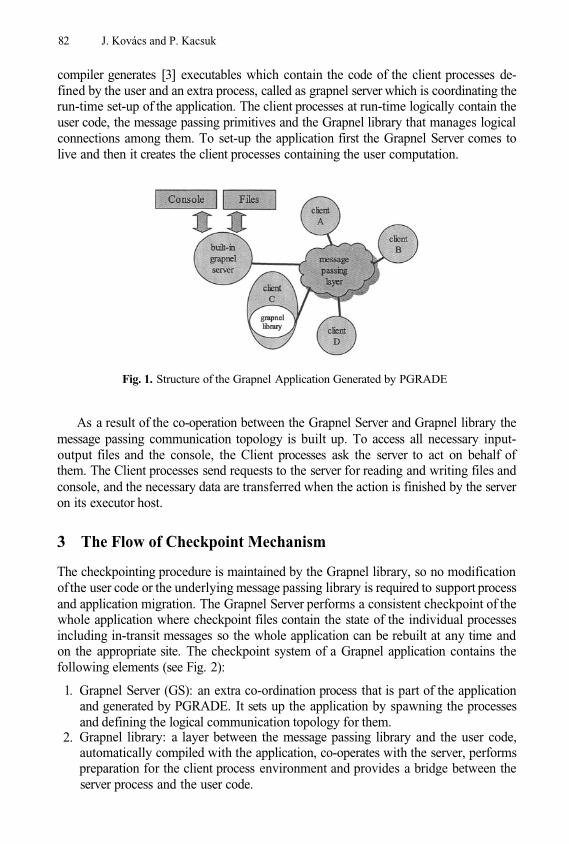
82 J. Kovács and P. Kacsuk
compiler generates [3] executables which contain the code of the client processes de-fined by the user and an extra process, called as grapnel server which is coordinating therun-time set-up of the application. The client processes at run-time logically contain theuser code, the message passing primitives and the Grapnel library that manages logicalconnections among them. To set-up the application first the Grapnel Server comes tolive and then it creates the client processes containing the user computation.
Fig. 1. Structure of the Grapnel Application Generated by PGRADE
As a result of the co-operation between the Grapnel Server and Grapnel library themessage passing communication topology is built up. To access all necessary input-output files and the console, the Client processes ask the server to act on behalf ofthem. The Client processes send requests to the server for reading and writing files andconsole, and the necessary data are transferred when the action is finished by the serveron its executor host.
3 The Flow of Checkpoint Mechanism
The checkpointing procedure is maintained by the Grapnel library, so no modificationof the user code or the underlying message passing library is required to support processand application migration. The Grapnel Server performs a consistent checkpoint of thewhole application where checkpoint files contain the state of the individual processesincluding in-transit messages so the whole application can be rebuilt at any time andon the appropriate site. The checkpoint system of a Grapnel application contains thefollowing elements (see Fig. 2):
Grapnel Server (GS): an extra co-ordination process that is part of the applicationand generated by PGRADE. It sets up the application by spawning the processesand defining the logical communication topology for them.Grapnel library: a layer between the message passing library and the user code,automatically compiled with the application, co-operates with the server, performspreparation for the client process environment and provides a bridge between theserver process and the user code.
1.
2.
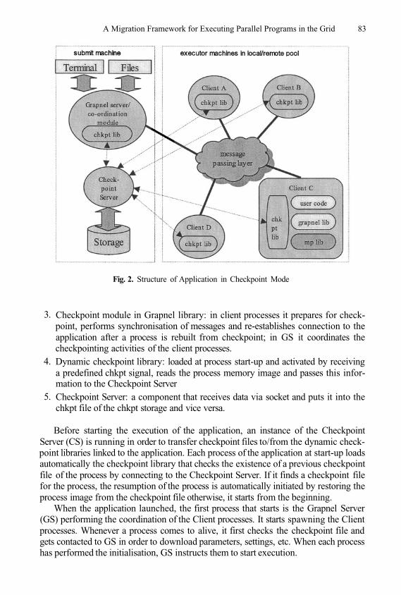
A Migration Framework for Executing Parallel Programs in the Grid 83
Fig. 2. Structure of Application in Checkpoint Mode
Checkpoint module in Grapnel library: in client processes it prepares for check-point, performs synchronisation of messages and re-establishes connection to theapplication after a process is rebuilt from checkpoint; in GS it coordinates thecheckpointing activities of the client processes.Dynamic checkpoint library: loaded at process start-up and activated by receivinga predefined chkpt signal, reads the process memory image and passes this infor-mation to the Checkpoint ServerCheckpoint Server: a component that receives data via socket and puts it into thechkpt file of the chkpt storage and vice versa.
3.
4.
5.
Before starting the execution of the application, an instance of the CheckpointServer (CS) is running in order to transfer checkpoint files to/from the dynamic check-point libraries linked to the application. Each process of the application at start-up loadsautomatically the checkpoint library that checks the existence of a previous checkpointfile of the process by connecting to the Checkpoint Server. If it finds a checkpoint filefor the process, the resumption of the process is automatically initiated by restoring theprocess image from the checkpoint file otherwise, it starts from the beginning.
When the application launched, the first process that starts is the Grapnel Server(GS) performing the coordination of the Client processes. It starts spawning the Clientprocesses. Whenever a process comes to alive, it first checks the checkpoint file andgets contacted to GS in order to download parameters, settings, etc. When each processhas performed the initialisation, GS instructs them to start execution.
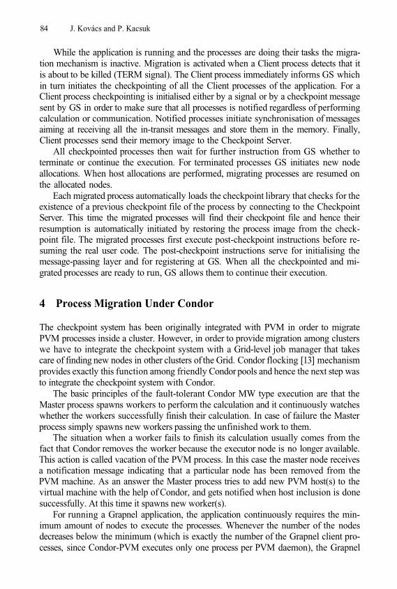
84 J. Kovács and P. Kacsuk
While the application is running and the processes are doing their tasks the migra-tion mechanism is inactive. Migration is activated when a Client process detects that itis about to be killed (TERM signal). The Client process immediately informs GS whichin turn initiates the checkpointing of all the Client processes of the application. For aClient process checkpointing is initialised either by a signal or by a checkpoint messagesent by GS in order to make sure that all processes is notified regardless of performingcalculation or communication. Notified processes initiate synchronisation of messagesaiming at receiving all the in-transit messages and store them in the memory. Finally,Client processes send their memory image to the Checkpoint Server.
All checkpointed processes then wait for further instruction from GS whether toterminate or continue the execution. For terminated processes GS initiates new nodeallocations. When host allocations are performed, migrating processes are resumed onthe allocated nodes.
Each migrated process automatically loads the checkpoint library that checks for theexistence of a previous checkpoint file of the process by connecting to the CheckpointServer. This time the migrated processes will find their checkpoint file and hence theirresumption is automatically initiated by restoring the process image from the check-point file. The migrated processes first execute post-checkpoint instructions before re-suming the real user code. The post-checkpoint instructions serve for initialising themessage-passing layer and for registering at GS. When all the checkpointed and mi-grated processes are ready to run, GS allows them to continue their execution.
4 Process Migration Under Condor
The checkpoint system has been originally integrated with PVM in order to migratePVM processes inside a cluster. However, in order to provide migration among clusterswe have to integrate the checkpoint system with a Grid-level job manager that takescare of finding new nodes in other clusters of the Grid. Condor flocking [13] mechanismprovides exactly this function among friendly Condor pools and hence the next step wasto integrate the checkpoint system with Condor.
The basic principles of the fault-tolerant Condor MW type execution are that theMaster process spawns workers to perform the calculation and it continuously watcheswhether the workers successfully finish their calculation. In case of failure the Masterprocess simply spawns new workers passing the unfinished work to them.
The situation when a worker fails to finish its calculation usually comes from thefact that Condor removes the worker because the executor node is no longer available.This action is called vacation of the PVM process. In this case the master node receivesa notification message indicating that a particular node has been removed from thePVM machine. As an answer the Master process tries to add new PVM host(s) to thevirtual machine with the help of Condor, and gets notified when host inclusion is donesuccessfully. At this time it spawns new worker(s).
For running a Grapnel application, the application continuously requires the min-imum amount of nodes to execute the processes. Whenever the number of the nodesdecreases below the minimum (which is exactly the number of the Grapnel client pro-cesses, since Condor-PVM executes only one process per PVM daemon), the Grapnel
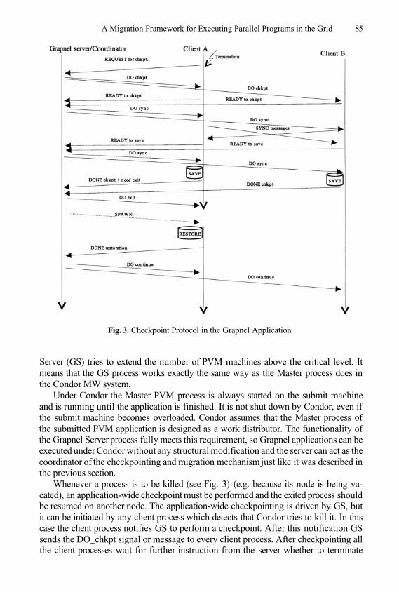
A Migration Framework for Executing Parallel Programs in the Grid 85
Fig. 3. Checkpoint Protocol in the Grapnel Application
Server (GS) tries to extend the number of PVM machines above the critical level. Itmeans that the GS process works exactly the same way as the Master process does inthe Condor MW system.
Under Condor the Master PVM process is always started on the submit machineand is running until the application is finished. It is not shut down by Condor, even ifthe submit machine becomes overloaded. Condor assumes that the Master process ofthe submitted PVM application is designed as a work distributor. The functionality ofthe Grapnel Server process fully meets this requirement, so Grapnel applications can beexecuted under Condor without any structural modification and the server can act as thecoordinator of the checkpointing and migration mechanism just like it was described inthe previous section.
Whenever a process is to be killed (see Fig. 3) (e.g. because its node is being va-cated), an application-wide checkpoint must be performed and the exited process shouldbe resumed on another node. The application-wide checkpointing is driven by GS, butit can be initiated by any client process which detects that Condor tries to kill it. In thiscase the client process notifies GS to perform a checkpoint. After this notification GSsends the DO_chkpt signal or message to every client process. After checkpointing allthe client processes wait for further instruction from the server whether to terminate
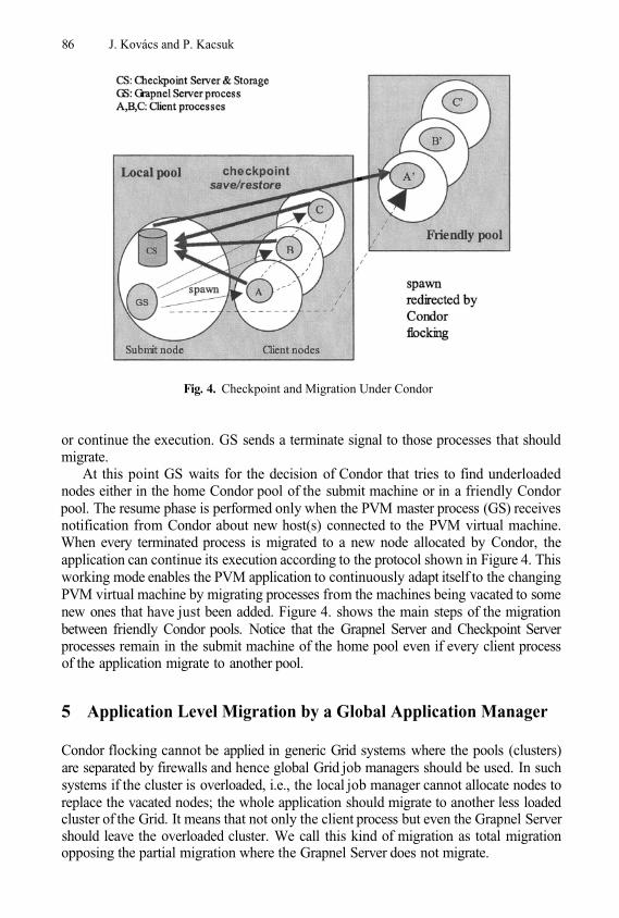
86 J. Kovács and P. Kacsuk
Fig. 4. Checkpoint and Migration Under Condor
or continue the execution. GS sends a terminate signal to those processes that shouldmigrate.
At this point GS waits for the decision of Condor that tries to find underloadednodes either in the home Condor pool of the submit machine or in a friendly Condorpool. The resume phase is performed only when the PVM master process (GS) receivesnotification from Condor about new host(s) connected to the PVM virtual machine.When every terminated process is migrated to a new node allocated by Condor, theapplication can continue its execution according to the protocol shown in Figure 4. Thisworking mode enables the PVM application to continuously adapt itself to the changingPVM virtual machine by migrating processes from the machines being vacated to somenew ones that have just been added. Figure 4. shows the main steps of the migrationbetween friendly Condor pools. Notice that the Grapnel Server and Checkpoint Serverprocesses remain in the submit machine of the home pool even if every client processof the application migrate to another pool.
5 Application Level Migration by a Global Application Manager
Condor flocking cannot be applied in generic Grid systems where the pools (clusters)are separated by firewalls and hence global Grid job managers should be used. In suchsystems if the cluster is overloaded, i.e., the local job manager cannot allocate nodes toreplace the vacated nodes; the whole application should migrate to another less loadedcluster of the Grid. It means that not only the client process but even the Grapnel Servershould leave the overloaded cluster. We call this kind of migration as total migrationopposing the partial migration where the Grapnel Server does not migrate.
A Migration Framework for Executing Parallel Programs in the Grid 87
In order to leave the pool - i.e. migrate the whole application to another pool - twoextra capabilities are needed. First of all, an upper layer, called a Grid Application Man-ager is needed that has submitted the application and is able to recognise the situationwhen a total migration of the Grapnel application to another pool is required. Secondly,the checkpoint saving mechanism should include the server itself, i.e., after checkpoint-ing all the client processes, the server checkpoints itself. Before server checkpoint, theserver should avoid sending any messages to the client processes and should store thestatus of all open files in order to be able to reopen them after resume. The checkpointsupport is built in the application; the rest e.g. removing from local queue, file move-ments, resource reselection and resubmission is task of the upper grid layers.
6 Demonstration Scenario
The migration mechanism described above has been demonstrated in Klagenfurt at theEuroPar’2003 conference. Three clusters were connected (two from Budapest and onefrom London) to provide a friendly Condor pool system. A parallel urban traffic simu-lation application was launched from Klagenfurt on the SZTAKI cluster.
Then the cluster was artificially overloaded and Condor recognising the situationvacated the nodes of the cluster. The Grapnel Server of PGRADE controlled the check-pointing of the application and then asked Condor to allocate new resources for the ap-plication processes. Condor has found the Westminster cluster and PGRADE migratedall the processes except the Grapnel Server to Westminster University. After resumingthe application at Westminster we artificially overloaded the Westminster cluster and asa result the application was migrated to the last underloaded cluster of the system at theTechnical University of Budapest. The Grid migration framework, the Mercury Gridmonitor and the PROVE visualization tool were integrated inside the PGRADE Gridrun-time environment. As a result the migration of the PVM application was on-linemonitored and visualized.
Regarding the performance of checkpointing overall time spent for migration arecheckpoint writing, reading, allocation of new resources and some coordination over-head. The time spent for writing or reading the checkpoint information through a TCP/IPconnection definitely depends on the size of the process to be checkpointed and thebandwidth of the connection between the nodes where the process including the check-point library and the checkpoint server are running. The overall time a complete mi-gration of a process takes also includes the responding time of the resource schedulingsystem e.g. while Condor vacates a machine, the matchmaking mechanism finds a newresource, allocates it, initialises pvmd and notifies the application. Finally, cost of syn-chronisation of messages and some cost used for coordination processing are negligible,less than one percent of the overall migration time.
7 Conclusions
The main contributions of the paper can be summarised as follows:
We developed a parallel program checkpointing mechanism that can be applied togeneric PVM programs.
1.
88 J. Kovács and P. Kacsuk
We showed how such checkpointing mechanism can be connected with Condor inorder to realize migration of PVM jobs among Condor pools.We also showed that by integrating our Grid migration framework and the MercuryGrid monitor PVM applications can be performance monitored and visualized evenduring their migration.
As a consequence, the integrated Condor/PGRADE system can guarantee the executionof any PVM job in Condor-based Grid systems and the user can observe the executionof the PVM job no matter where it is executed and how many times it was migratingin the Grid. Notice that the Condor system can only guarantee the execution of sequen-tial jobs and special Master/Worker PVM jobs and provides only the observability ofstatus changes of those jobs. In case of generic PVM jobs Condor cannot guarantee any-thing. Therefore, the developed checkpointing mechanism and its integration with theMercury monitor significantly extend the robustness and observability of Condor-basedGrid systems.
More than that, the developed checkpoint mechanism can be applied for other Gridjob managers like SGE, etc., hence providing a generic migration framework for anypossible Grid system where PVM programs should migrate among different multipro-cessor based Grid sites like clusters and supercomputers.
Though there are many existing parallel PVM programs, undoubtedly MPI is morepopular than PVM. Hence, supporting the migration of MPI programs would also bevery important. In 2004, we will start a new project in which we are going to adopt thedeveloped checkpointing mechanism even for MPI programs.
Condor [9], MPVM [1], DPVM [2], Fail-Safe PVM [8], CoCheck [12] are furthersoftware systems supporting adaptive parallel application execution including check-pointing and migration facility. The main drawbacks of these systems are that they aremodifying PVM, build complex executing system, require special support, need rootprivileges, require predefined topology, need operating system support, etc. Contraryto these systems our solution makes parallel applications be capable of being check-pointed, migrated or executed in a fault tolerant way on specific level and we do notrequire any support from execution environment or PVM.
The migration facility presented in this paper does not even need any modificationeither in the message-passing layer or in the scheduling and execution system. In thecurrent solution the checkpointing mechanism is an integrated part of PGRADE, so thecurrent system only supports parallel applications created by the PGRADE environ-ment. However, the described checkpoint and migration framework is generic enoughto separate it from PGRADE and provide it as a generic solution for the Grid. In thefuture we are going to create this standalone solution, too.
2.
3.
ReferencesJ. Casas, D. Clark, R. Konuru, S. Otto, R. Prouty, and J. Walpole, “MPVM: A MigrationTransparent Version of PVM”, Technical Report CSE-95-002, 1, 1995.L. Dikken, F. van der Linden, J.J.J. Vesseur, and P.M.A. Sloot, “DynamicPVM: DynamicLoad Balancing on Parallel Systems”, In W.Gentzsch and U. Harms, editors, Lecture notes incomputer sciences 797, High Performance Computing and Networking, volume ProceedingsVolume II, Networking and Tools, pages 273-277, Munich, Germany, April 1994. SpringerVerlag.
1.
2.
A Migration Framework for Executing Parallel Programs in the Grid 89
D. Drótos, G. Dózsa, and P. Kacsuk, “GRAPNEL to C Translation in the GRADE Environ-ment” ,Parallel Program Development for Cluster Comp.Methodology,Tools and IntegratedEnvironments, Nova Science Publishers, Inc. pp. 249-263, 2001.esky: A user-space checkp. system, http://ozlabs.org/people/dgibson/esky/esky.htmlI. Foster, C. Kesselman, S. Tuecke, “The Anatomy of the Grid.” Enabling Scalable VirtualOrganizations, Intern. Journal of Supercomputer Applications, 15(3), 2001.P. Kacsuk, “Visual Parallel Programming on SGI Machines”, Invited paper, Proc. of the SGIUsers Conference, Krakow, Poland, pp. 37-56, 2000.J. Kovács and P. Kacsuk, “Server Based Migration of Parallel Applications”, Proc. of DAP-SYS’2002, Linz, pp. 30-37, 2002.J. Leon, A. L. Fisher, and P. Steenkiste, “Fail-safe PVM: a portable package for distributedprogramming with transparent recovery”. CMU-CS-93-124. February, 1993.M. Litzkow, T. Tannenbaum, J. Basney, and M. Livny, “Checkpoint and Migration of UNIXProcesses in the Condor Distributed Processing System”, Technical Report #1346, ComputerSciences Department, University of Wisconsin, April 1997.PGRADE Parallel Grid Run-time and Application Development Environment:http://www.lpds.sztaki.hu/pgradeJ.S. Plank, M.Beck, G. Kingsley, and K.Li, “Libckpt: Transparent checkpointind underUnix”, In Proc. of Usenix Technical Conference 1995, New Orleans, LA, Jan. 1995.G. Stellner, “Consistent Checkpoints of PVM Applications”, In Proc. 1st Euro. PVM UsersGroup Meeting, 1994.D. Thain, T. Tannenbaum, and M. Livny, “Condor and the Grid”, in Fran Berman, AnthonyJ.G. Hey, Geoffrey Fox, editors, Grid Computing: Making The Global Infrastructure a Real-ity, John Wiley, 2003.http://www.cs.wisc.edu/˜zandy/ckpt
3.
4.5.
6.
7.
10.
11.
12.
13.
14.
8.
9.
Implementations of a Service-OrientedArchitecture on Top of Jini, JXTA and OGSI
Nathalie Furmento, Jeffrey Hau, William Lee,Steven Newhouse, and John Darlington
London e-Science Centre, Imperial College London, London SW7 2AZ, [email protected]
Abstract. This paper presents the design of an implementation-inde-pendent, Service-Oriented Architecture (SOA), which is the main basis ofthe ICENI Grid middleware. Three implementations of this architecturehave been provided on top of Jini, JXTA and the Open Grid ServicesInfrastructure (OGSI). The main goal of this paper is to discuss thesedifferent implementations and provide an analysis of their advantagesand disadvantages.
Keywords: Service-Oriented Architecture, Grid Middleware, Jini, JXTA,OGSI
1 Introduction
Service-oriented architectures are widely used in the Grid Community. Thesearchitectures provide the ability to register, discover, and use services, where thearchitecture is dynamic in nature. From all the initiatives to define standardsfor the Grid, a consensus seems to emerge towards the utilisation of such anarchitecture, as we can for example see with the OGSI initiative of the GlobalGrid Forum [4].
The ICENI Grid Middleware [5] is based on a service-oriented architecture(SOA) as well as on an augmented component programming model [6]. The goalof this paper is to show how the SOA has been designed to be implementation-independent. This gives us an open model where different low-level libraries canbe plugged in.
The following of the paper is organised as follows. § 2 shows in details thedesign of the Service-Oriented Architecture, the different implementations areexplained in § 3. A discussion on the current implementations is presented in § 4,before concluding in § 5.
2 Design of the ICENI’s SOA
A typical Service-Oriented Architecture is presented in Figure 1. One can seethree fundamental aspects of such an architecture:
Advertising. The Service Provider makes the service available to the ServiceBroker.
1.
M. Dikaiakos (Ed.): AxGrids 2004, LNCS 3165, pp. 90–99, 2004.© Springer-Verlag Berlin Heidelberg 2004
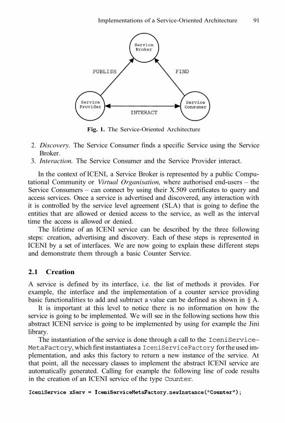
Implementations of a Service-Oriented Architecture 91
Fig. 1. The Service-Oriented Architecture
Discovery. The Service Consumer finds a specific Service using the ServiceBroker.Interaction. The Service Consumer and the Service Provider interact.
2.
3.
In the context of ICENI, a Service Broker is represented by a public Compu-tational Community or Virtual Organisation, where authorised end-users – theService Consumers – can connect by using their X.509 certificates to query andaccess services. Once a service is advertised and discovered, any interaction withit is controlled by the service level agreement (SLA) that is going to define theentities that are allowed or denied access to the service, as well as the intervaltime the access is allowed or denied.
The lifetime of an ICENI service can be described by the three followingsteps: creation, advertising and discovery. Each of these steps is represented inICENI by a set of interfaces. We are now going to explain these different stepsand demonstrate them through a basic Counter Service.
2.1 Creation
A service is defined by its interface, i.e. the list of methods it provides. Forexample, the interface and the implementation of a counter service providingbasic functionalities to add and subtract a value can be defined as shown in § A.
It is important at this level to notice there is no information on how theservice is going to be implemented. We will see in the following sections how thisabstract ICENI service is going to be implemented by using for example the Jinilibrary.
The instantiation of the service is done through a call to the IceniService–MetaFactory, which first instantiates a IceniServiceFactory for the used im-plementation, and asks this factory to return a new instance of the service. Atthat point, all the necessary classes to implement the abstract ICENI service areautomatically generated. Calling for example the following line of code resultsin the creation of an ICENI service of the type Counter.

92 N. Furmento et al.
2.2 Advertising
Once created, a service can be advertised on a specific domain or virtual organ-isation through the IceniServiceAdvertizingManager service. The service isadvertised with a SLA that defines the access policy that will be used to enforceinteraction with the service. The same service can be advertised in different or-ganisations with different SLA’s. This gives a flexible mechanism to control howdifferent organisations may access the service, by allowing advertising the servicecapabilities as required.
The advertising of a service is done through a XML document that definesthe SLA’s of the service for all the virtual organisations where the service is tobe made available. Appendix A shows a SLA XML document that gives accessfrom Monday to Friday noon to all the persons connecting from the virtualorganisation public1 and belonging to the organisation eScience.
2.3 Discovery
By connecting to a virtual organisation, a service consumer can query a serviceand interact with it once discovered. ICENI provides different types of query suchas interface matching that allow to listen to all services of a specific interface,or service data matching that allow to query services based on the value oftheir service data elements. The different steps to discover services are shown inFigure 2.
Fig. 2. Discovery and Interaction with ICENI Services
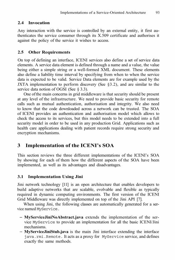
Implementations of a Service-Oriented Architecture 93
2.4 Invocation
Any interaction with the service is controlled by an external entity, it first au-thenticates the service consumer through its X.509 certificate and authorises itagainst the policy of the service it wishes to access.
2.5 Other Requirements
On top of defining an interface, ICENI services also define a set of service dataelements. A service data element is defined through a name and a value, the valuebeing either a simple string or a well-formed XML document. These elementsalso define a liability time interval by specifying from when to when the servicedata is expected to be valid. Service Data elements are for example used by theJXTA implementation to perform discovery (See §3.2), and are similar to theservice data notion of OGSI (See § 3.3).
One of the main concerns in grid middleware is that security should be presentat any level of the infrastructure. We need to provide basic security for remotecalls such as mutual authentication, authorisation and integrity. We also needto know that the code downloaded across a network can be trusted. The SOAof ICENI provides an authentication and authorisation model which allows tocheck the access to its services, but this model needs to be extended into a fullsecurity model in order to be used in any production Grid. Applications such ashealth care applications dealing with patient records require strong security andencryption mechanisms.
3 Implementation of the ICENI’s SOA
This section reviews the three different implementations of the ICENI’s SOAby showing for each of them how the different aspects of the SOA have beenimplemented, as well as its advantages and disadvantages.
3.1 Implementation Using Jini
Jini network technology [11] is an open architecture that enables developers tobuild adaptive networks that are scalable, evolvable and flexible as typicallyrequired in dynamic computing environments. The first version of the ICENIGrid Middleware was directly implemented on top of the Jini API [7].
When using Jini, the following classes are automatically generated for a ser-vice named MyService.
MyServiceJiniNoAbstract.java extends the implementation of the ser-vice MyService to provide an implementation for all the basic ICENI/Jinimechanisms.MyServiceJiniStub.java is the main Jini interface extending the interfacejava.rmi.Remote. It acts as a proxy for MyService service, and definesexactly the same methods.
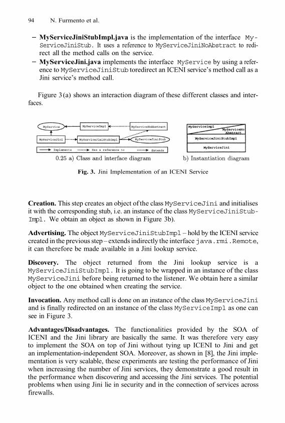
94 N. Furmento et al.
MyServiceJiniStubImpl.java is the implementation of the interface My-ServiceJiniStub. It uses a reference to MyServiceJiniNoAbstract to redi-rect all the method calls on the service.MyServiceJini.java implements the interface MyService by using a refer-ence to MyServiceJiniStub toredirect an ICENI service’s method call as aJini service’s method call.
Figure 3 (a) shows an interaction diagram of these different classes and inter-faces.
Fig. 3. Jini Implementation of an ICENI Service
Creation. This step creates an object of the class MyServiceJini and initialisesit with the corresponding stub, i.e. an instance of the class MyServiceJiniStub-Impl. We obtain an object as shown in Figure 3b).
Advertising. The object MyServiceJiniStubImpl – hold by the ICENI servicecreated in the previous step – extends indirectly the interfacejava.rmi.Remote,it can therefore be made available in a Jini lookup service.
Discovery. The object returned from the Jini lookup service is aMyServiceJiniStubImpl. It is going to be wrapped in an instance of the classMyServiceJini before being returned to the listener. We obtain here a similarobject to the one obtained when creating the service.
Invocation. Any method call is done on an instance of the class MyServiceJiniand is finally redirected on an instance of the class MyServiceImpl as one cansee in Figure 3.
Advantages/Disadvantages. The functionalities provided by the SOA ofICENI and the Jini library are basically the same. It was therefore very easyto implement the SOA on top of Jini without tying up ICENI to Jini and getan implementation-independent SOA. Moreover, as shown in [8], the Jini imple-mentation is very scalable, these experiments are testing the performance of Jiniwhen increasing the number of Jini services, they demonstrate a good result inthe performance when discovering and accessing the Jini services. The potentialproblems when using Jini lie in security and in the connection of services acrossfirewalls.
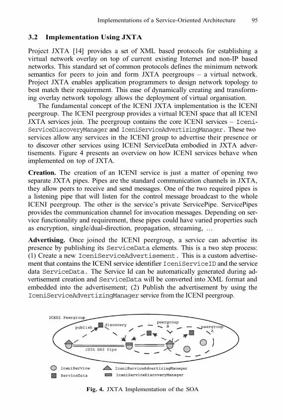
Implementations of a Service-Oriented Architecture 95
3.2 Implementation Using JXTA
Project JXTA [14] provides a set of XML based protocols for establishing avirtual network overlay on top of current existing Internet and non-IP basednetworks. This standard set of common protocols defines the minimum networksemantics for peers to join and form JXTA peergroups – a virtual network.Project JXTA enables application programmers to design network topology tobest match their requirement. This ease of dynamically creating and transform-ing overlay network topology allows the deployment of virtual organisation.
The fundamental concept of the ICENI JXTA implementation is the ICENIpeergroup. The ICENI peergroup provides a virtual ICENI space that all ICENIJXTA services join. The peergroup contains the core ICENI services – Iceni-ServiceDiscoveryManager and IceniServiceAdvertizingManager. These twoservices allow any services in the ICENI group to advertise their presence orto discover other services using ICENI ServiceData embodied in JXTA adver-tisements. Figure 4 presents an overview on how ICENI services behave whenimplemented on top of JXTA.
Creation. The creation of an ICENI service is just a matter of opening twoseparate JXTA pipes. Pipes are the standard communication channels in JXTA,they allow peers to receive and send messages. One of the two required pipes isa listening pipe that will listen for the control message broadcast to the wholeICENI peergroup. The other is the service’s private ServicePipe. ServicePipesprovides the communication channel for invocation messages. Depending on ser-vice functionality and requirement, these pipes could have varied properties suchas encryption, single/dual-direction, propagation, streaming, ...
Advertising. Once joined the ICENI peergroup, a service can advertise itspresence by publishing its ServiceData elements. This is a two step process:(1) Create a new IceniServiceAdvertisement. This is a custom advertise-ment that contains the ICENI service identifier IceniServiceID and the servicedata ServiceData. The Service Id can be automatically generated during ad-vertisement creation and ServiceData will be converted into XML format andembedded into the advertisement; (2) Publish the advertisement by using theIceniServiceAdvertizingManager service from the ICENI peergroup.
Fig. 4. JXTA Implementation of the SOA

96 N. Furmento et al.
Discovery. Peers in the ICENI peergroup can discover available services byusing the IceniServiceDiscoveryManager service. Search can be conductedusing service ID or service data elements.
Invocation. Invocation behaviour of ICENI JXTA services depends on the spe-cific protocol each service is running. There are currently some projects workingon providing different service architecture over JXTA such as JXTA-rmi [15] andJXTA-soap [16]. These projects wrap the original invocation messages (such asSOAP) into JXTA pipe messages and transport them through JXTA pipes toenable peers to invocate services using well-known service invocation API.
Advantages/Disadvantages. JXTA provides an architecture that gives mid-dleware programmers the flexibility and ease of creating virtual organisations.It also provides an easy interface for publishing and discovering data in a peerto peer manner. Different invocation architectures can be overlayed over JXTApipes. And finally, it is based on lightweight, firewall-proof, interchangeable net-work protocols. The potential problems with using JXTA as an architecture forbuilding Grid middleware lies in security and performance. JXTA’s P2P naturemakes it harder to secure than traditional platforms. Also it will be difficultfor the requirements of high performance grid application to be met by JXTA’scurrent XML based messaging protocols.
3.3 Implementation Using OGSI
The Open Grid Services Infrastructure is an effort to build on the wide adop-tion of web services as an inter-operable foundation for distributed computing.The Grid Services Specification [17] describes a set of core port types usingWSDL that are essential for the Grid setting. In ICENI, important notions ofan IceniService are mapped to the relevant constructs in the GridServiceport type, such as meta-data as service data, and lease as termination time.Our implementation is based on the Globus Toolkit 3.0 [1] core distribution.It is the Java reference implementation of the Grid Services Specification. Itallows Java objects to be deployed as OGSI services. The hosting environmentacts as a SOAP processing engine that can be executed as an embedded HTTPserver or operate as a Java Servlet inside a servlet engine. We have enhancedthe implementation with an Application Programming Interface (API) for run-time dynamic deployment of service without the use of deployment descriptor.It serves as the kernel for the ICENI OGSI implementation.
Creation. To transparently transform an IceniService object into an OGSI-compliant service, the runtime system reflectively interrogate the class infor-mation of the service object and generate adapted classes that can be deployedthrough the deployment API. Adaptation is performed using the ASM byte-codegeneration library [3]. The adapted class is loaded from the byte stream into therunning virtual machine using a specialised ClassLoader. The adapted objectrepresents a service object that conforms to the requirement of GT3, such as anextension to the GridServiceBase interface. The adapted class acts solely asthe delegate hosted by GT3 and directs invocation to the service object.
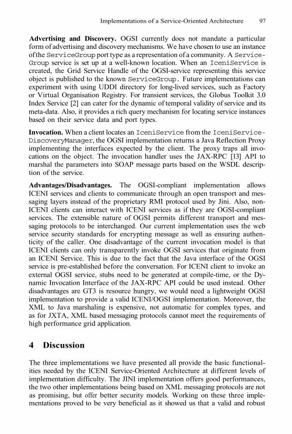
Implementations of a Service-Oriented Architecture 97
Advertising and Discovery. OGSI currently does not mandate a particularform of advertising and discovery mechanisms. We have chosen to use an instanceof the ServiceGroup port type as a representation of a community. A Service-Group service is set up at a well-known location. When an IceniService iscreated, the Grid Service Handle of the OGSI-service representing this serviceobject is published to the known ServiceGroup. Future implementations canexperiment with using UDDI directory for long-lived services, such as Factoryor Virtual Organisation Registry. For transient services, the Globus Toolkit 3.0Index Service [2] can cater for the dynamic of temporal validity of service and itsmeta-data. Also, it provides a rich query mechanism for locating service instancesbased on their service data and port types.
Invocation. When a client locates an IceniService from the IceniService-DiscoveryManager, the OGSI implementation returns a Java Reflection Proxyimplementing the interfaces expected by the client. The proxy traps all invo-cations on the object. The invocation handler uses the JAX-RPC [13] API tomarshal the parameters into SOAP message parts based on the WSDL descrip-tion of the service.
Advantages/Disadvantages. The OGSI-compliant implementation allowsICENI services and clients to communicate through an open transport and mes-saging layers instead of the proprietary RMI protocol used by Jini. Also, non-ICENI clients can interact with ICENI services as if they are OGSI-compliantservices. The extensible nature of OGSI permits different transport and mes-saging protocols to be interchanged. Our current implementation uses the webservice security standards for encrypting message as well as ensuring authen-ticity of the caller. One disadvantage of the current invocation model is thatICENI clients can only transparently invoke OGSI services that originate froman ICENI Service. This is due to the fact that the Java interface of the OGSIservice is pre-established before the conversation. For ICENI client to invoke anexternal OGSI service, stubs need to be generated at compile-time, or the Dy-namic Invocation Interface of the JAX-RPC API could be used instead. Otherdisadvantages are GT3 is resource hungry, we would need a lightweight OGSIimplementation to provide a valid ICENI/OGSI implementation. Moreover, theXML to Java marshaling is expensive, not automatic for complex types, andas for JXTA, XML based messaging protocols cannot meet the requirements ofhigh performance grid application.
4 Discussion
The three implementations we have presented all provide the basic functional-ities needed by the ICENI Service-Oriented Architecture at different levels ofimplementation difficulty. The JINI implementation offers good performances,the two other implementations being based on XML messaging protocols are notas promising, but offer better security models. Working on these three imple-mentations proved to be very beneficial as it showed us that a valid and robust
98 N. Furmento et al.
SOA can only be obtained by good performances and a powerful and extensiblesecurity model.
We believe that these concerns can be dealt with by using Jini 2.0 [12]. Thisnew version of the Jini Network Technology provides a comprehensive securitymodel which one of the main goals is to support pluggable invocation layer be-haviour and pluggable transport provider. We could therefore use OGSI insteadof RMI as a remote communication layer, and benefit of the encryption andauthentication features of the web service security standard.
To allow our three implementations to inter-operate and hence be able ofgetting a virtual organisation composed for example of ICENI/Jini services andICENI/JXTA services, we have developed a OGSA Gateway that allows ICENIservices to be exposed as Grid Services [5]. This allows us for example the fol-lowing configuration: use Jini inside a local organisation, and use JXTA to crossboundaries between networks potentially configured with firewalls.
In order to improve search capability of ICENI services, an adaptation frame-work is being developed. The ICENI Service Adaptation Framework [9] builds ontop of ICENI middleware to provide ways of annotating services using ResourceDescription Framework (RDF) and The Web Ontology Language (OWL). Se-mantic annotated services enable users to search through capability rather thanstatic interface definitions. Once user’s requirement is semantically matched witha semantic service, an adaptation proxy conforming to user’s interface require-ment is automatically generated. The adaptation proxy provides a implemen-tation and architecture independent way for both the client and the server toinvoke the required functionality.
5 Conclusion
We have shown in this paper the design of a Service-Oriented Architecture fora Grid Middleware that is implementation-independent. This Service-OrientedArchitecture has been successfully implemented on top of Jini. We are currentlyprototyping the JXTA and the OGSI implementations of the SOA.
These three implementations all provide a useful subset of the functionalitiesof a Grid Middleware, we are now planning to work on a new implementationwhich will provide a full security model by using characteristics of our existingimplementations.
The ICENI Grid Middleware has been used to develop high level grid servicessuch as scheduler services [18] or visualisation services [10].
References
The Globus Toolkit 3.0. http://www-unix.globus.org/toolkit/download.htmlGT3 Index Service Overview, http://www.globus.org/ogsa/releases/final/docs/infosvcs/indexsvc_overview.htmlE. Bruneton et al. ASM: A Code Manipulation Tool to Implement AdaptableSystems. In Adaptable and Extensible Component Systems, France, Nov. 2002.
1.2.
3.
Implementations of a Service-Oriented Architecture 99
Global Grid Forum. http://www.gridforum.org/N. Furmento, W. Lee, A. Mayer, S. Newhouse, and J. Darlington. ICENI: AnOpen Grid Service Architecture Implemented with Jini. In SuperComputing 2002,USA, Nov. 2002.N. Furmento, A. Mayer, S. McGough, S. Newhouse, T. Field, and J. Darlington.ICENI: Optimisation of Component Applications within a Grid Environment. Par-allel Computing, 28(12):1753–1772, 2002.N. Furmento, S. Newhouse, and J. Darlington. Building Computational Communi-ties from Federated Resources. In 7th International Euro-Par Conference, volume2150 of LNCS, pages 855–863, UK, Aug. 2001.N. Furmento et al. Performance of ICENI/Jini Service Oriented Architecture.Technical report, ICPC, 2002. http://www.lesc.ic.ac.uk/iceni/reports.jspJ. Hau, W. Lee, and Steven Newhouse. Autonomic Service Adaptation usingOntological Annotation. In 4th International Workshop on Grid Computing, Grid2003, USA, Nov. 2003.G. Kong, J. Stanton, S. Newhouse, and J. Darlington. Collaborative Visualisationover the Access Grid using the ICENI Grid Middleware. In UK AllHands Meeting, pages 393–396, UK, Sep. 2003. ISBN 1-904425-11-9.Jini Network Technology. http://www.sun.com/softwaure/jini/Jini Network Technology, v2.0. http://developer.java.sun.com/developer/products/jini/arch2_0.htmlSun Microsystems. Java API for XML-Based RPC 1.1 Specification. http://java.sun.com/xml/jaxrpc/index.htmlProject JXTA http://www.jxta.org/Project JXTA-rmi. http://jxta-rmi.jxta.org/servlets/ProjectHomeProject JXTA-soap. http://soap.jxta.org/servlets/ProjectHomeS. Tuecke et al. Open Grid Service Infrastructure (OGSI) v.1.0 Specification, Feb.2003.L. Young, S. McGough, S. Newhouse, and J. Darlington. Scheduling Architectureand Algorithms within the ICENI Grid Middleware. In UK All HandsMeeting, pages 5–12, UK, Sep. 2003. ISBN 1-904425-11-9.
4.5.
6.
7.
8.
9.
10.
11.12.
13.
14.15.16.17.
18.
A The Counter Service ExampleInterface for a Counter Service
Implementation for a Counter Service
Service Level Agreement for a Counter Service

Dependable Global Computing with JaWS++
George Kakarontzas and Spyros Lalis
Computer and Communications Engineering DepartmentUniversity of Thessaly
Volos, Greece{gkakar,lalis}@inf.uth.gr
Abstract. In this paper we propose a computational grid platformcalled JaWS++ that seeks to harvest the power of idle pools of work-stations connected through the Internet and integrate them in a gridcomputing platform for the execution of embarrassingly parallel com-putations. The computations are developed in the portable Java pro-gramming language and an API is provided for application development.JaWS++ is a compromise between scavenging and reservation-basedcomputational grids. Its service layer is composed by pools of work-stations that are autonomously administered by diiferent organizations.Each pool participates in JaWS++ under a well defined timetable to re-duce unforeseen availability problems, increase dependability and favorbatch work allocation and offline execution.
1 Introduction
Until a few years ago, grids were setup almost exclusively by connecting trustwor-thy, controlled and reliable computing infrastructures with each other, typicallyunder a well-defined resource-sharing scheme and admission policy. Recentlythere is a lot of activity in trying to “gridify” less reliable computing resources,most notably the idle processors of individual personal computers connected tothe Internet or entire networks of workstations located in organizations.
The resulting systems, also referred to as scavenging computational grids [4],fall short on the dependability and consistency characteristics of a “proper” grid.This is primarily due to the intermittent availability/presence of worker proces-sors, which makes efficient scheduling and fault-tolerance hard to achieve. Theseproblems are made even more challenging when the scavenging computationalgrid spans over wider areas of the Internet. In this case, slow and unreliablenetwork connectivity suggests that large chunks of work should be sent to theworkers to favor offline execution and amortize transmission delays. On the otherhand volatility of workers suggests that the exact opposite is a better option sincesending small chunks of work to workers results in less work lost when workerfailures occur.
Dealing with these issues would be easier if the resources were not treatedas “an undifferentiated swarm of global scope” [5] but grouped into resourcepools of a more “predictable” nature. Moreover, this grouping should take into
M. Dikaiakos (Ed.): AxGrids 2004, LNCS 3165, pp. 100–109, 2004.© Springer-Verlag Berlin Heidelberg 2004
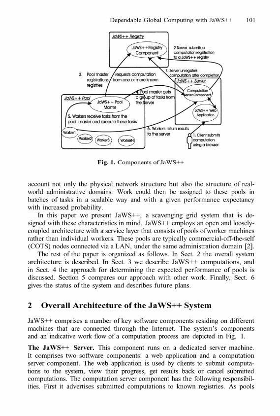
Dependable Global Computing with JaWS++ 101
Fig. 1. Components of JaWS++
account not only the physical network structure but also the structure of real-world administrative domains. Work could then be assigned to these pools inbatches of tasks in a scalable way and with a given performance expectancywith increased probability.
In this paper we present JaWS++, a scavenging grid system that is de-signed with these characteristics in mind. JaWS++ employs an open and loosely-coupled architecture with a service layer that consists of pools of worker machinesrather than individual workers. These pools are typically commercial-off-the-self(COTS) nodes connected via a LAN, under the same administration domain [2].
The rest of the paper is organized as follows. In Sect. 2 the overall systemarchitecture is described. In Sect. 3 we describe JaWS++ computations, andin Sect. 4 the approach for determining the expected performance of pools isdiscussed. Section 5 compares our approach with other work. Finally, Sect. 6gives the status of the system and describes future plans.
2 Overall Architecture of the JaWS++ System
JaWS++ comprises a number of key software components residing on differentmachines that are connected through the Internet. The system’s componentsand an indicative work flow of a computation process are depicted in Fig. 1.
The JaWS++ Server. This component runs on a dedicated server machine.It comprises two software components: a web application and a computationserver component. The web application is used by clients to submit computa-tions to the system, view their progress, get results back or cancel submittedcomputations. The computation server component has the following responsibil-ities. First it advertises submitted computations to known registries. As pools
102 G. Kakarontzas and S. Lalis
discover the computation (this process is explained in detail in the sequel) theycontact the server to retrieve all the information and files that are needed tolaunch the computation. The server also collects and merges the results as theyare being produced by the pools, and when a computation finishes, it unregis-ters the computation from the registries. Finally it monitors the tasks allocatedto pools and reallocates unfinished tasks in cases of excessive delays. Clientscan choose to setup their own JaWS++ server or use servers already available.It is thus possible -and desirable- to have numerous servers manging differentcomputations.
The JaWS++ Registry. The registry is a database where JaWS++ serversregister their computations, and typically runs on a remote dedicated machine.Each server knows one or more registries and is provided with the necessarycredentials to be allowed to submit registrations to them. Along the same lines,JaWS++ pools contact the registries to learn about computations and be for-warded to the corresponding server. A registry also applies a global schedulingpolicy. Although pools proactively contact a registry they know, it is up to theregistry to decide which registration (computation part) they will dispatch to thepool. For example, a least recently fetched policy could be applied in an attemptto be fair to all computations. Other options, taking into account priorities ofdifferent clients, can also be applied. It is important to note that the schedulingpolicy is entirely encapsulated into the registry logic (or configuration) thus canbe adjusted in a straightforward way.
The JaWS++ Pool Master. The pool master runs inside a JaWS++ poolof worker machines with the primary task of managing them. It has two modesof operation determined by its schedule which is set by the pool administrator.It can operate either in idle mode when there is no usual business activity orin opportunistic mode when the pool worker machines are likely to be used bytheir owners. When in idle mode, the pool master queries known registries thatit is authorized to access to receive a computation registration, and subsequentlycontacts the server at the address recorded in the registration. When the server iscontacted for the first time, the pool master receives a benchmark that is used todecide how many tasks it can take on (more on this in Sect. 4). The pool masterthen requests a number of tasks and downloads all the required files for thetasks. Then it starts distributing tasks to the workers. It continually monitors itsworkers and in cases of failures or worker reclaiming by their owners it reallocatesthe tasks to other workers. The opportunistic mode is used for the execution ofany remaining allocated tasks. As will be shown in Sect. 4 the JaWS++ poolmaster will allocate only as many tasks as can be completed during the idlemode of operation. Only in cases when this time is not enough, the executionof the remaining tasks will be extended to the opportunistic mode of operation.This is done in an attempt to minimize worker reclaiming and therefore avoidthe performance penalty associated with task migrations in global computingsystems.
The JaWS++ Workers. These are the machines where the actual computa-tion takes place. A daemon running as a background process on every machine
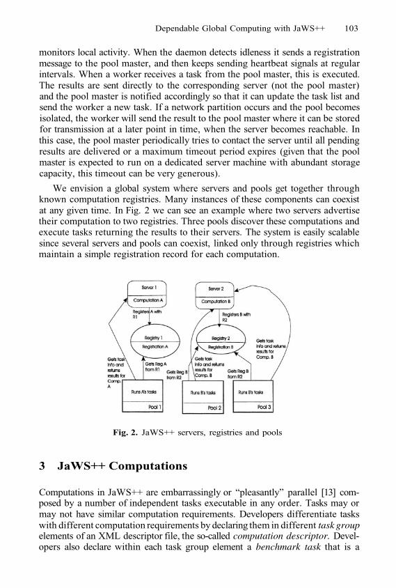
Dependable Global Computing with JaWS++ 103
monitors local activity. When the daemon detects idleness it sends a registrationmessage to the pool master, and then keeps sending heartbeat signals at regularintervals. When a worker receives a task from the pool master, this is executed.The results are sent directly to the corresponding server (not the pool master)and the pool master is notified accordingly so that it can update the task list andsend the worker a new task. If a network partition occurs and the pool becomesisolated, the worker will send the result to the pool master where it can be storedfor transmission at a later point in time, when the server becomes reachable. Inthis case, the pool master periodically tries to contact the server until all pendingresults are delivered or a maximum timeout period expires (given that the poolmaster is expected to run on a dedicated server machine with abundant storagecapacity, this timeout can be very generous).
Fig. 2. JaWS++ servers, registries and pools
3 JaWS++ Computations
Computations in JaWS++ are embarrassingly or “pleasantly” parallel [13] com-posed by a number of independent tasks executable in any order. Tasks may ormay not have similar computation requirements. Developers differentiate taskswith different computation requirements by declaring them in different task groupelements of an XML descriptor file, the so-called computation descriptor. Devel-opers also declare within each task group element a benchmark task that is a
We envision a global system where servers and pools get together throughknown computation registries. Many instances of these components can coexistat any given time. In Fig. 2 we can see an example where two servers advertisetheir computation to two registries. Three pools discover these computations andexecute tasks returning the results to their servers. The system is easily scalablesince several servers and pools can coexist, linked only through registries whichmaintain a simple registration record for each computation.
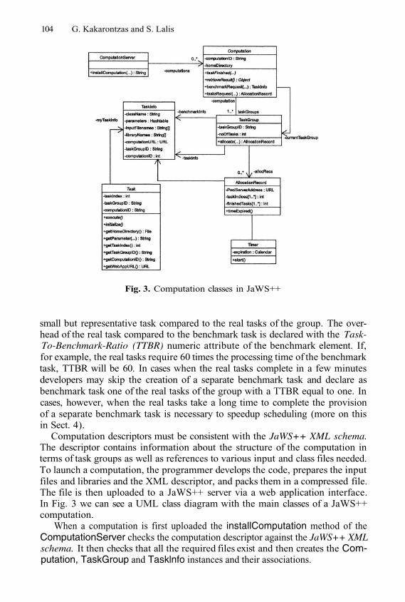
104 G. Kakarontzas and S. Lalis
Fig. 3. Computation classes in JaWS++
small but representative task compared to the real tasks of the group. The over-head of the real task compared to the benchmark task is declared with the Task-To-Benchmark-Ratio (TTBR) numeric attribute of the benchmark element. If,for example, the real tasks require 60 times the processing time of the benchmarktask, TTBR will be 60. In cases when the real tasks complete in a few minutesdevelopers may skip the creation of a separate benchmark task and declare asbenchmark task one of the real tasks of the group with a TTBR equal to one. Incases, however, when the real tasks take a long time to complete the provisionof a separate benchmark task is necessary to speedup scheduling (more on thisin Sect. 4).
Computation descriptors must be consistent with the JaWS++ XML schema.The descriptor contains information about the structure of the computation interms of task groups as well as references to various input and class files needed.To launch a computation, the programmer develops the code, prepares the inputfiles and libraries and the XML descriptor, and packs them in a compressed file.The file is then uploaded to a JaWS++ server via a web application interface.In Fig. 3 we can see a UML class diagram with the main classes of a JaWS++computation.
When a computation is first uploaded the installComputation method of theComputationServer checks the computation descriptor against the JaWS++ XMLschema. It then checks that all the required files exist and then creates the Com-putation, TaskGroup and Tasklnfo instances and their associations.
Dependable Global Computing with JaWS++ 105
The Computation class is an abstract class that programmers subclass to de-velop a specific computation, by providing implementation of the two abstractmethods, taskFinished and retrieveResult. The taskFinished method is responsi-ble for receiving a result of a task. It should be implemented as to integratethe result with the other results received so far in a meaningful way. The re-trieveResult method returns a partial or complete result to clients that monitorthe computation’s progress through the web interface of the server.
The Task class is also an abstract class and programmers provide the initializemethod and the execute method to develop their own concrete Task subclasses.The initialize method is called after the creation of a Task instance to initializethe task. Subsequently, the execute method is called which executes the actualtask code. Upon completion, the Task object, which encapsulates the result ofthe completed task, is returned to the server.
When a pool master first contacts a server, it requests a benchmark throughthe benchmarkRequest method. When the pool master decides how many tasksto allocate, it calls the tasksRequest method and as a result receives an Alloca-tionRecord which holds the information for the tasks and the indexes of the tasksto be created on the pool master. A copy of the allocation record is kept on theserver. After receiving the tasks the pool master will estimate the time that theallocated tasks will be completed and will notify this estimation to the server.When the deadline specified by the pool master expires the allocation recordis marked as delayed. When all tasks of a computation are delivered and newrequests for tasks arrive, unfinished tasks of delayed allocation records will bereallocated.
When all tasks of a computation complete, the computation is marked asfinished and all registrations are removed. Also all participating pools for thiscomputation are notified for the computation termination. Finished computa-tions are passivated in permanent storage to preserve memory. When later clientsrequest the result of a passivated computation the computation is activated backin memory. After clients get the result of a computation, the computation is re-moved from memory and all storage associated with the computation is released.
4 Calculating the Expected Pool Performance
JaWS++ workers have characteristics, such as CPU speed, memory capacityetc. In the present phase of development we simply request that the pool ad-ministrator should group workers according to their hardware configuration, sothat workers in the same worker group have more or less the same configuration.However, this process could as well be entirely automated.
When a pool master receives a new computation registration, it contacts theserver and downloads the benchmark information for the tasks of the currenttask group of the computation. Lets denote the number of worker groups with N,worker group with and the number of registered workers of worker group
with It is expected that will be equal to thetotal number of workers in group since the pool master requests computation
106 G. Kakarontzas and S. Lalis
registrations only when it operates in idle mode of operation, thus when more orless all workers in the pool are expected to be idle. However theused is the actual number of registered workers of group at the time that thework allocation process takes place.
When the pool master receives the benchmark information it chooses ran-domly an idle worker from each worker group and simulates the process of thetask execution cycle which includes the downloading of the required files, thebenchmark task creation, and the dispatching and receipt of the delivery confir-mation by the workers after they have executed the benchmark task and returnedthe result to its server.
Lets denote with the time units required for the randomly chosenworker of to complete the cycle. This is the benchmark score of LetTTBR stand for the overhead of the real tasks of the task group compared to thebenchmark task, as declared by the developer in the computation descriptor (seeSect. 3). Also let TR stand for the time units remaining until the idle mode ofoperation expires and the pool enters the opportunistic mode of operation again,measured from the time when the pool master contacts the server to allocate thetasks. We then define the processing capacity of as the numberof tasks that can deliver until the idle mode of operation expires:
and the total processing capacity of the pool PC as the total number of tasksthat the pool is capable of delivering until the idle mode of operation expires:
The pool master will calculate PC after all chosen workers have completedand delivered the benchmark tasks, and it will then request PC tasks fromthe server. The pool master will receive an allocation record for K tasks where
It will then estimate the completion time of the allocated tasks basedon the number of tasks actually allocated and will notify this estimation to theserver.
The pool master can then download the required files for the allocated tasksand proceed with the creation of tasks and their dispatching to the availableworkers.
5 Related Work
Several Java-based systems have been proposed for global computing [8–11,1].Java is an excellent choice for global computing since it provides the abilityfor customized security with the concept of Security Managers, class download-ing and namespace separation through the use of Class Loaders. All these fea-tures are essential for multi-application global computing systems, where clients
Dependable Global Computing with JaWS++ 107
may upload computations unknown to the system, with arbitrary behavior andwith the exact same package and class names. There are some projects such asXtremWeb [3] which favor binary code executables over Java code. While nativecode computations are faster than their Java counterparts (but note that Javaon-the-fly compilers are getting better with time), Java provides better securitywhich increases volunteer participation. Also native code in multi-applicationglobal computing systems restricts further the execution pool to those workerswhich have the appropriate machine architecture and are properly configured.
In comparison to JaWS++ Ninflet [11], SuperWeb [1], Popcorn[9] and eventhe predecessor of JaWS++, JaWS [6,7], have a flat structure in which workersare monitored directly by one single monitor server, usually the one who pro-vided their tasks. In JaWS++ the pool master monitors its pool and the servermonitors the pool master. The flat monitoring approach creates the followingissues. Firstly connection between the workers and their monitor servers maybe lost too often. Since workers and their monitor servers are not required tobe on the same network, network partitions become more likely to occur. Insuch cases monitor servers may loose contact with numerous workers all at onceand proceed with sometimes-unnecessary correcting measures such as redistri-bution of lost tasks. If the network partition heals before the newly distributedtasks complete then time and resources were spent with no benefit. In contrastin JaWS++ the monitoring of workers is assigned to a pool master residing inthe same network making network partitions much more unlikely to occur. Weassume of course that partitions may occur in the wide area network isolatingpools from JaWS++ servers. Given however that pool masters may keep resultsand forward them later to their server, servers can be much more assured thatthe results will ultimately arrive and proceed to redistribution of tasks only aftera very generous time period has expired giving time to the network partition toheal. Secondly the flat monitoring approach is inherently non-scalable. Since gridand global computing systems are built to integrate thousands or even millions ofmachines in one virtual community, having all these machines being monitoredby a single server is obviously non-scalable. In JaWS++ this limitation can beovercome by having several different servers managing only a modest amount ofcomputations running on a few machine pools.
XtremWeb [3] and Javelin2 [8] require an overlay network to be built on top ofthe real network, something common in P2P systems. JaWS++ doesn’t requirenor supports this, since we want the system to be used both for volunteer-basedcomputing and the formation of virtual organizations. JaWS++ pools reachtheir computations only through known and trusted computation registries.
Most of the systems already mentioned are cycle stealing systems where amachine becomes a worker of the system when its owner does not use it. Whenthe owner claims the machine back for her own use, any computations runningthere are quickly moved to the dispatcher and from there are migrated to anotheravailable worker for further execution until they complete. It is clear that in sucha setting the impact of worker reclaiming can be dramatic in performance sincemigrations can cause the whole computation to slow down, especially if tasks
108 G. Kakarontzas and S. Lalis
are migrated over the Internet. In JaWS++ workers are also used when theyare idle and are evacuated when their owners claim them. Pool masters howeverundertake work only when their pool operates in idle mode which is set bythe administrator of the JaWS++ pool. The idle mode is the period when thenetwork is not normally used by its owners (e.g. during the night, or duringthe weekends). This reduces substantially the possibility of task migrations andimproves performance.
The use of benchmarks to predict worker capabilities is also advocated in Su-per Web [1] and Popcorn [9], However benchmarks in these systems are unrelatedto the computations.They just provide an indication of how powerful or fast amachine is compared to another candidate machine. In JaWS++ the bench-mark task is related to the tasks that a worker will execute since benchmarktasks are provided by the computation developers. Benchmarking is essential formulti-application global computing systems. In JaWS++ the execution of thebenchmark can be carried out with no significant performance penalty since thedispatching unit is a group of tasks and not a single task, which means thatbenchmark is executed once for each allocation of a group of tasks.
6 Current Status and Future Research Directions
We have successfully implemented and tested a prototype for JaWS++, and weare now in the process of making the system more robust and administration freeso that it becomes suitable for real-world use. We also plan to investigate thesystem’s scheduling performance using simulations as well as real computations.
In the future, we plan to automate the workers grouping process to easepool administration and allow dynamic reconfiguration of groups. Technologiessuch as the Windows Management Instrumentation (WMI) and the NetworkWeather Service (NWS) [14] can be used to provide the necessary informationfor the automation of the grouping process.
We also intend to look at the Open Grid Services Infrastructure (OGSI)[12],a set of standards for Grid services defined by the Global Grid Forum (GGF),with the intention to express JaWS++ components as Grid services with WSDL(Web Services Description Language) architecture and programming languageneutral interfaces.
Another issue to be further researched is the global scheduling policy adoptedby JaWS++ registries. We currently apply a least-recently allocated policy re-turning the computation registration of the computation that was served leastrecently. However several policies can be applied very easily and we want to de-termine the circumstances under which a scheduling policy may be favorable toanother.
Last but not least, we intend to investigate the support of non-trivial com-putations, which are notoriously hard to deal with in “flat-scheduled” or P2P-based systems. Given that in JaWS++ the unit of scheduling is a task grouprather than a single task, it becomes possible to support non-trivial parallelcomputations with extensive inter-task communication. Since task groups are
Dependable Global Computing with JaWS++ 109
co-scheduled on the same pool, such communication can be efficiently carriedout using a variety of (even proprietary) mechanisms and without stumbling onthe usual problems of NATs and firewalls.
In conclusion JaWS++ targets the utilization of pools of workstations in aneffort to provide a more dependable global computing platform. We believe thatthis approach fills an empty space in the grid computing landscape and is verypromising in terms of addressing several important issues that are prevalent inmodern open and dynamic computing environments.
References
1.
2.3.
4.
5.
6.
7.
8.
9.
10.
11.
12.
13.
14.
Albert D. Alexandrov et. al.: “SuperWeb: research issues in Java-based globalcomputing”. Concurrency: Practice and Experience, vol. 9, no. 6, pp. 535–553,1997.Mark Baker ed.: “Cluster computing white paper, ver. 2”. December 2000.Gilles Fedak et. al.: “XtremWeb: a generic global computing system”. CCGRID2001.Luis Ferreira et. al: “Introduction to grid computing with Globus”. IBM Redbooks,September 2003.Ian Foster and Adriana Iamnitchi: “On death, taxes, and the convergence of Peer-to-Peer and Grid computing”. IPTPS’03, February 2003.George Kakarontzas and Spyros Lalis: “A market-based protocol with leasing sup-port for globally distributed computing”. Workshop on Global Computing on Per-sonal Devices, CCGRID 2001.Spyros Lalis and Alexandros Karypidis: “An open market-based architecture fordistributed computing”. International Workshop on Personal Computer-BasedNetworks of Workstations, International Parallel and Distributed Processing Sym-posium, 2000.Michael O. Neary et. al.: “Javelin 2.0: Java-based parallel computing on the Inter-net”. Euro-Par 2000, August 2000, Germany.Noam Nisan et. al.: “Globally distributed computation over the Internet - ThePopcorn project”. ICDCS’98, May 1998, Amsterdam, The Netherlands.Luis F. G. Sarmenta and Satoshi Hirano: “Bayanihan: building and studying Web-based volunteer computing systems using Java”. Future Generation Computer Sys-tems, vol. 15, no. 5–6, pp. 675–686, 1999.Hiromitsu Takagi et. al.: “Ninflet: A migratable parallel objects framework usingJava”. Concurrency: Practice and Experience, vol. 10, no. 11–13, pp. 1063–1078,1998.Steve Tuecke et. al.: “Open Grid Services Infrastructure”. Global Grid Forum,June 2003.B. Wilkinson and M. Allen: “Parallel programming: techniques and applicationsusing networked workstations and parallel computers”. Prentice-Hall, 1999.Richard Wolski et. al.: “The network weather service: a distributed resource per-formance forecasting service for metacomputing”. Future Generation ComputerSystems, vol. 15, no. 5–6, pp. 757–768, 1999.
Connecting Condor Poolsinto Computational Grids by Jini*
Gergely Sipos and Péter Kacsuk
MTA SZTAKI Computer and Automation Research Institute,Hungarian Academy of Sciences
1518 Budapest, P.O. Box 63., Hungary{sipos,kacsuk}@sztaki.hu
Abstract. The paper describes how Condor-pools could be joined together toform a large computational cluster-grid. In the architecture Jini provides the in-frastructure for resource lookup, while Condor manages the job execution on theindividual clusters. Semi on-line application monitoring is also available in thisstructure, moreover it works even through firewalls. Beside Condor the presentedJini based Grid can support other local jobmanager implementations, thus varioustypes of sequential or parallel jobs could be executed with the same framework.
1 Introduction
The availability of the Condor local jobmanager within single administrative domainshas been proved in several projects [4]. Other works described how Condor flockingcan be applied to connect clusters together [2]. Unfortunately in such a role Condormeets neither the security, nor the functionality requirements that second generation,service oriented grids should do.
We already presented how the Java based Jini technology can be used as the middle-ware layer in computational Grids [5]. Jini does have service-oriented vision, and basedon its Lookup Service infrastructure clients can find suitable computational services. Toexploit the advantages of both Condor and Jini we integrated them into a single frame-work. In this system Jini acts as the information system layer, while Condor managesthe running jobs on the connected clusters. Appling this structure there is no need touse Condor flocking since Jini can provide the necessary tools and protocols for theinter-domain communication. To make the cooperation of the two technologies avail-able Condor had to be wrapped into a Jini service program, and a suitable service proxyhad to be developed for it. Since neither Jini nor Condor supports application monitor-ing, the Mercury monitor infrastructure [1] has been integrated into the Grid as well.Our system supposes that Mercury has been accordingly installed on the machines ofthe Condor-pools and clients use the GRM trace collector and the PROVE visualisertools [3].
* The work presented in this paper was supported by the Ministry of Education underNo. IKTA5-089/2002, the Hungarian Scientific Research Fund No. T042459 and IHM4671/1/2003.
M. Dikaiakos (Ed.): AxGrids 2004, LNCS 3165, pp. 110–112, 2004.© Springer-Verlag Berlin Heidelberg 2004
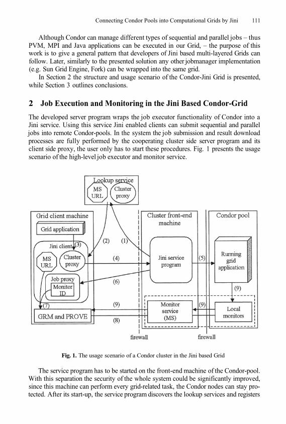
Connecting Condor Pools into Computational Grids by Jini 111
Although Condor can manage different types of sequential and parallel jobs – thusPVM, MPI and Java applications can be executed in our Grid, – the purpose of thiswork is to give a general pattern that developers of Jini based multi-layered Grids canfollow. Later, similarly to the presented solution any other jobmanager implementation(e.g. Sun Grid Engine, Fork) can be wrapped into the same grid.
In Section 2 the structure and usage scenario of the Condor-Jini Grid is presented,while Section 3 outlines conclusions.
2 Job Execution and Monitoring in the Jini Based Condor-Grid
The developed server program wraps the job executor functionality of Condor into aJini service. Using this service Jini enabled clients can submit sequential and paralleljobs into remote Condor-pools. In the system the job submission and result downloadprocesses are fully performed by the cooperating cluster side server program and itsclient side proxy, the user only has to start these procedures. Fig. 1 presents the usagescenario of the high-level job executor and monitor service.
Fig. 1. The usage scenario of a Condor cluster in the Jini based Grid
The service program has to be started on the front-end machine of the Condor-pool.With this separation the security of the whole system could be significantly improved,since this machine can perform every grid-related task, the Condor nodes can stay pro-tected. After its start-up, the service program discovers the lookup services and registers
112 G. Sipos and P. Kacsuk
the cluster proxy together with the URL of the Mercury Monitor Service (MS URL) atthem (1). When an appropriate Jini client application downloads these two objects (2),the proxy can be used to submit compiled PVM, MPI or Java programs to the Condorcluster (3). The proxy forwards the received application to the remote server (4) whichsubmits it into the Condor-pool with native calls (5). At the same time a job proxy isreturned to the client (6). This second proxy can be used to start or stop the remote gridapplication or to download its result files. Based on the monitor ID contained by this jobproxy and on the MS URL has been downloaded from the Lookup Service the GRMtool can register for the trace of the remote job (7, 8). Applying the Mercury infras-tructure (the components inside the broken lines) the instrumented grid application canforward trace events to the client side GRM trace collector and the PROVE visualisertools (9). Since Mercury is a pre-installed service on the cluster only one port has to beopened from the front-end machine to the public network to enable trace forwarding.Beside the service program and the proxies we already developed a client applicationthat can use the service in the described way.
3 Conclusions
The presented Condor based Jini executor service has been publicly demonstrated dur-ing the Grid Dissemination Day organised by the Hungarian Grid Competence Centre,as an important part of the JGrid project [6]. Although its automatic service discoveryand usage functionalities derived from Jini resulted an easy-to-use and easy-to-installsystem, due to security issues the present version cannot be publicly used. The demon-strated version builds on Jini version 1, thus authentication, authorization and dynamicpolicy configuration could not be handled. We are already working on the next versionof the service that will apply every security solution provided by Jini 2.
References
1.
2.
3.
4.
5.
6.
Z. Balaton and G. Gombás: Resource and Job Monitoring in the Grid, Proc. of EuroPar’2003Conference, Klagenfurt, Austria, pp. 404–411, 2003.D. H. J. Epema, M. Livny, R. van Dantzig, X. Evers, and J. Pruyne: A worldwide flockof condors: load sharing among workstation clusters. Technical Report DUT-TWI-95–130,Delft, The Netherlands, 1995.P. Kacsuk: Performance Visualization in the GRADE Parallel Programming Environment,Proc. of the 5th international conference/exhibition on High Performance Computing inAsia-Pacific region (HPC’Asia 2000), Peking, 2000, pp. 446–450.M. J. Litzkov, M. Livny, and M. W. Mutka: Condor – A hunter of idle workstations. Proc.of the 8th IEEE International Conference on Distributed Computing Systems, pp. 104–111,1988.G. Sipos and P. Kacsuk: Executing and Monitoring PVM Programs in Computational Gridswith Jini, Proc. of the 10th EuroPVM/MPI Conference, Springer-Verlag, Venice, Italy, 2003,pp. 570–576.JGrid project: http://pds.irt.vein.hu/jgrid
Overview of an Architecture Enabling GridBased Application Service Provision
S. Wesner1, B. Serhan1, T. Dimitrakos2, D. Mac Randal2,P. Ritrovato3, and G. Laria3
1 High Performance Computing Centre Stuttgart, 70550 Stuttgart, Germany{wesner,serhan}@hlrs.de
2 Central Laboratory of the Research Councils, Rutherford Appleton Lab, UK{t.dimitrakos,d.f.mac.randal}@rl.ac.uk
3 CRMPA – University of Salerno, Italy{ritrovato,laria}@crmpa.unisa.it
Abstract. In this short paper we examine the integration of three emerg-ing trends in Information Technology (Utility Computing, Grid Com-puting, and Web Services) into a new Computing paradigm (Grid-basedApplication Service Provision) that is taking place in the context of theEuropean research project GRASP. In the first part of the paper, weexplain how the integration of emerging trends can support enterprisesin creating competitive advantage. In the second part, we summarisean architecture blueprint of Grid-based Application Service Provision(GRASP), which enables a new technology-driven business paradigm ontop of such integration.
1 From Application Service Provisionto Utility Computing
Application Service Provision (ASP) is a business model, originally derived fromthe idea to use the Internet or other wide area networks to provide online appli-cation services on a rental basis-commercially delivering computing as a service.
As indicated in [1], [2], one can distinguish two different types of ASPs:the “traditional” ASP and the Internet Business Service Provider (IBSP alsoreferred to as the “network-centric” ASP). In contrast to traditional ASPs, pro-viding application services that are Internet-enabled by design, IBSPs build theirapplications instead of adapting the source code of their applications via changesin the configuration of the application rather than changing the source code ofits components. IBSPs therefore move closer to building their businesses on autility model than traditional ASPs.
Utility computing presents a paradigm where shared infrastructure can beprovided on demand to multiple customers [3]. It describes a system that letscompanies pay for IT services as needed. Beside the technological developmentsthat enable utility computing as a paradigm for ASPs also new business inter-action models and fine-grained accounting models for utility computing gettingpossible.
M. Dikaiakos (Ed.): AxGrids 2004, LNCS 3165, pp. 113–118, 2004.© Springer-Verlag Berlin Heidelberg 2004
114 S. Wesner et al.
2 Grid Services: An Enabling Technology
The following sections will assume as background knowledge: the basic principlesof the Service Oriented Architecture paradigm, the Open Grid Service Architec-ture [4] and their partial realization in the Grid Service specification [5] via theOpen Grid Service Architecture vision [6], [7].
3 GRASP:Towards Grid-Based Application Service Provision
The EU GRASP project [8] is an industry driven European research project,which is exploring the use of Grid Services paradigm as a means of providinga timely and effective technological basis supporting the evolution of the ASPmarket towards a sustainable Utility Computing model.
3.1 New Business Interaction Models for IBSPs
To achieve this GRASP is developing an architectural framework for Grid-basedApplication Service Provision (GRASP), a prototype realization of this frame-work in a GRASP platform and “proof-of-concept” implementations of “feder-ated” and “many-to-many” ASP models in different domains such as e-Learningand Biomedical Attention Management.
The “federated” model, which is concerned with the on-demand creation ofdynamic virtual organizations of service providers, which share resources,capabilities and information for a limited period of time and responding toa specific market need.The “many-to-many” model, essentially an evolution of the classic one-to-many model achieved by evolving its foundation from client-server to aservice-oriented paradigm: the entity can take the role of either a consumeror a service provider in the context of the same application depending onthe required interactions. Users may count their material contribution to theprovision of the overall application provision as a means of payment towardsusing that application.
The GRASP architectural framework closes the gap between the effectivedeployment of Grid infrastructures, Web Service based enabling technologies,and enterprise models for application service provision. Our intention is to im-prove enterprise application service provision models so as to be able to take fulladvantage of the flexibility offered by Web Services as a standardized means ofintegrating components of heterogeneous systems both within local, as well aswide area networks, and of the additional functionality and reliability offered byGrid Services for supporting dynamic resource allocation, life-time managementof dynamic service instances, resources integration and efficient distributed com-putation. We expect that when properly integrated within a business workflowthis bundle can soften enterprise borders, giving way to new, more flexible waysof secure and reliable collaboration.
Architecture Enabling Grid Based Application Service Provision 115
4 Main Subsystems of the GRASP Architecture
One of the key architectural elements of GRASP is the distinction between theApplication Service delivered to a client and the component Grid services thatare used to implement this. The component Grid services are provided on de-mand by 3rd party Service Providers running Virtual Hosting Environments(VHE), which of course may consist of many individual hosts actually runningthe services. From a management perspective each VHE uses a Gateway serverresponsible for creation and management of the Grid services within it. Thisarchitecture enables the VHE manager to control the operation of and accessto their services as necessary in a fully commercial environment while still ex-ploiting the power of the underlying Grid technology (including direct P2P com-munication between services) to actually deliver the overall Application Service.The basic business functionality that Application and Service Provider requireis built into the Grasp Framework, simplifying the job of building Grid-basedApplication Services.
The GRASP prototype exploits the functionality of the OGSI.NET toolkit[9] which is a full implementation of the most recent OGSI specification [10].However for the realisation of business applications further higher level servicesare needed. The following sections outline the key services identified missing inOGSI needed for business oriented applications.
4.1 Service Location
This component enters the picture in case the ASP provider is setting up anew dynamic application and is seeking for the appropriate services. Anotherpossibility is that in an existing operational dynamic application problems havebeen detected and services must be either replaced or accompanied by additionalservices.
So we assume the ASP Provider to be one party within a Virtual Organiza-tions (VO) grouping together several Service Providers that offer a list of services.The client of the Service Locator can specify the characteristics of needed ser-vices including pricing and QoS requirements. The Service Locator queries itsService Directory for potential Service Providers and also forward the request toother known Service Locators. As a result the Service Locator returns a list ofService Providers that potentially could be integrated into the dynamic applica-tion. This model assumes that the client receives by other means the connectiondata for the Service Locator. This is proved approach also used in other Gridframeworks such as UNICORE [11].
4.2 Filter and Instantiation Service
The Service Instantiator is located on the Gateway machine within a VirtualHosting Environment (VHE) as outlined above. The Service Instantiator (a GridService hosted by the Gateway machine) is responsible for all requests for instan-tiating a new service. The Filter service is present at the start of the standardserver pipeline in order to elaborate the incoming requests and forward them
116 S. Wesner et al.
to the right process. In case of a request for creating a new service the accessrights of the requestor are verified and the GRASP Service Container is queriedif the service already exists. If the service does not yet exist the Service In-stantiator chooses the appropriate factory within the HE and invokes it. TheFactory creates the new service instance and returns to Service Instantiator avalid reference to this instance (ServiceLocator, SL, in OGSI terminology). TheInstantiator generates a modified SL in order to hide the real reference, and callsthe Container to update a table maintaining the mapping between SL and(modified SL). The external reference for the new service instance is thenreturned to the requestor by the Service Instantiator.
If the service requestor invokes an already existing service instance the re-quest is intercepted by the Filter service forwarding the request to the Container(performing a to SL mapping). This additional intermediate SL allows theVHE to replace or move a service instance within the VHE (e.g. due to antici-pated problems with the SLA) without renegotiating with the service requestorand enables local solutions without affecting the virtualisation concept.
4.3 Service OrchestrationAs outline in section 1 the IBSP model assumes that applications are buildfrom several components allowing dynamic reconfiguration. Within GRASP thisconcept has been extended to build dynamic applications out of distributedservices. Such dynamic applications include not only Grid Services but also plainWeb Services (e.g. for checking the creditability of a credit card). This meansthat ideally a workflow engine capable of orchestrating web and grid services ina dynamically changing workflow is needed.
For the first version of the GRASP prototype a standard BPEL4WS [12]workflow engine has been chosen in favour of existing Grid specific workflowlanguages such as GSFL [13]. However the BPEL compliant engine is not ca-pable of handling the dynamicity of the Grid Services such as the on-demandservice location and instantiation and the transient nature of Grid Services. An-other problem is the potentially different organisation of workflows due to thestatefulness of Grid Services. These problems has been solved with Web Ser-vice proxies providing the needed static reference towards the BPEL engine andhandling the Grid specifics.
For the second version of the prototype BPEL extensions with a pre-parsingprocess or the extension of BPEL engines in general are considered in order tointegrate Grid Services more seamless in hybrid WebService/GridService work-flows.
4.4 SLA ManagementCommercial usage of SOA is typically closely connected with a demand for as-sured Quality of Services (QoS). Such QoS are negotiated between a serviceprovider and a service consumer and are specified in Service Level Agreements(SLA).
An appropriate SLA management system must support the the set-up processby allowing an automated negotiation and parsing of SLAs. During the operation
Architecture Enabling Grid Based Application Service Provision 117
phase the SLAs must be supervised on a per service basis. The basic architectureconsiders a Locator capable of searching for SLAs, support for an external SLAlanguage and a monitoring concept that allows future extensions regarding QoSprediction.
Regarding the observation of a single SLA we try to exploit the dynamicsof the grid in the way, that for every grid service running on behalf of a client,we instantiate an accompanying SLA grid service that contains and validates aspecific SLA to be fulfilled by the related grid service. We are encouraged by thefact that the first draft of OGSI-Agreement [14] introduces a similar approach,using Agreement Services. The first prototype of this concept is currently underimplementation.
4.5 Security
All of the GRASP security rests on top of OGSA-compliant Grid security mecha-nisms, and is orthogonal to Web Services security protocols, such as WS-Security.The ASP security context is addressed using a public key certificate scheme basedon GSI, and will exploit ASP securization technologies. For the Grasp infrastruc-ture context, a novel dynamic security perimiter model is proposed (see also [15][16] [17]) where a protective shell is introduced around each of the Grasp com-ponents involved in delivering the Application service in order to secure eachcomponent individually and the group as a whole. As this short paper does notallow to explain this concept in enough detail and we like to direct the interestedreader to [18].
5 Conclusion
The European GRASP project complements Grid infrastructure developmentprojects such as [19], [20], [11], Web technology deployment projects such as [21]and ASP business model assessment and risk management projects such as [22]by providing a tangible “proof-of-concept” for Grid-based Application ServiceProvision.
Building on top of OGSI the GRASP project has already prototype imple-mentations of some of the missing elements filling the large gap between thebasic functionality of OGSI and the overall picture of the Open Grid Service Ar-chitecture enabling the exploitation of the Grid Service concept in a commercialcontext.
References
1.
2.
3.
Strategies, S.: Market analysis report, traditional isvs: Moving along the software-as-services curve (2002) http://store.yahoo.net/summitresearch/sofasser.htmlStrategies, S.: Market analysis report, out of the box: Top nine net-native software-as-services design differentiators (2002) http://store.yahoo.net/summitresearch/sofasser.htmlMachiraju, V., Rolia, J., van Moorsel, A.: Quality of business driven service com-position and utility computing. Technical report, Software Technology Laboratory,HP Labs Palo Alto, HPL-2002-66 (2002)
118 S. Wesner et al.
4.5.
6.
7.
8.9.
10.
11.12.
13.
14.
15.
16.
17.
18.
19.20.
21.
22.
Foster, I., Kesselmann, C., Tuecke, S.: The anatomy of the gridTuecke, S., Czajkowski, K., Foster, I., Frey, J., Graham, S., Kesselman, C.: Grid ser-vice specification. Technical report, Open Grid Service Infrastructure WG, GlobalGrid Forum (2003).Foster, I., Kesselman, C., Nick, J., Tuecke, S.: The physiology of the grid:An open grid services architecture for distributed systems integration. Techni-cal report, Open Grid Service Infrastructure WG, Global Grid Forum (2002),http: //www. globus .org/research/papers/ogsa. pdfFoster, I., Kesselman, C., Nick, J., Tuecke, S.: Grid services for distributed systemintegration. Volume 35 of Computer (2002), http://www.gridforum.org/ogsiwg/drafts/GS_Spec_draft03_2002-07-17.pdfGRASP: (The grasp project) http://www.eu-grasp.netWasson, G., Beekwilder, N., Humphrey, M.: A technical overview of the ogsi.netsystem (2003).Tuecke, S., Czajkowski, K., Foster, I., Frey, J., Graham, S., Kesselmann, C.,Maquire, T., Sandholm, T., Snelling, D., Vanderbilt, P.: Open grid service in-frastructure (ogsi). Technical report (2003).UNICORE: (The unicore project), http://www.unicore.orgAndrews, T., Curbera, F., Dholakia, H., Goland, Y., Klein, J., Leymann, F., Liu,K., Roller, D., Smith, D., Thatte, S., Trickovic, I., Weerawarana, S.: Businessprocess execution language for web services version 1.1 (2003).Krishnan, S., Wagstrom, P., von Laszewski, G.: Gsfl: A workflow framework forgrid services (2002).Czajkowski, K., Dan, A., Rofrano, J., Tuecke, S., Xu, M.: Agreement-based gridservice management (ogsi-agreement) (2003).Dimitrakos, T., Dordjevic, I., B.M.Matthews, J.C.Bicarregui, Phillips, C.: Policy-driven access control over a distributed firewall architecture. In: Proc. of the 3rdIEEE International Workshop on Policies for Distributed Systems and Networks,IEEE Press (2002).Dimitrakos, T., Djordjevic, L, Milosevic, Z., Jøsang, A., Phillips, C.: Contract per-formance assessment for secure and dynamic virtual collaborations. In: Proceedingsof EDOC’03, 7th IEEE International Enterprise Distributed Object ComputingConference, IEEE Press (2003).Djordjevic, I., Dimitrakos, T., Phillips, C.: An architecture for dynamic securityperimeters of virtual collaborative networks. In: Accepted for publication in Proc.9th IEEE/IFIP Network Operations and Management Symposium (NOMS 2004),IEEE Press (2004).Djordjevic, I., Dimitrakos, T.: Dynamic service perimeters for secure collaborationsin grid-enabled virtual organisations: Overview of a proposed architecture (2004).GLOBUS: (The globus project), http://www.globus.orgLEGION, AVAKI: (The legion project), http://www.cs.virginia.edu/~legion andhttp://www.avaki.comThe SWAD Project: (The Semantic Web Advanced Development in Europeproject), http://www.w3.org/2001/sw/Europe/ALTERNATIVE: (The alternative project), http://www.alternativeproject.org
A Grid-Enabled Adaptive ProblemSolving Environment*
Yoonhee Kim1, Ilkyun Ra2, Salim Hariri3, and Yangwoo Kim4
1 Dept. of Computer Science, Sookmyung Women’s University, [email protected]
2 Dept. of Computer Science & Engineering,The University of Colorado at Denver, USA
[email protected] Dept. of Electrical and Computer Engineering, University of Arizona, USA
[email protected] Dept.of Information & Telecommunication Engineering, Dongguk University, Korea
Abstract. As complexity of computational applications and their envi-ronments has been increased due to the heterogeneity of resources; com-plexity, continuous changes of the applications as well as the resourcesstates, and the large number of resources involved, the importance ofproblem solving environments has been more emphasized. As a PSEfor metacomputing environment, Adaptive Distributed Computing En-vironment (ADViCE) has been developed before the emergence of Gridcomputing services. Current runtime systems for computing mainly fo-cus on executing applications with static resource configuration and donot adequately change the configuration of application execution envi-ronments dynamically to optimize the application performance. In thispaper, we present an architectural overview of ADViCE and discuss howit is evolving to incorporate Grid computing services to extend its rangeof services and decrease the cost of development, deployment, executionand maintenance for an application. We provide that ADViCE optimizethe application execution at runtime adaptively optimize based on ap-plication requirements in both non-Grid and Grid environment with op-timal execution options. We have implemented the ADViCE prototypeand currently evaluating the prototype and its adaptive services for alarger set of Grid applications.
1 Introduction
High performance problem solving computing environments capitalize on theemerging high speed network technology, parallel and distributed programmingtools and environments, and the proliferation of high performance computers.Recently, there has been an increased interest in building large scale high per-formance distributed computing (i.e. metacomputing). These metacomputing
* This Research was supported by the Sookmyung Women’s University ResearchGrants 2004.
M. Dikaiakos (Ed.): AxGrids 2004, LNCS 3165, pp. 119–128, 2004.© Springer-Verlag Berlin Heidelberg 2004
120 Y. Kim et al.
projects provide large scale applications with computing and storage power thatwas once available only in traditional supercomputers.
The concept of Grid computing has been investigated and developed to en-large the concept of distributed computing environment to create infrastructurethat enables integrated services for resource scheduling, data delivery, authen-tication, delegation, information service, management and other related issues[1]. As the Grid provides integrated infrastructure for solving problems, interfac-ing services such as web portal to access Grid services, PSEs (Problem SolvingEnvironments) have been developed to improve the collaboration among Gridservices and reduce significantly the time and effort required to develop, run, andexperiment with large scale Grid applications. However, most PSEs to supportparallel and distributed computing focus on providing environments for suc-cessful execution of applications and providing reasonable resource schedulingschemes. Due to the lack of adaptability on creating dynamic application con-figurations due to changes of resource status, the execution of these applicationsis inefficient.
There have been several application-specific tools and PSEs to utilize Gridenvironment efficiently. ASC Grid Portal [2] is a PSE for large-scale simulationin astrophysics. Hotpage [3] is another PSE targeted toward high performancecomputing applications. Cactus [4] provides a problem-solving environment fordeveloping large-scale distributed scientific applications. GrADS [5] is a toolkitto help users to build applications over heterogeneous resources with ease of use.Similarly, UNICORE [6] provides graphical user interface to access heterogeneousresources uniformly. However, providing adaptive application execution environ-ment by changing the application configurations at runtime has not been inves-tigated extensively. The Adaptive Distributed Virtual Computing Environment(ADViCE) [10] was developed to support adaptive PSE for component-basedapplications. The ADViCE provides an efficient web-based approach for devel-oping, running, evaluating and visualizing large-scale parallel and distributedapplications that utilize computing resources connected by local and/or widearea network.
In this paper, we describe the architecture of ADViCE, which has ADViCEinterface over non-Grid and Grid environment. ADViCE provides a parallel anddistributed programming environment; it provides an efficient web-based userinterface that allows users to develop, run and visualize parallel/distributed ap-plications running on heterogeneous computing resources connected by networks.To support Grid services through ADViCE, the ACS that creates adaptive appli-cation configurations using Resource Specification Language (RSL), which runsover the Globus toolkit [7]. We show that our approach to generate adaptive ap-plication configurations can improve the application performance significantlywith non-Grid and Grid services.
The organization of the remaining sections of the paper is as follows. Wepresent an overview of the ADViCE architecture in Section 2. In Section 3 wedescribe the porting approach of ADViCE over Globus. We also describe in detailhow the ACS can adaptively change the application configuration at runtime.
A Grid-Enabled Adaptive Problem Solving Environment 121
Section 4 shows the experimental results on ADViCE over non-Grid environmentand preliminary experimental results and we conclude the paper in Section 5.
2 Overview of the ADViCE Architecture
The ADViCE (Adaptive Distributed Virtual Computing Environment) [10] isa web-based computing environment and provides transparent computing andcommunication services for large scale parallel and distributed applications.It offers access transparency, configuration transparency, fault-tolerance trans-parency, and performance transparency:
Access Transparency: The users can login and access all the ADViCE re-sources (mobile and/or fixed) regardless of their locations. “Mobile Trans-parency: ADViCE supports in a transparent manner mobile, fixed users, andresources.Configuration Transparency: The resources allocated to run a parallel anddistributed application can be dynamically changed in a transparent manner;that is the applications or users do not need to make any adjustment to reflectthe changes in the resources allocated to them.Fault Tolerance Transparency: The execution of a parallel and distributedapplication can tolerate failures in the resources allocated to run that appli-cation.Performance Transparency: The resources allocated to run a given paralleland distributed application might change dynamically and in a transparentmanner to improve the application performance.
The ADViCE architecture consists of two independent web-based servers: Ap-plication Visualization Editing Server (VES) and Application Control and Man-agement Server (CMS). The VES provides Application Editing Service (AES),Application Visualization Service (AVS), and CMS offers Application ResourceService (ARS), Application Management Service (AMS), Application ControlService (ACS) and Application Data Service (ADS). The ADViCE providesthree important services/capabilities (refer to Figure 1): 1) Evaluation Tool:to analyze the performance of parallel and distributed applications with differ-ent machine and network configurations; 2) Problem Solving Environment: toassist in the development of large scale parallel and distributed applications, and3) Application-Transparent Adaptively: to allow parallel and distributed appli-cations to run in a transparent manner when their clients and resources are fixedor mobile.
3 Poring ADViCE on Grid
As ADViCE provides a graphical Application Editing Service (AES) and run-time execution environment, integrating it to Grid environment gives many ad-vantages for Grid applications. First, ADViCE supports computation oriented
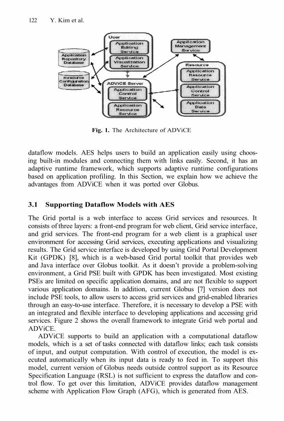
122 Y. Kim et al.
Fig. 1. The Architecture of ADViCE
dataflow models. AES helps users to build an application easily using choos-ing built-in modules and connecting them with links easily. Second, it has anadaptive runtime framework, which supports adaptive runtime configurationsbased on application profiling. In this Section, we explain how we achieve theadvantages from ADViCE when it was ported over Globus.
3.1 Supporting Dataflow Models with AES
The Grid portal is a web interface to access Grid services and resources. Itconsists of three layers: a front-end program for web client, Grid service interface,and grid services. The front-end program for a web client is a graphical userenvironment for accessing Grid services, executing applications and visualizingresults. The Grid service interface is developed by using Grid Portal DevelopmentKit (GPDK) [8], which is a web-based Grid portal toolkit that provides weband Java interface over Globus toolkit. As it doesn’t provide a problem-solvingenvironment, a Grid PSE built with GPDK has been investigated. Most existingPSEs are limited on specific application domains, and are not flexible to supportvarious application domains. In addition, current Globus [7] version does notinclude PSE tools, to allow users to access grid services and grid-enabled librariesthrough an easy-to-use interface. Therefore, it is necessary to develop a PSE withan integrated and flexible interface to developing applications and accessing gridservices. Figure 2 shows the overall framework to integrate Grid web portal andADViCE.
ADViCE supports to build an application with a computational dataflowmodels, which is a set of tasks connected with dataflow links; each task consistsof input, and output computation. With control of execution, the model is ex-ecuted automatically when its input data is ready to feed in. To support thismodel, current version of Globus needs outside control support as its ResourceSpecification Language (RSL) is not sufficient to express the dataflow and con-trol flow. To get over this limitation, ADViCE provides dataflow managementscheme with Application Flow Graph (AFG), which is generated from AES.
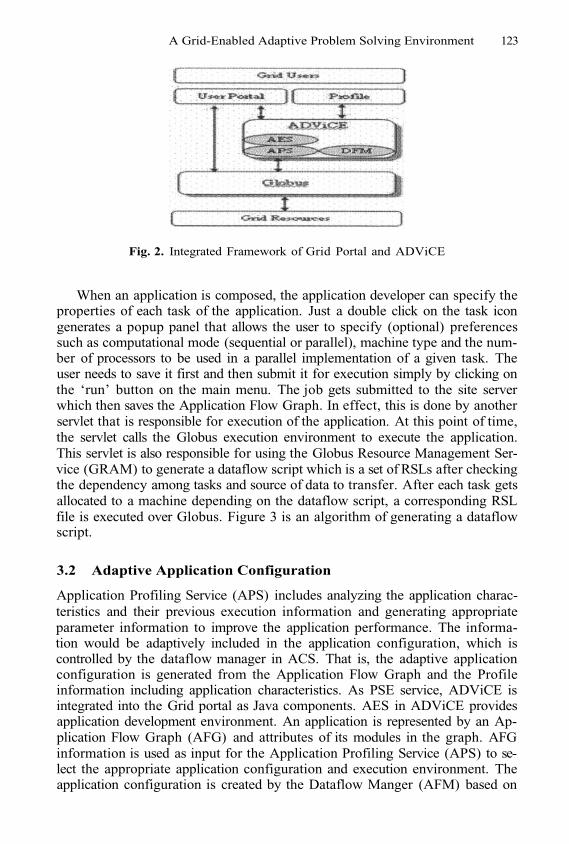
A Grid-Enabled Adaptive Problem Solving Environment 123
Fig. 2. Integrated Framework of Grid Portal and ADViCE
When an application is composed, the application developer can specify theproperties of each task of the application. Just a double click on the task icongenerates a popup panel that allows the user to specify (optional) preferencessuch as computational mode (sequential or parallel), machine type and the num-ber of processors to be used in a parallel implementation of a given task. Theuser needs to save it first and then submit it for execution simply by clicking onthe ‘run’ button on the main menu. The job gets submitted to the site serverwhich then saves the Application Flow Graph. In effect, this is done by anotherservlet that is responsible for execution of the application. At this point of time,the servlet calls the Globus execution environment to execute the application.This servlet is also responsible for using the Globus Resource Management Ser-vice (GRAM) to generate a dataflow script which is a set of RSLs after checkingthe dependency among tasks and source of data to transfer. After each task getsallocated to a machine depending on the dataflow script, a corresponding RSLfile is executed over Globus. Figure 3 is an algorithm of generating a dataflowscript.
3.2 Adaptive Application Configuration
Application Profiling Service (APS) includes analyzing the application charac-teristics and their previous execution information and generating appropriateparameter information to improve the application performance. The informa-tion would be adaptively included in the application configuration, which iscontrolled by the dataflow manager in ACS. That is, the adaptive applicationconfiguration is generated from the Application Flow Graph and the Profileinformation including application characteristics. As PSE service, ADViCE isintegrated into the Grid portal as Java components. AES in ADViCE providesapplication development environment. An application is represented by an Ap-plication Flow Graph (AFG) and attributes of its modules in the graph. AFGinformation is used as input for the Application Profiling Service (APS) to se-lect the appropriate application configuration and execution environment. Theapplication configuration is created by the Dataflow Manger (AFM) based on
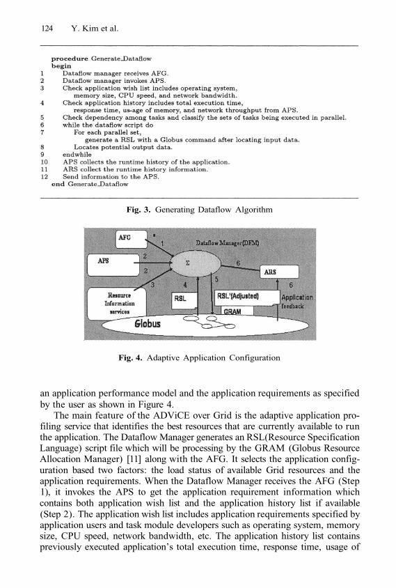
124 Y. Kim et al.
Fig. 3. Generating Dataflow Algorithm
Fig. 4. Adaptive Application Configuration
an application performance model and the application requirements as specifiedby the user as shown in Figure 4.
The main feature of the ADViCE over Grid is the adaptive application pro-filing service that identifies the best resources that are currently available to runthe application. The Dataflow Manager generates an RSL(Resource SpecificationLanguage) script file which will be processing by the GRAM (Globus ResourceAllocation Manager) [11] along with the AFG. It selects the application config-uration based two factors: the load status of available Grid resources and theapplication requirements. When the Dataflow Manager receives the AFG (Step1), it invokes the APS to get the application requirement information whichcontains both application wish list and the application history list if available(Step 2). The application wish list includes application requirements specified byapplication users and task module developers such as operating system, memorysize, CPU speed, network bandwidth, etc. The application history list containspreviously executed application’s total execution time, response time, usage of
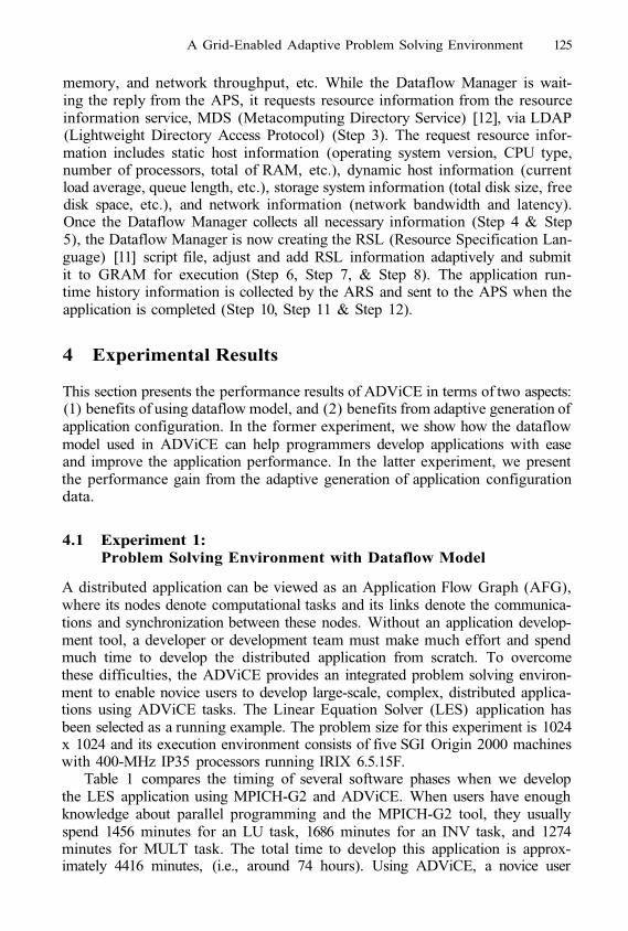
A Grid-Enabled Adaptive Problem Solving Environment 125
memory, and network throughput, etc. While the Dataflow Manager is wait-ing the reply from the APS, it requests resource information from the resourceinformation service, MDS (Metacomputing Directory Service) [12], via LDAP(Lightweight Directory Access Protocol) (Step 3). The request resource infor-mation includes static host information (operating system version, CPU type,number of processors, total of RAM, etc.), dynamic host information (currentload average, queue length, etc.), storage system information (total disk size, freedisk space, etc.), and network information (network bandwidth and latency).Once the Dataflow Manager collects all necessary information (Step 4 & Step5), the Dataflow Manager is now creating the RSL (Resource Specification Lan-guage) [11] script file, adjust and add RSL information adaptively and submitit to GRAM for execution (Step 6, Step 7, & Step 8). The application run-time history information is collected by the ARS and sent to the APS when theapplication is completed (Step 10, Step 11 & Step 12).
4 Experimental Results
This section presents the performance results of ADViCE in terms of two aspects:(1) benefits of using dataflow model, and (2) benefits from adaptive generation ofapplication configuration. In the former experiment, we show how the dataflowmodel used in ADViCE can help programmers develop applications with easeand improve the application performance. In the latter experiment, we presentthe performance gain from the adaptive generation of application configurationdata.
4.1 Experiment 1:Problem Solving Environment with Dataflow Model
A distributed application can be viewed as an Application Flow Graph (AFG),where its nodes denote computational tasks and its links denote the communica-tions and synchronization between these nodes. Without an application develop-ment tool, a developer or development team must make much effort and spendmuch time to develop the distributed application from scratch. To overcomethese difficulties, the ADViCE provides an integrated problem solving environ-ment to enable novice users to develop large-scale, complex, distributed applica-tions using ADViCE tasks. The Linear Equation Solver (LES) application hasbeen selected as a running example. The problem size for this experiment is 1024x 1024 and its execution environment consists of five SGI Origin 2000 machineswith 400-MHz IP35 processors running IRIX 6.5.15F.
Table 1 compares the timing of several software phases when we developthe LES application using MPICH-G2 and ADViCE. When users have enoughknowledge about parallel programming and the MPICH-G2 tool, they usuallyspend 1456 minutes for an LU task, 1686 minutes for an INV task, and 1274minutes for MULT task. The total time to develop this application is approx-imately 4416 minutes, (i.e., around 74 hours). Using ADViCE, a novice user
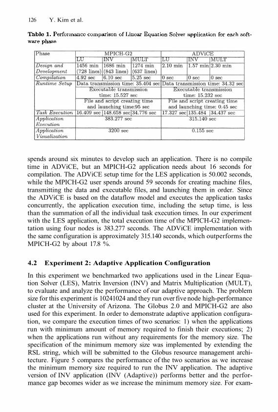
126 Y. Kim et al.
spends around six minutes to develop such an application. There is no compiletime in ADViCE, but an MPICH-G2 application needs about 16 seconds forcompilation. The ADViCE setup time for the LES application is 50.002 seconds,while the MPICH-G2 user spends around 59 seconds for creating machine files,transmitting the data and executable files, and launching them in order. Sincethe ADViCE is based on the dataflow model and executes the application tasksconcurrently, the application execution time, including the setup time, is lessthan the summation of all the individual task execution times. In our experimentwith the LES application, the total execution time of the MPICH-G2 implemen-tation using four nodes is 383.277 seconds. The ADViCE implementation withthe same configuration is approximately 315.140 seconds, which outperforms theMPICH-G2 by about 17.8 %.
4.2 Experiment 2: Adaptive Application Configuration
In this experiment we benchmarked two applications used in the Linear Equa-tion Solver (LES), Matrix Inversion (INV) and Matrix Multiplication (MULT),to evaluate and analyze the performance of our adaptive approach. The problemsize for this experiment is 10241024 and they run over five node high-performancecluster at the University of Arizona. The Globus 2.0 and MPICH-G2 are alsoused for this experiment. In order to demonstrate adaptive application configura-tion, we compare the execution times of two scenarios: 1) when the applicationsrun with minimum amount of memory required to finish their executions; 2)when the applications run without any requirements for the memory size. Thespecification of the minimum memory size was implemented by extending theRSL string, which will be submitted to the Globus resource management archi-tecture. Figure 5 compares the performance of the two scenarios as we increasethe minimum memory size required to run the INV application. The adaptiveversion of INV application (INV (Adaptive)) performs better and the perfor-mance gap becomes wider as we increase the minimum memory size. For exam-
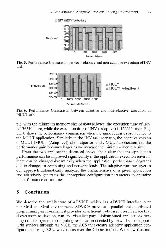
A Grid-Enabled Adaptive Problem Solving Environment 127
Fig. 5. Performance Comparison between adaptive and non-adaptive execution of INVtask
Fig. 6. Performance Comparison between adaptive and non-adaptive execution ofMULT task
ple, with the minimum memory size of 4500 Mbytes, the execution time of INVis 136240 msec, while the execution time of INV (Adaptive) is 126611 msec. Fig-ure 6 shows the performance comparison when the same scenarios are applied tothe MULT application. Similarly to the INV task scenario, the adaptive versionof MULT (MULT (Adaptive)) also outperforms the MULT application and theperformance gain becomes larger as we increase the minimum memory size.
From the two applications discussed above, their clear that the applicationperformance can be improved significantly if the application execution environ-ment can be changed dynamically when the application performance degradesdue to changes in computing and network loads. The adaptive runtime layer inour approach automatically analyzes the characteristics of a given applicationand adaptively generates the appropriate configuration parameters to optimizeits performance at runtime.
5 Conclusion
We describe the architecture of ADViCE, which has ADViCE interface overnon-Grid and Grid environment. ADViCE provides a parallel and distributedprogramming environment; it provides an efficient web-based user interface thatallows users to develop, run and visualize parallel/distributed applications run-ning on heterogeneous computing resources connected by networks. To supportGrid services through ADViCE, the ACS that creates adaptive application con-figurations using RSL, which runs over the Globus toolkit. We show that our
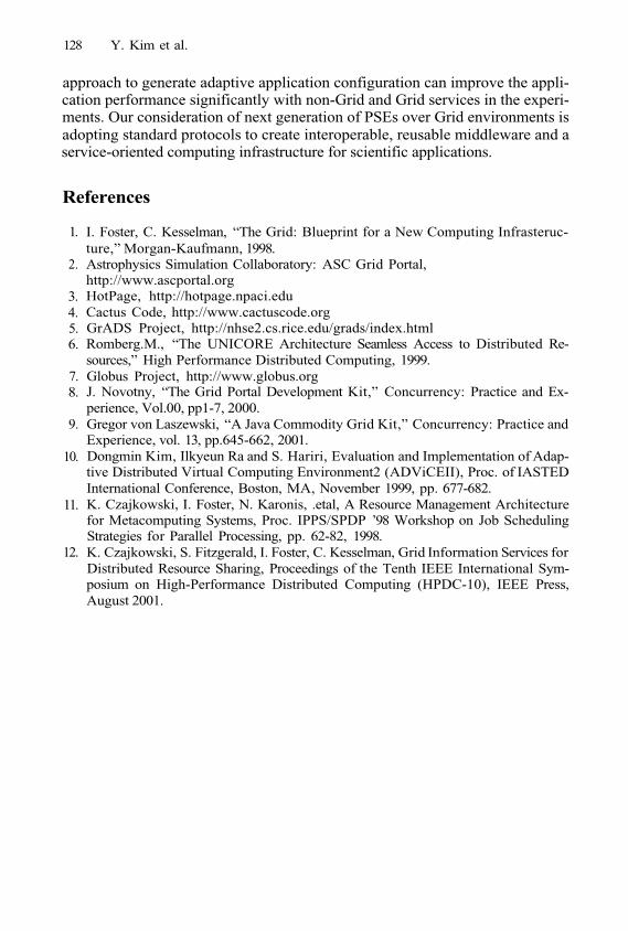
128 Y. Kim et al.
approach to generate adaptive application configuration can improve the appli-cation performance significantly with non-Grid and Grid services in the experi-ments. Our consideration of next generation of PSEs over Grid environments isadopting standard protocols to create interoperable, reusable middleware and aservice-oriented computing infrastructure for scientific applications.
References
1.
2.
3.4.5.6.
7.8.
9.
10.
11.
12.
I. Foster, C. Kesselman, “The Grid: Blueprint for a New Computing Infrasteruc-ture,” Morgan-Kaufmann, 1998.Astrophysics Simulation Collaboratory: ASC Grid Portal,http://www.ascportal.orgHotPage, http://hotpage.npaci.eduCactus Code, http://www.cactuscode.orgGrADS Project, http://nhse2.cs.rice.edu/grads/index.htmlRomberg.M., “The UNICORE Architecture Seamless Access to Distributed Re-sources,” High Performance Distributed Computing, 1999.Globus Project, http://www.globus.orgJ. Novotny, “The Grid Portal Development Kit,” Concurrency: Practice and Ex-perience, Vol.00, pp1-7, 2000.Gregor von Laszewski, “A Java Commodity Grid Kit,” Concurrency: Practice andExperience, vol. 13, pp.645-662, 2001.Dongmin Kim, Ilkyeun Ra and S. Hariri, Evaluation and Implementation of Adap-tive Distributed Virtual Computing Environment2 (ADViCEII), Proc. of IASTEDInternational Conference, Boston, MA, November 1999, pp. 677-682.K. Czajkowski, I. Foster, N. Karonis, .etal, A Resource Management Architecturefor Metacomputing Systems, Proc. IPPS/SPDP ’98 Workshop on Job SchedulingStrategies for Parallel Processing, pp. 62-82, 1998.K. Czajkowski, S. Fitzgerald, I. Foster, C. Kesselman, Grid Information Services forDistributed Resource Sharing, Proceedings of the Tenth IEEE International Sym-posium on High-Performance Distributed Computing (HPDC-10), IEEE Press,August 2001.
Workflow Support for Complex GridApplications: Integrated and Portal Solutions*
Róbert Lovas, Gábor Dózsa, Péter Kacsuk,Norbert Podhorszki, and Dániel Drótos
MTA SZTAKI, Laboratory of Parallel and Distributed Systems,H-1518 Budapest, P.O. Box 63, Hungary
{rlovas, dozsa, kacsuk, pnorbert, drdani}@sztaki. hu
http://www.lpds.sztaki.hu
Abstract. In this paper we present a workflow solution to supportgraphically the design, execution, monitoring, and performance visuali-sation of complex grid applications. The described workflow concept canprovide interoperability among different types of legacy applications onheterogeneous computational platforms, such as Condor or Globus basedgrids. The major design and implementation issues concerning the inte-gration of Condor tools, Mercury grid monitoring infrastructure, PROVEperformance visualisation tool, and the new workflow layer of P-GRADEare discussed in two scenarios. The integrated version of P-GRADE rep-resents the thick client concept, while the portal version needs only athin client and can be accessed by a standard web browser. To illustratethe application of our approach in the grid, an ultra-short range weatherprediction system is presented that can be executed in a grid testbedand visualised not only at workflow level but at the level of individualparallel jobs, too.
1 Introduction
The workflow concept is a widely accepted approach to compose large scaleapplications by connecting programs into an interoperating set of jobs in theGrid [6][12][17][19][20].
Our main aim was to develop a workflow solution for complex grid applica-tions to support the design, execution, monitoring, and performance visualisa-tion phases of development in a user-friendly way. In the presented approach theinteroperability among different types of legacy applications executed on hetero-geneous platforms, such as Condor [1] or Globus [14] based computational grids,is the particularly addressed issue beside the efficient monitoring and visualisa-tion facilities in the grid.
Several achievements of different grid-related projects have been exploited inthe presented work to hide the low-level details of heterogeneous software com-ponents as well as to provide a unified view for application developers. These
* The work presented in this paper was partially supported by the following grants:EU-GridLab IST-2001-32133, Hungarian SuperGrid (IKTA4-075), IHM 4671/1/2003, and Hungarian Scientific Research Fund (OTKA) No. T042459 projects.
M. Dikaiakos (Ed.): AxGrids 2004, LNCS 3165, pp. 129–138, 2004.© Springer-Verlag Berlin Heidelberg 2004
130 R. Lovas et al.
targets are crucial for the successful utilisation of grid environments by theusers from other scientific areas, such as physics, chemists, or meteorology. Thedesign and implementation issues concerning the integration of Condor/Condor-G/DAGman tools [1][2][20], Mercury/GRM grid monitoring infrastructure [3],PROVE performance visualisation tool [4], and the new high-level workflow edi-tor and manager layer of P-GRADE programming environment [10] are discussedin Section 2 and Section 3.
As the main result a new extension of P-GRADE graphical programming en-vironment was developed; the integrated workflow support enables construction,execution, and monitoring of complex applications on both Condor and Globusbased grids (see Section 2 and Section 3). The portal version of workflow layeroffers similar facilities via web interface to the integrated version but the occa-sionally slow and unreliable network connection must be taken into considerationmore rigorously during the separation of client and server side functionalities,(see Section 4).
To illustrate the application of our approach in the grid, an ultra-shortrange weather prediction system is presented that can be executed on a Condor-G/Globus based testbed and visualised the execution not only at workflow levelbut at the level of individual jobs, too.
2 Component Based Grid Programming by Workflow
The presented workflow connects existing sequential or parallel programs intoan interoperating set of jobs. Connections define dependency relations amongthe components of the workflow with respect to their execution order that cannaturally be represented as graphs. Such representation of a meteorological ap-plication is depicted in Fig. 1.
Nodes (labelled as delta, visib, etc. in Fig. 1) represent different jobs fromthe following four types: sequential, PVM, MPI, or GRAPNEL job (generatedby P-GRADE programming environment).
Small rectangles (labelled by numbers) around nodes represent data files(dark grey ones are input files, light grey ones are output files) of the corre-sponding job, and directed arcs interconnect pairs of input and output files ifan output file serves as input for another job. In other words, arcs denote thenecessary file transfers between jobs.
Therefore, the workflow describes both the control-flow and the data-flowof the application. A job can be started when all the necessary input files areavailable and transferred by GridFTP to the site where the job is allocated forexecution. Managing the file-transfers and recognition of the availability of thenecessary files is the task of our workflow manager that extends the CondorDAGMan capabilities.
For illustration purpose we use a meteorological application [5] called ME-ANDER developed by the Hungarian Meteorological Service. The main aim ofMEANDER is to analyse and predict in the ultra short-range (up to 6 hours)those weather phenomena, which might be dangerous for life and property. Typ-
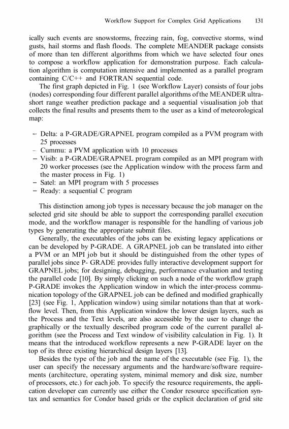
Workflow Support for Complex Grid Applications 131
ically such events are snowstorms, freezing rain, fog, convective storms, windgusts, hail storms and flash floods. The complete MEANDER package consistsof more than ten different algorithms from which we have selected four onesto compose a workflow application for demonstration purpose. Each calcula-tion algorithm is computation intensive and implemented as a parallel programcontaining C/C++ and FORTRAN sequential code.
The first graph depicted in Fig. 1 (see Workflow Layer) consists of four jobs(nodes) corresponding four different parallel algorithms of the MEANDER ultra-short range weather prediction package and a sequential visualisation job thatcollects the final results and presents them to the user as a kind of meteorologicalmap:
Delta: a P-GRADE/GRAPNEL program compiled as a PVM program with25 processesCummu: a PVM application with 10 processesVisib: a P-GRADE/GRAPNEL program compiled as an MPI program with20 worker processes (see the Application window with the process farm andthe master process in Fig. 1)Satel: an MPI program with 5 processesReady: a sequential C program
This distinction among job types is necessary because the job manager on theselected grid site should be able to support the corresponding parallel executionmode, and the workflow manager is responsible for the handling of various jobtypes by generating the appropriate submit files.
Generally, the executables of the jobs can be existing legacy applications orcan be developed by P-GRADE. A GRAPNEL job can be translated into eithera PVM or an MPI job but it should be distinguished from the other types ofparallel jobs since P- GRADE provides fully interactive development support forGRAPNEL jobs; for designing, debugging, performance evaluation and testingthe parallel code [10]. By simply clicking on such a node of the workflow graphP-GRADE invokes the Application window in which the inter-process commu-nication topology of the GRAPNEL job can be defined and modified graphically[23] (see Fig. 1, Application window) using similar notations than that at work-flow level. Then, from this Application window the lower design layers, such asthe Process and the Text levels, are also accessible by the user to change thegraphically or the textually described program code of the current parallel al-gorithm (see the Process and Text window of visibility calculation in Fig. 1). Itmeans that the introduced workflow represents a new P-GRADE layer on thetop of its three existing hierarchical design layers [13].
Besides the type of the job and the name of the executable (see Fig. 1), theuser can specify the necessary arguments and the hardware/software require-ments (architecture, operating system, minimal memory and disk size, numberof processors, etc.) for each job. To specify the resource requirements, the appli-cation developer can currently use either the Condor resource specification syn-tax and semantics for Condor based grids or the explicit declaration of grid site
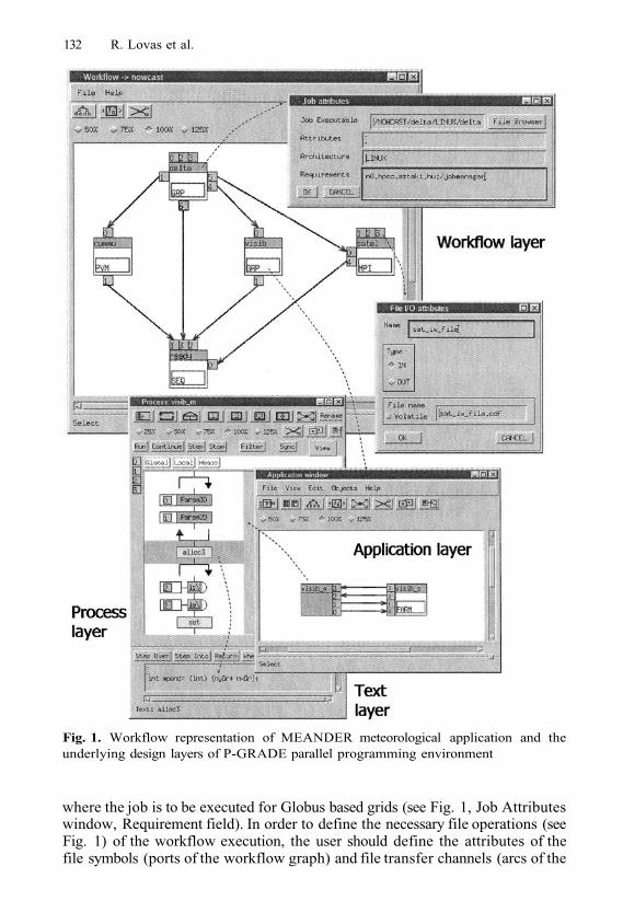
132 R. Lovas et al.
Fig. 1. Workflow representation of MEANDER meteorological application and theunderlying design layers of P-GRADE parallel programming environment
where the job is to be executed for Globus based grids (see Fig. 1, Job Attributeswindow, Requirement field). In order to define the necessary file operations (seeFig. 1) of the workflow execution, the user should define the attributes of thefile symbols (ports of the workflow graph) and file transfer channels (arcs of the
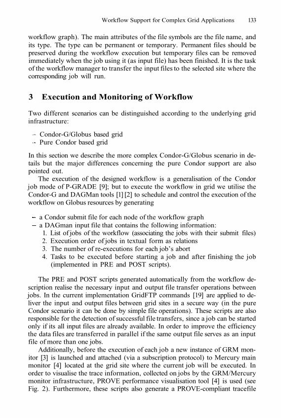
Workflow Support for Complex Grid Applications 133
workflow graph). The main attributes of the file symbols are the file name, andits type. The type can be permanent or temporary. Permanent files should bepreserved during the workflow execution but temporary files can be removedimmediately when the job using it (as input file) has been finished. It is the taskof the workflow manager to transfer the input files to the selected site where thecorresponding job will run.
3 Execution and Monitoring of Workflow
Two different scenarios can be distinguished according to the underlying gridinfrastructure:
Condor-G/Globus based gridPure Condor based grid
In this section we describe the more complex Condor-G/Globus scenario in de-tails but the major differences concerning the pure Condor support are alsopointed out.
The execution of the designed workflow is a generalisation of the Condorjob mode of P-GRADE [9]; but to execute the workflow in grid we utilise theCondor-G and DAGMan tools [1] [2] to schedule and control the execution of theworkflow on Globus resources by generating
a Condor submit file for each node of the workflow grapha DAGman input file that contains the following information:1.2.3.4.
List of jobs of the workflow (associating the jobs with their submit files)Execution order of jobs in textual form as relationsThe number of re-executions for each job’s abortTasks to be executed before starting a job and after finishing the job(implemented in PRE and POST scripts).
The PRE and POST scripts generated automatically from the workflow de-scription realise the necessary input and output file transfer operations betweenjobs. In the current implementation GridFTP commands [19] are applied to de-liver the input and output files between grid sites in a secure way (in the pureCondor scenario it can be done by simple file operations). These scripts are alsoresponsible for the detection of successful file transfers, since a job can be startedonly if its all input files are already available. In order to improve the efficiencythe data files are transferred in parallel if the same output file serves as an inputfile of more than one jobs.
Additionally, before the execution of each job a new instance of GRM mon-itor [3] is launched and attached (via a subscription protocol) to Mercury mainmonitor [4] located at the grid site where the current job will be executed. Inorder to visualise the trace information, collected on jobs by the GRM/Mercurymonitor infrastructure, PROVE performance visualisation tool [4] is used (seeFig. 2). Furthermore, these scripts also generate a PROVE-compliant tracefile
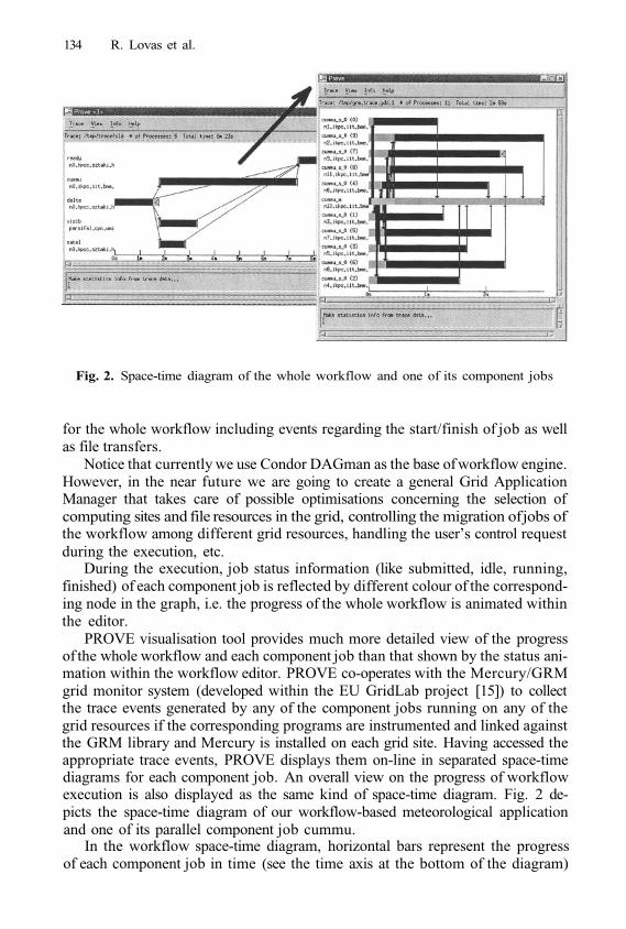
134 R. Lovas et al.
Fig. 2. Space-time diagram of the whole workflow and one of its component jobs
for the whole workflow including events regarding the start/finish of job as wellas file transfers.
Notice that currently we use Condor DAGman as the base of workflow engine.However, in the near future we are going to create a general Grid ApplicationManager that takes care of possible optimisations concerning the selection ofcomputing sites and file resources in the grid, controlling the migration of jobs ofthe workflow among different grid resources, handling the user’s control requestduring the execution, etc.
During the execution, job status information (like submitted, idle, running,finished) of each component job is reflected by different colour of the correspond-ing node in the graph, i.e. the progress of the whole workflow is animated withinthe editor.
PROVE visualisation tool provides much more detailed view of the progressof the whole workflow and each component job than that shown by the status ani-mation within the workflow editor. PROVE co-operates with the Mercury/GRMgrid monitor system (developed within the EU GridLab project [15]) to collectthe trace events generated by any of the component jobs running on any of thegrid resources if the corresponding programs are instrumented and linked againstthe GRM library and Mercury is installed on each grid site. Having accessed theappropriate trace events, PROVE displays them on-line in separated space-timediagrams for each component job. An overall view on the progress of workflowexecution is also displayed as the same kind of space-time diagram. Fig. 2 de-picts the space-time diagram of our workflow-based meteorological applicationand one of its parallel component job cummu.
In the workflow space-time diagram, horizontal bars represent the progressof each component job in time (see the time axis at the bottom of the diagram)
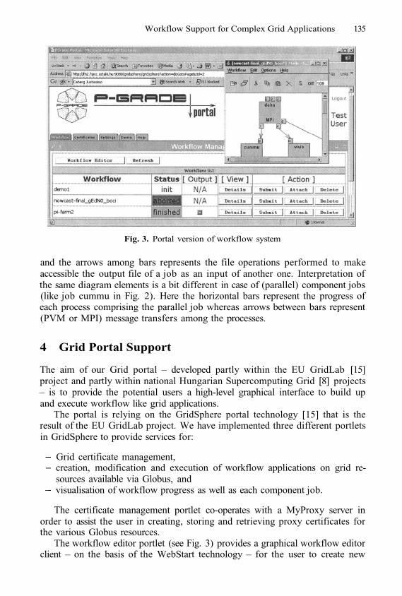
Workflow Support for Complex Grid Applications 135
Fig. 3. Portal version of workflow system
and the arrows among bars represents the file operations performed to makeaccessible the output file of a job as an input of another one. Interpretation ofthe same diagram elements is a bit different in case of (parallel) component jobs(like job cummu in Fig. 2). Here the horizontal bars represent the progress ofeach process comprising the parallel job whereas arrows between bars represent(PVM or MPI) message transfers among the processes.
4 Grid Portal Support
The aim of our Grid portal – developed partly within the EU GridLab [15]project and partly within national Hungarian Supercomputing Grid [8] projects– is to provide the potential users a high-level graphical interface to build upand execute workflow like grid applications.
The portal is relying on the GridSphere portal technology [15] that is theresult of the EU GridLab project. We have implemented three different portletsin GridSphere to provide services for:
Grid certificate management,creation, modification and execution of workflow applications on grid re-sources available via Globus, andvisualisation of workflow progress as well as each component job.
The certificate management portlet co-operates with a MyProxy server inorder to assist the user in creating, storing and retrieving proxy certificates forthe various Globus resources.
The workflow editor portlet (see Fig. 3) provides a graphical workflow editorclient – on the basis of the WebStart technology – for the user to create new
136 R. Lovas et al.
workflow application and to modify existing ones. The workflow editor clientcan upload all the executable and input files as well as the description of theworkflow to the server from the client machine and can also submit the wholeworkflow for execution.
The visualisation portlet (see Fig. 3) provides similar facilities to PROVE toolas it was described in Section 3, but this part of the system is mainly running onthe server side due to the large amount monitored information to be collectedand processed; the collection of trace files might require high network bandwidthand their visualisation might be computationally intensive calculation. In theimplemented visualisation portlet, only the raw image must be downloaded tothe client side, which is more reasonable from the thin client’s view.
5 Related and Future Work
Some other workflow solutions, such as Unicore [12], Triana [6] and Pegasus[17] provide sophisticated control facilities at workflow level, such as loops andconditional branches, or hierarchical design layers. Another advantage of Unicoreis the pluggable graphical user interface, where the application developer canimplement an application oriented front-end, making the Unicore environmentconfigurable and user-friendly. In our integrated solution, the user can easilyaccess and also modify the parallel program code of a workflow node using thehierarchical layers of GRED graphical editor [23] in case of GRAPNEL jobs (seeFig. 1).
Triana is a problem solving environment (PSE) based on Java technologyincluding workflow editor and resource manager. Recently it has been extendedto enable the invocation of legacy code [11]. The workflow support in MyGrid[16] has been demonstrated in bioinformatics based on web service technologybut there is a lack of integration of local applications and toolkits in their nativeform. Our workflow system has been already demonstrated with a wide range oflegacy applications including PVM and MPI applications written in Fortran, Cor C++.
Pegasus workflow manager (developed within GriPhyN project [18]) ad-dresses data intensive applications based on Condor-G/DAGman and Globustechnology. On the other hand, our workflow solution gives efficient supportfor calculation intensive parallel applications (utilizing the existing tools of P-GRADE programming environment in case of GRAPNEL jobs) as well as formonitoring and performance visualisation in the grid relying on the results ofGridLab project [15]. The monitoring facilities allow the user to focus on eitherthe global view of workflow execution, or the individual jobs running on a gridsite, or even the behaviour of component processes including their interactions.Moreover, the presented workflow tool can be executed either:
as the part of P-GRADE parallel programming environment taking the ad-vantages of all the integrated tools in P-GRADE at each stage of programdevelopment life-cycle, or
Workflow Support for Complex Grid Applications 137
via a web browser providing easy access for the workflow editor, and theunderlying execution manager, and monitoring/visualisation facilities.
Another advantage of the presented system is the existing migration support forparallel jobs between grid sites [21] that will be exploited and integrated in theworkflow manager during the further development. It will offer a more dynamicand more efficient runtime support for workflow execution of certain types ofapplication (e.g. long-running parallel simulations) than the current workflowsolutions can provide.
6 Conclusions
The developed workflow layer, workflow manager and Grid portal can be usedto create and to execute workflow like complex grid applications by connectingexisting sequential and parallel programs. Furthermore, it is capable of executingsuch workflows on a Globus or Condor based grid and observing the executionboth at the level of workflow and at the level of each individual (parallel) com-ponent job if Mercury/GRM service is installed on the grid resources.
Our workflow solutions have been developed and evaluated on a grid testbedconsisting of three different Linux clusters – located at MTA SZTAKI (Bu-dapest), at BUTE (Budapest) and at University of Westminster, CPC (London)– which are equipped by Globus Toolkit 2 as grid middleware, by Mercury asmonitoring infrastructure, and by MPICH and PVM as message passing libraries.
The developed workflow portal has been demonstrated successfully at differ-ent forums (ACM/IEEE Supercompting 2003, IEEE Cluster 2003) by a complexmeteorological program, which performs ultra-short range weather forecasting.This workflow solution is to be used in several national grid projects, e.g. theHungarian SuperGrid [8] project (Globus based grid), the Hungarian ChemistryGrid project [22], and Hungarian ClusterGrid project [7], which is a Condorbased nation-wide computational grid infrastructure.
References
1.
2.
3.
4.
5.
D. Thain, T. Tannenbaum, and M. Livny, Condor and the Grid, in Fran Berman,Anthony J.G. Hey, Geoffrey Fox, editors, Grid Computing: Making The GlobalInfrastructure a Reality, John Wiley, 2003James Frey, Todd Tannenbaum, Ian Foster, Miron Livny, and Steven Tuecke:Condor-G: A Computation Management Agent for Multi-Institutional Grids, Jour-nal of Cluster Computing volume 5, pages 237-246, 2002Z. Balaton and G. Gombás: Resource and Job Monitoring in the Grid, Proc. ofEuroPar’2003, Klagenfurt, pp. 404-411, 2003Z. Balaton, P. Kacsuk, and N. Podhorszki: Application Monitoring in the Gridwith GRM and PROVE, Proc. of the Int. Conf. on Computational Science – ICCS2001, San Francisco, pp. 253-262, 2001R. Lovas, et al.: Application of P-GRADE Development Environment in Meteo-rology, Proc. of DAPSYS’2002, Linz, pp. 30-37, 2002
138 R. Lovas et al.
6.
7.
8.
9.
10.
11.
12.13.
14.15.16.
17.
18.19.
20.21.
22.23.
I. Taylor, et al.: Grid Enabling Applications Using Triana, Workshop on GridApplications and Programming Tools, June 25, 2003, Seattle.P. Stefán: The Hungarian ClusterGrid Project, Proc. of MIPRO’2003, Opatija,2003P. Kacsuk: Hungarian Supercomputing Grid, Proc. of ICCS’2002, Amsterdam.Springer Verlag, Part II, pp. 671-678, 2002P. Kacsuk, R. Lovas, et al: Demonstration of P-GRADE job-mode for the Grid,In: Euro- Par 2003 Parallel Processing, Lecture Notes in Computer Science, Vol.2790, Springer- Verlag, 2003P-GRADE Graphical Parallel Program Development Environment:http://www.lpds.sztaki.hu/projects/pgradeYan Huang, Ian Taylor, David W. Walker and Robert Davies: Wrapping LegacyCodes for Grid-Based Applications, to be published in proceedings on the HIPS2003 workshop.www.unicore.orgP. Kacsuk, G. Dózsa, R. Lovas: The GRADE Graphical Parallel ProgrammingEnvironment, In the book: Parallel Program Development for Cluster Computing:Methodology, Tools and Integrated Environments (Chapter 10), Editors: P. Kac-suk, J.C. Cunha and S.C. Winter, pp. 231-247, Nova Science Publishers New York,2001Globus Toolkit, www.globus.org/toolkitGridLab project, www.gridlab.orgMatthew Addis, et al: Experiences with eScience workflow specification and en-actment in bioinformatics, Proceedings of UK e-Science All Hands Meeting 2003(Editors: Simon J. Cox)Ewa Deelman, et al: Mapping Abstract Complex Workflows onto Grid Environ-ments, Journal of Grid Computing, Vol.1, no. 1, 2003, pp. 25-39.GriPhyN project, www.griphyn.orgW. Allcock, J. Bester, J. Bresnahan, A. Chervenak, L. Liming, S. Meder, andS. Tuecke: Gridftp protocol specification, Technical report, Global Grid Forum,September 2002Condor DAGman, http://www.cs.wisc.edu/condor/dagman/J. Kovács, P. Kacsuk: A migration framework for executing parallel programs inthe Grid, Proc. of the 2nd AxGrids Conf., Nicosia, 2004Hungarian ChemistryGrid project, http://www.lpds.sztaki.hu/chemistrygridP. Kacsuk, G. Dózsa, T. Fadgyas and R. Lovas: The GRED Graphical Editorfor the GRADE Parallel Program Development Environment, Journal of FutureGeneration Computer Systems, Vol. 15(1999), No. 3, pp. 443-452.
Debugging MPI Grid ApplicationsUsing Net-dbx
Panayiotis Neophytou1, Neophytos Neophytou2, and Paraskevas Evripidou1
1 Department of Computer Science, University of Cyprus,P.O. Box 20537, CY-1678 Nicosia, Cyprus
{cs99pn1,skevos}@ucy.ac.cy2 Computer Science Department, Stony Brook University,
Stony Brook, NY 11794-4400, [email protected]
Abstract. Application-development in Grid environments is a challeng-ing process, thus the need for grid enabled development tools is also onethat has to be fulfilled. In our work we describe the development of a GridInterface for the Net-dbx parallel debugger, that can be used to debugMPI grid applications. Net-dbx is a web-based debugger enabling usersto use it for debugging from anywhere in the Internet. The proposeddebugging architecture is platform independent, because it uses Java,and it is accessible from anywhere, anytime because it is web based. Ourarchitecture provides an abstraction layer between the debugger and thegrid middleware and MPI implementation used. This makes the debuggereasily adaptable to different middlewares. The grid-enabled architectureof our debugger carries the portability and usability advantages of Net-dbx on which we have based our design. A prototype has been developedand tested.
1 Introduction
The rapidly growing demand on computational and storage resources has madethe development of Grids of various kinds and sizes, of different scopes and objec-tives, a common yet difficult task. A lot of different factors need to be consideredin the development and deployment of a Grid, the most important being the ap-plication domain on which it is going to be used. The requirements of a Grid areprovided by the set of people that are resource providers and resource consumersthat share common interests. These sets of people are what are called VirtualOrganizations (VO) [3]. So far a lot of Grids have been developed with differ-ent uses to serve a wide variety of researchers as well as business corporations.In this process, developers of such distributed systems for large-scale researchhave formed a community that has developed good quality middleware (Globus,EDG, etc.) that allows resource providers to interconnect their resources andefficiently and securely share them with other users, to solve common problems.
The next task is the development of the Grid applications that lie atop ofthe middleware’s infrastructure. These applications make the Grid accessible
M. Dikaiakos (Ed.): AxGrids 2004, LNCS 3165, pp. 139–148, 2004.© Springer-Verlag Berlin Heidelberg 2004
140 P. Neophytou, N. Neophytou, and P. Evripidou
and of service to its users. While the analysis and design of such applicationsis quite an important part of the process, their implementation is the mostchallenging part of this development cycle. These large-scale, resource demandingapplications may have their data and processing widely distributed across aGrid system. Powerful tools and IDEs (Integrated Development Environments),specifically debugging tools are becoming even more necessary. In this work wehave developed a grid-aware debugger targeted to the Message Passing Interface(MPI) [12], a well-known low level parallel programming paradigm that is nowbeing used as an additional alternative model for grid programming.
In this paper we describe our architecture for debugging Grid applications.Our architecture relies on an MPI enabled grid development and runtime envi-ronment, a Grid enabled MPI implementation, and an existing debugging tool(Net-dbx) that enables debugging of MPI applications across the internet. Wehave developed an architecture that addresses the heterogeneity associated withGrid environments, with the help of a communications proxy server and the useof abstraction layers. We call this architecture Net-dbx Grid Interface (Net-dbxGI). We have tested this architecture on our local test bed using the GlobusToolkit 2.4, MPICH-G2 and Netdbx. Support for other Grid enabled MPI im-plementations, such as PACX-MPI and LAM-MPI will be tested in the nearfuture.
Net-dbx [14] utilizes WWW capabilities in general and Java applets in partic-ular for portable, parallel and distributed runtime source-level debugging acrossthe Internet. It can be used with MPI programs written in C, C++ and FOR-TRAN. Its design is based on a framework that utilizes gdb [16] to attach theapplication processes on the individual nodes, and the additional facilities pro-vided by the underlying MPI implementation to provide a complete picture ofthe topology and communication aspects of the debugged application. Net-dbxGI extends this existing architecture and lays the necessary interfaces for properinitialization, communication and collaboration of the resources needed to par-ticipate in the debugging process for applications deployed on the Grid. Othersimilar architectures to Net-dbx are TotalView [2], p2d2 [9,1], Panorama [11]and others.
In the rest of this paper, we will show the improvements and changes made tothe existing Net-dbx architecture. In Section 2 we present the Net-dbx debuggingtool. In section 3 of the paper we describe the layered architecture and theinterfaces which are needed to adapt Net-dbx GI architecture to any Grid MPIenvironment. In section 4 we describe the testing procedure of the architectureusing the Globus Project [4] middleware and MPICH-G2 [10] MPI platform.
2 Net-dbx
Net-dbx’s approach to achieving distributed debugging is based on individuallyattaching every process to a local debugger at the lowest level and then integrat-ing the individual debuggers into a device-independent, interactive, user-friendlyenvironment [13]. For each process to be monitored, the integration environment
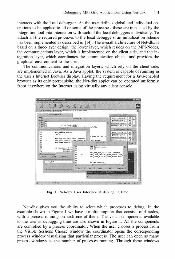
Debugging MPI Grid Applications Using Net-dbx 141
interacts with the local debugger. As the user defines global and individual op-erations to be applied to all or some of the processes, these are translated by theintegration tool into interaction with each of the local debuggers individually. Toattach all the required processes to the local debuggers, an initialization schemehas been implemented as described in [14]. The overall architecture of Net-dbx isbased on a three-layer design: the lower layer, which resides on the MPI-Nodes,the communications layer, which is implemented on the client side, and the in-tegration layer, which coordinates the communication objects and provides thegraphical environment to the user.
The communications and integration layers, which rely on the client side,are implemented in Java. As a Java applet, the system is capable of running inthe user’s Internet Browser display. Having the requirement for a Java-enabledbrowser as its only prerequisite, the Net-dbx applet can be operated uniformlyfrom anywhere on the Internet using virtually any client console.
Fig. 1. Net-dbx User Interface at debugging time
Net-dbx gives you the ability to select which processes to debug. In theexample shown in Figure 1 we have a multicomputer that consists of 4 nodes,with a process running on each one of them. The visual components availableto the user at debugging time are also shown in Figure 1. All the componentsare controlled by a process coordinator. When the user chooses a process fromthe Visible Sessions Choose window the coordinator opens the correspondingprocess window visualizing that particular process. The user can open as manyprocess windows as the number of processes running. Through these windows
142 P. Neophytou, N. Neophytou, and P. Evripidou
the user can set breakpoints, individually control the progress of a process etc.The user also has the choice of controlling groups of processes from the GroupProcess control. The complete functionality of Net-dbx is described in detail in[14].
We have chosen Net-dbx over any other of the tools mentioned in the Intro-duction because of some important advantages it has for usage on Grid envi-ronments. Firstly, it is web based, which makes it portable and available fromanywhere. Secondly, it is supported by low-bandwidth connections (as low as33Kbps) which makes it ideal for distant debugging through anywhere in theinternet in contrast with the other debuggers that are designed mostly for localuse.
3 Architecture of Net-dbx Grid Interface
The Net-dbx GI architecture is based on the same principles of layered designas Net-dbx. In order to make the new architecture portable, the previous designhas been enriched with basic components and methods that are required to sup-port most Grid implementations. An initialization scheme is required in order tobe able to locate and attach all the participating processes to local debuggers,and establish a communication link between those processes and the debuggingapplet. This is particularly challenging in Grid implementations, as the inherentarchitecture of the grid does not allow external users to login directly into theGrid nodes, but rather submit computational jobs asynchronously. The initial-ization scheme and communications layers have been tailored to address theseconstraints, and establish direct links to all participating nodes, using an inter-mediate proxy server.
At the lowest level, our implementation relies on the vendor-dependent MPIimplementation and local debugging tools on each node. These will then com-municate with higher communication abstraction layers, and at the topmostpart everything is integrated into the debugging GUI applet, which is hostedat the remote user’s web browser. In the following section we describe Net-dbxGI architecture, with particular focus on the communications and middlewareinterface layers that enable this tool to operate on Grid implementations.
3.1 Layered Architecture
Net-dbx GI architecture is depicted in Figure 2. Following the Net-dbx architec-ture, the lower layers are defined as the set of resources that all together withthe help of Grid services collaborate and constitute the Virtual Organization’sgrid network, which with the help of the local vendor-MPI implementation anda grid enabled MPI implementation work as a large MPI multi-computer. Itconsists of simple tools that are required on each Node and can be used forindividually debugging the processes running on that Node. These tools includethe local vendor-MPI runtime environment. A grid enabled MPI implementation
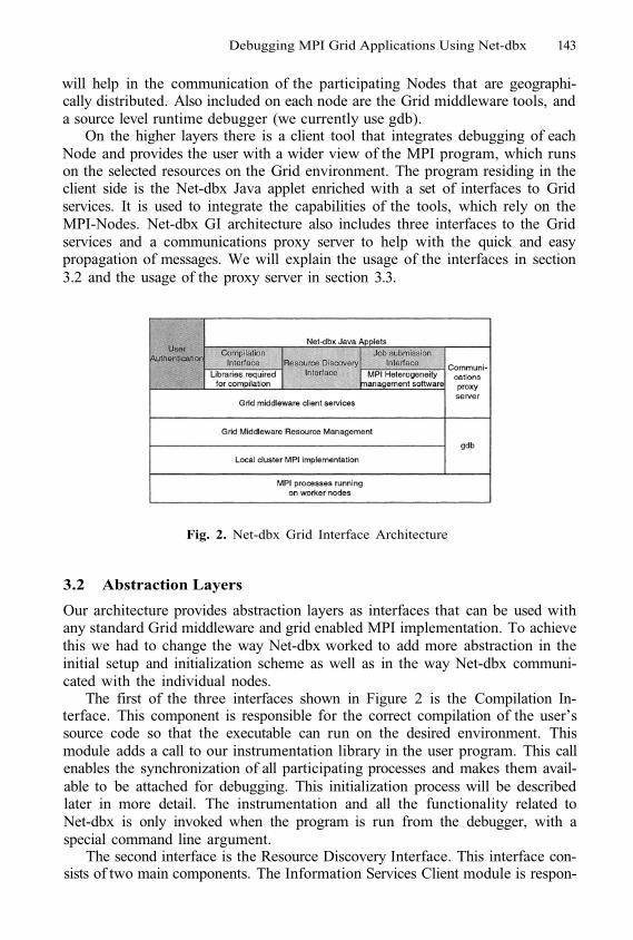
Debugging MPI Grid Applications Using Net-dbx 143
will help in the communication of the participating Nodes that are geographi-cally distributed. Also included on each node are the Grid middleware tools, anda source level runtime debugger (we currently use gdb).
On the higher layers there is a client tool that integrates debugging of eachNode and provides the user with a wider view of the MPI program, which runson the selected resources on the Grid environment. The program residing in theclient side is the Net-dbx Java applet enriched with a set of interfaces to Gridservices. It is used to integrate the capabilities of the tools, which rely on theMPI-Nodes. Net-dbx GI architecture also includes three interfaces to the Gridservices and a communications proxy server to help with the quick and easypropagation of messages. We will explain the usage of the interfaces in section3.2 and the usage of the proxy server in section 3.3.
Fig. 2. Net-dbx Grid Interface Architecture
3.2 Abstraction Layers
Our architecture provides abstraction layers as interfaces that can be used withany standard Grid middleware and grid enabled MPI implementation. To achievethis we had to change the way Net-dbx worked to add more abstraction in theinitial setup and initialization scheme as well as in the way Net-dbx communi-cated with the individual nodes.
The first of the three interfaces shown in Figure 2 is the Compilation In-terface. This component is responsible for the correct compilation of the user’ssource code so that the executable can run on the desired environment. Thismodule adds a call to our instrumentation library in the user program. This callenables the synchronization of all participating processes and makes them avail-able to be attached for debugging. This initialization process will be describedlater in more detail. The instrumentation and all the functionality related toNet-dbx is only invoked when the program is run from the debugger, with aspecial command line argument.
The second interface is the Resource Discovery Interface. This interface con-sists of two main components. The Information Services Client module is respon-
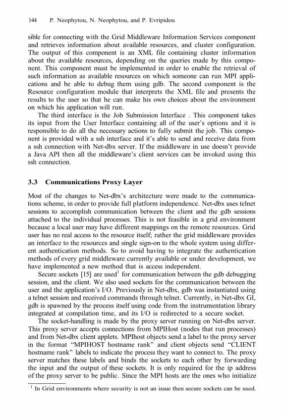
144 P. Neophytou, N. Neophytou, and P. Evripidou
sible for connecting with the Grid Middleware Information Services componentand retrieves information about available resources, and cluster configuration.The output of this component is an XML file containing cluster informationabout the available resources, depending on the queries made by this compo-nent. This component must be implemented in order to enable the retrieval ofsuch information as available resources on which someone can run MPI appli-cations and be able to debug them using gdb. The second component is theResource configuration module that interprets the XML file and presents theresults to the user so that he can make his own choices about the environmenton which his application will run.
The third interface is the Job Submission Interface . This component takesits input from the User Interface containing all of the user’s options and it isresponsible to do all the necessary actions to fully submit the job. This compo-nent is provided with a ssh interface and it’s able to send and receive data froma ssh connection with Net-dbx server. If the middleware in use doesn’t providea Java API then all the middleware’s client services can be invoked using thisssh connection.
3.3 Communications Proxy Layer
Most of the changes to Net-dbx’s architecture were made to the communica-tions scheme, in order to provide full platform independence. Net-dbx uses telnetsessions to accomplish communication between the client and the gdb sessionsattached to the individual processes. This is not feasible in a grid environmentbecause a local user may have different mappings on the remote resources. Griduser has no real access to the resource itself; rather the grid middleware providesan interface to the resources and single sign-on to the whole system using differ-ent authentication methods. So to avoid having to integrate the authenticationmethods of every grid middleware currently available or under development, wehave implemented a new method that is access independent.
Secure sockets [15] are used1 for communication between the gdb debuggingsession, and the client. We also used sockets for the communication between theuser and the application’s I/O. Previously in Net-dbx, gdb was instantiated usinga telnet session and received commands through telnet. Currently, in Net-dbx GI,gdb is spawned by the process itself using code from the instrumentation libraryintegrated at compilation time, and its I/O is redirected to a secure socket.
The socket-handling is made by the proxy server running on Net-dbx server.This proxy server accepts connections from MPIHost (nodes that run processes)and from Net-dbx client applets. MPIhost objects send a label to the proxy serverin the format “MPIHOST hostname rank” and client objects send “CLIENThostname rank” labels to indicate the process they want to connect to. The proxyserver matches these labels and binds the sockets to each other by forwardingthe input and the output of these sockets. It is only required for the ip addressof the proxy server to be public. Since the MPI hosts are the ones who initialize
1 In Grid environments where security is not an issue then secure sockets can be used.
Debugging MPI Grid Applications Using Net-dbx 145
the connections to the proxy server they may also be within private networkswith non-public ip addresses.
The proxy server also help us overcome one of the major security constraintsposed in Java is the rule that applets can have an Internet connection (of anykind – telnet, FTP, HTTP, TCP, etc) only with their HTTP server host [6].
3.4 Security
There are mainly two security issues raised by Net-dbx GI architecture. Thefirst is user authentication. A user of an implementation of the Net-dbx GIdebugging architecture is automatically considered a user of the whole VirtualOrganization because he is going to submit jobs on the resources. As such hemust be authenticated with the correct credentials required by the VO [5]. Sofar Net-dbx authenticates the user using a username and password given atlogin time and by comparing that with a list of usernames and passwords in adatabase on the server. The authentication mechanisms for Net-dbx had to berevised and a security layer has been added to the architecture (Figure 1: UserAuthentication Layer) so the implementers of the architecture can adapt thedebugger’s methods to the ones required by the VO.
The second aspect of security that needs to be considered is the communica-tion between the nodes, the client and the proxy server. The use of secure sockets[15] is required to prevent interception of the messages by malicious intruderswho could manipulate the command stream to the debugger and compromisethe target machine thereafter.
3.5 Initialization and Running Scheme
The initialization scheme used in Net-dbx is also preserved in Net-dbx GI. Theparticipating processes’ PIDs are used to attach the debugger. The synchroniza-tion scheme [14] ensures that all the processes of interest to the user are attachedin the local debuggers right after the MPI initialization calls. Net-dbx GI extendsthis scheme to meet the requirements of our architecture and to overcome theheterogeneity-related difficulties encountered in a grid environment. Figure 3shows the exact order of the initialization tasks starting from the point wherethe user chooses runtime parameters for his application, to the point that all theprocesses are fully attached and ready to be debugged using the user interface.The three main components are shown in the Figure 3. The Net-dbx applet whichis the component running on the user’s browser. The MPI processes that run onthe MPI enabled nodes that are shared within a GRID. Finally, in between isthe proxy server which is hosted on the Net-dbx web server.
At first, the system initiates an ssh session2 with the debugger server (which isthe web server) and authenticates as the Net-dbx user. The ssh session provides acommand line interface initiate and control the client services of the grid. It alsohandles the application’s standard input and output after the job submission.
Ssh is used in Grid environments where security is not an issue.2
146 P. Neophytou, N. Neophytou, and P. Evripidou
Using the ssh session, the Net-dbx client checks to ensure the availability of theproxy server. Once the proxy is available, the user preferences are passed tothe Job Submission module. Then this module can submit the job directly tothe grid services or indirectly by using the ssh session and command line tools(this depends on the implementation of the module). After job submission theprocesses begin execution on the nodes.
Fig. 3. Initialization and Running Scheme
The first call the processes make, after MPI_nit(), goes to the Net-dbx mod-ule added at compilation time. Process 0 gathers all the information regardingthe PIDs, the hostnames and ranks of all the processes (using standard MPIcommands) and sends them to the proxy server, which in turn outputs them tothe ssh session for the client to collect. Then, Process 0, which is responsiblefor handling program’s I/O, connects to the proxy server and redirects the pro-gram’s standard input and output to the secure socket connection. The proxyserver handles the program’s input and output through the ssh session, which isnow available to the user through a window in the client’s applet. After that, allprocesses call fork() and clone themselves. The clone connects to the proxy serverand immediately replaces itself with a gdb process. Then gbd’s I/O is redirectedto the connection. In the meanwhile, on the client side, one object is createdfor each process to control it (based on the information about the executionenvironment which includes PIDs, ranks and hostnames). Each of these objects
Debugging MPI Grid Applications Using Net-dbx 147
connects to the proxy server and requests a connection with the appropriate gdbsocket. If the proxy server has the requested socket it binds them together, ifnot it waits until the appropriate gdb connection occurs. After binding all the“interesting” (user selected) processes the program is synchronized at the pointwhere all the processes left the initialization call, and it is ready for debugging.
4 Prototype Implementation
A working prototype of the proposed architecture has been developed and tested.The goal of this prototype was to achieve the same behavior for the debuggeron both our disparate Grid clusters, as it worked on a local network.
We have tested the Grid Interface of Net-dbx using 2 clusters. The firstone consists of six dual processor SuperServer machines and the second oneconsists of six single processor IBM PCs. The operating system used is RedHatLinux 8. The grid middleware we have chosen is the Globus Toolkit v.2.4, whichsupports MPI, using MPICH-G2 as the grid enabled implementation of MPI.The underlying clusters’ MPI implementation we used is the MPICH p4 device[8], although any other MPI implementations may also be used as well. Theservices provided by the Globus Toolkit fulfill all the needs of our architecture.That is the resource management component, which is responsible for the jobsubmission mechanism and the information services component responsible forproviding information on the grid environment.
The implementation of the communications layer included the full develop-ment of the proxy server in Java and the extension of the Net-dbx instrumen-tation library. The proxy server was fully implemented in Java, as a portableplatform independent module, and it will be used in all the future implementa-tions of the architecture. The Net-dbx library was extended in order to enablethe spawning of gdb and the I/O redirections, as described in Section 3.5. Wehave implemented the compilation interface by using the existing Net-dbx com-pilation scripts and extended them for use with MPICH-G2 and Globus. Thecurrent Resource Discovery interface just hardcoded the resources that we hadavailable in our test-bed, as full implementation of the architecture was not ourgoal in this working prototype. Finally the Job Submission module was alsohard-coded because it depends on the Resource Discovery interface. The hard-coded layers are currently under further development, along with some additionsto the user interface.
5 Conclusions and Future Work
In this paper we have presented Net-dbx GI, our architecture for building agridenabled debugger based on the Net-dbx tool for remote debugging of localnetwork based MPI applications. We have tested our architecture on our localGlobus MPI enabled test-bed and we have shown that our architecture can beused to debug parallel grid applications on real grid environments. We are cur-rently working on an implementation of our architecture that will work as a
148 P. Neophytou, N. Neophytou, and P. Evripidou
debugging portal on the web. Developers will be able to use the portal to de-bug their parallel grid applications from anywhere with the use of a commonweb browser. Further additions to the user interface will provide useful runtimeenvironment information to the user, such as message propagation delays be-tween clusters and other grid-specific and topology aware information. We arealso working on a complete security infrastructure to ensure proper access to theVO’s resources.
References
1.
2.
3.
4.
5.
6.
7.
8.
9.
10.
11.
12.
13.
14.
15.
16.
Doreen Cheng, Robert Hood: A portable debugger for parallel and distributedprograms. SC 1994: 723-732“Etnus, Online Documentation for the TotalView Debugger”,http://www.etnus.com/Support/docs/index.html, 2003.Ian T. Foster: The Anatomy of the Grid: Enabling Scalable Virtual Organizations.Euro-Par 2001: 1-4.Ian T. Foster, Carl Kesselman: The Globus Project: A Status Report. Heteroge-neous Computing Workshop 1998: 4-18.Ian T. Foster, Carl Kesselman, Gene Tsudik, Steven Tuecke: A Security Architec-ture for Computational Grids. ACM Conference on Computer and Communica-tions Security 1998: 83-92.J. Steven Fritzinger, Marinanne Mueller: Java Security white Paper, Sun Microsys-tems Inc., 1996.Andrew S. Grimshaw, William A. Wulf: The Legion Vision of a Worldwide Com-puter. CACM 40(1): 39-45 (1997).William Gropp, Ewing L. Lusk, Nathan Doss, Anthony Skjellum: A High-Performance, Portable Implementation of the MPI Message Passing Interface Stan-dard. Parallel Computing 22(6): 789-828 (1996).Robert Hood, Gabriele Jost: A Debugger for Computational Grid Applications.Heterogeneous Computing Workshop 2000: 262-270.Nicholas T. Karonis, Brian R. Toonen, Ian T. Foster: MPICH-G2: A Grid-enabledimplementation of the Message Passing Interface. Journal of Parallel and Dis-tributed Computing 63(5): 551-563 (2003).John May, Francine Berman: Retargetability and Extensibility in a Parallel De-bugger. Journal of Parallel and Distributed Computing 35(2): 142-155 (1996).Message Passing Interface Forum. MPI: A message-passing interface standard. In-ternational Journal of Supercomputer Applications, 8(3/4) :165-414, 1994.Neophytos Neophytou, Paraskevas Evripidou: Net-dbx: A Java Powered Tool forInteractive Debugging of MPI Programs Across the Internet. Euro-Par 1998: 181-189.Neophytos Neophytou, Paraskevas Evripidou: Net-dbx: A Web-Based Debugger ofMPI Programs Over Low-Bandwidth Lines. IEEE Transactions on Parallel andDistributed Systems 12(9): 986-995 (2001).“Secure Sockets Layer”, http://wp.netscape.com/security/techbriefs/ssl.html,2003.Richard M. Stallman, Roland Pesch, Stan Shebs, et al., Debugging with GDB: TheGNU Source-Level Debugger, Ninth Edition, for GDB version 5.1.1, Free SoftwareFoundation.
Towards an UML Based GraphicalRepresentation of Grid Workflow Applications*
Sabri Pllana1, Thomas Fahringer2, Johannes Testori1,Siegfried Benkner1, and Ivona Brandic1
1 Institute for Software Science, University of ViennaLiechtensteinstraße 22, 1090 Vienna, Austria
{pllana,testori,sigi,brandic}@par.univie.ac.at
Institute for Computer Science, University of InnsbruckTechnikerstraße 25/7, 6020 Innsbruck, Austria
Abstract. Grid workflow applications are emerging as one of the mostinteresting programming models for the Grid. In this paper we presenta novel approach for graphically modeling and describing Grid workflowapplications based on the Unified Modeling Language (UML). Our ap-proach provides a graphic representation of Grid applications based ona widely accepted standard (UML) that is more amenable than puretextual-oriented specifications (such as XML). We describe some of themost important elements for modeling control flow, data flow, synchro-nization, notification, and constraints. We also introduce new featuresthat have not been included by other Grid workflow specification lan-guages which includes broadcast and parallel loops. Our UML-basedgraphical editor Teuta provides the corresponding tool support. Wedemonstrate our approach by describing a UML-based Grid workflowmodel for an advanced 3D medical image reconstruction application.
1 Introduction
In the past years extensive experience has been gained with single site appli-cations and parameter studies for the Grid. For a short time, Grid workflowapplications are emerging as an important new alternative to develop truly dis-tributed applications for the Grid. Workflow Grid applications can be seen as acollection of activities (mostly computational tasks or user interaction) that areprocessed in some order. Usually both control and data flow relationships areshown within a workflow. Although workflow applications have been extensivelystudied in areas such as business process modeling [9], it is relatively new in theGrid computing area.
The Web Service Flow Language (WSFL) [11] focuses on the composition ofWeb services by using a flow model and a global model. Moreover, the order ofthe Web services is defined. Both flow of control and data flow are represented.
* The work described in this paper is supported by the Austrian Science Fund as partof Aurora Project under contract SFBF1104.
M. Dikaiakos (Ed.): AxGrids 2004, LNCS 3165, pp. 149–158, 2004.© Springer-Verlag Berlin Heidelberg 2004
2
150 S. Pllana et al.
The Web service flow language can be considered as a language to describe con-crete workflows that are based on a specific implementation of workflow activi-ties namely Web services. However, it is not an abstract workflow language thatshields implementation details. There are multiple choices to represent workflowactivities. Web services represent one implementation. XLANG [15] is used tomodel business processes as autonomous agents which supports among othersexceptions, conditional and iterative statements, and transactions. The Busi-ness Process Execution Language for Web Services (BPEL4WS) [1] specifiesthe behavior of a business process based on Web Services. In BPEL4WS busi-ness processes provide and use functionality based on Web Service interfaces.BPEL4WS is a merge of the concepts of XLANG and WSFL.
Commonly these languages are considered to be too complex for Grid ap-plications with extensive language features for control flow and synchronizationthat in many cases make only sense in the business process modeling area. More-over, in these models workflow is commonly defined such that interaction amongWeb services is done via a central workflow control engine which certainly wouldbe a bottleneck for Grid applications.
There is also some work done to introduce languages for the specification ofGrid workflow applications based on the eXtensible Markup Language (XML) [5].Grid Workflow [4] is a language for describing Grid workflow applications de-veloped at Sandia National Laboratories. This language is missing the advancedconstructs for the control flow such as branches, loops, split and join. There is nographical representation defined for this language. Grid Services Flow Language(GSFL) [10] is an XML based language for Grid workflow applications developedat Argonne National Laboratory. It can represent only a sequence of activities,and is missing the advanced constructs for the control flow such as branches,loops, split and join.
Triana [6] supports the graphical representations of workflows. Triana work-flows are experiment-based: each unit of work is associated with a specific ex-periment. A workflow – defined by a task graph – defines the order in whichexperiments are executed. Triana provides support for simple control-flow con-structs, but for instance advanced concurrency cannot be explicitly expressedsince there is no support for synchronization conditions.
In this paper we introduce a new approach that employs the Unified Model-ing Language (UML) [12] for graphically modeling and describing Grid workflowapplications. Workflow modeling is strongly supported by UML through activ-ity diagrams. Moreover, UML is a widely used standard that is easier to readand understand by human beings than XML documents as commonly used bymany workflow specification languages. In order to facilitate machine processingof UML diagrams, UML tools support the automatic transformation of UML di-agrams into XML Metadata Interchange (XMI) [13]. We tried to incorporate allimportant features presented by previous workflow languages including WSFL,eliminated unnecessary complexity and introduced new concept that were miss-ing. Our UML modeling approach covers some of the most important modelingconstructs for workflow hierarchical decomposition, control and data flow, syn-
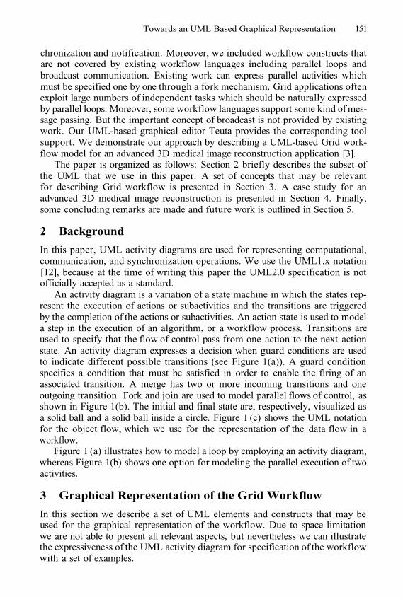
Towards an UML Based Graphical Representation 151
chronization and notification. Moreover, we included workflow constructs thatare not covered by existing workflow languages including parallel loops andbroadcast communication. Existing work can express parallel activities whichmust be specified one by one through a fork mechanism. Grid applications oftenexploit large numbers of independent tasks which should be naturally expressedby parallel loops. Moreover, some workflow languages support some kind of mes-sage passing. But the important concept of broadcast is not provided by existingwork. Our UML-based graphical editor Teuta provides the corresponding toolsupport. We demonstrate our approach by describing a UML-based Grid work-flow model for an advanced 3D medical image reconstruction application [3].
The paper is organized as follows: Section 2 briefly describes the subset ofthe UML that we use in this paper. A set of concepts that may be relevantfor describing Grid workflow is presented in Section 3. A case study for anadvanced 3D medical image reconstruction is presented in Section 4. Finally,some concluding remarks are made and future work is outlined in Section 5.
2 Background
In this paper, UML activity diagrams are used for representing computational,communication, and synchronization operations. We use the UML1.x notation[12], because at the time of writing this paper the UML2.0 specification is notofficially accepted as a standard.
An activity diagram is a variation of a state machine in which the states rep-resent the execution of actions or subactivities and the transitions are triggeredby the completion of the actions or subactivities. An action state is used to modela step in the execution of an algorithm, or a workflow process. Transitions areused to specify that the flow of control pass from one action to the next actionstate. An activity diagram expresses a decision when guard conditions are usedto indicate different possible transitions (see Figure 1(a)). A guard conditionspecifies a condition that must be satisfied in order to enable the firing of anassociated transition. A merge has two or more incoming transitions and oneoutgoing transition. Fork and join are used to model parallel flows of control, asshown in Figure 1(b). The initial and final state are, respectively, visualized asa solid ball and a solid ball inside a circle. Figure 1 (c) shows the UML notationfor the object flow, which we use for the representation of the data flow in aworkflow.
Figure 1 (a) illustrates how to model a loop by employing an activity diagram,whereas Figure 1(b) shows one option for modeling the parallel execution of twoactivities.
3 Graphical Representation of the Grid Workflow
In this section we describe a set of UML elements and constructs that may beused for the graphical representation of the workflow. Due to space limitationwe are not able to present all relevant aspects, but nevertheless we can illustratethe expressiveness of the UML activity diagram for specification of the workflowwith a set of examples.
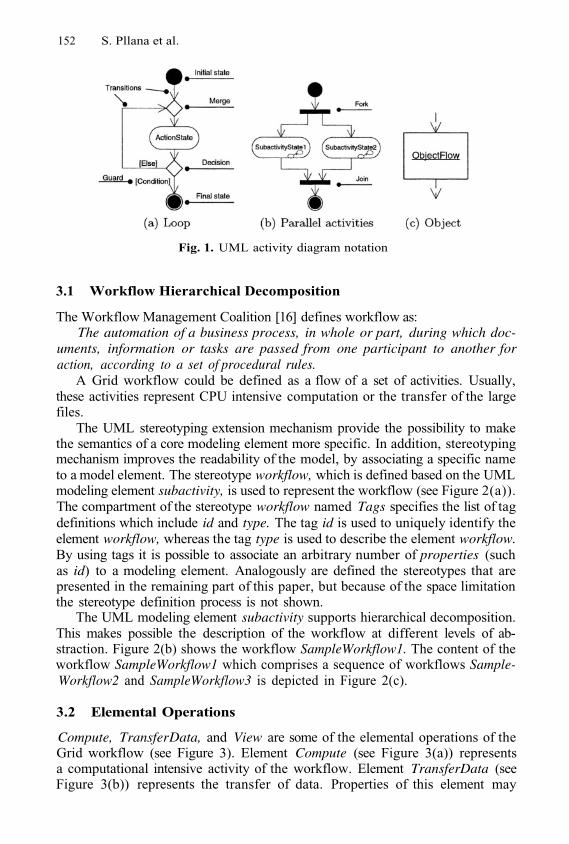
152 S. Pllana et al.
Fig. 1. UML activity diagram notation
3.1 Workflow Hierarchical Decomposition
The Workflow Management Coalition [16] defines workflow as:The automation of a business process, in whole or part, during which doc-
uments, information or tasks are passed from one participant to another foraction, according to a set of procedural rules.
A Grid workflow could be defined as a flow of a set of activities. Usually,these activities represent CPU intensive computation or the transfer of the largefiles.
The UML stereotyping extension mechanism provide the possibility to makethe semantics of a core modeling element more specific. In addition, stereotypingmechanism improves the readability of the model, by associating a specific nameto a model element. The stereotype workflow, which is defined based on the UMLmodeling element subactivity, is used to represent the workflow (see Figure 2(a)).The compartment of the stereotype workflow named Tags specifies the list of tagdefinitions which include id and type. The tag id is used to uniquely identify theelement workflow, whereas the tag type is used to describe the element workflow.By using tags it is possible to associate an arbitrary number of properties (suchas id) to a modeling element. Analogously are defined the stereotypes that arepresented in the remaining part of this paper, but because of the space limitationthe stereotype definition process is not shown.
The UML modeling element subactivity supports hierarchical decomposition.This makes possible the description of the workflow at different levels of ab-straction. Figure 2(b) shows the workflow SampleWorkflow1. The content of theworkflow SampleWorkflow1 which comprises a sequence of workflows Sample-Workflow2 and SampleWorkflow3 is depicted in Figure 2(c).
3.2 Elemental Operations
Compute, Transfer Data, and View are some of the elemental operations of theGrid workflow (see Figure 3). Element Compute (see Figure 3(a)) representsa computational intensive activity of the workflow. Element TransferData (seeFigure 3(b)) represents the transfer of data. Properties of this element may
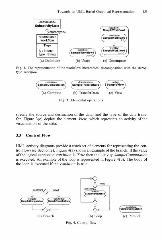
Towards an UML Based Graphical Representation 153
Fig. 2. The representation of the workflow hierarchical decomposition with the stereo-type workflow
Fig. 3. Elemental operations
specify the source and destination of the data, and the type of the data trans-fer. Figure 3(c) depicts the element View, which represents an activity of thevisualization of the data.
3.3 Control Flow
UML activity diagrams provide a reach set of elements for representing the con-trol flow (see Section 2). Figure 4(a) shows an example of the branch. If the valueof the logical expression condition is True then the activity SampleComputationis executed. An example of the loop is represented in Figure 4(b). The body ofthe loop is executed if the condition is true.
Fig. 4. Control flow
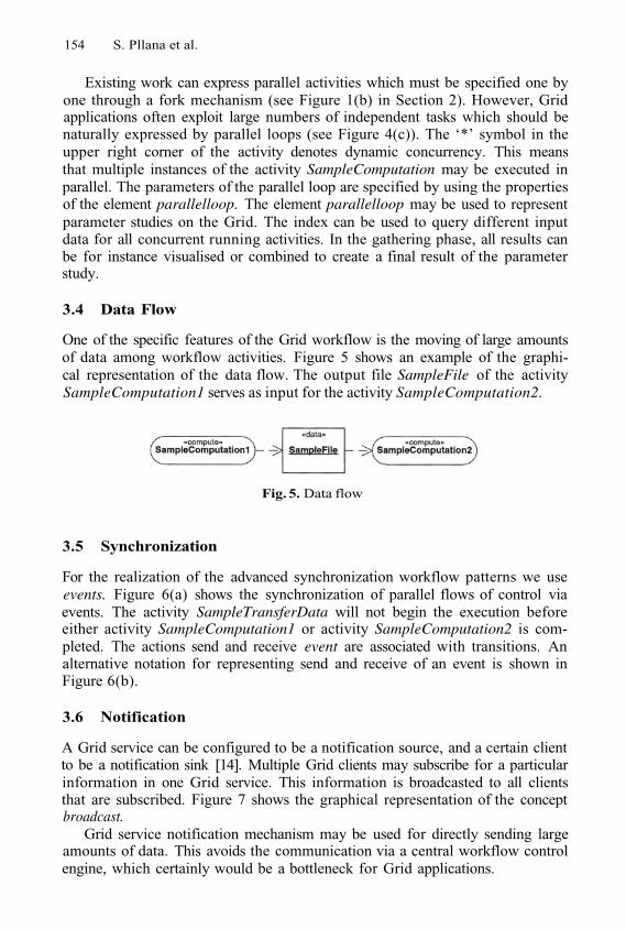
154 S. Pllana et al.
Existing work can express parallel activities which must be specified one byone through a fork mechanism (see Figure 1(b) in Section 2). However, Gridapplications often exploit large numbers of independent tasks which should benaturally expressed by parallel loops (see Figure 4(c)). The ‘*’ symbol in theupper right corner of the activity denotes dynamic concurrency. This meansthat multiple instances of the activity SampleComputation may be executed inparallel. The parameters of the parallel loop are specified by using the propertiesof the element parallelloop. The element parallelloop may be used to representparameter studies on the Grid. The index can be used to query different inputdata for all concurrent running activities. In the gathering phase, all results canbe for instance visualised or combined to create a final result of the parameterstudy.
3.4 Data Flow
One of the specific features of the Grid workflow is the moving of large amountsof data among workflow activities. Figure 5 shows an example of the graphi-cal representation of the data flow. The output file SampleFile of the activitySampleComputation1 serves as input for the activity SampleComputation2.
Fig. 5. Data flow
3.5 Synchronization
For the realization of the advanced synchronization workflow patterns we useevents. Figure 6(a) shows the synchronization of parallel flows of control viaevents. The activity SampleTransferData will not begin the execution beforeeither activity SampleComputation1 or activity SampleComputation2 is com-pleted. The actions send and receive event are associated with transitions. Analternative notation for representing send and receive of an event is shown inFigure 6(b).
3.6 Notification
A Grid service can be configured to be a notification source, and a certain clientto be a notification sink [14]. Multiple Grid clients may subscribe for a particularinformation in one Grid service. This information is broadcasted to all clientsthat are subscribed. Figure 7 shows the graphical representation of the conceptbroadcast.
Grid service notification mechanism may be used for directly sending largeamounts of data. This avoids the communication via a central workflow controlengine, which certainly would be a bottleneck for Grid applications.
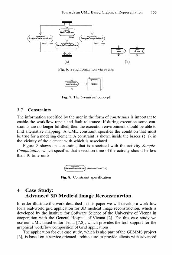
Towards an UML Based Graphical Representation 155
Fig. 7. The broadcast concept
3.7 Constraints
The information specified by the user in the form of constraints is important toenable the workflow repair and fault tolerance. If during execution some con-straints are no longer fulfilled, then the execution environment should be able tofind alternative mapping. A UML constraint specifies the condition that mustbe true for a modeling element. A constraint is shown inside the braces ({ }), inthe vicinity of the element with which is associated.
Figure 8 shows an constraint, that is associated with the activity Sample-Computation, which specifies that execution time of the activity should be lessthan 10 time units.
Fig. 8. Constraint specification
4 Case Study:Advanced 3D Medical Image Reconstruction
In order illustrate the work described in this paper we will develop a workflowfor a real-world grid application for 3D medical image reconstruction, which isdeveloped by the Institute for Software Science of the University of Vienna incooperation with the General Hospital of Vienna [2]. For this case study weuse our UML-based editor Teuta [7,8], which provides the tool-support for thegraphical workflow composition of Grid applications.
The application for our case study, which is also part of the GEMMS project[3], is based on a service oriented architecture to provide clients with advanced
Fig. 6. Synchronization via events
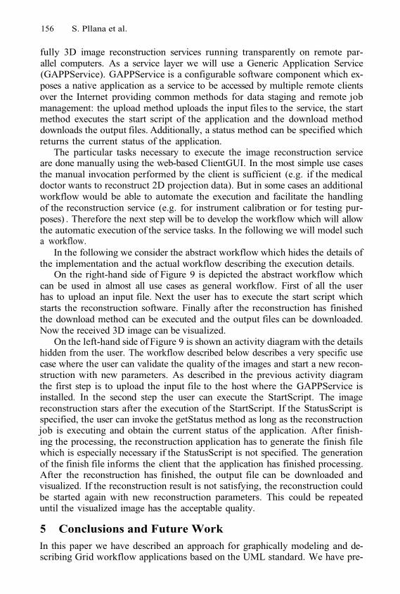
156 S. Pllana et al.
fully 3D image reconstruction services running transparently on remote par-allel computers. As a service layer we will use a Generic Application Service(GAPPService). GAPPService is a configurable software component which ex-poses a native application as a service to be accessed by multiple remote clientsover the Internet providing common methods for data staging and remote jobmanagement: the upload method uploads the input files to the service, the startmethod executes the start script of the application and the download methoddownloads the output files. Additionally, a status method can be specified whichreturns the current status of the application.
The particular tasks necessary to execute the image reconstruction serviceare done manually using the web-based ClientGUI. In the most simple use casesthe manual invocation performed by the client is sufficient (e.g. if the medicaldoctor wants to reconstruct 2D projection data). But in some cases an additionalworkflow would be able to automate the execution and facilitate the handlingof the reconstruction service (e.g. for instrument calibration or for testing pur-poses) . Therefore the next step will be to develop the workflow which will allowthe automatic execution of the service tasks. In the following we will model sucha workflow.
In the following we consider the abstract workflow which hides the details ofthe implementation and the actual workflow describing the execution details.
On the right-hand side of Figure 9 is depicted the abstract workflow whichcan be used in almost all use cases as general workflow. First of all the userhas to upload an input file. Next the user has to execute the start script whichstarts the reconstruction software. Finally after the reconstruction has finishedthe download method can be executed and the output files can be downloaded.Now the received 3D image can be visualized.
On the left-hand side of Figure 9 is shown an activity diagram with the detailshidden from the user. The workflow described below describes a very specific usecase where the user can validate the quality of the images and start a new recon-struction with new parameters. As described in the previous activity diagramthe first step is to upload the input file to the host where the GAPPService isinstalled. In the second step the user can execute the StartScript. The imagereconstruction stars after the execution of the StartScript. If the StatusScript isspecified, the user can invoke the getStatus method as long as the reconstructionjob is executing and obtain the current status of the application. After finish-ing the processing, the reconstruction application has to generate the finish filewhich is especially necessary if the StatusScript is not specified. The generationof the finish file informs the client that the application has finished processing.After the reconstruction has finished, the output file can be downloaded andvisualized. If the reconstruction result is not satisfying, the reconstruction couldbe started again with new reconstruction parameters. This could be repeateduntil the visualized image has the acceptable quality.
5 Conclusions and Future WorkIn this paper we have described an approach for graphically modeling and de-scribing Grid workflow applications based on the UML standard. We have pre-
Towards an UML Based Graphical Representation 157
Fig. 9. The workflow composition of the 3D image reconstruction application
sented a set of concepts for modeling control flow, data flow, synchronization,notification, and constraints. We have demonstrated our approach by describ-ing a Grid workflow model for an advanced 3D medical image reconstructionapplication.
The upcoming UML2.0 specification provides a richer set of concepts forbehavioral modeling. We plan to extend our tool Teuta for supporting of thenew concepts and notation of UML2.0.
References
1.
2.
T. Andrews, F. Curbera, H. Dholakia, Y. Goland, J. Klein, F. Leymann, K. Liu,D. Roller, D. Smith, S. Thatte, I. Trickovic, and S. Weerawarana. Business ProcessExecution Language for Web Services. Version 1.1, BEA, IBM, Microsoft, SAP, andSiebel, May 2003.W. Backfrieder, M. Forster, S. Benkner, and G. Engelbrecht. Locally Variant VORin Fully 3D SPECT within A Service Oriented Environment. In International Con-ference on Mathematics and Engineering Techniques in Medicine and BiologicalSciences, Las Vegas, USA, June 2003. CSREA Press.
158 S. Pllana et al.
3.
4.
5.
6.
7.
8.
9.
10.
11.
12.
13.
14.
15.
16.
G. Berti, S. Benkner, J. Fenner, J. Fingberg, G. Lonsdale, S. Middleton, andM. Surridge. Medical Simulation Services via the Grid. In 17th International Paral-lel and Distributed Processing Symposium (IPDPS 2003), Nice, France, April 2003.IEEE Computer Society.H. Bivens. Grid Workflow. Sandia National Laboratories,http://vir.sandia.gov/~hpbiven/, April 2001.T. Bray, J. Paoli, C. Sperberg-McQueen, and E. Maler. Extensible Markup Lan-guage (XML) 1.0 (Second Edition). http://www.w3.org/TR/REC-xml, October2000.Department of Physics and Astronomy, Cardiff University.Triana, 2003. http://www.triana.co.uk/.T. Fahringer, S. Pllana, and J. Testori. Teuta.University of Vienna, Institute for Software Science. Available online:http://www.par.univie.ac.at/project/prophet.T. Fahringer, S. Pllana, and J. Testori. Teuta: Tool Support for PerformanceModeling of Distributed and Parallel Applications. In International Conferenceon Computational Science. Tools for Program Development and Analysis in Com-putational Science., Krakow, Poland, June 2004. Springer-Verlag.Business Process Management Initiative. Business Process Modelling Language.www.bpmi.org/bmpi-downloads/BPML-SPEC-1.0.zip, June 2002.S. Krishnan, P. Wagstrom, and G. Laszewski. GSFL : A Workflow Frameworkfor Grid Services. Preprint ANL/MCS-P980-0802, Argonne National Laboratory,August 2002.F. Leymann. Web Services Flow Language (WSFL 1.0). Technical report, IBMSoftware Group, May 2001.OMG. Unified Modeling Language Specification. http://www.omg.org, March2003.OMG. XML Metadata Interchange (XMI) Specification. http://www.omg.org,May 2003.B. Sotomayor. The Globus Toolkit 3 Programmer’s Tutorial. http://www.casa-sotomayor.net/gt3-tutorial/, July 2003.S. Thatte. XLANG: Web services for Business Process Design. Technical report,Microsoft Corporation, 2001.The Workflow Management Coalition. http://www.wfmc.org/.
Support for User-Defined Metricsin the Online Performance Analysis Tool G-PM*
Roland Wismüller1, Marian Bubak2,3, 2,2,3, and Marcin Kurdziel2,3
1 LRR-TUM, Institut für Informatik, Technische Universität München,D-85747 Garching, Germany
2 Institute of Computer Science, AGH, al. Mickiewicza 30, 30-059 Kraków, Poland3 Academic Computer Centre – CYFRONET, Nawojki 11, 30-950 Kraków, Poland
phone: (+48 12) 617 39 64, fax: (+48 12) 633 80 54, phone: (+49 89) 289 17676{bubak,funika}@uci.agh.edu.pl, [email protected]
Abstract. This paper presents the support for user-defined metrics inthe G-PM performance analysis tool. G-PM addresses the demand foraggressive optimisation of Grid applications by using a new approachto performance monitoring. The tool provides developers, integrators,and end users with the ability to analyse the performance characteristicsof an application at a high level of abstraction. In particular, it allowsto relate an application’s performance to the Grid’s performance, andalso supports application-specific metrics. This is achieved by introduc-ing a language for the specification of performance metrics (PMSL) andthe concept of probes for providing application specific events and data.PMSL enables an easy specification of performance metrics, yet allow-ing an efficient implementation, required for the reduction of monitoringoverhead.
Keywords: Grid, performance monitoring, user-defined metrics
1 Introduction
With Grid computing, a new level of complexity has been introduced to thedevelopment process of distributed applications. Grid enabled applications arepresumed to be run not only in geographically distributed locations, but alsoon a diverse set of hardware and software platforms. At the same time, theemphasis is on the computing being as cost effective as possible. This leads to therequirements for the applications to utilise the available resources in the optimalway. Usually, performance degradations emerge as a result of an imbalance incomputation distribution, flaws in the schema of application synchronisationoperations, or suboptimal allocation of resources. Such conditions can be fullyobserved only during an application run in an environment that closely resemblesthe one in which the application is to be deployed. The best approach would
* This work was partly funded by the European Commission, project IST-2001-32243,CrossGrid.
M. Dikaiakos (Ed.): AxGrids 2004, LNCS 3165, pp. 159–168, 2004.© Springer-Verlag Berlin Heidelberg 2004
160 R. Wismüller et al.
be to observe the application directly on the Grid. Consequently, Grid orientedperformance monitoring systems become necessary tools for development of highperformance Grid applications. These tools should work in on-line mode – it is anecessary prerequisite not only for the monitoring of applications with a very longexecution time, but also for non-batch programs, like interactive applications orservices. Moreover, the monitoring should not introduce a noticeable overheadas this might disturb the application’s execution, thus rendering the measuredperformance properties useless.
A performance monitoring tool for Grid applications, G-PM, designed tofulfil the above-stated demands is being developed in the CrossGrid project [5].For gathering of the raw performance data, both application- and Grid-related,the G-PM tool uses the OCM-G monitoring service1. The performance data arerequested from the OCM-G and then analysed by G-PM during the application’sexecution. On top of the data returned by OCM-G, a set of standard, built-inmetrics is defined, like communication volume and delay, or overhead of file I/O.
The tool differs from related approaches (see Sect. 3) in the respect that itcombines the support for on-line standard performance measurements with thesupport for user-defined metrics and application-specific instrumentation. Thisenables to adjust the tool’s operation to the specific analysis needs meaningfulin the context of the application. Once such a metrics, specified with a simpledefinition language, has been entered in the tool’s user interface, it can be usedin the same way as the built-in ones.
This paper focuses on the support for user-defined metrics in the G-PM tool.The main part of the article (Section 2) presents the Performance Metrics Speci-fication Language PMSL and two usage examples. Furthermore, an approach tothe efficient implementation of the measurements based on user-defined metricsis described. Section 4 presents concluding remarks along with information onthe current state of G-PM.
2 User-Defined Metrics
In the following, we present the technical details on how user-defined metrics arespecified and how they are implemented in a distributed on-line fashion. Due tospace limitation, we must refer the reader to [3, 13] for the detailed motivation,design goals, and the basic concepts behind this work.
2.1 Specification of Metrics
A user-defined, application specific metrics in G-PM is based on already existingmetrics, plus some minimal, specific information from the user’s application:
Occurrences of important events in the application’s execution,associations between related events, and(optionally) performance data computed by the application itself.
1 For more details please see [1, 2].
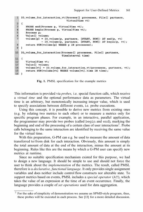
Support for User-Defined Metrics 161
Fig. 1. PMSL specification for the example metrics
This information is provided via probes, i.e. special function calls, which receivea virtual time and the optional performance data as parameters. The virtualtime is an arbitrary, but monotonically increasing integer value, which is usedto specify associations between different events, i.e. probe executions.
Using this concept, it is possible to derive new metrics from existing ones(e.g. by relating two metrics to each other) or to measure a metrics only forspecific program phases. For example, in an interactive, parallel application,the programmer may provide two probes (called begin and end), marking thebeginning and end of the processing of a certain class of user interactions2. Probecalls belonging to the same interaction are identified by receiving the same valuefor the virtual time.
With this preparation, G-PM can e.g. be used to measure the amount of datatransferred to/from disk for each interaction. Obviously, this amount is simplythe total amount of data at the end of the interaction, minus the amount at itsbeginning. Rules like this are the means by which a G-PM user can specify newmetrics at runtime.
Since no suitable specification mechanism existed for this purpose, we hadto design a new language. It should be simple to use and should not force theuser to think about the implementation of the metrics. The result, called PMSLtherefore is a declarative, functional language. It only provides single assignmentvariables and does neither include control flow constructs nor alterable state. Tosupport metrics based on events, PMSL includes a special operator (AT), whichtakes the value of an expression at the time of an event occurrence. Finally, thelanguage provides a couple of set operations used for data aggregation.
2 For the sake of simplicity of demonstration we assume an SPMD-style program, thus,these probes will be executed in each process. See [13] for a more detailed discussion.
162 R. Wismüller et al.
Instead of formally introducing the syntax and semantics of PMSL, we willjust discuss the specification for the example metrics introduced above, whichdemonstrates most of the language’s features. Fig. 1 shows the specification ofour example metrics. In general, each metrics has parameters that define
1.2.
3.
the object(s) to be measured (e.g. Process[] processes: a list ofprocesses),restrictions to the measurement, like partner objects or code regions (e.g.File[] partners: a list of files), anda time specification. This can be a point in real time at which the measure-ment is done, a measurement interval in real time (TimeInterval time), ora point in virtual time (VirtualTime vt).
In Fig. 1 two metrics are defined: IO_volume_for_interaction_vt specifies ametrics for the amount of disk I/O for a point in virtual time, i.e. (in our exam-ple) for a single user interaction. Line 7 tells how to compute the contribution ofone process: just subtract its total I/O volume at the begin event from the oneat the end event. The term [START,NOW] defines the measurement time intervalfor theIO_volume metrics (which is a built-in metrics of G-PM): the lower boundis the start time of the whole measurement, the upper bound is the current time,i.e. the time of the event. Line 8 finally states that the return value is the sumof the contributions of all measured processes. IO_volume_for_interaction isa metrics that refers to a given interval of (real) time. Its result is the I/Ovolume caused by all user interactions in the specified measurement time inter-val. Since all measurement values in G-PM are time-stamped, this metrics canbe computed by considering the results of IO_volume_for_interaction_vt forall virtual times and by summing up all results whose time-stamps lie in themeasurement interval.
The examples show that the metrics are specified at a rather high level ofabstraction, thus, users of G-PM should be able to define their own metricsaccording to their needs. Nevertheless, the specifications still can be convertedto efficient, distributed on-line measurements, as we will show in the next section.
2.2 Implementation of Measurements
There are two reasons why the measurements must be implemented in a dis-tributed fashion: First, the AT construct in PMSL requires a measurement valueto be determined when an event occurs. In order to avoid communication delayswhich would adulterate the results, determining the measurement value musthappen at the same place where the event occurs. Second, distributed process-ing of measurement data often significantly reduces the amount of data thatmust be sent to the G-PM tool via the network, thus reducing the perturbationof the measured system and increasing scalability.
The way from a PMSL specification to a distributed on-line measurementconsists of five phases:
1. When the user defines the new metrics, it is parsed into an intermediaterepresentation (IR).
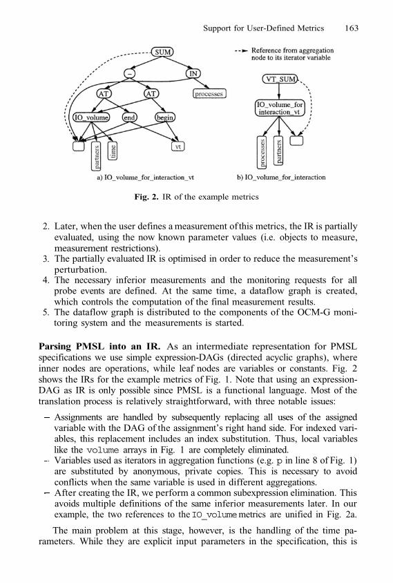
Support for User-Defined Metrics 163
Fig. 2. IR of the example metrics
2.
3.
4.
5.
Later, when the user defines a measurement of this metrics, the IR is partiallyevaluated, using the now known parameter values (i.e. objects to measure,measurement restrictions).The partially evaluated IR is optimised in order to reduce the measurement’sperturbation.The necessary inferior measurements and the monitoring requests for allprobe events are defined. At the same time, a dataflow graph is created,which controls the computation of the final measurement results.The dataflow graph is distributed to the components of the OCM-G moni-toring system and the measurements is started.
Parsing PMSL into an IR. As an intermediate representation for PMSLspecifications we use simple expression-DAGs (directed acyclic graphs), whereinner nodes are operations, while leaf nodes are variables or constants. Fig. 2shows the IRs for the example metrics of Fig. 1. Note that using an expression-DAG as IR is only possible since PMSL is a functional language. Most of thetranslation process is relatively straightforward, with three notable issues:
Assignments are handled by subsequently replacing all uses of the assignedvariable with the DAG of the assignment’s right hand side. For indexed vari-ables, this replacement includes an index substitution. Thus, local variableslike the volume arrays in Fig. 1 are completely eliminated.Variables used as iterators in aggregation functions (e.g. p in line 8 of Fig. 1)are substituted by anonymous, private copies. This is necessary to avoidconflicts when the same variable is used in different aggregations.After creating the IR, we perform a common subexpression elimination. Thisavoids multiple definitions of the same inferior measurements later. In ourexample, the two references to theIO_volume metrics are unified in Fig. 2a.
The main problem at this stage, however, is the handling of the time pa-rameters. While they are explicit input parameters in the specification, this is
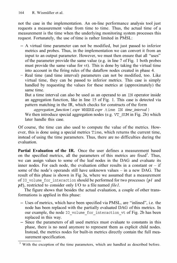
164 R. Wismüller et al.
not the case in the implementation. An on-line performance analysis tool justrequests a measurement value from time to time. Thus, the actual time of ameasurement is the time when the underlying monitoring system processes thisrequest. Fortunately, the use of time is rather limited in PMSL:
A virtual time parameter can not be modified, but just passed to inferiormetrics and probes. Thus, in the implementation we can convert it from aninput to an output parameter. However, we must then ensure that all “uses”of the parameter provide the same value (e.g. in line 7 of Fig. 1 both probesmust provide the same value for vt). This is done by taking the virtual timeinto account in the firing rules of the dataflow nodes created in phase 4.Real time (and time interval) parameters can not be modified, too. Likevirtual time, they can be passed to inferior metrics. This case is simplyhandled by requesting the values for these metrics at (approximately) thesame time.But a time interval can also be used as an operand to an IN operator insidean aggregation function, like in line 15 of Fig. 1. This case is detected viapattern matching in the IR, which checks for constructs of the form
aggregation_function( expr WHERE expr .time IN time_interval )We then introduce special aggregation nodes (e.g. VT_SUM in Fig. 2b) whichlater handle this case.
Of course, the time can also used to compute the value of the metrics. How-ever, this is done using a special metrics Time, which returns the current time,instead of using the time parameters. Thus, there are no difficulties during theevaluation.
Partial Evaluation of the IR. Once the user defines a measurement basedon the specified metrics, all the parameters of this metrics are fixed3. Thus,we can assign values to some of the leaf nodes in the DAG and evaluate itsinner nodes. For each node, the evaluation either results in a constant or – ifsome of the node’s operands still have unknown values – in a new DAG. Theresult of this phase is shown in Fig 3a, where we assumed that a measurementof IO_volume_for_interaction should be performed for two processes and
restricted to consider only I/O to a file named file1.The figure shows that besides the actual evaluation, a couple of other trans-
formations is applied in this phase:
Uses of metrics, which have been specified via PMSL, are “inlined”, i.e. thenode has been replaced with the partially evaluated DAG of this metrics. Inour example, the node IO_volume_for_interaction_vt of Fig. 2b has beenreplaced in this way.Since the parameters of all used metrics must evaluate to constants in thisphase, there is no need anymore to represent them as explicit child nodes.Instead, the metrics nodes for built-in metrics directly contain the full mea-surement specification.
3 With the exception of the time parameters, which are handled as described before.
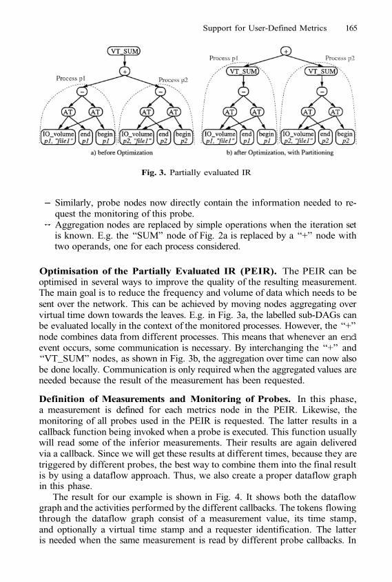
Support for User-Defined Metrics 165
Fig. 3. Partially evaluated IR
Similarly, probe nodes now directly contain the information needed to re-quest the monitoring of this probe.Aggregation nodes are replaced by simple operations when the iteration setis known. E.g. the “SUM” node of Fig. 2a is replaced by a “+” node withtwo operands, one for each process considered.
Optimisation of the Partially Evaluated IR (PEIR). The PEIR can beoptimised in several ways to improve the quality of the resulting measurement.The main goal is to reduce the frequency and volume of data which needs to besent over the network. This can be achieved by moving nodes aggregating overvirtual time down towards the leaves. E.g. in Fig. 3a, the labelled sub-DAGs canbe evaluated locally in the context of the monitored processes. However, the “+”node combines data from different processes. This means that whenever an endevent occurs, some communication is necessary. By interchanging the “+” and“VT_SUM” nodes, as shown in Fig. 3b, the aggregation over time can now alsobe done locally. Communication is only required when the aggregated values areneeded because the result of the measurement has been requested.
Definition of Measurements and Monitoring of Probes. In this phase,a measurement is defined for each metrics node in the PEIR. Likewise, themonitoring of all probes used in the PEIR is requested. The latter results in acallback function being invoked when a probe is executed. This function usuallywill read some of the inferior measurements. Their results are again deliveredvia a callback. Since we will get these results at different times, because they aretriggered by different probes, the best way to combine them into the final resultis by using a dataflow approach. Thus, we also create a proper dataflow graphin this phase.
The result for our example is shown in Fig. 4. It shows both the dataflowgraph and the activities performed by the different callbacks. The tokens flowingthrough the dataflow graph consist of a measurement value, its time stamp,and optionally a virtual time stamp and a requester identification. The latteris needed when the same measurement is read by different probe callbacks. In
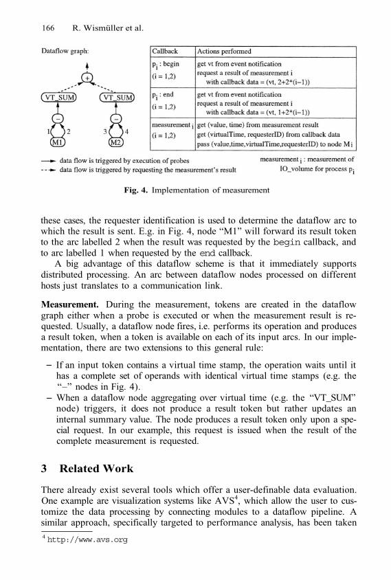
166 R. Wismüller et al.
Fig. 4. Implementation of measurement
these cases, the requester identification is used to determine the dataflow arc towhich the result is sent. E.g. in Fig. 4, node “M1” will forward its result tokento the arc labelled 2 when the result was requested by the begin callback, andto arc labelled 1 when requested by the end callback.
A big advantage of this dataflow scheme is that it immediately supportsdistributed processing. An arc between dataflow nodes processed on differenthosts just translates to a communication link.
Measurement. During the measurement, tokens are created in the dataflowgraph either when a probe is executed or when the measurement result is re-quested. Usually, a dataflow node fires, i.e. performs its operation and producesa result token, when a token is available on each of its input arcs. In our imple-mentation, there are two extensions to this general rule:
If an input token contains a virtual time stamp, the operation waits until ithas a complete set of operands with identical virtual time stamps (e.g. the“–” nodes in Fig. 4).When a dataflow node aggregating over virtual time (e.g. the “VT_SUM”node) triggers, it does not produce a result token but rather updates aninternal summary value. The node produces a result token only upon a spe-cial request. In our example, this request is issued when the result of thecomplete measurement is requested.
3 Related Work
There already exist several tools which offer a user-definable data evaluation.One example are visualization systems like AVS4, which allow the user to cus-tomize the data processing by connecting modules to a dataflow pipeline. Asimilar approach, specifically targeted to performance analysis, has been taken4 http://www.avs.org
Support for User-Defined Metrics 167
by Pablo [11]. Paraver [6] offers a menu-driven specification of user-defined met-rics. However, all of these approaches only support a centralized and off-linedata analysis, where large amounts of raw data (event traces in case of Pabloand Paraver) have to be sent to a single computer and have to be analysed there.In contrast, G-PM targets a distributed on-line analysis, where the raw data isprocessed at its origin, which greatly reduces the load of the network and thecomputer executing the tool’s user interface. Only this kind of analysis allows toprovide an immediate feedback on the behaviour of an application.
Some other performance analysis tools also use languages to define metrics.Examples are Paradyn [10] with its measurement definition language MDL [9],EXPERT [15] with the trace analysis language EARL [14], and the JavaPSLproperty specification language [8]. In contract to PMSL, these languages areused only internally in the tools; they are not suited for being exposed to theuser. MDL and EARL are imperative, rather than declarative languages, i.e. ametrics is defined by exactly specifying the implementation of its measurement.JavaPSL is declarative, but aims at different goals. In fact, JavaPSL and PMSLhave a common root in the APART Specification Language ASL [7]. A majorcontribution of PMSL is that it allows to combine events with existing metrics.
Finally, our approach of using expression DAGs has some similarity to dy-namic instrumentation techniques as implemented by Dyninst [4] and DPCL[12]. The main difference is that the DAG created from a PMSL specificationcombines information from distributed sources, i.e. its evaluation must be spreadacross several processes. In contrast, in Dyninst and DPCL the DAGs are lo-cal, i.e. they are always executed by a single process. However, the concepts fittogether rather well: In an advanced implementation, we could use Dyninst orDPCL to efficiently implement the local sub-DAGs marked in Fig. 3.
4 Conclusions
The paper presented a method to support user-defined metrics for monitoring ofGrid enabled, distributed applications, which relies on the PMSL performancemetrics specification language. The language allows to combine information fromevent occurrences, application specific data, and existing metrics in order todefine new, higher-level metrics. These metrics may summarize information fromdifferent processes of the distributed application; the necessary data processing isperformed on-line, using an efficient distributed dataflow scheme. Consequently,applications can be monitored with minimal additional overhead.
The PMSL language and its translation have been implemented as a first pro-totype, where the optimizations of the PEIR and the distribution of the dataflowgraphs are not yet included. This implementation is integrated into the currentversion of the G-PM tool, which will be released inside the CrossGrid projectin Spring 2004. The implementation of optimizations and the fully distributedevaluation based on the OCM-G monitoring system is work in progress.
168 R. Wismüller et al.
References1.
2.
3.
4.
5.
6.
7.
8.
9.
10.
11.
12.
13.
14.
15.
Bubak, M., Funika, W., Szepieniec, T., and Wismüller, R.: An Infras-tructure for Grid Application Monitoring. In: Recent Advances in Parallel VirtualMachine and Message Passing Interface, 9th European PVM/MPI Users’ GroupMeeting, Sept. - Oct. 2002, Linz, Austria, LNCS 2474, pp. 41-49, Springer-Verlag,2002.
Bubak, M., Funika, W., Szepieniec, T., and Wismüller, R.: Monitoringand Performance Analysis of Grid Application. In: Computational Science - ICCS2003, June 2003, St. Petersburg, Russia, LNCS 2657, pp. 214-224, Springer-Verlag,2003.Bubak, M., Funika, W., Wismüller, R., Arodz, T., and Kurdziel, M.: The G-PMTool for Grid-oriented Performance Analysis. In: 1st European Across Grids Con-ference, Santiago de Compostela, Spain, Feb. 2003, LNCS 2970, Springer-Verlag,2004Buck, B. and Hollingsworth, J.K.: An API for Runtime Code Patching, The In-ternational Journal of High Performance Computing Applications, 14(4), Winter2000, pp. 317–329.CrossGrid - Development of Grid Environment for interactive Applications, EUProject, IST-2001-32243, Technical Annex.http://www.eu-crossgrid.orgEuropean Center for Parallelism of Barcelona. Paraver.http://www.cepba.upc.es/paraver/T. Fahringer, M. Gerndt, G. Riley, and J. L. Träff: Knowledge Specification forAutomatic Performance Analysis. APART Technical Report, ESPRIT IV WorkingGroup on Automatic Performance Analysis, Nov. 1999.http://www.fz-juelich.de/apart-1/reports/wp2-asl.ps.gzT. Fahringer and C. Seragiotto: Modeling and Detecting Performance Problems forDistributed and Parallel Programs with JavaPSL. In 9th IEEE High-PerformanceNetworking and Computing Conference, SC’2001, Denver, CO, Nov. 2001.J. R. Hollingsworth, B. P. Miller, M. J. R. Gonçalves, Z. Xu, O. Naim, andL. Zheng: MDL: A Language and Compiler for Dynamic Program Instrumenta-tion. In Proc. International Conference on Parallel Architectures and CompilationTechniques, San Francisco, CA, USA, Nov. 1997.ftp://grilled.cs.wise.edu/technical_papers/mdl.ps.gz.Miller, B.P., et al.: The Paradyn Parallel Performance Measurement Tools. IEEEComputer, 28(11): 37-46, Nov. 1995.University of Illinois. Pablo Performance Analysis Environment: Data Analysis.http://www-pablo.cs.uiuc.edu/Project/Pablo/PabloDataAnalysis.htmUniversity of Madison, Wisconsin. Dynamic Probe Class Library (DPCL).http://www.cs.wise.edu/paradyn/DPCL/Wismüller, R., Bubak, M., Funika, W., and A Performance AnalysisTool for Interactive Applications on the Grid. International Journal of High Per-formance Computer Applications, Fall 2004, SAGE Publications. In print.F. Wolf and B. Mohr: EARL - A Programmable and Extensible Toolkit for Analyz-ing Event Traces of Message Passing Programs. In: Proc. of the 7th InternationalConference on High- Performance Computing and Networking (HPCN 99), LNCS1593, pp. 503–512, Amsterdam, 1999. Springer-Verlag.F. Wolf and B. Mohr: Automatic Performance Analysis of MPI Applications Basedon Event Traces. In: Euro-Par 2000 Parallel Processing, 6th International Euro-Par Conference, LNCS 1900, pp. 123–132, Munich, Germany, Aug. 2000. Springer-Verlag.
Software Engineeringin the EU CrossGrid Project*
Marian Bubak1,2, Maciej Malawski1,2, 3,PiotrNowakowski2, 2, Katarzyna Rycerz1,2, and 2,4
1 Institute of Computer Science, AGH, al. Mickiewicza 30, 30-059 Kraków, Poland2 Academic Computer Centre – CYFRONET, Nawojki 11, 30-950 Kraków, Poland
3 Websoft Ltd., Kraków, Poland4 Institute of Nuclear Physics, Kraków, Poland
phone: (+48 12) 617 39 64, fax: (+48 12) 633 80 54{bubak,malawski,kzajac}@uci.agh.edu.pl, [email protected],
{ymnowako,ympajak}@cyf-kr.edu.pl, [email protected]
Abstract. This paper details the software engineering process utilizedby the CrossGrid project, which is a major European undertaking, in-volving nearly two dozen separate organizations from 11 EU member andcandidate countries. A scientific project of this magnitude requires thecreation of custom-tailored procedures for ensuring uniformity of purposeand means throughout the Project Consortium.
Keywords: software engineering, grid, CrossGrid, quality indicators
1 Introduction
CrossGrid is one of the largest European projects in Grid research [2], uniting 21separate institutions and funded by the 5th European Framework Programme.The primary objectives of CrossGrid is to further extend the Grid environmentto a new category of applications of great practical importance and to involvemore countries (including EU candidate states) in European Grid research [12].The applications developed within CrossGrid are characterized by the inter-action with a person in a processing loop. They require a response from thecomputer system to an action by the person in different time scales; from realthrough intermediate to long time, and they are simultaneously compute- aswell as data-intensive. Examples of these applications are: interactive simulationand visualization for surgical procedures, flooding crisis team decision supportsystems, distributed data analysis in high-energy physics, air pollution combinedwith weather forecasting. A visualization engine should be developed and opti-mized for these applications.
* This research is partly funded by the European Commission IST-2001-32243 Project“CrossGrid” and the Polish State Committee for Scientific Research, SPUB-M112/E-356/SPB/5.PR UE/DZ 224/2002-2004.
M. Dikaiakos (Ed.): AxGrids 2004, LNCS 3165, pp. 169–178, 2004.© Springer-Verlag Berlin Heidelberg 2004
170 M. Bubak et al.
To enable efficient development of this category of applications for the Gridenvironment, new tools for verification of parallel source code, performance pre-diction, performance evaluation and monitoring are needed. This, in turn, re-quires extension of the Grid by new components for application-performancemonitoring, efficient distributed data access, and specific resource management.Users should be able to run their applications on the Grid in an easy and trans-parent way, without needing to know details of the Grid structure and opera-tion. CrossGrid will develop user-friendly portals and mobile personalized en-vironments and will integrate new components into the Grid and applicationdevelopment tools.
The elaborated methodology, generic application architecture, programmingenvironment, and new Grid services will be validated and tested thoroughly onthe CrossGrid testbeds. This will result in further extension of the Grid acrossEurope. CrossGrid development will exploit all the available achievements ofDataGrid, EuroGrid and other related projects in a way which enables theirinteroperability. CrossGrid closely collaborates with DataGrid.
2 Architecture
CrossGrid utilizes a layered architecture composed of three distinct softwarelayers (applications, tools and services) and one hardware layer, similar to thatdefined in [11]. The individual layers of CrossGrid are reflected by the distribu-tion of Project Work Packages (WPs): three technical WPs devoted to devel-opment of each layer separately, one testbed WP, providing hardware supportfor CrossGrid operations and one managerial WP. CrossGrid architecture essen-tially follows a layered approach in that the topmost layer (applications) relieson lower layers (support tools and Grid services), which in turn make use of theinfrastructure (testbed) layer. Each type of Work Package (technical, testbedand management) is subject to a different set of operating procedures and qual-ity assurance criteria, described below. This paper does not concentrate on thetechnical aspect of CrossGrid software, but rather on the management, oversightand reporting process inherent in a widely-distributed multinational undertakingthat is CrossGrid.
3 Project Phases
CrossGrid is scheduled for three years, officially starting in March 2002 andlasting until February 2005. The Project is divided into five distinct phases, asdepicted by Fig.1
CrossGrid utilizes an incremental software release policy, with three sched-uled releases. Therefore, the timeline is arranged as follows: Initial phase in-cluding requirement definition and merging (Months 1-3), First developmentphase including detailed design, refinement of requirements and production ofinitial prototypes (Months 4-12), Second development phase including furtherrefinement of prototypes and integration of components (Months 13-24), Third
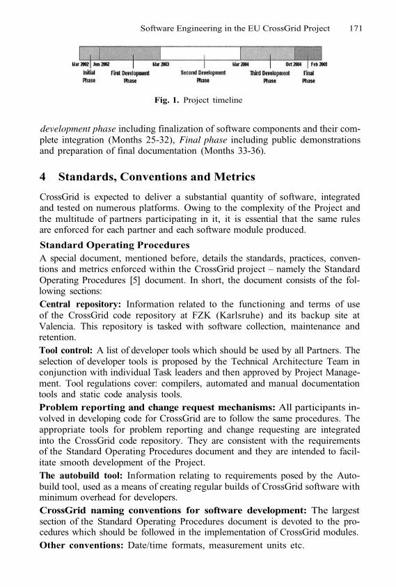
Software Engineering in the EU CrossGrid Project 171
Fig. 1. Project timeline
development phase including finalization of software components and their com-plete integration (Months 25-32), Final phase including public demonstrationsand preparation of final documentation (Months 33-36).
4 Standards, Conventions and Metrics
CrossGrid is expected to deliver a substantial quantity of software, integratedand tested on numerous platforms. Owing to the complexity of the Project andthe multitude of partners participating in it, it is essential that the same rulesare enforced for each partner and each software module produced.
Standard Operating ProceduresA special document, mentioned before, details the standards, practices, conven-tions and metrics enforced within the CrossGrid project – namely the StandardOperating Procedures [5] document. In short, the document consists of the fol-lowing sections:Central repository: Information related to the functioning and terms of useof the CrossGrid code repository at FZK (Karlsruhe) and its backup site atValencia. This repository is tasked with software collection, maintenance andretention.Tool control: A list of developer tools which should be used by all Partners. Theselection of developer tools is proposed by the Technical Architecture Team inconjunction with individual Task leaders and then approved by Project Manage-ment. Tool regulations cover: compilers, automated and manual documentationtools and static code analysis tools.Problem reporting and change request mechanisms: All participants in-volved in developing code for CrossGrid are to follow the same procedures. Theappropriate tools for problem reporting and change requesting are integratedinto the CrossGrid code repository. They are consistent with the requirementsof the Standard Operating Procedures document and they are intended to facil-itate smooth development of the Project.The autobuild tool: Information relating to requirements posed by the Auto-build tool, used as a means of creating regular builds of CrossGrid software withminimum overhead for developers.CrossGrid naming conventions for software development: The largestsection of the Standard Operating Procedures document is devoted to the pro-cedures which should be followed in the implementation of CrossGrid modules.Other conventions: Date/time formats, measurement units etc.
172 M. Bubak et al.
5 Tests and Reviews
As specified before, the CrossGrid project is divided into five phases, three ofwhich are termed development phases, which is where the software is actuallycreated. However, in order to develop software that matches its creators’ expec-tations, one must resort to formalized methods of design and control over thedevelopment process. To quote [1], we need to answer the question if we arebuilding the right thing, if what we’re building is technically feasible and whatis the best mode of utilization of the available resources. These aspects are ad-dressed by the CrossGrid software development plan and are described in thefollowing section.
Software Requirements Review
The Software Requirements Review is conducted upon the submission of the so-called Software Requirement Specifications (SRS) by each technical task (i.e.tasks, which develop software, as opposed to management tasks, integratedwithin WP5). These documents contain the following information: Overall de-scription of module (functionality, operations, interfaces, requirements and con-straints). Where appropriate, these should be augmented by UML componentand use case diagrams. A “state of the art” document reviewing technologiessuitable for the development of each module.
In addition, the Technical Architecture Team (TAT) is responsible for prepar-ing a preliminary draft of the general project architecture, expressing any inter-action between project components. Each task must fit into this architecture andthe TAT is responsible for reviewing all SRSs and deciding whether they conformto that overall Project hierarchy. Upon completion of this review, the partnersresponsible for each SRS are expected to make corrections in accordance withthe deliverable submission policy.
Design Review
Following the submission of SRS documents, each partner is to create a DesignDocument, expressing in concrete terms (UML class and sequence diagrams) theexact structure of their module. The Design Document is intended as a “whitebox” description of module functionality and is subjected to review by the IRBand TAT. The Design Documents contain the following information: Systemdecomposition description: an overview of the component breakdown of eachmodule, accompanied by UML component diagrams. This section describes themodule functionality in accordance with the IEEE-890 Standard Design Tem-plate. Dependency description: this section is devoted to the interaction betweenthe module being described and other modules (those being developed by othertasks as well as those external to the Project). Interface description: a formaldescription of any interface the software will provide (both APIs and GUIs) in-cluding method declarations and descriptions along with use cases and sequencediagrams (screenshots should be provided for GUIs).Detailed design: class dia-grams for each component of the software module being developed. This is themost low-level description of software design, with explanations regarding each
Software Engineering in the EU CrossGrid Project 173
attribute and method of the software being developed. The Design Documentsare the basis for the implementation process, which commences upon the comple-tion of their review. A standard Design Document template has been approvedby Project Management and distributed to all relevant partners.
Implementation and Software Releases
As stated before, following the submission and acceptance of Design Documents,CrossGrid enters a phase of incremental releases, each of which is subject to areview. Three major releases are accounted for in the Technical Annex, but –as experience dictates – additional releases may prove necessary and the imple-mentation process should be flexible enough to accommodate these releases. Thisissue has been addressed by the managers of the CrossGrid software repository,through the introduction of the Autobuild tool (see [7] for further details). Foreach release, the following procedure is intended to occur:
Coordination meeting: Involves a discussion of the previous release and devel-ops a framework for a subsequent release. The coordination meeting is organizedafter each release and is open to all Project participants, but entails the partici-pation of WP task leaders, CrossGrid steering group and representatives of theTechnical Architecture Team and WP4 Integration Team. The end product ofthis meeting is an evaluation of the release’s suitability and quality, along witha prioritized list of issues concerning the next release, including: all software anddocumentation modifications with regard to the previous release and versions ofexternal software (i.e. Globus Toolkit, DataGrid middleware, compilers etc.) tobe used for the next release. In preparation for the coordination meetings eachtask holds internal meetings to develop a common stance and deliver a cohesivepresentation.
WP follow-up meetings: Individual tasks discuss the issues related to thenext release and develop specific workplans. Each task holds an internal meetingin order to develop its own workplan with regard to the next release, taking intoaccount the results of the coordination meeting. The follow-up meetings involvedesignations of responsibilities for individual participants. A separate meeting isheld by the Architecture Team to gauge the influence of the coordination meetingon CrossGrid architecture. If significant changes are foreseen, an updated versionof the architecture document is developed.
Software release workplan coordination: The CrossGrid Steering Groupdevelops a plan for the next release, upon discussion with individual WP leaders.The plan includes a list of all third-party software units which need to be installedon testbed sites in order to satisfy the upcoming release’s requirements.
Middleware integration: Applications and middleware tasks upload the latest(internally tested) versions of their software to the central repository (Karlsruhe),where they are accessed by WP4.4 (Verification and QA) for testing. Integrationissues are reported and fixed through the use of mechanisms described in Section4. The WP4 Integration Team integrates the pertinent modules with externalsoftware units and oversees the basic integration tests as per the software releasetest plan described in WP4 deliverables.
174 M. Bubak et al.
Acceptance testing: An integrated CrossGrid release is installed on Testbedsites for acceptance testing. Acceptance tests are created by software developersin cooperation with the Project Technical Architecture Team, basing on the SRSdocuments and presented as a sequence of formalized test cases. The acceptancetests are deemed to have been passed when each test case presented by theapplication groups is executed correctly. Interactive and distributed componentsare tested on a special testbed, called the Test and Validation Testbed, madeup of specially-selected components of the Project’s testbed infrastructure andrunning standardized software.
Release: The Integration Team holds a meeting to describe the release andindicate changes introduced since the last release. The release is accompaniedby relevant documentation, developed by individual WPs and by the IntegrationTeam. The types of tests and the applicable procedures are further described inAppendix 4, WP4.1 section of [10].
For each major release, technical tasks are obliged to prepare a set of doc-uments detailing the structure and functionality of the software they are de-livering. The initial prototype documentation template has been approved byProject Management and distributed to all relevant partners. The template in-cludes descriptions of module components which have been implemented so farand the functionality of the prototype (with use cases), description of discrepan-cies between the structure of the prototype and the Design Documents submittedearlier (if any changes are introduced during the implementation phase, part-ners are expected to explain their rationality), instructions and requirements foroperating the prototype (its installation and running, description of tests whichthe software has been subjected to (both “black box” – i.e. comparison of actualoutput with required output and “white box” – confirmation of expected behav-ior of individual components), any issues which may affect the functioning ofthe prototype (including any known bugs) and references to properly annotatedsource code, contained in the CrossGrid CVS repository at the Research centerof Karlsruhe (FZK). The repository, contained in a Savannah portal, is main-tained by a dedicated administrator, answerable to the Project Steering Group,and includes separate directories for each task. The administrator controls ac-cess to the repository and grants permissions in accordance with the Project’sStandard Operating Procedures. The Savannah portal also integrates a tool forbug tracking – each bug is assigned by the relevant task leader to a particularprogrammer, who then reports on its resolution. The main CVS repository isnot public, as some organizations may choose to use their proprietary code forCrossGrid, thus uploading it to the repository. There is a back-up repository lo-cated in Valencia, for storage purposes only. Each task may, in addition, operateits own internal repository – this is not governed by Project Management.
It should be noted that in between major releases, work continues withineach task on a semi-separate basis. Since CrossGrid is a collection of tools andservices rather than a single, tightly-knit program or application, and since itis being developed by such a wide array of institutions and organizations –each with its own internal development culture and established procedures –
Software Engineering in the EU CrossGrid Project 175
it is imperative to allot some leeway to individual developers. Therefore, theproject consortium has decided to forgo frequent builds of the entire Project code(as is the case with commercial enterprises) in favor of allowing developers toorganize their own schedules and develop their particular modules internally. Theloose coupling between tasks – limited to common, explicitly-defined interfaces– makes it possible to limit Project builds to once a month and organizingdetailed integration and acceptance testing once per release. This approach hasbeen successfully employed over the first 18 months of the Project (see finalsection for details).
Testbed Releases and Validation
A “testbed release” identifies a well defined and complete collection of softwareto be deployed on a well defined set of distributed computing resources, in-cluding the corresponding installation mechanisms. According to the CrossGridArchitecture [4], the testbed supports the software components which are beingdeveloped within the framework of the project (CG software) and those fromGlobus and DataGrid (collectively referred as EDG software).
The CrossGrid testbed is divided into three focused testbeds, called the de-velopment testbed, test and validation testbed and production testbed, usedat various stages of the software release process. The development testbed isrelatively the smallest and supports day-to-day testing of software under devel-opment at various participating institutions. The test and validation testbed isused during integration meetings and the software release preparation procedure(see previous section), while the production testbed will be used for actual op-eration of the completed applications and tools. EDG release packages requiredby CrossGrid to operate are initially downloaded from the DataGrid officialCVS repository, although for convenience reasons, the full CrossGrid testbed re-lease, including the EDG packages, is available from a single entry point at thecode repository GridPortal hosted by FZK (see [7]). The current production andtest and validation testbed packages can be found there, and the developmenttestbeds will be hosted also there when required.
Quality Indicators
CrossGrid will employ a system of quality indicators (QI) during its developmentphase. The Project Office will be responsible for compiling and publishing thecurrent quality indicators each month. Three groups of quality indicators areenvisioned, one for development process, one for code development (these willbe task-specific) and one for testbeds. For each group, the relevant Project part-ners are expected to submit monthly updates regarding their indicators. Thesereports are submitted electronically to the Work Package 5 Quality AssuranceOfficer. Based on the information gathered, the Project Office prepares detailedreports, including all the defined indicators and summary reports of the overallProject progress (basing on quality indicators). The main purpose of these re-port is to obtain a sense of how well the Project is progressing from the QualityAssurance viewpoint, without a need to analyze all indicators in detail. To thisend, each indicator is accompanied by a cutoff value, which – when reached –
176 M. Bubak et al.
triggers automatic mention in the reports. All the reports prepared by CG Of-fice are published on the intranet pages (available from the main Project portal)and accessible by authorized users only. The Project portal also contains reporttemplates, prepared by the Project Office.
Process quality indicators. Process-related metrics are meant primarily tocapture the current status of development and anticipate changes in resource re-quirements. The metrics proposed in this area provide executive-level summaryof the Project status. Each Project Partner is responsible for creating and deliv-ering monthly reports to the Work Package 5 Quality Assurance Officer. Thesereports include number of person-hours allocated by each Project Partner to de-velopment of particular tasks and number of persons allocated by each ProjectPartner to development of all tasks during the measurement period,
The Project Office is obliged to prepare a summary report detailing all theinformation and indicators submitted by each Partner and, additionally, thefollowing global indicators: number of monthly reports delivered to CG Officeon time, ratio of deliverables submitted on time/total number of deliverablessubmitted for each WP, ratio of deliverables approved by the EU/total number ofdeliverables submitted for review (measured yearly), total number of deliverablesthat did not pass internal reviews (i.e. performed by IRB) for each WP, ratioof total number of person-hours reported by Project Partners per task/totalnumber of person-hours planned for the task in the Project’s schedule (measuredon a quarterly basis).
Code development quality indicators. Quality of code development hasbeen divided into two groups of indicators: static source code metrics and qualityindicators, and progress and effectiveness of testing.
For the latter type of indicators the collection of tests results is crucial. Itshould be also noted that testing policy is one of the critical factors that havemajor influence on the overall quality of the delivered software.
A thorough discussion of unit testing and their related quality indicatorscan be found in [8]. In addition to code and testing metrics described there,the following factors related to the Project’s issue tracking are measured foreach task on a monthly basis: amount of issues/defects reported in the project’sissues tracking system (using the Bugzilla tool as explained in [5]), average timerequired for issue resolution (measured and calculated for every Work Package),amount of pending (i.e. unassigned) issues, amount of issues with severity definedas blocking, critical or major.
At every monthly checkpoint the following criteria are also evaluated: theremust not be any open and/or pending issues of blocking or critical severity, thereshould not be any open and/or pending issues of major severity, there mustnot be any open issues that were reported as open in the previous checkpointreport, deliverable code stability,overall test effectiveness. The stability of thecode and effectiveness of testing methods is measured using indicators derivedfrom metrics described above ([8]).
Testbed quality indicators. The following are measured on a monthly basis:number of sites participating in the testbed, monthly uptime (for each testbed

Software Engineering in the EU CrossGrid Project 177
site), number of users (registered and active), job submittal success rate (numberof successful jobs / total number of jobs).
The appropriate values of all indicators are calculated by CG Office based onmeasurements performed during quality checks at CG Office and reports receivedfrom Project partners (i.e. delivered by Quality Assurance Officers assigned toeach WP). Based on this information, the WP5 Quality Assurance Officer canprepare a summary report which, among others, will contain graphs depicting thecurrent status of Quality Indicators. Each report will be published and accessibleinternally through the Project Portal only to registered members of the Project.
Managerial ReviewsCrossGrid is subject to a number of managerial reviews. These include the twelveQuarterly Reports, scheduled every three months and three Yearly Project Re-views, conducted at the EU Brussels office. In addition, most CrossGrid qualityindicators are computed on a monthly basis, along with descriptions of worksubmitted by each partner – their results are analysed by the Project Office andthe Project Steering Group on the fly.
Fig. 2. Selected Project Quality Indicators and their changes
6 Current Status of the Project
The CrossGrid project is currently in its 19th month and, hence, has entered thesecond development phase, as described in Section 3. Over the past 18 months,CrossGrid has attained all the necessary milestones set out in [9]: The SRSspecifications for each development task have been submitted and approved. Thedesign documents for each development task have been submitted and approved.CrossGrid held its first annual integration meeting in February 2003, in Santiagode Compostela (Spain) and a second one in July 2003, in Poznan (Poland). Thesemeetings saw the preparation of the first prototype release of CrossGrid tools,services and testbeds from Work Packages WP2, 3 and 4 along with demo runsof selected applications on the actual CrossGrid testbed. The Quality Indicatorsintroduced for the initial development stages have shown consistent progressof the Project, with more lines of code added each month, as described in the
178 M. Bubak et al.
relevant reports [6]. In order to provide an overview of the overall progress andcomplexity of the Project, Fig.2 presents some of the chief Quality Indicatorsand their changes over the last four months. The indicators depicted includestandard code statistics (number of lines of code, number of blank lines, numberof comment lines), complexity metrics (McCabe/cyclomatic complexity metric)and some general indicators of the Project’s size (number of classes and methodsin all technical Work Packages).
Acknowledgments. We wish to thank M. Garbacz, J. Marco, N. Meyer, P.M.A.Sloot, W. Funika, R. Wismüller, D. van Albada, and M. Hardt for their contri-bution to this work.
References1.
2.
3.
4.
5.
6.
7.8.
9.
10.
11.
12.
13.
Braude E., Software Engineering: An Object-Oriented Perspective (John Wiley &Sons, Inc., 2001.Bubak M., Turala M.: “CrossGrid and its Relatives in Europe”. In: KranzlmuellerD. et al (Eds.) Recent Advances in Parallel Virtual Machine and Message PassingInterface, Proc. 9th European PVM/MPI Users’ Group Meeting, Linz, Austria,September/October 2002, LNCS 2474, pp. 14-15.Bubak, M., Marco, J., Marten, H., Meyer, N., Noga, N., Sloot, P.M.A., and Turala,M.: CrossGrid: “Development of Grid Environment for Interactive Applications”,Presented at PIONIER 2002, Poznan, April 23-24, 2002, Proceedings, pp. 97-112,Poznan, 2002.CrossGrid Deliverable D5.2.2 (CrossGrid Architecture Requirements and First Def-inition of Architecture); multipart document stored athttp://www.eu-crossgrid.org/M3deliverables.htmCrossGrid Deliverable D5.2.3 (Standard Operating Procedures)http://www.eu-crossgrid.org/Deliverables/M6pdf/CG5.2-D5.2.3-v1.0-CYF020-StandardOperatingProcedures.pdfCrossGrid Monthly Quality Reports; confidential (available on request from theCrossGrid Project Office).The CrossGrid software repository and portal, http://gridportal.fzk.deCrossGrid Quality Assurance Plan,http://www.eu-crossgrid.org/Deliverables/1st Year-revised_deliverables/CG5.2-D5.2.1-v3.0-CYF055-QualityAssurancePlan.pdfCrossGrid Technical Annex and Description of Work,http://www.eu-crossgrid.org/CrossGridAnnex1-v31.pdfCrossGrid WP4.1 appendix 4,http://www.eu-crossgrid.org/Deliverables/M3pdf/CG-4-D4.1-004-TEST.pdfFoster I., Kesselman C., Tuecke S., The Anatomy of the Grid. Enabling ScalableVirtual Organizations. International Journal of High Performance Computing Ap-plications, 3/2001, pp. 200-222,http://www.globus.org/research/papers/anatomy.pdfFoster, I., Kesselman, C. (eds.): The Grid: Blueprint for a New Computing Infras-tructure. Morgan Kaufmann, 1999.Foster I., Kesselman C., Nick J. and Tuecke S.: The Physiology of the Grid. AnOpen Grid Services Architecture for Distributed Systems Integration, January2002, http://www.globus.org
Monitoring Message-Passing Parallel Applicationsin the Grid with GRM and Mercury Monitor*
Norbert Podhorszki, Zoltán Balaton, and Gábor Gombás
MTA SZTAKI, Budapest, H-1528 P.O.Box 63, Hungary{pnorbert,balaton,gombasg}@sztaki.hu
Abstract. The combination of the GRM application monitoring tool and theMercury resource and job monitoring infrastructure provides an on-line grid per-formance monitoring tool-set for message-passing parallel applications.
1 Application Monitoring with GRM and Mercury
There are several parallel applications that are used on a single cluster or a supercom-puter. As users get access to an actual grid they would like to execute their parallelapplications on the grid because of the limitations of their local resources. In currentgrid implementations, we are already allowed to submit our parallel application to thegrid and let it execute on a remote grid resource. However, those current grid systemsare not able to give detailed information about our application during its execution ex-cept its status, like standing in a queue, running, etc. Our target of research has beento provide a monitoring tool that is able to collect trace information about an – instru-mented – parallel application executed on a remote grid resource. Combining our GRMand Mercury Monitor tools we have achieved our goal and created an infrastructurethat enables the user to collect performance information about a parallel applicationand examine it the same way as it has been done on the local cluster in the past years.
For monitoring parallel applications on a local resource (cluster or supercomputer),the GRM tool [1] can be used. GRM provides an instrumentation library for messagepassing parallel applications (MPI or PVM). The user should first instrument the ap-plication with trace generation functions that provides user defined events besides thepredefined event types. PVM applications should be instrumented manually but MPIapplications can be just linked with a wrapper library that is instrumented for GRM.
The Mercury Grid Monitoring System [2] in the GridLab project provides a generaland extensible grid monitoring infrastructure. Its architecture is based on the Grid Mon-itoring Architecture GMA [3]. The input of the monitoring system consists of measure-ments generated by sensors. Sensors are controlled by producers that can transfer mea-surements to consumers when requested. The Mercury Monitor supports both event-like(i.e. an external event is needed to produce a metric value) and continuous metrics (i.e. ameasurement is possible whenever a consumer requests it such as, the CPU temperature
* The work described in this paper has been supported by the following grants: EU-DataGridIST-2000-25182 and EU-GridLab IST-2001-32133 projects, the Hungarian Supergrid OMFB-00728/2002 project, the IHM 4671/1/2003 project and the grant OTKA T042459.
M. Dikaiakos (Ed.): AxGrids 2004, LNCS 3165, pp. 179–181, 2004.
© Springer-Verlag Berlin Heidelberg 2004
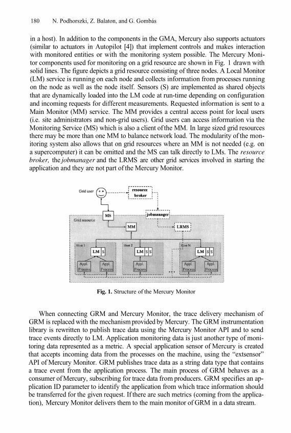
180 N. Podhorszki, Z. Balaton, and G. Gombás
in a host). In addition to the components in the GMA, Mercury also supports actuators(similar to actuators in Autopilot [4]) that implement controls and makes interactionwith monitored entities or with the monitoring system possible. The Mercury Moni-tor components used for monitoring on a grid resource are shown in Fig. 1 drawn withsolid lines. The figure depicts a grid resource consisting of three nodes. A Local Monitor(LM) service is running on each node and collects information from processes runningon the node as well as the node itself. Sensors (S) are implemented as shared objectsthat are dynamically loaded into the LM code at run-time depending on configurationand incoming requests for different measurements. Requested information is sent to aMain Monitor (MM) service. The MM provides a central access point for local users(i.e. site administrators and non-grid users). Grid users can access information via theMonitoring Service (MS) which is also a client of the MM. In large sized grid resourcesthere may be more than one MM to balance network load. The modularity of the mon-itoring system also allows that on grid resources where an MM is not needed (e.g. ona supercomputer) it can be omitted and the MS can talk directly to LMs. The resourcebroker, the jobmanager and the LRMS are other grid services involved in starting theapplication and they are not part of the Mercury Monitor.
Fig. 1. Structure of the Mercury Monitor
When connecting GRM and Mercury Monitor, the trace delivery mechanism ofGRM is replaced with the mechanism provided by Mercury. The GRM instrumentationlibrary is rewritten to publish trace data using the Mercury Monitor API and to sendtrace events directly to LM. Application monitoring data is just another type of moni-toring data represented as a metric. A special application sensor of Mercury is createdthat accepts incoming data from the processes on the machine, using the “extsensor”API of Mercury Monitor. GRM publishes trace data as a string data type that containsa trace event from the application process. The main process of GRM behaves as aconsumer of Mercury, subscribing for trace data from producers. GRM specifies an ap-plication ID parameter to identify the application from which trace information shouldbe transferred for the given request. If there are such metrics (coming from the applica-tion), Mercury Monitor delivers them to the main monitor of GRM in a data stream.
Monitoring Message-Passing Parallel Applications 181
The use of GRM as an application monitor is not changed compared to the originalusage. First, the application should be instrumented with GRM calls. Then, the jobshould be submitted to the resource broker, until the job is eventually started by theLRMS on a grid resource. Meanwhile, GRM can be started by the user on the localhost that connects to Mercury Monitor and subscribes for trace information about theapplication. When the application is started and generates trace data, Mercury Monitorforwards the trace to GRM based on the subscription information.
Problems for Application Monitoring in the Grid. There are two problems that can-not be solved within this infrastructure and there is a need for a grid information system.First, GRM has to subscribe to Mercury MS on that site which executes the given job.To do that, GRM has to find out, on which grid resource the job has started. Then, thepublic address of the Mercury Monitoring Service on that resource has to be found out.When these two pieces of information are available for GRM, it can connect to Mer-cury and subscribe for the trace. Second, the application should be identified uniquelyto distinguish it from other applications and prevent mixing of different traces. The gridjob id, given by the resource broker is fine but Mercury Monitor receives trace recordsfrom actual application processes that are identified with their process ID (PID). The re-lation between the process IDs and grid job IDs should be published in the informationsystem so that Mercury Monitor can deliver trace information for the right requests. Inthe EU-DataGrid (EDG) project R-GMA [5], the information system of EDG is used todeliver the necessary information to GRM.
2 Conclusion and Future WorkThe combination of GRM and Mercury Monitor provides an on-line performance toolfor monitoring message-passing applications that are executed in the grid. The currentimplementation of Mercury Monitor accepts trace data records from application pro-cesses through a UNIX domain socket. One of the most important tasks is to provide anapplication sensor that uses shared-memory for tracing, achieving a better performanceand bringing down the intrusion of monitoring.
References1.
2.
3.
4.
5.
N. Podhorszki, P. Kacsuk: Semi-on-line Monitoring of P-GRADE Applications. In: Qualityof Parallel and Distributed Programs and Systems, special issue of Journal of Parallel andDistributed Computing Practices, PDCP Vol.4, No. 4, Eds: P.Kacsuk, G.Kotsis, pp. 365-380,2001.Z. Balaton, G. Gombás. Resource and Job Monitoring in the Grid. Proc. of EuroPar’2003Conference, Klagenfurt, Austria, pp. 404-411, 2003.B. Tierney, R. Aydt, D. Gunter, W. Smith, V. Taylor, R. Wolski, and M. Swany. Agrid monitoring architecture. GGF Informational Document, GFD-I.7, GGF, 2001, URL:http://www.gridforum.org/Documents/GFD/GFD-I.7.pdfR. Ribler, J. Vetter, H. Simitci, D. Reed. Autopilot: Adaptive Control of Distributed Appli-cations. Proc. 7th IEEE Symposium on High Performance Distributed Computing, Chicago,Illinois, July 1998.S. Fisher et al. R-GMA: A Relational Grid Information and Monitoring System. 2nd KrakowGrid Workshop, Krakow, Poland, 2002.
Lhcmaster – A System for Storage and Analysisof Data Coming from the ATLAS Simulations
Maciej Malawski1,2, Marek Wieczorek1,Marian Bubak1,2, and 3,4
1 Institute of Computer Science, AGH, al. Mickiewicza 30, 30-059 Kraków, Poland{malawski, bubak}@uci.agh.edu.pl
2 Academic Computer Centre – CYFRONET, Nawojki 11, 30-950 Kraków, Poland3 Henryk Niewodniczanski Institute of Nuclear Physics,
ul. Radzikowskiego 152, 31-342 Kraków, Poland4 Jagiellonian University, Institute of Physics,
ul. Reymonta 4, 30-059 Kraków, Polandphone: (+48 12) 617 39 64, fax: (+48 12) 633 80 54
[email protected],[email protected]
Abstract. This paper presents the Lhcmaster system designed to aidthe physicist in the work of organizing and managing the large numberof files that are produced by simulations of High Energy Physics experi-ments. The implemented system stores and manages data files producedby the simulations of the ATLAS detector, making them available forphysicists. We will also present an outline of the Lhcmaster-G, a Gridversion of the system, that may be implemented in the future in orderto subsistute the Lhcmaster for a more effective and powerful tool.
Keywords: high-energy physics, particle detectors, fast simulation, datastorage, Grid, CrossGrid
1 Introduction
High Energy Physics (HEP) is an important research domain that provides manycompute- and data-intensive challenges for computer science. In the near future,CERN will complete the construction of the Large Hadron Collider (LHC). Cur-rently, scientific collaborations performing the above mentioned experiments takeadvantage of specialized software to simulate the physical processes and perfor-mance of the detectors. The ATLAS Experiment [2] is one of four large experi-ments [12] within the LHC, which will be brought online in 2007 at CERN - themost prominent European organization for nuclear reseach. Because of the largeamount of data which is going to be produced within the experiment, the AT-LAS is currently one of the most data-intensive computing challenges. Since theparticle detector at the core of experiment is not yet complete, the members ofthe ATLAS Collaboration team take advantage of software detector simulatorsin order to produce the data necessary to conduct their research. The simula-tors cooperate with event generators which produce data on simulated events inthe same way as the accelerator itself. One of these simulators is the ATLFAST
M. Dikaiakos (Ed.): AxGrids 2004, LNCS 3165, pp. 182–190, 2004.© Springer-Verlag Berlin Heidelberg 2004
Lhcmaster – A System for Storage and Analysis of Data 183
[1], designed to perform so-called fast simulation. Although the amount of dataproduced by the simulators is much less than in the case of a real detector, itsmanagement is also a serious challenge.
The Lhcmaster system presented in this paper, was created in order to aidthe storage of output data from the ATLFAST. Data stored in the system shouldbe easily available for physicists intending to use it. In a typical analysis thereare many processes to simulate and each of them can be simulated by using oneof the available Monte Carlo event generators (e.g. Pythia, Herwig [5,6]). Thereare also several options for each process, as well as additional parameters likethe number of events generated in each run, the filters applied, etc. The problemwas how to store hundreds of large files that vary with regards to many physicalproperties and simulation parameters. The files should be easily searchable bytheir contents, at best by means of histograms representing the contents of eachfile.
A further part of this paper presents the idea of Lhcmaster-G, an equivalentsystem designed to work on the Grid, that might be implemented in the future.We will show why a Grid-based architecture is optimal for such a system.
The specification of these two systems is enriched by the descriptions of otherprojects performed by physicists in order to solve similar problems.
2 Specification of Requirements for the Lhcmaster
The requirements for the Lhcmaster have been formulated by members of theATLAS Collaboration group working at the INP1. The system should be anetwork-accessible database system meant for storing data files coming fromthe ATLFAST detector simulator [1], and making them available for externalusers to download. It should also provide a legible graphical representation ofdata in the form of collection of standard histograms generated for each datafile.
The system should provide the following basic functionalities:
storage of files in the databases in a compact and coherent way; the storeddata should be ordered in a hierarchical structure based on the origin of files,a basic authentication facility protecting data collections, based on a schemeof authorized users and groups, supervising data access permissions,unlimited read-only multi-user access from outside the system to files storedin the system, andon-the-fly generation of histogram sets for the data files inserted into thesystem; each set of histograms should represent the physical characteristicsof data stored in a specific file; the corresponding histograms in each setshould represent the same physical quantity - as a result we should receivea kind of Graphical File Index (GFI) characterizing each file in the system.
1 Henryk Niewodniczanski Institute of Nuclear Physics, Cracow
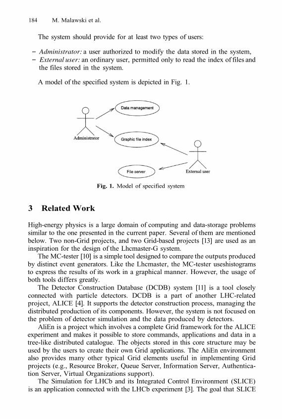
184 M. Malawski et al.
The system should provide for at least two types of users:
Administrator: a user authorized to modify the data stored in the system,External user: an ordinary user, permitted only to read the index of files andthe files stored in the system.
A model of the specified system is depicted in Fig. 1.
Fig. 1. Model of specified system
3 Related Work
High-energy physics is a large domain of computing and data-storage problemssimilar to the one presented in the current paper. Several of them are mentionedbelow. Two non-Grid projects, and two Grid-based projects [13] are used as aninspiration for the design of the Lhcmaster-G system.
The MC-tester [10] is a simple tool designed to compare the outputs producedby distinct event generators. Like the Lhcmaster, the MC-tester useshistogramsto express the results of its work in a graphical manner. However, the usage ofboth tools differs greatly.
The Detector Construction Database (DCDB) system [11] is a tool closelyconnected with particle detectors. DCDB is a part of another LHC-relatedproject, ALICE [4]. It supports the detector construction process, managing thedistributed production of its components. However, the system is not focused onthe problem of detector simulation and the data produced by detectors.
AliEn is a project which involves a complete Grid framework for the ALICEexperiment and makes it possible to store commands, applications and data in atree-like distributed catalogue. The objects stored in this core structure may beused by the users to create their own Grid applications. The AliEn environmentalso provides many other typical Grid elements useful in implementing Gridprojects (e.g., Resource Broker, Queue Server, Information Server, Authentica-tion Server, Virtual Organizations support).
The Simulation for LHCb and its Integrated Control Environment (SLICE)is an application connected with the LHCb experiment [3]. The goal that SLICE
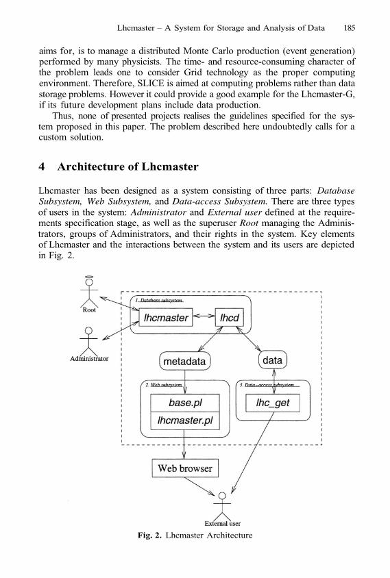
Lhcmaster – A System for Storage and Analysis of Data 185
aims for, is to manage a distributed Monte Carlo production (event generation)performed by many physicists. The time- and resource-consuming character ofthe problem leads one to consider Grid technology as the proper computingenvironment. Therefore, SLICE is aimed at computing problems rather than datastorage problems. However it could provide a good example for the Lhcmaster-G,if its future development plans include data production.
Thus, none of presented projects realises the guidelines specified for the sys-tem proposed in this paper. The problem described here undoubtedly calls for acustom solution.
4 Architecture of Lhcmaster
Lhcmaster has been designed as a system consisting of three parts: DatabaseSubsystem, Web Subsystem, and Data-access Subsystem. There are three typesof users in the system: Administrator and External user defined at the require-ments specification stage, as well as the superuser Root managing the Adminis-trators, groups of Administrators, and their rights in the system. Key elementsof Lhcmaster and the interactions between the system and its users are depictedin Fig. 2.
Fig. 2. Lhcmaster Architecture
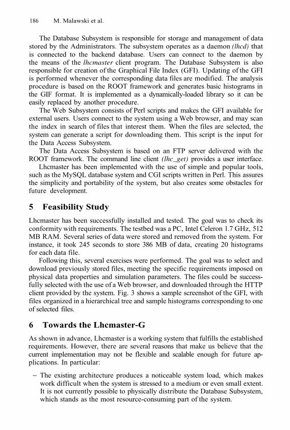
186 M. Malawski et al.
The Database Subsystem is responsible for storage and management of datastored by the Administrators. The subsystem operates as a daemon (lhcd) thatis connected to the backend database. Users can connect to the daemon bythe means of the lhcmaster client program. The Database Subsystem is alsoresponsible for creation of the Graphical File Index (GFI). Updating of the GFIis performed whenever the corresponding data files are modified. The analysisprocedure is based on the ROOT framework and generates basic histograms inthe GIF format. It is implemented as a dynamically-loaded library so it can beeasily replaced by another procedure.
The Web Subsystem consists of Perl scripts and makes the GFI available forexternal users. Users connect to the system using a Web browser, and may scanthe index in search of files that interest them. When the files are selected, thesystem can generate a script for downloading them. This script is the input forthe Data Access Subsystem.
The Data Access Subsystem is based on an FTP server delivered with theROOT framework. The command line client (lhc_get) provides a user interface.
Lhcmaster has been implemented with the use of simple and popular tools,such as the MySQL database system and CGI scripts written in Perl. This assuresthe simplicity and portability of the system, but also creates some obstacles forfuture development.
5 Feasibility Study
Lhcmaster has been successfully installed and tested. The goal was to check itsconformity with requirements. The testbed was a PC, Intel Celeron 1.7 GHz, 512MB RAM. Several series of data were stored and removed from the system. Forinstance, it took 245 seconds to store 386 MB of data, creating 20 histogramsfor each data file.
Following this, several exercises were performed. The goal was to select anddownload previously stored files, meeting the specific requirements imposed onphysical data properties and simulation parameters. The files could be success-fully selected with the use of a Web browser, and downloaded through the HTTPclient provided by the system. Fig. 3 shows a sample screenshot of the GFI, withfiles organized in a hierarchical tree and sample histograms corresponding to oneof selected files.
6 Towards the Lhcmaster-G
As shown in advance, Lhcmaster is a working system that fulfills the establishedrequirements. However, there are several reasons that make us believe that thecurrent implementation may not be flexible and scalable enough for future ap-plications. In particular:
The existing architecture produces a noticeable system load, which makeswork difficult when the system is stressed to a medium or even small extent.It is not currently possible to physically distribute the Database Subsystem,which stands as the most resource-consuming part of the system.
Lhcmaster – A System for Storage and Analysis of Data 187
Fig. 3. Histograms corresponding to a data file
The existing model of data storage based on local file copying lacks flexibilityand generates a significant system load. A logical solution of the problem isto replace this model with an efficient network file transfer protocol (e.g.,GridFTP).The current, centralized architecture of the system does not scale and maycause bottlenecks when new functionalities are introduced. New features,which might supplement existing ones, include:
allowing the production of data within the system, i.e. interfacing withthe Monte Carlo event generators and detector simulations like ATL-FAST, andallowing the users to perform their own, custom-designed analysis of datastored within the system.
The solution we believe will meet all these requirements is to implement thesystem in a Grid environment. Such implementation might take place in thefuture, according to the design described below.
Table 1 describes the solutions that will be applied in the Lhcmaster-G, inplace of existing ones.
The architecture of Lhcmaster-G is depicted in Fig. 4. The Lhcmaster-Genvironment will consist of several types of elements. The Storage Elements(SEs) and the Computing Elements (CEs) distributed among the nodes of theGrid will provide basic system functionalities. The Metadata Storage Elements(MSE) will be equivalent to the Web Subsystem. The Resource Broker (RB)and Replica Management (RM) providing typical Grid functionalities, will beadopted from the European DataGrid (EDG) [9] and the CrossGrid [16,17]projects. This seems to be the best existing environment providing an inte-grated set of Grid solutions for applications such as Lhcmaster-G. The central
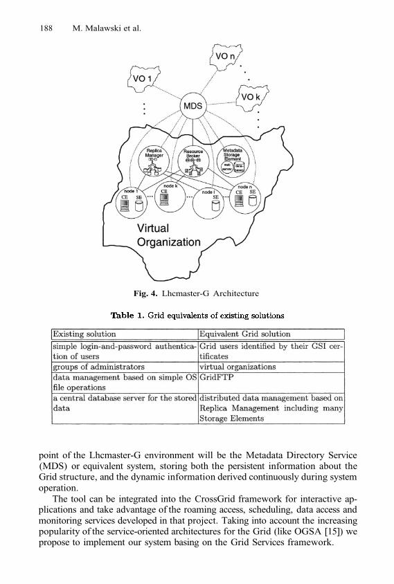
188 M. Malawski et al.
Fig. 4. Lhcmaster-G Architecture
point of the Lhcmaster-G environment will be the Metadata Directory Service(MDS) or equivalent system, storing both the persistent information about theGrid structure, and the dynamic information derived continuously during systemoperation.
The tool can be integrated into the CrossGrid framework for interactive ap-plications and take advantage of the roaming access, scheduling, data access andmonitoring services developed in that project. Taking into account the increasingpopularity of the service-oriented architectures for the Grid (like OGSA [15]) wepropose to implement our system basing on the Grid Services framework.
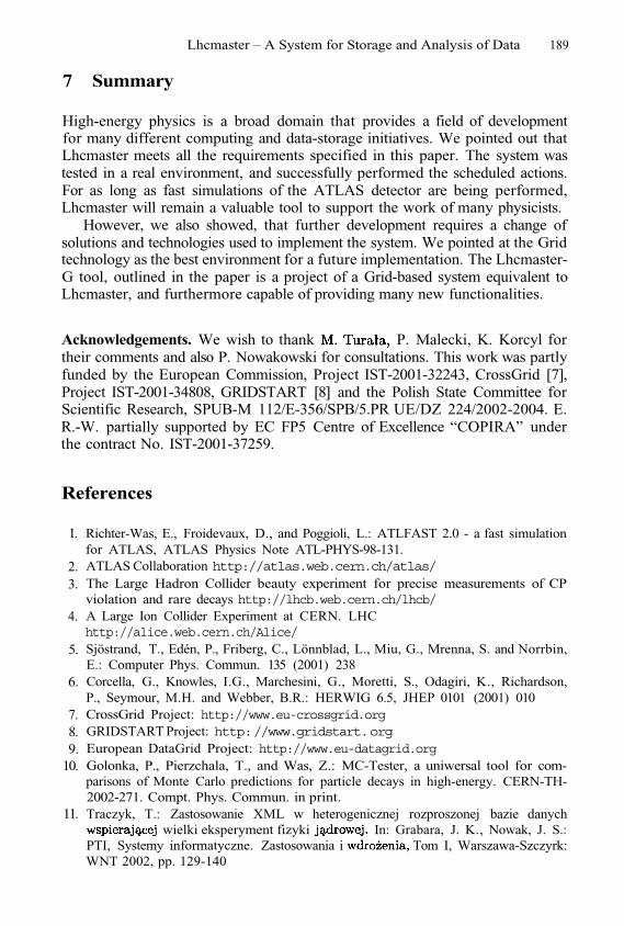
Lhcmaster – A System for Storage and Analysis of Data 189
7 Summary
High-energy physics is a broad domain that provides a field of developmentfor many different computing and data-storage initiatives. We pointed out thatLhcmaster meets all the requirements specified in this paper. The system wastested in a real environment, and successfully performed the scheduled actions.For as long as fast simulations of the ATLAS detector are being performed,Lhcmaster will remain a valuable tool to support the work of many physicists.
However, we also showed, that further development requires a change ofsolutions and technologies used to implement the system. We pointed at the Gridtechnology as the best environment for a future implementation. The Lhcmaster-G tool, outlined in the paper is a project of a Grid-based system equivalent toLhcmaster, and furthermore capable of providing many new functionalities.
Acknowledgements. We wish to thank P. Malecki, K. Korcyl fortheir comments and also P. Nowakowski for consultations. This work was partlyfunded by the European Commission, Project IST-2001-32243, CrossGrid [7],Project IST-2001-34808, GRIDSTART [8] and the Polish State Committee forScientific Research, SPUB-M 112/E-356/SPB/5.PR UE/DZ 224/2002-2004. E.R.-W. partially supported by EC FP5 Centre of Excellence “COPIRA” underthe contract No. IST-2001-37259.
References
1.
2.3.
4.
5.
6.
7.8.9.
10.
11.
Richter-Was, E., Froidevaux, D., and Poggioli, L.: ATLFAST 2.0 - a fast simulationfor ATLAS, ATLAS Physics Note ATL-PHYS-98-131.ATLAS Collaboration http://atlas.web.cern.ch/atlas/The Large Hadron Collider beauty experiment for precise measurements of CPviolation and rare decays http://lhcb.web.cern.ch/lhcb/A Large Ion Collider Experiment at CERN. LHChttp://alice.web.cern.ch/Alice/Sjöstrand, T., Edén, P., Friberg, C., Lönnblad, L., Miu, G., Mrenna, S. and Norrbin,E.: Computer Phys. Commun. 135 (2001) 238Corcella, G., Knowles, I.G., Marchesini, G., Moretti, S., Odagiri, K., Richardson,P., Seymour, M.H. and Webber, B.R.: HERWIG 6.5, JHEP 0101 (2001) 010CrossGrid Project: http://www.eu-crossgrid.orgGRIDSTART Project: http://www.gridstart.orgEuropean DataGrid Project: http://www.eu-datagrid.orgGolonka, P., Pierzchala, T., and Was, Z.: MC-Tester, a uniwersal tool for com-parisons of Monte Carlo predictions for particle decays in high-energy. CERN-TH-2002-271. Compt. Phys. Commun. in print.Traczyk, T.: Zastosowanie XML w heterogenicznej rozproszonej bazie danych
wielki eksperyment fizyki In: Grabara, J. K., Nowak, J. S.:PTI, Systemy informatyczne. Zastosowania i Tom I, Warszawa-Szczyrk:WNT 2002, pp. 129-140
190 M. Malawski et al.
12.
13.
14.
15.
16.
17.
Bethke, S., Calvetti, M., Hoffmann, H. F., Jacobs, D., Kasemann, M., Linglin, D.:Report of the steering group of the LHC Computing review, 22/02/2001http://lhc-computing-review-public.web.cern.ch/lhc-computing-review-public/Public/Report_final.PDFHarrison, K., Soroko, A.: Survey of technology relevant to a user-Grid interface forATLAS and LHCbhttp://ganga.web.cern.ch/ganga/documents/pdf/technology_survey.pdfBrun, R., Rademakers, F.: ROOT - An Object Oriented Data Analysis Framework,Proceedings AIHENP’96 Workshop, Lausanne, Sep. 1996, Nucl. Inst. & Meth. inPhys. Res. A 389 (1997) 81-86. See also http://root.cern.ch/Foster, I., Kesselman, C., Nick, J.M., and Tuecke, S.: The Physiology of the Grid.An Open Grid Services Architecture for Distributed Systems Integration, January2002, http://www.globus.orgBubak, M., M. Malawski, K. Zajac: Towards the CrossGrid Architecture. In: D.Kranzlmueller et al.: Recent Advances in Parallel Virtual Machine and MessagePassing Interface, Proc. 9th European PVM/MPI Users’ Group Meeting, Linz,Austria, 2002, LNCS 2474, pp. 16-24.Bubak, M., Malawski, M., Zajac, K., Architecture of the Grid for Interactive Ap-plications. In. Sloot, P. M. A.; Abramson, D.; Bogdanov, A. V.; Dongarra, J. J.;Zomaya, A. Y.; Gorbachev, Y. E. (Eds.): (2003) Computational Science - ICCS2003, International Conference, Melbourne, Australia and St. Petersburg, Russia,June 2-4, 2003. Proceedings
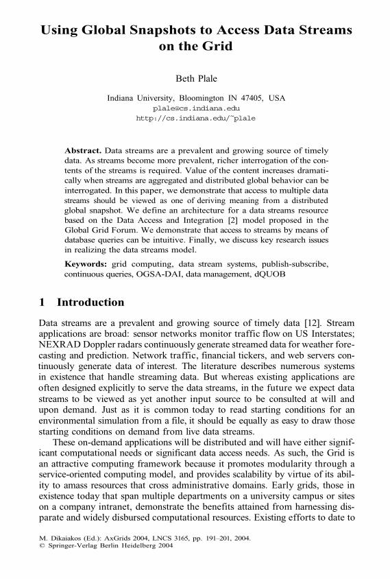
Using Global Snapshots to Access Data Streamson the Grid
Beth Plale
Indiana University, Bloomington IN 47405, [email protected]
http://cs.indiana.edu/~plale
Abstract. Data streams are a prevalent and growing source of timelydata. As streams become more prevalent, richer interrogation of the con-tents of the streams is required. Value of the content increases dramati-cally when streams are aggregated and distributed global behavior can beinterrogated. In this paper, we demonstrate that access to multiple datastreams should be viewed as one of deriving meaning from a distributedglobal snapshot. We define an architecture for a data streams resourcebased on the Data Access and Integration [2] model proposed in theGlobal Grid Forum. We demonstrate that access to streams by means ofdatabase queries can be intuitive. Finally, we discuss key research issuesin realizing the data streams model.
Keywords: grid computing, data stream systems, publish-subscribe,continuous queries, OGSA-DAI, data management, dQUOB
1 Introduction
Data streams are a prevalent and growing source of timely data [12]. Streamapplications are broad: sensor networks monitor traffic flow on US Interstates;NEXRAD Doppler radars continuously generate streamed data for weather fore-casting and prediction. Network traffic, financial tickers, and web servers con-tinuously generate data of interest. The literature describes numerous systemsin existence that handle streaming data. But whereas existing applications areoften designed explicitly to serve the data streams, in the future we expect datastreams to be viewed as yet another input source to be consulted at will andupon demand. Just as it is common today to read starting conditions for anenvironmental simulation from a file, it should be equally as easy to draw thosestarting conditions on demand from live data streams.
These on-demand applications will be distributed and will have either signif-icant computational needs or significant data access needs. As such, the Grid isan attractive computing framework because it promotes modularity through aservice-oriented computing model, and provides scalability by virtue of its abil-ity to amass resources that cross administrative domains. Early grids, those inexistence today that span multiple departments on a university campus or siteson a company intranet, demonstrate the benefits attained from harnessing dis-parate and widely disbursed computational resources. Existing efforts to date to
M. Dikaiakos (Ed.): AxGrids 2004, LNCS 3165, pp. 191–201, 2004.© Springer-Verlag Berlin Heidelberg 2004
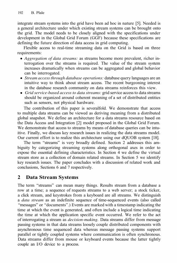
192 B. Plale
integrate stream systems into the grid have been ad hoc in nature [5]. Needed isa general architecture under which existing stream systems can be brought ontothe grid. The model needs to be closely aligned with the specifications underdevelopment in the Global Grid Forum (GGF) because these specifications aredefining the future direction of data access in grid computing.
Flexible access to real-time streaming data on the Grid is based on threerequirements:
Aggregation of data streams: as streams become more prevalent, richer in-terrogation over the streams is required. The value of the stream systemincreases dramatically when streams can be aggregated and global behaviorcan be interrogated.Stream access through database operations: database query languages are anintuitive way to think about stream access. The recent burgeoning interestin the database research community on data streams reinforces this view.Grid service-based access to data streams: grid service access to data streamsshould be organized around coherent meaning of a set of distributed entitiessuch as sensors, not physical hardware.The contribution of this paper is severalfold. We demonstrate that access
to multiple data streams can be viewed as deriving meaning from a distributedglobal snapshot. We define an architecture for a data streams resource based onthe Data Access and Integration [2] model proposed in the Global Grid Forum.We demonstrate that access to streams by means of database queries can be intu-itive. Finally, we discuss key research issues in realizing the data streams model.Our current effort is to realize this architecture using our dQUOB system [18].
The term “streams” is very broadly defined. Section 2 addresses this am-biguity by categorizing streaming systems along orthogonal axes in order toexpose the essential defining characteristics. In Section 4 we define the virtualstream store as a collection of domain related streams. In Section 5 we identifykey research issues. The paper concludes with a discussion of related work andconclusions, Sections 6 and 7 respectively.
2 Data Stream Systems
The term “streams” can mean many things. Results stream from a database arow at a time; a sequence of requests streams to a web server; a stock ticker,a click stream, and keystrokes from a keyboard are all streams. We distinguisha data stream as an indefinite sequence of time-sequenced events (also called“messages” or “documents”.) Events are marked with a timestamp indicating thetime at which the event is generated, and often include a logical time indicatingthe time at which the application specific event occurred. We refer to the actof interrogating a stream as decision-making. Data streams differ from messagepassing systems in that data streams loosely couple distributed components withasynchronous time sequenced data whereas message passing systems supportparallel or tightly coupled systems where communication is often synchronous.Data streams differ from mouse or keyboard events because the latter tightlycouple an I/O device to a process.
Using Global Snapshots to Access Data Streams on the Grid 193
Fig. 1. Stream routing system example
Data stream systems are middleware systems that operate on data streams.These systems fall into three general categories: stream routing systems, datamanipulation systems, and stream detection systems. Each is discussed below.
Stream routing systems. Stream routing systems disseminate events (or doc-uments or information about events) to interested recipients. These systems areknown by many names: publish/subscribe systems such as ECho [8], NaradaBro-ker [10], and Bayeux [23]; selective data dissemination system such as XFilter [1],document filtering system such as Xyleme [16], message-oriented middleware(MOM) [13]. Stream routing systems are distinguished by the locality of theinformation needed to make the decision. Decisions are made based almost ex-clusively upon the arriving event. Though some history may be maintained forinstance to optimize performance, decision-making is largely localized to the im-mediate event at hand. The high delivery rates expected of such systems ensurethat the decisions are kept simple.
A simple stream routing system is illustrated in Figure 1. A remote broker isshown receiving and distributing stock quote events. Users register their interestin particular stocks through submission of a query to the broker. The query mightbe, for instance, a Boolean expression, path expression, or Xpath query. Eventarrival triggers query evaluation. This is quite unlike a database where queryevaluation is triggered by query arrival. An arriving event is matched againstthe long-standing queries, and then is routed to the consumers indicated by theset of matching queries. The queries are long lived and are executed repeatedly.The expectation of these systems is that millions of queries can be active atany time. Key to achieving timeliness is the efficient matching of arriving eventsagainst a large number of long standing queries.
Data manipulation systems. Data manipulation systems are general streamprocessing systems that transform, filter, and aggregate data streams. Process-ing often results in the generation of new streams. There are looser timelinessrequirements on the results on these systems than for stream routing or streamdetection systems. For example, a large-scale instrument or set of instrumentsthat generates large data sets can make the data sets available to the science
194 B. Plale
community on the scale of hours later, and after having undergone extensivetransformative processing. The types of decisions in data manipulation systemscan be framed as requests for data and for manipulation of the data, thus thelanguage used to express the requests must be flexible enough to express thesecomplex requests [4,15,18,17]. Data manipulation systems can be based on theassumption of periodic streams, that is, the assumption of periodicity for allstreams in the system. Sensor network systems display this characteristic.
Data flow programming problems are another form of data manipulationsystem wherein data flows that originate at one or more data generators, areconsumed at one or more consumers, and undergo filtering and transformationalong the way. This functionality is provided in systems such as dQUOB [18]and DataCutter [6]. In work done at Cornell on ad hoc wireless networking,intermediate nodes aggregate information flowing from sensors to source [22].
Detection systems. Detection systems detect anomalous or changed behaviorin remote distributed entities. In these systems asynchronous streams are thenorm, that is, no assumptions about periodicity can be made. Stream detectionsystems are used to monitor performance, such as in R-GMA [9], Autopilot [19],Gigascope [7], changes in HTML pages, such as in Conquer [14], or safety criticalsystems, such as dQUOB [20]. Though overlap exists between detection systemsand data manipulation systems, the focus of the system drives the kind of sup-port provided to users. A detection system that provides timely detection ofanomalous behavior might put an emphasis on temporal operators.
3 Distributed Global Snapshot of Stream System
We assert that data manipulation and detection systems taken together forma class of stream systems that meet the criteria of a data resource. A dataresource is a collection of information that satisfies the properties of coherenceand meaning. A relational database has coherence and meaning in that the tablesin the database are related to one another and the relationships have meaning. Assuch, the database is amenable to rich interrogation, analysis, and manipulation.
Stream applications are organized around the production and consumptionof data and as such, they export their state or behavior. Unlike a distributedapplication wherein a distributed global snapshot consists of a snapshot of theprocesses in a distributed application plus all messages in progress between pro-cesses, the distributed global snapshot of a data stream application can be de-termined from examining the data streams alone. That is, we can safely drawconclusions about behavior of the distributed application simply by examining thestreams. This defining characteristic makes stream systems quite different fromstream routing systems and from distributed systems in general in that embod-ied in their data streams is a global snapshot. This condition is sufficient forthese systems to be considered a data resource in the same way as a databaseis considered a data resource. That is, the global snapshot over a set of streamssatisfies the requirements of coherence and meaning.
Using Global Snapshots to Access Data Streams on the Grid 195
4 Architecture for Stream Resource
Data-driven applications require access to data resident in files, databases, andstreams. Access to data in streams should be as intuitive and uniform as accessto these other mediums. We believe that this goal is best achieved within the gridservices framework by viewing the data streams generated by data manipulationand detection systems as a data resource that is accessible through a grid serviceinterface by means of a database query language. By modeling a data streamsystem as a data resource, we provide rich query access to the global snapshotthat is inherent in these stream collections. This leads to a definition of a virtualdata resource for streams management.
We define the “virtual stream store” as a collection of distributed, domain-related data streams that satisfy the properties of meaning and coherence. Sup-porting the stream store is a set of computational resources located in physicalproximity to data streams on which query processing can be carried out. The vir-tual stream store is accessed by means of a grid service that provides query accessto the data streams. Event stream providers are external to the virtual store. Thestreams they generate are external to the store unless explicitly published to it.Data streams produced as a product of data stream processing (i.e., views) areautomatically part of the virtual stream store.
An example data stream store, illustrated in Figure 2, consists of nine datastreams and associated computational resources. The computational resources,Ci, are contained within the virtual stream store but can be physically widelydisbursed. Computational resources are located in physical proximity to datastreams. The definition does not prohibit a computational resource from alsobeing a provider. The providers, which include the radar in the lower left, andsix sensors, two per sensor node for nodes C1, C2, and C4, are excluded fromthe virtual stream store. This is an important feature of the model. Throughthe feature, the model can accommodate a database implementation of a datastreams system, that is, where data streams are resident in a database and areserviced by long running queries managed through extensions to the databasemanagement system [4, 11]. Exclusion of providers benefits the provider by al-lowing it to retain control over which data streams are visible to a virtual streamstore and when the streams become visible. In the following section we probemore deeply into the suitability of a database access interface for a data streamstore and define open research issues.
5 Details
We have demonstrated that the virtual stream store architecture supports animportant class of data streaming problems on the grid. From the numeroussystems cited in Section 2 based on database concepts, it should be clear thatdatabase queries are a viable way to access stream data. For example, a practicalsolution to distributed monitoring is for a nuclear reactor monitoring system tofeed its streaming data into a time-based database and perform post mortem
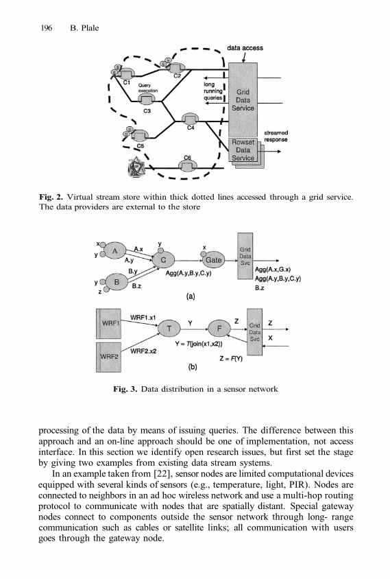
196 B. Plale
Fig. 2. Virtual stream store within thick dotted lines accessed through a grid service.The data providers are external to the store
Fig. 3. Data distribution in a sensor network
processing of the data by means of issuing queries. The difference between thisapproach and an on-line approach should be one of implementation, not accessinterface. In this section we identify open research issues, but first set the stageby giving two examples from existing data stream systems.
In an example taken from [22], sensor nodes are limited computational devicesequipped with several kinds of sensors (e.g., temperature, light, PIR). Nodes areconnected to neighbors in an ad hoc wireless network and use a multi-hop routingprotocol to communicate with nodes that are spatially distant. Special gatewaynodes connect to components outside the sensor network through long- rangecommunication such as cables or satellite links; all communication with usersgoes through the gateway node.
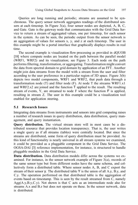
Using Global Snapshots to Access Data Streams on the Grid 197
Queries are long running and periodic; streams are assumed to be syn-chronous. The query sensor network aggregates readings of the distributed sen-sors at each timestep. In Figure 3(a), four sensor nodes are depicted, A, B, C,and Gate. Gate is the gateway node that communicates with the Grid Data Ser-vice to return a stream of aggregated values, one per timestep, for each sensorin the system. As can be seen, the periodic output from the sensor network isan aggregation of values for sensors x, y, and z at each timestep. The user inthis example might be a portal interface that graphically displays results in realtime.
The second example is visualization flow processing as provided in dQUOB[18] where compute nodes are located on the path between the parallel model(WRF1, WRF2) and its visualization; see Figure 3. Each node on the pathperforms filtering, transformation, or aggregating. Transformation might convertthe data from spectral domain to grid domain by application of an FFT. Anothermight join data streams from the model with a stream from the user and filteraccording to the user preference in a particular region of 3D space. Figure 3(b)depicts two model components, WRF1 and WRF2, that push data through atransformation node (T) and filter node (F). At node T the streams WRF1.x1and WRF2.x2 are joined and the function T applied to the result. The resultingstream of events, Y, are streamed to node F where the function F is applied,resulting in stream Z. The user in this example could be a visualization toolenabled for application steering.
5.1 Research Issues
Integrating data streams from instruments and sensors into grid computing raisesa number of research issues in query distribution, data distribution, query man-agement, and query instantiation.Query distribution. The virtual stream store will in most cases be a dis-tributed resource that provides location transparency. That is, the user writesa single query as if all streams (tables) were centrally located. But since thestreams are distributed, some form of query distribution must be provided. Asthis kind of functionality is nearly universal in all stream systems we examined,it could be provided as a pluggable component in the Grid Data Service. TheOGSA-DAI [3] reference implementation, for instance, is structured to handlepluggable modules in the Grid Data Service.Data distribution. Data distribution models differ across the systems we ex-amined. For instance, in the sensor network example of Figure 3(a), records ofthe same sensor type but from different nodes have the same schema, and col-lectively form a distributed table. Where sensor nodes A, B, and C export thestream of their sensor y. The distributed table Y is the union of all A.y, B.y, andC.y. The operation performed on that distributed table is the aggregation ofevents based on timestamp. This is seen by the result streamed from C, namelyAgg(A.y,B.y,C.y). Not shown is that C acts as an intermediate node also forstreams A.x and B.z but does not operate on these. In the sensor network, datais distributed.
198 B. Plale
In other examples, such as the flow model of dQUOB [18], the data is feder-ated in that the data from each node is treated as a separate table. While neitherapproach is superior, the virtual stream store and its grid service interface shouldbe flexible enough to handle different distribution schemes.
Query distribution in databases often includes assembling results from dis-tributed sources. This functionality is less important in a stream system be-cause aggregation of results is often done within the system itself. In the flow-programming example, the query is broken into subqueries and placed in thevirtual stream store in relation to other subqueries based on proximity to thesources. The results are returned from the stream system in their completedform.
Management of long running queries. The queries themselves reside foran extended period in the virtual stream store so lifetime is an issue. Querylifetime is often specified by means of extensions to the query language. If thissupport is not provided within the stream store, it would need to be providedby the grid service interface. The result of a long running query is a series oftuples generated over time that must be delivered by means of a stream deliverymechanism. These asynchronous requests are accommodated by the GGF DAISgrid service [2] by means of a special handling agent called a Rowset Data Service.
Query instantiation. Query instantiation is the realization of a query in thevirtual stream store. The user specifies a query as say, an ASCII SQL statement,but the query must then be transformed into an executable entity in the virtualstream store. This instantiation is typically handled in a stream system-specificway thus support in the grid service must be modular and pluggable. To illus-trate, suppose a set of hosts are available for use. In the Gigascope system [7],queries are pre-compiled into the executables that run on each of the nodes.In the case of dQUOB, the user submits a query that is compiled into a Tclscript that is then sent to the remote host. At the host are a runtime systemand a dQUOB library. The runtime system receives the script and invokes a Tclinterpreter. Through the process of interpretation the script calls the dQUOBlibrary which instantiates the query as C++ objects of operators (e.g., select,project) connected as a DAG. Thus the query is transported as a compact script,but runs efficiently as compiled code at the node. Further, the dQUOB querylanguage allows definition of a user-defined procedures to be executed as part ofthe query. These code chunks are dynamically linked into the query executionenvironment at runtime.
Updates. An update is the act of publishing to a data stream in a virtual streamstore. For reasons of performance and flexibility, data publication from devices,sensors, and instruments must be independent of the grid services interface.That is, the streams and query nodes within the virtual stream store shouldnot bound by the requirement to understand web service interface descriptions(i.e., WSDL) and use the SOAP transport protocol. Sensor nodes on an adhoc wireless network, for instance, do not have sufficient resources or protocolsupport to support the communication overhead inherent in the grid servicemodel.
Using Global Snapshots to Access Data Streams on the Grid 199
6 Related Work
Numerous stream systems have been cited in Section 2. Related efforts in gridservices for stream data are smaller in number. The OGSA-DAI project [3] hasdeveloped a set of services for connecting databases to the grid based on theGGF Grid Data Services specification. The OGSA-DAI work is complementaryto our work and in fact will serve as a key component in our implementation ofthe streaming architecture proposed in this paper. In the Antarctic monitoringproject [5], the authors propose a grid services architecture for interacting withan environment sensing device located in Antarctica. The grid services architec-ture provides access to and control of the sensor device, and accepts the datastream from the remote device via an iridium satellite phone network. The workdiffers from ours in that the service supports the combined functionalities ofdevice management and access a stream of data.
Narayanan et al [21] discuss a services oriented software infrastructure thatprovides database support for accessing, manipulating, and moving large scalescientific data sets. The service model differs from our work in that the targetdata resource is a database of large scale data sets. R-GMA [9] is a streamdetection system for performance monitoring of the grid middleware. It could becast into the architecture described in this paper, however we envision the datastream store as having value to application users, not grid middleware services.Additionally, R-GMA supports a more limited access language than is providedby our system.
7 Conclusion
Data streams are a prevalent and growing source of timely data. As streamsbecome more prevalent, richer interrogation of the contents of the streams arerequired. We argue in this paper that the value of the streamed content can bedramatically increased when a collection of streams is viewed as interrogating adistributed global snapshot. We define an architecture for a virtual stream storeas embodying the global snapshot, and provide access to the store through a gridservices Data Access and Integration [2] model. Our current effort is focused ondefining access semantics to the virtual stream store, and on providing access tothe results for clients who demand highly asynchronous streams and extremelytimely results.
References
1.
2.
Mehmet Altmel and Michael J. Franklin. Efficient filtering of XML documents forselective dissemination of information. In Proceedings of 26th VLDB Conference,2000.Mario Antonioletti, Malcolm Atkinson, Susan Malaika, Simon Laws, Normal Pa-ton, Dave Pearson, and Greg Riccardi. Grid data service specification. In GlobalGrid Forum GWD-R, September 2003.
200 B. Plale
3.
4.
5.
6.
7.
8.
9.
10.
11.
12.
13.
14.
15.
16.
17.
18.
19.
Mario Antonioletti, Neil Chue Hong, Ally Hume, Mike Jackson, Amy Krause,Jeremy Nowell, charaka Palansuriya, Tom Sugden, and Martin Westhead. Experi-ences of designing and implementing grid database services in the ogsa-dai project.In Global Grid Forum Workshop on Designing and Building Grid Services, Septem-ber 2003.Shivnath Babu and Jennifer Widom. Continuous queries over data streams. InInternational Conference on Management of Data (SIGMOD), 2001.Steven Benford and et al. e-Science from the antarctic to the GRID. In Proceedingsof UK e-Science All Hands Meeting, September 2003.M. Beynon, R. Ferreira, T. Kurc, A. Sussman, and J. Saltz. Datacutter: Mid-dleware for filtering very large scientific datasets on archival storage systems. InEighth Goddard Conference on Mass Storage Systems and Technologies/17th IEEESymposium on Mass Storage Systems, College Park, Maryland, March 2000.Chuck Cranoe, Theodore Johnson, Vladislav Shkapenyuk, and Oliver Spatscheck.Gigascope: a stream database for network applications. In International Conferenceon Management of Data (SIGMOD), 2003.Greg Eisenhauer. The ECho event delivery system. Technical Report GIT-CC-99-08, College of Computing, Georgia Institute of Technology, 1999.http://www.cc.gatech.edu/tech_reportsSteve Fisher. Relational model for information and monitoring. In Global GridForum, GWD-Perf-7-1, 2001.Geoffrey Fox and Shrideep Pallickara. An event service to support grid compu-tational environments. Journal of Concurrency and Computation: Practice andExperience. Special Issue on Grid Computing Environments., 2002.Dieter Gawlick and Shailendra Mishra. Information sharing with the Oracledatabase. 2003.Lukasz Golab and M. Tamer Ozsu. Issues in data stream management. SIGMODRecord, 32(2):5–14, June 2003.Ashish Kumar Gupta and Dan Suciu. Stream processing of Xpath queries withpredicates. In International Conference on Management of Data (SIGMOD), 2003.Ling Liu, Calton Pu, and Wei Tang. Continual queries for internet scale event-driven information delivery. IEEE Transactions on Knowledge and Data Engi-neering, Special issue on Web Technologies, January 1999.Sam Madden and Michael J. Franklin. Fjording the stream: An architecture forqueries over streaming sensor data. In International Conference on Data Engineer-ing ICDE, 2002.Benjamin Nguyen, Serge Abiteboul, Gregory Cobena, and Mihai Preda. Monitor-ing XML data on the web. In International Conference on Management of Data(SIGMOD), 2001.Clara Nippl, Ralf Rantzau, and Bernhard Mitschang. Streamjon: A genericdatabase approach to support the class of stream-oriented applications. In In-ternational Database Engineering and Applications Symposium IDEAS, 2000.Beth Plale and Karsten Schwan. Dynamic querying of streaming data with thedQUOB system. IEEE Transactions in Parallel and Distributed Systems, 14(4) :422– 432, April 2003.Randy Ribler, Jeffrey Vetter, Huseyin Simitci, and Daniel Reed. Autopilot: Adap-tive control of distributed applications. In IEEE International High PerformanceDistributed Computing (HPDC), August 1999.

Using Global Snapshots to Access Data Streams on the Grid 201
20.
21.
22.
23.
Beth (Plale) Schroeder, Sudhir Aggarwal, and Karsten Schwan. Software approachto hazard detection using on-line analysis of safety constraints. In Proceedings16th Symposium on Reliable and Distributed Systems SRDS97, pages 80–87. IEEEComputer Society, October 1997.Narayanan Sivaramakris, Tahsin Kurc, Umit Catalyurek, and Joel Saltz. Databasesupport for data-driven scientific applications in the grid. Parallel Processing Let-ters, 13(2), 2003.Yong Yao and Johannes Gehrke. Query processing in sensor networks. In FirstBiennial Conference on Innovative Data Systems Research, Asilomar, CA, January2003.S. Zhuang, B. Zhao, A. Joseph, R. Katz, and J. Kubiatowicz. Bayeux: An archi-tecture for scalable and fault-tolerant wide area data dissemination. In ProceedingsEleventh International Workshop on Network and Operating System Support forDigital Audio and Video (NOSSDAV 2001), June 2001.
SCALEA-G: A Unified Monitoringand Performance Analysis System for the Grid*
Hong-Linh Truong1 and Thomas Fahringer2
1 Institute for Software Science, University of [email protected]
2 Institute for Computer Science, University of [email protected]
Abstract. This paper describes SCALEA-G, a unified monitoring and perfor-mance analysis system for the Grid. SCALEA-G is implemented as a set ofgrid services based on the Open Grid Services Architecture (OGSA). SCALEA-G provides an infrastructure for conducting online monitoring and performanceanalysis of a variety of Grid services including computational and network re-sources, and Grid applications. Both push and pull models are supported, provid-ing flexible and scalable monitoring and performance analysis. Source code anddynamic instrumentation are exploited to perform profiling and monitoring ofGrid applications. A novel instrumentation request language has been developedto facilitate the interaction between client and instrumentation services.
1 Introduction
Grid Monitoring is an important task that provides useful information for several pur-poses such as performance analysis and tuning, performance prediction, fault detection,and scheduling. Most existing Grid monitoring tools are separated into two distinctdomains: Grid infrastructure monitoring and Grid application monitoring. The lack ofcombination of two domains in a single system has hindered the user from relating mea-surement metrics of various sources at different levels when conducting the monitoringand performance analysis. In addition, many existing Grid monitoring tools focus onthe monitoring and analysis for Grid infrastructure; yet little effort has been done forGrid applications. To date, application performance analysis tools are mostly targetedto conventional parallel and distributed systems (e.g. clusters, SMP machines). As a re-sult, these tools do not well address challenges in Grid environment such as scalability,diversity, dynamics and security.
To tackle above-mentioned issues, we are developing a new system namedSCALEA-G. SCALEA-G is a unified system for monitoring and performance analy-sis in the Grid. SCALEA-G is based on the concept of Grid Monitoring Architecture(GMA) [1] and is implemented as a set of OGSA-based services [12]. SCALEA-Gprovides an infrastructure of OGSA-compliant grid services for online monitoring andperformance analysis of a variety of Grid services including computational resources,
* This research is supported by the Austrian Science Fund as part of the Aurora Project undercontract SFBF1104.
M. Dikaiakos (Ed.): AxGrids 2004, LNCS 3165, pp. 202–211, 2004.© Springer-Verlag Berlin Heidelberg 2004
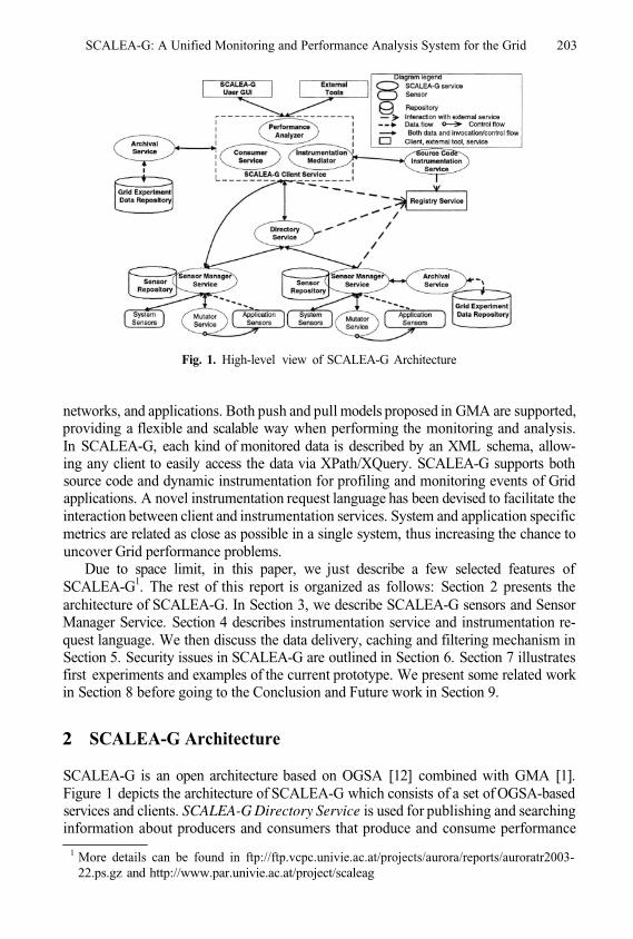
SCALEA-G: A Unified Monitoring and Performance Analysis System for the Grid 203
Fig. 1. High-level view of SCALEA-G Architecture
networks, and applications. Both push and pull models proposed in GMA are supported,providing a flexible and scalable way when performing the monitoring and analysis.In SCALEA-G, each kind of monitored data is described by an XML schema, allow-ing any client to easily access the data via XPath/XQuery. SCALEA-G supports bothsource code and dynamic instrumentation for profiling and monitoring events of Gridapplications. A novel instrumentation request language has been devised to facilitate theinteraction between client and instrumentation services. System and application specificmetrics are related as close as possible in a single system, thus increasing the chance touncover Grid performance problems.
Due to space limit, in this paper, we just describe a few selected features ofSCALEA-G1. The rest of this report is organized as follows: Section 2 presents thearchitecture of SCALEA-G. In Section 3, we describe SCALEA-G sensors and SensorManager Service. Section 4 describes instrumentation service and instrumentation re-quest language. We then discuss the data delivery, caching and filtering mechanism inSection 5. Security issues in SCALEA-G are outlined in Section 6. Section 7 illustratesfirst experiments and examples of the current prototype. We present some related workin Section 8 before going to the Conclusion and Future work in Section 9.
2 SCALEA-G Architecture
SCALEA-G is an open architecture based on OGSA [12] combined with GMA [1].Figure 1 depicts the architecture of SCALEA-G which consists of a set of OGSA-basedservices and clients. SCALEA-G Directory Service is used for publishing and searchinginformation about producers and consumers that produce and consume performance
1 More details can be found in ftp://ftp.vcpc.univie.ac.at/projects/aurora/reports/auroratr2003-22.ps.gz and http://www.par.univie.ac.at/project/scaleag
204 H.-L. Truong and T. Fahringer
data and information about types, characteristics of that data. Archival Service is a datarepository which is used to store monitored data and performance results collected andanalyzed by other components. Sensor Manager Service is used to manage sensors thatgather and/or measure a variety of kinds of data for monitoring and performance analy-sis. The instrumentation of application can be done at source code level by using SourceCode Instrumentation Service or dynamically at the runtime through Mutator Service.Client Service provides interfaces for administrating other SCALEA-G services andaccessing data in these services. In addition, it provides facilities for analyzing perfor-mance data. Any external tools can access SCALEA-G by using Client Service. UserGUI supports the user to graphically conduct online monitoring and performance anal-ysis; it is based on facilities provided by Client Service. SCALEA-G services registerinformation about their service instances with a Registry Service.
Interactions among SCALEA-G services and clients are divided into Grid serviceoperation invocations and stream data delivery. Grid service operation invocationsare used to perform tasks which include controlling activities of services and sensors,subscribing and querying requests for performance data, registering, querying and re-ceiving information of Directory Service. In stream data delivery, a stream channel isused to transfer data (monitored data, performance data and results) between producers(e.g. sensors, Sensor Manager Service) and consumers (e.g. Sensor Manager Service,clients). Grid service operations use transport-level and message-level security whereasdata channel is secure connection; all base on Grid Security Infrastructure (GSI) [10].
In deployment of SCALEA-G, instances of sensors and Mutator Service are exe-cuted in monitored nodes. An instance of Sensor Manager Service can be deployed tomanage sensors and Mutator Services in a node or a set of nodes, depending on the realsystem and workload. Similarly, an instance of Directory Service can manage multipleSensor Manager Services in an administrative domain. The client discovers SCALEA-G services through registry services which can be deployed in different domains.
3 Sensors and Sensor Manager Service
SCALEA-G distinguishes two kinds of sensors: system sensors and application sensors.System sensors are used to monitor and measure the performance of Grid infrastructure.Application sensors are used to measure execution behavior of code regions and tomonitor events in Grid applications. All sensors are associated with some commonproperties such as sensor identifier, data schema, parameters.
3.1 System Sensors and Sensor Repository
SCALEA-G provides a variety of system sensors for monitoring the most commonlyneeded types of performance information on the Grid investigated by GGF DAMED-WG [9] and NMWG [13].
To simplify the management and deployment of system sensors, a sensor repositoryis used to hold the information about available system sensors. Each sensor repositoryis managed by a Sensor Manager Service that makes sensors in the repository availablefor use when requested. Figure 2 presents XML schema used to express sensors in the
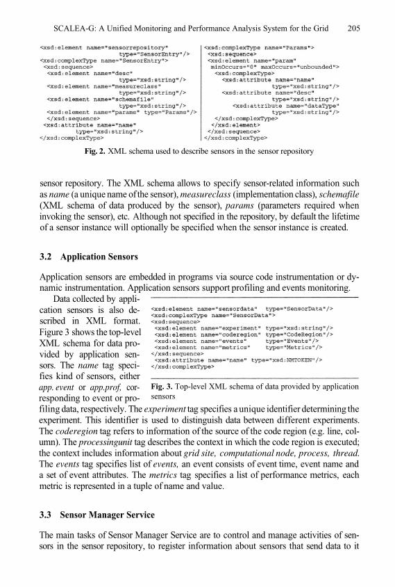
SCALEA-G: A Unified Monitoring and Performance Analysis System for the Grid 205
Fig. 2. XML schema used to describe sensors in the sensor repository
sensor repository. The XML schema allows to specify sensor-related information suchas name (a unique name of the sensor), measureclass (implementation class), schemafile(XML schema of data produced by the sensor), params (parameters required wheninvoking the sensor), etc. Although not specified in the repository, by default the lifetimeof a sensor instance will optionally be specified when the sensor instance is created.
3.2 Application Sensors
Application sensors are embedded in programs via source code instrumentation or dy-namic instrumentation. Application sensors support profiling and events monitoring.
Fig. 3. Top-level XML schema of data provided by applicationsensors
Data collected by appli-cation sensors is also de-scribed in XML format.Figure 3 shows the top-levelXML schema for data pro-vided by application sen-sors. The name tag speci-fies kind of sensors, eitherapp. event or app.prof, cor-responding to event or pro-filing data, respectively. The experiment tag specifies a unique identifier determining theexperiment. This identifier is used to distinguish data between different experiments.The coderegion tag refers to information of the source of the code region (e.g. line, col-umn). The processingunit tag describes the context in which the code region is executed;the context includes information about grid site, computational node, process, thread.The events tag specifies list of events, an event consists of event time, event name anda set of event attributes. The metrics tag specifies a list of performance metrics, eachmetric is represented in a tuple of name and value.
3.3 Sensor Manager Service
The main tasks of Sensor Manager Service are to control and manage activities of sen-sors in the sensor repository, to register information about sensors that send data to it
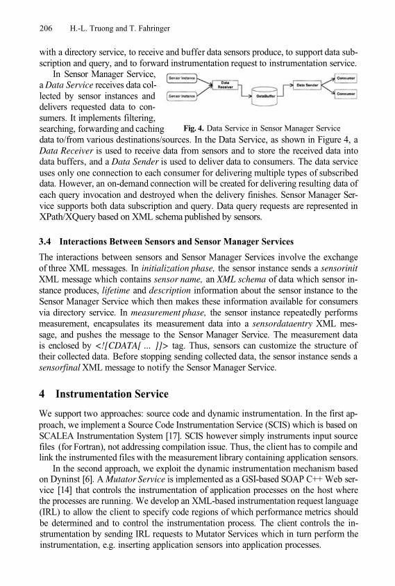
206 H.-L. Truong and T. Fahringer
with a directory service, to receive and buffer data sensors produce, to support data sub-scription and query, and to forward instrumentation request to instrumentation service.
In Sensor Manager Service,a Data Service receives data col-lected by sensor instances anddelivers requested data to con-sumers. It implements filtering,searching, forwarding and caching Fig. 4. Data Service in Sensor Manager Service
data to/from various destinations/sources. In the Data Service, as shown in Figure 4, aData Receiver is used to receive data from sensors and to store the received data intodata buffers, and a Data Sender is used to deliver data to consumers. The data serviceuses only one connection to each consumer for delivering multiple types of subscribeddata. However, an on-demand connection will be created for delivering resulting data ofeach query invocation and destroyed when the delivery finishes. Sensor Manager Ser-vice supports both data subscription and query. Data query requests are represented inXPath/XQuery based on XML schema published by sensors.
3.4 Interactions Between Sensors and Sensor Manager Services
The interactions between sensors and Sensor Manager Services involve the exchangeof three XML messages. In initialization phase, the sensor instance sends a sensorinitXML message which contains sensor name, an XML schema of data which sensor in-stance produces, lifetime and description information about the sensor instance to theSensor Manager Service which then makes these information available for consumersvia directory service. In measurement phase, the sensor instance repeatedly performsmeasurement, encapsulates its measurement data into a sensordataentry XML mes-sage, and pushes the message to the Sensor Manager Service. The measurement datais enclosed by <![CDATA[ ... ]]> tag. Thus, sensors can customize the structure oftheir collected data. Before stopping sending collected data, the sensor instance sends asensorfinal XML message to notify the Sensor Manager Service.
4 Instrumentation Service
We support two approaches: source code and dynamic instrumentation. In the first ap-proach, we implement a Source Code Instrumentation Service (SCIS) which is based onSCALEA Instrumentation System [17]. SCIS however simply instruments input sourcefiles (for Fortran), not addressing compilation issue. Thus, the client has to compile andlink the instrumented files with the measurement library containing application sensors.
In the second approach, we exploit the dynamic instrumentation mechanism basedon Dyninst [6]. A Mutator Service is implemented as a GSI-based SOAP C++ Web ser-vice [14] that controls the instrumentation of application processes on the host wherethe processes are running. We develop an XML-based instrumentation request language(IRL) to allow the client to specify code regions of which performance metrics shouldbe determined and to control the instrumentation process. The client controls the in-strumentation by sending IRL requests to Mutator Services which in turn perform theinstrumentation, e.g. inserting application sensors into application processes.
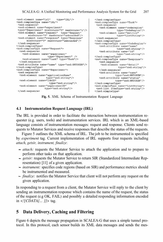
SCALEA-G: A Unified Monitoring and Performance Analysis System for the Grid 207
Fig. 5. XML Schema of Instrumentation Request Language
4.1 Instrumentation Request Language (IRL)
The IRL is provided in order to facilitate the interaction between instrumentation re-quester (e.g. users, tools) and instrumentation services. IRL which is an XML-basedlanguage consists of instrumentation messages: request and response. Clients send re-quests to Mutator Services and receive responses that describe the status of the requests.
Figure 5 outlines the XML schema of IRL. The job to be instrumented is specifiedby experiment tag. Current implementation of IRL supports four requests includingattach, getsir, instrument, finalize:
attach: requests the Mutator Service to attach the application and to prepare toperform other tasks on that application.getsir: requests the Mutator Service to return SIR (Standardized Intermediate Rep-resentation) [11] of a given application.instrument: specifies code regions (based on SIR) and performance metrics shouldbe instrumented and measured.finalize: notifies the Mutator Service that client will not perform any request on thegiven application.
In responding to a request from a client, the Mutator Service will reply to the client bysending an instrumentation response which contains the name of the request, the statusof the request (e.g OK, FAIL) and possibly a detailed responding information encodedin <![CDATA[... ]]> tag.
5 Data Delivery, Caching and Filtering
Figure 6 depicts the message propagation in SCALEA-G that uses a simple tunnel pro-tocol. In this protocol, each sensor builds its XML data messages and sends the mes-
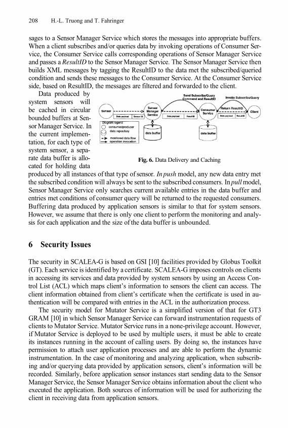
208 H.-L. Truong and T. Fahringer
sages to a Sensor Manager Service which stores the messages into appropriate buffers.When a client subscribes and/or queries data by invoking operations of Consumer Ser-vice, the Consumer Service calls corresponding operations of Sensor Manager Serviceand passes a ResultID to the Sensor Manager Service. The Sensor Manager Service thenbuilds XML messages by tagging the ResultID to the data met the subscribed/queriedcondition and sends these messages to the Consumer Service. At the Consumer Serviceside, based on ResultID, the messages are filtered and forwarded to the client.
Data produced bysystem sensors willbe cached in circularbounded buffers at Sen-sor Manager Service. Inthe current implemen-tation, for each type ofsystem sensor, a sepa-rate data buffer is allo-cated for holding data
Fig. 6. Data Delivery and Caching
produced by all instances of that type of sensor. In push model, any new data entry metthe subscribed condition will always be sent to the subscribed consumers. In pull model,Sensor Manager Service only searches current available entries in the data buffer andentries met conditions of consumer query will be returned to the requested consumers.Buffering data produced by application sensors is similar to that for system sensors.However, we assume that there is only one client to perform the monitoring and analy-sis for each application and the size of the data buffer is unbounded.
6 Security Issues
The security in SCALEA-G is based on GSI [10] facilities provided by Globus Toolkit(GT). Each service is identified by a certificate. SCALEA-G imposes controls on clientsin accessing its services and data provided by system sensors by using an Access Con-trol List (ACL) which maps client’s information to sensors the client can access. Theclient information obtained from client’s certificate when the certificate is used in au-thentication will be compared with entries in the ACL in the authorization process.
The security model for Mutator Service is a simplified version of that for GT3GRAM [10] in which Sensor Manager Service can forward instrumentation requests ofclients to Mutator Service. Mutator Service runs in a none-privilege account. However,if Mutator Service is deployed to be used by multiple users, it must be able to createits instances running in the account of calling users. By doing so, the instances havepermission to attach user application processes and are able to perform the dynamicinstrumentation. In the case of monitoring and analyzing application, when subscrib-ing and/or querying data provided by application sensors, client’s information will berecorded. Similarly, before application sensor instances start sending data to the SensorManager Service, the Sensor Manager Service obtains information about the client whoexecuted the application. Both sources of information will be used for authorizing theclient in receiving data from application sensors.
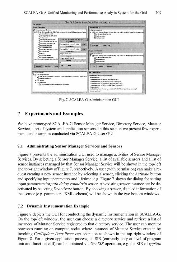
SCALEA-G: A Unified Monitoring and Performance Analysis System for the Grid 209
Fig.7. SCALEA-G Administration GUI
7 Experiments and Examples
We have prototyped SCALEA-G Sensor Manager Service, Directory Service, MutatorService, a set of system and application sensors. In this section we present few experi-ments and examples conducted via SCALEA-G User GUI.
7.1 Administrating Sensor Manager Services and Sensors
Figure 7 presents the administration GUI used to manage activities of Sensor ManagerServices. By selecting a Sensor Manager Service, a list of available sensors and a list ofsensor instances managed by that Sensor Manager Service will be shown in the top-leftand top-right window of Figure 7, respectively. A user (with permission) can make a re-quest creating a new sensor instance by selecting a sensor, clicking the Activate buttonand specifying input parameters and lifetime, e.g. Figure 7 shows the dialog for settinginput parameters forpath.delay.roundtrip sensor. An existing sensor instance can be de-activated by selecting Deactivate button. By choosing a sensor, detailed information ofthat sensor (e.g. parameters, XML schema) will be shown in the two bottom windows.
7.2 Dynamic Instrumentation Example
Figure 8 depicts the GUI for conducting the dynamic instrumentation in SCALEA-G.On the top-left window, the user can choose a directory service and retrieve a list ofinstances of Mutator Service registered to that directory service. The user can monitorprocesses running on compute nodes where instances of Mutator Service execute byinvoking Get/Update User Processes operation as shown in the top-right window ofFigure 8. For a given application process, its SIR (currently only at level of programunit and function call) can be obtained via Get SIR operation, e.g. the SIR of rpp3do
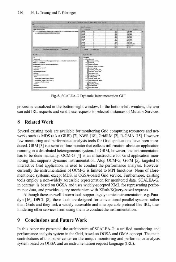
210 H.-L. Truong and T. Fahringer
Fig. 8. SCALEA-G Dynamic Instrumentation GUI
process is visualized in the bottom-right window. In the bottom-left window, the usercan edit IRL requests and send these requests to selected instances of Mutator Services.
8 Related Work
Several existing tools are available for monitoring Grid computing resources and net-works such as MDS (a.k.a GRIS) [7], NWS [18], GridRM [2], R-GMA [15]. However,few monitoring and performance analysis tools for Grid applications have been intro-duced. GRM [3] is a semi-on-line monitor that collects information about an applicationrunning in a distributed heterogeneous system. In GRM, however, the instrumentationhas to be done manually. OCM-G [4] is an infrastructure for Grid application mon-itoring that supports dynamic instrumentation. Atop OCM-G, G-PM [5], targeted tointeractive Grid application, is used to conduct the performance analysis. However,currently the instrumentation of OCM-G is limited to MPI functions. None of afore-mentioned systems, except MDS, is OGSA-based Grid service. Furthermore, existingtools employ a non-widely accessible representation for monitored data. SCALEA-G,in contrast, is based on OGSA and uses widely-accepted XML for representing perfor-mance data, and provides query mechanism with XPath/XQuery-based requests.
Although there are well-known tools supporting dynamic instrumentation, e.g. Para-dyn [16], DPCL [8], these tools are designed for conventional parallel systems ratherthan Grids and they lack a widely accessible and interoperable protocol like IRL, thushindering other services from using them to conduct the instrumentation.
9 Conclusions and Future Work
In this paper we presented the architecture of SCALEA-G, a unified monitoring andperformance analysis system in the Grid, based on OGSA and GMA concept. The maincontributions of this paper center on the unique monitoring and performance analysissystem based on OGSA and an instrumentation request language (IRL).
SCALEA-G: A Unified Monitoring and Performance Analysis System for the Grid 211
Yet, there are many rooms for improving the system. The set of sensors will beextended, enabling to monitor more resources and services, and providing more diversekinds of data. In addition, the sensor will be extended to support monitoring basedon resource model and rules. IRL will be extended to allow specifying more complexinstrumentation requests such as events, deactivating and removing instrumentation.
References
1.
2.
3.
4.
5.
6.
7.
8.
9.
10.
11.
12.
13.14.15.16.17.
18.
B. Tierney et. al. A Grid Monitoring Architecture.http://www-didc.lbl.gov/GGF-PERF/GMA-WG/papers/GWD-GP-16-2.pdfMark Baker and Garry Smith. GridRM: A resource monitoring architecture for the Grid.LNCS, 2536: p.268, 2002.Zoltan Balaton, Peter Kacsuk, Norbert Podhorszki, and Ferenc Vajda. From Cluster Moni-toring to Grid Monitoring Based on GRM. In Proceedings. 7th EuroPar’2001 Parallel Pro-cessings, pages 874–881, Manchester, UK, 2001.Bartosz Balis, Marian Bubak, Tomasz Szepieniec, and RolandWismüller. An infrastructure for Grid application monitoring. LNCS, 2474: p. 41, 2002.Marian Bubak, and Roland Wismüller. The CrossGrid performanceanalysis tool for interactive Grid applications. LNCS, 2474: p. 50, 2002.Bryan Buck and Jeffrey K. Hollingsworth. An API for Runtime Code Patching. The Interna-tional Journal of High Performance Computing Applications, 14(4):317–329, 2000.K. Czajkowski, S. Fitzgerald, I. Foster, and C. Kesselman. Grid Information Services forDistributed Resource Sharing. In Proceedings of the Tenth IEEE International Symposiumon High-Performance Distributed Computing (HPDC-10). IEEE Press, August 2001.L. DeRose, T. Hoover Jr., and J. Hollingsworth. The dynamic probe class library: An in-frastucture for developing instrumentation for performance tools. In Proceedings of the 15thInternational Parallel and Distributed Processing Symposium (IPDPS-01), Los Alamitos,CA, April 23–27 2001. IEEE Computer Society.Discovery and Monitoring Event Description (DAMED) Working Group. http://www-didc.lbl.gov/damed/Von Welch et all. Security for Grid Services. In Proceedings of 12th IEEE InternationalSymposium on High Performance Distributed Computing (HPDC’03), pages 48–57, Seattle,Washington, June 22 - 24 2003.T. Fahringer, M. Gerndt, Bernd Mohr, Martin Schulz, Clovis Seragiotto, and Hong-LinhTruong. Standardized Intermediate Representation for Fortran, Java, C and C++ Programs.APART Working group (http://www.kfa-juelich.de/apart/), Work in progress, June 2003.I. Foster, C. Kesselman, J. Nick, and S. Tuecke. Grid Services for Distributed System Inte-gration. IEEE Computer, pages 37–46, June 2002.GGF Network Measurements Working Group. http://forge.gridforum.org/projects/nm-wg/gSOAP: C/C++ Web Services and Clients. http://www.cs.fsu.edu/~engelen/soap.htmlR-GMA: Relational Grid Monitoring Architecture. http://www.r-gma.orgParadyn Parallel Performance Tools. http://www.cs.wisc.edu/paradyn/Hong-Linh Truong and Thomas Fahringer. SCALEA: A Performance Analysis Tool for Par-allel Programs. Concurrency and Computation: Practice and Experience, 15(11-12):1001–1025, 2003.R. Wolski, N. Spring, and J. Hayes. The Network Weather Service: A Distributed ResourcePerformance Forecasting Service for Metacomputing. Future Generation Computing Sys-tems, 15:757–768, 1999.
Application Monitoring in CrossGridand Other Grid Projects*
1,2 , Marian Bubak1,2, Marcin Radecki2,Tomasz Szepieniec2, and Roland Wismüller3
1 Institute of Computer Science, AGH, al. Mickiewicza 30, 30-059 Kraków, Poland{balis,bubak}@uci.agh.edu.pl
2 Academic Computer Centre – CYFRONET, Nawojki 11, 30-950 Kraków, Poland{t.szepieniec,m.radecki}@cyf-kr.edu.pl
3 LRR-TUM – Technische Universität München, D-80290 München, [email protected]
phone: (+48 12) 617 39 64, fax: (+48 12) 633 80 54, phone: (+49 89) 289-17676
Abstract. Monitoring of applications is important for performance anal-ysis, visualization, and other tools for parallel application development.While current Grid research is focused mainly on batch-oriented pro-cessing, there is a growing interest in interactive applications, wherethe user’s interactions are an important element of the execution. Thispaper presents the OMIS/OCM-G approach to monitoring interactiveapplications, developed in the framework of the CrossGrid project. Wealso overview the currently existing application monitoring approachesin other Grid projects.
Keywords: Grid, monitoring, interactive applications, CrossGrid
1 Introduction
While the current Grid technology is oriented more towards batch processing,there is a growing interest in interactive applications, e.g., in the European ISTproject CrossGrid [7]. Those applications involve a person ‘in the computingloop’ who can control the computation at runtime.
The user is often interested in improving performance of his application,steering it, or just in visualization of its execution. For all these purposes, spe-cialized tools usually exist. All such tools need a monitoring infrastructure whichcollects the information about the execution of the application and possibly alsooffers manipulation services.
In this paper, we present an approach to monitoring interactive applica-tions developed in the framework of the CrossGrid project. Additionally, we alsooverview the currently existing application monitoring approaches in other Gridprojects.
* This work was partly funded by the European Commission, project IST-2001-32243,CrossGrid [7].
M. Dikaiakos (Ed.): AxGrids 2004, LNCS 3165, pp. 212–219, 2004.© Springer-Verlag Berlin Heidelberg 2004
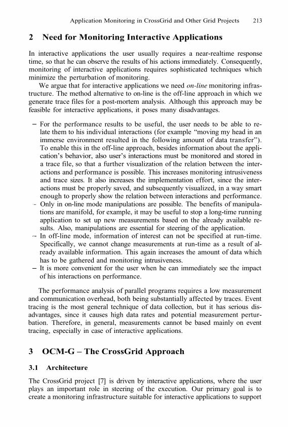
Application Monitoring in CrossGrid and Other Grid Projects 213
2 Need for Monitoring Interactive Applications
In interactive applications the user usually requires a near-realtime responsetime, so that he can observe the results of his actions immediately. Consequently,monitoring of interactive applications requires sophisticated techniques whichminimize the perturbation of monitoring.
We argue that for interactive applications we need on-line monitoring infras-tructure. The method alternative to on-line is the off-line approach in which wegenerate trace files for a post-mortem analysis. Although this approach may befeasible for interactive applications, it poses many disadvantages.
For the performance results to be useful, the user needs to be able to re-late them to his individual interactions (for example “moving my head in animmerse environment resulted in the following amount of data transfer”).To enable this in the off-line approach, besides information about the appli-cation’s behavior, also user’s interactions must be monitored and stored ina trace file, so that a further visualization of the relation between the inter-actions and performance is possible. This increases monitoring intrusivenessand trace sizes. It also increases the implementation effort, since the inter-actions must be properly saved, and subsequently visualized, in a way smartenough to properly show the relation between interactions and performance.Only in on-line mode manipulations are possible. The benefits of manipula-tions are manifold, for example, it may be useful to stop a long-time runningapplication to set up new measurements based on the already available re-sults. Also, manipulations are essential for steering of the application.In off-line mode, information of interest can not be specified at run-time.Specifically, we cannot change measurements at run-time as a result of al-ready available information. This again increases the amount of data whichhas to be gathered and monitoring intrusiveness.It is more convenient for the user when he can immediately see the impactof his interactions on performance.
The performance analysis of parallel programs requires a low measurementand communication overhead, both being substantially affected by traces. Eventtracing is the most general technique of data collection, but it has serious dis-advantages, since it causes high data rates and potential measurement pertur-bation. Therefore, in general, measurements cannot be based mainly on eventtracing, especially in case of interactive applications.
3 OCM-G – The CrossGrid Approach
3.1 Architecture
The CrossGrid project [7] is driven by interactive applications, where the userplays an important role in steering of the execution. Our primary goal is tocreate a monitoring infrastructure suitable for interactive applications to support
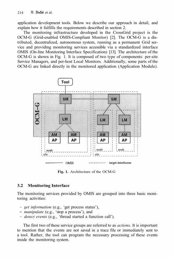
214 et al.
application development tools. Below we describe our approach in detail, andexplain how it fulfills the requirements described in section 2.
The monitoring infrastructure developed in the CrossGrid project is theOCM-G (Grid-enabled OMIS-Compliant Monitor) [2]. The OCM-G is a dis-tributed, decentralized, autonomous system, running as a permanent Grid ser-vice and providing monitoring services accessible via a standardized interfaceOMIS (On-line Monitoring Interface Specification) [13]. The architecture of theOCM-G is shown in Fig. 1. It is composed of two type of components: per-siteService Managers, and per-host Local Monitors. Additionally, some parts of theOCM-G are linked directly in the monitored application (Application Module).
Fig. 1. Architecture of the OCM-G
3.2 Monitoring Interface
The monitoring services provided by OMIS are grouped into three basic moni-toring activities:
get information (e.g., ‘get process status’),manipulate (e.g., ‘stop a process’), anddetect events (e.g., ‘thread started a function call’).
The first two of these service groups are referred to as actions. It is importantto mention that the events are not saved in a trace file or immediately sent toa tool. Rather, the tool can program the necessary processing of these eventsinside the monitoring system.
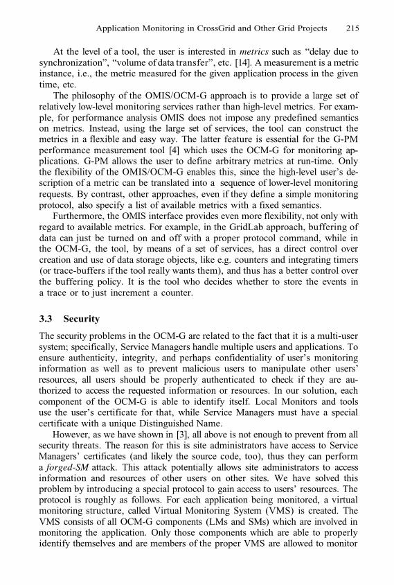
Application Monitoring in CrossGrid and Other Grid Projects 215
At the level of a tool, the user is interested in metrics such as “delay due tosynchronization”, “volume of data transfer”, etc. [14]. A measurement is a metricinstance, i.e., the metric measured for the given application process in the giventime, etc.
The philosophy of the OMIS/OCM-G approach is to provide a large set ofrelatively low-level monitoring services rather than high-level metrics. For exam-ple, for performance analysis OMIS does not impose any predefined semanticson metrics. Instead, using the large set of services, the tool can construct themetrics in a flexible and easy way. The latter feature is essential for the G-PMperformance measurement tool [4] which uses the OCM-G for monitoring ap-plications. G-PM allows the user to define arbitrary metrics at run-time. Onlythe flexibility of the OMIS/OCM-G enables this, since the high-level user’s de-scription of a metric can be translated into a sequence of lower-level monitoringrequests. By contrast, other approaches, even if they define a simple monitoringprotocol, also specify a list of available metrics with a fixed semantics.
Furthermore, the OMIS interface provides even more flexibility, not only withregard to available metrics. For example, in the GridLab approach, buffering ofdata can just be turned on and off with a proper protocol command, while inthe OCM-G, the tool, by means of a set of services, has a direct control overcreation and use of data storage objects, like e.g. counters and integrating timers(or trace-buffers if the tool really wants them), and thus has a better control overthe buffering policy. It is the tool who decides whether to store the events ina trace or to just increment a counter.
3.3 Security
The security problems in the OCM-G are related to the fact that it is a multi-usersystem; specifically, Service Managers handle multiple users and applications. Toensure authenticity, integrity, and perhaps confidentiality of user’s monitoringinformation as well as to prevent malicious users to manipulate other users’resources, all users should be properly authenticated to check if they are au-thorized to access the requested information or resources. In our solution, eachcomponent of the OCM-G is able to identify itself. Local Monitors and toolsuse the user’s certificate for that, while Service Managers must have a specialcertificate with a unique Distinguished Name.
However, as we have shown in [3], all above is not enough to prevent from allsecurity threats. The reason for this is site administrators have access to ServiceManagers’ certificates (and likely the source code, too), thus they can performa forged-SM attack. This attack potentially allows site administrators to accessinformation and resources of other users on other sites. We have solved thisproblem by introducing a special protocol to gain access to users’ resources. Theprotocol is roughly as follows. For each application being monitored, a virtualmonitoring structure, called Virtual Monitoring System (VMS) is created. TheVMS consists of all OCM-G components (LMs and SMs) which are involved inmonitoring the application. Only those components which are able to properlyidentify themselves and are members of the proper VMS are allowed to monitor
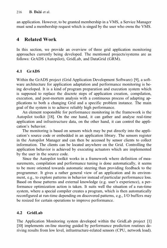
216 et al.
an application. However, to be granted membership in a VMS, a Service Managermust send a membership request which is singed by the user who owns the VMS.
4 Related Work
In this section, we provide an overview of three grid application monitoringapproaches currently being developed. The mentioned projects/systems are asfollows: GrADS (Autopilot), GridLab, and DataGrid (GRM).
4.1 GrADS
Within the GrADS project (Grid Application Development Software) [9], a soft-ware architecture for application adaptation and performance monitoring is be-ing developed. It is a kind of program preparation and execution system whichis supposed to replace the discrete steps of application creation, compilation,execution, and post-mortem analysis with a continuous process of adapting ap-plications to both a changing Grid and a specific problem instance. The maingoal of the system is to achieve reliably high performance.
An element responsible for performance monitoring in the framework is theAutopilot toolkit [18]. On the one hand, it can gather and analyse real-timeapplication and infrastructure data, on the other hand, it can control the appli-cation’s behavior.
The monitoring is based on sensors which may be put directly into the appli-cation’s source code or embedded in an application library. The sensors registerin the Autopilot Manager and can then be accessed by sensor clients to collectinformation. The clients can be located anywhere on the Grid. Controlling theapplication behavior is achieved by executing actuators which are implementedby the user in the source code.
Since the Autopilot toolkit works in a framework where definition of mea-surements, compilation and performance tuning is done automatically, it seemsto be more oriented towards automatic steering than providing feedback to theprogrammer. It gives a rather general view of an application and its environ-ment, e.g., to explore patterns in behavior instead of particular performance loss.Based on those patterns and external knowledge (e.g. user’s experience), a per-formance optimization action is taken. It suits well the situation of a run-timesystem, where a special compiler creates a program, which is then automaticallyreconfigured at run-time depending on discovered patterns, e.g., I/O buffers maybe resized for certain operations to improve performance.
4.2 GridLab
The Application Monitoring system developed within the GridLab project [1][10] implements on-line steering guided by performance prediction routines de-riving results from low level, infrastructure-related sensors (CPU, network load).
Application Monitoring in CrossGrid and Other Grid Projects 217
The sensors are mainly modules that are dynamically linked against monitor-ing system executables. They are designed to gather data from various sources,e.g., a special type of sensor can collect performance data from an application.When gathered at the lowest-level component, the information is passed to theso-called Main Monitor responsible for the management of the measurementand for providing the information to local users. The information can also beexposed to outside users by a Monitoring Service, which also does authenticationand authorisation of users.
GridLab proposed a protocol for high-level producer-consumer communica-tion. The protocol has three types of messages: commands, command responsesand metric values. A consumer can authenticate, initiate a measurement, andcollect data. Additionally, the GridLab team proposed a standard set of metricsalong with their semantics.
However, the approach is limited in its functionality and flexibility. First, itdoes not support manipulations on the target application. Second, it seems torely only on full traces, at least at the current state of development. Finally, thepredefined semantics of all metrics requires all Grid users to agree on this, whichis rather restrictive [11].
4.3 DataGrid
The GRM monitor and the PROVE visualization tool [17], being developed inthe DataGrid project [8], originate from the cluster environment, in which theywork as part of P-GRADE, an environment for parallel program development.These tools have been separated from P-GRADE and adapted to work on theGrid [12].
The GRM is a semi-on-line monitor which collects information about appli-cation and delivers them to the R-GMA [15], a relational information infras-tructure for the Grid. Another GRM component gets the information from theR-GMA and delivers them to the PROVE visualisation tool [16]. According tothe authors, semi-on-line mode means that only observation but not manipula-tion or data processing is possible, thus it is not a real on-line monitor. On theother hand though, the acquired data is not stored in local files like in off-lineapproaches, but is just buffered locally.
Monitoring in GRM/PROVE is mainly based on event tracing. However,event tracing has some serious drawbacks, as outlined in Section 2.
While the GRM/PROVE environment is well suited for the DataGrid project,where only batch processing is supported, it is less usable for the monitoring ofinteractive applications.
First, the R-GMA communication infrastructure used by GRM is based onJava servlets, which introduces a rather high communication latency. However,in order to perform accurate on-line measurements, it is important that the toolis provided with information as soon as possible. This is especially true whenmonitoring interactive applications.
Second, achieving low latency and low intrusion at the same time is basicallyimpossible when monitoring is based on trace data. If the traces are buffered, the
218 et al.
latency increases, if not, the overhead for transmitting the events is too high.This means that a tool will not be able to provide an update rate, which ishigh enough to meet the requirements of an on-line visualization, especially forinteractive applications.
5 Status and Future Work
Currently, we have released a second prototype implementation of the OCM-G.This version has a full support for a grid environment, including a bottom-upstart-up, globus-based security, and support for multiple applications. However,the prototype is still limited to work on a single site only.
The future work in the framework of the CrossGrid project, besides supportfor multiple sites, includes deployment of the OCM-G as a grid service (however,not in the web-services sense), support for multiple users, and a second layer ofsecurity which will allow not only for a proper authentication and authorizationof users, but will also prevent from forging components of the monitoring system.
Additionally, we currently work on a web-services based interface to theOCM-G which will allow to deploy the system as a grid service.
6 Summary
Monitoring of interactive applications poses high requirements on the monitoringinfrastructure. We have pointed out that on-line monitoring is best for this pur-pose. High efficiency is also very important, as in case of interactive applicationsa low response time is needed.
The OCM-G was designed with these requirements in mind. We use an ef-ficient communication layer, data reduction and instrumentation techniques tominimize the intrusion of the monitoring system. The flexible set of monitoringservices allows the user to define his own metrics, while the standard monitoringinterface OMIS enables interoperability of tools.
Similar Grid application monitoring projects exist, but their analysis revealsthat they have a focus which is rather different than that of our project.
Acknowledgements. We would like to thank prof. Peter Kacskuk and prof.Zsolt Nemeth for fruitful discussions.
References
Allen, G., Davis, K., Dolkas, K., Doulamis, N., Goodale, T., Kielmann, T., Merzky,A., Nabrzyski, J., Pukacki, J., Radke, T., Michael, M., Seidel, E., Shalf, J. , andTaylor, I.: Enabling Applications on the Grid: A GridLab Overview. InternationalJournal of High Performance Computing Applications: Special issue on Grid Com-puting: Infrastructure and Applications, to be published in August 2003.
Bubak, M., Szepieniec, T., Wismüller, R., and Radecki, M.: OCM-G –Grid Application Monitoring System: Towards the First Prototype. Proc. CracowGrid Workshop 2002, Krakow, December 2002.
1.
2.
Application Monitoring in CrossGrid and Other Grid Projects 219
M. Bubak, W. Rzasa, T. Szepieniec, R. Wismüller: Security in the OCM-G Grid Application Monitoring System. To be published in proc. PPAM 2003, 7-10September 2003, Czestochowa, Poland. Springer.Bubak, M., Funika, W., and Wismüller, R.: The CrossGrid Performance AnalysisTool for Interactive Grid Applications. Proc. EuroPVM/MPI 2002, Linz, Sept.2002.Bubak, M., Funika, W., Balis, B., and Wismüller, R.: Interoperability of OCM-based On-line Tools. Proc. PVM/MPI Users Group Meeting 2000, LNCS vol. 1908,pp. 242-249, Balatonfüred, Hungary, September 2000. Springer 2000.Wismüller, R, Ludwig, T.: Interoperable Run-Time Tools for Distributed Systems– A Case Study. The Journal of Supercomputing, 17(3):277-289, November 2000.The CrossGrid Project (IST-2001-32243): http://www.eu-crossgrid.orgThe DataGrid Project: http://www.eu-datagrid.orgThe GrADS Project: http://hipersoft.cs.rice.edu/gradsThe GridLab Project: http://www.gridlab.orgGridLab deliverable 11.3: Grid Monitoring Architecture Prototype.http://www.gridlab.org/Resources/Deliverables/D11.3.pdfKacsuk, P.: Parallel Program Development and Execution in the Grid. Proc. PAR-ELEC 2002, International conference on parallel computing in electrical engineer-ing. pp. 131-138, Warsaw, 2002.Ludwig, T., Wismüller, R., Sunderam, V., and Bode, A.: OMIS – On-line Monitor-ing Interface Specification (Version 2.0). Shaker Verlag, Aachen, vol. 9, LRR-TUMResearch Report Series, 1997. http://wwwbode.in.tum.de/~omis/Z. Nemeth: Grid Performance, Grid Benchmarks, Grid Metrics. Cracow Grid Work-shop, October 27-29, 2003, Cracow, Poland. Invited talk.R-GMA: A Grid Information and Monitoring System.http: //www. gridpp. ac. uk/abstracts/AllHands_RGMA.pdfN. Podhorszki and P. Kacsuk Monitoring Message Passing Applications in the Gridwith GRM and R-GMA Proceedings of EuroPVM/MPI’2003, Venice, Italy, 2003.Springer 2003.Podhorski, N., Kacsuk, P.: Design and Implementation of a Distributed Monitorfor Semi-on-line Monitoring of VisualMP Applications. Proc. DAPSYS 2000, Bal-atonfured, Hungary, 23-32, 2000.Vetter, J.S., and Reed, D.A.: Real-time Monitoring, Adaptive Control and Inter-active Steering of Computational Grids. The International Journal of High Perfor-mance Computing Applications, 14 357-366, 2000.
3.
4.
5.
6.
7.8.9.
10.11.
12.
13.
14.
15.
16.
17.
18.
Grid Infrastructure Monitoringas Reliable Information Service*
Petr Holub, Martin Kuba, and Miroslav Ruda
Institute of Computer Science, Masaryk University,Botanická 68a, 602 00 Brno, Czech Republic{hopet,makub,ludek,ruda}@ics.muni.cz
Abstract. A short overview of Grid infrastructure status monitoringis given followed by a discussion of key concepts for advanced statusmonitoring systems: passive information gathering based on direct ap-plication instrumentation, indirect one based on service and middlewareinstrumentation, multidimensional matrix testing, and on-demand activetesting using non-dedicated user identities. We also propose an idea ofaugmenting information provided traditionally using Grid informationservices by information from the infrastructure status monitoring whichgives verified and thus valid information only. The approach is demon-strated using a Testbed Status Monitoring Tool prototype developed fora GridLab project.
1 Introduction
A large-scale heterogeneous Grid is subject to frequent changes and service dis-ruptions of some of the huge number of components that constitute this en-vironment. Grid management requires on-line monitoring of the resources todetermine their state and availability. The less dynamic data about the Gridresources are usually published by the resources themselves using informationservices (e. g. Meta Directory Service from Globus package [2]), while the highlydynamic data are usually published via different means (some implementationof the general Grid Monitoring Architecture, GMA [1]). The information pro-vided by both of these approaches is used by other Grid services for discoveryof elements of the environment and the ways these elements can be used.
The general Grid monitoring covers two complementary areas: applicationmonitoring and infrastructure monitoring. Both can be subdivided into perfor-mance monitoring and status monitoring. Application performance monitoring,application status monitoring, and infrastructure performance monitoring areout of scope of this paper. We are dealing with Grid infrastructure status mon-itoring, which will be called status monitoring for brevity. Status monitoringcovers infrastructure sanity checks, availability and interoperability of comput-ers, other components, as well as web services and Grid services [5].
* This work is supported by the European Commission, grant IST–2001–32133 (Grid-Lab).
M. Dikaiakos (Ed.): AxGrids 2004, LNCS 3165, pp. 220–229, 2004.© Springer-Verlag Berlin Heidelberg 2004
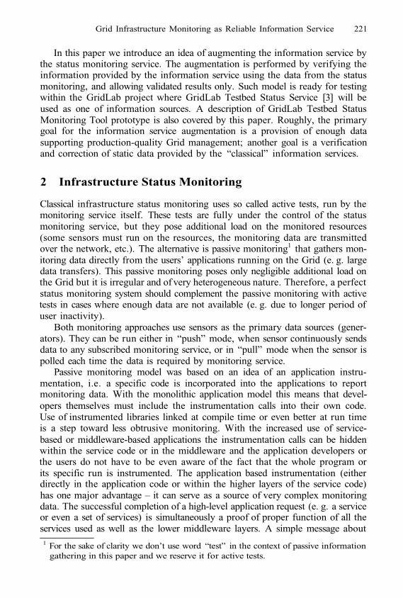
Grid Infrastructure Monitoring as Reliable Information Service 221
In this paper we introduce an idea of augmenting the information service bythe status monitoring service. The augmentation is performed by verifying theinformation provided by the information service using the data from the statusmonitoring, and allowing validated results only. Such model is ready for testingwithin the GridLab project where GridLab Testbed Status Service [3] will beused as one of information sources. A description of GridLab Testbed StatusMonitoring Tool prototype is also covered by this paper. Roughly, the primarygoal for the information service augmentation is a provision of enough datasupporting production-quality Grid management; another goal is a verificationand correction of static data provided by the “classical” information services.
2 Infrastructure Status Monitoring
Classical infrastructure status monitoring uses so called active tests, run by themonitoring service itself. These tests are fully under the control of the statusmonitoring service, but they pose additional load on the monitored resources(some sensors must run on the resources, the monitoring data are transmittedover the network, etc.). The alternative is passive monitoring1 that gathers mon-itoring data directly from the users’ applications running on the Grid (e. g. largedata transfers). This passive monitoring poses only negligible additional load onthe Grid but it is irregular and of very heterogeneous nature. Therefore, a perfectstatus monitoring system should complement the passive monitoring with activetests in cases where enough data are not available (e. g. due to longer period ofuser inactivity).
Both monitoring approaches use sensors as the primary data sources (gener-ators). They can be run either in “push” mode, when sensor continuously sendsdata to any subscribed monitoring service, or in “pull” mode when the sensor ispolled each time the data is required by monitoring service.
Passive monitoring model was based on an idea of an application instru-mentation, i.e. a specific code is incorporated into the applications to reportmonitoring data. With the monolithic application model this means that devel-opers themselves must include the instrumentation calls into their own code.Use of instrumented libraries linked at compile time or even better at run timeis a step toward less obtrusive monitoring. With the increased use of service-based or middleware-based applications the instrumentation calls can be hiddenwithin the service code or in the middleware and the application developers orthe users do not have to be even aware of the fact that the whole program orits specific run is instrumented. The application based instrumentation (eitherdirectly in the application code or within the higher layers of the service code)has one major advantage – it can serve as a source of very complex monitoringdata. The successful completion of a high-level application request (e. g. a serviceor even a set of services) is simultaneously a proof of proper function of all theservices used as well as the lower middleware layers. A simple message about1 For the sake of clarity we don’t use word “test” in the context of passive information
gathering in this paper and we reserve it for active tests.
222 P. Holub et al.
successful service call covers a success of many related (lower) services, increas-ing substantially scalability of the monitoring by allowing the system to omitindividual tests that are implicitly successful. On the other hand, a failure canimmediately trigger more detailed status tests of called services, thus leading tovery fast failure discovery.
Traditionally status monitoring has been performed on machine oriented ba-sis: either the machines sent continuously some data, or machine by machinewas tested whether all required and advertised services are running. Introduc-tion of widely deployed services within the Open Grid Services Architecture [5]framework leads to the necessity to perform also the service oriented monitoringto check that all services are running properly. Most services run in a machineindependent way, i. e. they are not tightly associated with a particular machineand can run in several instances simultaneously or can be easily re-started onany machine from a subset of Grid machines. This means that a service – not amachine – must be tested. Testing of a service means that the service must befound (discovered), connected to and actually tested (run) dynamically, with nostored (cached) information about the placement of the service.
For many services it is important to test availability on N-to-N or M-to-Nbasis (where M might be subset of N or it might be completely different andindependent set) instead of 1-to-N basis. For instance data transfer service maybe required to be capable of transferring data from any node to any node (oreven a set of nodes). Or a user may be required to be able to login from anynode within a selected subset of Grid nodes to any node from different subset.As a first step towards more complex solution, we have introduced matrix teststhat perform either M-to-N or N-to-N tests to cover such cases.
Another important aspect of the status monitoring is whether the tests runusing some dedicated testing identity (e.g. using dedicated service certificate)or whether the tests are run using ordinary users’ identities. While the secondoption is rather automatic for instrumented checks, it must be ensured thatsimilar way is possible for active checks as well. It is also desirable to be able torun active tests on demand under specific user identity as this provides meansfor looking for a cause of a problem encountered by particular users only.
3 Monitoring Servicesas Information Services Augmentation
Information services traditionally advertise information about resources avail-able on the Grid (machines and their capabilities, job submission mechanisms,services etc.). Owners of the resources or directly the resources usually pub-lish such information about the resources into information service without anyvalidation, and therefore obsolete or invalid information can be easily advertised.
Status monitoring can augment traditional information services by takinginformation published in them, checking validity and then publishing resultsin form of verified and thus authoritative information about resources usinginterface common to information services.
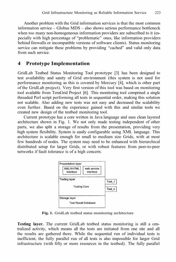
Grid Infrastructure Monitoring as Reliable Information Service 223
Another problem with the Grid information services is that the most commoninformation service – Globus MDS – also shows serious performance bottleneckwhen too many non-homogeneous information providers are subscribed to it (es-pecially with high percentage of “problematic” ones, like information providersbehind firewalls or incompatible versions of software clients). Status monitoringservice can mitigate these problems by providing “cached” and valid only datafrom such service.
4 Prototype Implementation
GridLab Testbed Status Monitoring Tool prototype [3] has been designed totest availability and sanity of Grid environment (this system is not used forperformance monitoring as this is covered by Mercury [4], which is other partof the GridLab project). Very first version of this tool was based on monitoringtool available from TeraGrid Project [6]. This monitoring tool comprised a singlethreaded Perl script performing all tests in sequential order, making this solutionnot scalable. Also adding new tests was not easy and decreased the scalabilityeven further. Based on the experience gained with this and similar tools wecreated new design of the testbed monitoring tool.
Current prototype has a core written in Java language and uses clean layeredarchitecture shown in Fig. 1. We not only made testing independent of otherparts, we also split a storage of results from the presentation, providing veryhigh system flexibility. System is easily configurable using XML language. Thisarchitecture is scalable enough for small to medium size Grids, with at mostfew hundreds of nodes. The system may need to be enhanced with hierarchicaldistributed setup for larger Grids, or with robust features from peer-to-peernetworks if fault tolerance is of a high concern.
Fig. 1. GridLab testbed status monitoring architecture
Testing layer. The current GridLab testbed status monitoring is still a cen-tralized activity, which means all the tests are initiated from one site and allthe results are gathered there. While the sequential run of individual tests isinefficient, the fully parallel run of all tests is also impossible for larger Gridinfrastructure (with fifty or more resources in the testbed). The fully parallel
224 P. Holub et al.
run may not only overload the testing machine, it may also pose an unaccept-able load on the whole Grid infrastructure. Therefore, we use thread pool ofconfigurable size to perform tests in a limited configurable parallel setup provid-ing us compromise between load on both testing and tested infrastructure andscalability needed.
The testing layer is exposed through a language independent interface whichmakes it possible to implement new tests in virtually any programming language.For example current tests based on Globus 2 protocols have been written eitherusing Java CoG or using small C wrapper for executing binaries written in otherlanguages. The wrapper takes care of timeouts for hung-up jobs and clean-upfor incorrectly finished ones, making the monitoring tool prototype resistant tofailures. Especially hang-ups caused by firewalls incorrectly discarding packetsshowed to be a constant problem in Grid environment.
Test dependencies have been implemented that allow skipping of tests forwhich some mandatory prerequisite has failed. This decreases the unnecessaryload on the tested Grid infrastructure. A language for general description of morecomplex dependencies is under development. We plan to use the same approachfor the passive monitoring based on service and application instrumentation (thedescription of dependencies is crucial in such environment).
The architecture also supports a user triggered on-demand tests. These testsrun under users’ own identities and provide valuable data for problem and bugtracking.
Storage layer. The regular tests are run periodically and their results are storedby the storage layer. As the history must be made available for inspection, thedata are stored in a database. While currently a PostgreSQL database is used,any other relational database can be easily substituted since JDBC databaseinterface is employed.
Presentation layer. The presentation layer supports both static and dynamicweb pages creation. For static results presentation, the test results are convertedto XML and then transformed to a static XHTML page using XSLT processing.The XHTML page mimics the original TeraGrid tests layout and provides goodgeneral overview of the current infrastructure status in the form of a full matrixof colored boxes.
For dynamic results presentation integrated in a Grid portal, GridSphere [7]portlet based interface with multi-lingual capabilities has also been implemented.This interface supports browsing through status data history.
Test results are available via web service interface as well which allows forusing this monitoring service as an information service by other services on theGrid. This specific web service uses SOAP transport protocol with GSI securityand the implementation is moving towards OGSA compliance (now lacking fewof the required Grid service interfaces).
4.1 Incorporated TestsWhile all currently implemented tests use active pull model, our general statusmonitoring framework supports easy integration of passive monitoring as well.
Grid Infrastructure Monitoring as Reliable Information Service 225
Active tests were chosen because of faster and easier implementation comparedto passive monitoring and especially applications, services and middleware in-strumentation. At this stage of the development, the “production” applicationruns are still a minority on the GridLab testbed, which means that passive mon-itoring can not yet be a major source of monitoring information. All tests arerun on regular scheduled basis with possible activation on demand by users usingtheir own identities.
Simple tests. A test from the simple test category produces a scalar value foreach tested machine. The prototype currently incorporates all tests available inthe original TeraGrid software and adds also several new tests:
Globus-2 tests: GRIS, GSI-FTP, Gatekeeper, GSI-SSH, and GIIS,availability of MPI C and MPI Fortran compilers,job manager tests: tests all job managers advertised in information services,whether they can run both normal and MPI jobs,GridLab specific tests: check on accepted CAs (whether compliant to Grid-Lab requirements), check whether required software is installed and re-ally working (C, C++, CVS, F90, GNU make, Perl, Java), check whethergrid-mapfile contains all required users, check GridLab Mercury [4], andGridLab MDS Extensions and MDS web service [8].
Except for GIIS which is tested once per GIIS server (in the case of GridLabonly once for the whole testbed since there is only one GIIS server in the testbed),all other tests run on per machine basis.
The simple tests on GridLab testbed currently take about 15 minutes to testall of 17 services on all 19 machines using 6 concurrent threads. The time isspent mostly in waiting for response due to delays in network communicationand in waiting for timeouts, because the widespread use of firewalls leaves noway to distinguish a slow responding service from unavailable service other thanwaiting for a timeout. The only notable CPU load is due to authentication andencryption in GSI communication.
Service tests. With OGSA model that is generally seen as the next genera-tion model for the Grid environment, Grid services become cornerstones of Gridinfrastructure. Therefore service oriented tests are appropriate solution for mon-itoring infrastructure based on this paradigm. Services may run on various Gridnodes and the important issue is whether service is running correctly and notwhether the service runs on one particular machine. Another fact supportingapproach different from machine oriented tests is that different machines willrun different subsets of services and eventually the matrix of host and servicesmay become quite sparse.
All the services produced by GridLab are persistent GSI-secured web ser-vices. It means they are accessible using HTTPG protocol (HTTP over GSI).Invocation of the web service methods by the testing tool is implemented usingeither Java CoG or C program using gSOAP tool [9] with GSI plug-in. The ser-vices support Grid security features, however to full OGSA compatibility they
226 P. Holub et al.
lack portType inheritance, because most of them are implemented in C, andthere is no C server-side implementation of OGSA available yet.
In the first stage the service status monitoring checks whether the serviceis responsive. We could not rely on all services’s API being inherited from asingle portType, so we require that each GridLab service must provide an op-eration called getServiceDescription() returning a string containing servicedescription. The responsiveness of a service is checked by calling this operation.
We have developed first stage tests for the following GridLab web services:GRMS, Adaptive service, Meta-data service, Replica Catalog, Data Movement,Data Browsing, Authorization, Message Box Service, and Testbed Status.
Second stage is aimed at verifying whether service is operational and performsas expected. Actual tests differ largely from service to service. Up to now secondstage tests for Data Movement service and GRMS have been implemented.
The service tests on GridLab testbed currently take just several seconds totest all 9 services.
Matrix tests. Up to now two matrix tests have been implemented for GridLabinfrastructure: Data Movement service test and GSI-SSH tests. The first onechecks correct operation of Data Movement service between all pairs of nodes inan N-to-N fashion thus forming two-dimensional matrix of results. The test canbe also easily extended to third dimension accommodating the possibility thatdata transfer can be initiated from a third node, i. e. node that is neither sourcenor target of the data being transferred. This example demonstrates problemwith extreme load growth imposed on underlying infrastructure when complexactive measurements and tests are put in use.
The GSI-SSH test checks whether it is possible to login from one node toanother node. The test can work in either full N-to-N or in M-to-N fashion sinceonly a selected subset of Grid nodes can be allowed to initiate SSH connectionto the rest of the Grid.
While the matrix tests are not scalable, they provide invaluable informationabout the “real” Grid status. The current history of use of the data movementtest had shown that it is almost perfect source of monitoring information aboutnode mutual interoperability (as opposed to the 1-to-N centralized tests whichcheck just interoperability between the testing machine and each node). Thematrix tests reflect much better the actual situation users encounter when usinga Grid and are able to find very specific and subtle problems (e. g. various in-compatible firewall configurations). These tests have also character of complextests that are similar to high level application tests (see Sec. 2), which meansthat if the test passes correctly all lower layers and services are verified as well.If failure of such test is experienced, specific lower level tests can be immediatelytriggered to identify precise source of the problem. For example Data Movementmatrix tests will not run without firewalls set up correctly, grid-mapfile in-stalled properly etc. This complex property allows to omit a lot of other teststhus compensating the scalability issue to some extent.
The matrix tests on GridLab testbed currently take about 2 hours to test afull matrix of 17 × 17 data transfers among all 17 machines, most of the time isagain spent waiting for timeouts caused by firewalls.
Grid Infrastructure Monitoring as Reliable Information Service 227
We expect that most of the inter-node tests required by full matrix setupcould be replaced by the passive monitoring information when the Grid is usedfor “real” production (the applications will become actual data sources). Thiswill add the necessary scalability to this kind of tests.
5 Future Work
Current status monitoring prototype tool mostly implements active tests inbottom-up fashion, i. e. testing starts from low level tests and proceeds to higherlevels only if lower level prerequisites are successfully tested. For future work weare targeting opposite approach in which tests of lower level services and layerswill be triggered only when higher level test fails to allow more precise identifi-cation of source of problems. This approach will be enabled by employing highdegree of passive monitoring based on instrumentation of applications, services,and various middleware layers resulting in lower load on Grid infrastructure in-duced by monitoring itself. Heavier use of push mode sensors goes hand in handwith deployment of passive monitoring model which results in far more scalableand inobtrusive monitoring solution.
We plan to extend the Grid Application Toolkit [10] (the specific middlewarelayer connecting transparently applications with lower layers of Grid infrastruc-ture) which is developed within the GridLab project with instrumented inter-faces that will allow use of applications as monitoring data providers. In the sametime we plan to use this instrumented layer to develop a monitoring worm thatwill “travel” autonomously through he Grid, gathering the monitoring informa-tion from used middleware components and nodes and sending this information(probably in a digested form when no error is to be reported) to some centralsite. The travel of the worm will be accomplished in close collaboration withall the middleware components (resource discovery, resource brokerage, job sub-mission service etc.), thus testing extensively the Grid environment as a whole.The combination of active tests and passive monitoring with the data providedby the (regular, random or user triggered) worm reports should cover the wholeGrid with a minimal obtrusive overhead. Understanding the interactions of thesemonitoring components will be subject of our future study.
We also want to build a database of typical problems occurring in the Gridenvironment. It will be used to produce better explanation of problems detected,thus improving understanding of the test results by end users.
6 Conclusions
A Grid infrastructure status monitoring system is an essential component ofany Grid that aims to provide a usable working environment. Such a system isalso a core of the Grid management, including information provision and valida-tion for resource management on the Grid. The status monitoring system beingdeveloped within the EU GridLab project is one of the most comprehensive sta-tus monitoring systems currently deployed on a really large scale heterogeneous
228 P. Holub et al.
Grid. As not only individual components, but also emerging Grid services arepermanently monitored, it represents a preliminary version of an OGSA com-pliant status monitoring system. Another advantage of this system is its use asinformation service augmentation and verification tool, providing a guarantee fora reliable information provided by a general information service (like the MDS).
The ability to define test dependencies in the monitoring system decreasesmonitoring overhead on the Grid infrastructure through elimination of the testsknown in advance to fail. As a complement to this approach, we introduced somevery high level tests whose successful completion signalizes that all the lowerlayers are working and eliminates necessity of individual tests. An example ofsuch higher level tests that is already used on the GridLab testbed is the DataMovement service test. Even the complexity of this test is not prohibitiveas it can potentially replace a large bunch of simpler, but also obtrusive tests.These will be needed only for a targeted inspection when the higher level testsfail.
The passive, service instrumentation based monitoring is another part of thewhole Grid monitoring system. While not discussed in this paper to much extent,they may eventually replace most of the active (monitoring system triggered)tests and thus keeping the overhead of the Grid monitoring to the acceptablelevel even in very large Grids.
References
Tierney, B., Aydt, R., Gunter, D., Smith, W., Swany, M., Taylor, V., Wolski, R.:A Grid Monitoring Architecture. GGF Technical Report GFD-I.7, January 2002.http://www.gridforum.org/Documents/GFD/GFD-I.7.pdfCzajkowski, K., Fitzgerald, S., Foster, I., Kesselman, C.: Grid Information Ser-vices for Distributed Resource Sharing. In Proceedings of the IEEE Interna-tional Symposium on High-Performance Distributed Computing (HPDC-10), IEEEPress, August 2001.Holub, P., Kuba, M., Matyska, L., Ruda, M.: GridLab Testbed Monitoring – Pro-totype Tool. Deliverable 5.6, GridLab Project (IST–2001–32133), 2003.http://www.gridlab.org/Resources/Deliverables/D5.6.pdfBalaton, Z., Gombás, G.: Resource and Job Monitoring. In the Grid. Proc. of theEuro-Par 2003 International Conference, Klagenfurt, 2003. 404–411Foster, I., Kesselman, C., Nick, J., Tuecke, S.: The Physiology of the Grid: AnOpen Grid Services Architecture for Distributed Systems Integration. Open GridService Infrastructure WG, Global Grid Forum, June 22, 2002.http://www.globus.org/research/papers.html#OGSABasney, J., Greenseid, J.: NCSA TestGrid Project: Grid Status Test.http://grid.ncsa.uiuc.edu/test/grid-status-test/Novotny, J., Russell, M., Wehrens, O.: GridSphere: A Portal Framework for Build-ing Collaborations. International Workshop on Middleware for Grid Computing,Rio de Janeiro, June 15 2003.Aloisio, G., Cafaro, M., Epicoco, I., Lezzi, D., Mirto, M., Mocavero, S., Pati, S.:First GridLabMDS Release. Deliverable 10.3, GridLab Project (IST–2001–32133),2002. http://www.gridlab.org/Resources/Deliverables/D10.3c.pdf
1.
2.
3.
4.
5.
6.
7.
8.

Grid Infrastructure Monitoring as Reliable Information Service 229
van Engelen, R. A., Gallivan, K. A.: The gSOAP Toolkit for Web Services and Peer-To-Peer Computing Networks. In the proceedings of IEEE CCGrid Conference2002.Allen, G., Davis, K., Dolkas, K.N., Doulamis, N.D., Goodale, T., Kielmann, T.,Merzky, A., Nabrzyski, J., Pukacki, J., Radke, T., Russell, M., Seidel, E., Shalf,J., Taylor, I.: Enabling Applications on the Grid: A GridLab Overview. Interna-tional Journal of High Performance Computing Applications: Special issue on GridComputing: Infrastructure and Applications, August 2003.
9.
10.
Towards a Protocol for the Attachmentof Semantic Descriptions to Grid Services
Simon Miles, Juri Papay, Terry Payne, Keith Decker, and Luc Moreau
School of Electronics and Computer Science,University of Southampton,
Southampton, SO17 1BJ, UK{sm,jp,trp,ksd,L.Moreau}@ecs.soton.ac.uk
Abstract. Service discovery in large scale, open distributed systems isdifficult because of the need to filter out services suitable to the taskat hand from a potentially huge pool of possibilities. Semantic descrip-tions have been advocated as the key to expressive service discovery,but the most commonly used service descriptions and registry protocolsdo not support such descriptions in a general manner. In this paper,we present a protocol, its implementation and an API for registering se-mantic service descriptions and other task/user-specific metadata, andfor discovering services according to these. Our approach is based on amechanism for attaching structured and unstructured metadata, whichwe show to be applicable to multiple registry technologies. The resultis an extremely flexible service registry that can be the basis of a so-phisticated semantically-enhanced service discovery engine, an essentialcomponent of a Semantic Grid.
1 Introduction
Service discovery is a difficult task in large scale, open distributed systems suchas the Grid and Web, due to the potentially large number of services advertised.In order to characterise their needs, users typically specify the complex require-ments they have of a service, including demands on its functionality, quality ofservice, security, reputation etc. These requirements cannot be fully expressedin the constrained information models provided by existing service registry tech-nologies such as UDDI (the de facto standard for Web Services registry), theOGSA Registry [7] or the Jini lookup service [1].
More demandingly, user requirements may contain information that assumesan understanding of particular application domains and that is meant to effectthe outcome of the discovery process. For example, a bioinformatician may searchfor services that process “expressed sequence tags” but also that operate on“nucleotide sequences”. The knowledge that the latter biological concept is amore general form of the former is known by the user, but is unlikely to beexpressible in either the query or standard published descriptions of any of thepotentially useful services.
On the other hand, there may be information that could be utilised in thediscovery process, but is not be published by the service provider. For example,
M. Dikaiakos (Ed.): AxGrids 2004, LNCS 3165, pp. 230–239, 2004.© Springer-Verlag Berlin Heidelberg 2004
Towards a Protocol for the Attachment of Semantic Descriptions 231
recommendations about which services to use may come from one member of anorganisation, and could be used by collaborating members of that organisation.
Finally, there are functional entities other than services that need to be pub-licised. For example, workflow scripts describe how to compose services togetherto get a useful composite behaviour. They are location-independent descriptionsof service use and should be publishable in the same registries as services sincethey provide comparable function, i.e. they are invocable, take inputs and returnoutputs (this equivalence is recognised explicitly in DAML-S [6]).
Given the plethora of services and sophistication of user requirements, manyhave advocated the use of semantic descriptions that qualify functional and non-functional characteristics of services in a manner that is amenable to automaticprocessing [3, 6, 14]. Against this background, we have designed a system thatallows the attachment of semantic information so as to provide a solution tothe shortcomings of existing registry technologies. These developments are partof the architecture developed by the myGrid project (www.mygrid.org.uk). Inthis paper, we report on our experience of designing such a system, specificallyfocusing on the following contributions.
We have developed a protocol for attaching metadata to registered servicedescriptions, and for querying over service descriptions and their metadata.We have implemented a UDDI-compatible service registry that allows meta-data to be attached to various parts of the service description, such as theservices themselves, their operations, their inputs and their outputs (as spec-ified in WSDL documents describing service interfaces).A programmatic interface (API) provides clients with an easy way to accessthis information, whether held in a remote Web Service or locally.We demonstrate with a common information model that our attachmentmethodology applies to multiple discovery technologies in a single registry,including UDDI, DAML-S and BioMOBY.
In this paper we will first examine the limitations of existing approaches (Sec-tion 2), then look at how we overcome these by providing a metadata attachmentmechanism (Section 3). We then examine the protocol by which a client can reg-ister and query over metadata (Section 4), and in Section 5 we discuss how ourservices overcome some of the problems mentioned above. Finally, we discussimplications of our work and its current and future developments in Section 6.
2 Limitation of Existing Approaches
The UDDI service registry (Universal Description, Discovery, and Integration)[12] has become the de-facto standard for service discovery in the Web Servicescommunity. Service queries are typically white or yellow pages based: servicesare located using a description of their provider or a specific classification (takenfrom a published taxonomy) of the desired service type. Service descriptions inUDDI are composed from a limited set of high-level data constructs (Business En-tity, Business Service etc.) which can include other constructs following a rigidschema. Some of these constructs, such as tModels, Category Bags and Identifier
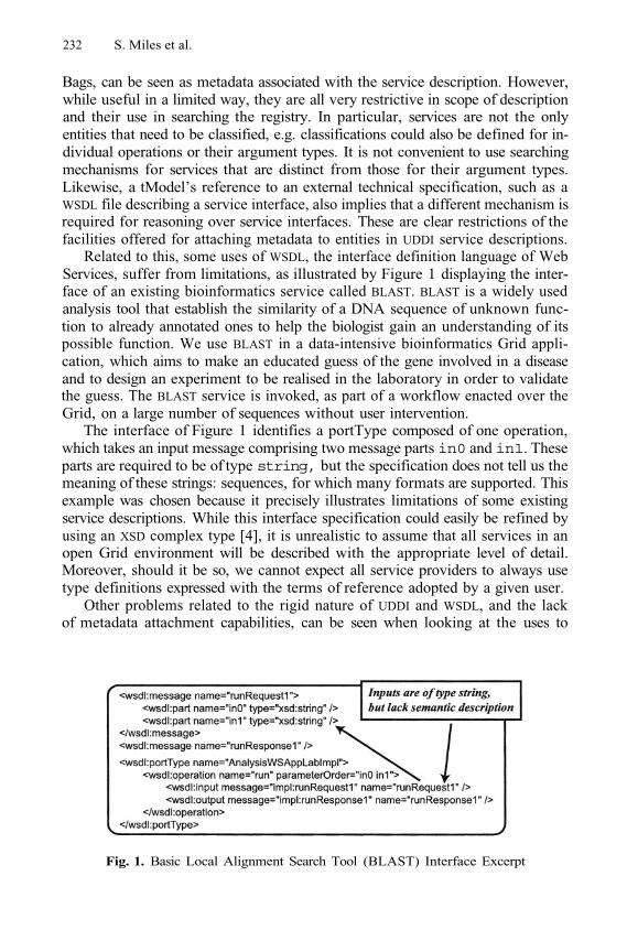
232 S. Miles et al.
Bags, can be seen as metadata associated with the service description. However,while useful in a limited way, they are all very restrictive in scope of descriptionand their use in searching the registry. In particular, services are not the onlyentities that need to be classified, e.g. classifications could also be defined for in-dividual operations or their argument types. It is not convenient to use searchingmechanisms for services that are distinct from those for their argument types.Likewise, a tModel’s reference to an external technical specification, such as aWSDL file describing a service interface, also implies that a different mechanism isrequired for reasoning over service interfaces. These are clear restrictions of thefacilities offered for attaching metadata to entities in UDDI service descriptions.
Related to this, some uses of WSDL, the interface definition language of WebServices, suffer from limitations, as illustrated by Figure 1 displaying the inter-face of an existing bioinformatics service called BLAST. BLAST is a widely usedanalysis tool that establish the similarity of a DNA sequence of unknown func-tion to already annotated ones to help the biologist gain an understanding of itspossible function. We use BLAST in a data-intensive bioinformatics Grid appli-cation, which aims to make an educated guess of the gene involved in a diseaseand to design an experiment to be realised in the laboratory in order to validatethe guess. The BLAST service is invoked, as part of a workflow enacted over theGrid, on a large number of sequences without user intervention.
The interface of Figure 1 identifies a portType composed of one operation,which takes an input message comprising two message parts in0 and in1. Theseparts are required to be of type string, but the specification does not tell us themeaning of these strings: sequences, for which many formats are supported. Thisexample was chosen because it precisely illustrates limitations of some existingservice descriptions. While this interface specification could easily be refined byusing an XSD complex type [4], it is unrealistic to assume that all services in anopen Grid environment will be described with the appropriate level of detail.Moreover, should it be so, we cannot expect all service providers to always usetype definitions expressed with the terms of reference adopted by a given user.
Other problems related to the rigid nature of UDDI and WSDL, and the lackof metadata attachment capabilities, can be seen when looking at the uses to
Fig. 1. Basic Local Alignment Search Tool (BLAST) Interface Excerpt
Towards a Protocol for the Attachment of Semantic Descriptions 233
which they are put. A UDDI query typically returns a list of available services,from which a subset may conform to a known and/or informally agreed uponpolicy and thus can be invoked. Such approaches work well within small, closedcommunities, where a priori definitions of signatures and data formats can bedefined. However, across open systems such as the Grid, no assumption canbe made about how desired services are described, how to interact with them,and how to interpret their corresponding results. Additionally, service providerstypically adopt different ways to model and present services, often because of thesubtle differences in the service itself. This raises the problem of semantic inter-operability, which is the capability of computer systems to meaningfully operatein conjunction with one another, even though the languages or structures withwhich they are described may be different. Semantic discovery is the process ofdiscovering services capable of semantic inter-operability.
Also, UDDI provides no data structures to represent either the abstract orconcrete details contained within a WSDL document, but only a standard way toexpress that a service implements a particular WSDL interface. A new proposalallows tModels to reference specific bindings and port types [5]. However, thisextension still does not provide access to, or queries over, operations or messages,which would allow the discovery of services capable of specific operations.
DAML-S attempts a full description of a service as some process that can beenacted to achieve a goal. First, by its nature, the DAML-S ontology may be sub-classed to provide new information about services such as, e.g. the task performedby a service, as discussed in [14]. DAML-S provides an alternate mechanism thatallows service publishers to attach semantic information to the parameters of aservice. Indeed, the argument types referred to by the profile input and outputparameters are semantic. Such semantic types are mapped to the syntactic typespecified in the WSDL interface by the intermediary of the service grounding. Wefeel that such a mechanism is a step in the right direction, but it is convoluted(in particular, because the mapping from semantic to syntactic types involvesthe process model, which we did not discuss). It also has limitations since itonly supports annotations provided by the publisher, and not by third-parties;furthermore, a profile only supports one semantic description per parameter anddoes not allow multiple interpretations. Finally, semantic annotations are re-stricted to input and output parameters, but not applied to other elements of aWSDL interface specification.
3 Extending Service Descriptions
Having discussed the limitations of existing technologies, we now focus on thecapabilities of our service registry. This allows for extension of service descrip-tions by adding metadata attachments. A metadata attachment is a piece of datagiving information about an existing entity in a service description, and is ex-plicitly associated with that entity. Entities to which metadata can be attachedinclude the service itself, an operation supported by the service, an input oroutput type of an operation invocable on the service. The metadata is attached
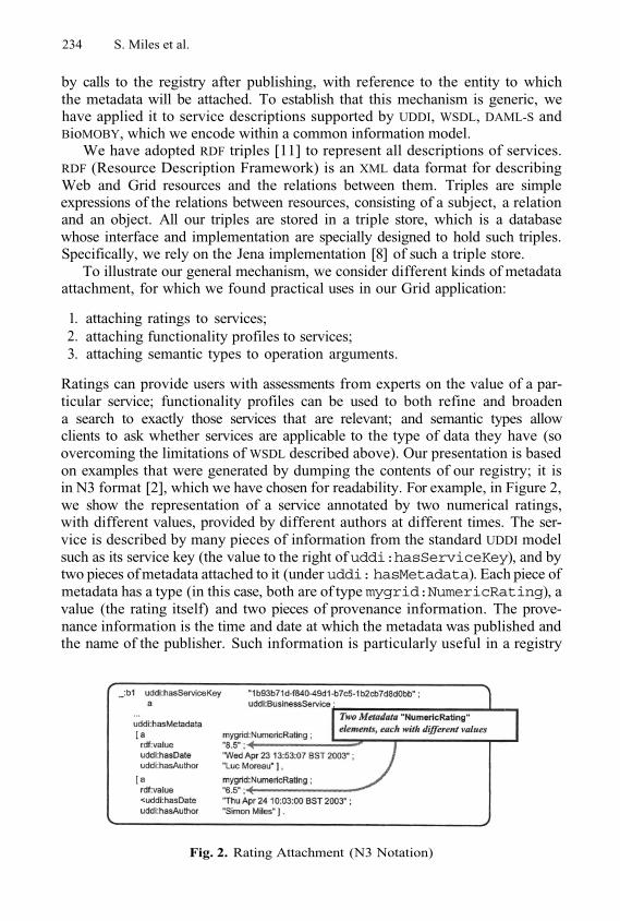
234 S. Miles et al.
by calls to the registry after publishing, with reference to the entity to whichthe metadata will be attached. To establish that this mechanism is generic, wehave applied it to service descriptions supported by UDDI, WSDL, DAML-S andBioMOBY, which we encode within a common information model.
We have adopted RDF triples [11] to represent all descriptions of services.RDF (Resource Description Framework) is an XML data format for describingWeb and Grid resources and the relations between them. Triples are simpleexpressions of the relations between resources, consisting of a subject, a relationand an object. All our triples are stored in a triple store, which is a databasewhose interface and implementation are specially designed to hold such triples.Specifically, we rely on the Jena implementation [8] of such a triple store.
To illustrate our general mechanism, we consider different kinds of metadataattachment, for which we found practical uses in our Grid application:
attaching ratings to services;attaching functionality profiles to services;attaching semantic types to operation arguments.
1.2.3.
Ratings can provide users with assessments from experts on the value of a par-ticular service; functionality profiles can be used to both refine and broadena search to exactly those services that are relevant; and semantic types allowclients to ask whether services are applicable to the type of data they have (soovercoming the limitations of WSDL described above). Our presentation is basedon examples that were generated by dumping the contents of our registry; it isin N3 format [2], which we have chosen for readability. For example, in Figure 2,we show the representation of a service annotated by two numerical ratings,with different values, provided by different authors at different times. The ser-vice is described by many pieces of information from the standard UDDI modelsuch as its service key (the value to the right ofuddi:hasServiceKey), and bytwo pieces of metadata attached to it (under uddi: hasMetadata). Each piece ofmetadata has a type (in this case, both are of type mygrid:NumericRating), avalue (the rating itself) and two pieces of provenance information. The prove-nance information is the time and date at which the metadata was published andthe name of the publisher. Such information is particularly useful in a registry
Fig. 2. Rating Attachment (N3 Notation)
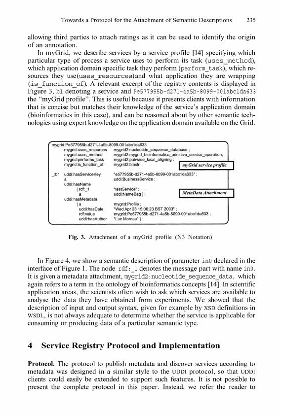
Towards a Protocol for the Attachment of Semantic Descriptions 235
allowing third parties to attach ratings as it can be used to identify the originof an annotation.
In myGrid, we describe services by a service profile [14] specifying whichparticular type of process a service uses to perform its task (uses_method),which application domain specific task they perform (perform_task), which re-sources they use (uses_resources) and what application they are wrapping(is_function_of). A relevant excerpt of the registry contents is displayed inFigure 3, b1 denoting a service and Pe577955b–d271–4a5b–8099–001abc1da633the “myGrid profile”. This is useful because it presents clients with informationthat is concise but matches their knowledge of the service’s application domain(bioinformatics in this case), and can be reasoned about by other semantic tech-nologies using expert knowledge on the application domain available on the Grid.
Fig. 3. Attachment of a myGrid profile (N3 Notation)
In Figure 4, we show a semantic description of parameter in0 declared in theinterface of Figure 1. The node rdf:_1 denotes the message part with name in0.It is given a metadata attachment, mygrid2:nucleotide_sequence_data, whichagain refers to a term in the ontology of bioinformatics concepts [14]. In scientificapplication areas, the scientists often wish to ask which services are available toanalyse the data they have obtained from experiments. We showed that thedescription of input and output syntax, given for example by XSD definitions inWSDL, is not always adequate to determine whether the service is applicable forconsuming or producing data of a particular semantic type.
4 Service Registry Protocol and Implementation
Protocol. The protocol to publish metadata and discover services according tometadata was designed in a similar style to the UDDI protocol, so that UDDIclients could easily be extended to support such features. It is not possible topresent the complete protocol in this paper. Instead, we refer the reader to
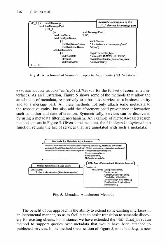
236 S. Miles et al.
Fig. 4. Attachment of Semantic Types to Arguments (N3 Notation)
www.ecs.soton.ac.uk/~sm/myGrid/Views/ for the full set of commented in-terfaces. As an illustration, Figure 5 shows some of the methods that allow theattachment of metadata, respectively to a business service, to a business entityand to a message part. All these methods not only attach some metadata tothe respective entity, but also add the aforementioned provenance informationsuch as author and date of creation. Symmetrically, services can be discoveredby using a metadata filtering mechanism. An example of metadata-based searchmethod appears in Figure 5. Given some metadata, the findServiceByMetadatafunction returns the list of services that are annotated with such a metadata.
Fig. 5. Metadata Attachment Methods
The benefit of our approach is the ability to extend some existing interfaces inan incremental manner, so as to facilitate an easier transition to semantic discov-ery for existing clients. For instance, we have extended the UDDI find_servicemethod to support queries over metadata that would have been attached topublished services. In the method specification of Figure 5, metadataBag, a new
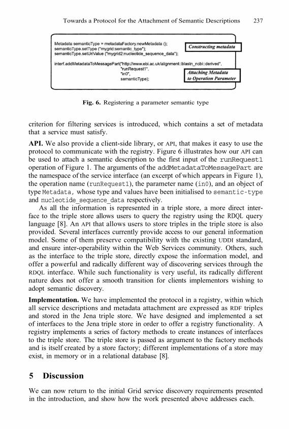
Towards a Protocol for the Attachment of Semantic Descriptions 237
Fig. 6. Registering a parameter semantic type
criterion for filtering services is introduced, which contains a set of metadatathat a service must satisfy.
API. We also provide a client-side library, or API, that makes it easy to use theprotocol to communicate with the registry. Figure 6 illustrates how our API canbe used to attach a semantic description to the first input of the runRequest1operation of Figure 1. The arguments of the addMetadataToMessagePart arethe namespace of the service interface (an excerpt of which appears in Figure 1),the operation name (runRequest1), the parameter name (in0), and an object oftype Metadata, whose type and values have been initialised to semantic-typeand nucleotide_sequence_data respectively.
As all the information is represented in a triple store, a more direct inter-face to the triple store allows users to query the registry using the RDQL querylanguage [8]. An API that allows users to store triples in the triple store is alsoprovided. Several interfaces currently provide access to our general informationmodel. Some of them preserve compatibility with the existing UDDI standard,and ensure inter-operability within the Web Services community. Others, suchas the interface to the triple store, directly expose the information model, andoffer a powerful and radically different way of discovering services through theRDQL interface. While such functionality is very useful, its radically differentnature does not offer a smooth transition for clients implementors wishing toadopt semantic discovery.
Implementation. We have implemented the protocol in a registry, within whichall service descriptions and metadata attachment are expressed as RDF triplesand stored in the Jena triple store. We have designed and implemented a setof interfaces to the Jena triple store in order to offer a registry functionality. Aregistry implements a series of factory methods to create instances of interfacesto the triple store. The triple store is passed as argument to the factory methodsand is itself created by a store factory; different implementations of a store mayexist, in memory or in a relational database [8].
5 Discussion
We can now return to the initial Grid service discovery requirements presentedin the introduction, and show how the work presented above addresses each.
238 S. Miles et al.
Automated Service Discovery. Using our registry, arbitrary metadata canbe attached to service descriptions and then programmatically discovered. Meta-data can be simple strings and URIs referring to other resources, such as onto-logical concepts. It can also be arbitrarily structured by giving typed relationsbetween pieces of metadata using triples. This can be attached to service de-scriptions using the methods and technologies discussed in Section 4.
Recommendations and Personal Opinions. Recommendations regardingservices, and opinions on their suitability from users can be attached as metadatato service descriptions and used in discovery. Clearly, this information may notbe appropriate for storing in the public registries in which services are published.We are currently working on a factory to create “views” over existing registries.
Publishing of Other Process Descriptions. Workflow scripts and otherlocation-independent processes can be published and discovered in our registry.Because they can be discovered and executed using the appropriate tools, theyare directly comparable to services invocation. In terms of interfaces, workflowsand parameterised queries both take inputs and provide outputs, each of whichmay be semantically annotated to enhance discovery.
6 Conclusion
In this paper, we have presented a protocol to publish semantic descriptions ofservices to promote semantic inter-operability. Our approach uses a mechanismcapable of attaching metadata to any entity within a service description. Suchmetadata may be published by third parties rather than the service providers.Our design extends standard UDDI to provide semantic capabilities, offering asmooth transition to semantic discovery for UDDI clients. We have used thesefacilities to register service descriptions specified by the myGrid ontology [14].Our future work will focus on providing service descriptions to Grid Services.This has extra demands on top of those for Web Services, due to Grid Servicesbeing created by factories, having lifetimes and server-side metadata. Grid Ser-vice factories require extra information to be stored in a service registry to allowclients to identify them as such and be informed as to how to use them to createthe Grid Services they need.
Acknowledgements. This research is funded in part by EPSRC myGrid project(reference GR/R67743/01). Keith Decker from the University of Delaware wason sabbatical stay at the University of Southampton when this work was car-ried out. We acknowledge Carole Goble, Phillip Lord and Chris Wroe for theircontributions to discussion on the work presented in this paper.
References
Arnod et al. The Jini Specification. Sun Microsystems, 1999.Tim Berners-Lee. Notation 3. http://www.w3.org/DesignIssues/Notation3,1998.
1.2.
Towards a Protocol for the Attachment of Semantic Descriptions 239
Tim Berners-Lee, James Hendler, and Ora Lassila. The Semantic Web. ScientificAmerican, 284(5):34–43, 2001.Paul V. Biron and Ashok Malhotra. Xml schema part 2: Datatypes.http://www.w3.org/TR/xmlschema–2/, May 2001.John Colgrave and Karsten Januszewski. Using wsdl in a uddi registry (version 2.0).http://www.oasis–open.org/committees/uddi–spec/doc/draft/uddi–spec–tc–tn–wsdl–20030319–wd.htm, 2003.DAML-S Coalition. DAML-S: Web Service Description for the Semantic Web. InFirst International Semantic Web Conference (ISWC) Proceedings, pages 348–363,2002.Ian Foster et al. The Physiology of the Grid — An Open Grid Services Archi-tecture for Distributed Systems Integration. Technical report, Argonne NationalLaboratory, 2002.Jena semantic web toolkit, http://www.hpl.hp.com/semweb/jena.htmPhillip Lord et al. Semantic and Personalised Service Discovery. In W. K. Cheungand Y. Ye, editors, WI/IAT 2003 Workshop on Knowledge Grid and Grid Intelli-gence, pages 100–107, Halifax, Canada, October 2003. Department of Mathematicsand Computing Science, Saint Mary’s University, Halifax, Nova Scotia, Canada.Simon Miles et al. Personalised grid service discovery. IEE Proceedings Software:Special Issue on Performance Engineering, 150(4):252–256, August 2003.Resource DescriptionFramework (RDF). http://www.w3.org/RDF/, 2001.Universal Description, Discovery and Integration of Business of the Web.www.uddi.org, 2001.MD Wilkinson and M. Links. Biomoby: an open-source biological web servicesproposal. Briefings In Bioinformatics, 4(3), 2002.Chris Wroe et al. A suite of daml+oil ontologies to describe bioinformatics webservices and data. International Journal of Cooperative Information Systems, 2003.
3.
4.
5.
6.
7.
8.9.
10.
1 1.12.
13.
14.
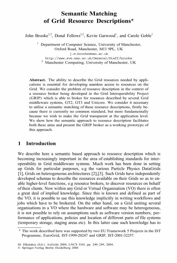
Semantic Matchingof Grid Resource Descriptions*
John Brooke1,2, Donal Fellows1,2, Kevin Garwood1, and Carole Goble1
1 Department of Computer Science, University of Manchester,Oxford Road, Manchester, M13 9PL, UK
http://www.sve.man.ac.uk/General/Staff/brooke2 Manchester Computing, University of Manchester, UK
Abstract. The ability to describe the Grid resources needed by appli-cations is essential for developing seamless access to resources on theGrid. We consider the problem of resource description in the context ofa resource broker being developed in the Grid Interoperability Project(GRIP) which is able to broker for resources described by several Gridmiddleware systems, GT2, GT3 and Unicore. We consider it necessaryto utilise a semantic matching of these resource descriptions, firstly be-cause there is currently no common standard, but more fundamentallybecause we wish to make the Grid transparent at the application level.We show how the semantic approach to resource description facilitatesboth these aims and present the GRIP broker as a working prototype ofthis approach.
1 Introduction
We describe here a semantic based approach to resource description which isbecoming increasingly important in the area of establishing standards for inter-operability in Grid middleware systems. Much work has been done in settingup Grids for particular purposes, e.g the various Particle Physics DataGrids[1], Grids on heterogeneous architectures [2],[3]. Such Grids have independentlydeveloped schemas to describe the resources available on their Grids so as to en-able higher-level functions, e.g resource brokers, to discover resources on behalfof their clients. Now within any Grid or Virtual Organisation (VO) there is oftena great deal of implied knowledge. Since this is known and defined as part ofthe VO, it is possible to use this knowledge implicitly in writing workflows andjobs which have to be brokered. On the other hand, on a Grid uniting severalorganisations in a VO where the hardware and software may be heterogeneous,it is not possible to rely on assumptions such as software version numbers, per-formance of applications, policies and location of different parts of file systems(temporary storage, staging areas etc). In this latter case such knowledge has to
* The work described here was supported by two EU Framework 5 Projects in the ISTProgramme, EuroGrid, IST-1999-20247 and GRIP, IST-2001-32257.
M. Dikaiakos (Ed.): AxGrids 2004, LNCS 3165, pp. 240–249, 2004.© Springer-Verlag Berlin Heidelberg 2004
Semantic Matching of Grid Resource Descriptions 241
be made explicit at the local rather than VO level and must be interrogated bybrokers and other high level agents.
The work described was developed in the Grid Interoperability Project[4]to create a broker which could interrogate on behalf of its clients two differentresource schemas. One schema is the GLUE [5] schema used to provide a uni-form description of resources on the Data Grids being developed in the US andEurope and to enable federation of VOs in those projects for global analysis ofdata from particle physics experiments. The other schema is provided by theUnicore framework [6], in particular the software model used to create local In-carnation Data Base (IDB) entries, used to ‘ground’ or ‘incarnate’ Abstract JobObjects (AJO), which are composed on behalf of client applications and sentaround the Grid as serialised Java objects. The incarnation process provides thetranslation of the grid-level AJO into the particular terminology of the local re-source descriptions. The motivation for providing interoperability between thesetwo systems is that both are widely deployed in Europe (now also in the Asia-Pacific region) and federating Grids on a European level will ultimately face theproblem of interoperability between them.
We need to introduce a Semantic Grid approach [7] for two reasons. One isthat there is currently no agreed framework for Resource Description on Grids,although this issue is being investigated by the CIM and CRM working groupsat GGF. As we show below, the MDS-2 framework used by Globus (GT2 andGT3) [8] is conceived differently from the resource descriptions of the UnicoreIncarnation Data Base (IDB). The second and more fundamental reason is thatthe semantics of the request for resources at an application level needs to bepreserved in some manner in order that appropriate resources can be selectedby intermediate agents such as brokers and schedulers. We describe this in moredetail in Section 2. Our approach is in line with the Open Grid Services Ar-chitecture (OGSA) [9] and we intend to move to a full OGSA service for theinteroperability functionality.
The structure of the paper is as follows. In Section 2 we describe the back-ground of our semantic analysis and its relation to the problem of designing aninteroperable broker. In Section 3 we describe an integration of a semantic trans-lation service with the architecture of the GRIP resource broker. In Section 4 wediscuss how we abstracted ontologies for both Unicore and the GLUE schema.In Section 5 we describe how we obtain a mapping between these two ontologies.In Section 6 we draw some tenative conclusions and outline future work.
2 Foundations of Semantic Translation
In [10] there is an analysis of the difference between Grid computing and previouswork on distributed computing, mainly on computational clusters. Behind theformalism proposed is the notion that the essence of a Grid is the virtualizationof resource and the virtualization of the concept of a user. The user virtualizationis most usually provided by a digital certificate, while the question of resourcevirtualization is addressed by OGSA. Currently, however, the OGSA services are
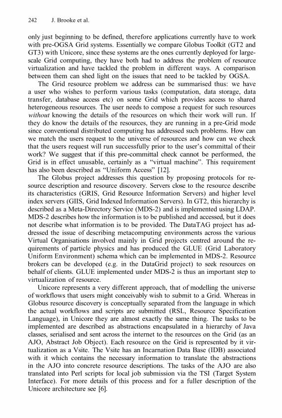
242 J. Brooke et al.
only just beginning to be defined, therefore applications currently have to workwith pre-OGSA Grid systems. Essentially we compare Globus Toolkit (GT2 andGT3) with Unicore, since these systems are the ones currently deployed for large-scale Grid computing, they have both had to address the problem of resourcevirtualization and have tackled the problem in different ways. A comparisonbetween them can shed light on the issues that need to be tackled by OGSA.
The Grid resource problem we address can be summarised thus: we havea user who wishes to perform various tasks (computation, data storage, datatransfer, database access etc) on some Grid which provides access to sharedheterogeneous resources. The user needs to compose a request for such resourceswithout knowing the details of the resources on which their work will run. Ifthey do know the details of the resources, they are running in a pre-Grid modesince conventional distributed computing has addressed such problems. How canwe match the users request to the universe of resources and how can we checkthat the users request will run successfully prior to the user’s committal of theirwork? We suggest that if this pre-committal check cannot be performed, theGrid is in effect unusable, certainly as a “virtual machine”. This requirementhas also been described as “Uniform Access” [12].
The Globus project addresses this question by proposing protocols for re-source description and resource discovery. Servers close to the resource describeits characteristics (GRIS, Grid Resource Information Servers) and higher levelindex servers (GIIS, Grid Indexed Information Servers). In GT2, this hierarchy isdescribed as a Meta-Directory Service (MDS-2) and is implemented using LDAP.MDS-2 describes how the information is to be published and accessed, but it doesnot describe what information is to be provided. The DataTAG project has ad-dressed the issue of describing metacomputing environments across the variousVirtual Organisations involved mainly in Grid projects centred around the re-quirements of particle physics and has produced the GLUE (Grid LaboratoryUniform Environment) schema which can be implemented in MDS-2. Resourcebrokers can be developed (e.g. in the DataGrid project) to seek resources onbehalf of clients. GLUE implemented under MDS-2 is thus an important step tovirtualization of resource.
Unicore represents a very different approach, that of modelling the universeof workflows that users might conceivably wish to submit to a Grid. Whereas inGlobus resource discovery is conceptually separated from the language in whichthe actual workflows and scripts are submitted (RSL, Resource SpecificationLanguage), in Unicore they are almost exactly the same thing. The tasks to beimplemented are described as abstractions encapsulated in a hierarchy of Javaclasses, serialised and sent across the internet to the resources on the Grid (as anAJO, Abstract Job Object). Each resource on the Grid is represented by it vir-tualization as a Vsite. The Vsite has an Incarnation Data Base (IDB) associatedwith it which contains the necessary information to translate the abstractionsin the AJO into concrete resource descriptions. The tasks of the AJO are alsotranslated into Perl scripts for local job submission via the TSI (Target SystemInterface). For more details of this process and for a fuller description of theUnicore architecture see [6].
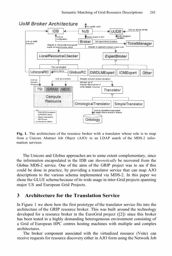
Semantic Matching of Grid Resource Descriptions 243
Fig. 1. The architecture of the resource broker with a translator whose role is to mapfrom a Unicore Abstract Job Object (AJO) to an LDAP search of the MDS-2 infor-mation services
The Unicore and Globus approaches are to some extent complementary, sincethe information encapsulated in the IDB can theoretically be recovered from theGlobus MDS-2 service. One of the aims of the GRIP project was to see if thiscould be done in practice, by providing a translator service that can map AJOdescriptions to the various schema implemented via MDS-2. In this paper wechose the GLUE schema because of its wide usage in inter-Grid projects spanningmajor US and European Grid Projects.
3 Architecture for the Translation Service
In Figure 1 we show how the first prototype of the translator service fits into thearchitecture of the GRIP resource broker. This was built around the technologydeveloped for a resource broker in the EuroGrid project ([2]) since this brokerhas been tested in a highly demanding heterogeneous environment consisting ofa Grid of European HPC centres hosting machines with multiple and complexarchitectures.
The broker component associated with the virtualized resource (Vsite) canreceive requests for resource discovery either in AJO form using the Network Job
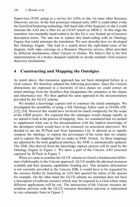
244 J. Brooke et al.
Supervisor (NJS) acting as a service for AJOs or else via some other ResourceDiscovery service. In the first prototype released early 2003 it could either evokethe EuroGrid brokering technology (left hand side of the diagram) or else it couldtranslate the AJO into a filter for an LDAP search on MDS-2. At this stage thetranslator was essentially hand-coded to do this for a very limited set of resourcedescription terms. The aim was to replace this hand-coding with an OntologyEngine that could automate the translation. We now describe how we developedthis Ontology Engine. This lead to a search down the right-hand route of thediagram, both sides converge on a Resource Discovery service, albeit providedby different mechanisms, either Unicore or Globus. We believe this is the firstimplementation of a broker designed explicitly to invoke multiple Grid resourcediscovery mechanisms.
4 Constructing and Mapping the Ontolgies
As noted above, this transation approach has not been attempted before in aGrid context. We therefore adopted the following procedure. Since the Unicoreabstractions are expressed in a hierarchy of Java classes we could extract aninitial ontology from the JavaDocs that encapsulates the semantics in the classesand inheritance tree. We then applied the same approach to the documentationprovided by the GLUE schema.
We needed a knowledge capture tool to construct the initial ontologies. Weinvestigated the possibility of using a full Ontology Editor such as DAML-OIL[13], [14]. However this would have involved too much complexity for the scopeof the GRIP project. We expected that the ontologies would change rapidly aswe started to look at the process of mapping. Also, we considered that we neededto supplement what was in the documentation with the implicit knowledge ofthe developers which would have to be extracted via structured interviews. Wedecided to use the PCPack tool from Epistemics Ltd. It allowed us to rapidlycompose the ontology, to express the provenance of the terms that we employand to capture the mappings that we make in XML format. As these mappingsare adjusted by the tools graphical interface, the XML is automatically updated.The XML files derived from the knowledge capture process will be used by theOntology Engine in Figure 1. We show a part of the Unicore AJO structurecaptured by PCPack in Figure 2.
When we came to examine the GLUE schema we found a fundamental differ-ence of philosophy to the Unicore approach. GLUE models the physical resourcesavailable and their dynamic capabilities (loading etc). This dynamic informationis not currently provided in the Unicore IDB, it would have to be requested bythe resource broker by launching an AJO that queried the status of the queuesfor example. On the other hand the GLUE schema we examined does not havea description of software resource which may be required in a Grid where manydifferent applications will be run. The intersection of the Unicore resource de-scription universe with the GLUE resource description universe is representedin very schematic form in Figure 3.
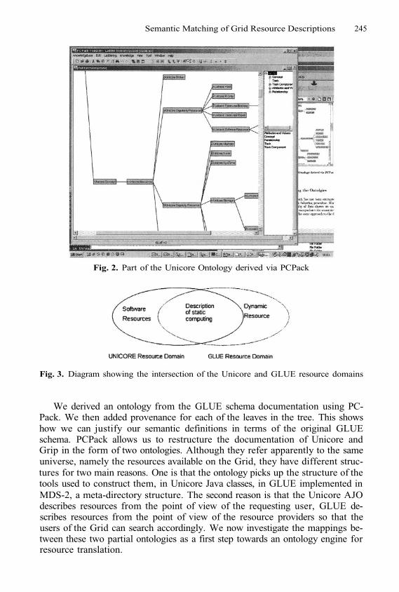
Semantic Matching of Grid Resource Descriptions 245
Fig. 2. Part of the Unicore Ontology derived via PCPack
Fig. 3. Diagram showing the intersection of the Unicore and GLUE resource domains
We derived an ontology from the GLUE schema documentation using PC-Pack. We then added provenance for each of the leaves in the tree. This showshow we can justify our semantic definitions in terms of the original GLUEschema. PCPack allows us to restructure the documentation of Unicore andGrip in the form of two ontologies. Although they refer apparently to the sameuniverse, namely the resources available on the Grid, they have different struc-tures for two main reasons. One is that the ontology picks up the structure of thetools used to construct them, in Unicore Java classes, in GLUE implemented inMDS-2, a meta-directory structure. The second reason is that the Unicore AJOdescribes resources from the point of view of the requesting user, GLUE de-scribes resources from the point of view of the resource providers so that theusers of the Grid can search accordingly. We now investigate the mappings be-tween these two partial ontologies as a first step towards an ontology engine forresource translation.
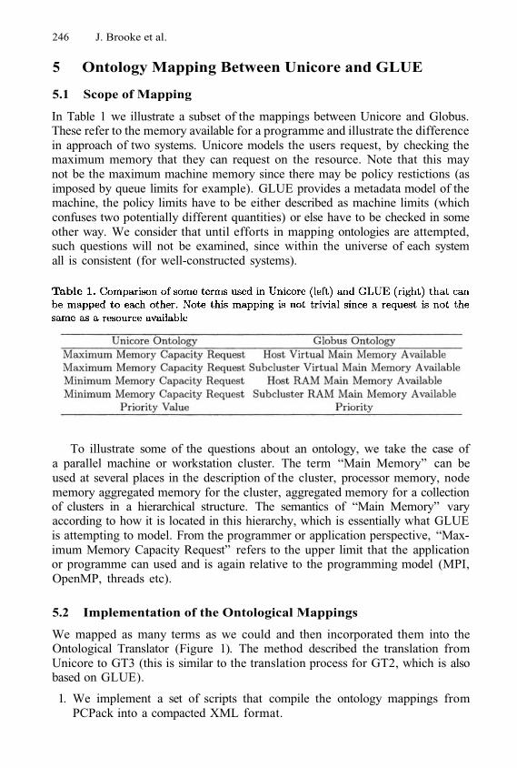
246 J. Brooke et al.
5 Ontology Mapping Between Unicore and GLUE
5.1 Scope of Mapping
In Table 1 we illustrate a subset of the mappings between Unicore and Globus.These refer to the memory available for a programme and illustrate the differencein approach of two systems. Unicore models the users request, by checking themaximum memory that they can request on the resource. Note that this maynot be the maximum machine memory since there may be policy restictions (asimposed by queue limits for example). GLUE provides a metadata model of themachine, the policy limits have to be either described as machine limits (whichconfuses two potentially different quantities) or else have to be checked in someother way. We consider that until efforts in mapping ontologies are attempted,such questions will not be examined, since within the universe of each systemall is consistent (for well-constructed systems).
To illustrate some of the questions about an ontology, we take the case ofa parallel machine or workstation cluster. The term “Main Memory” can beused at several places in the description of the cluster, processor memory, nodememory aggregated memory for the cluster, aggregated memory for a collectionof clusters in a hierarchical structure. The semantics of “Main Memory” varyaccording to how it is located in this hierarchy, which is essentially what GLUEis attempting to model. From the programmer or application perspective, “Max-imum Memory Capacity Request” refers to the upper limit that the applicationor programme can used and is again relative to the programming model (MPI,OpenMP, threads etc).
5.2 Implementation of the Ontological Mappings
We mapped as many terms as we could and then incorporated them into theOntological Translator (Figure 1). The method described the translation fromUnicore to GT3 (this is similar to the translation process for GT2, which is alsobased on GLUE).
1. We implement a set of scripts that compile the ontology mappings fromPCPack into a compacted XML format.
Semantic Matching of Grid Resource Descriptions 247
The translation engine loads the compacted format and builds an in-memoryversion of it.The general strategy is to compile a Unicore resource check into an XPathquery for a GT3 Index Service, that will have a non-empty result preciselywhen the resource check is satisfiable.For each Unicore Resource, we look it up and, if a mapping for that re-source exists, generate a constraint on the XPath query that corresponds tosatisfaction of that resource within the Unicore IDB.Resources without translation are collected together and, if the search of theIndex Service succeeds, are checked against the Unicore IDB for the virtualresource (Vsite). This stage is necessary because the set of matchable termsis very incomplete.
2.
3.
4.
5.
In Figure 4 we show a screenshot of a graphical representation of the mappingprocess that is intended to be used in discussions between the developers ofUnicore and GLUE to promote discussion and to widen the range of mappableterms. On the left we have the Unicore native terms and immediately to theright of these the derived ontology. On the right we have the equivalents forthe GLUE schema. Essentially the procedure of the Ontological Translator is anautomation of the mappings arrived at in these discussions. The XML descriptionthat it utilises has the following structure.
An outermost <translator> element with no attributes.Child elements are <mapping> and <domain> in any order. We need tohave a minimum of one <mapping> and two <domain> elements.<mapping> has name, from and to attributes. The name says what themapping is and the from and to state what domain we are going from andto (e.g from Unicore to GLUE).<mapping> contains an arbitrary number of <map> elements.<domain> has a name attribute (for matching against a <mapping>’s fromor to attribute.)<domain> contains an arbitrary number of <element> elements.<element> contains an arbitrary number of <attribute> attributes.<attribute> contains no elements.Both <element> and <attribute> have the same attributes. They are name(an ontological name for the entity) id (a unique number to the entity) andnative (which gives a “native” name for the entity). native is optional, butthe other two are required.<map> elements have two required attributes and one optional attribute.from and to are required and specify the entity (by matching against idnumber) within the from and to domains we are giving a mapping between.
1.2.
3.
4.5.
6.7.8.9.
Note that overall mappings are generally many-to-many; no uniqueness checksare applied.
6 Conclusions and Future Work
The work here is only a start, only very small subsets of Unicore and GLUE canbe immediately mapped in this way. However, it is a necessary start, and opens
10.
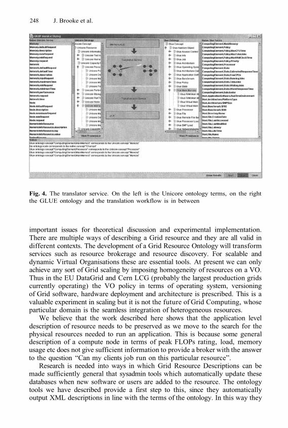
248 J. Brooke et al.
Fig. 4. The translator service. On the left is the Unicore ontology terms, on the rightthe GLUE ontology and the translation workflow is in between
important issues for theoretical discussion and experimental implementation.There are multiple ways of describing a Grid resource and they are all valid indifferent contexts. The development of a Grid Resource Ontology will transformservices such as resource brokerage and resource discovery. For scalable anddynamic Virtual Organisations these are essential tools. At present we can onlyachieve any sort of Grid scaling by imposing homogeneity of resources on a VO.Thus in the EU DataGrid and Cern LCG (probably the largest production gridscurrently operating) the VO policy in terms of operating system, versioningof Grid software, hardware deployment and architecture is prescribed. This is avaluable experiment in scaling but it is not the future of Grid Computing, whoseparticular domain is the seamless integration of heterogeneous resources.
We believe that the work described here shows that the application leveldescription of resource needs to be preserved as we move to the search for thephysical resources needed to run an application. This is because some generaldescription of a compute node in terms of peak FLOPs rating, load, memoryusage etc does not give sufficient information to provide a broker with the answerto the question “Can my clients job run on this particular resource”.
Research is needed into ways in which Grid Resource Descriptions can bemade sufficiently general that sysadmin tools which automatically update thesedatabases when new software or users are added to the resource. The ontologytools we have described provide a first step to this, since they automaticallyoutput XML descriptions in line with the terms of the ontology. In this way they
Semantic Matching of Grid Resource Descriptions 249
can provide an OGSA service for joining Grids together, even if they are runningdifferent underlying middleware for the description, control and monitoring ofresources.
References
1.2.3.
4.5.
6.
7.
8.
9.
The EU DataGrid project, http://www.datagrid.orgThe EU EuroGrid Project, http://www.eurogrid.orgUK Level 2 Grid, information available from the UK National eCentre,http://www.nesc.ac.ukGrid Interoperability Project, http://www.grid-interoperability.orgAndreozzi, S.: Glue schema implementation for the LDAP model, available athttp://www.cnaf.infn.it/ sergio/publications/Glue4LDAP.pdfErwin, D., Snelling, D.: Unicore: A Grid Computing Environment LNCS 2150,Euro-Par 2001, Springer, pp 825-834.Goble, C.A., De Roure, D.: Semantic Grid: An Application of the Semantic Web.ACM SIGMOD Record, 31(4) December 2002.Czajkowski K., Fitzgerald, S., Foster, I., and Kesselman, C.: Grid InformationServices for Resource Sharing. in Proceedings of HPDC-10, IEEE Press, 2002.Foster, I, Kesselman, C., Nick, J., and Tuecke, S.: The Physiology of the Grid.GGF Document available at http://www.ggf.org/ogsa-wgNémeth, Z., Sunderam, V.: Characterizing Grids: Attributes, Definitions, and For-malisms. Journal of Grid Computing, 1(1), p9-23, 2003.Access Grid: an environment for advanced collaborative working,http://www.accessgrid.orgJohnston, W., Brooke, J.M.: Core Functions for Production Grids, GGF GPA-RGdiscussion document, http://grid.lbl.gov/GPAHorrocks,I.: DAML+OIL: a reason-able web ontology language. Proc. of EDBT2002, March 2002.Ankolenkar, A., Burstein, M., Hobbs, J.R., Lassila, O., Martin, D.L., McDer-mott, D., cIlraith, S.A., Narayanan, S., Paolucci, M., Payne, T.R., and Sycara,K.: DAML-S: Web Service Description for the Semantic Web. The First Interna-tional Semantic Web Conference (ISWC), Sardinia (Italy), June 2002.
10.
11.
12.
13.
14.
Enabling Knowledge Discovery Serviceson Grids*
Antonio Congiusta1, Carlo Mastroianni2, Andrea Pugliese1,2,Domenico Talia1,2, and Paolo Trunfio1
1 DEIS, University of Calabria,Via P. Bucci 41C, 87036 Rende, Italy
{acongiusta,apugliese,talia,trunfio}@deis.unical.it2 ICAR-CNR,
Via P. Bucci 41C, 87036 Rende, [email protected]
Abstract. The Grid is mainly used today for supporting high-perfor-mance compute intensive applications. However, it is going to be ef-fectively exploited for deploying data-driven and knowledge discoveryapplications. To support these classes of applications, high-level toolsand services are vital. The Knowledge Grid is a high-level system forproviding Grid-based knowledge discovery services. These services allowprofessionals and scientists to create and manage complex knowledgediscovery applications composed as workflows that integrate data setsand mining tools provided as distributed services on a Grid. This pa-per presents and discusses how knowledge discovery applications can bedesigned and deployed on Grids. The contribution of novel technologiesand models such as OGSA, P2P, and ontologies is also discussed.
1 Introduction
Grid technology is receiving an increasing attention both from the research com-munity and from industry and governments. People is interested to learn how thisnew computing infrastructure can be effectively exploited for solving complexproblems and implementing distributed high-performance applications [1]. Gridtools and middleware developed today are larger than in the recent past in num-ber, variety, and complexity. They allow the user community to employ Gridsfor implementing a wider set of applications with respect to one or two yearsago. New projects started in different areas, such as genetics and proteomics,multimedia data archives (e.g., a Grid for the Library of Congress), medicine(e.g., Access Grid for battling SARS), drug design, and financial modeling.
Although the Grid today is still mainly used for supporting high-performancecompute intensive applications in science and engineering, it is going to be ef-fectively exploited for implementing data intensive and knowledge discovery ap-plications. To succeed in supporting this class of applications, tools and servicesfor data mining and knowledge discovery on Grids are essential.
* This research has been partially funded by the Italian FIRB MIUR project “Grid.it”(RBNE01KNFP).
M. Dikaiakos (Ed.): AxGrids 2004, LNCS 3165, pp. 250–259, 2004.© Springer-Verlag Berlin Heidelberg 2004
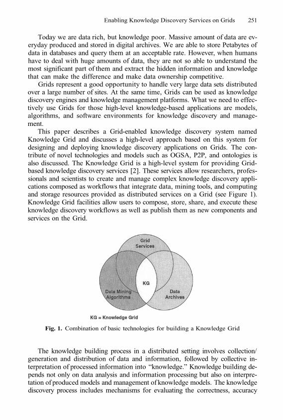
Enabling Knowledge Discovery Services on Grids 251
Today we are data rich, but knowledge poor. Massive amount of data are ev-eryday produced and stored in digital archives. We are able to store Petabytes ofdata in databases and query them at an acceptable rate. However, when humanshave to deal with huge amounts of data, they are not so able to understand themost significant part of them and extract the hidden information and knowledgethat can make the difference and make data ownership competitive.
Grids represent a good opportunity to handle very large data sets distributedover a large number of sites. At the same time, Grids can be used as knowledgediscovery engines and knowledge management platforms. What we need to effec-tively use Grids for those high-level knowledge-based applications are models,algorithms, and software environments for knowledge discovery and manage-ment.
This paper describes a Grid-enabled knowledge discovery system namedKnowledge Grid and discusses a high-level approach based on this system fordesigning and deploying knowledge discovery applications on Grids. The con-tribute of novel technologies and models such as OGSA, P2P, and ontologies isalso discussed. The Knowledge Grid is a high-level system for providing Grid-based knowledge discovery services [2]. These services allow researchers, profes-sionals and scientists to create and manage complex knowledge discovery appli-cations composed as workflows that integrate data, mining tools, and computingand storage resources provided as distributed services on a Grid (see Figure 1).Knowledge Grid facilities allow users to compose, store, share, and execute theseknowledge discovery workflows as well as publish them as new components andservices on the Grid.
Fig. 1. Combination of basic technologies for building a Knowledge Grid
The knowledge building process in a distributed setting involves collection/generation and distribution of data and information, followed by collective in-terpretation of processed information into “knowledge.” Knowledge building de-pends not only on data analysis and information processing but also on interpre-tation of produced models and management of knowledge models. The knowledgediscovery process includes mechanisms for evaluating the correctness, accuracy
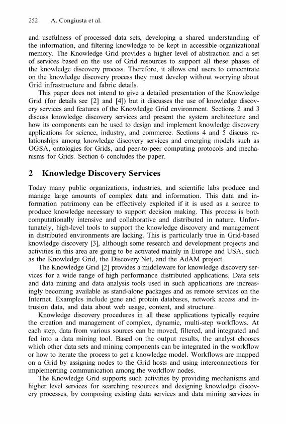
252 A. Congiusta et al.
and usefulness of processed data sets, developing a shared understanding ofthe information, and filtering knowledge to be kept in accessible organizationalmemory. The Knowledge Grid provides a higher level of abstraction and a setof services based on the use of Grid resources to support all these phases ofthe knowledge discovery process. Therefore, it allows end users to concentrateon the knowledge discovery process they must develop without worrying aboutGrid infrastructure and fabric details.
This paper does not intend to give a detailed presentation of the KnowledgeGrid (for details see [2] and [4]) but it discusses the use of knowledge discov-ery services and features of the Knowledge Grid environment. Sections 2 and 3discuss knowledge discovery services and present the system architecture andhow its components can be used to design and implement knowledge discoveryapplications for science, industry, and commerce. Sections 4 and 5 discuss re-lationships among knowledge discovery services and emerging models such asOGSA, ontologies for Grids, and peer-to-peer computing protocols and mecha-nisms for Grids. Section 6 concludes the paper.
2 Knowledge Discovery Services
Today many public organizations, industries, and scientific labs produce andmanage large amounts of complex data and information. This data and in-formation patrimony can be effectively exploited if it is used as a source toproduce knowledge necessary to support decision making. This process is bothcomputationally intensive and collaborative and distributed in nature. Unfor-tunately, high-level tools to support the knowledge discovery and managementin distributed environments are lacking. This is particularly true in Grid-basedknowledge discovery [3], although some research and development projects andactivities in this area are going to be activated mainly in Europe and USA, suchas the Knowledge Grid, the Discovery Net, and the AdAM project.
The Knowledge Grid [2] provides a middleware for knowledge discovery ser-vices for a wide range of high performance distributed applications. Data setsand data mining and data analysis tools used in such applications are increas-ingly becoming available as stand-alone packages and as remote services on theInternet. Examples include gene and protein databases, network access and in-trusion data, and data about web usage, content, and structure.
Knowledge discovery procedures in all these applications typically requirethe creation and management of complex, dynamic, multi-step workflows. Ateach step, data from various sources can be moved, filtered, and integrated andfed into a data mining tool. Based on the output results, the analyst chooseswhich other data sets and mining components can be integrated in the workflowor how to iterate the process to get a knowledge model. Workflows are mappedon a Grid by assigning nodes to the Grid hosts and using interconnections forimplementing communication among the workflow nodes.
The Knowledge Grid supports such activities by providing mechanisms andhigher level services for searching resources and designing knowledge discov-ery processes, by composing existing data services and data mining services in
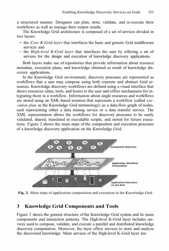
Enabling Knowledge Discovery Services on Grids 253
a structured manner. Designers can plan, store, validate, and re-execute theirworkflows as well as manage their output results.
The Knowledge Grid architecture is composed of a set of services divided intwo layers:
the Core K-Grid layer that interfaces the basic and generic Grid middlewareservices andthe High-level K-Grid layer that interfaces the user by offering a set ofservices for the design and execution of knowledge discovery applications.
Both layers make use of repositories that provide information about resourcemetadata, execution plans, and knowledge obtained as result of knowledge dis-covery applications.
In the Knowledge Grid environment, discovery processes are represented asworkflows that a user may compose using both concrete and abstract Grid re-sources. Knowledge discovery workflows are defined using a visual interface thatshows resources (data, tools, and hosts) to the user and offers mechanisms for in-tegrating them in a workflow. Information about single resources and workflowsare stored using an XML-based notation that represents a workflow (called exe-cution plan in the Knowledge Grid terminology) as a data-flow graph of nodes,each representing either a data mining service or a data transfer service. TheXML representation allows the workflows for discovery processes to be easilyvalidated, shared, translated in executable scripts, and stored for future execu-tions. Figure 2 shows the main steps of the composition and execution processesof a knowledge discovery application on the Knowledge Grid.
Fig. 2. Main steps of application composition and execution in the Knowledge Grid
3 Knowledge Grid Components and Tools
Figure 3 shows the general structure of the Knowledge Grid system and its maincomponents and interaction patterns. The High-level K-Grid layer includes ser-vices used to compose, validate, and execute a parallel and distributed knowledgediscovery computation. Moreover, the layer offers services to store and analyzethe discovered knowledge. Main services of the High-level K-Grid layer are:
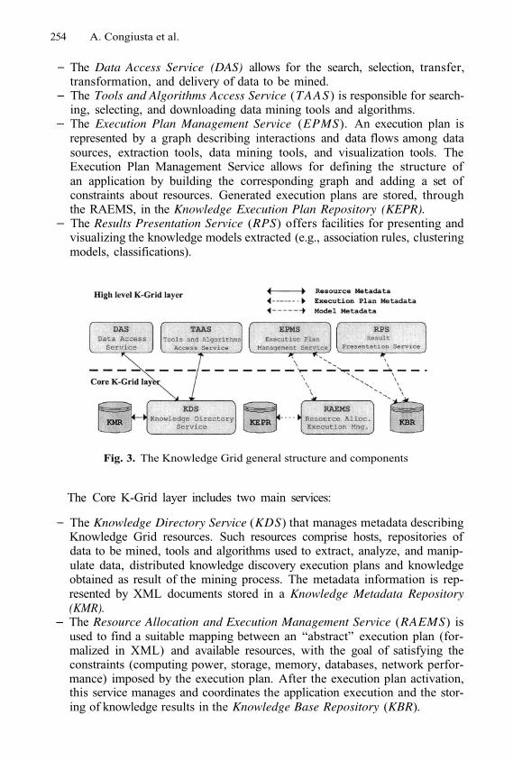
254 A. Congiusta et al.
The Data Access Service (DAS) allows for the search, selection, transfer,transformation, and delivery of data to be mined.The Tools and Algorithms Access Service (TAAS) is responsible for search-ing, selecting, and downloading data mining tools and algorithms.The Execution Plan Management Service (EPMS). An execution plan isrepresented by a graph describing interactions and data flows among datasources, extraction tools, data mining tools, and visualization tools. TheExecution Plan Management Service allows for defining the structure ofan application by building the corresponding graph and adding a set ofconstraints about resources. Generated execution plans are stored, throughthe RAEMS, in the Knowledge Execution Plan Repository (KEPR).The Results Presentation Service (RPS) offers facilities for presenting andvisualizing the knowledge models extracted (e.g., association rules, clusteringmodels, classifications).
Fig. 3. The Knowledge Grid general structure and components
The Core K-Grid layer includes two main services:
The Knowledge Directory Service (KDS) that manages metadata describingKnowledge Grid resources. Such resources comprise hosts, repositories ofdata to be mined, tools and algorithms used to extract, analyze, and manip-ulate data, distributed knowledge discovery execution plans and knowledgeobtained as result of the mining process. The metadata information is rep-resented by XML documents stored in a Knowledge Metadata Repository(KMR).The Resource Allocation and Execution Management Service (RAEMS) isused to find a suitable mapping between an “abstract” execution plan (for-malized in XML) and available resources, with the goal of satisfying theconstraints (computing power, storage, memory, databases, network perfor-mance) imposed by the execution plan. After the execution plan activation,this service manages and coordinates the application execution and the stor-ing of knowledge results in the Knowledge Base Repository (KBR).
Enabling Knowledge Discovery Services on Grids 255
The main components of the Knowledge Grid have been implemented and areavailable through a software environment, named VEGA (Visual Environmentfor Grid Applications), that embodies services and functionalities ranging frominformation and discovery services to visual design and execution facilities [4].
The main goal of VEGA is to offer a set of visual functionalities that give theusers the possibility to design applications starting from a view of the presentGrid status (i.e., available nodes and resources), and composing the differentstages constituting them inside a structured environment.
The high-level features offered by VEGA are intended to provide the userwith easy access to Grid facilities with a high level of abstraction, in order toleave her free to concentrate on the application design process. To fulfill this aim,VEGA builds a visual environment based on the component framework concept,by using and enhancing basic services offered by the Knowledge Grid and theGlobus Toolkit.
Key concepts in the VEGA approach to the design of a Grid application arethe visual language used to describe in a component-like manner, and through agraphical representation, the jobs constituting an application, and the possibilityto group these jobs in workspaces to form specific interdependent stages. Aconsistency checking module parses the model of the computation both whilethe design is in progress and prior to execute it, monitoring and driving useractions so as to obtain a correct and consistent graphical representation of theapplication. Together with the workspace concept, VEGA makes available alsothe virtual resource abstraction; thanks to these entities it is possible to composeapplications working on data processed/generated in previous phases even if theexecution has not been performed yet. VEGA includes an execution service,which gives the user the possibility to execute the designed application, monitorits status, and visualize results.
Knowledge discovery applications for network intrusion detection and bioin-formatics have been developed by VEGA in a direct and simple way. Developersfound the VEGA visual interface effective in supporting the application devel-opment from resource selection to knowledge models produced as output of theknowledge discovery process.
4 Knowledge Grid and OGSA
Grid technologies are evolving towards an open Grid architecture, called theOpen Grid Services Architecture (OGSA), in which a Grid provides an extensibleset of services that virtual organizations can aggregate in various ways [5].
OGSA defines a uniform exposed-service semantics, the so-called Grid ser-vice, based on concepts and technologies from both the Grid computing and Webservices communities. Web services define a technique for describing softwarecomponents to be accessed, methods for accessing these components, and dis-covery methods that enable the identification of relevant service providers. Webservices are in principle independent from programming languages and systemsoftware; standards are being defined within the World Wide Web Consortium(W3C) and other standards bodies.
256 A. Congiusta et al.
The OGSA model adopts three Web services standards: the Simple ObjectAccess Protocol (SOAP), the Web Services Description Language (WSDL), andthe Web Services Inspection Language (WS-Inspection).
Web services and OGSA aim at interoperability between loosely coupled ser-vices independently from implementation, location or platform. OGSA definesstandard mechanisms for creating, naming and discovering persistent and tran-sient Grid service instances, provides location transparency and multiple pro-tocol bindings for service instances, and supports integration with underlyingnative platform facilities. The OGSA model provides some common operationsand supports multiple underlying resource models representing resources as ser-vice instances.
OGSA defines a Grid service as a Web service that provides a set of well-defined WSDL interfaces and that follows specific conventions on the use for Gridcomputing. Integration of Web and Grids will be more effective with the recentdefinition of the the Web Service Resource Framework (WSRF). WSRF repre-sents a refactoring of the concepts and interfaces developed in the OGSA spec-ification for exploiting recent developments in Web services architecture (e.g.,WS-Addressing) and aligning Grids services with current Web services direc-tions.
The Knowledge Grid, is an abstract service-based Grid architecture that doesnot limit the user in developing and using service-based knowledge discovery ap-plications. We are devising an implementation of the Knowledge Grid in terms ofthe OGSA model. In this implementation, each of the Knowledge Grid servicesis exposed as a persistent service, using the OGSA conventions and mechanisms.For instance, the EPMS service implements several interfaces, among which thenotification interface that allows the asynchronous delivery to the EPMS of no-tification messages coming from services invoked as stated in execution plans. Atthe same time, basic knowledge discovery services can be designed and deployedby using the KDS services for discovering Grid resources that could be used incomposing knowledge discovery applications.
5 Semantic Grids, Knowledge Grids,and Peer-to-Peer Grids
The Semantic Web is an emerging initiative of World Wide Web Consortium(W3C) aiming at augmenting with semantic the information available over In-ternet, through document annotation and classification by using ontologies, soproviding a set of tools able to navigate between concepts, rather than hyper-links, and offering semantic search engines, rather than key-based ones.
In the Grid computing community there is a parallel effort to define a socalled Semantic Grid (www.semanticgrid.org). The Semantic Grid vision is toincorporate the Semantic Web approach based on the systematic descriptionof resources through metadata and ontologies, and provision for basic servicesabout reasoning and knowledge extraction, into the Grid. Actually, the use ofontologies in Grid applications could make the difference because it augments
Enabling Knowledge Discovery Services on Grids 257
the XML-based metadata information system associating semantic specificationto each Grid resource. These services could represent a significant evolution withrespect to current Grid basic services, such as the Globus MDS pattern-matchingbased search.
Cannataro and Comito proposed the integration of ontology-based servicesin the Knowledge Grid [6]. It is based on extending the architecture of theKnowledge Grid with ontology components that integrate the KDS, the KMRand the KEPR. An ontology of data mining tasks, techniques, and tools hasbeen defined and is going to be implemented to provide users semantic-basedservices in searching and composing knowledge discovery applications.
Another interesting model that could provide improvements to the currentGrid systems and applications is the peer-to-peer computing model. P2P isa class of self-organizing systems or applications that takes advantage of dis-tributed resources – storage, processing, information, and human presence –available at the Internet’s edges. The P2P model could thus help to ensure Gridscalability: designers could use the P2P philosophy and techniques to imple-ment nonhierarchical decentralized Grid systems. In spite of current practicesand thoughts, the Grid and P2P models share several features and have more incommon than we perhaps generally recognize. Broader recognition of key com-monalities could accelerate progress in both models. A synergy between the tworesearch communities, and the two computing models, could start with identi-fying the similarities and differences between them [7].
Resource discovery in Grid environments is based mainly on centralized orhierarchical models. In the Globus Toolkit, for instance, users can directly gaininformation about a given node’s resources by querying a server applicationrunning on it or running on a node that retrieves and publishes information abouta given organization’s node set. Because such systems are built to address therequirements of organizational-based Grids, they do not deal with more dynamic,large-scale distributed environments, in which useful information servers are notknown a priori. The number of queries in such environments quickly makes aclient-server approach ineffective. Resource discovery includes, in part, the issueof presence management – discovery of the nodes that are currently available ina Grid – since specific mechanisms are not yet defined for it. On the other hand,the presence-management protocol is a key element in P2P systems: each nodeperiodically notifies the network of its presence, discovering its neighbors at thesame time.
Future Grid systems should implement a P2P-style decentralized resourcediscovery model that can support Grids as open resource communities. We aredesigning some of the components and services of the Knowledge Grid in a P2Pmanner. For example, the KDS could be effectively redesigned using a P2P ap-proach. If we view current Grids as federations of smaller Grids managed bydiverse organizations, we can envision the KDS for a large-scale Grid by adopt-ing the super-peer network model. In this approach, each super peer operates asa server for a set of clients and as an equal among other super peers. This topol-ogy provides a useful balance between the efficiency of centralized search and the
258 A. Congiusta et al.
autonomy, load balancing, and robustness of distributed search. In a KnowledgeGrid KDS service based on the super-peer model, each participating organiza-tion would configure one or more of its nodes to operate as super peers andprovide knowledge resources. Nodes within each organization would exchangemonitoring and discovery messages with a reference super peer, and super peersfrom different organizations would exchange messages in a P2P fashion.
6 Conclusions
The Grid will represent in a near future an effective infrastructure for manag-ing very large data sources and providing high-level mechanisms for extractingvaluable knowledge from them [8]. To solve this class of applications, we needadvanced tools and services for knowledge discovery.
Here we discussed the Knowledge Grid: a Grid-based software environmentthat implements Grid-enabled knowledge discovery services. The KnowledgeGrid can be used as a high-level system for providing knowledge discovery ser-vices on dispersed resources connected through a Grid. These services allowprofessionals and scientists to create and manage complex knowledge discov-ery applications composed as workflows integrating data sets and mining toolsprovided as distributed services on a Grid.
In the next years the Grid will be used as a platform for implementing and de-ploying geographically distributed knowledge discovery [9] and knowledge man-agement platforms and applications. Some ongoing efforts in this direction haverecently been initiated. Examples of systems such as the Discovery Net [10], theAd AM system [11], and the Knowledge Grid discussed here show the feasibil-ity of the approach and can represent the first generation of knowledge-basedpervasive Grids.
The wish list of Grid features is still too long. Here are some main propertiesof future Grids that today are not available:
Easy to program – hiding architecture issues and details,Adaptive – exploiting dynamically available resources,Human-centric – offering end-user oriented services,Secure – providing secure authentication mechanisms,Reliable – offering fault-tolerance and high availability,Scalable – improving performance as problem size increases,Pervasive – giving users the possibility for ubiquitous access, andKnowledge-based – extracting and managing knowledge together with dataand information.
The future use of the Grid is mainly related to its ability to embody manyof these properties and to manage world-wide complex distributed applications.Among these, knowledge-based applications are a major goal. To reach this goal,the Grid needs to evolve towards an open decentralized infrastructure based oninteroperable high-level services that make use of knowledge both in providingresources and in giving results to end users. Software technologies as knowledge
Enabling Knowledge Discovery Services on Grids 259
Grids, OGSA, ontologies, and P2P will provide important elements to build uphigh-level applications on a World Wide Grid. They provide the key componentsfor developing Grid-based complex systems such as distributed knowledge man-agement systems providing pervasive access, adaptivity, and high performancefor virtual organizations in science, engineering, industry, and, more generally,in future society organizations.
Acknowledgements. We would like to thank other researchers working in theKnowledge Grid team: Mario Cannataro, Carmela Comito, and Pierangelo Vel-tri.
References
1.
2.
3.
4.
5.
6.
7.
8.
9.
10.
11.
I. Foster, C. Kesselman, J. M. Nick, and S. Tuecke, The Physiology of the Grid:An Open Grid Services Architecture for Distributed Systems Integration, technicalreport, http://www.globus.org/research/papers/ogsa.pdf, 2002.M. Cannataro, D. Talia, The Knowledge Grid, Communications of the ACM, 46(1),89-93, 2003.F. Berman, From TeraGrid to Knowledge Grid, Communications of the ACM,44(11), pp. 27-28, 2001.M. Cannataro, A. Congiusta, D. Talia, P. Trunfio, A Data Mining Toolset forDistributed High-Performance Platforms, Proc. 3rd Int. Conference Data Mining2002, WIT Press, Bologna, Italy, pp. 41-50, September 2002.D. Talia, The Open Grid Services Architecture: Where the Grid Meets the Web,IEEE Internet Computing, Vol. 6, No. 6, pp. 67-71, 2002.M. Cannataro, C. Comito, A Data Mining Ontology for Grid Programming, Proc.1st Int. Workshop on Semantics in Peer-to-Peer and Grid Computing, in conjunc-tion with WWW2003, Budapest, 20-24 May 2003.D. Talia, P. Trunfio, Toward a Sinergy Between P2P and Grids, IEEE InternetComputing, Vol. 7, No. 4, pp. 96-99, 2003.F. Berman, G. Fox, A. Hey, (eds.), Grid computing: Making the Global Infrastruc-ture a Reality, Wiley, 2003.H. Kargupta, P. Chan, (eds.), Advances in Distributed and Parallel KnowledgeDiscovery, AAAI Press 1999.M. Ghanem, Y. Guo, A. Rowe, P. Wendel, Grid-based Knowledge Discovery Ser-vices for High Throughput Informatics, Proc. 11th IEEE International Symposiumon High Performance Distributed Computing, p. 416, IEEE CS Press, 2002.T. Hinke, J. Novotny, Data Mining on NASA’s Information Power Grid, Proc.Ninth IEEE International Symposium on High Performance Distributed Comput-ing, pp. 292-293, IEEE CS Press, 2000.
A Grid Service Framework for MetadataManagement in Self-e-Learning Networks*
George Samaras, Kyriakos Karenos, and Eleni Christodoulou
Department of Computer Science, University of Cyprus{cssamara,cs98kk2,cseleni}@ucy.ac.cy
Abstract. Metadata management is critical for Grid systems. Morespecifically, semantically meaningful resource descriptions constitute ahighly beneficial extension to Grid environments that started to gain sig-nificant attention. In this work we contribute to the effort of enhancingcurrent Grid technologies to support semantic descriptors for resources– termed also the Semantic Grid. We use a Self e-Learning Network (Se-LeNe) as the testbed application and propose a set of services that areapplicable in such a case in alignment to the Open Grid Services Archi-tecture (OGSA). We concentrate on providing services for the utilizationof Learning Objects’ (LO)1 metadata, the basic of which, however, aregeneric enough to be utilized by other Grid-based systems that need tomake use of semantic descriptions. Different service placement scenariosproduce a number of possible architectural alternatives.
1 Introduction
Grid Technology has found uses in a wide area of applications that usually ad-dress large scale, process and data intensive problems. Our effort is to bring data-centric services adjusted to the Grid environment and to expand its functionalityin the area of resource sharing using e-Learning as the testbed application. Aswe elaborate in section 2, we consider metadata management (viewed as seman-tically meaningful resource descriptions of learning material), crucial especiallyas the Grid expands to be supplemented with capabilities towards supporting(and incorporating) technologies from the Semantic Web, termed the “SemanticGrid” [1] under the guidelines of the Global Grid Forum (GGF) [2].
Our work derives from our IST project SeLeNe: The SeLeNe Project is aim-ing to elaborate new educational metaphors and tools in order to facilitate theformation of learning communities who require world-wide discovery and as-similation of knowledge. To realize this vision, SeLeNe is relying on semanticmetadata describing educational material. SeLeNe offers advanced services forthe discovery, sharing, and collaborative creation of learning resources, facilitat-ing a syndicated and personalised access to such resources.
* This work has been supported by the E.U. Project “SeLeNe: Self e-Learning Net-works”, IST-2001-39045.
1 A LO is generally defined as an artifact in digital form utilized during the learningprocess.
M. Dikaiakos (Ed.): AxGrids 2004, LNCS 3165, pp. 260–269, 2004.© Springer-Verlag Berlin Heidelberg 2004
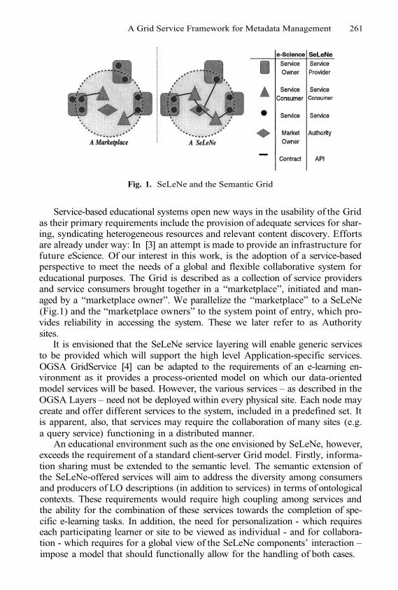
A Grid Service Framework for Metadata Management 261
Fig. 1. SeLeNe and the Semantic Grid
Service-based educational systems open new ways in the usability of the Gridas their primary requirements include the provision of adequate services for shar-ing, syndicating heterogeneous resources and relevant content discovery. Effortsare already under way: In [3] an attempt is made to provide an infrastructure forfuture eScience. Of our interest in this work, is the adoption of a service-basedperspective to meet the needs of a global and flexible collaborative system foreducational purposes. The Grid is described as a collection of service providersand service consumers brought together in a “marketplace”, initiated and man-aged by a “marketplace owner”. We parallelize the “marketplace” to a SeLeNe(Fig.1) and the “marketplace owners” to the system point of entry, which pro-vides reliability in accessing the system. These we later refer to as Authoritysites.
It is envisioned that the SeLeNe service layering will enable generic servicesto be provided which will support the high level Application-specific services.OGSA GridService [4] can be adapted to the requirements of an e-learning en-vironment as it provides a process-oriented model on which our data-orientedmodel services will be based. However, the various services – as described in theOGSA Layers – need not be deployed within every physical site. Each node maycreate and offer different services to the system, included in a predefined set. Itis apparent, also, that services may require the collaboration of many sites (e.g.a query service) functioning in a distributed manner.
An educational environment such as the one envisioned by SeLeNe, however,exceeds the requirement of a standard client-server Grid model. Firstly, informa-tion sharing must be extended to the semantic level. The semantic extension ofthe SeLeNe-offered services will aim to address the diversity among consumersand producers of LO descriptions (in addition to services) in terms of ontologicalcontexts. These requirements would require high coupling among services andthe ability for the combination of these services towards the completion of spe-cific e-learning tasks. In addition, the need for personalization - which requireseach participating learner or site to be viewed as individual - and for collabora-tion - which requires for a global view of the SeLeNe components’ interaction –impose a model that should functionally allow for the handling of both cases.
262 G. Samaras, K. Karenos, and E. Christodoulou
Although we do view the problem through Grid lenses, we identify the needto incorporate techniques from both Grid and P2P technologies. Efforts havealready been initiated towards the incorporation of P2P capabilities to the OGSAframework by the GGF community. Although currently efforts are still at anearly draft stage, one can clearly see the practical need for P2P-usable OGSA [5].
To this end, the most relevant work to SeLeNe is done within the SWAPproject [19], which combines P2P and Semantic Web technologies to supportknowledge sharing. Web Services technologies [20] provide an excellent infras-tructure on which SeLeNe services can be build. However we also consider otheralternatives, especially in the light of P2P/Grid requirements mentioned earlier.The JXTA project framework [21] offers a purely Java-based services core andconcentrates on a P2P-oriented model. On the other hand the Globus project [17]provides a range of basic services for the construction of Grid-based systems.These technologies have been studied extensively as part of a number of previ-ous works [19,16,18]. Herein, we provide the definition of the required servicesand the architectural model that would suit the user requirements, assigningmuch less weight on the possible future implementation alternatives.
It is important to note that some vital services need to be available at alltimes (e.g. registration, mediated querying etc) as well as the fact that we needto provide some method for information integration. Therefore we propose that“authority” sites should be present that will be more reliable and may acquire therole of mediator (e.g. to interconnect related sites by clustering) or coordinator(e.g. to support ontology mappings when and if necessary).
2 An OGSA-Guided, Metadata-Centric Architecture
It has already been mentioned that SeLeNe is concentrating on the manage-ment of LO metadata having in mind. Based on the OGSA service layering weconstruct, in this section, a corresponding layered set of services required for aSeLeNe2.
Management and manipulation of LO metadata is at least as important andcritical as LO management itself. In an educational system, content descriptionsare crucial in order to provide a uniform method for the discovery of LOs rele-vant to the user’s queries and for combining multiple such descriptions to realizespecific tasks that lead, eventually, to supporting the learning objectives. Ad-ditional requirements such as personalization support, change notification andautomatic/semi-automatic metadata generation are only indications of the de-manding nature of metadata management. When addressing large data set ser-vices in OGSA layering, metadata handling is usually present at the Resourceand Collective layers. In our case, as metadata is the actual shared resourceand due to the mentioned requirements we believe that it is required to providemetadata services covering all layers. For example there exists the need for de-scriptions of LOs to be accessed, manipulated and stored in an RDF repository2 User Requirement Analysis for Self e-learning Networks is available in [8] as further
work in the SeLeNe project.
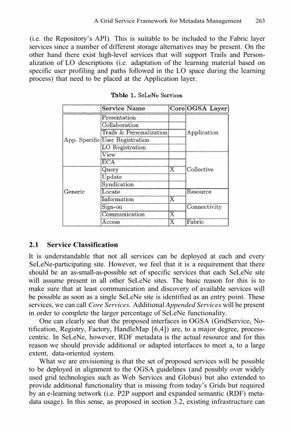
A Grid Service Framework for Metadata Management 263
(i.e. the Repository’s API). This is suitable to be included to the Fabric layerservices since a number of different storage alternatives may be present. On theother hand there exist high-level services that will support Trails and Person-alization of LO descriptions (i.e. adaptation of the learning material based onspecific user profiling and paths followed in the LO space during the learningprocess) that need to be placed at the Application layer.
2.1 Service Classification
It is understandable that not all services can be deployed at each and everySeLeNe-participating site. However, we feel that it is a requirement that thereshould be an as-small-as-possible set of specific services that each SeLeNe sitewill assume present in all other SeLeNe sites. The basic reason for this is tomake sure that at least communication and discovery of available services willbe possible as soon as a single SeLeNe site is identified as an entry point. Theseservices, we can call Core Services. Additional Appended Services will be presentin order to complete the larger percentage of SeLeNe functionality.
One can clearly see that the proposed interfaces in OGSA (GridService, No-tification, Registry, Factory, HandleMap [6,4]) are, to a major degree, process-centric. In SeLeNe, however, RDF metadata is the actual resource and for thisreason we should provide additional or adapted interfaces to meet a, to a largeextent, data-oriented system.
What we are envisioning is that the set of proposed services will be possibleto be deployed in alignment to the OGSA guidelines (and possibly over widelyused grid technologies such as Web Services and Globus) but also extended toprovide additional functionality that is missing from today’s Grids but requiredby an e-learning network (i.e. P2P support and expanded semantic (RDF) meta-data usage). In this sense, as proposed in section 3.2, existing infrastructure can
264 G. Samaras, K. Karenos, and E. Christodoulou
be utilized to mediate the underlying service functionality described below buttargeting to support RDF descriptions as the requested resource (i.e. instead ofcomputation cycles, storage, large data objects etc.). As argued next, genericRDF services can then be adopted by other grid systems. Besides characteriz-ing services as being either core or appended, one other important distinctivefactor for offered services is whether a service is generic or application specific(i.e. SeLeNe specific). Generic services will reside at the “hourglass neck” of theOGSA layers. These services will be usable for other applications or systemsthat require or make use of RDF. Examples of generic services include RDFview creation and change notification. On the other hand, application specificservices concentrate on the specifics within the SeLeNe with respect to the e-learning requirements such as trail management and personalization services. Inthe following subsections we will describe the high level functionality for each ofthe proposed services.
2.2 Core Services
Access Service. This service is located at the lower layer of the Grid Archi-tecture (Fabric). This service provides the direct access API to the local RDFRepository. It includes access methods for local requests as well as appropri-ate manipulation of locally stored descriptions (i.e. insert, delete and update ofthe repository content) irrespective of its low-level implementation. The actualstorage repository can be realized over a number of implementation alterna-tives such as Sesame RDF Repository [9], Jena toolkit [11] and the ICS-FORTHRDFSuite [10].
Communication Service. This service provides the basic communicationmechanisms for exchanging data. Current protocols may be used on which com-munication links can be established (such as TCP/IP) but we should also con-sider creating a simple “SeLeNe specific” communication service (i.e. for theexchange of specific types of messages e.g. task request submission.) Possible ex-ample technologies that can support this “SeLeNe specific” communication ser-vice are SOAP [12] and RPC techniques (e.g. Java RMI), however the messagecontent and structure is not part of our current investigations. RPC is generallymore appropriate for more formalized and concrete (e.g. local) communicationsand can be used in a local SeLeNe (e.g. installed at a single institution). On theother hand SOAP addresses incompatibility problems among multiple commu-nicating and possibly remote groups.
Information Service. The Information service provides the capabilities of ac-quiring descriptive information on some SeLeNe site. Informally, it will be ableto answer questions of the form: “what does this node understand in terms ofmetadata?” It provides the profile of the site (not the user). Put in another way,it provides metadata on metadata and more specifically the Namespaces usedand the RDF Schema(s) for that specific site. The Information service is builton top of the Access service. It does not raise any new research issues for us.
A Grid Service Framework for Metadata Management 265
Query. The Query Service is of great importance: we need to define a powerfulquery language that will allow for the extraction of results from multiple, localRDF repositories. The Query Service should be distributed and should allow forsearch message routing in order to forward sub-queries to sites that can provideanswers. It may also need to call the Syndication service to translate queriesexpressed against one RDF taxonomy to sub-queries expressed against differentlocal taxonomies. It then passes a subquery to the Access service supported bya particular peer, expressed in terms of that peer’s local RDF Schema. Anotherissue is the exploitation of the semantic meaning of our data to relate users ofsimilar interests. A good, super-peer based technique is provided in [13] where aclustering technique is used to mediate heterogeneous schemas. Authority sitescan become responsible for keeping semantically meaningful indexes about otherneighboring sites.
2.3 Appended Services
Sign-On. A site is able to register to the SeLeNe in order to advertise its contentand services. Also, in this way, it should be able to make its presence known toother sites. Sign-on allows for the update of the indexes of neighbors as well asthe directly connected authority site(s).Locate. This service relates to the OGSI GridService and makes requested ser-vice lookup possible. As soon as a site is connected, it should be able to discoverwhere there are services that will be used, along with any required parametersthat these services will need. We assume for now standard registry techniquesdepending on the architectural deployment of SeLeNe. A distributed catalogingscheme could suffice in this case (e.g. UDDI [15].) Semantic service descriptionsis an issue not addressed within SeLeNe for now although it does pose an inter-esting future research issue for the evolution and expansion of the proposed setof services.Syndication. The Syndication service is responsible for the translation betweendifferent RDF schemas. This is accomplished by using the user-supplied map-pings between heterogeneous schemas. This implies both data-to-data and query-to-query translations. Syndication issues are also of high importance.Update. The Update Service is used to appropriately transfer updates to de-scriptions expressed in diverse schemas. By analogy to the Query service, thisservice will take an update request for Peer 1 expressed in some RDF_Schema_2and translate it into the equivalent update expressed in terms of RDF_Schema_1by using the Syndication service. The Update Service would then request for theinvocation of the appropriate operation of the Access service at Peer 1 to enactthe actual update on its local RDF repository.Event-Condition-Action (ECA). LO descriptions are gradually updated andenhanced due to the ongoing learning process. Users should be able to registertheir interest to receive changes when they occur that are relevant to metadatathat are of their interest. This feature should be provided by the ECA Service,which will propagate updates and notifications to registered sites.
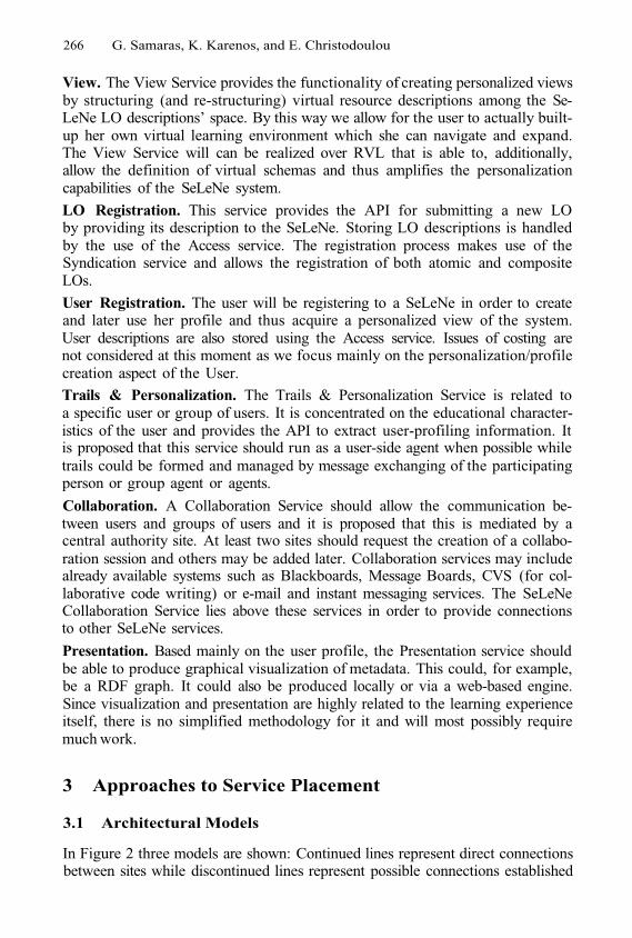
266 G. Samaras, K. Karenos, and E. Christodoulou
View. The View Service provides the functionality of creating personalized viewsby structuring (and re-structuring) virtual resource descriptions among the Se-LeNe LO descriptions’ space. By this way we allow for the user to actually built-up her own virtual learning environment which she can navigate and expand.The View Service will can be realized over RVL that is able to, additionally,allow the definition of virtual schemas and thus amplifies the personalizationcapabilities of the SeLeNe system.
LO Registration. This service provides the API for submitting a new LOby providing its description to the SeLeNe. Storing LO descriptions is handledby the use of the Access service. The registration process makes use of theSyndication service and allows the registration of both atomic and compositeLOs.
User Registration. The user will be registering to a SeLeNe in order to createand later use her profile and thus acquire a personalized view of the system.User descriptions are also stored using the Access service. Issues of costing arenot considered at this moment as we focus mainly on the personalization/profilecreation aspect of the User.
Trails & Personalization. The Trails & Personalization Service is related toa specific user or group of users. It is concentrated on the educational character-istics of the user and provides the API to extract user-profiling information. Itis proposed that this service should run as a user-side agent when possible whiletrails could be formed and managed by message exchanging of the participatingperson or group agent or agents.
Collaboration. A Collaboration Service should allow the communication be-tween users and groups of users and it is proposed that this is mediated by acentral authority site. At least two sites should request the creation of a collabo-ration session and others may be added later. Collaboration services may includealready available systems such as Blackboards, Message Boards, CVS (for col-laborative code writing) or e-mail and instant messaging services. The SeLeNeCollaboration Service lies above these services in order to provide connectionsto other SeLeNe services.
Presentation. Based mainly on the user profile, the Presentation service shouldbe able to produce graphical visualization of metadata. This could, for example,be a RDF graph. It could also be produced locally or via a web-based engine.Since visualization and presentation are highly related to the learning experienceitself, there is no simplified methodology for it and will most possibly requiremuch work.
3 Approaches to Service Placement
3.1 Architectural Models
In Figure 2 three models are shown: Continued lines represent direct connectionsbetween sites while discontinued lines represent possible connections established
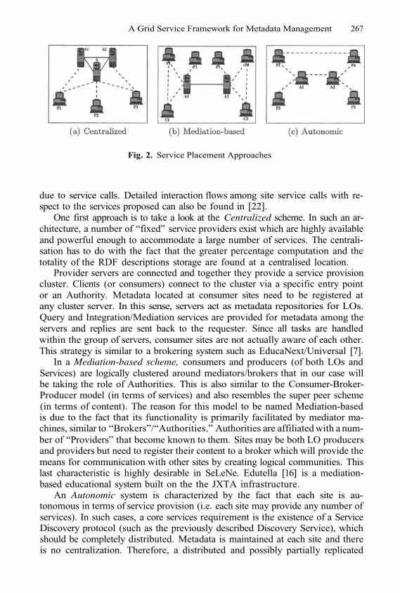
A Grid Service Framework for Metadata Management 267
Fig. 2. Service Placement Approaches
due to service calls. Detailed interaction flows among site service calls with re-spect to the services proposed can also be found in [22].
One first approach is to take a look at the Centralized scheme. In such an ar-chitecture, a number of “fixed” service providers exist which are highly availableand powerful enough to accommodate a large number of services. The centrali-sation has to do with the fact that the greater percentage computation and thetotality of the RDF descriptions storage are found at a centralised location.
Provider servers are connected and together they provide a service provisioncluster. Clients (or consumers) connect to the cluster via a specific entry pointor an Authority. Metadata located at consumer sites need to be registered atany cluster server. In this sense, servers act as metadata repositories for LOs.Query and Integration/Mediation services are provided for metadata among theservers and replies are sent back to the requester. Since all tasks are handledwithin the group of servers, consumer sites are not actually aware of each other.This strategy is similar to a brokering system such as EducaNext/Universal [7].
In a Mediation-based scheme, consumers and producers (of both LOs andServices) are logically clustered around mediators/brokers that in our case willbe taking the role of Authorities. This is also similar to the Consumer-Broker-Producer model (in terms of services) and also resembles the super peer scheme(in terms of content). The reason for this model to be named Mediation-basedis due to the fact that its functionality is primarily facilitated by mediator ma-chines, similar to “Brokers”/“Authorities.” Authorities are affiliated with a num-ber of “Providers” that become known to them. Sites may be both LO producersand providers but need to register their content to a broker which will provide themeans for communication with other sites by creating logical communities. Thislast characteristic is highly desirable in SeLeNe. Edutella [16] is a mediation-based educational system built on the the JXTA infrastructure.
An Autonomic system is characterized by the fact that each site is au-tonomous in terms of service provision (i.e. each site may provide any number ofservices). In such cases, a core services requirement is the existence of a ServiceDiscovery protocol (such as the previously described Discovery Service), whichshould be completely distributed. Metadata is maintained at each site and thereis no centralization. Therefore, a distributed and possibly partially replicated
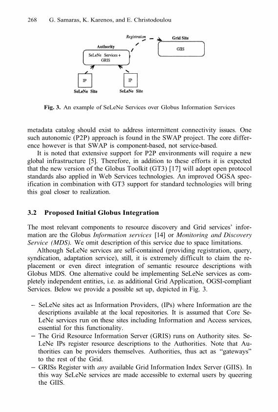
268 G. Samaras, K. Karenos, and E. Christodoulou
Fig. 3. An example of SeLeNe Services over Globus Information Services
metadata catalog should exist to address intermittent connectivity issues. Onesuch autonomic (P2P) approach is found in the SWAP project. The core differ-ence however is that SWAP is component-based, not service-based.
It is noted that extensive support for P2P environments will require a newglobal infrastructure [5]. Therefore, in addition to these efforts it is expectedthat the new version of the Globus Toolkit (GT3) [17] will adopt open protocolstandards also applied in Web Services technologies. An improved OGSA spec-ification in combination with GT3 support for standard technologies will bringthis goal closer to realization.
3.2 Proposed Initial Globus Integration
The most relevant components to resource discovery and Grid services’ infor-mation are the Globus Information services [14] or Monitoring and DiscoveryService (MDS). We omit description of this service due to space limitations.
Although SeLeNe services are self-contained (providing registration, query,syndication, adaptation service), still, it is extremely difficult to claim the re-placement or even direct integration of semantic resource descriptions withGlobus MDS. One alternative could be implementing SeLeNe services as com-pletely independent entities, i.e. as additional Grid Application, OGSI-compliantServices. Below we provide a possible set up, depicted in Fig. 3.
SeLeNe sites act as Information Providers, (IPs) where Information are thedescriptions available at the local repositories. It is assumed that Core Se-LeNe services run on these sites including Information and Access services,essential for this functionality.The Grid Resource Information Server (GRIS) runs on Authority sites. Se-LeNe IPs register resource descriptions to the Authorities. Note that Au-thorities can be providers themselves. Authorities, thus act as “gateways”to the rest of the Grid.GRISs Register with any available Grid Information Index Server (GIIS). Inthis way SeLeNe services are made accessible to external users by queeringthe GIIS.
A Grid Service Framework for Metadata Management 269
4 Conclusion
The usage of semantic metadata resource descriptions can highly benefit Gridtechnology. In our work within the SeLeNe project we have proposed a set ofcore and appended services that allow for the query, access and syndication ofheterogeneous RDF-based descriptions and propose the incorporation of suchservices to the current Grid Infrastructure. We use an educational e-learningapplication as a testbed and find that the usability of such a service set can beapplied to multiple architectural models. We believe that semantic metadata forthe Grid constitutes a critical extension towards the realization of the SemanticGrid vision.
References
1.2.3.
4.
5.6.
7.8.
9.
10.
11.12.13.
14.
15.
16.17.18.19.20.21.22.
The Semantic Grid Community Portal. Available at www.semanticgrid.org/Global Grid Forum (GGF). Available at www.gridforum.orgD. De Roure, N.R. Jennings, N.R. Shadbolt. The Semantic Grid: A Future eScienceInfrastructure. National e-Science Centre. Univ.of Edinburgh, UK. UKeS 2002.I. Foster, C. Kesselman, J. Nick, and S. Tuecke. The Physiology of the Grid: Anopen grid services architecture for distributed systems integration. Technical report,Open Grid Service Infrastructure WG, GGF, Jun. 2002.The OGSAP2P Group. Available at www.gridforum.org/4-GP/ogsap2p.htmIan Foster, Carl Kesselman, Steven Tuecke. The Anatomy of the Grid EnablingScalable Virtual Organizations. International J. Supercomputer Applications, 2001.EducaNext (Universal) Project. Available atwww.educanext.orgK. Keenoy, G. Papamarkos, A. Poulovassilis, M. Levene, D. Peterson, P. Wood,G. Loizou. Self e-Learning Networks - Functionality, User Requirements and Ex-ploitation Scenarios, SeLeNe Project Del. 2.2, Aug. 2003.Sesame Open Source RDF Schema-based Repository and Querying facility. Avail-able at sesame.aidministrator.nlICS-FORTH RDFSuite. High-level Scalable Tools for the Semantic Web: Availableat http://139.91.183.30:9090/RDF/index.htmlJena Semantic Web Toolkit. Available at www.hpl.hp.com/semweb/jena.htmSimple Object Access Protocol (SOAP). Available at www.w3.org/TR/SOAPLeonidas Galanis, Yuan Wang Shawn, R. Jeffery David J. DeWitt. Processing XMLContainment Queries in a Large Peer-to-Peer System. CAiSE 2003K. Czajkowski and S. Fitzgerald and I. Foster and C. Kesselman, Grid InformationServices for Distributed Resource Sharing, HPDC 2001.The Universal Description, Discovery and Integration Protocol. Available atwww.uddi.orgEdutella Project. Available at edutella.jxta.orgGlobus Toolkit. Available at www.globus.orgOnto Web: Available atwww.ontoweb.orgThe SWAP System. Available at swap.semanticweb.org/public/index.htmWeb Services at W3C. Available at www.w3.org/2002/wsProject JXTA. Available at www.jxta.orgThe SeLeNe Consortium. An Architectural Framework and Deployment Choicesfor SeLeNe. SeLeNe Project Del. 5.0. Dec. 2003.

This page intentionally left blank

Author Index
Ambrus, G. 69159
Astalos, J. 51
Bágyi, I. 69Balaton, Z. 179
212Benkner, S. 149Blythe, J. 11Brandic, I. 149Brooke, J. 240Bubak, M. 159, 169, 182, 212
Christodoulou, E. 260Congiusta, A. 250
Darlington, J. 90Darvas, F. 69Decker, K. 230Deelman, E. 11Dimitrakos, T. 113Dobrucky, M. 51Doulamis, A. 32Doulamis, N. 32Dózsa, G. 129Drótos, D. 129
Evripidou, P. 139
Fahringer, T. 149, 202Fellows D. 240Fernández, A. 42Fernández, E. 42Funika, W. 159Furmento, N. 90
Garwood, K. 240Gatial, E. 51Gil, Y. 11Goble, C. 240Gombás, G. 179Gomes, J. 61Graham, P. 1
Habala, O. 51Hariri, S. 119
Hau, J. 90Heikkurinen, M. 1Heymann, E. 42Hluchy, L. 51Holub, P. 220
Kacsuk, P. 80, 110, 129Kakarontzas, G. 100Karenos, K. 260Kesselman, C. 11Kim, Yangwoo 119Kim, Yoonhee 119Kovács, J. 80Kranzmueller, D. 77Kuba, M. 220Kurdziel, M. 159
Lalis, S. 100Laria, G. 113Lee, W. 90Litke, A. 32Livny, M. 11Lovas, R. 129
Malawski, M. 169, 182Marco, J. 61Marco, R. 61Martínez-Rivero, C. 61Mastroianni, C. 250Matyska, L. 220Mehta, G. 11Miles, S. 230
169Moreau, L. 230
Nabrzyski, J. 1Neophytou, N. 139Neophytou, P. 139Newhouse, S. 90Nowakowski, P. 169
Oleksiak, A. 1
169Panagakis, A. 32Papay, J. 230

272 Author Index
Papay, J. 230Papp, Á. 69Parsons, M. 1Patil, S. 11Payne, T. 230Plale, B. 191Pllana, S. 149Podhorszki, N. 129, 179Pugliese, A. 250
Ra, I. 119Radecki, M. 212Ragas, H. 77
182Ritrovato, P. 113Rodríguez, D. 61Rosmanith, H. 77Ruda, M. 220Rycerz, K. 169
Sakellariou, R. 21Salt, J. 42Samaras, G. 260Senar, M.A. 42Serhan, B. 113Shamonin, D. 77Simo, B. 51
Sipos, G. 110Stockinger, H. 1Stockinger, K. 1
1Su, M.-H. 11Szepieniec, T. 212
Talia, D. 250Testori, J. 149Tirado-Ramos, A. 77Tran, V.D. 51Trunfio, P. 250Truong, H.-L. 202
169
Ürge, L. 69
Vahi, K. 11Varvarigos, E. 32Varvarigou, T. 32
1Wesner, S. 113Wieczorek, M. 182Wismüller, R. 159, 212
Zhao, H. 21
Lecture Notes in Computer Science
For information about Vols. 1–3175
please contact your bookseller or Springer
Vol. 3293: C.-H. Chi, M. van Steen, C. Wills (Eds.), WebContent Caching and Distribution. IX, 283 pages. 2004.
Vol. 3274: R. Guerraoui (Ed.), Distributed Computing.XIII, 465 pages. 2004.
Vol. 3273: T. Baar, A. Strohmeier, A. Moreira, S.J. Mel-lor (Eds.),<<UML>> 2004 - The Unified ModellingLanguage. XIII, 454 pages. 2004.
Vol. 3271: J. Vicente, D. Hutchison (Eds.), Managementof Multimedia Networks and Services. XIII, 335 pages.2004.
Vol. 3270: M. Jeckle, R. Kowalczyk, P. Braun (Eds.), GridServices Engineering and Management. X, 165 pages.2004.
Vol. 3266: J. Solé-Pareta, M. Smirnov, P.V. Mieghem, J.Domingo-Pascual, E. Monteiro, P. Reichl, B. Stiller, R.J.Gibbens (Eds.), Quality of Service in the Emerging Net-working Panorama. XVI, 390 pages. 2004.
Vol. 3265: R.E. Frederking, K.B. Taylor (Eds.), MachineTranslation: From Real Users to Research. XI, 392 pages.2004. (Subseries LNAI).
Vol. 3264: G. Paliouras, Y. Sakakibara (Eds.), Gram-matical Inference: Algorithms and Applications. XI, 291pages. 2004. (Subseries LNAI).
Vol. 3263: M. Weske, P. Liggesmeyer (Eds.), Object-Oriented and Internet-Based Technologies. XII, 239pages. 2004.
Vol. 3261: T. Yakhno (Ed.), Advances in Information Sys-tems. XIV, 617 pages. 2004.
Vol. 3260: I. Niemegeers, S.H. de Groot (Eds.), PersonalWireless Communications. XIV, 478 pages. 2004.
Vol. 3258: M. Wallace (Ed.), Principles and Practice ofConstraint Programming – CP 2004. XVII, 822 pages.2004.
Vol. 3257: E. Motta, N.R. Shadbolt, A. Stutt, N. Gibbins(Eds.), Engineering Knowledge in the Age of the SemanticWeb. XVII, 517 pages. 2004. (Subseries LNAI).
Vol. 3256: H. Ehrig, G. Engels, F. Parisi-Presicce,G. Rozenberg (Eds.), Graph Transformations. XII, 451pages. 2004.
Vol. 3255: A. Benczúr, J. Demetrovics, G. Gottlob (Eds.),Advances in Databases and Information Systems. XI, 423pages. 2004.
Vol. 3254: E. Macii, V. Paliouras, O. Koufopavlou (Eds.),Integrated Circuit and System Design. XVI, 910 pages.2004.
Vol. 3253: Y. Lakhnech, S. Yovine (Eds.), Formal Tech-niques, Modelling and Analysis of Timed and Fault-Tolerant Systems. X, 397 pages. 2004.
Vol. 3250: L.-J. (LJ) Zhang, M. Jeckle (Eds.), Web Ser-vices. X, 301 pages. 2004.
Vol. 3249: B. Buchberger, J.A. Campbell (Eds.), ArtificialIntelligence and Symbolic Computation. X, 285 pages.2004. (Subseries LNAI).
Vol. 3246: A. Apostolico, M. Melucci (Eds.), String Pro-cessing and Information Retrieval. XIV, 332 pages. 2004.
Vol. 3245: E. Suzuki, S. Arikawa (Eds.), Discovery Sci-ence. XIV, 430 pages. 2004. (Subseries LNAI).
Vol. 3244: S. Ben-David, J. Case, A. Maruoka (Eds.), Al-gorithmic Learning Theory. XIV, 505 pages. 2004. (Sub-series LNAI).
Vol. 3243: S. Leonardi (Ed.), Algorithms and Models forthe Web-Graph. VIII, 189 pages. 2004.
Vol. 3242: X. Yao, E. Burke, J.A. Lozano, J. Smith, J.J.Merelo-Guervós, J.A. Bullinaria, J. Rowe, A.Kabán, H.-P. Schwefel (Eds.), Parallel Problem Solvingfrom Nature - PPSN VIII. XX, 1185 pages. 2004.
Vol. 3241: D. Kranzlmüller, P. Kacsuk, J.J. Dongarra(Eds.), Recent Advances in Parallel Virtual Machine andMessage Passing Interface. XIII, 452 pages. 2004.
Vol. 3240: I. Jonassen, J. Kim (Eds.), Algorithms in Bioin-formatics. IX, 476 pages. 2004. (Subseries LNBI).
Vol. 3239: G. Nicosia, V. Cutello, P.J. Bentley, J. Timmis(Eds.), Artificial Immune Systems. XII, 444 pages. 2004.
Vol. 3238: S. Biundo, T. Frühwirth, G. Palm (Eds.), KI2004: Advances in Artificial Intelligence. XI, 467 pages.2004. (Subseries LNAI).
Vol. 3236: M. Núñez, Z. Maamar, F.L. Pelayo, K.Pousttchi, F. Rubio (Eds.), Applying Formal Methods:Testing, Performance, and M/E-Commerce. XI, 381pages. 2004.
Vol. 3235: D. de Frutos-Escrig, M. Nunez (Eds.), For-mal Techniques for Networked and Distributed Systems– FORTE 2004. X, 377 pages. 2004.
Vol. 3232: R. Heery, L. Lyon (Eds.), Research and Ad-vanced Technology for Digital Libraries. XV, 528 pages.2004.
Vol. 3231: H.-A. Jacobsen (Ed.), Middleware 2004. XV,514 pages. 2004.
Vol. 3230: J.L. Vicedo, P. Martínez-Barco, R. Muñoz,M.S.Noeda (Eds.), Advances in Natural Language Processing.XII, 488 pages. 2004. (Subseries LNAI).
Vol. 3229: J.J. Alferes, J. Leite (Eds.), Logics in ArtificialIntelligence. XIV, 744 pages. 2004. (Subseries LNAI).
Vol. 3225: K. Zhang, Y. Zheng (Eds.), Information Secu-rity. XII, 442 pages. 2004.
Vol. 3224: E. Jonsson, A. Valdes, M. Almgren (Eds.), Re-cent Advances in Intrusion Detection. XII, 315 pages.2004.
Vol. 3223: K. Slind, A. Bunker, G. Gopalakrishnan (Eds.),Theorem Proving in Higher Order Logics. VIII, 337 pages.2004.
Vol. 3222: H. Jin, G.R. Gao, Z. Xu, H. Chen (Eds.), Net-work and Parallel Computing. XX, 694 pages. 2004.
Vol. 3221: S. Albers, T. Radzik (Eds.), Algorithms – ESA2004. XVIII, 836 pages. 2004.
Vol. 3220: J.C. Lester, R.M. Vicari, F. Paraguaçu (Eds.),Intelligent Tutoring Systems. XXI, 920 pages. 2004.
Vol. 3219: M. Heisel, P. Liggesmeyer, S. Wittmann(Eds.),Computer Safety, Reliability, and Security. XI, 339 pages.2004.
Vol. 3217: C. Barillot, D.R. Haynor, P. Hellier (Eds.), Med-ical Image Computing and Computer-Assisted Interven-tion – MICCAI 2004. XXXVIII, 1114 pages. 2004.
Vol. 3216: C. Barillot, D.R. Haynor, P. Hellier (Eds.), Med-ical Image Computing and Computer-Assisted Interven-tion – MICCAI 2004. XXXVIII, 930 pages. 2004.
Vol. 3215: M.G.. Negoita, R.J. Howlett, L.C. Jain (Eds.),Knowledge-Based Intelligent Information and Engineer-ing Systems. LVII, 906 pages. 2004. (Subseries LNAI).
Vol. 3214: M.G.. Negoita, R.J. Howlett, L.C. Jain (Eds.),Knowledge-Based Intelligent Information and Engineer-ing Systems. LVIII, 1302 pages. 2004. (Subseries LNAI).
Vol. 3213: M.G.. Negoita, R.J. Howlett, L.C. Jain (Eds.),Knowledge-Based Intelligent Information and Engineer-ing Systems. LVIII, 1280 pages. 2004. (Subseries LNAI).
Vol. 3212: A. Campilho, M. Kamel (Eds.), Image Analysisand Recognition. XXIX, 862 pages. 2004.
Vol. 3211: A. Campilho, M. Kamel (Eds.), Image Analysisand Recognition. XXIX, 880 pages. 2004.
Vol. 3210: J. Marcinkowski, A. Tarlecki (Eds.), ComputerScience Logic. XI, 520 pages. 2004.
Vol. 3209: B. Berendt, A. Hotho, D. Mladenic, M. vanSomeren, M. Spiliopoulou, G. Stumme (Eds.), Web Min-ing: From Web to Semantic Web. IX, 201 pages. 2004.(Subseries LNAI).
Vol. 3208: H.J. Ohlbach, S. Schaffert (Eds.), Principlesand Practice of Semantic Web Reasoning. VII, 165 pages.2004.
Vol. 3207: L.T. Yang, M. Guo, G.R. Gao, N.K. Jha (Eds.),Embedded and Ubiquitous Computing. XX, 1116 pages.2004.
Vol. 3206: P. Sojka, I. Kopecek, K. Pala (Eds.), Text,Speech and Dialogue. XIII, 667 pages. 2004. (SubseriesLNAI).
Vol. 3205: N. Davies, E. Mynatt, I. Siio (Eds.), UbiComp2004: Ubiquitous Computing. XVI, 452 pages. 2004.
Vol. 3203: J. Becker, M. Platzner, S. Vernalde (Eds.), FieldProgrammable Logic and Application. XXX, 1198 pages.2004.
Vol. 3202: J.-F. Boulicaut, F. Esposito, F. Giannotti, D.Pedreschi (Eds.), Knowledge Discovery in Databases:PKDD 2004. XIX, 560 pages. 2004. (Subseries LNAI).
Vol. 3201: J.-F. Boulicaut, F. Esposito, F. Giannotti, D.Pedreschi (Eds.), Machine Learning: ECML 2004. XVIII,580 pages. 2004. (Subseries LNAI).
Vol. 3199: H. Schepers (Ed.), Software and Compilers forEmbedded Systems. X, 259 pages. 2004.
Vol. 3198: G.-J. de Vreede, L.A. Guerrero, G. MarínRaventós (Eds.), Groupware: Design, Implementation andUse. XI, 378 pages. 2004.
Vol. 3196: C. Stary, C. Stephanidis (Eds.), User-CenteredInteraction Paradigms for Universal Access in the Infor-mation Society. XII, 488 pages. 2004.
Vol. 3195: C.G. Puntonet, A. Prieto (Eds.), IndependentComponent Analysis and Blind Signal Separation. XXIII,1266 pages. 2004.
Vol. 3194: R. Camacho, R. King, A. Srinivasan (Eds.), In-ductive Logic Programming. XI, 361 pages. 2004. (Sub-series LNAI).
Vol. 3193: P. Samarati, P. Ryan, D. Gollmann, R. Molva(Eds.), Computer Security – ESORICS 2004. X, 457pages. 2004.
Vol. 3192: C. Bussler, D. Fensel (Eds.), Artificial Intel-ligence: Methodology, Systems, and Applications. XIII,522 pages. 2004. (Subseries LNAI).
Vol. 3191: M. Klusch, S. Ossowski, V. Kashyap, R. Un-land (Eds.), Cooperative InformationAgents VIII. XI, 303pages. 2004. (Subseries LNAI).
Vol. 3190: Y. Luo (Ed.), Cooperative Design, Visualiza-tion, and Engineering. IX, 248 pages. 2004.
Vol. 3189: P.-C. Yew, J. Xue (Eds.), Advances in ComputerSystems Architecture. XVII, 598 pages. 2004.
Vol. 3188: F.S. de Boer, M.M. Bonsangue, S. Graf, W.-P.de Roever (Eds.), Formal Methods for Components andObjects. VIII, 373 pages. 2004.
Vol. 3187: G. Lindemann, J. Denzinger, I.J. Timm, R. Un-land (Eds.), Multiagent System Technologies. XIII, 341pages. 2004. (Subseries LNAI).
Vol. 3186: Z. Bellahsène, T. Milo, M. Rys, D. Suciu, R.Unland (Eds.), Database and XML Technologies. X, 235pages. 2004.
Vol. 3185: M. Bernardo, F. Corradini (Eds.), Formal Meth-ods for the Design of Real-Time Systems. VII, 295 pages.2004.
Vol. 3184: S. Katsikas, J. Lopez, G. Pernul (Eds.), Trustand Privacy in Digital Business. XI, 299 pages. 2004.
Vol. 3183: R. Traunmüller (Ed.), Electronic Government.XIX, 583 pages. 2004.
Vol. 3182: K. Bauknecht, M. Bichler, B. Pröll (Eds.), E-Commerce and Web Technologies. XI, 370 pages. 2004.
Vol. 3181: Y. Kambayashi, M. Mohania, W. Wöß (Eds.),Data Warehousing and Knowledge Discovery. XIV, 412pages. 2004.
Vol. 3180: F. Galindo, M. Takizawa, R. Traunmüller(Eds.), Database and Expert Systems Applications. XXI,972 pages. 2004.
Vol. 3179: F.J. Perales, B.A. Draper (Eds.), ArticulatedMotion and Deformable Objects. XI, 270 pages. 2004.
Vol. 3178: W. Jonker, M. Petkovic (Eds.), Secure DataManagement. VIII, 219 pages. 2004.
Vol. 3177: Z.R. Yang, H. Yin, R. Everson (Eds.), Intelli-gent Data Engineering and Automated Learning – IDEAL2004. XVIII, 852 pages. 2004.
Vol. 3176:O. Bousquet, U. vonLuxburg, G. Rätsch (Eds.),Advanced Lectures on Machine Learning. IX, 241 pages.2004. (Subseries LNAI).
Related Documents