Energy Research and Development Division FINAL PROJECT REPORT Grid Communication Interface for Smart Electric Vehicle Services Gavin Newsom, Governor May 2020 | CEC-500-2020-028

Welcome message from author
This document is posted to help you gain knowledge. Please leave a comment to let me know what you think about it! Share it to your friends and learn new things together.
Transcript

Energy Research and Development Division
FINAL PROJECT REPORT
Grid Communication Interface for Smart Electric Vehicle Services
Gavin Newsom, Governor
May 2020 | CEC-500-2020-028

PREPARED BY:
Primary Author:
Luigi Giubbolini, Ph.D.
Andromeda Power, LLC
2500 Mira Mar Ave,
Long Beach, CA 90815
Phone: 714-408-1901 | Fax: 949-209-1425
http://www.andromedapower.com
Contract Number: EPC-15-015
PREPARED FOR:
California Energy Commission
Matt Fung, P.E.
Project Manager
Jonah Steinbuck, Ph.D.
Office Manager
ENERGY GENERATION RESEARCH OFFICE
Laurie ten Hope
Deputy Director
ENERGY RESEARCH AND DEVELOPMENT DIVISION
Drew Bohan
Executive Director
DISCLAIMER
This report was prepared as the result of work sponsored by the California Energy Commission. It does not necessarily
represent the views of the Energy Commission, its employees or the State of California. The Energy Commission, the
State of California, its employees, contractors and subcontractors make no warranty, express or implied, and assume
no legal liability for the information in this report; nor does any party represent that the uses of this information will
not infringe upon privately owned rights. This report has not been approved or disapproved by the California Energy
Commission nor has the California Energy Commission passed upon the accuracy or adequacy of the information in
this report.

i
ACKNOWLEDGEMENTS
The world is a better place thanks to the people who develop and lead others. Andromeda
Power believes that there is something special about California’s leadership vision, in its
constant commitment to solve the challenges we face, our environment, educating the public
about what is at stake, advancing green technologies and establishing standards and goals for
the planet.
Andromeda Power’s mission is to make the world’s smart mobility a practical opportunity for
everyone. Creating solutions for optimal fast charging anytime, anywhere, from any electricity
source. Ultimately, what makes the world a better place is the people who share the gift of
their time and resources to drive this progress.
The Grid Communication Interface for Smart Electric Vehicle Services (InCISIVE) research
project was funded by the California Energy Commission Electric Program Investment Charge
(EPIC) program, Verdek, LLC, SunCharge, LLC, and Livebythepark, Inc. PIER staff provided
valuable logistical support, in particular Matt Fung for his always prompt, detailed, and patient
feedback during the development of the project. The InCISIVE research and development
activity benefited from the support of the Electric Power Research Institute (EPRI) (Chuck
Thomas and Walt Johnson), Nebland (Benjamin DuPont), OpenADR Alliance (Rolf Bienert),
and Open Charge Alliance (Robert de Leeuw).
Andromeda Power recognizes the continuous support and recommendations of the members
of the technical advisory committee (Robert Aceti, Mithat C. Kisacikoglu, Gaetano Mannino,
Patrick Martinez, and Ray Segall). Andromeda Power would like to express our deep gratitude
and appreciation to the entire team that has made possible the exceptional results of
InCISIVE. In particular Antonio Pizzardi for his endurance, Heather Lin for her wonderful
assistance and extreme patience, and Gianni Quaglia for his participation in interesting
brainstorming sessions. A special thanks to Hillel Pitlik for his advice and support. Part of the
experimental tests were performed by Judy and David Davis, passionate advocates of
renewable resource technologies.

ii
PREFACE
The California Energy Commission’s (CEC) Energy Research and Development Division
supports energy research and development programs to spur innovation in energy efficiency,
renewable energy and advanced clean generation, energy-related environmental protection,
energy transmission and distribution and transportation.
In 2012, the Electric Program Investment Charge (EPIC) was established by the California
Public Utilities Commission to fund public investments in research to create and advance new
energy solutions, foster regional innovation and bring ideas from the lab to the marketplace.
The CEC and the state’s three largest investor-owned utilities—Pacific Gas and Electric
Company, San Diego Gas & Electric Company and Southern California Edison Company—were
selected to administer the EPIC funds and advance novel technologies, tools, and strategies
that provide benefits to their electric ratepayers.
The CEC is committed to ensuring public participation in its research and development
programs that promote greater reliability, lower costs, and increase safety for the California
electric ratepayer and include:
• Providing societal benefits.
• Reducing greenhouse gas emission in the electricity sector at the lowest possible cost.
• Supporting California’s loading order to meet energy needs first with energy efficiency
and demand response, next with renewable energy (distributed generation and utility
scale), and finally with clean, conventional electricity supply.
• Supporting low-emission vehicles and transportation.
• Providing economic development.
• Using ratepayer funds efficiently.
Grid Communication Interface for Smart Electric Vehicle Services Research and Development is
the final report for the Grid Communication Interface for Smart Electric Vehicle Services
Research and Development project (Contract Number EPC-15-015) conducted by Andromeda
Power, LLC. The information from this project contributes to the Energy Research and
Development Division’s EPIC Program.
For more information about the Energy Research and Development Division, please visit the
CEC’s research website (www.energy.ca.gov/research/) or contact the CEC at 916-327-1551.

iii
ABSTRACT
Connecting growing numbers of electric vehicles to the electrical grid creates an opportunity to
demonstrate smart charging and discharging—referred to as vehicle grid integration—to
balance fluctuations on the grid and benefit electric vehicle owners.
The goal of the Grid Communication Interface for Smart Electric Vehicle Services (InCISIVE)
project was to prove the feasibility of the eight vehicle grid integration use cases defined in
the California Vehicle-Grid Integration Roadmap, specifically all combinations of: unidirectional
or bidirectional power flow, one or many aggregated resources, and unified or fragmented
actor objectives.
The research identified and addressed vehicle-grid integration technology needs and gaps
associated with:
1. Incompatibility of electric vehicles with electric vehicle supply equipment (charging
stations) connectors and standards.
2. Multiple protocols and architectures for charging station-to-utility communication.
3. Inconsistencies in implementation of vehicle-grid integration protocols.
This project designed a comprehensive system architecture that could address these three
technical barriers. Using this architecture, the project demonstrated that the technology and
standards support all vehicle grid integration use cases.
The InCISIVE technology was developed, implemented, and tested in a prototype capable of
smart charging and discharging. Because electric utilities have programs and plans for smart-
charging-capable charging stations but not for stations that accommodate discharge from the
vehicle, Andromeda Power advanced two smart-charging products to the market: Strada and
Zen. These products were qualified by Pacific Gas & Electric for the Electric Vehicle Charge
Network Program and by the New York State Energy Research and Development Authority for
the Charge Ready New York Program.
The research also identified inconsistencies and mismatches between vehicle-grid integration
protocols and produced a list of recommendations to address them.
Keywords: electric vehicle, electric vehicle supply equipment, smart grid, vehicle-to-grid, PEV,
V2G, EVSE, demand response, demand control, fast charging station, renewable energy,
CHAdeMO, SAE J1772, photovoltaic, grid integrated vehicle, energy management system,
microgrid.
Please use the following citation for this report:
Giubbolini, Luigi. 2020. Grid Communication Interface for Smart Electric Vehicle Services.
California Energy Commission. Publication Number: CEC-500-2020-028.

iv

v
TABLE OF CONTENTS
Page
ACKNOWLEDGEMENTS ......................................................................................................... i
PREFACE ............................................................................................................................ ii
ABSTRACT ......................................................................................................................... iii
EXECUTIVE SUMMARY ........................................................................................................ 1
Introduction ..................................................................................................................... 1
Project Purpose ................................................................................................................ 1
Project Approach .............................................................................................................. 2
Project Results ................................................................................................................. 4
Advancing the Research to Market .................................................................................... 5
Benefits to California ........................................................................................................ 7
CHAPTER 1: Introduction ................................................................................................... 9
CHAPTER 2: Project Approach ........................................................................................... 11
Design Approach for the InCISIVE Vehicle-Grid Integration Architecture ............................ 11
Development Approach for iVGI Software ........................................................................ 17
Development Approach of Vehicle-Grid Integration Prototype and Products ....................... 19
Field Trial of iVGI with Data Collection, Analysis, and Lessons Learned .............................. 20
CHAPTER 3: Project Results ............................................................................................... 22
Vehicle-Grid Integration Architecture ............................................................................... 22
Investor-Owned Utility Grid Infrastructure Interface ......................................................... 25
Electric Vehicle Supply Equipment Interface ..................................................................... 25
PEV Interfaces ............................................................................................................... 27
InCISIVE Energy Management System ............................................................................ 28
PEV User Interface ......................................................................................................... 31
ORCA-NET Party Interfaces ............................................................................................. 33
Network Manager Interface ............................................................................................ 33
ORCA-NET Asset and Aggregator Interfaces .................................................................... 33
Vehicle-Grid Integration Prototype................................................................................... 34
Vehicle-Grid Integration Testing Method .......................................................................... 42
CHAPTER 4: Technology/Knowledge/Market Transfer Activities ............................................ 51
Knowledge Gained ......................................................................................................... 51
Vehicle-Grid Integration State-of-the-Art and Decisions Relative to Market Constraints ....... 52
Technology/Knowledge Transfer Activities ....................................................................... 54

vi
CHAPTER 5: Conclusions and Recommendations ................................................................. 55
Obstacle Encountered ..................................................................................................... 55
Project Outcomes ........................................................................................................... 56
Lessons Learned ............................................................................................................ 56
CHAPTER 6: Benefits to Ratepayers ................................................................................... 58
Vehicle-Grid Integration Reduces Production Cost for Electricity in California ...................... 58
Ratepayers Save Millions of Dollars in Fuel Using Vehicle-Grid Integration ......................... 58
Vehicle-Grid Integration Technology Reduces Carbon Dioxide Emissions ............................ 59
Vehicle-Grid Integration Reduces the Cost of Energy Storage for Power Utilities ................. 59
Vehicle-Grid Integration Enables Off-Grid Application Without Purchasing Batteries ............ 59
iVGI-DC Increases the Available Power in the Microgrid .................................................... 59
GLOSSARY AND LIST OF ACRONYMS ................................................................................. 60
REFERENCES .................................................................................................................... 66
APPENDICES.........................................................................................................................
LIST OF FIGURES
Page
Figure ES-1: Andromeda Power Products with InCISIVE Vehicle-Grid Integration Interfaces ... 7
Figure 1: Vehicle-Grid Integration Infrastructure ................................................................... 9
Figure 2: Vehicle-Grid Integration Prototype Capable of V1G and V2G .................................. 10
Figure 3: Alternating Current Plug-in Electric Vehicle Plugs .................................................. 12
Figure 4: DC PEV Plugs ..................................................................................................... 12
Figure 5: Screen Shots from Plug-In Electric Vehicle Mobile App: Home and Settings Pages .. 14
Figure 6: InCISIVE Vehicle-Grid Integration Architecture “Direct” ......................................... 15
Figure 7: InCISIVE Vehicle-Grid Integration architecture “Aggregator” ................................. 16
Figure 8: Human Machine Interface of the Vehicle-Grid Integration prototype ...................... 20
Figure 9: Vehicle-Grid Integration Architecture: Logic Diagram With Parties and Protocols ..... 22
Figure 10: ORCA-NET Marketplace Model with Relations Between Parties and Systems ......... 23
Figure 11: Open Charge Point Protocol 1.6 Session Schedule: Authorize, Start, and Stop
Messages ......................................................................................................................... 26
Figure 12: Open Chart Point Protocol 1.6 Session Schedule: Meter Values Message .............. 26
Figure 13: Open Charge Point Protocol 1.6: Central Smart Charging Topology ...................... 27

vii
Figure 14: iEMS Peak Power Limiting and Coordination of the Charge/Discharge
Management .................................................................................................................... 29
Figure 15: Charge Point iEMS Control Loops ....................................................................... 30
Figure 16: Plug-In Electric Vehicle Charging, Time, Energy, and Power Constraints with Two
Demand Response Events ................................................................................................. 31
Figure 17: Plug-In Electric Vehicle User Interface - Control Console ..................................... 32
Figure 18: Vehicle-Grid Integration Prototype Schematic ..................................................... 35
Figure 19: V1G EVSE Schematic ......................................................................................... 36
Figure 20: V1G Electric Vehicle Supply Equipment Prototype ................................................ 37
Figure 21: InCISIVE V2G Prototype Schematic .................................................................... 40
Figure 22: V2G Electric Vehicle Supply Equipment Prototype ................................................ 41
Figure 23: V1G Session Power and Energy.......................................................................... 46
Figure 24: V2G Charging Session ....................................................................................... 49
Figure 25: V2G Discharging Session – Current’s Transition at Start ...................................... 50
Figure 26: InCISIVE Vehicle-Grid Integration Technology Overall Architecture ...................... 52
Figure 27: Second Generation of InCISIVE L2 Products ....................................................... 53
Figure 28: InCISIVE V2B Product Design ............................................................................ 54
LIST OF TABLES
Page
Table 1. Signal Level Meaning in V1G and V2G OpenADR 2.0b Demand Response Messages 39
Table 2: InCISIVE V2G Prototype: Use Cases ...................................................................... 39
Table 3: V1G Session List: Energy and Demand Response Events per Month ........................ 44
Table 4: V1G Messages’ List .............................................................................................. 45

viii

1
EXECUTIVE SUMMARY
Introduction Plug-in electric vehicles (PEVs) are now competitively priced with internal combustion engine
vehicles on the market and offer financial benefits to consumers and environmental benefits
for society. PEVs help reduce climate change and are critical to achieving California’s
greenhouse gas and other emission reduction goals.
The electric grid already supports two-way electricity flow with homes and facilities equipped
with renewable generation. The next step is to connect PEVs to the electric grid and use the
vehicle batteries as stationary storage. The PEV then becomes an asset for grid operators to
help manage overgeneration and intermittency from renewable resources like wind and solar.
Electricity from solar and wind generation can be stored in PEV batteries during periods of low
demand and delivered to the grid later as needed. Integrating PEV battery resources with
electricity system operations and markets provides potential economic and reliability
advantages for grid operators, PEV owners, and owners of electric vehicle charging stations,
also known as electric vehicle supply equipment. While the number of PEVs on the road in
California is growing rapidly, a single PEV battery stores a limited quantity of electrical energy;
therefore, a new business opportunity is developing for the aggregators that operate as
intermediaries between many individual PEV owners, charging station owners and managers,
and electric utilities.
The increase of distributed energy resources, including intermittent renewables and PEV
storage, creates challenges for reliable balancing of supply and demand. Growing numbers of
PEVs and electric vehicle supply equipment in California increases electric demand and stress
on the grid. Access to dynamic utility pricing information and automatic control of smart
charging (V1G) and bidirectional (V2G) stations can contribute to more efficient electricity
management that reduces overall costs, grid impacts of transport electrification, and
environmental burdens. However, real-time access to necessary information from the grid and
PEV operators is critically important to enable vehicle-grid integration on a large scale.
PEVs can currently use one or a combination of multiple hardware standards. The primary
standards adopted by PEVs today are from the Society of Automotive Engineers and CHArge
de MOve. To efficiently and effectively implement vehicle-grid integration services with
consistent quality of service, the grid and users must be capable of effectively communicating
with all PEVs and charging stations. Information technology and telecommunications
infrastructure have become critical components of the electricity sector for implementation of
vehicle-grid integration and a smart grid broadly.
The Grid Communication Interface for Smart Electric Vehicle Services Research and
Development project (InCISIVE) enables the seamless integration of vehicle-grid integration
services across different standards, charging infrastructure, and the grid. InCISIVE supports
the future possibility of using PEVs as distributed-energy storage and controllable load. This
project also furthers achievement of California’s statutory clean energy and climate goals.
Project Purpose This project developed an advanced vehicle-grid integration architecture that addresses
identified gaps and challenges and used this architecture to demonstrate both V1G and V2G

2
capabilities. The architecture developed allows utilities to send and dispatch signals to PEVs
with either the Society of Automotive Engineers or CHArge de MOve standard in “real time” to
optimize charging and discharging of PEV battery packs depending on local grid conditions,
while meeting a PEV driver’s mobility needs. This research has also advanced vehicle-grid
integration hardware and communication technologies to the marketplace.
PEVs are parked, or idle, 95 percent of the time, allowing vehicle batteries to function as
stationary storage resources for the grid at no additional cost to electric utilities that would
otherwise have to purchase and maintain batteries. Using PEV batteries for electricity storage
also allows PEV users, site owners, and fleet managers to receive financial compensation from
demand-response programs.
The goals of the InCISIVE project are to:
• Design and develop a comprehensive vehicle-grid integration communication interface
architecture.
• Design and develop V1G and V2G charging stations and demonstrate viability of
providing vehicle-grid integration services.
• Identify challenges and recommend solutions to commercializing vehicle-grid integration
communication technologies.
• Provide recommendations for accelerating the use of PEV charging infrastructure to
benefit the grid.
Project Approach The InCISIVE research and development team consisted of researchers representing
technology developers and users, including: Andromeda Power, LLC, Verdek, LLC, Suncharge,
LLC, and Livebythepark, Inc. The team conducted the project research in four phases:
1. Analysis of state-of-the-art and selection of technologies, protocol, and design of the
InCISIVE vehicle-grid integration architecture.
2. Development of V1G and V2G prototype stations.
3. Development of the control algorithms and implementation into the network
infrastructure.
4. Field trials of prototypes in real-world conditions with data collection, analysis, and
system refinements.
In the first phase (2016-2017), research focused on a detailed analysis of state-of-the-art of
vehicle-grid integration communication protocols. The project team assessed the ability of
each protocol to meet performance requirements and compiled a comparison of features and
benefits for different vehicle-grid integration use cases.
When selecting the communication protocols and design of the InCISIVE vehicle-grid
integration architecture, the project team considered electric utility requirements and the
vehicle-grid integration use cases defined in the California Independent System Operator
(California ISO) vehicle-grid integration roadmap. During this phase, the research team also
determined the network infrastructure and electric vehicle supply equipment requirements for
the V1G and V2G stations scheduled for development in the second and third project phases.
3
Demand response is a way for electric customers to reduce electricity demand during periods
of higher power prices, allowing them to manage energy use in response to market conditions.
Open automated demand response or OpenADR is a method for a dispatcher to continuously
broadcast a demand response signal to a customer. OpenADR 2.0b is one protocol that utilities
can use to communicate demand response messages for vehicle-grid integration applications,
providing economic incentives for PEV owners to allow use of their vehicle battery for either
energy storage or discharge.
The choice of “OpenADR Aggregator Scenario” was initially selected by Southern California
Edison in 2016 and Pacific Gas & Electric Company in 2017 before it was approved by the
California Public Utilities Commission in 2018. These scenarios define possible architectures
where the communication endpoint could be an electric vehicle supply equipment, a PEV, or a
PEV aggregator. These vehicle-grid integration architecture refinements continued throughout
the project. The project team eventually integrated the “PEV as a Distributed Energy
Resource” function of Rule 21 into the InCISIVE vehicle-grid integration architecture and used
it for V2G field tests performed in the project’s fourth phase. Rule 21 is a tariff that describes
the interconnection, operating, and metering requirements for generation equipment to be
connected to a utility’s distribution system.
The second phase developed V1G and V2G prototype charging stations to address a lack of
available products in the current marketplace. To reduce development costs, the V1G
prototype station integrated a commercially available Level 2 charger with both a
communication unit and a cellular 4G/LTE gateway. The V2G station design integrated a
commercially available smart inverter into an Andromeda Power bidirectional charging station
(INCEPTIVE) using modified software.
During the third phase, the research team developed network software to integrate the
communication infrastructure of the InCISIVE vehicle-grid integration architecture. This
software provides the web interfaces for all the parties in the vehicle-grid integration
marketplace including electric utilities, PEV aggregators, and PEV owners. The team developed
network software capable of communicating with both V1G and V2G stations using Open
Charge Point Protocol 1.6. Additional software modules and databases were developed and
integrated into the InCISIVE infrastructure.
In phase three, the project team studied and designed a new algorithm of the InCISIVE
Energy Management System capable of exploiting the new features of smart inverters
introduced by Rule 21 (Peak Power Limiting and Coordinate Charge/Discharge Management
functions). The InCISIVE Energy Management System provides real-time coordination of
electricity in a microgrid and schedules PEV charging and discharging sessions with three
simultaneous goals: 1) avoid demand limit penalties, 2) guarantee driver mobility, and 3)
simplify the user interface to maximize demand response participation.
The communication of demand response messages with electric utilities is based on open-
source codes developed by the Electric Power Research Institute that were integrated into the
InCISIVE network infrastructure. This software module provides communication that is
compatible with the protocol OpenADR 2.0b.
During the fourth phase, the project team tested the network software and the V1G and V2G
charging stations. The team collected performance data demonstrating V1G and V2G
capabilities for several months. During the testing, the team imposed various load curtailment
4
and power generation sessions on the InCISIVE network infrastructure and the V1G and the
V2G charging station prototypes. From the data collected during these sessions, the
researchers evaluated the extent of stress on the V2G system imposed by power generation.
The project team limited the output power rate at the start and end of charging sessions to
prevent overvoltage conditions and alarms in PEVs and the electric vehicle supply equipment.
The InCISIVE project benefitted from input from a technical advisory committee, research
institutions, universities, electric utilities, and electric vehicle charger manufacturers. The
technical advisory committee included experts from the Department of Power Electronics of
Alabama University, Hydro-Quebec Power Utility, and other project partners.
Project Results The InCISIVE project achieved its goal of demonstrating V1G and V2G capabilities across the
eight use cases defined in the California ISO vehicle-grid integration roadmap. The project
addressed interoperability challenges through adoption of a set of communication protocols
and the definition of a comprehensive vehicle-grid integration architecture-enabled resources
to participate in large-scale electricity markets. The research identified and addressed four
unmet vehicle-grid integration technology needs:
1. Incompatibility of PEV to electric vehicle supply equipment connectors and standards:
PEVs use different connectors and standards, though the primary ones are Society of
Automotive Engineers J1772 (Level 2, mounted on all PEVs), combined charging
systems (Level 3, mounted on United States and European Union PEVs), and CHArge de
MOve (Level 3, mounted on Japanese PEVs). These incompatibilities require multiple
PEV connectors.
2. Multiple potential protocols and architectures for electric vehicle supply equipment to
electric utility communication: The grid must able to automatically communicate and
control the electric vehicle supply equipment and the PEV to effectively implement V1G
and V2G and control and monitor electricity flows according to PEV preference. The
communication infrastructure should provide access to all parties ─ including electric
vehicle supply equipment hosts and aggregators, PEV users, and electric utility
operators ─ by establishing the framework for a marketplace capable of meeting
electricity demand. The vehicle-grid integration infrastructure should use a common set
of protocols and standards (collectively called “vehicle-grid integration standard”) that
provides effective interoperability that enhances a user’s charging experience. However,
interim conclusions on vehicle-grid integration state-of–the-art demonstrate that there
is no vehicle-grid integration standard that supports all vehicle-grid integration use
cases.
3. Inconsistencies within vehicle-grid integration protocols: Inconsistencies exist within
vehicle-grid integration protocols from multiple communication protocols accomplishing
similar goals, which can lead to market fragmentation.
4. Multiple electric utility choices of protocols and architectures: Utilities have different
programs for vehicle-grid integration use cases that specify their own selected features
within the same protocol.
Project activities led to the design of a comprehensive system architecture as a potential
solution capable of addressing these gaps, proving that the technology and standards are

5
ready for the V1G and the V2G use cases. Research, development, and demonstration
activities also led to identifying inconsistencies and mismatches between the vehicle-grid
integration protocols and producing recommendations to solve them. InCISIVE technology was
developed, implemented, tested, and validated in a prototype test that enabled V1G and V2G
system performance data collection.
Since electric utilities have programs and plans for electric vehicle supply equipment that are
capable of V1G, but not V2G, the technology advanced through two V1G electric vehicle
supply equipment products: Strada and Zen. These products qualified with Pacific Gas &
Electric Company for the EV Charge Network Program and with the New York State Energy
Research and Development Authority for the 2018 Charge Ready Program.
The major lesson learned from this project is that a V2G distributed energy resource system
dealing with solar generation and PEV charging and discharging would effectively enable
distributed electricity generation and storage. Such a system would benefit the grid and
microgrids. A microgrid is a local group of electricity loads and sources that normally operate
as part of the electric grid, but can be disconnected and operate autonomously when
conditions dictate it is better to do so. However, additional research and development is
needed to develop an electricity management system capable of integrating PEVs with
distributed energy resources, complying with Rule 21. This additional research would lead to
establishing a new family of V2G distributed energy resource capable products to interconnect
with solar panels, smart inverters, PEVs, the local microgrid, and the grid as a whole.
Advancing the Research to Market The research team gained considerable knowledge from this project about vehicle-grid
integration technology and related services. The approach to advancing market adoption was
to share knowledge and demonstrate and qualify products through the following integrated
communications products and activities:
• Press releases and press access to key team members to update both the general and
trade public on key project milestones and societal benefits.
• Posting vehicle-grid integration product qualifications on electric utility websites, with
links to additional information for trade professionals.
• Publication of project progress on the California Energy Commission’s (CEC) Innovation
Showcase website.
• Target audiences most likely to understand the importance and potential of the
project’s technology and present technical papers to them to spread the word.
• Publication of vehicle-grid integration product datasheets on Andromeda Power’s
corporate websites.
• Submission of public comments to the CEC on vehicle-grid integration projects
The team's three participating companies developed vehicle-grid integration knowledge for a
range of products with a variety of features and market targets:
1. Smart charger (V1G). This low-power 7.2 kilowatt charger allows curtailment of PEV
charging power load as demanded by utilities. The intended use is in residential and
commercial markets.

6
2. Vehicle-to-building stations. To satisfy microgrid demands, this configuration of a high-
power commercial station is capable of fast-charging and fast-discharging PEV
batteries.
3. Vehicle-to-grid as a distributed electricity resource station. This high-power commercial
station is capable of fast-charging PEVs directly from solar panels and fast-discharging
to the grid when directed by an electric utility.
The project team reached the following conclusions about vehicle-grid integration state-of-art
market constraints:
• There is no single standard that supports all vehicle-grid integration use cases.
• Electric utilities have programs and plans for V1G use cases, but not for V2G.
• Investor-owned utilities have plans to expand electric vehicle infrastructure and rebate
programs for V1G.
• There is market interest in vehicle-to-building use case products that reduce electricity
demand fees.
From these conclusions, the team identified the V1G and vehicle-to-building products as the
best candidates for the near-term vehicle-grid integration marketplace. The anticipated market
for V1G and vehicle-to-building products is proportionate to the growing PEV market. The V2G
distributed energy resource product was considered for the long-term market since its
adoption requires that electric utilities define programs and plans not yet in existence.
In 2017, the V1G Smart Charger prototype became a product named “ORCA InCISIVE L2.”
Two major electric utilities validated and qualified these smart chargers last year. In response
to increased market demand, the project team also developed reduced-cost second-generation
ORCA InCISIVE L2 products that meet market requirements with additional features. To
reduce manufacturing costs, the second-generation design is made from plastic and aluminum
instead of from the sheet-metal used in the original design.
Figure ES-1 shows the family of Andromeda Power products upgraded with the InCISIVE
vehicle-grid integration communication interfaces developed by this project.
Strada and Zen are V1G alternating current chargers (32 Amps or 80 Amps): Strada is free
standing with and without retractable charging cables, while Zen is wall mounted. Air Secure is
a V2B direct current fast charger and discharger capable of charging a PEV from the grid and
from solar panels and discharging the PEV battery to the microgrid. Mobile is a V1G direct
current fast charger. INCEPTIVE is a transportable V2B direct current fast charger and
discharger capable of charging a PEV from another PEV (vehicle-to-vehicle) or from the grid
and discharging the PEV to a microgrid.
Andromeda Power is planning full production and commercialization of V1G and vehicle-to-
building products, which require additional financial investments.

7
Figure ES-1: Andromeda Power Products with InCISIVE Vehicle-Grid Integration Interfaces
Source: Andromeda Power
Benefits to California Electric utilities can avoid grid overload, improve reliability, and defer system upgrades by
using vehicle-grid integration technology. The V1G Smart Charger reacts to demand response
signals from the utilities, smoothing the grid load. Improved grid reliability is achieved by
Vehicle-to-building and V2G distributed energy resource systems capable of discharging
electricity from the PEV battery into the microgrid or into the general grid in response to local
or remote electricity management systems. The V2G distributed energy resource system
mitigates the problem of intermittent generation from renewable resources by storing
electricity during periods of solar or wind generation and releasing the stored electricity on
demand.
Vehicle-grid integration technology adoption reduces carbon dioxide (CO2) emissions. In
particular, the vehicle-to-building and V2G distributed energy resource systems can provide
electricity during periods of peak demand. These systems would supply power in place of
“peaker” power plants (typically fueled by natural gas) that generally run only when there is
high demand. Using Incisive vehicle-to-building and V2G distributed energy resource systems,
one charging and discharging cycle per day of one PEV battery (50 kilowatt-hour) prevents
greenhouse gases emissions from peakers in the same amount sequestered by 15.2 acres of
United States forests, equivalent to 12.9 metric tons per year according to the United States
Environmental Protection Agency. Additionally, using low-priced renewable electricity stored in
PEVs instead of electricity from natural gas peakers would result in savings of
18.25 megawatt-hours (50 kilowatt-hours x 365 days) and cost savings for California and its
8
ratepayers of approximately $3,102 per PEV per year (based upon the electric statewide
average price of $0.17/kilowatt-hour reported by the CEC’s Energy Research and Development
Division).
Adopting vehicle-grid integration technology reduces the cost of electricity for home and
facility owners participating in V1G and V2G programs, who receive benefits and credits from
electric utilities.
The storage in PEV batteries of electricity generated by solar panels (and, in general, from any
renewable resource) enables off-grid application of the V2G distributed energy resource
system. The PEV battery power and the power provided from the grid will mean greater power
availability for microgrids.
This project sets the groundwork for future projects. The current challenge is implementation
of an “Advanced V2G Mode System” for “Vehicle-Grid Integrated Distributed Energy
Resources”. Connecting PEVs to the grid and to nearby renewable resources is an opportunity
for the grid to evolve into a network of V2G distributed energy resource systems where the
grid uses the PEV battery as electricity storage while preserving its primary functionality. Smart
charging and discharging of electric vehicles reduces the electricity fluctuations on the grid,
thus absorbing and time shifting excessive generation while concurrently benefiting PEV
owners.
The ideal smart charger and discharger that connects the grid with PEVs must be able to
communicate with the distribution system using the same Institute of Electrical and Electronics
Engineers (IEEE) 2030.5 protocol (already used by other distributed energy resource systems)
to guarantee interoperability; however, the vehicle-grid integration working group determined
there is no single existing common protocol that supports all of the vehicle-grid integration use
cases.
Additional research, design, and development will lead to a smart vehicle-grid integration
gateway capable of bridging all vehicle-grid integration protocols (IEEE 2030.5, OpenADR
2.0b, and Open Charge Point Protocol 2.0) and removing the communication and control gaps.
This vehicle-grid integration gateway will enable aggregated electric vehicles to be controlled
as distributed energy resources from the electric distribution system. The smart vehicle-grid
integration gateway should be integrated and demonstrated with the electricity management
system controlling electricity flows of a microgrid with solar panels, smart inverters, and V1G
and V2G stations. This research effort will also create business opportunities for residential
and commercial customers.

9
CHAPTER 1: Introduction
Electric utilities have traditionally supplied electricity based on predicted demand. This practice
is evolving as an increasing number of less-predictable distributed energy resources (DERs),
particularly solar and wind, are connected to the grid. These DERs generate electricity
intermittently, producing uncontrolled effects on the grid, leading to stability issues including
blackouts, which ironically are due to the overproduction of electricity.
Grid services are currently used to provide generation control and maintain system reliability,
and they consist of a variety of different services such as frequency response and spinning
reserves. Aggregating plug-in electric vehicles (PEVs) may provide similar grid services,
reducing carbon dioxide (CO2) emissions, production costs for electricity, and the cost of
electricity storage for electric utilities.
The number of PEVs is rapidly expanding in California. These PEVs need charging stations
(electric vehicle supply equipment, or EVSE), thus creating additional demand and stress on
the grid. The main reason for implementing vehicle-grid integration (VGI) is to collect and
share resources for grid services between electric utilities, EVSE owners, and PEV users.
Figure 1: Vehicle-Grid Integration Infrastructure
Source: Andromeda Power
The term vehicle-grid integration, or VGI, as defined in the California Independent System
Operator (California ISO) roadmap, encompasses the ways PEVs can provide grid services [3]
[4] [5]. V2G defines the ability to provide power from a plug-in electric vehicle back to the grid
in addition to managing its power load (V1G) during charging: electricity can flow in both
directions to enable useful service even when the battery is charged. V2G is different from

10
V1G controlled charging because V2G also often includes participation in the wholesale
electricity markets. To implement VGI use cases, two critical infrastructures are needed:
utility-to-EVSE communication and mono and bidirectional EVSEs. Giving access to PEV
aggregators in real time, to all the information from the grid, EVSE, and PEV operators, is of
primary importance to create the conditions for new marketplaces and business models of VGI
on a large scale [6] [7].
To demonstrate VGI technology and its benefits, the Andromeda Power’s (AP's) research team
developed an advanced smart infrastructure (Figure 1) and a prototype capable of operating
V1G and V2G use cases (Figure 2) with an energy management system [8] [9] [10] [11] [12]
[13].
Figure 2: Vehicle-Grid Integration Prototype Capable of V1G and V2G
The photo on the left shows the V1G EVSE prototype, a Level 2 charger with SAE connector. The photo
on the right shows the laboratory prototype of V2G, a bidirectional CHAdeMO charger/discharger
connected to the grid by a smart inverter.
Source: Andromeda Power
The infrastructure and prototype-enabled smart charging with PEVs using SAE, CCS,
CHAdeMO, and Rule 21 standards, connectors, and test procedures [14] [15] [16] [17] [18]
[19] [20] [21] [22] [23] [24] [25] [26] [27] [28] [29] [30] [31] demonstrates V1G and V2G
use cases.
The research team collaborated with an advisory committee and its project partners with
technical and commercial consultations and guidance. Andromeda Power and the project
partners gained considerable knowledge from this project in the field of VGI technology and
related services. The project's partners are continuing the development of a range of products
with different sets of features and market targets.
Andromeda Power has shared and published its technology results and made them available to
main stakeholders, including utilities, industry, and researchers [32] [33] [34].

11
CHAPTER 2: Project Approach
To achieve the project goals, the program manager assembled a team to support the project.
Experts in the field of demand response, OpenADR communication, Open Charge Point
Protocol (OCPP), and the technical advisory committee were consulted throughout this
project. The team achieved the following project objectives:
1. Design of the InCISIVE VGI architecture (iVGI)
2. Development of the iVGI software and prototype
3. Field trial of iVGI with data collection, analysis, and lessons learned
The approach to design the iVGI architecture was to establish a process of closing the
knowledge gaps determined by the absence of a single VGI standard. During this process a
continuous analysis of the state-of-the-art has driven refinement of the iVGI architecture.
When a gap in the VGI standards was encountered, AP’s criteria to proceed were to select the
solution that allowed the project to proceed in a timely manner with follow-up adjustments
when required. An agile approach was used for the development of the iVGI software. It was
organized in modules to maximize its usability during the evolution of the iVGI architecture.
The following sections describe the approaches used for each project objective.
Design Approach for the InCISIVE Vehicle-Grid Integration Architecture To design the iVGI architecture, one constant activity of the team was the analysis of the
state-of-the-art VGI protocols and technologies. The objective of this activity was to perform a
comprehensive assessment of existing and available communication protocols’ functionalities
to meet the VGI requirements. To this end, a detailed comparison of their features and
benefits versus VGI use cases was compiled in an interim report. The refinement of the VGI
architecture continued during the project, which also adopted the mandated requirements
from electric utilities’ Requests for Information (RFI) and market trends.
Analysis of the Vehicle-Grid Integration Use Case Requirements
The term vehicle-grid integration, or VGI, as defined in the California ISO roadmap,
encompasses the ways PEVs can provide grid services in eight use cases:
1. Unidirectional power flow (V1G) with one resource and Unified Actor objective.
2. V1G with many aggregated resources and Unified Actor objectives.
3. V1G with one or many aggregated resources and Fragmented Actor objectives.
4. Bidirectional power flow (V2G) with one or many aggregated resources and Unified or
Fragmented Actor objectives.
The project team considered the eight VGI use cases together with VGI standards, references,
and electric utility requirements to create the iVGI architecture.

12
Analysis of the Available Vehicle-Grid Integration Standards and References
The team determined the requirements of the eight use cases and the possibility of
implementing them using the available VGI standards and references. A selection of VGI
prevailing standards and references was analyzed with critical issues identified and some
recommendations provided to open charge point protocol (OCPP) and the Energy Commission
to unify communication mechanisms used in VGI use cases. Error! Reference source not f
ound. in Appendix A lists the VGI standards and references reviewed.
Analysis of Suitability of Plug-In Electric Vehicle Plugs for Vehicle-Grid
Integration Use Cases
In order to integrate PEVs of all standards with the grid, the team analyzed the features of
their plugs. There are three different types of plugs used globally, whether in AC or DC, in
charging or discharging. The establishment of a single plug type would eliminate a serious
incompatibility amongst different PEV brands.
Figure 3 and Figure 4 summarize the AC and DC plug types. Table A-2 in Appendix A tabulates
the main features: the plug type refers to the classification in IEC 62196-2 Standard and the
Level in the SAE J1772 Standard.
Figure 3: Alternating Current Plug-in Electric Vehicle Plugs
US Type 1 SAE (left), European Type 2 Mennekes (middle), and Tesla (right)
Source: Delf University of Technology, Netherlands
Figure 4: DC PEV Plugs
CCS/Combo charger for United States (left), European (middle), and CHAdeMO (right)
Source: Andromeda Power
Vehicle-Grid Integration Standards Create Possibility of Two Business Models
The VGI Standard supports two different VGI business models, both capable of implementing
the eighth VGI use cases:

13
• Business Model 1 (BM1): With a middleman. The electric utility sends demand response
(DR) messages to PEV's aggregators, not directly to the PEVs. The OpenADR standard
supports this business model.
• Business Model 2 (BM2): Without a middleman. The electric utility or California ISO
sends DR messages directly to the PEVs. The SAE J2836/J2847 and SEP2 standards
support this business model. There is no aggregator.
The Andromeda Power approach was to design the iVGI architecture to be capable of
operating with PEVs of all standards. While BM1 is indifferent with respect to the PEV plug
type, the BM2 operates only with PEV models mounting SAE J1772 or CCS plug types.
To extend the BM2-to-PEV mounting any type of plug, the approach was to design a software
PEV agent, an electric vehicle assistant (EVA). This proxy software emulates a PEV with
SAE/CCS plug interface in the cloud. When the EVSE is connected to a non-SAE PEV, it
redirects the DR communication to the EVA instead of to the PEV. Thus, the electric utility
communicates with the EVA instead of an actual PEV. Owners of PEVs mounting CHAdeMO or
Tesla plugs benefit from participation in the BM2 using EVA.
Analysis of Electric Utility Requirements to Determine OpenADR Scenarios
At the outset of the project, it was established that the most likely protocol used by electric
utilities to communicate DR messages for the VGI application would be OpenADR 2.0b (even if
it was not clear yet in which of the many possible “OpenADR scenarios” would be utilized).
These scenarios define possible architectures where the communication endpoint could be an
EVSE or a PEV or an aggregator of PEVs. Andromeda Power selected the OpenADR Scenario
“Direct 3” with the EVSE as the end point. This scenario has the important benefit of its
technological simplicity: the EVSE communicates directly with electric utilities without an
additional middleman. Because of its technological simplicity this approach seemed to be the
most reliable among all “scenarios” envisioned and proposed by the OpenADR standard. As
this scenario was already broadly adopted for other devices capable of DR, initially Andromeda
Power chose to adopt it for the iVGI architecture.
Analysis of Rule 21 Functions for Vehicle-Grid Integration
The analysis of Rule 21 recognized that the “PEV as a Distributed Energy Resource (DER)” can
act as a cost-effective tool to merge renewable resources and electricity storage in PEVs. Thus,
a new VGI use case, “VGI-DER,” was introduced into the design of the iVGI architecture,
taking advantage of hardware assets, like a smart inverter, already deployed for solar panels
in California. Tthese two smart inverter Rule 21 functions were analyzed and implemented in
the InCISIVE Energy Management System (iEMS):
• Peak Power Limiting Function
• Coordinated Charge/Discharge Management Function

14
Analysis of California Public Utilities Commission Exemplary Criteria for Vehicle-Grid Integration Use Cases and Energy Management System Priority
List
The iEMS deals with VGI Fragmented Actor objectives, specifically the objectives of the
manager of the facility or home where the PEV is connected to the grid, and the driving needs
of the PEV user. During the software implementation of the iEMS, it became clear that the
priorities of these objectives had to be established. At this point Andromeda Power adopted
the Exemplary Criteria standard for VGI use cases stipulated by the CPUC, establishing the
following priority order of the iEMS objectives:
• To avoid demand limit penalties. The maximum kW demand is the power consumed
over a predetermined period, usually between eight and 30 minutes (15 minutes in
California). This power is calculated and billed by a smart meter, which records the
peak power in every quarter hour period, over a month’s time. The iEMS must control
the power consumed from the grid so that it never exceeds the maximum contract
power limit so that penalty fees are avoided.
• To guarantee drivers’ mobility and the simplicity of the user interface to maximize DR
participation. The PEV user interface allows the user to define mobility needs when the
PEV is expected to be charged at the desired state of charge (SOC). The iEMS must
manage the electricity flow (charging and discharging the PEV) in such a way that the
PEV reaches the target SOC at or before the specified time while still using the PEV as
electricity storage to reduce demand-limit penalties.
To guarantee simplicity of user interface, Andromeda Power developed a user friendly smart
phone web application based on two web pages (see Figure 5):
• “Home” monitors operation of the EVSE and SOC of the PEV battery, providing
start/stop control of the EVSE.
• “Settings” to select options, such as opting in and out of the DR and DER programs
Figure 5: Screen Shots from Plug-In Electric Vehicle Mobile App:
Home and Settings Pages
Source: Andromeda Power

15
Design of the Energy Management System Scheduling Model and Algorithm
To accomplish its objectives, the iEMS must schedule electricity flow, the charging and
discharging PEVs, and control facility and home electric loads. Andromeda Power designed a
new scheduling model and algorithm using Peak Power Limiting and the Coordinated
Charge/Discharge Management functions of Rule 21. This algorithm avoids demand penalties
and ensures drivers’ mobility. Exploiting Rule 21 functions, iEMS uses the smart inverter not
only to deliver electricity from solar panels, but also to discharge the PEV to the grid.
Integrating PEV with smart inverters reduces the overall hardware cost of the EVSE.
Design of the First iVGI Architecture with OpenADR Direct Scenario
Andromeda Power designed and implemented two different VGI architectures. The first
architecture (see Figure 6) reflects the scheme originally described in the project proposal,
based on the conceptual OpenADR Scenario called “Direct 3” in the OpenADR standard.
Figure 6: InCISIVE Vehicle-Grid Integration Architecture “Direct”
Source: Andromeda Power
In this architecture the DR signals are sent from a utility’s Virtual Top Node (VTN) directly to
the Virtual End Node (VEN) of the Electric Vehicle Supply Equipment (EVSE) connecting the
PEV to the grid. According to OpenADR Alliance, this scenario is applicable for any sort of load
controller, such as a heating, ventilation, and air conditioning system, that has an embedded
VEN capable of interacting directly with the VTN. Andromeda Power embedded the VEN in the
EVSE in a similar fashion.

16
Design of the Second iVGI Architecture with OpenADR Aggregator Scenario
In May 2016, SCE released the RFI “Charge Ready PEV Charging Stations” defining a set of
features and requirements for qualification of V1G Level 2 EVSEs. This RFI specifies that EVSEs
must be capable of OpenADR communication that “in no instance will SCE directly
communicates to an EVSE,” therefore excluding the scenario “Direct 3” (VEN embedded into
EVSE) that Andromeda Power implemented during the project. Additionally, SCE’s RFI
specified the requirement of OCPP 1.6 protocol between the cloud and the EVSE.
Figure 7: InCISIVE Vehicle-Grid Integration architecture “Aggregator”
Source: Andromeda Power
In response to SCE’s requirements, a second iVGI architecture was designed implementing the
intermediary infrastructure named ORCA-NET in Figure 7, communicating with the EVSEs by
the OCPP 1.6 protocol. Thus, ORCA-NET is a cloud infrastructure separated from the demand-
side infrastructure where EVSEs are installed, which is used by an intermediary party to
interact with both the EVSEs and the grid infrastructure. An intermediary party is a party that
aggregates multiple resources together and presents them to the utility’s DR program party as
a single resource in their DR programs. In this context, an intermediary party is called
“aggregator” if it enrolls in a contractual agreement with the DR program party on behalf of
the EVSE owner. Otherwise, when the EVSE owner directly enrolls into an agreement with an
electric utility, the intermediary party is called “facilitator.” ORCA-NET can operate in both
aggregator and facilitator scenarios as defined by OpenADR Alliance. The OpenADR scenario
with OCPP was later requested by other RFIs, from PG&E in 2017 and NYSERDA in 2018, and
also recommended by the VGI Working Group in 2018, which is consistent with the second
iVGI architecture.

17
Development Approach for iVGI Software Andromeda Power developed specific software packages to implement the two iVGI
architectures operating according to the OpenADR direct and aggregator scenarios.
Scenario “Direct”
The first architecture, Direct, required the embedding of the VEN module code directly into the
EVSE. The open source VEN code provided by EPRI was integrated into three Level 3
charging/discharging EVSE (ORCA Inceptive) manufactured by Andromeda Power. To test its
functionality, the VTN code, open source also provided by EPRI, was installed in the cloud and
used to test the communication sending OpenADR DR signals and events to the EVSE.
Scenario “Aggregator”
The second iVGI architecture, Aggregator, was modified and enhanced during the project to
accommodate the new VGI references and standards. To accommodate the evolving
requirements and deal with the complexity of this second iVGI architecture, the software was
implemented and tested in modules through iterative process practice. Breaking the software
development work into small increments, the software requirements were modified during the
project, reusing and upgrading software modules with the final result of accelerating the
development. Andromeda Power developed the cloud and EVSE software to implement the
iVGI system using two different software environments.
Development Approach of the iVGI Cloud Software ORCA-NET
This development required the coding of the following modules:
• OpenADR Virtual End Node (ORCA-VEN), which collects signals and events from VTNs
• Identity and Access Management (IAM) of the VGI marketplace parties
• Human-Machine Interfaces (HMI) for VGI marketplace parties through Web Interfaces
• Aggregator Intermediary Infrastructure (AII), which dispatches DR events to the iEMS
• Energy Management Systems (iEMS), which builds the scheduling profiles for the EVSEs
• OCPP Central Management Station (CMS), which communicates with the EVSE
• APIs for data reporting to electric utilities
Multiple VENs are instantiated in ORCA-NET, one for each electric utility’s VTN. The DR signals
and events received by the VENs are collected by ORCA-VEN, then stored in a relational
database.
The Aggregator Scenario specifies four categories of parties participating in the VGI
marketplace with different roles: electric utilities, Aggregators, EVSE Owners, and PEV users.
In order to operate in the marketplace, these parties must have access to ORCA-NET with
different privileges and operability, depending on their roles. To this aim, Andromeda Power
used an identity-based security system to control access to ORCA-NET. When a party logs
onto ORCA-NET, the IAM authenticates the party identifying its category, then grants or
disables access to specific features. The access is through HMI, implemented with four web
interfaces, one for each party category.
In order to create an open ecosystem capable of aggregating assets through direct and free
interaction between utilities, aggregators, and asset parties, key features of the AII were
made available in the ORCA-NET for aggregator and asset parties:

18
• Association between a resource and an aggregator
• Association between a resource and a VEN of an aggregator
• Enrollment of a resource in a DR or DER program of a utility/California ISO
• Association between a resource and event targeting (groupID, resourceID, and partyID)
These key features enable EVSE owners and aggregators to enroll their EVSEs in PR programs
without a “network middleman,” using ORCA-NET as software as a service (SaaS).
The openness of the ORCA-NET provides the capability of interoperability, portability, and
extensibility that are not available from other competing restricted proprietary network
management services.
The DR events received by ORCA-VEN are forwarded to the AII that then filters the events
according to the event targets to identify which EVSEs are affected, then forward the events to
the iEMS. The events target may be a group, a resource, or a device identifier of the EVSEs.
The DR events are decoded by the iEMS that modifies the charging schedule of the targeted
EVSEs. Charging schedules are the means used by OCPP 1.6 to manage smart charging and
control the EVSE power curtailment. These charging schedules are sent to the EVSE before the
charging sessions commence and may affect the charging session depending on the
availability of the PEV user to participate in DR Programs.
The approach in software development was to utilize open-source code operating in a Linux
environment and using mySQL, Nodejs, JavaScript, C++, Python, .NET, HTML, CSS, and
Amazon Web Services (AWS) on Amazon Elastic Compute Cloud (EC2) instances. Cloud
security is monitored by periodic penetration tests performed by the AWS inspector and
software agents installed in other instances. The inspector provides automated security
assessment reports evaluating security loopholes and deviation from the best practices.
Additionally, in response to the 2017 PG&E RFI, a specific API for automatic reporting was
created. This API, embedded in ORCA-NET, periodically delivers the charging session and
asset data to the PG&E server.
Development Approach for iVGI Software of Electric Vehicle Supply Equipment
To complete the DR end-to-end communication pipeline, Andromeda Power developed the
OCPP 1.6 communication module. This module is embedded in the iVGI prototype made up
with a V1G (Level 2 charger) system and a V2G (Level 3 charger and discharger) system.
The OCPP “Core” and “Smart Charging” profiles were implemented in order to manage the
User Authentication, Charging Session Authorizations, and DR mechanisms. The composite
charging schedules are calculated by the cloud iEMS according to DR signals and events and
are periodically downloaded to the EVSE. Data from the smart Mmeter is uploaded to the CMS
and stored in the cloud database.
Test, Certification, and Qualification of iVGI Architecture
The OCPP communication module between the central management station and EVSE was first
validated using a third-party commercial charger (manufactured by LiteOn) capable of
communicating through OCPP. The LiteOn charger was connected to the ORCA-NET and
multiple charging sessions were conducted and managed in order to verify the conformance of
ORCA-NET to the OCPP standard.

19
To test the end-to-end DR communication a specific setup was designed including three VTNs,
five VENs and four EVSEs. The test procedure was designed to verify the functionality of the
DR mechanisms. The first set of tests verified cause and effect of the DR events observing
that events targeting specific EVSEs actually modified their charging/discharging session
behavior.
A second set of tests verified the efficacy of the Association feature by establishing (or
interrupting) the DR communication changing the Association status of the EVSE with the VEN.
The third set of tests evaluated the efficacy of the Aggregator filters on the Target signals
(Party, Resource, and Group): events were properly dispatched to EVSEs only when the Target
signals of the DR event and of the EVSE matched.
The end-to-end communication between VTN and EVSE through ORCA-NET was tested and
certified by Intertek, the qualification test lab of OpenADR Alliance. PG&E tested the ORCA-
NET API and qualified the Level 2 Andromeda Power products Strada and Zen.
Development Approach of Vehicle-Grid Integration Prototype and Products The lack of V1G and V2G products to fill an important gap in the marketplace demanded the
development of V1G and V2G prototypes.
V1G Prototype and Products
The approach to developing the V1G prototype was to integrate into a wall mounted enclosure
a commercially available Level 2 charger with an OCPP communication processor, an HMI, and
a gateway. After validation testing of the prototype in the field, the prototype was engineered
for mass-production. Two of Andromeda Power’s products, Strada and Zen, were designed by
replacing the charger with a custom board, embedding the HMI into the enclosure, and using
the Internet Of Things Network to minimize communication cost.
V2G Prototype and Vehicle-to-Building Products
The development approach of the V2G prototype was to integrate the power electronics of a
commercially available bidirectional charging station (INCEPTIVE manufactured by Andromeda
Power) with a smart inverter compliant with Rule 21. The prototype included an OCPP
communication processor, an HMI, and an Internet Of Things Network gateway. In response
to market demand, the V2G prototype was engineered into a Vehicle-to-Building (V2B) product
capable of supplying a building with the electricity stored in the PEV battery. To this end, an
additional MODBUS/IP interface was added, and the product was mounted into the unit
freestanding enclosure.
Human Machine Interface
Andromeda Power understands the importance of the human-machine interface (HMI) feature
in its products. The HMI must be intuitive and easy to operate. User experience was a priority
during the layout design. The project approach was to design the HMI for mass-production.
The project team built and field tested a HMI prototype. After design corrections and
validation, the HMI was engineered into the VGI products in order to minimize production cost.
The HMI components were selected for use in the final product, thus keeping in mind the
system requirements of usability, safety, security, and durability in the outdoor environment.

20
The approach for the HMI prototype was to produce a custom front panel mounting the HMI
components. The panel is constructed with a custom black anodized aluminum plate. Figure 8
shows the HMI prototype consisting of a display (mounted in portrait position), a card reader
for authorization and payment, and four buttons. For security, the card reader is compliant
with the Card Industry Data Security Standard (PCI DSS).
Figure 8: Human Machine Interface of the Vehicle-Grid Integration prototype
Source: Andromeda Power
Field Trial of iVGI with Data Collection, Analysis, and Lessons Learned The field trial of the prototype was performed under real world conditions with data collection
and analysis. The test of the iVGI system, ORCA-NET, was run in the lab and in the field
according to the following methodology:
1. Verification and certification of the DR end-to-end communication
2. Verification of the Web Interfaces for:
a. Association between a resource and an aggregator
b. Association between a resource and a VEN of an aggregator;
c. Enrollment of a resource in a DR or DER program of a utility
d. Association between a resource and the event targets.
3. Verification of the end-user HMIs, prototype and smartphone.
4. Verification of V1G functionality with generation of DR signals and execution of multiple
charging sessions with load curtailment.
5. Verification of V2G functionality with generation of DR signals and execution of multiple
charging/discharging sessions operating a PEV as electricity storage.
6. Verification of API for data reporting to PG&E.
The approach used to verify that the DR end-to-end communication functioned correctly was
based on the analysis of the sub-systems data logs. At this point the system was certified by
Intertek according to the OpenADR Alliance test requirements.

21
Next step was the verification of the efficacy of the ORCA-NET Web Interfaces for the
Aggregator and the Resource parties. Each feature of the interfaces was individually tested
verifying that the observed system behavior was the expected one. Penetration tests were run
to verify security.
The V1G prototype was initially tested at the Andromeda Power lab and then at a residential
location for ten months to optimize the HMI usability and the V1G functionality. As a result of
the system tests, the HMI firmware was modified to reduce latency time and make the user
experience more intuitive. The test approach for V2G functionality was to verify the V2G
charging/discharging power and current versus the DR messages. Two types of V2G sessions
were run:
• V2G charging sessions controlled by power curtailment DR events;
• V2G discharging sessions controlled by power generation DR events.
The test approach for the PG&E API was to automatically send reporting data from ORCA-NET
to the PG&E server. PG&E confirmed that the data transmission sessions were valid and
compliant to their requirements. The testing led to the qualification of the Strada and Zen
Andromeda Power's products.

22
CHAPTER 3: Project Results
The project results contain a thorough analysis of the VGI standards with a critical comparison
of the features, the requirements, and the benefits versus the CPUC VGI use cases. Appendix
A “Analysis of VGI Standards” summarizes the results. This analysis identified the parties, the
protocols, and the Equipment required for the design of the VGI architecture and interfaces,
the development of the software and hardware of the VGI prototype, its installation and test.
Vehicle-Grid Integration Architecture Figure 9 shows the finalized VGI architecture. It also supports the Aggregator and Facilitator
business models, or scenarios as defined by OpenADR Alliance. The DR communication and
processing pipeline between the utility grid and EVSE is based on the following:
1. Grid Interface: between the IOU’s Grid Infrastructure and the Aggregator Intermediary
Infrastructure (AII). Communication is by OpenADR 2.0b protocol and REST API
2. InCISIVE Energy Management System (iEMS): between AII and Central Station (CS)
3. EVSE Interface: between EVSE and CS. Communication is by OCPP 1.6 protocol
Figure 9: Vehicle-Grid Integration Architecture: Logic Diagram With Parties and Protocols
Source: Andromeda Power
According to the scenarios, there are different categories of business parties involved in
operating the ADR marketplace:
23
• Utilities
• Aggregator or facilitator,
• Asset (EVSE owner)
• PEV user
It is assumed that the parties agree on contractual terms and conditions of their business. The
contractual aspects of VGI marketplace are not part of this project as the objective of the
project is to develop the technology needed to support such a marketplace.
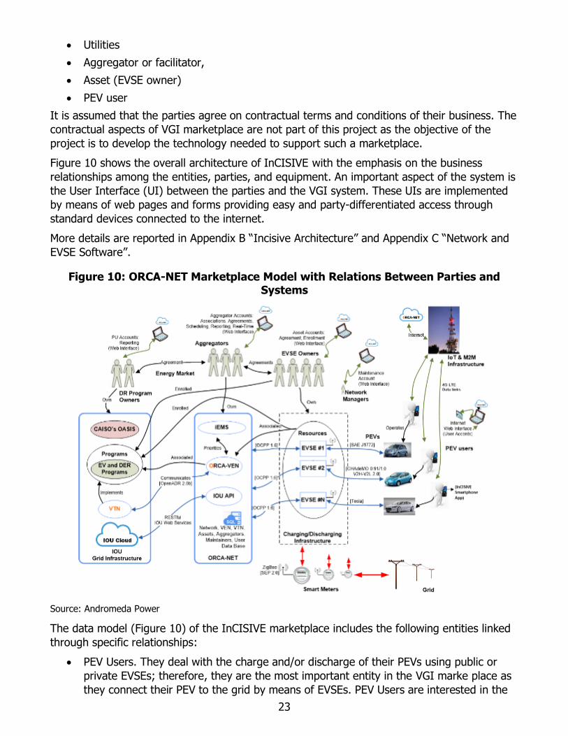
Figure 10 shows the overall architecture of InCISIVE with the emphasis on the business
relationships among the entities, parties, and equipment. An important aspect of the system is
the User Interface (UI) between the parties and the VGI system. These UIs are implemented
by means of web pages and forms providing easy and party-differentiated access through
standard devices connected to the internet.
More details are reported in Appendix B “Incisive Architecture” and Appendix C “Network and
EVSE Software”.
Figure 10: ORCA-NET Marketplace Model with Relations Between Parties and Systems
Source: Andromeda Power
The data model (Figure 10) of the InCISIVE marketplace includes the following entities linked
through specific relationships:
• PEV Users. They deal with the charge and/or discharge of their PEVs using public or
private EVSEs; therefore, they are the most important entity in the VGI marke place as
they connect their PEV to the grid by means of EVSEs. PEV Users are interested in the
24
geographical availability of EVSEs, as well as the cost/benefit of charging/discharging,
payment options, and benefits obtained through participation in ADR events of power
curtailment or distributed resource. PEV users are also users of EVSEs. When EVSE are
networked or managed as a business, PEV users might be interested in gaining benefits
provided by affiliations with the EVSE networks by applying for network memberships.
Consequently, they might also be interested in having access to a personal online
account of the EVSE network where they can monitor their balance and other details of
the EVSE usage, such as the charging/discharging sessions, date and time, location,
electricity charged/discharged, cost (paid or prepaid), membership benefits, and
network promotions, etc.
• EVSE Owners (or Asset Party). They can be owners of EVSE managed for private use
(i.e. a PEV charger/discharger installed in a private garage) or managed for business
purposes. In both cases, the EVSE Owners might be interested in gaining benefits from
utilities participating in ADR programs enabling their EVSE to communicate with the
utility and activating a business agreement with an aggregator that manages multiple
EVSEs and multiple networks of EVSEs as a whole load/resource with the utility IOU. To
increase profitability of their investments, owners of EVSEs can connect them into
networks and offer network memberships to PEV users. ORCA-NET manages EVSE
networks through web shops instantiated in the Andromeda Power’s web store. EVSE
owners can create their network by opening a web shop and linking it to their EVSE
network. Once the network is created, the web shop becomes the web interface for the
PEV users providing them online access to their network account and marketplace.
• PEV User Smartphone. PEV charging/discharging sessions can be of long duration and
often the PEV Users may want to walk away from the EVSE while maintaining
awareness of the charging and/or discharging status of the PEV. This feature is
provided through ORCA-NET by means of mirroring the EVSE display in a smartphone
app through the Internet. If the PEV User is affiliated with a network, the smartphone
app provides access to the network account and setting, including Opt In/Out to ADR
events, required charge completion time, and Target State Of Charge (SOC).
• EVSE. Depending on the equipment model, the EVSE can be a fast or a slow charger
with discharging capability. If connected to the grid through a smart meter, the EVSE
mirrors in the ORCA-NET cloud the quasi real-time information acquired from the smart
meter. Communication between EVSE and the ORCA-NET cloud is through OCCP. EVSE
can be enabled by their owners to participate in ADR events providing economic
benefits. After a business agreement between an EVSE Owner and an Aggregator is
reached, the ADR communication between an electric utility and EVSE is activated in
ORCA-NET by an exchange of public keys that are inserted by the asset and the
aggregator in their accounts.
• Aggregator/Facilitator. They deal with the electric utility aggregating multiple EVSEs into
a single Resource enrolled into the DR Programs. The electric utility does not have
access to the individual EVSE the Aggregator/Facilitator is managing.
Aggregator/Facilitator have control of the Resources through their accounts where they
can link each EVSE to an electric utility serving the territory where the specified EVSE is
installed. ADR events can target specific subsets of Resources, for example only EVSEs
connected to the grid in specific geographic areas. This selective targeting is
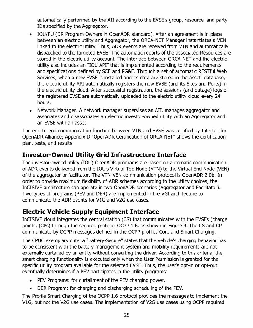
25
automatically performed by the AII according to the EVSE’s group, resource, and party
IDs specified by the Aggregator.
• IOU/PU (DR Program Owners in OpenADR standard). After an agreement is in place
between an electric utility and Aggregator, the ORCA-NET Manager instantiates a VEN
linked to the electric utility. Thus, ADR events are received from VTN and automatically
dispatched to the targeted EVSE. The automatic reports of the associated Resources are
stored in the electric utility account. The interface between ORCA-NET and the electric
utility also includes an “IOU API” that is implemented according to the requirements
and specifications defined by SCE and PG&E. Through a set of automatic RESTful Web
Services, when a new EVSE is installed and its data are stored in the Asset database,
the electric utility API automatically registers the new EVSE (and its Sites and Ports) in
the electric utility cloud. After successful registration, the sessions (and outage) logs of
the registered EVSE are automatically uploaded to the electric utility cloud every 24
hours.
• Network Manager. A network manager supervises an AII, manages aggregator and
associates and disassociates an electric investor-owned utility with an Aggregator and
an EVSE with an asset.
The end-to-end communication function between VTN and EVSE was certified by Intertek for
OpenADR Alliance; Appendix D "OpenADR Certification of ORCA-NET" shows the certification
plan, tests, and results.
Investor-Owned Utility Grid Infrastructure Interface The investor-owned utility (IOU) OpenADR programs are based on automatic communication
of ADR events delivered from the IOU’s Virtual Top Node (VTN) to the Virtual End Node (VEN)
of the aggregator or facilitator. The VTN-VEN communication protocol is OpenADR 2.0b. In
order to provide maximum flexibility of ADR schemes according to the utility choices, the
InCISIVE architecture can operate in two OpenADR scenarios (Aggregator and Facilitator).
Two types of programs (PEV and DER) are implemented in the VGI architecture to
communicate the ADR events for V1G and V2G use cases.
Electric Vehicle Supply Equipment Interface InCISIVE cloud integrates the central station (CS) that communicates with the EVSEs (charge
points, (CPs) through the secured protocol OCPP 1.6, as shown in Figure 9. The CS and CP
communicate by OCPP messages defined in the OCPP profiles Core and Smart Charging.
The CPUC exemplary criteria “Battery-Secure” states that the vehicle’s charging behavior has
to be consistent with the battery management system and mobility requirements are not
externally curtailed by an entity without consulting the driver. According to this criteria, the
smart charging functionality is executed only when the User Permission is granted for the
specific utility program available for the selected EVSE. Thus, the user’s opt-in or opt-out
eventually determines if a PEV participates in the utility programs:
• PEV Programs: for curtailment of the PEV charging power.
• DER Program: for charging and discharging scheduling of the PEV.
The Profile Smart Charging of the OCPP 1.6 protocol provides the messages to implement the
V1G, but not the V2G use cases. The implementation of V2G use cases using OCPP required

26
further technical discussion with the Open Charge Alliance (OCA). The discussion led to the
extension of the OCPP profile from Smart Charging to Smart Charging and Discharging.
A short technical description of how the VGI use cases are implemented in the EVSE system
using the OCPP 1.6, SAE J1772, CHAdeMO, and DIN 70121- ISO 15118 protocols is described
below. Additional details are included in Appendix E “Grid-to-EVSE Communication.”
Figure 11: Open Charge Point Protocol 1.6 Session Schedule: Authorize, Start, and Stop Messages
Source: OPEN CHARGE ALLIANCE
Electric Vehicle Supply Equipment Session Messages (Open Charge Point
Protocol Core Profile)
The general view of the operations between CP and CS is shown in Figure 11 with the OCPP
1.6 messages. A Charging and/or Discharging Session begins with an authorization request
from the PEV User, then continues with the start of the PEV charging/discharging, and
concludes with the stop transaction.
The CS Energy Management System uses real time data measured by the electricity meters
embedded in the EVSE ports. Figure 12 shows the OCPP method to transfer meter data from
CP to CS. The CP periodically sends MeterValues.req message to the CS. The message
frequency (one every 15 minutes) is configured using the ChangeConfiguration.req OCPP
Action specifying data acquisition intervals and data to be reported.
Figure 12: Open Chart Point Protocol 1.6 Session Schedule: Meter Values Message
Source: OPEN CHARGE ALLIANCE

27
Central Smart Charging and Discharging (Open Charge Point Protocol Smart Charging Profile)
Figure 13 shows the possible topologies of Central Smart Charging defined in the OCPP 1.6
standard. The Charging/Discharging Schedule, per transaction, are determined by the energy
management system in the CS.
Figure 13: Open Charge Point Protocol 1.6: Central Smart Charging Topology
Source: OPEN CHARGE ALLIANCE
The OCPP protocol specifies how to manage curtailment (V1G Use Case) using charging
schedule messages, however it does not define how to manage the PEV Discharging (needed
for V2G Use Case). To solve this matter the research team engaged with Robert de Leeuw,
Chair of the Open Charge Alliance Technology Working Group and responsible for the
development of the OCPP protocol. It was established that the charging schedule OCPP
message can also contain negative values meaning discharging. Thus, a charging schedule
message must be considered a Charging/Discharging Schedule when it contains positive and
negative curtailment data.
The energy management system (EMS) is logically located (see Figure 9) between the
aggregator infrastructure and the CS. Its task is to automatically build Charging/Discharging
Schedule messages to follow the DR events. According to PEV User preferences, the EMS
fetches DR events from the VEN database targeting the EVSE. The event can be active or
pending at the time of the query, in both cases the EMS calculates the Charging/Discharging
Schedule that the CS sends to the EVSE when a PEV is connected.
PEV Interfaces The OCPP Smart Charging/Discharging mechanisms in Appendix E are implemented in the
EVSE to communicate with the PEV and control its charging/discharging power. After user
authorization, the EVSE receives from the CS the updated Charging/Discharging Schedule for
the specific port of the EVSE connected to the PEV. The schedule defines the VGI Use Case
with limits of maximum charging and discharging currents versus time. These limits are
communicated to the PEV before the charging/discharging session starts and a
StartTransaction.req OCPP action is sent to the CS.
The specific EVSE-PEV communication and control signals depend on VGI Use Case and PEV
connector/standard:

28
• V1G Level 2 (AC, 7.2 kW, SAE J1772): the EVSE uses the Control Pilot PWM to
communicate to the PEV the maximum charging current available as defined by the
charging profile.
• V1G Level 3 (DC, 50 kW, CHAdeMO): the EVSE uses the dynamic control message
“Available output current" (H'108.3) to communicate to the PEV the maximum charging
current available as defined by the charging profile.
• V2G Level 3 (DC, 50 kW, CHAdeMO): the EVSE uses the dynamic control messages:
o “Available output current" (H'108.3) to instruct the PEV of the maximum
charging current available as defined by the charging profile.
o “Maximum discharge current” (H'200.0), sent from the PEV every 100 ms for
battery protection, to limit the discharging profile based on the state of charge of
the PEV.
• V1G Level 3 (DC, 50 kW, DIN 70121- ISO 15118): the EVSE uses the dynamic control
message "Current Demand Response" wherein are contained the limits that are set by
OCPP in the Charging Profile. The limits are specified by the maximum voltage, current,
and power the EVSE can deliver.
While charging/discharging session is in progress, the EVSE adapts the maximum current and
power according to the charging/discharging profile. Further, at any point in time, the CS may
send a new profile for the EVSE that imposes an updated charging schedule for the PEV.
InCISIVE Energy Management System EVSEs can be installed in Facilities or Homes where other loads are also connected to the grid
through a smart meter that provides real time measurements of electrical power consumption.
The InCISIVE energy management system (iEMS) algorithm controls in real time the electricity
flows in the Facility/Home microgrid collecting critical information such as power consumption,
user preferences and determining the optimal charging/discharging scheduling of the PEVs.
The goals of the iEMS algorithm are:
• To avoid demand limit penalties. The maximum demand (kW) is the power consumed
over a predetermined period of time, which is usually between 8 and 30 minutes (15
minutes in California). This power is calculated and billed by a smart meter, which
records the peak power in every quarter hour period, over a month’s time. The iEMS
must control the power consumed from the grid so that it never exceeds the contracted
maximum power limit and thus penalty fees are avoided.
• To guarantee driver’s mobility and simplicity of user interface to maximize DR
participation. The PEV user interface allows the user to define the mobility needs in
terms of when the PEV is supposed to be charged and the desired state of charge. The
iEMS must manage the electricity flows in such a way the PEV reaches the target SOC
at the specified time.
Depending on driver needs, microgrid load, and utility events, not all goals can be reached at
all times, thus a priority must be defined. Applying the CPUC exemplary criteria, goal A has
higher priority than B, thus protecting the grid from stress and avoiding the need for imposing
demand penalties.

29
In order to reach the iEMS goals a minimum set of functions to coordinate the microgrid
ecosystem is needed. This set can be obtained by combining two smart inverter functions
defined by Smart Inverter Working Group (SIWG) in Phase 3 DER Recommendations and
illustrated in Figure 14:
• Peak Power Limiting Function
• Coordinated Charge/Discharge Management Function
Figure 14: iEMS Peak Power Limiting and Coordination of the Charge/Discharge Management
Source: Smart Inverter Working Group
These functions use a set of parameters that are inputted by the aggregator in ORCA-NET that
also monitors the operation of the microgrid in real time by means of Web Interfaces.
The iEMS is structured in two software modules: the Central Station iEMS and the charge point
iEMS located in cloud and in the EVSE. The first module is a centralized control system that
builds Charging/Discharging Schedules for the EVSEs according to DR events and targets, and
user preferences. The schedules are sent from the CS to the CP iEMS to control the microgrid
load and sources as shown in Figure 15.
Both the loads and the EVSEs are behind the same smart meter and a discharging PEV can
electrically compensate for peak overloads so that the demand limit is not exceeded. To achieve
these goals, the iEMS schedules the EVSE loads according to the Charging/Discharging
Schedules and controlling in closed loop with the smart meter the microgrid loads, chargers, and
dischargers.
As shown in Figure 15 the CP iEMS has six input variables updated every second as a new
measure of power at the reference point (Smart Meter) becomes available. The two outputs of
the CP iEMS are: (1) the V1G and V2G Composite charging schedules controlling charging and
discharging of the PEVs, and (2) the Load Shedding turning On/Off the loads. In order to control
and schedule the V1G and V2G sessions, the CP iEMS calculates in real time two internal state
variables: (a) Charge Slack Time of the PEVs, and (b) the Power Error signal e(t).
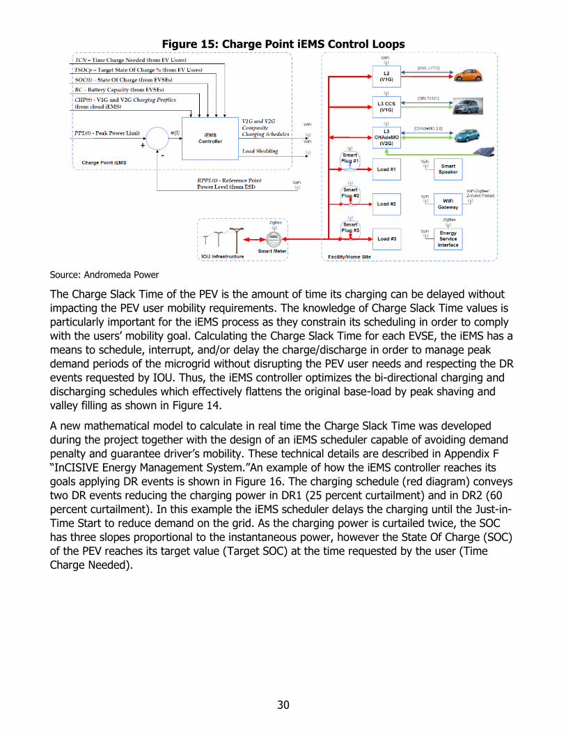
30
Figure 15: Charge Point iEMS Control Loops
Source: Andromeda Power
The Charge Slack Time of the PEV is the amount of time its charging can be delayed without
impacting the PEV user mobility requirements. The knowledge of Charge Slack Time values is
particularly important for the iEMS process as they constrain its scheduling in order to comply
with the users’ mobility goal. Calculating the Charge Slack Time for each EVSE, the iEMS has a
means to schedule, interrupt, and/or delay the charge/discharge in order to manage peak
demand periods of the microgrid without disrupting the PEV user needs and respecting the DR
events requested by IOU. Thus, the iEMS controller optimizes the bi-directional charging and
discharging schedules which effectively flattens the original base-load by peak shaving and
valley filling as shown in Figure 14.
A new mathematical model to calculate in real time the Charge Slack Time was developed
during the project together with the design of an iEMS scheduler capable of avoiding demand
penalty and guarantee driver’s mobility. These technical details are described in Appendix F
“InCISIVE Energy Management System.”An example of how the iEMS controller reaches its
goals applying DR events is shown in Figure 16. The charging schedule (red diagram) conveys
two DR events reducing the charging power in DR1 (25 percent curtailment) and in DR2 (60
percent curtailment). In this example the iEMS scheduler delays the charging until the Just-in-
Time Start to reduce demand on the grid. As the charging power is curtailed twice, the SOC
has three slopes proportional to the instantaneous power, however the State Of Charge (SOC)
of the PEV reaches its target value (Target SOC) at the time requested by the user (Time
Charge Needed).
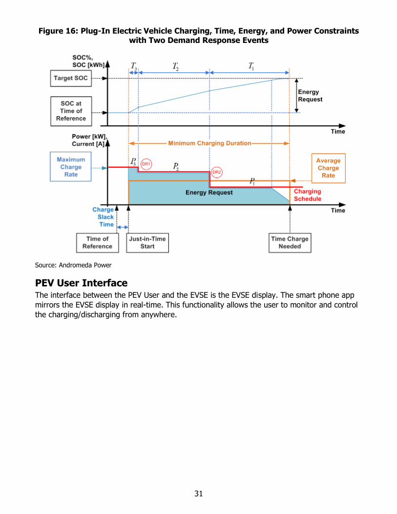
31
Figure 16: Plug-In Electric Vehicle Charging, Time, Energy, and Power Constraints with Two Demand Response Events
Source: Andromeda Power
PEV User Interface The interface between the PEV User and the EVSE is the EVSE display. The smart phone app
mirrors the EVSE display in real-time. This functionality allows the user to monitor and control
the charging/discharging from anywhere.

32
Figure 17: Plug-In Electric Vehicle User Interface - Control Console
Source: Andromeda Power
The functionality of the smartphone app is designed according to JSAE 2836/5 logic, as shown
in Appendix A. The user must have an active account in the ORCA-NET network to login,
monitor, and operate the EVSE from the app:
• Control Console
• Settings
The control of the EVSE is with two buttons:
• Start button (red). Once the PEV is plugged in, the Status banner shows the message
“Connected” and the Start button becomes available (bright red color). Pushing this
button, the EVSE begins the PEV charge mode. If the PEV user does not push Start
within 60 seconds after connecting the PEV, the PEV must be unplugged and plugged in
again in order to reset the Start function. Once the PEV charging begins the Start
button turns to dark red and is inoperable.
• Stop button (green). Once the Start button is pushed and the PEV charging begins, the
Stop button becomes active turning its color from dark to bright green. The user can

33
stop the PEV charging at any time pushing the Stop button. Within a few seconds the
communication between EVSE and PEV ends the charging session and the PEV may be
unplugged.
A complete description of the PEV user Smartphone Interface is reported in Appendix G “PEV
user Smartphone Interface”.
ORCA-NET Party Interfaces The Aggregator and Facilitator Scenarios specify four categories of parties participating in the
VGI marketplace with different roles: electric utilities, aggregators, asset (EVSE owners), and
PEV users. An additional category is Network Managers for the administration of an EVSE
Network in the ORCA-NET. In order to operate in the marketplace, these parties must have
access to ORCA-NET with privileges and operability depending on their role. ORCA-NET
implements an identity-based security system to control access through its Identity and Access
Management (IAM). When a party logs onto ORCA-NET, the IAM authenticates the party,
identifying its category, then enables access to specific features available by Web Interfaces.
Network Manager Interface A Network Manager is the administrator of an AII system, has access to the AII configuration
tools thru a Superuser account to:
• Set up Aggregator and Asset parties accounts.
• Configure the AII system
The AII configuration includes the definition and association of parties and equipment records
in the ORCA-NET database. The network manager configures the AII through the following DR
Setting Web Forms to:
• Set up a VTN record to associate a VEN to establish OpenADR communication (see
Appendix E).
• Set up an aggregator record to establish the association between the EVSE and the
aggregator (see Appendix E).
• Set up a VEN record, associate a VEN with a VTN, and associate an aggregator record
with one (or more) VEN record(s) (see Appendix E).
• Associate a Resource (EVSE) to an asset account (see Appendix E).
ORCA-NET Asset and Aggregator Interfaces In order to create an open ecosystem capable of aggregating assets without middleman
through direct and free interaction between utilities, aggregators, and asset parties, ORCA-
NET was developed as Software as a Service (SaaS).
The ORCA-NET infrastructure provides the following features to the asset and aggregator
parties through Web Forms:
• To the asset party (see Web Form in Appendix E):
o Association of an EVSE to an aggregator
o Enrollment of an EVSE in DR/DER programs.
• To the aggregator party (see Web Form in Appendix E):

34
o Association of an EVSE to a VEN
o Association of an EVSE to the OpenADR event targets.
These key features enable the EVSE Owners and the Aggregators to operate in the DR
marketplace without a “network middleman”, aggregating and connecting EVSEs to PUs/IOUs.
The association between an EVSE and an aggregator is initiated by the aggregator and asset
parties exchanging two public keys (“Aggregator Key” and “EVSE Key”) inserted by the parties
into two forms available in their accounts:
• Aggregator and asset parties exchange the public keys.
• Using the Web Form in Appendix E, the asset party associates the aggregator key with
an EVSE. The EVSE is automatically added to the EVSE list of the aggregator.
• Using the Web Form in Appendix E, the aggregator party completes the association
tagging the new EVSE with the asset key, linking it to a VEN and specifying its
OpenADR target values.
Once the Association is completed, DR events targeting the EVSEs automatically modify their
Charging/Discharging schedules.
Vehicle-Grid Integration Prototype The schematic of the VGI prototype is shown in Figure 18. It includes:
• Three VTNs instantiated on three cloud systems
• One ORCA-NET instantiated on one cloud system
• Aggregator, asset, and PEV user accounts in ORCA-NET
• One V1G EVSE Level 2 AC Charger (SAE J1772)
• One V2G EVSE Level 3 DC Charger/Discharger (CHAdeMO)

35
Figure 18: Vehicle-Grid Integration Prototype Schematic
Source: Andromeda Power
The AC microgrid connects the V1G and V2G EVSEs with the smart meter. The three VTNs
send DR events to VENs instantiated in the ORCA-NET and associated with the aggregator and
asset parties, and the EVSEs. The EVSEs include network adapters with specific
communication and control software for the two type of PEV standards (SAE and CHAdeMO).
The network adapter connects the charger to the central station in ORCA-NET using the OCPP
protocol via the WiFi LAN created by the 4G/LTE gateway. The users can monitor the
charging/discharging session on their smart phone connected via the Internet to the ORCA-
NET cloud.
V1G Electric Vehicle Supply Equipment: Level 2 AC Charger (SAE J1772)
Figure 19 shows the schematic of the V1G-capable Level 2 SAE EVSE with details of the
embedded “V1G SAE J1772 Network Adapter”.
Figure 20 shows the V1G EVSE prototype with views of the hardware and user interface.
The network adapter hardware includes one main processor, a micro controller with auxiliary
relays and I/O to control the EVSE. Additional sensors sample the instantaneous voltage and
current and perform the required processing to monitor the input active, reactive, and
apparent power values. The External Identification Method (EIM) is a card reader used for
user authentication. The adapter is connected to the gateway and to the display via Wi-Fi.

36
Figure 19: V1G EVSE Schematic
Source: Andromeda Power
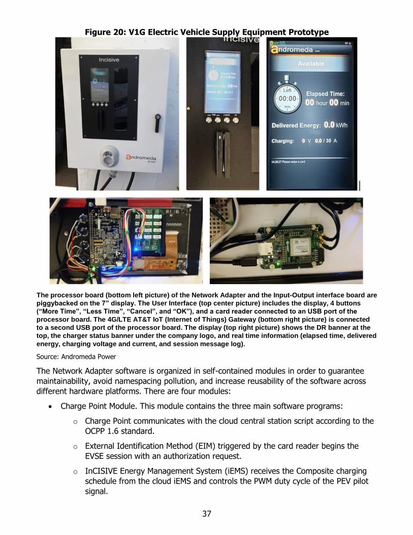
37
Figure 20: V1G Electric Vehicle Supply Equipment Prototype
The processor board (bottom left picture) of the Network Adapter and the Input-Output interface board are
piggybacked on the 7” display. The User Interface (top center picture) includes the display, 4 buttons
(“More Time”, “Less Time”, “Cancel”, and “OK”), and a card reader connected to an USB port of the
processor board. The 4G/LTE AT&T IoT (Internet of Things) Gateway (bottom right picture) is connected
to a second USB port of the processor board. The display (top right picture) shows the DR banner at the
top, the charger status banner under the company logo, and real time information (elapsed time, delivered
energy, charging voltage and current, and session message log).
Source: Andromeda Power
The Network Adapter software is organized in self-contained modules in order to guarantee
maintainability, avoid namespacing pollution, and increase reusability of the software across
different hardware platforms. There are four modules:
• Charge Point Module. This module contains the three main software programs:
o Charge Point communicates with the cloud central station script according to the
OCPP 1.6 standard.
o External Identification Method (EIM) triggered by the card reader begins the
EVSE session with an authorization request.
o InCISIVE Energy Management System (iEMS) receives the Composite charging
schedule from the cloud iEMS and controls the PWM duty cycle of the PEV pilot
signal.

38
• EVSE Schedulers Module. This module contains the Level 2 program that controls the
AC charging of the PEV using the SAE J1772 plug and signals.
• Users’ Interfaces Module. It contains two programs managing the user interface:
o User Interface includes a web server for EVSE GUI.
o Settings that manages the system settings and remote maintenance service.
The V1G EVSE operates according to the following:
1. The PEV user connects the PEV to the EVSE with the J1772 plug and swipes a valid ID
magnetic card (Credit Card or membership badge) in the card reader.
2. The External ID Method triggers the Level 2 Scheduler that requests a User
Authorization to the Central Station (in ORCA-NET cloud) using OCPP 1.6 protocol.
3. Within 3-5 seconds (depending on the communication traffic) the Central Station replies
with an Authorization or a Denial.
4. If the user is Authorized, the user is prompted on the display to select the Charging
Session Time between 15 minutes and 8 hours. If no buttons are pressed for 30
seconds, the session Authorization is considered expired and the user has to request a
new Authorization swiping again the card. Otherwise, if the user presses:
a. The “Cancel” button, the Authorization request is cancelled.
b. The “Enter” button, the Charging session is started after proper Start
authorization according to the OCPP 1.6 protocol. The charging session will
automatically terminate after the selected session time has expired.
5. The Charging/Discharging Schedule built by ORCA-NET is sent to the iEMS in the EVSE
at the Start authorization and updated during the charging session if needed.
6. During the session the display shows real time information, such as elapsed time,
voltage and current, pending or active DR events (if any) with power curtailment.
7. At any time the user can unplug the PEV terminating the charging session.
Signal Level in V1G and V2G Demand Response Events
The ORCA-NET infrastructure (see Figure 9) operates for all VGI use cases, including V1G and
V2G. The communication and processing chain between VTN and EVSE uses the same
protocols and network programs regardless of the VGI Use Case. However there is a
substantial difference in the meaning of the field Signal level sent in DR messages from the
VTN depending on the VGI Use Case.
Table 1 lists the Signal level field meanings adopted for V1G and V2G use cases.
In V1G Use Case, the charger can be controlled only as a load, curtailing its charging power in
25 percent increments from 25 percent up to 100 percent (100 percent means charging is off).
These four possible values of power curtailment are coded with the values from one to four in
the Signal Level field.
In V2G Use Case, the EVSE can operate also as source (discharging the PEV) to the
grid/microgrid and the Signal level field has eight different possible values. The additional four
values specify the percentage of power generation with respect to the maximum power

39
available from the PEV that is not a constant value, but depends on the battery state of
charge.
Table 1. Signal Level Meaning in V1G and V2G OpenADR 2.0b Demand Response Messages
DR Event
Signal Level V1G Use Case V2G Use Case
1 Power Curtailment: 25 percent Power Curtailment: 25 percent
2 Power Curtailment: 50 percent Power Curtailment: 50 percent
3 Power Curtailment: 75 percent Power Curtailment: 75 percent
4 Power Curtailment: 100 percent Power Curtailment: 100 percent
5 N/A Power Generation: 25 percent
6 N/A Power Generation: 50 percent
7 N/A Power Generation: 75 percent
8 N/A Power Generation: 100 percent
Source: Andromeda Power
V2G Electric Vehicle Supply Equipment: Level 3 DC Charger/Discharger
(CHAdeMO)
Figure 21 shows the schematic of the CHAdeMO EVSE capable of V2G use cases. The Network
Adapter hardware for V1G and V2G are identical, but with a different CHAdeMO scheduler
capable of managing OCPP Charging and Discharging Schedules of the PEV by dynamic
charging and discharging according to the CHAdeMO V2X (V. 2.1) protocol. V2X is defined as
bidirectional power flow from a PEV to an external load, or from an external source.
Table 2 provides a summary for each V2G use case and the status and functionality of the
main hardware blocks of the V2G EVSE shown in Figure 22. The AC charging path between the
grid and the PEV plug is made up of an AC/DC rectifier, an isolated DC/DC converter, and the
CHAdeMO cable and plug. The CHAdeMO cable brings the communication signals over the
CAN bus, five control signals, and the DC power over the positive and negative wires. The
discharging path is from the PEV plug to the microgrid through the Power Matrix (PM), the
isolated DC/DC converter, the Power Combiner (PC), and the smart inverter, that is a grid-tie
inverter with controllable output power.
Table 2: InCISIVE V2G Prototype: Use Cases
V2G Use Case AC/DC Power Matrix Connections
V2G-1: PEV charging from Grid (AC) ON PV to PC
PEV to DC/DC out
V2G-2: PEV charging from Solar Panels (DC) OFF PV to PC and to DC/DC in
PEV to DC/DC out
V2G-3: PEV discharging to Grid OFF PV to EC
PEV to EC
Source: Andromeda Power
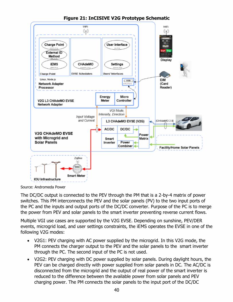
40
Figure 21: InCISIVE V2G Prototype Schematic
Source: Andromeda Power
The DC/DC output is connected to the PEV through the PM that is a 2-by-4 matrix of power
switches. This PM interconnects the PEV and the solar panels (PV) to the two input ports of
the PC and the inputs and output ports of the DC/DC converter. Purpose of the PC is to merge
the power from PEV and solar panels to the smart inverter preventing reverse current flows.
Multiple VGI use cases are supported by the V2G EVSE. Depending on sunshine, PEV/DER
events, microgrid load, and user settings constraints, the iEMS operates the EVSE in one of the
following V2G modes:
• V2G1: PEV charging with AC power supplied by the microgrid. In this V2G mode, the
PM connects the charger output to the PEV and the solar panels to the smart inverter
through the PC. The second input of the PC is not used.
• V2G2: PEV charging with DC power supplied by solar panels. During daylight hours, the
PEV can be charged directly with power supplied from solar panels in DC. The AC/DC is
disconnected from the microgrid and the output of real power of the smart inverter is
reduced to the difference between the available power from solar panels and PEV
charging power. The PM connects the solar panels to the input port of the DC/DC

41
converter of the charger and to the smart inverter through the PC. The charger output
is connected to the PEV and the second input of the PC is not used.
• V2G3: PEV discharging. During DER events or microgrid peak periods, the iEMS
discharges the PEV delivering power to the grid or to the microgrid loads. In this V2G
mode, the AC/DC is off and the DC/DC converter controls the current delivered to the
PC. The PM connects the DC/DC converter output and the solar panels to the two
inputs of the PC that merges their current power that is delivered to the microgrid
through the smart inverter.
Figure 22: V2G Electric Vehicle Supply Equipment Prototype
The top-left picture shows a laptop (serving as the Network Adapter for ORCA-NET) on a Smart Inverter
(manufactured by SMA, model SB7.7-1SP-US-40), next to a Level 3 EVSE (manufactured by Andromeda
Power, model ORCA Inceptive) power engine connected to the PEV (Nissan Leaf) thru the CHAdeMO V2X
interface (top right picture). The picture in the bottom-left shows the grid connection of the EVSE (50 kW)
and the smart inverter (10 kW) thru two high power plugs (3-phase plug for the EVSE and single phase
plug for the smart inverter). The picture in the bottom-right shows the smart inverter connections to the
EVSE and to the grid. A Wi-Fi router creates a LAN interconnecting EVSE, smart inverter, and V2X to the
Internet and to the Network Adapter software installed on the laptop.
Source: Andromeda Power

42
Vehicle-Grid Integration Testing Method The VGI Prototype was field tested according to the following method:
1. Verification of the DR connectivity from VTN to EVSE
2. Verification of VGI functionality with DR signals and execution of multiple sessions
3. Analysis of critical VGI real-time signals and lessons learned
Verification of the Demand Response Connectivity from Virtual Top Node to Electric Vehicle Supply Equipment
With reference to the VGI Architecture of Figure 9 and the VGI Prototype schematic of Figure
18, the three VTNs and the ORCA-NET cloud software were installed and run on four AWS
cloud instances.
Having logged in as administrator of ORCA-NET, the network manager created the accounts of
asset and aggregator parties, and registered the V1G and V2G EVSEs in the AII. The VTN and
VEN records were inserted in the AII database specifying the required information and
associating the VEN with the aggregator. The associations between EVSEs and aggregators
were registered using the asset and aggregator public keys. The successful completion of the
association was verified observing the EVSE display showing that “VTN Online” message in the
DR banner.
Verification of V1G Functionality with Generation of Demand Response
Signals and the Execution of Multiple Charging Sessions
A list of DR events was inserted in the VTN to test the V1G Test Prototype. The key feature of
the V1G DR events is the “signal level” coded for the V1G field tests on the four “payload
levels” (coded with the values one to four) corresponding to the four percentage values of the
charger power curtailment: 25 percent, 50 percent, 75 percent, and 100 percent, as reported
in Table 1.
The successful verification of the DR signal delivery was performed observing the behavior of
the V1G EVSE Prototype during charging sessions. Andromeda Power conducted field testing
and systematic data collection from April to December 2018.
Table 3 shows a number of PEV charging sessions, average value of the electricity delivered
per session, total electricity delivered, and number of DR events per month. Total number of
sessions is 309, total delivered electricity is 1,754.7 kWh, and total number of active DR V1G
events is 25.
Active DR events are those affecting the charging schedule of the VGI Prototype while an PEV
was connected. The successful verification of the presence of an active DR event was
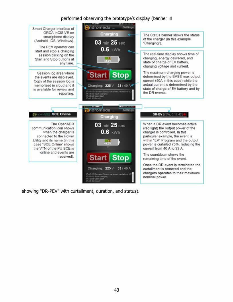
43
performed observing the prototype’s display (banner in
showing “DR-PEV” with curtailment, duration, and status).

44
Table 3: V1G Session List: Energy and Demand Response Events per Month
Month
Number of
Sessions
Average
Energy per
Session (kWh)
Total Energy
(kWh)
Number of
DR events
April 35 5.3 185.5 5
May 43 4.7 202.1 3
June 28 7.3 204.4 0
July 34 6.5 221.0 1
August 31 6.7 207.7 0
September 41 5.2 213.2 7
October 44 4.9 215.6 3
November 39 5.6 218.4 6
December 14 6.2 86.8 0
Total 309
1754.7 25
Source: Andromeda Power
The successful verification of the V1G functionality was performed by inspection of V1G
session logs reporting the actual power delivered to the PEV from the charger versus the DR
messages sent from the VTN.
Table 4 provides a complete list of messages of a specific charging session exchanged
between Central Station and V1G Test Prototype.
The charging session was authorized on 2018-04-07 at 17:46:12 UTC (message #5 in Table 4)
and started at 17:46:50 (message #6, Table 4). This particular charging session includes a
V1G Demand Response Event of Power Curtailment communicated from the VTN at 18:48:00
requesting 50 percent power reduction starting at 19:02:00 for 60 minutes (message #11,
Table 4).
Figure 23 shows the electricity measured every 15 minutes from the charger. The session
started at 17:31:12 (item 5 in Table 4) with OCPP User Authentication after the user swiped
the identification ID in the card reader of the charger. During authentication, the Central
Station updates the Charging Profile, limited to 5.3 kW.
Every 15 minutes, the charger acquired electricity and power values from its internal electricity
meter and uploaded the values to the asset database. At 18:48:00 the VTN sent a V1G DR
message to ORCA-VEN that triggered the iEMS to update the charging schedule of the
charger. The V1G DR event requested 50 percent power curtailment at 19:02:00 for 1 hour.
The power profile (Figure 23) shows that the power was successfully reduced during the
requested DR time.

45
Table 4: V1G Messages’ List
Msg
#
Time
UTC Event
Energy
Meter
(kWh)
Power
Meter
(kW)
1 17:00:00 Smart meter 15 mins 228.451 0.004
2 17:15:00 Smart meter 15 mins 228.452 0.004
3 17:30:00 Smart meter 15 mins 228.453 0.004
4 17:45:00 Smart meter 15 mins 228.454 0.004
5 17:46:12 User Authorization - -
6 17:46:50 Session Start 229.765 0.004
7 18:00:00 Smart meter 15 mins 229.779 5.298
8 18:15:00 Smart meter 15 mins 231.101 5.288
9 18:30:00 Smart meter 15 mins 232.424 5.294
10 18:45:00 Smart meter 15 mins 233.745 5.284
11 18:48:00
V1G - DR event:
Start time: 2018-04-07 19:02:00 UTC
Duration: 60 (minutes)
Response required: always
Payload value: 2 (-50 percent)
- -
12 19:00:00 Smart meter 15 mins 235.066 5.282
13 19:02:00 V1G - DR event: START - -
14 19:15:00 Smart meter 15 mins 235.787 2.515
15 19:30:00 Smart meter 15 mins 236.403 2.465
16 19:45:00 Smart meter 15 mins 237.007 2.416
17 20:00:00 Smart meter 15 mins 237.617 2.440
18 20:02:00 V1G - DR event: STOP - -
19 20:15:00 Smart meter 15 mins 238.940 5.295
20 20:30:00 Smart meter 15 mins 240.271 5.321
21 20:45:00 Smart meter 15 mins 241.596 5.300
22 21:00:00 Smart meter 15 mins 242.934 5.353
23 21:00:17 Session STOP 242.934 0.004
24 21:15:00 Smart meter 15 mins 242.935 0.004
25 21:30:00 Smart meter 15 mins 242.936 0.004
26 21:45:00 Smart meter 15 mins 242.937 0.004
Session 2018-04-07 17:46:12 UTC
Source: Andromeda Power

46
Figure 23: V1G Session Power and Energy
Session 2018-04-07 17:31:12 UTC.
Source: Andromeda Power
Test of the Asset Party control features (Demand Response Program Enabling Switches)
The Asset party can enable the EVSEs to participate in DR, PEV, and DER programs, setting
three switches in the Association Web Form accessible only from the asset’s account.
Only the DR and PEV switches operate in V1G use cases. Their functionality was successfully
verified for turning off and on the DR, enabling switches, and controlling the DR banner in the

47
EVSE display (see
). When DR was disabled, the VTN went off line and the scheduled DR events were canceled.
Test of the Aggregator Control Features (Target Filters)
In the DR marketplace, an aggregator establishes contractual agreements with chargers’
owners in order to create aggregated resources to be negotiated with electric utilities. Once a
set of aggregated resources is in place, a utility can target a specific aggregated resource
according to the grid demand by means of three target filters sent in the DR event message:
• Resource ID
• Party ID
• Group ID
DR messages are effectively controlling a specific EVSE only when their target filters match the
values assigned by the aggregator of that resource.
The target filters’ values of a charger selected by its serial number, are visible and can be
modified in the AggregatorWeb Form.

48
The proper operation of these filters was successfully verified changing their values and
observing that the DR event was canceled from the EVSE display synchronously with the
target filter modification.
Verification of V2G Functionality with Generation of Demand Response Signals and the Execution of Multiple Charging and Discharging Sessions
The V2G EVSE Prototype was tested with DR events sent with signal level values as defined in
Table 1 for the V2G Use Case. Signal level values in the range one-to-four define curtailment
percentage while values in the range five-to-eight define power generation (PEV discharging).
The V2G functionality was successfully verified by monitoring the current intensity and
direction at the PEV CHAdeMO connector. According to the signal level values sent from the
VTN to ORCA-NET, the network adapter received an OCPP charging/discharging schedule
containing positive or negative values of curtailments. Positive values effectively controlled the
EVSE charging power while negative values controlled its discharging.
The inspection of PEV current and power diagrams versus time with the DR event timing
confirmed the proper operation of the V2G EVSE (see Figure 24 and Figure 25).
Analysis of Critical Vehicle-Grid Integration Real-Time Signals and Lessons Learned
The PEV (all standards) onboard computer protects the battery from fast dynamic charging
and discharging current. This protection is necessary because high rapidly changing current
reduces the useful life of the battery. Utility 15118 and CHAdeMO standards specify a
maximum current rate of 20 A/s on the battery charging and discharging current. If this
current rate limit is exceeded, the PEV onboard computer raises an alert on the PEV dashboard
and, if this situation persists, it will disable the PEV charging/discharging port. If this event
occurs, the onboard computer of the PEV can be reset only by a dealer using specific
diagnostic tools not commercially available.
While the V1G Use Case normally deals with low power charging, the V2G Use Case controls
higher power. In the V1G EVSE, the network adapter provides a reference signal to the
onboard AC charger (PWM duty cycle of the Pilot signal as defined by SAE standard). The
reference signal follows the charging schedule according to DR events sent by the VTN and
there are no limits to its dynamic. Thus, in V1G EVSE, the onboard charger is in control of the
battery charging, limiting its current rate regardless of the dynamic of the reference input.
In the case of V2G EVSE, the intensity and rate of the charging/discharging current is
controlled by the off-board V2G EVSE. While the charging current intensity and rate are
controlled by the EVSE, the discharging current intensity and rate are controlled by the smart
inverter. The smart inverter control of the current rate may be incompatible with the given
PEV standards. The following V2G sessions exposed this issue and led to the inclusion of the
PM in the design of V2G EVSE:
1. V2G charging sessions controlled by power curtailment DR events. When the
curtailment is 100 percent, the event creates the largest dynamic charging
current/power. DR 100 percent curtailment events completely stop the charging. When
the event is completed, the charging current moves back from 0A to the maximum
charging current determined by the PEV battery’s state of charge. The current rates
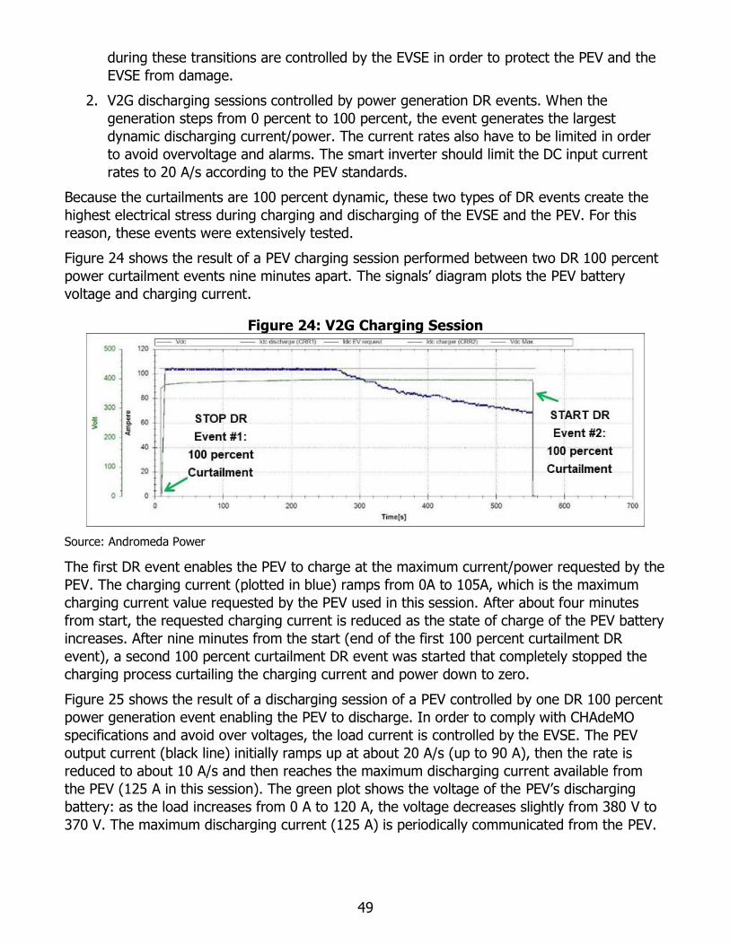
49
during these transitions are controlled by the EVSE in order to protect the PEV and the
EVSE from damage.
2. V2G discharging sessions controlled by power generation DR events. When the
generation steps from 0 percent to 100 percent, the event generates the largest
dynamic discharging current/power. The current rates also have to be limited in order
to avoid overvoltage and alarms. The smart inverter should limit the DC input current
rates to 20 A/s according to the PEV standards.
Because the curtailments are 100 percent dynamic, these two types of DR events create the
highest electrical stress during charging and discharging of the EVSE and the PEV. For this
reason, these events were extensively tested.
Figure 24 shows the result of a PEV charging session performed between two DR 100 percent
power curtailment events nine minutes apart. The signals’ diagram plots the PEV battery
voltage and charging current.
Figure 24: V2G Charging Session
Source: Andromeda Power
The first DR event enables the PEV to charge at the maximum current/power requested by the
PEV. The charging current (plotted in blue) ramps from 0A to 105A, which is the maximum
charging current value requested by the PEV used in this session. After about four minutes
from start, the requested charging current is reduced as the state of charge of the PEV battery
increases. After nine minutes from the start (end of the first 100 percent curtailment DR
event), a second 100 percent curtailment DR event was started that completely stopped the
charging process curtailing the charging current and power down to zero.
Figure 25 shows the result of a discharging session of a PEV controlled by one DR 100 percent
power generation event enabling the PEV to discharge. In order to comply with CHAdeMO
specifications and avoid over voltages, the load current is controlled by the EVSE. The PEV
output current (black line) initially ramps up at about 20 A/s (up to 90 A), then the rate is
reduced to about 10 A/s and then reaches the maximum discharging current available from
the PEV (125 A in this session). The green plot shows the voltage of the PEV’s discharging
battery: as the load increases from 0 A to 120 A, the voltage decreases slightly from 380 V to
370 V. The maximum discharging current (125 A) is periodically communicated from the PEV.

50
Figure 25: V2G Discharging Session – Current’s Transition at Start
Source: Andromeda Power
PEV standards state that the current rate should not exceed 20 A/s in charging/discharging. To
comply with this requirement the VGI EVSE design (see Figure 22) included the PM to use the
DC/DC converter as a current rate limiter.

51
CHAPTER 4: Technology/Knowledge/Market Transfer Activities
Knowledge Gained Andromeda Power and the project’s partners gained considerable knowledge from the
InCISIVE R&D project in the field of VGI technology and related services. The project
continued to refine the technologies developed by showing them to the main stakeholders
including utilities, industry, and researchers.
Additional data was collected and software and systems were modified based on data
collection, analysis, and feedback from interested parties. Consequently, the technology
transfer plan has been updated. Various VGI hardware and software technologies have been
developed, published, and discussed in publications already presented and other reports in
the course of its preparation. The VGI knowledge was used to develop a range of products
with different sets of features and market targets. These VGI products are part of the
developed VGI comprehensive architecture shown in Figure 26. To date Andromeda Power has
developed four categories of products:
1. V1G Level 2 AC charger: Two models (Charging Station CS#3 in Figure 26) capable of
demand response (DR) with network connectivity:
o InCISIVE L2 Strada (bollard mounted)
o InCISIVE L2 Zen (wall mounted)
2. V2B (bidirectional):
o InCISIVE V2B: charger/discharger integrated with smart inverter, capable of DR
controlled from the Building Management System (BMS). (Charging Station CS#1
in Figure 26)
3. V2G-DER (Vehicle-to-Grid integrated with Distributed Energy Resource):
o InCISIVE iV2G-DER: charger/discharger integrated with smart inverter and PV
capable of DR SEP 2.0 communication and Advanced V2G Modes according to
Rule 21 (Charging Station CS#1 in Figure 26)
4. VGI Building Management System:
o InCISIVE Building Management System (block iBMS in Figure 26) with EMS and
all-DR protocols Gateway (OpenADR 2.0b, OCPP 2.0, SEP 2.0)

52
Figure 26: InCISIVE Vehicle-Grid Integration Technology Overall Architecture
Source: Andromeda Power
Vehicle-Grid Integration State-of-the-Art and Decisions Relative to Market Constraints The R&D projects' activities made the following conclusions on VGI state-of-the-art and market
constraints:
• There is no standard supporting all VGI use cues.
• Electric utilities have programs and plans for V1G use cases, but not V2G.
• Large investor-owned utilities have plans to expand electric vehicle infrastructure and
rebate programs for V1G.
• There is a market interest for V2B use case products to avoid demand fees.
Because of the above VGI conclusions, the current project effort focused on the V1G and V2B
products, but not V2G yet.

53
Figure 27: Second Generation of InCISIVE L2 Products
Strada and Zen: InCISIVE L2 chargers capable of Demand Response. Strada can be equipped with
retractable cord. Up to four chargers can be mounted on the same pole. Zen is wall mounted.
Source: Andromeda Power
In 2018 the V1G products InCISIVE L2 Strada and Zen with ORCA-NET were validated and
technically qualified by two major electric utilities (PG&E and NYSERDA) and posted on their
websites in February and July 2018, respectively.
In response to market demands, the company’s team is developing a low-cost second
generation of the V1G InCISIVE L2 products to meet market requirements and an extended
set of features:
• Energy Star
• Retractable cable and multiple chargers mounted on the same pole (up to four)
• LED display 7"
• RF/ID for payment and authorization, IoT 4G/LTE+ gateway

54
Figure 27 shows the second generation InCISIVE Level 2 chargers. To reduce manufacturing
costs, the second generation design uses plastic and aluminum parts instead of sheet metal
technology used in the original design. New manufacturing technologies allow the reduction of
the enclosure unit cost for production in volume.
The Incisive V2B product is under development and its current design is shown in Figure 28.
Figure 28: InCISIVE V2B Product Design
The internal view of InCISIVE V2B design shows the 50-kW charger/discharger (ORCA Inceptive
manufactured by Andromeda Power) and a smart inverter (manufactured by SMA).
Source: Andromeda Power
Technology/Knowledge Transfer Activities To provide the new information, knowledge, and expertise developed in the InCISIVE project
to the broader society, Andromeda Power performed the following activities (complete list is in
Appendix H):
• Preparation of three press releases announcing Andromeda Power’s addition of demand
response-capable EVSEs
• Preparation of VGI technology qualification announcements for inclusion on electric
utility websites
• Preparation of showcase announcements for inclusion on Energy Commission website
• Preparation of technical posters and papers on the technology
• Preparation and publication of datasheets on Andromeda Power websites
• Preparation and publication of social media announcements
• Preparation and submission of public comments on VGI Energy Commission projects
55
CHAPTER 5: Conclusions and Recommendations
Andromeda Power's research team has successfully developed and demonstrated an advanced
smart grid VGI technology to achieve the goals of the project:
• Developed an advanced smart grid communication interface
• Developed a method to integrate PEVs of any standard into the power grid
• Controlled PEV charging/discharging through ADR signals
The developed and demonstrated VGI prototype, capable of operating V1G and V2G use
cases, includes:
• Communication infrastructure with interfaces for all the VGI parties: electric utilities,
aggregator, asset, PEV user, and network manager
• V1G and V2G EVSEs
The developed and demonstrated VGI prototype includes a communication infrastructure with
interfaces for all the VGI parties and an EVSE prototype capable of operating V1G and V2G use
cases.
The InCISIVE project achieved its goals of proving the feasibility of PEV integration into the
grid and charging/discharging them through ADR signals according to the eight VGI use cases,
as defined by CPUC and the California ISO roadmap.
Obstacle Encountered The research identified and addressed four unmet VGI technology needs and gaps dealing
with:
1. PEV connectors. Incompatibility of PEV-to-EVSE connectors and standards. Currently
PEVs use various connectors and standards, the main ones being SAE J1772 (Level 2
mounted on all PEVs), CCS (Level 3 mounted on PEVs manufactured in United States
and the European Union) and CHAdeMO (Level 3 mounted on Japanese PEVs). This
incompatibility creates the need for an EVSE with multiple PEV connectors.
2. Dealing with multiple potential protocols and architectures for EVSE-to-utility
communication. The grid has to be capable of automatic communication and control of
the EVSE and PEV to effectively implement V1G and V2G, as well as controlling and
monitoring the electricity flows according to PEV users’ preferences. The communication
infrastructure should provide access to all parties, such as EVSE hosts and aggregators,
PEV users, and PU operators, by establishing a framework for a marketplace able to
satisfy electricity demand. The VGI infrastructure should use a common set of protocols
and standards (collectively called here “VGI-Standard”) to provide effective
interoperability and to enhance the user charging experience; however, interim
conclusions on VGI state-of-the-art show that there is no VGI-Standard supporting all
VGI use cases.
3. Inconsistencies within VGI protocols. Inconsistencies exist within and without VGI
protocols. See "Recommendations" below.

56
4. Dealing with multiple utility choices of protocols and architectures. Electric utilities have
different programs for the V1G Use Case (but not V2G) specifying their own selection of
features within the same protocol.
Project Outcomes
• VGI comprehensive system architecture. The project activities lead to a comprehensive
system architecture design as a potential solution addressing all the above gaps,
proving that the technology and the standards are ready for the V1G and the V2G use
cases. The lack of a VGI standard was overcome by the adoption of a set of
communication protocols and the definition of a comprehensive VGI architecture. This
architecture enables VGI resources to participate in the electricity markets, benefitting
the ratepayers on a large scale. The RD&D activities also lead to the identification of
conflicting hardware control signals between Rule 21 and ISO 15118 protocol. See
"Recommendations" section below.
• VGI prototype. InCISIVE technology was developed, implemented, tested, and validated
in a prototype test bed capable of V1G and V2G. Extensive data were collected
demonstrating the validity of the system performance.
• V1G product. As utilities have programs and plans for EVSE capable of V1G, but not
V2G, the technology was advanced by introducing two V1G EVSE products: Strada and
Zen. These products were qualified in 2018 with PG&E for the PEV Charge Network
Program and with NYSERDA for the Charge Ready Program.
Lessons Learned A key lesson learned from this project is that a V2G-DER system that deals with solar
generation and PEV charging and discharging would enable distributed generation and
storage. Such a V2G-DER system would benefit the grid and the microgrid. To this end,
additional R&D is still necessary to finalize the development of an energy management system
capable of integrating PEVs with distributed resources and controlled by Rule 21 to participate
in DER programs. This additional research would lead to establishing a new family of products,
V2G-DER capable, of interconnecting solar panels, smart inverters, and PEVs with the local
microgrid and with the grid.
Recommendations to Solve and Avoid Inconsistencies Within and Across Vehicle-Grid Integration Protocols
• Rule 21 Coordinated Charge/Discharge Management Function can be used for V2G.
However, its Ramp Time (in seconds), should not be controlled by this Rule 21 Function
because Ramp Time is already controlled (limited) by the EVSE and the onboard battery
management system of the PEV to preserve the battery lifetime (as specified by
ISO/IEC 15118-2 and CHAdeMO standards).
• ISO/IEC 15118-2 edition 2 (not available yet). To implement V2G cases with CCS PEVs,
the standard should:
o Include dynamic charging and discharging (similar to CHAdeMO 2.0, V2X).
o Defer the ramp time control to the EVSE and not to the PEV (as in the current
standard edition). EVSE must be free to modify current direction and intensity in
real time in order to accommodate the instantaneous changes in solar and wind

57
power, as well as DR signals. Without this provision it will not be possible to
implement DR with quick response time (seconds instead of minutes).
• OCPP 2.0 formalizes new OCPP messages to deliver DR signals and events from the
central station (cloud) to the smart inverter embedded into the charge point (EVSE).
OCPP 2.0 message set should include the transport of SEP 2.0b (IEEE 2030.5)
messages. This inclusion would enable smart inverters to be used within charging
stations for V2G use cases and be managed by OCPP 2.0 according to SIWG
recommendations. This recommendation was sent to OCA in March 2017.
• OpenADR: VEN interoperability between different electric utilities. Different electric
utilities can implement similar plans and programs using different OpenADR
events/messages and signal levels. It is essential that the OpenADR Alliance provide a
set of “reference events” applicable for the basic electric utility programs, i.e. V1G
Power Curtailment, etc.
• OpenADR Alliance defines a new PEV-DER Program for a V2G-DER Use Case,
bidirectional EVSE with solar panels and smart inverter. Currently, the standard requires
the use of two programs: PEV and DER. The use of two programs could lead to
inconsistency of operation. A new OpenADR PEV-DER program for bidirectional
electricity resources is recommended (that would be applicable to EVSE-PEV-PV as
electricity generation and storage).
58
CHAPTER 6: Benefits to Ratepayers
Clean and renewable distributed electricity generation from solar and wind has become more
economical than generation from traditional centralized fossil-fuel electricity generators.
However, electricity from renewable resources depends on natural events that cannot be
controlled. Generation is intermittent, thus part of the generated electricity must be stored to
be used on demand when needed. In the last ten years, battery technology evolution has
stimulated a rapid expansion of PEVs, which reduce environmental impact. Consequently, PEV
charging stations create additional point demand and stress on the grid. The challenge of
connecting PEVs to the grid and nearby renewable resources while communicating with the
electric distribution system is an opportunity to evolve the grid toward a network of Vehicle-
Grid Integrated Distributed Energy Resources (VGI-DER) where the PEV battery can be used
not only for traction, but also as a renewable electricity storage resource. Smart charging and
discharging of PEVs can reduce fluctuations on the grid while benefiting PEV owners and the
environment.
Vehicle-Grid Integration Reduces Production Cost for Electricity in California The V1G Use Case reduces grid load in periods of high demand. The V2G and V2B use cases
store low-priced renewable resources in PEVs that can be delivered to the grid, or to a
building, during the high demand period (late afternoon) instead of generating electricity from
natural gas peakers. Considering one charge and discharge cycle per day of a common PEV
equipped with a 50 kWh battery, the electricity shift results in savings of 18.25 MWh/year (50
kWh x 365) and cost savings for California and its ratepayers of approximately $3,102 per
PEV per year (based on the electric statewide average price of $0.17/kWh reported by the
Energy Commission’s Energy Research and Development Division calculations).
Ratepayers Save Millions of Dollars in Fuel Using Vehicle-Grid Integration According to the official United States government source for fuel economy information, PEVs
convert between about 59 percent to 62 percent of the electricity from the grid to power at
the wheels.1 Conventional gasoline vehicles only convert about 17 percent to 21 percent of the
electricity stored in gasoline to power at the wheels. Thus, driving PEVs instead of
conventional gas-fueled vehicles, the electricity efficiency gain is 41.5 percent, on average. For
each kWh delivered from VGI to PEVs, California saves 0.41 kWh of that would otherwise be
wasted in gasoline (about $0.35 per gasoline gallon).
1 https://www.fueleconomy.gov/feg/evtech.shtml

59
Vehicle-Grid Integration Technology Reduces Carbon Dioxide Emissions The VGI technology can provide electricity for both buildings and the grid during periods of
peak demand. These systems would supply power in place of peakers (typically turbine
burning natural gas) that generally run only at times of high demand. Using V2G, or V2B, one
charging and discharging cycle per day of one PEV battery (50 kWh/day, 18.25 MWh/year)
prevents greenhouse gas emissions from peakers in the same amount sequestered by 15.2
acres of United States forests, equivalent to 12.9 metric tons per year (www.epa.gov).
Vehicle-Grid Integration Reduces the Cost of Energy Storage for Power Utilities Electric utilities can avoid grid overload, improve reliability, avoid electricity storage
purchasing, lower maintenance and reduce the risk of wildfire, by using VGI technology to
store electricity. The VGI technologies react to DR signals from the utilities, smoothing the grid
load. Improved grid reliability is achieved by VGI discharging electricity from the PEV battery
into the microgrid or into the grid in response to local or remote electricity management
systems. The VGI system mitigates the problem of intermittent generation from renewable
resources by storing electricity during periods of solar or wind generation and releasing that
stored electricity on demand. Reducing the electricity fluctuations on the grid, thus absorbing
and time-shifting excessive electricity generation, VGI increases grid reliability while benefiting
PEV owners. VGI products permit utilities to obtain electricity storage without paying for the
storage batteries and their operation. Connecting PEVs to the grid and nearby renewable
resources is an opportunity to transition the grid into a network of iVGI systems operating as
DER where the PEV battery is used as electricity storage while preserving the PEV's primary
traction functionality. Using the PEV battery owned by the end-user, electric utilities do not
need to purchase batteries or other means of storing electricity.
Vehicle-Grid Integration Enables Off-Grid Application Without
Purchasing Batteries The storage in PEV battery of electricity generated by solar panels (more in general from any
renewable resource) enables off-grid application of the V2G Use Case.
iVGI-DC Increases the Available Power in the Microgrid The superposition of PEV battery power and power provided by the grid results in greater
power availability at the microgrid. This surplus of power is useful in situations of peak
demand, to avoid grid overload or the need for peakers.

60
GLOSSARY AND LIST OF ACRONYMS
Term Definition
ADR Automated Demand Response.
AMI
Advanced Metering Infrastructure: systems that measure, collect, and analyze electricity usage, and communicate with metering
devices such as electricity meters, gas meters, heat meters, and water meters, either on request or on a schedule.
AMI Amazon Machine Image
AWS Amazon Web Server
BEV Battery Electric Vehicle: a type of electric vehicle that uses chemical electricity stored in rechargeable battery packs.
CAN
Controller Area Network: a vehicle bus standard designed to allow
microcontrollers and devices to communicate with each other in applications without a host computer.
CCSE California Center for Sustainable Energy.
CEC California Energy Commission.
Charging Schedule An OCPP definition, part of a charging profile. Defines a block of charging power or current limits. Can contain a start time and
length.
Charging Session An OCPP definition. Part of a transaction during which the PEV is allowed to request electricity.
Composite Charging
Schedule
An OCPP definition. The charging schedule as calculated by the Charge Point. It is the result of the calculation of all active schedules
and possible local limits present in the Charge Point. Also IEC 15118 limits might be taken into account.
Clearing
Term from the finance industry. In the PEV market it refers to the
process of exchanging information such as transaction information (“CDRs”) for billing (“settling”) and roaming purposes.
Clearing House Institution or system that facilitates (automatic) clearing.
CN
Common Name: identifies the host name associated with the certificate and represents the name protected by the SSL certificate.
The certificate is valid only if the request hostname matches the certificate common name.
CPUC California Public Utilities Commission.
CHAdeMO
CHArge de MOve: trade name of a quick charging method for battery electric vehicles delivering up to 50 kW (v. 1.1) and 150 kW
(v. 1.2) of direct current via a special electrical connector. It is proposed as a global industry standard by an association of the
same name and included in IEC 62196 as type 4.
DCH Data Clearing House.

61
Term Definition
DER
Distributed energy resource: sources of electric power that are not
directly connected to a bulk power transmission system. DER includes both generators and electricity storage technologies, and
sometimes may include controllable loads.
DR
Demand response: short-term changes in electric usage by end-use customers from their normal consumption patterns in response to changes in the price of electricity over time, or to incentive
payments designed to induce lower electricity use at times of high wholesale market prices or when system reliability is jeopardized.
DRC
Demand response control: a control that is capable of receiving and
automatically responding to a demand response signal sent via a third-Party network or device.
DRP Demand response period: time during which electricity loads are curtailed in response to a demand response signal.
DRS
Demand response signal: a signal sent by the local utility,
Independent System Operator, or designated curtailment service provider or aggregator indicating a price or a request to their
customers to curtail electricity consumption for a limited time period.
EMCS
Energy management control system: often a computerized control system designed to regulate the electricity consumption of a building by controlling the operation of electricity-consuming systems, such
as the heating, ventilation and air conditioning (HVAC), lighting and water heating systems. The EMCS is also capable of monitoring
environmental and system loads, and adjusting HVAC operations in order to optimize electricity usage and respond to demand response signals.
EIM
External identification method: where identification/authorization of
PEV User is performed without using Contract Certificates. Examples of EIM are credit cards, NFC, RFID, and SMS.
EMS Energy management system
EPIC (Electric
Program Investment Charge)
Electric Program Investment Charge created by the California Public
Utilities Commission in December 2011 that supports investments in clean energy technologies that benefit electricity ratepayers of PG&E, SCE, and SDG&E.
EPLAN Commercial CAD software.
ESCO
Energy services company: a commercial or non-profit business
providing a broad range of electricity solutions including designs and implementation of electricity savings projects, retrofitting, electricity conservation, electricity infrastructure outsourcing, power generation
and electric supply, and risk management.
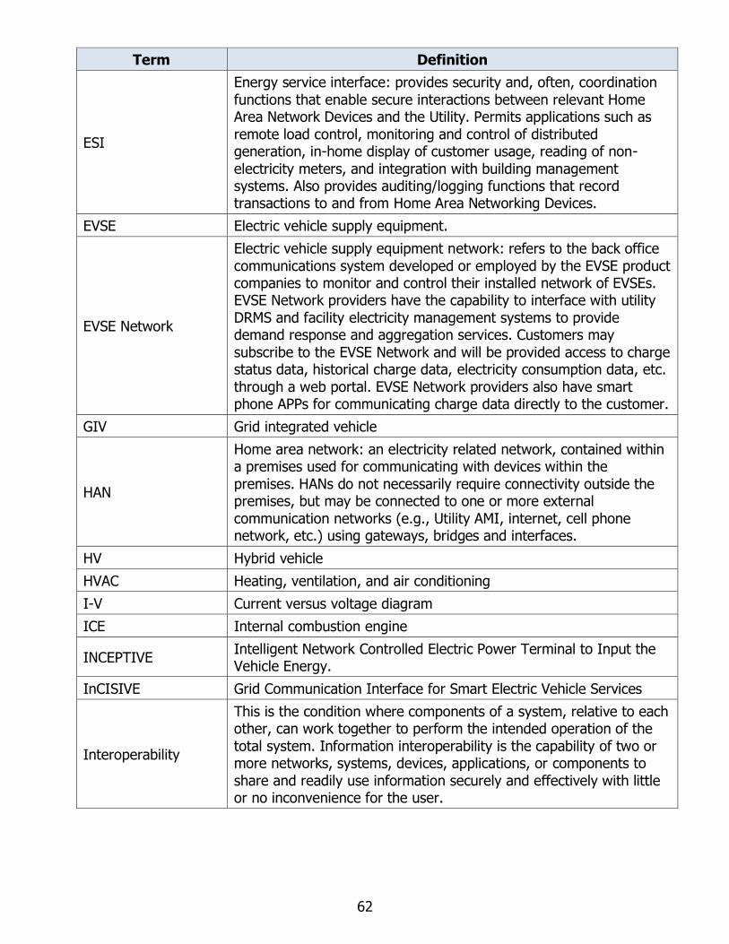
62
Term Definition
ESI
Energy service interface: provides security and, often, coordination
functions that enable secure interactions between relevant Home Area Network Devices and the Utility. Permits applications such as
remote load control, monitoring and control of distributed generation, in-home display of customer usage, reading of non-
electricity meters, and integration with building management systems. Also provides auditing/logging functions that record transactions to and from Home Area Networking Devices.
EVSE Electric vehicle supply equipment.
EVSE Network
Electric vehicle supply equipment network: refers to the back office
communications system developed or employed by the EVSE product companies to monitor and control their installed network of EVSEs. EVSE Network providers have the capability to interface with utility
DRMS and facility electricity management systems to provide demand response and aggregation services. Customers may
subscribe to the EVSE Network and will be provided access to charge status data, historical charge data, electricity consumption data, etc.
through a web portal. EVSE Network providers also have smart phone APPs for communicating charge data directly to the customer.
GIV Grid integrated vehicle
HAN
Home area network: an electricity related network, contained within a premises used for communicating with devices within the
premises. HANs do not necessarily require connectivity outside the premises, but may be connected to one or more external
communication networks (e.g., Utility AMI, internet, cell phone network, etc.) using gateways, bridges and interfaces.
HV Hybrid vehicle
HVAC Heating, ventilation, and air conditioning
I-V Current versus voltage diagram
ICE Internal combustion engine
INCEPTIVE Intelligent Network Controlled Electric Power Terminal to Input the Vehicle Energy.
InCISIVE Grid Communication Interface for Smart Electric Vehicle Services
Interoperability
This is the condition where components of a system, relative to each other, can work together to perform the intended operation of the
total system. Information interoperability is the capability of two or more networks, systems, devices, applications, or components to
share and readily use information securely and effectively with little or no inconvenience for the user.

63
Term Definition
IOU
Investor-owned utilities: private electricity and natural gas providers
overseen by the CPUC. PG&E, SDG&E, and SCE comprise approximately three quarters of electricity supply in California.
Utility provides electricity and typically refers to a collection of systems that include the Customer Information System (CIS), the
Advanced Metering Infrastructure (AMI), Rates and Revenue. The utility makes available to PEV through the ESCI pricing tables or discrete events. The utility also supplies information such as tariff
rate, interval for metered kWh consumption, and validation of PEV program for PEV ID, etc.
IoT Internet of Things
ISO Independent System Operator
kW Kilowatt
kWh Kilowatthour
MW Megawatt.
MWh Megawatthour
MPP Max Peak Power tracking
NAN Neighborhood Area Network
OASIS Organization for the Advancement of Structured Information Standards
OCPP
Open Charge Point Protocol: an application protocol for communication between PEV Charging stations and a central
management system, also known as a charging station network, similar to cell phones and cell phone networks. It is an open
application protocol which allows PEV charging stations and central management systems from different vendors to communicate with each other. It is in use by many vendors of PEV charging stations
and central management systems all over the world.
OEM Telematics
Server
[SAE definition]
Automobile systems that combine global positioning satellite (GPS) tracking and other wireless communications for automatic safety and
security information, navigation, entertainment, and diagnostics. OEMs are now implementing application programming interfaces (APIs) to their telematics servers that are compatible and
interoperable with utility standard protocols for the purpose of exchanging data (via internet protocols) to enable managed or smart
charging functionality. Additionally OEMs have developed smart phone applications for customers to be able to remotely receive real
time PEV charge status information and to set charging preferences based on available modes provided by the OEM.

64
Term Definition
OpenADR
Open Automated Demand Response: open and standardized way for
electricity providers and system operators to communicate DR signals with each other and with their customers using a common
language over any existing IP-based communications network, such as the Internet.
ORCA On-Road Chargers manufactured by Andromeda
P-V Power versus voltage diagram
PCS Power control system
PEV
Plug-in electric vehicle: plugs into an electricity portal at premises to charge vehicle. A PEV is also a BEV (Battery Electric Vehicle) that
relies only on electric propulsion. A PEV is also a PHEV (Plug-In-Hybrid Vehicle) that also includes an alternative source of propulsion power.
PHEV Plug-in hybrid electric vehicle
PHP General-purpose scripting language
PLC Power line communication
PU Power utilities
PV Photovoltaic
PWM Pulse width modulation
R&D Research and development
SAE
Society of Automotive Engineers: a United States-based, globally active professional association and standards developing
organization for engineering professionals in various industries. Principal emphasis is placed on transport industries such as
automotive, aerospace, and commercial vehicles.
SaaS
Software as a service: a software licensing and delivery model in
which software is licensed on a subscription basis and is centrally hosted.
SCE Southern California Edison
SEP2
Smart-Energy Profile 2.0: standard and interoperable protocol that
connects smart electricity devices in the home to the Smart Grid, The standard is designed to run over Transmission Control Protocol / Internet Protocol (TCP / IP) and is media access control (MAC) and
physical layer (PHY) agnostic. A coalition of Alliances had been formed (composed of Wi-Fi Alliance, ZigBee Alliance, HomePlug
Alliance and HomeGrid Alliance) to develop the protocol and the certification testing processes. SEP2 is now an IEEE standard – IEEE
2030.5-2013 IEEE Adoption of Smart Energy Profile 2.0 Application Protocol Standard.
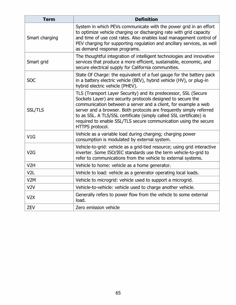
65
Term Definition
Smart charging
System in which PEVs communicate with the power grid in an effort
to optimize vehicle charging or discharging rate with grid capacity and time of use cost rates. Also enables load management control of
PEV charging for supporting regulation and ancillary services, as well as demand response programs.
Smart grid The thoughtful integration of intelligent technologies and innovative services that produce a more efficient, sustainable, economic, and
secure electrical supply for California communities.
SOC State Of Charge: the equivalent of a fuel gauge for the battery pack in a battery electric vehicle (BEV), hybrid vehicle (HV), or plug-in
hybrid electric vehicle (PHEV).
SSL/TLS
TLS (Transport Layer Security) and its predecessor, SSL (Secure Sockets Layer) are security protocols designed to secure the communication between a server and a client, for example a web
server and a browser. Both protocols are frequently simply referred to as SSL. A TLS/SSL certificate (simply called SSL certificate) is
required to enable SSL/TLS secure communication using the secure HTTPS protocol.
V1G Vehicle as a variable load during charging; charging power consumption is modulated by external system.
V2G
Vehicle-to-grid: vehicle as a grid-tied resource; using grid interactive
inverter. Some ISO/IEC standards use the term vehicle-to-grid to refer to communications from the vehicle to external systems.
V2H Vehicle to home: vehicle as a home generator.
V2L Vehicle to load: vehicle as a generator operating local loads.
V2M Vehicle to microgrid: vehicle used to support a microgrid.
V2V Vehicle-to-vehicle: vehicle used to charge another vehicle.
V2X Generally refers to power flow from the vehicle to some external load.
ZEV Zero emission vehicle

66
REFERENCES
[1] ORCA Mobile. http://www.andromedapower.com/products/orca-mobile/
[2] ORCA Inceptive. http://www.andromedapower.com/orca-inceptive/
[3] Adam Langton, Noel Crisostomo; Vehicle - Grid Integration; Energy Division, California
Public Utilities Commission; March 2014.
www.cpuc.ca.gov/WorkArea/DownloadAsset.aspx?id=7744
[4] California Independent System Operator (California ISO); California Vehicle-Grid
Integration (VGI) Roadmap: Enabling vehicle-based grid services; February 2014.
https://www.caiso.com/Documents/Vehicle-GridIntegrationRoadmap.pdf
[5] D. Bowermaster; EPRI Project Manager; Vehicle-to-Grid State of the Technology, Markets,
and Related Implementation; EPRI, Palo Alto, CA: 2016. 3002008935.
http://www.epri.com/abstracts/Pages/ProductAbstract.aspx?ProductId=0000000030020
08935
[6] Yutaka, Ota, et al.. Implementation of autonomous distributed V2G to electric vehicle and
DC charging system. June 2014. Electric Power Systems Research. Elsevier.
http://www.sciencedirect.com/science/article/pii/S0378779614002041
[7] Nissan North America Corporate Planning. Smart Charging and V2X. CEC EPIC S9
Workshop. June 30th, 2014. http://www.energy.ca.gov/research/epic/documents/2014-
06-30_workshop/presentations/Nissan_North_America-Smart_Charging_and_V2X.pdf
[8] Venkateswaran LakshminarayananV. Gowtam S. ChemudupatiSumit PramanickSumit
PramanickKaushik RajashekaraKaushik Rajashekara. Real-time Optimal Energy
Management Controller for Electric Vehicle Integration in Workplace Microgrid. IEEE
Transactions on Transportation Electrification, Volume: 5 , Issue: 1, March 2019.
https://ieeexplore.ieee.org/document/8458236
[9] Smart, John et al.. Extended Range Electric Vehicle Driving and Charging Behavior
Observed Early in the EV Project. SAE International , August 2013. doi:10.4271/2013-
01-1441.
[10] Julian de Hoog1, Kristian Handberg2, Raman Jegatheesan3. Demonstrating Demand
Management: How Intelligent EV Charging Can Benefit Everyone. EVS27 International
Battery, Hybrid and Fuel Cell Electric Vehicle Symposium, Barcelona, Spain, November
17-20, 2013.
[11] Shengnan, Shao, et al.. Grid Integration of Electric Vehicles and Demand Response with
Customer Choice. IEEE Transactions on Smart Grid, January 2012. ISSN 1949-3053.
[12] Jeffrey, Wishart. Utility demand charges and electric vehicle supply equipment. Charged
Electric Vehicles Magazine, October 2013. http://chargedevs.com/features/utility-
demand-charges-and-electric-vehicle-supply-equipment/

67
[13] Stephanie, Morse and Karen, Glitman. Electric Vehicles as Grid Resources in ISO-NE and
Vermont. Vermont Energy Investment Corporation Transportation Efficiency Group,
VEIC, April 2014. http://www.veic.org/documents/default-source/resources/reports/evt-
rd-electric-vehicles-grid-resource-final-report.pdf
[14] OpenADR 2.0a and the OpenADR 2.0b Profile Specification and schema. OpenADR
Alliance.
https://openadr.memberclicks.net/index.php?option=com_mcform&view=ngforms&id=
24296
[15] SAE Standard. J2836/1 Use Cases for Communication Between Plug-in Vehicles and the
Utility Grid. SAE, 2010-04-08. http://standards.sae.org/j2836/1_201004/
[16] SAE Standard. J2836/2 Use Cases for Communication between Plug-in Vehicles and Off-
Board DC Charger. SAE, 2011-09-15. http://standards.sae.org/j2836/2_201109/
[17] SAE Standard. J2836/3 PEV Communicating as a Distributed Energy Resource. SAE, 2013-
12-10. http://standards.sae.org/wip/j2836/3/
[18] SAE Standard. J2836/5 Use Cases for Customer Communication for Plug-in Electric
Vehicles. SAE, 2015-05-07. http://standards.sae.org/j2836/5_201505/
[19] SAE Standard. J2847/1 Communication for Smart Charging of Plug-in Electric Vehicles
using Smart Energy Profile 2.0. SAE, 2013-11-05.
http://standards.sae.org/j2847/1_201311/
[20] SAE Standard. J2847/2 Communication Between Plug-In Vehicles and Off-Board DC
Chargers. SAE, 2015-04-09. http://standards.sae.org/j2847/2_201504/
[21] SAE Standard. J2847/3 Communication for Plug-in Vehicles as a Distributed Energy
Resource. SAE, 2013-12-10. http://standards.sae.org/j2847/3_201312/
[22] ISO 15118-1:2013. Road vehicles -- Vehicle to grid communication interface -- Part 1:
General information and use-case definition.
http://www.iso.org/iso/catalogue_detail.htm?csnumber=55365
[23] SAE Standard. J2931/1 Digital Communications for Plug-in Electric Vehicles. SAE,
2014-12-11. http://standards.sae.org/j2931/1_201412/
[24] SAE Standard. J2931/4 Broadband PLC Communication for Plug-in Electric Vehicles. SAE,
2014-10-21. http://standards.sae.org/j2931/4_201410/
[25] CHAdeMO. CHAdeMO v.0.9, 1.0, 1.1, 1.2, 2.0, V2L standards. http://www.chademo.com/
[26] ISO 15118-2:2014. Road vehicles -- Vehicle-to-Grid Communication Interface -- Part 2:
Network and application protocol requirements.
http://www.iso.org/iso/home/store/catalogue_tc/catalogue_detail.htm?csnumber=5536
6
[27] ISO 15118-3:2015. Road vehicles -- Vehicle-to-Grid Communication Interface -- Part 3:
Physical and data link layer requirements.

68
http://www.iso.org/iso/home/store/catalogue_tc/catalogue_detail.htm?csnumber=5967
5
[28] DIN SPEC 70121:2014-12. Electromobility - Digital communication between a d.c. EV
charging station and an electric vehicle for control of d.c. charging in the Combine
Charging System. https://www.beuth.de/en/technical-rule/din-spec-70121/224350045
[29] R.11-09-011 COM/CJS/ar9; SIWG Phase 3, DER Functions: Recommendations to the CPUC
for Rule 21, Phase 3 Function Key Requirements, and Additional Discussion Issues,
FINAL, Version 8; March 2016; pages 67-73.
http://docs.cpuc.ca.gov/PublishedDocs/Published/G000/M164/K376/164376491.pdf
[30] SIWG Phase 3 DER Functions: Recommendations to the CPUC for Rule 21, Phase 3
Function Key Requirements, and Additional Discussion Issues, March 31, 2017, FINAL
https://www.energy.ca.gov/electricity_analysis/rule21/documents/phase3/SIWG_Phase
_3_Working_Document_March_31_2017.pdf
[31] S. Chakraborty, et al.. Interim Test Procedures for Evaluating Electrical Performance and
Grid Integration of Vehicle-to-Grid Applications. National Renewable Energy Laboratory,
Colorado, June 2011. Technical Report NREL/TP-5500-51001.
https://digital.library.unt.edu/ark:/67531/metadc836770/
[32] Luigi Giubbolini (Andromeda Power). Grid Communication Interface for Smart Electric
Vehicle Services (InCISIVE). Poster. 2019 EPIC Symposium.
[33] Emin Ucer, Mithat C. Kisacikoglu (Dept. of Electrical and Computer Eng., University of
Alabama, Tuscaloosa, AL), Eyuphan Bulut (Dept. of Electrical and Computer Eng.,
Virginia Commonwealth University, Richmong, VA), Mustafa Guven (3Schlumberger
Technology Inc., Sugar Land, TX), Yilmaz Sozer (Dept. of Electrical and Computer Eng.,
University of Akron, Akron, OH), Luigi Giubbolini (Andromeda Power LLC, Long Beach,
CA). A flexible V2V Charger as a New Layer of Vehicle-Grid Integration Framework.
IEEE-ECCE 2019 Conference. Baltimore, MD | Sept. 29 – Oct. 3, 2019.
[34] Luigi Giubbolini (Andromeda Power), Mithat Can Kisacikoglu (University of Alabama). A
flexible EV-to-EV DC Charge Sharing System. IEEE Transportation Electrification
Conference NOVI, MICHIGAN, USA. Baltimore, MD | Sept. 29 – Oct. 3, 2019. Work in
progress.

APPENDICES
Appendices A through H are available under separate cover (Publication Number CEC-500-
2020-028-APA-H) by contacting Matthew Fung at [email protected].
Related Documents


