Greg Sciame S.T.E.M. Lesson Plan SMART 2010 2010-2011 School Year This material is based upon work supported by the National Science Foundation under an RET Site Project with Grant #: EEC-0807286 TITLE: Introduction to Computer Science (for a possible culminating project idea as an exit project for 8 th grade students) NYS STANDARD ADDRESSED: New York Intermediate Level Science Core Curriculum, Grades 5-8 Standard 7: Interdisciplinary Problem Solving Key Idea 1: 1.3 Design solutions to real-world problems of general social interest related to home, school, or community using scientific experimentation to inform the solution and applying mathematical concepts and reasoning to assist in developing a solution. 1.4 Describe and explain phenomena by designing and conducting investigations involving systematic observations, accurate measurements, and the identification and control of variables; by inquiring into relevant mathematical ideas; and by using mathematical and technological tools and procedures to assist in the investigation. Aim: How does computer science affect you? After this class, students will be able to start thinking about the planning and design that goes into electronics that they interact with daily. Hopefully linking prior knowledge of gadgets that the students greatly appreciate will spark an interest for some students to take on a more challenging and creative exit project topic than familiar topics such as earthquakes or metal rusting. Do Now: Write down all of the electronic devices that you interacted with last night and this morning before you arrived at school. While students are compiling their electronics lists, check for participation and possible homework due for today’s class session. HW: **(Extra Credit)**Write a computer program that could calculate the area of a square, or other desired geometric shape Materials/Preparation: -Whiteboard -Dry Erase Markers -Golf Pencils as backups for unprepared students -Backup paper supp ly -Hando uts (parts of ‘what is a microcontroller’ parallax book a long with teacher instructions pasted into a word file) -Video Projector and appropriate cables -Computer with internet access Opening:

Welcome message from author
This document is posted to help you gain knowledge. Please leave a comment to let me know what you think about it! Share it to your friends and learn new things together.
Transcript
Greg Sciame S.T.E.M. Lesson Plan SMART 2010 2010-2011 School Year
This material is based upon work supported by the National Science Foundation under an RET Site Pro ject with Grant #: EEC-0807286
TITLE: Introduction to Computer Science (for a possible culminating project idea as an exit project for 8th
grade students)
NYS STANDARD ADDRESSED: New York Intermediate Level Science Core Curriculum, Grades 5-8 Standard 7: Interdisciplinary Problem Solving Key Idea 1: 1.3 Design solutions to real-world problems of general social interest related to home, school, or community using scientific experimentation to inform the solution and applying mathematical concepts and reasoning to assist in developing a solut ion. 1.4 Describe and explain phenomena by designing and conducting investigations involving systematic observations, accurate measurements, and the identification and control of variables; by inquiring into relevant mathematical ideas; and by using mathematical and technological tools and procedures to assist in the investigation. Aim: How does computer science affect you? After this class, students will be able to start thinking about the planning and design that goes into electronics that they interact with daily. Hopefully linking prior knowledge of gadgets that the students greatly appreciate will spark an interest for some students to take on a more challenging and creative exit project topic than familiar topics such as earthquakes or metal rusting. Do Now: Write down all of the electronic devices that you interacted with last night and this morning before you arrived at school. While students are compiling their electronics lists, check for participation and possible homework due for today’s class session. HW: **(Extra Credit)**Write a computer program that could calculate the area of a square, or other desired geometric shape Materials/Preparation: -Whiteboard -Dry Erase Markers -Golf Pencils as backups for unprepared students -Backup paper supp ly -Handouts (parts of ‘what is a microcontroller’ parallax book a long with teacher instructions pasted into a word file) -Video Projector and appropriate cables -Computer with internet access Opening:

Greg Sciame S.T.E.M. Lesson Plan SMART 2010 2010-2011 School Year
This material is based upon work supported by the National Science Foundation under an RET Site Pro ject with Grant #: EEC-0807286
After the Do Now pass out the worksheet and work through it as a class. Display what the program looks like on the projector. Procedure
• Try and spark interest by getting students excited about elsectronics (iphone, ipod, etc)
• Make sure to go through computer code very slowly and repeat yourself in different ways since this is likely new for most students
Assessment Informal assessment
: observations
Formal assessment:
collect worksheets for classwork/participation points.
Closing Review the lesson by asking students what they learned today… “What is a microcontroller?” “What does DEBUG mean in PBasic?” “What does ‘*’ mean in PBasic?” If time permits, show them how to download the software on the parallax site.

Lessons: Electric Current and Electric Circuit
Summary Students are introduced to concepts of electricity and electronic circuits. They learn about some of the physics behind circuits, the key components in a circuit and their pervasiveness in our homes and everyday lives. Students learn about Ohm's Law, electric power and energy and how it is used to analyze circuits. Engineering Connection To design and create the endless number of devices and processes that use electricity and circuits, engineers require a basic understanding of electricity and the physics behind circuits. Electrical engineers design the circuitry for the products we use every day. They also design computers and telecommunication devices, lighting and wiring for buildings, and operating electric power stations. Electrical engineers address energy conservation in our homes and businesses by developing better ways to design and implement circuits and electronic devices to efficiently use and ultimately save energy. Grade Level: 11 Lessons: 1-5 Time Required: 200 minutes Lesson Dependency: None Keywords: capacitor, circuit, coulomb, current, electrical, electricity, electronic, energy, inductor, Ohm's Law, power, resistance, resistor, volt, voltage Related Standards for New York
• 4.1o Circuit components may be connected in series* or in parallel*. Schematic diagrams are used to represent circuits and circuit elements.
• 4.1n A circuit is a closed path in which a current* can exist. • 4.1l All materials display a range of conductivity. At constant temperature, common
metallic conductors obey Ohm’s Law*. Pre-Req Knowledge A basic understanding of static electricity.
Learning Objectives After this lesson, students should be able to:
• Define electric current and voltage. • Explain the relationship between voltage, current and resistance (Ohm's Law). • Understand electric power and energy • List several different circuit components.
Introduction/Motivation Do you know why a cell phone must have a battery or why a computer must be plugged in to work? (Answer: Those devices need electricity to work.) Did you know that a battery or the power coming from the outlet in the wall is part of an electrical circuit? When a battery is placed in the cell phone or when a computer is plugged in, the circuit in the device is completed or "closed," allowing electric current to flow. So what is an electricity? Vocabulary/Definitions
Alternating current:
Current that is constantly changing directions, such as the electric current accessible via wall sockets in our homes and businesses.
Ampere: The unit of measure for electric current. Defined as 1 coulomb per second. Capacitance: The ability of the electric field in a capacitor to store energy. The main measurement of
capacitors. Defined as the ratio of the charge and the voltage of the capacitor. Capacitor: A circuit component that stores energy inside of an electric field.
Closed circuit: A circuit that allows current to flow. Coulomb: The unit of measure for charge.
Direct current: Current that travels in only one direction, such as the current supplied from a battery. Electric current:
The flow of positive charges through a conductor (wire, plate, electric field).
Electrical potential:
A measure of the potential energy contained in an electric field.
Farad: Unit of measure for capacitance or electric capacity. Named for engineering physicist Michael Faraday.
Inductance: The ability of a magnetic field to store energy. The main measure of an inductor. Inductor: A circuit component that stores energy inside of a magnetic field.
Integrated circuits:
Circuits built onto a silicon crystal, or chip, that contain many common circuit components and are designed to perform some defined task.
Ohm's Law: The statement of the physics relationship that for any circuit, the strength of an electric current (I) is directly proportional to the voltage (V) and inversely proportional to the
resistance (R) of the circuit. V = IR Resistance: A measure of an object's ability to restrict the flow of current through it.
Resistor: Any two terminal objects that provide a voltage drop in order to oppose the flow of current through it.
Transistor: A semiconductor that is commonly used as an amplifier or a switch. It is the building block of all modern circuitry including computers and cell phones.
Volt: The unit of measure of voltage. Defined as a joule per coulomb. Voltage: A measure of the difference in electrical potential between two points in an electric field.
Lesson 1 & 2: Electric Current
The flow of charge is called the current and it is the rate at which electric charges pass though a conductor. The charged particle can be either positive or negative.
Section 1. Flow of Charge: The Current
In order for a charge to flow, it needs a push (a force) and it is supplied by voltage, or potential difference. The charge flows from high potential energy to low potential energy.
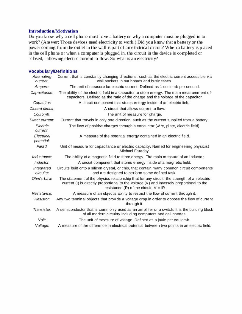
Suppose A has a potential of 12 V and B has a potential of 2 V. There is a potential difference. A has higher po tential energy than B, and it means there is voltage. The potential difference is:
VA - VB
If there is a po tential difference be tween two regions and if we join them together, the charge will flow. The charge will always move until the force acting on it is reduced to a minimum or until the voltage becomes the same.
= 12V – 2V = 10 V.
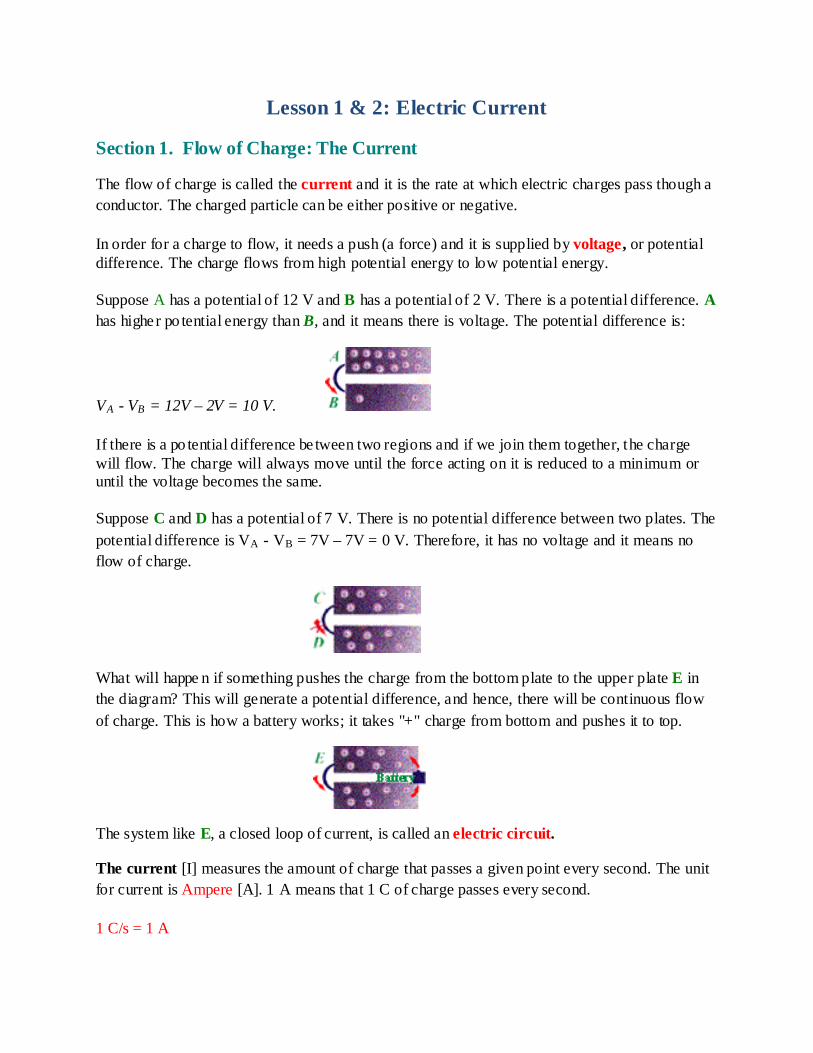
Suppose C and D has a potential of 7 V. There is no potential difference between two plates. The potential difference is VA - VB
= 7V – 7V = 0 V. Therefore, it has no voltage and it means no flow of charge.
What will happe n if something pushes the charge from the bottom plate to the upper plate E in the diagram? This will generate a potential difference, and hence, there will be continuous flow of charge. This is how a battery works; it takes "+" charge from bottom and pushes it to top.
The system like E, a closed loop of current, is called an electric circuit.
The current [I] measures the amount of charge that passes a given point every second. The unit for current is Ampere [A]. 1 A means that 1 C of charge passes every second.
1 C/s = 1 A
Sources of Electric Current
– Battery (chemical energy) – Photovoltaic Cell – Generators
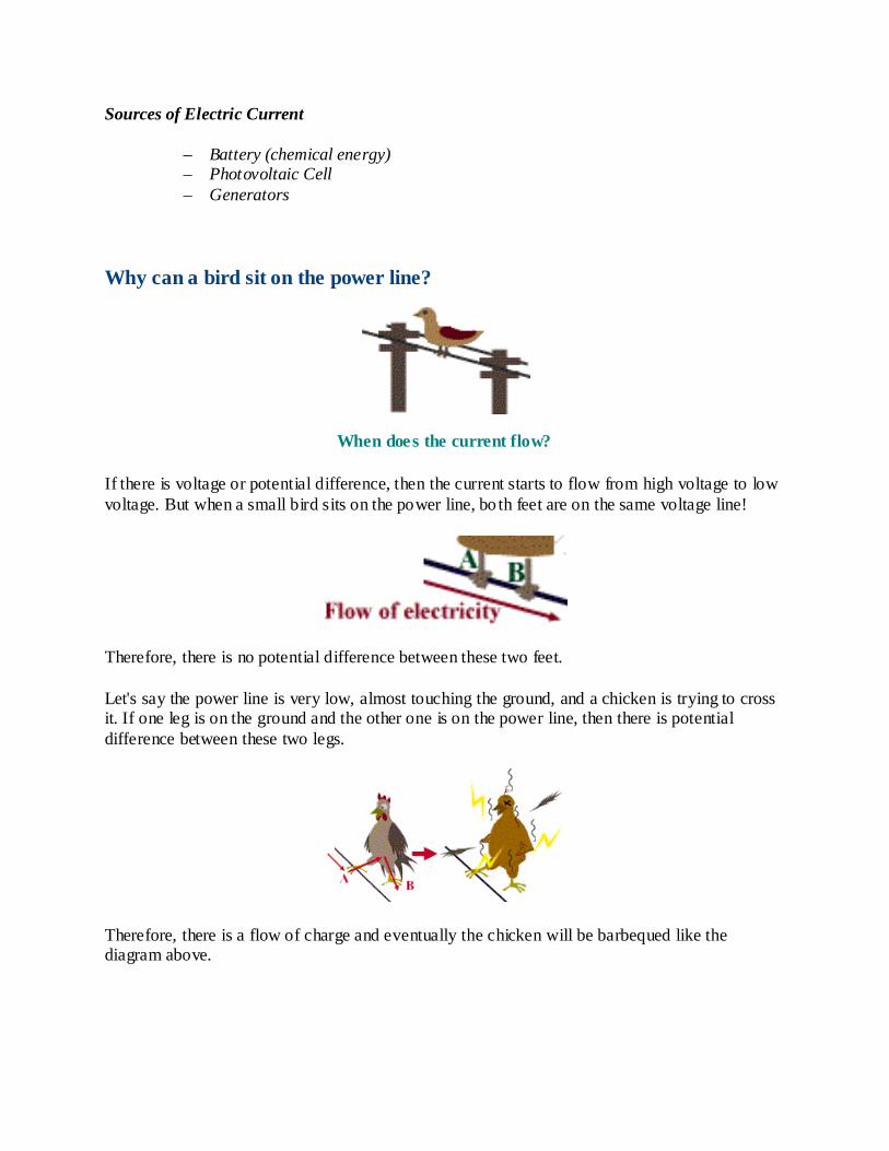
Why can a bird sit on the power line?
When does the current flow?
If there is voltage or potential difference, then the current starts to flow from high voltage to low voltage. But when a small bird sits on the power line, bo th feet are on the same voltage line!
Therefore, there is no potential difference between these two feet.
Let's say the power line is very low, almost touching the ground, and a chicken is trying to cross it. If one leg is on the ground and the other one is on the power line, then there is potential difference between these two legs.
Therefore, there is a flow of charge and eventually the chicken will be barbequed like the diagram above.
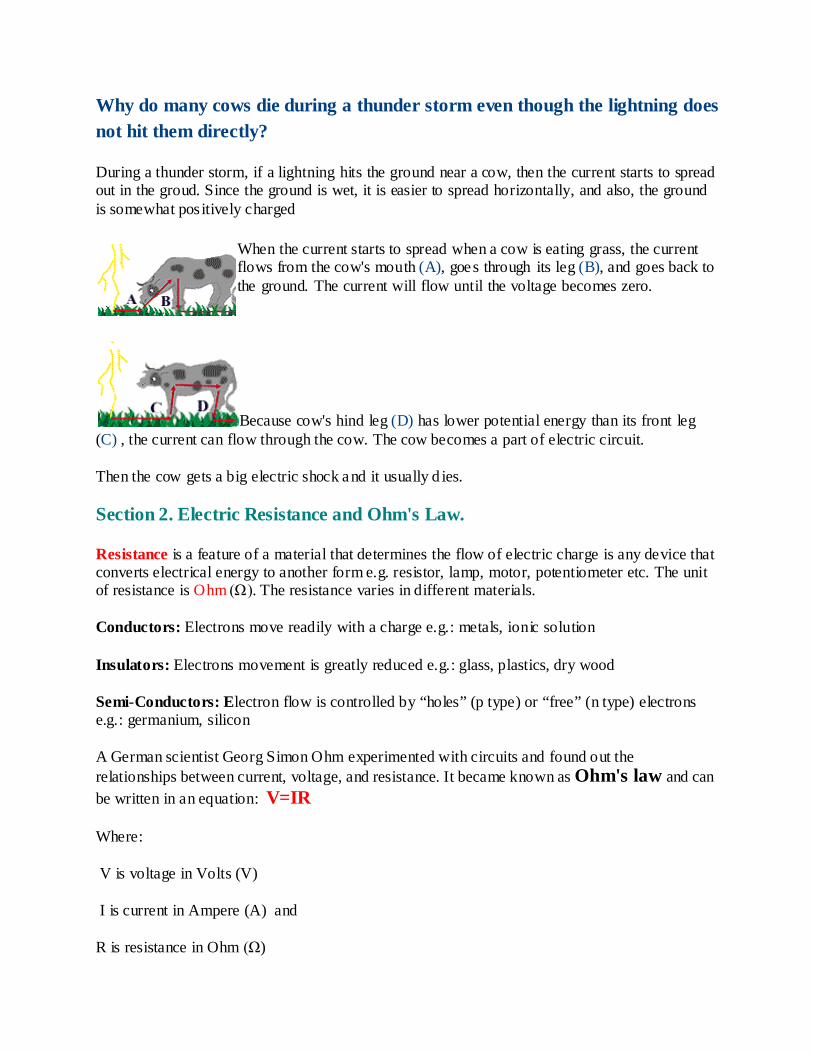
Why do many cows die during a thunder storm even though the lightning does not hit them directly?
During a thunder storm, if a lightning hits the ground near a cow, then the current starts to spread out in the groud. Since the ground is wet, it is easier to spread horizontally, and also, the ground is somewhat positively charged
When the current starts to spread when a cow is eating grass, the current flows from the cow's mouth (A), goes through its leg (B), and goes back to the ground. The current will flow until the voltage becomes zero.
Because cow's hind leg (D) has lower potential energy than its front leg (C) , the current can flow through the cow. The cow becomes a part of electric circuit.
Then the cow gets a big electric shock and it usually d ies.
Resistance is a feature of a material that determines the flow of electric charge is any device that converts electrical energy to another form e.g. resistor, lamp, motor, potentiometer etc. The unit of resistance is Ohm (Ω). The resistance varies in different materials.
Section 2. Electric Resistance and Ohm's Law.
Conductors: Electrons move readily with a charge e.g.: metals, ionic solution
Insulators: Electrons movement is greatly reduced e.g.: glass, plastics, dry wood
Semi-Conductors: Electron flow is controlled by “holes” (p type) or “free” (n type) electrons e.g.: germanium, silicon
A German scientist Georg Simon Ohm experimented with circuits and found out the relationships between current, voltage, and resistance. It became known as Ohm's law and can be written in an equation:
Where:
V=IR
V is voltage in Volts (V)
I is current in Ampere (A) and
R is resistance in Ohm (Ω)
Practice problem. What is the current of a circuit that has 3 V and 0.5 Ohm of resistance?
Answer: You first have to mod ify the equation V = IR to I = V / R.
Then you just have to input the numbers into this equation. I = 3V / 0.5 Ω = 6 A .
Example Problem 1.
a). What is the voltage if current is 0.5 A and resistance is 0.8 Ω?
b). What is the resistance if voltage is 3.0 V and current is 1.5 A?
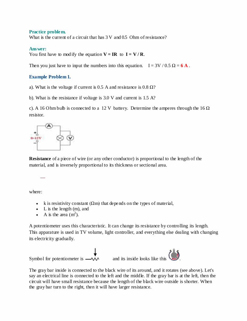
c). A 16 Ohm bulb is connected to a 12 V battery. Determine the amperes through the 16 Ω resistor.
Resistance of a piece of wire (or any other conductor) is proportional to the length of the material, and is inversely proportional to its thickness or sectional area.
where:
• k is resistivity constant (Ωm) that depends on the types of material, • L is the length (m), and • A is the area (m2
A potentiometer uses this characteristic. It can change its resistance by controlling its length. This apparature is used in TV volume, light controller, and everything else dealing with changing its electricity gradually.
).
Symbol for potentiometer is and its inside looks like this .
The gray bar inside is connected to the black wire of its around, and it rotates (see above). Let's say an electrical line is connected to the left and the middle. If the gray bar is at the left, then the circuit will have small resistance because the length of the black wire outside is shorter. When the gray bar turn to the right, then it will have larger resistance.

Learn how to read a resistor
Resistors limit current on a circuit.
How can we read a resistor? It is very easy. On the resistor, there are several colors. Color used is black, brown, red, orange, yellow, green, blue, violet, gray, and white.
This resistor has colors of red, orange, green, and gold.
Resistance can be calculated by
R = (First digit * 10 + second digit) * multiplier.
Therefore,
R = (Red * 10 + Orange) * Green = (2 * 10 + 3) * 100,000 = 230,000 ohm.
Tolerance of silver is + 10 % Tolerance of gold is + 5 %.
Here is the color table for calculating resistance:
Color 1st digit 2nd digit Multiplier Tolerance Black 0 0 1 Silver/Gold Brown 1 1 10 Silver/Gold
Red 2 2 100 Silver/Gold Orange 3 3 1000 Silver/Gold Yellow 4 4 10000 Silver/Gold Green 5 5 100000 Silver/Gold Blue 6 6 1000000 Silver/Gold
Violet 7 7 10000000 Silver/Gold Gray 8 8 100000000 Silver/Gold White 9 9 1000000000 Silver/Gold
Example Prob lems
What is the resistance of each resistor?
Voltage Law
Section 3. Voltage Law and Current Law
"In any circuit, the sum of decrease in voltage equals the sum of its increase
For example, imagine a circuit with a battery and a bulb. If the battery generates 3 V, then the bulb must consume 3 V, because the sum of decrease in voltage (-3 V consumed by the bulb) must be equal to the sum of increase in voltage (+3 V generated by the battery).
."
Current Law
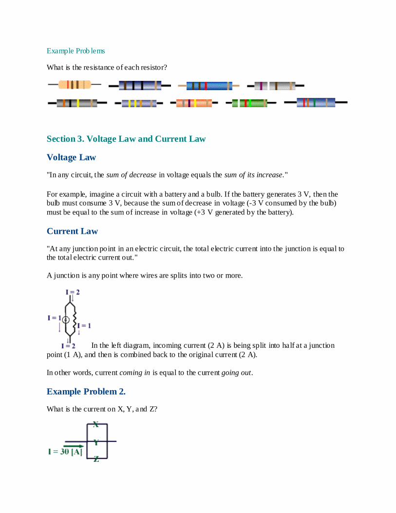
"At any junction point in an electric circuit, the total electric current into the junction is equal to the total electric current out."
A junction is any point where wires are splits into two or more.
In the left diagram, incoming current (2 A) is being split into half at a junction point (1 A), and then is combined back to the original current (2 A).
In other words, current coming in is equal to the current going out.
Example Problem 2.
What is the current on X, Y, and Z?
1. The flow of__________ is called the current and it is the rate at which electric charges pass though a conductor.
Section 4: Chapter Quiz
2. The__________measures the amount of charge that passes a given point in each second.
3. What is the resistance of a circuit if voltage is 3 V and current is 2 A. (e.g. "1.0
4. What is the current of a circuit if resistance is 3 ohm and voltage is 15V.
5. What is the voltage of a circuit if resistance is 7 ohm and current is 0.5 A.
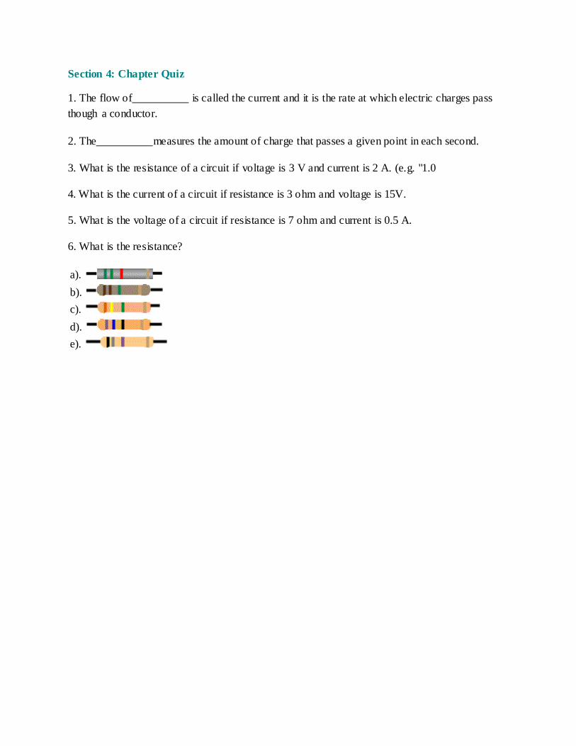
6. What is the resistance?
a). b). c). d). e).

Lesson 3 & 4: Basic Electric Circuit
The Hubble Telescope is an example of a modern device that depends on the millions of circuits for control, transfer of data and many images that would not be possible without functioning circuits.
There are basically three types of circuit: series, parallel, and series and parallel circuit combine.
Series Circuit:
Parallel Circuit:
Circuit conditions:
• Closed Circuit : A flow of electrons (Amperes) from a high potential energy (Voltage) to a low potential through a conducting material. (switch “on”)
• Open Circuit : electrons will not flow, and the potential is maximized. (switch “off”) • Short Circuit: Maximum electron flow with zero po tential. A conductor connects
directly across the potential ( switch is “bypassed”)
Section 1. Series Circuit
The total voltage is the sum of the voltage on each component. eq 1: Veq = V1+ V2 + V3 +...+ Vn (In this case, Veq = V1+ V2
The total resistance is equal to the sum of the resistance on each component.
)
eq 2: Req = R1 + R2 + R3 +...+ Rn (In this case, Req = R1 + R2
The total current is equa l in every component.
)
eq 3: Ieq = I1 = I2 = I3 =...= In (In this case, Ieq = I1 = I2
Example 1.
)
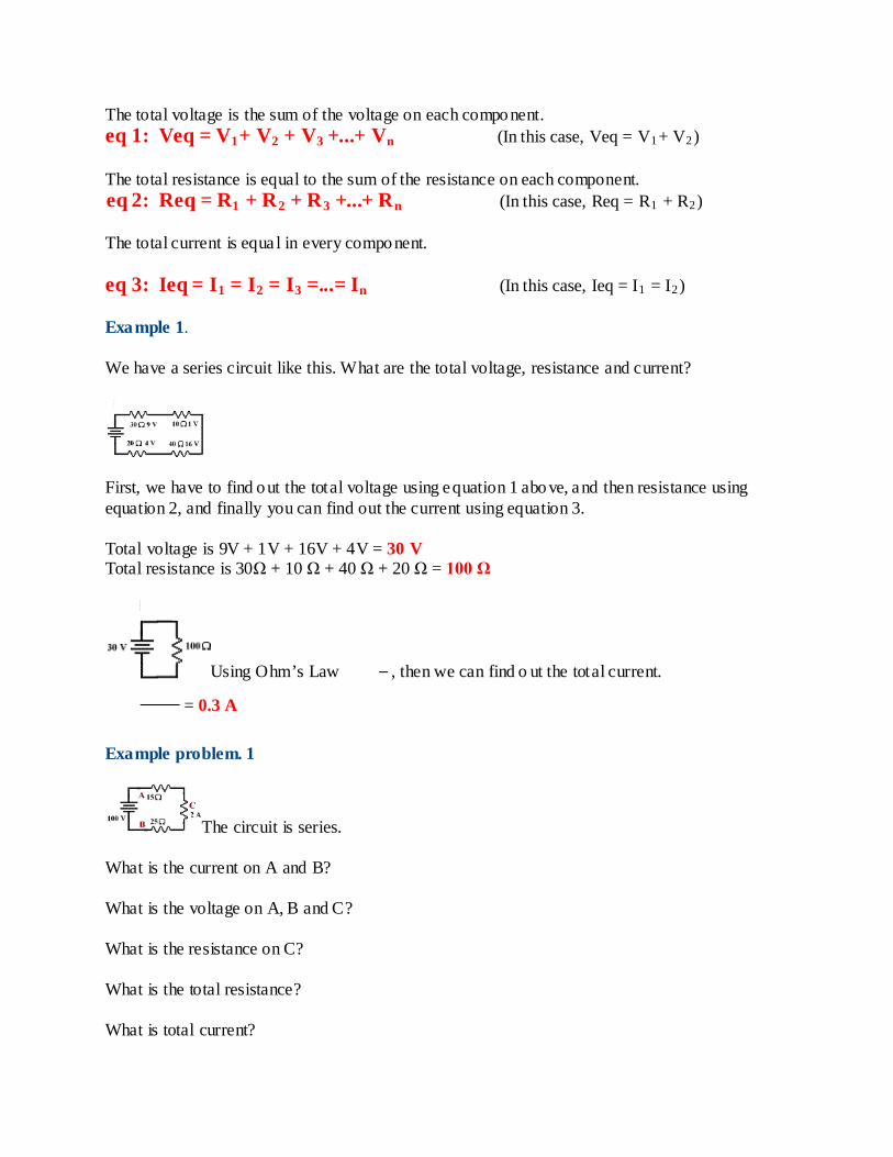
We have a series circuit like this. What are the total voltage, resistance and current?
First, we have to find out the total voltage using equation 1 above, and then resistance using equation 2, and finally you can find out the current using equation 3.
Total voltage is 9V + 1V + 16V + 4V = 30 V Total resistance is 30Ω + 10 Ω + 40 Ω + 20 Ω = 100 Ω
Using Ohm’s Law , then we can find o ut the total current.
= 0.3 A
Example problem. 1
The circuit is series.
What is the current on A and B?
What is the voltage on A, B and C?
What is the resistance on C?
What is the total resistance?
What is total current?
Section 2. Parallel Circuit.
The total voltage is equal in every component. eq 4: Veq = V1= V2= V3 =...= Vn (In this case, Veq = V1= V2
The resistance is equal to the sum of resistance on each component divided by the product of resistance of each component. eq 5: 1/Req = 1/R
)
1 + 1/R2 +...+ 1/Rn (In this case, 1/Req = 1/R1 + 1/R2
The total current is equal to the sum of current in each component. eq 6: Ieq = I
)
1 + I2 + I3 + I4 +...+ In (In this case, Ieq = I1 + I2
Example 2.
)
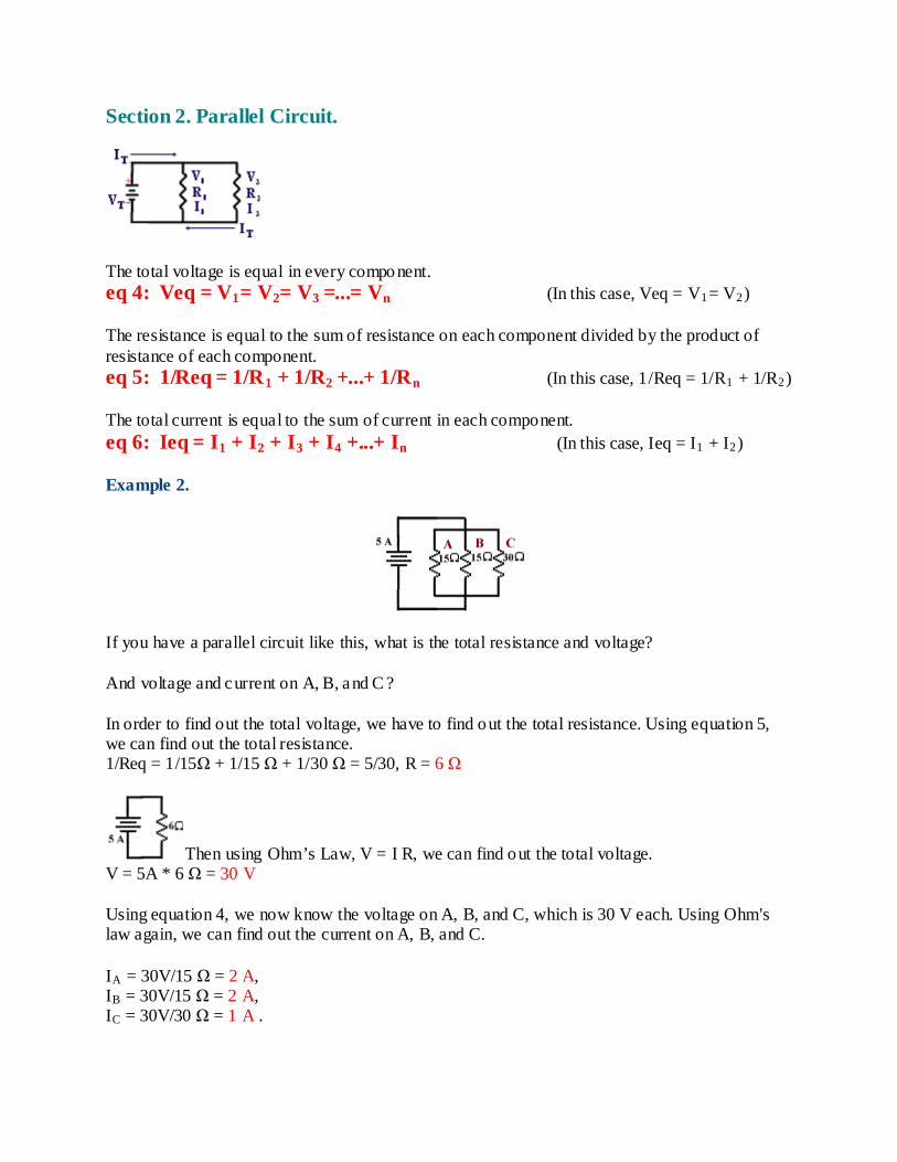
If you have a parallel circuit like this, what is the total resistance and voltage?
And voltage and current on A, B, and C ?
In order to find out the total voltage, we have to find out the total resistance. Using equation 5, we can find out the total resistance. 1/Req = 1/15Ω + 1/15 Ω + 1/30 Ω = 5/30, R = 6 Ω
Then using Ohm’s Law, V = I R, we can find out the total voltage. V = 5A * 6 Ω = 30 V
Using equation 4, we now know the voltage on A, B, and C, which is 30 V each. Using Ohm's law again, we can find out the current on A, B, and C.
IA = 30V/15 Ω = 2 A, IB = 30V/15 Ω = 2 A, IC = 30V/30 Ω = 1 A .
When you add up a ll the current (using equation 6), we get 5 A which is the total current.
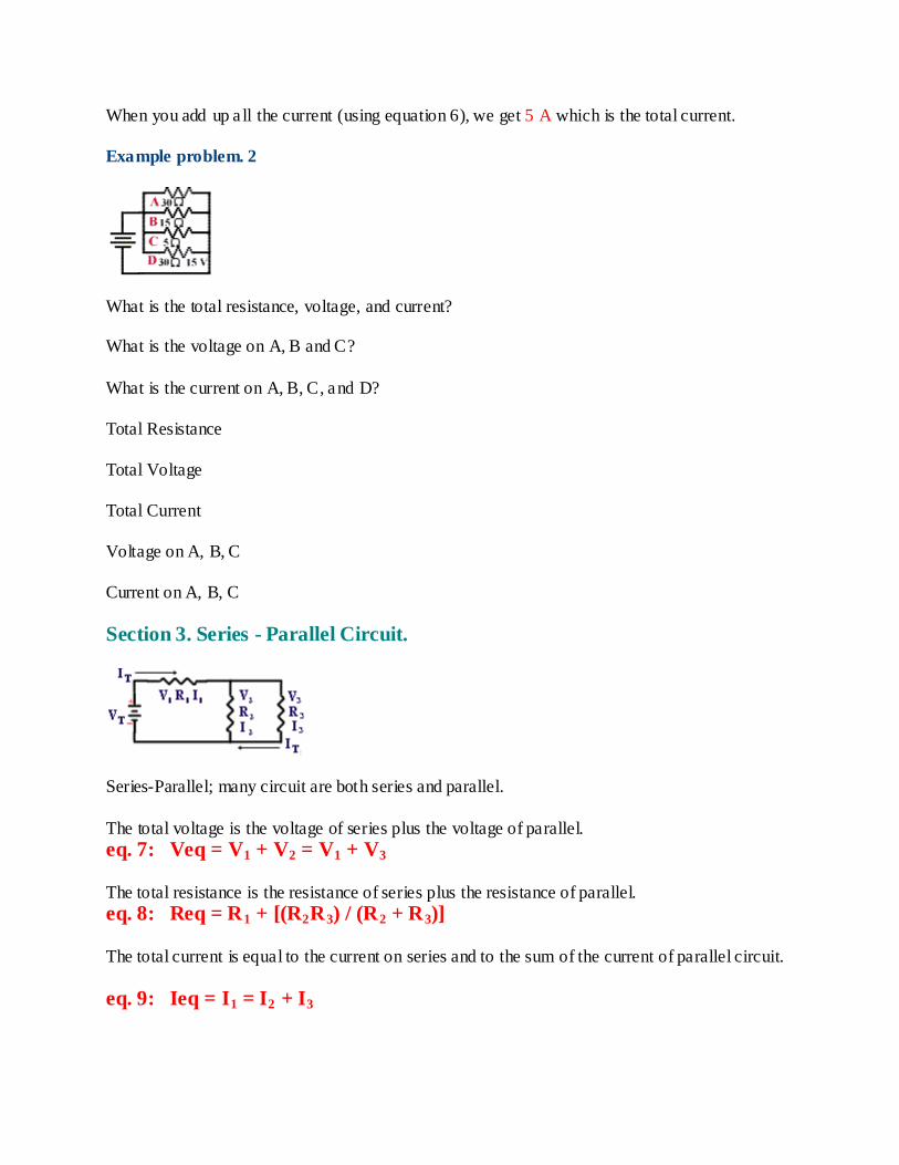
Example problem. 2
What is the total resistance, voltage, and current?
What is the voltage on A, B and C?
What is the current on A, B, C, and D?
Total Resistance
Total Voltage
Total Current
Voltage on A, B, C
Current on A, B, C
Section 3. Series - Parallel Circuit.
Series-Parallel; many circuit are both series and parallel.
The total voltage is the voltage of series plus the voltage of parallel. eq. 7: Veq = V1 + V2 = V1 + V3
The total resistance is the resistance of series plus the resistance of parallel. eq. 8: Req = R
1 + [(R2R3) / (R2 + R3
The total current is equal to the current on series and to the sum of the current of parallel circuit.
)]
eq. 9: Ieq = I1 = I2 + I
3
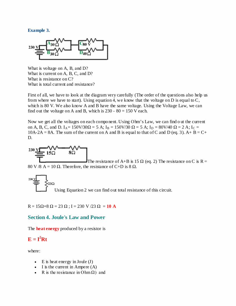
Example 3.
What is voltage on A, B, and D? What is current on A, B, C, and D? What is resistance on C? What is total current and resistance?
First of all, we have to look at the diagram very carefully (The order of the questions also help us from where we have to start). Using equation 4, we know that the voltage on D is equal to C, which is 80 V. We also know A and B have the same voltage. Using the Voltage Law, we can find out the voltage on A and B, which is 230 - 80 = 150 V each.
Now we get all the voltages on each component. Using Ohm’s Law, we can find o ut the current on A, B, C, and D. IA= 150V/30Ω = 5 A; IB = 150V/30 Ω = 5 A; ID = 80V/40 Ω = 2 A; IC
The resistance of A+B is 15 Ω (eq. 2) The resistance on C is R = 80 V /8 A = 10 Ω. Therefore, the resistance of C+D is 8 Ω.
= 10A-2A = 8A. The sum of the current on A and B is equal to that of C and D (eq. 3). A+ B = C+ D.
Using Equation 2 we can find out total resistance of this circuit.
R = 15Ω+8 Ω = 23 Ω ; I = 230 V /23 Ω = 10 A
The heat energy produced by a resistor is
Section 4. Joule's Law and Power
E = I2
where:
Rt
• E is heat energy in Joule (J) • I is the current in Ampere (A) • R is the resistance in Ohm Ω) and
• t is time in second (s)
In a parallel circuit, the least resistance draws the most current and produces the most heat energy because larger current flows through that component.
The rate of using or supplying energy is called Power [P]. The power consumption of a resistor is:
P = VI = I2R = V2
where:
/R
• [P] is power in Watts (W) • [V] is voltage through resistor in Volts (V) • [I] is current through resistor in Ampere (A), and • [R] is resistance in ohms (Ω).
Also,
Power [W] = work (energy) / time [t]
(unit of work is joule (J) and time (t) is in second).
Therefore,
work or energy [joule] = power [W] * time [t]. W = Pt
The unit for energy is watt-second; watt-minute; and watt-hour.
1 watt-second = 1 Joule
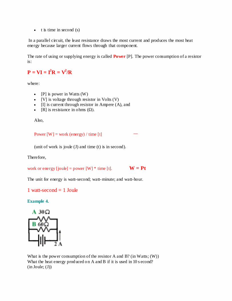
Example 4.
What is the power consumption of the resistor A and B? (in Watts; (W)) What the heat energy produced on A and B if it is used in 10 s econd? (in Joule; (J))

First, we have to find out the total resistance, and then the total potential difference (voltage). Total resistance is
R = 60Ω/3 = 20 Ω (eq. 5) And total potential difference is V= 20Ω * 2A = 40 V. (V=I*R) Now, we can find current on A and B. IA = 40V/30Ω = 4/3 A and IB
Power consumptions P
= 40V/60Ω = 2/3 A.
A
P
= (V*I) = 40V * 4/3A = 160V/3A = 53.3 W
B
The heat energies are: E
= 40V * 2/3A = 80V/3A = 26.7 W
A = I2Rt = (4/3A)2 * 30Ω * 10s = 1600/3= 533.3J EB = (2/3)2
Circuit Measurements:
* 60 * 10 = 800/3 (266.7) J.
• Ammeter : A device that connects in Series with a circuit to measure the Current (I) • Voltmeter : Similar to an ammeter except it is very high resistance connected in parallel

1. What circuit has the same potential difference in each component?
Section 5: Chapter Quiz
a) series circuit b) parallel circuit c) series and parallel circuit d) none of these
2. What is the total resistance and the total current on this circuit?
3. What are the potential differences on A, B, C, D and E?
What are the current on A, D?
What is the total resistance and current?
4. What is the power consumption (total P) of the circuit below?
What is the heat energy produced by this circuit in 10 second?
What is the heat energy produced by the resistor A in 10 second?

Lesson: Advanced Circuit
This part will explain some electrical components in details.
Diode rectifies or converts alternating current (AC) to direct current (DC).
Section 1: Diode
(Symbol )
The diode is made of two different parts. One part is called p-type and other part is called n-type. In between, we call it the p-n junction. P--type is silicon mixed with boron and n-type is silicon mixed with phosphorous. In order to explain how it works, we must know about the octet rule and valence electrons.
The octet rule is that bonded nonmetallic atoms has eight electron outermost shell or energy level
The valence electrons are
. It means that when two chemicals react each other and produce a product, its outer shell has eight electrons.
the electrons moving around the most outer shell of an individual atom and they are often involved into chemical reaction bonding.
In the periodic table, we can see all the names of elements and those are arranged into different periods and columns which are arranged by its chemical and physical characteristics. At the most right column, we can see very familiar names which are helium, neon, argon, k rypton, xenon, radon. We call them the noble gases because they don't chemically react with other chemicals. They have 8 valence electrons and without chemical reaction it satisfies the oc tet rule. The chemical reaction occurs because other elements want to have eight valence electrons in their outer energy level. Sodium which has 1 valence electron and chlorine which has 7 valence electrons can easily react each other. When they become sodium chloride which is salt, it is very stable because they have eight electrons in their outer energy level and the octet rule is satisfied.
P-type : Silicon has 4 valence electrons and bor on has 3 va lence electrons. When they are mixed together, their total valence electrons are 7. The octet rule is not satisfied and they are willing to accept one more electron. Let's say there are holes in that compound or crystal.
N-type : Silicon mixed with phosphorous which has 5 valence electrons. Their total valence electrons are 9. The octet rule is violated. They are willing to lose this one extra electron. Let's say there are extra electrons.
A
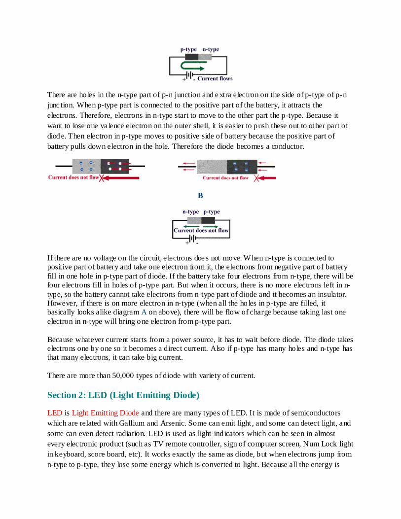
There are holes in the n-type part of p-n junction and extra electron on the side of p-type of p-n junc tion. When p-type part is connected to the positive part of the battery, it attracts the electrons. Therefore, electrons in n-type start to move to the other part the p-type. Because it want to lose one valence electron on the outer shell, it is easier to push these out to other part of diode. Then electron in p-type moves to positive side of battery because the positive part of battery pulls down electron in the hole. Therefore the diode becomes a conductor.
B
If there are no voltage on the circuit, e lectrons does not move. When n-type is connected to positive part of battery and take one electron from it, the electrons from negative part of battery fill in one hole in p-type part of diode. If the battery take four electrons from n-type, there will be four electrons fill in holes of p-type part. But when it occurs, there is no more electrons left in n-type, so the battery cannot take electrons from n-type part of diode and it becomes an insulator. However, if there is on more electron in n-type (when all the ho les in p-type are filled, it basically looks alike diagram A on above), there will be flow of charge because taking last one electron in n-type will bring one electron from p-type part. Because whatever current starts from a power source, it has to wait before diode. The diode takes electrons one by one so it becomes a direct current. Also if p-type has many holes and n-type has that many electrons, it can take big current.
There are more than 50,000 types of diode with variety of current.
LED is Light Emitting Diode and there are many types of LED. It is made of semiconductors which are related with Gallium and Arsenic. Some can emit light, and some can detect light, and some can even detect radiation. LED is used as light indicators which can be seen in almost every electronic product (such as TV remote controller, sign of computer screen, Num Lock light in keyboard, score board, etc). It works exactly the same as diode, but when electrons jump from n-type to p-type, they lose some energy which is converted to light. Because all the energy is
Section 2: LED (Light Emitting Diode)
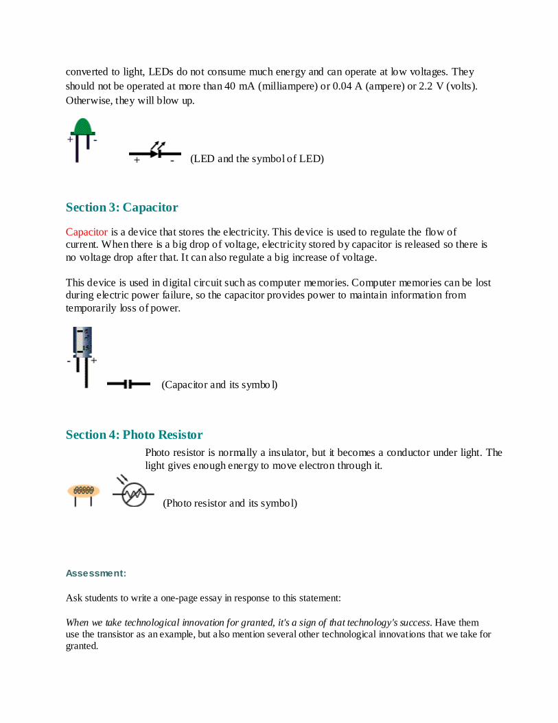
converted to light, LEDs do not consume much energy and can operate at low voltages. They should not be operated at more than 40 mA (milliampere) or 0.04 A (ampere) or 2.2 V (volts). Otherwise, they will blow up.
(LED and the symbol of LED)
Capacitor is a device that stores the electricity. This device is used to regulate the flow of current. When there is a big drop of voltage, electricity stored by capacitor is released so there is no voltage drop after that. It can also regulate a big increase of voltage.
Section 3: Capacitor
This device is used in digital circuit such as computer memories. Computer memories can be lost during electric power failure, so the capacitor provides power to maintain information from temporarily loss of power.
(Capacitor and its symbo l)
Section 4: Photo Resistor
Photo resistor is normally a insulator, but it becomes a conductor under light. The light gives enough energy to move electron through it.
(Photo resistor and its symbol)
Ask students to write a one-page essay in response to this statement:
Assessment:
When we take technological innovation for granted, it's a sign of that technology's success. Have them use the transistor as an example, but also mention several other technological innovations that we take for granted.
Mr. Sciame Intro to Computer Science Earth Science Exit Project Idea Name:_______________________Date:____________________ Class:____________________
1
HOW MANY MICROCONTROLLERS DID YOU USE TODAY?
What does a computer program look like? How is a computer program used?
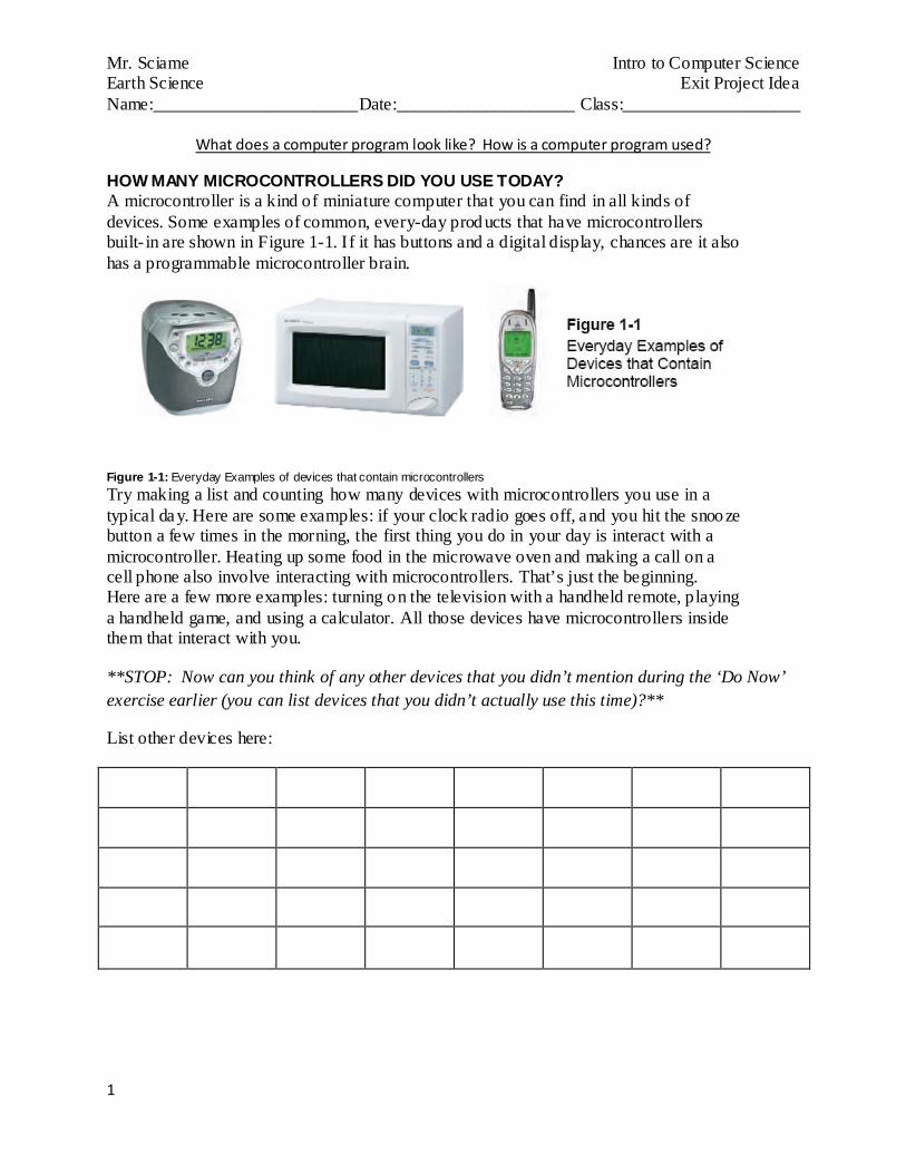
A microcontroller is a kind of miniature computer that you can find in all kinds of devices. Some examples of common, every-day products that have microcontrollers built- in are shown in Figure 1-1. I f it has buttons and a digital display, chances are it also has a programmable microcontroller brain.
Figure 1-1: Everyday Examples of devices that contain microcontrollers Try making a list and counting how many devices with microcontrollers you use in a typical day. Here are some examples: if your clock radio goes off, and you hit the snooze button a few times in the morning, the first thing you do in your day is interact with a microcontroller. Heating up some food in the microwave oven and making a call on a cell phone also involve interacting with microcontrollers. That’s just the beginning. Here are a few more examples: turning on the television with a handheld remote, playing a handheld game, and using a calculator. All those devices have microcontrollers inside them that interact with you.
**STOP: Now can you think of any other devices that you didn’t mention during the ‘Do Now’ exercise earlier (you can list devices that you didn’t actually use this time)?**
List other devices here:
Mr. Sciame Intro to Computer Science Earth Science Exit Project Idea Name:_______________________Date:____________________ Class:____________________
2
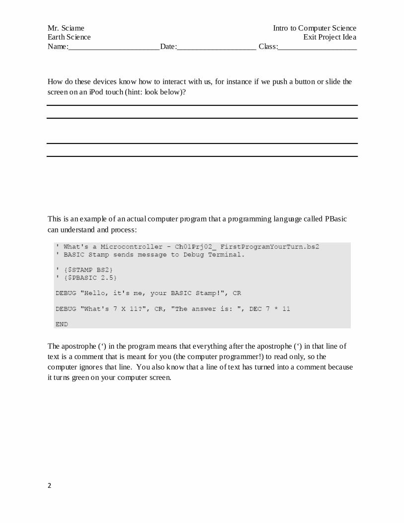
How do these devices know how to interact with us, for instance if we push a button or slide the screen on an iPod touch (hint: look below)?
This is an example of an actual computer program that a programming language called PBasic can understand and process:
The apostrophe (‘) in the program means that everything after the apostrophe (‘) in that line of text is a comment that is meant for you (the computer programmer!) to read only, so the computer ignores that line. You also know that a line of text has turned into a comment because it turns green on your computer screen.

Mr. Sciame Intro to Computer Science Earth Science Exit Project Idea Name:_______________________Date:____________________ Class:____________________
3
' What's a Microcontroller - Ch01Prj02_ FirstProgramYourTurn.bs2 ' BASIC Stamp sends message to Debug Terminal.
The (‘) on front of each line turns it into a comment.
' {$STAMP BS2} ' {$PBASIC 2.5}
These two comments are required for EVERY program written in PBasic.
DEBUG "Hello, it's me, your BASIC Stamp!", CR
‘DEBUG’ means that whatever you write in quotations will appear on the screen in a blue window called the debug terminal. CR stands for carriage return, which is the same as pushing enter.
DEBUG "What's 7 X 11?", CR, "The answer is: ", DEC 7 * 11
END
If you’d like you can follow these instructions and download this program on your computer for free:
ACTIVITY #1: GETTING THE SOFTWARE The BASIC Stamp Editor (version 2.5 or higher) is the software you will use in most of the activities and projects in this text. You will use this software to write programs that the BASIC Stamp module will run. You can also use this software to display messages sent by the BASIC Stamp that he lp you understand what it senses. Computer System Requirements You will need a personal computer to run the BASIC Stamp Editor software. Your computer will need to have the following features: • Microsoft Windows 2000 or newer operating system • An available serial or USB port • Internet access and an Internet browser program

Mr. Sciame Intro to Computer Science Earth Science Exit Project Idea Name:_______________________Date:____________________ Class:____________________
4
Downloading the Software from the Internet It is important to always use the latest version of the BASIC Stamp Editor software if possible. The first step is to go to the Parallax web site and download the software.
Using a web browser, go to www.parallax.com/basicstampsoftware
Click the red ‘download’ button and install the file after it is done downloading.
Related Documents