Installation Instructions Greengate DLVP - Distributed Low Voltage Power System Risk of Fire, Electrical Shock, Cuts or other Casualty Hazards- Installation and maintenance of this product must be performed by a qualified electrician. This product must be installed in accordance with the applicable installation code by a person familiar with the construction and operation of the product and hazards involved. Before installing or performing any service, the power MUST be turned OFF at the branch circuit breaker. According to NEC 240-83(d), if the branch is used as the main switch for a fluorescent lighting circuit, the circuit breaker should be marked with “SWD”. All installations should be in compliance with the National Electric Code and all state and local codes. Risk of Fire and Electric Shock- Make certain power is OFF before starting installation or attempting any maintenance. Disconnect power at fuse or circuit breaker. Risk of Burn- Disconnect power and allow fixture to cool before handling or servicing. Risk of Personal Injury- Due to sharp edges, handle with care. Failure to comply with these instructions may result in serious injury (including death) and property damage. WARNING DISCLAIMER OF LIABILITY: Cooper Lighting Solutions assumes no liability for damages or losses of any kind that may arise from the improper, careless, or negligent installation, handling or use of this product. IMPORTANT: Read carefully before installing product. Retain for future reference. NOTICE: Product/component may become damaged and/or unstable if not installed properly. Note: Specifications and dimensions subject to change without notice. ATTENTION Receiving Department: Note actual fixture description of any shortage or noticeable damage on delivery receipt. File claim for common carrier (LTL) directly with carrier. Claims for concealed damage must be filed within 15 days of delivery. All damaged material, complete with original packing must be retained. NOTICE: All new wiring must be fully verified before applying power. NOTICE: Designed for indoor installation and use only. Dry location rated. NOTICE: Do not mount near gas or electric heaters. Equipment should be mounted in locations and at adequate heights to prevent tampering by unauthorized personnel. NOTICE: Do not use this equipment for other than its intended purpose. MARKING SHALL INCLUDE EMERGENCY CIRCUITS CAUTION: This unit has more than one power supply connection point. To reduce the risk of electric shock disconnect both the branch circuit-breakers or fuses and emergency power supplies before servicing. CAUTION: Sealed unit LVPM not user serviceable. Replace entire unit when necessary. CAUTION: Service by Qualified Personnel Only. De-energize before opening. NOTICE: This equipment has not been evaluated for compliance with Article 700 of the National Electrical Code, ANSI/NFPA 70. NOTICE: Designed for indoor installation and use only. Dry location rated. IMPORTANT SAFEGUARDS When using electrical equipment, basic safety precautions should always be followed including the following: a) READ AND FOLLOW ALL SAFETY INSTRUCTIONS. b) Do not use outdoors (this item may be omitted if the product is suitable for outdoor use). c) Do not let power supply cords touch hot surfaces. d) Do not mount near gas or electric heaters. e) Use caution when servicing batteries. Battery acid can cause burns to skin and eyes. If acid is spilled on skin or in eyes, flush acid with fresh water and contact a physician immediately. f) Equipment should be mounted in locations and at heights where it will not readily be subjected to tampering by unauthorized personnel. g) The use of accessory equipment not recommended by the manufacturer may cause an unsafe condition. h) Caution: Halogen cycle lamp(s) are used in this equipment. To avoid shattering: Do not operate lamp in excess of rated voltage, protect lamp against abrasion and scratches and against liquids when lamp is operating, dispose of lamp with care. i) Halogen cycle lamps operate at high temperatures. Do not store or place flammable materials near lamp. j) Do not use this equipment for other than intended use. SAVE THESE INSTRUCTIONS

Welcome message from author
This document is posted to help you gain knowledge. Please leave a comment to let me know what you think about it! Share it to your friends and learn new things together.
Transcript

Installation Instructions Greengate
DLVP - Distributed Low Voltage Power System
Risk of Fire, Electrical Shock, Cuts or other Casualty Hazards- Installation and maintenance of this product must be performed by a qualified electrician. This product must be installed in accordance with the applicable installation code by a person familiar with the construction and operation of the product and hazards involved.
Before installing or performing any service, the power MUST be turned OFF at the branch circuit breaker. According to NEC 240-83(d), if the branch is used as the main switch for a fluorescent lighting circuit, the circuit breaker should be marked with “SWD”. All installations should be in compliance with the National Electric Code and all state and local codes.
Risk of Fire and Electric Shock- Make certain power is OFF before starting installation or attempting any maintenance. Disconnect power at fuse or circuit breaker.
Risk of Burn- Disconnect power and allow fixture to cool before handling or servicing.
Risk of Personal Injury- Due to sharp edges, handle with care.
Failure to comply with these instructions may result in serious injury (including death) and property damage.
WARNING
DISCLAIMER OF LIABILITY: Cooper Lighting Solutions assumes no liability for damages or losses of any kind that may arise from the improper, careless, or negligent installation, handling or use of this product. IMPORTANT: Read carefully before installing product. Retain for future reference. NOTICE: Product/component may become damaged and/or unstable if not installed properly. Note: Specifications and dimensions subject to change without notice.ATTENTION Receiving Department: Note actual fixture description of any shortage or noticeable damage on delivery receipt. File claim for common carrier (LTL) directly with carrier. Claims for concealed damage must be filed within 15 days of delivery. All damaged material, complete with original packing must be retained.
NOTICE: All new wiring must be fully verified before applying power.NOTICE: Designed for indoor installation and use only. Dry location rated.NOTICE: Do not mount near gas or electric heaters. Equipment should be mounted in locations and at adequate heights to prevent tampering by unauthorized personnel.NOTICE: Do not use this equipment for other than its intended purpose.MARKING SHALL INCLUDE EMERGENCY CIRCUITSCAUTION: This unit has more than one power supply connection point. To reduce the risk of electric shock disconnect both the branch circuit-breakers or fuses and emergency power supplies before servicing. CAUTION: Sealed unit LVPM not user serviceable. Replace entire unit when necessary.CAUTION: Service by Qualified Personnel Only. De-energize before opening. NOTICE: This equipment has not been evaluated for compliance with Article 700 of the National Electrical Code, ANSI/NFPA 70.NOTICE: Designed for indoor installation and use only. Dry location rated.IMPORTANT SAFEGUARDSWhen using electrical equipment, basic safety precautions should always be followed including the following:a) READ AND FOLLOW ALL SAFETY INSTRUCTIONS.b) Do not use outdoors (this item may be omitted if the product is suitable for outdoor use).c) Do not let power supply cords touch hot surfaces.d) Do not mount near gas or electric heaters.e) Use caution when servicing batteries. Battery acid can cause burns to skin and eyes. If acid is spilled on skin or in eyes, flush acid with fresh water and contact a physician immediately.f) Equipment should be mounted in locations and at heights where it will not readily be subjected to tampering by unauthorized personnel.g) The use of accessory equipment not recommended by the manufacturer may cause an unsafe condition.h) Caution: Halogen cycle lamp(s) are used in this equipment. To avoid shattering: Do not operate lamp in excess of rated voltage, protect lamp against abrasion and scratches and against liquids when lamp is operating, dispose of lamp with care.i) Halogen cycle lamps operate at high temperatures. Do not store or place flammable materials near lamp.j) Do not use this equipment for other than intended use.SAVE THESE INSTRUCTIONS
MN503061EN page 2November 2019
www.cooperlighting.com
Installation ManualGreengate - Distributed Low-Voltage Power System
System Overview
low-voltagelighting cables
pre-terminatedcontrol cable
low-voltagepower module
LVHH-01LVHH-02
emergency power input
normal power input
receptacleswitchpack
wallstation
occupancy sensor
daylight sensor
receptacle

MN503061EN page 3November 2019
www.cooperlighting.com
Installation Manual Greengate - Distributed Low-Voltage Power System
DLVP System Control Intent
Read and be aware of these system characteristicsThe Distributed Low-Voltage Power system was designed as an energy code compliant lighting control system. As such, users should be aware of the below operating behaviors:
On-Off TransitionsDLVP is a digital LED lighting control system. LED light fixtures, by their design, experience a significant but brief inrush current upon startup. To account for this and produce a uniform on and off transition, DLVP lighting does not “switch” on and off, but fades up and down. Users should expect lighting to gradually transition from off to on and vise versa.
Manual Only Control
DLVP is designed to expect occupancy sensors or time clock connections to turn lights off when not in use. As such, if the system is being used without an occupancy sensor (integrated or external) or time clock contact closure input, lights will turn off every hour as the system lacks a required input. If occupancy sensors and time clocks are not used, jumper the time clock input to allow for manual control only. Information on this process can be found on page 29.
Manual Hold TimeWhen using manual wallstations without occupancy sensors, it should be noted a manual button press generates a 1-hour timer to turn lights OFF. This was designed to prevent lights from remaining in the ON position without an automatic OFF mechanism (occupancy sensor or time clock input). When using a time clock, users should be aware that even though an after hours time clock event occurs, light may remain ON until the manual wallstation timer expires.
Occupancy Sets
DLVP is designed to be a simple space-based lighting control system. As such, it defaults to a single occupancy set (occupancy sensors affect all lights in the space) when using external or fixture integrated sensors. However, with integrated sensors, DLVP gives the designer the option to allow each control zone to be a separate occupancy set by enabling the Selectable Occupancy feature on the low-voltage power module. An application for this feature would be providing occupancy, daylighting, and manual control for three (3) private offices from a single low-voltage power module.
Integrated Sensor Default Behavior
When using light fixtures with integrated sensors for occupancy and closed loop daylighting, users should be aware that closed loop daylight is disabled out of the box as many users utilize integrated sensors for motion detection, but not daylighting or prefer open loop daylighting. To utilize closed loop daylighting, it must be enabled on each light fixture where it is desired (typically only in the primary and secondary daylight sets).
External Open Loop Daylight Configuration
When using external open loop daylight sensors, out of the box daylighting functionality may be provided if the space is zoned correctly. For out of the box daylighting to work correctly, light fixtures adjacent to the window wall should be defined as Zone 1 (primary daylight set). Light fixtures on the second row in from the window should be in Zone 2 (secondary daylight set). Light fixtures in the remainder of the room would be in the top daylight set (Zone 3).
Night Lights
Even though modern energy codes are making night lights a thing of the past, certain applications do require night light functionality. In DLVP, the night lighting feature requires the use of a time clock input to define normal hours of operation from after hours as night lights are not “always on lights.” During normal hours, all fixtures are full controllable (including lights assigned to be night lights). An after hours time clock event and manual action countdown mentioned in the Manual Only Control section above results in night lights remaining FULL ON while other lights go to their after hours unoccupied action (typically OFF). If the space is manually controlled after hours with night lights used, night lights are fully controllable.
Trim Settings
High and low end trim may be adjusted at the low-voltage power module for ALL connected loads (not individual lights). Out of the box, factory default settings should be at the min (1% capable for low end) and max (100% capable for high end). High end trim reduces the maximum output from the connected light fixtures to some lower amount to save energy and achieve desired target illuminance. Low end trim actually impairs the minimum possible dimming level from 1% up to something higher. Typically this would be used to match the dimming performance of other nearby systems.

MN503061EN page 4November 2019
www.cooperlighting.com
Installation ManualGreengate - Distributed Low-Voltage Power System
System Components
Low-Voltage Power Modules
DescriptionCooper Lighting Solutions Distributed Low Voltage Power (DLVP) system combines the benefits of both AC and DC power providing a flexible and efficient LED lighting control solution. By utilizing this and plug-and-play cables, a total installation cost savings of up to 20 percent can be achieved with DLVP.
Listed below are the advantages of a DLVP system over typical Class 1 overlay systems.
A reduction in installation labor up to 40 percent and up to a 20 percent reduction in total system cost by utilizing:
• Pre-terminated Class 2 cabling
• Favorable low-voltage labor rates
• Easily configured “Plug-n-Play” system independent of system wiring
Energy efficiency & savings by:
• Simplified energy code compliance
• Integrated or external sensors
• Utilizing AC for transmission and DC for connectivity.
Long term flexibility & value through:
• Safe & easy system reconfiguration without the need for rewiring
• Centralized maintenance from distributed low-voltage power modules
• Offering a complete system with power, LED lighting, and controls

MN503061EN page 5November 2019
www.cooperlighting.com
Installation Manual Greengate - Distributed Low-Voltage Power System
Specifications
Input Voltage 120-277VAC (50/60 Hz)
Input Current (amps) Normal Power Input
EM Power Input Single Panel Input only (LVCM-03-100-03 or wiring both normal and EM inputs together)
120VAC 277VAC 120VAC 277VAC 120VAC 277VAC
LVPM-03-100-03-1ELVPM-03-100-03 (no EM input)
1.8 0.8 0.9 0.4 2.6 1.1
Normal Power Input
EM Power Input Single Panel Input only (LVCM-06-100-03 or wiring both normal and EM inputs together)
120VAC 277VAC 120VAC 277VAC 120VAC 277VAC
LVPM-06-100-03-1ELVPM-06-100-03 (no EM input)
4.4 1.9 0.9 0.4 5.2 2.2
Power Factor Pf ≥ 0.9 at 50% or greater loadsTotal Harmonic Distortion THDi ≤ 10% at 50% or greater loadsClass 2 output 1.6A MAX @ 57VDC (nom) per low voltage circuitClass 2 outputs 300W = 3 (1 EM output)
600W = 6 (1 EM output, 90W max per output)Operating environment 32°F - 104°F (0°C - 40°C) Indoor dry locations only
Weight 10 lbs (4.5kg)
StandardsUL 2108 Listed
CFR 47 Part 15a
Emergency statement: LVPM-03-100-03-1E and LVPM-06-100-03-1E meet UL924 requirements when used with a centralized UL924 Listed power source

MN503061EN page 6November 2019
www.cooperlighting.com
Installation ManualGreengate - Distributed Low-Voltage Power System
600W Low-voltage power module
300W Low-voltage power moduleote: N The same functions are available in both the 600W and 300W models. The only difference is total available power.
11.8”(27.9 cm)
16.2”(41.2 cm)
11.5”(29.2 m)
6.1”(15.5 cm)
Dimensions

MN503061EN page 7November 2019
www.cooperlighting.com
Installation Manual Greengate - Distributed Low-Voltage Power System
InstallationThe low-voltage power module is a plenum rated passively cooled device designed to be mounted above the ceiling in or near the space to be powered and controlled. Low-voltage power modules must be installed in one of two orientations (as shown) for proper cooling and to maintain system warranty coverage.
ote: N This device does not meet CCEA requirements for Chicago plenum installations.
INSTALL WITH MINIMUM SPACINGS BETWEEN:
(A) CENTER-TO-CENTER OF ADJACENT
Low-voltage power module: 24in (600mm)
(B) TOP OF Low-voltage power module TO OVERHEAD BUILDING
MEMBER: 3in (75mm)
(C) Low-voltage power module CENTER TO SIDE BUILDING
MEMBER: 12in (300mm)
Not for use in fire rated installations.
Above ceiling access required.
ABC
Min. 3” (75mm)
Min. 24” (600mm) Min. 12”
(300mm)

MN503061EN page 8November 2019
www.cooperlighting.com
Installation ManualGreengate - Distributed Low-Voltage Power System
DLVP for emergency applications
OverviewMany of today’s lighting control applications require support for emergency lighting. Emergency lighting circuits typically provide minimum illumination levels for egress and safety as required by NFPA 101 Life Safety Code or other local building codes and standards.
Historically, emergency lighting was not fully controlled or dimmed, resulting in additional expense for dedicated emergency fixtures or for operating lighting that was continuously ON. With the DLVP system, designers can fully control lighting that meets both normal and emergency lighting needs, reducing product and operation costs, while ensuring code compliance.
Technical DetailsThe DLVP system allows complete control of the emergency load under normal power operation while guaranteeing proper emergency lighting functionality during emergency power conditions. Wiring for emergency lighting must be kept separate from normal wiring to prevent faults from affecting either normal or emergency lighting.
Units that control dimmed low voltage lighting must ensure that during a normal power loss sufficient power is provided for emergency lighting purposes.
InstallationThe DLVP System comes with a Normal power and Emergency power input. When wired to an emergency power source, in the event of power loss, the Emergency Power will provide power to the output labeled “Emergency”. The DLVP unit will then force any lights on the Emergency output to FULL ON.
Inside the unit, there is a metal divider to keep the Normal load separate from the Emergency load. If the DLVP unit being installed does not require an emergency load, the divider can be removed and wired to create an ALL NORMAL connection.
STA
TU
S
TE
ST
RE
SE
T
4 5 6
1 2
EMERGENCY
3
LOW-VOLTAGE OUTPUTSSUITABLE FOR CLASS 2 WIRING
+ - + - + -
DEMAND CLOCK ALERT
LOW HIGH
TR
IM
1 1 RECBMS/OUT
2 2 SWITCHPACK
WALLSENSORS
1 2 3 4 5V Y
O N
Occ
/ Va
c
Part
ial O
n
Y
N
Y
N
Sel
ect
Occ
Occ
Sh
are
F
S
Au
to O
n
DEFAULT
10%
1
20%
2 3 4 5
DIAG
NORM
57VDC 90W MAX (EACH OUTPUT)CAUTION: DO NOT OVERLOAD
30%
40%
Transferswitch
Normalpower
Normalpower
Emergencypower Emergency
panel
MN503061EN page 9November 2019
www.cooperlighting.com
Installation Manual Greengate - Distributed Low-Voltage Power System
Power Supply Connection
Low-voltage power modules have two (2) integrated wiring compartments - one (1) for normal panel and one (1) for emergency panel wiring - both with two (2) 1/2” knockouts (0.875” diameter).
If emergency power is not provided, normal power may be wired to both the normal and emergency inputs by removing the separator between the two wiring compartments.
emergency power connection
remove divider and wire internally when NOT using EM panel
Note: LVPM-03-100-03 and LVPM-06-100-03 do not have emergency inputs
normal power connection
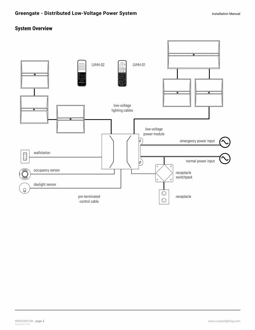
Low-Voltage Light Fixtures
DescriptionMany popular and energy efficient models of LED light fixtures are available for the Distributed Low-Voltage Power System. Consult www.cooperlighting.com for the most current model availability.
SpecificationsFor specifications of specific Cooper Lighting Solutions low-voltage light fixtures, consult www.cooperlighting.com.

MN503061EN page 10November 2019
www.cooperlighting.com
Installation ManualGreengate - Distributed Low-Voltage Power System
Fixture ConnectionConnect DLVP low-voltage light fixtures to any available low-voltage output on the low-voltage power module using the low-voltage cable as shown below. If emergency power input is being used with the LVPM-03-100-03-1E or LVPM-06-100-03-1E power module, the emergency fixtures should be wired to low-voltage output #3. The low-voltage power module is rated for 90 watts per low-voltage output circuit. The 600 watt model has six (6) low-voltage output circuits and the 300 watt model has three (3) low-voltage output circuits.
It is recommended that connections to low-voltage fixtures be made when the low-voltage power module is not energized. Each output circuit is rated for 90W MAX of low-voltage power allowing daisy-chain connections up to that limit - fixture type and control zone does not matter (except where emergency power input is provided. Low-voltage output #3 remains energized when emergency panel input is energized).
If the load (low-voltage fixtures and lighting cables) exceeds the capacity of the low-voltage circuit (90W MAX), the overloaded fixture(s) will not operate and will need to be reset. An error message will also be displayed via low-voltage power module status LED.
To reset a fixture relocated to another low-voltage power module:
1. Disconnect the last fixture(s) on the overloaded low-voltage circuit and press “RESET” on the low-voltage power module to clear the overload condition.
2. On the disconnected fixture, set ALL dip switches “ON” while the fixture is de-energized.
3. Connect the fixture to another low-voltage circuit with ample capacity (up to 90W MAX), wait 3 seconds before step 4.
4. While energized, return ALL dip switches on that fixture to the OFF position (factory default manual control zone 1).
5. See Light Fixture Zone Assignment section to continue with system configuration
To return the system to factory (last firmware upgrade) default settings:
Note - all light fixture’s zone assignments will follow fixture DIP switch settings - all commissioning data (not firmware upgrades) will be returned to factory settings.
1. While the system is energized, press and hold the RESET button on the low-voltage power module.
2. While holding the RESET button, press and hold the TEST button.
3. While holding both buttons and monitoring the blinking STATUS LED, release only the RESET button
4. When the STATUS LED blink pattern increases from slow to rapid (10 seconds), release the TEST button
5. This process returns saved scenes, sensor settings, etc. to default values and light fixtures will go to FULL during reset.
STA
TU
S
TE
ST
RE
SE
T
4 5 6
1 2
EMERGENCY
3
LOW-VOLTAGE OUTPUTSSUITABLE FOR CLASS 2 WIRING
LL50
3018
EN
57VDC 90W MAX (EACH OUTPUT)CAUTION: DO NOT OVERLOAD
+ - + - + -
DEMAND CLOCK ALERT
LOW HIGH
TR
IM
1 1 RECBMS/OUT
2 2 SWITCHPACK
WALLSENSORS
1 2 3 4 5V Y
O N
Occ
/ Va
c
Part
ial O
n
Y
N
Y
N
Sel
ect
Occ
Occ
Sh
are
F
S
Au
to O
n
DEFAULT
10%
1
20%30%40%
2 3 4 5
DIAG
NORM
connect 90W MAX
low-voltage lightingcable
low-voltage power module
low-voltage light fixture
MN503061EN page 11November 2019
www.cooperlighting.com
Installation Manual Greengate - Distributed Low-Voltage Power System
Wallstations
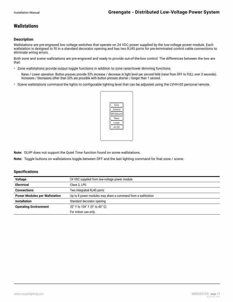
DescriptionWallstations are pre-engraved low voltage switches that operate on 24 VDC power supplied by the low-voltage power module. Each wallstation is designed to fit in a standard decorator opening and has two RJ45 ports for pre-terminated control cable connections to eliminate wiring errors.
Both zone and scene wallstations are pre-engraved and ready to provide out-of-the-box control. The differences between the two are that:
• Zone wallstations provide output toggle functions in addition to zone raise/lower dimming functions.
• Raise / Lower operation: Button presses provide 33% increase / decrease in light level per second held (raise from OFF to FULL over 3 seconds). Increases / Decreases other than 33% are possible with button presses shorter / longer than 1 second.
• Scene wallstations command the lights to configurable lighting level that can be adjusted using the LVHH-02 personal remote.
Entry
General
Whiteboard
Raise
Lower
All Off
ote: N DLVP does not support the Quiet Time function found on some wallstations.
ote: N Toggle buttons on wallstations toggle between OFF and the last lighting command for that zone / scene.
Specifications
Voltage 24 VDC supplied from low-voltage power module
Electrical Class 2, LPS
Connections Two integrated RJ45 ports
Power Modules per Wallstation Up to 8 power modules may share a command from a wallstation
Installation Standard decorator opening
Operating Environment 32° F to 104° F (0° to 40° C) For indoor use only.

MN503061EN page 12November 2019
www.cooperlighting.com
Installation ManualGreengate - Distributed Low-Voltage Power System
InstallationMount wallstations to a single or multi-gang wallbox with a minimum internal depth of 2 inches (51mm).
front cover inner plate main body
ConnectionUsing pre-terminated control cables, connect a wallstation(s) to a WALL port on the low-voltage power module as shown. Up to 12 wallstations may be daisy chained together and connected to a low-voltage power module (total for BOTH ports).
ote: N Use the shortest possible lengths of pre-terminated control cable between each wallstation that will reach their intended locations. Once they’re installed, mount wallstations in the wall box and attach the wallplates.
ote: N Wallstations can be connected to more than one low-voltage power module, however programmed functions will be duplicated unless a wallstation coupler (sold separately) is installed.
STA
TU
S
TE
ST
RE
SE
T
4 5 6
1 2
EMERGENCY
3
LOW-VOLTAGE OUTPUTSSUITABLE FOR CLASS 2 WIRING
LL50
3018
EN
57VDC 90W MAX (EACH OUTPUT)CAUTION: DO NOT OVERLOAD
+ - + - + -
DEMAND CLOCK ALERT
LOW HIGH
TR
IM
1 1 RECBMS/OUT
2 2 SWITCHPACK
WALLSENSORS
1 2 3 4 5V Y
O N
Occ
/ Va
c
Part
ial O
n
Y
N
Y
N
Sel
ect
Occ
Occ
Sh
are
F
S
Au
to O
n
DEFAULT
10%
1
20%30%40%
2 3 4 5
DIAG
NORM
pre-terminatedcontrol cable
(Class 2)pre-terminatedcontrol cable
(Class 2)
pre-terminatedcontrol cable
(Class 2)
pre-terminatedcontrol cable
(Class 2)
entry wallstation
(back)
additional wallstation
(back)
additional wallstation
(back)
additional wallstation
(back)

MN503061EN page 13November 2019
www.cooperlighting.com
Installation Manual Greengate - Distributed Low-Voltage Power System
Motion / Occupancy Sensors
DescriptionThe Distributed Low-Voltage Power system is compatible with low-voltage motion sensors from the Cooper Lighting Solutions Greengate OAC or OACW product lines. Consult www.cooperlighting.com for available models.
Specifications
Voltage 10-30 VDC (24 VDC supplied from low-voltage power module)
Electrical Class 2, LPS
Connections Wire leads connect to a provided OCC-RJ45 Input/Output Device. The Input/Output Device contains two RJ45 ports.
Operating Environment 32° F to 104° F (0° to 40° C) For indoor use only.
ote: N Not for use with vacancy sensors (DLVP requires occupancy sensors and the system can be placed in vacancy mode)
ote: N The low-voltage power module connects to low-voltage Greengate occupancy sensors, through the OCC-RJ45 Input/Output.
ote: N In standard operation, motion/occupancy sensors affect the occupancy condition of all light fixtures connected to a low-voltage power module. In Selectable Occupancy operation, external motion/occupancy sensors affect the occupancy condition of light fixtures in zone 1 only. For information on Selectable Occupancy, see System Settings and Configuration section.

MN503061EN page 14November 2019
www.cooperlighting.com
Installation ManualGreengate - Distributed Low-Voltage Power System
Installation
Ceiling Sensor Installation
OAC sensors can be mounted to the ceiling, junction box or round fixture with raceway.
ote: N
• Optimum mounting height is 8-10 feet. • Do not mount over 12 feet. • Mount at fixture height to avoid obstructing view. • Mount the sensor at least 4-6 feet from air supply ducts to avoid false activation.

MN503061EN page 15November 2019
www.cooperlighting.com
Installation Manual Greengate - Distributed Low-Voltage Power System
Wall/Corner Installation
OAWC sensors can be mounted to the ceiling, junction box, octagon box or round fixture with raceway.
ote: N
• Optimum mounting height is 8-10 feet. • Do not mount over 12 feet. • Mount at fixture height to avoid obstructing view. • Mount the sensor at least 4-6 feet from air supply ducts to avoid false activation.
mounting base
low voltage wires
wallboard
sensor
Occupancy Sensor Mounted to Wallboard
30’ (9.1 m)
30’ (9.1 m)
OAWC-DT-120W &OAWC-P-120W
MN503061EN page 16November 2019
www.cooperlighting.com
Installation ManualGreengate - Distributed Low-Voltage Power System
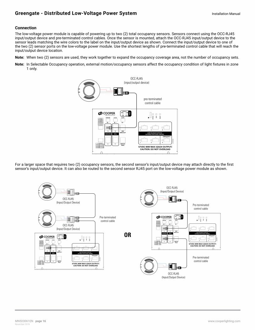
ConnectionThe low-voltage power module is capable of powering up to two (2) total occupancy sensors. Sensors connect using the OCC-RJ45 input/output device and pre-terminated control cables. Once the sensor is mounted, attach the OCC-RJ45 input/output device to the sensor leads matching the wire colors to the label on the input/output device as shown. Connect the input/output device to one of the two (2) sensor ports on the low-voltage power module. Use the shortest lengths of pre-terminated control cable that will reach the input/output device location.
ote: N When two (2) sensors are used, they work together to expand the occupancy coverage area, not the number of occupancy sets.
ote: N In Selectable Occupancy operation, external motion/occupancy sensors affect the occupancy condition of light fixtures in zone 1 only.
STA
TU
S
TE
ST
RE
SE
T
4 5 6
1 2
EMERGENCY
3
LOW-VOLTAGE OUTPUTSSUITABLE FOR CLASS 2 WIRING
LL50
3018
EN
57VDC 90W MAX (EACH OUTPUT)CAUTION: DO NOT OVERLOAD
+ - + - + -
DEMAND CLOCK ALERT
LOW HIGH
TR
IM1 1 REC
BMS/OUT
2 2 SWITCHPACK
WALLSENSORS
1 2 3 4 5V Y
O N
Occ
/ Va
c
Part
ial O
n
Y
N
Y
N
Sel
ect
Occ
Occ
Sh
are
F
S
Au
to O
n
DEFAULT
10%
1
20%30%40%
2 3 4 5
DIAG
NORM
Model: O
CC
-RJ45
Occupancy Sensor C
oupler
Brown
Black
Red
Blue
pre-terminatedcontrol cable
OCC-RJ45(input/output device)
For a larger space that requires two (2) occupancy sensors, the second sensor’s input/output device may attach directly to the first sensor’s input/output device. It can also be routed to the second sensor RJ45 port on the low-voltage power module as shown.
Model: O
CC
-RJ45
Occupancy Sensor C
oupler
Brown
Black
Red
Blue
Model: O
CC
-RJ45
Occupancy Sensor C
oupler
Brown
Black
Red
Blue
Model: O
CC
-RJ45
Occupancy Sensor C
oupler
Brown
Black
Red
Blue
Model: O
CC
-RJ45
Occupancy Sensor C
oupler
Brown
Black
Red
Blue
STA
TU
S
TE
ST
RE
SE
T
4 5 6
1 2
EMERGENCY
3
LOW-VOLTAGE OUTPUTSSUITABLE FOR CLASS 2 WIRING
LL50
3018
EN
57VDC 90W MAX (EACH OUTPUT)CAUTION: DO NOT OVERLOAD
+ - + - + -
DEMAND CLOCK ALERT
LOW HIGH
TR
IM
1 1 RECBMS/OUT
2 2 SWITCHPACK
WALLSENSORS
1 2 3 4 5V Y
O N
Occ
/ Va
c
Part
ial O
n
Y
N
Y
N
Sel
ect
Occ
Occ
Sh
are
F
S
Au
to O
n
DEFAULT
10%
1
20%30%40%
2 3 4 5
DIAG
NORM
OCC-RJ45(Input/Output Device)
OCC-RJ45(Input/Output Device)
OCC-RJ45(Input/Output Device)
Pre-terminatedcontrol cable
Pre-terminatedcontrol cable
Pre-terminatedcontrol cable
OR
OCC-RJ45(Input/Output Device)
MN503061EN page 17November 2019
www.cooperlighting.com
Installation Manual Greengate - Distributed Low-Voltage Power System
Daylight Sensor (open loop)
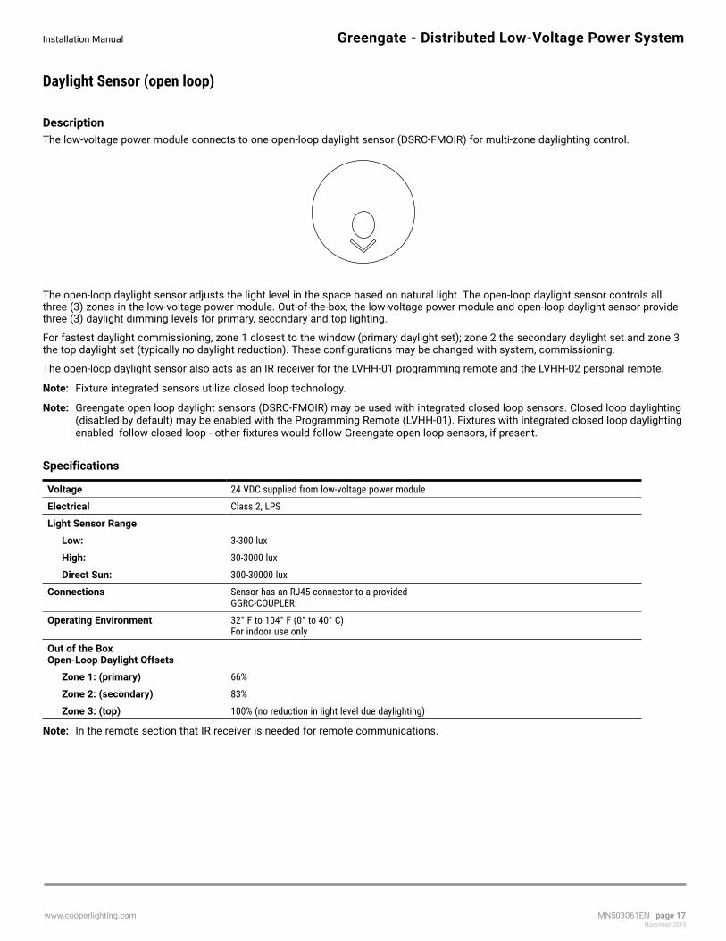
DescriptionThe low-voltage power module connects to one open-loop daylight sensor (DSRC-FMOIR) for multi-zone daylighting control.
The open-loop daylight sensor adjusts the light level in the space based on natural light. The open-loop daylight sensor controls all three (3) zones in the low-voltage power module. Out-of-the-box, the low-voltage power module and open-loop daylight sensor provide three (3) daylight dimming levels for primary, secondary and top lighting.
For fastest daylight commissioning, zone 1 closest to the window (primary daylight set); zone 2 the secondary daylight set and zone 3 the top daylight set (typically no daylight reduction). These configurations may be changed with system, commissioning.
The open-loop daylight sensor also acts as an IR receiver for the LVHH-01 programming remote and the LVHH-02 personal remote.
ote: N Fixture integrated sensors utilize closed loop technology.
ote: N Greengate open loop daylight sensors (DSRC-FMOIR) may be used with integrated closed loop sensors. Closed loop daylighting (disabled by default) may be enabled with the Programming Remote (LVHH-01). Fixtures with integrated closed loop daylighting enabled follow closed loop - other fixtures would follow Greengate open loop sensors, if present.
Specifications
Voltage 24 VDC supplied from low-voltage power module
Electrical Class 2, LPS
Light Sensor Range
Low: 3-300 lux
High: 30-3000 lux
Direct Sun: 300-30000 lux
Connections Sensor has an RJ45 connector to a provided GGRC-COUPLER.
Operating Environment 32° F to 104° F (0° to 40° C) For indoor use only
Out of the Box Open-Loop Daylight Offsets
Zone 1: (primary) 66%
Zone 2: (secondary) 83%
Zone 3: (top) 100% (no reduction in light level due daylighting)
ote: N In the remote section that IR receiver is needed for remote communications.

MN503061EN page 18November 2019
www.cooperlighting.com
Installation ManualGreengate - Distributed Low-Voltage Power System
InstallationThe open-loop daylight sensor can be mounted to a ceiling tile or fixture using the threaded post and locking washer in materials up to a 0.75” thick. The accessory mounting bracket (DSCM-MT) allows the open-loop daylight sensor to be mounted to a hard wall.
• Ensure the open-loop daylight sensor is not obstructed and is not looking directly at electric lighting.
• For skylights that contain motor controls, ensure the open-loop daylight sensor is mounted below the daylight blocking mechanism.
• Remember to adjust the sensor head to point the arrow and lens in the correct position (see examples below).
• Ensure the open-loop daylight sensor is not looking directly out the window or skylight.
Sensor Cable to Coupler(GGRC-COUPLER)
threaded mounting post
ceiling
locking washer
adjustable daylightsensor dome
daylight sensorviewing lens
Mount the daylight sensor one to two times the window height from the window wall. Position the sensor so its lens and arrow is pointed toward the window.
For narrower spaces, mount the daylight sensor near the window with the sensor lens and arrow facing away from the window and pointing into the space.
For skylights mount the daylight sensor on the south wall of theskylight well so that the lens is aimed at the north wall. Ensure the arrow and lens are pointed up.
Area viewed bydaylight sensor
Area viewed bydaylight sensor
Area viewed bydaylight sensor
Ceiling Location Narrow Location Skylight Location
60° 60°
60°
MN503061EN page 19November 2019
www.cooperlighting.com
Installation Manual Greengate - Distributed Low-Voltage Power System
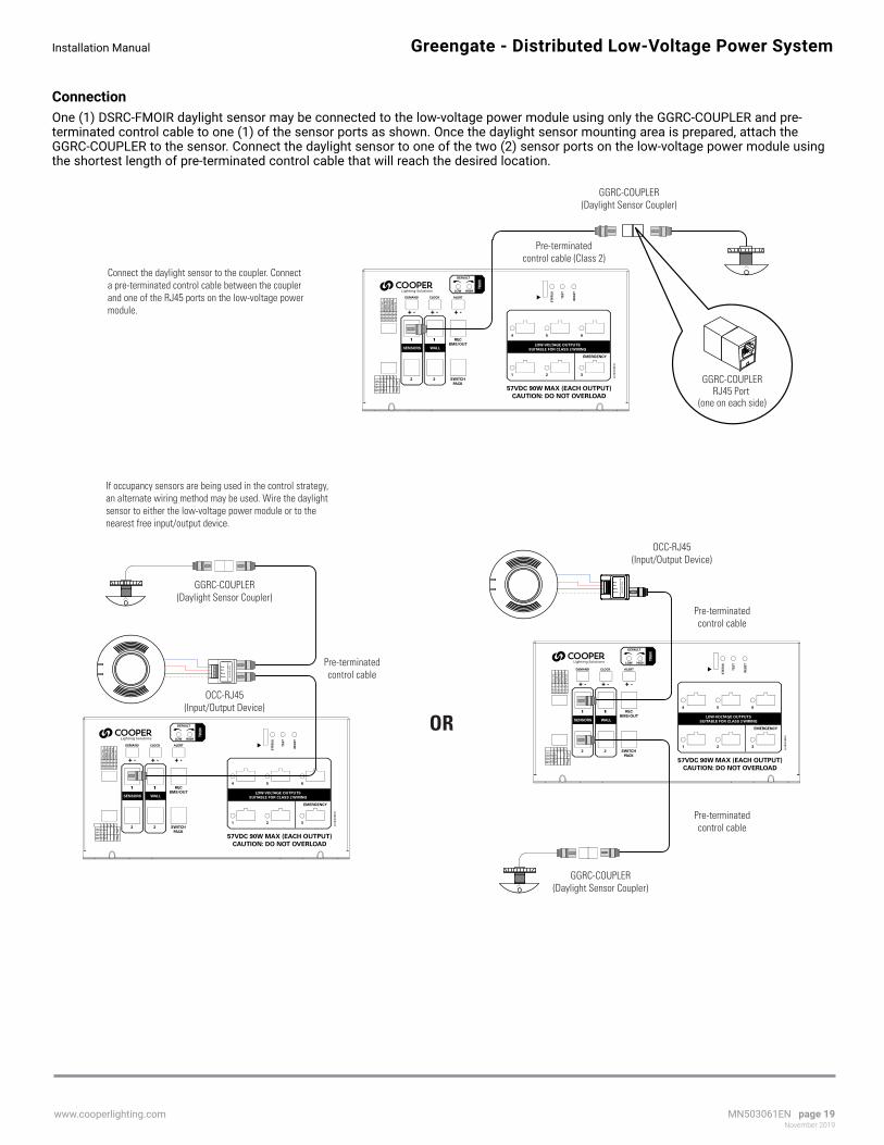
ConnectionOne (1) DSRC-FMOIR daylight sensor may be connected to the low-voltage power module using only the GGRC-COUPLER and pre-terminated control cable to one (1) of the sensor ports as shown. Once the daylight sensor mounting area is prepared, attach the GGRC-COUPLER to the sensor. Connect the daylight sensor to one of the two (2) sensor ports on the low-voltage power module using the shortest length of pre-terminated control cable that will reach the desired location.
STA
TU
S
TE
ST
RE
SE
T
4 5 6
1 2
EMERGENCY
3
LOW-VOLTAGE OUTPUTSSUITABLE FOR CLASS 2 WIRING
LL50
3018
EN
57VDC 90W MAX (EACH OUTPUT)CAUTION: DO NOT OVERLOAD
+ - + - + -
DEMAND CLOCK ALERT
LOW HIGH
TR
IM
1 1 RECBMS/OUT
2 2 SWITCHPACK
WALLSENSORS
1 2 3 4 5V Y
O N
Occ
/ Va
c
Part
ial O
n
Y
N
Y
N
Sel
ect
Occ
Occ
Sh
are
F
S
Au
to O
n
DEFAULT
10%
1
20%30%40%
2 3 4 5
DIAG
NORM
Model: O
CC
-RJ45
Occupancy Sensor C
oupler
Brown
Black
Red
Blue
Model: O
CC
-RJ45
Occupancy Sensor C
oupler
Brown
Black
Red
Blue
OCC-RJ45(Input/Output Device)
GGRC-COUPLER(Daylight Sensor Coupler)
GGRC-COUPLER(Daylight Sensor Coupler)
GGRC-COUPLER(Daylight Sensor Coupler)
GGRC-COUPLERRJ45 Port
(one on each side)
Pre-terminatedcontrol cable
Pre-terminatedcontrol cable
Pre-terminatedcontrol cable (Class 2)
Pre-terminatedcontrol cable
If occupancy sensors are being used in the control strategy, an alternate wiring method may be used. Wire the daylight sensor to either the low-voltage power module or to the nearest free input/output device.
Connect the daylight sensor to the coupler. Connect a pre-terminated control cable between the coupler and one of the RJ45 ports on the low-voltage powermodule.
OR
OCC-RJ45(Input/Output Device)

MN503061EN page 20November 2019
www.cooperlighting.com
Installation ManualGreengate - Distributed Low-Voltage Power System
BMS / Egress OutputConnect the OCC-RJ45 Input/Output Device to the BMS system. Use 18 AWG unshielded, 2 conductor twisted pair wiring for connection. Maximum distance must not exceed 1000 ft. (300m). Closure will be made across the Blue and Red terminal locations. Connect a pre-terminated control cable between the REC/BMS/OUT RJ45 port on the low-voltage power module and to one of the ports on the OCC-RJ45 ports.
A low-voltage power module provides a dry contact closure output to a BMS or other system to indicate that the room is occupied. The BMS output will close when the occupancy sensor senses motion (even when in vacancy mode), when any switch button is pressed to turn lighting loads ON, or when time clock drives business hours operation. The BMS output will open when the occupancy sensor no longer senses motion or, in applications where there is no occupancy sensor, when commanded into automatic shutoff (after-hours) mode from an external contact.
ote: N When using Selectable Occupancy mode, motion detected in any occupancy set / zone results in the BMS / Egress Output contact closure.
STA
TU
S
TE
ST
RE
SE
T
4 5 6
1 2
EMERGENCY
3
LOW-VOLTAGE OUTPUTSSUITABLE FOR CLASS 2 WIRING
LL50
3018
EN
57VDC 90W MAX (EACH OUTPUT)CAUTION: DO NOT OVERLOAD
+ - + - + -
DEMAND CLOCK ALERT
LOW HIGH
TR
IM
1 1 RECBMS/OUT
2 2 SWITCHPACK
WALLSENSORS
1 2 3 4 5V Y
O N
Occ
/ Va
c
Part
ial O
n
Y
N
Y
N
Sel
ect
Occ
Occ
Sh
are
F
S
Au
to O
n
DEFAULT
10%
1
20%30%40%
2 3 4 5
DIAG
NORM
Model: OCC-RJ45
Occupancy Sensor Coupler
Blue
RedBlack
BrownM
odel: OC
C-R
J45O
ccupancy Sensor Coupler
Brown
Black
Red
Blue
BMSsystem
OCC-RJ45(Input/Output Device)
RJ45 portsClosure to BMS system
Red
Blue
pre-terminatedcontrol cable
(Class 2)
Connect the OCC-RJ45 Input/Output Device to the BMS system.
Closure will be made across the Blue and Red wire locations.
Connect a pre-terminated control cable between the REC/BMS/OUT RJ45 port on the low-voltage power module and to one of the ports on the OCC-RJ45 ports.
(Class 2)
Press Here
CAUTION
The receptacle and BMS ports support the use of a receptacle switchpack or BMS Output. Do not tie both items into the port at the same time. Presence of the receptacle switchpack will cause 24 VDC to be present on the BMS output which may cause damage to the connected system.

MN503061EN page 21November 2019
www.cooperlighting.com
Installation Manual Greengate - Distributed Low-Voltage Power System
Receptacle Rated Switchpack
DescriptionThe Receptacle rated Switchpack includes a 20A relay for ON/OFF control of connected outlets. The Receptacle Rated Switchpack connects to the low-voltage power module to provide energy efficient control of receptacles.
Controlled receptacles will switch OFF when occupancy sensor(s) no longer sense motion (after occupancy hold time expires). In applications where no occupancy sensors are used, controlled receptacles are switched OFF by after hours time clock closure and after manual control time out expires (1-hour after last button press). The receptacle output will not blink-warn in automatic shutoff (after-hours) mode.
The receptacle control switchpack mounts to a standard four inch square junction box. All line voltage connections are made via flying leads. Connect the Receptacle Rated Switchpack to the low-voltage power module using a pre-terminated control RJ45 cable.
Specifications
Electrical Ratings Input Voltage 120 VAC 50/60Hz Relay Rating 120, 240, 277 VAC 50/60Hz General Use: 20A Standard Ballast: 20A Electronic Ballast: 16A Incandescent Load: 20A Motor Load: 1HP @ 120 VAC Control Voltage 24 VDC supplied by receptacle switchpackController Connections Line Voltage Flying leads Low-voltage power module RJ45 port/pre-terminated control cableOperating Environment 32° F to 104° F (0° to 40° C) For indoor use only.Housing Medium impact injection molded plastic housing. ABS resin complies with UL 94V0.
Plenum rated for external junction box mounting, with Teflon coated leads.

MN503061EN page 22November 2019
www.cooperlighting.com
Installation ManualGreengate - Distributed Low-Voltage Power System
InstallationThe Receptacle Rated Switchpack may be connected to a low-voltage power module for control of a 20A receptacle circuit as shown. Up to five (5) switchpacks can be connected to the low-voltage power module using the GGRC-SPLITTER accessory. Receptacles will be turned on when the occupancy sensor senses motion (in both occupancy and vacancy mode) or when any switch or remote button (regardless of zone) is pressed to turn lighting loads ON.
J Box
switchpack
All line voltage connections are made via pigtails with approved connectors.
ote: N Connect the black supply lead to the power source.
ote: N For details on receptacle rated switchpack operations, see DLVP Time Clock/Occupancy State section

MN503061EN page 23November 2019
www.cooperlighting.com
Installation Manual Greengate - Distributed Low-Voltage Power System
Connecting one switchpack: Connecting multiple switchpacks:
STA
TU
S
TE
ST
RE
SE
T
4 5 6
1 2
EMERGENCY
3
LOW-VOLTAGE OUTPUTSSUITABLE FOR CLASS 2 WIRING
LL50
3018
EN
57VDC 90W MAX (EACH OUTPUT)CAUTION: DO NOT OVERLOAD
+ - + - + -
DEMAND CLOCK ALERT
LOW HIGH
TR
IM1 1 REC
BMS/OUT
2 2 SWITCHPACK
WALLSENSORS
1 2 3 4 5V Y
O N
Occ
/ Va
c
Part
ial O
n
Y
N
Y
N
Sel
ect
Occ
Occ
Sh
are
F
S
Au
to O
n
DEFAULT
10%
1
20%30%40%
2 3 4 5
DIAG
NORM
connect the switchpack to the power module
via the switchpack port using a pre-terminated control cable
120VAC Hot
Neutral
BlueBlueWhite/BlackBlack
line voltage wiringto receptacle(s)Line In
receptacle
SPRC-R-20-120(receptacle rated switchpack)
RJ45 port
pre-terminatedcontrol cable
STA
TU
S
TE
ST
RE
SE
T
4 5 6
1 2
EMERGENCY
3
LOW-VOLTAGE OUTPUTSSUITABLE FOR CLASS 2 WIRING
LL50
3018
EN
57VDC 90W MAX (EACH OUTPUT)CAUTION: DO NOT OVERLOAD
+ - + - + -
DEMAND CLOCK ALERT
LOW HIGH
TR
IM
1 1 RECBMS/OUT
2 2 SWITCHPACK
WALLSENSORS
1 2 3 4 5V Y
O N
Occ
/ Va
c
Part
ial O
n
Y
N
Y
N
Sel
ect
Occ
Occ
Sh
are
F
S
Au
to O
n
DEFAULT
10%
1
20%30%40%
2 3 4 5
DIAG
NORM
line voltage wiringto receptacle(s)
120VAC Hot
Neutral
Black
Line In
receptacle
SPRC-R-20-120(receptacle rated switchpack)
RJ45 port
BlueBlueWhite/Black
120VAC Hot
Neutral
BlueBlueWhite/BlackBlack
line voltage wiringto receptacle(s)Line In
receptacle
SPRC-R-20-120(receptacle rated switchpack)
RJ45 port
*NOTE: Each cable length not to exceed 100 ft. Total length no to exceed 400ft.
GGRG-SPLITTER(1 to 2 cable splitter)
pre-terminatedcontrol cable
CAUTION
The REC / BMS OUT port is capable of supporting up to five (5) receptacle switchpacks. The use of additional switchpacks may cause damage to the connected system. The receptacle and BMS ports support the use of a receptacle switchpack or BMS Output. Do not tie both items into the port at the same time. Presence of the receptacle switchpack will cause 24 VDC to be present on the BMS out-put which may cause damage to the connected system.

MN503061EN page 24November 2019
www.cooperlighting.com
Installation ManualGreengate - Distributed Low-Voltage Power System
System Settings and Configuration
Low-Voltage Power Module SettingsLow-voltage power modules may be configured to satisfy the desired control intent of the many spaces via DIP switches located on the low voltage panel as shown. Please use the tables below to configure the low-voltage power module using these DIP switches.
+ - + - + -
DEMAND CLOCK ALERT
LOW HIGH
TR
IM
1 1 RECBMS/OUT
2 2 SWITCHPACK
WALLSENSORS
1 2 3 4 5V Y
O N
Occ
/ Va
c
Part
ial O
n
Y
N
Y
N
Sel
ect
Occ
Occ
Sh
are
F
S
Au
to O
n
DEFAULT
10%
1
20%30%40%
2 3 4 5
DIAG
NORM
Set A
Set B
DIP Switch Set A
Switch # / Mode Position Operation
1 / Occupancy V Vacancy mode
O Occupancy mode
2 / Partial ON Y Partial ON 50% (or less based on daylighting, trim, etc.)
N Scene 6 (default is FULL based on high end trim – (Subject to daylighting, trim, etc.)
3 Selectable Occupancy Y Each zone is an occupancy set (requires integrated sensors)
N All fixtures are in one occupancy set
4 Occupancy Sharing Y Occupancy shared between low-voltage power modules (on all shared low-voltage power modules)
N Occupancy not shared between low-voltage power modules
5 Scheduled Level F Fixed to FULL / OFF
D Default configured scenes
ote: N BOLD selections above are default.
ote: N *For information on Partial On and Partial Off, see Advanced Integration Setting section.
DIP Switch Set B
Switch # Position % Shed
1 DWN (OFF) 102 DWN (OFF)
1 UP (ON) 202 DWN (OFF)
1 DWN (OFF) 302 UP (ON)
1 UP (ON) 402 UP (ON)
3, 4 Not used (default position is DWN or OFF)5 UP (ON) System Check/Lighting Zone Confirmation (see note)5 DWN (OFF) Default operation
ote: N System Check is used by the contractor / installer to confirm each low-voltage light fixture is operation and assigned to the correct control zone. When enabled, fixtures assigned to zone 1 blink once, followed by a pause before lights in zone 2 blink twice, followed by a pause and zone 3 blinks three times. The entire blink cycle period is four seconds. The cycle repeats until the System Check mode is disabled.

MN503061EN page 25November 2019
www.cooperlighting.com
Installation Manual Greengate - Distributed Low-Voltage Power System
Scene Wallstation ProgrammingEach scene button can be programmed with user specified On/Off and dimmer settings. Using the personal remote (LVHH-02) and daylight sensor (DSRC-FMOIR or fixture integrated sensors) the user can define and save up to six (6) scenes to be recalled later from the scene buttons on the wallstation or the personal remote.
Required Components • Personal remote (LVHH-02)
• Daylight sensor* (DSRC-FMOIR or fixture integrated sensors)
• Scene wallstation (ex. RC-6TSB-P3-W)
*The daylight sensor is also an IR receiver
A scene wallstation may store up to six (6) scenes. Scenes 1-5 can be triggered using scene buttons located on a scene wallstation. Scene 6 is a special scene that is triggered upon occupancy detection, turning the lighting On to this special scene. Scene 6 requires that the low-voltage power module be in Occupancy mode.
The personal remote can also trigger all six scenes and can be issued even if a scene wallstation is not connected to the low-voltage power module.
ImplementationProgrammable scenes allow the user to customize the control of the lighting in the space and are perfect for conference rooms, classrooms, lecture halls, libraries and other spaces that typically use scene based control.
ote: N Scene wallstations are not for use with the Selectable Occupancy operating mode.
Programming Scenes1. Use the Dimmer Zone raise / lower buttons on the personal remote (LVHH-02) to set the preferred zone lighting levels for a
particular scene. Any IR interface (daylight or fixture integrated sensor) on the system can be used to receive the signal.
2. Keep the remote pointed at a daylight or integrated sensor for steps 3 and 4.
3. Press the SET button on the personal remote.
4. Press the appropriate scene button S1-S6 on the personal remote to save the current light levels to that scene button for recall at a later time.
5. All lights lower and raise to indicate scene was saved.
At this point the scene is saved and can be triggered using the associated button on the wallstation or personal remote.
RC-6TSB-P2-*Scene Wallstation
Dimmer Zone Raise/Lower
Sceneslight levels to jump to those percentages
SETSaves current light levels to
selected scene
Scene 1
Scene 2
Scene 3
Scene 4
Scene 5
All OFF
MN503061EN page 26November 2019
www.cooperlighting.com
Installation ManualGreengate - Distributed Low-Voltage Power System
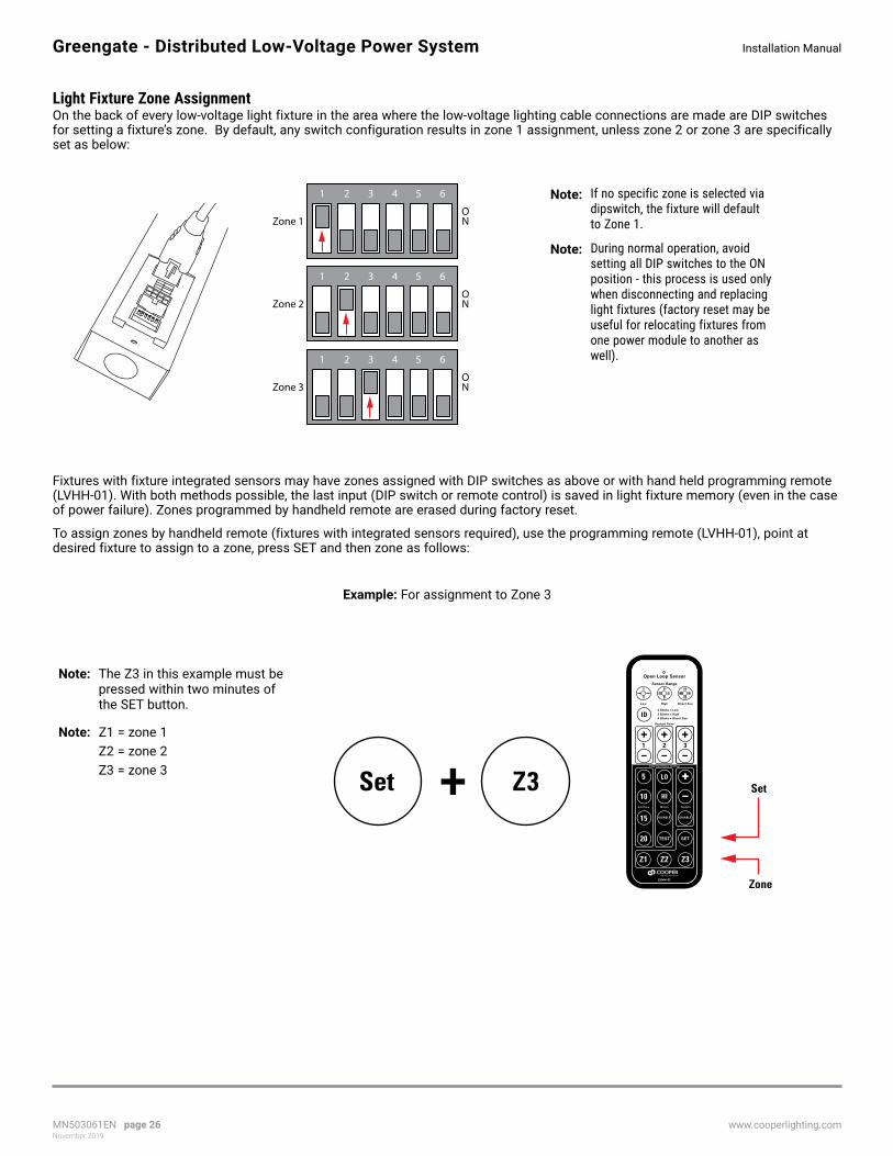
Light Fixture Zone Assignment On the back of every low-voltage light fixture in the area where the low-voltage lighting cable connections are made are DIP switches for setting a fixture’s zone. By default, any switch configuration results in zone 1 assignment, unless zone 2 or zone 3 are specifically set as below:
1 2 3 4 5 6
Zone 3ON
1 2 3 4 5 6
Zone 2ON
1 2 3 4 5 6
Zone 1ON
ote: N If no specific zone is selected via dipswitch, the fixture will default to Zone 1.
ote: N During normal operation, avoid setting all DIP switches to the ON position - this process is used only when disconnecting and replacing light fixtures (factory reset may be useful for relocating fixtures from one power module to another as well).
Fixtures with fixture integrated sensors may have zones assigned with DIP switches as above or with hand held programming remote (LVHH-01). With both methods possible, the last input (DIP switch or remote control) is saved in light fixture memory (even in the case of power failure). Zones programmed by handheld remote are erased during factory reset.
To assign zones by handheld remote (fixtures with integrated sensors required), use the programming remote (LVHH-01), point at desired fixture to assign to a zone, press SET and then zone as follows:
Example: For assignment to Zone 3
ote: N The Z3 in this example must be pressed within two minutes of the SET button.
ote: N Z1 = zone 1 Z2 = zone 2 Z3 = zone 3 +Set Z3 Set
Zone

MN503061EN page 27November 2019
www.cooperlighting.com
Installation Manual Greengate - Distributed Low-Voltage Power System
Adjusting the High and Low End TrimHigh and low trims can be adjusted to suit the needs of the user. High end trim allows the maximum light level to be turned down to a more comfortable level and reap additional energy savings. Low-end trim adjusts the light fixture dimming “cut off” point. This would typically be used to match the dimming cut-off light level of other lighting products in a space (for example, limiting a 1% dimming fixture to 10% to match other lights in the space).
Trim adjustments can be made from the front panel as shown. Using a small screwdriver, gently rotate the high and low end trim potentiometers until the desired levels are reached. The default position for low-end trim is completely counter-clockwise for dimming to 1%. For high-end trim, the default is completely clock-wise for maximum light levels. Press ALL OFF on a wallstation to confirm settings. If ALL OFF is not pressed or a controller with ALL OFF is not available, normal lighting control will resume two minutes after final adjustment.
ote: N The only wallstation button that produce actions during the two (2) minute period after final adjustment is ALL OFF. Other button inputs are ignored during that two (2) minute period.
STA
TU
S
TE
ST
RE
SE
T
4 5 6
1 2
EMERGENCY
3
LOW-VOLTAGE OUTPUTSSUITABLE FOR CLASS 2 WIRING
LL50
3018
EN
57VDC 90W MAX (EACH OUTPUT)CAUTION: DO NOT OVERLOAD
+ - + - + -
DEMAND CLOCK ALERT
LOW HIGH
TR
IM
1 1 RECBMS/OUT
2 2 SWITCHPACK
WALLSENSORS
1 2 3 4 5V Y
O N
Occ
/ Va
c
Part
ial O
n
Y
N
Y
N
Sel
ect
Occ
Occ
Sh
are
F
S
Au
to O
n
DEFAULT
10%
1
20%30%40%
2 3 4 5
DIAG
NORM
LOW HIGH
TR
IM
DEFAULT
LED System Indicators and Reset ButtonThe system has onboard status indicator LEDs to help troubleshoot technical issues.
STA
TU
S
TE
ST
RE
SE
T
4 5 6
1 2
EMERGENCY
3
LOW-VOLTAGE OUTPUTSSUITABLE FOR CLASS 2 WIRING
LL50
3018
EN
57VDC 90W MAX (EACH OUTPUT)CAUTION: DO NOT OVERLOAD
+ - + - + -
DEMAND CLOCK ALERT
LOW HIGH
TR
IM
1 1 RECBMS/OUT
2 2 SWITCHPACK
WALLSENSORS
1 2 3 4 5V Y
O N
Occ
/ Va
c
Part
ial O
n
Y
N
Y
N
Sel
ect
Occ
Occ
Sh
are
F
S
Au
to O
n
DEFAULT
10%
1
20%30%40%
2 3 4 5
DIAG
NORM
STA
TU
S
TE
ST
RE
SE
T
Operating Mode Blink Pattern
Low-Voltage power module
Normal Operation
Alert Mode
Hi-Priority Override
Demand Response
Circuit Overload
Reset: The reset button will restart the low-voltage power module’s microprocessor. When the reset is pressed, the controller will turn all lighting to full for three seconds before resuming normal control.
Status: The status indicator will flash on approximately once every two seconds indicating that the microprocessor is running.
0 sec 1 sec 2 sec

MN503061EN page 28November 2019
www.cooperlighting.com
Installation ManualGreengate - Distributed Low-Voltage Power System
Alternate Voltage SwitchpackIf an application requires mixed (class 1 and class 2) voltages, an alternative voltage switchpack may be connected to the low-voltage power module. Any Greengate switchpack may be wired to an OCCRJ45 Input/Output Device, allowing loads powered by 120 VAC, 240 VAC, 277 VAC, and 347 VAC circuits to be controlled. The switchpack will track its operation with Zone 1.
If using After-Hours Mode in lieu of motion sensors, the switchpack output will not perform the blink warn sequence with zone 1, allowing it to be used to control metal halide or other lighting loads that cannot be short cycled.
STA
TU
S
TE
ST
RE
SE
T
4 5 6
1 2
EMERGENCY
3
LOW-VOLTAGE OUTPUTSSUITABLE FOR CLASS 2 WIRING
LL50
3018
EN
57VDC 90W MAX (EACH OUTPUT)CAUTION: DO NOT OVERLOAD
+ - + - + -
DEMAND CLOCK ALERT
LOW HIGH
TR
IM
1 1 RECBMS/OUT
2 2 SWITCHPACK
WALLSENSORS
1 2 3 4 5V Y
O N
Occ
/ Va
c
Part
ial O
n
Y
N
Y
N
Sel
ect
Occ
Occ
Sh
are
F
S
Au
to O
n
DEFAULT
10%
1
20%30%40%
2 3 4 5
DIAG
NORM
Model: OCC-RJ45
Occupancy Sensor Coupler
Blue
RedBlack
Brown
Model: O
CC
-RJ45
Occupancy Sensor C
oupler
Brown
Black
Red
Blue
Line voltage from supply circuitand to lighting load
Refer to the switchpackinstallation diagram forline voltage connections
OCC-RJ45(Input/Output Device)
RJ45 portsBlack
Red
Blue
pre-terminated control cable
Connect the low-voltage wiring from the switchpack to the OCC-RJ45 Input/Output device, matching wire colors to the device label. Connect a pre-terminated control cable between the switchpack OCC-RJ45 and the SWITCHPACK port on the low-voltage power module.
Press Here
Standard Greengateswitchpack
Low voltage wiringfrom switchpack
Advanced Integration ConnectionsThe low-voltage power module allows for advanced input functionality from onboard integration control inputs including: external time clock, alert mode and demand response systems. The low-voltage power module provides inputs for an external dry contact closure.
Connect the dry contact closure to the appropriate terminal for the application. The terminal block(s) is removable for ease of wiring. Use 18 AWG unshielded, 2 conductor twisted pair wiring for connection. Maximum distance must not exceed 1000 ft. (300m).
ote: N When wiring multiple power modules to a single contact closure source, such as a time clock, maintain polarity on the wiring.

MN503061EN page 29November 2019
www.cooperlighting.com
Installation Manual Greengate - Distributed Low-Voltage Power System
+ - + - + -
DEMAND CLOCK ALERT
LOW HIGH
TR
IM
DEFAULT
Connected alternate voltage and receptacle switchpacks will not blink-warn with light fixtures. They will remain ON during the blink-warn process and will turn OFF with other lighting once the warning periods expire.
*Final light fixture dimmed level is determined by the following combination:
• High and low end trim level
• Daylighting contribution
• Demand Response value
ote: N Alert mode will override dimmed fixtures.
If enough natural light is entering the space and any of these three features have been implemented, the target light level may be lower than shown. Raise commands from pushbuttons do not override or raise the lighting above the target threshold implemented by these advanced energy saving methods.
Time Clock
Overview The DLVP low-voltage power module provides an onboard time clock input, that can be used to control lighting normally via time clock or implement partial on/ partial off controls. The low-voltage power module provides inputs for an external dry contact closure.
Connect the dry contact closure to the appropriate terminal for the application. The terminal block is removable for ease of wiring. Use 18 AWG unshielded, 2 conductor twisted pair wiring for connection. Maximum distance must not exceed 1000 ft. (300m).
Time clock commands can be sent to the low-voltage power module via dry contact input.
ote: N When wiring multiple power modules to a single time clock contact closure, maintain polarity on the wiring.
MN503061EN page 30November 2019
www.cooperlighting.com
Installation ManualGreengate - Distributed Low-Voltage Power System
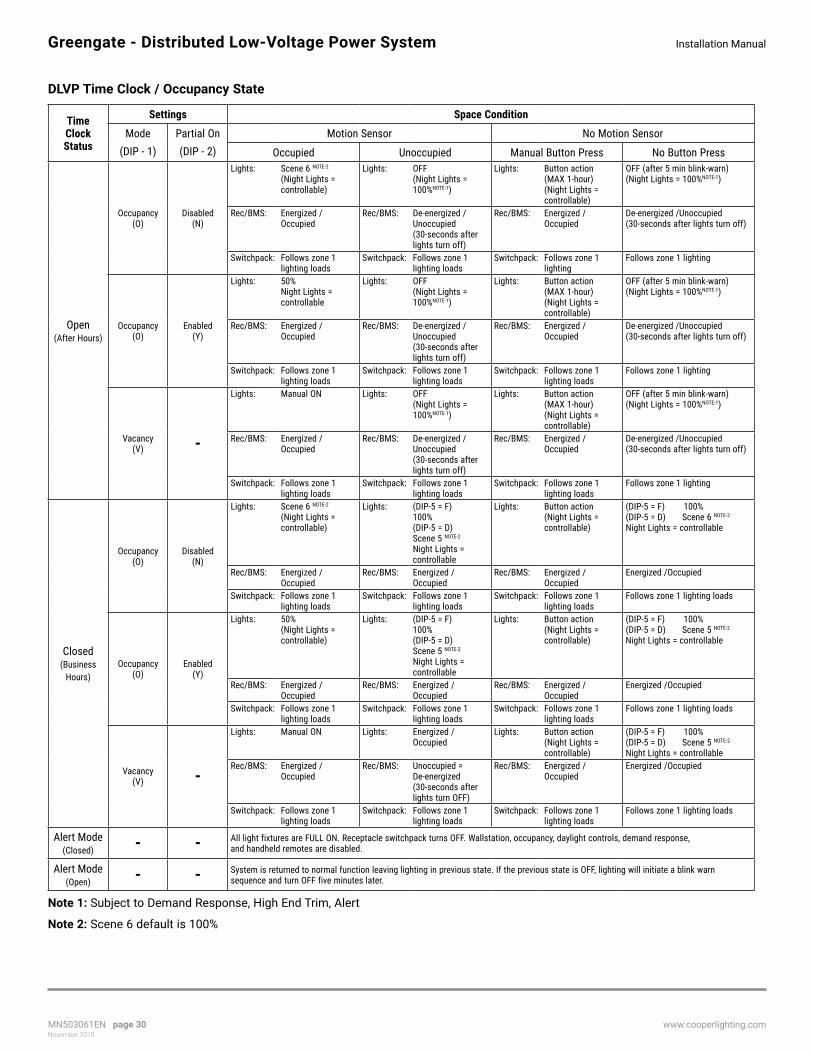
DLVP Time Clock / Occupancy State
Time Clock Status
Settings Space Condition
Mode (DIP - 1)
Partial On(DIP - 2)
Motion Sensor No Motion Sensor
Occupied Unoccupied Manual Button Press No Button Press
Open (After Hours)
Occupancy (O)
Disabled (N)
Lights:
Scene 6 NOTE-2 (Night Lights = controllable)
Lights: OFF (Night Lights = 100%NOTE-1)
Lights: Button action (MAX 1-hour) (Night Lights = controllable)
OFF (after 5 min blink-warn) (Night Lights = 100%NOTE-1)
Rec/BMS: Energized /Occupied
Rec/BMS: De-energized /Unoccupied (30-seconds after lights turn off)
Rec/BMS: Energized /Occupied
De-energized /Unoccupied (30-seconds after lights turn off)
Switchpack: Follows zone 1 lighting loads
Switchpack: Follows zone 1 lighting loads
Switchpack: Follows zone 1 lighting
Follows zone 1 lighting
Occupancy (O)
Enabled (Y)
Lights: 50% Night Lights = controllable
Lights: OFF (Night Lights = 100%NOTE-1)
Lights: Button action (MAX 1-hour) (Night Lights = controllable)
OFF (after 5 min blink-warn) (Night Lights = 100%NOTE-1)
Rec/BMS: Energized /Occupied
Rec/BMS: De-energized /Unoccupied (30-seconds after lights turn off)
Rec/BMS: Energized /Occupied
De-energized /Unoccupied (30-seconds after lights turn off)
Switchpack: Follows zone 1 lighting loads
Switchpack: Follows zone 1 lighting loads
Switchpack: Follows zone 1 lighting loads
Follows zone 1 lighting
Vacancy (V) -
Lights: Manual ON Lights: OFF (Night Lights = 100%NOTE-1)
Lights: Button action (MAX 1-hour) (Night Lights = controllable)
OFF (after 5 min blink-warn) (Night Lights = 100%NOTE-1)
Rec/BMS: Energized /Occupied
Rec/BMS: De-energized /Unoccupied (30-seconds after lights turn off)
Rec/BMS: Energized /Occupied
De-energized /Unoccupied (30-seconds after lights turn off)
Switchpack: Follows zone 1 lighting loads
Switchpack: Follows zone 1 lighting loads
Switchpack: Follows zone 1 lighting loads
Follows zone 1 lighting
Closed (Business
Hours)
Occupancy (O)
Disabled (N)
Lights:
Scene 6 NOTE-2 (Night Lights = controllable)
Lights: (DIP-5 = F) 100% (DIP-5 = D) Scene 5 NOTE-2 Night Lights = controllable
Lights: Button action (Night Lights = controllable)
(DIP-5 = F) 100% (DIP-5 = D) Scene 6 NOTE-2 Night Lights = controllable
Rec/BMS: Energized /Occupied
Rec/BMS: Energized /Occupied
Rec/BMS: Energized /Occupied
Energized /Occupied
Switchpack: Follows zone 1 lighting loads
Switchpack: Follows zone 1 lighting loads
Switchpack: Follows zone 1 lighting loads
Follows zone 1 lighting loads
Occupancy (O)
Enabled (Y)
Lights: 50% (Night Lights = controllable)
Lights: (DIP-5 = F) 100% (DIP-5 = D) Scene 5 NOTE-2 Night Lights = controllable
Lights: Button action (Night Lights = controllable)
(DIP-5 = F) 100% (DIP-5 = D) Scene 5 NOTE-2 Night Lights = controllable
Rec/BMS: Energized /Occupied
Rec/BMS: Energized /Occupied
Rec/BMS: Energized /Occupied
Energized /Occupied
Switchpack: Follows zone 1 lighting loads
Switchpack: Follows zone 1 lighting loads
Switchpack: Follows zone 1 lighting loads
Follows zone 1 lighting loads
Vacancy (V) -
Lights: Manual ON Lights: Energized /Occupied
Lights: Button action (Night Lights = controllable)
(DIP-5 = F) 100% (DIP-5 = D) Scene 5 NOTE-2 Night Lights = controllable
Rec/BMS: Energized /Occupied
Rec/BMS: Unoccupied = De-energized (30-seconds after lights turn OFF)
Rec/BMS: Energized /Occupied
Energized /Occupied
Switchpack: Follows zone 1 lighting loads
Switchpack: Follows zone 1 lighting loads
Switchpack: Follows zone 1 lighting loads
Follows zone 1 lighting loads
Alert Mode (Closed) - - All light fixtures are FULL ON. Receptacle switchpack turns OFF. Wallstation, occupancy, daylight controls, demand response,
and handheld remotes are disabled.
Alert Mode (Open) - - System is returned to normal function leaving lighting in previous state. If the previous state is OFF, lighting will initiate a blink warn
sequence and turn OFF five minutes later.
Note 1: Subject to Demand Response, High End Trim, Alert
Note 2: Scene 6 default is 100%

MN503061EN page 31November 2019
www.cooperlighting.com
Installation Manual Greengate - Distributed Low-Voltage Power System
Demand Response
Input Function Position Operation
Demand Response
Light fixtures current output is reduced by 10%, 20%, 30% or 40% of max based on DIP Switch setting.Contact Type Required: Normally Open, SPST Maintained.
Closed Light fixtures reduce by 5% over a 20 second transition, so a 20% load shed will transition over 80 seconds, for example. Controller continues to operate lighting within the reduced range.
Open Lighting levels will return to current levels (same transition rate entering and exiting demand response).
Bringing the DLVP System Online
The low-voltage power module is pre-programmed and ready for operation out-of-the-box. If no adjustments are done, the unit will operate from wallstations, daylight and occupancy sensors (including fixture integrated sensors for occupancy and daylight).
To obtain maximum energy efficiency and occupant satisfaction, complete the following checklist:
DLVP System Verification Checklist Location: _______
1 Initial Power Up Response
[ ] Apply power to the low-voltage power module.
[ ] Verify that all lighting loads turn on to full for 3 seconds before beginning normal operation.
2 Verify Occupancy Sensor Operation
[ ] Verify that the occupancy sensor has been located properly to prevent false activation.
[ ] Wait 2 minutes from power-up, then place OAC or OAWC sensors in test mode by moving DIP Switch 10 out of its current position, wait 3 seconds, then put back into its original position.
[ ] Move around the controlled area, verifying that the occupancy sensor LEDs flash with each motion and stop flashing when standing still.
[ ] If not already ON, turn lighting ON from the wallstation controls. For any stations with quiet time buttons, make sure that quiet time mode is de-activated (LED is not lit).
[ ] Leave the room and wait approximately one minute for the lighting to turn OFF.
If lighting does not turn OFF, refer to “DLVP System Troubleshooting”. Sensors will automatically exit test mode after a period of 5 to 10 minutes (timing is dependent on sensor model) and begin automatically adjusting based on occupancy patterns.
3 Verify Wallstation Operation
[ ] Check each wallstation for proper operation of intended loads.
4 Set Minimum and Maximum Trim Levels
Trim levels have been present to 0% for low end and 100% for high end. Additional energy savings can be gained by adjusting the trim further if electric lighting contribution is over the target illuminance for the space.
[ ] Locate the position of the trim level adjustment dials on the low-voltage power module.
STA
TU
S
TE
ST
RE
SE
T
4 5 6
1 2
EMERGENCY
3
LOW-VOLTAGE OUTPUTSSUITABLE FOR CLASS 2 WIRING
LL50
3018
EN
57VDC 90W MAX (EACH OUTPUT)CAUTION: DO NOT OVERLOAD
+ - + - + -
DEMAND CLOCK ALERT
LOW HIGH
TR
IM
1 1 RECBMS/OUT
2 2 SWITCHPACK
WALLSENSORS
1 2 3 4 5V Y
O N
Occ
/ Va
c
Part
ial O
n
Y
N
Y
N
Sel
ect
Occ
Occ
Sh
are
F
S
Au
to O
n
DEFAULT
10%
1
20%30%40%
2 3 4 5
DIAG
NORM
LOW HIGH
TR
IM
DEFAULT
[ ] Trim levels are to be adjusted at night or shades have been used to darken the space during daylight hours.
[ ] Using the wallstations, turn ON all controlled lighting.
[ ] Using a small screwdriver, twist the high end trim dial counter clockwise, then fully clockwise again. The lights will go full bright and the low-voltage power module will enter adjustment mode.
MN503061EN page 32November 2019
www.cooperlighting.com
Installation ManualGreengate - Distributed Low-Voltage Power System
[ ] Turn the high end trim adjustment dial counter-clockwise in small increments until the light level is at the desired maximum level.
[ ] Turn the low end trim dial clockwise then fully counter clockwise. The light level in the room will go full dim.
[ ] Turn the low end trim dial clockwise in small increments until the light level is noticed increasing in the monitored space, then turn the dial slightly counter clockwise from where this change begins.
[ ] Save the new trim settings and go back to normal operation by pressing the “ALL OFF” button on any wallstation. If “ALL OFF” is not pressed, the controller will automatically save these settings after two minutes.
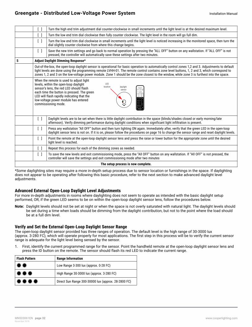
5 Adjust Daylight Dimming Response*
Out-of-the-box, the open-loop daylight sensor is operational for basic operation to automatically control zones 1,2 and 3. Adjustments to default light levels are done using the programming remote LVHH-01. The remote control contains zone level buttons, 1, 2 and 3, which correspond to zones 1, 2 and 3 on the low-voltage power module. Zone 1 should be the zone closest to the window, while zone 3 is furthest into the space.
When the remote is used to adjust light levels, within the open-loop daylight sensor’s lens, the red LED should flash each time the button is pressed. The green LED will flash rapidly indicating that the low-voltage power module has entered commissioning mode.
daylight sensor
LEDlocation
[ ] Daylight levels are to be set when there is little daylight contribution in the space (blinds/shades closed or early morning/late afternoon). Verify dimming performance during daylight conditions when significant light infiltration is present.
[ ] Press any wallstation “All OFF” button and then turn lighting ON again. Immediately after, verify that the green LED in the open-loop daylight sensor lens is not on. If it is on, please follow the procedures on page 16 to change the sensor range and reset daylight levels.
[ ] Point the remote at the open-loop daylight sensor lens and press the raise or lower button for the appropriate zone until the desired light level is reached.
[ ] Repeat this process for each of the dimming zones as needed.
[ ] To save the new levels and exit commissioning mode, press the “All OFF” button on any wallstation. If “All OFF” is not pressed, the controller will save the settings and exit commissioning mode after two minutes
The setup process is now complete.
*Some daylighting sites may require a more in-depth setup process due to sensor location or furnishings in the space. If daylighting does not appear to be operating after following this basic procedure, refer to the next section to make advanced daylight level adjustments.
Advanced External Open-Loop Daylight Level AdjustmentsFor more in-depth adjustments in rooms where daylighting does not seem to operate as intended with the basic daylight setup performed, OR, if the green LED seems to be on within the open-loop daylight sensor lens, follow the procedures below.
ote: N Daylight levels should not be set at night or when the space is not overly saturated with natural light. The daylight levels should be set during a time when loads should be dimming from the daylight contribution, but not to the point where the load should be at a full dim level.
Verify and Set the External Open-Loop Daylight Sensor RangeThe open-loop daylight sensor provided has three ranges of operation. The default level is the high range of 30-3000 lux (approx. 3-280 FC), which will operate properly for most applications. The first step in this process will be to verify the current sensor range is adequate for the light level being sensed by the sensor.
1. First, identify the current programmed range for the sensor. Point the handheld remote at the open-loop daylight sensor lens and press the ID button on the remote. The sensor should flash its red LED to indicate the current range.
Flash Pattern Range Information
Low Range 3-300 lux (approx. 0-28 FC)
High Range 30-3000 lux (approx. 3-280 FC)
Direct Sun Range 300-30000 lux (approx. 28-2800 FC)

MN503061EN page 33November 2019
www.cooperlighting.com
Installation Manual Greengate - Distributed Low-Voltage Power System
If the sensor is reading too much light for its current range setting, it will flash its green LED with a slow blink pattern (6 seconds ON, 1 second OFF, repeated)--this blink pattern may appear as if the green LED is continuously on. Adjust the range if this behavior is seen.
2. Once the current range has been determined, point the remote at the open-loop daylight sensor lens and press the button for the new desired range level. The sensor will acknowledge the new setting by flashing the red LED for the new set range.
3. If the range has been adjusted, wait one minute before making further adjustments to allow the sensor to settle. Make sure that the green LED is OFF before proceeding.
Open Loop Sensor
Sensor Range
Direct SunHighLow
daylight sensor
LEDlocation
Occupancy and Daylight Sensor LED Feedback
OAC sensor OAWC sensor
LED indicatordaylight sensor
Wallstation withQuiet Time Button
Occupancy SensorsRed LED: Indicates PIR detection of motion. The LED will flash on with each motion detected and will turn off when motion ceases.
Green LED: Indicates ultrasonic detection of motion. The LED will flash on with each motion detected and will turn off when motion ceases.
When placed in Test Mode, the red and green LEDs will flash at a faster rate when motion is detected.
Daylight SensorsRed LED: Flashes when the daylight sensor has received a signal from the LVHH-01 remote control. When the remote’s ID button is pressed, the number of flashes will indicate the current sensor range. Two = Low, Three = High, Four = Direct Sun
Green LED: Flashes slowly (ON for 6 seconds, off for 1 second, repeat) when the daylight levels in the space are higher than the current range can detect. Flashes rapidly when daylight levels are being adjusted with the LVHH-01 remote control to indicate that the controller is in Commissioning Mode.
Under normal operation, the daylight sensor LEDs will not flash.
WallstationsQuiet Time: Not supported with the DLVP system.
General
Whiteboard
Quiet Time
A/V Mode
Raise
Lower

MN503061EN page 34November 2019
www.cooperlighting.com
Installation ManualGreengate - Distributed Low-Voltage Power System
Reset Open-Loop Daylight Levels
Adjustments to default light levels are done using the open loop daylight sensor portion of the programming remote (LVHH-01). The remote control contains zone level buttons 1, 2 and 3, which correspond to zones 1, 2 and 3 on the low-voltage power module. With open-loop daylighting, zone 1 should be the zone closest to the window, while zone 3 is the furthest into the space.
When the remote is used to adjust light levels, within the open-loop daylight sensor’s lens, the red LED should flash each time the button is pressed. The green LED will flash rapidly indicating that the low-voltage power module has entered commissioning mode. To reset daylight levels and start daylight configuration from scratch, use the following procedure:
1. Ensure that daylight levels are being set during the day when lighting should be dimming from daylight contribution, but not to the point where loads should be at a full dim level.
2. Point the remote at the open-loop daylight sensor lens and press the raise or lower button for the appropriate zone until the desired level is reached.
Daylight SensorsRed LED: Flashes when the daylight sensor has received a signal from the LVHH-01 remote control. When the remote’s ID button is pressed, the number of flashes will indicate the current sensor range. Two = Low, Three = High, Four = Direct Sun
Green LED: Flashes slowly (ON for 6 seconds, off for 1 second, repeat) when the daylight levels in the space are higher than the current range can detect. Flashes rapidly when daylight levels are being adjusted with the LVHH-01 remote control to indicate that the controller is in Commissioning Mode.
Under normal operation, the daylight sensor LEDs will not flash.
3. Repeat this process for each of the dimming zones as necessary.
External sensor rangesensitivity and ID
Integrated sensordelay time
External sensordaylight gains
adjusts daylightlevels by zone
Integrated sensor daylight gains
Zone toggle
Integrated sensor sensitivity
Daylight GainsLight reduction factor associated with daylighting control.
4. To save the new levels and exit commissioning mode, press the “All OFF” button on any wallstation. If “All OFF” is not pressed, the controller will save the settings and exit commissioning mode after two minutes.
5. The low-voltage power module will now operate with the new daylight levels.

MN503061EN page 35November 2019
www.cooperlighting.com
Installation Manual Greengate - Distributed Low-Voltage Power System
Closed Loop (Fixture Integrated) Sensor Programming
OverviewCapture the benefits of traditional lighting controls, without complicated coverage planning or special wiring. Ideal for new construction or retrofit fixtures with the fixture integrated sensor delivers Automatic On to an energy saving light level (when closed loop daylighting is enabled), while ensuring lighting is turned OFF when the space is unoccupied.
The integral daylight sensor reduces the need for special daylight zone planning. Once closed loop daylighting is enabled via the programming remote (LVHH-01), each luminaire will automatically adjust the light level based on reflected light beneath the sensor.
How it works: As the user enters the space controlled by the fixture integrated sensor, the lighting turns ON to the defined light level (subject to daylight setting if enabled and demand response condition).
Lighting will remain at the specified target level until no motion is detected for the full delay time (default value is 20 minutes). At that point, the space is considered to be unoccupied.
ote: N See the DLVP Time Clock / Occupancy State section to define occupancy driven actions.
Using the Personal Remote (LVHH-02)
1
32
1 Raise / Lower ZonesManually raise and lower control zones individually
2 Save Custom ScenesOnce the light levels for each of the three (3) manual control zones are at the desired levels, use the SET button followed by a scene button to save a custom scene for recall later through this remote or through a wall mounted scene stationNote: Look for a lowering and then raising of lights to indicate the scene was properly saved
3 Scene ButtonsUse the six (6) scene buttons to recall customizable saved scenes
Note: See the Time Clock Table for functionality of Scene 5 and Scene 6

MN503061EN page 36November 2019
www.cooperlighting.com
Installation ManualGreengate - Distributed Low-Voltage Power System
Using the Programming Remote (LVHH-01) Open Loop Sensor
Sensor Range
2 Blinks = Low3 Blinks = High4 Blinks = Direct Sun
Direct SunHighLow
Daylight Gains
Integrated Sensor Settings
Motion
LVHH-01
TEST SET
++LO
ID
5
10
15
20
Z1 Z2 Z3
HI
+321
−
+
−
+
−
DISABLE DISABLE
DaylightHold Time
−
6
2
1
5
4
3
1 Toggle Zones (manual control)• Use the Z1, Z2, & Z3 buttons to manually toggle
each zone ON/OFF
Assign Fixtures to Control Zones (requires integrated sensors)• While pointed at a specific fixture’s sensor, press
SET followed by one of the three zone buttons to assign that fixture to a control zone (independent of fixture DIP switch setting)
2 Enable and Set Daylight Targets (integrated sensor only)Use the + or – button to enable closed loop daylighting on a fixture with an integrated sensor. Adjust to the preferred illuminance target for that fixture by the method below:Set Closed Loop Target Illuminance (this is setting the target illuminance when the light is at its MAX output)
• Make sure there is not excessively bright illumination source near the target area. Daylight levels are best set when there is little daylight contribution in the space (blinds/shades closed or early morning/late afternoon). Verify dimming performance during daylight conditions when significant light infiltration is present.• Use the gain raise / lower buttons on the programming remote (LVHH-01) to adjust the fixture light level to the MAX desirable level. Use of a light meter for this step is recommended.• After two minutes of fixture inactivity, the new target illuminance setting is programmed. There is no need to press any other button to program. Once the setting is programmed, the indicator light on the sensor will blink quickly for a short time.• This process must be performed for each fixture containing a fixture integrated sensor.
Disabling Closed Loop Daylighting (integrated sensor only) Point the LVHH-01 remote at a sensor and press the DISABLE button. The LED in the sensor will blink and the light fixture will blink confirming the command has been received. The system will include any disabled fixture in any applicable open loop daylighting set.To re-enable closed loop daylighting, press the raise (+) or lower (-) button on the remote.
3 Sensor Delay Time Value (integrated sensor only)Set the time (5, 10, 15, or 20 minutes) the sensor will delay after seeing last motion before turning the lights to the unoccupied condition (typically OFF)
4 Occupancy Sensor Sensitivity Level (integrated sensor only)Press the “LO” button to put the occupancy sensor into the Low (50%) sensitivity mode which reduces the effective coverage area of the motion sensor.Press the “HI” button to put the occupancy sensor into the High (full) coverage sensitivity mode.
Disable Occupancy Sensing (integrated sensor only)Point the LVHH-01 remote at a fixture and press the DISABLE button. The LED on the sensor and the light fixture will flash confirming the command was received.To re-enable the occupancy detection, press the HIGH or LOW button.
Test Mode (integrated sensors only)Point the LVHH-01 remote at a sensor and press the TEST button. The LED on the sensor and the light fixture will blink confirming the command was received.The sensor will remain in test mode for 10-mintues. While in test mode, the occupancy hold time is set to 10-seconds. The sensor will resume normal operation 10-minutes after the last TEST button press.

MN503061EN page 37November 2019
www.cooperlighting.com
Installation Manual Greengate - Distributed Low-Voltage Power System
5 External Open Loop Daylight Gain SettingsUse the raise and lower buttons to adjust the daylight gains (daylight scaling factor) for each of the three (3) daylight sets (By convention, Zone 1 is the primary daylight set adjacent to the window, Zone 2 is secondary, and Zone 3 is top lighting)
6 External Open Loop Daylight Sensor Range Setting and IDUse the Range buttons to establish the light sensor range of the sensor based on the table below: Low = 3 – 300 Lux High = 30 – 3000 Lux Direct Sun = 300 – 30,000 LuxThe ID button is used to used to verify the current sensor daylight range setting of the external open loop sensor – see Verify and Set the External Open-Loop Daylight Sensor Range section for more details
DLVP System Troubleshooting
Lights will not turn ONIssue Possible Causes Suggestions
Lights will not turn ON automatically
Vacancy Mode set on Low-voltage power module
Low-voltage power module may be in vacancy mode. In vacancy mode, lights turn on when wallstation button is pressed.
Vacancy Mode set on Occupancy Sensor
If a sensor is being used that has an automatic/manual mode, ensure that the sensor is in automatic mode.
Connection Issue Verify that all connections are connected to the correct ports for the accessories being used.
Lights will not turn ON from wallstations
Connection Issue Verify that all connections are connected to the correct ports for the accessories being used.
Microprocessor Verify that the low-voltage power module status LED is flashing. If it is flashing, press and release the reset button and verify that lighting turns ON for 3 seconds. If there is no response, contact technical support.
Power Interruption If the low-voltage power module status LED is not flashing, check incoming voltage and/or wiring.
If still having trouble with lighting turning ON, consult Troubleshooting Guide or call Technical Services at 1-800-553-3879
Lights will not turn OFFIssue Possible Causes Suggestions
Lights will not turn OFF automatically
Occupancy Sensor Turn zone OFF using the programming remote (LVHH-01) to verify the lights will turn off.Verify the occupancy sensor is properly sensing lack of motion, is not located within 4-6 feet of air vents, make sensitivity adjustments if necessary.Place occupancy sensors in test mode to verify lighting turns OFF.Verify that the occupancy sensor is not overridden (DIP Switch 8 up).Make sensitivity adjustments if necessary.
Quiet Time If the wallstation has a Quiet Time button, ensure that this is not activated. Motion sensors are ignored during the 60-minute quiet time count down.
Occupancy Sensor or Time Clock connections are not present
To turn lighting OFF automatically, the low-voltage power module requires either a vacancy command from an occupancy sensor, OR a time clock command to automatic shutoff (after-hours) mode.
Alert Mode If alert mode has been activated, lighting will be on and full bright until the alert is cleared. Disconnect contact into the alert mode terminal to verify normal operation resumes. Troubleshoot the connected system to determine the cause of the alert signal.
Lights will not turn OFF from wallstations
Connection Issue Verify that all connections are connected to the correct ports for the accessories being used.
Alert Mode If alert mode has been activated, lighting will be ON and full bright until the alert is cleared. Disconnect contact into the alert mode terminal to verify normal operation resumes. Troubleshoot the connected system to determine the cause of the alert signal.
If still having trouble with lighting turning ON, consult Troubleshooting Guide or call Technical Services at 1-800-553-3879

MN503061EN page 38November 2019
www.cooperlighting.com
Installation ManualGreengate - Distributed Low-Voltage Power System
Lights turn OFF unexpectedlyIssue Possible Causes Suggestions
Lights will not remain ON (Lights turn OFF approx. 30 seconds after the ON command)
The controller senses that there is an occupancy sensor connected but is not seeing an occupied signal from the sensor.
Verify that the occupancy sensor LEDs are flashing when motion is occurring.Make sure that the occupancy sensor coupler is connected to the correct wires from the occupancy sensor.If the occupancy sensor being used has an Auto/Manual selection, verify that the occupancy sensor is in auto mode.Verify that a VAC model sensor is not being used.
Lights will not remain ON (Lights turn OFF approx. 60 minutes after the ON command)
Automatic shutoff (after-hours) mode The low-voltage power module is in automatic shutoff (after-hours) mode. Verify that the system connected to the time clock input has been programmed for the correct times. A closure indicates automatic shutoff (after-hours) mode where 60-minute timers will run. An open state indicates normal mode.
Lights will not remain ON
The Occupancy sensitivity may be set to LOW
Verify that movement in the space causes the red LED to flash.Using the programming remote (LVHH-01) push the “HI” button.Using the programming remote (LVHH-01) push the zone ON button to ensure the fixture has power.
If still having trouble with lighting turning ON, consult Troubleshooting Guide or call Technical Services at 1-800-553-3879
Lighting level will not raise or lower as expectedIssue Possible Causes Suggestions
Lights turn ON but remain at a dimmed level (lighting does not respond to dimming raise controls)
Demand Response Demand response mode may have caused light levels to automatically reduce. Check contact from demand response system. Verify that the demand response energy options DIP switches are set for the appropriate lighting level.
Daylighting Daylight levels may not be correct for the space. Press the reset button on the controller to verify loads turn ON to Full ON for 3 seconds. If loads go Full ON, then resume dimmed level:Look in the Open-loop daylight Sensor lens to determine if the green LED is ON fairly steadily. If it is, the sensor is seeing more daylight than its range will allow. Set a new range using the LVHH-01 remote and the advanced daylight level adjustment procedures in the installation instructions.If the Open-loop daylight sensor’s green LED is not on, use the LVHH-01 remote to adjust daylight levels per the advanced daylight level adjustment procedures in the installation instructions.Check the High End trim pot to ensure it is not set all the way counter-clockwise.
Lights turn ON but remain at a full bright level (lighting does not respond to dimming lower controls)
Alert Mode If alert mode has been activated, lighting will be ON and full bright until the alert is cleared. Disconnect contact into the alert mode terminal to verify normal operation resumes. Troubleshoot the connected system to determine the cause of the alert signal.
Lights turn ON at a full bright level and responds to manual dim-ming lower con-trols but do not appear to dim automatically from daylight-ing
Daylighting Verify that the open-loop daylight sensor is installed in a location that is not obstructed from receiving daylight.Verify that the open-loop daylight sensor is properly connected to the low-voltage power module per the installation instructions.Verify that the open-loop daylight sensor lens is oriented properly for the location it is installed in.The sensor range may be set too high. If the sensor is located in a darker location, try reducing the sensor range to a lower range using the instructions in the advanced daylight level adjustment section.Use the HHPR-01 remote to adjust daylight levels per the advanced daylight level adjustment procedures in the installation instructions.

MN503061EN page 39November 2019
www.cooperlighting.com
Installation Manual Greengate - Distributed Low-Voltage Power System
Lights turn ON but remain at full bright level
Daylighting Daylight levels may not be correct for the space.Using the personal remote (LVHH-02) or a connected wallstation, press the lower button to ensure the light level can go lower.Use the programming remote (LVHH-01) to adjust the daytime occupied light level.
Lights turn ON but remain at a full bright level (lighting does not respond to dimming lower controls)
Alert Mode If alert mode has been activated, lighting will be ON and full bright until the alert is cleared. Disconnect contact into the alert mode terminal to verify normal operation resumes. Troubleshoot the connected system to determine the cause of the alert signal.
Fixtures do not respond to open loop daylight sensors
Connection Issue Check to see if closed loop fixture integrated sensors are on the same system. When open loop and closed loop fixture integrated sensors are on the same system, the open loop daylight sensors are ignored. Remove the open loop or closed loop fixture integrated sensors so that both are not on the same system.
If still having trouble with lighting turning ON, consult Troubleshooting Guide or call Technical Services at 1-800-553-3879
Receptacle switchpacks are not responding as expectedIssue Possible Causes Suggestions
Receptacle switchpacks will not turn ON
Alert Mode Alert mode turns OFF all receptacle switchpacks while the alert is active. Disconnect contact into the alert mode terminal to verify normal operation resumes. Troubleshoot the connected system to determine the cause of the alert signal.
Connection Issue Verify that all connections are connected to the correct ports for the accessories being used.
Power Interruption Check incoming voltage and/or wiring to the receptacle switchpacks.
Receptacle switchpacks will not turn OFF
Occupancy Sensor or Time Clock connections are not present
The receptacle switchpacks require either a vacancy command from an occupancy sensor, OR a time clock command to automatic shutoff (after-hours) mode to turn OFF. Wallstations do not cause receptacles to turn OFF. Ensure that one of these methods is being used to successfully integrate receptacle switchpacks.
If still having trouble with lighting turning ON, consult Troubleshooting Guide or call Technical Services at 1-800-553-3879
Miscellaneous IssuesIssue Possible Causes Suggestions
Lighting turns ON but is not in the right zone
Zone Assignment Verify that fixtures have been assigned to the appropriate zone (1, 2, or 3) to meet the application.
How to know if the integrated sensor is work-ing on power up
Occupancy Sensor Energize the low-voltage power module. The light should start at 50% light level and then raise or lower to the daylight level.The red LED on the sensor should slow blink (ON for 2 seconds, OFF for 2 seconds) for a 1-minute duration then blink only on occupancy.Using the programming remote (LVHH-01) press the zone ON/OFF button to ensure the light fixture turns ON/OFF.
One or more lights on a low-voltage circuit does not come on
Connection Issue If status light on low-voltage power module is blinking, circuit is overloaded. Remove last fixture and cable from that circuit and press RESET button on low-voltage power module.
If still having trouble with lighting turning ON, consult Troubleshooting Guide or call Technical Services at 1-800-553-3879

MN503061EN page 40November 2019
Cooper Lighting Solutions1121 Highway 74 SouthPeachtree City, GA 30269P: 770-486-4800www.cooperlighting.comFor service or technical assistance:1-800-553-3879
Canada Sales 5925 McLaughlin RoadMississauga, Ontario L5R 1B8P: 905-501-3000F: 905-501-3172
© 2020 Cooper Lighting SolutionsAll Rights Reserved. Product availability, specifications, and compliances are subject to change without notice.
Installation ManualGreengate - Distributed Low-Voltage Power System
Warranties and Limitation of LiabilityPlease refer to www.cooperlighting.com for our terms and conditions.
Garanties et limitation de responsabilitéVeuillez consulter le site www.cooperlighting.com pour obtenir les conditions générales.
Garantías y Limitación de ResponsabilidadVisite www.cooperlighting.com para conocer nuestros términos y condiciones.
FCC StatementNote: This equipment has been tested and found to comply with the limits for a Class A digital device, pursuant to part 15 of the FCC Rules. These limits are designed to provide reasonable protection against harmful interference when the equipment is operated in a commercial environment. This equipment generates, uses, and can radiate radio frequency energy and, if not installed and used in accordance with the instruction manual, may cause harmful interference to radio communications. Operation of this equipment in a residential area is likely to cause harmful interference in which case the user will be required to correct the interference at his own expense.
Related Documents