Green Stormwater Infrastructure Planning & Design Manual Version 3.0 January 2021

Welcome message from author
This document is posted to help you gain knowledge. Please leave a comment to let me know what you think about it! Share it to your friends and learn new things together.
Transcript
Green Stormwater Infrastructure Planning & Design Manual Version 3.0 January 2021

GSI Planning & Design Manual | Version 3.0 January 2021
pg. 2

pg. 3
GSI Planning & Design Manual | Version 3.0 January 2021
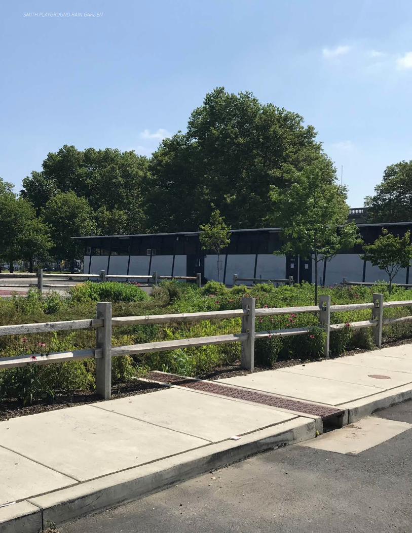
SMITH PLAYGROUND RAIN GARDEN
S c o p e
pg. 5
GSI Planning & Design Manual | Version 3.0 January 2021
Additional Resources(Found Online)
• Project Management
Resources• Data & Metadata• Design Guidance
Documents• Geotechnical
Guidelines• Drawing & Survey
Standards• Landscape Design
Guidebook• Typical Details• Maintenance Manual
• Partner Permits
Scope of Work(Project Specific)
• Project Requirements• Deliverables• Detailed Schedule
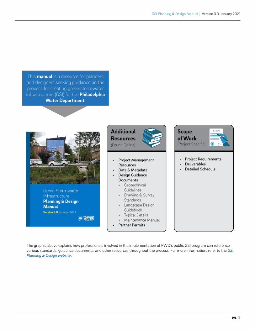
This manual is a resource for planners and designers seeking guidance on the process for creating green stormwater infrastructure (GSI) for the Philadelphia
Water Department.
The graphic above explains how professionals involved in the implementation of PWD’s public GSI program can reference various standards, guidance documents, and other resources throughout the process. For more information, refer to the GSI Planning & Design website.
GSI Planning & Design Manual | Version 3.0 January 2021
pg. 6 | Table of Contents
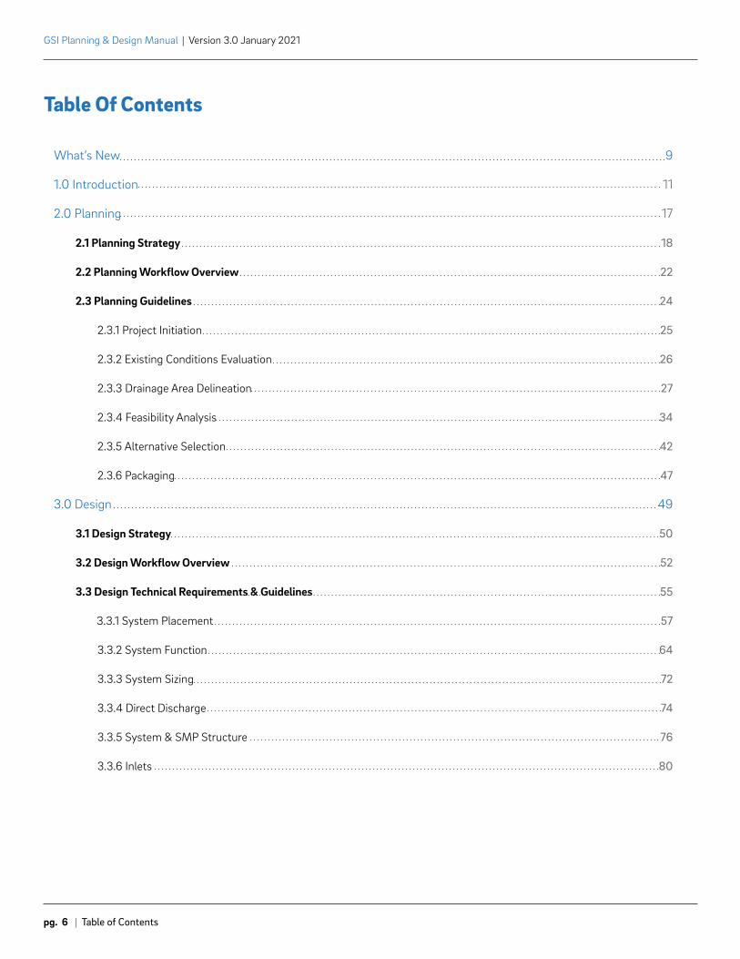
Table Of Contents
What’s New
1.0 Introduction
2.0 Planning
2.1 Planning Strategy
2.2 Planning Workflow Overview
2.3 Planning Guidelines
2.3.1 Project Initiation
2.3.2 Existing Conditions Evaluation
2.3.3 Drainage Area Delineation
2.3.4 Feasibility Analysis
2.3.5 Alternative Selection
2.3.6 Packaging
3.0 Design
3.1 Design Strategy
3.2 Design Workflow Overview
3.3 Design Technical Requirements & Guidelines
3.3.1 System Placement
3.3.2 System Function
3.3.3 System Sizing
3.3.4 Direct Discharge
3.3.5 System & SMP Structure
3.3.6 Inlets
9
11
17
18
22
24
25
26
27
34
42
47
49
50
52
55
57
64
72
74
76
80
Table of Contents | pg. 7
GSI Planning & Design Manual | Version 3.0 January 2021
3.3.7 Piping
3.3.8 Monitoring
3.3.9 Cost Estimates and Specifications
3.3.10 Survey and Drawing Standards
3.3.11 Geotechnical Testing Guidelines
3.3.12 Typical Details
3.3.13 Landscape Design Guidebook
3.3.14 Metrics Reporting
3.3.15 Project Summaries Manual
4.0 Post-Design
4.1 Post-Design Workflow Overview
4.2 Post-Design Resources
4.2.1 As-Built Survey & Drafting Manual
4.2.2 Maintenance Manual
Appendices
A.1 Detailed Workflow
A.1.1 Planning
A.1.2 Design
A.1.3 Post-Design
A.2 Project Management Resources
A.3 Definitions
A.4 Acronyms
84
91
93
94
94
94
95
95
95
97
99
100
100
100
103
105
110
118
128
134
137
143
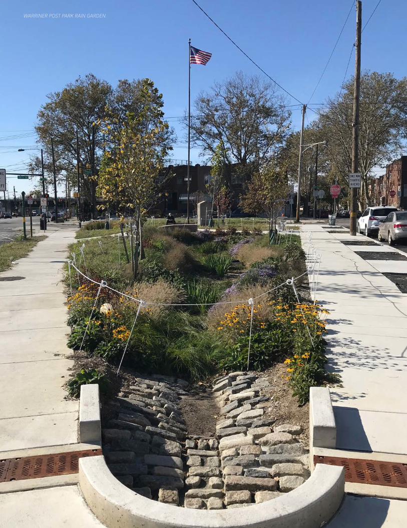
WARRINER POST PARK RAIN GARDEN
What's New | pg. 9
GSI Planning & Design Manual | Version 3.0 January 2021
What’s New
Effective Date: January 2021
Revisions History: Listed below are the major changes that occurred between the 2018 version of the GSI Planning & Design Manual and this most recent 2021 version.
• Renamed Large Area Disconnection (LAD) projects to Centralized GSI Facility.
• Expanded guidance on system placement and offsets from utilities. See section 3.3.1 System Placement.
• Expanded on impermeable liner guidance. See section 3.3.2 System Function.
• Reduced target storm size to be managed from 2-inches to 1.5-inches. See section 3.3.3 System Sizing.

Phila
delp
hia
Wat
er D
epar
tmen
t |
GSI
Pla
nnin
g &
Des
ign
Man
ual
v 3.
0

Introduction1.0
GSI Planning & Design Manual | Version 3.0 January 2021
pg. 12 | Introduction
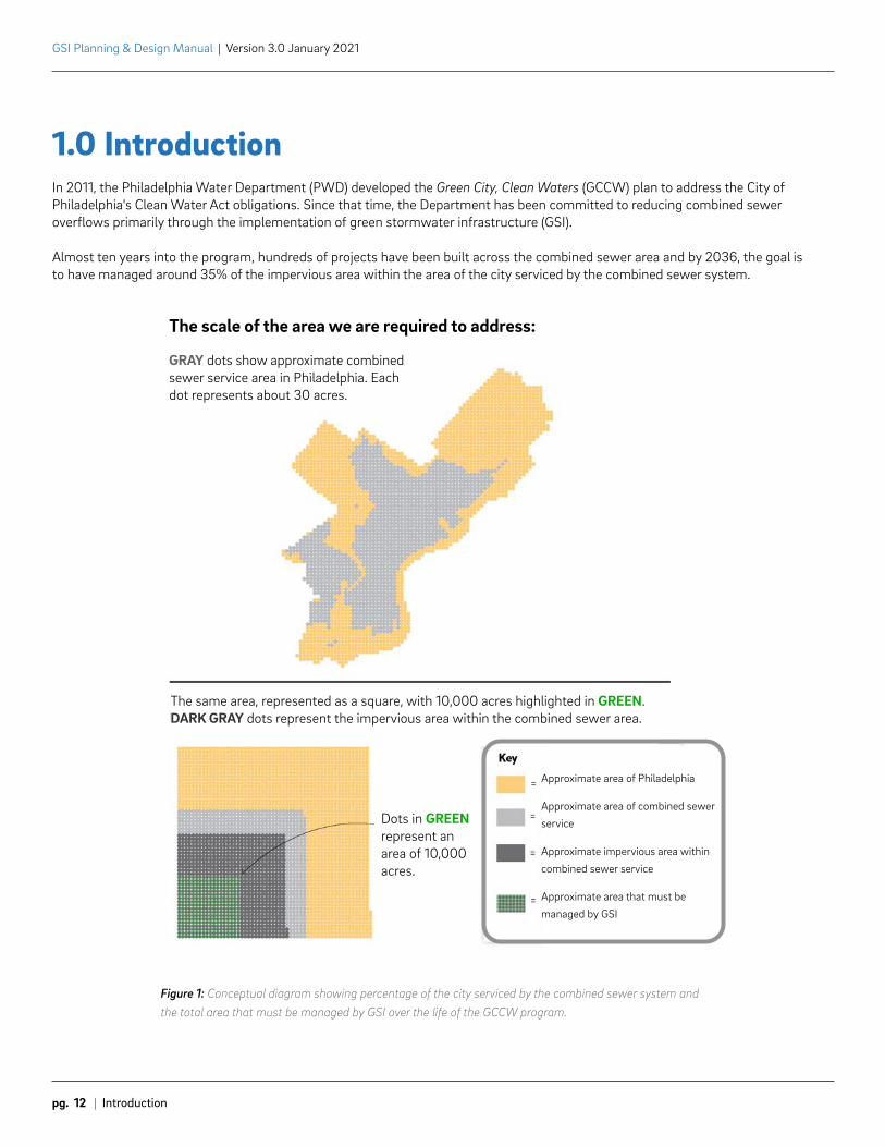
Figure 1: Conceptual diagram showing percentage of the city serviced by the combined sewer system and the total area that must be managed by GSI over the life of the GCCW program.
1.0 IntroductionIn 2011, the Philadelphia Water Department (PWD) developed the Green City, Clean Waters (GCCW) plan to address the City of Philadelphia's Clean Water Act obligations. Since that time, the Department has been committed to reducing combined sewer overflows primarily through the implementation of green stormwater infrastructure (GSI).
Almost ten years into the program, hundreds of projects have been built across the combined sewer area and by 2036, the goal is to have managed around 35% of the impervious area within the area of the city serviced by the combined sewer system.
The scale of the area we are required to address:
GRAY dots show approximate combined sewer service area in Philadelphia. Each dot represents about 30 acres.
The same area, represented as a square, with 10,000 acres highlighted in GREEN. DARK GRAY dots represent the impervious area within the combined sewer area.
Dots in GREEN represent an area of 10,000 acres.
Approximate area of Philadelphia
Approximate area of combined sewer service
Approximate impervious area within combined sewer service
Approximate area that must be managed by GSI
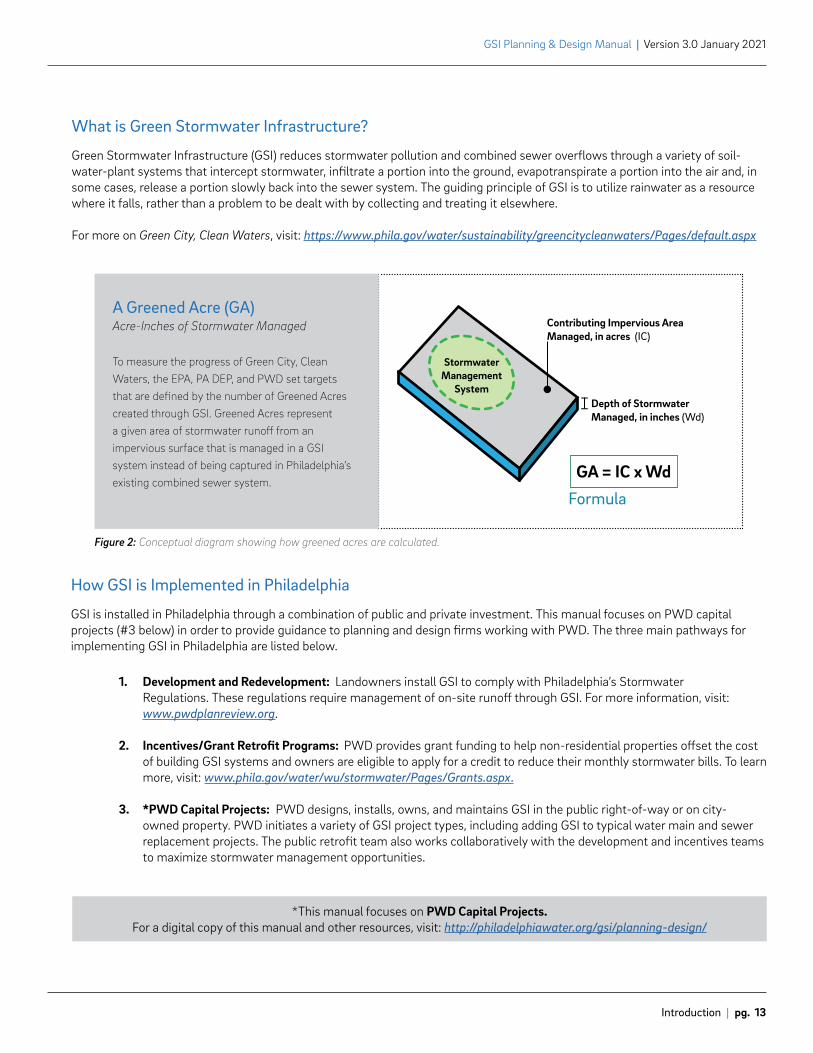
Depth of StormwaterManaged, in inches (Wd)
Stormwater Management
System
Contributing Impervious AreaManaged, in acres (IC)
GA = IC x Wd
A Greened Acre (GA): Acre-Inches of Stormwater Managed
Introduction | pg. 13
GSI Planning & Design Manual | Version 3.0 January 2021
*This manual focuses on PWD Capital Projects. For a digital copy of this manual and other resources, visit: http://philadelphiawater.org/gsi/planning-design/
Figure 2: Conceptual diagram showing how greened acres are calculated.
What is Green Stormwater Infrastructure?
Green Stormwater Infrastructure (GSI) reduces stormwater pollution and combined sewer overflows through a variety of soil-water-plant systems that intercept stormwater, infiltrate a portion into the ground, evapotranspirate a portion into the air and, in some cases, release a portion slowly back into the sewer system. The guiding principle of GSI is to utilize rainwater as a resource where it falls, rather than a problem to be dealt with by collecting and treating it elsewhere.
For more on Green City, Clean Waters, visit: https://www.phila.gov/water/sustainability/greencitycleanwaters/Pages/default.aspx
How GSI is Implemented in Philadelphia
GSI is installed in Philadelphia through a combination of public and private investment. This manual focuses on PWD capital projects (#3 below) in order to provide guidance to planning and design firms working with PWD. The three main pathways for implementing GSI in Philadelphia are listed below.
1. Development and Redevelopment: Landowners install GSI to comply with Philadelphia’s Stormwater Regulations. These regulations require management of on-site runoff through GSI. For more information, visit: www.pwdplanreview.org.
2. Incentives/Grant Retrofit Programs: PWD provides grant funding to help non-residential properties offset the cost of building GSI systems and owners are eligible to apply for a credit to reduce their monthly stormwater bills. To learn more, visit: www.phila.gov/water/wu/stormwater/Pages/Grants.aspx.
3. *PWD Capital Projects: PWD designs, installs, owns, and maintains GSI in the public right-of-way or on city-owned property. PWD initiates a variety of GSI project types, including adding GSI to typical water main and sewer replacement projects. The public retrofit team also works collaboratively with the development and incentives teams to maximize stormwater management opportunities.
A Greened Acre (GA)Acre-Inches of Stormwater Managed
To measure the progress of Green City, Clean Waters, the EPA, PA DEP, and PWD set targets that are defined by the number of Greened Acres created through GSI. Greened Acres represent a given area of stormwater runoff from an impervious surface that is managed in a GSI system instead of being captured in Philadelphia’s existing combined sewer system.
Formula
GSI Planning & Design Manual | Version 3.0 January 2021
pg. 14 | Introduction
About the Philadelphia Water Department’s GSI Capital Projects Program
PWD has a diverse in-house staff of planners, designers, environmental scientists, outreach specialists, policy and partnership liaisons, maintenance and monitoring professionals, contract administrators, and construction inspectors and engineers. These teams work collaboratively to plan, design, bid, build, maintain, and monitor GSI for PWD. PWD staff are supported by a variety of on-call and project specific professional services contracts that provide in-depth, area-wide planning, identification and initial conceptualization of GSI projects, surveying and geotechnical testing, engineering and landscape design, maintenance services, modeling, and monitoring support. Firms under contract with PWD are considered an extension of Department staff and are an important component to the success of the GSI program.
This manual is part of a robust technical library of resources and standards established by PWD during the first phase of the program, creating a clear and documented planning and design approach to GSI in Philadelphia. Building on this foundation, PWD continues to improve and innovate while focusing on implementation of the highest performing and most cost-effective GSI solutions.
Much of the work completed by PWD would not be possible without support from other City agencies, partners and community groups. To accomplish the goals of Green City, Clean Waters, PWD utilizes a combination of City-owned right-of-way spaces, such as streets and sidewalks, and public property, such as parks, for GSI. As the program evolves from a technical perspective, PWD continues to look for opportunities to partner with outside entities to implement GSI across the city.
Getting Started
This manual provides detailed information about the planning and design strategy, technical requirements, and workflows for GSI projects installed and maintained by PWD. It is intended for use by PWD staff, providers of professional planning and engineering services contracted by PWD, and other agencies/partner organizations working with PWD.
The manual is organized into the typical phases PWD follows to implement GSI projects. Some resources are provided as linked attachments due to file size and to ensure that content is current and accurate.
• Section 2.0 Planning focuses on the project planning phase, including delineating existing drainage areas, identifying recommended project locations, and initial placement of GSI.
• Section 3.0 Design details the basis of design requirements including how to size GSI, infiltration and slow-release requirements, typical details, drawing requirements, and more.
• Section 4.0 Post-Design provides an overview of what happens after design - during bidding, construction, and maintenance phases.
Note on Professional Judgment: It remains the sole responsibility of planning and design professionals to develop projects that are consistent with all laws and regulations and are based on sound judgment. Any time professional judgment differs from the guidance outlined in this document, the concern should be discussed with the PWD project manager. Compliance with the requirements and guidelines contained in this document does not ensure planning or design acceptance by PWD.
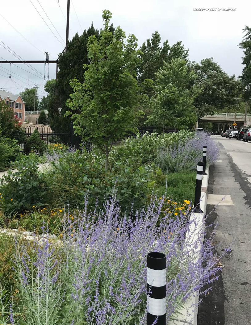
SEDGEWICK STATION BUMPOUT

Phila
delp
hia
Wat
er D
epar
tmen
t |
GSI
Pla
nnin
g &
Des
ign
Man
ual
v 3.
0

Planning2.0
Schuylki ll
River
De
law
are
Riv
er
North
South
West
Central
LowerSouth
WestPark
Upper North
RiverWards
NorthDelaware
UpperNorthwest
LowerSouthwest
Lower FarNortheast
LowerNorthwest
Upper FarNortheast
LowerNorth
CentralNortheast
LowerNortheast
UniversitySouthwest
0 2.5 51.25 Miles I
4
3
2
1
GSI Planning & Design Manual | Version 3.0 January 2021
pg. 18 | Planning | 2.1 Planning Strategy
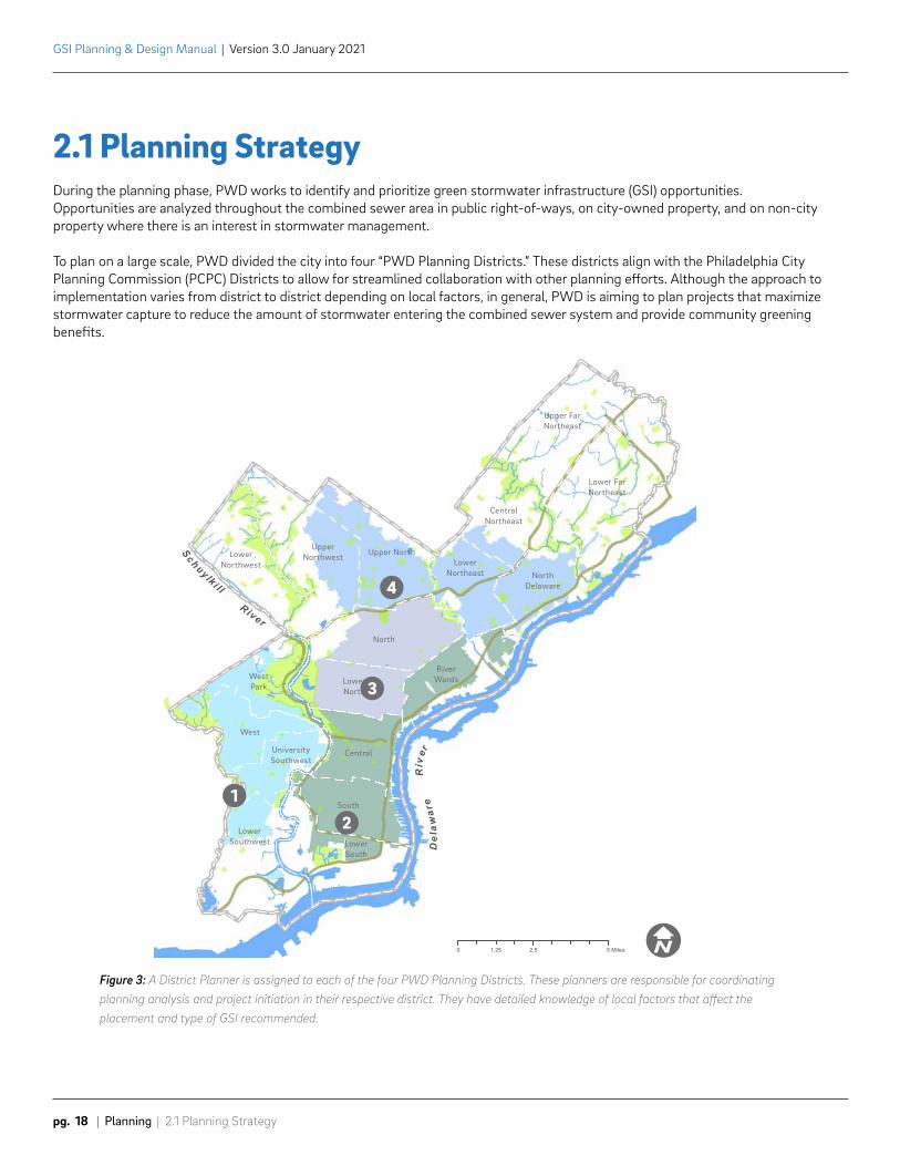
Figure 3: A District Planner is assigned to each of the four PWD Planning Districts. These planners are responsible for coordinating planning analysis and project initiation in their respective district. They have detailed knowledge of local factors that affect the placement and type of GSI recommended.
2.1 Planning StrategyDuring the planning phase, PWD works to identify and prioritize green stormwater infrastructure (GSI) opportunities. Opportunities are analyzed throughout the combined sewer area in public right-of-ways, on city-owned property, and on non-city property where there is an interest in stormwater management.
To plan on a large scale, PWD divided the city into four “PWD Planning Districts.” These districts align with the Philadelphia City Planning Commission (PCPC) Districts to allow for streamlined collaboration with other planning efforts. Although the approach to implementation varies from district to district depending on local factors, in general, PWD is aiming to plan projects that maximize stormwater capture to reduce the amount of stormwater entering the combined sewer system and provide community greening benefits.
Schuylki llRiver
Del
aw
are
Ri v
er
0 2.5 51.25 Miles I
2.1 Planning Strategy | Planning | pg. 19
GSI Planning & Design Manual | Version 3.0 January 2021
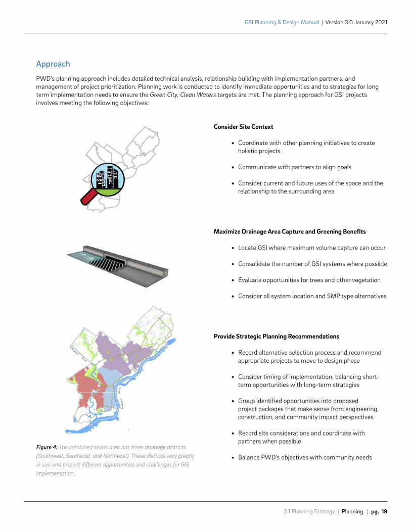
Consider Site Context
• Coordinate with other planning initiatives to create holistic projects
• Communicate with partners to align goals
• Consider current and future uses of the space and the relationship to the surrounding area
Maximize Drainage Area Capture and Greening Benefits
• Locate GSI where maximum volume capture can occur
• Consolidate the number of GSI systems where possible
• Evaluate opportunities for trees and other vegetation
• Consider all system location and SMP type alternatives
Provide Strategic Planning Recommendations
• Record alternative selection process and recommend appropriate projects to move to design phase
• Consider timing of implementation, balancing short-term opportunities with long-term strategies
• Group identified opportunities into proposed project packages that make sense from engineering, construction, and community impact perspectives
• Record site considerations and coordinate with partners when possible
• Balance PWD’s objectives with community needs
Approach
PWD’s planning approach includes detailed technical analysis, relationship building with implementation partners, and management of project prioritization. Planning work is conducted to identify immediate opportunities and to strategize for long term implementation needs to ensure the Green City, Clean Waters targets are met. The planning approach for GSI projects involves meeting the following objectives:
Figure 4: The combined sewer area has three drainage districts (Southwest, Southeast, and Northeast). These districts vary greatly in size and present different opportunities and challenges for GSI implementation.
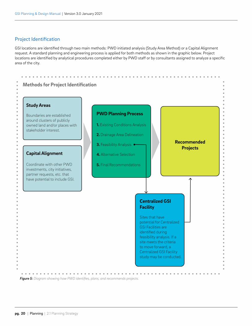
Centralized GSI Facility
Sites that have potential for Centralized GSI Facilities are identified during feasibility analysis. If a site meets the criteria to move forward, a Centralized GSI Facility study may be conducted.
Study Areas
Boundaries are established around clusters of publicly owned land and/or places with stakeholder interest.
Capital Alignment
Coordinate with other PWD investments, city initiatives, partner requests, etc. that have potential to include GSI.
PWD Planning Process
1. Existing Conditions Analysis
2. Drainage Area Delineation
3. Feasibility Analysis
4. Alternative Selection
5. Final Recommendations
Recommended Projects
GSI Planning & Design Manual | Version 3.0 January 2021
pg. 20 | Planning | 2.1 Planning Strategy
Project Identification
GSI locations are identified through two main methods: PWD initiated analysis (Study Area Method) or a Capital Alignment request. A standard planning and engineering process is applied for both methods as shown in the graphic below. Project locations are identified by analytical procedures completed either by PWD staff or by consultants assigned to analyze a specific area of the city.
Figure 5: Diagram showing how PWD identifies, plans, and recommends projects.
Methods for Project Identification
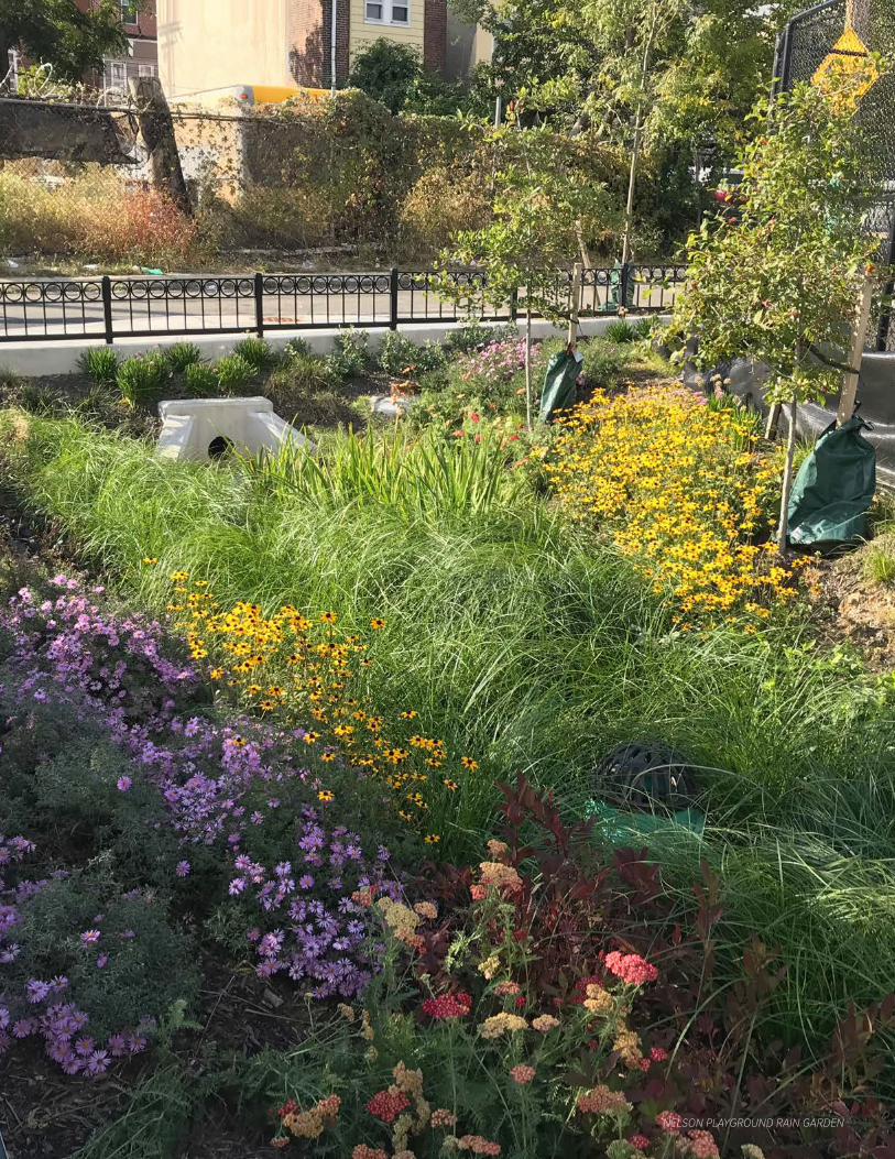
NELSON PLAYGROUND RAIN GARDEN
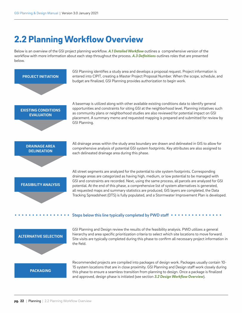
PROJECT INITIATION
EXISTING CONDITIONS EVALUATION
DRAINAGE AREA DELINEATION
FEASIBILITY ANALYSIS
ALTERNATIVE SELECTION
PACKAGING
GSI Planning identifies a study area and develops a proposal request. Project information is entered into CIPIT, creating a Master Project Proposal Number. When the scope, schedule, and budget are finalized, GSI Planning provides authorization to begin work.
A basemap is utilized along with other available existing conditions data to identify general opportunities and constraints for siting GSI at the neighborhood level. Planning initiatives such as community plans or neighborhood studies are also reviewed for potential impact on GSI placement. A summary memo and requested mapping is prepared and submitted for review by GSI Planning.
All drainage areas within the study area boundary are drawn and delineated in GIS to allow for comprehensive analysis of potential GSI system footprints. Key attributes are also assigned to each delineated drainage area during this phase.
All street segments are analyzed for the potential to site system footprints. Corresponding drainage areas are categorized as having high, medium, or low potential to be managed with GSI and constraints are recorded. Next, using the same process, all parcels are analyzed for GSI potential. At the end of this phase, a comprehensive list of system alternatives is generated, all requested maps and summary statistics are produced, GIS layers are completed, the Data Tracking Spreadsheet (DTS) is fully populated, and a Stormwater Improvement Plan is developed.
GSI Planning and Design review the results of the feasibility analysis. PWD utilizes a general hierarchy and area specific prioritization criteria to select which site locations to move forward. Site visits are typically completed during this phase to confirm all necessary project information in the field.
Recommended projects are compiled into packages of design work. Packages usually contain 10-15 system locations that are in close proximity. GSI Planning and Design staff work closely during this phase to ensure a seamless transition from planning to design. Once a package is finalized and approved, design phase is initiated (see section 3.2 Design Workflow Overview).
Steps below this line typically completed by PWD staff
GSI Planning & Design Manual | Version 3.0 January 2021
pg. 22 | Planning | 2.2 Planning Workflow Overview
2.2 Planning Workflow OverviewBelow is an overview of the GSI project planning workflow. A.1 Detailed Workflow outlines a comprehensive version of the workflow with more information about each step throughout the process. A.3 Definitions outlines roles that are presented below.
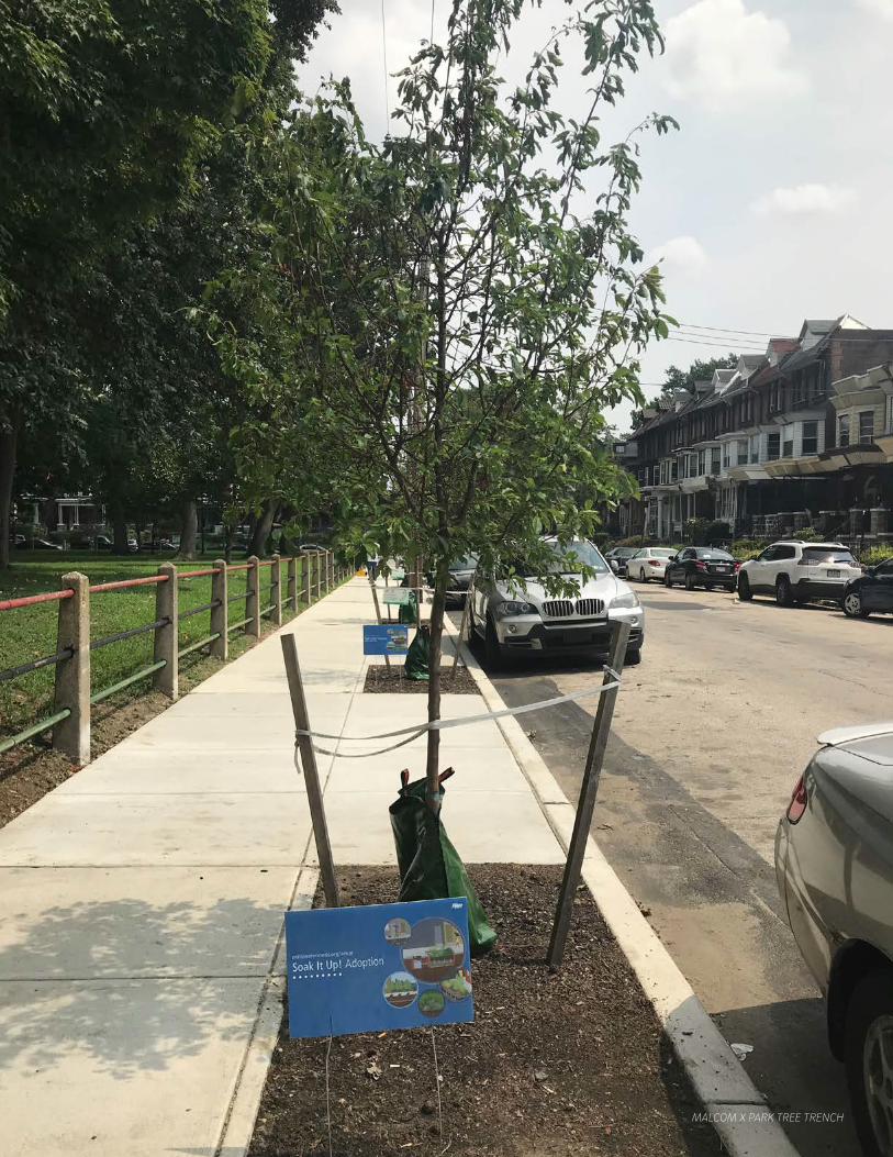
MALCOM X PARK TREE TRENCH
GSI Planning & Design Manual | Version 3.0 January 2021
pg. 24 | Planning | 2.3 Planning Guidelines
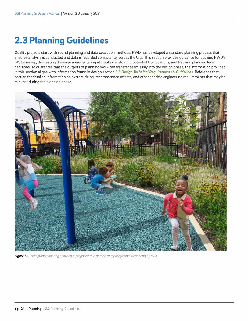
2.3 Planning GuidelinesQuality projects start with sound planning and data collection methods. PWD has developed a standard planning process that ensures analysis is conducted and data is recorded consistently across the City. This section provides guidance for utilizing PWD’s GIS basemap, delineating drainage areas, entering attributes, evaluating potential GSI locations, and tracking planning level decisions. To guarantee that the outputs of planning work can transfer seamlessly into the design phase, the information provided in this section aligns with information found in design section 3.3 Design Technical Requirements & Guidelines. Reference that section for detailed information on system sizing, recommended offsets, and other specific engineering requirements that may be relevant during the planning phase.
Figure 6: Conceptual rendering showing a proposed rain garden at a playground. Rendering by PWD.
2.3 Planning Guidelines | Planning | pg. 25
GSI Planning & Design Manual | Version 3.0 January 2021
2.3.1 Project InitiationA standard set of GIS layers and other data tracking tools are utilized throughout the planning process. Planning work is usually conducted pre-survey, so understanding available resources (provided in GIS and other formats) is critical to developing accurate planning recommendations.
GIS BasemapGIS tools are used in coordination with other internal databases to understand site conditions and to track important project information. A standard GIS basemap is used in-house. The PWD project manager will help facilitate a formal GIS request with PWD and recommend a list of relevant datasets needed for GSI site planning. PWD will provide GIS information for layers that are not publicly available on Open Data Philly. It is the consultant’s responsibility to download open data for layers owned by other city agencies and link them to the basemap document.
Editing Feature ClassesThe basemap will include reference GIS data that helps facilitate data editing of two feature classes: GSI Planning Drainage Areas and GSI Conceptual Designs. These layers will be provided as a working dataset. Drainage areas and GSI system footprints should be fully drawn and attributed based on guidelines provided in the following sections where the delineation process, attribution rules, and requirements are covered in further detail.
The geodatabase structure, spatial reference, and table design (schema) of the geospatial data provided by PWD must not be altered. All PWD GIS feature classes use a standard spatial reference adopted by the City of Philadelphia - State Plane (Local PA) NAD_1983_StatePlane_Pennsylvania_South_FIPS_3702_Feet. Brief descriptions of these feature classes are listed below.
• GSI Planning Drainage Areas: Pre-survey drainage areas are drawn during planning. The data helps to visualize and quantify the area of stormwater runoff planned to be collected at a given site. The data is developed and used for preliminary site planning purposes.
• GSI Conceptual Designs: Conceptual system footprints. The data helps to visualize the location of potential systems planned at a given site. The data is developed and used for preliminary site planning purposes.
Data Tracking Spreadsheet (DTS)PWD maintains an internal project database application called PlanIT to record and track detailed information about potential GSI locations. A spreadsheet version of PlanIT’s key fields, called the Data Tracking Spreadsheet (DTS), will be provided to consultants to be populated so that entries can be imported to the master database. The spreadsheet includes specific coding to allow for direct import into PlanIT and for multiple drop-downs to be selected. It is important that DTS fields are not modified and additional columns are not added to the spreadsheet.
Site specific data is recorded in the DTS and can be cross-referenced with both the GSI Planning Drainage Areas and GSI Conceptual Designs drawn in GIS by unique IDs. The Data Tracking Spreadsheet template will be provided by the PWD project manager at the beginning of each assignment that includes detailed instructions on the first tab of the spreadsheet. The DTS will be utilized during several phases of planning and will be referenced in upcoming sections.
Additional ResourcesAdditional resources such as Highway Supervisor Plans, Philadelphia Gas Works (PGW) plats, City Plan information, and baseplans from previous PWD work will be shared if available. These references should be used to cross check for constraints and confirm GIS information is as accurate as possible.
GSI Planning & Design Manual | Version 3.0 January 2021
pg. 26 | Planning | 2.3 Planning Guidelines
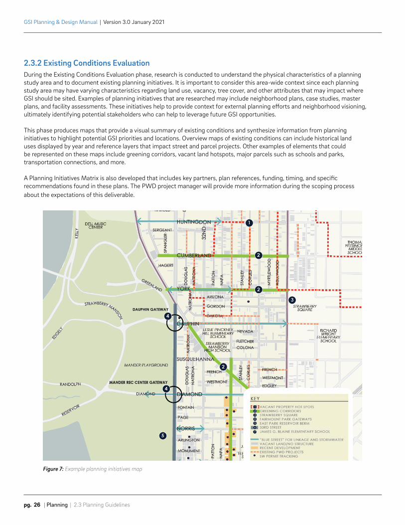
2.3.2 Existing Conditions EvaluationDuring the Existing Conditions Evaluation phase, research is conducted to understand the physical characteristics of a planning study area and to document existing planning initiatives. It is important to consider this area-wide context since each planning study area may have varying characteristics regarding land use, vacancy, tree cover, and other attributes that may impact where GSI should be sited. Examples of planning initiatives that are researched may include neighborhood plans, case studies, master plans, and facility assessments. These initiatives help to provide context for external planning efforts and neighborhood visioning, ultimately identifying potential stakeholders who can help to leverage future GSI opportunities.
This phase produces maps that provide a visual summary of existing conditions and synthesize information from planning initiatives to highlight potential GSI priorities and locations. Overview maps of existing conditions can include historical land uses displayed by year and reference layers that impact street and parcel projects. Other examples of elements that could be represented on these maps include greening corridors, vacant land hotspots, major parcels such as schools and parks, transportation connections, and more.
A Planning Initiatives Matrix is also developed that includes key partners, plan references, funding, timing, and specific recommendations found in these plans. The PWD project manager will provide more information during the scoping process about the expectations of this deliverable.
Figure 7: Example planning initiatives map
2.3 Planning Guidelines | Planning | pg. 27
GSI Planning & Design Manual | Version 3.0 January 2021
2.3.3 Drainage Area Delineation
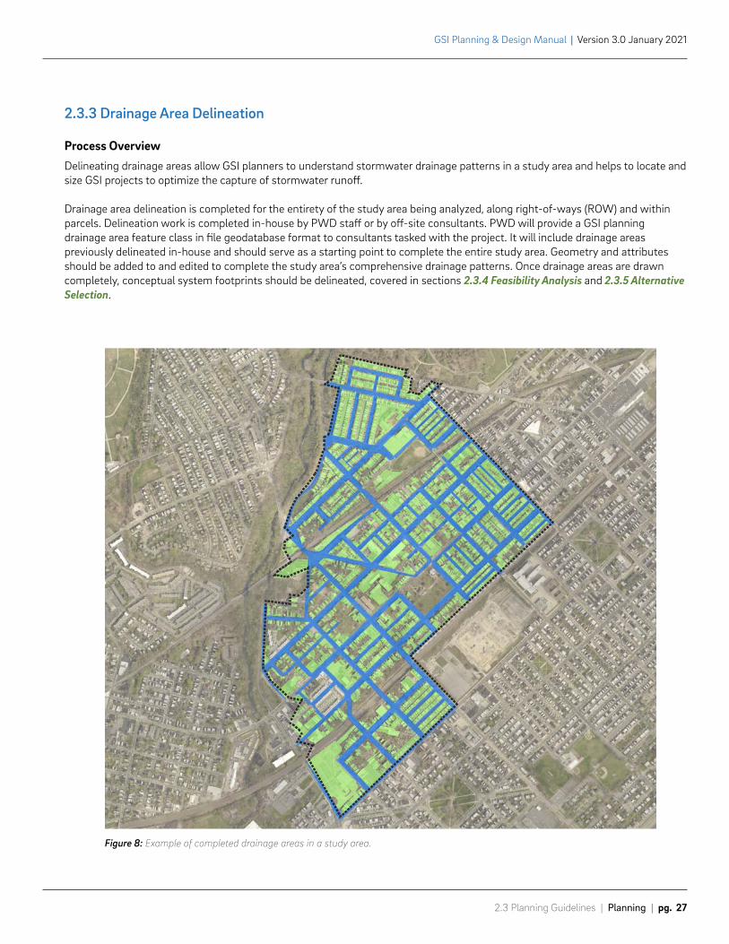
Process OverviewDelineating drainage areas allow GSI planners to understand stormwater drainage patterns in a study area and helps to locate and size GSI projects to optimize the capture of stormwater runoff.
Drainage area delineation is completed for the entirety of the study area being analyzed, along right-of-ways (ROW) and within parcels. Delineation work is completed in-house by PWD staff or by off-site consultants. PWD will provide a GSI planning drainage area feature class in file geodatabase format to consultants tasked with the project. It will include drainage areas previously delineated in-house and should serve as a starting point to complete the entire study area. Geometry and attributes should be added to and edited to complete the study area’s comprehensive drainage patterns. Once drainage areas are drawn completely, conceptual system footprints should be delineated, covered in sections 2.3.4 Feasibility Analysis and 2.3.5 Alternative Selection.
Figure 8: Example of completed drainage areas in a study area.
GSI Planning & Design Manual | Version 3.0 January 2021
pg. 28 | Planning | 2.3 Planning Guidelines
DelineationFor consultants delineating drainage areas, it is important to check the GIS data provided by PWD. If the “Drainage Area Feasibility” attribute is coded as “Managed,” the drainage area is being managed by an existing project and should not be altered. The PWD project manager will ensure that this information is up to date before the GIS data is sent out for editing. All other drainage areas should be reevaluated using the methodology discussed in this section.
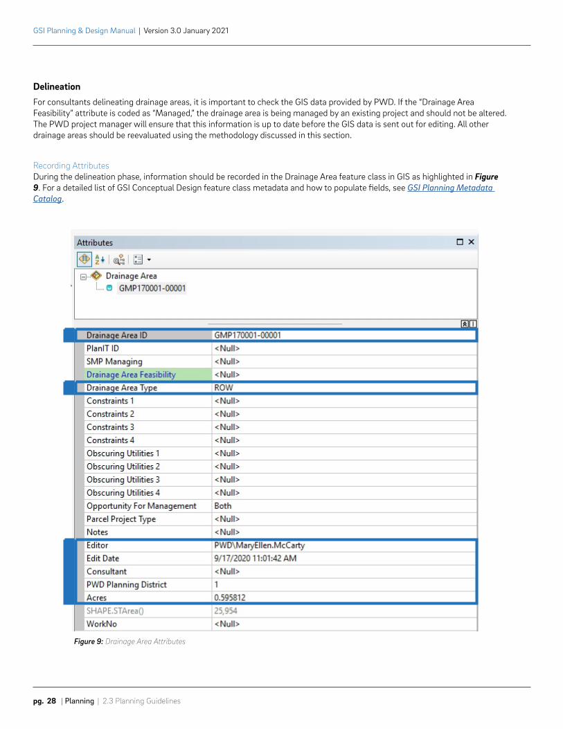
Recording AttributesDuring the delineation phase, information should be recorded in the Drainage Area feature class in GIS as highlighted in Figure 9. For a detailed list of GSI Conceptual Design feature class metadata and how to populate fields, see GSI Planning Metadata Catalog.
Figure 9: Drainage Area Attributes
Street Centerline Intersection
Street Centerline Intersection
Parcel Corner
3
Parcel Corner2
1
4
2.3 Planning Guidelines | Planning | pg. 29
GSI Planning & Design Manual | Version 3.0 January 2021
Drainage Area NumberingUnique Drainage Area IDs (DA_ID) are required for all drainage areas drawn. For in-house delineation, unique Drainage Area IDs are generated automatically with the Attribute Assistant tool bar. Consultants preparing drainage areas off-site must also populate Drainage Area IDs. IDs must be assigned based on a combination of the contract work number and a sequential numbering system. A five-digit sequential number must be used to maintain a consistent amount of characters within this numbering schema. The following Drainage Area ID numbering methodology must be utilized both within the drainage area GIS feature class and the Data Tracking Spreadsheet:
[Master Project Proposal Number] – [Sequential number]
For Example: If a project’s work number was GMP170001, the Drainage Area IDs would be assigned sequentially as GMP170001-00001, GMP170001-00002, GMP170001-00003, and so on.
This unique numbering system allows PWD to link drainage areas drawn in the GIS feature class and corresponding potential project locations tracked in the Data Tracking Spreadsheet.
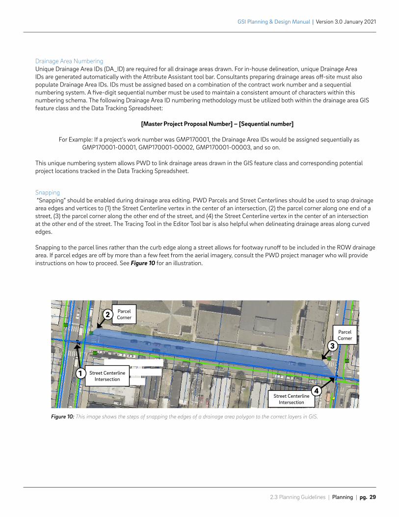
Snapping “Snapping” should be enabled during drainage area editing. PWD Parcels and Street Centerlines should be used to snap drainage area edges and vertices to (1) the Street Centerline vertex in the center of an intersection, (2) the parcel corner along one end of a street, (3) the parcel corner along the other end of the street, and (4) the Street Centerline vertex in the center of an intersection at the other end of the street. The Tracing Tool in the Editor Tool bar is also helpful when delineating drainage areas along curved edges.
Snapping to the parcel lines rather than the curb edge along a street allows for footway runoff to be included in the ROW drainage area. If parcel edges are off by more than a few feet from the aerial imagery, consult the PWD project manager who will provide instructions on how to proceed. See Figure 10 for an illustration.
Figure 10: This image shows the steps of snapping the edges of a drainage area polygon to the correct layers in GIS.
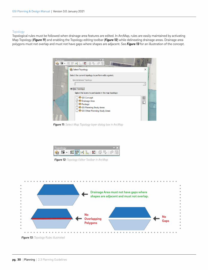
Figure 11: Select Map Topology layer dialog box in ArcMap
No Gaps
No Overlapping Polygons
Drainage Area must not have gaps where shapes are adjacent and must not overlap.
GSI Planning & Design Manual | Version 3.0 January 2021
pg. 30 | Planning | 2.3 Planning Guidelines
Topology Topological rules must be followed when drainage area features are edited. In ArcMap, rules are easily maintained by activating Map Topology (Figure 11) and enabling the Topology editing toolbar (Figure 12) while delineating drainage areas. Drainage area polygons must not overlap and must not have gaps where shapes are adjacent. See Figure 13 for an illustration of the concept.
Figure 12: Topology Editor Toolbar in ArcMap
Figure 13: Topology Rules illustrated
2.3 Planning Guidelines | Planning | pg. 31
GSI Planning & Design Manual | Version 3.0 January 2021
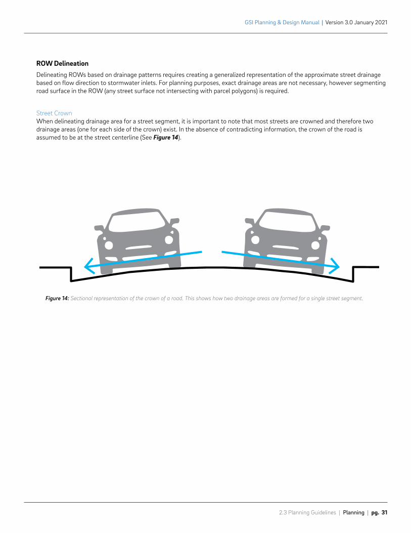
ROW DelineationDelineating ROWs based on drainage patterns requires creating a generalized representation of the approximate street drainage based on flow direction to stormwater inlets. For planning purposes, exact drainage areas are not necessary, however segmenting road surface in the ROW (any street surface not intersecting with parcel polygons) is required.
Street CrownWhen delineating drainage area for a street segment, it is important to note that most streets are crowned and therefore two drainage areas (one for each side of the crown) exist. In the absence of contradicting information, the crown of the road is assumed to be at the street centerline (See Figure 14).
Figure 14: Sectional representation of the crown of a road. This shows how two drainage areas are formed for a single street segment.
GSI Planning & Design Manual | Version 3.0 January 2021
pg. 32 | Planning | 2.3 Planning Guidelines
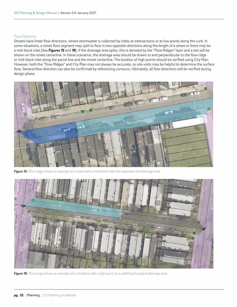
Flow DirectionStreets have linear flow directions, where stormwater is collected by inlets at intersections or at low points along the curb. In some situations, a street flow segment may split to flow in two opposite directions along the length of a street or there may be a mid-block inlet (See Figures 15 and 16). If the drainage area splits, this is denoted by the “Flow Ridges” layer and a dot will be shown on the street centerline. In these scenarios, the drainage area should be drawn to end perpendicular to the flow ridge or mid-block inlet along the parcel line and the street centerline. The location of high points should be verified using City Plan. However, both the “Flow Ridges” and City Plan may not always be accurate, so site visits may be helpful to determine the surface flow. General flow direction can also be confirmed by referencing contours. Ultimately, all flow directions will be verified during design phase.
Figure 16: This image shows an example of a city block with a high point, thus splitting the typical drainage area.
Figure 15: This image shows an example of a street with a mid-block inlet that separates the drainage area.
2.3 Planning Guidelines | Planning | pg. 33
GSI Planning & Design Manual | Version 3.0 January 2021
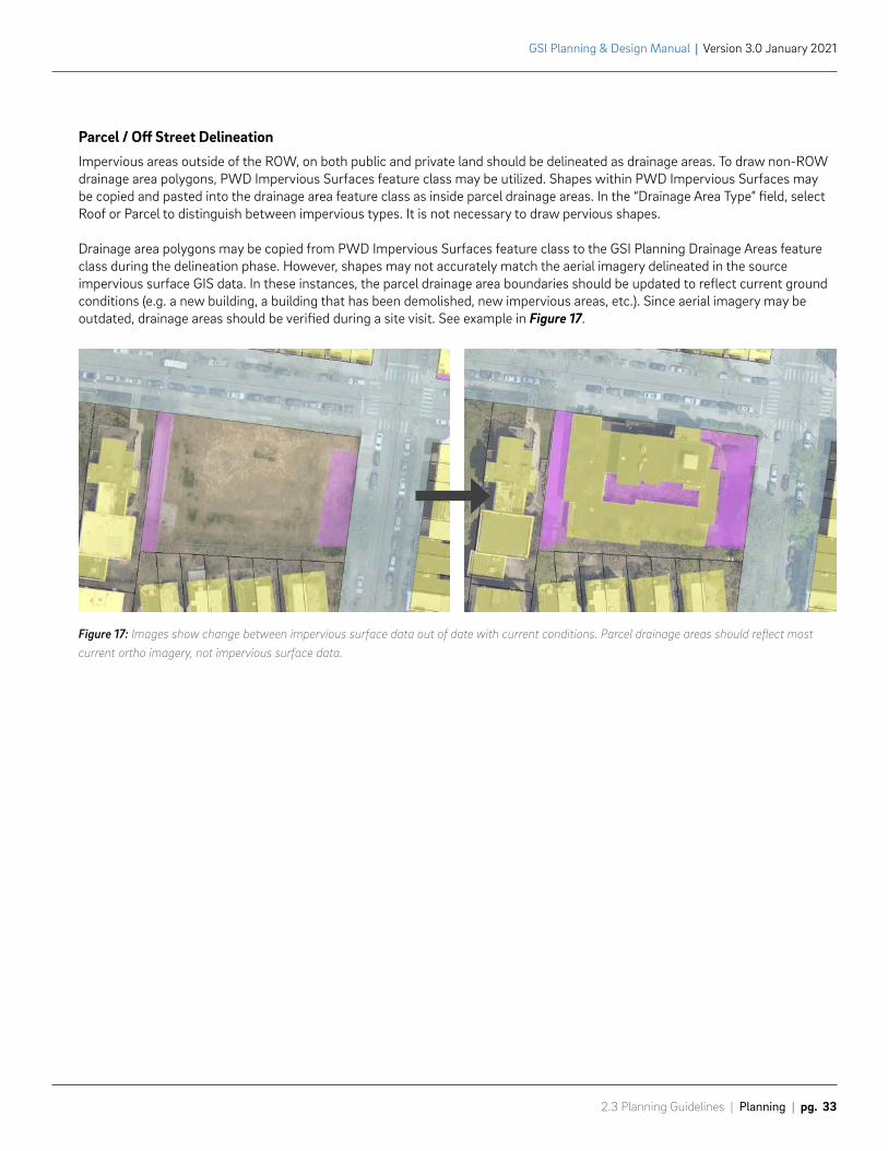
Parcel / Off Street DelineationImpervious areas outside of the ROW, on both public and private land should be delineated as drainage areas. To draw non-ROW drainage area polygons, PWD Impervious Surfaces feature class may be utilized. Shapes within PWD Impervious Surfaces may be copied and pasted into the drainage area feature class as inside parcel drainage areas. In the “Drainage Area Type” field, select Roof or Parcel to distinguish between impervious types. It is not necessary to draw pervious shapes.
Drainage area polygons may be copied from PWD Impervious Surfaces feature class to the GSI Planning Drainage Areas feature class during the delineation phase. However, shapes may not accurately match the aerial imagery delineated in the source impervious surface GIS data. In these instances, the parcel drainage area boundaries should be updated to reflect current ground conditions (e.g. a new building, a building that has been demolished, new impervious areas, etc.). Since aerial imagery may be outdated, drainage areas should be verified during a site visit. See example in Figure 17.
Figure 17: Images show change between impervious surface data out of date with current conditions. Parcel drainage areas should reflect most current ortho imagery, not impervious surface data.
Phase 1 Phase 2
GSI Planning & Design Manual | Version 3.0 January 2021
pg. 34 | Planning | 2.3 Planning Guidelines
2.3.4 Feasibility Analysis
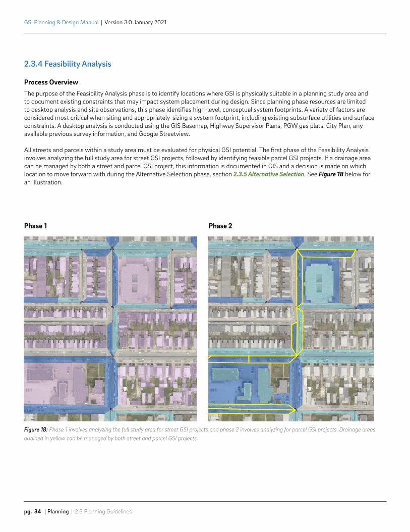
Process OverviewThe purpose of the Feasibility Analysis phase is to identify locations where GSI is physically suitable in a planning study area and to document existing constraints that may impact system placement during design. Since planning phase resources are limited to desktop analysis and site observations, this phase identifies high-level, conceptual system footprints. A variety of factors are considered most critical when siting and appropriately-sizing a system footprint, including existing subsurface utilities and surface constraints. A desktop analysis is conducted using the GIS Basemap, Highway Supervisor Plans, PGW gas plats, City Plan, any available previous survey information, and Google Streetview.
All streets and parcels within a study area must be evaluated for physical GSI potential. The first phase of the Feasibility Analysis involves analyzing the full study area for street GSI projects, followed by identifying feasible parcel GSI projects. If a drainage area can be managed by both a street and parcel GSI project, this information is documented in GIS and a decision is made on which location to move forward with during the Alternative Selection phase, section 2.3.5 Alternative Selection. See Figure 18 below for an illustration.
Figure 18: Phase 1 involves analyzing the full study area for street GSI projects and phase 2 involves analyzing for parcel GSI projects. Drainage areas outlined in yellow can be managed by both street and parcel GSI projects.
2.3 Planning Guidelines | Planning | pg. 35
GSI Planning & Design Manual | Version 3.0 January 2021
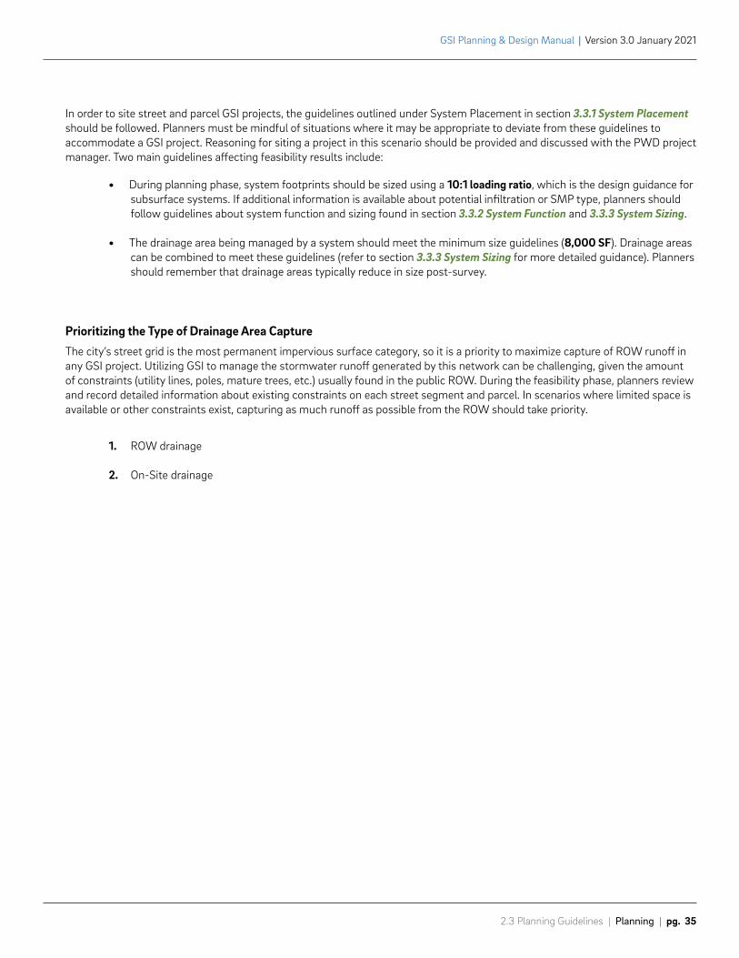
In order to site street and parcel GSI projects, the guidelines outlined under System Placement in section 3.3.1 System Placement should be followed. Planners must be mindful of situations where it may be appropriate to deviate from these guidelines to accommodate a GSI project. Reasoning for siting a project in this scenario should be provided and discussed with the PWD project manager. Two main guidelines affecting feasibility results include:
• During planning phase, system footprints should be sized using a 10:1 loading ratio, which is the design guidance for subsurface systems. If additional information is available about potential infiltration or SMP type, planners should follow guidelines about system function and sizing found in section 3.3.2 System Function and 3.3.3 System Sizing.
• The drainage area being managed by a system should meet the minimum size guidelines (8,000 SF). Drainage areas can be combined to meet these guidelines (refer to section 3.3.3 System Sizing for more detailed guidance). Planners should remember that drainage areas typically reduce in size post-survey.
Prioritizing the Type of Drainage Area CaptureThe city’s street grid is the most permanent impervious surface category, so it is a priority to maximize capture of ROW runoff in any GSI project. Utilizing GSI to manage the stormwater runoff generated by this network can be challenging, given the amount of constraints (utility lines, poles, mature trees, etc.) usually found in the public ROW. During the feasibility phase, planners review and record detailed information about existing constraints on each street segment and parcel. In scenarios where limited space is available or other constraints exist, capturing as much runoff as possible from the ROW should take priority.
1. ROW drainage
2. On-Site drainage
GSI Planning & Design Manual | Version 3.0 January 2021
pg. 36 | Planning | 2.3 Planning Guidelines
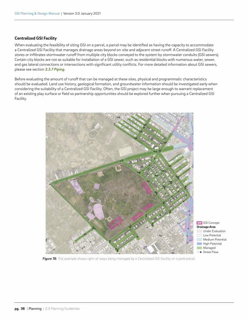
Centralized GSI FacilityWhen evaluating the feasibility of siting GSI on a parcel, a parcel may be identified as having the capacity to accommodate a Centralized GSI Facility that manages drainage areas beyond on-site and adjacent street runoff. A Centralized GSI Facility stores or infiltrates stormwater runoff from multiple city blocks conveyed to the system by stormwater conduits (GSI sewers). Certain city blocks are not as suitable for installation of a GSI sewer, such as residential blocks with numerous water, sewer, and gas lateral connections or intersections with significant utility conflicts. For more detailed information about GSI sewers, please see section 3.3.7 Piping.
Before evaluating the amount of runoff that can be managed at these sites, physical and programmatic characteristics should be evaluated. Land use history, geological formation, and groundwater information should be investigated early when considering the suitability of a Centralized GSI Facility. Often, the GSI project may be large enough to warrant replacement of an existing play surface or field so partnership opportunities should be explored further when pursuing a Centralized GSI Facility.
Figure 19: This example shows right-of-ways being managed by a Centralized GSI Facility on a park parcel.
GSI Concept
Under EvaluationLow PotentialMedium PotentialHigh PotentialManagedStreet Flow
Drainage Area
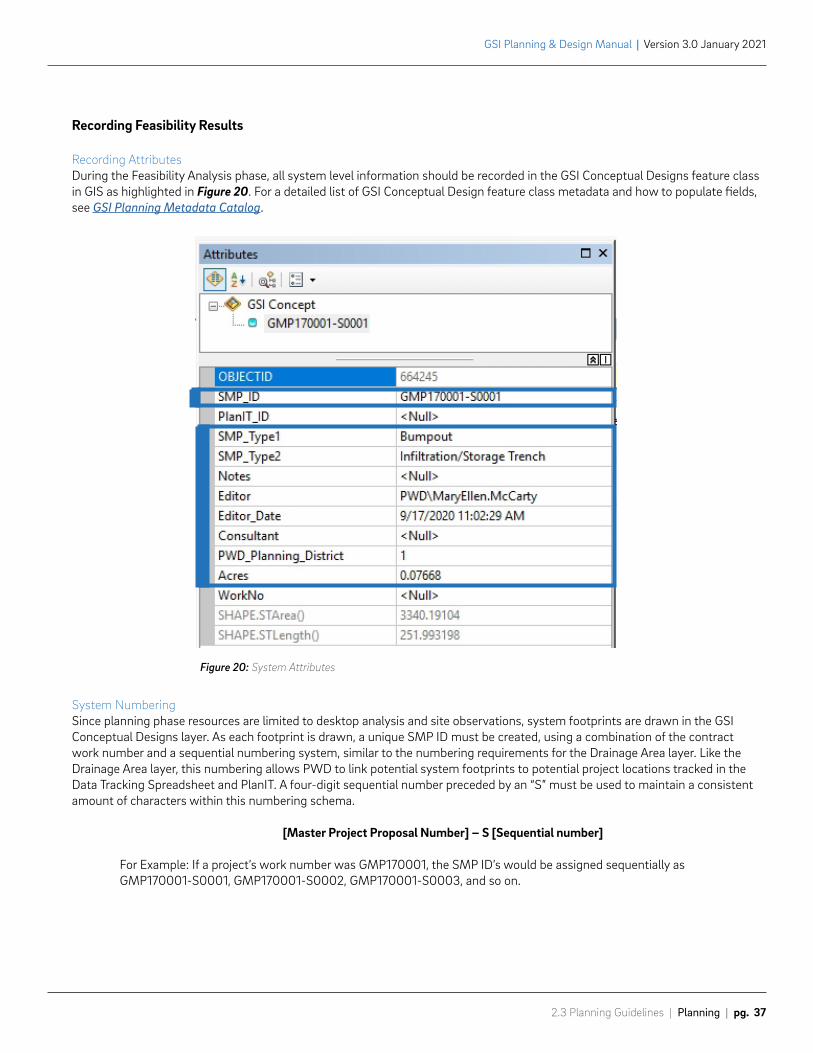
Figure 20: System Attributes
2.3 Planning Guidelines | Planning | pg. 37
GSI Planning & Design Manual | Version 3.0 January 2021
Figure 19: This example shows right-of-ways being managed by a Centralized GSI Facility on a park parcel.
Recording Feasibility Results
Recording AttributesDuring the Feasibility Analysis phase, all system level information should be recorded in the GSI Conceptual Designs feature class in GIS as highlighted in Figure 20. For a detailed list of GSI Conceptual Design feature class metadata and how to populate fields, see GSI Planning Metadata Catalog.
System Numbering Since planning phase resources are limited to desktop analysis and site observations, system footprints are drawn in the GSI Conceptual Designs layer. As each footprint is drawn, a unique SMP ID must be created, using a combination of the contract work number and a sequential numbering system, similar to the numbering requirements for the Drainage Area layer. Like the Drainage Area layer, this numbering allows PWD to link potential system footprints to potential project locations tracked in the Data Tracking Spreadsheet and PlanIT. A four-digit sequential number preceded by an “S” must be used to maintain a consistent amount of characters within this numbering schema.
[Master Project Proposal Number] – S [Sequential number]
For Example: If a project’s work number was GMP170001, the SMP ID’s would be assigned sequentially as GMP170001-S0001, GMP170001-S0002, GMP170001-S0003, and so on.
GSI Planning & Design Manual | Version 3.0 January 2021
pg. 38 | Planning | 2.3 Planning Guidelines
Drainage Area CategorizationAs system footprints are sited, drainage areas are categorized based on their feasibility for capture given available utility information and surface feature observations. Utility age, material, and size are documented to inform potential relocation during design. Classification should be recorded in the Drainage Area Feasibility field in the Drainage Area feature class based on the definitions listed below.* The Drainage Area feature class also includes drop-downs for “Constraints” and “Obscuring Utilities” which should be used to quickly identify the physical constraints and utilities that affect a drainage area polygon.
• High Potential: Drainage area can be managed on a street segment or parcel within the framework of current design practices. “Obscuring Utilities” do not need to be filled out in the attribute table if they don’t impact the system footprint. The nearest utility to the system footprint should be listed in the notes of the drainage area (i.e. “1980 8” PECO, 3’ cov, 2’ from N curb into cartway”).
• Medium Potential: Drainage areas are affected by the following:
» Rooftop
» Street crossing
» System spans more than two 2-foot contour lines (“Topographic” should be selected under “Considerations”)
» System impacted by single parallel utility of the following sizes (“Obscuring Utilities” and “Notes” should be filled out – i.e. “1980 4” Cl water, 3’ cov, 2’ from N curb into footway”)
• PGW 10 inches or under
• Water 6 inches or under
• PECO 6 inches or under
» Inlet closure
» Trees proposed to be removed
• Low Potential: Multiple confirmed physical constraints exist making the drainage area difficult to manage following current design guidelines. It is critical to consider all alternatives for management before selecting this designation. “Constraints” and “Obscuring Utilities” should be selected based on the order of restriction if they prevent siting of a system footprint. More detailed information on these constraining utilities should be listed in the notes of the drainage area (i.e. “1980 36” PECO, 3’ cov, 2’ from N curb into footway”). Drainage areas smaller than 5,000 SF should be categorized as Low Potential.
*Note: These classifications are not fixed; they are subject to change based on constraints that may be overcome as the program and suggested guidelines develop. The classifications should be determined based on desktop analysis, information gathered from site visits, and professional judgment. Additional guidance may be provided by the PWD project manager.
VENICE ISLAND PLANTERS
2.3 Planning Guidelines | Planning | pg. 39
GSI Planning & Design Manual | Version 3.0 January 2021
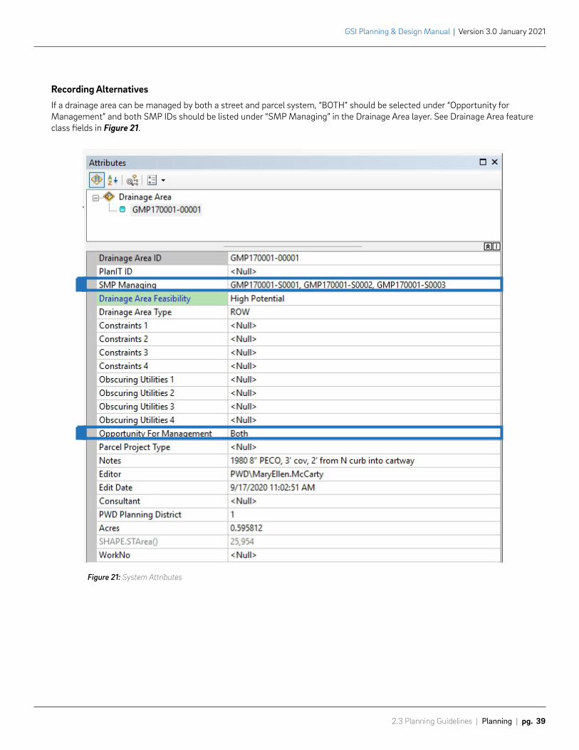
Recording AlternativesIf a drainage area can be managed by both a street and parcel system, “BOTH” should be selected under “Opportunity for Management” and both SMP IDs should be listed under “SMP Managing” in the Drainage Area layer. See Drainage Area feature class fields in Figure 21.
Figure 21: System Attributes
38
36
38
38
38
38
38
39
37
36
37
38
39
39
37
39
383938
Proposed GSI Pipe
GSI Planning & Design Manual | Version 3.0 January 2021
pg. 40 | Planning | 2.3 Planning Guidelines
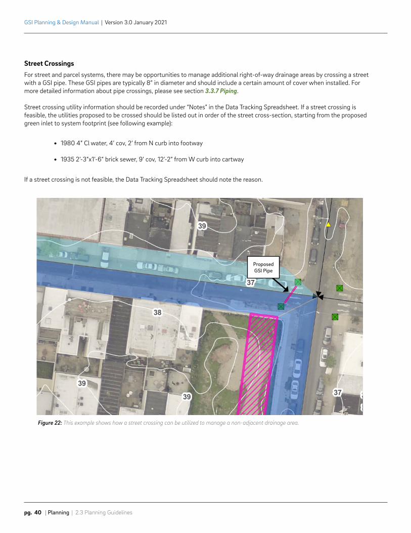
Street CrossingsFor street and parcel systems, there may be opportunities to manage additional right-of-way drainage areas by crossing a street with a GSI pipe. These GSI pipes are typically 8” in diameter and should include a certain amount of cover when installed. For more detailed information about pipe crossings, please see section 3.3.7 Piping.
Street crossing utility information should be recorded under “Notes” in the Data Tracking Spreadsheet. If a street crossing is feasible, the utilities proposed to be crossed should be listed out in order of the street cross-section, starting from the proposed green inlet to system footprint (see following example):
• 1980 4” Cl water, 4’ cov, 2’ from N curb into footway
• 1935 2’-3”x1’-6” brick sewer, 9’ cov, 12’-2” from W curb into cartway
If a street crossing is not feasible, the Data Tracking Spreadsheet should note the reason.
Figure 22: This example shows how a street crossing can be utilized to manage a non-adjacent drainage area.
2.3 Planning Guidelines | Planning | pg. 41
GSI Planning & Design Manual | Version 3.0 January 2021
Data Tracking SpreadsheetThe Data Tracking Spreadsheet (DTS) is used to record the results of the Feasibility Analysis phase. Every street segment and parcel that is evaluated must have an entry in the DTS. This includes all public parcels and select private parcels, as discussed with the PWD project manager. Site specific data is recorded in the DTS and is linked with both the Drainage Areas and system footprints drawn in GIS. At the completion of the Feasibility Analysis phase, a determination should be made for each location by filling in the “Recommended by Site Analyst” field with one of the following options.
• Yes: System is physically feasible.
• No: System is not physically feasible based on current guidelines.
Project StatusThe “Project Status” field should be filled out using the following guidance:
• Under Evaluation: This status should be used if multiple alternatives exist. PWD project manager will make a final determination during the alternative selection phase.
• Recommended: The project has been recommended for GSI. No physical constraints and can manage one or more drainage areas.
• On Hold: Major constraints exist making it difficult to place GSI footprints following current design guidelines.
Stormwater Improvement PlanThis may include a brief narrative summarizing the project process and methodology applied, all relevant maps, statistics, and supporting text outlining study results as well as information listed in the previous phases. The PWD project manager will provide more information during the scoping process about the expectations of this deliverable.
Example elements include but are not limited to:
• Pulling all deliverables from each task together
• Metrics
• Background maps
• Community plan alignment
• Matrix of ROW
• Early project ideas
GSI Planning & Design Manual | Version 3.0 January 2021
pg. 42 | Planning | 2.3 Planning Guidelines
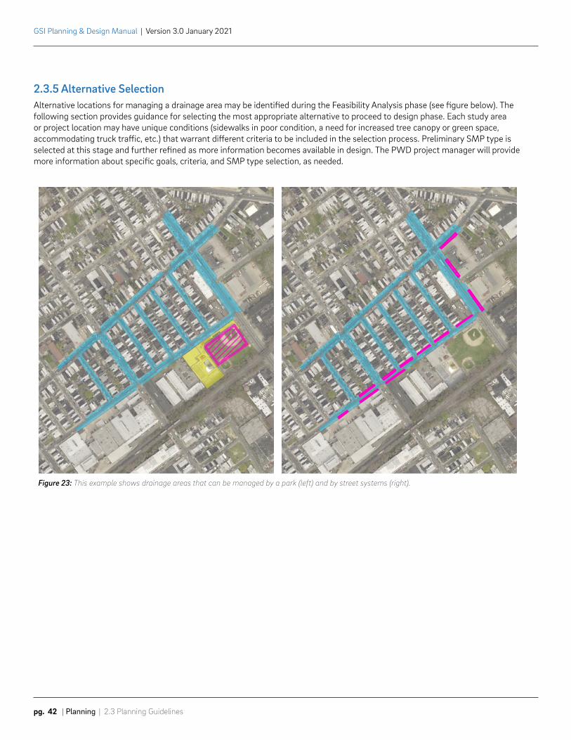
Figure 23: This example shows drainage areas that can be managed by a park (left) and by street systems (right).
2.3.5 Alternative SelectionAlternative locations for managing a drainage area may be identified during the Feasibility Analysis phase (see figure below). The following section provides guidance for selecting the most appropriate alternative to proceed to design phase. Each study area or project location may have unique conditions (sidewalks in poor condition, a need for increased tree canopy or green space, accommodating truck traffic, etc.) that warrant different criteria to be included in the selection process. Preliminary SMP type is selected at this stage and further refined as more information becomes available in design. The PWD project manager will provide more information about specific goals, criteria, and SMP type selection, as needed.
2.3 Planning Guidelines | Planning | pg. 43
GSI Planning & Design Manual | Version 3.0 January 2021
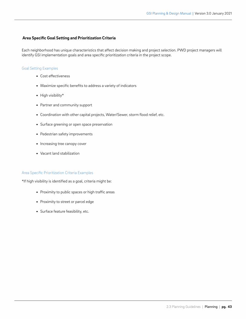
Area Specific Goal Setting and Prioritization Criteria
Each neighborhood has unique characteristics that affect decision making and project selection. PWD project managers will identify GSI implementation goals and area specific prioritization criteria in the project scope.
Goal Setting Examples
• Cost effectiveness
• Maximize specific benefits to address a variety of indicators
• High visibility*
• Partner and community support
• Coordination with other capital projects, Water/Sewer, storm flood relief, etc.
• Surface greening or open space preservation
• Pedestrian safety improvements
• Increasing tree canopy cover
• Vacant land stabilization
Area Specific Prioritization Criteria Examples
*If high visibility is identified as a goal, criteria might be:
• Proximity to public spaces or high traffic areas
• Proximity to street or parcel edge
• Surface feature feasibility, etc.
GSI Planning & Design Manual | Version 3.0 January 2021
pg. 44 | Planning | 2.3 Planning Guidelines
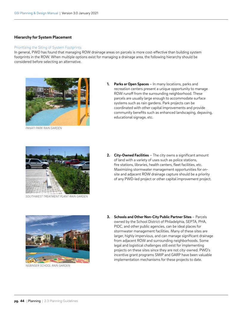
Hierarchy for System Placement
Prioritizing the Siting of System FootprintsIn general, PWD has found that managing ROW drainage areas on parcels is more cost-effective than building system footprints in the ROW. When multiple options exist for managing a drainage area, the following hierarchy should be considered before selecting an alternative.
1. Parks or Open Spaces – In many locations, parks and recreation centers present a unique opportunity to manage ROW runoff from the surrounding neighborhood. These parcels are usually large enough to accommodate surface systems such as rain gardens. Park projects can be coordinated with other capital improvements and provide community benefits such as enhanced landscaping, depaving, educational signage, etc.
2. City-Owned Facilities – The city owns a significant amount of land with a variety of uses such as police stations, fire stations, libraries, health centers, fleet facilities, etc. Maximizing stormwater management opportunities for on-site and adjacent ROW drainage capture should be a priority of any PWD-led project or other capital improvement project.
3. Schools and Other Non-City Public Partner Sites – Parcels owned by the School District of Philadelphia, SEPTA, PHA, PIDC, and other public agencies, can be ideal places for stormwater management facilities. Many of these sites are larger, highly impervious, and can manage significant drainage from adjacent ROW and surrounding neighborhoods. Some legal and logistical challenges still exist for implementing projects on these sites since they are not city-owned. PWD’s incentive grant programs SMIP and GARP have been valuable implementation mechanisms for these projects to date.
PANATI PARK RAIN GARDEN
SOUTHWEST TREATMENT PLANT RAIN GARDEN
NEBINGER SCHOOL RAIN GARDEN
HESTON VACANT LOT RAIN GARDEN
STANLEY’S HARDWARE RAIN GARDEN (PRIVATE)
2.3 Planning Guidelines | Planning | pg. 45
GSI Planning & Design Manual | Version 3.0 January 2021
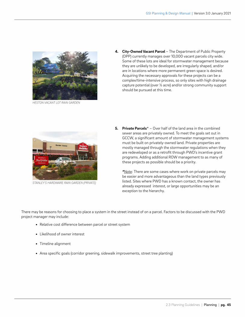
4. City-Owned Vacant Parcel – The Department of Public Property (DPP) currently manages over 10,000 vacant parcels city wide. Some of these lots are ideal for stormwater management because they are unlikely to be developed, are irregularly shaped, and/or are in locations where more permanent green space is desired. Acquiring the necessary approvals for these projects can be a complex/time-intensive process, so only sites with high drainage capture potential (over ½ acre) and/or strong community support should be pursued at this time.
5. Private Parcels* – Over half of the land area in the combined sewer areas are privately owned. To meet the goals set out in GCCW, a significant amount of stormwater management systems must be built on privately-owned land. Private properties are mostly managed through the stormwater regulations when they are redeveloped or as a retrofit through PWD’s incentive grant programs. Adding additional ROW management to as many of these projects as possible should be a priority.
*Note: There are some cases where work on private parcels may be easier and more advantageous than the land types previously listed. Sites where PWD has a known contact, the owner has already expressed interest, or large opportunities may be an exception to the hierarchy.
There may be reasons for choosing to place a system in the street instead of on a parcel. Factors to be discussed with the PWD project manager may include:
• Relative cost difference between parcel or street system
• Likelihood of owner interest
• Timeline alignment
• Area specific goals (corridor greening, sidewalk improvements, street tree planting)
Prepared by: Nicole Hostettler | Last Updated: August 11, 2020
3,831
2,943
5,993
5,958
5,091
5,937
3,725
4,882
7,088
4,2606,236
3,491
4,035
3,244
1,259
142
140
138
144
146
142
1915 2'3" X 1'6" Brick
1914
2'3
" X
1'6"
Bric
k
1914
2'3
" X
1'6"
Bric
k
1915 2'3" X 1'6" Brick
1914
2'3
" X
1'6"
Bric
k19
14 6
" C
I
1915 12" CI
1911
6"
CI
1914 12" CI
1914
6"
CI
N TA
NEY
ST
W INDIANA AVE
N BA
ILEY
ST
0 20 4010Feet
°
System 2: W Indiana Ave, N Taney St - N Bailey St Opportunities/Constraints:• New inlet proposed in south footway• Utility poles with overhead wires (5' from SMP)• 5 Cave In (CI) issues reported in 2002, 2003, 2006, 2009 and 2013 for 2964 N Bailey St• SMP proposed a minimum of 3' from roadway center line
W Indiana Ave: ArcGIS, PGW Plats, Utility Cards, PA One Call
Year Size Utility Material Cover Utility OffsetSystem Offset
1914 12" Water Cl 3'-7" 17'-8" from S curb into cartway 10'
1915 2'-3" x 1'-6" Sewer Brick 10'-3" 7' from N curb into cartway 21'
N Taney StYear Size Utility Material Cover Utility Offset
1914 2'-3" x 1'-6" Sewer Brick 9'-8" 6' from W curb into cartway
1914 6" Water CI 2'-7" 10' from E curb into cartway
1914 6" PGW - 2'-7" 3'-6" from E curb into cartway
N Bailey StYear Size Utility Material Cover Utility Offset
- 16" x 17" Verizon - 2'-7" 7'-9" from W curb into footway
1914 6" PGW - 2'-10" 3'-6" from W curb into cartway
1914 2'-3" x 1'-6" Sewer Brick 9'-8" 6' from W curb into cartway
1914 6" Water CI 3'-6" 10' from E curb into footway
Service locations shown in GIS may not be accurate. Consultants are responsible for verifying connections.
Drainage Area: 18,725 sf (0.43 ac)Tree Trench: 1,259 sf (15' x 90')Loading Ratio: 15:1W Indiana Ave (Class 4): 12' Footway / 36' CartwayProgram Type: Streets Address: N/AOwner: Public ROW
2
W Indiana Ave, looking East from N Taney St (Street view: Sep 2018) W Indiana Ave, looking West from N Bailey St (Street view: Sep 2018)
# GSI Numbering
Managed DA
GSI Concept
Under Evaluation
Low Potential
Medium Potential
High Potential
Managed
:9 Combined Sewer InletCombined Sewer(diameter in)
Water (diameter in)!( Water Valve
!H Manhole
Ñ! Fire Hydrant
' Traffic Signals
!( Street Poles
( Sign Poles
2' Contours
Street Flow
Stubbed Laterals
142
144
140
138
146
148
136
142
142
144
146
146
GSI Planning & Design Manual | Version 3.0 January 2021
pg. 46 | Planning | 2.3 Planning Guidelines
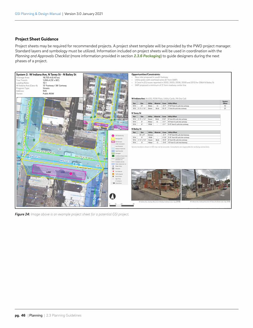
Project Sheet GuidanceProject sheets may be required for recommended projects. A project sheet template will be provided by the PWD project manager. Standard layers and symbology must be utilized. Information included on project sheets will be used in coordination with the Planning and Approvals Checklist (more information provided in section 2.3.6 Packaging) to guide designers during the next phases of a project.
Figure 24: Image above is an example project sheet for a potential GSI project.

2.3 Planning Guidelines | Planning | pg. 47
GSI Planning & Design Manual | Version 3.0 January 2021
2.3.6 PackagingAfter the completion of a planning study, there are numerous street and parcel locations that are recommended for siting GSI. PWD strategically groups these locations into packages of work and then times the start of design to align with program targets. These packages typically have 10-15 system footprints and are generally close together spatially. This provides cost efficiencies during the design and construction phases by minimizing survey and geotechnical costs, review times, and construction staging. Packages generally include similar SMP types to expedite the design process.
Before a package of work moves to design phase, planning staff compile the detailed project sheets for each system footprint, complete an internal Planning and Approvals Checklist, and make necessary database and GIS updates. These steps ensure specific elements of the package are flagged for coordination with appropriate PWD units and external partners. Additional steps such as a land use history review are included in these checklists as well. These final planning steps provide important documentation that should continue to be referenced throughout the design process.

Phila
delp
hia
Wat
er D
epar
tmen
t |
GSI
Pla
nnin
g &
Des
ign
Man
ual
v 3.
0

3.0 Design
GSI Planning & Design Manual | Version 3.0 January 2021
pg. 50 | Design | 3.1 Design Strategy
3.1 Design StrategyThroughout the design phase, PWD builds on opportunities identified during planning. Design follows a standardized process – from surveying and geotechnical testing to the development of construction documents – while constantly seeking opportunities to further streamline and innovate. PWD works collaboratively with other City agencies, partners, and stakeholders to design projects that not only meet and exceed the stormwater management goals, but also create projects that add value to the City.
ApproachPWD’s design approach includes development of cost-effective, context sensitive SMPs that meet Philadelphia’s compliance and operational requirements. Designs are prepared for packaged sites in geographic proximity, allowing for efficiencies in mobilization. The design approach for PWD GSI projects builds on the approach taken during planning, outlined in section 2.1 Planning Strategy, and can be summarized by the following objectives:
Maximize Managed Drainage AreaProject locations have been selected with the intent of maximizing potential runoff capture. During design phase, each system should seek to manage the largest drainage area feasible.
Minimize CostAll projects must strive to be as cost-effective as possible. To maintain affordability of the program, design and construction costs are monitored closely against established benchmarks at each phase of the project. While some projects will be more expensive than others to construct, PWD is actively pursuing partnerships and innovative opportunities to maintain overall affordability.
Maximize Water Quality Goals and Greening BenefitsInfiltration is preferred, wherever possible, to maximize water quality goals. Infiltrating stormwater removes it from the existing sewer system and allows it to filter through the existing soils. Where infiltration is not feasible, stormwater can be managed by detaining runoff, treating it for quality by routing it through a pollutant reducing SMP, and returning it to the existing sewer at a controlled rate. Greening benefits should be maximized by utilizing surface practices, where appropriate, preserving existing trees, and installing new and large stature trees.
3.1 Design Strategy | Design | pg. 51
GSI Planning & Design Manual | Version 3.0 January 2021
Consider Site ContextGSI projects typically fall on sites that are publicly-owned by a City Department other than PWD and these sites have purposes and programming outside the plans for GSI. GSI projects should be designed to accommodate the existing context, aim to enrich existing programming, and provide additional environmental benefits such as reducing heat island and maximizing tree canopy. Designs should carry through the site objectives identified during the planning phase.
Design for PWD MaintenanceAll projects designed for PWD’s GSI program are maintained by PWD and therefore must use standard components and configurations. All projects must be designed and reviewed with PWD GSI maintenance requirements in mind. See section 4.2.2 Maintenance Manual for a link to this resource.
Maintain PWD Design StandardsAll projects follow consistent standards for documentation and project delivery to provide PWD the information necessary to track projects in records, metrics, GIS, and projects tracking systems. PWD has a rich history of public works project delivery. GSI projects build upon this history, following a tailored approach for GSI.
GSI Planning & Design Manual | Version 3.0 January 2021
pg. 52 | Design | 3.2 Design Workflow Overview
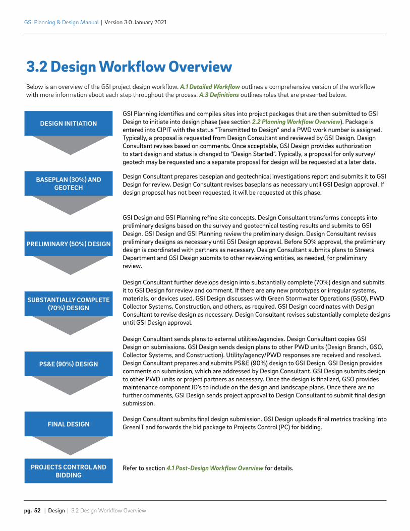
GSI Planning identifies and compiles sites into project packages that are then submitted to GSI Design to initiate into design phase (see section 2.2 Planning Workflow Overview). Package is entered into CIPIT with the status “Transmitted to Design” and a PWD work number is assigned. Typically, a proposal is requested from Design Consultant and reviewed by GSI Design. Design Consultant revises based on comments. Once acceptable, GSI Design provides authorization to start design and status is changed to “Design Started”. Typically, a proposal for only survey/geotech may be requested and a separate proposal for design will be requested at a later date.
Design Consultant prepares baseplan and geotechnical investigations report and submits it to GSI Design for review. Design Consultant revises baseplans as necessary until GSI Design approval. If design proposal has not been requested, it will be requested at this phase.
GSI Design and GSI Planning refine site concepts. Design Consultant transforms concepts into preliminary designs based on the survey and geotechnical testing results and submits to GSI Design. GSI Design and GSI Planning review the preliminary design. Design Consultant revises preliminary designs as necessary until GSI Design approval. Before 50% approval, the preliminary design is coordinated with partners as necessary. Design Consultant submits plans to Streets Department and GSI Design submits to other reviewing entities, as needed, for preliminary review.
Design Consultant further develops design into substantially complete (70%) design and submits it to GSI Design for review and comment. If there are any new prototypes or irregular systems, materials, or devices used, GSI Design discusses with Green Stormwater Operations (GSO), PWD Collector Systems, Construction, and others, as required. GSI Design coordinates with Design Consultant to revise design as necessary. Design Consultant revises substantially complete designs until GSI Design approval.
Design Consultant sends plans to external utilities/agencies. Design Consultant copies GSI Design on submissions. GSI Design sends design plans to other PWD units (Design Branch, GSO, Collector Systems, and Construction). Utility/agency/PWD responses are received and resolved. Design Consultant prepares and submits PS&E (90%) design to GSI Design. GSI Design provides comments on submission, which are addressed by Design Consultant. GSI Design submits design to other PWD units or project partners as necessary. Once the design is finalized, GSO provides maintenance component ID’s to include on the design and landscape plans. Once there are no further comments, GSI Design sends project approval to Design Consultant to submit final design submission.
Design Consultant submits final design submission. GSI Design uploads final metrics tracking into GreenIT and forwards the bid package to Projects Control (PC) for bidding.
Refer to section 4.1 Post-Design Workflow Overview for details.
3.2 Design Workflow OverviewBelow is an overview of the GSI project design workflow. A.1 Detailed Workflow outlines a comprehensive version of the workflow with more information about each step throughout the process. A.3 Definitions outlines roles that are presented below.
DESIGN INITIATION
BASEPLAN (30%) AND GEOTECH
PRELIMINARY (50%) DESIGN
SUBSTANTIALLY COMPLETE (70%) DESIGN
PS&E (90%) DESIGN
FINAL DESIGN
PROJECTS CONTROL AND BIDDING
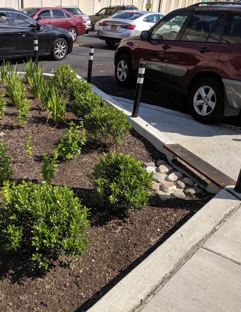
WINDRIM AVE BUMPOUT
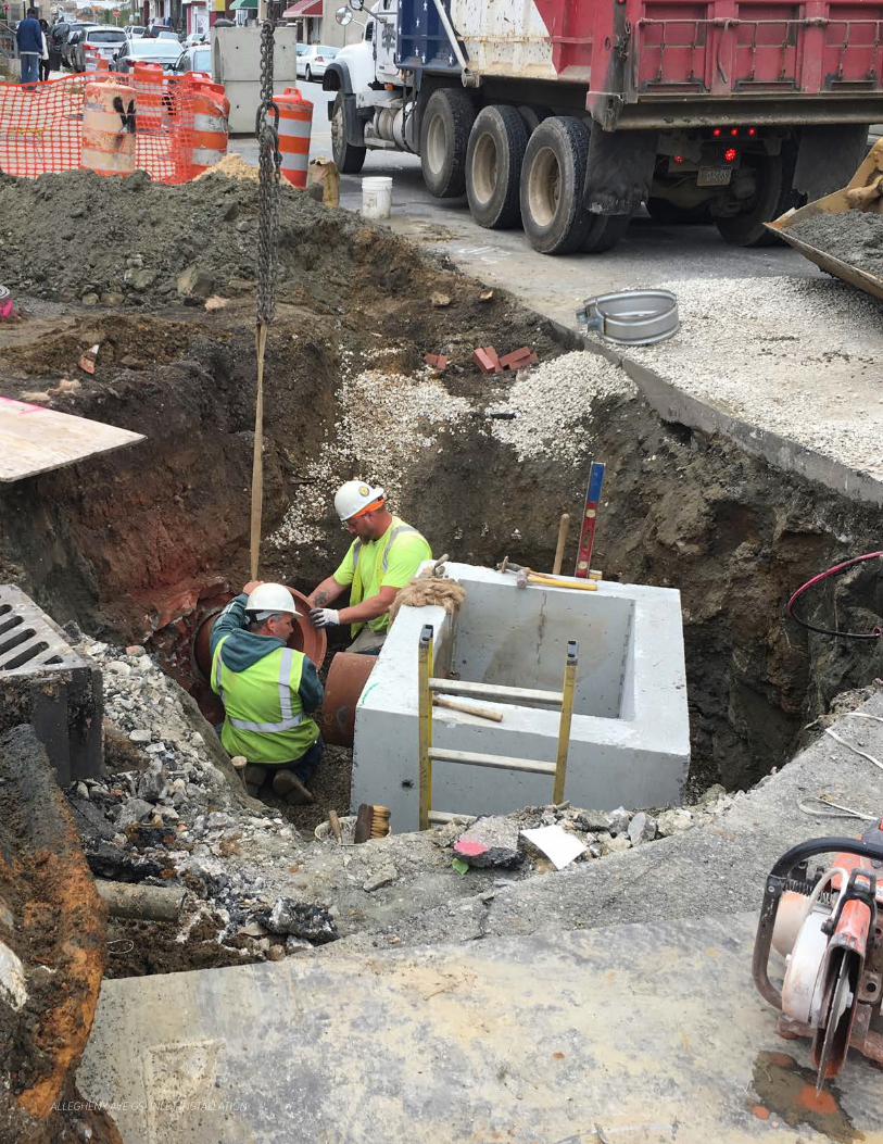
ALLEGHENY AVE GSI INLET INSTALLATION
3.3 Design Technical Requirements & Guidelines | Design | pg. 55
GSI Planning & Design Manual | Version 3.0 January 2021
Note on Separate Sewer Areas: The guidelines presented herein are intended for projects within areas of Philadelphia served by combined sewers. When working in separate sewer areas, more specific requirements, or deviations from these requirements, will be provided by the PWD project manager.
3.3 Design Technical Requirements & GuidelinesTo provide clarity on design direction, this section divides content into requirements and guidelines.
• Requirements: Instructions that must be followed for all GSI designs.
• Guidelines: Instructions that should generally be followed, but may allow for exceptions. Exceptions are determined on a case-by-case basis and should be discussed with the PWD project manager. Guidelines should still generally be followed and may be enforced strictly by PWD.
There may be additional limitations beyond those mentioned in this manual. Some constraints may be modified in certain circumstances, at the direction of the PWD project manager.
Note on Innovation: It is not uncommon in PWD’s experience that GSI projects need to move beyond standard design requirements and guidelines to create unique solutions to match unique challenges. As such, PWD expects and encourages innovation in the course of designing GSI. PWD’s general direction, when innovation appears to be called for, is for the consultant to work with the PWD project manager to evaluate options and proceed in general accordance with the information listed in section 3.3 Design Technical Requirements & Guidelines.
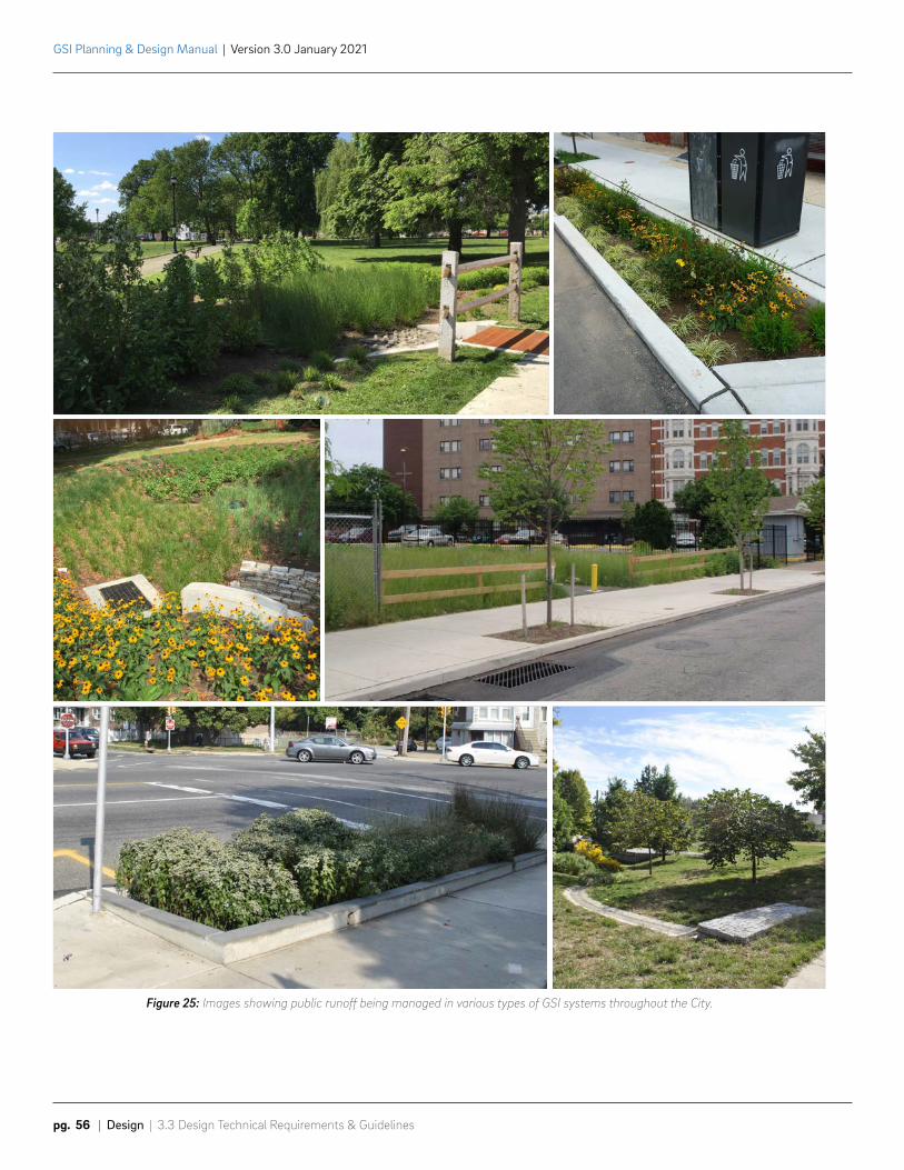
Figure 25: Images showing public runoff being managed in various types of GSI systems throughout the City.
GSI Planning & Design Manual | Version 3.0 January 2021
pg. 56 | Design | 3.3 Design Technical Requirements & Guidelines
3.3 Design Technical Requirements & Guidelines | Design | pg. 57
GSI Planning & Design Manual | Version 3.0 January 2021
3.3.1 System Placement
General Considerations
Guidelines
3.3.1.1 The number of individual systems should be minimized to reduce cost and future maintenance requirements.
3.3.1.2 Systems should be located directly upstream from existing inlets whenever possible to maximize drainage areas and allow for a convenient underdrain connection to an existing inlet.
3.3.1.3 Systems should be located to maximize opportunities for infiltration and minimize the need for use of impermeable geomembrane liners.
3.3.1.4 Infiltration/storage trench footprints should be designed as simple shapes. Complex configurations are difficult for construction. Surface SMP layouts can be more complex than subsurface trenches in order to tie into the existing site.
Note: Designers should reference planning notes and checklists when finalizing system placement. Designers should have a full understanding of the planning process before starting design work. This section should be utilized by planners during the feasibility phase to site initial system footprints. Preliminary SMP type is selected during planning stage and refined with information in design. PWD project manager will provide more information about SMP selection as needed.
GSI Planning & Design Manual | Version 3.0 January 2021
pg. 58 | Design | 3.3 Design Technical Requirements & Guidelines
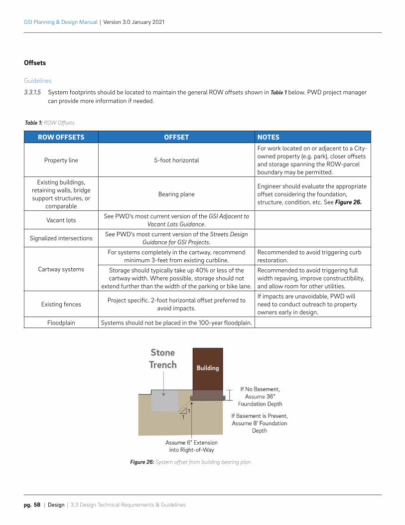
ROW OFFSETS OFFSET NOTES
Property line 5-foot horizontal
For work located on or adjacent to a City-owned property (e.g. park), closer offsets and storage spanning the ROW-parcel boundary may be permitted.
Existing buildings, retaining walls, bridge support structures, or
comparable
Bearing planeEngineer should evaluate the appropriate offset considering the foundation, structure, condition, etc. See Figure 26.
Vacant lots See PWD's most current version of the GSI Adjacent to Vacant Lots Guidance.
Signalized intersections See PWD's most current version of the Streets Design Guidance for GSI Projects.
Cartway systems
For systems completely in the cartway, recommend minimum 3-feet from existing curbline.
Recommended to avoid triggering curb restoration.
Storage should typically take up 40% or less of the cartway width. Where possible, storage should not
extend further than the width of the parking or bike lane.
Recommended to avoid triggering full width repaving, improve constructibility, and allow room for other utilities.
Existing fences Project specific. 2-foot horizontal offset preferred to avoid impacts.
If impacts are unavoidable, PWD will need to conduct outreach to property owners early in design.
Floodplain Systems should not be placed in the 100-year floodplain.
Table 1: ROW Offsets
Offsets
Guidelines
3.3.1.5 System footprints should be located to maintain the general ROW offsets shown in Table 1 below. PWD project manager can provide more information if needed.
Figure 26: System offset from building bearing plan.
3.3 Design Technical Requirements & Guidelines | Design | pg. 59
GSI Planning & Design Manual | Version 3.0 January 2021
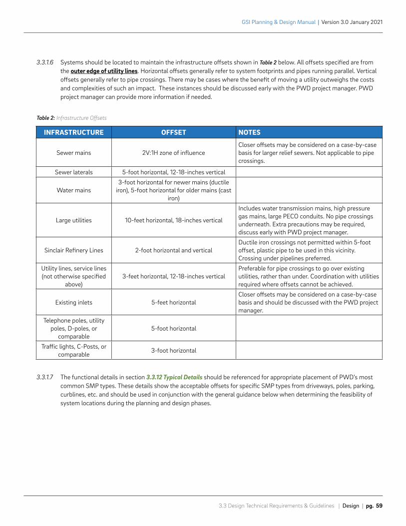
INFRASTRUCTURE OFFSET NOTES
Sewer mains 2V:1H zone of influenceCloser offsets may be considered on a case-by-case basis for larger relief sewers. Not applicable to pipe crossings.
Sewer laterals 5-foot horizontal, 12-18-inches vertical
Water mains3-foot horizontal for newer mains (ductile
iron), 5-foot horizontal for older mains (cast iron)
Large utilities 10-feet horizontal, 18-inches vertical
Includes water transmission mains, high pressure gas mains, large PECO conduits. No pipe crossings underneath. Extra precautions may be required, discuss early with PWD project manager.
Sinclair Refinery Lines 2-foot horizontal and verticalDuctile iron crossings not permitted within 5-foot offset, plastic pipe to be used in this vicinity. Crossing under pipelines preferred.
Utility lines, service lines (not otherwise specified
above)3-feet horizontal, 12-18-inches vertical
Preferable for pipe crossings to go over existing utilities, rather than under. Coordination with utilities required where offsets cannot be achieved.
Existing inlets 5-feet horizontalCloser offsets may be considered on a case-by-case basis and should be discussed with the PWD project manager.
Telephone poles, utility poles, D-poles, or
comparable5-foot horizontal
Traffic lights, C-Posts, or comparable 3-foot horizontal
Table 2: Infrastructure Offsets
3.3.1.6 Systems should be located to maintain the infrastructure offsets shown in Table 2 below. All offsets specified are from the outer edge of utility lines. Horizontal offsets generally refer to system footprints and pipes running parallel. Vertical offsets generally refer to pipe crossings. There may be cases where the benefit of moving a utility outweighs the costs and complexities of such an impact. These instances should be discussed early with the PWD project manager. PWD project manager can provide more information if needed.
3.3.1.7 The functional details in section 3.3.12 Typical Details should be referenced for appropriate placement of PWD’s most common SMP types. These details show the acceptable offsets for specific SMP types from driveways, poles, parking, curblines, etc. and should be used in conjunction with the general guidance below when determining the feasibility of system locations during the planning and design phases.
GSI Planning & Design Manual | Version 3.0 January 2021
pg. 60 | Design | 3.3 Design Technical Requirements & Guidelines
Pedestrian and Vehicular Access
Guidelines
3.3.1.8 Maintenance access should be considered early in the design process and must be reviewed and approved by PWD. Vehicular access for trucks and entry permissions (easements) must be provided for off-street sites. PWD project manager will coordinate the acquisition of appropriate easements.
a. Access must allow for maintenance trucks measuring eight (8) feet wide and thirty-five (35) feet long, with a twelve (12) foot vertical clearance. Driving surfaces must be generally 12-feet wide and support trucks weighing 68,000 pounds when fully loaded.
b. Consider location of maintenance truck when locating sump components such as inlets, water level control structures, cleanouts, domed risers, maintenance ports, etc. Maintenance ports must be accessible by vactor hose and clear of obstacles. Consider that vactor truck booms typically extend to a maximum of 30 feet and features that need this type of cleaning should ideally be located within this distance of the vehicular maintenance access location. Obstacles such as fences, wide footways, adjacent mature trees, and/or utility lines should also be evaluated when placing these maintenance features.
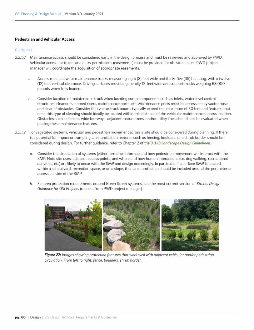
3.3.1.9 For vegetated systems, vehicular and pedestrian movement across a site should be considered during planning. If there is a potential for impact or trampling, area protection features such as fencing, boulders, or a shrub border should be considered during design. For further guidance, refer to Chapter 2 of the 3.3.13 Landscape Design Guidebook.
a. Consider the circulation of systems (either formal or informal) and how pedestrian movement will interact with the SMP. Note site uses, adjacent access points, and where and how human interactions (i.e. dog walking, recreational activities, etc) are likely to occur with the SMP and design accordingly. In particular, if a surface SMP is located within a school yard, recreation space, or on a slope, then area protection should be included around the perimeter or accessible side of the SMP.
b. For area protection requirements around Green Street systems, see the most current version of Streets Design Guidance for GSI Projects (request from PWD project manager).
Figure 27: Images showing protection features that work well with adjacent vehicular and/or pedestrian circulation. From left to right: fence, boulders, shrub border.
3.3 Design Technical Requirements & Guidelines | Design | pg. 61
GSI Planning & Design Manual | Version 3.0 January 2021
Greening
Guidelines
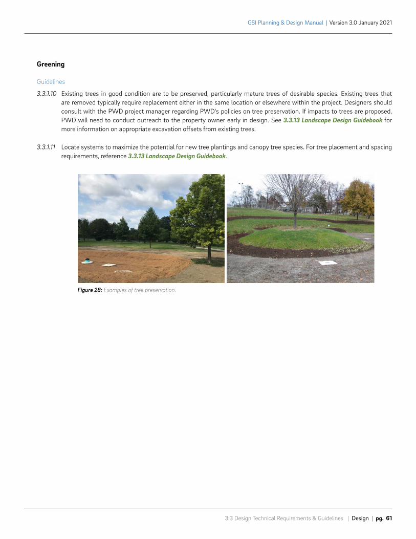
3.3.1.10 Existing trees in good condition are to be preserved, particularly mature trees of desirable species. Existing trees that are removed typically require replacement either in the same location or elsewhere within the project. Designers should consult with the PWD project manager regarding PWD's policies on tree preservation. If impacts to trees are proposed, PWD will need to conduct outreach to the property owner early in design. See 3.3.13 Landscape Design Guidebook for more information on appropriate excavation offsets from existing trees.
3.3.1.11 Locate systems to maximize the potential for new tree plantings and canopy tree species. For tree placement and spacing requirements, reference 3.3.13 Landscape Design Guidebook.
Figure 28: Examples of tree preservation.
GSI Planning & Design Manual | Version 3.0 January 2021
pg. 62 | Design | 3.1 Design Strategy
Grading and Elevations
Guidelines
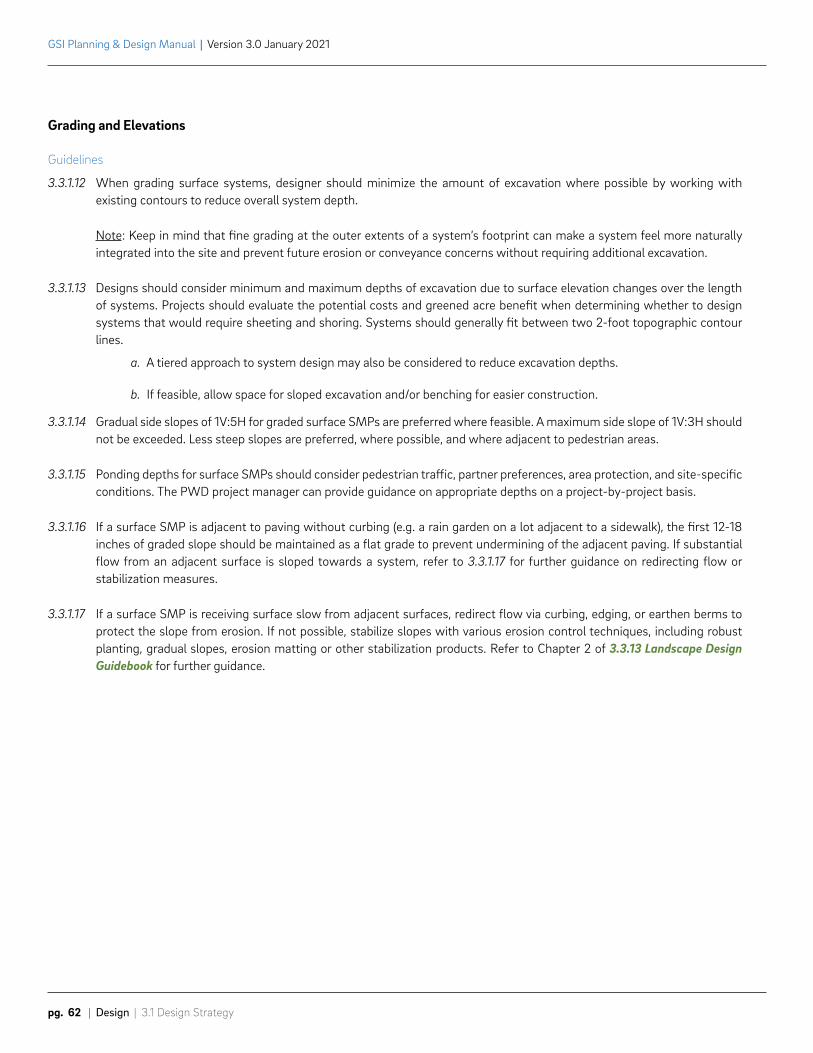
3.3.1.12 When grading surface systems, designer should minimize the amount of excavation where possible by working with existing contours to reduce overall system depth.
Note: Keep in mind that fine grading at the outer extents of a system’s footprint can make a system feel more naturally integrated into the site and prevent future erosion or conveyance concerns without requiring additional excavation.
3.3.1.13 Designs should consider minimum and maximum depths of excavation due to surface elevation changes over the length of systems. Projects should evaluate the potential costs and greened acre benefit when determining whether to design systems that would require sheeting and shoring. Systems should generally fit between two 2-foot topographic contour lines.
a. A tiered approach to system design may also be considered to reduce excavation depths.
b. If feasible, allow space for sloped excavation and/or benching for easier construction.
3.3.1.14 Gradual side slopes of 1V:5H for graded surface SMPs are preferred where feasible. A maximum side slope of 1V:3H should not be exceeded. Less steep slopes are preferred, where possible, and where adjacent to pedestrian areas.
3.3.1.15 Ponding depths for surface SMPs should consider pedestrian traffic, partner preferences, area protection, and site-specific conditions. The PWD project manager can provide guidance on appropriate depths on a project-by-project basis.
3.3.1.16 If a surface SMP is adjacent to paving without curbing (e.g. a rain garden on a lot adjacent to a sidewalk), the first 12-18 inches of graded slope should be maintained as a flat grade to prevent undermining of the adjacent paving. If substantial flow from an adjacent surface is sloped towards a system, refer to 3.3.1.17 for further guidance on redirecting flow or stabilization measures.
3.3.1.17 If a surface SMP is receiving surface slow from adjacent surfaces, redirect flow via curbing, edging, or earthen berms to protect the slope from erosion. If not possible, stabilize slopes with various erosion control techniques, including robust planting, gradual slopes, erosion matting or other stabilization products. Refer to Chapter 2 of 3.3.13 Landscape Design Guidebook for further guidance.
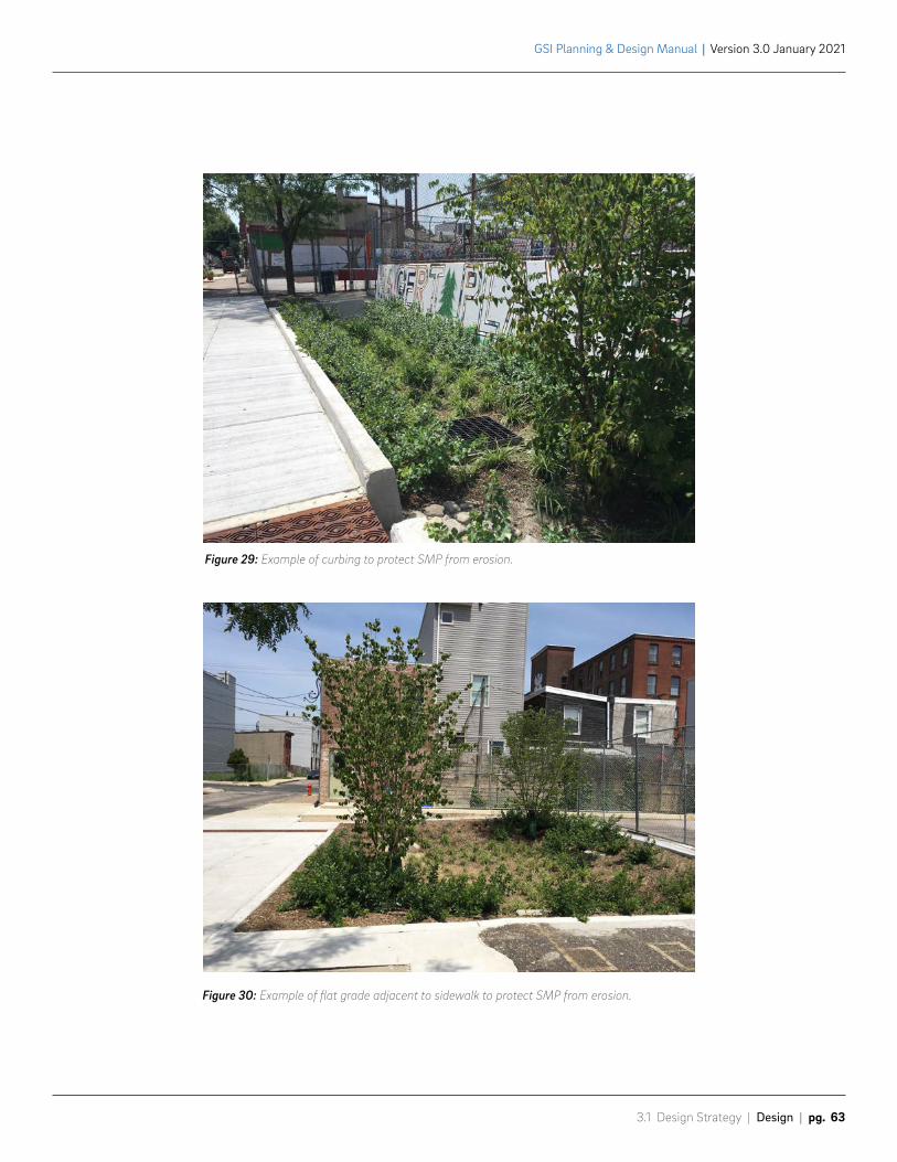
3.1 Design Strategy | Design | pg. 63
GSI Planning & Design Manual | Version 3.0 January 2021
Figure 29: Example of curbing to protect SMP from erosion.
Figure 30: Example of flat grade adjacent to sidewalk to protect SMP from erosion.
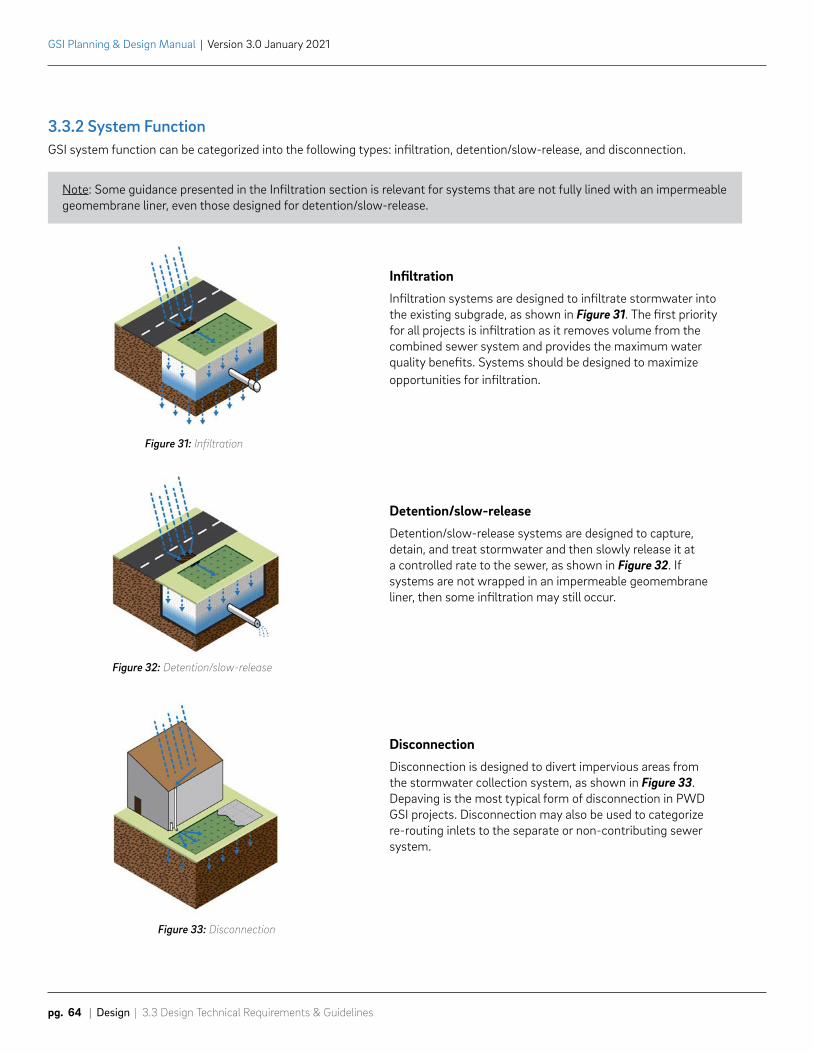
GSI Planning & Design Manual | Version 3.0 January 2021
pg. 64 | Design | 3.3 Design Technical Requirements & Guidelines
3.3.2 System FunctionGSI system function can be categorized into the following types: infiltration, detention/slow-release, and disconnection.
Note: Some guidance presented in the Infiltration section is relevant for systems that are not fully lined with an impermeable geomembrane liner, even those designed for detention/slow-release.
Infiltration Infiltration systems are designed to infiltrate stormwater into the existing subgrade, as shown in Figure 31. The first priority for all projects is infiltration as it removes volume from the combined sewer system and provides the maximum water quality benefits. Systems should be designed to maximize opportunities for infiltration.
Detention/slow-releaseDetention/slow-release systems are designed to capture, detain, and treat stormwater and then slowly release it at a controlled rate to the sewer, as shown in Figure 32. If systems are not wrapped in an impermeable geomembrane liner, then some infiltration may still occur.
DisconnectionDisconnection is designed to divert impervious areas from the stormwater collection system, as shown in Figure 33. Depaving is the most typical form of disconnection in PWD GSI projects. Disconnection may also be used to categorize re-routing inlets to the separate or non-contributing sewer system.
Figure 31: Infiltration
Figure 32: Detention/slow-release
Figure 33: Disconnection
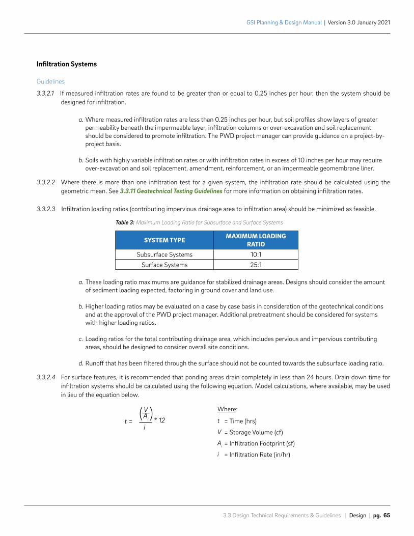
SYSTEM TYPE MAXIMUM LOADING RATIO
Subsurface Systems 10:1
Surface Systems 25:1
t =
V
i* 12
( )Ai
3.3 Design Technical Requirements & Guidelines | Design | pg. 65
GSI Planning & Design Manual | Version 3.0 January 2021
Infiltration Systems
Guidelines
3.3.2.1 If measured infiltration rates are found to be greater than or equal to 0.25 inches per hour, then the system should be designed for infiltration.
a. Where measured infiltration rates are less than 0.25 inches per hour, but soil profiles show layers of greater permeability beneath the impermeable layer, infiltration columns or over-excavation and soil replacement should be considered to promote infiltration. The PWD project manager can provide guidance on a project-by-project basis.
b. Soils with highly variable infiltration rates or with infiltration rates in excess of 10 inches per hour may require over-excavation and soil replacement, amendment, reinforcement, or an impermeable geomembrane liner.
3.3.2.2 Where there is more than one infiltration test for a given system, the infiltration rate should be calculated using the geometric mean. See 3.3.11 Geotechnical Testing Guidelines for more information on obtaining infiltration rates.
3.3.2.3 Infiltration loading ratios (contributing impervious drainage area to infiltration area) should be minimized as feasible.
a. These loading ratio maximums are guidance for stabilized drainage areas. Designs should consider the amount of sediment loading expected, factoring in ground cover and land use.
b. Higher loading ratios may be evaluated on a case by case basis in consideration of the geotechnical conditions and at the approval of the PWD project manager. Additional pretreatment should be considered for systems with higher loading ratios.
c. Loading ratios for the total contributing drainage area, which includes pervious and impervious contributing areas, should be designed to consider overall site conditions.
d. Runoff that has been filtered through the surface should not be counted towards the subsurface loading ratio.
3.3.2.4 For surface features, it is recommended that ponding areas drain completely in less than 24 hours. Drain down time for infiltration systems should be calculated using the following equation. Model calculations, where available, may be used in lieu of the equation below.
Table 3: Maximum Loading Ratio for Subsurface and Surface Systems
= Time (hrs)
= Storage Volume (cf)
= Infiltration Footprint (sf)
= Infiltration Rate (in/hr)
t
V
Ai
i
Where:
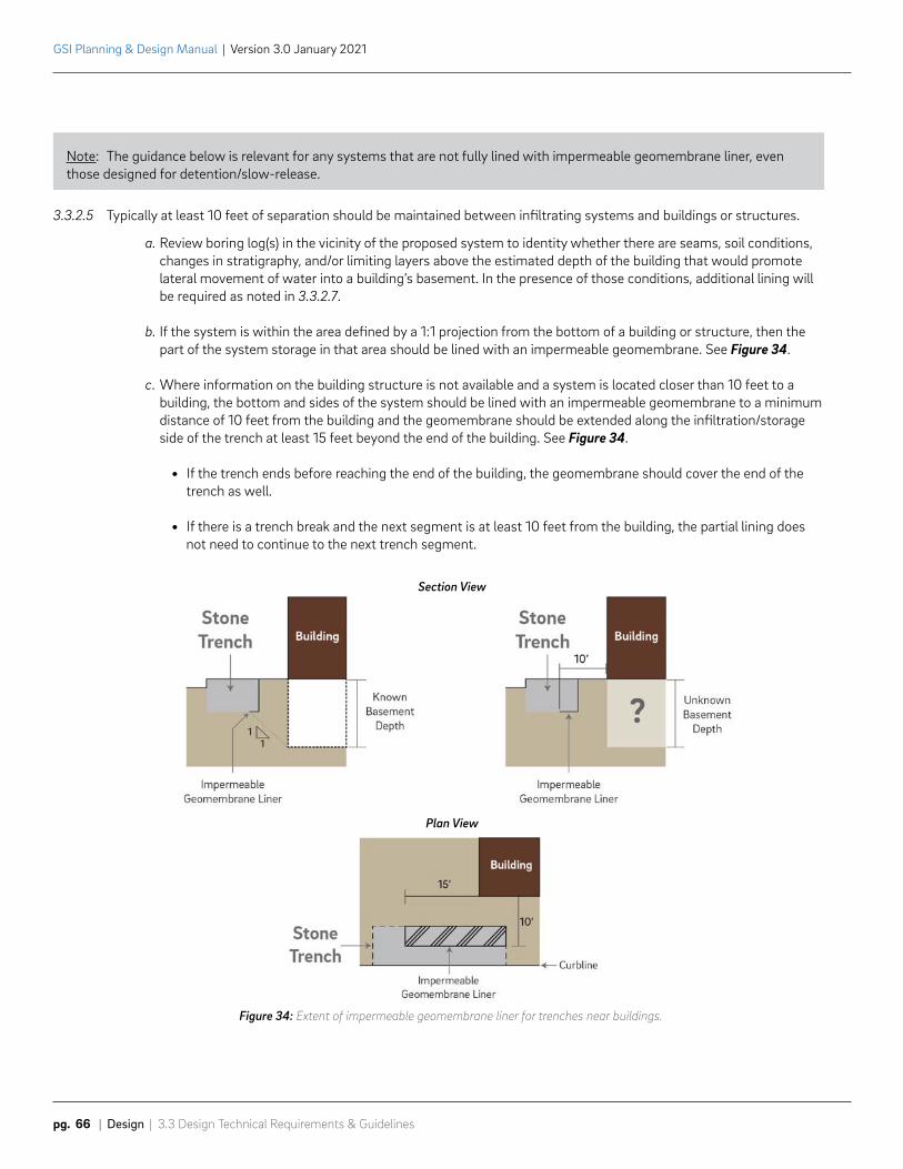
GSI Planning & Design Manual | Version 3.0 January 2021
pg. 66 | Design | 3.3 Design Technical Requirements & Guidelines
3.3.2.5 Typically at least 10 feet of separation should be maintained between infiltrating systems and buildings or structures.
a. Review boring log(s) in the vicinity of the proposed system to identity whether there are seams, soil conditions, changes in stratigraphy, and/or limiting layers above the estimated depth of the building that would promote lateral movement of water into a building’s basement. In the presence of those conditions, additional lining will be required as noted in 3.3.2.7.
b. If the system is within the area defined by a 1:1 projection from the bottom of a building or structure, then the part of the system storage in that area should be lined with an impermeable geomembrane. See Figure 34.
c. Where information on the building structure is not available and a system is located closer than 10 feet to a building, the bottom and sides of the system should be lined with an impermeable geomembrane to a minimum distance of 10 feet from the building and the geomembrane should be extended along the infiltration/storage side of the trench at least 15 feet beyond the end of the building. See Figure 34.
• If the trench ends before reaching the end of the building, the geomembrane should cover the end of the trench as well.
• If there is a trench break and the next segment is at least 10 feet from the building, the partial lining does not need to continue to the next trench segment.
Figure 34: Extent of impermeable geomembrane liner for trenches near buildings.
Section View
Plan View
Note: The guidance below is relevant for any systems that are not fully lined with impermeable geomembrane liner, even those designed for detention/slow-release.
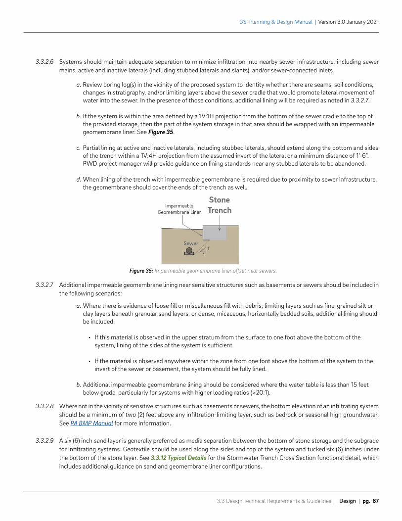
3.3 Design Technical Requirements & Guidelines | Design | pg. 67
GSI Planning & Design Manual | Version 3.0 January 2021
3.3.2.7 Additional impermeable geomembrane lining near sensitive structures such as basements or sewers should be included in the following scenarios:
a. Where there is evidence of loose fill or miscellaneous fill with debris; limiting layers such as fine-grained silt or clay layers beneath granular sand layers; or dense, micaceous, horizontally bedded soils; additional lining should be included.
• If this material is observed in the upper stratum from the surface to one foot above the bottom of the system, lining of the sides of the system is sufficient.
• If the material is observed anywhere within the zone from one foot above the bottom of the system to the invert of the sewer or basement, the system should be fully lined.
b. Additional impermeable geomembrane lining should be considered where the water table is less than 15 feet below grade, particularly for systems with higher loading ratios (>20:1).
3.3.2.8 Where not in the vicinity of sensitive structures such as basements or sewers, the bottom elevation of an infiltrating system should be a minimum of two (2) feet above any infiltration-limiting layer, such as bedrock or seasonal high groundwater. See PA BMP Manual for more information.
3.3.2.9 A six (6) inch sand layer is generally preferred as media separation between the bottom of stone storage and the subgrade for infiltrating systems. Geotextile should be used along the sides and top of the system and tucked six (6) inches under the bottom of the stone layer. See 3.3.12 Typical Details for the Stormwater Trench Cross Section functional detail, which includes additional guidance on sand and geomembrane liner configurations.
3.3.2.6 Systems should maintain adequate separation to minimize infiltration into nearby sewer infrastructure, including sewer mains, active and inactive laterals (including stubbed laterals and slants), and/or sewer-connected inlets.
a. Review boring log(s) in the vicinity of the proposed system to identity whether there are seams, soil conditions, changes in stratigraphy, and/or limiting layers above the sewer cradle that would promote lateral movement of water into the sewer. In the presence of those conditions, additional lining will be required as noted in 3.3.2.7.
b. If the system is within the area defined by a 1V:1H projection from the bottom of the sewer cradle to the top of the provided storage, then the part of the system storage in that area should be wrapped with an impermeable geomembrane liner. See Figure 35.
c. Partial lining at active and inactive laterals, including stubbed laterals, should extend along the bottom and sides of the trench within a 1V:4H projection from the assumed invert of the lateral or a minimum distance of 1’-6”. PWD project manager will provide guidance on lining standards near any stubbed laterals to be abandoned.
d. When lining of the trench with impermeable geomembrane is required due to proximity to sewer infrastructure, the geomembrane should cover the ends of the trench as well.
Figure 35: Impermeable geomembrane liner offset near sewers.
Q = Cd Ao 2gh
2V
Cd Ao 2gh * 3600t =
GSI Planning & Design Manual | Version 3.0 January 2021
pg. 68 | Design | 3.3 Design Technical Requirements & Guidelines
Detention/Slow-Release Systems
Requirements
3.3.2.10 Detention/slow-release systems must be designed to release at a maximum rate of 0.05 cfs per acre of contributing impervious drainage area. Release rates should be rounded to the nearest hundredth.
3.3.2.11 Slow-release rates and orifice sizing should be calculated using the orifice equation.
3.3.2.12 For constructibility, orifice diameters must be sized for common drill bits (must be a multiple of 1/8 inch).
3.3.2.13 Orifice diameters must not be less than 0.5 inches to minimize the potential for clogging.
Guidelines
3.3.2.14 If design infiltration rates are found to be less than 0.25 inches per hour, or if the system is fully or mostly lined, the system should be designed for detention/slow-release.
3.3.2.15 Systems may also be lined and designed for detention/slow-release if geotechnical findings or contamination issues make infiltration inadvisable.
3.3.2.16 Detention/slow-release systems should route ground-level runoff through a PWD-approved pollutant reducing SMP where possible and cost-effective. Pollutant reducing SMPs include basins, planters, rain gardens, bumpouts, green gutters, stormwater trees, or other SMPs that route runoff through a soil profile or other equivalent porous media.
3.3.2.17 Model calculations may be used in lieu of the equations shown at the discretion of the PWD project manager.
3.3.2.18 For surface features, it is recommended that ponding areas drain completely in less than 24 hours. Drain down time for detention/slow-release systems with a uniform horizontal cross section should be calculated using the following equation. This equation was derived from the submerged orifice discharge formula and modified to account for volume draining through a porous media, as is typical in PWD GSI systems. The detailed derivation of this equation is available upon request from the PWD project manager.
t
V
h
Cd
Ao
g
Q
Cd
Ao
g
h
Where: = Peak Release Rate
= Discharge Coefficient = 0.62
= Area of Orifice (ft2) = π*r2
= Gravity (ft/s2) = 32.2
= Slow-Release Hydraulic Head (ft)
Where: = Time (hrs)
= Storage Volume (ft3)
= Slow-Release Hydraulic Head (ft)
= Discharge Coefficient = 0.62
= Area of Orifice (ft2) = π*r2
= Gravity (ft/s2) = 32.2
Note: For systems that are not fully lined with impermeable geomembrane liner, see additional guidance on previous pages. This guidance is relevant even for detention/slow-release systems.
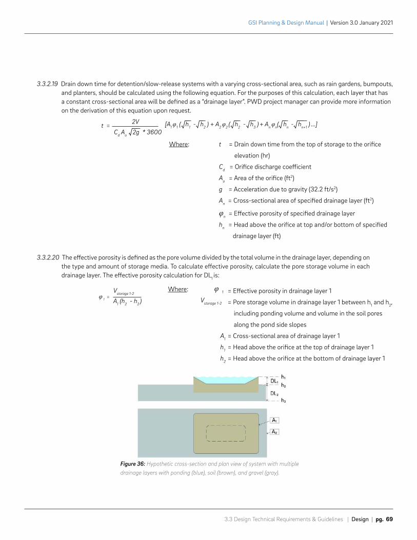
2V
Cd Ao 2g * 3600t = [A1 φ1 ( h1 - h2 ) + A2 φ2 ( h2 - h3 ) + An φn( hn - hn+1 ) ...]
φ 1 =Vstorage 1-2
A1 (h2 - h2 )
3.3 Design Technical Requirements & Guidelines | Design | pg. 69
GSI Planning & Design Manual | Version 3.0 January 2021
3.3.2.20 The effective porosity is defined as the pore volume divided by the total volume in the drainage layer, depending on the type and amount of storage media. To calculate effective porosity, calculate the pore storage volume in each drainage layer. The effective porosity calculation for DL1 is:
t = Drain down time from the top of storage to the orifice
elevation (hr)
Cd = Orifice discharge coefficient
Ao = Area of the orifice (ft2)
g = Acceleration due to gravity (32.2 ft/s2)
An = Cross-sectional area of specified drainage layer (ft2)
φn = Effective porosity of specified drainage layer
hn = Head above the orifice at top and/or bottom of specified
drainage layer (ft)
3.3.2.19 Drain down time for detention/slow-release systems with a varying cross-sectional area, such as rain gardens, bumpouts, and planters, should be calculated using the following equation. For the purposes of this calculation, each layer that has a constant cross-sectional area will be defined as a “drainage layer”. PWD project manager can provide more information on the derivation of this equation upon request.
Figure 36: Hypothetic cross-section and plan view of system with multiple drainage layers with ponding (blue), soil (brown), and gravel (gray).
φ 1
Vstorage 1-2
= Effective porosity in drainage layer 1
= Pore storage volume in drainage layer 1 between h1 and h2,
including ponding volume and volume in the soil pores
along the pond side slopes
= Cross-sectional area of drainage layer 1
= Head above the orifice at the top of drainage layer 1
= Head above the orifice at the bottom of drainage layer 1
A1
h1
h2
Where:
Where:
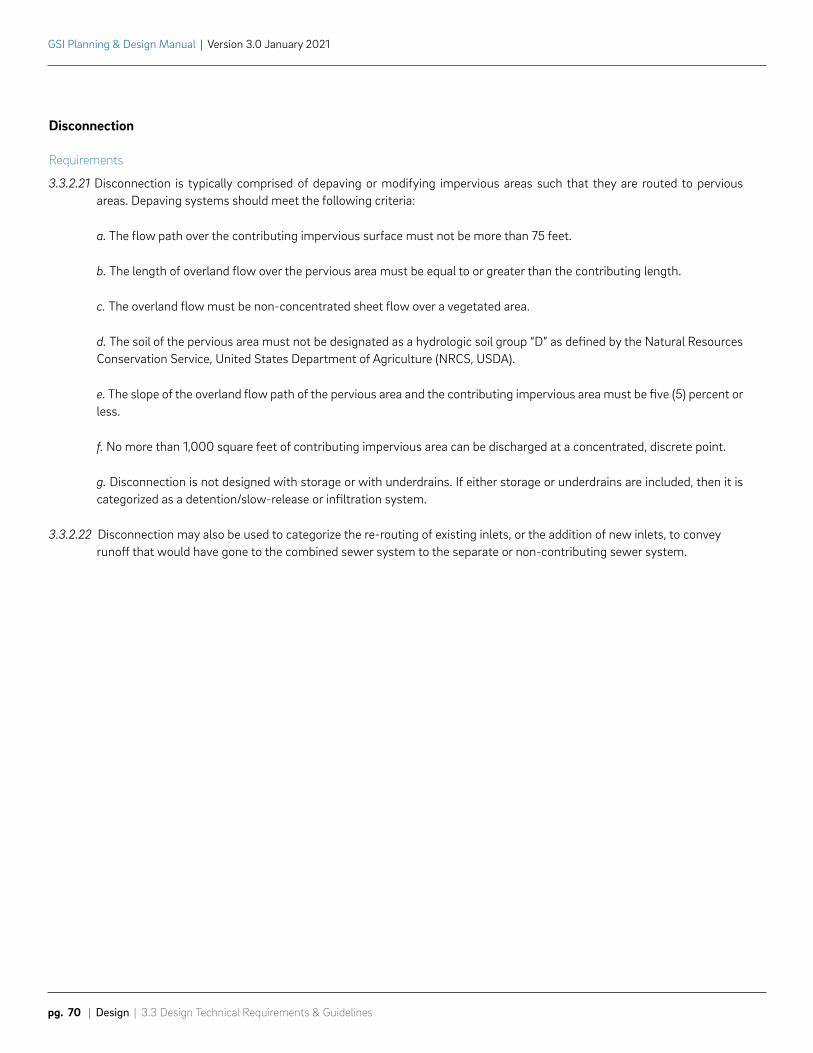
GSI Planning & Design Manual | Version 3.0 January 2021
pg. 70 | Design | 3.3 Design Technical Requirements & Guidelines
Disconnection
Requirements
3.3.2.21 Disconnection is typically comprised of depaving or modifying impervious areas such that they are routed to pervious areas. Depaving systems should meet the following criteria:
a. The flow path over the contributing impervious surface must not be more than 75 feet.
b. The length of overland flow over the pervious area must be equal to or greater than the contributing length.
c. The overland flow must be non-concentrated sheet flow over a vegetated area.
d. The soil of the pervious area must not be designated as a hydrologic soil group “D” as defined by the Natural Resources Conservation Service, United States Department of Agriculture (NRCS, USDA).
e. The slope of the overland flow path of the pervious area and the contributing impervious area must be five (5) percent or less.
f. No more than 1,000 square feet of contributing impervious area can be discharged at a concentrated, discrete point.
g. Disconnection is not designed with storage or with underdrains. If either storage or underdrains are included, then it is categorized as a detention/slow-release or infiltration system.
3.3.2.22 Disconnection may also be used to categorize the re-routing of existing inlets, or the addition of new inlets, to convey runoff that would have gone to the combined sewer system to the separate or non-contributing sewer system.
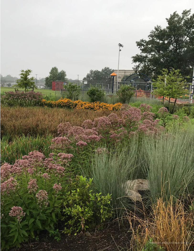
CARMELLA PLAYGROUND RAIN GARDEN
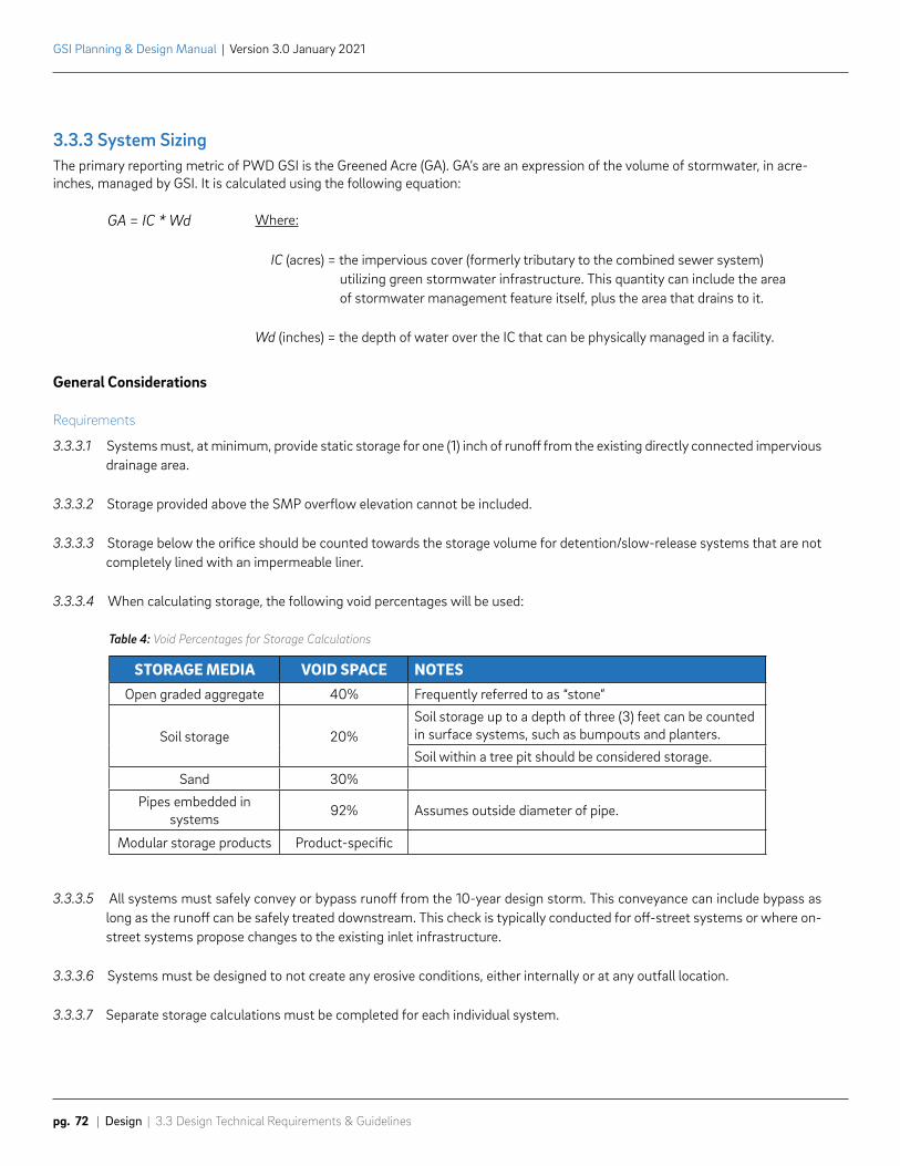
STORAGE MEDIA VOID SPACE NOTESOpen graded aggregate 40% Frequently referred to as “stone”
Soil storage 20%Soil storage up to a depth of three (3) feet can be counted in surface systems, such as bumpouts and planters.
Soil within a tree pit should be considered storage.
Sand 30%
Pipes embedded in systems 92% Assumes outside diameter of pipe.
Modular storage products Product-specific
GSI Planning & Design Manual | Version 3.0 January 2021
pg. 72 | Design | 3.3 Design Technical Requirements & Guidelines
3.3.3 System SizingThe primary reporting metric of PWD GSI is the Greened Acre (GA). GA’s are an expression of the volume of stormwater, in acre-inches, managed by GSI. It is calculated using the following equation:
General Considerations
Requirements
3.3.3.1 Systems must, at minimum, provide static storage for one (1) inch of runoff from the existing directly connected impervious drainage area.
3.3.3.2 Storage provided above the SMP overflow elevation cannot be included.
3.3.3.3 Storage below the orifice should be counted towards the storage volume for detention/slow-release systems that are not completely lined with an impermeable liner.
3.3.3.4 When calculating storage, the following void percentages will be used:
Table 4: Void Percentages for Storage Calculations
3.3.3.5 All systems must safely convey or bypass runoff from the 10-year design storm. This conveyance can include bypass as long as the runoff can be safely treated downstream. This check is typically conducted for off-street systems or where on-street systems propose changes to the existing inlet infrastructure.
3.3.3.6 Systems must be designed to not create any erosive conditions, either internally or at any outfall location.
3.3.3.7 Separate storage calculations must be completed for each individual system.
Where:
IC (acres) = the impervious cover (formerly tributary to the combined sewer system) utilizing green stormwater infrastructure. This quantity can include the area of stormwater management feature itself, plus the area that drains to it.
Wd (inches) = the depth of water over the IC that can be physically managed in a facility.
GA = IC * Wd

3.3 Design Technical Requirements & Guidelines | Design | pg. 73
GSI Planning & Design Manual | Version 3.0 January 2021
Guidelines
3.3.3.8 Where feasible and cost-effective, systems should provide static storage for up to 1.5 inches of runoff from the existing directly connected impervious drainage area. Storage should not exceed a volume equivalent to two (2) inches of runoff, unless otherwise approved by PWD where future connections to the GSI system are anticipated.
3.3.3.9 In order to be cost-effective, systems should manage a minimum drainage area of 8,000 SF. Individual drainage areas to each inlet should be no less than 5,000 SF. If an individual drainage area is less than 5,000 SF and adjacent to the area of system excavation, smaller drainage area thresholds may be considered.
3.3.3.10 Under current policy, only drainage areas in the right-of-way, from alleys, or on public lands should be counted for sizing considerations. Alleys with significant drainage contributing to the right-of-way that can be verified and mapped may be included in sizing, though right-of-way drainage should be prioritized in system sizing since it is a more stable land area. Designers should consider the actual topography, land use types, and discuss potential issues with the PWD project manager.
3.3.3.11 Within the right-of-way, grass strips or other highly compacted areas should be considered impervious unless modified with soil improvements as part of the proposed work.
3.3.3.12 Clean-washed stone used as sidewalk or street sub-base can be included in storage calculations where elevations allow.
3.3.3.13 Modular storage may be considered, where determined cost-effective, for sites that have constrained storage opportunities.
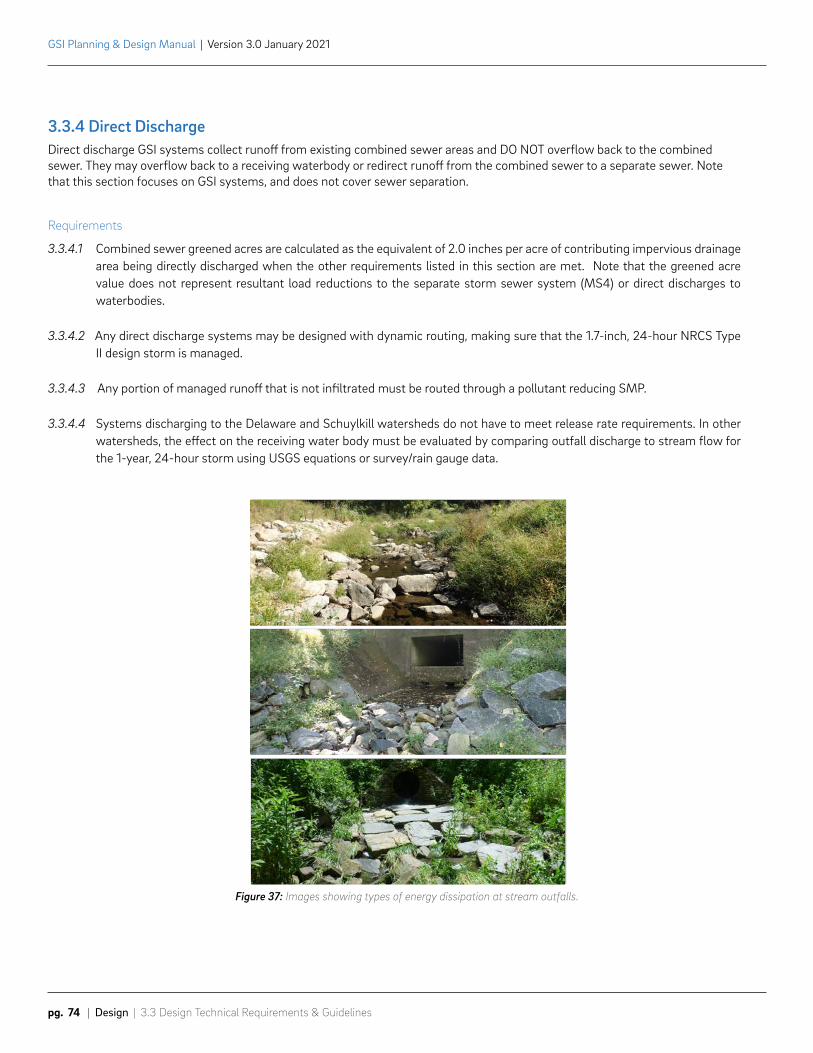
GSI Planning & Design Manual | Version 3.0 January 2021
pg. 74 | Design | 3.3 Design Technical Requirements & Guidelines
3.3.4 Direct DischargeDirect discharge GSI systems collect runoff from existing combined sewer areas and DO NOT overflow back to the combined sewer. They may overflow back to a receiving waterbody or redirect runoff from the combined sewer to a separate sewer. Note that this section focuses on GSI systems, and does not cover sewer separation.
Requirements
3.3.4.1 Combined sewer greened acres are calculated as the equivalent of 2.0 inches per acre of contributing impervious drainage area being directly discharged when the other requirements listed in this section are met. Note that the greened acre value does not represent resultant load reductions to the separate storm sewer system (MS4) or direct discharges to waterbodies.
3.3.4.2 Any direct discharge systems may be designed with dynamic routing, making sure that the 1.7-inch, 24-hour NRCS Type II design storm is managed.
3.3.4.3 Any portion of managed runoff that is not infiltrated must be routed through a pollutant reducing SMP.
3.3.4.4 Systems discharging to the Delaware and Schuylkill watersheds do not have to meet release rate requirements. In other watersheds, the effect on the receiving water body must be evaluated by comparing outfall discharge to stream flow for the 1-year, 24-hour storm using USGS equations or survey/rain gauge data.
Figure 37: Images showing types of energy dissipation at stream outfalls.
3.3 Design Technical Requirements & Guidelines | Design | pg. 75
GSI Planning & Design Manual | Version 3.0 January 2021
Figure 37: Images showing types of energy dissipation at stream outfalls.
Guidelines
3.3.4.5 Where there are concerns of damage to overflow points (outfalls, level spreaders, etc.) from large storms, upstream flow control should be used to route higher flows to the combined sewer.
3.3.4.6 The following should be considered when designing a stream outfall:
a. Ensure that outfall pipe elevation is not blocked by stream flow during rain events.
b. Consider fencing and maintenance access.
3.3.4.7 The following energy dissipation options should be considered for stream outfalls:
a. Armored or grass-lined channel
b. Step Pools
c. Pre-formed scour holes below outfall
3.3.4.8 The following energy dissipation design tools from FHWA’s Hydraulic Engineering Circular (HEC) should be used for stream outfalls:
a. HEC 11 (riprap)
b. HEC 14 (energy dissipators)
c. HEC 15 (flexible linings)
3.3.4.9 The following should be considered when designing a level spreader:
a. PA BMP Manual may be used as design guidance.
b. Location in constructed fill should be avoided where possible.
c. Erosion control/slope stabilization must be considered in design.
d. Maintenance truck access must be provided.
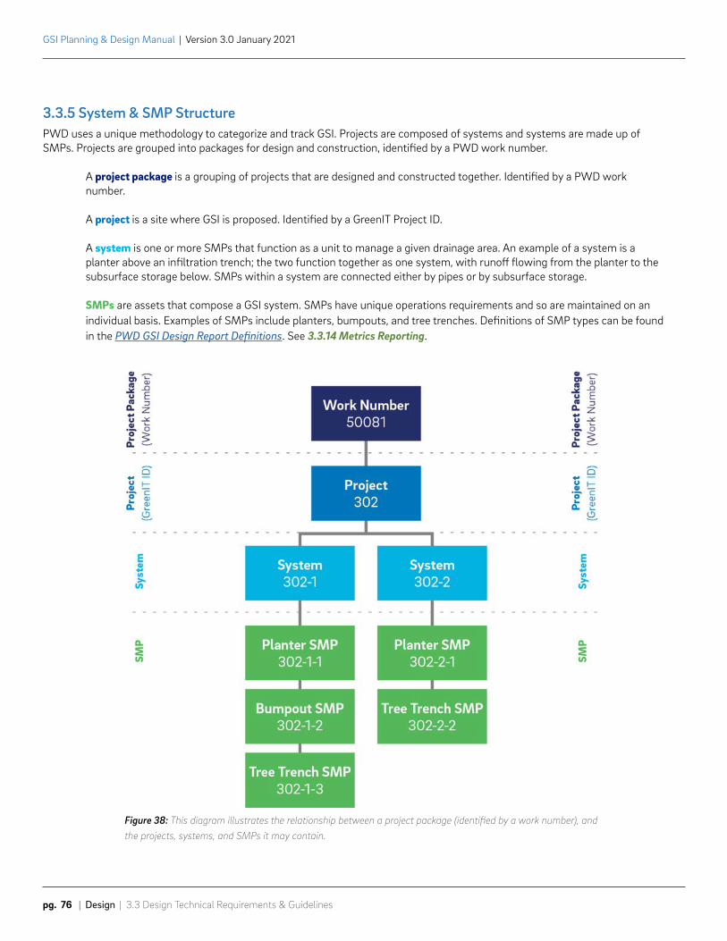
GSI Planning & Design Manual | Version 3.0 January 2021
pg. 76 | Design | 3.3 Design Technical Requirements & Guidelines
3.3.5 System & SMP StructurePWD uses a unique methodology to categorize and track GSI. Projects are composed of systems and systems are made up of SMPs. Projects are grouped into packages for design and construction, identified by a PWD work number.
A project package is a grouping of projects that are designed and constructed together. Identified by a PWD work number.
A project is a site where GSI is proposed. Identified by a GreenIT Project ID.
A system is one or more SMPs that function as a unit to manage a given drainage area. An example of a system is a planter above an infiltration trench; the two function together as one system, with runoff flowing from the planter to the subsurface storage below. SMPs within a system are connected either by pipes or by subsurface storage.
SMPs are assets that compose a GSI system. SMPs have unique operations requirements and so are maintained on an individual basis. Examples of SMPs include planters, bumpouts, and tree trenches. Definitions of SMP types can be found in the PWD GSI Design Report Definitions. See 3.3.14 Metrics Reporting.
Figure 38: This diagram illustrates the relationship between a project package (identified by a work number), and the projects, systems, and SMPs it may contain.
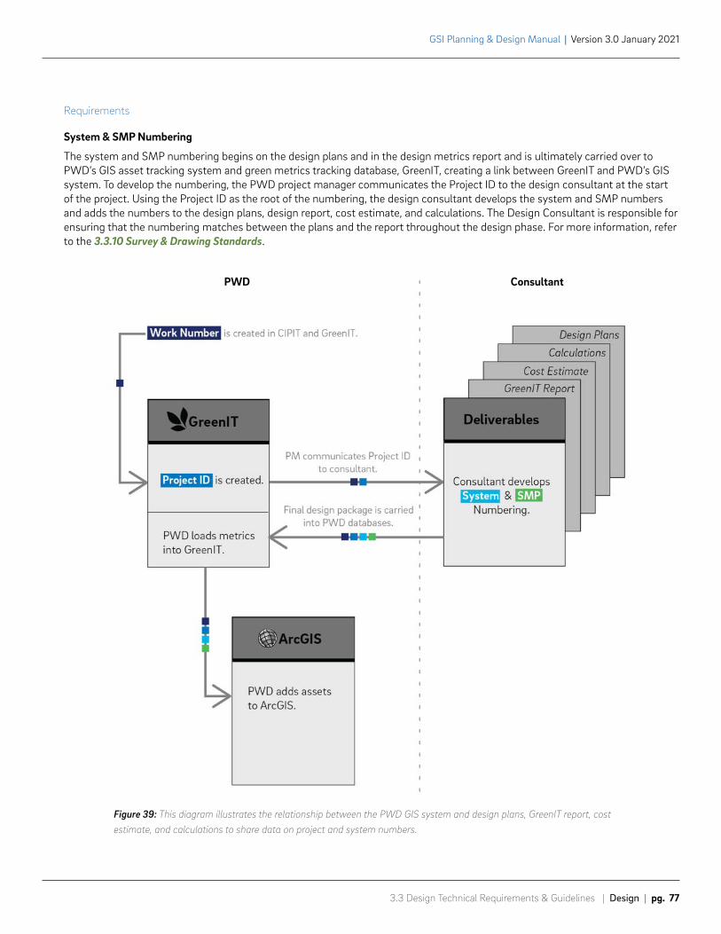
3.3 Design Technical Requirements & Guidelines | Design | pg. 77
GSI Planning & Design Manual | Version 3.0 January 2021
Figure 39: This diagram illustrates the relationship between the PWD GIS system and design plans, GreenIT report, cost estimate, and calculations to share data on project and system numbers.
Requirements
System & SMP Numbering
The system and SMP numbering begins on the design plans and in the design metrics report and is ultimately carried over to PWD’s GIS asset tracking system and green metrics tracking database, GreenIT, creating a link between GreenIT and PWD’s GIS system. To develop the numbering, the PWD project manager communicates the Project ID to the design consultant at the start of the project. Using the Project ID as the root of the numbering, the design consultant develops the system and SMP numbers and adds the numbers to the design plans, design report, cost estimate, and calculations. The Design Consultant is responsible for ensuring that the numbering matches between the plans and the report throughout the design phase. For more information, refer to the 3.3.10 Survey & Drawing Standards.
PWD Consultant
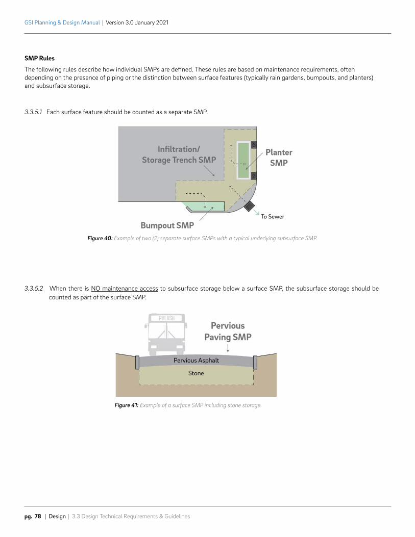
GSI Planning & Design Manual | Version 3.0 January 2021
pg. 78 | Design | 3.3 Design Technical Requirements & Guidelines
SMP Rules
The following rules describe how individual SMPs are defined. These rules are based on maintenance requirements, often depending on the presence of piping or the distinction between surface features (typically rain gardens, bumpouts, and planters) and subsurface storage.
Figure 40: Example of two (2) separate surface SMPs with a typical underlying subsurface SMP.
Figure 41: Example of a surface SMP including stone storage.
3.3.5.1 Each surface feature should be counted as a separate SMP.
3.3.5.2 When there is NO maintenance access to subsurface storage below a surface SMP, the subsurface storage should be counted as part of the surface SMP.
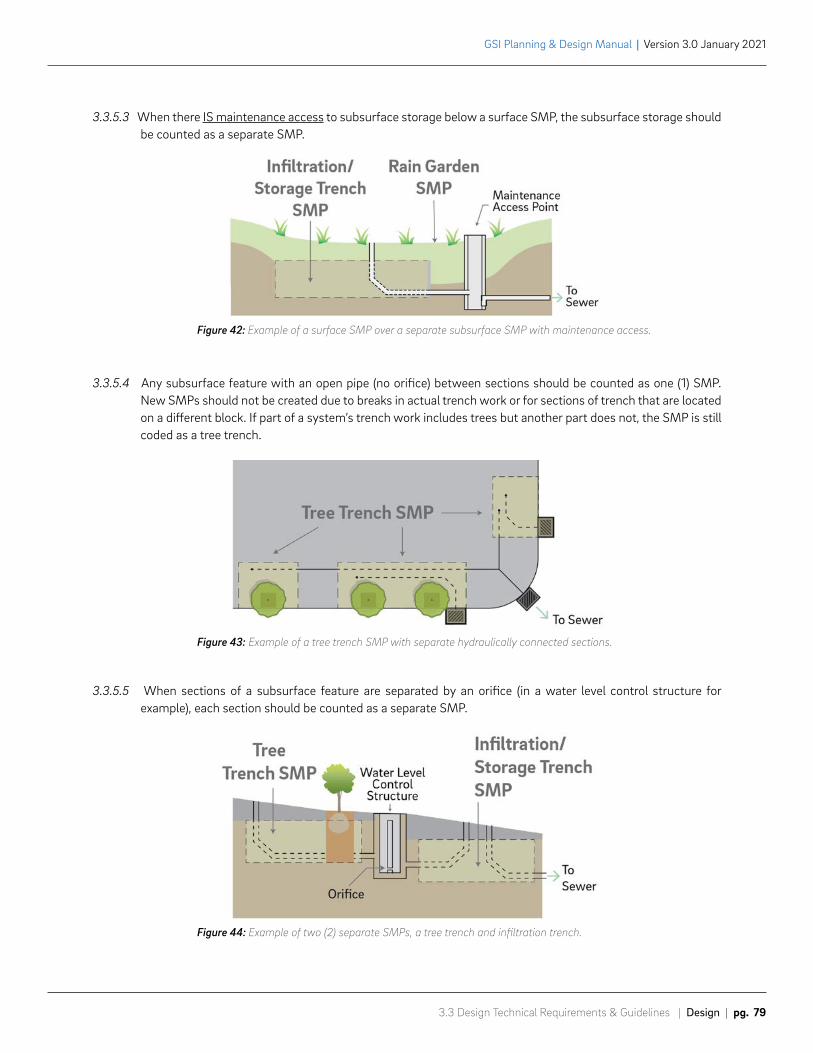
3.3 Design Technical Requirements & Guidelines | Design | pg. 79
GSI Planning & Design Manual | Version 3.0 January 2021
Figure 42: Example of a surface SMP over a separate subsurface SMP with maintenance access.
Figure 43: Example of a tree trench SMP with separate hydraulically connected sections.
3.3.5.3 When there IS maintenance access to subsurface storage below a surface SMP, the subsurface storage should be counted as a separate SMP.
3.3.5.4 Any subsurface feature with an open pipe (no orifice) between sections should be counted as one (1) SMP. New SMPs should not be created due to breaks in actual trench work or for sections of trench that are located on a different block. If part of a system’s trench work includes trees but another part does not, the SMP is still coded as a tree trench.
3.3.5.5 When sections of a subsurface feature are separated by an orifice (in a water level control structure for example), each section should be counted as a separate SMP.
Figure 44: Example of two (2) separate SMPs, a tree trench and infiltration trench.
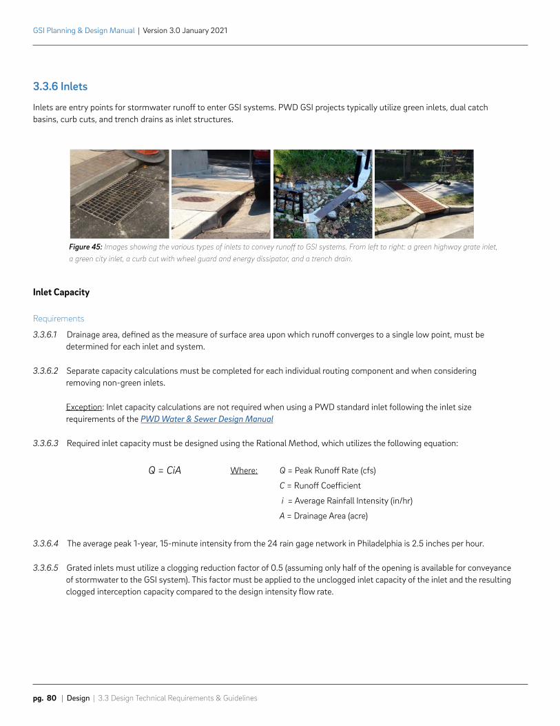
GSI Planning & Design Manual | Version 3.0 January 2021
pg. 80 | Design | 3.3 Design Technical Requirements & Guidelines
Figure 45: Images showing the various types of inlets to convey runoff to GSI systems. From left to right: a green highway grate inlet, a green city inlet, a curb cut with wheel guard and energy dissipator, and a trench drain.
3.3.6 Inlets
Inlets are entry points for stormwater runoff to enter GSI systems. PWD GSI projects typically utilize green inlets, dual catch basins, curb cuts, and trench drains as inlet structures.
Q = Peak Runoff Rate (cfs)
C = Runoff Coefficient
i = Average Rainfall Intensity (in/hr)
A = Drainage Area (acre)
Where:Q = CiA
Inlet Capacity
Requirements
3.3.6.1 Drainage area, defined as the measure of surface area upon which runoff converges to a single low point, must be determined for each inlet and system.
3.3.6.2 Separate capacity calculations must be completed for each individual routing component and when considering removing non-green inlets.
Exception: Inlet capacity calculations are not required when using a PWD standard inlet following the inlet size requirements of the PWD Water & Sewer Design Manual
3.3.6.3 Required inlet capacity must be designed using the Rational Method, which utilizes the following equation:
3.3.6.4 The average peak 1-year, 15-minute intensity from the 24 rain gage network in Philadelphia is 2.5 inches per hour.
3.3.6.5 Grated inlets must utilize a clogging reduction factor of 0.5 (assuming only half of the opening is available for conveyance of stormwater to the GSI system). This factor must be applied to the unclogged inlet capacity of the inlet and the resulting clogged interception capacity compared to the design intensity flow rate.

3.3 Design Technical Requirements & Guidelines | Design | pg. 81
GSI Planning & Design Manual | Version 3.0 January 2021
Guidelines
3.3.6.6 PWD uses a typical trench drain detail that establishes a 4.5 foot curb opening length. Trench drains can be used without needing to do independent curb opening length calculations where the drainage area is less than 15,000 SF and the longitudinal slope is less than 6%.
3.3.6.7 Where curb opening lengths need to be sized, follow the methods described in the FHWA Hydraulic Engineering Circular No. 22 (HEC-22). However, different coefficients should be used in the curb opening length equation (see below) to better represent PWD inlets. The basis for these modifications are presented in the “Hydraulic Efficiency of Street Inlets Common to UDFCD Region” technical memorandum (see equation 3 for CDOT type R inlets).
LT = Curb opening length required to intercept
100% of gutter flow (ft)
N = 0.38
Q = Peak Runoff Rate (cfs)
a = 0.51 (acre)
SL = Longitudinal Slope
b = 0.06
n = Manning’s Roughness Coefficient
Se = Equivalent Transverse Street Slope
c = 0.46
Where:
GSI Planning & Design Manual | Version 3.0 January 2021
pg. 82 | Design | 3.3 Design Technical Requirements & Guidelines
Inlet SelectionThe following guidelines are used to determine inlet selection. More information about standard inlet design, typical placement locations, inlet photos, and preferred sewer connection types can be found in the PWD Water & Sewer Design Manual.
Requirements
3.3.6.8 For systems in the right-of-way, all sewer-connected inlets should conform to the types and locations specified in the PWD Water & Sewer Design Manual. See Appendix 5A.
Guidelines
3.3.6.9 Green inlets (inlets that convey runoff to GSI systems) are typically placed 5-feet upstream of existing sewer-connected inlets.
3.3.6.10 The PWD Standard Green Highway Grate Inlet is preferred for conveying street runoff to a subsurface system. A green city inlet may be used when there is a conflict in the cartway.
3.3.6.11 For off-street applications or surface systems, other inlet selection, such as shallow green city inlets or trench drains, may be considered at the advisement of the PWD project manager.
3.3.6.12 Dual catch basin inlets should only be considered where other inlet types are infeasible due to space constraints. Dual catch basin inlets connect to both the GSI system and to the sewer, diverting flow over an overflow weir. When using dual catch basin inlets, designers should keep in mind that the top of storage elevation for the GSI system cannot be higher than the elevation of the top of the dual catch basin weir. When these inlets are proposed at a low point, designers should also evaluate the risk of surface flooding because dual catch basin pretreatment adds difficulty to maintaining the inlet in flooded conditions.
3.3.6.13 Trench drains may be used to convey runoff to surface features in some scenarios, though a shallow inlet is preferred.
a. PWD uses a typical trench drain detail that establishes width and curb opening length. See 3.3.12 Typical Details.
b. Do not install trench drains longer than 20 feet.
c. Avoid grade changes of trench drain grate.
d. Trench drain lengths should be in two (2) foot increments to avoid cutting grate castings.
3.3.6.14 Energy dissipation should be included at all inflow points to all surface features to minimize erosion.
3.3.6.15 All green inlets should have permanent inlet protection included for pretreatment. The PWD Master Green Specifications includes the requirements for standard pretreatment provisions.
3.3 Design Technical Requirements & Guidelines | Design | pg. 83
GSI Planning & Design Manual | Version 3.0 January 2021
Inlet Replacement The following guidelines must be used to determine inlet replacement. More information about standard inlet replacement, typical placement locations, inlet photos, and preferred sewer connection types can be found in the PWD Water & Sewer Design Manual.
Requirements
3.3.6.16 If underdrain connections to the existing inlet are being made, the considerations below must be used to determine if the existing inlet should be replaced.
3.3.6.17 Replace all No. 1, No. 2, No. 3, or No. 4 old City inlets. Inlet pipe diameter for existing No. 3 and No. 4 City inlets is 12 inches and 8 inches respectively, and therefore should be reconstructed with 15 inch diameter VCP the full length back to the sewer. Exceptions made for sewers less than 15 inches in diameter.
3.3.6.18 Any inlet that has a brick inlet box must be replaced, regardless of whether the inlet has a newer top style. Type of inlet box is determined during survey by visual inspection.
3.3.6.19 Replace all inlets in poor condition or inlets with a history of problems. PWD project manager can provide inlet history report.
Guidelines
3.3.6.20 If underdrain connections are not being made to the existing inlet and the surrounding footway/paving is not being replaced, inlets may not need to be replaced.
3.3.6.21 If inlet replacement is required, the PWD project manager can provide guidance on whether designs should propose new sewer connections or reconnections to the existing lateral.
3.3.6.22 Designs that propose to abandon existing inlets to increase the drainage area directed to a system should be discussed with the PWD project manager. Inlet removal requires review by PWD Collectors Systems and Water/Sewer Design Utility Engineering.
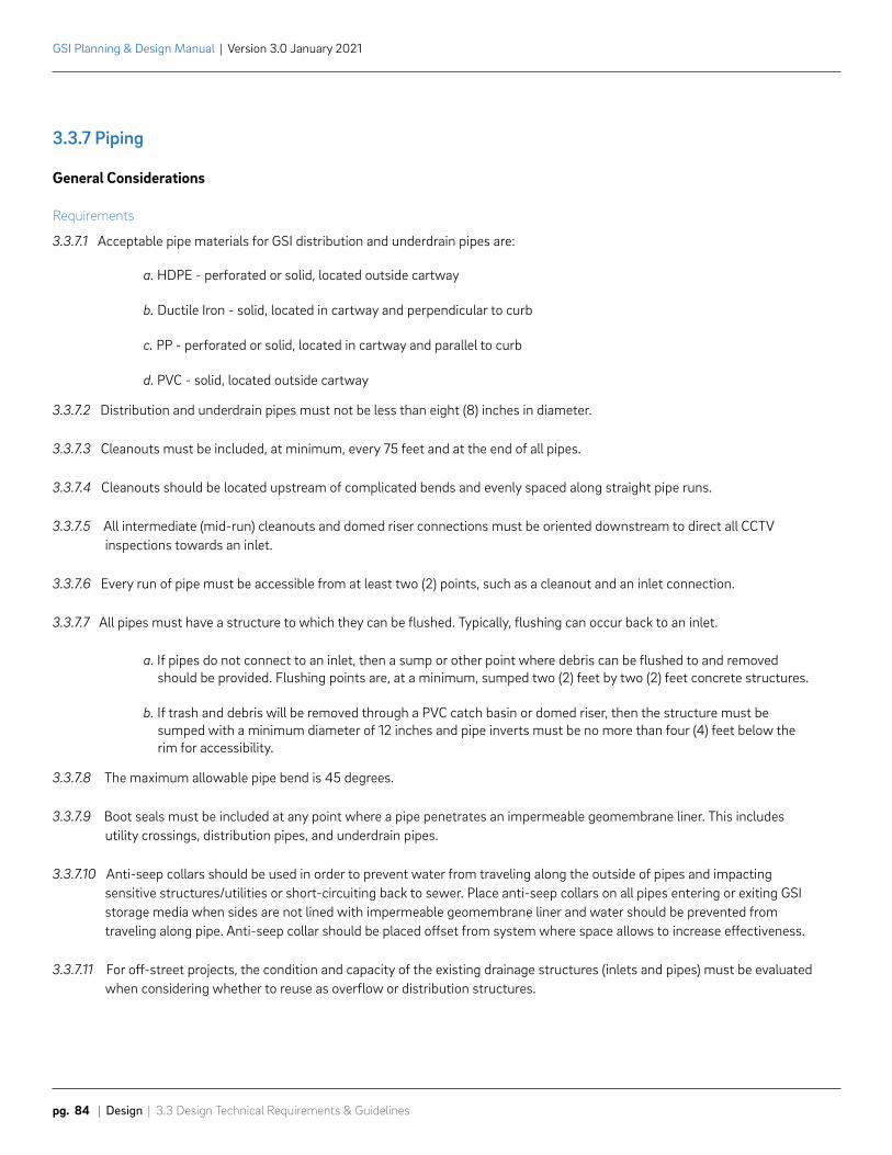
GSI Planning & Design Manual | Version 3.0 January 2021
pg. 84 | Design | 3.3 Design Technical Requirements & Guidelines
3.3.7 Piping
General Considerations
Requirements
3.3.7.1 Acceptable pipe materials for GSI distribution and underdrain pipes are:
a. HDPE - perforated or solid, located outside cartway
b. Ductile Iron - solid, located in cartway and perpendicular to curb
c. PP - perforated or solid, located in cartway and parallel to curb
d. PVC - solid, located outside cartway
3.3.7.2 Distribution and underdrain pipes must not be less than eight (8) inches in diameter.
3.3.7.3 Cleanouts must be included, at minimum, every 75 feet and at the end of all pipes.
3.3.7.4 Cleanouts should be located upstream of complicated bends and evenly spaced along straight pipe runs.
3.3.7.5 All intermediate (mid-run) cleanouts and domed riser connections must be oriented downstream to direct all CCTV inspections towards an inlet.
3.3.7.6 Every run of pipe must be accessible from at least two (2) points, such as a cleanout and an inlet connection.
3.3.7.7 All pipes must have a structure to which they can be flushed. Typically, flushing can occur back to an inlet.
a. If pipes do not connect to an inlet, then a sump or other point where debris can be flushed to and removed should be provided. Flushing points are, at a minimum, sumped two (2) feet by two (2) feet concrete structures.
b. If trash and debris will be removed through a PVC catch basin or domed riser, then the structure must be sumped with a minimum diameter of 12 inches and pipe inverts must be no more than four (4) feet below the rim for accessibility.
3.3.7.8 The maximum allowable pipe bend is 45 degrees.
3.3.7.9 Boot seals must be included at any point where a pipe penetrates an impermeable geomembrane liner. This includes utility crossings, distribution pipes, and underdrain pipes.
3.3.7.10 Anti-seep collars should be used in order to prevent water from traveling along the outside of pipes and impacting sensitive structures/utilities or short-circuiting back to sewer. Place anti-seep collars on all pipes entering or exiting GSI storage media when sides are not lined with impermeable geomembrane liner and water should be prevented from traveling along pipe. Anti-seep collar should be placed offset from system where space allows to increase effectiveness.
3.3.7.11 For off-street projects, the condition and capacity of the existing drainage structures (inlets and pipes) must be evaluated when considering whether to reuse as overflow or distribution structures.
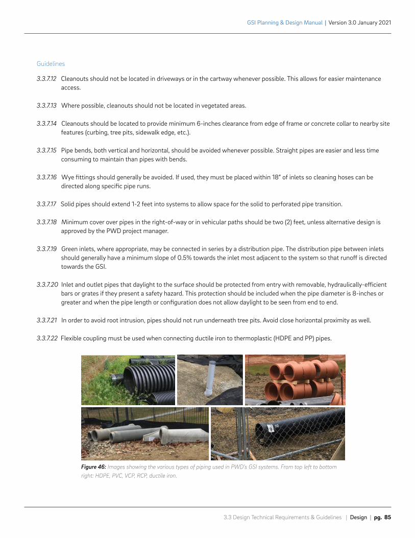
3.3 Design Technical Requirements & Guidelines | Design | pg. 85
GSI Planning & Design Manual | Version 3.0 January 2021
Guidelines
3.3.7.12 Cleanouts should not be located in driveways or in the cartway whenever possible. This allows for easier maintenance access.
3.3.7.13 Where possible, cleanouts should not be located in vegetated areas.
3.3.7.14 Cleanouts should be located to provide minimum 6-inches clearance from edge of frame or concrete collar to nearby site features (curbing, tree pits, sidewalk edge, etc.).
3.3.7.15 Pipe bends, both vertical and horizontal, should be avoided whenever possible. Straight pipes are easier and less time consuming to maintain than pipes with bends.
3.3.7.16 Wye fittings should generally be avoided. If used, they must be placed within 18” of inlets so cleaning hoses can be directed along specific pipe runs.
3.3.7.17 Solid pipes should extend 1-2 feet into systems to allow space for the solid to perforated pipe transition.
3.3.7.18 Minimum cover over pipes in the right-of-way or in vehicular paths should be two (2) feet, unless alternative design is approved by the PWD project manager.
3.3.7.19 Green inlets, where appropriate, may be connected in series by a distribution pipe. The distribution pipe between inlets should generally have a minimum slope of 0.5% towards the inlet most adjacent to the system so that runoff is directed towards the GSI.
3.3.7.20 Inlet and outlet pipes that daylight to the surface should be protected from entry with removable, hydraulically-efficient bars or grates if they present a safety hazard. This protection should be included when the pipe diameter is 8-inches or greater and when the pipe length or configuration does not allow daylight to be seen from end to end.
3.3.7.21 In order to avoid root intrusion, pipes should not run underneath tree pits. Avoid close horizontal proximity as well.
3.3.7.22 Flexible coupling must be used when connecting ductile iron to thermoplastic (HDPE and PP) pipes.
Figure 46: Images showing the various types of piping used in PWD’s GSI systems. From top left to bottom right: HDPE, PVC, VCP, RCP, ductile iron.
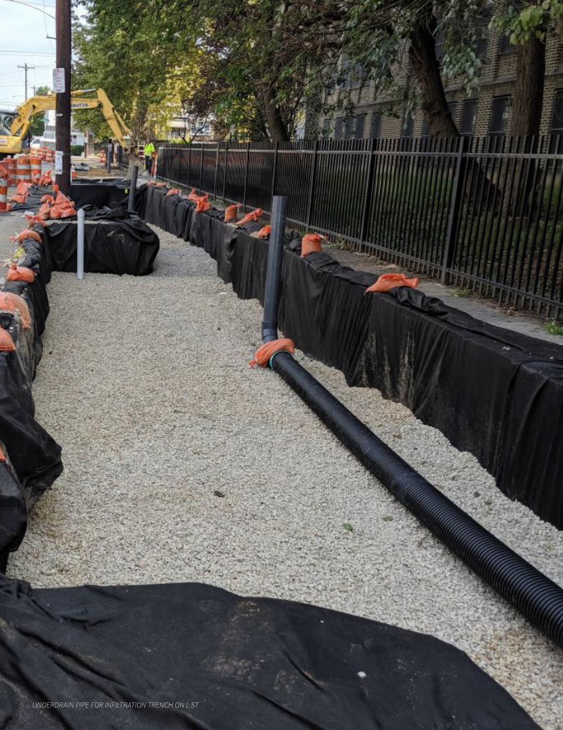
UNDERDRAIN PIPE FOR INFILTRATION TRENCH ON L ST
3.3 Design Technical Requirements & Guidelines | Design | pg. 87
GSI Planning & Design Manual | Version 3.0 January 2021
Underdrains
Requirements
3.3.7.23 To protect underdrains from sedimentation and trash, underdrain pipes should not have an open connection to any surface features; i.e. underdrain pipes should end in cleanouts and never in domed risers.
Guidelines
3.3.7.24 Regardless of whether a system is designed for infiltration or for detention/slow-release, underdrains should be considered for all systems (not applicable to disconnection systems). This allows for conversion to a detention/slow-release system if the system fails to infiltrate due to clogging.
3.3.7.25 Underdrains should extend inside the system for a minimum length of 20 feet. Lined surface systems should include more extensive underdrains to ensure full draindown of ponded and soil storage.
3.3.7.26 Underdrains should connect perpendicularly to the adjacent existing inlet or a sewer connected control structure. The underdrain should terminate either in a solid cap or orifice depending on whether the system is designed for infiltration or detention/slow-release.
Exception: If it is not possible or advisable to connect the underdrain to an adjacent existing inlet, then the underdrain should extend for a minimum of five (5) feet outside of the system and be capped. This allows for future access to the underdrain without disruption of the system should the system need to be converted to detention/slow-release.
3.3.7.27 Provide, at minimum, a seven and a half (7 ½) inch offset between the invert of the underdrain pipe and the invert of the outlet pipe to the sewer. See section 3.3.12 Typical Details for the Standard Inlet with Underdrain Connection detail.
3.3.7.28 When a trench is broken into multiple segments, the underdrain should be extended through subsequent trench sections to ensure that the full trench has the ability to drain down.
3.3.7.29 Underdrains should be sumped to increase storage capacity in systems fully lined with an impermeable geomembrane liner.

GSI Planning & Design Manual | Version 3.0 January 2021
pg. 88 | Design | 3.3 Design Technical Requirements & Guidelines
GSI SewersA GSI sewer is a stormwater conduit designed to convey drainage from multiple city blocks to a Centralized GSI Facility. Designers should follow the general requirements for stormwater conduits in the PWD Water & Sewer Design Manual except where they differ with the language below.
Requirements
3.3.7.30 GSI sewers should be able to flow at full capacity (maximum flow entering inlet laterals) without overflowing manholes. Hydraulic grade line (HGL) must remain below rims of manholes.
3.3.7.31 GSI sewers should be designed with a minimum velocity of two (2) feet per second. Designs should attempt to maintain velocity without sacrificing GSI system depth.
3.3.7.32 Acceptable pipe materials for main sewer stem and inlet connections are:
a. Reinforced concrete – minimum 15 inch diameter, should be built with a continuous concrete cradle
b. Ductile iron – for diameters less than 15-inches and shallow covers less than two (2) feet, diameters 12-inches and greater should be built with a continuous concrete cradle
c. HDPE/PP – outside of cartway at depths two (2) feet or greater
d. VCP – used only for tight inlet connections where numerous bends are required
3.3.7.33 If the proposed GSI sewers modify existing sewersheds, designs must confirm that the existing sewer has capacity for the potential increased flow. The PWD design project manager will coordinate internally with PWD’s Hydraulic & Hydrologic (H&H) Modeling Group.
3.3.7.34 Borings, as noted in the PWD Water & Sewer Design Manual, are required where the bearing capacity is unknown.
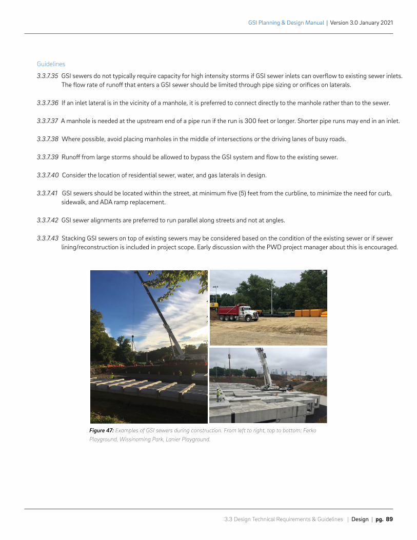
3.3 Design Technical Requirements & Guidelines | Design | pg. 89
GSI Planning & Design Manual | Version 3.0 January 2021
LANIER PARK CENTRALIZED GSI FACILITY
LANIER PARK SYSTEM PIPING
Guidelines
3.3.7.35 GSI sewers do not typically require capacity for high intensity storms if GSI sewer inlets can overflow to existing sewer inlets. The flow rate of runoff that enters a GSI sewer should be limited through pipe sizing or orifices on laterals.
3.3.7.36 If an inlet lateral is in the vicinity of a manhole, it is preferred to connect directly to the manhole rather than to the sewer.
3.3.7.37 A manhole is needed at the upstream end of a pipe run if the run is 300 feet or longer. Shorter pipe runs may end in an inlet.
3.3.7.38 Where possible, avoid placing manholes in the middle of intersections or the driving lanes of busy roads.
3.3.7.39 Runoff from large storms should be allowed to bypass the GSI system and flow to the existing sewer.
3.3.7.40 Consider the location of residential sewer, water, and gas laterals in design.
3.3.7.41 GSI sewers should be located within the street, at minimum five (5) feet from the curbline, to minimize the need for curb, sidewalk, and ADA ramp replacement.
3.3.7.42 GSI sewer alignments are preferred to run parallel along streets and not at angles.
3.3.7.43 Stacking GSI sewers on top of existing sewers may be considered based on the condition of the existing sewer or if sewer lining/reconstruction is included in project scope. Early discussion with the PWD project manager about this is encouraged.
Figure 47: Examples of GSI sewers during construction. From left to right, top to bottom: Ferko Playground, Wissinoming Park, Lanier Playground.

MONITORING OF COLUMBUS SQUARE PLANTERS
3.3 Design Technical Requirements & Guidelines | Design | pg. 91
GSI Planning & Design Manual | Version 3.0 January 2021
3.3.8 Monitoring
Observation Wells
Requirements
3.3.8.1 A minimum of one (1) observation well is required for each GSI system, including systems that are fully lined with an impermeable geomembrane liner.
3.3.8.2 The placement of the first observation well should not exceed a distance of more than 50-feet from the primary inflow structure to the subsurface. For larger systems, additional observation wells are required so that any part of the system footprint is within a 100-foot radius of at least one observation well.
Guidelines
3.3.8.3 For trenches that are broken into 2 to 4 sections, one observation well is recommended in the first section and one in the last section. For trenches broken into more than 5 sections, one observation well is recommended in the first section, one in the middle section, and one in the last section.
3.3.8.4 Observation wells should not be located in driveways. If possible, avoid placing in the cartway as well. This allows for easier monitoring access.
3.3.8.5 Where possible, observation wells and maintenance ports should not be located in vegetated areas.
3.3.8.6 Observation wells should be located to provide minimum 6-inches clearance from edge of frame or concrete collar to nearby site features (curbing, tree pits, sidewalk edge, etc.).
Groundwater Monitoring Wells
Requirements
3.3.8.7 Groundwater monitoring wells must be installed on the proposed site for Centralized GSI Facility projects. The wells are to be monitored by PWD for a full year prior to design of Centralized GSI Facility projects to evaluate the seasonally high groundwater levels and provide data for design phase groundwater mounding analyses.
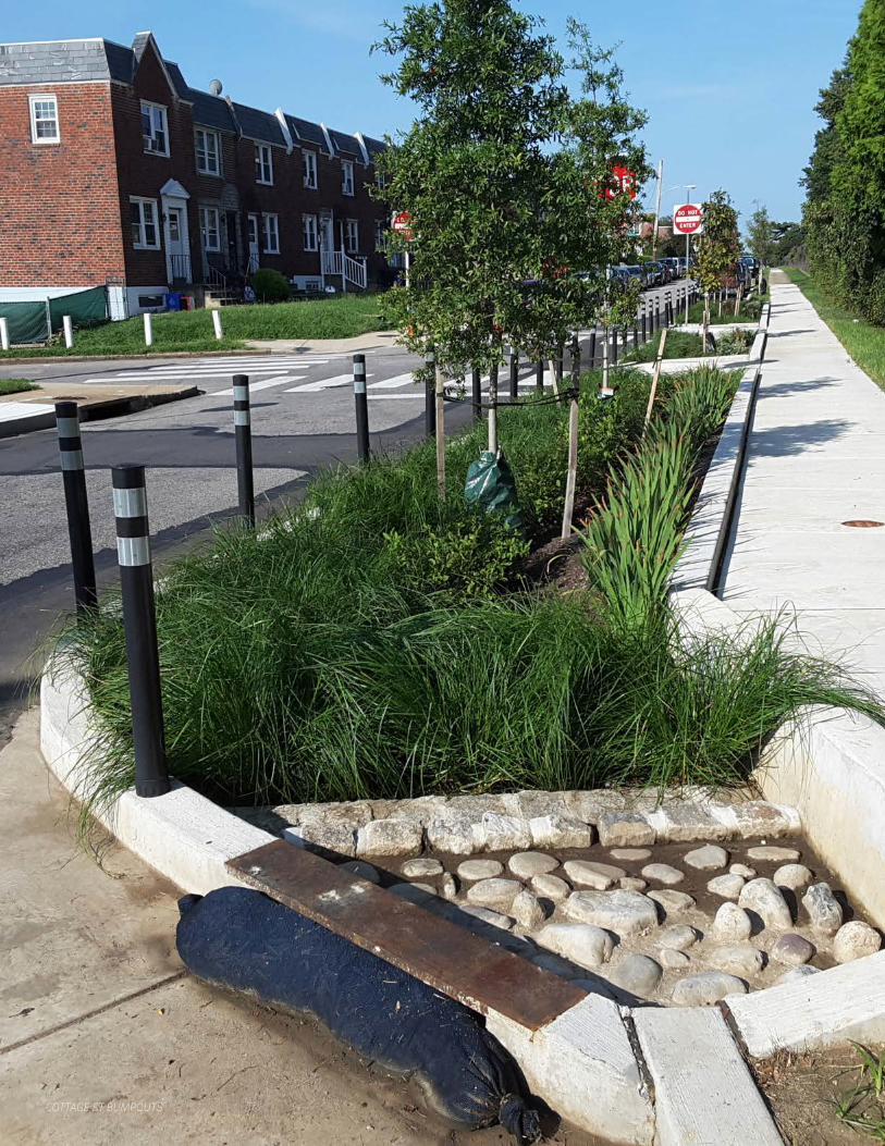
COTTAGE ST BUMPOUTS
3.3 Design Technical Requirements & Guidelines | Design | pg. 93
GSI Planning & Design Manual | Version 3.0 January 2021
3.3.9 Cost Estimates and SpecificationsPWD has Master Green Specifications and a standard Bid Item List & Estimate Template that should be used when preparing construction specifications and engineering estimates for GSI projects.
Requirements
3.3.9.1 The PWD Green Specifications must be used on all projects bid by PWD.
3.3.9.2 Design Consultants should request the Master Green Specifications from the PWD project manager at the appropriate phase in design, typically during or after utility review.
3.3.9.3 Parts of the Master Green Specifications must be edited by Design Consultants. All edits must be done using tracked changes. PWD project managers can provide additional instruction on a project-by-project basis.
3.3.9.4 Design Consultants should request the bid item list and cost estimate template from the PWD project manager before development of the preliminary design. This file includes item numbers, descriptions and historical average unit costs. If a project includes work that is not covered in the bid item list, the PWD project manager will provide the new item number and description. Design Consultant to provide estimate for non-standard items.
3.3.9.5 Cost estimates must be prepared for each GSI system and summed to the project package (work number) level.
3.3.9.6 Include calculations of cost per GA and impervious DA (in acres) at the system and project package (work number) level.
3.3.9.7 Items funded by different funding sources, such as sewer, water, partner, and Philadelphia City Council funding, should be presented in separate tables on the engineering estimates with subtotals provided for each funding source. Items with different funding sources are also distinguished by unique item numbers which will be provided by the PWD project manager or by the project partner.
Guidelines
3.3.9.8 Design Consultants should evaluate opportunities for cost savings in all GSI designs. Costs should be minimized both at the system and at the project package level. Examples of possible design modifications to reduce costs include, but are not limited to:
a. Maximizing use of surface practices, especially off-street surface practices or surface practices with limited expensive appurtenances (e.g., planter walls) to reduce excavation and material costs
b. Consolidating two or more drainage areas to be managed by one, larger GSI system instead of smaller ones
c. Minimizing piping and structures that add construction and maintenance costs
d. Reducing paving and resurfacing
e. Reducing excavation by minimizing system depth or area. Excavation is the largest driver of GSI construction cost.
f. Reducing the number of trench breaks. Generally a maximum of three trench segments (or two trench breaks) is preferred to reduce the number of pipe penetrations and material transitions.
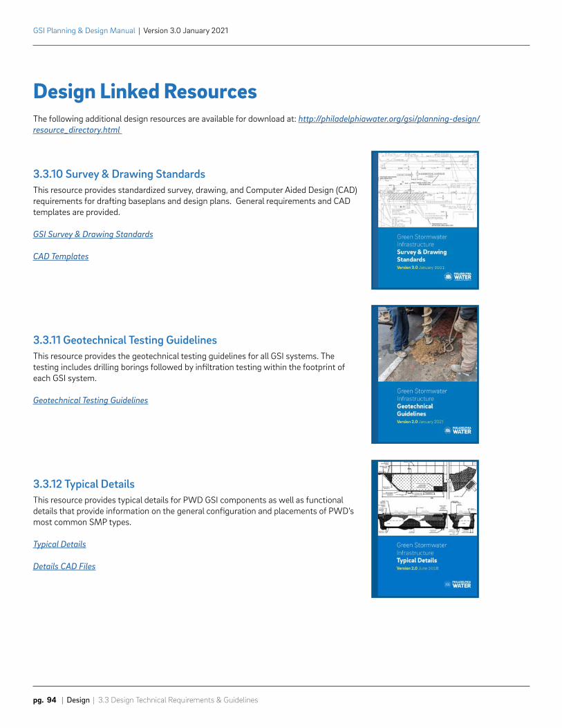
GSI Planning & Design Manual | Version 3.0 January 2021
pg. 94 | Design | 3.3 Design Technical Requirements & Guidelines
3.3.10 Survey & Drawing StandardsThis resource provides standardized survey, drawing, and Computer Aided Design (CAD) requirements for drafting baseplans and design plans. General requirements and CAD templates are provided.
GSI Survey & Drawing Standards
CAD Templates
3.3.11 Geotechnical Testing GuidelinesThis resource provides the geotechnical testing guidelines for all GSI systems. The testing includes drilling borings followed by infiltration testing within the footprint of each GSI system.
Geotechnical Testing Guidelines
3.3.12 Typical DetailsThis resource provides typical details for PWD GSI components as well as functional details that provide information on the general configuration and placements of PWD’s most common SMP types.
Typical Details
Details CAD Files
Design Linked ResourcesThe following additional design resources are available for download at: http://philadelphiawater.org/gsi/planning-design/resource_directory.html
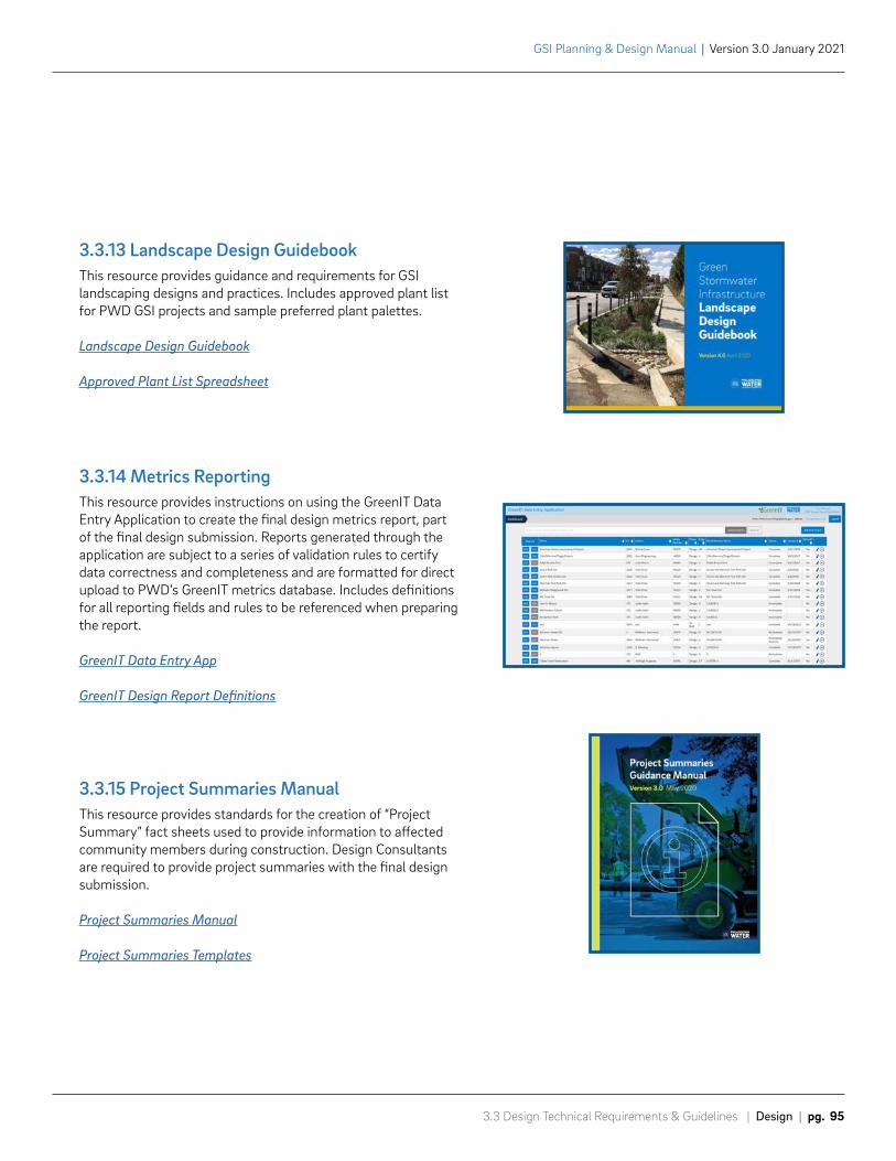
3.3 Design Technical Requirements & Guidelines | Design | pg. 95
GSI Planning & Design Manual | Version 3.0 January 2021
3.3.13 Landscape Design GuidebookThis resource provides guidance and requirements for GSI landscaping designs and practices. Includes approved plant list for PWD GSI projects and sample preferred plant palettes.
Landscape Design Guidebook
Approved Plant List Spreadsheet
3.3.14 Metrics ReportingThis resource provides instructions on using the GreenIT Data Entry Application to create the final design metrics report, part of the final design submission. Reports generated through the application are subject to a series of validation rules to certify data correctness and completeness and are formatted for direct upload to PWD’s GreenIT metrics database. Includes definitions for all reporting fields and rules to be referenced when preparing the report.
GreenIT Data Entry App
GreenIT Design Report Definitions
3.3.15 Project Summaries ManualThis resource provides standards for the creation of “Project Summary” fact sheets used to provide information to affected community members during construction. Design Consultants are required to provide project summaries with the final design submission.
Project Summaries Manual
Project Summaries Templates

Phila
delp
hia
Wat
er D
epar
tmen
t |
GSI
Pla
nnin
g &
Des
ign
Man
ual
v 3.
0

4.0Post-Design
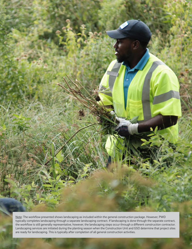
PWD GREEN STORMWATER OPERATIONS
Note: The workflow presented shows landscaping as included within the general construction package. However, PWD typically completes landscaping through a separate landscaping contract. If landscaping is done through the separate contract, the workflow is still generally representative, however, the landscaping steps occur through a different construction contractor. Landscaping services are initiated during the planting season when the Construction Unit and GSO determine that project sites are ready for landscaping. This is typically after completion of all general construction activities.
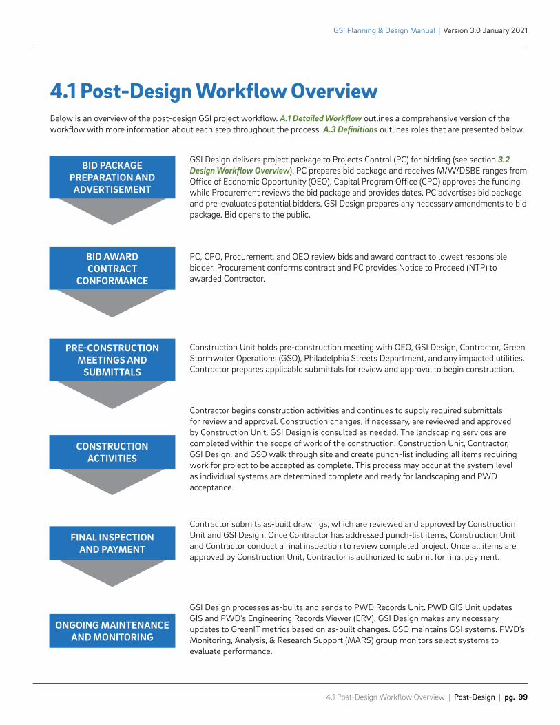
4.1 Post-Design Workflow Overview | Post-Design | pg. 99
GSI Planning & Design Manual | Version 3.0 January 2021
GSI Design delivers project package to Projects Control (PC) for bidding (see section 3.2 Design Workflow Overview). PC prepares bid package and receives M/W/DSBE ranges from Office of Economic Opportunity (OEO). Capital Program Office (CPO) approves the funding while Procurement reviews the bid package and provides dates. PC advertises bid package and pre-evaluates potential bidders. GSI Design prepares any necessary amendments to bid package. Bid opens to the public.
PC, CPO, Procurement, and OEO review bids and award contract to lowest responsible bidder. Procurement conforms contract and PC provides Notice to Proceed (NTP) to awarded Contractor.
Construction Unit holds pre-construction meeting with OEO, GSI Design, Contractor, Green Stormwater Operations (GSO), Philadelphia Streets Department, and any impacted utilities. Contractor prepares applicable submittals for review and approval to begin construction.
Contractor begins construction activities and continues to supply required submittals for review and approval. Construction changes, if necessary, are reviewed and approved by Construction Unit. GSI Design is consulted as needed. The landscaping services are completed within the scope of work of the construction. Construction Unit, Contractor, GSI Design, and GSO walk through site and create punch-list including all items requiring work for project to be accepted as complete. This process may occur at the system level as individual systems are determined complete and ready for landscaping and PWD acceptance.
Contractor submits as-built drawings, which are reviewed and approved by Construction Unit and GSI Design. Once Contractor has addressed punch-list items, Construction Unit and Contractor conduct a final inspection to review completed project. Once all items are approved by Construction Unit, Contractor is authorized to submit for final payment.
GSI Design processes as-builts and sends to PWD Records Unit. PWD GIS Unit updates GIS and PWD’s Engineering Records Viewer (ERV). GSI Design makes any necessary updates to GreenIT metrics based on as-built changes. GSO maintains GSI systems. PWD’s Monitoring, Analysis, & Research Support (MARS) group monitors select systems to evaluate performance.
4.1 Post-Design Workflow OverviewBelow is an overview of the post-design GSI project workflow. A.1 Detailed Workflow outlines a comprehensive version of the workflow with more information about each step throughout the process. A.3 Definitions outlines roles that are presented below.
PRE-CONSTRUCTIONMEETINGS AND
SUBMITTALS
BID PACKAGE PREPARATION AND
ADVERTISEMENT
CONSTRUCTION ACTIVITIES
FINAL INSPECTIONAND PAYMENT
ONGOING MAINTENANCEAND MONITORING
BID AWARDCONTRACT
CONFORMANCE
Green Stormwater InfrastructureMaintenance Manual
Version 2.0 September 2016
GSI Planning & Design Manual | Version 3.0 January 2021
pg. 100 | Post-Design | 4.2 Post-Design Resources
4.2 Post-Design ResourcesPWD has teams of engineers, inspectors, and operators who take over responsibility of the project after design is complete. While this manual is primarily intended for use by planners and designers of PWD GSI, it is valuable to understand the full life cycle of GSI assets. The GSI As-Built Survey & Drafting Manual and Maintenance Manual are linked to provide detailed information about post-design aspects of PWD GSI.
4.2.1. As-Built Survey & Drafting ManualThis manual describes procedures for collecting and drafting as-built survey data for PWD GSI projects. As-built data is used to verify that systems and SMPs will perform as designed and is relied upon during routine and special maintenance. The manual presents detailed instructions for construction contractors on the collection and presentation of survey data in a manner that can be integrated smoothly into PWD’s existing records. The manual is considered an extension of the project specifications, by reference.
As-Built Survey & Drafting Manual
4.2.2 Maintenance ManualThis manual describes PWD’s GSI maintenance program for surface and subsurface features. The manual presents standard operating procedures, equipment, and materials for maintenance professionals and operators to execute specific tasks for routine maintenance of PWD GSI.
Maintenance Manual
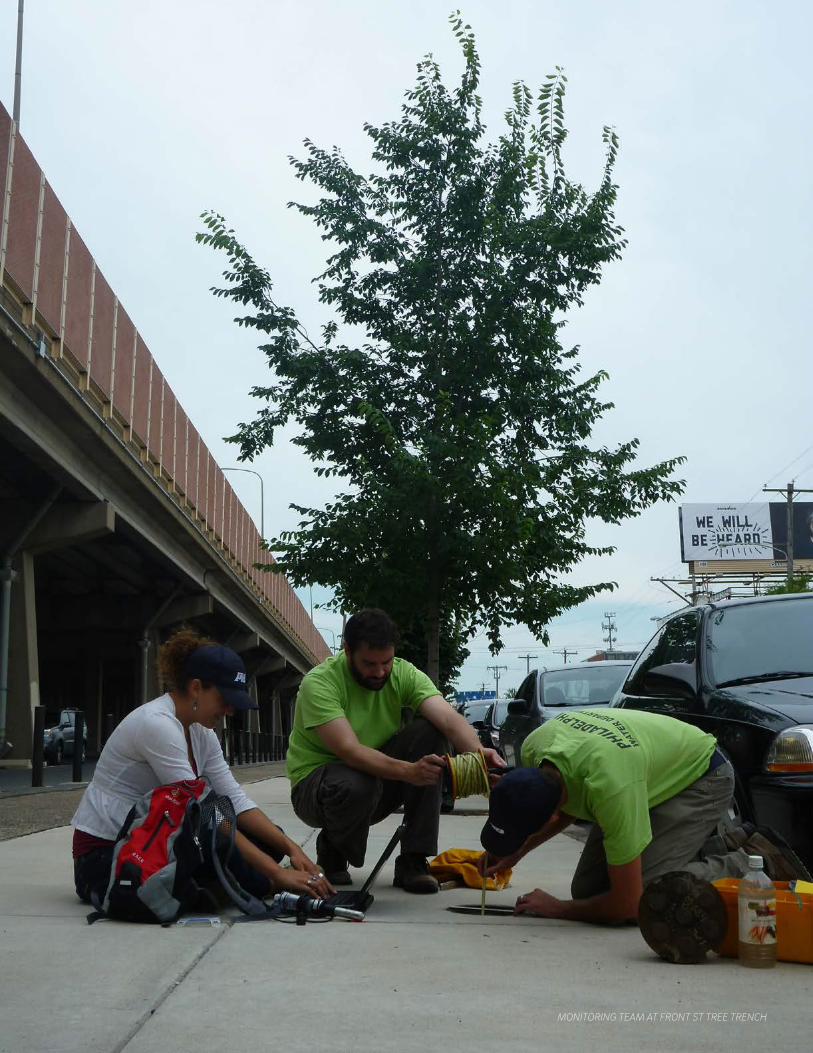
MONITORING TEAM AT FRONT ST TREE TRENCH

Phila
delp
hia
Wat
er D
epar
tmen
t |
GSI
Pla
nnin
g &
Des
ign
Man
ual
v 3.
0

Appendices
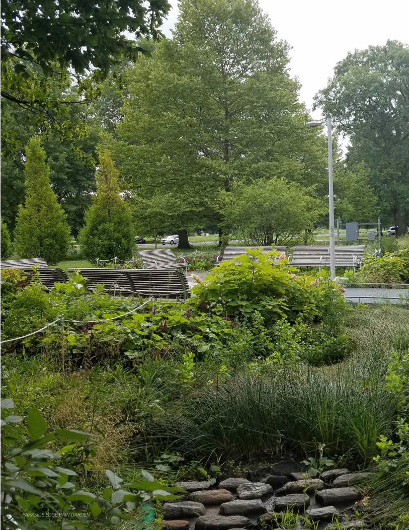
PARKSIDE EDGE RAIN GARDEN
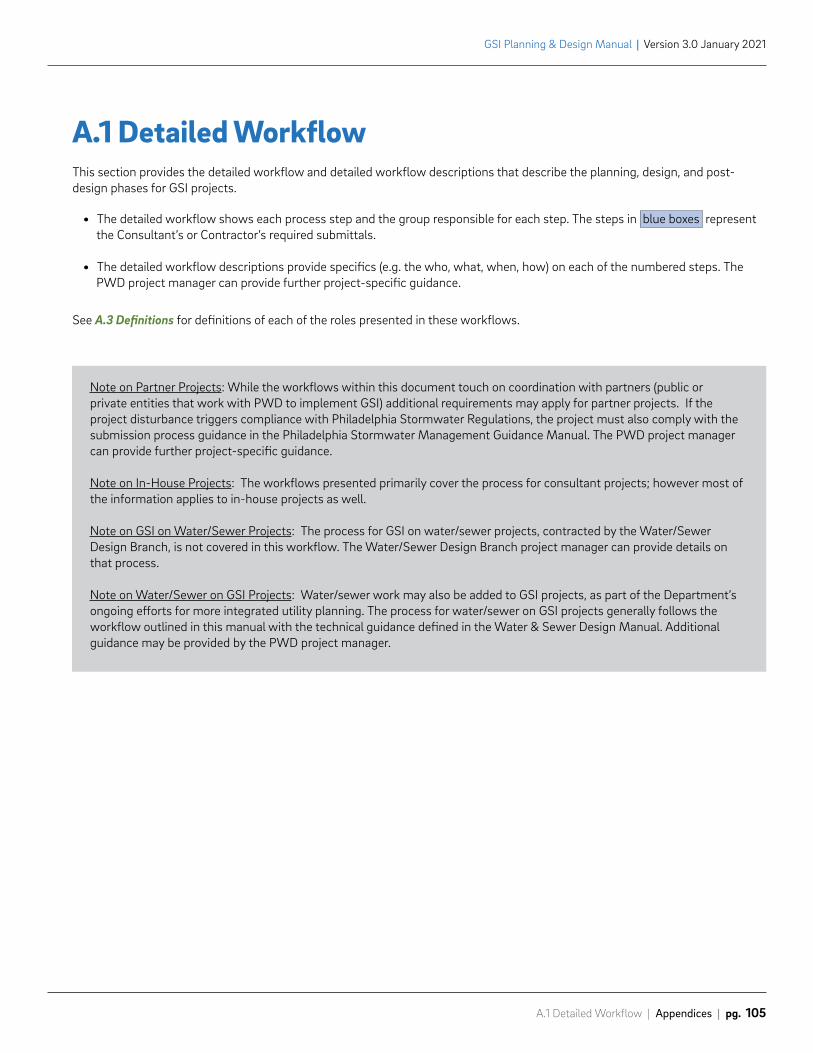
A.1 Detailed Workflow | Appendices | pg. 105
GSI Planning & Design Manual | Version 3.0 January 2021
A.1 Detailed WorkflowThis section provides the detailed workflow and detailed workflow descriptions that describe the planning, design, and post-design phases for GSI projects.
• The detailed workflow shows each process step and the group responsible for each step. The steps in blue boxes represent the Consultant’s or Contractor’s required submittals.
• The detailed workflow descriptions provide specifics (e.g. the who, what, when, how) on each of the numbered steps. The PWD project manager can provide further project-specific guidance.
Note on Partner Projects: While the workflows within this document touch on coordination with partners (public or private entities that work with PWD to implement GSI) additional requirements may apply for partner projects. If the project disturbance triggers compliance with Philadelphia Stormwater Regulations, the project must also comply with the submission process guidance in the Philadelphia Stormwater Management Guidance Manual. The PWD project manager can provide further project-specific guidance.
Note on In-House Projects: The workflows presented primarily cover the process for consultant projects; however most of the information applies to in-house projects as well.
Note on GSI on Water/Sewer Projects: The process for GSI on water/sewer projects, contracted by the Water/Sewer Design Branch, is not covered in this workflow. The Water/Sewer Design Branch project manager can provide details on that process.
Note on Water/Sewer on GSI Projects: Water/sewer work may also be added to GSI projects, as part of the Department’s ongoing efforts for more integrated utility planning. The process for water/sewer on GSI projects generally follows the workflow outlined in this manual with the technical guidance defined in the Water & Sewer Design Manual. Additional guidance may be provided by the PWD project manager.
See A.3 Definitions for definitions of each of the roles presented in these workflows.
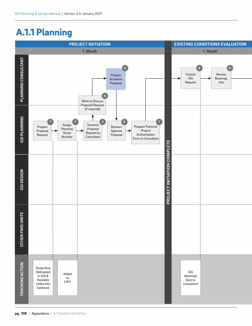
GSI
PLA
NN
ING
PLA
NN
ING
CO
NSU
LTA
NT
GSI
DES
IGN
TRA
CKIN
G A
CTIO
NO
THER
PW
D U
NIT
S
PROJECT INITIATION1 Month 1 Month
EXISTING CONDITIONS EVALUATION
PrepareProposal Request
1Assign
PlanningStudy
Number
2TransmitProposal
Request toConsultant
3
Review/ApproveProposal
6Prepare/Transmit
ProjectAuthorization
Form to Consultant
7
SubmitGIS
Request
8
ReviewBasemap
Info
9
Meet to DiscussProposal Request
(if required)
4
Prepare & Submit Proposal
5
Study AreaDelineated
in GIS &Available
Utility InfoGathered
Addedto
CIPIT
GISBasemapSent to
Consultant
PRO
JECT
INIT
IATI
ON
CO
MPL
ETE
Prepare &SubmitExisting
ConditionsEvaluation
GSI Planning & Design Manual | Version 3.0 January 2021
pg. 106 | Appendices | A.1 Detailed Workflow
A.1.1 Planning
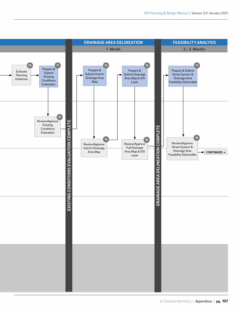
1 Month 2 - 3 Months
DRAINAGE AREA DELINEATION FEASIBILITY ANALYSIS
EvaluatePlanningInitiatives
10
Review/ApproveExisting
ConditionsEvaluation
12
Review/ApproveInterim Drainage
Area Map
14Review/Approve
Full DrainageArea Map & GIS
Layer
16Review/ApproveStreet System &
Drainage AreaFeasibility Deliverable
18
CONTINUED ->
Prepare &SubmitExisting
ConditionsEvaluation
11
Prepare &Submit InterimDrainage Area
Map
13
Prepare &Submit DrainageArea Map & GIS
Layer
15
Prepare & SubmitStreet System &
Drainage AreaFeasibility Deliverable
17EX
ISTI
NG
CO
ND
ITIO
NS
EVA
LUAT
ION
CO
MPL
ETE
DR
AIN
AG
E A
REA
DEL
INEA
TIO
N C
OM
PLET
E
A.1 Detailed Workflow | Appendices | pg. 107
GSI Planning & Design Manual | Version 3.0 January 2021
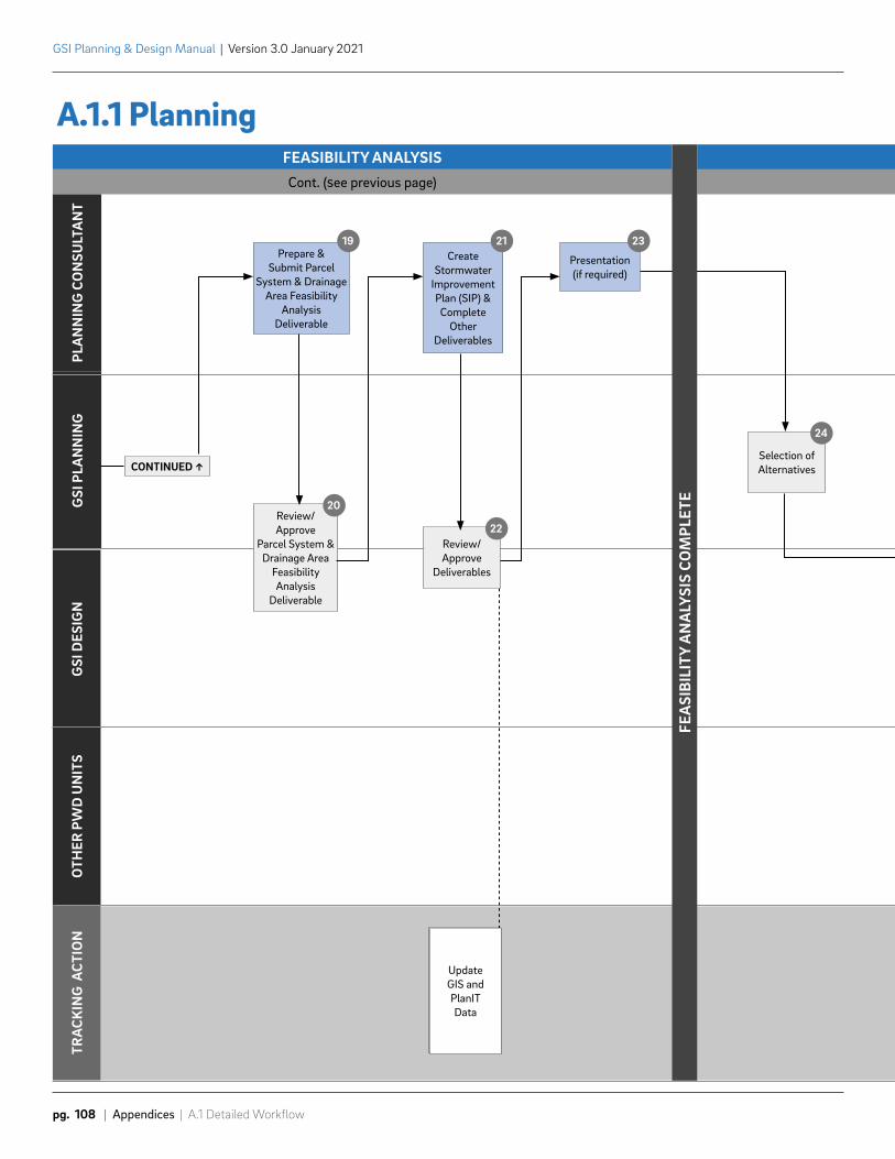
GSI
PLA
NN
ING
PLA
NN
ING
CO
NSU
LTA
NT
GSI
DES
IGN
TRA
CKIN
G A
CTIO
NO
THER
PW
D U
NIT
S
A.1.1 PlanningFEASIBILITY ANALYSISCont. (See previous page)
Review/Approve
Parcel System & Drainage Area
Feasibility Analysis
Deliverable
20
Review/Approve
Deliverables
22
Selection ofAlternatives
24
CONTINUED ↑
Prepare &Submit Parcel
System & DrainageArea Feasibility
Analysis Deliverable
19Create
Stormwater Improvement Plan (SIP) &Complete
Other Deliverables
21
Presentation(if required)
23
UpdateGIS and PlanITData
UpdateGIS and PlanITData
FEA
SIBI
LITY
AN
ALY
SIS
COM
PLET
E
GSI Planning & Design Manual | Version 3.0 January 2021
pg. 108 | Appendices | A.1 Detailed Workflow
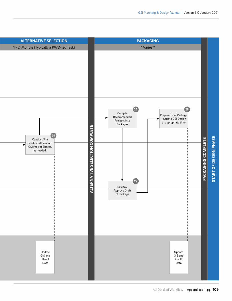
1 - 2 Months (Typically a PWD-led Task) * Varies *
ALTERNATIVE SELECTION PACKAGING
Conduct SiteVisits and DevelopGSI Project Sheets,
as needed.
25
Compile Recommended
Projects into Packages
26
Prepare Final Package- Sent to GSI Designat appropriate time
28
Review/Approve Draft
of Package
27
UpdateGIS and PlanITData
UpdateGIS and PlanITData
PACK
AG
ING
CO
MPL
ETE
STA
RT O
F D
ESIG
N P
HA
SE
ALT
ERN
ATIV
E SE
LECT
ION
CO
MPL
ETE
A.1 Detailed Workflow | Appendices | pg. 109
GSI Planning & Design Manual | Version 3.0 January 2021
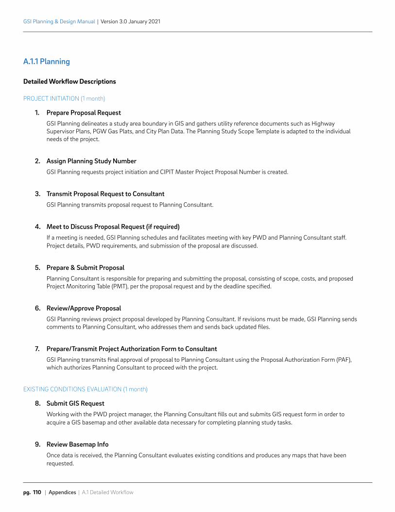
GSI Planning & Design Manual | Version 3.0 January 2021
pg. 110 | Appendices | A.1 Detailed Workflow
A.1.1 Planning
Detailed Workflow Descriptions
PROJECT INITIATION (1 month)
1. Prepare Proposal RequestGSI Planning delineates a study area boundary in GIS and gathers utility reference documents such as Highway Supervisor Plans, PGW Gas Plats, and City Plan Data. The Planning Study Scope Template is adapted to the individual needs of the project.
2. Assign Planning Study Number GSI Planning requests project initiation and CIPIT Master Project Proposal Number is created.
3. Transmit Proposal Request to ConsultantGSI Planning transmits proposal request to Planning Consultant.
4. Meet to Discuss Proposal Request (if required)If a meeting is needed, GSI Planning schedules and facilitates meeting with key PWD and Planning Consultant staff. Project details, PWD requirements, and submission of the proposal are discussed.
5. Prepare & Submit Proposal Planning Consultant is responsible for preparing and submitting the proposal, consisting of scope, costs, and proposed Project Monitoring Table (PMT), per the proposal request and by the deadline specified.
6. Review/Approve ProposalGSI Planning reviews project proposal developed by Planning Consultant. If revisions must be made, GSI Planning sends comments to Planning Consultant, who addresses them and sends back updated files.
7. Prepare/Transmit Project Authorization Form to ConsultantGSI Planning transmits final approval of proposal to Planning Consultant using the Proposal Authorization Form (PAF), which authorizes Planning Consultant to proceed with the project.
EXISTING CONDITIONS EVALUATION (1 month)
8. Submit GIS RequestWorking with the PWD project manager, the Planning Consultant fills out and submits GIS request form in order to acquire a GIS basemap and other available data necessary for completing planning study tasks.
9. Review Basemap InfoOnce data is received, the Planning Consultant evaluates existing conditions and produces any maps that have been requested.
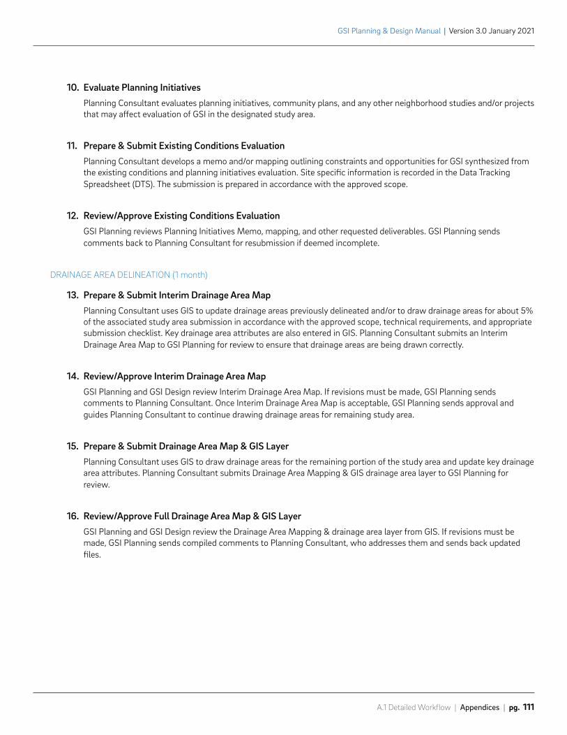
A.1 Detailed Workflow | Appendices | pg. 111
GSI Planning & Design Manual | Version 3.0 January 2021
10. Evaluate Planning InitiativesPlanning Consultant evaluates planning initiatives, community plans, and any other neighborhood studies and/or projects that may affect evaluation of GSI in the designated study area.
11. Prepare & Submit Existing Conditions EvaluationPlanning Consultant develops a memo and/or mapping outlining constraints and opportunities for GSI synthesized from the existing conditions and planning initiatives evaluation. Site specific information is recorded in the Data Tracking Spreadsheet (DTS). The submission is prepared in accordance with the approved scope.
12. Review/Approve Existing Conditions EvaluationGSI Planning reviews Planning Initiatives Memo, mapping, and other requested deliverables. GSI Planning sends comments back to Planning Consultant for resubmission if deemed incomplete.
DRAINAGE AREA DELINEATION (1 month)
13. Prepare & Submit Interim Drainage Area MapPlanning Consultant uses GIS to update drainage areas previously delineated and/or to draw drainage areas for about 5% of the associated study area submission in accordance with the approved scope, technical requirements, and appropriate submission checklist. Key drainage area attributes are also entered in GIS. Planning Consultant submits an Interim Drainage Area Map to GSI Planning for review to ensure that drainage areas are being drawn correctly.
14. Review/Approve Interim Drainage Area MapGSI Planning and GSI Design review Interim Drainage Area Map. If revisions must be made, GSI Planning sends comments to Planning Consultant. Once Interim Drainage Area Map is acceptable, GSI Planning sends approval and guides Planning Consultant to continue drawing drainage areas for remaining study area.
15. Prepare & Submit Drainage Area Map & GIS LayerPlanning Consultant uses GIS to draw drainage areas for the remaining portion of the study area and update key drainage area attributes. Planning Consultant submits Drainage Area Mapping & GIS drainage area layer to GSI Planning for review.
16. Review/Approve Full Drainage Area Map & GIS LayerGSI Planning and GSI Design review the Drainage Area Mapping & drainage area layer from GIS. If revisions must be made, GSI Planning sends compiled comments to Planning Consultant, who addresses them and sends back updated files.
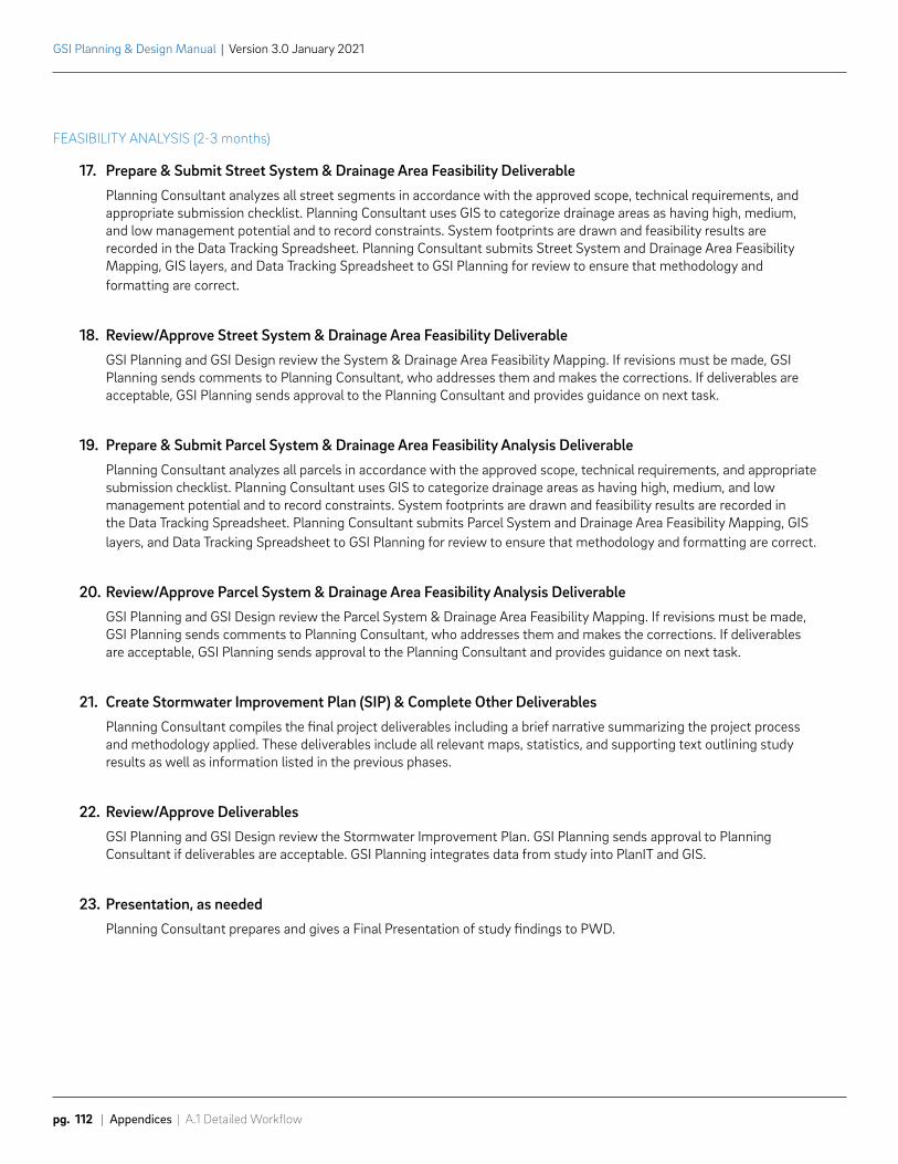
GSI Planning & Design Manual | Version 3.0 January 2021
pg. 112 | Appendices | A.1 Detailed Workflow
FEASIBILITY ANALYSIS (2-3 months)
17. Prepare & Submit Street System & Drainage Area Feasibility DeliverablePlanning Consultant analyzes all street segments in accordance with the approved scope, technical requirements, and appropriate submission checklist. Planning Consultant uses GIS to categorize drainage areas as having high, medium, and low management potential and to record constraints. System footprints are drawn and feasibility results are recorded in the Data Tracking Spreadsheet. Planning Consultant submits Street System and Drainage Area Feasibility Mapping, GIS layers, and Data Tracking Spreadsheet to GSI Planning for review to ensure that methodology and formatting are correct.
18. Review/Approve Street System & Drainage Area Feasibility DeliverableGSI Planning and GSI Design review the System & Drainage Area Feasibility Mapping. If revisions must be made, GSI Planning sends comments to Planning Consultant, who addresses them and makes the corrections. If deliverables are acceptable, GSI Planning sends approval to the Planning Consultant and provides guidance on next task.
19. Prepare & Submit Parcel System & Drainage Area Feasibility Analysis DeliverablePlanning Consultant analyzes all parcels in accordance with the approved scope, technical requirements, and appropriate submission checklist. Planning Consultant uses GIS to categorize drainage areas as having high, medium, and low management potential and to record constraints. System footprints are drawn and feasibility results are recorded in the Data Tracking Spreadsheet. Planning Consultant submits Parcel System and Drainage Area Feasibility Mapping, GIS layers, and Data Tracking Spreadsheet to GSI Planning for review to ensure that methodology and formatting are correct.
20. Review/Approve Parcel System & Drainage Area Feasibility Analysis DeliverableGSI Planning and GSI Design review the Parcel System & Drainage Area Feasibility Mapping. If revisions must be made, GSI Planning sends comments to Planning Consultant, who addresses them and makes the corrections. If deliverables are acceptable, GSI Planning sends approval to the Planning Consultant and provides guidance on next task.
21. Create Stormwater Improvement Plan (SIP) & Complete Other DeliverablesPlanning Consultant compiles the final project deliverables including a brief narrative summarizing the project process and methodology applied. These deliverables include all relevant maps, statistics, and supporting text outlining study results as well as information listed in the previous phases.
22. Review/Approve DeliverablesGSI Planning and GSI Design review the Stormwater Improvement Plan. GSI Planning sends approval to Planning Consultant if deliverables are acceptable. GSI Planning integrates data from study into PlanIT and GIS.
23. Presentation, as neededPlanning Consultant prepares and gives a Final Presentation of study findings to PWD.
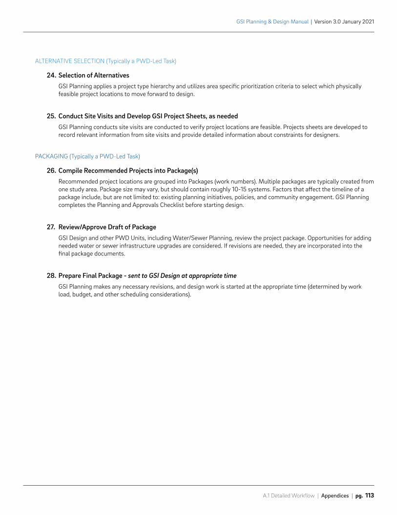
A.1 Detailed Workflow | Appendices | pg. 113
GSI Planning & Design Manual | Version 3.0 January 2021
ALTERNATIVE SELECTION (Typically a PWD-Led Task)
24. Selection of AlternativesGSI Planning applies a project type hierarchy and utilizes area specific prioritization criteria to select which physically feasible project locations to move forward to design.
25. Conduct Site Visits and Develop GSI Project Sheets, as neededGSI Planning conducts site visits are conducted to verify project locations are feasible. Projects sheets are developed to record relevant information from site visits and provide detailed information about constraints for designers.
PACKAGING (Typically a PWD-Led Task)
26. Compile Recommended Projects into Package(s)Recommended project locations are grouped into Packages (work numbers). Multiple packages are typically created from one study area. Package size may vary, but should contain roughly 10-15 systems. Factors that affect the timeline of a package include, but are not limited to: existing planning initiatives, policies, and community engagement. GSI Planning completes the Planning and Approvals Checklist before starting design.
27. Review/Approve Draft of PackageGSI Design and other PWD Units, including Water/Sewer Planning, review the project package. Opportunities for adding needed water or sewer infrastructure upgrades are considered. If revisions are needed, they are incorporated into the final package documents.
28. Prepare Final Package - sent to GSI Design at appropriate timeGSI Planning makes any necessary revisions, and design work is started at the appropriate time (determined by work load, budget, and other scheduling considerations).
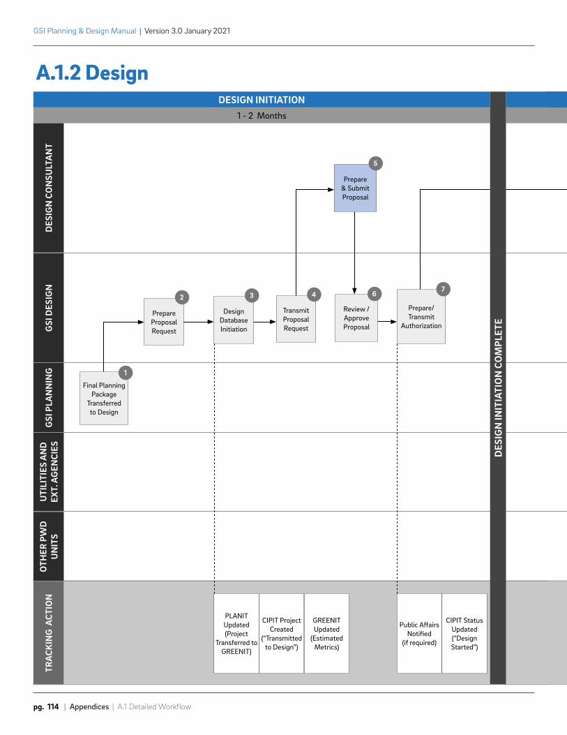
DESIGN INITIATION1 - 2 Months
DES
IGN
CO
NSU
LTA
NT
GSI
DES
IGN
GSI
PLA
NN
ING
UTI
LITI
ES A
ND
EX
T. A
GEN
CIES
OTH
ER P
WD
UN
ITS
TRA
CKIN
G A
CTIO
N
Final PlanningPackage
Transferredto Design
1
PrepareProposalRequest
2
Design Database Initiation
3
Transmit Proposal Request
4
Review /Approve Proposal
6
Prepare/ Transmit
Authorization
7
Prepare & Submit Proposal
5
PLANIT Updated (Project
Transferred to GREENIT)
CIPIT Project Created
(“Transmitted to Design”)
GREENIT Updated
(Estimated Metrics)
Public Affairs Notified
(if required)
CIPIT Status Updated (“Design Started”)
DES
IGN
INIT
IATI
ON
CO
MPL
ETE
3 - 5 Months
BASEPLAN (30%) & GEOTECH
GSI Planning & Design Manual | Version 3.0 January 2021
pg. 114 | Appendices | A.1 Detailed Workflow
A.1.2 Design
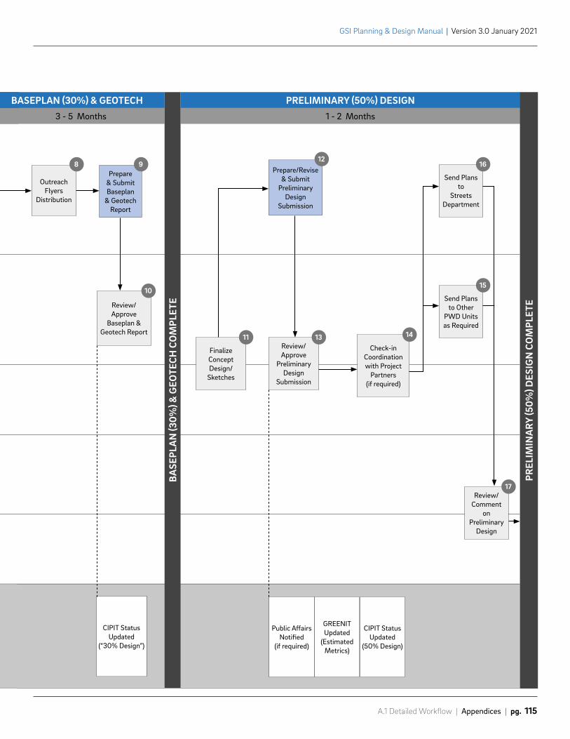
3 - 5 Months 1 - 2 Months
BASEPLAN (30%) & GEOTECH PRELIMINARY (50%) DESIGN
Review/ Approve
Baseplan & Geotech Report
10
Finalize Concept Design/
Sketches
11Review/Approve
PreliminaryDesign
Submission
13Check-in
Coordination with Project
Partners (if required)
14
Send Plans to Other
PWD Units as Required
15
Review/Comment
onPreliminary
Design
17
Send Plans to
StreetsDepartment
16
Outreach Flyers
Distribution
8Prepare
& Submit Baseplan
& Geotech Report
9Prepare/Revise
& Submit Preliminary
Design Submission
12
Public Affairs Notified
(if required)
GREENITUpdated
(EstimatedMetrics)
CIPIT Status Updated
(50% Design)
CIPIT Status Updated
(“30% Design”)
BASE
PLA
N (3
0%) &
GEO
TECH
CO
MPL
ETE
PREL
IMIN
ARY
(50%
) DES
IGN
CO
MPL
ETE
A.1 Detailed Workflow | Appendices | pg. 115
GSI Planning & Design Manual | Version 3.0 January 2021
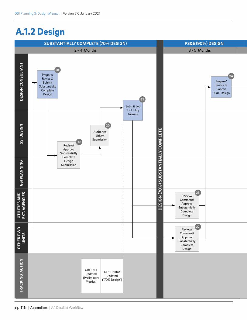
3 - 5 Months
SUBSTANTIALLY COMPLETE (70% DESIGN)2 - 4 Months
DES
IGN
CO
NSU
LTA
NT
GSI
DES
IGN
GSI
PLA
NN
ING
UTI
LITI
ES A
ND
EX
T. A
GEN
CIES
OTH
ER P
WD
UN
ITS
TRA
CKIN
G A
CTIO
N
Review/ Approve
Substantially Complete
Design Submission
19
Authorize Utility
Submission
20
Review/Comment/
ApproveSubstantially
CompleteDesign
23
Review/Comment/
ApproveSubstantially
CompleteDesign
22
Prepare/Revise & Submit
Substantially Complete
Design
18
Prepare/Revise & Submit
PS&E Design
24
Submit Jobfor Utility
Review
21
GREENITUpdated
(PreliminaryMetrics)
CIPIT StatusUpdated
(“70% Design”)
PS&E (90%) DESIGN
DES
IGN
(70%
) SU
BSTA
NTI
ALL
Y CO
MPL
ETE
GSI Planning & Design Manual | Version 3.0 January 2021
pg. 116 | Appendices | A.1 Detailed Workflow
A.1.2 Design
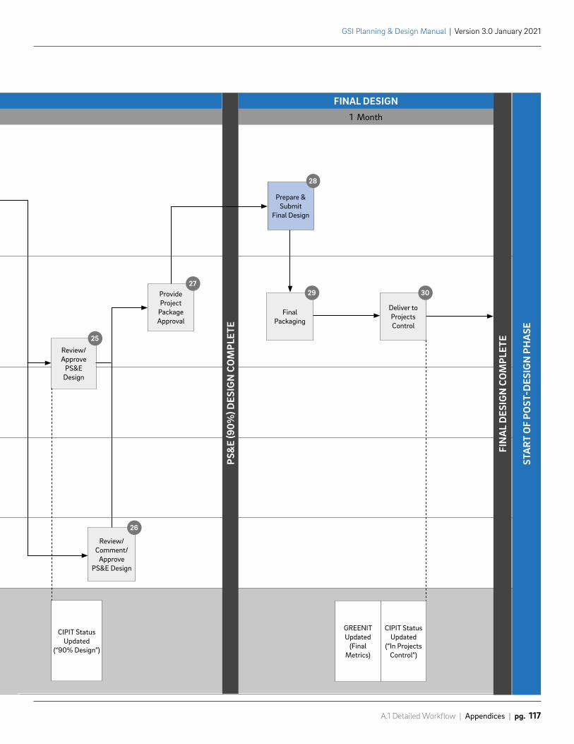
Review/Approve
PS&EDesign
25
Review/Comment/
ApprovePS&E Design
26
ProvideProject
Package Approval
27
FinalPackaging
29
Deliver to Projects Control
30
Prepare & Submit
Final Design
28
1 Month
FINAL DESIGN
GREENITUpdated
(FinalMetrics)
CIPIT Status Updated
(“In ProjectsControl”)
CIPIT Status Updated
(“90% Design”)
PS&
E (9
0%) D
ESIG
N C
OM
PLET
E
FIN
AL
DES
IGN
CO
MPL
ETE
STA
RT O
F PO
ST-D
ESIG
N P
HA
SE
A.1 Detailed Workflow | Appendices | pg. 117
GSI Planning & Design Manual | Version 3.0 January 2021
GSI Planning & Design Manual | Version 3.0 January 2021
pg. 118 | Appendices | A.1 Detailed Workflow
A.1.2 Design
Detailed Workflow Descriptions
DESIGN INITIATION (1 – 2 months)
1. Final Project Package Transferred to DesignGSI Planning identifies sites, compiles sites into a project package and submits to GSI Design to initiate into design phase.
2. Prepare Proposal RequestGSI Design prepares the proposal request letter for the project package. The Design Project Scope Template is adapted to the individual needs of the project. The proposal request includes project concepts and requests scope for survey/baseplan, geotechnical investigations, and/or design services. Depending on specifics of the project package, later stages of design may be scoped later in the design process.
3. Design Database InitiationProject package is initiated in CIPIT and transferred from PlanIT to GreenIT. GSI Design enters estimated design metrics such as greened acres, drainage area, and SMP type in GreenIT. Work Number assigned in CIPIT. Status assigned as “Transmitted to Design”.
4. Transmit Proposal RequestGSI Design transmits proposal request to Design Consultant.
5. Prepare & Submit ProposalDesign Consultant prepares and submits the proposal, consisting of scope, costs, and proposed Project Monitoring Table (PMT), per the proposal request and by the deadline specified.
6. Review/Approve ProposalGSI Design reviews proposal developed by Design Consultant. If revisions must be made, GSI Design sends comments to Design Consultant, who addresses them and sends back updated files.
7. Prepare/Transmit AuthorizationGSI Design transmits final approval of proposal to Design Consultant using the Proposal Authorization Form (PAF), which authorizes Design Consultant to proceed with the project package. GSI Design notifies Public Affairs if required. GSI Design updates the CIPIT status to “Design Started”.
Note: Proposal request and preparation steps may repeat multiple times during design as projects are typically broken into at least two phases.
A.1 Detailed Workflow | Appendices | pg. 119
GSI Planning & Design Manual | Version 3.0 January 2021
BASEPLAN (30%) AND GEOTECH (3 – 5 months)
8. Outreach Flyers DistributionDesign Consultant notifies Public Affairs, distributes flyers or door hangers around the entire block of the survey and geotechnical investigation site at least one week prior to the survey and testing, and takes photographs of the area before any equipment arrives.
9. Prepare and Submit Baseplan & Geotech ReportDesign Consultant performs survey and prepares baseplan and geotech report submission in accordance with the approved scope, technical requirements, and appropriate submission checklist. Design Consultant coordinates right of entry with required partners such as SEPTA, school, and park sites. Informal interim submissions and check-ins before the baseplan submission are encouraged. If GSI Design responds to the baseplan submission with comments that must be resolved before approval, Design Consultant makes necessary revisions and resubmits the design, along with a letter responding to each comment. Resubmissions must be recorded in the PMT. GSI Design updates the CIPIT status to “30% Design”.
10. Review/Approve Baseplan and GeotechGSI Design reviews baseplan submission and conducts site visit. If revisions are needed, comments are sent back to Design Consultant in the form of a review letter. This process repeats until GSI Design approves the baseplan. Multiple submissions are typically necessary. Once baseplan is acceptable, GSI Design sends approval to Design Consultant.
PRELIMINARY (50%) DESIGN (1 – 2 months)
11. Finalize Concept Design/SketchesGSI Design and GSI Planning make changes as necessary to concept based on baseplan and geotechnical investigation. More complex projects may require additional concept refinement as part of the beginning of the preliminary design.
12. Prepare/Revise & Submit Preliminary Design SubmissionDesign Consultant prepares preliminary design submission in accordance with the approved scope, technical requirements, and appropriate submission checklist. Informal interim submissions and check-ins before the preliminary design submission are encouraged, including a concept vetting meeting with PWD early in design development. If GSI Design responds to the preliminary design submission with comments that must be resolved before approval, Design Consultant makes necessary revisions and resubmits the design, along with a letter responding to each comment. Resubmissions must be recorded in the PMT.
13. Review & Approve Preliminary Design SubmissionGSI Design and GSI Planning review the preliminary design submission. If the submission requires revision, GSI Design sends comments back to Design Consultant for resubmission. This process repeats until GSI Design and GSI Planning determine that preliminary design approval requirements are met. Multiple submissions are typically necessary. GSI Design notifies Public Affairs if required. GSI Design enters preliminary design metrics such as greened acres, drainage area, and SMP type in GreenIT. GSI Design updates the CIPIT status to “50% Design”.
GSI Planning & Design Manual | Version 3.0 January 2021
pg. 120 | Appendices | A.1 Detailed Workflow
14. Check-In Coordination with Partners (if required)Once it is confirmed that there are no issues with the preliminary design submission, GSI Design provides partners (if there are any) with an update on the status of the design and alerts them of any changes to the concept. GSI Design and GSI Planning respond to comments from partners before approving preliminary design.
15. Send Plans to Other PWD Units as RequiredOn an as-needed basis, GSI Design coordinates with other PWD units, including but not limited to: Green Stormwater Operations (GSO), Collector Systems, and Design - Utility Engineering.
16. Send Plans to Street DepartmentDesign Consultant sends plans to Streets Department for preliminary review. Turning analyses are included for all bumpouts.
17. Review/Comment on Preliminary DesignStreets Department and Other PWD units review preliminary design. Streets Department sends comments back to Design Consultant. Other PWD units send comments back to GSI Design. Design Consultant incorporates comments into Substantially Complete Design.
SUBSTANTIALLY COMPLETE (70%) DESIGN (2 – 4 months)
18. Prepare/Revise & Submit Substantially Complete DesignDesign Consultant prepares substantially complete design submission in accordance with the approved scope, technical requirements, and appropriate submission checklist. Design Consultant may start developing ADA ramp designs in accordance with the scope or at GSI Design’s direction. Informal interim submissions and check-ins before the substantially complete design submission are encouraged. If GSI Design responds to substantially complete design submission with comments that must be resolved before approval, Design Consultant makes necessary revisions and resubmits design, along with a letter responding to each comment. Resubmissions must be recorded in the PMT.
19. Review & Approve Substantially Complete Design SubmissionGSI Design and GSI Planning review the substantially complete design submission, soliciting feedback on landscape design from GSO. If the submission requires revision, GSI Design sends comments back to Design Consultant for resubmission. This process repeats until GSI Design and GSI Planning determine that substantially complete design approval requirements are met. Multiple submissions are typically necessary.
20. Authorize Utility SubmissionOnce GSI Design has determined that there are no outstanding issues with the substantially complete design, GSI Design responds to Design Consultant’s latest submission by confirming that the substantially complete design is approved and the project package is ready for submission to utilities.
A.1 Detailed Workflow | Appendices | pg. 121
GSI Planning & Design Manual | Version 3.0 January 2021
21. Submit Job for Utility ReviewOnce substantially complete design has been approved, plans are submitted for utility review. Design Consultant submits to external utilities/agencies. GSI Design submits and coordinates review directly with other PWD units (Construction Unit, Water/Sewer Design Utility Engineering, GSO, and Collector Systems Unit) and partners. GSI Design and Design Consultant should reference the GSI Review Contacts available on the Project Management tab of the GSI Planning & Design website. This resource provides information on what utilities/agencies should be submitted to, what their submission requirements are, and where the submissions should be sent. Design Consultant is encouraged to ask GSI Design about any utility submission details. Copies of all transmittals to utilities/agencies should be provided to GSI Design. Once copies of transmittals to utility/agencies are received, GSI Design updates the CIPIT status to “70% Design”. GSI Design updates preliminary design metrics such as greened acres, drainage area, and SMP type in GreenIT.
PS&E (90%) DESIGN (3 - 5 months)
22. Review/Comment/Approve Substantially Complete DesignOther PWD units and partners review plans and send approval/comments to GSI Design. Comments are generally addressed with the Plans, Specifications, & Estimate (PS&E) 90% submission.
23. Review/Comment/Approve Substantially Complete DesignUtilities/Agencies review plans and send approval/comments back to Design Consultant. Design Consultant must be proactive in checking on the status of review and be in close contact with PWD if it appears that there is a delay in any particular review. Design Consultant can contact GSI Design with any questions. If a utility/agency does not approve design, Design Consultant addresses comments at the advisement of GSI Design and resubmits plans to the utility/agency.
24. Prepare/Revise & Submit PS&E DesignDesign Consultant prepares and submits PS&E design in accordance with comments from utilities/agencies/other PWD units, any outstanding comments from GSI Design, the approved scope, technical requirements, and appropriate submission checklist. If GSI Design responds to the PS&E design submittal with comments, Design Consultant makes necessary revisions and resubmits the design, along with a letter responding to each comment.
25. Review & Approve PS&E DesignGSI Design and GSI Planning review the PS&E Design Submission. GSI Design may submit design to other PWD units and partners as needed. If the submission requires revision, GSI Design sends comments back to Design Consultant for resubmission. This process repeats until GSI Design determines that the requirements for final design are met. GSI Design updates status to “90% Design”. GSI Design sends 90% plans to GSO to assign maintenance component ID’s.
26. Review/Comment/Approve PS&E DesignOther PWD units and partners, as needed, review plans and specifications and send approval/comments back to GSI Design. Design Consultant makes any needed corrections to design. Multiple submissions may be necessary. GSO assigns maintenance component ID’s. See 3.3.10 Survey & Drawing Standards for component ID labeling requirements.
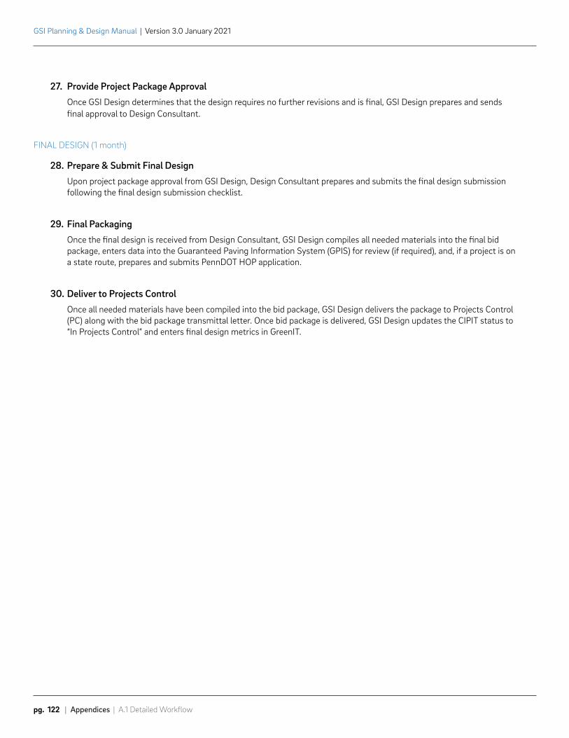
GSI Planning & Design Manual | Version 3.0 January 2021
pg. 122 | Appendices | A.1 Detailed Workflow
27. Provide Project Package ApprovalOnce GSI Design determines that the design requires no further revisions and is final, GSI Design prepares and sends final approval to Design Consultant.
FINAL DESIGN (1 month)
28. Prepare & Submit Final DesignUpon project package approval from GSI Design, Design Consultant prepares and submits the final design submission following the final design submission checklist.
29. Final PackagingOnce the final design is received from Design Consultant, GSI Design compiles all needed materials into the final bid package, enters data into the Guaranteed Paving Information System (GPIS) for review (if required), and, if a project is on a state route, prepares and submits PennDOT HOP application.
30. Deliver to Projects ControlOnce all needed materials have been compiled into the bid package, GSI Design delivers the package to Projects Control (PC) along with the bid package transmittal letter. Once bid package is delivered, GSI Design updates the CIPIT status to “In Projects Control” and enters final design metrics in GreenIT.
COLLAZO PARK RAIN GARDEN
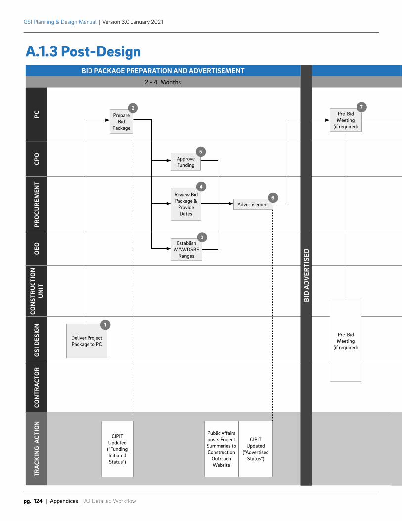
BID PACKAGE PREPARATION AND ADVERTISEMENT 2 - 4 Months
PCCP
OPR
OCU
REM
ENT
OEO
CON
STR
UCT
ION
U
NIT
GSI
DES
IGN
CON
TRA
CTO
RTR
ACK
ING
ACT
ION
Deliver ProjectPackage to PC
1
CIPIT Updated
(“Funding InitiatedStatus”)
Public Affairsposts ProjectSummaries toConstruction
OutreachWebsite
CIPITUpdated
(“AdvertisedStatus”)
Pre-BidMeeting
(if required)
Prepare Bid
Package
2
EstablishM/W/DSBE
Ranges
3
Review Bid Package &
ProvideDates
4
Pre-BidMeeting
(if required)
7
ApproveFunding
5
Advertisement6
BID
AD
VER
TISE
D
GSI Planning & Design Manual | Version 3.0 January 2021
pg. 124 | Appendices | A.1 Detailed Workflow
A.1.3 Post-Design
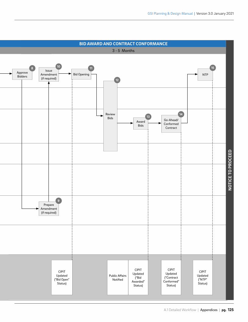
CIPITUpdated
(“Bid Open” Status)
Public AffairsNotified
CIPITUpdated
(“Bid Awarded”
Status)
CIPITUpdated
(“Contract Conformed”
Status)
CIPITUpdated(“NTP”Status)
NO
TICE
TO
PR
OCE
ED
3 - 5 Months
BID AWARD AND CONTRACT CONFORMANCE
PrepareAmendment(if required)
9
IssueAmendment (if required)
10
Go-Ahead/Conformed
Contract
14
Bid Opening
11
ReviewBids
12
Approve Bidders
8
Award Bids
13
NTP
15
A.1 Detailed Workflow | Appendices | pg. 125
GSI Planning & Design Manual | Version 3.0 January 2021
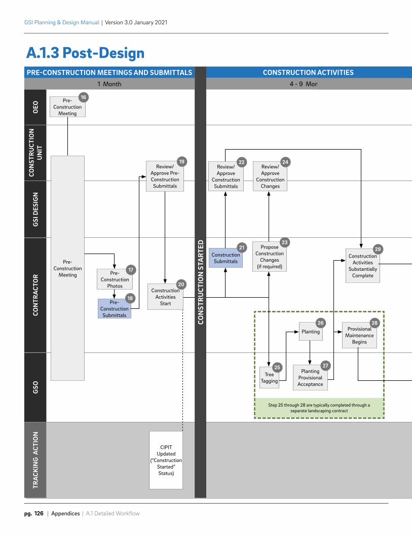
Step 25 through 28 are typically completed through a separate landscaping contract
PRE-CONSTRUCTION MEETINGS AND SUBMITTALS1 Month
OEO
CON
STR
UCT
ION
UN
ITG
SI D
ESIG
NCO
NTR
ACT
OR
GSO
TRA
CKIN
G A
CTIO
N
Pre-Construction
Meeting
16
Pre-Construction
Meeting
CIPIT Updated
(“ConstructionStarted”Status)
4 - 9 Months
CONSTRUCTION ACTIVITIES
Pre-Construction
Photos
17
Review/Approve Pre-Construction Submittals
19
Construction Activities
Start
20
Review/Approve
ConstructionSubmittals
22Review/Approve
ConstructionChanges
24
ProposeConstruction
Changes (if required)
23
Tree Tagging
25
Planting
26
PlantingProvisional Acceptance
27
Provisional Maintenance
Begins
28
ConstructionActivities
SubstantiallyComplete
29
Pre-ConstructionSubmittals
18
ConstructionSubmittals
21
CON
STR
UCT
ION
STA
RTED
GSI Planning & Design Manual | Version 3.0 January 2021
pg. 126 | Appendices | A.1 Detailed Workflow
A.1.3 Post-Design
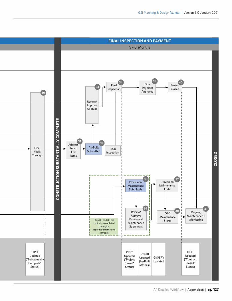
Step 35 and 36 are typically completed
through a separate landscaping
contract
CIPIT Updated
(“SubstantiallyComplete”
Status)
CIPIT Updated (“ProjectClosed”Status)
GreenIT Updated (As-BuiltMetrics)
GIS/ERVUpdated
CIPITUpdated
(“ContractClosed”Status)
CLO
SED
3 - 6 Months
FINAL INSPECTION AND PAYMENT
AddressPunch
ListItems
31
Final Inspection
34
Review/Approve
ProvisionalMaintenance
Submittals
36
ProvisionalMaintenance
Ends
37
GSOMaintenance
Starts
38 OngoingMaintenance &
Monitoring
41
Final Inspection
Final PaymentApproved
39ProjectClosed
40
Review/ApproveAs-Built
33
Final Walk
Through
30
ProvisionalMaintenance
Submittals
35
As-BuiltSubmitted
32
CON
STR
UCT
ION
SU
BSTA
NTI
ALL
Y CO
MPL
ETE
A.1 Detailed Workflow | Appendices | pg. 127
GSI Planning & Design Manual | Version 3.0 January 2021
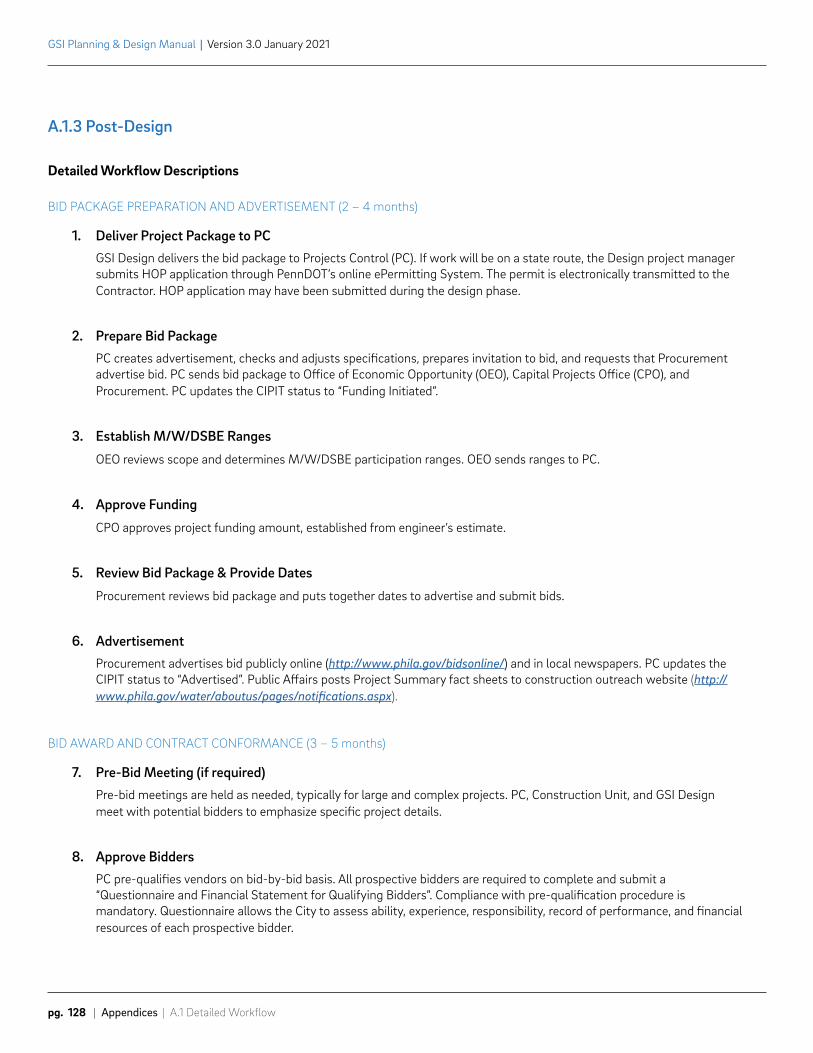
GSI Planning & Design Manual | Version 3.0 January 2021
pg. 128 | Appendices | A.1 Detailed Workflow
A.1.3 Post-Design
Detailed Workflow Descriptions
BID PACKAGE PREPARATION AND ADVERTISEMENT (2 – 4 months)
1. Deliver Project Package to PCGSI Design delivers the bid package to Projects Control (PC). If work will be on a state route, the Design project manager submits HOP application through PennDOT’s online ePermitting System. The permit is electronically transmitted to the Contractor. HOP application may have been submitted during the design phase.
2. Prepare Bid PackagePC creates advertisement, checks and adjusts specifications, prepares invitation to bid, and requests that Procurement advertise bid. PC sends bid package to Office of Economic Opportunity (OEO), Capital Projects Office (CPO), and Procurement. PC updates the CIPIT status to “Funding Initiated”.
3. Establish M/W/DSBE Ranges
OEO reviews scope and determines M/W/DSBE participation ranges. OEO sends ranges to PC.
4. Approve Funding
CPO approves project funding amount, established from engineer’s estimate.
5. Review Bid Package & Provide Dates
Procurement reviews bid package and puts together dates to advertise and submit bids.
6. AdvertisementProcurement advertises bid publicly online (http://www.phila.gov/bidsonline/) and in local newspapers. PC updates the CIPIT status to “Advertised”. Public Affairs posts Project Summary fact sheets to construction outreach website (http://www.phila.gov/water/aboutus/pages/notifications.aspx).
BID AWARD AND CONTRACT CONFORMANCE (3 – 5 months)
7. Pre-Bid Meeting (if required) Pre-bid meetings are held as needed, typically for large and complex projects. PC, Construction Unit, and GSI Design meet with potential bidders to emphasize specific project details.
8. Approve Bidders PC pre-qualifies vendors on bid-by-bid basis. All prospective bidders are required to complete and submit a “Questionnaire and Financial Statement for Qualifying Bidders”. Compliance with pre-qualification procedure is mandatory. Questionnaire allows the City to assess ability, experience, responsibility, record of performance, and financial resources of each prospective bidder.
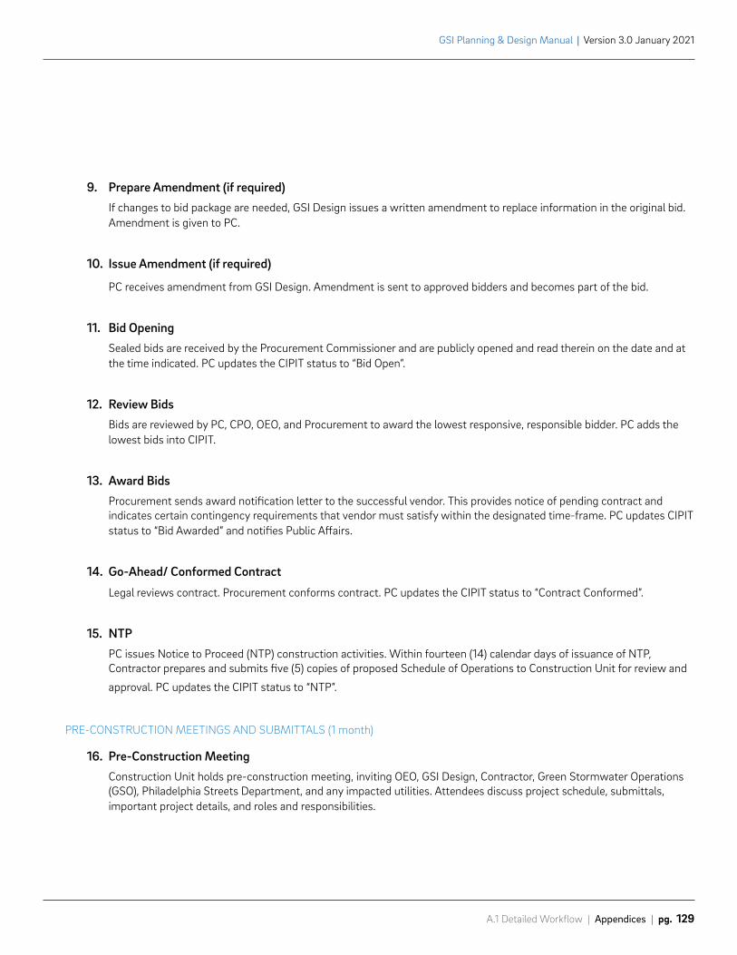
A.1 Detailed Workflow | Appendices | pg. 129
GSI Planning & Design Manual | Version 3.0 January 2021
9. Prepare Amendment (if required)If changes to bid package are needed, GSI Design issues a written amendment to replace information in the original bid. Amendment is given to PC.
10. Issue Amendment (if required)
PC receives amendment from GSI Design. Amendment is sent to approved bidders and becomes part of the bid.
11. Bid OpeningSealed bids are received by the Procurement Commissioner and are publicly opened and read therein on the date and at the time indicated. PC updates the CIPIT status to “Bid Open”.
12. Review Bids Bids are reviewed by PC, CPO, OEO, and Procurement to award the lowest responsive, responsible bidder. PC adds the lowest bids into CIPIT.
13. Award BidsProcurement sends award notification letter to the successful vendor. This provides notice of pending contract and indicates certain contingency requirements that vendor must satisfy within the designated time-frame. PC updates CIPIT status to “Bid Awarded” and notifies Public Affairs.
14. Go-Ahead/ Conformed Contract
Legal reviews contract. Procurement conforms contract. PC updates the CIPIT status to “Contract Conformed”.
15. NTPPC issues Notice to Proceed (NTP) construction activities. Within fourteen (14) calendar days of issuance of NTP, Contractor prepares and submits five (5) copies of proposed Schedule of Operations to Construction Unit for review and
approval. PC updates the CIPIT status to “NTP”.
PRE-CONSTRUCTION MEETINGS AND SUBMITTALS (1 month)
16. Pre-Construction Meeting Construction Unit holds pre-construction meeting, inviting OEO, GSI Design, Contractor, Green Stormwater Operations (GSO), Philadelphia Streets Department, and any impacted utilities. Attendees discuss project schedule, submittals, important project details, and roles and responsibilities.
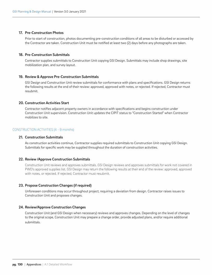
GSI Planning & Design Manual | Version 3.0 January 2021
pg. 130 | Appendices | A.1 Detailed Workflow
17. Pre-Construction PhotosPrior to start of construction, photos documenting pre-construction conditions of all areas to be disturbed or accessed by the Contractor are taken. Construction Unit must be notified at least two (2) days before any photographs are taken.
18. Pre-Construction SubmittalsContractor supplies submittals to Construction Unit copying GSI Design. Submittals may include shop drawings, site mobilization plan, and survey layout.
19. Review & Approve Pre-Construction SubmittalsGSI Design and Construction Unit review submittals for conformance with plans and specifications. GSI Design returns the following results at the end of their review: approved, approved with notes, or rejected. If rejected, Contractor must resubmit.
20. Construction Activities StartContractor notifies adjacent property owners in accordance with specifications and begins construction under Construction Unit supervision. Construction Unit updates the CIPIT status to “Construction Started” when Contractor mobilizes to site.
CONSTRUCTION ACTIVITIES (4 - 9 months)
21. Construction SubmittalsAs construction activities continue, Contractor supplies required submittals to Construction Unit copying GSI Design. Submittals for specific work may be supplied throughout the duration of construction activities.
22. Review /Approve Construction SubmittalsConstruction Unit reviews and approves submittals. GSI Design reviews and approves submittals for work not covered in PWD’s approved supplies list. GSI Design may return the following results at their end of the review: approved, approved with notes, or rejected. If rejected, Contractor must resubmit.
23. Propose Construction Changes (if required)Unforeseen conditions may occur throughout project, requiring a deviation from design. Contractor raises issues to Construction Unit and proposes changes.
24. Review/Approve Construction ChangesConstruction Unit (and GSI Design when necessary) reviews and approves changes. Depending on the level of changes to the original scope, Construction Unit may prepare a change order, provide adjusted plans, and/or require additional submittals.
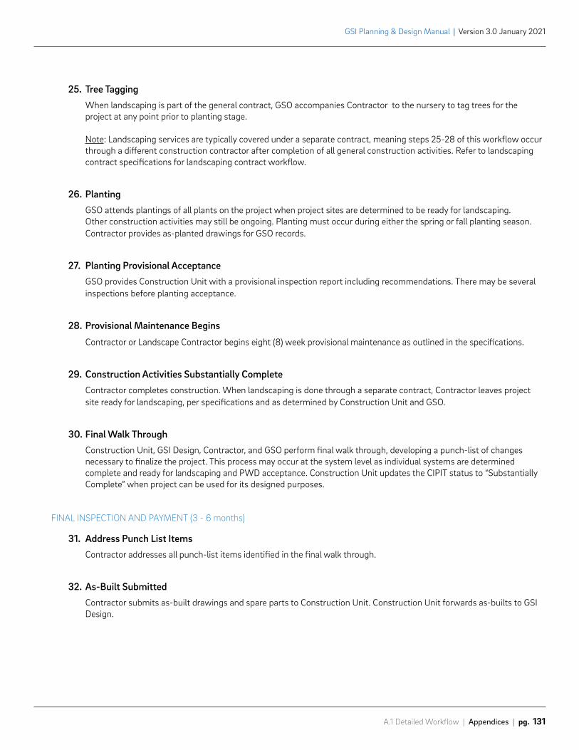
A.1 Detailed Workflow | Appendices | pg. 131
GSI Planning & Design Manual | Version 3.0 January 2021
25. Tree Tagging When landscaping is part of the general contract, GSO accompanies Contractor to the nursery to tag trees for the project at any point prior to planting stage.
Note: Landscaping services are typically covered under a separate contract, meaning steps 25-28 of this workflow occur through a different construction contractor after completion of all general construction activities. Refer to landscaping contract specifications for landscaping contract workflow.
26. PlantingGSO attends plantings of all plants on the project when project sites are determined to be ready for landscaping. Other construction activities may still be ongoing. Planting must occur during either the spring or fall planting season. Contractor provides as-planted drawings for GSO records.
27. Planting Provisional AcceptanceGSO provides Construction Unit with a provisional inspection report including recommendations. There may be several inspections before planting acceptance.
28. Provisional Maintenance Begins
Contractor or Landscape Contractor begins eight (8) week provisional maintenance as outlined in the specifications.
29. Construction Activities Substantially CompleteContractor completes construction. When landscaping is done through a separate contract, Contractor leaves project site ready for landscaping, per specifications and as determined by Construction Unit and GSO.
30. Final Walk ThroughConstruction Unit, GSI Design, Contractor, and GSO perform final walk through, developing a punch-list of changes necessary to finalize the project. This process may occur at the system level as individual systems are determined complete and ready for landscaping and PWD acceptance. Construction Unit updates the CIPIT status to “Substantially Complete” when project can be used for its designed purposes.
FINAL INSPECTION AND PAYMENT (3 - 6 months)
31. Address Punch List Items Contractor addresses all punch-list items identified in the final walk through.
32. As-Built SubmittedContractor submits as-built drawings and spare parts to Construction Unit. Construction Unit forwards as-builts to GSI Design.
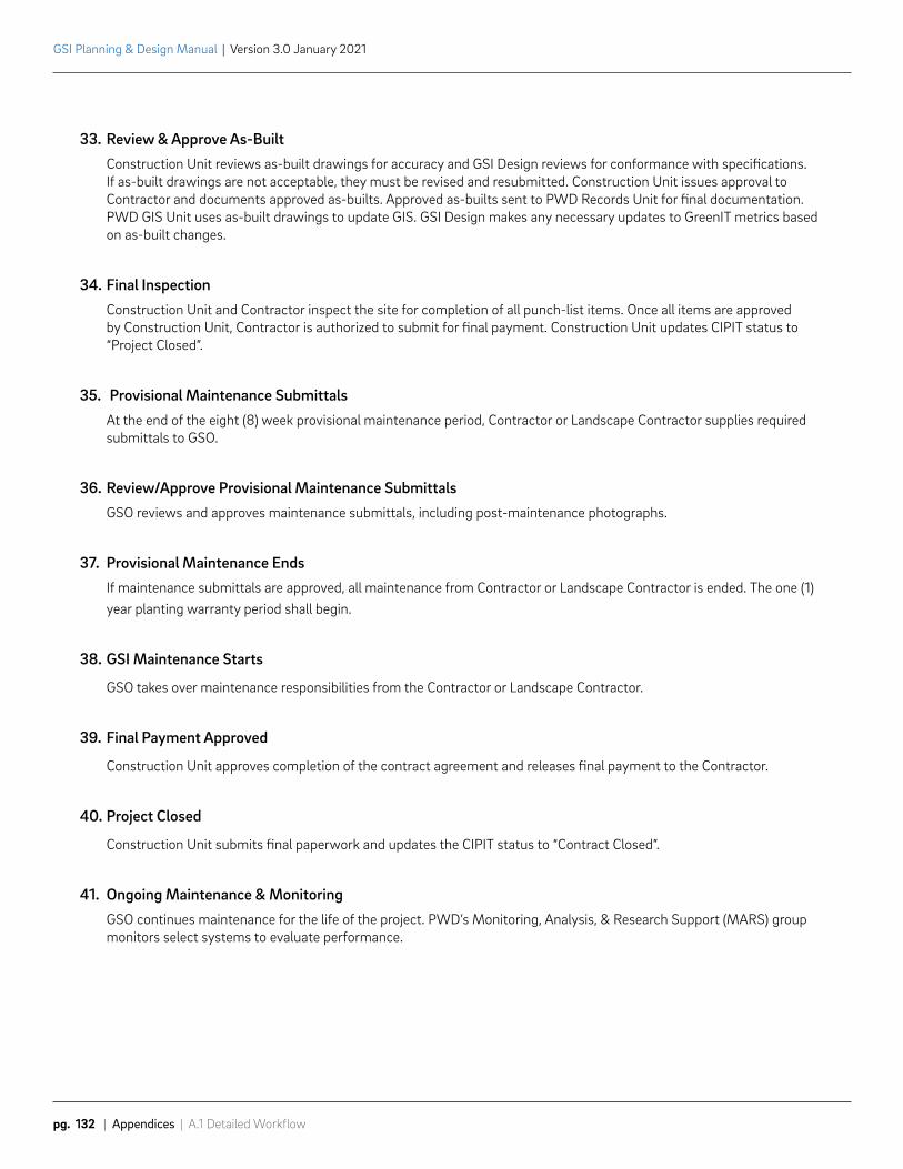
GSI Planning & Design Manual | Version 3.0 January 2021
pg. 132 | Appendices | A.1 Detailed Workflow
33. Review & Approve As-BuiltConstruction Unit reviews as-built drawings for accuracy and GSI Design reviews for conformance with specifications. If as-built drawings are not acceptable, they must be revised and resubmitted. Construction Unit issues approval to Contractor and documents approved as-builts. Approved as-builts sent to PWD Records Unit for final documentation. PWD GIS Unit uses as-built drawings to update GIS. GSI Design makes any necessary updates to GreenIT metrics based on as-built changes.
34. Final InspectionConstruction Unit and Contractor inspect the site for completion of all punch-list items. Once all items are approved by Construction Unit, Contractor is authorized to submit for final payment. Construction Unit updates CIPIT status to “Project Closed”.
35. Provisional Maintenance SubmittalsAt the end of the eight (8) week provisional maintenance period, Contractor or Landscape Contractor supplies required submittals to GSO.
36. Review/Approve Provisional Maintenance SubmittalsGSO reviews and approves maintenance submittals, including post-maintenance photographs.
37. Provisional Maintenance EndsIf maintenance submittals are approved, all maintenance from Contractor or Landscape Contractor is ended. The one (1) year planting warranty period shall begin.
38. GSI Maintenance Starts
GSO takes over maintenance responsibilities from the Contractor or Landscape Contractor.
39. Final Payment Approved
Construction Unit approves completion of the contract agreement and releases final payment to the Contractor.
40. Project Closed
Construction Unit submits final paperwork and updates the CIPIT status to “Contract Closed”.
41. Ongoing Maintenance & MonitoringGSO continues maintenance for the life of the project. PWD’s Monitoring, Analysis, & Research Support (MARS) group monitors select systems to evaluate performance.
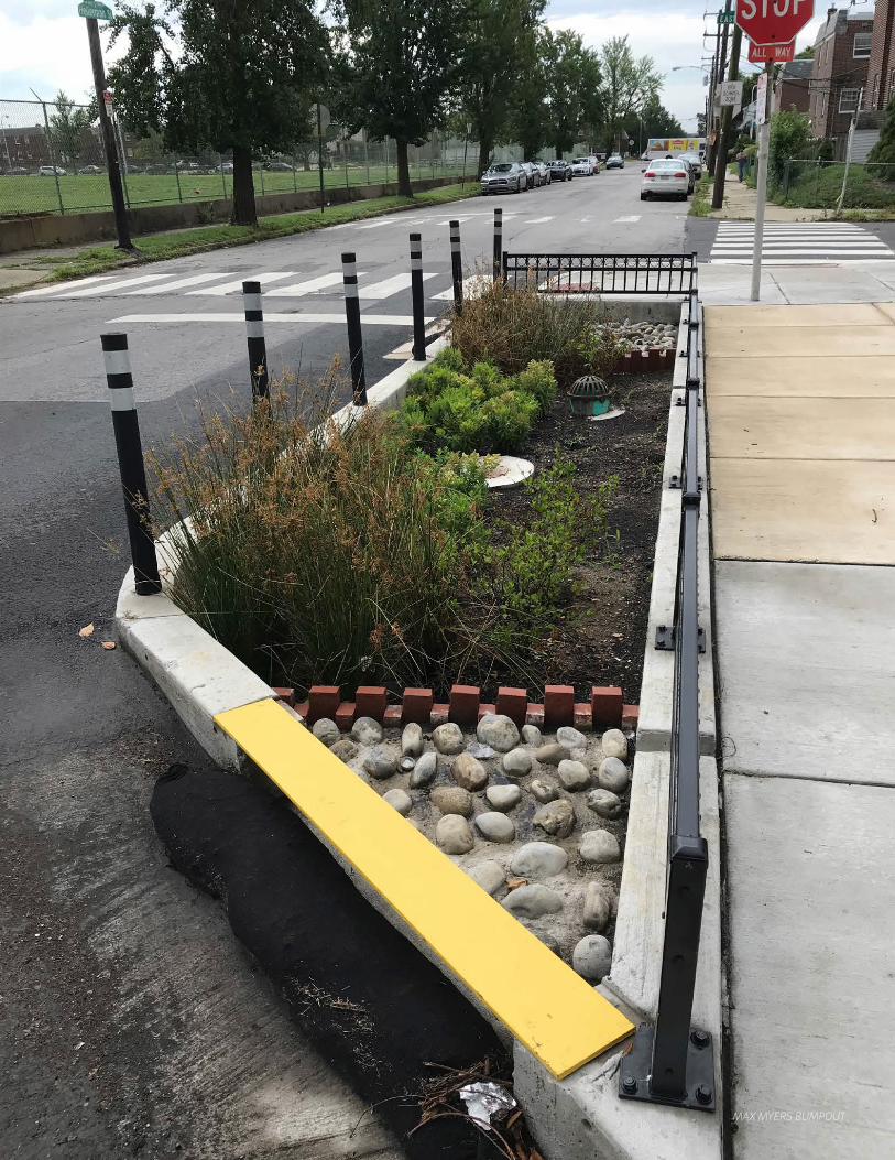
MAX MYERS BUMPOUT
GSI Planning & Design Manual | Version 3.0 January 2021
pg. 134 | Appendices | A.2 Project Management Resources
A.2 Project Management ResourcesPWD has a variety of project management resources available on the website. Resources include:
• Standardized reporting and invoicing procedures
• Submission checklists to be included with all design deliverables
• External review contact lists
• Forms for requesting data from PWD
• Standard outreach materials
• Instructions for gaining right-of-access for work on partner property
Planning and Design Consultants are encouraged to check the GSI Planning & Design website frequently to ensure the most up-to-date resources are used.
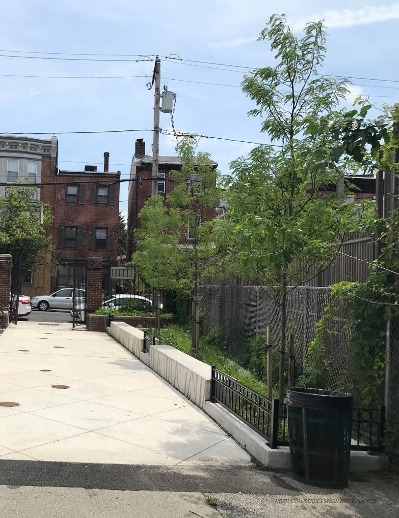
NORTHERN LIBERTIES STORMWATER PLANTER
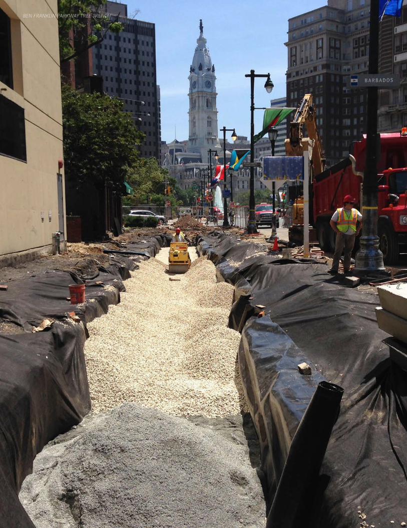
BEN FRANKLIN PARKWAY TREE TRENCH
A.3 Definitions | Appendices | pg. 137
GSI Planning & Design Manual | Version 3.0 January 2021
A.3 DefinitionsThe definitions in this section are for key terms that appear in this manual. The section is divided into “GSI Planning and Design Definitions”, which includes general terms used throughout the manual, and “Roles and Responsibilities” which defines positions that are referenced in the workflows.
Definitions of SMP types and reporting requirements can be found in the GreenIT Design Report Definitions. See 3.3.14 Metrics Reporting.
GSI Planning and Design Definitions
CIPIT – Capital Improvement Program Information Tracking System. PWD’s database that tracks project schedule, budget, and assignments for all PWD projects. Tracks GSI project packages from design initiation through construction.
Council District – Philadelphia is divided into 10 Council districts. Voters within each district elect one individual to represent them in the Philadelphia City Council, the legislative arm of the municipal government.
Data Tracking Spreadsheet – A spreadsheet filled out by Planning Consultants to record key information about analyzed drainage areas and recommended SMPs. The Data Tracking Spreadsheet imports directly into PWD’s PlanIT database.
Disconnected Impervious Area – Impervious surfaces that drain to pervious surfaces, such as depaved areas, and do not connect to the sewer drainage system.
Distribution Pipe – Pipe used to distribute flow into a GSI system through perforations.
Drainage Area (DA) – Contributing surface area managed using GSI systems. Typically measured in square feet or acres.
Contributing Impervious Area (IC) – Existing impervious surface with a direct connection to the stormwater management system. Determined during the design phase.
Contributing Pervious Area – The drainage area to the stormwater management system from additional existing pervious surfaces. This is mostly applicable for off-street work. Management of pervious areas is not counted towards greened acres. Determined during the design phase.
Estimated Drainage Area – Preliminary estimate of probable drainage area that can be managed during the planning phase.
Maximum Potential Drainage Area – Preliminary estimate of the maximum potential drainage area that can be managed during the planning phase.
Energy Dissipation – Splash pads, forebays, or other features used to slow the velocity and distribute the flow of stormwater runoff entering GSI systems. Important for minimizing erosion.
Flow Ridges – Boundaries of drainage area limits shown in PWD’s GIS layers. If the drainage area splits, it is denoted by the flow ridge layer.
Green Inlet – An inlet that conveys runoff to a GSI system.
Greened Acre (GA) – Expression of the volume of stormwater managed by a GSI practice. Typically, a conversion of the system storage volume into acre-inches.
GSI Planning & Design Manual | Version 3.0 January 2021
pg. 138 | Appendices | A.3 Definitions
Greened Acre Retrofit Program (GARP) – PWD’s program that provides grants to contractors, companies or project aggregators who can build large-scale stormwater retrofit projects across multiple properties.
GreenIT – PWD’s database used to track all GSI project metrics. Links to CIPIT.
GreenIT Project ID – A unique number assigned to the GreenIT project. Used in the system and SMP numbering.
GSI Sewer – Stormwater conduit designed to convey drainage from multiple blocks to a centralized GSI system.
Guaranteed Pavement Information System (GPIS) –Database developed by the Philadelphia Streets Department to track all projects resulting in street openings in the city. Portal for identifying conflicts with other utility’s projects in design and applying for a street opening permit.
Infiltration Column – A stone column that extends below the bottom of the surrounding GSI system in order to promote infiltration in more permeable sub-grades that exist at greater depths.
Infiltration Footprint – The area where infiltration will occur within a system. Excludes any part of the storage that is lined with an impermeable geomembrane liner.
Infiltration Rate – Rate or velocity at which water enters the soil. Calculated from infiltration testing, may include a reduction factor.
Loading Ratio – The ratio of the drainage area to the infiltration footprint of the GSI system.
Loading Ratio for Connected Impervious Area – Ratio of the connected impervious drainage area to the infiltration footprint.
Loading Ratio for Total Contributing Drainage Area – Ratio of the connected impervious and contributing pervious drainage areas to the infiltration footprint.
Master Green Specifications – Standard specifications template for all GSI projects bid by PWD. Designers update with project specific details. The specifications instruct the construction contractor on payment, submittals, material, and execution requirements.
Master Project Proposal Number – Number assigned by PWD to a planning study once it is initiated in CIPIT.
Observation Well – A slotted PVC stand pipe installed inside of GSI systems to provide a location for water level monitoring.
Orifice – A flow restrictor used to regulate flow back to the sewer in detention/slow-release systems.
Parcel – Division of land identified in city records.
Peak Release Rate – The maximum flow rate through the orifice when the system is full. PWD design standards require release rates to be less than 0.05 cubic feet per second per acre of contributing impervious drainage area.
PlanIT – A database used by the GSI Planning group to track potential GSI projects in the planning phase.
Planning Study Number – Number assigned by PWD to a planning study once it is initiated in CIPIT. Sometimes referred to as a planning work number.
Pollutant Reducing SMP – SMPs that improve water quality by filtering out pollutants. PWD-approved pollutant reducing SMPs include basins, planters, rain gardens, bumpouts, green gutters, stormwater trees, or other SMPs that route runoff through a soil profile or other equivalent porous media.
A.3 Definitions | Appendices | pg. 139
GSI Planning & Design Manual | Version 3.0 January 2021
Ponding Depth – The maximum depth of free surface water in surface systems, taken as the finished soil grade to the overflow or discharge point.
Pretreatment – Used to screen particles and trash before entering GSI. May include sumps, forebays, inlet inserts, upstream SMPs, traps, filter strips, and screens.
Project Monitoring Table (PMT) – Table used to track the original, actual, and projected project schedule. Prepared by Consultant based off a template provided by PWD. Submitted as part of the proposal for a GSI project. Serves as the proposed schedule for the project, then is updated monthly by the Consultant and submitted to PWD project manager for project schedule tracking.
Project – A site where GSI is proposed. Identified by a GreenIT Project ID.
Project Package – A grouping of projects that are designed and constructed together. Identified by a PWD work number.
Project Sheet – Deliverable during the planning phase. A schematic that shows the proposed drainage area and system footprint for recommended projects.
Project Status Report (PSR) – Report submitted monthly to provide information on work accomplished during the reporting period, issues, outstanding needs, and projected tasks. Prepared by Consultant based off a template provided by PWD.
Proposal – Document prepared by Planning and Design Consultants and approved by PWD prior to start of a project. Includes scope of work, project schedule, PMT, and costs.
Sewershed – A unique drainage basin which collects the upstream network of sewer pipes and collectively drains to a main sewer, outlet, or outfall. Delineated from the point where the storm water enters the collection system.
Slow Release Hydraulic Head – The depth of water from the bottom of the orifice to the overflow weir or discharge point, inclusive of all potential storage media (gravel, soil, sand, and free surface water depths), exclusive of the depth of water below the orifice.
SMP Number – A unique sequential number for each SMP within each system. The SMP number is built off of the GreenIT Project ID and system number. Used by GSI Maintenance to assign and track work orders. Also used to link GreenIT to PWD’s GIS databases.
Storage Volume – The volume of runoff storage created by the system. Includes the volume within all potential storage media (gravel, soil, sand, and free surface water depths, etc). Includes the volume below the orifice for all unlined systems.
Storm Size Managed – The depth of runoff managed by the system. PWD typically only takes credit for up to two (2) inches of runoff managed.
Stormwater Management Incentives Program (SMIP) – PWD’s program that provides grants directly to non-residential property owners who want to construct stormwater retrofit projects.
Stormwater Management Practice (SMP) – An individual asset that composes a system for stormwater management. PWD has a set list of SMP types: Basin, Blue Roof, Bumpout, Depaving, Drainage Well, Green Gutter, Green Roof, Infiltration/Storage Trench, Inlet Disconnection, Pervious Paving, Planter, Rain Garden, Stormwater Tree, Swale, Tree Trench, and Wetland.
Subsurface Features – SMPs that do not have a vegetated surface nor receive surface flow. Also referred to as Subsurface Practices.
Surface Features – SMPs that receive surface flow onto a vegetated surface. Also referred to as Surface Practices.
GSI Planning & Design Manual | Version 3.0 January 2021
pg. 140 | Appendices | A.3 Definitions
System – A combination of SMPs that are hydraulically connected and function as a unit to manage a given drainage area. There may be multiple systems within a given project location.
System Number – A unique sequential number for each system. Built off of the GreenIT Project ID.
Underdrain – Perforated pipe placed within a system for the purpose of slow-releasing non-infiltrated stormwater back to the sewer.
Work Number – Number assigned by PWD to a design project package once it is initiated in CIPIT. It is used to identify the project package from design initiation through construction.
Roles and Responsibilities
The following are descriptions of key roles that appear in this manual and the general responsibilities associated with those roles.
Capital Program Office (CPO) – The City’s financing and implementation office for the construction and renovation of City-owned buildings, public facilities, and infrastructure. Duties include approving the funding for construction budgets.
Construction Unit – Any member of PWD’s Construction Unit who performs duties related to the construction management and construction inspection of PWD GSI projects. Duties include attending construction meetings, reviewing submittals, preparing punch-list items, attending regular inspections, reviewing as-built documents, inspecting construction, supervising progress, and releasing contract payments.
Contractor – The awarded responsible bidder of a construction contract who performs duties related to the construction of a GSI bid package. Duties include applying for applicable permits, attending construction meetings, preparing submittals, performing construction activities, addressing punch-list items, and preparing as-built documents.
Design Consultant – Engineering firm under a professional services contract with PWD. Performs survey, geotechnical investigation, and engineering design services for the project.
GSI Design – Any member of PWD’s GSI Design group who performs duties related to the design and management of PWD GSI design projects. See PWD Project Manager for role and duties.
GSI Planning – Any member of PWD’s GSI Planning group who performs duties related to the planning and management of PWD GSI planning projects. See PWD Project Manager for role and duties.
Green Stormwater Operations (GSO) – Any member of PWD’s Green Stormwater Operations Unit who performs duties related to the maintenance of PWD GSI projects. Duties include reviewing GSI designs, inspecting plant tagging and planting, preparing punch-list items, attending the final inspection, and taking over maintenance responsibilities from the Contractor.
Monitoring, Analysis, & Research Support (MARS) – Any member of PWD’s Monitoring, Analysis, & Research Support (MARS) group who performs duties related to the evaluation of the effectiveness of GSI systems through monitoring hydrological conditions, sewer hydraulics, groundwater levels, and individual control performance.
Office of Economic Opportunity (OEO) – City office that promotes the economic development of Minority, Women, and Disabled Owned Business Enterprises (M/W/DSBEs) through its registration program, contract review and monitoring activities, and ongoing interaction with other City departments, quasi-public agencies, and the local market. Duties include establishing the M/W/DSBE percent of contract ranges for projects and attending the pre-construction meeting.
A.3 Definitions | Appendices | pg. 141
GSI Planning & Design Manual | Version 3.0 January 2021
Partnerships & Policy – PWD’s Partnerships & Policy Group is responsible for the advancement of partnerships with City and non-City agencies and for researching and influencing changes in local and national policy and practice that have bearing on Combined Sewer Overflow and Stormwater permit compliance, with a particular emphasis on green infrastructure planning, implementation, management, and maintenance.
Philadelphia City Planning Commission (PCPC) – Governmental body of Philadelphia with the mission to guide the orderly growth and development of the city. Addresses issues of community and economic development, public health and environmental sustainability, and multi-modal transportation policies.
Planning Consultant – Firm under a professional services contract with PWD. Performs planning services for area-wide analysis and project identification.
Plan Review – PWD’s Stormwater Plan Review is responsible for administering the Stormwater Regulations for private (re)development in Philadelphia. The group provides a range of services relating to the enforcement and implementation of the stormwater regulations.
Procurement – Any member of PWD’s Procurement Unit who performs duties related to the bidding of PWD GSI projects. Duties include reviewing bid packages and providing dates for advertisement, reviewing bids, awarding bids, and conforming the contract.
Projects Control (PC) – Any member of PWD’s Projects Control Unit who performs duties related to bidding PWD GSI projects. Duties include preparing and advertising the bid package, issuing bid amendments, approving bidders, opening bidding, reviewing bids, and issuing the Notice to Proceed (NTP).
Project Partners – Public and private entities who are partnered with PWD on a project (PP&R, DPP, FPC, PHS, PRA, Schools, Universities, private organizations, etc.).
Public Affairs – Group in PWD that conducts the majority of the outreach for the Green City, Clean Waters program, including project level outreach and programmatic level education.
PWD Project Manager – Any member of GSI Planning, GSI Design, or Design Branch who performs duties related to the management of PWD GSI projects. For Planners, duties include identifying, prioritizing, and packaging project locations, managing work done by Planning Consultants, performing technical and quality reviews, and transferring project packages to GSI Design. For Designers, duties include overseeing the development of construction documents for GSI, managing work done by Design Consultants, performing technical and quality reviews, submitting project packages to Projects Control, preparing permits when required, preparing bid amendments, attending construction meetings, reviewing construction submittals, preparing punch-list items, attending final site inspections, and reviewing as-built documents.
Water/Sewer Design Branch – Any member of PWD’s Water & Sewer Design Branch who performs duties related to the design or management of water and sewer replacement projects, including water and sewer projects that incorporate GSI. Duties include review and management of water/sewer projects.
Water/Sewer Design Utility Engineering – Any member of PWD’s Water & Sewer Design Utility Engineering Group who performs duties related to the oversight of the Private Cost process and review of projects for their impact on water/sewer infrastructure.
Water/Sewer Planning – Any member of PWD’s Water & Sewer Planning Group who identifies potential water/sewer projects, bundles them into Work Numbers, initiates water/sewer design projects, and performs initial hydraulic evaluations that form the basis of water/sewer designs.
COBBS CREEK & SPRINGFIELD RAIN GARDENALLEGHENY AVE RAIN GARDEN
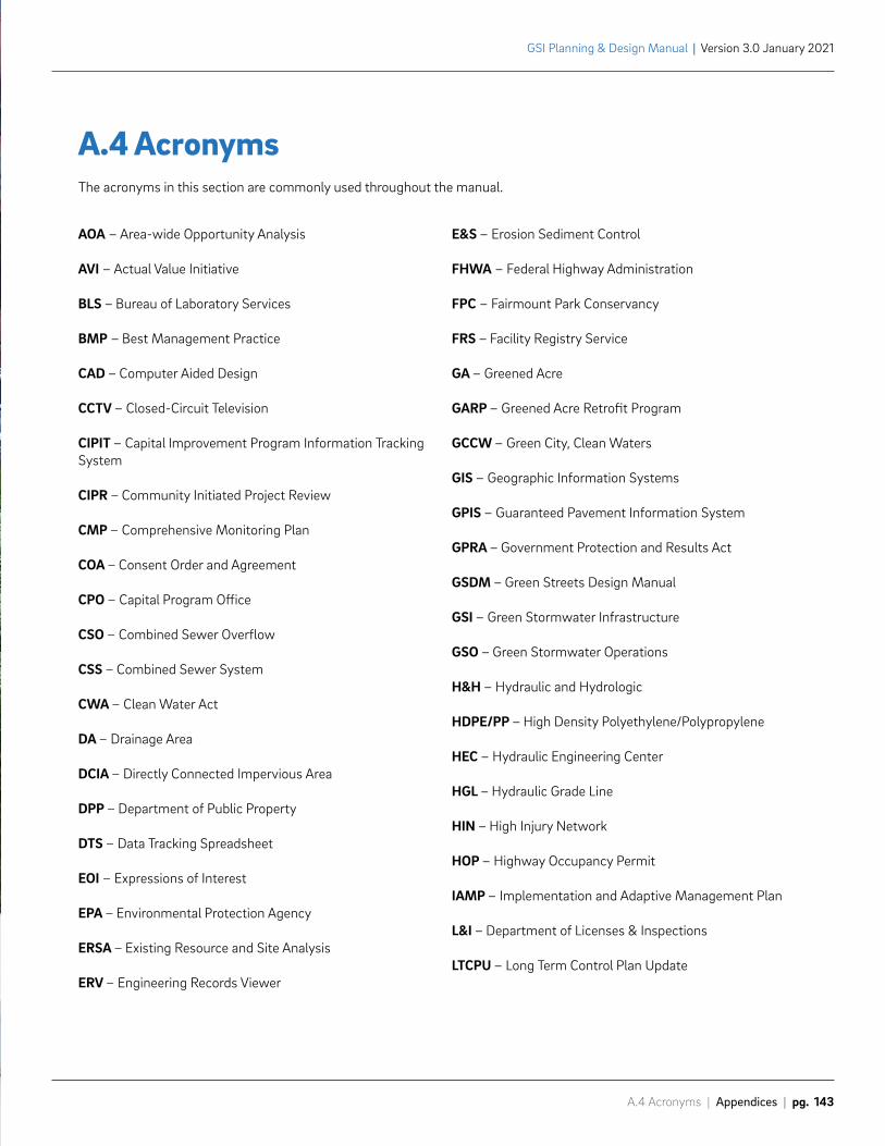
A.4 Acronyms | Appendices | pg. 143
GSI Planning & Design Manual | Version 3.0 January 2021
AOA – Area-wide Opportunity Analysis
AVI – Actual Value Initiative
BLS – Bureau of Laboratory Services
BMP – Best Management Practice
CAD – Computer Aided Design
CCTV – Closed-Circuit Television
CIPIT – Capital Improvement Program Information Tracking System
CIPR – Community Initiated Project Review
CMP – Comprehensive Monitoring Plan
COA – Consent Order and Agreement
CPO – Capital Program Office
CSO – Combined Sewer Overflow
CSS – Combined Sewer System
CWA – Clean Water Act
DA – Drainage Area
DCIA – Directly Connected Impervious Area
DPP – Department of Public Property
DTS – Data Tracking Spreadsheet
EOI – Expressions of Interest
EPA – Environmental Protection Agency
ERSA – Existing Resource and Site Analysis
ERV – Engineering Records Viewer
A.4 AcronymsThe acronyms in this section are commonly used throughout the manual.
E&S – Erosion Sediment Control
FHWA – Federal Highway Administration
FPC – Fairmount Park Conservancy
FRS – Facility Registry Service
GA – Greened Acre
GARP – Greened Acre Retrofit Program
GCCW – Green City, Clean Waters
GIS – Geographic Information Systems
GPIS – Guaranteed Pavement Information System
GPRA – Government Protection and Results Act
GSDM – Green Streets Design Manual
GSI – Green Stormwater Infrastructure
GSO – Green Stormwater Operations
H&H – Hydraulic and Hydrologic
HDPE/PP – High Density Polyethylene/Polypropylene
HEC – Hydraulic Engineering Center
HGL – Hydraulic Grade Line
HIN – High Injury Network
HOP – Highway Occupancy Permit
IAMP – Implementation and Adaptive Management Plan
L&I – Department of Licenses & Inspections
LTCPU – Long Term Control Plan Update
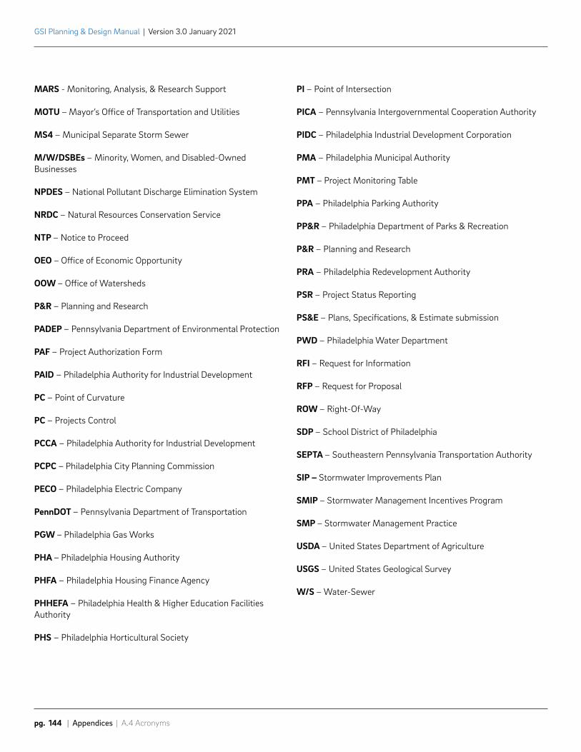
GSI Planning & Design Manual | Version 3.0 January 2021
pg. 144 | Appendices | A.4 Acronyms
MARS - Monitoring, Analysis, & Research Support
MOTU – Mayor’s Office of Transportation and Utilities
MS4 – Municipal Separate Storm Sewer
M/W/DSBEs – Minority, Women, and Disabled-Owned Businesses
NPDES – National Pollutant Discharge Elimination System
NRDC – Natural Resources Conservation Service
NTP – Notice to Proceed
OEO – Office of Economic Opportunity
OOW – Office of Watersheds
P&R – Planning and Research
PADEP – Pennsylvania Department of Environmental Protection
PAF – Project Authorization Form
PAID – Philadelphia Authority for Industrial Development
PC – Point of Curvature
PC – Projects Control
PCCA – Philadelphia Authority for Industrial Development
PCPC – Philadelphia City Planning Commission
PECO – Philadelphia Electric Company
PennDOT – Pennsylvania Department of Transportation
PGW – Philadelphia Gas Works
PHA – Philadelphia Housing Authority
PHFA – Philadelphia Housing Finance Agency
PHHEFA – Philadelphia Health & Higher Education Facilities Authority
PHS – Philadelphia Horticultural Society
PI – Point of Intersection
PICA – Pennsylvania Intergovernmental Cooperation Authority
PIDC – Philadelphia Industrial Development Corporation
PMA – Philadelphia Municipal Authority
PMT – Project Monitoring Table
PPA – Philadelphia Parking Authority
PP&R – Philadelphia Department of Parks & Recreation
P&R – Planning and Research
PRA – Philadelphia Redevelopment Authority
PSR – Project Status Reporting
PS&E – Plans, Specifications, & Estimate submission
PWD – Philadelphia Water Department
RFI – Request for Information
RFP – Request for Proposal
ROW – Right-Of-Way
SDP – School District of Philadelphia
SEPTA – Southeastern Pennsylvania Transportation Authority
SIP – Stormwater Improvements Plan
SMIP – Stormwater Management Incentives Program
SMP – Stormwater Management Practice
USDA – United States Department of Agriculture
USGS – United States Geological Survey
W/S – Water-Sewer
STENTON PARK RAIN GARDEN

Phila
delp
hia
Wat
er D
epar
tmen
t |
GSI
Pla
nnin
g &
Des
ign
Man
ual
v 3.
0
Related Documents