Americas Headquarter s: Cisco Systems, Inc., 17 0 West Tasman Drive, San J ose, CA 95134-1 706 USA MPLS VPN over mGRE First Published: November 20, 2009 Last Updated: September 20, 2011 The MPLS VPN over mGRE feature overcomes the requirement that a carrier support multiprotocol label switching (MPLS) by allowing you to provide MPLS connectivity between networks that are connected by IP-only networks. This allows MPLS label switched paths (LSPs) to use generic routing encapsulation (GRE) tunnels to cross routing areas , autonomous systems, and internet service providers (ISPs). when MPLS VPNs are configured over multipoint GRE (mGRE) you can deploy layer-3 (L3) provider edge (PE) based virtual private network (VPN) services using a standards-based IP core. This allows you to provision the VPN services without using the overlay method. You can configure mGRE tunnels to create a multipoint tunnel network that overlays an IP backbone. This overlay connects PE routers to transport V PN traffic. In addition, when MPLS VPN s are configured over mGRE you can deploy L3 PE-based VPN services using a standards-based IP core. This allows you to provision the VPN services without using the overlay method. When MPLS VPN over mGRE is configured, the system uses IPv4-based mGRE tunnels to encapsulate VPN-labeled IPv4 and IPv6 packets between PEs. Finding Feature Information Y our software release may n ot support all the features documented in this module. For the latest feature information and caveats, see the release notes for your platform a nd software release. To fi nd inf ormat ion about the features documented in this module, and to see a list of the releases in which each feature is supported, see the “Feature Informat ion for MPLS VPN over mGRE” sect ion on page 16 . Use Cisco Feature Navigator to f ind information about platform support and Cisco software image support. T o access Cisco Feature Navigator, go to http://www.cisco.com/go/cfn. An account on Cisco.com is not required. Contents Prerequisites for MPLS VPN over mGRE, page 2 • Restric tions for MPLS VPN ov er mGRE, page 2

Welcome message from author
This document is posted to help you gain knowledge. Please leave a comment to let me know what you think about it! Share it to your friends and learn new things together.
Transcript

8/13/2019 GRE VPN Mpls
http://slidepdf.com/reader/full/gre-vpn-mpls 1/16
Americas Headquarters:
Cisco Systems, Inc., 170 West Tasman Drive, San Jose, CA 95134-1706 USA
MPLS VPN over mGRE
First Published: November 20, 2009Last Updated: September 20, 2011
The MPLS VPN over mGRE feature overcomes the requirement that a carrier support multiprotocol
label switching (MPLS) by allowing you to provide MPLS connectivity between networks that are
connected by IP-only networks. This allows MPLS label switched paths (LSPs) to use generic routingencapsulation (GRE) tunnels to cross routing areas , autonomous systems, and internet service providers
(ISPs). when MPLS VPNs are configured over multipoint GRE (mGRE) you can deploy layer-3 (L3)
provider edge (PE) based virtual private network (VPN) services using a standards-based IP core. This
allows you to provision the VPN services without using the overlay method.
You can configure mGRE tunnels to create a multipoint tunnel network that overlays an IP backbone.
This overlay connects PE routers to transport VPN traffic. In addition, when MPLS VPNs are configured
over mGRE you can deploy L3 PE-based VPN services using a standards-based IP core. This allows you
to provision the VPN services without using the overlay method. When MPLS VPN over mGRE is
configured, the system uses IPv4-based mGRE tunnels to encapsulate VPN-labeled IPv4 and IPv6
packets between PEs.
Finding Feature InformationYour software release may not support all the features documented in this module. For the latest feature
information and caveats, see the release notes for your platform and software release. To find information
about the features documented in this module, and to see a list of the releases in which each feature is
supported, see the “Feature Information for MPLS VPN over mGRE” section on page 16.
Use Cisco Feature Navigator to find information about platform support and Cisco software image
support. To access Cisco Feature Navigator, go to http://www.cisco.com/go/cfn. An account on
Cisco.com is not required.
Contents Prerequisites for MPLS VPN over mGRE, page 2
• Restrictions for MPLS VPN over mGRE, page 2
8/13/2019 GRE VPN Mpls
http://slidepdf.com/reader/full/gre-vpn-mpls 2/16
MPLS VPN over mGRE
Prerequisites for MPLS VPN over mGRE
2
• Information About MPLS VPN over mGRE, page 3
• How to Configure MPLS VPN over mGRE, page 5
• Configuration Examples for MPLS VPN over mGRE, page 11
• Additional References, page 14
• Feature Information for MPLS VPN over mGRE, page 16
Prerequisites for MPLS VPN over mGREBefore you configure MPLS VPN with mGRE tunnels, ensure that the MPLS VPN is configured and
working properly. See the “Configuring MPLS Layer 3 VPNs” module for information about setting up
MPLS VPNs.
Restrictions for MPLS VPN over mGRE• MPLS VPN over mGRE is supported on the Cisco 7600 series routers using the ES-40 line card and
the SIP 400 line card as core facing cards.
• Tunnelled tag traffic must enter the router through a line card that supports MPLS VPN over mGRE.
• Each PE router supports one tunnel configuration only.
• MPLS VPN over mGRE does not support the transportation of multicast traffic between VPNs.
• When a GRE tunnel has the same destination address and source address as the mGRE, the tunnel
gets route-cache switched.
• The packets that require fragmentation get route cache-switched.
• When an L3VPN profile is removed and added back, then you should clear the Border Gateway
Protocol (BGP) using the clear ip bgp soft command.
• When an mGRE tunnel is created, a dummy tunnel is also created.
• The loopback or IP address used in the update source of the BGP configuration should be the same
as that of the transport source of the L3VPN profile.
• mGRE is not stateful switchover (SSO) compliant. However, both mGRE and SSO coexist.
• mGRE and multicast distribution tree (MDT) tunnel should not be configured with the same
loopback address.
The limitations for MPLS VPN over mGRE feature are as follows:
– Not all GRE options are supported in the hardware (for example, GRE extended header and
GRE key).
– Checking identical VLANs (Internet Control Message Protocol [ICMP] redirect) is not
supported on the tunnels.
– Features such as unicast reverse path forwarding (uRPF) and BGP policy accounting are not
supported on the tunnels.
8/13/2019 GRE VPN Mpls
http://slidepdf.com/reader/full/gre-vpn-mpls 3/16
MPLS VPN over mGRE
Information About MPLS VPN over mGRE
3
Information About MPLS VPN over mGRE• MPLS VPN over mGRE, page 3
MPLS VPN over mGREGRE is a point-to-point tunneling protocol where two peers form the endpoints of the tunnel. It is
designed to encapsulate network-layer packets inside IP tunneling packets. mGRE is a similar protocol
with a single endpoint at one side of the tunnel connected to multiple endpoints at the other side of the
tunnel. The mGRE tunnel provides a common link between branch offices that connect to the same VPN.
Because mGRE is a point-to-multipoint model, fully meshed GRE tunnels are not required to
interconnect MPLS VPN PE devices.
MPLS is a widely deployed VPN internet architecture. MPLS requires that all core routers in the network
support MPLS. This feature is useful in networks where the service provider uses a backbone carrier to
provide connectivity.
The MPLS VPN over mGRE feature overcomes the requirement of carrier support MPLS by allowing
you to provide MPLS connectivity between networks that are connected by IP-only networks. Thisallows MPLS LSPs to use GRE tunnels to cross routing areas, autonomous systems, and ISPs.
When MPLS VPNs are configured over mGRE you can deploy L3 PE-based VPN services using a
standards-based IP core. This allows you to provision the VPN services without using LSP or a Label
Distribution Protocol (LDP). The system uses IPv4-based mGRE tunnels to encapsulate VPN-labeled
IPv4 and IPv6 packets between PEs.
The MPLS VPN over mGRE feature also allows you to deploy existing MPLS VPN LSP-encapsulated
technology concurrently with MPLS VPN over mGRE and enables the system to determine which
encapsulation method is used to route specific traffic. The ingress PE router determines which
encapsulation technology to use when a packet is sent to the remote PE router.
This section includes information on the following topics on MPLS VPN over mGRE feature:
• Route Maps, page 4
• Tunnel Endpoint Discovery and Forwarding, page 4
• Tunnel Decapsulation, page 4
• Tunnel Source, page 4
• IPv6 VPN, page 5
8/13/2019 GRE VPN Mpls
http://slidepdf.com/reader/full/gre-vpn-mpls 4/16
MPLS VPN over mGRE
Information About MPLS VPN over mGRE
4
Route Maps
By default, VPN traffic is sent using an LSP. The MPLS VPN over mGRE feature uses user-defined route
maps to determine which VPN prefixes are reachable over an mGRE tunnel and which VPN prefixes are
reachable using an LSP. The route map is applied to advertisements for VPNv4 and VPNv6 address
families. The route map uses a next hop tunnel table to determine the encapsulation method for the VPN
traffic.
To route traffic over the mGRE tunnel, the system creates an alternative address space that shows that
all next hops are reached by encapsulating the traffic in an mGRE tunnel. To configure a specific route
to use an mGRE tunnel, the user adds an entry for that route to the route map. The new entry remaps the
Network Layer Reachability Information (NLRI) of the route to the alternative address space. If there is
no remap entry in the route map for a route, then traffic on that route is forwarded over an LSP.
When the user configures MPLS VPN over mGRE, the system automatically provisions the alternative
address space, normally held in the tunnel-encapsulated virtual routing and forwarding (VRF) instance.
To ensure that all traffic reachable through the address space is encapsulated in an mGRE tunnel, the
system installs a single default route out of a tunnel. The system also creates a default tunnel on the route
map. The user can attach this default route map to the appropriate BGP updates.
Tunnel Endpoint Discovery and Forwarding
In order for the MPLS VPN over mGRE feature to function correctly, the system must be able to discover
the remote PEs in the system and construct tunnel forwarding information for these remote PEs. In
addition the system must be able to detect when a remote PE is no longer valid and remove the tunnel
forwarding information for that PE.
If an ingress PE receives a VPN advertisement over BGP, it uses the route target attributes (which it
inserts into the VRF) and the MPLS VPN label from the advertisement, to associate the prefixes with
the appropriate customer. The next hop of the inserted route is set to the NLRI of the advertisement.
The advertised prefixes contain information about remote PEs in the system (in the form of NLRIs), and
the PE uses this information to notify the system when an NLRI becomes active or inactive. The system
uses this notification to update the PE forwarding information.
When the system receives notification of a new remote PE, it adds the information to the tunnel endpoint
database, which causes the system to create an adjacency associated with the tunnel interface. The
adjacency description includes information on the encapsulation and other processing that the system
must perform to send encapsulated packets to the new remote PE.
The adjacency information is placed into the tunnel encapsulated VRF. When a user remaps a VPN NLRI
to a route in the VRF (using the route map), the system links the NLRI to the adjacency; therefore the
VPN is linked to a tunnel.
Tunnel Decapsulation
When the egress PE receives a packet from a tunnel interface that uses the MPLS VPN over mGREfeature, the PE decapsulates the packet to create a VPN label tagged packet, and sends the packet to the
MPLS forwarding (MFI) code.
Tunnel Source
The MPLS VPN over mGRE feature uses a single tunnel configured as an mGRE tunnel to configure a
system with a large number of endpoints (remote PEs). To identify the origin of tunnel-encapsulated
packets, the system uses the tunnel source information.
8/13/2019 GRE VPN Mpls
http://slidepdf.com/reader/full/gre-vpn-mpls 5/16
MPLS VPN over mGRE
How to Configure MPLS VPN over mGRE
5
At the transmitting (ingress) PE, when a VPN packet is sent to a tunnel, the tunnel destination is the
NLRI. At a receiving (egress) PE, the tunnel source is the address that the packets encapsulated in the
mGRE tunnel are received on. Therefore, at the egress PE the packet destination must match the NLRI
from the local PE.
IPv6 VPNIf the advertising PE router has an IPv6 address then the NLRI must also be an IPv6 address (regardless
of the network between the PEs). If the network between the PEs is IPv4 based, the system creates the
IPv6 address of the advertising PE using an IPv4 mapped address in the following form:
::FFFF:IPv4-PE-address. The receiving PE sets the next hop for the VPN tag IPv6 prefixes to the IPv4
address embedded in the IPv6 NLRI. This enables the PE to link VPNv6 traffic to an LSP or an mGRE
tunnel in the same way it maps VPNv4 traffic.
When a PE receives VPNv6 updates, it applies the IPv6 route map. The MPLS VPN over mGRE feature
uses the IPv6 route map to set the next hop information in the Tunnel_Encap VRF.
How to Configure MPLS VPN over mGRETo deploy MPLS VPN over mGRE tunnels, you create a VRF instance, enable and configure L3 VPN
encapsulation, link the route map to the application template, and set up the BGP VPNv4 and VPNv6
exchange so that updates are filtered through the route map.
The configuration steps to deploy MPLS VPN over mGRE are described in the following sections:
• Configuring an L3VPN Encapsulation Profile, page 5 (required)
• Configuring BGP and Route Maps, page 6 (required)
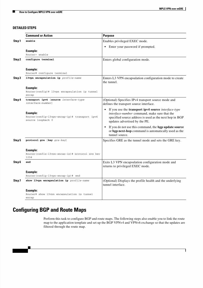
Configuring an L3VPN Encapsulation Profile
This section describes how to configure an L3VPN encapsulation profile.
Note Transport protocols such as IPv6, MPLS, IP, and Layer 2 Tunneling Protocol version 3 (L2TPv3) can
also be used in this configuration.
SUMMARY STEPS
1. enable
2. configure terminal
3. l3vpn encapsulation ip profile-name
4. transport ipv4 [source interface-type interface-number ]
5. protocol gre [key gre-key]
6. end
7. show l3vpn encapsulation ip profile-name
8/13/2019 GRE VPN Mpls
http://slidepdf.com/reader/full/gre-vpn-mpls 6/16
MPLS VPN over mGRE
How to Configure MPLS VPN over mGRE
6
DETAILED STEPS
Configuring BGP and Route Maps
Perform this task to configure BGP and route maps. The following steps also enable you to link the route
map to the application template and set up the BGP VPNv4 and VPNv6 exchange so that the updates are
filtered through the route map.
Command or Action Purpose
Step 1 enable
Example:Router> enable
Enables privileged EXEC mode.
• Enter your password if prompted.
Step 2 configure terminal
Example:Router# configure terminal
Enters global configuration mode.
Step 3 l3vpn encapsulation ip profile-name
Example:Router(config)# l3vpn encapsulation ip tunnel
encap
Enters L3 VPN encapsulation configuration mode to create
the tunnel.
Step 4transport ipv4 [source interface-type
interface-number ]
Example:Router(config-l3vpn-encap-ip)# transport ipv4
source loopback 0
(Optional) Specifies IPv4 transport source mode anddefines the transport source interface.
• If you use the transport ipv4 source interface-type
interface-number command, make sure that the
specified source address is used as the next hop in BGP
updates advertised by the PE.
• If you do not use this command, the bgp update source
or bgp next-hop command is automatically used as the
tunnel source.
Step 5 protocol gre [key gre-key ]
Example:Router(config-l3vpn-encap-ip)# protocol gre key
1234
Specifies GRE as the tunnel mode and sets the GRE key.
Step 6 end
Example:Router(config-l3vpn-encap-ip)# end
Exits L3 VPN encapsulation configuration mode and
returns to privileged EXEC mode.
Step 7 show l3vpn encapsulation ip profile-name
Example:Router# show l3vpn encapsulation ip tunnel
encap
(Optional) Displays the profile health and the underlying
tunnel interface.

8/13/2019 GRE VPN Mpls
http://slidepdf.com/reader/full/gre-vpn-mpls 7/16
MPLS VPN over mGRE
How to Configure MPLS VPN over mGRE
7
SUMMARY STEPS
1. enable
2. configure terminal
3. router bgp as-number
4. bgp log-neighbor-changes
5. neighbor ip-address remote-as as-number
6. neighbor ip-address update-source interface-name interface-number
7. address-family ipv4
8. no synchronization
9. redistribute connected
10. neighbor ip-address activate
11. no auto-summary
12. exit
13. address-family vpnv4
14. neighbor ip-address activate
15. neighbor ip-address send-community both
16. neighbor ip-address route-map map-name in
17. exit
18. address-family vpnv6
19. neighbor ip-address activate
20. neighbor ip-address send-community both
21. neighbor ip-address route-map map-name in
22. exit
23. route-map map-tag permit position
24. set ip next-hop encapsulate l3vpn profile-name
25. set ipv6 next-hop encapsulate l3vpn profile-name
26. exit
27. exit
8/13/2019 GRE VPN Mpls
http://slidepdf.com/reader/full/gre-vpn-mpls 8/16
MPLS VPN over mGRE
How to Configure MPLS VPN over mGRE
8
DETAILED STEPS
Command or Action Purpose
Step 1 enable
Example:Router> enable
Enables privileged EXEC mode.
• Enter your password if prompted.
Step 2 configure terminal
Example:Router# configure terminal
Enters global configuration mode.
Step 3 router bgp as-number
Example:Router(config)# router bgp 100
Specifies the number of an autonomous system that
identifies the router to other BGP routers and tags the
routing information passed along, and enters router
configuration mode.
Step 4 bgp log-neighbor-changes
Example:Router(config-router)# bgp log-neighbor-changes
Enables logging of BGP neighbor resets.
Step 5 neighbor ip-address remote-as as-number
Example:Router(config-router)# neighbor 209.165.200.225
remote-as 100
Adds an entry to the BGP or multiprotocol BGP neighbor
table.
Step 6 neighbor ip-address update-source interface
name
Example:Router(config-router)# neighbor 209.165.200.225
update-source loopback 0
Allows BGP sessions to use any operational interface for
TCP connections.
Step 7 address-family ipv4
Example:Router(config-router)# address-family ipv4
Enters address family configuration mode to configure
routing sessions that use IPv4 address prefixes.
Step 8 no synchronization
Example:Router(config-router-af)# no synchronization
Enables the Cisco IOS software to advertise a network route
without waiting for an IGP.
Step 9 redistribute connected
Example:Router(config-router-af)# redistribute
connected
Redistributes routes from one routing domain into another
routing domain and allows the target protocol to redistribute
routes learned by the source protocol and connected
prefixes on those interfaces over which the source protocol
is running.
8/13/2019 GRE VPN Mpls
http://slidepdf.com/reader/full/gre-vpn-mpls 9/16
MPLS VPN over mGRE
How to Configure MPLS VPN over mGRE
9
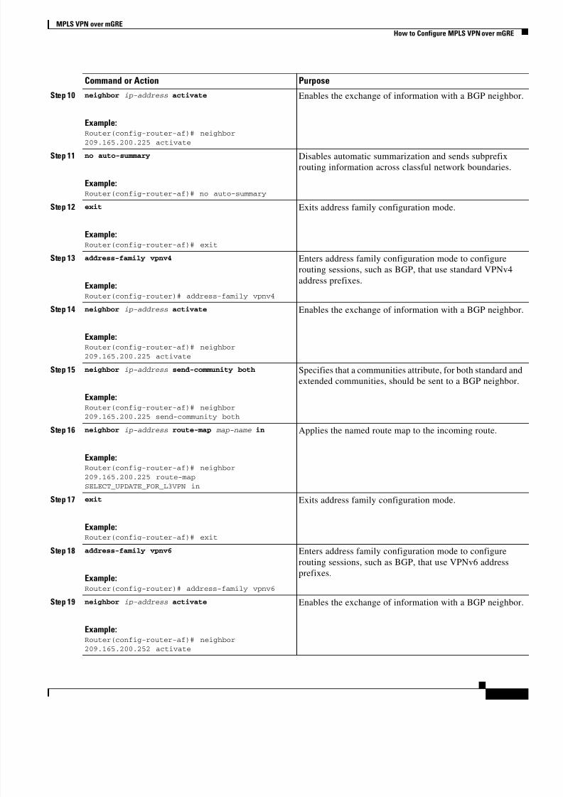
Step 10 neighbor ip-address activate
Example:Router(config-router-af)# neighbor
209.165.200.225 activate
Enables the exchange of information with a BGP neighbor.
Step 11 no auto-summary
Example:Router(config-router-af)# no auto-summary
Disables automatic summarization and sends subprefix
routing information across classful network boundaries.
Step 12 exit
Example:Router(config-router-af)# exit
Exits address family configuration mode.
Step 13 address-family vpnv4
Example:Router(config-router)# address-family vpnv4
Enters address family configuration mode to configure
routing sessions, such as BGP, that use standard VPNv4
address prefixes.
Step 14 neighbor ip-address activate
Example:Router(config-router-af)# neighbor
209.165.200.225 activate
Enables the exchange of information with a BGP neighbor.
Step 15 neighbor ip-address send-community both
Example:Router(config-router-af)# neighbor
209.165.200.225 send-community both
Specifies that a communities attribute, for both standard and
extended communities, should be sent to a BGP neighbor.
Step 16 neighbor ip-address route-map map-name in
Example:Router(config-router-af)# neighbor
209.165.200.225 route-map
SELECT_UPDATE_FOR_L3VPN in
Applies the named route map to the incoming route.
Step 17 exit
Example:Router(config-router-af)# exit
Exits address family configuration mode.
Step 18 address-family vpnv6
Example:Router(config-router)# address-family vpnv6
Enters address family configuration mode to configure
routing sessions, such as BGP, that use VPNv6 address
prefixes.
Step 19 neighbor ip-address activate
Example:Router(config-router-af)# neighbor
209.165.200.252 activate
Enables the exchange of information with a BGP neighbor.
Command or Action Purpose
8/13/2019 GRE VPN Mpls
http://slidepdf.com/reader/full/gre-vpn-mpls 10/16
MPLS VPN over mGRE
How to Configure MPLS VPN over mGRE
10
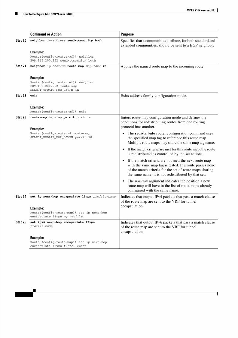
Step 20 neighbor ip-address send-community both
Example:Router(config-router-af)# neighbor
209.165.200.252 send-community both
Specifies that a communities attribute, for both standard and
extended communities, should be sent to a BGP neighbor.
Step 21 neighbor ip-address route-map map-name in
Example:Router(config-router-af)# neighbor
209.165.200.252 route-map
SELECT_UPDATE_FOR_L3VPN in
Applies the named route map to the incoming route.
Step 22 exit
Example:Router(config-router-af)# exit
Exits address family configuration mode.
Step 23 route-map map-tag permit position
Example:Router(config-router)# route-map
SELECT_UPDATE_FOR_L3VPN permit 10
Enters route-map configuration mode and defines theconditions for redistributing routes from one routing
protocol into another.
• The redistribute router configuration command uses
the specified map tag to reference this route map.
Multiple route maps may share the same map tag name.
• If the match criteria are met for this route map, the route
is redistributed as controlled by the set actions.
• If the match criteria are not met, the next route map
with the same map tag is tested. If a route passes none
of the match criteria for the set of route maps sharing
the same name, it is not redistributed by that set.
• The position argument indicates the position a new
route map will have in the list of route maps already
configured with the same name.
Step 24 set ip next-hop encapsulate l3vpn profile-name
Example:Router(config-route-map)# set ip next-hop
encapsulate l3vpn my profile
Indicates that output IPv4 packets that pass a match clause
of the route map are sent to the VRF for tunnel
encapsulation.
Step 25 set ipv6 next-hop encapsulate l3vpn
profile-name
Example:Router(config-route-map)# set ip next-hop
encapsulate l3vpn tunnel encap
Indicates that output IPv6 packets that pass a match clause
of the route map are sent to the VRF for tunnel
encapsulation.
Command or Action Purpose
8/13/2019 GRE VPN Mpls
http://slidepdf.com/reader/full/gre-vpn-mpls 11/16
MPLS VPN over mGRE
Configuration Examples for MPLS VPN over mGRE
11
Configuration Examples for MPLS VPN over mGRE• Example: Verifying The MPLS VPN over mGRE Configuration, page 11
• Example: Configuration Sequence For MPLS VPN over mGRE, page 12
Example: Verifying The MPLS VPN over mGRE Configuration
Use the following examples to verify that the configuration is working properly:
Cisco Express Forwarding (CEF) Switching
You can verify that CEF switching is working as expected:
Router# show ip cef vrf Customer_A tunnel 0
209.165.200.250/24
nexthop 209.165.200.251 Tunnel0 label 16
Endpoint CreationYou can verify the tunnel endpoint that has been created:
Router# show tunnel endpoints tunnel 0
Tunnel0 running in multi-GRE/IP mode
Endpoint transport 209.165.200.251 Refcount 3 Base 0x2AE93F0 Create Time 00:00:42
overlay 209.165.200.254 Refcount 2 Parent 0x2AE93F0 Create Time 00:00:42
Adjacency
You can verify that the corresponding adjacency has been created:
Router# show adjacency tunnel 0
Protocol Interface Address
IP Tunnel0 209.165.200.251(4)
TAG Tunnel0 209.165.200.251(3)
Profile Health
You can use show l3vpn encapsulation profile-name command to get information on the basic state of
the application. The output of this command provides you details on the references to the underlying
tunnel.
Step 26 exit
Example:Router(config-route-map)# exit
Exits route-map configuration mode and enters global
configuration mode.
Step 27 exit
Example:Router(config)# exit
Exits global configuration mode.
Command or Action Purpose
8/13/2019 GRE VPN Mpls
http://slidepdf.com/reader/full/gre-vpn-mpls 12/16
MPLS VPN over mGRE
Configuration Examples for MPLS VPN over mGRE
12
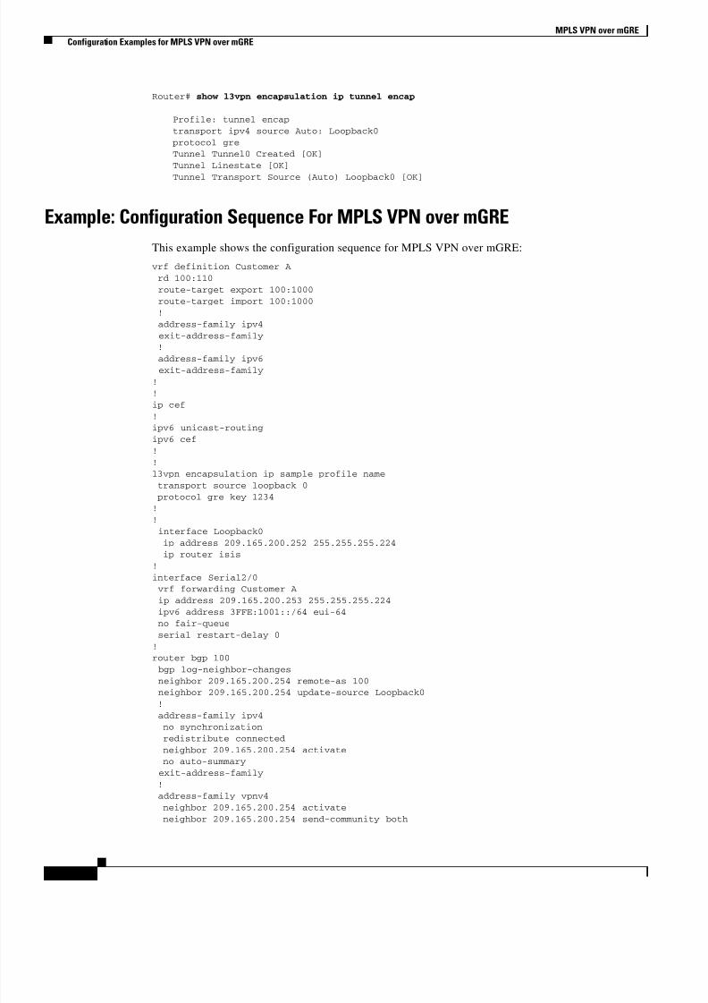
Router# show l3vpn encapsulation ip tunnel encap
Profile: tunnel encap
transport ipv4 source Auto: Loopback0
protocol gre
Tunnel Tunnel0 Created [OK]
Tunnel Linestate [OK]
Tunnel Transport Source (Auto) Loopback0 [OK]
Example: Configuration Sequence For MPLS VPN over mGRE
This example shows the configuration sequence for MPLS VPN over mGRE:
vrf definition Customer A
rd 100:110
route-target export 100:1000
route-target import 100:1000
!
address-family ipv4
exit-address-family
!
address-family ipv6
exit-address-family
!
!
ip cef
!
ipv6 unicast-routing
ipv6 cef
!
!
l3vpn encapsulation ip sample profile name
transport source loopback 0
protocol gre key 1234
!
!
interface Loopback0
ip address 209.165.200.252 255.255.255.224
ip router isis
!
interface Serial2/0
vrf forwarding Customer A
ip address 209.165.200.253 255.255.255.224
ipv6 address 3FFE:1001::/64 eui-64
no fair-queue
serial restart-delay 0
!
router bgp 100
bgp log-neighbor-changes
neighbor 209.165.200.254 remote-as 100
neighbor 209.165.200.254 update-source Loopback0
! address-family ipv4
no synchronization
redistribute connected
neighbor 209.165.200.254 activate
no auto-summary
exit-address-family
!
address-family vpnv4
neighbor 209.165.200.254 activate
neighbor 209.165.200.254 send-community both
8/13/2019 GRE VPN Mpls
http://slidepdf.com/reader/full/gre-vpn-mpls 13/16
MPLS VPN over mGRE
Configuration Examples for MPLS VPN over mGRE
13
neighbor 209.165.200.254 route-map SELECT_UPDATE_FOR_L3VPN in
exit-address-family
!
address-family vpnv6
neighbor 209.165.200.254 activate
neighbor 209.165.200.254 send-community both
neighbor 209.165.200.254 route-map SELECT_UPDATE_FOR_L3VPN in
exit-address-family
!
address-family ipv4 vrf Customer A
no synchronization
redistribute connected
exit-address-family
!
address-family ipv6 vrf Customer A
redistribute connected
no synchronization
exit-address-family
!
!
route-map SELECT_UPDATE_FOR_L3VPN permit 10
set ip next-hop encapsulate sample profile name
set ipv6 next-hop encapsulate sample profile name
8/13/2019 GRE VPN Mpls
http://slidepdf.com/reader/full/gre-vpn-mpls 14/16
MPLS VPN over mGRE
Additional References
14
Additional References
Related Documents
Standards
MIBs
RFCs
Related Topic Document Title
Configuring MPLS Layer 3 VPNs Cisco IOS Multiprotocol Label Switching Configuration Guide
Dynamic Layer 3 VPNs with multipoint GRE tunnels Cisco IOS Interface and Hardware Component Configuration Guide
Cisco Express Forwarding Cisco IOS IP Switching Configuration Guide
Generic routing encapsulation Cisco IOS Interface and Hardware Component Configuration Guide
Standard Title
None —
MIB MIBs Link
IETF-PPVPN-MPLS-VPN-MIB To locate and download MIBs for selected platforms, Cisco software
releases, and feature sets, use Cisco MIB Locator found at the
following URL:
http://www.cisco.com/go/mibs
RFC Title
RFC 2547 BGP/MPLS VPNs
RFC 2784 Generic Routing Encapsulation (GRE)
RFC 2890 Key Sequence Number Extensions to GRE
RFC 4023 Encapsulating MPLS in IP or Generic Routing Encapsulation
RFC 4364 BGP/MPLS IP Virtual Private Networks (VPNs)
8/13/2019 GRE VPN Mpls
http://slidepdf.com/reader/full/gre-vpn-mpls 15/16
MPLS VPN over mGRE
Additional References
15
Technical Assistance
Description Link
The Cisco Support website provides extensive online
resources, including documentation and tools for
troubleshooting and resolving technical issues with
Cisco products and technologies.
To receive security and technical information about
your products, you can subscribe to various services,
such as the Product Alert Tool (accessed from Field
Notices), the Cisco Technical Services Newsletter, and
Really Simple Syndication (RSS) Feeds.
Access to most tools on the Cisco Support website
requires a Cisco.com user ID and password.
http://www.cisco.com/cisco/web/support/index.html
8/13/2019 GRE VPN Mpls
http://slidepdf.com/reader/full/gre-vpn-mpls 16/16
MPLS VPN over mGRE
Feature Information for MPLS VPN over mGRE
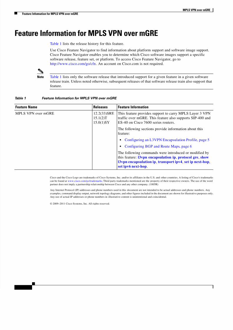
Feature Information for MPLS VPN over mGRETable 1 lists the release history for this feature.
Use Cisco Feature Navigator to find information about platform support and software image support.
Cisco Feature Navigator enables you to determine which Cisco software images support a specific
software release, feature set, or platform. To access Cisco Feature Navigator, go to
http://www.cisco.com/go/cfn. An account on Cisco.com is not required.
Note Table 1 lists only the software release that introduced support for a given feature in a given software
release train. Unless noted otherwise, subsequent releases of that software release train also support that
feature.
Cisco and the Cisco Logo are trademarks of Cisco Systems, Inc. and/or its affiliates in the U.S. and other countries. A listing of Cisco's trademarks
can be found at www.cisco.com/go/trademarks. Third party trademarks mentioned are the property of their respective owners. The use of the word
partner does not imply a partnership relati onship between Cisco and any other company. (1005R)
Any Internet Protocol (IP) addresses and phone numbers used in this document are not intended to be actual addresses and phone numbers. Any
examples, command display output, network topology diagrams, and other figures included in the document are shown for illustrative purposes only.
Any use of actual IP addresses or phone numbers in illustrative content is unintentional and coincidental.
© 2009–2011 Cisco Systems, Inc. All rights reserved.
Table 1 Feature Information for MPLS VPN over mGRE
Feature Name Releases Feature Information
MPLS VPN over mGRE 12.2(33)SRE
15.1(2)T
15.0(1)SY
This feature provides support to carry MPLS Layer 3 VPN
traffic over mGRE. This feature also supports SIP-400 and
ES-40 on Cisco 7600 series routers.
The following sections provide information about this
feature:
• Configuring an L3VPN Encapsulation Profile, page 5
• Configuring BGP and Route Maps, page 6
The following commands were introduced or modified by
this feature: l3vpn encapsulation ip, protocol gre, show
l3vpn encapsulation ip, transport ipv4, set ip next-hop,
set ipv6 next-hop.
Related Documents