Hindawi Publishing Corporation Laser Chemistry Volume 2008, Article ID 239417, 19 pages doi:10.1155/2008/239417 Review Article Gratings in Structured Optical Fibres John Canning, 1 Nathaniel Groothoff, 1 Kevin Cook, 1 Cicero Martelli, 1, 2 Alexandre Pohl, 1, 3 John Holdsworth, 1, 4 Somnath Bandyopadhyay, 1, 5 and Michael Stevenson 1 1 Interdisciplinary Photonics Laboratories, School of Chemistry, University of Sydney, Sydney, NSW 2006, Australia 2 Mechanical Engineering Department, Pontifical Catholic University of Rio de Janeiro-PUC-Rio, Rio de Janeiro 22453-900, Brazil 3 Federal University of Technology-Paran´ a, Curitiba 80230-901, Brazil 4 School of Mathematical and Physical Sciences, Faculty of Science and Information Technology, Newcastle University, Newcastle, NSW 2308, Australia 5 Central Glass and Ceramic Research Institute, Kolkata-700032, India Correspondence should be addressed to John Canning, [email protected] Received 10 June 2008; Accepted 18 August 2008 Recommended by Stavros Pissadakis Grating writing in structured optical fibres and their properties and applications are reviewed. To date, most gratings have been written in a straightforward manner into structured fibres containing a photosensitive germanosilicate step-index core. However, gratings have also been written directly into single material, structured silica fibres and into air-clad cores using two and higher- photon processes with both UV and near IR pulsed (nanosecond-femtosecond) light. Given the intrinsic-added functionality possible within a structured optical fibre, structured fibre gratings offer further capabilities for sensors, diagnostics, lasers, and devices. Copyright © 2008 John Canning et al. This is an open access article distributed under the Creative Commons Attribution License, which permits unrestricted use, distribution, and reproduction in any medium, provided the original work is properly cited. 1. Introduction Structured optical fibres such as suspended core fibres [1], photonic crystal fibres [2], and Fresnel fibres [3] introduce a new degree of functionality hitherto not possible. For example, the composite properties of a structured optical fibre can be tailored by adding materials into the holes. This opens up a range of new possibilities, from zero temperature-dependent fibres and components, including gratings [4], to advanced functionality possible by super- posing multiple properties; an example is an optical fibre white light source made by superposing the properties of individual dye molecules that are spatially separated to avoid quenching [5]. Access to the evanescent field over long lengths had enabled direct evanescent field spectroscopy of silica interfaces, revealing new bands not possible without resonant techniques [6]. Adding spectral selectivity to extend with similar ease the possible applications using laser written components such as fibre Bragg gratings demands a new level of engineering in grating writing since structured fibres introduce several challenges to grating writing not present in conventional fibres. These include high levels of scattered light arising from multiple interface reflections and, more critically, rotationally variant symmetry. Nevertheless, straightfor- ward conventional single-photon Bragg grating writing has been demonstrated with 244 nm, 266 nm (nanosecond and femtosecond pulsed), 193 nm and in various structured fibres that contain conventional step index germanosilicate cores [7–12]. Unfortunately, for many applications, the advantages of having a surrounding structured cladding are lost when conventional step cores are inserted. Further in many applications, such as Er 3+ /Yb 3+ -codoped lasers, germanium present in the core is undesirable. Hydro- gen loading is one approach for writing gratings using 193 nm in nongermanosilicate structured optical fibres [9]. Alternatively, two-photon absorption directly into the core has also been used to write gratings in pure silica core conventional step index fibres with a fluorinated cladding [13] and in all-silica, single material-structured fibres including photonic crystal fibre [14] and Fresnel fibres [15]. The generic nature of two-photon excitation

Welcome message from author
This document is posted to help you gain knowledge. Please leave a comment to let me know what you think about it! Share it to your friends and learn new things together.
Transcript
Hindawi Publishing CorporationLaser ChemistryVolume 2008, Article ID 239417, 19 pagesdoi:10.1155/2008/239417
Review Article
Gratings in Structured Optical Fibres
John Canning,1 Nathaniel Groothoff,1 Kevin Cook,1 Cicero Martelli,1, 2 Alexandre Pohl,1, 3
John Holdsworth,1, 4 Somnath Bandyopadhyay,1, 5 and Michael Stevenson1
1 Interdisciplinary Photonics Laboratories, School of Chemistry, University of Sydney, Sydney, NSW 2006, Australia2 Mechanical Engineering Department, Pontifical Catholic University of Rio de Janeiro-PUC-Rio,Rio de Janeiro 22453-900, Brazil
3 Federal University of Technology-Parana, Curitiba 80230-901, Brazil4 School of Mathematical and Physical Sciences, Faculty of Science and Information Technology, Newcastle University,Newcastle, NSW 2308, Australia
5 Central Glass and Ceramic Research Institute, Kolkata-700032, India
Correspondence should be addressed to John Canning, [email protected]
Received 10 June 2008; Accepted 18 August 2008
Recommended by Stavros Pissadakis
Grating writing in structured optical fibres and their properties and applications are reviewed. To date, most gratings have beenwritten in a straightforward manner into structured fibres containing a photosensitive germanosilicate step-index core. However,gratings have also been written directly into single material, structured silica fibres and into air-clad cores using two and higher-photon processes with both UV and near IR pulsed (nanosecond-femtosecond) light. Given the intrinsic-added functionalitypossible within a structured optical fibre, structured fibre gratings offer further capabilities for sensors, diagnostics, lasers, anddevices.
Copyright © 2008 John Canning et al. This is an open access article distributed under the Creative Commons Attribution License,which permits unrestricted use, distribution, and reproduction in any medium, provided the original work is properly cited.
1. Introduction
Structured optical fibres such as suspended core fibres [1],photonic crystal fibres [2], and Fresnel fibres [3] introducea new degree of functionality hitherto not possible. Forexample, the composite properties of a structured opticalfibre can be tailored by adding materials into the holes.This opens up a range of new possibilities, from zerotemperature-dependent fibres and components, includinggratings [4], to advanced functionality possible by super-posing multiple properties; an example is an optical fibrewhite light source made by superposing the properties ofindividual dye molecules that are spatially separated to avoidquenching [5]. Access to the evanescent field over longlengths had enabled direct evanescent field spectroscopy ofsilica interfaces, revealing new bands not possible withoutresonant techniques [6].
Adding spectral selectivity to extend with similar ease thepossible applications using laser written components suchas fibre Bragg gratings demands a new level of engineeringin grating writing since structured fibres introduce several
challenges to grating writing not present in conventionalfibres. These include high levels of scattered light arisingfrom multiple interface reflections and, more critically,rotationally variant symmetry. Nevertheless, straightfor-ward conventional single-photon Bragg grating writing hasbeen demonstrated with 244 nm, 266 nm (nanosecond andfemtosecond pulsed), 193 nm and in various structuredfibres that contain conventional step index germanosilicatecores [7–12]. Unfortunately, for many applications, theadvantages of having a surrounding structured claddingare lost when conventional step cores are inserted. Furtherin many applications, such as Er3+/Yb3+-codoped lasers,germanium present in the core is undesirable. Hydro-gen loading is one approach for writing gratings using193 nm in nongermanosilicate structured optical fibres[9]. Alternatively, two-photon absorption directly into thecore has also been used to write gratings in pure silicacore conventional step index fibres with a fluorinatedcladding [13] and in all-silica, single material-structuredfibres including photonic crystal fibre [14] and Fresnelfibres [15]. The generic nature of two-photon excitation
2 Laser Chemistry
allowed gratings to be written into structured fibres forlaser applications both as distributed Bragg reflector (DBR)elements and as phase-shifted distributed feedback (DFB)cavities [16–18]. The fibre in these cases was an Er3+-doped aluminosilicate core photonic crystal fibre. Usingtwo-photon absorption into the band edge avoids theneed for hydrogen loading. The specific need of fibrelasers has also seen the inscription of both single-photon[19] and multiple-photon Bragg gratings [20] within Yb-doped core air-clad nanostructured optical fibres specificallyfabricated for high-power fibre lasers. This work has beencomplemented in photonic crystal fibres by higher-exponentprocesses made possible using femtosecond lasers [21]. Anupdated review on photosensitivity in general is given in[22].
Although grating writing has been demonstrated in arange of structured optical fibres, the rotational varianceof these fibres, however, leads to variations in the writingintensity across the core from the side during subsequentgrating writing, posing serious challenges to reproducibilityand predictability. Unlike conventional fibre grating writing,these must be considered if the process is to be brought undercontrol. This surrounding structure leads to scattering,diffractive in the case of regular or quasicrystalline structures,which actually carries information regarding the structure ofthat fibre—indeed, such a property has been proposed as asimple photonic encryption key [23]. For grating writing,an obvious solution is to fill the holes with index matchingfluids which can be subsequently removed [8]. However,for shorter wavelengths such as 193 nm solutions withappropriate transmission are not readily available. Higher-photon effects, both in the UV and in the near IR, are alsounable to access the core without significant absorption andheating within the liquid itself, which can damage the fibre.If the structure is sufficiently removed from the step-indexcore, this problem can be overcome [20]. Here, we review theprogress to date on grating writing within structured opticalfibres and discuss some of the challenges and directions tofurther extending the capability of structured fibres usinggratings. We also elaborate some of the unique propertiesand applications of structured optical fibres using Bragggratings.
2. Scattering from the Structured Cladding
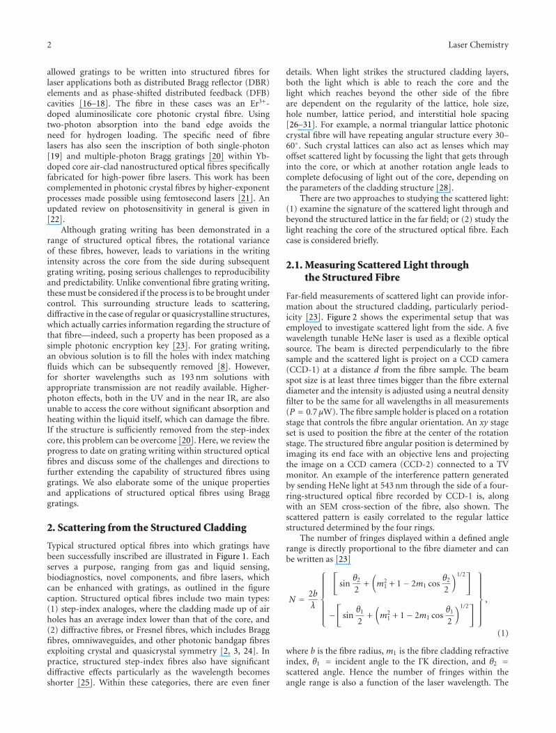
Typical structured optical fibres into which gratings havebeen successfully inscribed are illustrated in Figure 1. Eachserves a purpose, ranging from gas and liquid sensing,biodiagnostics, novel components, and fibre lasers, whichcan be enhanced with gratings, as outlined in the figurecaption. Structured optical fibres include two main types:(1) step-index analoges, where the cladding made up of airholes has an average index lower than that of the core, and(2) diffractive fibres, or Fresnel fibres, which includes Braggfibres, omniwaveguides, and other photonic bandgap fibresexploiting crystal and quasicrystal symmetry [2, 3, 24]. Inpractice, structured step-index fibres also have significantdiffractive effects particularly as the wavelength becomesshorter [25]. Within these categories, there are even finer
details. When light strikes the structured cladding layers,both the light which is able to reach the core and thelight which reaches beyond the other side of the fibreare dependent on the regularity of the lattice, hole size,hole number, lattice period, and interstitial hole spacing[26–31]. For example, a normal triangular lattice photoniccrystal fibre will have repeating angular structure every 30–60◦. Such crystal lattices can also act as lenses which mayoffset scattered light by focussing the light that gets throughinto the core, or which at another rotation angle leads tocomplete defocusing of light out of the core, depending onthe parameters of the cladding structure [28].
There are two approaches to studying the scattered light:(1) examine the signature of the scattered light through andbeyond the structured lattice in the far field; or (2) study thelight reaching the core of the structured optical fibre. Eachcase is considered briefly.
2.1. Measuring Scattered Light throughthe Structured Fibre
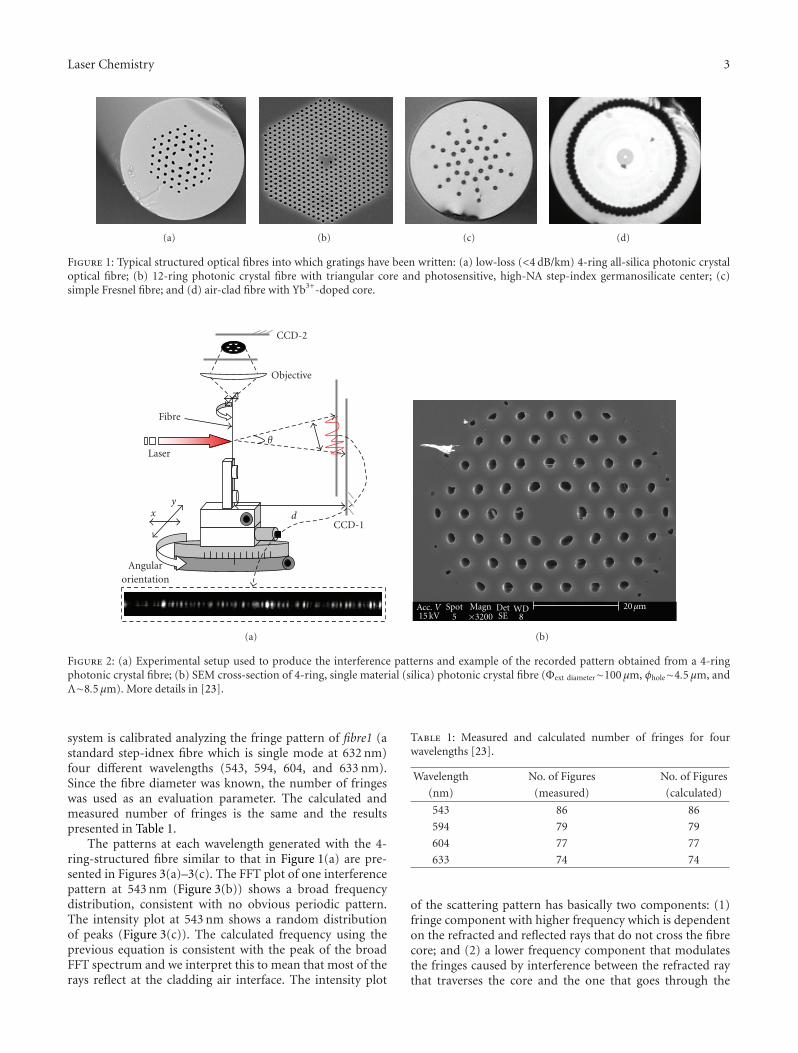
Far-field measurements of scattered light can provide infor-mation about the structured cladding, particularly period-icity [23]. Figure 2 shows the experimental setup that wasemployed to investigate scattered light from the side. A fivewavelength tunable HeNe laser is used as a flexible opticalsource. The beam is directed perpendicularly to the fibresample and the scattered light is project on a CCD camera(CCD-1) at a distance d from the fibre sample. The beamspot size is at least three times bigger than the fibre externaldiameter and the intensity is adjusted using a neutral densityfilter to be the same for all wavelengths in all measurements(P = 0.7 μW). The fibre sample holder is placed on a rotationstage that controls the fibre angular orientation. An xy stageset is used to position the fibre at the center of the rotationstage. The structured fibre angular position is determined byimaging its end face with an objective lens and projectingthe image on a CCD camera (CCD-2) connected to a TVmonitor. An example of the interference pattern generatedby sending HeNe light at 543 nm through the side of a four-ring-structured optical fibre recorded by CCD-1 is, alongwith an SEM cross-section of the fibre, also shown. Thescattered pattern is easily correlated to the regular latticestructured determined by the four rings.
The number of fringes displayed within a defined anglerange is directly proportional to the fibre diameter and canbe written as [23]
N = 2bλ
⎧⎪⎪⎪⎪⎪⎪⎨
⎪⎪⎪⎪⎪⎪⎩
[
sinθ2
2+(
m21 + 1− 2m1 cos
θ2
2
)1/2]
−[
sinθ1
2+(
m21 + 1− 2m1 cos
θ1
2
)1/2]
⎫⎪⎪⎪⎪⎪⎪⎬
⎪⎪⎪⎪⎪⎪⎭
,
(1)
where b is the fibre radius, m1 is the fibre cladding refractiveindex, θ1 = incident angle to the ΓK direction, and θ2 =scattered angle. Hence the number of fringes within theangle range is also a function of the laser wavelength. The
Laser Chemistry 3
(a) (b) (c) (d)
Figure 1: Typical structured optical fibres into which gratings have been written: (a) low-loss (<4 dB/km) 4-ring all-silica photonic crystaloptical fibre; (b) 12-ring photonic crystal fibre with triangular core and photosensitive, high-NA step-index germanosilicate center; (c)simple Fresnel fibre; and (d) air-clad fibre with Yb3+-doped core.
CCD-2
Objective
Fibre
Laser
Angularorientation
CCD-1
θ
dxy
(a)
Acc. V15 kV
Spot5
Magn×3200
DetSE
WD8
20μm
(b)
Figure 2: (a) Experimental setup used to produce the interference patterns and example of the recorded pattern obtained from a 4-ringphotonic crystal fibre; (b) SEM cross-section of 4-ring, single material (silica) photonic crystal fibre (Φext diameter∼100 μm, φhole∼4.5 μm, andΛ∼8.5 μm). More details in [23].
system is calibrated analyzing the fringe pattern of fibre1 (astandard step-idnex fibre which is single mode at 632 nm)four different wavelengths (543, 594, 604, and 633 nm).Since the fibre diameter was known, the number of fringeswas used as an evaluation parameter. The calculated andmeasured number of fringes is the same and the resultspresented in Table 1.
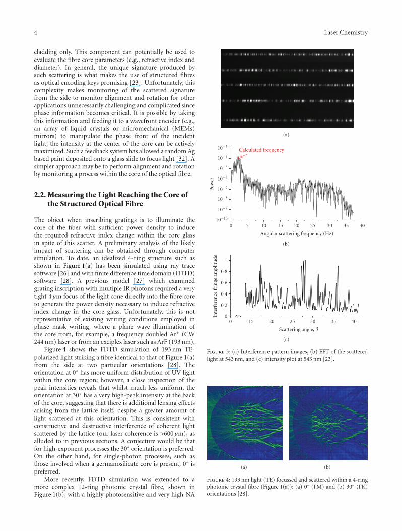
The patterns at each wavelength generated with the 4-ring-structured fibre similar to that in Figure 1(a) are pre-sented in Figures 3(a)–3(c). The FFT plot of one interferencepattern at 543 nm (Figure 3(b)) shows a broad frequencydistribution, consistent with no obvious periodic pattern.The intensity plot at 543 nm shows a random distributionof peaks (Figure 3(c)). The calculated frequency using theprevious equation is consistent with the peak of the broadFFT spectrum and we interpret this to mean that most of therays reflect at the cladding air interface. The intensity plot
Table 1: Measured and calculated number of fringes for fourwavelengths [23].
Wavelength No. of Figures No. of Figures
(nm) (measured) (calculated)
543 86 86
594 79 79
604 77 77
633 74 74
of the scattering pattern has basically two components: (1)fringe component with higher frequency which is dependenton the refracted and reflected rays that do not cross the fibrecore; and (2) a lower frequency component that modulatesthe fringes caused by interference between the refracted raythat traverses the core and the one that goes through the
4 Laser Chemistry
cladding only. This component can potentially be used toevaluate the fibre core parameters (e.g., refractive index anddiameter). In general, the unique signature produced bysuch scattering is what makes the use of structured fibresas optical encoding keys promising [23]. Unfortunately, thiscomplexity makes monitoring of the scattered signaturefrom the side to monitor alignment and rotation for otherapplications unnecessarily challenging and complicated sincephase information becomes critical. It is possible by takingthis information and feeding it to a wavefront encoder (e.g.,an array of liquid crystals or micromechanical (MEMs)mirrors) to manipulate the phase front of the incidentlight, the intensity at the center of the core can be activelymaximized. Such a feedback system has allowed a random Agbased paint deposited onto a glass slide to focus light [32]. Asimpler approach may be to perform alignment and rotationby monitoring a process within the core of the optical fibre.
2.2. Measuring the Light Reaching the Core ofthe Structured Optical Fibre
The object when inscribing gratings is to illuminate thecore of the fiber with sufficient power density to inducethe required refractive index change within the core glassin spite of this scatter. A preliminary analysis of the likelyimpact of scattering can be obtained through computersimulation. To date, an idealized 4-ring structure such asshown in Figure 1(a) has been simulated using ray tracesoftware [26] and with finite difference time domain (FDTD)software [28]. A previous model [27] which examinedgrating inscription with multiple IR photons required a verytight 4 μm focus of the light cone directly into the fibre coreto generate the power density necessary to induce refractiveindex change in the core glass. Unfortunately, this is notrepresentative of existing writing conditions employed inphase mask writing, where a plane wave illumination ofthe core from, for example, a frequency doubled Ar+ (CW244 nm) laser or from an exciplex laser such as ArF (193 nm).
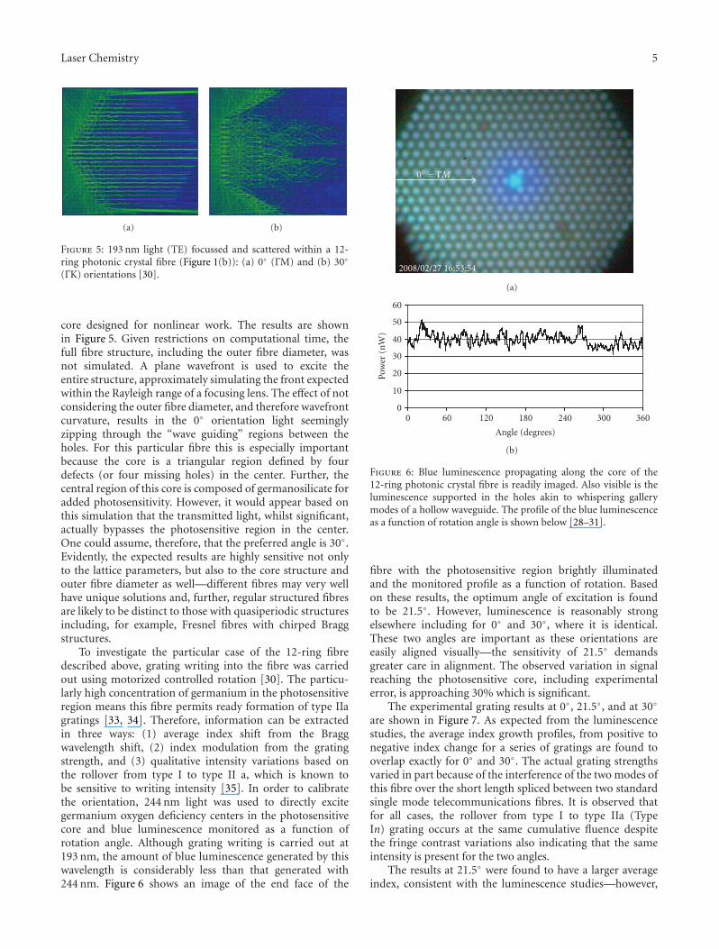
Figure 4 shows the FDTD simulation of 193 nm TE-polarized light striking a fibre identical to that of Figure 1(a)from the side at two particular orientations [28]. Theorientation at 0◦ has more uniform distribution of UV lightwithin the core region; however, a close inspection of thepeak intensities reveals that whilst much less uniform, theorientation at 30◦ has a very high-peak intensity at the backof the core, suggesting that there is additional lensing effectsarising from the lattice itself, despite a greater amount oflight scattered at this orientation. This is consistent withconstructive and destructive interference of coherent lightscattered by the lattice (our laser coherence is >600 μm), asalluded to in previous sections. A conjecture would be thatfor high-exponent processes the 30◦ orientation is preferred.On the other hand, for single-photon processes, such asthose involved when a germanosilicate core is present, 0◦ ispreferred.
More recently, FDTD simulation was extended to amore complex 12-ring photonic crystal fibre, shown inFigure 1(b), with a highly photosensitive and very high-NA
(a)
10−10
10−9
10−8
10−7
10−6
10−5
10−4
10−3
Pow
er
0 5 10 15 20 25 30 35 40
Angular scattering frequency (Hz)
Calculated frequency
(b)
0
0.2
0.4
0.6
0.8
1
Inte
rfer
ence
frin
geam
plit
ude
0 15 20 25 30 35 40
Scattering angle, θ
(c)
Figure 3: (a) Interference pattern images, (b) FFT of the scatteredlight at 543 nm, and (c) intensity plot at 543 nm [23].
(a) (b)
Figure 4: 193 nm light (TE) focussed and scattered within a 4-ringphotonic crystal fibre (Figure 1(a)): (a) 0◦ (ΓM) and (b) 30◦ (ΓK)orientations [28].
Laser Chemistry 5
(a) (b)
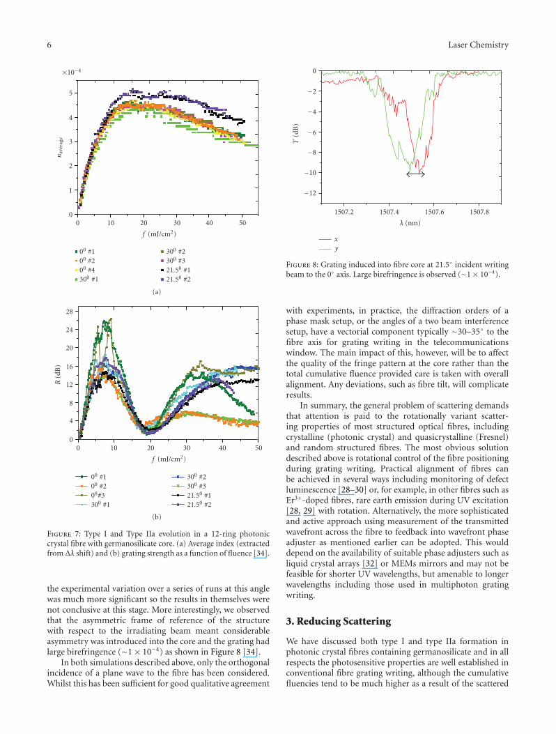
Figure 5: 193 nm light (TE) focussed and scattered within a 12-ring photonic crystal fibre (Figure 1(b)): (a) 0◦ (ΓM) and (b) 30◦
(ΓK) orientations [30].
core designed for nonlinear work. The results are shownin Figure 5. Given restrictions on computational time, thefull fibre structure, including the outer fibre diameter, wasnot simulated. A plane wavefront is used to excite theentire structure, approximately simulating the front expectedwithin the Rayleigh range of a focusing lens. The effect of notconsidering the outer fibre diameter, and therefore wavefrontcurvature, results in the 0◦ orientation light seeminglyzipping through the “wave guiding” regions between theholes. For this particular fibre this is especially importantbecause the core is a triangular region defined by fourdefects (or four missing holes) in the center. Further, thecentral region of this core is composed of germanosilicate foradded photosensitivity. However, it would appear based onthis simulation that the transmitted light, whilst significant,actually bypasses the photosensitive region in the center.One could assume, therefore, that the preferred angle is 30◦.Evidently, the expected results are highly sensitive not onlyto the lattice parameters, but also to the core structure andouter fibre diameter as well—different fibres may very wellhave unique solutions and, further, regular structured fibresare likely to be distinct to those with quasiperiodic structuresincluding, for example, Fresnel fibres with chirped Braggstructures.
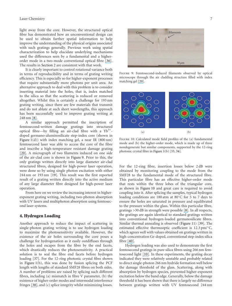
To investigate the particular case of the 12-ring fibredescribed above, grating writing into the fibre was carriedout using motorized controlled rotation [30]. The particu-larly high concentration of germanium in the photosensitiveregion means this fibre permits ready formation of type IIagratings [33, 34]. Therefore, information can be extractedin three ways: (1) average index shift from the Braggwavelength shift, (2) index modulation from the gratingstrength, and (3) qualitative intensity variations based onthe rollover from type I to type II a, which is known tobe sensitive to writing intensity [35]. In order to calibratethe orientation, 244 nm light was used to directly excitegermanium oxygen deficiency centers in the photosensitivecore and blue luminescence monitored as a function ofrotation angle. Although grating writing is carried out at193 nm, the amount of blue luminescence generated by thiswavelength is considerably less than that generated with244 nm. Figure 6 shows an image of the end face of the
2008/02/27 16:53:54
00 = ΓM
(a)
0
10
20
30
40
50
60
Pow
er(n
W)
0 60 120 180 240 300 360
Angle (degrees)
(b)
Figure 6: Blue luminescence propagating along the core of the12-ring photonic crystal fibre is readily imaged. Also visible is theluminescence supported in the holes akin to whispering gallerymodes of a hollow waveguide. The profile of the blue luminescenceas a function of rotation angle is shown below [28–31].
fibre with the photosensitive region brightly illuminatedand the monitored profile as a function of rotation. Basedon these results, the optimum angle of excitation is foundto be 21.5◦. However, luminescence is reasonably strongelsewhere including for 0◦ and 30◦, where it is identical.These two angles are important as these orientations areeasily aligned visually—the sensitivity of 21.5◦ demandsgreater care in alignment. The observed variation in signalreaching the photosensitive core, including experimentalerror, is approaching 30% which is significant.
The experimental grating results at 0◦, 21.5◦, and at 30◦
are shown in Figure 7. As expected from the luminescencestudies, the average index growth profiles, from positive tonegative index change for a series of gratings are found tooverlap exactly for 0◦ and 30◦. The actual grating strengthsvaried in part because of the interference of the two modes ofthis fibre over the short length spliced between two standardsingle mode telecommunications fibres. It is observed thatfor all cases, the rollover from type I to type IIa (TypeIn) grating occurs at the same cumulative fluence despitethe fringe contrast variations also indicating that the sameintensity is present for the two angles.
The results at 21.5◦ were found to have a larger averageindex, consistent with the luminescence studies—however,
6 Laser Chemistry
0
1
2
3
4
5
×10−4
nav
erag
e
0 10 20 30 40 50
f (mJ/cm2)
00 #100 #200 #4300 #1
300 #2300 #321.50 #121.50 #2
(a)
0
4
8
12
16
20
24
28
R(d
B)
0 10 20 30 40 50
f (mJ/cm2)
00 #100 #200#3300 #1
300 #2300 #321.50 #121.50 #2
(b)
Figure 7: Type I and Type IIa evolution in a 12-ring photoniccrystal fibre with germanosilicate core. (a) Average index (extractedfrom Δλ shift) and (b) grating strength as a function of fluence [34].
the experimental variation over a series of runs at this anglewas much more significant so the results in themselves werenot conclusive at this stage. More interestingly, we observedthat the asymmetric frame of reference of the structurewith respect to the irradiating beam meant considerableasymmetry was introduced into the core and the grating hadlarge birefringence (∼1× 10⁻⁴) as shown in Figure 8 [34].
In both simulations described above, only the orthogonalincidence of a plane wave to the fibre has been considered.Whilst this has been sufficient for good qualitative agreement
−12
−10
−8
−6
−4
−2
0
T(d
B)
1507.2 1507.4 1507.6 1507.8
λ (nm)
xy
Figure 8: Grating induced into fibre core at 21.5◦ incident writingbeam to the 0◦ axis. Large birefringence is observed (∼1× 10⁻⁴).
with experiments, in practice, the diffraction orders of aphase mask setup, or the angles of a two beam interferencesetup, have a vectorial component typically ∼30–35◦ to thefibre axis for grating writing in the telecommunicationswindow. The main impact of this, however, will be to affectthe quality of the fringe pattern at the core rather than thetotal cumulative fluence provided care is taken with overallalignment. Any deviations, such as fibre tilt, will complicateresults.
In summary, the general problem of scattering demandsthat attention is paid to the rotationally variant scatter-ing properties of most structured optical fibres, includingcrystalline (photonic crystal) and quasicrystalline (Fresnel)and random structured fibres. The most obvious solutiondescribed above is rotational control of the fibre positioningduring grating writing. Practical alignment of fibres canbe achieved in several ways including monitoring of defectluminescence [28–30] or, for example, in other fibres such asEr3+-doped fibres, rare earth emission during UV excitation[28, 29] with rotation. Alternatively, the more sophisticatedand active approach using measurement of the transmittedwavefront across the fibre to feedback into wavefront phaseadjuster as mentioned earlier can be adopted. This woulddepend on the availability of suitable phase adjusters such asliquid crystal arrays [32] or MEMs mirrors and may not befeasible for shorter UV wavelengths, but amenable to longerwavelengths including those used in multiphoton gratingwriting.
3. Reducing Scattering
We have discussed both type I and type IIa formation inphotonic crystal fibres containing germanosilicate and in allrespects the photosensitive properties are well established inconventional fibre grating writing, although the cumulativefluencies tend to be much higher as a result of the scattered
Laser Chemistry 7
light away from the core. However, the structured opticalfibre has demonstrated how an unconventional design canbe used to obtain further spatial information to helpimprove the understanding of the physical origins associatedwith such gratings generally. Previous work using spatialcharacterization to help elucidate underlying mechanismsused the differences seen by a fundamental and a higher-order mode in a two-mode conventional optical fibre [36].The results in Section 2 are consistent with that work.
It is clearly important to control rotational variance bothin terms of reproducibility and in terms of grating writingefficiency. This is especially so for higher-exponent processesthat require substantially more photons per unit area. Analternative approach to deal with this problem is to considerinserting material into the holes, that is, index matchedto the silica so that the scattering is reduced or removedaltogether. Whilst this is certainly a challenge for 193 nmgrating writing, since there are few materials that transmitand do not ablate at such short wavelengths, this approachhas been successfully used to improve grating writing at248 nm [8].
A similar approach permitted the inscription offemtosecond-written damage gratings into structuredoptical fibre—by filling an air-clad fibre with a Yb3+-doped germano-aluminosilicate step-index core (shown inFigure 1(d)) with index matching gel, a near IR (800 nm)femtosecond laser was able to access the core of the fibreand inscribe a high-temperature resistant damage grating[20]. A micrograph of two filaments induced on one sideof the air-clad core is shown in Figure 9. Prior to this, theonly gratings written directly into large diameter air-cladstructured fibres, designed for high-power laser operation,were done so by using single photon excitation with either244 nm or 193 nm [19]. This result was the first reportedresult of a grating written directly into the active mediumof any large diameter fibre designed for high-power laseroperation.
From here on we review the increasing interest in higher-exponent grating writing, including two-photon absorptionwith UV lasers and multiphoton absorption using femtosec-ond laser systems.
4. Hydrogen Loading
Another approach to reduce the impact of scattering insingle-photon grating writing is to use hydrogen loadingto maximize the photosensitivity available. However, theexistence of the air holes surrounding the core poses achallenge for hydrogenation as it easily outdiffuses throughthe holes and escapes from the fibre by the end facets,which drastically reduces the photosensitivity. A practicalsolution is to seal the fibre end facets before hydrogenloading [37]. For the 12-ring photonic crystal fibre shownin Figure 1(b), this was done by fusion splicing the PCFlength with lengths of standard SMF28 fibres on both sides.A number of problems are raised by splicing such differentfibres, including (a) mismatch in fibre V parameter, (b) theexistence of higher-order modes and intermodal interferencefringes [38], and (c) splice integrity whilst minimizing losses.
Core Filaments
50μm
Figure 9: Femtosecond-induced filaments observed by opticalmicroscope through the air cladding structure filled with indexmatching gel [20].
(a) (b)
Figure 10: Calculated mode field profiles of the (a) fundamentalmode and (b) the higher-order mode, which is made up of threenondegenerate but similar components, supported by the 12-ringphotonic crystal fibre in Figure 1(b) [33, 34].
For the 12-ring fibre, insertion losses below 2 dB wereobtained by monitoring coupling to the mode from theSMF28 to the fundamental mode of the structured fibre.This particular fibre has an effective higher-order modethat rests within the three lobes of the triangular core,as shown in Figure 10 and great care is required to avoidcoupling into it. After splicing the samples, typical hydrogenloading conditions are 180 atm at 80◦C for 5 to 7 days toensure the holes are saturated in pressure and equilibratedto the pressure within the glass. Within this particular fibre,gratings >30 dB in strength were possible [8]. In all respects,the gratings are again identical to standard gratings writteninto conventional hydrogen-loaded germanosilicate fibres.Similar thermal annealing is observed (Figure 11) [39]. Theestimated effective thermooptic coefficient is 12.3 pm/◦C,which agrees well with values obtained on gratings written inhigh-concentration Ge-doped, conventional step-index silicafibre [40].
Hydrogen loading was also used to demonstrate the firstfemtosecond gratings in pure silica fibres using 266 nm fem-tosecond light [10]. In these experiments, the grating decayindicated they were relatively unstable and probably relatedto direct single-photon 266 nm hydride formation well belowthe damage threshold of the glass. Scattering, along withabsorption by hydrogen species, prevented higher-exponentexcitation below the band edge. Generally, below the damagethreshold it has been shown that there is largely no differencebetween gratings written with UV femtosecond 244 nm
8 Laser Chemistry
1537
1538
1539
1540
1541
1542
Wav
elen
gth
(nm
)
0 50 100 150 200 250 300
1.75 nm
Temperature (◦C)
First temperature rise
Cool-down afterannealing
Second temperature rise
Cool-down after secondtemperature rise
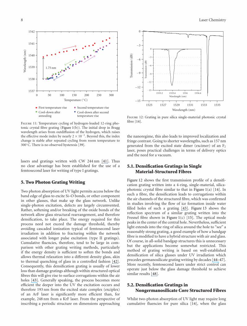
Figure 11: Temperature cycling of hydrogen-loaded 12-ring pho-tonic crystal fibre grating (Figure 1(b)). The initial drop in Braggwavelength arises from outdiffusion of the hydrogen, which raisesthe effective mode index by nearly 2 × 10⁻³. Beyond this, the indexchange is stable after repeated cycling from room temperature to300◦C. There is no observed hysteresis [39].
lasers and gratings written with CW 244 nm [41]. Thusno clear advantage has been established for the use of afemtosecond laser for writing of type I gratings.
5. Two Photon Grating Writing
Two photon absorption of UV light permits access below theband edge of glass to excite Si–O bonds, or other componentin other glasses, that make up the glass network. Unlikesingle-photon excitation, defects are largely circumvented.Rather, softening and/or breaking of the oxide bonds of thenetwork allow glass structural rearrangement, and thereforedensification, to take place. The energy required for thisprocess need not exceed the damage threshold, therebyavoiding cascaded ionization typical of femtosecond laserirradiation in addition to fracturing within the networkassociated with longer pulse excitation (type II gratings).Cumulative fluencies, therefore, tend to be large in com-parison with other grating writing methods, particularlyif the energy density is sufficient to soften the bonds andallows thermal relaxation into a different density glass, akinto thermal quenching of glass in a controlled fashion [42].Consequently, this densification grating is usually of lowerloss than damage gratings although within structured opticalfibres this will give rise to surface corrugations within the airholes [43]. Generally speaking, the process becomes moreefficient the deeper into the UV the excitation occurs andtherefore 193 nm from the excited state complex (exciplex)of an ArF laser is significantly more efficient than, forexample, 248 nm from a KrF laser. From the perspective ofinscribing a periodic structure on dimensions approaching
−15
−12
−9
−6
−3
0
−15
−12
−9
−6
−3
0
Tran
smis
sion
(dB
)
1533.2 1533.6 1534 1534.4
Wavelength (nm)
Tran
smis
sion
(dB
)
1525 1527 1529 1531 1533 1535
Wavelength (nm)
Figure 12: Grating in pure silica single-material photonic crystalfibre [14].
the nanoregime, this also leads to improved localization andfringe contrast. Going to shorter wavelengths, such as 157 nmgenerated from the excited state dimer (excimer) of an F2
laser, poses practical challenges in terms of delivery opticsand the need for a vacuum.
5.1. Densification Gratings in SingleMaterial-Structured Fibres
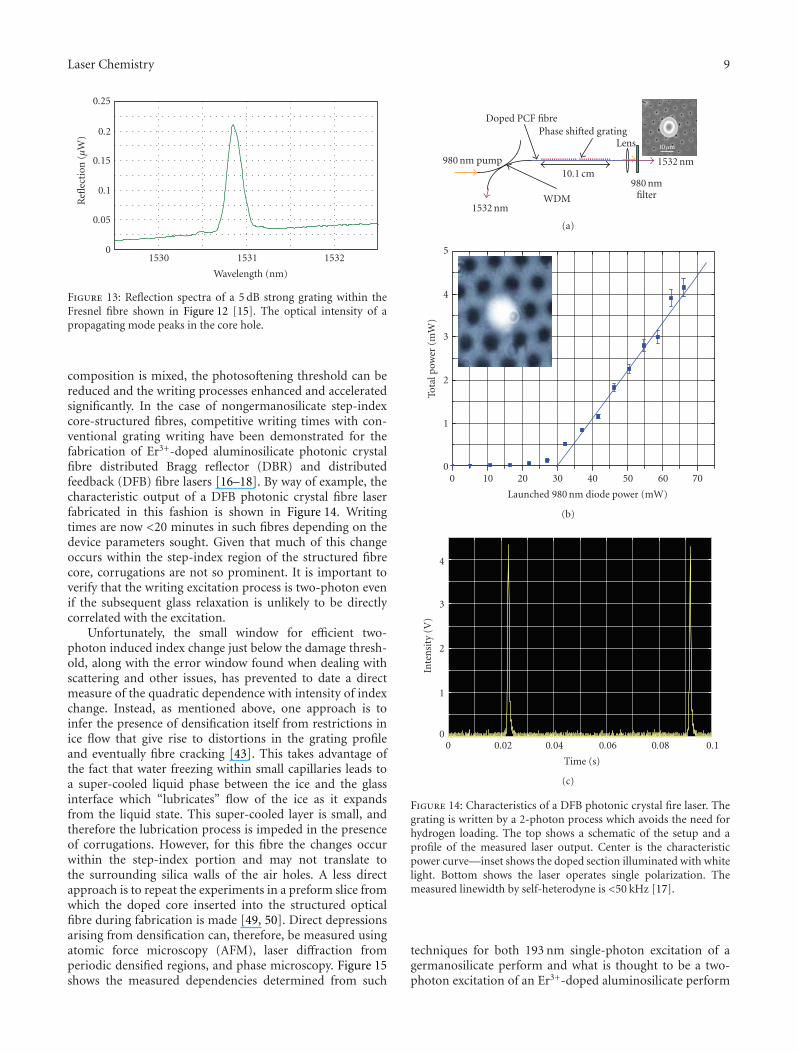
Figure 12 shows the first transmission profile of a densifi-cation grating written into a 4-ring, single-material, silica-photonic crystal fibre similar to that in Figure 1(a) [14]. Insuch a fibre, the densification leads to corrugations withinthe air channels of the structured fibre, which was confirmedin studies involving the flow of ice formation inside waterfilled holes of such a grating [43]. Figure 13 shows thereflection spectrum of a similar grating written into theFresnel fibre shown in Figure 1(c) [15]. The optical modepeaks in the center of the central hole. Nevertheless, sufficientlight extends into the ring of silica around the hole to “see” areasonably strong grating, a good example of how a bandgapfibre is modified to have a hybrid structure with air and glass.Of course, in all-solid bandgap structures this is unnecessarybut the applications become somewhat restricted. Thismethod of grating writing is based on well-establisheddensification of silica glasses under UV irradiation whichprecedes germanosilicate grating writing by decades [44–47].More recently, femtosecond lasers under strict control canoperate just below the glass damage threshold to achievesimilar results [48].
5.2. Densification Gratings inNongermanosilicate Core Structured Fibres
Whilst two-photon absorption of UV light may require longcumulative fluencies for pure silica [14], when the glass
Laser Chemistry 9
0
0.05
0.1
0.15
0.2
0.25
Refl
ecti
on(μ
W)
1530 1531 1532
Wavelength (nm)
Figure 13: Reflection spectra of a 5 dB strong grating within theFresnel fibre shown in Figure 12 [15]. The optical intensity of apropagating mode peaks in the core hole.
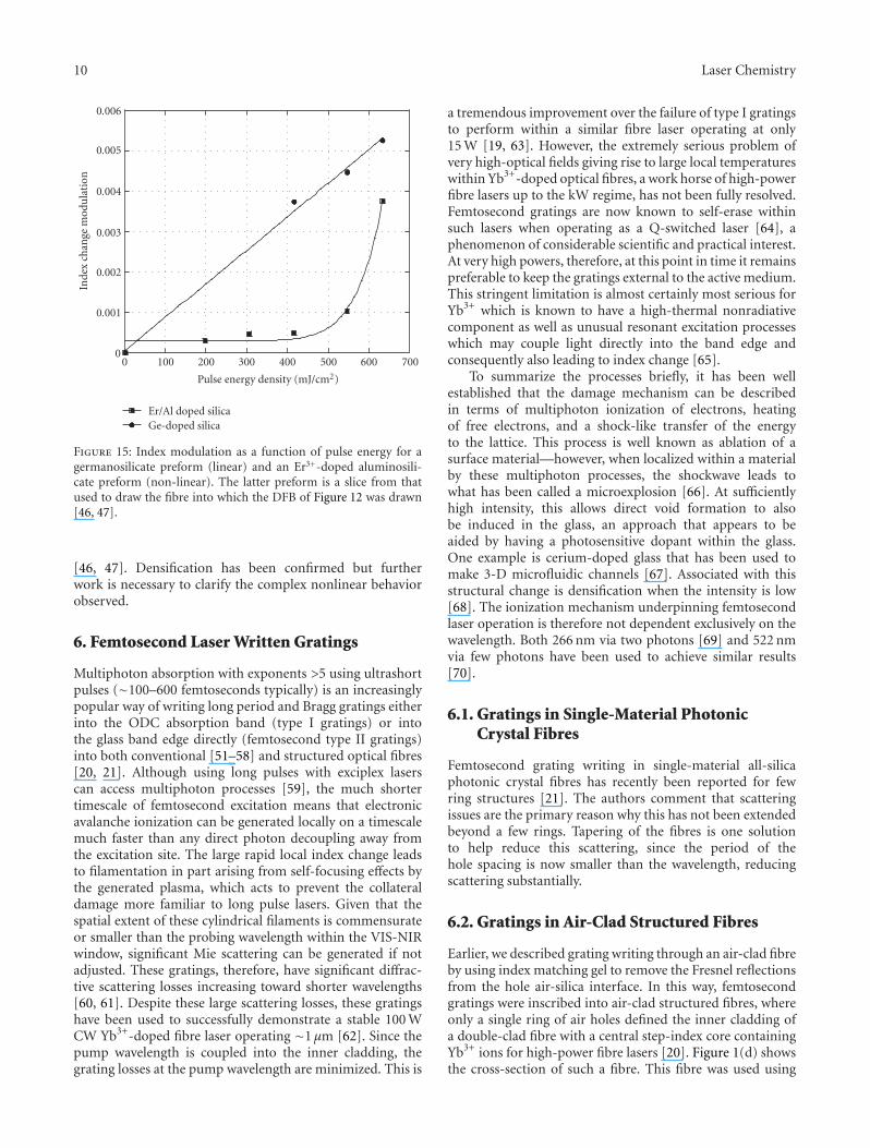
composition is mixed, the photosoftening threshold can bereduced and the writing processes enhanced and acceleratedsignificantly. In the case of nongermanosilicate step-indexcore-structured fibres, competitive writing times with con-ventional grating writing have been demonstrated for thefabrication of Er3+-doped aluminosilicate photonic crystalfibre distributed Bragg reflector (DBR) and distributedfeedback (DFB) fibre lasers [16–18]. By way of example, thecharacteristic output of a DFB photonic crystal fibre laserfabricated in this fashion is shown in Figure 14. Writingtimes are now <20 minutes in such fibres depending on thedevice parameters sought. Given that much of this changeoccurs within the step-index region of the structured fibrecore, corrugations are not so prominent. It is important toverify that the writing excitation process is two-photon evenif the subsequent glass relaxation is unlikely to be directlycorrelated with the excitation.
Unfortunately, the small window for efficient two-photon induced index change just below the damage thresh-old, along with the error window found when dealing withscattering and other issues, has prevented to date a directmeasure of the quadratic dependence with intensity of indexchange. Instead, as mentioned above, one approach is toinfer the presence of densification itself from restrictions inice flow that give rise to distortions in the grating profileand eventually fibre cracking [43]. This takes advantage ofthe fact that water freezing within small capillaries leads toa super-cooled liquid phase between the ice and the glassinterface which “lubricates” flow of the ice as it expandsfrom the liquid state. This super-cooled layer is small, andtherefore the lubrication process is impeded in the presenceof corrugations. However, for this fibre the changes occurwithin the step-index portion and may not translate tothe surrounding silica walls of the air holes. A less directapproach is to repeat the experiments in a preform slice fromwhich the doped core inserted into the structured opticalfibre during fabrication is made [49, 50]. Direct depressionsarising from densification can, therefore, be measured usingatomic force microscopy (AFM), laser diffraction fromperiodic densified regions, and phase microscopy. Figure 15shows the measured dependencies determined from such
Doped PCF fibre
980 nm pump
Phase shifted grating
10.1 cm
Lens
980 nmfilter
1532 nm
1532 nm
WDM
10μm
(a)
0
1
2
3
4
5
Tota
lpow
er(m
W)
0 10 20 30 40 50 60 70
Launched 980 nm diode power (mW)
(b)
0
1
2
3
4
Inte
nsi
ty(V
)
0 0.02 0.04 0.06 0.08 0.1
Time (s)
(c)
Figure 14: Characteristics of a DFB photonic crystal fire laser. Thegrating is written by a 2-photon process which avoids the need forhydrogen loading. The top shows a schematic of the setup and aprofile of the measured laser output. Center is the characteristicpower curve—inset shows the doped section illuminated with whitelight. Bottom shows the laser operates single polarization. Themeasured linewidth by self-heterodyne is <50 kHz [17].
techniques for both 193 nm single-photon excitation of agermanosilicate perform and what is thought to be a two-photon excitation of an Er3+-doped aluminosilicate perform
10 Laser Chemistry
0
0.001
0.002
0.003
0.004
0.005
0.006
Inde
xch
ange
mod
ula
tion
0 100 200 300 400 500 600 700
Pulse energy density (mJ/cm2)
Er/Al doped silicaGe-doped silica
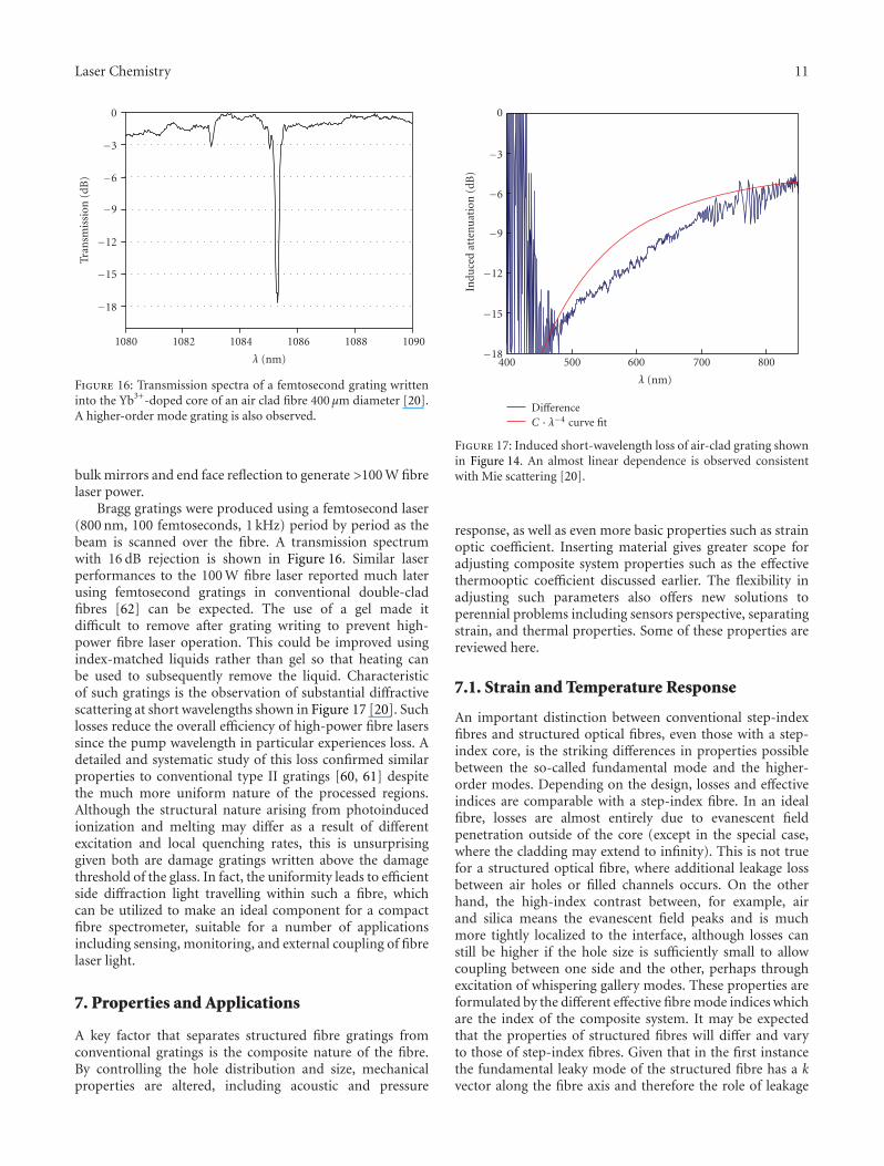
Figure 15: Index modulation as a function of pulse energy for agermanosilicate preform (linear) and an Er3+-doped aluminosili-cate preform (non-linear). The latter preform is a slice from thatused to draw the fibre into which the DFB of Figure 12 was drawn[46, 47].
[46, 47]. Densification has been confirmed but furtherwork is necessary to clarify the complex nonlinear behaviorobserved.
6. Femtosecond Laser Written Gratings
Multiphoton absorption with exponents >5 using ultrashortpulses (∼100–600 femtoseconds typically) is an increasinglypopular way of writing long period and Bragg gratings eitherinto the ODC absorption band (type I gratings) or intothe glass band edge directly (femtosecond type II gratings)into both conventional [51–58] and structured optical fibres[20, 21]. Although using long pulses with exciplex laserscan access multiphoton processes [59], the much shortertimescale of femtosecond excitation means that electronicavalanche ionization can be generated locally on a timescalemuch faster than any direct photon decoupling away fromthe excitation site. The large rapid local index change leadsto filamentation in part arising from self-focusing effects bythe generated plasma, which acts to prevent the collateraldamage more familiar to long pulse lasers. Given that thespatial extent of these cylindrical filaments is commensurateor smaller than the probing wavelength within the VIS-NIRwindow, significant Mie scattering can be generated if notadjusted. These gratings, therefore, have significant diffrac-tive scattering losses increasing toward shorter wavelengths[60, 61]. Despite these large scattering losses, these gratingshave been used to successfully demonstrate a stable 100 WCW Yb3+-doped fibre laser operating ∼1 μm [62]. Since thepump wavelength is coupled into the inner cladding, thegrating losses at the pump wavelength are minimized. This is
a tremendous improvement over the failure of type I gratingsto perform within a similar fibre laser operating at only15 W [19, 63]. However, the extremely serious problem ofvery high-optical fields giving rise to large local temperatureswithin Yb3+-doped optical fibres, a work horse of high-powerfibre lasers up to the kW regime, has not been fully resolved.Femtosecond gratings are now known to self-erase withinsuch lasers when operating as a Q-switched laser [64], aphenomenon of considerable scientific and practical interest.At very high powers, therefore, at this point in time it remainspreferable to keep the gratings external to the active medium.This stringent limitation is almost certainly most serious forYb3+ which is known to have a high-thermal nonradiativecomponent as well as unusual resonant excitation processeswhich may couple light directly into the band edge andconsequently also leading to index change [65].
To summarize the processes briefly, it has been wellestablished that the damage mechanism can be describedin terms of multiphoton ionization of electrons, heatingof free electrons, and a shock-like transfer of the energyto the lattice. This process is well known as ablation of asurface material—however, when localized within a materialby these multiphoton processes, the shockwave leads towhat has been called a microexplosion [66]. At sufficientlyhigh intensity, this allows direct void formation to alsobe induced in the glass, an approach that appears to beaided by having a photosensitive dopant within the glass.One example is cerium-doped glass that has been used tomake 3-D microfluidic channels [67]. Associated with thisstructural change is densification when the intensity is low[68]. The ionization mechanism underpinning femtosecondlaser operation is therefore not dependent exclusively on thewavelength. Both 266 nm via two photons [69] and 522 nmvia few photons have been used to achieve similar results[70].
6.1. Gratings in Single-Material PhotonicCrystal Fibres
Femtosecond grating writing in single-material all-silicaphotonic crystal fibres has recently been reported for fewring structures [21]. The authors comment that scatteringissues are the primary reason why this has not been extendedbeyond a few rings. Tapering of the fibres is one solutionto help reduce this scattering, since the period of thehole spacing is now smaller than the wavelength, reducingscattering substantially.
6.2. Gratings in Air-Clad Structured Fibres
Earlier, we described grating writing through an air-clad fibreby using index matching gel to remove the Fresnel reflectionsfrom the hole air-silica interface. In this way, femtosecondgratings were inscribed into air-clad structured fibres, whereonly a single ring of air holes defined the inner cladding ofa double-clad fibre with a central step-index core containingYb3+ ions for high-power fibre lasers [20]. Figure 1(d) showsthe cross-section of such a fibre. This fibre was used using
Laser Chemistry 11
−18
−15
−12
−9
−6
−3
0
Tran
smis
sion
(dB
)
1080 1082 1084 1086 1088 1090
λ (nm)
Figure 16: Transmission spectra of a femtosecond grating writteninto the Yb3+-doped core of an air clad fibre 400 μm diameter [20].A higher-order mode grating is also observed.
bulk mirrors and end face reflection to generate >100 W fibrelaser power.
Bragg gratings were produced using a femtosecond laser(800 nm, 100 femtoseconds, 1 kHz) period by period as thebeam is scanned over the fibre. A transmission spectrumwith 16 dB rejection is shown in Figure 16. Similar laserperformances to the 100 W fibre laser reported much laterusing femtosecond gratings in conventional double-cladfibres [62] can be expected. The use of a gel made itdifficult to remove after grating writing to prevent high-power fibre laser operation. This could be improved usingindex-matched liquids rather than gel so that heating canbe used to subsequently remove the liquid. Characteristicof such gratings is the observation of substantial diffractivescattering at short wavelengths shown in Figure 17 [20]. Suchlosses reduce the overall efficiency of high-power fibre laserssince the pump wavelength in particular experiences loss. Adetailed and systematic study of this loss confirmed similarproperties to conventional type II gratings [60, 61] despitethe much more uniform nature of the processed regions.Although the structural nature arising from photoinducedionization and melting may differ as a result of differentexcitation and local quenching rates, this is unsurprisinggiven both are damage gratings written above the damagethreshold of the glass. In fact, the uniformity leads to efficientside diffraction light travelling within such a fibre, whichcan be utilized to make an ideal component for a compactfibre spectrometer, suitable for a number of applicationsincluding sensing, monitoring, and external coupling of fibrelaser light.
7. Properties and Applications
A key factor that separates structured fibre gratings fromconventional gratings is the composite nature of the fibre.By controlling the hole distribution and size, mechanicalproperties are altered, including acoustic and pressure
−18
−15
−12
−9
−6
−3
0
Indu
ced
atte
nu
atio
n(d
B)
400 500 600 700 800
λ (nm)
DifferenceC · λ−4 curve fit
Figure 17: Induced short-wavelength loss of air-clad grating shownin Figure 14. An almost linear dependence is observed consistentwith Mie scattering [20].
response, as well as even more basic properties such as strainoptic coefficient. Inserting material gives greater scope foradjusting composite system properties such as the effectivethermooptic coefficient discussed earlier. The flexibility inadjusting such parameters also offers new solutions toperennial problems including sensors perspective, separatingstrain, and thermal properties. Some of these properties arereviewed here.
7.1. Strain and Temperature Response
An important distinction between conventional step-indexfibres and structured optical fibres, even those with a step-index core, is the striking differences in properties possiblebetween the so-called fundamental mode and the higher-order modes. Depending on the design, losses and effectiveindices are comparable with a step-index fibre. In an idealfibre, losses are almost entirely due to evanescent fieldpenetration outside of the core (except in the special case,where the cladding may extend to infinity). This is not truefor a structured optical fibre, where additional leakage lossbetween air holes or filled channels occurs. On the otherhand, the high-index contrast between, for example, airand silica means the evanescent field peaks and is muchmore tightly localized to the interface, although losses canstill be higher if the hole size is sufficiently small to allowcoupling between one side and the other, perhaps throughexcitation of whispering gallery modes. These properties areformulated by the different effective fibre mode indices whichare the index of the composite system. It may be expectedthat the properties of structured fibres will differ and varyto those of step-index fibres. Given that in the first instancethe fundamental leaky mode of the structured fibre has a kvector along the fibre axis and therefore the role of leakage
12 Laser Chemistry
loss is somewhat suppressed, the fundamental mode may notbe so distinctive in behavior to that of the step-index analog.This forms the justification for the step-index approximationof simple-structured fibres, where the cladding index is, onaverage, lower than the core index. On the other hand, tightlyconfining such a fibre will deliver noticeable and applicationworthy differences. By adjusting the crystal lattice parametersof a photonic crystal fibre appropriately, unique compositesystem properties can be displayed. A good example is thedemonstration of dual dispersion compensation and Ramanamplification [71].
In contrast, higher-order modes will be significantlyaffected by leakage loss and greater evanescent field penetra-tion into the holes. The extreme example of this is the air-cladfibre shown in Figure 1(d), where diffractive scattering playsa critical role in ensuring mode mixing and overlap with thecore is high [72, 73], an important advantage that permitsair-clad high-power fibre lasers to retain symmetry. Inpractice, even the higher-order modes of an ordinary regularphotonic crystal fibre are far more sensitive to the claddingstructure and enable practical sensing to be developed [74].Even over short lengths supposedly, single-mode photoniccrystal fibre can support higher-order leaky modes thatlead to analogous intermodal interference observed withshort lengths of standard single-mode telecommunicationsfibre [75]. It is noted within the literature that manygratings written into single-mode structured fibres have anobservable higher-order mode resonance [9, 14, 20].
It is this difference between the well-confined funda-mental mode and the higher-order modes that allows aqualitative study of the properties of a structured optical fibreusing Bragg gratings to determine both effective strain andthermooptic coefficients and compare with those obtainedfor standard optical fibres. In previous work, fiber Bragggratings, written by two-photon excitation, within a two-mode solid core photonic crystal fiber, which has a claddingregion defined by a silica layer containing a triangularlattice of air-channels, were used to obtain the strain andtemperature dependence of the structured fibre. The coreis composed of an inner, doped core, and one outer silicaring—the presence of Er3+ plays no important role in theBragg resonance dependence with strain [76]. The effectiveindices of the two modes give rise to two distinct gratingpeaks (Figure 1)—we note that this higher-order mode ismade up of slightly nondegenerate components [18] but theresolution used was not able to separate these components.The modes are determined by the corresponding fractionalpowers (η) of each mode within the higher-index-dopedregion (0.002) and in the surrounding silica. Leakagephenomena play an important part in determining anddefining the mode field radius and therefore the fractionaldistribution of light of the modes either in the doped coreor in the silica. Therefore, those modes with large transversevector components will be sensitive to changes in the holeshape and stress between the holes in the structure arisingfrom, for example, tensile or compressive stress applied alongthe fiber.
But it is also clear that this sensitivity will very muchdepend on air fraction, the regularity of the lattice, the
constituent materials, and the type of index guidance. Forexample, the Fresnel fibre described earlier has much less airfraction, no regularity, is single-material all-silica, and themode is largely determined by diffractive guidance even forthe fundamental mode rather than an average step-index-like effect. Therefore, a comparison of both temperatureand strain effects of the fundamental mode within a single-material Fresnel fibre and a single-material photonic crystalfibre will further illustrate just how much flexibility in designexists by controlling structure alone.
7.1.1. Temperature Dependence
(a) Fundamental versus Higher-Order Modes
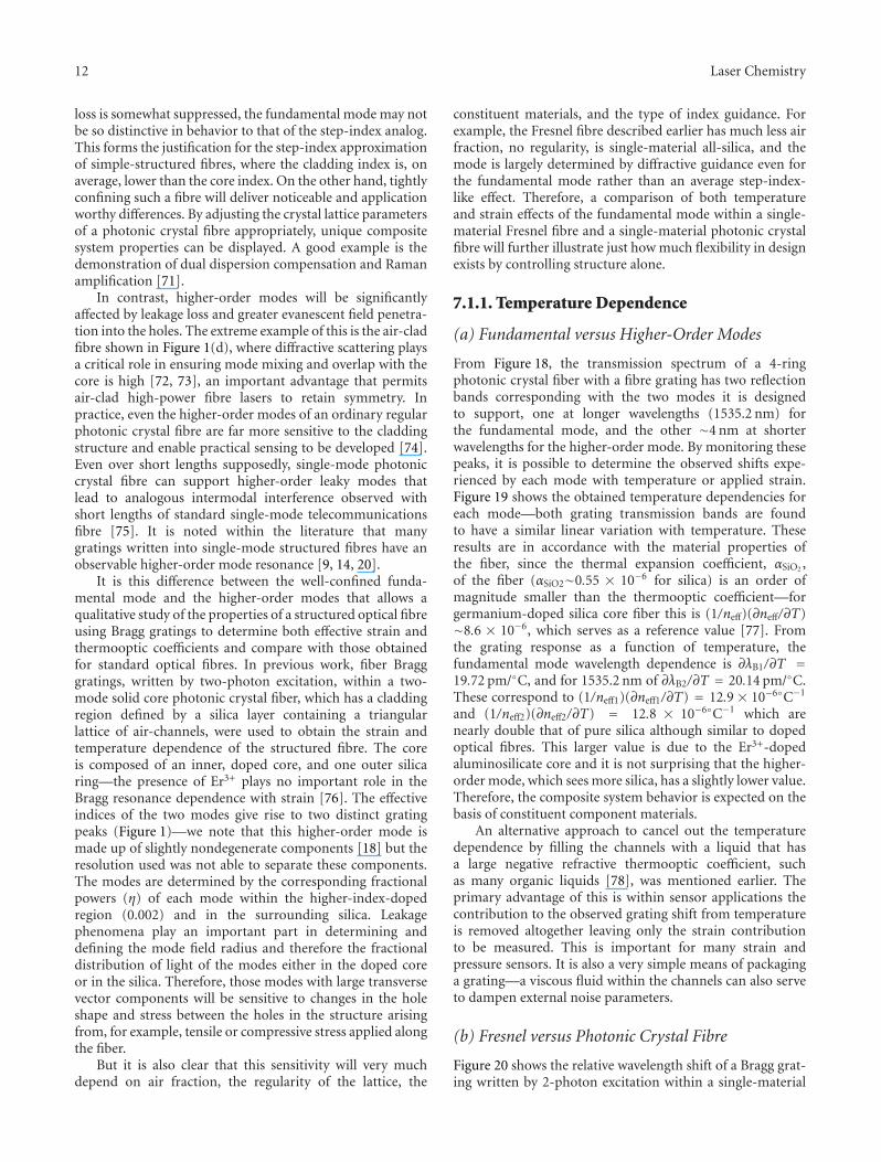
From Figure 18, the transmission spectrum of a 4-ringphotonic crystal fiber with a fibre grating has two reflectionbands corresponding with the two modes it is designedto support, one at longer wavelengths (1535.2 nm) forthe fundamental mode, and the other ∼4 nm at shorterwavelengths for the higher-order mode. By monitoring thesepeaks, it is possible to determine the observed shifts expe-rienced by each mode with temperature or applied strain.Figure 19 shows the obtained temperature dependencies foreach mode—both grating transmission bands are foundto have a similar linear variation with temperature. Theseresults are in accordance with the material properties ofthe fiber, since the thermal expansion coefficient, αSiO2 ,of the fiber (αSiO2∼0.55 × 10⁻⁶ for silica) is an order ofmagnitude smaller than the thermooptic coefficient—forgermanium-doped silica core fiber this is (1/neff)(∂neff/∂T)∼8.6 × 10−6, which serves as a reference value [77]. Fromthe grating response as a function of temperature, thefundamental mode wavelength dependence is ∂λB1/∂T =19.72 pm/◦C, and for 1535.2 nm of ∂λB2/∂T = 20.14 pm/◦C.These correspond to (1/neff1)(∂neff1/∂T) = 12.9 × 10⁻⁶◦C−1
and (1/neff2)(∂neff2/∂T) = 12.8 × 10⁻⁶◦C−1 which arenearly double that of pure silica although similar to dopedoptical fibres. This larger value is due to the Er3+-dopedaluminosilicate core and it is not surprising that the higher-order mode, which sees more silica, has a slightly lower value.Therefore, the composite system behavior is expected on thebasis of constituent component materials.
An alternative approach to cancel out the temperaturedependence by filling the channels with a liquid that hasa large negative refractive thermooptic coefficient, suchas many organic liquids [78], was mentioned earlier. Theprimary advantage of this is within sensor applications thecontribution to the observed grating shift from temperatureis removed altogether leaving only the strain contributionto be measured. This is important for many strain andpressure sensors. It is also a very simple means of packaginga grating—a viscous fluid within the channels can also serveto dampen external noise parameters.
(b) Fresnel versus Photonic Crystal Fibre
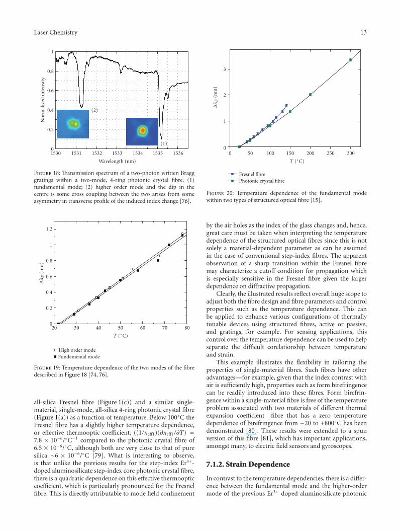
Figure 20 shows the relative wavelength shift of a Bragg grat-ing written by 2-photon excitation within a single-material
Laser Chemistry 13
0
0.2
0.4
0.6
0.8
1
(2)
(1)
Nor
mal
ized
inte
nsi
ty
1530 1531 1532 1533 1534 1535 1536
Wavelength (nm)
Figure 18: Transmission spectrum of a two-photon written Bragggratings within a two-mode, 4-ring photonic crystal fibre. (1)fundamental mode; (2) higher order mode and the dip in thecentre is some cross coupling between the two arises from someasymmetry in transverse profile of the induced index change [76].
0
0.2
0.4
0.6
0.8
1
1.2
Δλ B
(nm
)
20 30 40 50 60 70 80
T (◦C)
High order modeFundamental mode
Figure 19: Temperature dependence of the two modes of the fibredescribed in Figure 18 [74, 76].
all-silica Fresnel fibre (Figure 1(c)) and a similar single-material, single-mode, all-silica 4-ring photonic crystal fibre(Figure 1(a)) as a function of temperature. Below 100◦C theFresnel fibre has a slightly higher temperature dependence,or effective thermooptic coefficient, ((1/neff1)(∂neff1/∂T) =7.8 × 10⁻⁶/◦C−1 compared to the photonic crystal fibre of6.5 × 10−6/◦C, although both are very close to that of puresilica ∼6 × 10⁻⁶/◦C [79]. What is interesting to observe,is that unlike the previous results for the step-index Er3+-doped aluminosilicate step-index core photonic crystal fibre,there is a quadratic dependence on this effective thermoopticcoefficient, which is particularly pronounced for the Fresnelfibre. This is directly attributable to mode field confinement
0
1
2
3
Δλ B
(nm
)
0 50 100 150 200 250 300
T (◦C)
Fresnel fibrePhotonic crystal fibre
Figure 20: Temperature dependence of the fundamental modewithin two types of structured optical fibre [15].
by the air holes as the index of the glass changes and, hence,great care must be taken when interpreting the temperaturedependence of the structured optical fibres since this is notsolely a material-dependent parameter as can be assumedin the case of conventional step-index fibres. The apparentobservation of a sharp transition within the Fresnel fibremay characterize a cutoff condition for propagation whichis especially sensitive in the Fresnel fibre given the largerdependence on diffractive propagation.
Clearly, the illustrated results reflect overall huge scope toadjust both the fibre design and fibre parameters and controlproperties such as the temperature dependence. This canbe applied to enhance various configurations of thermallytunable devices using structured fibres, active or passive,and gratings, for example. For sensing applications, thiscontrol over the temperature dependence can be used to helpseparate the difficult corelationship between temperatureand strain.
This example illustrates the flexibility in tailoring theproperties of single-material fibres. Such fibres have otheradvantages—for example, given that the index contrast withair is sufficiently high, properties such as form birefringencecan be readily introduced into these fibres. Form birefrin-gence within a single-material fibre is free of the temperatureproblem associated with two materials of different thermalexpansion coefficient—fibre that has a zero temperaturedependence of birefringence from −20 to +800◦C has beendemonstrated [80]. These results were extended to a spunversion of this fibre [81], which has important applications,amongst many, to electric field sensors and gyroscopes.
7.1.2. Strain Dependence
In contrast to the temperature dependencies, there is a differ-ence between the fundamental mode and the higher-ordermode of the previous Er3+-doped aluminosilicate photonic
14 Laser Chemistry
0
0.1
0.2
0.3
0.4
0.5
0.6
0.7
0.8
Δλ B
(nm
)
0 100 200 300 400 500 600 700
ΔL/L× 10−6
High order modeFundamental mode
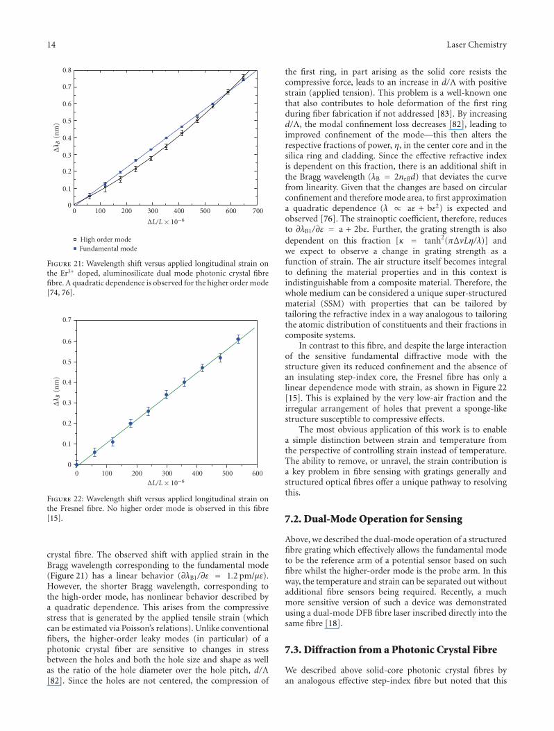
Figure 21: Wavelength shift versus applied longitudinal strain onthe Er3+ doped, aluminosilicate dual mode photonic crystal fibrefibre. A quadratic dependence is observed for the higher order mode[74, 76].
0
0.1
0.2
0.3
0.4
0.5
0.6
0.7
Δλ B
(nm
)
0 100 200 300 400 500 600ΔL/L× 10−6
Figure 22: Wavelength shift versus applied longitudinal strain onthe Fresnel fibre. No higher order mode is observed in this fibre[15].
crystal fibre. The observed shift with applied strain in theBragg wavelength corresponding to the fundamental mode(Figure 21) has a linear behavior (∂λB1/∂ε = 1.2 pm/με).However, the shorter Bragg wavelength, corresponding tothe high-order mode, has nonlinear behavior described bya quadratic dependence. This arises from the compressivestress that is generated by the applied tensile strain (whichcan be estimated via Poisson’s relations). Unlike conventionalfibers, the higher-order leaky modes (in particular) of aphotonic crystal fiber are sensitive to changes in stressbetween the holes and both the hole size and shape as wellas the ratio of the hole diameter over the hole pitch, d/Λ[82]. Since the holes are not centered, the compression of
the first ring, in part arising as the solid core resists thecompressive force, leads to an increase in d/Λ with positivestrain (applied tension). This problem is a well-known onethat also contributes to hole deformation of the first ringduring fiber fabrication if not addressed [83]. By increasingd/Λ, the modal confinement loss decreases [82], leading toimproved confinement of the mode—this then alters therespective fractions of power, η, in the center core and in thesilica ring and cladding. Since the effective refractive indexis dependent on this fraction, there is an additional shift inthe Bragg wavelength (λB = 2neffd) that deviates the curvefrom linearity. Given that the changes are based on circularconfinement and therefore mode area, to first approximationa quadratic dependence (λ ∝ aε + bε2) is expected andobserved [76]. The strainoptic coefficient, therefore, reducesto ∂λB1/∂ε = a + 2bε. Further, the grating strength is alsodependent on this fraction [κ = tanh2(πΔvLη/λ)] andwe expect to observe a change in grating strength as afunction of strain. The air structure itself becomes integralto defining the material properties and in this context isindistinguishable from a composite material. Therefore, thewhole medium can be considered a unique super-structuredmaterial (SSM) with properties that can be tailored bytailoring the refractive index in a way analogous to tailoringthe atomic distribution of constituents and their fractions incomposite systems.
In contrast to this fibre, and despite the large interactionof the sensitive fundamental diffractive mode with thestructure given its reduced confinement and the absence ofan insulating step-index core, the Fresnel fibre has only alinear dependence mode with strain, as shown in Figure 22[15]. This is explained by the very low-air fraction and theirregular arrangement of holes that prevent a sponge-likestructure susceptible to compressive effects.
The most obvious application of this work is to enablea simple distinction between strain and temperature fromthe perspective of controlling strain instead of temperature.The ability to remove, or unravel, the strain contribution isa key problem in fibre sensing with gratings generally andstructured optical fibres offer a unique pathway to resolvingthis.
7.2. Dual-Mode Operation for Sensing
Above, we described the dual-mode operation of a structuredfibre grating which effectively allows the fundamental modeto be the reference arm of a potential sensor based on suchfibre whilst the higher-order mode is the probe arm. In thisway, the temperature and strain can be separated out withoutadditional fibre sensors being required. Recently, a muchmore sensitive version of such a device was demonstratedusing a dual-mode DFB fibre laser inscribed directly into thesame fibre [18].
7.3. Diffraction from a Photonic Crystal Fibre
We described above solid-core photonic crystal fibres byan analogous effective step-index fibre but noted that this
Laser Chemistry 15
approximation, used by many authors (see, e.g., [2] and thereferences therein), is generally not valid for higher-ordermodes. In fact, the effective core and cladding of this step-index approximation can be highly sensitive to the extent ofthe modal field into the cladding. As a consequence of thehigh-core-cladding index contrast, the contribution to modepropagation from, for example, a periodic arrangement ofholes is negligible when the wavelength of light is largerthan the bridge thickness between the holes but smallerthan the core diameter. On the other hand, for less confinedmodes or when the wavelength of light is commensurate orsmaller than the interstitial hole spacing, as well as the coresize itself, a periodic lattice provides phase conditions thatallow coherent scattering of light and therefore diffractiveconfinement [84]. This resonant phenomenon has beenobserved in bending loss tests, where light leaks out fromthe core and is launched into the cladding, generating ashort wavelength cutoff in the fibre transmission band [85].This short wavelength cutoff is sensitive to the perturbationsapplied to the fibre as well as the index of the material withinthe hole. In fact, such regular coupling of light between theinterstitial regions of a regular lattice-structured fibre playsa key role in high-bend loss characteristic of such fibres[86]. The best way to prevent this is, therefore, to removethe crystalline regularity of this lattice thereby spoiling thecoupling—zero bend loss has been demonstrated using achirped Fresnel fibre (or fractal fibre) [86] which in turnserved as the basis for ideal tapered structured fibre forefficient metal free SNOM [87].
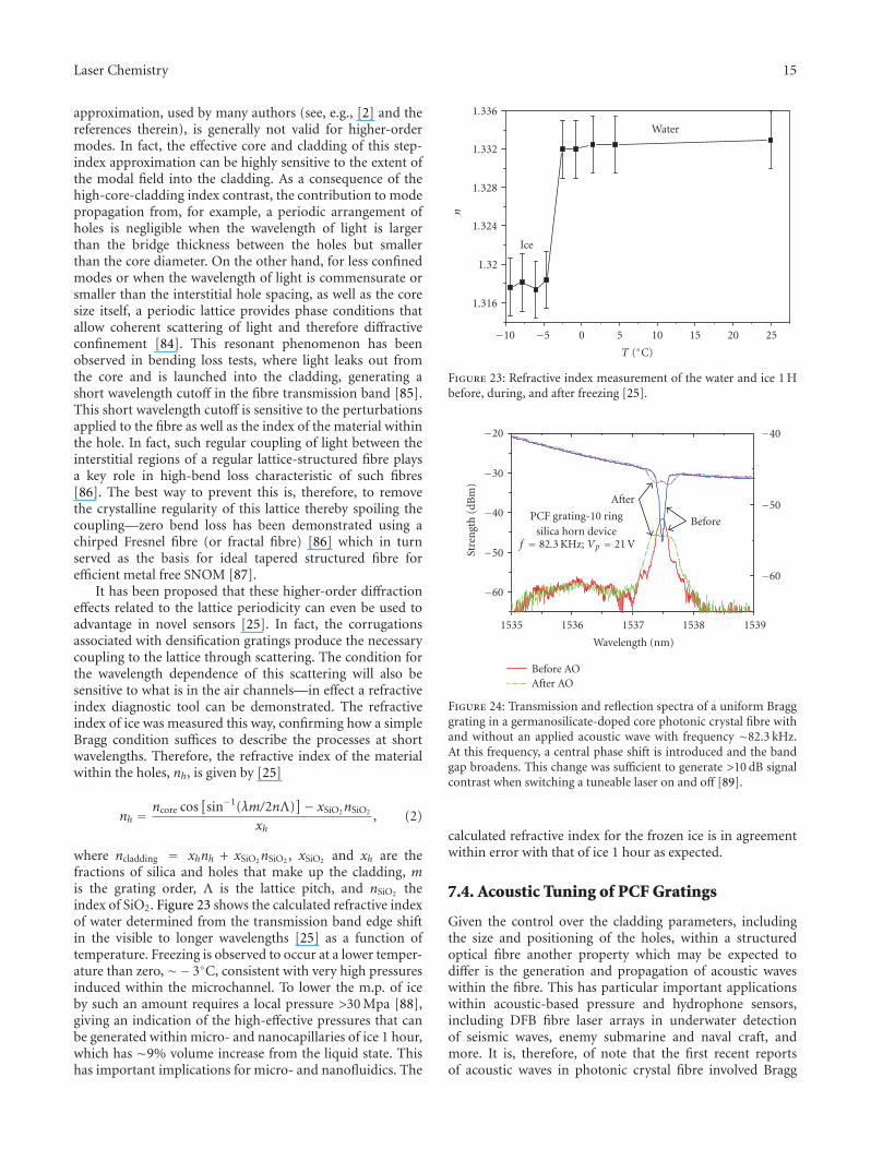
It has been proposed that these higher-order diffractioneffects related to the lattice periodicity can even be used toadvantage in novel sensors [25]. In fact, the corrugationsassociated with densification gratings produce the necessarycoupling to the lattice through scattering. The condition forthe wavelength dependence of this scattering will also besensitive to what is in the air channels—in effect a refractiveindex diagnostic tool can be demonstrated. The refractiveindex of ice was measured this way, confirming how a simpleBragg condition suffices to describe the processes at shortwavelengths. Therefore, the refractive index of the materialwithin the holes, nh, is given by [25]
nh =ncore cos
[sin−1(λm/2nΛ)
]− xSiO2nSiO2
xh, (2)
where ncladding = xhnh + xSiO2nSiO2 , xSiO2 and xh are thefractions of silica and holes that make up the cladding, mis the grating order, Λ is the lattice pitch, and nSiO2 theindex of SiO2. Figure 23 shows the calculated refractive indexof water determined from the transmission band edge shiftin the visible to longer wavelengths [25] as a function oftemperature. Freezing is observed to occur at a lower temper-ature than zero, ∼− 3◦C, consistent with very high pressuresinduced within the microchannel. To lower the m.p. of iceby such an amount requires a local pressure >30 Mpa [88],giving an indication of the high-effective pressures that canbe generated within micro- and nanocapillaries of ice 1 hour,which has ∼9% volume increase from the liquid state. Thishas important implications for micro- and nanofluidics. The
1.316
1.32
1.328
1.324
1.332
1.336
n
−10 −5 0 5 10 15 20 25
Water
Ice
T (◦C)
Figure 23: Refractive index measurement of the water and ice 1 Hbefore, during, and after freezing [25].
−60
−50
−40
−30
−20
Stre
ngt
h(d
Bm
)
1535 1536 1537 1538 1539
Wavelength (nm)
−60
−50
−40
PCF grating-10 ringsilica horn device
f = 82.3 KHz; Vp = 21 V
After
Before
Before AOAfter AO
Figure 24: Transmission and reflection spectra of a uniform Bragggrating in a germanosilicate-doped core photonic crystal fibre withand without an applied acoustic wave with frequency ∼82.3 kHz.At this frequency, a central phase shift is introduced and the bandgap broadens. This change was sufficient to generate >10 dB signalcontrast when switching a tuneable laser on and off [89].
calculated refractive index for the frozen ice is in agreementwithin error with that of ice 1 hour as expected.
7.4. Acoustic Tuning of PCF Gratings
Given the control over the cladding parameters, includingthe size and positioning of the holes, within a structuredoptical fibre another property which may be expected todiffer is the generation and propagation of acoustic waveswithin the fibre. This has particular important applicationswithin acoustic-based pressure and hydrophone sensors,including DFB fibre laser arrays in underwater detectionof seismic waves, enemy submarine and naval craft, andmore. It is, therefore, of note that the first recent reportsof acoustic waves in photonic crystal fibre involved Bragg
16 Laser Chemistry
gratings inscribed into the fibres for these applications [89–91]. A tuneable Moire grating was demonstrated for the firsttime [89] by having an acoustic standing wave establishedover the Bragg grating which leads to bandwidth broadeningand a phase-shifted structure as shown in Figure 22. Furtherwork is underway to explore the potential of structured fibresin enhancing and controlling these properties.
8. Conclusions
Considerable work has already been carried out in theinscription of Bragg gratings and other structures withinstructured optical fibres. Both positive and negative indexgratings in Type I regime (below the damage threshold [22])are easily demonstrated and unsurprising within structurefibres containing standard photosensitive cores. However, thecontrol and refinement of this writing process is considerablymore difficult as a result of the rotational variance ofthe optical fibre. Progress in this direction has led to aconsiderable improvement in the reliable inscription ofgratings. More challenging, but in many ways far moreimportant, has been the inscription of higher-exponentphoton gratings, including densification and damage grat-ings, that do not rely on accessing defects so that muchof the advantages of structured fibres, including single-material fibres with no temperature dependence arising fromdifferences in expansion coefficients. Some of the distinctadvantages of structured fibres have been argued from theperspective of the grating itself. Gratings act as both a criticaldiagnostic interferometer and as an important spectrallyselective component to further extend these advantages inmuch the same way gratings have, and continue, to extendconventional optical fibre. Applications are liberal spanningfrom telecommunications, lasers, sensors, and diagnostics.
Acknowledgments
The authors would like to acknowledge various students,staff, and colleagues, both local (Andrew Michie and MattiasAslund from IPL, Sydney University, Graham Marshall,Nem Jovanovic et al. from Macquarie University; ShaneHuntington et al. from Melbourne University) and overseas(Henrick Sorenson, Hans Deyerl, Martin Kristensen et al.from Research Centre COM, Danish Technical University;Matthieu Lancry and Bertrand Poumellec, Universide deParis Sude, France), who have contributed over recentyears to some aspects of the described work. Fundingfor this work came from the Australian Research Counciland the Department of Education, Science and Training(DEST), Australia. Cicero Martelli acknowledges a CAPES,Brazil Student scholarship, and Somnath Bandyopadhyayacknowledges a Raman Research Fellowship of CSIR, Indiafor his stay in Australia.
References
[1] P. Kaiser and H. W. Astle, “Low-loss single-material fibersmade from pure fused silica,” Bell System Technical Journal,vol. 53, no. 6, pp. 1021–1039, 1974.
[2] A. Bjarklev, J. Broeng, and A. S. Bjarklev, Photonic CrystalFibres, Kluwer Academic Publishers, Boston, Mass, USA, 2003.
[3] J. Canning, “Fresnel optics inside optical fibres,” in PhotonicsResearch Developments, chapter 4, Nova Science, Huntington,NY, USA, 2008.
[4] H. R. Sørensen, J. Canning, J. Lægsgaard, K. Hansen, and P.Varming, “Liquid filling of photonic crystal fibres for gratingwriting,” Optics Communications, vol. 270, no. 2, pp. 207–210,2007.
[5] J. Canning, S. K. Lim, T. K. Yip, and C. Martelli, “Newdevice functionality within structured optical fibres by selec-tive filling,” in Proceedings of the Joint Conference on Opto-Electronics and Communications Conference and the AustralianConference on Optical Fibre Technology (ACOFT/OECC ’08),Sydney, Australia, July 2008.
[6] C. Martelli, J. Canning, J. R. Reimers, M. Sintic, D. Stocks, andM. J. Crossley, “Evanescent field spectroscopy using structuredoptical fibres: detection of charge-transfer at the porphyrin-silica interface,” submitted to Journal of the American ChemicalSociety.
[7] B. J. Eggleton, P. S. Westbrook, R. S. Windeler, S. Spalter, and T.A. Strasser, “Grating resonances in air-silica microstructuredoptical fibers,” Optics Letters, vol. 24, no. 21, pp. 1460–1462,1999.
[8] H. R. Sørensen, J. Canning, J. Lægsgaard, K. Hansen, and P.Varming, “Liquid filling of photoniccrystal fibres for gratingwriting,” Optics Communications, vol. 270, no. 2, pp. 207–210,2007.
[9] V. Beugin, L. Bigot, P. Niay, et al., “Efficient Bragg gratingsin phosphosilicate and germanosilicate photonic crystal fiber,”Applied Optics, vol. 45, no. 32, pp. 8186–8193, 2006.
[10] L. B. Fu, G. D. Marshall, J. A. Bolger, et al., “Femtosecond laserwriting Bragg gratings in pure silica photonic crystal fibres,”Electronics Letters, vol. 41, no. 11, pp. 638–640, 2005.
[11] M. C. Phan Huy, G. Laffont, Y. Frignac, et al., “FibreBragg grating photowriting in microstructured optical fibresfor refractive index measurement,” Measurement Science andTechnology, vol. 17, no. 5, pp. 992–997, 2006.
[12] G. Violakis and S. Pissadakis, “Improved efficiency Bragggrating inscription in a commercial solid core microstructuredoptical fiber,” in Proceedings of the 9th International Conferenceon Transparent Optical Networks (ICTON ’07), vol. 2, pp. 217–220, Rome , Italy, July 2007.
[13] J. Albert, M. Fokine, and W. Margulis, “Grating formation inpure silica-core fibers,” Optics Letters, vol. 27, no. 10, pp. 809–811, 2002.
[14] N. Groothoff, J. Canning, E. Buckley, K. Lyttikainen, and J.Zagari, “Bragg gratings in air-silica structured fibers,” OpticsLetters, vol. 28, no. 4, pp. 233–235, 2003.
[15] N. Groothoff, C. Martelli, J. Canning, and K. Lyytikainen,“Fibre Bragg grating in Fresnel fibre with temperature andstrain characterisation,” in Proceedings of the 30th AustralianConference on Optical Fibre Technology (ACOFT ’05), Sydney,Australia, July 2005.
[16] J. Canning, N. Groothoff, E. Buckley, T. Ryan, K. Lyytikainen,and J. Digweed, “All-fibre photonic crystal distributed Braggreflector (PC-DBR) fibre laser,” Optics Express, vol. 11, no. 17,pp. 1995–2000, 2003.
[17] N. Groothoff, J. Canning, T. Ryan, K. Lyytikainen, and H.Inglis, “Distributed feedback photonic crystal fibre (DFB-PCF) laser,” Optics Express, vol. 13, no. 8, pp. 2924–2930, 2005.
[18] N. Groothoff, C. Martelli, and J. Canning, “A dual wavelengthdistributed-feedback fiber laser,” Journal of Applied Physics,vol. 103, no. 1, Article ID 013101, 6 pages, 2008.
Laser Chemistry 17
[19] J. Canning, S. D. Jackson, M. L. Aslund, N. Groothoff, B.Ashton, and K. Lyytikainen, “Air-clad fibre laser with internalBragg grating,” Electronics Letters, vol. 41, no. 20, pp. 1103–1104, 2005.
[20] N. Groothoff, J. Canning, N. Jovanovic, G. D. Marshall, andM. J. Whitford, “Gratings in large diameter air-clad opticalfibre using a femtosecond laser,” in Proceedings of the OSATopical Meeting: Bragg Gratings, Photosensitivity and Poling(BGPP ’07), Quebec City, Canada, September 2007.
[21] S. J. Mihailov, D. Grobnic, H. Ding, C. W. Smelser, and J.Broeng, “Femtosecond IR laser fabrication of Bragg gratings inphotonic crystal fibers and tapers,” IEEE Photonics TechnologyLetters, vol. 18, no. 17, pp. 1837–1839, 2006.
[22] J. Canning, “Fibre gratings and devices,” in Lasers andPhotonics Reviews, John Wiley & Sons, New York, NY, USA,2008.
[23] C. Martelli, J. Canning, B. Gibson, and S. Huntington, “Cryp-tography based on coherent scattering of light,” in Proceedingsof the Joint International Conference on Optical Internet andthe 32nd Australian Conference on Optical Fibre Technology(COIN-ACOFT ’07), pp. 1–3, Melbourne, Australia, June2007.
[24] R. C. Gauthier, “Photonic quasi-crystals: a review,” in Proceed-ings of the Progress in Electromagnetics Research Symposium(PIERS ’08), p. 151, Hangzhou, China, March 2008.
[25] C. Martelli, J. Canning, M. Kristensen, and N. Groothoff,“Refractive index measurement within a photonic crystal fibrebased on short wavelength diffraction,” Sensors, vol. 7, no. 11,pp. 2492–2498, 2007.
[26] J. De Iuliis, “Modelling the angular dependence on Bragggrating writing in photonic crystal fibre,” Student PracticalOptical Design Report, University of Newcastle, 2006.
[27] G. D. Marshall, D. J. Kan, A. A. Asatryan, L. C. Botten, andM. J. Withford, “Transverse coupling to the core of a photoniccrystal fiber: the photo-inscription of gratings,” Optics Express,vol. 15, no. 12, pp. 7876–7887, 2007.
[28] J. Canning, “Gratings and grating devices in structured fibresusing 193 nm from an ArF laser,” in Proceedings of the OSATopical Meeting: Bragg Gratings, Photosensitivity and Poling(BGPP ’07), Quebec City, Canada, September 2007.
[29] J. L. Holdsworth, J. Canning, and C. Dewhurst, “Rotationaldependence of laser light accessing photonic crystal fibrecores from the side,” in Proceedings of the 19th InternationalConference on Optical Fibre Sensors, D. Sampson, S. Collins, K.Oh, and R. Yamauchi, Eds., vol. 7004 of Proceedings of SPIE,pp. 1–4, Perth, Australia, April 2008.
[30] J. Holdsworth, S. Bandyopadhyay, J. Canning, M. Steven-son, and J. de Iuliis, “Transversely illuminating the core ofphotonic crystal fibres,” in Proceedings of the Joint Confer-ence of the Opto-Electronics and Communications Conferenceand the Australian Conference on Optical Fibre Technology(OECC/ACOFT ’08), Sydney, Australia, July 2008.
[31] J. Holdsworth, K. Cook, J. Canning, S. Bandyopadhyay, and M.Stevenson, “Rotationally variant grating writing in photoniccrystal fibres,” submitted to Optics Express.
[32] A. P. Mosk, “Focussing of light by disordered metamaterials,”in Proceedings of the Progress in Electromagnetics ResearchSymposium (PIERS ’08), p. 741, Hangzhou, China, March2008.
[33] K. Cook, A. Pohl, and J. Canning, “Positive and nega-tive index gratings in 10-ring photonic crystal fibres withgermanosilicate cores using 193 nm,” in Proceedings of the
Joint Conference of the Opto-Electronics and CommunicationsConference and the Australian Conference on Optical FibreTechnology (OECC/ACOFT ’08), Sydney, Australia, July 2008.
[34] K. Cook, A. Pohl, and J. Canning, “Type IIA gratings inhydrogen-free 10-ring photonic crystal fibre with germanosil-icate core,” submitted to Optics Letters.
[35] N. Groothoff and J. Canning, “Enhanced type IIA gratings forhigh-temperature operation,” Optics Letters, vol. 29, no. 20,pp. 2360–2362, 2004.
[36] J. Canning, K. Sommer, M. Englund, and S. Huntington,“Direct evidence of two types of UV-induced glass changes insilicate-based optical fibers,” Advanced Materials, vol. 13, no.12-13, pp. 970–973, 2001.
[37] H. Sorensen, J. B. Jensen, F. Bruyere, and K. P. Hansen,“Practical hydrogen loading of air silica fibers,” in BraggGratings Photosensitivity and Poling in Glass Waveguides,Trends in Optics and Photonics Series, Optical Society ofAmerica, Washington, DC, USA , 2005.
[38] D. Kacik, I. Turek, I. Martincek, J. Canning, N. A. Issa, andK. Lyytikainen, “Intermodal interference in a photonic crystalfibre,” Optics Express, vol. 12, no. 15, pp. 3465–3470, 2004.
[39] A. Pohl, K. Cook, and J. Canning, “Bragg grating writingin H2-loaded many-layered PCF without liquid filling of theholes,” in Proceedings of the Joint Conference of the Opto-Electronics and Communications Conference and the AustralianConference on Optical Fibre Technology (OECC/ACOFT ’08),Sydney, Australia, July 2008.
[40] M. Janos and J. Canning, “Permanent and transient reso-nances thermally induced in optical fibre Bragg gratings,”Electronics Letters, vol. 31, no. 12, pp. 1007–1009, 1995.
[41] A. Canagasabey, J. Canning, J. Mills, D. P. Banks, and M. Ibsen,“Fibre Bragg grating fabrication in germanosilicate fibres with244 nm femtosecond laser light,” in Proceedings of the 2ndPacific International Conference on Applications of Lasers andOptics (PICALO ’06), Melbourne, Australia, April 2006.
[42] A. Wootton, B. Thomas, and P. Harrowell, “Radiation-induceddensification in amorphous silica: a computer simulationstudy,” Journal of Chemical Physics, vol. 115, no. 7, pp. 3336–3341, 2001.
[43] C. Martelli, J. Canning, M. Kristensen, and N. Groothoff,“Impact of water and ice 1h formation in a photonic crystalfiber grating,” Optics Letters, vol. 31, no. 6, pp. 706–708, 2006.
[44] W. Primak, L. H. Fuchs, and P. Day, “Radiation damage ininsulators,” Physical Review, vol. 92, no. 4, pp. 1064–1065,1953.
[45] W. Primak and H. Szymanski, “Radiation damage in vitreoussilica: annealing of the density changes,” Physical Review, vol.101, no. 4, pp. 1268–1271, 1956.
[46] W. Primak and R. Kampwirth, “The radiation compaction ofvitreous silica,” Journal of Applied Physics, vol. 39, no. 12, pp.5651–5658, 1968.
[47] C. Fiori and R. A. B. Devine, “Evidence for a wide continuumof polymorphs in a-SiO2,” Physical Review B, vol. 33, no. 4, pp.2972–2974, 1986.
[48] M. Lancry and B. Poumellec, “Multiphoton absorption pro-cesses & UV laser processing of silica-based materials,” inProceedings of the 1st International Workshop on MultiphotonProcesses in Glass and Glassy Materials, J. Canning, Ed., Sydney,Australia, December 2006.
[49] N. Groothoff, M. Lancry, B. Poumellec, and J. Canning,“193 nm photolytic mechanism in Er/Al doped silica,” inProceedings of the Joint Conference on Opto-Electronics andCommunications Conference and the Australian Conference
18 Laser Chemistry
on Optical Fibre Technology (ACOFT/OECC ’08), Sydney,Australia, July 2008.
[50] M. Lancry, N. Groothoff, B. Poumellec, and J. Canning, “Two-photon grating writing in Er/Al doped preform plates using193 nm laser light,” In preparation.
[51] A. Dragomir, D. N. Nikogosyan, K. A. Zagorulko, P. G.Kryukov, and E. M. Dianov, “Inscription of fiber Bragggratings by ultraviolet femtosecond radiation,” Optics Letters,vol. 28, no. 22, pp. 2171–2173, 2003.
[52] S. J. Mihailov, C. W. Smelser, P. Lu, et al., “Fiber Bragg gratingsmade with a phase mask and 800-nm femtosecond radiation,”Optics Letters, vol. 28, no. 12, pp. 995–997, 2003.
[53] K. A. Zagorulko, P. G. Kryukov, Yu. V. Larionov, et al.,“Fabrication of fiber Bragg gratings with 267 nm femtosecondradiation,” Optics Express, vol. 12, no. 24, pp. 5996–6001, 2004.
[54] A. Martinez, M. Dubov, I. Khrushchev, and I. Bennion,“Direct writing of fibre Bragg gratings by femtosecond laser,”Electronics Letters, vol. 40, no. 19, pp. 1170–1172, 2004.
[55] C. W. Smelser, S. J. Mihailov, D. Grobnic, et al., “Multiple-beam interference patterns in optical fiber generated withultrafast pulses and a phase mask,” Optics Letters, vol. 29, no.13, pp. 1458–1460, 2004.
[56] C. W. Smelser, S. J. Mihailov, and D. Grobnic, “Hydrogenloading for fiber grating writing with a femtosecond laser anda phase mask,” Optics Letters, vol. 29, no. 18, pp. 2127–2129,2004.
[57] C. W. Smelser, S. J. Mihailov, and D. Grobnic, “Formation oftype I-IR and type II-IR gratings with an ultrafast IR laser anda phase mask,” Optics Express, vol. 13, no. 14, pp. 5377–5386,2005.
[58] in Proceedings of the 1st International Workshop on MultiphotonProcesses in Glass and Glassy Materials, J. Canning, Ed., Sydney,Australia, December 2006.
[59] C. G. Askins, T.-E. Tsai, G. M. Williams, M. A. Putnam, M.Bashkansky, and E. J. Friebele, “Fiber Bragg reflectors preparedby a single excimer pulse,” Optics Letters, vol. 17, no. 11, pp.833–835, 1992.
[60] M. L. Aslund, N. Jovanovic, N. Groothoff, et al., “Largediffractive scattering losses in the visible region producedby femtosecond laser written Bragg gratings,” in Proceed-ings of the Australian Conference on Optical Fibre Tech-nology & Opto-Electronics and Communications Conference(ACOFT/OECC ’08), Sydney, Australia, July 2008.
[61] M. L. Aslund, N. Jovanovic, N. Groothoff, et al., “Opticalloss mechanisms in femtosecond laser-written point-by-pointfibre Bragg gratings,” Optics Express, vol. 16, no. 18, pp. 14248–14254, 2008.
[62] N. Jovanovic, M. L. Aslund, A. Fuerbach, S. D. Jackson, G.D. Marshall, and M. J. Withford, “Narrow linewidth, 100 Wcw Yb3+-doped silica fiber laser with a point-by-point Bragggrating inscribed directly into the active core,” Optics Letters,vol. 32, no. 19, pp. 2804–2806, 2007.
[63] M. L. Aslund, S. D. Jackson, J. Canning, N. Groothoff, B.Ashton, and K. Lyytikainen, “High power Yb3+ doped air-clad fibre laser using a Bragg grating written into the activemedium,” in Proceedings of the 7th Australian Conference onOptics, Lasers and Spectroscopy (ACOLS ’05), Roturua, NewZealand, December 2005, paper WeA2.
[64] M. L. Aslund, private communication, unpublished work,2007.
[65] J. Arkwright, G. Atkins, Z. Brodzeli, et al., “All optical switch-ing in rare-earth doped fibers,” in Proceedings of the PacificRim Conference on Lasers and Electro-Optics (CLEO/PacificRim ’97), p. 265, Chiba, Japan, July 1997, paper FH1.
[66] E. N. Glezer and E. Mazur, “Ultrafast-laser driven micro-explosions in transparent materials,” Applied Physics Letters,vol. 71, no. 7, pp. 882–884, 1997.
[67] K. Sugioka, Y. Cheng, and K. Midorikawa, “Three-dimensional micromachining of glass using femtosecondlaser for lab-on-a-chip device manufacture,” Applied PhysicsA, vol. 81, no. 1, pp. 1–10, 2005.
[68] J. W. Chan, T. R. Huser, S. H. Risbud, and D. M. Krol,“Modification of the fused silica glass network associatedwith waveguide fabrication using femtosecond laser pulses,”Applied Physics A, vol. 76, no. 3, pp. 367–372, 2003.
[69] S. A. Slattery, D. N. Nikogosyan, and G. Brambilla, “FiberBragg grating inscription by high-intensity femtosecond UVlaser light: comparison with other existing methods of fabri-cation,” Journal of the Optical Society of America B, vol. 22, no.2, pp. 354–361, 2005.
[70] L. Shah, A. Arai, S. Eaton, and P. Herman, “Waveguide writingin fused silica with a femtosecond fiber laser at 522 nm and1 MHz repetition rate,” Optics Express, vol. 13, no. 6, pp. 1999–2006, 2005.
[71] K. Digweed-Lyytikainen, C. A. De Francisco, D. Spadoti, et al.,“Photonic crystal optical fibers for dispersion compensationand Raman amplification: design and experiment,” Microwaveand Optical Technology Letters, vol. 49, no. 4, pp. 872–874,2007.
[72] M. L. Aslund, J. Canning, S. D. Jackson, A. Teixeira, and K.Lyytikainen, “Diffraction in air-clad fibres,” Optics Express,vol. 13, no. 14, pp. 5227–5233, 2005.
[73] M. L. Aslund, S. D. Jackson, J. Canning, A. Teixeira, and K.Lyytikainen-Digweed, “The influence of skew rays on angularlosses in air-clad fibres,” Optics Communications, vol. 262, no.1, pp. 77–81, 2006.
[74] C. Martelli, J. Canning, N. Groothoff, and K. Lyytikainen,“Strain and temperature characterization of photonic crystalfiber Bragg gratings,” Optics Letters, vol. 30, no. 14, pp. 1785–1787, 2005.
[75] D. Kacik, I. Turek, I. Martincek, J. Canning, N. A. Issa, andK. Lyytikainen, “Intermodal interference in a photonic crystalfibre,” Optics Express, vol. 12, no. 15, pp. 3465–3470, 2004.
[76] C. Martelli, J. Canning, N. Groothoff, and K. Lyttikainen,“Bragg gratings in photonic crystal fibers: strain and tem-perature chacterization,” in 17th International Conference onOptical Fibre Sensors, M. Voet, R. Willsch, W. Ecke, J. Jones,and B. Culshaw, Eds., vol. 5855 of Proceedings of SPIE, pp. 302–305, Bruges, Belgium, May 2005.
[77] M. Janos and J. Canning, “Permanent and transient reso-nances thermally induced in optical fibre Bragg gratings,”Electronics Letters, vol. 31, no. 12, pp. 1007–1009, 1995.
[78] H. R. Sørensen, J. Canning, J. Lægsgaard, and K. Hansen,“Control of the wavelength dependent thermo-optic coeffi-cients in structured fibres,” Optics Express, vol. 14, no. 14, pp.6428–6433, 2006.
[79] O. V. Mazurin, M. V. Streltsina, and T. P. Shvaiko-shvaikovskaya, Eds., Handbook of Glass Data. Part A. SilicaGlass and Binary Silicate Glasses, Elsevier, Amsterdam, TheNetherlands, 1983.
[80] A. Michie, J. Canning, K. Lyytikainen, M. L. Aslund, andJ. Digweed, “Temperature independent highly birefringentphotonic crystal fibre,” Optics Express, vol. 12, no. 21, pp.5160–5165, 2004.
[81] A. Michie, J. Canning, I. Bassett, et al., “Spun ellipticallybirefringent photonic crystal fibre,” Optics Express, vol. 15, no.4, pp. 1811–1816, 2007.
Laser Chemistry 19
[82] D. Ferrarini, L. Vincetti, M. Zoboli, A. Cucinotta, and S.Selleri, “Leakage properties of photonic crystal fibers,” OpticsExpress, vol. 10, no. 23, pp. 1314–1319, 2002.
[83] K. Lyytikainen, Control of complex structural geometry inoptical fibre drawing, Ph.D. thesis, School of Physics andInterdisciplinary Photonics Laboratories, The University ofSydney, Sydney, Australia, 2004.
[84] J. Canning, “Diffraction-free mode generation and propaga-tion in optical waveguides,” Optics Communications, vol. 207,no. 1–6, pp. 35–39, 2002.
[85] D. Kacik, I. Turek, I. Martincek, J. Canning, and K.Lyytikainen, “The role of diffraction in influencing the shortwavelength loss edge of photonic crystal fibres,” in Proceedingsof the 30th Australian Conference on Optical Fibre Technology(ACOFT ’05), Sydney, Australia, July 2005.
[86] C. Martelli, J. Canning, B. Gibson, and S. Huntington, “Bendloss in structured optical fibres,” Optics Express, vol. 15, no. 26,pp. 17639–17644, 2007.
[87] C. M. Rollinson, S. M. Orbons, S. T. Huntington, et al., “Nearfield characterisation of a nano-structured metamaterial witha metal-free optical fiber probe,” submitted to Nano Letters.
[88] V. F. Petrenko and R. W. Whitworth, Physics of Ice, OxfordUniversity Press, New York, NY, USA, 2002.
[89] A. A. P. Pohl, R. A. Oliveira, K. Cook, and J. Canning,“Modulation of a photonic crystal fibre Bragg grating inducedby acoustical waves,” submitted to Optics Express.
[90] A. A. P. Pohl, P. T. Neves Jr., R. A. Oliveira, M. Stevenson,N. Groothoff, and J. Canning, “Technique for estimating thetuning speed of fiber Bragg gratings,” in 19th InternationalConference on Optical Fibre Sensors, vol. 7004 of Proceedingsof SPIE, Perth, Australia, April 2008.
[91] R. A. Oliveira, P. de T. Neves Jr., J. M. Maia, A. de A. P. Pohl,and J. Canning, “Modulacao da Refletividade de Redes deBragg usando Interacao Acusto-Optica de Baixa Frequencia,”in Proceedings of the 13 SBMO Brazilian Symposium onMicrowave and Optoelectronics and 8th CBMag BrazilianCongress of Eletromagnetismo (MOMAG ’08), pp. 396–398,Florianpolis, Brazil, September 2008.
Related Documents