minerals Article Graphite Dendrites in Cast Iron and Their Fundamental Role in the Control of Morphology to Obtain Aero-Eutectic Graphite Alicia N. Roviglione 1, *, Alvaro Y. Tesio 2 , Fernando Fungo 3 and Ricardo W. Gregorutti 4 Citation: Roviglione, A.N; Tesio, A.Y; Fungo, F.; Gregorutti, R.W Graphite Dendrites in Cast Iron and Their Fundamental Role in the Control of Morphology to Obtain Aero-Eutectic Graphite. Minerals 2021, 11, 109. https://doi.org/10.3390/min11020109 Received: 18 December 2020 Accepted: 19 January 2021 Published: 22 January 2021 Publisher’s Note: MDPI stays neutral with regard to jurisdictional claims in published maps and institutional affil- iations. Copyright: © 2021 by the authors. Licensee MDPI, Basel, Switzerland. This article is an open access article distributed under the terms and conditions of the Creative Commons Attribution (CC BY) license (https:// creativecommons.org/licenses/by/ 4.0/). 1 Departamento de Ingeniería Mecánica, Facultad de Ingeniería, Universidad de Buenos Aires, Av. Paseo Colón 850, C1063ACV Ciudad Autónoma de Buenos Aires, Argentina 2 Centro de Investigación y Desarrollo en Materiales Avanzados y Almacenamiento de Energía de Jujuy (CIDMEJu), Centro de Desarrollo Tecnológico General Manuel Savio, Y4612 Palpalá, Argentina; [email protected] 3 Instituto de Investigaciones en Tecnologías Energéticas y Materiales Avanzados, (UNRC-CONICET) Departamento de Química, Universidad Nacional de Río Cuarto, Agencia Postal 3, X5804BYA Río Cuarto, Argentina; [email protected] 4 LEMIT—Comisión de Investigaciones Científicas de la Provincia de Buenos Aires, Av. 52 e/121 y 122, B1900AYB La Plata, Argentina; [email protected] * Correspondence: arovi@fi.uba.ar Abstract: This work analyzes the growth of graphite in the eutectic system of gray cast iron, focusing on laminar type A and undercooled type D morphology, and a modified morphology, such as vermicular or compact graphite. The objective of the study is to find an optimal graphite structure, from which a new class of lightweight materials results that has been called aero-eutectic graphite (AEG). The method to obtain AEG consists of dissolving the gray iron ferrous matrix by means of a chemical attack. From experiences of unidirectional solidification, it has been found that laminar graphite grows in a non-faceted way, coupled to austenite, while in vermicular the growth is through foliated dendrites. This characteristic allows vermicular graphite to have a higher specific intrinsic surface area. According to the Brunauer-Emmett-Teller (BET) analysis, the surface of the vermicular was 106.27 m 2 g -1 , while those corresponding to type A and D were 83.390 m 2 g -1 and 89.670 m 2 g -1 , respectively. AEG with graphite type D was used as a cathode in Li-O 2 batteries with satisfactory results, reaching more than 70 charge and discharge cycles, and 150 cycles at this time and still cycling, using Ru(bpy) 3 (ClO 4 ) 2 as redox mediator. Keywords: graphite growth; graphite foliated dendrite; porous graphite; hierarchical porous struc- ture; Li-O 2 battery cathode; ruthenium complex 1. Introduction 1.1. About the Objective of This Work: Aero-Eutectic Graphite (AEG) In this work, a new material called aero-eutectic graphite (AEG) is presented, made with 100% crystalline pure eutectic graphite (G) obtained from gray cast iron. It is a very light material, with a large surface area and different types and sizes of porosities suitable for assembling different simple and specific functions in an integrated process of greater complexity. For this reason, it belongs to the so-called hierarchically structured materials [1]. Its versatility is enhanced, because it can be designed by the controlled solidification of cast iron. A subsequent dissolution of the metal matrix, by means of using a specially-designed technique that consists of sequential acid attack with different acids, allows preserving the structural integrity of the eutectic graphite to finally obtain various types of AEG (AEGs). These, in turn, can be subsequently adapted to achieve different objectives through specific functionalization. Some of AEG’s possible applications may be catalyst support, electrodes, or diffuser plates for the production and/or storage of energy in batteries, fuel cells, and super capacitor, etc. Here we will refer its recent use as a cathode in Li-O 2 batteries [2]. Minerals 2021, 11, 109. https://doi.org/10.3390/min11020109 https://www.mdpi.com/journal/minerals

Welcome message from author
This document is posted to help you gain knowledge. Please leave a comment to let me know what you think about it! Share it to your friends and learn new things together.
Transcript

minerals
Article
Graphite Dendrites in Cast Iron and Their Fundamental Role inthe Control of Morphology to Obtain Aero-Eutectic Graphite
Alicia N. Roviglione 1,*, Alvaro Y. Tesio 2 , Fernando Fungo 3 and Ricardo W. Gregorutti 4
�����������������
Citation: Roviglione, A.N; Tesio, A.Y;
Fungo, F.; Gregorutti, R.W Graphite
Dendrites in Cast Iron and Their
Fundamental Role in the Control of
Morphology to Obtain Aero-Eutectic
Graphite. Minerals 2021, 11, 109.
https://doi.org/10.3390/min11020109
Received: 18 December 2020
Accepted: 19 January 2021
Published: 22 January 2021
Publisher’s Note: MDPI stays neutral
with regard to jurisdictional claims in
published maps and institutional affil-
iations.
Copyright: © 2021 by the authors.
Licensee MDPI, Basel, Switzerland.
This article is an open access article
distributed under the terms and
conditions of the Creative Commons
Attribution (CC BY) license (https://
creativecommons.org/licenses/by/
4.0/).
1 Departamento de Ingeniería Mecánica, Facultad de Ingeniería, Universidad de Buenos Aires,Av. Paseo Colón 850, C1063ACV Ciudad Autónoma de Buenos Aires, Argentina
2 Centro de Investigación y Desarrollo en Materiales Avanzados y Almacenamiento de Energía deJujuy (CIDMEJu), Centro de Desarrollo Tecnológico General Manuel Savio, Y4612 Palpalá, Argentina;[email protected]
3 Instituto de Investigaciones en Tecnologías Energéticas y Materiales Avanzados, (UNRC-CONICET)Departamento de Química, Universidad Nacional de Río Cuarto, Agencia Postal 3,X5804BYA Río Cuarto, Argentina; [email protected]
4 LEMIT—Comisión de Investigaciones Científicas de la Provincia de Buenos Aires, Av. 52 e/121 y 122,B1900AYB La Plata, Argentina; [email protected]
* Correspondence: [email protected]
Abstract: This work analyzes the growth of graphite in the eutectic system of gray cast iron, focusingon laminar type A and undercooled type D morphology, and a modified morphology, such asvermicular or compact graphite. The objective of the study is to find an optimal graphite structure,from which a new class of lightweight materials results that has been called aero-eutectic graphite(AEG). The method to obtain AEG consists of dissolving the gray iron ferrous matrix by means ofa chemical attack. From experiences of unidirectional solidification, it has been found that laminargraphite grows in a non-faceted way, coupled to austenite, while in vermicular the growth is throughfoliated dendrites. This characteristic allows vermicular graphite to have a higher specific intrinsicsurface area. According to the Brunauer-Emmett-Teller (BET) analysis, the surface of the vermicularwas 106.27 m2 g−1, while those corresponding to type A and D were 83.390 m2 g−1 and 89.670 m2 g−1,respectively. AEG with graphite type D was used as a cathode in Li-O2 batteries with satisfactoryresults, reaching more than 70 charge and discharge cycles, and 150 cycles at this time and stillcycling, using Ru(bpy)3(ClO4)2 as redox mediator.
Keywords: graphite growth; graphite foliated dendrite; porous graphite; hierarchical porous struc-ture; Li-O2 battery cathode; ruthenium complex
1. Introduction1.1. About the Objective of This Work: Aero-Eutectic Graphite (AEG)
In this work, a new material called aero-eutectic graphite (AEG) is presented, made with100% crystalline pure eutectic graphite (G) obtained from gray cast iron. It is a very lightmaterial, with a large surface area and different types and sizes of porosities suitablefor assembling different simple and specific functions in an integrated process of greatercomplexity. For this reason, it belongs to the so-called hierarchically structured materials [1].Its versatility is enhanced, because it can be designed by the controlled solidification of castiron. A subsequent dissolution of the metal matrix, by means of using a specially-designedtechnique that consists of sequential acid attack with different acids, allows preserving thestructural integrity of the eutectic graphite to finally obtain various types of AEG (AEGs).These, in turn, can be subsequently adapted to achieve different objectives through specificfunctionalization. Some of AEG’s possible applications may be catalyst support, electrodes,or diffuser plates for the production and/or storage of energy in batteries, fuel cells, andsuper capacitor, etc. Here we will refer its recent use as a cathode in Li-O2 batteries [2].
Minerals 2021, 11, 109. https://doi.org/10.3390/min11020109 https://www.mdpi.com/journal/minerals

Minerals 2021, 11, 109 2 of 17
1.2. Briefly, About the Basic Graphite Crystallography and Derived Properties
G is an open crystal (pinacoid type, analogous to CdI2 and MoS2) that results fromthe stacking of at least three layers of sp2 atoms of C bonding by strong covalent unionsin a regular hexagonal disposition called basal planes {00.2}. These planes in turn arejoined between them with Van der Waals bonds, and their habit is closed with shapes{11.0} and {10.0} called prism planes. Depending on the type of layer stacking, generallyindicated as ABCABC or ABAB (where layer A is identical to layers B and C, but displacedbetween them by a/3 <11.0>) two stable allotropic varieties of G under normal pressure-temperature are formed: the ABCABC stack called hexagonal G (D6h4-PG3/mmc; unit cellconstants: a = 245.6 pm, c = 670.8 pm) [3] and the ABAB stack (D3d5-R3m; unit cellconstants: a = 256.6 pm, c = 1006.2 pm) [3], slightly less stable, called rhombohedral G,which is obtained by mechanical deformation of hexagonal G .
Some other types of G were proposed from crystallographic considerations by Hol-combe, and the characteristic spacing associated with its presence have been identified byX-ray diffraction in the following varieties: interdendritic laminar graphite Type D (LDG),compacted graphite (CG) and nodular graphite (NG) [4,5]. These varieties are the productof extensive stacking faults in the basal planes [6]. There are other stacking faults originatedby the rotation of the basal planes in preferential angles to fit in a “coincidence networks”with lesser energies. All these faults increase the rigidity of the phase as the thickness ofthe sheet increases [7]. There are other phase defects that are relevant to explain shapechange processes, such as the curving of a pinacoid shape [8] or emergence from the basalplane of a new crystallite with a different orientation. More details of the different types oftwins, tilt boundaries, and dislocation arrangements are described in [9].
1.3. About Some of Our Theoretical Guides
G pinacoids would normally be similar to plates or flat leaves. Saratovkin [10] wasthe first to propose that one of the growth forms of open faceted crystals is through foliateddendrites, as may be seen in Figure 1.
Figure 1. Scheme of the foliate dendrites proposed by Saratovkin [10]: (a) in plane; (b) in section.
This type of crystalline G was first mentioned, as far as we know, in 1991, in relationto the formation of kish G in cast iron, by Liu and Loper [11]. Almost simultaneously,Roviglione and Biloni [12,13] reported that foliated graphite dendrites are the constitutingelements of compact G (CG) and nodular G (NG). After that, in 2002, Roviglione andHermida [14] published crucial results obtained by using a new technique that permits re-stricted solidification, in-situ addition of modifier alloys, and also subsequent interruptionof solidification just in front of solid/liquid interface by an original freezing procedure.

Minerals 2021, 11, 109 3 of 17
Finally, in 2004, the same authors formalized a theory that explains the reversible and con-tinuous transition between the laminar and morphologically-modified G. Its explanation isbased precisely in the change of type of growth of G from a non-faceted to a faceted one,adopting the form of foliated dendrites [15]. More recently, in 2016, Stefanescu et al. [16],in a very interesting work, mentioned that Saratovkin “used the foliated dendrite growthmechanism to explain iron entrapment between graphite layers during graphite growthin cast iron”. Unfortunately, there are not cited works on this matter that may be veryrelevant to the object of the present study, as will be discussed latter. Certainly, there existforms similar to leaves in the so-called gray cast iron, where flakes or lamellas of graphiteare distributed in a network of interconnected sheets inside the ferrous matrix, known aslamellar graphite (LG). By modifying solidification parameters, different morphologiesand distributions of LG are obtained, classified by ASTM A247 standard [17]. By means ofincreasing the undercooling, finer lamellar graphite can be obtained, producing a transitionfrom laminar graphite type A (LAG) to type D (LDG) [18]. In the directional solidificationstudy, it has been observed that S and Te promote that transition, while Ti additions leadto very fine interdendritic G [19]. The greater fineness of graphite increases the interfacegraphite/matrix that, in turn, will render in a high specific surface area in AEG, which isa very relevant property for the new functionalities that are expected for it. Additionally,after different kinds of procedures, other external forms of G appear. They look similar tospheres and worms, better known as spheroidal and vermicular cast iron, or, alternatively,as NG or CG, respectively, as earlier was said. On the other hand, the role of the eutecticpartner of G, the eutectic austenite, has not been as well researched, or taken into accountin the morphological modification (MM) of the eutectic itself. This is true when being com-pared to the amount of works that have been devoted to the influence of primary austeniteon mechanical properties. For our purposes, the removal of the primary austenite lattice inAEG is very useful because, as a result of the growth mode in the FCC system, the dendriticbranches grow in the <100> directions, so after chemical dissolution, they leave a type ofstraight cylindrical pores of great length, fixed diameter, and branched at 90◦. All this isoptimal for the conduction of fluids through the porous structure. Perhaps, for this reason,it is quite appropriate the recent research made by Hernando et al. [20] in which, by cyclicremelting followed by a retention time, where solid and liquid coexist before solidification,an isothermal thickening process of the primary austenite dendrites network was achieved.Obviously, this provides a way to manipulate these pores in AEGs.
Eventually, there is a controversy over what is the “natural” way of growth forgraphite, which does not have much sense, since, for each composition and growth condi-tions during the eutectic transformation, the system adopts the one which is less expensivein terms of energy and the more accessible in terms of kinetics which, at the same time, ismore “natural” for the circumstances. The discussion about MM has been taking placefor decades and it will probably continue. There still are many unanswered questions.However, the increasing access to cutting-edge technologies can most definitely help an-swer them. Naturally, excellent updated reviews may be consulted [21].
2. Materials and Methods2.1. AEG Manufacturing
Gray cast iron with laminar LAG and LDG, and CG cast iron have been made toobtain AEGs with the desired structures. LGD iron was cast in 6 mm thick plates to achievethe necessary undercooling to obtain this graphite morphology, while LAG and CG ironsin 12.7 mm “Y” blocks. CG morphology was obtained by means of adding the necessaryamount of FeSiMgCeCa alloy (8–10 Mg, 44–47 Si, 0.7–1.5 Ca, 1–1.2 Ce, balance Fe, in wt%)to the liquid metal at 1450 ◦C, by means of using the sandwich technique in ladle.
Square samples of 6 mm side were cut and mechanically thinned to 0.5 mm thickness,keeping the faces parallel and subsequently polished to #1000 silicon carbide papers.After that, the matrix was dissolved with an acid sequence to obtain AEGs [22]. The firststep of the acid dissolution sequence was performed with a non-oxidizing polyprotic acid,
Minerals 2021, 11, 109 4 of 17
for which the graphite phase is immune, to dissolve and complex Fe. In this step, Si formsan amorphous phase, mainly composed by phosphosilicates, which were removed by adilute solution of a strong acid. Then, the resulting porous graphite was subsequentlywashed with distilled water and ethyl alcohol in order to remove the remaining acidsolution. The resulting porous graphite was then washed with distilled water and ethylalcohol, in order to remove the remaining acid solution. The crystalline structure wasexamined by X-ray diffraction (Philips 3020 Goniometer with a PW 3710 controller) usingCu Kα radiation at 35 kV and 40 mA, between 3◦ and 70◦ with a step of 0.04◦ and a countingtime of 2 s/step. The morphological and chemical analyses of the AEGs were performed bymeans of a scanning electron microscope (SEM) FEI Quanta 200. The determination of thesurface area was performed by Brunauer-Emmett-Teller (BET) analysis with N2 absorptionisotherms, by using Micromeritics ASAP 2020 equipment.
2.2. Electrochemical AEG Test: Li-O2 Battery
A home-made Teflon body closed with standard high vacuum components was usedas electrochemical cell. Its design was based on the Giessen battery [23]. This cell ensures afixed and uniform pressure, simple cell assembly, and easy gas flow around the electrodesduring the addition of oxygen.
The battery consisted of a lithium metal foil anode (Gelon Energy Co., VimengroadLanshan, Rizhao, China), with 0.8 cm2 surface area and 0.45 mm thickness, a 260 µmthickness fiberglass separator (FilterLab MFV1, Filtros Anoia S.A., Barcelona, Spain) wettedwith 0.1 mL of electrolyte: 1 M lithium bis-(trifluoromethanesulfonyl)-imide (LiTFSI),99.95% in triethylene glycol dimethyl ether (Triglyme) (both, Sigma-Aldrich, St. Louis,MO, USA). Finally, small sheets of the studied material (≈0.3 cm2) were used as a cathode.A stainless-steel disc mesh was used as a current collector. All Li-O2 cells were assembledin an argon-filled glove box (MBRAUN Unilab Pro SP, Garching, Bavaria, Germany).Electrochemical measurements were performed at 23 ◦C using a multi-channel potentiostat(Bio-Logic VMP3, Seyssinet-Pariset, France). Oxygen was forced to pass through the cellfor 60 s before starting electrochemical measurements.
Cyclic voltammetries were carried out, working in an electrochemical window,between 2.0 to 4.6 V at 0.02 Vs−1 in successive cycles. On the other hand, in order todetermine the useful life, successive cycles at constant current with a fixed cut-off in poten-tial and capacity were performed. During discharge, a negative current (reduction current)was applied until the potential of the cell between the electrodes reached 2.0 V, or until thecapacity of the cell reached 0.5 mAh cm−2. Then, the charge was carried out by means ofapplying a positive current (oxidation current), until the potential of the cell reached 4.6 V,or until the capacity of the cell reached 0.5 mAh cm−2. This cycle was repeated, as longas it was observed that the obtained capacities were close to the set capacity value, in thiscase 0.5 mAh cm−2.
Redox mediators synthesis: the Ru(bpy)3(ClO4)2 was synthetized by a metathesisreaction between the metal complex Ru(bpy)3Cl2, (Aldrich-Chemical) in presence of anexcess of sodium perchlorate (NaClO4, purity >99%, Fluka), under constant agitation.An orange solid was obtained, which, at the same time, was filtered and purified byrecrystallization, in a 50:50 mixture of acetonitrile/benzene, and then it was dried in avacuum oven at 120 ◦C for 24 h.
3. Results3.1. SEM
Figure 2a shows a monolithic wedge to illustrate that the extraction technique main-tains the integrity of macroscopic pieces in the required shape and size. In Figure 2b,the image of the microstructure of the AEG obtained is shown, while in the upper rightinsert, the electrode with the dimensions required to be mounted on the battery is observed.

Minerals 2021, 11, 109 5 of 17
Figure 2. (a) Monolithic wedge; (b) aero-eutectic graphite (AEG) extracted from laminar graphiteType D (LDG) with insert on the upper right with the dimension of electrode of Li-O2 battery.
Figure 3 corresponds to AEGs of LAG and CG that were obtained after the chemicalattack, while Figure 4 shows the AEG from LDG that was probed in Li-O2. The transitionbetween zones with different spacing, as shown in Figure 4c, is explained in the nextsection, called Discussion.
Figure 3. SEM images of AEGs obtained at two different magnifications from: LAG (a) and (b);compacted graphite (CG) (c) and (d).

Minerals 2021, 11, 109 6 of 17
Figure 4. SEM images of the AEG-LDG that was tested in Li-O2, at four different magnifications:(a) Field view of AEG-LDG; (b) Quasi-cylindrical channels left by the dissolved matrix; (c) Transitionfrom LDG to another finer LG; (d) Detail of the finer LG.
Figure 5 shows a record of an infrequent “worm’s” fracture event in a CG Charpyassay. Note the narrow and, probably, very extensive slits left by the imperfect stacking offoliate dendrites. See Discussion for more details.
Figure 5. SEM Images of CG breakage caused in a Charpy impact test.
3.2. BET and X-Ray Diffraction
BET analysis of the surface area of the three AEGs analyzed are reported in Table 1.

Minerals 2021, 11, 109 7 of 17
Table 1. Surface area determined by Brunauer-Emmett-Teller (BET) analysis of the graphite morphologies.
Graphite Area
Type LAG 83.390 m2 g−1
Type LDG 89.670 m2 g−1
CG 106.277 m2 g−1
The AEG from CG presented the highest specific surface of graphite, compared totype AEG from LAG and LDG. Despite that LAG and LDG have very big flakes surfaces,their specific areas were the smallest. The reason may be attributed to the fact that the AEGsfrom LAG and LDG are formed by structures much finer, but building with nonporouswalls of G. Instead, as CG is constituted by a large quantity of stacked foliated dendrites,it has an intrinsic porosity that does not exist in laminar G types, as discussed later.
Figure 6 shows the X-ray diffraction pattern of AEG-LDG used in the battery, where itcan be seen the peaks that correspond to crystallographic planes of G, and a small peakthat is ascribed to Cu0.
Figure 6. XRD pattern of AEG-LDG.
3.3. Cyclic Voltammetry and Discharging Profiles of Li-O2 Battery With LDG-AEG Cathode
Before being cycled in the Li-O2 battery, the cathode was subjected to a cyclic voltam-metry test, both in argon and in oxygen. The results are shown in Figure 7.
Figure 7. Cyclic voltammetry performed at 0.02 V s−1 for 1 M lithium bis-(trifluoromethanesulfonyl)-imide (LiTFSI), Triglyme solution in argon atmosphere (dotted line) and in oxygenated cell (continu-ous line).
Minerals 2021, 11, 109 8 of 17
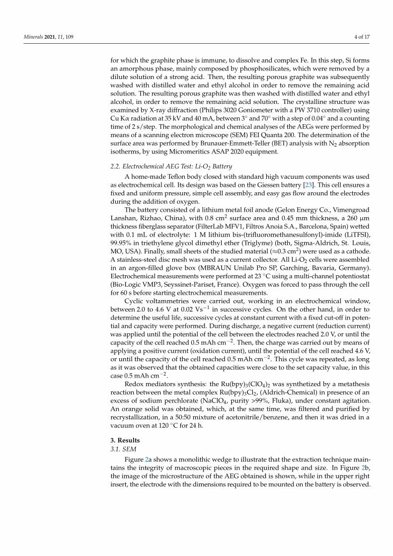
To test the performance of the AEG as a Li-O2 battery cathode, successive discharge-charge cycles were performed. Figure 8 shows the results obtained from being used ineither the presence or the absence of a redox mediator.
Figure 8. Li-O2 discharge-discharge profiles of 1 M LiTFSI in Triglyme electrolyte in oxygenated cellusing AEG as a cathode, (a) without and (b) with 5 mM Ru(bpy)3(ClO4)2. Current density of 0.1 mA cm−2.
Discharge limited to 0.5 mAh cm−2. The cycle number is indicated inside.
4. Discussion4.1. Evidence of Non-Faceted Growth in LG
The Fe-C system has been classified as faceted (G)/non-faceted (γ—austenite), due tothe high fusion entropy of G and to the fact that it produces an irregular structure. The fol-lowing discussion is intended to illustrate that this is not the case.
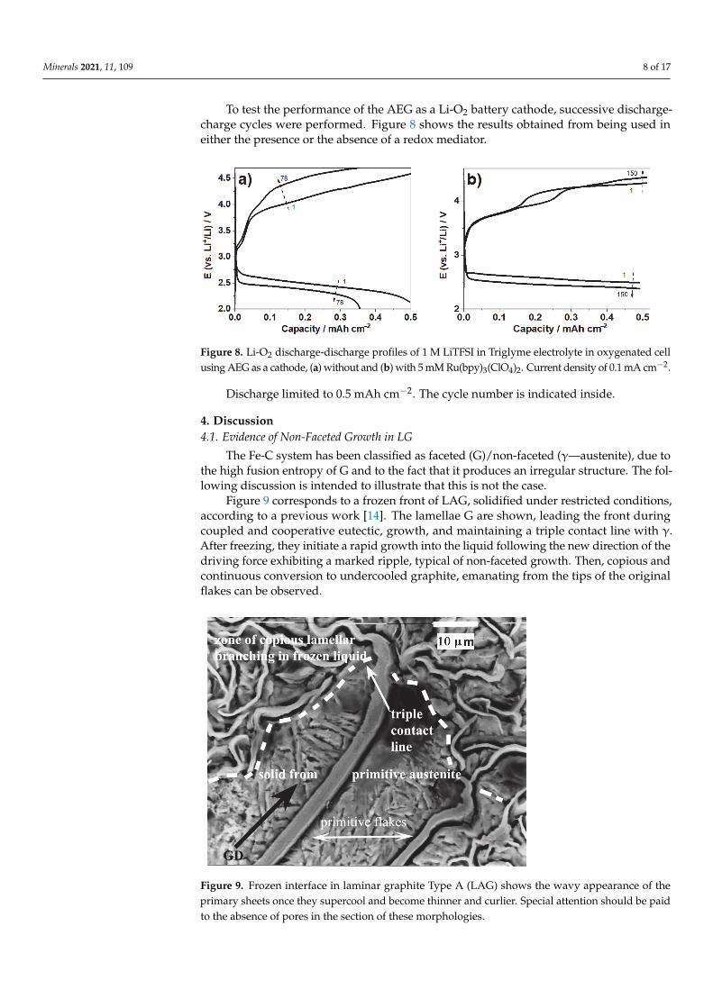
Figure 9 corresponds to a frozen front of LAG, solidified under restricted conditions,according to a previous work [14]. The lamellae G are shown, leading the front duringcoupled and cooperative eutectic, growth, and maintaining a triple contact line with γ.After freezing, they initiate a rapid growth into the liquid following the new direction of thedriving force exhibiting a marked ripple, typical of non-faceted growth. Then, copious andcontinuous conversion to undercooled graphite, emanating from the tips of the originalflakes can be observed.
Figure 9. Frozen interface in laminar graphite Type A (LAG) shows the wavy appearance of theprimary sheets once they supercool and become thinner and curlier. Special attention should be paidto the absence of pores in the section of these morphologies.
Minerals 2021, 11, 109 9 of 17
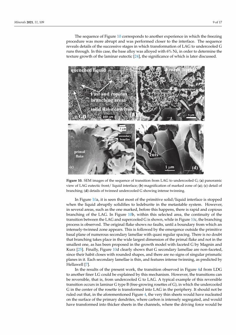
The sequence of Figure 10 corresponds to another experience in which the freezingprocedure was more abrupt and was performed closer to the interface. The sequencereveals details of the successive stages in which transformation of LAG to undercooled Gruns through. In this case, the base alloy was alloyed with 6% Ni, in order to determine thetexture growth of the laminar eutectic [24], the significance of which is later discussed.
Figure 10. SEM images of the sequence of transition from LAG to undercooled G; (a) panoramicview of LAG eutectic front/ liquid interface; (b) magnification of marked zone of (a); (c) detail ofbranching; (d) details of twinned undercooled G showing intense twinning.
In Figure 10a, it is seen that most of the primitive solid/liquid interface is stoppedwhen the liquid abruptly solidifies to ledeburite in the metastable system. However,in several areas, such as the one marked, before this happens, there is rapid and copiousbranching of the LAG. In Figure 10b, within this selected area, the continuity of thetransition between the LAG and supercooled G is shown, while in Figure 10c, the branchingprocess is observed. The original flake shows no faults, until a boundary from which anintensely-twinned zone appears. This is followed by the emergence outside the primitivebasal plane of numerous secondary lamellae with quasi regular spacing. There is no doubtthat branching takes place in the wide largest dimension of the primal flake and not in thesmallest one, as has been proposed in the growth model with faceted G by Magnin andKurz [25]. Finally, Figure 10d clearly shows that G secondary lamellae are non-faceted,since their habit closes with rounded shapes, and there are no signs of singular prismaticplanes in it. Each secondary lamellae is thin, and features intense twinning, as predicted byHellawell [7].
In the results of the present work, the transition observed in Figure 4d from LDGto another finer LG could be explained by this mechanism. However, the transitions canbe reversible, that is, from undercooled G to LAG. A typical example of this reversibletransition occurs in laminar G type B (free-growing rosettes of G), in which the undercooledG in the center of the rosette is transformed into LAG in the periphery. It should not beruled out that, in the aforementioned Figure 4, the very thin sheets would have nucleatedon the surface of the primary dendrites, where carbon is intensely segregated, and wouldhave transformed into thicker sheets in the channels, where the driving force would be

Minerals 2021, 11, 109 10 of 17
less, due to latent heat released and the least amount of constitutional undercooling pro-moted by carbon. The key to the inverse transformation is that the two eutectic phasescan reestablish the γ/G interface with preferential growth orientations. The crystallo-graphic coupling relationships between the phases are reproduced below and have beendescribed in an earlier work [24]. In conclusion, we consider that the LG eutectic belongsto the non-faceted/non-faceted class, and its growth proceeds through a cooperative andcoupled mechanism.
Preferential growth ratios of LG in the interface γ/G:Majority proportion; <100> γ // <11.0>G // growth direction,A significant proportion; <10.0>G // growth direction,Lesser extent; {10.1}G ⊥ growth direction.Figure 11 shows two examples of supercooled Gs from LDG and LEG showing
evidence of non-faceted growth, including n-f dendrites. The particle in the center ofFigure 11a, with a very well-defined cubic habit (probably TiC), leaves no doubt that atthis magnification, prismatic planes should be detected. It can be concluded that the Gphase has a non-faceted growth, therefore, adjusting its curvature easily, according to thescheme proposed in Figure 12 to maintain preferential common interface relationshipswith austenite. As a consequence, it is expected that the sheets, whatever their size andshape may be, will turn out, from a crystalline point of view, fairly perfect and withoutintrinsic porosity. Particularly noteworthy is the way in which the G sheets manage toeasily surround the austenite branches following their curvature, obeying the drivingforce that nourishes them, which, in this case, is the maximized accumulation of C there.The only pores in the resulting AEG will then correspond to those left behind by theintricate continuous austenite network when this phase is finally removed.
Figure 11. SEM images from non-faceted G of graphite lamellas of gray cast iron, (a) type D and (b)type E.
4.2. Evidence of Faceted Dendritic Growth in GC
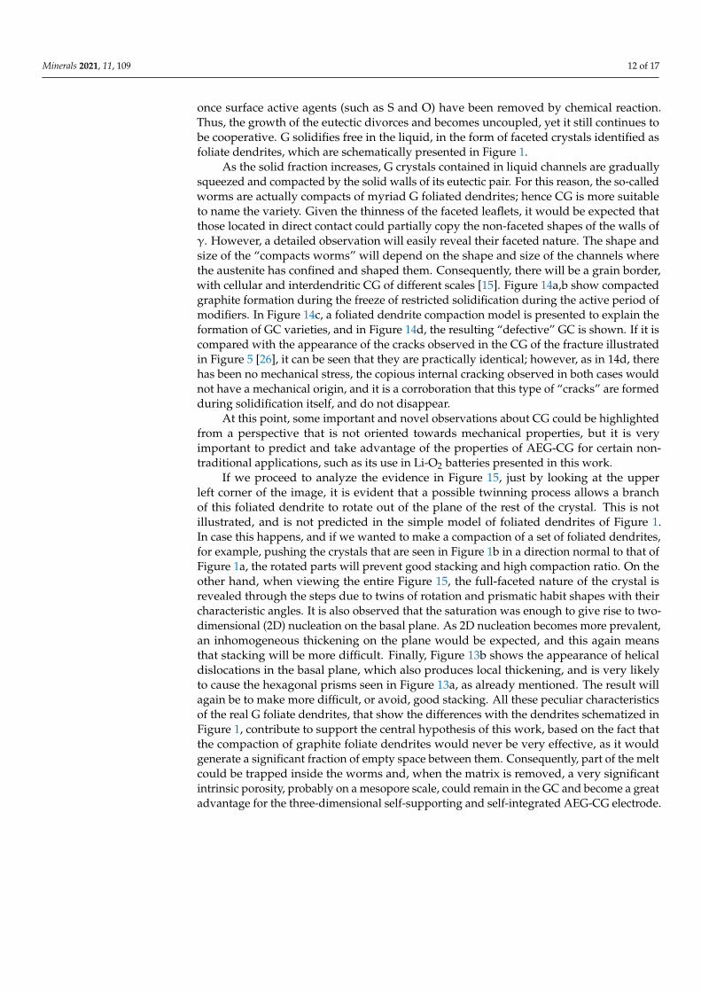
Curiously, the CG morphologies have been, and are still, called vermicular becauseunder optical microscopy (OM) observation, without or with a slight etching, they looksimilar to “worms”, and their limits look smooth and rounded. However, Figure 13a,tacked after deep etching procedure, shows a lateral surface view that reveals the surfaceclearly faceted of the “worm” (see insert in the lower right corner for more details). So,non-faceted appearance under OM is very misleading. In Figure 13b, foliated dendriteswith two helical dislocations emerging on basal plane are shown.
Minerals 2021, 11, 109 11 of 17
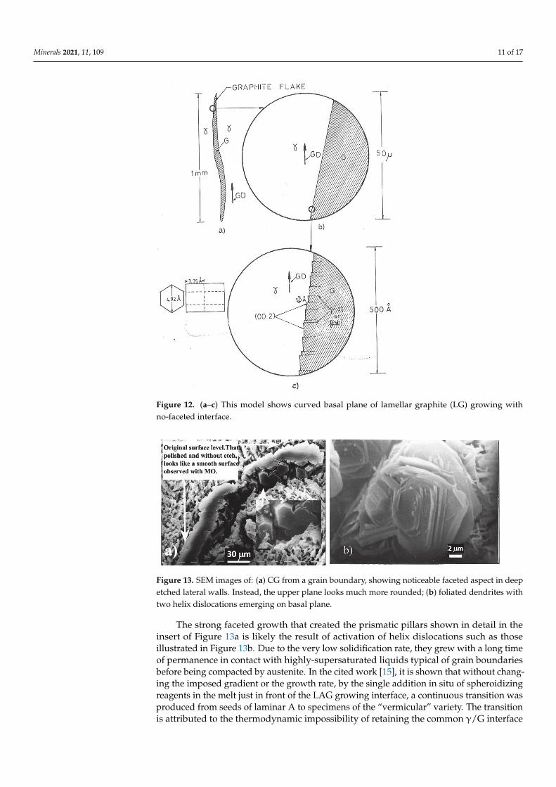
Figure 12. (a–c) This model shows curved basal plane of lamellar graphite (LG) growing withno-faceted interface.
Figure 13. SEM images of: (a) CG from a grain boundary, showing noticeable faceted aspect in deepetched lateral walls. Instead, the upper plane looks much more rounded; (b) foliated dendrites withtwo helix dislocations emerging on basal plane.
The strong faceted growth that created the prismatic pillars shown in detail in theinsert of Figure 13a is likely the result of activation of helix dislocations such as thoseillustrated in Figure 13b. Due to the very low solidification rate, they grew with a long timeof permanence in contact with highly-supersaturated liquids typical of grain boundariesbefore being compacted by austenite. In the cited work [15], it is shown that without chang-ing the imposed gradient or the growth rate, by the single addition in situ of spheroidizingreagents in the melt just in front of the LAG growing interface, a continuous transition wasproduced from seeds of laminar A to specimens of the “vermicular” variety. The transitionis attributed to the thermodynamic impossibility of retaining the common γ/G interface
Minerals 2021, 11, 109 12 of 17
once surface active agents (such as S and O) have been removed by chemical reaction.Thus, the growth of the eutectic divorces and becomes uncoupled, yet it still continues tobe cooperative. G solidifies free in the liquid, in the form of faceted crystals identified asfoliate dendrites, which are schematically presented in Figure 1.
As the solid fraction increases, G crystals contained in liquid channels are graduallysqueezed and compacted by the solid walls of its eutectic pair. For this reason, the so-calledworms are actually compacts of myriad G foliated dendrites; hence CG is more suitableto name the variety. Given the thinness of the faceted leaflets, it would be expected thatthose located in direct contact could partially copy the non-faceted shapes of the walls ofγ. However, a detailed observation will easily reveal their faceted nature. The shape andsize of the “compacts worms” will depend on the shape and size of the channels wherethe austenite has confined and shaped them. Consequently, there will be a grain border,with cellular and interdendritic CG of different scales [15]. Figure 14a,b show compactedgraphite formation during the freeze of restricted solidification during the active period ofmodifiers. In Figure 14c, a foliated dendrite compaction model is presented to explain theformation of GC varieties, and in Figure 14d, the resulting “defective” GC is shown. If it iscompared with the appearance of the cracks observed in the CG of the fracture illustratedin Figure 5 [26], it can be seen that they are practically identical; however, as in 14d, therehas been no mechanical stress, the copious internal cracking observed in both cases wouldnot have a mechanical origin, and it is a corroboration that this type of “cracks” are formedduring solidification itself, and do not disappear.
At this point, some important and novel observations about CG could be highlightedfrom a perspective that is not oriented towards mechanical properties, but it is veryimportant to predict and take advantage of the properties of AEG-CG for certain non-traditional applications, such as its use in Li-O2 batteries presented in this work.
If we proceed to analyze the evidence in Figure 15, just by looking at the upperleft corner of the image, it is evident that a possible twinning process allows a branchof this foliated dendrite to rotate out of the plane of the rest of the crystal. This is notillustrated, and is not predicted in the simple model of foliated dendrites of Figure 1.In case this happens, and if we wanted to make a compaction of a set of foliated dendrites,for example, pushing the crystals that are seen in Figure 1b in a direction normal to that ofFigure 1a, the rotated parts will prevent good stacking and high compaction ratio. On theother hand, when viewing the entire Figure 15, the full-faceted nature of the crystal isrevealed through the steps due to twins of rotation and prismatic habit shapes with theircharacteristic angles. It is also observed that the saturation was enough to give rise to two-dimensional (2D) nucleation on the basal plane. As 2D nucleation becomes more prevalent,an inhomogeneous thickening on the plane would be expected, and this again meansthat stacking will be more difficult. Finally, Figure 13b shows the appearance of helicaldislocations in the basal plane, which also produces local thickening, and is very likelyto cause the hexagonal prisms seen in Figure 13a, as already mentioned. The result willagain be to make more difficult, or avoid, good stacking. All these peculiar characteristicsof the real G foliate dendrites, that show the differences with the dendrites schematized inFigure 1, contribute to support the central hypothesis of this work, based on the fact thatthe compaction of graphite foliate dendrites would never be very effective, as it wouldgenerate a significant fraction of empty space between them. Consequently, part of the meltcould be trapped inside the worms and, when the matrix is removed, a very significantintrinsic porosity, probably on a mesopore scale, could remain in the GC and become a greatadvantage for the three-dimensional self-supporting and self-integrated AEG-CG electrode.

Minerals 2021, 11, 109 13 of 17
Figure 14. (a) Optical microscopy (OM) frozen interphase of growing CG; (b) idem SEM with deepetching; (c) compaction model; (d) CG showing compaction defects analogous to those showed onthe fracture of Figure 5b.
Figure 15. Foliated dendrite.
Minerals 2021, 11, 109 14 of 17
The preceding discussion explains why CG exhibited the highest BET specific graphitesurface, compared to the LAG type and the LDG type.
On the other hand, it should be noted that the proportion of specific surface associatedwith prismatic planes should be higher than in AEG-LG, which would be important forsome functions of the electrodes of some Li batteries [27,28]. Future work is expected todetermine the specific surface of prismatic planes, as well as the type and size of pores.
4.3. AEG As Cathode in Li-O2 Battery
The operation of a Li-O2 battery implies oxygen reduction and evolution reactions(ORR and OER, respectively), during charge and discharge processes. These heterogeneousreactions require three different phases: the oxygen gas, the liquid non-aqueous electrolyte,where O2 and Li+ are dissolved, and the solid cathode.
It is important to note how the distribution of pores is relevant in the improvement ofthe efficiency and cyclability of batteries, because their contact with the liquid (electrolyte)and gas (oxygen) phases would facilitate a good ionic transport. In this case, an openmacroporous network is needed [29,30].
A cyclic voltammetry test was first conducted in order to evaluate the performanceof the AEG cathode. Before oxygen purge, the cell filled with argon (from the glove-box)was electrochemically tested, in which was not observed a typical voltammetry ORR signal(see Figure 7). However, it is possible to see two reversible redox couples at 3.2 V and 3.7 V,probably originating from the titanium compounds and copper, which are present in theAEG. On the other hand, after oxygen purge, the ORR and the OER process take placeat the usual potential values (starting close to 2.7 V and 3.2 V, respectively), as shown inFigure 7, where the position and the shape of the peaks are similar to those reported inprevious works on Li-O2 cells, in similar conditions [31,32]. According to these results,it may be inferred that the contact between the electrolyte and the AEG material is suitableenough to work as Li-O2 cells cathode.
During the OER in oxygen atmosphere, it can be seen a broad oxidation peak at3.7 V, which is usually attributed to the oxidation of lithium peroxide particles of differentsizes [33].
In order to test the AEG-LGD material as Li-O2 batteries cathode, galvanostaticdischarge-charge cycles with a cut-off fixed at 0.5 mAh cm−2 were carried out at a typicalcurrent density of 0.1 mA cm−2. The potential vs. capacity curve of Figure 8a during thefirst and the last discharge-charge cycle shows a typical battery profile, which is similarto previous reports using the same electrolyte [34,35]. Working under these conditions,the battery reaches seventy cycles before the loss of capacity starts to be significant.
The observed capacity fade could be attributed to the increased reaction potentialbeyond the cut-off voltage and the impossibility to remove all the ORR products depositedon the electrode surface, and also, the removal of byproducts generated during ORR,because highly reactive oxygen products react with the components of the cell. Amongthem, singlet oxygen is the main cause for parasitic reactions during cycling of aproticlithium-oxygen batteries [36].
With the aim to decrease the charge potential, which both the electrodes and theelectrolyte are exposed to, and in order to extend the battery cycling, an electro activecompound was added to the electrolyte and tested as a redox mediator (RM) under thesame conditions.
However, RM should fulfill the energetic requirement imposed by the thermodynam-ics, and also RM should have the capability to deal with the reduced reactive oxygen species(RROS), which are known for their reactivity with many organic substrates, reducing theuseful life of the battery. In this context, redox couples that may have the potential to act asLi-O2 battery RMs are coordination compounds derived from ruthenium. Ru complexesare known for their excellent photochemical and electrochemical properties, as well asfor the flexibility that they have to tune their properties through the selection of differentorganic ligands. Thus, this kind of material has shown an outstanding performance in sev-

Minerals 2021, 11, 109 15 of 17
eral applications, including electrochemical and photo electrochemical catalysis in energyconversion area for light-emitting devices, sensors, among others [37].
As may be seen in Figure 8b, through the use of 5 mM Ru(bpy)3(ClO4)2, as RM, it ispossible to improve the battery cycling by having the same values of discharge potentialand decreasing the recharge potential value. Finally, the Li-O2 battery with Ru(bpy) reached150 cycles and still kept the fixed capacity value. In both cases, AEG-LDG showed a goodperformance in Li-O2 battery.
Although more studies of stability and on the reaction mechanism of Ru(bpy)3(ClO4)2as RM are needed, it is clear that it can be used satisfactorily in Li-O2 batteries.
5. Conclusions
Restricted solidification studies have proven that lamellar graphite (LG) grows in anon-faceted way in eutectic gray cast iron, while vermicular, or compact graphite (CG)does it as compacted faceted foliated graphite dendrites. This leads to vermicular graphitehaving a larger surface area than laminar varieties A and D.
From these results, an aero-eutectic graphite (AEG) that optimizes its functions couldbe designed. In the case of the present work, it is considered that the performance of typeD AEG, as a cathode of Li-O2 batteries, is satisfactory. For future works, it is contemplatedto carry out tests with the compact graphite variety, taking into account its larger surface.
Author Contributions: Conceptualization: A.N.R.; data curation: A.N.R., A.Y.T. and R.W.G.; formalanalysis: A.N.R., A.Y.T., F.F. and R.W.G.; funding acquisition: A.Y.T., F.F. and R.W.G.; investigation:A.N.R., A.Y.T., F.F. and R.W.G.; methodology: A.N.R.; project administration: A.N.R., F.F. and R.W.G.;resources: A.N.R. and R.W.G.; validation: A.N.R., A.Y.T. and F.F.; visualization: A.Y.T., F.F. andR.W.G.; writing—original draft: A.N.R., A.Y.T., F.F. and R.W.G.; writing—review and editing: A.N.R.and R.W.G. All authors have read and agreed to the published version of the manuscript.
Funding: This research received no external funding.
Institutional Review Board Statement: Not applicable.
Informed Consent Statement: Not applicable.
Data Availability Statement: Not applicable.
Acknowledgments: The authors also give special thanks to the Comisión de Investigaciones Científicasde la Provincia de Buenos Aires (CICPBA), Centro de Investigación y Desarrollo en Materiales Avanza-dos y Almacenamiento de Energía de Jujuy (CIDMEJu) and Facultad de Ingeniería de la Universidadde Buenos Aires (FIUBA) for their financial support to carry out the experimental works.
Conflicts of Interest: The authors declare no conflict of interest.
Abbreviations
AEG Aero-Eutectic GraphiteAEG-CG Aero-Eutectic graphite from compacted graphiteAEG-LGD Aero-Eutectic graphite from Type D graphiteBET Brunauer-Emmett-TellerCG Compacted graphiteFCC Face centered cubicLAG Lamellar graphite Type ALDG Laminar graphite Type DLEG Lamellar graphite Type ELG Lamellar graphiteLG-AEG Aero-Eutectic graphite lamellar graphiteLiTFSI Lithium bis-(trifluoromethanesulfonyl)-imideMM Morphological Modificationn-f non-facetedNG Nodular graphiteOER Oxygen evolution reaction

Minerals 2021, 11, 109 16 of 17
OM Optical microscopyORR Oxygen reduction reactionRM Redox mediatorTriglyme Triethylene glycol dimethyl etherγ Austenite
References1. Su, B.L.; Sánchez, C.; Yang, X.-Y. Hierarchically Structured Porous Materials: From Nanoscience to Catalysis, Separation, Optics, Energy,
and Life Science, 1st ed.; Wiley VCH: Weinheim, Germany, 2012.2. Gregorutti, R.W.; Tesio, A.Y.; Gómez-Cámer, J.L.; Roviglione, A.N. Synthesis and characterization of aero-eutectic graphite
obtained by solidification and its application in energy storage: Cathodes for lithium oxygen batteries. Electron. Mater. 2020, 1, 3.[CrossRef]
3. McNaught, A.D.; Wilkinson, A. Compendium of Chemical Terminology, 2nd ed.; The “Gold Book”; Blackwell Scientific Publications:Oxford, UK, 1997; ISBN 0-9678550-9-8. [CrossRef]
4. Holcombe, C.E. USAEC Oak Ridge Y-12 Plant, Report Y 1887; National Technical lnformation Service: Springfield, VA, USA, 1973.5. Roviglione, A.N.; Hermida, J.D. Mechanism of formation of different cast iron graphite structures. In Proceedings of the
72nd National Conference of the Argentine Physical Association (AFA), San Carlos de Bariloche, Argentina, 28 September–2October 1987.
6. Delavignette, P.; Amelinckx, S. Dislocation patterns in graphite. J. Nuclear Mater. 1962, 5, 17–66. [CrossRef]7. Double, D.D.; Hellawell, A. Cone-helix growth forms of graphite. Acta Metall. 1974, 22, 481–487. [CrossRef]8. Roviglione, A.N.; Hermida, J.D. Rhombohedral graphite phase in nodules from ductile cast iron. Proc. Mater. Sci. 2015, 8, 924–933.
[CrossRef]9. Kelly, B.T. Physics of Graphite; Applied Science Publishers: London, UK, 1981.10. Saratovkin, D.D. Dendritic Crystallization; Consultants Bureau Transl.: New York, NY, USA, 1959.11. Liu, S.; Loper, C.R. The formation of kish graphite. Carbon 1991, 29, 547–555. [CrossRef]12. Roviglione, A.N.; Biloni, H. Modificación de la morfología de crecimiento de la fase grafito durante la solidificación unidireccional
de la fundición de hierro gris. PARTE I: “Solidificación Unidireccional. modificación in-situ, congelado de la interfaz Sólido-Líquido y Caracterización de Microestructuras”. In Actas Jornadas Metalúrgicas SAM’91; II ALAMET’91 ed.; Sociedad Argentinade Metales: Buenos Aires, Argentina, 1991.
13. Roviglione, A.N.; Biloni, H. Unidirectional solidification of cast iron: Morphological changes of graphite due to in-situ modifica-tion. In Proceedings of the Fifth International Symposium on the Physical Metallurgy of Cast Iron (SCI-5), Nancy, France, 3–5October 1994; pp. 369–376.
14. Roviglione, A.N.; Hermida, J.D. A new unidirectional solidification method to study gray cast iron. Metall. Mater. Trans. B 2002,33, 235–241. [CrossRef]
15. Roviglione, A.N.; Hermida, J.D. From flake to nodular: A new theory of morphological modification in gray cast iron.Metall. Mater. Trans. B 2004, 35, 313–330. [CrossRef]
16. Stefanescu, D.M.; Huff, R.; Alonso, G.; Larrañaga, P.; De La Fuenta, E.; Suarez, R. On the crystallization of compacted and chunkygraphite from liquid multicomponent Iron-Carbon-Silicon-based melts. Metall. Mater. Trans. A 2016, 47, 4012–4023. [CrossRef]
17. ASTM A247-19. Standard Test Method for Evaluating the Microstructure of Graphite in Iron Castings; ASTM International: West Con-shohocken, PA, USA, 2019. [CrossRef]
18. Park, J.S.; Verhoeven, J.D. Transitions between type A flake, type D flake, and coral graphite eutectic structures in cast irons.Metall. Mater. Trans. A 1996, 27, 2741–2753. [CrossRef]
19. Larrañaga, P.; Sertucha, J.; Loizaga, A.; Suarez, R.; Stefanescu, D.M. Gray cast iron with high austenite-to-eutectic ratio. Part III-High strength, low hardness, high carbon equivalent gray iron with superfine graphite. Am. Found. Soc. 2012, 120, 347–353.
20. Hernando, J.C.; Diószegi, A. On the primary solidification of compacted graphite iron: Microstructure evolution during isothermalcoarsening. Mater. Sci. For. 2018, 925, 90–97. [CrossRef]
21. ASM. Cast Iron Science and Technology; Doru, M.S., Ed.; ASM: Almere, The Netherlands, 2017.22. Roviglione, A.N. An useful technique for studying graphite in cast iron. Mater. Charact. 1993, 31, 209–216. [CrossRef]23. Bender, C.L.; Hartmann, P.; Vracar, M.; Adelhelm, P.; Janek, J. On the thermodynamics, the role of the carbon cathode, and the
cycle life of the sodium superoxide (NaO2) battery. Adv. Energy Mater. 2014, 4, 1301863. [CrossRef]24. Roviglione, A.N.; Hermida, J.D. X-ray diffraction characterization of flake and compacted graphite in cast iron. Mater. Charact.
1994, 32, 127–137. [CrossRef]25. Kurz, W.; Fisher, D.J. Fundamentals of Solidification; Trans Tech. Publications: Bäch, Switzerland, 1986; pp. 111–112.26. Gregorutti, R.W.; Grau, J.E. Mechanical properties of compacted graphite cast iron with different microstructures. Inter. J. Cast
Metal. Res. 2014, 27, 275–281. [CrossRef]27. Placke, T.; Siozios, V.; Schmitz, R.; Lux, S.; Bieker, P.; Colle, C.; Meyer, H.-W.; Passerini, S.; Winter, M. Influence of graphite surface
modifications on the ratio of basal plane to “non-basal plane” surface area and on the anode performance in lithium ion batteries.J. Power Sour. 2012, 200, 83–91. [CrossRef]

Minerals 2021, 11, 109 17 of 17
28. Olivier, J.P.; Buqa, H.; Kohs, W.; Schröttner, H.; Golob, P.; Winter, M. The Relevance of Graphite Surface Properties for Anode Performancein Lithium Ion Cells-III. Surface Area and Surface Heterogeneieties; Micromeritics Instrument Corp, Inc.: Norcross, GA, USA, 2001.
29. Yuan, J.; Yu, J.-S.; Sundén, B. Review on mechanisms and continuum models of multi-phase transportphenomena in porousstructures of non-aqueous Li-Air batteries. J. Power Sour. 2015, 278, 352–369. [CrossRef]
30. Lim, H.-D.; Yun, Y.S.; Ko, Y.; Bae, Y.; Song, M.Y.; Yoon, H.J.; Kang, K.; Jin, H.-J. Three-dimensionally branchedcarbon nanowebs asair-cathode for redox-mediated Li-O2 batteries. Carbon 2017, 118, 114–119. [CrossRef]
31. Ferrari, S.; Quartarone, E.; Tomasi, C.; Bini, M.; Galinetto, P.; Fagnoni, M.; Mustarelli, P. Investigation of ether-based ionic liquidelectrolytes for Lithium-O2 batteries. J. Electrochem. Soc. 2015, 162, A3001–A3006. [CrossRef]
32. Laoire, C.O.; Mukerjee, S.; Abraham, K.M.; Plichta, E.J.; Hendrickson, M.A. Influence of nonaqueous solvents on the electrochem-istry of oxygen in the rechargeable lithium-air battery. J. Phys. Chem. 2010, 114, 9178–9186. [CrossRef]
33. Guo, L.; Wang, J.; Ma, S.; Zhang, Y.; Wang, E.; Peng, Z. The origin of potential rise during charging of Li-O2 batteries.Sci. China Chem. 2017, 60, 1527–1532. [CrossRef]
34. Lai, J.; Xing, Y.; Chen, N.; Li, L.; Wu, F.; Chen, R. A comprehensive insight into the electrolytes for rechargeablelithium–airbatteries. Angew. Chem. 2019, 59, 2974–2997. [CrossRef] [PubMed]
35. Tamakloe, W.; Agyeman, D.A.; Park, M.; Yang, J.; Kang, Y. Polydopamine-induced surface functionalization of carbon nanofiberfor Pd deposition enabling an enhanced catalytic activity for oxygen reduction and evolution reactions. J. Mater. Chem. A 2019, 7,7396–7405. [CrossRef]
36. Mahne, N.; Schafzahl, B.; Leypold, C.; Leypold, M.; Grumm, S.; Lietgeb, A.; Strohmeier, G.A.; Wilkening, M.; Fontaine, O.;Kramer, D.; et al. Singlet oxygen generation as a major cause for parasitic reactions during cycling of aprotic lithium–oxygenbatteries. Nat. Energy 2017, 2, 17036. [CrossRef]
37. Juris, A.; Balzani, V.; Barigelletti, F.; Campagna, S.; Belser, P.; von Zelewsky, A. Ru(II) polypyridine complexes: Photophysics,photochemistry, eletrochemistry, and chemiluminescence. Coordination Chem. Rev. 1988, 84, 85–277. [CrossRef]
Related Documents