Ref: Donald Hearn & M. Pauline Baker , Computer Graphics (Chapter – 2) Foley, van Dam, Feiner & Hughes, Computer Graphics Principles & Practice Graphics-UPES

Welcome message from author
This document is posted to help you gain knowledge. Please leave a comment to let me know what you think about it! Share it to your friends and learn new things together.
Transcript
Ref: Donald Hearn & M. Pauline Baker , Computer Graphics (Chapter – 2)
Foley, van Dam, Feiner & Hughes, Computer Graphics Principles & Practice
Graphics-UPES

GRAPHICS HARDWARE
Graphics Input Devices
Graphics-UPES
Components of an Interactive Graphics System
• Graphics Hardware
- Graphics Input and Storage devices
- Graphics Display devices
• Graphics Software
- General Programming packages
- Special-purpose applications packages
Graphics-UPES

Figure: Components of a typical interactive graphics system
Graphics-UPES
Graphics Input Devices
• Any device that allows information from outside the computer to be communicated to the computer is considered an input device.
• Understanding of various input devices is important in order to construct high-quality graphical user-interfaces.
• Input devices are of two basic types: analog and digital.
Graphics-UPES
Commonly used Analog Input Devices
(convert a graphic system user’s movements into changes in voltage)
• Paddle control,
• Trackball,
• Mouse, and
• Joystick
Graphics-UPES

Commonly used Digital Input Devices
(are actually analog devices that collect input information in discrete form)
• Light pen,• Magnetic pen and tablet,• Touch Panel, and• Keyboard• Digitizers• Image Scanners
Graphics-UPES
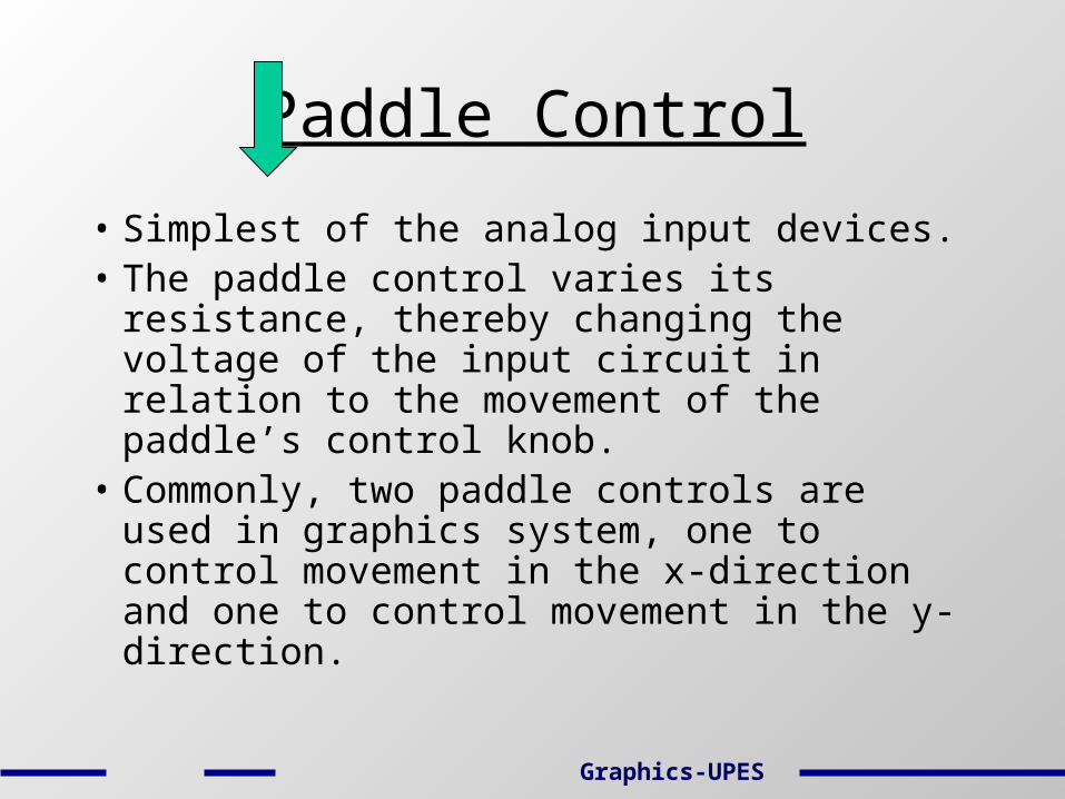
Paddle Control
• Simplest of the analog input devices.• The paddle control varies its resistance,
thereby changing the voltage of the input circuit in relation to the movement of the paddle’s control knob.
• Commonly, two paddle controls are used in graphics system, one to control movement in the x-direction and one to control movement in the y-direction.
Graphics-UPES
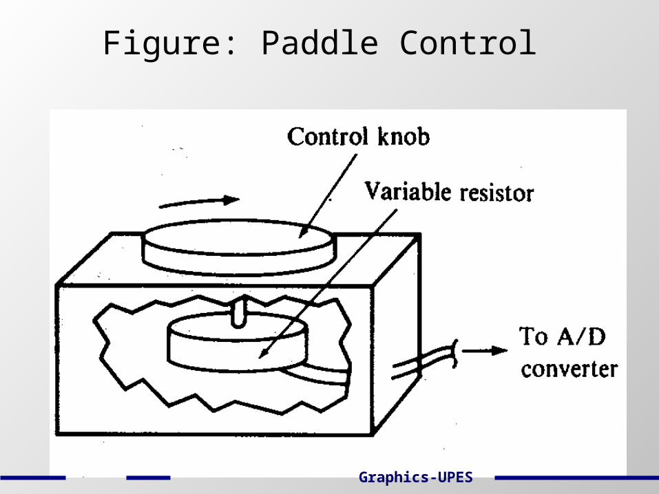
Figure: Paddle Control
Graphics-UPES
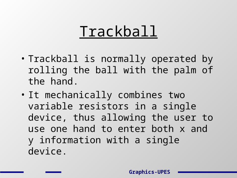
Trackball
• Trackball is normally operated by rolling the ball with the palm of the hand.
• It mechanically combines two variable resistors in a single device, thus allowing the user to use one hand to enter both x and y information with a single device.
Graphics-UPES
Figure: Trackball
Graphics-UPES
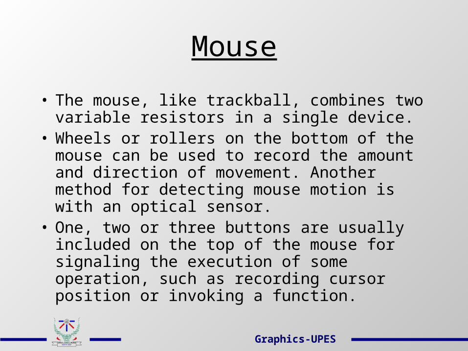
Mouse
• The mouse, like trackball, combines two variable resistors in a single device.
• Wheels or rollers on the bottom of the mouse can be used to record the amount and direction of movement. Another method for detecting mouse motion is with an optical sensor.
• One, two or three buttons are usually included on the top of the mouse for signaling the execution of some operation, such as recording cursor position or invoking a function.
Graphics-UPES
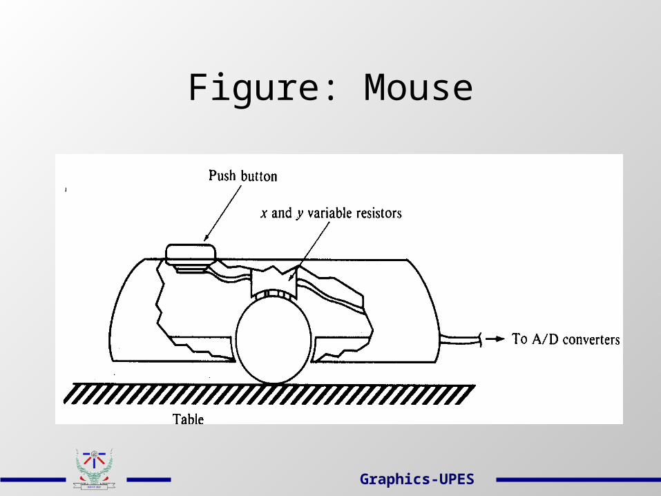
Figure: Mouse
Graphics-UPES

Joystick
• A joystick consists of a small, vertical lever (stick) mounted on a base that is used to steer the screen cursor around.
• The distance that the stick is moved in any direction from its center position corresponds to screen-cursor movement in that direction.
Graphics-UPES

Figure: Joystick
Graphics-UPES

Light Pen
• Light pens are used to select screen positions by detecting the light coming from the points on the CRT screen.
• They are sensitive to the short burst of light emitted from the phosphor coating at the instant the electron beam strikes a particular point.
• The recorded light-pen coordinates can be used to position an object or to select a processing option.
Graphics-UPES

Figure: Light pen system
Graphics-UPES
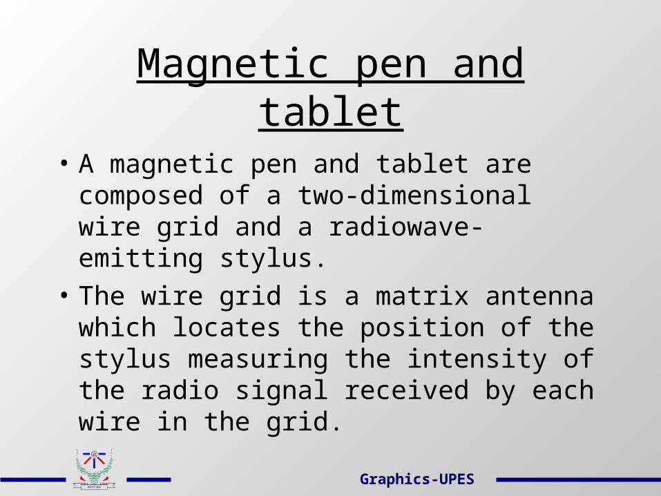
Magnetic pen and tablet
• A magnetic pen and tablet are composed of a two-dimensional wire grid and a radiowave-emitting stylus.
• The wire grid is a matrix antenna which locates the position of the stylus measuring the intensity of the radio signal received by each wire in the grid.
Graphics-UPES
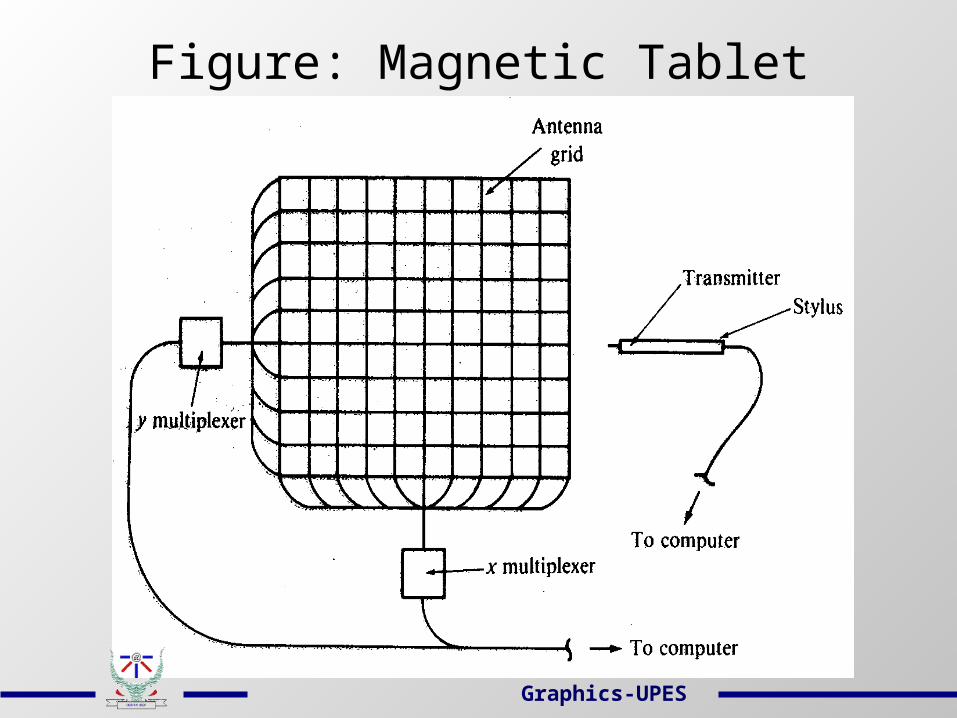
Figure: Magnetic Tablet
Graphics-UPES
Touch Panel
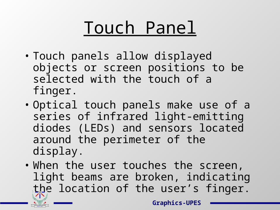
• Touch panels allow displayed objects or screen positions to be selected with the touch of a finger.
• Optical touch panels make use of a series of infrared light-emitting diodes (LEDs) and sensors located around the perimeter of the display.
• When the user touches the screen, light beams are broken, indicating the location of the user’s finger.
Graphics-UPES
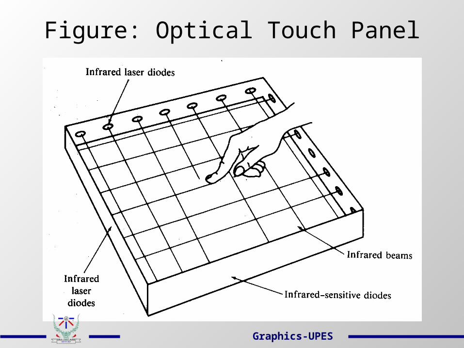
Figure: Optical Touch Panel
Graphics-UPES
Keyboard
• The keyboard is an efficient device for inputting nongraphic data as picture levels associated with a graphic display.
• Keyboards can also be provided with features to facilitate entry of screen coordinates, menu selections, or graphic functions.
• Function keys allow users to enter frequently used operations in a single keystroke, and cursor-control keys can be used to select displayed objects or coordinate positions by positioning the screen cursor.
Graphics-UPES
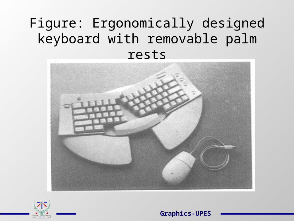
Figure: Ergonomically designed keyboard with removable palm rests
Graphics-UPES
Digitizers
• A common device for interactively selecting coordinate positions on a object is a digitizer.
• These discrete coordinate positions can be joined with straight-line segments to approximate the curve or surface shapes.
• Graphic tablets provide a highly accurate method for selecting coordinate positions with accuracy of about 0.05 mm.
Graphics-UPES
Digitizers
• Many graphic tablets are constructed with a rectangular grid of wires embedded in the tablet surface.
• Electromagnetic pulses are generated in sequence along the wires, and an electric signal is induced in a wire coil in an activated stylus or hand cursor to record a tablet position.
Contd…
Graphics-UPES
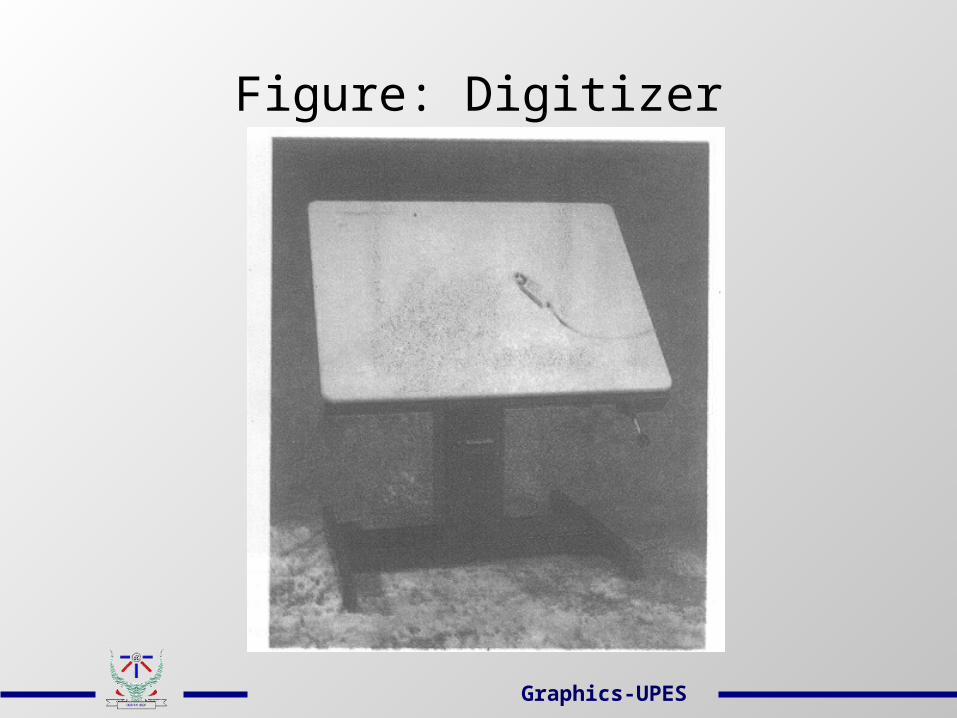
Figure: Digitizer
Graphics-UPES
Image Scanners
• An image scanner records the gradations of gray scale/color of a given color or b/w photos and stores in an array.
• On stores image, we can apply transformations to rotate, scale, crop the picture to a particular screen area.
• We can also apply various image processing methods to modify the array representation of the picture (e.g. contrast enhancement).
Graphics-UPES

Figure: Flatbed scanner
Graphics-UPES
DataGlove: 3D Interaction Device• The glove is constructed with a series of
sensors that detect hand and finger movements.
• Electromagnetic coupling between transmitting antennas and receiving antennas is used to provide information about position and orientation of the hand.
• Inputs from the glove can be used to position or manipulate objects in a virtual scene.
Graphics-UPES
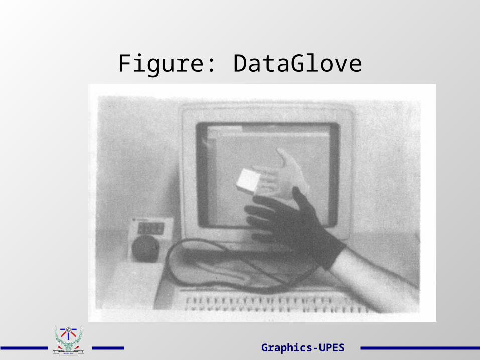
Figure: DataGlove
Graphics-UPES
Graphic Storage Formats
Regardless of the storage medium selected, the graphics system designer will always use some combination of the following basic storage formats:
1. Image-only Storage2. Display-memory Storage3. Compressed-memory Storage4. Information Storage
Graphics-UPES

Image-Only Storage
• Here the video image is retained on video tape or video disk or as a photograph.
• Storage of images in this fashion is relatively inexpensive.
• Once the image is stored, it is difficult and expensive to restore it to the computer for further manipulation.
Graphics-UPES
Display-Memory Storage
• Here the bit pattern that represents the image is copied directly from display memory to the storage medium.
• A utility program may be used to save blocks of the computer memory by passing the starting and ending addresses of the display memory.
• Drawback: Storing images in this manner requires a great deal of memory.
Graphics-UPES
Compressed-Memory Storage
• Storage space can be greatly reduced by storing images in compressed format.
• Compression takes advantage of repeated patterns in display memory.
• Compression routines can be very complex, taking advantage of long series of replication.
• It may not be useful when images to be saved contain no or few series of replicated bytes.
Graphics-UPES
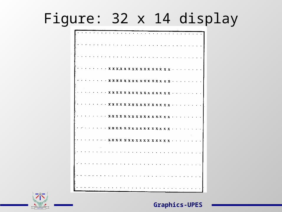
Figure: 32 x 14 display
Graphics-UPES
Information Storage
• It retains the information (series of commands that describe the image) used to construct the image.
• It can save considerable time and memory if the image to be stored is composed entirely of standard objects.
• This approach is not fruitful if nonstandard objects are used.
Graphics-UPES
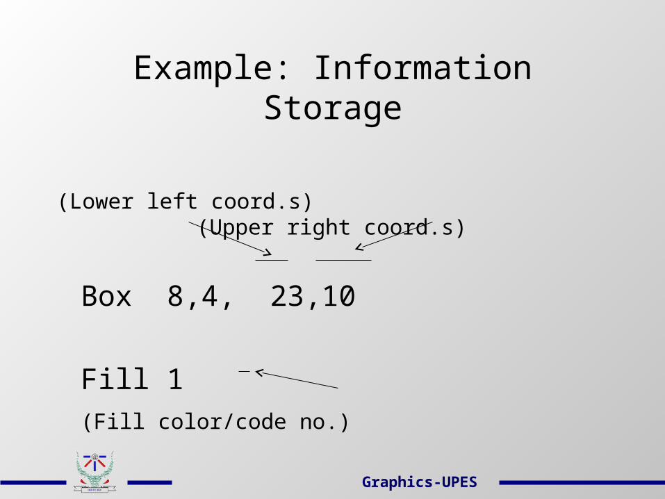
Example: Information Storage
(Lower left coord.s) (Upper right coord.s)
Box 8,4, 23,10
Fill 1
(Fill color/code no.)
Graphics-UPES

GRAPHICS HARDWARE
Graphics Output Devices
Graphics-UPES
Graphics Output Devices
• Most commonly used computer output devices that are capable of producing graphical output are:
Raster-scan Cathode Ray Tube (CRT)Plasma DisplayLiquid Crystal Display3D Viewing using Stereoscopic SystemsPlotters and Printers
Graphics-UPES

Raster-Scan CRT
• Interactive computer graphics demands display devices whose images can be changed quickly.
• Nonpermanent image displays allow an image to be changed, making possible dynamic movement of portions of an image.
• Raster-scan CRTs are used in common television sets. The term “raster” is synonym for the term “matrix”. A raster-scan CRT scans a matrix with an electron beam.
• The basic understanding of CRT’s internal operations is useful in graphics programming.

Components of a raster-scan CRT
• Electron gun
• Control electrode
• Focusing electrode
• Deflection yoke
• Phosphorus-coated screen
Graphics-UPES
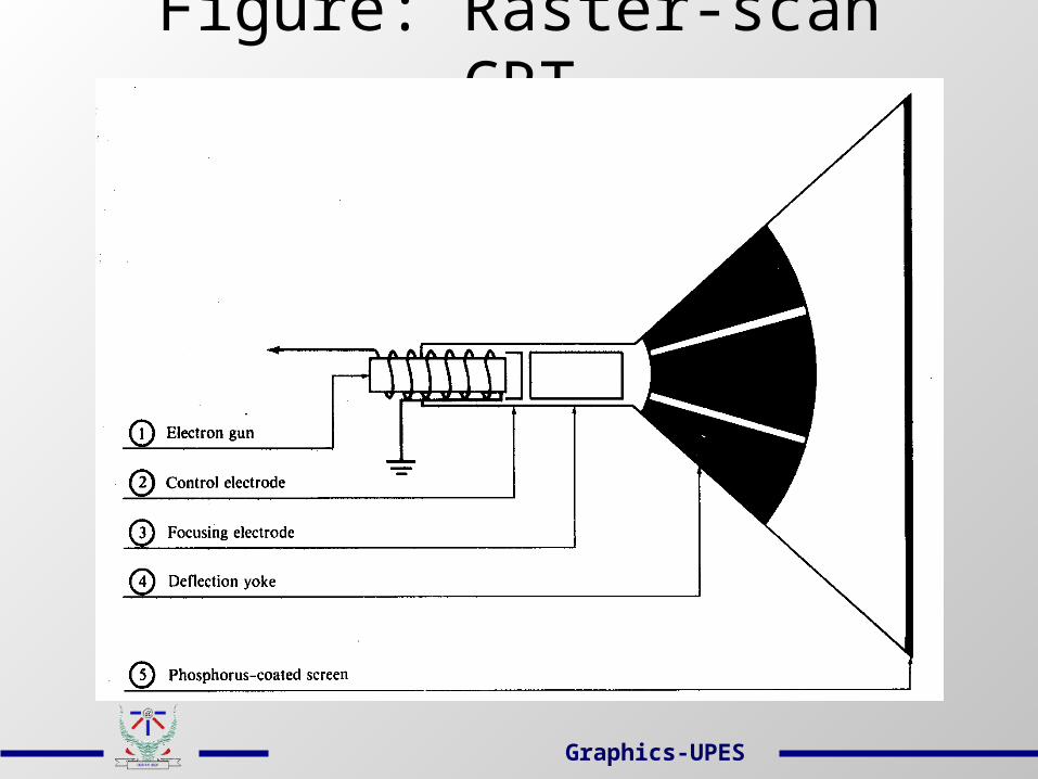
Figure: Raster-scan CRT
Graphics-UPES

Electron Gun
• It consists of a series of components (primarily a heater and a cathode) which together cause electrons to collect at the end of the electron gun.
• These electrons are then accelerated by application of an electric field.
Graphics-UPES

Control Electrode
• It is used to regulate the flow of electrons.• It is a metal cylinder that fits over the
cathode.• A negative voltage on the control electrode
simply decreases the number of electrons passing through.
• Hence intensity of the electron beam is controlled by setting voltage levels on the control electrode.
Graphics-UPES
Focusing Electrode
• It is used to create a clear picture by focusing the electron beam into a narrow beam.
• The focusing electrode serves this purpose by extracting an electromagnetic force on the electrons in the electron beam.
• The effect resembles that of a glass lens on light wave.
Graphics-UPES
Deflection Yoke
• It is used to control the direction of the electron beam.
• The deflection yoke creates a magnetic field which will bend the electron beam as it passes through the field.
• In a conventional CRT the yoke is connected to a scan generator.
Graphics-UPES
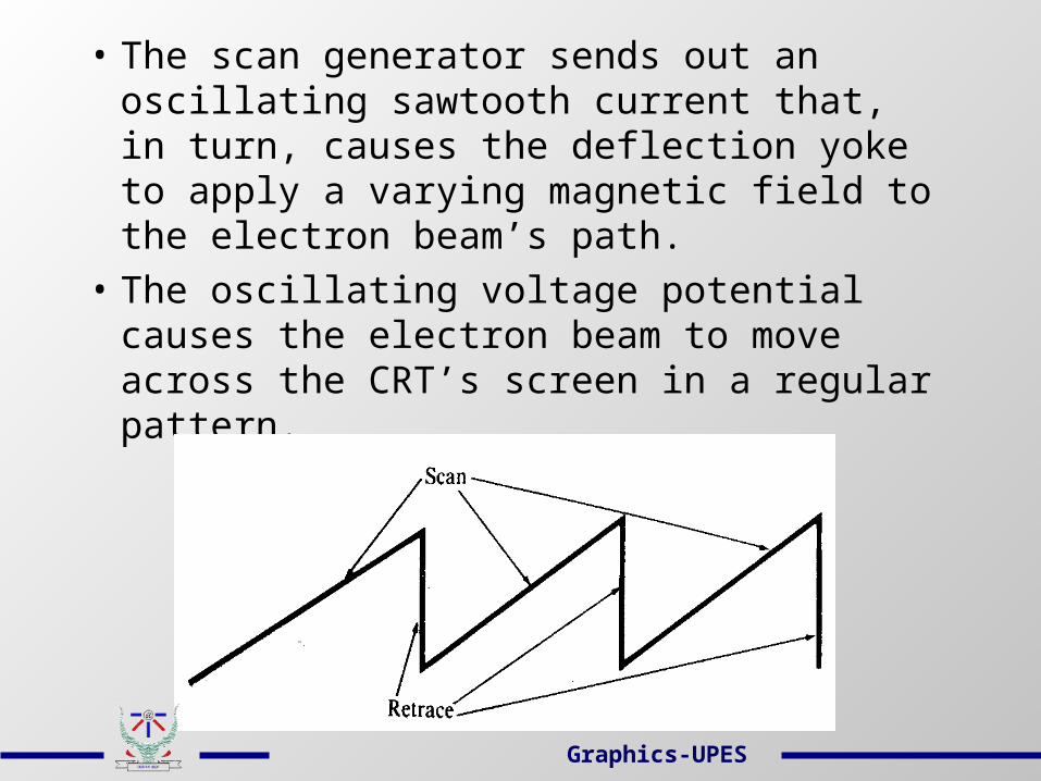
• The scan generator sends out an oscillating sawtooth current that, in turn, causes the deflection yoke to apply a varying magnetic field to the electron beam’s path.
• The oscillating voltage potential causes the electron beam to move across the CRT’s screen in a regular pattern.
Graphics-UPES

Phosphorus-coated Screen
• The CRT surface is coated with special crystals called phosphors.
• Phosphors glow when they are hit by a high-energy electron beam.
• The glow given off by the phosphor during exposure to the electron beam is known as fluorescence.
• The continuing glow given off after the beam is removed is known as phosphorescence. Its duration is known as the phosphor’s persistence.
Graphics-UPES
Principle of Raster-scan Displays
• Picture definition is stored in a memory area called the refresh buffer or frame buffer. This memory area holds the set of intensity values for all the screen points.
• The electron beam is swept across the screen, one row at a time from top to bottom and painting the stored intensity values.
Graphics-UPES
Refresh and Flicker
Each time the electron beam goes through a complete cycle of rater or scan lines, the CRT is said to be “refreshed”.
It is very important that the persistence of the phosphor used and the refresh rate be matched.
Otherwise, an image on the CRT may appear to flash rapidly on and off. It is called “flicker”.
Graphics-UPES
Horizontal/ Vertical Retrace
• Refreshing of rater-scan displays is done at the rate of 60 to 80 frames per second.
• At the end of each scan line, the electron beam returns to the left side of the screen to begin displaying the next line (horizontal retrace).
• And at the end of each frame, the electron beam returns to the top left corner of the screen to begin the next frame (vertical retrace).
Graphics-UPES
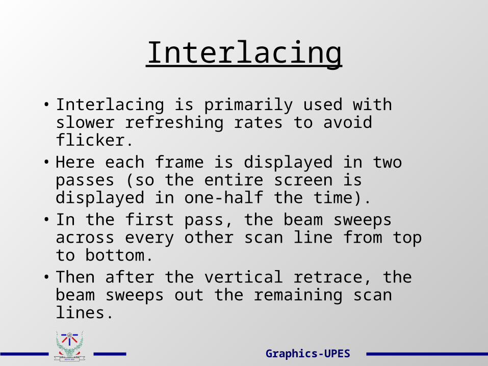
Interlacing
• Interlacing is primarily used with slower refreshing rates to avoid flicker.
• Here each frame is displayed in two passes (so the entire screen is displayed in one-half the time).
• In the first pass, the beam sweeps across every other scan line from top to bottom.
• Then after the vertical retrace, the beam sweeps out the remaining scan lines.
Graphics-UPES
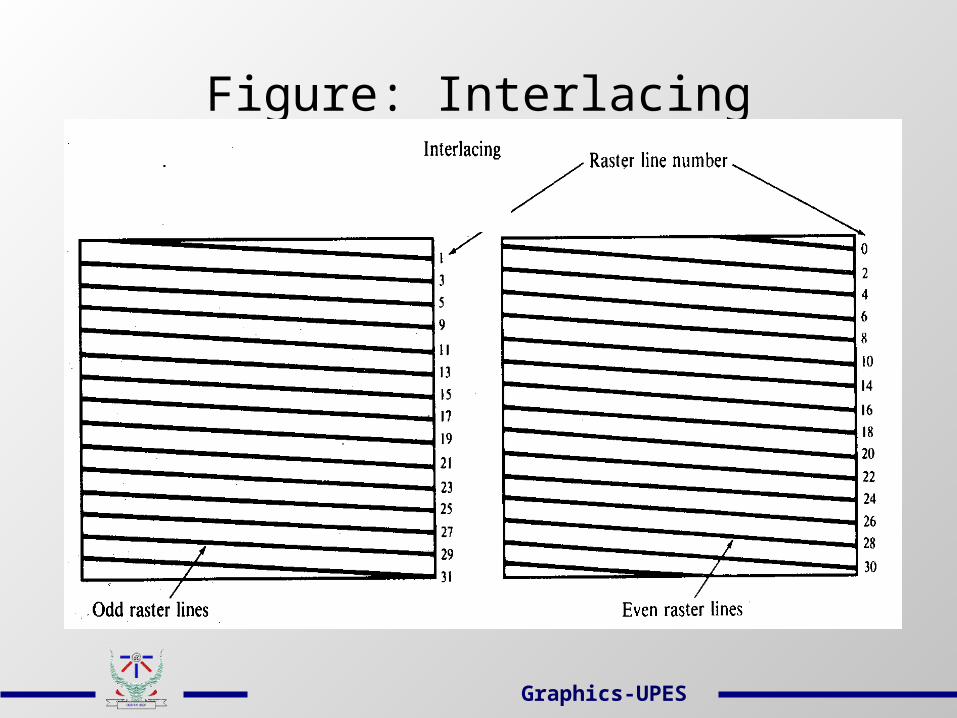
Figure: Interlacing
Graphics-UPES
Plasma DisplayIt is one of the flat-panel display under
emissive (convert electrical energy into light) display category.
Plasma displays do not have to be refreshed; that is, once a pixel is displayed on the screen, it will remain lit until it is intentionally turned off.
The electrofluorescent material is nothing but an array of tiny neon bulbs. Each bulb can be put into an “on” state or an “off” state, and remains in the state until explicitly changed to the other.
Graphics-UPES
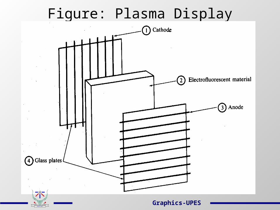
Figure: Plasma Display
Graphics-UPES
Liquid Crystal Display These non-emissive devices produce a
picture by passing polarized light from the surroundings or from an internal light source through a liquid crystal material that can be aligned to either block or transmit the light.
The Glass plate serves as a bounding surface for the conductive coating.
Conductive coating acts as a conductor so that a voltage can be applied across the liquid crystal.
Graphics-UPES
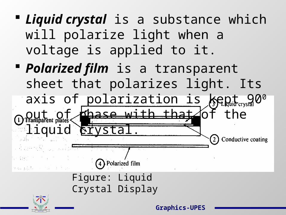
Liquid crystal is a substance which will polarize light when a voltage is applied to it.
Polarized film is a transparent sheet that polarizes light. Its axis of polarization is kept 900 out of phase with that of the liquid crystal.
Figure: Liquid Crystal Display
Graphics-UPES

Plotters
• All plotters behave like slow vector devices from the graphics programmer’s point of view.
• Examples:
Flatbed plotter
Drum plotter
• Components of a Flatbed plotter:
Pen – an actual pen that draws on the paper.
Graphics-UPES
Write-move mechanism – used to lift and lower the pen.
Pen cartridge – holds several different colored pens. The plotter holds a program in ROM that instructs to pick corresponding color pen.
x Driver motor – moves the pen horizontally across the paper.
y Driver motor – moves the pen vertically across the paper.
Graphics-UPES
3D Viewing using Stereoscopic Systems
• In a stereoscopic projection, two views of a scene are generated from a viewing direction corresponding to each eye.
• When we simultaneously look at the left view with the left eye and the right view with the right eye, the two views merge into a single image and we perceive a scene with depth.
• Examples: i) stereoscopic glasses & an infrared synchronizing emitter, ii) Headset
Graphics-UPES
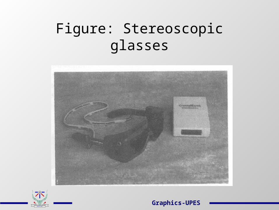
Figure: Stereoscopic glasses
Graphics-UPES
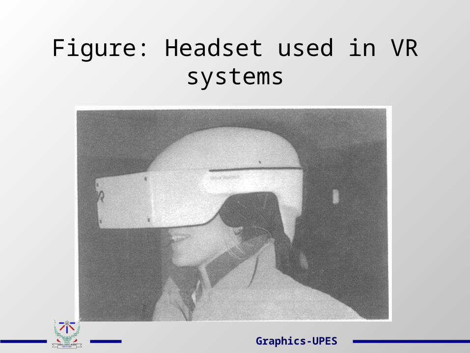
Figure: Headset used in VR systems
Graphics-UPES
Architecture of a Raster-graphics System Video Controller- It performs the basic refreshing operation.- It accesses the frame buffer directly to refresh the
screen.- It can retrieve multiple pixel values from the
frame buffer on each pass.- The multiple pixel intensities are then stored in a
separate register and used to control the CRT beam intensity for a group of adjacent pixels.
- Double buffering is often used in real-time animations.
Graphics-UPES

Display Processor- Its purpose is to free the CPU from the
graphics chores.- It digitizes a picture definition given in an
application program into a set of pixel intensity values for storage in the frame buffer.
- Other functions include generating various line styles (dashed, dotted or solid), displaying color areas and performing manipulations on displayed objects.
Graphics-UPES
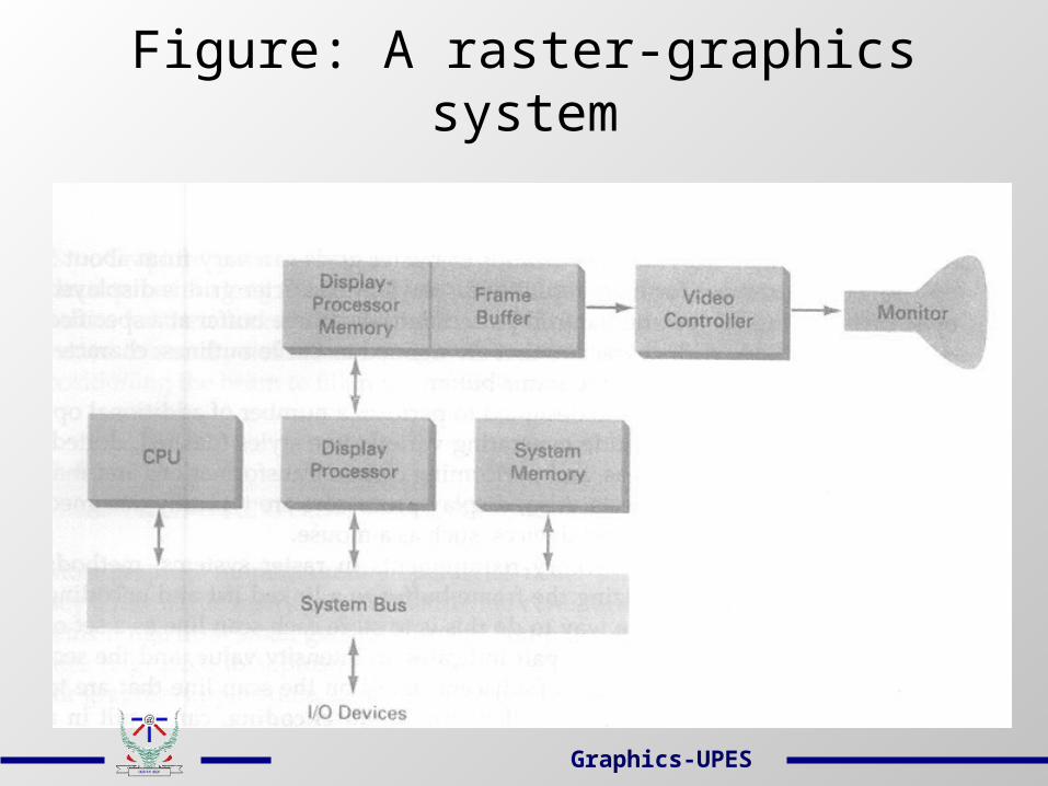
Figure: A raster-graphics system
Graphics-UPES

Architecture of a Random-display System
• Graphics pattern are drawn on a random-scan (vector) system by directing the electron beam along the component lines of the picture.
• Graphic commands in the application program are translated by the graphics package into a display file stored in the system memory.
• The display processor cycles through each command in the display file program once during each refresh cycle.
Graphics-UPES
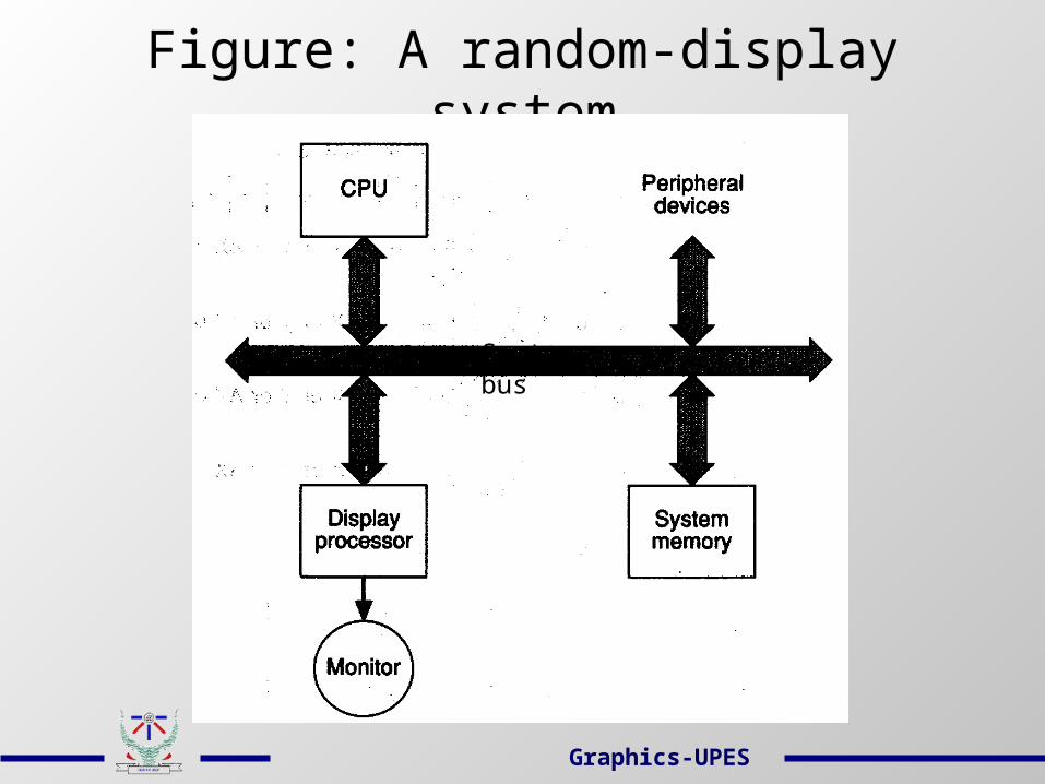
Figure: A random-display system
System bus
Graphics-UPES
Related Documents


