BRITISH STANDARD BS 1553-1: 1977 Specification for Graphical symbols for general engineering — Part 1: Piping systems and plant UDC 003.62:62+621.64+628.8+66.02+697 Licensed Copy: Loughborough ATHENS, Loughborough University, 10/01/2013 17:30, Uncontrolled Copy, (c) The British Standards Institution 2012

Welcome message from author
This document is posted to help you gain knowledge. Please leave a comment to let me know what you think about it! Share it to your friends and learn new things together.
Transcript
BRITISH STANDARD BS 1553-1:1977
Specification for
Graphical symbols for general engineering —
Part 1: Piping systems and plant
UDC 003.62:62+621.64+628.8+66.02+697
Lice
nsed
Cop
y: L
ough
boro
ugh
AT
HE
NS
, Lou
ghbo
roug
h U
nive
rsity
, 10/
01/2
013
17:3
0, U
ncon
trol
led
Cop
y, (
c) T
he B
ritis
h S
tand
ards
Inst
itutio
n 20
12
BS 1553-1:1977
This British Standard, having been prepared under the direction of the Mechanical and the Chemical Standards Committees, was published under the authority of the Executive Board on 31 March 1977
© BSI 01-1999
First published September 1949First revision March 1977
The following BSI references relate to the work on this standard:Committee references MEE/88 and CHE/17Drafts for comment 71/34910,71/34911 and 71/35726
ISBN 0 580 09551 7
Cooperating organizations
The Mechanical Engineering Standards Committee and the Chemical Engineering Standards Committee, under whose supervision this British Standard was prepared, consist of representatives from the following Government departments and professional and industrial organizations:
Mechanical Engineering Standards Committee Institution of Heating and VentilatingAssociated Offices Technical Committee EngineersAssociation of Consulting Engineers Institution of Mechanical EngineersAssociation of Hydraulic Equipment Institution of Plant Engineers
Manufacturers’ Ltd* Institution of Production EngineersAssociation of Mining Electrical and London Transport Executive
Mechanical Engineers Machine Tool Trades’ AssociationBritish Compressed Air Society Ministry of Defence*
British Electrical and Allied Manufacturers’ National Coal BoardAssociation National Engineering Laboratory —
British Gas Corporation Department of IndustryBritish Gear Manufacturers’ Association Process Plant AssociationBritish Internal Combustion Engine Railway Industry Association of Great Britain
Manufacturers’ Association Royal Institute of British ArchitectsBritish Mechanical Engineering Confederation Society of Motor Manufacturers and TradersBritish Pump Manufacturers’ Association Telecommunication Engineering andBritish Steel Corporation Manufacturing AssociationBritish Steel Industry Chemical Engineering Standards CommitteeCrown Agents for Oversea Governments and Association of Consulting Engineers
Administrations British Gas CorporationDepartment of the Environment British Mechanical Engineering ConfederationDepartment of Industry Chemical Industries Association*Department of Trade Coke Oven Managers’ AssociationElectricity Supply Industry in England and Department of Industry
Wales* Department of TradeEngineering Equipment Users’ Association Engineering Equipment Users’ Association*Federation of Manufacturers of Construction Institution of Chemical Engineers
Equipment and Cranes Institution of Gas Engineers*Health and Safety Executive (HM Factory Institution of Structural Engineers
Inspectorate) Process Plant Association*Institution of Gas Engineers*
The Government department and scientific and industrial organizations marked with an asterisk in the above lists, together with the following, were directly represented on the committees entrusted with the preparation of this British Standard.
Chartered Institute of Patent Agents North East Coast Institution of EngineersElectricity Supply Industry in England and Shipbuilders
and Wales Patent OfficeInstitution of Chemical Engineers Society of Chemical IndustryInstitution of Civil Engineering United Kingdom Atomic Energy Authority
Amendments issued since publication
Amd. No. Date of issue Comments
Lice
nsed
Cop
y: L
ough
boro
ugh
AT
HE
NS
, Lou
ghbo
roug
h U
nive
rsity
, 10/
01/2
013
17:3
0, U
ncon
trol
led
Cop
y, (
c) T
he B
ritis
h S
tand
ards
Inst
itutio
n 20
12
BS 1553-1:1977
© BSI 01-1999 i
Contents
PageCooperating organizations Inside front coverForeword ii
1 Scope 12 References 13 Symbols (or elements of symbols) used in conjunction
with other symbols 13.1 General 13.2 Pipelines 23.3 Valves: actuating methods 3 4 Basic functional symbols 44.1 Pipelines 4 4.2 Joints 54.3 End closures 64.4 Supports and hangers 74.5 Valves 84.6 Trap functions 104.7 Pipeline flexibility 104.8 Pipeline features and general equipment 114.9 Sensing elements for measurement and control 125 Basic and developed symbols for plant and equipment 135.1 Heat transfer equipment 13 5.2 Vessels and tanks 175.3 Pumps and compressors 20 5.4 Solids handling 215.5 Shaping and forming 245.6 Drying 255.7 Materials handling 265.8 Prime movers 295.9 Trucking 306 Heating and ventilating installations 306.1 Pipelines 306.2 Ducts (trunks) 306.3 Changes of section and/or size of duct (trunk) 316.4 Duct (trunk) bends: representation and design 326.5 Duct (trunk) fittings 326.6 Grills and diffusers 336.7 Dampers 336.8 Damper actuation 346.9 Heat exchange equipment 34 6.10 Air conditioning and ventilation equipment 36
Appendix A Representation of flow lines crossing(connected and unconnected) 38 Appendix B Example of the use of symbols on a drawing of a lowtemperature hot water heating installation 39Appendix C Example of the use of symbols on a drawing ofan extraction ventilation installation 40
Publications referred to Inside back cover
Lice
nsed
Cop
y: L
ough
boro
ugh
AT
HE
NS
, Lou
ghbo
roug
h U
nive
rsity
, 10/
01/2
013
17:3
0, U
ncon
trol
led
Cop
y, (
c) T
he B
ritis
h S
tand
ards
Inst
itutio
n 20
12
BS 1553-1:1977
ii © BSI 01-1999
Foreword
For many years BSI has published separate specifications for graphical symbols used on engineering diagrams relating to individual technical disciplines; this has inevitably led to a few inconsistencies between standards. In this revision of BS 1553-1:1949, which has been prepared under the authority of the Mechanical and the Chemical Standards Committees, an attempt has been made to eliminate such differences and produce a standard which specifies symbols which will be common to heating and ventilating installations and to process plants of all types. To accomplish this aim BS 1553-4:1956 “Graphical symbols for heating and ventilating installations” and BS 974:1953 “Symbols for use on flow diagrams of chemical and petroleum plant”, have also been revised and incorporated into this standard. BS 1553-4 and BS 974 have accordingly been withdrawn.It is intended that the symbols specified in this standard should be applied in accordance with the practice recommended in BS 5070.A British Standard does not purport to include all the necessary provisions of a contract. Users of British Standards are responsible for their correct application.
Compliance with a British Standard does not of itself confer immunity from legal obligations.
Summary of pagesThis document comprises a front cover, an inside front cover, pages i and ii, pages 1 to 40, an inside back cover and a back cover.This standard has been updated (see copyright date) and may have had amendments incorporated. This will be indicated in the amendment table on the inside front cover.
Lice
nsed
Cop
y: L
ough
boro
ugh
AT
HE
NS
, Lou
ghbo
roug
h U
nive
rsity
, 10/
01/2
013
17:3
0, U
ncon
trol
led
Cop
y, (
c) T
he B
ritis
h S
tand
ards
Inst
itutio
n 20
12
BS 1553-1:1977
© BSI 01-1999 1
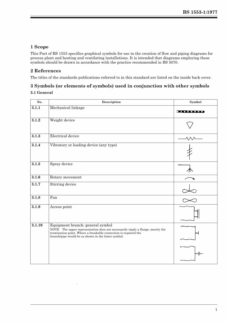
1 ScopeThis Part of BS 1553 specifies graphical symbols for use in the creation of flow and piping diagrams for process plant and heating and ventilating installations. It is intended that diagrams employing these symbols should be drawn in accordance with the practice recommended in BS 5070.
2 ReferencesThe titles of the standards publications referred to in this standard are listed on the inside back cover.
3 Symbols (or elements of symbols) used in conjunction with other symbols3.1 General
No. Description Symbol
3.1.1 Mechanical linkage
3.1.2 Weight device
3.1.3 Electrical device
3.1.4 Vibratory or loading device (any type)
3.1.5 Spray device
3.1.6 Rotary movement
3.1.7 Stirring device
3.1.8 Fan
3.1.9 Access point
3.1.10 Equipment branch: general symbolNOTE The upper representation does not necessarily imply a flange, merely the termination point. Where a breakable connection is required thebranch/pipe would be as shown in the lower symbol.
Lice
nsed
Cop
y: L
ough
boro
ugh
AT
HE
NS
, Lou
ghbo
roug
h U
nive
rsity
, 10/
01/2
013
17:3
0, U
ncon
trol
led
Cop
y, (
c) T
he B
ritis
h S
tand
ards
Inst
itutio
n 20
12
BS 1553-1:1977
2 © BSI 01-1999
3.2 Pipelines
No. Description Symbol
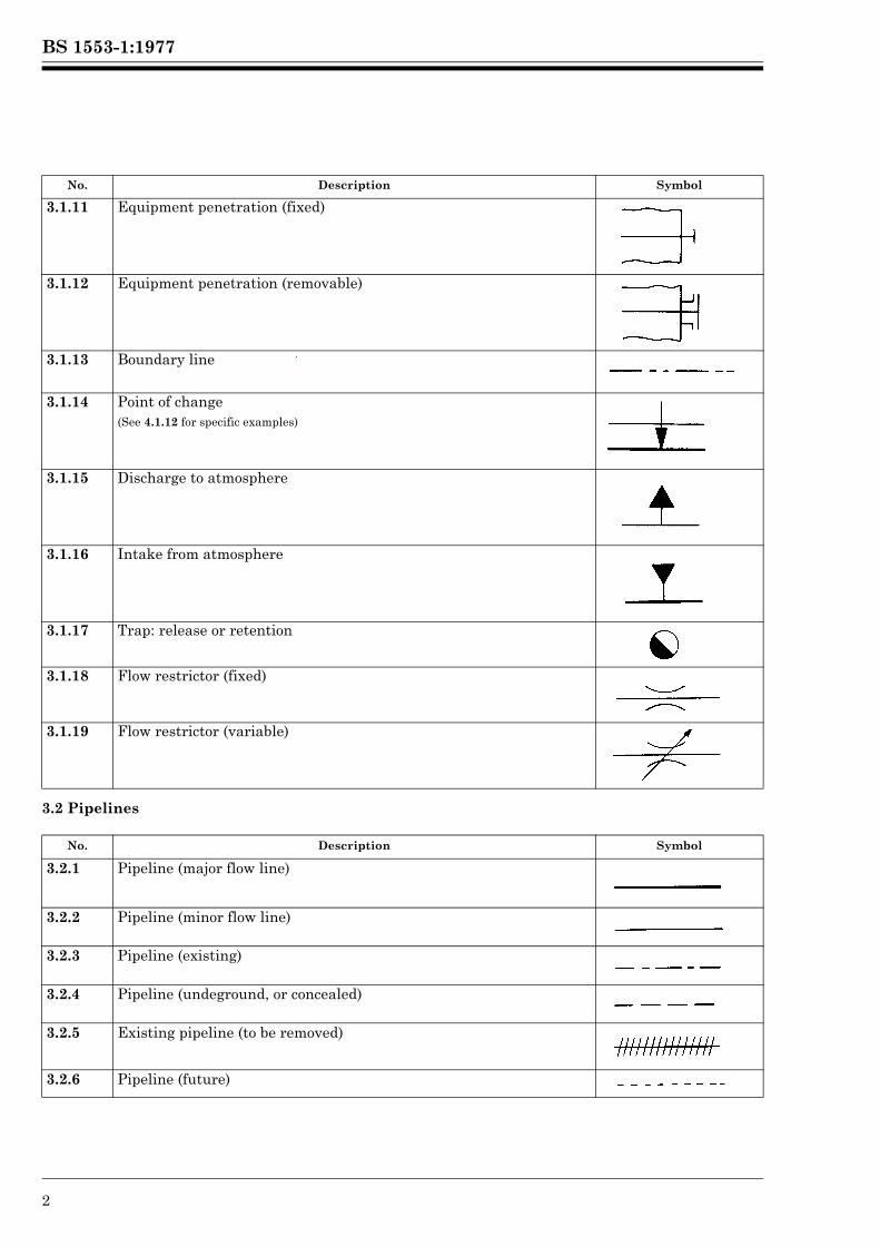
3.1.11 Equipment penetration (fixed)
3.1.12 Equipment penetration (removable)
3.1.13 Boundary line
3.1.14 Point of change(See 4.1.12 for specific examples)
3.1.15 Discharge to atmosphere
3.1.16 Intake from atmosphere
3.1.17 Trap: release or retention
3.1.18 Flow restrictor (fixed)
3.1.19 Flow restrictor (variable)
No. Description Symbol
3.2.1 Pipeline (major flow line)
3.2.2 Pipeline (minor flow line)
3.2.3 Pipeline (existing)
3.2.4 Pipeline (undeground, or concealed)
3.2.5 Existing pipeline (to be removed)
3.2.6 Pipeline (future)
Lice
nsed
Cop
y: L
ough
boro
ugh
AT
HE
NS
, Lou
ghbo
roug
h U
nive
rsity
, 10/
01/2
013
17:3
0, U
ncon
trol
led
Cop
y, (
c) T
he B
ritis
h S
tand
ards
Inst
itutio
n 20
12
BS 1553-1:1977
© BSI 01-1999 3
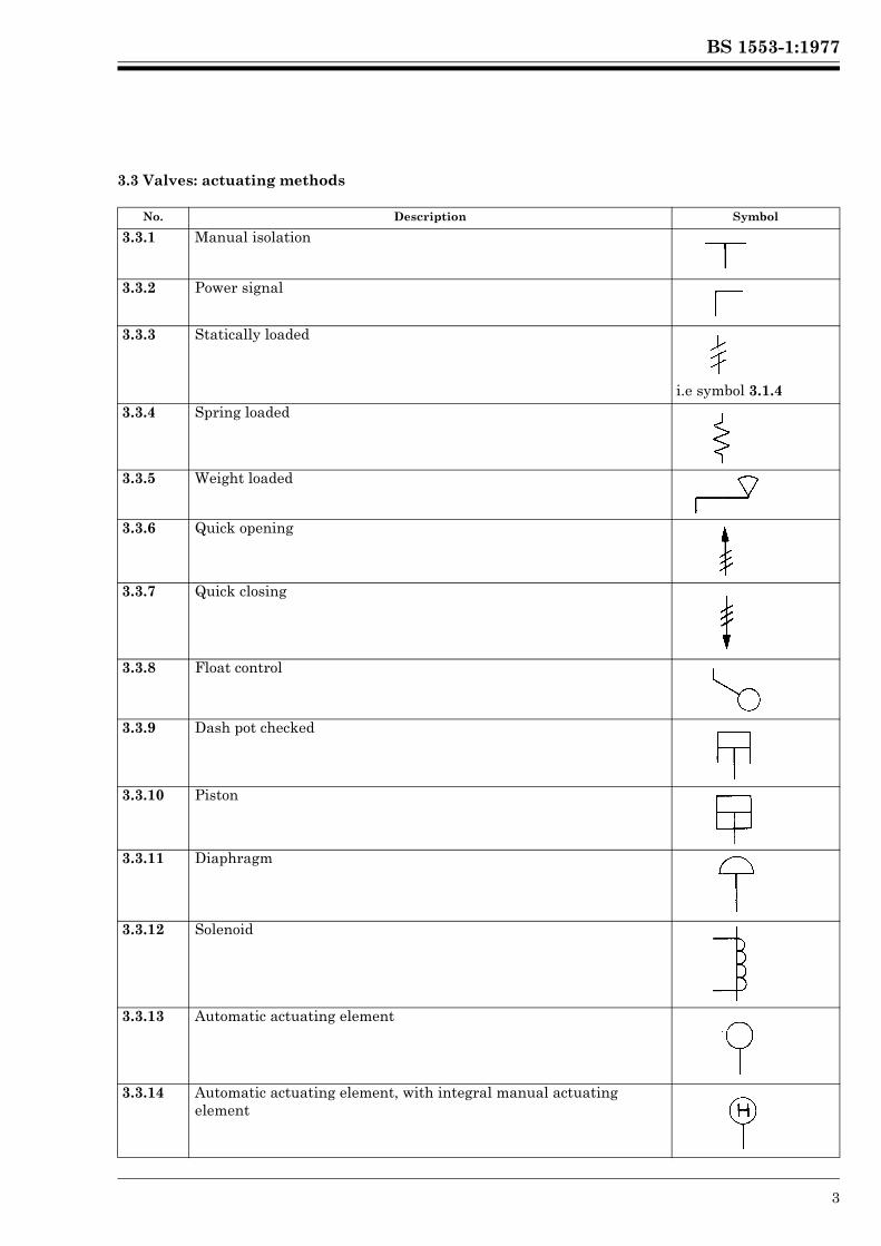
3.3 Valves: actuating methods
No. Description Symbol
3.3.1 Manual isolation
3.3.2 Power signal
3.3.3 Statically loaded
i.e symbol 3.1.43.3.4 Spring loaded
3.3.5 Weight loaded
3.3.6 Quick opening
3.3.7 Quick closing
3.3.8 Float control
3.3.9 Dash pot checked
3.3.10 Piston
3.3.11 Diaphragm
3.3.12 Solenoid
3.3.13 Automatic actuating element
3.3.14 Automatic actuating element, with integral manual actuating elementLi
cens
ed C
opy:
Lou
ghbo
roug
h A
TH
EN
S, L
ough
boro
ugh
Uni
vers
ity, 1
0/01
/201
3 17
:30,
Unc
ontr
olle
d C
opy,
(c)
The
Brit
ish
Sta
ndar
ds In
stitu
tion
2012
BS 1553-1:1977
4 © BSI 01-1999
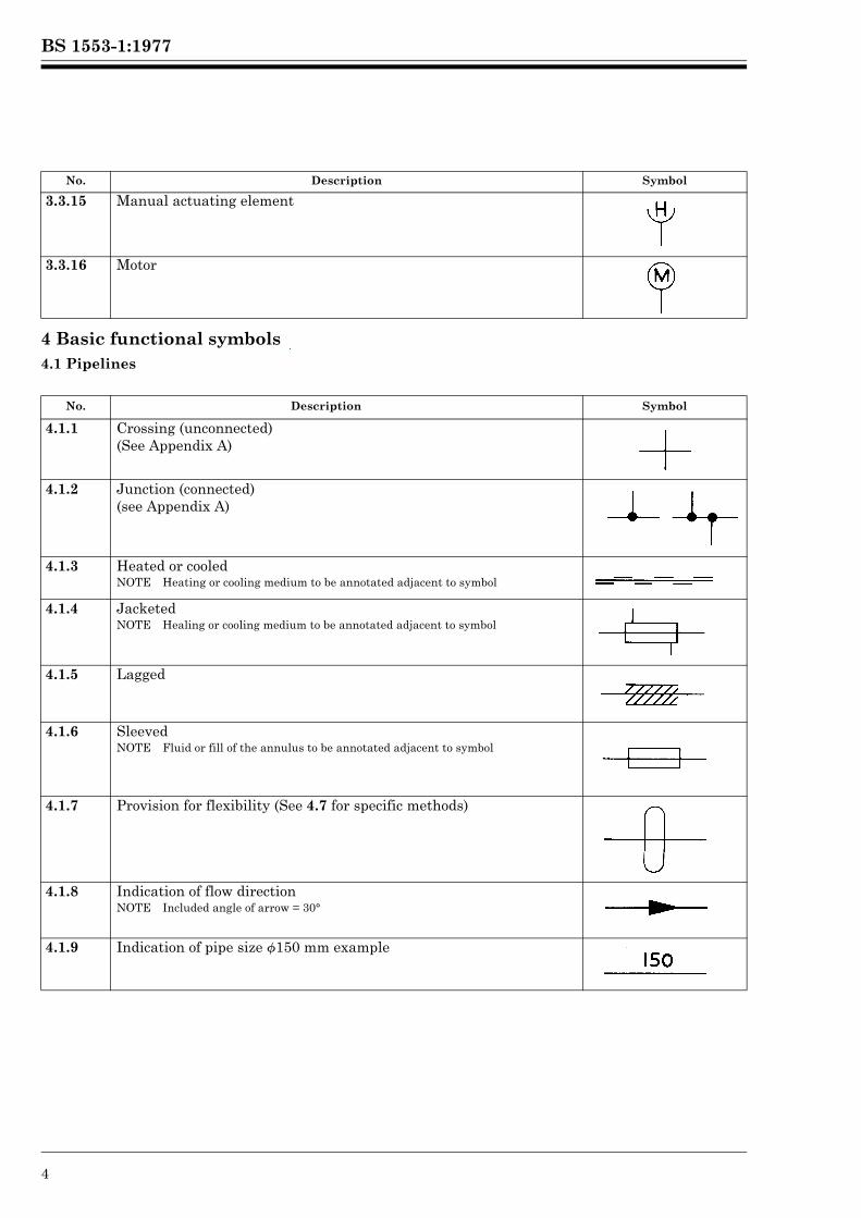
4 Basic functional symbols4.1 Pipelines
No. Description Symbol
3.3.15 Manual actuating element
3.3.16 Motor
No. Description Symbol
4.1.1 Crossing (unconnected)(See Appendix A)
4.1.2 Junction (connected)(see Appendix A)
4.1.3 Heated or cooledNOTE Heating or cooling medium to be annotated adjacent to symbol
4.1.4 JacketedNOTE Healing or cooling medium to be annotated adjacent to symbol
4.1.5 Lagged
4.1.6 SleevedNOTE Fluid or fill of the annulus to be annotated adjacent to symbol
4.1.7 Provision for flexibility (See 4.7 for specific methods)
4.1.8 Indication of flow directionNOTE Included angle of arrow = 30°
4.1.9 Indication of pipe size f150 mm example
Lice
nsed
Cop
y: L
ough
boro
ugh
AT
HE
NS
, Lou
ghbo
roug
h U
nive
rsity
, 10/
01/2
013
17:3
0, U
ncon
trol
led
Cop
y, (
c) T
he B
ritis
h S
tand
ards
Inst
itutio
n 20
12
BS 1553-1:1977
© BSI 01-1999 5
4.2 Joints
No. Description Symbol
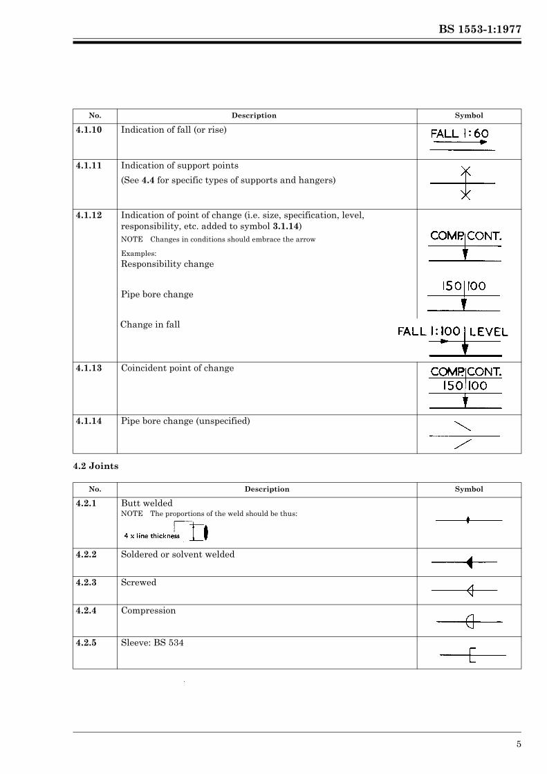
4.1.10 Indication of fall (or rise)
4.1.11 Indication of support points
(See 4.4 for specific types of supports and hangers)
4.1.12 Indication of point of change (i.e. size, specification, level, responsibility, etc. added to symbol 3.1.14)NOTE Changes in conditions should embrace the arrow
Examples:
Responsibility change
Pipe bore change
Change in fall
4.1.13 Coincident point of change
4.1.14 Pipe bore change (unspecified)
No. Description Symbol
4.2.1 Butt weldedNOTE The proportions of the weld should be thus:
4.2.2 Soldered or solvent welded
4.2.3 Screwed
4.2.4 Compression
4.2.5 Sleeve: BS 534
Lice
nsed
Cop
y: L
ough
boro
ugh
AT
HE
NS
, Lou
ghbo
roug
h U
nive
rsity
, 10/
01/2
013
17:3
0, U
ncon
trol
led
Cop
y, (
c) T
he B
ritis
h S
tand
ards
Inst
itutio
n 20
12
BS 1553-1:1977
6 © BSI 01-1999
4.3 End closures
No. Description Symbol
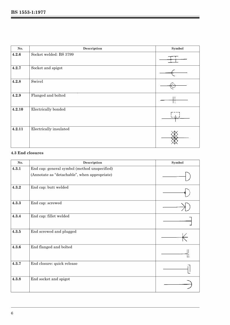
4.2.6 Socket welded: BS 3799
4.2.7 Socket and spigot
4.2.8 Swivel
4.2.9 Flanged and bolted
4.2.10 Electrically bonded
4.2.11 Electrically insulated
No. Description Symbol
4.3.1 End cap: general symbol (method unspecified)
(Annotate as “detachable”, when appropriate)
4.3.2 End cap: butt welded
4.3.3 End cap: screwed
4.3.4 End cap: fillet welded
4.3.5 End screwed and plugged
4.3.6 End flanged and bolted
4.3.7 End closure: quick release
4.3.8 End socket and spigot
Lice
nsed
Cop
y: L
ough
boro
ugh
AT
HE
NS
, Lou
ghbo
roug
h U
nive
rsity
, 10/
01/2
013
17:3
0, U
ncon
trol
led
Cop
y, (
c) T
he B
ritis
h S
tand
ards
Inst
itutio
n 20
12
BS 1553-1:1977
© BSI 01-1999 7
4.4 Supports and hangers
No. Description Symbol
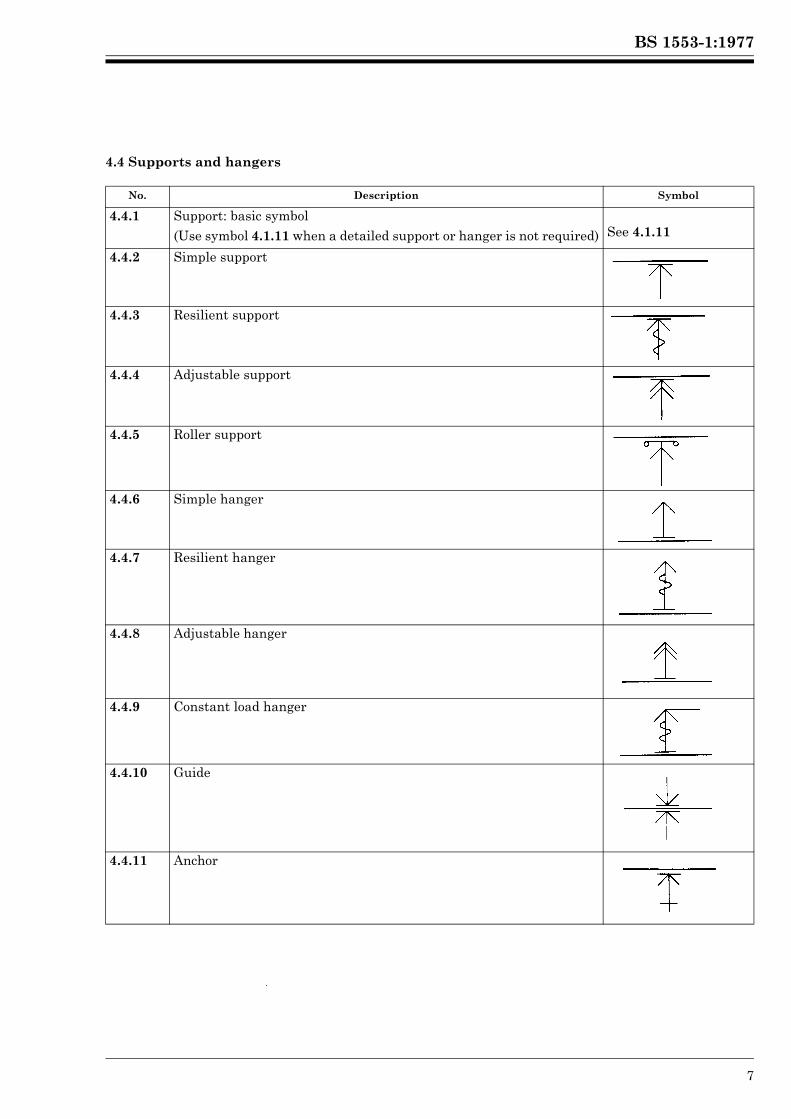
4.4.1 Support: basic symbol(Use symbol 4.1.11 when a detailed support or hanger is not required) See 4.1.11
4.4.2 Simple support
4.4.3 Resilient support
4.4.4 Adjustable support
4.4.5 Roller support
4.4.6 Simple hanger
4.4.7 Resilient hanger
4.4.8 Adjustable hanger
4.4.9 Constant load hanger
4.4.10 Guide
4.4.11 Anchor
Lice
nsed
Cop
y: L
ough
boro
ugh
AT
HE
NS
, Lou
ghbo
roug
h U
nive
rsity
, 10/
01/2
013
17:3
0, U
ncon
trol
led
Cop
y, (
c) T
he B
ritis
h S
tand
ards
Inst
itutio
n 20
12
BS 1553-1:1977
8 © BSI 01-1999
4.5 Valves
No. Description Symbol
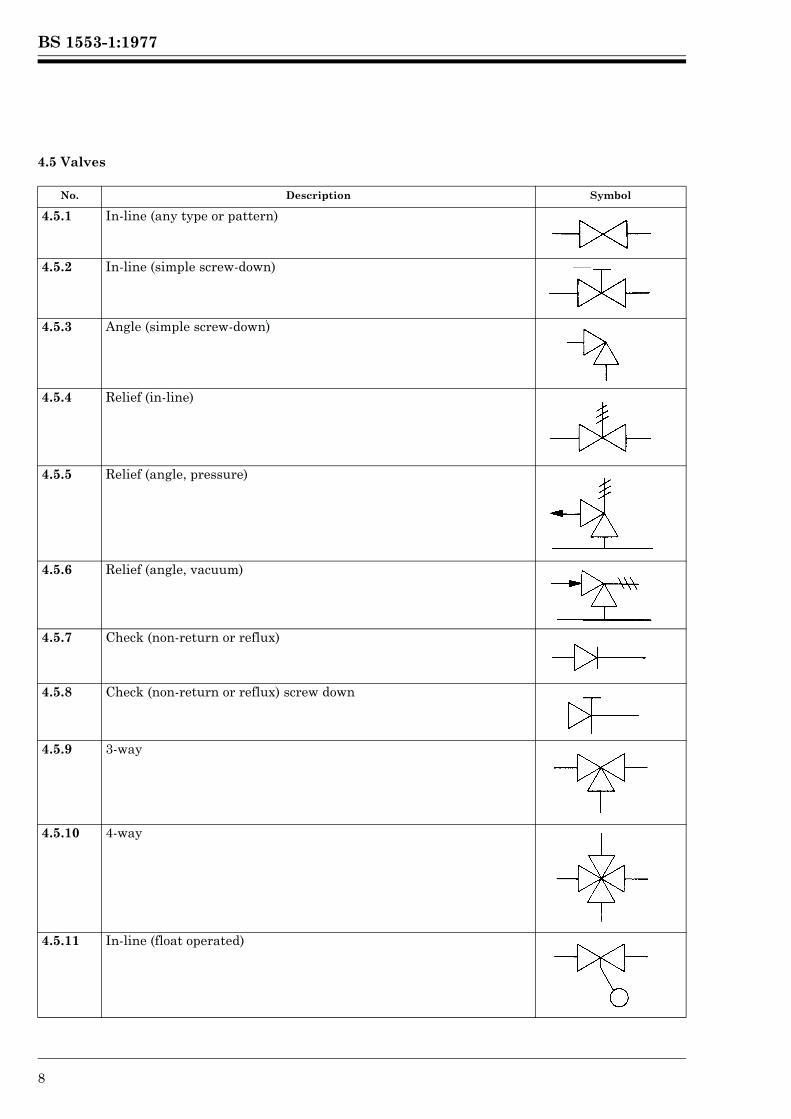
4.5.1 In-line (any type or pattern)
4.5.2 In-line (simple screw-down)
4.5.3 Angle (simple screw-down)
4.5.4 Relief (in-line)
4.5.5 Relief (angle, pressure)
4.5.6 Relief (angle, vacuum)
4.5.7 Check (non-return or reflux)
4.5.8 Check (non-return or reflux) screw down
4.5.9 3-way
4.5.10 4-way
4.5.11 In-line (float operated)
Lice
nsed
Cop
y: L
ough
boro
ugh
AT
HE
NS
, Lou
ghbo
roug
h U
nive
rsity
, 10/
01/2
013
17:3
0, U
ncon
trol
led
Cop
y, (
c) T
he B
ritis
h S
tand
ards
Inst
itutio
n 20
12
BS 1553-1:1977
© BSI 01-1999 9
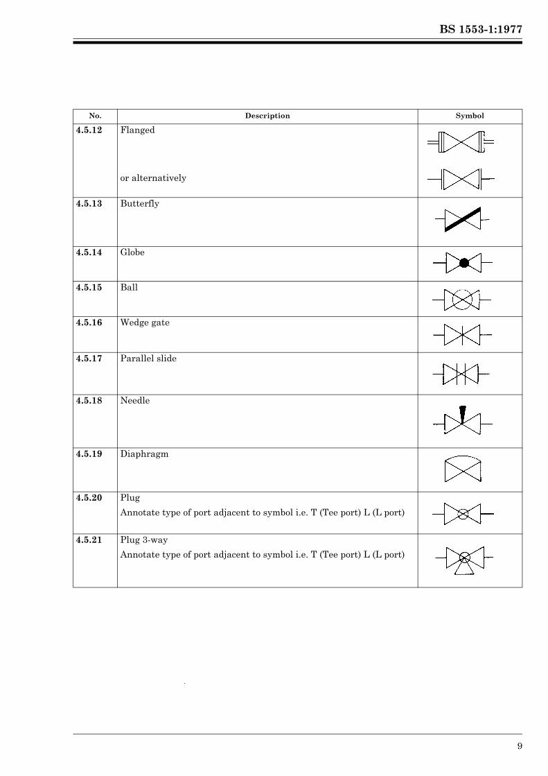
No. Description Symbol
4.5.12 Flanged
or alternatively
4.5.13 Butterfly
4.5.14 Globe
4.5.15 Ball
4.5.16 Wedge gate
4.5.17 Parallel slide
4.5.18 Needle
4.5.19 Diaphragm
4.5.20 Plug
Annotate type of port adjacent to symbol i.e. T (Tee port) L (L port)
4.5.21 Plug 3-way
Annotate type of port adjacent to symbol i.e. T (Tee port) L (L port)
Lice
nsed
Cop
y: L
ough
boro
ugh
AT
HE
NS
, Lou
ghbo
roug
h U
nive
rsity
, 10/
01/2
013
17:3
0, U
ncon
trol
led
Cop
y, (
c) T
he B
ritis
h S
tand
ards
Inst
itutio
n 20
12
BS 1553-1:1977
10 © BSI 01-1999
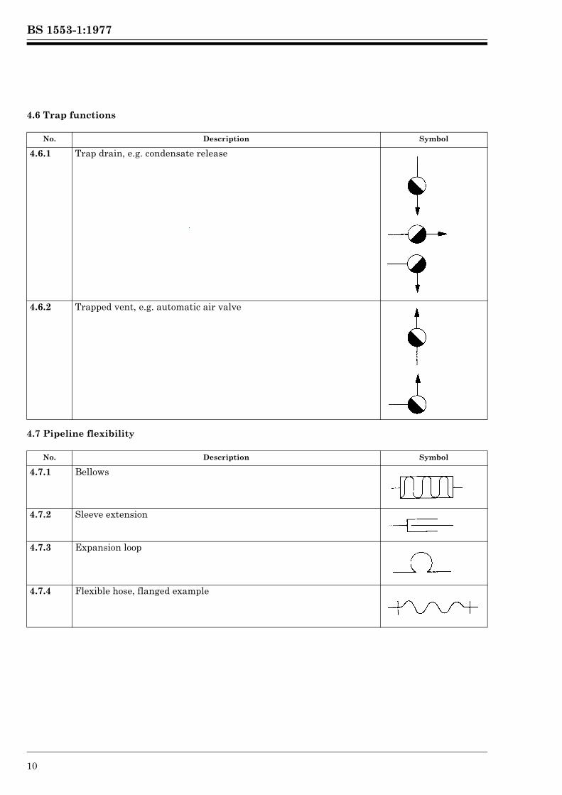
4.6 Trap functions
4.7 Pipeline flexibility
No. Description Symbol
4.6.1 Trap drain, e.g. condensate release
4.6.2 Trapped vent, e.g. automatic air valve
No. Description Symbol
4.7.1 Bellows
4.7.2 Sleeve extension
4.7.3 Expansion loop
4.7.4 Flexible hose, flanged example
Lice
nsed
Cop
y: L
ough
boro
ugh
AT
HE
NS
, Lou
ghbo
roug
h U
nive
rsity
, 10/
01/2
013
17:3
0, U
ncon
trol
led
Cop
y, (
c) T
he B
ritis
h S
tand
ards
Inst
itutio
n 20
12
BS 1553-1:1977
© BSI 01-1999 11
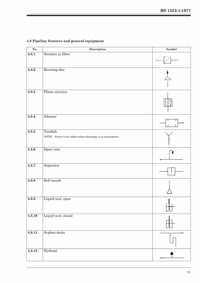
4.8 Pipeline features and general equipment
No. Description Symbol
4.8.1 Strainer or filter
4.8.2 Bursting disc
4.8.3 Flame arrester
4.8.4 Silencer
4.8.5 TundishNOTE Arrow to be added when discharge is to atmosphere
4.8.6 Open vent
4.8.7 Separator
4.8.8 Bell mouth
4.8.9 Liquid seal, open
4.8.10 Liquid seal, closed
4.8.11 Syphon drain
4.8.12 HydrantLice
nsed
Cop
y: L
ough
boro
ugh
AT
HE
NS
, Lou
ghbo
roug
h U
nive
rsity
, 10/
01/2
013
17:3
0, U
ncon
trol
led
Cop
y, (
c) T
he B
ritis
h S
tand
ards
Inst
itutio
n 20
12
BS 1553-1:1977
12 © BSI 01-1999
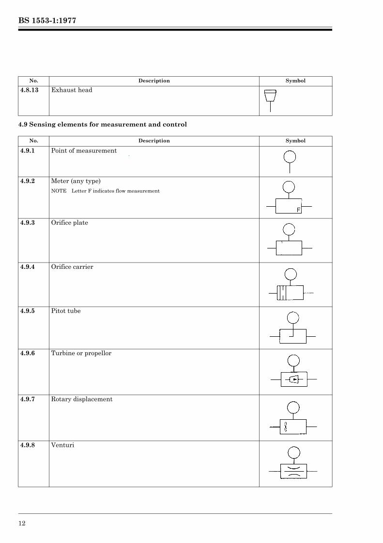
4.9 Sensing elements for measurement and control
No. Description Symbol
4.8.13 Exhaust head
No. Description Symbol
4.9.1 Point of measurement
4.9.2 Meter (any type)NOTE Letter F indicates flow measurement
4.9.3 Orifice plate
4.9.4 Orifice carrier
4.9.5 Pitot tube
4.9.6 Turbine or propellor
4.9.7 Rotary displacement
4.9.8 Venturi
Lice
nsed
Cop
y: L
ough
boro
ugh
AT
HE
NS
, Lou
ghbo
roug
h U
nive
rsity
, 10/
01/2
013
17:3
0, U
ncon
trol
led
Cop
y, (
c) T
he B
ritis
h S
tand
ards
Inst
itutio
n 20
12
BS 1553-1:1977
© BSI 01-1999 13
5 Basic and developed symbols for plant and equipment5.1 Heat transfer equipment
No. Description Symbol
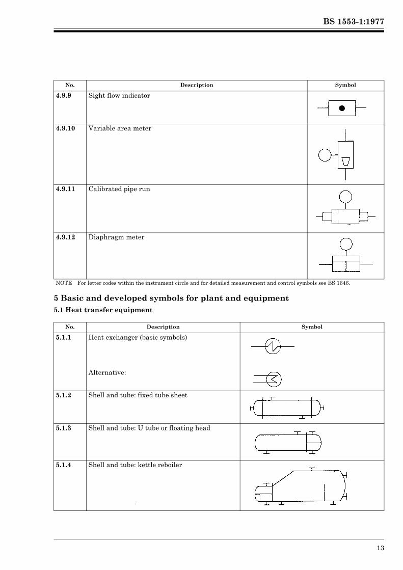
4.9.9 Sight flow indicator
4.9.10 Variable area meter
4.9.11 Calibrated pipe run
4.9.12 Diaphragm meter
NOTE For letter codes within the instrument circle and for detailed measurement and control symbols see BS 1646.
No. Description Symbol
5.1.1 Heat exchanger (basic symbols)
Alternative:
5.1.2 Shell and tube: fixed tube sheet
5.1.3 Shell and tube: U tube or floating head
5.1.4 Shell and tube: kettle reboiler
Lice
nsed
Cop
y: L
ough
boro
ugh
AT
HE
NS
, Lou
ghbo
roug
h U
nive
rsity
, 10/
01/2
013
17:3
0, U
ncon
trol
led
Cop
y, (
c) T
he B
ritis
h S
tand
ards
Inst
itutio
n 20
12
BS 1553-1:1977
14 © BSI 01-1999
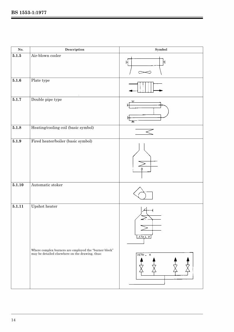
5.1.5 Air-blown cooler
5.1.6 Plate type
5.1.7 Double pipe type
5.1.8 Heating/cooling coil (basic symbol)
5.1.9 Fired heater/boiler (basic symbol)
5.1.10 Automatic stoker
5.1.11 Upshot heater
Where complex burners are employed the “burner block” may be detailed elsewhere on the drawing, thus:
No. Description Symbol
Lice
nsed
Cop
y: L
ough
boro
ugh
AT
HE
NS
, Lou
ghbo
roug
h U
nive
rsity
, 10/
01/2
013
17:3
0, U
ncon
trol
led
Cop
y, (
c) T
he B
ritis
h S
tand
ards
Inst
itutio
n 20
12
BS 1553-1:1977
© BSI 01-1999 15
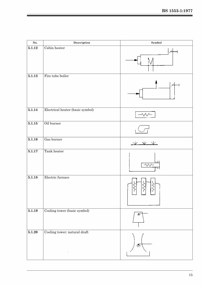
5.1.12 Cabin heater
5.1.13 Fire tube boiler
5.1.14 Electrical heater (basic symbol)
5.1.15 Oil burner
5.1.16 Gas burner
5.1.17 Tank heater
5.1.18 Electric furnace
5.1.19 Cooling tower (basic symbol)
5.1.20 Cooling tower: natural draft
No. Description Symbol
Lice
nsed
Cop
y: L
ough
boro
ugh
AT
HE
NS
, Lou
ghbo
roug
h U
nive
rsity
, 10/
01/2
013
17:3
0, U
ncon
trol
led
Cop
y, (
c) T
he B
ritis
h S
tand
ards
Inst
itutio
n 20
12
BS 1553-1:1977
16 © BSI 01-1999
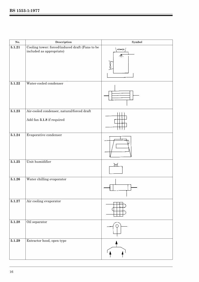
5.1.21 Cooling tower: forced/induced draft (Fans to be included as appropriate)
5.1.22 Water-cooled condenser
5.1.23 Air-cooled condenser, natural/forced draft
Add fan 3.1.8 if required
5.1.24 Evaporative condenser
5.1.25 Unit humidifier
5.1.26 Water chilling evaporator
5.1.27 Air cooling evaporator
5.1.28 Oil separator
5.1.29 Extractor hood, open type
No. Description Symbol
Lice
nsed
Cop
y: L
ough
boro
ugh
AT
HE
NS
, Lou
ghbo
roug
h U
nive
rsity
, 10/
01/2
013
17:3
0, U
ncon
trol
led
Cop
y, (
c) T
he B
ritis
h S
tand
ards
Inst
itutio
n 20
12
BS 1553-1:1977
© BSI 01-1999 17
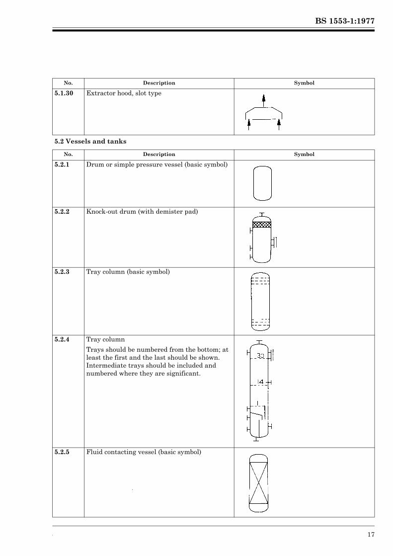
5.1.30 Extractor hood, slot type
5.2 Vessels and tanks
No. Description Symbol
5.2.1 Drum or simple pressure vessel (basic symbol)
5.2.2 Knock-out drum (with demister pad)
5.2.3 Tray column (basic symbol)
5.2.4 Tray column
Trays should be numbered from the bottom; at least the first and the last should be shown. Intermediate trays should be included and numbered where they are significant.
5.2.5 Fluid contacting vessel (basic symbol)
No. Description Symbol
Lice
nsed
Cop
y: L
ough
boro
ugh
AT
HE
NS
, Lou
ghbo
roug
h U
nive
rsity
, 10/
01/2
013
17:3
0, U
ncon
trol
led
Cop
y, (
c) T
he B
ritis
h S
tand
ards
Inst
itutio
n 20
12
BS 1553-1:1977
18 © BSI 01-1999
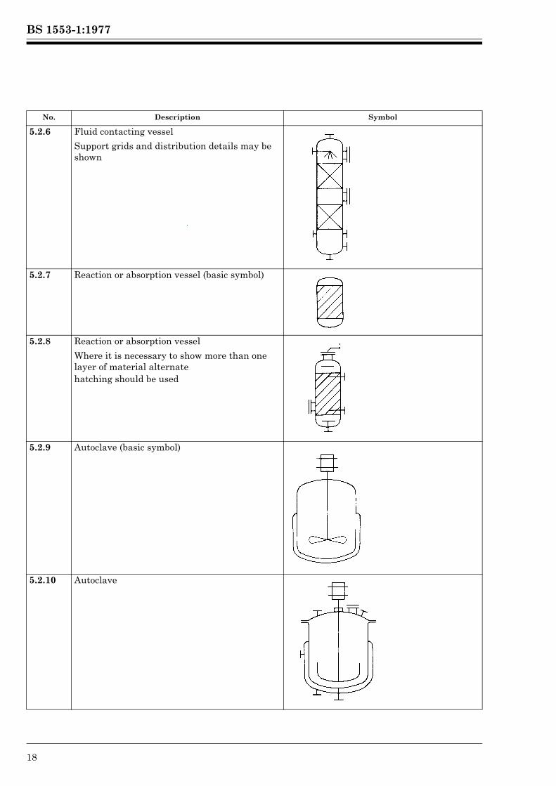
5.2.6 Fluid contacting vessel
Support grids and distribution details may be shown
5.2.7 Reaction or absorption vessel (basic symbol)
5.2.8 Reaction or absorption vessel
Where it is necessary to show more than one layer of material alternatehatching should be used
5.2.9 Autoclave (basic symbol)
5.2.10 Autoclave
No. Description Symbol
Lice
nsed
Cop
y: L
ough
boro
ugh
AT
HE
NS
, Lou
ghbo
roug
h U
nive
rsity
, 10/
01/2
013
17:3
0, U
ncon
trol
led
Cop
y, (
c) T
he B
ritis
h S
tand
ards
Inst
itutio
n 20
12
BS 1553-1:1977
© BSI 01-1999 19
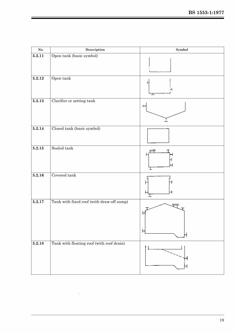
5.2.11 Open tank (basic symbol)
5.2.12 Open tank
5.2.13 Clarifier or setting tank
5.2.14 Closed tank (basic symbol)
5.2.15 Sealed tank
5.2.16 Covered tank
5.2.17 Tank with fixed roof (with draw-off sump)
5.2.18 Tank with floating roof (with roof drain)
No. Description Symbol
Lice
nsed
Cop
y: L
ough
boro
ugh
AT
HE
NS
, Lou
ghbo
roug
h U
nive
rsity
, 10/
01/2
013
17:3
0, U
ncon
trol
led
Cop
y, (
c) T
he B
ritis
h S
tand
ards
Inst
itutio
n 20
12
BS 1553-1:1977
20 © BSI 01-1999
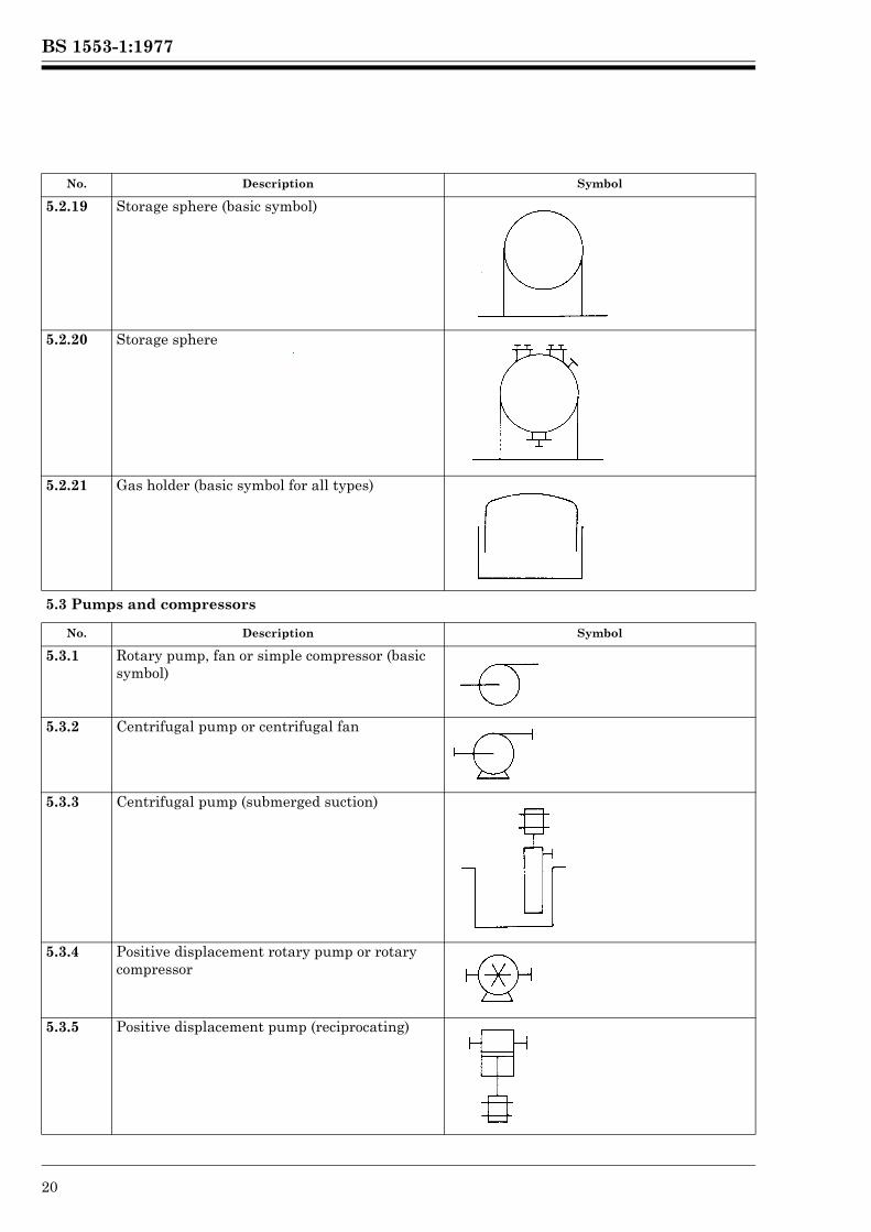
5.2.19 Storage sphere (basic symbol)
5.2.20 Storage sphere
5.2.21 Gas holder (basic symbol for all types)
5.3 Pumps and compressors
No. Description Symbol
5.3.1 Rotary pump, fan or simple compressor (basic symbol)
5.3.2 Centrifugal pump or centrifugal fan
5.3.3 Centrifugal pump (submerged suction)
5.3.4 Positive displacement rotary pump or rotary compressor
5.3.5 Positive displacement pump (reciprocating)
No. Description Symbol
Lice
nsed
Cop
y: L
ough
boro
ugh
AT
HE
NS
, Lou
ghbo
roug
h U
nive
rsity
, 10/
01/2
013
17:3
0, U
ncon
trol
led
Cop
y, (
c) T
he B
ritis
h S
tand
ards
Inst
itutio
n 20
12
BS 1553-1:1977
© BSI 01-1999 21
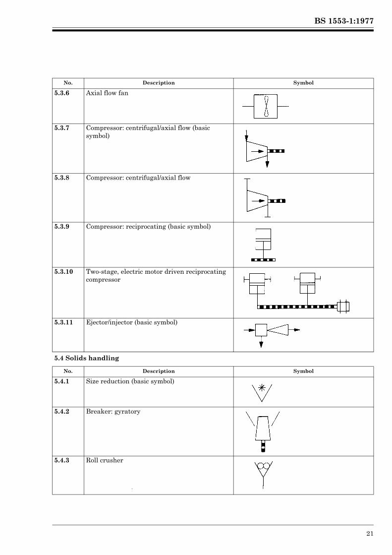
5.3.6 Axial flow fan
5.3.7 Compressor: centrifugal/axial flow (basic symbol)
5.3.8 Compressor: centrifugal/axial flow
5.3.9 Compressor: reciprocating (basic symbol)
5.3.10 Two-stage, electric motor driven reciprocating compressor
5.3.11 Ejector/injector (basic symbol)
5.4 Solids handling
No. Description Symbol
5.4.1 Size reduction (basic symbol)
5.4.2 Breaker: gyratory
5.4.3 Roll crusher
No. Description Symbol
Lice
nsed
Cop
y: L
ough
boro
ugh
AT
HE
NS
, Lou
ghbo
roug
h U
nive
rsity
, 10/
01/2
013
17:3
0, U
ncon
trol
led
Cop
y, (
c) T
he B
ritis
h S
tand
ards
Inst
itutio
n 20
12
BS 1553-1:1977
22 © BSI 01-1999
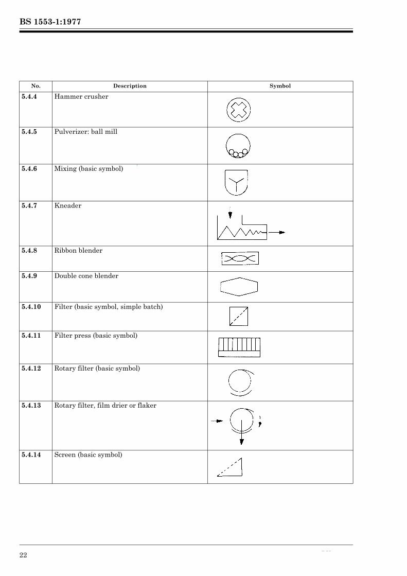
5.4.4 Hammer crusher
5.4.5 Pulverizer: ball mill
5.4.6 Mixing (basic symbol)
5.4.7 Kneader
5.4.8 Ribbon blender
5.4.9 Double cone blender
5.4.10 Filter (basic symbol, simple batch)
5.4.11 Filter press (basic symbol)
5.4.12 Rotary filter (basic symbol)
5.4.13 Rotary filter, film drier or flaker
5.4.14 Screen (basic symbol)
No. Description Symbol
Lice
nsed
Cop
y: L
ough
boro
ugh
AT
HE
NS
, Lou
ghbo
roug
h U
nive
rsity
, 10/
01/2
013
17:3
0, U
ncon
trol
led
Cop
y, (
c) T
he B
ritis
h S
tand
ards
Inst
itutio
n 20
12
BS 1553-1:1977
© BSI 01-1999 23
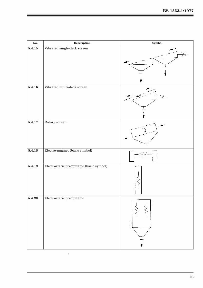
5.4.15 Vibrated single-deck screen
5.4.16 Vibrated multi-deck screen
5.4.17 Rotary screen
5.4.18 Electro-magnet (basic symbol)
5.4.19 Electrostatic precipitator (basic symbol)
5.4.20 Electrostatic precipitator
No. Description Symbol
Lice
nsed
Cop
y: L
ough
boro
ugh
AT
HE
NS
, Lou
ghbo
roug
h U
nive
rsity
, 10/
01/2
013
17:3
0, U
ncon
trol
led
Cop
y, (
c) T
he B
ritis
h S
tand
ards
Inst
itutio
n 20
12
BS 1553-1:1977
24 © BSI 01-1999
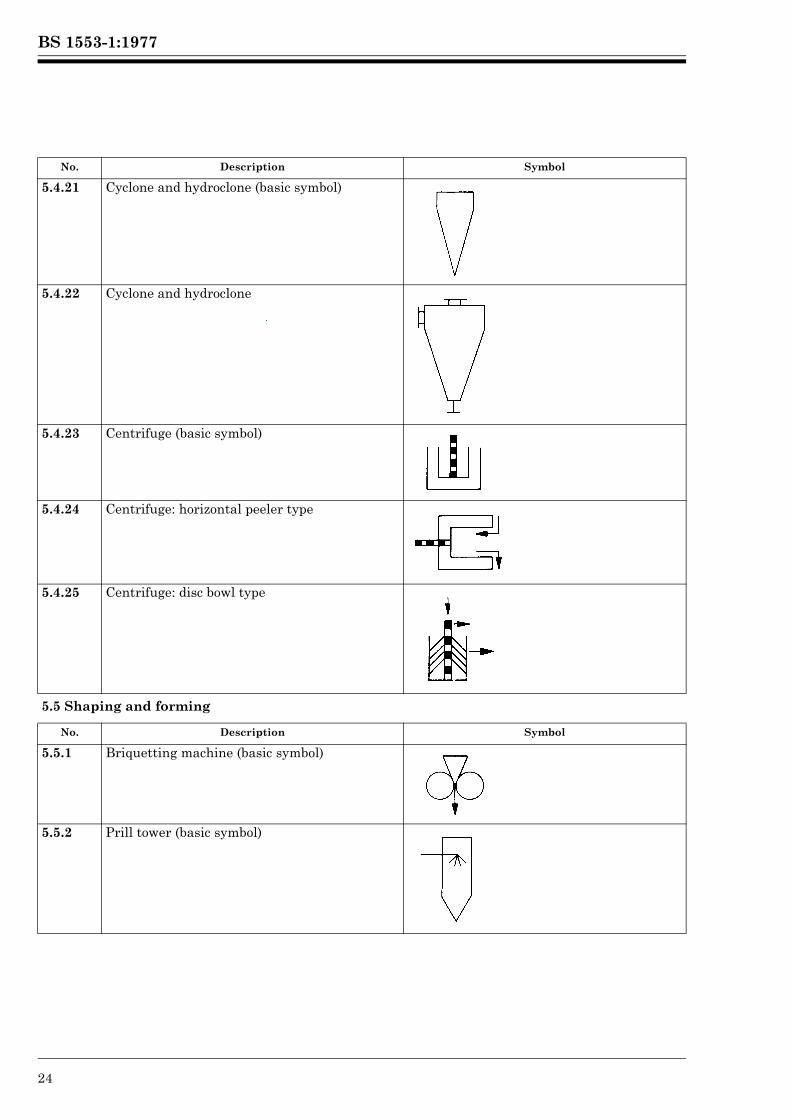
5.4.21 Cyclone and hydroclone (basic symbol)
5.4.22 Cyclone and hydroclone
5.4.23 Centrifuge (basic symbol)
5.4.24 Centrifuge: horizontal peeler type
5.4.25 Centrifuge: disc bowl type
5.5 Shaping and forming
No. Description Symbol
5.5.1 Briquetting machine (basic symbol)
5.5.2 Prill tower (basic symbol)
No. Description Symbol
Lice
nsed
Cop
y: L
ough
boro
ugh
AT
HE
NS
, Lou
ghbo
roug
h U
nive
rsity
, 10/
01/2
013
17:3
0, U
ncon
trol
led
Cop
y, (
c) T
he B
ritis
h S
tand
ards
Inst
itutio
n 20
12
BS 1553-1:1977
© BSI 01-1999 25
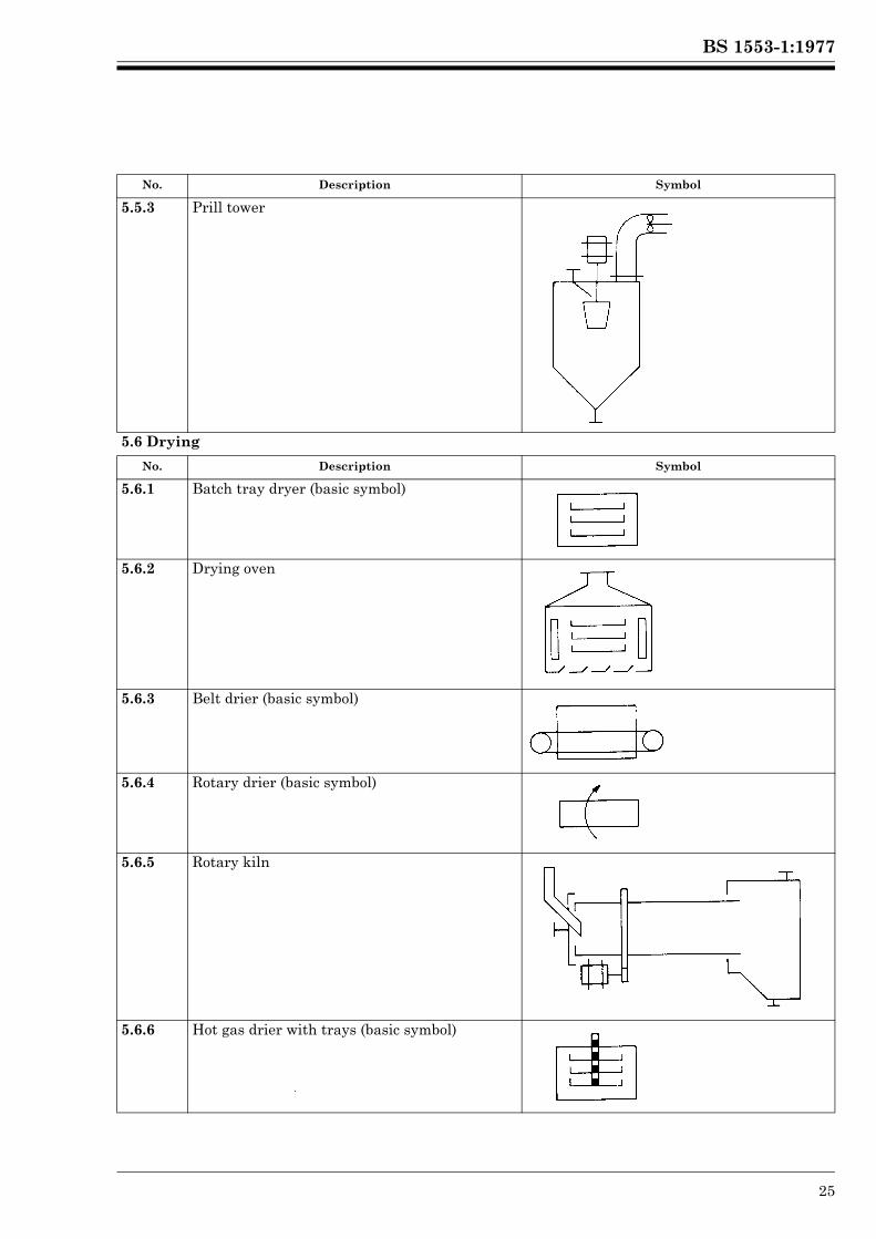
5.5.3 Prill tower
5.6 Drying
No. Description Symbol
5.6.1 Batch tray dryer (basic symbol)
5.6.2 Drying oven
5.6.3 Belt drier (basic symbol)
5.6.4 Rotary drier (basic symbol)
5.6.5 Rotary kiln
5.6.6 Hot gas drier with trays (basic symbol)
No. Description Symbol
Lice
nsed
Cop
y: L
ough
boro
ugh
AT
HE
NS
, Lou
ghbo
roug
h U
nive
rsity
, 10/
01/2
013
17:3
0, U
ncon
trol
led
Cop
y, (
c) T
he B
ritis
h S
tand
ards
Inst
itutio
n 20
12
BS 1553-1:1977
26 © BSI 01-1999
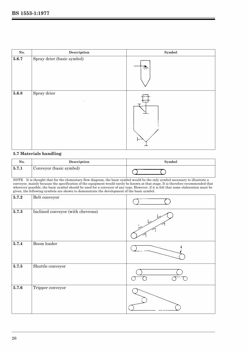
5.6.7 Spray drier (basic symbol)
5.6.8 Spray drier
5.7 Materials handling
No. Description Symbol
5.7.1 Conveyor (basic symbol)
NOTE It is thought that for the elementary flow diagram, the basic symbol would be the only symbol necessary to illustrate a conveyor, mainly because the specification of the equipment would rarely be known at that stage. It is therefore recommended that wherever possible, the basic symbol should be used for a conveyor of any type. However, if it is felt that some elaboration must be given, the following symbols are shown to demonstrate the development of the basic symbol.
5.7.2 Belt conveyor
5.7.3 Inclined conveyor (with chevrons)
5.7.4 Boom loader
5.7.5 Shuttle conveyor
5.7.6 Tripper conveyor
No. Description Symbol
Lice
nsed
Cop
y: L
ough
boro
ugh
AT
HE
NS
, Lou
ghbo
roug
h U
nive
rsity
, 10/
01/2
013
17:3
0, U
ncon
trol
led
Cop
y, (
c) T
he B
ritis
h S
tand
ards
Inst
itutio
n 20
12
BS 1553-1:1977
© BSI 01-1999 27
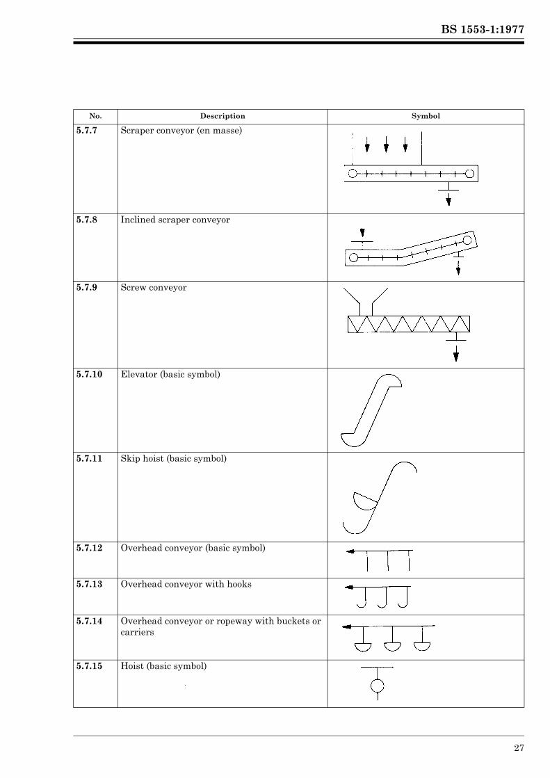
5.7.7 Scraper conveyor (en masse)
5.7.8 Inclined scraper conveyor
5.7.9 Screw conveyor
5.7.10 Elevator (basic symbol)
5.7.11 Skip hoist (basic symbol)
5.7.12 Overhead conveyor (basic symbol)
5.7.13 Overhead conveyor with hooks
5.7.14 Overhead conveyor or ropeway with buckets or carriers
5.7.15 Hoist (basic symbol)
No. Description Symbol
Lice
nsed
Cop
y: L
ough
boro
ugh
AT
HE
NS
, Lou
ghbo
roug
h U
nive
rsity
, 10/
01/2
013
17:3
0, U
ncon
trol
led
Cop
y, (
c) T
he B
ritis
h S
tand
ards
Inst
itutio
n 20
12
BS 1553-1:1977
28 © BSI 01-1999
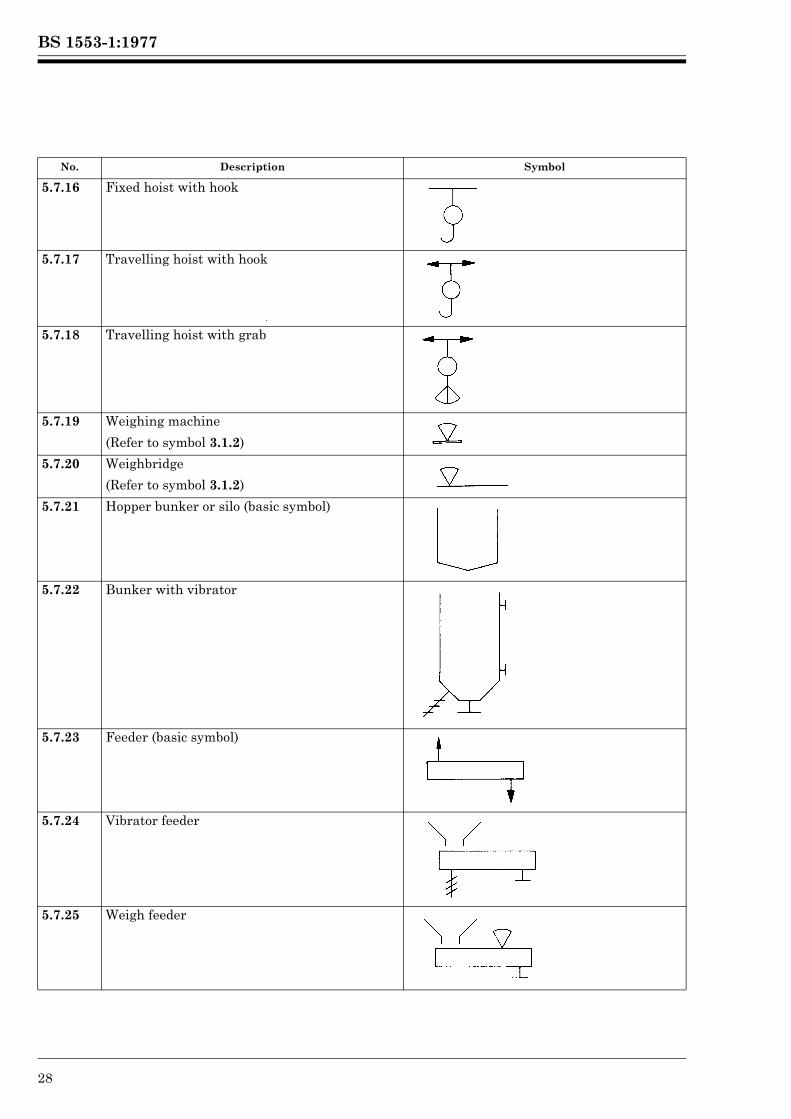
5.7.16 Fixed hoist with hook
5.7.17 Travelling hoist with hook
5.7.18 Travelling hoist with grab
5.7.19 Weighing machine
(Refer to symbol 3.1.2)
5.7.20 Weighbridge
(Refer to symbol 3.1.2)
5.7.21 Hopper bunker or silo (basic symbol)
5.7.22 Bunker with vibrator
5.7.23 Feeder (basic symbol)
5.7.24 Vibrator feeder
5.7.25 Weigh feeder
No. Description Symbol
Lice
nsed
Cop
y: L
ough
boro
ugh
AT
HE
NS
, Lou
ghbo
roug
h U
nive
rsity
, 10/
01/2
013
17:3
0, U
ncon
trol
led
Cop
y, (
c) T
he B
ritis
h S
tand
ards
Inst
itutio
n 20
12
BS 1553-1:1977
© BSI 01-1999 29
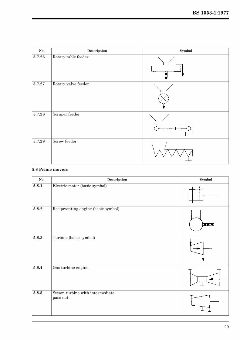
5.8 Prime movers
5.7.26 Rotary table feeder
5.7.27 Rotary valve feeder
5.7.28 Scraper feeder
5.7.29 Screw feeder
No. Description Symbol
5.8.1 Electric motor (basic symbol)
5.8.2 Reciprocating engine (basic symbol)
5.8.3 Turbine (basic symbol)
5.8.4 Gas turbine engine
5.8.5 Steam turbine with intermediatepass-out
No. Description Symbol
Lice
nsed
Cop
y: L
ough
boro
ugh
AT
HE
NS
, Lou
ghbo
roug
h U
nive
rsity
, 10/
01/2
013
17:3
0, U
ncon
trol
led
Cop
y, (
c) T
he B
ritis
h S
tand
ards
Inst
itutio
n 20
12
BS 1553-1:1977
30 © BSI 01-1999
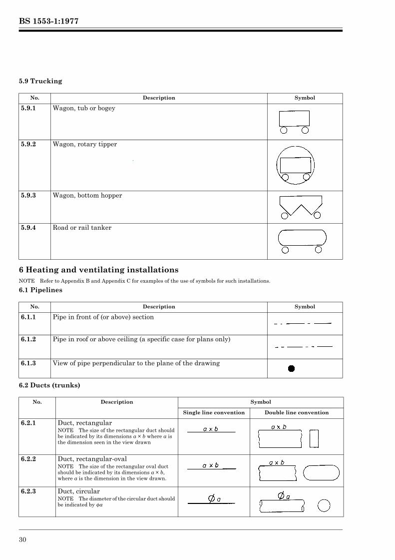
5.9 Trucking
6 Heating and ventilating installations NOTE Refer to Appendix B and Appendix C for examples of the use of symbols for such installations.
6.1 Pipelines
6.2 Ducts (trunks)
No. Description Symbol
5.9.1 Wagon, tub or bogey
5.9.2 Wagon, rotary tipper
5.9.3 Wagon, bottom hopper
5.9.4 Road or rail tanker
No. Description Symbol
6.1.1 Pipe in front of (or above) section
6.1.2 Pipe in roof or above ceiling (a specific case for plans only)
6.1.3 View of pipe perpendicular to the plane of the drawing
No. Description Symbol
Single line convention Double line convention
6.2.1 Duct, rectangularNOTE The size of the rectangular duct should be indicated by its dimensions a × b where a is the dimension seen in the view drawn
6.2.2 Duct, rectangular-ovalNOTE The size of the rectangular oval duct should be indicated by its dimensions a × b, where a is the dimension in the view drawn.
6.2.3 Duct, circularNOTE The diameter of the circular duct should be indicated by fa
Lice
nsed
Cop
y: L
ough
boro
ugh
AT
HE
NS
, Lou
ghbo
roug
h U
nive
rsity
, 10/
01/2
013
17:3
0, U
ncon
trol
led
Cop
y, (
c) T
he B
ritis
h S
tand
ards
Inst
itutio
n 20
12
BS 1553-1:1977
© BSI 01-1999 31
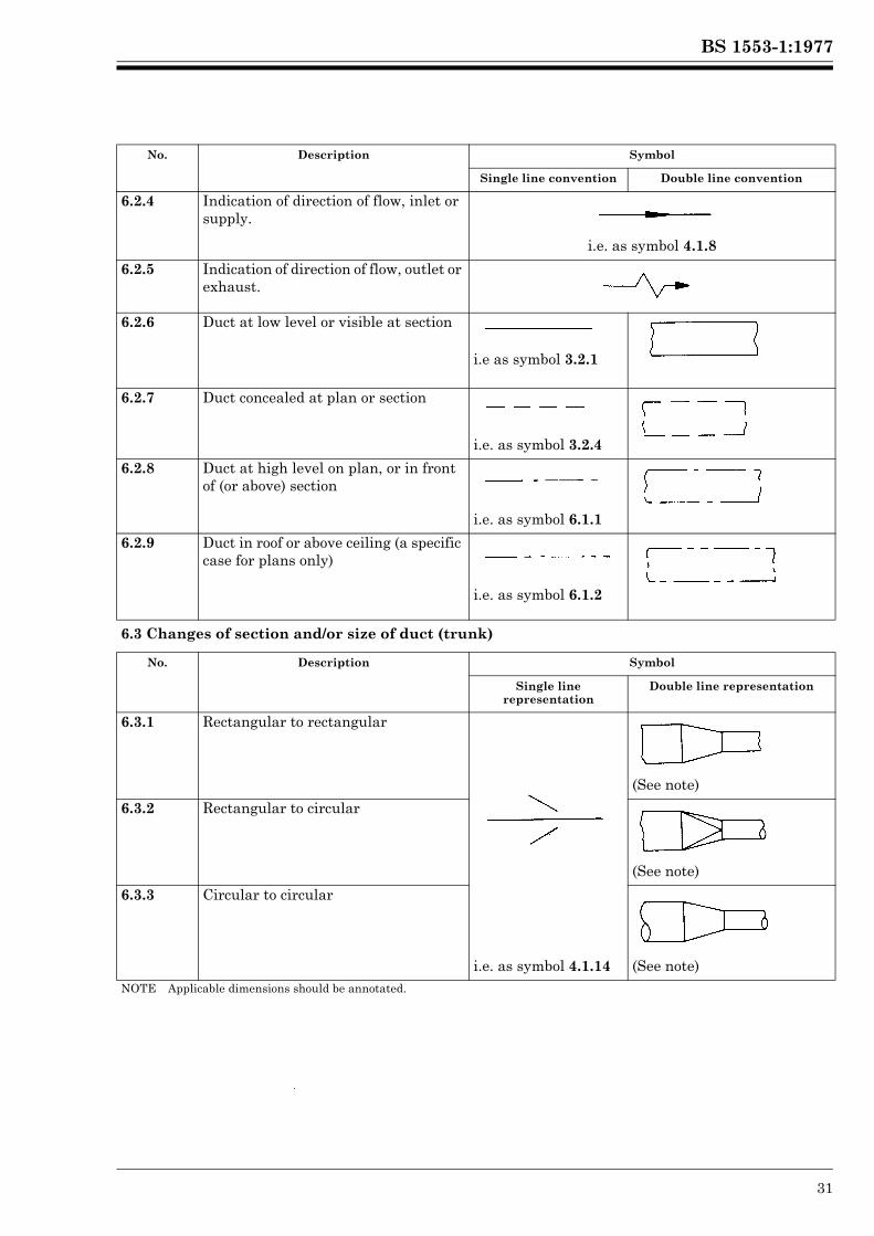
6.2.4 Indication of direction of flow, inlet or supply.
i.e. as symbol 4.1.8
6.2.5 Indication of direction of flow, outlet or exhaust.
6.2.6 Duct at low level or visible at section
i.e as symbol 3.2.1
6.2.7 Duct concealed at plan or section
i.e. as symbol 3.2.4
6.2.8 Duct at high level on plan, or in front of (or above) section
i.e. as symbol 6.1.1
6.2.9 Duct in roof or above ceiling (a specific case for plans only)
i.e. as symbol 6.1.2
6.3 Changes of section and/or size of duct (trunk)
No. Description Symbol
Single line representation
Double line representation
6.3.1 Rectangular to rectangular
(See note)
6.3.2 Rectangular to circular
(See note)
6.3.3 Circular to circular
i.e. as symbol 4.1.14 (See note)NOTE Applicable dimensions should be annotated.
No. Description Symbol
Single line convention Double line convention
Lice
nsed
Cop
y: L
ough
boro
ugh
AT
HE
NS
, Lou
ghbo
roug
h U
nive
rsity
, 10/
01/2
013
17:3
0, U
ncon
trol
led
Cop
y, (
c) T
he B
ritis
h S
tand
ards
Inst
itutio
n 20
12
BS 1553-1:1977
32 © BSI 01-1999
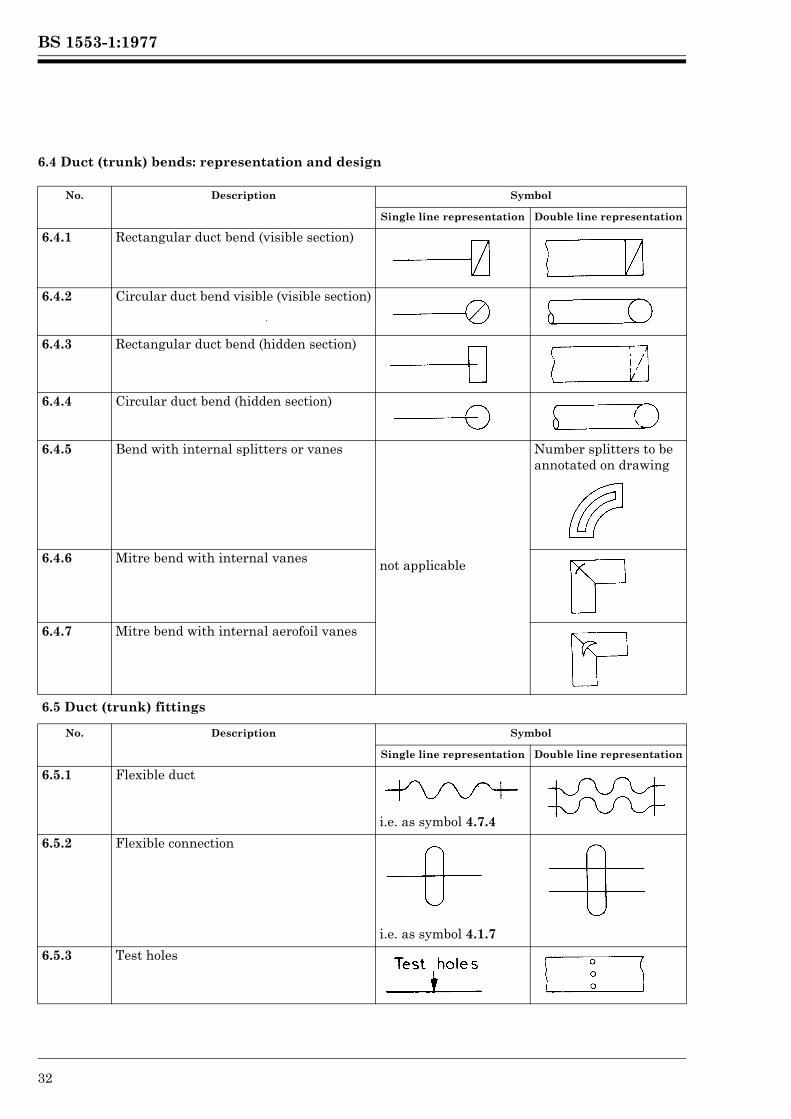
6.4 Duct (trunk) bends: representation and design
No. Description Symbol
Single line representation Double line representation
6.4.1 Rectangular duct bend (visible section)
6.4.2 Circular duct bend visible (visible section)
6.4.3 Rectangular duct bend (hidden section)
6.4.4 Circular duct bend (hidden section)
6.4.5 Bend with internal splitters or vanes
not applicable
Number splitters to be annotated on drawing
6.4.6 Mitre bend with internal vanes
6.4.7 Mitre bend with internal aerofoil vanes
6.5 Duct (trunk) fittings
No. Description Symbol
Single line representation Double line representation
6.5.1 Flexible duct
i.e. as symbol 4.7.4
6.5.2 Flexible connection
i.e. as symbol 4.1.7
6.5.3 Test holes
Lice
nsed
Cop
y: L
ough
boro
ugh
AT
HE
NS
, Lou
ghbo
roug
h U
nive
rsity
, 10/
01/2
013
17:3
0, U
ncon
trol
led
Cop
y, (
c) T
he B
ritis
h S
tand
ards
Inst
itutio
n 20
12
BS 1553-1:1977
© BSI 01-1999 33
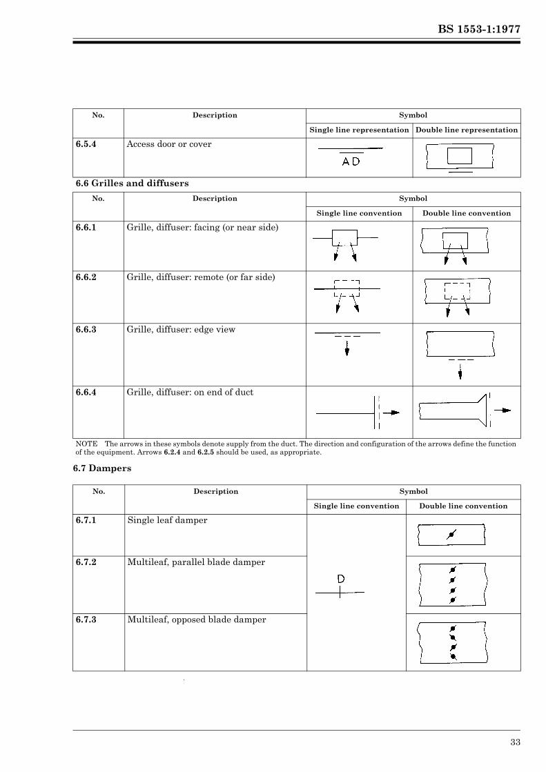
6.7 Dampers
6.5.4 Access door or cover
6.6 Grilles and diffusers
No. Description Symbol
Single line convention Double line convention
6.6.1 Grille, diffuser: facing (or near side)
6.6.2 Grille, diffuser: remote (or far side)
6.6.3 Grille, diffuser: edge view
6.6.4 Grille, diffuser: on end of duct
NOTE The arrows in these symbols denote supply from the duct. The direction and configuration of the arrows define the function of the equipment. Arrows 6.2.4 and 6.2.5 should be used, as appropriate.
No. Description Symbol
Single line convention Double line convention
6.7.1 Single leaf damper
6.7.2 Multileaf, parallel blade damper
6.7.3 Multileaf, opposed blade damper
No. Description Symbol
Single line representation Double line representation
Lice
nsed
Cop
y: L
ough
boro
ugh
AT
HE
NS
, Lou
ghbo
roug
h U
nive
rsity
, 10/
01/2
013
17:3
0, U
ncon
trol
led
Cop
y, (
c) T
he B
ritis
h S
tand
ards
Inst
itutio
n 20
12
BS 1553-1:1977
34 © BSI 01-1999
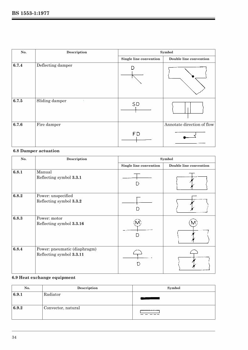
6.9 Heat exchange equipment
6.7.4 Deflecting damper
6.7.5 Sliding damper
6.7.6 Fire damper Annotate direction of flow
6.8 Damper actuation
No. Description Symbol
Single line convention Double line convention
6.8.1 ManualReflecting symbol 3.3.1
6.8.2 Power: unspecifiedReflecting symbol 3.3.2
6.8.3 Power: motorReflecting symbol 3.3.16
6.8.4 Power: pneumatic (diaphragm)Reflecting symbol 3.3.11
No. Description Symbol
6.9.1 Radiator
6.9.2 Convector, natural
No. Description Symbol
Single line convention Double line convention
Lice
nsed
Cop
y: L
ough
boro
ugh
AT
HE
NS
, Lou
ghbo
roug
h U
nive
rsity
, 10/
01/2
013
17:3
0, U
ncon
trol
led
Cop
y, (
c) T
he B
ritis
h S
tand
ards
Inst
itutio
n 20
12
BS 1553-1:1977
© BSI 01-1999 35
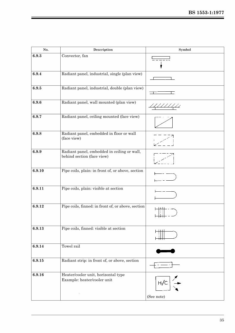
6.9.3 Convector, fan
6.9.4 Radiant panel, industrial, single (plan view)
6.9.5 Radiant panel, industrial, double (plan view)
6.9.6 Radiant panel, wall mounted (plan view)
6.9.7 Radiant panel, ceiling mounted (face view)
6.9.8 Radiant panel, embedded in floor or wall (face view)
6.9.9 Radiant panel, embedded in ceiling or wall, behind section (face view)
6.9.10 Pipe coils, plain: in front of, or above, section
6.9.11 Pipe coils, plain: visible at section
6.9.12 Pipe coils, finned: in front of, or above, section
6.9.13 Pipe coils, finned: visible at section
6.9.14 Towel rail
6.9.15 Radiant strip: in front of, or above, section
6.9.16 Heater/cooler unit, horizontal typeExample: heater/cooler unit
(See note)
No. Description Symbol
Lice
nsed
Cop
y: L
ough
boro
ugh
AT
HE
NS
, Lou
ghbo
roug
h U
nive
rsity
, 10/
01/2
013
17:3
0, U
ncon
trol
led
Cop
y, (
c) T
he B
ritis
h S
tand
ards
Inst
itutio
n 20
12
BS 1553-1:1977
36 © BSI 01-1999
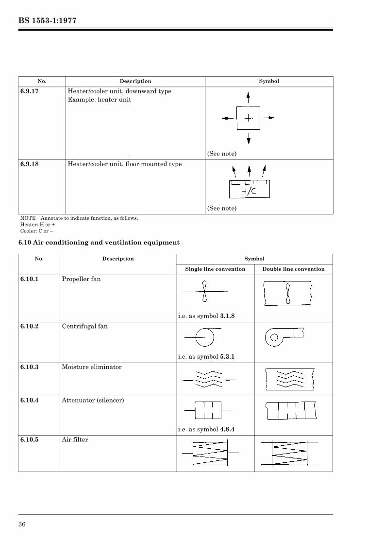
6.10 Air conditioning and ventilation equipment
6.9.17 Heater/cooler unit, downward typeExample: heater unit
(See note)
6.9.18 Heater/cooler unit, floor mounted type
(See note)NOTE Annotate to indicate function, as follows.Heater: H or +Cooler: C or –
No. Description Symbol
Single line convention Double line convention
6.10.1 Propeller fan
i.e. as symbol 3.1.8
6.10.2 Centrifugal fan
i.e. as symbol 5.3.1
6.10.3 Moisture eliminator
6.10.4 Attenuator (silencer)
i.e. as symbol 4.8.4
6.10.5 Air filter
No. Description Symbol
Lice
nsed
Cop
y: L
ough
boro
ugh
AT
HE
NS
, Lou
ghbo
roug
h U
nive
rsity
, 10/
01/2
013
17:3
0, U
ncon
trol
led
Cop
y, (
c) T
he B
ritis
h S
tand
ards
Inst
itutio
n 20
12
BS 1553-1:1977
© BSI 01-1999 37
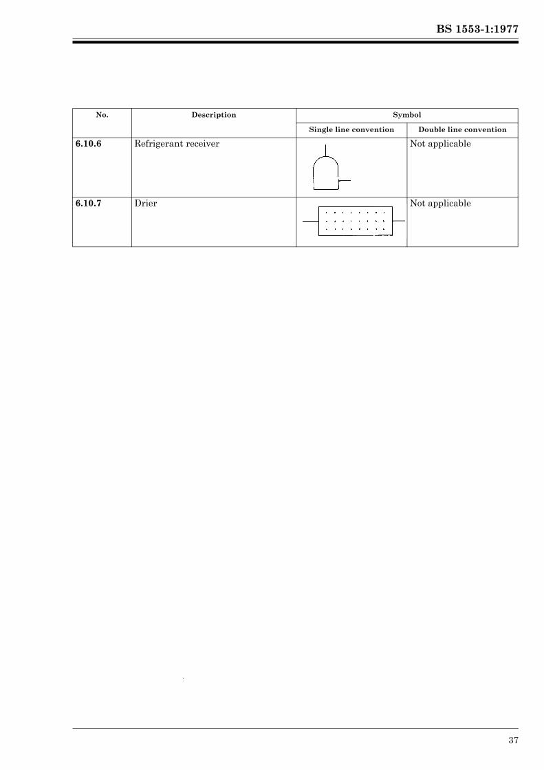
6.10.6 Refrigerant receiver Not applicable
6.10.7 Drier Not applicable
No. Description Symbol
Single line convention Double line convention
Lice
nsed
Cop
y: L
ough
boro
ugh
AT
HE
NS
, Lou
ghbo
roug
h U
nive
rsity
, 10/
01/2
013
17:3
0, U
ncon
trol
led
Cop
y, (
c) T
he B
ritis
h S
tand
ards
Inst
itutio
n 20
12
BS 1553-1:1977
38 © BSI 01-1999
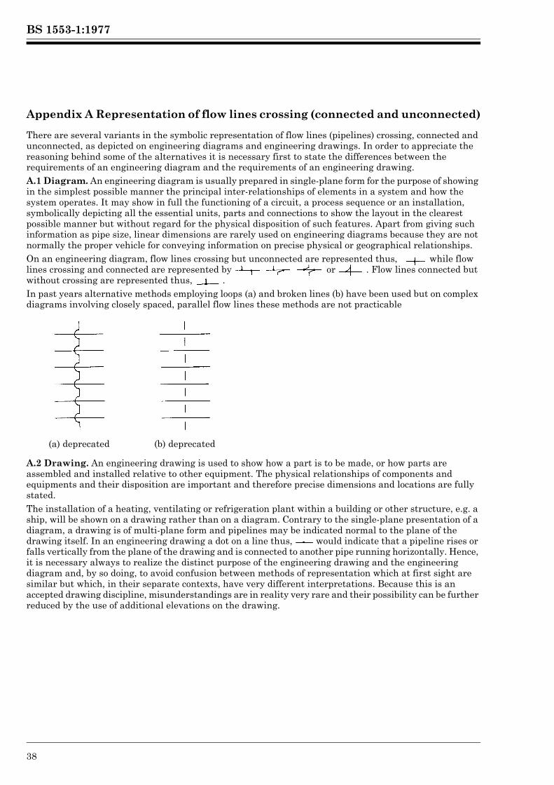
Appendix A Representation of flow lines crossing (connected and unconnected)
There are several variants in the symbolic representation of flow lines (pipelines) crossing, connected and unconnected, as depicted on engineering diagrams and engineering drawings. In order to appreciate the reasoning behind some of the alternatives it is necessary first to state the differences between the requirements of an engineering diagram and the requirements of an engineering drawing.A.1 Diagram. An engineering diagram is usually prepared in single-plane form for the purpose of showing in the simplest possible manner the principal inter-relationships of elements in a system and how the system operates. It may show in full the functioning of a circuit, a process sequence or an installation, symbolically depicting all the essential units, parts and connections to show the layout in the clearest possible manner but without regard for the physical disposition of such features. Apart from giving such information as pipe size, linear dimensions are rarely used on engineering diagrams because they are not normally the proper vehicle for conveying information on precise physical or geographical relationships.On an engineering diagram, flow lines crossing but unconnected are represented thus, while flow lines crossing and connected are represented by or . Flow lines connected but without crossing are represented thus, .In past years alternative methods employing loops (a) and broken lines (b) have been used but on complex diagrams involving closely spaced, parallel flow lines these methods are not practicable
A.2 Drawing. An engineering drawing is used to show how a part is to be made, or how parts are assembled and installed relative to other equipment. The physical relationships of components and equipments and their disposition are important and therefore precise dimensions and locations are fully stated.The installation of a heating, ventilating or refrigeration plant within a building or other structure, e.g. a ship, will be shown on a drawing rather than on a diagram. Contrary to the single-plane presentation of a diagram, a drawing is of multi-plane form and pipelines may be indicated normal to the plane of the drawing itself. In an engineering drawing a dot on a line thus, would indicate that a pipeline rises or falls vertically from the plane of the drawing and is connected to another pipe running horizontally. Hence, it is necessary always to realize the distinct purpose of the engineering drawing and the engineering diagram and, by so doing, to avoid confusion between methods of representation which at first sight are similar but which, in their separate contexts, have very different interpretations. Because this is an accepted drawing discipline, misunderstandings are in reality very rare and their possibility can be further reduced by the use of additional elevations on the drawing.
(a) deprecated (b) deprecated
Lice
nsed
Cop
y: L
ough
boro
ugh
AT
HE
NS
, Lou
ghbo
roug
h U
nive
rsity
, 10/
01/2
013
17:3
0, U
ncon
trol
led
Cop
y, (
c) T
he B
ritis
h S
tand
ards
Inst
itutio
n 20
12
BS 1553-1:1977
© BSI 01-1999 39
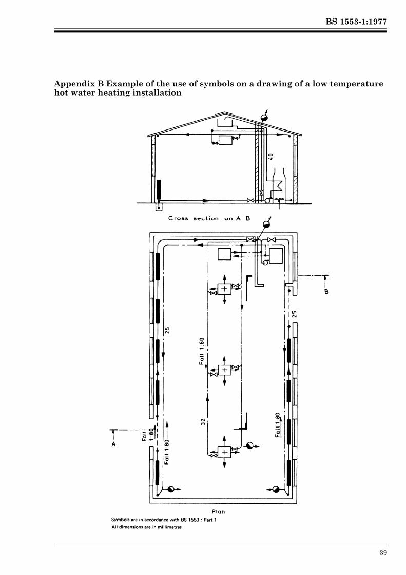
Appendix B Example of the use of symbols on a drawing of a low temperature hot water heating installation
Lice
nsed
Cop
y: L
ough
boro
ugh
AT
HE
NS
, Lou
ghbo
roug
h U
nive
rsity
, 10/
01/2
013
17:3
0, U
ncon
trol
led
Cop
y, (
c) T
he B
ritis
h S
tand
ards
Inst
itutio
n 20
12
BS 1553-1:1977
40 © BSI 01-1999
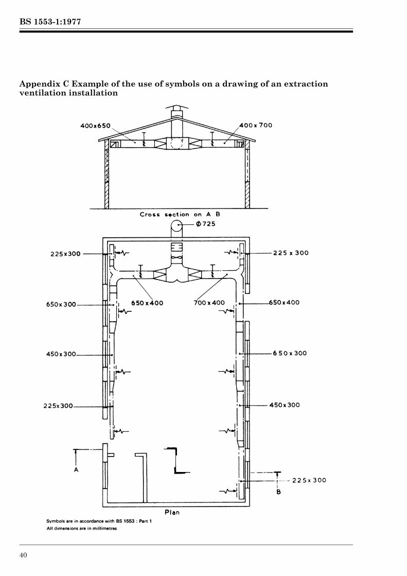
Appendix C Example of the use of symbols on a drawing of an extraction ventilation installation
Lice
nsed
Cop
y: L
ough
boro
ugh
AT
HE
NS
, Lou
ghbo
roug
h U
nive
rsity
, 10/
01/2
013
17:3
0, U
ncon
trol
led
Cop
y, (
c) T
he B
ritis
h S
tand
ards
Inst
itutio
n 20
12

BS 1553-1:1977
© BSI 01-1999
Publications referred to
BS 534, Steel pipes, fittings and specials for water, gas and sewage. BS1646, Graphical symbols for process measurement and control functions. BS 3799, Steel pipe fittings, screwed and socket-welding for the petroleum industry. BS 5070, Drawing practice for engineering diagrams.
Lice
nsed
Cop
y: L
ough
boro
ugh
AT
HE
NS
, Lou
ghbo
roug
h U
nive
rsity
, 10/
01/2
013
17:3
0, U
ncon
trol
led
Cop
y, (
c) T
he B
ritis
h S
tand
ards
Inst
itutio
n 20
12

BSI389 Chiswick High RoadLondonW4 4AL
|||||||||||||||||||||||||||||||||||||||||||||||||||||||||||||||||||||||||||||||||||||||||||||||||||||||||||||||||||||||||||||||
BSI Ð British Standards Institution
BSI is the independent national body responsible for preparing British Standards. Itpresents the UK view on standards in Europe and at the international level. It isincorporated by Royal Charter.
Revisions
British Standards are updated by amendment or revision. Users of British Standardsshould make sure that they possess the latest amendments or editions.
It is the constant aim of BSI to improve the quality of our products and services. Wewould be grateful if anyone finding an inaccuracy or ambiguity while using thisBritish Standard would inform the Secretary of the technical committee responsible,the identity of which can be found on the inside front cover. Tel: 020 8996 9000.Fax: 020 8996 7400.
BSI offers members an individual updating service called PLUS which ensures thatsubscribers automatically receive the latest editions of standards.
Buying standards
Orders for all BSI, international and foreign standards publications should beaddressed to Customer Services. Tel: 020 8996 9001. Fax: 020 8996 7001.
In response to orders for international standards, it is BSI policy to supply the BSIimplementation of those that have been published as British Standards, unlessotherwise requested.
Information on standards
BSI provides a wide range of information on national, European and internationalstandards through its Library and its Technical Help to Exporters Service. VariousBSI electronic information services are also available which give details on all itsproducts and services. Contact the Information Centre. Tel: 020 8996 7111.Fax: 020 8996 7048.
Subscribing members of BSI are kept up to date with standards developments andreceive substantial discounts on the purchase price of standards. For details ofthese and other benefits contact Membership Administration. Tel: 020 8996 7002.Fax: 020 8996 7001.
Copyright
Copyright subsists in all BSI publications. BSI also holds the copyright, in the UK, ofthe publications of the international standardization bodies. Except as permittedunder the Copyright, Designs and Patents Act 1988 no extract may be reproduced,stored in a retrieval system or transmitted in any form or by any means ± electronic,photocopying, recording or otherwise ± without prior written permission from BSI.
This does not preclude the free use, in the course of implementing the standard, ofnecessary details such as symbols, and size, type or grade designations. If thesedetails are to be used for any other purpose than implementation then the priorwritten permission of BSI must be obtained.
If permission is granted, the terms may include royalty payments or a licensingagreement. Details and advice can be obtained from the Copyright Manager.Tel: 020 8996 7070.
Lice
nsed
Cop
y: L
ough
boro
ugh
AT
HE
NS
, Lou
ghbo
roug
h U
nive
rsity
, 10/
01/2
013
17:3
0, U
ncon
trol
led
Cop
y, (
c) T
he B
ritis
h S
tand
ards
Inst
itutio
n 20
12
Related Documents