University of Wollongong University of Wollongong Research Online Research Online University of Wollongong Thesis Collection 1954-2016 University of Wollongong Thesis Collections 1985 Graphical Kernel System: a comparative evaluation Graphical Kernel System: a comparative evaluation Mazhar Ali Sahib University of Wollongong Follow this and additional works at: https://ro.uow.edu.au/theses University of Wollongong University of Wollongong Copyright Warning Copyright Warning You may print or download ONE copy of this document for the purpose of your own research or study. The University does not authorise you to copy, communicate or otherwise make available electronically to any other person any copyright material contained on this site. You are reminded of the following: This work is copyright. Apart from any use permitted under the Copyright Act 1968, no part of this work may be reproduced by any process, nor may any other exclusive right be exercised, without the permission of the author. Copyright owners are entitled to take legal action against persons who infringe their copyright. A reproduction of material that is protected by copyright may be a copyright infringement. A court may impose penalties and award damages in relation to offences and infringements relating to copyright material. Higher penalties may apply, and higher damages may be awarded, for offences and infringements involving the conversion of material into digital or electronic form. Unless otherwise indicated, the views expressed in this thesis are those of the author and do not necessarily Unless otherwise indicated, the views expressed in this thesis are those of the author and do not necessarily represent the views of the University of Wollongong. represent the views of the University of Wollongong. Recommended Citation Recommended Citation Sahib, Mazhar Ali, Graphical Kernel System: a comparative evaluation, Master of Science (Hons.) thesis, Department of Computer Science, University of Wollongong, 1985. https://ro.uow.edu.au/theses/2802 Research Online is the open access institutional repository for the University of Wollongong. For further information contact the UOW Library: [email protected]

Welcome message from author
This document is posted to help you gain knowledge. Please leave a comment to let me know what you think about it! Share it to your friends and learn new things together.
Transcript
University of Wollongong University of Wollongong
Research Online Research Online
University of Wollongong Thesis Collection 1954-2016 University of Wollongong Thesis Collections
1985
Graphical Kernel System: a comparative evaluation Graphical Kernel System: a comparative evaluation
Mazhar Ali Sahib University of Wollongong
Follow this and additional works at: https://ro.uow.edu.au/theses
University of Wollongong University of Wollongong
Copyright Warning Copyright Warning
You may print or download ONE copy of this document for the purpose of your own research or study. The University
does not authorise you to copy, communicate or otherwise make available electronically to any other person any
copyright material contained on this site.
You are reminded of the following: This work is copyright. Apart from any use permitted under the Copyright Act
1968, no part of this work may be reproduced by any process, nor may any other exclusive right be exercised,
without the permission of the author. Copyright owners are entitled to take legal action against persons who infringe
their copyright. A reproduction of material that is protected by copyright may be a copyright infringement. A court
may impose penalties and award damages in relation to offences and infringements relating to copyright material.
Higher penalties may apply, and higher damages may be awarded, for offences and infringements involving the
conversion of material into digital or electronic form.
Unless otherwise indicated, the views expressed in this thesis are those of the author and do not necessarily Unless otherwise indicated, the views expressed in this thesis are those of the author and do not necessarily
represent the views of the University of Wollongong. represent the views of the University of Wollongong.
Recommended Citation Recommended Citation Sahib, Mazhar Ali, Graphical Kernel System: a comparative evaluation, Master of Science (Hons.) thesis, Department of Computer Science, University of Wollongong, 1985. https://ro.uow.edu.au/theses/2802
Research Online is the open access institutional repository for the University of Wollongong. For further information contact the UOW Library: [email protected]
Graphical Kernel System
A Comparative Evaluation
A thesis submitted in partial fulfilment of the
requirements for the award of the degree of
HONOURS MASTER OF SCIENCE (Computing Science)
from
THE UNIVERSITY OF WOLLONGONG
by
MAZHAR ALI SAHIB, B. Sc. (WA)
UNiVERSITY OF WOLLONGONG
LIBRAi Y M.»W»H i-t .f'
Dept. of Computing Science,
1985

{ ù
ABSTRACT
This thesis presents a comparison between Graphical
Kernel System (GKS) - the proposed general purpose graphics
standard and an existing package, namely Graphics Assistance
Package (GAP), whose origins can be traced back to the late
1960s. In doing so, it illustrates the similarities between
the two systems while examining the enhancements and new
concepts incorporated into the proposed standard.
The thesis firstly provides general overviews of the
two graphics systems tracing their origins together with an
outline of the key features of each system. This is then
followed by the comparison which was conducted along the
lines of the comparative criteria developed by the Graphics
Standard Planning Committee (GSPC) established under the
auspices of the ACM Special Interest Group on Computer
Graphics (SIGGRAPH).
- lii -
TO WHOM IT MAY CONCERN
1. Except where reference is made in the text, this Thesis
contains no material published elsewhere or extracted
from a Thesis presented by me for another Degree or
Diploma;
2. No other persons' work has been used without due ack-
nowledgement;
3. This Thesis has not been submitted for the award of any
other Degree or Diploma in any other Tertiary Insti-
tute.
M. A. Sahib,
December 1985.
ACKNOWLEDGEMENTS
Many people have helped in one way or another in the
research, writing and editing of this thesis. To them, I
wish to express my sincerest gratitude. I apologize in
advance for any omission by name.
In particular however, I wish to thank my supervisor.
Professor Juris Rienfelds, for his constant support and
encouragement throughout my graduate study at Wollongong,
and especially in the course of this research. His comments
and suggestions on many occasions led to better alternatives
and hence, a better presentation to what may have otherwise
resulted.
Furthermore, I wish to thank the teaching and support
staff within the Department of Computing Science for provid-
ing invaluable information and advice along the way. In
this regard, my sincere appreciation to Drs. G. Dromey; R.
F. Hille and M. Wagner along with Gary Stafford for not only
their encouragement but more importantly, for providing "an
ear" to talk to however frequently needed.
Discussions with valued friends and colleagues are
appreciated and will be remembered.
A special note of thanks to David Cheesman. His care-
ful reading of this thesis at various stages and comments
along the way are gratefully acknowledged.
On a personal level, I wish to thank my parents for the
many years of support they have given me. They have sacri-
ficed much to get me to this point. It is to them that I
dedicate this thesis.
Last, but by no means least, to my wife Noorshad go my
deepest appreciation for her companionship during my years
at Wollongong. Her encouragement and understanding during
the last few months is especially appreciated.
TABLE OF CONTENTS
ABSTRACT ii
STATEMENT OF ORIGINALITY iii
ACKNOWLEDGEMENT iv
TABLE OF CONTENTS vi
1. INTRODUCTION 1
2. HISTORY OF COMPUTER GRAPHICS 3
2.1. Early Devices and their Applications 3
2.2. Storage Tube Devices 4
2.3. Raster Devices 5
2.4. Realization for the Need of a Standard 6
2.5. The Standardization of Computer Graphics . . . . 7
2.5.1. Graphics Standards Planning Committee . . . 8
2.5.2. The ISO Graphics Working Group 9
2.5.3. The GKS Review 10
3. GRAPHICAL KERNEL SYSTEM 12
3.1, History of the System 13
3.2. Key Features of the System 13
4. GRAPHICS ASSISTANCE PACKAGE 18
4.1. History of the Package 18
4.2. Key Features of the Package 19
5. THE EVALUATION 23
5.1. Control 23
5.1.1. System/Package Setup 23
5.1.2. Initialization 25
5.1.3. Device Characteristics 29
5.1.4. Error Handling 32
5.1.5. Termination 35
5.2. Coordinate Systems 38
5.2.1. World / User 38
5.2.2. Device 39
5.2.3. Orientation 40
5.3. Input 41
5.3.1. Logical Input Devices .42
5.3.2. Graphical 45
5.3.2.1. Picking 45
5.3.2.2. Locator and Stroke 46
5.3.3. Valuator 46
5.3.4. Text 47
5.3.5. Choice 47
5.4. Output 48
5.4.1. Picture Specifications 49
5.4.1.1. Segmentation 49
5.4.1.1.1. Segment Attributes 50
5.4.1.1.2. Segment/Symbol Operations 51
5.4.1.1.3. Segment/Symbol Transformations . . . 54
5.4.1.2. Viewing Transformations 57
5.4.1.2.1. Windowing 57
5.4.1.2.2. Viewporting 58
5.4.1.2.3. Shielding . .' 61
5.4.1.2.4, Manipulation of Transformations . . 61
5.4.2. Output Primitives 62
5.4.2.1. Position and Point Generation 65
5.4.2.2. Straight Lines 66
5.4.2.3. Markers 69
5.4.2.4. Curved Lines and Circles 72
5.4.2.5. Surfaces 74
5.4.2.6. Text 77
5.4.2.6.1. Attributes 79
5.4.2.6.2. Transformations 87
5.4.2.7. Numeric Output 89
5.4.2.8. Others 90
5.5. Application Extension 91
5.5.1. Graphing Operations 92
5.5.2. Curve Fitting and Data Smoothing 94
5.5.3. Positioned Text 94
5.5.4. Others 95
5.6. Application Program Compilation / Display File Generation 96
5.6.1. Data Structures 98
5.6.2. Application Storage and Retrieval 98
5.7. Sizing Information 101
5.8. Implementation Environment 102
5.9. Graphical Hardware Supported 103
5.10. Computers on which the Systems Operate 104
5.11. Number of Installations 105
5.12. Documentation 106
6. CONCLUSIONS 108
BIBLIOGRAPHY 120
GLOSSARY 126
APPENDIX I: CONTROL 128
APPENDIX II: COORDINATE SYSTEMS 129
APPENDIX III: INPUT 130
APPENDIX IV: OUTPUT - PICTURE SPECIFICATIONS 131
APPENDIX V: OUTPUT - PRIMITIVES 132
APPENDIX VI: EXTENSIONS, COMPILATION & IMPLEMENTATION ENVIRONMENT 133
APPENDIX VII: MISCELLANEOUS INFORMATION 134
INDEX 135
I* INTRODUCTION
Computer graphics, as defined by the International
Standards Organization (ISO), is the "... methods and tech-
niques for converting data to and from graphical displays
via a computer ... (Enderle et.al., 1984, p.2)". Although
this definition refers to the three basic components of any
graphics system (namely "computer", "data" and "display"),
one of the most important aspects and hence, a major reason
for its ever increasing popularity is not acknowledged.
Enderle, therefore suggests the alternative definition that
computer graphics is the "... most powerful and versatile
means of communication between a computer and a human
(ibid)".
Despite this and the fact that the origins of computer
graphics can be traced back to the early 1950s, its stan-
dardization was only partially achieved in 1982. In June of
that year, ISO voted to accept Graphical Kernel System (GKS)
as the "Draft International Standard" for computer graphics.
Numerous de facto standards however, existed in the meantime
(and some still do) both in terms of widely available
hardware and later, in terms of device independent graphics
systems. If the full benefits of standardization are to be
realized, it is hoped that time and understanding will lead
to their being abandoned.
This thesis investigates the advancements attained by
GKS (through its acceptance as a graphics standard) over an
existing package, namely the Graphics Assistance Package
(GAP). GAP'S origins can be traced back to the late 1960s.
This package was chosen for comparison with GKS, primarily
because of its availability in the same environment. Furth-
ermore, both graphics systems utilize similar graphics dev-
ices as currently implemented at the University of Wol-
longong.
The investigation was conducted on the basis of a com-
parative criteria developed by the "State-of-the-Art" sub-
group within the Graphics Standards Planning Committee
(GSPC), (Ewald & Fryer, 1978). By developing this criteria,
the subgroup provided a framework for comparing line-drawing
graphics systems. This investigation however, omits the 3D
graphics extensions mentioned within the comparative cri-
teria as neither GKS nor GAP is capable of producing 3D
graphics.
Chapter 2 of this thesis presents a brief history of
computer graphics up to and including the standardization
process. Chapters 3 and 4 present overviews of GKS and GAP
respectively, firstly tracing their origin and then outlin-
ing their key features. The results of the investigation
are presented in Chapter 5 (and summarized in the Appen-
dices) while the final chapter (6), outlines the implica-
tions of this investigation.
1* HISTORY OF COMPUTER GRAPHICS
¿•i* E ^ ly Devices and their Applications
Developments in computer graphics have been closely
associated with those in the computer technology itself.
The earliest occurrences of computer graphics involved con-
necting cathode ~ray tubes (CRT) to computers directly to
view output. Output on these devices was plotted in terms
of points on the display surface. Whirlwind I and ILLIAC,
both appearing in 1951 at Massachusetts Institute of Tech-
nology (MIT) and the University of Illinois respectively,
were examples of early computer systems providing graphics
via CRT displays. Both these computers used dual scopes as
part of their output displays with one maintaining a visible
screen while the other was connected to a computer con-
trolled camera (van Dam, 1966; Whitted, 1982).
Plotters began to emerge in 1953 and were followed by
the introduction of lightpens which provided the first means
of graphical input. The SAGE air-defense system (one of the
earliest on-line man/machine interactive applications) was
developed in 1955. Using this system, the operator sat in
front of a radar type screen on which symbols and identif-
iers appeared. The task at hand was to identify the symbols
via the identifiers by connecting the appropriate pairs
using a lightpen (van Dam, 1984a).
Colour displays began to appear in 1962 and in the fol-
lowing year, the public got their first glimpse of interac-
tive computer graphics through a film showing Ivan
Sutherland's SKETCHPAD (ibid). In the film, Sutherland (a
doctoral student at MIT) was shown to sketch the image of a
bolt on the CRT display and later, using a lightpen, perform
various transformations to the image before inserting the
final figure into a bracket (also displayed).
In 1965, the first commercial plotters were made avail-
able by the California Computer Products Inc., (CALCOMP).
These plotters contained FORTRAN callable routines and soon
were being accepted as the unofficial standard for basic
plotter graphics. IBM began to market its IBM 2250 graphics
terminals in 1966 for their newly released 360 series of
computers. These terminals soon became the first widely
available interactive (vector) graphics devices.
^.2. Storage Tube Devices
Two years later (in 1968), Tektronix introduced their
first direct-view storage tube terminals. These display
devices consisted of a fine dielectric mesh with phosphor
coating on the inside of the screen. The mesh held the
image created by an electron beam tracing out a sketch.
Thus, the complete image stayed visible until it was deli-
berately erased from the screen.
In the late 1960s, commercial displays were facilitated
for the first time by the development of time-sharing and
multiprogramming. Until then, Interactive graphics had
required an expensive refresh display and a dedicated host
computer totaling In excess of $US 400,000. The advent of
time-sharing along with storage tube displays drastically
reduced the costs. This reduction In costs was facilitated
primarily by removing the need to refresh Images which In
turn, eliminated the costly refresh buffer. Consequently,
the display processor's logic circuits were simplified.
Display devices using storage tube technology ranged between
$US 4,000 - $US 15,000 as opposed to refresh displays (used
In the IBM 2250) costing In excess of $US 80,000 each (Hop-
good, et.al., 1983).
_2 Raster Devices
Towards the end of the 1960s concern began to shift
towards dynamic graphics using the raster technology of
television monitors. This was mainly due to the fact that
storage tubes did not allow selective erasure; that Is, the
erasure of parts of Images currently displayed. One Impact
of this move towards dynamic graphics was that more accurate
flight simulators began to appear. Prior to this, scenes
produced by vector graphics and storage tubes were not real-
istic. Objects were shown only as a collection of lines and
arcs without solid surfaces. I.e. "wireframe" Images.
Pilots now looked at screens that simulated cockpit windows
and could also observe the terrain below as they manipulated
the controls (van Dam, 1984a).
With the advent of microcomputers in the early 1970s,
Xerox at Palo Alto released their new graphics-based micro-
computer ALTO, whose design brought together four important
ideas at the time. These ideas were:
(1) the cost of computing was falling drastically;
(2) the interface between the user and the computer was to
be a graphical one;
(3) the graphics display was to be based on raster technol-
ogy; and
(4) ALTO computers were to be capable of interconnecting
together for communication purposes and resource shar-
ing of expensive peripherals (ibid).
During the mid 1970s, a large number of device indepen-
dent graphics systems began to emerge. These systems
allowed a higher-level user interface to graphics functions,
e.g. DISPLA (Puk,1979), GINO and GHOST (Hopgood, et.al.,
1983). Furthermore, most of these systems were coded almost
entirely in FORTRAN thus not only making them device
independent but also host (computer) independent.
Realization for the Need of Standard
Microprocessors, semi-conductor RAMs and advancements
in raster video display technology began to appear towards
the end of the 1970s. This coupled with the falling cost of
memory drastically advanced computer graphics to such a
level that traditional non-graphics languages (such as FOR-
TRAN) were no longer cost effective (Anderson, 1980). For
maximum convenience and functionality, users began to turn
to device independent graphics languages that permitted
graphics to be created and altered easily.
As a result, the desire for a graphics standard was
voiced by both industry and government sources. They had
begun to realize the benefits standardization would bring
both in terms of greater productivity from graphics program-
mers and also in terms of greater longevity of graphics
(application) programs (Puk, 1979).
. The Standardization of Computer Graphics
The realization of the need for a standard in computer
graphics was felt as early as 1972 by which time many of the
graphics devices that now exists had begun to appear in some
form. Coupled with this was the fact that quite a few dev-
ice independent graphics systems had also emerged.
As a result of this realization, the Association for
Computer Machinery's (ACM) Special Interest Group on Graph-
ics (SIGGRAPH) conducted a workshop on Device Independent
Graphics in April 1974. At this meeting, the general obser-
vation was that "... computer graphics as a discipline is at
a point where an investigation into computer graphics stan-
dardization could be initiated ...(Puk, 1979, p.3)".
.J . Graphics Standards Planning Committee
This observation led to the formation of the Graphics
Standard Planning Committee (GSPC) which spearheaded the
American efforts to create a graphics standard. In August
of the same year (1974), the International Federation for
Information Processing (IFIP) met In Sweden where "... an
active programme directed towards establishing standards for
computer graphics ...(Hopgood, et.al., 1983, p.2)" was Ini-
tiated.
In May 1976, a meeting (which later turned out to be a
seminal event) on computer graphics standardization was held
In France. This was attended by graphics experts from all
over the world. Including some GSPC members. Topics studied
ranged from the reasons for standardization to the scope and
requirements of a standard. Consensus reached by all In
attendance was that both Input and output be Included In the
definition of a standard.
GSPC, In the following year (1977), published their
first draft of a core graphics system (often referred to as
"Core") In a "Status Report (1977)". Later In that year,
the British graphics experts, with the backing of the Brit-
ish Standards Institute (BSI), proposed to the ISO their
GINO-F graphics package as a suitable candidate for the
standard. However, ISO resolved that no existing graphics
package could be considered as a suitable candidate (Hop-
good, et.al., 1983). In the meantime, GSPC published an
enhanced version of Core, in a special issue of "ACM Com-
puter Surveys (1978)", with the added features of single
attribute setting and the current position concept.
I'l'l* IlH ISO Graphics Working Group
In 1978, the "Working Group on Graphics", established
under the auspices of ISCs programming language subcommit-
tee, met in Italy for the first time. At this meeting, the
Norwegian delegation (with the backing of the Dutch) indi-
cated their intention to submit "Interactive Device Indepen-
dent Graphics System (IDIGS)" as their candidate for the
standard. Also, the West Germans, through their standards
organization (DIN), proposed the "Graphical Kernel System
(GKS)", (Hopgood, et.al., 1983). By this time, it was real-
ized that many nations had begun work towards developing
their own graphics standard. As a result, an Editorial
Board was set up to compare the various proposals and recom-
mend changes so that they (the proposals) may converge or at
least be compatible.
By the time the Editorial Board conducted its first
meeting in February 1979, only two of the three proposals.
Core and GKS, were available. Two of the major differences
between the proposed standards were the inclusion the
current position concept in Core (GKS opted for the absolute
coordinate system) and the bundled concept for attribute
handling in GKS (Core went for . the conventional single
attribute setting), (Encarnacao, et.al., 1979). The fact
that Core was a 3D graphics system while GKS was a 2D system
did not create problems as Core was capable of 2D graphics
also.
The American National Standards Institute (ANSI)
accepted Core as the American standard in June 1979, follow~
ing the publication of GSPC's second draft (Status Report,
1979). In this draft, GSPC incorporated the Editorial
Board's recommendations into Core along with enhanced text
output facilities.
The Graphics Working Group held their second meeting in
October 1979 in Hungary, at which GSPC presented their
latest version of Core, DIN presented GKS (also incorporat-
ing the Editorial Board's changes) and the Norwegians their
IDIGS. Of the three, GKS was most technically refined and
hence, was accepted as the "Work Item" for a graphics stan-
dard, with the aim of accepting it as a "Draft Proposal"
within a year.
I'l'l' Ihl Review
Following a thorough review of GKS by national bodies,
a technical meeting was arranged in West Germany in June
1980, at which the resulting issues were raised. Of the 300
issues put before the meeting, 200 were from ANSI. The
issues themselves, ranged from clarification of documenta-
tion to suggested changes to increase functionality or
reduce complexity. Two further technical meetings were
then scheduled for the following year to clarify these
issues. By the end of the second meeting, held in England
in October 1981, GKS was accepted as the "Draft Proposal"
and a mail ballot was conducted soon thereafter, to accept
it as a "Draft International Standard".
In 1982, a third meeting of the Graphics Working Group
was held in The Netherlands to consider and respond to the
comments that accompanied the voting. ANSI, while recogniz-
ing the importance of the bundled attribute concept, recom-
mended that single attribute setting be also included into
GKS. A combined scheme, whereby the user may define attri-
bute settings either individually or as a bundle, was
finally incorporated.
In the following year (March 1983), the revised version
of GKS (ISO/DIS 7942, 1982) was officially accepted as the
"Draft International Standard" for computer graphics and it
is expected to become the "International Standard" (now a
formal process only) by the end of 1985.
1- GRAPHICAL KERNEL SYSTEM
The Graphical Kernel System (GKS) is a device indepen-
dent, interactive graphics system that allows the generation
of 2D graphical and/or textual output. Although originally
implemented in FORTRAN, bindings of GKS now exist in a
number of other languages, e.g. ' C (Rosenthal & ten Hagen,
1982), Pascal (Anton & Dettroi, 1983; Sclimitgen, 1983;
Enderle et.al., 1984) and Ada (Wagner, 1985). Furthermore,
work is currently underway in designing a VLSI chip to sup-
port GKS (Mehl & Noll, 1984).
GKS achieves device independence using the concept of
abstract workstations. A workstatiou is defined by the sys-
tem as being a virtual device with zero or one output
(display) surface and/or zero or more input devices. Works-
tations are therefore, classified into one of three major
categories(*) depending on the input/output facilities they
provide. These categories are INPUT, OUTPUT and OUTIN (for
workstations capable of both). Workstations are mapped onto
real devices via GKS device drivers. Multiple workstations
may be active at any given time. Thus, vihenever output is
generated, it is displayed on all active workstations
belonging to either OUTIN or OUTPUT categories.
(*)There are three other categories of (special) works-tations. However, these are not mapped onto physical devices as they represent storage mechanisms for graph-ical information.
See "Application Storage and Retrieval".
History of the System
Following the recognition of the need for an interna-
tional standard in computer graphics, many nations set about
to develop a suitable candidate. The West Germans commenced
work on GKS in 1977. Two years later, GKS was accepted by
the ISO as the "Work Item" for a graphics standard, ahead of
the American proposal (Core) and the Norwegian standard
IDIGS. In 1982, following three more years of technical
refinements, GKS was accepted as the "Draft International
Standard" and is expected to achieve the status of "Interna-
tional Standard" in 1985.
Key Features of the System
GKS supports user input and interaction by providing a
number of graphical input routines. These routines (and the
physical devices onto which they are mapped) are classified
into one of six input classes in accordance with the type of
data they return.
Constructing graphical output using GKS involves three
coordinate systems. Firstly, the user defines all informa-
tion (via the application) using the Cartesian coordinate
system referred to (by GKS) as the World Coordinate (WC)
system. All other user coordinate systems must be mapped
onto the WC system by the application program itself. GKS
then transforms the WC values onto corresponding Normalized
Device Coordinate (NDC) values (which acts as the device
independent coordinate system). Once this is done, device
drivers then map the resulting NDC values onto specific Dev-
ice Coordinates (DC) of the (output) devices being used.
Furthermore, GKS allows the user the ability to select a
window within the WC system, through which to view output
being generated. This window may then be mapped onto the
complete display surface of the output device or some part
of it. The actual area used within the display surface is
referred to as the viewport.
Output under GKS may be generated using the (output)
primitives provided or alternatively, in terms of subpic-
tures. The subpictures of GKS themselves consist of a col-
lection of output primitives and are referred to as seg-
ments. Each segment has a unique name associated with its
definition through which it is subsequently identified.
Hence, complete pictures may be generated using one or more
segments. Their appearances are influenced by a number of
attributes under GKS. Thus, by altering the values for
these attributes, segment appearances may be modified. Seg-
ments also provide an alternative form of input in that,
their names may be used to identify objects and/or parts of
objects already displayed on the screen. The segment defin-
itions may be deleted and once removed, their (segment)
names may be re-used.
GKS defines all output in terms of four basic output
actions, these being the drawing of lines, symbols (or mark-
ers), generation of enclosed areas and textual output.
Hence, the system provides four corresponding output primi-
tives(*), namely "POLYLINE", "POLYMARK", "FILLAREA" and
"TEXT".
Textual displays may be achieved using software or
hardware generated characters. All textual output is gen-
erated using one of three levels of precision. The lowest
STRING is also the fastest in terms of generation time as it
uses the fewest of attributes that influence the appearance
of text. Hence, STRING precision is most useful in interac-
tive applications where prompts and messages need to appear
as soon as possible. Next level of precision CHAR provides
a higher quality of textual output. CHAR is most useful in
conducting proof work before generating the final output as
it uses more attributes than STRING. The highest precision
is provided by STROKE which uses all attributes that influ-
ence the generation the text. These attributes include the
character height, width and spacing as well as character
expansion, text alignment, colour and direction (path) of
output.
Storage and retrieval of graphical information under
GKS is also achieved in terms of segments and/or (output)
(*)GKS provides two other output primitives, "CELLAR-RAY" and "GENERALIZED DRAWING PRIMITIVE (GDP)". The former allows the usage of raster based display devices while the latter allows application programs to address special output capabilities of individual workstations.
primitives. Using the set of special routines provided by
the system, segments are stored on special workstations from
which they are subsequently retrieved for generation. These
workstations however, disappear when the system is closed.
Hence, long term storage is provided by copying all graphi-
cal information (segments and primitives) onto a metafile
which acts as a special output workstation. Consequently,
the retrieval routines are used to obtain information from
the metafile (which now acts as a special input worksta-
tion). Metafiles also provide the means of transporting
applications across systems and locations.
Under GKS, clipping may be enabled or disabled as
required. If enabled, all clipping is performed at the
viewport boundary on the basis of the primitive being gen-
erated. Lines are clipped at the boundary while markers are
displayed only if their center lies within the viewport
boundary. Clipping of textual strings in contrast, depends
on the level of precision being used. Under STRING preci-
sion, text is generated only if the starting position lies
within the viewport. CHAR text is clipped on the basis of
individual characters and hence, only those characters which
lie within the viewport are displayed. Under STROKE, charac-
ters are clipped at the boundary thereby displaying parts of
individual characters that lie on the boundary.
Errors that result from calls to GKS routines are
reported to the user by being written onto an error file.
All error messages report the error number and the name of
the GKS routine in which it was detected. Consequently, all
errors detected by GKS cause the invocation of an error
handler routine that specifies a set of error reactions.
Thus, all graphical information generated up to the detec-
tion of the error may be saved or displayed using appropri-
ate instructions within the error handler.
GKS provides the user with the ability to define his
own error handler via which he may execute a set of specific
instructions upon encountering an error. The system pro-
vided error handler (invoked by default) generates the error
message(s) into an error file before terminating execution
of the application program.
A- GRAPHICS ASSISTANCE PACKAGE
The Graphics Assistance Package (GAP) provides FORTRAN
and callable routines for the purpose of producing 2D
graphical output. This is achieved via a two-step process.
Firstly, the GAP routines (as invoked by the application
program) generates a display file containing the output in
device independent format. The resulting display file is
then interpreted by a second program (referred to as the
interpreter) to produce the equivalent device dependent
code. Consequently, there is a separate interpreter for
each graphical device type available at a particular GAP
installation.
GAP does not contain specific input routines. However,
an interactive graphics environment may be simulated by
incorporating input control statements into the application
program. Such programs are then coupled with the inter-
preter directly. This allows the interpretation of device
independent descriptions of the output as it is being gen-
erated (rather than generating the complete display file
before interpreting it).
A*JL* History of the Package
GAP was implemented at the University of Wollongong's
Computing Science Department in 1980 (Nealon, 1980). It was
based on the "GD3 Graphics Package" and "Plot Package". GD3
itself, was developed at the "European Organization for
Nuclear Research (CERN)" in Geneva (Howie & Miller, 1974;
Miller, 1976) while Plot Package was implemented at the
University of Wollongong Computer Centre. Plot Package
itself originated from GD3 (Castle, 1979). However, over
the years it has undergone numerous extensions to provide
more facilities than had been originally incorporated into
GD3 (Castle, 1982).
^^y Features of the Package
GAP routines produce 2D graphical output in a device
independent format. This output is written either into a
named display file (if one is specified) or directly to
standard output. The interpreter is then used to convert
this device independent code (from a display file or stan-
dard input) into particular device dependent instructions.
The selection of the interpreter determines the device type
to be used. Output generated by the interpreter (which by
default is written to the standard output) is then
redirected to the particular graphics device to be used.
Although GAP does not contain specific input routines,
the system may be used interactively. This is achieved by
coupling the application program with the desired inter-
preter via the UNIX(*) pipeline. In this manner, GAP rou-
tines send output directly to the interpreter (rather than
to a display file) for conversion into device specific
(*)UNIX is a Trademark of Bell Laboratories.
instructions.
In the case of passive output, (i.e. generating a
display file) long term storage is provided by means of the
display file itself. Consequently, retrieval of the infor-
mation merely involves interpreting the contents of the
(display) file at some later stage.
GAP allows users the option of constructing output in
terms of either Cartesian or polar coordinate system. The
system selected is referred to as the User Coordinate sys-
tem. All other coordinate systems employed by the applica-
tion program must, therefore, be mapped onto the user coor-
dinate system before GAP is used. Furthermore, GAP allows
the user to select a window within the user coordinate sys-
tem to view output being displayed. This window may then be
mapped onto a viewport covering either the complete display
surface of the output device or some part of it.
Facilities are also provided by GAP to construct output
in terms of sub-pictures. GAP refers to these sub-pictures
as symbols (as do GD3 and Plot Packages). Symbols are iden-
tified by the names assigned to them when created. These
symbols may be transformed via rotation and/or scaling rou-
tines before being generated. The definition of symbols may
be removed by invoking the appropriate routine and once a
symbol has been deleted, its name can be re-used in the
definition of a new one.
Textual output under GAP may be displayed using either
software generated or hardware provided fonts. A number of
attributes affect the appearance of text and hence, control
is given to the user to define the extent to which these
attributes influence the output generated. The attributes
include the ability to:
specify the direction of textual output (horizontal or
vertical);
- select the alignment of the text string (left or cen-
tre);
- specify the height and width of individual characters;
and
- define the amount of shearing (slanting) of software
generated characters before they are displayed.
GAP provides a number of routines for the construction
of graphs using different graphing techniques. These tech-
niques include the ability to select from various distin-
guishable linetypes and markers to depict the graphs them-
selves along with a selection of different histogram
options. Routines are also provided to generate complete
(or parts of) circles together with non-linear (curved)
lines.
Clipping under GAP is done automatically at the
viewport boundaries irrespective of the type of output being
generated.
Error messages are generated by the GAP routines and
printed out onto the standard error unit. Errors are clas-
sified into one of three levels of severity, namely "warn-
ing", "severe" and "fatal" (Nealon, 1980). Warnings refer
to comments made by the system on conditions and situations
that are not completely correct. Such errors may be ignored
or even suppressed. Severe errors generally refer to situa-
tions where the called routine (or specified action) cannot
be performed. Hence, GAP allows the user the option of
specifying the action is to be taken in such situations by
either ignoring the routine call completely or terminating
the execution of the user program. Fatal errors are those
that refer to situations where GAP itself, cannot proceed
any further and as a result, terminates the execution of the
application programs automatically.
5. THE EVALUATION
5.1. Control
¿•Ji'JL* System/Package Setup
Graphical Kernel System (GKS) has been developed and
accepted as the general purpose graphics standard. It
strives towards presenting a comprehensive set of routines
that enable the generation of most types of applications,
from simple plotting to highly interactive displays. The
philosophy behind the system is to provide routines that may
be used either directly or as building blocks to generate
the required application(s).
In doing so, GKS provides a comprehensive set of input
and output facilities together with the ability to manipu-
late or transform graphical items to produce complex output.
As a result, GKS has become quite a large system and in most
cases, provides far more facilities than generally needed.
Hence, in attempting to provide such facilities and reducing
complexity, GKS is available in nine (9) levels of implemen-
tation ranging from simple output generation to usage of
multiple devices (for input and output) simultaneously.
Each implementation of GKS consists of a library of
functions which may be invoked as desired by application
programs to generate graphical output on most types of dev-
ices. The selected functions in.turn, invoke corresponding
output primitives contained within the device drivers being
used, thus generating device specific instructions. These
instructions are then sent directly to workstations to pro-
duce visual displays.
The Graphics Assistance Package (GAP) also consists of
a library of functions that may be invoked by application
programs. These functions, when executed, generate a device
independent description of the output which may be written
into a display file (specified by the "START" routine) or
sent directly to the interpreter. In either case, the dev-
ice independent description is then interpreted to produce
device specific instructions that are sent to the output
device(s) for actual generation.
GKS is constructed using a hierarchical organization
consisting of five (5) operating states. The system, when
initially encountered, is in 'GKS Closed' state and moves to
'GKS Open' upon initialization. In this state (signifying
that the system has been initialized and is ready), worksta-
tions may be opened for use. This results in the system
moving to 'Workstation Open' state. Input may commence on
workstations that have been opened. Output however, is
disallowed until an open workstation is activated. Any
number of workstations may be opened while others are
activated, thus enabling the input process to continue on
open ones while output (when generated) appears on all
active workstations.
Once a workstation is activated, the system moves to
'Workstation Active' state. Within this state, application
programs may define subpictures (or segments as they are
called) consisting of one or more output primitives. Creat-
ing a segment causes the system to enter its fifth state,
that of 'Segment Open'. Upon completing the definition of a
segment, GKS returns to 'Workstation Active' state. Conse-
quently, when all active workstations are deactivated, the
system reverts to 'Workstation Open' state and so on.
This hierarchical organization of GKS imposes restric-
tions in terms of sets of allowable functions within each
state, thus enabling the system to provide a comprehensive
error checking facility. For example, interaction with
workstations is not possible until the system itself has
been opened. Furthermore, output generation and hence, seg-
ment definition is disallowed until at least one workstation
has been activated (for display purposes). Conversely,
workstations cannot be, closed until they are deactivated.
GAP does not contain such an organization. Conse-
quently, once the system has been initialized, any of its
routines may be invoked. This therefore, limits GAP's error
checking to those of validating the routine call rather than
checking the call in relation to the current status of the
system.
I'k'l' Initialization
Initialization of GKS is achieved by invoking "OPEN
GKS" which also moves the system from its closed state to
that of open and ready for usage. Hence, this should be the
first GKS function to be called by application programs.
Failure to do so results in an error situation as the system
remains in the closed state. Its invocation in effect, sets
up the various state and description tables containing
information about the GKS implementation being used and the
workstations supported by it.
The various tables (and lists) initiated by "OPEN GKS"
are:
(i) the operating state table; consisting of a single value
indicating the current state of the system;
(ii) GKS description table: describing the overall charac-
teristics of the implementation, such as the implemen-
tation level, the number (and types) of workstations
available, the maximum number of simultaneously
open/active workstations permitted, etc;
(iii)GKS state list: containing information about the
current status of the system in terms of the number of
workstations currently open/active, window to viewport
mapping and the settings of workstation independent
attributes (e.g. clipping indicator, etc.);
(iv) workstation description tables: (one per workstation
supported) specifying the capabilities of each worksta-
tion available, such as its input/output category, the
maximum addressable/dlsplayable area (hence the device
coordinate limits), primitives supported, etc. The
values contained within these tables represent the ini-
tial or default settings.
These tables allow users to inquire after information con-
cerning the GKS implementation and workstations available.
Thus form this information, modifications can be made to the
behaviour of application programs to make best use of the
facilities available.
"OPEN GKS" further provides access to a specified error
file into which all subsequent system generated messages are
written. This provides a permanent record of such messages
that may be examined later.
Initialization of GAP flags and modes are achieved
using two routines (namely "SYSTM" and "GPSET") both of
which need to be invoked at the beginning of all application
programs. The former specifies various operating modes of
the system, these referring to the coordinate system being
used (Cartesian or polar), the enabling or disabling of
warning messages and the behaviour of application programs
upon encountering severe errors.
The second routine "GPSET", is used to select environ-
ment factors that influence generation of the final output.
These include:
- limits of the user coordinate system;
- specification of windows into the user area and
viewports to be used;
- factors influencing software generated characters; and
the rotation factor influencing all subsequent output.
As with GKS, GAP provides the user with the ability to
inquire after information concerning the current status of
the system. This is done using its inquiry function
"IGIVE". This facility however, limits inquiries to those
environmental factors set using "GPSET" (above), such as
the name of the current display file being generated, the
current pen or beam position and the limits of the graph
axes being generated(*).
GKS, in contrast, provides a comprehensive set of
inquiry functions (75) that provide access to information
concerning all aspects of the system. These aspects range
from the number of workstations available to the capabili-
ties of individual workstations and the system itself. Much
of the information returned by the inquiry functions are
contained within the various state tables (and lists) ini-
tiated by "OPEN GKS". Inquiry functions may be invoked from
within any of the five operating states of the system as
these do not generate errors themselves.
(' )See "Application Extensions'
. Device Characteristics
Physical devices are not accessed directly under GKS.
Instead, they are classified as workstations or components
of workstations depending on their input and/or output capa-
bilities as well as their locality. Hence, all interaction
with physical devices are made possible only via the
workstation(s) with which they are associated.
Devices are therefore, selected by opening the
workstation(s) on which they are situated using "OPEN WORKS-
TATION". The effects of this invocation are that a connec-
tion is established between GKS and the specified worksta-
tion with its (the workstation's) name is added to the list
of open workstations contained within the GKS state table.
Further, a fifth state table is initiated, this containing
information about the current status of the workstation.
The table:
(v) workstation state listi contains all aspects of a
workstation that may be modified directly or indirectly
by the application. These include descriptions of the
input/output primitives available in terms of their
attributes, mappings of all windows and viewports
defined on it, etc.
Initial values for this table are obtained from the
corresponding workstation description table (initiated by
"OPEN GKS") and updated as changes occur. This table is
also made available for subsequent inquiries concerning the
current status of the workstation,
Input may commence using any of the input devices asso-
ciated with workstations that are open. As a result, GKS
allows the use of multiple input devices simultaneously.
Output however, must wait until an open workstation has been
activated, this being achieved by invoking "ACTIVATE WORKS-
TATION" .
Workstations with output capabilities may be activated
as this signals to GKS that particular workstations are
ready for output generation. Consequently, output when gen-
erated appears on all workstations that are/were active dur-
ing the actual generation process. In this manner, GKS
allows selective output generation on workstations simply by
activating and deactivating them (using "DEACTIVATE WORKSTA-
TION") as required.
Output generation under GAP, as mentioned earlier,
involves a two-step process whereby device independent
instructions are generated before being interpreted. As a
result, device selection under GAP is left until the
interpretation process. Application programs therefore, do
not have knowledge of the device(s) or the device type(s) to
be used for output generation. Furthermore, due to the
interpretation process, GAP does not allow the use of multi-
ple devices simultaneously.
Access to hardware capabilities is provided under GKS
via corresponding software routines. These include the
ability to clear the display surface, use of hardware pro-
vided character sets for textual output and access to any
workstation dependent output facilities not directly sup-
ported by GKS. Clearing the display area or plotting sur-
face is achieved by invoking "CLEAR WORKSTATION" which when
used in conjunction with plotters and/or printers is inter-
preted as a form-feed, chart advance or simply a pause to
reload the paper manually. When used with storage tube and
raster devices, this generates a device specific 'clear
screen' instruction.
Use of hardware provided character sets is achieved
under GKS by assigning the (integer) value to the font
attribute. This in all cases, maps onto the default charac-
ter set of an output device. Further values may be used to
gain access to other hardware fonts, but this does not
always guarantee the usage of one as some output devices
provide only one character set.
GKS further, provides access to other output facilities
of a particular workstation that are not directly supported
by the system. This is achieved using the "GENERALIZED
DRAWING PRIMITIVE (GDP)"(*) which provides a standard way of
accessing additional non-standard features of a workstation.
Access to hardware facilities under GAP is limited to
(*)See "Output'
that of clearing the screen and the usage of hardware pro-
vided fonts only. Clearing the display surface is treated
under GAP in a similar manner to that of GKS using one of
two routines, namely "CLEAR" and "CSCRN" (both of which per-
form the same action). Usage of hardware fonts is provided
by invoking one of a number of text routines that specifi-
cally use such character sets. In generating such text how-
ever, the size and orientation factors do not influence the
output, hence the use of such textual routines should be
avoided where these factors are of importance.
—'i'A* Error Handling
As a result of its hierarchical organization, GKS pro-
vides a comprehensive set of error detection facilities.
This structure has enabled the system to construct its func-
tion in terms of sets of allowable routines within each of
the five operating states of the system. Consequently, all
errors detected arise in one of two possible situations,
these being:
(A) those detected within GKS functions; and
(B) those detected outside GKS (i.e. in device driver or
operating system routines invoked either by GKS of the
application program itself).
Thus, the GKS error handling strategy is based on the possi-
ble reactions of the system to such errors, these reactions
being :
(I) a precisely defined reaction;
(II) an attempt to save as much Information as possible; and
(III)unpredlctable results, Including a loss of Information.
Errors detected outside GKS (situation B) may or may
not result In the application program regaining control over
execution. In the latter case, results subsequently pro-
duced will be unpredictable (reaction III) and In the worst
case, all Information produced thus far may be lost. If
however, control Is regained by the application. It may
attempt to terminate the use of GKS properly, or at least
attempt an 'emergency' closure of the system, thus saving as
much Information as possible (reaction II). All errors
detected within GKS functions (situation A) result In the
system calling an error handling routine to produce a pre-
cisely defined reaction (reaction I).
Comprehensive error checking Is also provided by GAP.
The errors, when detected, are classified Into three levels,
these being 'warning', 'severe' and 'fatal'.
Warnings Indicate conditions or situations that are not
completely correct and In each case, the system merely
reports of these before proceeding further. The application
may disable the generation of such warning messages by
Invoking "SYSTM" with Its parameter specifying 'nowarn'.
Severe errors refer to situations where the required
action (or routine call) cannot be executed. GAP allows
users the option of aborting the execution of the applica-
tion program upon encountering such errors or simply
proceeding further, thus ignoring such errors. The latter
however, may not produce the desired results as some speci-
fied action(s) may not have been executed.
Fatal errors terminate the execution of application
programs following the generation of the corresponding error
message(s).
Unlike GBCS where all system generated messages are
written into the error file specified by "OPEN GKS", error
messages generated by GAP appear on the standard error unit.
This, unfortunately in most cases, is also the standard out-
put unit or display surface of graphical devices. Hence,
the generation of such messages often disrupts output
displayed thus far.
Errors detected within GKS functions result in the sys-
tem calling an error handler routine to provide a precisely
defined reaction. The strategy adopted by GKS in providing
such facilities enables the error handler to invoke a second
routine "ERROR LOGGING" to actually generate error messages
onto to error file. This allows applications to specify
their own error handlers which may perform specific error
reactions before initiating "ERROR LOGGING".
An application specified error handler may access
information contained within the various state tables using
the appropriate GKS inquiry functions. The values contained
within these tables reflect those prior to the function call
that detected the error. Hence, once an error condition has
been identified, modifications to the contents of the state
tables are no longer possible. Consequently, the inquiry
functions, "ERROR LOGGING" and "EMERGENCY CLOSE GKS" are the
only routines that may be invoked within an error handler.
Thus, the application specified error handler must define
its error reaction(s) using one or a combination of these
routines. It must however, call "ERROR LOGGING" to generate
the error messages onto the error file for later examina-
tion.
Error reactions under GAP however, are limited to the
selecting the possible actions upon encountering warning and
severe errors only. This therefore, restricts the reactions
to either aborting the execution of application programs or
continuing it with the knowledge that certain conditions may
not be completely correct and/or some specified actions may
not be executed.
Termination
Due to the hierarchical organization of GKS, a strict
sequence of functions must be invoked by an application pro-
gram to terminate the usage of workstations and the system
itself. This sequence consists of deactivating all active
workstations before closing them, followed by the closure of
GKS. The set of corresponding functions are "DEACTIVATE
WORKSTATION", "CLOSE WORKSTATION" and "CLOSE GKS" respec-
tively.
Deactivating a workstation involves removing its name
from the list of active workstations contained within the
GKS state table. However, before deactivation of a worksta-
tion is possible, any segment definition that is currently
open (i.e. being created) must be completed or closed.
Thus once a workstation is deactivated, further output on it
is no longer possible.
Workstations must be deactivated before they can be
closed. Hence, once a workstation is closed its name is
removed from the list of open workstations and its worksta-
tion state table is deallocated. Furthermore, the connec-
tion between GKS and the workstation is terminated, thus
disabling usage of the devices situated on it.
"CLOSE GKS" is invoked only after all workstations have
been closed. The result of this is that all housekeeping
routines are performed before the system is shut down. The
housekeeping routines include deallocation of all state and
description tables (initiated by "OPEN GKS") and the release
of all GKS buffers and (error) files.
This sequence of routines may however, be replaced by a
(single) call to "EMERGENCY CLOSE GKS" which is primarily
invoked from within an error handler. Use of this routine
normally reflects the situation that the error detected is
unrecoverable and hence, an attempt is being made to save as
much information as possible before closing GKS. "EMERGENCY
CLOSE GKS" performs the following actions (if possible):
CLOSE SEGMENT (if one is open);
UPDATE all WORKSTATIONS;
DEACTIVATE all active WORKSTATIONS;
CLOSE all open WORKSTATIONS; and
CLOSE GKS.
Note that updating a workstation ensures that all output
currently underway to it is actually generated on the
display surface. Furthermore, it ensures the output of
those changes requiring a complete regeneration of the
display.
Terminating the generation of a display file under GAP
is achieved by invoking one of two routines, namely "FNEXT"
and "GPEND". The former, used in situations where multiple
display files are being generated by a single application
program, enables the closure of the current display file
(via "GPEND") before setting up the new file for subsequent
output.
"GPEND" terminates an open display file by generating
an "end of display file" marker to. it. Under an interactive
application (where a pipe exists between the application
program and the interpreter) invoking "GPEND" closes the
pipe thereby removing the program-interpreter connection
permanently. This routine also enables the flushing of all
display file buffers, thus ensuring that all output is gen-
erated on the display device.
Coordinate Systems
1-1-i- Wo ld / User
Both graphics systems allow the user to define a work-
ing space within which the display is to be constructed.
This work area (referred to as the World Coordinate system
under GKS and the User Coordinate system under GAP) is
specified via application programs and expressed as real
numbers. Although neither GKS nor GAP imposes restrictions
on the working space in terms of its size or position within
the world/user coordinate system, both require the work area
to be rectangular in shape with its boundaries lying paral-
lel to the coordinate axes. Positional information within
the world coordinate system must be expressed as absolute
values while under GAP they may be expressed either as abso-
lute or relative values.
GKS requires each application to explicitly define its
world coordinate system while GAP provides a default region
(the square ranging between 0.0 and 100.0). Applications
under GKS that use non-Cartesian coordinate systems to con-
struct its output are required to map such values onto the
Cartesian (world) coordinate system before using the GKS
primitives. GAP in contrast, provides users with the option
of selecting between two types of coordinate systems, these
being Cartesian and polar (via the "SYSTM" routine). Conse-
quently, all output is specified to GAP in terms of the user
coordinate system selected. GAP itself, converts data
expressed as polar coordinates into their corresponding
Cartesian values before generating the output.
I ' l ' l ' Device
Device coordinates provide a means of addressing the
entire display surface of an output device. However, as
device coordinates are almost unique to individual device
types, their ranges and sizes vary quite distinctly. Conse-
quently, both GKS and GAP map their world/user coordinate
values onto the device coordinates of a particular display
device by means of a third, intermediate coordinate system.
GKS refers to this as Normalized Device Coordinates (NDC)
while under GAP it is left unnamed.
Positional values specified by application programs
under GKS (using world coordinates) are mapped onto their
equivalent normalized device coordinate values. These
values are in turn, mapped onto the device coordinates of
the output workstation(s) being used. Hence, the process of
mapping world coordinates onto normalized device coordinates
is referred to as normalization transformation while the
process of mapping normalized device coordinates onto device
coordinates is referred to as workstation transformation.
Normalization and workstation transformations are assigned
unique transformation numbers by which they may be identi-
fied and invoked at a later stage. The transformation
numbers also provide a means of converting positional input
to their corresponding world coordinate values.
The default normalized device coordinate system under
GKS is represented by the unit square ranging 0.0 to 1.0,
although applications may define their own area. However,
such definitions must lie within the default (maximum)
range. In either case, the normalized region is mapped onto
the viewport(s) being used.
GAP achieves the mapping of user coordinates onto dev-
ice coordinates in a similar manner to that of GKS. Under
GAP however, the 'normalized' region is represented by the
square ranging between 0 and 100,000 (expressed as
integers). Consequently, output is specified (by GAP rou-
tines) in terms of the user coordinate system, whereupon
these are transformed into corresponding normalized values
before being sent directly to the display file. The
selected interpreter then transforms the normalized coordi-
nate values into that of the display device being used.
Orientation
Both graphics systems assume the point of origin to be
situated at the lower left corner of all display surfaces.
Furthermore, the X-axis is assumed to be horizontally
aligned with the values increasing to the right of the
viewer while the Y-axis increases vertically upwards.
.3 . Input
GAP does not contain any input routines. The system
however, may be used interactively by coupling the applica-
tion program with an interpreter, thereby omitting the gen-
eration of a display file. In such cases, users must incor-
porate into the application programs - routines (or subpro-
grams) that interact directly with the input devices to be
used. Furthermore, the data must be accepted and validated
by such routines (or subprograms) before being passed onto
the application program for subsequent usage.
In contrast, GKS provides six forms of input, each
being classified as a separate logical (input) class. Phy-
sical (input) devices are therefore, mapped onto correspond-
ing logical (input) devices within one of these classes
depending on the type of data they return. Hence, it is
possible under GKS to have zero or more input devices within
each logical class. Consequently, a physical device is
accessed firstly by the logical input class to which it
belongs followed by a specific device number unique to that
device within its class.
The six logical input classes of GKS are:
(i) pick: allowing the selection of displayed objects or
items defined as subpictures;
(ii) choice: allowing the selection of a choice from a list
of alternatives;
(iii)locator: allowing the input of singular positional
information in terms of its coordinate values within
the display area of a device;
(iv) stroke: allowing the input of multiple positional
information;
(v) valuator: allowing the input of numerical values; and
(vi) string: allowing the input of textual strings.
5 »S . Logical Input Devices
GKS does not allow direct access to physical input dev-
ices but rather through the logical input devices onto which
they are mapped. Logical devices found within a particular
input class return the same type of information. For exam-
ple, devices found within the pick class return names of
displayed objects or subpictures that are defined as seg-
ments. Choice devices return a positive integer represent-
ing a selection made from a set of alternatives. Locator
and stroke devices return positional information in terms of
their X- and y- (device) coordinate values. The difference
between the two is that locator devices return single coor-
dinate pairs while stroke devices return a series of posi-
tions (representing a 'stroke'). Valuator devices return
numeric values expressed as real numbers. Finally, devices
within the string class return a string of characters which
often represent a filename or some labeling/titling informa-
tion.
Each of these logical input devices may be used in one
of three modes, namely 'request', 'sample' and 'event'.
These modes specify the type of interaction between the exe-
cution of application programs and the input process. An
application program therefore, using request mode operates
almost identically to that of a GAP program obtaining input
via a "READ" statement or a "scanf" function. In such
cases, execution is halted until the required input is
obtained from the specified device.
Under sample mode however, the input process is con-
ducted independently of program execution. Hence, whenever
input is required from such devices, the application obtains
(or samples) the latest value received from the devices.
Input under event mode is also conducted independently of
the execution. However, the input (or events) are collected
from such devices by GKS and maintained within an input
queue. The application, when requiring data, obtains them
from the queue on a 'first in, first out' basis.
Events are maintained within the input queue in terms
reports. Each event report consists of an identif-
ication of the logical input device that generated it along
with the data itself. The input queue, at any given
instance, may contain zero or more event reports. Conse-
quently, GKS provides a number of (input) queue management
routines that enable the proper use of this facility.
To safeguard against attempting to read information
from an empty queue, GKS provides "AWAIT EVENT". This func-
tion is used to synchronize the application program with the
input process in that, it causes GKS to enter into a 'wait'
state until either an event report is generated or a speci-
fied 'timeout' period has elapsed. In either case, informa-
tion is returned to the system (and hence to the applica-
tion) indicating the outcome.
Event reports may be removed from the input queue via
one of the following routines, namely "GET <input class>",
"FLUSH DEVICE EVENTS" and "CLOSE WORKSTATION". The "GET
<input class>" routines (one per logical input class) obtain
information from the head of the input queue thereby remov-
ing it from the queue. The particular routine used from
within this set corresponds to the type of data at the head
of the queue (this information also returned by "AWAIT
EVENT"). "FLUSH DEVICE EVENTS", on the other hand, removes
all event reports from the queue that were generated by a
particular logical device. "CLOSE WORKSTATION" in contrast,
removes all event reports generated by all input devices
situated on the workstation being closed.
Input queue overflow may be checked using "INQUIRE
INPUT QUEUE OVERFLOW". In general, this routine is invoked
immediately after an "AWAIT EVENT" to determine whether the
addition of the latest event report resulted in an overflow.
If overflow occurs, all event reports already in the queue
must be used up or removed before further additions to it
are possible.
Naturally, only one (logical) input device may be used
in request mode. However, input may be obtained from multi-
ple devices simultaneously under the other two modes of
interaction. This is because input process under the latter
two modes (sample and event) is independent of the execution
of application programs and hence, information when
required, is sampled or obtained from the input queue.
Graphical
1-1-1-i- Picking
Graphical objects or items are identified under GKS by
using the segment names assigned to them at the time of
their creation. Within segments, a more specific form of
identification is possible; this referring the output primi-
tives that constitute the segment. The second level of nam-
ing, referred to as Pick Identifiers, represents an integer
value assigned to individual output primitives within the
segment. Text may also be identified using a pick
identifier. However, to distinguish individual characters
within a string, each character must be generated as a
separate primitive with its own pick identifier.
Thus, pick devices, when used to identify displayed
objects, return both the segment name and the pick identif-
ier corresponding to the actual output primitive picked
within the segment.
_ 5 L o c a t o r and Stroke
Locator and stroke devices return positional informa-
tion to the system along with a normalization transformation
number. The positional information is expressed as device
coordinate values which are then converted by the system
into corresponding world coordinate values using the
transformation number. Hence, such positional information
is returned to the application program in terms of the world
coordinate system being used. Feedback of such information
may be achieved by generating a positional cursor at the
specified location(s) within the display surface.
Valuator
Input devices within the valuator (logical) class
return single numeric data expressed as real numbers. Users
are provided with the option of specifying a range within
which the value must lie. This information in most cases,
represents a measurement of some sort and therefore, logical
devices are mapped onto such input devices as scales.
gauges, thermometers, etc. Feedback of this information may
be provided by echoing it on some part of the display area
and further updating the value as changes occur,
l-l-i- Text
Textual input is achieved by GKS using devices belong-
ing to the string class. These devices are in most cases,
mapped onto alphanumeric keyboards. Textual strings are
normally requested by application programs to specify the
title of the display being generated or for labels of sub-
sections. In this manner, feedback of the input may be pro-
vided by echoing it on some part of the display reserved for
the title or label.
GKS does not restrict textual input to a maximum length
(of characters) nor does it require the definition of a
string delimiter to specify the end of the input string.
I'l'l' Choice
Input devices belonging to the choice class return a
non-negative integer to the system specifying the choice
made from a number of alternatives. Devices may return zero
(0) to the system thereby indicating that none of the alter-
natives was chosen (i.e. a 'no choice' situation). The log-
ical devices themselves may be mapped onto programmable
function keypads, buttons, switches, etc. Feedback of the
input may be provided by means .of displaying the selected
choice using lights associated with switches and buttons or
even highlighting (in some device dependent manner).
¿•A* Output
Output may be generated in terms of objects (subpic-
tures) and/or calls to individual output primitives. The
ability to compose output using objects or subpictures is
referred to as picture segmentation, a facility provided by
both GKS and GAP.
The output itself can consist of graphical and/or tex-
tual items. Such items are specified by application pro-
grams constructing the display within the world/user coordi-
nate system being used. Textual items may be displayed
using either software generated or hardware provided charac-
ter sets.
Both GKS and GAP allow the user the option of viewing
output as it is being generated through a window into the
world/user coordinate area. The contents of this window may
then be displayed either the complete display surface of the
output device or some part of it. The former stage (that of
defining a window within the work area) is referred to as
windowing while mapping a window onto the display surface is
referred to as viewporting.
Output that lies outside the window selected may or may
not be clipped under GKS at the boundary. This is deter-
mined by the (current) setting of the clipping indicator
whose value may be changed using "SET CLIPPING INDICATOR".
If disabled, output lying outside the viewport is displayed
up to the physical limits of the display surface. With the
indicator enabled, clipping is left until actual generation,
that is until all necessary transformations have been
applied to the primitives.
Clipping under GAP in contrast, is enforced on all out-
put, thus restricting displays to those contained within the
selected viewport limits.
Picture Specifications
¿•A'i'i' Segmentation
The most complex objects or items under either graphics
systems refer to subpictures that are composed of calls to
one or more output primitives. GKS refers to these subpic-
tures as segments while GAP calls them symbols (a term that
is traceable to both GD3 and Plot packages). The definition
of segments and sjnnbols may consist of calls to other (pre-
viously) defined ones. Moreover, recursive definitions are
permitted under GAP.
Once a segment or symbol has been defined, further
modification to the contents is no longer possible. How-
ever, their appearances when generated, may be altered by
assigning different values to the attributes influencing the
(output) primitives themselves. . GKS provides numerous
attributes which directly influence the generation of
segments. These are discussed in the next section.
—•A'i'i'JL* Segment Attributes
GKS contains four attributes that directly influence
generation of segments. These attributes refer to segment
'visibility', 'highlighting', 'priority' and 'detectabil-
ity'. Segments with their visibility attribute enabled are
generated on the display area upon encountering subsequent
calls to display them. If disabled however, these calls are
ignored.
Segment highlighting allows the system to flash or
blink the segment while displaying it. This is particularly
useful in interactive applications where one needs to
attract the operator's attention to some aspect of the
display.
Segment priority levels provide a means of displaying
segments that overlap. The priorities are expressed as real
numbers lying within the range 0 to 1. However, it must be
noted that although the levels appear to be unlimited, this
is generally not the case. Hence, priority levels selected
must map onto the number of levels available on output dev-
ices that are capable of providing this facility. Further-
more, it is left up to the devices themselves how to display
overlapped segments which have equal priority.
Segment detectability determines whether a displayed
segment can or cannot be picked or selected using a pick
device. If enabled, the pick device returns both the seg-
ment name and the pick identifier associated with the output
primitive actually selected within the segment itself.
Each of these attributes obtains a default value from
the system as each segment is created. The default values
are: visibility enabled; highlighting disabled; priority
0.0; and detectability enabled. The values may be changed
at a later stage by the appropriate attribute setting func-
tion which is provided by the system.
GAP, in contrast, does not provide any specific attri-
butes that directly influence generation of symbols. Hence,
the only possible way of modifying the appearance of symbols
at successive generations is by selecting a different colour
(or pen) each time before the call to generate the symbol.
A'iL'i'i*^* Segment/Symbol Operations
Segment definitions are initiated under GKS via "CREATE
SEGMENT". Once invoked, all subsequent output primitives
are incorporated into the definition until "CLOSE SEGMENT"
is encountered. The definition may consist of calls to
other (defined) segments together with output primitives
themselves.
Conceptually, a segment, when created, is stored on all
output workstations that were active during its creation.
This storage facility is referred to as the Workstation
Dependent Segment Storage (WDSS). Any changes made to the
segment attributes are also stored within the WDSS. Hence,
when required to display a segment on a particular worksta-
tion, the system uses the definition stored within that
workstation's WDSS. Consequently, a segment cannot be gen-
erated on a workstation that does not contain the appropri-
ate definition within Its WDSS. In such cases, the segment
must be copied Into the WDSS before Its generation Is possi-
ble.
A second storage facility Is also provided for seg-
ments, this being referred to as Workstation Independent
Segment Storage (WISS). Segment definitions are copied Into
the WISS at the time of their creation, thus treating WISS
as a special (output) workstation that Is always active when
a segment Is being created. The main purpose of this facil-
ity Is to provide a means of transferring segment defini-
tions across workstations, that Is to those workstations
that weren't active during the creation process. Further-
more, It enables the Insertion of previously defined seg-
ments Into the definition of a new segment.
Symbols are defined under GAP In a similar manner to
the segments of GKS. The definition commences with the
Invocation of "SMDEF" with all output primitives (and calls
to defined symbols) being Incorporated Into the definition
until "SMEND" Is encountered. Invoking "CREATE SEGMENT" (to
define a segment) and "SMDEF" (to define a symbol) allows
the specification of a name by which the segment/symbol Is
henceforth referred to as.
Once created, further modification to the contents of
segments or sjonbols are no longer possible. Attempting to
open a defined segment or s3rmbol under both GKS and GAP
results in an error situation as this is interpreted as an
attempt to recreate an already defined object. However,
defined segments may be renamed using "RENAME SEGMENT". In
such situations, the old name(s) may be used to specify new
segments.
Segments are generated by calling the segment name (in
a similar manner to a procedure call under PASCAL). Sym-
bols, in contrast, are generated by invoking one of three
routines, namely "SYMBL", "SPLOT" and "ROTSM". To each of
these routines, a frame is specified along with the sjnnbol
name. Selection of the frame size and position within the
user coordinate system determines the location of the output
on the display surface. "SYMBL" is used to generate the
named symbol within the specified frame. "SPLOT" in con-
trast, is used to generate the specified symbol as viewed
from a window, onto the defined frame. Thus, by reducing
the window, the user is able to produce a zooming effect on
some part of the symbol.
The third routine, "ROTSM", is used to generate a sym-
bol after applying a rotation to its definition. In all
cases, the contents of the s3nnbol (including software gen-
erated text items) are transformed before actual generation
to maintain its definition ratio within the frame. Hence,
the purpose of the frame in each case is to allow scaling
transformations on the definitions of symbols before genera-
tion.
When no longer required, the definition of segments and
symbols may be deleted using "DELETE SEGMENT" and "RMSYM"
respectively. This allows the deleted name to be re-used in
the definition of a new segment/sjanbol. It must be noted
that "DELETE SEGMENT" removes the definition of the speci-
fied segment from all workstations, both WDSS and WISS.
"DELETE SEGMENT FROM WORKSTATION" in contrast, deletes the
segment definition from the specified workstation. Further-
more, "CLEAR WORKSTATION" removes the definition of all seg-
ments contained within the specified workstation. Hence,
deleting segment definitions using the latter two routines
merely involves removing them from the specified worksta-
tions' WDSSs however, leaving a copy within the WISS.
Unlike GAP where symbols are identified by their symbol
names only, GKS provides a second, more specific level of
naming referred to as pick identifiers. Pick identifiers
represent collections of output primitives that constitute
the segment definition itself.
5.4 »J *2• Segment/Symbol Transformations
Segment transformations under GKS are achieved by
applying a 2x3 transformational matrix onto the segment
definitions prior to actual generation. This matrix
represents a compact way of specifying the set of allowable
transformations collectively. However, generating the
matrices is quite difficult and hence, the system provides
two utility functions for this purpose. The functions
accept specifications of desired transformations (in terms
of their scaling, shifting and rotational components) before
generating the equivalent transformational matrices.
The first of these routines, "EVALUATE TRANSFORMATION
MATIX", generates matrices for transformations that are
singular rotations, scaling and/or translations. Hence,
accepting these three factors as parameters, the function
produces an equivalent matrix. It must be noted that there
is a strict order in which these three components are used,
this being scaling, rotation and then shift (translation).
Generally, a different order (of transformations) yields a
different transformational matrix and hence, produces a com-
pletely different result (output).
However, in situations where the desired transformation
is too complex to be expressed as single transformational
components, the second routine "ACCUMULATE TRANSFORMATION
MATRIX" may be used. This routine, accepting similar param-
eters to those described above, requires an input matrix
holding intermediate transformational values. This function
(as the name suggests) combines intermediate stages of a
transformation to produce a singular matrix which may then
be applied directly to the segment definition(s).
Each transformational matrix is assigned a unique name
when they are created. This enables the identification of
different matrices as well as storing them for later use.
Furthermore, transformations stored as matrices allow the
application of a single transformation onto the definitions
of numerous segments. Assigning the name of a matrix
already in use results in the new values overwriting the
previous definition.
Symbol transformations in GAP, are achieved indirectly
as GAP does not contain specific routines for this purpose.
The routines provided for symbol generation, namely "SYMBL",
"SPLOT" and "ROTSM", require the specification of a frame as
part of the call to them. The symbols when generated, are
scaled and/or translated as required to fit within the
frame. Rotation of symbols is achieved using the third rou-
tine "ROTSM" which, when generating symbols, rotates them
about the centre by a specified angle before scaling the
resulting display to fit within the frame.
As a result of symbol transformations being achieved
indirectly, there are no provisions for storing such
transformations for later use. Hence, each transformation
of a symbol is achieved by calling one of the three routines
mentioned above. Furthermore, complex transformations can-
not be generated by accumulating its intermediate stages.
_5 Viewing Transformations
As stated earlier, both graphics systems provide users
with the ability to view output through a window into the
world/user coordinate systems. The contents of this window
may then be mapped either onto the complete display surface
of an output device or some part of it. The area used
within the display surface is referred to as the viewport.
All windows and viewports used within an application program
under GKS are assigned unique names by which each one may be
identified and invoked at various stages of the
application's execution. This, unfortunately, is not the
case under GAP. Hence, once a window or viewport's specifi-
cation is changed, the previous definition(s) are lost.
Although no restrictions are placed on the window or
viewport in terms of their size or position within their
respective coordinate systems, both GKS and GAP require them
to be rectangular in shape with boundaries parallel to the
coordinate axes.
¿'A'JL'^'ÍL* Windowing
GKS contains two forms of windowing, namely windows and
workstation windows. Windows are defined within the world
coordinate system and provide a means of viewing output that
is generated within this area. Workstation windows, in con-
trast, are defined within the normalized device coordinate
system. These allow different aspects of the composed output
(picture) to be selected and displayed on different worksta-
tions.
GAP on the other hand, provides two routines either of
which may be used by an application program to specify a
window into the user coordinate system. These routines are
"GPSET" and "WINDO". "GPSET" (an initialization routine
used to select environmental factors) requires the specifi-
cation of the mode or factor being set (in this case "win-
dow") and the limits in terms of its lower left and upper
right corner points. "WINDO" also requires the specifica-
tion of the window in terms of its corner points.
By defining the window size to be larger than the user
coordinate area, output is seen as being further away from
the viewer (i.e. zoomed out). Conversely, by reducing the
size of the window, a zooming in effect may be achieved on
some part of the displayed output.
GAP does not provide any form of error checking in
terms of the values specified as limits of a window. Conse-
quently, it is left up to the user to ensure that the window
specification does indeed make sense.
l-^'L'l'l' Viewporting
A viewport refers to the area of a display surface that
is used to generate the contents of the currently selected
window. Output distortion results.under both GKS and GAP if
the aspect ratio between the window and its corresponding
viewport is not maintained.
GKS contains two types of viewporting, namely viewports
and workstation viewports. The former specifies a rectangu-
lar region within the normalized device coordinate system
onto which a window is mapped. The process of mapping a
window (defined within the world coordinate system) onto a
viewport (specified within the normalized device coordinate
system) is referred to as a normalization transformation.
Each normalization transformation (and hence, each window to
viewport mapping) is assigned a unique transformation number
by which it may be invoked at a later stage.
The second type of viewport (workstation viewport) is
defined within the device coordinates of a particular output
device being used. Similarly, workstation windows (defined
within the normalized device coordinates) are mapped onto
workstation viewports (specified within the device coordi-
nates of the workstation to be used). Hence, this mapping
is referred to as a workstation transformation.
Unlike the construction of output within a viewport
(where the display may be constructed using a number of nor-
malization transformations), the final output within the
workstation viewport must use a single workstation transfor-
mation only. In fact, only one workstation transformation
is permitted per workstation. Hence, if the workstation
transformation is changed after output generation has com-
menced, the complete output is regenerated using the new
transformation selected. Furthermore, differences between
the workstation window and workstation viewport aspect ratio
does not result in output distortion. In such cases, the
workstation window is mapped onto the largest rectangular
region it occupies when overlapped onto the workstation
viewport (while their lower left corners map onto each
other).
GAP provides two routines for the definition of
viewports, or displays as they are called. The routines are
"GPSET" and "DISPLA", either of which may be used to specify
the display area in terms of its corner points. The coordi-
nate values expressing these points must lie within the
currently selected user coordinate system. It must be noted
that displays expressed as the complete user coordinate area
(by default) map onto the entire display surface of the out-
put device(s) being used.
Although GAP allows the generation of output in terms
of multiple windows and viewports, it does not specify the
result(s) in situations where displays (viewports) overlap.
GKS however, is more concise on this point in that, all
viewports are assigned a default priority level that may be
changed to specify their ordering. This facility. Viewport
Input Priority, is primarily used to determine the worksta-
tion transformation to be used to convert input data con-
cerning location (i.e. locator and stroke input) into their
corresponding world coordinate values. Hence, it also aids
in determining the order of appearance of viewports that
overlap, with the highest priority viewport appearing on
top.
The priorities of viewports may be changed as required
using "SET VIEWPORT INPUT PRIORITY". This function accepts
two workstation transformations as parameters while a third
parameter specifies whether the first transformation is of a
greater priority than the second. Using this method of
assigning priority levels ensures that no two transforma-
tions (hence workstation viewports) have the same priority.
l-iL-i-i-l- ShieldingC*)
Shielding routines, as such, are not provided by either
of the two graphics systems. This facility however, may be
obtained by manipulating the windowing and viewporting
facilities available to generate the desired result(s).
¿•iL ii*—'A* Manipulation of Transformations
GKS contains a record of all window to viewport map-
pings in terms of their transformation numbers. Each new
transformation is assigned a unique number unless one of the
previously defined ones is no longer needed. In this case,
the old transformation number may be re-used. Hence, using
"SELECT NORMALIZATION TRANSFORMATION" with the appropriate
(*)Shielding refers to the ability to generate output around a particular area but not within it.
transformation number, the required window to viewport map-
ping may be invoked. However, modifying the currently
active workstation transformation, as stated above, requires
the complete regeneration of all output. As a result,
workstation transformations do not contain a transformation
number associated with them.
Although GAP provides the ability to define windows and
viewports, it does not contain facilities to store such map-
pings for later use. Hence, once a mapping is terminated,
knowledge of its existence is lost. It is therefore up to
the application program to provide its own mechanism for
storing window to viewport mappings for later usage.
¿•A'A* Output Primitives
All output, whether generated via segments/symbols or
other routines, is achieved by invoking one or more of the
output routines provided by the respective graphics systems.
The routines themselves, are referred to as primitives under
both GKS and GAP. However, the philosophies adopted by both
systems in providing these primitives differ quite drasti-
cally.
GKS identifies the four basic output actions of any
graphics system as being generation of lines, positional
markers, enclosed areas and textual items. Consequently,
the system provides four corresponding output primitives,
these being "POLYLINE", "POLYMARK", "FILLAREA" and "TEXT".
All output workstations incorporated into the system must
support these four primitives(*). All other factors that
influence the appearances of these primitives are referred
to as attributes and therefore, may be assigned different
values to generate distinguishable output. It must be noted
that the corresponding output primitive(s) need to be
invoked to generate visual output. When invoked however,
the primitives are displayed using the current settings of all attributes that influence it.
GAP provides individual routines to generate various
different instances of the same primitive. For example,
generating solid lines as opposed to broken (dashed) lines
involves calling two different routines. Moreover, generat-
ing textual items involve choosing the appropriate primitive
from two such sets depending on whether software-generated
or hardware-provided characters are to be used. All output
primitives provided by GAP are classified into one of two
groups as determined by their interpretation of coordinate
data (i.e. as absolute or relative positions).
Attribute values under GKS may be specified individu-
ally or collectively for all attributes that influence a
particular primitive. The former method is referred to as
(*)Two other output primitives are provided by GKS, these being "CELLARRAY" and "GENERALIZED DRAWING PRIMI-TIVES (GDP)". Both of these address special charac-teristics of the output workstations and therefore need not be supported on all workstations. These primitives are discussed in later sections.
individual specification while the latter is referred to as
bundled specification. The concept of setting attribute
values as bundles is unique to GKS. Primitives defined as
bundles contain a unique primitive index (an integer value)
that distinguishes one bundled setting from another. All
bundled settings of a particular primitive are stored within
that primitive's bundle table. Hence, a particular
representation (of a primitive) may be invoked by enabling
the required specification via its primitive index.
Each primitive, when used to generate visual output
from within a segment, may be assigned a pick identifier.
Hence, when the primitive is picked (or selected) using a
pick input device, the corresponding pick identifier is
returned together with the segment name.
GAP classifies its output primitives into two levels,
the first being referred to as "low level primitives". This
group consists of routines that generate basic graphical
actions such as movements of the pen or light beam from one
position to another and the generation of visible output
such as lines, markers and/or ASCII character(s) at speci-
fied location(s).
Using these primitives as building blocks, a higher
level of (output) routines is provided by GAP to generate
more complex output such as, different line types (including
curves and arcs), different positi9nal markers and a variety
of textual displays.
All positional information is specified to the GKS
primitives in terms of the world coordinate system being
used. Values that lie outside this area are ignored until
actual generation within the workstation viewport, whereupon
they are either clipped at the veiwport boundary or gen-
erated to the limits of the display surface (as determined
by the clipping indicator). Coordinate data passed to the
GAP primitives should lie within the defined user coordinate
region. Any output that lies outside this region is
automatically clipped at the boundary by the system.
¿'A'Z'ii* Position and Point Generation
GKS does not contain any specific positioning routines
as such. Instead, it requires explicit specification of
positional information as part of the call to any of the
output primitives. Consequently, the first coordinate posi-
tion specified via a call to each of the output primitives
is interpreted by GKS as a "move to (absolute) location".
The positioning of the pen (or light beam) at a partic-
ular location is achieved under GAP using one of two rou-
tines, namely "DMOVE" and "DMOVR". The former generates an
absolute move to the specified location (within the user
coordinate system) while the latter defines a relative move.
In either case, the new location is recorded as the updated
current position and its coordinate values may be obtained
using "IGIVE".
Point generation is treated by GKS as an instance of
displaying positional markers. Consequently, generating a
point using GKS is done by setting the marker attribute to
'dot' before invoking "POLYMARK" specifying the positional
information. In such usages of "POLYMARK" (i.e. generation
of dots), the only other attribute used to generate the
output is colour. This is because the dotted markertype is
always produced as the smallest displayable dot (point) and
therefore, is not affected by the sizing factor.
Generation of points at a specific location is achieved
under GAP using one of two routines, namely "PPLOT" and
"PPLTR". The former specifies point generation at the abso-
lute location passed in while the latter specifies the rela-
tive coordinate. In situations where the pen or beam is
already at the required position, a third routine "VDRAW"
may be used to generate the point.
I'^'l'l' Straight Lines
All lines segments are generated under GKS using the
system provided "POLYLINE". Two parameters are passed to
the primitive when invoking it, these being the number of
points to be connected via the line and the coordinate
values themselves. An error condition results therefore, if
the number of coordinate positions specified to "POLYLINE"
is less than two.
GKS provides three attributes that influence the gen-
eration of polylines, these being 'Linetype', ^Linewidth'
and 'Colour". Consequently, assigning different values to
these attributes before calling "POLYLINE" normally results
in distinguishable output. However, a workstation may use
one or more of these attributes to ensure that polylines
with different (attribute) settings are distinguishable when
generated.
Linetype specifies the texture of the line segment to
be generated. Four standard linetypes are supported by all
output workstations, these being 'solid', 'dotted', 'dashed'
and 'dot-dashed'. Others may be provided by particular
workstations depending on their capabilities. The default
linetype on all workstations is 'solid', thus generating a
continuous line to join the specified points. Hence, once
the desired linetype is selected, all subsequent calls to
"POLYLINE" generates the same line segment until its value
is explicitly reset to another.
Linewidth, representing the line width scale factor, is
expressed as a real number with the default value being 1.0.
Thus, linewidths greater than 1.0 result in line segments
appearing proportionally thicker than the default one while
values less than 1.0 generate lines that are thinner.
Colours are expressed under GKS as red-green-blue (RGB)
intensity values that are collectively placed within a
Colour Table. There is one colour table per output worksta-
tion. Consequently, the Colour attribute does not specify a
colour directly but instead, points to a particular
representation within the colour table. Note that for
plotter-type devices, the colour table contains integers
representing colour pens available, while on black-and-white
devices the table contains representations of the various
grey scales or patterns used.
Values of these attributes may be assigned individually
using the appropriate functions provided (e.g. "SET LINE-
TYPE", "SET LINEWIDTH SCALE FACTOR" and "SET LINE COLOUR").
Conversely, the values may be assigned collectively
representing a Polyline Bundle. Each such representation is
assigned a unique Polyline Index and placed within the Poly-
line Bundle Table of the workstation(s) being used. The
index (an integer value) provides a means of identifying a
particular line representation. Hence, a specific represen-
tation may be invoked using "SET POLYLINE INDEX" with the
appropriate index value. All subsequent lines are there-
fore, generated using the active (polyline) representation
until it is explicitly changed.
Line segments are generated under GAP using routines
from either of the two levels of primitives supported by the
package. Using the low level primitives the user may invoke
"VDRAW" or "VDRWR". The former specifies line generation
from the current position to the absolute coordinates passed
in, while the latter generates a line to the relative posi-
tion specified. The output produced in both cases
represents a solid (continuous) line.
Lines may also be generated using a number of high
level primitives provided by GAP. For example, calling
"LDRAW" signals the generation of a solid line between two
specified positions. A second routine "LDASH" enables users
to specify the linetype to be generated between the two
coordinate points. The linetype (specified in terms of a
string of ASCII characters) may be used repeatedly to join
the two points if the length of the string itself is less
than that of the line segment to be generated.
A'A'^'J.* Markers
GKS provides "POLYMARK" to enable the generation of all
positional markers. Markers generated using this primitive
are centered at the specified position(s). As with "POLY-
LINE", calls to "POLYMARK" contain two parameters. The
first specifies the number of markers to be generated while
the second specifies the coordinate positions. However,
unlike "POLYLINE", this primitive allows the specification
of a single coordinate position and hence, generates a sin-
gle marker at that location.
Appearances of the markers generated by "POLYMARK" are
influenced by three attributes, these being 'Markertype',
'Markersize' and 'Colour'. Once again, a particular works-
tation may use one or more of these attributes to generate
markers that appear distinguishable for different (attri-
bute) settings.
Markertype specifies the type of positional marker to
be generated. All output workstations support five marker-
types that are standard to the system. The five markers are
'asterisk', "circle', 'cross', 'dot' and 'plus', although
individual workstations may provide others depending on the
capabilities of the output devices themselves. The default
marker generated by "POLYMARK" is 'dot'. The user there-
fore, specifies the desired markertype before calling "POLY-
MARK". Consequently, all subsequent calls to "POLYMARK"
generate the same marker until it is explicitly set to
another.
Markersize, representing the marker size scale factor,
is expressed as a real number with the default value being
1.0. All other scale factors are specified relative to the
default value. Consequently, markersizes greater than 1.0
result in larger markers, while sizes less than 1.0 produce
relatively smaller ones.
The Colour attribute (as with the other GKS colour
attributes) points to a particular RGB setting (or pen)
within a colour table of the workstation being used.
Values may be assigned to these attributes either indi-
vidually using the appropriate functions (e.g. "SET MARKER-
TYPE", "SET MARKERSIZE SCALE FACTOR" and "SET MARKER COLOUR
INDEX") or collectively in terms of a Marker Bundle. Each
marker representation specified as a bundle is assigned a
unique Polymark Index and collectively placed within a Poly-
mark Bundle Table of the workstation(s) being used. The
polymark index is used to identify and initiate a previously
defined (attribute) setting, this being achieved by "SET
POLYMARK INDEX". Once a marker representation is activated,
all subsequent calls to "POLYMARK" generate the same marker
until a new representation is invoked.
Generating positional markers under GAP may be achieved
using one of three routines, namely "PPLOT", "PPLTR" and
"CPLOT". Of these, the former two generate points at the
specified location, while "CPLOT" allows the user to specify
a particular ASCII character as the marker to be displayed.
As stated earlier, all coordinate positions specified to
"PPLOT" are treated as absolute data while using "PPLTR"
they are interpreted as relative values.
"CPLOT" allows the user to select an ASCII character
(alphabet, numeric, sign, etc.) to depict a position.
Actual generation of the selected character is done using
the corresponding hardware-provided character set. As a
result, the displayed marker is not affected by the current
settings of size or orientation factors. In situations
where the specified character is a blank or an unprintable
(control) character, a period ('.') is displayed instead.
A'A'^'A* Curved Lines and Circles
Although GKS does not contain specific routines to gen-
erate curves or circles, these may be obtained using other
output primitives provided by the system. Curves, for exam-
ple, may be generated using either "POLYLINE" or "POLYMARK".
In both cases however, the user must specify the coordinate
positions to these routines when Invoking either of them.
Generating circles, In contrast, may be achieved using any
of the following "POLYLINE", "POLYMARK" or "FILLAREA". Once
again, using "POLYLINE" or "FILLAREA", users must specify
the coordinate points depicting the complete circle, thus
requiring either primitive to merely connect these posi-
tions.
Generally however, the coordinate positions of required
circles are not known. Hence In such situations, applica-
tions may generate a circle using "POLYMARK" as one of the
standard markertypes supported on all (output) wokstatlons
Is a circle. As stated earlier, such markers are centered
at the specified position when displayed. Furthermore, the
size of the circle may be manipulated by altering the mark-
erslze attribute before Invoking "POLYMARK".
In contrast, GAP provides three (high level) routines
which enable the generation of curved lines. The first of
these "CDRAW" displays a curved line by connecting the vari-
ous coordinate positions passed to It. The second routine,
"CDASH" acts In a similar manner to that of "CDRAW", however
allowing the user to specify an alternative linetype.
The third routine "CHSTR" provides an alternative means
of depicting a curve. This routine generates successive
characters from a (specified) string at the coordinate
points depicting the curve. The string may be used repeat-
edly to display the curve if the length of the string is
less than the number of points specifying the curve itself.
Complete circles, or parts of circles, may be generated
under GAP using one of two routines, these being "CURVE" and
"DCRVE". Generating circles using the former involves
specifying to it the coordinate position about which the
circle is to be centered together with its radius. Further-
more, two angles are specified, the first depicting the
starting position (from the x- axis) while the second speci-
fies the end point (also from the x- axis). Hence for exam-
ple, generating a complete circle centered at (x,y) and hav-
ing the radius 'r', the following routine call may be used:
CURVE(x, y, r, 0, 360)
while generating the first three quadrants of the same cir-
cle may be achieved by:
CURVE(x, y, r, 0, 270)
The second routine, "DCRVE" (also containing similar
parameters) requires the specification of arc sweeping
increments, thus enabling the generation of circles in terms
of regular polygons. Consequently, the curves are depicted
as straight line approximations. For example, to generate a
pentagon, the following routine call may be used:
DCRVE(x, y, r, 0, 360, 72)
Note that a sweep of 72 degrees draws the five lines to
serve as an approximation of the curve.
Surfaces
GAP does not provide facilities for generating surfaces
and as a result, surfaces must be generated by the applica-
tion program itself.
GKS in contrast, provides two routines that are capable
of displaying enclosed regions in a manner that is best
suited to the individual device being used. The enclosed
areas (or surfaces) may be displayed using a variety of dif-
ferent techniques ranging from solid fill-ins (using
colours) to patterns and/or hatching styles available on the
workstation. The two primitives are "FILLAREA" and "CELLAR-
RAY". "FILLAREA" incorporates into it the various different
methods of generating enclosed areas while the use of "CEL-
LARRAY" is restricted to raster based workstations.
Areas are specified to "FILLAREA" via polygons that are
passed in through its parameter list. The enclosed regions
are generated when the primitive connects successive coordi-
nate positions together (with the last joined to the first).
Although no restrictions are placed on the shape of
polygons, insular structures (i.e. areas with holes needing
separate polygons) have been excluded from the system. This
is because, such structures are regarded by the designers of
GKS as being outside the scope of a kernel system and there-
fore, must be handled by the application program itself
(Enderle, et.al., 1984).
"FILLAREA" possesses three major attributes, namely
'Fillarea Interior Style', 'Fillarea Style Index' and 'Fil-
larea Colour Index'. The Fillarea Interior Style determines
the style with which the enclosed area is to be displayed
and may be assigned one of the following values: 'solid',
'pattern', 'hatch' or 'hollow'. Using 'solid', enclosed
regions or surfaces is completely filled in with the colour
being indexed via the Fillarea Colour Index. This style is
typically used on colour raster displays.
Using 'pattern', interior of a polygon is filled in
with the pattern being pointed to by the Fillarea Style
Index. In this context, the style index points into an
adjustable Pattern Table for the workstation being used.
Patterns are widely used with black-and-white raster devices
where such patterns provide the only means of distinguishing
different regions or surfaces.
Under 'hatch', the enclosed polygon may be hatched
using the colour index and the hatching style being pointed
to by the style index (such patterns residing in a Hatch
Table). Hatching is primarily used on plotters or printers
to display enclosed areas or surfaces.
With 'hollow', the interior of polygons are left empty.
The boundary however, is depicted by a line generated using
the colour pointed to by the colour attribute. This inte-
rior fill is mostly used on storage tube devices as well as
vector refresh displays that have a limited number of
displayable vectors and on which generating surfaces is
quite difficult.
While "FILLAREA" restricts the generation a single
colour onto the complete area depicting a surfcace, "CELLAR-
RAY" allows the specification of subsections (within the
surface) using different colours. "CELLARRAY" essentially
generates an array of rectangular cells with individual
colours, this being a generalization of an array of pixels
on raster graphics devices. However, the cells of this
primitive need not map on a one-to-one basis with the pixels
of the raster device. "CELLARRAY" is therefore, best suited
for displaying photographic images containing random colour
distribution or surfaces with continuously varying colours.
Colours are specified via a matrix of colour indices
defined as a cell array rather than as separate attributes.
These indices however, are handled in the same way as colour
attributes of the other output primitives in that, they
point to particular RGB intensity values within the worksta-
tion colour table.
1-A-l-A- Text
All textual output under GKS is accomplished using the
"TEXT" primitive. This contains two parameters, the first
specifying the (absolute) starting coordinate position while
the latter contains the string to be displayed. The textual
output itself may be displayed using software generated or
hardware provided characters. Factors influencing textual
output are treated as attributes that influence "TEXT". As
a result, a greater number of attributes have been specified
for this output primitive by GKS than for any of the others.
Textual items may be generated under GAP using a number
of routines depending on the type of characters to be used.
The routines provided for this purpose are classified into
one of two groups as determined by the fonts used (software
characters or hardware provided). Textual routines within
the two groups are further classified into two subgroups on
the basis of their interpretation of the coordinate data
passed in (i.e. values expressing absolute or relative posi-
tions ). As a result, many of the textual routines under
GAP are repetitions of each other, differing only in the
character sets used or the starting positions specified.
Consequently, the user is presented with a total of twelve
output routines to select from. These twelve routines
include two that convert numeric data to corresponding ASCII
strings before generating them.
Of the twelve routines, two provide a means of
generating Individual (software) characters either at the
current position or at a specified location. The two rou-
tines are "SCHAR" and "SPCHR" respectively. The correspond-
ing routines that use the hardware characters are "HCHAR"
and "HPCHR".
To generate strings of text, GAP provides a total of
six routines, four of which use software characters.
Displaying a textual string from a specified position that
is horizontally aligned is achieved by invoking either
"SHTXT" (for software characters) or "HHTXT" (for hardware
characters). Textual strings that are vertically aligned
may be generated using either "SVTXT" or "HVTXT" for
software and hardware characters respectively.
Generating text at the current (pen or beam) position
is enabled under GAP by "STEXT". This routine (using
software characters) displays the string horizontally. At
the end of the output, the routine positions the pen or beam
at the beginning of the next line, thus facilitating succes-
sive calls to "STEXT" without the need to specify coordinate
positions for each call.
To enable center aligned textual output, GAP provides
"CHTXT". This generates the specified string at the current
x-position but calculates the y-coordinate value to produce
text that is centered. Upon completion of the current
string, the routine moves the pen or beam to the next line
(same x- but lower y- value) thus again, facilitating
repeated calls to "CHTXT" without requiring the specifica-
tion of coordinate values.
Attributes
As stated earlier, all textual output is displayed
under GKS using the "TEXT" primitive. Generation of text
however, is the most complex of all output primitives pro-
vided by the system. This is primarily due to the user
community's acceptance of such a variety of different types
of textual output as good (high) quality, whether it is in a
book or in context of pictures and diagrams. The text
itself may be displayed using different styles, in different
fonts, at different orientations and different alignments.
As a result, final generation of text is influenced by a
large number of attribut es. The attributes themselves may
be divided into two groups - those that may be necessary for
common usage and those that address more advanced features
of text generation, thus requiring some knowledge of typo-
graphical concepts.
Within the first group (attributes applicable for gen-
eral use) are the following 'Character Height', 'Character
Up Vector', 'Text Colour' and 'Text Index'. Of these the
first, Character Height specifies the height of a capital
letter and hence, is expressed as a real number. By speci-
fying the height, the primitive also controls the character
width and spacing as these are r.atios of the character
height. The default height is 1.0, although the actual
characters generated on individual workstations may differ
for this value.
Textual output is by default, generated horizontally
along a baseline lying parallel to the x-axis. The baseline
and hence, the angle of printing may be changed as required
using Character Up Vector. The up vector itself is speci-
fied to this attribute in terms of its x- and y~ components.
Hence, the baseline in such cases becomes the hypotenuse of
the triangle specified by the y- and x- (rise and run)
values.
The Text Colour index is used to specify the colour (or
pen) to be used to display textual output on workstations
that are capable of generating colour. The index, as with
other colour indices, points to a particular RGB value (or
pen) within the workstation colour table.
As with other output primitives of GKS, values may be
assigned to these attributes individually using the
appropriate routines provided ("SET CHARACTER HEIGHT",
"SET CHARACTER UP VECTOR" and "SET TEXT COLOUR INDEX") or
collectively in terms of a Text Bundle. These bundles are
grouped together within Text Bundle Table(s) of the
workstation(s) being used. Each set of specifications
defined as a bundle is further assigned a unique Text Index
through which individual specifications may be accessed and
invoked at a later stage.
The advanced group of text attributes includes "Charac-
ter Expansion Factor', 'Character Spacing', 'Text Path',
'Text Alignment' and 'Text Font and Precision'. Of these.
Character Expansion Factor allows the manipulation of the
height/width ratio of the characters. Widths of individual
characters in such cases are scaled by the specified amount.
Hence for example, a scale factor of 0.5 narrows the body
down to half the original width while a factor of 2.0 dou-
bles it. Note that the height of characters does not change
in either case.
Character Spacing is be used to specify the amount of
additional spacing to be inserted between two adjacent char-
acters. Changes to the spacing factor from its default
value of 0.0 result in corresponding changes to the text
string generated in terms of the spacing between successive
characters. For example, positive spacing factors result in
additional space being inserted between characters while
negative values result in them drawing closer or even over-
lapping each other.
The direction of textual output generation is specified
to GKS via the Text Path. This attribute may be assigned
one of four values: 'right', 'left', 'up' or 'down'.
'Right' indicates the normal manner of output where one
proceeds to generate successive characters moving towards
the right edge of the display surface. Conversely, assigning
the value 'left' to the attribute, text strings are gen-
erated backwards. For example, generating a string using
'right' textual path produces the following:
+ Right
while using 'left' textual path generates the following out-
put :
tfeL +
Note that the plus (+) sign In the above (and subsequent)
examples Indicate the starting position specified to "TEXT"
while the arrow depicts the direction (path) of output.
To generate textual strings vertically, either of the
values "up' or 'down' may be assigned to the direction of
the path, the choice depending on the required direction In
which successive characters of the string are to appear.
Hence for example, assigning the values 'up' and 'down' to
the text path on successive calls, the following output may
be achieved:
+ d o
p w u n
it (again, the plus sign specifying the starting position).
Text Alignment Is used to define the exact positioning
of the text string In relation to the starting position
specified to "TEXT". Text alignment consists of two parts,
a horizontal and vertical component. The horizontal factor
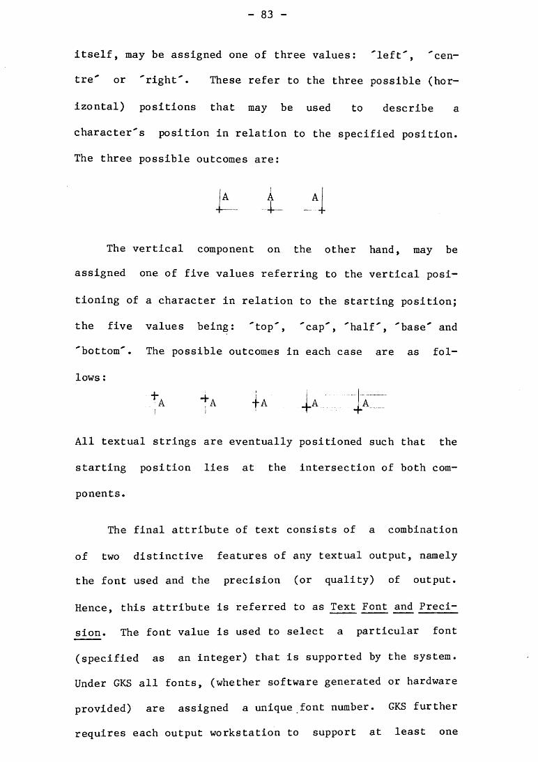
itself, may be assigned one of three values: 'left', 'cen-
tre' or 'right'. These refer to the three possible (hor-
izontal) positions that may be used to describe a
character's position in relation to the specified position.
The three possible outcomes are:
I A
The vertical component on the other hand, may be
assigned one of five values referring to the vertical posi-
tioning of a character in relation to the starting position;
the five values being: 'top', 'cap', 'half, 'base' and
'bottom'. The possible outcomes in each case are as fol-
lows :
4 A " A f^
All textual strings are eventually positioned such that the
starting position lies at the intersection of both com-
ponents.
The final attribute of text consists of a combination
of two distinctive features of any textual output, namely
the font used and the precision (or quality) of output.
Hence, this attribute is referred to as Text Font and Preci-
sion. The font value is used to select a particular font
(specified as an integer) that is supported by the system.
Under GKS all fonts, (whether software generated or hardware
provided) are assigned a unique font number. GKS further
requires each output workstation to support at least one
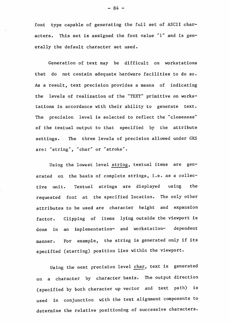
font type capable of generating the full set of ASCII char-
acters. This set is assigned the font value and is gen-
erally the default character set used.
Generation of text may be difficult on workstations
that do not contain adequate hardware facilities to do so.
As a result, text precision provides a means of indicating
the levels of realization of the "TEXT" primitive on works-
tations in accordance with their ability to generate text.
The precision level is selected to reflect the "closeness"
of the textual output to that specified by the attribute
settings. The three levels of precision allowed under GKS
are: 'string', 'char' or 'stroke'.
Using the lowest level string, textual items are gen-
erated on the basis of complete strings, i.e. as a collec-
tive unit. Textual strings are displayed using the
requested font at the specified location. The only other
attributes to be used are character height and expansion
factor. Clipping of items lying outside the viewport is
done in an implementation- and workstation- dependent
manner. For example, the string is generated only if its
specified (starting) position lies within the viewport.
Using the next precision level char, text is generated
on a character by character basis. The output direction
(specified by both character up vector and text path) is
used in conjunction with the text alignment components to
determine the relative positioning of successive characters.
Individual characters are displayed in the requested font
using character height, spacing and expansion factors.
Clipping is performed on a character by character basis,
thus displaying only those characters that lie completely
within the viewport.
Under the third and highest level of precision stroke,
textual output is generated on the basis of individual
strokes that constitute a character. The string itself, is
generated at the specified location using current settings
of all of text attributes. Strings may further be
transformed before actual generation. Characters or parts
of characters that lie on the viewport boundary may be
clipped at the boundary thereby displaying only those char-
acters, or parts of characters, that lie within the viewport
itself.
It must be noted that attributes belonging to the
second (advanced) group can be, and often are, assigned
values collectively in terms of a text bundle together with
those from the first (general) group. Hence, as users gain
experience in utilizing all the attributes affecting text
generation, more complex representations may be specified as
bundles and accessed through their text indices.
Selection of fonts under GAP in contrast, are limited
to those generated by software only. The selection is
obtained by invoking "SCSET" with its parameter specifying
the string name of the desired font. The selection of fonts
is restricted to one of two types, these being 'standard'
(upright characters) and 'cursive' (running writing).
There are three other attributes under GAP that may be
assigned values to produce distinguishable text output. The
first of these, "COLOUR" can be invoked prior to any of the
output primitives specifying the selection of a new colour
or pen to be used for subsequent output. Although GAP does
not contain a specific colour scheme that is uniform across
all output devices, it does contain the restriction that
COLOR(O)
specifies no visible output. Thus for plotters, this rou-
tine call may indicate either that all pens are put away or
that the current pen position is off the plotting surface
thereby being unable to generate further output until expli-
citly instructed to do so.
The second text attribute of GAP allows the ability to
specify the size of software generated characters using
"SCSIZ". The size itself is specified in terms of the per-
centage of the current display frame, both in the x- and y-
directions. The default size, expressed as
SCSIZ(0.04, 0.04)
specifies the character height and width (including spacing)
to be 4 percent of the currently selected frame size. How-
ever, when generating textual output from within symbols,
the size of text output is automatically scaled in relation
to the rest of the sjanbol to fit within the specified frame.
The third attribute under GAP influencing textual out-
put is shearing (specified using "SCSHR"). Shearing effect
is achieved by slanting the top of all characters by a
specified amount expressed as a real number ranging between
-1.0 and 1.0. The default shear factor is 0.0, thus causing
characters to be generated in an upright position. Positive
shear factors result is slanting towards the right while
negative factors cause slanting to the left. Selection of a
new font automatically resets the shear factor to the
default value.
Apart from the colour attribute mentioned above, all
other attributes of GAP apply to software generated charac-
ters only. Hence under GAP, the hardware provided text
facilities may be used only in situations where the size and
shearing factors are of no importance.
5.4.2.6.2. Transformations
The text geometry under GKS is defined in terms of
world coordinate values thus, enabling the representation of
individual characters to be transformed in a similar manner
to the other output primitives. As a result, the three
(normalization-, workstation- and segmentation-) transforma-
tions are also applicable to textual output. Consequently,
using any or a combination of these transformations in con-
junction with the text attributes mentioned above, quite
complex forms of textual displays may be achieved.
For efficiency reasons (i.e. because of the varying
capabilities of output devices at handling text output), the
strict rule of being able to transform characters in a simi-
lar manner to the other output primitives has been relaxed
for the lower two precision levels (e.g. "string' and
'char').
Transformation of textual items under GAP in contrast,
is restricted to those produced via software generated char-
acters. These transformations include rotation and mirror
imaging of text items using the two coordinate axes. Furth-
ermore, textual items generated within symbols are
transformed accordingly when a call is made to generate the
s3mibols themselves within specified frames.
Rotation of characters is achieved using "ROTAT". The
rotational angle and center point is specified to this rou-
tine such that all subsequent output (including software
generated characters) are rotated about the center by the
specified amount.
Reflection (or mirroring) of the output is achieved
under GAP using "MIROR". To this routine, the axis is
specified over which the reflection is appear. The effect
of this invocation is essentially to reverse the order of
the coordinate system designated to produce the output,
hence producing the "mirrored". If invoked using the param-
eter 'x', the output (including textual items) is displayed
to show a reflection along the x-axis while invoking it with
'y' demonstrates a reflection along the y-axis.
Textual items contained within symbols are transformed
to maintain its original aspect ratio within the symbols
when displayed. Such transformations may include scaling
and translation of characters together with rotation as
specified by the symbol generation routine invoked.
¿'A'^'Z* Numeric Output
GKS does not provide numeric data to string conversion
facilities. As a result, all numeric data must be converted
into their equivalent characters strings by application pro-
grams before being passed to the "TEXT" primitive for output
generation.
GAP in contrast, provides routines for such purposes,
these being "SHFPN" and "SHSIN". Both routines convert
values passed in to their corresponding ASCII character
strings before being displayed using software generated
characters.
The first of these, "SHFPN" accepts a floating point
number converting it into a string corresponding to the
required format. The formats are specified in a similar
manner to that of FORTRAN. For example, requiring a real
number to be displayed as six digits with four after the
decimal point, the format may be used. "SHSIN" also
operates in a similar manner accepting integer values rather
than reals.
1-A-l-l- Others
GKS provides a special output primitive through which
an application may access output facilities that, although
provided by individual workstations, are not supported by
the system. These facilities generally refer to arc and
spline generation, line fitting (data smoothing) and projec-
tioning. This "GENERALIZED DRAWING PRIMITIVE" (GDP) itself,
specifies how such capabilities of the workstations may be
addressed and used to enhance the output generated.
It is not necessary for all workstations to support the
GDPs provided. Consequently, when a particular facility is
invoked on a workstation that does not support it, an
appropriate (error) message is generated to indicate this.
All geometric data (i.e. characteristics controlling
the shape and size) accompanying a particular GDP are nor-
mally specified separately from the non-geometric data (con-
trolling the appearance). This therefore, permits the
application of transformations to all geometric data, thus
maintaining consistency with the other primitives supported
by the system.
Due to the fact that facilities accessed via the GDP
are non-standard (i.e. not directly supported by GKS), the
system does not provide specific attributes that influence
their generation. If however, a particular facility is
similar to one of the other primitives supported by the sys-
tem, corresponding attributes of that primitive may be used
to specify the appearance of the GDP itself. For example,
the attributes of "POLYLINE" may be used to generate arcs
and spline curves, while those of "FILLAREA" may be used to
display histograms and/or pie charts.
._5 . Application Extension
GKS, from its inception, has been defined (and imple-
mented) as a general purpose graphics standard. As a
result, it provides most facilities needed to generate
graphical output for most types of applications. Further-
more, the system was developed to use most types of graphi-
cal input and output devices available. This in itself
threatened to increase the size of GKS enormously. Hence,
with its designers striving for simplicity, efficiency and
minimality of functions (among other considerations), it was
resolved that GKS would not contain any application specific
routines. Thus, under GKS it is left up to the user to con-
struct such routines using the basic facilities provided by
the system.
GAP, in contrast, provides a number o£ routines for the
generation of graphs and also construction of output in
terms of a grid system. The grid system, using matrix ter-
minology (and analogous to a two-dimensional array) involves
the generation of predefined symbols within the sectors of
the grid.
^•¿'i* Graphing Operations
The graphing operations provided by GAP include the
ability to generate histograms, line graphs and error bar
graphs. As utilities, the package also provides routines to
generate and label axes as well as drawing the graphs and
histograms themselves. Furthermore, the system provides the
ability to draw several graphs using the same set of axes.
The graphing routines may be classified into one of two
levels (with respect to their operations). The first of the
lower level routines "RAXIS" is used to generate axes lines
with tic-marks at the specified intervals. Furthermore, it
allows the specification of the number of levels of tic-
marks that are to be generated on the axes. The tic-marks
themselves may appear on either side of the axes (i.e. the
negative and/or positive quadrants).
"UHIST", the second low level graphing routine, is
invoked by applications to generate histograms of which
there are three types, these being 'normal', 'solid' and
'dash'. Essentially, these three modes specify the means of
displaying individual bins. Using normal, the sides of each
bin are left undisplayed while under solid, the sides are
depicted using solid (continuous) lines. Conversely, using
dash, the sides of each bin are displayed with dashed line
segments.
"PHIST" (another GAP routine to generate histograms)
acts almost identically to "UHIST". The difference however,
is that "PHIST" allows the specification of a rectangular
frame into which the histogram is to be generated. This,
therefore, allows users the ability to specify the size and
positioning of histograms within the display area.
The fourth and final low level graphing routine of GAP
is provided by "GEBAR". It is used to generate graphs con-
sisting of error bars. This task is accomplished by the
routine firstly generating a graph depicted by the first set
of coordinate positions specified to it. Treating the
second set as absolute deviations, "GEBAR" then displays
these deviations using a horizontal and vertical line.
Of the two high level graphing routines provided by
GAP, the first "GRAPH" allows the generation of mathematical
graphs, graphs with error bars and/or histograms as deter-
mined by its mode settings. In generating these output,
"GRAPH" firstly determines the range of the axes required by
examining the data passed in. Upon determining this, the
routine then generates and labels the axes as requested.
This is then followed by generation of the actual graph
itself. The various tasks of "GRAPH" are accomplished (as
expected) using the low level graphing primitives mentioned
above.
The other high level graphing operation of GAP is
achieved using "XGRPH". This routine (invoked in conjunc-
tion with "GRAPH") is used to generate a number of graphs
using the same set of axes. Hence, following the generation
of the first graph (via "GRAPH"), all subsequent output may
be displayed using "XGRPH".
_5._5._2. Curve Fitting and Data Smoothing
Neither graphics system provides curve fitting or data
smoothing facilities. Consequently, such actions when
required, must be done by the application themselves.
• Positioned Text
Neither graphics system provides text windowing facili-
ties and as a result, these must be specified by the appli-
cations themselves. Furthermore, neither GKS not GAP con-
tains routines that enable the creation and subsequent usage
of menus. However, these may be simulated using the basic
facilities provided by both systems.
Menus can be generated under GKS by placing the text
strings (listing the alternatives) within segments. The
selection made from this list of alternatives are then be
indicated to the system via an input device belonging to the
pick class. In this manner, the segment name returned by
the pick device identifies the menu selected from, while the
pick identifier itself specifies the alternative selected.
Furthermore, attributes influencing segment generation may
be used to control the appearances of the menu and its con-
tents. For example, a menu contained within a segment is
kept invisible until required. Once made visible, all
options applicable to the current situation are then be made
detectable (for selection) while the others remain undetect-
able. Once a selection is made from the displayed menu, the
segment is then returned to its invisible state.
Although not so elaborate, menus may also be created
and used under GAP as well. In such cases, the contents of
the menu may be placed in a symbol and generated when
required within a specified area of the display surface.
Input concerning the selection made within the menu must
however, be handled by the application program itself (via
appropriate input statements). The correlation between the
selected item and those displayed within the menu must also
be done by the application.
Others
GAP provides a two-dimensional grid system into which
previously defined symbols may be generated, thus enabling
the creation of complex output. The symbols when generated,
are scaled to fit within each grid sector. A total of six
routines are provided by GAP, each of which specifies a dif-
ferent method of filling in the grid sectors.
The first "GSSYM" generates a specified symbol within a
particular grid sector while "GSFIL" generates the named
symbol into each of the grid sectors, thus repeatedly
displaying the same symbol in each of the grid sectors.
"GSROT" acts in a similar manner to that of "GSSYM" in that
it generates a named s3nnbol within a specified sector. How-
ever, "GSROT" allows users the option of applying rotation
to the symbol's definition before actual generation.
"GSVEC" and "GSVES" are two routines that accept an
array of symbol names to be generated. The order in which
the grid sectors are filled however, differs between the
two. The former "GSVEC", fills the sectors in terms of its
columns while the latter, "GSVES" fills the grid using a
specified sequence (via the array). In both cases a sector
is left vacant if the corresponding symbol name is 'zero'
(an illegal symbol name).
The final grid filling routine "GSARY" fills the sec-
tors using the s3aiibol names specified in an array of the
same dimensions as the grid itself. Again, a sector is left
vacant if its corresponding symbol name is 'zero'.
5.6. Application Program Compilation / Display File Genera-
tion
Application programs under both graphics systems are
compiled by linking them to their respective graphics
libraries (and others that may be needed) at compile time.
Once compiled, the GKS application is then executed with
device specific instructions being sent directly to the
nominated workstations. As a result, users do not have
access to the descriptions of the output and are therefore,
unable to modify the appearances of the output without mak-
ing appropriate changes to the applications themselves.
Upon linking the application program to the GAP
library, routines invoked generate a device independent
description of the output. This description is then inter-
preted to produce device specific instructions that are
redirected to the graphics device being used. The device
independent instructions may either be written into a
display file (that is interpreted at a later stage) or sent
directly to an interpreter.
The display file, when generated under GAP, consists of
a stream of commands and arguments that may be modified
after generation using the local editing facilities avail-
able. This modification however, may be difficult as one is
required to know the exact device independent instruction(s)
(including specification of coordinate values, etc.) neces-
sary to generate the required change(s). This activity (of
modifying display files) is not recommended as the applica-
tion program may no longer correspond to the output gen-
erated .
Under GAP, only one display file may be generated by an
application program at any given instant. Hence, if "START"
is invoked while a display file is being generated (i.e.
signaling the creation and subsequent generation of a new
one), the currently open display file is closed by the sys-
tem automatically before the new one is opened for subse-
quent output. In this manner, concatenation of display
files is not easily achieved under GAP as each file is ter-
minated with the "end of display file" instruction (thus
signaling the end of output generation from that file).
Data Structures
Neither GKS nor GAP generates descriptions of output in
terms of data structures but instead, as a continuous stream
of commands (and their arguments). The commands under GKS
represent device specific instructions that are sent
directly to their respective (activated) workstations on
which the resulting output is subsequently displayed.
In the case of GAP, the stream of commands (and associ-
ated arguments) represent device independent instructions
that are subsequently interpreted to generate the output.
The instructions are expressed as hexadecimal numbers (con-
sisting of 1 byte each) while the possible arguments express
coordinate values (using integers), singular characters
and/or character strings. Such instructions are then con-
verted into device specific code by the selected inter-
preter.
Application Storage and Retrieval
GKS provides three forms of storage mechanisms, two of
which apply strictly to segments while the third allows all
types of graphical Information to be stored for later use.
Of the two segment storage facilities, Workstation Dependent
Segment Storage (WDSS) provides a means of storing segment
definitions on all workstations that were active during the
actual definition process. Hence, when required to display
a particular segment. Its definition contained within WDSS
Is used.
The second form of segment storage refers to Worksta-
tion Independent Segment Storage (WISS). This contains the
definition of all segments specified by a particular appli-
cation. WISS facilitates the copying of segments onto
workstations that were Inactive during the definition pro-
cess. Furthemore, definitions contained within the WISS
allows the Insertion of already defined segments Into those
that are subsequently created.
However, the restrictions placed on both WDSS and WISS
Is quite limiting In that only segments (and their contents)
may be stored within these. More Importantly however, con-
tents of both these storage facilities are lost once the an
application terminates usage of the system.
To overcome these limitations, GKS provides a more per-
manent storage mechanism referred to as metafiles (sequen-
tial files created and stored on mass storage devices). A
metafile provides the means of storing Information for later
usage and for transfer of graphical and/or other Information
across different locations and/or systems.
Metafiles are treated by GKS as special workstations
having both input and output capabilities (but not at the
same time). When information is being written into a
metafile it is treated as an output workstation, while when
information is being retrieved from it, the metafile is
treated as an input workstation. Apart from containing a
workstation identifier (name) and its input/output category,
metafile workstations do not possess any other features nor-
mally associated with a workstation. As a result, a special
output primitive ("WRITE ITEM TO GKSM") is provided by the
system to write information to metafiles. Consequently, a
set of special input primitives ("GET ITEM TYPE FROM GKSM"
and "READ ITEM FROM GKSM") provides the ability to retrieve
information from them. Once information is obtained, it is
interpreted via "INTERPRET ITEM". Note that all information
is stored and retrieved in terms of units referred to as
items. The items correspond to the various aspects of the
graphics system such as primitives, attributes, transforma-
tions.
Display files generated by GAP application programs
provide a means of storing graphical output for subsequent
regeneration. Such files may be stored on mass storage
facilities. To generate the output of a particular display
file, the user needs only to specify the name of the display
file to the interpreter being used while redirecting the
(device specific) instructions to the actual graphics device
being used. Consequently, the output specified by a
particular display file may be generated on numerous devices
individually by interpreting the contents of the file using
the appropriate interpreters before redirecting the output
to the corresponding devices themselves.
However, once generated, a display file cannot be
retrieved for modification purposes. Furthermore, GAP does
not allow the merging of two or more display file and as a
result, concatenation of applications specified using two or
more display files is not possible under the system.
Sizing Information(*)
As expected, GKS is significantly larger than GAP -
both in terms of the object code and source code. For exam-
ple, the GKS library (including three device drivers) for
the Hewlett-Packard & Servogor plotters and the Tektronix
4006 terminal) consists of 620 blocks while GAP (with the
same three device interpreters) comprises 463 blocks.
Without the device drivers/interpreters, the GKS library
consists of 304 blocks while the GAP library constitutes 185
blocks. The source for the graphics standard consists of
(*)Note that the comparison values specified for GKS refer to those of the prereleased version of the system as currently installed at the University of Wollongong. These values will obviously change once the final ver-sion is installed.
Note also that the values specified in this section refer to sizes in terms blocks used with each block consisting of a maximum of 512 bytes.
374 blocks while GAP is less than half of this (158 blocks).
This ratio of 42% is further reflected when comparing the
lines of actual code, 8170 lines for GKS as opposed to 3530
lines for GAP.
However, it is interesting to note that GAP inter-
preters are significantly larger than the corresponding GKS
device drivers. For example, the three device drivers of
GKS amount to 2681 lines of code while the three
(equivalent) GAP interpreters total to 3272 lines. This
implies that GAP becomes increasing larger (in terms of
size) as more devices are incorporated into the package.
Both systems provide a similar number of user callable
routines (GKS - 77 and GAP - 72). Of the GKS routines,
only six generate any form of visual output on the display
surface(s) while 41 of the GAP routines produce some form of
output. Furthermore, 32 of the GKS routines (attributes)
describe the actual appearance of the output when generated
as opposed to four of the GAP routines.
5.8. Implementation Environment
The prereleased version of GKS installed at the Univer-
sity of Wollongong is coded entirely in 'C' and is commonly
referred to as "GKS-in-C". Originally implemented at the
Amsterdam Mathematisch Centrum in The Netherlands, the sys-
tem consists of a library of functions to which all user
(application) programs must link at compile time. Gonse-
quently, usage of the system is open to all application pro-
grams that are capable of linking to the GKS library. Under
present situation however, this is limited to programs
only.
The GAP system, also consists of a library of routines
and is coded entirely in FORTRAN 77 with the various device
specific interpreters written in 'C. The package, from its
offset, was designed for use by application programs coded
in a variety of different languages that could interface to
the library. This is presently the case for applications
written either in FORTRAN or itself.
Neither graphics systems use any facilities of the
operating system under which they are implemented, apart
from that of opening and closing files at runtime. These
files, in the case of GKS, are error files and metafiles
that may be used to store and/or retrieve graphical and
other information. The files under GAP are the display
files that may be generated by the application program.
Graphical Hardware Supported
One of the considerations taken into account when
deciding to evaluate GKS by comparing it with an existing
graphics package was that both graphics systems, as
currently implemented at the University of Wollongong, were
capable of using the same graphics devices available within
the Department of Computing Science. These devices include:
- lOA -
- Hewlett Packard 7475A 6- pen plotter;
Servogor 281 8- pen plotter;
Tektronix 4006 terminal.
"GKS-in-C" device drivers also exist for:
AED 512 display terminals;
Tektronix 4014 terminals; and
- Versatec printer plotters.
The former three device drivers were developed at the
University of Wollongong while the latter three accompanied
the system from Amsterdam. Other GKS device drivers also
exist for Calcomp Plotters, Visual monochrome raster VDUs,
Ramtek colour raster VDUs and ACT~1 ink jet plotters (Wat-
kins, 1983).
In addition to the GAP interpreters mentioned above,
others exist for the Apple Laser-Writer, Calcomp drum
plotters, Houston Grit-wheel plotter, Perkin - Elmer 7000
Series Computer display terminals and VC 404 teletype termi-
nals .
5.10. Computers on which the Systems Operate
As mentioned earlier, the original "GKS-in-C" was
implemented at the Amsterdam Mathematisch Centrum (although
it is not known which host computer). The implementation at
the University of Wollongong (along with GAP ) are both on
the Department of Computing Science's - Perkin-Elmer 3230
running under UNIX (version 7.0).
Other known implementations of GKS are reported to be
running on a multitude of different mainframes, these
include CYBER 172 and 835, IBM and VAX machines, NOVA-GKS,
the UNIVAC series, SIEMENS 7000 and HARRIS H-lOO series
machines and others. Recent conference proceedings indicate
that success has been achieved in porting GKS onto the
Siemen's graphics workstation SIGRIS and also to PDP ll/40s.
Another installation of GAP appears on the Perkin-Elmer
7000 Series Computer running under Idris. This latter
installation however, is used primarily for demonstration
purposes.
5.11. Number of Installations
With its ever increasing popularity and support as the
graphics standard from both hardware manufacturers (e.g.
IBM, NOVA, etc.) and industry itself, GKS implementations
have begun to appear in numerous different language bindings
(i.e. FORTRAN, ' C , PASCAL, ADA, etc.). Furthermore, graph-
ics standardization, and especially GKS, are also being
granted numerous (discussion) panel sessions at graphics
conferences throughout the world (ten Hagen, 1983). As a
result, it is impossible to state (or even suggest) the
approximate number of GKS installations throughout the
wo rid.
At least two "GKS-in-C" installations are known, these
sites being the Amsterdam Mathematisch Centrum (where the
implementation originated) and the University of Wollongong.
Moreover, the Free University of Berlin reported at the
"Eurographics Conference of 1982" (Buhtz, 1982) of its
implementation of the GKS (version 6.4), referred to as the
Common Graphics Manager (CGM). Also reported at this
conference was the development of GRAPH (at Oxford Univer-
sity), a program for interactive statistical modeling based
on GKS (Slater & Baker, 1982).
Publications of the "Eurographics Conference of 1983"
show that work is already underway in numerous countries to
develop a PASCAL binding for GKS (Antoy & Dettroi, 1983;
Schmitgen, 1983). Also noted at this conference was the
fact that the Hungarian Academy of Sciences was developing
its version of the system, "XGKS - a Multitask Implementa-
tion of GKS" (Herman, et.al; 1983). Work is also underway
for the development of an ADA binding for GKS (Wagner,
1985). Furthermore, as the trend towards accepting GKS as
the graphics standard is increasing, VLSI support for the
system is also beginning to appear (Mehl & Noll, 1984).
Documentation
All purchases of "GKS-in-C" from the Matematisch Cen-
trum are accompanied by a copy of the accepted "ISO Draft
International Standard" document (ISO/DIS/7942, 1983). This
contains a comprehensive description of the graphics system
itself, including the features and facilities available. It
contains descriptions of the functions available and the
list of possible errors that may be generated when invoked
incorrectly.
Books have also begun to appear on the topic of GKS and
the standardization of computer graphics itself (Enderle,
et.al; 1984; Hopgood, et.al., 1984). The appearance of
these may be directly attributable to the standardization of
this area of computing and also the acceptance of GKS. A
departmental preprint, which also serves as user manual for
"GKS-in-C" (Sahib, 1985) is available from the University of
Wollongong.
In contrast, there is a single departmental preprint
that acts both as a reference and a user manual for GAP
(Nealon, 1980). This publication presents a description of
each GAP routine available and the equivalent display file
code generated by the routines when invoked. Also included
under the description of each routine, are the possible
error(s) that may be generated (along with their severity
level) as a result of incorrect usage of the GAP routine.
CONCLUSIONS
In determining the advancements attained by Graphical
Kernel System (GKS) - the proposed international standard
for computer graphics, it was compared with an existing
package, namely Graphics Assistance Package (GAP) (whose
origins can be traced back to the late 1960s), to determine
the similarities between the two systems along with the
enhancements and new concepts incorporated into the proposed
standard.
GAP is a single level implementation while GKS is
available in nine (9) independent levels, each meeting
specific user requirements in terms of the facilities pro-
vided. The facilities themselves range from simple passive
output to highly interactive environments that use multiple
input and/or output devices simultaneously. This, therefore
allows selection of a particular implementation that is best
suited for the requirements and/or environment for which it
is intended.
Each implementation of GKS consists of a hierarchical
structure comprising of five (5) operating states with each
state containing its own set of allowable routines. This
ensures proper usage of the system in terms of the routines
invokable within each state and an orderly transition from
one state to the next.
All interaction with physical devices under GAP is
achieved by redirecting output from the selected
interpreter(s) to their respective device(s). GKS, in con-
trast, interacts with physical devices via the workstations
onto which they are mapped. Output devices, for example,
are mapped either onto individual workstations or incor-
porated into others. Input devices, on the other hand, are
mapped onto corresponding logical input devices (depending
on the type of data they return) which in turn are incor-
porated into workstations.
While GAP does not contain any specific routines to
interact with input devices (thus forcing application pro-
grams to do so themselves), GKS supports six (6) classes of
input each containing any number of logical (input) devices.
These classes are referred to as: 'Pick' (for selection of
displayed objects); 'Choice' (for selection from a list of
alternatives); 'Locator' and 'Stroke' (for positional
input); 'Valuator' (for numeric input) and 'String (for tex-
tual input).
Logical input devices may be used in one of three modes
of interaction, namely 'request', 'sample' or 'event'.
These modes specify the interaction between an application
program's execution and the input process. Under request
mode, program execution is suspended until the requested
input is obtained on the specified (logical) device while
under the latter modes, input occurs independently of the
execution. Using sample mode, the latest value (input)
obtained by the specified device is used or sampled when
required by the application. In contrast, all input
obtained under event mode is placed within an input queue
and is read off when required.
The concept of abstract workstations is unique to GKS
as it does away with the requirement that application pro-
grams incorporate device specific information within them.
Consequently, the system (using appropriate device drivers)
generate device specific instructions that are sent directly
to the graphical hardware being used.
Individual workstations may consist of any number of
logical (and hence, physical) input devices together with
zero or one output device. As a result, each workstation is
classified into one of three categories depending on its
input/output capabilities. Workstations with input facili-
ties are ready for use once they have been opened while the
output facility may be used only after such workstations
have been opened and activated. This, therefore allows a
particular workstation (with both capabilities) to be used
for input and output purposes alternatively by simply
activating and deactivating it as required once the worksta-
tion has been opened. Furthermore, multiple workstations
may be used simultaneously for input and/or output purposes
by simply opening those that are to receive input and
activating those that are to display the output generated by
the application. Hence, logical input devices under either
- Ill -
'sample' or 'event' mode may continue to receive data while
output is being displayed on all workstations that are
active.
Unlike GAP which requires two routines to initialize
the system (one to set operating modes and the other to set
environmental factors), initialization of GKS is achieved by
simply opening the system (via "OPEN GKS"). This, in
effect, sets up various description and state tables con-
taining information about the implementation and worksta-
tions supported. Description tables contain information
about the facilities available under GKS while state tables
reflect the current status of the system and its worksta-
tions. Consequently, there is a description and a state
table for each workstation supported by the system.
Both GKS and GAP provide facilities for application
programs to obtain information about the system and its
current settings. In the case of GAP this information is
limited to information concerning those environmental fac-
tors which are set by its initialization routines (i.e. lim-
its of the user coordinate system, window and/or viewport
areas, etc.). GKS, in contrast, provides a comprehensive
set (75) of inquiry functions that obtain information from
the various description and state tables, thus allowing
modification of the behaviour of an application program to
make best use of the facilities available.
Errors detected within GAP are classified into one of
three levels of seriousness, namely 'warning', 'severe" and
'fatal'. Warning errors merely generate messages to this
effect and proceed with the execution of the application.
Severe errors generate appropriate messages and allow the
user the option of continuing with execution or terminating
it. Fatal errors generate error messages indicating the
error before aborting execution of the application program.
In contrast, errors detected within GKS result in the
invocation either of the user defined or system specified
(default) error handler. Although the default error handler
simply generates error messages and terminates execution,
application specified error handlers may invoke inquiry
functions to obtain more information about the state of the
system and hence, the error itself. Furthermore, it may
attempt an emergency closure of GKS in situations where the
error(s) detected are unrecoverable. Error messages gen-
erated by GAP appear on standard output which, unfortunately
is also the display surface on most graphical devices.
Hence in such cases, the display (or output) generated prior
to the error is interrupted by error messages. GKS, on the
other hand, initiates an error file during initialization of
the system. Consequently, all messages generated by the
system are written into the error file for subsequent exami-
nation at a later stage.
Due to its hierarchical structure, GKS contains a
strict sequence of routines that must be invoked to ter-
minate usage of the workstation(s) and the system itself.
This sequence, (consisting of deactivating workstations,
closing workstations and then the system itself) ensures
that all housekeeping functions are performed (including the
deallocation of description and state tables and release of
all physical devices) before terminating the link between
the system and the application program.
Generating an application using either graphics system
involves three independent coordinate systems. All output
is specified within the user or world coordinate (WC) system
which are then mapped onto an intermediate device indepen-
dent coordinate system (referred to as the normalized device
coordinate (NDC) system under GKS). Such values are then
transformed onto specific device coordinate systems by the
selected interpreters (under GAP) or by device driver rou-
tines (under GKS). Furthermore, both graphics systems allow
the application to specify windows into the user/world coor-
dinate system through which to view output. The contents of
such a window can then be generated within a viewport speci-
fied using device coordinate values.
The process of mapping windows onto the normalized dev-
ice coordinate system under GKS is referred to as normaliza-
tion transformation, while mapping NDC values onto
corresponding device coordinates within the viewports is
referred to as workstation transformation. GKS allows mul-
tiple normalization transformations and each is assigned a
unique transformation number. Normalization transformations
can be invoked at later stages by simply identifying the
required one via its transformation number. In contrast,
only one workstation transformation is permitted per works-
tation, although different ones may be active on different
workstations. This allows different aspects of the same
output to be generated on different workstations. Conse-
quently, changes to the current workstation transformation
on a particular workstation results in the complete regen-
eration of its display.
Positional input is obtained by GKS in terms of device
coordinates that are then mapped onto corresponding NDC
values by the appropriate device drivers. The resulting NDC
values are then converted to world coordinates by the system
itself before being returned to the application program for
subsequent usage.
Graphical output under both systems may be generated in
terms of individual (output) primitives or as objects (or
subpictures) that collectively depict the required output.
The subpictures (referred to as symbols under GAP and seg-
ments under GKS) may consist of calls to output primitives
and/or other s)rmbols / segments already defined. Each sym-
bol or segment is assigned a unique identifier when created
and is henceforth referred to by that name. Both GAP and
GKS allow symbol/segment definitions to be created,
transformed, generated, inserted into subsequent definitions
and deleted (GKS further allows segments to be renamed).
Although the definition of such objects cannot be modified
once created, both systems provide some means of making each
occurrence of a particular symbol or segment distinguish-
able. Under GAP, this facility is limited to selecting a
different colour or pen to generate the s3mibol, and the use
of a different font if text is generated from within a sym-
bol definition.
GKS, in contrast, provides a number of attributes that
directly influence the generation of segments. These attri-
butes refer to 'segment visibility', 'highlighting', 'prior-
ity' and 'detectability'. Used in conjunction with the
attributes influencing output primitives, appearances of the
same segment can be made quite distinctive.
Unlike GAP where sjonbol transformations are achieved
indirectly and hence, cannot be stored for later usage, GKS
specifies a transformational matrix that represents a com-
pact manner of expressing scaling, rotation and translation
factors. The matrices themselves (assigned unique identif-
iers) provides a mean of storing transformations for subse-
quent usage or alternatively, to other segments. Moreover,
the matrices may contain intermediate stages of a complex
transformation and hence, concatenated to yield the final
matrix (or transformation).
In contrast to many existing graphics packages (includ-
ing GAP) where individual routines are provided to generate
similar output, GKS contains a limited number of output
primitives only. These correspond to the basic output
actions of any graphics system, namely drawing lines and
positional markers, generating enclosed areas and textual
output. The philosophy of GKS is therefore, to provide the
basic primitives only together with a number of factors that
influence the appearance of such primitives, these factors
being referred to as 'attributes'. Hence, each output prim-
itive of GKS which when assigned different attribute values
generally yield distinguishable output.
Assigning attribute values themselves may be done indi-
vidually or collectively in terms of a 'bundle' (a concept
that is unique to GKS). As bundles, each attribute
influencing a particular primitive is assigned a value. The
bundle (reflecting a particular representation of that prim-
itive) is then stored within a bundle table and may be
invoked when desired. A separate bundle table exists for
each primitive and is stored within a workstation's descrip-
tion table. The currently active representation is there-
fore, stored within the workstation's state table.
The four basic output primitives of GKS mentioned above
are "POLYLINE", "POLYMARK", "FILLAREA" and "TEXT". Each of
these are supported on all workstations incorporated into
the system. GKS further provides two primitives, these
being "CELLARRAY" and "GENERALIZED DRAWING PRIMITIVE" (GDP).
These primitives however, apply to specific workstation
capabilities and therefore may not be supported by all
workstations available within a particular GKS implementa-
tion. The former "CELLARRAY", provides access to raster
facilities of such output devices while the latter GDP,
enables the use of specific output capabilities available on
individual devices themselves but not directly supported by
GKS.
Storage of graphical information under GAP is achieved
in terms display files into which device independent
description of the output is generated. Contents of such
files can be interpreted only for output generation (using
one of the device specific interpreters) as the system does
not contain mechanisms via which application programs may
read and interpret information from display files. Conse-
quently, GAP does not provide facilities that enable appli-
cations to store information for any other purpose than out-
put generation.
GKS in contrast, allows storage of graphical informa-
tion in terms of both segments and individual primitives.
Segments are stored on workstations that were active during
the definition process. Subsequent changes to the segment
attributes are also stored on such workstations. However,
these storage facilities are lost once the workstations are
closed.
In GKS, a more permanent means of storing information
is provided via metafiles which are sequential files stored
on mass storage devices. Metafiles provide a means of tran-
sporting information across systems, locations and implemen-
tations since the format of data stored within such files
are identical for all implementations of GKS. Consequently,
metafiles are treated as output workstations when informa-
tion is being written into them and as input workstations
when information is read from them.
In contrast to GAP which provides a number of applica-
tion specific routines (e.g. graphing and histogram facili-
ties together with grid specification and filling routines),
GKS does not contain any application specific routines due
to the desire of its designers to keep the system simple and
minimal in terms of the number of routines provided. How-
ever, most forms of applications may be generated using the
building blocks that are provided by the system.
In conclusion therefore, the major requirement of a
graphics standard is that it should free application pro-
grams from the peculiarities of different devices and dif-
ferent (host) machines. To do this, the standard should be
implementable in any of the major ISO languages, be capable
of driving the majority of currently available graphics dev-
ices and offer a simple interface to application programs.
The principal mechanisms by which GKS achieves these
requirements center basically on two new concepts incor-
porated into the proposed standard. These refer to: the use
of abstraction to define logical input and output that can
be linked to physical devices; and the concept of worksta-
tions which relieves the user from unnecessary involvement
with the features and limitations of each device to be used.
Whether or not GKS is finally accepted as the interna-
tional standard for computer graphics and becomes widely
used is still uncertain (especially in light of the time
interval since its acceptance as the Draft International
Standard). Hardware manufacturers in Europe and America, in
the meantime, have begun to offer GKS facilities in
hardware. Software implementations already exist in ADA,
'C, FORTRAN and PASCAL. Hence, the future looks bright.
Whatever the outcome, GKS is an important step in the right
direction.
BIBLIOGRAPHY
Anton, S. & Dettroi, G. "Towards GKS Binding to Pascal" in P. J. ten Hagen (Ed) Eurographics 83, Elsevier Science Publishers, North Holland, 1983, 2TT-214.
Bell, C. G. "Standards Can Help Us", Computer, June 1984, 71-78.
Bono, P. R., et. al. "GKS - The First Graphics Standard", IEEE Computer Graphics and Applications, 2, 5, July T5B7, 9-23.
Bowerman, R. "Creative Communication with Graphics", Inter-face Age, 8, 10, October 1983, 68-74.
Buhtz, R. "CGM - Concepts and their Realization", in Greena-way, D.S. & Warman, E.A. (Eds) Eurographics 82, North-Holland Publishing Company, Amsterdam, 1982, 371-382.
Carlbom, I. & Paciorek, J. "Planar Geometric Projections and Viewing Transformations", ACM Computing Surveys, 10, 1978, 465-503.
Castle, P. Plot Package - Reference Manual, Computing Cent-er Document" 2nd Edition, University of Wollongong, 1979.
Castle, P. Plot Package - Reference Manual, Computing Cent-er Document No. PP-001, University of Wollongong, Janu-ary 1982.
Clarkson, T.B. "Standardizing PC Graphics", Computer Graph-ics World, August 1985, 51-52.
Davis, A. "Proprietary / Standard Graphics Software Mix to Give More", Computer Design, 23, May 1984, 229-234.
Encarnacao, J. etal; "The Workstation Concept of GKS and the Resulting Conceptual Differences to the GSPC Core Sys-tem", Computer Graphics, 14, (3), 1980, 226-230.
Enderle, G; Kansy, K. & Pfaff, G. Computer Graphics Program-ming, GKS - The Graphics Standard, Springer-Verlag, Berlin, 1984.
Ewald, R.H. & Fryer, R. (Eds) "Final Report of the GSPC State-of-the-Art Subcommittee", Computer Graphics, 12, -June 1978, 14-169.
Garbe, 0. & Reilly, P. "ECL Chip Set Handles High-end Dis-play Applications", Computer Design, July 1985, 73-77
Geller, R.D. "Two Graphics Standards, Core and'GKS, Vie for U.S. Market Acceptance", Computer Technology Review, Winter 1983, 135-140.
Gustan, P. "Graphics Systems Deliver Upfront Performance", Computer Design, July 1985, 61-65.
Hardin, H.J. "Graphics Standards Finally Start to Sort Them-selves Out", Computer Design, 23, May 1984, 167-180.
Harris, D. Computer Graphics and Applications, Chapman and Hall Computing Series, Chapman and Hall Ltd., London, 1984.
Herman, I., Tolnay-Knefely, T. & Vincze, A. "XGKS - A Muti-task Implementation of GKS" in P. J. ten Hagen (Ed) Eurographics 83, Elsevier Science Publishers, North Holland, 1983 5-222.
Hopgood, F. R. A. "Standardization" in P. J. ten Hagen (Ed) Eurographics 83, Elsevier Science Publishers, North Holland, 1983, 301.
Hopgood, F.R.A., Duce, D.A., Gallop, J.R. & Sutcliffe, D.C. Introduction to the Graphical Kernel System (GKS), Academic Press, London, 1983.
Howie, J.M. & Miller, R. GD3 Graphics Package - User Guide, CERN Computer Centre Preprint, October 1974.
ISO/DIS 7942 Information Processing - Graphical Kernel Sys-tem - Functional Description, GKS Version 7.2,
ISO/TC97/SC5/WG2 N163, 1983.
Langhorst F.E. "Working Towards Standards in Graphics", Com-puter Design, 21, July 1982, 177-182.
Lubinski, T. & Hutzel, I. "An Object - Oriented Graphical Kernel System", Computer World Graphics, 7, July 1984, 69-75.
Machover, C. & Myers, W. "Interactive Computer Graphics", Computer, October 1984, 145-161.
Meads, J.A. "The Graphics Standards Battle", Datamation, 30, May 1984, 76-84.
Mehl, M.E. & Noll, S.J. "A VLSI Support for'GKS", IEEE Com-puter Graphics & Applications, _7, 12, December 1984, 52-55.
Michener, J.C & van Dam, A. "A Functional Overview of the Core System with Glossary", ACM Computing Surveys, 10, 1978, 381-388.
Michener, J.C & Foley, J.D. "Some Major Issues in the Design of the Core Graphics System", ACM Computing Surveys, 10, 1978, 445-464.
Miller, R. GD3 - Long Write-Up, CERN Computing Centre Pre-print, May 1976.
Nealon, R. GAP - Graphics Assistance Package, Dept. of Comp-uting Science, Preprint No. 80-6, Univerisity of Wol-longong, 1980.
Newman W.M. & Sproull, R.F. Principles of Interactive Comp-uter Graphics", McGraw-Hill Book Company, New York, im.
Newman W. M. & van Dam, A. "Recent Efforts Towards Graphics Standardization", Computing Surveys, 1£, 1978, 365-380.
Puk, R.F. "The Background of Computer Graphics Standardiza-tion", Computer Graphics, 12, June 1978, 2-6.
Rix,'J. "On Developing a GKS Driver Architecture for Raster Workstations" in P.'J. ten Hagen (Ed) Eurographics 83, Elsevier Science Publishers, North Holland, 1983, 185-193.
Rosenthal, D.S.H. & ten Hagen, P. "GKS in C", in Greena-way, D.S. & Warraan, E.A. (Eds) Eurographics 82, North-Holland Publishing Company, Amsterdam, 1982, 359-369.
Sahib, Dudani; et.al. "Graphics Software Tools Forum", Com-puter Graphics World, July, 1985, 57-76.
Sahib, Dudani; "Toolkit Development Profiles", Computer Graphics World, July, 1985, 79-88.
Sahib, M. A. Graphical Kernel System (GKS), Dept. of Comp-uting Science, Preprint No. 85-11, May 1985.
Schmitgen, G. "GKS 300 - Pascal Implementation of the Graph-ical Kernel System on a Minicomputer Based Graphical Workstation", in P.J. ten Hagen (Ed) Eurographics 83, Elsevier Science Publishers, North Holland, 1983, 205-210.
Scott, G. M. "Practical Implementations of GKS", Computer Graphics World, December 1984, 35-38.
Slater, M.& Baker, R.J. "GRAPH: An Interactive Program based on the Graphical Kernel System", in D.S. Greenaway (Ed) Eurographics 82, North - Holland Publishing Company, 1982, 383-393.
Special Issue: Graphics Standards", ACM Computing Surveys, 10, (4), 1978, 363-502.
Status Report of the Graphics Standard Planning Committee of ACM/SIGGRAPH", Computer Graphics, 11, (3), 1977.
Status Report of the Graphics Standard Planning Committee", Computer Graphics, 13, (3), 1979.
Steele, R. H. "Display List Languages Unsnarls Graphics Traffic", Computer Design, July 1985, 69-72.
Takala, T. "Standard Graphics as a Geometric Modelling Dev-ice", in P.J. ten Hagen (Ed) Eurographics 83, Elsevier Science Publishers, North Holland, 1983, 17-28.
ten Hagen, P.'J. W. The GKS Reviewing Process, Departmental Preprint, Mathematisch Centrum, Amsterdam, 1981a.
ten Hagen, P.J.W. Communicating Graphics, Departmental Pre-print, Mathematisch Centrum, Amsterdam, 1981b.
van Dam, A. "Computer Driven Displays and Their Uses in Man/ Machine Interaction", Advances in Computers, _7, 1966, 239-289.
van Dam, A. "Computer Graphics Comes of Age", Communication of the ACM, 27,'July 1984a, 638-648.
van Dam, A. "Computer Software for Graphics", Scientific American, 27, September 1984b, 102-113.
van Deusen, E. "7 Graphics Standards Vie for Acceptance to Meet Differing Goals", Computer Technology Review, Spring 1985, 119-125.
Wagner, P. M. "Ada and Graphics", Computer World Graphics, 8, February 1985, 17 -20.
Warren, C. "Graphics Software Schemes Enhance Peripheral Interfacing", Mini-Micro Systems, July 1984, 163-178.
Watkins, H. K. "A High Level Interface to the Graphical Kernel System - GKS" in P.J. ten Hagen (Ed) Eurograph-ics 83, Elsevier Science Publishers, North Holland, l983,T9-44.
Whitted, T. "Some Recent Advances in Computer"Graphics", Science, 215, (12), February 1982, 767-774.
Williams, T. "Graphics Processing Migrates From Host To

Workstation", Computer Design, July 1985, 49-57
Wright, T. "Is GKS Powerful Enough for the Application", Computer Design, 23, May 1984, 211-214.
Yule, A; Miller, R; Jeavons, A. & Piney, C. Graphic Display System (GD3), CERN Computer Centre Preprint, November 1971.
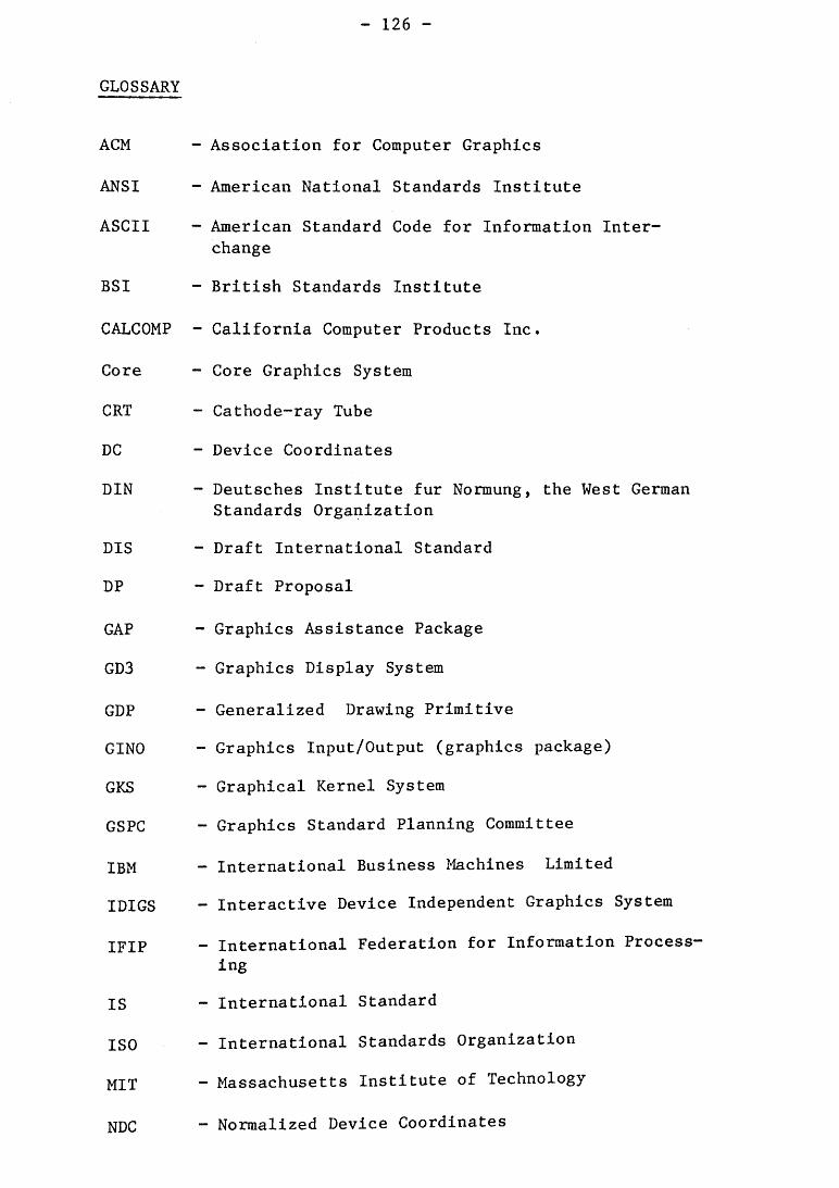
GLOSSARY
ACM - Association for Computer Graphics
ANSI ~ American National Standards Institute
ASCII - American Standard Code for Information Inter-change
BSI - British Standards Institute
CALCOMP - California Computer Products Inc.
Core - Core Graphics System
CRT - Cathode-ray Tube
DC - Device Coordinates
DIN - Deutsches Institute fur Normung, the West German Standards Organization
DIS - Draft International Standard
DP - Draft Proposal
GAP - Graphics Assistance Package
GD3 - Graphics Display System
GDP - Generalized Drawing Primitive
GINO - Graphics Input/Output (graphics package)
GKS - Graphical Kernel System
GSPC - Graphics Standard Planning Committee
IBM - International Business I*lachines Limited
IDIGS - Interactive Device Independent Graphics System
IFIP - International Federation for Information Process-ing
IS - International Standard
ISO - International Standards Organization
MIT - Massachusetts Institute of Technology
NDC - Normalized Device Coordinates

PLOT - PLOT Package (graphics package)
SIGGRAPH - ACM Special Interest Group on Computer Graphics
VDU - Visual Display Unit
WC - World Coordinates
WDSS - Workstation Dependent Segment Storage
WISS - Workstation Independent Segment Storage
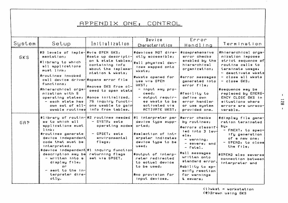
nPPENDIX O N E s C O N T R O L
S y s t e m S e t u p I n i t i a l i z a t i o n Dev ice
Character f s i î cs E r r o r
H a n d 1 i n g T e r m i n a t i o n
GKS #9 l e v e l s of Imple-m e n t a i I o n ;
i H l b r a r y to w h i c h a l l a p p 1 I c a t Ions m u s t 1 InU;
^ r o u t i n e s f n o o U e d c a l l d e v i c e d r i v e r f u n c t I o n s j
# h f e r a r c h I c a 1 o r g a -n 1 z a t I o n w i t h S o p e r a t i n g s t a t e s j - e a c h s t a t e h a s
o w n set of a l l -o w a b l e r o u t i n e s
# v l a O P E N G K S ; # s e t s up d e s c r i p t i -o n s t a t e t a b l e s j c o n t a i n i n g Info a b o u t t h e I m p l e m e -n t a t i o n 8. w U s t s i
# o p e n s e r r o r f i l e
# m o v e s G K S f r o m c l -o s e d to o p e n s t a t e
# o n c e I n i t i a l i z e d , 75 I n q u i r y f u n c t i -o n s u s a b l e to g a i n Info f r o m t a b l e s .
# d e v l c e s N O T d i r e -c t l y a c c e s s i b l e ;
# a l l p h y s i c a l d e v -ices m a p p e d o n t o w U s t s i
# w k s t s o p e n e d f o r u s e v i a O P E N U K S T ; - Input m a y p r o -
c e e d I - o u t p u t r e q u i r -
es w U s t s to be act I v a t e d vI a RCTIUflTE U K S T ,
# c o m p r e h e n s l v e e r r o r c h e c k s e n a b l e d by t h e h I e r a r c h I c a 1 o r g a n l z a t I o n ,
# e r r o r m e s s a g e s g e n e r a t e d Into e r r o r f i l e ;
# f a c I 1 Ity to d e f i n e o w n e r r o r h a n d l e r or use s y s t e m p r o v i d e d o n e .
# h I e r a r c h I c a 1 o r g a -n i z a t i o n I m p o s e s s t r I c t s e q u e n c e of r o u t Ine c a 1 1 s to t e r m i n a t e usage* - d e a c t i v a t e w U s t s - c l o s e a l l w k s t s - c l o s e G K S ;
# s e q u e n c e m a y be r e p l a c e d by E M E R G -E N C Y C L O S E GKS fn s i t u a t i o n s w h e r e e r r o r s a r e u n r e c o -v e r a b 1 e .
6 f l ?
# l l b r a r y of r o u t i n -e s to w h I c h a l l a p p l i c a t i o n s m u s t 1 Ink;
^ r o u t i n e s g e n e r a t e d e v i c e I n d e p e n d e n t c o d e t h a t m u s t be I n t e r p r e t e d ;
# d e v l c e I n d e p e n d e n t d e s c r i p t i o n m a y be - w r I t t e n Into a
d I s p 1 ay f i l e ; or
- s e n t to t h e In-t e r p r e t e r d i r e -ct ly .
#2 r o u t i n e s n e e d e d - S Y S T H i s e t s
o p e r a t i n g m o d e s
- G P S E T , s e t s e n v I r o n m e n t a 1 f l a g s ;
#1 I n q u i r y f u n c t i o n r e t u r n i n g f l a g s set v i a G P S E T .
#1 I n t e r p r e t e r p e r d e v I c e t y p e s u p p -o r t e d ;
t s e l e c t l o n of Int-e r p e t e r I n d i c a t e s d e v i c e t y p e to be u s e d ;
# o u t p u t of I n t e r p -r e t e r r e d i r e c t e d to a c t u a l d e v i c e to be u s e d ;
#no p r o v i s i o n f o r Input d e v i c e s .
# e r r o r c h e c k s by r o u t Ines j
t e r r o r s c l a s s i f led Into 3 lev e 1 st - w a r n Ing; - s e v e r e ; a n d - f a t a l .
# a 1 1 m e s s a g e s w r i t t e n o n t o s t a n d a r d e r r o r
# a b I 1 Ity to s p -ec I f y r e a c t I on f o r w a r n i n g s 8, s e v e r e ;
by
# d l s p l a y f i l e gene-r a t i o n t e r m i n a t e d
- F N E X T i to s p e c Ify g e n e r a t i o n of a n e w o n e ;
- G P E N D i to c l o s e t h e f i l e ;
ttGPENI) a l s o s e v e r e s c o n n e c t i o n b e t w e e n I n t e r p r e t e r a n d
C O w k s t = w o r k s t a t i o n <!e>I]rewn u s i n g G K S
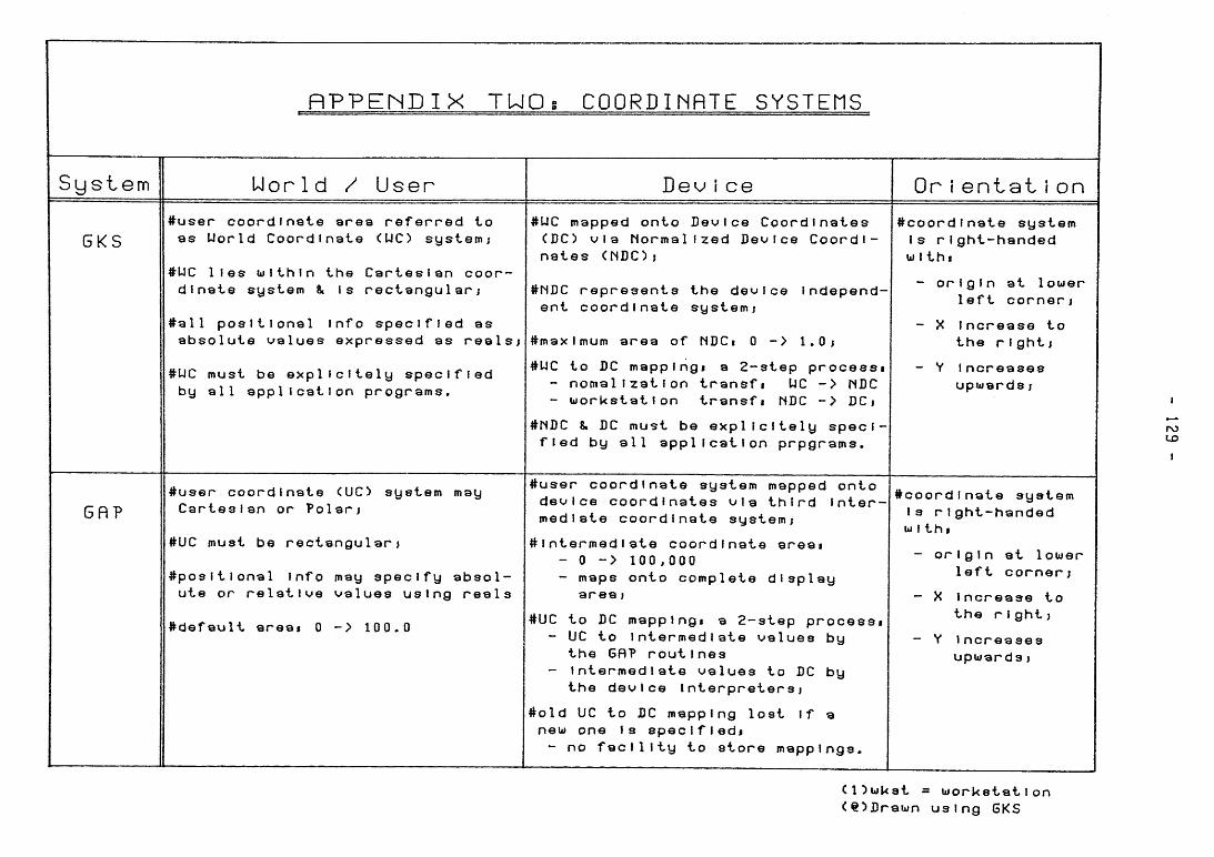
R P P E N D I X T U O s COORDINRTE SYSTEMS
S y s t e m U o r l d / U s e r Be^f i c e Or I e n t a t I o n
6KS
GR?
#user c o o r d i n a t e area r e f e r r e d to as U o r l d C o o r d i n a t e (UC) systemj
#UC lies m l t h l n the C a r t e s i a n c o o r -d i n a t e system & Is r e c t a n g u l a r )
#a11 p o s i t i o n a l Info s p e c i f i e d as a b s o l u t e v a l u e s e x p r e s s e d as r e a l s ;
#UC must be e x p l i c l t e l y s p e c i f i e d by all a p p l i c a t i o n p r o g r a m s .
#IJC m a p p e d onto D e v i c e C o o r d i n a t e s CDC) v i a M o r m a l l z e d D e v i c e C o o r d i -n a t e s ( N D O j
# N D C r e p r e s e n t s the device I n d e p e n d -ent c o o r d i n a t e systemj
# m a x l m u m a r e a of NDCt 0 - > 1.0;
#UC to DC mapplngi a 2 - s t e p p r o c e s s i - n o m a l l z a t l o n transfi UC - > M D C - w o r k s t a t i o n transfi NDC - > DCj
#MDC & DC m u s t be e x p l l c l t e l y s p e c i -f i e d by all a p p l i c a t i o n p r p g r a m s .
#user c o o r d i n a t e CUCD system may C a r t e s i a n or Polar;
#UC must be r e c t a n g u l a r ;
# p o s l t l o n a l Info may s p e c i f y a b s o l -ute or r e l a t i v e v a l u e s u s i n g r e a l s
» d e f a u l t areai 0 - > 100.0
#user c o o r d i n a t e system m a p p e d o n t o d e v i c e c o o r d i n a t e s via t h i r d Inter-m e d i a t e c o o r d i n a t e system;
# I n t e r m e d I ate c o o r d i n a t e areai - 0 - > 100,000 - m a p s onto c o m p l e t e d i s p l a y
area;
#UC to DC mapplngi a 2 - s t e p p r o c e s s i - UC to I n t e r m e d i a t e v a l u e s by
the Gfl? r o u t i n e s - I n t e r m e d i a t e v a l u e s to DC by
the d e v i c e Interpreters;
# o l d UC to DC m a p p i n g lost if a neui one is speclfledi - no f a c i l i t y to store m a p p i n g s .
^ c o o r d i n a t e s y s t e m Is r I g h t - h a n d e d w I thi
- o r i g i n at 1ouer left c o r n e r ;
- X Increase to the r I g h t ;
- Y I n c r e a s e s u p w a r d s ;
# c o o r d I n a t e s y s t e m la r i g h t - h a n d e d w I thi
- o r i g i n at lower left c o r n e r ;
- X Increase to the r i g h t ;
- Y I n c r e a s e s u p w a r d s ;
C D w k s t = w o r k s t a t i o n <e:>Drawn u s i n g GKS
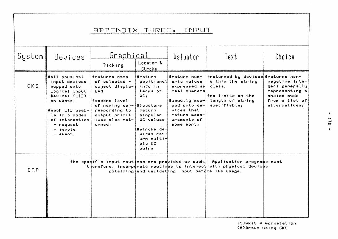
ñ P P E N D I X T H R E E S I N P U T
S y s t e m J e u i e e s G r a o h i c a " . ? i cU Í ng Locator t
Stroke
Ualuator ex Choice
GKS
# a l l p h y s i c a l Inpul d e v I c e s m a p p e d o n t o L o g I cal I n p u t D e u l c e s C L I D ) on w k s i s j
# e a c h L I D u s a b -le In 3 m o d e s of I n t e r a c t i o n - r e q u e s t - s a m p l e - e u e n t j
# r e t u r n s n a m e of s e l e c t e d -o b j e c t d I sp I a-y e d
# s e c o n d l e v e l of n a m I ng cor-r e s p o n d i n g to o u t p u t pr I m 11-lues a l s o ret-u r n e d j
# r e t u r n po s 1 1 1 o n a 1 Info In t e r m s of U C ,
# 1 o c a t o r s r e t u r n s I n g u I a r U C u a l u e s
#strol<e d e -u 1 c e s r e t -u r n m u 1 1 1 -p i e U C pa I r s
# r e t u r n n u m -er I c u a 1 u e s e x p r e s s e d a s r e a l n u m b e r s
# u s u a I Iy m a p -p e d o n t o d e -v i c e s t h a t r e t u r n m e a s -u r e m e n t s of s o m e s o r t ;
# r e t u r n e d by d e v i c e s w i t h i n t h e s t r i n g c1 a s s i
# n o l i m i t s o n t h e l e n g t h of s t r i n g s p e c I f I a b 1 e J
# r e t u r n s n o n -n e g a t i v e Inte-g e r s g e n e r a l l y r e p r e s e n t i n g a c h o I c e m a d e f r o m a 1 Ist of a 1 t e r n a t I v e s j
I
UM
I
GRP # N o spec
tt-
I f I c I n p u t r o u t o r o f o r e , Incorpi
o b t a I n I n g
n e s a r e p r o r a t e r o u t i n a n d v a l l d a t
V Ided a s s u c h . es to Interact I ng I n p u t b e f c
ñ p p l l c a t l o n prograJfts m u s t w i t h p h y s i c a l devicjaa
re Its u s a g e .
(l^uiket = w o r k s t a t i o n < e > D r a w n u s i n g G K S
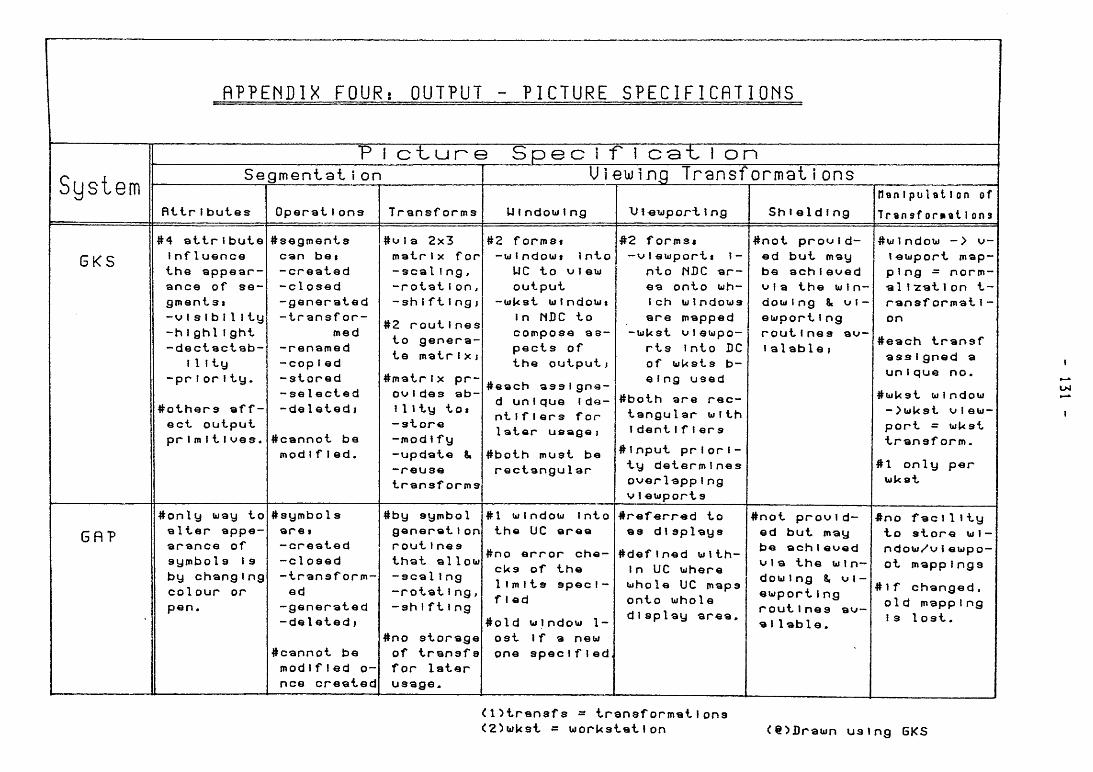
fìPPENDlX F O U R í O U T P U T - P I C T U R E S P E C I F I C f ì T I O M S
System S e g m e n t a l î on
fìttr Í b u t e s O p e r a i Ions T r a n s f o r m s
S p e c i r i c a - t \ o n
U i e u i n g T r ^ n s f o r n i a i i o n s
U f n d o u 1 n g \>l-eupor"t ing S h I © I d ! n g
flan Ipulailon of
Transf o m a t ì ona
G K S
Gfì?
#4 a t t r i b u t e I n f 1 u e n c e t h e a p p e a r -a n c e of se-g m e n t 31 - V Is f bI I Ity - h I g h l I g h t - d e c t a c t a b -
i I ! ty - p r I or I t y .
# o t h e r 3 a f f -e c t o u t p u t p r I m I t I u e s .
# s e g m e n t s can bei - c r e a t e d - c l o s e d - g e n e r a t e d - t r a n s f o r -
m e d - r e n a m e d - c o p Ied - s t o r e d - s e l e c t e d - d e I © t e d 1
# c a n n o t b e m o d I f I e d .
# o l a 2 x 3 m a t r I x f o r - s e a I ! n g , - r o t a t I on J - s h I f 1 1 n g J
#2 r o u t i n e s to g e n e r a -te m a t r I x j
# m a t r I x p r -ovi d e s ab-ili t y tot - s t o r e - m o d Ify - u p d a t e & - r e u s © t r a n s f o r m s
#2 forms« - w I n d o w t \nto
U C to u 1 e w o u t p u t
- w U s t uiindouii In N D C to c o m p o s e a s -p e c t s of t h e o u t p u t J
# e a c h a s s i g n e -d un 1 q u e I da-nti f I © r s f o r I a t o r u s a g e t
# b o t h m u s t be r e c t a n g u 1 a r
# 2 f o r m s « -vieuiporti I-
n t o ISBC ai— ea o n t o w h -I ch w I ndouis a r e m a p p e d
-luUst u i © w p o -r t s Into DC of uiksts b -e l n g u s e d
# b o t h a r e r e c -t a n g u l a r ui 1 th I d e n t I f I e r s
# l n p u t p r i o r i -t y d e t e r m i n e s o v e r l a p p I n g V \ © w p o r t s
# n o t p r o v i d -e d b u t m a y b© a c h { © v © d V I a t h © w I n-d o w I n g & vi -©ü/port I n g r o u t I n © 3 av-I a 1 a b 1 © ;
# o n l y w a y to a l t e r a p p e -a r a n c e of s y m b o 1 s Is b y c h a n g i n g c o l o u r or p e n .
# 3 y m b o 1 s a r e i - c r e a t e d - c l o s e d - t r a n s f o r m -ed
- g e n e r a t e d - d e 1 e t e d j
# c a n n o t b e m o d i f i e d o-n c e c r e a t e d
# b y s y m b o l g e n e r a t I on r o u t Ines t h a t a l l o w - s e a l Ing - r o t a t I n g , - s h I ft Ing
# n o s t o r a g e of t r a n s f s f o r l a t e r u s a g e .
# 1 w I n d o u Into t h e U C a r e a
# n o e r r o r c h e -c k s of t h e 1 I m 11s s p e c I -f I ed
# 0 1 d w I n d o w 1-o s t If a n © w on© s p © c I f I e d
• r e f e r r e d to a s dI s p l a y s
# d e f l n e d w i t h -in UC w h e r e w h o l e U C m a p s o n t o w h o l e d i s p l a y a r e a ,
# n o t p r o v I d -ed b u t m a y b© a c h i e v e d V I a t h © w I n-dow 1 n g 8, v i -© w p o r t 1 n g r o u t I n © s av-a I l a b i © .
# w 1 n d o w - > V leuiport map-p i n g = norm-al I "zat \ on t-r a n s f o r m a t I • on
# e a c h t r a n s f a s s i g n e d a unI q u e n o .
#bjUst w I n d o w - > w U 3 t V I ew-p o r t - w U s t t r a n s f o r m .
#1 o n l y p e r u k s t
* n o f a c 1 1 Ity t o s t o r e wi-n d o w / v I ©upo-o t m a p p i n g s
# 1 f c h a n g a d , o l d m a p p I n g Is 1 o s t .
( D t r a n s f s - t r a n s f o r m a t I ons < 2 ) w k s t = w o r k s t a t i o n < e > D r a u n u s i n g 6 K S
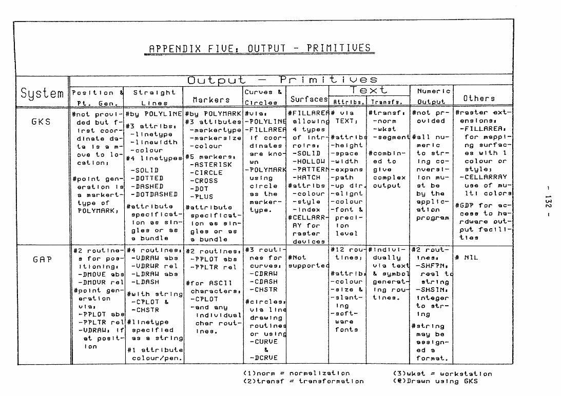
R P P E N D I X F l U E : O U T P U T - P R i n i T I U E S
Sustem
G K S
Position i Ft. Gen.
Straight Lines
#not provi-ded but f-Irst coor-dinate da-ta 1 s a m-ove to lo-catI on I
#polnt gen-eration Is a markert-type of POLYHñRKi
ttby POLYLIME #3 attrlbsi -1 Inetype -1i new f dth -col our
#4 1 I netypes -SOLID -DOTTED -DfiSHED -DOTDflSHED
#attrIbute spec IfIcat-I on as sIn-gles or as a bundle
O u - t p u - t — P r - i m î - L i v ^ e s
tlarUer s
#by POLYHflRK #3 attlbutes -marUertype -marker sIze -co 1 our
#5 markersi -fiSTERlSK -CIRCLE -CROSS -DOT -PLUS
#attrIbute spec IfIcat-I on as sin-gles or as a bundle
Curves 8. C1rcles #vlai -POLYLINE -FlLLflREP If coor-dI nates are kno-wn
-POLYnRRK us I ng circle as the marker-type .
Surf aces #FlLLflREF al1owIni 4 types of intr-roIrSi -SOLID -HOLLOU -PflTTERM -HATCH
#attrlbs -col our -sty1e - Index
#CELLFIRR-} RY for raster devIces
T e x t flllrIbs. # via TEXT;
#attrIb -he Ight -space -wIdth -expans -path -up dIr -al Ignt -col our -font 8. precI -1 on 1 eve I
Transf s. #transf -norm -wkst -segment
#combIn-ed to g I ve complex output
NumerIc Output
#not p(— ovIded
#all nu-mer I c to sti— Ing co-nversl-I on mu-st be by the appi 1c— al Î on progr-ajn
Others
^raster -e ct-ensIonsi -FlLLflREfli for mappI-ng surfac-es w I th 1 colour or style J
-CELLfìRRfìY use of mu-lti col or3
#GIIP for ac-cess to ha-rdw-are out-put, f^cT11-"t 1 « s
ro
GfìP #2 routlne-s for pos-iti on I ngi -DnOUE abs -DnOUR rei
#polnt gen-erai \ on via» -PPLOT abs -PPLTR rei -UDRfìU, If at posIt-I on
#4 rout Inesi -UDRflU abs -UDRUR rel -LDRRU abs -LDRSH
#wlth string -CTLOT 8. -CHSTR
#lInetype spec IfIed as a string #1 attribute colour/pen.
#2 routlnesi -PPLOT abs -PPLTR rel
#for ASCII character s t -CPLOT -and any IndI V I dual char rout-l nes.
#3 routi-nes for curves I -CDRAU -CDASH -CHSTR
#cIrclesi via I In€ draw Ing routlnea or using -CURUE
8. -DCRUE
#Not supportée
#12 rou-tines;
#attrIbJ -col our -size 8. -slant-I ng
-soft-ware fonts
#IndI V I-dually via text 8i symbol general-I ng rou tInes-
#2 roul-în-esa -5JHFTM, r-e-al tc
1 ng -5HS1NJ 1nleger to stj— \ ng
#strIng may be assign-ed a f ormat.
•# MIL
il)norm = normalization <2)transf = transformatlon
<3)wk3t - workstation <e)Drawn using GKS
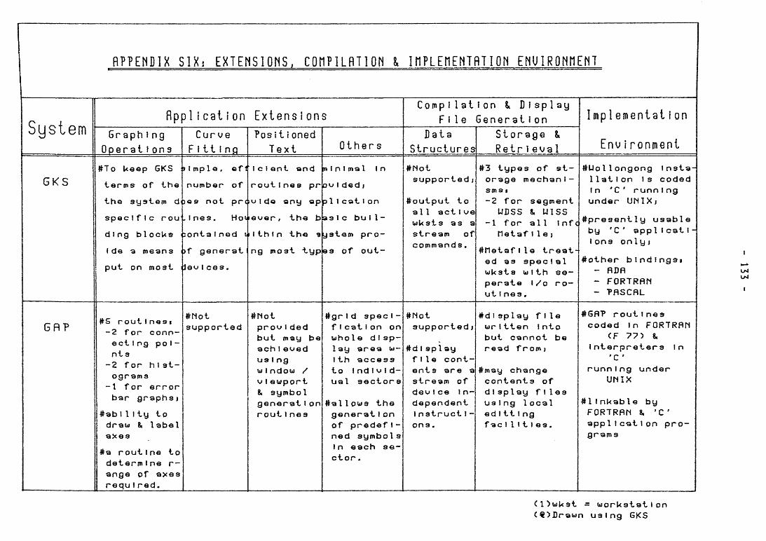
R P P E î i D l X S I X ; E X T E H S I O h S . C O n P l L f l T l O Î i l i n P L E n E h T f l T I O r i E N U I R Q Î i î l E M T
System fìppli c a t I o n E x i e n s Î o n s
G r a p h i n g
O p e r a t i o n s
C u r v e
F i t t i n g
P o s i t i o n e d
T e x t O t h e r s
C o m p i I a t i o n S D i s p l a y
F i l e G e n e r a t i o n
D a t a
S t r u c t u r e s
S t o r a g e &
R e t r i è v a 1
I m p 1eiïientat i o n
i r o n m e n i
G K S
# T o U e e p G K S
t e r m s of t h e
t h e s y a l e m dt
s p e c IfIc r o u
d i n g b l o c U s
f de 3 inesns
p u t on m o s t
I m p l e , ©fi
n u m b e r of
0 9 n o t pr
I n e s . Hoii
:ontaI n e d
i)f g e n e r a t
leu I c e s .
I c I e n t a n d
r o u t I n e s pr
I de a n y a p
e v e r , t h e b
I t h i n t h e «
n g m o s t "typ
m i n i m a l In
o v I d e d i
p1 I c a t I on
as 1c buI 1-
y s t e m p r o -
e s of o u t -
# N o t s u p p o r t e d j
# o u t p u t to all a c t I ve uiUsts a s a s t r e a m of c o m m a n d s .
#3 t y p e s of s t -o r a g e m e c h a n i -sm S I -2 f o r s e g m e n t
U D S S 8. U I S S -1 f o r a l l infc
rietaf 1 1 e J
# n e t a f I l e t r e a t -ed as s p e c I a 1 w U s t s w i t h s e -p e r a t e i/o r o -u t i n e s .
# U o l l o n g o n g insta 1 1 a t 1 o n Is c o d e d In *C ' r u n n l n g u n d e r U N I X j
# p r e s e n t l y u s a b l e
by 'C' a p p i Icatl•
lons o n l y j
# o t h e r b i n d i n g s i - fiDfì - F O R T R A N ~ P A S C A L
LM
G B ? #5 r o u t Inesi -2 f o r c o n n -e c t i n g p o i -n t s
- 2 f o r h i s t -o g r a m s
-1 f o r e r r o r b a r g r a p h s )
#abI 1 Ity to draui 8i label a x e s
#a r o u t Ine to d e t e r m i n e r-a n g e of a x e s r e q u I r e d .
# N o t s u p p o r t e d
#liot p r o u Ided b u t m a y b e a c h I e u e d u s I n g ui I n d o u / u I e w p o r t 8. s y m b o l g e n e r a t i o n r o u t Ines
# g r I d s p e c I-fI c a t I on on w h o le d I s p -lay a r e a w-Ith a c c e s s to I n d I u I d -u a l s e c t o r s
# a l l o w s t h e g e n e r a t I on of p r e d e f I -n e d s y m b o l s In e a c h s e -c t o r .
#fiot s u p p o r t e d j
# d I s p 1 ay f i l e c o n t -e n t s a r e a s t r e a m of d e u I c e in-d e p e n d e n t I n s t r u c t I -o n s .
#dI s p l a y f i l e wr I t t e n Into b u t c a n n o t b e r e a d f r o m »
# m a y c h a n g e c o n t e n t s of d1 s p l a y f i l e s u s Ing 1 o c a l e d 1 t t I n g facI 1 1 1 1 e s .
# G A P r o u t i n e s
c o d e d In F O R T R A N CF 7 7 > 8.
I n t e r p r e t e r s In ' C
r u n n I n g u n d e r U N I X
#1 I n U a b l e by F O R T R A N 8. ' C a p p l I c a t 1 on p r o -g r a m s
( l ^ w U s t = w o r k s t a t i o n < « ) D r a w n u s i n g G K S
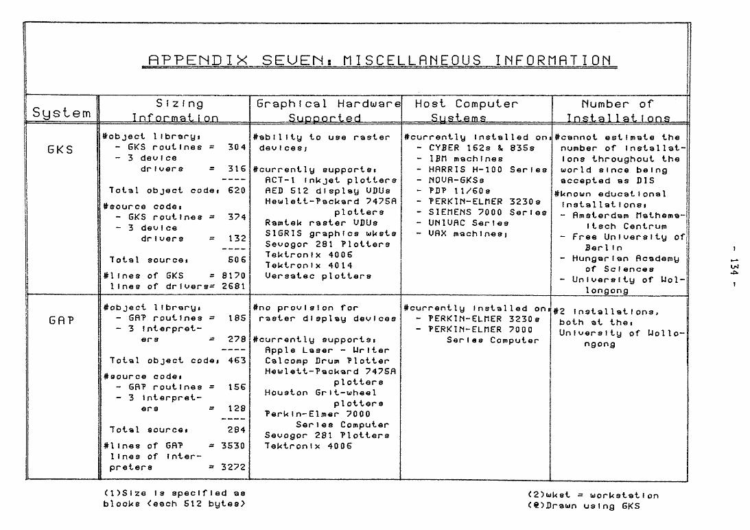
fìPPENDIX S E U E M í n i S C E L L f ì M E O U S I M F O R M R T I O N
S y s t e m S í z f ng
Inf ormai í on Graphical H a r d w a r e
S u p p o r t e d Host Computer
S y s t e m s M u m b e r of
Instai lai í ons
6 K S
G ñ ?
# o b j e c i I IbraryI - 6KS r o u t i n e s = 304 - 3 deufce
drI vers - 316
Total o b j e c t code« 620
# s o u r c e codei - GKS r o u t i n e « - 374 - 3 dev f ce
d r i v e r s 132
# a b l l i t y to use r a s t e r deuI ces;
Total source 506
# l I n e s of 6KS = 8170 l i n e s of drloers^i 2681
#current1 ñCT-l I ñED 512 H e w l e t t
R a m t e U S Î G R 1 S Se«>^ogor T e U t r o n T e U t r o n U e r s a t e
y supportsi n U j e t p l o t t e r s d i s p l a y U D U s
- P a c k a r d 7475fl pi o t t e r s
r a s t e r U D U s g r a p h i c s w U s t s 281 P l o t t e r s
IX 4006 IX 4014 c p l o t t e r s
# c u r r e n t l y I n s t a l l e d ont - CYBER 162s 8. 8 3 5 s - IBM m a c h i n e s - H A R R I S H-lOO S e r i e s - N O U ñ - G K S s - ?D? 11/60S - P E R K I N - E L H E R 3 2 3 0 s - S I E H E N S 7000 S e r i e s - UNlUfiC S e r i e s - UfiX machlnesj
^ c a n n o t est Im n u m b e r of In Ions t h r o u g h w o r l d s i n c e a c c e p t e d as
# U n o w n e d u c a t I ns t a l I at I on - fimsterdam
Itsch Ce - F r e e U n l u e
Ber1 I n - H u n g e r I an
of S c l e n - Unlc»erslty
l o n g o n g
ate the sta I1 a t -out the be I ng BIS I ona l Si tlathema-n t r u m r s i t y of
ficademy c e s of U o l -
# o b j e c t llbraryi - GflP r o u t i n e s == 185 - 3 Interpret-
e r s •= 2 7 8
Total object codej 463
# 8 o u r c e code» - GflP r o u t i n e s = 156 - 3 Interpret-
ers » 128
Total source» 284
#1 m e s of GRP = 3530 I Ines of Inter-p r e t e r s = 3272
#no p r o v i s i o n for r a s t e r d i s p l a y det^lces
# c u r r e n t I A p p l e L C a l c o m p H e w l e t t
H o u s t o n
Peru In-Se
S e u o g o r T e k t r o n
y supportsi aser - W r i t e r D r u m P l o t t e r
- P a c k a r d 7475fl p I o t t e r s
Gr I t - w h e e I p l o t t e r s
Elmer 7000 r l e s C o m p u t e r 281 P l o t t e r s
IX 4 0 0 6
# c u r r e n t l y Installed on» - P E R K l h - E L H E R 3 2 3 0 s - P E R K I M - E L n E R 7000
S e r i e s C o m p u t e r
#2 I n s t a l l a t i o n s , b o t h at the» U n i v e r s i t y of Uollo-
n g o n g
( O S i z e Is s p e c i f i e d as b l o o U s <eQch 512 b y t e e >
<2)wk8t •= w o r k s t a t i o n C e ^ D r a w n u s i n g GKS
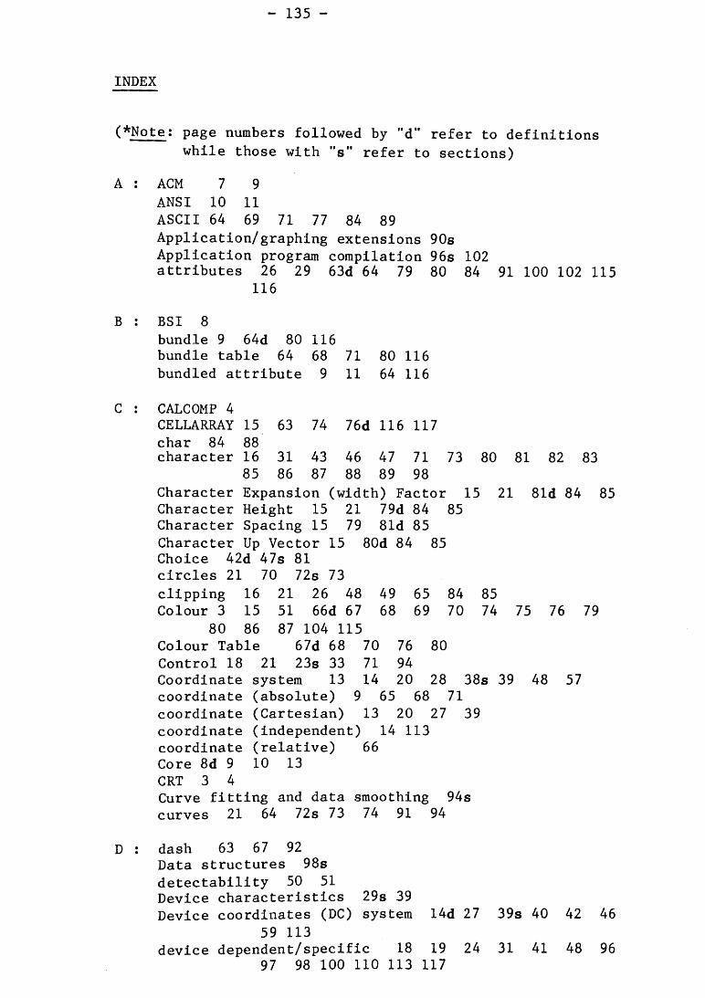
INDEX
(*Note: page numbers followed by "d" refer to definitions while those with "s" refer to sections)
A : ACM 7 9 ANSI 10 11 ASCII 64 69 71 77 84 89 Application/graphing extensions 90s Application program compilation 96s 102 attributes 26 29 63d 64 79 80 84 91 100 102 115
1 16
B : BSI 8 bundle 9 64d 80 116 bundle table 64 68 71 80 116 bundled attribute 9 11 64 116
C : CALCOMP 4 CELLARRAY 15 63 74 76d 116 117 char 84 88 character 16 31 43 46 47 71 73 80 81 82 83
85 86 87 88 89 98 Character Expansion (width) Factor 15 21 81d 84 85 Character Height 15 21 79d 84 85 Character Spacing 15 79 81d 85 Character Up Vector 15 80d 84 85 Choice 42d 47s 81 circles 21 70 72s 73 clipping 16 21 26 48 49 65 84 85 Colour 3 15 51 66d 67 68 69 70 74 75 76 79
80 86 87 104 115 Colour Table 67d 68 70 76 80 Control 18 21 23s 33 71 94 Coordinate system 13 14 20 28 38s 39 48 57 coordinate (absolute) 9 65 68 71 coordinate (Cartesian) 13 20 27 39 coordinate (independent) 14 113 coordinate (relative) 66 Core 8d 9 10 13 CRT 3 4 Curve fitting and data smoothing 94s curves 21 64 72s 73 74 91 94
D : dash 63 67 92 Data structures 98s detectability 50 51 Device characteristics 29s 39 Device coordinates (DC) system I4d 27 39s 40 42 46
59 113 device dependent/specific 18 19 24 31 41 48 96
97 98 100 110 113 117
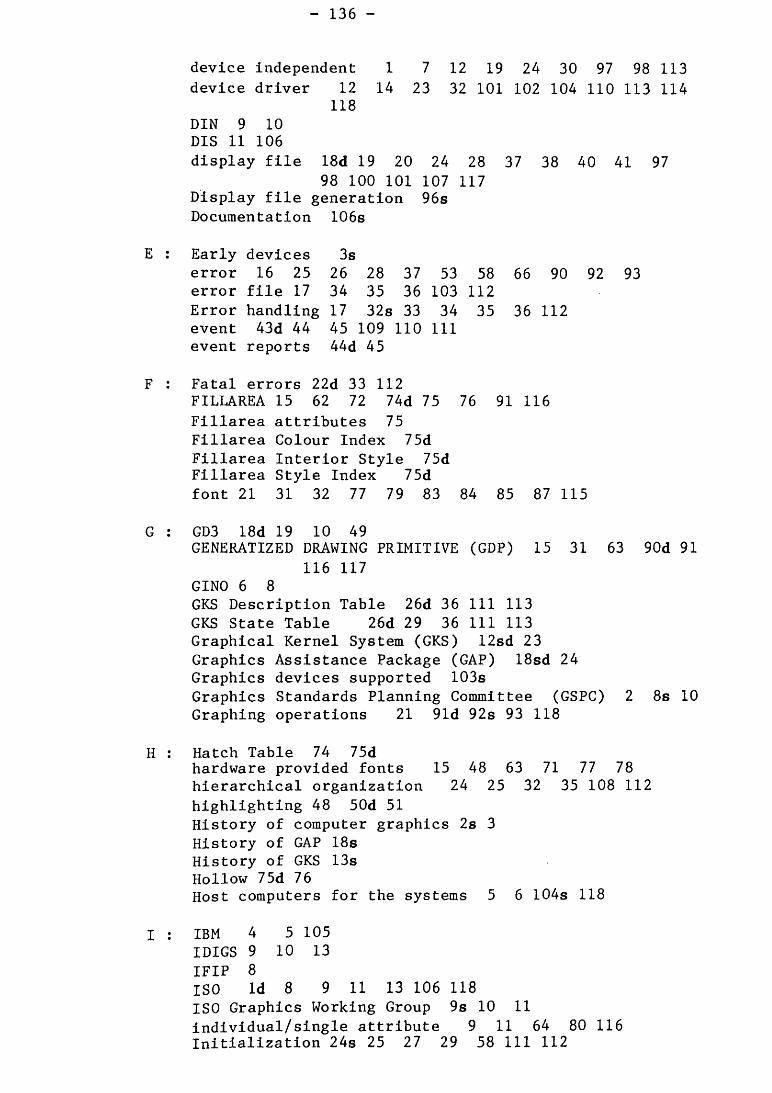
device independent 1 7 12 19 24 30 97 98 113 device driver 12 14 23 32 101 102 104 110 113 114
118 DIN 9 10 DIS 11 106 display file 18d 19 20 24 28 37 38 40 41 97
98 100 101 107 117 Display file generation 96s Documentation 106s
E : Early devices 3s error 16 25 26 28 37 53 58 66 90 92 93 error file 17 34 35 36 103 112 Error handling 17 328 33 34 35 36 112 event 43d 44 45 109 110 111 event reports 44d 45
F : Fatal errors 22d 33 112 FILLAREA 15 62 72 74d 75 76 91 116 Fillarea attributes 75 Fillarea Colour Index 75d Fillarea Interior Style 75d Fillarea Style Index 75d font 21 31 32 77 79 83 84 85 87 115
G : GD3 18d 19 10 49 GENERATIZED DRAWING PRIMITIVE (GDP) 15 31 63 90d 91
116 117 GINO 6 8 GKS Description Table 26d 36 111 113 GKS State Table 26d 29 36 111 113 Graphical Kernel System (GKS) 12sd 23 Graphics Assistance Package (GAP) 18sd 24 Graphics devices supported 103s Graphics Standards Planning Committee (GSPC) 2 8s 10 Graphing operations 21 91d 92s 93 118
H : Hatch Table 74 75d hardware provided fonts 15 48 63 71 77 78 hierarchical organization 24 25 32 35 108 112 highlighting 48 50d 51 History of computer graphics 2s 3 History of GAP 188 History of GKS 13s Hollow 75d 76 Host computers for the systems 5 6 104s 118
I : IBM 4 5 105 IDIGS 9 10 13 IFIP 8 ISO Id 8 9 11 13 106 118 ISO Graphics Working Group 9s 10 11 individual/single attribute 9 11 64 80 116 Initialization 248 25 27 29 58 111 112
input 14 18 19 24 40 41s 43 47 55 60 64 94 95 110 114 118
input (graphical) 3 12 13 input devices 12 30 41s 44 45 46 91 94 100 108 109
110 input/output 8 12 23 26 29 91 100 108 118 input queue 43d 44 45 110 interpreter 18d 19 24 38 40 41 97 98 100 109
L : line width scale factor 67d Linetype 21 67d 69 73 Linewidth 67d Locator 42d 43 46s 60 109 Logical input devices 41d 42s 43 44 45 46 109 110 118
M : Manipulation of transformations 61s Marker attributes 66 68 70 71 Marker bundle 69d marker size scale factor 69d Markers 16 21 37 62 64 66 69d 70 71 72 116 Markersize 69d 70 72 Markertype 66 69d 70 72 metafile 16d 99 100 103 117 118 metafile items 100 MIT 3 4
N : normal 81 92 normalization transformation 13 38d 40 46 49 59d 60
113 114 Normalized Device Coordinate (NDC) 13d 14 39d 113 114 Number of installations 105s Numeric output 42 43 46 47 71 77 89s 109
0 : operating states 24 26 27 28 32 108 111 Operating State Table 26d Orientation 40s Output 3 8 10 12 13 18 19 20 21 24 26 28 30
31 32 34 36 37 38 40 48s 50 52 53 54 55 57 58 60 61 62 67 70 78 81 82 83 85 91 94 95 96 97 98 101 102 108 109 110 111 112 113 118
Output primitives 14 15 16 23 25 27 29 39 45 46 48 49 51 62s 63 64 65 66 68 69 72 74 76 77 79 80 84 86 87 88 89 90 91 93 100 114 115 116 117
pattern 68 74 75 Pattern Table 75d Pick 42 45s 46 50 51 54 64 94 107 Pick Identifier 45d 46 51 54 64 94 picture specifications 5 48 49s PLOT Package 18d 19 20 49 POLYLINE 15 62 66d 67 68 69 72 91 116 Polyline attributes 66 67 68 91
Polyline bundle 68 Polyline Bundle Table 68d Polyline Index 68d POLYMARK 15 62 66 69d 70 71 72 116 Polymark Bundle Table 7Id Poljrmark Index 7 Id Position and point generation 65s Positioned text 94s primitive index 64 primitives 628 63d 91 93 100 114 115 116 117
R : Raster devices 5s 6 15 31 74 75 76 104 117 request 43d 45 47 109
S : sample 43d 45 109 111 segment 16 25 36 42 45 46 51d 53 54 56 62 64
66 67 68 69 87 92 95 98 99 114 117 Segment attributes 14 49 50s 51 52 55 60 61 94
115 Segment Priority 50d 51 55 60 61 115 Segment/symbol operations 49 51s 52 53 54 Segment/Symbol transformations 54s 56 Severe errors 22 27 33d 35 112 Shielding 61s SIGGRAPH 7 Size information 101s software generated fonts 28 48 77 78 86 88 solid 5 63 67 69 74 75 92d state and description table 26 27 28 35 107 111 113 Stroke 42s 43 46s 60 63 84 85 109 Storage and retrieval 12 15 16 20 31 51 52 98s
99 100 117 Storage tube devices 4s 5 31 76 Straight line 14 21 62 64 66s 67 68 69 72 73
74 76 90 92 93 116 string 42 43d 46 47s 69 73 77 78 81 84 85 89 Surfaces 5 74d 75 76 symbol 20d 49 51 52 53 54 56 62 86 88 89 90
91 95 96 114 115
T : Termination 17 22 33 35d 36 37 62 112 113 TEXT 10 12 15 16 21 31 32 42 45 48 53 62
63 64 77s 78 79 80 81 82 83 84 85 86 87 88 89 94 115 116
Text Alignment 15 81d Text attributes 15 21 77 79s 81 84 85 86 87 Text Bundle 80d 85 Text Bundle Table 80d Text Colour 79 80d Text Font 31 81 83d Text Index 79 80d Text Path 15 81d 82 84 Text Precision 15 16 81 83d 84 85 88 transformation numbers 40d 46 59 61 62 114
transformational matrix 54d 55 56 115 transformation 4 20 40 49 54 55 56 60 61 87
88 89 90 100
U : User Coordinate (UC) system 20d 28 38s 39 40 48 53 57 58 60 65 111 113
V : Valuator 42d 438 46 109 VDU 104 Viewing transformations 48s 57 viewport 14d 16 20 21 26 40 49 57 58 59 60 61
62 65 84 85 111 113 Viewport Input Priority 50d 51 60 61 115 visibility 50d 51 115
W : Warning errors 22d 27 33 112 window 14d 20 26 48 53 57 58 59 60 61 62 111
113 Workstation Dependent Segment Storage (WDSS) 51d 52 54
98 99 Workstation Description Table 26d 29 36 111 113 116 Workstation Independent Segment Storage (WISS) 52d 54
99 Workstation State Table 29d 36 116 workstation transformation 40d 49 59d 61 62 113 114 workstation viewport 59d 60 61 65 workstation window 57d 59 60 workstation 12d 24 26 27 28 31 36 45 54 58 68
69 74 80 84 90 96 109 111 114 116 workstation (abstract) 12d 110 workstation (active) 25 35 98 99 110 workstation (input) 100 118 workstation (open) 2 9 30 110 workstation (output) 51 52 63 67 workstation (special) 16 100 117 World Coordinate (WC) system 13d 14 38s 39 40 46 48
57 59 60 65 87 113 114

Related Documents