polymers Review Graphene-Based Nanocomposites: Synthesis, Mechanical Properties, and Characterizations Ahmed Ibrahim 1, *, Anna Klopocinska 1 , Kristine Horvat 2 and Zeinab Abdel Hamid 3 Citation: Ibrahim, A.; Klopocinska, A.; Horvat, K.; Abdel Hamid, Z. Graphene-Based Nanocomposites: Synthesis, Mechanical Properties, and Characterizations. Polymers 2021, 13, 2869. https://doi.org/10.3390/ polym13172869 Academic Editors: Cristina Vallés and Jin-Hae Chang Received: 1 July 2021 Accepted: 17 August 2021 Published: 26 August 2021 Publisher’s Note: MDPI stays neutral with regard to jurisdictional claims in published maps and institutional affil- iations. Copyright: © 2021 by the authors. Licensee MDPI, Basel, Switzerland. This article is an open access article distributed under the terms and conditions of the Creative Commons Attribution (CC BY) license (https:// creativecommons.org/licenses/by/ 4.0/). 1 Department of Mechanical Engineering, Farmingdale State College, Farmingdale, NY 11735, USA; [email protected] 2 Department of Chemical Engineering, University of New Haven, West Haven, CT 06516, USA; [email protected] 3 Central Metallurgical Research and Development Institute (CMRDI), Cairo 11421, Egypt; [email protected] * Correspondence: [email protected] Abstract: Graphene-based nanocomposites possess excellent mechanical, electrical, thermal, optical, and chemical properties. These materials have potential applications in high-performance transistors, biomedical systems, sensors, and solar cells. This paper presents a critical review of the recent developments in graphene-based nanocomposite research, exploring synthesis methods, character- izations, mechanical properties, and thermal properties. Emphasis is placed on characterization techniques and mechanical properties with detailed examples from recent literature. The impor- tance of characterization techniques including Raman spectroscopy, X-ray diffraction (XRD), atomic force microscopy (AFM), scanning electron microscopy (SEM), and high-resolution transmission electron microscopy (HRTEM) for the characterization of graphene flakes and their composites were thoroughly discussed. Finally, the effect of graphene even at very low loadings on the mechanical properties of the composite matrix was extensively reviewed. Keywords: graphene; graphene nanocomposites; graphene characterizations; polymer nanocompos- ites; mechanical properties of graphene nanocomposites 1. Introduction This paper provides a critical review of the synthesis, properties and characterizations perspectives of recent advances in graphene-based nanocomposites. Section 2 presents an overview of the importance of the graphene properties and prospect applications in smart phones, ultra-thin flexible displays, hydrogen storage, transparent touchscreens, chemical sensors, biosensors, and super-fast transistors. Sections 3 and 4 summarize the most frequent graphene synthesis techniques including mechanical exfoliation, liquid- phase exfoliation and chemical synthesis technique. They also highlight the polymer nanocomposite processing methods and the morphological states for graphene-based polymer nanocomposites. A critical review of the characterization of graphene and graphene nanocomposites was presented in Section 5. Detailed research results of graphene characterization from recent literature are thoroughly discussed. Different types of microscopic and spectro- scopic characterization methods to obtain structural and morphological data are presented. Mechanical properties of graphene-based nanocomposites are thoroughly discussed in Section 6. In addition, a summary from recent research that exemplifies the effect of graphene’s filler on the improvement of mechanical properties of graphene-based polymer nanocomposites is also thoroughly discussed. Two major tables summarizing the reinforc- ing effect of graphene-based materials on mechanical properties and thermal conductivity have been constructed. The thermal properties of graphene and graphite nanocomposites are subsequently discussed in Section 7. The variation in thermal conductivity with differ- ent forms of graphene and graphite nanocomposites from recent research are summarized. Polymers 2021, 13, 2869. https://doi.org/10.3390/polym13172869 https://www.mdpi.com/journal/polymers

Welcome message from author
This document is posted to help you gain knowledge. Please leave a comment to let me know what you think about it! Share it to your friends and learn new things together.
Transcript
polymers
Review
Graphene-Based Nanocomposites: Synthesis, MechanicalProperties, and Characterizations
Ahmed Ibrahim 1,*, Anna Klopocinska 1, Kristine Horvat 2 and Zeinab Abdel Hamid 3
�����������������
Citation: Ibrahim, A.; Klopocinska,
A.; Horvat, K.; Abdel Hamid, Z.
Graphene-Based Nanocomposites:
Synthesis, Mechanical Properties, and
Characterizations. Polymers 2021, 13,
2869. https://doi.org/10.3390/
polym13172869
Academic Editors: Cristina Vallés and
Jin-Hae Chang
Received: 1 July 2021
Accepted: 17 August 2021
Published: 26 August 2021
Publisher’s Note: MDPI stays neutral
with regard to jurisdictional claims in
published maps and institutional affil-
iations.
Copyright: © 2021 by the authors.
Licensee MDPI, Basel, Switzerland.
This article is an open access article
distributed under the terms and
conditions of the Creative Commons
Attribution (CC BY) license (https://
creativecommons.org/licenses/by/
4.0/).
1 Department of Mechanical Engineering, Farmingdale State College, Farmingdale, NY 11735, USA;[email protected]
2 Department of Chemical Engineering, University of New Haven, West Haven, CT 06516, USA;[email protected]
3 Central Metallurgical Research and Development Institute (CMRDI), Cairo 11421, Egypt;[email protected]
* Correspondence: [email protected]
Abstract: Graphene-based nanocomposites possess excellent mechanical, electrical, thermal, optical,and chemical properties. These materials have potential applications in high-performance transistors,biomedical systems, sensors, and solar cells. This paper presents a critical review of the recentdevelopments in graphene-based nanocomposite research, exploring synthesis methods, character-izations, mechanical properties, and thermal properties. Emphasis is placed on characterizationtechniques and mechanical properties with detailed examples from recent literature. The impor-tance of characterization techniques including Raman spectroscopy, X-ray diffraction (XRD), atomicforce microscopy (AFM), scanning electron microscopy (SEM), and high-resolution transmissionelectron microscopy (HRTEM) for the characterization of graphene flakes and their composites werethoroughly discussed. Finally, the effect of graphene even at very low loadings on the mechanicalproperties of the composite matrix was extensively reviewed.
Keywords: graphene; graphene nanocomposites; graphene characterizations; polymer nanocompos-ites; mechanical properties of graphene nanocomposites
1. Introduction
This paper provides a critical review of the synthesis, properties and characterizationsperspectives of recent advances in graphene-based nanocomposites. Section 2 presentsan overview of the importance of the graphene properties and prospect applications insmart phones, ultra-thin flexible displays, hydrogen storage, transparent touchscreens,chemical sensors, biosensors, and super-fast transistors. Sections 3 and 4 summarize themost frequent graphene synthesis techniques including mechanical exfoliation, liquid-phase exfoliation and chemical synthesis technique. They also highlight the polymernanocomposite processing methods and the morphological states for graphene-basedpolymer nanocomposites.
A critical review of the characterization of graphene and graphene nanocompositeswas presented in Section 5. Detailed research results of graphene characterization fromrecent literature are thoroughly discussed. Different types of microscopic and spectro-scopic characterization methods to obtain structural and morphological data are presented.Mechanical properties of graphene-based nanocomposites are thoroughly discussed inSection 6. In addition, a summary from recent research that exemplifies the effect ofgraphene’s filler on the improvement of mechanical properties of graphene-based polymernanocomposites is also thoroughly discussed. Two major tables summarizing the reinforc-ing effect of graphene-based materials on mechanical properties and thermal conductivityhave been constructed. The thermal properties of graphene and graphite nanocompositesare subsequently discussed in Section 7. The variation in thermal conductivity with differ-ent forms of graphene and graphite nanocomposites from recent research are summarized.
Polymers 2021, 13, 2869. https://doi.org/10.3390/polym13172869 https://www.mdpi.com/journal/polymers
Polymers 2021, 13, 2869 2 of 32
2. Graphene
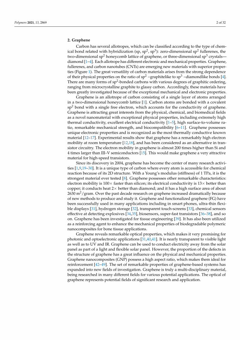
Carbon has several allotropes, which can be classified according to the type of chem-ical bond related with hybridization (sp, sp2, sp3): zero-dimensional sp2 fullerenes, thetwo-dimensional sp2 honeycomb lattice of graphene, or three-dimensional sp3 crystals—diamond [1–4]. Each allotrope has different electronic and mechanical properties. Graphene,fullerenes, and carbon nanotubes (CNTs) are emerging new materials with superior proper-ties (Figure 1). The great versatility of carbon materials arises from the strong dependenceof their physical properties on the ratio of sp2 ~graphitelike to sp3 ~diamondlike bonds [4].There are many forms of sp2-bonded carbons with various degrees of graphitic ordering,ranging from microcrystalline graphite to glassy carbon. Accordingly, these materials havebeen greatly investigated because of the exceptional mechanical and electronic properties.
Graphene is an allotrope of carbon consisting of a single layer of atoms arrangedin a two-dimensional honeycomb lattice [1]. Carbon atoms are bonded with a covalentsp2 bond with a single free electron, which accounts for the conductivity of graphene.Graphene is attracting great interests from the physical, chemical, and biomedical fieldsas a novel nanomaterial with exceptional physical properties, including extremely highthermal conductivity, excellent electrical conductivity [1–5], high surface-to-volume ra-tio, remarkable mechanical strength, and biocompatibility [6–11]. Graphene possessesunique electronic properties and is recognized as the most thermally conductive knownmaterial [12–17]. Experimental results show that graphene has a remarkably high electronmobility at room temperature [12,18], and has been considered as an alternative in tran-sistor circuitry. The electron mobility in graphene is almost 200 times higher than Si and4 times larger than III–V semiconductors [15]. This would make graphene a very attractivematerial for high-speed transistors.
Since its discovery in 2004, graphene has become the center of many research activi-ties [1,9,19–30]. It is a unique type of carbon where every atom is accessible for chemicalreaction because of its 2D structure. With a Young’s modulus (stiffness) of 1 TPa, it is thestrongest material ever tested [8]. Graphene possesses other remarkable characteristics:electron mobility is 100× faster than silicon; its electrical conductivity is 13× better thancopper; it conducts heat 2× better than diamond; and it has a high surface area of about2630 m2/gram. Over the past decade research on graphene increased dramatically becauseof new methods to produce and study it. Graphene and functionalized graphene (FG) havebeen successfully used in many applications including in smart phones, ultra-thin flexi-ble displays [31], hydrogen storage [32], transparent touch-screens [33], chemical sensorseffective at detecting explosives [34,35], biosensors, super-fast transistors [36–38], and soon. Graphene has been investigated for tissue engineering [39]. It has also been utilizedas a reinforcing agent to enhance the mechanical properties of biodegradable polymericnanocomposites for bone tissue applications.
Graphene reveals remarkable optical properties, which makes it very promising forphotonic and optoelectronic applications [31,40,41]. It is nearly transparent to visible lightas well as to UV and IR. Graphene can be used to conduct electricity away from the solarpanel as part of a light and flexible solar panel. However, the proportion of the defects inthe structure of graphene has a great influence on the physical and mechanical properties.Graphene nanocomposites (GNP) possess a high aspect ratio, which makes them ideal forreinforcement [42–49]. The set of remarkable properties of graphene-based systems hasexpanded into new fields of investigation. Graphene is truly a multi-disciplinary material,being researched in many different fields for various potential applications. The optical ofgraphene represents potential fields of significant research and application.
Polymers 2021, 13, 2869 3 of 32Polymers 2021, 13, x FOR PEER REVIEW 3 of 33
Figure 1. Crystal structures of different allotropes of carbon: graphite (3D); graphene (2D); nano-tubes (1D); and fullerene (buckyballs) (0D).
3. Methods of Graphene Preparation Graphene has great prospects for industrial applications, such as polymer compo-
sites, conductive coatings, fuel cells batteries, and ultracapacitors due to its distinctive properties of high strength and exemplary electrical and thermal conductivity [2,3]. These applications demand large quantities of graphene in the form of nanoparticles or nano-platelets at a reasonable price. Several approaches have been used to prepare graphene. Mass production of high-quality graphene (single or few layers graphene) is a major chal-lenge. Structural disorders, defects, and wrinkles within the graphene may have a detri-mental impact on its electronic properties [50].
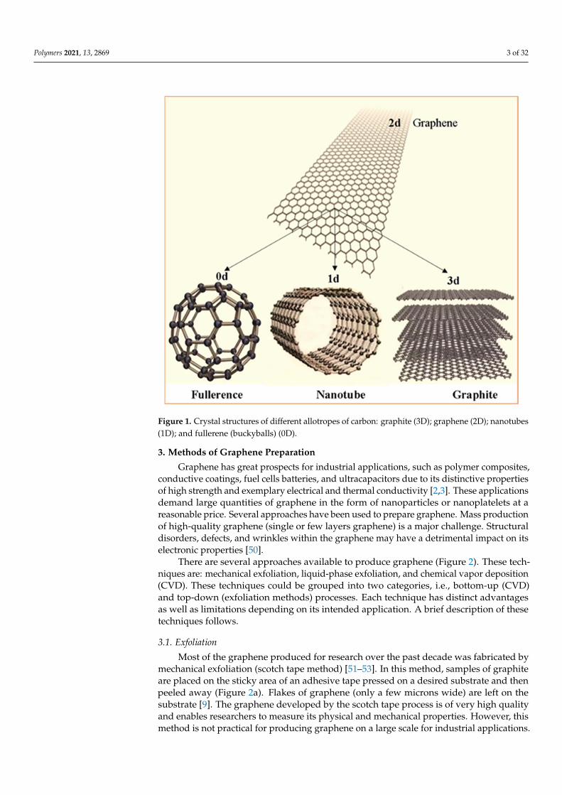
There are several approaches available to produce graphene (Figure 2). These tech-niques are: mechanical exfoliation, liquid-phase exfoliation, and chemical vapor deposi-tion (CVD). These techniques could be grouped into two categories, i.e., bottom-up (CVD) and top-down (exfoliation methods) processes. Each technique has distinct advantages as well as limitations depending on its intended application. A brief description of these techniques follows.
3.1. Exfoliation Most of the graphene produced for research over the past decade was fabricated by
mechanical exfoliation (scotch tape method) [51–53]. In this method, samples of graphite are placed on the sticky area of an adhesive tape pressed on a desired substrate and then peeled away (Figure 2a). Flakes of graphene (only a few microns wide) are left on the substrate [9]. The graphene developed by the scotch tape process is of very high quality and enables researchers to measure its physical and mechanical properties. However, this method is not practical for producing graphene on a large scale for industrial applications.
Figure 1. Crystal structures of different allotropes of carbon: graphite (3D); graphene (2D); nanotubes(1D); and fullerene (buckyballs) (0D).
3. Methods of Graphene Preparation
Graphene has great prospects for industrial applications, such as polymer composites,conductive coatings, fuel cells batteries, and ultracapacitors due to its distinctive propertiesof high strength and exemplary electrical and thermal conductivity [2,3]. These applicationsdemand large quantities of graphene in the form of nanoparticles or nanoplatelets at areasonable price. Several approaches have been used to prepare graphene. Mass productionof high-quality graphene (single or few layers graphene) is a major challenge. Structuraldisorders, defects, and wrinkles within the graphene may have a detrimental impact on itselectronic properties [50].
There are several approaches available to produce graphene (Figure 2). These tech-niques are: mechanical exfoliation, liquid-phase exfoliation, and chemical vapor deposition(CVD). These techniques could be grouped into two categories, i.e., bottom-up (CVD)and top-down (exfoliation methods) processes. Each technique has distinct advantagesas well as limitations depending on its intended application. A brief description of thesetechniques follows.
3.1. Exfoliation
Most of the graphene produced for research over the past decade was fabricated bymechanical exfoliation (scotch tape method) [51–53]. In this method, samples of graphiteare placed on the sticky area of an adhesive tape pressed on a desired substrate and thenpeeled away (Figure 2a). Flakes of graphene (only a few microns wide) are left on thesubstrate [9]. The graphene developed by the scotch tape process is of very high qualityand enables researchers to measure its physical and mechanical properties. However, thismethod is not practical for producing graphene on a large scale for industrial applications.
Polymers 2021, 13, 2869 4 of 32
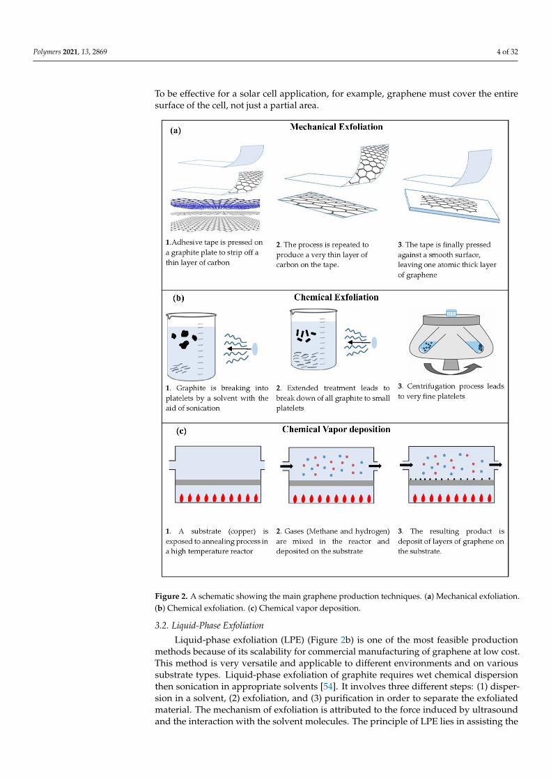
To be effective for a solar cell application, for example, graphene must cover the entiresurface of the cell, not just a partial area.
Polymers 2021, 13, x FOR PEER REVIEW 4 of 33
To be effective for a solar cell application, for example, graphene must cover the entire surface of the cell, not just a partial area.
Figure 2. A schematic showing the main graphene production techniques. (a) Mechanical exfolia-tion. (b) Chemical exfoliation. (c) Chemical vapor deposition
3.2. Liquid-Phase Exfoliation Liquid-phase exfoliation (LPE) (Figure 2b) is one of the most feasible production
methods because of its scalability for commercial manufacturing of graphene at low cost. This method is very versatile and applicable to different environments and on various substrate types. Liquid-phase exfoliation of graphite requires wet chemical dispersion then sonication in appropriate solvents [54]. It involves three different steps: (1) dispersion in a solvent, (2) exfoliation, and (3) purification in order to separate the exfoliated material. The mechanism of exfoliation is attributed to the force induced by ultrasound and the
Figure 2. A schematic showing the main graphene production techniques. (a) Mechanical exfoliation.(b) Chemical exfoliation. (c) Chemical vapor deposition.
3.2. Liquid-Phase Exfoliation
Liquid-phase exfoliation (LPE) (Figure 2b) is one of the most feasible productionmethods because of its scalability for commercial manufacturing of graphene at low cost.This method is very versatile and applicable to different environments and on varioussubstrate types. Liquid-phase exfoliation of graphite requires wet chemical dispersionthen sonication in appropriate solvents [54]. It involves three different steps: (1) disper-sion in a solvent, (2) exfoliation, and (3) purification in order to separate the exfoliatedmaterial. The mechanism of exfoliation is attributed to the force induced by ultrasoundand the interaction with the solvent molecules. The principle of LPE lies in assisting the

Polymers 2021, 13, 2869 5 of 32
separation between graphene layers. In graphite, they are held together by strong elec-trostatic attractions that require a large amount of mechanical force to separate. One wayto reduce this energy input is to disrupt the attractive forces holding layers of graphenetogether. This is achieved by first immersing the bulk material in a special liquid, followedby exfoliation. Nuvoli et al. obtained a high concentration of few-layer graphene sheetsby liquid-phase exfoliation of graphite in ionic liquid [55]. Phase exfoliation of graphenefrom bulk graphite is a versatile top-down approach for producing high-quality graphenesamples. LPE techniques have several advantages, including a relatively low cost for highyield and the ease of scaling up. High-quality graphene production methods are crucialfor harnessing graphene’s properties for future applications as a material with variousapplications [55].
3.3. Chemical Vapor Deposition (CVD)
The CVD method is widely used for the synthesis of carbon nanostructures (CNTs)for composite materials with outstanding mechanical properties [56–58]. Figure 2c showshow graphene can be created by thermocatalytic decomposition of gaseous hydrocarbonsonto a metal surface. CVD is a relatively new technique for producing films of large areaof continuous, 2D graphene. During the CVD process, a metal substrate such as copperis placed into a furnace and heated under low vacuum. Gases (methane and hydrogen)run through the furnace. The hydrogen then catalyzes a response between the methaneand the area of the metal substrate, producing carbon atoms in the methane to be settledonto the outer lining of the metal. The resulting product is a deposit of layers of grapheneon the substrate [59]. Copper is not the only substrate that may be utilized in grapheneCVD—quite few other transition metals can be used as well. For example, graphene CVDon nickel and cobalt have also been performed. [60]. The CVD technique allows for precisecontrol of the number of layers grown.
4. Graphene-Based Nanocomposites
Research on polymer nanocomposites (PNC) has been growing over the past decadedue to their remarkable material properties, yield strength, toughness, electrical conduc-tivity, thermal conductivity, and optical properties, and their applications are growingsubstantially [2,61–80]. Traditional composite structures contain a significant amount(~50 vol%) of filler bound in a polymer matrix—PNC typically—containing a small amountof inorganic particles (usually 1 to 3 wt%) and size less than 100 nm, with a very largesurface area dispersed in the polymer matrix [79]. However, it has been shown that agraphene of micron-size could be made scalable to mass production [81]. This makesgraphene-based composite materials appealing to a great number of applications [81].
Graphene possesses many desirable properties such as high strength and elasticmodulus, high electrical and thermal conductivity, high aspect ratio, high thermal stability,high gas impermeability, and good dimensional stability [6–12]. Polymer properties can bedramatically improved by the addition of graphene at a low volume fraction. Moreover,graphene has a higher surface-to-volume ratio than CNT and can be used at a lowervolume fraction than CNT. It is potentially more promising for improving many propertiesof polymer matrices.
Graphene can be produced in large quantities from graphite precursor by oxidation.Hence, graphene-based polymer nanocomposites have attracted considerable researchinterest around the globe. Various polymers, such as epoxy [82–88], PMMA [89–95],HDPE [96], polystyrene [96–101], and nylon [91,102–107] have been used as matrices tofabricate graphene polymer nanocomposites. Malucelli et al. (2016) provide an excellentsummary of the preparation of graphene-based nanocomposites [82]. It is worth notingthat the quality of graphene dispersion in the polymer matrix directly correlates to itseffectiveness in improving the nanocomposites’ properties [108,109]. The properties of acomposite are also closely related to the aspect ratio of the graphene filler.
Polymers 2021, 13, 2869 6 of 32
Graphene-based nanocomposites are increasingly being used for the developmentof new materials for alternative energy sources, for example, (a) in lithium-ion batteries,graphene-based nanocomposites show better performance as they have high power densityand energy density and a fast charging speed in hydrogen fuel cells; (b) graphene is used asan electrode material to enhance electrocatalytic activity; (c) in solar cells, graphene-basedcomposites are used in photovoltaic devices because of their unique characteristics of highcarrier mobility and low resistivity; and (d) in thermoelectric materials.
Characterization of nanocomposites is crucial to understand the basic physical andchemical properties of the nanocomposites. Graphene materials available in the marketare made by different companies through different techniques. It is expected that thesegraphenes are quite different from each other in flake width, thickness, and defect concen-tration. All the different techniques to modify the filler surface as well as to synthesize thepolymer nanocomposites need to be supplemented with robust characterization of theseprocesses as well as resulting composite properties to gain insight into the various factorsaffecting the nanocomposite microstructure. Several techniques have been used in the char-acterization of nanocomposites, dispersion, distribution, and orientation within polymermatrix. These techniques include optical microscopy, scanning electron microscopy, hightransmission electron microscopy, Raman spectroscopy, atomic force microscopy and X-raydiffraction; these have been shown to be very useful for quantification of nanocomposites.It is also, in many instances, necessary to employ more than one characterization techniquein order to accurately characterize the nanocomposite material.
4.1. Polymer Nanocomposite Synthesis
Nanocomposites contain matrices of diverse materials such as polymer, metal orceramic, and also include different nanoparticle fillers (graphene, nanotubes, clays). Thesefillers enhance the mechanical, thermal and electrical properties of the material [110–112].The polymeric type nanocomposites are by far the most versatile and their application iswidespread in many diverse industrial fields such as energy, electronics, biomedical, etc.
Depending upon the degree of dispersion of the nano-sized layer structure, polymercomposites can be divided into three main categories: microcomposites, intercalatednanocomposites, and exfoliated nanocomposites [109,113,114]. In the microcomposites’structure (Figure 3a), graphene sheets are dispersed inside the polymer matrix in theform of particles and the graphene platelets remain intact. When individual polymerchains are introduced between graphene layers, intercalated constructions are obtained(Figure 3b). In the exfoliated hybrids (Figure 3c), graphene layers are homogenouslydispersed in the polymer matrix. The exfoliation configuration is the preferred morphologyfor nanocomposites as it maximizes the area of contact between the polymer and the fillerand results in stronger bonding, and remarkable mechanical properties [108].
The properties of graphene nanocomposites are dependent on chemical compatibilitybetween the filler and the matrix, the volume fraction of the filler and the processing condi-tions such as dispersion and exfoliation of filler. To achieve optimal results, appropriatefabrication methods must be employed [59,60]. Moreover, the performance quality ofnanocomposites is strongly associated with the degree of dispersion [107,114–118]. Meth-ods of polymer nanocomposite synthesis can be divided into three main categories: in situpolymerization, melt intercalation, and exfoliation adsorption (Figure 4).
Polymers 2021, 13, 2869 7 of 32Polymers 2021, 13, x FOR PEER REVIEW 7 of 33
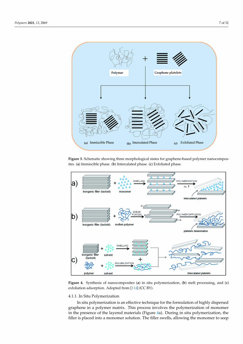
Figure 3. Schematic showing three morphological states for graphene-based polymer nanocomposites. (a) Immiscible phase. (b) Intercalated phase. (c) Exfoliated phase.
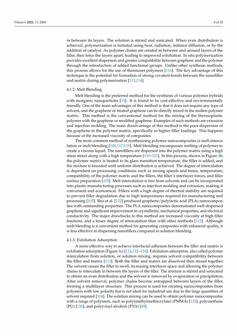
Figure 4. Synthesis of nanocomposites (a) in situ polymerization, (b) melt processing, and (c) exfo-liation adsorption. Adopted from [114] (CC BY).
4.1.1. In Situ Polymerization In situ polymerization is an effective technique for the formulation of highly dis-
persed graphene in a polymer matrix. This process involves the polymerization of mono-mer in the presence of the layered materials (Figure 4a). During in situ polymerization, the filler is placed into a monomer solution. The filler swells, allowing the monomer to seep in between its layers. The solution is stirred and sonicated. When even distribution
Figure 3. Schematic showing three morphological states for graphene-based polymer nanocompos-ites. (a) Immiscible phase. (b) Intercalated phase. (c) Exfoliated phase.
Polymers 2021, 13, x FOR PEER REVIEW 7 of 33
Figure 3. Schematic showing three morphological states for graphene-based polymer nanocomposites. (a) Immiscible phase. (b) Intercalated phase. (c) Exfoliated phase.
Figure 4. Synthesis of nanocomposites (a) in situ polymerization, (b) melt processing, and (c) exfo-liation adsorption. Adopted from [114] (CC BY).
4.1.1. In Situ Polymerization In situ polymerization is an effective technique for the formulation of highly dis-
persed graphene in a polymer matrix. This process involves the polymerization of mono-mer in the presence of the layered materials (Figure 4a). During in situ polymerization, the filler is placed into a monomer solution. The filler swells, allowing the monomer to seep in between its layers. The solution is stirred and sonicated. When even distribution
Figure 4. Synthesis of nanocomposites (a) in situ polymerization, (b) melt processing, and (c)exfoliation adsorption. Adopted from [114] (CC BY).
4.1.1. In Situ Polymerization
In situ polymerization is an effective technique for the formulation of highly dispersedgraphene in a polymer matrix. This process involves the polymerization of monomerin the presence of the layered materials (Figure 4a). During in situ polymerization, thefiller is placed into a monomer solution. The filler swells, allowing the monomer to seep
Polymers 2021, 13, 2869 8 of 32
in between its layers. The solution is stirred and sonicated. When even distribution isachieved, polymerization is initiated using heat, radiation, initiator diffusion, or by theaddition of catalyst. As polymer chains are created in between and around layers of thefiller, they force the layers apart, leading to improved exfoliation. In situ polymerizationprovides excellent dispersion and greater compatibility between graphene and the polymerthrough the introduction of added functional groups. Unlike other synthesis methods,this process allows for the use of thermoset polymers [114]. The key advantage of thistechnique is the potential for formation of strong covalent bonds between the nanofillerand matrix during polymerization [113,114].
4.1.2. Melt Blending
Melt blending is the preferred method for the synthesis of various polymer hybridswith inorganic nanoparticles [15]. It is found to be cost-effective and environmentallyfriendly. One of the main advantages of this method is that it does not require any type ofsolvent, and the graphene or treated graphene can be directly mixed in the molten polymermatrix. This method is the conventional method for the mixing of the thermoplasticpolymer with the graphene or modified graphene. Examples of such methods are extrusionand injection molding. The main disadvantage of this method is the poor dispersion ofthe graphene in the polymer matrix, specifically in higher filler loadings. This happensbecause of the increased viscosity of composites.
The most common method of synthesizing polymer nanocomposites is melt interca-lation or melt blending [109,117,119]. Melt blending encompasses melting of polymer tocreate a viscous liquid. The nanofillers are dispersed into the polymer matrix using a highshear mixer along with a high temperature [119–121]. In this process, shown in Figure 4b,the polymer matrix is heated to its glass transition temperature, the filler is added, andthe mixture is kneaded until uniform distribution is achieved. The degree of intercalationis dependent on processing conditions such as mixing speeds and times, temperature,compatibility of the polymer matrix and the fillers, the filler’s interlayer forces, and fillersurface preparation [105]. Melt intercalation is free from solvents and can be incorporatedinto plastic manufacturing processes such as injection molding and extrusion, making itconvenient and economical. Fillers with a high degree of thermal stability are requiredto prevent filler degradation due to high temperatures required for manufacturing andprocessing [105]. Bao et al. [122] produced graphene/polylactic acid (PLA) nanocompos-ites with outstanding properties. The PLA nanocomposites demonstrated well-dispersedgraphene and significant improvement in crystallinity, mechanical properties, and electricalconductivity. The major drawbacks to this method are increased viscosity at high fillerfractions, and a lesser degree of intercalation than with other methods [112]. Althoughmelt blending is a convenient method for generating composites with enhanced quality, itis less effective in dispersing nanofillers compared to solution blending.
4.1.3. Exfoliation Adsorption
A more effective way to achieve interfacial adhesion between the filler and matrix isexfoliation adsorption (Figure 4c) [114,122–124]. Exfoliation adsorption, also called polymerintercalation from solution, or solution mixing, requires solvent compatibility betweenthe filler and matrix [113]. Both the filler and matrix are dissolved then mixed together.The solvent causes the filler to swell, increasing interlayer space and allowing the polymerchains to intercalate in between the layers of the filler. The mixture is stirred and sonicatedto obtain an even distribution and the solvent is removed by evaporation or precipitation.After solvent removal, polymer chains become entrapped between layers of the filler,forming a multilayer structure. This process is used for creating nanocomposites frompolymers with low polarity but is not ideal for industrial use due to the large quantities ofsolvent required [104]. The solution mixing can be used to obtain polymer nanocompositeswith a range of polymers, such as poly(methylmethacrylate) (PMMA) [125], polyurethane(PU) [126], and poly(vinyl alcohol) (PVA) [49].
Polymers 2021, 13, 2869 9 of 32
5. Characterization of Graphene and Graphene Nanoplatelets (XGnPs)
Graphene is a material with outstanding properties, such as high specific surfacearea 2600 m2/g, high mobility (15000 cm2/V·s) [10,15], superior thermal conductivity(3000 W/m·K) [127], and extremely low permeability. Topological defects exist in large-area polycrystalline graphene [127–130], and are thought to play crucial roles in tailoringmechanical and physical properties of graphene [127,131–134]. Thus, characterizationof graphene is an important step for understanding graphene’s properties. The overallelectronic properties and the purity of a graphene sample are determined by the number oflayers present. Characterizations of graphene encompass different types of microscopicand spectroscopic methods to obtain structural and morphological data of the synthesizedgraphene. Similarly, the characterization process is also related to determining of thepurity and defects of graphene. Synthesis processes and/or processing parameters havea great effect on graphene’s purity. HRTEM and AFM are commonly used to determinenumber of layers of graphene. On the other hand, Raman spectroscopy is commonlyemployed to characterize the purity of graphene and to measure the number of its layersby detecting various crystal structures and bonding information. Furthermore, XPS andRaman spectroscopy are the fundamental methods for the measurement of graphene’schemical purity and detection of functional groups attached to the graphene.
5.1. Raman Spectroscopy
Raman spectroscopy is a standard nondestructive tool for the characterization ofcrystalline, nanocrystalline, and amorphous carbons [135–151]. It is a high-resolution toolfor the characterization of the lattice structure and the electronic, optical, and phononproperties of carbon materials, including three-dimensional (3d) diamond and graphite,2d graphene, 1d carbon nanotubes, and 0d fullerenes. Raman spectroscopy is a powerfuland reliable tool for the characterization of graphene family materials due to its sensitivityto the vibration of C–C bonds [135–137]. It is a highly sensitive method to determine andquantify the density of defects in graphene [135]. As the process of making graphene isvery diverse, including mechanical exfoliation, chemical vapor deposition, and chemicalexfoliation, several types of carbon can exist as byproducts. Raman is a very powerfultechnique that can be of great benefit for characterization of carbon nanomaterials.
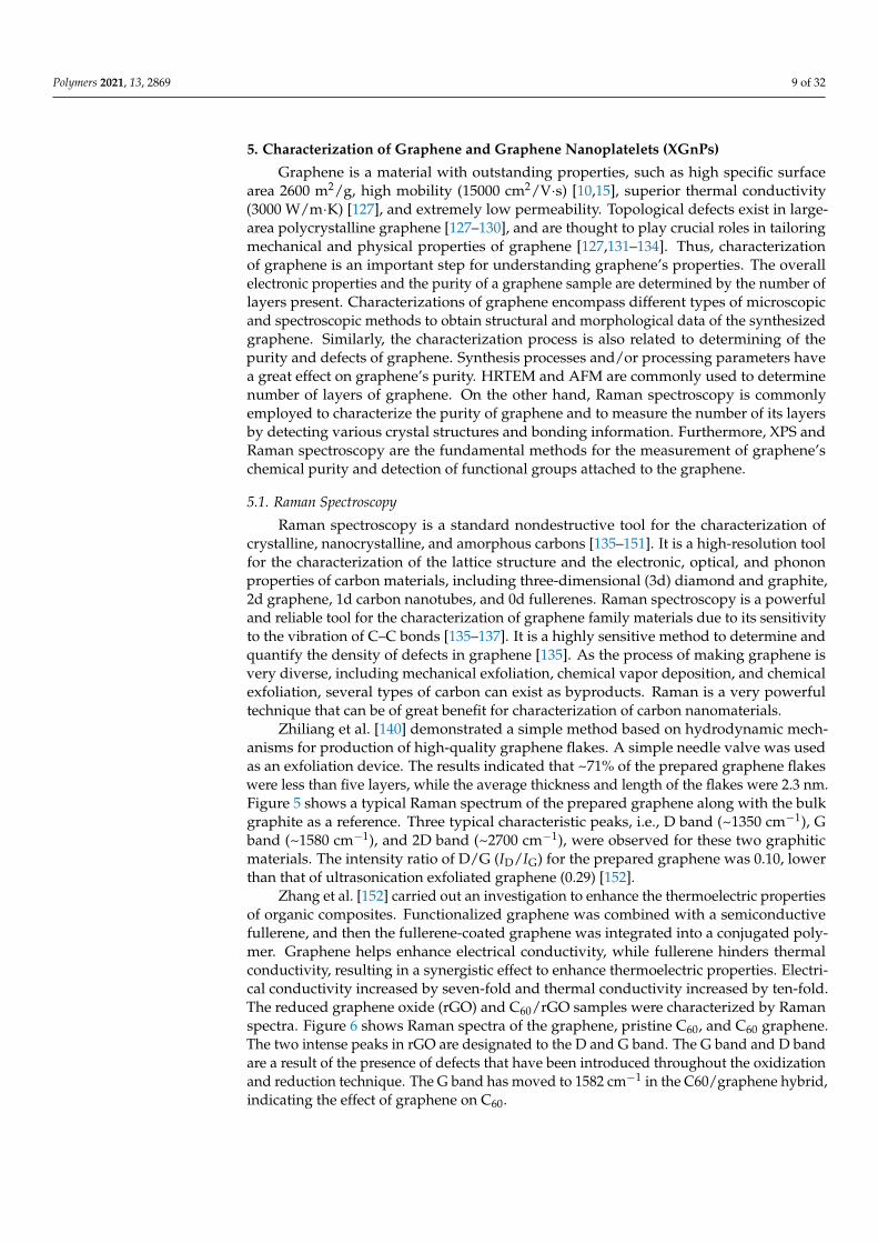
Zhiliang et al. [140] demonstrated a simple method based on hydrodynamic mech-anisms for production of high-quality graphene flakes. A simple needle valve was usedas an exfoliation device. The results indicated that ~71% of the prepared graphene flakeswere less than five layers, while the average thickness and length of the flakes were 2.3 nm.Figure 5 shows a typical Raman spectrum of the prepared graphene along with the bulkgraphite as a reference. Three typical characteristic peaks, i.e., D band (~1350 cm−1), Gband (~1580 cm−1), and 2D band (~2700 cm−1), were observed for these two graphiticmaterials. The intensity ratio of D/G (ID/IG) for the prepared graphene was 0.10, lowerthan that of ultrasonication exfoliated graphene (0.29) [152].
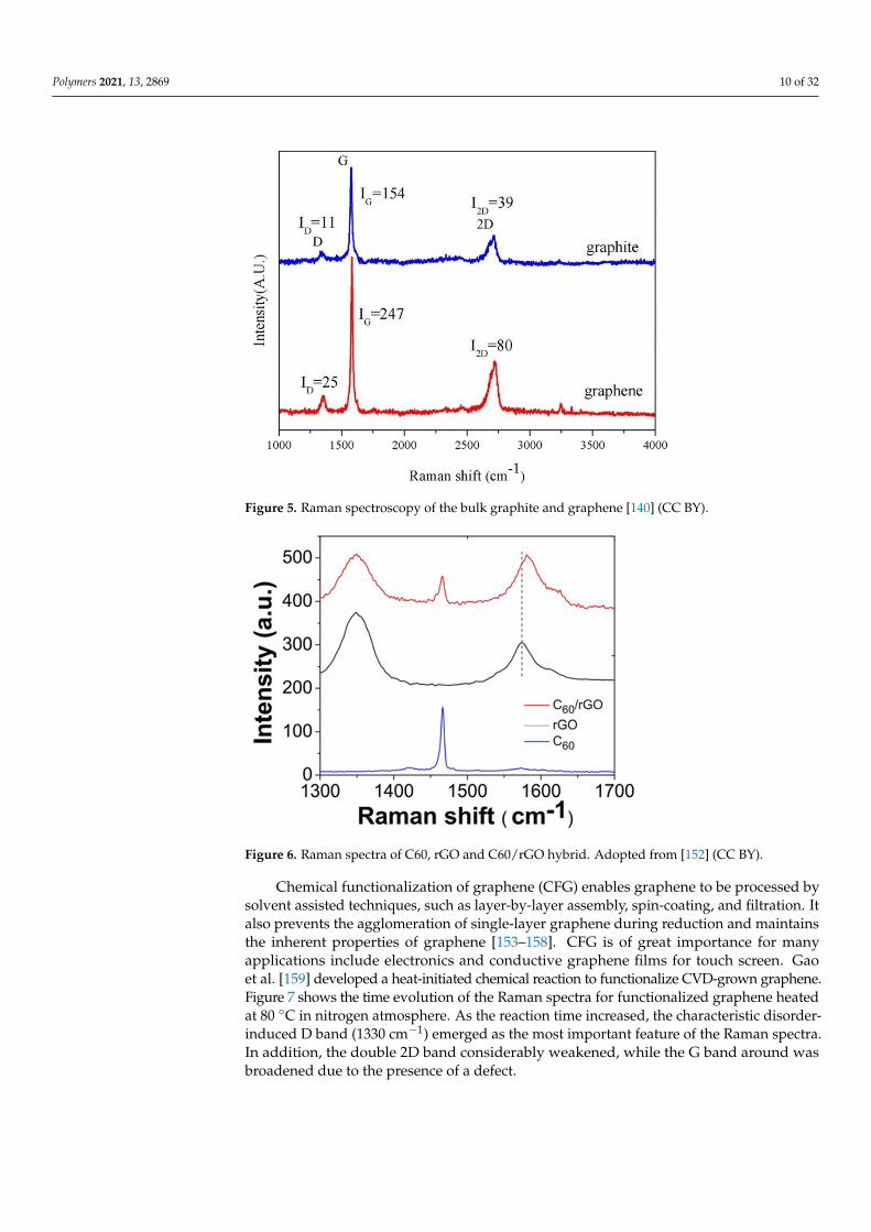
Zhang et al. [152] carried out an investigation to enhance the thermoelectric propertiesof organic composites. Functionalized graphene was combined with a semiconductivefullerene, and then the fullerene-coated graphene was integrated into a conjugated poly-mer. Graphene helps enhance electrical conductivity, while fullerene hinders thermalconductivity, resulting in a synergistic effect to enhance thermoelectric properties. Electri-cal conductivity increased by seven-fold and thermal conductivity increased by ten-fold.The reduced graphene oxide (rGO) and C60/rGO samples were characterized by Ramanspectra. Figure 6 shows Raman spectra of the graphene, pristine C60, and C60 graphene.The two intense peaks in rGO are designated to the D and G band. The G band and D bandare a result of the presence of defects that have been introduced throughout the oxidizationand reduction technique. The G band has moved to 1582 cm−1 in the C60/graphene hybrid,indicating the effect of graphene on C60.
Polymers 2021, 13, 2869 10 of 32Polymers 2021, 13, x FOR PEER REVIEW 10 of 33
Figure 5. Raman spectroscopy of the bulk graphite and graphene [140] (CC BY).
Figure 6. Raman spectra of C60, rGO and C60/rGO hybrid. Adopted from [152] (CC BY).
Chemical functionalization of graphene (CFG) enables graphene to be processed by solvent assisted techniques, such as layer-by-layer assembly, spin-coating, and filtration. It also prevents the agglomeration of single-layer graphene during reduction and main-tains the inherent properties of graphene [153–158]. CFG is of great importance for many applications include electronics and conductive graphene films for touch screen. Gao et al. [159] developed a heat-initiated chemical reaction to functionalize CVD-grown gra-phene. Figure 7 shows the time evolution of the Raman spectra for functionalized gra-phene heated at 80 °C in nitrogen atmosphere. As the reaction time increased, the charac-teristic disorder-induced D band (1330 cm−1) emerged as the most important feature of the Raman spectra. In addition, the double 2D band considerably weakened, while the G band around was broadened due to the presence of a defect.
Figure 5. Raman spectroscopy of the bulk graphite and graphene [140] (CC BY).
Polymers 2021, 13, x FOR PEER REVIEW 10 of 33
Figure 5. Raman spectroscopy of the bulk graphite and graphene [140] (CC BY).
Figure 6. Raman spectra of C60, rGO and C60/rGO hybrid. Adopted from [152] (CC BY).
Chemical functionalization of graphene (CFG) enables graphene to be processed by solvent assisted techniques, such as layer-by-layer assembly, spin-coating, and filtration. It also prevents the agglomeration of single-layer graphene during reduction and main-tains the inherent properties of graphene [153–158]. CFG is of great importance for many applications include electronics and conductive graphene films for touch screen. Gao et al. [159] developed a heat-initiated chemical reaction to functionalize CVD-grown gra-phene. Figure 7 shows the time evolution of the Raman spectra for functionalized gra-phene heated at 80 °C in nitrogen atmosphere. As the reaction time increased, the charac-teristic disorder-induced D band (1330 cm−1) emerged as the most important feature of the Raman spectra. In addition, the double 2D band considerably weakened, while the G band around was broadened due to the presence of a defect.
Figure 6. Raman spectra of C60, rGO and C60/rGO hybrid. Adopted from [152] (CC BY).
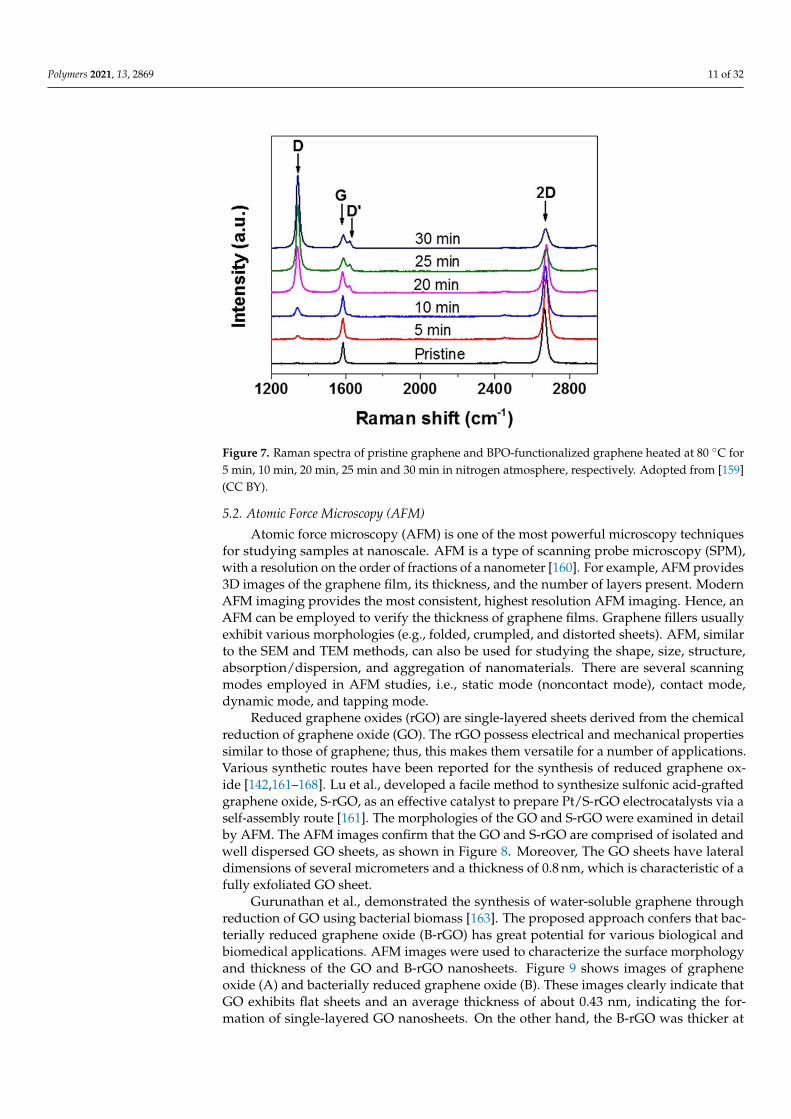
Chemical functionalization of graphene (CFG) enables graphene to be processed bysolvent assisted techniques, such as layer-by-layer assembly, spin-coating, and filtration. Italso prevents the agglomeration of single-layer graphene during reduction and maintainsthe inherent properties of graphene [153–158]. CFG is of great importance for manyapplications include electronics and conductive graphene films for touch screen. Gaoet al. [159] developed a heat-initiated chemical reaction to functionalize CVD-grown graphene.Figure 7 shows the time evolution of the Raman spectra for functionalized graphene heatedat 80 ◦C in nitrogen atmosphere. As the reaction time increased, the characteristic disorder-induced D band (1330 cm−1) emerged as the most important feature of the Raman spectra.In addition, the double 2D band considerably weakened, while the G band around wasbroadened due to the presence of a defect.
Polymers 2021, 13, 2869 11 of 32Polymers 2021, 13, x FOR PEER REVIEW 11 of 33
Figure 7. Raman spectra of pristine graphene and BPO-functionalized graphene heated at 80 °C for 5 min, 10 min, 20 min, 25 min and 30 min in nitrogen atmosphere, respectively. Adopted from [159] (CC BY).
5.2. Atomic Force Microscopy (AFM) Atomic force microscopy (AFM) is one of the most powerful microscopy techniques
for studying samples at nanoscale. AFM is a type of scanning probe microscopy (SPM), with a resolution on the order of fractions of a nanometer [160]. For example, AFM pro-vides 3D images of the graphene film, its thickness, and the number of layers present. Modern AFM imaging provides the most consistent, highest resolution AFM imaging. Hence, an AFM can be employed to verify the thickness of graphene films. Graphene fill-ers usually exhibit various morphologies (e.g., folded, crumpled, and distorted sheets). AFM, similar to the SEM and TEM methods, can also be used for studying the shape, size, structure, absorption/dispersion, and aggregation of nanomaterials. There are several scanning modes employed in AFM studies, i.e., static mode (noncontact mode), contact mode, dynamic mode, and tapping mode.
Reduced graphene oxides (rGO) are single-layered sheets derived from the chemical reduction of graphene oxide (GO). The rGO possess electrical and mechanical properties similar to those of graphene; thus, this makes them versatile for a number of applications. Various synthetic routes have been reported for the synthesis of reduced graphene oxide [142,161–168]. Lu et al., developed a facile method to synthesize sulfonic acid-grafted gra-phene oxide, S-rGO, as an effective catalyst to prepare Pt/S-rGO electrocatalysts via a self-assembly route [161]. The morphologies of the GO and S-rGO were examined in detail by AFM. The AFM images confirm that the GO and S-rGO are comprised of isolated and well dispersed GO sheets, as shown in Figure 8. Moreover, The GO sheets have lateral dimen-sions of several micrometers and a thickness of 0.8 nm, which is characteristic of a fully exfoliated GO sheet.
Gurunathan et al., demonstrated the synthesis of water-soluble graphene through reduction of GO using bacterial biomass [163]. The proposed approach confers that bac-terially reduced graphene oxide (B-rGO) has great potential for various biological and biomedical applications. AFM images were used to characterize the surface morphology and thickness of the GO and B-rGO nanosheets. Figure 9 shows images of graphene oxide (A) and bacterially reduced graphene oxide (B). These images clearly indicate that GO exhibits flat sheets and an average thickness of about 0.43 nm, indicating the formation of single-lay-ered GO nanosheets. On the other hand, the B-rGO was thicker at ~4.23 nm, demonstrat-ing that the biomass adhered and reduced the GO surface successfully (Figure 10b).
Figure 7. Raman spectra of pristine graphene and BPO-functionalized graphene heated at 80 ◦C for5 min, 10 min, 20 min, 25 min and 30 min in nitrogen atmosphere, respectively. Adopted from [159](CC BY).
5.2. Atomic Force Microscopy (AFM)
Atomic force microscopy (AFM) is one of the most powerful microscopy techniquesfor studying samples at nanoscale. AFM is a type of scanning probe microscopy (SPM),with a resolution on the order of fractions of a nanometer [160]. For example, AFM provides3D images of the graphene film, its thickness, and the number of layers present. ModernAFM imaging provides the most consistent, highest resolution AFM imaging. Hence, anAFM can be employed to verify the thickness of graphene films. Graphene fillers usuallyexhibit various morphologies (e.g., folded, crumpled, and distorted sheets). AFM, similarto the SEM and TEM methods, can also be used for studying the shape, size, structure,absorption/dispersion, and aggregation of nanomaterials. There are several scanningmodes employed in AFM studies, i.e., static mode (noncontact mode), contact mode,dynamic mode, and tapping mode.
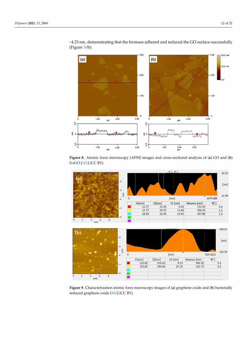
Reduced graphene oxides (rGO) are single-layered sheets derived from the chemicalreduction of graphene oxide (GO). The rGO possess electrical and mechanical propertiessimilar to those of graphene; thus, this makes them versatile for a number of applications.Various synthetic routes have been reported for the synthesis of reduced graphene ox-ide [142,161–168]. Lu et al., developed a facile method to synthesize sulfonic acid-graftedgraphene oxide, S-rGO, as an effective catalyst to prepare Pt/S-rGO electrocatalysts via aself-assembly route [161]. The morphologies of the GO and S-rGO were examined in detailby AFM. The AFM images confirm that the GO and S-rGO are comprised of isolated andwell dispersed GO sheets, as shown in Figure 8. Moreover, The GO sheets have lateraldimensions of several micrometers and a thickness of 0.8 nm, which is characteristic of afully exfoliated GO sheet.
Gurunathan et al., demonstrated the synthesis of water-soluble graphene throughreduction of GO using bacterial biomass [163]. The proposed approach confers that bac-terially reduced graphene oxide (B-rGO) has great potential for various biological andbiomedical applications. AFM images were used to characterize the surface morphologyand thickness of the GO and B-rGO nanosheets. Figure 9 shows images of grapheneoxide (A) and bacterially reduced graphene oxide (B). These images clearly indicate thatGO exhibits flat sheets and an average thickness of about 0.43 nm, indicating the for-mation of single-layered GO nanosheets. On the other hand, the B-rGO was thicker at
Polymers 2021, 13, 2869 12 of 32
~4.23 nm, demonstrating that the biomass adhered and reduced the GO surface successfully(Figure 10b).
Polymers 2021, 13, x FOR PEER REVIEW 12 of 33
Figure 8. Atomic force microscopy (AFM) images and cross-sectional analysis of (a) GO and (b) S-rGO [161] (CC BY).
Figure 9. Characterization atomic force microscopy images of (a) graphene oxide and (b) bacterially reduced graphene oxide [163] (CC BY).
Figure 8. Atomic force microscopy (AFM) images and cross-sectional analysis of (a) GO and (b)S-rGO [161] (CC BY).
Polymers 2021, 13, x FOR PEER REVIEW 12 of 33
Figure 8. Atomic force microscopy (AFM) images and cross-sectional analysis of (a) GO and (b) S-rGO [161] (CC BY).
Figure 9. Characterization atomic force microscopy images of (a) graphene oxide and (b) bacterially reduced graphene oxide [163] (CC BY).
Figure 9. Characterization atomic force microscopy images of (a) graphene oxide and (b) bacteriallyreduced graphene oxide [163] (CC BY).
Polymers 2021, 13, 2869 13 of 32Polymers 2021, 13, x FOR PEER REVIEW 13 of 33
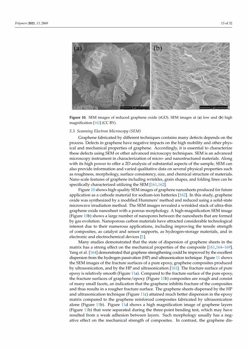
Figure 10. SEM images of reduced graphene oxide (rGO). SEM images at (a) low and (b) high mag-nification [162] (CC BY).
5.3. Scanning Electron Microscopy (SEM) Graphene fabricated by different techniques contains many defects depends on the
process. Defects in graphene have negative impacts on the high mobility and other phys-ical and mechanical properties of graphene. Accordingly, it is essential to characterize these defects using SEM or other advanced microscopy techniques. SEM is an advanced microscopy instrument in characterization of micro- and nanostructured materials. Along with its high power to offer a 2D analysis of substantial aspects of the sample, SEM can also provide information and varied qualitative data on several physical properties such as roughness, morphology, surface consistency, size, and chemical structure of materials. Nano scale features of graphene including wrinkles, grain shapes, and folding lines can be specifically characterized utilizing the SEM [161,162].
Figure 10 shows high-quality SEM images of graphene nanosheets produced for fu-ture application as a cathode material for sodium-ion batteries [162]. In this study, gra-phene oxide was synthesized by a modified Hummers’ method and reduced using a solid-state microwave irradiation method. The SEM images revealed a wrinkled stack of ultra-thin graphene oxide nanosheet with a porous morphology. A high-magnification SEM image (Figure 10b) shows a large number of nanopores between the nanosheets that are formed by gas evolution. Nanoporous carbon materials have attracted considerable tech-nological interest due to their numerous applications, including improving the tensile strength of composites, as catalyst and sensor supports, as hydrogen-storage materials, and in electronic and electrochemical devices [1].
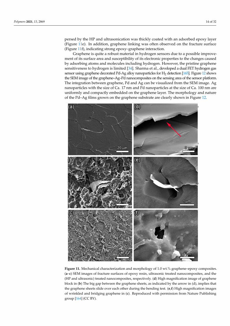
Many studies demonstrated that the state of dispersion of graphene sheets in the ma-trix has a strong effect on the mechanical properties of the composite [161,164–169]. Yang et al. [164] demonstrated that graphene strengthening could be improved by the excellent dispersion from the hydrogen passivation (HP) and ultrasonication technique. Figure 11 shows the SEM images of the fracture surfaces of a pure epoxy, graphene composites pro-duced by ultrasonication, and by the HP and ultrasonication [161]. The fracture surface of pure epoxy is relatively smooth (Figure 11a). Compared to the fracture surface of the pure epoxy, the fracture surfaces of graphene/epoxy (Figure 11b) composites are rough and consist of many small facets, an indication that the graphene inhibits fracture of the com-posites and thus results in a rougher fracture surface. The graphene sheets dispersed by the HP and ultrasonication technique (Figure 11c) attained much better dispersion in the epoxy matrix compared to the graphene reinforced composites fabricated by ultrasoni-cation alone (Figure 11b). Figure 11d shows a high magnification image of graphene layers (Figure 11b) that were separated during the three-point bending test, which may have resulted from a weak adhesion between layers. Such morphology usually has a negative effect on the mechanical strength of composites. In contrast, the graphene dispersed by
Figure 10. SEM images of reduced graphene oxide (rGO). SEM images at (a) low and (b) highmagnification [162] (CC BY).
5.3. Scanning Electron Microscopy (SEM)
Graphene fabricated by different techniques contains many defects depends on theprocess. Defects in graphene have negative impacts on the high mobility and other phys-ical and mechanical properties of graphene. Accordingly, it is essential to characterizethese defects using SEM or other advanced microscopy techniques. SEM is an advancedmicroscopy instrument in characterization of micro- and nanostructured materials. Alongwith its high power to offer a 2D analysis of substantial aspects of the sample, SEM canalso provide information and varied qualitative data on several physical properties suchas roughness, morphology, surface consistency, size, and chemical structure of materials.Nano scale features of graphene including wrinkles, grain shapes, and folding lines can bespecifically characterized utilizing the SEM [161,162].
Figure 10 shows high-quality SEM images of graphene nanosheets produced for futureapplication as a cathode material for sodium-ion batteries [162]. In this study, grapheneoxide was synthesized by a modified Hummers’ method and reduced using a solid-statemicrowave irradiation method. The SEM images revealed a wrinkled stack of ultra-thingraphene oxide nanosheet with a porous morphology. A high-magnification SEM image(Figure 10b) shows a large number of nanopores between the nanosheets that are formedby gas evolution. Nanoporous carbon materials have attracted considerable technologicalinterest due to their numerous applications, including improving the tensile strengthof composites, as catalyst and sensor supports, as hydrogen-storage materials, and inelectronic and electrochemical devices [1].
Many studies demonstrated that the state of dispersion of graphene sheets in thematrix has a strong effect on the mechanical properties of the composite [161,164–169].Yang et al. [164] demonstrated that graphene strengthening could be improved by the excellentdispersion from the hydrogen passivation (HP) and ultrasonication technique. Figure 11 showsthe SEM images of the fracture surfaces of a pure epoxy, graphene composites producedby ultrasonication, and by the HP and ultrasonication [161]. The fracture surface of pureepoxy is relatively smooth (Figure 11a). Compared to the fracture surface of the pure epoxy,the fracture surfaces of graphene/epoxy (Figure 11b) composites are rough and consistof many small facets, an indication that the graphene inhibits fracture of the compositesand thus results in a rougher fracture surface. The graphene sheets dispersed by the HPand ultrasonication technique (Figure 11c) attained much better dispersion in the epoxymatrix compared to the graphene reinforced composites fabricated by ultrasonicationalone (Figure 11b). Figure 11d shows a high magnification image of graphene layers(Figure 11b) that were separated during the three-point bending test, which may haveresulted from a weak adhesion between layers. Such morphology usually has a neg-ative effect on the mechanical strength of composites. In contrast, the graphene dis-
Polymers 2021, 13, 2869 14 of 32
persed by the HP and ultrasonication was thickly coated with an adsorbed epoxy layer(Figure 11e). In addition, graphene linking was often observed on the fracture surface(Figure 11f), indicating strong epoxy–graphene interaction.
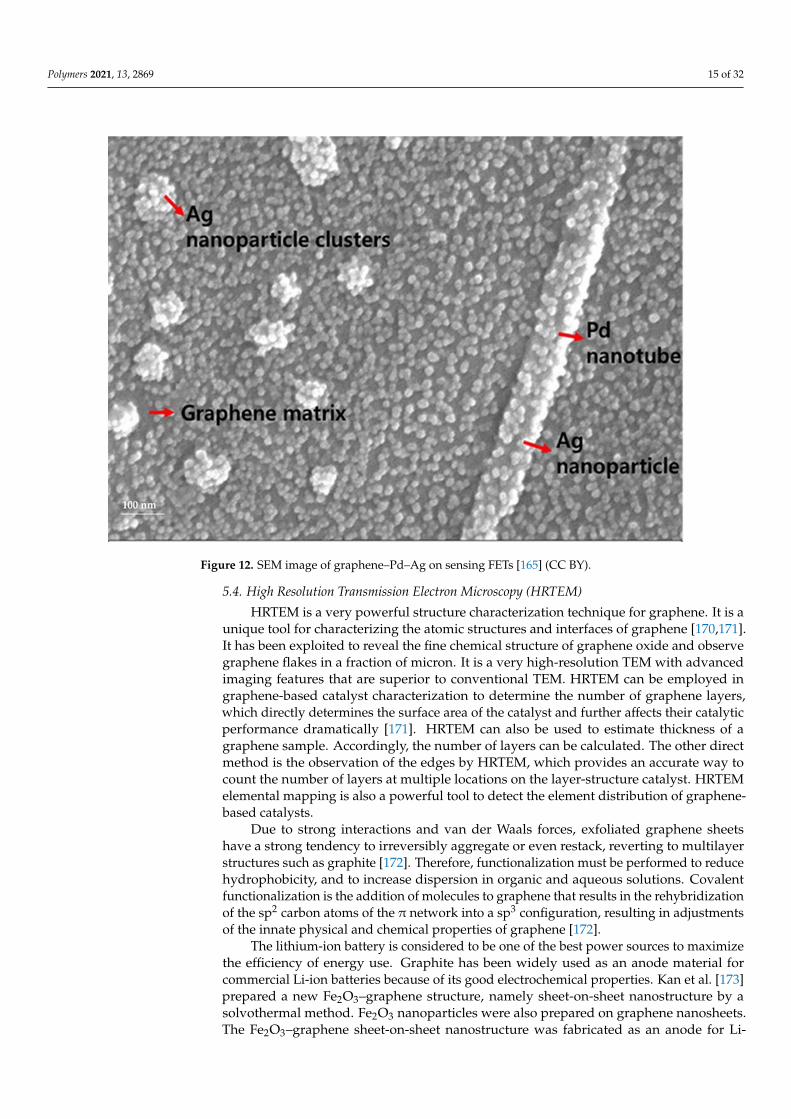
Graphene is quite a robust material in hydrogen sensors due to a possible improve-ment of its surface area and susceptibility of its electronic properties to the changes causedby adsorbing atoms and molecules including hydrogen. However, the pristine graphenesensitiveness to hydrogen is limited [34]. Sharma et al., developed a dual FET hydrogen gassensor using graphene decorated Pd-Ag alloy nanoparticles for H2 detection [165]. Figure 12 showsthe SEM image of the graphene–Ag–Pd nanocomposites on the sensing area of the sensor platform.The integration between graphene, Pd and Ag can be visualized from the SEM image. Agnanoparticles with the size of Ca. 17 nm and Pd nanoparticles at the size of Ca. 100 nm areuniformly and compactly embedded on the graphene layer. The morphology and natureof the Pd–Ag films grown on the graphene substrate are clearly shown in Figure 12.
Polymers 2021, 13, x FOR PEER REVIEW 14 of 33
the HP and ultrasonication was thickly coated with an adsorbed epoxy layer (Figure 11e). In addition, graphene linking was often observed on the fracture surface (Figure 11f), in-dicating strong epoxy–graphene interaction.
Graphene is quite a robust material in hydrogen sensors due to a possible improve-ment of its surface area and susceptibility of its electronic properties to the changes caused by adsorbing atoms and molecules including hydrogen. However, the pristine graphene sensitiveness to hydrogen is limited [34]. Sharma et al., developed a dual FET hydrogen gas sensor using graphene decorated Pd-Ag alloy nanoparticles for H2 detection [165]. Figure 12 shows the SEM image of the graphene–Ag–Pd nanocomposites on the sensing area of the sensor platform. The integration between graphene, Pd and Ag can be visual-ized from the SEM image. Ag nanoparticles with the size of Ca. 17 nm and Pd nanoparti-cles at the size of Ca. 100 nm are uniformly and compactly embedded on the graphene layer. The morphology and nature of the Pd–Ag films grown on the graphene substrate are clearly shown in Figure 12.
Figure 11. Mechanical characterization and morphology of 1.0 wt.% graphene–epoxy composites. (a–c) SEM images of fracture surfaces of epoxy resin, ultrasonic treated nanocomposites, and the (HP and ultrasonic) treated nanocomposites, respectively. (d) High magnification image of gra-phene block in (b) The big gap between the graphene sheets, as indicated by the arrow in Figure 3d, implies that the graphene sheets slide over each other during the bending test. (e,f) High mag-nification images of wrinkled and bridging graphene in (c). Reproduced with permission from Nature Publishing group [164] (CC BY).
Figure 11. Mechanical characterization and morphology of 1.0 wt.% graphene–epoxy composites.(a–c) SEM images of fracture surfaces of epoxy resin, ultrasonic treated nanocomposites, and the(HP and ultrasonic) treated nanocomposites, respectively. (d) High magnification image of grapheneblock in (b) The big gap between the graphene sheets, as indicated by the arrow in (d), implies thatthe graphene sheets slide over each other during the bending test. (e,f) High magnification imagesof wrinkled and bridging graphene in (c). Reproduced with permission from Nature Publishinggroup [164] (CC BY).
Polymers 2021, 13, 2869 15 of 32Polymers 2021, 13, x FOR PEER REVIEW 15 of 33
Figure 12. SEM image of graphene–Pd–Ag on sensing FETs [165] (CC BY).
5.4. High Resolution Transmission Electron Microscopy (HRTEM) HRTEM is a very powerful structure characterization technique for graphene. It is a
unique tool for characterizing the atomic structures and interfaces of graphene [170,171]. It has been exploited to reveal the fine chemical structure of graphene oxide and observe graphene flakes in a fraction of micron. It is a very high-resolution TEM with advanced imaging features that are superior to conventional TEM. HRTEM can be employed in gra-phene-based catalyst characterization to determine the number of graphene layers, which directly determines the surface area of the catalyst and further affects their catalytic per-formance dramatically [171]. HRTEM can also be used to estimate thickness of a graphene sample. Accordingly, the number of layers can be calculated. The other direct method is the observation of the edges by HRTEM, which provides an accurate way to count the number of layers at multiple locations on the layer-structure catalyst. HRTEM elemental mapping is also a powerful tool to detect the element distribution of graphene-based cat-alysts.
Due to strong interactions and van der Waals forces, exfoliated graphene sheets have a strong tendency to irreversibly aggregate or even restack, reverting to multilayer struc-tures such as graphite [172]. Therefore, functionalization must be performed to reduce hydrophobicity, and to increase dispersion in organic and aqueous solutions. Covalent functionalization is the addition of molecules to graphene that results in the rehybridiza-tion of the sp2 carbon atoms of the π network into a sp3 configuration, resulting in adjust-ments of the innate physical and chemical properties of graphene [172].
The lithium-ion battery is considered to be one of the best power sources to maximize the efficiency of energy use. Graphite has been widely used as an anode material for com-mercial Li-ion batteries because of its good electrochemical properties. Kan et al. [173] prepared a new Fe2O3–graphene structure, namely sheet-on-sheet nanostructure by a sol-vothermal method. Fe2O3 nanoparticles were also prepared on graphene nanosheets. The
Figure 12. SEM image of graphene–Pd–Ag on sensing FETs [165] (CC BY).
5.4. High Resolution Transmission Electron Microscopy (HRTEM)
HRTEM is a very powerful structure characterization technique for graphene. It is aunique tool for characterizing the atomic structures and interfaces of graphene [170,171].It has been exploited to reveal the fine chemical structure of graphene oxide and observegraphene flakes in a fraction of micron. It is a very high-resolution TEM with advancedimaging features that are superior to conventional TEM. HRTEM can be employed ingraphene-based catalyst characterization to determine the number of graphene layers,which directly determines the surface area of the catalyst and further affects their catalyticperformance dramatically [171]. HRTEM can also be used to estimate thickness of agraphene sample. Accordingly, the number of layers can be calculated. The other directmethod is the observation of the edges by HRTEM, which provides an accurate way tocount the number of layers at multiple locations on the layer-structure catalyst. HRTEMelemental mapping is also a powerful tool to detect the element distribution of graphene-based catalysts.
Due to strong interactions and van der Waals forces, exfoliated graphene sheetshave a strong tendency to irreversibly aggregate or even restack, reverting to multilayerstructures such as graphite [172]. Therefore, functionalization must be performed to reducehydrophobicity, and to increase dispersion in organic and aqueous solutions. Covalentfunctionalization is the addition of molecules to graphene that results in the rehybridizationof the sp2 carbon atoms of the π network into a sp3 configuration, resulting in adjustmentsof the innate physical and chemical properties of graphene [172].
The lithium-ion battery is considered to be one of the best power sources to maximizethe efficiency of energy use. Graphite has been widely used as an anode material forcommercial Li-ion batteries because of its good electrochemical properties. Kan et al. [173]prepared a new Fe2O3–graphene structure, namely sheet-on-sheet nanostructure by asolvothermal method. Fe2O3 nanoparticles were also prepared on graphene nanosheets.The Fe2O3–graphene sheet-on-sheet nanostructure was fabricated as an anode for Li-
Polymers 2021, 13, 2869 16 of 32
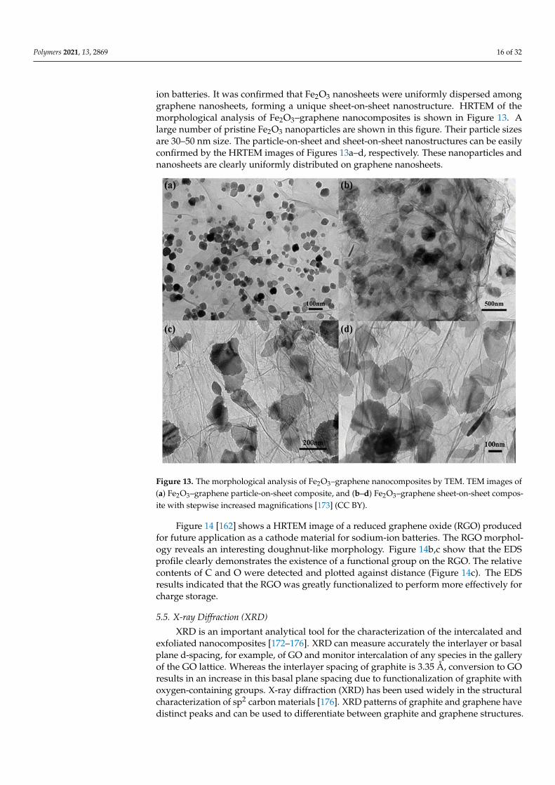
ion batteries. It was confirmed that Fe2O3 nanosheets were uniformly dispersed amonggraphene nanosheets, forming a unique sheet-on-sheet nanostructure. HRTEM of themorphological analysis of Fe2O3–graphene nanocomposites is shown in Figure 13. Alarge number of pristine Fe2O3 nanoparticles are shown in this figure. Their particle sizesare 30–50 nm size. The particle-on-sheet and sheet-on-sheet nanostructures can be easilyconfirmed by the HRTEM images of Figures 13a–d, respectively. These nanoparticles andnanosheets are clearly uniformly distributed on graphene nanosheets.
Polymers 2021, 13, x FOR PEER REVIEW 16 of 33
Fe2O3–graphene sheet-on-sheet nanostructure was fabricated as an anode for Li-ion bat-teries. It was confirmed that Fe2O3 nanosheets were uniformly dispersed among graphene nanosheets, forming a unique sheet-on-sheet nanostructure. HRTEM of the morphologi-cal analysis of Fe2O3–graphene nanocomposites is shown in Figure 13. A large number of pristine Fe2O3 nanoparticles are shown in this figure. Their particle sizes are 30–50 nm size. The particle-on-sheet and sheet-on-sheet nanostructures can be easily confirmed by the HRTEM images of Figure 13a and Figure 13b–d, respectively. These nanoparticles and nanosheets are clearly uniformly distributed on graphene nanosheets.
Figure 13. The morphological analysis of Fe2O3–graphene nanocomposites by TEM. TEM images of (a) Fe2O3–graphene particle-on-sheet composite, and (b–d) Fe2O3–graphene sheet-on-sheet compo-site with stepwise increased magnifications [173] (CC BY).
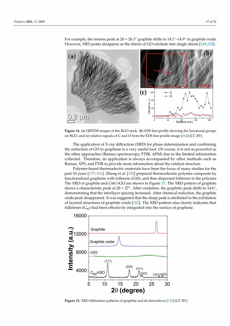
Figure 14 [162] shows a HRTEM image of a reduced graphene oxide (RGO) produced for future application as a cathode material for sodium-ion batteries. The RGO morphol-ogy reveals an interesting doughnut-like morphology. Figure 14b,c show that the EDS profile clearly demonstrates the existence of a functional group on the RGO. The relative contents of C and O were detected and plotted against distance (Figure 14c). The EDS results indicated that the RGO was greatly functionalized to perform more effectively for charge storage.
Figure 13. The morphological analysis of Fe2O3–graphene nanocomposites by TEM. TEM images of(a) Fe2O3–graphene particle-on-sheet composite, and (b–d) Fe2O3–graphene sheet-on-sheet compos-ite with stepwise increased magnifications [173] (CC BY).
Figure 14 [162] shows a HRTEM image of a reduced graphene oxide (RGO) producedfor future application as a cathode material for sodium-ion batteries. The RGO morphol-ogy reveals an interesting doughnut-like morphology. Figure 14b,c show that the EDSprofile clearly demonstrates the existence of a functional group on the RGO. The relativecontents of C and O were detected and plotted against distance (Figure 14c). The EDSresults indicated that the RGO was greatly functionalized to perform more effectively forcharge storage.
5.5. X-ray Diffraction (XRD)
XRD is an important analytical tool for the characterization of the intercalated andexfoliated nanocomposites [172–176]. XRD can measure accurately the interlayer or basalplane d-spacing, for example, of GO and monitor intercalation of any species in the galleryof the GO lattice. Whereas the interlayer spacing of graphite is 3.35 Å, conversion to GOresults in an increase in this basal plane spacing due to functionalization of graphite withoxygen-containing groups. X-ray diffraction (XRD) has been used widely in the structuralcharacterization of sp2 carbon materials [176]. XRD patterns of graphite and graphene havedistinct peaks and can be used to differentiate between graphite and graphene structures.
Polymers 2021, 13, 2869 17 of 32
For example, the intense peak at 2θ = 26.3◦ graphite shifts to 14.1◦–14.9◦ in graphite oxide.However, XRD peaks disappear as the sheets of GO exfoliate into single sheets [149,150].
Polymers 2021, 13, x FOR PEER REVIEW 17 of 33
Figure 14. (a) HRTEM images of the RGO stack. (b) EDS line-profile showing the functional groups on RGO, and (c) relative signals of C and O from the EDS line-profile image [162] (CC BY).
5.5. X-ray Diffraction (XRD) XRD is an important analytical tool for the characterization of the intercalated and
exfoliated nanocomposites [172–176]. XRD can measure accurately the interlayer or basal plane d-spacing, for example, of GO and monitor intercalation of any species in the gallery of the GO lattice. Whereas the interlayer spacing of graphite is 3.35 Å, conversion to GO results in an increase in this basal plane spacing due to functionalization of graphite with oxygen-containing groups. X-ray diffraction (XRD) has been used widely in the structural characterization of sp2 carbon materials [176]. XRD patterns of graphite and graphene have distinct peaks and can be used to differentiate between graphite and graphene struc-tures. For example, the intense peak at 2θ = 26.3° graphite shifts to 14.1°–14.9° in graphite oxide. However, XRD peaks disappear as the sheets of GO exfoliate into single sheets [149,150].
The application of X-ray diffraction (XRD) for phase determination and confirming the reduction of GO to graphene is a very useful tool. Of course, it is not as powerful as the other approaches (Raman spectroscopy, FTIR, AFM) due to the limited information collected. Therefore, its application is always accompanied by other methods such as Ra-man, XPS, and FTIR to provide more information about the catalyst structure.
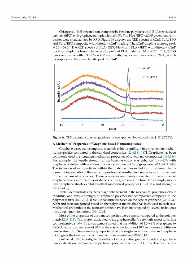
Polymer-based thermoelectric materials have been the focus of many studies for the past 10 years [177–181]. Zhang et al. [152] prepared thermoelectric polymer composite by functionalized graphene with fullerene (C60), and then dispersed fullerene in the poly-mer. The XRD of graphite and C60/rGO are shown in Figure 15. The XRD pattern of graph-ite shows a characteristic peak at 2θ = 27°. After oxidation, the graphitic peak shifts to 14.6°, demonstrating that the interlayer spacing increased. After chemical reduction, the graphite oxide peak disappeared. It was suggested that the sharp peak is attributed to the exfoliation of layered structures of graphite oxide [182]. The XRD pattern also clearly in-dicates that fullerenes (C60) had been effectively integrated into the surface of graphene.
Figure 14. (a) HRTEM images of the RGO stack. (b) EDS line-profile showing the functional groupson RGO, and (c) relative signals of C and O from the EDS line-profile image [162] (CC BY).
The application of X-ray diffraction (XRD) for phase determination and confirmingthe reduction of GO to graphene is a very useful tool. Of course, it is not as powerful asthe other approaches (Raman spectroscopy, FTIR, AFM) due to the limited informationcollected. Therefore, its application is always accompanied by other methods such asRaman, XPS, and FTIR to provide more information about the catalyst structure.
Polymer-based thermoelectric materials have been the focus of many studies for thepast 10 years [177–181]. Zhang et al. [152] prepared thermoelectric polymer composite byfunctionalized graphene with fullerene (C60), and then dispersed fullerene in the polymer.The XRD of graphite and C60/rGO are shown in Figure 15. The XRD pattern of graphiteshows a characteristic peak at 2θ = 27◦. After oxidation, the graphitic peak shifts to 14.6◦,demonstrating that the interlayer spacing increased. After chemical reduction, the graphiteoxide peak disappeared. It was suggested that the sharp peak is attributed to the exfoliationof layered structures of graphite oxide [182]. The XRD pattern also clearly indicates thatfullerenes (C60) had been effectively integrated into the surface of graphene.
Polymers 2021, 13, x FOR PEER REVIEW 18 of 33
Figure 15. XRD diffraction patterns of graphite and its derivatives [152] (CC BY).
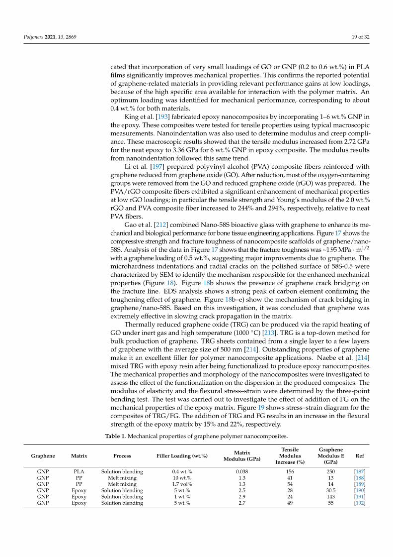
Chieng et al. [183] prepared nanocomposite by blending poly(lactic acid) (PLA)/epoxidized palm oil (EPO) with graphene nanoplatelet (xGnP). The PLA/EPO/xGnP green nanocomposites were characterized by XRD. Figure 16 displays the XRD spectra of xGnP, PLA/EPO and PLA/EPO composite with different xGnP loading. The xGnP displays a strong peak at 2θ = 26.4°. The XRD spectra of PLA/5EPO blend and PLA/5EPO with different xGnP loadings display a broad characteristic peak of PLA ma-trix at 2θ = ~16°. PLA/5EPO nanocomposites with 0.3 wt.% xGnP loading display a small peak around 26.5°, which corresponds to the characteristic peak of xGnP.
Figure 16. XRD patterns of different graphene nanocomposites. Reproduced from [183] (CC BY).
6. Mechanical Properties of Graphene-Based Nanocomposites Graphene-based nanocomposite materials exhibit significant improvement in me-
chanical properties compared to the standard composites [2,46,184–187]. Graphene has been commonly used to strengthen mechanical properties of several nanocomposites [185,186]. For example, the tensile strength of the baseline epoxy was enhanced by ~40%
Figure 15. XRD diffraction patterns of graphite and its derivatives [152] (CC BY).
Polymers 2021, 13, 2869 18 of 32
Chieng et al. [183] prepared nanocomposite by blending poly(lactic acid) (PLA)/epoxidizedpalm oil (EPO) with graphene nanoplatelet (xGnP). The PLA/EPO/xGnP green nanocom-posites were characterized by XRD. Figure 16 displays the XRD spectra of xGnP, PLA/EPOand PLA/EPO composite with different xGnP loading. The xGnP displays a strong peakat 2θ = 26.4◦. The XRD spectra of PLA/5EPO blend and PLA/5EPO with different xGnPloadings display a broad characteristic peak of PLA matrix at 2θ = ~16◦. PLA/5EPOnanocomposites with 0.3 wt.% xGnP loading display a small peak around 26.5◦, whichcorresponds to the characteristic peak of xGnP.
Polymers 2021, 13, x FOR PEER REVIEW 18 of 33
Figure 15. XRD diffraction patterns of graphite and its derivatives [152] (CC BY).
Chieng et al. [183] prepared nanocomposite by blending poly(lactic acid) (PLA)/epoxidized palm oil (EPO) with graphene nanoplatelet (xGnP). The PLA/EPO/xGnP green nanocomposites were characterized by XRD. Figure 16 displays the XRD spectra of xGnP, PLA/EPO and PLA/EPO composite with different xGnP loading. The xGnP displays a strong peak at 2θ = 26.4°. The XRD spectra of PLA/5EPO blend and PLA/5EPO with different xGnP loadings display a broad characteristic peak of PLA ma-trix at 2θ = ~16°. PLA/5EPO nanocomposites with 0.3 wt.% xGnP loading display a small peak around 26.5°, which corresponds to the characteristic peak of xGnP.
Figure 16. XRD patterns of different graphene nanocomposites. Reproduced from [183] (CC BY).
6. Mechanical Properties of Graphene-Based Nanocomposites Graphene-based nanocomposite materials exhibit significant improvement in me-
chanical properties compared to the standard composites [2,46,184–187]. Graphene has been commonly used to strengthen mechanical properties of several nanocomposites [185,186]. For example, the tensile strength of the baseline epoxy was enhanced by ~40%
Figure 16. XRD patterns of different graphene nanocomposites. Reproduced from [183] (CC BY).
6. Mechanical Properties of Graphene-Based Nanocomposites
Graphene-based nanocomposite materials exhibit significant improvement in mechan-ical properties compared to the standard composites [2,46,184–187]. Graphene has beencommonly used to strengthen mechanical properties of several nanocomposites [185,186].For example, the tensile strength of the baseline epoxy was enhanced by ~40% withgraphene platelets with addition of a very small weight % of graphene (~0.1 wt.%) [46].The inclusion of nanoparticles within the matrix enhances linking of polymer chains(crosslinking density) of the nanocomposites and resulted in a remarkable improvementin the mechanical properties. These properties are mainly correlated to the number ofgraphene layers and the interior defects of the graphene structure. For example, mono-layer graphene sheets exhibit excellent mechanical properties (E ~ 1 TPa and strength ~130 GPa) [8].
Table 1 demonstrates the percentage enhancement in the mechanical properties, elasticmodulus, and tensile strength of graphene polymer nanocomposites compared to thepolymer matrix [187–203]. Table 1 is constructed based on the type of graphene (GNP, GO,rGO) and then categorized based on the polymer matrix that has been used in each case.Mechanical properties of the nanocomposites have been investigated by several techniquesincluding nanoindentations [204–208].
Most of the properties of the nanocomposites were superior compared to the polymermatrix [209–211]. This is often attributed to the graphene filler’s very high aspect ratio. In acomprehensive study [4], it was demonstrated that the addition of 1.0 wt.% of graphene toPMMA leads to an increase of 80% in the elastic modulus and 20% in increase in ultimatetensile strength. The same study reported that the single-layer functionalized graphene(FGS) gives the best results compared to other nanofillers (SWNT, EG).
Pinto et al. [187] investigated the effect of incorporating graphene oxide and graphenenanoplatelets on mechanical properties of poly(lactic acid) (PLA) films. The results indi-
Polymers 2021, 13, 2869 19 of 32
cated that incorporation of very small loadings of GO or GNP (0.2 to 0.6 wt.%) in PLAfilms significantly improves mechanical properties. This confirms the reported potentialof graphene-related materials in providing relevant performance gains at low loadings,because of the high specific area available for interaction with the polymer matrix. Anoptimum loading was identified for mechanical performance, corresponding to about0.4 wt.% for both materials.
King et al. [193] fabricated epoxy nanocomposites by incorporating 1–6 wt.% GNP inthe epoxy. These composites were tested for tensile properties using typical macroscopicmeasurements. Nanoindentation was also used to determine modulus and creep compli-ance. These macroscopic results showed that the tensile modulus increased from 2.72 GPafor the neat epoxy to 3.36 GPa for 6 wt.% GNP in epoxy composite. The modulus resultsfrom nanoindentation followed this same trend.
Li et al. [197] prepared polyvinyl alcohol (PVA) composite fibers reinforced withgraphene reduced from graphene oxide (GO). After reduction, most of the oxygen-containinggroups were removed from the GO and reduced graphene oxide (rGO) was prepared. ThePVA/rGO composite fibers exhibited a significant enhancement of mechanical propertiesat low rGO loadings; in particular the tensile strength and Young’s modulus of the 2.0 wt.%rGO and PVA composite fiber increased to 244% and 294%, respectively, relative to neatPVA fibers.
Gao et al. [212] combined Nano-58S bioactive glass with graphene to enhance its me-chanical and biological performance for bone tissue engineering applications. Figure 17 shows thecompressive strength and fracture toughness of nanocomposite scaffolds of graphene/nano-58S. Analysis of the data in Figure 17 shows that the fracture toughness was ~1.95 MPa · m1/2
with a graphene loading of 0.5 wt.%, suggesting major improvements due to graphene. Themicrohardness indentations and radial cracks on the polished surface of 58S-0.5 werecharacterized by SEM to identify the mechanism responsible for the enhanced mechanicalproperties (Figure 18). Figure 18b shows the presence of graphene crack bridging onthe fracture line. EDS analysis shows a strong peak of carbon element confirming thetoughening effect of graphene. Figure 18b–e) show the mechanism of crack bridging ingraphene/nano-58S. Based on this investigation, it was concluded that graphene wasextremely effective in slowing crack propagation in the matrix.
Thermally reduced graphene oxide (TRG) can be produced via the rapid heating ofGO under inert gas and high temperature (1000 ◦C) [213]. TRG is a top-down method forbulk production of graphene. TRG sheets contained from a single layer to a few layersof graphene with the average size of 500 nm [214]. Outstanding properties of graphenemake it an excellent filler for polymer nanocomposite applications. Naebe et al. [214]mixed TRG with epoxy resin after being functionalized to produce epoxy nanocomposites.The mechanical properties and morphology of the nanocomposites were investigated toassess the effect of the functionalization on the dispersion in the produced composites. Themodulus of elasticity and the flexural stress–strain were determined by the three-pointbending test. The test was carried out to investigate the effect of addition of FG on themechanical properties of the epoxy matrix. Figure 19 shows stress–strain diagram for thecomposites of TRG/FG. The addition of TRG and FG results in an increase in the flexuralstrength of the epoxy matrix by 15% and 22%, respectively.
Table 1. Mechanical properties of graphene polymer nanocomposites.
Graphene Matrix Process Filler Loading (wt.%) MatrixModulus (GPa)
TensileModulus
Increase (%)
GrapheneModulus E
(GPa)Ref
GNP PLA Solution blending 0.4 wt.% 0.038 156 250 [187]GNP PP Melt mixing 10 wt.% 1.3 41 13 [188]GNP PP Melt mixing 1.7 vol% 1.3 54 14 [189]GNP Epoxy Solution blending 5 wt.% 2.5 28 30.5 [190]GNP Epoxy Solution blending 1 wt.% 2.9 24 143 [191]GNP Epoxy Solution blending 5 wt.% 2.7 49 55 [192]
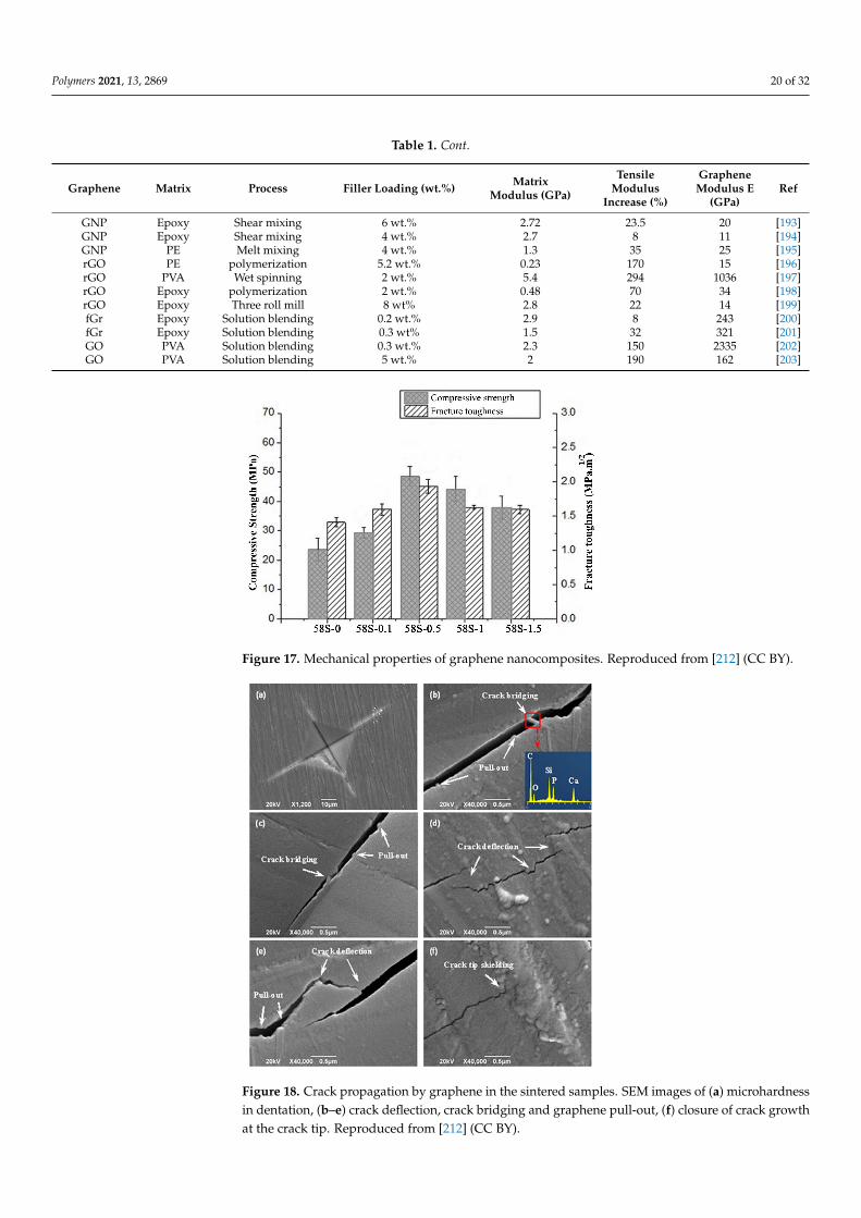
Polymers 2021, 13, 2869 20 of 32
Table 1. Cont.
Graphene Matrix Process Filler Loading (wt.%) MatrixModulus (GPa)
TensileModulus
Increase (%)
GrapheneModulus E
(GPa)Ref
GNP Epoxy Shear mixing 6 wt.% 2.72 23.5 20 [193]GNP Epoxy Shear mixing 4 wt.% 2.7 8 11 [194]GNP PE Melt mixing 4 wt.% 1.3 35 25 [195]rGO PE polymerization 5.2 wt.% 0.23 170 15 [196]rGO PVA Wet spinning 2 wt.% 5.4 294 1036 [197]rGO Epoxy polymerization 2 wt.% 0.48 70 34 [198]rGO Epoxy Three roll mill 8 wt% 2.8 22 14 [199]fGr Epoxy Solution blending 0.2 wt.% 2.9 8 243 [200]fGr Epoxy Solution blending 0.3 wt% 1.5 32 321 [201]GO PVA Solution blending 0.3 wt.% 2.3 150 2335 [202]GO PVA Solution blending 5 wt.% 2 190 162 [203]
Polymers 2021, 13, x FOR PEER REVIEW 20 of 33
bulk production of graphene. TRG sheets contained from a single layer to a few layers of graphene with the average size of 500 nm [214]. Outstanding properties of graphene make it an excellent filler for polymer nanocomposite applications. Naebe et al. [214] mixed TRG with epoxy resin after being functionalized to produce epoxy nanocomposites. The me-chanical properties and morphology of the nanocomposites were investigated to assess the effect of the functionalization on the dispersion in the produced composites. The mod-ulus of elasticity and the flexural stress–strain were determined by the three-point bend-ing test. The test was carried out to investigate the effect of addition of FG on the mechan-ical properties of the epoxy matrix. Figure 19 shows stress–strain diagram for the compo-sites of TRG/FG. The addition of TRG and FG results in an increase in the flexural strength of the epoxy matrix by 15% and 22%, respectively.
Table 1. Mechanical properties of graphene polymer nanocomposites.
Graphene Matrix Process Filler Loading (wt.%) Matrix
Modulus (GPa)
Tensile Modulus
Increase (%)
Graphene Modulus E
(GPa) Ref
GNP PLA Solution blending 0.4 wt.% 0.038 156 250 [187] GNP PP Melt mixing 10 wt.% 1.3 41 13 [188] GNP PP Melt mixing 1.7 vol% 1.3 54 14 [189] GNP Epoxy Solution blending 5 wt.% 2.5 28 30.5 [190] GNP Epoxy Solution blending 1 wt.% 2.9 24 143 [191] GNP Epoxy Solution blending 5 wt.% 2.7 49 55 [192] GNP Epoxy Shear mixing 6 wt.% 2.72 23.5 20 [193] GNP Epoxy Shear mixing 4 wt.% 2.7 8 11 [194] GNP PE Melt mixing 4 wt.% 1.3 35 25 [195] rGO PE polymerization 5.2 wt.% 0.23 170 15 [196] rGO PVA Wet spinning 2 wt.% 5.4 294 1036 [197] rGO Epoxy polymerization 2 wt.% 0.48 70 34 [198] rGO Epoxy Three roll mill 8 wt% 2.8 22 14 [199] fGr Epoxy Solution blending 0.2 wt.% 2.9 8 243 [200] fGr Epoxy Solution blending 0.3 wt% 1.5 32 321 [201] GO PVA Solution blending 0.3 wt.% 2.3 150 2335 [202] GO PVA Solution blending 5 wt.% 2 190 162 [203]
Figure 17. Mechanical properties of graphene nanocomposites. Reproduced from [212] (CC BY). Figure 17. Mechanical properties of graphene nanocomposites. Reproduced from [212] (CC BY).
Polymers 2021, 13, x FOR PEER REVIEW 21 of 33
Figure 18. Crack propagation by graphene in the sintered samples. SEM images of (a) microhard-ness in dentation, (b–e) crack deflection, crack bridging and graphene pull-out, (f) closure of crack growth at the crack tip. Reproduced from [212] (CC BY).
Figure 19. (a) Stress–strain diagrams; (b) bending modulus and strength of the composite samples. Reproduced from [213] (CC BY).
Nanoindentation is a widely used technique for measuring the nano and microscale mechanical properties in nanomaterials and nanocomposites. This technique has been commonly used in determining the mechanical properties of polymers [204–208]. Re-cently, it has been used to measure mechanical properties of nanocomposites. Shokrieh et al. [206] used nanoindentation to evaluate the mechanical properties of graphene nano-composites. According to this investigation, the mechanical properties of a pure polymer matrix are remarkably improved by the addition of small amounts (0.05 wt.%) of gra-phene nanoplatelets (GNP).
Shen et al. [207] used nanoindentation to study mechanical properties of clay nano-composites with different polymer matrices. Aldousiri et al. [208] used nanoindentation
Figure 18. Crack propagation by graphene in the sintered samples. SEM images of (a) microhardnessin dentation, (b–e) crack deflection, crack bridging and graphene pull-out, (f) closure of crack growthat the crack tip. Reproduced from [212] (CC BY).
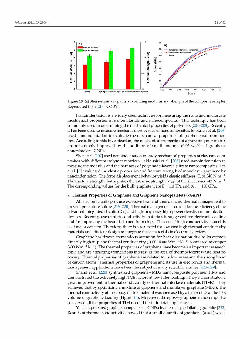
Polymers 2021, 13, 2869 21 of 32
Polymers 2021, 13, x FOR PEER REVIEW 21 of 33
Figure 18. Crack propagation by graphene in the sintered samples. SEM images of (a) microhard-ness in dentation, (b–e) crack deflection, crack bridging and graphene pull-out, (f) closure of crack growth at the crack tip. Reproduced from [212] (CC BY).
Figure 19. (a) Stress–strain diagrams; (b) bending modulus and strength of the composite samples. Reproduced from [213] (CC BY).
Nanoindentation is a widely used technique for measuring the nano and microscale mechanical properties in nanomaterials and nanocomposites. This technique has been commonly used in determining the mechanical properties of polymers [204–208]. Re-cently, it has been used to measure mechanical properties of nanocomposites. Shokrieh et al. [206] used nanoindentation to evaluate the mechanical properties of graphene nano-composites. According to this investigation, the mechanical properties of a pure polymer matrix are remarkably improved by the addition of small amounts (0.05 wt.%) of gra-phene nanoplatelets (GNP).
Shen et al. [207] used nanoindentation to study mechanical properties of clay nano-composites with different polymer matrices. Aldousiri et al. [208] used nanoindentation
Figure 19. (a) Stress–strain diagrams; (b) bending modulus and strength of the composite samples.Reproduced from [213] (CC BY).
Nanoindentation is a widely used technique for measuring the nano and microscalemechanical properties in nanomaterials and nanocomposites. This technique has beencommonly used in determining the mechanical properties of polymers [204–208]. Recently,it has been used to measure mechanical properties of nanocomposites. Shokrieh et al. [206]used nanoindentation to evaluate the mechanical properties of graphene nanocompos-ites. According to this investigation, the mechanical properties of a pure polymer matrixare remarkably improved by the addition of small amounts (0.05 wt.%) of graphenenanoplatelets (GNP).
Shen et al. [207] used nanoindentation to study mechanical properties of clay nanocom-posites with different polymer matrices. Aldousiri et al. [208] used nanoindentation tomeasure the modulus and the hardness of polyamide-layered silicate nanocomposites. Leeet al. [8] evaluated the elastic properties and fracture strength of monolayer graphene bynanoindentation. The force displacement behavior yields elastic stiffness, E, of 340 N m−1.The fracture strength that signifies the intrinsic strength (σint) of the sheet was ~42 N m−1.The corresponding values for the bulk graphite were E = 1.0 TPa and σint = 130 GPa.
7. Thermal Properties of Graphene and Graphene Nanoplatelets (xGnPs)
All electronic units produce excessive heat and thus demand thermal management toprevent premature failure [215–220]. Thermal management is crucial for the efficiency of theadvanced integrated circuits (ICs) and high-frequency high-power density communicationdevices. Recently, use of high-conductivity materials is suggested for electronic coolingand for improving the heat dissipated from chips. The cost of high conductivity materialsis of major concern. Therefore, there is a real need for low cost high thermal conductivitymaterials and efficient design to integrate these materials in electronic devices.
Graphene has drawn tremendous attention for heat dissipation due to its extraor-dinarily high in-plane thermal conductivity (2000~4000 Wm−1K−1) compared to copper(400 Wm−1K−1). The thermal properties of graphene have become an important researchtopic and are attracting tremendous interest in the area of thermoelectric waste heat re-covery. Thermal properties of graphene are related to its low mass and the strong bondof carbon atoms. Thermal properties of graphene and its use in electronics and thermalmanagement applications have been the subject of many scientific studies [220–229].
Shahil et al. [220] synthesized graphene−MLG nanocomposite polymer TIMs anddemonstrated the extremely high TCE factors at low filler loadings. They demonstrated agreat improvement in thermal conductivity of thermal interface materials (TIMs). Theyachieved that by optimizing a mixture of graphene and multilayer graphene (MLG). Thethermal conductivity of the epoxy matrix material was increased by a factor of 23 at the 10%volume of graphene loading (Figure 20). Moreover, the epoxy–graphene nanocompositeconserved all the properties of TIM needed for industrial applications.
Yu et al. prepared graphite nanoplatelets (GNPs) by thermally exfoliating graphite [222].Results of thermal conductivity showed that a small quantity of graphene (n = 4) was a
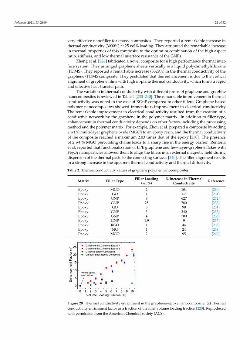
Polymers 2021, 13, 2869 22 of 32
very effective nanofiller for epoxy composites. They reported a remarkable increase inthermal conductivity (3000%) at 25 vol% loading. They attributed the remarkable increasein thermal properties of this composite to the optimum combination of the high aspectratio, stiffness, and low thermal interface resistance of the GNPs.
Zhang et al. [226] fabricated a novel composite for a high performance thermal inter-face system. They arranged graphene sheets vertically in a liquid polydimethylsiloxane(PDMS). They reported a remarkable increase (3329%) in the thermal conductivity of thegraphene/PDMS composite. They postulated that this enhancement is due to the verticalalignment of graphene films with high in-plane thermal conductivity, which forms a rapidand effective heat-transfer path.
The variation in thermal conductivity with different forms of graphene and graphitenanocomposites is reviewed in Table 2 [230–240]. The remarkable improvement in thermalconductivity was noted in the case of XGnP compared to other fillers. Graphene-basedpolymer nanocomposites showed tremendous improvement in electrical conductivity.The remarkable improvement in electrical conductivity resulted from the creation of aconductive network by the graphene in the polymer matrix. In addition to filler type,enhancement in thermal conductivity depends on other factors including the processingmethod and the polymer matrix. For example, Zhou et al. prepared a composite by adding2 wt.% multi-layer graphene oxide (MGO) to an epoxy resin, and the thermal conductivityof the composite reached a maximum 2.03 times that of the epoxy [230]. The presenceof 2 wt.% MGO percolating chains leads to a sharp rise in the energy barrier. Renteriaet al. reported that functionalization of LPE graphene and few-layer-graphene flakes withFe3O4 nanoparticles allowed them to align the fillers in an external magnetic field duringdispersion of the thermal paste to the connecting surfaces [240]. The filler alignment resultsin a strong increase in the apparent thermal conductivity and thermal diffusivity.
Table 2. Thermal conductivity values of graphene polymer nanocomposites.
Matrix Filler Type Filler Loading(wt.%)
% Increase in ThermalConductivity Reference
Epoxy MGO 2 104 [230]Epoxy GO 1 4.8 [231]Epoxy GNP 8 627 [232]Epoxy GNP 25 780 [233]Epoxy GO 3 90 [234]Epoxy GNP 5 240 [235]Epoxy GNP 4 700 [236]Epoxy GNP 1.9 9 [237]Epoxy RGO 1 44 [238]Epoxy NG 1 24 [239]Epoxy MGO 2 95 [240]
Polymers 2021, 13, x FOR PEER REVIEW 23 of 33
dispersion of the thermal paste to the connecting surfaces [240]. The filler alignment re-sults in a strong increase in the apparent thermal conductivity and thermal diffusivity.
Table 2. Thermal conductivity values of graphene polymer nanocomposites.
Matrix Filler Type Filler Loading
(wt.%) % Increase in Thermal
Conductivity Reference
Epoxy MGO 2 104 [230] Epoxy GO 1 4.8 [231] Epoxy GNP 8 627 [232] Epoxy GNP 25 780 [233] Epoxy GO 3 90 [234] Epoxy GNP 5 240 [235] Epoxy GNP 4 700 [236] Epoxy GNP 1.9 9 [237] Epoxy RGO 1 44 [238] Epoxy NG 1 24 [239] Epoxy MGO 2 95 [240]
Figure 20. Thermal conductivity enrichment in the graphene–epoxy nanocomposite. (a) Thermal conductivity enrichment factor as a fraction of the filler volume loading fraction [220]. Reproduced with permission from the American Chemical Society (ACS).
8. Conclusions This article reviewed the recent progress in graphene-based polymer nanocompo-
sites, focusing on two areas: properties and characterization. Emphasis was placed on the unique roles and advantages of advanced graphene characterization techniques, such as Raman spectroscopy, XRD, AFM, and HRTEM. Characterization of 2D graphene involves different types of microscopic and spectroscopic techniques to obtain the structural, mor-phological, and chemical information of as-synthesized graphene. Raman spectroscopy is a remarkable analytical tool that can detect small changes in the structural morphology of carbon nanomaterials. It is used to determine the number of layers, defects, strain, and chemical modifications. HRTEM is one of the most powerful characterization techniques for graphene’s structural characterizations. Several examples of graphene polymer com-posite characterizations using Raman, SEN, TEM, AFM, XRD, and HRTEM were dis-cussed.
Most common graphene synthesis techniques have been discussed. The mechanical exfoliation of graphene is a simple technique for graphene fabrication. The process has the ability to fabricate a single crystal of graphene with various numbers of layers. However,
Figure 20. Thermal conductivity enrichment in the graphene–epoxy nanocomposite. (a) Thermalconductivity enrichment factor as a fraction of the filler volume loading fraction [220]. Reproducedwith permission from the American Chemical Society (ACS).
Polymers 2021, 13, 2869 23 of 32
8. Conclusions
This article reviewed the recent progress in graphene-based polymer nanocomposites,focusing on two areas: properties and characterization. Emphasis was placed on the uniqueroles and advantages of advanced graphene characterization techniques, such as Ramanspectroscopy, XRD, AFM, and HRTEM. Characterization of 2D graphene involves differenttypes of microscopic and spectroscopic techniques to obtain the structural, morphological,and chemical information of as-synthesized graphene. Raman spectroscopy is a remark-able analytical tool that can detect small changes in the structural morphology of carbonnanomaterials. It is used to determine the number of layers, defects, strain, and chemi-cal modifications. HRTEM is one of the most powerful characterization techniques forgraphene’s structural characterizations. Several examples of graphene polymer compositecharacterizations using Raman, SEN, TEM, AFM, XRD, and HRTEM were discussed.
Most common graphene synthesis techniques have been discussed. The mechanicalexfoliation of graphene is a simple technique for graphene fabrication. The process has theability to fabricate a single crystal of graphene with various numbers of layers. However,control over the wafer scale synthesis and reproducibility is very difficult. Liquid-phaseexfoliation is one of the most practical methods for commercial manufacturing of graphenebecause of its low cost and potential scalability. Graphene prepared by this techniqueexhibited a low percentage of defects and oxygen functional groups.
Chemical synthesis techniques are suitable for low volume production of graphene atlow temperature. Furthermore, the process can yield graphene film or graphene coatings onseveral substrate materials. Graphene synthesized using chemical processes exhibits a highsurface area and easy functionalization. CVD is widely used for the synthesis of carbonnanostructures. This method has been effectively used for producing carbon filamentswhich are the basis for composite materials with outstanding mechanical properties.
Graphene–polymer nanocomposites display remarkable mechanical properties com-pared to the pure polymer. Table 1 shows the percentage enhancement in the mechanicalproperties, elastic modulus and bending strength of nanocomposites. Most of the proper-ties of nanocomposites were significantly higher than the polymer matrix. This remarkableimprovement was related to the filler’s very large aspect ratio.
Graphene and xGnP have attracted tremendous attention for heat removal due totheir extraordinarily high in-plane thermal conductivity (2000~4000 Wm−1K−1). Grapheneand MLG, produced by the liquid-phase exfoliation technique, were successfully used tofabricate novel nanocomposites to be used as TIM in electronic applications. Remarkableenhancement of thermal conductivity of the epoxy matrix (increase by 23×) was achievedat the 10% volume of graphene loading. Graphene and xGnP are potential key materials forthe next generations of ICs and 3D electronics. Graphene chemical functionalization causedoutstanding improvement in the thermal conductivity of the polymer composites. Thermalconductivity is affected by several factors, such as the graphene loading, dispersion, andthe thermal resistance of the interface.
Author Contributions: A.I. wrote original conception, preparation, and final revision of this work.A.K., K.H., and Z.A.H. collected and analyzed information and reviewed the manuscript. All authorshave read and agreed to the published version of the manuscript.
Funding: The authors received no funding for this work.
Institutional Review Board Statement: Not applicable.
Informed Consent Statement: Not applicable.
Data Availability Statement: Not applicable.
Conflicts of Interest: The authors declare no conflict of interest.
Polymers 2021, 13, 2869 24 of 32
Abbreviations
CVD Chemical vapor depositionFGr Functionalized Reduced Graphene OxideGO Graphene oxideRGO Reduced graphene oxideTRGO Thermally reduced graphene oxideGIC Graphite intercalation compoundsCNT Carbon nanotubeSWCNT Single-walled carbon nanotubeMWCNT Multi-walled carbon nanotubeEG Expanded graphiteGNP Graphite nanoplateletsHDPE High density polyethylenePET Poly(ethylene terephthalate)PMMA Poly(methyl methacrylate)PP PolypropyleneXGnP Graphene nanoplateletsFG Functionalized graphenePVA Poly(vinyl alcohol);EVA, ethylene vinyl acetatePS PolystyrenePU PolyurethanePLA poly(lactic acid)MGO Multi-layer graphene oxideNG Natural graphiteGF Graphite flakesMLG Multilayer grapheneIM Thermal interface materialsLPE Liquid-phase exfoliation
References1. Geim, A.K.; Novoselov, K.S. The rise of graphene. Nat. Mater 2007, 6, 183–191. [CrossRef]2. Potts, J.R.; Dreyer, D.R.; Bielawski, C.W.; Ruoff, R.S. Graphene-based polymer nanocomposites. Polymer 2011, 52, 5–25. [CrossRef]3. Singh, V.; Joung, D.; Zhai, L.; Das, S.; Khondaker, S.I.; Seal, S. Graphene based materials: Past, present and future. Prog. Mater. Sci.
2011, 56, 1178–1271. [CrossRef]4. Stankovich, S.; Dikin, D.A.; Dommett, G.H.B.; Kohlhaas, K.M.; Zimney, E.J.; Stach, E.A.; Piner, R.D.; Nguyen, S.; Ruoff, R.S.
Graphene-based composite materials. Nature 2006, 442, 282–286. [CrossRef]5. Young, R.; Kinloch, I.A.; Gong, L.; Novoselov, K. The mechanics of graphene nanocomposites: A review. Compos. Sci. Technol.
2012, 72, 1459–1476. [CrossRef]6. Chandrasekaran, S.; Sato, N.; Tölle, F.; Mülhaupt, R.; Fiedler, B.; Schulte, K. Fracture toughness and failure mechanism of
graphene based epoxy composites. Compos. Sci. Technol. 2014, 97, 90–99. [CrossRef]7. Compton, O.C.; Nguyen, S. Graphene Oxide, Highly Reduced Graphene Oxide, and Graphene: Versatile Building Blocks for
Carbon-Based Materials. Small 2010, 6, 711–723. [CrossRef] [PubMed]8. Lee, C.; Wei, X.; Kysar, J.W.; Hone, J. Measurement of the Elastic Properties and Intrinsic Strength of Monolayer Graphene. Science
2008, 321, 385–388. [CrossRef] [PubMed]9. Novoselov, K.S.; Geim, A.K.; Morozov, S.V.; Jiang, D.; Zhang, Y.; Dubonos, S.V.; Grigorieva, I.V.; Firsov, A.A. Electric Field Effect
in Atomically Thin Carbon Films. Science 2004, 306, 666–669. [CrossRef]10. Yasmin, A.; Daniel, I.M. Mechanical and thermal properties of graphite platelet/epoxy composites. Polymer 2004, 45, 8211–8219.
[CrossRef]11. Zhu, Y.; Murali, S.; Cai, W.; Li, X.; Suk, J.W.; Potts, J.R.; Ruoff, R.S. Graphene and graphene oxide: Synthesis, properties, and
applications. Adv. Mater. 2010, 22, 3906–3924. [CrossRef]12. Pallecchi, E.; Lafont, F.; Cavaliere, V.; Schopfer, F.; Mailly, D.; Poirier, W.; Ouerghi, A. High Electron Mobility in Epitaxial Graphene
on 4H-SiC (0001) via post-growth annealing under hydrogen. Sci. Rep. 2014, 4, 4558. [CrossRef]13. Chen, J.-H.; Jang, C.; Xiao, S.; Ishigami, M.; Fuhrer, M.S. Intrinsic and extrinsic performance limits of graphene devices on SiO2.
Nat. Nanotechnol. 2008, 3, 206–209. [CrossRef] [PubMed]14. Geim, A.K.; GHuang, X.; Lim, T.-T. Performance and Mechanism of a Hydrophobic−Oleophilic Kapok Filter for Oil/Water
Separation. Desalination 2006, 190, 295–307. [CrossRef]15. Kasap, S. Springer Handbook of Electronic and Photonic Materials; Springer Science & Busines Media: Berlin/Heidelberg, Germany, 2006.
Polymers 2021, 13, 2869 25 of 32
16. Novoselov, K.; Geim, A.K.; Morozov, S.; Jiang, D.; Katsnelson, M.I.; Grigorieva, I.V.; Dubonos, S.V.; Firsov, A.A. Two-dimensionalgas of massless Dirac fermions in graphene. Nature 2005, 438, 197–200. [CrossRef]
17. Schedin, F.; Geim, A.K.; Morozov, S.V.; Hill, E.W.; Blake, P.; Katsnelson, M.I.; Novoselov, K.S. Detection of indi-vidual gasmolecules adsorbed on graphene. Nat. Mater. 2007, 6, 652–655. [CrossRef]
18. Bolotin, K. Electronic transport in graphene: Towards high mobility. Graphene 2014, 199–227. [CrossRef]19. Nagashio, K.; Nishimura, T.; Kita, K.; Toriumi, A. Metal/graphene contact as a performance Killer of ultra-high mobility graphene
analysis of intrinsic mobility and contact resistance. In Proceedings of the 2009 IEEE International Electron Devices Meeting(IEDM), Baltimore, MD, USA, 7–9 December 2009; pp. 1–4. [CrossRef]
20. Mattevi, C.; Colléaux, F.; Kim, H.; Lin, Y.-H.; Park, K.T.; Chhowalla, M.; Anthopoulos, T.D. Solution-processable organic dielectricsfor graphene electronics. Nanotechnology 2012, 23, 344017. [CrossRef] [PubMed]
21. Aristov, V.Y.; Urbanik, G.; Kummer, K.; Vyalikh, D.V.; Molodtsova, O.; Preobrajenski, A.B.; Zakharov, A.A.; Hess, C.; Hänke, T.;Büchner, B.; et al. Graphene Synthesis on Cubic SiC/Si Wafers. Perspectives for Mass Production of Graphene-Based ElectronicDevices. Nano Lett. 2010, 10, 992–995. [CrossRef] [PubMed]
22. Avouris, P.; Xia, F. Graphene applications in electronics and photonics. MRS Bull. 2012, 37, 1225–1234. [CrossRef]23. Bolotin, K.I.; Sikes, K.J.; Hone, J.; Stormer, H.L.; Kim, P. Temperature-dependent transport in suspended gra-phene. Phys. Rev.
Lett. 2008, 101, 096802. [CrossRef] [PubMed]24. Bonanni, A.; Pumera, M. Graphene Platform for Hairpin-DNA-Based Impedimetric Genosensing. ACS Nano 2011, 5, 2356–2361.
[CrossRef] [PubMed]25. Brownson, D.; Kampouris, D.; Banks, C. Graphene electrochemistry: Fundamental concepts through to prominent applications.
Chem. Soc. Rev. 2012, 41, 6944–6976. [CrossRef]26. Hernandez, Y.; Nicolosi, V.; Lotya, M.; Blighe, F.M.; Sun, Z.; De, S.; McGovern, I.T.; Holland, B.; Byrne, M.; Gun’Ko, Y.; et al.
High-yield production of graphene by liquid-phase exfoliation of graphite. Nat. Nanotechnol. 2008, 3, 563–568. [CrossRef][PubMed]
27. Paredes, J.I.; Villar-Rodil, S.; Fernández-Merino, M.J.; Guardia, L.; Martínez-Alonso, A.; Tascón, J.M.D. Environ-mentally friendlyapproaches toward the mass production of processable graphene from graphite oxide. J. Mater. Chem. 2011, 21, 298–306.[CrossRef]
28. Park, S.; An, J.; Piner, R.D.; Jung, I.; Yang, D.; Velamakanni, A.; Nguyen, S.; Ruoff, R.S. Aqueous Suspension and Characterizationof Chemically Modified Graphene Sheets. Chem. Mater. 2008, 20, 6592–6594. [CrossRef]
29. Prasai, D.; Tuberquia, J.C.; Harl, R.R.; Jennings, G.K.; Bolotin, K.I. Graphene: Corrosion-Inhibiting Coating. ACS Nano 2012, 6,1102–1108. [CrossRef]
30. Song, W.; Ji, X.; Deng, W.; Chen, Q.; Shen, C.; Banks, C.E. Graphene ultracapacitors: Structural impacts. Phys. Chem. Chem. Phys.2013, 15, 4799–4803. [CrossRef] [PubMed]
31. Wang, G.; Yang, J.; Park, J.; Gou, X.; Wang, B.; Liu, H.; Yao, J. Facile synthesis and characterization of graphene nanosheets. J.Phys. Chem. C 2008, 112, 8192–8195. [CrossRef]
32. Bonaccorso, F.; Sun, Z.; Hasan, T.; Ferrari, A.C. Graphene photonics and optoelectronics. Nat. Photonics 2010, 4, 611–622.[CrossRef]
33. El-Kady, M.F.; Shao, Y.; Kaner, R.B. Graphene for batteries, supercapacitors and beyond. Nat. Rev. Mater. 2016, 1, 16033. [CrossRef]34. Ilnicka, A.; Lukaszewicz, J.P. Graphene-Based Hydrogen Gas Sensors: A Review. Processes 2020, 8, 633. [CrossRef]35. Wang, Y.; Shao, Y.; Matson, D.W.; Li, J.; Lin, Y. Nitrogen-Doped Graphene and Its Application in Electrochemical Biosensing. ACS
Nano 2010, 4, 1790–1798. [CrossRef]36. Lerner, M.B.; Matsunaga, F.; Han, G.H.; Hong, S.J.; Xi, J.; Crook, A.; Perez-Aguilar, J.M.; Park, Y.W.; Saven, J.G.; Liu, R.; et al.
Scalable Production of Highly Sensitive Nanosensors Based on Graphene Functionalized with a Designed G Protein-CoupledReceptor. Nano Lett. 2014, 14, 2709–2714. [CrossRef] [PubMed]
37. Lin, Y.-M.; Dimitrakopoulos, C.; Jenkins, K.A.; Farmer, D.B.; Chiu, H.-Y.; Grill, A.; Avouris, P. 100-GHz Transistors fromWafer-Scale Epitaxial Graphene. Science 2010, 327, 662. [CrossRef] [PubMed]
38. Wu, Y.; Lin, Y.-M.; Bol, A.; Jenkins, K.A.; Xia, F.; Farmer, D.B.; Zhu, Y.; Avouris, P. High-frequency, scaled graphene transistors ondiamond-like carbon. Nature 2011, 472, 74–78. [CrossRef] [PubMed]
39. Liao, L.; Lin, Y.C.; Bao, M.; Cheng, R.; Bai, J.; Liu, Y.; Qu, Y.; Wang, K.L.; Huang, Y.; Duan, X. High-speed gra-phene transistorswith a self-aligned nanowire gate. Nature 2010, 467, 305–308. [CrossRef] [PubMed]
40. Lalwani, G.; Henslee, A.M.; Farshid, B.; Lin, L.; Kasper, F.; Qin, Y.-X.; Mikos, A.G.; Sitharaman, B. Two-Dimensional Nanostructure-Reinforced Biodegradable Polymeric Nanocomposites for Bone Tissue Engineering. Biomacromolecules 2013, 14, 900–909. [Cross-Ref] [PubMed]
41. Blake, P.; Hill, E.W.; Castro Neto, A.H.; Novoselov, K.S.; Jiang, D.; Yang, R.; Booth, T.J.; Geim, A.K. Making gra-phene visible.Appl. Phys. Lett. 2007, 91, 063124. [CrossRef]
42. Casiraghi, C.; Hartschuh, A.; Lidorikis, E.; Qian, H.; Harutyunyan, H.; Gokus, T.; Novoselov, K.; Ferrari, A.C. Rayleigh Imagingof Graphene and Graphene Layers. Nano Lett. 2007, 7, 2711–2717. [CrossRef]
43. Mittal, G.; Dhand, V.; Rhee, K.Y.; Park, S.-J.; Lee, W.R. A review on carbon nanotubes and graphene as fillers in reinforced polymernanocomposites. J. Ind. Eng. Chem. 2014, 21, 11–25. [CrossRef]
Polymers 2021, 13, 2869 26 of 32
44. Liu, W.W.; Chai, S.-P.; Mohamed, A.R.; Hashim, U. Synthesis and characterization of graphene and carbon nanotubes: A reviewon the past and recent developments. J. Ind. Eng. Chem. 2014, 20, 1171–1185. [CrossRef]
45. Rafiee, M.; Lu, W.; Thomas, A.V.; Zandiatashbar, A.; Rafiee, J.; Tour, J.M.; Koratkar, N.A. Graphene Nanoribbon Composites. ACSNano 2010, 4, 7415–7420. [CrossRef] [PubMed]
46. Rafiee, M.A.; Rafiee, J.; Wang, Z.; Song, H.; Yu, Z.Z.; Koratkar, N. Enhanced mechanical properties of nanocomposites at lowgraphene content. ACS Nano 2009, 3, 3884–3890. [CrossRef]
47. Varela-Rizo, H.; Rodriguez-Pastor, I.; Merino, C.; Martin-Gullon, I. Highly crystalline graphene oxide nano-platelets producedfrom helical-ribbon carbon nanofibers. Carbon 2010, 48, 3640–3643. [CrossRef]
48. Viculis, L.M.; Mack, J.J.; Mayer, O.M.; Hahn, H.T.; Kaner, R.B. Intercalation and exfoliation routes to graphite nanoplatelets. J.Mater. Chem. 2005, 15, 974–978. [CrossRef]
49. Zhao, X.; Zhang, Q.; Chen, D.; Lu, P. Enhanced Mechanical Properties of Graphene-Based Poly(vinyl alcohol) Composites.Macromolecules 2010, 43, 2357–2363. [CrossRef]
50. Goenka, S.; Sant, V.; Sant, S. Graphene-based nanomaterials for drug delivery and tissue engineering. J. Control. Release 2014, 173,75–88. [CrossRef] [PubMed]
51. Rourke, J.P.; Pandey, P.A.; Moore, J.J.; Bates, M.; Kinloch, I.A.; Young, R.; Wilson, N.R. The Real Graphene Oxide Revealed:Stripping the Oxidative Debris from the Graphene-like Sheets. Angew. Chem. Int. Ed. 2011, 50, 3173–3177. [CrossRef] [PubMed]
52. Jayasena, B.; Melkote, S.N. An Investigation of PDMS Stamp Assisted Mechanical Exfoliation of Large Area Graphene. ProcediaManuf. 2015, 1, 840–853. [CrossRef]
53. Yi, M.; Shen, Z. A review on mechanical exfoliation for the scalable production of graphene. J. Mater. Chem. A 2015, 3, 11700–11715.[CrossRef]
54. Zhou, M.; Tian, T.; Li, X.; Sun, X.; Zhang, J.; Cui, P.; Tang, J.; Qin, L.C. Production of graphene by liquid-phase exfoliation ofintercalated graphite. Int. J. Electrochem. Sci. 2014, 9, 810–820.
55. Nuvoli, D.; Valentini, L.; Alzari, V.; Scognamillo, S.; Bon, S.B.; Piccinini, M.; Illescas, J.; Mariani, A. Obtained high concen-trationfew-layer graphene sheets by liquid phase exfoliation of graphite in ionic liquid. J. Mater. Chem. 2011, 21, 3428–3431. [CrossRef]
56. Zhu, L.; Zhao, X.; Li, Y.; Yu, X.; Li, C.; Zhang, Q. High-quality production of graphene by liquid-phase exfoliation of ex-pandedgraphite. Mater. Chem. Phys. 2013, 137, 984–990. [CrossRef]
57. Che, G.; Lakshmi, B.B.; Martin, A.C.R.; Fisher, E.R.; Ruoff, R.S. Chemical Vapor Deposition Based Synthesis of Carbon Nanotubesand Nanofibers Using a Template Method. Chem. Mater. 1998, 10, 260–267. [CrossRef]
58. Eletskii, A.V.; Iskandarova, I.M.; Knizhnik, A.A.; Krasikov, D. Graphene: Fabrication methods and thermophysical properties.Physics-Uspekhi 2011, 54, 227–258. [CrossRef]
59. Zhang, M.; Zhao, J.H.; Wu, Z.; Wei, B.Q.; Liang, J.; Wu, D.H.; Cao, L.M.; Xu, Y.F.; Wang, W.K. Large-area Synthesis of CarbonNanofiber Films. J. Mater. Sci. Lett. 1998, 17, 2109–2111. [CrossRef]
60. Kim, K.S.; Zhao, Y.; Jang, H.; Lee, S.Y.; Kim, J.M.; Kim, K.S.; Ahn, J.-H.; Kim, P.; Choi, J.-Y.; Hong, B.H. Large-scale pattern growthof graphene films for stretchable transparent electrodes. Nature 2009, 457, 706–710. [CrossRef] [PubMed]
61. Chang, H.; Wu, H. Graphene-based nanocomposites: Preparation, functionalization, and energy and environmental applications.Energy Environ. Sci. 2013, 6, 3483–3507. [CrossRef]
62. Rasheed, A.; Chae, H.G.; Kumar, S.; Dadmun, M.D. Polymer nanotube nanocomposites: Correlating intermolecular interaction toultimate properties. Polymer 2006, 47, 4734–4741. [CrossRef]
63. Burgaz, E. Thermomechanical Analysis of Polymer Nanocomposites BT—Polymer Nanocomposites: Electrical and Thermal Properties;Huang, X., Zhi, C., Eds.; Springer International Publishing: Cham, Switzerland, 2016; pp. 191–242.
64. Choudhary, V.; Gupta, A. Polymer/carbon nanotube nanocomposites. In Carbon Nanotubes-Polymer Nanocomposites; IntechOpen:London, UK, 2011; pp. 65–90.
65. Du, F.; Scogna, R.C.; Zhou, W.; Brand, S.; Fischer, J.E.; Winey, K.I. Nanotube networks in polymer nanocomposites: Rheology andelectrical conductivity. Macromolecules 2004, 37, 9048–9055. [CrossRef]
66. Li, Q.; Wang, Q. Polymer Nanocomposites for Power Energy Storage BT—Polymer Nanocomposites: Electrical and Thermal Properties;Huang, X., Zhi, C., Eds.; Springer International Publishing: Cham, Switzerland, 2016; pp. 139–163.
67. Mclauchlin, A.R.; Thomas, N.L. 13—Biodegradable polymer nanocomposites A2—Gao, Fengge BT—Advances in PolymerNanocomposites. In Woodhead Publishing Series in Composites Science and Engineering; Woodhead Publishing: Sawston, UK, 2012;pp. 398–430.
68. Wakabayashi, K.; Pierre, C.; Dikin, D.A.; Ruoff, R.S.; Ramanathan, T.; Brinson, L.; Torkelson, J.M. Polymer−Graphite Nanocom-posites: Effective Dispersion and Major Property Enhancement via Solid-State Shear Pulverization. Macromolecules 2008, 41,1905–1908. [CrossRef]
69. Moniruzzaman, M.; Winey, K.I. Polymer Nanocomposites Containing Carbon Nanotubes. Macromolecules 2006, 39, 5194–5205.[CrossRef]
70. Rangari, V.K.; Dey, S. Synthesis Fabrication and Characterization of Ag/CNT-Polymer Nanocomposites. In Synthesis Techniquesfor Polymer Nanocomposites; Wiley-VCH Verlag GmbH & Co. KgaA: Hoboken, NJ, USA, 2014; pp. 115–130.
71. Marras, S.I.; Kladi, K.P.; Tsivintzelis, I.; Zuburtikudis, I.; Panayiotou, C. Biodegradable polymer nanocomposites: The roleof nanoclays on the thermomechanical characteristics and the electrospun fibrous structure. Acta Biomater. 2008, 4, 756–765.[CrossRef] [PubMed]
Polymers 2021, 13, 2869 27 of 32
72. Wang, Z.; Zhi, C. Thermally Conductive Electrically Insulating Polymer Nanocomposites BT—Polymer Nanocomposites: Electrical andThermal Properties; Huang, X., Zhi, C., Eds.; Springer International Publishing: Cham, Switzerland, 2016; pp. 281–321.
73. Winey, K.I.; Vaia, R.A. Polymer Nanocomposites. MRS Bull. 2007, 32, 314–322. [CrossRef]74. Yang, L.; Toh, C.L.; Lu, X. In Situ Preparation of Conducting Polymer Nanocomposites. In Synthesis Techniques for Polymer
Nanocomposites; Wiley-VCH Verlag GmbH & Co. KgaA: Hoboken, NJ, USA, 2014; pp. 211–240.75. Zope, I.S.; Dasari, A. High-Temperature-Resistant Polymer Nanocomposites. In Functional and Physical Properties of Polymer
Nanocomposites; John Wiley & Sons, Ltd.: Hoboken, NJ, USA, 2016; pp. 183–201.76. Jancar, J.; Douglas, J.; Starr, F.; Kumar, S.; Cassagnau, P.; Lesser, A.; Sternstein, S.; Buehler, M. Current issues in research on
structure–property relationships in polymer nanocomposites. Polymer 2010, 51, 3321–3343. [CrossRef]77. Arash, B.; Wang, Q.; Varadan, V.K. Mechanical properties of carbon nanotube/polymer composites. Sci. Rep. 2014, 4, 6479.
[CrossRef] [PubMed]78. Crosby, A.J.; Lee, J.Y. Polymer Nanocomposites: The “Nano” Effect on Mechanical Properties. Polym. Rev. 2007, 47, 217–229.
[CrossRef]79. Nguyen, B.H.; Nguyen, V.H. Promising applications of graphene and graphene-based nanostructures. Adv. Nat. Sci. Nanosci.
Nanotechnol. 2016, 7, 023002. [CrossRef]80. Tanaka, T.; Montanari, G.C.; Mulhaupt, R. Polymer nanocomposites as dielectrics and electrical insulation-perspectives for
processing technologies, material characterization and future applications. IEEE Trans. Dielectr. Electr. Insul. 2004, 11, 763–784.[CrossRef]
81. Park, J.K.; Do, I.-H.; Askeland, P.; Drzal, L.T. Electrodeposition of exfoliated graphite nanoplatelets onto carbon fibers andproperties of their epoxy composites. Compos. Sci. Technol. 2008, 68, 1734–1741. [CrossRef]
82. Malucelli, G.; Mariani, A. Straightforward Routes for the Preparation of Graphene-Based Polymer Nanocomposites. In GrapheneScience Handbook: Applications and Industrialization; Aliofkhazraei, M., Ali, N., Milne, W.I., Ozkan, C.S., Mitura, S., Gervasoni, J.L.,Eds.; CRC Press: Boca Raton, FL, USA, 2016.
83. Chen, G.; Weng, W.; Wu, D.; Wu, C. PMMA/graphite nanosheets composite and its conducting properties. Eur. Polym. J. 2003, 39,2329–2335. [CrossRef]
84. Ganguli, S.; Roy, A.K.; Anderson, D.P. Improved thermal conductivity for chemically functionalized exfoliated graphite/epoxycomposites. Carbon 2008, 46, 806–817. [CrossRef]
85. Jovic, N.; Dudic, D.; Montone, A.; Antisari, M.V.; Mitric, M.; Djokovic, V. Temperature dependence of the electrical conductivityof epoxy/expanded graphite nanosheet composites. Scr. Mater. 2008, 58, 846–849. [CrossRef]
86. Li, J.; Sham, M.L.; Kim, J.K.; Marom, G. Morphology and properties of UV/ozone treated graphite nanoplatelet/epoxy nanocom-posites. Compos. Sci. Technol. 2007, 67, 296–305. [CrossRef]
87. Li, J.; Vaisman, L.; Marom, G.; Kim, J.-K. Br treated graphite nanoplatelets for improved electrical conductivity of polymercomposites. Carbon 2007, 45, 744–750. [CrossRef]
88. Gu, J.; Yang, X.; Lv, Z.; Li, N.; Liang, C.; Zhang, Q. Functionalized graphite nanoplatelets/epoxy resin nanocomposites with highthermal conductivity. Int. J. Heat Mass Transf. 2016, 92, 15–22. [CrossRef]
89. Jang, J.Y.; Kim, M.S.; Jeong, H.M.; Shin, C.M. Graphite oxide/poly(methyl methacrylate) nanocomposites prepared by a novelmethod utilizing macroazoinitiator. Compos. Sci. Technol. 2009, 69, 186–191. [CrossRef]
90. Kim, S.; Do, I.; Drzal, L.T. Thermal stability and dynamic mechanical behavior of exfoliated graphite nanoplatelets-LLDPEnanocomposites. Polym. Compos. 2009, 31, 755–761. [CrossRef]
91. Ramanathan, T.; Stankovich, S.; Dikin, D.A.; Liu, H.; Shen, H.; Nguyen, S.; Brinson, L.C. Graphitic nanofillers in PMMAnanocomposites—An investigation of particle size and dispersion and their influence on nanocomposite properties. J. Polym. Sci.Part B Polym. Phys. 2007, 45, 2097–2112. [CrossRef]
92. Weng, W.; Chen, G.; Wu, D. Crystallization kinetics and melting behaviors of nylon 6/foliated graphite nanocomposites. Polymer2003, 44, 8119–8132. [CrossRef]
93. Ye, L.; Meng, X.-Y.; Ji, X.; Li, Z.-M.; Tang, J.-H. Synthesis and characterization of expandable graphite–poly(methyl methacrylate)composite particles and their application to flame retardation of rigid polyurethane foams. Polym. Degrad. Stab. 2009, 94, 971–979.[CrossRef]
94. Zheng, W.; Wong, S.-C. Electrical conductivity and dielectric properties of PMMA/expanded graphite composites. Compos. Sci.Technol. 2003, 63, 225–235. [CrossRef]
95. Zheng, W.; Wong, S.-C.; Sue, H. Transport behavior of PMMA/expanded graphite nanocomposites. Polymer 2002, 43, 6767–6773.[CrossRef]
96. Zheng, W.; Lu, X.; Wong, S.-C. Electrical and mechanical properties of expanded graphite-reinforced high-density polyethylene. J.Appl. Polym. Sci. 2004, 91, 2781–2788. [CrossRef]
97. Kim, H.; Hahn, H.T.; Viculis, L.M.; Gilje, S.; Kaner, R.B. Electrical conductivity of graphite/polystyrene composites made frompotassium intercalated graphite. Carbon 2007, 45, 1578–1582. [CrossRef]
98. Pan, Y.X.; Yu, Z.Z.; Ou, Y.C.; Hu, G.H. A new process of fabricating electrically conducting nylon 6/graphite nanocomposites viaintercalation polymerization. J. Polym. Sci. Part B Polym. Phys. 2000, 38, 1626–1633. [CrossRef]
99. Wang, W.-P.; Pan, C.-Y. Preparation and characterization of polystyrene/graphite composite prepared by cationic graftingpolymerization. Polymer 2004, 45, 3987–3995. [CrossRef]
Polymers 2021, 13, 2869 28 of 32
100. Xiao, M.; Sun, L.; Liu, J.; Li, Y.; Gong, K. Synthesis and properties of polystyrene/graphite nanocomposites. Polymer 2002, 43,2245–2248. [CrossRef]
101. Xiao, P.; Xiao, M.; Gong, K. Preparation of exfoliated graphite/polystyrene composite by polymerization-filling technique.Polymer 2001, 42, 4813–4816. [CrossRef]
102. Zou, J.F.; Yu, Z.Z.; Pan, Y.X.; Fang, X.P.; Ou, Y.C. Conductive mechanism of polymer/graphite conducting composites with lowpercolation threshold. J. Polym. Sci. Part B Polym. Phys. 2002, 40, 954–963. [CrossRef]
103. Scully, K.; Bissessur, R. Decomposition kinetics of nylon-6/graphite and nylon-6/graphite oxide composites. Thermochim. Acta2009, 490, 32–36. [CrossRef]
104. Uhl, F.M.; Wilkie, C.A. Polystyrene/graphite nanocomposites: Effect on thermal stability. Polym. Degrad. Stab. 2002, 76, 111–122.[CrossRef]
105. Uhl, F.M.; Yao, Q.; Nakajima, H.; Manias, E.; Wilkie, C.A. Expandable graphite/polyamide-6 nanocomposites. Polym. Degrad.Stab. 2005, 89, 70–84. [CrossRef]
106. Weng, W.; Chen, G.; Wu, D. Transport properties of electrically conducting nylon 6/foliated graphite nanocomposites. Polymer2005, 46, 6250–6257. [CrossRef]
107. Weng, W.; Chen, G.; Wu, D.; Chen, X.; Lu, J.; Wang, P. Fabrication and characterization of nylon 6/foliated graphite electricallyconducting nanocomposite. J. Polym. Sci. Part B Polym. Phys. 2004, 42, 2844–2856. [CrossRef]
108. Costantino, A.; Pettarin, V.; Viana, J.; Pontes, A.; Pouzada, A.; Frontini, P. Microstructure of PP/clay nanocomposites produced byshear induced injection moulding. Procedia Mater. Sci. 2012, 1, 34–43. [CrossRef]
109. Paul, D.; Robeson, L. Polymer nanotechnology: Nanocomposites. Polymer 2008, 49, 3187–3204. [CrossRef]110. Haraguchi, K. Synthesis and properties of soft nanocomposite materials with novel organic/inorganic network structures. Polym.
J. 2011, 43, 223–241. [CrossRef]111. Mittal, V. Polymer Nanocomposites: Synthesis, Microstructure, and Properties. In Optimization of Polymer Nanocomposite Properties;
Wiley-VCH Verlag GmbH & Co. KgaA: Hoboken, NJ, USA, 2010; pp. 1–19.112. Schadler, L.S. Polymer-Based and Polymer-Filled Nanocomposites. In Nanocomposite Science and Technology; Wiley-VCH Verlag
GmbH & Co. KgaA: Hoboken, NJ, USA, 2003; pp. 77–153.113. Alexandre, M.; Dubois, P. Polymer-layered silicate nanocomposites: Preparation, properties and uses of a new class of materials.
Mater. Sci. Eng. R Rep. 2000, 28, 1–63. [CrossRef]114. Unalan, I.U.; Cerri, G.; Marcuzzo, E.; Cozzolino, C.A.; Farris, S. Nanocomposite films and coatings using inorganic nanobuilding
blocks (NBB): Current applications and future opportunities in the food packaging sector. RSC Adv. 2014, 4, 29393–29428.[CrossRef]
115. Bousmina, M. Study of Intercalation and Exfoliation Processes in Polymer Nanocomposites. Macromolecules 2006, 39, 4259–4263.[CrossRef]
116. Fu, S.-Y.; Sun, Z.; Huang, P.; Li, Y.-Q.; Hu, N. Some basic aspects of polymer nanocomposites: A critical review. Nano Mater. Sci.2019, 1, 2–30. [CrossRef]
117. Frontini, P.M.; Pouzada, A.S. Is there any chance for polypropylene/clay nanocomposites in injection molding? Express Polym.Lett. 2011, 5, 661. [CrossRef]
118. Ray, S.S.; Bousmina, M. Biodegradable polymer/layered silicate nanocomposites. In Polymer Nanocomposites; WoodheadPublishing: Sawston, UK, 2006; pp. 57–129. [CrossRef]
119. Gorga, R.E.; Cohen, R.E. Toughness enhancements in poly(methyl methacrylate) by addition of oriented multiwall carbonnanotubes. J. Polym. Sci. Part B Polym. Phys. 2004, 42, 2690–2702. [CrossRef]
120. Yuan, J.-M.; Fan, Z.-F.; Chen, X.-H.; Chen, X.-H.; Wu, Z.-J.; He, L.-P. Preparation of polystyrene–multiwalled carbon nanotubecomposites with individual-dispersed nanotubes and strong interfacial adhesion. Polymer 2009, 50, 3285–3291. [CrossRef]
121. Bao, C.; Song, L.; Xing, W.; Yuan, B.; Wilkie, C.A.; Huang, J.; Guo, Y.; Hu, Y. Preparation of graphene by pressurized oxidation andmultiplex reduction and its polymer nanocomposites by masterbatch-based melt blending. J. Mater. Chem. 2012, 22, 6088–6096.[CrossRef]
122. Khvan, S.; Kim, J.; Lee, S.-S. Fabrication of pre-exfoliated clay masterbatch via exfoliation-adsorption of polystyrene nanobeads.Macromol. Res. 2007, 15, 51–58. [CrossRef]
123. Li, B.; Hu, Y.; Liu, J.; Chen, Z.; Fan, W. Preparation of poly (methyl methacrylate)/LDH nanocomposite by exfoliation-adsorptionprocess. Colloid Polym. Sci. 2003, 281, 998–1001. [CrossRef]
124. Vazquez, A.; Cyras, V.P.; Alvarez, V.A.; Moran, J.I. Starch/clay nano-biocomposites. In Environmental Silicate Nano-Biocomposites;Springer: London, UK, 2012; pp. 287–321. [CrossRef]
125. Zhang, H.-B.; Zheng, W.-G.; Yan, Q.; Jiang, Z.-G.; Yu, Z.-Z. The effect of surface chemistry of graphene on rheological andelectrical properties of polymethylmethacrylate composites. Carbon 2012, 50, 5117–5125. [CrossRef]
126. Kim, H.; Miura, Y.; Macosko, C.W. Graphene/Polyurethane Nanocomposites for Improved Gas Barrier and Electrical Conductivity.Chem. Mater. 2010, 22, 3441–3450. [CrossRef]
127. Balandin, A.A.; Ghosh, S.; Bao, W.; Calizo, I.; Teweldebrhan, D.; Miao, F.; Lau, C.N. Superior Thermal Conductivity of Single-LayerGraphene. Nano Lett. 2008, 8, 902–907. [CrossRef] [PubMed]
Polymers 2021, 13, 2869 29 of 32
128. Huang, P.; Ruiz-Vargas, C.S.; van der Zande, A.; Whitney, W.S.; Levendorf, M.P.; Kevek, J.W.; Garg, S.; Alden, J.S.; Hustedt,C.J.; Zhu, Y.; et al. Grains and grain boundaries in single-layer graphene atomic patchwork quilts. Nature 2011, 469, 389–392.[CrossRef]
129. Bae, S.; Kim, H.; Lee, Y.; Xu, X.; Park, J.-S.; Zheng, Y.; Balakrishnan, J.; Lei, T.; Kim, H.R.; Song, Y.I.; et al. Roll-to-roll production of30-inch graphene films for transparent electrodes. Nat. Nanotechnol. 2010, 5, 574–578. [CrossRef] [PubMed]
130. Li, X.; Cai, W.; An, J.; Kim, S.; Nah, J.; Yang, D.; Piner, R.; Velamakanni, A.; Jung, I.; Tutuc, E.; et al. Large-Area Synthesis ofHigh-Quality and Uniform Graphene Films on Copper Foils. Science 2009, 324, 1312–1314. [CrossRef]
131. Zhang, T.; Li, X.; Gao, H. Defects controlled wrinkling and topological design in graphene. J. Mech. Phys. Solids 2014, 67, 2–13.[CrossRef]
132. Yazyev, O.; Louie, S.G. Electronic transport in polycrystalline graphene. Nat. Mater. 2010, 9, 806–809. [CrossRef] [PubMed]133. Yazyev, O.; Louie, S.G. Topological defects in graphene: Dislocations and grain boundaries. Phys. Rev. B 2010, 81, 195420.
[CrossRef]134. Lusk, M.T.; Carr, L. Nanoengineering Defect Structures on Graphene. Phys. Rev. Lett. 2008, 100, 175503. [CrossRef]135. Ferrari, A.C. Raman spectroscopy of graphene and graphite: Disorder, electron–phonon coupling, doping and nonadiabatic
effects. Solid State Commun. 2007, 143, 47–57. [CrossRef]136. Malard, L.; Pimenta, M.; Dresselhaus, G.; Dresselhaus, M. Raman spectroscopy in graphene. Phys. Rep. 2009, 473, 51–87.
[CrossRef]137. Milani, A.; Tommasini, M.; Russo, V.; Bassi, A.L.; Lucotti, A.; Cataldo, F.; Casari, C.S. Raman spectroscopy as a tool to investigate
the structure and electronic properties of carbon-atom wires. Beilstein J. Nanotechnol. 2015, 6, 480–491. [CrossRef]138. Das, A.; Chakraborty, B.; Sood, A.K. Raman spectroscopy of graphene on different substrates and influence of defects. Bull. Mater.
Sci. 2008, 31, 579–584. [CrossRef]139. Ferrari, A.C.; Robertson, J. Interpretation of Raman spectra of disordered and amorphous carbon. Phys. Rev. B 2000, 61,
14095–14107. [CrossRef]140. Zhang, Z.; Jin, H.; Wu, C.; Ji, J. Efficient production of high-quality few-layer graphene using a simple hydrodynamic-assisted
exfoliation method. Nanoscale Res. Lett. 2018, 13, 1–8. [CrossRef] [PubMed]141. Casiraghi, C.; Hartschuh, A.; Qian, H.; Piscanec, S.; Georgi, C.; Fasoli, A.; Novoselov, K.; Basko, D.M.; Ferrari, A.C. Raman
Spectroscopy of Graphene Edges. Nano Lett. 2009, 9, 1433–1441. [CrossRef] [PubMed]142. Muthoosamy, K.; Bai, R.G.; Abubakar, I.B.; Sudheer, S.M.; Lim, H.N.; Loh, H.S.; Huang, N.M.; Chia, C.H.; Manickam, S.
Exceedingly biocompatible and thin-layered reduced graphene oxide nanosheets using an eco-friendly mushroom extractstrategy. Int. J. Nanomed. 2015, 10, 1505. [CrossRef]
143. Das, A.; Chakraborty, B.; Piscanec, S.; Pisana, S.; Sood, A.K.; Ferrari, A.C. Phonon renormalization in doped bilayer graphene.Phys. Rev. B 2009, 79, 155417. [CrossRef]
144. Das, A.; Pisana, S.; Chakraborty, B.; Piscanec, S.; Saha, S.K.; Waghmare, U.V.; Novoselov, K.S.; Krishnamurthy, H.R.; Geim,A.K.; Ferrari, A.C.; et al. Monitoring dopants by Raman scattering in an electrochemically top-gated graphene transistor. Nat.Nanotechnol. 2008, 3, 210–215. [CrossRef]
145. Elias, D.C.; Nair, R.R.; Mohiuddin, T.M.G.; Morozov, S.V.; Blake, P.; Halsall, M.P.; Ferrari, A.C.; Boukhvalov, D.W.; Katsnelson,M.I.; Geim, A.K.; et al. Control of graphene’s properties by reversible hydrogenation: Evidence for graphane. Science 2009, 323,610–613. [CrossRef] [PubMed]
146. Galpaya, D.; Wang, M.; Liu, M.; Motta, N.; Waclawik, E.; Yan, C. Recent Advances in Fabrication and Characterization ofGraphene-Polymer Nanocomposites. Graphene 2012, 1, 30–49. [CrossRef]
147. Graf, D.; Molitor, F.; Ensslin, K.; Stampfer, C.; Jungen, A.; Hierold, C.; Wirtz, L. Spatially resolved Raman spectroscopy ofsingle-and few-layer graphene. Nano Lett. 2007, 7, 238–242. [CrossRef]
148. Mohiuddin, T.M.G.; Lombardo, A.; Nair, R.R.; Bonetti, A.; Savini, G.; Jalil, R.; Bonini, N.; Basko, D.M.; Galiotis, C.; Marzari, N.;et al. Uniaxial strain in graphene by Raman spectroscopy: G peak splitting, Grüneisen parameters, and sample orientation. Phys.Rev. B 2009, 79, 205433. [CrossRef]
149. Piscanec, S.; Lazzeri, M.; Mauri, F.; Ferrari, A.C.; Robertson, J. Kohn Anomalies and Electron-Phonon Interactions in Graphite.Phys. Rev. Lett. 2004, 93, 185503. [CrossRef]
150. Schedin, F.; Lidorikis, E.; Lombardo, A.; Kravets, V.G.; Geim, A.K.; Grigorenko, A.N.; Novoselov, K.S.; Ferrari, A.C. Surface-Enhanced Raman Spectroscopy of Graphene. ACS Nano 2010, 4, 5617–5626. [CrossRef]
151. Boxel, S.; Pierce, J. Characterizing-Graphene-with-Cost-Effective-Raman-Spectroscopy; StellarNet, Inc.: Tampa, FL, USA, 2019.152. Zhang, K.; Zhang, Y.; Wang, S. Enhancing thermoelectric properties of organic composites through hierarchical nanostructures.
Sci. Rep. 2013, 3, 3448. [CrossRef]153. Georgakilas, V.; Otyepka, M.; Bourlinos, A.B.; Chandra, V.; Kim, N.; Kemp, K.; Hobza, P.; Zboril, R.; Kim, K.S. Functionalization of
Graphene: Covalent and Non-Covalent Approaches, Derivatives and Applications. Chem. Rev. 2012, 112, 6156–6214. [CrossRef]154. Park, J.; Yan, M. Covalent Functionalization of Graphene with Reactive Intermediates. Acc. Chem. Res. 2012, 46, 181–189.
[CrossRef]155. Liao, L.; Peng, H.; Liu, Z. Chemistry Makes Graphene beyond Graphene. J. Am. Chem. Soc. 2014, 136, 12194–12200. [CrossRef]156. Farmer, D.B.; Golizadeh-Mojarad, R.; Perebeinos, V.; Lin, Y.-M.; Tulevski, G.S.; Tsang, J.C.; Avouris, P. Chemical Doping and
Electron−Hole Conduction Asymmetry in Graphene Devices. Nano Lett. 2009, 9, 388–392. [CrossRef]
Polymers 2021, 13, 2869 30 of 32
157. Li, B.; Zhou, L.; Wu, D.; Peng, H.; Yan, K.; Zhou, Y.; Liu, Z. Photochemical Chlorination of Graphene. ACS Nano 2011, 5, 5957–5961.[CrossRef] [PubMed]
158. Zhang, H.; Bekyarova, E.; Huang, J.W.; Zhao, Z.; Bao, W.; Wang, F.; Haddon, R.C.; Lau, C.N. Aryl functionalization as a route toband gap engineering in single layer graphene devices. Nano Lett. 2011, 11, 4047–4405. [CrossRef]
159. Gao, G.; Liu, D.; Tang, S.; Huang, C.; Shangcheng, T.; Guodong, G.; Sun, X.; Gao, B. Heat-Initiated Chemical Functionalization ofGraphene. Sci. Rep. 2016, 6, 20034. [CrossRef]
160. Ding, Y.H.; Zhang, P.; Ren, H.M.; Zhuo, Q.; Yang, Z.M.; Jiang, X.; Jiang, Y. Surface adhesion properties of graphene and grapheneoxide studied by colloid-probe atomic force microscopy. Appl. Surf. Sci. 2011, 258, 1077–1081. [CrossRef]
161. Lu, J.; Li, Y.; Li, S.; Jiang, S.P. Self-assembled platinum nanoparticles on sulfonic acid-grafted graphene as effective electrocatalystsfor methanol oxidation in direct methanol fuel cells. Sci. Rep. 2016, 6, 21530. [CrossRef] [PubMed]
162. Ali, G.; Mehmood, A.; Ha, H.Y.; Kim, J.; Chung, K.Y. Reduced graphene oxide as a stable and high-capacity cathode material forNa-ion batteries. Sci. Rep. 2017, 7, 40910. [CrossRef] [PubMed]
163. Gurunathan, S.; Han, J.W.; Eppakayala, V.; Kim, J.-H. Green synthesis of graphene and its cytotoxic effects in human breast cancercells. Int. J. Nanomed. 2013, 8, 1015–1027. [CrossRef]
164. Yang, Y.; Rigdon, W.; Huang, X.; Li, X. Enhancing graphene reinforcing potential in composites by hydrogen passivation induceddispersion. Sci. Rep. 2013, 3, srep02086. [CrossRef] [PubMed]
165. Sharma, B.; Kim, J.-S. MEMS based highly sensitive dual FET gas sensor using graphene decorated Pd-Ag alloy nanoparticles forH2 detection. Sci. Rep. 2018, 8, 5902. [CrossRef] [PubMed]
166. Shin, S.; Bae, D. The Effect of Mechanically Exfoliated Graphene Dispersion on the Mechanical Properties of Aluminum/GrapheneComposites. In Light Metals 2014; Grandfield, J., Ed.; Springer International Publishing: Cham, Switzerland, 2016; pp. 1441–1442.[CrossRef]
167. Frasca, D.; Schulze, D.; Wachtendorf, V.; Morys, M.; Schartel, B. Multilayer graphene/chlorine-isobutene-isoprene rubbernanocomposites: The effect of dispersion. Polym. Adv. Technol. 2016, 27, 872–881. [CrossRef]
168. Tang, L.-C.; Wan, Y.-J.; Yan, D.; Pei, Y.-B.; Zhao, L.; Li, Y.-B.; Wu, L.-B.; Jiang, J.-X.; Lai, G.-Q. The effect of graphene dispersion onthe mechanical properties of graphene/epoxy composites. Carbon 2013, 60, 16–27. [CrossRef]
169. Toshihiro, T.; Kazushi, Y. Observation by ultrasonic atomic force microscopy of reversible displacement of subsurface dis-locationsin highly oriented pyrolytic graphite. Nanotechnology 2001, 12, 301.
170. Spence, J.C.H.; Crewe, A.V. Experimental High-Resolution Electron Microscopy. Phys. Today 1981, 34, 90. [CrossRef]171. Shindo, D.; Hiraga, K. Application of High-Resolution Electron Microscopy. In High-Resolution Electron Microscopy for Materials
Science; Springer: Tokyo, Japan, 1998; pp. 41–128.172. Georgakilas, V. Functionalization of Graphene by other Carbon Nanostructures. In Functionalization of Graphene; Wiley-VCH
Verlag GmbH & Co. KgaA: Hoboken, NJ, USA, 2014; pp. 255–282.173. Kan, J.; Wang, Y. Large and fast reversible Li-ion storages in Fe2O3-graphene sheet-on-sheet sandwich-like nanocomposites. Sci.
Rep. 2013, 3, 3502. [CrossRef]174. Lee, J.-K.; Lee, S.; Kim, Y.-I.; Kim, J.-G.; Min, B.-K.; Lee, K.-I.; Park, Y.; John, P. The seeded growth of graphene. Sci. Rep. 2014, 4,
5682. [CrossRef]175. Deng, D.; Yu, L.; Pan, X.; Wang, S.; Chen, X.; Hu, P.; Sun, L.; Bao, X. Size effect of graphene on electrocatalytic activation of oxygen.
Chem. Commun. 2011, 47, 10016–10018. [CrossRef] [PubMed]176. Stobinski, L.; Lesiak-Orłowska, B.; Małolepszy, A.; Mazurkiewicz-Pawlicka, M.; Mierzwa, B.; Zemek, J.; Jiricek, P.; Bieloshapka, I.
Graphene oxide and reduced graphene oxide studied by the XRD, TEM and electron spectroscopy methods. J. Electron Spectrosc.Relat. Phenom. 2014, 195, 145–154. [CrossRef]
177. Du, Y.; Shen, S.Z.; Cai, K.; Casey, P.S. Research progress on polymer–inorganic thermoelectric nanocomposite materials. Prog.Polym. Sci. 2011, 37, 820–841. [CrossRef]
178. Lee, S.; Chen, G. Nanostructured Thermoelectric Materials. In Innovative Thermoelectric Materials; Imperial College Press: London,UK, 2014; pp. 77–105.
179. Piao, M.; Kim, G.; Kennedy, G.P.; Roth, S.; Dettlaff-Weglikowska, U. Preparation and characterization of expanded graphitepolymer composite films for thermoelectric applications. Phys. Status Solidi B 2013, 250, 2529–2534. [CrossRef]
180. Yao, Q.; Chen, L.; Qu, S. Conducting Polymer-Based Nanocomposites for Thermoelectric Applications. In Fundamentals ofConjugated Polymer Blends, Copolymers and Composites; John Wiley & Sons, Inc.: Hoboken, NJ, USA, 2015; pp. 339–378.
181. Ireland, R.M.; Katz, H.E. Thermoelectric Polymer? Inorganic Composites. In Innovative Thermoelectric Materials; Imperial CollegePress: London, UK, 2014; pp. 147–191.
182. Wang, S.; Zhang, Y.; Abidi, N.; Cabrales, L. Wettability and Surface Free Energy of Graphene Films. Langmuir 2009, 25, 11078–11081.[CrossRef]
183. Chieng, B.W.; Ibrahim, N.A.; Yunus, W.M.Z.W.; Hussein, M.Z.; Silverajah, V.S.G. Graphene Nanoplatelets as Novel ReinforcementFiller in Poly(lactic acid)/Epoxidized Palm Oil Green Nanocomposites: Mechanical Properties. Int. J. Mol. Sci. 2012, 13,10920–10934. [CrossRef]
184. Kuila, T.; Bhadra, S.; Yao, D.; Kim, N.H.; Bose, S.; Lee, J.H. Recent advances in graphene based polymer composites. Prog. Polym.Sci. 2010, 35, 1350–1375. [CrossRef]
185. Koo, J. Fundamentals, Properties, and Applications of Polymer Nanocomposites; Cambridge University Press: Cambridge, UK, 2014.
Polymers 2021, 13, 2869 31 of 32
186. Bortz, D.R.; Heras, E.G.; Martin-Gullon, I. Impressive Fatigue Life and Fracture Toughness Improvements in Graphene Ox-ide/Epoxy Composites. Macromolecules 2011, 45, 238–245. [CrossRef]
187. Pinto, A.M.; Cabral, J.I.T.A.; Tanaka, D.A.P.; Mendes, A.; Magalhães, F. Effect of incorporation of graphene oxide and graphenenanoplatelets on mechanical and gas permeability properties of poly(lactic acid) films. Polym. Int. 2012, 62, 33–40. [CrossRef]
188. Zhong, J.; Isayev, A.I.; Zhang, X. Ultrasonic twin screw compounding of polypropylene with carbon nanotubes, graphenenanoplates and carbon black. Eur. Polym. J. 2016, 80, 16–39. [CrossRef]
189. Ahmad, S.R.; Xue, C.; Young, R.J. The mechanisms of reinforcement of polypropylene by graphene nanoplatelets. Mater. Sci. Eng.B 2017, 216, 2–9. [CrossRef]
190. Prolongo, S.; Moriche, R.; Jiménez-Suárez, A.; Sanchez, M.; Ureña, A. Advantages and disadvantages of the addition of graphenenanoplatelets to epoxy resins. Eur. Polym. J. 2014, 61, 206–214. [CrossRef]
191. Chong, H.M.; Hinder, S.J.; Taylor, A.C. Graphene nanoplatelet-modified epoxy: Effect of aspect ratio and surface functionality onmechanical properties and toughening mechanisms. J. Mater. Sci. 2016, 51, 8764–8790. [CrossRef]
192. Wang, F.; Drzal, L.T.; Qin, Y.; Huang, Z. Mechanical properties and thermal conductivity of graphene nanoplatelet/epoxycomposites. J. Mater. Sci. 2015, 50, 1082–1093. [CrossRef]
193. King, J.A.; Klimek, D.R.; Miskioglu, I.; Odegard, G.M. Mechanical properties of graphene nanoplatelet/epoxy composites. J. Appl.Polym. Sci. 2012, 128, 4217–4223. [CrossRef]
194. Klimek-McDonald, D.R.; King, J.A.; Miskioglu, I.; Pineda, E.J.; Odegard, G.M. Determination and Modeling of MechanicalProperties for Graphene Nanoplatelet/Epoxy Composites. Polym. Compos. 2016, 39, 1845–1851. [CrossRef]
195. Bora, C.; Bharali, P.; Baglari, S.; Dolui, S.K.; Konwar, B.K. Strong and conductive reduced graphene oxide/polyester resincomposite films with improved mechanical strength, thermal stability and its antibacterial activity. Compos. Sci. Technol. 2013, 87,1–7. [CrossRef]
196. Todd, A.D.; Bielawski, C.W. Thermally reduced graphite oxide reinforced polyethylene composites: A mild synthetic approach.Polymer 2013, 54, 4427–4430. [CrossRef]
197. Li, Y.; Sun, J.; Wang, J.; Qin, C.; Dai, L. Preparation of well-dispersed reduced graphene oxide and its mechanical reinforcement inpolyvinyl alcohol fibre. Polym. Int. 2016, 65, 1054–1062. [CrossRef]
198. Yousefi, N.; Lin, X.; Zheng, Q.; Shen, X.; Pothnis, J.R.; Jia, J.; Zussman, E.; Kim, J.-K. Simultaneous in situ reduction, self-alignmentand covalent bonding in graphene oxide/epoxy composites. Carbon 2013, 59, 406–417. [CrossRef]
199. Mittal, V. (Ed.) Overview of Polymer Nanotube Nanocomposites. In Polymer Nanotube Nanocomposites; John Wiley & Sons, Inc.:Hoboken, NJ, USA, 2010; pp. 15–44.
200. Wan, Y.-J.; Tang, L.-C.; Yan, D.; Zhao, L.; Li, Y.-B.; Wu, L.-B.; Jiang, J.-X.; Lai, G.-Q. Improved dispersion and interface in thegraphene/epoxy composites via a facile surfactant-assisted process. Compos. Sci. Technol. 2013, 82, 60–68. [CrossRef]
201. Zhang, Y.; Wang, Y.; Yu, J.; Chen, L.; Zhu, J.; Hu, Z. Tuning the interface of graphene platelets/epoxy composites by the covalentgrafting of polybenzimidazole. Polymer 2014, 55, 4990–5000. [CrossRef]
202. Kashyap, S.; Pratihar, S.K.; Behera, S.K. Strong and ductile graphene oxide reinforced PVA nanocomposites. J. Alloys Compd. 2016,684, 254–260. [CrossRef]
203. Xu, Y.; Hong, W.; Bai, H.; Li, C.; Shi, G. Strong and ductile poly(vinyl alcohol)/graphene oxide composite films with a layeredstructure. Carbon 2009, 47, 3538–3543. [CrossRef]
204. Jee, A.-Y.; Lee, M. Comparative analysis on the nanoindentation of polymers using atomic force microscopy. Polym. Test. 2010, 29,95–99. [CrossRef]
205. Liao, Q.; Huang, J.; Zhu, T.; Xiong, C.; Fang, J. A hybrid model to determine mechanical properties of soft polymers bynanoindentation. Mech. Mater. 2010, 42, 1043–1047. [CrossRef]
206. Shokrieh, M.M.; Hosseinkhani, M.; Naimi-Jamal, M.R.; Tourani, H. Nanoindentation and nanoscratch investigations on graphene-based nanocomposites. Polym. Test. 2013, 32, 45–51. [CrossRef]
207. Shen, L.; Wang, L.; Liu, T.; He, C. Nanoindentation and Morphological Studies of Epoxy Nanocomposites. Macromol. Mater. Eng.2006, 291, 1358–1366. [CrossRef]
208. Aldousiri, B.; Dhakal, H.; Onuh, S.; Zhang, Z.; Bennett, N. Nanoindentation behaviour of layered silicate filled spent polyamide-12nanocomposites. Polym. Test. 2011, 30, 688–692. [CrossRef]
209. Morimune, S.; Kotera, M.; Nishino, T.; Goto, T. Uniaxial drawing of poly(vinyl alcohol)/graphene oxide nanocomposites. Carbon2014, 70, 38–45. [CrossRef]
210. Cheng, H.K.F.; Sahoo, N.G.; Tan, Y.P.; Pan, Y.; Bao, H.; Li, L.; Chan, S.H.; Zhao, J. Poly (vinyl alcohol) nanocomposites filled withpoly (vinyl alcohol)-grafted graphene oxide. ACS Appl. Mater. Interfaces 2012, 4, 2387–2394. [CrossRef]
211. Yang, S.-Y.; Lin, W.-N.; Huang, Y.-L.; Tien, H.-W.; Wang, J.-Y.; Ma, C.-C.M.; Li, S.-M.; Wang, Y.-S. Synergetic effects of grapheneplatelets and carbon nanotubes on the mechanical and thermal properties of epoxy composites. Carbon 2011, 49, 793–803.[CrossRef]
212. Gao, C.; Liu, T.; Shuai, C.; Peng, S. Enhancement mechanisms of graphene in nano-58S bioactive glass scaffold: Mechanical andbiological performance. Sci. Rep. 2014, 4, 4712. [CrossRef]
213. Kim, H.; Abdala, A.A.; Macosko, C.W. Graphene/polymer nanocomposites. Macromolecules 2010, 43, 6515–6530. [CrossRef]214. Naebe, M.; Wang, J.; Amini, A.; Khayyam, H.; Hameed, N.; Li, L.; Chen, Y.; Fox, B. Mechanical Property and Structure of Covalent
Functionalised Graphene/Epoxy Nanocomposites. Sci. Rep. 2014, 4, 4375. [CrossRef] [PubMed]
Polymers 2021, 13, 2869 32 of 32
215. Nakayama, W.; Bergles, A.E. Thermal Interfacing Techniques for Electronic Equipment—A Perspective. J. Electron. Packag. 2003,125, 192–199. [CrossRef]
216. Yeh, L.-T.; Chu, R.; Janna, W. Thermal Management of Microelectronic Equipment: Heat Transfer Theory, Analysis Methods, andDesign Practices. ASME Press Book Series on Electronic Packaging. Appl. Mech. Rev. 2003, 56, B46–B48. [CrossRef]
217. Bejan, A. Constructal-theory network of conducting paths for cooling a heat generating volume. Int. J. Heat Mass Transf. 1997, 40,799–816. [CrossRef]
218. Lorenzini, G.; Biserni, C.; Rocha, L.A.O. Constructal design of X-shaped conductive pathways for cooling a heat-generating body.Int. J. Heat Mass Transf. 2013, 58, 513–520. [CrossRef]
219. Renteria, D.J.; Nika, L.D.; Balandin, A.A. Graphene Thermal Properties: Applications in Thermal Management and EnergyStorage. Appl. Sci. 2014, 4, 525–547. [CrossRef]
220. Shahil, K.M.F.; Balandin, A.A. Graphene–Multilayer Graphene Nanocomposites as Highly Efficient Thermal Interface Materials.Nano Lett. 2012, 12, 861–867. [CrossRef]
221. Yan, Z.; Nika, D.L.; Balandin, A.A. Thermal properties of graphene and few-layer graphene: Applications in electronics. IETCircuits Devices Syst. 2015, 9, 4–12. [CrossRef]
222. Yu, A.; Ramesh, P.; Sun, X.; Bekyarova, E.; Itkis, M.E.; Haddon, R.C. Enhanced Thermal Conductivity in a Hybrid GraphiteNanoplatelet—Carbon Nanotube Filler for Epoxy Composites. Adv. Mater. 2008, 20, 4740–4744. [CrossRef]
223. Pop, E.; Varshney, V.; Roy, A.K. Thermal properties of graphene: Fundamentals and applications. MRS Bull. 2012, 37, 1273–1281.[CrossRef]
224. Renteria, J.; Legedza, S.; Salgado, R.; Balandin, M.P.; Ramirez, S.; Saadah, M.; Kargar, F.; Balandin, A.A. Magnetically-functionalized self-aligning graphene fillers for high-efficiency thermal management applications. Mater. Des. 2015, 88, 214–221.[CrossRef]
225. Wang, H.; Gong, J.; Pei, Y.; Xu, Z. Thermal transfer in graphene-interfaced materials: Contact resistance and interface engineering.ACS Appl. Mater. Interfaces 2013, 5, 2599–2603. [CrossRef]
226. Zhang, Y.-F.; Han, D.; Zhao, Y.-H.; Bai, S.-L. High-performance thermal interface materials consisting of vertically alignedgraphene film and polymer. Carbon 2016, 109, 552–557. [CrossRef]
227. Zhao, Y.-H.; Wu, Z.-K.; Bai, S.-L. Study on thermal properties of graphene foam/graphene sheets filled polymer composites.Compos. Part A Appl. Sci. Manuf. 2015, 72, 200–206. [CrossRef]
228. Garimella, S.V.; Fleischer, A.S.; Murthy, J.Y.; Keshavarzi, A.; Prasher, R.; Patel, C.; Bhavnani, S.H.; Venkatasubramanian, R.;Mahajan, R.; Joshi, Y.; et al. Thermal challenges in next-generation electronic systems. IEEE Trans. Comp. Packag. Technol. 2008, 31,801–815. [CrossRef]
229. Goli, P.; Ning, H.; Li, X.; Lu, C.Y.; Novoselov, K.S.; Balandin, A.A. Thermal properties of graphene–copper–graphene heteroge-neous films. Nano Lett. 2014, 14, 1497–1503. [CrossRef]
230. Zhou, T.; Koga, H.; Nogi, M.; Sugahara, T.; Nagao, S.; Nge, T.T.; Suganuma, K.; Cui, H.W.; Liu, F.; Nishina, Y. Targeted kineticstrategy for improving the thermal conductivity of epoxy composite containing percolating multi-layer graphene oxide chains.Express Polym. Lett. 2015, 9, 608–623. [CrossRef]
231. Wang, R.; Zhuo, D.; Weng, Z.; Wu, L.; Cheng, X.; Zhou, Y.; Wang, J.; Xuan, B. A novel nanosilica/graphene oxide hybrid and itsflame retarding epoxy resin with simultaneously improved mechanical, thermal conductivity, and dielectric properties. J. Mater.Chem. A 2015, 3, 9826–9836. [CrossRef]
232. Wang, Y.; Yu, J.; Dai, W.; Song, Y.; Wang, D.; Zeng, L.; Jiang, N. Enhanced thermal and electrical properties of epoxy compositesreinforced with graphene nanoplatelets. Polym. Compos. 2014, 36, 556–565. [CrossRef]
233. Guo, W.; Chen, G. Fabrication of graphene/epoxy resin composites with much enhanced thermal conductivity via ball millingtechnique. J. Appl. Polym. Sci. 2014, 131. [CrossRef]
234. Kim, J.; Yim, B.S.; Kim, J.M.; Kim, J. The effects of functionalized graphene nanosheets on the thermal and mechanical propertiesof epoxy composites for anisotropic conductive adhesives (ACAs). Microelectron. Reliabil. 2012, 52, 595–602. [CrossRef]
235. Min, C.; Yu, D.; Cao, J.; Wang, G.; Feng, L. A graphite nanoplatelet/epoxy composite with high dielectric constant and highthermal conductivity. Carbon 2013, 55, 116–125. [CrossRef]
236. Teng, C.-C.; Ma, C.-C.M.; Lu, C.-H.; Yang, S.-Y.; Lee, S.-H.; Hsiao, M.-C.; Yen, M.-Y.; Chiou, K.-C.; Lee, T.-M. Thermal conductivityand structure of non-covalent functionalized graphene/epoxy composites. Carbon 2011, 49, 5107–5116. [CrossRef]
237. Kandare, E.; Khatibi, A.A.; Yoo, S.; Wang, R.; Ma, J.; Olivier, P.; Gleizes, N.; Wang, C.H. Improving the through-thickness thermaland electrical conductivity of carbon fibre/epoxy laminates by exploiting synergy between graphene and silver nano-inclusions.Compos. Part A Appl. Sci. Manuf. 2015, 69, 72–82. [CrossRef]
238. Zeng, C.; Lu, S.; Xiao, X.; Gao, J.; Pan, L.; He, Z.; Yu, J. Enhanced thermal and mechanical properties of epoxy composites bymixing noncovalently functionalized graphene sheets. Polym. Bull. 2014, 72, 453–472. [CrossRef]
239. Corcione, C.E.; Maffezzoli, A. Transport properties of graphite/epoxy composites: Thermal, permeability and dielectric character-ization. Polym. Test. 2013, 32, 880–888. [CrossRef]
240. Zhou, T.; Nogi, M.; Nagao, S.; Sugahara, T.; Koga, H.; Suganuma, K.; Nge, T.T.; Nishina, Y. Facile identification of the criticalcontent of multi-layer graphene oxide for epoxy composite with optimal thermal properties. RSC Adv. 2015, 5, 20376–20385.[CrossRef]
Related Documents