Published: August 04, 2011 r2011 American Chemical Society 17612 dx.doi.org/10.1021/jp205568v | J. Phys. Chem. C 2011, 115, 17612–17620 ARTICLE pubs.acs.org/JPCC Graphene-Based Flexible Supercapacitors: Pulse-Electropolymerization of Polypyrrole on Free-Standing Graphene Films Aaron Davies, Philippe Audette, Blake Farrow, Fathy Hassan, Zhongwei Chen, Ja-Yeon Choi, and Aiping Yu* Department of Chemical Engineering, Waterloo Institute for Nanotechnology, Waterloo Institute for Sustainable Energy, University of Waterloo, 200 University Avenue West, Waterloo, Ontario, Canada N2L 3G1 b S Supporting Information ’ INTRODUCTION There has recently been a growing demand for energy storage systems with high power for use in such diverse applications as hybrid electric vehicles, personal electronics, and industrial power backup. 16 Recent attention has focused on supercapaci- tors (also known as ultracapacitors or electrochemical capacitors) to address these demands. 2,614 Supercapacitors are a promising new energy storage system on account of the high charge discharge rates, simple mechanism, long cycle-life, and high power density that they possess. 5,6,1317 Focus has presently turned to the creation of flexible supercapacitors for use in various personal soft portable electronics such as cell phones and mp3 players, where flexibility is becoming an increasingly desirable quality. 18,19 Figure 1 shows a schematic representation of a flexible supercapacitor made from graphene/polypyrrole. Supercapacitors gain their capacitive properties from two separate mechanisms; electric double-layer capacitance (EDLC) and pseudocapacitance. 5,6,9,13,1517 EDLC is a result of the accu- mulation of electrostatically charged layers at the interface between the electrode and electrolyte and is therefore greatly influenced by the surface area of the electrode material. 1,6,810,13,15,20 To max- imize EDLC, various forms of high surface area carbon have been investigated such as carbon nanotubes, activated carbon black, and graphene. 1,6,8,12,15,17,2125 As a prominent material, graphene (G) sheets are 2D, single-atom thick layers of sp 2 -bonded carbon. 2629 These are of particular interest because it has been recently shown that optically transparent, flexible G films can be created while preserving G’s good electrochemical properties. 15,19,2835 Pseudocapacitance is a result of reversible, fast faradic reac- tions occurring between an electroactive electrode material and the electrolyte. 1,6,9,10,13,15,17,20 Some pseudocapacitive materials that have been widely studied are metal oxides and electrically conducting polymers (ECPs). 1,2,4,5,8,9,13,15,17,20,21,36,37 ECPs, such as polyaniline and polypyrrole (PPy), have received much attention because of their fast electrochemical switching, low cost, and high specific capacitance values. 2,11,3841 PPy is parti- cularly appropriate for this application because of the water solubility of the pyrrole monomer as well as the much lower carcinogenic risks associated with its degradation products compared with polyaniline. 3,39,41 A variety of electrode synthesis methods have been employed to create conductive polymercarbon nanostructure hetero- structures, including one-pot copolymerization, and electrode- position on prefabricated CNT membranes. It is anticipated that the new heterostructure can bring the EDLC and pseudocapa- citive behavior together, leading to a significantly enhanced performance and stability. 6,8,23,36 However, copolymerization with graphene or CNT suspensions suffers from polymeric aggregation and high electrode resistances because of poor interconnection between conducting structures, whereas post- fabrication electrodeposition often blocks electrolyte channels at the outer surface and does not form a conformal coating of polymer. 39,41,42 Much attention has been given to the pulse Received: June 14, 2011 Revised: July 19, 2011 ABSTRACT: A simple method has been implemented to create flexible, uniform graphenepolypyrrole composite films using a pulsed electro- polymerization technique for supercapacitor electrodes. Applying the pseudocapacitive contribution of conformal redox-active polypyrrole to graphene supercapacitor electrodes results in high performance while still maintaining the inherent flexibility of graphene films. Specific capacitances as high as 237 F/g were obtained for a moderate total deposition time of only 120 s, which is approximately four times higher than the blank scaffold, graphene films. This flexible supercapacitor film exhibited very high energy and power densities with values of ∼33 Wh/kg and ∼1184 W/kg, respectively, at a scan rate of 0.01 V/s. This increase was attributed to the favorable nucleation of new polymer chains at defects on the graphene surface, which become less favorable as defect sites are occupied by existing polymer nanoparticles.

Welcome message from author
This document is posted to help you gain knowledge. Please leave a comment to let me know what you think about it! Share it to your friends and learn new things together.
Transcript
Published: August 04, 2011
r 2011 American Chemical Society 17612 dx.doi.org/10.1021/jp205568v | J. Phys. Chem. C 2011, 115, 17612–17620
ARTICLE
pubs.acs.org/JPCC
Graphene-Based Flexible Supercapacitors:Pulse-Electropolymerization of Polypyrrole on Free-StandingGraphene FilmsAaron Davies, Philippe Audette, Blake Farrow, Fathy Hassan, Zhongwei Chen, Ja-Yeon Choi, and Aiping Yu*
Department of Chemical Engineering, Waterloo Institute for Nanotechnology, Waterloo Institute for Sustainable Energy,University of Waterloo, 200 University Avenue West, Waterloo, Ontario, Canada N2L 3G1
bS Supporting Information
’ INTRODUCTION
There has recently been a growing demand for energy storagesystems with high power for use in such diverse applications ashybrid electric vehicles, personal electronics, and industrialpower backup.1�6 Recent attention has focused on supercapaci-tors (also known as ultracapacitors or electrochemical capacitors)to address these demands.2,6�14 Supercapacitors are a promisingnew energy storage system on account of the high charge�discharge rates, simple mechanism, long cycle-life, and high powerdensity that they possess.5,6,13�17 Focus has presently turned to thecreation of flexible supercapacitors for use in various personal softportable electronics such as cell phones and mp3 players, whereflexibility is becoming an increasinglydesirable quality.18,19 Figure1shows a schematic representation of a flexible supercapacitor madefrom graphene/polypyrrole.
Supercapacitors gain their capacitive properties from twoseparate mechanisms; electric double-layer capacitance (EDLC)and pseudocapacitance.5,6,9,13,15�17 EDLC is a result of the accu-mulation of electrostatically charged layers at the interface betweenthe electrode and electrolyte and is therefore greatly influenced bythe surface area of the electrode material.1,6,8�10,13,15,20 To max-imize EDLC, various forms of high surface area carbon have beeninvestigated such as carbon nanotubes, activated carbon black, andgraphene.1,6,8,12,15,17,21�25 As a prominent material, graphene (G)sheets are 2D, single-atom thick layers of sp2-bonded carbon.26�29
These are of particular interest because it has been recently shownthat optically transparent, flexible G films can be created whilepreserving G’s good electrochemical properties.15,19,28�35
Pseudocapacitance is a result of reversible, fast faradic reac-tions occurring between an electroactive electrode material andthe electrolyte.1,6,9,10,13,15,17,20 Some pseudocapacitive materialsthat have been widely studied are metal oxides and electricallyconducting polymers (ECPs).1,2,4,5,8,9,13,15,17,20,21,36,37 ECPs,such as polyaniline and polypyrrole (PPy), have received muchattention because of their fast electrochemical switching, lowcost, and high specific capacitance values.2,11,38�41 PPy is parti-cularly appropriate for this application because of the watersolubility of the pyrrole monomer as well as the much lowercarcinogenic risks associated with its degradation productscompared with polyaniline.3,39,41
A variety of electrode synthesis methods have been employedto create conductive polymer�carbon nanostructure hetero-structures, including one-pot copolymerization, and electrode-position on prefabricated CNTmembranes. It is anticipated thatthe new heterostructure can bring the EDLC and pseudocapa-citive behavior together, leading to a significantly enhancedperformance and stability.6,8,23,36 However, copolymerizationwith graphene or CNT suspensions suffers from polymericaggregation and high electrode resistances because of poorinterconnection between conducting structures, whereas post-fabrication electrodeposition often blocks electrolyte channels atthe outer surface and does not form a conformal coating ofpolymer.39,41,42 Much attention has been given to the pulse
Received: June 14, 2011Revised: July 19, 2011
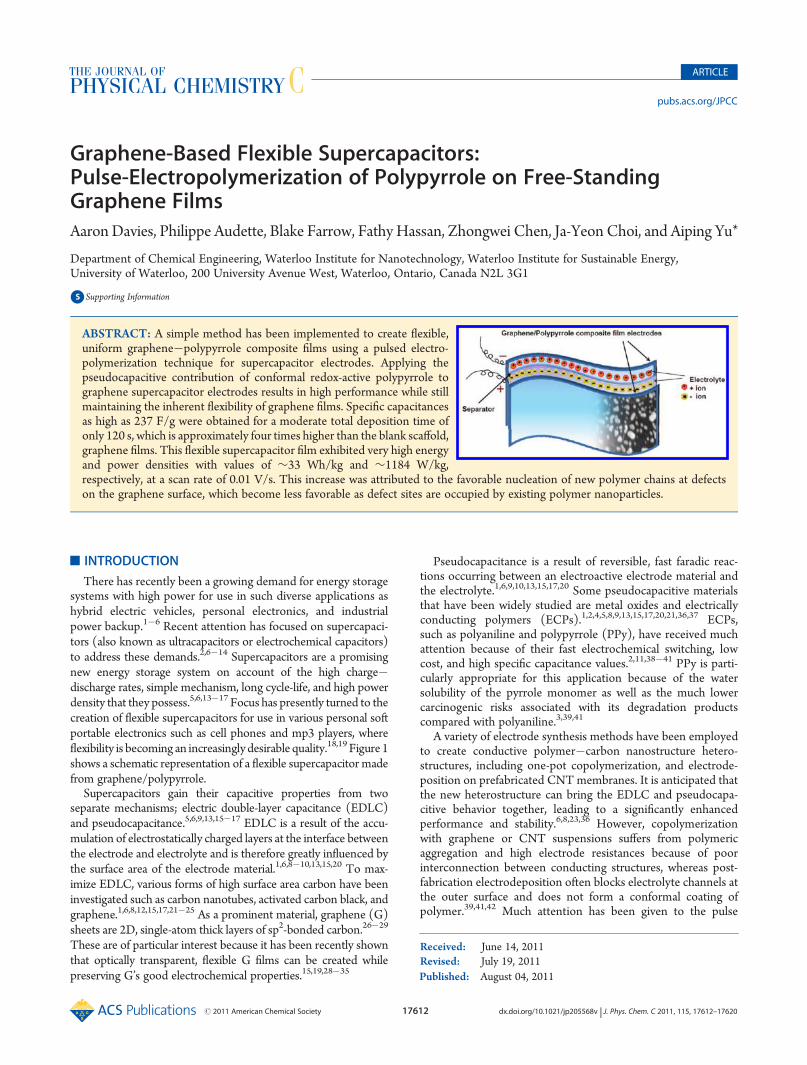
ABSTRACT: A simple method has been implemented to create flexible,uniform graphene�polypyrrole composite films using a pulsed electro-polymerization technique for supercapacitor electrodes. Applying thepseudocapacitive contribution of conformal redox-active polypyrrole tographene supercapacitor electrodes results in high performance while stillmaintaining the inherent flexibility of graphene films. Specific capacitancesas high as 237 F/g were obtained for a moderate total deposition time ofonly 120 s, which is approximately four times higher than the blank scaffold,graphene films. This flexible supercapacitor film exhibited very high energyand power densities with values of ∼33 Wh/kg and ∼1184 W/kg,respectively, at a scan rate of 0.01 V/s. This increase was attributed to the favorable nucleation of new polymer chains at defectson the graphene surface, which become less favorable as defect sites are occupied by existing polymer nanoparticles.
17613 dx.doi.org/10.1021/jp205568v |J. Phys. Chem. C 2011, 115, 17612–17620
The Journal of Physical Chemistry C ARTICLE
electrodeposition techniques owing to their promising resultsshown recently by several groups.2,41,42 In a recent study, pulsedelectrodeposition has been employed using well-separated shortpotential pulses, which allows pyrrole monomers to diffuse intothe carbon EDLC material pore space between polymerizationpulses, and demonstrated a significant improvement in theuniformity of PPy coatings on CNTs.42 A schematic illustrationshowing how rest periods allow for Py molecules to diffuse intothe pore space of the G between deposition pulses is shown inFigure 2. This leads to a more uniform coating and less blockedpores than obtained with a continuous deposition method. Somegroups have also proposed that during rest periods polypyrrolechains stabilize, making nucleation of new chains more favorableduring subsequent polymerization pulses rather than enlargingprevious chains.2,41 Short deposition pulses have also beenshown to produce fewer defects in the structure of the resultingpolypyrrole chains. Figure 1 shows a schematic of the pulsedelectrodeposition process.
In our previous work, we have demonstrated the high effi-ciency of ultrathin flexible graphene films for supercapacitors.19
In this study, graphene/polypyrrole composites were createdusing a modified pulsed electrodeposition technique withdiffering total deposition times in an effort to optimize theelectrodeposition time of Py for synergistic capacitive ability.The primary objective of this study is to prepare optimizedhomogeneous graphene/polypyrrole composite films that give
reasonably high performance for flexible supercapacitorsapplications.
’EXPERIMENTAL SECTION
Graphite and pyrrole were purchased from Alfa and Aldrich,respectively. Reduced graphene oxide was prepared by using amodified Hummers method, which yielded individual and few-layer graphene flakes with diameters ranging from 0.1 to 1 μm.43
Graphene films were prepared on an insulating polycarbonatemembrane support. To prepare these samples, we sonicated as-prepared graphene with a concentration of 0.05 mg/mL for 1 h.This dispersion was vacuum-filtered through a polycarbonate(PC) membrane (25 mm diameter, 0.4 μm pores) to create auniform graphene film.
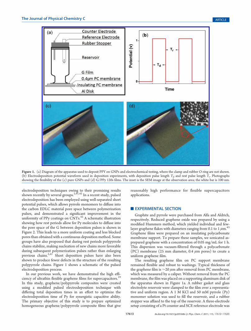
The resulting graphene film on PC support membraneremained flexible and robust to washings. Typical thickness ofthe graphene film is∼20 μm after removal from PC membrane,which was measured by a caliper. Without removal from the PCmembrane, the film was placed on a supporting aluminum disk ofthe apparatus shown in Figure 1a. A rubber gasket and glasselectrolyte reservoir were clamped to the film over a representa-tive and uniform region. A 1 M KCl and 50 mM pyrrole (Py)monomer solution was used to fill the reservoir, and a rubberstopper was affixed to the top of the reservoir. A three-electrodesetup consisting of a Pt counter and SCE reference electrode was
Figure 1. (a) Diagram of the apparatus used to deposit PPY on GNPs and electrochemical testing, where the clamp and rubber O-ring are not shown.(b) Electrodeposition potential waveform used in deposition experiments, with deposition pulse length Td and rest pulse length Tr. Photographsshowing the flexibility of the (c) pure GNPs and (d) G/PPy 120s films. The inset is the SEM image at the observation area; the white bar is 100 nm.
17614 dx.doi.org/10.1021/jp205568v |J. Phys. Chem. C 2011, 115, 17612–17620
The Journal of Physical Chemistry C ARTICLE
placed in solution through the rubber stopper. The graphene filmwas then wired as the working electrode.
A CHI 760D electrochemical workstation (CH Instruments,USA) was used to pulse the potential from 0 to 1.05 V for 0.1 seach until a predefined total deposition time was reached todeposit PPy uniformly onto the G. To determine the optimalPPy electrodeposition time, electrodes and films were preparedwith several total electrodeposition times ranging from 60to 360 s with 60 s intervals and are denoted G/PPy 60,G/PPy 120, G/PPy 180, G/PPy 240, G/PPy 300, and G/PPy360, respectively, with the pure G electrode being denoted simplyG. The results were focused on the G, G/PPy 60, G/PPy 120,and G/PPy 360 samples to demonstrate the concept andperformances.
Electrochemical characterization was carried out using thesame apparatus as above and followed by draining the depositionsolution from the reservoir and rinsing the resulting compositefilm with deionized water. After drying at 50 �C under vacuum,the G/PPy membrane with a diameter of 25 mm was ready foruse as an electrode without any further treatment. Cyclicvoltametry (CV), charge discharge (CD), and electrochemicalimpedance spectroscopy (EIS) techniques were all carried outfollowing a 25-cycle CV activation between �0.4 and 0.6 Vversus SCE at a scan rate of 0.1 V/s in 1 M KCl electrolyte. CVwas carried out between�0.4 and 0.6 V versus SCE at scan ratesbetween 0.01 and 0.2 V/s. CD was carried out between�0.4 and0.6 V versus SCE at current densities between 1 and 4 A/g. EISwas carried out between 1 MHz and 10 mHz under an opencircuit potential (OCP) with AC signal amplitudes between 10and 100 mV. The capacitance of the supercapacitor was calcu-lated on the mass of the graphene films because the mass of thedeposited polypyrrole was negligible by so short deposition time.
TGA was conducted on a Q500 thermogravimetric analyzer(TA Instruments, USA) in nitrogen between 50 and 800 at10 �C/min. TGA analysis of samples involved drying at 60 �C for72 h prior to testing. SEM images were obtained using an LEO1550 FESEM (LEO Electron Microscopy, USA).
’RESULTS AND DISCUSSION
The waveform of the shape shown in Figure 1b was applied tothe GNP film in an electropolymerization solution containing1 M KCl electrolyte and 50 mM pyrrole. The “on” potential washeld at 1.05 V versus SCE for electropolymerization, and loweredto OCP during the “off” resting cycles. These waveforms wererepeated until a total deposition time Td had been reached.Figure 1c,d shows a graphene film supported on a PCmembranewith a diameter of 25 mm before and after 120 s of electro-deposition of PPy. Both films are homogeneous and show goodflexibility, which indicates that deposition pulses do not inhibitthe flexibility of pure G. This also suggests that the feasibleconstruction of flexible supercapacitors was able to take advan-tage of both EDLC and pseudocapacitance, which providesa good way to meet the increasing demands for high-energydensity supercapacitors.6,18,44
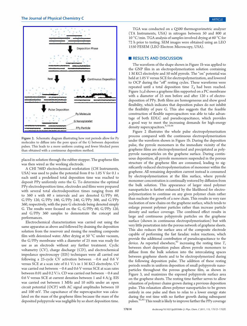
Figure 2 illustrates the whole pulse electropolymerizationprocess compared with the continuous electropolymerizationunder the waveform shown in Figure 1b. During the depositionpulse, the pyrrole monomers in the immediate vicinity of thegraphene films are electropolymerized and precipitated as poly-pyrrole nanoparticles on the graphene surface. During contin-uous deposition, all pyrrole monomers suspended in the porousstructure of the graphene film are consumed, leading to sig-nificantly reduced electropolymerization of monomer within thegraphene. All remaining deposition current instead is consumedby electropolymerization at the film surface, where pyrrolemonomer concentration is continually restored by diffusion fromthe bulk solution. This appearance of larger sized polymernanoparticles is further enhanced by the likelihood for electro-polymerization to continue on any given polymer chain ratherthan nucleate the growth of a new chain. This results in very rarenucleation of new chains on the graphene surface, which tends toenlarge present polymer particles rather than increase particledensity and surface coverage. The combined effect results inlarge and continuous polypyrrole particles on the graphenesurface (shown in continuous electropolymerization) but withvery little penetration into the porous network of graphene sheets.This also reduces the surface area of the composite electrodecapable of performing the fast faradaic redox reactions, whichprovide the additional contribution of pseudocapacitance to thedevice. As reported elsewhere,42 increasing the resting time Trbetween short deposition pulses allows pyrrole monomers todiffuse from the bulk solution into the intercalating spacesbetween graphene sheets and to be electropolymerized duringthe following deposition pulse. The addition of these restingperiods results in uniform deposition of small polypyrrole nano-particles throughout the porous graphene film, as shown inFigure 3, and maximizes the exposed polypyrrole surface areaon the graphene sheets. The resting time further serves to allowrelaxation of polymer chains grown during a previous depositionpulse. This relaxation allows polymer nanoparticles to be grownentirely in one pulse and then to relax to a lower energy stateduring the rest time with no further growth during subsequentpulses.42,45 This result is likely to improve further the PPy coverage
Figure 2. Schematic diagram illustrating how rest periods allow for Pymolecules to diffuse into the pore space of the G between depositionpulses. This leads to a more uniform coating and fewer blocked poresthan obtained with a continuous deposition method.
17615 dx.doi.org/10.1021/jp205568v |J. Phys. Chem. C 2011, 115, 17612–17620
The Journal of Physical Chemistry C ARTICLE
on the graphene electrode and increase the pseudocapacitivecontribution to the specific capacitance of the composite films.
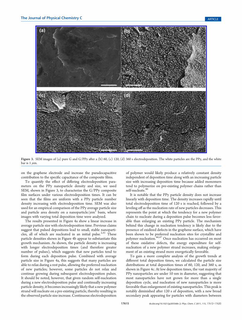
To quantify the effect of differing electrodeposition para-meters on the PPy nanoparticle density and size, we usedSEM, shown in Figure 3, to characterize the G/PPy compositefilm surfaces under various electrodeposition times. It can beseen that the films are uniform with a PPy particle numberdensity increasing with electrodeposition time. SEM was alsoused for an empirical comparison of the PPy average particle sizeand particle area density on a nanoparticle/μm2 basis, whereimages with varying total deposition time were analyzed.
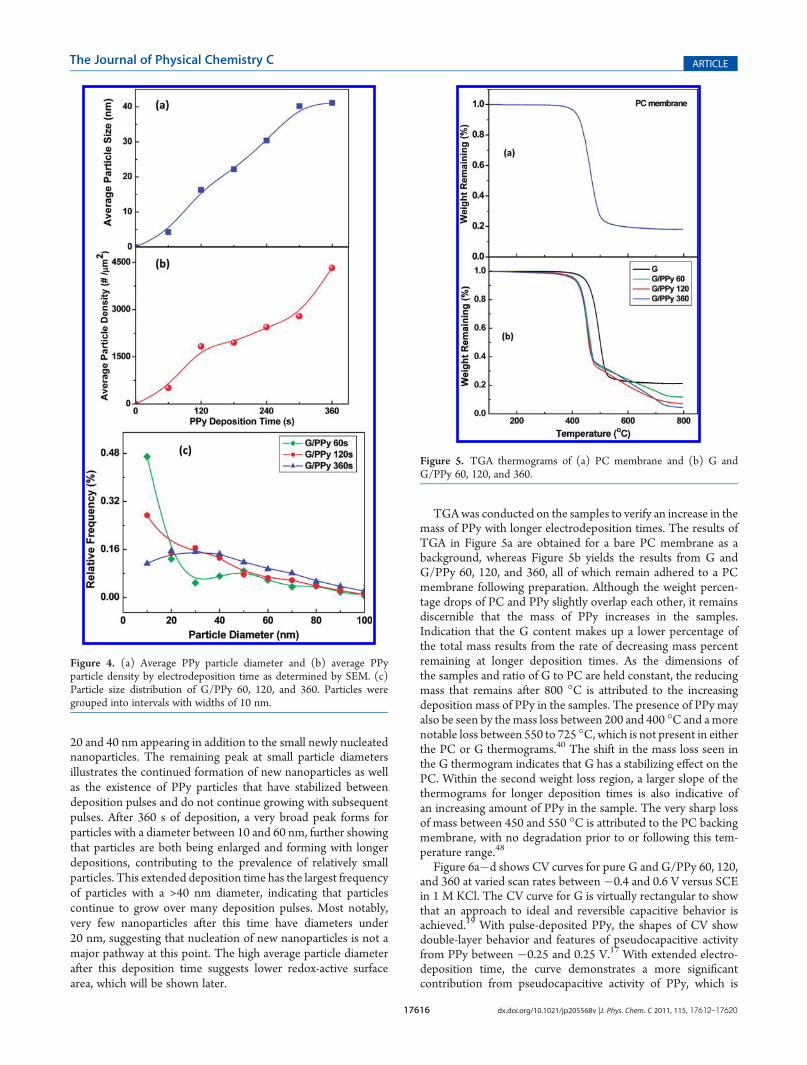
The results presented in Figure 4a show a linear increase inaverage particle size with electrodeposition time. Previous claimssuggest that pulsed depositions lead to small, stable nanoparti-cles, all of which are nucleated in an initial pulse.2,41 Theseparticle densities shown in Figure 4b appear to substantiate thisgrowth mechanism. As shown, the particle density is increasingwith longer electrodeposition times (and therefore greaternumber of pulses), which suggests that new particles tend toform during each deposition pulse. Combined with averageparticle size in Figure 4a, this suggests that many particles areable to relax during a rest pulse, allowing the preferred nucleationof new particles; however, some particles do not relax andcontinue growing during subsequent electrodeposition pulses.It should be noted, however, that given random self-nucleationduring a new electrodeposition pulse and continually increasingparticle density, it becomes increasingly likely that a new polymerstrand will nucleate on a pre-existing particle, thereby resulting inthe observed particle size increase. Continuous electrodeposition
of polymer would likely produce a relatively constant densityindependent of deposition time along with an increasing particlesize with increasing deposition time because added monomerstend to polymerize on pre-existing polymer chains rather thanself-nucleate.46
It is notable that the PPy particle density does not increaselinearly with deposition time. The density increases rapidly untiltotal electrodeposition time of 120 s is reached, followed by aleveling off as the nucleation rate of new particles decreases. Thisrepresents the point at which the tendency for a new polymerchain to nucleate during a deposition pulse becomes less favor-able than enlarging an existing PPy particle. The mechanismbehind this change in nucleation tendency is likely due to thepresence of oxidized defects in the graphene surface, which havebeen shown to be preferred nucleation sites for crystallite andpolymer nucleation.46,47 Once nucleation has occurred on mostof these oxidative defects, the energy expenditure for self-nucleation of a new polymer strand increases, making enlarge-ment of an existing strand more energetically favorable.
To gain a more complete analysis of the growth trends atdifferent total deposition times, we calculated the particle sizedistributions at total deposition times of 60, 120, and 360 s, asshown in Figure 4c. At low deposition times, the vast majority ofPPy nanoparticles are under 10 nm in diameter, suggesting thatmost nanoparticles have not grown for more than a singledeposition cycle, and nucleation of new nanoparticles is morefavorable than enlargement of existing nanoparticles. This peak isnotably diminished after 120 s of deposition, with a new broadsecondary peak appearing for particles with diameters between
Figure 3. SEM images of (a) pure G and G/PPy after a (b) 60, (c) 120, (d) 360 s electrodeposition. The white particles are the PPy, and the whitebar is 1 μm.
17616 dx.doi.org/10.1021/jp205568v |J. Phys. Chem. C 2011, 115, 17612–17620
The Journal of Physical Chemistry C ARTICLE
20 and 40 nm appearing in addition to the small newly nucleatednanoparticles. The remaining peak at small particle diametersillustrates the continued formation of new nanoparticles as wellas the existence of PPy particles that have stabilized betweendeposition pulses and do not continue growing with subsequentpulses. After 360 s of deposition, a very broad peak forms forparticles with a diameter between 10 and 60 nm, further showingthat particles are both being enlarged and forming with longerdepositions, contributing to the prevalence of relatively smallparticles. This extended deposition time has the largest frequencyof particles with a >40 nm diameter, indicating that particlescontinue to grow over many deposition pulses. Most notably,very few nanoparticles after this time have diameters under20 nm, suggesting that nucleation of new nanoparticles is not amajor pathway at this point. The high average particle diameterafter this deposition time suggests lower redox-active surfacearea, which will be shown later.
TGAwas conducted on the samples to verify an increase in themass of PPy with longer electrodeposition times. The results ofTGA in Figure 5a are obtained for a bare PC membrane as abackground, whereas Figure 5b yields the results from G andG/PPy 60, 120, and 360, all of which remain adhered to a PCmembrane following preparation. Although the weight percen-tage drops of PC and PPy slightly overlap each other, it remainsdiscernible that the mass of PPy increases in the samples.Indication that the G content makes up a lower percentage ofthe total mass results from the rate of decreasing mass percentremaining at longer deposition times. As the dimensions ofthe samples and ratio of G to PC are held constant, the reducingmass that remains after 800 �C is attributed to the increasingdeposition mass of PPy in the samples. The presence of PPy mayalso be seen by themass loss between 200 and 400 �C and amorenotable loss between 550 to 725 �C, which is not present in eitherthe PC or G thermograms.40 The shift in the mass loss seen inthe G thermogram indicates that G has a stabilizing effect on thePC. Within the second weight loss region, a larger slope of thethermograms for longer deposition times is also indicative ofan increasing amount of PPy in the sample. The very sharp lossof mass between 450 and 550 �C is attributed to the PC backingmembrane, with no degradation prior to or following this tem-perature range.48
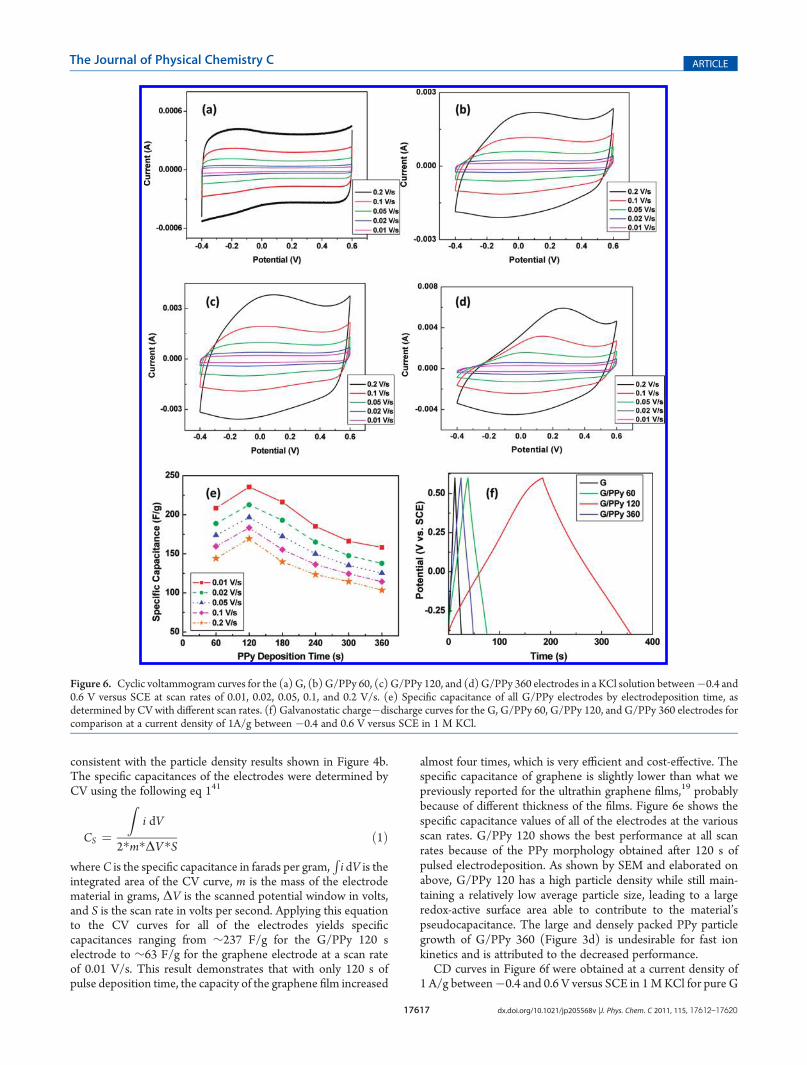
Figure 6a�d shows CV curves for pure G and G/PPy 60, 120,and 360 at varied scan rates between�0.4 and 0.6 V versus SCEin 1 M KCl. The CV curve for G is virtually rectangular to showthat an approach to ideal and reversible capacitive behavior isachieved.19 With pulse-deposited PPy, the shapes of CV showdouble-layer behavior and features of pseudocapacitive activityfrom PPy between �0.25 and 0.25 V.17 With extended electro-deposition time, the curve demonstrates a more significantcontribution from pseudocapacitive activity of PPy, which is
Figure 4. (a) Average PPy particle diameter and (b) average PPyparticle density by electrodeposition time as determined by SEM. (c)Particle size distribution of G/PPy 60, 120, and 360. Particles weregrouped into intervals with widths of 10 nm.
Figure 5. TGA thermograms of (a) PC membrane and (b) G andG/PPy 60, 120, and 360.
17617 dx.doi.org/10.1021/jp205568v |J. Phys. Chem. C 2011, 115, 17612–17620
The Journal of Physical Chemistry C ARTICLE
consistent with the particle density results shown in Figure 4b.The specific capacitances of the electrodes were determined byCV using the following eq 141
CS ¼
Zi dV
2�m�ΔV�S ð1Þ
whereC is the specific capacitance in farads per gram,Ri dV is the
integrated area of the CV curve, m is the mass of the electrodematerial in grams, ΔV is the scanned potential window in volts,and S is the scan rate in volts per second. Applying this equationto the CV curves for all of the electrodes yields specificcapacitances ranging from ∼237 F/g for the G/PPy 120 selectrode to ∼63 F/g for the graphene electrode at a scan rateof 0.01 V/s. This result demonstrates that with only 120 s ofpulse deposition time, the capacity of the graphene film increased
almost four times, which is very efficient and cost-effective. Thespecific capacitance of graphene is slightly lower than what wepreviously reported for the ultrathin graphene films,19 probablybecause of different thickness of the films. Figure 6e shows thespecific capacitance values of all of the electrodes at the variousscan rates. G/PPy 120 shows the best performance at all scanrates because of the PPy morphology obtained after 120 s ofpulsed electrodeposition. As shown by SEM and elaborated onabove, G/PPy 120 has a high particle density while still main-taining a relatively low average particle size, leading to a largeredox-active surface area able to contribute to the material’spseudocapacitance. The large and densely packed PPy particlegrowth of G/PPy 360 (Figure 3d) is undesirable for fast ionkinetics and is attributed to the decreased performance.
CD curves in Figure 6f were obtained at a current density of1 A/g between�0.4 and 0.6 V versus SCE in 1MKCl for pure G
Figure 6. Cyclic voltammogram curves for the (a) G, (b) G/PPy 60, (c) G/PPy 120, and (d) G/PPy 360 electrodes in a KCl solution between�0.4 and0.6 V versus SCE at scan rates of 0.01, 0.02, 0.05, 0.1, and 0.2 V/s. (e) Specific capacitance of all G/PPy electrodes by electrodeposition time, asdetermined by CV with different scan rates. (f) Galvanostatic charge�discharge curves for the G, G/PPy 60, G/PPy 120, and G/PPy 360 electrodes forcomparison at a current density of 1A/g between �0.4 and 0.6 V versus SCE in 1 M KCl.
17618 dx.doi.org/10.1021/jp205568v |J. Phys. Chem. C 2011, 115, 17612–17620
The Journal of Physical Chemistry C ARTICLE
and G/PPy 60, 120, and 360. Near-ideal EDLC behavior of theCD curves is seen by the highly linear charge and dischargeslopes, where linearity indicates that the rate of change inpotential is independent of an applied current.19 Approach toideality is also noted by the symmetry of the charge and dischargeslopes.1 The slight curvatures of the slopes of the G/PPyelectrodes are indicative of the pseudocapacitive effects of thePPy, and, as expected, the curvatures becomes more pronouncedwith longer electrodeposition times, indicating increased con-tribution of pseudocapacitance to the systems. The G/PPy 120shows a minimal internal resistance (IR) drop upon initiatedcharge and discharge, illustrating the low contact resistance of theG/PPy composites and efficient use of a capacitance current.29
This quality reduces the amount of energy lost to contactresistance with each charge/discharge cycle in the form of heat.
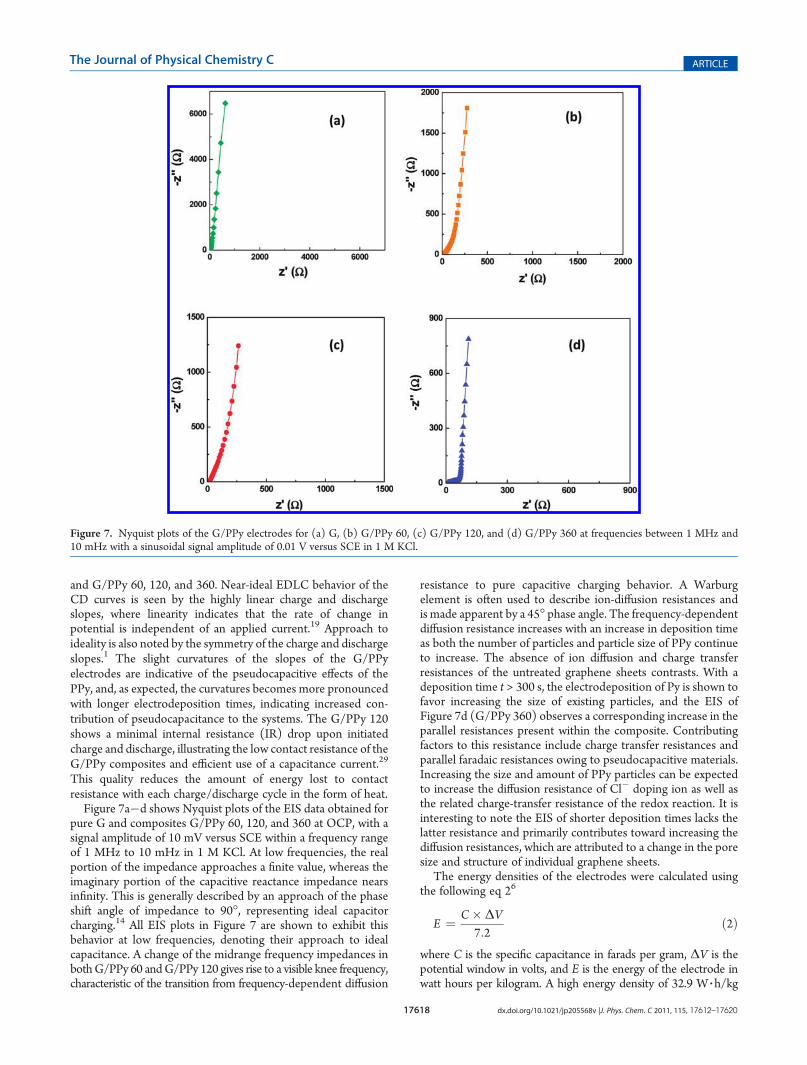
Figure 7a�d shows Nyquist plots of the EIS data obtained forpure G and composites G/PPy 60, 120, and 360 at OCP, with asignal amplitude of 10 mV versus SCE within a frequency rangeof 1 MHz to 10 mHz in 1 M KCl. At low frequencies, the realportion of the impedance approaches a finite value, whereas theimaginary portion of the capacitive reactance impedance nearsinfinity. This is generally described by an approach of the phaseshift angle of impedance to 90�, representing ideal capacitorcharging.14 All EIS plots in Figure 7 are shown to exhibit thisbehavior at low frequencies, denoting their approach to idealcapacitance. A change of the midrange frequency impedances inbothG/PPy 60 andG/PPy 120 gives rise to a visible knee frequency,characteristic of the transition from frequency-dependent diffusion
resistance to pure capacitive charging behavior. A Warburgelement is often used to describe ion-diffusion resistances andis made apparent by a 45� phase angle. The frequency-dependentdiffusion resistance increases with an increase in deposition timeas both the number of particles and particle size of PPy continueto increase. The absence of ion diffusion and charge transferresistances of the untreated graphene sheets contrasts. With adeposition time t > 300 s, the electrodeposition of Py is shown tofavor increasing the size of existing particles, and the EIS ofFigure 7d (G/PPy 360) observes a corresponding increase in theparallel resistances present within the composite. Contributingfactors to this resistance include charge transfer resistances andparallel faradaic resistances owing to pseudocapacitive materials.Increasing the size and amount of PPy particles can be expectedto increase the diffusion resistance of Cl� doping ion as well asthe related charge-transfer resistance of the redox reaction. It isinteresting to note the EIS of shorter deposition times lacks thelatter resistance and primarily contributes toward increasing thediffusion resistances, which are attributed to a change in the poresize and structure of individual graphene sheets.
The energy densities of the electrodes were calculated usingthe following eq 26
E ¼ C� ΔV7:2
ð2Þ
where C is the specific capacitance in farads per gram, ΔV is thepotential window in volts, and E is the energy of the electrode inwatt hours per kilogram. A high energy density of 32.9 W 3 h/kg
Figure 7. Nyquist plots of the G/PPy electrodes for (a) G, (b) G/PPy 60, (c) G/PPy 120, and (d) G/PPy 360 at frequencies between 1 MHz and10 mHz with a sinusoidal signal amplitude of 0.01 V versus SCE in 1 M KCl.
17619 dx.doi.org/10.1021/jp205568v |J. Phys. Chem. C 2011, 115, 17612–17620
The Journal of Physical Chemistry C ARTICLE
was derived from CV data for G/PPy 120 and 8.75W 3 h/kg for Gat a scan rate of 0.01 V/s.
The power densities of the electrodes were calculated from theratio of energy densities to discharge time as50
P ¼ Et
ð3Þ
where E is the energy density of the electrode in watt hours perkilogram and t is the discharge time of the CV curve in hours, anda power density of 315 and 1184 W/kg were obtained for G andG/PPy 120, respectively, at 0.01 V/s.
’CONCLUSIONS
In conclusion, we have presented a simple method to createflexible, uniform G/PPy composite films using a pulsed electro-deposition technique. Specific capacitances as high as 237 F/gwere obtained for a moderate deposition time of 120 s. Thisresult compares favorably to studies with much longer andcomplex processes for deposition of PPy to different carbonscaffolds. G/PPy 120 also exhibited the highest energy withmaximum values of ∼32.9 W 3 h/kg, which was notably higherthan the values obtained for all other electrodes and comparesvery favorably to literature values.14,41 It was clearly shown bySEM that increased electrodeposition time results in increasedparticle density up to 120 s total deposition time. This increasewas attributed to the favorable nucleation of new polymer chainsat defects in the graphene surface, which becomes less favorableas defect sites are covered by existing polymer nanoparticles.
With the addition of a pseudocapacitive contribution tographene supercapacitor electrodes due to a conformal nano-particle coating of redox-active PPy, it is possible to obtain highpower and energy densities while still maintaining the inherentflexibility of graphene films. It is expected that the increases inenergy and power densities in a flexible material will lead tonumerous applications, especially in the field of personal electro-nics and renewable energy storage.
’ASSOCIATED CONTENT
bS Supporting Information. Full description of the materi-al. This material is available free of charge via the Internet athttp://pubs.acs.org.
’AUTHOR INFORMATION
Corresponding Author*E-mail: [email protected].
’ACKNOWLEDGMENT
This research was financially supported by the Natural Sciencesand Engineering Research Council of Canada (NSERC) and theUniversity of Waterloo.
’REFERENCES
(1) Reddy, A. L. M.; Ramaprabhu, S. J. Phys. Chem. C 2007, 1117727–7734.(2) Sharma, R. K.; Rastogi, A. C.; Desu, S. B. Electrochem. Commun.
2008, 10, 268–272.(3) Shi, C.; Zhitomirsky, I. Nanoscale Res. Lett. 2010, 5, 518–523.(4) Sivakkumar, S. R.; Ko, J. M.; Kim, D. Y.; Kim, B. C.; Wallace,
G. G. Electrochim. Acta 2007, 52, 7377–7385.
(5) Subramanian, V.; Zhu, H. W.; Wei, B. Q. Electrochem. Commun.2006, 8, 827–832.
(6) Zhang, L. L.; Zhao, X. S. Chem. Soc. Rev. 2009, 38, 2520–2531.(7) Dubal, D. P.; Dhawale, D. S.; Salunkhe, R. R.; Lokhande, C. D.
J. Alloy. Compd. 2010, 496, 370–375.(8) Frackowiak, E. Phys. Chem. Chem. Phys. 2007, 9, 1774–1785.(9) Hu, C. C.; Tsou, T. W. J. Power Sources 2003, 115, 179–186.(10) Lee, C. Y.; Tsai, H. M.; Chuang, H. J.; Li, S. Y.; Lin, P.; Tseng,
T. Y. J. Electrochem. Soc. 2005, 152, A716–A720.(11) Li, G. R.; Feng, Z. P.; Zhong, J. H.; Wang, Z. L.; Tong, Y. X.
Macromolecules 2010, 43, 2178–2183.(12) Masarapu, C.; Zeng, H. F.; Hung, K. H.; Wei, B. Q. Acs Nano
2009, 3, 2199–2206.(13) Roberts, A. J.; Slade, R. C. T. J. Mater. Chem. 2010, 20, 3221–
3226.(14) Wang, Y.; Shi, Z.; Huang, Y.; Ma, Y.; Wang, C.; Chen, M.;
Chen, Y. J. Phys. Chem. C 2009, 113, 13103–13107.(15) Du, Q. L.; Zheng, M. B.; Zhang, L. F.; Wang, Y. W.; Chen, J. H.;
Xue, L. P.; Dai, W. J.; Ji, G. B.; Cao, J. M. Electrochim. Acta 2010, 55,3897–3903.
(16) Jiang, J. H.; Kucernak, A. Electrochim. Acta 2002, 47, 2381–2386.(17) Kim, J. H.; Nam, K. W.; Ma, S. B.; Kim, K. B. Carbon 2006, 44,
1963–1968.(18) Kaempgen, M.; Chan, C. K.; Ma, J.; Cui, Y.; Gruner, G. Nano
Lett. 2009, 9, 1872–1876.(19) Yu, A. P.; Roes, I.; Davies, A.; Chen, Z.W.Appl. Phys. Lett. 2010,
96, 253105–253108.(20) Raymundo-Pinero, E.; Khomenko, V.; Frackowiak, E.; Beguin, F.
J. Electrochem. Soc. 2005, 152, A229–A235.(21) Dubal, D. P.; Dhawale, D. S.; Salunkhe, R. R.; Pawar, S. M.;
Lokhande, C. D. Appl. Surf. Sci. 2010, 256, 4411–4416.(22) Huang, J. S.; Sumpter, B. G.; Meunier, V. Angew. Chem., Int. Ed.
2008, 47, 520–524.(23) Konno, H.; Ito, T.; M., U.; K., F.; K., A. J. Power Sources 2010,
195, 1739–1746.(24) Li, F. H.; Song, J. F.; Yang, H. F.; Gan, S. Y.; Zhang, Q. X.; Han,
D. X.; Ivaska, A.; Niu, L. Nanotechnology 2009, 20, 455602.(25) Zhang, Y. P.; Li, H. B.; Pan, L. K.; Lu, T.; Sun, Z. J. Electroanal.
Chem. 2009, 634, 68–71.(26) Li, D.; Muller, M. B.; Gilje, S.; Kaner, R. B.; Wallace, G. G. Nat.
Nanotechnol. 2008, 3, 101–105.(27) Shen, J. F.; Hu, Y. H.; Li, C.; Qin, C.; Ye, M. X. Small 2009,
5, 82–85.(28) Si, Y.; Samulski, E. T. Nano Lett. 2008, 8, 1679–1682.(29) Wu, Q.; Xu, Y. X.; Yao, Z. Y.; Liu, A. R.; Shi, G. Q. ACS Nano
2010, 4, 1963–1970.(30) Ansari, S.; Giannelis, E. P. J. Polym. Sci., Polym. Phys. 2009, 47,
888–897.(31) Park, S.; An, J. H.; Jung, I. W.; Piner, R. D.; An, S. J.; Li, X. S.;
Velamakanni, A.; Ruoff, R. S. Nano Lett. 2009, 9, 1593–1597.(32) Schniepp,H.C.; Li, J. L.;McAllister,M. J.; Sai,H.;Herrera-Alonso,
M.; Adamson, D. H.; Prud’homme, R. K.; Car, R.; Saville, D. A.; Aksay, I. A.J. Phys. Chem. B 2006, 110, 8535–8539.
(33) Stankovich, S.; Piner, R. D.; Chen, X. Q.; Wu, N. Q.; Nguyen,S. T.; Ruoff, R. S. J. Mater. Chem. 2006, 16, 155–158.
(34) Tung, V. C.; Allen, M. J.; Yang, Y.; Kaner, R. B. Nat. Nano-technol. 2009, 4, 25–29.
(35) Stankovich, S.; Dikin, D. A.; Dommett, G. H. B.; Kohlhaas,K. M.; Zimney, E. J.; Stach, E. A.; Piner, R. D.; Nguyen, S. T.; Ruoff, R. S.Nature 2006, 442, 282–286.
(36) Nam, K. W.; Lee, C. W.; Yang, X. Q.; Cho, B. W.; Yoon, W. S.;Kim, K. B. J. Power Sources 2009, 188, 323–331.
(37) Qu, Q. T.; Zhang, P.; Wang, B.; Chen, Y. H.; Tian, S.; Wu, Y. P.;Holze, R. J. Phys. Chem. C 2009, 113, 14020–14027.
(38) Zhang, J.; Kong, L.-B.; Li, H.; Luo, Y.-C.; Kang, L. J. Mater. Sci.2010, 45, 1947–1954.
(39) Han, Y. Q.; Qing, X. T.; Ye, S. J.; Lu, Y. Synth. Met. 2010,160, 1159–1166.
17620 dx.doi.org/10.1021/jp205568v |J. Phys. Chem. C 2011, 115, 17612–17620
The Journal of Physical Chemistry C ARTICLE
(40) Mavinakuli, P.; Wei, S. Y.; Wang, Q.; Karki, A. B.; Dhage, S.;Wang, Z.; Young, D. P.; Guo, Z. H. J. Phys. Chem. C 2010, 114,3874–3882.(41) Yan, J.; Wei, T.; Fan, Z.; Qian, W.; Zhang, M.; Shen, X.; Wei, F.
J. Power Sources 2010, 195, 3041–3045.(42) Fang, Y. P.; Liu, J. W.; Yu, D. J.; Wicksted, J. P.; Kalkan, K.;
Topal, C. O.; Flanders, B. N.; Wu, J. D.; Li, J. J. Power Sources 2010, 195,674–679.(43) Hummers, W. S.; Offeman, R. E. J. Am. Chem. Soc. 1958, 80,
1339–1339.(44) Wang, D. W.; Li, F.; Lui, M.; Cheng, H. M. New Carbon Mater.
2007, 22, 307–314.(45) Cui, L. L.; Lu, X. F.; Chao, D. M.; Liu, H. T.; Li, Y. X.; Wang, C.
Phys. Status Solidi A 2011, 208, 459–461.(46) Massa, M. V.; Carvalho, J. L.; Dalnoki-Veress, K. Phys. Rev. Lett.
2006, 97.(47) Gouldstone, A.; Vliet, K. J. V.; Suresh, S.Nature 2001, 411, 656.(48) Jang, B. N.; Wilkie, C. A. Polym. Degrad. Stab. 2004, 86,
419–430.(49) Zhou, H. H.; Chen, H.; Luo, S. L.; Lu, G. W.; Wei, W. Z.;
Kuang, Y. F. J. Solid State Electrochem. 2005, 9, 574–580.(50) Yan, J.; Fan, Z. J.; Wei, T.; Cheng, J.; Shao, B.; Wang, K.; Song,
L. P.; Zhang, M. L. J. Power Sources 2009, 194, 1202–1207.
Related Documents
![Development of an equivalent circuit model for ...chemeng.uwaterloo.ca/zchen/publications/documents/1-s2.0-S... · or in parallel [18,19]. This model structure is useful to provide](https://static.cupdf.com/doc/110x72/5e7d8131a311c6435054a7dc/development-of-an-equivalent-circuit-model-for-or-in-parallel-1819-this.jpg)