Inte Inte Inte International Journal rnational Journal rnational Journal rnational Journal of of of of Software Engineering and Its Applications Software Engineering and Its Applications Software Engineering and Its Applications Software Engineering and Its Applications Vol. Vol. Vol. Vol. 8, No. , No. , No. , No. 2, , , , (2014) (2014) (2014) (2014), , , , Graph-Based Decomposition of Design Patterns Najet Zoubeir Institut Supérieur d’Informatique [email protected] Adel Khalfallah Institut Supérieur d’Informatique [email protected] Samir Benahmed Faculté des Sciences de Tunis [email protected] Abstract Design patterns recognition and injection constitute challenging tasks in software engineering, since they are generally conducted in a non-formal way. In this paper, we will present an approach for decomposing and formalizing design patterns using graph transformation systems. We will propose a combined graph-based description for design patterns structure, interactions and constraints. Then, based on this description, we will introduce a set of Elementary Transformations whose diverse combinations lead to the design patterns injection. These elementary transformations are formal, precise and presented in a generic form that allows to describe the 23 design patterns defined by the GOF. Detailed descriptions and examples are presented in this paper in order to illustrate our approach. Key-words: Design Patterns Decomposition, Graph Transformation Systems 1. Introduction Design patterns (DPs) constitute a corpus of knowledge on models structuration, in accordance with the good practices of Object Oriented design and programming, such as DRY [1], SOLID [2], and GRASP [3]. One major challenge in working with DP is how to identify and evolve them within models. In fact, these tasks are generally performed in a non-formal way. In this area, graph-based approaches appear promising, due to their robust theoretical foundation. In this paper, we propose a combined approach for DPs description and decomposition using Graph Transformation Systems (GTSs). As illustrated in figure 1, GTSs are used in our approach in order to: - Express the syntax and the semantics of DP: The use of graphs to express systems syntax and operational semantics is widely used in software engineering [4, 5, 6, 7, 8]. In this paper, we present a combined description of DP generic structure and interaction, and we associate a graph transformation rule to every method whose operational semantics is significant. - Express and verify the constraints defined on DPs: Constraints defined on models, and particularly OCL constraints can be expressed and verified using graphs [9]. - Express the DPs recognition and injection through graph transformations: We propose to formalize the injection of DPs into models using GTSs. We define a decomposition of DPs based on graph transformation rules, so that the whole set of GOF patterns are decomposed and formalized by combining these different graph transformations.

Welcome message from author
This document is posted to help you gain knowledge. Please leave a comment to let me know what you think about it! Share it to your friends and learn new things together.
Transcript
InteInteInteInternational Journalrnational Journalrnational Journalrnational Journal of of of of Software Engineering and Its ApplicationsSoftware Engineering and Its ApplicationsSoftware Engineering and Its ApplicationsSoftware Engineering and Its Applications
Vol. Vol. Vol. Vol. 8888, No. , No. , No. , No. 2222, , , , (2014)(2014)(2014)(2014), , , ,
Graph-Based Decomposition of Design Patterns
Najet Zoubeir
Institut Supérieur d’Informatique
Adel Khalfallah
Institut Supérieur d’Informatique
Samir Benahmed
Faculté des Sciences de Tunis
Abstract
Design patterns recognition and injection constitute challenging tasks in software engineering, since they are generally conducted in a non-formal way. In this paper, we will present an approach for decomposing and formalizing design patterns using graph transformation systems. We will propose a combined graph-based description for design patterns structure, interactions and constraints. Then, based on this description, we will introduce a set of Elementary Transformations whose diverse combinations lead to the design patterns injection. These elementary transformations are formal, precise and presented in a generic form that allows to describe the 23 design patterns defined by the GOF. Detailed descriptions and examples are presented in this paper in order to illustrate our approach.
Key-words: Design Patterns Decomposition, Graph Transformation Systems
1. Introduction
Design patterns (DPs) constitute a corpus of knowledge on models structuration, in accordance with the good practices of Object Oriented design and programming, such as DRY [1], SOLID [2], and GRASP [3]. One major challenge in working with DP is how to identify and evolve them within models. In fact, these tasks are generally performed in a non-formal way. In this area, graph-based approaches appear promising, due to their robust theoretical foundation. In this paper, we propose a combined approach for DPs description and decomposition using Graph Transformation Systems (GTSs). As illustrated in figure 1, GTSs are used in our approach in order to:
- Express the syntax and the semantics of DP: The use of graphs to express systems syntax and operational semantics is widely used in software engineering [4, 5, 6, 7, 8]. In this paper, we present a combined description of DP generic structure and interaction, and we associate a graph transformation rule to every method whose operational semantics is significant.
- Express and verify the constraints defined on DPs: Constraints defined on models, and particularly OCL constraints can be expressed and verified using graphs [9].
- Express the DPs recognition and injection through graph transformations: We propose to formalize the injection of DPs into models using GTSs. We define a decomposition of DPs based on graph transformation rules, so that the whole set of GOF patterns are decomposed and formalized by combining these different graph transformations.
InteInteInteInternational Journalrnational Journalrnational Journalrnational Journal of of of of Software Engineering and Its ApplicationsSoftware Engineering and Its ApplicationsSoftware Engineering and Its ApplicationsSoftware Engineering and Its Applications
Vol. Vol. Vol. Vol. 8888, No. , No. , No. , No. 2222, , , , (2014)(2014)(2014)(2014), , , ,
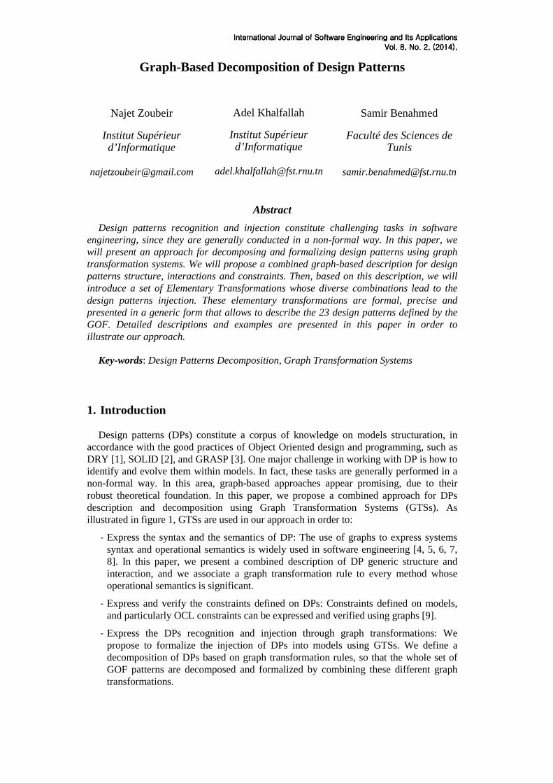
- Enchain the obtained graph transformations in order to analyze their combined effect.
Figure 1: DP as graph transformation systems
We worked in this paper on the original definition of DPs proposed by the GoF [10]. In our approach, a DP injection is regarded as a set of graph transformations applied on a graph instance representing a given model. So, the DP recognition is performed by the mechanism of matching within graphs. A graph transformation introducing a DP is composed by a sequence of graph transformation units representing Elementary Transformations (ETs) decomposing the introduction of DPs. These ETs represent generic and configurable micro-transformations whose different combinations lead to the introduction of DPs into models.
We implemented the ETs as graph transformation rules using the toolset GROOVE1 [11]. We obtained a library of the possible instantiations of each ET, and hence, a DP injection can be described in the form of a sequence of Elementary Transformation Implementations (ETIs). Using ETs, and as we will explain later in this paper, we were able de formalize the 23 DPs proposed by the GOF.
The set of ETs constitutes our proposal for a formal DP decomposition. Besides, all our graphs are typed over an architectural meta-model which combines structure, behavior and constraints. Hence, the ET we propose take into consideration the interactions of models and DPs for both the matching and the execution. Formal DP decomposition and injection are interesting and enlarging the specter of DP use, analysis, evolution, etc.
2. Related work
Graph grammars have known a wide success in describing visual languages semantics.
In fact, unlike the most of visual languages description techniques, they offer a fair compromise between understandability and rigor. They present promising results in capturing and verifying design patterns, seen as declarative or operational transformations. They provide a solid theoretical foundation based on the theory of categories [12].
1 GRaphs for Object-Oriented VErification
InteInteInteInternational Journalrnational Journalrnational Journalrnational Journal of of of of Software Engineering and Its ApplicationsSoftware Engineering and Its ApplicationsSoftware Engineering and Its ApplicationsSoftware Engineering and Its Applications
Vol. Vol. Vol. Vol. 8888, No. , No. , No. , No. 2222, , , , (2014)(2014)(2014)(2014), , , ,
The work in [13] proposes a tool that captures design patterns using graph queries and graph rewriting rules. The tool creates architectural graphs by reverse engineering existing source code, then applies graph rewriting rules on these graphs in order to transform them to satisfy a given design pattern. This work however, starts from existing source code and not models. Besides, it is oriented to distributed architectures, and its applicability on general architectures and patterns is not studied.
Kong et al. in [14] use Reserved Graph Grammar (RGG) in order to propose graph based syntax and semantics for UML class diagrams, which support models verification and design patterns identification. Graph production rules are used to ensure a valid construction of a class diagram, and to transform system architecture according to a given architectural style. In this work, the transformation concerns only the macro-level (architectural styles), i.e. the micro-architectural design patterns are studied only in terms of collecting and reconstructing related pieces of information in a model. The graph productions corresponding to architecture transformation treat patterns as blocks: no analysis has been presented for patterns decomposition or variability on the patterns application conditions. Besides, the use of RGG reduces the models understandability since this kind of grammar is visually more complex than normal graphs.
Aakash et al. propose a typed attributed graph-based approach for identifying [15] and evolving design patterns [16]. They use attributed graphs to identify and formalize the patterns of the possible changes that can occur on a service architecture log. They also use graph morphisms to automate the application of the patterns. However, this work is tightly related to service architecture changes. The considered type graphs are specific to the mentioned domain, so the approach cannot be generalized to common patterns.
In this paper, we propose a graph-based decomposition of DPs that permits the formalization of the whole set of GOF patterns as elementary graph transformations, which when combined, lead to the DP injection into models. The remainder of this paper is organized as follows: In section 3 we will present the combined architectural meta-model we adopted for our graphs. Section 4 will be devoted to the description of our proposed decomposition of DPs, in the form of a set of Elementary Transformations accompanied by the implementation we adopted for them. Our proposal will be illustrated first in section 5 by the decomposition of two GoF patterns, which are the “Singleton” and the “Observer”, and secondly in section 6 using an illustrating example. Finally in section 7, we will conclude and discuss some of our further work.
3. Architectural meta-model
In our work we manipulate typed attributed graphs as they were defined in [5]: “typed attributed graphs with inheritance node and edge labeled multi-graph that allows for node inheritance in the type graph and uses special datatype nodes for the representation of attributes”. Essentially, a GTS is composed by three kinds of graphs: type graphs, instance or host graphs and graph transformation rules. As depicted in figure 1, type graphs are used in order to express DP structure, host graphs for the model instances and graphs transformation rules for both operational semantics and constraints. In this section, we will present the architectural meta-model over which are typed our graphs, and which combines structure, behavior and constraints. This meta-model, which we manipulate as a set of type graphs, will be presented using class diagrams.
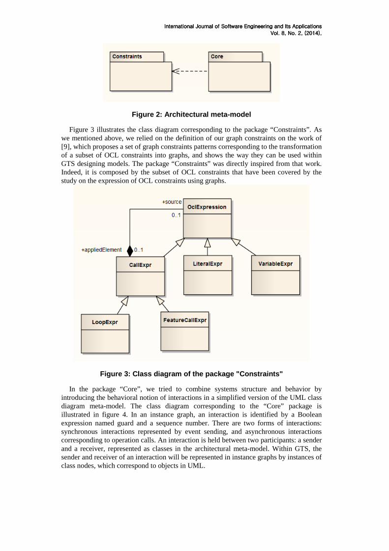
Our combined meta-model is composed by two packages: the package “Constraints” and the package “Core”, so that the latter one uses the former one, as illustrated in figure 2.
InteInteInteInternational Journalrnational Journalrnational Journalrnational Journal of of of of Software Engineering and Its ApplicationsSoftware Engineering and Its ApplicationsSoftware Engineering and Its ApplicationsSoftware Engineering and Its Applications
Vol. Vol. Vol. Vol. 8888, No. , No. , No. , No. 2222, , , , (2014)(2014)(2014)(2014), , , ,
Figure 2: Architectural meta-model
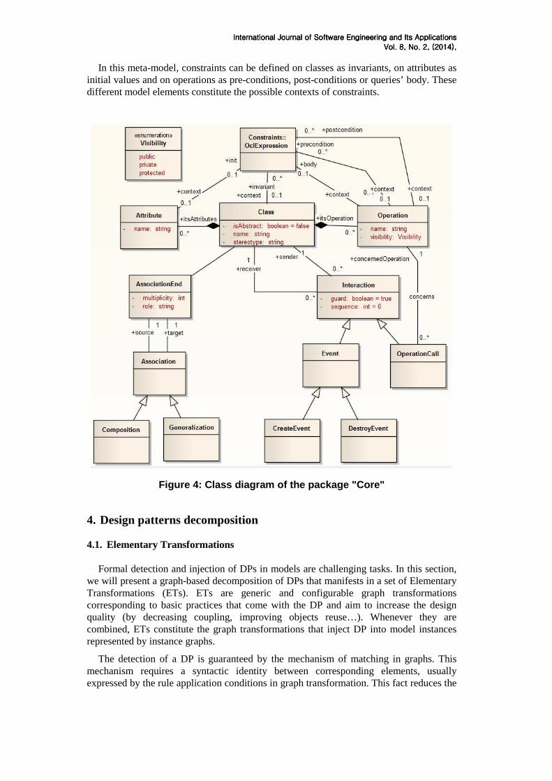
Figure 3 illustrates the class diagram corresponding to the package “Constraints”. As we mentioned above, we relied on the definition of our graph constraints on the work of [9], which proposes a set of graph constraints patterns corresponding to the transformation of a subset of OCL constraints into graphs, and shows the way they can be used within GTS designing models. The package “Constraints” was directly inspired from that work. Indeed, it is composed by the subset of OCL constraints that have been covered by the study on the expression of OCL constraints using graphs.
Figure 3: Class diagram of the package "Constraints"
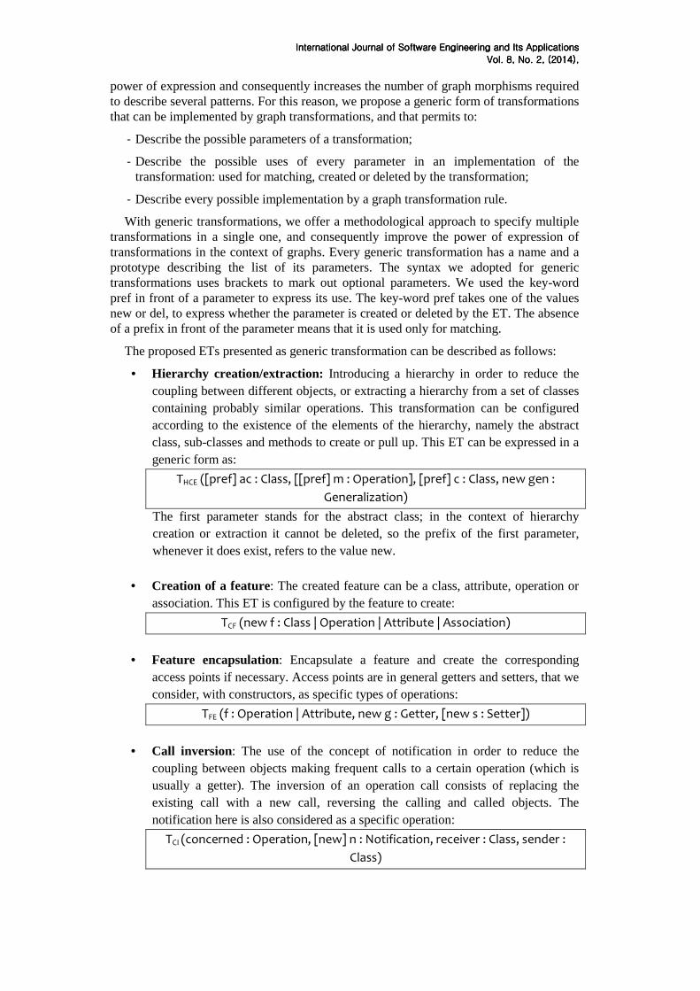
In the package “Core”, we tried to combine systems structure and behavior by introducing the behavioral notion of interactions in a simplified version of the UML class diagram meta-model. The class diagram corresponding to the “Core” package is illustrated in figure 4. In an instance graph, an interaction is identified by a Boolean expression named guard and a sequence number. There are two forms of interactions: synchronous interactions represented by event sending, and asynchronous interactions corresponding to operation calls. An interaction is held between two participants: a sender and a receiver, represented as classes in the architectural meta-model. Within GTS, the sender and receiver of an interaction will be represented in instance graphs by instances of class nodes, which correspond to objects in UML.
InteInteInteInternational Journalrnational Journalrnational Journalrnational Journal of of of of Software Engineering and Its ApplicationsSoftware Engineering and Its ApplicationsSoftware Engineering and Its ApplicationsSoftware Engineering and Its Applications
Vol. Vol. Vol. Vol. 8888, No. , No. , No. , No. 2222, , , , (2014)(2014)(2014)(2014), , , ,
In this meta-model, constraints can be defined on classes as invariants, on attributes as initial values and on operations as pre-conditions, post-conditions or queries’ body. These different model elements constitute the possible contexts of constraints.
Figure 4: Class diagram of the package "Core"
4. Design patterns decomposition 4.1. Elementary Transformations
Formal detection and injection of DPs in models are challenging tasks. In this section,
we will present a graph-based decomposition of DPs that manifests in a set of Elementary Transformations (ETs). ETs are generic and configurable graph transformations corresponding to basic practices that come with the DP and aim to increase the design quality (by decreasing coupling, improving objects reuse…). Whenever they are combined, ETs constitute the graph transformations that inject DP into model instances represented by instance graphs.
The detection of a DP is guaranteed by the mechanism of matching in graphs. This mechanism requires a syntactic identity between corresponding elements, usually expressed by the rule application conditions in graph transformation. This fact reduces the
InteInteInteInternational Journalrnational Journalrnational Journalrnational Journal of of of of Software Engineering and Its ApplicationsSoftware Engineering and Its ApplicationsSoftware Engineering and Its ApplicationsSoftware Engineering and Its Applications
Vol. Vol. Vol. Vol. 8888, No. , No. , No. , No. 2222, , , , (2014)(2014)(2014)(2014), , , ,
power of expression and consequently increases the number of graph morphisms required to describe several patterns. For this reason, we propose a generic form of transformations that can be implemented by graph transformations, and that permits to:
- Describe the possible parameters of a transformation;
- Describe the possible uses of every parameter in an implementation of the transformation: used for matching, created or deleted by the transformation;
- Describe every possible implementation by a graph transformation rule.
With generic transformations, we offer a methodological approach to specify multiple transformations in a single one, and consequently improve the power of expression of transformations in the context of graphs. Every generic transformation has a name and a prototype describing the list of its parameters. The syntax we adopted for generic transformations uses brackets to mark out optional parameters. We used the key-word pref in front of a parameter to express its use. The key-word pref takes one of the values new or del, to express whether the parameter is created or deleted by the ET. The absence of a prefix in front of the parameter means that it is used only for matching.
The proposed ETs presented as generic transformation can be described as follows:
• Hierarchy creation/extraction: Introducing a hierarchy in order to reduce the coupling between different objects, or extracting a hierarchy from a set of classes containing probably similar operations. This transformation can be configured according to the existence of the elements of the hierarchy, namely the abstract class, sub-classes and methods to create or pull up. This ET can be expressed in a generic form as:
THCE ([pref] ac : Class, [[pref] m : Operation], [pref] c : Class, new gen :
Generalization)
The first parameter stands for the abstract class; in the context of hierarchy creation or extraction it cannot be deleted, so the prefix of the first parameter, whenever it does exist, refers to the value new.
• Creation of a feature: The created feature can be a class, attribute, operation or association. This ET is configured by the feature to create:
TCF (new f : Class | Operation | Attribute | Association)
• Feature encapsulation: Encapsulate a feature and create the corresponding
access points if necessary. Access points are in general getters and setters, that we consider, with constructors, as specific types of operations:
TFE (f : Operation | Attribute, new g : Getter, [new s : Setter])
• Call inversion: The use of the concept of notification in order to reduce the
coupling between objects making frequent calls to a certain operation (which is usually a getter). The inversion of an operation call consists of replacing the existing call with a new call, reversing the calling and called objects. The notification here is also considered as a specific operation:
TCI (concerned : Operation, [new] n : Notification, receiver : Class, sender :
Class)
InteInteInteInternational Journalrnational Journalrnational Journalrnational Journal of of of of Software Engineering and Its ApplicationsSoftware Engineering and Its ApplicationsSoftware Engineering and Its ApplicationsSoftware Engineering and Its Applications
Vol. Vol. Vol. Vol. 8888, No. , No. , No. , No. 2222, , , , (2014)(2014)(2014)(2014), , , ,
• Introduction of intermediate : Increase abstraction and reduce the coupling between communicating objects: replace a direct association between two classes by an intermediate class, or replace a call to an operation by another:
TII (source : Class, target : Class, [new c : Class], [new assoc : Association],
[new oc : OperationCall])
4.2. Implementations of ETs
The specificity of ETs is that they are generic enough to express and decompose the 23
DPs of the GoF, and allow at the same time they refined control of the DP, due to the use of parameters. The use of any given ET on the decomposition of a DP depends on the category of this pattern: creational, structural or behavioral. Some of the ET, like “Hierarchy creation/extraction” is often used with structural DP, while others like “Call inversion” are mainly used with behavioral ones. ETs such as “Introduction of intermediate” can be used indifferently with all DP categories.
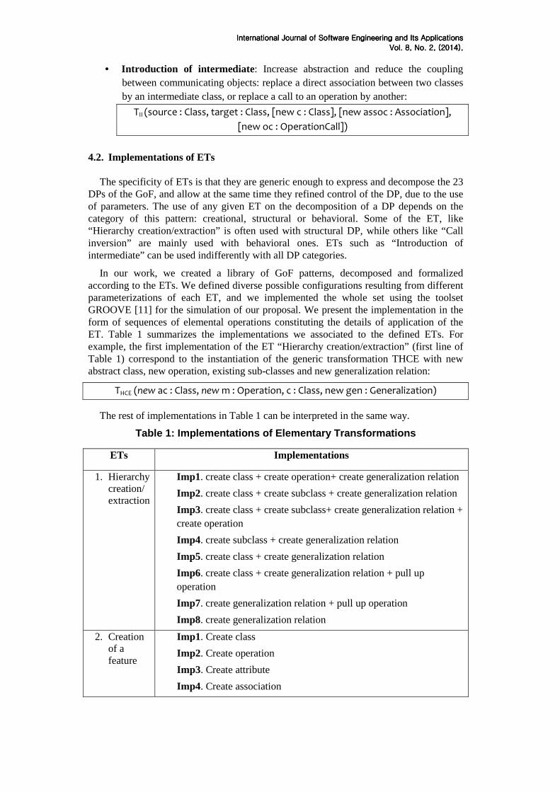
In our work, we created a library of GoF patterns, decomposed and formalized according to the ETs. We defined diverse possible configurations resulting from different parameterizations of each ET, and we implemented the whole set using the toolset GROOVE [11] for the simulation of our proposal. We present the implementation in the form of sequences of elemental operations constituting the details of application of the ET. Table 1 summarizes the implementations we associated to the defined ETs. For example, the first implementation of the ET “Hierarchy creation/extraction” (first line of Table 1) correspond to the instantiation of the generic transformation THCE with new abstract class, new operation, existing sub-classes and new generalization relation:
THCE (new ac : Class, new m : Operation, c : Class, new gen : Generalization)
The rest of implementations in Table 1 can be interpreted in the same way.
Table 1: Implementations of Elementary Transformations
ETs Implementations
1. Hierarchy creation/ extraction
Imp1. create class + create operation+ create generalization relation
Imp2. create class + create subclass + create generalization relation
Imp3. create class + create subclass+ create generalization relation + create operation
Imp4. create subclass + create generalization relation
Imp5. create class + create generalization relation
Imp6. create class + create generalization relation + pull up operation
Imp7. create generalization relation + pull up operation
Imp8. create generalization relation
2. Creation of a feature
Imp1. Create class
Imp2. Create operation
Imp3. Create attribute
Imp4. Create association
InteInteInteInternational Journalrnational Journalrnational Journalrnational Journal of of of of Software Engineering and Its ApplicationsSoftware Engineering and Its ApplicationsSoftware Engineering and Its ApplicationsSoftware Engineering and Its Applications
Vol. Vol. Vol. Vol. 8888, No. , No. , No. , No. 2222, , , , (2014)(2014)(2014)(2014), , , ,
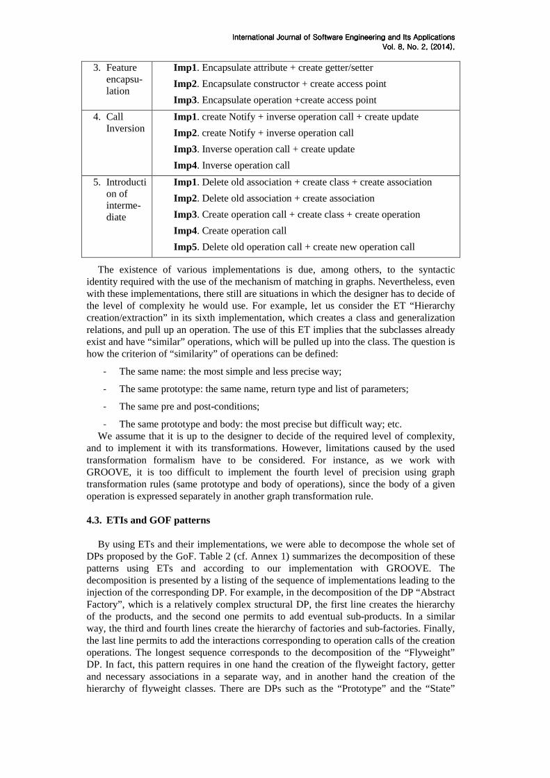
3. Feature encapsu-lation
Imp1. Encapsulate attribute + create getter/setter
Imp2. Encapsulate constructor + create access point
Imp3. Encapsulate operation +create access point
4. Call Inversion
Imp1. create Notify + inverse operation call + create update
Imp2. create Notify + inverse operation call
Imp3. Inverse operation call + create update
Imp4. Inverse operation call
5. Introduction of interme-diate
Imp1. Delete old association + create class + create association
Imp2. Delete old association + create association
Imp3. Create operation call + create class + create operation
Imp4. Create operation call
Imp5. Delete old operation call + create new operation call
The existence of various implementations is due, among others, to the syntactic identity required with the use of the mechanism of matching in graphs. Nevertheless, even with these implementations, there still are situations in which the designer has to decide of the level of complexity he would use. For example, let us consider the ET “Hierarchy creation/extraction” in its sixth implementation, which creates a class and generalization relations, and pull up an operation. The use of this ET implies that the subclasses already exist and have “similar” operations, which will be pulled up into the class. The question is how the criterion of “similarity” of operations can be defined:
- The same name: the most simple and less precise way;
- The same prototype: the same name, return type and list of parameters;
- The same pre and post-conditions;
- The same prototype and body: the most precise but difficult way; etc. We assume that it is up to the designer to decide of the required level of complexity,
and to implement it with its transformations. However, limitations caused by the used transformation formalism have to be considered. For instance, as we work with GROOVE, it is too difficult to implement the fourth level of precision using graph transformation rules (same prototype and body of operations), since the body of a given operation is expressed separately in another graph transformation rule.
4.3. ETIs and GOF patterns
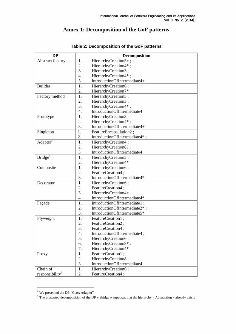
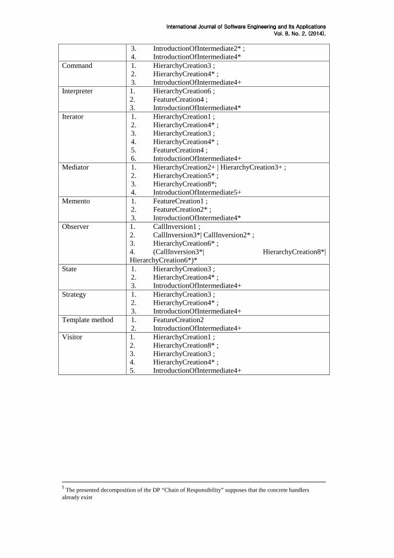
By using ETs and their implementations, we were able to decompose the whole set of
DPs proposed by the GoF. Table 2 (cf. Annex 1) summarizes the decomposition of these patterns using ETs and according to our implementation with GROOVE. The decomposition is presented by a listing of the sequence of implementations leading to the injection of the corresponding DP. For example, in the decomposition of the DP “Abstract Factory”, which is a relatively complex structural DP, the first line creates the hierarchy of the products, and the second one permits to add eventual sub-products. In a similar way, the third and fourth lines create the hierarchy of factories and sub-factories. Finally, the last line permits to add the interactions corresponding to operation calls of the creation operations. The longest sequence corresponds to the decomposition of the “Flyweight” DP. In fact, this pattern requires in one hand the creation of the flyweight factory, getter and necessary associations in a separate way, and in another hand the creation of the hierarchy of flyweight classes. There are DPs such as the “Prototype” and the “State”
InteInteInteInternational Journalrnational Journalrnational Journalrnational Journal of of of of Software Engineering and Its ApplicationsSoftware Engineering and Its ApplicationsSoftware Engineering and Its ApplicationsSoftware Engineering and Its Applications
Vol. Vol. Vol. Vol. 8888, No. , No. , No. , No. 2222, , , , (2014)(2014)(2014)(2014), , , ,
whose decomposition is quite the same. This is due to the fact that they have similar structures (a hierarchy of prototypes and a hierarchy of states) and similar interactions (calls to the added operations). To differentiate them, more semantics should be added to the model by the designer.
5. Examples of DPs formalization
In this section, we will present the formalization of the DP “Singleton” and “Observer”
as illustration of our proposal. For each DP, we will present the structure using type graphs, the introduction by instantiating the generic transformations corresponding to the ET we defined, and, if possible, the constraints using graph transformation rules. The DP injection is described using ET. In fact, as we associate to every ETI a graph transformation rule created using GROOVE, with the same name and the corresponding number, we propose to describe the DP injection by a sequence of graph transformation rules.
5.1. The “Singleton”
The DP “Singleton” is a creational pattern that monitors the number of instances of a
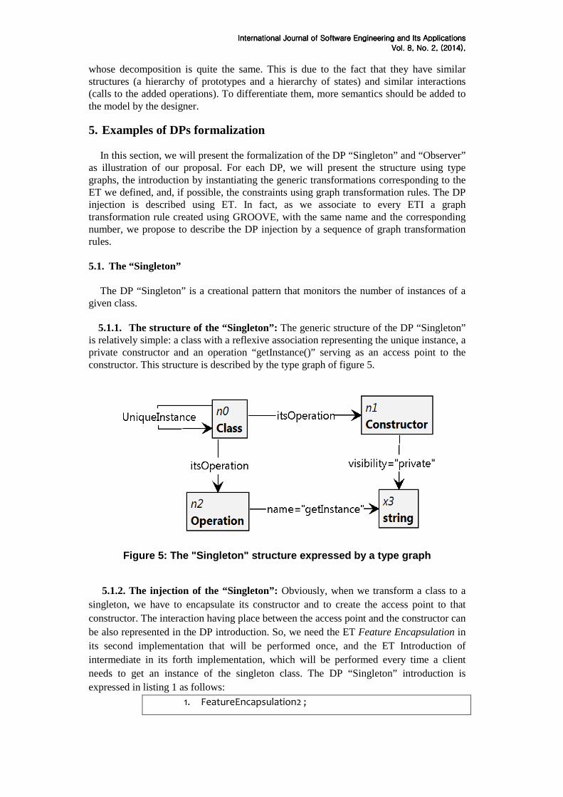
given class. 5.1.1. The structure of the “Singleton”: The generic structure of the DP “Singleton”
is relatively simple: a class with a reflexive association representing the unique instance, a private constructor and an operation “getInstance()” serving as an access point to the constructor. This structure is described by the type graph of figure 5.
Figure 5: The "Singleton" structure expressed by a type graph
5.1.2. The injection of the “Singleton”: Obviously, when we transform a class to a
singleton, we have to encapsulate its constructor and to create the access point to that constructor. The interaction having place between the access point and the constructor can be also represented in the DP introduction. So, we need the ET Feature Encapsulation in its second implementation that will be performed once, and the ET Introduction of intermediate in its forth implementation, which will be performed every time a client needs to get an instance of the singleton class. The DP “Singleton” introduction is expressed in listing 1 as follows:
1. FeatureEncapsulation2 ;
InteInteInteInternational Journalrnational Journalrnational Journalrnational Journal of of of of Software Engineering and Its ApplicationsSoftware Engineering and Its ApplicationsSoftware Engineering and Its ApplicationsSoftware Engineering and Its Applications
Vol. Vol. Vol. Vol. 8888, No. , No. , No. , No. 2222, , , , (2014)(2014)(2014)(2014), , , ,
2. IntroductionOfIntermediate4* ;
Listing 1 : DP "Singleton" introduction
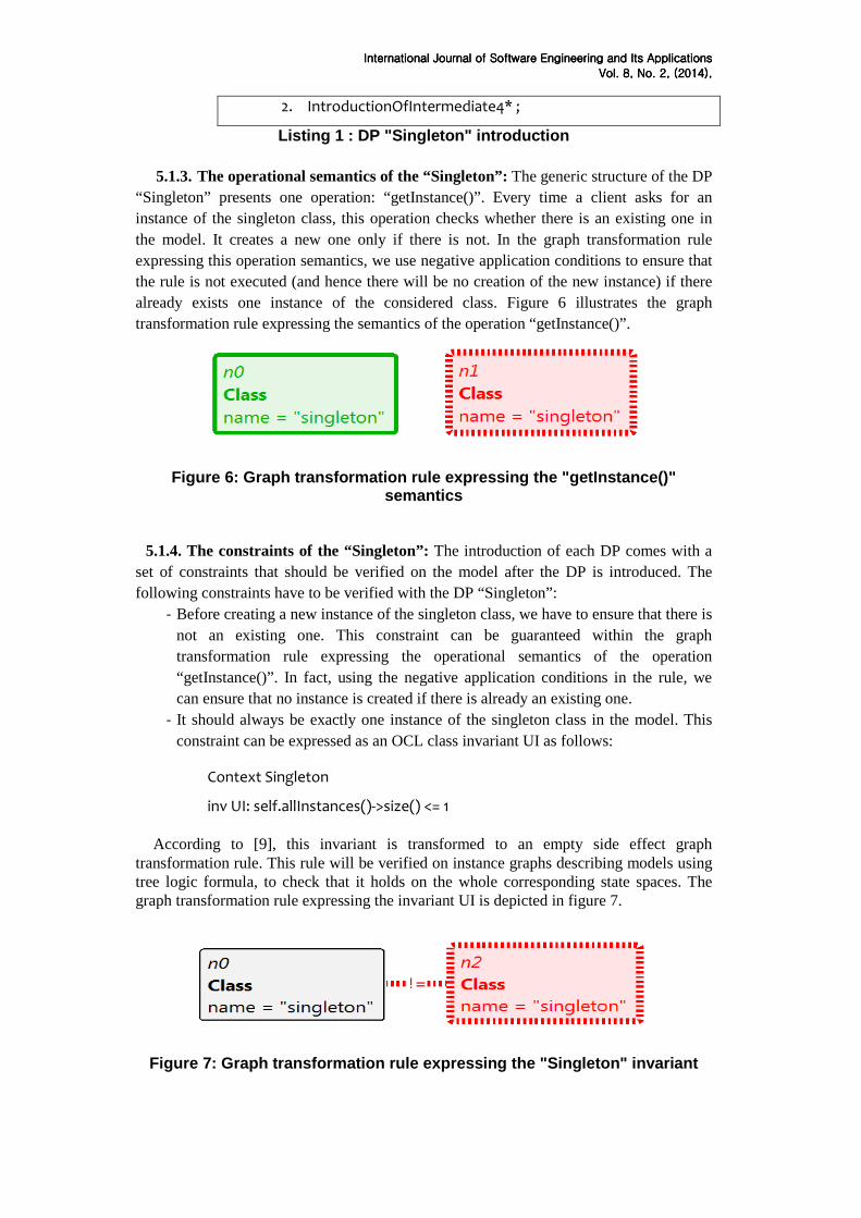
5.1.3. The operational semantics of the “Singleton”: The generic structure of the DP “Singleton” presents one operation: “getInstance()”. Every time a client asks for an instance of the singleton class, this operation checks whether there is an existing one in the model. It creates a new one only if there is not. In the graph transformation rule expressing this operation semantics, we use negative application conditions to ensure that the rule is not executed (and hence there will be no creation of the new instance) if there already exists one instance of the considered class. Figure 6 illustrates the graph transformation rule expressing the semantics of the operation “getInstance()”.
Figure 6: Graph transformation rule expressing the "getInstance()" semantics
5.1.4. The constraints of the “Singleton”: The introduction of each DP comes with a set of constraints that should be verified on the model after the DP is introduced. The following constraints have to be verified with the DP “Singleton”:
- Before creating a new instance of the singleton class, we have to ensure that there is not an existing one. This constraint can be guaranteed within the graph transformation rule expressing the operational semantics of the operation “getInstance()”. In fact, using the negative application conditions in the rule, we can ensure that no instance is created if there is already an existing one.
- It should always be exactly one instance of the singleton class in the model. This constraint can be expressed as an OCL class invariant UI as follows:
Context Singleton
inv UI: self.allInstances()->size() <= 1
According to [9], this invariant is transformed to an empty side effect graph transformation rule. This rule will be verified on instance graphs describing models using tree logic formula, to check that it holds on the whole corresponding state spaces. The graph transformation rule expressing the invariant UI is depicted in figure 7.
Figure 7: Graph transformation rule expressing the "Singleton" invariant
InteInteInteInternational Journalrnational Journalrnational Journalrnational Journal of of of of Software Engineering and Its ApplicationsSoftware Engineering and Its ApplicationsSoftware Engineering and Its ApplicationsSoftware Engineering and Its Applications
Vol. Vol. Vol. Vol. 8888, No. , No. , No. , No. 2222, , , , (2014)(2014)(2014)(2014), , , ,
5.2. The “Observer” The DP “Observer” is mainly used for event handling on systems. Its basic idea is that a subject observed by one or more observers, must send them a notification signal every time its state is changed.
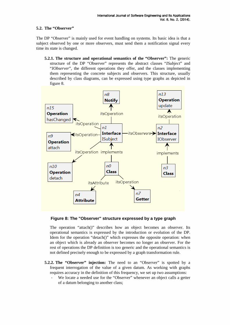
5.2.1. The structure and operational semantics of the “Observer”: The generic structure of the DP “Observer” represents the abstract classes “ISubject” and “ IObserver”, the different operations they offer, and the classes implementing them representing the concrete subjects and observers. This structure, usually described by class diagrams, can be expressed using type graphs as depicted in figure 8.
Figure 8: The "Observer" structure expressed by a type graph
The operation “attach()” describes how an object becomes an observer. Its operational semantics is expressed by the introduction or evolution of the DP. Idem for the operation “detach()” which expresses the opposite operation: when an object which is already an observer becomes no longer an observer. For the rest of operations the DP definition is too generic and the operational semantics is not defined precisely enough to be expressed by a graph transformation rule.
5.2.2. The “Observer” injection: The need to an “Observer” is spotted by a frequent interrogation of the value of a given datum. As working with graphs requires accuracy in the definition of this frequency, we set up two assumptions: - We locate a needed use for the “Observer” whenever an object calls a getter
of a datum belonging to another class;
InteInteInteInternational Journalrnational Journalrnational Journalrnational Journal of of of of Software Engineering and Its ApplicationsSoftware Engineering and Its ApplicationsSoftware Engineering and Its ApplicationsSoftware Engineering and Its Applications
Vol. Vol. Vol. Vol. 8888, No. , No. , No. , No. 2222, , , , (2014)(2014)(2014)(2014), , , ,
- When an object makes an operation call for the getter, it is considered as potential observer and the DP can be introduced there.
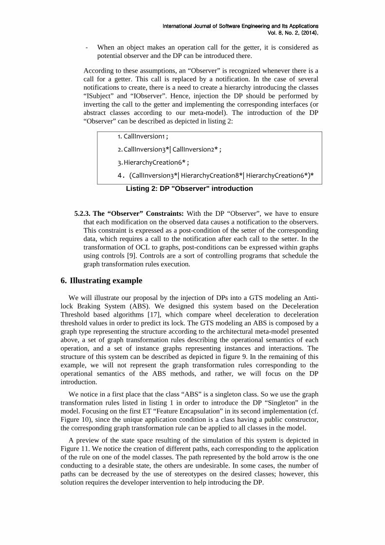
According to these assumptions, an “Observer” is recognized whenever there is a call for a getter. This call is replaced by a notification. In the case of several notifications to create, there is a need to create a hierarchy introducing the classes “ISubject” and “IObserver”. Hence, injection the DP should be performed by inverting the call to the getter and implementing the corresponding interfaces (or abstract classes according to our meta-model). The introduction of the DP “Observer” can be described as depicted in listing 2:
1. CallInversion1 ;
2. CallInversion3*| CallInversion2* ;
3. HierarchyCreation6* ;
4. (CallInversion3*| HierarchyCreation8*| HierarchyCreation6*)*
Listing 2: DP "Observer" introduction
5.2.3. The “Observer” Constraints: With the DP “Observer”, we have to ensure that each modification on the observed data causes a notification to the observers. This constraint is expressed as a post-condition of the setter of the corresponding data, which requires a call to the notification after each call to the setter. In the transformation of OCL to graphs, post-conditions can be expressed within graphs using controls [9]. Controls are a sort of controlling programs that schedule the graph transformation rules execution.
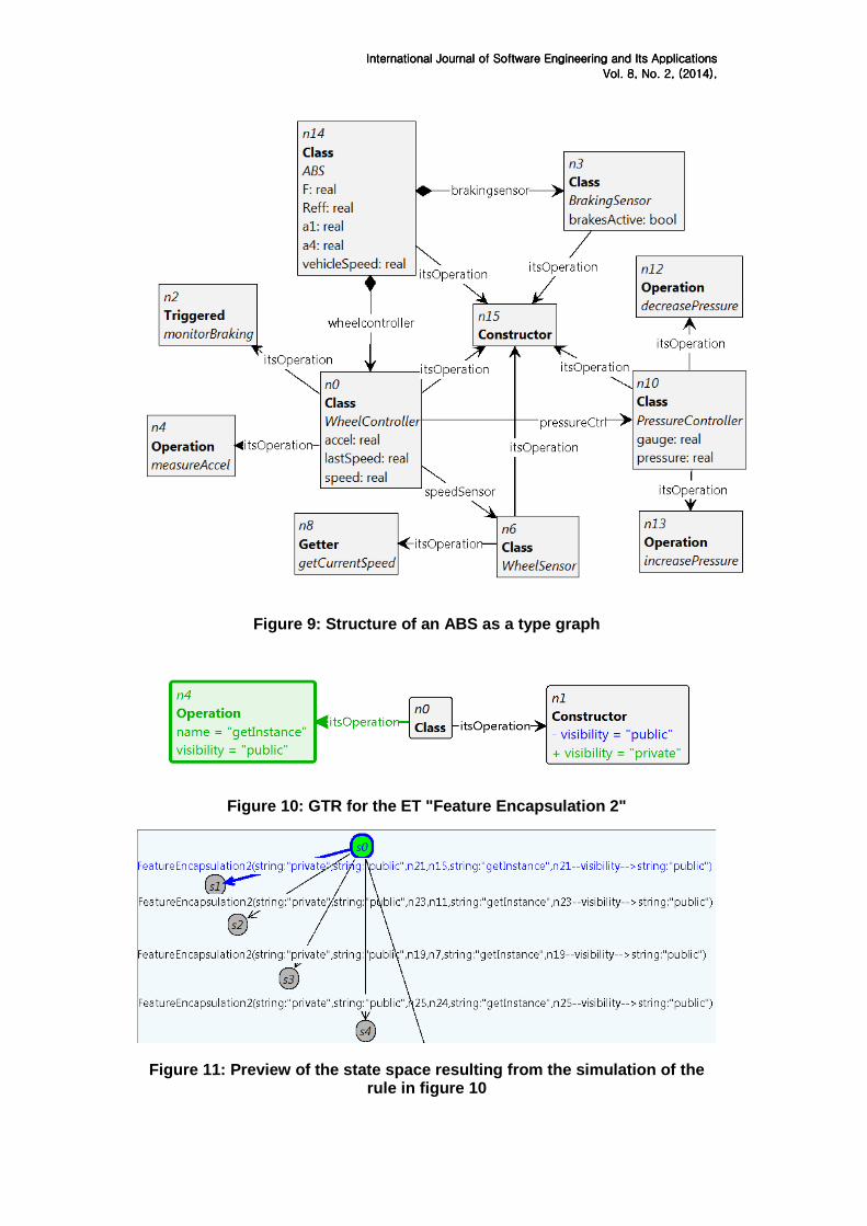
6. Illustrating example We will illustrate our proposal by the injection of DPs into a GTS modeling an Anti-
lock Braking System (ABS). We designed this system based on the Deceleration Threshold based algorithms [17], which compare wheel deceleration to deceleration threshold values in order to predict its lock. The GTS modeling an ABS is composed by a graph type representing the structure according to the architectural meta-model presented above, a set of graph transformation rules describing the operational semantics of each operation, and a set of instance graphs representing instances and interactions. The structure of this system can be described as depicted in figure 9. In the remaining of this example, we will not represent the graph transformation rules corresponding to the operational semantics of the ABS methods, and rather, we will focus on the DP introduction.
We notice in a first place that the class “ABS” is a singleton class. So we use the graph transformation rules listed in listing 1 in order to introduce the DP “Singleton” in the model. Focusing on the first ET “Feature Encapsulation” in its second implementation (cf. Figure 10), since the unique application condition is a class having a public constructor, the corresponding graph transformation rule can be applied to all classes in the model.
A preview of the state space resulting of the simulation of this system is depicted in Figure 11. We notice the creation of different paths, each corresponding to the application of the rule on one of the model classes. The path represented by the bold arrow is the one conducting to a desirable state, the others are undesirable. In some cases, the number of paths can be decreased by the use of stereotypes on the desired classes; however, this solution requires the developer intervention to help introducing the DP.
InteInteInteInternational Journalrnational Journalrnational Journalrnational Journal of of of of Software Engineering and Its ApplicationsSoftware Engineering and Its ApplicationsSoftware Engineering and Its ApplicationsSoftware Engineering and Its Applications
Vol. Vol. Vol. Vol. 8888, No. , No. , No. , No. 2222, , , , (2014)(2014)(2014)(2014), , , ,
Figure 9: Structure of an ABS as a type graph
Figure 10: GTR for the ET "Feature Encapsulation 2"
Figure 11: Preview of the state space resulting from the simulation of the rule in figure 10
InteInteInteInternational Journalrnational Journalrnational Journalrnational Journal of of of of Software Engineering and Its ApplicationsSoftware Engineering and Its ApplicationsSoftware Engineering and Its ApplicationsSoftware Engineering and Its Applications
Vol. Vol. Vol. Vol. 8888, No. , No. , No. , No. 2222, , , , (2014)(2014)(2014)(2014), , , ,
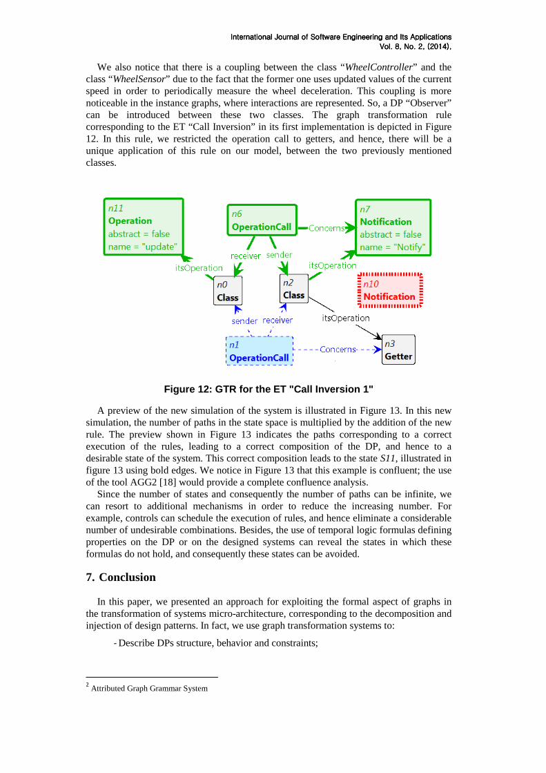
We also notice that there is a coupling between the class “WheelController” and the class “WheelSensor” due to the fact that the former one uses updated values of the current speed in order to periodically measure the wheel deceleration. This coupling is more noticeable in the instance graphs, where interactions are represented. So, a DP “Observer” can be introduced between these two classes. The graph transformation rule corresponding to the ET “Call Inversion” in its first implementation is depicted in Figure 12. In this rule, we restricted the operation call to getters, and hence, there will be a unique application of this rule on our model, between the two previously mentioned classes.
Figure 12: GTR for the ET "Call Inversion 1"
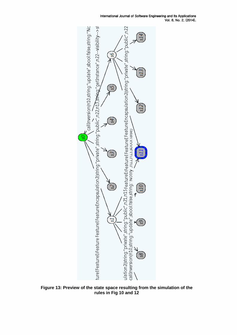
A preview of the new simulation of the system is illustrated in Figure 13. In this new simulation, the number of paths in the state space is multiplied by the addition of the new rule. The preview shown in Figure 13 indicates the paths corresponding to a correct execution of the rules, leading to a correct composition of the DP, and hence to a desirable state of the system. This correct composition leads to the state S11, illustrated in figure 13 using bold edges. We notice in Figure 13 that this example is confluent; the use of the tool AGG2 [18] would provide a complete confluence analysis.
Since the number of states and consequently the number of paths can be infinite, we can resort to additional mechanisms in order to reduce the increasing number. For example, controls can schedule the execution of rules, and hence eliminate a considerable number of undesirable combinations. Besides, the use of temporal logic formulas defining properties on the DP or on the designed systems can reveal the states in which these formulas do not hold, and consequently these states can be avoided.
7. Conclusion
In this paper, we presented an approach for exploiting the formal aspect of graphs in the transformation of systems micro-architecture, corresponding to the decomposition and injection of design patterns. In fact, we use graph transformation systems to:
- Describe DPs structure, behavior and constraints;
2 Attributed Graph Grammar System
InteInteInteInternational Journalrnational Journalrnational Journalrnational Journal of of of of Software Engineering and Its ApplicationsSoftware Engineering and Its ApplicationsSoftware Engineering and Its ApplicationsSoftware Engineering and Its Applications
Vol. Vol. Vol. Vol. 8888, No. , No. , No. , No. 2222, , , , (2014)(2014)(2014)(2014), , , ,
- Decompose DPs into a set of Elementary Transformations that can be implemented by graph transformation rules
- Inject DPs into instance graphs describing models, by combining different elementary transformations implementations; and
- Simulate the result of DPs introduction into instance graphs describing systems. In our further work, we aim to diversify the specter of implementations of ETs by the
use of different tools like AGG or PROGRES [19], and to enlarge our pattern library by formalizing other micro and macro-patterns. Besides, as we presented each elementary transformations implementation by a set of elemental operations meant to express operations that can be performed by a graph morphism (cf. Table 1), we aim to create a set of graph refactorings by comparing ETIs with the original proposition of refactorings [20].
8. References [1] A. Hunt, D. Thomas and W. Cunningham, The Pragmatic Programmer: From Journeyman to Master, Addison-Wesley Longman, Amsterdam, (1999) [2] R. C. Marin, Design Principles and Design Patterns, url = http://www.objectmentor.com/resources/articles/Principles_and_Patterns.pdf, (2000), last visited 17/11/2013 [3] C. Larman, Applying UML and Patterns – An Introduction to Object-Oriented Analysis and Design and Iterative Development (3rd ed.). New Jersey: Prentice Hall (2004) [4] M. Gogolla and M. Richters, Bézivin, Jean and Muller, Pierre-Alain, Transformation Rules for UML Class Diagrams, Proceedings of UML ‘98: the unified modeling language: beyond the notationUnified modeling language. International workshop No1, (1999), 3-4 June Mulhouse, France [5] J. H. Hausmann, Dynamic Meta Modeling: A Semantics Description Technique for Visual Modeling Languages, PhD thesis, University of Paderborn, Germany, (2005) [6] S. Kuske, M. Gogolla, R. Kollmann and H. Kreowski, An integrated semantics for UML class, object and state diagrams based on graph transformation. In: of Lecture Notes in Computer Science, Springer (2002) [7] M. Gogolla, P. Ziemann and S. Kuske, Towards an integrated graph based semantics for UML. In: Electronic Notes in Theoretical Computer Science. 72. (2003) [8] K. Holscher, P. Ziemann and M. Gogolla, On translating UML models into graph transformation systems. Journal of Visual Languages and Computing archive 17(1) (2006) [9] N. Zoubeir, A. Khalfallah and S. Benahmed, Expressing and Validating OCL Constraints using Graphs, in Embedded Computing Systems: Applications, Optimization and Advanced Design, IGI Global, (2013), pp. 93-107. [10] E. Gamma, R. Helm, R. Johnson and J. Vlissides, Design Patterns: Elements of Reusable Object-Oriented Software, Addison-Wesley Professional, (1995) [11] GRaphs for Object-Oriented Verification, (1995), url= http://groove.cs.utwente.nl/, last visited 15/09/2012 [12] E. Syriani and J. Gray, Antoniol, Giuliano and Bertolino, Antonia and Labiche, Yvan, Challenges for Addressing Quality Factors in Model Transformation, Proceedings of IEEE Fifth International Conference on Software Testing, Verification and Validation, (2012) [13] A. Radermacher, Support for Design Patterns Through Graph Transformation Tools. AGTIVE, Lecture Notes in Computer Science, Springer, 1779 (1999) [14] J. Kong, K. Zhang, J. Dong and G. Song, A Graph Grammar Approach to Software Architecture Verification and Transformation, in Proceedings of the 27th Annual International Computer Software and Applications Conference, (2003) [15] A. Aakash, P. Jamshidi, and C. Pahl, Graph-based Pattern Identification from Architecture Change Logs. In International Workshop on System/Software Architectures IWSSA’2012, (2012), 25-29 June, Gdansk, Poland [16] A. Aakash, P. Jamshidi, C. Pahl and F. Khaliq, PatEvol - A Pattern Language for Evolution in Component-Based Software Architectures. First Workshop on Patterns Promotion and Anti-patterns Prevention PPAP'2013, (2013), 5 Mar, Genoa, Italy [17] R. Rajamani, Vehicle Dynamics and Control, Mechanical Engineering Series, Springer, (2006) [18] Attributed Graph Grammar System, last release AGG 2.5.0, (2013), url= http://user.cs.tu-berlin.de/~gragra/agg/, last visited 05/11/2013 [19] PROgrammed Graph REwriting Systems, (2008), url = http://www.se.rwth-aachen.de/tikiwiki/tiki-index.php%3Fpage=Research%3A+Progres.html, last visited 05/11/2013 [20] M. Fowler, Refactoring: Improving the design of existing code, Boston, MA, USA: Addison-Wesley, (1999).
InteInteInteInternational Journalrnational Journalrnational Journalrnational Journal of of of of Software Engineering and Its ApplicationsSoftware Engineering and Its ApplicationsSoftware Engineering and Its ApplicationsSoftware Engineering and Its Applications
Vol. Vol. Vol. Vol. 8888, No. , No. , No. , No. 2222, , , , (2014)(2014)(2014)(2014), , , ,
Figure 13: Preview of the state space resulting from the simulation of the rules in Fig 10 and 12
InteInteInteInternational Journalrnational Journalrnational Journalrnational Journal of of of of Software Engineering and Its ApplicationsSoftware Engineering and Its ApplicationsSoftware Engineering and Its ApplicationsSoftware Engineering and Its Applications
Vol. Vol. Vol. Vol. 8888, No. , No. , No. , No. 2222, , , , (2014)(2014)(2014)(2014), , , ,
Annex 1: Decomposition of the GoF patterns
Table 2: Decomposition of the GoF patterns
DP Decomposition Abstract factory 1. HierarchyCreation5+ ;
2. HierarchyCreation4* ; 3. HierarchyCreation3 ; 4. HierarchyCreation4* ; 5. IntroductionOfIntermediate4+
Builder 1. HierarchyCreation6 ; 2. HierarchyCreation7*
Factory method 1. HierarchyCreation5 ; 2. HierarchyCreation3 ; 3. HierarchyCreation4* ; 4. IntroductionOfIntermediate4
Prototype 1. HierarchyCreation3 ; 2. HierarchyCreation4* ; 3. IntroductionOfIntermediate4+
Singleton 1. FeatureEncapsulation2 ; 2. IntroductionOfIntermediate4* ;
Adapter3 1. HierarchyCreation4 ; 2. HierarchyCreation8? ; 3. IntroductionOfIntermediate4
Bridge4 1. HierarchyCreation3 ; 2. HierarchyCreation4*
Composite 1. HierarchyCreation6 ; 2. FeatureCreation4 ; 3. IntroductionOfIntermediate4*
Decorator 1. HierarchyCreation6 ; 2. FeatureCreation4 ; 3. HierarchyCreation4+ 4. IntroductionOfIntermediate4*
Façade 1. IntroductionOfIntermediate1 ; 2. IntroductionOfIntermediate2* ; 3. IntroductionOfIntermediate5*
Flyweight 1. FeatureCreation1 ; 2. FeatureCreation2 ; 3. FeatureCreation4 ; 4. IntroductionOfIntermediate4 ; 5. HierarchyCreation6 ; 6. HierarchyCreation8* ; 7. HierarchyCreation4*
Proxy 1. FeatureCreation1 ; 2. HierarchyCreation8 ; 3. IntroductionOfIntermediate4
Chain of responsibility5
1. HierarchyCreation6 ; 2. FeatureCreation4 ;
3 We presented the DP “Class Adapter”
4 The presented decomposition of the DP « Bridge » supposes that the hierarchy « Abstraction » already exists
InteInteInteInternational Journalrnational Journalrnational Journalrnational Journal of of of of Software Engineering and Its ApplicationsSoftware Engineering and Its ApplicationsSoftware Engineering and Its ApplicationsSoftware Engineering and Its Applications
Vol. Vol. Vol. Vol. 8888, No. , No. , No. , No. 2222, , , , (2014)(2014)(2014)(2014), , , ,
3. IntroductionOfIntermediate2* ; 4. IntroductionOfIntermediate4*
Command 1. HierarchyCreation3 ; 2. HierarchyCreation4* ; 3. IntroductionOfIntermediate4+
Interpreter 1. HierarchyCreation6 ; 2. FeatureCreation4 ; 3. IntroductionOfIntermediate4*
Iterator 1. HierarchyCreation1 ; 2. HierarchyCreation4* ; 3. HierarchyCreation3 ; 4. HierarchyCreation4* ; 5. FeatureCreation4 ; 6. IntroductionOfIntermediate4+
Mediator 1. HierarchyCreation2+ | HierarchyCreation3+ ; 2. HierarchyCreation5* ; 3. HierarchyCreation8*; 4. IntroductionOfIntermediate5+
Memento 1. FeatureCreation1 ; 2. FeatureCreation2* ; 3. IntroductionOfIntermediate4*
Observer 1. CallInversion1 ; 2. CallInversion3*| CallInversion2* ; 3. HierarchyCreation6* ; 4. (CallInversion3*| HierarchyCreation8*| HierarchyCreation6*)*
State 1. HierarchyCreation3 ; 2. HierarchyCreation4* ; 3. IntroductionOfIntermediate4+
Strategy 1. HierarchyCreation3 ; 2. HierarchyCreation4* ; 3. IntroductionOfIntermediate4+
Template method 1. FeatureCreation2 2. IntroductionOfIntermediate4+
Visitor 1. HierarchyCreation1 ; 2. HierarchyCreation8* ; 3. HierarchyCreation3 ; 4. HierarchyCreation4* ; 5. IntroductionOfIntermediate4+
5 The presented decomposition of the DP “Chain of Responsibility” supposes that the concrete handlers
already exist
Related Documents