GRAND GULF NUCLEAR GENERATING STATION Updated Final Safety Analysis Report (UFSAR) TABLE OF CONTENTS 11-i Revision 2016-00 CHAPTER 11 RADIOACTIVE WASTE MANAGEMENT 11.1 SOURCE TERMS .............................................. 11.1-1 11.1.1 Fission Products ............................... 11.1-2 11.1.1.1 Noble Radiogas Fission Products ................ 11.1-2 11.1.1.2 Radiohalogen Fission Products .................. 11.1-5 11.1.1.3 Other Fission Products ......................... 11.1-7 11.1.1.4 Nomenclature ................................... 11.1-7 11.1.2 Activation Products ............................ 11.1-8 11.1.2.1 Coolant Activation Products .................... 11.1-9 11.1.2.2 Noncoolant Activation Products ................. 11.1-9 11.1.2.3 Steam and Power Conversion System N-16 Inventory ...................................... 11.1-9 11.1.3 Tritium ........................................ 11.1-9 11.1.4 Fuel Fission Product Inventory and Fuel Experience .................................... 11.1-12 11.1.4.1 Fuel Fission Product Inventory ................ 11.1-12 11.1.4.2 Fuel Experience ............................... 11.1-13 11.1.5 Process Leakage Sources ....................... 11.1-13 11.1.6 Radioactive Sources in the Liquid Radwaste System ........................................ 11.1-14 11.1.7 Radioactive Sources in the Offgas System ...... 11.1-14 11.1.8 Source Terms for Component Failures ........... 11.1-14 11.1.9 References .................................... 11.1-15 11.2 LIQUID RADWASTE SYSTEM .................................... 11.2-1 11.2.1 Design Objectives .............................. 11.2-1 11.2.1.1 Power Generation Design Bases .................. 11.2-1 11.2.1.2 Codes and Standards ............................ 11.2-2 11.2.2 System Description ............................. 11.2-3 11.2.2.1 Equipment Drains (Clean Radwaste) .............. 11.2-3 11.2.2.2 Floor Drains (Dirty Radwaste) .................. 11.2-4 11.2.2.3 Chemical Waste Subsystem ....................... 11.2-6 11.2.2.4 Miscellaneous Support Sub-systems .............. 11.2-6

Welcome message from author
This document is posted to help you gain knowledge. Please leave a comment to let me know what you think about it! Share it to your friends and learn new things together.
Transcript

GRAND GULF NUCLEAR GENERATING STATION
Updated Final Safety Analysis Report (UFSAR)
TABLE OF CONTENTS
11-i Revision 2016-00
CHAPTER 11 RADIOACTIVE WASTE MANAGEMENT
11.1 SOURCE TERMS .............................................. 11.1-1
11.1.1 Fission Products ............................... 11.1-2
11.1.1.1 Noble Radiogas Fission Products ................ 11.1-2
11.1.1.2 Radiohalogen Fission Products .................. 11.1-5
11.1.1.3 Other Fission Products ......................... 11.1-7
11.1.1.4 Nomenclature ................................... 11.1-7
11.1.2 Activation Products ............................ 11.1-8
11.1.2.1 Coolant Activation Products .................... 11.1-9
11.1.2.2 Noncoolant Activation Products ................. 11.1-9
11.1.2.3 Steam and Power Conversion System N-16
Inventory ...................................... 11.1-9
11.1.3 Tritium ........................................ 11.1-9
11.1.4 Fuel Fission Product Inventory and Fuel
Experience .................................... 11.1-12
11.1.4.1 Fuel Fission Product Inventory ................ 11.1-12
11.1.4.2 Fuel Experience ............................... 11.1-13
11.1.5 Process Leakage Sources ....................... 11.1-13
11.1.6 Radioactive Sources in the Liquid Radwaste
System ........................................ 11.1-14
11.1.7 Radioactive Sources in the Offgas System ...... 11.1-14
11.1.8 Source Terms for Component Failures ........... 11.1-14
11.1.9 References .................................... 11.1-15
11.2 LIQUID RADWASTE SYSTEM .................................... 11.2-1
11.2.1 Design Objectives .............................. 11.2-1
11.2.1.1 Power Generation Design Bases .................. 11.2-1
11.2.1.2 Codes and Standards ............................ 11.2-2
11.2.2 System Description ............................. 11.2-3
11.2.2.1 Equipment Drains (Clean Radwaste) .............. 11.2-3
11.2.2.2 Floor Drains (Dirty Radwaste) .................. 11.2-4
11.2.2.3 Chemical Waste Subsystem ....................... 11.2-6
11.2.2.4 Miscellaneous Support Sub-systems .............. 11.2-6

GRAND GULF NUCLEAR GENERATING STATION
Updated Final Safety Analysis Report (UFSAR)
TABLE OF CONTENTS
11-ii Revision 2016-00
11.2.2.5 Instrumentation Application .................... 11.2-8
11.2.2.6 System Design ................................. 11.2-10
11.2.2.7 Operating Procedures .......................... 11.2-12
11.2.2.8 Performance Testing and Inspection ............ 11.2-18
11.2.2.9 Quality Control ............................... 11.2-19
11.2.3 Radioactive Releases .......................... 11.2-19
11.2.3.1 Release Points ................................ 11.2-20
11.2.3.2 Dilution Factors .............................. 11.2-20
11.2.3.3 Estimated Doses ............................... 11.2-20
11.2.4 References .................................... 11.2-22
11.3 GASEOUS RADWASTE MANAGEMENT SYSTEMS ....................... 11.3-1
11.3.1 Design Bases ................................... 11.3-1
11.3.1.1 Design Objectives .............................. 11.3-1
11.3.1.2 Design Criteria ................................ 11.3-1
11.3.1.3 Equipment Design Criteria ...................... 11.3-2
11.3.2 System Description ............................. 11.3-3
11.3.2.1 Main Condenser Steam Jet Air Ejector Low-
Temp System .................................... 11.3-3
11.3.2.2 System Design Description ..................... 11.3-11
11.3.2.3 Operating Procedure ........................... 11.3-15
11.3.2.4 Offgas System Procedure Tests ................. 11.3-16
11.3.2.5 Other Radioactive Gas Sources ................. 11.3-18
11.3.3 Radioactive Releases .......................... 11.3-18
11.3.3.1 Calculated Releases ........................... 11.3-18
11.3.3.2 Release Points ................................ 11.3-19
11.3.3.3 Dilution Factors .............................. 11.3-19
11.3.3.4 Estimated Doses ............................... 11.3-19
11.3.4 Recent BWR Iodine 133 Release Experience ...... 11.3-20
11.3.5 References .................................... 11.3-22
11.4 SOLID RADWASTE SYSTEM ..................................... 11.4-1
11.4.1 Design Bases ................................... 11.4-1

GRAND GULF NUCLEAR GENERATING STATION
Updated Final Safety Analysis Report (UFSAR)
TABLE OF CONTENTS
11-iii Revision 2016-00
11.4.1.1 Power Generation Design Bases .................. 11.4-1
11.4.1.2 Codes and Standards ............................ 11.4-2
11.4.2 System Description ............................. 11.4-2
11.4.2.1 General Description ............................ 11.4-2
11.4.2.2 Component Description .......................... 11.4-3
11.4.2.3 Component Integration .......................... 11.4-5
11.4.2.4 System Operation ............................... 11.4-6
11.4.3 Malfunction Analysis .......................... 11.4-10
11.4.4 Expected Volumes .............................. 11.4-10
11.4.5 Packaging ..................................... 11.4-11
11.4.6 Storage Facilities ............................ 11.4-11
11.4.6.1 Radwaste Building ............................. 11.4-11
11.4.6.2 Large Component Storage Building .............. 11.4-12
11.4.6.3 GGNS Independent Spent Fuel Storage
Installation Cask Storage Pad ................. 11.4-12
11.4.7 Shipment ...................................... 11.4-12
11.4.8 Test and Inspection ........................... 11.4-13
11.4.9 Quality Control ............................... 11.4-13
11.5 PROCESS AND EFFLUENT RADIOLOGICAL MONITORING AND
SAMPLING SYSTEMS .......................................... 11.5-1
11.5.1 Design Bases ................................... 11.5-1
11.5.1.1 Design Objectives .............................. 11.5-1
11.5.1.2 Design Criteria ................................ 11.5-3
11.5.2 System Description ............................. 11.5-5
11.5.2.1 Systems Required for Safety .................... 11.5-5
11.5.2.2 Systems Required for Plant Operation ........... 11.5-7
11.5.2.3 Inspection, Calibration and Maintenance ....... 11.5-21
11.5.3 Effluent Monitoring and Sampling .............. 11.5-24
11.5.3.1 Implementation of General Design Criterion 64 11.5-24
11.5.4 Process Monitoring and Sampling ............... 11.5-25
11.5.4.1 Implementation of General Design Criterion 60 11.5-25
11.5.4.2 Implementation of General Design Criterion 63 11.5-26

GRAND GULF NUCLEAR GENERATING STATION
Updated Final Safety Analysis Report (UFSAR)
LIST OF TABLES
11-iv Revision 2016-00
Table 11.1-1 Noble Radiogas Source Terms
Table 11.1-2 Halogen Radioisotopes in Reactor Water
Table 11.1-3 Other Fission Product Radioisotopes in
Reactor Water
Table 11.1-4 Coolant Activation Products in Reactor Water
and Steam
Table 11.1-5 Noncoolant Activation Products in Reactor
Water
Table 11.2-1 Design Specific Activities in Transfer,
Collector, and Sample Liquid Radwaste System
Tanks (3 Sheets)
Table 11.2-2 Design Activities in Evaporator Bottoms,
Spent Resin, RWCU Phase Separator Decay, and
Condensate Phase Separator Tanks (3 Sheets)
Table 11.2-3 Design Activities Deposited on Filters and
Demineralizers (Ci) (3 Sheets)
Table 11.2-4 Deleted
Table 11.2-5 Deleted
Table 11.2-6 Deleted
Table 11.2-7 Parameters for Calculating Concentrations and
Activities in Liquid Radwaste System (6
Sheets)
Table 11.2-8 Parameters Input to BWR-GALE Code (Per
Reactor Basis) (3 Sheets)
Table 11.2-9 Expected Concentration in Primary Coolant
Table 11.2-10 Liquid Effluent/Releases (6 Sheets)
Table 11.2-11 Estimated Individual Doses from Liquid
Effluents
Table 11.2-12 Estimated Population Doses from Liquid
Effluents
Table 11.2-13 Commercial and Sport Aquatic Food Catch Data
Table 11.2-14 Materials of Construction for Major
Components of the Liquid Radwaste System (5
Sheets)
Table 11.2-15 Tanks Located Outside the Containment Which
Contain Potentially Radioactive Fluid (8
Sheets)

GRAND GULF NUCLEAR GENERATING STATION
Updated Final Safety Analysis Report (UFSAR)
LIST OF TABLES
11-v Revision 2016-00
Table 11.3-1 Estimated Air Ejector Offgas Release Rates
Per Unit (30 scfm inleakage)
Table 11.3-2 Offgas System Major Equipment Items (3
Sheets)
Table 11.3-3 Process Data for the Offgas (RECHAR) System
(Proprietary)
Table 11.3-4 Inventory Activities for Offgas RECHAR
Equipment (Low-Temperature) (Microcuries) (5
Sheets)
Table 11.3-5 Equipment Malfunction Analysis (5 Sheets)
Table 11.3-6 Radwaste Equipment Design Requirements
Table 11.3-7 Deleted
Table 11.3-8 Parameters Input to BWR-GALE Code (Per
Reactor Basis) (3 Sheets)
Table 11.3-9 Expected Annual Release of Gaseous Effluents
Per Unit (Ci/yr) (4 Sheets)
Table 11.3-10 Description of Release Points
Table 11.3-11 /Q and D/Qs for the Vegetable Gardens,
Residences and Cows Within 5 Miles
Table 11.3-12 Maximum Individual Doses from Gaseous
Effluents (Per Unit) (2 Sheets)
Table 11.3-13 Population Doses from Gaseous Releases
Table 11.3-14 Annual Airborne Releases of Elemental Iodine-
131 According to Plant Operating Mode for
Environmental Impact Evaluation Millicuries per
Year
Table 11.3-15 Annual Airborne Releases of Non-Elemental
Iodine-131 Species According to Plant
Operating Mode for Environmental Impact
Evaluations Millicuries per Year
Table 11.4-1 Expected Solid Radwaste Volumes and Specific
Activity
Table 11.4-2 Expected Solid Radwaste Curie Content at
Time of Solidification and After 30 Days
Storage
Table 11.4-3 Deleted
Table 11.4-3a Expected Isotopic Composition of Solid
Radwaste (µCi/cc) (3 Sheets)

GRAND GULF NUCLEAR GENERATING STATION
Updated Final Safety Analysis Report (UFSAR)
LIST OF TABLES
11-vi Revision 2016-00
Table 11.4-3b Deleted
Table 11.4-4 Description of Solid Radwaste System
Components (2 Sheets)
Table 11.5-1 Process and Effluent Radioactivity Monitoring
Systems (3 Sheets)
Table 11.5-2 Radiological Analysis Summary of Liquid
Process Samples (4 Sheets)
Table 11.5-3 Provisions for Monitoring and Sampling
Gaseous and Liquid Streams (2 Sheets)

11-vii Revision 2016-00
GRAND GULF NUCLEAR GENERATING STATION
Updated Final Safety Analysis Report (UFSAR)
LIST OF FIGURES
Figure 11.1-1 Noble Radiogas Decay Constant Exponent
Frequency Histrogram
Figure 11.1-2 Radiohalogen Decay Constant Exponent Frequency
Histrogram
Figure 11.1-3 Noble Radiogas Leakage Versus I-131 Leakage
Figure 11.2-1 P&I Diagram Liquid Radwaste System
Figure 11.2-2 P&I Diagram Liquid Radwaste System
Figure 11.2-3 P&I Diagram Liquid Radwaste System
Figure 11.2-4 P&I Diagram Liquid Radwaste System
Figure 11.2-5 P&I Diagram Liquid Radwaste System
Figure 11.2-6 P&I Diagram Liquid Radwaste System
Figure 11.2-7 P&I Diagram Liquid Radwaste System
Figure 11.2.8 P&I Diagram Liquid Radwaste System
Figure 11.2-9 P&I Diagram Liquid Radwaste System
Figure 11.2-10 P&I Diagram Liquid Radwaste System
Figure 11.2-11 P&I Diagram Liquid Radwaste System
Figure 11.2-12 P&I Diagram Liquid Radwaste System
Figure 11.2-12a P&I Diagram Liquid Radwaste System,
Units 1 & 2
Figure 11.2-12b P&I Diagram Liquid Radwaste System
Units 1 & 2
Figure 11.2-13 System Flow Diagram Liquid Radwaste System
Figure 11.2-14 System Flow Diagram Liquid Radwaste System
Figure 11.2-15 System Flow Diagram Liquid Radwaste System
Figure 11.2-16 System Flow Diagram Liquid Radwaste System
Figure 11.2-17 System Flow Diagram Liquid Radwaste System
Figure 11.2-18 System Flow Diagram Liquid Radwaste System
Figure 11.3-1 System Flow Diagram Offgas System Unit 1*
Figure 11.3-2 System Flow Diagram Offgas System Unit 1*
Figure 11.3-3 System Flow Diagram Offgas System Unit 1*
Figure 11.3-4 System Flow Diagram Offgas System Unit 1*
Figure 11.3-5 P&I Diagram Offgas System-Low Temperature
Unit 1

GRAND GULF NUCLEAR GENERATING STATION
Updated Final Safety Analysis Report (UFSAR)
LIST OF FIGURES
11-viii LBDCR 2018-101
Figure 11.3-6 Deleted
Figure 11.3-7 P&I Diagram Offgas System-Low Temperature
Unit 1
Figure 11.3-8 P&I Diagram Offset System-Low Temperature
Unit 1
Figure 11.3-9 P&I Diagram Offgas Vault Refrigeration System
Unit 1
Figure 11.3-10 Offgas System - Low Temperature
Figure 11.4-1 Solid Radwaste System
Figure 11.4-1a Solid Radwaste System
Figure 11.4-1b Piping and Instrumentation Diagram Solid
Radwaste System Vendor Progress Piping
Units 1 & 2
Figure 11.4-1c Solid Radwaste System
Figure 11.4-2 System Flow Diagram Solid Radwaste System
Figure 11.5-1 Process Radiation Monitoring System
Figure 11.5-2 Process Radiation Monitoring System
Figure 11.5-3 Process Radiation Monitoring System
Figure 11.5-4 Process Radiation Monitoring System
Figure 11.5-5 Process Radiation Monitoring System
Figure 11.5-6 Process Radiation Monitoring System
Figure 11.5-7 Process Radiation Monitoring System
Figure 11.5-8 Process Radiation Monitoring System
* These Figures are Proprietary.

GRAND GULF NUCLEAR GENERATING STATION
Updated Final Safety Analysis Report (UFSAR)
11.1-1 LBDCR 2018-097
CHAPTER 11.0 RADIOACTIVE WASTE MANAGEMENT
11.1 SOURCE TERMS
This information is evaluated in PUSAR Section 2.9.1
General Electric has evaluated radioactive material sources
(activation products and fission products releases from fuel) in
operating boiling water reactors (BWRs) over the past decade.
These source terms are reviewed and periodically revised to
incorporate up-to-date information. Release of radioactive
material from operating BWRs has generally resulted in doses to
offsite persons which have been only a small fraction of
permissible doses, or of the natural background dose.
The information provided in this section defines the design basis
radioactive material levels in the reactor water, steam, and
offgas. The various radioisotopes listed have been grouped as
coolant activation products, noncoolant activation products, and
fission products. The fission product levels are based on
measurements of BWR reactor water and offgas at several stations
through mid-1971. Emphasis was placed on observations made at KRB
and Dresden 2. The design basis radioactive material levels do not
necessarily include all the radioisotopes observed or predicted
theoretically to be present. The radioisotopes included are
considered significant to one or more of the following criteria:
a. Plant equipment design
b. Shielding design
c. Understanding system operation and performance
d. Measurement practicability
e. Evaluating radioactive material releases to the
environment
For halogens, radioisotopes with half-lives less than 3 minutes
were omitted. For other fission product radioisotopes in reactor
water, radioisotopes with half-lives less than 10 minutes were
not considered.
The EPU source term analysis (Ref.9) calculated the radioisotopes
concentrations expected at the EPU power levels. The EPU analysis
concluded that the sum of activated corrosion products activity and the
fission product activity remains a fraction (14%) of the total design
basis activity in reactor water. The analysis also noted that the

GRAND GULF NUCLEAR GENERATING STATION
Updated Final Safety Analysis Report (UFSAR)
11.1-2 LBDCR 2018-097
margin of GGNS plant design basis for reactor coolant activation
concentrations significantly exceeded potential increases due to EPU
increased thermal power levels. Therefore the activated corrosion
product and fission product activities, and reactor coolant activation
concentrations design bases for GGNS are unchanged. Tables 11.1-1
through 11.1-5 source term concentrations were updated to reflect the
current license basis contained in the EPU source term analysis
(Ref.9).

GRAND GULF NUCLEAR GENERATING STATION
Updated Final Safety Analysis Report (UFSAR)
11.1-3 Revision 2016-00
11.1.1 Fission Products
11.1.1.1 Noble Radiogas Fission Products
The noble radiogas fission product source terms observed in
operating BWRs are generally complex mixtures whose sources vary
from minuscule defects in cladding to “tramp” uranium on external
cladding surfaces. The relative concentrations or amounts of
noble radiogas isotopes can be described as follows:
Equilibrium: Rg ~ k1y (11.1-1)
Recoil: Rg ~ k2y (11.1-2)
The nomenclature in subsection 11.1.1.4 defines the terms in
these and succeeding equations. The constants k1 and k2 describe
the fractions of the total fissions that are involved in each of
the releases. The equilibrium and recoil mixtures are the two
extremes of the mixture spectrum that are physically possible.
When a sufficient time delay occurs between the fission event and
the time of release of the radiogases from the fuel to the
coolant, the radiogases approach equilibrium levels in the fuel
and the equilibrium mixture results. When there is no delay or
impedance between the fission event and the release of the
radiogases, the recoil mixture is observed.
Prior to Vallecitos boiling water reactor (VBWR) and Dresden 1
experience, it was assumed that noble radiogas leakage from the
fuel would be the equilibrium mixture of the noble radiogases
present in the fuel.
VBWR and early Dresden 1 experience indicated that the actual
mixture most often observed approached a distribution which was
intermediate in character to the two extremes (Ref. 1). This
intermediate decay mixture was termed the “diffusion” mixture. It
must be emphasized that this “diffusion” mixture is merely one
possible point on the mixture spectrum ranging from the
equilibrium to the recoil mixture and does not have the absolute
mathematical and mechanistic basis for the calculational methods
possible for equilibrium and recoil mixtures. However, the
“diffusion” distribution pattern which has been described is as
follows:
Diffusion: Rg ~ k3yλ0.5
(11.1-3)

GRAND GULF NUCLEAR GENERATING STATION
Updated Final Safety Analysis Report (UFSAR)
11.1-4 Revision 2016-00
The constant k3 describes the fraction of total fissions that are
involved in the release. The value of the exponent of the decay
constant, λ, is midway between the values for equilibrium, 0, and
recoil, 1. The “diffusion” pattern value of 0.5 was originally
derived from diffusion theory.
Although the previously described “diffusion” mixture was used by
GE as a basis for design since 1963, the design basis release
magnitude used has varied from 0.5 Ci/sec to 0.1 Ci/sec as
measured after 30-min decay (t = 30 min).* Since about 1967, the
design basis release magnitude used (including the 1971 source
terms) was established at an annual average of 0.1 Ci/sec (t = 30
min). This design basis is considered as an annual average with
some time above and some time below this value. This design value
was selected on the basis of operating experience rather than
predictive assumptions. Several judgment factors, including the
significance of environmental release, reactor water radioisotope
concentrations, liquid waste handling and effluent disposal
criteria, building air contamination, shielding design, and
turbine and other component contamination affecting maintenance,
have been considered in establishing this level.
Noble radiogas source terms from fuel above 0.1 Ci/sec (t = 30
min) can be tolerated for reasonable periods of time. Continual
assessment of these values is made on the basis of actual
operating experience in BWRs (Ref. 2 and 3).
While the noble radiogas source-term magnitude was established at
0.1 Ci/sec (t = 30 min), it was recognized that there may be a
more statistically applicable distribution for the noble radiogas
mixture. Sufficient data were available from KRB operations from
1967 to mid-1971 along with Dresden 2 data from operation in 1970
and several months in 1971 to characterize more accurately the
noble radiogas mixture pattern for an operating BWR.
The basic equation for each radioisotope used to analyze the
collected data is:
* The noble radiogas source-term rate after 3D-minute decay has been
used as a conventional measure of the design basis fuel leakage rate
since it is conveniently measurable and was consistent with the nominal
design basis 30-minute offgas holdup system used on a number of plants.

GRAND GULF NUCLEAR GENERATING STATION
Updated Final Safety Analysis Report (UFSAR)
11.1-5 Revision 2016-00
With the exception of Kr-85 with a half-life of 10.74 years, the
noble radiogas fission products in the fuel are essentially at an
equilibrium condition after an irradiation period of several
months (rate of formation is equal to the rate of decay). So for
practical purposes the term (1 - e-λT
) approaches 1 and can be
neglected when the reactor has been operating at steady-state for
long periods of time. The term (e-λT
) is used to adjust the
releases from the fuel (t = 0) to the decay time for which values
are needed. Historically, t = 30 min has been used. When
discussing long steady-state operation and leakage from the fuel
(t = 0), the following simplified form of Equation 11.1-4 can be
used to describe the leakage of each noble radiogas:
Rg = Kgy λm
(11.1-5)
The constant, Kg, describes the magnitude of leakage. The relative
rates of leakage of the different noble radiogas isotopes is
accounted for by the variable, m, the exponent of the decay
constant, λ.
Dividing both sides of Equation 11.1-5 by y, the fission yield,
and taking the logarithm of both sides results in the following
equation:
log (Rg/y) = m log (λ) + log (Kg) (11.1-6)
Equation 11.1-6 represents a straight line when log Rg/y is
plotted versus log (λ); m is the slope of the line. This straight
line is obtained by plotting (Rg/y) versus (λ) on logarithmic
graph paper. By fitting actual data from KRB and Dresden 2 (using
least squares techniques) to the equation the slope, m, can be
obtained. This can be estimated on the plotted graph. With
radiogas leakage at KRB over the nearly 5-year period varying from
0.001 to 0.056 Ci/sec (t = 30 min) and with radiogas leakage at
Dresden 2 varying from 0.001 to 0.169 Ci/sec (t = 30 min), the
average value of m was determined. The value for m- is 0.4 with a
standard deviation of ±0.07. This is illustrated in Figure 11.1-1
as a frequency histogram. As can be seen from this figure,
variations in m were observed in the range m = 0.1 to m = 0.6.
After establishing the value of m = 0.4, the value of Kg can be
calculated by selecting a value for Rg, or as has been done
historically, the design basis is set by the total design basis

GRAND GULF NUCLEAR GENERATING STATION
Updated Final Safety Analysis Report (UFSAR)
11.1-6 LBDCR 2018-097
source-term magnitude at t = 30 min. With Σ Rg at 30 min = 100,000
μCi/sec, Kg can be calculated as being 2.6 x 10⁷ and Equation
11.1-4 becomes:
Rg = 2.6 x 10⁷ yλ
0.4(1 - e
-λT) (e
-λt) (11.1-7)
This updated noble radiogas source-term mixture has been termed
the “1971 Mixture” to differentiate it from the “diffusion
mixture.” The noble gas source term for each radioisotope can be
calculated from Equation 11.1-7. The resultant source terms are
presented in Table 11.1-1 as leakage from fuel (t = 0) and after
30-min decay. While Kr-85 can be calculated using Equation 11.1-
7, the number of confirming experimental observations was limited
by the difficulty of measuring very low release rates of this
isotope. Therefore, the table provides an estimated range for Kr-
85 based on a few actual measurements. Table 11.1-1 was updated
to reflect the EPU source term analysis (Ref.9) and the expected
source terms as leakage from fuel after 30-min decay. The “t=0”
values results were not included in the EPU analysis and the t=0
values remain as the original design basis values as discussed.
11.1.1.2 Radiohalogen Fission Products
Historically, the radiohalogen design basis source term was
established by the same equation as that used for noble
radiogases. In a fashion similar to that used with gases, a
simplified equation can be shown to describe the release of each
halogen radioisotope:
Rh = Khy λn
(11.1-8)
The constant, Kh, describes the magnitude of leakage from fuel.
The relative rates of halogen radioisotope leakage is expressed
in terms of n, the exponent of the decay constant, λ. As was done
with the noble radiogases, the average value was determined for n.
The value for n is 0.5 with a standard deviation of ±0.19. This is
illustrated in Figure 11.1-2 as a frequency histogram. As can be
seen from this figure, variations in n were observed in the range
of n = 0.1 to n = 0.9.
It appeared that the use of the previous method of calculating
radiohalogen leakage from fuel was overly conservative. Figure
11.1-3 relates KRB and Dresden 2 noble radiogas versus I-131
leakage. While it can be seen from Dresden 2 data during the
period August 1970 to January 1971 that there is a relationship
between noble radiogas and I-131 leakage under one fuel

GRAND GULF NUCLEAR GENERATING STATION
Updated Final Safety Analysis Report (UFSAR)
11.1-7 Revision 2016-00
condition, there was no simple relationship for all fuel
conditions experienced. Also, it can be seen that during this
period, high radiogas leakages were not accompanied by high
radioiodine leakage from the fuel. Except for one KRB datum
point, all steady-state I-131 leakages observed at KRB or
Dresden 2 were equal to or less than 505 μCi/sec. Even at
Dresden 1 in March 1965, when severe defects were experienced
in stainless-steel- clad fuel, I-131 leakages greater than 500
μCi/sec were not experienced. Figure 11.1-3 shows that these
higher radioiodine leakages from the fuel were related to noble
radiogas source terms of less than the design basis value of
0.1 Ci/sec (t = 30 min). This may be partially explained by
inherent limitations due to internal plant operational
problems that caused plant derating.
In general, it would not be anticipated that operation at full
power would continue for any significant time period with fuel
cladding defects which would be indicated by I-131 leakage from
the fuel in excess of 700 μCi/sec. When high radiohalogen leakages
are observed, other fission products will be present in greater
amounts. This may increase potential radiation exposure to
operating and maintenance personnel during plant outages
following such operation.
Using these judgment factors and experience to date, the design
basis radiohalogen source terms from fuel were established based
on I-131 leakage of 700 μCi/sec. This value, as seen in
Figure 11.1-3, accommodates the experience data and the design
basis noble radiogas source term of 0.1 Ci/sec (t = 30 min). With
the I-131 design basis source term established, Kh can be
calculated as being 2.4 x 10⁷ and halogen radioisotope release can
be expressed by the following equation:
Rh = 2.4 x 10⁷ yλ
0.5 (1 - e
-λT) (e
-t) (11.1-9)
Concentrations of radiohalogens in reactor water can be
calculated using the following equation:

GRAND GULF NUCLEAR GENERATING STATION
Updated Final Safety Analysis Report (UFSAR)
11.1-8 LBDCR 2018-097
Although carryover of most soluble radioisotopes from reactor
water to steam is observed to be <0.1 percent (<0.001 fraction),
the observed “carryover” for radiohalogens has varied from 0.1
percent to about 2 percent on newer plants. The average of
observed radiohalogen carryover measurements has been 1.2 percent
by weight of reactor water in steam with a standard deviation of
±0.9. In the present source-term definition, a radiohalogen
carryover of 2 percent (0.02 fraction) was used.
The halogen release rate from the fuel can be calculated from
Equation 11.1-9. Concentrations in reactor water can be
calculated from Equation 11.1-10. The resultant concentrations
calculated at EPU power levels (Ref. 9) are presented in Table
11.1-2.
11.1.1.3 Other Fission Products
The observations of other fission products (and transuranic
nuclides, including Np-239) in operating BWRs are not adequately
correlated by simple equations. For these radioisotopes, design
basis concentrations in reactor water have been estimated
conservatively from experience data and updated based on the EPU
source term analysis (Ref.9). These results are presented in
Table 11.1-3. Carryover of these radioisotopes from the reactor
water to the steam is estimated to be <0.1 percent (<0.001
fraction). In addition to carryover, however, decay of noble
radiogases in the steam leaving the reactor will result in
production of noble gas daughter radioisotopes in the steam and
condensate systems.
Some daughter radioisotopes (e.g., yttrium and lanthanum), were
not listed as being in reactor water. Their independent leakage to
the coolant is negligible; however, these radioisotopes may be
observed in some samples in equilibrium or approaching
equilibrium with the parent radioisotope.
Except for Np-239, trace concentrations of transuranic isotopes
have been observed in only a few samples where extensive and
complex analyses were carried out. The predominant alpha emitter
present in reactor water is Cm-242 at an estimated concentration
of 10-6
µCi/g or less, which is below the maximum permissible
concentration in drinking water applicable to continuous use by
the general public. The concentration of alpha-emitting plutonium
radioisotopes is more than one order of magnitude lower than that
of Cm-242.

GRAND GULF NUCLEAR GENERATING STATION
Updated Final Safety Analysis Report (UFSAR)
11.1-9 Revision 2016-00
Plutonium-241 (a beta emitter) may also be present in
concentrations comparable to the Cm-242 level.
11.1.1.4 Nomenclature
The following list of nomenclature defines the terms used in
equations for source-term calculations:
Rg Leakage rate of a noble gas radioisotope (µCi/sec)
Rh Leakage rate of a halogen radioisotope (µCi/sec)
y Fission yield of a radioisotope (atoms/fission)
λ Decay constant of a radioisotope (sec-1)
T Fuel irradiation time (sec)
t Decay time following leakage from fuel (sec)
m Noble radiogas decay constant exponent (dimensionless)
n Radiohalogen decay constant exponent (dimensionless)
Kg A constant establishing the level of noble radiogas
leakage from fuel
Kh A constant establishing the level of radiohalogen
leakage from fuel
Ch Concentration of a halogen radioisotope in reactor
water (µCi/g)
M Mass of water in the operating reactor (g)
β Cleanup system removal (sec)
g Grams mass

GRAND GULF NUCLEAR GENERATING STATION
Updated Final Safety Analysis Report (UFSAR)
11.1-10 LBDCR 2018-097
γ = halogen steam carryover removal constant (sec-1)
γ = concentration of halogen
radioisotope in steam (Ci/g) steam flow (g/sec)
11.1.2 Activation Products
This information is evaluated in PUSAR Section 2.9.1
11.1.2.1 Coolant Activation Products
The coolant activation products are not adequately correlated by
simple equations. Design basis concentrations in reactor water
and steam have been estimated conservatively from experience
data. The resultant concentrations calculated at EPU power
levels (Ref.9) are presented in Table 11.1-4.
11.1.2.2 Noncoolant Activation Products
The activation products formed by activation of impurities in the
coolant or by corrosion of irradiated system materials are not
adequately correlated by simple equations. The design basis
source terms of noncoolant activation products have been
estimated conservatively from experience data. The resultant
concentrations calculated at EPU power levels (Ref.9) are
presented in Table 11.1-5. Carryover of these isotopes from the
reactor water to the steam is estimated to be
<0.1 percent (<0.001 fraction).
11.1.2.3 Steam and Power Conversion System N-16 Inventory
N-16 sources in the steam and power conversion system are
described in Section 12.2.
11.1.3 Tritium
In a BWR, tritium is produced by three principal methods:
a. Activation of naturally occurring deuterium in the primary
coolant

GRAND GULF NUCLEAR GENERATING STATION
Updated Final Safety Analysis Report (UFSAR)
11.1-11 Revision 2016-00
b. Nuclear fission of UO2 fuel
c. Neutron reactions with boron used in reactivity control
rods
The tritium, formed in control rods, which may be released from a
BWR in liquid or gaseous effluents, is believed to be negligible.
A prime source of tritium available for release from a BWR is that
produced from activation of deuterium in the primary coolant.
Some fission product tritium may also transfer from fuel to
primary coolant. This discussion is limited to the uncertainties
associated with estimating the amounts of tritium generated in a
BWR which are available for release.
All of the tritium produced by activation of deuterium in the
primary coolant is available for release in liquid or gaseous
effluents. The tritium formed in a BWR from this source can be
calculated using the equation:

GRAND GULF NUCLEAR GENERATING STATION
Updated Final Safety Analysis Report (UFSAR)
11.1-12 Revision 2016-00
where,
Ract = tritium formation rate by deuterium activation
(µCi/sec/MWt)
Σ = macroscopic thermal neutron cross section (cm-1)
Φ = thermal neutron flux (neutrons/ (cm2-sec))
V = coolant volume in core (cm3)
λ = tritium radioactive decay constant (1.78 x 10⁻⁹
sec-1)
P = reactor power level (MWt)
For recent BWR designs, Ract is calculated to be 1.3 ± 0.4 x 10⁻⁴
μCi/sec/MWt. The uncertainty indicated is derived from the
estimated errors in selecting values for the coolant volume in the
core, coolant density in the core, abundance of deuterium in light
water (some additional deuterium will be present because of the
H(n,γ) D reaction, thermal neutron flux, and microscopic cross
section for deuterium).
The fraction of tritium produced by fission which may transfer
from fuel to the coolant (which will then be available for release
in liquid and gaseous effluents) is much more difficult to
estimate. However, since zircaloy-clad fuel rods are used in
BWRs, essentially all fission product tritium will remain in the
fuel rods unless defects are present in the cladding material
(Ref. 4).
The study made at Dresden 1 in 1968 by the U.S. Public Health
Service suggests that essentially all of the tritium released
from the plant could be accounted for by the deuterium activation
source (Ref. 3). For purposes of estimating the leakage of tritium
from defective fuel, it can be assumed that it leaks in a manner
similar to the leakage of noble radiogases. Thus, use can be made
of the empirical relationship described as the “diffusion
mixture” used for predicting the source term of individual noble
gas radioisotopes as a function of the total noble gas source
term. The equation which describes this relationship is:
Rdif = Kyλ (11.1-12)

GRAND GULF NUCLEAR GENERATING STATION
Updated Final Safety Analysis Report (UFSAR)
11.1-13 Revision 2016-00
where,
Rdif = leakage rate of tritium from fuel (µCi/sec)
y = fission yield fraction (atoms/fission)
λ = radioactive decay constant (sec-1)
K = a constant related to total tritium leakage rate
If the total noble radiogas source term is 105 µCi/sec after 30-
minute decay, leakage from fuel can be calculated to be about 0.24
µCi/sec of tritium. To place this value in perspective in the
USPHS study, the observed rate of Kr-85 (which has a half-life
similar to that of tritium) was 0.06 to 0.4 times that calculated
using the “diffusion mixture” relationship. This would suggest
that the actual tritium leakage rate might range from 0.015 to
0.10 µCi/sec. Since the annual average noble radiogas leakage
from a BWR is expected to be less than 0.1 Ci/sec (t = 30 min),
the annual average tritium release rate from the fission source
can be conservatively estimated at 0.12 ± 0.12 µCi/sec, or 0.0 to
0.24 µCi/sec.
For this reactor, the estimated total tritium appearance rate in
reactor coolant and release rate in the effluent is about 19 µCi/
year.
Tritium formed in the reactor is generally present as tritiated
oxide (HTO) and to a lesser degree as tritiated gas (HT). Tritium
concentration in the steam formed in the reactor will be the same
as in the reactor water at any given time. This tritium
concentration will also be present in condensate and feedwater.
Since radioactive effluents generally originate from the reactor
and power cycle equipment, radioactive effluents will also have
this tritium concentration. Condensate storage receives treated

GRAND GULF NUCLEAR GENERATING STATION
Updated Final Safety Analysis Report (UFSAR)
11.1-14 Revision 2016-00
water from the liquid radwaste system and supplies water to the
condensate system. Thus, all plant process water will have a
common tritium concentration.
Offgases released from the plant will contain tritium, which is
present as tritiated gas (HT) resulting from reactor water
radiolysis as well as tritiated water vapor (HTO). In addition,
water vapor from the turbine gland seal steam packing exhauster
and a lesser amount present in ventilation air due to process
steam leaks or evaporation from sumps, tanks, and spills on floors
will also contain tritium. The remainder of the tritium will leave
the plant in liquid effluents or with solid wastes.
Recombination of radiolysis gases in the offgas system (from the
air ejector discharge) will form water, which is condensed and
returned to the main condenser. This tends to reduce the amount of
tritium leaving in gaseous effluents. Reducing the gaseous
tritium release will result in a slightly higher tritium
concentration in the plant process water. Reducing the amount of
liquid effluent discharged will also result in a higher process
coolant equilibrium tritium concentration.
Essentially, all tritium entering the primary coolant will
eventually be released to the environs, either as water vapor and
gas to the atmosphere, or as liquid effluent to the plant
discharge or as solid waste. Reduction due to radioactive decay is
negligible due to the 12-year half-life of tritium.
The USPHS study at Dresden 1 estimated that approximately 90
percent of the tritium release was observed in liquid effluent,
with the remaining 10 percent leaving as gaseous effluent
(Ref. 5). Efforts to reduce the volume of liquid effluent
discharges may change this distribution so that a greater amount
of tritium will leave as gaseous effluent. From a practical
standpoint, the fraction of tritium leaving as liquid effluent
may vary between 60 and 90 percent with the remainder leaving in
gaseous effluent.
11.1.4 Fuel Fission Product Inventory and Fuel Experience
11.1.4.1 Fuel Fission Product Inventory
Fuel fission product inventory information is used in
establishing fission product source terms for accident analysis
and is discussed in Chapter 15.

GRAND GULF NUCLEAR GENERATING STATION
Updated Final Safety Analysis Report (UFSAR)
11.1-15 Revision 2016-00
11.1.4.2 Fuel Experience
A discussion of fuel experience gained for BWR fuel including
failure experience, burnup experience, and thermal conditions
under which the experience was gained is available in three GE
topical reports (Ref. 2, 3 and 6) and one ENC topical report (Ref.
8).
11.1.5 Process Leakage Sources
Process leakage results in potential release paths for noble
gases and other volatile fission products via ventilation
systems. Liquids from process leaks are all collected and routed
to the liquid-solid radwaste system. Radionuclide releases via
ventilation paths are at extremely low levels and have been
insignificant compared to process offgas from operating BWR
plants. However, because the implementation of improved process
offgas treatment systems makes the ventilation release relatively
significant, General Electric has conducted measurements to
identify and qualify these low-level release paths. General
Electric has maintained an awareness of other measurements by the
Electric Power Research Institute and other organizations and
routine measurements by utilities with operating BWRs. Leakage of
fluids from the process system results in the release of
radionuclides into plant buildings. In general, the noble
radiogases remain airborne and are released to the atmosphere
with little delay via the building ventilation exhaust ducts. The
radionuclides partition between air and water, and airborne
radioiodines may “plateout” on metal surfaces, concrete, and
paint. A significant amount of radioiodine remains in the air or
is desorbed from surfaces. Radioiodines are found in ventilation
air as methyl and inorganic iodines which are here defined as
particulate, elemental, and hypoiodous acid forms of iodine.
Particulates will also be present in the ventilation exhaust air.
The airborne radiological releases from BWR building heating,
ventilating, and air conditioning and the main condenser
mechanical vacuum pump have been compiled and evaluated in NEDO-
21159, Airborne Releases from BWRs for Environmental Impact
Evaluations, March 1976, Licensing Topical Report (Ref. 7). This
report is periodically updated to incorporate the most recent
data on airborne emissions. The results of these evaluations are
based on data obtained by utility personnel and special in-plant

GRAND GULF NUCLEAR GENERATING STATION
Updated Final Safety Analysis Report (UFSAR)
11.1-16 LBDCR 2018-097
studies of operating BWR plants by independent organizations and
the General Electric Company. The results are summarized in
Section 11.3.
11.1.6 Radioactive Sources in the Liquid Radwaste System
The source terms for the liquid radwaste system are described in
Section 11.2.
11.1.7 Radioactive Sources in the Offgas System
The radioactive sources for the offgas system are described in
Section 11.3. The calculated offgas rates for EPU (Ref.9) after
thirty minutes decay are 0.064 Curies/sec, within the original
design basis of 0.1 Curies/sec. Therefore, no change was required
in the design basis for offgas activity as a result of the
increased EPU power levels.
11.1.8 Source Terms for Component Failures
The source terms for evaluation of the radiological consequences
of component failures are described in Section 15.7.

GRAND GULF NUCLEAR GENERATING STATION
Updated Final Safety Analysis Report (UFSAR)
11.1-17 LBDCR 2018-097
11.1.9 References
1. Brutschy, F. J., “A Comparison of Fission Product Release
Studies in Loops and VBWR,” Paper presented at the
Tripartite Conference on Transport of Materials in Water
Systems, Chalk River, Canada (February 1961).
2. Williamson, H. E., Ditmore, D. C., “Experience with BWR
Fuel Through September 1971,” NEDO-10505, May 1972
(Update).
3. Elkins, R. B., “Experience with BWR Fuel Through September
1974,” NEDO-20922, June 1975.
4. Ray, J. W., “Tritium in Power Reactors,” Reactor and Fuel-
Processing Technology, 12 (1), pp. 19-26, Winter 1968-
1969.
5. Kahn, B., et al, “Radiological Surveillance Studies at a
Boiling Water Nuclear Power Reactor,” BRH/DER 70-1, March
1970.
6. Williamson, H. E., Ditmore, D. C., “Current State of
Knowledge of High Performance BWR Zircaloy Clad UO Fuel,”
NEDO-10173, May 1970.
7. Marrero, T. R., “Airborne Releases From BWRs for
Environmental Impact Evaluations,” NEDO-21159, March 1976.
8. XN-NF-86-74(P), Revision 1, “Summary of Exxon Nuclear
Company Fuel Performance for 1985,” September 1987.
9. GE Hitachi Nuclear Energy Report, “Safety Analysis Report
for Grand Gulf Nuclear Station Constant Pressure Power
Uprate,” NEDC-33477P, August 2010 (Tables 2.9-2 through
2.9-6).

GRAND GULF NUCLEAR GENERATING STATION
Updated Final Safety Analysis Report (UFSAR)
11.1-18 LBDCR 2018-097
TABLE 11.1-1: NOBLE RADIOGAS SOURCE TERMS
Isotope Half-Life
Source Term
@ t = 0 Note 1
(µCi/sec)
Source Term
@ t = 30 min
(µCi/sec)
Kr-83m 1.86 hr 3.4 X 10³ 1.8 X 10
3
Kr-85m 4.4 hr 6.1 X 10³ 3.5 X 10
3
Kr-85 10.74 yr 10 to 20 * 10 to 20 * 12
Kr-87 76 min 2.0 X 10⁴ 1.0 X 10
4
Kr-88 2.79 hr 2.0 X 10⁴ 1 2 X 10
4
Kr-89 3.18 min 1.3 X 10⁵ 1.1 X 10
2
Kr-90 32.3 sec 2.8 X 10⁵
Kr-91 8.6 sec 3.3 X 10⁵
Kr-92 1.84 sec 3.3 X 10⁵
Kr-93 1.29 sec 9.9 X 10⁴
Kr-94 1.0 sec 2.3 X 10⁴
Kr-95 0.5 sec 2.1 X 10³
Kr-97 1.0 sec 1.4 X 101
Xe-131m 11.96 day 1.5 X 101 9.3 X 10
0
Xe-133m 2.26 day 2.9 X 10² 1.8 X 10
2
Xe-133 5.27 day 8.2 X 10³ 5.0 X 10
3
Xe-135m 15.7 min 2.6 X 10⁴ 4.3 X 10
3
Xe-135 9.16 hr 2.2 X 10⁴ 1.4 X 10
4
Xe-137 3.82 min 1.5 X 10⁵ 4.1 X 10
2
Xe-138 14.2 min 8.9 X 10⁴ 1.3 X 10
4
Xe-139 40 sec 2.8 X 10⁵
Xe-140 13.6 sec 3.0 X 10⁵
Xe-141 1.72 sec 2.4 X 10⁵
Xe-142 1.22 sec 7.3 X 10⁴
Xe-143 0.96 sec 1.2 X 10⁴
Xe-144 9.0 sec 5.6 X 10²
TOTALS ~2.5 X 10⁶ 6.4 X 10
4
*Estimated from experimental observations.
Note 1: Source Term @ t=0 was not included in the EPU source term
analysis and the associated t=0 values contained in Table 11.1-1
reflect the original design basis values.

GRAND GULF NUCLEAR GENERATING STATION
Updated Final Safety Analysis Report (UFSAR)
11.1-19 LBDCR 2018-097
TABLE 11.1-2: HALOGEN RADIOISOTOPES IN REACTOR WATER
Isotope Half-Life Concentration(µCi/g)
Br-83 Note 1 2.40 hr 1.5 x 10⁻²
Br-84 Note 1 31.8 min 2.8 x 10⁻²
Br-85 Note 1 3.0 min 1.7 x 10⁻²
I-131 8.065 day 3.5 x 10⁻³
I-132 2.284 hr 5.3 x 10⁻²
I-133 20.8 hr 4.7 x 10⁻²
I-134 52.3 min 8.6 x 10⁻²
I-135 6.7 hr 4.6 x 10⁻²
Note 1: Isotopes Br-83, Br-84, and Br-85 were not included in the
EPU source term analysis results and the values contained in Table
11.1-2 reflects the original design basis source term analysis
values.

GRAND GULF NUCLEAR GENERATING STATION
Updated Final Safety Analysis Report (UFSAR)
11.1-20 LBDCR 2018-097
TABLE 11.1-3: OTHER FISSION PRODUCT RADIOISOTOPES IN REACTOR
WATER
Isotope Half-Life
Concentration
(µCi/g)
Sr-89 50.8 day 9.4 X 10⁻⁵
Sr-90 28.9 yr 6.6 X 10⁻⁶
Sr-91 9.67 hr 3.7 X 10⁻³
Sr-92 2.69 hr 8.8 X 10⁻³
Zr-95 65.5 day 7.5 X 10⁻⁶
Zr-97 16.8 hr 5.5 X 10⁻⁶
Nb-95 15.1 day 7.5 X 10⁻⁶
Mo-99 66.6 hr 1.9 X 10⁻³
TC-99m 6.007 hr 1.9 X 10⁻²
TC-101 Note 1 14.2 min 1.6 X 10⁻¹
Ru-103 39.8 day 1.9 X 10⁻⁵
Ru-106 368 day 2.8 X 10⁻⁶
Te-129m 34.1 day 3.7 X 10⁻⁵
Te-132 78.0 hr 9.3 X 10⁻⁶
Cs-134 2.06 yr 2.8 X 10⁻⁵
Cs-136 13.0 day 1.8 X 10⁻⁵
Cs-137 30.2 yr 7.4 X 10⁻⁵
Cs-138 32.3 min 8.3 X 10⁻³
Ba-139 83.2 min 8.6 X 10⁻³
Ba-140 12.8 day 3.7 X 10⁻⁴
Ba-141 18.3 min 8.4 X 10⁻³
Ba-142 10.7 min 5.0 X 10⁻³
Ce-141 32.53 day 2.8 X 10⁻⁵
Ce-143 33.0 hr 2.8 X 10⁻⁵
Ce-144 284.4 day 2.8 X 10⁻⁶
Pr-143 13.58 day 3.7 X 10⁻⁵
Nd-147 11.06 day 2.8 X 10⁻⁶
Np-239 2.35 day 7.5 X 10⁻³
Note 1: Isotope Tc-101 was not included in the EPU souce term
analysis results and the value in Table 11.1-3 reflects the
original design basis source term value.

GRAND GULF NUCLEAR GENERATING STATION
Updated Final Safety Analysis Report (UFSAR)
11.1-21 LBDCR 2018-097
TABLE 11.1-4: COOLANT ACTIVATION PRODUCTS IN REACTOR WATER AND
STEAM
Isotope EPU Analysis
Values
(µCi/g)
Design Basis
Values
(µCi/g)
EPU Analysis
Values
(µCi/g)
Design Basis
Values
(µCi/g)
Reactor Water Steam
N-13 4.0E-02 7.1E-01 3.5E-02 1.5E-03
N-16 4.8E+01 4.8E+01 2.5E+02 2.5E+02
N-17 7.2E-03 1.3E-02 1.0E-01 3.5E-02
O-19 5.6E-01 1.2E+00 1.0E+00 5.9E-01
F-18 3.2E-03 4.8E-02 2.0E+02 4.4E-04
Total 4.9E+01 5.0E+01 2.5E+02 2.5E+02

GRAND GULF NUCLEAR GENERATING STATION
Updated Final Safety Analysis Report (UFSAR)
11.1-22 LBDCR 2018-097
TABLE 11.1-5: NONCOOLANT ACTIVATION PRODUCTS IN REACTOR WATER
Isotope Half-Life Concentration(µCi/g)
Na-24 15.0 hr 9.2 X 10⁻³
P-32 14.31 day 1.9 X 10⁻⁴
Cr-51 27.8 day 5.6 X 10⁻³
Mn-54 313.0 day 6.6 X 10⁻⁵
Mn-56 2.582 hr 4.4 X 10⁻²
Co-58 71.4 day 1.9 X 10⁻⁴
Co-60 5.258 yr 3.7 X 10⁻⁴
Fe-59 45.0 day 2.8 X 10⁻⁵
Ni-65 2.55 hr 2.6 X 10⁻⁴
Zn-65 243.7 day 1.9 X 10⁻³
Zn-69m Note 1 13.7 hr 3.0 X 10⁻⁵
Ag-110m 253.0 day 9.4 X 10⁻⁷
W-187 23.9 hr 2.8 X 10⁻⁴
Note 1: Isotope Zn-69m was not included in the EPU source
term analysis results and the value contained on Table 11.1-5
reflects the original design basis value.

GRAND GULF NUCLEAR GENERATING STATION
Updated Final Safety Analysis Report (UFSAR)
11.1-23 Revision 2016-00

GRAND GULF NUCLEAR GENERATING STATION
Updated Final Safety Analysis Report (UFSAR)
11.1-24 Revision 2016-00

GRAND GULF NUCLEAR GENERATING STATION
Updated Final Safety Analysis Report (UFSAR)
11.1-25 Revision 2016-00

GRAND GULF NUCLEAR GENERATING STATION
Updated Final Safety Analysis Report (UFSAR)
11.2-1 Revision 2016-00
11.2 LIQUID RADWASTE SYSTEM
11.2.1 Design Objectives
The design objective of the liquid radwaste system is to collect,
process, monitor and recycle or dispose radioactive liquid
wastes. Liquid waste is processed on a batch basis to permit
optimum control and disposal of radioactive waste. Prior to being
released, samples will be analyzed to determine the types and
amounts of radioactivity present. Based on the results of this
analysis as well as other parameters, the waste may be recycled
for eventual reuse in the plant, retained for further processing,
or released under controlled conditions to the environment.
Discharge to the environs from the Liquid Radwaste System, shall
be via the discharge basin. Recycle of liquid waste will result in
a radwaste material release which conforms with 10 CFR 50, which
requires such releases to be “as low as reasonably achievable.”
11.2.1.1 Power Generation Design Bases
The power generation design objective of the liquid radwaste
system is to collect, process, recycle or dispose of potentially
radioactive wastes produced during the operation of the plant.
Therefore, waste concentrations which result from effluent
releases during normal plant operation will be below the
regulatory limits of 10 CFR 20 and will result in doses below the
“as low as reasonably achievable” guidelines set forth in 10 CFR
50, Appendix I. These wastes are grouped as floor drains,
equipment drains, and chemical waste.
Liquid waste collected in the equipment drain processing system
is normally transferred to the condensate storage tank after
processing. Chemical wastes are sent to the floor drain collector
tank for further processing or returned to the condensate storage
tank. Liquid waste collected in the floor drain processing system
is normally treated and released to the environment but may be
recycled to the condensate storage tank. Any of these treated
wastes may be discharged to the environment, providing proper
dilution at the discharge basin is maintained; however, normally
only processed waste from the floor drain and chemical waste
subsystems will be discharged to the environment. The discharge
basin is the only area designed for release of liquid effluent
from the liquid radwaste system to the environment.

GRAND GULF NUCLEAR GENERATING STATION
Updated Final Safety Analysis Report (UFSAR)
11.2-2 Revision 2016-00
The liquid effluents from the liquid radwaste system are
continuously monitored, and the discharges are terminated if the
effluents exceed preset radioactivity levels. These levels are
specified in the Offsite Dose Calculation Manual (ODCM).
Figures 11.2-13 through 11.2-18 show the liquid radwaste system
components and their design parameters (e.g., flow, temperature,
and pressure). Materials of construction for major components are
listed in Table 11.2-14.
The liquid radwaste system is designed so that failure or
maintenance of any frequently used component will not impair
system or plant operation. Redundancy of frequently used
components is provided to achieve this design basis. Equipment
which is not redundant is cross-tied, where feasible, with
similar components for backup service. The location of backup and
redundant equipment allows access to nonfunctioning components
for maintenance and repair. Areas of the radwaste building for
which access is required under all operating conditions are
shielded from radioactive and potentially radioactive components.
Condensate flushing connections are provided on all process pump
suction lines for decontamination of system lines and components.
Permanent contaminated laundry services will not be provided on
site; normally contaminated laundry will be contracted to a
commercial laundry licensed to handle contaminated material from
nuclear facilities. Temporary services for contaminated laundry
may be provided during outages or times of high laundry demand.
11.2.1.2 Codes and Standards
Codes and standards applicable to the liquid waste management
system are listed in Table 3.2-1. The liquid waste management
system and the Radwaste Building are designed and constructed in
accordance with quality group D and the additional requirements
of Branch Technical Position ETSB 11-1 (Revision 1, 4/75),
“Design Guidance for Radioactive Waste Management Systems
Installed In Light-Water-Cooled Nuclear Power Reactor Plants.”
The Spent Resin Tank (G17A007) was exposed to an overpressure
condition which resulted in this tank exceeding its maximum
allowable design pressure and stresses. The tank was subsequently
examined, evaluated, and tested to verify it is adequate for its
intended Radwaste System function. Although this tank was
originally designed, constructed and tested in accordance with
ASME Code Section VIII, due to the overpressure event, the tank no

GRAND GULF NUCLEAR GENERATING STATION
Updated Final Safety Analysis Report (UFSAR)
11.2-3 Revision 2016-00
longer meets requirements of ASME Code Section VIII, API-620,
API-650, AWWA-D100, ANSI B96.1, or Branch Technical Position ETSB
11-1 (Revision 1).
11.2.2 System Description
The liquid radwaste system is composed of a group of subsystems
designed to collect and treat different types of liquid waste.
These subsystems are designated as the equipment drain processing
subsystem (clean radwaste), floor drain processing subsystem
(dirty radwaste), chemical waste subsystem, and miscellaneous
supporting subsystems. The piping and instrumentation diagrams of
these subsystems are shown in Figures 11.2-1 through 11.2-12. The
system flow diagrams are shown in Figures 11.2-13 through 11.2-
18. Activity concentrations for selected points on the system
flow diagram also are indicated.
Design isotopic concentration or inventories for major components
are given in Tables 11.2-1 through 11.2-3. These are based on
parameters given in Table 11.2-7.
Isotopic decontamination factors for each piece of equipment in
each subsystem are given in Tables 11.2-7 and 11.2-8.
11.2.2.1 Equipment Drains (Clean Radwaste)
High quality, generally low conductivity (less than 100 μmho/cm)
wastes collected in the various equipment drain sumps (floor and
equipment drains system) located throughout the plant are pumped
to one of the two equipment drain collector tanks located in the
radwaste building.
Figures 11.2-1 through 11.2-3 show the various flow paths that are
available and the instrumentation and sample lines which provide
operational performance data of the equipment.
The estimated specific activity in the equipment drain collector
tank is 5.50 x 10⁻¹
μCi/ml, assuming an average flow rate of 12
gpm. This subsystem will normally be operated on a batch basis 24-
hours-per-day.
The waste, which is collected in one of the two 40,000-gallon
equipment drain collector tanks, is pumped at a maximum process
flow rate of 300 gpm through a precoat-type filter.

GRAND GULF NUCLEAR GENERATING STATION
Updated Final Safety Analysis Report (UFSAR)
11.2-4 Revision 2016-00
After being filtered, the waste is processed through a mixed deep
bed non-regenerative demineralizer and discharged into one of two
40,000-gallon sample tanks. If the demineralizer is not
operating, the waste can be bypassed directly to the sample tank
or processed in the floor drain demineralizer, depending on the
water quality. Provisions are also available for interfacing with
mobile filtration equipment or alternative waste processing
equipment.
Conductivity elements are located upstream and downstream of the
equipment drain demineralizer to signal improper equipment
operation. Prior to pumping the recycled water back to the
condensate storage tank samples are taken from the sample tank to
assure that the water quality meets the requirements for reuse. If
the water in a sample tank does not meet the specified
requirements, it can be pumped back to the corresponding
collector tank or the waste surge tank. (See subsection
11.2.2.7.)
In addition to the tanks which are considered part of the
equipment drain processing subsystem, there are two waste surge
tanks (interconnected) with a total capacity of 100,000 gallons.
These tanks are normally used to collect surge volumes of liquid
wastes for processing and can accommodate very large transient
waste generation (e.g., discharge from the suppression pool and
RHR systems). The waste collected in the waste surge tanks can be
processed as equipment drain waste, except that
the condensate precoat filter backwash wastes, produced during
startup, which are normally collected by the condensate phase
separator tanks, can also be collected in the waste surge tanks
and transferred directly to the solid radwaste system for
disposal. In the event neither the equipment drain nor floor drain
processing equipment is available, there is adequate storage in
the collector tanks for approximately three days accumulation of
waste (assuming an average daily total input of 32,052 gallons).
Both subsystem flow rates are adequate to process the anticipated
waste volumes from both equipment drains and floor drains.
11.2.2.2 Floor Drains (Dirty Radwaste)
Lower quality, intermediate-conductivity (between 100 and 1000
μmho/cm) wastes collected in the various floor drain sumps (floor
and equipment drains system) located in the drywell, containment,
auxiliary building, and radwaste building and chemical drain

GRAND GULF NUCLEAR GENERATING STATION
Updated Final Safety Analysis Report (UFSAR)
11.2-5 Revision 2016-00
subsystem wastes are pumped directly to the floor drain collector
tank (capacity 30,000 gallons) in the radwaste building. Turbine
building floor drains and drains from the control building are
first routed through the liquid radwaste system floor drain oil
separator; oil-free effluent from the oil separator is then
allowed to overflow to the floor drain collector tank. These
wastes will contain a lesser percentage of reactor coolant water
than the waste treated as equipment drain waste.
Figures 11.2-4 through 11.2-7, 11.2-9 and 11.2-12 show the
various flow paths that are available and the instrumentation and
sample lines which provide the operational and performance data
of the equipment.
The floor drain waste is filtered and demineralized with the same
type of equipment as the equipment drain waste. This subsystem
will normally be operated on a batch basis 24 hours per day. As
with the equipment drain subsystem, provisions are available for
interfacing with mobile filtration equipment or alternative waste
processing equipment.
If it is impractical to clean up the floor drain subsystem
inventory to meet condensate water quality standards, the water
can either be sent back to the floor drain collector tank or waste
surge tank, or discharged to the environment. Prior to discharge
of water to the environs, it may be processed through mobile
filtration equipment or alternative waste processing equipment.
Up to 100 percent of this waste may be discharged. All discharges
will be monitored for concentration of radioactive material and
evaluated for doses to unrestricted areas in accordance with the
Offsite Dose Calculation Manual (ODCM).
There is sufficient storage capacity in the floor drain collector
tank to accommodate the average flow from the floor drain
subsystem for approximately 2.5 days (assuming an average daily
input of 11,775 gallons).
This subsystem is so sized that, in the event the equipment drain
processing subsystem is unavailable, the floor drain subsystem
can accommodate the entire equipment drain flow without
detrimental effect on plant operation.

GRAND GULF NUCLEAR GENERATING STATION
Updated Final Safety Analysis Report (UFSAR)
11.2-6 Revision 2016-00
11.2.2.3 Chemical Waste Subsystem
Chemical wastes from laboratory drains, equipment
decontamination, and drains from systems that have chemical
additives are transferred from the chemical waste sumps (floor
and equipment drains system) located in various areas of the plant
to the miscellaneous chemical waste receiver tank (capacity
10,000 gallons) located in the radwaste building.
The chemical waste subsystem is shown in Figures 11.2-8, 11.2-9,
and 11.2-11. Indicated are the various flow paths that are
available and the instrumentation and sample lines which provide
the operational performance data of the equipment.
The Advanced Resin Cleaning Subsystem is located in the area where
the resin regeneration equipment had previously been located on
Elevation 93'-0" of the Turbine Building. The drains in the
immediate vicinity are chemical waste drains. Even though the
ARCS does not produce chemical wastes, the drains for the ARCS are
routed to the chemical waste drains in the immediate vicinity.
These ARCS drains will be mixed and processed along with dirty
radwaste. Also, mobile filtration equipment or alternative waste
processing equipment may be used to process this waste.
11.2.2.4 Miscellaneous Support Subsystems
The following support items are included as part of the liquid
radwaste system to serve the noted functions:
a. Oil Separation
The floor drain oil separator is used to prevent oil from
entering the liquid radwaste processing stream, and thus
avoiding potential problems in attaining high-quality
effluent for return to condensate storage or for plant
discharge. Oil is separated from the water on the basis of
the difference in their specific gravities. Oil which is
collected on the surface of the water is removed by a
skimming process. The oilfree effluent from the oil
separator overflows, by gravity, to the floor drain
collector tank. This item and associated flows are shown
in Figure 11.2-14.
b. RWCU Phase Separation and Decay

GRAND GULF NUCLEAR GENERATING STATION
Updated Final Safety Analysis Report (UFSAR)
11.2-7 Revision 2016-00
Wastes resulting from the backwash of the reactor water
cleanup (RWCU) system filter/demineralizers and fuel pool
cooling and cleanup (FPC&CU) system filter/ demineralizers
are transferred from the containment and auxiliary
building, respectively, to one of the two RWCU phase
separator decay tanks located in the radwaste building.
The RWCU decant pump draws off excess water and transfers
it to the equipment drain collector tank for further
processing. When sufficient decay of the RWCU and FPC&CU
precoat material waste has been achieved, the contents of
the tank are slurried with condensate and pumped to the
solid radwaste system for disposal.
Figure 11.2-10 shows the various flow paths that are
available and the instrumentation associated with this
equipment.
c. Spent Resin
The spent resin tank collects exhausted resins from the
equipment drain and floor drain demineralizers and
condensate demineralizers. The spent resin pump is used to
provide motive force to the spent resin tank sparger to
slurry the resins and to transfer the resin slurry to the
solid radwaste system for disposal.
These items and associated flows are shown in Figure 11.2-
16. Isotopic activities of the exhausted resin mixture
entering the spent resin tank are given in Table 11.2-2.
d. Condensate Phase Separation
Wastes resulting from the backwash of the condensate
cleanup system precoat filters are transferred from the
turbine building to one of two condensate phase separator
tanks located in the radwaste building. Excess water is
gravity drained to the waste surge tanks or RWCU phase
separator decay tanks for further processing. When
processing of the spent filter precoat material is
desired, the contents of the tank are slurried with
condensate and pumped to solid radwaste system for
disposal.
Figure 11.2-12a shows the various flow paths that are
available and the instrumentation associated with this
equipment.

GRAND GULF NUCLEAR GENERATING STATION
Updated Final Safety Analysis Report (UFSAR)
11.2-8 Revision 2016-00
e. Removal of Resin Fines, Particles and Other Impurities
Liquid radwaste flow from the Equipment Drain
Demineralizer is filtered via the Liquid Radwaste
cartridge filter before going into the Equipment Drain
Sample Tanks and subsequently to the Condensate Storage
Tank.
Figure 11.2-3 shows the filter and various flow paths
available and instrumentation associated with this
equipment.
f. Alternative Liquid Radioactive Waste Processing Equipment
The radwaste system includes provisions for use of
alternate liquid radioactive processing equipment. This
equipment may include strainers, carbon bed filters,
cartridge filters, a reverse osmosis unit or other
components which process liquid radioactive wastes.
Alternative liquid waste processing equipment will be used
in conjunction with existing radwaste system equipment
such as collection tanks, transfer piping and
demineralizers. This processing equipment will be designed
and constructed in accordance with applicable codes and
standards. The flow rate of the alternative liquid waste
processing system will be commensurate with the design of
the liquid radwaste system. Radioactive wastes generated
by the alternative liquids waste processing equipment will
be collected and processed through the use of approved
methods.
g. Condensate Full Flow Filter (CFFF) backwash suspended
solids that are removed from the condensate system by the
CFFF system are backwashed into the Condensate Clean Waste
Tank (CCWT). From there the fluid is pumped to the
Radwaste system for processing. The CCWT acts as a surge
tank allowing for a controlled flow to be forwarded into
the Radwaste system.
11.2.2.5 Instrumentation Application
The equipment drain collector tanks, waste surge tanks, equipment
drain sample tanks, floor drain collector tank, floor drain
sample tanks, condensate demineralizer regeneration solution
receiving tanks, and miscellaneous chemical waste receiver tank
are each provided with the following instrumentation:

GRAND GULF NUCLEAR GENERATING STATION
Updated Final Safety Analysis Report (UFSAR)
11.2-9 Revision 2016-00
a. Continuous level recording in the water inventory control
station and continuous level monitoring by the plant
computer
b. Alarm points and computer logging for each excessively
high or low tank level
c. Low-level pump shutoff for pump protection
In addition to the above, the recirculation conductivity is
continuously monitored on the equipment drain collector tanks,
the waste surge tanks, and the floor drain collector tank.
The equipment drain collector pump, waste surge pump, equipment
drain sample pump, floor drain collector pump, and miscellaneous
chemical waste receiver pump are each provided with the following
instrumentation:
a. Continuous local pressure indication on the pump discharge
b. Alarm points, computer logging, and pump shutoff for
excessively high discharge pressure
The spent resin pump and condensate phase separator pumps have
continuous local pressure indication on the pump discharge only.
The RWCU phase separator discharge pump and the RWCU phase
separator decant pump have continuous local pressure indication
on the pump discharge as well as pump shutoff for excessively low
pressure.
The equipment drain and floor drain filters are package systems.
The following instrumentation is provided as part of the package:
a. Inlet pressure indication
b. Differential pressure indication between filter vessel and
the outlet
c. An excessive cake-thickness switch
d. Turbidity monitoring of the filter effluent
e. Miscellaneous switches and indicators for proper control
and performance monitoring of the system

GRAND GULF NUCLEAR GENERATING STATION
Updated Final Safety Analysis Report (UFSAR)
11.2-10 Revision 2016-00
The flow through each filter shall be recorded and controlled in
the water inventory control station and monitored by the plant
computer. An excessively low flow will be alarmed and logged by
the plant computer.
The radwaste demineralizers have their differential pressure
indicated locally. An excessively high differential pressure will
be alarmed and logged by the plant computer.
The influent and effluent conductivity of each demineralizer is
continuously recorded and monitored by the plant computer. An
excessively high effluent conductivity will be alarmed, and
logged by the plant computer, and isolation of the sample tanks
will be initiated.
The RWCU phase separator tanks, condensate phase separator tanks,
and the spent resin tank have ultrasonic level instrumentation.
This instrumentation will indicate discrete resin levels and
discrete liquid levels for control and alarming functions. The
spent resin tank and the condensate phase separator tanks also
have a bubbler system for gross liquid level indication and
control functions.
All radwaste discharge to the plant discharge basin is
continuously monitored, recorded, and controlled for flow, and
continuously monitored for radioactivity. High radioactivity will
be alarmed, and the discharge isolated.
11.2.2.6 System Design
The radwaste building equipment arrangement is presented in
Figures 12.3-5 through 12.3-9. Seismic analysis of the building
is in accordance with Branch Technical Position ETSB 11-1
(Revision 1, 4/75). The seismic classification of the radwaste
building foundation is also in accordance with the requirements
of ETSB 11-1. The radwaste building layout provides design
features consistent with Regulatory Guide 8.8 (as discussed in
Appendix 3A) to minimize operator exposure. Components of high
activity are segregated and shielded in separate compartments.
Those of intermediate and low activity are grouped so that doses
are minimized during operator entry for inspection or
maintenance.
System piping and components were hydrostatically tested prior to
initial startup.

GRAND GULF NUCLEAR GENERATING STATION
Updated Final Safety Analysis Report (UFSAR)
11.2-11 Revision 2016-00
A 6-inch curb is provided at the entrance to each liquid radwaste
system tank room to contain the release of radioactive wastes
caused by a pipe break or equipment failure inside the room.
Overflow from these tanks will be collected in one of the floor
and equipment drains system sumps.
The primary operating station for the liquid radwaste system is
the water inventory control station located at El. 118-0 in the
radwaste building, with some less critical functions being
performed locally. The philosophy of the liquid radwaste control
system is manual start and automatic stop, with all functions
interlocked to provide a fail-safe mode of operation. Each
process path is set up manually and interlocked by means of the
solid-state interlock system (radwaste control) to prevent
incorrect operation. Only when a “legitimate” path is established
by the operator can processing through the selected path
commence.
Samples needed frequently are drawn in a centrally located sample
sink adjacent to the sample lab. Throughout the building, process
support equipment, such as pumps and valves, are located outside
process component cells in their own shielded areas. Piping runs
are located in shielded piping chases.
Special equipment design provisions also have been incorporated
to reduce maintenance, equipment downtime, and liquid leakage and
to reduce operator exposure, consistent with Regulatory Guide
8.8. Where practicable, welded connections are used in lieu of
flanged ones. Butt welds without backing rings are used through
most of the liquid waste systems to reduce crud trap formation.
Redundant or backup pumps and process lines allow for draining and
flushing of individual pumps and piping.
Tanks are provided with mixing eductors and sloped bottoms to
control sediment buildup. Reduced maintenance of equipment is
provided by utilizing plug valves and corrosion-resistant
materials wherever feasible.
Control and monitoring of radioactive releases consistent with
Design Criteria 60 and 64 of Appendix A to 10 CFR 50 are discussed
in subsection 11.2.3 and Section 11.4, respectively.
A list of tanks located outside the containment which contain
potentially radioactive fluid is provided in Table 11.2-15.

GRAND GULF NUCLEAR GENERATING STATION
Updated Final Safety Analysis Report (UFSAR)
11.2-12 Revision 2016-00
11.2.2.7 Operating Procedures
Operation of the liquid radwaste system consists of a series of
automatic and operator-controlled operations. Collection is
generally accomplished automatically while processing paths are
selected by the operator. Plant operating procedures will be
written covering Radioactive Waste Management.
Filters are used until the pressure drop across them or the cake
thickness on the plates reaches a predetermined limit. In the
modified filtration mode the flow through the filters can be
continued at reduced flow rate while maintaining a constant
pressure drop across the filter until a preset minimum is reached.
At this time the flow can be stopped or diverted until backwash
and precoating are completed. Demineralizers (ion exchangers) are
operated until either the conductivity of the effluent or the
differential pressure across the vessels reaches a preset level
indicating resin bed depletion. At this time the demineralizer is
isolated from the system. The exhausted resin bed is sluiced to
the spent resin tank and a new resin bed is established using
either new resin or used resin transferred from the condensate
clean-up (N22) system demineralizers.
Two evaporators were available for removing solids from the
liquid radwaste system. Though originally intended for normal use
in processing liquid radwaste, the evaporators at GGNS have never
been used.
The distillate sample tanks and pumps will be used to dispose of
flush water resulting from standby liquid control system testing.
When two tanks are used for collection of wastes, one tank is used
to receive influent liquid until processing begins or until the
tank's liquid volume reaches the predetermined level. Tank level
switches, with appropriate gauges and alarms, are used to alert
operators to high level and low level conditions. Overflow lines
are connected to the radwaste building sumps.
The following constitutes a set of operational methods which
minimizes operator error and provides proper integrated system
operation.

GRAND GULF NUCLEAR GENERATING STATION
Updated Final Safety Analysis Report (UFSAR)
11.2-13 Revision 2016-00
11.2.2.7.1 Equipment Drain
Equipment drains are collected in one of two equipment drain
collector tanks. The contents of one tank will be processed while
the other tank is being filled. Two interconnected waste surge
tanks can also be used to collect quantities of waste. Wastes from
both sets of tanks can be processed in a similar manner.
A cross-connection with the suction of the floor drain collector
pump is located upstream of the isolation valves on the equipment
drain collector pump and the waste surge pump. The cross-
connection allows the processing of the contents of any of the
above tanks, including the floor drain collector tank, using any
of the three pumps. Similar cross-connections exist between the
pump discharges for each of the three pumps, downstream of the
equipment and floor drain filters and downstream of the equipment
and floor drain demineralizers. Additional flexibility is
provided in the form of cross-ties which permit interfacing with
mobile filtration equipment or alternative waste processing
equipment.
Waste water is processed through the equipment drain filter and
equipment drain demineralizer. A flow element downstream of the
filter will automatically cause an alarm in the water inventory
control station should the system flow rate drop below 25 percent
of rated flow. Both the floor and equipment drain filters have the
capability to remove suspended “crud” and heavy metal oxides,
such as iron oxides. Conductivity cells are located both upstream
and downstream of the equipment drain demineralizer. A high
reading in either conductivity cell will automatically alarm in
the water inventory control station. If low flow is detected
downstream of the filter, the equipment drain collector pump will
be stopped.
If high conductivity is detected, the process feed isolation
valve will be closed and the pump will be returned to its
recirculation mode of operation. A conductivity cell is also
provided on the equipment drain collector tank and waste surge
tank recirculation lines. This feature enables the operator to
determine the conductivity of the wastes prior to processing,
without sampling, thereby permitting best selection of a
processing mode (i.e., filtration and/or demineralization).

GRAND GULF NUCLEAR GENERATING STATION
Updated Final Safety Analysis Report (UFSAR)
11.2-14 Revision 2016-00
Cross-connections have been provided between each demineralizer
inlet and outlet line; this feature permits operation of the
equipment drain demineralizer and floor drain demineralizer in
either a series or a parallel mode.
A siphon-breaker loop seal is provided on the line between the
demineralizer and the sample tank. The purpose of this device is
to prevent the loss of water from the filter and demineralizer,
because of the difference in elevation between the equipment and
the sample tank, when process flow is stopped.
The processed water is collected in one of two equipment drain
sample tanks. The water is sampled and, if suitable for condensate
makeup, is pumped, using the equipment drain sample pump, to the
condensate storage tank. If additional processing is required,
the water may be transferred to either of the equipment drain
collector tanks or the floor drain subsystem. At no time will
discharge from either equipment drain sample tank be allowed
while it is being filled. It is anticipated that most of the water
treated as equipment drains will be reused in the plant.
11.2.2.7.2 Floor Drains
Floor drains are collected in the floor drain collector tank. Two
interconnected waste surge tanks can collect quantities of waste
in the event the floor drain collector tank is unavailable or in
use for other purposes.
A cross-connection with the suction piping of the equipment drain
collector pump and the waste surge pump from the suction piping of
the floor drain collector pump is located upstream of the pump
suction isolation valves. Similar cross-connections exist between
the pump discharges, filter discharges, and demineralizer
discharges. As with the equipment drain subsystem, cross-ties are
available which permit interfacing with mobile filtration
equipment or alternative waste processing equipment.
When the floor drain collector tank is filled, its contents are
processed through the floor drain filter and the floor drain
demineralizer. A flow element downstream of the filter will
automatically cause an alarm in the water inventory control
station should the system flow rate drop below 25 percent of the
rated flow. Conductivity cells are located both upstream and
downstream of the floor drain demineralizer. A high reading in
either conductivity cell will automatically alarm in the water
inventory control station. If low flow is detected downstream of

GRAND GULF NUCLEAR GENERATING STATION
Updated Final Safety Analysis Report (UFSAR)
11.2-15 Revision 2016-00
the filter, the floor drain collector pump will be stopped. If
high conductivity is detected, the process feed isolation valve
will be closed and the pump will be returned to its recirculation
mode of operation. A conductivity cell is also provided on the
floor drain collector pump recirculation line to provide the
operator with an immediate reading on the conductivity of tank
contents. If the conductivity is relatively high, the waste may be
processed with or without filtration and processed through
alternative available equipment. If the conductivity is
relatively low, the waste may be processed, normally, by
filtration and demineralization.
Cross-connections on the inlet and outlet lines of the floor drain
demineralizer permit operation of the equipment and floor drain
demineralizers in series or parallel, in lieu of the single stream
processing mode.
A siphon-breaker loop seal is provided on the line between the
demineralizer and the sample tank. The purpose of this device is
to prevent the loss of water from the filter and demineralizer,
because of the difference in elevation between this equipment and
the sample tank, when process flow is stopped.
If the conductivity of the floor drain waste is low enough to be
treated (i.e., by filtration and demineralization) the processed
water is collected in one of two floor drain sample tanks. The
water is sampled, and, if suitable for condensate makeup, is
pumped, using the floor drain sample pump, to the condensate
storage tank. A cross-connection exists between the suction side
of the equipment drain and floor drain sample pumps. Should either
pump be out of service, the contents of any of the aforementioned
four sample tanks can be transferred using the remaining sample
pump. If, after sampling, additional processing is required, the
water may be recycled to the floor drain collector tank. At no
time will discharge from either floor drain sample tank be allowed
while it is being filled. Waste which is not recycled will be
discharged to the environs through the discharge basin.
11.2.2.7.3 Chemical Wastes
Chemical wastes collected in the miscellaneous chemical waste
receiver tank or regeneration solution receiving tanks may be
mixed with floor drain wastes, processed, and released to the
discharge basin.

GRAND GULF NUCLEAR GENERATING STATION
Updated Final Safety Analysis Report (UFSAR)
11.2-16 Revision 2016-00
Since the radwaste system evaporators are not used to process
radioactive wastes, the evaporator concentrate line heat trace
circuits have been electrically disconnected and have been
abandoned in place. All concentrate lines were electrically heat
traced to prevent crystallization (or solidification) of
evaporator concentrate in the process lines. Although these heat
trace circuits are electrically disconnected, and are not in use,
the heat trace material remains installed on the affected
radwaste system piping.
11.2.2.7.4 Miscellaneous Support Systems
a. Oil Separation
Radioactive drains from the turbine building floors and
control building hot machine shop area and nonradioactive,
potentially oily drains from the lube oil conditioner,
reactor feed pump turbine lube oil coolers and tank, and
the main turbine lube oil reservoir area are collected in
selected floor drain sumps (floor and equipment drains
systems) and are pumped to the radwaste building for
processing. Because of deleterious and undesirable effects
on the liquid radwaste system processing components, it is
necessary to remove all oil from the liquid waste influent
streams. The floor drain oil separator is used to remove
this oil contaminant. The oil is separated from the water
on the basis of the difference in their specific
gravities. As the waste stream enters the unit the oil is
allowed to separate and rise to the top, while the
clarified water is directed out the discharge and allowed
to overflow to the floor drain collector tank. The oil
which is collected on the surface of the water is
controlled, and finally removed, by a pivoted float
assembly and skimmer.
b. RWCU Phase Separation and Decay
Backwash from the RWCU filter/demineralizers and FPC&CU
filter/demineralizer is transferred to one of the two RWCU
phase separator decay tanks. After the filter media
settles, the RWCU decant pump is used to draw off the
excess backwash water. This water is routed to the
equipment drain collector tank for processing. A sparger
system in each tank is used to prevent excessive settling
of the media. After decanting, water is added to the tank

GRAND GULF NUCLEAR GENERATING STATION
Updated Final Safety Analysis Report (UFSAR)
11.2-17 Revision 2016-00
through the sparger system. The solids in the tank are
mixed with the water until a homogeneous slurry
(approximately 15 percent by weight) is produced. The
slurry is then pumped, using the RWCU discharge pump, into
liners for dewatering or solidification.
c. Spent Resin
A high conductivity reading in the conductivity cell
located downstream of either the equipment or floor drain
demineralizer, without a high reading in the corresponding
conductivity cell upstream of the demineralizer, would
indicate resin exhaustion. A high differential pressure
across the demineralizer can also indicate exhaustion of
the resin bed, but in this case, exhaustion will be due to
a high crud loading and not ionic depletion of the resin.
In either case, flow through the demineralizer is stopped
(see subsections 11.2.2.7.1 and 11.2.2.7.2), and the spent
resins are flushed from the vessel. The spent resin is
collected in the spent resin tank and held for decay. The
spent resin tank may also be used to collect wastes
resulting from depleted condensate demineralizer resins
and high particulate wastes resulting from cleaning of the
condensate demineralizer beds. After sufficient time for
radioactive decay of the short-lived isotopes, the resin
is transferred to the solid radwaste system. The spent
resin pump is used to mix the settled resins with water
(using the spent resin tank sparger) until a homogeneous
slurry is produced, and to transfer the slurry to the
solid radwaste system for disposal.
d. Condensate Phase Separation
Backwash from the condensate cleanup system precoat filter
is transferred to one of the two condensate phase
separator tanks. After the filter media settles, the
excess water is gravity drained to the waste surge tanks,
where it is processed as described in Subsection
11.2.2.7.1, or the RWCU phase separator decay tanks (where
further settling can be performed) where it is processed
as described in Subsection 11.2.2.7.4.b. Either condensate
phase separator tank can be used to collect the condensate
precoat filter backwashes. When processing of the filter
media is desired water can be added to the tank(s) from
the condensate and refueling water storage and transfer

GRAND GULF NUCLEAR GENERATING STATION
Updated Final Safety Analysis Report (UFSAR)
11.2-18 Revision 2016-00
system. The solids in the tank are mixed with a sparger
until a homogeneous slurry is produced. The slurry is then
pumped, using the condensate phase separator pump, to the
solid radwaste system for disposal.
e. Removal of Resin Fines, Particles and Other Impurities
Before going to the EDSTs, Liquid Radwaste, from the
Equipment Drain Demineralizers is filtered via the
Radwaste Cartridge Filter. Resin fines, filter media
particles, iron particles and other impurities are removed
from water passing through the filter before being
transferred into the EDSTs for makeup to the Condensate
Storage Tank (CST). Filtering the water before it reaches
the CST is needed to prevent the transfer of resin and
particulates which could cause reactor conductivity
spikes.
11.2.2.8 Performance Testing and Inspection
Actual system performance tests (without radioactive materials)
for each component are performed prior to plant operation to
ensure that the equipment performs as specified. Shop tests are
performed on most equipment to ensure it meets the performance
requirements prior to its shipment. Field tests also are
performed after the component has been installed.
In addition to performance testing, the process components of the
radwaste system (liquid and solid) are inspected for conformance
to design specifications and particular installation requirements
set forth in Table 3.2-1.
Tests involving radioactive materials cannot be performed until
the plant is operational and waste is being produced.
Samples are taken at strategic locations to assure that the
equipment decontamination factors are equal to or better than
those used in estimating plant effluents. In the event the factors
are significantly higher or lower than those specified, the
Safety Analysis Report and Environmental Report will be amended
to reflect the new factors. During the startup test phase, the
operation and surveillance of the liquid radwaste system
processing will be in accordance with technical specifications
and approved plant operating procedures.

GRAND GULF NUCLEAR GENERATING STATION
Updated Final Safety Analysis Report (UFSAR)
11.2-19 LDC 2018-060
The frequency of these tests is based on actual operating
experience in the plant and data from other plants with similar
systems.
11.2.2.9 Quality Control
The quality control program for the liquid radwaste system is the
same as described in section 11.3.2.2.1.3. This program is in
accordance with BTP-ETSB 11-1 (Rev. 1).
11.2.3 Radioactive Releases
As discussed in subsection 11.2.1.1, the subsystem that normally
discharges to the environment is the floor drain processing
subsystem which includes the chemical waste subsystem as
discussed in subsection 11.2.2.7.3. However, the processed
equipment drains may be discharged via the discharge canal to the
environment if necessary. The rate of discharge will be
controlled so as to have the proper dilution factor where the
discharge is mixed with the dilution flow. The discharge flow rate
will be determined in accordance with the techniques specified in
GGNS's Offsite Dose Calculation Manual (ODCM).
Control of liquid releases from the liquid radwaste system
includes a radiation monitor, an effluent flow control valve, and
dilution water flow rate monitoring equipment. The system design
provides an automatic isolation signal in the event that the
measured radioactivity level, or release rate departs from preset
ranges of values. For dilution flow, the system design provides an
automatic isolation signal or manual isolation in the event the
measured dilution water flow rate departs from a preset range of
values. This design ensures radioactive liquid releases will be
controlled in accordance with applicable regulations and impacts
to offsite areas will be consistent with ALARA concepts.
Calculations of the annual releases of radioactivity to the
environment in liquid effluents assumed Unit 1 to be operational.
The calculations are performed by the BWR-GALE Code given in the
USNRC's NUREG-0016 Report (Ref. 1) which is a companion document
to Regulatory Guide 1.112, “Calculation of Releases of
Radioactive Materials in Gaseous and Liquid Effluents from Light-
Water-Cooled Power Reactors,” April 1976.
The following section contains historical information:
[Parameter inputs to the BWR-GALE Code assumed single unit
operation. These parameters are presented in Table 11.2-8.

GRAND GULF NUCLEAR GENERATING STATION
Updated Final Safety Analysis Report (UFSAR)
11.2-20 LDC 2018-060
The annual expected releases of activity to the environment in
liquid effluents (including tritium) are presented in Table 11.2-
10. (Table 11.2-10 contains data based on design calculations
performed for effluent releases of liquid radwaste. Operating
procedures allow up to 100% effluent release as long as ODCM
requirements are maintained.) These releases are obtained
directly from the BWR-GALE Code's output.]
11.2.3.1 Release Points
The primary release point of liquid radioactive waste is via the
radwaste discharge pipe. This point is shown in Figures 11.2-9 and
11.2-16. The release point of this waste, together with other
plant effluents, is shown on Figure 2.1-2. In addition to sample
points at strategic places in all the subsystems, there is an
automatic plug valve to assure that wastes not meeting regulatory
requirements are not discharged. The discharge radiation monitor
will measure gross beta-gamma radiation. Specific isotope
analysis will be done in the laboratory on a periodic basis.
Low levels of tritium may be released via the storm drainage
system, outfall 007. This release point will be sampled and
evaluated in accordance with GGNS’s Offsite Dose Calculation
Manual.
11.2.3.2 Dilution Factors
The offsite dose analysis is based on an average dilution flow
rate of 11,370 gpm. The liquid waste discharge from the plant is
via the radwaste discharge pipe to the discharge basin. This
release flow will be diluted by circulating water cooling tower
blowdown, Plant Service Water or by use of the low volume waste
water basin. Prior to discharge, the allowable discharge flow
rate will be determined in accordance with the techniques
specified in GGNS's Offsite Dose Calculation Manual.
For releases via the storm drain system, the dilution factor is
the environmental dilution derived from the lowest historical
annual precipitation.
11.2.3.3 Estimated Doses
Release of the radioactive materials in liquid effluents to the
discharge basin from where radioactive materials are subsequently
released to and mix with the Mississippi River water, will result
in minimal radiological exposures to individuals and the general

GRAND GULF NUCLEAR GENERATING STATION
Updated Final Safety Analysis Report (UFSAR)
11.2-21 Revision 2016-00
public. Since irrigation has not been found necessary or observed
in the area around the Grand Gulf site (average rainfall for
Vicksburg -50 inches) this pathway has not been considered in the
evaluation of doses. Likewise, the dose due to drinking water has
not been considered since the nearest point for potable use of
water is below Baton Rouge, Louisiana, about 195 river miles
downstream. Shoreline use is very limited with essentially no
fishing from the bank, swimming or sunbathing and consequently is
expected to be an insignificant pathway in comparison with the
pathway of aquatic foods. Nevertheless, for purposes of
conservatism, this pathway has been included in the evaluation of
doses for the maximum exposed individual.
Estimated annual radiation exposures to the maximum (expected)
exposed individual via the pathways of aquatic foods and
shoreline deposits and to the population within a 50-mile radius
of the Grand Gulf Nuclear Station via the pathway of aquatic foods
are given in Tables 11.2-11 and 11.2-12, respectively. These
doses have been evaluated using the models and the values for the
required parameters given in Regulatory Guide 1.109 (Ref. 2). A
single dilution factor was conservatively chosen for all points
of exposure or harvest of aquatic food. For shore width, a value
of 0.2 given in Reference 2 for river shore line was chosen.
Expected population distribution by sectors and distances in the
year 2000 given in subsection 2.1.3 and the commercial and sport
aquatic food catch data provided in Table 11.2-13 were used to
evaluate population exposures.
Low levels of tritium have been detected in the storm drain system
(Ref. 5). Historically the amount of tritium released via the
storm drain system contributes less than 10 percent of the total
dose from all the release pathways at Grand Gulf, therefore it is
not considered significant in accordance with Regulatory Guide
1.109 (Ref. 2). The storm drain system will be periodically
sampled and evaluated in accordance with the GGNS’s Offsite Dose
Calculation Manual.
As can be seen from Table 11.2-11, the maximum (expected) exposed
individual annual doses from the discharge of radioactive
materials in liquid effluents from Grand Gulf meets the
guidelines of Appendix I to 10 CFR 50. Since the guidelines for
the maximum individual exposure via hydrospheric pathways are
much more restrictive (at least by a factor of 160) than the
standards of 10 CFR Part 20, it can be inferred that radioactive
releases in liquid effluents from Grand Gulf Nuclear Station meet

GRAND GULF NUCLEAR GENERATING STATION
Updated Final Safety Analysis Report (UFSAR)
11.2-22 Revision 2016-00
the standards on concentrations of released radioactive materials
in water (accessible to a maximum exposed individual of the
general public) as specified in Column 2 of Table II of 10 CFR 20.
11.2.4 References
1. USNRC NUREG-0016, (Rev. 1), “Calculations of Releases of
Radioactive Materials in Gaseous and Liquid Effluents from
Boiling Water Reactors” (BWR-GALE Code).
2. USNRC Regulatory Guide 1.109 Revision 1, October, 1977
“Calculation of Annual Doses to Man from Radioactive
Releases of Reactor Effluents for the Purpose of
Evaluating Compliance with 10 CFR Part 50, Appendix 1."
3. Letter from W. T. Cottle to NRC Document Control Desk,
GNRO-91/00148, August 15, 1991, Subject: Schedule for
UFSAR Changes Reflecting Termination of Construction
Permit No. CPPR-119 for GGNS Unit 2.
4. General Electric Document 22A2703V, Rev. 4.
5. Radiological Assessment of Storm Drain Tritium Discharges
at the Grand Gulf Nuclear Station. GIN 2005-00562

TABLE 11.2-1: DESIGN SPECIFIC ACTIVITIES IN TRANSFER, COLLECTOR, AND SAMPLE LIQUID
RADWASTE SYSTEM TANKS
Floor Drain Wastes
(µCi/cc)
Equipment Drain Wastes
(µCi/cc)
Miscellaneous
Chemical Wastes
(µCi/cc)
Isotope
Collector
Tank
Sample
Tank
Collector
Tank
Surge
Tank
Sample
Tank
Receiver
Tank
Sample
Tank
F-18 4.00E-06 4.00E-08 1.09E-03 2.40E-04 9.72E-06 4.00E-06 4.00E-08
Na-24 2.00E-06 2.00E-08 5.46E-04 1.20E-05 4.86E-06 2.00E-06 2.00E-08
P-32 2.00E-08 2.00E-10 5.46E-06 1.20E-06 4.86E-08 2.00E-08 2.00E-10
Cr-51 5.00E-07 5.00E-09 1.37E-04 3.00E-05 1.22E-06 5.00E-07 5.00E-09
Mn-54 4.00E-08 4.00E-10 1.09E-05 2.40E-06 9.72E-08 4.00E-08 4.00E-10
Mn-56 5.00E-05 5.00E-07 1.37E-02 3.00E-03 1.22E-04 5.00E-05 5.00E-07
Fe-59 8.00E-08 8.00E-10 2.18E-05 4.80E-06 1.94E-07 8.00E-08 8.00E-10
Co-58 5.00E-06 5.00E-08 1.37E-03 3.00E-04 1.22E-05 5.00E-06 5.00E-08
Co-60 5.00E-07 5.00E-09 1.37E-04 3.00E-05 1.22E-06 5.00E-07 5.00E-09
Zn-65 2.00E-09 2.00E-11 5.46E-07 1.20E-07 4.86E-09 2.00E-09 2.00E-11
Zn-69m 3.00E-08 3.00E-10 8.19E-06 1.80E-06 7.29E-08 3.00E-08 3.00E-10
Ni-65 3.00E-07 3.00E-09 8.19E-05 1.80E-05 7.29E-07 3.00E-07 3.00E-09
Br-83 1.30E-05 1.30E-07 3.55E-03 7.80E-04 3.16E-05 1.30E-05 1.30E-07
Br-84 2.80E-05 2.80E-07 7.64E-03 1.68E-03 6.80E-05 2.80E-05 2.80E-07
Br-85 1.90E-05 1.90E-07 5.19E-03 1.14E-03 4.62E-05 1.90E-05 1.90E-07
Sr-89 2.30E-06 2.30E-08 6.28E-04 1.38E-04 5.59E-06 2.30E-06 2.30E-08
Sr-90 1.70E-07 1.70E-09 4.64E-05 1.02E-05 4.13E-07 1.70E-07 1.70E-09
Sr-91 5.70E-05 5.70E-07 1.56E-02 3.42E-03 1.39E-04 5.70E-05 5.70E-07
Sr-92 1.00E-04 1.00E-06 2.73E-02 6.00E-03 2.43E-04 1.00E-04 1.00E-06
Zr-95 3.00E-08 3.00E-10 8.19E-06 1.80E-06 7.29E-08 3.00E-08 3.00E-10
Nb-95 3.10E-08 3.10E-10 8.46E-06 1.86E-06 7.53E-08 3.10E-08 3.10E-10
Zr-97 2.50E-08 2.50E-10 6.83E-06 1.50E-06 6.08E-08 2.50E-08 2.50E-10
Mo-99 1.70E-05 1.70E-07 4.64E-03 1.02E-03 4.13E-05 1.70E-05 1.70E-07
Tc-99m 6.90E-05 6.90E-07 1.88E-02 4.14E-03 1.68E-04 6.90E-05 6.90E-07
GRAND GULF NUCLEAR GENERATING STATION
Updated Final Safety Analysis Report (UFSAR)
11.2-23
Revision 2016-00

TABLE 11.2-1: DESIGN SPECIFIC ACTIVITIES IN TRANSFER, COLLECTOR, AND SAMPLE LIQUID
RADWASTE SYSTEM TANKS (CONTINUED)
Floor Drain Wastes
(µCi/cc)
Equipment Drain Wastes
(µCi/cc)
Miscellaneous
Chemical Wastes
(µCi/cc)
Isotope
Collector
Tank
Sample
Tank
Collector
Tank
Surge
Tank
Sample
Tank
Receiver
Tank
Sample
Tank
Tc-101 1.60E-05 1.60E-06 4.37E-02 9.60E-03 3.89E-04 1.60E-04 1.60E-06
Ru-103 1.50E-04 1.50E-10 4.10E-06 9.00E-07 3.65E-08 1.50E-08 1.50E-10
Ru-106 1.90E-09 1.90E-11 5.19E-07 1.14E-07 4.62E-09 1.90E-09 1.90E-11
Ag-110m 6.00E-08 6.00E-10 1.64E-05 3.60E-06 1.46E-07 6.00E-08 6.00E-10
Te-129m 2.60E-07 2.60E-09 7.10E-05 1.56E-05 6.32E-07 2.60E-07 2.60E-09
Te-132 1.10E-05 1.10E-07 3.00E-03 6.60E-04 2.67E-05 1.10E-05 1.10E-07
I-131 1.10E-05 1.10E-07 3.00E-03 6.60E-04 2.67E-05 1.10E-05 1.10E-07
I-132 1.10E-04 1.10E-06 3.00E-02 6.60E-03 2.67E-04 1.10E-04 1.10E-06
I-133 7.40E-05 7.40E-07 2.02E-02 4.44E-03 1.80E-04 7.40E-05 7.40E-07
I-134 2.30E-04 2.30E-06 6.28E-02 1.38E-02 5.59E-04 2.30E-04 2.30E-06
I-135 1.10E-04 1.10E-06 3.00E-02 6.60E-03 2.67E-04 1.10E-04 1.10E-06
Cs-134 1.20E-07 6.00E-09 3.28E-05 7.20E-06 1.46E-06 1.20E-07 6.00E-09
Cs-136 8.00E-08 4.00E-09 2.18E-05 4.80E-06 9.72E-07 8.00E-08 4.00E-09
Cs-137 1.80E-07 9.00E-09 4.91E-05 1.08E-05 2.19E-06 1.80E-07 9.00E-09
Cs-138 2.00E-04 1.00E-05 5.46E-02 1.20E-02 2.43E-03 2.00E-04 1.00E-05
Ba-139 1.60E-04 1.60E-06 4.37E-02 9.60E-03 3.89E-04 1.60E-04 1.60E-06
Ba-140 6.70E-06 6.70E-08 1.83E-03 4.02E-04 1.63E-05 6.70E-06 6.70E-08
Ba-141 1.90E-04 1.90E-06 5.19E-02 1.14E-02 4.62E-04 1.90E-04 1.90E-06
Ba-142 1.90E-04 1.90E-06 5.19E-02 1.14E-02 4.62E-04 1.90E-04 1.90E-06
Ce-141 3.00E-08 3.00E-10 8.19E-06 1.80E-06 7.29E-08 3.00E-08 3.00E-10
Ce-143 2.70E-08 2.70E-10 7.37E-06 1.62E-06 6.56E-08 2.70E-08 2.70E-10
Ce-144 2.60E-08 2.60E-10 7.10E-06 1.56E-06 6.32E-08 2.60E-08 2.60E-10
Pr-143 2.90E-08 2.90E-10 7.92E-06 1.74E-06 7.05E-08 2.90E-08 2.90E-10
Nd-147 1.10E-08 1.10E-10 3.00E-06 6.60E-07 2.67E-08 1.10E-08 1.10E-10
GRAND GULF NUCLEAR GENERATING STATION
Updated Final Safety Analysis Report (UFSAR)
11.2-24
Revision 2016-00

TABLE 11.2-1: DESIGN SPECIFIC ACTIVITIES IN TRANSFER, COLLECTOR, AND SAMPLE LIQUID
RADWASTE SYSTEM TANKS (CONTINUED)
Floor Drain Wastes
(µCi/cc)
Equipment Drain Wastes
(µCi/cc)
Miscellaneous
Chemical Wastes
(µCi/cc)
Isotope
Collector
Tank
Sample
Tank
Collector
Tank
Surge
Tank
Sample
Tank
Receiver
Tank
Sample
Tank
W-187 3.00E-06 3.00E-08 8.19E-04 1.80E-04 7.29E-06 3.00E-06 3.00E-08
Np-239 1.90E-04 1.90E-06 5.19E-02 1.14E-02 4.62E-04 1.90E-04 1.90E-06
11-2-
25Total
2.01E-03 2.82E-05 5.50E-01 1.21E-01 6.84E-03 2.01E-03 2.82E-05
Note: The above values are based on Design Primary Coolant Activities documented in GE Document 22A2703V
(Rev. 4) using radioactive half-life values obtained from Lange’s Handbook of Chemistry, Twelfth
Edition, McGraw-Hill Book Company.
GRAND GULF NUCLEAR GENERATING STATION
Updated Final Safety Analysis Report (UFSAR)
11.2-25
Revision 2016-00
GRAND GULF NUCLEAR GENERATING STATION
Updated Final Safety Analysis Report (UFSAR)

GRAND GULF NUCLEAR GENERATING STATION
Updated Final Safety Analysis Report (UFSAR)
11.2-26 Revision 2016-00
TABLE 11.2-2: DESIGN ACTIVITIES IN EVAPORATOR BOTTOMS,
SPENT RESIN, RWCU PHASE SEPARATOR DECAY,
AND CONDENSATE PHASE SEPARATOR TANKS
Inventory After Collection
(in Curies)
Isotope
Evaporator
Bottoms Tank,
Regenerant
Wastes
Evaporator
Bottoms Tank,
Chemical
Wastes
Spent
Resin
Tank
RWCU Phase
Separator
Decay Tank
Condensate
Phase
Separator
Tank
(Note 1,6) (Note 1,6) (Note 2,3,6) (Note 2,4,6) (Note 2,5,6)
F-18 1.76E-01 2.33E-04 1.57E-03 N 3.36E-03
Na-24 3.64E-02 9.57E-04 6.41E-03 N 1.37E-02
P-32 1.39E-02 2.19E-04 1.46E-03 8.54E-02 3.15E-03
Cr-51 5.88E-01 1.06E-02 6.53E-02 6.62E+01 1.53E-01
Mn-54 8.98E-02 4.72E-03 1.26E-02 2.15E+02 1.08E-01
Mn-56 1.56E-01 4.12E-03 2.76E-02 0.00E+00 5.91E-02
Fe-59 1.22E-01 2.72E-03 1.46E-02 4.87E+01 4.02E-02
Co-58 8.91E+00 2.59E-01 1.13E+00 7.50E+03 3.92E+00
Co-60 1.19E+00 7.70E-02 1.73E-01 3.79E+03 2.45E+00
Zn-65 4.40E-03 2.18E-04 6.15E-04 9.79E+00 4.71E-03
Zn-69m N N 8.87E-05 N 1.89E-04
Ni-65 9.24E-04 2.44E-05 1.65E-04 N 3.53E-04
Br-83 1.51E+00 9.97E-04 6.68E-03 N 1.43E-02
Br-84 3.48E-01 4.73E-04 3.18E-03 N 6.80E-03
Br-85 2.30E-02 3.04E-05 2.03E-04 N 4.35E-04
Y-90 3.91E-01 2.70E-02 N N N
Y-91 5.62E-01 1.46E-02 N N N
Y-91m 4.07E-01 1.08E-02 N N N
Y-92 3.24E-01 8.56E-03 N N N
Sr-89 3.68E+00 9.11E-02 4.53E-01 1.97E+03 1.34E+00
Sr-90 4.07E-01 2.73E-02 5.98E-02 1.36E+03 9.24E-01
Sr-91 6.69E-01 1.77E-02 1.18E-01 N 2.53E-01
Sr-92 3.24E-01 8.56E-03 5.81E-02 0.00E+00 1.24E-01
Zr-95 5.22E-02 1.45E-03 6.55E-03 3.88E+01 2.16E-02
Nb-95 6.56E-02 2.20E-03 4.78E-03 9.06E+00 1.19E-02
Zr-97 N N 9.10E-05 N 1.95E-04
Mo-99 1.75E+00 3.60E-02 2.43E-01 N 5.21E-01
Tc-99m N N 8.94E-02 N 1.91E-01
Tc-101 N N 7.99E-03 0.00E+00 1.71E-02
Ru-103 2.15E-02 4.54E-04 2.51E-03 6.31E+00 6.54E-03
Ru-106 4.32E-03 2.35E-04 6.12E-04 1.10E+01 5.76E-03
Ag-110m 1.33E-01 6.63E-03 1.86E-02 2.99E+02 1.45E-01
Te-129m N N 3.94E-02 7.02E+01 9.77E-02
Te-132 N N 83E-01 N 3.92E-01
I-131 8.42E+01 6.78E-02 4.55E-01 2.95E-01 9.75E-01

GRAND GULF NUCLEAR GENERATING STATION
Updated Final Safety Analysis Report (UFSAR)
11.2-27 Revision 2016-00
TABLE 11.2-2: DESIGN ACTIVITIES IN EVAPORATOR BOTTOMS,
SPENT RESIN, RWCU PHASE SEPARATOR DECAY,
AND CONDENSATE PHASE SEPARATOR TANKS (CONTINUED)
Inventory After Collection
(in Curies)
Isotope
Evaporator
Bottoms Tank,
Regenerant
Wastes
Evaporator
Bottoms Tank,
Chemical
Wastes
Spent
Resin
Tank
RWCU Phase
Separator
Decay Tank
Condensate
Phase
Separator
Tank
I-132 6.13E+00 8.00E-03 5.32E-02 N 1.14E-01
I-133 3.69E+01 4.78E-02 3.22E-01 N 6.89E-01
I-134 4.81E+00 6.36E-03 4.27E-02 N 9.14E-02
I-135 1.78E+01 2.35E-02 1.57E-01 N 3.37E-01
Cs-134 2.54E-01 1.70E-02 2.02E-01 8.22E+02 4.86E-01
Cs-136 4.82E-02 8.40E-04 2.79E-02 2.55E-01 1.21E-02
Cs-137 3.90E-01 2.90E-02 3.17E-01 1.44E+03 9.80E-01
Cs-138 1.17E-01 3.42E-03 1.15E-01 0.00E+00 4.92E-02
Ba-139 2.68E-01 7.07E-03 4.74E-02 0.00E+00 1.02E-01
Ba-140 4.20E+00 6.54E-02 4.38E-01 1.32E+01 9.45E-01
La-140 4.41E+00 6.54E-02 N 0.00E+00 N
Ba-141 6.97E-02 1.84E-03 1.22E-02 0.00E+00 2.62E-02
Ba-142 4.09E-02 1.08E-03 7.46E-03 0.00E+00 1.60E-02
Ce-141 1.35E-01 2.58E-03 4.40E-03 6.93E+00 1.07E-02
Ce-143 1.16E-03 2.84E-05 1.91E-04 N 4.09E-04
Ce-144 5.80E-02 2.98E-03 8.15E-03 1.36E+02 6.76E-02
Pr-143 1.64E-02 2.53E-04 2.01E-03 8.74E-02 4.34E-03
Nd-147 N N 6.23E-04 6.67E-03 1.34E-03
W-187 8.90E-02 2.28E-03 1.54E-02 N 3.29E-02
Np-239 N N 2.29E+00 N 4.91E+00
Total 1.82E+02 9.67E-01 7.25E+00 1.78E+04 2.07E+01
Note 1: The Evaporator Bottoms Tanks activity data presented above are for
historical purposes only since this equipment has been abandoned in
place.
Note 2: Decay correction during filter or demineralizer service life has been
incorporated into the activity values presented above.
Note 3: The Spent Resin Tank waste volume is assumed to be 1337 ft3 with 297 ft3
Equipment Drain resins and 1040 ft3 floor drain resins.
Note 4: The RWCU Phase Separator Decay Tank includes a 120 day decay correction
and assumes a volume of 1428 ft3 (23.6% RWCU resins and 76.4% FPC&CU
resins).

GRAND GULF NUCLEAR GENERATING STATION
Updated Final Safety Analysis Report (UFSAR)
11.2-28 Revision 2016-00
TABLE 11.2-2 DESIGN ACTIVITIES IN EVAPORATOR BOTTOMS,
SPENT RESIN, RWCU PHASE SEPARATOR DECAY,
AND CONDENSATE PHASE SEPARATOR TANKS (CONTINUED)
Note 5: The Condensate Phase Separator Tank assumes contents of 1160 ft3 of
spent Condensate Demineralizer resins (approximately 4 bed volumes).
Note 6: “N” denotes those activities that have negligible concentrations or
those isotopes that were not analyzed for the associated waste stream.

TABLE 11.2-3: DESIGN ACTIVITIES DEPOSITED ON FILTERS AND DEMINERALIZERS (IN CURIES)
Isotope
Floor Drain
Filter
Floor Drain
Demin
Equipment
Drain Filter
Equipment
Drain Demin
RWCU
Filter/Demin
Condensate
Demin (1 bed)
Fuel Pool
Filter/Demin
F-18 1.77E-05 1.77E-06 7.40E-03 7.40E-04 4.32E-01 8.39E-04 2.64E-02
Na-24 7.23E-05 7.23E-06 3.03E-02 3.03E-03 1.77E+00 3.44E-03 1.08E-01
P-32 9.33E-06 1.24E-06 2.14E-03 6.89E-04 4.03E-01 7.87E-04 1.90E-02
Cr-51 2.79E-04 4.10E-05 5.83E-02 3.09E-02 1.87E+01 3.83E-02 6.34E-01
Mn-54 2.69E-05 4.44E-06 5.07E-03 6.00E-03 4.12E+00 2.71E-02 6.95E-02
Mn-56 3.11E-04 3.11E-05 1.30E-01 1.30E-02 7.59E+00 1.48E-02 4.64E-01
Fe-59 4.83E-05 7.44E-06 9.67E-03 6.91E-03 4.33E+00 1.00E-02 1.16E-01
Co-58 3.16E-03 5.00E-04 6.17E-01 5.37E-01 3.47E+02 9.80E-01 7.80E+00
Co-60 3.41E-04 5.70E-05 6.39E-02 8.24E-02 5.76E+01 6.12E-01 8.94E-01
Zn-65 1.34E-06 2.20E-07 2.53E-04 2.92E-04 2.00E-01 1.18E-03 3.45E-03
Zn-69m 1.00E-06 1.00E-07 4.19E-04 4.19E-05 2.43E-02 4.73E-05 1.49E-03
Ni-65 1.86E-06 1.86E-07 7.80E-04 7.80E-05 4.54E-02 8.83E-05 2.78E-03
Br-83 7.54E-05 7.54E-06 3.16E-02 3.16E-03 1.84E+00 3.58E-03 1.12E-01
Br-84 3.59E-05 3.59E-06 1.50E-02 1.50E-03 8.75E-01 1.70E-03 5.35E-02
Br-85 2.29E-06 2.29E-07 9.60E-04 9.60E-05 5.60E-02 1.09E-04 3.42E-03
Sr-89 1.41E-03 2.20E-04 2.80E-01 2.15E-01 1.36E+02 3.35E-01 3.42E+00
Sr-90 1.16E-04 1.95E-05 2.17E-02 2.84E-02 1.99E+01 2.31E-01 3.05E-01
Sr-91 1.33E-03 1.33E-04 5.58E-01 5.58E-02 3.25E+01 6.32E-02 1.99E+00
Sr-92 6.55E-04 6.55E-05 2.74E-01 2.74E-02 1.60E+01 3.11E-02 9.78E-01
Zr-95 1.88E-05 2.97E-06 3.69E-03 3.11E-03 2.00E+00 5.40E-03 4.62E-02
Nb-95 1.80E-05 2.71E-06 3.68E-03 2.27E-03 1.39E+00 2.99E-03 4.20E-02
Zr-97 1.03E-06 1.03E-07 4.30E-04 4.30E-05 2.51E-02 4.88E-05 1.53E-03
Mo-99 2.70E-03 2.74E-04 9.75E-01 1.15E-01 6.70E+01 1.30E-01 4.09E+00
Tc-99M 1.01E-03 1.01E-04 4.22E-01 4.22E-02 2.46E+01 4.79E-02 1.50E+00
Tc-101 9.02E-05 9.02E-06 3.78E-02 3.78E-03 2.20E+00 4.28E-03 1.35E-01
Ru-103 8.88E-06 1.35E-06 1.80E-03 1.19E-03 7.38E-01 1.64E-03 2.10E-02
Ru-106 1.28E-06 2.12E-07 2.41E-04 2.91E-04 2.00E-01 1.44E-03 3.32E-03
Ag-110m 4.02E-05 6.61E-06 7.60E-03 8.82E-03 6.03E+00 3.63E-02 1.04E-01
Te-129M 1.51E-04 2.26E-05 3.08E-02 1.87E-02 1.15E+01 2.44E-02 3.50E-01
Te-132 2.01E-03 2.06E-04 6.95E-01 8.65E-02 5.04E+01 9.81E-02 3.08E+00
GRAND GULF NUCLEAR GENERATING STATION
Updated Final Safety Analysis Report (UFSAR)
11.2-29
Revision 2016-00

TABLE 11.2-3: DESIGN ACTIVITIES DEPOSITED ON FILTERS AND DEMINERALIZERS (IN CURIES)
(CONTINUED)
Isotope
Floor Drain
Filter
Floor Drain
Demin
Equipment
Drain Filter
Equipment
Drain Demin
RWCU
Filter/Demin
Condensate
Demin (1 bed)
Fuel Pool
Filter/Demin
I-131 3.95E-03 4.69E-04 1.03E+00 2.15E-01 1.25E+02 2.44E-01 7.08E+00
I-132 6.01E-04 6.01E-05 2.52E-01 2.52E-02 1.47E+01 2.85E-02 8.96E-01
I-133 3.63E-03 3.63E-04 1.52E+00 1.52E-01 8.86E+01 1.72E-01 5.42E+00
I-134 4.82E-04 7.82E-05 2.02E-01 2.02E-02 1.18E+01 2.29E-02 7.18E-01
I-135 1.78E-03 1.78E-04 7.44E-01 7.44E-02 4.33E+01 8.43E-02 2.65E+00
Cs-134 4.53E-05 6.78E-05 8.50E-03 9.62E-02 1.34E+01 1.21E-01 2.13E-01
Cs-136 2.04E-05 2.43E-05 4.72E-03 1.32E-02 1.55E+00 3.02E-03 7.40E-02
Cs-137 6.85E-05 1.03E-04 1.28E-02 1.51E-01 2.11E+01 2.45E-01 3.23E-01
Cs-138 1.44E-04 1.30E-04 6.03E-02 5.43E-02 6.33E+00 1.23E-02 3.87E-01
Ba-139 5.35E-04 5.35E-05 2.24E-01 2.24E-02 1.31E+01 2.54E-02 7.99E-01
Ba-140 3.00E-03 3.91E-04 7.03E-01 2.07E-01 1.21E+02 2.36E-01 5.96E+00
Ba-141 1.38E-04 1.38E-05 5.77E-02 5.77E-03 3.36E+00 6.54E-03 2.06E-01
Ba-142 8.42E-05 8.42E-06 3.53E-02 3.53E-03 2.06E+00 4.00E-03 1.26E-01
Ce-141 1.72E-05 2.58E-06 3.54E-03 2.09E-03 1.27E+00 2.69E-03 3.99E-02
Ce-143 2.15E-06 2.15E-07 8.82E-04 9.02E-05 5.26E-02 1.02E-04 3.21E-03
Ce-144 1.74E-05 2.88E-06 3.30E-03 3.87E-03 2.65E+00 1.69E-02 4.51E-02
Pr-143 1.33E-05 1.75E-06 3.08E-03 9.51E-04 5.57E-01 1.08E-03 2.67E-02
Nd-147 4.63E-06 5.87E-07 1.12E-03 2.95E-04 1.72E-01 3.35E-04 8.91E-03
W-187 1.73E-04 1.73E-05 7.22E-02 7.26E-03 4.23E+00 8.22E-03 2.58E-01
Np-239 2.57E-02 2.59E-03 9.68E+00 1.08E+00 6.32E+02 1.23E+00 3.86E+01
Total 5.43E-02 6.25E-03 1.89E+01 3.43E+00 1.92E+03 5.17E+00 9.02E+01
Accumulation
Time,
in days
17.0 28.5 7.6 99.7 120 730 30
GRAND GULF NUCLEAR GENERATING STATION
Updated Final Safety Analysis Report (UFSAR)
11.2-30
Revision 2016-00

TABLE 11.2-3: DESIGN ACTIVITIES DEPOSITED ON FILTERS AND DEMINERALIZERS (IN CURIES)
(CONTINUED)
Note 1: The above data are based on Design Reactor Coolant Activities obtained from GE Document 22A2703V
(Rev 4.). [4]
Note 2: Decay correction during service life has been incorporated into the activity values presented
above.
Note 3: “N” denotes isotopes with negligible concentrations or isotopes not analyzed for the associated
waste stream.
GRAND GULF NUCLEAR GENERATING STATION
Updated Final Safety Analysis Report (UFSAR)
11.2-31
Revision 2016-00

GRAND GULF NUCLEAR GENERATING STATION
Updated Final Safety Analysis Report (UFSAR)
11.2-32 Revision 2016-00
TABLE 11.2-4: (SHEETS 1 THROUGH 3 DELETED)

GRAND GULF NUCLEAR GENERATING STATION
Updated Final Safety Analysis Report (UFSAR)
11.2-33 Revision 2016-00
TABLE 11.2-5: (SHEETS 1 THROUGH 3 DELETED)

GRAND GULF NUCLEAR GENERATING STATION
Updated Final Safety Analysis Report (UFSAR)
11.2-34 Revision 2016-00
TABLE 11.2-6: (SHEETS 1 THROUGH 4 DELETED)

TABLE 11.2-7: PARAMETERS FOR CALCULATING CONCENTRATIONS AND ACTIVITIES IN LIQUID
RADWASTE SYSTEM
A. Source Term
Item Value Reference
Primary coolant specific activities (PCA)
Design: Table 11.2-9 GE Document 22A2703V
(Rev. 4)[4]
Partition factor for steam activities
Halogens: 0.02 GE Document 22A2703V
(Rev. 4)[4]
Others: 0.001 GE Document 22A2703V
(Rev. 4)[4]
B. High Purity (Equipment Drain) Waste
Item Value Reference
Flow rate into collector tank (gpd) 17,499 Fig. 11.2-13
Effective PCA fraction for collector tank 0.243 Fig. 11.2-13
Flow rate into surge tank (gpd) 2,778 Fig. 11.2-13
Effective PCA fraction for surge tank 0.060 Fig. 11.2-13
Collection time for the collector tank
(days) 1.7 GALE Code Output
Decontamination factors (DFs) for the
processing equipment Cs&Rb
20
Others
100
Table 11.2-8
NUREG-0016
GRAND GULF NUCLEAR GENERATING STATION
Updated Final Safety Analysis Report (UFSAR)
11.2-35
Revision 2016-00
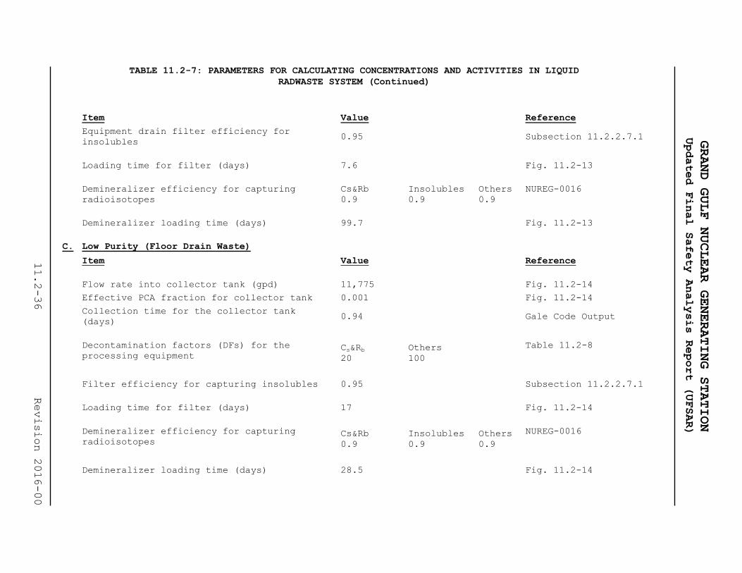
TABLE 11.2-7: PARAMETERS FOR CALCULATING CONCENTRATIONS AND ACTIVITIES IN LIQUID
RADWASTE SYSTEM (Continued)
Item Value Reference
Equipment drain filter efficiency for
insolubles 0.95 Subsection 11.2.2.7.1
Loading time for filter (days) 7.6 Fig. 11.2-13
Demineralizer efficiency for capturing
radioisotopes
Cs&Rb
0.9
Insolubles
0.9
Others
0.9
NUREG-0016
Demineralizer loading time (days) 99.7 Fig. 11.2-13
C. Low Purity (Floor Drain Waste)
Item Value Reference
Flow rate into collector tank (gpd) 11,775 Fig. 11.2-14
Effective PCA fraction for collector tank 0.001 Fig. 11.2-14
Collection time for the collector tank
(days) 0.94 Gale Code Output
Decontamination factors (DFs) for the
processing equipment Cs&Rb
20
Others
100
Table 11.2-8
Filter efficiency for capturing insolubles 0.95 Subsection 11.2.2.7.1
Loading time for filter (days) 17 Fig. 11.2-14
Demineralizer efficiency for capturing
radioisotopes Cs&Rb
0.9
Insolubles
0.9
Others
0.9
NUREG-0016
Demineralizer loading time (days) 28.5 Fig. 11.2-14
GRAND GULF NUCLEAR GENERATING STATION
Updated Final Safety Analysis Report (UFSAR)
11.2-36
Revision 2016-00

TABLE 11.2-7: PARAMETERS FOR CALCULATING CONCENTRATIONS AND ACTIVITIES IN LIQUID
RADWASTE SYSTEM (Continued)
D. Chemical Wastes
Item Value Reference
Flow rate into chemical waste receiver tank
(gpd) 4000 Fig. 11.2-15
Effective PCA fraction for receiver tank 0.001 Fig. 11.2-15
Collection time for receiver tank (days) N/A Gale Code Output
Decontamination factors (DFs) for the
processing equipment Cs-Rb
20
Others
100
NUREG-0016
E. Regenerant Wastes
Item Value References
Flow rate into regenerant solution receiving
tank (gpd)
Not Used Section 11.2.2.3
Effective PCA fraction for solution N/A N/A
Collection time for receiving tank (days) N/A N/A
DFs for the processing equipment N/A N/A
F. Miscellaneous
Item Value Reference
GRAND GULF NUCLEAR GENERATING STATION
Updated Final Safety Analysis Report (UFSAR)
11.2-37
Revision 2016-00

TABLE 11.2-7: PARAMETERS FOR CALCULATING CONCENTRATIONS AND ACTIVITIES IN LIQUID
RADWASTE SYSTEM (Continued)
Chemical waste evaporator bottoms tank
inventory after collection in the bottoms
tank (Ci):
Not used Section 11.2.2.3
Item Value Reference
Period of accumulation (days) N/A N/A
Accumulation rate N/A N/A
Regenerant waste evaporator bottoms tank
inventory after collection in the bottoms
tank:
Not Used Section 11.2.2.3
Number of batches N/A N/A
Batch activity N/A N/A
Decay for batches (days)after accumulation
for
60 days:
Design:
First
batch
Second
batch
Fig. 11.2-13 &
11.2-14
0 0
Spent resin tank (SRT) inventory:
Collection time (days) 99.7 Fig. 11.2-16
Number of equipment drain demineralizer
batches to SRT 1
Fig. 11.2-13
Batch activity for equipment drain
demineralizer
Activity accumulated over a
period of 99.7 days
Fig. 11.2-13
Number of floor drain demineralizer batches
to SRT:
3
Fig. 11.2-16
GRAND GULF NUCLEAR GENERATING STATION
Updated Final Safety Analysis Report (UFSAR)
11.2-38
Revision 2016-00

TABLE 11.2-7: PARAMETERS FOR CALCULATING CONCENTRATIONS AND ACTIVITIES IN LIQUID
RADWASTE SYSTEM (Continued)
Batch activity for floor drain demineralizer Activity accumulated over a
period of 28.5 days
Fig. 11.2-14
Number of ARCS/URC batches 48/yr Fig. 11.2-13
Activity (PCA fraction)
(This is also an input for the floor drain
system. It has been included here for
conservatism.)
0.05
NUREG-0016
Item Value Reference
RWCU phase separator decay tank Inventory
(Ci):
5187 Fig. 11.2-17
Collection time (days) 730
Number of batches (RWCU demineralizer) (Here
batch means, activity associated with 1 RWCU
demineralizer bed)
20 batches
Fig. 11.2-17
Batch activity (RWCU demineralizer) Activity accumulated in
120 days
Fig. 11.2-17
Number of batches due to fuel pool cleanup
(Fuel pool demineralizer bed)
24
Fig. 11.2-17
Decay in the decay tank after collection
(days) 70
Fig. 11.2-17
RWCU filter/demineralizer bed inventory
(Ci): 1920
Fig. 11.2-17
Flow rate through 1 bed (gpm)
Table 11.2-8 180
Table 11.2-8
Loading time (days) 120 Fig. 11.2-17
Demineralizer efficiencies for capturing
isotopes
1.0
100% Eff. Assumed for
Design Purposes
GRAND GULF NUCLEAR GENERATING STATION
Updated Final Safety Analysis Report (UFSAR)
11.2-39
Revision 2016-00

TABLE 11.2-7: PARAMETERS FOR CALCULATING CONCENTRATIONS AND ACTIVITIES IN LIQUID
RADWASTE SYSTEM (Continued)
Condensate demineralizer bed inventory (Ci):
Flow rate of condensate through demineralizer
bed (gpm)
3550
Table 11.2-8
Loading time (days) 60 Table 11.2-8
Demineralizer efficiencies for capturing
isotopes
Same as given for RWCU
system for design and
expected cases
Same as given for
RWCU system
Item Value Reference
Fuel pool cleanup demineralizer bed
inventory (Ci):
Flow rate of fuel pool water through
demineralizer bed (gpm)
1100
Fig. 9.1-29
Loading time (days) 30 Fig. 11.2-17
Demineralizer efficiencies for capturing
isotopes
Same as given for RWCU
system for design and
expected cases
Same as given for
RWCU system
Notes
(1) Specific activities in collector and receiver tanks have been calculated ignoring decay during
collection in these tanks.
(2) Activities accumulated on the filter demineralizer beds include decay credit during collection in the
respective processing vessel.
GRAND GULF NUCLEAR GENERATING STATION
Updated Final Safety Analysis Report (UFSAR)
11.2-40
Revision 2016-00

TABLE 11.2-8: PARAMETERS INPUT TO BWR-GALE CODE
[This table is historical]
NOTE: All relevant parameters have been adjusted to 102 percent of rated power level except as
noted.
A. General
Description Input
Maximum core thermal power level, Mwt 4,496
B. Nuclear Steam Supply System (NSSS)
Description Input
Total steam flow rate, lb/hr 19.428 x 10⁶
Mass of coolant in reactor vessel and recirculation lines at
full power, lb 5.587 x 10⁵
C. Reactor Coolant Cleanup System
Description Input
Cleanup demineralizer flow rate, lb/hr 1.78 x 10⁵
Condensate demineralizer regeneration time (days) 720
Fission product carry-over fraction (Cs, Rb and other
isotopes) 0.001
Halogen carry-over fraction 0.02
Condenser Tubing Material 0=No Copper 0
Fraction of feedwater through condensate demineralizers 0.647
D. High-Purity Waste
Description Input
Name of Waste Stream Equipment Drain
Flow rate - (gal/day 20,334
GRAND GULF NUCLEAR GENERATING STATION
Updated Final Safety Analysis Report (UFSAR)
11.2-41
LBDCR 2018-060

TABLE 11.2-8: PARAMETERS INPUT TO BWR-GALE CODE (Continued)
[This table is historical]
Activity as a fraction of Primary Coolant Activity 0.243
DF for Anions 102
DF for Cs, Rb 20
DF for other isotopes 102
Collection time (days) 1.708
Decay time based on waste processing and discharge time (days) 0.102
Fraction of Wastes Discharged 0.1
E. Low-Purity Waste
Description Input
Name of Waste Stream Floor Drain
Flow rate - (gal/day) 11,801
Activity as a fraction of Primary Coolant Activity 0.001
DF for Anions 102
DF for Cs, Rb 20
DF for other isotopes 102
Collection time (days) 0.9392
Sum of waste processing and discharge
time (days) 0.0503
Fraction of Wastes Discharged 0.6
F. Chemical Waste
Description Input
Name of Waste Stream Not Applicable
Flow rate - (gal/day) 0.0
Activity as a fraction of Primary Coolant Activity 0.0
DF for Anions 1.0
GRAND GULF NUCLEAR GENERATING STATION
Updated Final Safety Analysis Report (UFSAR)
11.2-42
LBDCR 2018-060

TABLE 11.2-8: PARAMETERS INPUT TO BWR-GALE CODE (Continued)
[This table is historical]
DF for Cs, Rb 1.0
DF for other 1.0
Collection time (days) 0.0
Sum of waste processing and discharge
time (days) 0.0
Fraction of Wastes Discharged 0.0
G. Regenerant Solutions Waste
Description Input
Name of Waste Stream Not Applicable
Flow rate - (gal/day) 0.0
DF for Anions 1.0
DF for Cs, Rb 1.0
DF for other 1.0
Collection time (days) 0.0
Sum of waste processing and discharge time (days) 0.0
Fraction of Wastes Discharged 0.0
H. Miscellaneous
Description Input
Detergent Waste 0.0
Note: For all wastes, the discharge rate to the environment will be determined in accordance with the
techniques specified in the GGNS Offsite Dose Calculation Manual. For the offsite dose analysis, a
discharge flow rate of 5.04 x 10⁴ gpd has been used.
GRAND GULF NUCLEAR GENERATING STATION
Updated Final Safety Analysis Report (UFSAR)
11.2-43
LBDCR 2018-060

GRAND GULF NUCLEAR GENERATING STATION
Updated Final Safety Analysis Report (UFSAR)
TABLE 11.2-9: DESIGN CONCENTRATION IN PRIMARY COOLANT
Nuclide
Half-life
(days)
Concentration
in Primary
Coolant
(µCi/ml)
(Note 1) Nuclide
Half-life
(days)
Concentration
in Primary
Coolant
(µCi/ml)
(Note 1)
Corrosion and activation products
Na-24 6.23-01 2.00E-3 F-18 7.62E-2 4.00E-3
P-32 1.43+01 2.0E-5 Cr-51 2.78+01 5.0E-4
Mn-54 3.03+02 4.0E-5 Mn-56 1.08-01 5.0E-2
Fe-59 4.50+01 8.0E-2
Co-58 7.13+01 5.0E-3 Co-60 1.92+03 5.0E-4
Ni-65 1.07-01 3.0E-4
Zn-69M 5.75-01 3.0E-5 Zn-65 2.45+02 2.0E-6
Np-239 2.35+00 1.90E-1 W-187 9.96-01 3.0E-3
Fission Products
Br-83
1.00-01
1.30E-2
Br-84 2.21-02 2.8E-2 Br-85 2.08-03 1.9E-2
Sr-89 5.20+01 2.30E-3
Sr-90 1.03+04 1.70E-4 Sr-91 4.03-01 5.70E-2
Sr-92 1.13-01 1.00E-1
Zr-95 6.50+01 3.00E-5 Nb-95 3.50+01 3.10E-5
Zr-97 7.08-01 2.50E-5
Mo-99 2.79+00 1.70E-2 Tc-99m 2.50-01 6.90E-2
Tc-101 9.72-03 1.60E-1 Ru-103 3.96+01 1.50E-5
Ru-106 3.67+02 1.90E-6 Ag-110m 2.53+02 6.00E-5
Te-129m 3.40+01 2.60E-4
I-131 8.05+00 1.1E-2 Te-132 3.25+00 1.10E-2
I-132 9.58-02 1.1E-1 I-133 8.75-01 7.40E-2
I-134 3.67-02 2.30E-1 Cs-134 7.49+02 1.20E-4
I-135 2.79-01 1.1E-1 Cs-136 1.30+01 8.00E-5
Cs-137 1.10+04 1.80E-4 Cs-138 2.24-02 2.00E-1
Ba-139 5.76-02 1.60E-1 Ba-140 1.28+01 6.70E-3
Ba-141 1.25-02 1.90E-1 Ce-141 3.24+01 3.00E-5
Ba-142 7.64-03 1.90E-1
Ce-143 1.37+00 2.70E-5 Pr-143 1.37+01 2.90E-5
Ce-144 2.84+02 2.60E-5 Nd-147 1.11+01 1.10E-5
Note 1: Reference GE Document 22A2703V (Rev. 4) [4]
11.2-44 Revision 2016-00

TABLE 11.2-10: LIQUID EFFLUENT RELEASES
[This table is historical]
(Curies/Year)
GRAND GULF
THERMAL POWER LEVEL (MEGAWATTS) 4496.00000
PLANT CAPACITY FACTOR 1.00000
TOTAL STEAM FLOW (MILLION LBS/HR) 19.42800
MASS OF WATER IN REACTOR VESSEL (MILLION LBS) .58870
CLEAN-UP DEMINERALIZER FLOW (MILLION LBS/HR) .17800
CONDENSATE DEMINERALIZER REGENERATION TIME (DAYS) 720.0000
FISSION PRODUCT CARRY-OVER FRACTION .00100
HALOGEN CARRY-OVER FRACTION .02000
FRACTION FEED WATER THROUGH CONDENSATE DEMIN .64700
LIQUID WASTE INPUTS
DECAY
TIME
(DAYS)
DECONTAMINATION FACTORS
STREAM
FLOW RATE
(GAL/DAY)
FRACTION
OF PCA
FRACTION OF
DISCHARGED
COLLECTION TIME
(DAYS) I CS OTHERS
HIGH PURITY WASTE 2.03E+04 .243 .100 1.708 .102 1.00E+02 2.00E+01 1.00E+02
LOW PURITY WASTE 1.18E+04 .001 .600 .939 .050 1.00E+02 2.00E+01 1.00E+02
CHEMICAL WASTE 0.00E+00 .000 .000 .000 .000 1.00E+00 1.00E+00 1.00E+00
REGENERANT SOLS 0.00E+00 .000 .000 .000 1.00E+00 1.00E+00 1.00E+00
GRAND GULF NUCLEAR GENERATING STATION
Updated Final Safety Analysis Report (UFSAR)
11.2-45
LBDCR 2018-060

GASEOUS WASTE INPUTS
TABLE 11.2-10: LIQUID EFFLUENT RELEASES (CONTINUED)
[This table is historical]
GLAND SEAL STEAM FLOW (THOUSAND LBS/HR) .00000
GLAND SEAL HOLDUP TIME (HOURS) .00000
AIR EJECTOR OFFGAS HOLDUP TIME (HOURS) .16700
CONTAINMENT BUILDING IODINE RELEASE FRACTION .01000
PARTICULATE RELEASE FRACTION .01000
TURBINE BUILDING IODINE RELEASE FRACTION 1.00000
PARTICULATE RELEASE FRACTION 1.00000
GLAND SEAL VENT, IODINE PF 1.00000
AIR EJECTOR OFFGAS IODINE PF .00000
AUXILIARY BUILDING IODINE RELEASE FRACTION 1.00000
PARTICULATE RELEASE FRACTION 1.00000
RADWASTE BUILDING IODINE RELEASE FRACTION 1.00000
PARTICULATE RELEASE FRACTION .01000
THERE IS A CHARCOAL DELAY SYSTEM
KRYPTON HOLDUP TIME (DAYS) 2.01779
XENON HOLDUP TIME (DAYS) 46.31317
KRYPTON DYNAMIC ADSORPTION COEFFICIENT (CM3/GM) 105.00000
XENON DYNAMIC ADSORPTION COEFFICIENT (CM3/GM) 2410.00000
MASS OF CHARCOAL (THOUSAND LBS) 48.00000
THERE IS NOT A PERMANENT ONSITE LAUNDRY
GRAND GULF NUCLEAR GENERATING STATION
Updated Final Safety Analysis Report (UFSAR)
11.2-46
LBDCR 2018-060

TABLE 11.2-10: LIQUID EFFLUENT RELEASES (CONTINUED)
[This table is historical]
ANNUAL RELEASES TO DISCHARGE CANAL
CONCENTRATION
IN PRIMARY
NUCLIDE HALF-LIFE COOLANT HIGH LOW CHEMICAL TOTAL ADJUSTED DETERGENT TOTAL
(DAYS) (MICRO CI/ML) PURITY PURITY (CURIES) LWS TOTAL WASTES WASTES
(CURIES) (CURIES) (CURIES) (CI/YR) (CI/YR) (CI/YR)
CORROSION AND ACTIVATION PRODUCTS
NA-24 6.25E-01 1.19E-02 .03262 .00069 .00000 .03331 .03803 .00000 .03800
P-32 1.43E+01 2.43E-04 .00158 .00002 .00000 .00161 .00183 .00000 .00180
CR-51 2.78E+01 7.28E-03 .04855 .00070 .00000 .04926 .05624 .00000 .05600
MN-54 3.03E+02 8.50E-05 .00058 .00001 .00000 .00059 .00067 .00000 .00067
MN-56 1.07E-01 5.71E-02 .01833 .00066 .00000 .01899 .02168 .00000 .02200
FE-55 9.50E+02 1.21E-03 .00828 .00012 .00000 .00840 .00959 .00000 .00960
FE-59 4.50E+01 3.64E-05 .00025 .00000 .00000 .00025 .00028 .00000 .00028
CO-58 7.13E+01 2.43E-04 .00164 .00002 .00000 .00167 .00190 .00000 .00190
CO-60 1.92E+03 4.86E-04 .00332 .00005 .00000 .00336 .00384 .00000 .00380
NI-65 1.07E-01 3.42E-04 .00011 .00000 .00000 .00011 .00013 .00000 .00013
CU-64 5.33E-01 3.57E-02 .08572 .00189 .00000 .08761 .10002 .00000 .10000
ZN-65 2.45E+02 2.43E-04 .00165 .00002 .00000 .00168 .00192 .00000 .00190
vZN-69M 5.75E-01 2.38E-03 .00610 .00013 .00000 .00623 .00711 .00000 .00710
W-187 9.96E-01 3.60E-04 .00134 .00002 .00000 .00136 .00156 .00000 .00160
NP-239 2.35E+00 9.66E-03 .05029 .00081 .00000 .05111 .05835 .00000 .05800
FISSION PRODUCTS
BR-83 1.00E-01 6.64E-03 .00190 .00007 .00000 .00197 .00225 .00000 .00230
BR-84 2.21E-02 7.58E-03 .00004 .00001 .00000 .00004 .00005 .00000 .00005
SR-89 5.20E+01 1.21E-04 .00083 .00001 .00000 .00084 .00096 .00000 .00096
SR-90 1.03E+04 8.50E-06 .00006 .00000 .00000 .00006 .00007 .00000 .00007
SR-91 4.03E-01 4.73E-03 .00874 .00021 .00000 .00895 .01022 .00000 .01000
Y-91 5.88E+01 4.86E-05 .00049 .00001 .00000 .00049 .00056 .00000 .00056
GRAND GULF NUCLEAR GENERATING STATION
Updated Final Safety Analysis Report (UFSAR)
11.2-47
LBDCR 2018-060

TABLE 11.2-10: LIQUID EFFLUENT RELEASES (CONTINUED)
[This table is historical]
ANNUAL RELEASES TO DISCHARGE CANAL
CONCENTRATION
IN PRIMARY
NUCLIDE HALF-LIFE COOLANT HIGH LOW CHEMICAL TOTAL ADJUSTED DETERGENT TOTAL
(DAYS) (MICRO CI/ML) PURITY PURITY (CURIES) LWS TOTAL WASTES WASTES
(CURIES) (CURIES) (CURIES) (CI/YR) (CI/YR) (CI/YR)
SR-92 1.13E-01 1.14E-02 .00398 .00014 .00000 .00412 .00471 .00000 .00470
Y-92 1.47E-01 6.91E-03 .01029 .00030 .00000 .01059 .01209 .00000 .01200
Y-93 4.25E-01 4.74E-03 .00923 .00022 .00000 .00945 .01079 .00000 .01100
ZR-95 6.50E+01 9.71E-06 .00007 .00000 .00000 .00007 .00008 .00000 .00008
NB-95 3.50E+01 9.71E-06 .00007 .00000 .00000 .00007 .00008 .00000 .00008
ZR-97 7.08E-01 7.17E-06 .00002 .00000 .00000 .00002 .00003 .00000 .00002
NB-98 3.54E-02 4.42E-03 .00012 .00001 .00000 .00013 .00015 .00000 .00015
MO-99 2.79E+00 2.42E-03 .01312 .00021 .00000 .01333 .01521 .00000 .01500
TC-99M 2.50E-01 2.34E-02 .03526 .00084 .00000 .03610 .04121 .00000 .04100
RU-103 3.96E+01 2.43E-05 .00016 .00000 .00000 .00017 .00019 .00000 .00019
TC-104 1.25E-02 8.66E-02 .00002 .00001 .00000 .00003 .00004 .00000 .00004
RU-105 1.85E-01 2.32E-03 .00169 .00005 .00000 .00174 .00199 .00000 .00200
RU-106 3.67E+02 3.64E-06 .00002 .00000 .00000 .00003 .00003 .00000 .00003
TE-129M 3.40E+01 4.85E-05 .00033 .00000 .00000 .00033 .00038 .00000 .00038
TE-131M 1.25E+00 1.20E-04 .00050 .00001 .00000 .00051 .00058 .00000 .00058
I-131 8.05E+00 4.20E-03 .02650 .00039 .00000 .02690 .03071 .00000 .03100
TE-132 3.25E+00 1.21E-05 .00007 .00000 .00000 .00007 .00008 .00000 .00008
I-132 9.58E-02 6.63E-02 .01761 .00066 .00000 .01827 .02086 .00000 .02100
I-133 8.75E-01 5.65E-02 .19521 .00375 .00000 .19896 .22716 .00000 .23000
I-134 3.67E-02 1.09E-01 .00335 .00023 .00000 .00358 .00409 .00000 .00410
CS-134 7.49E+02 3.60E-05 .00123 .00002 .00000 .00124 .00142 .00000 .00140
I-135 2.79E-01 5.61E-02 .06909 .00188 .00000 .07097 .08103 .00000 .08100
CS-136 1.30E+01 2.39E-05 .00078 .00001 .00000 .00079 .00090 .00000 .00090
CS-137 1.10E+04 9.59E-05 .00327 .00005 .00000 .00332 .00379 .00000 .00380
GRAND GULF NUCLEAR GENERATING STATION
Updated Final Safety Analysis Report (UFSAR)
11.2-48
LBDCR 2018-060

TABLE 11.2-10: LIQUID EFFLUENT RELEASES (CONTINUED)
[This table is historical]
ANNUAL RELEASES TO DISCHARGE CANAL
CONCENTRATION
IN PRIMARY
NUCLIDE HALF-LIFE COOLANT HIGH LOW CHEMICAL TOTAL ADJUSTED DETERGENT TOTAL
(DAYS) (MICRO CI/ML) PURITY PURITY (CURIES) LWS TOTAL WASTES WASTES
(CURIES) (CURIES) (CURIES) (CI/YR) (CI/YR) (CI/YR)
CS-138 2.24E-02 1.08E-02 .00030 .00004 .00000 .00033 .00038 .00000 .00038
BA-139 5.76E-02 1.12E-02 .00109 .00005 .00000 .00114 .00130 .00000 .00130
BA-140 1.28E+01 4.85E-04 .00315 .00005 .00000 .00319 .00365 .00000 .00360
CE-141 3.24E+01 3.64E-05 .00027 .00000 .00000 .00028 .00032 .00000 .00032
LA-142 6.39E-02 5.61E-03 .00079 .00004 .00000 .00083 .00094 .00000 .00094
CE-143 1.38E+00 3.61E-05 .00016 .00000 .00000 .00016 .00018 .00000 .00018
PR-143 1.37E+01 4.85E-05 .00032 .00000 .00000 .00033 .00038 .00000 .00038
CE-144 2.84E+02 3.64E-06 .00002 .00000 .00000 .00003 .00003 .00000 .00003
ND-147 1.11E+01 3.64E-06 .00002 .00000 .00000 .00002 .00003 .00000 .00003
ALL OTHERS 1.23E-01 .02016 .00042 .00000 .02058 .02350 .00000 .02400
TOTAL
(EXCEPT TRITIUM) 7.32E-01 .69068 .01487 .00000 .70555 .80555 .00000 .81000
TRITIUM RELEASE 84 CURIES PER YEAR
Note:.00000 indicates that the value is less than 1.0E-5. A value of 0.00000 means zero.
All others refers to:
NI 63 ZN 69 U235 PU239 BR 85 RB 89 Y 90 Y 91M ZR 93 NB 93M
NB 95M NB 97M NB 97 TC 99 TC101 RH103M RH105M RH105 RH106 AG110M
AG110 TE129 I129 TE131 CS135 BA137M LA140 BA141 LA141 BA142
PR144 PM147
GRAND GULF NUCLEAR GENERATING STATION
Updated Final Safety Analysis Report (UFSAR)
11.2-49
LBDCR 2018-060

TABLE 11.2-10: LIQUID EFFLUENT RELEASES (CONTINUED)
[This table is historical]
ANNUAL RELEASES TO DISCHARGE CANAL
Note
The amounts of P-32, Cu-64, Zn-65, Zn-69M, and Zn-69 will be negligible in liquid effluents because Grand Gulf does
not use admiralty metal for condenser tubes, and depleted zinc oxide is used in the zinc injection system.
GRAND GULF NUCLEAR GENERATING STATION
Updated Final Safety Analysis Report (UFSAR)
11.2-50
LBDCR 2018-060

GRAND GULF NUCLEAR GENERATING STATION
Updated Final Safety Analysis Report (UFSAR)
11.2-51 Revision 2016-00
TABLE 11.2-11: ESTIMATED INDIVIDUAL DOSES FROM LIQUID EFFLUENTS
(MREM/YR)
Pathway Annual Dose
Total Body Thyroid(1)
Aquatic Foods 0.45 0.68
Shoreline deposits 0.0001 0.0011
Total from all pathways 0.45 0.68
10 CFR 50 Appendix I Guidelines 3.0 10.0
Note: (1) Doses to other organs are less than thyroid doses.

GRAND GULF NUCLEAR GENERATING STATION
Updated Final Safety Analysis Report (UFSAR)
11.2-52 Revision 2016-00
TABLE 11.2-12: ESTIMATED POPULATION DOSES FROM LIQUID EFFLUENTS
Item Annual Dose man-rem/yr
Total body 8.17
Thyroid 4.35

GRAND GULF NUCLEAR GENERATING STATION
Updated Final Safety Analysis Report (UFSAR)
11.2-53 Revision 2016-00
TABLE 11.2-13: COMMERCIAL AND SPORT AQUATIC FOOD CATCH DATA
Type of Catch Amount Caught kg/year
Fish 4.47 + 5
Invertebrate 3.51 + 3

TABLE 11.2-14: MATERIALS OF CONSTRUCTION FOR MAJOR COMPONENTS OF THE LIQUID
RADWASTE SYSTEM
Quantity Material of Construction
Tanks
Distillate sample tank 2 304 S.S.
Fresh resin addition tank 1 304 S.S.
Spent resin tank 1 304 S.S.
Evaporator bottoms tank (not used) 2 304 S.S.
Condensate demineralizer regeneration
solution receiving tank 2 304 S.S.
Miscellaneous chemical waste receiver
tank 1 304 S.S.
RWCU phase separator decay tank 2 304 S.S.
Floor drain collector tank 1 304 S.S.
Floor drain sample tank 2 304 S.S.
GRAND GULF NUCLEAR GENERATING STATION
Updated Final Safety Analysis Report (UFSAR)
11.2-54
Revision 2016-00

TABLE 11.2-14: MATERIALS OF CONSTRUCTION FOR MAJOR COMPONENTS OF THE LIQUID
RADWASTE SYSTEM (Continued)
Quantity Material of Construction
Chemical addition tank 1 304 S.S.
Body feed tank 1 304 S.S.
Precoat addition tank 1 304 S.S.
Equipment drain collector tank 2 304 S.S.
Equipment drain sample tank 2 304 S.S.
Waste surge tank 2 304 S.S.
Condensate phase separator tank 2 304 S.S.
Pumps
Distillate sample pump 2 316 S.S.
Spent resin pump 1 316 S.S.
Evaporator bottoms pump (not used) 2 316 S.S.
GRAND GULF NUCLEAR GENERATING STATION
Updated Final Safety Analysis Report (UFSAR)
11.2-55
Revision 2016-00

TABLE 11.2-14: MATERIALS OF CONSTRUCTION FOR MAJOR COMPONENTS OF THE LIQUID
RADWASTE SYSTEM (Continued)
Quantity Material of Construction
Condensate demineralizer regeneration
solution receiving pump (not used) 1 316 S.S.
Miscellaneous chemical waste receiver
pump 1 316 S.S.
RWCU phase separator discharge pump 1 316 S.S.
Pumps
RWCU phase separator decant pump 1 316 S.S.
Floor drain sample pump 1 316 S.S.
Body feed pump 2 316 S.S.
Chemical addition pump 1 316 S.S.
Precoat pump 1 316 S.S.
Floor drain oil separator flushing
header pump 1
GRAND GULF NUCLEAR GENERATING STATION
Updated Final Safety Analysis Report (UFSAR)
11.2-56
Revision 2016-00

TABLE 11.2-14: MATERIALS OF CONSTRUCTION FOR MAJOR COMPONENTS OF THE LIQUID
RADWASTE SYSTEM (Continued)
Quantity Material of Construction
Equipment drain collector pump 1 316 S.S.
Equipment drain sample pump 1 316 S.S.
Waste surge pump 1 316 S.S.
Floor drain collector pump 1 316 S.S.
Condensate phase separator pump 2 316 S.S.
Miscellaneous
Miscellaneous chemical waste evaporator
package (not used)
1 304 S.S., 316 S.S.
Incoloy 825,
Carbon Steel
Floor drain evaporator package (not
used)
1 304 S.S., 316 S.S.
Incoloy 825,
Carbon Steel
Floor drain filter 1 304 S.S.
GRAND GULF NUCLEAR GENERATING STATION
Updated Final Safety Analysis Report (UFSAR)
11.2-57
Revision 2016-00

TABLE 11.2-14: MATERIALS OF CONSTRUCTION FOR MAJOR COMPONENTS OF THE LIQUID
RADWASTE SYSTEM (Continued)
Quantity Material of Construction
Floor drain demineralizer 1 304 S.S.
Floor drain oil separator 1 Carbon Steel
Floor drain oil separator oil removal
pump 1 Cast Iron, Carbon Steel
Equipment drain filter 1 304 S.S.
Equipment drain demineralizer 1 304 S.S.
Floor drain oil separator flushing
header pump 1 Cast Iron, Carbon Steel, Bronze
*S.S. = Stainless Steel
GRAND GULF NUCLEAR GENERATING STATION
Updated Final Safety Analysis Report (UFSAR)
11.2-58
Revision 2016-00
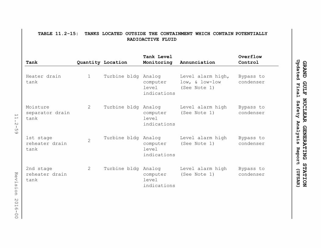
TABLE 11.2-15: TANKS LOCATED OUTSIDE THE CONTAINMENT WHICH CONTAIN POTENTIALLY
RADIOACTIVE FLUID
Tank Quantity Location
Tank Level
Monitoring Annunciation
Overflow
Control
Heater drain
tank
1 Turbine bldg Analog
computer
level
indications
Level alarm high,
low, & low-low
(See Note 1)
Bypass to
condenser
Moisture
separator drain
tank
2 Turbine bldg Analog
computer
level
indications
Level alarm high
(See Note 1)
Bypass to
condenser
1st stage
reheater drain
tank
2 Turbine bldg Analog
computer
level
indications
Level alarm high
(See Note 1)
Bypass to
condenser
2nd stage
reheater drain
tank
2 Turbine bldg Analog
computer
level
indications
Level alarm high
(See Note 1)
Bypass to
condenser
GRAND GULF NUCLEAR GENERATING STATION
Updated Final Safety Analysis Report (UFSAR)
11.2-59
Revision 2016-00

TABLE 11.2-15: TANKS LOCATED OUTSIDE THE CONTAINMENT WHICH CONTAIN POTENTIALLY
RADIOACTIVE FLUID (Continued)
Tank Quantity Location
Tank Level
Monitoring Annunciation
Overflow
Control
Condensate drain
tank
1 Turbine bldg Analog
computer
level
indications
Level alarm high &
low
(See Note 1)
Turbine bldg
west
equipment
drain sump
Ultrasonic resin
cleaner
1 Turbine bldg Level
indication
(See Note 2)
Level alarm high &
low
(See Note 1)
Closed system
to condensate
clean waste
tank
Resin separation
& cation
regeneration
tank
1 Turbine bldg None
(See Note
10)
None (See Note 10) Closed system
to condensate
clean waste
tank
Anion
regeneration
tank
1 Turbine bldg None
(See Note
10)
None (See Note 10) Closed system
to condensate
clean waste
tank
Resin mix and
storage tank
1 Turbine bldg None
(See Note
10)
None (See Note 10) Closed system
to condensate
clean waste
tank
GRAND GULF NUCLEAR GENERATING STATION
Updated Final Safety Analysis Report (UFSAR)
11.2-60
Revision 2016-00

TABLE 11.2-15: TANKS LOCATED OUTSIDE THE CONTAINMENT WHICH CONTAIN POTENTIALLY
RADIOACTIVE FLUID (Continued)
Tank Quantity Location
Tank Level
Monitoring Annunciation
Overflow
Control
Condensate
storage tank
1 Yard Level
Indication
(See Note 3)
Level alarm high &
low
(See Note 3)
Waste surge
tank
Fuel pool drain
tank
1 Auxiliary
bldg
Redundant
level
indication
(See Note 4)
Level alarm high
(See Note 1)
Not required
(See Note 11)
Condensate clean
waste tank
1 Turbine bldg Digital
computer
level
indication
Level alarm high
(See Note 6)
Turbine bldg
west floor
drain sump
Floor drain
sample tank
2 Radwaste
bldg
Continuous
level
recording
(See Note 6)
Level alarm high &
low
(See Note 6)
Radwaste bldg
floor drain
sump
Floor drain
collect or tank
1 Radwaste
bldg
Continuous
level
recording
(See Note 6)
Level alarm high &
low
(See Note 6)
Radwaste bldg
floor drain
sump
GRAND GULF NUCLEAR GENERATING STATION
Updated Final Safety Analysis Report (UFSAR)
11.2-61
Revision 2016-00
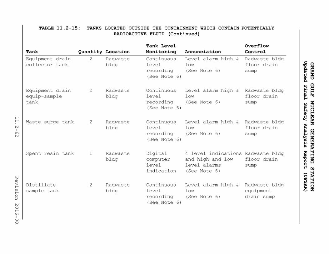
TABLE 11.2-15: TANKS LOCATED OUTSIDE THE CONTAINMENT WHICH CONTAIN POTENTIALLY
RADIOACTIVE FLUID (Continued)
Tank Quantity Location
Tank Level
Monitoring Annunciation
Overflow
Control
Equipment drain
collector tank
2 Radwaste
bldg
Continuous
level
recording
(See Note 6)
Level alarm high &
low
(See Note 6)
Radwaste bldg
floor drain
sump
Equipment drain
equip-sample
tank
2 Radwaste
bldg
Continuous
level
recording
(See Note 6)
Level alarm high &
low
(See Note 6)
Radwaste bldg
floor drain
sump
Waste surge tank 2 Radwaste
bldg
Continuous
level
recording
(See Note 6)
Level alarm high &
low
(See Note 6)
Radwaste bldg
floor drain
sump
Spent resin tank 1 Radwaste
bldg
Digital
computer
level
indication
4 level indications
and high and low
level alarms
(See Note 6)
Radwaste bldg
floor drain
sump
Distillate
sample tank
2 Radwaste
bldg
Continuous
level
recording
(See Note 6)
Level alarm high &
low
(See Note 6)
Radwaste bldg
equipment
drain sump
GRAND GULF NUCLEAR GENERATING STATION
Updated Final Safety Analysis Report (UFSAR)
11.2-62
Revision 2016-00

TABLE 11.2-15: TANKS LOCATED OUTSIDE THE CONTAINMENT WHICH CONTAIN POTENTIALLY
RADIOACTIVE FLUID (Continued)
Tank Quantity Location
Tank Level
Monitoring Annunciation
Overflow
Control
Evaporator
bottoms tank
(not used)
2 Radwaste
bldg
Continuous
level
recording
(See Note 6)
Level alarm high &
low
(See Note 6)
Radwaste bldg
chemical
waste sump
RWCU phase
separator decay
tank
2 Radwaste
bldg
Digital
Computer
level
indication
Level alarm high &
low
(See note 6)
Overflow
crosstie
between the
two tanks.
Decant to
equipment
drain
collector
tank
Miscellaneous
chemical waste
receiver tank
1 Radwaste
bldg
Continuous
level
recording
(See Note 6)
Level alarm high &
low
(See Note 6)
Radwaste bldg
chemical
waste sump
Condensate
demineralizer
regeneration
solution
receiving tank
2 Radwaste
bldg
Continuous
level
recording
(See Note 6)
Level alarm high &
low
(See Note 6)
Radwaste bldg
chemical
waste sump
GRAND GULF NUCLEAR GENERATING STATION
Updated Final Safety Analysis Report (UFSAR)
11.2-63
Revision 2016-00

TABLE 11.2-15: TANKS LOCATED OUTSIDE THE CONTAINMENT WHICH CONTAIN POTENTIALLY
RADIOACTIVE FLUID (Continued)
Tank Quantity Location
Tank Level
Monitoring Annunciation
Overflow
Control
Fuel pool
backwash
receiving tank
1 Auxiliary
bldg
Continuous
level
indication
(See Note 5)
Level alarm high Auxiliary
bldg
equipment
drain sump
Waste holding
tank
3 Radwaste
bldg
Level
indication
(Note 7)
Level alarm high &
low
(See Note 7)
Radwaste bldg
floor drain
sump
Condensate
demineralizer
regeneration
solution
collector tank
1 Turbine bldg Level
indication
(See Note 6)
Level alarm high &
low
(See Note 6)
Turbine bldg
south
chemical
waste sump
Auxiliary bldg
equipment drain
transfer tank
1 Auxiliary
bldg
Level
indication
(See Note 6)
Level alarm high-
high
(See Note 6)
Auxiliary
bldg south
floor drain
sump
Auxiliary bldg
floor drain
transfer tank
1 Auxiliary
bldg
Level
indication
(See Note 6)
Level alarm high-
high (See Note 6)
Auxiliary
bldg south
floor drain
sump
GRAND GULF NUCLEAR GENERATING STATION
Updated Final Safety Analysis Report (UFSAR)
11.2-64
Revision 2016-00
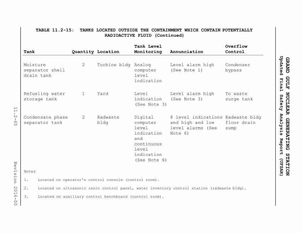
TABLE 11.2-15: TANKS LOCATED OUTSIDE THE CONTAINMENT WHICH CONTAIN POTENTIALLY
RADIOACTIVE FLUID (Continued)
Tank Quantity Location
Tank Level
Monitoring Annunciation
Overflow
Control
Moisture
separator shell
drain tank
2 Turbine bldg Analog
computer
level
indication
Level alarm high
(See Note 1)
Condenser
bypass
Refueling water
storage tank
1 Yard Level
indication
(See Note 3)
Level alarm high
(See Note 3)
To waste
surge tank
Condensate phase
separator tank
2 Radwaste
bldg
Digital
computer
level
indication
and
continuous
level
indication
(See Note 6)
8 level indications
and high and low
level alarms (See
Note 6)
Radwaste bldg
floor drain
sump
Notes
1. Located on operator's control console (control room).
2. Located on ultrasonic resin control panel, water inventory control station (radwaste bldg).
3. Located on auxiliary control benchboard (control room).
GRAND GULF NUCLEAR GENERATING STATION
Updated Final Safety Analysis Report (UFSAR)
11.2-65
Revision 2016-00

4. Located on Division 1 leak detection vertical board and Division 2 leak detection vertical board
(control room).
5. Located on fuel pool cooling and cleanup filter demineralizer control panel (auxiliary bldg).
6. Located on liquid radwaste control console, water inventory control station (radwaste bldg).
7. Located on solid radwaste control console, water inventory control station (radwaste bldg).
8. Mounted on the tank.
9. Deleted
10. Tank capacity is larger than that of the vessel from which it is receiving flow.
11. The tank vent extends to an elevation higher than the maximum water level possible in the fuel pool.
Tank overflow condition cannot occur.
GRAND GULF NUCLEAR GENERATING STATION
Updated Final Safety Analysis Report (UFSAR)
11.2-66
Revision 2016-00

GRAND GULF NUCLEAR GENERATING STATION
Updated Final Safety Analysis Report (UFSAR)
11.2-67 LBDCR 2018-121
!t
ii ii
' " }'_
j~ L ,, ~*

GRAND GULF NUCLEAR GENERATING STATION
Updated Final Safety Analysis Report (UFSAR)
11.2-68 LBDCR 2017-064

GRAND GULF NUCLEAR GENERATING STATION
Updated Final Safety Analysis Report (UFSAR)
11.2-69 Revision 2016-00

GRAND GULF NUCLEAR GENERATING STATION
Updated Final Safety Analysis Report (UFSAR)
11.2-70 Revision 2016-00

GRAND GULF NUCLEAR GENERATING STATION
Updated Final Safety Analysis Report (UFSAR)
11.2-71 LBDCR 2018-121

GRAND GULF NUCLEAR GENERATING STATION
Updated Final Safety Analysis Report (UFSAR)
11.2-72 Revision 2016-00

GRAND GULF NUCLEAR GENERATING STATION
Updated Final Safety Analysis Report (UFSAR)
11.2-73 Revision 2016-00

GRAND GULF NUCLEAR GENERATING STATION
Updated Final Safety Analysis Report (UFSAR)
11.2-74 Revision 2016-00

GRAND GULF NUCLEAR GENERATING STATION
Updated Final Safety Analysis Report (UFSAR)
11.2-75 LBDCR 2018-121

GRAND GULF NUCLEAR GENERATING STATION
Updated Final Safety Analysis Report (UFSAR)
11.2-76 Revision 2016-00

GRAND GULF NUCLEAR GENERATING STATION
Updated Final Safety Analysis Report (UFSAR)
11.2-77 Revision 2016-00
Figure 11.2-011
Deleted

GRAND GULF NUCLEAR GENERATING STATION
Updated Final Safety Analysis Report (UFSAR)
11.2-78 Revision 2016-00

GRAND GULF NUCLEAR GENERATING STATION
Updated Final Safety Analysis Report (UFSAR)
11.2-79 Revision 2016-00

GRAND GULF NUCLEAR GENERATING STATION
Updated Final Safety Analysis Report (UFSAR)
11.2-80 Revision 2016-00

GRAND GULF NUCLEAR GENERATING STATION
Updated Final Safety Analysis Report (UFSAR)
11.2-81 LBDCR 2018-121

GRAND GULF NUCLEAR GENERATING STATION
Updated Final Safety Analysis Report (UFSAR)
11.2-82 LBDCR 2018-121

GRAND GULF NUCLEAR GENERATING STATION
Updated Final Safety Analysis Report (UFSAR)
11.2-83 Revision 2016-00

GRAND GULF NUCLEAR GENERATING STATION
Updated Final Safety Analysis Report (UFSAR)
11.2-84 LBDCR 2018-121

GRAND GULF NUCLEAR GENERATING STATION
Updated Final Safety Analysis Report (UFSAR)
11.2-85 Revision 2016-00

GRAND GULF NUCLEAR GENERATING STATION
Updated Final Safety Analysis Report (UFSAR)
11.2-86 Revision 2016-00

GRAND GULF NUCLEAR GENERATING STATION
Updated Final Safety Analysis Report (UFSAR)
11.3-1 Revision 2016-00
11.3 GASEOUS WASTE MANAGEMENT SYSTEMS
The gaseous waste management systems include all systems that
have the potential to release airborne radioactive materials into
the environment during normal operation and anticipated
operational occurrences. Included are the vent systems of
normally and potentially radioactive components, building
ventilation systems, the offgas system and the mechanical vacuum
pump system.
The waste gases originating in the reactor coolant consist mainly
of hydrogen and nitrogen with trace amounts of radioactive gases.
The function of the offgas system is to collect and isolate these
radioactive noble gases, airborne halogens, and particulates, and
to reduce their activity through decay.
The plant ventilation exhaust systems accommodate other potential
release paths for gaseous radioactivity from miscellaneous
leakages and aerated vents from systems containing radioactive
fluids. Systems which handle these gases are included here to the
extent that they represent potential release paths for gaseous
radioactivity. Potential sources of gaseous releases are
discussed in subsection 11.3.3.
11.3.1 Design Bases
11.3.1.1 Design Objective
The objective of the gaseous waste management systems is to
process and control the release of gaseous radioactive effluents
to the site environs so as to maintain as low as reasonably
achievable, the exposure of persons in unrestricted areas, to
radioactive gaseous effluents (Appendix I to 10 CFR 50, May 5,
1975). This is to be accomplished while maintaining occupational
exposure as low as reasonably achievable and without limiting
plant operation or availability.
11.3.1.2 Design Criteria
The gaseous effluent treatment systems are designed to limit the
dose to offsite persons from routine station releases to
significantly less than the limits specified in 10 CFR 20 and to
operate within the emission rate limits established in the
station operating license.

GRAND GULF NUCLEAR GENERATING STATION
Updated Final Safety Analysis Report (UFSAR)
11.3-2 Revision 2016-00
As a design basis for the offgas system, an annual average noble
radiogas source term (based on 30-min decay) of 100,000 μCi/sec of
the “1971 Mixture” has been used. Table 11.3-1 indicates the
design basis noble radiogas source terms referenced to 30-min
decay. The radiation dose design basis for the treated offgas is
to delay the gas until the required fraction of the radionuclides
has decayed and the daughter products are retained by the charcoal
and the HEPA filters.
The gaseous radwaste equipment is selected, arranged and shielded
to maintain occupational exposure as low as reasonably achievable
in accordance with Nuclear Regulatory Commission Regulatory Guide
8.8.
The gaseous effluent treatment systems are designed to the
requirements of General Design Criteria as follows:
General Design Criterion 60
The systems have sufficient capacity to reduce the offgas
activity to permissible levels for release during normal
operation, including anticipated operational occurrences, and to
alleviate any termination of releases or limitation of plant
operation due to unfavorable site environmental conditions.
General Design Criterion 64
Implementation of General Design Criterion 64 is discussed in
Section 11.5.
11.3.1.3 Equipment Design Criteria
A list of the offgas system major equipment items which includes
materials, rates process conditions, and number of units supplied
is provided in Table 11.3-2. Equipment and piping will be designed
and constructed in accordance with the requirements of the
applicable codes as given in Table 3.2-1 and will comply with the
welding and material requirements. Seismic Category, safety
class, quality assurance requirements, and principal construction
codes information is contained in Section 3.2.
The failure of the offgas system is analyzed in subsection 15.7.1.
The containment, turbine building, and radwaste building contain
radioactive gas sources. The design bases for the ventilation
systems for these three buildings are described in Section 9.4.

GRAND GULF NUCLEAR GENERATING STATION
Updated Final Safety Analysis Report (UFSAR)
11.3-3 LBDCR 2018-060
11.3.2 System Description
The offgas from the main condenser steam-jet air ejector is
treated by means of a system utilizing catalytic recombination
and low-temperature charcoal adsorption. Descriptions of the
major process components including design temperature and
pressure are given in Table 11.3-2 and in the following
paragraphs.
11.3.2.1 Main Condenser Steam Jet Air Ejector Low-Temp System
Noncondensable radioactive offgas is continuously removed from
the main condenser by the air ejector during plant operation.
The following paragraph contains historical information
(bracketed):
The air ejector offgas will normally contain activation gases,
principally N-16, 0-19, and N-13. The N-16 and 0-19 have short
half-lives and are readily decayed. [The 10-min N-13 is present
in small amounts that are further reduced by decay.]
The air ejector offgas will also contain radioactive nobles gases
including parents of biologically significant Sr-89, Sr-90, Ba-
140, and Cs-137. The concentration of these noble gases depends on
the amount of tramp uranium in the coolant and on the cladding
surfaces (usually extremely small) and the number and size of fuel
cladding leaks.
11.3.2.1.1 Process Description
The following paragraph contains historical information:
[A main condenser offgas system has been incorporated in the
plant design to reduce the gaseous radwaste emission from the
station. The offgas system uses a catalytic recombiner to
recombine radiolytically dissociated hydrogen and oxygen. After
cooling (to approximately 130 F) to strip the condensibles and
reduce the volume, the remaining noncondensibles (principally
air with traces of krypton and xenon) will be delayed in the 10-
min holdup system. The gas is cooled to 45 F and filtered
through a HEPA filter. The gas is then passed through a
desiccant dryer that reduces the dew point to approximately -90
F and is then chilled to about 0 F. Charcoal adsorption beds,
operating in a refrigerated vault at about 0 F, selectively
adsorb and delay the xenons and kryptons from the bulk carrier
gas (principally dry air). After the delay, the gas is again
passed through a HEPA filter and discharged to the environment
through the plant vent.]

GRAND GULF NUCLEAR GENERATING STATION
Updated Final Safety Analysis Report (UFSAR)
11.3-4 LBDCR 2018-060
11.3.2.1.1.1 Process Flow Diagram
Figures 11.3-1 through 11.3-4 are the process flow diagrams for
the system. The process data for startup and normal operating
conditions are submitted as proprietary data under separate cover
as Table 11.3-3.
The information supporting the process data is presented in
Reference 2. The radwaste building vent is the single release
point for this system. The location of this vent is indicated on
the site plan on Figure 2.1-2.
11.3.2.1.2 Noble Gas Radionuclide Source Term and Decay
The following paragraph contains historical information:
[The design basis isotopic source terms for the annual average
activity input of the main condenser offgas treatment system are
given in Table 11.3-1 at t=30 minutes. The system is mechanically
capable of processing three times the source terms of Table 11.3-
1 without affecting delay time of the noble gases. Also listed is
the isotopic distribution at t=0. With an air inleakage of 30
scfm, this treatment system results in a delay of 46 hr for
krypton and 42 days for xenon.
Table 11.3-1 lists isotopic activities at the discharge of the
system, and the decontamination factor for each noble gas isotope
can be determined.]
11.3.2.1.3 Piping and Instrumentation Diagram (P&ID)
The P&ID is provided as Figures 11.3-5 through 11.3-8.
Figure 11.3-6 is submitted as proprietary data under separate
cover. The main process routing is indicated by a heavy line.
11.3.2.1.4 Recombiner Sizing
The basis for sizing the recombiner is to maintain the hydrogen
concentration below 4 percent (including steam) at the inlet and
below 4 percent at the outlet on a dry basis. The exit hydrogen
concentration is normally well below the 4 percent maximum
allowed. The hydrogen generation rate of the reactor is based on
data from nine BWRs. The hydrogen generation rate is given in the
data referenced in subsection 11.3.2.1.1.1.

GRAND GULF NUCLEAR GENERATING STATION
Updated Final Safety Analysis Report (UFSAR)
11.3-5 Revision 2016-00
11.3.2.1.5 Process Design Parameters
The Kr and Xe holdup time is closely approximated by the following
equation:
where:
T = holdup time of a given gas
KD = dynamic adsorption coefficient for the given gas
M = weight of charcoal
V = flow rate of the carrier gas in consistent units.
Dynamic adsorption coefficient values for xenon and krypton were
reported by Browning (Ref. 1). General Electric has performed
pilot plant tests at their Vallecitos Laboratory and the results
were reported at the 12th AEC Air Cleaning Conference (Ref. 3).
Moisture has a detrimental effect on adsorption coefficients. It
is to prevent moisture from reaching the charcoal that the -90 F
dew point fully redundant, adsorbent air driers are supplied.
There are redundant moisture analyzers that will alarm on
breakthrough of the drier beds; however, breakthrough is not
expected since the drier beds will be regenerated on a time basis.
The system is slightly pressurized which, together with very
stringent leak rate requirements, prevents leakage of moist air
into the charcoal.
Carrier gas is the air inleakage from the main condenser after the
radiolytic hydrogen and oxygen are removed by the recombiner. The
air inleakage design basis is conservatively sized at 40 scfm
total. The Sixth Edition of Heat Exchange Institute Standards for
Steam Surface Condensers (Ref. 4) Par. S.1(c) (2) indicates that
with certain conditions of stable operation and suitable
construction, noncondensibles (not including radiological
decomposition products) should not exceed 6 scfm for large
condensers. Dresden 2, Monticello, Fukushima l, Tsuruga, and KRB
have all operated at 6 scfm or below after initial startup.
Dilution air is not added to the system unless the air inleakage
is less than 6 scfm. In that event, 6 scfm will be added to

GRAND GULF NUCLEAR GENERATING STATION
Updated Final Safety Analysis Report (UFSAR)
11.3-6 LDC 2018-060
provide for dilution of residual hydrogen from the recombiner. An
initial bleed of oil-free air is added on startup until the
recombiner comes up to temperature.
11.3.2.1.6 Charcoal Absorbers
11.3.2.1.6.1 Charcoal Temperature
The following paragraph contains historical information
(bracketed):
[The charcoal absorbers operate at a nominal 0oF temperature.]
The decay heat is sufficiently small that, even in the no-flow
condition, there is no significant loss of adsorbed noble gases
due to temperature rise in the absorbers. The absorbers are
located in a shielded room, and maintained at a constant
temperature by a redundant vault refrigeration system (Figure
11.3-9). Failure of the refrigeration system will cause an alarm
in the control room. In addition, a radiation monitor is provided
to monitor the radiation level in the charcoal bed vault. High
radiation will cause an alarm in the control room.
11.3.2.1.6.2 Gas Channeling in the Charcoal Adsorber
Channeling in the charcoal absorbers is prevented by supplying an
effective flow distributor on the inlet, having long columns and
having a high bed-to-particle diameter ratio of approximately
500. Underhill has stated that channeling or wall effects may
reduce efficiency of the holdup bed if this ratio is not greater
than 12 (Ref. 5).
11.3.2.1.6.3 Charcoal Bypass Mode
Two valves in series are provided to bypass the charcoal
absorbers. The main purpose of this bypass is to protect the
charcoal during preoperation and startup testing when gas
activity is zero or very low. An additional purpose is to allow
isolation of the charcoal adsorbers in the unlikely event of a
charcoal fire. Following isolation, a nitrogen purge supply is
available to aid in extinguishing the fire and lowering charcoal
bed temperatures.
It may be desirable to use the bypass for short periods during
startup or normal operations. This bypass mode would not be used
for normal operation unless some unforeseen system malfunction
would necessitate shutting down the power plant or operating in
the bypass mode and remaining within release limits. The activity
release is controlled by a process monitor upstream of the vent
isolation valve that will cause the bypass valves to close on a

GRAND GULF NUCLEAR GENERATING STATION
Updated Final Safety Analysis Report (UFSAR)
11.3-7 Revision 2016-00
high radiation alarm. This interlock can be defeated only by a
keylock switch. The alarm setting is covered in subsection
7.6.1.3. In addition, there is a high high-high alarm on the same
monitor that will cause the offgas system to be isolated from the
vent if established release limits are exceeded.
11.3.2.1.7 Leakage of Radioactive Gases
Leakage of radioactive gases from the system is limited by welding
piping connections where possible and using bellows stem seals or
equivalent valving. The system operates at a maximum of 7 psig
during startup and less than 2 psig during normal operation so
that the differential pressure to cause leakage is small.
11.3.2.1.8 Hydrogen Concentration
Hydrogen concentration of gases from the air ejector is kept below
the flammable limit by maintaining adequate process steam flow
for dilution at all times. This steam flow rate is monitored and
alarmed.
11.3.2.1.9 Field Run Piping
Piping and tubing 2 inches and under is field routed. This does
not include major process piping but does include drain lines,
steam lines, and sample lines which are shown on the P&ID (Figures
11.3-5 through 11.3-8). Figure 11.3-6 is submitted as proprietary
data under separate cover.
11.3.2.1.10 Liquid Seals
There are several liquid seals to prevent gas escape through
drains shown on the P&ID (Figures 11.3-5 through 11.3-8). These
seals are protected against permanent loss of liquid by an
enlarged section downstream of the seal that can hold the seal
volume and will drain by gravity back into the loop after the
momentary pressure surge has passed. Each seal has a manual valve
that can be used to fill the loop. Seals are also equipped with
solenoid valves that close if release from this system exceeds
established limits.

GRAND GULF NUCLEAR GENERATING STATION
Updated Final Safety Analysis Report (UFSAR)
11.3-8 LDC 2018-060
11.3.2.1.11 System Performance
The following section contains historical information
(bracketed):
[Noble gas activity release is about 49-59/μCi/sec from the
steam jet air ejector system based upon 30 scfm air inleakage
and an input of 100,000 μCi/sec of 30-min-old “1971 Mixture.”]
The isotopic composition is given in Table 11.3-1 in units of
μCi/sec and Ci/yr.
Iodine input into the offgas system is small by virtue of its
retention in reactor water and condensate. The iodine remaining
is essentially removed by adsorption in the charcoal. This is
supported by the fact that charcoal filters remove 99.9 percent of
the iodine in 2 inches of charcoal, whereas this system has
approximately 76 ft. of charcoal in the flow path.
The following section contains historical information
(bracketed):
[Particulates are removed with a 99.95 percent efficiency by a HEPA
filter as gas exits the 10-min holdup.] The noble gas decays within
the interstices of the activated charcoal and daughters are
entrapped there. The charcoal serves as an excellent filter for
other particulates and essentially no particulates exit from the
charcoal. The charcoal is followed with a HEPA filter which is a
safeguard against escape of charcoal dust. Particulate activity
discharged from this system is essentially zero.
The charcoal adsorber trains are capable of being bypassed,
thereby decreasing the delay time of the system to approximately
the 10 minutes provided by the delay line at design basis normal
flow. This bypass line is intended to be used only during
preoperational testing, and perhaps initial system startup
operation until proper functioning of upstream equipment is
established, to prevent possible degradation of charcoal
adsorption coefficients by introduction of excessive moisture,
etc. Thereafter, it is intended that the spectacle flange in the
bypass line be closed, so as to assure zero leakage flow and
effective administrative control over use of the line.
The bypass line should then be used only when it is, for some
reason, impracticable to operate through the charcoal adsorbers,
and the activity input is low enough to allow bypassing operation
while staying within administrative release limits.
No other portion of the system is capable of being bypassed.

GRAND GULF NUCLEAR GENERATING STATION
Updated Final Safety Analysis Report (UFSAR)
11.3-9 Revision 2016-00
11.3.2.1.12 Isotopic Inventory
The isotopic inventory of each equipment piece is given in Table
11.3-4 for 30 scfm flow, 100,000 μCi/sec mixing, and 1 year
buildup time.
11.3.2.1.13 Previous Experience
Performance of a similar system operating at ambient temperatures
and the results of experimental testing performed by GE have been
submitted in the General Electric Company proprietary topical
report, “Experimental and Operational Confirmation of Offgas
System Design Parameters,” (Ref. 2). Nonproprietary portions of
this information are reported in Reference 3.
11.3.2.1.14 Single Failures and Operator Errors
Design provisions are incorporated which preclude the
uncontrolled release of radioactivity to the environment as a
result of any single operator error or of any single failure short
of the catastrophic failures described in Chapter 15. A
comprehensive discussion of single failures is provided in Table
11.3-5.
Design precautions taken to prevent uncontrolled releases of
activity include the following:
a. The system design seeks to eliminate ignition sources so
that a hydrogen detonation is highly unlikely even in the
event of a recombiner failure.
b. The system pressure boundary is detonation-resistant,
despite the measures taken to avoid a possible detonation.
c. All discharge paths to the environment are monitored: the
normal effluent path by the Process Radiation Monitoring
System; equipment areas by the Area Radiation Monitoring
System.
d. Dilution steam flow to the steam jet air ejector is
monitored and alarmed, and the valving is required to be
such that loss of dilution steam cannot occur without
coincident loss of motive steam, so that the process gas
is sufficiently diluted if it is flowing at all.

GRAND GULF NUCLEAR GENERATING STATION
Updated Final Safety Analysis Report (UFSAR)
11.3-10 Revision 2016-00
11.3.2.1.15 Cost-Benefit Ratio
A cost benefit ratio is not required as stated in Paragraph II.D
of Appendix I of 10 CFR 50.
11.3.2.1.16 Maintainability of Offgas System
Design features which reduce or ease required maintenance include
the following:
a. Redundant components for all active, in-process equipment
pieces.
b. No rotating equipment in the process stream, and elsewhere
in the system only where maintenance can be performed
while the system is in operation.
Design features which reduce leakage and releases of radioactive
material include the following:
a. Extremely stringent leak rate requirements placed upon all
equipment, piping, and instruments, and enforced by
requiring as-installed helium leak tests of the entire
process system during initial installation. For
modifications made after initial installation, NDE will be
conducted in accordance with approved procedures to ensure
acceptable leakage rates are maintained.
b. Use of welded joints wherever practicable.
c. Specification of valve types with extremely low leak
rate characteristics, i.e., bellows seal, double stem
seal, or equal.
d. Use of loop seals with enlarged discharge section to avoid
siphoning and to be self-refilling following a pressure
surge.
e. Specification of stringent seat-leak characteristics for
valves and lines discharging to the environment via other systems.

GRAND GULF NUCLEAR GENERATING STATION
Updated Final Safety Analysis Report (UFSAR)
11.3-11 Revision 2016-00
11.3.2.2 System Design Description
11.3.2.2.1 Main Condenser Steam Jet Air Ejector Offgas Low-Temp
System
11.3.2.2.1.1 Quality Classification and Construction and Testing
Requirements
Equipment and piping will be designed and constructed in
accordance with the requirements of the applicable codes as given
in Table 11.3-6 and will comply with the welding and material
requirements and the system construction and testing requirements
as follows.
11.3.2.2.1.2 Seismic Design
11.3.2.2.1.2.1 Equipment
Equipment and components used to collect, process, or store
gaseous radioactive waste are designed in accordance with the
criteria in Table 3.2-1.
11.3.2.2.1.2.2 Buildings Housing Offgas Processing Systems
The turbine building, which houses portions of the offgas system
is a nonseismic Category I building. The radwaste building, which
houses the major portion of the offgas system including the
charcoal adsorbers, complies with the guidelines stated in Branch
Technical Position ETSB 11-1, Revision 1.
11.3.2.2.1.3 Quality Control
A program is established that is sufficient to assure that the
design, construction, and testing requirements are met. The
following areas are included in the program:
a. Design and Procurement Document Control - Procedures are
established to ensure that requirements are specified and
included in design and procurement documents and that
deviations therefrom are controlled.
b. Control of Purchased Material, Equipment, and Services -
Procedures are established to assure that purchased
material, equipment, and construction services conform to
the procurement documents.

GRAND GULF NUCLEAR GENERATING STATION
Updated Final Safety Analysis Report (UFSAR)
11.3-12 Revision 2016-00
c. Inspection - A program for inspection of activities
affecting quality is established and executed by or for
the organization performing the activity to verify
conformance with the documented instructions, procedures,
and drawings for accomplishing the activity.
d. Handling, Storage, and Shipping - Procedures are
established to control the handling, storage, shipping,
cleaning, and preservation of material and equipment in
accordance with work and inspection instructions to
prevent damage or deterioration.
e. Inspection, Test, and Operating Status - Procedures are
established to provide for the identifications of items
which have satisfactorily passed required inspections and
tests.
f. Corrective Action - Procedures are established to assure
that conditions adverse to quality, such as failures,
malfunctions, deficiencies, deviations, defective
material and equipment, and nonconformances are promptly
identified and corrected.
11.3.2.2.1.4 Welding
All welding constituting the pressure boundary of pressure
retaining components is performed by qualified welders employing
qualified welding procedures per Table 11.3-6.
11.3.2.2.1.5 Materials
Materials for pressure retaining components of process systems
are selected from those covered by the material specifications
listed in Section II, Part A of the ASME Boiler and Pressure
Vessel Code, except that malleable, wrought or cast-iron
materials will not be used. Plastic pipe will not be utilized in
the gaseous radwaste system. The components meet all of the
mandatory requirements of the material specifications with regard
to manufacture, examination, repair, testing, identification, and
certification.
A description of the major process equipment including the design
temperature and pressure and the materials of construction is
given in Table 11.3-2.

GRAND GULF NUCLEAR GENERATING STATION
Updated Final Safety Analysis Report (UFSAR)
11.3-13 Revision 2016-00
Impact testing of carbon steel components operating at cold
temperatures is in accordance with Paragraph UG84, Section VIII,
of ASME “Pressure Vessel - Division 1."
11.3.2.2.1.6 Construction of Process Systems
Pressure retaining components of process systems utilize welded
construction to the maximum practicable extent. Process piping
systems include the first root valve on sample and instrument
lines. Process lines are not less than 3/4-inch nominal pipe size.
Sample and instrument lines are not considered as portions of the
process systems. Flanged joints or suitable rapid disconnect
fittings are not used except where maintenance requirements
clearly indicate that such construction is preferable. Screwed
connections in which threads provide the only seal are not used.
Screwed connections backed up by seal welding or mechanical
joints used only on lines of 3/4-inch nominal pipe size. In lines
3/4-inch or greater, but less than 2-1/2-inch nominal pipe size,
socket type welds are used. In lines 2-1/2-inch nominal pipe size
and larger, pipe welds will be of the butt joint type, but backing
rings are not used in lines carrying sludges, resins, etc.
11.3.2.2.1.7 System Integrity Testing
Completed process systems are pressure tested to the maximum
practicable extent. Piping systems are hydrostatically tested in
their entirety, utilizing available valves or temporary plugs at
atmospheric tank connections. Hydrostatic testing of piping
systems is performed at a pressure 1.5 times the design pressure,
but in no case at less than 75 psig. The test pressure is held for
a minimum of 30 minutes with no leakage indicated. Pneumatic
testing may be substituted for hydrostatic testing in accordance
with the applicable codes.
11.3.2.2.1.8 Instrumentation and Control
This system is monitored by flow, temperature, pressure, and
humidity instrumentation, and by hydrogen analyzers to ensure
correct operation and control.
Instrumentation and controls are described in subsection
7.7.1.10. The operator is in control of the system at all times.

GRAND GULF NUCLEAR GENERATING STATION
Updated Final Safety Analysis Report (UFSAR)
11.3-14 Revision 2016-00
A radiation monitor after the offgas condenser continuously
monitors radioactivity release from the reactor and input to the
charcoal adsorbers. This radiation monitor is used to provide an
alarm on high radiation in the offgas.
A radiation monitor is also provided at the outlet of the charcoal
adsorbers to continuously monitor the rate from the adsorber
beds. This radiation monitor is used to isolate the offgas system
on high radioactivity to prevent treated gas of unacceptably high
activity from entering the vent.
The activity of the gas entering and leaving the offgas treatment
system is continuously monitored. Thus, system performance is
known to the operator at all times. Provision is made for sampling
and periodic analysis of the influent and effluent gases for
purposes of determining their compositions. This information is
used in calibrating the monitors and in relating the release to
calculated environs dose. Process radiation instrumentation is
described in subsection 7.6.1.2.
Environmental monitoring will be used; however, at the estimated
low dose levels, it is doubtful that the measurements can
distinguish doses from the plant from normal variation in
background radiation.
11.3.2.2.1.9 Detonation Resistance
The pressure boundary of the system is designed to be detonation
resistant. The pressure vessels are designed to withstand 350
psig static pressure, and piping and valving are designed to
resist dynamic pressures encountered in long runs of piping at the
design temperature. This analysis is covered in a proprietary
report submitted to the NRC (Ref. 6).
By this procedure a designer can obtain the required wall
thickness of a specific equipment design, which normally or
possibly contains a detonable mixture of hydrogen and oxygen,
which is then translated to the corresponding detonation-
containing, static equipment pressure rating by using an
appropriate code calculation.
The method assumes the absence of simultaneous secondary events
such as earthquakes.

GRAND GULF NUCLEAR GENERATING STATION
Updated Final Safety Analysis Report (UFSAR)
11.3-15 LBDCR 2018-060
This procedure is the simplest that has been found that does not
include a detailed and laborious analysis of the gas dynamics of
the system. It results in a design that will sustain the whole
envelope of feasible detonations.
11.3.2.2.1.10 Operator Exposure Criteria and Controls
This system is normally operated from the main control room.
Equipment and process valves containing radioactive fluid are
placed in shielded cells maintained at a pressure negative to
normally occupied areas.
11.3.2.2.1.11 Equipment Malfunction
Malfunction analysis, indicating consequences and design
precautions taken to accommodate failure of various components of
the system, is given in Table 11.3-5.
11.3.2.2.1.12 Previous Experience
A system with similar equipment is in service at the KRB plant in
Germany. Its performance is reviewed in Reference 2. The Tsuruga
and Fukushima I plants in Japan have similar recombiners in
service. Similar systems (ambient temperature charcoal) are in
service at Dresden 2 and 3, Pilgrim, Quad Cities 1 and 2,
Nuclenor, Hatch, Browns Ferry 1, 2 and 3, and Duane Arnold.
11.3.2.3 Operating Procedure
11.3.2.3.1 Treated (Delayed) Radioactive Gas Sources
11.3.2.3.1.1 Main Condenser Steam Jet Air Ejector Offgas Low-Temp
System
11.3.2.3.1.1.1 Prestartup Preparations
The following paragraph contains historical Information:
[Prior to starting the main steam jet air ejectors (SJAE), the
charcoal vault is cooled to near 0 F, the glycol cooler is chilled
to near 35 F and glycol is circulated through the cooler
condenser, a desiccant dryer is regenerated and valved in, the
offgas condenser cooling water is valved in, and the recombiner
heaters are turned on.]

GRAND GULF NUCLEAR GENERATING STATION
Updated Final Safety Analysis Report (UFSAR)
11.3-16 Revision 2016-00
11.3.2.3.1.1.2 Startup
As the reactor is pressurized, preheater steam is supplied and air
is bled through the preheater and recombiner. The recombiner is
preheated to at least 225 F with this air bleed and/or by
admitting steam to the final SJAE. With the recombiners
preheated, and the desiccant drier and charcoal adsorbers valved
in, the SJAE string is started. The bleed air is terminated when
no longer required. As the condenser is pumped down and the
reactor power increases, the recombiner inlet stream is diluted
to less than 4 percent hydrogen by volume by a fixed steam supply,
and the offgas condenser outlet is maintained at less than 4
percent hydrogen by volume.
11.3.2.3.1.1.3 Normal Operation
After startup, the noncondensibles pumped by the SJAE will
stabilize. Recombiner performance is closely followed by the
recorded temperature profile in the recombiner catalyst bed. The
hydrogen effluent concentration is measured by a hydrogen
analyzer.
Normal operation is terminated following a normal reactor
shutdown or a scram by terminating steam to the SJAEs and the
preheater.
Plant operating procedures will be written covering Radioactive
Waste Management.
11.3.2.3.1.1.4 Previous Experience
Previous experience is reviewed in subsection 11.3.2.2.1.12.
11.3.2.4 Offgas System Performance Tests
11.3.2.4.1 Treated (Delayed) Radioactive Gas Sources
11.3.2.4.1.1 Main Condenser Steam Jet Air Ejector Offgas Low-Temp
System
This system is used on a routine basis and does not require
specific testing to assure operability. Monitoring equipment will
be calibrated and maintained on a specific schedule and on
indication of malfunction.

GRAND GULF NUCLEAR GENERATING STATION
Updated Final Safety Analysis Report (UFSAR)
11.3-17 Revision 2016-00
11.3.2.4.1.1.1 Recombiner
Recombiner performance is continuously monitored and recorded by
catalyst bed thermocouples that monitor the bed temperature
profile and by a hydrogen analyzer that measures the hydrogen
concentration of the effluent.
11.3.2.4.1.1.2 Prefilter
These particulate filters are tested at the time of filter
installation or replacement using DOP (dioctylphthalate) aerosol
to determine whether an installed filter meets the minimum in-
place efficiency of 99.95 percent rejection.
The DOP from filter testing is not allowed into the desiccant or
the activated charcoal. This equipment is isolated during filter
DOP testing and is bypassed until the process lines have been
purged clear of test material.
Because the DOP would have a detrimental effect on the desiccant
and charcoal, this filter is not periodically tested. This is
justified because the main function of this prefilter is to
prevent the long-lived daughters of the radioactive xenons
generated in the holdup pipe from depositing in the downstream
equipment as a maintenance aid. Leakage through the filter would
be unimportant to environmental release.
11.3.2.4.1.1.3 Desiccant Gas Drier
Desiccant gas drier performance is continuously monitored by an
onstream humidity analyzer.
11.3.2.4.1.1.4 Charcoal Performance
The ability of the charcoal to delay the noble gases can be
continuously evaluated by comparing activity measured and
recorded by the process activity monitors at the exit of the
offgas condenser and at the exit of the charcoal adsorbers.
Experience with boiling water reactors has shown that the
calibration of the offgas and vent effluent monitors changes with
isotopic content. Isotopic content can change depending on the
presence or absence of fuel cladding leaks in the reactor and the
nature of the leaks. Because of this possible variation, the
monitors are calibrated against grab samples periodically and

GRAND GULF NUCLEAR GENERATING STATION
Updated Final Safety Analysis Report (UFSAR)
11.3-18 Revision 2016-00
whenever the radiation monitor after the offgas condenser shows
significant variation in noble gas activity indicating a
significant change in plant operations.
Grab sample points are located upstream and downstream of the
first charcoal bed and downstream of the last charcoal bed and can
be used for periodic sampling if the monitoring equipment
indicates degradation of system delay performance.
11.3.2.4.1.1.5 Post Filter
On installation, replacements, and at periodic intervals during
operation, these particulate filters are tested using a DOP smoke
test or equivalent.
11.3.2.4.1.1.6 Previous Experience
Previous experience is reviewed in subsection 11.3.2.2.1.12.
11.3.2.5 Other Radioactive Gas Sources
There are four buildings that contain radioactive gas sources;
they are the containment, the auxiliary building, the turbine
building, and the radwaste building. The ventilation systems for
these buildings are described in Section 9.4. The ventilation
flow rates are described in subsection 9.4.7 for the containment,
9.4.6 for the auxiliary building, 9.4.4 for the turbine building,
and 9.4.3 for the radwaste building. The mechanical vacuum pumps
are described in subsection 10.4.2. The primary noble gases which
have been shown to exist during operation of the mechanical vacuum
pump are the xenon 133 and 135 isotopes, which are daughters of
iodine 133 and 135. The effluent from the mechanical vacuum pump
is routed to the turbine building vent for discharge to the
environment.
11.3.3 Radioactive Releases
11.3.3.1 Calculated Releases
Calculations of the annual releases of radioactivity to the
environment in gaseous effluents from GGNS (per UFSAR Section
1.1.1, Unit 2 has been canceled) have been performed using the
BWR-GALE Code described in Reference 7. Parameters input to the

GRAND GULF NUCLEAR GENERATING STATION
Updated Final Safety Analysis Report (UFSAR)
11.3-19 Revision 2016-00
BWR-GALE Code which are specific to GGNS (per UFSAR Section 1.1.1,
Unit 2 has been canceled) and references for their bases are
presented in Table 11.3-8.
The calculated annual releases of activity to the environment in
gaseous effluents are presented in Table 11.3-9. They include
releases of tritium, noble gases, iodine, and particulates from
ventilation systems of the containment, auxiliary, turbine and
radwaste buildings, from operation of the mechanical vacuum pump
and from the condenser offgas treatment system. Expected annual
releases of carbon 14 and argon-41 (Ref. 7) are added to the
release table.
11.3.3.2 Release Points
Gaseous effluents are released from the radwaste building vent,
the turbine building vent, the containment vent, and the
auxiliary vent. The mechanical vacuum pump exhausts to the
turbine building vent, and the offgas system exhausts to the
radwaste building vent. Figure 2.1-2 shows the release points on a
plot plan. Table 11.3-10 describes these release points.
11.3.3.3 Dilution Factors
Atmospheric dilution factors (χ/Q) and deposition factors (D/Q)
corresponding to ground level releases required to evaluate doses
to the maximum exposed individual at locations of cows, vegetable
gardens, and residences within 5 miles have been calculated using
pertinent data and methodology given in Regulatory Guide 1.111
(Ref. 8) and these are given in Table 11.3-11. χ/Q's and D/Q's
corresponding to ground level releases required to evaluate
population doses within a radius of 50 miles of the plant have
been calculated in the same manner as described above and these
are given in Section 2.3. These dilution and deposition factors do
not include recirculation factors. Updates to χ/Q’s and D/Q’s
used to calculate dose to the public are located in and controlled
by the Offsite Dose Calculation Manual.
11.3.3.4 Estimated Doses
Release of the radioactive materials in gaseous effluents from a
single Grand Gulf unit to the environment will result in minimal
radiological exposure to individuals and the general public.
Calculated annual radiation exposures to the maximum exposed
individual and the population within a 50-mile radius of the Grand
Gulf Nuclear Station via the pathways of submersion, ground

GRAND GULF NUCLEAR GENERATING STATION
Updated Final Safety Analysis Report (UFSAR)
11.3-20 Revision 2016-00
contamination, inhalation and ingestion are given in Tables 11.3-
12 and 11.3-13 respectively. The annual Radioactive Effluent
Release Report (per ODCM 5.6.3) contains current information and
data. The report includes an assessment of the radiation doses due
to the radioactive liquid and gaseous effluents released from the
station during the year. The report also includes an assessment of
the radiation doses from radioactive liquid and gaseous effluents
to members of the public due to their activities inside the site
boundary. The Radioactive Effluent Release Report also provides
an assessment of radiation does to the likely most exposed member
of the public from reactor releases, including doses from primary
effluent pathways and direct radiation.
[HISTORIACAL INFORMATION] [The noble gas submersion doses were
evaluated using the semi-infinite cloud model given in
reference 9. Doses due to radionuclides and particulates were
evaluated using the models given in reference 9. Release data
given in Table 11.3-9 and the values of required parameters given
in reference 9 were used for the dose evaluation. Annual
production rates of vegetables, meat, and milk and the population
distribution within a 50-mile radius of the Grand Gulf Nuclear
Station given in Section 2.1 of the Final Environmental Report for
the Grand Gulf Nuclear Station were used to evaluate population
exposures.
As can be seen from Table 11.3-12, annual doses to the maximum
exposed individual due to release of radioactive materials in
gaseous effluents from a single Grand Gulf unit meet the
guidelines of Appendix I to 10 CFR 50. Since the guidelines of
Appendix I to 10 CFR 50 for maximum individual exposures via
atmospheric pathways are much more restrictive (by a factor of ~
100) than the standards of 10 CFR 20, it can be inferred that
radioactive releases via gaseous effluents from Grand Gulf (per
UFSAR Section 1.1.1, Unit 2 has been canceled) meet the standards
for concentrations of released radioactive materials in air at
the location of maximum annual dose to an individual and hence at
all locations accessible to the general public as specified in
Column 1 of Table II of 10 CFR 20.]
11.3.4 Recent BWR Iodine 133 Release Experience
Leakage of fluids from the process system will result in the
release of radionuclides into plant buildings. In general, the
noble radiogases will remain airborne and will be released to the
atmosphere with little delay via the building ventilation exhaust

GRAND GULF NUCLEAR GENERATING STATION
Updated Final Safety Analysis Report (UFSAR)
11.3-21 Revision 2016-00
ducts. The radioiodines will partition between air and water to
approach equilibrium conditions. Airborne iodines will “plate
out” on most surfaces, including pipe, concrete, and paint. A
significant amount of radioiodine remains in air or is desorbed
from surfaces. Radioiodines are found in ventilation air as
methyl iodide and as inorganic iodine which is here defined as
particulate, elemental, and hypoiodous acid forms of iodine.
Particulates will also be present in the ventilation exhaust air.
[HISTORICAL INFORMATION] [Recent BWR operation plant experience
applied to Grand Gulf indicates that the expected per unit average
annual release of I-131 is 107 millicuries in elemental form.
Other forms of I-131 amount to 178 millicuries per year. These
forms of I-131 include hypoiodous acid, particulates, and methyl
iodide. The basis for these releases is as follows:
a. A calendar year consisting of 300 days of power operations
and one refueling/maintenance shutdown period
b. A concentration of I-131 in reactor water of 8.75μ μCi/kg
c. A carryover of I-131 from reactor water to steam of 1.5
percent
d. Forward-pumped heater drains
e. Use of “clean” steam from an auxiliary boiler for the
turbine gland seals
Note: GGNS presently uses the seal steam generator (heat
exchanger) as the auxiliary boiler has been abandoned.
The results in Tables 11.3-14 and 11.3-15 were calculated from
normalized releases of I-131 as reported in reference 11 and
adjusted according to the above assumptions. A value for the I-131
reactor water concentration of 5 μCi/kg is reported in reference
12. The concentration of 8.75 μCi/kg for this plant includes the
effect of forward pumped heater drains.]

GRAND GULF NUCLEAR GENERATING STATION
Updated Final Safety Analysis Report (UFSAR)
11.3-22 Revision 2016-00
11.3.5 References
1. Browning, W. E., et al., “Removal of Fission Product Gases
from Reactor Off-Gas Streams by Adsorption,” (ORNL) CF59-
6-47, June 11, 1959.
2. Miller, C. W., “Experimental and Operational Confirmation
of Off-Gas System Design Parameters,” NEDO-10751, January
1973. (Proprietary)
3.
4. Standards for Steam Surface Condensers, Sixth Edition,
Heat Exchange Institute, New York, NY (1970).
5. Underhill, Dwight, et al., “Design of Fission Gas Holdup
Systems,” Proceedings of the Eleventh AEC Air Cleaning
Conference, p. 217, 1970.
6. Nesbitt, L. B., “Design Basis for New Gas Systems,” NEDE-
11146, July 1971. (Proprietary)
7. USNRC NUREG-0016, Rev. 1, “Calculation of Releases of
Radioactive materials in Gaseous and Liquid effluents from
boiling water reactors (BWR-GALE Code)” - January 1979.
8. USNRC Regulatory Guide 1.111, “Methods for Estimating
Atmospheric Transport and Dispersion of Gaseous Effluents
in Routine Releases from Light Water Cooled Reactors” -
July 1977. (Revision 1)
9. USNRC Regulatory Guide 1.109, “Calculation of Annual Doses
to Man from Routine Releases of Reactor Effluents for the
Purpose of Evaluating Compliance with 10 CFR Part 50,
Appendix I” (Revision 1) October 1977
10. Slade, David H., “Meteorology and Atomic Energy, TID-
24190, July 1968.
11. “Airborne Releases from BWRs for Environmental Impact
Evaluations,” NEDO-21159-2, 1978.
12. American Nuclear Society, ANSI Std. 18.1, and ANSI Std.
N237-1976, Table 5
13. Letter from W. T. Cottle to NRC Document Control Desk,
GNRO-91/00148, August 15, 1991, Subject: Schedule for
GRAND GULF NUCLEAR GENERATING STATION
Updated Final Safety Analysis Report (UFSAR)
11.3-23 Revision 2016-00
UFSAR Changes Reflecting Termination of Construction
Permit No. CPPR-119 for GGNS Unit 2
14. Deleted

TABLE 11.3-1: ESTIMATED AIR EJECTOR OFFGAS RELEASE RATES FOR A SINGLE UNIT
(30 scfm inleakage)
Release rates are based on the 1971 Mixture
Isotope
Half-Life T=0 μCi/Sec
T=30
Minutes
μCi/sec
Normal Discharge from
Charcoal Adsorbers
Additional Discharge
from Charcoal
Adsorbers During Startup
μCi/sec Ci/yrb Ci/sec Ci/startup
Kr-83m 1.86 hr 3.4x10³ 2.9x10
3 -
Kr-85m 4.4 hr 6.1x10³ 5.6x10
3 4.3 1.2x10
1 1.1x10
1 1.4
Kr-85(a) 10.74 yr 10 - 20 10 - 20 10 - 20 280 - 560 0
Kr-87 76 min 2.0x10⁴ 1.5x10
4 -
Kr-88 2.79 hr 2.0x10⁴ 1.8x10
4 2.1x10
-1 6.0 1.4 1.7x10
-1
Kr-89 3.18 min 1.3x10⁵ 1.8x10
2 -
Kr-90 32.3 sec 2.8x10⁵ - -
Kr-91 8.6 sec 3.3x10⁵ - -
Kr-92 1.84 sec 3.3x10⁵ - -
Kr-93 1.29 sec 9.9x10⁴ - -
Kr-94 1.0 sec 2.3x10⁴ - -
Kr-95 0.5 sec 2.1x10³ - -
Kr-97 1 sec 1.4x101 - -
Xe-131m 11.96 day 1.5x101 1.5x10
1 1.3 3.7x10
1 3.0x10
-2 1.07x10
-1
Xe-133m 2.26 day 2.9x10² 2.8x10
2 -
Xe-133 5.27 day 8.2x10³ 8.2x10
3 3.3x10
+1 9.4x10
2 1.9 6.8
Xe-135m 15.7 min 2.6x10⁴ 6.9x10
3 - -
Xe-135 9.16 hr 2.2x10⁴ 2.2x10
4 -
Xe-137 3.82 min 1.5x10⁵ 6.7x10
2 -
Xe-138 14.2 min 8.9x10⁴ 2.1x10
4 -
Xe-139 40 sec 2.8x10⁵ - -
Xe-140 13.6 sec 3.0x10⁵ - -
Xe-141 1.72 sec 2.4x10⁵ - -
Xe-142 1.22 sec 7.3x10⁴ - -
Xe-143 0.96 sec 1.2x10⁴ - -
Xe-144 9 sec 5.6x10² - -
_______ _______ _______ _______ _______ _______ _______
TOTALS ~2.5x10⁶ ~1.0x10
5 49-59 1383-1663 14.3 8.5
GRAND GULF NUCLEAR GENERATING STATION
Updated Final Safety Analysis Report (UFSAR)
11.3-24
Revision 2016-00

TABLE 11.3-1: ESTIMATED AIR EJECTOR OFFGAS RELEASE RATES FOR A SINGLE UNIT
Notes:
Estimated from experimental observations.
This is based on curies present at time of release. No decay in environment is included.
GRAND GULF NUCLEAR GENERATING STATION
Updated Final Safety Analysis Report (UFSAR)
11.3-25
Revision 2016-00

GRAND GULF NUCLEAR GENERATING STATION
Updated Final Safety Analysis Report (UFSAR)
11.3-26 Revision 2016-00
TABLE 11.3-2: OFFGAS SYSTEM MAJOR EQUIPMENT ITEMS
Offgas Preheaters - 2 required.
Construction: Stainless steel tubes and carbon steel shell. 350
psig shell design pressure, 1000 psig tube design pressure. 40F/
450F shell design temperature, 40F/575F tube design temperature.
Catalytic Recombiners - 2 required.
Construction: Carbon steel cartridge, carbon steel shell.
Catalyst cartridge containing a precious metal catalyst on metal
base or porous non-dusting ceramic. Catalyst cartridge to be
replaceable without removing vessel. 350 psig design pressure.
900 F design temperature.
Offgas Condenser - 2 required
Construction: Low alloy steel shell. Stainless steel tubes. 350
psig shell design pressure. 250 psig tube design pressure. 900 F
shell design temperature. 150 F tube design temperature.
Water Separator - 2 required.
Construction: Carbon steel shell, stainless steel wire mesh. 350
psig design pressure. 250 F design temperature.
Cooler-Condenser - 2 required.
Construction: Carbon or stainless steel shell. Stainless steel
tubes. 100 psig tube design pressure. 350 psig shell design
pressure. 150 F tube design temperature 32 F/150 F shell design
temperature.
Moisture Separators (Downstream of cooler-condenser) - 2
required.
Construction: Carbon steel shell, stainless steel wire mesh. 350
psig design pressure 32 F/150 F design temperature.
Desiccant Dryer - 4 required.
Construction: Carbon steel shell packed with Linde Mol Sieve or
equivalent. 350 psig design pressure, 32 F/500 F design
temperature.

GRAND GULF NUCLEAR GENERATING STATION
Updated Final Safety Analysis Report (UFSAR)
11.3-27 Revision 2016-00
TABLE 11.3-2: OFFGAS SYSTEM MAJOR EQUIPMENT ITEMS (CONTINUED)
Desiccant Regeneration Skid- 2 required.
Dryer Chiller - 2 required.
Construction: Carbon steel shell, stainless steel tubes, design
temperature 32 F/500 F. Design pressure 50 psig.
Regenerator Blower - 2 required
Construction: Electrical, design pressure 50 psig design
temperature 32 F/150 F. Seller's Standard.
Dryer Heater - 2 required
Construction: Electrical, design temperature 32 F/500 F, design
pressure 50 psig.
Gas Cooler - 2 required
Construction: Carbon or stainless steel material. 1050 psig
design temperature. -50 F/150 F design temperature.
Glycol Cooler Skid - 1 required.
Glycol Storage Tank - 1 required.
Construction: Carbon steel, 3,000 gal. Water-filled
hydrostatic design pressure. 32 F design temperature.
Glycol Solution Refrigerators and Motor Drives - 3
required.
Construction: Conventional refrigeration units. Glycol
solution exit temperature 35 F.
Glycol Pumps and Motor Drives - 3 required.
Construction: Cast iron, 3-in. connections, 0 F design
temperature.

GRAND GULF NUCLEAR GENERATING STATION
Updated Final Safety Analysis Report (UFSAR)
11.3-28 Revision 2016-00
TABLE 11.3-2: OFFGAS SYSTEM MAJOR EQUIPMENT ITEMS (CONTINUED)
Prefilters and After Filters - 2 required of each type.
Construction: Carbon steel shell. High-efficiency,
moisture¬resistant filter element. Flanged shell. 350 psig
design pressure. -50 F/250 F design temperature.
Charcoal Adsorbers - 8 beds.
Construction: Carbon steel. Approximately 4-ft. o.d. x 21 ft
vessels each containing ~3 tons of activated carbon. Design
pressure 350 psig. Design temperature -50 F/250 F.

GRAND GULF NUCLEAR GENERATING STATION
Updated Final Safety Analysis Report (UFSAR)
11.3-29 Revision 2016-00
TABLE 11.3-3: PROCESS DATA FOR THE OFFGAS (RECHAR) SYSTEM
(PROPRIETARY)

TABLE 11.3-4: INVENTORY ACTIVITIES FOR OFFGAS RECHAR EQUIPMENT(LOW-
TEMPERATURE)(MICROCURIES)*
Pre-
heater Recomb
Offgas
Cond
Water
Sep
Holdup
Pipe
Cooler
Cond
Moist
Sep
Pre-
Filter Dryer
Charcoal
Vessels
(Train)
Charcoal
Vessels
(First)
After-
Filter
Times
Gas Res 3.00-
1S
9.00-1S 2.53+1S 3.60 S 1.00+1M 8.20 S 4.80 S 2.73+1S 2.18M 4.23 H 1.06 H 3.02+1S
Kr Res 1.92 D 1.15+1H
Xe 4.20+1D 1.05+1D
Oper Time 0. 0. 0. 0. 0. 0. 0. 1.00 Y 1.01+1
Y
1.01+1Y 1.01+1Y 1.00Y
S.D. Capture 0 0. 100 100 60 0 0 100 100 100 100 100
S.D. Washout 100 100 100 0 0 0 0 0
Isotope
N-13 4.47+3 1.34+4 3.71+5 5.19+4 6.22+6 5.85+4 3.40+4 1.90+5 8.32+5 5.07+6 2.50+6 3.00-3
N-17 3.39+3 9.22+3 5.60+4 3.76+2 4.56+2 0 0 0 0 0 0 0
O-19 5.26+5 1.55+6 3.17+7 3.05+6 3.12+7 1.06 5.25-1 2.01 1.89 6.57-2 3.29-2 0
Kr-83M 1.04+3 3.12+3 8.76+4 1.24+4 2.01+6 2.66+4 1.56+4 8.85+4 4.21+5 3.10+7 1.53+7 3.61-3
Kr-85 7.14 2.14+1 6.02+2 8.56+1 1.43+4 1.95+2 1.14+2 6.50+2 3.12+3 3.99+6 4.97+5 7.27+2
Kr-85M 1.85+3 5.54+3 1.56+5 2.21+4 3.64+6 4.91+4 2.87+4 1.63+5 7.80+5 1.35+8 5.68+7 1.25+2
Kr-87 5.90+3 1.77+4 4.96+5 7.05+4 1.27+7 1.48+5 8.56+4 4.86+5 2.30+6 1.15+8 5.71+7 0.
Rb-87 0. 0. 0. 0. 0. 0. 0. 7.20-5 3.21-4 1.58-2 7.90-3 0.
Kr-88 6.05+3 1.82+4 5.10+5 7.25+4 1.18+7 1.58+5 9.26+4 5.26+5 2.51+6 2.77+8 1.30+8 6.11
Rb-88 5.93-1 8.89 4.59+3 8.51+1 1.23+6 2.13+4 1.28+4 4.65+6 2.51+6 2.77+8 1.30+8 6.11
Kr-89 3.63+4 1.09+5 2.91+6 3.93+5 2.65+7 9.93+4 5.68+4 3.05+5 1.11+6 1.82+6 9.09+5 0.
Rb-89 4.14 6.20+1 3.10+4 5.39+2 4.10+6 4.92+4 2.90+4 8.26+6 1.11+6 1.82+6 9.09+5 0.
Sr-89 0. 4.12-6 4.38-2 1.02-4 1.57+2 3.57 2.12 1.10+7 1.11+6 1.82+6 9.09+5 0.
Y-89M 0. 0. 1.04-2 3.94-6 1.43+2 3.39 2.02 1.10+7 1.11+6 1.82+6 9.09+5 0.
GRAND GULF NUCLEAR GENERATING STATION
Updated Final Safety Analysis Report (UFSAR)
11.3-30
Revision 2016-00

TABLE 11.3-4: INVENTORY ACTIVITIES FOR OFFGAS RECHAR EQUIPMENT(LOW-
TEMPERATURE)(MICROCURIES)* (CONTINUED)
Pre-
heater Recomb
Offgas
Cond
Water
Sep
Holdup
Pipe
Cooler
Cond
Moist
Sep
Pre-
Filter Dryer
Charcoal
Vessels
(Train)
Charcoal
Vessels
(First)
After-
Filter
Kr-90 6.31+4 1.87+5 4.01+6 4.14+5 5.14+6 2.08 1.06 4.31 5.08 3.23-1 1.61-1 0.
Rb-90 4.06+1 6.03+2 2.54+5 3.21+3 2.79+6 6.79+3 3.87+3 1.86+5 5.08 3.23-1 1.61-1 0.
Sr-90 0. 0. 1.80-3 2.95-6 8.02-1 1.16-2 6.81-3 4.86+4 1.09 6.88-2 3.44-2 0.
Y-90 0. 0. 0. 0. 5.24-4 1.33-5 7.94-6 4.81+4 1.09 6.87-2 3.43-2 0.
Kr-91 3.30+4 9.43+4 1.09+6 4.11+4 1.22+5 0. 0. 0. 0. 0. 0. 0.
Rb-91 5.95+1 8.67+2 2.28+5 9.17+2 7.32+4 4.01 2.17 3.66+1 0. 0. 0. 0.
Sr-91 1.19-4 7.33-3 1.79+1 2.25-2 7.31+2 7.88 4.61 4.83+4 0. 0. 0. 0.
Y-91 0. 0. 0. 0. 1.01-3 3.15-5 1.89-5 4.81+4 0. 0. 0. 0.
Kr-92 5.80+2 1.39+3 3.45+3 1.85-1 6.40-2 0. 0. 0. 0. 0. 0. 0.
*Note 1.00+5 indicates 1.00x10⁵ Ci
Isotope
Rb-92 1.35+1 1.72+2 5.09+3 5.16-2 3.84-2 0. 0. 0. 0. 0. 0. 0.
Sr-92 9.82-5 5.49-3 6.82 5.16-6 1.59-3 1.44-5 8.43-6 2.45-2 0. 0. 0. 0.
Y-92 0. 0. 3.69-3 0. 2.55-5 0. 0. 2.56-2 0. 0. 0. 0.
Kr-93 1.93+1 4.24+1 6.82+1 7.34-5 1.24-5 0. 0. 0. 0. 0. 0. 0.
Rb-93 3.47-1 4.26 1.18+2 1.74-5 7.44-6 0. 0. 0. 0. 0. 0. 0.
Sr-93 5.43-5 2.96-3 3.27 0. 4.44-6 0. 0. 1.96-6 0. 0. 0. 0.
Y-93 0. 0. 6.14-4 0. 0. 0. 0. 4.94-6 0. 0. 0. 0.
Zr-93 0. 0. 0. 0. 0. 0. 0. 0. 0. 0. 0. 0.
Nb-93M 0. 0. 0. 0. 0. 0. 0. 0. 0. 0. 0. 0.
Kr-94 5.30-1 1.06 1.23 0. 0. 0. 0. 0. 0. 0. 0. 0.
GRAND GULF NUCLEAR GENERATING STATION
Updated Final Safety Analysis Report (UFSAR)
11.3-31
Revision 2016-00

TABLE 11.3-4: INVENTORY ACTIVITIES FOR OFFGAS RECHAR EQUIPMENT(LOW-
TEMPERATURE)(MICROCURIES)* (CONTINUED)
Pre-
heater
Recomb
Offgas
Cond
Water
Sep
Holdup
Pipe
Cooler
Cond
Moist
Sep
Pre-
Filter
Dryer
Charcoal
Vessels
(Train)
Charcoal
Vessels
(First)
After-
Filter
Rb-94
2.08-2
2.33-1
2.57
0.
0.
0.
0.
0.
0.
0.
0.
0.
Sr-94 1.91-5 9.75-4 4.86-1 0. 0. 0. 0. 0. 0. 0. 0. 0.
Y-94 0. 0. 3.13-3 0. 0. 0. 0. 0. 0. 0. 0. 0.
Kr-95 3.64-6 5.02-6 2.01-6 0. 0. 0. 0. 0. 0. 0. 0. 0.
Rb-95 0. 5.26-6 4.49-6 0. 0. 0. 0. 0. 0. 0. 0. 0.
Sr-95
0.
0.
5.15-6
0.
0.
0.
0.
0.
0.
0.
0.
0.
Y-95 0. 0. 0. 0. 0. 0. 0. 0. 0. 0. 0. 0.
Zr-95 0. 0. 0. 0. 0. 0. 0. 0. 0. 0. 0. 0.
Nb-95 0. 0. 0. 0. 0. 0. 0. 0. 0. 0. 0. 0.
Kr-97 3.18-4 6.39-4 7.38-4 0. 0. 0. 0. 0. 0. 0. 0. 0.
Rb-97
1.57-4
6.81-4
8.58-4
0.
0.
0.
0.
0.
0.
0.
0.
0.
Sr-97 5.69-5 4.55-4 1.21-3 0. 0. 0. 0. 0. 0. 0. 0. 0.
Y-97 1.34-6 1.06-4 1.59-3 0. 0. 0. 0. 0. 0. 0. 0. 0.
Zr-97 0. 0. 0. 0. 0. 0. 0. 0. 0. 0. 0. 0.
Nb-97 0. 0. 0. 0. 0. 0. 0. 0. 0. 0. 0. 0.
Nb-97M
0.
0.
0.
0.
0.
0.
0.
0.
0.
0.
0.
0.
Xe-131M 4.54 1.36+1 3.83+2 5.45+1 9.08+3 1.24+2 7.26+1 4.13+2 1.98+3 2.06+7 5.14+6 4.00+1
Xe-133 2.48+3 7.43+3 2.09+5 2.97+4 4.95+6 6.76+4 3.96+4 2.25+5 1.08+6 5.48+9 2.05+9 1.03+3
Xe-133M 8.32+1 2.49+2 7.01+3 9.98+2 1.66+5 2.27+3 1.33+3 7.55+3 3.62+4 7.79+7 3.74+7 1.03+3
Xe-135 6.67+3 2.00+4 5.62+5 8.00+4 1.33+7 1.82+5 1.07+5 6.06+5 2.91+6 1.08+9 5.38+8 0.
Xe-135M
7.82+3
2.35+4
6.53+5
9.20+4
1.24+7
1.34+5
7.81+4
4.39+5
1.99+6
1.96+7
9.82+6
0.
Cs-135 0. 0. 0. 0. 2.29-5 0. 0. 1.87 8.83 3.27+3 1.62+3 0.
GRAND GULF NUCLEAR GENERATING STATION
Updated Final Safety Analysis Report (UFSAR)
11.3-32
Revision 2016-00

TABLE 11.3-4: INVENTORY ACTIVITIES FOR OFFGAS RECHAR EQUIPMENT(LOW-
TEMPERATURE)(MICROCURIES)* (CONTINUED)
Pre-
heater
Recomb
Offgas
Cond
Water
Sep
Holdup
Pipe
Cooler
Cond
Moist
Sep
Pre-
Filter
Dryer
Charcoal
Vessels
(Train)
Charcoal
Vessels
(First)
After-
Filter
Xe-137
4.45+4
1.33+5
3.60+6
4.90+5
3.75+7
1.79+5
1.03+5
5.57+5
2.12+6
4.37+6
2.30+6
0.
Cs-137 4.85-6 7.27-5 3.68-2 6.43-4 6.32 9.00-2 5.32-2 3.59+5 4.37+5 9.03+5 4.72+5 0.
Ba-137M 0. 0. 1.44-3 3.48-6 3.54 6.90-2 4.08-2 3.59+5 4.37+5 9.03+5 4.72+5 0.
Xe-138
2.67+4
7.99+4
2.22+6
3.13+5
4.12+7
4.35+5
2.53+5
1.42+6
6.40+6
5.70+7
2.85+7
0.
Cs-138 1.44 2.15+1 1.11+4 2.02+2 2.67+6 4.38+4 2.62+4 1.67+7 6.40+6 5.70+7 2.85+7 0.
Xe-139 6.62+4 1.97+5 4.44+6 4.88+5 7.60+6 3.12+1 1.63+1 7.09+1 1.05+2 1.22+1 6.09 0.
Cs-139 1.23+1 1.84+2 8.20+4 1.10+3 2.22+6 1.57+4 9.14+3 1.53+6 1.05+2 1.22+1 6.09 0.
Ba-139 1.71-4 1.07-2 1.05+2 1.84-1 9.16+4 1.63+3 9.61+2 2.97+6 1.05+2 1.22+1 6.09 0.
Xe-140
4.58+5
1.34+5
2.10+6
1.39+5
7.19+5
0.
0.
0.
0.
0.
0.
0.
Cs-140 7.50+1 1.10+3 3.59+5 2.76+3 4.30+5 4.57+1 2.49+1 4.63+2 0. 0. 0. 0.
Ba-140 4.71-6 2.93-4 2.25 2.12-3 1.32+2 1.47 8.63-1 2.87+5 0. 0. 0. 0.
La-140 0. 0. 7.69-5 0. 1.60-1 3.48-3 2.06-3 2.87+5 0. 0. 0. 0.
Xe-141 2.97+2 7.04+2 1.61+3 4.60-2 1.41-2 0. 0. 0. 0. 0. 0. 0.
Cs-141
1.27
1.67+1
1.26+3
2.77-3
8.45-3
0.
0.
0.
0.
0.
0.
0.
Ba-141 8.13-5 4.66-3 1.08+1 2.34-6 2.52-3 2.04-5 1.19-5 3.92-3 0. 0. 0. 0.
La-141 0. 0. 4.62-3 0. 3.71-5 0. 0. 5.61-3 0. 0. 0. 0.
Ce-141 0. 0. 0. 0. 0. 0. 0. 5.61-3 0. 0. 0. 0.
Xe-142 9.44 2.03+1 3.05+1 1.52-5 2.26-6 0. 0. 0. 0. 0. 0. 0.
Cs-142
5.72-1
6.32
5.34+1
8.98-6
1.36-6
0.
0.
0.
0.
0.
0.
0.
Ba-142 6.32-5 3.21-3 1.43 0. 0. 0. 0. 0. 0. 0. 0. 0.
La-142 0. 0. 2.04-3 0. 0. 0. 0. 0. 0. 0. 0. 0.
GRAND GULF NUCLEAR GENERATING STATION
Updated Final Safety Analysis Report (UFSAR)
11.3-33
Revision 2016-00

TABLE 11.3-4: INVENTORY ACTIVITIES FOR OFFGAS RECHAR EQUIPMENT(LOW-
TEMPERATURE)(MICROCURIES)* (CONTINUED)
Pre-
heater
Recomb
Offgas
Cond
Water
Sep
Holdup
Pipe
Cooler
Cond
Moist
Sep
Pre-
Filter
Dryer
Charcoal
Vessels
(Train)
Charcoal
Vessels
(First)
After-
Filter
Xe-143
1.85-1
3.66-1
4.00-1
0.
0.
0.
0.
0.
0.
0.
0.
0.
Cs-143 1.13-2 1.19-1 8.20-1 0. 0. 0. 0. 0. 0. 0. 0. 0.
Ba-143
6.67-5
3.24-3
6.87-1
0.
0.
0.
0.
0.
0.
0.
0.
0.
La-143 0. 0. 7.86-3 0. 0. 0. 0. 0. 0. 0. 0. 0.
Ce-143 0. 0. 0. 0. 0. 0. 0. 0. 0. 0. 0. 0.
Pr-143 0. 0. 0. 0. 0. 0. 0. 0. 0. 0. 0. 0.
Xe-144 5.92+1 1.70+2 2.03+3 8.15+1 2.55+2 0. 0. 0. 0. 0. 0. 0.
Nd-144
0.
0.
0.
0.
0.
0.
0.
0.
0.
0.
0.
0.
I-131
3.30+6
3.30+6
I-132 3.50+5 3.50+5
I-133 2.40+6 2.40+6
I-134 2.60+5 2.60+5
I-135 2.10+6 2.10+6
Gas (Kr+Xe)
3.48+5
1.03+6
2.31+7
2.66+6
1.78+8
1.48+6
8.61+5
4.83+6
2.17+7
7.30+9
2.93+9
1.92+3
S.O 2.14+2 3.12+3 9.80+5 8.87+3 1.36+7 1.39+5 8.20+4 5.79+7 1.31+7 3.41+8 1.63+8 6.11
Kr Gas 1.48+5 4.36+5 9.27+6 1.03+6 6.05+7 4.80+5 2.79+5 1.57+6 7.13+6 5.63+8 2.61+8 8.58+2
Xe Gas 2.01+5 5.95+5 1.38+7 1.63+6 1.18+8 1.00+6 5.82+5 3.26+6 1.45+7 6.74+9 2.67+9 1.07+3
GRAND GULF NUCLEAR GENERATING STATION
Updated Final Safety Analysis Report (UFSAR)
11.3-34
Revision 2016-00

TABLE 11.3-5: EQUIPMENT MALFUNCTION ANALYSIS
Equipment Item Malfunction Consequences Design Precautions
Steam Jet Air
Ejectors
Low flow of
motive high-
pressure
steam
When the hydrogen and oxygen con-
centrations exceed 4 and 5 vol %,
respectively, the process gas becomes
flammable.
Alarm provided on steam for
low steam flow. Recombiner
temperure alarm.
Inadequate steam flow will cause
overheating and deterioration of
the catalyst.
Steam flow to be held at constant
maximum flow regardless of plant
level. Recombiner temperature
alarm.
Wear of steam
supply nozzle
of ejector
Increased steam flow to recombiner.
This could reduce degree of recom-
bination at low power levels.
Low temperature alarms
on preheater exit (recombiner
inlet). Recombiner outlet H2
analyzers.
Preheaters Steam leak Would further dilute process off-gas.
Steam consumption would increase.
Spare preheater.
Low pressure
steam supply
Recombiner performance would fail
off at low power level, and hydrogen
content of recombiner gas discharge may
increase, eventually to a combustible
mixture.
Low-temperature alarms on
preheater exit (recombiner
inlet). Recombiner outlet H2
analyzers.
Recombiners Catalyst
gradually
deactivates
Temperature profile changes through
catalyst. Eventually excess H2 would be
detected by H2 analyzer or by gas
flowmeter. Eventually the stripped gas
could become combustible.
Temperature probes in re-
combiner H2 analyzer provided.
Spare recombiner.
GRAND GULF NUCLEAR GENERATING STATION
Updated Final Safety Analysis Report (UFSAR)
11.3-35
Revision 2016-00

TABLE 11.3-5: EQUIPMENT MALFUNCTION ANALYSIS (CONTINUED)
Equipment Item Malfunction Consequences Design Precautions
Catalyst gets
wet at start
H2 conversion falls off and H2 is
detected by downstream analyzers.
Eventually the gas could become
combustible.
Condensate drains, temperature
probes in recombiner. Air bleed
system at startup. Recombiner
thermal blanket, spare
recombiner, and heater.
Hydrogen analyzer.
Offgas
Condenser
Cooling
water leak
The coolant (reactor condensate) would
leak to the process gas (shell) side.
This would be detected if drain well
liquid level increases. Moderate leakage
would be of no concern from a process
standpoint. (The process condensate
drains to the hotwell.)
None
Liquid level
instruments
fail
If both drain valves fail to open water
will build up in the condenser and
pressure drop will increase.
Two independent drain systems,
each, provided with high- and
low-level alarms.
The high ΔP, if not detected by
instrumentation, could cause pressure
buildup in the main condenser and
eventually initiate a reactor scram. If
a drain valve fails to close, gas will
recycle to the main condenser, increase
the load on the SJAE, and increase
operating pressure of the main
condenser.
Water
Separator
Corrosion of
wire mesh
element
Higher quantity of water collected in
holdup line and routed to radwaste.
Stainless steel mesh specified.
GRAND GULF NUCLEAR GENERATING STATION
Updated Final Safety Analysis Report (UFSAR)
11.3-36
Revision 2016-00

TABLE 11.3-5: EQUIPMENT MALFUNCTION ANALYSIS (CONTINUED)
Equipment Item Malfunction Consequences Design Precautions
Holdup Line Corrosion of
line
Leakage to soil of gaseous and liquid
fission products
Outside of pipe dipped and
wrapped. 1/4-in. corrosion
allowance.
Cooler-
Condensers
Corrosion of
tubes
Glycol-water solution would leak into
process (shell) side and be discharged
to clean radwaste. If not detected at
radwaste, the glycol solution would
discharge to the reactor condensate
system.
Stainless-steel tubes
specified. Low level alarm
glycol tank level. Spare cooler
condenser provided.
Icing up of
tubes
Shell side of cooler could plug up with
ice, gradually building up pressure
drop. If this happens, the spare unit
could be activated. Complete blockage
of both units would increase ΔP and lead to a reactor scram.
Design glycol-H2O solution
temperature well above freezing
point. Spare unit provided.
Temperature indication and low
alarms on glycol temperature
and process gas temperature.
Glycol
Refrigeration
Machines
Mechanical
failure
If both spare units fail to operate,
the glycol solution temperature will
rise and the dehumidification system
performance will deteriorate. This will
require rapid regeneration cycles for
the desiccant beds and may raise the
gas dewpoint as it is discharged from
the drier.
Two spare refrigerators during
normal operation are provided.
Glycol solution temperature
alarms provided. Gas moisture
detectors provided downstream
of gas driers.
GRAND GULF NUCLEAR GENERATING STATION
Updated Final Safety Analysis Report (UFSAR)
11.3-37
Revision 2016-00
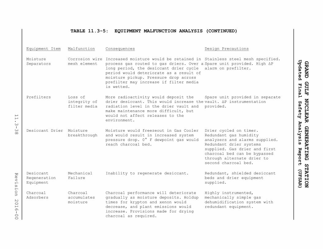
TABLE 11.3-5: EQUIPMENT MALFUNCTION ANALYSIS (CONTINUED)
Equipment Item Malfunction Consequences Design Precautions
Moisture
Separators
Corrosion wire
mesh element
Increased moisture would be retained in
process gas routed to gas driers. Over a
long period, the desiccant drier cycle
period would deteriorate as a result of
moisture pickup. Pressure drop across
prefilter may increase if filter media
is wetted.
Stainless steel mesh specified.
Spare unit provided. High ΔP
alarm on prefilter.
Prefilters Loss of
integrity of
filter media
More radioactivity would deposit the
drier desiccant. This would increase the
radiation level in the drier vault and
make maintenance more difficult, but
would not affect releases to the
environment.
Spare unit provided in separate
vault. ΔP instrumentation
provided.
Desiccant Drier Moisture
breakthrough
Moisture would freezeout in Gas Cooler
and would result in increased system
pressure drop. 0° F dewpoint gas would
reach charcoal bed.
Drier cycled on timer.
Redundant gas humidity
analyzers and alarms supplied.
Redundant drier systems
supplied. Gas drier and first
charcoal bed can be bypassed
through alternate drier to
second charcoal bed.
Desiccant
Regeneration
Equipment
Mechanical
Failure
Inability to regenerate desiccant. Redundant, shielded desiccant
beds and drier equipment
supplied.
Charcoal
Adsorbers
Charcoal
accumulates
moisture
Charcoal performance will deteriorate
gradually as moisture deposits. Holdup
times for krypton and xenon would
decrease, and plant emissions would
increase. Provisions made for drying
charcoal as required.
Highly instrumented,
mechanically simple gas
dehumidification system with
redundant equipment.
GRAND GULF NUCLEAR GENERATING STATION
Updated Final Safety Analysis Report (UFSAR)
11.3-38
Revision 2016-00

TABLE 11.3-5: EQUIPMENT MALFUNCTION ANALYSIS (CONTINUED)
Equipment Item Malfunction Consequences Design Precautions
Vault
Refrigeration
Units
Mechanical
failure
If temperature exceeds approximately 0
F, increased emission could occur.
Spare refrigeration unit
provided. Vault and charcoal
adsorber temperature alarms
provided.
After Filters Loss of
integrity of
filter media
Probably of no real consequence. The
charcoal media itself should be a good
filter at the low air velocity.
ΔP instrumentation provided.
Spare unit provided.
System Internal
detonation
Release of radioactivity if pressure
boundary fails.
Main process equipment and
piping are designed to contain
a detonation.
System Earthquake
damage
Release of radioactivity. Dose consequences are within
10CFR20 limits. Analysis is
included in Reference 6.
GRAND GULF NUCLEAR GENERATING STATION
Updated Final Safety Analysis Report (UFSAR)
11.3-39
Revision 2016-00

TABLE 11.3-6: RADWASTE EQUIPMENT DESIGN REQUIREMENTS
Equipment Codes
Design and
Fabrication Materials(2)
Welder
Qualification
and Procedure
Inspection
and Testing
Pressure Vessels ASME Code Section
VIII, Div 1
ASME Code Section
II
ASME Code Section
IX
ASME Code Section
VIII, Div 1
Atmospheric or 0-
15 psig tanks
ASME Code(3)
Section III, Class
3, API 620; 650,
AWWA D-100
ASME Code Section
II
ASME Code(3)
Section IX
ASME Code Section
III, Class 3, API
620; 650, AWWA D-
100
Heat Exchangers ASME Code Section
VIII, Div 1; and TEMA
ASME Code Section
II
ASME Code
Section IX
ASME Code Section
VIII, Div 1
Piping and Valves ANSI B 31.1 ASTM or ASME Code
Section II
ASME Code Section
IX
ANSI B 31.1
Pumps Manufacturers(1)
Standards
ASME Code Section
II or
Manufacturer’s
Standard
ASME Code Section
IX
(as required)
ASME Code(3)
Section III Class
3; and Hydraulic
Institute
Notes:(1)Manufacturer's standard for the intended service. Hydrotesting should be 1.5 times the
design pressure.
(2)Material Manufacturer's certified test reports should be obtained whenever possible.
(3)ASME Code stamp and material traceability not required.
GRAND GULF NUCLEAR GENERATING STATION
Updated Final Safety Analysis Report (UFSAR)
11.3-40
Revision 2016-00

GRAND GULF NUCLEAR GENERATING STATION
Updated Final Safety Analysis Report (UFSAR)
11.3-41 Revision 2016-00
TABLE 11.3-7: DELETED

GRAND GULF NUCLEAR GENERATING STATION
Updated Final Safety Analysis Report (UFSAR)
11.3-42 LBDCR 2018-060
TABLE 11.3-8: PARAMETERS INPUT TO BWR-GALE CODE
[This Table is historical]
Item, Description Input
Main Condenser and Turbine Gland Seal Air Removal
System:
Gland seal steam flow (103 lbm/hr) 0.0
Gland seal hold up time (hours) 0.0
Holdup time (hr) for offgases from the main condenser
air ejector prior to processing by the offgas
treatment system
0.167
Treatment system for offgases
from condenser air ejector Charcoal delay system
Offgases from the mechanical
vacuum pump
No treatment prior to
release
Air inleakage per condenser
shell(cfm)
10 cfm (Built into
GALE Code)
Mass of Charcoal in the charcoal delay systems (103
lbs) 48
Operating temperature of the delay system (F) 0
Dewpoint temperature of the delay system (F) -90
Dynamic adsorption coefficient for xenon (cm3/g) 2410
Dynamic adsorption coefficient for Krypton (cm3/g) 105
Cryogenic distillation system Not used
Steam flow to turbine gland seal (lb/hr) [Clean steam
is used] 0.0
Source of steam to the turbine gland seal Seal steam generator

GRAND GULF NUCLEAR GENERATING STATION
Updated Final Safety Analysis Report (UFSAR)
11.3-43 LBDCR 2018-060
TABLE 11.3-8: PARAMETERS INPUT TO BWR-GALE CODE (CONTINUED)
[This table is historical]
Item, Description Input
Iodine released from gland seal system [Clean steam
is used] 0
Fraction of radioiodine released from Turbine Gland
Seal Condenser Vent 0
Fraction of radioiodine released from the Condenser
Air Ejector Offgas Treatment System 1
Ventilation and Exhaust Systems:
Provisions incorporated to reduce radioactivity
releases through ventilation exhaust systems:
Containment building Release through
charcoal and HEPA
filters
Drywell purge Same as for
containment
Auxiliary building No treatment of
releases
Turbine building No treatment of
releases
Radwaste building Release through HEPA
filters. No credit is
taken for charcoal
filters for tank
vents

GRAND GULF NUCLEAR GENERATING STATION
Updated Final Safety Analysis Report (UFSAR)
11.3-44 LBDCR 2018-060
TABLE 11.3-8: PARAMETERS INPUT TO BWR-GALE CODE (CONTINUED)
[This table is historical]
Filter Removal Efficiency Iodine Particulates
Containment building releases
99
99
Auxiliary building releases
0
0
Radwaste building releases
0
99
Turbine building releases
0
0

Table 11.3-9: EXPECTED ANNUAL RELEASE OF GASEOUS EFFLUENTS (Ci/yr)
[This table is historical]
Grand Gulf BWR
Thermal Power Level (megawatts) 4496.00000
Plant Capacity Factor 1.00000
Total Steam Flow (million lbs/hr) 19.42800
Mass of Water in Reactor Vessel (million lbs) .58870
Clean-up Demineralizer Flow (million lbs/hr) .17800
Condensate Demineralizer Regeneration Time (days) 720.00000
Fission Product Carry-Over Fraction .00100
Halogen Carry-Over Fraction .02000
Fraction Feed Water Through Condensate Demin .64700
Reactor Vessel Halogen Carryover Factor .02000
GRAND GULF NUCLEAR GENERATING STATION
Updated Final Safety Analysis Report (UFSAR)
11.3-45
LBDCR 2018-060

TABLE 11.3-9: EXPECTED ANNUAL RELEASE OF GASEOUS EFFLUENTS (Continued)
[This table is historical]
LIQUID WASTE INPUTS
FLOW RATE
(GAL/DAY)
FRACTION
OF PCA
FRACTION
DISCHARGED
COLLECTION
TIME(DAYS)
DECAY
TIME(DAYS)
DECONTAMINATION FACTORS
STEAM I CS OTHERS
HIGH PURITY
WASTE
2.03E+04
.243
.100
1.708
.102
1.00E+02
2.00E+01
1.00E+02
LOW PURITY
WASTE
1.18E+04
.001
.600
.939
.050
1.00E+02
2.00E+01
1.00E+02
CHEMICAL
WASTE
0.00E+00
.000
.000
.000
.000
1.00E+00
1.00E+00
1.00E+00
REGENERANT
SOLS
0.00E+00
.000
.000
.000
1.00E+00
1.00E+00
1.00E+00
GASOUS WASTE INPUTS
GLAND SEAL STEAM FLOW (THOUSAND LBS/HR) .00000
GLAND SEAL HOLUP TIME (HOURS) .00000
AIR EJECTOR OFFGASS HOLDUP TIME (HOURS) .16700
CONTAINMENT BLDG IODINE RELEASE FRACTION .01000
PARTICULATE RELEASE FRACTION .01000
TURBINE BLDG IODINE RELEASE FRACTION 1.00000
PARTICULATE RELEASE FRACTION 1.00000
GLAND SEAL VENT, IODINE PF 1.00000
AIR EJECTOR OFFGASS IODINE PF .00000
AUXILIARY BLDG IODINE RELEASE FRACTION 1.00000
PARTICULATE RELEASE FRACTION 1.00000
RADWASTE BLDG IODINE RELEASE FRACTION 1.00000
PARTICULATE RELEASE FRACTION .01000
THERE IS A CHARCOAL DELAY SYSTEM:
KRYPTON HOLDUP TIME (DAYS) 2.0179
XENON HOLDUP TIME (DAYS) 46.3137
KRYPTON DYNAMIC ADSORPTION COEFFICIENT (CM3/GM) 105.00000
XENON DYNAMIC ADSORPTION COEFFICIENT (CM3/GM) 2410.00000
MASS OF CHARCOAL (THOUDANS LBS) 48.00000
THERE IS NOT A PERMANENT ON-SITE LAUDRY
GRAND GULF NUCLEAR GENERATING STATION
Updated Final Safety Analysis Report (UFSAR)
11.3-46
LBDCR 2018-060

TABLE 11.3-9: EXPECTED ANNUAL RELEASE OF GASEOUS EFFLUENTS (Continued)
[This table is historical]
GASOUS RELEASE RATE (CURIES PER YEAR)
NUCLIDE
COOLANT
CONC
(MICROCU-
RIES/G)
CONTAINMENT
BUILDING
TURBINE
BUILDING
AUXILIARY
BUILDING
RADWASTE
BUILDING
GLAND
SEAL
AIR
EJECTOR
MECH VAC
PUMP TOTAL
I-131 3.362E-03 2.0E-04 2.8E-01 3.9E-02 2.0E-02 0.0E+00 0.0E+00 2.1E-01 5.5E-01
I-133 4.524E-02 2.7E-03 3.8E+00 5.2E-01 2.7E-01 0.0E+00 0.0E+00 2.2E+00 6.8E+00
H-3 RELEASED FROM TURBINE BUILDING VENTILATION SYSTEM 4.2E+01
H-3 RELEASED FROM CONTAINMENT BUILDING VENTILATION SYSTEM 4.2E+01
TOTAL H-3 RELEASED VIA GASEOUS PATHWAY 8.5E+01
C-14 RELEASED VIA MAIN CONDENSER OFFGAS SYSTEM = 9.5 CI/YR
NUCLIDE
COOLANT
CONC
(MICROCU-
RIES/G)
CONTAINMENT
BUILDING
TURBINE
BUILDING
AUXILIARY
BUILDING
RADWASTE
BUILDING
GLAND
SEAL
AIR
EJECTOR
MECH VAC
PUMP TOTAL
AR-41 0.000E+00 1.5E+01 0.0E+00 0.0E+00 0.0E+00 0.0E+00 5.7E+01 0.0E+00 7.2E+01
KR-83M 9.100E-04 0.0E+00 0.0E+00 0.0E+00 0.0E+00 0.0E+00 0.0E+00 0.0E+00 0.0E+00
KR-85M 1.600E-03 1.0E+00 2.5E+01 3.0E+00 0.0E+00 0.0E+00 5.9E+01 0.0E+00 8.8E+01
KR-85 5.000E-06 0.0E+00 0.0E+00 0.0E+00 0.0E+00 0.0E+00 3.9E+02 0.0E+00 3.9E+02
KR-87 5.500E-03 0.0E+00 6.1E+01 2.0E+00 0.0E+00 0.0E+00 0.0E+00 0.0E+00 6.3E+01
KR-88 5.500E-03 1.0E+00 9.1E+01 3.0E+00 0.0E+00 0.0E+00 3.0E+00 0.0E+00 9.8E+01
KR-89 3.400E-02 0.0E+00 5.8E+02 2.0E+00 2.9E+01 0.0E+00 0.0E+00 0.0E+00 6.1E+02
XE-131M 3.900E-06 0.0E+00 0.0E+00 0.0E+00 0.0E+00 0.0E+00 2.0E+01 0.0E+00 2.0E+01
XE-133M 7.500E-05 0.0E+00 0.0E+00 0.0E+00 0.0E+00 0.0E+00 0.0E+00 0.0E+00 0.0E+00
XE-133 2.100E-03 2.7E+01 1.5E+02 8.3E+01 2.2E+02 0.0E+00 3.7E+02 1.3E+03 2.2E+03
XE-135M 7.000E-03 1.5E+01 4.0E+02 4.5E+01 5.3E+02 0.0E+00 0.0E+00 0.0E+00 9.9E+02
XE-135 6.000E-03 3.3E+01 3.3E+02 9.4E+01 2.8E+02 0.0E+00 0.0E+00 5.0E+02 1.2E+03
XE-137 3.900E-02 4.5E+01 1.0E+03 1.4E+02 8.3E+01 0.0E+00 0.0E+00 0.0E+00 1.3E+03
XE-138
TOTAL NOBLE
2.300E-02
GASES
2.0E+00 1.0E+03 6.0E+00 2.0E+00 0.0E+00 0.0E+00 0.0E+00 1.0E+03
8.0E+03
0.0 APPEARING IN THE TABLE INDICATES RELEASE IS LESS THAN 1.0 CI/YR FOR NOBLE GAS
GRAND GULF NUCLEAR GENERATING STATION
Updated Final Safety Analysis Report (UFSAR)
11.3-47
LBDCR 2018-060

TABLE 11.3-9: EXPECTED ANNUAL RELEASE OF GASEOUS EFFLUENTS (Continued)
[This table is historical]
AIRBORNE PARTICULATE RELEASE RATE (CURIES PER YEAR)
NUCLIDE
CONTAINMENT
BUILDING
TURBINE
BUILDING
AUXILIARY
BUILDING
RADWASTE
BUILDING
MECH VAC
PUMP TOTAL
CR-51 2.0E-06 9.0E-04 9.0E-04 7.0E-06 1.0E-06 1.8E-03
MN-54 4.0E-06 6.0E-04 1.0E-03 4.0E-05 0.0E+00 1.6E-03
CO-58 1.0E-06 1.0E-03 2.0E-04 2.0E-06 0.0E+00 1.2E-03
FE-59 9.0E-07 1.0E-04 3.0E-04 3.0E-06 0.0E+00 4.0E-04
CO-60 1.0E-05 1.0E-03 4.0E-03 7.0E-05 5.6E-07 5.1E-03
ZN-65 1.0E-05 6.0E-03 4.0E-03 3.0E-06 3.4E-07 1.0E-02
SR-89 3.0E-07 6.0E-03 2.0E-05 0.0E+00 0.0E+00 6.0E-03
SR-90 3.0E-08 2.0E-05 7.0E-06 0.0E+00 0.0E+00 2.7E-05
NB-95 1.0E-05 6.0E-06 9.0E-03 4.0E-08 0.0E+00 9.0E-03
ZR-95 3.0E-06 4.0E-05 7.0E-04 8.0E-06 0.0E+00 7.5E-04
MO-99 6.0E-05 2.0E-03 6.0E-02 3.0E-08 0.0E+00 6.2E-02
RU-103 2.0E-06 5.0E-05 4.0E-03 1.0E-08 0.0E+00 4.1E-03
AG-110M 4.0E-09 0.0E+00 2.0E-06 0.0E+00 0.0E+00 2.0E-06
SB-124 2.0E-07 1.0E-04 3.0E-05 7.0E-07 0.0E+00 1.3E-04
CS-134 7.0E-06 2.0E-04 4.0E-03 2.4E-05 3.2E-06 4.2E-03
CS-136 1.0E-06 1.0E-04 4.0E-04 0.0E+00 1.9E-06 5.0E-04
CS-137 1.0E-05 1.0E-03 5.0E-03 4.0E-05 8.9E-06 6.1E-03
BA-140 2.0E-05 1.0E-02 2.0E-02 4.0E-08 1.1E-05 3.0E-02
CE-141 2.0E-06 1.0E-02 7.0E-04 7.0E-08 0.0E+00 1.1E-02
* Containment iodine releases include a reduction factor of 100 to account for provision of 8-in deep-bed charcoal
adsorbers on the containment exhaust line.
** 0 appearing in the table indicates release is less than 1.0 Ci/yr for noble gas, 0.0001 Ci/yr for iodine
GRAND GULF NUCLEAR GENERATING STATION
Updated Final Safety Analysis Report (UFSAR)
11.3-48
LBDCR 2018-060

TABLE 11.3-10: DESCRIPTION OF RELEASE POINTS
Release point
Ht. above
grade
(ft.)
Ht.above
adjacent
structure (ft)
Location
relative to
adjacent
structure
ΔT (F) between
gaseous effluent
and ambient air
and normal
condition
(assume ambient
Temp. 95 F)
Flow rate
(cfm) normal
condition
Exit
Velocity Normal
condition
approx. fpm
Discharge
Point
Radwaste bldg 31.5 See Figure
2.1-2
See Figure
2.1-2 25 52,495 2,500 (1)
SGTS 139.5 See Figure
2.1-2
See Figure
2.1-2 67 4,000 1,273 (1)
Auxiliary bldg 139.5 See Figure
2.1-2
See Figure
2.1-2 3 25,075 3,134 (2)
Containment 60.5 See Figure
2.1-2
See Figure
2.1-2 15 6,000 2,700 (1)
Turbine bldg:
a. Smoke exhaust 54.5 See Figure
2.1-2
See Figure
2.1-2 10 19,000 422 (2)
b. Battery
room exh. 36.5
See Figure
2.1-2
See Figure
2.1-2 10 2,000 500 (2)
c. Lube oil room
exh.
10 See Figure
2.1-2
See Figure
2.1-2 10
1,500 400 (2)
GRAND GULF NUCLEAR GENERATING STATION
Updated Final Safety Analysis Report (UFSAR)
11.3-49
LBDCRs 2018-064
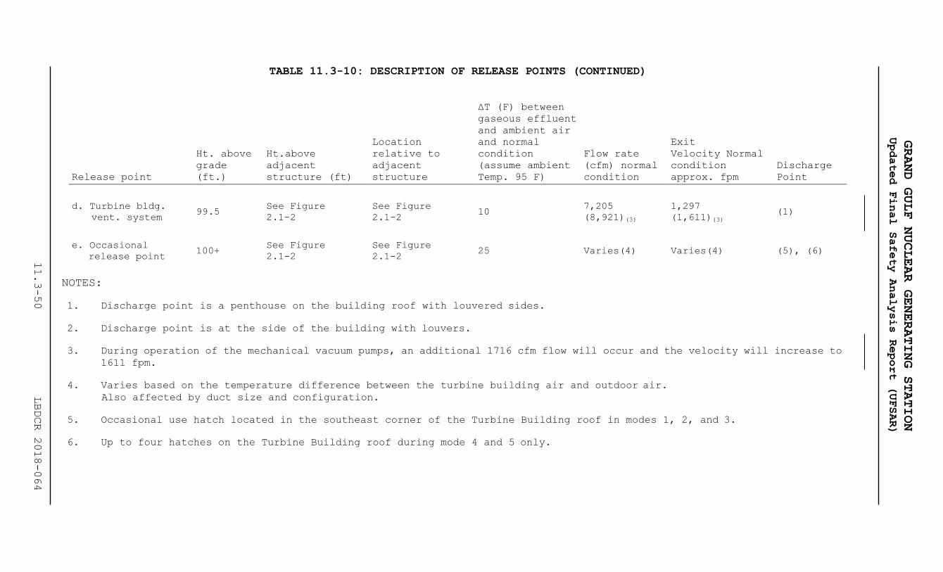
TABLE 11.3-10: DESCRIPTION OF RELEASE POINTS (CONTINUED)
Release point
Ht. above
grade
(ft.)
Ht.above
adjacent
structure (ft)
Location
relative to
adjacent
structure
ΔT (F) between
gaseous effluent
and ambient air
and normal
condition
(assume ambient
Temp. 95 F)
Flow rate
(cfm) normal
condition
Exit
Velocity Normal
condition
approx. fpm
Discharge
Point
d. Turbine bldg.
vent. system 99.5
See Figure
2.1-2
See Figure
2.1-2 10
7,205
(8,921)(3)
1,297
(1,611)(3) (1)
e. Occasional
release point 100+
See Figure
2.1-2
See Figure
2.1-2 25 Varies(4) Varies(4) (5), (6)
NOTES:
1. Discharge point is a penthouse on the building roof with louvered sides.
2. Discharge point is at the side of the building with louvers.
3. During operation of the mechanical vacuum pumps, an additional 1716 cfm flow will occur and the velocity will increase to
1611 fpm.
4. Varies based on the temperature difference between the turbine building air and outdoor air.
Also affected by duct size and configuration.
5. Occasional use hatch located in the southeast corner of the Turbine Building roof in modes 1, 2, and 3.
6. Up to four hatches on the Turbine Building roof during mode 4 and 5 only.
GRAND GULF NUCLEAR GENERATING STATION
Updated Final Safety Analysis Report (UFSAR)
11.3-50
LBDCR 2018-064

GRAND GULF NUCLEAR GENERATING STATION
Updated Final Safety Analysis Report (UFSAR)
TABLE 11.3-11: χ/Q AND D/QS FOR THE VEGETABLE GARDENS,
RESIDENCES AND COWS WITHIN 5 MILES
Item
Sector
Distance
(meters)
χ/Q
(Sec/meter3)
D/Q
(1 meter2)
Vegetable Garden
NNE
2414
1.195E-06
1.893E-09
ENE 4828 2.098E-07 3.958E-10
E 2414 4.615E-07 9.058E-10
ESE 4426 1.931E-07 3.721E-10
N 2816 1.453E-06 2.100E-09
Residence
NNE
1448
2.534E-06
4.543E-09
NE 1062 2.563E-06 6.142E-09
ENE 4297 2.493E-07 4.863E-10
E 982 1.796E-06 4.162E-09
ESE 4007 2.239E-07 4.434E-10
SE 3299 3.738E-07 7.693E-10
SSE 1690 1.763E-06 4.065E-09
S 1770 2.669E-06 4.389E-09
SSW 3734 1.541E-06 1.154E-09
SW 1432 9.416E-06 6.669E-09
WNW 6437 7.276E-07 2.842E-10
NNW 1738 2.964E-06 3.622E-09
N 1481 3.710E-06 6.337E-09
Cow
E
8047
7.809E-08
1.080E-10
Note: Updates to χ/Q’s and D/Q’s used to calculate dose to the public
are located in and controlled by the Offsite Dose Calculation
Manual.
11.3-51 Revision 2016-00

TABLE 11.3-12: MAXIMUM INDIVIDUAL DOSES FROM GASEOUS EFFLUENTS
Noble Gases [HISTORICAL INFORMATION]
Pathway Location Annual Dose
10 CFR 50
Appendix I Limits
Cloud Submersion
- total body SSW sector-site boundary - 1046 meters 0.88 mrem 5 mrem
- skin SSW sector-site boundary - 1046 meters 2.16 mrem 15 mrem
Air dose
- gamma SSW sector-site boundary - 1046 meters 1.35 mrad 10 mrad
- beta SW sector-site boundary - 1368 meters 1.83 mrad 20 mrad
GRAND GULF NUCLEAR GENERATING STATION
Updated Final Safety Analysis Report (UFSAR)
11.3-52
Revision 2016-00

TABLE 11.3-12: MAXIMUM INDIVIDUAL DOSES FROM GASEOUS EFFLUENTS (CONTINUED)
Radioiodines and Particulates
(Thyroid)*
Location and Pathway Age Group
Annual Dose
(mrem)
10 CFR 50 Appendix I
Annual Limits (mrem)
SW sector - site boundary - 1368 meters Child
- inhalation 8.91 15 from all pathways
- ground contamination 0.06
SW sector - residence - 1432 meters Child
- inhalation 8.31 15 from all pathways
- meat ingestion 0.59
- ground contamination 0.05
N sector - vegetable garden - 2816 meters Child
- inhalation 1.23 15 from all pathways
- vegetable ingestion 0.95
- ground contamination 0.02
E sector - pasture - 8047 meters Infant
- inhalation 0.05 15 from all pathways
- cow’s milk ingestion 0.96
- ground contamination 0.001
* Doses to other organs are less than the dose to the thyroid.
GRAND GULF NUCLEAR GENERATING STATION
Updated Final Safety Analysis Report (UFSAR)
11.3-53
Revision 2016-00

GRAND GULF NUCLEAR GENERATING STATION
Updated Final Safety Analysis Report (UFSAR)
11.3-54 Revision 2016-00
TABLE 11.3-13: POPULATION DOSES FROM GASEOUS RELEASES
[HISTORICAL INFORMATION]
Pathway
Total Body Dose
(person-rem)
Thyroid Dose
(person-rem)
Noble Gases
Cloud submersion 0.143 0.143
Radioiodine and Particulates
Ground contamination 0.032 0.032
Inhalation 0.046 3.03
Vegetable consumption 0.915 3.07
Milk consumption 0.149 1.35
Meat consumption 0.183 0.303
1.325 7.785

GRAND GULF NUCLEAR GENERATING STATION
Updated Final Safety Analysis Report (UFSAR)
11.3-55 Revision 2016-00
TABLE 11.3-14: ANNUAL AIRBORNE RELEASES OF ELEMENTAL IODINE-131
ACCORDING TO PLANT OPERATING MODE FOR ENVIRONMENTAL IMPACT
EVALUATION MILLICURIES PER YEAR
[HISTORICAL INFORMATION]
Source Plant Operating Mode
Building or Exhaust
Power
Generation Refueling/Maintenance
Reactor building* 30.0 3.5
Turbine building 59.0 3.2
Radwaste building 11.0 0.34
Gland seal steam and
mechanical vacuum pump 0.0036 0.020
Total 100. 7.1
Total Elemental I-131 = 107.1 millicuries/year
*Use 50% of reactor building release for the auxiliary building and 50%
for the containment building.

TABLE 11.3-15: ANNUAL AIRBORNE RELEASES OF NON-ELEMENTAL IODINE-131
SPECIES ACCORDING TO PLANT OPERATING MODE FOR
ENVIRONMENTAL IMPACT EVALUATIONS
MILLICURIES PER YEAR
[HISTORICAL INFORMATION]
Plant Operating Mode
Refueling/Maintenance
Power Operation
Source Species
Building or
Exhaust Particulate HOI CH3I Particulate HOI CH3I
Reactor
building*
8.8 13.0 28.0 0.69 5.7 4.0
Turbine
building
21.0 16.0 9.8 0.56 4.6 3.3
Radwaste
building
1.6 4.2 30.0 0.044 0.58 6.0
Gland seal
steam and
mechanical
vacuum pump
0.0029 0.013 0.043 0.039 0.020 20.0
Total 31.4 33.2 67.8 1.33 10.9 33.3
Particulate 31.4 + 1.33 = 32.7 millicuries/year
GRAND GULF NUCLEAR GENERATING STATION
Updated Final Safety Analysis Report (UFSAR)
11.3-56
Revision 2016-00

TABLE 11.3-15: ANNUAL AIRBORNE RELEASES OF NON-ELEMENTAL IODINE-131
SPECIES ACCORDING TO PLANT OPERATING MODE FOR
ENVIRONMENTAL IMPACT EVALUATIONS
MILLICURIES PER YEAR
This information is evaluated in PUSAR Sections 2.10.1.2.4,
Sections 2.5.5.1.1 and ODCM
Plant Operating Mode
Refueling/Maintenance
Power Operation
Source Species
Building or
Exhaust Particulate HOI CH3I Particulate HOI CH3I
HOI 33.2 + 10.9 = 44.1 millicuries/year
CHI 67.8 + 33.3 = 101.1 millicures/year
Total Non-elemental I-131 = 177.9 millicuries/year
*Use 50% of reactor building release for the auxiliary building
and 50% for the containment building.
GRAND GULF NUCLEAR GENERATING STATION
Updated Final Safety Analysis Report (UFSAR)
11.3-57
Revision 2016-00
GRAND GULF NUCLEAR GENERATING STATION
Updated Final Safety Analysis Report (UFSAR)
11.3-58 Revision 2016-00
FIGURES 11.3-1, 11.3-2, 11-3-3, 11.3-4, AND 11.3-6
ARE
P R O P R I E T A R Y
GENERAL TITLES:
System Flow Diagrams
Offgas System Drawings
P & I Diagrams

GRAND GULF NUCLEAR GENERATING STATION
Updated Final Safety Analysis Report (UFSAR)
11.3-59 LBDCRs 2018-099 & 2018-102

GRAND GULF NUCLEAR GENERATING STATION
Updated Final Safety Analysis Report (UFSAR)
11.3-60 LBDCR 2018-101
This page intentionally left blank.

GRAND GULF NUCLEAR GENERATING STATION
Updated Final Safety Analysis Report (UFSAR)
11.3-61 Revision 2016-00

GRAND GULF NUCLEAR GENERATING STATION
Updated Final Safety Analysis Report (UFSAR)
11.3-62 LBDCR 2018-098

GRAND GULF NUCLEAR GENERATING STATION
Updated Final Safety Analysis Report (UFSAR)
11.3-63 Revision 2016-00

GRAND GULF NUCLEAR GENERATING STATION
Updated Final Safety Analysis Report (UFSAR)
11.3-64 Revision 2016-00

GRAND GULF NUCLEAR GENERATING STATION
Updated Final Safety Analysis Report (UFSAR)
11.4-1 Rev. 4
11.4 SOLID RADWASTE SYSTEM
The solid radwaste system is designed to provide solidification
and packaging for radioactive wastes that are produced during
shutdown, startup, and normal plant operation, and to store these
wastes until they are shipped offsite for burial. The system is
located in the radwaste building. Plant operating procedures will
be written covering Radioactive Waste Management and Materials
Control Procedures.
11.4.1 Design Bases
11.4.1.1 Power Generation Design Bases
a. The solid radwaste system provides the capability for
processing and packaging wastes from the reactor water
cleanup system, fuel pool cooling and cleanup system,
liquid radwaste system, and resins, and particulate wastes
from the condensate cleanup system. Wastes from the above
systems may consist of spent resin, or other filtering
media.
b. The solid radwaste system provides a means of compacting
and packaging miscellaneous dry radioactive materials,
such as paper, rags, contaminated clothing, gloves, and
shoe coverings, and for packaging contaminated metallic
materials and incompressible solid objects, such as small
tools and equipment parts.
c. The solid radwaste system is designed so that failure or
maintenance of any frequently used component shall not
impair system or plant operation. Redundancy of some
components is provided to allow continued operation when
one piece of equipment is out of service due to either
failure or maintenance. Equipment which is not redundant
is cross-tied, where feasible, with similar components for
backup service. Additionally, a mobile solidification
station is provided to accommodate processing of wastes
with mobile, or portable waste processing equipment.
d. Redundant and backup equipment are shielded from each
other, where possible, to allow access to nonfunctioning
components for maintenance and repair. Areas of the solid
radwaste system for which access is required under all
operating conditions are shielded from radioactive, and
potentially radioactive, components.

GRAND GULF NUCLEAR GENERATING STATION
Updated Final Safety Analysis Report (UFSAR)
11.4-2 Rev. 4
e. System piping and components were hydrostatically tested
prior to initial startup.
f. The primary operating station for the solid radwaste
system is the water inventory control station located at
El. 118-0 in the radwaste building; container capping and
swipe sample retrieval are performed locally. The
operating philosophy of the solid radwaste control system
is manual start and stop, with all functions interlocked
to provide a fail-safe mode of operation.
11.4.1.2 Codes and Standards
Codes and standards applicable to the solid radwaste system are
listed in Table 3.2-1 item XVIII. The solid radwaste system is
designed and constructed in accordance with quality group D and
the additional requirements of Branch Technical Position ETSB 11-
1 (Revision 1, 4/75), “Design Guidance for Radioactive Waste
Management Systems Installed In Light-Water-Cooled Nuclear Power
Reactor Plants.” The solid radwaste system components and the
structure housing the components are designed to the seismic
criteria of ETSB 11-1.
Collection, processing, packaging, and storage of radioactive
wastes will be performed so as to maintain any potential radiation
exposure to plant personnel to “as low as is reasonably
achievable” levels, in accordance with Regulatory Guide 8.8 (Rev.
2 March, 1977) guidelines (see Section 12.1), and within the dose
limits of 10 CFR 20. Some of the design features incorporated to
maintain ALARA criteria include remote system operation, remotely
actuated flushing, and equipment layout that permits shielding of
components containing radioactive materials.
Packaging and transporting radioactive wastes will be in
conformance with 10 CFR 71. Packaged wastes will be shipped in
conformance with 49 CFR 173 dose limits.
11.4.2 System Description
11.4.2.1 General Description
The solid radwaste system consists of the following:
a. Three waste holding tanks, capable of dewatering slurries
and complete with level detection devices and mixing and
flushing equipment

GRAND GULF NUCLEAR GENERATING STATION
Updated Final Safety Analysis Report (UFSAR)
11.4-3 Rev. 4
b. Three waste transfer pumps
c. One indoor, electric, overhead, double-trolley bridge
crane
d. A decontamination area
e. Disposable shipping containers
f. Optical surveillance facilities
g. One hot water heater
h. One waste compactor
i. One mobile solidification station
Detailed piping and instrumentation diagrams are provided in
Figure 11.4-1. A process flow diagram indicating the process
route, expected flows, and equipment capacities is shown in
Figure 11.4-2. A physical layout drawing illustrating the
packaging, storage, and shipping areas of the radwaste building
is presented in Figures 1.2-10, 1.2-13, 12.3-6, and 12.3-7.
Table 11.4-1 lists the expected volumes of wastes to be processed
on an annual basis.
11.4.2.2 Component Description
A description of the solid radwaste system components, (including
materials of construction) as shown in the process flow diagram,
is given in Table 11.4-4.
The following is a functional description of the major system
components:
a. Waste Holding Tanks - These tanks function as batch tanks
to provide a starting point for the solids waste process.
They also provide capability for dewatering resins and
high-solid-content wastes, and for mixing these wastes.
The agitator provides a homogeneous waste slurry. These
tanks are vented to the radwaste building ventilation
system. Overflows from the waste holding tanks are
directed to the radwaste building floor drain sump for
reprocessing through the liquid radwaste system. The
holding tanks have the provisions to obtain representative
waste samples which may be removed for chemical lab

GRAND GULF NUCLEAR GENERATING STATION
Updated Final Safety Analysis Report (UFSAR)
11.4-4 Rev. 4
analysis if necessary. From samples, the batch parameters
for packaging are determined as described in subsection
11.4.5.
b. Waste Transfer Pumps - These pumps transfer the
homogeneous waste stream from the waste holding tanks and
may also function as transfer pumps for recycling wastes
back to the liquid radwaste system for additional waste
processing or storage.
c. Bridge Crane - This crane is locally controlled and
provides a means of moving containers from the fill area
to the solid waste storage area, and from the waste
storage area to the shipping area. The crane is also used
for moving empty containers to the fill area. The crane is
equipped with television cameras to facilitate remote
handling. However, the television equipment is not used
and is abandoned in place.
d. Decontamination Station - The decontamination station is
not used and is abandoned in place. This station provides
for container washdown if they become contaminated during
the filling sequence. Drain hubs in the floor are provided
to route flushing water from this process to the radwaste
building floor drain sump for processing through the
liquid radwaste system. Since this method of
decontamination is not a normal occurrence, the small
amount of solids associated with the washdown is not
expected to cause drain clogging.
e. Disposable Shipping Containers - For storage and
transporting solid wastes, 55-gallon, DOT standard drums
and other containers approved by DOT and the waste
disposal facility are used.
f. Optical Surveillance Facilities - A closed circuit
television viewing system provides for remote monitoring
of container filling, storage, and transport loading
operations. This system is inoperative and is abandoned in
place.
g. Hot Water Heater - This unit provides hot water for
suitable flushing and decontamination of the waste holding
tanks and associated equipment. The water heater is not
used and is abandoned in place.

GRAND GULF NUCLEAR GENERATING STATION
Updated Final Safety Analysis Report (UFSAR)
11.4-5 Rev. 4
h. Waste Compactor - This unit is a powered, mechanical ram
and is used to reduce the volume of compressible dry
wastes. The compactor is complete with a hooded exhaust
fan and filter to control airborne particles during dry
waste compaction.
i. Mobile Solidification Station - This station, located in
the radwaste building railroad bay, provides interfaces
with all liquid radwaste system tanks, which normally
input to the solid radwaste system, and with necessary
plant auxiliaries to accommodate the use of mobile, or
portable, waste processing systems.
None of the above tanks use compressed gases for transport or
drying of resins or filter sludge.
11.4.2.3 Component Integration
The following description shows how the major system components
described in subsection 11.4.2.2 function as an integrated
system:
a. Equipment Drain Filter Discharge, Floor Drain Filter
Discharge, and High Solids Content Waste
When either of the two liquid radwaste filters reaches the
end of its filtering cycle, the flow through the filter
will be terminated. The filter will be drained of excess
water and the solid radioactive wastes will be
centrifugally discharged from the precoat filter. The
filter will be capable of discharging a maximum of
approximately 26.5 cubic feet, at one time, either as a
wet sludge or as a dry cake (approximately 50 percent by
weight moisture). The filter wastes will be collected in
the waste holding tank located directly below the filter.
Once the filter waste has been collected in this tank, it
will be pumped by the tank-associated waste transfer pump
to the waste processing station. The wastes will normally
be pumped into liners and dewatered. If solidification is
required it will be performed by a vendor, using their own
operating procedures and process control program accepted
by the NRC or the On-Site Safety Review Committee. High
solids content wastes (described in subsection 11.4.2.4),
which are not filtered, will be sluiced directly to the
waste processing station. After sufficient time for the

GRAND GULF NUCLEAR GENERATING STATION
Updated Final Safety Analysis Report (UFSAR)
11.4-6 Rev. 4
solids to settle is allowed, excess water will be
decanted. Processing shall then proceed as described
above.
b. Solid Radwaste Handling Crane
After capping, smear swipe sampling, and decontamination
(if required), the container will be moved, by the solid
radwaste handling crane, to the appropriate storage area.
When it is time to ship the container offsite for burial,
or further processing, the solid radwaste handling crane
will pick up the container and move it onto the waiting
truck.
c. Decontamination Station
The decontamination station is not used and is abandoned
in place. The decontamination station is used for cleaning
and inspection of the filled shipping containers. After
decontamination, a smear swipe is taken of the side of the
container and analyzed for gross beta-gamma surface
contamination. The container is also classified as to its
dose rate at a specified distance; this will determine its
storage location in the decay area and shielding
requirements for shipment.
11.4.2.4 System Operation
11.4.2.4.1 High Solids Content Waste
The slurry wastes normally will be processed as described below.
Solidification of these wastes will be accomplished as described
in subsection 11.4.2.4.2.
a. Reactor Water Cleanup (RWCU) Backwash - The RWCU discharge
pump (liquid radwaste system) is used to produce a
homogeneous slurry of resin and water in the RWCU phase
separator decay tank. The discharge valve is then opened,
allowing a portion of the recycle flow to be directed to
the container. If it is determined that excess water is
present after the solids have settled, the excess will be
removed. Water removed in this manner will be returned to
the Liquid Radwaste System.

GRAND GULF NUCLEAR GENERATING STATION
Updated Final Safety Analysis Report (UFSAR)
11.4-7 Rev. 4
b. Fuel Pool Cooling and Cleanup Wastes - Fuel pool cooling
and cleanup (FPC & CU) wastes will be collected in the
RWCU phase separator decay tank and processed as described
in a. above.
c. Spent Resins - Spent resins from the spent resin tank are
also slurried to the shipping container. Excess water will
be decanted and routed to the Liquid Radwaste System, or
Solid Radwaste System.
d. Condensate resin cleaning - Overflow from resin cleaning
activities (condensate clean-up system) is directed to the
condensate clean waste tank (floor and equipment drains
system). These wastes may then be transferred to the spent
resin tank or the condensate phase separator decay tank
and processed with the spent resins as described in c.
above. Liquid wastes discharged through the spent resin
tank overflow are collected in the floor drain collection
tank for processing.
e. Condensate Precoat Filter Backwash - Condensate precoat
filter wastes will be collected in one of the two
condensate phase separator tanks (liquid radwaste system).
Because it is expected that sufficient volumes of
particulate waste will make direct processing feasible,
the wastes will be transferred directly to the shipping
container, and handled as described in the latter portion
of a. above, with decant effluent being routed to the
Liquid Radwaste System for processing.
11.4.2.4.2 Equipment Drain Filter Discharge, Floor Drain Filter
Discharge, and High Solids Content Waste Handling
As dirt, crud, and filter-aid material (if required) are built up
on the equipment drain or floor drain filter, the pressure drop
across the filter increases until a preset limit is reached. At
this time, processing through the filter is stopped manually. The
unit is either drained back to the tank from which the waste water
originated or to a sump; if desired, the cake built up on the
filter elements may be dried, with air, to a predetermined
moisture content (refer to liquid radwaste system, Section 11.2).
The filter nest is then mechanically rotated, throwing the cake
off. As the cake drops to the bottom of the filter, high pressure
air is used to force the cake out the discharge port and into the
waste holding tank. Once the filter cake has been collected in the

GRAND GULF NUCLEAR GENERATING STATION
Updated Final Safety Analysis Report (UFSAR)
11.4-8 Rev. 4
waste holding tank, the waste may be transferred to shipping
containers for dewatering or returned to the condensate phase
separator for further processing.
Radioactive waste packaging and processing will be accomplished
by using the appropriate waste transfer pump to transfer
predetermined amounts of filter waste (or high solids content
waste) into the shipping container.
Level detectors will be provided at the shipping container as part
of the vendor's equipment. On high level in the shipping
container, the detector will alarm and automatically stop the
container fill process.
The vendor's mobile/portable processing unit will provide waste
and level detection connections to the containers. The unit will
allow for level detection and addition of the waste. Connection of
the unit to the container will be made manually.
11.4.2.4.3 Capping
After filling has been completed, the shipping container will be
capped.
11.4.2.4.4 Decontamination Station
The decontamination station is not used and is abandoned in place.
11.4.2.4.5 Solid Radwaste Handling Crane
After sufficient decontamination, if required, and dose rate
classification, the solid radwaste handling crane will be used to
move the container to its storage area. The solid radwaste
handling crane may also be used for maintenance on the liquid
waste filters.
When it is time to ship the containers offsite for burial or
further processing, the solid radwaste handling crane will be
used to pick the containers up, and move them onto the waiting
truck.
Prior to shipment a final radiological survey of the loaded
transport vehicle will be performed.
11.4.2.4.6 Remote Viewing Television
This system is inoperative and is abandoned in place.

GRAND GULF NUCLEAR GENERATING STATION
Updated Final Safety Analysis Report (UFSAR)
11.4-9 Rev. 4
11.4.2.4.7 Process Pump Cleaning Upon Loss of Power
The loss of electrical control power to the waste processing
system will result in the immediate shutdown of the system. The
waste holding tank power-operated outlet valves will close upon
loss of air pressure or electrical power and all pumps will cease
to operate. Other waste transfer power-operated valves will fail-
as-is, permitting the pumps and associated piping to be drained
and flushed.
The short term corrective action in this situation is the cleaning
of the waste transfer pumps of liquid wastes by flushing with
condensate supplied to the inlet piping of the pumps.
If the power outage is not sufficiently long, no action is
required. However, if the operator determines that the outage
will be sufficiently long, the waste holding tanks and associated
piping could be drained and flushed. The necessary valve openings
can be achieved by applying bottled gas pressure or plant air to
the appropriate valve operators. This is done through valve rack
manifolds located in the access and operating galleries. Tubing
connections from these manifolds extend to the various valves
which must be operated for system draining, return of waste to the
liquid radwaste system, or dumping into waste containers. Another
flush valve provides a source of flush water to the inlet of the
waste transfer pump to assist in cleaning this portion of the
system and the waste holding tank spray nozzles. The expected
length of the power outage will determine if cleaning this portion
of the system is necessary.
11.4.2.4.8 Hydraulic Press
The solid radwaste system will also dispose of dry waste
consisting of small tools, air filters, miscellaneous paper,
rags, equipment parts which cannot be effectively decontaminated,
wood, and solid laboratory waste. Compressible wastes can be
compacted to reduce their volume. Ventilation is provided to
maintain control of contaminated particles when operating this
equipment. Noncompressible wastes are packaged manually in
appropriate containers. Because of its low activity, this waste
can be stored until enough is accumulated to permit economic
transportation offsite for final disposal or further processing.

GRAND GULF NUCLEAR GENERATING STATION
Updated Final Safety Analysis Report (UFSAR)
11.4-10 Rev. 4
Storage areas for dry waste are provided in various locations
throughout the plant. These areas are posted in accordance with
the requirements of 10CFR20 and are arranged to maintain
personnel exposures ALARA.
11.4.2.4.9 Mobile Solidification Station/Waste Processing
Equipment
To provide system flexibility, a mobile solidification station is
provided to accommodate processing of influents to the solid
radwaste system with a mobile or portable system. The associated
system piping, as shown in Figure 11.4-1b, provides interfaces
from the RWCU phase separator decay tank, spent resin tank, waste
holding tanks, and the condensate phase separator tanks to a valve
station located within the radwaste building railroad bay.
Condensate and service air connections to this piping are
provided to permit backflushing of these lines after completion
of transfer operations, and a dewatering return line is provided
to the RWCU phase separator decay tanks. Additional condensate,
service air, radwaste building ventilation, and electrical power
interfaces are provided in this area for use with this mobile/
portable equipment.
11.4.3 Malfunction Analysis
The radwaste solidification system is equipped with a numa logic
control system.
The process system is protected from component malfunction and
operator error through a series of safety interlocks.
If a parameter is violated, an alarm will sound and the
annunciator will identify the problem.
Once operating, pressure sensing switches will automatically stop
the system if the valves fail to open.
On loss of power, supply valves close.
11.4.4 Expected Volumes
The quantities of waste and specific activities shipped per year
are given in Table 11.4-1. The total activity is directly related
to the activity in the liquids from each source and the

GRAND GULF NUCLEAR GENERATING STATION
Updated Final Safety Analysis Report (UFSAR)
11.4-11 Rev. 4
decontamination factors (DF) assumed in the respective system.
Additionally, it is conservatively assumed that both soluble and
particulate nuclides are deposited in the demineralizers. Decay,
prior to shipment is also considered. It is expected that
intervals of 30 days or longer will occur prior to shipment.
11.4.5 Packaging
All wastes collected in the solid radwaste system for disposal
will be processed as described in subsection 11.4.2.4. If
solidification is required, it will be completed as specified in
the process control program. If other waste processing methods
are used, the alternative methods will be reviewed and approved in
accordance with the GGNS Process Control Program.
The administrative control requirements contained in Regulatory
Guide 1.33, Revision 2, and ANSI N18.7-1976 shall be implemented
in the Operation Procedures. In addition, Quality Programs (see
Section 17.2) will perform periodic monitoring, review, and
inspection activities to establish adequate confidence levels
that operating procedures are being adhered to.
The estimated curie content of solid radwaste to be stored onsite
is given in Table 11.4-2.
11.4.6 Storage Facilities
11.4.6.1 Radwaste Building
Packaged high activity solid radwaste is stored in a shielded
storage area in the radwaste building, as shown in Figure 12.3-7.
The storage area shield walls are sufficiently high to provide
additional storage flexibility. Approximately 384 filled drums or
29 filled 120 ft3 containers can be stored in this area at one
time. Filled 120 ft3 containers are not stacked. Based on
generation of two hundred 120 ft3 containers (approximately 22,036
ft3) of waste per year, the solid radwaste storage area can
provide storage capabilities of more than 30 days. The quantity of
solidified/processed waste generated is given in Figures 11.2-6
through 11.2-10, and 11.4-2.

GRAND GULF NUCLEAR GENERATING STATION
Updated Final Safety Analysis Report (UFSAR)
11.4-12 LBDCR 2018-097
11.4.6.2 Large Component Storage Building
The Large Component Storage Building (LCSB) is a radioactive
materials storage area located in the Northwest laydown area as
shown in Figure 2.1-001. The approximate internal dimensions of
the LCSB are 106 ft x 108 ft x 20 ft. Several components were
replaced during the Extended Power Uprate (EPU) at GGNS. This
building serves as permanent storage for these components until
decommissioning. They include the steam dryer, both moisture
separator reheaters, 9 feedwater heaters, both reactor feedpump
turbines and their inner casings and the high pressure turbine
rotor. The total expected volume of the major components
contributing to offsite dose is approximately 39,000 cubic feet.
The principal sources of radioactivity are from solid activated
corrosion product buildup on the steam dryer, moisture separator
reheaters, and the feedwater heaters. The maximum total quantity
of stored radioactivity in the LCSB contributing to offsite dose
is 960 curies. The LCSB is designed to limit calculated dose rates
to within the limits of 10CFR20 and 40CFR190. The calculated dose
rate at the site area boundary, approximately 400 feet north of
the LCSB, is less than 0.5 mrem/yr.
11.4.6.3 GGNS Independent Spent Fuel Storage Installation Cask
Storage Pad
The GGNS ISFSI storage pad is located at the north end of the GGNS
plant site and at a location north of the canceled Unit 2
Containment and Turbine Building (see UFSAR Figure 1.2-001 and
3.4-001). The pad stores spent nuclear fuel. Detailed design and
radiological information is provided in the NRC Certificate of
Compliance (CoC) 72-1014, HI-STORM 100 FSAR HI-2002444, and the
GGNS HI-STORM 100 10CFCFR72.212 Evaluation Report. Additional
discussions are also provided UFSAR Chapters 1.2, 3.4, and 9.1.
The ISFSI FSAR is maintained in accordance with 10CFR72.
11.4.7 Shipment
Containers normally can be shipped immediately after filling,
provided the proper shielding is available, without exceeding
Department of Transportation radiation limits. If 49 CFR 173 dose
limitations cannot be met with the available shielding, however,
the containers are stored until the appropriate shielding is
available, or until dose rates have decreased.

GRAND GULF NUCLEAR GENERATING STATION
Updated Final Safety Analysis Report (UFSAR)
11.4-13 Rev. 4
All contaminated shipping containers and vehicles used for solid
waste handling will be stored inside the power block or within
designated areas within the Restricted Area in accordance with 10
CFR 20. Uncontaminated shipping containers and vehicles may be
stored outside.
The expected annual volumes of solid radwaste to be shipped
offsite are estimated in Table 11.4-1. The corresponding isotopic
curie contents of solidified wastes are estimated in Tables 11.4-
3a and 11.4-3b assuming 30-day decay.
11.4.8 Test and Inspection
The solid radwaste system is proved operable by its use during
normal plant operation.* During the startup test phase, the
operation and surveillance of the solid radwaste system
processing will be in accordance with approved plant operating
procedures.
11.4.9 Quality Control
The quality control program for the solid radwaste system is the
same as described in subsection 11.3.2.2.1.3. This program is in
accordance with BTP-ETSB-11-1 (Rev. 1).
*The solid radwaste system process components are inspected for
conformance with design specifications and particular
installation requirements set forth in Table 3.2-1.

GRAND GULF NUCLEAR GENERATING STATION
Updated Final Safety Analysis Report (UFSAR)
11.4-14 Revision 2016-00
TABLE 11.4-1: EXPECTED SOLID RADWASTE VOLUMES AND SPECIFIC
ACTIVITY
Component
Identification
Backwash
Volume, in ft3
in days
Backwash,
Frequency,
in days
Annual Waste,
Volume, in ft3
Specific
Activity, in
μCi/cc
(Note 1) (Note 1) (Note 2)
Equipment Drain
Filter
22.4 7.6 1076 1.66E+00
Equipment Drain
Demin
141.5 99.7 518 2.53E-01
Floor Drain Filter 22.4 17.04 480 8.12E-03
Floor Drain Demin 141.5 28.5 1812 2.35E-04
Condensate Demin
Beds
290 730 1160 2.86E-01
Condensate Precoat
Filters
24 See Note 4 145 8.20E+00
RWCU Filter/Demins 5 75 49 3.75E+03
FPCU & CU
Filter/Demins
13 30 156 3.39E+01
Total Waste Volume, ft3/year 5396
Note 1: Where multiple components exist, the backwash volume and backwash frequency are
“per unit” while the annual waste volume represents the waste stream.
Note 2: The expressed specific activity incorporates a 30 day storage period for decay.
Note 3: The volume of solid waste presented above reflects wet, unprocessed waste
volume.
Note 4: The backwash frequency for Condensate Precoat Filters is assumed to be 1
backwash every 90 days when these filters are used in the Suppression Pool
clean-up mode and two backwashes per year when used in the Condensate System
clean-up mode.

GRAND GULF NUCLEAR GENERATING STATION
Updated Final Safety Analysis Report (UFSAR)
11.4-15 Revision 2016-00
TABLE 11.4-2: EXPECTED SOLID RADWASTE CURIE CONTENT AFTER 30
DAYS OF STORAGE
Waste Stream
Identification
Waste Volume, in
ft3/yr
Specific
Activity,
in μCi/cc
Total
Activity,
in Ci/yr Notes
Flood Drain Filter
Solids 480 8.12E-03 0.11 1
Equipment Drain
Filter Solids 1076 1.66E+00 50.5 1
Spent Resin Tank 2330 5.64E-02 3.72 1,2
RWCU Phase Separator
Tank 205 9.21E+02 5346 1,3
Condensate
Demineralizer 1160 2.86E-01 9.39 1
Condensate Precoat
Filters 145 8.20E+00 33.8 1,4
Note 1: Specific and Total activity decay corrected for 30 days of storage.
Note 2: Mixture of Floor Drain and Equipment Drain demineralizer resins.
Note 3: Mixture of RWCU and FPC&CU filter/demineralizer resins.
Note 4: Mixture of Condensate Precoat filter/demineralizer resins from
Suppression Pool and Condensate System usage.

TABLE 11.4-3A: EXPECTED ISOTOPIC COMPOSITION OF SOLID RADWATE (IN μCI/cc)
Isotope
Floor Drain
Filter
Solids
Equipment
Drain
Filter
Solids
Spent Resin
Tank
RWCU Phase
Separator
Tank
Condensate
Deminerallizer
Condensate
Precoat
Filters
(Note 1) (Note 1) (Note 1, 2) (Note 1, 3) (Note 1, 4) (Note 1, 5)
F-18 N N N N N N
Na-24 N N N N N N
P-32 3.43E-06 7.87E-04 8.98E-06 1.68E-01 2.24E-05 2.56E-03
Cr-51 2.08E-04 4.35E-02 8.16E-04 1.56E+01 2.21E-03 1.81E-01
Mn-54 3.96E-05 7.46E-03 3.12E-04 6.62E+00 3.08E-03 4.68E-02
Mn-56 N N N N N N
Fe-59 4.83E-05 9.66E-03 2.44E-04 4.78E+00 7.75E-04 4.66E-02
Co-58 3.72E-03 7.27E-01 2.23E-02 4.50E+02 8.92E-02 3.87E+00
Co-60 5.32E-04 9.97E-02 4.53E-03 9.80E+01 7.37E-02 6.54E-01
Zn-65 1.94E-06 3.66E-04 1.49E-05 3.16E-01 1.32E-04 2.27E-03
Zn-69M N N N N N N
Ni-65 N N N N N N
Br-83 N N N N N N
Br-84 N N N N N N
Br-85 N N N N N N
Sr-89 1.50E-03 2.98E-01 8.08E-03 1.60E+02 2.75E-02 1.49E+00
Sr-90 1.83E-04 3.41E-02 1.58E-03 3.42E+01 2.81E-02 2.26E-01
Sr-91 N N N N N N
Sr-92 N N N N N N
Zr-95 2.16E-05 4.23E-03 1.26E-04 2.52E+00 4.78E-04 2.22E-02
GRAND GULF NUCLEAR GENERATING STATION
Updated Final Safety Analysis Report (UFSAR)
11.4-16
Revision 2016-00

TABLE 11.4-3A: EXPECTED ISOTOPIC COMPOSITION OF SOLID RADWATE (IN μCI/cc) (Continued)
Isotope
Floor Drain
Filter
Solids
Equipment
Drain
Filter
Solids
Spent Resin
Tank
RWCU Phase
Separator
Tank
Condensate
Deminerallizer
Condensate
Precoat
Filters
Nb-95 1.57E-05 3.20E-03 6.98E-05 1.35E+00 2.01E-04 1.44E-02
Zr-97 N N N N N N
Mo-99 2.43E-06 8.76E-04 3.67E-06 6.93E-02 9.04E-06 1.44E-03
Tc-99m N N N N N N
Tc-101 N N N N N N
Ru-103 8.28E-06 1.68E-03 3.92E-05 7.63E-01 1.18E-04 7.78E-03
Ru-106 1.91E-06 3.59E-04 1.53E-05 3.26E-01 1.66E-04 2.28E-03
Ag-110M 5.84E-05 1.10E-02 4.52E-04 9.57E+00 4.07E-03 6.84E-02
Te-129M 1.29E-04 2.64E-02 5.67E-04 1.09E+01 1.62E-03 1.18E-01
Te-132 5.16E-06 1.78E-03 7.88E-06 1.49E-01 1.94E-05 3.09E-03
I-131 4.70E-04 1.23E-01 9.08E-04 1.71E+01 2.24E-03 3.13E-01
I-132 N N N N N N
I-133 N N N N N N
I-134 N N N N N N
I-135 N N N N N N
Cs-134 6.95E-05 1.30E-02 5.20E-03 2.24E+01 1.44E-02 1.52E-01
(Note 1) (Note 1) (Note 1, 2) (Note 1, 3) (Note 1, 4) (Note 1, 5)
Cs-136 7.05E-06 1.63E-03 1.62E-04 6.06E-01 8.05E-05 9.37E-03
Cs-137 1.08E-04 2.01E-02 8.38E-03 3.62E+01 2.98E-02 2.40E-01
Cs-138 N N N N N N
Ba-139 N N N N N N
Ba-140 9.33E-04 2.19E-01 2.28E-03 4.28E+01 5.68E-03 6.79E-01
Ba-141 N N N N N N
GRAND GULF NUCLEAR GENERATING STATION
Updated Final Safety Analysis Report (UFSAR)
11.4-17
Revision 2016-00

TABLE 11.4-3A: EXPECTED ISOTOPIC COMPOSITION OF SOLID RADWATE (IN μCI/cc) (Continued)
Isotope
Floor Drain
Filter
Solids
Equipment
Drain
Filter
Solids
Spent Resin
Tank
RWCU Phase
Separator Tank
Condensate
Deminerallizer
Condensate
Precoat
Filters
Ba-142 N N N N N N
Ce-141 1.43E-05 2.95E-03 6.15E-05 1.18E+00 1.73E-04 1.29E-02
Ce-143 N N N N N N
Ce-144 2.55E-05 4.84E-03 2.00E-04 4.25E+00 1.91E-03 3.01E-02
Pr-143 4.54E-06 1.05E-03 1.15E-05 2.15E-01 2.86E-05 3.34E-03
Nd-147 1.11E-06 2.69E-04 2.51E-06 4.71E-02 6.21E-06 7.85E-04
W-187 N N N N N N
Np-239 5.81E-06 2.19E-03 8.66E-06 1.64E-01 2.15E-05 3.43E-03
TOTAL 8.12E-03 1.66E+00 5.64E-02 9.21E+02 2.86E-01 8.20E+00
Note 1: The above data reflects specific activity decay corrected for 30 days of storage in the various
waste tanks. "N" denotes those isotopic activities that are negligible due to decay during the
storage period.
Note 2: The above data reflects a composite mixture of exhausted Floor Drain and Equipment Drain
demineralizer resins.
Note 3: The above data reflects a composite mixture of exhausted RWCU and FPC&CU filter/demineralizer
resins.
Note 4: The above data reflects estimated specific activity after a two year service life (with no
regeneration or cleaning).
Note 5: The above data reflects a composite mixture of exhausted Condensate Precoat filter/demineralizer
resins from Suppression Pool and Condensate System usage.
GRAND GULF NUCLEAR GENERATING STATION
Updated Final Safety Analysis Report (UFSAR)
11.4-18
Revision 2016-00

GRAND GULF NUCLEAR GENERATING STATION
Updated Final Safety Analysis Report (UFSAR)
TABLE 11.4-3B: DELETED
11.4-19 Revision 2016-00

TABLE 11.4-4: DESCRIPTION OF SOLID RADWASTE SYSTEM COMPONENTS
Tanks
Equipment
Numbers Quantity
Capacity
(ft3 ea.)
Design
Pressure
Design
Temp. (F) Material
Waste
holding
tanks
A001A,B,C 3 100 Atm 150
Stainless
steel
Pumps
Equipment
Numbers Quantity Type
Discharge
Pressure
(psig)
Capacity
(gpm, ea) Material
Waste
transfer
pumps
C005A-N,B-
N,C-N 3
Horiz.
Cont. 39 50
Stainless
steel
Dewatering
pumps
C003A-N,B-
N,C-N 3
Horiz.
cent. 23 10
Stainless
steel
Mixer Units
Equipment
Numbers Quantity Type
Discharge
Pressure
(psig)
Capacity
(gpm, ea) Material
Static
mixer
unit(1)
D009A,B 2 Radial 0-2 9.7 max.
Stainless
steel
GRAND GULF NUCLEAR GENERATING STATION
Updated Final Safety Analysis Report (UFSAR)
11.4-20
Revision 2016-00

TABLE 11.4-4: DESCRIPTION OF SOLID RADWASTE SYSTEM COMPONENTS (CONTINUED)
Electric Transfer Cart(1)
Equipment Number D003A-N, B-N
Material Stainless steel and carbon steel
Quantity 2
Type Electric, with direct drive
Travel, ft. 26
Capacity, tons 7-1/2
Container diameter, ft. (max) 4
Velocity, fpm (max) 15
Fill Ports(1)
Equipment Number D006A,B
Material Stainless steel and carbon steel
Quantity 2
Type Retractable with leaktight connection
Remote positioning, attachment, and removal
Shipping Containers
Equipment Number NA
Material Steel, polyethylene, or other materials
approved by DOT and burial site
GRAND GULF NUCLEAR GENERATING STATION
Updated Final Safety Analysis Report (UFSAR)
11.4-21
Revision 2016-00

TABLE 11.4-4: DESCRIPTION OF SOLID RADWASTE SYSTEM COMPONENTS (CONTINUED)
Quantity As required
Type Various
Capacity Various
Swipe Test Sample Retrieval(1)
Equipment Number D010A,B
Material Stainless steel, carbon steel, and brass
Quantity 2
Type Remote-manual manipulator
Drum Capper(1)
Equipment Number D011A,B
Material Carbon steel
Quantity 2
Type Remote control; air operated
GRAND GULF NUCLEAR GENERATING STATION
Updated Final Safety Analysis Report (UFSAR)
11.4-22
Revision 2016-00

TABLE 11.4-4: DESCRIPTION OF SOLID RADWASTE SYSTEM COMPONENTS (CONTINUED)
Miscellaneous Equipment Numbers Materials Quantity Type
Waste holding
tank agitator D012A,B,C Stainless steel 3
Electric
Waste holding
tank decant
filter
D012A,B,C Stainless steel 3
Floating
Hot water heater(1)
(100 gallon) D014-N
Steel and
fiberglass 1
Electric
Note:
(1) Equipment is inoperative and has been abandoned in place.
GRAND GULF NUCLEAR GENERATING STATION
Updated Final Safety Analysis Report (UFSAR)
11.4-23
Revision 2016-00

GRAND GULF NUCLEAR GENERATING STATION
Updated Final Safety Analysis Report (UFSAR)
11.4-24 LBDCR 2018-121

GRAND GULF NUCLEAR GENERATING STATION
Updated Final Safety Analysis Report (UFSAR)
11.4-25 Revision 2016-00

GRAND GULF NUCLEAR GENERATING STATION
Updated Final Safety Analysis Report (UFSAR)
11.4-26 LBDCR 2018-121

GRAND GULF NUCLEAR GENERATING STATION
Updated Final Safety Analysis Report (UFSAR)
11.4-27 Revision 2016-00

GRAND GULF NUCLEAR GENERATING STATION
Updated Final Safety Analysis Report (UFSAR)
11.4-28 Revision 2016-00

GRAND GULF NUCLEAR GENERATING STATION
Updated Final Safety Analysis Report (UFSAR)
11.5-1 Revision 2016-00
11.5 PROCESS AND EFFLUENT RADIOLOGICAL MONITORING AND SAMPLING
SYSTEMS
The process and effluent radiological monitoring and sampling
systems are provided to allow determination of the content of
radioactive material in various gaseous and liquid process and
effluent streams. The design objective and criteria are primarily
determined by the system designation of either:
a. Instrumentation systems required for safety, or
b. Instrumentation systems required for plant operation.
11.5.1 Design Bases
11.5.1.1 Design Objectives
11.5.1.1.1 Systems Required for Safety
The main objective of radiation monitoring systems required for
safety is to initiate appropriate protective action to limit the
potential release of radioactive materials from the reactor
vessel and primary and secondary containment if predetermined
radiation levels are exceeded in major process/effluent streams.
Additional objectives are to have these systems available under
all operating conditions including accidents and to provide
control room personnel with an indication of the radiation levels
in the major process/effluent streams plus alarm annunciation if
high radiation levels are detected.
The radiation monitoring systems (RMS) provided to meet these
objectives are:
a. Main Steam Line RMS
b. Containment and Drywell Ventilation Exhaust PMS
c. Auxiliary Building Fuel Handling Area Ventilation Exhaust
RMS
d. Auxiliary Building Fuel Handling Area Pool Sweep Exhaust
RMS

GRAND GULF NUCLEAR GENERATING STATION
Updated Final Safety Analysis Report (UFSAR)
11.5-2 Revision 2016-00
11.5.1.1.2 Systems Required for Plant Operation
The main objective of radiation monitoring systems required for
plant operation is to provide operating personnel with
measurement of the content of radioactive material in all
effluent and important process streams. This allows demonstration
of compliance with plant normal operational Offsite Dose
Calculation Manual/TRM specifications by providing gross
radiation level monitoring and collection of halogens and
particulates on filters (gaseous effluents) as required by
Regulatory Guide 1.21. Additional objectives are to initiate
discharge valve isolation on the offgas or liquid radwaste
systems if predetermined release rates are exceeded and to
provide for sampling at certain radiation monitor locations to
allow determination of specific radionuclide content.
The radiation monitoring systems provided to meet these
objectives are:
a. For gaseous effluent streams
1. Containment Ventilation RMS
2. Offgas and Radwaste Building Ventilation RMS
3. Fuel Handling Area Ventilation RMS
4. Turbine Building Ventilation RMS
5. Standby Gas Treatment Exhaust Ventilation RMS
b. For liquid effluent streams
1. Radwaste Effluent RMS
c. For gaseous process streams
1. Offgas Pretreatment RMS
2. Offgas Post-treatment RMS
3. Carbon Bed Vault RMS
d. For liquid process streams
1. Standby Service Water System RMS (Loops A and B)

GRAND GULF NUCLEAR GENERATING STATION
Updated Final Safety Analysis Report (UFSAR)
11.5-3 Revision 2016-00
2. Component Cooling Water RMS
3. Plant Service Water RMS (ADHRS effluent)
11.5.1.2 Design Criteria
11.5.1.2.1 Systems Required for Safety
The design criteria for the safety-related radioactivity
monitoring systems are that the systems:
a. Withstand the effect of natural phenomena (e.g.,
earthquakes) without loss of capability to perform their
functions.
b. Perform their intended safety function in the environment
resulting from normal and postulated accident conditions.
c. Meet the reliability, testability, independence and
failure mode requirements of engineered safety features.
d. Provide continuous outputs on control room panels.
e. Permit checking of the operational availability of each
channel during reactor operation with provision for
calibration function and instrument checks.
f. Assure an extremely high probability of accomplishing
their safety functions in the event of anticipated
operational occurrences.
g. Initiate prompt protective action prior to exceeding plant
limits.
h. Provide warning of increasing radiation levels indicative
of abnormal conditions by alarm annunciation.
i. Insofar as practical, provide self-monitoring of
components to the extent that power failure or component
malfunction causes annunciation and channel trip.
j. Register full scale output if radiation detection exceeds
full scale.
k. Have sensitivities and ranges compatible with anticipated
radiation levels.

GRAND GULF NUCLEAR GENERATING STATION
Updated Final Safety Analysis Report (UFSAR)
11.5-4 Revision 2016-00
The applicable General Design Criteria of 10 CFR 50 Appendix A are
63 and 64. The systems meet the design requirements for Safety
Class 2, Seismic Category I systems, along with the quality
assurance requirements of 10 CFR 50, Appendix B.
11.5.1.2.2 Systems Required for Plant Operation
The design criteria for operational radiation monitoring systems
are that the systems:
a. Provide continuous indication of radiation levels in the
control room.
b. Provide warning of increasing radiation levels indicative
of abnormal conditions by alarm annunciation.
c. Insofar as practical, provide self-monitoring of
components to the extent that power failure or component
malfunction causes annunciation and, for systems
initiating discharge isolation, channel trip.
d. Monitor a sample representative of the bulk stream or
volume. A description of provisions made to ensure that
representative samples are made is contained in subsection
9.3.2.2.3.
e. Have provisions for calibration, function and
instrumentation checks.
f. Have sensitivities and ranges compatible with anticipated
radiation levels and ODCM/TRM limits.
g. Register full scale output if radiation detection exceeds
full scale.
The RMS monitoring discharges from the gaseous and liquid
radwaste treatment systems have provisions to alarm and to
initiate automatic closure of the waste discharge valve on the
affected treatment system prior to exceeding the normal operation
limits specified in the ODCM/TRM, as required by Regulatory Guide
1.21.
The applicable General Design Criteria of 10 CFR 50, Appendix A
are 60, 63, and 64.

GRAND GULF NUCLEAR GENERATING STATION
Updated Final Safety Analysis Report (UFSAR)
11.5-5 Revision 2016-00
11.5.2 System Description
11.5.2.1 Systems Required for Safety
Information on these systems is presented in Table 11.5-1 and the
arrangements shown in Figure 7.6-1.
11.5.2.1.1 Main Steam Line Radiation Monitoring System
This system monitors the gamma radiation level exterior to the
main steam lines. The normal radiation level is produced
primarily by coolant activation gases plus smaller quantities of
fission gases being transported with the steam. In the event of a
gross release of fission products from the core, this monitoring
system provides channel trip signals to the Rx water sample line
drywell isolation valves and to the mechanical vacuum pump and
valves to initiate protective action.
The system consists of four redundant instrument channels. Each
channel consists of a local detector (gamma-sensitive ion
chamber) and a control room radiation monitor with an auxiliary
trip unit. Power for two channels (A and C) is supplied from ESF
UPS bus division 1 and 3 and for the other two channels (B and D)
from ESF UPS bus division 2 and 4. Channels A and C are physically
and electrically independent of channels B and D.
The detectors are physically located near the main steam lines
just downstream of the outboard main steam line isolation valves
in the space between the containment and auxiliary building
walls.
The detectors are geometrically arranged so that this system is
capable of detecting significant increases in radiation level
with any number of main steam lines in operation. Table 11.5-1
lists the range of the detectors.
Each radiation monitor has four trip circuits: two upscale (high-
high and high), one downscale (low), and one inoperative. Each
trip is visually displayed on the affected radiation monitor. A
high-high or inoperative trip in the radiation monitor results in
a channel trip in the auxiliary unit which is an input to the
reactor protection system (RPS). These trip inputs result in
initiation of mechanical vacuum pump shutdown, discharge valve
closure and reactor water sample valve closure. A high trip
actuates a MSL high radiation control room annunciator. A
downscale trip actuates a MSL downscale control room annunciator

GRAND GULF NUCLEAR GENERATING STATION
Updated Final Safety Analysis Report (UFSAR)
11.5-6 Revision 2016-00
common to all channels. High and low trips do not result in a
channel trip. Each radiation monitor visually displays the
measured radiation level.
11.5.2.1.2 Containment and Drywell Ventilation Exhaust
Radiation Monitoring System
This system monitors the radiation level exterior to the
containment ventilation system exhaust duct. A high activity
level in the ductwork could be due to fission gases from a leak or
an accident.
The system consists of four redundant instrument channels. Each
channel consists of a local detection assembly (a sensor and
converter unit containing a GM tube and electronics) and a control
room radiation monitor. Power for two channels (A and C) is
supplied from ESF UPS bus division 1 and 3 and for the other two
channels (B and D) from ESF UPS bus division 2 and 4. Channels A
and C are physically and electrically independent of channels B
and D. One recorder powered from the 125 V dc bus A allows the
output of all channels to be recorded. The detection assemblies
are physically located outside and adjacent to the exhaust
ducting upstream of the containment discharge isolation valves.
Each radiation monitor provides both an analog output signal and
contact which opens on upscale (high-high) radiation or an
inoperative circuit. Two-out-of-two upscale/inoperative trips in
channels A and C initiate closure of the containment ventilation
outboard isolation valves and the drywell inboard isolation
valves. The same condition for channels B and D initiates closure
of the containment inboard valves and drywell outboard valves.
An upscale/inoperative trip is visually displayed on the affected
radiation monitor and actuates a containment and drywell
ventilation exhaust high-high radiation control room annunciator.
A downscale trip is also visually displayed on the radiation
monitor. Containment and drywell vent high radiation and
downscale control room annunciators common to all channels are
generated from the analog signal. Each radiation monitor visually
displays the measured radiation level.

GRAND GULF NUCLEAR GENERATING STATION
Updated Final Safety Analysis Report (UFSAR)
11.5-7 Revision 2016-00
11.5.2.1.3 Auxiliary Building Fuel Handling Area Ventilation
Exhaust Radiation Monitoring System
This system monitors the radiation level exterior to the
auxiliary building fuel handling area ventilation exhaust duct.
The system consists of four channels identical to the channels in
the containment and drywell ventilation radiation monitoring
system with the same arrangement and power sources, corresponding
annunciators, and recorder.
Two-out-of-two upscale (high-high)/inoperative trips in channels
A and C initiate closure of the inboard isolation valves of the
auxiliary building and fuel handling area ventilation systems,
and initiate startup of standby gas treatment system (SGTS) train
A. The same condition for channels B and D initiates closure of
the corresponding outboard isolation valves and initiates startup
of SGTS train B.
11.5.2.1.4 Auxiliary Building Fuel Handling Area Pool Sweep
Exhaust Radiation Monitoring System
This system monitors the radiation level exterior to the pool
sweep exhaust duct. See Table 9.3-3 for liquid sampling
provisions of the fuel pool cooling and cleanup system. The system
is identical to the auxiliary building fuel handling area
ventilation exhaust radiation monitoring system with the same
channel trip logic and protective action initiation. The recorder
is powered from 125 V dc bus B.
11.5.2.2 Systems Required for Plant Operation
Information on these systems is presented in Table 11.5-1 and the
arrangements are shown in Figure 7.6-1.
11.5.2.2.1 Offgas Pretreatment Radiation Monitoring System
This system monitors radioactivity in the condenser offgas at the
inlet to the holdup piping after it has passed through the offgas
condenser and moisture separator. The monitor detects the
radiation level which is attributable to the fission gases
produced in the reactor and transported with steam through the
turbine to the condenser.
A continuous sample is extracted from the offgas pipe via a sample
line. It is then passed through a sample chamber and a sample
panel before being returned to the suction side of the SJAE. The

GRAND GULF NUCLEAR GENERATING STATION
Updated Final Safety Analysis Report (UFSAR)
11.5-8 Revision 2016-00
sample chamber is a steel pipe which is internally polished to
minimize plateout. It can be purged with room air to check
detector response to background radiation by using a three-way
solenoid operated valve. The valve is controlled by a switch
located in the control room. The sample panel measures and
indicates sample line flow. A sensor and converter (GM tube) is
positioned adjacent to the vertical sample chamber and is
connected to a radiation monitor in the control room. See Figure
11.5-1 for the system arrangement.
Power is supplied from channel A of the containment and drywell
ventilation exhaust monitoring system for the radiation monitor
and detector from the 120 V ac instrument bus for a recorder, and
from a 120 V ac local bus for the sample and vial sampler panels.
The radiation monitor has three trip circuits: two upscale (high-
high and high) and one downscale (low).
The trip outputs are used for alarm function only. Each trip is
visually displayed on the radiation monitor and actuates a
control room annunciator: offgas high-high, offgas high, and
offgas downscale. High or low sample line flow measured at the
sample panel actuates a control room offgas sample high-low flow
annunciator.
The radiation level output by the monitor can be directly
correlated to the concentration of the noble gases by using the
semiautomatic vial sampler panel to obtain a grab sample. To draw
a sample, a serum bottle is inserted into a sample chamber, the
sample lines are evacuated and a solenoid-operated sample valve
is opened to allow offgas to enter the bottle. The bottle is then
removed and the sample is analyzed in the counting room with a
multichannel gamma pulse height analyzer to determine the
concentration of the various noble gas radionuclides. A
correlation between the observed activity and the monitor reading
permits calibration of the monitor.
11.5.2.2.2 Offgas Post Treatment Radiation Monitor
This system monitors radioactivity in the offgas piping
downstream of the offgas system charcoal absorbers and upstream
of the offgas system discharge valve. A continuous sample is
extracted from the offgas system piping, passed through the
offgas post-treatment sample panel for monitoring and sampling,
and returned to the offgas system piping. The sample panel has a
pair of filters (one for particulate collection and one for

GRAND GULF NUCLEAR GENERATING STATION
Updated Final Safety Analysis Report (UFSAR)
11.5-9 Revision 2016-00
halogen collection) in parallel (with respect to flow) with two
identical continuous gross radiation detection assemblies. Each
gross radiation assembly consists of a shielded chamber, a set of
GM tubes, and a check source. Two radiation monitors in the
control room analyze and visually display the measured gross
radiation level.
The sample panel shielded chambers can be purged with room air to
check detector response to background radiation by using a
solenoid valve arrangement operated from the control room. The
sample panel measures and indicates sample line flow. A solenoid
operated check source for each detection assembly operated from
the control room can be used to check operability of the gross
radiation channel. See Figure 11.5-1 for the system arrangement.
Power is supplied from 125 V dc bus D for one radiation monitor,
from 125 V dc bus E for the other radiation monitor, from the 120
V ac instrument bus for a common recorder, and from a 120 V ac
local bus for the sample panel.
Each radiation monitor has three trip circuits: two upscale
(high-high-high, and high) and one downscale (low). Each trip is
visually displayed on the radiation monitor. These three trips
actuate corresponding control room annunciators: offgas post
treatment high-high-high radiation, offgas post treatment high
radiation, and offgas post treatment downscale. A trip circuit on
the recorder actuates an offgas post treatment high-high
radiation annunciator. High or low sample flow measured at the
sample panel actuates a control room offgas vent pipe sample high-
low flow annunciator.
A trip auxiliary unit in the control room takes the high-high-high
(HHH) and downscale trip outputs and, if its logic is satisfied,
initiates closure of the offgas system discharge and drain
valves. The logic is satisfied if two HHH, one HHH and one
downscale, or two downscale trips occur. Any one high upscale trip
initiates closure of offgas system bypass line valve and
initiates opening of the treatment line valve.
A vial sampler panel similar to the pretreatment sampler panel is
provided for grab sample collection to allow isotopic analysis
and gross monitor calibration.

GRAND GULF NUCLEAR GENERATING STATION
Updated Final Safety Analysis Report (UFSAR)
11.5-10 Revision 2016-00
11.5.2.2.3 Carbon Bed Vault Radiation Monitoring System
The carbon vault is monitored for gross gamma radiation level with
a single instrument channel. The channel includes a sensor and
converter, an indicator and trip unit and a locally mounted
auxiliary unit. The indicator and trip unit is located in the
control room. The channel provides for sensing and readout, both
local and remote, of gamma radiation over a range of six
logarithmic decades (1 to 10 mR/hr).
The indicator and trip unit has one adjustable upscale trip
circuit for alarm and one downscale trip circuit for instrument
trouble. The trip circuits are capable of convenient operational
verification by means of test signals or through the use of
portable gamma sources. Power is supplied from channel A of the
containment and drywell ventilation exhaust radiation monitoring
system.
11.5.2.2.4 Containment Ventilation Radioactivity Monitoring
System
The containment ventilation radioactivity monitoring system
consists of a microprocessor-based system, utilizing a single
flow monitoring and isokinetic sampling (FM&IS) unit located in
the exhaust duct. In addition to the microprocessor based system,
a GE radiation monitoring system utilizing a sample probe
directly downstream of the FM&IS sample probes provides redundant
radiation monitoring capabilities.
When the Containment Ventilation system is operated in the Low
Volume Purge mode, the Containment Ventilation Exhaust Fans flow
meter is used to monitor containment vent discharge flow.
11.5.2.2.4.1 Containment Ventilation Microprocessor-Based
Radiation Monitoring System
This system monitors the containment ventilation discharge for
noble gases, iodines, and particulates, and collects halogen and
particulate samples. A representative sample is continuously
extracted from the ventilation ducting through the FM&IS unit in
accordance with ANSI N13.1-1969, passed through the containment
ventilation sample panel for monitoring and sampling, and
returned to the ventilation ducting.

GRAND GULF NUCLEAR GENERATING STATION
Updated Final Safety Analysis Report (UFSAR)
11.5-11 Revision 2016-00
The effluent radioactivity monitoring system consists of the
FM&IS unit located in the exhaust duct, an isokinetic sample
panel, a redundant stack flow monitoring panel, a microprocessor-
based normal range radioactivity monitor, a particulate-iodine
sample filter, a microprocessor-based accident range
radioactivity monitor, a data acquisition module (DAM), and
interface to Plant Data System (PDS) computer with report
generating capability in the control room and Technical Support
Center. During normal plant operation, the effluent sample is
continuously delivered to the microprocessor-based normal range
radioactivity monitor for particulate, iodine, and noble gas
analysis. Should the radioactivity level exceed the normal range
monitor's capacity (i.e., post-accident), a dedicated sample
probe for the accident range monitor will provide monitoring of
the gaseous effluent at the higher ranges. The operating ranges of
the monitors overlap sufficiently to permit continuity of
measurement upon changing from the normal to the accident range
monitor. Should the radioactivity level return to normal (after
the accident is over), the normal range monitor can be manually
reset via access controlled PDS terminal to resume the
radioactivity monitoring function.
The FM&IS unit consists of a velocity sensing (flow monitoring)
section consisting of an array of total and static pressure
sensors symmetrically connected to an averaging manifold to
provide for the instantaneous and continuous monitoring of the
stack flow rate. A minimum of one velocity sensor is provided for
each half square foot of duct cross-sectional area.
The FM&IS unit also consists of a multi-probe isokinetic sampling
section consisting of an array of sampling nozzles connected to a
collection manifold for extracting a highly representative sample
of the stack air from the airstream. The sampling nozzles are
capable of simultaneously extracting an equal volume of stack gas
and are located such that a minimum of one nozzle exists for each
square foot of duct cross-sectional area. A redundant stack flow
monitoring panel is provided in parallel with the isokinetic
sample panel. Its function is to measure stack flow from the FM&IS
unit to the isokinetic sample panel and provide a signal to the
data acquisition module (DAM). This information is made available
to the operator through the PDS Computer and serves as a backup to
the sample flow signal from the isokinetic sample panel to the
normal range monitor.

GRAND GULF NUCLEAR GENERATING STATION
Updated Final Safety Analysis Report (UFSAR)
11.5-12 Revision 2016-00
A redundant radioactivity monitoring system consisting of the GE
constant volume radioactivity monitoring system is used to
constantly monitor airborne radioactivity. This extends the
overall system capabilities by providing additional indication of
airborne radioactivity, or in the event of FM&IS unit failure, the
redundant capability to monitor radioactivity. In the event of
both FM&IS failure and failure of the GE radiation monitor,
provisions have been made to obtain grab samples for laboratory
analysis. See subsection 11.5.2.2.4.2 for a discussion of the GE
system.
The radioactivity detection assembly for the normal range monitor
consists of a shielded chamber, a sample filter of activated
charcoal for iodine collection, a sodium iodide crystal gamma
scintillation detector capable of monitoring the iodine 364 keV
gamma peak with approximately 4 percent (4) efficiency, a sample
filter of 0.009-inch-thick filter paper for particulate
collection, a plastic beta scintillation detector to monitor the
particulate Cs-137 beta particles with approximately 11 percent
(4) efficiency, a beta scintillation detector and a GM tube to
monitor gross radioactivity (i.e., noble gas activity) with an
accuracy of approximately 15 percent of logarithmic scale down to
40 keV, and a check source mechanism.
The normal range monitor is also provided with a purge assembly
which can be manually initiated from the data acquisition module
or any access controlled PDS Computer terminal. In addition, upon
receipt of a high radioactivity isolation signal, the normal
range monitor will automatically isolate and the purge will
automatically be initiated to purge the normal range monitor. The
purge air is then exhausted back to the containment ventilation
system exhaust duct.
The accident range monitor flow path is provided with a
particulate-iodine sample filter assembly. The sample filter,
constructed of silver zeolite, has a collection efficiency
greater than 90 percent for 0.3-micron-diameter particles and for
iodines. A bypass line is provided around the sample filter to
permit filtered flow to continue to the high range monitor through
the bulk filter. See Figure 11.5-2 for the system arrangement
drawing. Sample filter removal is provided by means of quick
disconnects. The sample filter is housed in a lead shield, mounted
for ease of removal and replacement of filter media and capable of

GRAND GULF NUCLEAR GENERATING STATION
Updated Final Safety Analysis Report (UFSAR)
11.5-13 Revision 2016-00
being transported to the on-site analysis facility during normal
and accident conditions without the operator receiving doses in
excess of those specified in 10 CFR Part 20.
The radioactivity detection assembly for the accident range
monitor consists of a shielded chamber, a GM tube to monitor gross
radioactivity (i.e., noble gases) with an accuracy of
approximately 15 percent of logarithmic scale down to 40 keV, and
a check source mechanism.
The accident range monitor, particulate-iodine sample filter, and
bulk filter are also provided with a purge assembly which can be
manually initiated from the data acquisition module or any access
controlled PDS Computer terminal after the accident range
monitor, particulate-iodine sample filter, and bulk filter are
isolated from the sample to permit purge air to flush the above
equipment. The purge air is then exhausted back to the containment
ventilation system exhaust duct.
In the event of failure of the accident range noble gas effluent
monitoring system, there are provisions for alternate monitoring.
The associated General Electric or Eberline micro-processor based
normal range monitors are the pre-planned alternate method of
monitoring, provided they are operable and on scale. If these
monitors are inoperable, provisions have been made for collection
of grab samples for laboratory analysis.
Area monitors are provided for the normal and accident range
monitors and for the sample filter assembly to compensate for
final and variable background radioactivity.
The data acquisition module (DAM) contains a microcomputer which
performs background subtraction, applies conversion factors, and
retains the data from each detector channel in history files
consisting of the last 4 hours of 10-minute averages, the last 24
hours of 1-hour averages, and the last 24 days of 1-day averages.
The DAM also receives a stack flow signal from the redundant stack
flow monitoring panel. Each DAM is ac operated with 8 hours of
battery backup. Bidirectional communication is provided between
the DAM and the PDS Computer. Provisions exist to access each
local DAM with a portable control terminal to conduct calibration
and service functions at the DAM location. Each DAM, with its
detectors, is optically isolated from the rest of the system.
Failure of a DAM or its detector(s) will have no effect on any
other portion of the system. Each DAM communicates with the PDS
GRAND GULF NUCLEAR GENERATING STATION
Updated Final Safety Analysis Report (UFSAR)
11.5-14 Revision 2016-00
Computer via communication interfaces. Because the local DAM is
completely self-supporting for the performance of the tasks, even
complete loss of PDS communication does not result in any loss of
data accumulation or storage in the DAM.
The PDS Computer is the operator's interface with the rest of the
system. The operator can perform routine operating functions, as
well as changes to calibration parameters, alarm set points, and
system status annunciator. The PDS Computer performs the
functions of polling each local processor for operational status
and data, logging any changes in status and associated data,
logging history files automatically or upon manual request,
performing calculations on data in the history files, and
annunciating status conditions and communication error messages.
Changes in operating conditions are displayed within seconds of
the occurrence. Data are presented only if the data are
significant. History can be displayed in an interpretable,
orderly manner, ensuring ease of operation. With a few manual
entries any data, status, or parameters are presented. An
interface is provided to connect the radioactivity monitoring
system to a separate computer capable of determining off-site
releases during both accident and recovery conditions.
The radioactivity monitors are provided with check source
mechanisms. Radionuclides for each monitor are chosen which best
represent the radioactive isotope of interest. The check source
mechanism can be either actuated at the DAM or at any access
controlled PDS terminal.
The effluent radiation monitoring system is powered from the same
power source that powers the respective ventilation system
exhaust fan.
The microprocessor-based radioactivity monitor alarms the
annunciators on the DAM and the PDS Computer. A control room
annunciator alarms to indicate system trouble.
There are no seismic requirements for the containment ventilation
radioactivity monitoring system discussed herein. However ever,
the system is designed to withstand local environmental
conditions during and after an accident to ensure system
operability.

GRAND GULF NUCLEAR GENERATING STATION
Updated Final Safety Analysis Report (UFSAR)
11.5-15 Revision 2016-00
11.5.2.2.4.2 Containment Ventilation GE Radiation Monitoring
System
The GE radiation monitoring system receives its sample from
sample probes directly downstream of the FM&IS probes.
The GE sample panel is provided with a pair of sample filters (one
for particulate collection and one for halogen collection) in
parallel (with respect to flow) with a continuous gross radiation
detection assembly. The gross radiation detection assembly
consists of a shielded chamber, a beta-sensitive GM tube, and a
check source. A radiation monitor in the control room analyzes and
visually displays the measured gross radiation level. See Figures
7.6-lb and 11.5-2 for the system arrangement drawings.
The sample panel shielded chambers can be purged with room air to
check detector response to background radiation by using a three-
way solenoid valve operated from the control room. The sample
panel measures and indicates sample line flow. A solenoid
operated check source operated from the control room can be used
to check operability of the gross radiation channel.
Power is supplied from 125 V dc bus A for the radiation monitor
and recorder, and from a 120 V ac local bus for the sample panel.
The recorder has two inputs, one used by this system and the other
used by the offgas and radwaste building ventilation radiation
monitoring system.
The radiation monitor has three trip circuits: two upscale (high-
high and high) and one downscale (low). Each trip is visually
displayed on the radiation monitor. These three trips actuate
corresponding control room annunciators: containment ventilation
high-high radiation, containment ventilation high radiation, and
containment ventilation downscale. High or low sample flow
measured at the sample panel actuates a control room containment
ventilation sample high-low flow annunciator.
11.5.2.2.5 Liquid Process and Effluent Monitoring Systems
These systems monitor the gamma radiation levels of liquid
process and effluent streams. With the exception of the radwaste
system effluent, the streams monitored normally contain only
background levels of radioactive materials. Increases in
radiation level may be indicative of heat exchanger leakage or
equipment malfunction.

GRAND GULF NUCLEAR GENERATING STATION
Updated Final Safety Analysis Report (UFSAR)
11.5-16 Revision 2016-00
Radiation monitors are used to detect reactor coolant leakage
into cooling water systems supplying the RHR heat exchangers and
the RWCU heat exchangers. These monitoring channels are part of
the process radiation monitoring system. The process radiation
monitoring channels monitor for leakage into each common cooling
water header downstream of the RHR heat exchangers and the RWCU
nonregenerative heat exchangers. Each channel will alarm on high
radiation conditions indicating process leakage into the cooling
water. Set points of monitors are given in the TRM.
Power is supplied from 125 V dc non-divisional buses for the
radiation monitors and recorders, and from a 110 V ac local bus
for the sample panels.
Each radiation monitor has three trip circuits: two upscale
(high-high and high) and one downscale (low). Each trip is
visually displayed on the affected radiation monitor. Each of the
trips actuate corresponding control room annunciators: one
upscale (high radiation) and one upscale (high-high radiation)/
downscale for the affected liquid monitoring channel. High or low
sample flow measured at the sample panel actuates a control room
high-low flow annunciator for the affected liquid channel.
For each liquid monitoring location, a continuous sample is
extracted from the liquid process pipe, passed through a liquid
sample panel which contains a detection assembly for gross
radiation monitoring, and returned to the process pipe. The
detection assembly consists of a scintillation detector mounted
in a shielded sample chamber equipped with a check source. A
radiation monitor in the control room analyzes and visually
displays the measured gross radiation level.
The sample panel chamber and lines can be drained to allow
assessment of background buildup. The panel measures and
indicates sample line flow. A solenoid operated check source
operated from the control room can be used to check operability of
the channel. See Figure 11.5-1 for the system arrangement.
11.5.2.2.5.1 Radwaste Effluent Radiation Monitoring System
This system monitors the radioactivity in the radwaste effluent
prior to its discharge. See Figure 11.5-3 for the system
arrangement.

GRAND GULF NUCLEAR GENERATING STATION
Updated Final Safety Analysis Report (UFSAR)
11.5-17 Revision 2016-00
Liquid waste can be discharged from several radwaste processed
water tanks such as the floor drain sample tanks, equipment drain
sample tanks or distillate sample tanks. These tanks contain
liquids that have been processed through one or more treatment
systems such as evaporation, filtration and ion exchange. Prior
to discharge from any tank, the liquid in the appropriate tank is
sampled and analyzed in the laboratory. Based upon this analysis,
discharge is permitted at a specified release rate and dilution
rate.
The downscale and high-high upscale trips on the radwaste
effluent radiation monitor are used to initiate closure of the
radwaste system discharge valve and actuate a control room
annunciator. The high-high upscale trip point is set such that
closure is initiated prior to exceeding limits for liquid
effluents. The high upscale trip actuates an annunciator in the
control room.
11.5.2.2.5.2 Standby Service Water Radiation Monitoring System
This system consists of two channels: one for monitoring
downstream of equipment in standby service water system loop A and
the other for loop B. If a high radiation level is detected, the
affected standby service water line can be manually isolated. See
Figure 11.5-1 for the system arrangement. The skids are required
to maintain their pressure retaining capabilities before, during
and after an SSE in order to maintain the required 30 day SSW
basin inventory.
11.5.2.2.5.3 Component Cooling Water Radiation Monitoring System
This system has a single channel for monitoring downstream of
equipment in the component cooling water system. See Figure 11.5-
1 for the system arrangement.
11.5.2.2.5.4 Plant Service Water Radiation Monitoring System
This system has a single channel for monitoring downstream of
ADHRS equipment in the plant service water system. See Figure
11.5.8 for the system arrangement.

GRAND GULF NUCLEAR GENERATING STATION
Updated Final Safety Analysis Report (UFSAR)
11.5-18 Revision 2016-00
11.5.2.2.6 Offgas and Radwaste Building Ventilation
Radioactivity Monitoring System
11.5.2.2.6.1 Microprocessor-Based Offgas and Radwaste Building
Ventilation Radioactivity Monitoring System
This system monitors the offgas and radwaste building ventilation
discharge, including the radwaste storage tank vents, for noble
gases, iodines, and particulates and collects halogen and
particulate samples. This system is identical to the
microprocessor-based containment ventilation radioactivity
monitoring system discussed in subsection 11.5.2.2.4.1 with
corresponding annunciators. See Figure 11.5-3 for the system
arrangement.
11.5.2.2.6.2 GE Offgas and Radwaste Building Ventilation
Radiation Monitoring System
This system monitors the offgas and radwaste building ventilation
discharge, including radwaste storage tank vents, for gross
radiation level and collects halogen and particulate samples. The
system is identical to the GE containment ventilation radiation
monitoring system with corresponding annunciators. See subsection
11.5.2.2.4.2 for a description of the GE system. See Figures 7.6-
lb and 11.5-3 for the system arrangement.
11.5.2.2.7 Fuel Handling Area Ventilation Radioactivity
Monitoring System
11.5.2.2.7.1 Microprocessor-Based Fuel Handling Area Ventilation
Radioactivity Monitoring System
This system monitors the fuel handling area ventilation
discharge, including auxiliary building and fuel pool sweep
vents, for noble gases, iodines, and particulates and collects
halogen and particulate samples. This system is identical to the
microprocessor-based containment radioactivity monitoring system
discussed in subsection 11.5.2.2.4.1 with corresponding
annunciators. See Figure 11.5-4 for the system arrangement.
11.5.2.2.7.2 GE Fuel Handling Area ventilation Radiation
Monitoring System
This system monitors the fuel handling area ventilation radiation
monitoring system discharge, including auxiliary building and
fuel pool sweep vents, for gross radiation level and collects

GRAND GULF NUCLEAR GENERATING STATION
Updated Final Safety Analysis Report (UFSAR)
11.5-19 Revision 2016-00
halogen and particulate samples. The system is identical to the GE
containment ventilation radiation monitoring system with
corresponding annunciators.
The fuel handling area ventilation system is powered from a 120V
ac local bus for the sample panel and 125 V dc bus B for the GE
radiation monitor and recorder. See subsection 11.5.2.2.4.2 for a
description of the system. See Figures 7.6-1c and 11.5-4 for the
system arrangement.
11.5.2.2.8 Turbine Building Ventilation Radioactivity
Monitoring System
11.5.2.2.8.1 Microprocessor-Based Turbine Building Ventilation
Radioactivity Monitoring System
This system monitors the turbine building ventilation discharge
for noble gases, iodines, and particulates and collects halogen
and particulate samples. This system is identical to the
microprocessor-based containment radioactivity monitoring system
discussed in subsection 11.5.2.2.4.1 with corresponding
annunciators. See Figure 11.5-5 for the system arrangement.
11.5.2.2.8.2 GE Turbine Building Ventilation Radiation Monitoring
System
This system monitors the turbine building ventilation discharge
for gross radiation level and collects halogen and particulate
samples. The system is identical to the GE containment
ventilation radiation monitoring system with corresponding
annunciators.
The turbine building ventilation system is powered from a 120V ac
local bus for the sample panel and 125 V dc bus B for the GE
radiation monitor. A recorder is shared between this system and
the fuel handling area ventilation GE radiation monitoring
system. See subsection 11.5.2.2.4.2 for a description of the
system. See Figures 7.6-1c and 11.5-5 for the system arrangement.
11.5.2.2.8.3 Occasional Turbine Building Release Point
Radioactive Monitoring System and Duct
This system consists of a duct with the required flow and
radiation monitoring equipment. It is connected to the southeast
most smoke hatch on the turbine building.

GRAND GULF NUCLEAR GENERATING STATION
Updated Final Safety Analysis Report (UFSAR)
11.5-20 LBDCR 2015-048
In modes 1, 2, and 3 the hatch is occasionally opened to vent
noble gases or relieve heat conditions on the turbine deck. The
radiation monitoring equipment monitors the release and alarms in
the control room if equipment malfunctions or release rates are
exceeded. The system also has a flow monitor to measure the total
release. Release rates are viewable from the control room.
11.5.2.2.8.4 Modes 4 and 5 Turbine Building Hatches Release Point
In modes 4 and 5 up to four Turbine Building Hatches may be
opened. The source term will be monitored by the Turbine Building
exhaust fan flow rate bypassing the Filter Train. The
radionuclide concentrations from the Turbine Building exhaust
will be periodically monitored and limited to £ 30% of the ODCM
6.11.4 and 6.11.6 dose limit.
11.5.2.2.9 Standby Gas Treatment A and B Exhaust Ventilation
Radioactivity Monitoring System
These systems monitor the standby gas treatment system (SGTS) A
and B discharges for noble gases, iodines, and particulates, and
collects halogen and particulate samples. (See Figures 11.5-6 and
11.5-7 for the system arrangement). These systems are identical to
the containment ventilation microprocessor-based radioactivity
monitoring system discussed in subsection 11.5.2.2.4.1 with the
following exceptions:
a. The SGTS normally operates during accident conditions;
therefore, the SGTS radioactivity monitoring system will
operate during accident and recovery conditions. The SGTS A
and B exhaust ventilation RMS are powered from a Class lE
power supply.
b. Each of the SGTS effluent radioactivity monitoring systems
will be manually initiated by the operator. Initiation of
the radioactivity monitoring system will automatically start
the isokinetic sampling portion of the system with the
exception of the vacuum pump which may be started manually
or automatically on initiation of SGTS. The SGTS B RMS had
its isokinetic vacuum pump disabled. A sample pump is
located on the Normal Range Monitor that provides the same
functions, as long as the flowrates are maintained.
c. The SGTS radioactivity monitoring systems do not have an
associated GE system.

GRAND GULF NUCLEAR GENERATING STATION
Updated Final Safety Analysis Report (UFSAR)
11.5-21 LBDCR 2015-048
d. Any portion of the SGTS effluent radioactivity monitoring
systems which penetrates the boundary of the SGTS is
designed to the seismic criteria of the exhaust duct.
e. The SGTS A radioactivity monitoring system annunciates at
the data acquisition module and the PDS Computer. The SGTS B
RMS annunciates at the local panels and Horizon, which sends
it to PDS.
f. Grab sample points are located on plant elevation 139 feet
in the auxiliary building that permit onsite analysis during
normal and accident conditions.
g. The SGTS B RMS is composed of a Canberra Normal Range and
High Range panels in addition with the Air Monitor FM&IS
panel. The Horizon software console provides interface with
the GGNS PDS network. No Data Acquisition Module (DAM) is
present with the SGTS B RMS. The functions provided by the
DAM are supplied by the Normal Range Ratemeter, High Range
Ratemeter, and Horizon software console. The Horizon
software console is located on the 148' Elevation, Computer
Room and is interfaced with PDS.
h. Upon exit of accident/high range conditions, the SGTS B RMS
will return to the Normal Range monitor for operation.
i. For the SGTS B RMS, the redundant stack flow monitoring
panel provides a signal to the High Range Panel.
j. The SGTS B RMS uses 2.25 inch filter paper for particulate
and iodine collection.
k. The purge feature can be initiated on either the Normal
Range or High Range Panels or remotely via the Horizon
software console in the 148' Elevation Control Building,
Computer Room (for the SGTS B RMS).
l. The collection efficiency for the SGTS B RMS is 99% for
particulates and 95% for iodines.
m. The High Range Panel for the SGTS B RMS does not have a
particulate/iodine sample filter.
n. The check source feature can only be initiated at the Normal
and High Range Panels for the SGTS B RMS.

GRAND GULF NUCLEAR GENERATING STATION
Updated Final Safety Analysis Report (UFSAR)
11.5-22 LBDCR 2015-048
o. The maximum reading for the SGTS B RMS is 9.9 x 10⁴ μCi/cc
versus the 105 μCi/cc stated in UFSAR Section 18.1.27.1.
The overlap between the Normal Range Monitor and the High
Range Monitor is 0.05 μCi/cc instead of a factor of 10
stated in UFSAR Section 18.1.27.1.
p. The SGTS B RMS normal range monitors the iodine 364 keV and
284 keV peaks at an efficiency of approximately 6.2%. The
efficiency of the monitor is relative to both peaks summed
and is defined for surface buildup of activity on the filter
(not uniform buildup).
q. The SGTS B RMS normal range has the ability to monitor the
particulate Cs-137 beta particles at an efficiency of
approximately 18.8%.
r. The SGTS B RMS does not use a beta scintillation/GM tube to
monitor gross radioactivity (i.e., noble gas activity), only
a beta scintillation detector. Accuracy is approximately
10% under reference conditions with a simple multiplicative
scalar to adjust for efficiency instead of a logarithmic
scale down.
11.5.2.3 Inspection, Calibration and Maintenance
11.5.2.3.1 Inspection and Tests
During reactor operation and during times required by the
ODCM/TRM, checks of system operability are made at the
frequencies specified in ODCM/TRM by observing channel behavior.
At periodic intervals during reactor operation, the detector
response (of each monitor provided with a remotely positioned
check source) will be recorded together with the instrument
background count rate to ensure proper functioning of the
monitors. Any detector whose response cannot be verified by
observation during normal operation or by using the remotely
positioned check source will have its response checked with a
portable check source. A record will be maintained showing the
background radiation level and the detector response.
The system has electronic testing and calibrating equipment which
permits channel testing without relocating or dismounting channel
components. An internal trip test circuit, adjustable over the
full range of the readout meter, is used for testing. Each channel
is functionally tested at least monthly except as identified in
the Technical Specifications, Offsite Dose Calculation Manual or
other TRM/UFSAR sections. Verification of valve operation,

GRAND GULF NUCLEAR GENERATING STATION
Updated Final Safety Analysis Report (UFSAR)
11.5-23 LBDCR 2015-048
ventilation diversion, or other trip function will be done at this
time if it can be done without jeopardizing the plant safety. The
tests will be documented.
11.5.2.3.1.1 Detailed Inspection and Tests
a. The following monitors have alarm trip circuits which can
be tested by using test signals or portable gamma sources:
1. Main steam line
2. Containment and drywell ventilation exhaust
3. Auxiliary building fuel handling area
4. Auxiliary building fuel handling area pool sweep
5. Offgas pretreatment
6. Carbon bed fault
b. The following monitors include built-in check sources and
purge systems which can be operated from the control room:
1. Offgas post-treatment
2. Containment ventilation
3. Offgas and radwaste building
4. Fuel handling area ventilation
5. Turbine building ventilation
6. Standby gas treatment system A
c. The following monitors include built-in check sources
which can be operated from the control room:
1. Radwaste effluent
2. Standby service water
3. Component cooling water
4. Plant service water
d. The following monitor includes a built-in purge systems
which can be operated remotely (148’ Elevation Control
Room Computer Room):

GRAND GULF NUCLEAR GENERATING STATION
Updated Final Safety Analysis Report (UFSAR)
11.5-24 LBDCR 2015-048
1. Standby gas treatment system B
11.5.2.3.2 Calibration
The continuous radiation monitor's initial calibration is
performed using one or more of the reference standards certified
by the National Institute of Standards and Technology (NIST) or
using standards that have been obtained from suppliers that
participate in measurement assurance activities with NIST. These
standards are to permit calibrating the system over its intended
measurement range. For subsequent calibrations, sources that have
been related to the initial calibration are to be used. Each
continuous monitor is calibrated at times required by the ODCM/
TRM.

GRAND GULF NUCLEAR GENERATING STATION
Updated Final Safety Analysis Report (UFSAR)
11.5-25 Revision 2018-00
11.5.2.3.2.1 Specific calibration criteria are as follows:
a. The following monitor shall have as a criterion for
calibration response to a gross gamma signal with the
calibration factor in mr/hr per μCi/sec being derived from
periodic analyses of grab samples:
1. Offgas pretreatment
b. The following monitors shall have as a criterion for
calibration response to a gross gamma signal with the
calibration factor in counts/min per μCi/sec being derived
from periodic analyses of grab or filter samples:
1. Offgas post-treatment
2. Containment ventilation
3. Offgas and radwaste building vent
4. Fuel handling area vent
5. Turbine building vent
6. Standby gas treatment systems A and B
7. Radwaste effluent
8. Standby service water
9. Component cooling water
c. The following monitors shall be calibrated to read the
gross gamma rate in mr/hr:
1. Main steam line
2. Containment and drywell vent
3. Auxiliary building fuel handling area
4. Auxiliary building fuel handling area pool sweep
5. Carbon bed vault

GRAND GULF NUCLEAR GENERATING STATION
Updated Final Safety Analysis Report (UFSAR)
11.5-26 Revision 2018-00
11.5.2.3.3 Maintenance
The channel detector, electronics and recorder are serviced and
maintained on an annual basis or in accordance with
manufacturers' recommendations to ensure reliable operations.
Such maintenance includes cleaning, lubrication, and verification
of recorder operation in addition to the replacement or
adjustment of any components required after performing a test or
calibration check. If any work is performed which would affect the
calibration, a recalibration is performed at the completion of
the work.
Maintenance, replacement, or decontamination of detectors for
process and effluent monitors will not result in the opening of
the process system or the loss of capability to isolate the
effluent stream. Each detector is located external to the pipe or
duct through which the process fluid flows or in wells inserted
into the pipe, so that replacement of the sensor does not require
opening of the process stream. Replacing a detector places that
detector's channel in an inoperative status which causes a
channel trip. Capability to isolate the effluent stream is
maintained since tripping of the operative channel results
directly in an isolation with the inoperative channel already
tripped.
11.5.2.3.4 Audits and Verifications
Independent audits and verifications of test, calibration and
maintenance records and procedures are conducted as described in
Section 17.2.
11.5.3 Effluent Monitoring and Sampling
11.5.3.1 Implementation of General Design Criterion 64
All major and potentially significant radioactive effluent
discharge paths are monitored for radioactivity; certain effluent
streams are continuously monitored for gross radiation level.
Liquid releases are monitored for gross gamma. Solid waste
shipping containers are monitored with gamma sensitive portable
survey instruments. Gaseous releases are monitored for gross
gamma. The following gaseous effluent paths are sampled and
monitored:
a. Containment Ventilation System

GRAND GULF NUCLEAR GENERATING STATION
Updated Final Safety Analysis Report (UFSAR)
11.5-27 Revision 2018-00
b. Offgas and Radwaste Building Ventilation System which
includes the offgas system and the storage tank vents
c. Fuel Handling Area Ventilation System which includes the
auxiliary building, fuel handling area, and fuel pool
sweep ventilation systems
d. Turbine Building Ventilation System
e. Standby Gas Treatment System
The following liquid effluent path is sampled and monitored:
Liquid Radwaste System
All monitors have wide ranges and are listed in Table 11.5-1.
An isotopic analysis is performed periodically on samples
obtained from each effluent release path in order to verify the
adequacy of effluent processing to meet the discharge limits to
unrestricted areas.
This effluent monitoring and sampling program is of such a
comprehensive nature as to provide the information for the
effluent measuring and reporting programs required by 10 CFR 50
Section 36A Appendix A General Design Criterion 64, and Appendix I
and Regulatory Guide 1.21 in Annual reports to the NRC. The
frequency of the periodic sampling and analysis described herein
is a minimum and will be increased if effluent levels approach
limits. Table 11.5-2 presents the sample schedules.
11.5.4 Process Monitoring and Sampling
11.5.4.1 Implementation of General Design Criterion 60
All potentially significant radioactive discharge paths are
equipped with a control system to automatically isolate the
discharge on indication of a high radiation level. All discharge
valves or dampers which receive an automatic control signal to
close from a process or effluent radiological monitor fail in the
close position except for the mechanical vacuum pump suction
which fails as-is (see Figure 10.4-2) and the offgas discharge
valve which fails open (see Figure 11.3-6 PROPRIETARY). These
include:
a. Offgas post-treatment
GRAND GULF NUCLEAR GENERATING STATION
Updated Final Safety Analysis Report (UFSAR)
11.5-28 Revision 2018-00
b. Containment and drywell ventilation exhaust
c. Liquid radwaste effluent
The effluent isolation functions for each monitor are given in
Table 11.5-1.
11.5.4.2 Implementation of General Design Criterion 63
Radiation levels in radioactive and potentially radioactive
process streams are monitored by the following process monitors:
a. Main Steam Line
b. Offgas Pretreatment
c. Offgas Post-treatment
d. Carbon Bed Vault
e. Component Cooling Water
f. Standby Service Water
g. Plant Service Water
Airborne radioactivity in the fuel handling area is detected by
the auxiliary building fuel handling area vent exhaust monitor
and the fuel pool sweep monitor which initiate the standby gas
treatment system on high radioactivity. Airborne radioactivity in
the containment is detected by the containment and drywell
ventilation exhaust monitor which isolates the containment
ventilation on high radioactivity. These monitors are also
described in subsection 12.3.4 since they are used to monitor in
plant airborne radioactivity to protect the workers. The area
radiation monitors described in subsection 12.3.4 detect abnormal
radiation levels in the various process equipment rooms.
Batch releases are sampled and analyzed prior to discharge in
addition to the continuous effluent monitoring. The radwaste
process monitoring systems are listed in Table 11.5-1. The
gaseous and liquid process streams or effluent release points are
monitored and sampled according to Table 11.5-3. Liquid sampling
provisions are given in Table 9.3-3.

TABLE 11.5-1: PROCESS AND EFFLUENT RADIOACTIVITY MONITORING SYSTEMS
Monitored
Process
No. of
Channels Detector Type
Sample Line or
Detector Location
Channel
Range
Upscale Set Point
Purpose of
Measurement
Principal
Radionuclides
Detected
Warnin
g
Alarm
Trip Scale
A. Safety Related Systems
Main Steam
Line 4
Gamma Sensitive
Ionization Chamber
Immediately
downstream of last
main stm line isol
valve
1-106
mr/hr
1.5x
Full
power
bknd
TRM 6 dec.
log
Monitors MSLs
-Initiates
mech. vac
pump
isolation and
Rx water
sample line
isolation
N-16, Xe-133
0-19,Xe-135
Containment
and Drywell
Vent Exhaust
4 Geiger-Muller
Tube
Exhaust dust upstream
of exhaust
ventilation isol
valve
0.01 mr/hr
to 100
mr/hr
tech
spec
tech
spec
4 dec.
log
Monitor
exhaust -
Isolates
containment
ventilation
Xe-133, Kr-85
Aux Bldg
Fuel Handling
Area Vent
Exhaust
4 Geiger-Muller
Tube
Exhaust dust upstream
of exhaust
ventilation isol
valve
0.01 mr/hr
to 100
mr/hr
tech
spec
tech
spec
4 dec.
log
Isolate
building &
initiate
standby gas
treatment
Xe-133, Kr-85
Xe-135, Kr-
87,88
Aux Bldg Fuel
Handling area
Pool Sweep
Exhaust
4 Geiger-Muller
Tube
Exhaust duct upstream
of exhaust
ventilation isol
valve
0.01 mr/hr
to 100
mr/hr
tech
spec
tech
spec
4 dec.
log
Isolate
building &
initiate
standby gas
treatment
X-133,
Xe-135, Kr-85
87, 88
I-1317
Control Room
Ventilation 4
Geiger-Muller
Tube
Supply duct upstream
of exhaust
ventilation isol
valve
0.01 mr/hr
to 100
mr/hr
tech
spec
tech
spec
4 dec.
log
Isolate
control room
& initiate
emergency
ventilation
Xe-133,Kr-85
I131
Cs-137
Co-60
GRAND GULF NUCLEAR GENERATING STATION
Updated Final Safety Analysis Report (UFSAR)
11.5-27
Revision 2016-00

TABLE 11.5-1: PROCESS AND EFFLUENT RADIOACTIVITY MONITORING SYSTEMS (Continued)
Monitored
Process
No. of
Channels Detector Type
Sample Line or
Detector Location
Channel
Range
Upscale Set Point
Purpose of
Measurement
Principal
Radionuclides
Detected
Warnin
g
Alarm
Trip Scale
B. System Required for Plant Operation
Liquid
Radwaste
Effluent
1 Scintillation Sample Line 10 to 10
6
counts/min
tech
spec
tech
spec
5 dec.
log
Isolate
discharge Cs-137, Co-60
Component
Cooling Water
System
1 Scintillation Sample Line 10 to 10
6
counts/min
tech
spec N/A
5 dec.
log
Detect heat
exchanger
leaks
Cs-137, Co-60
Standby
Service Water
System
2 Scintillation Sample Line 10 to 10
6
counts/min
tech
spec N/A
5 dec.
log
Detect heat
exchanger
leaks
Cs-137, Co-60
Plant Service
Water System 1 Scintillation Sample Line
10 to 106
counts/min
tech
spec N/A
5 dec.
log
Detect heat
exchanger
leaks
Cs-137, Co-60
Offgas
Post-treat 2
Geiger-Muller
Tube Sample Line
10 to 106
counts/min
tech
spec
tech
spec
5 dec.
log
Monitor and
control
process after
treatment
Kr-85, Xe-133
Offgas
Pretreat 1
Geiger-Muller
Tube Sample Line
1 to 106
mr/hr
tech
spec N/A
6 dec.
log
Monitor
process
before
treatment
Kr-85, 87, 88
Xe-133m, 135
Carbon Bed
Vault 1
Geiger-Muller
Tube Carbon bed vault
1 to 106
mr/hr
tech
spec N/A
6 dec.
log
Monitor
process
Xe-135, 135m
Kr-87, 88
Containment
Ventilation
(GE System)
1 Geiger-Muller
Tube Sample line
10 to 106
counts/min
tech
spec N/A
5 dec.
log
Audit
discharge to
environs
Xe-133, Kr-85
Offgas and
Radwaste Bldg
Vent (GE
System)
1 Geiger-Muller
Tube Sample line
10 to 106
counts/min
tech
spec
1 x
106
5 dec.
log
Audit
discharge to
environs
Xe-133, Kr-85
GRAND GULF NUCLEAR GENERATING STATION
Updated Final Safety Analysis Report (UFSAR)
11.5-28
Revision 2016-00

TABLE 11.5-1: PROCESS AND EFFLUENT RADIOACTIVITY MONITORING SYSTEMS (Continued)
Monitored
Process
No. of
Channels Detector Type
Sample Line or
Detector Location
Channel
Range
Upscale Set Point
Purpose of
Measurement
Principal
Radionuclides
Detected
Warnin
g
Alarm
Trip Scale
Fuel Handling
Area Vent (GE
System)
1 Geiger-Muller
Tube Sample line
10 to 106
counts/min
tech
spec N/A
5 dec.
log
Audit
discharge to
environs
Xe-133, Kr-85
Turbine Bldg
Vent (GE
System)
1 Geiger-Muller
Tube Sample line
10 to 106
counts/min
tech
spec N/A
5 dec.
log
Audit
discharge to
environs
Xe-133, Kr-85
Containment
Vent
(Microprocess
or System)
(See Note 1)
1 Scintillation
Detector
Sample line
10 to 106
counts/min
tech
spec N/A
5 dec.
log
Audit
discharge to
environs
I-131
1 Scintillation
Detector
Sample line
10 to 106
counts/min
tech
spec N/A
5 dec.
log
Audit
discharge to
environs
Cs-137
1 Scintillation
Detector
Sample line
10-7 to 6 x
10-2
μCi/cc
tech
spec N/A
5 dec.
log
Audit
discharge to
environs
Xe-133, Kr-85
1 Geiger-Muller
Tube
Sample line
2 x 10⁻² to
4 x 10²
μCi/cc
tech
spec N/A
4 dec.
log
Audit
discharge to
environs
Xe-133, Kr-85
1 Geiger-Muller
Tube
Sample line
10-4 to 10
1
μCi/cc
tech
spec N/A
5 dec.
log
Audit
discharge to
environs
Xe-133, Kr-85
1 Geiger-Muller
Tube Sample line
101 to 10
5
μCi/cc
tech
spec N/A
4 dec.
log
Audit
discharge to
environs
Xe-133, Kr-85
GRAND GULF NUCLEAR GENERATING STATION
Updated Final Safety Analysis Report (UFSAR)
11.5-29
Revision 2016-00

TABLE 11.5-1: PROCESS AND EFFLUENT RADIOACTIVITY MONITORING SYSTEMS (Continued)
Monitored
Process
No. of
Channels Detector Type
Sample Line or
Detector Location
Channel
Range
Upscale Set Point
Purpose of
Measurement
Principal
Radionuclides
Detected
Warnin
g
Alarm
Trip Scale
Offgas &
Radwaste Bld
Vent
(Microprocess
or System)
1 Scintillation
Detector
Sample line
10 to 106
counts/min
tech
spec N/A
5 dec.
log
Audit
discharge to
environs
I-131
1 Scintillation
Detector
Sample line
10 to 106
counts/min
tech
spec N/A
5 dec.
log
Audit
discharge to
environs
Cs-137
1 Scintillation
Detector
Sample line
10-7 to 6 x
10-2 μCi/cc
tech
spec
tech
spec
5 dec.
log
Audit
discharge to
environs
Xe-133, Kr-85
1 Geiger-Muller
Tube Sample line
2 x 10⁻² to
4 x 10²
μCi/cc
tech
spec N/A
4 dec.
log
Audit
discharge to
environs
Xe-133, Kr-85
1 Geiger-Muller
Tube Sample line
10-4 to 10
1
μCi/cc
tech
spec
tech
spec
5 dec.
log
Audit
discharge to
environs
Xe-133, Kr-85
1 Geiger-Muller
Tube Sample line
101 to 10
5
μCi/cc
tech
spec N/A
4 dec.
log
Audit
discharge to
environs
Xe-133, Kr-85
Note:
1. Typical for FHA Vent, Turbine Building Vent, Standby Gas Treatment Vent A, and Standby Gas Treatment
Vent B Systems also.
GRAND GULF NUCLEAR GENERATING STATION
Updated Final Safety Analysis Report (UFSAR)
11.5-30
LBDCR 2018-026

TABLE 11.5-2: RADIOLOGICAL ANALYSIS SUMMARY OF LIQUID PROCESS SAMPLES
Sample Description
Grab Sample
Frequency Analysis
Sensitivity
μCi/ml Program
1. Equipment Drain Collector
Tanks (2)
Periodically Gross γ 10-5 Evaluate system
performance
2. Floor Drain Collector
Tank
Periodically Gross γ 10-5 Evaluate system
performance
3. Chemical Waste Tank Periodically Gross γ 10-5 Evaluate system
performance
4. Evaporator bottoms Periodically Gross γ 10-6
Comparison of activity
with that determined
by drum readings
5. Offgas Monitor (SJAE)
Sample
Monthly Gamma
Spectrum
10-4 Determines offgas
activity
6. Post treatment sample Monthly Gamma
Spectrum
10-4 Determines offgas
system cleanup
performance
7. Floor Drain Sample Tanks
(2)
Batch(a) Principal
gamma
emitters
5 x 10⁻⁷ Effluent discharge
record
8. Equipment Drain Sample
Tanks(2)
Batch(a) Principal
gamma
emitters
5 x 10⁻⁷ Effluent discharge
record
GRAND GULF NUCLEAR GENERATING STATION
Updated Final Safety Analysis Report (UFSAR)
11.5-31
Revision 2016-00

TABLE 11.5-2: RADIOLOGICAL ANALYSIS SUMMARY OF LIQUID PROCESS SAMPLES (Continued)
Sample Description
Grab Sample
Frequency Analysis
Sensitivity
μCi/ml Program
9. Distillate Sample Tank Batch(a) Principal
gamma
emitters
5 x 10⁻⁷ Effluent discharge
record
10. Liquid Radwaste Effluent
Ba/La-140 & I-131
Batch(a) Principal
gamma
emitters
5 x 10⁻⁷ Effluent discharge
record
Composite of all
tanks discharged
Monthly Tritium
Gross Alpha
Dissolved
Gas(b)
5 x 10⁻⁵
10-7
10-5
Quarterly Sr-89/90 5 x 10⁻⁸
(a) If tank is to be discharged, analyses will be performed on each batch.
(b) Typical batch of average release. All other samples are proportional composites.
11. Auxiliary Building,
Radwaste Building, Turbine
Building, and Containment
Vents
Weekly Principal
gamma
emitters
(a) for at
least I-131
& Ba-La-140
10-11 Effluent Record
I-131(b) 10-12
GRAND GULF NUCLEAR GENERATING STATION
Updated Final Safety Analysis Report (UFSAR)
11.5-32
Revision 2016-00

TABLE 11.5-2: RADIOLOGICAL ANALYSIS SUMMARY OF LIQUID PROCESS SAMPLES (Continued)
Sample Description
Grab Sample
Frequency Analysis
Sensitivity
μCi/ml Program
Monthly Principle
gamma
emitters(c)
10-4
Gross
Alpha(a)
10-11
I-133 &
135(b)
10-10
(a) On particulate filter
(b) On charcoal cartridge
(c) Gas samples
GRAND GULF NUCLEAR GENERATING STATION
Updated Final Safety Analysis Report (UFSAR)
11.5-33
Revision 2016-00

TABLE 11.5-3: PROVISIONS FOR MONITORING AND SAMPLING GASEOUS AND LIQUID STREAMS
Monitor Provisions Sample Provisions
In Process In Effluent In Process In Effluent
Process System Cont.¹ ACF² ACF² Cont.¹ Grab³ Grab³ Cont.¹
A. Gaseous Streams
Offgas posttreatment NG NG NIGR
Offgas pretreatment (Condenser Air
Removal) NG NIG
Containment ventilation system4 NG NG NGI NIGRT NGI
Offgas & RW bldg. vent. system5 NG NGI NIGRT NGI
Fuel-handling area vent. system6 NG NG NGI NIGRT NGI
Turbine bldg. vent. system7 NGI NIGRT NGI
Standby gas treatment "A" NGI NIGRT NGI
Standby gas treatment "B" NGI NIGRT NGI
Carbon bed vault NG IG
B. Liquid Streams
Floor drain sample tanks8 GR
Equip. drain sample tanks8 GR
Chemical waste distillate sample tanks8 G GR
Condensate storage tank GR
Laundry waste monitoring tank9 GR
Refueling water storage tank GR
Condensate storage tank dike sump10 G
GRAND GULF NUCLEAR GENERATING STATION
Updated Final Safety Analysis Report (UFSAR)
11.5-34
Revision 2016-00

TABLE 11.5-3: PROVISIONS FOR MONITORING AND SAMPLING GASEOUS AND LIQUID STREAMS
(Continued)
Monitor Provisions Sample Provisions
In Process In Effluent In Process In Effluent
Process System Cont.¹ ACF² ACF² Cont.¹ Grab³ Grab³ Cont.¹
Liquid radwaste effluent G G GRT
Component cooling water system G G
Standby service water system11 G GR
Plant service water system
(ADHRS effluent only) G G
Notes
1. Continuous radiation monitor.
2. Automatic control feature.
3. Sample point available to obtain grab samples for laboratory analyses indicated.
4. Includes drywell purge and containment and drywell ventilation exhaust process monitor.
5. Includes offgas system, radwaste evaporator condenser vents, radwaste tank vents, and laboratory
and sample system hood vents.
6. Includes auxiliary building FHA ventilation exhaust and auxiliary building FHA pool sweep
ventilation exhaust process monitors and auxiliary building ventilation system.
7. Includes mechanical vacuum pump and gland seal condenser vent.
8. All liquid radwaste tanks are pumped to one of these tanks. These tanks are sampled and analyzed
prior to release.
9. This tank will be used only in abnormal situations. Refer to subsection 9.2.4.2.
10. A sample will be taken and analyzed prior to pumping down the sump to the plant Storm Drainage
System.
GRAND GULF NUCLEAR GENERATING STATION
Updated Final Safety Analysis Report (UFSAR)
11.5-35
Revision 2016-00

11. Grand Gulf will use the results of the analyses referenced in this table to calculate radioactive
releases via the standby service water system.
Guide to Abbreviations
N - Noble gas radioactivity.
I - Radioiodine radioactivities and radioactivity of materials in particulate form and alpha emitters.
G - Gross radioactivity.
R - Principal identification and concentration of radionuclides and alpha emitters.
T - Tritium radioactivity
GRAND GULF NUCLEAR GENERATING STATION
Updated Final Safety Analysis Report (UFSAR)
11.5-36
Revision 2016-00

GRAND GULF NUCLEAR GENERATING STATION
Updated Final Safety Analysis Report (UFSAR)
11.5-37 Revision 2016-00

GRAND GULF NUCLEAR GENERATING STATION
Updated Final Safety Analysis Report (UFSAR)
11.5-38 LBDCR 2018-079

GRAND GULF NUCLEAR GENERATING STATION
Updated Final Safety Analysis Report (UFSAR)
11.5-39 Revision 2016-00

GRAND GULF NUCLEAR GENERATING STATION
Updated Final Safety Analysis Report (UFSAR)
11.5-40 LBDCR 2018-079

GRAND GULF NUCLEAR GENERATING STATION
Updated Final Safety Analysis Report (UFSAR)
11.5-41 LBDCR 2018-079

GRAND GULF NUCLEAR GENERATING STATION
Updated Final Safety Analysis Report (UFSAR)
11.5-42 LBDCR 2015-048

GRAND GULF NUCLEAR GENERATING STATION
Updated Final Safety Analysis Report (UFSAR)
11.5-43
LBDCR 2015-048
I
,::;
>--
,\;(
y• l t ~ ,, ' ;;t:------,
,_i.'f),_,,
>< UP?f""f!ER URAW!l'<O l\POMTI0/116 UlfflCAc
UPDATED FINAL SAFETY ANALYSIS REPORT
ric,.,,Pt \LI/C:=l 'l.b 007
,w,-,-;~ 'l,'T<> C'Ct,:'~~"J;

GRAND GULF NUCLEAR GENERATING STATION
Updated Final Safety Analysis Report (UFSAR)
11.5-44 Revision 2016-00

GRAND GULF NUCLEAR GENERATING STATION
Updated Final Safety Analysis Report (UFSAR)
11.5-45 Revision 2016-00
Related Documents