GRAFCET & Ladder Diagram Chapter 9 : GRAFCET and Ladder Diagram The GRAFCET is a tool for describing the specifications of the control unit of an automated system. The working of an automatic equipment may be described graphically by a group of: • STEPS to which are associated certain ACTIONS • TRANSITIONS which are conditions to be fulfilled • DIRECTED LINKS linking steps and transitions step 0 step 1 step 2 step 3 step 4 step 5 output 1 output 2 output 3 input 1 input 2 input 3 input 4 input 5 input 6 output 4 Transitions Directed Links Actions

Welcome message from author
This document is posted to help you gain knowledge. Please leave a comment to let me know what you think about it! Share it to your friends and learn new things together.
Transcript

����������� ��������������� ��������������� �� ������������
GRAFCET & Ladder Diagram
Chapter 9 : GRAFCET and Ladder Diagram The GRAFCET is a tool for describing the specifications of the control unit of an automated system. The working of an automatic equipment may be described graphically by a group of: • STEPS to which are associated certain ACTIONS • TRANSITIONS which are conditions to be fulfilled • DIRECTED LINKS linking steps and transitions
step 0
step 1
step 2
step 3
step 4
step 5
output 1
output 2
output 3
input 1
input 2
input 3
input 4
input 5
input 6
output 4
Transitions
Directed Links
Actions
����������� ��������������� ��������������� �� ������������
GRAFCET & Ladder Diagram
The GRAFCET (cont’d)
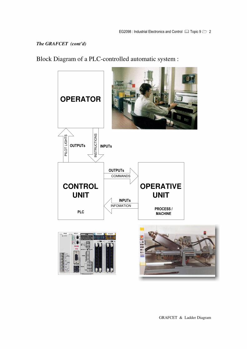
Block Diagram of a PLC-controlled automatic system :
CONTROLUNIT
OPERATIVEUNIT
COMMANDS
INFOMATION
OPERATORIN
STR
UC
TIO
NS
PIL
OT
LIG
HTS
PSA2 FP2-C1 XY64D2T XY64D2T
��� � � � �
��� � � � �
� � � � � � � �
� � � � � � � �
� � � � � � �
� � � ��� �� � �

����������� ��������������� ��������������� �� ������������
GRAFCET & Ladder Diagram
The GRAFCET (cont’d)
1
2
3
extend cylinder A
extend cylinder B
retract cylinder A
retract cylinder B
start
cylinder A extended
cylinder B extended
cylinder A retracted � cylinder B retracted
0 WAIT step ( - doing nothing, in this case )
Initial Step (double box) Initiated by First Cycle Bit
Transitions
Transitions (AND operation)
Actions
Two Actions In One step
These are sensors !
����������� ��������������� ��������������� �� ������������
GRAFCET & Ladder Diagram
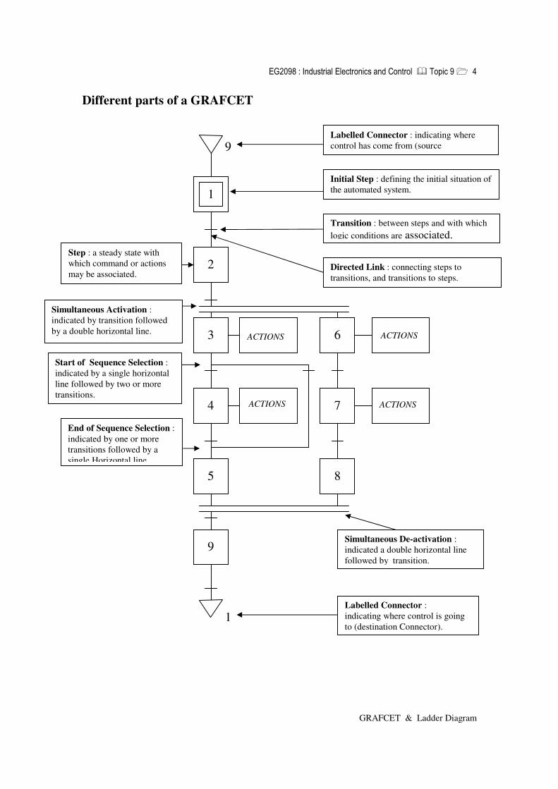
Different parts of a GRAFCET
ACTIONS ACTIONS
ACTIONS ACTIONS
1
2
3 6
4
5
7
8
9
1
9 Labelled Connector : indicating where control has come from (source
Initial Step : defining the initial situation of the automated system.
Transition : between steps and with which logic conditions are associated.
Directed Link : connecting steps to transitions, and transitions to steps.
Step : a steady state with which command or actions may be associated.
Simultaneous Activation : indicated by transition followed by a double horizontal line.
Start of Sequence Selection : indicated by a single horizontal line followed by two or more transitions.
End of Sequence Selection : indicated by one or more transitions followed by a single Horizontal line.
Simultaneous De-activation : indicated a double horizontal line followed by transition.
Labelled Connector : indicating where control is going to (destination Connector).

����������� ��������������� ��������������� �� ������������
GRAFCET & Ladder Diagram
Grafcet Design – Sequence How to do the sequence. 1. Represent the steps (step_1 and step_2) by internal
Relay bits R1 and R2. R1 and R2 will either be “1” (active) or “0” (inactive).
2. Only 1 step should be active at any one time.
3. Do not worry about outputs at the moment. 4. The initial step should be activated by the PLC
internal scan cycle (the very first cycle). After which it will be activated by step_2 and stop_PB (during the return loop). Step_1 activated by 1st cycle bit, but it will turn off during the 2nd cycle onwards. Hence, the need to on to the avtive state (therefore latch It) using step_1. Step_1 latched. When step_1 is active and start_PB is pressed, step_2 will be active and need to be latched (because start_PB will eventually be released!) (But then there will be 2 active steps: step_1 and step_2.We want to have only one active step. Therfore, when step_2 becomes active, step_2 should de-activate (kill-off) step_1. Similarly, the step after step_2, that is step_1, should be used to de-activate (kill-off) step-2. Provision must be made to go back to step_1 again when Step_2 is active and stop_PB is pressed.(This is to loop back).
1
2
START
STOP
1st_cycle_bit Step-1
Step-1
Step-2
1st_cycle_bit
Step-1
Step-1
Step-2
Start
Step-1
Step-2
Step-2
1st_cycle_bit
Step-1
Step-2
Step-1
Stop
Start
Step-2 Step-1
Occurs only once upon PLC power on
To kill Step 2 when Step 1 is active
�
�

����������� ��������������� ��������������� �� ������������
GRAFCET & Ladder Diagram
Grafcet Design – Output
How to do the output: 1. Now that we have got the sequence, (sequence
Ensures that step_1 and start_PB goes to step_2, And step_2 and stop_PB goes back to step_1, And so on) we can determine the outputs (i.e. What happens at each step).
2. We can decide to turn on red_light in step_1 And turn on green_light in step_2 (if that is What is required).
3. That means upon powering up of PLC (remember 1st_ cycle_ bit → hence the initial step : step_1), the red light turns. When start_PB is pressed, green_light turns on. When stop_PB is pressed, red light turns on, and so on. (Remember : no change in sequence, only the output).
OR
We can decide to turn on the buzzer in step_2 and turn on both the lights in step_1. So that when start_PB is pressed, the red_light and green_light will turn on. (Remember : still no change in sequence, only the output).
2
1
START
STOP
ON RED
ON GREEN 2
Step-1
Step-2 ON GREEN
ON RED
1
START
STOP
ON RED ON GREEN
ON BUZZER 2
Step-1 ON RED
ON GREEN
Step-2 ON BUZZER
Work the Outputs from right to left
�

����������� ��������������� ��������������� �� ������������
GRAFCET & Ladder Diagram
OR
Other examples.
Note : Beware of repeated output in the ladder diagram program. Even though the GRAFCET contains two instances of ON BUZZER The OUTPUT ladder diagram should contain only one instance of ON BUZZER. It is wise therefore to state the output first and see which steps need this output. That is work the output part of the ladder diagram from right to left.
1
START
STOP
ON RED ON GREEN
ON RED ON BUZZER
2 Step-1
Step-2
Step-1
Step-2 ON BUZZER
ON GREEN
ON RED
1
START
STOP
ON RED ON BUZZER
ON GREEN ON BUZZER
2
Step-1
Step-2
Step-1
Step-2 ON GREEN
ON RED
ON BUZZER
Outputs may be in any order
No Repeated Outputs !!
Inputs may be repeated
Outputs
�

����������� ��������������� ��������������� �� ������������
GRAFCET & Ladder Diagram
1 UNPROCESSED
MATERIAL IN POSITION
LOWER STAMP
RAISE STAMP
LOWER DIE
EVACUATE PART
RAISE DIE
Material in position and cycle start
End of compression
Stamp in high position
Die in low position
Evacuation completed
Die in high position
2
6
5
4
3
GRAFCET of the Press Start PB Stamp
Die
( steps )
( input = sensor )
( outputs / actions )
Stamp
Stamp
Die
Die
Stamp
Stamp
Done manually by operator

����������� ��������������� ��������������� �� ������������
GRAFCET & Ladder Diagram
SEQUENCE
Step-2
1st_cycle_bit
Die-High Step-6
Step-1 Step-2
Step-1
Step-1 Material Start
Step-2 Step-3
Step-2
Step-2 End-High
Step-3 Step-4
Step-3
Step-3 Stamp-High
Step-4 Step-5
Step-4
Step-4 Die-Low
Step-5 Step-6
Step-5
Step-6 Step-5 Evacuate
Step-6 Step-1
OUTPUT
Step-3
Step-4
Step-5
Step-6
Lower Stamp
Raise Stamp
Lower Die
Evacuate part
Raise Die
Ladder Diagram of the Press

����������� ��������������� ��������������� �� �������������
GRAFCET & Ladder Diagram
Project 1 - Moving a Wagon
Left Side Right Side
Moving A Wagon
1
2 Move Wagon to the Right
3
Start PB pressed
Left Side reached
Right Side reached
Move Wagon to the Left
Start PB
Step-3
Step-1
Step-2
1st_cycle_bit
Left-side
Step-1
Step-3
Step-2
Step-1 Start
Step-2 Step-3
Step-2 Right-side
Step-3 Step-1
SEQUENCE OUTPUT
Step-2
Step-3
Move-right
Move-left
����������� ��������������� ��������������� �� �������������
GRAFCET & Ladder Diagram
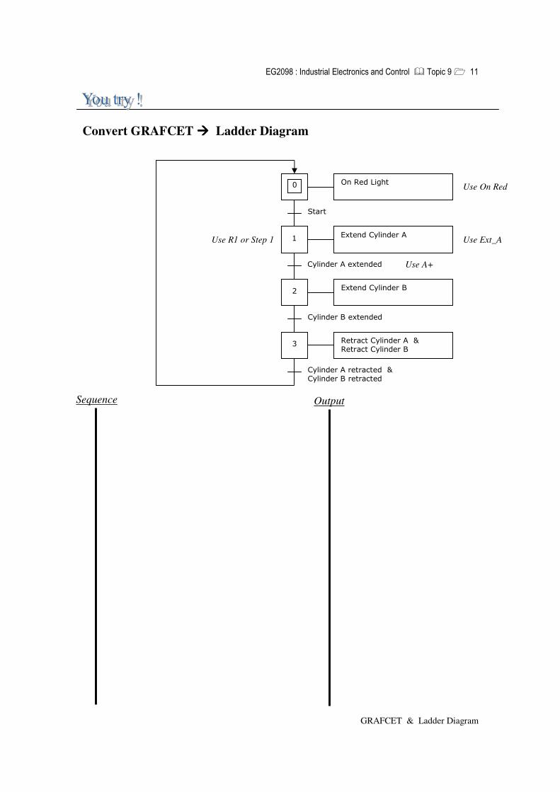
Convert GRAFCET ���� Ladder Diagram
�� �����������
�����
�� �����������������
��������������������
����������������
�������������������
���������������������������������������
��������������������������������������������
��
��
Sequence Output
Use Ext_A
Use A+
Use On Red
Use R1 or Step 1

����������� ��������������� ��������������� �� �������������
GRAFCET & Ladder Diagram
1
2
3
Run & System initialised
Cylinder B extended
Cylinder A extended
On Green Light Extend Cylinder A
Step 4 / TIM001 / 3s . Drill_low
Drill_ high
Cylinder A retracted . Cylinder B retracted
Extend Cylinder B
Lower Drill
Raise Drill
Retract Cylinder A Retract Cylinder B
4
5
6
Drill-high
Drill-Low
Drill
Part / Material
Cylinder B Cylinder A
GRAFCET of the Drill
Cylinder A and Cylinder B hold the material (part to be drilled) tightly while the drilling machine drills the hole.
A+ A - B -
B+
System initialization : Retract Cylinder A Retract Cylinder B Off Green Light
sensors
sensors
����������� ��������������� ��������������� �� �����������
GRAFCET & Ladder Diagram
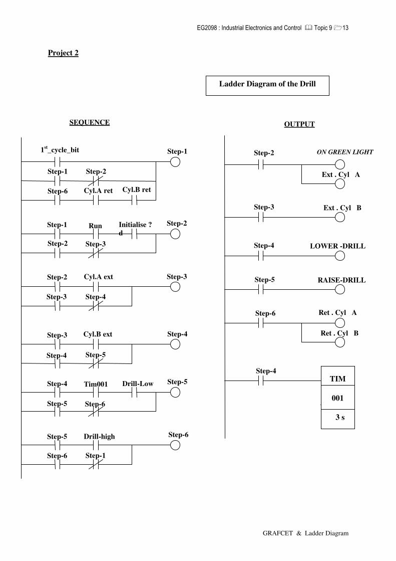
Project 2
SEQUENCE
1 st _cycle_bit
Step - 1 Step - 2
Step - 6 Cyl.A ret Cyl.B ret
Step - 1 Run
Step - 2 Step - 3
Step - 2 Cyl.A ext
Step - 3 Step - 4
Step - 4 Tim001
Step - 5 Step - 6
Initialise ? d
Drill - Low
Step - 5 Drill - high
Step - 6 Step - 1
Step - 3 Cyl. B ext
Step - 4 Step - 5
Step - 1
Step - 2
Step - 3
Step - 4
Step - 5
Step - 6
E xt . C yl A
Step - 2
Step - 4
Step - 3
Step - 5
OUTPUT
Step - 6
Step - 4 TIM
001
3 s
RAISE - DRILL
R et . C yl A
R et . C yl B
E xt . C yl B
Ladder Diagram of the Drill
ON GREEN LIGHT
LOWER -DRILL

����������� ��������������� ��������������� �� �����������
GRAFCET & Ladder Diagram
Grafcet Design Automatic Hand Dryer The system incorporates a diffuse sensor to detect the the presence of a pair of hands. When a pair of hands are placed just below the the Automatic Hand Dryer, heated air flow is turned on. When the person has completed drying his hands, the removal or absence of hands will be detected. The heated air will continue to flow for a further 3 seconds before the heated air flow is turned off.
1
2
Off Hand Dryer
3
Presence of Hands
Step 3 / Timer5 / 3s
Absence of Hands
On Hand Dryer
Automatic Hand Dryer
Fill in the blanks :
Inputs Outputs

����������� ��������������� ��������������� �� �����������
GRAFCET & Ladder Diagram
Automatic Hand Dryer
Step - 1
Step - 2
DIF
Ste p - 0
Step - 0 1 st _cycle_bit
Step - 0 Step - 1
Step - 2 Tim 005
Step - 1 Step - 0
Step - 1
DIF
Step - 2
SEQUENCE
Step - 2
Step - 0
Step - 1
Step - 2
OUTPUT
Step - 2
OFF HAND DRYER
ON H AND DRYER
Presence
Absence
DIF (=ON) = Presence of hands
Timer5
3s

����������� ��������������� ��������������� �� �����������
GRAFCET & Ladder Diagram
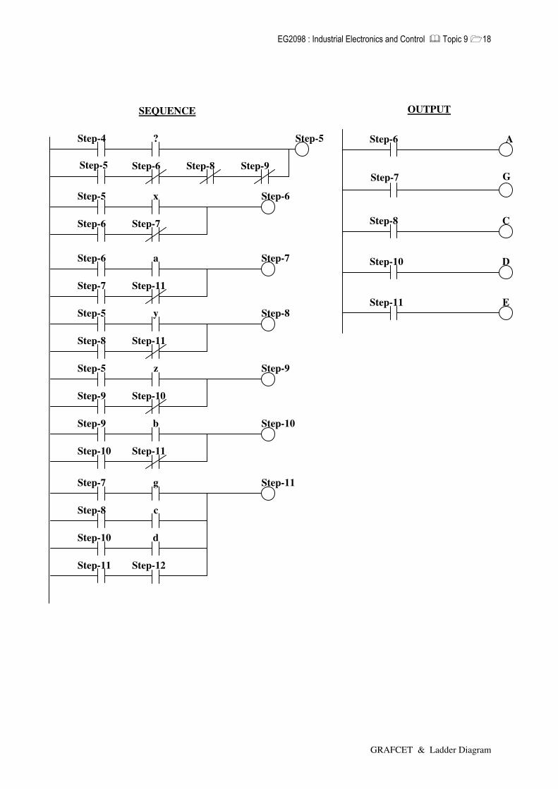
GRAFCET with multiple selections
A Grafcet is generally made up of several sequences (several series of steps that execute one after the other) and it is often necessary to exclusively select one of these sequences. Example:
5
8 6 9
10 7
11
Action A Action C
Action G Action D
Action E
x y z
a c
g
b
d
The above GRAFCET consists of a switch which allow to select one out of three possible sequences depend on the transition conditions x, y and z. The different transitions corresponding with their conditions x, y and z may be enable simultaneously and they could be cleared simultaneously if the transition conditions x, y and z were true at the same time. In order to avoid this from happening, the transition conditions must be mutually exclusive. It is also possible to introduce the priorities among the different sequences.
k

����������� ��������������� ��������������� �� �����������
GRAFCET & Ladder Diagram
GRAFCET with multiple selections
12
13 14
a.b
The transition conditions a.b and a.b are mutually exclusive. If a and b are both present, the transition from step 12 will not be cleared.
a.b
12
13 14
a
The transition 12-13 has higher priority than 12-14: the transition 12-13 will be cleared if both a and b are true at the same time.
a.b
f.e
Action E
15
14
13
12
Action G
Action H
Action J
g
h
j
f.e
Jump from step 12 to step 15 if condition f.e is true.
k
Action K
19
18
17
16
Action L
Action M
Action P
l
n.m
p
n.m
Repeat 17-18 if condition n.m is not obtained and n.m is true.
����������� ��������������� ��������������� �� �����������
GRAFCET & Ladder Diagram
Step-6 A
Step-11 E
Step-8 C
Step-10 D
OUTPUT
Step-5
Step-6
x
Step-7
Step-6
Step-5
Step-9
z
Step-10
Step-9
Step-9
Step-10
b
Step-11
Step-10
Step-5
Step-8
y
Step-11
Step-8
Step-6
Step-7
a
Step-11
Step-7
Step-4
Step-5
?
Step-6
Step-5
Step-7
Step-8
g
c
Step-11
Step-10
Step-11
d
Step-12
Step-8 Step-9
SEQUENCE
Step-7 G

����������� ��������������� ��������������� �� �����������
GRAFCET & Ladder Diagram
Label Addr Label Addr Head Tail
X1 X2
TOSS COIN GREEN RED
Y1 Y2 Y3
1
2
TOSS COIN
ON GREEN
ON RED 3
TAIL
HEAD
STEP - 2 - 3/ Timer7 / 3s
GRAFCET : COIN TOSSER
TOSS COIN 1 st _cycle_bit
Step - 1 Step - 2
Step - 1
Step - 1
Step - 2
Head
Step - 1
Step - 2
Step - 1
Step - 3
Tail
Step - 1
Step - 3
Step - 2
Step -
Input Output
3
Timer7
Step - 1
Step - 3 ON RED
Step - 2 ON GREEN
Step - 2 Timer7
3s Step - 3
OUTPUT SEQUENCE
Step - 3
���� IO Listing or IO Address Assignment Table

����������� ��������������� ��������������� �� �����������
GRAFCET & Ladder Diagram
SOLUTION : Sequence & Output
FAIL-PUSHER-EXT
EXTEND FAIL-PUSHER
EXTEND PASS-PUSHER
LOAD NEXT COMPONENT
START
PASS
PASS-PUSHER-EXT
FAIL
MATERIAL (IN POSITION)
1
2
4 3
5
GRAFCET: COMPONENT INSPECTION
����������� ��������������� ��������������� �� �����������
GRAFCET & Ladder Diagram
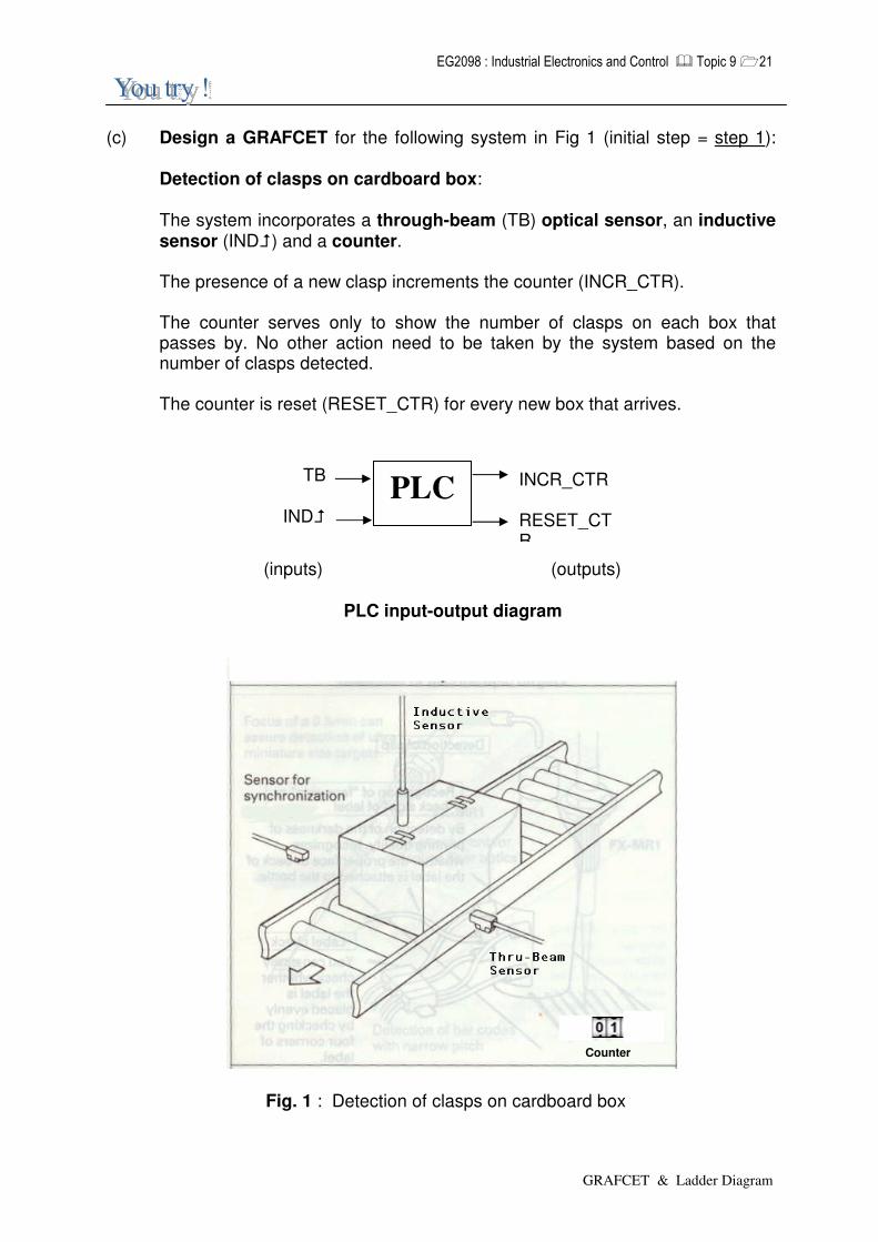
(c) Design a GRAFCET for the following system in Fig 1 (initial step = step 1):
Detection of clasps on cardboard box: The system incorporates a through-beam (TB) optical sensor, an inductive sensor (IND�) and a counter. The presence of a new clasp increments the counter (INCR_CTR). The counter serves only to show the number of clasps on each box that passes by. No other action need to be taken by the system based on the number of clasps detected. The counter is reset (RESET_CTR) for every new box that arrives.
(inputs) (outputs) PLC input-output diagram
Fig. 1 : Detection of clasps on cardboard box
PLC INCR_CTR RESET_CTR
TB
IND�
Counter

����������� ��������������� ��������������� �� �����������
GRAFCET & Ladder Diagram
Solution :
����������� ��������������� ��������������� �� �����������
GRAFCET & Ladder Diagram
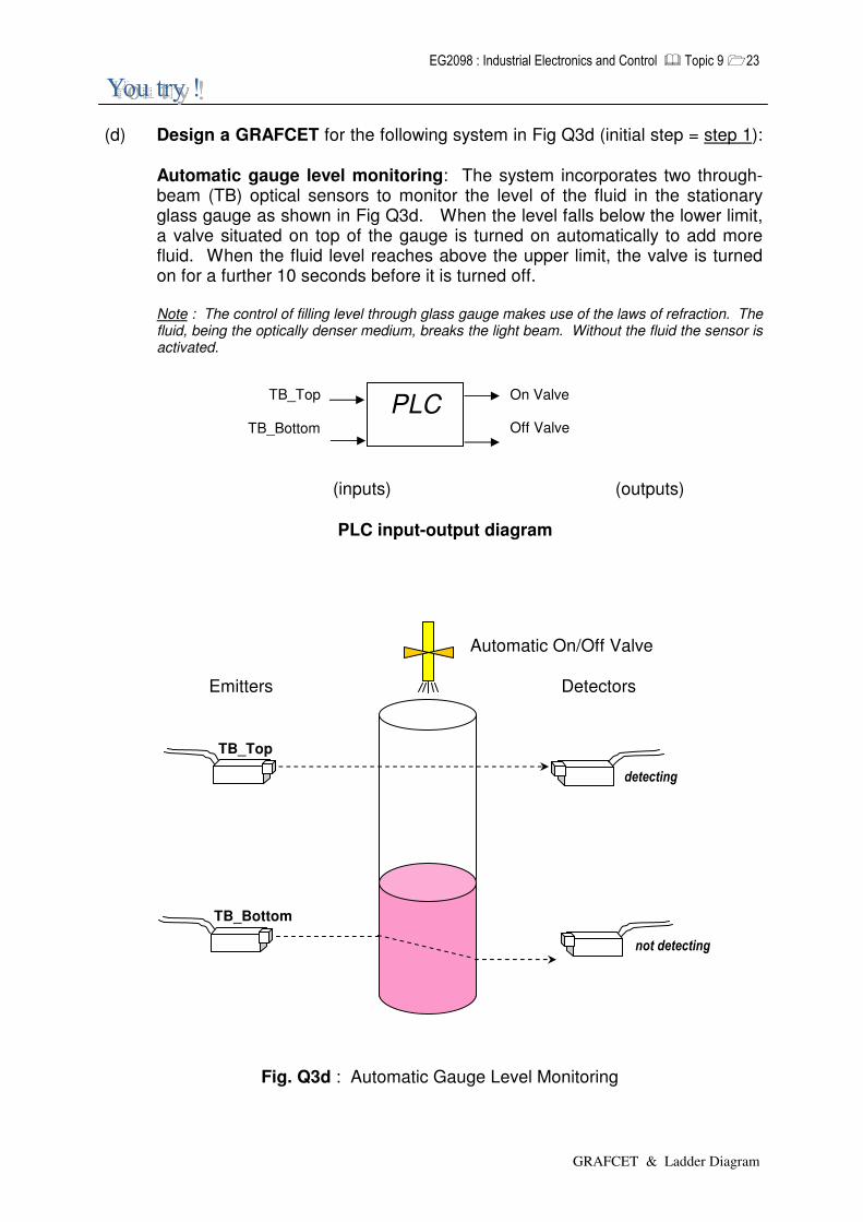
(d) Design a GRAFCET for the following system in Fig Q3d (initial step = step 1):
Automatic gauge level monitoring: The system incorporates two through-beam (TB) optical sensors to monitor the level of the fluid in the stationary glass gauge as shown in Fig Q3d. When the level falls below the lower limit, a valve situated on top of the gauge is turned on automatically to add more fluid. When the fluid level reaches above the upper limit, the valve is turned on for a further 10 seconds before it is turned off.
Note : The control of filling level through glass gauge makes use of the laws of refraction. The fluid, being the optically denser medium, breaks the light beam. Without the fluid the sensor is activated.
(inputs) (outputs) PLC input-output diagram
Automatic On/Off Valve Emitters Detectors
Fig. Q3d : Automatic Gauge Level Monitoring
PLC On Valve Off Valve
TB_Top
TB_Bottom
����������
�������������
TB_Bottom
TB_Top

����������� ��������������� ��������������� �� �����������
GRAFCET & Ladder Diagram
Solution :
Related Documents