Huang et al. / J Zhejiang Univ Sci A 2009 10(2):151-164 151 Gradual refinement for application-specific MPSoC design from Simulink model to RTL implementation # Kai HUANG †1 , Xiao-lang YAN 1 , Sang-il HAN 2 , Soo-ik CHAE 2 , Ahmed A. JERRAYA 3 , Katalin POPOVICI 4 , Xavier GUERIN 4 , Lisane BRISOLARA 5 , Luigi CARRO 5 ( 1 Institute of VLSI Design, Zhejiang University, Hangzhou 310027, China) ( 2 System Design Group, Seoul National University, Seoul 151-744, Korea) ( 3 CEA-LETI, Grenoble 38054, France) ( 4 SLS Group, TIMA Laboratory, Grenoble 38031, France) ( 5 Informatics Institute, Federal University of Rio Grande do Sul, Porto Alegre 15064, Brazil) † E-mail: [email protected] Received Jan. 28, 2008; Revision accepted July 30, 2008; Crosschecked Oct. 28, 2008 Abstract: The application-specific multiprocessor system-on-chip (MPSoC) architecture is becoming an attractive solution to deal with increasingly complex embedded applications, which require both high performance and flexible programmability. As an effective method for MPSoC development, we present a gradual refinement flow starting from a high-level Simulink model to a synthesizable and executable hardware and software specification. The proposed methodology consists of five different abstract levels: Simulink combined algorithm and architecture model (CAAM), virtual architecture (VA), transactional accurate archi- tecture (TA), virtual prototype (VP) and field-programmable gate array (FPGA) emulation. Experimental results of Motion-JPEG and H.264 show that the proposed gradual refinement flow can generate various MPSoC architectures from an original Simulink model, allowing processor, communication and tasks design space exploration. Key words: Multiprocessor system-on-chip (MPSoC) design, Refinement, Simulink, SystemC, Motion-JPEG, H.264 doi:10.1631/jzus.A0820085 Document code: A CLC number: TN402; TP36 INTRODUCTION With the increasing demand for complex em- bedded applications, heterogeneous multithreaded multiprocessor system-on-chip (MPSoC) architec- tures are becoming attractive solutions, because of their high computation power and flexible program- mability (Jerraya et al., 2005). MPSoC hardware architectures may be represented, without loss of generality, as a set of processing nodes or components which interact via a communication network (Jerraya et al., 2006). As shown by (a) in Fig.1, processing nodes may be either hardware or software. Software nodes are those programmable sub-systems with one or several processors. The heterogeneity of proces- sors implies the need for multiple software stacks that may require different computation and communica- tion performances. The MPSoC software stack is organized by three layers: application software, hardware dependent software (HdS), and hardware abstraction layer (HAL) (Jerraya et al., 2006), as shown by (b) in Fig.1. The application software may be a multithreaded description of the application, which makes use of high-level primitives (HdS API) to abstract the underlying platform. The HdS consists of a thread library and a specific I/O communication library. The HAL is responsible for architecture- specific services (HAL API), such as context switching, interrupt service routines, specific hard- ware components, and specific I/O controls. As more Journal of Zhejiang University SCIENCE A ISSN 1673-565X (Print); ISSN 1862-1775 (Online) www.zju.edu.cn/jzus; www.springerlink.com E-mail: [email protected] # Expanded based on “Simulink-based MPSoC Design Flow: Case Study for Motion-JPEG and H.264” by Kai Huang, Sang-il Han, et al., which appeared in the Proceedings of the 2007 Design Automa- tion Conference (DAC 2007)

Welcome message from author
This document is posted to help you gain knowledge. Please leave a comment to let me know what you think about it! Share it to your friends and learn new things together.
Transcript
Huang et al. / J Zhejiang Univ Sci A 2009 10(2):151-164 151
Gradual refinement for application-specific MPSoC design from Simulink model to RTL implementation#
Kai HUANG†1, Xiao-lang YAN1, Sang-il HAN2, Soo-ik CHAE2, Ahmed A. JERRAYA3,
Katalin POPOVICI4, Xavier GUERIN4, Lisane BRISOLARA5, Luigi CARRO5 (1Institute of VLSI Design, Zhejiang University, Hangzhou 310027, China) (2System Design Group, Seoul National University, Seoul 151-744, Korea)
(3CEA-LETI, Grenoble 38054, France) (4SLS Group, TIMA Laboratory, Grenoble 38031, France)
(5Informatics Institute, Federal University of Rio Grande do Sul, Porto Alegre 15064, Brazil) †E-mail: [email protected]
Received Jan. 28, 2008; Revision accepted July 30, 2008; Crosschecked Oct. 28, 2008 Abstract: The application-specific multiprocessor system-on-chip (MPSoC) architecture is becoming an attractive solution to deal with increasingly complex embedded applications, which require both high performance and flexible programmability. As an effective method for MPSoC development, we present a gradual refinement flow starting from a high-level Simulink model to a synthesizable and executable hardware and software specification. The proposed methodology consists of five different abstract levels: Simulink combined algorithm and architecture model (CAAM), virtual architecture (VA), transactional accurate archi-tecture (TA), virtual prototype (VP) and field-programmable gate array (FPGA) emulation. Experimental results of Motion-JPEG and H.264 show that the proposed gradual refinement flow can generate various MPSoC architectures from an original Simulink model, allowing processor, communication and tasks design space exploration. Key words: Multiprocessor system-on-chip (MPSoC) design, Refinement, Simulink, SystemC, Motion-JPEG, H.264 doi:10.1631/jzus.A0820085 Document code: A CLC number: TN402; TP36 INTRODUCTION
With the increasing demand for complex em-
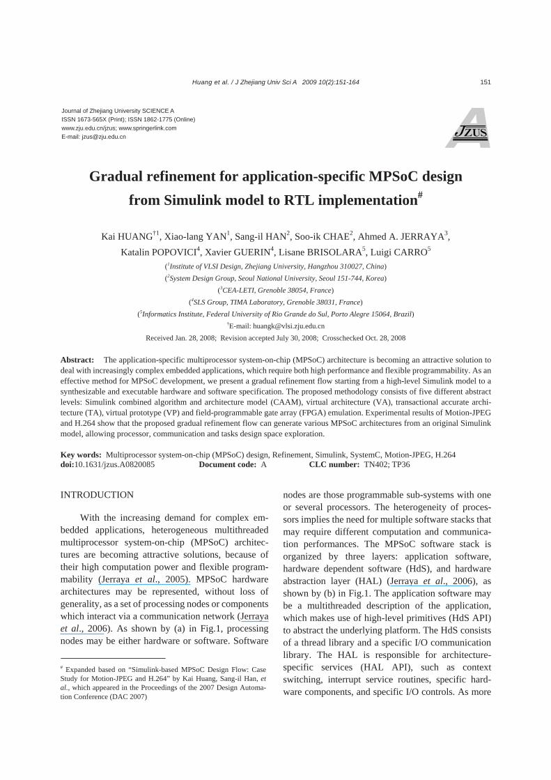
bedded applications, heterogeneous multithreaded multiprocessor system-on-chip (MPSoC) architec-tures are becoming attractive solutions, because of their high computation power and flexible program-mability (Jerraya et al., 2005). MPSoC hardware architectures may be represented, without loss of generality, as a set of processing nodes or components which interact via a communication network (Jerraya et al., 2006). As shown by (a) in Fig.1, processing nodes may be either hardware or software. Software
nodes are those programmable sub-systems with one or several processors. The heterogeneity of proces-sors implies the need for multiple software stacks that may require different computation and communica-tion performances. The MPSoC software stack is organized by three layers: application software, hardware dependent software (HdS), and hardware abstraction layer (HAL) (Jerraya et al., 2006), as shown by (b) in Fig.1. The application software may be a multithreaded description of the application, which makes use of high-level primitives (HdS API) to abstract the underlying platform. The HdS consists of a thread library and a specific I/O communication library. The HAL is responsible for architecture- specific services (HAL API), such as context switching, interrupt service routines, specific hard-ware components, and specific I/O controls. As more
Journal of Zhejiang University SCIENCE A ISSN 1673-565X (Print); ISSN 1862-1775 (Online) www.zju.edu.cn/jzus; www.springerlink.com E-mail: [email protected]
# Expanded based on “Simulink-based MPSoC Design Flow: Case Study for Motion-JPEG and H.264” by Kai Huang, Sang-il Han, et al., which appeared in the Proceedings of the 2007 Design Automa-tion Conference (DAC 2007)
Huang et al. / J Zhejiang Univ Sci A 2009 10(2):151-164
152
processors and hardware components are integrated, designing and programming these complex multi-processor architectures has become a major challenge.
In a pure top-down design process as shown in Fig.1, application specification is the starting point for the design process, and the mapping of an algo-rithm to an architecture is an essential step from conception to implementation (Keutzer et al., 2000). In conventional design approaches, hardware and software are usually considered separately, and their integration is done only when the hardware is fully defined (e.g., after RTL implementation). The lack of early coordination between hardware and software designs can cause unacceptable delay and cost over-heads at the system level. Therefore, design and verification of hardware and software should be per-formed concurrently at all abstraction levels of the design flow, in order to reduce design time for com-plex multiprocessor systems (Jerraya and Wolf, 2005). Furthermore, starting at the application level, there is a need for programming models and communication APIs that allow applications to be easily re-configured for many different possible architec-tures without tedious rewriting, while at the same time ensuring efficient production code (Grant, 2006).
This paper focuses on a gradual hardware and software refinement flow for application-specific MPSoC, which starts from a Simulink algorithm model and has an RTL implementation as a result. It provides concurrent hardware/software design and
verification at five different abstraction levels: Simu-link combined algorithm and architecture model (CAAM) for high-level algorithm and architecture specification, virtual architecture (VA) model for early development and validation of the multi-threaded application software, transactional accurate architecture (TA) model for fast verification of hardware architecture and operating system (OS) library, virtual prototype (VP) model for accurate system verification and performance estimation, and RTL model for field-programmable gate array (FPGA) emulation and implementation. Using these pro-gramming models, which cover abstract specification to detailed low-level implementation, one can gradu-ally refine the hardware/software interface and effi-ciently validate function and performance of the tar-geted MPSoC hardware and software architecture. The experimental results using a Motion-JPEG de-coder and an H.264 baseline decoder show the feasi-bility and efficiency of the proposed methodology, the specific MPSoC refinement flow, in both the functional and the physical dimensions.
The rest of the paper is organized as follows. Section 2 discusses the related work about MPSoC design. Section 3 presents the gradual flow of hard-ware and software refinement for MPSoC design from Simulink model to RTL implementation. Sec-tion 4 shows the experimental results covering Motion-JPEG and H.264 decoders using the proposed MPSoC refinement flow. Finally, Section 5 concludes the paper and discusses future work.
SW NodeSW NodeSW Node
AlgorithmspecificationArchitectureCPU
HWaccel.NIComm.
SW node
Network interconnection
NI
HW node
F3
F4
F5
F6F1 F2 F8F7
F9F10
TnT2
HdS
HdS API
HAL
HAL API
T1
(a) Hardware architecture
(b) Software stack
Application
RTL/Gate implementation
High-levelabstractionHW & SW
programming model
CPUSW node
Mapping
Memory
HW: hardware SW: software NI: network interface HdS: hardware dependent softwareHAL: hardware abstraction layer
Fig.1 MPSoC design from application to RTL implementation
Huang et al. / J Zhejiang Univ Sci A 2009 10(2):151-164 153
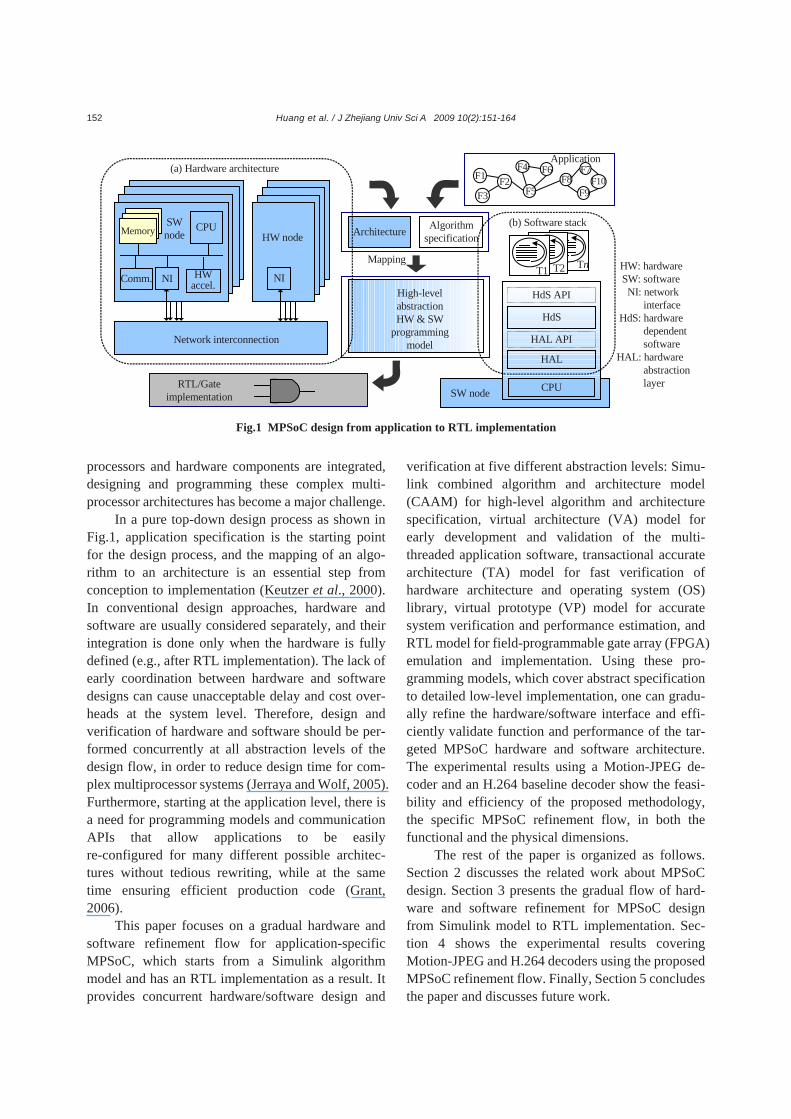
RELATED WORK Nowadays, Simulink (Mathworks, Inc.) has been
widely adopted as the prevailing environment for modeling and simulation of complex systems at the algorithm level of abstraction. There are several tools to map Simulink models into hardware or software designs. For example, dSpace (dSpace, Inc.) provides an automatic software generator, targeted to a specific architecture, which consists of several commercial off-the-shelf (COTS) processor boards, and generates software code for a multiprocessor system from a specific Simulink model. In (Reynari et al., 2001) a design flow for data-dominated embedded systems is proposed, which uses Simulink environment for functional specification and analysis of timing and power dissipation. This approach mainly focuses on an IP-based design with a single processor. System Generator for DSP (Xilinx, Inc.) and DSP Builder (Altera, Inc.) are high-level tools for designing multi- processor systems with hardware logics targeted to FPGAs from Simulink. Using a similar method, Ou and Prasanna (2005) proposed a design space explo-ration technique for configurable multiprocessor platforms. However, these tools mostly focus on generating either software or hardware, but not both.
Recently, SystemC has become a preferred hardware-software co-design language, because it enables one to specify and simulate both software and hardware within a wide range of abstraction levels. ROSES (Cesario et al., 2002) and ConvergenSC (Coware, Inc.) tools have proposed the automatic generation of the software and hardware of an MPSoC from its SystemC transaction-level model. However, since a SystemC model is still oriented towards hardware designers, it is not suitable for specifying complex systems at the algorithm level. We propose a gradual refinement from an application algorithm using Simulink to several high-level ab-straction models with SystemC. A Simulink-SystemC joint design flow can improve the efficiency for early software/hardware architecture co-design.
Ptolemy (Ptolemy Project, 2006, http://ptolemy. eecs.berkeley.edu), Metropolis (Balarin et al., 2003), Artemis (Pimentel et al., 2001) and SpecC (Gajski et al., 2000) are high-level design frameworks for system-level specification, simulation, analysis and synthesis. Ptolemy is a well-known development
environment for high-level system specification and simulation that supports multiple models of compu-tation (e.g., SDF, BDF, FSM, etc.). Metropolis en-ables the representation of design constraints in the system model. The meta-model serves as input for all the tools built in Metropolis. The meta-model files are parsed and turned into an abstract syntax tree (AST) by the Metropolis front-end. Tools are written as back-ends that operate on the AST, and either output results or modify the meta-model code (www. gigascale.org/metropolis/tods.html). Artemis pro-vides a high-level modeling and simulation envi-ronment to automatically refine hardware/software from a coarse-grain Kahn process network (KPN) (Kahn and MacQueen, 1977). This environment supports a subset of Matlab for the application de-scription, and Pearl or SystemC for the architecture description, at the same time providing a fast simula-tion method based on computation and communica-tion events generated from an application model. The SpecC methodology follows a top-down approach, which uses the SpecC language as a high-level ab-stract specification of the intended system, and refines it down to a cycle-accurate implementation at the RTL level. The software code with real-time OS IP is not developed until the hardware architecture design is completed at the back-end stage. Koski (Kangas et al., 2006) was proposed as a UML-based MPSoC design flow that provides an automated path from UML design entry to FPGA prototyping, including functional verification and automated architecture exploration. However, most of these tools design hardware and software separately. On the contrary, the flow proposed here uses one mixed model to de-scribe hardware and software orthogonally. Both the hardware architecture and the multithreaded software code can be gradually refined from this mixed model to different abstraction level models. Moreover, some problems of complex MPSoC hardware and software co-design can also be found in the early design stage, which greatly promotes design efficiency. GRADUAL REFINEMENT FOR MPSOC DESIGNS
As shown in Fig.2, the gradual refinement from
application to circuit implementation follows the
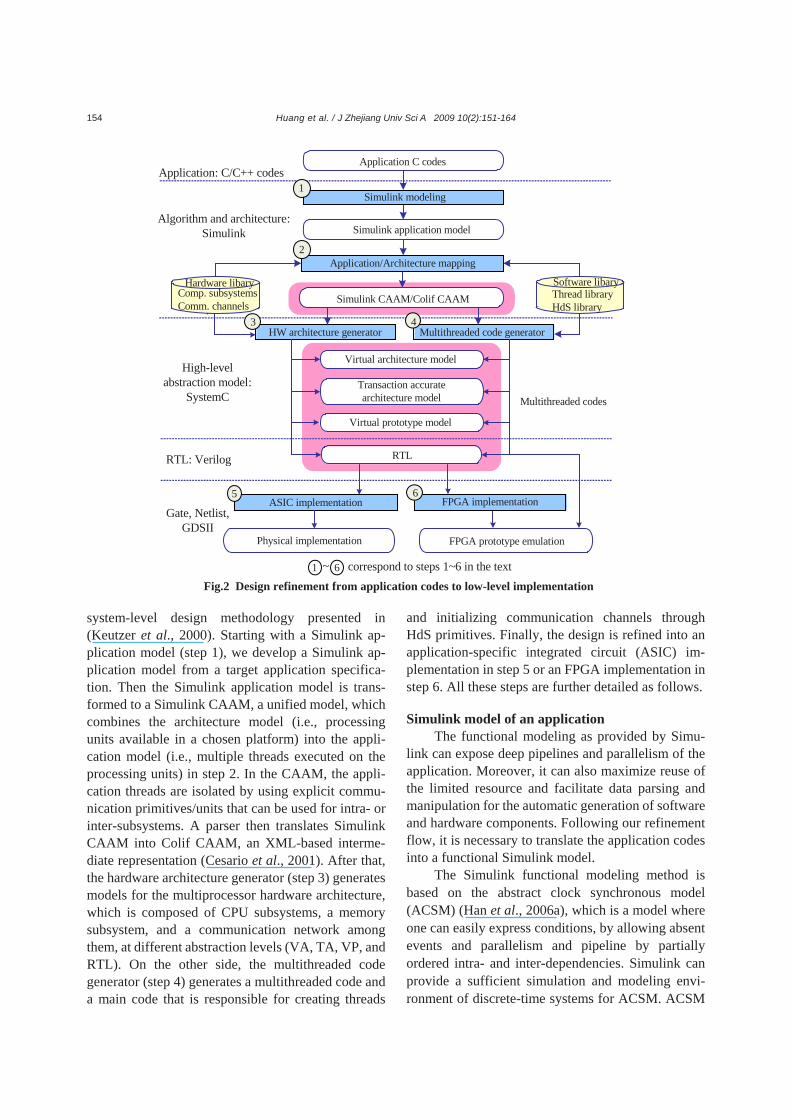
Huang et al. / J Zhejiang Univ Sci A 2009 10(2):151-164
154
system-level design methodology presented in (Keutzer et al., 2000). Starting with a Simulink ap-plication model (step 1), we develop a Simulink ap-plication model from a target application specifica-tion. Then the Simulink application model is trans-formed to a Simulink CAAM, a unified model, which combines the architecture model (i.e., processing units available in a chosen platform) into the appli-cation model (i.e., multiple threads executed on the processing units) in step 2. In the CAAM, the appli-cation threads are isolated by using explicit commu-nication primitives/units that can be used for intra- or inter-subsystems. A parser then translates Simulink CAAM into Colif CAAM, an XML-based interme-diate representation (Cesario et al., 2001). After that, the hardware architecture generator (step 3) generates models for the multiprocessor hardware architecture, which is composed of CPU subsystems, a memory subsystem, and a communication network among them, at different abstraction levels (VA, TA, VP, and RTL). On the other side, the multithreaded code generator (step 4) generates a multithreaded code and a main code that is responsible for creating threads
and initializing communication channels through HdS primitives. Finally, the design is refined into an application-specific integrated circuit (ASIC) im-plementation in step 5 or an FPGA implementation in step 6. All these steps are further detailed as follows.
Simulink model of an application
The functional modeling as provided by Simu-link can expose deep pipelines and parallelism of the application. Moreover, it can also maximize reuse of the limited resource and facilitate data parsing and manipulation for the automatic generation of software and hardware components. Following our refinement flow, it is necessary to translate the application codes into a functional Simulink model.
The Simulink functional modeling method is based on the abstract clock synchronous model (ACSM) (Han et al., 2006a), which is a model where one can easily express conditions, by allowing absent events and parallelism and pipeline by partially ordered intra- and inter-dependencies. Simulink can provide a sufficient simulation and modeling envi-ronment of discrete-time systems for ACSM. ACSM
Application C codes
Simulink modeling
Simulink application model
Application/Architecture mapping
Simulink CAAM/Colif CAAM
Virtual architecture model
Transaction accurate architecture model
Virtual prototype model
HW architecture generator Multithreaded code generator43
Hardware libary
.
Software libaryThread libraryHdS library
ASIC implementation5
1
2
Physical implementation
Multithreaded codes
Application: C/C++ codes
Algorithm and architecture: Simulink
High-level abstraction model:
SystemC
RTL: Verilog
Gate, Netlist, GDSII
RTL
FPGA implementation6
FPGA prototype emulation
Comp. subsystems Comm. channels
correspond to steps 1~6 in the text1 6~
Fig.2 Design refinement from application codes to low-level implementation
Huang et al. / J Zhejiang Univ Sci A 2009 10(2):151-164 155
involves three basic components: block, delay and arc, which correspond to block, discrete delay and con-necting line in Simulink, respectively. Two subsys-tems of ACSM, IAS and FIS, can be used as if-action subsystem and for-iterator subsystem in Simulink.
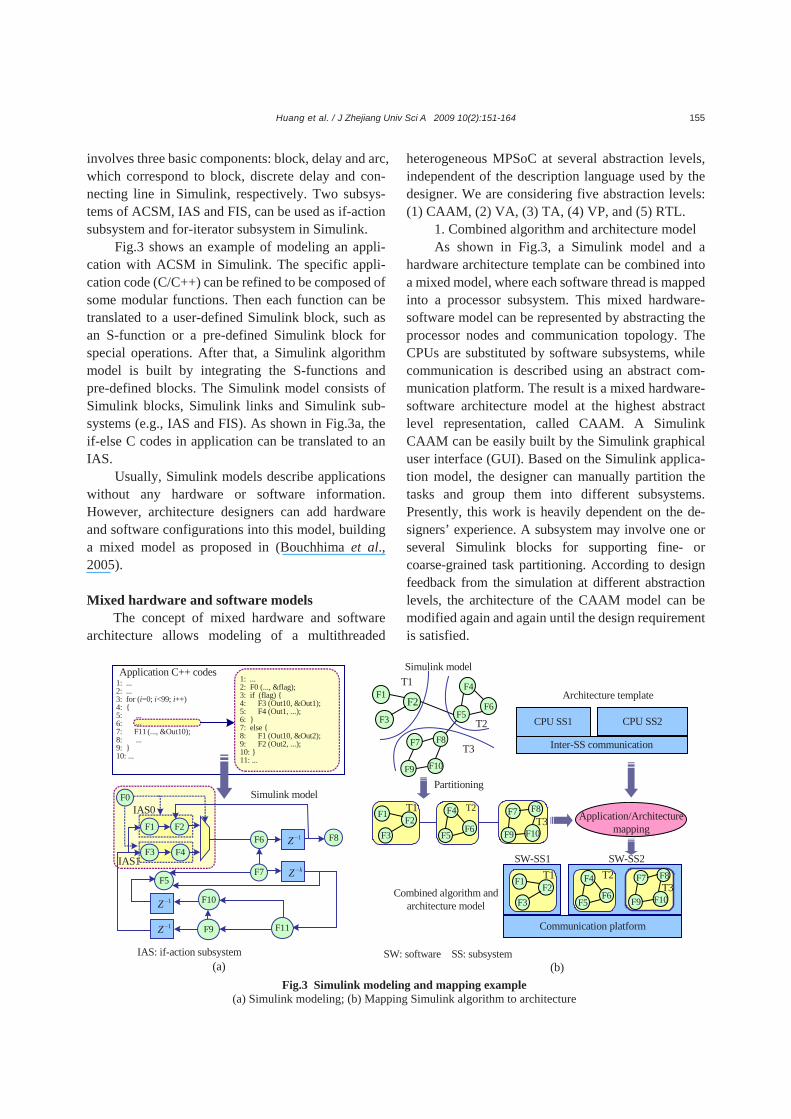
Fig.3 shows an example of modeling an appli-cation with ACSM in Simulink. The specific appli-cation code (C/C++) can be refined to be composed of some modular functions. Then each function can be translated to a user-defined Simulink block, such as an S-function or a pre-defined Simulink block for special operations. After that, a Simulink algorithm model is built by integrating the S-functions and pre-defined blocks. The Simulink model consists of Simulink blocks, Simulink links and Simulink sub-systems (e.g., IAS and FIS). As shown in Fig.3a, the if-else C codes in application can be translated to an IAS.
Usually, Simulink models describe applications without any hardware or software information. However, architecture designers can add hardware and software configurations into this model, building a mixed model as proposed in (Bouchhima et al., 2005).
Mixed hardware and software models
The concept of mixed hardware and software architecture allows modeling of a multithreaded
heterogeneous MPSoC at several abstraction levels, independent of the description language used by the designer. We are considering five abstraction levels: (1) CAAM, (2) VA, (3) TA, (4) VP, and (5) RTL.
1. Combined algorithm and architecture model As shown in Fig.3, a Simulink model and a
hardware architecture template can be combined into a mixed model, where each software thread is mapped into a processor subsystem. This mixed hardware- software model can be represented by abstracting the processor nodes and communication topology. The CPUs are substituted by software subsystems, while communication is described using an abstract com-munication platform. The result is a mixed hardware- software architecture model at the highest abstract level representation, called CAAM. A Simulink CAAM can be easily built by the Simulink graphical user interface (GUI). Based on the Simulink applica-tion model, the designer can manually partition the tasks and group them into different subsystems. Presently, this work is heavily dependent on the de-signers’ experience. A subsystem may involve one or several Simulink blocks for supporting fine- or coarse-grained task partitioning. According to design feedback from the simulation at different abstraction levels, the architecture of the CAAM model can be modified again and again until the design requirement is satisfied.
Fig.3 Simulink modeling and mapping example (a) Simulink modeling; (b) Mapping Simulink algorithm to architecture
F3
F4
F5F6
F7 F8
F9
F1F2
T1
T2
T3
CPU SS1 CPU SS2
Inter-SS communication
F3
F1F2
F4
F6F5
F7 F8
F10F9
T1 T2T3
F3
F1F2
F4
F6F5
F7 F8
F10F9
T1 T2T3
Communication platform
SW-SS1 SW-SS2
Partitioning
Combined algorithm and architecture model
Simulink model
Architecture template
Application/Architecture mapping
F3 F4
F1 F2
F5
IAS1
IAS0
F6
F7
F0
F8
F11
1: ...2: F0 (..., &flag);3: if (flag) {4: F3 (Out10, &Out1);5: F4 (Out1, ...);6: } 7: else {8: F1 (Out10, &Out2);9: F2 (Out2, ...); 10: }11: ...
1: ...2: ...3: for (i=0; i<99; i++)4: { 5: ...6: ...7: F11 (..., &Out10);8: ...9: }10: ...
...
Application C++ codes
F10
F9
Simulink model
(a) (b)
1Z −
1Z −
1Z −
kZ −
F10
SW: software SS: subsystemIAS: if-action subsystem
Huang et al. / J Zhejiang Univ Sci A 2009 10(2):151-164
156
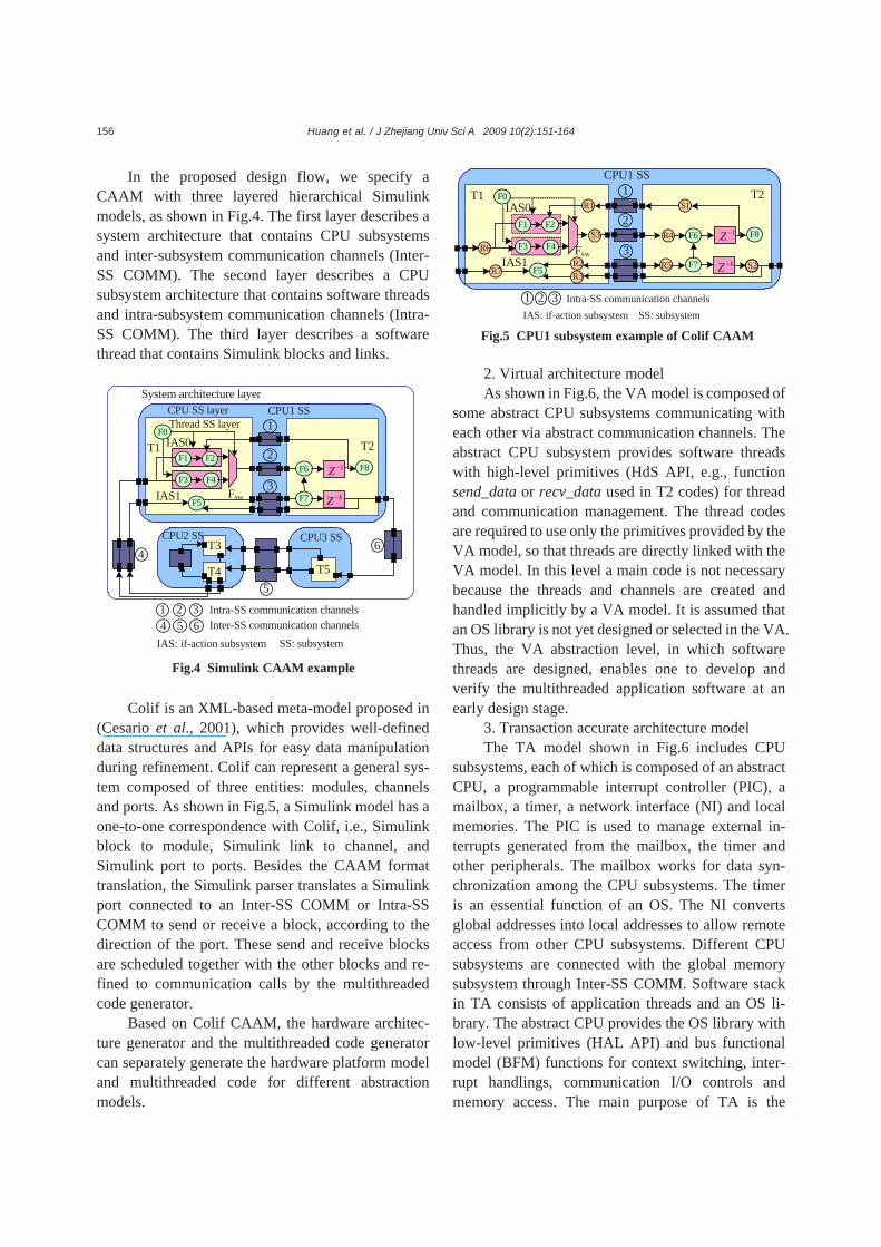
In the proposed design flow, we specify a CAAM with three layered hierarchical Simulink models, as shown in Fig.4. The first layer describes a system architecture that contains CPU subsystems and inter-subsystem communication channels (Inter- SS COMM). The second layer describes a CPU subsystem architecture that contains software threads and intra-subsystem communication channels (Intra- SS COMM). The third layer describes a software thread that contains Simulink blocks and links.
Colif is an XML-based meta-model proposed in
(Cesario et al., 2001), which provides well-defined data structures and APIs for easy data manipulation during refinement. Colif can represent a general sys-tem composed of three entities: modules, channels and ports. As shown in Fig.5, a Simulink model has a one-to-one correspondence with Colif, i.e., Simulink block to module, Simulink link to channel, and Simulink port to ports. Besides the CAAM format translation, the Simulink parser translates a Simulink port connected to an Inter-SS COMM or Intra-SS COMM to send or receive a block, according to the direction of the port. These send and receive blocks are scheduled together with the other blocks and re-fined to communication calls by the multithreaded code generator.
Based on Colif CAAM, the hardware architec-ture generator and the multithreaded code generator can separately generate the hardware platform model and multithreaded code for different abstraction models.
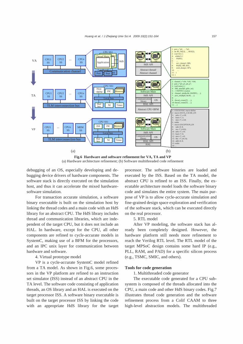
2. Virtual architecture model As shown in Fig.6, the VA model is composed of
some abstract CPU subsystems communicating with each other via abstract communication channels. The abstract CPU subsystem provides software threads with high-level primitives (HdS API, e.g., function send_data or recv_data used in T2 codes) for thread and communication management. The thread codes are required to use only the primitives provided by the VA model, so that threads are directly linked with the VA model. In this level a main code is not necessary because the threads and channels are created and handled implicitly by a VA model. It is assumed that an OS library is not yet designed or selected in the VA. Thus, the VA abstraction level, in which software threads are designed, enables one to develop and verify the multithreaded application software at an early design stage.
3. Transaction accurate architecture model The TA model shown in Fig.6 includes CPU
subsystems, each of which is composed of an abstract CPU, a programmable interrupt controller (PIC), a mailbox, a timer, a network interface (NI) and local memories. The PIC is used to manage external in-terrupts generated from the mailbox, the timer and other peripherals. The mailbox works for data syn-chronization among the CPU subsystems. The timer is an essential function of an OS. The NI converts global addresses into local addresses to allow remote access from other CPU subsystems. Different CPU subsystems are connected with the global memory subsystem through Inter-SS COMM. Software stack in TA consists of application threads and an OS li-brary. The abstract CPU provides the OS library with low-level primitives (HAL API) and bus functional model (BFM) functions for context switching, inter-rupt handlings, communication I/O controls and memory access. The main purpose of TA is the
F3 F4
F1 F2
F0
F5IAS1
IAS0
Fsw
T1 T2
F6
F7
F8
CPU1 SS
T3
T5
CPU3 SSCPU2 SS
T4
System architecture layerCPU SS layerThread SS layer
1Z −
kZ −
2
1
3
4
5
6
SS: subsystem
Intra-SS communication channels Inter-SS communication channels2 315 64
IAS: if-action subsystem
Fig.4 Simulink CAAM example
F3 F4
F1 F2
F5IAS1
IAS0
Fsw
T1 T2
F6
F7
F8
CPU1 SS
F0R1
S3
R2R3R7 R5
R4
S1
S2
1Z −
kZ −
R6
Intra-SS communication channels
2
1
3
IAS: if-action subsystem SS: subsystem 21 3
Fig.5 CPU1 subsystem example of Colif CAAM
Huang et al. / J Zhejiang Univ Sci A 2009 10(2):151-164 157
debugging of an OS, especially developing and de-bugging device drivers of hardware components. The software stack is directly executed on the simulation host, and thus it can accelerate the mixed hardware- software simulation.
For transaction accurate simulation, a software binary executable is built on the simulation host by linking the thread codes and a main code with an HdS library for an abstract CPU. The HdS library includes thread and communication libraries, which are inde-pendent of the target CPU, but it does not include an HAL. In hardware, except for the CPU, all other components are refined to cycle-accurate models in SystemC, making use of a BFM for the processors, and an IPC unix layer for communication between hardware and software.
4. Virtual prototype model VP is a cycle-accurate SystemC model refined
from a TA model. As shown in Fig.6, some proces-sors in the VP platform are refined to an instruction set simulator (ISS) instead of an abstract CPU in the TA level. The software code consisting of application threads, an OS library and an HAL is executed on the target processor ISS. A software binary executable is built on the target processor ISS by linking the code with an appropriate HdS library for the target
processor. The software binaries are loaded and executed by the ISS. Based on the TA model, the abstract CPU is refined to an ISS. Finally, the ex-ecutable architecture model loads the software binary code and simulates the entire system. The main pur-pose of VP is to allow cycle-accurate simulation and fine-grained design space exploration and verification of the software stack, which can be executed directly on the real processor.
5. RTL model After VP modeling, the software stack has al-
ready been completely designed. However, the hardware platform still needs more refinement to reach the Verilog RTL level. The RTL model of the target MPSoC design contains some hard IP (e.g., PLL, RAM, and PAD) for a specific silicon process (e.g., TSMC, SMIC, and others).
Tools for code generation
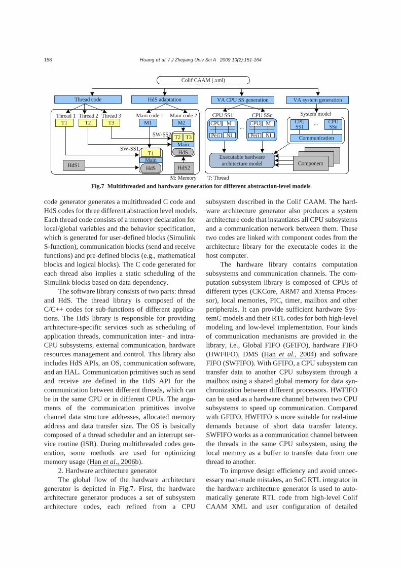
1. Multithreaded code generator The executable code generated for a CPU sub-
system is composed of the threads allocated into the CPU, a main code and other HdS binary codes. Fig.7 illustrates thread code generation and the software refinement process from a Colif CAAM to three high-level abstraction models. The multithreaded
port portPort Port
HdS APIHdSApp
CPU SS1
T1 T2
Abstract thread/Abstract channelCommunication channel
CPU1 SS
CPU2 SS
CPUn SS
...Thread Main 2
Application
Thread Main 1
1: port_t *p0, …, *p3;2: int M1, M2[3], ..., M10[3];3: void T2( ) {4: while(1) {5: F0(M1);6: …7: recv_data(p3, M8); 8: F6(M2, M8, M7);9: send_data(p2, M7);10: …11: }12: }
HdS API
T1 T2
TLM interconnection bus
CPU1 SS
CPU2 SS
CPUn SS
...
1: channel_t *ch4, *ch5, *ch6;2: port_t *p4, p5, p6, p7;3: void main( ) {4: ISR_attach(0, gfifo_isr);5: // SWFIFO creation 6: channel_init(&ch6, SWFIFO, …);7: port_init(&p6, &ch6, …);8: …9: thread_create(T1, …);10: thread_create(T2, …); 11: …}
Software MainHost
+BFM PIC Memory
Local bus
NIMail box Timer
CPU SS1
Abstract CPU+BFM
HAL APIOS
HdS API
T1 T2
TLM interconnection bus
CPU1 SS
CPUn SS
MEM SS
... Software MainISS PIC
Local bus
NIMail box Timer
CPU SS1
HALHAL API
OSCommunication library
VA
TA
VP
1: //CK510 HAL macro define2: macro DATA_CACHE_EN3: mfcr r7, cr18;4: bseti r7, 3; 5: mtcr r7, cr18;6: endm7: macro EXCEPTION_EN8: subi r0, 8;9: stw r7, (r0,0);10: mfcr r7, cr0;11: bseti r7, 8;12: mtcr r7, cr0;13: ldw r7, (r0, 0);14: addi r0, 8;15: endm16: ...
Communication library
(a) (b)
Memory
Fig.6 Hardware and software refinement for VA, TA and VP (a) Hardware architecture refinement; (b) Software multithreaded code refinement
Huang et al. / J Zhejiang Univ Sci A 2009 10(2):151-164
158
code generator generates a multithreaded C code and HdS codes for three different abstraction level models. Each thread code consists of a memory declaration for local/global variables and the behavior specification, which is generated for user-defined blocks (Simulink S-function), communication blocks (send and receive functions) and pre-defined blocks (e.g., mathematical blocks and logical blocks). The C code generated for each thread also implies a static scheduling of the Simulink blocks based on data dependency.
The software library consists of two parts: thread and HdS. The thread library is composed of the C/C++ codes for sub-functions of different applica-tions. The HdS library is responsible for providing architecture-specific services such as scheduling of application threads, communication inter- and intra- CPU subsystems, external communication, hardware resources management and control. This library also includes HdS APIs, an OS, communication software, and an HAL. Communication primitives such as send and receive are defined in the HdS API for the communication between different threads, which can be in the same CPU or in different CPUs. The argu-ments of the communication primitives involve channel data structure addresses, allocated memory address and data transfer size. The OS is basically composed of a thread scheduler and an interrupt ser-vice routine (ISR). During multithreaded codes gen-eration, some methods are used for optimizing memory usage (Han et al., 2006b).
2. Hardware architecture generator The global flow of the hardware architecture
generator is depicted in Fig.7. First, the hardware architecture generator produces a set of subsystem architecture codes, each refined from a CPU
subsystem described in the Colif CAAM. The hard-ware architecture generator also produces a system architecture code that instantiates all CPU subsystems and a communication network between them. These two codes are linked with component codes from the architecture library for the executable codes in the host computer.
The hardware library contains computation subsystems and communication channels. The com-putation subsystem library is composed of CPUs of different types (CKCore, ARM7 and Xtensa Proces-sor), local memories, PIC, timer, mailbox and other peripherals. It can provide sufficient hardware Sys-temC models and their RTL codes for both high-level modeling and low-level implementation. Four kinds of communication mechanisms are provided in the library, i.e., Global FIFO (GFIFO), hardware FIFO (HWFIFO), DMS (Han et al., 2004) and software FIFO (SWFIFO). With GFIFO, a CPU subsystem can transfer data to another CPU subsystem through a mailbox using a shared global memory for data syn-chronization between different processors. HWFIFO can be used as a hardware channel between two CPU subsystems to speed up communication. Compared with GFIFO, HWFIFO is more suitable for real-time demands because of short data transfer latency. SWFIFO works as a communication channel between the threads in the same CPU subsystem, using the local memory as a buffer to transfer data from one thread to another.
To improve design efficiency and avoid unnec-essary man-made mistakes, an SoC RTL integrator in the hardware architecture generator is used to auto-matically generate RTL code from high-level Colif CAAM XML and user configuration of detailed
Fig.7 Multithreaded and hardware generation for different abstraction-level models
HdS2
Thread code HdS adaptation
T1 T2 T3Thread 1 Thread 2 Thread 3
M1 M2Main code 1 Main code 2
HdS1
T1
HdS
SW-SS2
SW-SS1
T2
HdS
T3Main
Main
Colif CAAM (.xml)
VA CPU SS generation VA system generation
CPU M
Peri NI
CPU M
Peri NI...
CPU SS1 CPU SSn
Communication
CPU SS1
CPU SSn
...
System model
ComponentExecutable hardware architecture model
M: Memory T: Thread
Huang et al. / J Zhejiang Univ Sci A 2009 10(2):151-164 159
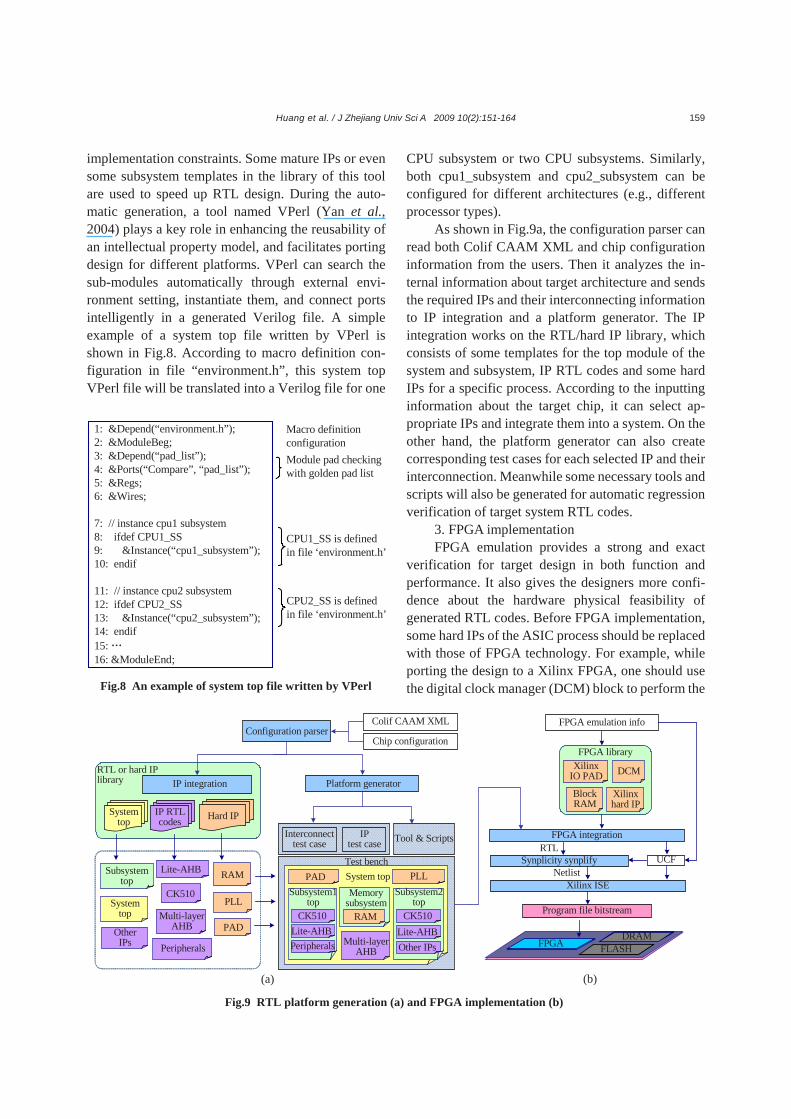
implementation constraints. Some mature IPs or even some subsystem templates in the library of this tool are used to speed up RTL design. During the auto-matic generation, a tool named VPerl (Yan et al., 2004) plays a key role in enhancing the reusability of an intellectual property model, and facilitates porting design for different platforms. VPerl can search the sub-modules automatically through external envi-ronment setting, instantiate them, and connect ports intelligently in a generated Verilog file. A simple example of a system top file written by VPerl is shown in Fig.8. According to macro definition con-figuration in file “environment.h”, this system top VPerl file will be translated into a Verilog file for one
CPU subsystem or two CPU subsystems. Similarly, both cpu1_subsystem and cpu2_subsystem can be configured for different architectures (e.g., different processor types).
As shown in Fig.9a, the configuration parser can read both Colif CAAM XML and chip configuration information from the users. Then it analyzes the in-ternal information about target architecture and sends the required IPs and their interconnecting information to IP integration and a platform generator. The IP integration works on the RTL/hard IP library, which consists of some templates for the top module of the system and subsystem, IP RTL codes and some hard IPs for a specific process. According to the inputting information about the target chip, it can select ap-propriate IPs and integrate them into a system. On the other hand, the platform generator can also create corresponding test cases for each selected IP and their interconnection. Meanwhile some necessary tools and scripts will also be generated for automatic regression verification of target system RTL codes.
3. FPGA implementation FPGA emulation provides a strong and exact
verification for target design in both function and performance. It also gives the designers more confi-dence about the hardware physical feasibility of generated RTL codes. Before FPGA implementation, some hard IPs of the ASIC process should be replaced with those of FPGA technology. For example, while porting the design to a Xilinx FPGA, one should use the digital clock manager (DCM) block to perform the
Fig.8 An example of system top file written by VPerl
1: &Depend(“environment.h”);2: &ModuleBeg;3: &Depend(“pad_list”);4: &Ports(“Compare”, “pad_list”);5: &Regs;6: &Wires;
7: // instance cpu1 subsystem8: ifdef CPU1_SS9: &Instance(“cpu1_subsystem”);10: endif
11: // instance cpu2 subsystem12: ifdef CPU2_SS13: &Instance(“cpu2_subsystem”);14: endif15: … 16: &ModuleEnd;
Module pad checkingwith golden pad list
Macro definition configuration
CPU1_SS is defined in file ‘environment.h’
CPU2_SS is defined in file ‘environment.h’
Fig.9 RTL platform generation (a) and FPGA implementation (b)
(a) (b)
Configuration parser
System top
IP RTL codes
IP integration
CK510
Multi-layerAHB
Systemtop
Subsystemtop
Hard IP
RAM
PAD
Test bench
Tool & ScriptsInterconnect test case
IPtest case
System topSubsystem1
topSubsystem2
top
Multi-layerAHB
PLL
PAD
CK510Lite-AHB
Lite-AHB
CK510Lite-AHBOther IPsPeripherals
PLLMemory
subsystemRAM
Platform generator
PeripheralsOtherIPs
Colif CAAM XML
Chip configuration
RTL or hard IP library
DCM
Block RAM
XilinxIO PAD
FPGA integration
Xilinx hard IP
FPGA library
FPGA emulation info
Synplicity synplify UCF
Xilinx ISENetlist
RTL
Program file bitstream
FPGA FLASHDRAM
Huang et al. / J Zhejiang Univ Sci A 2009 10(2):151-164
160
same functions as PLL in ASIC design. As shown in Fig.9, the PAD, on-chip SRAM and PLL in system RTL codes have been changed to Xilinx IO PAD, block RAM and DCM, respectively. VPerl can ef-fectively complete this task. Then this new FPGA- version RTL code can be compiled into gate-level Netlist by Synplicity Synplify (Synplicity, Inc.). The user constraint file (UCF) generated from user FPGA emulation information provides a constraint for tim-ing, PAD allocation and other issues related to the synthesis. After that, both Netlist and UCF can be processed by Xilinx ISE (Xilinx, Inc.) to produce a program file bitstream to the FPGA implementation. EXPERIMENTAL RESULTS
In our experiment, both Motion-JPEG and H.264 decoders were used as a case study to show the hardware/software interface refinement and verify the feasibility of our design flow. Compared with the Motion-JPEG decoder, the H.264 baseline decoder is more complex and has more opportunities for opti-mization in both hardware and software. While the first case study showed the design space exploration at processor level in our design flow (Huang et al., 2007), we were interested in analyzing the effect of different task partitioning strategies with the H.264 decoder.
Three different kinds of processors were used: ARM7 (ARM, Inc.), CKCore (C-SKY, Inc.) and Xtensa (Tensilica, Inc.) processors. The Xtensa mod-eling protocol (XTMP) simulator was generated with the following configuration: a 32-bit multiplier, a 16-bit MAC and no instruction/data cache. GFIFO and DMS communication mechanisms were used for inter-subsystem communication. The simulation for Motion-JPEG and for H.264 covers the decoding of a 10-frame QVGA (320×240) JPEG stream and a 30- frame QCIF (176×144) H.264 stream, respectively.
Simulink modeling result and CAAM example
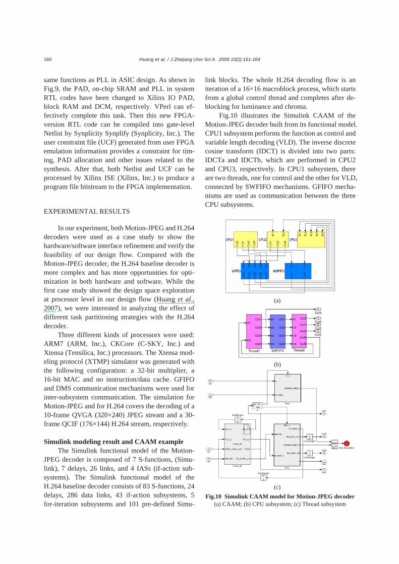
The Simulink functional model of the Motion- JPEG decoder is composed of 7 S-functions, (Simu-link), 7 delays, 26 links, and 4 IASs (if-action sub-systems). The Simulink functional model of the H.264 baseline decoder consists of 83 S-functions, 24 delays, 286 data links, 43 if-action subsystems, 5 for-iteration subsystems and 101 pre-defined Simu-
link blocks. The whole H.264 decoding flow is an iteration of a 16×16 macroblock process, which starts from a global control thread and completes after de-blocking for luminance and chroma.
Fig.10 illustrates the Simulink CAAM of the Motion-JPEG decoder built from its functional model. CPU1 subsystem performs the function as control and variable length decoding (VLD). The inverse discrete cosine transform (IDCT) is divided into two parts: IDCTa and IDCTb, which are performed in CPU2 and CPU3, respectively. In CPU1 subsystem, there are two threads, one for control and the other for VLD, connected by SWFIFO mechanisms. GFIFO mecha-nisms are used as communication between the three CPU subsystems.
Fig.10 Simulink CAAM model for Motion-JPEG decoder
(a) CAAM; (b) CPU subsystem; (c) Thread subsystem
(a) (b) (c)
Huang et al. / J Zhejiang Univ Sci A 2009 10(2):151-164 161
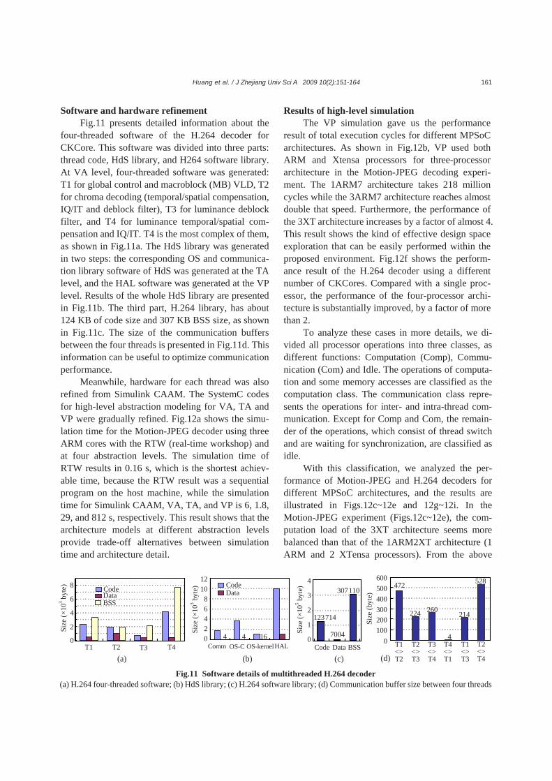
Software and hardware refinement Fig.11 presents detailed information about the
four-threaded software of the H.264 decoder for CKCore. This software was divided into three parts: thread code, HdS library, and H264 software library. At VA level, four-threaded software was generated: T1 for global control and macroblock (MB) VLD, T2 for chroma decoding (temporal/spatial compensation, IQ/IT and deblock filter), T3 for luminance deblock filter, and T4 for luminance temporal/spatial com-pensation and IQ/IT. T4 is the most complex of them, as shown in Fig.11a. The HdS library was generated in two steps: the corresponding OS and communica-tion library software of HdS was generated at the TA level, and the HAL software was generated at the VP level. Results of the whole HdS library are presented in Fig.11b. The third part, H.264 library, has about 124 KB of code size and 307 KB BSS size, as shown in Fig.11c. The size of the communication buffers between the four threads is presented in Fig.11d. This information can be useful to optimize communication performance.
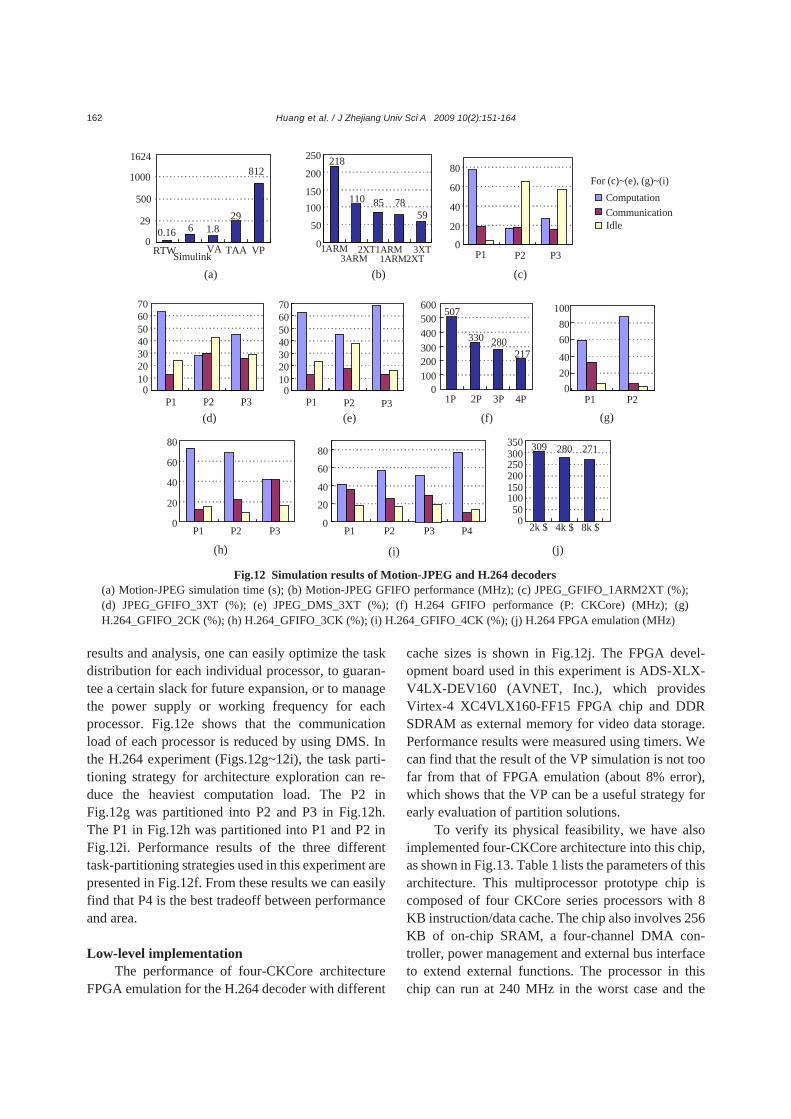
Meanwhile, hardware for each thread was also refined from Simulink CAAM. The SystemC codes for high-level abstraction modeling for VA, TA and VP were gradually refined. Fig.12a shows the simu-lation time for the Motion-JPEG decoder using three ARM cores with the RTW (real-time workshop) and at four abstraction levels. The simulation time of RTW results in 0.16 s, which is the shortest achiev-able time, because the RTW result was a sequential program on the host machine, while the simulation time for Simulink CAAM, VA, TA, and VP is 6, 1.8, 29, and 812 s, respectively. This result shows that the architecture models at different abstraction levels provide trade-off alternatives between simulation time and architecture detail.
Results of high-level simulation The VP simulation gave us the performance
result of total execution cycles for different MPSoC architectures. As shown in Fig.12b, VP used both ARM and Xtensa processors for three-processor architecture in the Motion-JPEG decoding experi-ment. The 1ARM7 architecture takes 218 million cycles while the 3ARM7 architecture reaches almost double that speed. Furthermore, the performance of the 3XT architecture increases by a factor of almost 4. This result shows the kind of effective design space exploration that can be easily performed within the proposed environment. Fig.12f shows the perform-ance result of the H.264 decoder using a different number of CKCores. Compared with a single proc-essor, the performance of the four-processor archi-tecture is substantially improved, by a factor of more than 2.
To analyze these cases in more details, we di-vided all processor operations into three classes, as different functions: Computation (Comp), Commu-nication (Com) and Idle. The operations of computa-tion and some memory accesses are classified as the computation class. The communication class repre-sents the operations for inter- and intra-thread com-munication. Except for Comp and Com, the remain-der of the operations, which consist of thread switch and are waiting for synchronization, are classified as idle.
With this classification, we analyzed the per-formance of Motion-JPEG and H.264 decoders for different MPSoC architectures, and the results are illustrated in Figs.12c~12e and 12g~12i. In the Motion-JPEG experiment (Figs.12c~12e), the com-putation load of the 3XT architecture seems more balanced than that of the 1ARM2XT architecture (1 ARM and 2 XTensa processors). From the above
7004
123714
3071104
3
2
1
0Code Data BSS
0
8
6
4
2
T1 T2 T3 T44 4 16
121086420
Comm OS-C OS-kernel
CodeData
472
224 260
4
214
528
0100200300400500600
HAL
BSS
Size
(×10
3 byt
e)
Size
(×10
3 byt
e)
Size
(×10
5 byt
e)CodeData
T1<>T2
T2<>T3
T3<>T4
T4<>T1
T1<>T3
T2<>T4
Size
(byt
e)
(a) (b) (c) (d)
Fig.11 Software details of multithreaded H.264 decoder (a) H.264 four-threaded software; (b) HdS library; (c) H.264 software library; (d) Communication buffer size between four threads
Huang et al. / J Zhejiang Univ Sci A 2009 10(2):151-164
162
results and analysis, one can easily optimize the task distribution for each individual processor, to guaran-tee a certain slack for future expansion, or to manage the power supply or working frequency for each processor. Fig.12e shows that the communication load of each processor is reduced by using DMS. In the H.264 experiment (Figs.12g~12i), the task parti-tioning strategy for architecture exploration can re-duce the heaviest computation load. The P2 in Fig.12g was partitioned into P2 and P3 in Fig.12h. The P1 in Fig.12h was partitioned into P1 and P2 in Fig.12i. Performance results of the three different task-partitioning strategies used in this experiment are presented in Fig.12f. From these results we can easily find that P4 is the best tradeoff between performance and area.
Low-level implementation
The performance of four-CKCore architecture FPGA emulation for the H.264 decoder with different
cache sizes is shown in Fig.12j. The FPGA devel-opment board used in this experiment is ADS-XLX- V4LX-DEV160 (AVNET, Inc.), which provides Virtex-4 XC4VLX160-FF15 FPGA chip and DDR SDRAM as external memory for video data storage. Performance results were measured using timers. We can find that the result of the VP simulation is not too far from that of FPGA emulation (about 8% error), which shows that the VP can be a useful strategy for early evaluation of partition solutions.
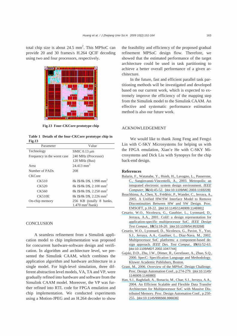
To verify its physical feasibility, we have also implemented four-CKCore architecture into this chip, as shown in Fig.13. Table 1 lists the parameters of this architecture. This multiprocessor prototype chip is composed of four CKCore series processors with 8 KB instruction/data cache. The chip also involves 256 KB of on-chip SRAM, a four-channel DMA con-troller, power management and external bus interface to extend external functions. The processor in this chip can run at 240 MHz in the worst case and the
Fig.12 Simulation results of Motion-JPEG and H.264 decoders (a) Motion-JPEG simulation time (s); (b) Motion-JPEG GFIFO performance (MHz); (c) JPEG_GFIFO_1ARM2XT (%);(d) JPEG_GFIFO_3XT (%); (e) JPEG_DMS_3XT (%); (f) H.264 GFIFO performance (P: CKCore) (MHz); (g)H.264_GFIFO_2CK (%); (h) H.264_GFIFO_3CK (%); (i) H.264_GFIFO_4CK (%); (j) H.264 FPGA emulation (MHz)
ComputationCommunicationIdle
0
20
40
60
80
P1 P2 P3 P4
010203040506070
0
20
40
60
80
P1 P2 P3
309 280 271
050
100150200250300
2k $ 4k $ 8k $
350
P1 P2 P30
10203040506070
P1 P2 P3
507
330 280217
0100200300400500600
1P 2P 3P 4P0
2040
6080
100
P1 P2
3XT
218
110 85 7859
0
50
100150
200
250
1ARM3ARM
2XT1ARM1ARM2XT
0
20
40
60
80
P1 P2 P3
For (c)~(e), (g)~(i)
RTWSimulinkVA TAA VP
0.16 6 1.829
812
29
0
1624
500
1000
(a) (b) (c)
(d) (e) (f) (g)
(h) (i) (j)
Huang et al. / J Zhejiang Univ Sci A 2009 10(2):151-164 163
total chip size is about 24.5 mm2. This MPSoC can provide 20 and 30 frames/s H.264 QCIF decoding using two and four processors, respectively.
CONCLUSION
A seamless refinement from a Simulink appli-cation model to chip implementation was proposed for concurrent hardware-software design and verifi-cation. In algorithm and architecture level, we pre-sented the Simulink CAAM, which combines the application algorithm and hardware architecture in a single model. For high-level simulation, three dif-ferent abstraction level models, VA, TA and VP, were gradually refined into hardware and software from the Simulink CAAM model. Moreover, the VP was fur-ther refined into RTL code for FPGA emulation and chip implementation. We conducted experiments using a Motion-JPEG and an H.264 decoder to show
the feasibility and efficiency of the proposed gradual refinement MPSoC design flow. Therefore, we showed that the estimated performance of the target architecture could be used in task partitioning to achieve a better overall performance of a given ar-chitecture.
In the future, fast and efficient parallel task par-titioning methods will be investigated and developed based on our current work, which is expected to ex-tremely improve the efficiency of the mapping step from the Simulink model to the Simulink CAAM. An effective and systematic performance estimation method is also our future work.
ACKNOWLEDGEMENT We would like to thank Jiong Feng and Fengyi
Lin with C-SKY Microsystems for helping us with the FPGA emulation, Xian’e He with C-SKY Mi-crosystems and Dick Liu with Synopsys for the chip back-end design.
References Balarin, F., Watanabe, Y., Hsieh, H., Lavagno, L., Passerone,
C., Sangiovanni-Vincentelli, A., 2003. Metropolis: an integrated electronic system design environment. IEEE Computer, 36(4):45-52. [doi:10.1109/MC.2003.1193228]
Bouchhima, A., Chen, X., Frédéric, P., Wander, C., Jerraya, A., 2005. A Unified HW/SW Interface Model to Remove Discontinuities Between HW and SW Design. Proc. EMSOFT, p.18-22. [doi:10.1145/1146909.1146981]
Cesario, W.O., Nicolescu, G., Gauthier, L., Lyonnard, D., Jerraya, A.A., 2001. Colif: a design representation for application-specific multiprocessor SoC. IEEE Design Test Comput., 18(5):18-20. [doi:10.1109/54.953268]
Cesario, W.O., Lyonnard, D., Nicolescu, G., Paviot, Y., Yoo, S.J., Jerraya, A.A., Gauthier, L., Diaz-Nava, M., 2002. Multiprocessor SoC platforms: a component-based de-sign approach. IEEE Des. Test Comput., 19(6):52-63. [doi:10.1109/MDT.2002.1047744]
Gajski, D.D., Zhu, J.W., Dömer, R., Gerstlauer, A., Zhao, S.Q., 2000. SpecC: Specification Language and Methodology. Kluwer Academic Publishers, Boston.
Grant, M., 2006. Overview of the MPSoC Design Challenge. Proc. Design Automation Conf., p.274-279. [doi:10.1145/ 1146909.1146980]
Han, S.I., Baghdadi, A., Bonaciu, M., Chae, S.I., Jerraya, A.A., 2004. An Efficient Scalable and Flexible Data Transfer Architecture for Multiprocessor SoC with Massive Dis-tributed Memory. Proc. Design Automation Conf., p.250- 255. [doi:10.1145/996566.996636]
Fig.13 Four-CKCore prototype chip
Table 1 Details of the four-CKCore prototype chip in Fig.13
Parameter Value Technology SMIC 0.13 μm Frequency in the worst case 240 MHz (Processor)
120 MHz (Bus) Area 24.413 mm2 Number of PADs 208 CKCore
CK510 8k I$/8k D$, 1.998 mm2 CK520 8k I$/8k D$, 2.100 mm2 CK560 8k I$/8k D$, 2.250 mm2 CK510E 8k I$/8k D$, 2.226 mm2
On-chip memory 256 KB (totally 8 banks, 1.470 mm2/bank)
Huang et al. / J Zhejiang Univ Sci A 2009 10(2):151-164
164
Han, S.I., Chae, S.I., Jerraya, A.A., 2006a. Functional Mod-eling Techniques for Efficient SW Code Generation of Video Codec Applications. Proc. Conf. on Asia South Pacific Design Automation, p.935-940. [doi:10.1145/ 1118299.1118509]
Han, S.I., Guerin, X., Chae, S.I., Jerraya, A.A., 2006b. Buffer Memory Optimization for Video Codec Application Modeled in Simulink. Proc. Design Automation Conf., p.689-694. [doi:10.1145/1146909.1147084]
Huang, K., Han, S.I., Popovici, K., Brisolara, L., Guerin, X., Li, L., Yan, X.L., Chae, S.I., Carro, L., Jerraya, A.A., 2007. Simulink-based MPSoC Design Flow: Case Study of Motion-JPEG and H.264. Proc. Design Automation Conf., p.39-42. [doi:10.1145/1278480.1278491]
Jerraya, A.A., Wolf, W., 2005. Hardware/Software interface co-design for embedded systems. IEEE Computer, 38(2):63-69.
Jerraya, A.A., Tenhunen, H., Wolf, W., 2005. Guest editors’ introduction: multiprocessor systems-on-chips. Computer, 38(7):36-40. [doi:10.1109/MC.2005.231]
Jerraya, A.A., Bouchhima, A., Petrot, F., 2006. Programming Models and HW-SW Interfaces Abstraction for Multi-Processor SoC. Proc. Design Automation Conf., p.280- 285. [doi:10.1145/1146909.1146981]
Kahn, G., MacQueen, D.B., 1977. Coroutines and Networks of Parallel Processes. Proc. Information Processing, Toronto, Canada, p.993-998.
Kangas, T., Kukkala, P., Orsila, H., Salminen, E., Hannikainen, M., Hammalainen, T.D., Rihimaki, J., Kuusilinna, K., 2006. UML-based multiprocessor SoC design framework. ACM Trans. Embed. Comput. Syst., 5(2):281-320. [doi:10.1145/1151074.1151077]
Keutzer, K., Newton, A.R., Rabaey, J.M., Sangiovanni- Vincentelli, A., 2000. System-level design: orthogonali-zation of concerns and platform-based design. IEEE Trans. CAD Integr. Circuits Syst., 19(12):1523-1543. [doi:10.1109/43.898830]
Ou, J., Prasanna, V.K., 2005. Design space exploration using arithmetic level hardware-software co-simulation for configurable multi-processor platforms. ACM Trans. Embed. Comput. Syst., 2(3):111-137. [doi:10.1145/1151 074.1151080]
Pimentel, A.D., Hertzbetger, L.O., Lieverse, P., van der Wolf, P., Deprettere, E.E., 2001. Exploring embedded-systems architectures with Artemis. IEEE Computer, 34(11):57- 63. [doi:10.1109/2.963445]
Reynari, L.M., Cucinotta, F., Serra, A., Lavagno, L., 2001. A Hardware/Software Co-design Flow and IP Library Based on SimulinkTM. Proc. Design Automation Conf., p.593-598.
Yan, X.L., Yu, L.L., Wang, J.B., 2004. A front-end automation tool supporting design, verification and reuse of SoC. J. Zhejiang Univ. Sci., 5(9):1102-1105. [doi:10.1631/jzus. 2004.1102]
Related Documents


![GCC internals intro y optimizationesnicolasw/Docencia/CP/gcc_int_intro.pdf · Optimizaciones Back-end Backend: – RTL tree + RTL language + RTL Engine + RTL Compiler [Middle-End]](https://static.cupdf.com/doc/110x72/5f066be67e708231d417e97b/gcc-internals-intro-y-optimizationes-nicolaswdocenciacpgccintintropdf-optimizaciones.jpg)