ISSN 2217-8139 (Print) UDK: 06.055.2:62-03+620.1+624.001.5(497.1)=861 ISSN 2334-0229 (Online) 2018. GODINA LXI GRAĐEVINSKI MATERIJALI I KONSTRUKCIJE BUILDING MATERIALS AND STRUCTURES Č ASOPIS ZA ISTRAŽIVANJA U OBLASTI MATERIJALA I KONSTRUKCIJA J O U R N A L F O R R E S E A R C H OF M A T E R I A L S A N D S T R U C T U R E S DRUŠTVO ZA ISPITIVANJE I ISTRAŽIVANJE MATERIJALA I KONSTRUKCIJA SRBIJE SOCIETY FOR MATERIALS AND STRUCTURES TESTING OF SERBIA D DI I M MK K

Welcome message from author
This document is posted to help you gain knowledge. Please leave a comment to let me know what you think about it! Share it to your friends and learn new things together.
Transcript
ISSN 2217-8139 (Print) UDK: 06.055.2:62-03+620.1+624.001.5(497.1)=861ISSN 2334-0229 (Online)
2018.GODINA
LXI
GRAĐEVINSKIMATERIJALI I
KONSTRUKCIJEBUILDING
MATERIALS ANDSTRUCTURES
ČA S O P I S Z A I S T R A Ž I V A N J A U O B L A S T I M A T E R I J A L A I K O N S T R U K C I J AJ O U R N A L F O R R E S E A R C H OF M A T E R I A L S A N D S T R U C T U R E S
DRUŠTVO ZA ISPITIVANJE I ISTRAŽIVANJE MATERIJALA I KONSTRUKCIJA SRBIJESOCIETY FOR MATERIALS AND STRUCTURES TESTING OF SERBIA
DDIIMMKK

DRUŠTVO ZА ISPITIVАNJE I ISTRАŽIVАNJE MАTERIJАLА I KONSTRUKCIJА SRBIJES O C I E T Y F O R M А T E R I А L S А N D S T R U C T U R E S T E S T I N G O F S E R B I А
GGRRAAĐĐEEVVIINNSSKKII BBUUIILLDDIINNGGMMAATTEERRIIJJAALLII II MMААTTEERRIIААLLSS AANNDDKKOONNSSTTRRUUKKCCIIJJEE SSTTRRUUCCTTUURREESSČАS O P I S Z A I S T RАŽ I VАN J A U O B LАS T I MАT E R I JАLА I K O N S T R U K C I JА
J O U RNАL F O R R E S EАR C H I N T H E F I E L D O F MАT E RIАL S АN D ST R U CT U R E SШ
INTERNATIONAL EDITORIAL BOARDProfessor Radomir Folić, Editor in-Chief
Faculty of Technical Sciences, University of Novi Sad, SerbiaFakultet tehničkih nauka, Univerzitet u Novom Sadu, Srbija
e-mail:[email protected]
Professor Mirjana Malešev, Deputy editorFaculty of Technical Sciences, University of Novi Sad,Serbia - Fakultet tehničkih nauka, Univerzitet u NovomSadu, Srbija, e-mail: [email protected]
Dr Ksenija JankovićInstitute for Testing Materials, Belgrade, SerbiaInstitut za ispitivanje materijala, Beograd, Srbija
Dr Jose Adam, ICITECHDepartment of Construction Engineering, Valencia,Spain.
Professor Radu BanchilaDep. of Civil Eng. „Politehnica“ University ofTemisoara, Romania
Professor Dubravka BjegovićUniversity of Zagreb, Faculty of Civil Engineering,Department of Materials, Zagreb, Croatia
Assoc. professor Meri CvetkovskaFaculty of Civil Eng. University "St Kiril and Metodij“,Skopje, Macedonia
Professor Michael FordeUniversity of Edinburgh, Dep. of Environmental Eng.UK
Dr Vladimir GocevskiHydro-Quebec, Montreal, Canada
Acad. Professor Yachko IvanovBulgarian Academy of Sciences, Sofia, Bulgaria
Dr. Habil. Miklos M. IvanyiUVATERV, Budapest, Hungary
Professor Asterios LioliosDemocritus University of Thrace, Faculty of CivilEng., Greece
Professor Doncho PartovUniversity of Construction and Architecture - VSU "LJ.Karavelov" Sofia, Bulgaria
Predrag PopovićWiss, Janney, Elstner Associates, Northbrook,Illinois, USA.
Professor Rüdiger HöfferyRuhr University of Bochum, Bochum, Germany
Professor Valeriu StoinDep. of Civil Eng. „Poloitehnica“ University ofTemisoara, Romania
Acad. Professor Miha Tomažević, SNB and CEI,Slovenian Academy of Sciences and Arts,
Professor Mihailo Trifunac,Civil Eng.Department University of Southern California, LosAngeles, USA
Sekretar redakcije: Slavica Živković, mast.ekon.Lektori za srpski jezik: Dr Miloš Zubac, profesor
Aleksandra Borojev, profesorProofreader: Prof. Jelisaveta Šafranj, Ph DTechnicаl editor: Stoja Todorovic, e-mail: [email protected]
PUBLISHERSociety for Materials and Structures Testing of Serbia, 11000 Belgrade, Kneza Milosa 9
Telephone: 381 11/3242-589; e-mail:[email protected], veb sajt: www.dimk.rsREVIEWERS: All papers were reviewedKORICE: Pretpostavljeni mehanizmi sloma u zoni baze šipovaCOVER: Assumed failure mechanisms in zone of the piles base
Financial supports: Ministry of Scientific and Technological Development of the Republic of Serbia


ISSN 2217-8139 (Print ) GODINA LXI - 2018. ISSN 2334-0229 (Online)
DRUŠTVO ZА ISPITIVАNJE I ISTRАŽIVАNJE MАTERIJАLА I KONSTRUKCIJА SRBIJE S O C I E T Y F O R M А T E R I А L S А N D S T R U C T U R E S T E S T I N G O F S E R B I А
GGRRAAĐĐEEVVIINNSSKKII BBUUIILLDDIINNGG MMAATTEERRIIJJAALLII II MMААTTEERRIIААLLSS AANNDD KKOONNSSTTRRUUKKCCIIJJEE SSTTRRUUCCTTUURREESS
ČАS O P I S Z A I S T RАŽ I VАN J A U O B LАS T I MАT E R I JАLА I K O N S T R U K C I JА J O U RNАL F OR R E S EАR C H I N T H E F I E L D O F MАT E RIАL S АN D ST R U CT U R E S SАDRŽАJ Radomir FOLIĆ UVODNIK .................................................................... BIOGRAFIJA akademika prof. dr DUŠANA MILOVIĆA Dušan MILOVIĆ NOSIVOST ŠIPOVA - TEORIJSKE I TERENSKE METODE Originalni naučnii rad ................................................ H. BRANDL TEČENJA (SEKUNDARNA/TERCIJALNA SLEGANJA) VEOMA STIŠLJIVOG TLA I TALOGA Originalni naučni rad ................................................. Vojkan JOVIČIĆ UPOTREBA METODOLOGIJE PROBNOG TUNELA ZA PREVAZILEŽANJE TEŠKIH USLOVA GRADNJE U TUNELU KARAVANKE Pregledni rad.............................................................. Nikolay MILEV Junichi KOSEKI STATIČKO I DINAMIČKO VREDNOVANJE ELASTIČNIH SVOJSTAVA PESKA IZ SOFIJE I TOJOURA SOFISTICIRANIM TRIAKSIJALNIM OPITOM Pregledni rad.............................................................. Boris FOLIĆ Radomir FOLIĆ KOMPARATIVNA NELINEARNA ANALIZA INTERAKCIJE ŠIP-TLO AB 2D RAMA Originalni naučni rad ................................................. Sanja JOCKOVIĆ Mirjana VUKIĆEVIĆ VALIDACIJA I IMPLEMENTACIJA HASP KONSTITUTIVNOG MODELA ZA PREKONSOLIDOVANE GLINE Originalni naučni rad ................................................. Slobodan ĆORIĆ Dragoslav RAKIĆ Stanko ĆORIĆ Irena BASARIĆ BOČNA NOSIVOST I POMERANJA VERTIKALNIH ŠIPOVA OPTEREĆENIH HORIZONTALNIM SILAMA Pregledi rad ................................................................
5
11
15
27
37
47
63
91
111
CONTENTS Radomir FOLIC EDITORIAL.................................................................. BIOGRAPHY Academician Prof. Dr. DUSAN MILOVIC Dusan MILOVIC BEARING CAPACIITY OF PILES - THEORY AND FIELD TESTS Original scientific paper ............................................ H. BRANDL CREEPING (SECONDARY/TERTIARY SETTLEMENTS) OF HIGHLY COMPRESSIBLE SOILS AND SLUDGE Original scientific paper ............................................ Vojkan JOVICIC USE OF PILOT TUNNEL METHOD TO OVERCOME DIFFICULT GROUND CONDITIONS IN KARAVANKE TUNNEL Review paper.............................................................. Nikolay MILEV Junichi KOSEKI STATIC AND DYNAMIC EVALUATION OF ELASTIC PROPERTIES of SOFIA SAND AND TOYOURA SAND BY SOPHISTICATED TRIAXIAL TESTS Review paper.............................................................. Boris FOLIC Radomir FOLIC COMPАRАTIVE NONLINEАR АNАLYSIS OF A RC 2D FRАME SOIL-PILE INTERАCTION Original scientific paper ............................................ Sanja JOCKOVIC Mirjana VUKICEVIC VALIDATION AND IMPLEMENTATION OF HASP CONSTITUTIVE MODEL FOR OVERCONSOLIDATED CLAYS Original scientific paper ............................................ Slobodan CORIC Dragoslav RAKIC Stanko CORIC Irena BASARIC LATERAL CAPACITY AND DEFORMATIONS OF VERTICAL PILES LOADED BY HORIZONTAL FORCES Review paper..............................................................
5
11
15
27
37
47
63
91
111
GRAĐEVINSKI MATERIJALI I KONSTRUKCIJE 60 (2017) 4 (3-4)BUILDING MATERIALS AND STRUCTURES 60 (2017) 4 (3-4)3
Kristina BOŽIĆ TOMIĆNenad ŠUŠIĆMato ULJAREVIĆSISTEMATIZACIJA ANALITIČKIH I NUMERIČKIHMETODA PRORAČUNA STABILNOSTI KLIZIŠTAStručni rad..................................................................
Petar SANTRAČŽeljko BAJIĆPRIMER ZAŠTITE DUBOKE TEMELJNE JAME ISUSEDNIH OBJEKATA U SLOŽENIM URBANIM IGEOTEHNIČKIM USLOVIMAStručni rad..................................................................
Stanislav MILOVANOVIĆGrozde ALEKSOVSKIIn MEMORIAM profesor dr VLADIMIR SIMONČE,dipl.inž.građ. (1934-2016) .......................................
Miloš MAJRANOVIĆRadomir FOLIĆIn MEMORIAM profesor Dr.-Iing. habil. TOM ŠANC,dipl.inž.građ. (1962-2017) .......................................
ISTORIJAT SAVEZA SA GRBOM 1968-2018 ..............
Uputstvo autorima ....................................................
129
161
179
181
184
185
Kristina BOZIC TOMICNenad SUSICMato ULJAREVICTHE SYSTEMATIZATION OF ANALYTICAL ANDNUMERICAL METHODS OF LANDSLIDE STABILITYCALCULATIONProfessional paper .....................................................
Petar SANTRAČZeljko BAJIĆEXAMPLE OF PROTECTION OF DEEPFOUNDATION PIT IN COMPLEX URBAN ANDGEOTECHNICAL CONDITIONSProfessional paper .....................................................
Stanislav MILOVANOVICGrozde ALEKSOVSKIIn MEMORIAM Professor Dr. VLADIMIR SIMONCE,B.Sc.Eng.civ. (1934-2016) ......................................
Milos MAJRANOVICRadomir FOLICIn MEMORIAM Professor Dr.-Ing. habil. TOMSCHANZ, B.LSc.Eng.civ. (1962-2017) ....................
HISTORY OF ASSOCIATION 1968-2018 ...................
Preview report ...........................................................
129
161
179
181
184
185
GRAĐEVINSKI MATERIJALI I KONSTRUKCIJE 61 (2018) 1 (5-10)BUILDING MATERIALS AND STRUCTURES 61 (2018) 1 (5-10)
5
U V O D N I K
E D I T O R I A L
Ovaj broj časopisa posvećen je akademiku SANUprofesoru Dušanu Miloviću, diplomiranom inženjerugrađevine i redovnom profesoru Fakulteta tehničkihnauka Univerziteta u Novom Sadu u penziji.
Ove godine, Savez inženjera i tehničara Srbije slavi150 godina postojanja i rada, u različitim uslovima i srazličitim intenzitetom aktivnosti (videti sažet istorijatposle objavljenih radova). S tim u vezi, jedna odnajvažnijih aktivnosti pojedinih članica i samog savezajeste rad na planiranoj publikaciji „Znameniti inženjeriSrbije“. Reč je o svojevrsnom dugu jedne generacijeprema stvaraocima u minulim periodima, pa jerukovodstvo Saveza građevinskih inženjera Srbijepredložilo da se i jedan broj časopisa „Građevinskimaterijali i konstrukcije“, za sada vodećeg u oblastigrađevinarstva u Srbiji, posveti jednom od vodećihsrpskih naučnika u toj oblasti. Ovaj predlog jejednoglasno prihvatila Skupština Srpskog društva zamehaniku tla i geotehničko inženjerstvo.
Dušan Milović je naučnik sa izuzetno zapaženimrezultatima na osnovu kojih je doprineo afirmaciji iugledu isprva bivše SFR Jugoslavije, a zatim i Srbije, usvetu. Njegovo svestrano angažovanje u oblastimehanike tla i geotehničkog inženjerstva veoma jeznačajno, posebno zato što je praćeno laboratorijskim iterenskim geomehaničkim istraživanjima, na različitimlokacijama. Naročito se ističu njegova istraživanja lesa,koji je veoma osetljiv na uticaj vlage, s brojnimrezultatima i predlozima za fundiranje različitihkonstrukcija na njemu, što je detaljnije navedeno uBiografiji i daljem tekstu uvodnika.
Nesumnjivo je da je izbor da se časopis u celostiposveti akademiku Dušanu Miloviću, proizašao izvrednovanja rezultata koje je postigao u svojojdugogodišnjoj karijeri, jer su njegovi dometi, kao plodvišedecenijskog upornog rada, poznati, visoko cenjeni ipriznati i kod nas i u svetu. S obzirom na to što je DušanMilović od početka svoje interesovanje usmerio naoblast Mehanike tla i fundiranja, on pripada pionirimaove, relativno nove, naučne oblasti u našoj zemlji.
Uslovi rada u toj oblasti bili su veoma složeni islojeviti, jer je sredinom dvadesetog stoleća ovadisciplina bila mlada i tek se razvijala u Jugoslaviji iSrbiji, te nije bila dostupna u nastavi za nekoliko celihgeneracija posle Drugog svetskog rata. Moto profesoraMilovića, na početku rada pripremljenog za publikovanje
This volume of the Journal is dedicated to ProfessorDusan Milovic, Ph.D. in civil engineering, member of theSANU and full professor of the Faculty of TechnicalSciences at the University of Novi Sad in retirement.
This year, the Union of Engineers and Technicians ofSerbia celebrates 150 years of existence and work,under different conditions and intensity of activity (seethe concise history after the published works). One ofthe most important activities of individual members andthe General Union in this year is working on the futurepublication named Famous Engineers of Serbia. It isconsidered as responsibility of this generation towardsthe creators living in the past periods, so in addition tothe above publication, the leadership of the Union ofCivil Engineers of Serbia decided to dedicate onevolume of the journal Building Materials and Structures,which is now the leading magazine in the field of civilengineering in Serbia, to one of the leading Serbianscientists in the field. This decision was unanimouslyadopted by the Assembly of the Serbian Society for SoilMechanics and Geotechnical Engineering.
Dusan Milovic is a scientist with extremely notableresults that contributed to the affirmation and reputationof both the former SFR Yugoslavia and Serbia in theworld. His comprehensive engagement in the field of soilmechanics and geotechnical engineering is veryimportant, especially because it was accompanied bylaboratory and field geomechanical research at variouslocations. His research of loess, which is very sensitiveto the influence of moisture, is particularly important witha number of results and proposals for founding variousstructures on it, which is detailed in the Biography andthe further text of this editorial.
Undoubtedly, the choice to devote the entire journalto the academician Dusan Milovic was based on theevaluation of the results he has achieved during theyears of his career, because his achievements, resultingfrom several decades of persistent work, are highlyvalued and recognized both in our country and abroad.Given that from the very beginning Professor Milovic hasfocused his attention on the field of soil mechanics, hebelongs to the pioneers in this relatively new scientificfield in our country.
Working conditions in this field were extremely dif-ficult, because in the middle of the 20th century the SoilMechanics was the youngest branch in Civil Engineering
GRAĐEVINSKI MATERIJALI I KONSTRUKCIJE 61 (2018) 1 (5-10)BUILDING MATERIALS AND STRUCTURES 61 (2018) 1 (5-10)
6
u ovom broju časopisa, podseća nas na upozorenjačuvenog Terzagija, tvorca nove naučne disciplineMehanike tla i fundiranja, koja se proučava i koristi radiuspešnog građenja svih građevinskih objekata u svetu:„Temelji građevina uvek su bili pastorčad zato što nemaslave u temeljenju. Ali dela osvete zbog nedovoljnepažnje oko njih mogu biti katastrofalna“. Odabrani motopokazuje entuzijazam i veru koji su profesora Milovićapodsticali da desetinama godina posvećeno radi u ovojoblasti. Pre svega se to odnosi na uspešno rešavanjeaktuelnih problema u građevinskoj praksi čija jekompleksnost zahtevala teorijska rešenja vrednovana iverifikovana eksperimentalnim istraživanjima.
Dušan Milović je svoje aktivnosti posebno usmeriona naučno-istraživački rad. On je u svojojvišedecenijskoj karijeri vodio šesnaest istraživačkihprojekata za Fond za nauku Srbije i Vojvodine, ali iistraživanja za Nacionalni fond Kanade i nacionalnenaučne fondacije SAD, te za Fond za nauku SANU.
Profesor Milović je u teorijskim radovima, koristećiduple Furijeove redove, metodu konačnih i graničnihelemenata i konačnih razlika, formulisao brojnaoriginalna teorijska rešenja. Ona predstavljaju najvažnijadostignuća njegovog istraživačkog rada, koja sudostupna pošto je publikovao petnaest monografija iudžbenika, 137 članaka u časopisima u bivšoj Jugoslavijii Srbiji i zbornicima radova s brojnih kongresa, 73 člankau međunarodnim časopisima i kongresnimpublikacijama, s preko 3500 stranica. Ovi članci citiranisu 194 puta do 2007. godine u 18 zamalja (Sci citationindex, u knjigama u regionu i u doktoratima u SAD iKanadi).
Probleme plitkih temelja Dušan Milović je širokorazmatrao uz primenu teorije elastičnosti. Njegovarešenja komponentalnih napona i deformacija dobijenasu metodom konačnih elemenata. Rešenja kojaobuhvataju različite oblike i relativne krutosti temelja, i zarazličita opterećenja i veoma složene modele tla,uključivši višeslojne sisteme, anizotropnih svojstava,ograničene debljine stišljivih slojeva, procenjena su kaopionirski radovi. Radovi saopšteni na Međunarodnimkongresima u Londonu (1957), Parizu (1961), Visbadenu(1963) i Parizu (1963) prvi su radovi iz Srbije u tojoblasti. Njegova originalna rešenja dobijena metodomkonačnih elemenata (MKE), šest radova u zemlji (uperiodu 1971– 1974) i u međunarodnim naučnimčasopisima (osam radova u Londonu, Parizu, Berlinu iMoskvi) ubrajaju se među prve s rezultatima dobijenimmetodom konačnih elemenata u mehanici tla. Posebnuvrednost predstavlja knjiga „Naponi i deformacije plitkihtemelja“, jedina knjiga srpskog autora štampana uRoterdamu (Elsevier), u kojoj su data teorijska rešenja izmehanike tla.
Tokom boravka u Kanadi, Dušan Milović je posebnupažnju posvetio proučavanju nestabilnih, takozvanihLeda glina u Kvebeku. Bitno svojstvo ove vrste glinajeste potpuni gubitak smičuće otpornosti pod cikličkimopterećenjem i vibracijama. U ovim slučajevima,događaju se pokreti, klizanja i propadanje tla, štougrožava stabilnost konstrukcija. Radi boljegrazumevanja ponašanja ovih glina, obavljeno je mnoštvoterenskih i laboratorijskih testova. Zapaženo je damehanički poremećaji osetljivih glina bitno utiču napreciznost rezultata. Zato je Milović uveo test statičkepenetracije u inženjersku praksu radi dobijanja rezultata
in Yugoslavia and Serbia and this subject was not yetincluded in the regular study programme for severalpost-war generations.
The motto of Professor Milovic, at the beginning ofthe paper prepared for publication in this volume,reminds us of the warnings of the famous Terzaghi, whois considered to be the creator of the new scientificdiscipline of soil mechanics and foundation engineering,which is being studied and used in the construction of allbuildings in the world: "Building foundations have alwaysbeen treated as step children because there is no gloryattached to the foundations, but their acts of revenge forthe lack of attention can be very embarrassing," andshows his enthusiasm and faith that prompted him towork tens of years in this field.
Therefore, in order to be able to solve the currentproblems in civil engineering practice, and the com-plexity of these problems, it was essential to develop thetheoretical solutions and verify the validity of thesesolutions by means of the experimental investigations.
Dusan Milovic directed his activity towards scientificand research work. He has been the leader and principalinvestigator of 16 research projects, financed by theFund for scientific work of Serbia, SIZ for scientific workof Vojvodina, National Research of Canada, AmericanNational Science Foundation and Fund for researchwork of the Academy of Sciences and Arts.
In his theoretical studies he used double Fourier’sseries, power series method, finite and boundaryelement method, finite difference method and finiteelement method. Numerous original theoretical solutionsrepresent one of the most important achievements in hisresearch works. He published 15 monographs and text-books, 137 papers in Yugoslav and Serbian journals andcongress volumes, 73 in international journals andcongress proceedings with over 3500 pages. Thesepapers have been cited 194 times until 2007 in 18countries (Science Citation Index, textbooks in foreigncountries and in doctoral thesis in USA and Canada).
In the field of shallow foundations he considerablybroadens the application of the Theory of Elasticity. Hissolutions obtained by means of the finite elementmethod for calculation of componential stresses anddisplacements for various shapes and any relativestiffness of foundations, for any type of loading and verycomplex soil models, including multilayer systems, ani-sotropic properties, limited thickness of the compressiblelayers have been estimated as pioneer works. Paperspresented at international congresses in London (1957),Paris (1961), Wiesbaden (1963) and Paris (1963) arethe first Serbian papers. In addition, his original solu-tions, obtained by the finite element method, publishedin the country (6 papers over the period from 1971 to1974), and in the international scientific journals (8papers in London, Paris, Berlin and Moscow over theperiod from 1970 to 1973) are among first with thesolutions obtained by finite element method in the field ofSoil Mechanics. It is also worth mentioning that his book"Stresses and displacements for shallow foundations" isthe only Serbian book published in English (Ed.Elsevier), in which are given the theoretical solutionsrelated to Soil Mechanics.
During his stay in Canada, Dusan Milovic paidparticular attention to the investigation of sensitive Ledaclay in Quėbec. The essential property of this kind of
GRAĐEVINSKI MATERIJALI I KONSTRUKCIJE 61 (2018) 1 (5-10)BUILDING MATERIALS AND STRUCTURES 61 (2018) 1 (5-10)
7
za glinu u prirodnim uslovima.Sa zadovoljstvom ističem da su se svi autori kojima
sam se obratio da učestvuju svojim radovima u ovombroju časopisa, veoma rado odazvali i svojimdoprinosima pokazali koliko cene ličnost i rad profesoraMilovića. Ovaj stav potkrepljujem rečima profesoraHenza Brandl-a, koji mi je napisao: „It gives me greathonour to publish in a volume that is dedicated to Prof.Dusan Milovic. I knew him personally, because between1968 and 2015 I was the official representative of Austriain the Council Meeting of the ISSMGE (InternationalSociety for Soil Mechanics and GeotechnicalEngineering)”.
Veliki uspesi, ponekad, mogu da izazovu i odbojnostu okruženju, pa je tako akademik Milović bio povređenčinjenicom da je u Katalogu nauka i tehnika –Realizovana rešenja članova Odeljenja tehničkih naukaSANU 1841–2016, umesto adekvatnog predstavljanjanjegovih rezultata i dostignuća, bio potpuno izostavljen.U vezi s tim nemilim događajem, akademik Milović mi jenapisao: „Dugo sam oklevao da spominjem onadogađanja ili bolje rečeno pohvale koje su bile upućenena moj rad i moje uspehe. Mislim da nije neumesno, jerimamo ružne primere onih koji sami sebe veličaju bezikakve istinite osnove, pa ne vidim da nemam moralnogprava da spomenem samo ono što su drugi rekli omeni.“ Zbog toga smatram da je od interesa za stručnujavnost da ovde iznesem šta su izuzetne ličnosti uoblasti građevinarstva rekle o radovima DušanaMilovića.
Akademik Đorđe Lazarević svojevremeno je uputiodr Miloviću, autoru monografije „Analiza napona ideformacija u Mehanici tla” svoj stav da smatra korisnimsavet da se ona štampa na našem i jednom od svetskihtehničkih jezika. Iz monografije se inače ne bi mogla niizbliza izvući ona korist koja bi bila u skladu sa autorovimdoprinosom postupka konačnih elemenata u obradinovih rešenja. Dr Milović je nastavio da daje prilogeteoriji elastičnosti, koje je počeo još Boussinesq – snaponima i deformacijama elastičnih polu-prostora.
Za isto delo štampano na srpskom i engleskomjeziku, Arpad Kezdi, član Mađarske akademije nauka,profesor Univerziteta u Budimpešti, navodi: „Autor ovogznačajnog naučnog dela ’Stresses and Displacements inSoil Mechanics’ u kome se obrađuje primena Teorijeelastičnosti pri proračunu napona i deformacija ispodtemelja, uvodeći u razmatranje i aelotropski poluprostor,dao je rešenje za mnoge slučajeve opterećenja, koji sejavljaju u inženjerskoj praksi. Na taj način, autor jeriznicom podataka koji se ne mogu naći u udžbenicima,znatno proširio polje primene Teorije elastičnosti.“
Još prilikom odbrane doktorske disertacije DušanaMilovića, Milan Luković, član SANU, profesor naRudarsko-geološkom fakultetu u Beogradu, izjavio je usvojstvu predsednika komisije za odbranu doktorsketeze: „Vi ste bez sumnje najbolji poznavalac lesa iproblematike fundiranja na njemu u čitavoj zemlji“.
Akademik Božidar Vujanović, profesor Fakultetatehničkih nauka u Novom Sadu rekao je: „Od srca Vamčestitam na vrlo impresivnim podacima, koji pokazujukoliko ste truda, energije i volje uložili u stvaralački ioriginalni rad, koji zaslužuje svako poštovanje. Ja seveoma dobro sećam Vaše monografije štampane naengleskom jeziku, a Vaši inženjerski naučni radoviproneli su ugled jugoslovenske i svetske nauke i
clay is the complete loss of shear strength under theinfluence of cyclic loading and vibrations. In these casesmovements and sliding of soil occur and endanger thestability of structures. In order to better understand thebehaviour of these clays numerous field and laboratoryrests have been performed. It has been also observedthat the mechanical disturbance of sensitive clays has aconsiderable influence on the precision of the obtainedresults. Therefore, he introduced the static penetrationtest in engineering practice in order to get the results forclay in the natural state.
It is my pleasure to point out that all authors whom Iasked to participate with their papers in this volume werevery happy to contribute, showing they respect to thepersonality and work of Professor Milovic. This position Isupport by the words of Professor Hens Brandl, whowrote to me: "It gives me great honour to publish in avolume that is dedicated to Professor Dušan Milovic. Iknew him personally, because between 1968 and 2015 Iwas the official representative of Austria in the CouncilMeeting of the ISSMGE (International Society for SoilMechanics and Geotechnical Engineering)."
Great success sometimes can provoke reverence inthe environment, so Professor Milovic was hurt by thefact that, instead of adequately presenting his resultsand achievements, he was completely omitted in theCatalogue of Science and Technology - Realizedsolutions of Members of the Department of TechnicalSciences of the SANU 1841-2016. In connection withthis unwelcome event, Professor Milovic wrote to me: "Ihave long hesitated to mention those events, morespecifically praises that were addressed to my work andmy successes. I think it is inappropriate, because wehave ugly examples of those who glorify themselveswithout any real basis, so I think that I have moral rightto mention only what others have said about me." Forthis reason, I believe that it is of interest of professionalcommunity to cite here what other important individualsin the field of civil engineering have said about the workof Dusan Milovic.
Djordje Lazarevic, member of the SANU, onceexpressed his opinion to Dr. Milovic, the author of themonograph "Analysis of Stresses and Displacements inSoil Mechanics", that it is useful for the Council to printthe monograph in Serbian and in one of the world'stechnical languages as well. Otherwise, it will be impos-sible to derive the benefit from the monograph which isin accordance with the author's contribution to theprocess of finite element method in processing of newsolutions. Dr. Milovic continued his contributions to thetheory of elasticity, which began with Boussinesq aboutthe stresses and strains of elastic half-spaces.
Arpad Kezdi, a professor at the University ofBudapest and member of the Hungarian Academy ofSciences, wrote about the same paper printed in Serbianand English: The author of this important scientific paper"Stresses and Displacements in Soil Mechanics", inwhich he analyzes the application of theory of elasticityfor the calculation of the stresses and displacementsbelow the foundations, introducing the aelotropic half-space into consideration, has provided a solution tomany cases of loading that occur in engineeringpractice. In this way, offering a repository of data thatcannot be found in textbooks, the author significantlyexpanded the field of application of theory of elasticity.
GRAĐEVINSKI MATERIJALI I KONSTRUKCIJE 61 (2018) 1 (5-10)BUILDING MATERIALS AND STRUCTURES 61 (2018) 1 (5-10)
8
zaslužuju najveće priznanje i poštovanje.“Akademik Đorđe Zloković, profesor na
Arhitektonskom fakultetu u Beogradu: „Vaša impresivnabibliografija zadivljuje i obimom i kvalitetom. Vaš opusVas stavlja u vrh svetske nauke“.
Jedan od vodećih naučnika u svetu Harry Poulos,profesor Univerziteta u Sidneju, Australija, ističe: „Radoviprof. Milovića, u kojima su prikazana rešenja metodomkonačnih elemenata jesu pionirski, jer su u to vreme onibili retkost u geotehnici. Njegova izvanredna knjiga, kojuje objavio izdavač Elsevier iz Holandije, poslužila bi mičesto pri rešavanju raznih problema. Iz izvanrednihradova prof. Milovića, prikazanih tokom više godina,prof. Davis i ja smo neke od rezultata uvrstili u našumonografiju o naponima i pomeranjima.
Alan Lutenegger, profesor Univerziteta uMasačusetsu, Amherst, Sjedinjene Države, navodi:„Izvanredni radovi prof. Milovića o lesu sadrže takvepodatke kakvi još nigde u svetu nisu do sada objavljeni“.
P. Habib, profesor Politehničke škole u Parizu:„Eksperimentalni radovi prof. Milovića predstavljajuizvanrednu proveru teorijskih rešenja u Mehanici tla.“
Gaston Denis, dekan Građevinskog fakultetaŠerbruk u Kanadi rekao je: „Za mene je laka i prijatnadužnost da izrazim moje najdublje poštovanje kako zavrednost dr Dušana Milovića kao naučnika, tako i zanjegovu kompetenciju kao predavača i njegovu odanostkao saradnika. Dr Miloviću smo poverili zadatak daorganizuje Odeljenje za Mehaniku tla na našemgrađevinskom odseku, i da njime upravlja. Taj zadatakobavio je do te mere briljantno, da se samo posle trigodine Univerzitet u Šerbruku mogao ponositilaboratorijom za naučna istraživanja koja je priznata kaojedan od centara izvrsnosti u Kanadi u domenuMehanike tla i fundiranja.“
Prof. Milović uživao je velik ugled i lično je dobio 110000 dolara kao sredstva za naučni rad od Nacionalnogsaveta Kanade i Ministarstva za obrazovanje provincijeKvebek. Rezultati njegovih naučnoistraživačkih radovaomogućili su mu da publikuje četrnaest članaka učasopisima i da prikaže šest radova na internacionalnimkongresima. Vredno je pomena da je odajući priznanjedr Miloviću za kvalitet rada i za veliku reputaciju koju jestekao u Kanadi i u inostranstvu, Univerzitet u Šerbrukuubrzanim promocijama njemu dodelio zvanje vanrednogprofesora, a 1969. godine najviše zvanje – redovnogprofesora. Profesor Claude Hamel, na Građevinskomfakultetu Univerziteta Šerbruk izjavio je „da pored togašto je naučnik velike vrednosti, dr Milović je i najprijatnijisaradnik. Njegovi studenti veoma ga poštuju i njegovekolege duboko ga uvažavaju. U mnogobrojnimkontaktima koje smo imali, uvek sam se uveravao unjegovu izvanrednu ljubaznost i neumornu predanost,njegov marljiv i metodičan radni elan. Milovićevameđunarodna reputacija u oblasti Mehanike tla, i višepublikovanih radova za vreme njegovog boravka uŠerbruku, doneli su našem fakultetu izuzetan ugled uovom domenu. Dr Milovića su priznali kao izvanredanogprofesora, kako studenti na nivou redovnih studija, tako ioni na nivou magistrature i doktorata.“
Ovde ću, sa zadovoljstvom, navesti ono što za svenas koji smo upoznati s njegovim rezultatima idometima, predstavlja najveći uspeh akademikaMilovića, a koji se može potvrditi neoborivim dokazima:
1. Proširio je primenu teorije elastičnosti na
During the defence of the doctoral thesis of DusanMilovic, Milan Lukovic, member of the SANU, professorat the Faculty of Mining and Geology in Belgrade, statedas the President of the Commission for the defence ofthe doctoral thesis: "You are undoubtedly the bestconnoisseur of loess and the issues of founding on it inthe whole country".
Bozidar Vujanovic, member of the SANU andprofessor at the Faculty of Technical Sciences in NoviSad, said: "I congratulate you on the very impressivedata that show how much effort, energy and commitmentyou invested in your creative and original work, whichdeserves all respect. I remember very well your mono-graph printed in English, and your engineering researchpapers have made the Yugoslav science globallyacknowledged and deserve the utmost recognition andrespect."
Djordje Zlokovic, member of the SANU and profes-sor at the Faculty of Architecture in Belgrade: "Yourimpressive bibliography is amazing both in scope andquality. Your opus brings you to the top of the worldscience."
One of the world's leading scientist Harry Poulos,professor at the University of Sydney (Australia)declares that "Professor Milovic's papers which presentsolutions obtained based on the finite element methodare pioneering because at that time they were rare ingeotechnics. His extraordinary book, published byElsevier from the Netherlands, has often served me tosolve a variety of problems. From extraordinary paperspresented by Professor Milovic over the years, ProfessorDavis and I have included some of the results in ourmonograph on stresses and displacements."
Alan Lutenegger, professor at MassachusettsUniversity, Amherst (USA) states that "The extraordinaryworks of Professor Milovic about loess contains datawhich have not yet been published in the world."
P. Habib, professor at the Polytechnic School inParis declares that "Experimental works of ProfessorMilovic represent an extraordinary test for theoreticalsolutions in soil mechanics."
Gaston Denis, dean of the Sherbrooke School ofEngineering in Canada said that "It is an easy andpleasant duty for me to express my deepest respect forDr. Dusan Milovic as a scientist, as well as hiscompetence as a lecturer, and loyalty as an associate.We entrusted Dr. Milovic with the task of organizing andmanaging the Department of Soil Mechanics at our civilengineering section, a task which he carried out in abrilliant way to the extent that only after 3 years, theUniversity of Sherbrooke could have been proud ofhaving a scientific research laboratory recognized asone of the Centers of Excellence in Canada in the fieldof Soil Mechanics and Funding.
Professor Milovic enjoyed a great reputation, andfrom the National Council of Canada and the Ministry ofEducation of the Province of Quebec he personallyreceived $ 110,000 as a funding for the scientific work.The results of his scientific research enabled him topublish 14 papers in journals and present 6 papers atinternational congresses. It is worth mentioning that inrecognition to Dr. Milovic's work and his great reputationin both Canada and abroad, the University of Sher-brooke, based on accelerated promotions, promoted himto the position of associate professor, and in 1969 he
GRAĐEVINSKI MATERIJALI I KONSTRUKCIJE 61 (2018) 1 (5-10)BUILDING MATERIALS AND STRUCTURES 61 (2018) 1 (5-10)
9
rešavanju problema u oblasti Mehanike tla i fundiranja;2. Rešenja prikazana metodom konačnih elemenata
i metodom Furijerovih dvostrukih redova smatraju sepionirskim (radovi objavljeni u Parizu, Berlinu, Londonu,Moskvi i Tokiju, u periodu od 1970. do 1973. godine);
3. Radovi provere teorijskih rešenja u Mehanici tlasmatraju se izvanrednim;
4. Pionirski, izuzetni radovi o lesu sadrže takvepodatke kakvi još nigde u svetu do sada nisu objavljeni;
5. Na svetskim kongresima za Mehaniku tla ifundiranje zapaženo je njegovih dvanaest radova:London, Pariz, Montreal, Meksiko Siti, Moskva, Tokio,Stokholm, San Francisko, Rio de Žaneiro, Hamburg,Osaka i Čikago.
6. Na svetskim kongresima za inženjersku geologijuprikazana su tri rada u Buenos Ajresu, Lisabonu iVankuveru.
7. Na evropskim kongresima, internacionalnimregionalnim i dunavskim kongresima za Mehaniku tla ifundiranje prikazano je 27 radova.
8. Radovi akademika Milovića citirani su 205 puta(SCI) do 2009. godine.
9. Na internacionalnim kongresima u periodu od1965. do 2014. godine bio je deset puta pozivan odInstituta za mehaniku tla, da u svojstvu člana panelaodrži predavanje po pozivu (invited speaker), da budegeneralni izvestilac, potpredsednik sekcije zakolapsibilna tla, predsednik sekcije za makro-poroznatla, a na poziv Instituta za Mehaniku tla Kineskeakademije nauka pripremio je Key Paper zaInternacionalni kongres za Mehaniku tla i fundiranje uVuhanu 2012. godine. Takođe, organizatorInternacionalne Konferencije Geo SIN 2014. godine uSingapuru, poziva ga da pripremi Key Paper i daorganizuje jednu sekciju po sopstvenom izboru.
Iz navedenih podataka može se zaključiti da energijai entuzijazam, svojstveni samo retkim stvaraocima, nenapuštaju akademika Milovića, te da, iako u poodmaklimgodinama, daje zapažene doprinose nauci i struci. Tojoš jednom potvrđuje i člankom koji je napisan za ovajbroj časopisa. Iz njega izviru bogato iskustvo i originalneideje pretočene u predloženi proračunski model kojidoprinosi realnijoj proceni nosivosti šipova. Sve todokazuje da je izbor akademika Milovića kao prveličnosti kojoj se posvećuje ceo broj časopisa – upotpunosti opravdan.
Svojim delovanjem uvek je izlazio iz uskih okviraoblasti Geotehničkog inženjerstva. To mu je omogućilaširoka kultura kakva dolikuje velikanima, pošto je poredizvanrednog poznavanja struke i nauke i svetskih jezika,pratio i druge oblasti, naročito konstrukterska ostvarenja.Mislio je i o drugima i pratio njihove domete s radošću i sdivljenjem je govorio i pisao o dipl. inž. Iliji Stojadinoviću,projektantu mostova velikih raspona, i mosta Krk–Sv.Marko–Kopno, koji je dugo bio svetski rekord poostvarenim rasponima. Izbegavao je intervjuenovinarima, jer je smatrao da oni prihvataju mnogeizjave bez argumentacije, čemu se protivio i tražio je usvemu utemeljenost u činjenicama, a ne u frazi „Stručnajavnost, to sam ja“.
Uvodničar je nekoliko godina radio sa akademikomDušanom Milovićem u istoj instituciji iz koje je on 1992.godine otišao u zasluženu penziju. Naši kontakti nisuprekinuti ni posle njegovog preseljenja u Kanadu. Plodtih kontakata jeste objavljivanje većeg broja radova koje
was awarded the title of full professor. Claude Hamel,professor at the University of Sherbrooke's Faculty ofCivil Engineering said that "in addition to being a greatscientist, Dr. Milovic is a remarkable associate. He isgreatly respected by his students and deeply ap-preciated by his colleagues. The many contacts we hadrepeatedly convinced me of his extraordinary kindness,tireless commitment, and diligent and methodical work-manship. His international reputation in the field of soilmechanics and a number of published papers during hisstay in Sherbrooke provided our faculty with outstandingreputation in this domain. Dr. Milovic is recognized as anexcellent professor by both graduate students andstudents at master and doctoral studies."
I am pleased to state here the greatest achievementsof academician Milovic for all of us who are familiar withhis results and achievements that can be confirmed withindelible evidences:
1. He expanded the application of theory of elasticityto solving problems in the field soil mechanics andfoundation engineering;
2. Solutions presented by the finite element methodand the Fourier double series method are consideredpioneering (papers published in Paris, Berlin, London,Moscow and Tokyo over the period from 1970 to 1973);
3. Papers aimed at verifying the theoretical solutionsin soil mechanics are considered extraordinary;
4. Pioneering and extraordinary papers on loesscontain data that were previously not published in theworld;
5. Twelve of his papers were recognized at WorldConferences for Soil Mechanics and Funding: London,Paris, Montreal, Mexico City, Moscow, Tokyo, Stockholm,San Francisco, Rio de Janeiro, Hamburg, Osaka andChicago.
6. Three of his papers were presented at Inter-national Conferences on Engineering Geology: BuenosAires, Lisbon and Vancouver.
7. Twenty seven of his papers were presented atEuropean, international, regional and Danube conferen-ces on soil mechanics and foundation engineering.
8. By 2009, Professor Milovic's papers were quoted205 times (SCI).
9. At international conferences in the period from1965 to 2014, he was invited 10 times by the Institute ofSoil Mechanics to speak as invited speaker and a panelmember, to be a general reporter, vice president of thesection for collapsible soils, president of the section formacro-porous soils, and upon the invitation of theInstitute of Soil Mechanics of Chinese Academy ofSciences he prepared the Key Paper for the Inter-national Conference on Soil Mechanics and FoundationEngineering in Wuhan in 2012. Upon the invitation of theorganizer of the International Conference Geo SIN 2014in Singapore he also delivered a Key Paper andorganized one section of his own choice.
From the above it can be concluded that the energyand enthusiasm, unique only to creative individuals,persisted in academician Milovic, and despite his old agehe still contributes remarkably to science and profession.This is confirmed once again by the paper written for thisvolume of the journal. It reflects rich experience andoriginal ideas that have been translated into theproposed calculation model, which contributes to a morerealistic assessment of pile capacity. All this fully justifies
GRAĐEVINSKI MATERIJALI I KONSTRUKCIJE 61 (2018) 1 (5-10)BUILDING MATERIALS AND STRUCTURES 61 (2018) 1 (5-10)
10
je kao autor ili koautor napisao, u našem časopisu, a i uovom broju, za šta smo mu veoma zahvalni, jer je timesadržajno obogatio naš časopis. Uz radost što i u ovimgodinama kreativno stvara i deluje, želimo mu da iubuduće ostane u dobrom zdravlju i u mogućnosti danastavi sa svojim radom.
Glavni i odgovorni urednik
Radomir Folić
the choice of academician D. Milovic as the first personto whom the entire volume of this journal is dedicated.
By his work, it always went beyond the narrowframework of the field of geotechnical engineering. Thiswas facilitated by his broad culture that fits the giants,culture which, in addition to the excellent knowledge ofthe profession and science and world languages,accompanies other areas as well, especially achieve-ments in civil engineering. He was also thinking of othersand was happy for their success. He spoke and wroteabout the Ilija Stojadinovic, BSc. designer of large spanbridges, especially the Krk bridge, which has long heldthe world record for the achieved spans. He avoidedinterviews with journalists because he believed that theyaccepted many statements without argumentation, towhich he opposed and sought a factual basis in every-thing and disagreed with the expression "Professionalcommunity, that's me."
The editor of this Journal worked with academicianDusan Milovic for several years in the same institutionfrom which he went to a well deserved pension in 1992.Their contacts continued when prof. Milovic moved toCanada, and resulted in the publication of many papers,which he has written for this Journal either as the authoror co-author, including this volume as well, enrichingthereby our Journal, for which we are very grateful tohim. Being happy for his ability to create and work in thisage, we wish him good health in the future to be able tocontinue with his creative work.
Editor in chiefRadomir Folic
GRAĐEVINSKI MATERIJALI I KONSTRUKCIJE 61 (2018) 1 (11-14)BUILDING MATERIALS AND STRUCTURES 61 (2018) 1 (11-14)
11
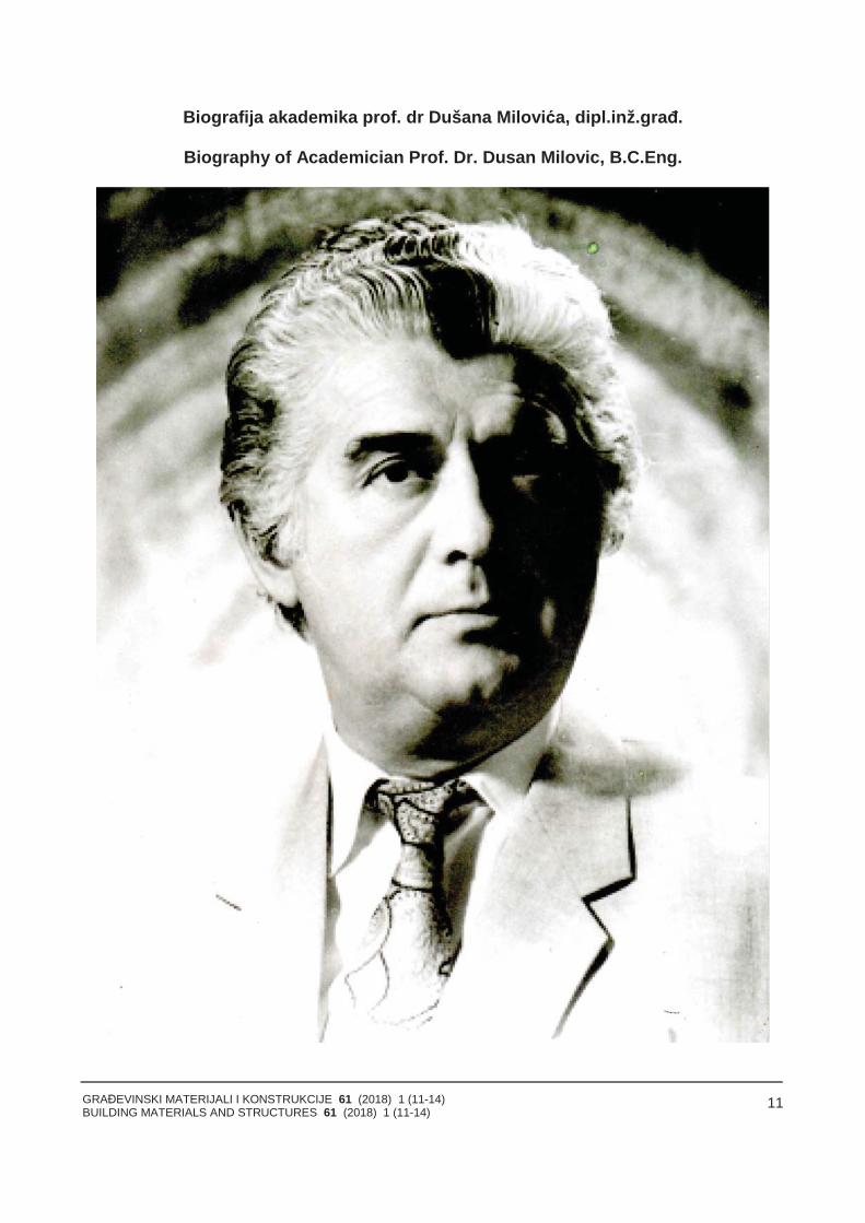
Biografija akademika prof. dr Dušana Milovića, dipl.inž.građ.
Biography of Academician Prof. Dr. Dusan Milovic, B.C.Eng.
GRAĐEVINSKI MATERIJALI I KONSTRUKCIJE 61 (2018) 1 (11-14)BUILDING MATERIALS AND STRUCTURES 61 (2018) 1 (11-14)
12
Dušan Milović (1925) rođen je u Novoj Varoši, uSrbiji. Gimnaziju je završio u Beogradu 1943. godine.Diplomirao je 1954. godine na Građevinskom fakultetu uBeogradu - konstruktivni smer (oblast: armirano-betonskimostovi). Doktorsku disertaciju, pod naslovom "Inže-njerske osobine lesa u Jugoslaviji”, odbranio je 1959.godine na Rudarsko-geološkom fakultetu u Beogradu iprvi u Srbiji dobio je zvanje doktora tehničkih nauka izoblasti mehanike tla i fundiranja. U periodu od 1954. do1966. godine radio je kao naučni saradnik u Institutu zaispitivanje materijala Srbije. Od 1966. do 1971. godineradio je na Univerzitetu u Šerbruku (Kvebek, Kanada),isprva kao pozvani profesor, a kasnije kao vanredni, teubrzo potom i kao redovni profesor i šef Katedre zamehaniku tla i fundiranje. Od 1972. do 1980. godine, bioje savetnik u Institutu za građevinarstvo Vojvodine uSubotici i redovni profesor na novoosnovanomgrađevinskom fakultetu, na kome je bio i prvi dekan. Od1980. do 1992. godine, bio je redovni profesor u Institutuza industrijsku gradnju Fakulteta tehničkih nauka uNovom Sadu i šef Katedre za mehaniku tla i fundiranje,gde je i penzionisan. Za dopisnog člana Vojvođanskeakademije nauka i umetnosti izabran je 1981. godine, aza njenog redovnog člana – 1987. godine. Srpska aka-demija nauka i umetnosti primila ga je 1991. godine kaoredovnog člana. Bio je član Društva za mehaniku tla ifundiranje Srbije (predsednik), član Jugoslovenskogdruštva za mehaniku tla i fundiranje (član predsed-ništva), delegat Jugoslovenskog društva za mehaniku tlai fundiranje u Svetskom društvu za mehaniku tla ifundiranje, član Predsedništva SANU, savetnik uKomitetu za uzimanje uzoraka pri Svetskom društvu zamehaniku tla i fundiranje. Tokom dugogodišnjeg rada naUniverzitetu u Novom Sadu, držao je predavanja izmehanike tla i fundiranja studentima na Građevinskomfakultetu u Novom Sadu i Subotici, kao i u Institutu zauređenje voda Poljoprivrednog fakulteta u Novom Sadu.Na Građevinskom fakultetu u Šerbruku držao jepredavanja i na magistarskim i na doktorskim studijama.Bio je mentor prilikom izrade više magistarskih radova idoktorskih disertacija. Treba naglasiti i to da je sredinomXX veka mehanika tla bila najmlađa disciplina ugrađevinarstvu u Jugoslaviji i tek su tada prve posleratnegeneracije imale su taj predmet u programu studija.
Istraživački rad
U periodu od 1954. do 1995. godine, poredfokusiranja na nastavni i obrazovni rad, Dušan Milovićusmerio je svoju aktivnost i na rešavanje teorijskihproblema u oblasti mehanike tla, kao i na eksperi-mentalno proučavanje temeljnog tla i temeljnih kon-strukcija pri dejstvu opterećenja od objekta. Taj radostvaren je u šesnaest naučnoistraživačkih projekata, čijije bio nosilac i glavni istraživač. Pomenute projektefinansirali su Fond za naučni rad Srbije (3), ConseilNational de Recherches Ottawa u Kanadi (3), Siz zanaučni rad Vojvodine (7), Jugoslovensko-američki JointVenture projekat (1) i Fond za naučni rad Srpskeakademije nauka i umetnosti (2). Originalna teorijskarešenja i rezultate eksperimentalnih ispitivanja objavio jeu 226 radova, od kojih je u 195 prvi autor (a u 138 –jedini autor). Do 2009. godine, njegovi radovi citirani su205 puta (SCI). U oblasti direktnog fundiranja, proširio jeprimenu teorije elastičnosti i prikazao rešenja za
Dusan Milovic was born on 28 March 1925 in NovaVaroš, Serbia . He finished his primary school in Nis andgrammar school in 1943, in Belgrade. He graduatedfrom the Faculty of Civil Engineering, in 1954. on thesubject of concrete bridges, at Belgrade University. In1959 he defended his doctoral thesis entitled “Engi-neering properties of loess soils in Jugoslavia“ and hewas the first who received Ph. D. degree in the field ofSoil mechanics and foundations in Serbia .
From 1959 he worked at the Serbian Institute forTesting materials, Department of Soil Mechanics andFoundations in Belgrade. He remained there until 1966working as science associate and senior scienceadviser. From 1966 until 1971 he worked in Québec,Canada, where he occupied various functions at theUniversity of Sherbrooke, as invited professor, associ-ated professor and the Head of the Department of SoilMechanics and Foundation Engineering. In 1969, hewas elected full professor. After return from Canada, inthe period from 1971 until 1980 he was a counsellor inthe Institute for Civil Engineering in Vojvodina (Subotica)and full professor and the first Dean of the newly openedFaculty of Civil Engineering. From 1980 until 1992 hewas full professor at the Institute for Industrial Building atthe Faculty of Technical Sciences in Novi Sad, directorof the Institute and Head of the Soil MechanicsDepartment. He retired in 1992.
He was elected corresponding member of the Vojvo-dina Academy of Sciences and Arts in 1981 and in 1987he became its full member. In 1991 he was elected fullmember of the Serbian Academy of Sciences and Arts .
During the long period of active work he taught SoilMechanics and Foundation at the Faculty of TechnicalSciences in Novi Sad, Faculty of Civil Engineering inSubotica, Faculty of Agriculture in Novi Sad and Facultyof Civil Engineering in Sherbrooke, Canada, where hehad held post graduate courses. He headed for severalmaster’s thesis and doctoral dissertations in Serbia andCanada.
He speaks English and French, and has a consi-derable knowledge of German.
In the field of deep foundations Dusan Milovicdeveloped the procedure for determination of bearingcapacity of piles, subjected to a vertical compressionload, using the results of the cone penetration tests inthe field. By means of the finite difference method, hesolved theoretically the problem of calculation of hori-zontal displacements, bending moments, rotation andshear forces for any relative rigidity of free head or fixedhead piles, produced by horizontal load and bendingmoment. The agreement between the theoretical andfield test results was performed using field load tests inthe scale 1:1. Experience gained in engineering practiceconfirms that his method provides more precise resultsthan those obtained by static or dynamic methods andrepresents considerable improvement in prediction ofpile behaviour subjected to vertical or horizontal load.During the long period of time it has been noticed thatseismic forces can cause the liquefaction in sand layerswith catastrophic consequences. Studying the behaviourof sand deposits under the influence of cyclic load hehas found that severe damages and collapse of structurevery often take place due to degradation of skin frictionof piles.
One of his very significant activities was directed
GRAĐEVINSKI MATERIJALI I KONSTRUKCIJE 61 (2018) 1 (11-14)BUILDING MATERIALS AND STRUCTURES 61 (2018) 1 (11-14)
13
određivanje veličine sleganja i ugaonih distorzija za sveoblike i sve relativne krutosti temelja, za razne slučajeveopterećenja i kompleksne modele tla, uključujući aniso-tropna svojstva tla, ograničenu debljinu deformabilnesredine nedeformabilnim substratumom, kao i višeslojnesisteme. Rešenja dobijena metodom konačnih eleme-nata i dvostrukim Fourier-ovim redovima prikazana su nainternacionalnim kongresima geomehanike i objavljena učasopisima svetskog renomea (osam radova u Londonu,Parizu, Berlinu, Moskvi i Tokiju, u periodu od 1970. do1973. godine), te se smatraju pionirskim.
*
U oblasti dubokog fundiranja, Dušan Milović rešio jeprobleme određivanja veličine graničnog i dozvoljenogopterećenja šipova pomoću podataka dobijenih izterenskih opita statičke penetracije. Metodom konačnihrazlika, prikazao je rešenje za određivanje horizontalnogpomeranja šipa, momenata savijanja, rotacije i popreč-nih sila za šip bilo koje krutosti, sa slobodnom iuklještenom glavom, usled dejstva vertikalnog i hori-zontalnog opterećenja. Tačnost teorijskih rešenja prove-ravana je terenskim opitima, probnim opterećenjem urazmeri 1:1. Eksperimentalni radovi predstavljaju izvan-rednu proveru teorijskih rešenja u mehanici tla.
Značajnih aktivnosti Dušana Milovića bila su usme-rene na teorijske studije i terenska ispitivanja lesnog tla.Osim u našoj zemlji, ova vrsta tla je veoma raspros-tranjena u Rusiji, Kini, Americi, kao i u mnogim drugimzemljama. Kako su u svim pomenutim zemljama regi-strovana veoma teška oštećenja, pa čak i rušenjaobjekata i pri relativno niskim vrednostima delujućegopterećenja, vrlo opsežnim terenskim i laboratorijskimispitivanjima, odredio je parametre koji su od presudnogznačaja za ponašanje lesnog tla. Na osnovu dobijenihrezultata, modifikovao je teoriju proračuna ukupnih idiferencijalnih sleganja. Novim predloženim postupkom,dokazano je da se dato rešenje može uspešno primenitina bilo koju lokaciju u svetu, gde se javlja lesno tlo.Milovićevi izvanredni radovi o lesu sadrže takve podatkekakvi još nigde u svetu nisu do sada objavljeni.
Pored aktivnog višedecenijskog rada na nastavnom inaučnom planu, aktivno je učestvovao u rešavanjunajsloženijih problema fundiranja mnogobrojnih objekatavisokogradnje u građevinarstvu. Za više od 220 objekatadao je rešenje za siguran i ekonomičan način fundiranja(npr. za stambene zgrade s trinaest spratova, zastambene zgrade do devetnaest spratova, za silose zažito, mostove, administrativne zgrade, čeličane, ener-gane, šećerane, sportske centre, luke, brodogradilišta).Osim u zemlji, radio je studije fundiranja i za objekte uIraku, Čehoslovačkoj, Poljskoj i Kanadi.
Rezultate istraživačkih radova prikazao je na mnogimsvetskim kongresima za mehaniku tla i fundiranje(London 1957, Pariz 1961, Montreal 1965, Meksiko Siti1969, Moskva 1973,Tokio 1977, Stokholm 1981, SanFrancisko 1985, Rio de Žaneiro 1989, Hamburg 1997,Osaka 2005. g. i Čikago 2013).
Njegovi radovi prikazani su na tri svetska kongresaza inženjersku geologiju - u Buenos Ajresu 1986, uLisabonu 1994. i Vankuveru 1998. godine.
Učestvovao je s radovima na sledećim evropskimkongresima, internacionalnim regionalnim kongresima idunavskim kongresima za mehaniku tla i fundiranje(Budimpešta 1963, Visbaden 1963, Čikago 1965, Haifa
toward theoretical, field and laboratory studies of loesssoils .This kind of soil covers about 9% of continentsurface, reaching the thickness greater than 100 mBeside of our country, loess is widely spread in Russia,China, America and in other countries It has beenreported that loess exhibits unusual properties . In manycountries a great number of damaged or collapsedstructures has been noticed, despite the fact that theapplied load was relatively low. On the basis of theextensive laboratory and field investigations he definedthe parameters which have the greatest influence on theloess behaviour. He modified the method of settlementcalculation, involving the additional component of dif-ferential settlement, caused by wetting or saturation ofloess soil and including the effect of anisotropy. Duringthe laboratory testing of loess samples he establishedthat the mechanical disturbance can lead to the quiteerroneous results and conclusions concerning itsbearing capacity and expected settlements. By means ofthe obtained solution it is possible to solve successfullyfoundation problems on loess soils in every country withloess deposits. These results have been estimated asexceptional achievement in this field, not earlierpublished anywhere else.
In the capacity of designer, expert and consultant hehas made a considerable contribution in the field offoundation engineering, providing a safe and economicalsolutions to the geotechnical problems for more than 220structures. Some of the most important are apartmentbuildings with 13 to 19 stories, silo groups, bridges, steelwork, rolling mill building, factory of chemical products,halls of fair, hotels, sport centers, shipbuilding yard,harbours and others important structures. In addition,solutions of the foundation problems have been providedfor structures in Iraq, Poland, Czechoslovakia andCanada.
Papers have been published in Journals Glas(Serbian Academy of Sciences and Arts), Our CivilEngineering, Publications of the Institute for TestingMaterials, Buildings, Road and Traffic, Materials andStructures. He has taken part with papers at 29Yugoslav and Serbian congresses on Soil Mechanicsand Foundation Engineering .
Some papers were published in foreign countries inthe most recognized international geotechnical journalssuch as Géotechnique (London, England), Soils andFoundations (Tokyo, Japan), Journal of the AmericanSociety for Testing and Materials ASTM USA, Sol Soils(Paris, France), L’Ingénieur Constructer (Paris, France),Le Génie Civil (Paris, France), Bauingenieur (Berlin,Germany).
Papers have been presented at World Conferenceson Soil Mechanics and Foundation Engineering, inLondon 1957, Paris 1961, Montreal 1965, Mexico City1969, Moscow 1973, Tokyo 1977, Stockholm 1981, SanFrancisco, 1985, Rio de Janeiro 1989, Hamburg 1997,Osaka 2005 and Chicago 2013.
Papers have been presented at 3 WorldConferences on Engineering Geology, in Buenos Aires1986, Lisbon 1994 and Vancouver 1998 .
He has participated with papers at 27 EuropeanCongresses, International Regional Congresses andDanube Congresses on Soil Mechanics and FoundationEngineering, Budapest 1963, Wiesbaden 1963, Chicago1965, Haifa 1967, Belgrade 1970, Bangkok 1971,
GRAĐEVINSKI MATERIJALI I KONSTRUKCIJE 61 (2018) 1 (11-14)BUILDING MATERIALS AND STRUCTURES 61 (2018) 1 (11-14)
14
1967, Beograd 1970, Bangkok 1971, Budimpešta 1971,Pariz 1971, Stokholm 1974, Beč 1976, Bratislava 1977,Brno 1979, Pariz 1980, Cirih 1982, Amsterdam 1982,Budimpešta 1984, Pariz 1984, Nagoja 1985, Peking1986. i 1988, London 1989, Budimpešta 1990, Firenca1990, Vankuver 1991, Dalas 1992, Gent 1993. iKopenhagen 1995).
*
Pored aktivnih učestvovanja na internacionalnomplanu, objavio je i sledeće knjige i monografije:"Geomehanika” 1976. godine (148 strana); "Mehanikatla” 1977 (243); „Mehanika tla” 1982 (323); „Mehanikatla” 1987 (475); "Analiza napona i deformacija umehanici tla” (na srpskom i engleskom jeziku) 1974 (264strane); "Problemi fundiranja na lesnom tlu” 1987 (255);"Greške u fundiranju” 2005 (438); "Problemi interakcijetlo-temelj - konstrukcija” 2009 (428); Stresses anddisplacements for shallow foundations 1992, Elsevier,620 strana.
Tokom internacionalnih kongresa, bio je Invitedpanel member 1965. godine, potpredsednik sekcije zakolapsibilna tla 1969, Invited lecturer – 1969, Invitedlecturer – 1979, Invited speaker – 1989, Invited panelmember i General reporter – 1990, predsednik tehničkesekcije za kolapsibilna tla – 1992. i Invited speaker –1995. godine. Nadalje, imao je poziv od Instituta zamehaniku tla Kineske akademije nauka da pripremi (KeyPaper) za Internacionalni kongres za mehaniku tla ifundiranje u Vuhanu (Wuhan) 2012. godine i daorganizuje rad jedne od sekcija, poziv od organizatoraInternacionalne konferencije GEO SIN 2014. godine uSingapuru da bude njihov savetnik, da pripremi KeyPaper i da organizuje jednu sekciju po sopstvenomizboru.
Priznanja i nagrade
Dušan Milović je dobitnik Oktobarske nagradegrada Beograda 1962. godine. Odlikovan je Medaljomzasluge za narod i Ordenom rada sa srebrnim vencem.Dušan Milović je počasni i zaslužni član Savezagrađevinskih inženjera i tehničara Srbije.
Budapest 1971, Paris 1971, Stockholm 1974, Wien1976, Bratislava 1977, Brno 1979, Paris 1980, Zurich1982, Amsterdam 1982, Budapest 1984, Paris 1984,Nagoya 1985, Beijing 1986 and 1988, London 1989,Budapest 1990, Firenze 1990, Vancouver 1991, Dallas1992, Ghent 1993 and Copenhagen 1995.
In addition, he published several books such as SoilMechanics 1976, 148 pages, Soil Mechanics 1977, 243pages, Soil Mechanics 1982, 323 pages, Soil Mechanics1987, 475 pages, Analyses of Stresses and Deforma-tions in Soil Mechanics, (Serbian and English) 1974, 264pages, Foundation problems on loess soil, 1987, 255pages, Mistakes in Foundations, 2005, 438 pages, Inter-action problems soil - foundation - construction, 2009,pages 428 pages.
Stresses and displacements for shallow foundations,1992, ELSEVIER, 620 pages.
He was invited for panel member in Chicago, 1965,vice president of the section for collapsible soils on theWorld Conference in Mexico 1969, lecturer at EcolePolytechnique in Montreal 1969, panel member andlecturer at the Conference in Brno 1979, invited speakerin London 1989, panel member and General reporter inBudapest 1990, president of Technical section forcollapsible soils at the International Conference held inDallas 1992, invited speaker to deliver a lecture at theEuropean Conference on Soil Mechanics and Founda-tion Engineering held in Copenhagen 1995; Invitedspeaker to deliver a Key Lecture at the InternationalConference on Problematic Soils - CHINESE
ACADEMY OF SIENCES Institute for Soil Mecha-nics, Wahan, 2012, and to be president of one Technicalsection; Invited speaker to deliver a Key Paper at theInternational Conference GEO SIN 2014 in Singapore.
Dusan Milovic was President of Serbian Society ofSoil mechanics and Foundation Engineering, member ofthe Presidency of Yugoslav Society of Soil Mechanics,Representative of the Yugoslav Society at the WorldSociety of Soil Mechanics and Foundation Engineering,member of the European Society of Numerical methods,member of the European Committee of PenetrationTesting and advisor in the Committee of World Societyfor soil sampling.
GRAĐEVINSKI MATERIJALI I KONSTRUKCIJE 61 (2018) 1 (15-26)BUILDING MATERIALS AND STRUCTURES 61 (2018) 1 (15-26)
15
NOSIVOST ŠIPOVA - TEORIJSKE I TERENSKE METODE
BEARING CAPACITY OF PILES - THEORY AND FIELD TESTS
Dušan MILOVIĆORIGINALNI NAUČNI RAD
ORIGINAL SCIENTIFIC PAPERUDK: 624.154.046.2
doi:10.5937/GRMK1801015M
Karl Terzaghi, 1948 god."Temelji građevina uvek su bili pastorčad, zato što nemaslave u temeljenju. Ali dela osvete zbog nedovoljnepažnje oko njih mogu biti katastrofalna". '
Karl Terzaghi, 1948 th."Foundations of structures always were orphansbecause there is no glory in foundation. But the works ofrevenge because of this neglect can be catastrophic”.
1 UVOD
Za pravilno dimenzioniranje temelja na šipovima,potrebno je zadovoljiti više kriterijuma, među kojima sunajvažniji oni u vezi sa slomom tla i pojavomnedozvoljeno velikih sleganja. Pri svemu tome, potrebnoje primeniti najekonomičnije rešenje – koje podrazumevaoptimalan broj šipova odgovarajućeg poprečnog presekai dužine.
Zbog značaja što tačnijeg određivanja veličinegraničnog opterećenja šipova, razvijene su brojnemetode – kako teorijske, tako i eksperimentalne – kojese koriste u inženjerskoj praksi. Međutim, pokazalo seda postoje znatne razlike u veličinama dobijenihrezultata. Stoga, za 48 izvedenih šipova izvršeno je iterensko ispitivanje probnim opterećenjem do sloma tla,kako bi se teorijski određene veličine graničnogopterećenja uporedile s realnom veličinom i kako bi seutvrdio stepen tačnosti najčešće korišćenih teorijskihmetoda.
Potrebno je pomenuti i to da je na jednom nedavnoodržanom svetskom kongresu za mehaniku tla ifundiranje generalni izvestilac obavestio skup svetskihstručnjaka da još nema rešenja kojim bi se moglaodrediti veličina graničnog opterećenja, a da pritomgreška bude manja ili veća za 30% od veličine dobijeneprobnim opterećenjem. Veća vrednost od realnevrednosti ima za posledicu da umanji stepen sigurnostiobjekta, ili – u drugom slučaju – da poveća troškovegradnje.
Akademik prof. dr Dušan Milović,dipl.ing.građ. SANU
1 INTRODUCTION
For successful design of the foundations on piles it isnecessary to satisfy some criterion. Amongst the mostimportant are soil rupture and unacceptable greatsettlement. Also it is very important to apply the mosteconomical solution, which consist of the optimalnumber of piles with the corresponding cross sectionand length.
In order to determine the values of the bearingcapacity of piles numerous theoretical and experimentalmethods were developed, which are used in theengineering practice. However, it was observed that theobtained results were very different. For that reason 48concrete piles were in situ tested in order to determinethe real values of the ultimate load and to compare itwith the theoretical results. In this way it was possible toevaluate the level of precision of the used theoreticalsolutions.
It is necessary to mention that in the recent WorldConference on Soil Mechanics and FoundationEngineering the General Reporter informed that theSociety does not have a solution to determine theultimate bearing capacity of pile without making the error 30 % from the real value obtained by field load test ofa pile.
Academician Professor Dr. Dusan Milovic, SASA
GRAĐEVINSKI MATERIJALI I KONSTRUKCIJE 61 (2018) 1 (15-26)BUILDING MATERIALS AND STRUCTURES 61 (2018) 1 (15-26)
16
2 METODE ZA ODREĐIVANJE GRANIČNOG I DOZVOLJENOG OPTEREĆENJA ŠIPOVA
2.1 Statičke metode
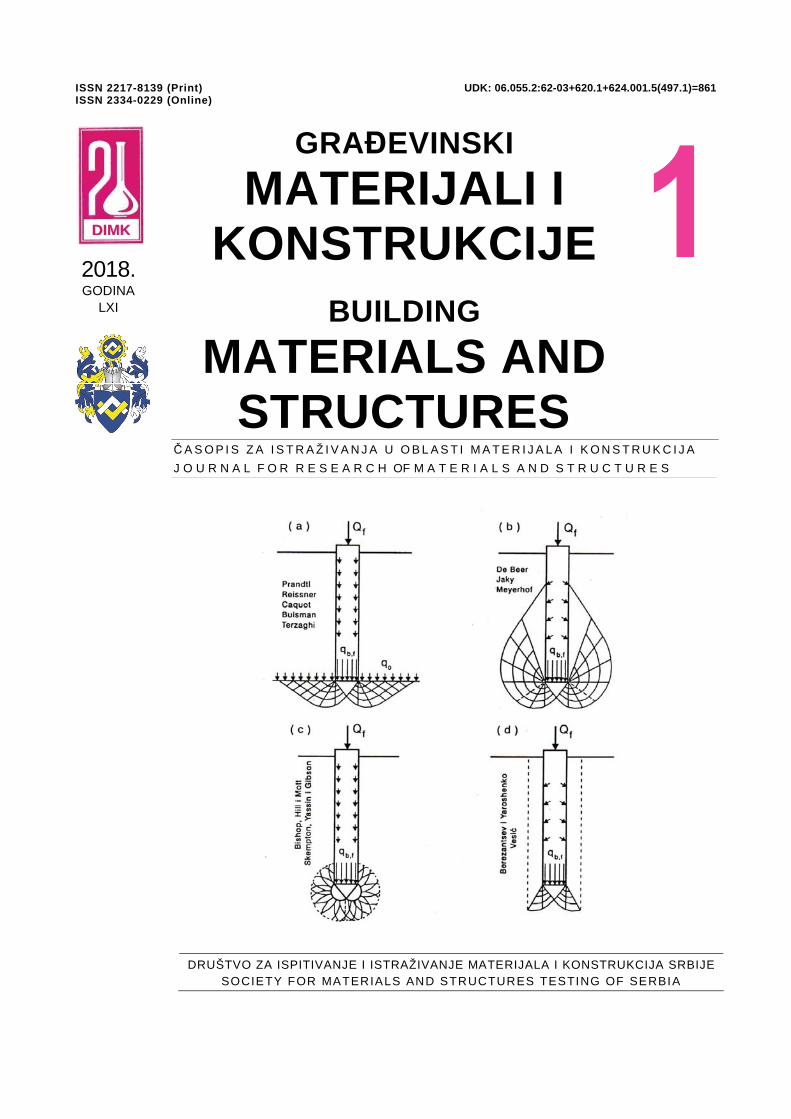
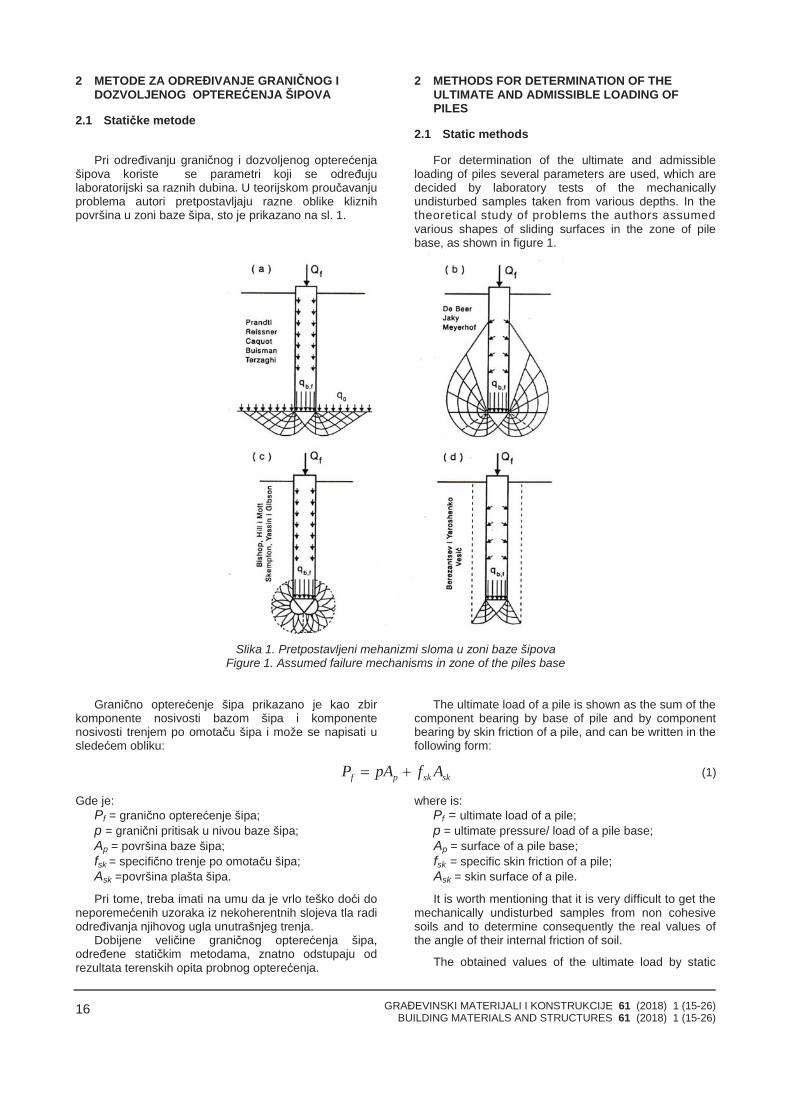
Pri određivanju graničnog i dozvoljenog opterećenjašipova koriste se parametri koji se određujulaboratorijski sa raznih dubina. U teorijskom proučavanjuproblema autori pretpostavljaju razne oblike kliznihpovršina u zoni baze šipa, sto je prikazano na sl. 1.
2 METHODS FOR DETERMINATION OF THEULTIMATE AND ADMISSIBLE LOADING OFPILES
2.1 Static methods
For determination of the ultimate and admissibleloading of piles several parameters are used, which aredecided by laboratory tests of the mechanicallyundisturbed samples taken from various depths. In thetheoretical study of problems the authors assumedvarious shapes of sliding surfaces in the zone of pilebase, as shown in figure 1.
Slika 1. Pretpostavljeni mehanizmi sloma u zoni baze šipovaFigure 1. Assumed failure mechanisms in zone of the piles base
Granično opterećenje šipa prikazano je kao zbirkomponente nosivosti bazom šipa i komponentenosivosti trenjem po omotaču šipa i može se napisati usledećem obliku:
The ultimate load of a pile is shown as the sum of thecomponent bearing by base of pile and by componentbearing by skin friction of a pile, and can be written in thefollowing form:
skskpf AfpAP (1)
Gde je:Pf = granično opterećenje šipa;p = granični pritisak u nivou baze šipa;Ap = površina baze šipa;fsk = specifično trenje po omotaču šipa;Ask =površina plašta šipa.
Pri tome, treba imati na umu da je vrlo teško doći doneporemećenih uzoraka iz nekoherentnih slojeva tla radiodređivanja njihovog ugla unutrašnjeg trenja.
Dobijene veličine graničnog opterećenja šipa,određene statičkim metodama, znatno odstupaju odrezultata terenskih opita probnog opterećenja.
where is:Pf = ultimate load of a pile;p = ultimate pressure/ load of a pile base;Ap = surface of a pile base;fsk = specific skin friction of a pile;Ask = skin surface of a pile.
It is worth mentioning that it is very difficult to get themechanically undisturbed samples from non cohesivesoils and to determine consequently the real values ofthe angle of their internal friction of soil.
The obtained values of the ultimate load by static
GRAĐEVINSKI MATERIJALI I KONSTRUKCIJE 61 (2018) 1 (15-26)BUILDING MATERIALS AND STRUCTURES 61 (2018) 1 (15-26)
17
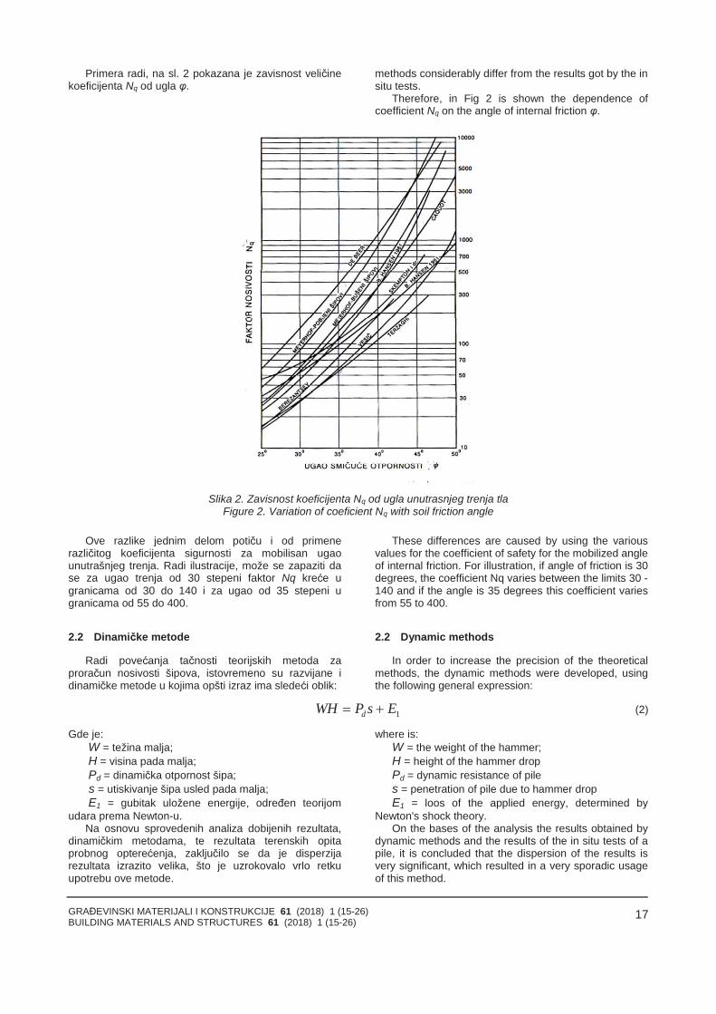
Primera radi, na sl. 2 pokazana je zavisnost veličinekoeficijenta Nq od ugla φ.
methods considerably differ from the results got by the insitu tests.
Therefore, in Fig 2 is shown the dependence ofcoefficient Nq on the angle of internal friction φ.
Slika 2. Zavisnost koeficijenta Nq od ugla unutrasnjeg trenja tlaFigure 2. Variation of coeficient Nq with soil friction angle
Ove razlike jednim delom potiču i od primenerazličitog koeficijenta sigurnosti za mobilisan ugaounutrašnjeg trenja. Radi ilustracije, može se zapaziti dase za ugao trenja od 30 stepeni faktor Nq kreće ugranicama od 30 do 140 i za ugao od 35 stepeni ugranicama od 55 do 400.
2.2 Dinamičke metode
Radi povećanja tačnosti teorijskih metoda zaproračun nosivosti šipova, istovremeno su razvijane idinamičke metode u kojima opšti izraz ima sledeći oblik:
These differences are caused by using the variousvalues for the coefficient of safety for the mobilized angleof internal friction. For illustration, if angle of friction is 30degrees, the coefficient Nq varies between the limits 30 -140 and if the angle is 35 degrees this coefficient variesfrom 55 to 400.
2.2 Dynamic methods
In order to increase the precision of the theoreticalmethods, the dynamic methods were developed, usingthe following general expression:
1EsPWH d (2)
Gde je:W = težina malja;H = visina pada malja;Pd = dinamička otpornost šipa; s = utiskivanje šipa usled pada malja;E1 = gubitak uložene energije, određen teorijom
udara prema Newton-u.Na osnovu sprovedenih analiza dobijenih rezultata,
dinamičkim metodama, te rezultata terenskih opitaprobnog opterećenja, zaključilo se da je disperzijarezultata izrazito velika, što je uzrokovalo vrlo retkuupotrebu ove metode.
where is:W = the weight of the hammer;H = height of the hammer dropPd = dynamic resistance of piles = penetration of pile due to hammer dropE1 = loos of the applied energy, determined by
Newton's shock theory.On the bases of the analysis the results obtained by
dynamic methods and the results of the in situ tests of apile, it is concluded that the dispersion of the results isvery significant, which resulted in a very sporadic usageof this method.
GRAĐEVINSKI MATERIJALI I KONSTRUKCIJE 61 (2018) 1 (15-26)BUILDING MATERIALS AND STRUCTURES 61 (2018) 1 (15-26)
18
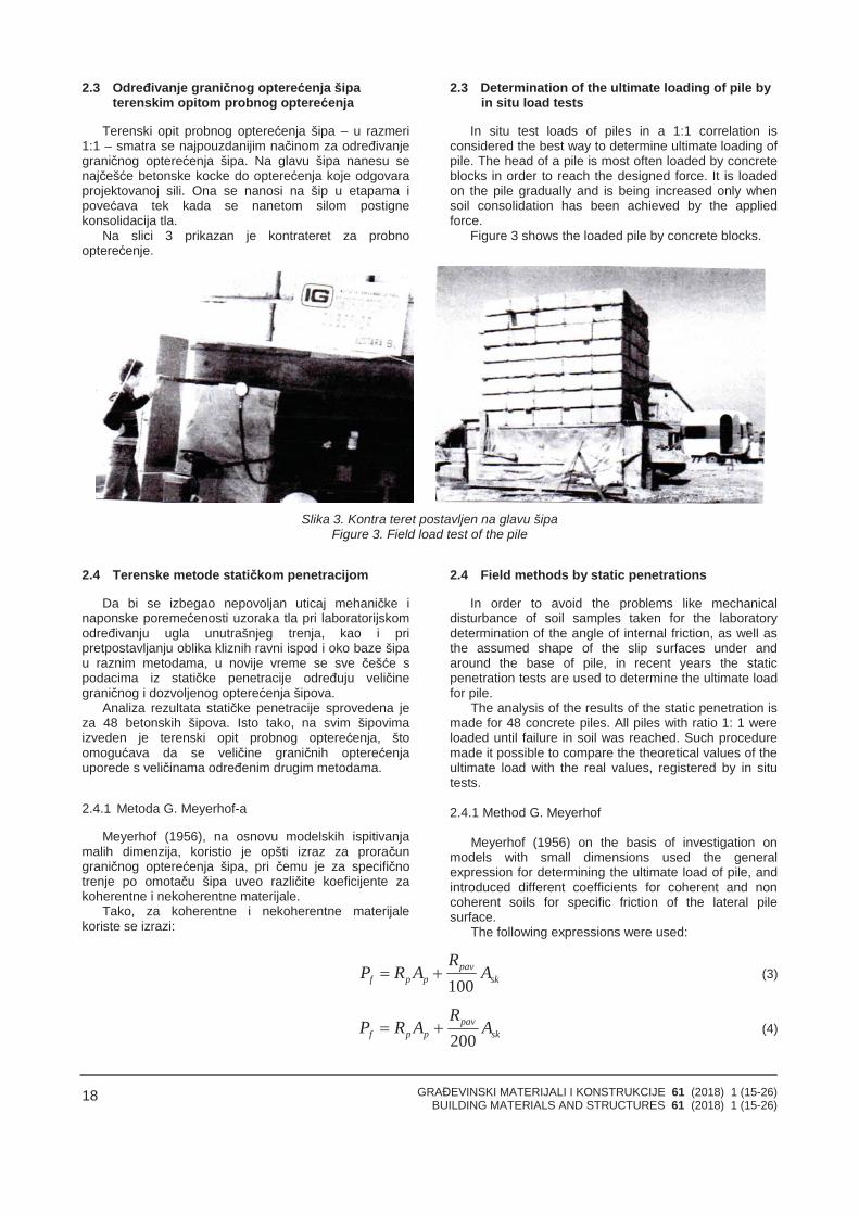
2.3 Određivanje graničnog opterećenja šipaterenskim opitom probnog opterećenja
Terenski opit probnog opterećenja šipa – u razmeri1:1 – smatra se najpouzdanijim načinom za određivanjegraničnog opterećenja šipa. Na glavu šipa nanesu senajčešće betonske kocke do opterećenja koje odgovaraprojektovanoj sili. Ona se nanosi na šip u etapama ipovećava tek kada se nanetom silom postignekonsolidacija tla.
Na slici 3 prikazan je kontrateret za probnoopterećenje.
2.3 Determination of the ultimate loading of pile byin situ load tests
In situ test loads of piles in a 1:1 correlation isconsidered the best way to determine ultimate loading ofpile. The head of a pile is most often loaded by concreteblocks in order to reach the designed force. It is loadedon the pile gradually and is being increased only whensoil consolidation has been achieved by the appliedforce.
Figure 3 shows the loaded pile by concrete blocks.
Slika 3. Kontra teret postavljen na glavu šipaFigure 3. Field load test of the pile
2.4 Terenske metode statičkom penetracijom
Da bi se izbegao nepovoljan uticaj mehaničke inaponske poremećenosti uzoraka tla pri laboratorijskomodređivanju ugla unutrašnjeg trenja, kao i pripretpostavljanju oblika kliznih ravni ispod i oko baze šipau raznim metodama, u novije vreme se sve češće spodacima iz statičke penetracije određuju veličinegraničnog i dozvoljenog opterećenja šipova.
Analiza rezultata statičke penetracije sprovedena jeza 48 betonskih šipova. Isto tako, na svim šipovimaizveden je terenski opit probnog opterećenja, štoomogućava da se veličine graničnih opterećenjauporede s veličinama određenim drugim metodama.
2.4.1 Metoda G. Meyerhof-a
Meyerhof (1956), na osnovu modelskih ispitivanjamalih dimenzija, koristio je opšti izraz za proračungraničnog opterećenja šipa, pri čemu je za specifičnotrenje po omotaču šipa uveo različite koeficijente zakoherentne i nekoherentne materijale.
Tako, za koherentne i nekoherentne materijalekoriste se izrazi:
2.4 Field methods by static penetrations
In order to avoid the problems like mechanicaldisturbance of soil samples taken for the laboratorydetermination of the angle of internal friction, as well asthe assumed shape of the slip surfaces under andaround the base of pile, in recent years the staticpenetration tests are used to determine the ultimate loadfor pile.
The analysis of the results of the static penetration ismade for 48 concrete piles. All piles with ratio 1: 1 wereloaded until failure in soil was reached. Such proceduremade it possible to compare the theoretical values of theultimate load with the real values, registered by in situtests.
2.4.1 Method G. Meyerhof
Meyerhof (1956) on the basis of investigation onmodels with small dimensions used the generalexpression for determining the ultimate load of pile, andintroduced different coefficients for coherent and noncoherent soils for specific friction of the lateral pilesurface.
The following expressions were used:
skpav
ppf AR
ARP100
(3)
skpav
ppf AR
ARP200
(4)
GRAĐEVINSKI MATERIJALI I KONSTRUKCIJE 61 (2018) 1 (15-26)BUILDING MATERIALS AND STRUCTURES 61 (2018) 1 (15-26)
19
Gde je:Rp = otpornost na prodor konusa ispod baze šipa;Ap = površina baze šipa;Rpav = prosečna otpornost na prodor konusa duž
omotača šipa;Ask = površina omotača šipa.
2.4.2 Metoda Mohan - a i Kumar - a
Mohan i Kumar (1963) su na osnovu podataka iz 8probnih opterećenja instrumentalnih šipova i podataka izliterature predložili sledeći izraz za proračun graničnog idozvoljenog opterećenja šipa:
were is:Rp =penetration resistance under the base of a pile;Ap = surface of a pile base;Rpav = average penetration resistance of lateral
surface of pile;Ask = lateral surface of pile.
2.4.2 Method Mohan and Kumar
Mohan and Kumar (1963) on the basis of the resultsfor 8 in situ tests and data from literature used thefollowing expression for evaluation of the ultimate andadmissible loading of pile:
skpav
skskpf AR
PPPP50
(5)
gde je:Rp = otpornost na prodor konusa ispod baze šipa;Ap = površina poprečnog preseka baze šipa;Rpav = prosečna otpornost na prodor konusa oko
stabla šipa;Ask = površina omotača šipa.
Pri tome, za proračun dozvoljenog opterećenja šipakoristi se parcijalni faktor sigurnosti Fp = 2,5 za nosivostbazom i Fsk = 2,0 za nosivost trenjem po omotaču šipa.
2.4.3 Metoda Bustamante-a i Gianeselli-a
Bustamante i Gianeselli (1982) uveli su redukcionifaktor Kp za nosivost šipa bazom i faktor Ksk za nosivosttrenjem po omotaču u koherentnom tlu, pa se graničnoopterećenje može odrediti pomoću izraza:
where is:Rp = penetration resistance under the base of a pile;Ap = surface of a pile base;Rpav = average penetration resistance of lateral
surface of pile;Ask = lateral surface of pile;
In this case the partial factor of security for bearing ofbase Fp = 2.5 was used and for the bearing of the lateralsurface of pile Fsk = 2. 0.
2.4.3 Method Bustamante and Gianeselli
Bustamante and Gianeselli (1982) are introduced afactor Kp for the bearing of pile base and factor K sk forthe bearing of lateral surface of pile in cohesive soils.The ultimate load now can be written in the followingform:
ii ski
pipppf hD
KR
KARP π (6)
Gde je:Kp = bezdimenzioni koeficijent za slojeve tla ispod
baze šipa;RPh =prosečna penetraciona otpornost na prodor
konusa u sloju debljine h;Ksk = bezdimenzioni koeficijent za slojeve iznad baze
šipa;D = prečnik šipa;h = debljina sloja i;
Mada se metode statičke penetracije zasnivaju naistoj vrsti terenskog ispitivanja, odnosno na merenjuveličine otpornosti na prodor konusa duž stabla i ispodbaze šipa, primenom pomenutih metoda dobijaju seznatne razlike u veličinama graničnog i dozvoljenogopterećenja.
2.4.4 Metoda autora i upoređivanje rezultata sprikazanim metodama
U daljem tekstu prikazaće se rezultati pojedinihautora, koji se odnose na određivanje graničnog i
where is:Kp = dimensionless coefficient for soil layers under
the pile base;RPh = average penetration resistance in the layer of
thickness h.Ksk = dimensionless coefficient for soil layers above
the pile base;D = diameter of pile;h = thickness of the layer i.
Despite the fact that all methods are based on thesame kind of in situ investigation, by using thementioned methods one obtains considerabledifferences in values of the ultimate and admissibleloading of piles.
2.4.4 New method of Milovic and comparison of theresults with the presented methods
Further are shown the results of all mentionedauthors concerning the determination of the ultimate
GRAĐEVINSKI MATERIJALI I KONSTRUKCIJE 61 (2018) 1 (15-26)BUILDING MATERIALS AND STRUCTURES 61 (2018) 1 (15-26)
20
dozvoljenog opterećenja šipova, a koji su određeni spodacima iz terenskih opita statičke penetracije i opitaprobnog opterećenja u razmeri 1:1.
U ovom radu prikazani su rezultati analize 48 šipovaza koje su određene veličine graničnog i dozvoljenogopterećenja i za koje su bili izvedeni terenski opitiprobnog opterećenja.
U novoj metodi prikazan je izraz prema kome suvršeni proračuni veličine komponente sile koju primabaza šipa i komponente koju prima omotač šipa i koji jedat u sledećem obliku:
loading of piles, which are obtained by using the resultsof static penetration tests and the results obtained bysite loading tests on the pile in the scale 1: 1.
In this paper are shown the results for 48 piles. Thevalues of the ultimate load were obtained using thetheoretical solutions and also the results of field loadtests.
The expression used in the new method for thedetermination the values of base pile component andlateral surface component is given by:
phf p sk p p p i
sk
RP P P P A D h
(7)
Gde je:Rp = otpornost na prodor konusa u zoni sloma oko
baze;Rph = prosečna otpornost na prodor konusa u sloju
debljine h;A = površina poprečnog preseka baze šipa;D = prečnik šipa;h = debljina posmatranog sloja i;
Pα i skα = koeficijenti nosivosti bazom i trenjem poomotaču šipa.
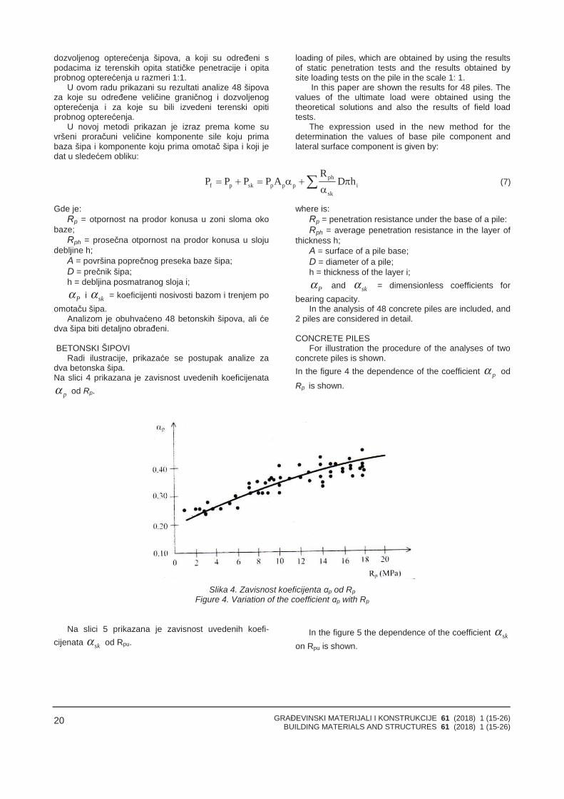
Analizom je obuhvaćeno 48 betonskih šipova, ali ćedva šipa biti detaljno obrađeni.
BETONSKI ŠIPOVIRadi ilustracije, prikazaće se postupak analize za
dva betonska šipa.Na slici 4 prikazana je zavisnost uvedenih koeficijenata
pα od Rp.
where is:Rp = penetration resistance under the base of a pile:Rph = average penetration resistance in the layer of
thickness h;A = surface of a pile base;D = diameter of a pile;h = thickness of the layer i;
Pα and skα = dimensionless coefficients forbearing capacity.
In the analysis of 48 concrete piles are included, and2 piles are considered in detail.
CONCRETE PILESFor illustration the procedure of the analyses of two
concrete piles is shown.In the figure 4 the dependence of the coefficient pα od
Rp is shown.
Slika 4. Zavisnost koeficijenta αp od RpFigure 4. Variation of the coefficient αp with Rp
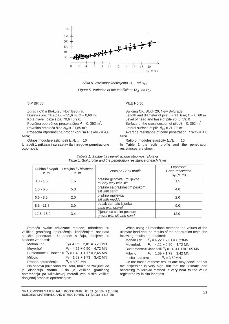
Na slici 5 prikazana je zavisnost uvedenih koefi-cijenata skα od Rpu.
In the figure 5 the dependence of the coefficient skαon Rpu is shown.
GRAĐEVINSKI MATERIJALI I KONSTRUKCIJE 61 (2018) 1 (15-26)BUILDING MATERIALS AND STRUCTURES 61 (2018) 1 (15-26)
21
Slika 5. Zavisnost koeficijenta skα od Rpu
Figure 5. Variation of the coefficient skα on Rph
ŠIP BR 30
Zgrada CK u Bloku 20, Novi BeogradDužina i prečnik šipa L = 11,6 m; D = 0,60 m;Kota glave i baze šipa; 70,6 i 5 9,0;Površina poprečnog preseka šipa A = 0, 352 m2;Površina omotača šipa Ask = 21,85 m2;Prosečna otpornost na prodor konusa R skav - = 4,6
MPa;Odnos modula elastičnosti Eb/Esk = 10
U tabeli 1 prikazani su sastav tla i njegove penetracioneotpornosti.
PILE No 30
Building CK, Block 20, New BelgradeLength and diameter of pile L = 11. 6 m; D = 0. 60 mLevel of head and base of pile 70. 6; 59. 0Surface of the cross section of pile A = 0. 352 m2
Lateral surface of pile Ask = 21. 85 m2
Average resistance of cone penetration R skav = 4.6MPa
Ratio of modules elasticity Eb/Esk = 10In Table 1 the soils profile and the penetrationresistances are shown.
Tabela 1. Sastav tla i penetracione otpornosti slojevaTable 1. Soil profile and the penetration resistance of each layer
Dubina / Depthz, m
Debljina / Thicknessh, m Vrsta tla / Soil profile
OtpornostCone resistance
Rp (MPa)
0.0 - 1.6 1.6 prašina glinovita , muljevitamuddy clay with silt 1.5
1.6 - 6.6 5.0 prašina sa prašinastim peskomsilt with sand 4.0
6.6 - 8.6 2.0 prašina muljevitasilt with muddy 2.0
8.6 - 11.6 3.0 pesak sa malo šljunkasand with gravel 9.0
11.6 -15.0 3.4 šljunak sa sitnim peskomgravel with silt and sand 12.0
Pomoću svake prikazane metode, određene suveličine graničnog opterećenja, korišćenjem rezultatastatičke penetracije. U datom slučaju, dobijene susledeće vrednosti:
Mohan i dr. Pf = 4,22 + 2,01 = 6,23 MNMeyerhof Pf = 4,22 + 0,50 = 4,72 MNBustamante i Gianeselli Pf = 1,48 + 1,17 = 2,65 MNMilović Pf = 1,69 + 1,73 = 3,42 MNProbno opterećenje Pf = 3,50 MN.Na osnovu prikazanih rezultata, može se zaključiti da
je disperzija znatna i da je veličina graničnogopterećenja po Milovićevoj metodi vrlo bliska veličinidobijenoj probnim opterećenjem.
When using all mentions methods the values of theultimate load and the results of the penetration tests, thefollowing results are obtained:
Mohan i dr Pf = 4.22 + 2.01 = 6.23MNMeyerhof. Pf = 4.22 + 0.50 = 4.72 MNBustamante&Gianeselli Pf =1.48+1.17=2.65 MNMilovic Pf = 1.69 + 1.73 = 3.42 MNIn situ load test Pf = 3.50MN.On the bases of these results one may conclude that
the dispersion is very high, but that the ultimate loadaccording to Milovic method is very near to the valueregistered by in situ load test.
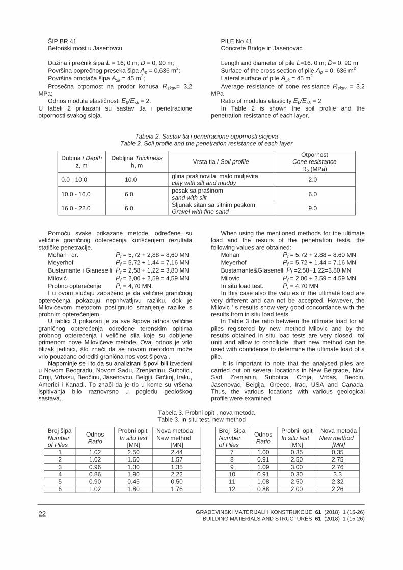
GRAĐEVINSKI MATERIJALI I KONSTRUKCIJE 61 (2018) 1 (15-26)BUILDING MATERIALS AND STRUCTURES 61 (2018) 1 (15-26)
22
ŠIP BR 41Betonski most u Jasenovcu
Dužina i prečnik šipa L = 16, 0 m; D = 0, 90 m;Površina poprečnog preseka šipa Ap = 0,636 m2;Površina omotača šipa Ask = 45 m2;Prosečna otpornost na prodor konusa Rskav= 3,2
MPa;Odnos modula elastičnosti Eb/Esk = 2.
U tabeli 2 prikazani su sastav tla i penetracioneotpornosti svakog sloja.
PILE No 41Concrete Bridge in Jasenovac
Length and diameter of pile L=16. 0 m; D= 0. 90 mSurface of the cross section of pile Ap = 0. 636 m2
Lateral surface of pile Ask = 45 m2
Average resistance of cone resistance Rskav = 3.2MPa
Ratio of modulus elasticity Eb/Esk = 2In Table 2 is shown the soil profile and the
penetration resistance of each layer.
Tabela 2. Sastav tla i penetracione otpornosti slojevaTable 2. Soil profile and the penetration resistance of each layer
Dubina / Depthz, m
Debljina Thicknessh, m Vrsta tla / Soil profile
OtpornostCone resistance
Rp (MPa)
0.0 - 10.0 10.0 glina prašinovita, malo muljevitaclay with silt and muddy 2.0
10.0 - 16.0 6.0 pesak sa prašinomsand with silt 6.0
16.0 - 22.0 6.0 Šljunak sitan sa sitnim peskomGravel with fine sand 9.0
Pomoću svake prikazane metode, određene suveličine graničnog opterećenja korišćenjem rezultatastatičke penetracije.
Mohan i dr. Pf = 5,72 + 2,88 = 8,60 MNMeyerhof Pf = 5,72 + 1,44 = 7,16 MNBustamante i Gianeselli Pf = 2,58 + 1,22 = 3,80 MNMilović Pf = 2,00 + 2,59 = 4,59 MNProbno opterećenje Pf = 4,70 MN.I u ovom slučaju zapaženo je da veličine graničnog
opterećenja pokazuju neprihvatljivu razliku, dok jeMilovićevom metodom postignuto smanjenje razlike sprobnim opterećenjem.
U tablici 3 prikazan je za sve šipove odnos veličinegraničnog opterećenja određene terenskim opitimaprobnog opterećenja i veličine sila koje su dobijeneprimenom nove Milovićeve metode. Ovaj odnos je vrloblizak jedinici, što znači da se novom metodom moževrlo pouzdano odrediti granična nosivost šipova .
Napominje se i to da su analizirani šipovi bili izvedeniu Novom Beogradu, Novom Sadu, Zrenjaninu, Subotici,Crnji, Vrbasu, Beočinu, Jasenovcu, Belgiji, Grčkoj, Iraku,Americi i Kanadi. To znači da je tlo u kome su vršenaispitivanja bilo raznovrsno u pogledu geološkogsastava..
When using the mentioned methods for the ultimateload and the results of the penetration tests, thefollowing values are obtained:
Mohan Pf = 5.72 + 2.88 = 8.60 MNMeyerhof Pf = 5.72 + 1.44 = 7.16 MNBustamante&GIasenelli Pf =2.58+1.22=3.80 MNMilovic Pf = 2.00 + 2.59 = 4.59 MNIn situ load test. Pf = 4.70 MNIn this case also the valu es of the ultimate load are
very different and can not be accepted. However, theMilovic ' s results show very good concordance with theresults from in situ load tests.
In Table 3 the ratio between the ultimate load for allpiles registered by new method Milovic and by theresults obtained in situ load tests are very closed toIuniti and allow to concllude thatt new method can beused with confidence to determine the ultimate load of apile.
It is important to note that the analysed piles arecarried out on several locations in New Belgrade, NoviSad, Zrenjanin, Subotica, Crnja, Vrbas, Beocin,Jasenovac, Belgija, Greece, Iraq, USA and Canada.Thus, the various locations with various geologicalprofile were examined.
Tabela 3. Probni opit , nova metodaTable 3. In situ test, new method
Broj šipaNumberof Piles
OdnosRatio
Probni opitIn situ test
[MN]
Nova metodaNew method
[MN]
Broj šipaNumberof Piles
OdnosRatio
Probni opitIn situ test
[MN]
Nova metodaNew method
[MN]1 1.02 2.50 2.44 7 1.00 0.35 0.352 1.02 1.60 1.57 8 0.91 2.50 2.753 0.96 1.30 1.35 9 1.09 3.00 2.764 0.86 1.90 2.22 10 0.91 0.30 3.35 0.90 0.45 0.50 11 1.08 2.50 2.326 1.02 1.80 1.76 12 0.88 2.00 2.26
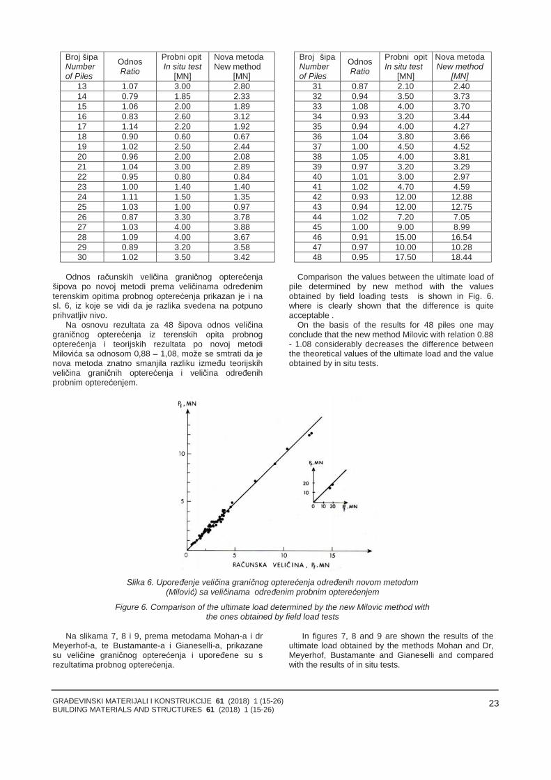
GRAĐEVINSKI MATERIJALI I KONSTRUKCIJE 61 (2018) 1 (15-26)BUILDING MATERIALS AND STRUCTURES 61 (2018) 1 (15-26)
23
Broj šipaNumberof Piles
OdnosRatio
Probni opitIn situ test
[MN]
Nova metodaNew method
[MN]
Broj šipaNumberof Piles
OdnosRatio
Probni opitIn situ test
[MN]
Nova metodaNew method
[MN]13 1.07 3.00 2.80 31 0.87 2.10 2.4014 0.79 1.85 2.33 32 0.94 3.50 3.7315 1.06 2.00 1.89 33 1.08 4.00 3.7016 0.83 2.60 3.12 34 0.93 3.20 3.4417 1.14 2.20 1.92 35 0.94 4.00 4.2718 0.90 0.60 0.67 36 1.04 3.80 3.6619 1.02 2.50 2.44 37 1.00 4.50 4.5220 0.96 2.00 2.08 38 1.05 4.00 3.8121 1.04 3.00 2.89 39 0.97 3.20 3.2922 0.95 0.80 0.84 40 1.01 3.00 2.9723 1.00 1.40 1.40 41 1.02 4.70 4.5924 1.11 1.50 1.35 42 0.93 12.00 12.8825 1.03 1.00 0.97 43 0.94 12.00 12.7526 0.87 3.30 3.78 44 1.02 7.20 7.0527 1.03 4.00 3.88 45 1.00 9.00 8.9928 1.09 4.00 3.67 46 0.91 15.00 16.5429 0.89 3.20 3.58 47 0.97 10.00 10.2830 1.02 3.50 3.42 48 0.95 17.50 18.44
Odnos računskih veličina graničnog opterećenjašipova po novoj metodi prema veličinama određenimterenskim opitima probnog opterećenja prikazan je i nasl. 6, iz koje se vidi da je razlika svedena na potpunoprihvatljiv nivo.
Na osnovu rezultata za 48 šipova odnos veličinagraničnog opterećenja iz terenskih opita probnogopterećenja i teorijskih rezultata po novoj metodiMilovića sa odnosom 0,88 – 1,08, može se smtrati da jenova metoda znatno smanjila razliku između teorijskihveličina graničnih opterećenja i veličina određenihprobnim opterećenjem.
Comparison the values between the ultimate load ofpile determined by new method with the valuesobtained by field loading tests is shown in Fig. 6.where is clearly shown that the difference is quiteacceptable .
On the basis of the results for 48 piles one mayconclude that the new method Milovic with relation 0.88- 1.08 considerably decreases the difference betweenthe theoretical values of the ultimate load and the valueobtained by in situ tests.
Slika 6. Upoređenje veličina graničnog opterećenja određenih novom metodom(Milović) sa veličinama određenim probnim opterećenjem
Figure 6. Comparison of the ultimate load determined by the new Milovic method withthe ones obtained by field load tests
Na slikama 7, 8 i 9, prema metodama Mohan-a i drMeyerhof-a, te Bustamante-a i Gianeselli-a, prikazanesu veličine graničnog opterećenja i upoređene su srezultatima probnog opterećenja.
In figures 7, 8 and 9 are shown the results of theultimate load obtained by the methods Mohan and Dr,Meyerhof, Bustamante and Gianeselli and comparedwith the results of in situ tests.
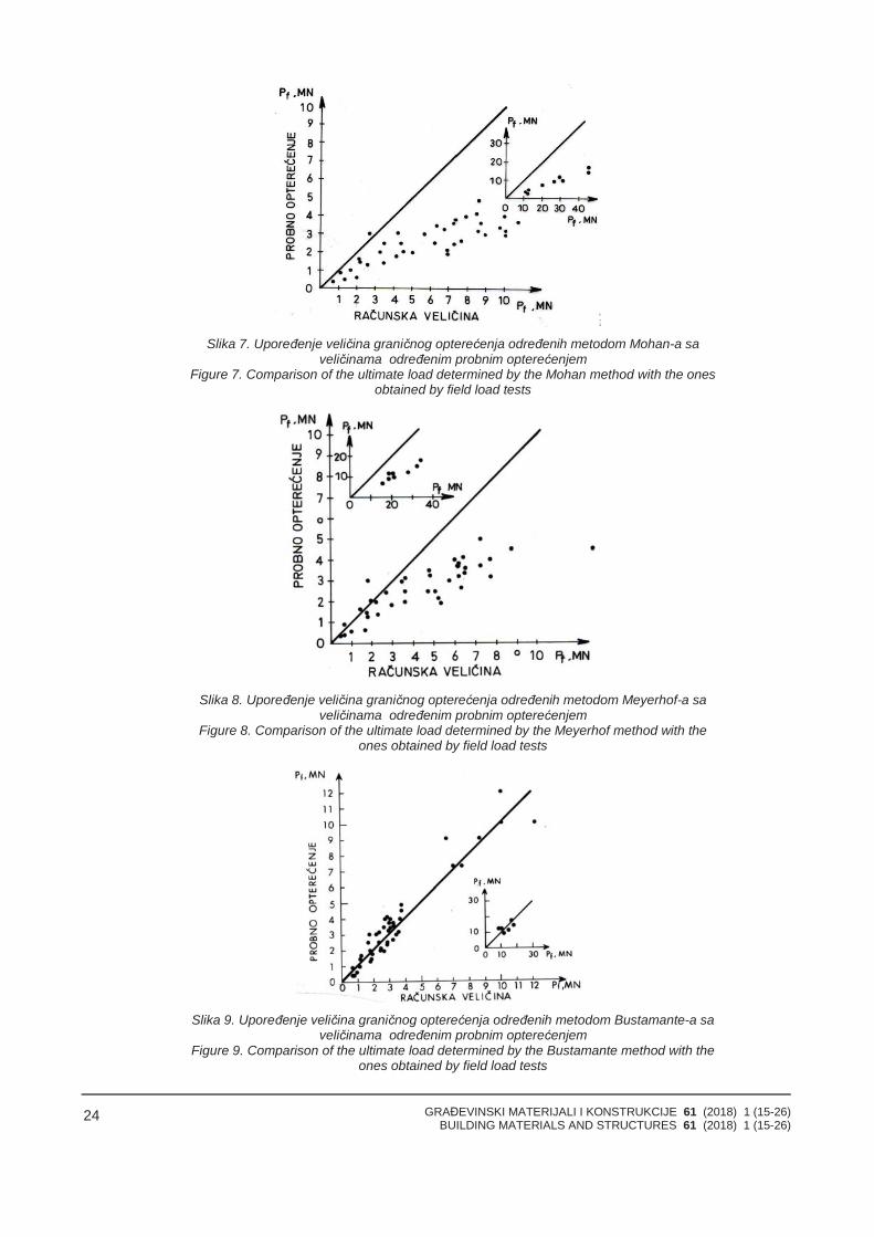
GRAĐEVINSKI MATERIJALI I KONSTRUKCIJE 61 (2018) 1 (15-26)BUILDING MATERIALS AND STRUCTURES 61 (2018) 1 (15-26)
24
Slika 7. Upoređenje veličina graničnog opterećenja određenih metodom Mohan-a saveličinama određenim probnim opterećenjem
Figure 7. Comparison of the ultimate load determined by the Mohan method with the onesobtained by field load tests
Slika 8. Upoređenje veličina graničnog opterećenja određenih metodom Meyerhof-a saveličinama određenim probnim opterećenjem
Figure 8. Comparison of the ultimate load determined by the Meyerhof method with theones obtained by field load tests
Slika 9. Upoređenje veličina graničnog opterećenja određenih metodom Bustamante-a saveličinama određenim probnim opterećenjem
Figure 9. Comparison of the ultimate load determined by the Bustamante method with theones obtained by field load tests
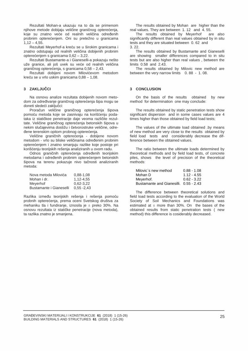
GRAĐEVINSKI MATERIJALI I KONSTRUKCIJE 61 (2018) 1 (15-26)BUILDING MATERIALS AND STRUCTURES 61 (2018) 1 (15-26)
25
Rezultati Mohan-a ukazuju na to da se primenomnjihove metode dobijaju veličine graničnog opterećenja,koje su znatno veće od realnih veličina određenihprobnim opterećenjem. Oni su pretežno u granicama1,12 – 4,55.
Rezultati Meyerhof-a kreću se u širokim granicama iznatno odstupaju od realnih veličina dobijenih probnimopterećenjem s granicama 0,62 – 3,22.
Rezultati Bustamante-a i Gianeselli-a pokazuju neštouže granice, ali još uvek su veće od realnih veličinagraničnog opterećenja, s granicama 0,58 – 2,43.
Rezultati dobijeni novom Milovićevom metodomkreću se u vrlo uskim granicama 0,88 – 1,08.
3 ZAKLJUČCI
Na osnovu analize rezultata dobijenih novom meto-dom za određivanje graničnog opterećenja šipa mogu sedoneti sledeći zaključci:
Proračun veličine graničnog opterećenja šipovapomoću metoda koje se zasnivaju na korišćenju poda-taka iz statičkee penetracije daje veoma različite rezul-tate. Veličine graničnog opterećenja betonskih šipova unekim slučajevima dostižu i četvorostruke veličine, odre-đene terenskim opitom probnog opterećenja.
Veličine graničnih opterećenja - dobijene novommetodom - vrlo su bliske veličinama određenim probnimopterećenjem i znatno smanjuju razlike koje postoje prikorišćenju teorijskih rešenja analiziranih u ovom radu.
Odnos graničnih opterećenja određenih teorijskimmetodama i određenih probnim opterećenjem betonskihšipova na terenu pokazuje nivo tačnosti analiziranihmetoda:
Nova metoda Milovića 0,88-1,08Mohan i dr. 1,12-4,55Meyerhof 0,62-3,22Bustamante i Gianeselli 0,55 -2,43
Razlika između teorijskih rešenja i rešenja pomoćuprobnih opterećenja, prema oceni Svetskog društva zamehaniku tla i fundiranje, iznosila je preko 30%. Naosnovu rezultata iz statičke penetracije (nova metoda),ta razlika znatno je smanjena.
The results obtained by Mohan are higher than thereal values. They are between 1. 12 and 4. 55.
The results obtained by Meyerhof are alsosignificantly different than real values obtained by in situtests and they are situated between 0. 62 and3. 22.
The results obtained by Bustamante and Gianeselliare showing smaller differences compared to in situtests but are also higher than real values , between thelimits 0.58 and 2.43.
The results obtained by Milovic new method arebetween the very narrow limits 0. 88 - 1. 08.
3 CONCLUSION
On the basis of the results obtained by newmethod for determination one may conclude:
The results obtained by static penetration tests showsignificant dispersion and in some cases values are 4times higher than those obtained by field load tests;
The values of the ultimate load obtained .by meansof new method are very close to the results obtained byfield load tests and considerably decrease the dif-ference between the obtained values.
The ratio between the ultimate loads determined bytheoretical methods and by field load tests, of concretepiles, shows the level of precision of the theoreticalmethods:
Milovic`s new method 0.88 - 1.08Mohan D 1.12 - 4.55Meyerhof. 0.62 - 3.22Bustamante and Gianesilli. 0.55 - 2.43
The difference between theoretical solutions andfield load tests according to the evaluation of the WorldSociety of Soil Mechanics and Foundations wasestimated at more than 30%. On the bases of theobtained results from static penetration tests ( newmethod) this difference is cosiderably decreased.
GRAĐEVINSKI MATERIJALI I KONSTRUKCIJE 61 (2018) 1 (15-26)BUILDING MATERIALS AND STRUCTURES 61 (2018) 1 (15-26)
26
4 LITERATURAREFERENCES
[1] Bustamante, M. and Giasenelli L. (1982) "P:ilebearing capacity by means of static penetrometarCPT ESOPT H", Amsterdam, Vol, 2, pp. 493 - 500.
[2] Bustamante, M. Frank R. et Giasenelli L. (1987)"Le dimensionement des fondation profondes".Bulletin Liaison Laboratoire des Ponts etChaussees, 149, pp. 13-22.
[3] Meyerhof, G.G. (1956): "Penetration tests andbearing capacity of cohesionless soils."Journal ofthe Soil Mechanics and Foundation Engineering,ASCE, Vol. 82, No SM 1, pp. 1 -19
[4] Meyerhof, G.G. (1995): "Behaviour of pilefoundations under special conditions."CanadianGeotechnical Journal, Vol. 12, pp: 204 - 222.
[5] Milovic, D. (1986): "Bearing capacity of pilesdetermined by penetration tests. Proc. of theInternational Conference of Deep FoundationsPeking,Vol.1,pp: 2170-2175.
[6] Milovic, D. (1993); "Predicted and observedbehavior of piles. Proc of the 2 nd InternationalInternational Seminar on Deep Foundations onBored and Auger Piles, Belgium, pp: 381 - 384.
[7] Mohan, D. Jain D. S. and Kumar, V. (1963 ): "Loadbearing capacity of piles". Geotechnique, London,Vol. 13, No 1, pp: 76 - 86.
[8] Poulos, H. G. and Davis F. H. (1980). "Pilefoundation analysis and design. John Wiley, NewYork, pp: 1 - 397.
[9] Poulos H. G. (1989): "Pile behaviour - theory andapplication"Geotechnique 39, No 3,pp: 365-415. :
[10] Vesic, A, (1972); "Ehpansion of cavities in infinitesoil mass."Journ of Soil Mechanics and FoundationDivision, ASCE, Vol. 98,pp265 -290.
REZIME
NOSIVOST ŠIPOVA - TEORIJSKE I TERENSKEMETODE
Dušan MILOVIĆ
U radu su prikazani rezultati penetracionih ispitivanjakao i terenskih opita probnog opterećenja radi proračunagraničnog opterećenja šipa. U tim ispitivanjima korišćenje kontra teret, koji je dostizao i veličinu primenjene silečak i do 5,00 MN.
Analizom terenskih i teorijskih rezultata obuhvaćenoje 48 šipova. Primenom prikazane nove metode jepostignuto znatno smanjenje razllike izmadju novemetode i i terenskih opita probnog opterecenja
Ključne reči: Nosivost šipova, statičke metode,dinamičke metode, statička penetracija, probnoopterećenje šipova, nosivost bazom, nosivost bočnimtrenjem.
SUMMАRY
BEARING CAPACITY OF PILES - THEORY ANDFIELD TESTS
Dusan MILOVIC
In the paper are presented the results of thepenetration tests and the field load tests.. In these teststhe piles were loaded with the concrete blocks, reachingthe vertical force of up to 5.00 MN.
By the analyses of theoretical and field load tests48 piles were included. By the application of the newmethod a considerable decrease between the newmethod and field load tests is achieved
Key words: bearing capacity of piles, staticpenetration tests, static methods, dynamic methods, fieldload test, bearing capacity of the base and of the lateralskin friction.
GRAĐEVINSKI MATERIJALI I KONSTRUKCIJE 61 (2018) 1 (27-36)BUILDING MATERIALS AND STRUCTURES 61 (2018) 1 (27-36)
27
CREEPING (SECONDARY/TERTIARY SETTLEMENTS) OF HIGHLY COMPRESSIBLESOILS AND SLUDGE
TEČENJA (SEKUNDARNA/TERCIJALNA SLEGANJA) VEOMA STIŠLJIVOGTLA I TALOGA
H. BRANDLORIGINALNI NAUČNI RAD
ORIGINAL SCIENTIFIC PAPERUDK: 624.131.542
doi:10.5937/GRMK1801027B
1 GENERAL
K. Terzaghi and O.K. Fröhlich’s theory of (onedimensional) consolidation refers to the dissipation ofexcess pore water pressure during loading of saturatedsoil. The time taken for the clay to consolidate dependsentirely on the permeability of the laterally confined clay.These assumptions correspond to the primaryconsolidation in an oedometer test (widely neglectingpossible rearrangements of the soil structure already inthe initial phase of loading).
At the 1st International Conference on SoilMechanics and Foundation Engineering 1936 at HarvardUniversity, Cambridge, MA., A.S. KeverlingBuismanpresented a theory for creep of fine-grained soft soils.However, this (logarithmic) formula and his statementthat creeping of clays never ends was severelyquestioned, not only by K. Terzaghi (ConferenceChairman), but also internationally. Meanwhile thistheory has been accepted theoretically and could bewidely confirmed, especially by the following test resultsshowing low-term creep, but also a fading out tertiarycreep.
2 SETTLEMENT / CREEPING OF HIGHLYCOMPRESSIBLE (ORGANIC) CLAYEY SILT
Total settlement of saturated cohesive soil comprisesimmediate settlements (so - undrained, at constant volume),primary settlements (s1 - consolidated by pore water pres-
BRANDL, H. Emeritus Professor, Vienna University ofTechnology
pressure dissipation) and long-term creeping (s2, s3). Inthe field, all phases interact during transition zones, andcreeping under shear stress also occurs. This leadsinevitably to soil rheology comprising also cohesionlesssoils and other geomaterials.
In the design phase (1971 – 1972) of a highwayjunction on highly compressible soils with locally organicinclusions and peaty interlayers numerous samples weretaken and investigated in the laboratory. Several of themwere left in the oedometers for long-term creeping tests.The maximum observation period has been from 1971 to2013, hence 42 years. Some results are described in thefollowing, further investigations and in-situ influences ofground improvement measures are given in the chapterafter next.
Table 1 shows the relevant data of a selectedsample (A). It is an extremely soft clayey silt(33% < 0,002 mm) with organic components of liquidconsistency. The plasticity index of Ip = 0.34 is ratherdue to the decomposed peaty organics than to themineralogical composition of the fines as can be seenfrom Table 2. The platy shape of the fines and its way ofsedimentation created a special fabric and highcompressibility.
In the natural state the permeability coefficient wasabout k = 10-7 m/s but dropped significantly duringloading. At the maximum load finally a value of aboutk = 10-9 m/s was reached. These data explain, amongother influence factors, the relatively quick primaryconsolidation and a long-lasting creeping phase.
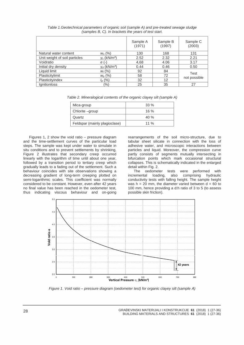
GRAĐEVINSKI MATERIJALI I KONSTRUKCIJE 61 (2018) 1 (27-36)BUILDING MATERIALS AND STRUCTURES 61 (2018) 1 (27-36)
28
Table 1.Geotechnical parameters of organic soil (sample A) and pre-treated sewage sludge(samples B, C). In brackets the years of test start.
Sample A (1971)
Sample B (1997)
Sample C (2003)
Natural water content wn (%) 130 168 131Unit weight of soil particles γs (kN/m³) 2.52 2.32 2.21Voidratio e (-) 4,68 4.06 3.17Initial dry density γd (kN/m³) 0.44 0.46 0.50Liquid limit wl (%) 92 84Plasticitylimit wp (%) 58 72Plasticityindex Ip (%) 32 12
Testnot possible
Ignitionloss (%) 25 35 27
Table 2. Mineralogical contents of the organic clayey silt (sample A)
Mica-group 33 %Chlorite –group 16 %Quartz 40 %Feldspar (mainly plagioclase) 11 %
Figures 1, 2 show the void ratio – pressure diagramand the time-settlement curves of the particular loadsteps. The sample was kept under water to simulate insitu conditions and to prevent settlements by shrinking,Figure 2 illustrates that secondary creep occurredlinearly with the logarithm of time until about one year,followed by a transition period to tertiary creep whichgradually leads to a fading out of the settlement. Such abehaviour coincides with site observations showing adecreasing gradient of long-term creeping plotted onsemi-logarithmic scales. This coefficient was normallyconsidered to be constant. However, even after 42 yearsno final value has been reached in the oedometer test,thus indicating viscous behaviour and on-going
rearrangements of the soil micro-structure, due totabular sheet silicate in connection with the loss ofadhesive water, and microscopic interactions betweenparticles and liquid. Moreover, the compression curvepartly consists of segments mutually intersecting inbifurcation points which mark occasional structuralcollapses. This is schematically indicated in the enlargeddetail within Fig. 2.
The oedometer tests were performed withincremental loading, also comprising hydraulicconductivity tests with falling height. The sample heightwas h = 20 mm, the diameter varied between d = 60 to100 mm, hence providing a d:h ratio of 3 to 5 (to assesspossible skin friction).
Figure 1. Void ratio – pressure diagram (oedometer test) for organic clayey silt (sample А)
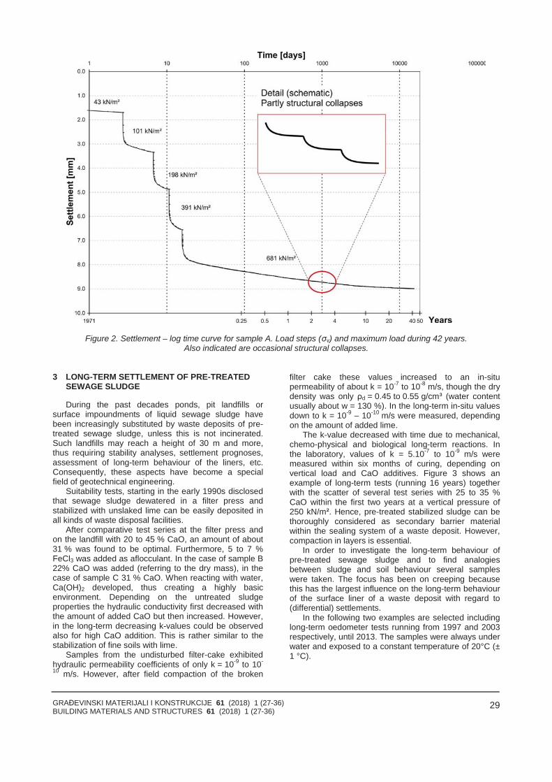
GRAĐEVINSKI MATERIJALI I KONSTRUKCIJE 61 (2018) 1 (27-36)BUILDING MATERIALS AND STRUCTURES 61 (2018) 1 (27-36)
29
Figure 2. Settlement – log time curve for sample A. Load steps (σv) and maximum load during 42 years.Also indicated are occasional structural collapses.
3 LONG-TERM SETTLEMENT OF PRE-TREATEDSEWAGE SLUDGE
During the past decades ponds, pit landfills orsurface impoundments of liquid sewage sludge havebeen increasingly substituted by waste deposits of pre-treated sewage sludge, unless this is not incinerated.Such landfills may reach a height of 30 m and more,thus requiring stability analyses, settlement prognoses,assessment of long-term behaviour of the liners, etc.Consequently, these aspects have become a specialfield of geotechnical engineering.
Suitability tests, starting in the early 1990s disclosedthat sewage sludge dewatered in a filter press andstabilized with unslaked lime can be easily deposited inall kinds of waste disposal facilities.
After comparative test series at the filter press andon the landfill with 20 to 45 % CaO, an amount of about31 % was found to be optimal. Furthermore, 5 to 7 %FeCl3 was added as aflocculant. In the case of sample B22% CaO was added (referring to the dry mass), in thecase of sample C 31 % CaO. When reacting with water,Ca(OH)2 developed, thus creating a highly basicenvironment. Depending on the untreated sludgeproperties the hydraulic conductivity first decreased withthe amount of added CaO but then increased. However,in the long-term decreasing k-values could be observedalso for high CaO addition. This is rather similar to thestabilization of fine soils with lime.
Samples from the undisturbed filter-cake exhibitedhydraulic permeability coefficients of only k = 10-9 to 10-
10 m/s. However, after field compaction of the broken
filter cake these values increased to an in-situpermeability of about k = 10-7 to 10-8 m/s, though the drydensity was only ρd = 0.45 to 0.55 g/cm³ (water contentusually about w = 130 %). In the long-term in-situ valuesdown to k = 10-9 – 10-10 m/s were measured, dependingon the amount of added lime.
The k-value decreased with time due to mechanical,chemo-physical and biological long-term reactions. Inthe laboratory, values of k = 5.10-7 to 10-9 m/s weremeasured within six months of curing, depending onvertical load and CaO additives. Figure 3 shows anexample of long-term tests (running 16 years) togetherwith the scatter of several test series with 25 to 35 %CaO within the first two years at a vertical pressure of250 kN/m². Hence, pre-treated stabilized sludge can bethoroughly considered as secondary barrier materialwithin the sealing system of a waste deposit. However,compaction in layers is essential.
In order to investigate the long-term behaviour ofpre-treated sewage sludge and to find analogiesbetween sludge and soil behaviour several sampleswere taken. The focus has been on creeping becausethis has the largest influence on the long-term behaviourof the surface liner of a waste deposit with regard to(differential) settlements.
In the following two examples are selected includinglong-term oedometer tests running from 1997 and 2003respectively, until 2013. The samples were always underwater and exposed to a constant temperature of 20°C (±1 °C).
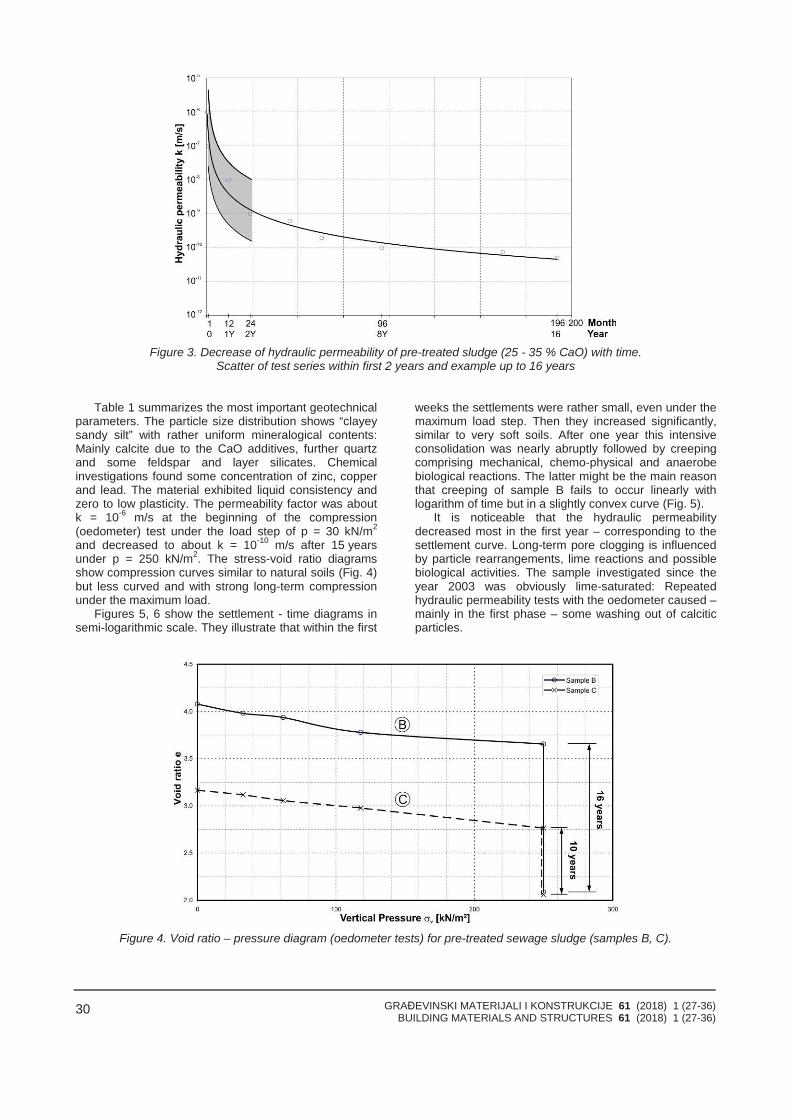
GRAĐEVINSKI MATERIJALI I KONSTRUKCIJE 61 (2018) 1 (27-36)BUILDING MATERIALS AND STRUCTURES 61 (2018) 1 (27-36)
30
Figure 3. Decrease of hydraulic permeability of pre-treated sludge (25 - 35 % CaO) with time.Scatter of test series within first 2 years and example up to 16 years
Table 1 summarizes the most important geotechnicalparameters. The particle size distribution shows “clayeysandy silt” with rather uniform mineralogical contents:Mainly calcite due to the CaO additives, further quartzand some feldspar and layer silicates. Chemicalinvestigations found some concentration of zinc, copperand lead. The material exhibited liquid consistency andzero to low plasticity. The permeability factor was aboutk = 10-6 m/s at the beginning of the compression(oedometer) test under the load step of p = 30 kN/m2
and decreased to about k = 10-10 m/s after 15 yearsunder p = 250 kN/m2. The stress-void ratio diagramsshow compression curves similar to natural soils (Fig. 4)but less curved and with strong long-term compressionunder the maximum load.
Figures 5, 6 show the settlement - time diagrams insemi-logarithmic scale. They illustrate that within the first
weeks the settlements were rather small, even under themaximum load step. Then they increased significantly,similar to very soft soils. After one year this intensiveconsolidation was nearly abruptly followed by creepingcomprising mechanical, chemo-physical and anaerobebiological reactions. The latter might be the main reasonthat creeping of sample B fails to occur linearly withlogarithm of time but in a slightly convex curve (Fig. 5).
It is noticeable that the hydraulic permeabilitydecreased most in the first year – corresponding to thesettlement curve. Long-term pore clogging is influencedby particle rearrangements, lime reactions and possiblebiological activities. The sample investigated since theyear 2003 was obviously lime-saturated: Repeatedhydraulic permeability tests with the oedometer caused – mainly in the first phase – some washing out of calciticparticles.
Figure 4. Void ratio – pressure diagram (oedometer tests) for pre-treated sewage sludge (samples B, C).
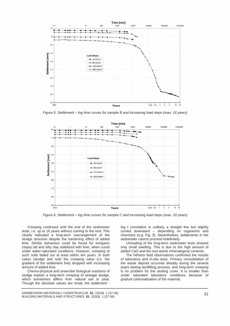
GRAĐEVINSKI MATERIJALI I KONSTRUKCIJE 61 (2018) 1 (27-36)BUILDING MATERIALS AND STRUCTURES 61 (2018) 1 (27-36)
31
Figure 5. Settlement – log time curves for sample B and increasing load steps (max. 16 years)
Figure 6. Settlement – log time curves for sample C and increasing load steps (max. 10 years)
Creeping continued until the end of the oedometertests, i.e. up to 16 years without coming to the end. Thisclearly indicated a long-term rearrangement of thesludge structure despite the hardening effect of addedlime. Similar behaviour could be found for inorganicclayey silt and silty clay stabilized with lime, when curedunder water-saturated conditions. However, creeping ofsuch soils faded out at least within ten years. In bothcases (sludge and soil) the creeping value (i.e. thegradient of the settlement line) dropped with increasingamount of added lime.
Chemo-physical and anaerobe biological reactions ofsludge explain a long-term creeping of sewage sludge,which sometimes differs from natural soil or peat.Though the absolute values are small, the settlement -
log t correlation is unlikely a straight line but slightlycurved downward – depending on organisms andchemistry (e.g. Fig. 5). Nevertheless, settlements in theoedometer cannot proceed indefinitely.
Unloading of the long-term oedometer tests showedonly small swelling. This is due to the high amount ofadded CaO and the non-active mineralogical contents.
The hitherto field observations confirmed the resultsof laboratory and in-situ tests. Primary consolidation ofthe waste deposit occurred already during the severalyears lasting landfilling process, and long-term creepingis no problem for the sealing cover. It is smaller thanunder saturated laboratory conditions because ofgradual carbonatisation of the material.
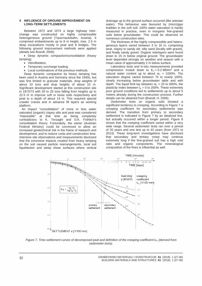
GRAĐEVINSKI MATERIJALI I KONSTRUKCIJE 61 (2018) 1 (27-36)BUILDING MATERIALS AND STRUCTURES 61 (2018) 1 (27-36)
32
4 INFLUENCE OF GROUND IMPROVEMENT ONLONG-TERM SETTLEMENTS
Between 1972 and 1974 a large highway inter-change was constructed on highly compressibleheterogeneous ground (Tauernautobahn, Austria). Itcomprised embankments up to 8 m height, max. 2.5 mdeep excavations mostly in peat and 8 bridges. Thefollowing ground improvement methods were applied(details see Brandl, 2006):
Deep dynamic compaction/consolidation (heavytamping),
Vibroflotation, Temporary surcharge loading, Local combinations of the previous methods.Deep dynamic compaction by heavy tamping has
been used in Austria and Germany since the 1930s, butwas first limited to granular materials, drop weights ofabout 10 tons and drop heights of about 10 m.Significant development started at this construction sitein 1972/73 with 20 to 25 tons falling from heights up to22.5 m to improve soft or loose soils respectively andpeat to a depth of about 14 m. This required specialcrawler cranes and in advance fill layers as workingplatform.
An impact “consolidation” of more or less watersaturated (organic) clayey silts and peat was considered“impossible” at that time as being completelycontradictory to K. Terzaghi and O.K. Fröhlich’sconsolidation theory. Fortunately, the owner (AustrianFederal Ministry) could be convinced to allow anincreased geotechnical risk in the frame of research anddevelopment, and to reduce costs and construction time.Intensive site observations and measurements disclosedthat the excessive impacts created from heavy tampingon the soil caused particle rearrangements, local soilliquefaction and steep shear surfaces where vertical
drainage up to the ground surface occurred (like artesianwater). This behaviour was favoured by (micro)gasbubbles in the soft soil: 100% water saturation is hardlymeasured in practice, even in inorganic fine-grainedsoils below groundwater. This could be observed onnumerous construction sites.
The thickness of the highly compressible and hetero-geneous layers varied between 3 to 16 m, comprisingpeat, clayey to sandy silt, silty sand (locally with gravel),and finally sandy gravel. Organic interlayers were founddown to 15 m below original ground. The groundwaterlevel depended strongly on weather and season with amean value of approximately 2 m below surface.
Laboratory tests and in-situ measurements providedcompression moduli down to Es = 0.2 MN/m² and anatural water content up to about wn = 1000%. Thesaturation degree varied between 75 to nearly 100%,clearly increasing below groundwater table and withdepth. The liquid limit lay between wL = 20 to 600%, theplasticity index between Ip = 0 to 250%. These extremelypoor ground conditions led to settlements up to about 5meters already during the construction process. Furtherdetails can be obtained from (Brandl, H. 2006).
Oedometer tests on organic soils showed asignificant tendency to creeping. According to Figure 7 acreeping coefficient for secondary settlements wasderived. The transition from primary to secondarysettlement is indicated in Figure 7 by an idealized line,but actually occurred within a longer period. Figure 8shows that the creeping coefficient varied within a verywide range. Several oedometer tests ran over a periodof 20 years and one test up to 42 years (from 1971 to2013). These long-term investigations have disclosedthat secondary and tertiary creep may continueextremely long if the fine-grained soil has a high voidratio and organic components. The mineralogicalcomposition of the fines is influential as well.
Figure 7. Time-settlement curves of decomposed peat and definition of the creeping coefficient kcr (derived fromoedometer tests).
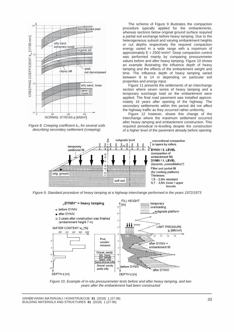
GRAĐEVINSKI MATERIJALI I KONSTRUKCIJE 61 (2018) 1 (27-36)BUILDING MATERIALS AND STRUCTURES 61 (2018) 1 (27-36)
33
Figure 8. Creeping coefficient kcr for several soilsdescribing secondary settlement (creeping).
The scheme of Figure 9 illustrates the compactionprocedure typically applied for the embankments,whereas sections below original ground surface requireda partial soil exchange before heavy tamping. Due to theheterogeneous subsoil and varying embankment heightsor cut depths respectively the required compactionenergy varied in a wide range with a maximum ofapproximately E = 2500 tm/m². Deep compaction controlwas performed mainly by comparing pressuremetervalues before and after heavy tamping. Figure 10 showsan example illustrating the influence depth of heavytamping and the effects of the embankment weight andtime. The influence depth of heavy tamping variedbetween 8 to 14 m depending on particular soilproperties and energy input.
Figure 11 presents the settlements of an interchangesection where seven series of heavy tamping and atemporary surcharge load on the embankment wereapplied. The final road pavement was installed approxi-mately 16 years after opening of the highway. Thesecondary settlements within this period did not affectthe highway traffic as they occurred rather uniformly.
Figure 12 however, shows this change of theinterchange where the maximum settlement occurredafter heavy tamping and embankment construction. Thisrequired periodical re-levelling despite the constructionof a higher level of the pavement already before opening
Figure 9. Standard procedure of heavy tamping at a highway interchange performed in the years 1972/1973
Figure 10. Example of in-situ pressuremeter tests before and after heavy tamping, and twoyears after the embankment had been constructed
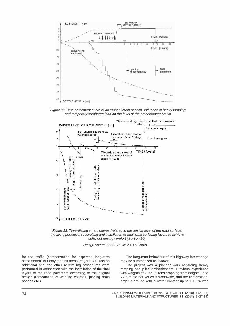
GRAĐEVINSKI MATERIJALI I KONSTRUKCIJE 61 (2018) 1 (27-36)BUILDING MATERIALS AND STRUCTURES 61 (2018) 1 (27-36)
34
Figure 11.Time-settlement curve of an embankment section. Influence of heavy tampingand temporary surcharge load on the level of the embankment crown
Figure 12. Time-displacement curves (related to the design level of the road surface)involving periodical re-levelling and installation of additional surfacing layers to achieve
sufficient driving comfort (Section 10).
Design speed for car traffic: v = 150 km/h
for the traffic (compensation for expected long-termsettlements). But only the first measure (in 1977) was anadditional one; the other re-levelling procedures wereperformed in connection with the installation of the finallayers of the road pavement according to the originaldesign (remediation of wearing courses, placing drainasphalt etc.).
The long-term behaviour of this highway interchangemay be summarized as follows:
The project was a pioneer work regarding heavytamping and piled embankments. Previous experiencewith weights of 20 to 25 tons dropping from heights up to22.5 m did not yet exist worldwide, and the fine-grained,organic ground with a water content up to 1000% was
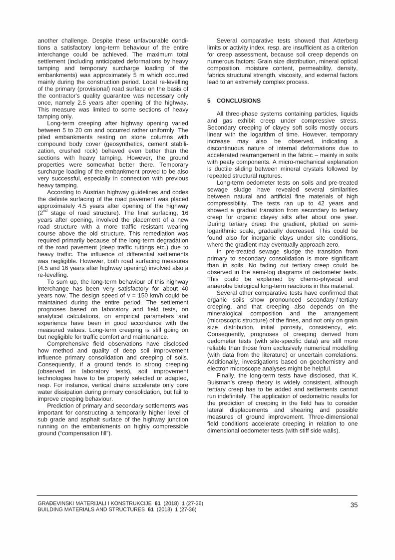
GRAĐEVINSKI MATERIJALI I KONSTRUKCIJE 61 (2018) 1 (27-36)BUILDING MATERIALS AND STRUCTURES 61 (2018) 1 (27-36)
35
another challenge. Despite these unfavourable condi-tions a satisfactory long-term behaviour of the entireinterchange could be achieved. The maximum totalsettlement (including anticipated deformations by heavytamping and temporary surcharge loading of theembankments) was approximately 5 m which occurredmainly during the construction period. Local re-levellingof the primary (provisional) road surface on the basis ofthe contractor's quality guarantee was necessary onlyonce, namely 2.5 years after opening of the highway.This measure was limited to some sections of heavytamping only.
Long-term creeping after highway opening variedbetween 5 to 20 cm and occurred rather uniformly. Thepiled embankments resting on stone columns withcompound body cover (geosynthetics, cement stabili-zation, crushed rock) behaved even better than thesections with heavy tamping. However, the groundproperties were somewhat better there. Temporarysurcharge loading of the embankment proved to be alsovery successful, especially in connection with previousheavy tamping.
According to Austrian highway guidelines and codesthe definite surfacing of the road pavement was placedapproximately 4.5 years after opening of the highway(2nd stage of road structure). The final surfacing, 16years after opening, involved the placement of a newroad structure with a more traffic resistant wearingcourse above the old structure. This remediation wasrequired primarily because of the long-term degradationof the road pavement (deep traffic ruttings etc.) due toheavy traffic. The influence of differential settlementswas negligible. However, both road surfacing measures(4.5 and 16 years after highway opening) involved also are-levelling.
To sum up, the long-term behaviour of this highwayinterchange has been very satisfactory for about 40years now. The design speed of v = 150 km/h could bemaintained during the entire period. The settlementprognoses based on laboratory and field tests, onanalytical calculations, on empirical parameters andexperience have been in good accordance with themeasured values. Long-term creeping is still going onbut negligible for traffic comfort and maintenance.
Comprehensive field observations have disclosedhow method and quality of deep soil improvementinfluence primary consolidation and creeping of soils.Consequently, if a ground tends to strong creeping(observed in laboratory tests), soil improvementtechnologies have to be properly selected or adapted,resp. For instance, vertical drains accelerate only porewater dissipation during primary consolidation, but fail toimprove creeping behaviour.
Prediction of primary and secondary settlements wasimportant for constructing a temporarily higher level ofsub grade and asphalt surface of the highway junctionrunning on the embankments on highly compressibleground (“compensation fill”).
Several comparative tests showed that Atterberglimits or activity index, resp. are insufficient as a criterionfor creep assessment, because soil creep depends onnumerous factors: Grain size distribution, mineral opticalcomposition, moisture content, permeability, density,fabrics structural strength, viscosity, and external factorslead to an extremely complex process.
5 CONCLUSIONS
All three-phase systems containing particles, liquidsand gas exhibit creep under compressive stress.Secondary creeping of clayey soft soils mostly occurslinear with the logarithm of time. However, temporaryincrease may also be observed, indicating adiscontinuous nature of internal deformations due toaccelerated rearrangement in the fabric – mainly in soilswith peaty components. A micro-mechanical explanationis ductile sliding between mineral crystals followed byrepeated structural ruptures.
Long-term oedometer tests on soils and pre-treatedsewage sludge have revealed several similaritiesbetween natural and artificial fine materials of highcompressibility. The tests ran up to 42 years andshowed a gradual transition from secondary to tertiarycreep for organic clayey silts after about one year.During tertiary creep the gradient, plotted on semi-logarithmic scale, gradually decreased. This could befound also for inorganic clays under site conditions,where the gradient may eventually approach zero.
In pre-treated sewage sludge the transition fromprimary to secondary consolidation is more significantthan in soils. No fading out tertiary creep could beobserved in the semi-log diagrams of oedometer tests.This could be explained by chemo-physical andanaerobe biological long-term reactions in this material.
Several other comparative tests have confirmed thatorganic soils show pronounced secondary / tertiarycreeping, and that creeping also depends on themineralogical composition and the arrangement(microscopic structure) of the fines, and not only on grainsize distribution, initial porosity, consistency, etc.Consequently, prognoses of creeping derived fromoedometer tests (with site-specific data) are still morereliable than those from exclusively numerical modelling(with data from the literature) or uncertain correlations.Additionally, investigations based on geochemistry andelectron microscope analyses might be helpful.
Finally, the long-term tests have disclosed, that K.Buisman’s creep theory is widely consistent, althoughtertiary creep has to be added and settlements cannotrun indefinitely. The application of oedometric results forthe prediction of creeping in the field has to considerlateral displacements and shearing and possiblemeasures of ground improvement. Three-dimensionalfield conditions accelerate creeping in relation to onedimensional oedometer tests (with stiff side walls).
GRAĐEVINSKI MATERIJALI I KONSTRUKCIJE 61 (2018) 1 (27-36)BUILDING MATERIALS AND STRUCTURES 61 (2018) 1 (27-36)
36
6 REFERENCES
[1] Brandl, H. (2006). “Ground improvement andearthwork innovations for transportationinfrastructure”.Active Geotechnical Design inInfrastructure Development. XIII Danube-EuropeanConference on Geotechnical Eng., CIP-Ljubljana,Vol. 1, 217-232.
[2] Buisman, A.S.K. (1936). “Results of long durationsettlement observations“. Proceedings of the 1stInternational Conference of the ISSMFE
(International Society for Soil Mechanics andFoundation Engineering), Cambridge, Vol. 1, 103-106.
[3] Terzaghi, K. and Fröhlich, O.K. (1936). „Theorieder Setzung von Tonschichten“. Franz Deuticke,Leipzig – Wien.
[4] Havel, F. (2004). „Creep in soft soils“. Doc. Thesis.Norwegian Univ. of Science and Technology,Trondheim.
SUMMARY
CREEPING (SECONDARY/TERTIARYSETTLEMENTS) OF HIGHLY COMPRESSIBLE SOILSAND SLUDGE
H. BRANDL
The paper focuses on long-term oedometer testslasting up to 42 years and performed on silty sand,(organic) clayey silt, peat and (pre-treated) sewagesludge. Secondary consolidation (creep) could beobserved in all cases, lasting over many years andoccurring widely linear with the logarithm of time. Thislong-term phase is followed by tertiary creep with a longlasting fading out period. In addition to the laboratorytests results of comprehensive field observations aresummarized, showing the influence of groundimprovement on the creeping behaviour of very soft fine-grained soils (partly organic). The data were collectedfrom a highway junction on highly compressible,heterogeneous ground (with natural water content up to100%), constructed between 1972 and 1974, andmonitored since.
Key words: long-term settlements, creeping, highlycompressible soils, oedometer tests, heavy tamping,deep soil improvement, sludge
REZIME
TEČENJA (SEKUNDARNA/TERCIJALNA SLEGANJA)VEOMA STIŠLJIVOG TLA I TALOGA
H. BRANDL
Ovaj rad je usmeren na dugotrajna edometarskaispitivanja koja su trajala 42 godine i izvedena su naprašinastom pesku, (organskoj) glinovitoj prašini,tresetu, i (pre obrade) kanalizacionom talogu. Sekundar-na konsolidacija (tečenje/puzanje) mogla je da budeuočena u svim slučajevima i trajala je mnogo godina iispoljavala se, uglavnom, kao linearno zavisna odlogaritma vremena. Ovu dugotrajnu fazu prati tercijarnotečenje sa dugotrajnim periodom vremena do konačnognestajanja. Osim laboratorijskih opita, sumirani surezultati sveobuhvatnih terenskih ispitivanja i onipokazuju uticaj poboljšanja tla na tečenje vrlo mekogsitnozrnog tla (delimično organskog). Ovi podaci suprikupljeni na raskrsnici autoputa na veoma stišljivomheterogenom zemljištu (sa prirodnim sadržajem vode do100%) koja je izgrađena između 1972 i 1974 i od tada jeosmatrana.
Ključne reči: dugotrajna sleganja, tečenje (puzanje),jako stišljivo tlo, edometarski opiti, dinamičko zbijanje,poboljšanje dubljih slojeva tla, talog
GRAĐEVINSKI MATERIJALI I KONSTRUKCIJE 61 (2018) 1 (37-45)BUILDING MATERIALS AND STRUCTURES 61 (2018) 1 (37-45)
37
USE OF PILOT TUNNEL METHOD TO OVERCOME DIFFICULT GROUNDCONDITIONS IN KARAVANKE TUNNEL
UPOTREBA METODOLOGIJE PROBNOG TUNELA ZA PREVAZILAŽENJE TEŠKIHUSLOVA GRADNJE U TUNELU KARAVANKE
Vojkan JOVIČIĆPREGLEDNI RADREVIEW PAPER
UDK: 624.191.1(497.4)doi:10.5937/GRMK1801037J
1 INTRODUCTION
The tunnel Karavanke is some 7,9km long singletube tunnel, which is located at European corridor 10,European motorway road E61. It is the only remainingtunnel at the corridor 10 and also at the Sloveniannetwork of motorways, which provides for the traffic inboth directions in a single tube. As such, the tunnel is inbreach of the directive of European Council2004/54/ESof 2004. According to the directive, eachtunnel longer than 1000m must have an escape route inthe form of evacuation adit or the second tube, whichcan be also used for single way traffic.
The tunnel presents the most frequent traffic linkbetween Slovenia and Austria. It is the last and thelongest tunnel on the northern arm (Ljubljana –Jesenice) of the Slovenian motorway network. Inhistorical terms the tunnel plays a significant role inconnecting the Middle with Southern Europe as the linkpasses beneath some 2500m high Karavanke chain ofmountains. Approximately half of the tunnel, that is some3,5km, is on the Slovenian side, the rest is in Austria.
As will be explained in some detail, the constructionof the first tube, which took place some 30 years ago,was met with many challenges. These challenges willremain for the construction of the second tube but willtake different and sometimes more demanding forms.The main challenges for the construction of the secondtube are summarised as follows: a) large convergencedisplacements in squeezing rock conditions, and b) thehuge inflows of water during the excavation. Both of these
Vojkan Jovičić, Ph.D. C.E.IRGO Consulting d.o.o.Slovenčeva 93, 1000 Ljubljana, Sloveniae-mail: [email protected]
challenges can be reasonably addressed by the use ofthe pilot tunnel method, which in this case providesseveral advantages in the comparison to the traditionalNATM (New Austrian Tunnelling Method) division of thetunnel to top heading, bench and invert.
2 PILOT TUNNEL METHOD
The pilot tunnel method is based on a constructionof a small-diameter tunnel, which is driven parallel tothe axis of a much larger main tunnel. Pilot tunnel canbe located near the crown, bench, invert, or rarelyoutside the layout of the main tunnel to provide accessto critical locations.
The main purposes of the pilot tunnel method arenumerous and are summarised as follows: a)investigating the nature and behaviour of rock mass, b)exploring adequate excavation techniques, c)introducing new support procedures, d) treating orimproving the ground prior to construction of the maintunnel, e) dewatering of the rock mass, f) enablinggradual stress relief for control of displacements andothers. Pilot tunnels are used primarily in difficult groundconditions, in which this method is proved to be veryuseful. Kavadass (1999) reports successful use of themethod for the ground pre-treatment with a Tube-aManchette grouting from a pilot tunnel ahead of thetunnel face in Athens metro. The method, schematicallypresented in Figure 1, was successful in drasticallyreducing ground settlements and was used extensivelyduring the construction of underground metro stationswhere the tunnels passed below buildings of the Old Cityof Athens.
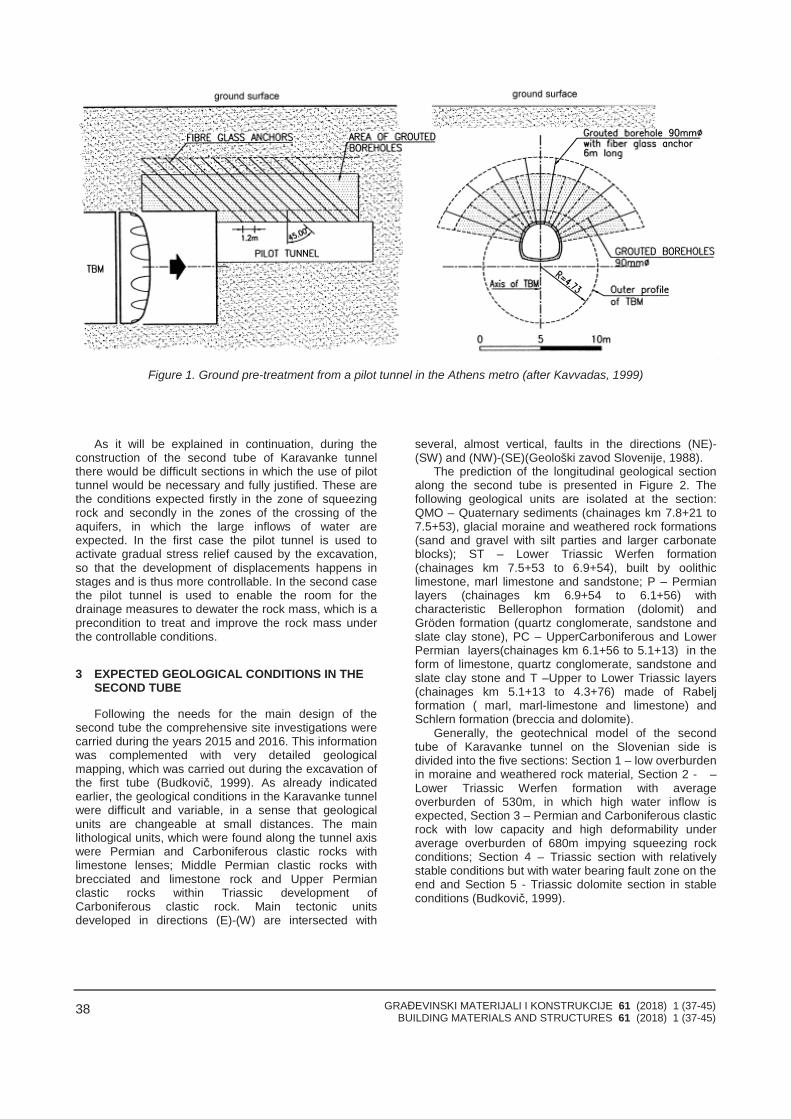
GRAĐEVINSKI MATERIJALI I KONSTRUKCIJE 61 (2018) 1 (37-45)BUILDING MATERIALS AND STRUCTURES 61 (2018) 1 (37-45)
38
Figure 1. Ground pre-treatment from a pilot tunnel in the Athens metro (after Kavvadas, 1999)
As it will be explained in continuation, during theconstruction of the second tube of Karavanke tunnelthere would be difficult sections in which the use of pilottunnel would be necessary and fully justified. These arethe conditions expected firstly in the zone of squeezingrock and secondly in the zones of the crossing of theaquifers, in which the large inflows of water areexpected. In the first case the pilot tunnel is used toactivate gradual stress relief caused by the excavation,so that the development of displacements happens instages and is thus more controllable. In the second casethe pilot tunnel is used to enable the room for thedrainage measures to dewater the rock mass, which is aprecondition to treat and improve the rock mass underthe controllable conditions.
3 EXPECTED GEOLOGICAL CONDITIONS IN THESECOND TUBE
Following the needs for the main design of thesecond tube the comprehensive site investigations werecarried during the years 2015 and 2016. This informationwas complemented with very detailed geologicalmapping, which was carried out during the excavation ofthe first tube (Budkovič, 1999). As already indicatedearlier, the geological conditions in the Karavanke tunnelwere difficult and variable, in a sense that geologicalunits are changeable at small distances. The mainlithological units, which were found along the tunnel axiswere Permian and Carboniferous clastic rocks withlimestone lenses; Middle Permian clastic rocks withbrecciated and limestone rock and Upper Permianclastic rocks within Triassic development ofCarboniferous clastic rock. Main tectonic unitsdeveloped in directions (E)-(W) are intersected with
several, almost vertical, faults in the directions (NE)-(SW) and (NW)-(SE)(Geološki zavod Slovenije, 1988).
The prediction of the longitudinal geological sectionalong the second tube is presented in Figure 2. Thefollowing geological units are isolated at the section:QMO – Quaternary sediments (chainages km 7.8+21 to7.5+53), glacial moraine and weathered rock formations(sand and gravel with silt parties and larger carbonateblocks); ST – Lower Triassic Werfen formation(chainages km 7.5+53 to 6.9+54), built by oolithiclimestone, marl limestone and sandstone; P – Permianlayers (chainages km 6.9+54 to 6.1+56) withcharacteristic Bellerophon formation (dolomit) andGröden formation (quartz conglomerate, sandstone andslate clay stone), PC – UpperCarboniferous and LowerPermian layers(chainages km 6.1+56 to 5.1+13) in theform of limestone, quartz conglomerate, sandstone andslate clay stone and T –Upper to Lower Triassic layers(chainages km 5.1+13 to 4.3+76) made of Rabeljformation ( marl, marl-limestone and limestone) andSchlern formation (breccia and dolomite).
Generally, the geotechnical model of the secondtube of Karavanke tunnel on the Slovenian side isdivided into the five sections: Section 1 – low overburdenin moraine and weathered rock material, Section 2 - –Lower Triassic Werfen formation with averageoverburden of 530m, in which high water inflow isexpected, Section 3 – Permian and Carboniferous clasticrock with low capacity and high deformability underaverage overburden of 680m impying squeezing rockconditions; Section 4 – Triassic section with relativelystable conditions but with water bearing fault zone on theend and Section 5 - Triassic dolomite section in stableconditions (Budkovič, 1999).
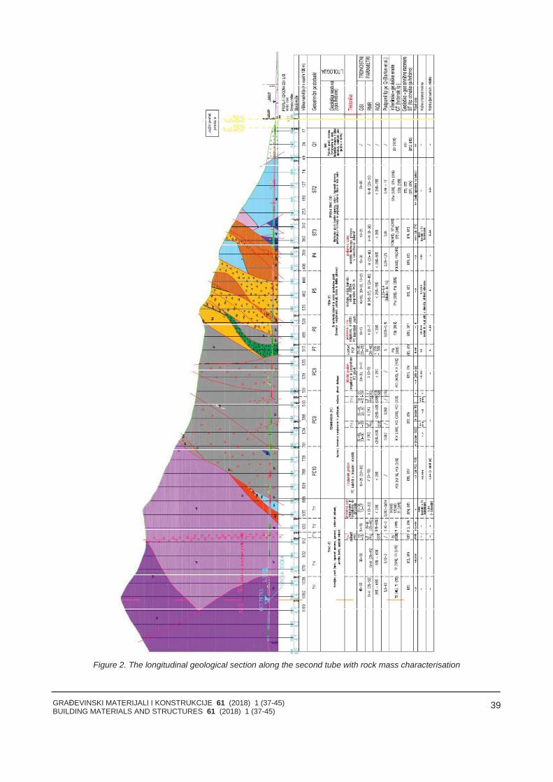
GRAĐEVINSKI MATERIJALI I KONSTRUKCIJE 61 (2018) 1 (37-45)BUILDING MATERIALS AND STRUCTURES 61 (2018) 1 (37-45)
39
Figure 2. The longitudinal geological section along the second tube with rock mass characterisation
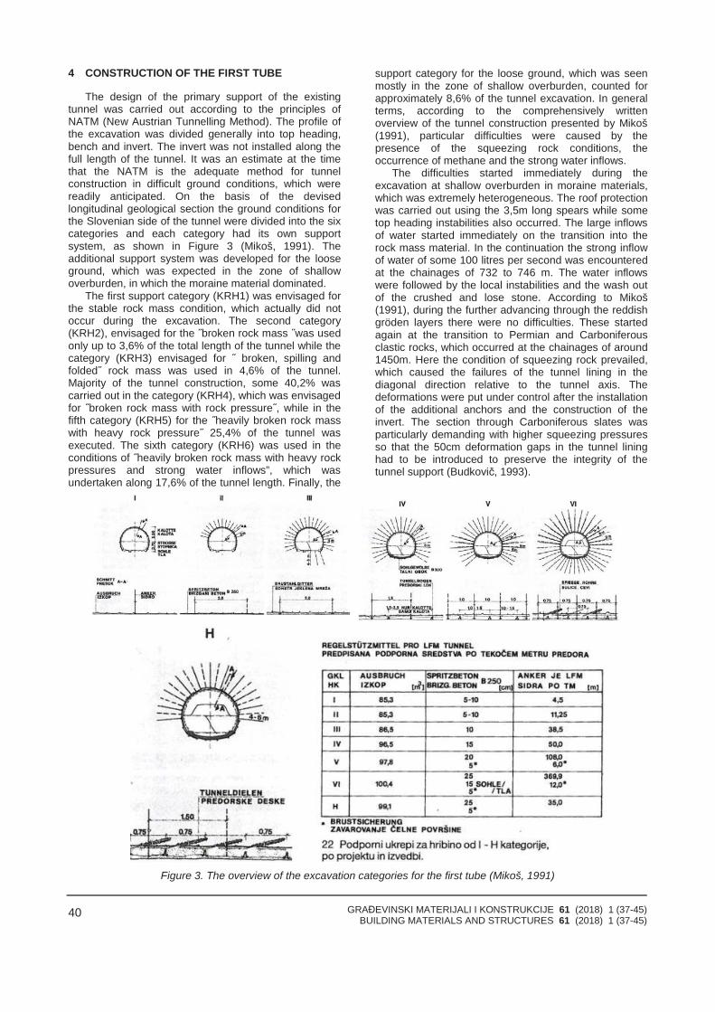
GRAĐEVINSKI MATERIJALI I KONSTRUKCIJE 61 (2018) 1 (37-45)BUILDING MATERIALS AND STRUCTURES 61 (2018) 1 (37-45)
40
4 CONSTRUCTION OF THE FIRST TUBE
The design of the primary support of the existingtunnel was carried out according to the principles ofNATM (New Austrian Tunnelling Method). The profile ofthe excavation was divided generally into top heading,bench and invert. The invert was not installed along thefull length of the tunnel. It was an estimate at the timethat the NATM is the adequate method for tunnelconstruction in difficult ground conditions, which werereadily anticipated. On the basis of the devisedlongitudinal geological section the ground conditions forthe Slovenian side of the tunnel were divided into the sixcategories and each category had its own supportsystem, as shown in Figure 3 (Mikoš, 1991). Theadditional support system was developed for the looseground, which was expected in the zone of shallowoverburden, in which the moraine material dominated.
The first support category (KRH1) was envisaged forthe stable rock mass condition, which actually did notoccur during the excavation. The second category(KRH2), envisaged for the ˝broken rock mass ˝was usedonly up to 3,6% of the total length of the tunnel while thecategory (KRH3) envisaged for ˝ broken, spilling andfolded˝ rock mass was used in 4,6% of the tunnel.Majority of the tunnel construction, some 40,2% wascarried out in the category (KRH4), which was envisagedfor ˝broken rock mass with rock pressure˝, while in thefifth category (KRH5) for the ˝heavily broken rock masswith heavy rock pressure˝ 25,4% of the tunnel wasexecuted. The sixth category (KRH6) was used in theconditions of ˝heavily broken rock mass with heavy rockpressures and strong water inflows”, which wasundertaken along 17,6% of the tunnel length. Finally, the
support category for the loose ground, which was seenmostly in the zone of shallow overburden, counted forapproximately 8,6% of the tunnel excavation. In generalterms, according to the comprehensively writtenoverview of the tunnel construction presented by Mikoš(1991), particular difficulties were caused by thepresence of the squeezing rock conditions, theoccurrence of methane and the strong water inflows.
The difficulties started immediately during theexcavation at shallow overburden in moraine materials,which was extremely heterogeneous. The roof protectionwas carried out using the 3,5m long spears while sometop heading instabilities also occurred. The large inflowsof water started immediately on the transition into therock mass material. In the continuation the strong inflowof water of some 100 litres per second was encounteredat the chainages of 732 to 746 m. The water inflowswere followed by the local instabilities and the wash outof the crushed and lose stone. According to Mikoš(1991), during the further advancing through the reddishgröden layers there were no difficulties. These startedagain at the transition to Permian and Carboniferousclastic rocks, which occurred at the chainages of around1450m. Here the condition of squeezing rock prevailed,which caused the failures of the tunnel lining in thediagonal direction relative to the tunnel axis. Thedeformations were put under control after the installationof the additional anchors and the construction of theinvert. The section through Carboniferous slates wasparticularly demanding with higher squeezing pressuresso that the 50cm deformation gaps in the tunnel lininghad to be introduced to preserve the integrity of thetunnel support (Budkovič, 1993).
Figure 3. The overview of the excavation categories for the first tube (Mikoš, 1991)
GRAĐEVINSKI MATERIJALI I KONSTRUKCIJE 61 (2018) 1 (37-45)BUILDING MATERIALS AND STRUCTURES 61 (2018) 1 (37-45)
41
At the chainage 1700m the tunnel excavation wasfully in Carboniferous clastic rock. Instead of theexpected 35cm of total convergence movement thesewere accelerating in the top heading at a rate of around17 cm per day (Mikoš, 1991). Large and fastdeformations were pulling out the anchors and theanchor plates were sheared off. For this reason a newanchor head was introduced, which allowed for 20cm ofaxial deformation before the full capacity of the anchorwas activated. Also the deformation gaps wereintroduced into the lining so that more of the load wastransferred to the rock mass before was taken by thetunnel lining. The extreme deformations wereencountered at the transition from sandstone partieswithin the clastic rocks into the much weakerCarboniferous slates. These movements were at somepoints up to 150cm so that some remedial works on theprimary lining were inevitable despite all the measuresthat were undertaken to prevent this. The occurrence ofthe high concentration of methane was detectedbetween the chainages 1560m and 2600m. Thisrequired a particular safety measures for the work underthe methane regime, which additionally slowed down theprogression (Mikoš, 1991). The presence of methanewas detected by using the pre-drilling procedures, whichwere systematically used along this difficult section.
Carboniferous section ended at the chainage of2550m. The next section was significantly easierfeaturing limestone and schlern dolomites. The highoverburden, which was at this point some 800m, and thehigh inflow of water did not caused particular difficulties.By the rule, after the excavation, the inflow of waterquickly ceased and the predrilling, which wascontinuously used also at this section, was an effectivemeasure to instrument the drainage.
These conditions prevailed up to the chainage3030m, in which the pre-drilling indicated that an aquiferzone lies ahead featuring extremely high waterpressures. The additional boreholes were installed at thehead of excavation, but these were clogged almostimmediately and it was clear that the water pressurebuild up behind the top heading would inevitably causean incontrollable and dangerous failure. At this point thehuman workforce and the machines were moved far outfrom the top heading and the failure was causedremotely by the controlled blast. The sudden inflow ofhuge amount of water flooded the tunnel. There was anestimate that 4500m3 of the material was washed outand that the initial inflow was some 1m3 per second(Mikoš, 1991).
Once the inflow of the water became controllable andconstant the major remedial works started. Gabionswere used to ensure the stability of the locally damagedtunnel lining. The water pressure relieve boreholes werefurther installed at the head of excavation to enablecontrollable drainage conditions. Finally, the bypass pilottunnel of smaller dimensions was built along thedeviation of the tunnel axis, which revealed a major faultzone that was channelling the water inflow. Morepressure relief boreholes were installed from the bypasspilot tunnel towards the main axis. After the progressionthrough the fault zone the pilot tunnel was re-directedalong the tunnel axis and the works advanced within therelatively simple geotechnical conditions with no furtherdelay. At the position of the fault zone, the head of the
excavation of the main tunnel was injected and stabilisedand the breakthrough of the main tunnel within the faultzone was carried out in fully controllable manner.
The continuation of the excavation up to the stateborder was relatively undemanding as the last 400m ofthe tunnel construction were carried out within the hardlimestone and dolomites with occasional sections of marland sandstone.
5 USE OF PILOT TUNNEL METHOD IN THESECOND TUBE
Given the complex geological structure and theexperience from the construction of the first tubedescribed in the previous sections the followingchallenges are expected during the construction of thesecond tube: a) large convergence displacements in thesqueezing rock conditions and b) huge inflows of water.Both of these conditions can be partly or fully addressedusing the pilot tunnel method, as it will be explained incontinuation.
(i) Large convergence displacements
During the construction of the first tube the largeconvergence displacements were first encountered inextreme form at the chainage 1450m in which there wasa transition from Permian to Permian-Carboniferous rockin the form of clay slate structure. The deformations thatwere measured along the tunnel are shown in Figure 4.As it can be seen in the figure even more extremedeformations, up to 1,5m were experienced at the chain-age of 1700m. The trend of high displacementscontinued along the full length of Permian-Carboniferoussection with similar magnitude of deformation (Mikoš,1991).
The philosophy of the NATM method is based on thenotion that the lining needs to be flexible so that majorityof the load caused by the relaxation of the initial stressesis taken by the surrounding rock mass. This is verydifficult to achieve in the condition of the squeezing rockin which the ratio between the height of overburden andthe uniaxial strength of the rock mass is very high. Thisimplicitly leads to high and wide plasticisation of the rockmass around the cavity and premature installation of thetunnel lining will result in the loss of lining integrity.
The measures that are predicted to cope with largeconvergence displacements under the conditions ofsqueezing rock include the use of deformation gaps(once they close the lining start taking the load) whichare integrated in the lining. They can be made to be loadbearing, which can help in controlling the rate of theconvergence movements and thus transfer of the forcefrom the rock mass to the tunnel lining.
The next measure is the use of the rock anchors withductile rods, which enables them to take the full loadeven after the significant level of deformation. Thecontrol of the large convergence displacements can becarried out to a certain extent by the careful sequencingof the excavation of the top heading bench and theinvert. The closing of the invert should be carefullychosen once the activation of the lining is nearing to thefull capacity. For this purpose the load cells arepredicted to be installed in the deformation gaps so thatthe process can be monitored in real time and the
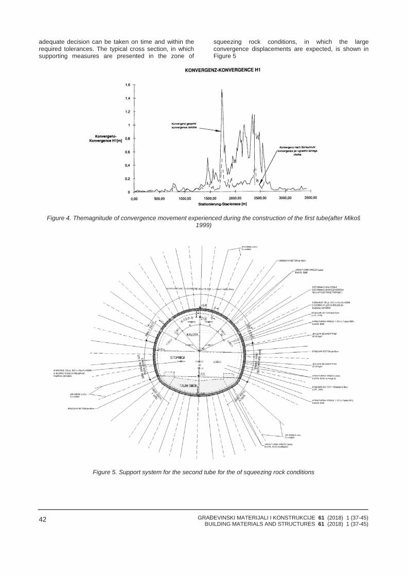
GRAĐEVINSKI MATERIJALI I KONSTRUKCIJE 61 (2018) 1 (37-45)BUILDING MATERIALS AND STRUCTURES 61 (2018) 1 (37-45)
42
adequate decision can be taken on time and within therequired tolerances. The typical cross section, in whichsupporting measures are presented in the zone of
squeezing rock conditions, in which the largeconvergence displacements are expected, is shown inFigure 5
Figure 4. Themagnitude of convergence movement experienced during the construction of the first tube(after Mikoš1999)
Figure 5. Support system for the second tube for the of squeezing rock conditions
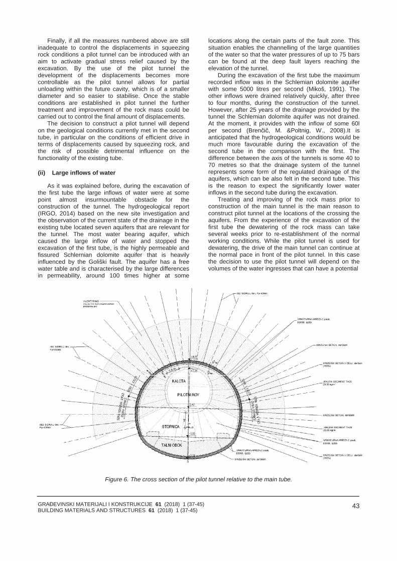
GRAĐEVINSKI MATERIJALI I KONSTRUKCIJE 61 (2018) 1 (37-45)BUILDING MATERIALS AND STRUCTURES 61 (2018) 1 (37-45)
43
Finally, if all the measures numbered above are stillinadequate to control the displacements in squeezingrock conditions a pilot tunnel can be introduced with anaim to activate gradual stress relief caused by theexcavation. By the use of the pilot tunnel thedevelopment of the displacements becomes morecontrollable as the pilot tunnel allows for partialunloading within the future cavity, which is of a smallerdiameter and so easier to stabilise. Once the stableconditions are established in pilot tunnel the furthertreatment and improvement of the rock mass could becarried out to control the final amount of displacements.
The decision to construct a pilot tunnel will dependon the geological conditions currently met in the secondtube, in particular on the conditions of efficient drive interms of displacements caused by squeezing rock, andthe risk of possible detrimental influence on thefunctionality of the existing tube.
(ii) Large inflows of water
As it was explained before, during the excavation ofthe first tube the large inflows of water were at somepoint almost insurmountable obstacle for theconstruction of the tunnel. The hydrogeological report(IRGO, 2014) based on the new site investigation andthe observation of the current state of the drainage in theexisting tube located seven aquifers that are relevant forthe tunnel. The most water bearing aquifer, whichcaused the large inflow of water and stopped theexcavation of the first tube, is the highly permeable andfissured Schlernian dolomite aquifer that is heavilyinfluenced by the Goliški fault. The aquifer has a freewater table and is characterised by the large differencesin permeability, around 100 times higher at some
locations along the certain parts of the fault zone. Thissituation enables the channelling of the large quantitiesof the water so that the water pressures of up to 75 barscan be found at the deep fault layers reaching theelevation of the tunnel.
During the excavation of the first tube the maximumrecorded inflow was in the Schlemian dolomite aquiferwith some 5000 litres per second (Mikoš, 1991). Theother inflows were drained relatively quickly, after threeto four months, during the construction of the tunnel.However, after 25 years of the drainage provided by thetunnel the Schlemian dolomite aquifer was not drained.At the moment, it provides with the inflow of some 60lper second (Brenčič, M. &Poltnig, W., 2008).It isanticipated that the hydrogeological conditions would bemuch more favourable during the excavation of thesecond tube in the comparison with the first. Thedifference between the axis of the tunnels is some 40 to70 metres so that the drainage system of the tunnelrepresents some form of the regulated drainage of theaquifers, which can be also felt in the second tube. Thisis the reason to expect the significantly lower waterinflows in the second tube during the excavation.
Treating and improving of the rock mass prior toconstruction of the main tunnel is the main reason toconstruct pilot tunnel at the locations of the crossing theaquifers. From the experience of the excavation of thefirst tube the dewatering of the rock mass can takeseveral weeks prior to re-establishment of the normalworking conditions. While the pilot tunnel is used fordewatering, the drive of the main tunnel can continue atthe normal pace in front of the pilot tunnel. In this casethe decision to use the pilot tunnel will depend on thevolumes of the water ingresses that can have a potential
Figure 6. The cross section of the pilot tunnel relative to the main tube.
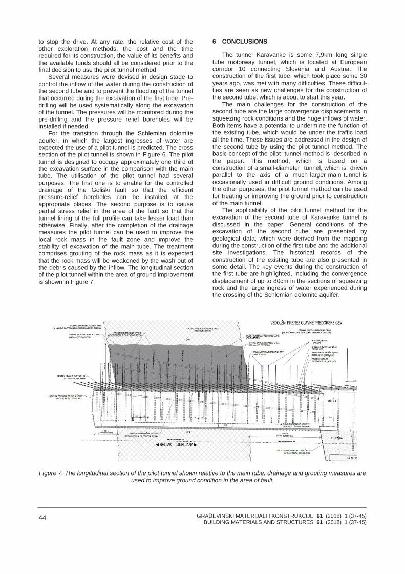
GRAĐEVINSKI MATERIJALI I KONSTRUKCIJE 61 (2018) 1 (37-45)BUILDING MATERIALS AND STRUCTURES 61 (2018) 1 (37-45)
44
to stop the drive. At any rate, the relative cost of theother exploration methods, the cost and the timerequired for its construction, the value of its benefits andthe available funds should all be considered prior to thefinal decision to use the pilot tunnel method.
Several measures were devised in design stage tocontrol the inflow of the water during the construction ofthe second tube and to prevent the flooding of the tunnelthat occurred during the excavation of the first tube. Pre-drilling will be used systematically along the excavationof the tunnel. The pressures will be monitored during thepre-drilling and the pressure relief boreholes will beinstalled if needed.
For the transition through the Schlemian dolomiteaquifer, in which the largest ingresses of water areexpected the use of a pilot tunnel is predicted. The crosssection of the pilot tunnel is shown in Figure 6. The pilottunnel is designed to occupy approximately one third ofthe excavation surface in the comparison with the maintube. The utilisation of the pilot tunnel had severalpurposes. The first one is to enable for the controlleddrainage of the Goliški fault so that the efficientpressure-relief boreholes can be installed at theappropriate places. The second purpose is to causepartial stress relief in the area of the fault so that thetunnel lining of the full profile can take lesser load thanotherwise. Finally, after the completion of the drainagemeasures the pilot tunnel can be used to improve thelocal rock mass in the fault zone and improve thestability of excavation of the main tube. The treatmentcomprises grouting of the rock mass as it is expectedthat the rock mass will be weakened by the wash out ofthe debris caused by the inflow. The longitudinal sectionof the pilot tunnel within the area of ground improvementis shown in Figure 7.
6 CONCLUSIONS
The tunnel Karavanke is some 7,9km long singletube motorway tunnel, which is located at Europeancorridor 10 connecting Slovenia and Austria. Theconstruction of the first tube, which took place some 30years ago, was met with many difficulties. These difficul-ties are seen as new challenges for the construction ofthe second tube, which is about to start this year.
The main challenges for the construction of thesecond tube are the large convergence displacements insqueezing rock conditions and the huge inflows of water.Both items have a potential to undermine the function ofthe existing tube, which would be under the traffic loadall the time. These issues are addressed in the design ofthe second tube by using the pilot tunnel method. Thebasic concept of the pilot tunnel method is described inthe paper. This method, which is based on aconstruction of a small-diameter tunnel, which is drivenparallel to the axis of a much larger main tunnel isoccasionally used in difficult ground conditions. Amongthe other purposes, the pilot tunnel method can be usedfor treating or improving the ground prior to constructionof the main tunnel.
The applicability of the pilot tunnel method for theexcavation of the second tube of Karavanke tunnel isdiscussed in the paper. General conditions of theexcavation of the second tube are presented bygeological data, which were derived from the mappingduring the construction of the first tube and the additionalsite investigations. The historical records of theconstruction of the existing tube are also presented insome detail. The key events during the construction ofthe first tube are highlighted, including the convergencedisplacement of up to 80cm in the sections of squeezingrock and the large ingress of water experienced duringthe crossing of the Schlemian dolomite aquifer.
Figure 7. The longitudinal section of the pilot tunnel shown relative to the main tube: drainage and grouting measures areused to improve ground condition in the area of fault.
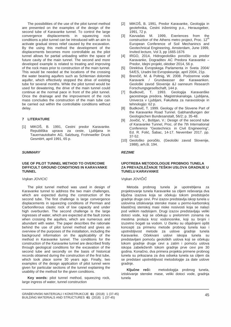
GRAĐEVINSKI MATERIJALI I KONSTRUKCIJE 61 (2018) 1 (37-45)BUILDING MATERIALS AND STRUCTURES 61 (2018) 1 (37-45)
45
The possibilities of the use of the pilot tunnel methodare presented on the examples of the design of thesecond tube of Karavanke tunnel. To control the largeconvergence displacements in squeezing rockconditions a pilot tunnel can be introduced with an aim toactivate gradual stress relief caused by the excavation.By the using this method the development of thedisplacements becomes more controllable as the pilottunnel allows for partial unloading within the space offuture cavity of the main tunnel. The second and moredeveloped example is related to treating and improvingof the rock mass prior to construction of the main tunnel.This would be needed at the locations of the crossingthe water bearing aquifers such as Schlemian dolomiteaquifer, which effectively stopped the drive of existingtube for several months. While the pilot tunnel would beused for dewatering, the drive of the main tunnel couldcontinue at the normal pace in front of the pilot tunnel.Once the drainage and the improvement of the rockmass concludes the construction of the main tube canbe carried out within the controllable conditions withoutdelay.
7 LITERATURE
[1] MIKOŠ, B. 1991, Cestni predor Karavanke.Republiška uprava za ceste, Ljubljana inTauernautobahn AG, Salzburg, Frohnweller DruckGesmbH, april 1991, 65 p.
[2] MIKOŠ, B. 1991, Predor Karavanke, Geologija ingeotehnika, Cestni inženiring p.o., Herausgeber,1991, 72 p.
[3] Kavvadas M. 1999, Exeriences from theconstruction of the Athens metro project, Proc. 12th
European Conference of Soil Mechanincs andGeotechnical Engineering, Amsterdam, June 1999,Invited lecture, Vol 3, pp 1665-1676
[4] IRGO, 2014, Hidrogeološko poročilo za predorKaravanke, Dograditev AC Predora Karavanke –Predor, Idejni projekt, oktober 2014, 56 p.
[5] Direktiva Evropskega Parlamenta in Sveta 2004/54/ES, Uradni list Evropskeunije, april 2004, 21p.
[6] Brenčič, M. & Poltnig, W. 2008. Podzemne vodeKaravank / Grundwasser der Karawanken.Geološki zavod Slovenije &J oanneum ResearchForschungsgesellschaft, 144 p.
[7] Budkovič, T. 1993. Geologija Karavanškegacestnega predora. Magistrskanaloga. Ljubljana,Univerza v Ljubljani, Fakulteta za naravoslovje intehnologijo: 62 p.
[8] Budkovič, T. 1999. Geology of the Slovene Part ofthe Karavanke Road Tunnel. Gabhandlungen derGeologischen Bundesanstalt, 56/2; p. 35-48.
[9] Jovičić, V., Boštjan, V.: Design of the second tubeof Karavanke Tunnel, Proc. of the 7th InternationalConference "Geotechnics in Civil Engineering",Ed. R. Folić, Šabac, 14-17. Nevember 2017. pp.37-52.
[10] Geološko poročilo, (Geološki zavod Slovenije,1988), arh.št. 194.
SUMMARY
USE OF PILOT TUNNEL METHOD TO OVERCOMEDIFFICULT GROUND CONDITIONS IN KARAVANKETUNNEL
Vojkan JOVICIC
The pilot tunnel method was used in design ofKaravanke tunnel to address the two main challenges,which are expected during the construction of thesecond tube. The first challenge is large convergencedisplacements in squeezing conditions of Permian andCarboniferous clastic rock of low capacity and underhigh overburden. The second challenge is the largeingresses of water, which are expected at the fault zoneswhen crossing the aquifers, which are numerous andabundant with water. The paper describes the rationalebehind the use of pilot tunnel method and gives anoverview of the purposes of the installation, including thebackground information on the applicability of themethod in Karavanke tunnel. The conditions for theconstruction of the Karavanke tunnel are described firstlythrough geological conditions for the excavation of thesecond tube and secondly on the basis of historicalrecords obtained during the construction of the first tube,which took place some 30 years ago. Finally, twoexamples of the design application of pilot tunnel weregiven for particular sections of the tunnel explaining theusability of the method for the given conditions.
Key words: pilot tunnel method, squeezing rock,large ingress of water, tunnel construction
REZIME
UPOTREBA METODOLOGIJE PROBNOG TUNELAZA PREVAZILEŽANJE TEŠKIH USLOVA GRADNJE UTUNELU KARAVANKE
Vojkan JOVIČIĆ
Metoda probnog tunela je upotrebljena zaprojektovanje tunela Karavanke sa ciljem reševanja dvaključna izazova koja se očekuju tokom predstojećegradnje druge cevi. Prvi izazov predstavlja iskop tunela uuslovima iztiskivanja stenske mase u permo-karbonskojklastičnoj stenskoj masi niske nosivosti koja se nalazipod velikim nadslojem. Drugi izazov predstavljaju velikidotoci vode, koji se očekuju u prelomnim zonama namestima prolaza kroz vodonosnike, koji su brojni iizuzetno bogati sa vodom. U članku su objašnjeni opštikoncepti za primenu metode probnog tunela kao iupotrebljivost metode za uslove gradnje tunelaKaravanke. Očekivani uslovi iskopa tunela supredstavljani pomoću geoloških uslova koji se očekujutokom gradnje druge cevi a zatim i pomoću uslovaiskopa zabeleženih tokom gradnje prve cevi pre 30godina. Konačno, dva primera projekta primene probnogtunela su prikazana za dva odseka tunela sa ciljem dase predstavi upotrebljivost metodologije za date uslovegradnje.
Ključne reči: metodologija probnog tunela,iztiskivanje stenske mase, veliki dotoci vode, gradnjatunela

GRAĐEVINSKI MATERIJALI I KONSTRUKCIJE 61 (2018) 1 (37-45)BUILDING MATERIALS AND STRUCTURES 61 (2018) 1 (37-45)
46
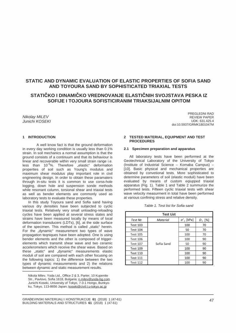
GRAĐEVINSKI MATERIJALI I KONSTRUKCIJE 61 (2018) 1 (47-61)BUILDING MATERIALS AND STRUCTURES 61 (2018) 1 (47-61)
47
STATIC AND DYNAMIC EVALUATION OF ELASTIC PROPERTIES OF SOFIA SANDAND TOYOURA SAND BY SOPHISTICATED TRIAXIAL TESTS
STATIČKO I DINAMIČKO VREDNOVANJE ELASTIČNIH SVOJSTAVA PESKA IZSOFIJE I TOJOURA SOFISTICIRANIM TRIAKSIJALNIM OPITOM
Nikolay MILEVJunichi KOSEKI
PREGLEDNI RADREVIEW PAPERUDK: 631.425.4
doi:10.5937/GRMK1801047M
1 INTRODUCTION
A well know fact is that the ground deformationin every day working condition is usually less than 0.1%strain. In soil mechanics a normal assumption is that theground consists of a continuum and that its behaviour islinear and recoverable within very small strain range i.e.less than 10-3%. Therefore „elastic“ deformationproperties of soil such as Young's modulus andmaximum shear modulus play important role in civilengineering design. In order to obtain these paramatersthrough in-situ tests it is common to use corss-holelogging, down hole and suspension sonde methodswhile resonant column, torsional shear and triaxial testsas well as bender elements are commonly used aslaboratory tests to evaluate these properties.
In this study Toyoura sand and Sofia sand havingvarious dry densities have been subjected to cyclictriaxial tests. Relatively very small unloading-reloadingcycles have been applied at several stress states andstrains have been measured locally by means of localdeformation transducers (LDTs), [6], at the side surfaceof the specimen. This method is called „static“ herein.For the „dynamic“ measurement two types of wavepropagation teqniques have been adopted. One is usingbender elements and the other is composed of trigger-elements which transmit shear wave and two ceramicaccelerometers which receive the shear wave. Based onthese „static“ and „dynamic“ measurements elasticmoduli of soil are compared with each other focusing onthe following topics: 1) the difference between the twotypes of dynamic measurements and 2) the relationsbetween dynamic and static measurement results.
Nikola Milev, Yoda Ltd., Office 2 & 3, Parter, 10 KupeniteStr., Pavlovo, Sofia 1618, Bulgaria; [email protected] Koseki, University of Tokyo, 7-3-1 Hongo, Bunkyo-ku, Tokyo, 113-8656 Japan; [email protected]
2 TESTED MATERIAL, EQUIPMENT AND TESTPROCEDURES
2.1 Specimen preparation and apparatus
All laboratory tests have been performed at theGeotechnical Laboratory of the University of Tokyo(Institute of Industrial Science – Komaba Campus) –[10]. Basic physical and mechanical properties areobtained by convetional tests. More sophisticated todetermine parameters of soil (elastic moduli) have beenevaluated by means of custom eqiupped triaxialapparatus (Fig. 1). Table 1 and Table 2 summurize theperformed tests. Fifteen cyclic triaxial tests with shearwave velocity measurment in total have been performedat various confining stress and relative density.
Table 1. Test list for Sofia sand
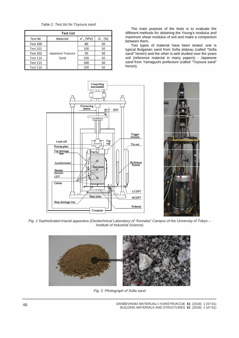
GRAĐEVINSKI MATERIJALI I KONSTRUKCIJE 61 (2018) 1 (47-61)BUILDING MATERIALS AND STRUCTURES 61 (2018) 1 (47-61)
48
Table 2. Test list for Toyoura sandThe main purpose of the tests is to evaluate the
different methods for obtaining the Young's modulus andmaximum shear modulus of soil and make a comparisonbetween them.
Two types of material have been tested: one istypical Bulgarian sand from Sofia plateau (called “Sofiasand” herein) and the other is well studied over the yearssoil (reference material in many papers) - Japanesesand from Yamaguchi prefecture (called “Toyoura sand”herein).
Fig. 1 Sophisticated triaxial apparatus (Geotechnical Laboratory of “Komaba” Campus of the University of Tokyo –Institute of Industrial Science)
Fig. 2. Photograph of Sofia sand
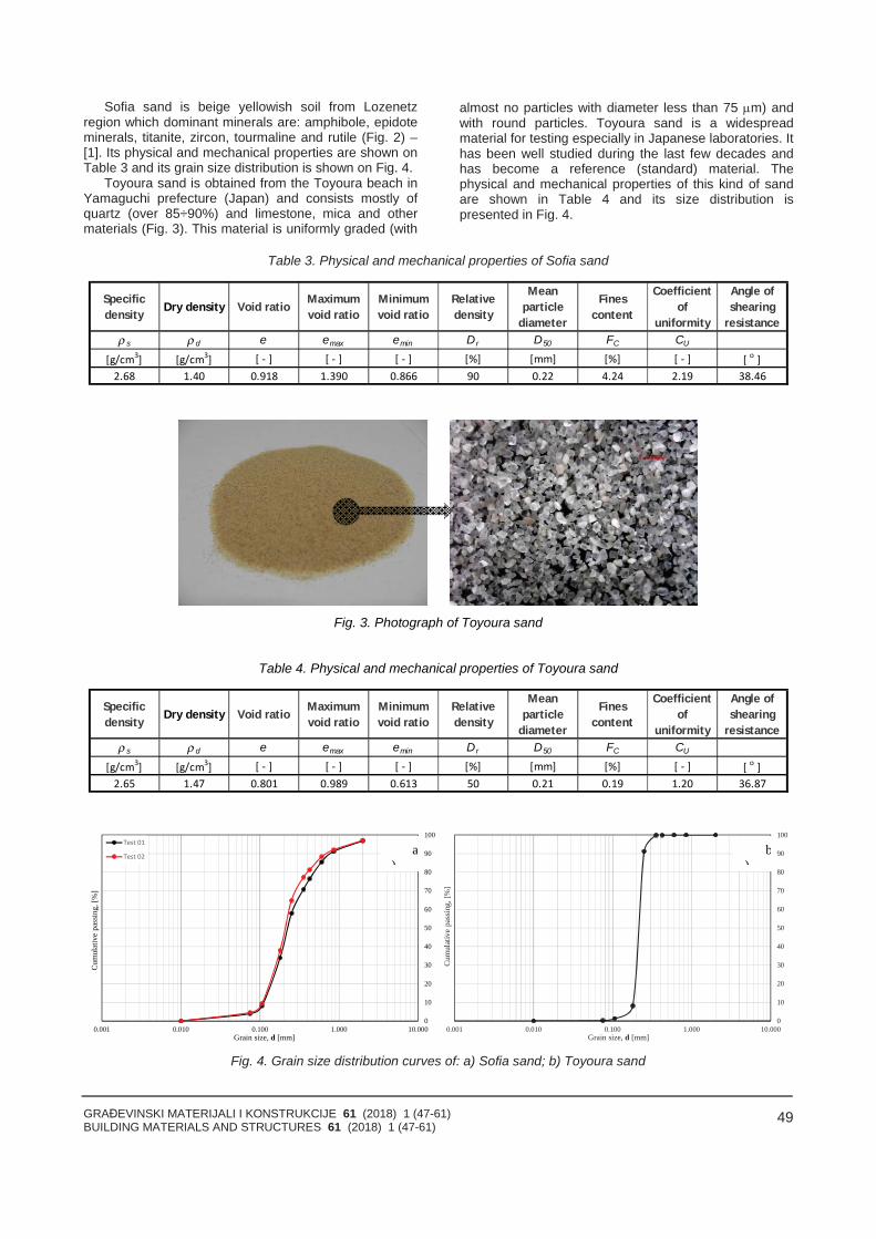
GRAĐEVINSKI MATERIJALI I KONSTRUKCIJE 61 (2018) 1 (47-61)BUILDING MATERIALS AND STRUCTURES 61 (2018) 1 (47-61)
49
Sofia sand is beige yellowish soil from Lozenetzregion which dominant minerals are: amphibole, epidoteminerals, titanite, zircon, tourmaline and rutile (Fig. 2) –[1]. Its physical and mechanical properties are shown onTable 3 and its grain size distribution is shown on Fig. 4.
Toyoura sand is obtained from the Toyoura beach inYamaguchi prefecture (Japan) and consists mostly ofquartz (over 85÷90%) and limestone, mica and othermaterials (Fig. 3). This material is uniformly graded (with
almost no particles with diameter less than 75 m) andwith round particles. Toyoura sand is a widespreadmaterial for testing especially in Japanese laboratories. Ithas been well studied during the last few decades andhas become a reference (standard) material. Thephysical and mechanical properties of this kind of sandare shown in Table 4 and its size distribution ispresented in Fig. 4.
Table 3. Physical and mechanical properties of Sofia sand
Specificdensity Dry density Void ratio Maximum
void ratioMinimumvoid ratio
Relativedensity
Meanparticle
diameter
Finescontent
Coefficientof
uniformity
Angle ofshearing
resistanceρ s ρ d e emax emin Dr D50 FC CU �
Fig. 3. Photograph of Toyoura sand
Table 4. Physical and mechanical properties of Toyoura sand
Specificdensity Dry density Void ratio Maximum
void ratioMinimumvoid ratio
Relativedensity
Meanparticle
diameter
Finescontent
Coefficientof
uniformity
Angle ofshearing
resistanceρ s ρ d e emax emin Dr D50 FC CU �
0
10
20
30
40
50
60
70
80
90
100
0.001 0.010 0.100 1.000 10.000
Cum
ulat
ive
pass
ing,
[%]
Grain size, d [mm]
0
10
20
30
40
50
60
70
80
90
100
0.001 0.010 0.100 1.000 10.000
Cum
ulat
ive
pass
ing,
[%]
Grain size, d [mm]
Fig. 4. Grain size distribution curves of: a) Sofia sand; b) Toyoura sand
a)
b)
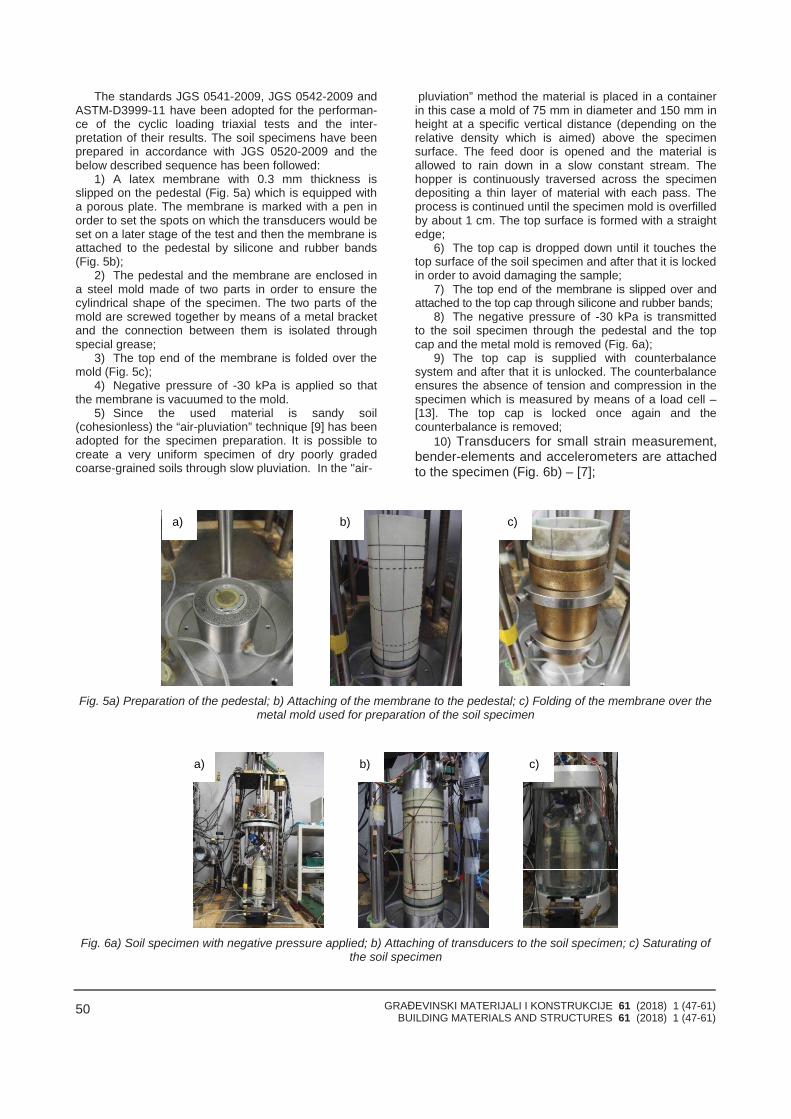
GRAĐEVINSKI MATERIJALI I KONSTRUKCIJE 61 (2018) 1 (47-61)BUILDING MATERIALS AND STRUCTURES 61 (2018) 1 (47-61)
50
The standards JGS 0541-2009, JGS 0542-2009 andASTM-D3999-11 have been adopted for the performan-ce of the cyclic loading triaxial tests and the inter-pretation of their results. The soil specimens have beenprepared in accordance with JGS 0520-2009 and thebelow described sequence has been followed:
1) A latex membrane with 0.3 mm thickness isslipped on the pedestal (Fig. 5a) which is equipped witha porous plate. The membrane is marked with a pen inorder to set the spots on which the transducers would beset on a later stage of the test and then the membrane isattached to the pedestal by silicone and rubber bands(Fig. 5b);
2) The pedestal and the membrane are enclosed ina steel mold made of two parts in order to ensure thecylindrical shape of the specimen. The two parts of themold are screwed together by means of a metal bracketand the connection between them is isolated throughspecial grease;
3) The top end of the membrane is folded over themold (Fig. 5c);
4) Negative pressure of -30 kPa is applied so thatthe membrane is vacuumed to the mold.
5) Since the used material is sandy soil(cohesionless) the “air-pluviation” technique [9] has beenadopted for the specimen preparation. It is possible tocreate a very uniform specimen of dry poorly gradedcoarse-grained soils through slow pluviation. In the "air-
pluviation” method the material is placed in a containerin this case a mold of 75 mm in diameter and 150 mm inheight at a specific vertical distance (depending on therelative density which is aimed) above the specimensurface. The feed door is opened and the material isallowed to rain down in a slow constant stream. Thehopper is continuously traversed across the specimendepositing a thin layer of material with each pass. Theprocess is continued until the specimen mold is overfilledby about 1 cm. The top surface is formed with a straightedge;
6) The top cap is dropped down until it touches thetop surface of the soil specimen and after that it is lockedin order to avoid damaging the sample;
7) The top end of the membrane is slipped over andattached to the top cap through silicone and rubber bands;
8) The negative pressure of -30 kPa is transmittedto the soil specimen through the pedestal and the topcap and the metal mold is removed (Fig. 6a);
9) The top cap is supplied with counterbalancesystem and after that it is unlocked. The counterbalanceensures the absence of tension and compression in thespecimen which is measured by means of a load cell –[13]. The top cap is locked once again and thecounterbalance is removed;
10) Transducers for small strain measurement,bender-elements and accelerometers are attachedto the specimen (Fig. 6b) – [7];
Fig. 5a) Preparation of the pedestal; b) Attaching of the membrane to the pedestal; c) Folding of the membrane over themetal mold used for preparation of the soil specimen
Fig. 6a) Soil specimen with negative pressure applied; b) Attaching of transducers to the soil specimen; c) Saturating ofthe soil specimen
a) b) c)
a) b) c)
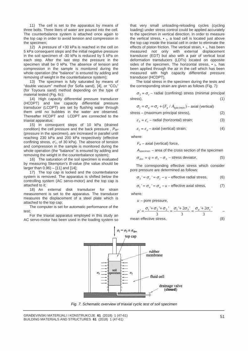
GRAĐEVINSKI MATERIJALI I KONSTRUKCIJE 61 (2018) 1 (47-61)BUILDING MATERIALS AND STRUCTURES 61 (2018) 1 (47-61)
51
11) The cell is set to the apparatus by means ofthree bolts. Three liters of water are poured into the cell.The counterbalance system is attached once again tothe top cap in order to avoid tension and compression inthe specimen;
12) A pressure of +30 kPa is reached in the cell on5 kPa consequent steps and the initial negative pressurein the soil specimen of -30 kPa is reduced by 5 kPa oneach step. After the last step the pressure in thespecimen shall be 0 kPa. The absence of tension andcompression in the sample is monitored during thewhole operation (the “balance” is ensured by adding andremoving of weight in the counterbalance system);
13) The specimen is fully saturated by means of“double vacuum” method (for Sofia sand), [4], or “CO2”(for Toyoura sand) method depending on the type ofmaterial tested (Fig. 6c);
14) High capacity differential pressure transducer(HCDPT) and low capacity differential pressuretransducer (LCDPT) are set by flushing water throughthem until no bubbles in the water are observed.Thereafter HCDPT and LCDPT are connected to thetriaxial apparatus;
15) In consequent steps of 10 kPa (drainedcondition) the cell pressure and the back pressure , PBP(pressure in the specimen), are increased in parallel untilreaching 230 kPa and 200 kPa respectively (effectiveconfining stress, σ’c, of 30 kPa). The absence of tensionand compression in the sample is monitored during thewhole operation (the “balance” is ensured by adding andremoving the weight in the counterbalance system);
16) The saturation of the soil specimen is evaluatedby measuring Skempton’s B-value (the value should belarger than 0.96) – [11] and [14];
17) The top cap is locked and the counterbalancesystem is removed. The apparatus is shifted below thecontrolling system (AC servo-motor) and the top cap isattached to it;
18) An external disk transducer for strainmeasurement is set to the apparatus. The transducermeasures the displacement of a steel plate which isattached to the top cap;
The computer is set for automatic performance of thetest;
For the triaxial apparatus employed in this study anAC servo-motor has been used in the loading system so
that very small unloading-reloading cycles (cyclingloading) under stress control could be applied accuratelyto the specimen in vertical direction. In order to measurethe vertical stress, • 1, a load cell is located just abovethe top cap inside the triaxial cell in order to eliminate theeffects of piston friction. The vertical strain, • 1, has beenmeasured not only with external displacementtransducer (EDT) but also with a pair of vertical localdeformation transducers (LDTs) located on oppositesides of the specimen. The horizontal stress, • 3, hasbeen applied through the air in the cell which has beenmeasured with high capacity differential pressuretransducer (HCDPT).
The total stress in the specimen during the tests andthe corresponding strain are given as follows (Fig. 7):
3 cσ σ= – radial (confining) stress (minimal principalstress), (1)
1 ( / )a c a specimenF Aσ σ σ= = + – axial (vertical)
stress – (maximum principal stress), (2)
3 cε ε= – radial (horizontal) strain; (3)
1 aε ε= – axial (vertical) strain; (4)
where:
Fa – axial (vertical) force,
Aspecimen – area of the cross section of the specimen
1 3dev qσ σ σ= = − – stress deviator, (5)
The corresponding effective stress which considerpore pressure are determined as follows:
3 ' 'c c uσ σ σ= = − – effective radial stress, (6)
1 ' 'а а uσ σ σ= = − – effective axial stress, (7)
where:
u – pore pressure,
1 31 2 2 ' 2 ' ' 2 '' ' ''
3 3 3a cp
σ σ σ σσ σ σ + ++ += = = –
mean effective stress, (8)
Fig. 7. Schematic overview of triaxial cyclic test of soil specimen
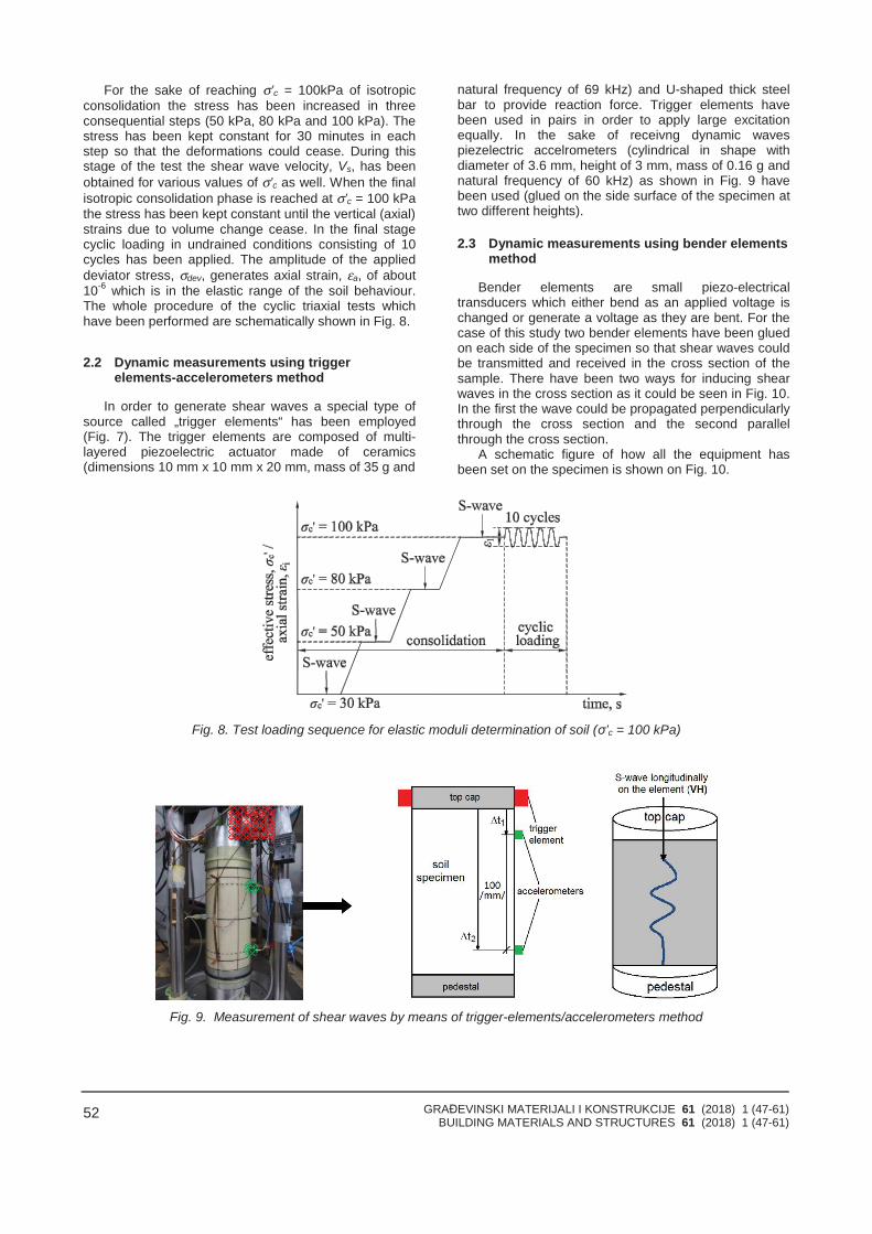
GRAĐEVINSKI MATERIJALI I KONSTRUKCIJE 61 (2018) 1 (47-61)BUILDING MATERIALS AND STRUCTURES 61 (2018) 1 (47-61)
52
For the sake of reaching σ’c = 100kPa of isotropicconsolidation the stress has been increased in threeconsequential steps (50 kPa, 80 kPa and 100 kPa). Thestress has been kept constant for 30 minutes in eachstep so that the deformations could cease. During thisstage of the test the shear wave velocity, Vs, has beenobtained for various values of σ’c as well. When the finalisotropic consolidation phase is reached at σ’c = 100 kPathe stress has been kept constant until the vertical (axial)strains due to volume change cease. In the final stagecyclic loading in undrained conditions consisting of 10cycles has been applied. The amplitude of the applieddeviator stress, σdev, generates axial strain, εa, of about10-6 which is in the elastic range of the soil behaviour.The whole procedure of the cyclic triaxial tests whichhave been performed are schematically shown in Fig. 8.
2.2 Dynamic measurements using triggerelements-accelerometers method
In order to generate shear waves a special type ofsource called „trigger elements“ has been employed(Fig. 7). The trigger elements are composed of multi-layered piezoelectric actuator made of ceramics(dimensions 10 mm x 10 mm x 20 mm, mass of 35 g and
natural frequency of 69 kHz) and U-shaped thick steelbar to provide reaction force. Trigger elements havebeen used in pairs in order to apply large excitationequally. In the sake of receivng dynamic wavespiezelectric accelrometers (cylindrical in shape withdiameter of 3.6 mm, height of 3 mm, mass of 0.16 g andnatural frequency of 60 kHz) as shown in Fig. 9 havebeen used (glued on the side surface of the specimen attwo different heights).
2.3 Dynamic measurements using bender elementsmethod
Bender elements are small piezo-electricaltransducers which either bend as an applied voltage ischanged or generate a voltage as they are bent. For thecase of this study two bender elements have been gluedon each side of the specimen so that shear waves couldbe transmitted and received in the cross section of thesample. There have been two ways for inducing shearwaves in the cross section as it could be seen in Fig. 10.In the first the wave could be propagated perpendicularlythrough the cross section and the second parallelthrough the cross section.
A schematic figure of how all the equipment hasbeen set on the specimen is shown on Fig. 10.
Fig. 8. Test loading sequence for elastic moduli determination of soil (σ’c = 100 kPa)
Fig. 9. Measurement of shear waves by means of trigger-elements/accelerometers method
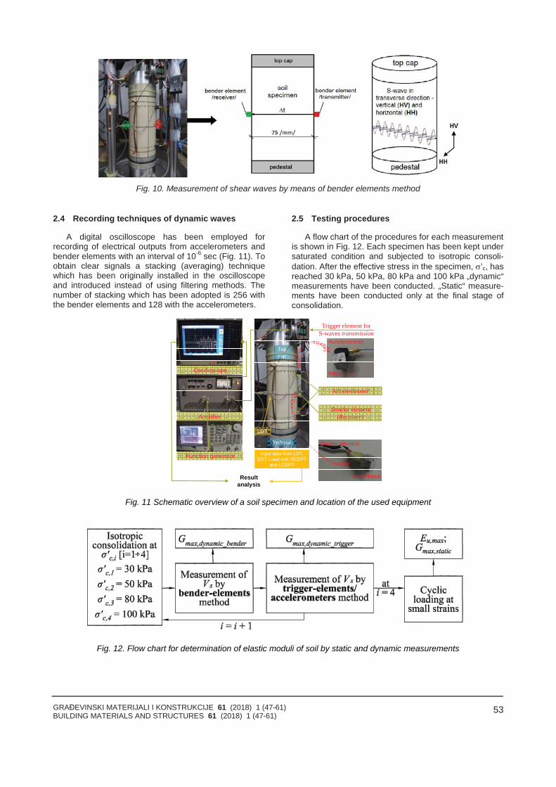
GRAĐEVINSKI MATERIJALI I KONSTRUKCIJE 61 (2018) 1 (47-61)BUILDING MATERIALS AND STRUCTURES 61 (2018) 1 (47-61)
53
Fig. 10. Measurement of shear waves by means of bender elements method
2.4 Recording techniques of dynamic waves
A digital oscilloscope has been employed forrecording of electrical outputs from accelerometers andbender elements with an interval of 10-6 sec (Fig. 11). Toobtain clear signals a stacking (averaging) techniquewhich has been originally installed in the oscilloscopeand introduced instead of using filtering methods. Thenumber of stacking which has been adopted is 256 withthe bender elements and 128 with the accelerometers.
2.5 Testing procedures
A flow chart of the procedures for each measurementis shown in Fig. 12. Each specimen has been kept undersaturated condition and subjected to isotropic consoli-dation. After the effective stress in the specimen, ’c, hasreached 30 kPa, 50 kPa, 80 kPa and 100 kPa „dynamic“measurements have been conducted. „Static“ measure-ments have been conducted only at the final stage ofconsolidation.
Input data from LDT,EDT, Load cell, HCDPT
and LCDPT
Trigger element forS-waves transmission
Topcap
Pedestal
Metal block
Accelerometer
Metal block
Bender element
Oscilloscope
Amplifier
Function generator
LDT
Specimen
Resultanalysis
Bender element(Receiver)
Accelerometer
Fig. 11 Schematic overview of a soil specimen and location of the used equipment
Fig. 12. Flow chart for determination of elastic moduli of soil by static and dynamic measurements
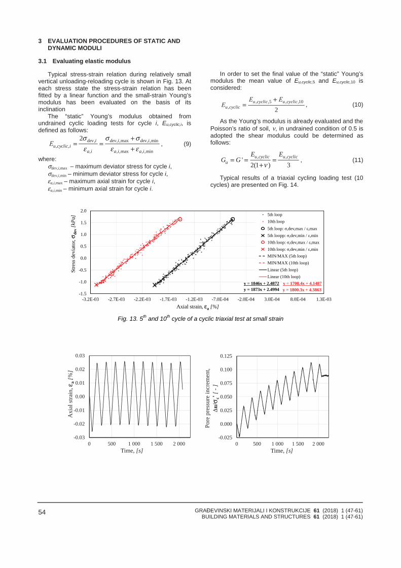
GRAĐEVINSKI MATERIJALI I KONSTRUKCIJE 61 (2018) 1 (47-61)BUILDING MATERIALS AND STRUCTURES 61 (2018) 1 (47-61)
54
3 EVALUATION PROCEDURES OF STATIC ANDDYNAMIC MODULI
3.1 Evaluating elastic modulus
Typical stress-strain relation during relatively smallvertical unloading-reloading cycle is shown in Fig. 13. Ateach stress state the stress-strain relation has beenfitted by a linear function and the small-strain Young’smodulus has been evaluated on the basis of itsinclination
The “static” Young’s modulus obtained fromundrained cyclic loading tests for cycle i, Eu,cyclic,i, isdefined as follows:
, , ,max , ,min, ,
, , ,max , ,min
2 dev i dev i dev iu cyclic i
a i a i a iЕ
σ σ σε ε ε
+= =
+, (9)
where:σdev,i,max – maximum deviator stress for cycle i,σdev,i,min – minimum deviator stress for cycle i,εa,i,max – maximum axial strain for cycle i,εa,i,min – minimum axial strain for cycle i.
In order to set the final value of the “static” Young’smodulus the mean value of Eu,cyclic,5 and Eu,cyclic,10 isconsidered:
, ,5 , ,10, 2
u cyclic u cyclicu cyclic
Е ЕЕ
+= , (10)
As the Young’s modulus is already evaluated and thePoisson’s ratio of soil, ν, in undrained condition of 0.5 isadopted the shear modulus could be determined asfollows:
, ,'2(1 ) 3
u cyclic u cyclicu
E EG G
ν= = =
+, (11)
Typical results of a triaxial cycling loading test (10cycles) are presented on Fig. 14.
y = 1873x + 2.4994 y = 1800.3x + 4.3863y = 1846x + 2.4872 y = 1708.4x + 4.1487
-1.5
-1.0
-0.5
0.0
0.5
1.0
1.5
2.0
-3.2E-03 -2.7E-03 -2.2E-03 -1.7E-03 -1.2E-03 -7.0E-04 -2.0E-04 3.0E-04 8.0E-04 1.3E-03
Stre
ssde
viat
or,σ
dev
[kPa
]
Axial strain, εa [%]
5th loop10th loop5th loop: σ,dev,max / ε,max5th loopp: σ,dev,min / ε,min10th loop: σ,dev,max / ε,max10th loop: σ,dev,min / ε,minMIN/MAX (5th loop)MIN/MAX (10th loop)Linear (5th loop)Linear (10th loop)
Fig. 13. 5th and 10th cycle of a cyclic triaxial test at small strain
-0.03
-0.02
-0.01
0.00
0.01
0.02
0.03
0 500 1 000 1 500 2 000
Axi
alst
rain
,εa
[%]
Time, [s]
-0.025
0.000
0.025
0.050
0.075
0.100
0.125
0 500 1 000 1 500 2 000
Pore
pres
sure
incr
emen
t,Δu
/σc'
[-]
Time, [s]
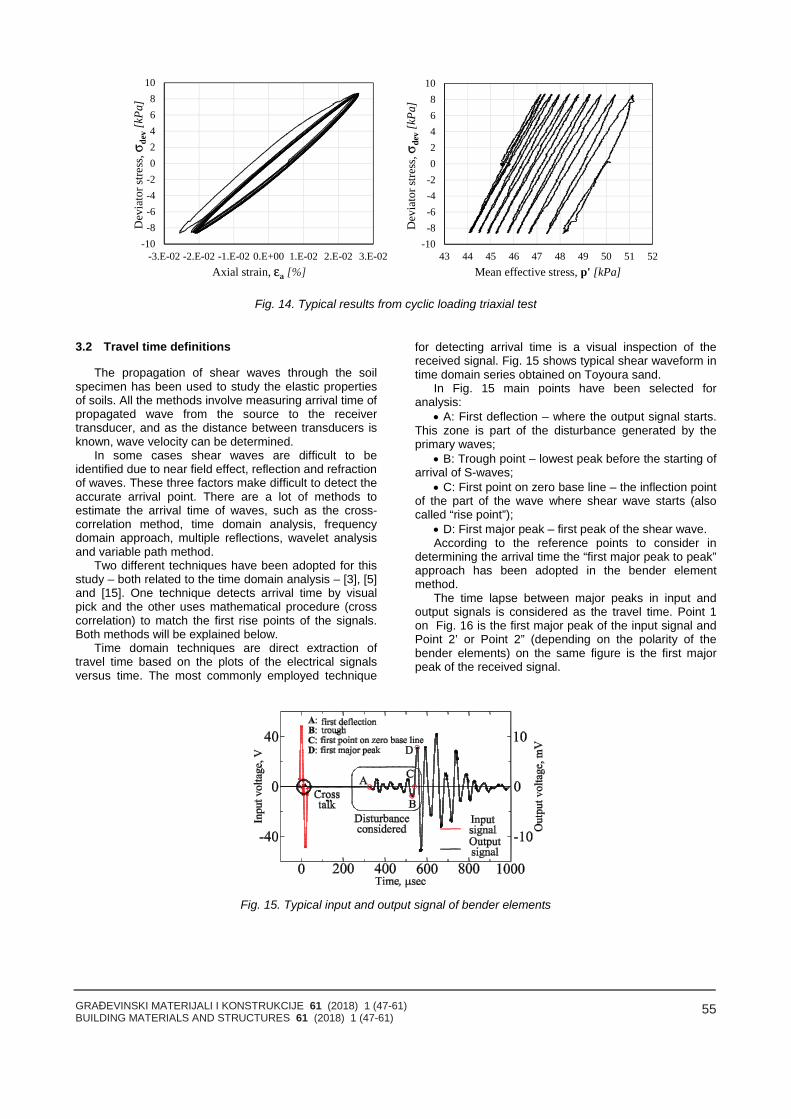
GRAĐEVINSKI MATERIJALI I KONSTRUKCIJE 61 (2018) 1 (47-61)BUILDING MATERIALS AND STRUCTURES 61 (2018) 1 (47-61)
55
-10-8-6-4-202468
10
-3.E-02 -2.E-02 -1.E-02 0.E+00 1.E-02 2.E-02 3.E-02
Dev
iato
rstre
ss,σ
dev
[kPa
]
Axial strain, εa [%]
-10-8-6-4-202468
10
43 44 45 46 47 48 49 50 51 52
Dev
iato
rstre
ss,σ
dev
[kPa
]
Mean effective stress, p' [kPa]
Fig. 14. Typical results from cyclic loading triaxial test
3.2 Travel time definitions
The propagation of shear waves through the soilspecimen has been used to study the elastic propertiesof soils. All the methods involve measuring arrival time ofpropagated wave from the source to the receivertransducer, and as the distance between transducers isknown, wave velocity can be determined.
In some cases shear waves are difficult to beidentified due to near field effect, reflection and refractionof waves. These three factors make difficult to detect theaccurate arrival point. There are a lot of methods toestimate the arrival time of waves, such as the cross-correlation method, time domain analysis, frequencydomain approach, multiple reflections, wavelet analysisand variable path method.
Two different techniques have been adopted for thisstudy – both related to the time domain analysis – [3], [5]and [15]. One technique detects arrival time by visualpick and the other uses mathematical procedure (crosscorrelation) to match the first rise points of the signals.Both methods will be explained below.
Time domain techniques are direct extraction oftravel time based on the plots of the electrical signalsversus time. The most commonly employed technique
for detecting arrival time is a visual inspection of thereceived signal. Fig. 15 shows typical shear waveform intime domain series obtained on Toyoura sand.
In Fig. 15 main points have been selected foranalysis:
A: First deflection – where the output signal starts.This zone is part of the disturbance generated by theprimary waves;
B: Trough point – lowest peak before the starting ofarrival of S-waves;
C: First point on zero base line – the inflection pointof the part of the wave where shear wave starts (alsocalled “rise point”);
D: First major peak – first peak of the shear wave.According to the reference points to consider in
determining the arrival time the “first major peak to peak”approach has been adopted in the bender elementmethod.
The time lapse between major peaks in input andoutput signals is considered as the travel time. Point 1on Fig. 16 is the first major peak of the input signal andPoint 2’ or Point 2” (depending on the polarity of thebender elements) on the same figure is the first majorpeak of the received signal.
Fig. 15. Typical input and output signal of bender elements
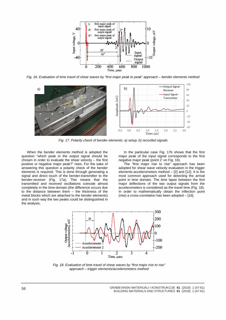
GRAĐEVINSKI MATERIJALI I KONSTRUKCIJE 61 (2018) 1 (47-61)BUILDING MATERIALS AND STRUCTURES 61 (2018) 1 (47-61)
56
Fig. 16. Evaluation of time travel of shear waves by “first major peak to peak” approach – bender elements method
-60
-40
-20
0
20
40
60
80
100
-0,5 0,0 0,5 1,0 1,5 2,0 2,5 3,0
Am
plitu
de[m
V]
Times [μs]
Fig. 17. Polarity check of bender elements: a) setup; b) recorded signals
When the bender elements method is adopted thequestion “which peak in the output signal should bechosen in order to evaluate the shear velocity – the firstpositive or negative major peak?” rises. For the sake ofanswering this question a polarity check of the benderelements is required. This is done through generating asignal and direct touch of the bender-transmitter to thebender-receiver (Fig. 17a). This means that thetransmitted and received oscillations coincide almostcompletely in the time-domain (the difference occurs dueto the distance between them – the thickness of themetal blocks which are attached to the bender elements)and in such way the two peaks could be distinguished inthe analysis.
In the particular case Fig. 17b shows that the firstmajor peak of the input signal corresponds to the firstnegative major peak (point 2’ on Fig. 16).
The “first major rise to rise” approach has beenadopted for shear wave velocity evaluation in the triggerelements-accelerometers method – [2] and [12]. It is themost common approach used for detecting the arrivalpoint in time domain. The time lapse between the firstmajor deflections of the two output signals from theaccelerometers is considered as the travel time (Fig. 18).In order to mathematically obtain the inflection point(rise) a cross-correlation has been adopted – [16].
Fig. 18. Evaluation of time travel of shear waves by “first major rise to rise”approach – trigger elements/accelerometers method
a) b)
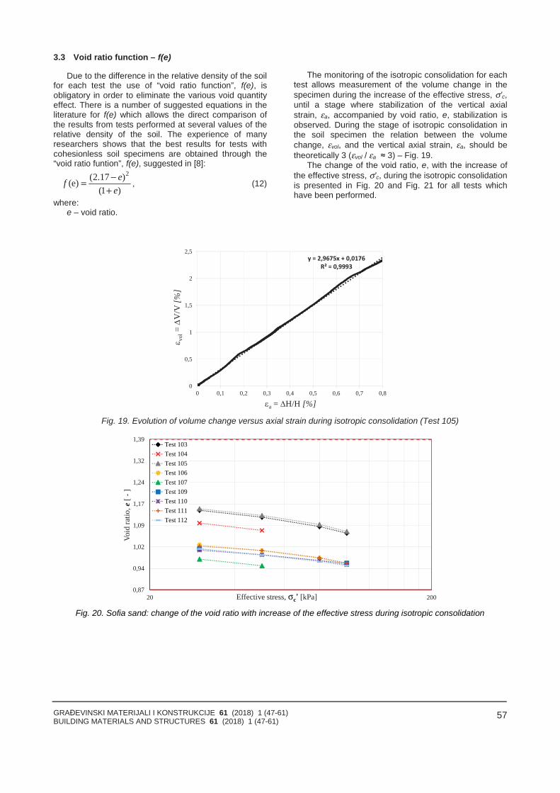
GRAĐEVINSKI MATERIJALI I KONSTRUKCIJE 61 (2018) 1 (47-61)BUILDING MATERIALS AND STRUCTURES 61 (2018) 1 (47-61)
57
3.3 Void ratio function – f(e)
Due to the difference in the relative density of the soilfor each test the use of “void ratio function”, f(e), isobligatory in order to eliminate the various void quantityeffect. There is a number of suggested equations in theliterature for f(e) which allows the direct comparison ofthe results from tests performed at several values of therelative density of the soil. The experience of manyresearchers shows that the best results for tests withcohesionless soil specimens are obtained through the“void ratio funtion”, f(e), suggested in [8]:
2(2.17 )(e)(1 )
efe
−=+
, (12)
where:e – void ratio.
The monitoring of the isotropic consolidation for eachtest allows measurement of the volume change in thespecimen during the increase of the effective stress, σ’c,until a stage where stabilization of the vertical axialstrain, εa, accompanied by void ratio, e, stabilization isobserved. During the stage of isotropic consolidation inthe soil specimen the relation between the volumechange, εvol, and the vertical axial strain, εa, should betheoretically 3 (εvol / εa ≈ 3) – Fig. 19.
The change of the void ratio, e, with the increase ofthe effective stress, σ’c, during the isotropic consolidationis presented in Fig. 20 and Fig. 21 for all tests whichhave been performed.
0
0,5
1
1,5
2
2,5
0 0,1 0,2 0,3 0,4 0,5 0,6 0,7 0,8
vol
=
V/V
[%]
a = H/H [%]
Fig. 19. Evolution of volume change versus axial strain during isotropic consolidation (Test 105)
0,87
0,94
1,02
1,09
1,17
1,24
1,32
1,39
20 200
Void
ratio
,e[-
]
Effective stress, σc' [kPa]
Test 103Test 104Test 105Test 106Test 107Test 109Test 110Test 111Test 112
Fig. 20. Sofia sand: change of the void ratio with increase of the effective stress during isotropic consolidation
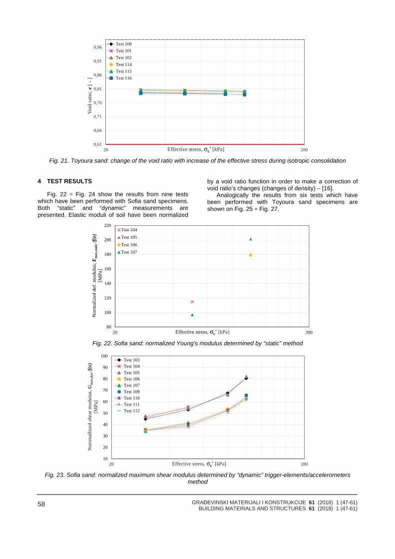
GRAĐEVINSKI MATERIJALI I KONSTRUKCIJE 61 (2018) 1 (47-61)BUILDING MATERIALS AND STRUCTURES 61 (2018) 1 (47-61)
58
0,61
0,66
0,71
0,76
0,81
0,86
0,91
0,96
20 200
Void
ratio
,e[-
]
Effective stress, σc' [kPa]
Test 100Test 101Test 102Test 114Test 115Test 116
Fig. 21. Toyoura sand: change of the void ratio with increase of the effective stress during isotropic consolidation
4 TEST RESULTS
Fig. 22 ÷ Fig. 24 show the results from nine testswhich have been performed with Sofia sand specimens.Both “static” and “dynamic” measurements arepresented. Elastic moduli of soil have been normalized
by a void ratio function in order to make a correction ofvoid ratio’s changes (changes of density) – [16].
Analogically the results from six tests which havebeen performed with Toyoura sand specimens areshown on Fig. 25 ÷ Fig. 27.
80
100
120
140
160
180
200
220
20 200
Nor
mal
ized
def.
mod
ulus
,Em
ax,st
atic
/f(e)
[MPa
]
Effective stress, σc' [kPa]
Test 104Test 105Test 106Test 107
Fig. 22. Sofia sand: normalized Young’s modulus determined by “static” method
10
20
30
40
50
60
70
80
90
100
20 200
Nor
rmal
lized
shea
rmod
ulus
,Gm
ax,d
yn/f(
e)[M
Pa]
Effective stress, σc' [kPa]
Test 103Test 104Test 105Test 106Test 107Test 109Test 110Test 111Test 112
Fig. 23. Sofia sand: normalized maximum shear modulus determined by “dynamic” trigger-elements/accelerometersmethod
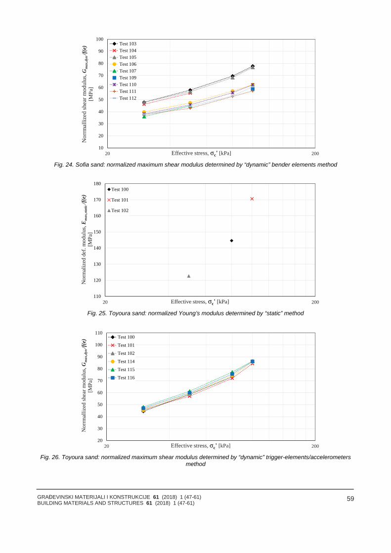
GRAĐEVINSKI MATERIJALI I KONSTRUKCIJE 61 (2018) 1 (47-61)BUILDING MATERIALS AND STRUCTURES 61 (2018) 1 (47-61)
59
10
20
30
40
50
60
70
80
90
100
20 200
Nor
rmal
lized
shea
rmod
ulus
,Gm
ax,d
yn/f(
e)[M
Pa]
Effective stress, σc' [kPa]
Test 103Test 104Test 105Test 106Test 107Test 109Test 110Test 111Test 112
Fig. 24. Sofia sand: normalized maximum shear modulus determined by “dynamic” bender elements method
110
120
130
140
150
160
170
180
20 200
Nor
mal
ized
def.
mod
ulus
,Em
ax,st
atic
/f(e)
[MPa
]
Effective stress, σc' [kPa]
Test 100
Test 101
Test 102
Fig. 25. Toyoura sand: normalized Young’s modulus determined by “static” method
20
30
40
50
60
70
80
90
100
110
20 200
Nor
rmal
lized
shea
rmod
ulus
,Gm
ax,d
yn/f(
e)[M
Pa]
Effective stress, σc' [kPa]
Test 100
Test 101
Test 102
Test 114
Test 115
Test 116
Fig. 26. Toyoura sand: normalized maximum shear modulus determined by “dynamic” trigger-elements/accelerometersmethod
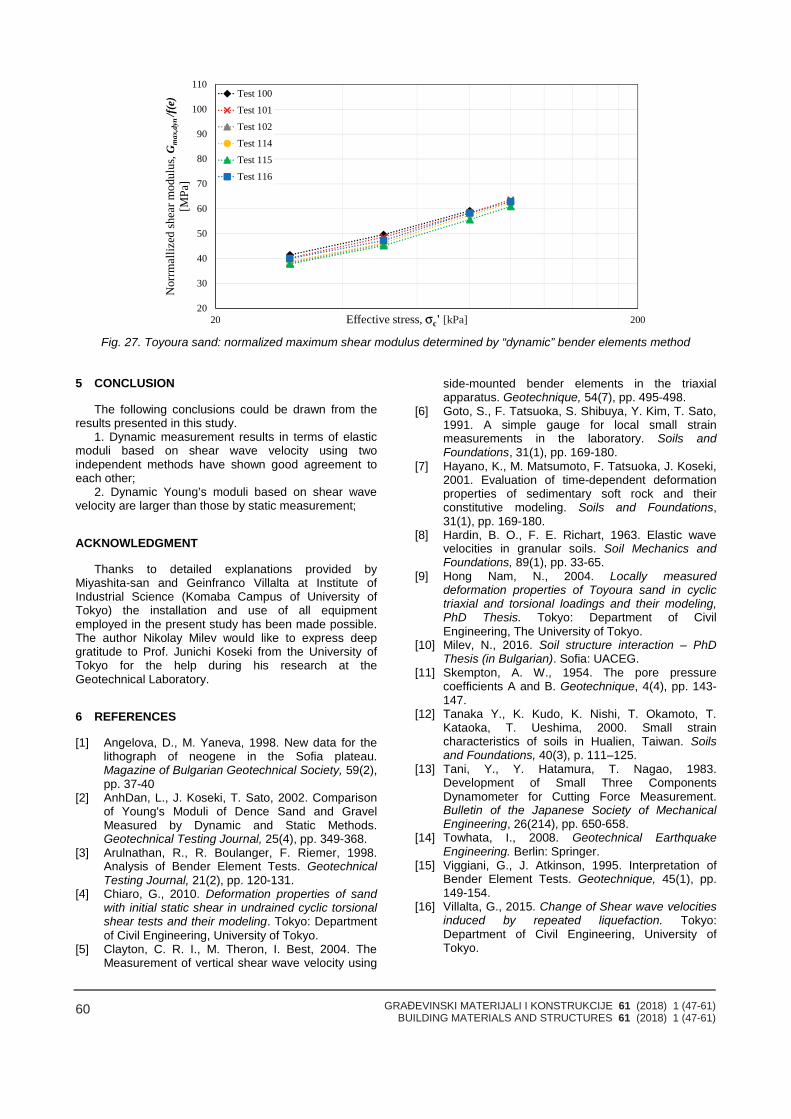
GRAĐEVINSKI MATERIJALI I KONSTRUKCIJE 61 (2018) 1 (47-61)BUILDING MATERIALS AND STRUCTURES 61 (2018) 1 (47-61)
60
20
30
40
50
60
70
80
90
100
110
20 200
Nor
rmal
lized
shea
rmod
ulus
,Gm
ax,d
yn/f(
e)[M
Pa]
Effective stress, σc' [kPa]
Test 100
Test 101
Test 102
Test 114
Test 115
Test 116
Fig. 27. Toyoura sand: normalized maximum shear modulus determined by “dynamic” bender elements method
5 CONCLUSION
The following conclusions could be drawn from theresults presented in this study.
1. Dynamic measurement results in terms of elasticmoduli based on shear wave velocity using twoindependent methods have shown good agreement toeach other;
2. Dynamic Young’s moduli based on shear wavevelocity are larger than those by static measurement;
ACKNOWLEDGMENT
Thanks to detailed explanations provided byMiyashita-san and Geinfranco Villalta at Institute ofIndustrial Science (Komaba Campus of University ofTokyo) the installation and use of all equipmentemployed in the present study has been made possible.The author Nikolay Milev would like to express deepgratitude to Prof. Junichi Koseki from the University ofTokyo for the help during his research at theGeotechnical Laboratory.
6 REFERENCES
[1] Angelova, D., M. Yaneva, 1998. New data for thelithograph of neogene in the Sofia plateau.Magazine of Bulgarian Geotechnical Society, 59(2),pp. 37-40
[2] AnhDan, L., J. Koseki, T. Sato, 2002. Comparisonof Young's Moduli of Dence Sand and GravelMeasured by Dynamic and Static Methods.Geotechnical Testing Journal, 25(4), pp. 349-368.
[3] Arulnathan, R., R. Boulanger, F. Riemer, 1998.Analysis of Bender Element Tests. GeotechnicalTesting Journal, 21(2), pp. 120-131.
[4] Chiaro, G., 2010. Deformation properties of sandwith initial static shear in undrained cyclic torsionalshear tests and their modeling. Tokyo: Departmentof Civil Engineering, University of Tokyo.
[5] Clayton, C. R. I., M. Theron, I. Best, 2004. TheMeasurement of vertical shear wave velocity using
side-mounted bender elements in the triaxialapparatus. Geotechnique, 54(7), pp. 495-498.
[6] Goto, S., F. Tatsuoka, S. Shibuya, Y. Kim, T. Sato,1991. A simple gauge for local small strainmeasurements in the laboratory. Soils andFoundations, 31(1), pp. 169-180.
[7] Hayano, K., M. Matsumoto, F. Tatsuoka, J. Koseki,2001. Evaluation of time-dependent deformationproperties of sedimentary soft rock and theirconstitutive modeling. Soils and Foundations,31(1), pp. 169-180.
[8] Hardin, B. O., F. E. Richart, 1963. Elastic wavevelocities in granular soils. Soil Mechanics andFoundations, 89(1), pp. 33-65.
[9] Hong Nam, N., 2004. Locally measureddeformation properties of Toyoura sand in cyclictriaxial and torsional loadings and their modeling,PhD Thesis. Tokyo: Department of CivilEngineering, The University of Tokyo.
[10] Milev, N., 2016. Soil structure interaction – PhDThesis (in Bulgarian). Sofia: UACEG.
[11] Skempton, A. W., 1954. The pore pressurecoefficients A and B. Geotechnique, 4(4), pp. 143-147.
[12] Tanaka Y., K. Kudo, K. Nishi, T. Okamoto, T.Kataoka, T. Ueshima, 2000. Small straincharacteristics of soils in Hualien, Taiwan. Soilsand Foundations, 40(3), p. 111–125.
[13] Tani, Y., Y. Hatamura, T. Nagao, 1983.Development of Small Three ComponentsDynamometer for Cutting Force Measurement.Bulletin of the Japanese Society of MechanicalEngineering, 26(214), pp. 650-658.
[14] Towhata, I., 2008. Geotechnical EarthquakeEngineering. Berlin: Springer.
[15] Viggiani, G., J. Atkinson, 1995. Interpretation ofBender Element Tests. Geotechnique, 45(1), pp.149-154.
[16] Villalta, G., 2015. Change of Shear wave velocitiesinduced by repeated liquefaction. Tokyo:Department of Civil Engineering, University ofTokyo.
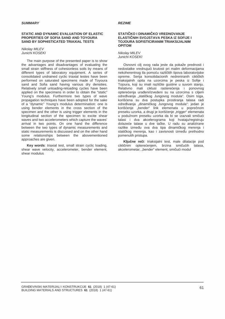
GRAĐEVINSKI MATERIJALI I KONSTRUKCIJE 61 (2018) 1 (47-61)BUILDING MATERIALS AND STRUCTURES 61 (2018) 1 (47-61)
61
SUMMARY
STATIC AND DYNAMIC EVALUATION OF ELASTICPROPERTIES OF SOFIA SAND AND TOYOURASAND BY SOPHISTICATED TRIAXIAL TESTS
Nikolay MILEVJunichi KOSEKI
The main purpose of the presented paper is to showthe advantages and disadvantages of evaluating thesmall strain stiffness of cohesionless soils by means ofdifferent types of laboratory equipment. A series ofconsolidated undrained cyclic triaxial testes have beenperformed on saturated specimens made of Toyourasand and Sofia sand having various dry densities.Relatively small unloading-reloading cycles have beenapplied on the specimens in order to obtain the “static”Young’s modulus. Furthermore two types of wavepropagation techniques have been adopted for the sakeof a “dynamic” Young’s modulus determination: one isusing bender elements in the cross section of thespecimen and the other is using trigger elements in thelongitudinal section of the specimen to excite shearwaves and two accelerometers which capture the waves’arrival in two points. On one hand the differencebetween the two types of dynamic measurements andstatic measurements is discussed and on the other handsome relationships between the abovementionedapproaches are given.
Key words: triaxial test, small strain cyclic loading,shear wave velocity, accelerometer, bender element,shear modulus
REZIME
STATIČKO I DINAMIČKO VREDNOVANJEELASTIČNIH SVOJSTAVA PESKA IZ SOFIJE I TOJOURA SOFISTICIRANIM TRIAKSIJALNIMOPITOM
Nikolay MILEVJunichi KOSEKI
Osnovni cilj ovog rada jeste da pokaže prednosti inedostatke vrednujući krutosti pri malim deformacijamanekoherentnog tla pomoću različitih tipova laboratorijskeopreme. Serija konsolidacionih nedreniranih cikličkihtriaksijalnih opita na uzorcima je peska iz Sofije iTojoura, koji su imali različite gustine u suvom stanju.Relativno mali ciklusi rasterećenja i ponovnogopterećenja urađeni/izvedeni su na uzorcima s ciljemodređivanja „statičkog Jungovog modula“. Osim toga,korišćena su dva postupka prostiranja talasa radiodređivanja „dinamičkog Jungovog modula“: jedan jekorišćenje „bender“ link elemenata u poprečnompreseku uzorka, a drugi je korišćenje „trigger“ elemenatau podužnom preseku uzorka da bi se izazvali smičućitalasi i dva akcelerograma koji hvataju/registrujudolazeće talase u dve tačke. U radu su analiziranerazlike između ova dva tipa dinamičkog merenja istatičkog merenja, kao i zavisnosti između prethodnopomenutih pristupa.
Ključne reči: triaksijalni test, male dilatacije podcikličnim opterećenjem, brzina smičućih talasa,akcelerometar, „bender“ element, smičući modul

GRAĐEVINSKI MATERIJALI I KONSTRUKCIJE 61 (2018) 1 (67-68)BUILDING MATERIALS AND STRUCTURES 61 (2018) 1 (67-68)
62
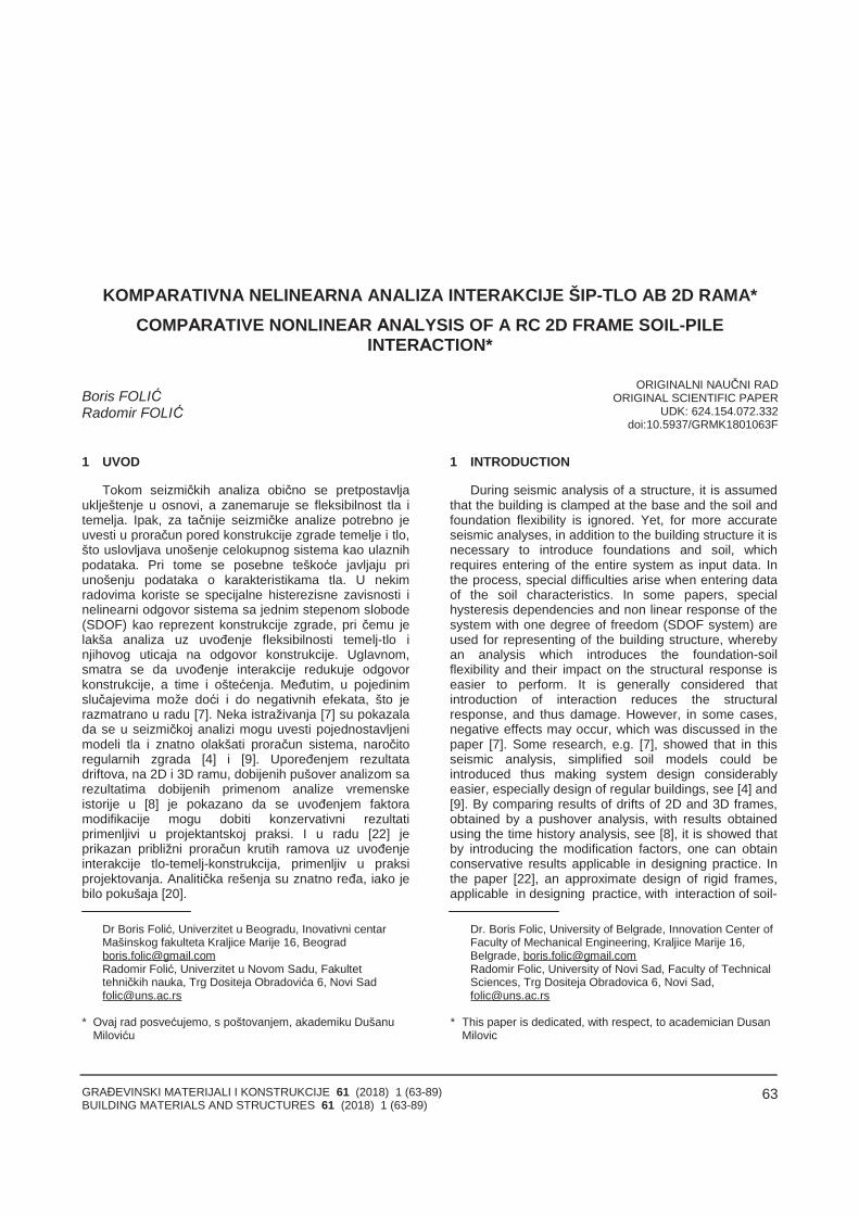
GRAĐEVINSKI MATERIJALI I KONSTRUKCIJE 61 (2018) 1 (63-89)BUILDING MATERIALS AND STRUCTURES 61 (2018) 1 (63-89)
63
KOMPARATIVNA NELINEARNA ANALIZA INTERAKCIJE ŠIP-TLO AB 2D RAMA*COMPАRАTIVE NONLINEАR АNАLYSIS OF A RC 2D FRАME SOIL-PILE
INTERАCTION*
Boris FOLIĆRadomir FOLIĆ
ORIGINALNI NAUČNI RADORIGINAL SCIENTIFIC PAPER
UDK: 624.154.072.332doi:10.5937/GRMK1801063F
1 UVOD
Tokom seizmičkih analiza obično se pretpostavljauklještenje u osnovi, a zanemaruje se fleksibilnost tla itemelja. Ipak, za tačnije seizmičke analize potrebno jeuvesti u proračun pored konstrukcije zgrade temelje i tlo,što uslovljava unošenje celokupnog sistema kao ulaznihpodataka. Pri tome se posebne teškoće javljaju priunošenju podataka o karakteristikama tla. U nekimradovima koriste se specijalne histerezisne zavisnosti inelinearni odgovor sistema sa jednim stepenom slobode(SDOF) kao reprezent konstrukcije zgrade, pri čemu jelakša analiza uz uvođenje fleksibilnosti temelj-tlo injihovog uticaja na odgovor konstrukcije. Uglavnom,smatra se da uvođenje interakcije redukuje odgovorkonstrukcije, a time i oštećenja. Međutim, u pojedinimslučajevima može doći i do negativnih efekata, što jerazmatrano u radu [7]. Neka istraživanja [7] su pokazalada se u seizmičkoj analizi mogu uvesti pojednostavljenimodeli tla i znatno olakšati proračun sistema, naročitoregularnih zgrada [4] i [9]. Upoređenjem rezultatadriftova, na 2D i 3D ramu, dobijenih pušover analizom sarezultatima dobijenih primenom analize vremenskeistorije u [8] je pokazano da se uvođenjem faktoramodifikacije mogu dobiti konzervativni rezultatiprimenljivi u projektantskoj praksi. I u radu [22] jeprikazan približni proračun krutih ramova uz uvođenjeinterakcije tlo-temelj-konstrukcija, primenljiv u praksiprojektovanja. Analitička rešenja su znatno ređa, iako jebilo pokušaja [20].
Dr Boris Folić, Univerzitet u Beogradu, Inovativni centarMašinskog fakulteta Kraljice Marije 16, [email protected] Folić, Univerzitet u Novom Sadu, Fakultettehničkih nauka, Trg Dositeja Obradovića 6, Novi [email protected]
* Ovaj rad posvećujemo, s poštovanjem, akademiku DušanuMiloviću
1 INTRODUCTION
During seismic analysis of a structure, it is assumedthat the building is clamped at the base and the soil andfoundation flexibility is ignored. Yet, for more accurateseismic analyses, in addition to the building structure it isnecessary to introduce foundations and soil, whichrequires entering of the entire system as input data. Inthe process, special difficulties arise when entering dataof the soil characteristics. In some papers, specialhysteresis dependencies and non linear response of thesystem with one degree of freedom (SDOF system) areused for representing of the building structure, wherebyan analysis which introduces the foundation-soilflexibility and their impact on the structural response iseasier to perform. It is generally considered thatintroduction of interaction reduces the structuralresponse, and thus damage. However, in some cases,negative effects may occur, which was discussed in thepaper [7]. Some research, e.g. [7], showed that in thisseismic analysis, simplified soil models could beintroduced thus making system design considerablyeasier, especially design of regular buildings, see [4] and[9]. By comparing results of drifts of 2D and 3D frames,obtained by a pushover analysis, with results obtainedusing the time history analysis, see [8], it is showed thatby introducing the modification factors, one can obtainconservative results applicable in designing practice. Inthe paper [22], an approximate design of rigid frames,applicable in designing practice, with interaction of soil-
Dr. Boris Folic, University of Belgrade, Innovation Center ofFaculty of Mechanical Engineering, Kraljice Marije 16,Belgrade, [email protected] Folic, University of Novi Sad, Faculty of TechnicalSciences, Trg Dositeja Obradovica 6, Novi Sad,[email protected]
* This paper is dedicated, with respect, to academician DusanMilovic
GRAĐEVINSKI MATERIJALI I KONSTRUKCIJE 61 (2018) 1 (63-89)BUILDING MATERIALS AND STRUCTURES 61 (2018) 1 (63-89)
64
Evropska regulativa za seizmičko projektovanje EN1998, Part 1 i Part 5, ne razmatra detaljno problemuvođenja interakcije tlo-temelj-konstrukcija (SFI) unumeričkim seizmičkim analizama. U EN 1998-5 to sezahteva gde P-Δ efekti imaju veliku ulogu; konstrukcijesa masivnim i dubokim temeljima, i konstrukcije naveoma mekom tlu u kojima je prosečna brzina smičućihtalasa manja od 100 m/s [5] i [10]. Razlike seizmičkogponašanja objekata plitko fundiranih i na šipovimadetaljno je opisana u [4] i [5]. U njima je detaljno opisannačin analize kinematičke i inercijalne interakcije prifundiranju na šipovima. Kinematička interakcija potiče odrazlike pokreta tla i temelja ili šipova, tokom zemljotresa,pri čemu se masa zanemaruje. Kod inercijalneinterakcije, pručava se uticaj inercijalnih sila odkonstrukcije na temelje.
U ovom radu je sprovedena komparativna nelinearnastatička (NSA), često nazvana pushover analiza, idinamička analiza NDA, detaljno opisane u [3], na 2Drama AB skeletne zgrade fundirane na šipovima. Umodelu je uključena i linearno-nelinearna interakcije šip-tlo korišćenjem link elemenata. Tlo je modelovano saviše(linijskim) plastičnim veznim elementima, kaoanvelopama u obliku p-y krivih, sa obe strane šipa. P-ykrive prenose (primaju) samo pritisak. Krive p-y sumodelovane prema Koksu, Risu i Matloku [4] i [12] i [19]za potopljen pesak, i šipove prečnika 60 cm. Analiziranesu seizmičke performanse sistema konstrukcija-temelj-tlo jednog 2D rama fundiranog na šipovima. Prikazano jedelimično linearno i nešto detaljnije nelinearnoponašanje krovne grede, dok se ostale grede ramaponašaju nelinearno. Linearna krovna greda je ona kodkoje nisu uvedeni plastični zglobovi u čvorovima napreseku sa unutrašnjim stubovima, ali ni u polju krovnegrede.
2 OPIS KONSTRUKCIJE, TEMELJA I METODAANALIZE
2.1 Analizirana konstrukcija
Analiziran je fasadni ram koji ima četiri stuba, kao iunutrašnji ram. Na fasadnom ramu su ugaoni stub i ivičnistubovi. Ugaoni stubovi fasadnog rama su fundirani nagrupi od 3 šipa, a unutrašnji na grupi od po četiri šipa.Fasadni ram je “kondenzovan”, tako što su svi elementišipova ubačeni putem projekcije upravno na srednjuravan rama. Na taj način se model rama može prikazatiu samo jednoj ravni. Grupa od 3 kružna šipa ima deokoji se sastoji od jednog šipa (1D60), i deo koji se sastojiod dva kondenzovana šipa (2D60) slika 1. Dakle u„kondenzovanom“ modelu od tri šipa unose se samo dvašipa, 1 je samostalan šip, a drugi je dvostruki šip (tj. uravanskom modelu je unet jedan šip kod koga supoprečni preseci FRAME elementa, u programuSAP2000, u delu Set Modifiers, krutost i masapomnoženi sa 2). Shodno tome p-y krive „dvostrukog“šipa imaju dvostruko veću krutost. Objekat ima dverelativno vitke donje etaže. Visina prve dve etaže je po 5metara, ali su zato poprečni preseci stubova na ove dve
foundation-structure, was presented. Analytical solutionsare rare, even though there were attempts, [20].
European regulation for seismic design, EN 1998,Part 1 and Part 5, does not consider in detail theproblem of introducing the soil-foundation-structureinteraction (SFI) in the numerical seismic analyses. InEN 1998-5 it is required where P-Δ effects have animportant role: the structures with massive and deepfoundations, and structures in a very soft soil where theaverage velocity of shear waves is less than 100 m/s,see [5] and [10]. The difference of seismic behaviour ofthe structures founded on shallow foundations and onthe piles was described in detail in [4] and [5]. In them,the method of analysis of kinematic and inertialinteraction of pile foundations was described in detail.
А comparative non-linear static analysis (NSА), oftencalled a pushover analysis, as well as the dynamic non-linear analysis (NDА), described in detail in [3], andapplied on 2D frames of RC skeletal buildings foundedon piles are presented in this paper. The model involvesa linear-non-linear pile-soil interaction, using linkelements. The soil is modelled using multiple (linear)plastic link elements, as envelopes in the form of the p-ycurves, on both sides of the pile. P-y curves aretransferring only compression and are modelledaccording to Cox, Reese and Matlock [4], [12] and [19]for submerged sand, and piles with a diameter 60 cm.The seismic performances of the structure-foundation-soil system of a 2D frame founded on piles are analyzed.Detailed analysis of hierarchy of formation of plastichinges in the frame and piles is presented. A partiallinear and a more detailed non-linear behaviour of a roofbeam are presented, while the remaining beams of theframe behave non-linearly. Linear roof beam is the beamwithout plastic hinges at intersections with inner columnsor along the beam. Kinematic interaction arises fromdifferent motions of the soil and foundation, or piles,during earthquake, while the mass is neglected. Ininertial interaction, the effect of inertial forces from thestructure upon the foundation is considered.
2 DESCRIPTION OF THE STRUCTURE,FOUNDATIONS AND METHODS OF ANALYSIS
2.1 Analyzed structure
A façade frame with four columns and an inner frameare analyzed. On the façade frame, there are cornercolumns and peripheral columns. The corner columns ofthe facade frame are founded using a group of 3 piles,whereas the inner columns are founded on a group offour piles. The façade frame is “condensed” by insertingall pile elements via projection along the directionperpendicular to the frame middle plane. In this way, it ispossible to draw the frame model using only twodimensions. The group of 3 circular piles consists of apart made of one pile (1D60), and another part made oftwo condensed piles (2D60), figure 1. Hence, in this“condensed” model, only two out of three piles areintroduced, one of which is an individual pile, whereasthe other is a double pile (i.e. a single pile wasintroduced to the model, whose Frame element cross-section, stiffness and mass were multiplied by 2), in SАP2000 software, within the Set Modifiers module. Inaccordance with this, the p-y curves of the “double” pile
GRAĐEVINSKI MATERIJALI I KONSTRUKCIJE 61 (2018) 1 (63-89)BUILDING MATERIALS AND STRUCTURES 61 (2018) 1 (63-89)
65
etaže 85/85cm.U seizmičkoj analizi su primenjene nelinearna
statička (NSA), često nazvana pushover, i nelinearnadinamička analiza (NDA), u vremenskom domenu (TimeHistory). S obzirom da se tokom NSA i NDA [3]praktično ne pojavljuju plastični zglobovi u šipovima kodkrućih vrsta tla (osim u specijalnim slučajevima),analizirani su i uticaji u tlu, preko link elemenata podubini, pod seizmičkim dejstvom (TH El Centro 0,30g).Oni na takav način nisu dovoljno obrađeni u dostupnojliteraturi. Analizirana su ekstremna pomeranja, sile,ukupan rad, “trenutni rad”, i raspodela istih po dubini linkelemenata šipa. Analiziran je samo jedan šip iz grupe ito samostalni šip (1D60) iz grupe od tri šipa (1+2, na slici1). To je krajnji šip na obe strane simetričnog rama (vidisliku 1 desno). Konkretno je, u ovom radu, istraživansamo levi krajnji šip. Takođe je analizirana promenaukupne smičuće sile u osnovi sa porastom vršnogubrzanja (PGA), i promena stanja plastičnih zglobova ukonstrukciji i šipovima i u skladu s tom promenomkonstruktivnog sistema, promena prvog i drugogsvojstvenog tona nakon završetka seizmičkog dejstva(Time History).
also have the double value of stiffness. The building hastwo relatively slender lower stories. The height of the firsttwo storeys is 5 meters each, but the cross-sections ofcolumns in these two floors are 85/85 cm.
Seismic analysis is performed using the non-linearstatic analysis (NSA), often called the pushover analysis,and the non-linear dynamic analysis (NDA) in the timedomain (time history). Regarding that during NSA andNDA [3] there is practically no occurrence of plastichinges in the piles for stiffer types of soil (except inspecial cases) the effects in the soil are analyzed too,via link elements along the depth, under a seismic action(TH El Centro 0.30g). They are not sufficiently discussedin the available literature in this way. Extremedisplacements, forces, total work, “instantaneous work”in link elements and their distribution along depth of thepile are analyzed. Only one pile from the group isanalyzed, namely, a single pile (1D60) from the group ofthree piles (1+2, in figure1). These are the end piles onboth sides of the symmetrical frame (see figure 1 right).In this paper specifically, only the left endmost pile isstudied. Also, the variation of the total seismic base-shear force, with the increase of peak acceleration(PGA) is analyzed, and also the variation of condition ofplastic hinges in the structure and the piles, and variationof the first and second natural tones after seismicexcitation (Time History)
Slika 1. Princip „kondenzacije“ grupe od 3 šipa u grupu od 2 šipa u ravni. 1D60 samostalni šip, a 2D60 dvostrukiFigure 1. „Condensation“ principle of a group of 3 piles (1D60 – individual pile, 2D60 – double pile).
Prostorni (3D) ram je dimenzionisan na zemljotresnodejstvo u programu SAP 2000 v14. sa uvođenjemupravnog pravca i torzije (sa 5% ekscentriciteta), zafaktor ponašanja 5.85. Nakon toga je iz takodimenzionisanog modela izdvojen, napred opisani,fasadni 2D ram sa pripadajućim opterećenjem. Rasponramova je 8m, a to je i osno rastojanje stubova, u obapravca. Objekat je dvoosno simetričan. Visina prve dveetaže je po 5m, a ostalih 6 etaža je 3.1 m. Model jesličan modelima datom u [2] i [4]. Razlika je u p-ykrivama koje su u navedenom radu [4] date za šipoveprečnika 1,2m. Takođe, u navedenom radu je dato višerazličitih modela, sa i bez interakcije šip-tlo. Izgled ovdeusvojenog, samo jednog modela rama, je dat u nastavkurada, kod analize stanja plastičnih zglobova. Kod [2], zaizveden objekat, stubovi su svi preseka 60/60cm, aopterećenje je nešto manje.
Izdvajanje 2D rama iz trodimenzionalnog (3D) ramaprati specifična problematika [4] i [8]. Prvi parametar je
The spatial (3D) frame is dimensioned with referenceto earthquake action, using SАP 2000 v14 software,including the effects in the perpendicular direction andtorsion (with 5% eccentricity), for a behaviour factor of5.85. The previously described façade 2D frame with itscorresponding loads is then taken out of a 3D modeldimensioned in this way. The span between frames is8m, which is also the distance between the pile axes, inboth directions, since the structure in question issymmetrical along two orthogonal axes. The height ofthe first two stories is 5m, while for the remaining 6storeys, it is 3.1 m. The model is similar to modelsshown in [2] and [4]. However, the difference is in p-ycurves, which are, in [4], given for piles of diameter1.2m. Also, more different models with and without pile-soil interaction are given in [4]. The geometry of thesingle frame considered here is presented later in thesection where the state of plastic hinges is analysed.Paper [2] is related to built structure, where all columns
GRAĐEVINSKI MATERIJALI I KONSTRUKCIJE 61 (2018) 1 (63-89)BUILDING MATERIALS AND STRUCTURES 61 (2018) 1 (63-89)
66
pripadajuće opterećenje, drugi je geometrija poprečnihpreseka (pre svega) greda, a za dinamičku analizu,neophodno je proveriti i razliku svojstvenih periodaizdvojenog 2D rama u odnosu na 3D model. Poželjno je,proveriti i deformaciju („ugib“) vrha 3D objekta u odnosuna vrh 2D rama. Realnije ponašanje ravanskih modela(kod kojih je izdvojen samo jedan 2D ram), u odnosu naprostorni ram, daju modeli kod kojih je link elementima iliprostim štapovima spregnuto više ramova u 2D modelu[11]. Kao npr. spregnuti fasadni i unutrašnji 2D ram ili 2unutrašnja i 2 fasadna, uz uslov da se spregnuti ramoviu 3D modelu moraju pružati u istom pravcu.
Kod izdvajanja 2D rama, neophodno je proveritiprihvatljivo poklapanje vrednosti normalnih sila ustubovima, i reakcija oslonaca za oba modela. Takođe,kod čvorova gde se sučeljavanju grede iz drugogpravca, može se primeniti komanda Set Modifiers, zauvećanje krutosti poprečnih preseka napregnutih nasavijanje, zbog učešća torzione krutosti drugog pravca.Kod (malih) poprečnih preseka greda i tanjih ploča, kodkojih torziona krutost, brzo opada/degradira se tokomzemljotresa, bolje je uvesti nelinearnu rotacionu oprugu,kojom se simulira ova krutost, ali i pad iste tokomzemljotresa. Često se u seizmičkoj (dinamičkoj i kvazistatičkoj) analizi, zbog smanjenja broja nepoznatihisključuju ploče, i koriste bruto preseci greda, čak i bezpripadajućih aktivnih širina ploča, i bez komandeModifiers. Kako je to na strani sigurnosti, primenjeno je iu ovom radu, za fasadne grede. Uticaj spratnih ploča, naujednačavanje horizontalnih pomeranja spratova, kod2D i kod 3D rama, može se poboljšati komandom Joint -Constraints (Equal).
Gornji čvorovi (u krovnoj ravni) unutrašnjih stubovane zadovoljavaju uslove odnosa krutosti greda i stubova,te je u prvom delu rada, taj deo grede linearizovan,odnosno na tom delu nisu uneti plastični zglobovi. To ćese sagledati, kasnije, u delu analize rezultata. (premestitizarez)
Ukoliko se ne upotrebi preporučena opcija SAPa,automatske podele plastičnih zglobova u linijskimelementima od 0,02, lom greda se događa i na drugomspratu dosta rano, a kasnije i na drugim lokacijama, pase produžava vreme proračuna. Ovaj primer nijeprikazan, iako je i ovakav način loma moguć, ali manjeverovatan, ako je konstrukcija dobro izvedena. Zato je usvim ovde prikazanim modelima, ova opcija primenjena.
Odnos ukupne seizmičke sile u osnovi i ukupne siletežine objekta, kod (regularnog, kvadratnog u osnovi) 3Dmodela, je: 5316 kN/71093 kN= 7,48%. Svojstveniperiodi 3D modela su: T1=T2=2,04 sec, T3=1,47 sec.Prva dva tona su horizontalna-lateralna, a treći jetorzioni-obrtni [4].
are 60/60cm, and the loading is slightly lower.Extraction of a 2D frame from a three-dimensional
(3D) frame is accompanied by specific problems, [4] and[8]. The first parameter is the corresponding load; thesecond is the geometry of cross sections (primarily) ofthe beams, while for a dynamic analysis, it is necessaryto check the difference between the natural periods ofthe extracted 2D frame and the 3D model. It is desirableto check and compare the deformation (horizontaldeflection) of the top of a 3D object in comparison to thetop of the 2D frame. A more realistic behaviour of theplanar models (where only one 2D frame is extractedfrom 3D model), when compared with the spatial frame,is obtained by 2D models where more 2D frames arecombined in one model, using link or truss elements,[11]. For instance, coupled façade and the interior 2Dframe, or 2 interior and 2 façade frames, are examplesof that. Of course, it is assumed that frames are alignedalong the same direction.
When extracting a 2D frame, it is necessary to checkthe acceptable agreement of values of normal forces inthe columns, and the support reactions of both models.Also, in a case of nodes where the beams from anotherdirection are connected, one might use the commandSet Modifiers, in order to increase the bending stiffnessof sections, due to influence of the torsional stiffness inanother direction. In the case of (relatively small) cross-sections of beams and thin slabs, where the torsionalstiffness quickly decreases/degrades during earth-quakes, it is better to introduce a non-linear rotationalspring which simulates this stiffness and its declineduring earthquakes. Very often, in the seismic (dynamicand quasi static) analysis, due to reduction of a numberof unknowns, the slabs are excluded, and gross cross-sections of beams are used, even without the belongingactive widths of the slabs, and without the Modifierscommand. Since it is on the safety side, it is imple-mented in this paper, too, for the façade beams. Theeffects of the floor slabs to unify the horizontal storeydisplacements, in 2D and 3D frames, may be improvedby using the command Joint – Constraints (Equal).
Upper nodes (in the roof) of the inner columns do notmeet the conditions of stiffness ratio of beams andcolumns, so in the first part of the paper this upper beamis linearized, i.e. no plastic hinges are introduced in thisbeam. It will be considered later, in the section of theresult analysis.
Unless the recommended option of SAP,Assign/Frame/Frame Signed Overwrights/Auto Subdi-vide Line Objects at Hinge of 0,02 is used, the failure ofthe beams occurs on the second storey quite early, andlater in other locations as well, so the time of calculationis prolonged. This example is not presented, eventhough such failure mode is quite possible, but unlikely,if the structure is well constructed. For this reason in allthe presented models, this option is implemented.
The ratio of the total base-shear force and the totalforce of the building weight (of a regular, square layout)3D model, is: 5316kN/71093kN= 7.48%. Natural periodsof the 3D model are: T1=T2=2.04 sec, T3=1.47 sec. Thefirst two tones are horizontal-lateral, and the third one istorsional-rotational [4].
GRAĐEVINSKI MATERIJALI I KONSTRUKCIJE 61 (2018) 1 (63-89)BUILDING MATERIALS AND STRUCTURES 61 (2018) 1 (63-89)
67
2.2 Ponašanje i modeliranje tla u zemljotresu
Odgovor na pitanje šta se događa u tlu tokomzemljotresa, zavisi, pre svega, od načina modelovanjatla u sistemu konstrukcija temelj tlo, zatim koji zemljotresi kakav uticaj se konkretno istražuje. Verovatno najboljiodgovor, na ovo pitanje, pruža talasna mehanika, i njenaprimena na numeričke analize korišćenjem Solidelemenata tla. To je posebna problematika, jer uprocesu modelovanja zahteva iznalaženje optimumatokom zadovoljenja često suprotstavljenih uslova.Parametri koje u procesu definisanja modela trebaodrediti su: dimenzije modela konstrukcije, zatim veličinemodela sistema, veličine mreže KE, oblast frekvencije ivrste talasa koji se prostiru, granični problemi, itd. [17].Kod ove metode, važno je u odnosu na veličinukonstrukcije proceniti minimalnu veličinu modela zasistem konstrukcija-temelj-tlo, kako bi vreme proračunabilo što kraće, a da se pri tom adekvatno obuhvate svipotrebni talasni fenomeni. Takođe treba odrediti imaksimalnu veličinu konačnih elemenata tla, koja se nesme prekoračiti kako ne bi došlo do neželjenih talasnihefekata u samim konačnim elementima tla i sl. Ovdećemo se zadržati na korišćenju link elemenata tla (LES),kao Takedina anvelopa eksperimentalno određenih p-ykrivih (ATPY), jer je to jednostavniji model za primenu, teće i odgovor biti zasnovan na istom.
2.3 P-Y krive za šipove u pesku
Tlo se u analizi dinamičke interakcije sistemakonstrukcija-temelj-tlo može predstaviti upotrebommodela različitog stepena složenosti (sofisticiranosti).Uobičajene metode seizmičke analize nelinearnogponašanja konstrukcija su kvazi-statička pušover NSA inelinearna dinamička analiza u vremenskom domenuNDA, kao numerička integracija akcelerograma, tzv.metoda korak po korak (time history, step by step). Pritome su za seizmička dejstva korišćeni akcelerogrami ElCentro, za PGA 0,20; 0,25 i 0,30 g.
Tlo može biti modelovano preko različitih uslovaoslanjanja, konstrukcije ili šipova, kao što je:
linearnih opruga sa jednom čvornom tačkom(spring), koje trpe podjednako i zatezanja i pritisak,
linearnih link elemenata više-linearnih plastičnih link elemenata, koje se
mogu zadati tako, da prenose samo pritisak.Tlo je modelovano preko elemenata veze, tzv. link
elemenata, prema p-y modelu za pesak koji je razvio Risi dr. Reese, Cox, Koop, 1974, i Reese , Sullivan, 1980,citirano prema [15].
Prema [13] verovatno prvi model p-y krivih uveli suMcClelland and Focht (1958), preporučujući proceduruza korelaciju podataka triaksijalnog naponsko-deformacijskog opita sa krivama sila-pomeranje šipa zaodređene dubine, preko očekivanog modula reakcije tla,za svaki sloj tla, po dubini. Riz je prvi prikazao svojkoncept sloma tla oblika klina, koji se javlja blizupovršine tla [19]. Uticaj variranja ulaznih parametara p-ykrivih na odgovor šipa može se sagledati u [12].
2.2 Soil behaviour and its modelling duringearthquakes
The answer to the question what occurs in the soilduring earthquakes depends, primarily on the method ofsoil modelling in the structure-foundation-soil system,and then what earthquake and what effect arespecifically investigated. The best answer to thisquestion is probably provided by the wave mechanics,and its implementation in the numerical analyses usingSolid elements of soil. It is a specific problem, becausein the process of modelling, it requires finding anoptimum for satisfying often confronted conditions. Theparameters which need to be determined in the modeldefinition process are: dimensions of the structuralmodel, system model size, FE mesh size, frequencydomain and types of propagating waves, boundaryissues, etc. [17]. In this method, it is important to assessa minimum size of the model for the structure-foundation-soil system, in order to keep the calculationtime as short as possible, but still to include all thenecessary wave phenomena. Also, the maximum size offinite elements of soil must be determined, which mustnot be exceeded so as to avoid the undesirable waveeffects in the actual finite elements of the soil, etc. Weare discussing here the use of link elements in soil(LES), as Takeda envelopes of experimentally dete-rmined p-y curves (ATPY), because it is a simpler modelfor practical use, so the response will be based on it.
2.3 P-Y curves for piles in sand
Models of different levels of sophistication can beused for presentation of soil in an analysis of thedynamic interaction of a structure-foundation-soilsystem. The usual methods of seismic analysis of non-linear behaviour of structures are the quasi-staticpushover NSA analysis and the non-linear dynamic NDAanalysis in the time domain, as a numerical integration ofaccelerogram, a so-called step-by-step time historymethod. For the seismic action, accelerogram of ElCentro, for PGA of 0.20; 0.25 and 0.30 g are used.
Soil can be modelled using various conditions ofsupport, structure or piles, such as:
Linear single-node springs, which equally resisttension and compression,
Linear link elements Multi-linear plastic link elements which can be set
so that only transfer compression.Soil is modelled using the connection elements, so
called link elements, according to the p-y sand modeldeveloped by Reese et al, Reese, Cox, Koop, 1974, andReese, Sullivan, 1980, cited according to [15] .
According to [13] probably the first model of p-ycurves was introduced by [10], which recommends theprocedure for correlation of data of triaxial stress-straintest with the force-displacement curves of the piles forcertain depths, via the expected soil reaction modulus,for every layer of soil, along the depth. Reese was thefirst to present his concept of wedge-like soil failurewhich occurs close to the soil surface [19]. The influenceof variation of input parameters of p-y curves on the pileresponse can be observed in [12].
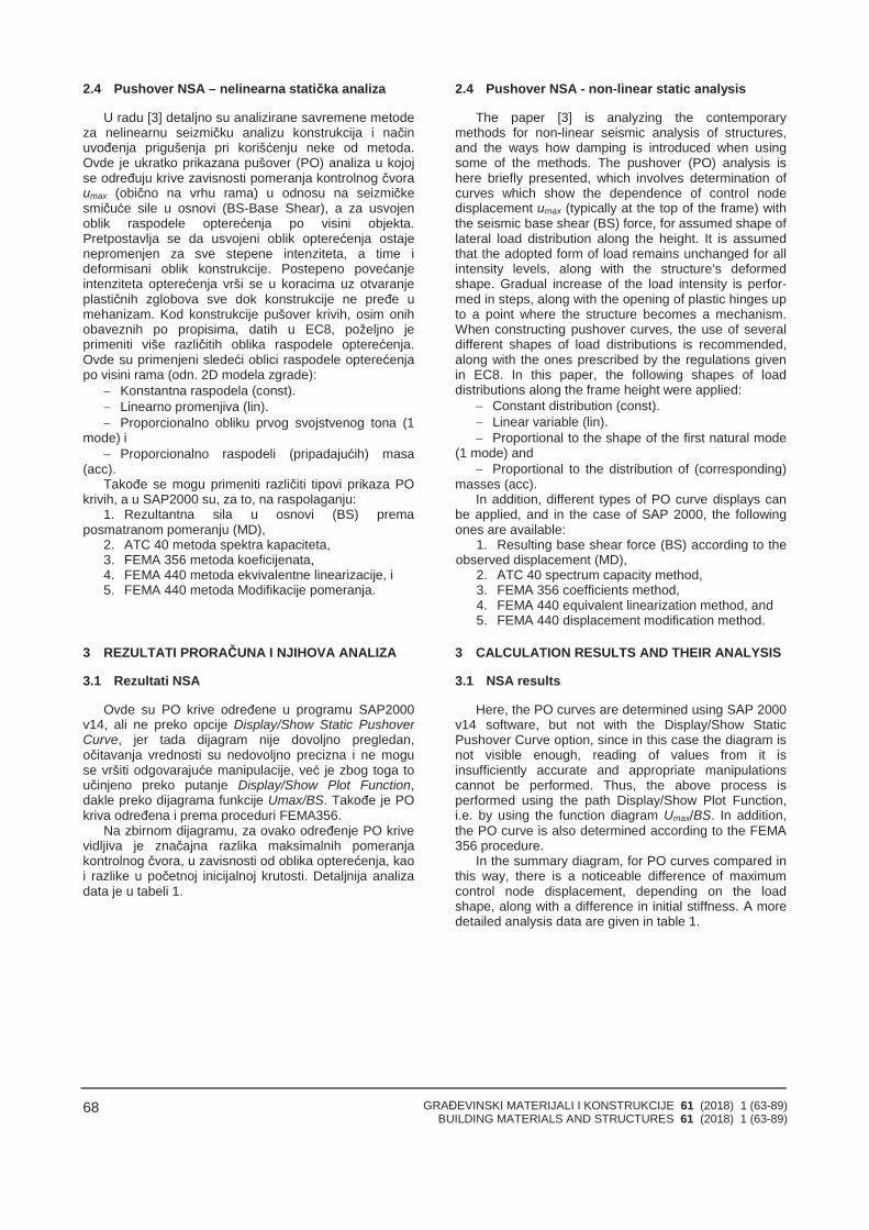
GRAĐEVINSKI MATERIJALI I KONSTRUKCIJE 61 (2018) 1 (63-89)BUILDING MATERIALS AND STRUCTURES 61 (2018) 1 (63-89)
68
2.4 Pushover NSA – nelinearna statička analiza
U radu [3] detaljno su analizirane savremene metodeza nelinearnu seizmičku analizu konstrukcija i načinuvođenja prigušenja pri korišćenju neke od metoda.Ovde je ukratko prikazana pušover (PO) analiza u kojojse određuju krive zavisnosti pomeranja kontrolnog čvoraumax (obično na vrhu rama) u odnosu na seizmičkesmičuće sile u osnovi (BS-Base Shear), a za usvojenoblik raspodele opterećenja po visini objekta.Pretpostavlja se da usvojeni oblik opterećenja ostajenepromenjen za sve stepene intenziteta, a time ideformisani oblik konstrukcije. Postepeno povećanjeintenziteta opterećenja vrši se u koracima uz otvaranjeplastičnih zglobova sve dok konstrukcije ne pređe umehanizam. Kod konstrukcije pušover krivih, osim onihobaveznih po propisima, datih u EC8, poželjno jeprimeniti više različitih oblika raspodele opterećenja.Ovde su primenjeni sledeći oblici raspodele opterećenjapo visini rama (odn. 2D modela zgrade):
Konstantna raspodela (const). Linearno promenjiva (lin). Proporcionalno obliku prvog svojstvenog tona (1
mode) i Proporcionalno raspodeli (pripadajućih) masa
(acc).Takođe se mogu primeniti različiti tipovi prikaza PO
krivih, a u SAP2000 su, za to, na raspolaganju:1. Rezultantna sila u osnovi (BS) prema
posmatranom pomeranju (MD),2. ATC 40 metoda spektra kapaciteta,3. FEMA 356 metoda koeficijenata,4. FEMA 440 metoda ekvivalentne linearizacije, i5. FEMA 440 metoda Modifikacije pomeranja.
3 REZULTATI PRORAČUNA I NJIHOVA ANALIZA
3.1 Rezultati NSA
Ovde su PO krive određene u programu SAP2000v14, ali ne preko opcije Display/Show Static PushoverCurve, jer tada dijagram nije dovoljno pregledan,očitavanja vrednosti su nedovoljno precizna i ne moguse vršiti odgovarajuće manipulacije, već je zbog toga toučinjeno preko putanje Display/Show Plot Function,dakle preko dijagrama funkcije Umax/BS. Takođe je POkriva određena i prema proceduri FEMA356.
Na zbirnom dijagramu, za ovako određenje PO krivevidljiva je značajna razlika maksimalnih pomeranjakontrolnog čvora, u zavisnosti od oblika opterećenja, kaoi razlike u početnoj inicijalnoj krutosti. Detaljnija analizadata je u tabeli 1.
2.4 Pushover NSA - non-lineаr stаtic аnаlysis
The paper [3] is analyzing the contemporarymethods for non-linear seismic analysis of structures,and the ways how damping is introduced when usingsome of the methods. The pushover (PO) analysis ishere briefly presented, which involves determination ofcurves which show the dependence of control nodedisplacement umax (typically at the top of the frame) withthe seismic base shear (BS) force, for assumed shape oflateral load distribution along the height. It is assumedthat the adopted form of load remains unchanged for allintensity levels, along with the structure’s deformedshape. Gradual increase of the load intensity is perfor-med in steps, along with the opening of plastic hinges upto a point where the structure becomes a mechanism.When constructing pushover curves, the use of severaldifferent shapes of load distributions is recommended,along with the ones prescribed by the regulations givenin EC8. In this paper, the following shapes of loaddistributions along the frame height were applied:
Constant distribution (const). Linear variable (lin). Proportional to the shape of the first natural mode
(1 mode) and Proportional to the distribution of (corresponding)
masses (acc).In addition, different types of PO curve displays can
be applied, and in the case of SАP 2000, the followingones are available:
1. Resulting base shear force (BS) according to theobserved displacement (MD),
2. АTC 40 spectrum capacity method,3. FEMА 356 coefficients method,4. FEMА 440 equivalent linearization method, and5. FEMА 440 displacement modification method.
3 CALCULATION RESULTS AND THEIR ANALYSIS
3.1 NSA results
Here, the PO curves are determined using SАP 2000v14 software, but not with the Display/Show StaticPushover Curve option, since in this case the diagram isnot visible enough, reading of values from it isinsufficiently accurate and appropriate manipulationscannot be performed. Thus, the above process isperformed using the path Display/Show Plot Function,i.e. by using the function diagram Umax/BS. In addition,the PO curve is also determined according to the FEMА356 procedure.
In the summary diagram, for PO curves compared inthis way, there is a noticeable difference of maximumcontrol node displacement, depending on the loadshape, along with a difference in initial stiffness. А moredetailed analysis data are given in table 1.
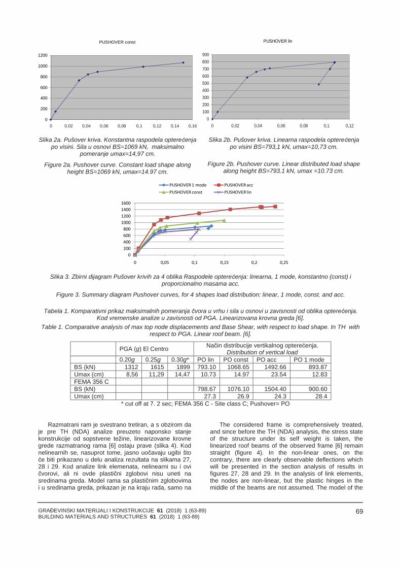
GRAĐEVINSKI MATERIJALI I KONSTRUKCIJE 61 (2018) 1 (63-89)BUILDING MATERIALS AND STRUCTURES 61 (2018) 1 (63-89)
69
PUSHOVER const
0
200
400
600
800
1000
1200
0 0,02 0,04 0,06 0,08 0,1 0,12 0,14 0,16
PUSHOVER lin
0100200300400500600700800900
0 0,02 0,04 0,06 0,08 0,1 0,12
Slika 2a. Pušover kriva. Konstantna raspodela opterećenjapo visini. Sila u osnovi BS=1069 kN, maksimalno
pomeranje umax=14,97 cm.
Figure 2a. Pushover curve. Constant load shape alongheight BS=1069 kN, umax=14.97 cm.
Slika 2b. Pušover kriva. Linearna raspodela opterećenjapo visini BS=793,1 kN, umax=10,73 cm.
Figure 2b. Pushover curve. Linear distributed load shapealong height BS=793.1 kN, umax =10.73 cm.
Slika 3. Zbirni dijagram Pušover krivih za 4 oblika Raspodele opterećenja: linearna, 1 mode, konstantno (const) iproporcionalno masama acc.
Figure 3. Summary diagram Pushover curves, for 4 shapes load distribution: linear, 1 mode, const. and acc.
Tabela 1. Komparativni prikaz maksimalnih pomeranja čvora u vrhu i sila u osnovi u zavisnosti od oblika opterećenja.Kod vremenske analize u zavisnosti od PGA. Linearizovana krovna greda [6].
Table 1. Comparative analysis of max top node displacements and Base Shear, with respect to load shape. In TH withrespect to PGA. Linear roof beam. [6].
PGA (g) El Centro Način distribucije vertikalnog opterećenja.Distribution of vertical load
0.20g 0.25g 0.30g* PO lin PO const PO acc PO 1 modeBS (kN) 1312 1615 1899 793.10 1068.65 1492.66 893.87Umax (cm) 8,56 11,29 14,47 10.73 14.97 23.54 12.83FEMA 356 CBS (kN) 798.67 1076.10 1504.40 900.60Umax (cm) 27.3 26.9 24.3 28.4
* cut off at 7. 2 sec; FEMA 356 C - Site class C; Pushover= PO
Razmatrani ram je svestrano tretiran, a s obzirom daje pre TH (NDA) analize preuzeto naponsko stanjekonstrukcije od sopstvene težine, linearizovane krovnegrede razmatranog rama [6] ostaju prave (slika 4). Kodnelinearnih se, nasuprot tome, jasno uočavaju ugibi štoće biti prikazano u delu analiza rezultata na slikama 27,28 i 29. Kod analize link elemenata, nelinearni su i ovičvorovi, ali ni ovde plastični zglobovi nisu uneti nasredinama greda. Model rama sa plastičnim zglobovimai u sredinama greda, prikazan je na kraju rada, samo na
The considered frame is comprehensively treated,and since before the TH (NDA) analysis, the stress stateof the structure under its self weight is taken, thelinearized roof beams of the observed frame [6] remainstraight (figure 4). In the non-linear ones, on thecontrary, there are clearly observable deflections whichwill be presented in the section analysis of results infigures 27, 28 and 29. In the analysis of link elements,the nodes are non-linear, but the plastic hinges in themiddle of the beams are not assumed. The model of the
GRAĐEVINSKI MATERIJALI I KONSTRUKCIJE 61 (2018) 1 (63-89)BUILDING MATERIALS AND STRUCTURES 61 (2018) 1 (63-89)
70
slici 31, uz kratak osvrt na problematiku istog.Nelinearna dinamička analiza, urađena je za
akcelerogram El Centro za vršne vrednosti PGA od 0.20,0.25 i 0.30 g. Razmatrano je pomeranje čvora u vrhu iukupne seizmicke sile u osnovi. Proveravana su stanjaplastičnih zglobova (loma) na kraju svakog zemljotresa.
frame with plastic hinges in the middle of beams as well,is presented at the end of the paper, in figure 31 only,with a short comment on the issue.
Non-linear dynamic analysis is performed for the ElCentro ground motion record, for peak PGА values 0.20,0.25 and 0.30 g. Node displacements at the top and theseismic base shear are considered. The states of plastichinges (failure) are checked at the end of eachearthquake.
Slika 4. Stanje plastičnih zglobova PHS na kraju zemljotresa El Centro, levo PGA 0,20g PHS: 79Y, 19 IO,desno PGA 0,25g PHS: 71Y, 25 IO i 2 LS. Linearna krovna greda
Figure 4. State of plastic hinges (PHS) at the end earthquake ElCentro, left PGA 0.20g PHS: 79Y, 19 IO,right PGA 0.25g PHS: 71Y, 25 IO and 2 LS. Linear roof beams
Slika 5. Dijagram pomeranja čvora u vrhu zgrade tokom akcelerograma El Centro levo PGA 0,20g, Umax=8,56cm,desno PGA 0,25g, Umax =11,29 cm. Linearna krovna greda.
Figure 5. Displacement plot of the joint at the top of the building, due earthquake acc. El Centro: left PGA 0.20g, Umax=8.56cm, right PGA 0.25g, Umax =11.29 cm Linear roof beams.
Koeficijent proporcionalnosti i za sile i za pomeranja,kod prelaska sistema sa više stepeni slobode kretanja,(MDOF) na sistem sa jednim stepenom slobode (SDOF),je:
The proportionality coefficient, both for the forcesand for displacements, during transition from a mulltidegree of freedom system (MDOF) to a single degree offreedom system (SDOF) is:
22*1
iiii
iiT
T
mm
m
mmm
(1)
GRAĐEVINSKI MATERIJALI I KONSTRUKCIJE 61 (2018) 1 (63-89)BUILDING MATERIALS AND STRUCTURES 61 (2018) 1 (63-89)
71
3.2 Driftovi stubova za različite vrednosti PGA
Sa nelinearnom (NL) krovnom gredom i celim NL 2Dramom, sračunate su ekstremne vrednosti drifta stubovai njihova promena tokom dejstva akcelerograma ElCentro, za PGA 0,20; 0,25 i 0,30 g.
3.2 Column drifts for different values of PGA
For the non-linear roof beam, and entire 2D frame,the extreme values of column drift and their variationduring action of accelerogram of El Centro, for PGA of0.20; 0.25 and 0.30 g, are calculated.
extreme Drift Floor ElCentro 0,20g
0
2
4
6
8
10
1 1,5 2 2,5 3 3,5 4 4,5
Local Drift (‰)
Floo
rnum
ber
Slika 6a. Ekstremni spratni drift (stuba) El Centro 0,20g. Prekoračuje dozvoljene vrednostiFigure 6a. El Centro 0.20g. Extreme Local Drift (column) exceeds permissible values
extreme Drift Floor ElCentro 0,25g
0
2
4
6
8
10
1 1,5 2 2,5 3 3,5 4 4,5 5
Local Drift (‰)
Floo
rnum
ber
Slika 6b Ekstremni spratni drift (stuba) El Centro 0,25g. Prekoračuje dozvoljene vrednostiFigure 6b El Centro 0.25g. Extreme Local Drift (column) exceeds permissible values
extreme Drift Floor ElCentro 0,30g
0
2
4
6
8
10
1 1,5 2 2,5 3 3,5 4 4,5 5 5,5 6
Local Drift (‰)
Floo
rnum
ber
Slika 6c. Ekstremni spratni drift (stuba) El Centro 0,30g Prekoračuje dozvoljene vrednostiFigure 6c. El Centro 0.30g. Extreme Local Drift (column) exceeds permissible values
Slika 6c se razlikuje po obliku u odnosu na 6a i 6b,za PGA 0,20 i 0,25g.
3.3 P-y krive
P-y kriva (slika 7) se sastoji iz 4 dela, prvi linearni odkoordinatnog početka do tačke k, drugi eksponencijalnideo od k do m, i treći deo je druga linearna funkcija od mdo u, a posle tačke u, p-y kriva je konstantna prava.
Koeficijenti redukcije (slika 8) A i B zavise od vrsteopterećenja, a za dinamičku analizu koriste se krivecikličnog opterećenja. Koeficijenti A i B su dati na
Figure 6c, is different in shape from Figs. 6a and 6b,which are given for PGA 0.20 and 0.25g.
3.3 P-y curves
P-y curve (Fig. 7) consists of 4 parts: the first is linearfrom the coordinate beginning till the point u, the secondis exponential part from k to m, the third is the secondlinear function from m to u, while after the point u, p-yline remains constant.
Reduction coefficients A and B (Fig. 8) depend onthe type of the load, and for dynamic analysis, the
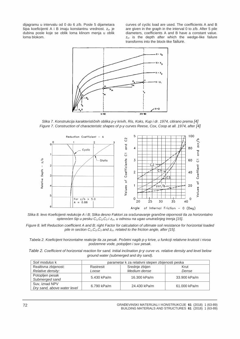
GRAĐEVINSKI MATERIJALI I KONSTRUKCIJE 61 (2018) 1 (63-89)BUILDING MATERIALS AND STRUCTURES 61 (2018) 1 (63-89)
72
dijagramu u intervalu od 0 do 6 z/b. Posle 5 dijametarašipa koeficijenti A i B imaju konstantnu vrednost. zcr jedubina posle koje se oblik loma klinom menja u oblikloma blokom.
curves of cyclic load are used. The coefficients A and Bare given in the graph in the interval 0 to z/b. After 5 pilediameters, coefficients A and B have a constant value.zcr is the depth after which the wedge-like failuretransforms into the block-like failure.
Slika 7. Konstrukcija karakterističnih oblika p-y krivih, Ris, Koks, Kup i dr. 1974, citirano prema [4]Figure 7. Construction of characteristic shapes of p-y curves Reese, Cox, Coop at all. 1974, after [4]
Slika 8. levo Koeficijenti redukcije A i B; Slika desno Faktori za sračunavanje granične otpornosti tla za horizontalnoopterećen šip u pesku C1,C2,C3 i zcr, u odnosu na ugao unutrašnjeg trenja [15].
Figure 8. left Reduction coefficient A and B; right Factor for calculation of ultimate soil resistance for horizontal loadedpile in section C1,C2,C3 and zcr, related to the friction angle, after [15].
Tabela 2. Koeficijent horizontalne reakcije tla za pesak. Početni nagib p-y krive, u funkciji relativne krutosti i nivoapodzemne vode, potopljen i suv pesak.
Table 2. Coefficient of horizontal reaction for sand. Initial inclination p-y curve vs. relative density and level belowground water (submerged and dry sand).
Soil modulus k parametar k za relativni stepen zbijenosti peskaRealtivna zbijenost:Relative density:
RastresitLoose
Srednje zbijenMedium dense
KrutDense
Potopljen pesakSubmerged sand 5.430 kPa/m 16.300 kPa/m 33.900 kPa/m
Suv, iznad NPVDry sand, above water level 6.790 kPa/m 24.430 kPa/m 61.000 kPa/m
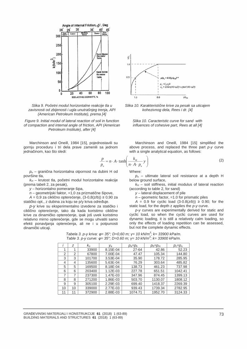
GRAĐEVINSKI MATERIJALI I KONSTRUKCIJE 61 (2018) 1 (63-89)BUILDING MATERIALS AND STRUCTURES 61 (2018) 1 (63-89)
73
Slika 9. Početni modul horizontalne reakcije tla uzavisnosti od zbijenosti i ugla unutrašnjeg trenja, API
(American Petroleum Institute), prema [4]
Figure 9. Initial modul of lateral reaction of soil in functionof compaction and internal angle of friction, API (American
Petroleum Institute), after [4]
Slika 10. Karakteristične krive za pesak sa uticajemkohezivnog dela, Rees i dr. [4]
Slika 10. Caracteristic curve for sand withinfluences of cohesive part, Rees at all [4]
Marchinson and Oneill, 1984 [15], pojednostavili sugornju proceduru i tri dela prave zamenili sa jednomjednačinom, kao što sledi:
Marchinson and Oneill, 1984 [15] simplified theabove process, and replaced the three part p-y curvewith a single analytical equation, as follows:
ypAn
kAnpp
u
H
u
tanh (2)
pu – granična horizontalna otpornost na dubini H odpovršine tla,
kH – krutost tla, početni modul horizontalne reakcije(prema tabeli 2, za pesak),
y – horizontalno pomeranje šipa,n – geometrijski faktor, =1,0 za prizmatične šipove,A = 0,9 za ciklično opterećenje, (3-0,8(z/b)) ≥ 0,90 za
statičko opt., z dubina za koju se p/y kriva određuje.p-y krive su eksperimentalno izvedene za statičko i
ciklično opterećenje, tako da kada koristimo cikličnekrive za dinamičko opterećenje, ipak još uvek koristimorelativno mirno opterećenje, gde se mogu uhvatiti samoefekti ponavljanja opterećenja, ali ne i u potpunostidinamički uticaji.
Where:pu – ultimate lateral soil resistance at a depth H
below ground surface,kH – soil stiffness, initial modulus of lateral reaction
(according to table 2, for sand)y – lateral displacement of pilen – geometric factor, =1.0 for prismatic pilesA = 0.9 for cyclic load (3-0.8(z/b)) ≥ 0.90; for the
static load, for the depth z applies the p-y curve.p-y curves are experimentally derived for static and
cyclic load, so when the cyclic curves are used fordynamic loading, it is still a relatively calm loading, soonly the effects of loading repetition can be assessed,but not the complete dynamic effects.
Tabela 3. p-y kriva: φ= 35°; D=0,60 m; γ= 10 kN/m3; k= 33900 kPa/m.Table 3. p-y curve: φ= 35°; D=0.60 m; γ= 10 kN/m3; k= 33900 kPa/m.
i z ko ya pa=pk pb=pm pc=pu1 1 33900 8.15E-04 27-64 42.86 52.232 2 67800 7.00E-04 47.47 105.34 144.803 3 101700 3.53E-04 35.90 178.72 285.954 4 135600 5.63E-04 76.29 303.64 485.825 5 169500 8.18E-04 138.73 461.23 737.986 6 203400 1.12E-03 227.78 651.51 1042.417 7 237300 1.47E-03 347.96 874.45 1399.138 8 271200 1.86E-03 503.70 1130.07 1808.129 9 305100 2.29E-03 699.40 1418.37 2269.39
10 10 339000 2.77E-03 939.43 1739.34 2782.9511 11 372900 2.88E-03 1074.71 1952.70 3124.33
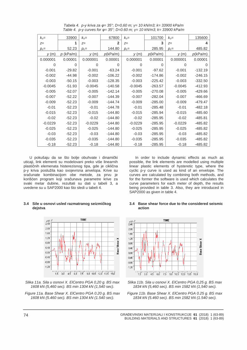
GRAĐEVINSKI MATERIJALI I KONSTRUKCIJE 61 (2018) 1 (63-89)BUILDING MATERIALS AND STRUCTURES 61 (2018) 1 (63-89)
74
Tabela 4. p-y kriva za φ= 35°; D=0,60 m; γ= 10 kN/m3; k= 33900 kPa/mTable 4. p-y curves for φ= 35°; D=0.60 m; γ= 10 kN/m3; k= 33900 kPa/m
ko= 33900 ko= 67800 ko= 101700 ko= 135600z= 1 z= 2 z= 3 z= 4pc= 52.23 pc= 144.80 pc= 285.95 pc= 485.82
y (m) p (kPa/m) y (m) p(kPa/m) y (m) p(kPa/m) y (m) p(kPa/m)0.000001 0.00001 0.000001 0.00001 0.000001 0.00001 0.000001 0.00001
0 0 0 0 0 0 0 0-0.001 -29.82 -0.001 -63.24 -0.001 -97.62 -0.001 -132.19-0.002 -44.98 -0.002 -106.22 -0.002 -174.86 -0.002 -246.15-0.003 -50.15 -0.003 -128.35 -0.003 -225.42 -0.003 -332.50
-0.0045 -51.93 -0.0045 -140.58 -0.0045 -263.57 -0.0045 -412.93-0.005 -52.07 -0.005 -142.14 -0.005 -270.08 -0.005 -429.66-0.007 -52.22 -0.007 -144.39 -0.007 -282.04 -0.007 -466.69-0.009 -52.23 -0.009 -144.74 -0.009 -285.00 -0.009 -479.47
-0.01 -52.23 -0.01 -144.78 -0.01 -285.48 -0.01 -482.18-0.015 -52.23 -0.015 -144.80 -0.015 -285.94 -0.015 -485.60
-0.02 -52.23 -0.02 -144.80 -0.02 -285.95 -0.02 -485.81-0.0229 -52.23 -0.0229 -144.80 -0.0229 -285.95 -0.0229 -485.82-0.025 -52.23 -0.025 -144.80 -0.025 -285.95 -0.025 -485.82
-0.03 -52.23 -0.03 -144.80 -0.03 -285.95 -0.03 -485.82-0.035 -52.23 -0.035 -144.80 -0.035 -285.95 -0.035 -485.82
-0.18 -52.23 -0.18 -144.80 -0.18 -285.95 -0.18 -485.82
U pokušaju da se što bolje obuhvate i dinamičkiuticaji, link elementi su modelovani preko više linearnihplastičnih elemenata histerezisnog tipa, gde je cikličnap-y kriva poslužila kao svojevrsna anvelopa. Krive susračunate kombinacijom obe metode, za prvu jekorišćen program koji sračunava parametre krive zasvaki metar dubine, rezultati su dati u tabeli 3, auvedene su u SAP2000 kao što sledi u tabeli 4.
3.4 Sile u osnovi usled razmatranog seizmičkogdejstva
In order to include dynamic effects as much aspossible, the link elements are modelled using multiplelinear plastic elements of hysteretic type, where thecyclic p-y curve is used as kind of an envelope. Thecurves are calculated by combining both methods, andfor the former the software is used which calculates thecurve parameters for each meter of depth, the resultsbeing provided in table 3. Also, they are introduced inSAP2000 as given in table 4.
3.4 Base shear force due to the considered seismicaction
Slika 11a. Sila u osnovi X. ElCentro PGA 0,20 g. BS max1608 kN (5,460 sec). BS min 1304 kN (1,540 sec).
Figure 11a. Base Shear X. ElCentro PGA 0.20 g. BS max1608 kN (5.460 sec). BS min 1304 kN (1.540 sec).
Slika 11b. Sila u osnovi X. ElCentro PGA 0,25 g. BS max1834 kN (5,460 sec). BS min 1582 kN (1,540 sec).
Figure 11b. Base Shear X. ElCentro PGA 0.25 g. BS max1834 kN (5.460 sec). BS min 1582 kN (1.540 sec).
GRAĐEVINSKI MATERIJALI I KONSTRUKCIJE 61 (2018) 1 (63-89)BUILDING MATERIALS AND STRUCTURES 61 (2018) 1 (63-89)
75
Slika 11c. Sila u osnovi X. ElCentro PGA 0,30 g. BS max 2114 kN (2,720 sec). BS min 1854 kN (1,540 sec)Figure11c. Base Shear X. ElCentro PGA 0.30 g. BS max 2114 kN (2.720 sec). BS min 1854 kN (1.540 sec)
Sva tri grafika sila u osnovi su vrlo slična. Međutimprimećuje se da je vršna vrednost maksimuma za 0,30g,pomerena sa 5,46 sec na 2,72 sec. Prema istraživanjima[18], kod analize uticaja akcelerograma, nije bitno samovršno ubrzanje tla PGA, već je neophodno posmatrati ineposrednu okolinu, i uočiti na koji način je maksimumspregnut sa susednim ekstremima. To se ovdeprimenjuje i kod sile u osnovi.
All three graphs of the BS forces are basically verysimilar. However it can be observed that the peak valuefor 0,30g, changes from 5.46 sec to 2.72 sec. Accordingto the research [18], during the accelerogram (i.e. timehistory) analysis, not only peak ground acceleration(PGA) is important, but it is necessary to observe theimmediate surroundings of the peak, and find out inwhich way the peak is related to the adjacent peaks. It isimplemented here for the Base Shear force.
Tabela 5. Zavisnost sile u osnovi i PGA(g). Trenutak max i min.Table 5. Variation of base shear force with respect to PGA (g). Instances of max and min
ElCentro Base Shear Base Shear t max t minPGA (g) max (kN) min (kN) (sec) (sec)
0.20 1608 1304 5.460 1.5400.25 1834 1582 5.460 1.5400.30 2114 1854 2.720 1.540
3.5 Uticaji u link elementima iz NDA (TH) za dejstvo„El Centro“ i preko rada
Kao rezultat ove analize na sl. 12 prikazani sudijagrami pomeranja i sila spregnutih parova linkelemenata 1 i 2 (dubina 1 m), za PGA 0.20g. Ovi uparenielementi su spregnuti u istom čvoru šipa.
3.5 Effects in the link elements from NDA (TH)action of „El Centro“ and via the work
As a result of this analysis Fig. 12 presentsdisplacement and force diagrams of coupled linkelements 1 and 2 (depth 1 m), for PGA 0,20g. Coupledlink elements are related to the same node.
Slika 12a. Link 1 i 2, nivo -1,0 m. PGA 0,20g El CentroNDA. Pomeranje: max 0,201cm. min 0,194 cm
Figure 12a. Link1 and 2, level -1,0 m. PGA 0,20g ElCentro NDA. Displacement: max 0.201cm. Min0.194 cm 0.201cm. min 0.194 cm.
Slika 12b. Link 1 i 2, nivo -1,0 m. PGA 0,20g El CentroNDA. Sila. max 45,88 kN
Figure 12b. Link 1 and 2, level -1.0 m. PGA 0.20g ElCentro NDA. Force. max 45.88 kN
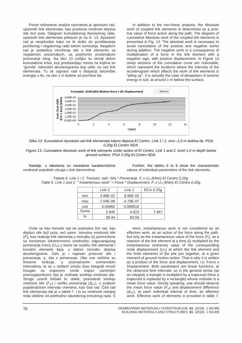
GRAĐEVINSKI MATERIJALI I KONSTRUKCIJE 61 (2018) 1 (63-89)BUILDING MATERIALS AND STRUCTURES 61 (2018) 1 (63-89)
76
Pored nelinearne analize razmatran je apsolutni rad,uparenih link elemenata, kao pozitivna vrednost dejstvasile duž puta. Dijagram kumulativnog Apsolutnog rada,uparenih link elemenata prikazan je na sl. 13. Apsolutnirad je neophodan kako ne bi došlo do poništavanjapozitivnog i negativnog rada tokom sumiranja. Negativnirad je posledica množenja sile u link elementu sanegativnim predznakom, sa pozitivnim predznakompomeranja istog. Na slici 13 uočljivi su strmiji delovikumulativne krive, koji predstavljaju mesta na kojima se“gomila” intenzitet akcelerograma koji utiče na rad linkelemenata. Tu se zapravo radi o disipaciji seizmičkeenergije u tlu, na oko 1 m dubine od površine tla.
In addition to the non-linear analysis, the Absolutework of coupled link elements is determined as a posi-tive value of force action along the path. The diagram ofcumulative Absolute work of the coupled link elements ispresented in Fig. 13. The absolute work is necessary toavoid cancelation of the positive and negative worksduring addition. The negative work is a consequence ofmultiplication of a force in the link element with anegative sign, with positive displacement. In Figure 13steep sections of the cumulative curve are noticeable,which represent the locations where the intensity of theaccelerogram which affects the work of link elements is“piling up”. It is actually the case of dissipation of seismicenergy in soil, at around 1 m bellow the surface.
Kumulativ. SUM |ABS Medium force x dif. Displacement|
0,00E+001,00E-012,00E-013,00E-014,00E-015,00E-016,00E-01
0 2 4 6 8 10 12 14
t (sec)
kum
.Sum
AB
S|F
srxΔ
U1|
(kN
m)
Series1
Slika 13. Kumulativni Apsolutni rad link elemenata tokom dejstva El Centro. Link 1 i 2, nivo -1,0 m dubina tla. PGA0,20g ELCentro NDA.
Figure 13. Cumulative Absolute work of link elements under action of El Centro. Link 1 and 2, level 1,0 m depth belowground surface. PGA 0.20g ELCentro NDA.
Nadalje, u tabelama su navedene karakterističnevrednosti pojedinih uticaja u link elementima.
Further, the tables 6 to 9 show the characteristicvalues of individual parameters of the link elements.
Tabela 6. Link 1 i 2 Trenutni rad= Sila * Pomeranje Fi x U1i (kNm) El Centro 0,20g.Table 6. Link 1 and 2 “ Instantenous work“ = Force * Displacement Fi x U1i (kNm) El Centro 0.20g.
Link 2 Link 1 ElCe 0.20gmin 4.98E-02 8.90E-02max -7.04E-08 -4.79E-07extr 0.04982 0.089016
Suma 2.945 4.522 7.467% 39.44 60.56
Ovde se kao trenutni rad ne posmatra čist rad, kaodejstvo sile duž puta, već samo trenutna vrednosti sile(Fi), kao reakcije link elementa u trenutku (ti) pomnoženesa trenutnom (ekstremnom) vrednošću odgovarajućegpomeranja čvora (U1i) u kome se sustiču link elemenat ikonačni elementi šipa, u datom trenutku dejstvaakcelerograma. Zato je i napisan proizvod sile ipomeranja, tj. sila x pomeranje. Obe ove veličine sulinearne funkcije, u posmatranim vremenskimintervalima, te se u opštem smislu (kao integral) množitrougao sa trapezom (ovde trapez zamenjenpravougaonikom) čija je ordinata srednja vrednost sile.Strogo uzevši trebalo bi, dakle, posmatrati srednjuvrednost sile (Fsr) i razliku pomeranja (ΔU1), u svakompojedinačnom intervalu vremena, kao čisti rad. Čisti radlink elemenata dat je u tabeli 7, i to su vrednosti manjegreda veličine od prethodno navedenog trenutnog rada. S
Here, instantaneous work is not considered as aneffective work, as an action of the force along the path,but only as the instantaneous value of the force (Fi), as areaction of the link element at a time (ti) multiplied by theinstantaneous (extreme) value of the correspondingnode displacement (U1i) at which the link element andthe finite elements of the pile join together, at a givenmoment of ground motion action. That is why it is writtenas a product of the force and displacement, i.e. Force xDisplacement. Both parameters are linear functions, atthe observed time intervals, so in the general sense (asan integral) a triangle is multiplied by a trapezoid (here atrapezoid is replaced by a rectangle) whose ordinate is amean force value. Strictly speaking, one should observethe mean force value (Fsr) and displacement difference(ΔU1), at each individual interval of time, as effectivework. Effective work of elements is provided in table 7,
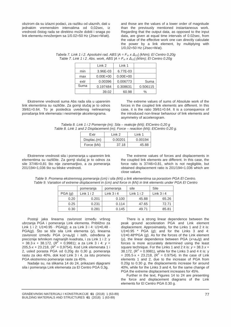
GRAĐEVINSKI MATERIJALI I KONSTRUKCIJE 61 (2018) 1 (63-89)BUILDING MATERIALS AND STRUCTURES 61 (2018) 1 (63-89)
77
obzirom da su izlazni podaci, za razliku od ulaznih, dati ujednakim vremenskim intervalima od 0,02sec, izvrednosti čistog rada se direktno može dobiti i snaga polink elementu množenjem sa 1/0.02=50 Hz (J/sec=Watt).
and those are the values of a lower order of magnitudethan the previously mentioned instantaneous work.Regarding that the output data, as opposed to the inputdata, are given at equal time intervals of 0.02sec, fromthe value of the effective work one can directly calculatethe power by a link element, by multiplying with1/0,02=50 Hz (J/sec=Wat).
Tabela 7. Link 1 i 2. Apsolutni rad, ABS |A = Fsr x ΔU1| (kNm); El Centro 0,20gTable 7. Link 1 i 2. Abs. work, ABS |A = Fsr x ΔU1| (kNm); El Centro 0.20g
Link 2 Link 1min 3.96E-03 6.77E-03max 0.00E+00 0.00E+00extr 0.00396 0.006773 Suma
Suma 0.197484 0.308631 0.50611539.02 60.98 %
Ekstremne vrednosti suma Abs rada sila u uparenimlink elementima su različite. Za gornji slučaj je to odnos39/61=0.64. To je posledica uvedenog nelinearnogponašanja link elemenata i nesimetrije akcelerograma.
The extreme values of sums of Absolute work of theforces in the coupled link elements are different. In thiscase, it is the ratio 39/61=0.64. It is a consequence ofthe introduced non-linear behaviour of link elements andasymmetry of accelerogram.
Tabela 8. Link 1 i 2 Pomernje (m); Sila – reakcije (kN); ElCentro 0,20 gTable 8. Link 1 and 2 Displacement (m); Force – reaction (kN); ElCentro 0.20 g.
Extr Link 2 Link 1Displac.(m) 0.00201 0.00194Force (kN) 37.18 45.88
Ekstremne vrednosti sila i pomeranja u uparenim linkelementima su različite. Za gornji slučaj je to odnos zasile 37/46=0,81 što nije zanemarljivo, a za pomeranja201/194=1,036 što su bliske vrednosti.
The extreme values of forces and displacements inthe coupled link elements are different. In this case, theforce ratio is 37/46=0.81, which is not negligible, butobtained displacement ratio is 201/194=1.036 which areclose values.
Table 9. Promena ekstremnog pomeranja (cm) i sila (kN) u link elementima sa porastom PGA El Centro.Table 9. Variation of extreme displacement in (cm) and force in (kN) in link elements under PGA El Centro
pomeranja pomeranja sile SilePGA (g) Link 1 i 2 Link 3 i 4 Link 1 i 2 Link 3 i 4
0.20 0.201 0.100 45.88 65.260.25 0.231 0.114 47.65 72.710.30 0.281 0.145 49.71 85.81
Postoji jaka linearna zavisnost između vršnogubrzanja PGA i pomeranja Link elementa. Približno zaLink 1 i 2: U1≈0.95 · PGA(g); a za Link 3 i 4: U1≈0,48 ·PGA(g). Što se tiče sila Link elementa (y), linearnazavisnost između PGA (x=ah/g) i istih, određena jepreciznije tehnikom najmanjih kvadrata, i za Link 1 i 2: y= 38.3·x + 38.172, (R2 = 0,9981); a za Link 3 i 4: y =205,5·x + 23.218, (R2 = 0,9754). Kod Link elemenata 1 i2, usled porasta PGA od 0,20g do 0,30 g, pomeranjarastu za oko 40%, dok kod Link 3 i 4, za istu promenuPGA ekstremno pomeranje raste za 45%.
Nadalje su, na slikama 14 do 24, prikazani dijagramisila i pomeranja Link elemenata za El Centro PGA 0,3g.
There is a strong linear dependence between thepeak ground acceleration PGA and Link elementdisplacement. Approximately, for the Links 1 and 2 it is:U1≈0.95 * PGA (g); and for the Links 3 and 4:U1≈0.48*PGA (g). As for the forces of the Link element(y), the linear dependence between PGA (x=ah/g) andforces is more accurately determined using the leastsquare technique. For the Links 1 and 2 it is: y = 38.3·x +38.172, (R2 = 0.9981), while for the Links 3 and 4 it is: y= 205.5·x + 23.218, (R2 = 0.9754). In the case of Linkelements 1 and 2, due to the increase of PGA from0.20g to 0.30 g, the displacements increase for around40%, while for the Links 3 and 4, for the same change ofPGA the extreme displacement increases for 45%.
Further in the text, Figures 14 to 24 are presentingthe force and displacement diagrams of the Linkelements for El Centro PGA 0.30 g.
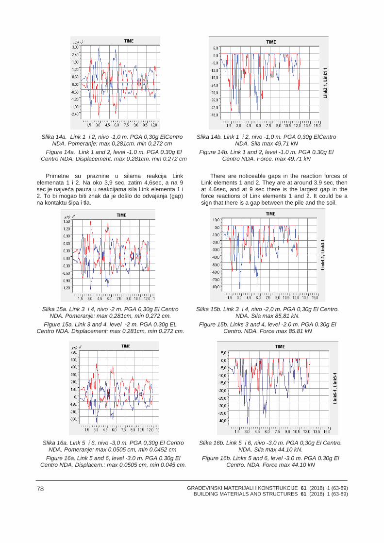
GRAĐEVINSKI MATERIJALI I KONSTRUKCIJE 61 (2018) 1 (63-89)BUILDING MATERIALS AND STRUCTURES 61 (2018) 1 (63-89)
78
Slika 14a. Link 1 i 2, nivo -1,0 m. PGA 0,30g ElCentroNDA. Pomeranje: max 0,281cm. min 0,272 cm
Figure 14a. Link 1 and 2, level -1.0 m. PGA 0.30g ElCentro NDA. Displacement. max 0.281cm. min 0.272 cm
Slika 14b. Link 1 i 2, nivo -1,0 m. PGA 0,30g ElCentroNDA. Sila max 49,71 kN
Figure 14b. Link 1 and 2, level -1.0 m. PGA 0.30g ElCentro NDA. Force. max 49.71 kN
Primetne su praznine u silama reakcija Linkelemenata 1 i 2. Na oko 3,9 sec, zatim 4,6sec, a na 9sec je najveća pauza u reakcijama sila Link elementa 1 i2. To bi mogao biti znak da je došlo do odvajanja (gap)na kontaktu šipa i tla.
There are noticeable gaps in the reaction forces ofLink elements 1 and 2. They are at around 3.9 sec, thenat 4.6sec, and at 9 sec there is the largest gap in theforce reactions of Link elements 1 and 2. It could be asign that there is a gap between the pile and the soil.
Slika 15a. Link 3 i 4, nivo -2 m. PGA 0,30g El CentroNDA. Pomeranje: max 0,281cm, min 0,272 cm.
Figure 15a. Link 3 and 4, level -2 m. PGA 0.30g ELCentro NDA. Displacement: max 0.281cm, min 0.272 cm.
Slika 15b. Link 3 i 4, nivo -2,0 m. PGA 0,30g El Centro.NDA. Sila max 85,81 kN.
Figure 15b. Links 3 and 4, level -2.0 m. PGA 0.30g ElCentro. NDA. Force max 85.81 kN
Slika 16a. Link 5 i 6, nivo -3,0 m. PGA 0,30g El CentroNDA. Pomeranje: max 0,0505 cm, min 0,0452 cm.
Figure 16a. Link 5 and 6, level -3.0 m. PGA 0.30g ElCentro NDA. Displacem.: max 0.0505 cm, min 0.045 cm.
Slika 16b. Link 5 i 6, nivo -3,0 m. PGA 0,30g El Centro.NDA. Sila max 44,10 kN.
Figure 16b. Links 5 and 6, level -3.0 m. PGA 0.30g ElCentro. NDA. Force max 44.10 kN
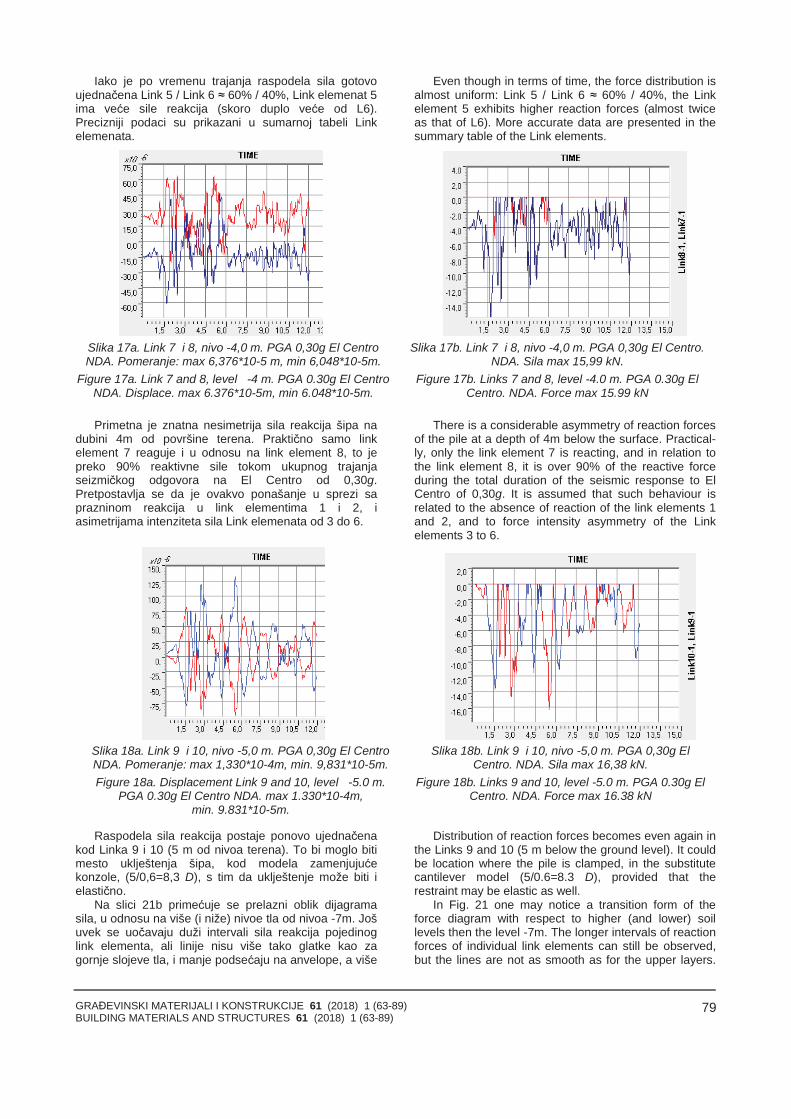
GRAĐEVINSKI MATERIJALI I KONSTRUKCIJE 61 (2018) 1 (63-89)BUILDING MATERIALS AND STRUCTURES 61 (2018) 1 (63-89)
79
Iako je po vremenu trajanja raspodela sila gotovoujednačena Link 5 / Link 6 ≈ 60% / 40%, Link elemenat 5ima veće sile reakcija (skoro duplo veće od L6).Precizniji podaci su prikazani u sumarnoj tabeli Linkelemenata.
Even though in terms of time, the force distribution isalmost uniform: Link 5 / Link 6 ≈ 60% / 40%, the Linkelement 5 exhibits higher reaction forces (almost twiceas that of L6). More accurate data are presented in thesummary table of the Link elements.
Slika 17a. Link 7 i 8, nivo -4,0 m. PGA 0,30g El CentroNDA. Pomeranje: max 6,376*10-5 m, min 6,048*10-5m.
Figure 17a. Link 7 and 8, level -4 m. PGA 0.30g El CentroNDA. Displace. max 6.376*10-5m, min 6.048*10-5m.
Slika 17b. Link 7 i 8, nivo -4,0 m. PGA 0,30g El Centro.NDA. Sila max 15,99 kN.
Figure 17b. Links 7 and 8, level -4.0 m. PGA 0.30g ElCentro. NDA. Force max 15.99 kN
Primetna je znatna nesimetrija sila reakcija šipa nadubini 4m od površine terena. Praktično samo linkelement 7 reaguje i u odnosu na link element 8, to jepreko 90% reaktivne sile tokom ukupnog trajanjaseizmičkog odgovora na El Centro od 0,30g.Pretpostavlja se da je ovakvo ponašanje u sprezi saprazninom reakcija u link elementima 1 i 2, iasimetrijama intenziteta sila Link elemenata od 3 do 6.
There is a considerable asymmetry of reaction forcesof the pile at a depth of 4m below the surface. Practical-ly, only the link element 7 is reacting, and in relation tothe link element 8, it is over 90% of the reactive forceduring the total duration of the seismic response to ElCentro of 0,30g. It is assumed that such behaviour isrelated to the absence of reaction of the link elements 1and 2, and to force intensity asymmetry of the Linkelements 3 to 6.
Slika 18a. Link 9 i 10, nivo -5,0 m. PGA 0,30g El CentroNDA. Pomeranje: max 1,330*10-4m, min. 9,831*10-5m.Figure 18a. Displacement Link 9 and 10, level -5.0 m.
PGA 0.30g El Centro NDA. max 1.330*10-4m,min. 9.831*10-5m.
Slika 18b. Link 9 i 10, nivo -5,0 m. PGA 0,30g ElCentro. NDA. Sila max 16,38 kN.
Figure 18b. Links 9 and 10, level -5.0 m. PGA 0.30g ElCentro. NDA. Force max 16.38 kN
Raspodela sila reakcija postaje ponovo ujednačenakod Linka 9 i 10 (5 m od nivoa terena). To bi moglo bitimesto uklještenja šipa, kod modela zamenjujućekonzole, (5/0,6=8,3 D), s tim da uklještenje može biti ielastično.
Distribution of reaction forces becomes even again inthe Links 9 and 10 (5 m below the ground level). It couldbe location where the pile is clamped, in the substitutecantilever model (5/0.6=8.3 D), provided that therestraint may be elastic as well.
Na slici 21b primećuje se prelazni oblik dijagramasila, u odnosu na više (i niže) nivoe tla od nivoa -7m. Jošuvek se uočavaju duži intervali sila reakcija pojedinoglink elementa, ali linije nisu više tako glatke kao zagornje slojeve tla, i manje podsećaju na anvelope, a više
In Fig. 21 one may notice a transition form of theforce diagram with respect to higher (and lower) soillevels then the level -7m. The longer intervals of reactionforces of individual link elements can still be observed,but the lines are not as smooth as for the upper layers.
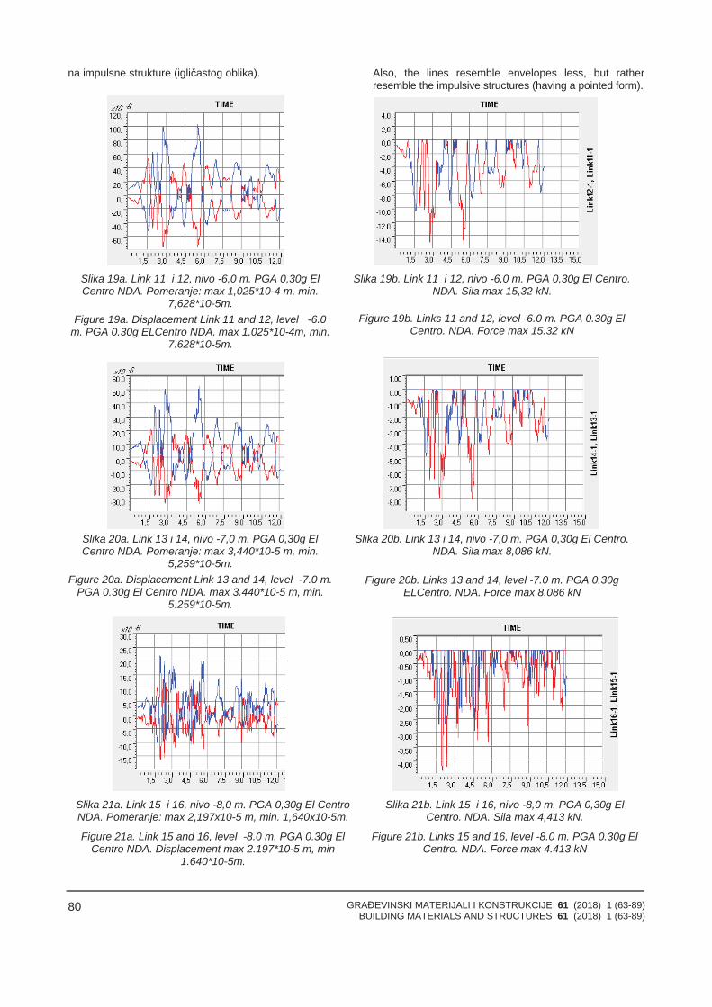
GRAĐEVINSKI MATERIJALI I KONSTRUKCIJE 61 (2018) 1 (63-89)BUILDING MATERIALS AND STRUCTURES 61 (2018) 1 (63-89)
80
na impulsne strukture (igličastog oblika). Also, the lines resemble envelopes less, but ratherresemble the impulsive structures (having a pointed form).
Slika 19a. Link 11 i 12, nivo -6,0 m. PGA 0,30g ElCentro NDA. Pomeranje: max 1,025*10-4 m, min.
7,628*10-5m.Figure 19a. Displacement Link 11 and 12, level -6.0
m. PGA 0.30g ELCentro NDA. max 1.025*10-4m, min.7.628*10-5m.
Slika 19b. Link 11 i 12, nivo -6,0 m. PGA 0,30g El Centro.NDA. Sila max 15,32 kN.
Figure 19b. Links 11 and 12, level -6.0 m. PGA 0.30g ElCentro. NDA. Force max 15.32 kN
Slika 20a. Link 13 i 14, nivo -7,0 m. PGA 0,30g ElCentro NDA. Pomeranje: max 3,440*10-5 m, min.
5,259*10-5m.Figure 20a. Displacement Link 13 and 14, level -7.0 m.
PGA 0.30g El Centro NDA. max 3.440*10-5 m, min.5.259*10-5m.
Slika 20b. Link 13 i 14, nivo -7,0 m. PGA 0,30g El Centro.NDA. Sila max 8,086 kN.
Figure 20b. Links 13 and 14, level -7.0 m. PGA 0.30gELCentro. NDA. Force max 8.086 kN
Slika 21a. Link 15 i 16, nivo -8,0 m. PGA 0,30g El CentroNDA. Pomeranje: max 2,197x10-5 m, min. 1,640x10-5m.
Figure 21a. Link 15 and 16, level -8.0 m. PGA 0.30g ElCentro NDA. Displacement max 2.197*10-5 m, min
1.640*10-5m.
Slika 21b. Link 15 i 16, nivo -8,0 m. PGA 0,30g ElCentro. NDA. Sila max 4,413 kN.
Figure 21b. Links 15 and 16, level -8.0 m. PGA 0.30g ElCentro. NDA. Force max 4.413 kN
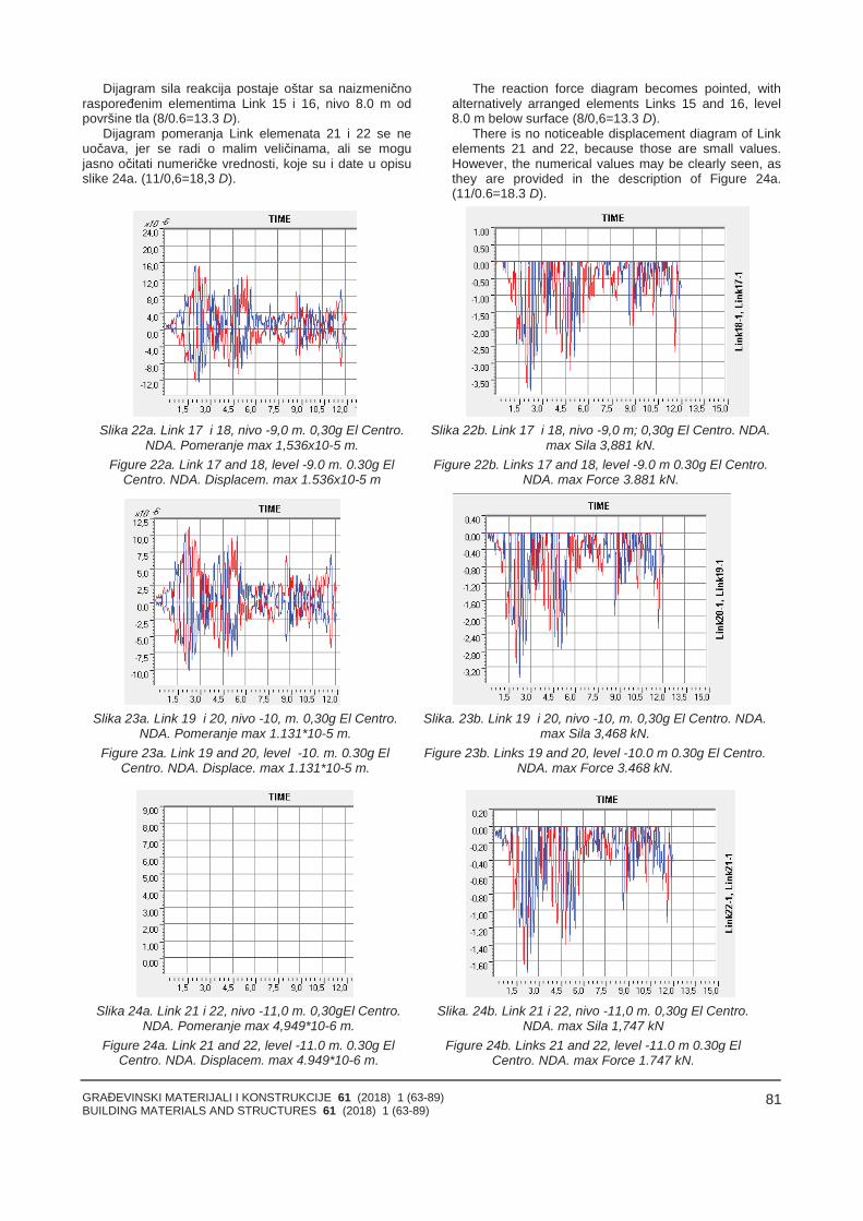
GRAĐEVINSKI MATERIJALI I KONSTRUKCIJE 61 (2018) 1 (63-89)BUILDING MATERIALS AND STRUCTURES 61 (2018) 1 (63-89)
81
Dijagram sila reakcija postaje oštar sa naizmeničnoraspoređenim elementima Link 15 i 16, nivo 8.0 m odpovršine tla (8/0.6=13.3 D).
Dijagram pomeranja Link elemenata 21 i 22 se neuočava, jer se radi o malim veličinama, ali se mogujasno očitati numeričke vrednosti, koje su i date u opisuslike 24a. (11/0,6=18,3 D).
The reaction force diagram becomes pointed, withalternatively arranged elements Links 15 and 16, level8.0 m below surface (8/0,6=13.3 D).
There is no noticeable displacement diagram of Linkelements 21 and 22, because those are small values.However, the numerical values may be clearly seen, asthey are provided in the description of Figure 24a.(11/0.6=18.3 D).
Slika 22a. Link 17 i 18, nivo -9,0 m. 0,30g El Centro.NDA. Pomeranje max 1,536x10-5 m.
Figure 22a. Link 17 and 18, level -9.0 m. 0.30g ElCentro. NDA. Displacem. max 1.536x10⁻⁵ m
Slika 22b. Link 17 i 18, nivo -9,0 m; 0,30g El Centro. NDA. max Sila 3,881 kN.
Figure 22b. Links 17 and 18, level -9.0 m 0.30g El Centro.NDA. max Force 3.881 kN.
Slika 23a. Link 19 i 20, nivo -10, m. 0,30g El Centro.NDA. Pomeranje max 1.131*10-5 m.
Figure 23a. Link 19 and 20, level -10. m. 0.30g ElCentro. NDA. Displace. max 1.131*10-5 m.
Slika. 23b. Link 19 i 20, nivo -10, m. 0,30g El Centro. NDA. max Sila 3,468 kN.
Figure 23b. Links 19 and 20, level -10.0 m 0.30g El Centro.NDA. max Force 3.468 kN.
Slika 24a. Link 21 i 22, nivo -11,0 m. 0,30gEl Centro.NDA. Pomeranje max 4,949*10-6 m.
Figure 24a. Link 21 and 22, level -11.0 m. 0.30g ElCentro. NDA. Displacem. max 4.949*10-6 m.
Slika. 24b. Link 21 i 22, nivo -11,0 m. 0,30g El Centro.NDA. max Sila 1,747 kN
Figure 24b. Links 21 and 22, level -11.0 m 0.30g ElCentro. NDA. max Force 1.747 kN.
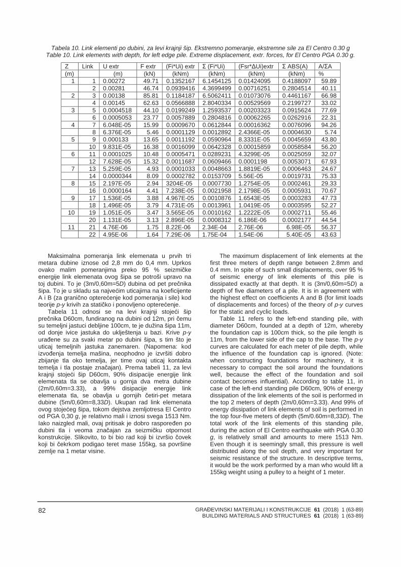
GRAĐEVINSKI MATERIJALI I KONSTRUKCIJE 61 (2018) 1 (63-89)BUILDING MATERIALS AND STRUCTURES 61 (2018) 1 (63-89)
82
Tabela 10. Link elementi po dubini, za levi krajnji šip. Ekstremno pomeranje, ekstremne sile za El Centro 0.30 gTable 10. Link elements with depth, for left edge pile. Extreme displacement, extr. forces, for El Centro PGA 0.30 g.
Z Link U extr F extr (Fi*Ui) extr Σ (Fi*Ui) (Fsr*ΔUi)extr Σ ABS(A) A/ΣA(m) (m) (kN) (kNm) (kNm) (kNm) (kNm) %
1 1 0.00272 49.71 0.1352167 6.1454125 0.01424095 0.4188097 59.892 0.00281 46.74 0.0939416 4.3699499 0.00716251 0.2804514 40.11
2 3 0.00138 85.81 0.1184187 6.5062411 0.01073076 0.4461167 66.984 0.00145 62.63 0.0566888 2.8040334 0.00529569 0.2199727 33.02
3 5 0.0004518 44.10 0.0199249 1.2593537 0.00203323 0.0915624 77.696 0.0005053 23.77 0.0057889 0.2804816 0.00062265 0.0262916 22.31
4 7 6.048E-05 15.99 0.0009670 0.0612844 0.00016362 0.0076096 94.268 6.376E-05 5.46 0.0001129 0.0012892 2.4366E-05 0.0004630 5.74
5 9 0.000133 13.65 0.0011192 0.0590964 8.3331E-05 0.0045659 43.8010 9.831E-05 16.38 0.0016099 0.0642328 0.00015859 0.0058584 56.20
6 11 0.0001025 10.48 0.0005471 0.0289231 4.3299E-05 0.0025059 32.0712 7.628E-05 15.32 0.0011687 0.0609466 0.0001198 0.0053071 67.93
7 13 5.259E-05 4.93 0.0001033 0.0048663 1.8819E-05 0.0006463 24.6714 0.0000344 8.09 0.0002782 0.0153709 5.56E-05 0.0019731 75.33
8 15 2.197E-05 2.94 3204E-05 0.0007730 1.2754E-05 0.0002461 29.3316 0.0000164 4.41 7.238E-05 0.0021958 2.1798E-05 0.0005931 70.67
9 17 1.536E-05 3.88 4.967E-05 0.0010876 1.6543E-05 0.0003283 47.7318 1.496E-05 3.79 4.731E-05 0.0013961 1.0419E-05 0.0003595 52.27
10 19 1.051E-05 3.47 3.565E-05 0.0010162 1.2222E-05 0.0002711 55.4620 1.131E-05 3.13 2.896E-05 0.0008312 6.186E-06 0.0002177 44.54
11 21 4.76E-06 1.75 8.22E-06 2.34E-04 2.76E-06 6.98E-05 56.3722 4.95E-06 1.64 7.29E-06 1.75E-04 1.54E-06 5.40E-05 43.63
Maksimalna pomeranja link elemenata u prvih trimetara dubine iznose od 2,8 mm do 0,4 mm. Uprkosovako malim pomeranjima preko 95 % seizmičkeenergije link elemenata ovog šipa se potroši upravo natoj dubini. To je (3m/0,60m=5D) dubina od pet prečnikašipa. To je u skladu sa najvećim uticajima na koeficijenteA i B (za granično opterećenje kod pomeranja i sile) kodteorije p-y krivih za statičko i ponovljeno opterećenje.
Tabela 11 odnosi se na levi krajnji stojeći šipprečnika D60cm, fundiranog na dubini od 12m, pri čemusu temeljni jastuci debljine 100cm, te je dužina šipa 11m,od donje ivice jastuka do uklještenja u bazi. Krive p-yurađene su za svaki metar po dubini šipa, s tim što jeuticaj temeljnih jastuka zanemaren. (Napomena: kodizvođenja temelja mašina, neophodno je izvršiti dobrozbijanje tla oko temelja, jer time ovaj uticaj kontaktatemelja i tla postaje značajan). Prema tabeli 11, za levikrajnji stojeći šip D60cm, 90% disipacije energije linkelemenata tla se obavlja u gornja dva metra dubine(2m/0,60m=3.33), a 99% disipacije energije linkelemenata tla, se obavlja u gornjih četiri-pet metaradubine (5m/0,60m=8,33D). Ukupan rad link elemenataovog stojećeg šipa, tokom dejstva zemljotresa El Centrood PGA 0,30 g, je relativno mali i iznosi svega 1513 Nm.Iako naizgled mali, ovaj pritisak je dobro raspoređen podubini tla i veoma značajan za seizmičku otpornostkonstrukcije. Slikovito, to bi bio rad koji bi izvršio čovekkoji bi čekrkom podigao teret mase 155kg, sa površinezemlje na 1 metar visine.
The maximum displacement of link elements at thefirst three meters of depth range between 2.8mm and0.4 mm. In spite of such small displacements, over 95 %of seismic energy of link elements of this pile isdissipated exactly at that depth. It is (3m/0,60m=5D) adepth of five diameters of a pile. It is in agreement withthe highest effect on coefficients A and B (for limit loadsof displacements and forces) of the theory of p-y curvesfor the static and cyclic loads.
Table 11 refers to the left-end standing pile, withdiameter D60cm, founded at a depth of 12m, wherebythe foundation cap is 100cm thick, so the pile length is11m, from the lower side of the cap to the base. The p-ycurves are calculated for each meter of pile depth, whilethe influence of the foundation cap is ignored. (Note:when constructing foundations for machinery, it isnecessary to compact the soil around the foundationswell, because the effect of the foundation and soilcontact becomes influential). According to table 11, incase of the left-end standing pile D60cm, 90% of energydissipation of the link elements of the soil is performed inthe top 2 meters of depth (2m/0,60m=3.33). And 99% ofenergy dissipation of link elements of soil is performed inthe top four-five meters of depth (5m/0.60m=8,33D). Thetotal work of the link elements of this standing pile,during the action of El Centro earthquake with PGA 0.30g, is relatively small and amounts to mere 1513 Nm.Even though it is seemingly small, this pressure is welldistributed along the soil depth, and very important forseismic resistance of the structure. In descriptive terms,it would be the work performed by a man who would lift a155kg weight using a pulley to a height of 1 meter.
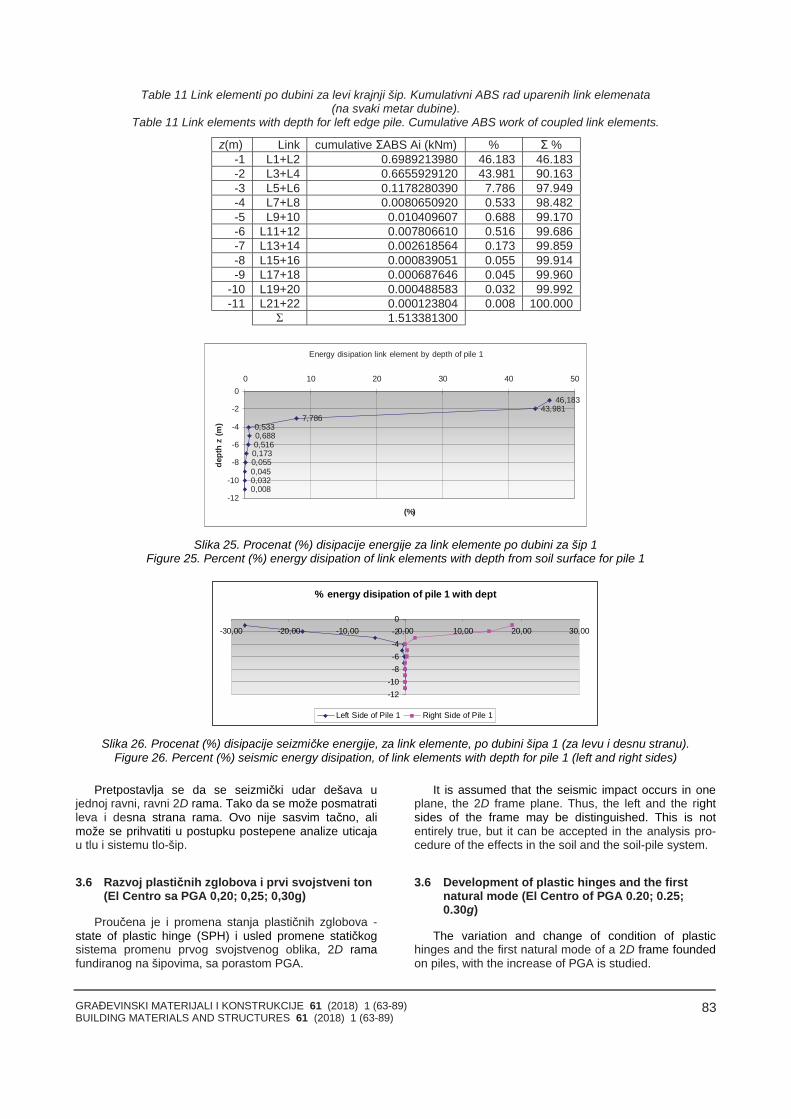
GRAĐEVINSKI MATERIJALI I KONSTRUKCIJE 61 (2018) 1 (63-89)BUILDING MATERIALS AND STRUCTURES 61 (2018) 1 (63-89)
83
Table 11 Link elementi po dubini za levi krajnji šip. Kumulativni ABS rad uparenih link elemenata(na svaki metar dubine).
Table 11 Link elements with depth for left edge pile. Cumulative ABS work of coupled link elements.
z(m) Link cumulative ΣABS Ai (kNm) % Σ %-1 L1+L2 0.6989213980 46.183 46.183-2 L3+L4 0.6655929120 43.981 90.163-3 L5+L6 0.1178280390 7.786 97.949-4 L7+L8 0.0080650920 0.533 98.482-5 L9+10 0.010409607 0.688 99.170-6 L11+12 0.007806610 0.516 99.686-7 L13+14 0.002618564 0.173 99.859-8 L15+16 0.000839051 0.055 99.914-9 L17+18 0.000687646 0.045 99.960
-10 L19+20 0.000488583 0.032 99.992-11 L21+22 0.000123804 0.008 100.000
Σ 1.513381300
Energy disipation link element by depth of pile 1
46,18343,981
7,7860,5330,6880,5160,1730,0550,0450,0320,008
-12
-10
-8
-6
-4
-2
00 10 20 30 40 50
(%)
dept
hz
(m)
Slika 25. Procenat (%) disipacije energije za link elemente po dubini za šip 1Figure 25. Percent (%) energy disipation of link elements with depth from soil surface for pile 1
% energy disipation of pile 1 with dept
-12-10-8-6-4-20
-30,00 -20,00 -10,00 0,00 10,00 20,00 30,00
Left Side of Pile 1 Right Side of Pile 1
Slika 26. Procenat (%) disipacije seizmičke energije, za link elemente, po dubini šipa 1 (za levu i desnu stranu).Figure 26. Percent (%) seismic energy disipation, of link elements with depth for pile 1 (left and right sides)
Pretpostavlja se da se seizmički udar dešava ujednoj ravni, ravni 2D rama. Tako da se može posmatratileva i desna strana rama. Ovo nije sasvim tačno, alimože se prihvatiti u postupku postepene analize uticajau tlu i sistemu tlo-šip.
3.6 Razvoj plastičnih zglobova i prvi svojstveni ton(El Centro sa PGA 0,20; 0,25; 0,30g)
Proučena je i promena stanja plastičnih zglobova -state of plastic hinge (SPH) i usled promene statičkogsistema promenu prvog svojstvenog oblika, 2D ramafundiranog na šipovima, sa porastom PGA.
It is assumed that the seismic impact occurs in oneplane, the 2D frame plane. Thus, the left and the rightsides of the frame may be distinguished. This is notentirely true, but it can be accepted in the analysis pro-cedure of the effects in the soil and the soil-pile system.
3.6 Development of plastic hinges and the firstnatural mode (El Centro of PGA 0.20; 0.25;0.30g)
The variation and change of condition of plastichinges and the first natural mode of a 2D frame foundedon piles, with the increase of PGA is studied.
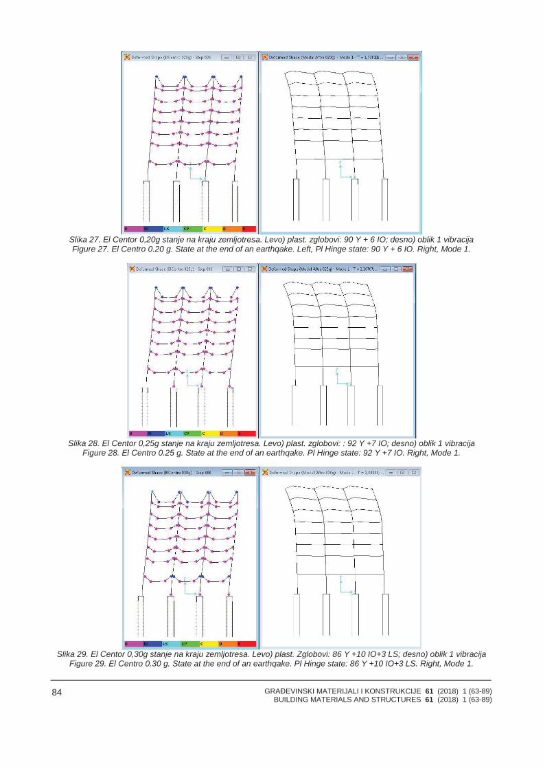
GRAĐEVINSKI MATERIJALI I KONSTRUKCIJE 61 (2018) 1 (63-89)BUILDING MATERIALS AND STRUCTURES 61 (2018) 1 (63-89)
84
Slika 27. El Centor 0,20g stanje na kraju zemljotresa. Levo) plast. zglobovi: 90 Y + 6 IO; desno) oblik 1 vibracijaFigure 27. El Centro 0.20 g. State at the end of an earthqake. Left, Pl Hinge state: 90 Y + 6 IO. Right, Mode 1.
Slika 28. El Centor 0,25g stanje na kraju zemljotresa. Levo) plast. zglobovi: : 92 Y +7 IO; desno) oblik 1 vibracijaFigure 28. El Centro 0.25 g. State at the end of an earthqake. Pl Hinge state: 92 Y +7 IO. Right, Mode 1.
Slika 29. El Centor 0,30g stanje na kraju zemljotresa. Levo) plast. Zglobovi: 86 Y +10 IO+3 LS; desno) oblik 1 vibracijaFigure 29. El Centro 0.30 g. State at the end of an earthqake. Pl Hinge state: 86 Y +10 IO+3 LS. Right, Mode 1.
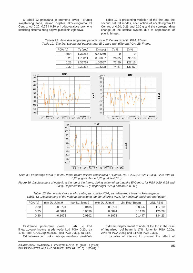
GRAĐEVINSKI MATERIJALI I KONSTRUKCIJE 61 (2018) 1 (63-89)BUILDING MATERIALS AND STRUCTURES 61 (2018) 1 (63-89)
85
U tabeli 12 prikazana je promena prvog i drugogsvojstvenog tona, nakon dejstva akcelerograma ElCentro, od 0,20; 0,25 i 0,30 g i odgovarajuće promenestatičkog sistema zbog pojave plastičnih zglobova.
Table 12 is presenting variation of the first and thesecond natural modes, after action of accelerogram ElCentro, of 0.20; 0.25 and 0.30 g and the correspondingchange of the statical system due to appearance ofplastic hinges.
Tabela 12. Prva dva svojstvena perioda posle El Centra različitih PGA. 2D ram.Table 12. The first two natural periods after El Centro with different PGA. 2D Frame.
PGA (g) T1 (sec) T2 (sec) T1 % T2 %start 1.37255 0.44269 0 00.20 1.73011 0.86837 26.05 96.160.25 2.36767 1.00557 72.50 127.150.30 2.39338 1.03398 74.37 133.57
Slika 30. Pomeranje čvora 9, u vrhu rama, tokom dejstva zemljotresa El Centro, za PGA 0.20; 0.25 i 0.30g. Gore levo za0,20 g, gore desno 0,25 g i dole 0,30 g
Figure 30. Displacement of node 9, at the top of the frame, during action of earthquake El Centro, for PGA 0.20; 0.25 and0.30g. Upper left for 0.20 g, upper right 0.25 g and down 0.30 g
Table. 13. Pomeranje čvora u vrhu stuba, za različito PGA, za nelinearnu i linearnu krovnu gredu.Table. 13. Displacement of the node at the column top, for different PGA, for nonlinear and linear roof girder.
PGA (g) min U1 Joint 9 max U1 Joint 9 extr U1 Joint 9 Lin. Roof Beam L/NL RB%0.20 -0.0731 0.0485 0.0731 0.0856 117.100.25 -0.0894 0.0636 0.0894 0.1129 126.290.30 -0.1078 0.0802 0.1078 0.1447 134.23
Ekstremno pomeranje čvora u vrhu je kodlinearizovane krovne grede veće kod PGA 0,20g za17%, kod PGA 0,25g za 26%, i kod PGA 0,30g, za 34%.
Od interesa je i prikaz uticaja uvođenja plastičnih
Extreme displacement of node at the top in the caseof linearized roof beam is 17% higher for PGA 0,20g,26% for PGA 0,25g and 34%for PGA 0,30g.
It is also of interest to present the effect of
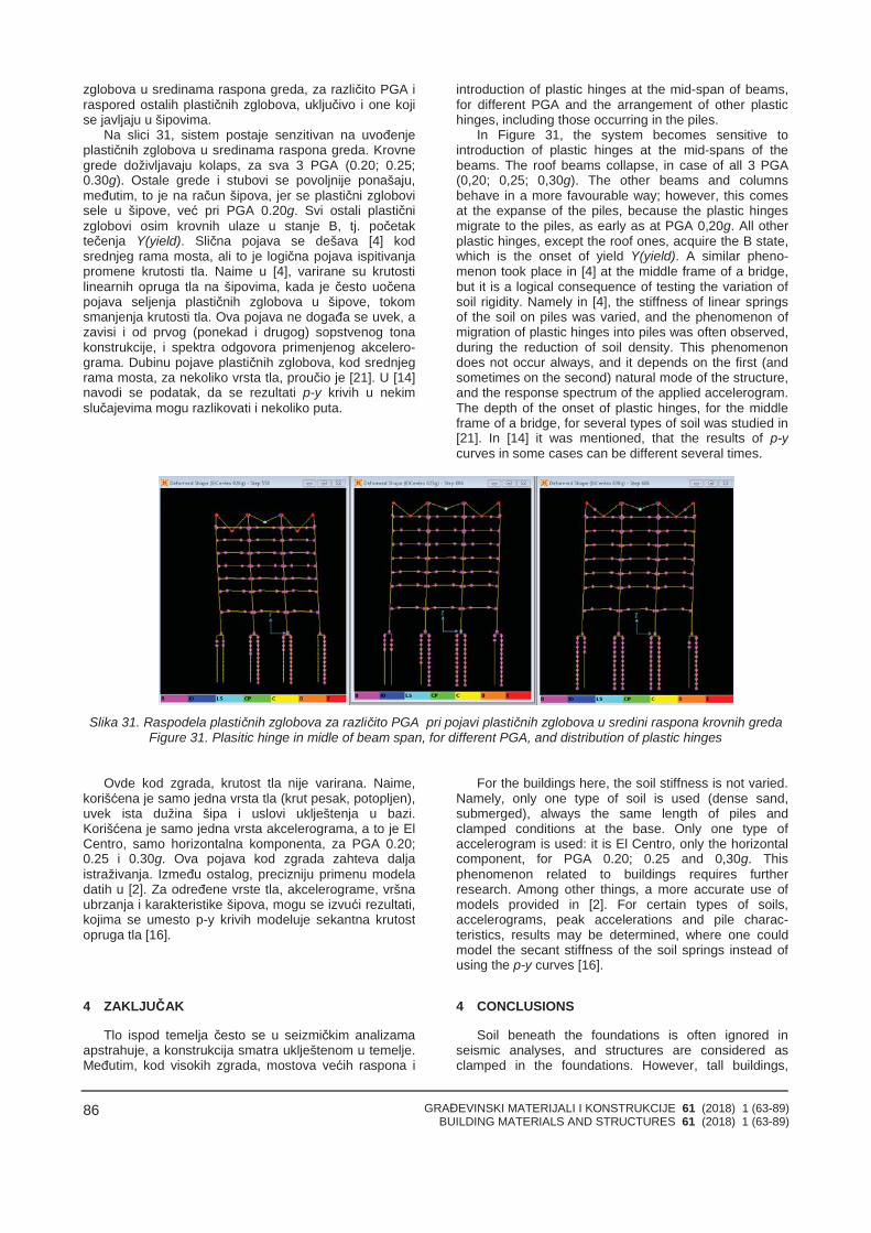
GRAĐEVINSKI MATERIJALI I KONSTRUKCIJE 61 (2018) 1 (63-89)BUILDING MATERIALS AND STRUCTURES 61 (2018) 1 (63-89)
86
zglobova u sredinama raspona greda, za različito PGA iraspored ostalih plastičnih zglobova, uključivo i one kojise javljaju u šipovima.
Na slici 31, sistem postaje senzitivan na uvođenjeplastičnih zglobova u sredinama raspona greda. Krovnegrede doživljavaju kolaps, za sva 3 PGA (0.20; 0.25;0.30g). Ostale grede i stubovi se povoljnije ponašaju,međutim, to je na račun šipova, jer se plastični zglobovisele u šipove, već pri PGA 0.20g. Svi ostali plastičnizglobovi osim krovnih ulaze u stanje B, tj. početaktečenja Y(yield). Slična pojava se dešava [4] kodsrednjeg rama mosta, ali to je logična pojava ispitivanjapromene krutosti tla. Naime u [4], varirane su krutostilinearnih opruga tla na šipovima, kada je često uočenapojava seljenja plastičnih zglobova u šipove, tokomsmanjenja krutosti tla. Ova pojava ne događa se uvek, azavisi i od prvog (ponekad i drugog) sopstvenog tonakonstrukcije, i spektra odgovora primenjenog akcelero-grama. Dubinu pojave plastičnih zglobova, kod srednjegrama mosta, za nekoliko vrsta tla, proučio je [21]. U [14]navodi se podatak, da se rezultati p-y krivih u nekimslučajevima mogu razlikovati i nekoliko puta.
introduction of plastic hinges at the mid-span of beams,for different PGA and the arrangement of other plastichinges, including those occurring in the piles.
In Figure 31, the system becomes sensitive tointroduction of plastic hinges at the mid-spans of thebeams. The roof beams collapse, in case of all 3 PGA(0,20; 0,25; 0,30g). The other beams and columnsbehave in a more favourable way; however, this comesat the expanse of the piles, because the plastic hingesmigrate to the piles, as early as at PGA 0,20g. All otherplastic hinges, except the roof ones, acquire the B state,which is the onset of yield Y(yield). A similar pheno-menon took place in [4] at the middle frame of a bridge,but it is a logical consequence of testing the variation ofsoil rigidity. Namely in [4], the stiffness of linear springsof the soil on piles was varied, and the phenomenon ofmigration of plastic hinges into piles was often observed,during the reduction of soil density. This phenomenondoes not occur always, and it depends on the first (andsometimes on the second) natural mode of the structure,and the response spectrum of the applied accelerogram.The depth of the onset of plastic hinges, for the middleframe of a bridge, for several types of soil was studied in[21]. In [14] it was mentioned, that the results of p-ycurves in some cases can be different several times.
Slika 31. Raspodela plastičnih zglobova za različito PGA pri pojavi plastičnih zglobova u sredini raspona krovnih gredaFigure 31. Plasitic hinge in midle of beam span, for different PGA, and distribution of plastic hinges
Ovde kod zgrada, krutost tla nije varirana. Naime,korišćena je samo jedna vrsta tla (krut pesak, potopljen),uvek ista dužina šipa i uslovi uklještenja u bazi.Korišćena je samo jedna vrsta akcelerograma, a to je ElCentro, samo horizontalna komponenta, za PGA 0.20;0.25 i 0.30g. Ova pojava kod zgrada zahteva daljaistraživanja. Između ostalog, precizniju primenu modeladatih u [2]. Za određene vrste tla, akcelerograme, vršnaubrzanja i karakteristike šipova, mogu se izvući rezultati,kojima se umesto p-y krivih modeluje sekantna krutostopruga tla [16].
4 ZAKLJUČAK
Tlo ispod temelja često se u seizmičkim analizamaapstrahuje, a konstrukcija smatra uklještenom u temelje.Međutim, kod visokih zgrada, mostova većih raspona i
For the buildings here, the soil stiffness is not varied.Namely, only one type of soil is used (dense sand,submerged), always the same length of piles andclamped conditions at the base. Only one type ofaccelerogram is used: it is El Centro, only the horizontalcomponent, for PGA 0.20; 0.25 and 0,30g. Thisphenomenon related to buildings requires furtherresearch. Among other things, a more accurate use ofmodels provided in [2]. For certain types of soils,accelerograms, peak accelerations and pile charac-teristics, results may be determined, where one couldmodel the secant stiffness of the soil springs instead ofusing the p-y curves [16].
4 CONCLUSIONS
Soil beneath the foundations is often ignored inseismic analyses, and structures are considered asclamped in the foundations. However, tall buildings,
GRAĐEVINSKI MATERIJALI I KONSTRUKCIJE 61 (2018) 1 (63-89)BUILDING MATERIALS AND STRUCTURES 61 (2018) 1 (63-89)
87
nekim inženjerskim konstrukcijama treba u seizmičkojanalizi uključiti i interakciju konstrukcija-temelj-tlo.Uvođenje analize na 3D modelima je veomakompleksno, pa je u ovom radu pokazano da sezamenom prostorne skeletne konstrukcije zgrade 2Dramom problem znatno pojednostavljuje.
Kod određivanja seizmičkih performansi konstrukcijekorišćenjem NSA (pušover analize) bitno je odredititačku kada konstrukcija prelazi u mehanizam. Promenubroja i stanja plastičnih zglobova sa porastompomeranja, u koracima NSA kod određivanja PO krivih uprogramu SAP2000 v14, nije lako direktno utvrditi. Boljiprikaz PO krivih za zgrade ima program ETABS, madase i kod programskog paketa SAP2000, mogu dobitidobri prikazi naročito kod inženjerskih objekata, ali trebavoditi računa o alternativnim procedurama. Analizakorišćenjem metode N2 PO se primenjuje za određiva-nje ciljnog pomeranje konstrukcije, kao tačka presekaseizmičkog zahteva (preko spektra odgovora) iseizmičkog kapaciteta konstrukcije. Prikazan postupakrelativno pojednostavljene procedure za određivanjeuticaja NSA i NDA dinamičke interakcije tlo-šip-konstruk-cija. Radi dobijanja sveobuhvatnije slike performansikonstrukcije osim više različitih modela, sa i bezinterakcije, neophodno je primeniti više različitih metoda,oblika opterećenja, više različitih vrsta i skaliranjaakcelerograma, zatim procedura i programskih paketa.
Numeričkim istraživanjima uticaja u tlu, utvrđeno jeda su sile reakcija link elementa male veličine u odnosuna ukupnu seizmičku silu u osnovi. Iako su intenzitetireakcija link elemenata, tokom dejstva zemljotresa, uodnosu na vrednost sila u osnovi, relativno maleveličine, one su veoma značajne za ukupnu seizmičkuotpornost objekta. Uočene su određene zakonitostipromene dijagrama sila po dubini link elemenata, ali jeiste neophodno tumačiti na dijagramima, što je u ovomradu urađeno.
Analizom seizmičkog ponašanja pri ulaznimpodacima (akcelerogrami za PGA 0.20; 0.25 i 0.30g)razmatrani sistem je veoma osetljiv na uvođenjeplastičnih zglobova u sredinama raspona greda. Ukrovnim gredama došlo je do loma, za sva 3 PGA (0.20;0.25; 0.30g), ostale grede i stubovi se povoljnijeponašaju jer se plastični zglobovi „sele“ u šipove, već priPGA 0.20g. Zbog toga je veoma važno pri projektovanjuAB ramovskih konstrukcija adekvatnim dimenzionisa-njem i detaljima izbeći formiranje plastičnih zglobova upoljima greda.
Može se zaključiti da se uvođenjem SSI postižepozitivan efekat naročito ako se radi o krućimkonstrukcijama zgrada, da bi se izbegle veće deforma-cije tavanica i potencijalni sudar sa susednim objektimau gušćim urbanim sredinama, što je potvrđeno u [1] i [9].
Naredna istraživanja potrebno je proširiti, na svešipove rama, i za p-y krive za različite relativne zbijenostipeska. Takođe je potrebno uvesti i vertikalnu interakcijusa tlom, koja je u ovom radu zanemarena. Takođe je,kod pušover krivih potrebno utvrditi da li postoji jakazakonitost oblika vertikalnog opterećenja od gornjekonstrukcije, sa oblikom odziva p-y krivih po dubinišipova (oblik odziva pomeranja čvorova i drift šipova).Ovaj odziv može se posmatrati i kod TH analize, a da lipostoji jasna zakonitost to tek treba utvrditi.
large-span bridges and some engineering structuresrequire inclusion of the structure-foundation-soilinteraction. Introduction of the analysis based on 3Dmodels is very complex, so in this paper it is shown thatby replacing the spatial frame structure of a building,with a 2D frame, the problem is considerably simplified.
When determining the seismic performance of astructure using the NSA (pushover analysis), it isimportant to determine the point at which the structurebecomes a mechanism. The change in the number andstates of plastic hinges resulting from the increase indisplacements, (in steps) of PO curves using SАP2000v14 software cannot be easily determined. ETАBSsoftware has better displays of PO curves, although thiscan be achieved in SАP2000 as well (especially in thecase of engineering structures) if alternative proceduresare taken into account. A PO analysis is applied withinthe N2 method in order to determine the target structuredisplacement, as an intersection point of the seismicrequirements (through spectrum response) and of theseismic capacity of structures. The presented relativelysimplified procedure for determining the effects of NSАand dynamic NDА soil-pile-structure interaction isprovided in this paper. In order to obtain a morecomprehensive insight about the structure’sperformance, it is necessary to apply several differentmodels, load shapes, types and scales ofaccelerograms, procedures and software packages, withand without interactions.
Numerical research of effects in the soil, determinedthat reaction forces of link elements are small in relationto the total base force. Even though the intensities of linkelements reactions during earthquakes are relativelysmall in comparison to the value of base forces, they arevery important for the total seismic resistance of thestructure. Certain regularities in the variation of the forcediagram, along the depth of the link elements areobserved, but they need to be interpreted on thediagrams, which has been done in this paper.
The analysis of the seismic behaviour using the inputdata (accelerograms with PGA 0.20; 0.25 and 0.30g)showed that the considered system is very sensitive atearly formation (introduction) of plastic hinges at mid-spans of the beams. There was a failure of the roofbeams, for all 3 PGA (0.20; 0.25; 0.30g), while theremaining beams and columns behave more favourably,because the plastic hinges migrate to piles, as early asat PGA 0,20g. For that reason, it is very important toavoid formation of plastic hinges in the beam spansusing adequate design and details of RC framestructures.
It may be concluded that by introduction of SSI apositive effect could be achieved especially if stiffbuilding structures are in question, in order to avoidsevere ceiling deformations and potential collision withadjacent structures in densely populated urbanenvironments, which is confirmed in [1] and [9] as well.
The following research must be extended to all theframe piles, and to p-y curves for different relative sanddensities. It is also necessary to introduce a verticalinteraction with the soil which is ignored in this paper.Also, in pushover curves, it is necessary to determinewhether there is a strong regularity of the vertical loadupon the superstructure, with the form of response of p-ycurves, along the depth of the piles (shape of the nodal
GRAĐEVINSKI MATERIJALI I KONSTRUKCIJE 61 (2018) 1 (63-89)BUILDING MATERIALS AND STRUCTURES 61 (2018) 1 (63-89)
88
ZAHVALNOST
Ovaj rad je urađen uz finansijsku potporu Ministrstvaza Nauku, prosvetu i tehnološki razvoj Republike Srbije,u okviru projekta za tehnološki razvoj TR36043.
displacement response and the pile drift). This responsemay be analysed through the TH analysis as well, and itstill needs to be determined if there is a clear regularity.
АCKNOWLEDGEMENT
This paper was done with the financial assistance ofthe Ministry of Science, Education and TechnologicalDevelopment of the Republic of Serbia, within the projectfor technological development TR 36043.
5 LITERATURAREFERENCES
1. Carbonari, S., Dezi, E., Graziano, L. (2012):Nonlinear seismic behaviour of wall-frame dualsystems accounting for soil-structure interaction,Earthquake Eng. and Structural Dynamic, 41, pp.1651-1672. DOI: 10.1002/eqe.1195.
2. Čaušević M.: Dinamika konstrukcija. GoldenMarketing. Tehnička knjiga. Zagreb, 2010.
3. Ćosić, M., Folić, R., Brčić, S. (2017): An overviewof modern seismic analyses with different ways ofdamping introduction (Pregled savremenihseizmičkih analiza i načina uvođenja prigušenje unjima), Building Materials and Structures (Građe-vinski materijali i konstrukcije) (60), br.1, pp. 3 – 30.
4. Folić B.: Seizmička analiza betonskih konstrukcijafundiranih na šipovima. Doktorska disertacija. FTN.Univerzitet u Novom Sadu. Novi Sad 2017.
5. Folić, B., Folić, R. (2009): Design methods analysisof seismic interaction soil-foundation-bridgestructures for different foundations, in: Coupled Siteand Soil-Structure Interaction Effects withApplication to Seismic Risk Mitigation, Ed. T.Schanz and R. Jankov, Springer Sciences+Business Media, pp. 179-191.
6. Folić B., Ladjinović Đ., Sedmak S., LioliosA.:Comparative nonlinear analysis soil-pileinteraction 2D frame. 7th international conference:“Geotehnicis in Civil Engineering”, ACE of Serbia,Proc. Ed. R. Folić, Šabac, November 14-17. 2017.pp. 473-484.
7. Folić, R., Liolios, A.: Application inclined piles inseismic prone area, useful or not? 7th internationalconference: “Geotehnicis in Civil Engineering”,ACE of Serbia, Proc. Ed. R. Folić, Šabac,November 14-17. 2017. pp. 461-472.
8. Forootan, F., Moghadam, A.S. (2006): Comparisonof 2D and 3D pushover analysis with time historyanalysis in asymertic building, First European Conf.on Earthq. Eng. and Seismology, Geneva, 3-8September, Paper Number: 447
9. Jawad Arefi, M. (2008): Effects of soil-structureinteraction of the seismic response of existing RCframe buildings, A dissert. of master degree,Universita degli studi di Pavia, Italy
10. Kraus, I., Džakić, D. (2013): Soil-Structureinteraction effects on seismic behaviour of RCframes, 5th Intern. Conf. CE EEE 1963. IZIS,Skopje, p. 8.
11. MacLeod I.A.(1990): Analytical modelling ofstructural system. Ellis Horwood limited. London.
12. Mayer, B.J., Reese,L.C. (1979): Analysis of singlepiles under lateral loading, Res. St. 3-5-78-244,Texas Sdof Highways PT
13. Maymond P. J. (1998): Shaking table scale modeltest of nonlinear soli-pile –superstructureinteraction in soft clay, University of California,Berkley. Ph.D.
14. Milović, D., Đogo. M.: Problemi interakcije tlo-temelj-konstrukcija. Srpska akademija nauka iumetnosti ogranak u Novom Sadu. Novi Sad 2009.
15. Mosher R., Dawkins W.: Theoretical Manual forPile Foundations, U.S. Army Corps of Engineers,Report ERDC/ITL TR-00-5, Washington, USA,2000.
16. Pando, M. (2013): Analyses of Lateral LoadedPiles with p-y Curves - Observations on the Effectof Pile Flexural Stiffness and Cyclic Loading.NCDOT 7thGeo3T2, Raleigh, NC, Thursday, April04, 2013. Paper: 3B-1_A49
17. Petronijević, M.(1993): Analiza dinamičkogsadejstva tla i objekta primenom metode konačnihelemenata. Doktorska disertacija. Građevinskifakultet, Univerzitet u Beogradu.
18. Prakash, S. Ed, (1992): Soil under Dynamic Loads.Geotechnical Special Publication. GeotechnicalEngineering Division of ASCE. 1992. No. 34
19. Reese L., Van Impe W. (2001): Single pile and pilegroups under lateral loading, Balkema, Rotterdam,2001
20. Stewart,J.P., Fenves, G.L., Seed, R.B. (1999):Seismic soil-structure interaction in buildings.1:Analytical methods, Journal Environm.Engineering, ASCE, V. 125:1, pp. 26-37
21. Suarez, V.(2005): Implementation of DirectDisplacement Based Design for Pile and DrilledShaft Bents. NCSU. North Caroliona StateUniversity. October. 2005.
22. Tabatabaiefara,H.R., Massumi, A. (2010): Asimplified method to determine seismic response ofreinforced concrete moment resisting buildingframes under influence of soil-structure interaction,Soil Dynamics and Earthquake Eng. 30, 11, pp.1250-1267.
GRAĐEVINSKI MATERIJALI I KONSTRUKCIJE 61 (2018) 1 (63-89)BUILDING MATERIALS AND STRUCTURES 61 (2018) 1 (63-89)
89
REZIME
KOMPARATIVNA NELINEARNA ANALIZAINTERAKCIJE ŠIP-TLO AB 2D RAMA
Boris FOLIĆRadomir FOLIĆ
U radu je sprovedena komparativna nelinearnastatička (NSA) i nelinearna dinamička analiza (NDA)seizmičkog ponašanja rama kao dela skeletnekonstrukcije AB zgrade fundirane na šipovima. Da bi sedobila realnija slika ponašanja ramovske konstrukcije uanalizu je uključena interakcija konstrukcija – temelj –tlo. Pri tome u proračunski model je uključena i linearno-nelinearna dinamička interakcija šip-tlo korišćenjem linkelemenata.
Konstrukcija temelja sastoji se od bušenih šipoveprečnika 60cm. Tlo je modelovano sa više (linijskih)plastičnih veznih elemenata, kao p-y krivama, sa obestrane šipa, za potopljen krut pesak, i uz pretpostavkuda p-y krive (eksperimentalno određene nelinearne krivezavisnosti: pomeranje/pritisak, u tlu po dubini šipa)primaju samo pritisak. Analizom je ukazano naprobleme, koje prate izdvajanje 2D ramova kaoreprezenta regularne prostorne 3D konstrukcije. Proučenje uticaj pojave i lokacije pojedinih plastičnih zglobova naseizmičke performanse analiziranog konstruktivnogsistema, i analizirana relativna spratna pomeranja(driftovi). Zaključeno je da se analizom 2D rama uinterakciji sa temeljom i tlom, mogu dobiti dovoljno tačnirezultati ponašanja i ocene seizmičkih performansiskeletne AB višespratne zgrade. To je značajno jeruvođenje prostorne konstrukcije u ovakve analize jeveoma kompleksno i zahtevno.
Ključne reči: Dinamička interakcija tlo-šip, nelinear-na dinamička analiza (NDA), nelinearna statička (puš-over) analiza (NSA), Interakcija tlo-konstrukcija (SSI),višelinijski plastični link element MPLE, p-y krive,raspodela uticaja po dubini tla link elemenata
SUMMАRY
COMPАRАTIVE NONLINEАR АNАLYSIS OF A RC 2DFRАME SOIL-PILE INTERАCTION
Boris FOLICRadomir FOLIC
Comparative non-linear static (NSА) and non-lineardynamic analyses (NDА) of 2D frames (as parts ofskeletal 3D structures) of RC buildings founded on pilesare presented in this paper. In order to produce a morerealistic presentation of behaviour of a frame structure,the analysis involves a structure-foundation-soilinteraction. Also, the model involves a linear-non-lineardynamic pile-soil interaction, using link elements. Thefoundation consists of drilled piles having 60 cm indiameter. The soil is modelled using Multi-linear plasticlink elements, as well as with p-y curves, on both sidesof the pile, assuming that p-y curves transfer onlycompression (p-y curves are experimentally determinednon-linear relationships of displacement/pressure in soil,along the depth of a pile). The analysis shows theproblems which accompany extraction of a 2D frame, asa representative of a regular 3D space frame. Theimpact of onset and location of individual plastic hingeson seismic performances of the analyzed structuralsystem are investigated, and relative floor drifts areanalyzed. It was concluded that the analysis of 2Dframe, in the interaction with the foundation and soil,may provide sufficiently accurate results of behaviourand assessments of seismic performances of skeletalRC multi-storey building. It is important, becauseintroduction of a spatial structure in such analyses isvery complex and challenging.
Key words: Dynamic soil-pile interaction (DSPI),non-linear dynamic analysis (NDА), non-linear static(pushover) analysis (NSА), soil-structure interaction(SSI), multiline plastic link elements (MPLE), p-y curves,after-shock, distribution of influence with depth of soil

GRAĐEVINSKI MATERIJALI I KONSTRUKCIJE 61 (2018) 1 (67-68)BUILDING MATERIALS AND STRUCTURES 61 (2018) 1 (67-68)
90
GRAĐEVINSKI MATERIJALI I KONSTRUKCIJE 61 (2018) 1 (91-109)BUILDING MATERIALS AND STRUCTURES 61 (2018) 1 (91-109)
91
VALIDACIJA I IMPLEMENTACIJA HASP KONSTITUTIVNOG MODELA ZAPREKONSOLIDOVANE GLINE
VALIDATION AND IMPLEMENTATION OF HASP CONSTITUTIVE MODEL FOROVERCONSOLIDATED CLAYS
Sanja JOCKOVIĆMirjana VUKIĆEVIĆ
ORIGINALNI NAUČNI RADORIGINAL SCIENTIFIC PAPER
UDK: 624.138.23doi:10.5937/GRMK1801091J
1 UVOD
Značajan deo u oblasti konstitutivnog modeliranja tlapredstavlja opisivanje naponsko-deformacijskih relacijaprekonsolidovanih glina. Prekonsolidovane gline su uprošlosti bile opterećene vertikalnim efektivnim naponomkoji je veći od tekuće veličine vertikalnog efektivnognapona. Prekonsolidacija može biti i posledica izvođenjarazličitih građevinskih radova na tlu i u tlu. U poređenju snormalno konsolidovanim glinama, imaju manjikoeficijent poroznosti i veću smičuću čvrstoću. U prirodisu najčešće ispucale, što dovodi do nehomogenog poljadeformacija. Iz tog razloga, ispoljavaju složen oblikponašanja pri lomu.
Veliki broj konstitutivnih modela za prekonsolidovanegline razvijen je koristeći koncept kritičnog stanja [35, 38]i Modifikovani Cam Clay (MCC) model [36]. MCC modelse može, pri monotonom opterećenju, koristiti s velikompouzdanošću za normalno konsolidovane i lakoprekonsolidovane gline. Za jako prekonsolidovane gline,MCC model precenjuje smičući napon pri lomu ipredviđa nagli prelaz iz elastične oblasti u elasto-plastičnu oblast, što nije u skladu sa eksperimentalnimpodacima koji pokazuju postepeno smanjenje krutostiprilikom opterećivanja.
Za prevazilaženje nedostataka MCC modela,korišćeni su različiti koncepti. Zienkiewicz i Naylor [52] urelacije konstitutivnog modela uveli su matematički opispovrši Hvorsleva, što su u svojim modifikacijama sledili i
Sanja Jocković, asistent dr, Građevinski fakultetUniverziteta u Beogradu, Bulevar kralja Aleksandra 73,[email protected] Vukićević, v. prof dr, Građevinski fakultetUniverziteta u Beogradu, Bulevar kralja Aleksandra 73,[email protected]
1 INTRODUCTION
A significant part in the area of constitutive soilmodelling is the description of the stress-strainrelationships of overconsolidated clays. In the past,overconsolidated clays were exposed to the verticaleffective stress that is greater than the currentmagnitude of vertical effective stress. Overconsolidationcan also be a consequence of carrying out variousconstruction works on the soil and in the soil. Comparedto the normally consolidated clays, they have a lowervoid ratio and higher shear strength. In nature, they aremostly cracked, leading to a nonhomogeneous field ofstrains. For this reason, they exhibit a complex form ofshear failure.
A large number of constitutive models foroverconsolidated clays has been developed using thecritical state concept [35, 38] and Modified Cam Clay(MCC) model [36]. The MCC model can be used fornormally consolidated and lightly overconsolidated claysunder monotonic load, with great certainty. For heavilyoverconsolidated clays, the MCC model overestimatesthe failure shear stress and predicts a sudden transitionfrom elastic to elastic-plastic region, which is not inaccordance with experimental data that indicate agradual stiffness reduction during loading.
Different concepts were used to overcome thedeficiencies of the MCC model. Zienkiewicz and Naylor[52] have incorporated the mathematical description of
Sanja Jockovic, assistant, PhD, Faculty of CivilEngineering, Belgrade, Bulevar kralja Aleksandra 73,[email protected] Vukicevic, associate Professor, PhD, Faculty ofCivil Engineering Belgrade, Bulevar kralja Aleksandra 73,[email protected]
GRAĐEVINSKI MATERIJALI I KONSTRUKCIJE 61 (2018) 1 (91-109)BUILDING MATERIALS AND STRUCTURES 61 (2018) 1 (91-109)
92
drugi autori [15, 25, 50, 46, 37]. Na taj način semodifikuje granica mogućih naponskih stanja iznad linijekritičnog stanja i realnije opisuje veličina smičućegnapona pri lomu u dreniranim i nedreniranim uslovima.
Pored toga, razvijen je koncept s više površi tečenja– Multi Surface Plasticity – MSP [16, 26], koji adekvatnijeopisuje zakon ojačanja materijala, postepen prelaz izelastične u plastičnu oblast, ponašanje prekonsolido-vanog tla, kao i ponašanje tla pri cikličnom opterećenju.Predstavljao je generalni okvir u kome su razvijeni mnogikonstitutivni modeli. Koncept granične površi – BoundingSurface Plasticity – BSP [8, 9, 22] je zasnovan na MSPkonceptu i predstavljao je poboljšanje u opisivanjupostepenog prelaza iz elastične oblasti u elasto-plastičnu oblast. Osnovna ideja je da se – umestoklasične površi tečenja kod Cam Clay modela kojaograničava elastični region – definiše granična površunutar koje je dozvoljen razvoj plastične deformacije.Prednost ovog koncepta jeste uzimanje u obzirprethodne istorije opterećivanja. Takođe, omogućena jesimulacija ponašanja tla pod cikličnim opterećenjem, jerpovrš popuštanja koja ograničava elastični region možeda se translatorno pomera unutar granične površi. Brojnikonstitutivni modeli za prekonsolidovano tlo zasnovanisu na MSP ili BSP konceptima: Bubble model [2], MIT-E3 [48], 3 SKH model [45], Two Kinematic HardeningConstitutive Models [12], Modified 3 SKH model [24],SANICLAY model [10], UH-model [50]. Navedeni modeli,u matematičkom smislu, složeniji su od MCC modela iimaju veći broj materijalnih parametara. Matematičkasloženost zahteva napredne numeričke metode iodgovarajući softver, što u današnje vreme nepredstavlja veliki problem, jer su takvi komercijalnisoftveri dostupni inženjerima u praksi. Znatno većiproblem za primenu ovih modela u praksi jeste to što sedodatni materijalni parametri uglavnom ne mogu dobiti izstandardnih laboratorijskih opita. Upravo zahvaljujućijednostavnosti i lakoj identifikaciji parametara modela,MCC model se još uvek najčešće koristi u analizigeotehničkih problema, iako predviđanja naponsko-deformacijskih relacija ne odgovaraju realnomponašanju prekonsolidovanih glina. Jedan od načina dase unapredi konstitutivni model, a da se ne povećavabroj materijalnih parametara, jeste da se koristeunutrašnje promenljive koje adekvatno definišu stanje tla– kao bitnu odrednicu njegovog mehaničkog ponašanja.Jedna od takvih promenljivih je parametar stanja (stateparameter) koji se još uvek ne koristi dovoljno ukonstitutivnom modeliranju.
2 KONCEPT PARAMETRA STANJA
Koncept parametra stanja prvi su predstavili Been iJefferies [4] za opisivanje ponašanja peska. Umestokoeficijenta poroznosti koji se koristio kao bitnakarakteristika za ponašanje peska, predloženo jekorišćenje parametra stanja kao fundamentalnepromenljive. Veličina srednjeg normalnog efektivnognapona p' značajno utiče na ponašanje tla, tako da sekrupnozrno tlo za dati koeficijent poroznosti pri velikojvrednosti srednjeg efektivnog napona ponaša kaorastresito, dok se za manje vrednosti srednjegefektivnog napona ponaša kao zbijeno. To znači da je zakarakterizaciju krupnozrnog tla – pored koeficijentaporoznosti – neophodna i veličina srednjeg efektivnog
the Hvorslev surface, which was followed by otherauthors in their modifications [15, 25, 50, 46, 37]. Thatimposes a more realistic limit to possible stress statesabove the critical state line and gives a more realisticdescription of peak shear stress value in drained andundrained conditions.
In addition, the concept of Multi Surface Plasticity –MSP [16, 26] has been developed, which describesmore specifically the hardening rule, a gradual transitionfrom elastic to elastic-plastic region, mechanicalbehaviour of overconsolidated soil, as well as soilbehaviour at cyclic loads. It was a general framework inwhich many constitutive models were developed. Theboundary surface concept – Bounding Surface Plasticity– BSP [8, 9, 22] is based on the MSP concept and hasbeen an improvement in describing the gradual transitionfrom elastic to elastic-plastic region. The basic idea is todefine, instead of the classic Cam Clay yield surface thatlimits the elastic region, the boundary surface withinwhich development of plastic strain is allowed. Theadvantage of this concept is taking into account previoushistory of loads. Also, simulation of the soil behaviourunder a cyclic load is made possible, since the yieldsurface that limits the elastic region can be moved withinthe boundary surface. Numerous constitutive models foroverconsolidated soil are based on MSP or BSPconcepts: Bubble model [2], MIT-E3 [48], 3 SKH model[45], Two Kinematic Hardening Constitutive model [12],Modified 3 SKH model [24], SANICLAY model [10], UH-model [50]. These models are mathematically morecomplex than the MCC model and have a greaternumber of material parameters. The mathematicalcomplexity requires advanced numerical methods andappropriate software, which is not a problem becausesuch commercial software is available to engineers inpractice. Much greater problem for practical applicationof these models is that additional material parametersmostly cannot be obtained from standard laboratorytests. Due to the simplicity and easy identification ofmodel parameters, the MCC model is still most oftenused in analysis of geotechnical problems, although theprediction of stress-strain relations do not correspond tothe real behaviour of overconsolidated clays. One way toimprove the constitutive model, without increasing thenumber of material parameters, is to use internalvariables that adequately define soil state as anessential determinant of its mechanical behaviour. Onesuch variable is state parameter, which is usedinsufficiently in constitutive modelling.
2 STATE PARAMETER CONCEPT
The state parameter concept was first introduced byBeen and Jefferies [4] to describe the behaviour of sand.Instead of the void ratio that was used as an essentialcharacteristic of the sand behaviour, they suggested touse the state parameter as the fundamental variable.The size of the mean normal effective stress p'significantly influences the behaviour of the soil, so thatthe coarse-grained soil for the given void ratio, at a largevalue of the mean effective stress behaves as loose,while for lower values of the mean effective stressbehaves compacted. This means that besides the voidratio, the magnitude of the mean effective stress is alsonecessary for the characterization of the coarse-grained
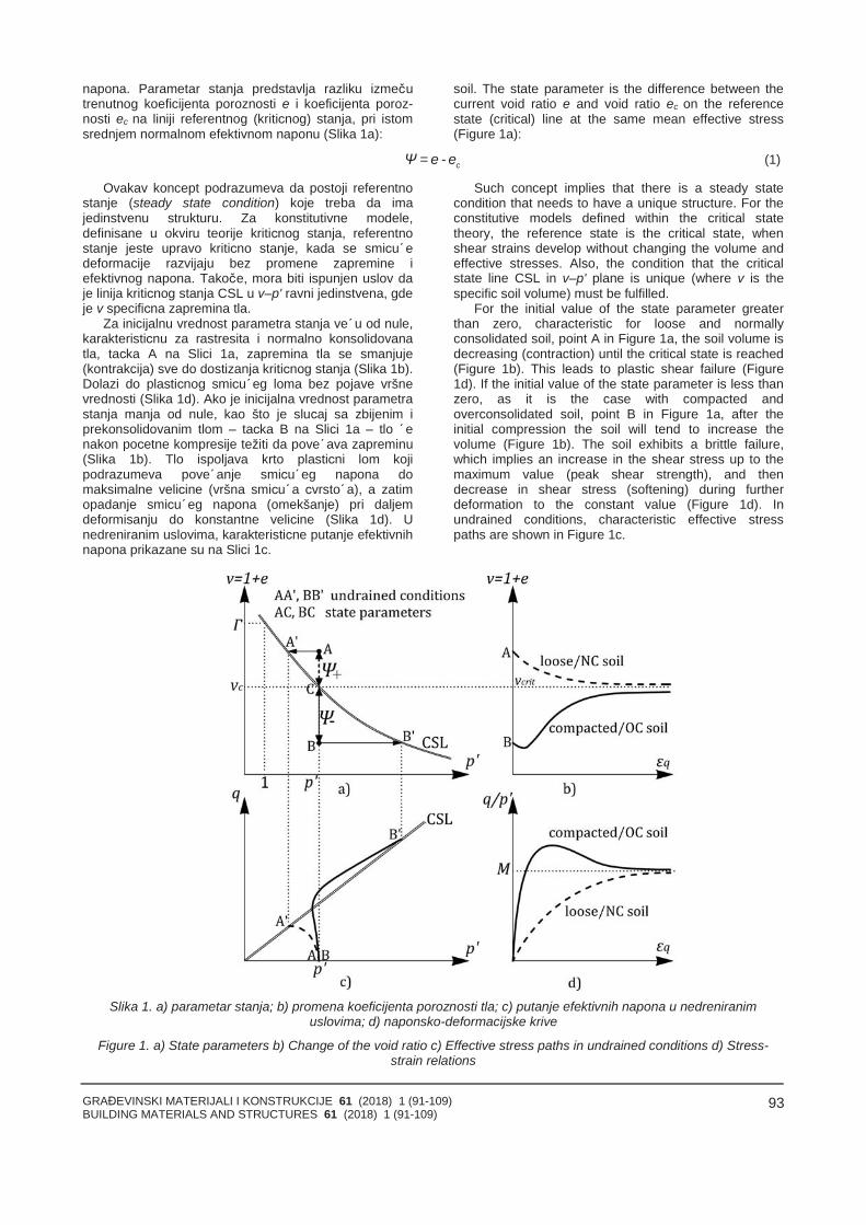
GRAĐEVINSKI MATERIJALI I KONSTRUKCIJE 61 (2018) 1 (91-109)BUILDING MATERIALS AND STRUCTURES 61 (2018) 1 (91-109)
93
napona. Parametar stanja predstavlja razliku izmečutrenutnog koeficijenta poroznosti e i koeficijenta poroz-nosti ec na liniji referentnog (kritičnog) stanja, pri istomsrednjem normalnom efektivnom naponu (Slika 1a):
soil. The state parameter is the difference between thecurrent void ratio e and void ratio ec on the referencestate (critical) line at the same mean effective stress(Figure 1a):
cΨ = e - e (1)
Ovakav koncept podrazumeva da postoji referentnostanje (steady state condition) koje treba da imajedinstvenu strukturu. Za konstitutivne modele,definisane u okviru teorije kritičnog stanja, referentnostanje jeste upravo kritično stanje, kada se smičućedeformacije razvijaju bez promene zapremine iefektivnog napona. Takoče, mora biti ispunjen uslov daje linija kritičnog stanja CSL u v–p' ravni jedinstvena, gdeje v specifična zapremina tla.
Za inicijalnu vrednost parametra stanja veću od nule,karakterističnu za rastresita i normalno konsolidovanatla, tačka A na Slici 1a, zapremina tla se smanjuje(kontrakcija) sve do dostizanja kritičnog stanja (Slika 1b).Dolazi do plastičnog smičućeg loma bez pojave vršnevrednosti (Slika 1d). Ako je inicijalna vrednost parametrastanja manja od nule, kao što je slučaj sa zbijenim iprekonsolidovanim tlom – tačka B na Slici 1a – tlo ćenakon početne kompresije težiti da povećava zapreminu(Slika 1b). Tlo ispoljava krto plastični lom kojipodrazumeva povećanje smičućeg napona domaksimalne veličine (vršna smičuća čvrstoća), a zatimopadanje smičućeg napona (omekšanje) pri daljemdeformisanju do konstantne veličine (Slika 1d). Unedreniranim uslovima, karakteristične putanje efektivnihnapona prikazane su na Slici 1c.
Such concept implies that there is a steady statecondition that needs to have a unique structure. For theconstitutive models defined within the critical statetheory, the reference state is the critical state, whenshear strains develop without changing the volume andeffective stresses. Also, the condition that the criticalstate line CSL in v–p' plane is unique (where v is thespecific soil volume) must be fulfilled.
For the initial value of the state parameter greaterthan zero, characteristic for loose and normallyconsolidated soil, point A in Figure 1a, the soil volume isdecreasing (contraction) until the critical state is reached(Figure 1b). This leads to plastic shear failure (Figure1d). If the initial value of the state parameter is less thanzero, as it is the case with compacted andoverconsolidated soil, point B in Figure 1a, after theinitial compression the soil will tend to increase thevolume (Figure 1b). The soil exhibits a brittle failure,which implies an increase in the shear stress up to themaximum value (peak shear strength), and thendecrease in shear stress (softening) during furtherdeformation to the constant value (Figure 1d). Inundrained conditions, characteristic effective stresspaths are shown in Figure 1c.
Slika 1. a) parametar stanja; b) promena koeficijenta poroznosti tla; c) putanje efektivnih napona u nedreniranimuslovima; d) naponsko-deformacijske krive
Figure 1. a) State parameters b) Change of the void ratio c) Effective stress paths in undrained conditions d) Stress-strain relations
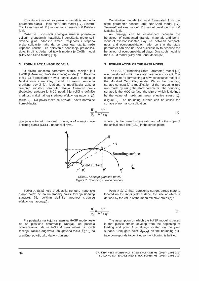
GRAĐEVINSKI MATERIJALI I KONSTRUKCIJE 61 (2018) 1 (91-109)BUILDING MATERIALS AND STRUCTURES 61 (2018) 1 (91-109)
94
Konstitutivni modeli za pesak – nastali iz konceptaparametra stanja – jesu: Nor-Sand model [17], Severn-Trent sand model [11], model koji su razvili Li & Dafalias[23].
Može se uspostaviti analogija između ponašanjazbijenih granularnih materijala i ponašanja prekonsoli-dovane gline, odnosno između zbijenosti i stepenaprekonsolidacije, tako da se parametar stanja možeuspešno koristiti i za opisivanje ponašanja prekonsoli-dovanih glina. Jedan od takvih modela je CASM model(Clay And Send Model) [51].
3 FORMULACIJA HASP MODELA
U okviru koncepta parametra stanja, razvijen je iHASP (HArdening State Parameter) model [18]. Polaznatačka za formulisanje novog konstitutivnog modela jeModifikovani Cam Clay model. U okviru konceptagranične površi [9], izvršena je modifikacija zakonaojačanja koristeći parametar stanja. Granična površ(bounding surface) je MCC površ čiju veličinu definiševrednost maksimalnog srednjeg efektivnog napona 0p(Slika 2). Ova površ može se nazvati i površ normalnekonsolidacije:
Constitutive models for sand formulated from thestate parameter concept are: Nor-Sand model [17],Severn-Trent sand model [11], model developed by Li &Dafalias [23].
An analogy can be established between thebehaviour of compacted granular materials and beha-viour of overconsolidated clay, i.e. between compact-ness and overconsolidation ratio, so that the stateparameter can also be used successfully to describe thebehaviour of overconsolidated clays. One such model isthe CASM model (Clay and Send Model) [51].
3 FORMULATION OF THE HASP MODEL
The HASP (HArdening State Parameter) model [18]was developed within the state parameter concept. Thestarting point for formulating a new constitutive model isthe Modified Cam Clay model. Within the boundingsurface concept [9] a modification of the hardening rulewas made by using the state parameter. The boundingsurface is the MCC surface, the size of which is definedby the value of maximum mean effective stress 0p(Figure 2). The bounding surface can be called thesurface of normal consolidation:
2
2 20
p M=p M +η
(2)
gde je η – trenutni naponski odnos, a M – nagib linijekritičnog stanja (CSL) u naponskoj ravni.
where η is the current stress ratio and M is the slope ofthe critical state line (CSL) in the stress plane.
Slika 2. Koncept granične površiFigure 2. Bounding surface concept
Tačka A (p',q) koja predstavlja trenutno naponskostanje nalazi se na unutrašnjoj površi tečenja (loadingsurface), čiju veličinu definiše vrednost srednjegefektivnog napona 0p :
Point A (p',q) that represents current stress state islocated on the inner yield surface, the size of which isdefined by the value of the mean effective stress 0p :
2
2 20
p M=p M +η
(3)
Pretpostavka na kojoj se zasniva HASP model jesteda se plastične deformacije razvijaju od početkaopterećivanja i da se tačka A uvek nalazi na površitečenja. Tački A odgovara konjugovana tačka A(p ,q) nagraničnoj površi, tako da je ispunjeno:
The assumption on which the HASP model is basedis that plastic strains develop from the beginning ofloading and point A is always located on the yieldsurface. Conjugate point A(p ,q) on the bounding sur-face corresponds to point A, so the following is fulfilled:
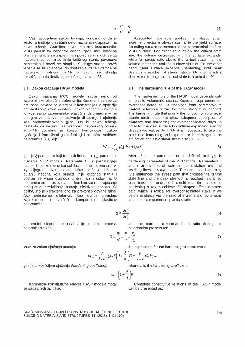
GRAĐEVINSKI MATERIJALI I KONSTRUKCIJE 61 (2018) 1 (91-109)BUILDING MATERIALS AND STRUCTURES 61 (2018) 1 (91-109)
95
q qη= =p p
(4)
Važi asocijativni zakon tečenja, odnosno to da jevektor priraštaja plastičnih deformacija uvek upravan napovrš tečenja. Granična površ ima sve karakteristikeMCC površi: za naponski odnos ispod linije kritičnogstanja smanjuje se zapremina i površ se širi, dok se zanaponski odnos iznad linije kritičnog stanja povećavazapremina i površ se skuplja. S druge strane, površtečenja se širi (ojačanje) do dostizanja vršne čvrstoće prinaponskom odnosu η=Mf, a zatim se skuplja(omekšanje) do dostizanja kritičnog stanja η=M.
3.1 Zakon ojačanja HASP modela
Zakon ojačanja MCC modela zavisi samo odzapreminske plastične deformacije. Generalni zahtev zaprekonsolidovana tla je prelaz iz kompresije u ekspanzijupre dostizanja vršne čvrstoće. Zakon ojačanja – koji je ufunkciji samo zapreminske plastične deformacije – neomogućava adekvatno opisivanje dilatancije i ojačanjakod prekonsolidovanih glina. Da bi površ tečenjanastavila da se širi i za vrednosti naponskog odnosaM<η<Mf, potrebno je koristiti kombinovani zakonojačanja i formulisati ga u funkciji i plastične smičućedeformacije [28, 50]:
Associated flow rule applies, i.e. plastic strainincrement vector is always normal to the yield surface.Bounding surface possesses all the characteristics of theMCC surface. For stress ratio below the critical stateline, the volume decreases and the surface expands,while for stress ratio above the critical state line, thevolume increases and the surface shrinks. On the otherhand, yield surface expands (hardening) until peakstrength is reached at stress ratio η=Mf, after which itshrinks (softening) until critical state is reached η=M.
3.1 The hardening rule of the HASP model
The hardening rule of the HASP model depends onlyon plastic volumetric strains. General requirement foroverconsolidated soil is transition from contractive todilatant behaviour before the peak strength is reached.The hardening rule that is only the function of volumetricplastic strain does not allow adequate description ofdilatancy and hardening for overconsolidated clays. Inorder for the yield surface to continue expanding also forstress ratio values M<η<Mf, it is necessary to use thecombined hardening and express the hardening rule asa function of plastic shear strain also [28, 50]:
p pv q0 0
vdp = p dε +ξdελ -κ (5)
gde je ξ parametar koji treba definisati, a 0p parametarojačanja MCC modela. Parametri λ i κ predstavljajunagibe linije izotropne konsolidacije i linije bubrenja u v-lnp' dijagramu. Kombinovani zakon ojačanja utiče naputanju napona koja prelazi liniju kritičnog stanja idostiže se vršna čvrstoća u dreniranim uslovima. Unedreniranim uslovima, kombinovano ojačanjeomogućava predviđanje putanje efektivnih napona „S”oblika, što je karakteristično za prekonsolidovane gline.Ako definišemo dilatanciju kao odnos priraštajazapreminske i smičuće komponente plastičnedeformacije:
where ξ is the parameter to be defined, and 0p ishardening parameter of the MCC model. Parameters λand κ are slopes of isotropic consolidation line andswelling lines in v-lnp' plane. The combined hardeningrule influences the stress path that crosses the criticalstate line and the peak strength is reached in drainedconditions. In undrained conditions, the combinedhardening is key to achieve "S" shaped effective stresspath, which is typical for overconsolidated clays. If wedefine dilatancy via the ratio of increment of volumetricand shear component of plastic strain:
pvpq
dεd =
dε(6)
a trenutni stepen prekonsolidacije u toku procesadeformisanja kao:
and the current overconsolidation ratio during thedeformation process as:
0
0
pp qR = = =p q p
(7)
izraz za zakon ojačanja postaje: the expression for the hardening rule becomes:
p p0 0 v 0 v
v ξ vdp = p dε 1+ R = p dε ωλ - κ d λ - κ
(8)
gde je ω koeficijent ojačanja (hardening coefficient): where ω is the hardening coefficient:
ξω= 1+ Rd
(9)
Kompletne konstitutivne relacije HASP modela moguse sada predstaviti kao:
Complete constitutive relations of the HASP modelcan be presented as:
GRAĐEVINSKI MATERIJALI I KONSTRUKCIJE 61 (2018) 1 (91-109)BUILDING MATERIALS AND STRUCTURES 61 (2018) 1 (91-109)
96
2 2
2 2 2 2v
2q
2 2 2 2 2 2
1 λ - κ 1 M - η λ - κ 1 η+K vp ω vp ωM + η M + ηdε dp
=dε λ - κ 1 η 1 λ - κ 1 η dq+
vp ω G vp ωM + η M + η M - η
2
2 43
(10)
Koeficijent ojačanja ω direktno utiče i na veličinuplastičnih deformacija, tako da se adekvatnomformulacijom koeficijenta ojačanja mogu značajnoredukovati plastične deformacije prekonsolidovane glineu početnoj fazi opterećivanja, kada MCC model predviđasamo elastične deformacije. Na taj način je mogućepretpostaviti da tlo od samog početka opterećivanja trpi iplastične deformacije, koje su tada veoma male. Kakose u procesu deformisanja polako smanjuje i stepenprekonsolidacije tla, tako se i koeficijent ω smanjuje(ω→1) i plastične deformacije postaju dominantne. Pridostizanju vršne čvrstoće (prelaz iz ojačanja uomekšanje), uočava se maksimalni gradijent promenezapremine – maksimalna dilatancija i iz izraza (8) sledida je ω=0. Tada važi relacija maxξ = -d , što znači daparametar ξ predstavlja maksimalnu vrednost dilatancijepri vršnoj čvrstoći u dreniranim uslovima [29].
U izrazu za koeficijent ojačanja (9) odnos ξ/d jedefinisan preko parametra stanja. Parametar stanja zatrenutnu naponsku tačku (Slika 3) može se izraziti kao:
The hardening coefficient ω directly affects the valueof the plastic strains, and thus, with the adequateformulation of the hardening coefficient, it is possible tosignificantly reduce the plastic strains of overcon-solidated clay in the initial load phase, when the MCCmodel predicts only elastic strains. It is then possible toassume that soil deforms plastically from the verybeginning of loading. As the overconsolidation ratio ofsoil decreases in the deformation process, the hardeningcoefficient ω also decreases (ω→1) and plastic strainsbecome dominant. When reaching the peak strength(transition from hardening to softening) the maximumvolume change gradient is observed – maximumdilatancy and from expression (8) it can be concludedthat ω=0. Then the relation maxξ = -d applies, whichmeans that parameter ξ is the maximum dilatancy valueat peak strength in drained conditions [29].
In the expression for hardening coefficient (9) theration ξ/d is defined via the state parameter. Stateparameter for the current stress point (Figure 3) can beexpressed as:
Ψ =v + λlnp - Γ (11)
gde je Γ – parametar koji definiše položaj CSL ukompresionoj p’-v ravni. Parametar stanja je negativanza jako prekonsolidovane gline, dok je za lakoprekonsolidovane i normalno konsolidovane gline –pozitivan. Parametar stanja za imaginarnu naponskutačku iznosi:
where Γ is the parameter that defines the position ofCSL in compression p’-v plain. State parameter isnegative for highly overconsolidated clays, while forlightly overconsolidated and normally overconsolidatedclays it is positive. State parameter for conjugate stresspoint is:
2
2 2
MΨ = λ - κ lnM + η
2(12)
Stepen prekonsolidacije (7) može se takođe izrazitikao funkcija parametara stanja:
The overconsolidation ratio (7) can also beexpressed as a function of state parameter:
p q Ψ -ΨR = = = expp q λ - κ
(13)
Na osnovu velikog broja triaksijalnih opita na pesku iprekonsolidovanoj glini, Parry [34] je pokazao da jedilatancija pri vršnoj čvrstoći u dreniranim uslovimaproporcionalna stepenu prekonsolidacije, a Been &Jefferies [4] su pokazali da je parametar stanja linearnoproporcionalan dilatanciji. U skladu s navedenim iimajući u vidu vezu između parametra stanja i stepenaprekonsolidacije (13), pretpostavljeno je da jemaksimalna vrednost dilatancije u direktnoj zavisnosti odΨ -Ψ . Takođe, može se pokazati da se dilatancijamenja na sličan način kao parametar stanja zaimaginarnu tačku Ψ . Na osnovu navedenog, sledi da seodnos ξ/d može izraziti preko parametra stanja kao:
On the basis of a large number of triaxial tests on sandand overconsolidated clays, Parry [34] showed that thedilatancy at peak strength in drained conditions is inproportion to the overconsolidation ratio. Also, Been &Jefferies [4] showed that the state parameter is in linearproportion to the dilatancy. In accordance with theaforementioned and taking into account the relationshipbetween the state parameter and overconsolidation ratio(13), it is assumed that the maximum value of dilatancyis directly dependent on Ψ -Ψ . On the other hand, itcan be shown that the dilatancy changes in a similarmanner as the state parameter for conjugate stress pointΨ . Based on the above, it can be concluded that theratio ξ/d can be expressed via the state parameter:
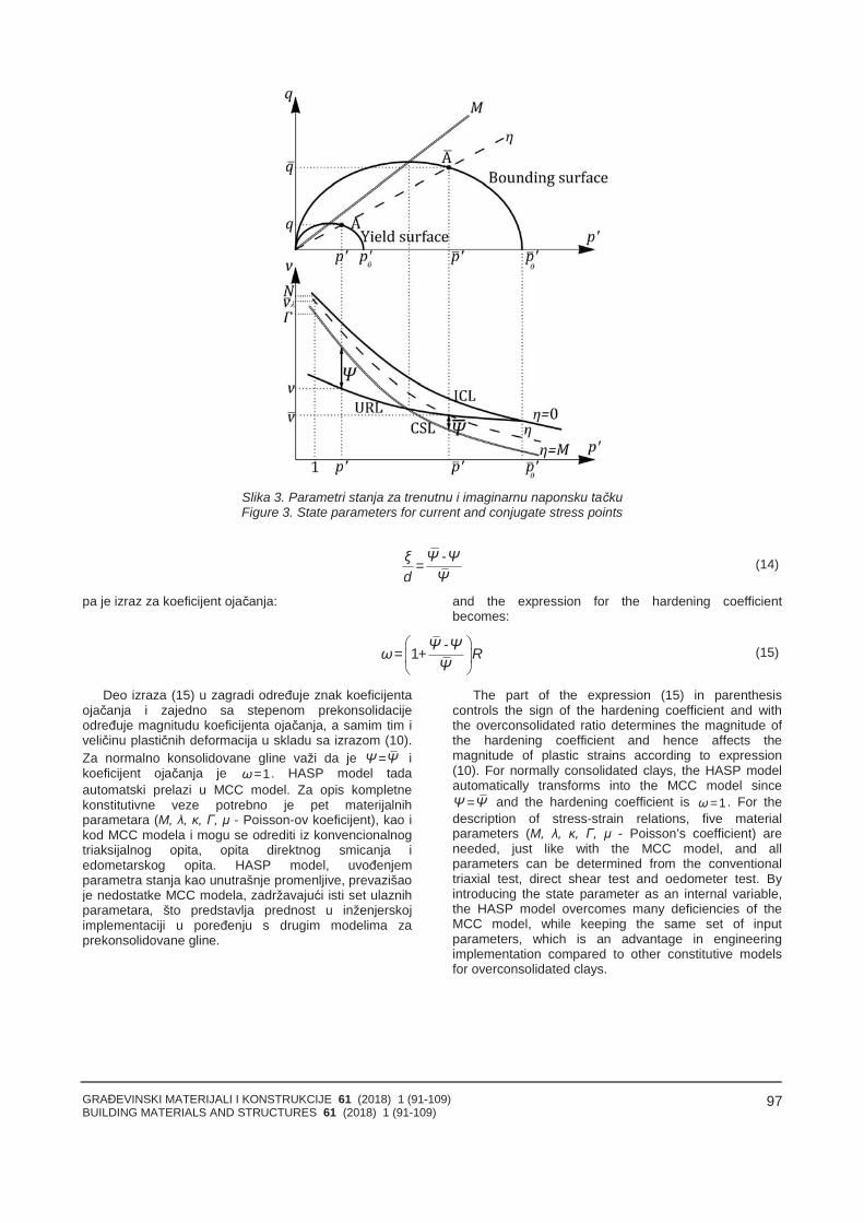
GRAĐEVINSKI MATERIJALI I KONSTRUKCIJE 61 (2018) 1 (91-109)BUILDING MATERIALS AND STRUCTURES 61 (2018) 1 (91-109)
97
Slika 3. Parametri stanja za trenutnu i imaginarnu naponsku tačkuFigure 3. State parameters for current and conjugate stress points
ξ Ψ -Ψ=d Ψ
(14)
pa je izraz za koeficijent ojačanja: and the expression for the hardening coefficientbecomes:
Ψ -Ψω= + RΨ
1 (15)
Deo izraza (15) u zagradi određuje znak koeficijentaojačanja i zajedno sa stepenom prekonsolidacijeodređuje magnitudu koeficijenta ojačanja, a samim tim iveličinu plastičnih deformacija u skladu sa izrazom (10).Za normalno konsolidovane gline važi da je Ψ=Ψ ikoeficijent ojačanja je ω=1. HASP model tadaautomatski prelazi u MCC model. Za opis kompletnekonstitutivne veze potrebno je pet materijalnihparametara (M, λ, κ, Γ, μ - Poisson-ov koeficijent), kao ikod MCC modela i mogu se odrediti iz konvencionalnogtriaksijalnog opita, opita direktnog smicanja iedometarskog opita. HASP model, uvođenjemparametra stanja kao unutrašnje promenljive, prevazišaoje nedostatke MCC modela, zadržavajući isti set ulaznihparametara, što predstavlja prednost u inženjerskojimplementaciji u poređenju s drugim modelima zaprekonsolidovane gline.
The part of the expression (15) in parenthesiscontrols the sign of the hardening coefficient and withthe overconsolidated ratio determines the magnitude ofthe hardening coefficient and hence affects themagnitude of plastic strains according to expression(10). For normally consolidated clays, the HASP modelautomatically transforms into the MCC model sinceΨ =Ψ and the hardening coefficient is ω=1. For thedescription of stress-strain relations, five materialparameters (M, λ, κ, Γ, μ - Poisson’s coefficient) areneeded, just like with the MCC model, and allparameters can be determined from the conventionaltriaxial test, direct shear test and oedometer test. Byintroducing the state parameter as an internal variable,the HASP model overcomes many deficiencies of theMCC model, while keeping the same set of inputparameters, which is an advantage in engineeringimplementation compared to other constitutive modelsfor overconsolidated clays.
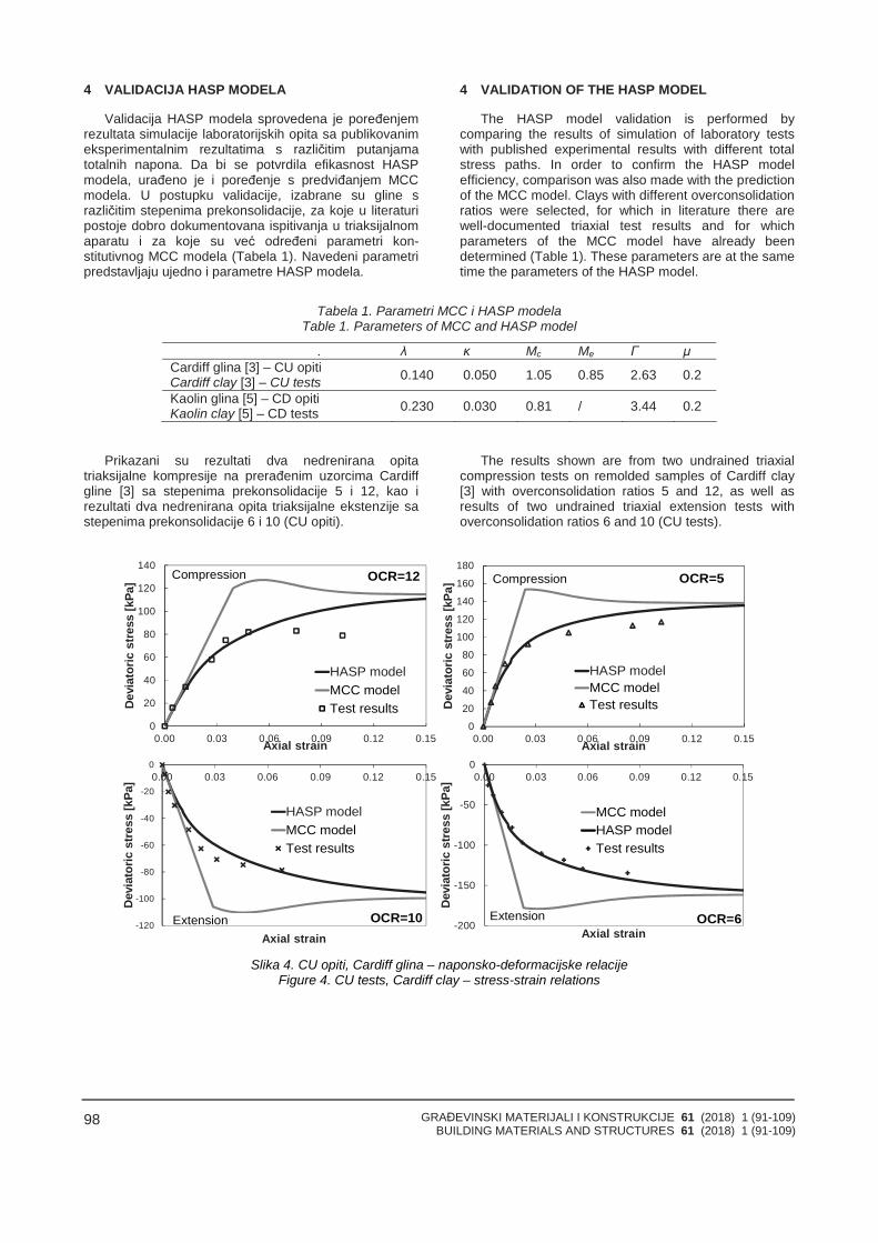
GRAĐEVINSKI MATERIJALI I KONSTRUKCIJE 61 (2018) 1 (91-109)BUILDING MATERIALS AND STRUCTURES 61 (2018) 1 (91-109)
98
4 VALIDACIJA HASP MODELA
Validacija HASP modela sprovedena je poređenjemrezultata simulacije laboratorijskih opita sa publikovanimeksperimentalnim rezultatima s različitim putanjamatotalnih napona. Da bi se potvrdila efikasnost HASPmodela, urađeno je i poređenje s predviđanjem MCCmodela. U postupku validacije, izabrane su gline srazličitim stepenima prekonsolidacije, za koje u literaturipostoje dobro dokumentovana ispitivanja u triaksijalnomaparatu i za koje su već određeni parametri kon-stitutivnog MCC modela (Tabela 1). Navedeni parametripredstavljaju ujedno i parametre HASP modela.
4 VALIDATION OF THE HASP MODEL
The HASP model validation is performed bycomparing the results of simulation of laboratory testswith published experimental results with different totalstress paths. In order to confirm the HASP modelefficiency, comparison was also made with the predictionof the MCC model. Clays with different overconsolidationratios were selected, for which in literature there arewell-documented triaxial test results and for whichparameters of the MCC model have already beendetermined (Table 1). These parameters are at the sametime the parameters of the HASP model.
Tabela 1. Parametri MCC i HASP modelaTable 1. Parameters of MCC and HASP model
. λ κ Mc Me Γ μCardiff glina [3] – CU opitiCardiff clay [3] – CU tests 0.140 0.050 1.05 0.85 2.63 0.2
Kaolin glina [5] – CD opitiKaolin clay [5] – CD tests 0.230 0.030 0.81 / 3.44 0.2
Prikazani su rezultati dva nedrenirana opitatriaksijalne kompresije na prerađenim uzorcima Cardiffgline [3] sa stepenima prekonsolidacije 5 i 12, kao irezultati dva nedrenirana opita triaksijalne ekstenzije sastepenima prekonsolidacije 6 i 10 (CU opiti).
The results shown are from two undrained triaxialcompression tests on remolded samples of Cardiff clay[3] with overconsolidation ratios 5 and 12, as well asresults of two undrained triaxial extension tests withoverconsolidation ratios 6 and 10 (CU tests).
0
20
40
60
80
100
120
140
0.00 0.03 0.06 0.09 0.12 0.15
Dev
iato
ricst
ress
[kPa
]
Axial strain
HASP modelMCC modelTest results
OCR=12Compression
0
20
40
60
80
100
120
140
160
180
0.00 0.03 0.06 0.09 0.12 0.15
Dev
iato
ricst
ress
[kPa
]
Axial strain
HASP modelMCC modelTest results
OCR=5Compression
-120
-100
-80
-60
-40
-20
00.00 0.03 0.06 0.09 0.12 0.15
Dev
iato
ricst
ress
[kPa
]
Axial strain
HASP modelMCC modelTest results
Extension OCR=10 -200
-150
-100
-50
00.00 0.03 0.06 0.09 0.12 0.15
Dev
iato
ricst
ress
[kPa
]
Axial strain
MCC modelHASP modelTest results
Extension OCR=6
Slika 4. CU opiti, Cardiff glina – naponsko-deformacijske relacijeFigure 4. CU tests, Cardiff clay – stress-strain relations
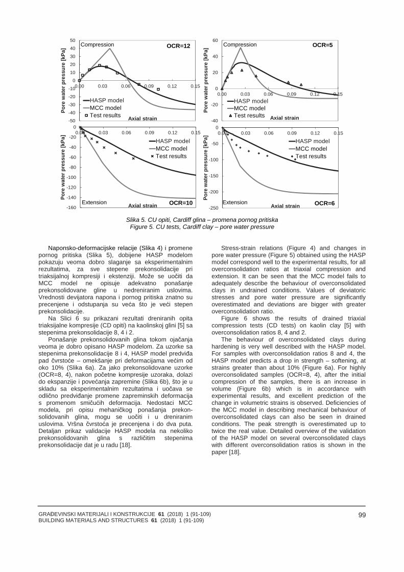
GRAĐEVINSKI MATERIJALI I KONSTRUKCIJE 61 (2018) 1 (91-109)BUILDING MATERIALS AND STRUCTURES 61 (2018) 1 (91-109)
99
-50
-40
-30
-20
-10
0
10
20
30
40
50
0.00 0.03 0.06 0.09 0.12 0.15
Pore
wat
erpr
essu
re[k
Pa]
Axial strain
HASP modelMCC modelTest results
OCR=12Compression
-40
-20
0
20
40
60
0.00 0.03 0.06 0.09 0.12 0.15
Pore
wat
erpr
essu
re[k
Pa]
Axial strain
HASP modelMCC modelTest results
OCR=5Compression
-160
-140
-120
-100
-80
-60
-40
-20
00.00 0.03 0.06 0.09 0.12 0.15
Pore
wat
erpr
essu
re[k
Pa]
Axial strain
HASP modelMCC modelTest results
OCR=10Extension-250
-200
-150
-100
-50
00.00 0.03 0.06 0.09 0.12 0.15
Pore
wat
erpr
essu
re[k
Pa]
Axial strain
HASP modelMCC modelTest results
OCR=6Extension
Slika 5. CU opiti, Cardiff glina – promena pornog pritiskaFigure 5. CU tests, Cardiff clay – pore water pressure
Naponsko-deformacijske relacije (Slika 4) i promenepornog pritiska (Slika 5), dobijene HASP modelompokazuju veoma dobro slaganje sa eksperimentalnimrezultatima, za sve stepene prekonsolidacije pritriaksijalnoj kompresiji i ekstenziji. Može se uočiti daMCC model ne opisuje adekvatno ponašanjeprekonsolidovane gline u nedreniranim uslovima.Vrednosti devijatora napona i pornog pritiska znatno suprecenjene i odstupanja su veća što je veći stepenprekonsolidacije.
Na Slici 6 su prikazani rezultati dreniranih opitatriaksijalne kompresije (CD opiti) na kaolinskoj glini [5] sastepenima prekonsolidacije 8, 4 i 2.
Ponašanje prekonsolidovanih glina tokom ojačanjaveoma je dobro opisano HASP modelom. Za uzorke sastepenima prekonsolidacije 8 i 4, HASP model predviđapad čvrstoće – omekšanje pri deformacijama većim odoko 10% (Slika 6a). Za jako prekonsolidovane uzorke(OCR=8, 4), nakon početne kompresije uzoraka, dolazido ekspanzije i povećanja zapremine (Slika 6b), što je uskladu sa eksperimentalnim rezultatima i uočava seodlično predviđanje promene zapreminskih deformacijas promenom smičućih deformacija. Nedostaci MCCmodela, pri opisu mehaničkog ponašanja prekon-solidovanih glina, mogu se uočiti i u dreniranimuslovima. Vršna čvrstoća je precenjena i do dva puta.Detaljan prikaz validacije HASP modela na nekolikoprekonsolidovanih glina s različitim stepenimaprekonsolidacije dat je u radu [18].
Stress-strain relations (Figure 4) and changes inpore water pressure (Figure 5) obtained using the HASPmodel correspond well to the experimental results, for alloverconsolidation ratios at triaxial compression andextension. It can be seen that the MCC model fails toadequately describe the behaviour of overconsolidatedclays in undrained conditions. Values of deviatoricstresses and pore water pressure are significantlyoverestimated and deviations are bigger with greateroverconsolidation ratio.
Figure 6 shows the results of drained triaxialcompression tests (CD tests) on kaolin clay [5] withoverconsolidation ratios 8, 4 and 2.
The behaviour of overconsolidated clays duringhardening is very well described with the HASP model.For samples with overconsolidation ratios 8 and 4, theHASP model predicts a drop in strength – softening, atstrains greater than about 10% (Figure 6a). For highlyoverconsolidated samples (OCR=8, 4), after the initialcompression of the samples, there is an increase involume (Figure 6b) which is in accordance withexperimental results, and excellent prediction of thechange in volumetric strains is observed. Deficiencies ofthe MCC model in describing mechanical behaviour ofoverconsolidated clays can also be seen in drainedconditions. The peak strength is overestimated up totwice the real value. Detailed overview of the validationof the HASP model on several overconsolidated clayswith different overconsolidation ratios is shown in thepaper [18].
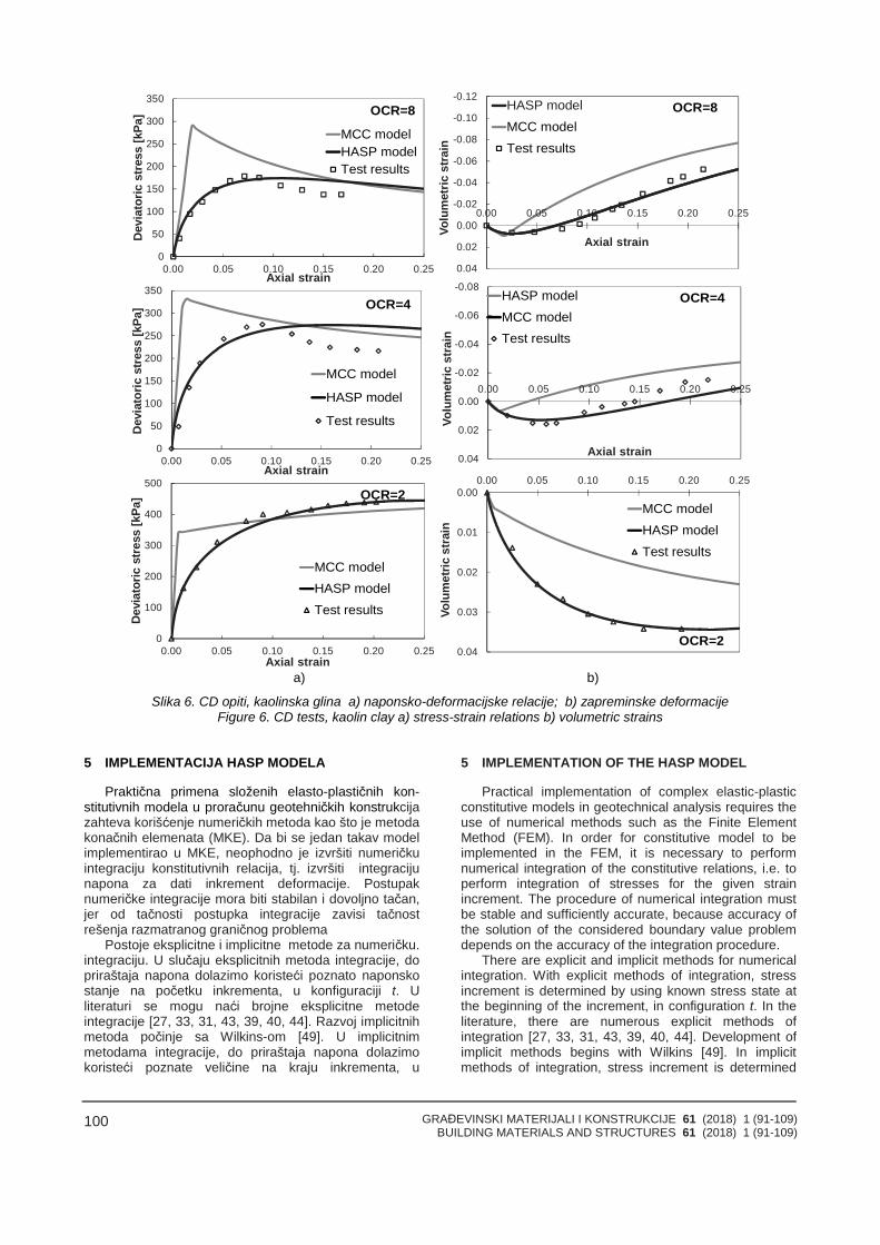
GRAĐEVINSKI MATERIJALI I KONSTRUKCIJE 61 (2018) 1 (91-109)BUILDING MATERIALS AND STRUCTURES 61 (2018) 1 (91-109)
100
0
50
100
150
200
250
300
350
0.00 0.05 0.10 0.15 0.20 0.25
Dev
iato
ricst
ress
[kPa
]
Axial strain
MCC modelHASP modelTest results
OCR=8
0
50
100
150
200
250
300
350
0.00 0.05 0.10 0.15 0.20 0.25
Dev
iato
ricst
ress
[kPa
]
Axial strain
MCC model
HASP model
Test results
OCR=4
0
100
200
300
400
500
0.00 0.05 0.10 0.15 0.20 0.25
Dev
iato
ricst
ress
[kPa
]
Axial strain
MCC modelHASP modelTest results
OCR=2
-0.12
-0.10
-0.08
-0.06
-0.04
-0.02
0.00
0.02
0.04
0.00 0.05 0.10 0.15 0.20 0.25
Volu
met
ricst
rain
Axial strain
HASP modelMCC modelTest results
OCR=8
-0.08
-0.06
-0.04
-0.02
0.00
0.02
0.04
0.00 0.05 0.10 0.15 0.20 0.25
Volu
met
ricst
rain
Axial strain
HASP modelMCC modelTest results
OCR=4
0.00
0.01
0.02
0.03
0.04
0.00 0.05 0.10 0.15 0.20 0.25
Volu
met
ricst
rain
MCC modelHASP modelTest results
OCR=2
a) b)
Slika 6. CD opiti, kaolinska glina a) naponsko-deformacijske relacije; b) zapreminske deformacijeFigure 6. CD tests, kaolin clay a) stress-strain relations b) volumetric strains
5 IMPLEMENTACIJA HASP MODELA
Praktična primena složenih elasto-plastičnih kon-stitutivnih modela u proračunu geotehničkih konstrukcijazahteva korišćenje numeričkih metoda kao što je metodakonačnih elemenata (MKE). Da bi se jedan takav modelimplementirao u MKE, neophodno je izvršiti numeričkuintegraciju konstitutivnih relacija, tj. izvršiti integracijunapona za dati inkrement deformacije. Postupaknumeričke integracije mora biti stabilan i dovoljno tačan,jer od tačnosti postupka integracije zavisi tačnostrešenja razmatranog graničnog problema
Postoje eksplicitne i implicitne metode za numeričku.
5 IMPLEMENTATION OF THE HASP MODEL
Practical implementation of complex elastic-plasticconstitutive models in geotechnical analysis requires theuse of numerical methods such as the Finite ElementMethod (FEM). In order for constitutive model to beimplemented in the FEM, it is necessary to performnumerical integration of the constitutive relations, i.e. toperform integration of stresses for the given strainincrement. The procedure of numerical integration mustbe stable and sufficiently accurate, because accuracy ofthe solution of the considered boundary value problemdepends on the accuracy of the integration procedure.
integraciju. U slučaju eksplicitnih metoda integracije, dopriraštaja napona dolazimo koristeći poznato naponskostanje na početku inkrementa, u konfiguraciji t. Uliteraturi se mogu naći brojne eksplicitne metodeintegracije [27, 33, 31, 43, 39, 40, 44]. Razvoj implicitnihmetoda počinje sa Wilkins-om [49]. U implicitnimmetodama integracije, do priraštaja napona dolazimokoristeći poznate veličine na kraju inkrementa, u
There are explicit and implicit methods for numericalintegration. With explicit methods of integration, stressincrement is determined by using known stress state atthe beginning of the increment, in configuration t. In theliterature, there are numerous explicit methods ofintegration [27, 33, 31, 43, 39, 40, 44]. Development ofimplicit methods begins with Wilkins [49]. In implicitmethods of integration, stress increment is determined
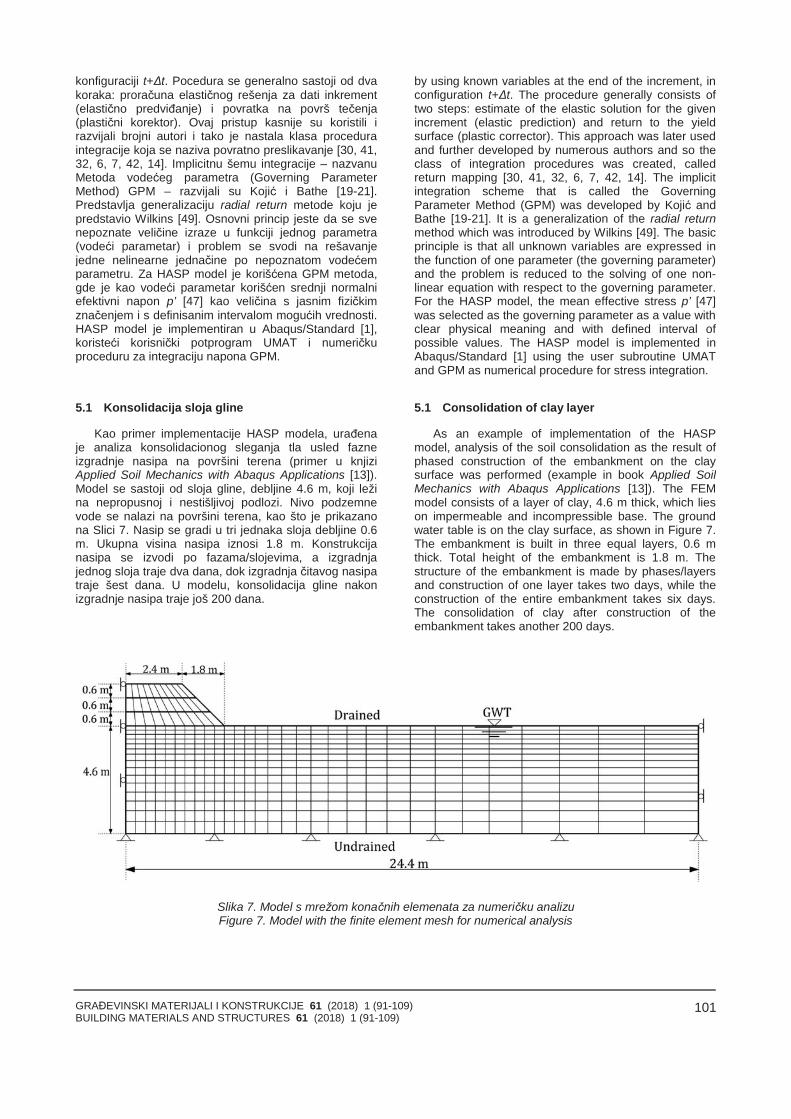
GRAĐEVINSKI MATERIJALI I KONSTRUKCIJE 61 (2018) 1 (91-109)BUILDING MATERIALS AND STRUCTURES 61 (2018) 1 (91-109)
101
konfiguraciji t+Δt. Pocedura se generalno sastoji od dvakoraka: proračuna elastičnog rešenja za dati inkrement(elastično predviđanje) i povratka na površ tečenja(plastični korektor). Ovaj pristup kasnije su koristili irazvijali brojni autori i tako je nastala klasa proceduraintegracije koja se naziva povratno preslikavanje [30, 41,32, 6, 7, 42, 14]. Implicitnu šemu integracije – nazvanuMetoda vodećeg parametra (Governing ParameterMethod) GPM – razvijali su Kojić i Bathe [19-21].Predstavlja generalizaciju radial return metode koju jepredstavio Wilkins [49]. Osnovni princip jeste da se svenepoznate veličine izraze u funkciji jednog parametra(vodeći parametar) i problem se svodi na rešavanjejedne nelinearne jednačine po nepoznatom vodećemparametru. Za HASP model je korišćena GPM metoda,gde je kao vodeći parametar korišćen srednji normalniefektivni napon p’ [47] kao veličina s jasnim fizičkimznačenjem i s definisanim intervalom mogućih vrednosti.HASP model je implementiran u Abaqus/Standard [1],koristeći korisnički potprogram UMAT i numeričkuproceduru za integraciju napona GPM.
5.1 Konsolidacija sloja gline
Kao primer implementacije HASP modela, urađenaje analiza konsolidacionog sleganja tla usled fazneizgradnje nasipa na površini terena (primer u knjiziApplied Soil Mechanics with Abaqus Applications [13]).Model se sastoji od sloja gline, debljine 4.6 m, koji ležina nepropusnoj i nestišljivoj podlozi. Nivo podzemnevode se nalazi na površini terena, kao što je prikazanona Slici 7. Nasip se gradi u tri jednaka sloja debljine 0.6m. Ukupna visina nasipa iznosi 1.8 m. Konstrukcijanasipa se izvodi po fazama/slojevima, a izgradnjajednog sloja traje dva dana, dok izgradnja čitavog nasipatraje šest dana. U modelu, konsolidacija gline nakonizgradnje nasipa traje još 200 dana.
by using known variables at the end of the increment, inconfiguration t+Δt. The procedure generally consists oftwo steps: estimate of the elastic solution for the givenincrement (elastic prediction) and return to the yieldsurface (plastic corrector). This approach was later usedand further developed by numerous authors and so theclass of integration procedures was created, calledreturn mapping [30, 41, 32, 6, 7, 42, 14]. The implicitintegration scheme that is called the GoverningParameter Method (GPM) was developed by Kojić andBathe [19-21]. It is a generalization of the radial returnmethod which was introduced by Wilkins [49]. The basicprinciple is that all unknown variables are expressed inthe function of one parameter (the governing parameter)and the problem is reduced to the solving of one non-linear equation with respect to the governing parameter.For the HASP model, the mean effective stress p’ [47]was selected as the governing parameter as a value withclear physical meaning and with defined interval ofpossible values. The HASP model is implemented inAbaqus/Standard [1] using the user subroutine UMATand GPM as numerical procedure for stress integration.
5.1 Consolidation of clay layer
As an example of implementation of the HASPmodel, analysis of the soil consolidation as the result ofphased construction of the embankment on the claysurface was performed (example in book Applied SoilMechanics with Abaqus Applications [13]). The FEMmodel consists of a layer of clay, 4.6 m thick, which lieson impermeable and incompressible base. The groundwater table is on the clay surface, as shown in Figure 7.The embankment is built in three equal layers, 0.6 mthick. Total height of the embankment is 1.8 m. Thestructure of the embankment is made by phases/layersand construction of one layer takes two days, while theconstruction of the entire embankment takes six days.The consolidation of clay after construction of theembankment takes another 200 days.
Slika 7. Model s mrežom konačnih elemenata za numeričku analizuFigure 7. Model with the finite element mesh for numerical analysis
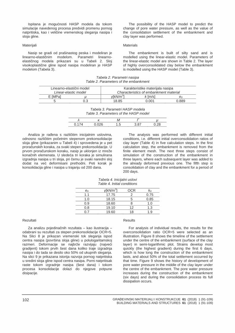
GRAĐEVINSKI MATERIJALI I KONSTRUKCIJE 61 (2018) 1 (91-109)BUILDING MATERIALS AND STRUCTURES 61 (2018) 1 (91-109)
102
Ispitana je mogućnosti HASP modela da tokomsimulacije navedenog procesa predvidi promenu pornognatpritiska, kao i veličine vremenskog sleganja nasipa isloja gline.
Materijali
Nasip se gradi od prašinastog peska i modeliran jelinearno-elastičnim modelom. Parametri linearno-elastičnog modela prikazani su u Tabeli 2. Slojvisokoplastične gline ispod nasipa modeliran je HASPmodelom (Tabela 3).
The possibility of the HASP model to predict thechange of pore water pressure, as well as the value ofthe consolidation settlement of the embankment andclay layer was performed.
Materials
The embankment is built of silty sand and ismodelled using the linear-elastic model. Parameters ofthe linear-elastic model are shown in Table 2. The layerof highly overconsolidated clay below the embankmentis modelled using the HASP model (Table 3).
Tabela 2. Parametri nasipaTable 2. Parameters of the embankment
Linearno-elastični modelLinear-elastic model
Karakteristike materijala nasipaCharacteristics of embankment material
E [MPa] μ γ[kN/m3] k [m/s] e0
5 0.3 18.85 0.001 0.889
Tabela 3. Parametri HASP modelaTable 3. Parameters of the HASP model
λ κ M Γ μ0.174 0.026 1.5 3.87 0.28
Analiza je rađena s različitim inicijalnim uslovima,odnosno različitim početnim stepenom prekonsolidacijesloja gline (prikazanim u Tabeli 4) i sprovedena je u petproračunskih koraka, za svaki stepen prekonsolidacije. Uprvom proračunskom koraku, nasip je uklonjen iz mrežekonačnih elemenata. U sledeća tri koraka je simuliranaizgradnja nasipa u tri sloja, pri čemu je svaki naredni slojdodat na već deformisani prethodni. Peti korak jekonsolidacija gline i nasipa u trajanju od 200 dana.
The analysis was performed with different initialconditions, i.e. different initial overconsolidation ratios ofclay layer (Table 4) in five calculation steps. In the firstcalculation step, the embankment is removed from thefinite element mesh. The next three steps consist ofsimulation of the construction of the embankment inthree layers, where each subsequent layer was added tothe already deformed previous one. The fifth step isconsolidation of clay and the embankment for a period of200 days.
Tabela 4. Inicijalni usloviTable 4. Initial conditions
e0 γ[kN/m3] OCR k0
1.1 17.75 2 0.751.0 18.15 5 0.850.9 18.60 8 1.00.8 19.10 12 1.30.7 19.60 18 1.9
Rezultati
Za analizu pojedinačnih rezultata – kao ilustracija –odabrani su rezultati za stepen prekonsolidacije OCR=5.Na Slici 8 je prikazan vremenski tok sleganja ispodcentra nasipa (površina sloja gline) u polulogaritamskojrazmeri. Deformacije se najbrže razvijaju (najvećigradijent) tokom prvih šest dana koliko traje izgradnjanasipa i do tada se desilo oko 50% od ukupnih sleganja.Na slici 9 je prikazana istorija razvoja pornog natpritiskau sredini sloja gline ispod centra nasipa. Porni natpritisakraste tokom izgradnje nasipa (šest dana) i tokomprocesa konsolidacije dolazi do njegove potpunedisipacije.
Results
For analysis of individual results, the results for theoverconsolidation ratio OCR=5 were selected as anillustration. Figure 8 shows the timeline of the settlementunder the centre of the embankment (surface of the claylayer) in semi-logarithmic plot. Strains develop mostquickly (the highest gradient) during the first 6 days,which is how long the construction of the embankmentlasts, and about 50% of the total settlement occurred bythat time. Figure 9 shows the history of development ofpore water pressure in the middle of the clay layer underthe centre of the embankment. The pore water pressureincreases during the construction of the embankment(six days) and during the consolidation process its fulldissipation occurs.
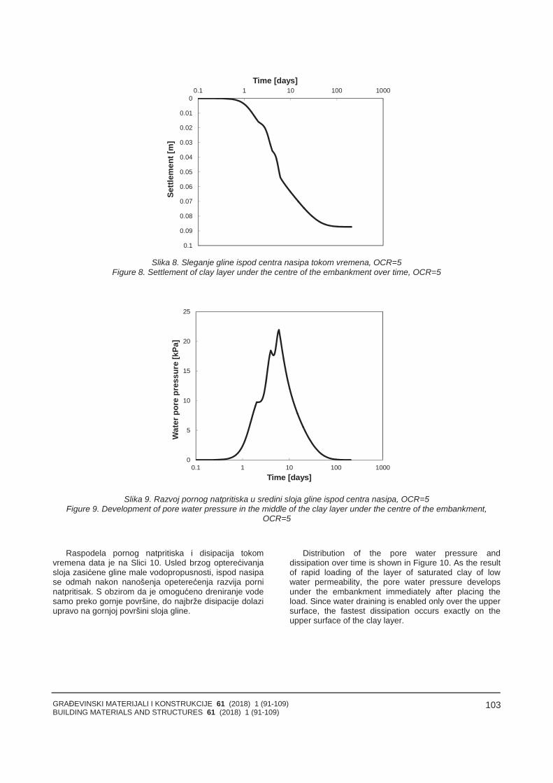
GRAĐEVINSKI MATERIJALI I KONSTRUKCIJE 61 (2018) 1 (91-109)BUILDING MATERIALS AND STRUCTURES 61 (2018) 1 (91-109)
103
0
0.01
0.02
0.03
0.04
0.05
0.06
0.07
0.08
0.09
0.1
0.1 1 10 100 1000
Settl
emen
t[m
]
Time [days]
Slika 8. Sleganje gline ispod centra nasipa tokom vremena, OCR=5Figure 8. Settlement of clay layer under the centre of the embankment over time, OCR=5
0
5
10
15
20
25
0.1 1 10 100 1000
Wat
erpo
repr
essu
re[k
Pa]
Time [days]
Slika 9. Razvoj pornog natpritiska u sredini sloja gline ispod centra nasipa, OCR=5Figure 9. Development of pore water pressure in the middle of the clay layer under the centre of the embankment,
OCR=5
Raspodela pornog natpritiska i disipacija tokomvremena data je na Slici 10. Usled brzog opterećivanjasloja zasićene gline male vodopropusnosti, ispod nasipase odmah nakon nanošenja opeterećenja razvija porninatpritisak. S obzirom da je omogućeno dreniranje vodesamo preko gornje površine, do najbrže disipacije dolaziupravo na gornjoj površini sloja gline.
Distribution of the pore water pressure anddissipation over time is shown in Figure 10. As the resultof rapid loading of the layer of saturated clay of lowwater permeability, the pore water pressure developsunder the embankment immediately after placing theload. Since water draining is enabled only over the uppersurface, the fastest dissipation occurs exactly on theupper surface of the clay layer.
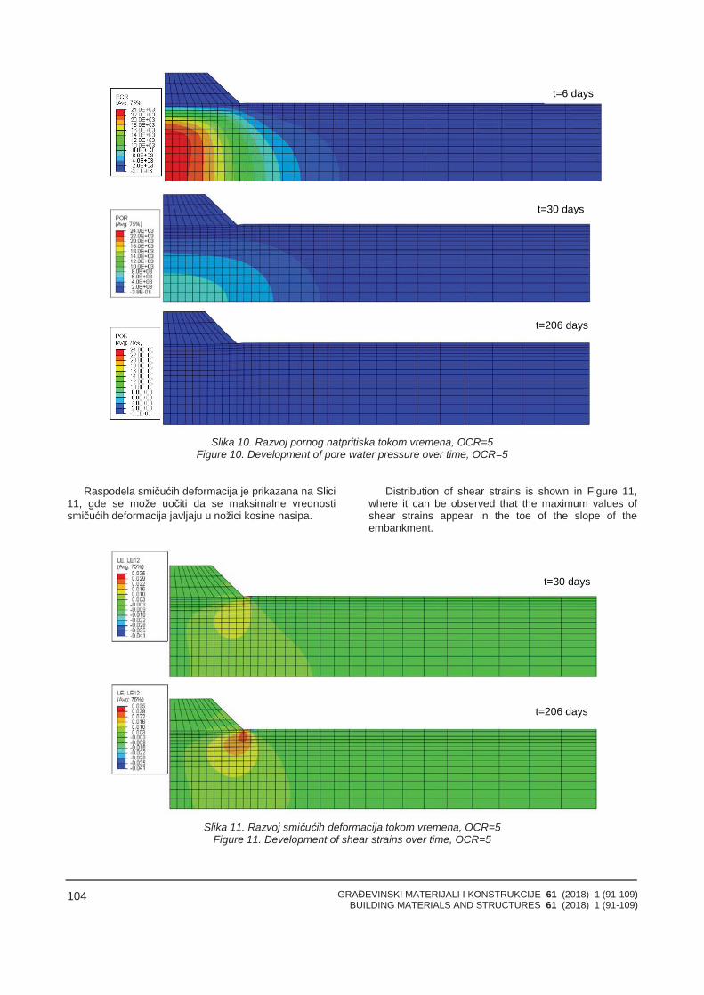
GRAĐEVINSKI MATERIJALI I KONSTRUKCIJE 61 (2018) 1 (91-109)BUILDING MATERIALS AND STRUCTURES 61 (2018) 1 (91-109)
104
Slika 10. Razvoj pornog natpritiska tokom vremena, OCR=5Figure 10. Development of pore water pressure over time, OCR=5
Raspodela smičućih deformacija je prikazana na Slici11, gde se može uočiti da se maksimalne vrednostismičućih deformacija javljaju u nožici kosine nasipa.
Distribution of shear strains is shown in Figure 11,where it can be observed that the maximum values ofshear strains appear in the toe of the slope of theembankment.
Slika 11. Razvoj smičućih deformacija tokom vremena, OCR=5Figure 11. Development of shear strains over time, OCR=5
t=6 days
t=30 days
t=206 days
t=206 days
t=30 days
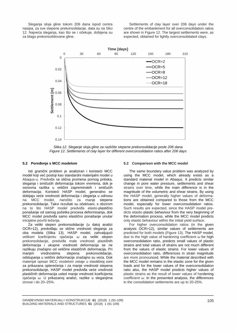
GRAĐEVINSKI MATERIJALI I KONSTRUKCIJE 61 (2018) 1 (91-109)BUILDING MATERIALS AND STRUCTURES 61 (2018) 1 (91-109)
105
Sleganja sloja gline tokom 206 dana ispod centranasipa, za sve stepene prekonsolidacije, data su na Slici12. Najveća sleganja, kao što se i očekuje, dobijena suza blago prekonsolidovane gline.
Settlements of clay layer over 206 days under thecentre of the embankment for all overconsolidation ratiosare shown in Figure 12. The largest settlements were, asexpected, obtained for lightly overconsolidated clays.
0
0.02
0.04
0.06
0.08
0.1
0.12
0.14
0 30 60 90 120 150 180 210Se
ttlem
ent[
m]
Time [days]
OCR=2OCR=5OCR=8OCR=12OCR=18
Slika 12. Sleganje sloja gline za različite stepene prekonsolidacije posle 206 danaFigure 12. Settlements of clay layer for different overconsolidation ratios after 206 days
5.2 Poređenje s MCC modelom
Isti granični problem je analiziran i koristeći MCCmodel koji već postoji kao standardni materijalni model uAbaqus-u. Predviđa se slična promena pornog pritiska,sleganja i smičućih deformacija tokom vremena, dok jeosnovna razlika u veličini zapreminskih i smičućihdeformacija. Koristeći HASP model, generalno sedobijaju veće vrednosti deformacija i sleganja u odnosuna MCC model, naročito za manje stepeneprekonsolidacije. Takvi rezultati su očekivani, s obziromna to što HASP model predviđa elasto-plastičnoponašanje od samog početka procesa deformisanja, dokMCC model predviđa samo elastično ponašanje unutarinicijalne površi tečenja.
Za veliki stepen prekonsolidacije (u datoj analiziOCR>12), predviđaju se slične vrednosti sleganja zaoba modela (Slika 13). HASP model, zahvaljujućivelikom koeficijentu ojačanja ω za veliki stepenprekonsolidacije, predviđa male vrednosti plastičnihdeformacija i ukupne vrednosti deformacija se nerazlikuju značajno od veličine elastičnih deformacija. Primanjim vrednostima stepena prekonsolidacije,odstupanja u veličini deformacije značajno su veća. Dokmaterijal opisan MCC modelom ostaje u elastičnoj zoniza prikazana opterećenja i za manje vrednosti stepenaprekonsolidacije, HASP model predviđa veće vrednostiplastičnih deformacija usled manje vrednosti koeficijentaojačanja ω. U prikazanoj analizi, razlike u sleganjimaiznose i do 20–25%.
5.2 Comparison with the MCC model
The same boundary value problem was analyzed byusing the MCC model, which already exists as astandard material model in Abaqus. It predicts similarchange in pore water pressure, settlements and shearstrains over time, while the main difference is in themagnitude of the volumetric and shear strains. By usingthe HASP model, generally higher values of deforma-tions are obtained compared to those from the MCCmodel, especially for lower overconsolidation ratios.Such results are expected, since the HASP model pre-dicts elastic-plastic behaviour from the very beginning ofthe deformation process, while the MCC model predictsonly elastic behaviour within the initial yield surface.
For higher overconsolidation ratios (in the givenanalysis OCR>12), similar values of settlements arepredicted for both models (Figure 13). The HASP model,due to the high value of hardening coefficient ω for highoverconsolidation ratio, predicts small values of plasticstrains and total values of strains are not much differentfrom the values of elastic strains. For lower values ofoverconsolidation ratio, differences in strain magnitudeare more pronounced. While the material described withthe MCC model remains in the elastic zone for the givenloads and for the lower values of the overconsolidationratio also, the HASP model predicts higher values ofplastic strains as the result of lower values of hardeningcoefficient ω. In the presented analysis, the differencesin the consolidation settlements are up to 20-25%.
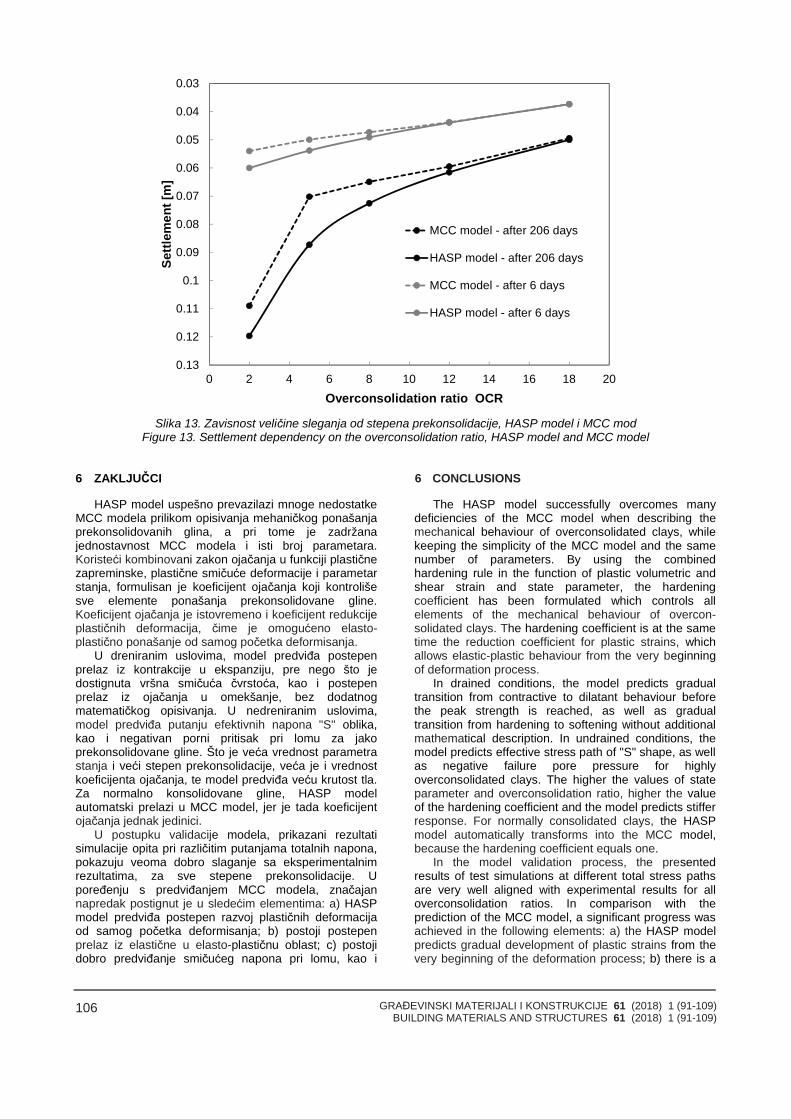
GRAĐEVINSKI MATERIJALI I KONSTRUKCIJE 61 (2018) 1 (91-109)BUILDING MATERIALS AND STRUCTURES 61 (2018) 1 (91-109)
106
0.03
0.04
0.05
0.06
0.07
0.08
0.09
0.1
0.11
0.12
0.130 2 4 6 8 10 12 14 16 18 20
Settl
emen
t[m
]
Overconsolidation ratio OCR
MCC model - after 206 days
HASP model - after 206 days
MCC model - after 6 days
HASP model - after 6 days
Slika 13. Zavisnost veličine sleganja od stepena prekonsolidacije, HASP model i MCC modFigure 13. Settlement dependency on the overconsolidation ratio, HASP model and MCC model
6 ZAKLJUČCI
HASP model uspešno prevazilazi mnoge nedostatkeMCC modela prilikom opisivanja mehaničkog ponašanjaprekonsolidovanih glina, a pri tome je zadržanajednostavnost MCC modela i isti broj parametara.Koristeći kombinovani zakon ojačanja u funkciji plastičnezapreminske, plastične smičuće deformacije i parametarstanja, formulisan je koeficijent ojačanja koji kontrolišesve elemente ponašanja prekonsolidovane gline.Koeficijent ojačanja je istovremeno i koeficijent redukcijeplastičnih deformacija, čime je omogućeno elasto-plastično ponašanje od samog početka deformisanja.
U dreniranim uslovima, model predviđa postepenprelaz iz kontrakcije u ekspanziju, pre nego što jedostignuta vršna smičuća čvrstoća, kao i postepenprelaz iz ojačanja u omekšanje, bez dodatnogmatematičkog opisivanja. U nedreniranim uslovima,model predviđa putanju efektivnih napona "S" oblika,kao i negativan porni pritisak pri lomu za jakoprekonsolidovane gline. Što je veća vrednost parametrastanja i veći stepen prekonsolidacije, veća je i vrednostkoeficijenta ojačanja, te model predviđa veću krutost tla.Za normalno konsolidovane gline, HASP modelautomatski prelazi u MCC model, jer je tada koeficijentojačanja jednak jedinici.
U postupku validacije modela, prikazani rezultatisimulacije opita pri različitim putanjama totalnih napona,pokazuju veoma dobro slaganje sa eksperimentalnimrezultatima, za sve stepene prekonsolidacije. Upoređenju s predviđanjem MCC modela, značajannapredak postignut je u sledećim elementima: a) HASPmodel predviđa postepen razvoj plastičnih deformacijaod samog početka deformisanja; b) postoji postepenprelaz iz elastične u elasto-plastičnu oblast; c) postojidobro predviđanje smičućeg napona pri lomu, kao i
6 CONCLUSIONS
The HASP model successfully overcomes manydeficiencies of the MCC model when describing themechanical behaviour of overconsolidated clays, whilekeeping the simplicity of the MCC model and the samenumber of parameters. By using the combinedhardening rule in the function of plastic volumetric andshear strain and state parameter, the hardeningcoefficient has been formulated which controls allelements of the mechanical behaviour of overcon-solidated clays. The hardening coefficient is at the sametime the reduction coefficient for plastic strains, whichallows elastic-plastic behaviour from the very beginningof deformation process.
In drained conditions, the model predicts gradualtransition from contractive to dilatant behaviour beforethe peak strength is reached, as well as gradualtransition from hardening to softening without additionalmathematical description. In undrained conditions, themodel predicts effective stress path of "S" shape, as wellas negative failure pore pressure for highlyoverconsolidated clays. The higher the values of stateparameter and overconsolidation ratio, higher the valueof the hardening coefficient and the model predicts stifferresponse. For normally consolidated clays, the HASPmodel automatically transforms into the MCC model,because the hardening coefficient equals one.
In the model validation process, the presentedresults of test simulations at different total stress pathsare very well aligned with experimental results for alloverconsolidation ratios. In comparison with theprediction of the MCC model, a significant progress wasachieved in the following elements: a) the HASP modelpredicts gradual development of plastic strains from thevery beginning of the deformation process; b) there is a
GRAĐEVINSKI MATERIJALI I KONSTRUKCIJE 61 (2018) 1 (91-109)BUILDING MATERIALS AND STRUCTURES 61 (2018) 1 (91-109)
107
pornog pritiska za prekonsolidovana tla.HASP model je implementiran u Abaqus/Standard
putem dostupnog korisničkog potprograma UMAT. Zanumeričku integraciju konstitutivnih relacija, vrlo uspešnoje primenjena Metoda vodećeg parametra.
U razmatranom primeru konsolidacije sloja zasićeneprekonsolidovane gline usled fazne izgradnje nasipa,prikazana je sposobnost HASP modela da predvidivremenski tok promene pornih pritisaka, zapreminskih ismičućih deformacija. Rezultati su poređeni s MCCmodelom. Usled brzog opterećivanja sloja zasićene glinemale vodopropusnosti, HASP model predviđa pojavupornog natpritiska, koji raste tokom izgradnje nasipa, teu procesu konsolidacije dolazi do potpune disipacijepornog natpritiska. Deformacije se najbrže razvijajutokom izgradnje nasipa, a najveća sleganja dobijena suza blago prekonsolidovane gline. U poređenju s MCCmodelom, osnovna razlika jeste u veličini zapreminskih ismičućih deformacija. Koristeći HASP model, generalnose dobijaju veće vrednosti deformacija nego u MCCmodelu, s obzirom na to što HASP model predviđaelasto-plastično ponašanje od samog početka procesadeformisanja, dok MCC model predviđa samo elastičnoponašanje unutar inicijalne površi tečenja.
Na osnovu prikazanih rezultata, može se zaključiti daHASP model ima dobar balans između sofisticiranosti ijednostavnosti, što omogućava njegovu široku praktičnuprimenu u rešavanju geotehničkih problema.
gradual transition from elastic into elastic-plastic region;c) there is good prediction of failure shear stress, as wellas pore water pressure for overconsolidated soil.
The HASP model is implemented inAbaqus/Standard through the available user subroutineUMAT. For numerical integration of constitutive relations,the Governing Parameter Method was used verysuccessfully.
Through the discussed example of consolidation ofsaturated overconsolidated clay layer, as the result ofphased construction of the embankment, the ability ofthe HASP model to predict the changes of pore waterpressure, volumetric and shear strains was presented.The results were compared with the MCC model. As theresult of rapid increase of load on the saturated claylayer with low permeability, the HASP model predicts theincrease of pore water pressure during the constructionof the embankment and full dissipation of the pore waterpressure in the process of consolidation. Strains developmost rapidly during the construction of the embankmentand greatest amount of settlement were obtained forslightly overconsolidated clays. In comparison with theMCC model, the main difference is in the magnitude ofthe volumetric and shear strains. By using the HASPmodel, higher values of strains are generally obtainedagainst the MCC model, since the HASP model predictselastic-plastic behaviour from the very beginning of thedeformation process, while the MCC model predicts onlyelastic behaviour within the initial yield surface.
Based on the presented results, it can be concludedthat the HASP model has good balance of sophisticationand simplicity, which allows its wide practical use insolving various geotechnical problems.
7 LITERATURAREFERENCES
[1] ABAQUS. User manual Hibbit, Karlsson &Sorensen, Inc. 2011.
[2] Al-Tabbaa, A. & Wood, D.M. An experimentallybased „bubble” model for clay. Numerical Models inGeomechanics NUMOG III (eds S Pietruszczakand GN Pande), Elsevier Applied Science 1989;91–99.
[3] Banerjee, P.K. & Stipho, A.S. Elastoplastic modelfor undrained behavior of heavily overconsolidatedclays. Int J Numer Anal Mech Geomech 1979; 3(1):97–103.
[4] Been, K. & Jefferies, M.G. A state parameter forsands. Géotechnique 1985; 35(2): 99–112.
[5] Biarez, J. & Hicher, P.Y. Elementary Mechanics ofSoil Behaviour. Saturated Remoulded Soils. A. A.Balkema, Rotterdam; 1994.
[6] Borja, R.I. & Lee, S.R. Cam clay plasticity, part I:Implicit integration of constitutive relations,Comput. Meth. Appl. Mech. Eng. 1990; Vol. 78,49–72.
[7] Borja R.I. Cam clay plasticity, part II: Implicitintegration of constitutive equations based onnonlinear elastic stress prediction, Comput. Meth.Appl. Mech. Eng. 1991; Vol. 88, 225–240.
[8] Dafalias, Y.F. & Popov, E.P. Plastic internalvariables formalism of cyclic plasticity. J. of AppliedMechanics 1976; Vol. 98, 645–651.
[9] Dafalias, Y.F. & Herrmann, L.R. A boundingsurface soil plasticity model. Proc. Int. Symp. onSoils under Cyclic and Transient Loading 1980;Vol. 1, 335–345.
[10] Dafalias Y.F., Manzari M.T., Papadimitriou A.G.SANICLAY: simple anisotropic clay plasticitymodel. International Journal for Numerical andAnalytical Methods in Geomechanics 2006; 30:1231–1257. DOI: 10.1002/nag. 524.
[11] Gajo, A. & Wood, D.M. A new approach toanisotropic, bounding surface plasticity: Generalformulation and simulations of natural andreconstituted clay behaviour. Int J Numer AnalytMeth Geomech 2001; 25-3: 207–241.
[12] Grammatikopoulou, A., Zdravkovic, L., Potts, D.M.General Formulation of Two Kinematic HardeningConstitutive Models with a Smooth ElastoplasticTransition. Int J Geomech 2006; 6:291–302.doi:10.1061/(ASCE) 1532–3641 (2006) 6:5 (291).
[13] Helwany, S. Applied soil mechanics with ABAQUSapplications. John Willey & Sons, Canada, 2007.
[14] Hickman, R.J. & Gutierrez, M. An internallyconsistent integration method for critical statemodels. Int J Numer Anal Methods Geomech 2005;29: 227–48.
GRAĐEVINSKI MATERIJALI I KONSTRUKCIJE 61 (2018) 1 (91-109)BUILDING MATERIALS AND STRUCTURES 61 (2018) 1 (91-109)
108
[15] Houlsby, G.T., Wroth, C.P., Wood, D.M.Predictions of the results of laboratory tests on aclay using a critical state model. In Proc. int.workshop on constitutive behaviour of soils,Grenoble, Balkema (Rotterdam) 1982; 99–121.
[16] Iwan, W.D. On a class of models for the yieldbehaviour of continuous and composite systems.Journal of Applied Mechanics 1967, ASME 34;612–617.
[17] Jefferies, M.G. Nor-Sand: a simple critical statemodel for sand. Géotechnique 1993; 43(1):91–103.
[18] Jocković, S. & Vukićević, M. Bounding surfacemodel for overconsolidated clays with new stateparameter formulation of hardening rule. ComputGeotech 2017; 83:16–29.doi:10.1016/j.compgeo.2016.10.013.
[19] Kojić, M. & Bathe K.J. The effective-stress-functionalgorithm for thermo-elastoplasticity and creep, Int.J. Num. Meth. Engng. 1987; Vol. 24, pp. 1509–1532.
[20] Kojić, M. The governing parameter method forimplicit integration of viscoplastic constitutiverelations for isotropic and orthotropic metals,Computational Mechanics 1996; Vol. 19, 49–57.
[21] Kojić, M. & Bathe, K.J. Inelastic Analysis of Solidsand Structures, Berlin, Springer-Verlag, 2003.
[22] Krieg, R. D. A practical two-surface plasticitytheory. Journal of Applied Mechanics 1975; Vol.42, No. E3, pp. 641–646.
[23] Li, X.S. & Dafalias, Y.F. Dilatancy for cohesionlesssoils. Géotechnique 2000; 50:449–60.doi:10.1680/geot.2000.50.4.449.
[24] McDowell, G.R. & Hau, K.W. A simple non-associated three-surface kinematic hardeningmodel. Géotechnique 2003, No. 4, 433−437.
[25] Mita, K.A., Dasari, G.R., Lo, K.W. Performance of athree-dimensional Hvorslev-Modified Cam claymodel for overconsolidated clay. ASCE, Int JGeomech 2004; 4(4): 296–309.
[26] Mróz, Z. On the description of anisotropicworkhardening. Journal of the Mechanics andPhysics of Solids 1967; 15, 163–175.
[27] Nayak, G.C., & Zienkiewicz, O.C. Elastoplasticstress analysis: a generalization for variousconstitutive relations including strain softening.International Journal for Numerical Methods inEngineering 1972; 5, 113–135.
[28] Nova, R. & Wood, D.M. A constitutive model forsand in triaxial compression. Int J Numer AnalMethods Geomech 1979; 3: 255–278.
[29] Nova, R. Modelling of bonded soils with unstablestructure. International Workshop on ModernTrends in Geomechanics – Vienna Springer, 2006.
[30] Ortiz, M., Pinsky, P.M., Taylor, R.L. Operator splitmethods for the numerical solution of the elasto-plastic dynamic problem, Comp. Meth. Appl. Mech.Engng. 1983; Vol. 39, pp. 137–157.
[31] Ortiz, M. & Popov, E.P. Accuracy and stability ofintegration algorithms for elastoplastic constitutiverelations. International Journal for NumericalMethods in Engineering 1985; 21:1561–1576.
[32] Ortiz, M. & Simo, J.C. An analysis of a new class ofintegration algorithms for elasto-plastic constitutiverelations, Int. J. Num. Meth. Eng. 1986; Vol. 23,353–366.
[33] Owen, D.R.J. & Hinton, E. Finite Elements inPlasticity: Theory and Practice 1980. PineridgePress, Swansea, Wales, 594 p.
[34] Parry, R.H.G. Correspondence. Géotechnique1958; 8:183–186.
[35] Roscoe, K.H., Schofield, A.N., Wroth, C.P. On theyielding of soils. Géotechnique 1958; 8, 22–53.
[36] Roscoe, K.H. & Burland, J.B. On the generalisedstress-strain behaviour of ‘wet’ clay. In: Heyman J,Leckie FA, editors. Engineering plasticity 1968.Cambridge, UK: Cambridge University Press; 535–609.
[37] Schädlich, B. & Schweiger, H.F. Modelling theshear strength of overconsolidated clays with aHvorslev surface. Geotechnik 2014; 37:47–56. doi:10.1002/gete. 201300016.
[38] Schofield, A.N. & Wroth, C.P. Models and soilmechanics. Critical state soil mechanics. McGraw-Hill, London, New York, 1968; 20–21.
[39] Sheng, D.C., Sloan, S.W., Gens, A., Smith, D.W.Finite element formulation and algorithms forunsaturated soils. Part 1: Theory. InternationalJournal for Numerical and Analytical Methods inGeomechanics 2003; 27(9):745–765.
[40] Sheng, D.C., Smith, D.W., Sloan, S.W., Gens, A.Finite element formulation and algorithms forunsaturated soils. Part 2: Verification andApplications. International Journal for Numericaland Analytical Methods in Geomechanics 2003;27(9):767–790.
[41] Simo, J.C. & Taylor, R.L. Consistent tangentoperators for rate independent elasto-plasticity,Comp. Meth. Appl. Mech. Engng. 1985; Vol. 48,pp. 101–118.
[42] Simo, J.C. & Hughes, T. Computational inelasticity.Interdisciplinary applied mathematics series.Springer, 1998.
[43] Sloan, S.W. Substepping schemes for the numeri-cal integration of elastoplastic stress-strain rela-tions. Int J Numer Methods Eng 1987; 24:893–911.
[44] Sołowski, W.T. & Gallipoli, D. Explicit stressintegration with error control for the BarcelonaBasic Model. Part II: Algorithms efficiency andaccuracy. Computers & Geotechnics 2010; 37(1-2):68–81. http://dx.doi.org/10.1016/j.compgeo.2009.07.00.
[45] Stallebrass, S.E. & Taylor, R.N. The developmentof a constitutive model for the prediction of groundmovements in overconsolidated clay.Géotechnique 1997; 47, 235 - 253.
[46] Tsiampousi, A., Zdravković, L., Potts, D.M. A newHvorslev surface for critical state type unsaturatedand saturated constitutive models. ComputGeotech 2013; 48:156–66.doi:10.1016/j.compgeo.2012.09.010.
[47] Vukićević, M. Governing parameter method forimplicit stress integration of Modified Cam Claymodel, using the mean stress as the governingparameter. XIV Danube – European Conference onGeotechnical Engineering, DECGE 2010,Bratislava 2010; 274-275.
[48] Whittle, A. & Kavvadas, M. Formulation of MIT-E3constitutive model for overconsolidated clays. J.Geotech. Eng. 1994; 120 (1), 173–198.
GRAĐEVINSKI MATERIJALI I KONSTRUKCIJE 61 (2018) 1 (91-109)BUILDING MATERIALS AND STRUCTURES 61 (2018) 1 (91-109)
109
[49] Wilkins, M. L. Calculation of elastic-plastic flow.Methods of Computational Physics. AcademicPress, N. Y. 1964; Vol 3.
[50] Yao, Y.P., Hou, W., Zhou, A.N. UH model: three-dimensional unified hardening model foroverconsolidated clays. Géotechnique 2009;59:451–69. doi:10.1680/geot.2007.00029.
[51] Yu, H.S. CASM: A unified state parameter modelfor clay and sand. International Journal forNumerical and Analytical Methods inGeomechanics 1998; 22, No. 8: 621-653.
[52] Zienkiewicz, O.C. & Naylor, D.J. Finite elementstudies of soils and porous media. Lecture, finiteelements, Oden and de Arantes (eds), UAH Press1973; 459–493.
REZIME
VALIDACIJA I IMPLEMENTACIJA HASPKONSTITUTIVNOG MODELA ZAPREKONSOLIDOVANE GLINE
Sanja JOCKOVIĆMirjanaVUKIĆEVIĆ
Za široku primenu konstitutivnih modela za tlo usavremenoj inženjerskoj praksi postoje dva bitna uslova:a) model treba dovoljno dobro da predviča ponašanje tlapri različitim putanjama napona; b) materijalne konstantemodela mogu da se odrede iz standardnih opita.Uvažavajući oba uslova, formulisan je HASP model zaopisivanje mehaničkog ponašanja prekonsolidovanihglina, koristeći teoriju kritičnog stanja i koncept graničnepovrši. HASP model, na jednostavan način, prevazilazimnoge nedostatke Modifikovanog Cam Clay modela,bez uvočenja dodatnih materijalnih parametara.Formulacijom zakona ojačanja u funkciji parametrastanja i stepena prekonsolidacije, omogućeno jeopisivanje brojnih elemenata mehaničkog ponašanjaprekonsolidovanih glina. HASP model je implementiran uprogram Abaqus koristeći Metodu vodećeg parametra zanumeričku integraciju konstitutivnih relacija. U radu jeprikazana validacija HASP modela – porečenjem spublikovanim rezultatima triaksijalnih opita, kao imogućnosti modela da adekvatno predvidi ponašanjeprekonsolidovanih glina putem analize graničnog(konturnog) problema metodom konačnih elemenata.Razmatran je problem konsolidacionog sleganja tlausled fazne izgradnje nasipa na površini zasićeneprekonsolidovane gline, za različite stepeneprekonsolidacije.
Ključne reči: konstitutivni model, prekonsolidovanegline, parametar stanja
SUMMАRY
VALIDATION AND IMPLEMENTATION OF HASPCONSTITUTIVE MODEL FOR OVERCONSOLIDATEDCLAYS
Sanja JOCKOVICMirjanaVUKICEVIC
There are two important conditions for the wideapplication of constitutive models for soil in contempo-rary engineering practice: a) the model should predictsufficiently well the soil behaviour at different stresspaths; b) the material constants of the model can bedetermined from standard laboratory tests. Taking intoaccount both conditions, a HASP model has beenformulated to describe the mechanical behaviour of theoverconsolidated clays, using the critical state theoryand the boundary surface concept. The HASP model ina simple way overcomes many deficiencies of theModified Cam Clay model, without introducing anyadditional material parameters. The formulation of thehardening rule in the function of the state parameter andoverconsolidation ratio, allows the description ofnumerous elements of the mechanical behaviour of theoverconsolidated clays. The HASP model has beenimplemented in software Abaqus using the GoverningParameter Method for the numerical integration ofconstitutive relations. The paper presents validation ofthe HASP model in comparison with the publishedresults of triaxial tests as well as the possibilities of themodel to adequately predict the behaviour of theoverconsolidated clays through the analysis of theboundary value problem using the finite element method.The problem of the clay settlements due to phasedconstruction of the embankment on the saturated claysurface was analyzed, assuming different over-consolidation ratios.
Key words: constitutive model, overconsolidatedclays, state parameter

GRAĐEVINSKI MATERIJALI I KONSTRUKCIJE 61 (2018) 1 (91-109)BUILDING MATERIALS AND STRUCTURES 61 (2018) 1 (91-109)
110
GRAĐEVINSKI MATERIJALI I KONSTRUKCIJE 61 (2018) 1 (111-127)BUILDING MATERIALS AND STRUCTURES 61 (2018) 1 (111-127)
111
BOČNA NOSIVOST I POMERANJA VERTIKALNIH ŠIPOVA OPTEREĆENIHHORIZONTALNIM SILAMA
LATERAL CAPACITY AND DEFORMATIONS OF VERTICAL PILES LOADED BYHORIZONTAL FORCES
Slobodan ĆORIĆDragoslav RAKIĆStanko ĆORIĆIrena BASARIĆ
PREGLEDNI RADREVIEW PAPER
UDK: 624.154.042.1.046.2doi:10.5937/GRMK1801111C
1 UVOD
Temelji graČevinskih objekata fundiranih na šipovimauglavnom prenose vertikalno opterećenje, a šipovi suopterećeni aksijalnim silama pritiska/zatezanja [7].MeČutim, ponekad su vertikalni šipovi opterećeni iznačajnim horizontalnim silama koje mogu da buduposledica stalnog opterećenja, ali i vetra i/ili zemljotresa.U takvim slučajevima, potrebno je da se odredi bočnanosivost vertikalnih šipova [13]. Ona je posledicahorizontalnog pomeranja šipova i usled toga mobilisanjanjihove čvrstoće i čvrstoće okolnog tla. Imajući to u vidu,bočna otpornost šipova može da bude prekoračena sobzirom na:
nosivost okolnog tla, što je tzv. geotehničkanosivost;
nosivost poprečnog preseka šipa, što je tzv.konstruktivna nosivost.
U ovom radu ćemo, pre svega, analizirati geo-tehničku nosivost šipova i - saglasno tome - obradićemosledeće metode: Rankinovu, Bromsovu i Brinč-Han-senovu. Osim toga, pokazaćemo kako se mogu odreditihorizontalne deformacije bočno opterećenih vertikalnih
Slobodan Ćorić, prof. dr, Univerzitet u Beogradu –Rudarsko-geološki fakultet, Đušina 7, 11000 Beograd,[email protected] Rakić, doc. dr, Univerzitet u Beogradu –Rudarsko-geološki fakultet, Đušina 7, 11000 Beograd,[email protected] Ćorić, doc. dr, Univerzitet u Beogradu – GraČevinskifakultet, Bulevar kralja Aleksandra 73, 11000 Beograd,[email protected] Basarić, asistent-student doktorskih studija,Univerzitet u Beogradu – Rudarsko-geološki fakultet,Đušina 7, 11000 Beograd, [email protected]
1 INTRODUCTION
Pile foundations are mostly loaded by vertical forces,which means that they are loaded by axial compressionor tension forces [7]. However, in some cases verticalpiles are loaded by high horizontal forces due to thedead loads, winds or earthquakes. In such cases it isnecessary to determine lateral capacity of vertical pileswhich is due to the horizontal displacements of piles andtherefore mobilized pile strength and the strength ofsurrounding soil [13]. So, the ultimate resistance of pilescan be reached regarding
ultimate capacity of surrounding soil i.e.geotechnical capacity
ultimate capacity of pile cross section i.e.structural capacity.
In this paper, the geotechnical capacity of piles willbe analyzed first and then, according to the findings thefollowing methods will be presented: Rankine’s, Broms’and Brinch-Hansen's methods. Afterwards, the followingmethods for determining horizontal deformations ofvertical piles loaded by horizontal forces will bepresented: applications of elastic theory, coefficient of
Slobodan Coric, Full Professor, Ph D, University ofBelgrade – Faculty of Mining and Geology, Djusina 7,11000 Belgrade, [email protected] Rakic, Assistant Professor, Ph D, University ofBelgrade – Faculty of Mining and Geology, Djusina 7,11000 Belgrade, [email protected] Coric, Assistant Professor, Ph D, University ofBelgrade – Faculty of Civil Engineering, Bulevar kraljaAleksandra 73, 11000 Belgrade, [email protected] Basaric, Teaching assistant, University of Belgrade –Faculty of Mining and Geology, Djusina 7, 11000 Belgrade,[email protected]
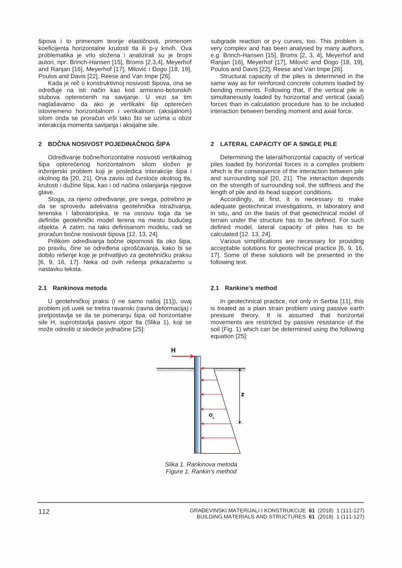
GRAĐEVINSKI MATERIJALI I KONSTRUKCIJE 61 (2018) 1 (111-127)BUILDING MATERIALS AND STRUCTURES 61 (2018) 1 (111-127)
112
šipova i to primenom teorije elastičnosti, primenomkoeficijenta horizontalne krutosti tla ili p-y krivih. Ovaproblematika je vrlo složena i analizirali su je brojniautori, npr. Brinch-Hansen [15], Broms [2,3,4], Meyerhofand Ranjan [16], Meyerhof [17], Milović i Đogo [18, 19],Poulos and Davis [22], Reese and Van Impe [26].
Kada je reč o konstruktivnoj nosivosti šipova, ona seodređuje na isti način kao kod armirano-betonskihstubova opterećenih na savijanje. U vezi sa timnaglašavamo da ako je vertikalni šip opterećenistovremeno horizontalnom i vertikalnom (aksijalnom)silom onda se proračun vrši tako što se uzima u obzirinterakcija momenta savijanja i aksijalne sile.
2 BOČNA NOSIVOST POJEDINAČNOG ŠIPA
Određivanje bočne/horizontalne nosivosti vertikalnogšipa opterećenog horizontalnom silom složen jeinženjerski problem koji je posledica interakcije šipa iokolnog tla [20, 21]. Ona zavisi od čvrstoće okolnog tla,krutosti i dužine šipa, kao i od načina oslanjanja njegoveglave.
Stoga, za njeno određivanje, pre svega, potrebno jeda se sprovedu adekvatna geotehnička istraživanja,terenska i laboratorijska, te na osnovu toga da sedefiniše geotehnički model terena na mestu budućegobjekta. A zatim, na tako definisanom modelu, radi seproračun bočne nosivosti šipova [12, 13, 24].
Prilikom određivanja bočne otpornosti tla oko šipa,po pravilu, čine se određena uprošćavanja, kako bi sedobilo rešenje koje je prihvatljivo za geotehničku praksu[6, 9, 16, 17]. Neka od ovih rešenja prikazaćemo unastavku teksta.
2.1 Rankinova metoda
U geotehničkoj praksi (i ne samo našoj [11]), ovajproblem još uvek se tretira ravanski (ravna deformacija) ipretpostavlja se da se pomeranju šipa, od horizontalnesile H, suprotstavlja pasivni otpor tla (Slika 1), koji semože odrediti iz sledeće jednačine [25]:
subgrade reaction or p-y curves, too. This problem isvery complex and has been analysed by many authors,e.g. Brinch-Hansen [15], Broms [2, 3, 4], Meyerhof andRanjan [16], Meyerhof [17], Milović and Đogo [18, 19],Poulos and Davis [22], Reese and Van Impe [26].
Structural capacity of the piles is determined in thesame way as for reinforced concrete columns loaded bybending moments. Following that, if the vertical pile issimultaneously loaded by horizontal and vertical (axial)forces than in calculation procedure has to be includedinteraction between bending moment and axial force.
2 LATERAL CAPACITY OF A SINGLE PILE
Determining the lateral/horizontal capacity of verticalpiles loaded by horizontal forces is a complex problemwhich is the consequence of the interaction between pileand surrounding soil [20, 21]. The interaction dependson the strength of surrounding soil, the stiffness and thelength of pile and its head support conditions.
Accordingly, at first, it is necessary to makeadequate geotechnical investigations, in laboratory andin situ, and on the basis of that geotechnical model ofterrain under the structure has to be defined. For suchdefined model, lateral capacity of piles has to becalculated [12. 13, 24].
Various simplifications are necessary for providingacceptable solutions for geotechnical practice [6, 9, 16,17]. Some of these solutions will be presented in thefollowing text.
2.1 Rankine's method
In geotechnical practice, not only in Serbia [11], thisis treated as a plain strain problem using passive earthpressure theory. It is assumed that horizontalmovements are restricted by passive resistance of thesoil (Fig. 1) which can be determined using the followingequation [25]:
Slika 1. Rankinova metodaFigure 1. Rankin's method
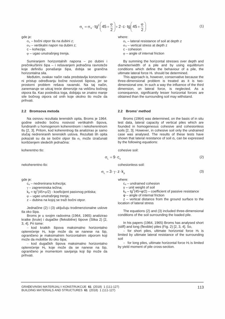
GRAĐEVINSKI MATERIJALI I KONSTRUKCIJE 61 (2018) 1 (111-127)BUILDING MATERIALS AND STRUCTURES 61 (2018) 1 (111-127)
113
2L V tg 45 2 c tg 45
2 2
(1)
gde je:L – bočni otpor tla na dubini z;V – vertikalni napon na dubini z;c – kohezija; – ugao unutrašnjeg trenja.
Sumiranjem horizontalnih napona – po dubini iprečniku/širini šipa – i rešavanjem jednačina ravnotežekoje definišu ponašanje šipa, dobija se graničnahorizontalna sila.
Međutim, ovakav način rada predstavlja konzervativ-ni pristup određivanju bočne nosivosti šipova, jer seprostorni problem rešava ravanski. Na taj način,zanemaruje se uticaj treće dimenzije na veličinu bočnogotpora tla. Kao posledica toga, dobijaju se znatno manjesile bočnog otpora od onih koje okolno tlo može daprihvati.
2.2 Bromsova metoda
Na osnovu rezultata terenskih opita, Broms je 1964.godine odredio bočnu nosivost vertikalnih šipova,fundiranih u homogenom koherentnom i nekoherentnomtlu [2, 3]. Pritom, kod koherentnog tla analizirao je samoslučaj nedreniranih terenskih uslova. Rezultati tih opitapokazali su da se bočni otpor tla L može izračunatikorišćenjem sledećih jednačina:
where:L – lateral resistance of soil at depth zV – vertical stress at depth zc - cohesion – angle of internal friction
By summing the horizontal stresses over depth anddiameter/width of a pile and by using equilibriumconditions which define the behaviour of a pile, theultimate lateral force Hf should be determined.
This approach is, however, conservative because thethree-dimensional problem is treated as it is two-dimensional one. In such a way the influence of the thirddimension, on lateral force, is neglected. As aconsequence, significantly lesser horizontal forces areobtained than the surrounding soil may withstand.
2.2 Broms' method
Broms (1964) was determined, on the basis of in situtest data, lateral capacity of vertical piles which arefounded in homogeneous cohesive and cohesionlesssoils [2, 3]. However, in cohesive soil only the undrainedcase was analysed. The results of these tests haveshown that lateral resistance of soil σL can be expressedby the following equations:
koherentno tlo: cohesive soil:
L u9 c (2)
nekoherentno tlo: cohesionless soil:
L p3 z k (3)
gde je:cu – nedrenirana kohezija; – zapreminska težina;kp = tg2(45+/2) - koeficijent pasivnog pritiska; – ugao unutrašnjeg trenja;z – dubina na kojoj se traži bočni otpor.
Jednačine (2) i (3) uključuju trodimenzionalne uslovetla oko šipa.
Broms je u svojim radovima (1964, 1965) analiziraokratke (krute) i dugačke (fleksibilne) šipove (Slika 2) [2,3, 4]. Pri tome:
kod kratkih šipova maksimalno horizontalnoopterećenje Hf, koje može da se nanese na šip,ograničeno je maksimalnim horizontalnim otporom kojimože da mobiliše tlo oko šipa;
kod dugačkih šipova maksimalno horizontalnoopterećenje Hf, koje može da se nanese na šip,ograničeno je momentom savijanja koji šip može daprihvati.
where:cu – undrained cohesionγ – unit weight of soilkp – tg2(45+φ/2) – coefficient of passive resistanceφ – angle of internal frictionz – vertical distance from the ground surface to the
location of lateral stress
The equations (2) and (3) included three-dimensionalconditions of the soil surrounding the loaded pile.
In his papers (1964, 1965) Broms has analysed short(stiff) and long (flexible) piles (Fig. 2) [2, 3, 4]. So,
for short piles, ultimate horizontal force Hf islimited by ultimate lateral resistance of the surroundingsoil
for long piles, ultimate horizontal force Hf is limitedby yield moment of pile cross-section.
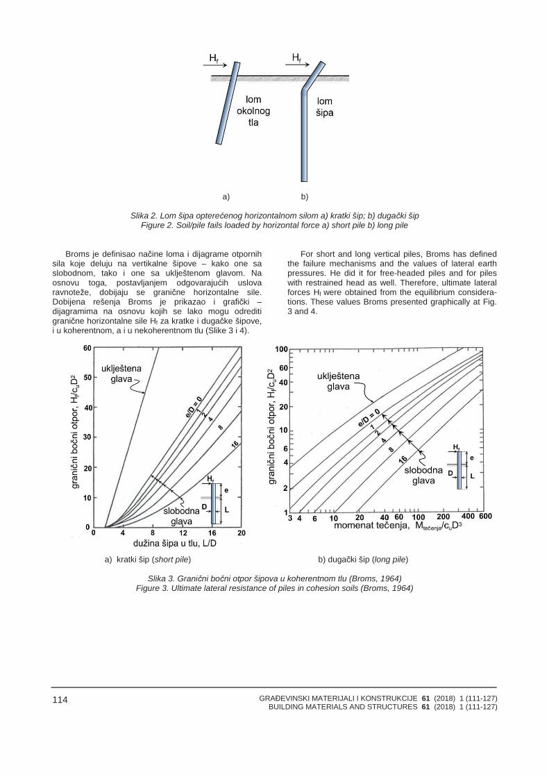
GRAĐEVINSKI MATERIJALI I KONSTRUKCIJE 61 (2018) 1 (111-127)BUILDING MATERIALS AND STRUCTURES 61 (2018) 1 (111-127)
114
a) b)
Slika 2. Lom šipa opterećenog horizontalnom silom a) kratki šip; b) dugački šipFigure 2. Soil/pile fails loaded by horizontal force a) short pile b) long pile
Broms je definisao načine loma i dijagrame otpornihsila koje deluju na vertikalne šipove – kako one saslobodnom, tako i one sa uklještenom glavom. Naosnovu toga, postavljanjem odgovarajućih uslovaravnoteže, dobijaju se granične horizontalne sile.Dobijena rešenja Broms je prikazao i grafički –dijagramima na osnovu kojih se lako mogu odreditigranične horizontalne sile Hf za kratke i dugačke šipove,i u koherentnom, a i u nekoherentnom tlu (Slike 3 i 4).
For short and long vertical piles, Broms has definedthe failure mechanisms and the values of lateral earthpressures. He did it for free-headed piles and for pileswith restrained head as well. Therefore, ultimate lateralforces Hf were obtained from the equilibrium considera-tions. These values Broms presented graphically at Fig.3 and 4.
a) kratki šip (short pile) b) dugački šip (long pile)
Slika 3. Granični bočni otpor šipova u koherentnom tlu (Broms, 1964)Figure 3. Ultimate lateral resistance of piles in cohesion soils (Broms, 1964)
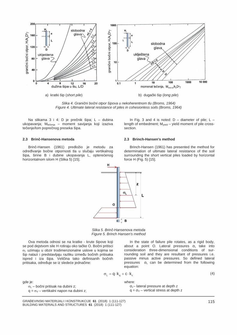
GRAĐEVINSKI MATERIJALI I KONSTRUKCIJE 61 (2018) 1 (111-127)BUILDING MATERIALS AND STRUCTURES 61 (2018) 1 (111-127)
115
a) kratki šip (short pile) b) dugački šip (long pile)
Slika 4. Granični bočni otpor šipova u nekoherentnom tlu (Broms, 1964)Figure 4. Ultimate lateral resistance of piles in cohesionless soils (Broms, 1964)
Na slikama 3 i 4: D je prečnik šipa; L – dubinaukopavanja; Mtečenja – moment savijanja koji izazivatečenje/lom poprečnog preseka šipa.
2.3 Brinč-Hansenova metoda
Brinč-Hansen (1961) predložio je metodu zaodređivanje bočne otpornosti tla u slučaju vertikalnogšipa, širine B i dubine ukopavanja L, opterećenoghorizontalnom silom H (Slika 5) [15].
In Fig. 3 and 4 is noted: D – diameter of pile; L –length of embedment; Myield – yield moment of pile cross-section.
2.3 Brinch-Hansen's method
Brinch-Hansen (1961) has presented the method fordetermination of ultimate lateral resistance of the soilsurrounding the short vertical piles loaded by horizontalforce H (Fig. 5) [15].
Slika 5. Brinč-Hansenova metodaFigure 5. Brinch Hansen's method
Ova metoda odnosi se na kratke - krute šipove kojise pod dejstvom sile H rotiraju oko tačke O. Bočni pritisciL uzimaju u obzir trodimenzionalne uslove u kojima sešip nalazi i predstavljaju razliku između bočnih pritisakaispred i iza šipa. Veličina tako definisanih bočnihpritisaka, određuje se iz sledeće jednačine:
In the state of failure pile rotates, as a rigid body,about a point O. Lateral pressures σL take intoconsideration three-dimensional conditions of sur-rounding soil and they are resultant of pressures i.e.passive minus active pressures. So defined lateralpressures σL can be determined from the followingequation:
L q cq k c k (4)
gde je:L – bočni pritisak na dubini z;q = V – vertikalni napon na dubini z;
where:σL– lateral pressure at depth zq = σV – vertical stress at depth z
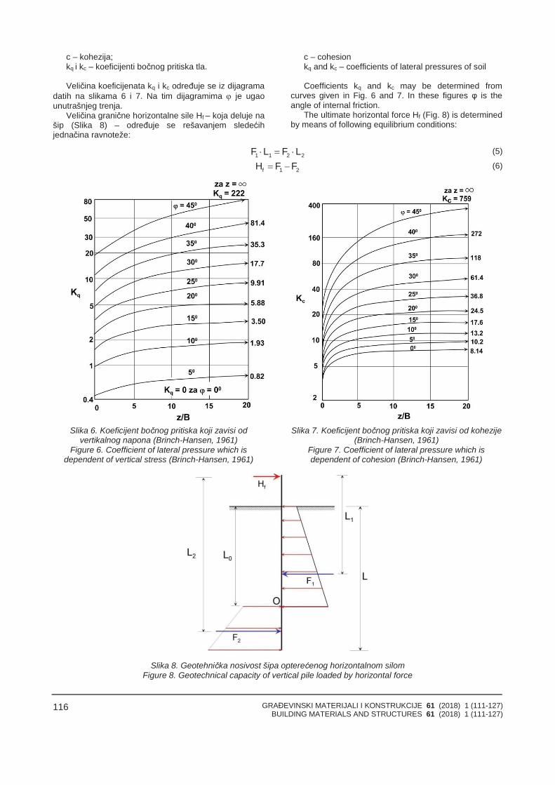
GRAĐEVINSKI MATERIJALI I KONSTRUKCIJE 61 (2018) 1 (111-127)BUILDING MATERIALS AND STRUCTURES 61 (2018) 1 (111-127)
116
c – kohezija;kq i kc – koeficijenti bočnog pritiska tla.
Veličina koeficijenata kq i kc određuje se iz dijagramadatih na slikama 6 i 7. Na tim dijagramima je ugaounutrašnjeg trenja.
Veličina granične horizontalne sile Hf – koja deluje našip (Slika 8) – određuje se rešavanjem sledećihjednačina ravnoteže:
c – cohesionkq and kc – coefficients of lateral pressures of soil
Coefficients kq and kc may be determined fromcurves given in Fig. 6 and 7. In these figures φ is theangle of internal friction.
The ultimate horizontal force Hf (Fig. 8) is determinedby means of following equilibrium conditions:
1 1 2 2F L F L (5)
f 1 2H F F (6)
Slika 6. Koeficijent bočnog pritiska koji zavisi odvertikalnog napona (Brinch-Hansen, 1961)
Figure 6. Coefficient of lateral pressure which isdependent of vertical stress (Brinch-Hansen, 1961)
Slika 7. Koeficijent bočnog pritiska koji zavisi od kohezije(Brinch-Hansen, 1961)
Figure 7. Coefficient of lateral pressure which isdependent of cohesion (Brinch-Hansen, 1961)
Slika 8. Geotehnička nosivost šipa opterećenog horizontalnom silomFigure 8. Geotechnical capacity of vertical pile loaded by horizontal force
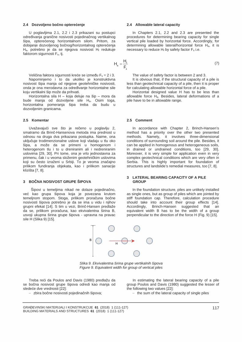
GRAĐEVINSKI MATERIJALI I KONSTRUKCIJE 61 (2018) 1 (111-127)BUILDING MATERIALS AND STRUCTURES 61 (2018) 1 (111-127)
117
2.4 Dozvoljeno bočno opterećenje
U poglavljima 2.1, 2.2 i 2.3 prikazani su postupciodređivanja granične nosivosti pojedinačnog vertikalnogšipa, opterećenog horizontalnom silom. Pritom, zadobijanje dozvoljenog bočnog/horizontalnog opterećenjaHa, potrebno je da se njegova nosivost Hf redukujefaktorom sigurnosti Fs, tj.
2.4 Allowable lateral capacity
In Chapters 2.1, 2.2 and 2.3 are presented theprocedures for determining bearing capacity for singlevertical pile loaded by horizontal force. Accordingly, fordetermining allowable lateral/horizontal force Ha, it isnecessary to reduce Hf by safety factor Fs i.e.
fa
s
HHF
(7)
Veličina faktora sigurnosti kreće se između Fs = 2 i 3.Napominjemo i to da ukoliko je konstruktivna
nosivost šipa manja od njegove geotehničke nosivosti,onda je ona merodavna za određivanje horizontalne silekoju vertikalni šip može da prihvati.
Horizontalna sila H – koja deluje na šip – mora dabude manja od dozvoljene sile Ha. Osim toga,horizontalna pomeranja šipa treba da budu udozvoljenim granicama.
2.5 Komentar
Uvažavajući sve što je rečeno u poglavlju 2,smatramo da Brinč-Hansenova metoda ima prednost uodnosu na druga dva prikazana postupka. Naime, onauključuje trodimenzionalne uslove koji vladaju u tlu okošipa, a može da se primeni u homogenom iheterogenom tlu i to u dreniranim ali i nedreniranimuslovima [29, 30]. Pri tome, ona je vrlo jednostavna zaprimenu, čak i u veoma složenim geotehničkim uslovimakoji su često izraženi u Srbiji. To je veoma značajnoprilikom fundiranja objekata, kao i prilikom sanacijeklizišta [7, 8].
3 BOČNA NOSIVOST GRUPE ŠIPOVA
Šipovi u temeljima nikad ne dolaze pojedinačno,već kao grupa šipova koja je povezana krutomtemeljnom stopom. Stoga, prilikom proračuna bočnenosivosti šipova potrebno je da se ima u vidu i njihovgrupni efekat [14]. S tim u vezi, Brinč-Hansen predlažeda se, prilikom proračuna, kao ekvivalentna širina B,usvoji ukupna širina grupe šipova - upravna na pravacsile H (Slika 9) [15].
The value of safety factor is between 2 and 3.It is obvious that, if the structural capacity of a pile is
less than geotechnical capacity of a pile, then it is properfor calculating allowable horizontal force of a pile.
Horizontal designed value H has to be less thanallowable force Ha. Besides, lateral deformations of apile have to be in allowable range.
2.5 Comment
In accordance with Chapter 2, Brinch-Hansen’smethod has a priority over the other two presentedmethods. Namely, it involves three-dimensionalconditions of surrounding soil around the pile. Besides, itcan be applied in homogenous and heterogeneous soils,in drained or undrained conditions, too [29, 30].Moreover, it is very simple for application even in verycomplex geotechnical conditions which are very often inSerbia. This is highly important for foundation ofstructures and landslide’s remedial measures, too [7, 8].
3 LATERAL BEARING CAPACITY OF A PILEGROUP
In the foundation structure, piles are unlikely installedas single ones, but as group of piles which are jointed bystiff foundation cap. Therefore, calculation procedureshould take into account their group effects [14].Accordingly, Brinch-Hansen suggested that anequivalent width B has to be the width of a groupperpendicular to the direction of the force H (Fig. 9) [15].
Slika 9. Ekvivalentna širina grupe vertikalnih šipovaFigure 9. Equivalent width for group of vertical piles
Treba reći da Poulos and Davis (1980) predlažu dase bočna nosivost grupe šipova odredi kao manja odsledeće dve vrednosti [22]:
zbira bočne nosivosti pojedinačnih šipova;
In estimating the lateral bearing capacity of a pilegroup Poulos and Davis (1980) suggested the lesser ofthe following two values [22]:
the sum of the lateral capacity of single piles
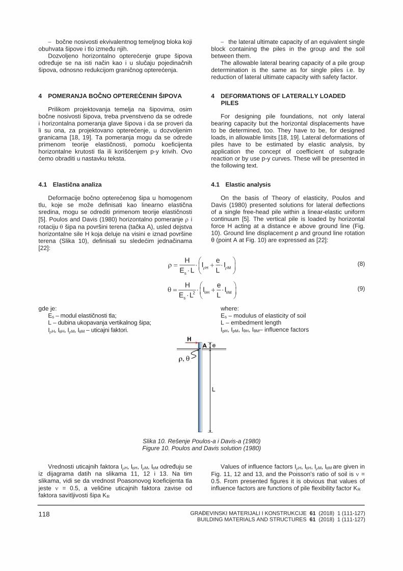
GRAĐEVINSKI MATERIJALI I KONSTRUKCIJE 61 (2018) 1 (111-127)BUILDING MATERIALS AND STRUCTURES 61 (2018) 1 (111-127)
118
bočne nosivosti ekvivalentnog temeljnog bloka kojiobuhvata šipove i tlo između njih.
Dozvoljeno horizontalno opterećenje grupe šipovaodređuje se na isti način kao i u slučaju pojedinačnihšipova, odnosno redukcijom graničnog opterećenja.
4 POMERANJA BOČNO OPTEREĆENIH ŠIPOVA
Prilikom projektovanja temelja na šipovima, osimbočne nosivosti šipova, treba prvenstveno da se odredei horizontalna pomeranja glave šipova i da se proveri dali su ona, za projektovano opterećenje, u dozvoljenimgranicama [18, 19]. Ta pomeranja mogu da se odredeprimenom teorije elastičnosti, pomoću koeficijentahorizontalne krutosti tla ili korišćenjem p-y krivih. Ovoćemo obraditi u nastavku teksta.
4.1 Elastična analiza
Deformacije bočno opterećenog šipa u homogenomtlu, koje se može definisati kao linearno elastičnasredina, mogu se odrediti primenom teorije elastičnosti[5]. Poulos and Davis (1980) horizontalno pomeranje irotaciju šipa na površini terena (tačka A), usled dejstvahorizontalne sile H koja deluje na visini e iznad površineterena (Slika 10), definisali su sledećim jednačinama[22]:
the lateral ultimate capacity of an equivalent singleblock containing the piles in the group and the soilbetween them.
The allowable lateral bearing capacity of a pile groupdetermination is the same as for single piles i.e. byreduction of lateral ultimate capacity with safety factor.
4 DEFORMATIONS OF LATERALLY LOADEDPILES
For designing pile foundations, not only lateralbearing capacity but the horizontal displacements haveto be determined, too. They have to be, for designedloads, in allowable limits [18, 19]. Lateral deformations ofpiles have to be estimated by elastic analysis, byapplication the concept of coefficient of subgradereaction or by use p-y curves. These will be presented inthe following text.
4.1 Elastic analysis
On the basis of Theory of elasticity, Poulos andDavis (1980) presented solutions for lateral deflectionsof a single free-head pile within a linear-elastic uniformcontinuum [5]. The vertical pile is loaded by horizontalforce H acting at a distance e above ground line (Fig.10). Ground line displacement ρ and ground line rotationθ (point A at Fig. 10) are expressed as [22]:
H Ms
H eI IE L L
(8)
H M2s
H eI IE L L
(9)
gde je:Es – modul elastičnosti tla;L – dubina ukopavanja vertikalnog šipa;IH, IH, IM, IM – uticajni faktori.
where:Es – modulus of elasticity of soilL – embedment lengthIρH, IρM, IθH, IθM– influence factors
Slika 10. Rešenje Poulos-a i Davis-a (1980)Figure 10. Poulos and Davis solution (1980)
Vrednosti uticajnih faktora IH, IH, IM, IM određuju seiz dijagrama datih na slikama 11, 12 i 13. Na timslikama, vidi se da vrednost Poasonovog koeficijenta tlajeste = 0.5, a veličine uticajnih faktora zavise odfaktora savitljivosti šipa KR
Values of influence factors IH, IH, IM, IM are given inFig. 11, 12 and 13, and the Poisson’s ratio of soil is =0.5. From presented figures it is obvious that values ofinfluence factors are functions of pile flexibility factor KR
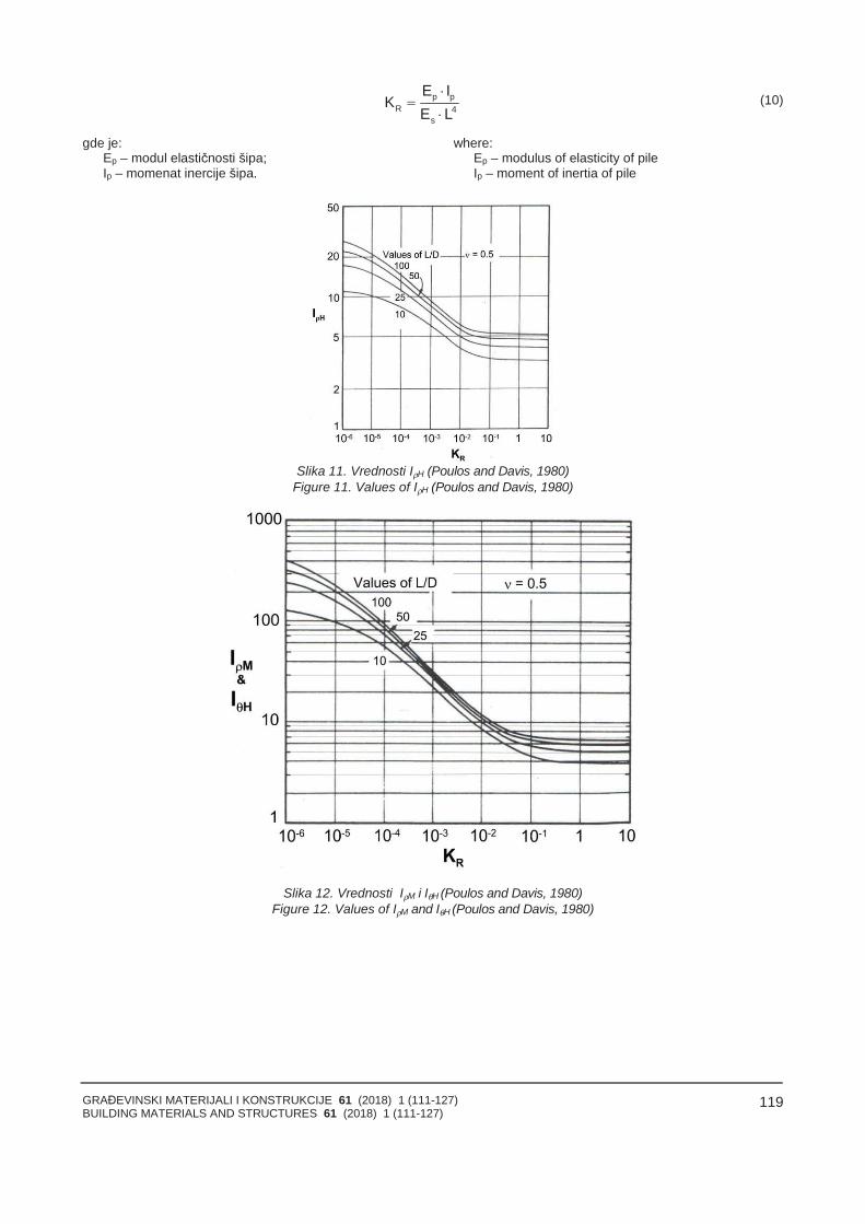
GRAĐEVINSKI MATERIJALI I KONSTRUKCIJE 61 (2018) 1 (111-127)BUILDING MATERIALS AND STRUCTURES 61 (2018) 1 (111-127)
119
p pR 4
s
E IK
E L
(10)
gde je:Ep – modul elastičnosti šipa;Ip – momenat inercije šipa.
where:Ep – modulus of elasticity of pileIp – moment of inertia of pile
Slika 11. Vrednosti IρH (Poulos and Davis, 1980)Figure 11. Values of IρH (Poulos and Davis, 1980)
Slika 12. Vrednosti IρM i IθH (Poulos and Davis, 1980)Figure 12. Values of IρM and IθH (Poulos and Davis, 1980)
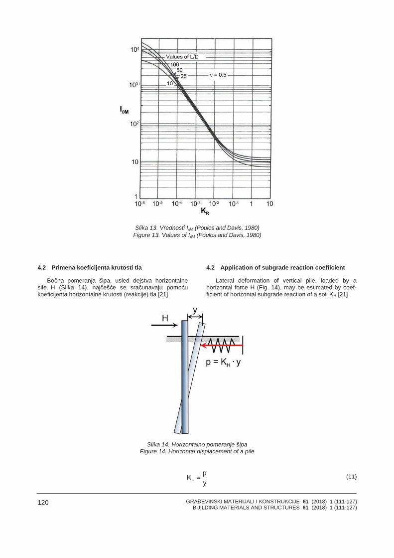
GRAĐEVINSKI MATERIJALI I KONSTRUKCIJE 61 (2018) 1 (111-127)BUILDING MATERIALS AND STRUCTURES 61 (2018) 1 (111-127)
120
Slika 13. Vrednosti IθM (Poulos and Davis, 1980)Figure 13. Values of IθM (Poulos and Davis, 1980)
4.2 Primena koeficijenta krutosti tla
Bočna pomeranja šipa, usled dejstva horizontalnesile H (Slika 14), najčešće se sračunavaju pomoćukoeficijenta horizontalne krutosti (reakcije) tla [21]
4.2 Application of subgrade reaction coefficient
Lateral deformation of vertical pile, loaded by ahorizontal force H (Fig. 14), may be estimated by coef-ficient of horizontal subgrade reaction of a soil KH [21]
Slika 14. Horizontalno pomeranje šipaFigure 14. Horizontal displacement of a pile
HpKy
(11)
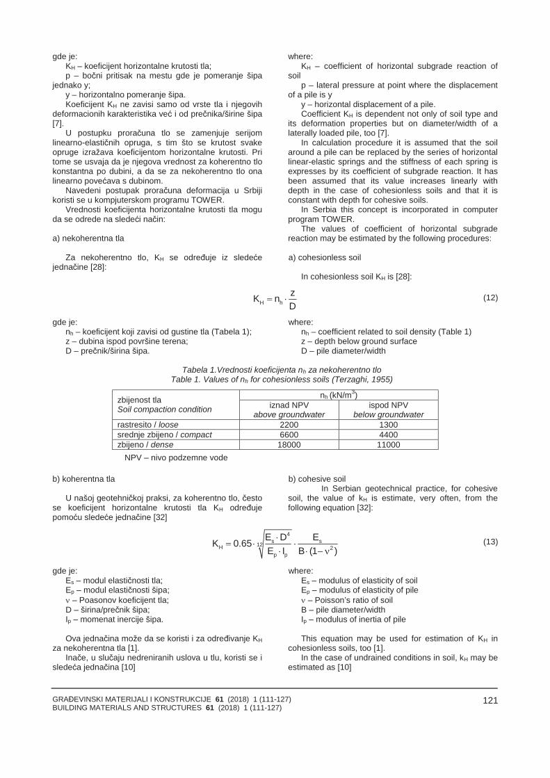
GRAĐEVINSKI MATERIJALI I KONSTRUKCIJE 61 (2018) 1 (111-127)BUILDING MATERIALS AND STRUCTURES 61 (2018) 1 (111-127)
121
gde je:KH – koeficijent horizontalne krutosti tla;p – bočni pritisak na mestu gde je pomeranje šipa
jednako y;y – horizontalno pomeranje šipa.Koeficijent KH ne zavisi samo od vrste tla i njegovih
deformacionih karakteristika već i od prečnika/širine šipa[7].
U postupku proračuna tlo se zamenjuje serijomlinearno-elastičnih opruga, s tim što se krutost svakeopruge izražava koeficijentom horizontalne krutosti. Pritome se usvaja da je njegova vrednost za koherentno tlokonstantna po dubini, a da se za nekoherentno tlo onalinearno povećava s dubinom.
Navedeni postupak proračuna deformacija u Srbijikoristi se u kompjuterskom programu TOWER.
Vrednosti koeficijenta horizontalne krutosti tla moguda se odrede na sledeći način:
a) nekoherentna tla
Za nekoherentno tlo, KH se određuje iz sledećejednačine [28]:
where:KH – coefficient of horizontal subgrade reaction of
soilp – lateral pressure at point where the displacement
of a pile is yy – horizontal displacement of a pile.Coefficient KH is dependent not only of soil type and
its deformation properties but on diameter/width of alaterally loaded pile, too [7].
In calculation procedure it is assumed that the soilaround a pile can be replaced by the series of horizontallinear-elastic springs and the stiffness of each spring isexpresses by its coefficient of subgrade reaction. It hasbeen assumed that its value increases linearly withdepth in the case of cohesionless soils and that it isconstant with depth for cohesive soils.
In Serbia this concept is incorporated in computerprogram TOWER.
The values of coefficient of horizontal subgradereaction may be estimated by the following procedures:
a) cohesionless soil
In cohesionless soil KH is [28]:
H hzK nD
(12)
gde je:nh – koeficijent koji zavisi od gustine tla (Tabela 1);z – dubina ispod površine terena;D – prečnik/širina šipa.
where:nh – coefficient related to soil density (Table 1)z – depth below ground surfaceD – pile diameter/width
Tabela 1.Vrednosti koeficijenta nh za nekoherentno tloTable 1. Values of nh for cohesionless soils (Terzaghi, 1955)
nh (kN/m3)zbijenost tlaSoil compaction condition iznad NPV
above groundwaterispod NPV
below groundwaterrastresito / loose 2200 1300srednje zbijeno / compact 6600 4400zbijeno / dense 18000 11000
NPV nivo podzemne vode
b) koherentna tla
U našoj geotehničkoj praksi, za koherentno tlo, čestose koeficijent horizontalne krutosti tla KH određujepomoću sledeće jednačine [32]
b) cohesive soilIn Serbian geotechnical practice, for cohesive
soil, the value of kH is estimate, very often, from thefollowing equation [32]:
4s s12H 2p p
E D EK 0.65E I B (1 )
(13)
gde je:Es – modul elastičnosti tla;Ep – modul elastičnosti šipa; – Poasonov koeficijent tla;D – širina/prečnik šipa;Ip – momenat inercije šipa.
Ova jednačina može da se koristi i za određivanje KHza nekoherentna tla [1].
Inače, u slučaju nedreniranih uslova u tlu, koristi se isledeća jednačina [10]
where:Es – modulus of elasticity of soilEp – modulus of elasticity of pile – Poisson’s ratio of soilB – pile diameter/widthIp – modulus of inertia of pile
This equation may be used for estimation of KH incohesionless soils, too [1].
In the case of undrained conditions in soil, kH may beestimated as [10]
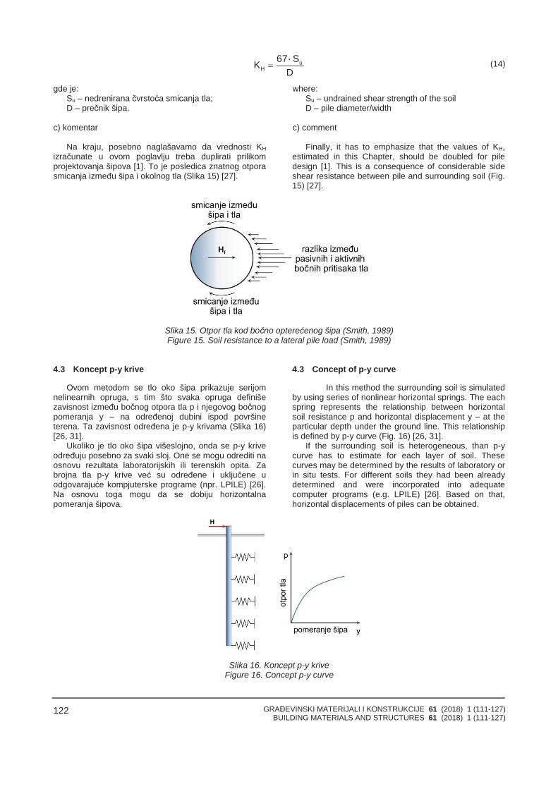
GRAĐEVINSKI MATERIJALI I KONSTRUKCIJE 61 (2018) 1 (111-127)BUILDING MATERIALS AND STRUCTURES 61 (2018) 1 (111-127)
122
uH
67 SKD
(14)
gde je:Su – nedrenirana čvrstoća smicanja tla;D – prečnik šipa.
c) komentar
Na kraju, posebno naglašavamo da vrednosti KHizračunate u ovom poglavlju treba duplirati prilikomprojektovanja šipova [1]. To je posledica znatnog otporasmicanja između šipa i okolnog tla (Slika 15) [27].
where:Su – undrained shear strength of the soilD – pile diameter/width
c) comment
Finally, it has to emphasize that the values of KH,estimated in this Chapter, should be doubled for piledesign [1]. This is a consequence of considerable sideshear resistance between pile and surrounding soil (Fig.15) [27].
Slika 15. Otpor tla kod bočno opterećenog šipa (Smith, 1989)Figure 15. Soil resistance to a lateral pile load (Smith, 1989)
4.3 Koncept p-y krive
Ovom metodom se tlo oko šipa prikazuje serijomnelinearnih opruga, s tim što svaka opruga definišezavisnost između bočnog otpora tla p i njegovog bočnogpomeranja y – na određenoj dubini ispod površineterena. Ta zavisnost određena je p-y krivama (Slika 16)[26, 31].
Ukoliko je tlo oko šipa višeslojno, onda se p-y kriveodređuju posebno za svaki sloj. One se mogu odrediti naosnovu rezultata laboratorijskih ili terenskih opita. Zabrojna tla p-y krive već su određene i uključene uodgovarajuće kompjuterske programe (npr. LPILE) [26].Na osnovu toga mogu da se dobiju horizontalnapomeranja šipova.
4.3 Concept of p-y curve
In this method the surrounding soil is simulatedby using series of nonlinear horizontal springs. The eachspring represents the relationship between horizontalsoil resistance p and horizontal displacement y – at theparticular depth under the ground line. This relationshipis defined by p-y curve (Fig. 16) [26, 31].
If the surrounding soil is heterogeneous, than p-ycurve has to estimate for each layer of soil. Thesecurves may be determined by the results of laboratory orin situ tests. For different soils they had been alreadydetermined and were incorporated into adequatecomputer programs (e.g. LPILE) [26]. Based on that,horizontal displacements of piles can be obtained.
Slika 16. Koncept p-y kriveFigure 16. Concept p-y curve
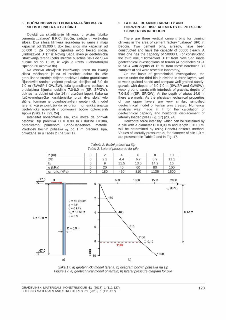
GRAĐEVINSKI MATERIJALI I KONSTRUKCIJE 61 (2018) 1 (111-127)BUILDING MATERIALS AND STRUCTURES 61 (2018) 1 (111-127)
123
5 BOČNA NOSIVOST I POMERANJA ŠIPOVA ZASILOS KLINKERA U BEOČINU
Objekti za skladištenje klinkera, u okviru fabrikecementa „Lafarge” B.F.C. Beočin, sadrže tri vertikalnasilosa. Dva silosa klinkera izgrađena su ranije i imajukapacitet od 35.000 t, dok treći silos ima kapacitet od50.000 t. Za potrebe izgradnje ovog trećeg silosa,„Hidrozavod DTD” iz Novog Sada izveo je geotehničkaistraživanja terena (četiri istražne bušotine SB-1 do SB-4dubine od po 15 m, iz kojih je uzeto i laboratorijskiispitano 30 uzoraka tla).
Na osnovu obavljenih istraživanja, teren na lokacijisilosa raščlanjen je na tri sredine: dobro do lošegranulisane srednje zbijene peskove i dobro granulisanešljunkovite srednje zbijene peskove debljine od 6.0 do7.0 m (SW/SP i GW/SW), loše granulisane peskove sproslojcima šljunka, debljine 7.0-8.0 m (SP, SP/GW),dok su na dubini od oko 14 m utvrđeni lapori. Kako sufizičko-mehaničke karakteristike prva dva sloja vrloslične, formiran je pojednostavljeni geotehnički modelterena, koji je poslužio da se uradi i numerička analizageotehničke nosivosti i pomeranja bočno opterećenihšipova (Slika 17) [23, 24].
Intenzitet horizontalne sile, koju može da prihvatibetonski šip prečnika D = 0.90 m i dužine L=10m,odredićemo primenom Brinč-Hansenove metode.Vrednosti bočnih pritisaka L po 1 m prečnika šipa,prikazane su u Tabeli 2 i na Slici 17.
5 LATERAL BEARING CAPACITY ANDHORIZONTAL DISPLACEMENTS OF PILES FORCLINKER BIN IN BEOCIN
There are three vertical cement bins for binningclinkers in the area of cement factory “Lafarge” BFC inBeocin. Two cement bins, already, have beenconstructed and have the capacity of 35000 t each. Athird one has the capacity of 50000 t. For constructingthe third one, “Hidrozavod DTD” from Novi Sad madegeotechnical investigations of terrain (4 boreholes SB-1to SB-4 with depths of 15 m; from these boreholes 30samples of soil were tested in laboratory).
On the basis of geotechnical investigations, theterrain under the third bin is divided in three layers: wellto weak grained sands and compact well grained sandy-gravels with depths of 6,0-7,0 m (SW/SP and GW/SW),weak ground sands with interbeds of gravels, depths of7,0-8,0 m(SP, SP/GW). At the depth of about 14,0 mthere are marls. As the physical-mechanical propertiesof two upper layers are very similar, simplifiedgeotechnical model of terrain was created. Numericalanalysis was made in it for the calculation ofgeotechnical capacity and horizontal displacement oflaterally loaded piles (Fig. 17) [23, 24].
Horizontal force intensity, which can be sustained bya pile with a diameter D = 0,90 m and length L = 10 m,will be determined by using Brinch-Hansen’s method.Values of laterally pressures σL for diameter of pile 1,0 mare presented in Table 2 and in Fig. 17.
Tabela 2. Bočni pritisci na šipTable 2. Lateral pressures for pile
z (m) 0 2 4 6 8 10z/D 0 2.2 4.4 6.7 8.9 11.1kq 0 9 11.5 13.5 14.2 16q (kPa) 0 20 40 60 80 100σL=q·kq (kPa) 0 180 460 810 1136 1600
a) b)
Slika 17. a) geotehnički model terena; b) dijagram bočnih pritisaka na šipFigure 17. a) geotechnical model of terrain; b) lateral pressure diagram for pile
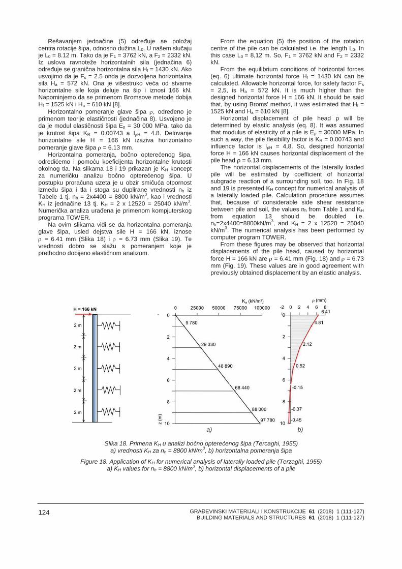
GRAĐEVINSKI MATERIJALI I KONSTRUKCIJE 61 (2018) 1 (111-127)BUILDING MATERIALS AND STRUCTURES 61 (2018) 1 (111-127)
124
Rešavanjem jednačine (5) određuje se položajcentra rotacije šipa, odnosno dužina L0. U našem slučajuje L0 = 8.12 m. Tako da je F1 = 3762 kN, a F2 = 2332 kN.Iz uslova ravnoteže horizontalnih sila (jednačina 6)određuje se granična horizontalna sila Hf = 1430 kN. Akousvojimo da je Fs = 2.5 onda je dozvoljena horizontalnasila Ha = 572 kN. Ona je višestruko veća od stvarnehorizontalne sile koja deluje na šip i iznosi 166 kN.Napominjemo da se primenom Bromsove metode dobijaHf = 1525 kN i Ha = 610 kN [8].
Horizontalno pomeranje glave šipa , određeno jeprimenom teorije elastičnosti (jednačina 8). Usvojeno jeda je modul elastičnosti šipa Ep = 30 000 MPa, tako daje krutost šipa KR = 0.00743 a IH = 4.8. Delovanjehorizontalne sile H = 166 kN izaziva horizontalnopomeranje glave šipa = 6.13 mm.
Horizontalna pomeranja, bočno opterećenog šipa,odredićemo i pomoću koeficijenta horizontalne krutostiokolnog tla. Na slikama 18 i 19 prikazan je KH konceptza numeričku analizu bočno opterećenog šipa. Upostupku proračuna uzeta je u obzir smičuća otpornostizmeđu šipa i tla i stoga su duplirane vrednosti nh izTabele 1 tj. nh = 2x4400 = 8800 kN/m3, kao i vrednostiKH iz jednačine 13 tj. KH = 2 x 12520 = 25040 kN/m3.Numerička analiza urađena je primenom kompjuterskogprograma TOWER.
Na ovim slikama vidi se da horizontalna pomeranjaglave šipa, usled dejstva sile H = 166 kN, iznose = 6.41 mm (Slika 18) i = 6.73 mm (Slika 19). Tevrednosti dobro se slažu s pomeranjem koje jeprethodno dobijeno elastičnom analizom.
From the equation (5) the position of the rotationcentre of the pile can be calculated i.e. the length L0. Inthis case L0 = 8,12 m. So, F1 = 3762 kN and F2 = 2332kN.
From the equilibrium conditions of horizontal forces(eq. 6) ultimate horizontal force Hf = 1430 kN can becalculated. Allowable horizontal force, for safety factor Fs= 2,5, is Ha = 572 kN. It is much higher than thedesigned horizontal force H = 166 kN. It should be saidthat, by using Broms’ method, it was estimated that Hf =1525 kN and Ha = 610 kN [8].
Horizontal displacement of pile head ρ will bedetermined by elastic analysis (eq. 8). It was assumedthat modulus of elasticity of a pile is Ep = 30000 MPa. Insuch a way, the pile flexibility factor is KR = 0.00743 andinfluence factor is IρH = 4,8. So, designed horizontalforce H = 166 kN causes horizontal displacement of thepile head ρ = 6.13 mm.
The horizontal displacements of the laterally loadedpile will be estimated by coefficient of horizontalsubgrade reaction of a surrounding soil, too. In Fig. 18and 19 is presented KH concept for numerical analysis ofa laterally loaded pile. Calculation procedure assumesthat, because of considerable side shear resistancebetween pile and soil, the values nh from Table 1 and KHfrom equation 13 should be doubled i.e.nh=2x4400=8800kN/m3, and KH = 2 x 12520 = 25040kN/m3. The numerical analysis has been performed bycomputer program TOWER.
From these figures may be observed that horizontaldisplacements of the pile head, caused by horizontalforce H = 166 kN are = 6.41 mm (Fig. 18) and = 6.73mm (Fig. 19). These values are in good agreement withpreviously obtained displacement by an elastic analysis.
a) b)
Slika 18. Primena KH u analizi bočno opterećenog šipa (Tercaghi, 1955)a) vrednosti KH za nh = 8800 kN/m3, b) horizontalna pomeranja šipa
Figure 18. Application of KH for numerical analysis of laterally loaded pile (Terzaghi, 1955)a) KH values for nh = 8800 kN/m3, b) horizontal displacements of a pile
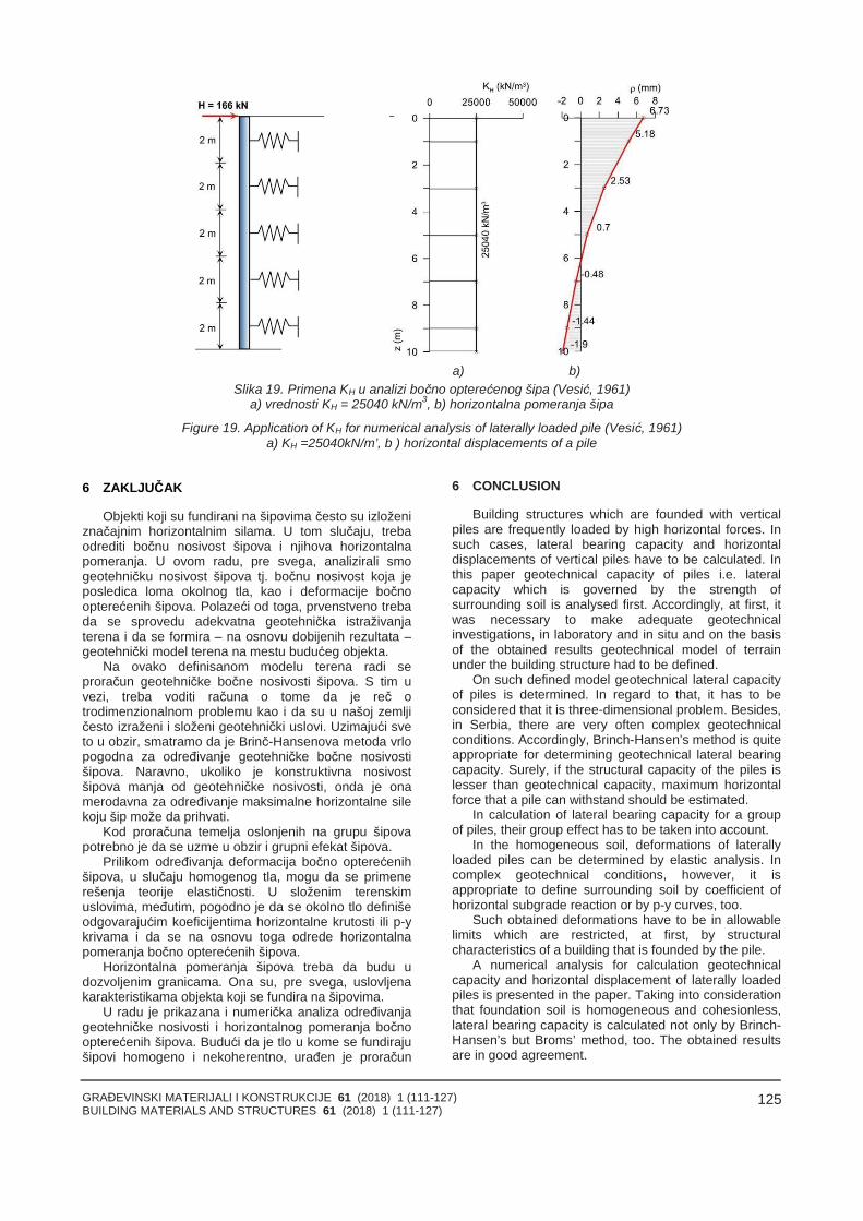
GRAĐEVINSKI MATERIJALI I KONSTRUKCIJE 61 (2018) 1 (111-127)BUILDING MATERIALS AND STRUCTURES 61 (2018) 1 (111-127)
125
a) b)Slika 19. Primena KH u analizi bočno opterećenog šipa (Vesić, 1961)
a) vrednosti KH = 25040 kN/m3, b) horizontalna pomeranja šipa
Figure 19. Application of KH for numerical analysis of laterally loaded pile (Vesić, 1961)a) KH =25040kN/m’, b ) horizontal displacements of a pile
6 ZAKLJUČAK
Objekti koji su fundirani na šipovima često su izloženiznačajnim horizontalnim silama. U tom slučaju, trebaodrediti bočnu nosivost šipova i njihova horizontalnapomeranja. U ovom radu, pre svega, analizirali smogeotehničku nosivost šipova tj. bočnu nosivost koja jeposledica loma okolnog tla, kao i deformacije bočnoopterećenih šipova. Polazeći od toga, prvenstveno trebada se sprovedu adekvatna geotehnička istraživanjaterena i da se formira – na osnovu dobijenih rezultata –geotehnički model terena na mestu budućeg objekta.
Na ovako definisanom modelu terena radi seproračun geotehničke bočne nosivosti šipova. S tim uvezi, treba voditi računa o tome da je reč otrodimenzionalnom problemu kao i da su u našoj zemljičesto izraženi i složeni geotehnički uslovi. Uzimajući sveto u obzir, smatramo da je Brinč-Hansenova metoda vrlopogodna za određivanje geotehničke bočne nosivostišipova. Naravno, ukoliko je konstruktivna nosivostšipova manja od geotehničke nosivosti, onda je onamerodavna za određivanje maksimalne horizontalne silekoju šip može da prihvati.
Kod proračuna temelja oslonjenih na grupu šipovapotrebno je da se uzme u obzir i grupni efekat šipova.
Prilikom određivanja deformacija bočno opterećenihšipova, u slučaju homogenog tla, mogu da se primenerešenja teorije elastičnosti. U složenim terenskimuslovima, međutim, pogodno je da se okolno tlo definišeodgovarajućim koeficijentima horizontalne krutosti ili p-ykrivama i da se na osnovu toga odrede horizontalnapomeranja bočno opterećenih šipova.
Horizontalna pomeranja šipova treba da budu udozvoljenim granicama. Ona su, pre svega, uslovljenakarakteristikama objekta koji se fundira na šipovima.
U radu je prikazana i numerička analiza određivanjageotehničke nosivosti i horizontalnog pomeranja bočnoopterećenih šipova. Budući da je tlo u kome se fundirajušipovi homogeno i nekoherentno, urađen je proračun
6 CONCLUSION
Building structures which are founded with verticalpiles are frequently loaded by high horizontal forces. Insuch cases, lateral bearing capacity and horizontaldisplacements of vertical piles have to be calculated. Inthis paper geotechnical capacity of piles i.e. lateralcapacity which is governed by the strength ofsurrounding soil is analysed first. Accordingly, at first, itwas necessary to make adequate geotechnicalinvestigations, in laboratory and in situ and on the basisof the obtained results geotechnical model of terrainunder the building structure had to be defined.
On such defined model geotechnical lateral capacityof piles is determined. In regard to that, it has to beconsidered that it is three-dimensional problem. Besides,in Serbia, there are very often complex geotechnicalconditions. Accordingly, Brinch-Hansen’s method is quiteappropriate for determining geotechnical lateral bearingcapacity. Surely, if the structural capacity of the piles islesser than geotechnical capacity, maximum horizontalforce that a pile can withstand should be estimated.
In calculation of lateral bearing capacity for a groupof piles, their group effect has to be taken into account.
In the homogeneous soil, deformations of laterallyloaded piles can be determined by elastic analysis. Incomplex geotechnical conditions, however, it isappropriate to define surrounding soil by coefficient ofhorizontal subgrade reaction or by p-y curves, too.
Such obtained deformations have to be in allowablelimits which are restricted, at first, by structuralcharacteristics of a building that is founded by the pile.
A numerical analysis for calculation geotechnicalcapacity and horizontal displacement of laterally loadedpiles is presented in the paper. Taking into considerationthat foundation soil is homogeneous and cohesionless,lateral bearing capacity is calculated not only by Brinch-Hansen’s but Broms’ method, too. The obtained resultsare in good agreement.
GRAĐEVINSKI MATERIJALI I KONSTRUKCIJE 61 (2018) 1 (111-127)BUILDING MATERIALS AND STRUCTURES 61 (2018) 1 (111-127)
126
bočne nosivosti i po metodi Brinč-Hansena i po metodiBromsa i dobijena su dobra slaganja. Osim toga,izračunata su i horizontalna pomeranja glave šipaelastičnom analizom, kao i pomoću koeficijentahorizontalne krutosti tla. Razlike u rezultatima su u uskimgranicama, sasvim prihvatljivim za inženjersku praksu.
Zahvalnica: Ovaj rad je realizovan u okviruistraživanja za projekat TR36014, koji finansiraMinistarstvo prosvete, nauke i tehnološkog razvojaRepublike Srbije.
In addition, the pile head displacements aredetermined by elastic analysis and application theory ofsubgrade reaction. The calculated values are in narrowlimits, quite acceptable for engineering practice.
Acknowledgment: This paper was realized underthe project number 36014 which is funded by theMinistry of Education, Science and TechnologicalDevelopment of Republic of Serbia.
7 LITERATURAREFERENCES
[1] Bowles, J. E.: Foundation analysis and design,McGraw – Hill, New York, 4th Edition, 1988, pp1004.
[2] Broms, B. R.: Lateral resistance of piles in cohesivesoils, Journal of the Soil Mechanics andFoundations Division, ASCE, Vol 90, No. SM 2,1964.
[3] Broms, B. R.: Lateral resistance of piles incohesionless soils, Journal of the Soil Mechanicsand Foundations Division, ASCE, Vol 90, No. SM3, 1964.
[4] Broms, B. R.: Design of laterally loaded piles,Journal of the Soil Mechanics and FoundationsDivision, ASCE, Vol 91, No. SM 3, 1965.
[5] Canadian foundation engineering manual, 4thedition, Canadian Geotechnical Society, Calgary,Alberta, 2006.
[6] Conduto, D. R.: Foundation design "Principles andpractice", Prentice Hall, New Jersey, 2001.
[7] Ćorić, S.: Geostatički proračuni – IV izdanje,Časopis Izgradnja i Srpsko društvo za mehaniku tlai geotehničko inženjerstvo, Beograd, 2017. str. 460.
[8] Ćorić, S., Rakić, D., Hadži-Niković, G., Basarić, I.:Bočna nosivost šipova opterećenih horizontalnimsilama, Zbornik radova Geotehnički aspektigrađevinarstva, 2017, str. 421-432.
[9] Das, B.M.: Principles of foundation engineering,Sixth Edition, Thomson Engineering, 2007, pp. 750.
[10] Davisson, M.T.: Lateral Load Capacity of Piles,Highway research Record, TransportationResearch Boarde , Washington, DC, No. 333,1970. pp. 104-112.
[11] Day, R. W.: Foundation engineering handbook,McGraw-Hill, New York, 2006.
[12] Berisavljević, D., Filipović, V., Ćorić, S., Rakić, D:Analiza bočno opterećenih šipova primenomrezultata DMT opita, Zbornik radova Geotehničkiaspekti građevinarstva, 2017, str. 439-446.
[13] Folić, R., Liolios, A.: Application incilined piles in aseismic prone area, useful or not?, Zbornik radovaGeotehnički aspekti građevinarstva, 2017, str. 461-472.
[14] Folić, B., Liolios, A., Liolios , K: Effects of horizontalinteraction on redistribution of forces of piles in agroup, Zbornik radova Geotehnički aspektigrađevinarstva, 2017, str. 461-472.
[15] Hansen, J. B.: The ultimate resistance of rigid pilesagainst transversal forces, Danish GeotechnicalInstitute, Bulletin No. 12, Copenhagen, 1961.
[16] Meyerhof, G. G. and Ranjan, G.: The bearingcapacity of rigid piles under inclined loads in sand:Vertical piles, Canadian Geotechnical Journal, No.9, pp. 430-446, 1972.
[17] Meyerhof, G. G.: Behaviour of pile foundationsunder special loading conditions: 1994 R. M. Hardykeynote address, Canadian Geotechnical Journal,No. 32, pp. 204-222, 1995.
[18] Milović, D., Đogo, M.: Šip opterećen horizontalnomsilom – teorijski i eksperimentalni rezultati,Materijali i konstrukcije, 43, 3-4, 2000, str. 3-8.
[19] Milović, D., Đogo, M.: Ponašanje šipa pri dejstvusile H određeno na osnovu rezultata statičkepenetracije, Materijali i konstrukcije, 44, 3-4, 2001,str. 3-13.
[20] Milović, D., Đogo, M.: Problemi interakcije tlo-temelj-konstrukcija, Srpska akademija nauka iumetnosti – ogranak u Novom sadu, 2009, str. 248.
[21] Milović, S.: Interakcija tla i šipa opterećenoghorizontalnom silom i momentom, Magistarskateza, Rudarsko-geološki fakultet Beograd, 1996.
[22] Poulos, H. G. and Davis, E. H.: Pile foundationanalysis and design, John Wiley & Sons, NewYork, 1980.
[23] Rakić, D.: Geotehnički činioci i njihov uticaj nanosivost i sleganje vertikalno opterećenih šipova,Magistarska teza, Rudarsko-geološki fakultetBeograd, str. 193., 1997.
[24] Rakić, D. and Ćorić. S: Application of modernnumerical methods in settlement analysis of avertically loaded pile, Journal of mining andgeological sciences, Volume 37. Belgrade, 1998.pp. 75-83.
[25] Rankine, W.M.J.: On the Stability of Lose Earth,Philosophical Transactions of the Royal Society,London Part I, 1857. pp. 9-27.
[26] Reese, C.L. and Van Impe, W: Single Piles andPile Groups Under Lateral Loading, CRC Press,Taylor & Francis Group, London, 2011.
[27] Smith, T.D.: Fact or Friction: A Review of SoilResponse to a Laterally Moving Pile, Partof: Foundation Engineering: Current Principles andPractices, F.H. Kulhawy editor, American society ofcivil engineers, ASCE, New York, Vol. 1., 1989, pp.588-598.
[28] Terzaghi, K.: Evaluation of Coefficients ofSubgrade Reaction . Geotechnique, Vol. 5,London, 1955, pp. 297-326.
GRAĐEVINSKI MATERIJALI I KONSTRUKCIJE 61 (2018) 1 (111-127)BUILDING MATERIALS AND STRUCTURES 61 (2018) 1 (111-127)
127
[29] Tomlinson, M. J.: Foundation design andconstruction, The Pitman book, London, 1980.
[30] Tomlinson, M. J. and Woodward, J. C.: Pile designand construction practice, CRC Press, Boca Raton,2015.
[31] U.S. Army Corps of Engineers, Deep Foundations,Unified Facilites Criteria (UFC), 2004, pp. 1-1 - D-2.
[32] Vesić, A. B.: Bending of Beams Resting onIsotropic Elastic Solid, Journal of the EngineeringMechanics Division, Vol. 87, Issue 2, 1961, pp. 35-54.
REZIME
BOČNA NOSIVOST I POMERANJA VERTIKALNIHŠIPOVA OPTEREĆENIH HORIZONTALNIM SILAMA
Slobodan ĆORIĆDragoslav RAKIĆStanko ĆORIĆIrena BASARIĆ
Temelji na šipovima često su izloženi značajnimhorizontalnim silama. U takvim slučajevima, važno je dase odredi bočna nosivost vertikalnih šipova. Ona jeuslovljena čvrstoćom okolnog tla (geotehnička nosivost)odnosno čvrstoćom poprečnog preseka šipa(konstruktivna nosivost). U radu je prvenstvenoanalizirana geotehnička nosivost šipova i primenjene susledeće metode za određivanje bočne nosivostipojedinačnih šipova: Rankinova, Bromsova i Brinč-Hansenova metoda. S tim u vezi, polazeći od složenihgeoloških uslova koji su česti u Srbiji, smatramo da Brinč-Hansenova metoda ima prednost u odnosu na druge dvemetode. Naime, ona može da se primeni i u homogenom iu heterogenom tlu i to za drenirane, kao i za nedreniraneuslove. To je veoma važno prilikom fundiranja objekata iprilikom sanacije klizišta. Zato je u radu prikazano i kakose u proračun uvodi grupno dejstvo šipova. Horizontalnapomeranja bočno opterećenih šipova mogu da se, uslučaju homogenog tla, odrede primenom teorijeelastičnosti. U slučaju složenih geoloških uslova, međutim,ta pomeranja se određuju primenom koeficijentahorizontalne krutosti okolnog tla ili korišćenjem p-ykrivih.Na kraju rada data je numerička analiza određivanjageotehničke nosivosti i horizontalnog pomeranja glavebočno opterećenih šipova koji se koriste za fundiranjesilosa klinkera u Beočinu.
Ključne reči: pojedinačni šipovi, grupa šipova,bočna nosivost, dozvoljeno bočno opterećenje, bočnedeformacije.
SUMMАRY
LATERAL CAPACITY AND DEFORMATIONS OFVERTICAL PILES LOADED BY HORIZONTALFORCES
Slobodan ĆORIĆDragoslav RAKIĆStanko ĆORIĆIrena BASARIĆ
Pile foundations are frequently loaded by horizontalforces. In such cases, it is important to calculate lateralcapacity of vertical piles. It is governed by the strength ofthe surrounding soil i.e. geotechnical capacity or pilestrength parameters i.e. structural capacity of a pile. Inthis paper, geotechnical capacity is analysed first, andthen the Rankine’s, Broms’ and Brinch-Hansen’smethods for calculating ultimate bearing capacity of asingle pile under lateral loads are presented. Inaccordance with complex geological conditions, whichare very often in Serbia, Brinch-Hansen’s method has anadvantage over the other two methods. It can be appliedboth to uniform and layered soils under drained orundrained conditions. This is highly important forfoundation of structures and landslide’s remedialmeasures, too. Accordingly, load capacity calculation ofa pile group is presented as well. In the case ofhomogenous surrounding soil, deformations of laterallyloaded piles may be determined by elastic analysis.However, in the case of complex geological conditions,these deformations may be calculated by the concept ofcoefficient of subgrade reaction or by p-y curves, too.Finally, numerical analysis for calculation of geotechnicalcapacity and pile head displacement of laterally loadedpiles for foundation of Clinker Bin in Beocin is presented.
Key words: single piles, pile groups, ultimate lateralcapacity, allowable lateral load, lateral deformations.

GRAĐEVINSKI MATERIJALI I KONSTRUKCIJE 61 (2018) 1 (111-127)BUILDING MATERIALS AND STRUCTURES 61 (2018) 1 (111-127)
128
GRAĐEVINSKI MATERIJALI I KONSTRUKCIJE 61 (2018) 1 (129-160)BUILDING MATERIALS AND STRUCTURES 61 (2018) 1 (129-160)
129
SISTEMATIZACIJA ANALITIČKIH I NUMERIČKIH METODA PRORAČUNASTABILNOSTI KLIZIŠTA
THE SYSTEMATIZATION OF ANALYTICAL AND NUMERICAL METHODS OFLANDSLIDE STABILITY CALCULATION
Kristina BOŽIĆ TOMIĆNenad ŠUŠIĆMato ULJAREVIĆ
STRUČNI RADPROFESSIONAL PAPER
UDK: 624.131.537doi:10.5937/GRMK1801129B
1 UVOD
S obzirom na kompleksnost geometrije reljefazemljine površi, kosine su među problematičnijimgeološkim formama u geotehnici. Kosine karakterišenagla promena geometrije terena (denivelacija), spredispozicijom promene ove geometrije usled dejstvarazličitih faktora. Najčešći i najsloženiji vid narušavanjatla i geometrije kosine odnosi se na stabilnost terena –bilo prirodnih padina ili veštačkih kosina. Svako naru-šavanje postojeće ravnoteže na padinama ili kosinamaizaziva pomeranja pod uticajem gravitacije: klizanje,odronjavanje ili tečenje površinskog dela tla, ali i dubljihdelova stenske mase. Za ovako uspostavljeno klizanje, ugeološkoj i geotehničkoj terminologiji i nomenklaturi,ustaljen je termin – klizište [11]. Uslovi za nastanak irazvoj klizišta jesu: geotehnički, geološki, geomorfološki,hidrogeološki, meteorološki, vegetacioni, antropogeni,dejstvo zemljotresa, dejstvo akumulacija, vibracije usledsaobraćaja i drugi.
U poslednjih sto godina, zabeležen je znatan brojkatastrofalnih klizišta, nastalih kao posledica dejstvazemljotresa, erupcije vulkana, nagomilavanja snega,višednevnih i intenzivnih kiša i uragana [16]. Zbog formi-ranja ovih klizišta, poginulo je nekoliko stotina hiljada ljudikoji su - u najvećem broju slučajeva - imali sagrađene
Mr Kristina Božić-Tomić, Institut za ispitivanje materijalaIMS, Beograd, Srbija, [email protected] Nenad Šušić, naučni savetnik, Institut za ispitivanjematerijala IMS, Beograd, Srbija, [email protected]. dr Mato Uljarević, Arhitektonsko-građevinsko-geodetski fakultet, Univerzitet u Banjoj Luci, RepublikaSrpska, [email protected]
1 INTRODUCTION
Given the complexity of geometry of the relief of theearth's surface, slopes represent one of the problematicgeological forms in geotechnics. The slopes are charac-terized by a sudden change in geometry of the terrain(denivelation) with a predisposition to the change of thisgeometry due to the effects of various factors. The mostcommon and most complex type of soil disturbance andslope geometry is the stability of the terrain, whethernatural slopes or artificial slopes. Any disturbance of theexisting balance on the slopes causes displacementunder the influence of gravity: sliding, erosion or flowingthe surface of the soil, but also the deeper parts of therock mass. For the established sliding, in the geologicaland geotechnical terminology and nomenclature, theterm "landslide" is established [11]. Conditions for theformation and development of landslides are: geotechni-cal, geological, geo-morphological, hydro-geological,meteorological, vegetation, anthropogenic, earthquakeeffects, accumulation effects, traffic vibrations, etc.
In the last hundred years there has been a significantnumber of catastrophic landslides that have occurred asa result of earthquakes, volcanic eruptions, snowaccumulation, multi-day heavy rainfall and hurricanes[16]. Due to the formation of these landslides several
Mr Kristina Bozic-Tomic, Institute for testing of materialsIMS, Belgrade, Serbia, [email protected] Nenad Susic, Institute for testing of materials IMS,Belgrade, Serbia, [email protected]. dr Mato Uljarevic, Faculty of architecture, civilengineering and geodesy, University of Banja Luka,Republika Srpska, [email protected]
GRAĐEVINSKI MATERIJALI I KONSTRUKCIJE 61 (2018) 1 (129-160)BUILDING MATERIALS AND STRUCTURES 61 (2018) 1 (129-160)
130
domove na klizištima ili u njihovoj neposrednoj blizini.Prema [29], u najkatastrofalnija klizišta – zabeležena uposlednjih sto godina – ubrajaju se: Haiyuan landslides u Kini 1920, Vargas tragedy u Venecueli 1999, Nevado delRuiz debris flows u Kolumbiji 1985, Nevados Huascarandebris avalanche u Peru 1970, North India floodmudslides u Indiji 2013, Khait rock slide u USSR 1949 islično. U katastarskom listu evidencije klizišta u Srbiji,zabeleženo je više od 2.200 aktivnih, trenutno umirenih ireaktivnih klizišta [15]. Znatno je manji broj trenutnoumirenih od aktivnih i reaktivnih klizišta. Vrlo često, upraksi se susrećemo s problemima stabilnosti klizišta,kada je nakon izvedenih terenskih istraživanja, labora-torijsko-geomehaničkih ispitivanja, definisanja uzroka iuslova nastanka klizišta potrebno definisati meresanacije. Međutim, da bismo uspešno upravljali svimprojektnim situacijama analize stabilnosti i sanacijeklizišta, potrebno je da imamo kvalitetne matematičkemodele i metode analize stabilnosti klizišta. Dosadašnjaiskustva pokazuju da postoji potreba za implementa-cijom kompleksnijih (realističnijih) matematičkih modelau praktične svrhe, kao i za dodatnim unapređivanjempostojećih metoda analize stabilnosti klizišta.
Jedan od prvih radova u kojem su adekvatno teorijskirazmatrani aspekti nekoliko analitičkih, ali i numeričkihmetoda analize stabilnosti klizišta, jeste rad [9], gde jesprovedena klasifikacija, imajući u vidu: formulacijugraničnog stanja (limit formulation) i formulaciju stanjapomeranja (displacement formulation). Kod formulacijegraničnog stanja, postoje dve opcije: gornja graničnarešenja (upper bound solution) i donja granična rešenja(lower bound solution), pri čemu metoda karakteristikapomeranja (method of characteristics for displacement)pripada grupi gornjih graničnih rešenja, a metodakarakteristika napona (method of characteristics forstress) pripada grupi donjih graničnih rešenja. Metodedefinisane prema formulaciji graničnog stanja, zapravosu metode granične ravnoteže (LEM - Limit EquilibriumMethod), od kojih se najčešće primenjuju gornja gra-nična rešenja. U poređenju s njima, metode definisaneprema formulaciji stanja pomeranja, zapravo su metodeanalize pomeranja (DFM - Displacement FormulationMethod), odnosno numeričke metode. U radu [20] dat jepregled numeričkih metoda stabilnosti klizišta, pri čemuje korišćena formulacija po metodi konačnih razlika(FDM - Finite Difference Method). Studija performansinekoliko različitih metoda stabilnosti klizišta prikazana jeu radu [27], dok su u radu [21] prikazane metodestabilosti klizišta, imajući u vidu deterministički pristup,teoriju pouzdanosti i optimizacije. Primena numeričkihmetoda analize stabilnosti kosina u izmenjenoj serpen-tinskoj stenskoj masi prikazana je u radu [25], pri čemusu, između ostalog, korišćeni i sledeći parametri: geološ-ki indeks čvrstoće i deformabilnosti stenske mase, dok jekao kriterijum sloma primenjen Hoek Brown-ov kriteri-jum. Razmatranje kompleksne problematike stabilnostiklizišta, iz aspekta analize hazarda, analize povred-ljivosti, procene i upravljanja rizikom prikazani su u radu[6], gde je - zasnivajući se na prethodno navedenimteorijama - predložen GIS integralni model za analizuklizišta.
Cilj istraživanja prikazanog u ovom radu jeste da sedetaljnije sistematizuju metode proračuna klizišta ialgoritmi modeliranja, s posebnim osvrtom na numeričkeanalize stabilnosti.
hundred thousand people were killed, who in most caseshad their own homes built on or near the landslide.According to [29], the most catastrophic landslidesrecorded over the last hundred years, were: Haiyuanlandslides in China 1920, Vargas tragedy in Venezuela1999, Nevado del Ruizdebris flows in Colombia 1985,Nevados Huascaran debris avalanche in Peru 1970,North India flood mudslides in India 2013, Khait rockslide in the USSR in 1949 and the like. In the cadastralregister of landslide records in Serbia, more than 2200active, currently calm and reactive landslides have beenrecorded [15]. There is a significantly lower number ofcurrently calm, compared to active and reactive land-slides. Very often, in practice, problems with the stabilityof the landslide are encountered, when after the conduc-ted field investigations, laboratory-geomechanical tests,defining the causes and conditions of landslide forma-tion, it is necessary to define repair measures. However,in order to successfully manage all project situations ofthe landslide stability analysis and landslide repair, it isnecessary to have high quality mathematical models andlandslide methods. Previous experience shows thatthere is a need for the implementation of more complex(more realistic) mathematical models for practicalpurposes and further improvement of existing landslidestability methods.
One of the first papers in which the aspects ofseveral analytical and also numerical methods oflandslide stability are adequately theoretically conside-red is the paper [9], where the classification was carriedout taking into account the limit formulation and thedisplacement formulation. There are two options for thelimit formulation: upper bound solution and lower boundsolution, where the method of characteristics for displa-cement belongs to the group of upper bound solutions,and the method of characteristics for stress belongs tothe group of lower bound solutions. The methodsdefined by the limit formulation are in fact the LimitEquilibrium Method (LEM), of which the upper boundsolutions are most commonly applied. In relation tothem, the methods defined by the displacement formula-tion are in fact Displacement Formulation Methods(DFM), or numerical methods. The paper [20] gives anoverview of the numerical methods of landslide stability,using the Finite Difference Method (FDM) formulation. Astudy of the performances of several different landslidestability methods is presented in [27], while in [21] themethods of landslide stability are presented taking intoaccount the deterministic approach, the theory ofreliability and optimization. The use of numericalmethods for analyzing the stability of slopes in thealternating serpentine rock mass was shown in [25],where, among other things, these parameters wereused: the geological strength index and deformability ofthe rock mass, and for the criterion of failure HoekBrown's criterion was applied. Consideration of thecomplex problem of landslide stability, but also from theaspect of hazard analysis, vulnerability analysis, riskassessment and risk management, are presented in [6],where, based on the aforementioned theories, a GISintegral model for landslide analysis is proposed.
The aim of the research presented in this paper is tofurther systematize the methods of landslide calculationsand modelling algorithms with a special emphasis onnumerical stability analyses.
GRAĐEVINSKI MATERIJALI I KONSTRUKCIJE 61 (2018) 1 (129-160)BUILDING MATERIALS AND STRUCTURES 61 (2018) 1 (129-160)
131
2 UOPŠTENO O RAZMATRANJIMA STABILNOSTIKLIZIŠTA I FAKTORIMA BITNIM ZA PRORAČUN
Generalno razmatrajući, kosine se mogu nalaziti ustabilnom ravnotežnom, nestabilnom neravnotežnom iindiferentnom poluravnotežnom stanju. Stabilno ravno-težno stanje karakteriše uspostavljen odnos destabili-zujućih i stabilizujućih sila, tako da – ukoliko je uticajstabilizujućih sila veći - veći je i faktor sigurnosti.Nestabilno neravnotežno stanje karakteriše narušenodnos destabilizujućih i stabilizujućih sila, tako da jeuticaj destabilizujućih sila dominantan. Indiferentno (neo-dređeno) poluravnotežno stanje predstavlja prelaznukategoriju između stabilnog ravnotežnog i nestabilnogneravnotežnog stanja. Odnos destabilizujućih i stabili-zujućih sila indiferentnog poluravnotežnog stanja značaj-nije je narušen u stabilno ravnotežnom stanju i dovoljanje i mali priraštaj destabilizujućih sila, pa da transformišeovo stanje u nestabilno neravnotežno stanje. S obziromna kompleksnost indiferentnog stanja i mogućnostparcijalne promene geometrije kosine, odnosno polufor-miranja klizišta, indiferentno stanje karakteriše skup višerazličitih poluravnotežnih stanja. Ovo je posebno karak-teristično u situacijama kada nastupi narušavanje stabili-tetnog ravnotežnog stanja, pri čemu ne mora doći dopotpunog kretanja klizne mase tla, već se možeuspostaviti novo poluravnotežno stanje. Detaljnijaklasifikacija stabilitetnih i nestabilitetnih stanja kosina,podrazumevajući pritom i prelazne kategorije, prikazanaje u [24]: stabilna kosina, potencijalno nestabilna kosina,rana faza rušenja, srednja faza rušenja, delimično ilitotalno rušenje i potpuno rušenje,dok su mehanizminastanka i razvoja klizišta: rotacioni model, translacionimodel, model formiran iz različitih geometrijskih formiblokova, model s klizanjem, kotrljanjem i padanjemkamena različitih dimenzija, model sa značajnim odvalji-vanjem kliznog tla, klizište formirano usled obimnih kiša,klizište formirano kao obimni bujični tok, klizišteformirano tečenjem tla i klizište formirano puzanjem tlauz pojavu prslina i rascepa u tlu. Jedan od ključnihparametara pri klasifikaciji klizišta jeste brzina kretanjaklizne mase, kao i uticaj površinske i podzemne vode.Uopšte uzev, može se konstatovati da klizišta koja imajuveći nagib spoljašnje konture tla - imaju i veću brzinukretanja klizne mase [18]. Ovo je posledica dejstvagravitacionih sila. Međutim, razmatranje uticaja brzinekretanja klizne mase tla i inkrementalnog povećanjavode u tlu zahteva primenu metoda za proračunstabilnosti klizišta u vremenskom domenu, a što je dostakompleksnije od uobičajenih metoda proračuna.
Metodologija analize potencijalnog klizišta sastoji seiz sledećih nekoliko segmenata: geodetsko osmatranjeterena i prikupljanje podataka, geotehnička in-situispitivanja, analiza fizičko-mehaničkih parametara tla ulaboratoriji i proračun kosine primenom matematičkihmetoda u geotehnici. Metodologija analize formiranogklizišta zasniva se na projektu sanacije klizišta, koji setakođe sastoji iz nekoliko segmenata: geodetskoosmatranje terena i prikupljanje podataka, geotehničkain-situ ispitivanja, analiza fizičko-mehaničkih parametaratla u laboratoriji, rekonstruktivna analiza prethodnogstanja klizišta, analiza faktora koji su doveli do formiranjaklizišta, razmatranje varijantnih rešenja sanacije klizišta,proračuni varijantnih rešenja klizišta primenom matema-tičkih metoda u geotehnici, ekonomska analiza varijant-
2 GENERAL ON LANDSLIDE STABILITYCONSIDERATIONS AND FACTORS RELEVANTTO THE CALCULATION
Generally speaking, the slopes can be found in astable equilibrium state, unstable imbalance state andindifferent semi-equilibrium state. A stable equilibriumstate is characterized by the established relation ofdestabilizing and stabilizing forces, so if the effect ofstabilizing forces is greater, the safety factor is greater.The unstable imbalance state is characterized by adisturbed relation between destabilizing and stabilizingforces, so the influence of destabilizing forces isdominant. The indifferent (indefinite) half-balance staterepresents a transition category between a stableequilibrium and an unstable imbalance state. The ratio ofdestabilizing and stabilizing forces of the indifferentsemi-equilibrium state is significantly more disturbedthan the stable equilibrium state, and it is sufficient thatthe small increment of destabilizing forces transformsthis state into an unstable imbalance state. Given thecomplexity of the indifferent state and the possibility of apartial change in the slope geometry or the semi-formingof the landslide, the indifferent state is characterized bya set of several different half-equilibrium states. This isespecially characteristic in situations where thedisturbance of the stable equilibrium state occurs,without the complete movement of the sliding mass ofthe soil, but a new half-balance state can be established.A more detailed classification of the stable and instablestates of the slopes, taking into account the transitioncategories, is shown in [24]: stable slope, potentiallyunstable slope, early demolition phase, mediumdemolition phase, partial or complete demolition andcomplete demolition, while the mechanisms of formationand development of landslides are: rotational model,translational model, model formed from differentgeometric shapes of blocks, model with sliding, rollingand falling of stone of different dimensions, model withsignificant sliding of the landslide soil, landslide formeddue to heavy rainfall, landslide formed as voluminoustorrential flow, landslide formed by soil flow and landslideformed by soil crawling with the appearance of cracksand clefts in the soil. One of the key parameters inlandslide classification is the velocity of movement of thesliding mass, as well as the level of underground waterin the soil. In general, it can be concluded that thelandslides, which have a higher slope of the outercontour of the soil, have a higher velocity of movementof the sliding mass [18]. This is due to the effect ofgravitational forces. However, the consideration of theinfluence of the rate of movement of the sliding mass ofthe soil and the incremental increase in water in the soilrequires the application of methods for estimating thestability of landslides in the time domain, which isconsiderably more complex than the usual methods ofcalculation.
The methodology of the analysis of the potentiallandslide consists of several segments: geodetic surveyof terrain and data collection, geotechnical in-situ testing,the analysis of physico-mechanical parameters of soil inthe laboratory and calculation of slope usingmathematical methods in geo-technics. Themethodology of the analysis of the formed landslide isbased on a landslide repair project consisting of several
GRAĐEVINSKI MATERIJALI I KONSTRUKCIJE 61 (2018) 1 (129-160)BUILDING MATERIALS AND STRUCTURES 61 (2018) 1 (129-160)
132
nih rešenja, višekriterijumska optimizacija varijantnihrešenja i detaljna analiza tehnologije sanacije klizišta zaoptimalno izabrano rešenje.
Prilikom analize klizišta, sprovode se prethodnageotehnička in-situ ispitivanja pomoću kojih seprvenstveno formira inženjersko-geološki profil terena.Ključna geotehnička ispitivanja koja se sprovode zaformiranje inženjersko-geološkog profila terena jesuistražne bušotine. One se sprovode tehnikom bušenjajezgrovanjem, prilikom čega se uzorci tla pažljivoklasifikuju radi identifikacije tipa tla po dubini i analizefizičko-mehaničkih karakterstika tla. Izvođenje istražnebušotine potrebno je sprovesti dovoljno duboko, kako bise na inženjersko-geološkom profilu klizišta utvrdilaklizna površ. Broj potrebnih istražnih bušotina u korelacijije s geometrijom klizišta, dimenzijama klizišta, dubinamaklizne površi, promenljivosti geologije i tako dalje.
Za razliku od geotehničkih ispitivanja klizišta,geodetska ispitivanja sprovode se radi utvrđivanjageometrije, dimenzija i monitoringa klizišta. Na osnovusnimljene geometrije klizišta, formira se situacioni planklizišta u 2D koordinatnom sistemu. Identifikacijomvećeg broja kliznih ravni za odgovarajući brojinženjersko-geoloških profila i njihovom integracijom sa2D situacionim planom klizišta, konstruiše se 3D modelklizišta u softveru za geometrijsku prezentaciju (CAD -Computer Added Design). Ovako povezane klizne ravniformiraju kliznu površ. Konstruisan 3D model klizišta,formiran iz oblaka tačaka i linija, može se eksportovati usoftver za numeričku analizu stabilnosti klizišta.Monitoring i analiza pomeranja klizne mase, geodetskimmetodama, sprovodi se radi periodičnog ili kontinualnogpraćenja stanja klizišta: direktno na terenu (geodetskiminstrumentima, primenom radara na zemlji, brzihkamera), primenom radara iz satelita, bespilotnih letelica(dronova), aviona, terestričkog laserskog skeniranja ilikombinovano. Podaci dobijeni monitoringom iz inicijalnihstanica (GPS - Global Positioning System) direktno setransferuju u baznu stanicu, a zatim u kontrolni centar zadalju obradu. S obzirom na to što klizišta karakterišepomeranje klizne mase, prvenstveno se prate horizon-talna i vertikalna površinska pomeranja i horizontalna ivertikalna pomeranja u unutrašnjosti klizišta na odre-đenim dubinama. Takođe, monitoring se sprovodi i zakontrolu varijacije nivoa podzemne vode primenompijezometara i analizu vertikalne i ortogonalnih horizon-talnih akceleracija primenom akcelerometara. Zapisakceleracija prikazuje se akcelerogramom koji senaknadno, u digitalizovanom formatu, procesira:skaliranjem, filtriranjem, korekcijom bazne linije (BLC -base line correction), kompatibilizacijom (SM - spectralmatching) i algoritmom konvolucije/dekonvolucije. Svi ovipodaci – dobijeni geodetskim osmatranjem terena –mogu se interaktivno uključiti u matematički model kojimse sprovodi analiza stabilnosti klizišta, tako da se krozvreme, kontinualnom korekcijom numeričkog modela,upravlja svim aspektima proračuna i dodatno smanjujenivo nepouzadnosti ulaznih parametara (parametriproračunskog modela i parametri spoljašnjih/unutrašnjihdejstava). Ovakav numerički model predstavlja, zapravo,numerički model u realnom vremenu (real timenumerical model).
Prilikom formiranja proračunskog modela klizišta,potrebno je razmotriti sve relevantne parametre i odreditinjihove vrednosti, budući da je konačno rešenje u
segments: geodetic surveying of the terrain and datacollection, geotechnical in-situ testing, analysis ofphysico-mechanical parameters of soil in the laboratory,reconstructive analysis of the previous landslide state,analysis of the factors that led to the formation oflandslides, the consideration of variant solutions forlandslide repair, calculations of variant landslidesolutions using mathematical methods in geotechnics,economic analysis of variant solutions, multicriteriaoptimization of variant solutions, and detailed analysis oflandslide repair technology for the chosen optimalsolution.
During the landslide analysis, preliminarygeotechnical in situ testing are carried out, by which, inthe first place, an engineering-geological profile of theterrain is formed. Key geotechnical investigations carriedout for the formation of the engineering-geological profileof the terrain are exploratory boreholes. Exploratoryboreholes are made using core drilling technique, wheresoil samples are carefully classified for soil typeidentification according to the depth and the analysis ofphysico-mechanical characteristics of the soil. Theexecution of the exploratory borehole must be carriedout deep enough to determine the sliding surface on theengineering-geological profile of the landslide. Thenumber of required exploratory boreholes is incorrelation with: landslide geometry, landslidedimensions, depths of sliding surfaces, geologicalvariations, and the like.
In relation to geotechnical landslides testing,geodetic testing are carried out in order to determine thegeometry, dimensions and monitoring of the landslide.Based on the recorded landslide geometry, thesituational plan of the landslide is formed in the 2Dcoordinate system. By identifying a greater number ofsliding plates for the corresponding number ofengineering-geological profiles and by integrating themwith the 2D situational landslide plan, a 3D model oflandslide in Computer Added Design (CAD) wasconstructed. The associated sliding plane forms a slidingsurface. The constructed 3D landslide model, formedfrom cloud of nodes and lines, can be exported to thesoftware for numerical analysis of landslide stability.Monitoring and analysis of sliding mass movement, bygeodetic methods, are carried out in order to periodicallyor continuously monitor the landslide situation: directlyon the ground (geodetic instruments, using radars onearth, fast cameras), using radar from satellites,unmanned aircraft (drones), planes, terrestrial laserscanning or combined. The data obtained frommonitoring from the initial stations (GPS - GlobalPositioning System) are directly transferred to the basestation, and then to the control centre for furtherprocessing. Since the landslides are characterized bythe movement of the sliding mass, this is primarilyfollowed by horizontal and vertical surface movementsand horizontal and vertical movements in the interior ofthe landslide at certain depths. In addition, monitoring isalso carried out to control the variation of groundwaterlevel by using piezometers and analyzing vertical andorthogonal horizontal acceleration using accelerometers.The acceleration record is displayed with anaccelerometer, which is subsequently processed in adigitized format: scaling, filtering, baseline correction,spectral matching, and convolution/deconvolution
GRAĐEVINSKI MATERIJALI I KONSTRUKCIJE 61 (2018) 1 (129-160)BUILDING MATERIALS AND STRUCTURES 61 (2018) 1 (129-160)
133
direktnoj korelaciji sa selekcijom i varijacijom vrednostiparametara. Relevantni parametri proračunskog modelaklizišta mogu se klasifikovati u pet grupa: parametrigeometrije proračunskog modela, parametri fizičko-mehaničkih karakteristika tla, parametri dejstava, poseb-ni tipovi parametara i parametri proračuna. Parametrimageometrije proračunskog modela modelira se kompleks-nost geometrije kosine i višeslojnost tla po dubini. Sobzirom na to što slojevi mogu biti složene geometrije, ane samo horizontalni ili približno horizontalni, to se priproračunu kompleksne višeslojne geometrije tla prime-njuju numeričke metode proračuna klizišta. Takođe, uove parametre ubrajaju se i parametri geometrije kon-strukcija koje se nalaze na klizištu ili u njihovoj blizini ilisu to konstrukcije kojima se sprovodi sanacija klizišta,tako da se i za njih, pri proračunu, uzima u obzir efekatinterakcije konstrukcija-tlo (SSI - soil-structure intera-ction). Pravilan unos ovih parametara zavisi od nivoakvaliteta formiranog inženjersko-geološkog profilaterena. Parametri fizičko-mehaničkih karakteristika tladobijaju se iz laboratorijskog ispitivanja uzoraka, od kojihse izdvajaju: opit jednoaksijalne čvrstoće, opit direktnogsmicanja, triaksijalni opit i edometarski opit stišljivosti. Zaanalize stabilnosti kosina značajni su sledeći parametri:zapreminska težina tla, težina tla u zasićenom stanju,kohezija, ugao unutrašnjeg trenja, Young-ov modulelastičnosti, edometarski modul stišljivosti, modul defor-macije, Poisson-ov koeficijent, referentan modul smica-nja, dilatancija, koeficijent poroznosti i tako dalje. Uzavisnosti od tipa konstitutivnog modela ponašanja tla,definišu se i relevantni parametri, s tim što se kodkonstitutivnih modela kojim se opisuje trodimenzionalnonaponsko stanje znatno povećava broj parametara.Najčešće, kao konstitutivni model ponašanja tla, prianalizi klizišta, primenjuje se Mohr-Coulomb-ov modeltla, dok se – u zavisnosti od specifičnosti tipa tla – mogukoristiti omekšavajući (soft soil model) ili ojačavajući(hardening soil model), Cam-Clay model, Drucker-Prager-ov model i drugi. Postoje i dodatni parametrikojima se unapređuje konstitutivni model ponašanja tla;na primer, parametri kojima se dodatno utiče napromenu čvrstoće i kohezije po dubini tla, uvođenjezatežuće čvrstoće tla i definisanje parametara konso-lidacije. Takođe, dobro je poznavati konzistenciju tla(veoma meka, meka, srednja, kruta, veoma kruta).Prilikom definisanja parametara prema EN 1997-1:2004propisima, potrebno je poznavati parcijalne faktore zaugao unutrašnjeg trenja, efektivnu koheziju i nedreniranusmičuću čvrstoću tla [7]. Parametrima dejstava definišuse: tipovi opterećenja (koncentrisano, linijsko, površin-sko, prostorno), tipovi dejstva opterećenja (stalno,povremeno, incidentno), seizmičko dejstvo (prekoseizmičkih koeficijenata, pri čemu se odgovor klizištarazmatra u domenu analize kapaciteta pomeranja ilipreko akcelerograma, pri čemu se odgovor klizištarazmatra u vremenskom domenu) i projektne situacije(stalna, povremena, incidentna, seizmička). Posebnimtipovima parametara modeliraju se: konturni uslovi(samo komponente krutosti ili komponente krutosti iprigušenja), prelazni uslovi (interface zone), kruta tela(ne uzimaju se u obzir efekti njihovih deformacija, većsamo pomeranja u ukupnim pomeranjima sistema),specifično trenje na relaciji konstrukcija-tlo (zakonstrukcije koje se nalaze na klizištu ili u njegovoj bliziniili su to konstrukcije kojima se sprovodi sanacija klizišta),
algorithm. All these data obtained by geodetic fieldobservation can be interactively included in themathematical model that analyzes the stability of thelandslide so that through time, the continuous correctionof the numerical model is managed by all aspects of thebudget and further decreases the level of inconsistencyof the input parameters (parameters of the budget modeland parameters of the external/internal actions). Thisnumerical model is, in fact, real time numeric model.
When forming the calculated landslide model, it isnecessary to consider all relevant parameters anddetermine their values, since the final solution is in adirect correlation with the selection and variation ofparameter values. The relevant parameters of thecalculated landslide model can be classified into fivegroups: parameters of the geometry of the calculatedmodel, parameters of physical-mechanical charac-teristics of the soil, parameters of actions, special typesof parameters and calculation parameters. Thecomplexity of the slope geometry and the multi-layeredsoil depth are modelled by parameters of the geometryof the calculated landslide model. Since the layers canbe complex geometries, and not only horizontal orapproximately horizontal, the numerical methods ofcalculating the landslide are used in the calculation ofcomplex multilayer soil geometry. In addition, theseparameters include the parameters of the geometry ofthe structures located on or near the landslide, or theyare constructions for which the landslide is beingrepaired, so that for them, the effect of the soil-structureinteraction (SSI) is considered. The correct input ofthese parameters depends on the level of quality of theformed engineering-geological profile of the terrain. Theparameters of the physical-mechanical characteristics ofthe soil are obtained from laboratory testing of samples,of which the following are distinguished: one-axialstrength, direct shear strength, triaxial test andedometric compressibility test. For stability analyzes ofslopes, parameters are important: soil weight, soil weightin saturated state, cohesion, internal friction angle,Young's elastic modulus, edometric modulus of com-pressibility, deformation module, Poisson's coefficient,reference shear modulus, dilatation, coefficient porosityand other. Depending on the type of constitutive modelof soil behaviour, the relevant parameters are defined,whereas for the constitutive models describing the three-dimensional stress state the number of parameters isconsiderably increased. Most often, Mohr-Coulomb's soilmodel is used as a constitutive soil model for analyzinglandslide, while depending on soil type specificity, softsoil model or hardening soil model can be used, Cam-Clay model, Drucker-Prager model and others. Thereare also additional parameters that enhance theconstitutive model of soil behaviour, such as, forexample, parameters that additionally affect the changein strength and cohesion along the depth of the soil, theintroduction of tensile strength of the soil and thedefinition of consolidation parameters. In addition,knowing the soil consistency (very soft, soft, medium,rigid, very rigid) is of significant interest. When definingthe parameters according to EN 1997-1:2004 code, it isnecessary to know the partial factors for: angle ofinternal friction, effective cohesion and undrained shearstrength of soil[7]. The parameters of the actions aredefined: types of loads (concentrated, linear, surface,
GRAĐEVINSKI MATERIJALI I KONSTRUKCIJE 61 (2018) 1 (129-160)BUILDING MATERIALS AND STRUCTURES 61 (2018) 1 (129-160)
134
elementi veze kojima se mogu, između ostalog, modeli-rati i specifični konstruktivni elementi (model ponašanjamože biti linearno-elastičan ili nelinearan), podzemnavoda (direktno modeliranje horizontalnog ili promenljivognivoa podzemne vode NPV, modeliranje pornih pritisaka,modeliranje sile uzgona, modeliranje prslina na površinitla ispunjenih vodom i nastalih usled zatezanja) i faznagradnja/sanacija (modeliranje promene geometrije kosi-ne po fazama gradnje/sanacije, modeliranje promene tlapo fazama gradnje/sanacije, modeliranje promene nivoapodzemne vode po fazama gradnje/sanacije, modelira-nje promene opterećenja po fazama gradnje/sanacije,modeliranje promene dejstva zemljotresa po fazamagradnje/sanacije, modeliranje promene projektne situa-cije po fazama gradnje/sanacije). Parametri proračunaumnogome definišu aspekte numeričkih analiza stabilno-sti kosina: broj inkremenata kod inkrementalno-iterativneanalize, broj iteracija kod inkrementalno-iterativne anali-ze, broj korekcija matrice krutosti sistema, vrednostitolerancija (za pomeranje, neizbalansirane/rezidualnesile i energiju) i faktor optimizacije (algoritam pretraži-vanja minimalnog faktora sigurnosti za veći broj kliznihpovrši).
3 METODE PRORAČUNA STABILNOSTI KLIZIŠTA
3.1 Podela metoda proračuna stabilnosti klizišta
Metode proračuna stabilnosti klizišta generalno semogu podeliti u četiri grupe: analitičke, numeričke,eksperimentalne i hibridne. U zavisnosti od toga koja ćemetoda biti primenjena, dobijaju se rešenja s manjim iliveći stepenom pouzdanosti, s tim što prednost treba datinumeričkim metodama. S obzirom na to što se analitičkei numeričke metode proračuna stabilnosti klizišta najvišeprimenjuju pri projektovanju i sanaciji klizišta, ali i zapotrebe naučnih istraživanja, pregled istraživanja –prikazan u daljem tekstu rada – odnosi se samo na ovemetode. U zavisnosti od načina dobijanja konačnogrešenja ispitivanja stabilnosti klizišta, moguće jesprovesti podelu na metode kojima se rešenje dobijaputem jednog koraka ili jednokoračne analize (one step),putem više koraka ili višekoračne analize (step by step) iinkrementalno-iterativne nelinearne analize. Shodnoprethodno definisanom, uvedena je podela na metodeproračuna klizišta:
spatial), types of load action (permanent, occasional,incidental), seismic effect (through seismic coefficients,where the response of the landslide is considered in thecapacity domain or through the accelerogram, where theresponse of the landslide is considered in the timedomain) and the project situation (permanent,occasional, incidental, seismic). Specific types ofparameters are modelled: contour conditions (onlystiffness or stiffness and damping components),interface zone, rigid bodies (they do not take intoaccount the effects of their deformations, but onlydisplacements in overall system displacements), specificfriction on construction-ground relation (for structureslocated on or near the landslide or structures that areused for landslide repair), link elements which can beused to model specific structural elements (thebehaviour model can be linear-elastic or non-linear),groundwater (direct modelling of horizontal or variablelevel of groundwater NPV, modelling of the pore stress,modelling of the lifting force, modelling of cracks on thesurface of the soil filled with water and caused bytensioning) and phase construction/repair (modelling theslope geometry change by construction/repair phases,modelling the soil change by construction/repair phases,modelling the groundwater level change by construc-tion/repair phases, modelling the load change byconstruction/repair phases, modelling the change of theearthquake effects by construction/repair phases,modelling the change in the project situation by con-struction/repair phases). The calculated parametersdefine, as far as possible, the numerical analysis of theslope stability: number of increments in the incremental-iterative analysis, number of iterations in the incre-mental-iterative analysis, number of corrections of thesystem stiffness matrix, tolerance values (fordisplacement, unbalanced/residual forces and energy)and optimization factor (algorithm for search of theminimal safety factor, for a greater number of slidingsurfaces).
3 METHODS OF LANDSLIDE STABILITYCALCULATION
3.1 Methods of landslide stability calculationdivision
Methods of landslide stability calculation can,generally, be divided into four groups: analytical,numerical, experimental and hybrid. Depending on themethod applied, solutions with a lower or a higherdegree of reliability are obtained, while the priorityshould be given to numerical methods. Since theanalytical and numerical methods of landslide stabilitycalculation are mostly applied in the design and repair oflandslides, but also for the needs of scientificresearches, this exactly is why the overview of theresearches, presented in the following text, applies onlyto these methods. Depending on the method of obtainingthe final solution of the landslide stability test, it ispossible to divide the methods according to whether thesolution is obtained through one step or one-stepanalyses, through several steps or step-by-step analy-ses, and incrementally-iterative nonlinear analyses. Ac-cording to the previously defined, a division of landslidecalculation methods was introduced:
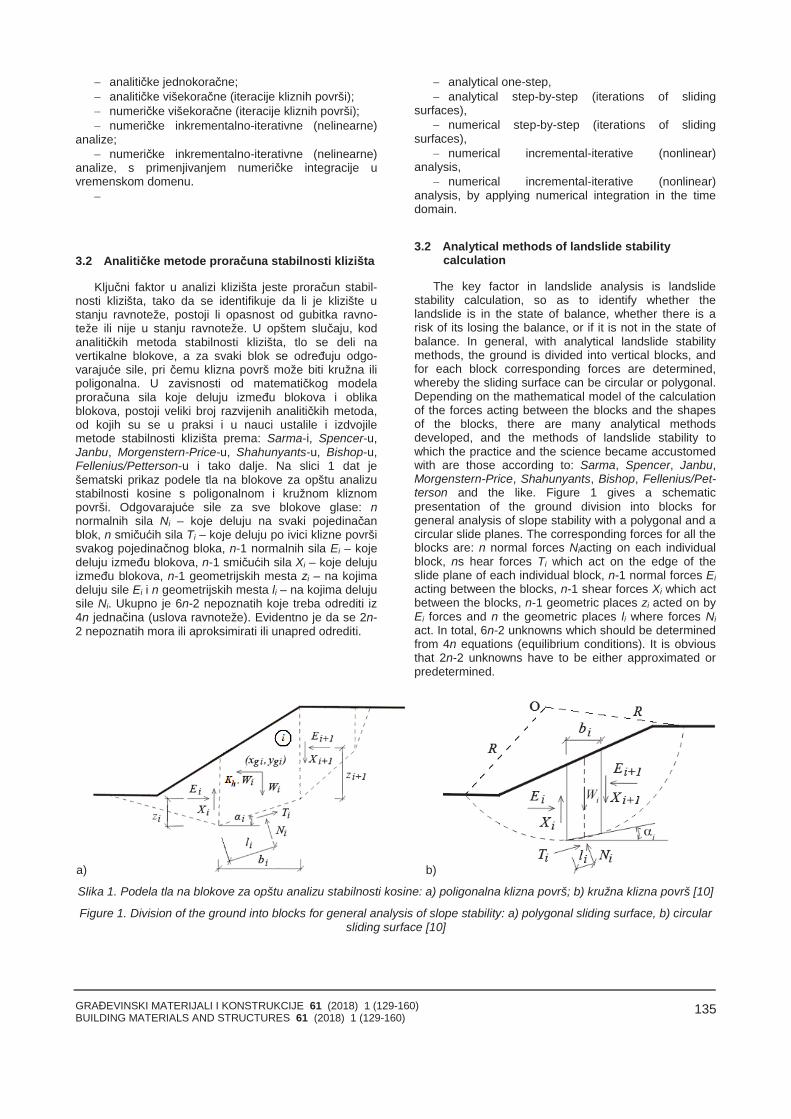
GRAĐEVINSKI MATERIJALI I KONSTRUKCIJE 61 (2018) 1 (129-160)BUILDING MATERIALS AND STRUCTURES 61 (2018) 1 (129-160)
135
analitičke jednokoračne; analitičke višekoračne (iteracije kliznih površi); numeričke višekoračne (iteracije kliznih površi); numeričke inkrementalno-iterativne (nelinearne)
analize; numeričke inkrementalno-iterativne (nelinearne)
analize, s primenjivanjem numeričke integracije uvremenskom domenu.
3.2 Analitičke metode proračuna stabilnosti klizišta
Ključni faktor u analizi klizišta jeste proračun stabil-nosti klizišta, tako da se identifikuje da li je klizište ustanju ravnoteže, postoji li opasnost od gubitka ravno-teže ili nije u stanju ravnoteže. U opštem slučaju, kodanalitičkih metoda stabilnosti klizišta, tlo se deli navertikalne blokove, a za svaki blok se određuju odgo-varajuće sile, pri čemu klizna površ može biti kružna ilipoligonalna. U zavisnosti od matematičkog modelaproračuna sila koje deluju između blokova i oblikablokova, postoji veliki broj razvijenih analitičkih metoda,od kojih su se u praksi i u nauci ustalile i izdvojilemetode stabilnosti klizišta prema: Sarma-i, Spencer-u,Janbu, Morgenstern-Price-u, Shahunyants-u, Bishop-u,Fellenius/Petterson-u i tako dalje. Na slici 1 dat ješematski prikaz podele tla na blokove za opštu analizustabilnosti kosine s poligonalnom i kružnom kliznompovrši. Odgovarajuće sile za sve blokove glase: nnormalnih sila Ni – koje deluju na svaki pojedinačanblok, n smičućih sila Ti – koje deluju po ivici klizne površisvakog pojedinačnog bloka, n-1 normalnih sila Ei – kojedeluju između blokova, n-1 smičućih sila Xi – koje delujuizmeđu blokova, n-1 geometrijskih mesta zi – na kojimadeluju sile Ei i n geometrijskih mesta li – na kojima delujusile Ni. Ukupno je 6n-2 nepoznatih koje treba odrediti iz4n jednačina (uslova ravnoteže). Evidentno je da se 2n-2 nepoznatih mora ili aproksimirati ili unapred odrediti.
analytical one-step, analytical step-by-step (iterations of sliding
surfaces), numerical step-by-step (iterations of sliding
surfaces), numerical incremental-iterative (nonlinear)
analysis, numerical incremental-iterative (nonlinear)
analysis, by applying numerical integration in the timedomain.
3.2 Analytical methods of landslide stabilitycalculation
The key factor in landslide analysis is landslidestability calculation, so as to identify whether thelandslide is in the state of balance, whether there is arisk of its losing the balance, or if it is not in the state ofbalance. In general, with analytical landslide stabilitymethods, the ground is divided into vertical blocks, andfor each block corresponding forces are determined,whereby the sliding surface can be circular or polygonal.Depending on the mathematical model of the calculationof the forces acting between the blocks and the shapesof the blocks, there are many analytical methodsdeveloped, and the methods of landslide stability towhich the practice and the science became accustomedwith are those according to: Sarma, Spencer, Janbu,Morgenstern-Price, Shahunyants, Bishop, Fellenius/Pet-terson and the like. Figure 1 gives a schematicpresentation of the ground division into blocks forgeneral analysis of slope stability with a polygonal and acircular slide planes. The corresponding forces for all theblocks are: n normal forces Niacting on each individualblock, ns hear forces Ti which act on the edge of theslide plane of each individual block, n-1 normal forces Eiacting between the blocks, n-1 shear forces Xi which actbetween the blocks, n-1 geometric places zi acted on byEi forces and n the geometric places li where forces Niact. In total, 6n-2 unknowns which should be determinedfrom 4n equations (equilibrium conditions). It is obviousthat 2n-2 unknowns have to be either approximated orpredetermined.
a) b)
Slika 1. Podela tla na blokove za opštu analizu stabilnosti kosine: a) poligonalna klizna površ; b) kružna klizna površ [10]
Figure 1. Division of the ground into blocks for general analysis of slope stability: a) polygonal sliding surface, b) circularsliding surface [10]
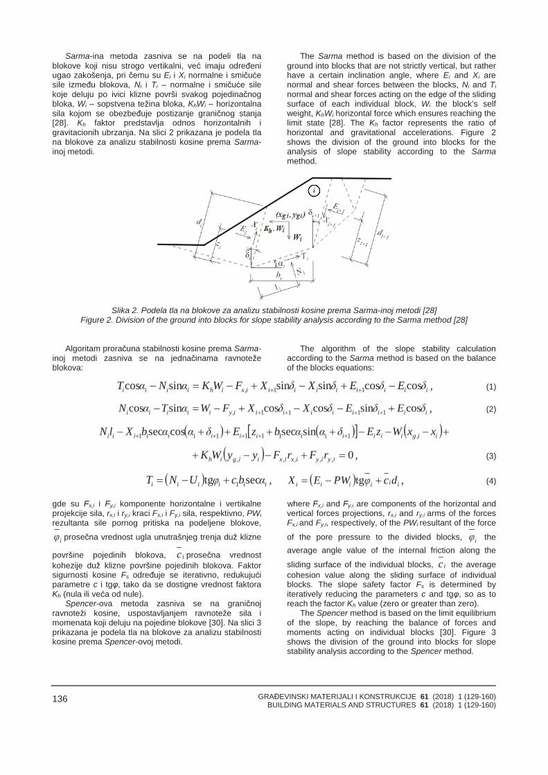
GRAĐEVINSKI MATERIJALI I KONSTRUKCIJE 61 (2018) 1 (129-160)BUILDING MATERIALS AND STRUCTURES 61 (2018) 1 (129-160)
136
Sarma-ina metoda zasniva se na podeli tla nablokove koji nisu strogo vertikalni, već imaju određeniugao zakošenja, pri čemu su Ei i Xi normalne i smičućesile između blokova, Ni i Ti – normalne i smičuće silekoje deluju po ivici klizne površi svakog pojedinačnogbloka, Wi – sopstvena težina bloka, KhWi – horizontalnasila kojom se obezbeđuje postizanje graničnog stanja[28]. Kh faktor predstavlja odnos horizontalnih igravitacionih ubrzanja. Na slici 2 prikazana je podela tlana blokove za analizu stabilnosti kosine prema Sarma-inoj metodi.
The Sarma method is based on the division of theground into blocks that are not strictly vertical, but ratherhave a certain inclination angle, where Ei and Xi arenormal and shear forces between the blocks, Ni and Tinormal and shear forces acting on the edge of the slidingsurface of each individual block, Wi the block’s selfweight, KhWi horizontal force which ensures reaching thelimit state [28]. The Kh factor represents the ratio ofhorizontal and gravitational accelerations. Figure 2shows the division of the ground into blocks for theanalysis of slope stability according to the Sarmamethod.
Slika 2. Podela tla na blokove za analizu stabilnosti kosine prema Sarma-inoj metodi [28]Figure 2. Division of the ground into blocks for slope stability analysis according to the Sarma method [28]
Algoritam proračuna stabilnosti kosine prema Sarma-inoj metodi zasniva se na jednačinama ravnotežeblokova:
The algorithm of the slope stability calculationaccording to the Sarma method is based on the balanceof the blocks equations:
iiiiiiiii,xihiiii δEδEδXδXFWKαNαT coscossinsinsincos 11 , (1)
iiiiiiiii,yiiiii δEδEδXδXFWαTαN cossincoscossincos 1111 , (2)
ii,giiiiiiiiiiiii xxWzEδααbzEδααbXlN 1i1111i1 sinseccossec
0 i,yi,yi,xi,xii,gih rFrFyyWK , (3)
iiiiii αbcφUNT sectg 1 , iiiiii dcφPWEX tg , (4)
gde su Fx,i i Fy,i komponente horizontalne i vertikalneprojekcije sila, rx,i i ry,i kraci Fx,i i Fy,i sila, respektivno, PWirezultanta sile pornog pritiska na podeljene blokove,
iφ prosečna vrednost ugla unutrašnjeg trenja duž klizne
površine pojedinih blokova, ic prosečna vrednostkohezije duž klizne površine pojedinih blokova. Faktorsigurnosti kosine Fs određuje se iterativno, redukujućiparametre c i tgφ, tako da se dostigne vrednost faktoraKh (nula ili veća od nule).
Spencer-ova metoda zasniva se na graničnojravnoteži kosine, uspostavljanjem ravnoteže sila imomenata koji deluju na pojedine blokove [30]. Na slici 3prikazana je podela tla na blokove za analizu stabilnostikosine prema Spencer-ovoj metodi.
where Fx,i and Fy,i are components of the horizontal andvertical forces projections, rx,i and ry,i arms of the forcesFx,i and Fy,i, respectively, of the PWi resultant of the force
of the pore pressure to the divided blocks, iφ theaverage angle value of the internal friction along the
sliding surface of the individual blocks, ic the averagecohesion value along the sliding surface of individualblocks. The slope safety factor Fs is determined byiteratively reducing the parameters c and tgφ, so as toreach the factor Kh value (zero or greater than zero).
The Spencer method is based on the limit equilibriumof the slope, by reaching the balance of forces andmoments acting on individual blocks [30]. Figure 3shows the division of the ground into blocks for slopestability analysis according to the Spencer method.
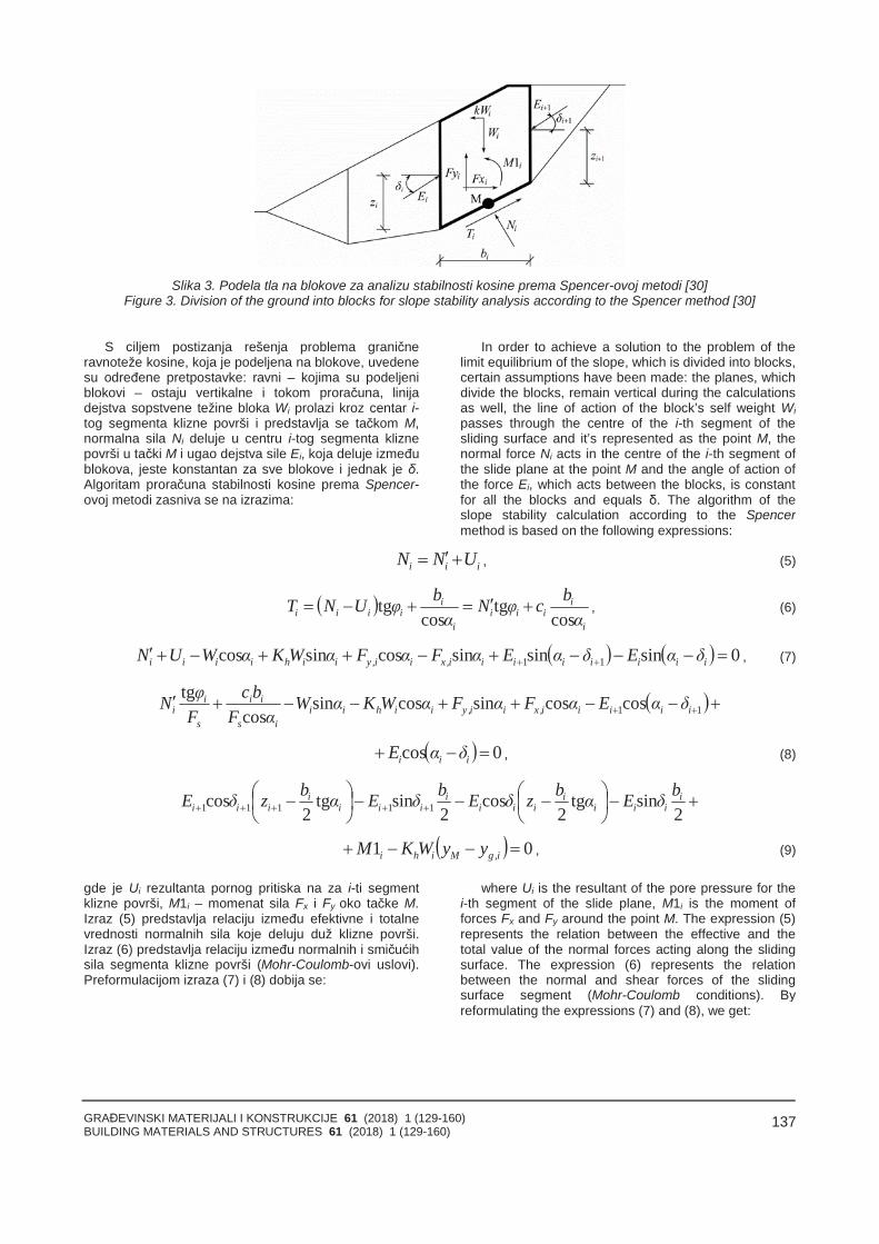
GRAĐEVINSKI MATERIJALI I KONSTRUKCIJE 61 (2018) 1 (129-160)BUILDING MATERIALS AND STRUCTURES 61 (2018) 1 (129-160)
137
Slika 3. Podela tla na blokove za analizu stabilnosti kosine prema Spencer-ovoj metodi [30]Figure 3. Division of the ground into blocks for slope stability analysis according to the Spencer method [30]
S ciljem postizanja rešenja problema graničneravnoteže kosine, koja je podeljena na blokove, uvedenesu određene pretpostavke: ravni – kojima su podeljeniblokovi – ostaju vertikalne i tokom proračuna, linijadejstva sopstvene težine bloka Wi prolazi kroz centar i-tog segmenta klizne površi i predstavlja se tačkom M,normalna sila Ni deluje u centru i-tog segmenta kliznepovrši u tački M i ugao dejstva sile Ei, koja deluje izmeđublokova, jeste konstantan za sve blokove i jednak je δ.Algoritam proračuna stabilnosti kosine prema Spencer-ovoj metodi zasniva se na izrazima:
In order to achieve a solution to the problem of thelimit equilibrium of the slope, which is divided into blocks,certain assumptions have been made: the planes, whichdivide the blocks, remain vertical during the calculationsas well, the line of action of the block’s self weight Wipasses through the centre of the i-th segment of thesliding surface and it’s represented as the point M, thenormal force Ni acts in the centre of the i-th segment ofthe slide plane at the point M and the angle of action ofthe force Ei, which acts between the blocks, is constantfor all the blocks and equals δ. The algorithm of theslope stability calculation according to the Spencermethod is based on the following expressions:
iii UNN , (5)
i
iiii
i
iiiii α
bcφNα
bφUNTcos
tgcos
tg , (6)
0sinsinsincossincos 11 iiiiiiii,xii,yiihiiii δαEδαEαFαFαWKαWUN , (7)
11coscossincossincos
tgiiiii,xii,yiihii
is
ii
s
ii δαEαFαFαWKαW
αFbc
FφN
0cos iii δαE , (8)
2
sintg2
cos2
sintg2
cos 11111i
iiii
iiii
iiii
iiibδEαbzδEbδEαbzδE
01 i,gMihi yyWKM , (9)
gde je Ui rezultanta pornog pritiska na za i-ti segmentklizne površi, M1i – momenat sila Fx i Fy oko tačke M.Izraz (5) predstavlja relaciju između efektivne i totalnevrednosti normalnih sila koje deluju duž klizne površi.Izraz (6) predstavlja relaciju između normalnih i smičućihsila segmenta klizne površi (Mohr-Coulomb-ovi uslovi).Preformulacijom izraza (7) i (8) dobija se:
where Ui is the resultant of the pore pressure for thei-th segment of the slide plane, M1i is the moment offorces Fx and Fy around the point M. The expression (5)represents the relation between the effective and thetotal value of the normal forces acting along the slidingsurface. The expression (6) represents the relationbetween the normal and shear forces of the slidingsurface segment (Mohr-Coulomb conditions). Byreformulating the expressions (7) and (8), we get:
GRAĐEVINSKI MATERIJALI I KONSTRUKCIJE 61 (2018) 1 (129-160)BUILDING MATERIALS AND STRUCTURES 61 (2018) 1 (129-160)
138
11
1
cossin
sinsincos
iis
iii
s
iiiiiii,xihii,yi
i
δαFφtgδα
FφtgδαEUαFWKαFW
E
iiiii,xihii,yiis
ii δαEαFWKαFWαF
bc coscossin
cos . (10)
Primenom izraza (10) mogu se odrediti sve sile Eikoje deluju između blokova za date vrednosti δi i Fs.Preformulacijom izraza (9), dobija se:
By applying the expression (10), all the forces Eiacting between the blocks for the given values δi and Fscan be determined. By reformulating expression (9) weget:
11
111
1 cos
1costgcossintgcossin2
ii
i,gMihiiiiiiiiiiiii
i δE
yyWKMδzEαδδEαδδEb
z . (11)
Primenom izraza (11), mogu se odrediti svi kraci silez za date vrednosti ugla δi. Faktor sigurnosti Fs određujese primenom iterativnog algoritma: inicijalna vrednost zaugao δ jeste δ=0, faktor sigurnosti Fs, za datu vrednostugla δ, određuje se prema izrazu (10), imajući u vidu tošto je En+1=0 na kraju klizne površi, ugao δ se određujeiz izraza (11), koristeći vrednosti za silu E – koja jeodređena iz prethodnog koraka analize, pri čemu jevrednost zn+1=0 i prethodna dva koraka analize iterativnose ponavljaju sve dok vrednost ugla δ, u dve uzastopneiteracije, ne postane jednaka. Da bi algoritam iteracijabio dovoljno stabilan, potrebno je intervenisati kako bi seotklonila nestabilna rešenja. Ove nestabilnosti javljaju sekada se u izrazima (10) i (11) pojave situacije deljenja snulom. U izrazu (11) ovakva situacija može se pojaviti zavrednosti ugla δ=π/2 ili δ=-π/2, pa se rešenje mora tražitiza interval ugla δ=[-π/2;π/2]. Deljenje s nulom u izrazu(10) pojavljuje se u slučaju:
By applying the expression (11) all the moment armsof the force z for the given values of the angle δi can bedetermined. The safety factor Fsis determined using aniterative algorithm: the initial value for the angle δ is δ=0,the safety factor Fs for the given value of the angle δ isdetermined according to the expression (10), taking intoaccount that En+1=0 at the end of the sliding surface, theangle δ is determined from the expression (11) using thevalues for the force E, which is determined from theprevious step of the analysis, where the value zn+1=0and the previous two steps of the analysis are repeatediteratively until the value of the angle δ, during twoconsecutive iterations, becomes equal. In order for theiteration algorithm to be stable enough, it is necessary tointervene with the aim of eliminating any unstablesolutions. These instabilities occur when expressions(10) and (11) show the situation of the division by zero.In expression (11) such a situation can occur for thevalues of the angle δ=π/2 or δ=-π/2, so the solutionshould be sought for the interval of the angle δ=[-π/2;π/2]. Division by zero in expression (10) appears inthe case of:
iiis αδφF 1tgtg . (12)
Radi sprečavanja nestabilnosti rešenja, potrebno jesprovesti proveru parametra mα prema izrazu:
In order to prevent the solution instabilities, it isnecessary to perform a parameter check mα according tothe expression:
20tgsincos .F
φααms
iiiα . (13)
Pre nego što se započne sa iterativnom analizom,potrebno je pronaći najveću kritičnu vrednost Fs,min kojazadovoljava prethodne uslove. Vrednosti faktorasigurnosti Fs koje su ispod ove kritične vrednosti Fs,minpripadaju oblasti nestabilnog rešenja. Prva iteracijazapočinje s vrednošću faktora sigurnosti Fs koja je teknešto veća od Fs,min, tako da su i preostale vrednostifaktora sigurnosti Fs – koje se određuju proračunom –uvek veće od Fs,min.
Janbu-ova metoda jeste procedura verifikacije
Before beginning iterative analysis, it is necessary tofind the highest critical value of Fs,min that satisfies theprevious conditions. The values of the safety factors Fsbelow this critical value Fs,min belong to the area ofunstable solution. The first iteration starts with the valueof the safety factor Fs, which is just slightly higher thanFs,min, so the remaining values of the safety factors Fs,which are determined by the calculation, are alwayshigher than Fs,min.
The Janbu's method is a procedure of verifying the
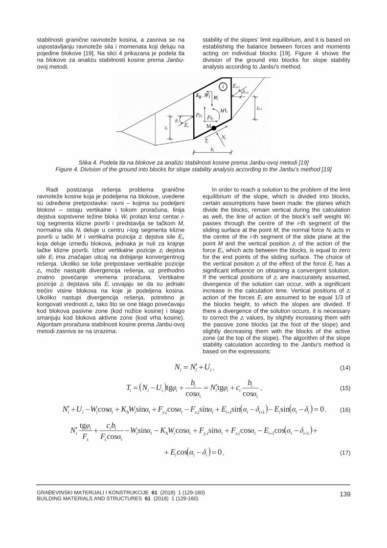
GRAĐEVINSKI MATERIJALI I KONSTRUKCIJE 61 (2018) 1 (129-160)BUILDING MATERIALS AND STRUCTURES 61 (2018) 1 (129-160)
139
stabilnosti granične ravnoteže kosina, a zasniva se nauspostavljanju ravnoteže sila i momenata koji deluju napojedine blokove [19]. Na slici 4 prikazana je podela tlana blokove za analizu stabilnosti kosine prema Janbu-ovoj metodi.
stability of the slopes’ limit equilibrium, and it is based onestablishing the balance between forces and momentsacting on individual blocks [19]. Figure 4 shows thedivision of the ground into blocks for slope stabilityanalysis according to Janbu's method.
Slika 4. Podela tla na blokove za analizu stabilnosti kosine prema Janbu-ovoj metodi [19]Figure 4. Division of the ground into blocks for slope stability analysis according to the Janbu's method [19]
Radi postizanja rešenja problema graničneravnoteže kosine koja je podeljena na blokove, uvedenesu određene pretpostavke: ravni – kojima su podeljeniblokovi – ostaju vertikalne i tokom proračuna, linijadejstva sopstvene težine bloka Wi prolazi kroz centar i-tog segmenta klizne površi i predstavlja se tačkom M,normalna sila Ni deluje u centru i-tog segmenta kliznepovrši u tački M i vertikalna pozicija zi dejstva sile Ei,koja deluje između blokova, jednaka je nuli za krajnjetačke klizne površi. Izbor vertikalne pozicije zi dejstvasile Ei ima značajan uticaj na dobijanje konvergentnogrešenja. Ukoliko se loše pretpostave vertikalne pozicijezi, može nastupiti divergencija rešenja, uz prethodnoznatno povećanje vremena proračuna. Vertikalnepozicije zi dejstava sila Ei usvajaju se da su jednakitrećini visine blokova na koje je podeljena kosina.Ukoliko nastupi divergencija rešenja, potrebno jekorigovati vrednosti zi, tako što se one blago povećavajukod blokova pasivne zone (kod nožice kosine) i blagosmanjuju kod blokova aktivne zone (kod vrha kosine).Algoritam proračuna stabilnosti kosine prema Janbu-ovojmetodi zasniva se na izrazima:
In order to reach a solution to the problem of the limitequilibrium of the slope, which is divided into blocks,certain assumptions have been made: the planes whichdivide the blocks, remain vertical during the calculationas well, the line of action of the block’s self weight Wipasses through the centre of the i-th segment of thesliding surface at the point M, the normal force Ni acts inthe centre of the i-th segment of the slide plane at thepoint M and the vertical position zi of the action of theforce Ei, which acts between the blocks, is equal to zerofor the end points of the sliding surface. The choice ofthe vertical position zi of the effect of the force Ei has asignificant influence on obtaining a convergent solution.If the vertical positions of zi are inaccurately assumed,divergence of the solution can occur, with a significantincrease in the calculation time. Vertical positions of ziaction of the forces Ei are assumed to be equal 1/3 ofthe blocks height, to which the slopes are divided. Ifthere a divergence of the solution occurs, it is necessaryto correct the zi values, by slightly increasing them withthe passive zone blocks (at the foot of the slope) andslightly decreasing them with the blocks of the activezone (at the top of the slope). The algorithm of the slopestability calculation according to the Janbu's method isbased on the expressions:
iii UNN , (14)
i
iiii
i
iiiii α
bcφNα
bφUNTcos
tgcos
tg , (15)
0sinsinsincossincos 11 iiiiiiii,xii,yiihiiii δαEδαEαFαFαWKαWUN , (16)
11coscossincossincos
tgiiiii,xii,yiihii
is
ii
s
ii δαEαFαFαWKαW
αFbc
FφN
0cos iii δαE , (17)
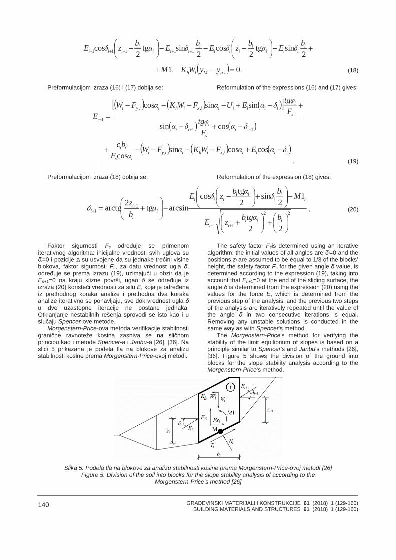
GRAĐEVINSKI MATERIJALI I KONSTRUKCIJE 61 (2018) 1 (129-160)BUILDING MATERIALS AND STRUCTURES 61 (2018) 1 (129-160)
140
2
sintg2
cos2
sintg2
cos 11111i
iiii
iiii
iiii
iiibδEαbzδEbδEαbzδE
01 i,gMihi yyWKM . (18)
Preformulacijom izraza (16) i (17) dobija se: Reformulation of the expressions (16) and (17) gives:
11
1
cossin
sinsincos
iis
iii
s
iiiiiii,xihii,yi
i
δαFφtgδα
FφtgδαEUαFWKαFW
E
iiiii,xihii,yiis
ii δαEαFWKαFWαF
bc coscossin
cos. (19)
Preformulacijom izraza (18) dobija se: Reformulation of the expression (18) gives:
22
11
11
22
12
sin2tgcos
arcsintg2arctg
iiiii
ii
iii
iii
ii
ii
bαtgbzE
MbδαbzδEα
bzδ . (20)
Faktor sigurnosti Fs određuje se primenomiterativnog algoritma: inicijalne vrednosti svih uglova suδi=0 i pozicije zi su usvojene da su jednake trećini visineblokova, faktor sigurnosti Fs, za datu vrednost ugla δ,određuje se prema izrazu (19), uzimajući u obzir da jeEn+1=0 na kraju klizne površi, ugao δ se određuje izizraza (20) koristeći vrednosti za silu E, koja je određenaiz prethodnog koraka analize i prethodna dva korakaanalize iterativno se ponavljaju, sve dok vrednost ugla δu dve uzastopne iteracije ne postane jednaka.Otklanjanje nestabilnih rešenja sprovodi se isto kao i uslučaju Spencer-ove metode.
Morgenstern-Price-ova metoda verifikacije stabilnostigranične ravnoteže kosina zasniva se na sličnomprincipu kao i metode Spencer-a i Janbu-a [26], [36]. Naslici 5 prikazana je podela tla na blokove za analizustabilnosti kosine prema Morgenstern-Price-ovoj metodi.
The safety factor Fsis determined using an iterativealgorithm: the initial values of all angles are δi=0 and thepositions zi are assumed to be equal to 1/3 of the blocks’height, the safety factor Fs for the given angle δ value, isdetermined according to the expression (19), taking intoaccount that En+1=0 at the end of the sliding surface, theangle δ is determined from the expression (20) using thevalues for the force E, which is determined from theprevious step of the analysis, and the previous two stepsof the analysis are iteratively repeated until the value ofthe angle δ in two consecutive iterations is equal.Removing any unstable solutions is conducted in thesame way as with Spencer's method.
The Morgenstern-Price's method for verifying thestability of the limit equilibrium of slopes is based on aprinciple similar to Spencer's and Janbu's methods [26],[36]. Figure 5 shows the division of the ground intoblocks for the slope stability analysis according to theMorgenstern-Price's method.
Slika 5. Podela tla na blokove za analizu stabilnosti kosine prema Morgenstern-Price-ovoj metodi [26]Figure 5. Division of the soil into blocks for the slope stability analysis of according to the
Morgenstern-Price's method [26]
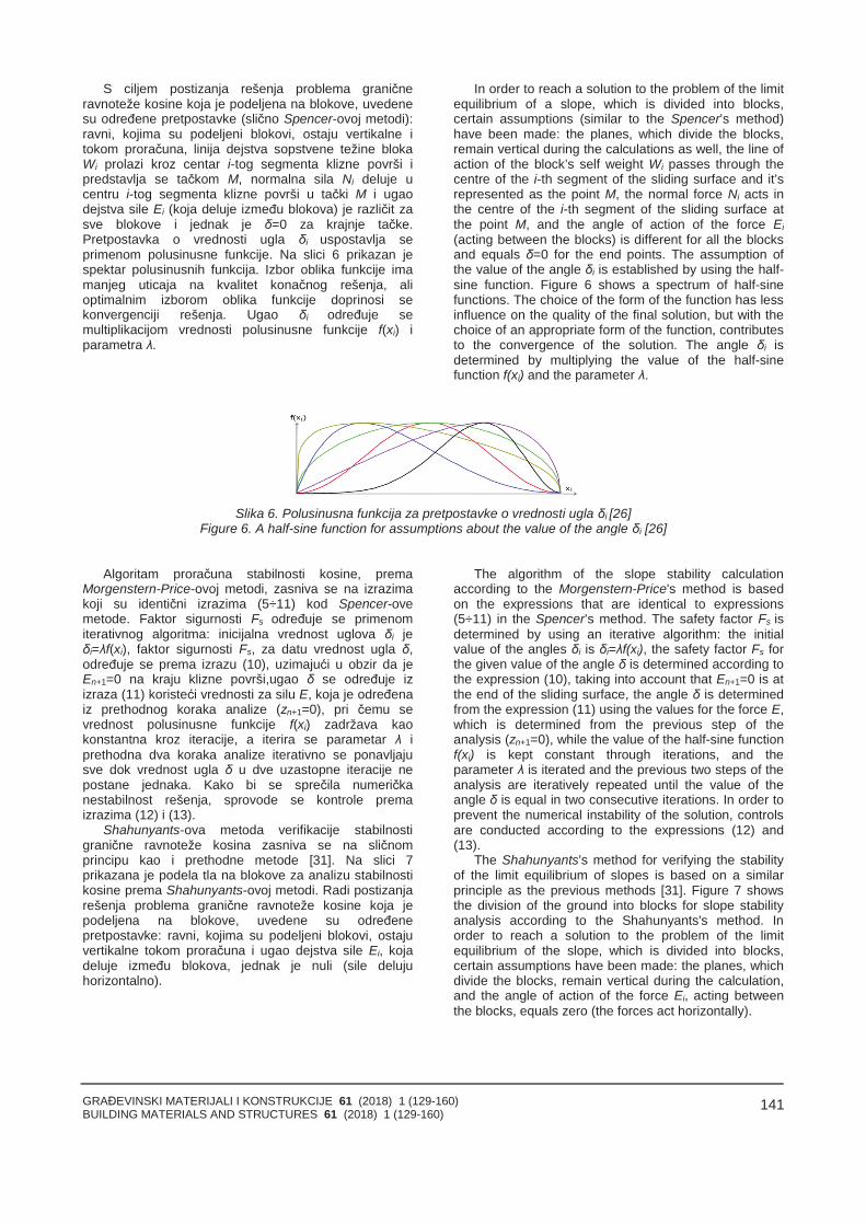
GRAĐEVINSKI MATERIJALI I KONSTRUKCIJE 61 (2018) 1 (129-160)BUILDING MATERIALS AND STRUCTURES 61 (2018) 1 (129-160)
141
S ciljem postizanja rešenja problema graničneravnoteže kosine koja je podeljena na blokove, uvedenesu određene pretpostavke (slično Spencer-ovoj metodi):ravni, kojima su podeljeni blokovi, ostaju vertikalne itokom proračuna, linija dejstva sopstvene težine blokaWi prolazi kroz centar i-tog segmenta klizne površi ipredstavlja se tačkom M, normalna sila Ni deluje ucentru i-tog segmenta klizne površi u tački M i ugaodejstva sile Ei (koja deluje između blokova) je različit zasve blokove i jednak je δ=0 za krajnje tačke.Pretpostavka o vrednosti ugla δi uspostavlja seprimenom polusinusne funkcije. Na slici 6 prikazan jespektar polusinusnih funkcija. Izbor oblika funkcije imamanjeg uticaja na kvalitet konačnog rešenja, alioptimalnim izborom oblika funkcije doprinosi sekonvergenciji rešenja. Ugao δi određuje semultiplikacijom vrednosti polusinusne funkcije f(xi) iparametra λ.
In order to reach a solution to the problem of the limitequilibrium of a slope, which is divided into blocks,certain assumptions (similar to the Spencer’s method)have been made: the planes, which divide the blocks,remain vertical during the calculations as well, the line ofaction of the block’s self weight Wi passes through thecentre of the i-th segment of the sliding surface and it’srepresented as the point M, the normal force Ni acts inthe centre of the i-th segment of the sliding surface atthe point M, and the angle of action of the force Ei(acting between the blocks) is different for all the blocksand equals δ=0 for the end points. The assumption ofthe value of the angle δi is established by using the half-sine function. Figure 6 shows a spectrum of half-sinefunctions. The choice of the form of the function has lessinfluence on the quality of the final solution, but with thechoice of an appropriate form of the function, contributesto the convergence of the solution. The angle δi isdetermined by multiplying the value of the half-sinefunction f(xi) and the parameter λ.
Slika 6. Polusinusna funkcija za pretpostavke o vrednosti ugla δi [26]Figure 6. A half-sine function for assumptions about the value of the angle δi [26]
Algoritam proračuna stabilnosti kosine, premaMorgenstern-Price-ovoj metodi, zasniva se na izrazimakoji su identični izrazima (5÷11) kod Spencer-ovemetode. Faktor sigurnosti Fs određuje se primenomiterativnog algoritma: inicijalna vrednost uglova δi jeδi=λf(xi), faktor sigurnosti Fs, za datu vrednost ugla δ,određuje se prema izrazu (10), uzimajući u obzir da jeEn+1=0 na kraju klizne površi,ugao δ se određuje izizraza (11) koristeći vrednosti za silu E, koja je određenaiz prethodnog koraka analize (zn+1=0), pri čemu sevrednost polusinusne funkcije f(xi) zadržava kaokonstantna kroz iteracije, a iterira se parametar λ iprethodna dva koraka analize iterativno se ponavljajusve dok vrednost ugla δ u dve uzastopne iteracije nepostane jednaka. Kako bi se sprečila numeričkanestabilnost rešenja, sprovode se kontrole premaizrazima (12) i (13).
Shahunyants-ova metoda verifikacije stabilnostigranične ravnoteže kosina zasniva se na sličnomprincipu kao i prethodne metode [31]. Na slici 7prikazana je podela tla na blokove za analizu stabilnostikosine prema Shahunyants-ovoj metodi. Radi postizanjarešenja problema granične ravnoteže kosine koja jepodeljena na blokove, uvedene su određenepretpostavke: ravni, kojima su podeljeni blokovi, ostajuvertikalne tokom proračuna i ugao dejstva sile Ei, kojadeluje između blokova, jednak je nuli (sile delujuhorizontalno).
The algorithm of the slope stability calculationaccording to the Morgenstern-Price's method is basedon the expressions that are identical to expressions(5÷11) in the Spencer’s method. The safety factor Fs isdetermined by using an iterative algorithm: the initialvalue of the angles δi is δi=λf(xi), the safety factor Fs forthe given value of the angle δ is determined according tothe expression (10), taking into account that En+1=0 is atthe end of the sliding surface, the angle δ is determinedfrom the expression (11) using the values for the force E,which is determined from the previous step of theanalysis (zn+1=0), while the value of the half-sine functionf(xi) is kept constant through iterations, and theparameter λ is iterated and the previous two steps of theanalysis are iteratively repeated until the value of theangle δ is equal in two consecutive iterations. In order toprevent the numerical instability of the solution, controlsare conducted according to the expressions (12) and(13).
The Shahunyants's method for verifying the stabilityof the limit equilibrium of slopes is based on a similarprinciple as the previous methods [31]. Figure 7 showsthe division of the ground into blocks for slope stabilityanalysis according to the Shahunyants's method. Inorder to reach a solution to the problem of the limitequilibrium of the slope, which is divided into blocks,certain assumptions have been made: the planes, whichdivide the blocks, remain vertical during the calculation,and the angle of action of the force Ei, acting betweenthe blocks, equals zero (the forces act horizontally).
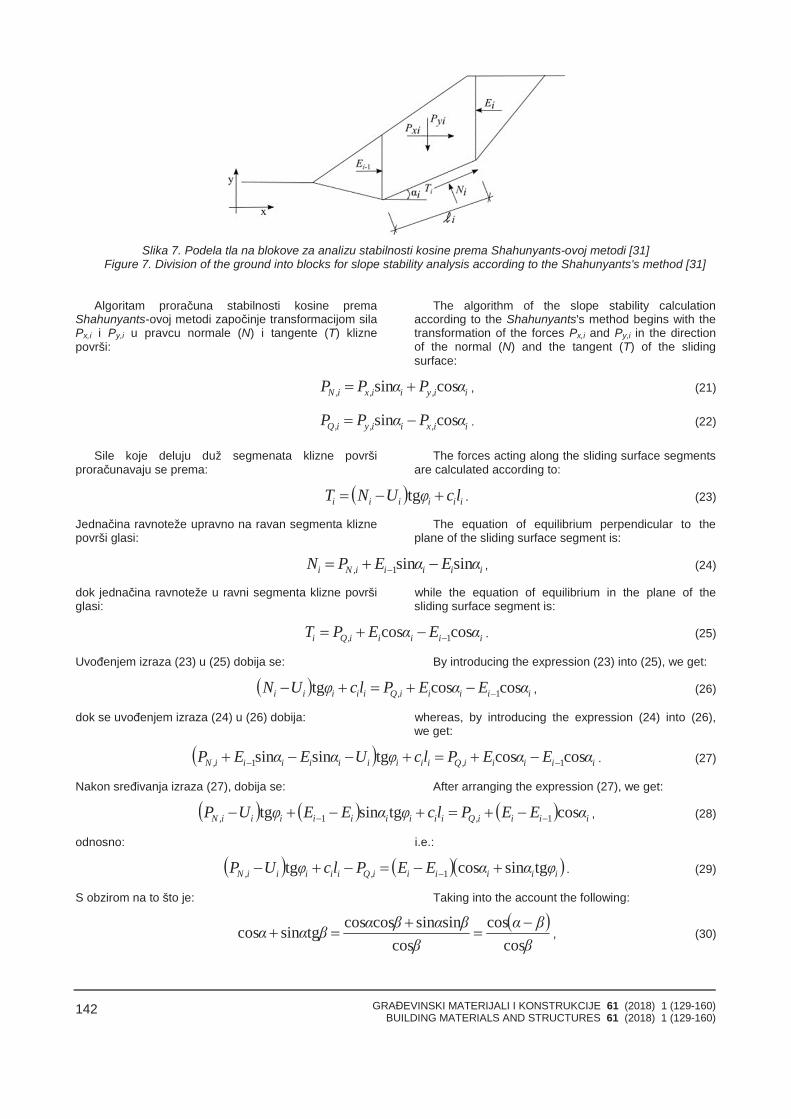
GRAĐEVINSKI MATERIJALI I KONSTRUKCIJE 61 (2018) 1 (129-160)BUILDING MATERIALS AND STRUCTURES 61 (2018) 1 (129-160)
142
Slika 7. Podela tla na blokove za analizu stabilnosti kosine prema Shahunyants-ovoj metodi [31]Figure 7. Division of the ground into blocks for slope stability analysis according to the Shahunyants's method [31]
Algoritam proračuna stabilnosti kosine premaShahunyants-ovoj metodi započinje transformacijom silaPx,i i Py,i u pravcu normale (N) i tangente (T) kliznepovrši:
The algorithm of the slope stability calculationaccording to the Shahunyants's method begins with thetransformation of the forces Px,i and Py,i in the directionof the normal (N) and the tangent (T) of the slidingsurface:
ii,yii,xi,N αPαPP cossin , (21)
ii,xii,yi,Q αPαPP cossin . (22)
Sile koje deluju duž segmenata klizne površiproračunavaju se prema:
The forces acting along the sliding surface segmentsare calculated according to:
iiiiii lcφUNT tg . (23)
Jednačina ravnoteže upravno na ravan segmenta kliznepovrši glasi:
The equation of equilibrium perpendicular to theplane of the sliding surface segment is:
iiiii,Ni αEαEPN sinsin1 , (24)
dok jednačina ravnoteže u ravni segmenta klizne površiglasi:
while the equation of equilibrium in the plane of thesliding surface segment is:
iiiii,Qi αEαEPT coscos 1 . (25)
Uvođenjem izraza (23) u (25) dobija se: By introducing the expression (23) into (25), we get:
iiiii,Qiiiii αEαEPlcφUN coscostg 1 , (26)
dok se uvođenjem izraza (24) u (26) dobija: whereas, by introducing the expression (24) into (26),we get:
iiiii,Qiiiiiiiii,N αEαEPlcφUαEαEP coscostgsinsin 11 . (27)
Nakon sređivanja izraza (27), dobija se: After arranging the expression (27), we get:
iiii,Qiiiiiiiii,N αEEPlcφαEEφUP costgsintg 11 , (28)
odnosno: i.e.:
iiiiii,Qiiiii,N φααEEPlcφUP tgsincostg 1 . (29)
S obzirom na to što je: Taking into the account the following:
ββα
ββαβαβαα
coscos
cossinsincoscostgsincos
, (30)
GRAĐEVINSKI MATERIJALI I KONSTRUKCIJE 61 (2018) 1 (129-160)BUILDING MATERIALS AND STRUCTURES 61 (2018) 1 (129-160)
143
dobija se da je izraz (29): we get that the expression (29) is:
i
iiiii,Qiiiii,N φ
φαEEPlcφUPcos
costg 1
, (31)
a dodatnom modifikacijom izraza (31) dobija se: and the additional modification of the expression (31)gives:
i
iii
i
iiii,Qiiiii,N φ
φαEφφαEPlcφUP
coscos
coscostg 1
. (32)
Primenom izraza (32) sile koje deluju između blokova Eiodređuju se prema:
By applying the expression (32), the forces actionbetween the blocks Ei are determined according to:
1cos
costg
iii
ii,Qiiiii,Ni E
φαφPlcφUP
E . (33)
Sada se u proračun stabilnosti kosine uvodi faktorsigurnosti Fs, dok se PQ,i sile razlažu na sile kojedoprinose klizanju PQ,i,sd (aktivne sile) i sile koje nedoprinose klizanju PQ,i,ud (stabilizujuće sile):
Now, the safety factor Fs is introduced into the slopestability calculation, while the PQ,i forces are brokendown into the forces contributing to the sliding PQ,i,sd(active forces) and the forces that do not contribute tosliding PQ,i,ud (stabilizing forces):
1cos
costg
iii
iud,i,Qsd,i,Qsiiiii,Ni E
φαφPPFlcφUP
E . (34)
PQ,i je pozitivno kada doprinosi klizanju kosine, anegativno kada ne doprinosi klizanju kosine, tako da seizraz (34) može pisati u formi:
PQ,i is positive when it contributes to the sliding of theslope, and negative when it does not contribute to thesliding of the slope, hence, the expression (34) can bewritten in the form:
1cos
costg
i
ii
iud,i,Qsd,i,Qsiiiii,Ni E
φαφPPFlcφUP
E . (35)
Na kliznoj površi vrednost sile E0 jednaka je nula, dok zaE1 važi:
On the sliding surface, the value of the force E0equals zero, whereas the following applies to E1:
11
111111111 cos
costgφα
φPPFlcφUPE ud,,Qsd,,Qs,N
, (36)
a za E2: and to E2:
22
222222222 cos
costgφα
φPPFlcφUPE ud,,Qsd,,Qs,N
11
11111111
coscostg
φαφPPFlcφUP ud,,Qsd,,Qs,N
. (37)
Slično se mogu prikazati i izrazi za sve sile koje delujuizmeđu blokova, pri čemu je En=0:
The expressions for all the forces acting between theblocks can be presented in a similar way, where En=0:
0cos
coscos
costg11
n
i ii
isd,i,Qs
n
i ii
iud,i,Qiiiii,Nn φα
φPFφα
φPlcφUPE , (38)
tako da se iz ovog izraza može direktno prikazati faktorsigurnosti Fs u formi:
so that, from this expression, the safety factor Fs can bedirectly presented in the following form:
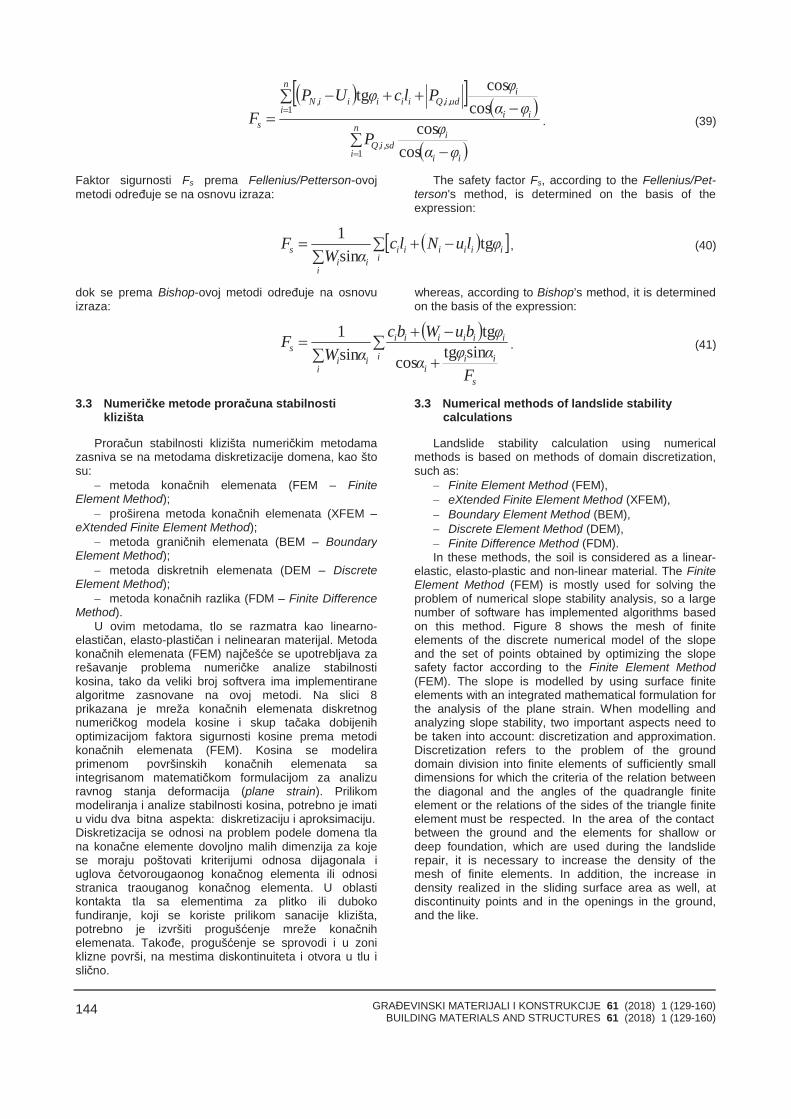
GRAĐEVINSKI MATERIJALI I KONSTRUKCIJE 61 (2018) 1 (129-160)BUILDING MATERIALS AND STRUCTURES 61 (2018) 1 (129-160)
144
n
i ii
isd,i,Q
n
i ii
iud,i,Qiiiii,N
s
φαφP
φαφPlcφUP
F
1
1
coscos
coscostg
. (39)
Faktor sigurnosti Fs prema Fellenius/Petterson-ovojmetodi određuje se na osnovu izraza:
The safety factor Fs, according to the Fellenius/Pet-terson's method, is determined on the basis of theexpression:
i
iiiiii
iii
s φluNlcαW
F tgsin1
, (40)
dok se prema Bishop-ovoj metodi određuje na osnovuizraza:
whereas, according to Bishop’s method, it is determinedon the basis of the expression:
i
s
iii
iiiiii
iii
s
Fαφα
φbuWbcαW
F sintgcos
tgsin1
. (41)
3.3 Numeričke metode proračuna stabilnostiklizišta
Proračun stabilnosti klizišta numeričkim metodamazasniva se na metodama diskretizacije domena, kao štosu:
metoda konačnih elemenata (FEM – FiniteElement Method);
proširena metoda konačnih elemenata (XFEM –eXtended Finite Element Method);
metoda graničnih elemenata (BEM – BoundaryElement Method);
metoda diskretnih elemenata (DEM – DiscreteElement Method);
metoda konačnih razlika (FDM – Finite DifferenceMethod).
U ovim metodama, tlo se razmatra kao linearno-elastičan, elasto-plastičan i nelinearan materijal. Metodakonačnih elemenata (FEM) najčešće se upotrebljava zarešavanje problema numeričke analize stabilnostikosina, tako da veliki broj softvera ima implementiranealgoritme zasnovane na ovoj metodi. Na slici 8prikazana je mreža konačnih elemenata diskretnognumeričkog modela kosine i skup tačaka dobijenihoptimizacijom faktora sigurnosti kosine prema metodikonačnih elemenata (FEM). Kosina se modeliraprimenom površinskih konačnih elemenata saintegrisanom matematičkom formulacijom za analizuravnog stanja deformacija (plane strain). Prilikommodeliranja i analize stabilnosti kosina, potrebno je imatiu vidu dva bitna aspekta: diskretizaciju i aproksimaciju.
3.3 Numerical methods of landslide stabilitycalculations
Landslide stability calculation using numericalmethods is based on methods of domain discretization,such as:
Finite Element Method (FEM), eXtended Finite Element Method (XFEM), Boundary Element Method (BEM), Discrete Element Method (DEM), Finite Difference Method (FDM).In these methods, the soil is considered as a linear-
elastic, elasto-plastic and non-linear material. The FiniteElement Method (FEM) is mostly used for solving theproblem of numerical slope stability analysis, so a largenumber of software has implemented algorithms basedon this method. Figure 8 shows the mesh of finiteelements of the discrete numerical model of the slopeand the set of points obtained by optimizing the slopesafety factor according to the Finite Element Method(FEM). The slope is modelled by using surface finiteelements with an integrated mathematical formulation forthe analysis of the plane strain. When modelling andanalyzing slope stability, two important aspects need tobe taken into account: discretization and approximation.Discretization refers to the problem of the grounddomain division into finite elements of sufficiently smalldimensions for which the criteria of the relation betweenthe diagonal and the angles of the quadrangle finiteelement or the relations of the sides of the triangle finiteelement must be respected. In the area of the contact
Diskretizacija se odnosi na problem podele domena tlana konačne elemente dovoljno malih dimenzija za kojese moraju poštovati kriterijumi odnosa dijagonala iuglova četvorougaonog konačnog elementa ili odnosistranica traouganog konačnog elementa. U oblastikontakta tla sa elementima za plitko ili dubokofundiranje, koji se koriste prilikom sanacije klizišta,potrebno je izvršiti progušćenje mreže konačnihelemenata. Takođe, progušćenje se sprovodi i u zoniklizne površi, na mestima diskontinuiteta i otvora u tlu islično.
between the ground and the elements for shallow ordeep foundation, which are used during the landsliderepair, it is necessary to increase the density of themesh of finite elements. In addition, the increase indensity realized in the sliding surface area as well, atdiscontinuity points and in the openings in the ground,and the like.
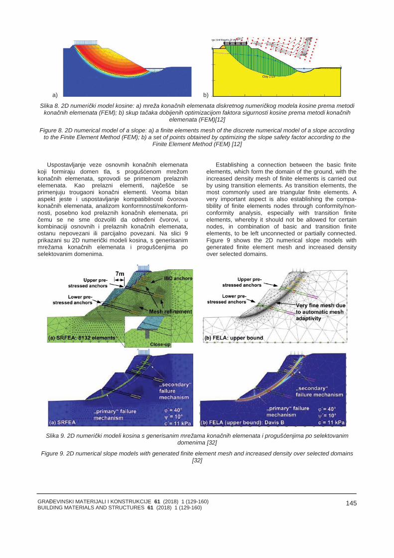
GRAĐEVINSKI MATERIJALI I KONSTRUKCIJE 61 (2018) 1 (129-160)BUILDING MATERIALS AND STRUCTURES 61 (2018) 1 (129-160)
145
a) b)
Slika 8. 2D numerički model kosine: a) mreža konačnih elemenata diskretnog numeričkog modela kosine prema metodikonačnih elemenata (FEM); b) skup tačaka dobijenih optimizacijom faktora sigurnosti kosine prema metodi konačnih
elemenata (FEM)[12]
Figure 8. 2D numerical model of a slope: a) a finite elements mesh of the discrete numerical model of a slope accordingto the Finite Element Method (FEM); b) a set of points obtained by optimizing the slope safety factor according to the
Finite Element Method (FEM) [12]
Uspostavljanje veze osnovnih konačnih elemenatakoji formiraju domen tla, s progušćenom mrežomkonačnih elemenata, sprovodi se primenom prelaznihelemenata. Kao prelazni elementi, najčešće seprimenjuju trougaoni konačni elementi. Veoma bitanaspekt jeste i uspostavljanje kompatibilnosti čvorovakonačnih elemenata, analizom konformnosti/nekonform-nosti, posebno kod prelaznih konačnih elemenata, pričemu se ne sme dozvoliti da određeni čvorovi, ukombinaciji osnovnih i prelaznih konačnih elemenata,ostanu nepovezani ili parcijalno povezani. Na slici 9prikazani su 2D numerički modeli kosina, s generisanimmrežama konačnih elemenata i progušćenjima poselektovanim domenima.
Establishing a connection between the basic finiteelements, which form the domain of the ground, with theincreased density mesh of finite elements is carried outby using transition elements. As transition elements, themost commonly used are triangular finite elements. Avery important aspect is also establishing the compa-tibility of finite elements nodes through conformity/non-conformity analysis, especially with transition finiteelements, whereby it should not be allowed for certainnodes, in combination of basic and transition finiteelements, to be left unconnected or partially connected.Figure 9 shows the 2D numerical slope models withgenerated finite element mesh and increased densityover selected domains.
Slika 9. 2D numerički modeli kosina s generisanim mrežama konačnih elemenata i progušćenjima po selektovanimdomenima [32]
Figure 9. 2D numerical slope models with generated finite element mesh and increased density over selected domains[32]
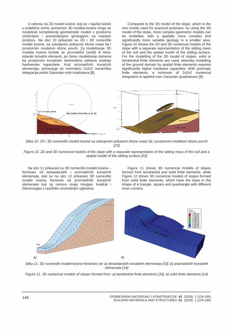
GRAĐEVINSKI MATERIJALI I KONSTRUKCIJE 61 (2018) 1 (129-160)BUILDING MATERIALS AND STRUCTURES 61 (2018) 1 (129-160)
146
U odnosu na 2D model kosine, koji se i najviše koristiu praktične svrhe, primenom 3D modela kosine mogu semodelirati kompleksniji geometrijski modeli s prostornosloženijom i promenljivijom geologijom na manjemprostoru. Na slici 10 prikazani su 2D i 3D numeričkimodeli kosine, sa izdvojenim prikazom klizne mase tla iprostornim modelom klizne površi. Za modeliranje 3Dmodela kosina koriste se prizmatični (solid) ili tetra-edarski konačni elementi, pri čemu modeliranje domenatla prostornim konačnim elementima zahteva znatnijehardverske kapacitete. Kod prizmatičnih konačnihelemenata, primenjuje se minimalno 2x2x2 numeričkaintegracija preko Gaussian-ovih kvadratura [8].
Compared to the 2D model of the slope, which is theone mostly used for practical purposes, by using the 3Dmodel of the slope, more complex geometric models canbe modelled, with a spatially more complex andsignificantly more variable geology in a smaller area.Figure 10 shows the 2D and 3D numerical models of theslope with a separate representation of the sliding massof the soil and the spatial model of the sliding surface.For the modelling of the 3D model of slopes, solid ortetrahedral finite elements are used, whereby modellingof the ground domain by spatial finite elements requiressignificantly higher hardware capacities. With prismaticfinite elements, a minimum of 2x2x2 numericalintegration is applied over Gaussian quadratures [8].
Slika 10. 2D i 3D numerički modeli kosine sa izdvojenim prikazom klizne mase tla i prostornim modelom klizne površi[23]
Figure 10. 2D and 3D numerical models of the slope with a separate representation of the sliding mass of the soil and aspatial model of the sliding surface [23]
Na slici 11 prikazani su 3D numerički modeli kosina –formirani od tetraedarskih i prizmatičnih konačnihelemenata, dok su na slici 12 prikazani 3D numeričkimodeli kosina formirani od prizmatičnih konačnihelemenata koji za osnovu imaju trougao, kvadrat ičetvorougao s različitim unutrašnjim uglovima.
Figure 11 shows 3D numerical models of slopesformed from tetrahedral and solid finite elements, whileFigure 12 shows 3D numerical models of slopes formedfrom solid finite elements, which have the base in theshape of a triangle, square and quadrangle with differentinner corners.
a) b)
Slika 11. 3D numerički modeli kosina formirani od: a) tetraedarskih konačnih elemenata [33]; b) prizmatičnih konačnihelemenata [14]
Figure 11. 3D numerical models of slopes formed from: a) tetrahedral finite elements [33], b) solid finite elements [14]
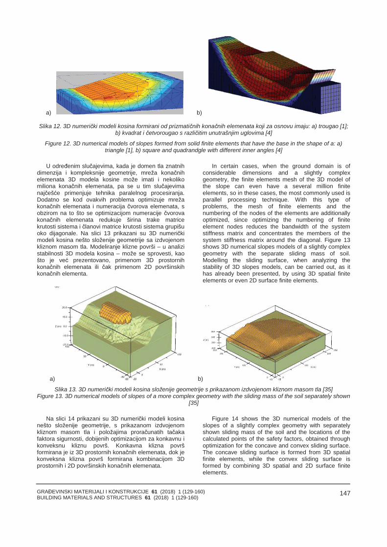
GRAĐEVINSKI MATERIJALI I KONSTRUKCIJE 61 (2018) 1 (129-160)BUILDING MATERIALS AND STRUCTURES 61 (2018) 1 (129-160)
147
a) b)
Slika 12. 3D numerički modeli kosina formirani od prizmatičnih konačnih elemenata koji za osnovu imaju: a) trougao [1];b) kvadrat i četvorougao s različitim unutrašnjim uglovima [4]
Figure 12. 3D numerical models of slopes formed from solid finite elements that have the base in the shape of a: a)triangle [1], b) square and quadrandgle with different inner angles [4]
U određenim slučajevima, kada je domen tla znatnihdimenzija i kompleksnije geometrije, mreža konačnihelemenata 3D modela kosine može imati i nekolikomiliona konačnih elemenata, pa se u tim slučajevimanajčešće primenjuje tehnika paralelnog procesiranja.Dodatno se kod ovakvih problema optimizuje mrežakonačnih elemenata i numeracija čvorova elemenata, sobzirom na to što se optimizacijom numeracije čvorovakonačnih elemenata redukuje širina trake matricekrutosti sistema i članovi matrice krutosti sistema grupišuoko dijagonale. Na slici 13 prikazani su 3D numeričkimodeli kosina nešto složenije geometrije sa izdvojenomkliznom masom tla. Modeliranje klizne površi – u analizistabilnosti 3D modela kosina – može se sprovesti, kaošto je već prezentovano, primenom 3D prostornihkonačnih elemenata ili čak primenom 2D površinskihkonačnih elementa.
In certain cases, when the ground domain is ofconsiderable dimensions and a slightly complexgeometry, the finite elements mesh of the 3D model ofthe slope can even have a several million finiteelements, so in these cases, the most commonly used isparallel processing technique. With this type ofproblems, the mesh of finite elements and thenumbering of the nodes of the elements are additionallyoptimized, since optimizing the numbering of finiteelement nodes reduces the bandwidth of the systemstiffness matrix and concentrates the members of thesystem stiffness matrix around the diagonal. Figure 13shows 3D numerical slopes models of a slightly complexgeometry with the separate sliding mass of soil.Modelling the sliding surface, when analyzing thestability of 3D slopes models, can be carried out, as ithas already been presented, by using 3D spatial finiteelements or even 2D surface finite elements.
a) b)
Slika 13. 3D numerički modeli kosina složenije geometrije s prikazanom izdvojenom kliznom masom tla [35]Figure 13. 3D numerical models of slopes of a more complex geometry with the sliding mass of the soil separately shown
[35]
Na slici 14 prikazani su 3D numerički modeli kosinanešto složenije geometrije, s prikazanom izdvojenomkliznom masom tla i položajima proračunatih tačakafaktora sigurnosti, dobijenih optimizacijom za konkavnu ikonveksnu kliznu površ. Konkavna klizna površformirana je iz 3D prostornih konačnih elemenata, dok jekonveksna klizna površ formirana kombinacijom 3Dprostornih i 2D površinskih konačnih elemenata.
Figure 14 shows the 3D numerical models of theslopes of a slightly complex geometry with separatelyshown sliding mass of the soil and the locations of thecalculated points of the safety factors, obtained throughoptimization for the concave and convex sliding surface.The concave sliding surface is formed from 3D spatialfinite elements, while the convex sliding surface isformed by combining 3D spatial and 2D surface finiteelements.
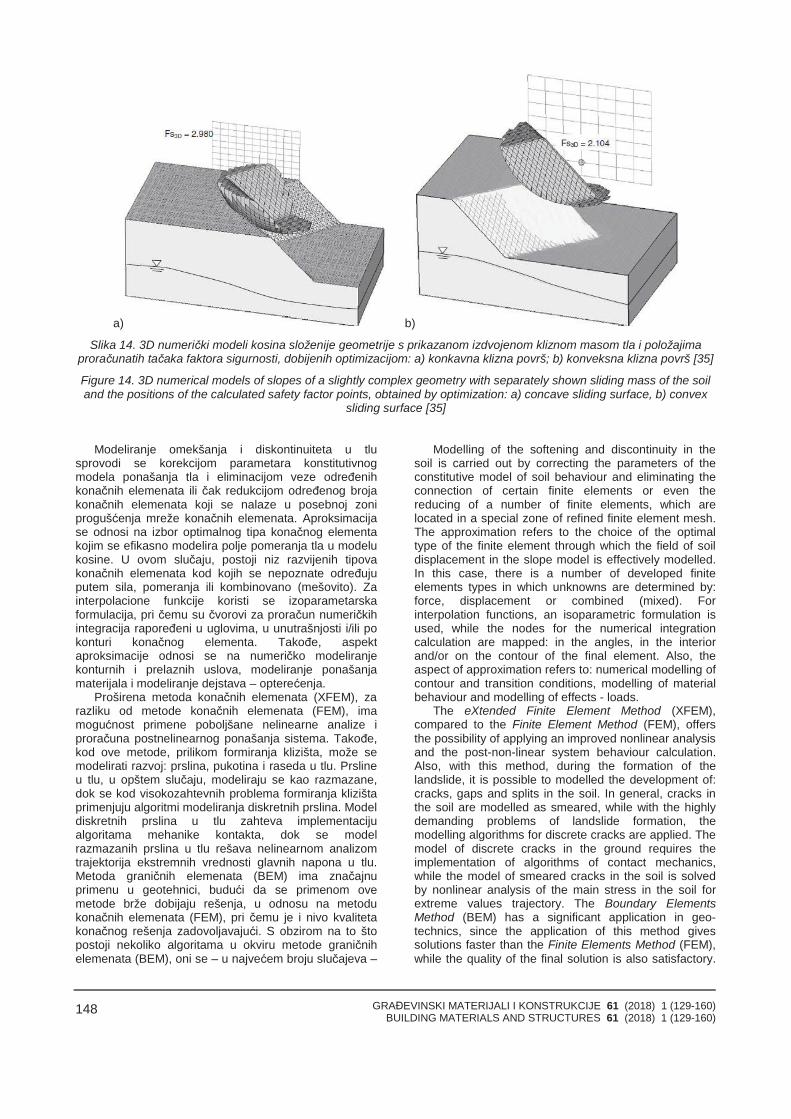
GRAĐEVINSKI MATERIJALI I KONSTRUKCIJE 61 (2018) 1 (129-160)BUILDING MATERIALS AND STRUCTURES 61 (2018) 1 (129-160)
148
a) b)
Slika 14. 3D numerički modeli kosina složenije geometrije s prikazanom izdvojenom kliznom masom tla i položajimaproračunatih tačaka faktora sigurnosti, dobijenih optimizacijom: a) konkavna klizna površ; b) konveksna klizna površ [35]
Figure 14. 3D numerical models of slopes of a slightly complex geometry with separately shown sliding mass of the soiland the positions of the calculated safety factor points, obtained by optimization: a) concave sliding surface, b) convex
sliding surface [35]
Modeliranje omekšanja i diskontinuiteta u tlusprovodi se korekcijom parametara konstitutivnogmodela ponašanja tla i eliminacijom veze određenihkonačnih elemenata ili čak redukcijom određenog brojakonačnih elemenata koji se nalaze u posebnoj zoniprogušćenja mreže konačnih elemenata. Aproksimacijase odnosi na izbor optimalnog tipa konačnog elementakojim se efikasno modelira polje pomeranja tla u modelukosine. U ovom slučaju, postoji niz razvijenih tipovakonačnih elemenata kod kojih se nepoznate određujuputem sila, pomeranja ili kombinovano (mešovito). Zainterpolacione funkcije koristi se izoparametarskaformulacija, pri čemu su čvorovi za proračun numeričkihintegracija rapoređeni u uglovima, u unutrašnjosti i/ili pokonturi konačnog elementa. Takođe, aspektaproksimacije odnosi se na numeričko modeliranjekonturnih i prelaznih uslova, modeliranje ponašanjamaterijala i modeliranje dejstava – opterećenja.
Proširena metoda konačnih elemenata (XFEM), zarazliku od metode konačnih elemenata (FEM), imamogućnost primene poboljšane nelinearne analize iproračuna postnelinearnog ponašanja sistema. Takođe,kod ove metode, prilikom formiranja klizišta, može semodelirati razvoj: prslina, pukotina i raseda u tlu. Prslineu tlu, u opštem slučaju, modeliraju se kao razmazane,dok se kod visokozahtevnih problema formiranja klizištaprimenjuju algoritmi modeliranja diskretnih prslina. Modeldiskretnih prslina u tlu zahteva implementacijualgoritama mehanike kontakta, dok se modelrazmazanih prslina u tlu rešava nelinearnom analizomtrajektorija ekstremnih vrednosti glavnih napona u tlu.Metoda graničnih elemenata (BEM) ima značajnuprimenu u geotehnici, budući da se primenom ovemetode brže dobijaju rešenja, u odnosu na metodukonačnih elemenata (FEM), pri čemu je i nivo kvalitetakonačnog rešenja zadovoljavajući. S obzirom na to štopostoji nekoliko algoritama u okviru metode graničnihelemenata (BEM), oni se – u najvećem broju slučajeva –
Modelling of the softening and discontinuity in thesoil is carried out by correcting the parameters of theconstitutive model of soil behaviour and eliminating theconnection of certain finite elements or even thereducing of a number of finite elements, which arelocated in a special zone of refined finite element mesh.The approximation refers to the choice of the optimaltype of the finite element through which the field of soildisplacement in the slope model is effectively modelled.In this case, there is a number of developed finiteelements types in which unknowns are determined by:force, displacement or combined (mixed). Forinterpolation functions, an isoparametric formulation isused, while the nodes for the numerical integrationcalculation are mapped: in the angles, in the interiorand/or on the contour of the final element. Also, theaspect of approximation refers to: numerical modelling ofcontour and transition conditions, modelling of materialbehaviour and modelling of effects - loads.
The eXtended Finite Element Method (XFEM),compared to the Finite Element Method (FEM), offersthe possibility of applying an improved nonlinear analysisand the post-non-linear system behaviour calculation.Also, with this method, during the formation of thelandslide, it is possible to modelled the development of:cracks, gaps and splits in the soil. In general, cracks inthe soil are modelled as smeared, while with the highlydemanding problems of landslide formation, themodelling algorithms for discrete cracks are applied. Themodel of discrete cracks in the ground requires theimplementation of algorithms of contact mechanics,while the model of smeared cracks in the soil is solvedby nonlinear analysis of the main stress in the soil forextreme values trajectory. The Boundary ElementsMethod (BEM) has a significant application in geo-technics, since the application of this method givessolutions faster than the Finite Elements Method (FEM),while the quality of the final solution is also satisfactory.
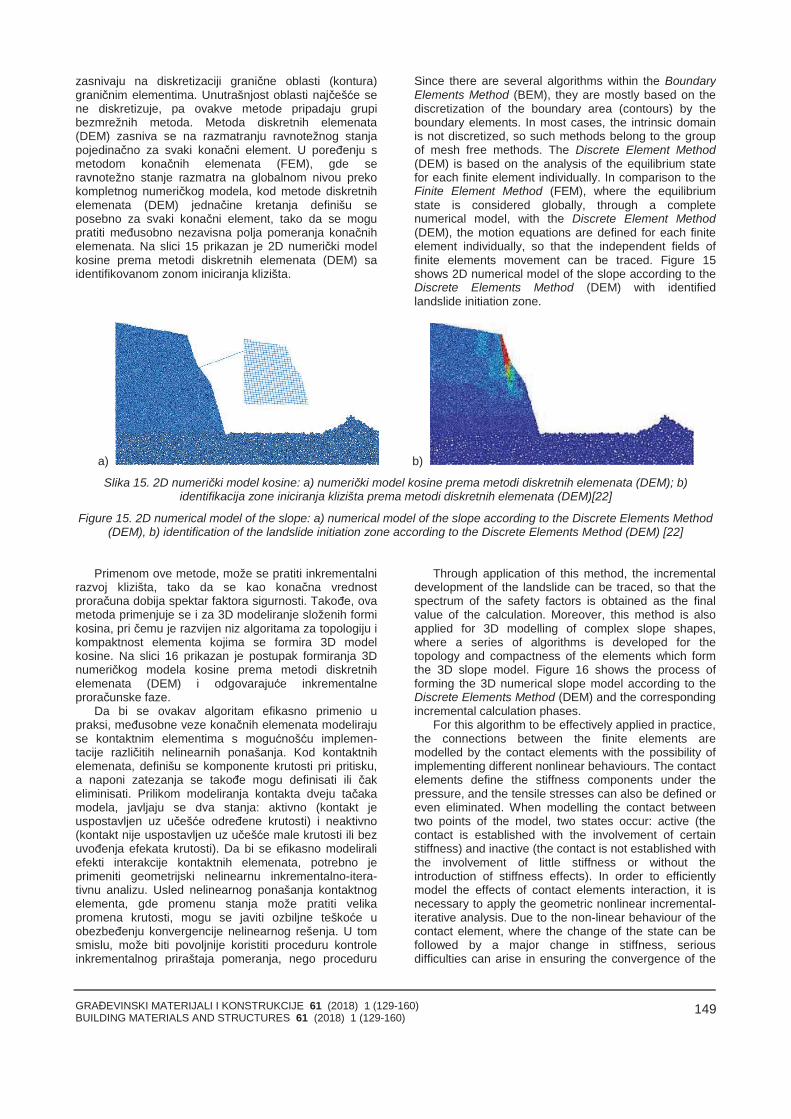
GRAĐEVINSKI MATERIJALI I KONSTRUKCIJE 61 (2018) 1 (129-160)BUILDING MATERIALS AND STRUCTURES 61 (2018) 1 (129-160)
149
zasnivaju na diskretizaciji granične oblasti (kontura)graničnim elementima. Unutrašnjost oblasti najčešće sene diskretizuje, pa ovakve metode pripadaju grupibezmrežnih metoda. Metoda diskretnih elemenata(DEM) zasniva se na razmatranju ravnotežnog stanjapojedinačno za svaki konačni element. U poređenju smetodom konačnih elemenata (FEM), gde seravnotežno stanje razmatra na globalnom nivou prekokompletnog numeričkog modela, kod metode diskretnihelemenata (DEM) jednačine kretanja definišu seposebno za svaki konačni element, tako da se mogupratiti međusobno nezavisna polja pomeranja konačnihelemenata. Na slici 15 prikazan je 2D numerički modelkosine prema metodi diskretnih elemenata (DEM) saidentifikovanom zonom iniciranja klizišta.
Since there are several algorithms within the BoundaryElements Method (BEM), they are mostly based on thediscretization of the boundary area (contours) by theboundary elements. In most cases, the intrinsic domainis not discretized, so such methods belong to the groupof mesh free methods. The Discrete Element Method(DEM) is based on the analysis of the equilibrium statefor each finite element individually. In comparison to theFinite Element Method (FEM), where the equilibriumstate is considered globally, through a completenumerical model, with the Discrete Element Method(DEM), the motion equations are defined for each finiteelement individually, so that the independent fields offinite elements movement can be traced. Figure 15shows 2D numerical model of the slope according to theDiscrete Elements Method (DEM) with identifiedlandslide initiation zone.
a) b)
Slika 15. 2D numerički model kosine: a) numerički model kosine prema metodi diskretnih elemenata (DEM); b)identifikacija zone iniciranja klizišta prema metodi diskretnih elemenata (DEM)[22]
Figure 15. 2D numerical model of the slope: a) numerical model of the slope according to the Discrete Elements Method(DEM), b) identification of the landslide initiation zone according to the Discrete Elements Method (DEM) [22]
Primenom ove metode, može se pratiti inkrementalnirazvoj klizišta, tako da se kao konačna vrednostproračuna dobija spektar faktora sigurnosti. Takođe, ovametoda primenjuje se i za 3D modeliranje složenih formikosina, pri čemu je razvijen niz algoritama za topologiju ikompaktnost elementa kojima se formira 3D modelkosine. Na slici 16 prikazan je postupak formiranja 3Dnumeričkog modela kosine prema metodi diskretnihelemenata (DEM) i odgovarajuće inkrementalneproračunske faze.
Da bi se ovakav algoritam efikasno primenio upraksi, međusobne veze konačnih elemenata modelirajuse kontaktnim elementima s mogućnošću implemen-tacije različitih nelinearnih ponašanja. Kod kontaktnihelemenata, definišu se komponente krutosti pri pritisku,a naponi zatezanja se takođe mogu definisati ili čakeliminisati. Prilikom modeliranja kontakta dveju tačakamodela, javljaju se dva stanja: aktivno (kontakt jeuspostavljen uz učešće određene krutosti) i neaktivno(kontakt nije uspostavljen uz učešće male krutosti ili bezuvođenja efekata krutosti). Da bi se efikasno modeliraliefekti interakcije kontaktnih elemenata, potrebno jeprimeniti geometrijski nelinearnu inkrementalno-itera-tivnu analizu. Usled nelinearnog ponašanja kontaktnogelementa, gde promenu stanja može pratiti velikapromena krutosti, mogu se javiti ozbiljne teškoće uobezbeđenju konvergencije nelinearnog rešenja. U tomsmislu, može biti povoljnije koristiti proceduru kontroleinkrementalnog priraštaja pomeranja, nego proceduru
Through application of this method, the incrementaldevelopment of the landslide can be traced, so that thespectrum of the safety factors is obtained as the finalvalue of the calculation. Moreover, this method is alsoapplied for 3D modelling of complex slope shapes,where a series of algorithms is developed for thetopology and compactness of the elements which formthe 3D slope model. Figure 16 shows the process offorming the 3D numerical slope model according to theDiscrete Elements Method (DEM) and the correspondingincremental calculation phases.
For this algorithm to be effectively applied in practice,the connections between the finite elements aremodelled by the contact elements with the possibility ofimplementing different nonlinear behaviours. The contactelements define the stiffness components under thepressure, and the tensile stresses can also be defined oreven eliminated. When modelling the contact betweentwo points of the model, two states occur: active (thecontact is established with the involvement of certainstiffness) and inactive (the contact is not established withthe involvement of little stiffness or without theintroduction of stiffness effects). In order to efficientlymodel the effects of contact elements interaction, it isnecessary to apply the geometric nonlinear incremental-iterative analysis. Due to the non-linear behaviour of thecontact element, where the change of the state can befollowed by a major change in stiffness, seriousdifficulties can arise in ensuring the convergence of the
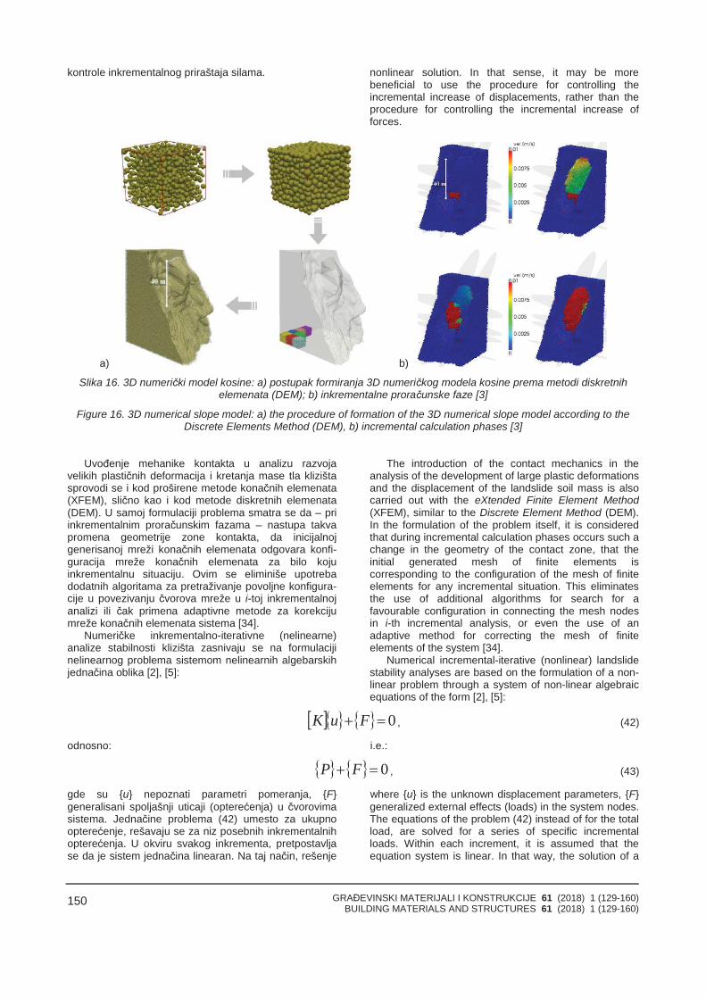
GRAĐEVINSKI MATERIJALI I KONSTRUKCIJE 61 (2018) 1 (129-160)BUILDING MATERIALS AND STRUCTURES 61 (2018) 1 (129-160)
150
kontrole inkrementalnog priraštaja silama. nonlinear solution. In that sense, it may be morebeneficial to use the procedure for controlling theincremental increase of displacements, rather than theprocedure for controlling the incremental increase offorces.
а) b)
Slika 16. 3D numerički model kosine: a) postupak formiranja 3D numeričkog modela kosine prema metodi diskretnihelemenata (DEM); b) inkrementalne proračunske faze [3]
Figure 16. 3D numerical slope model: a) the procedure of formation of the 3D numerical slope model according to theDiscrete Elements Method (DEM), b) incremental calculation phases [3]
Uvođenje mehanike kontakta u analizu razvojavelikih plastičnih deformacija i kretanja mase tla klizištasprovodi se i kod proširene metode konačnih elemenata(XFEM), slično kao i kod metode diskretnih elemenata(DEM). U samoj formulaciji problema smatra se da – priinkrementalnim proračunskim fazama – nastupa takvapromena geometrije zone kontakta, da inicijalnojgenerisanoj mreži konačnih elemenata odgovara konfi-guracija mreže konačnih elemenata za bilo kojuinkrementalnu situaciju. Ovim se eliminiše upotrebadodatnih algoritama za pretraživanje povoljne konfigura-cije u povezivanju čvorova mreže u i-toj inkrementalnojanalizi ili čak primena adaptivne metode za korekcijumreže konačnih elemenata sistema [34].
Numeričke inkrementalno-iterativne (nelinearne)analize stabilnosti klizišta zasnivaju se na formulacijinelinearnog problema sistemom nelinearnih algebarskihjednačina oblika [2], [5]:
The introduction of the contact mechanics in theanalysis of the development of large plastic deformationsand the displacement of the landslide soil mass is alsocarried out with the eXtended Finite Element Method(XFEM), similar to the Discrete Element Method (DEM).In the formulation of the problem itself, it is consideredthat during incremental calculation phases occurs such achange in the geometry of the contact zone, that theinitial generated mesh of finite elements iscorresponding to the configuration of the mesh of finiteelements for any incremental situation. This eliminatesthe use of additional algorithms for search for afavourable configuration in connecting the mesh nodesin i-th incremental analysis, or even the use of anadaptive method for correcting the mesh of finiteelements of the system [34].
Numerical incremental-iterative (nonlinear) landslidestability analyses are based on the formulation of a non-linear problem through a system of non-linear algebraicequations of the form [2], [5]:
0 FuK , (42)
odnosno: i.e.:
0 FP , (43)
gde su {u} nepoznati parametri pomeranja, {F}generalisani spoljašnji uticaji (opterećenja) u čvorovimasistema. Jednačine problema (42) umesto za ukupnoopterećenje, rešavaju se za niz posebnih inkrementalnihopterećenja. U okviru svakog inkrementa, pretpostavljase da je sistem jednačina linearan. Na taj način, rešenje
where {u} is the unknown displacement parameters, {F}generalized external effects (loads) in the system nodes.The equations of the problem (42) instead of for the totalload, are solved for a series of specific incrementalloads. Within each increment, it is assumed that theequation system is linear. In that way, the solution of a
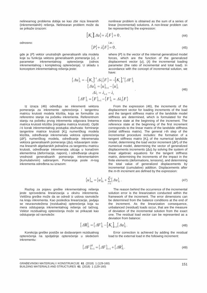
GRAĐEVINSKI MATERIJALI I KONSTRUKCIJE 61 (2018) 1 (129-160)BUILDING MATERIALS AND STRUCTURES 61 (2018) 1 (129-160)
151
nelinearnog problema dobija se kao zbir niza linearnih(inkrementalnih) rešenja. Nelinearan problem može dase prikaže izrazom:
nonlinear problem is obtained as the sum of a series oflinear (incremental) solutions. A non-linear problem canbe represented by the expression:
0 FλuΔKt , (44)
odnosno: i.e.: 0 FλP , (45)
gde je {P} vektor unutrašnjih generalisanih sila modelakoje su funkcija vektora generalisanih pomeranja {u}, λparametar inkrementalnog opterećenja (odnosinkrementalnog i kompletnog opterećenja). U skladu skonceptom inkrementalnog rešenja jeste:
where {P} is the vector of the internal generalized modelforces, which are the function of the generalizeddisplacement vector {u}, {λ} the incremental loadingparameter (the ratio of incremental and total load). Inaccordance with the concept of incremental solution, wehave:
FλΔFFFΔλλλΔ
uuuΔFΔKFλΔKuΔ
iiii
iii
iii
iititi
1
1
1
11
. (46)
Iz izraza (46) određuju se inkrementi vektorapomeranja za inkremente opterećenja i tangentnumatricu krutosti modela klizišta, koja se formuliše zareferentno stanje na početku inkrementa. Referentnomstanju na početku prvog inkrementa odgovara linearnamatrica krutosti klizišta (inicijalna matrica krutosti). Opštii-ti korak inkrementalnog postupka obuhvata: formiranjetangentne matrice krutosti [Kt]i numeričkog modelaklizišta, određivanje inkremenata vektora opterećenja{ΔF}i numeričkog modela, određivanje inkremenatavektora generalisanih pomeranja {Δu}i rešavanjem siste-ma linearnih algebarskih jednačina za tangentnu matricukrutosti, određivanje inkremenata uticaja u konačnimelementima (deformacije, naponi), i određivanje ukupnevrednosti generalisanih pomeranja inkrementalnim(kumulativnim) sabiranjem. Pomeranja posle m-toginkrementa određena su izrazom:
From the expression (46), the increments of thedisplacement vector for loading increments of the loadand the tangent stiffness matrix of the landslide modelstiffness are determined, which is formulated for thereference state at the beginning of the increment. Thereference state at the beginning of the first incrementcorresponds to the linear matrix of the landslide stiffness(initial stiffness matrix). The general i-th step of theincremental procedure includes: the formation of atangent stiffness matrix [Kt]i of the numerical landslidemodel, determining the load vector increment {ΔF}i of thenumerical model, determining the vector of generalizeddisplacements increments {Δu}i by solving the system oflinear algebraic equations for the tangent stiffnessmatrix, determining the increments of the impact in thefinite elements (deformations, tensions), and determiningthe total value of generalized displacements byincremental (cumulative) addition. Displacements afterthe m-th increment are defined by the expression:
m
iim uΔuu
10 . (47)
Razlog za pojavu greške inkrementalnog rešenjajeste sprovedena linearizacija u okviru inkrementa.Veličina greške može da se odredi iz uslova ravnotežena kraju inkrementa. Kao posledica linearizacije, javljajuse neuravnotežena (rezidualna) opterećenja koja sumera odstupanja inkrementalnog rešenja od tačnog.Vektor rezidualnog opterećenja može se prikazati kaoodstupanje od ravnoteže:
The reason behind the occurrence of the incrementalsolution error is the linearization conducted within theframework of the increment. The error dimensions canbe determined from the balance conditions at the end ofthe increment. As the linearization consequence,unbalanced (residual) loads occur, that are the measureof deviation of the incremental solution from the exactone. The residual load vector can be represented as adeviation from balance:
iitii uΔKFΔRΔ 1 . (48)
Korekcija greške postiže se dodavanjem rezidualnogopterećenja na spoljašnje opterećenje u sledećeminkrementu:
Error correction is achieved by adding the residualload to the external load in the following increment:
iiRi RΔFΔFΔ 11 . (49)
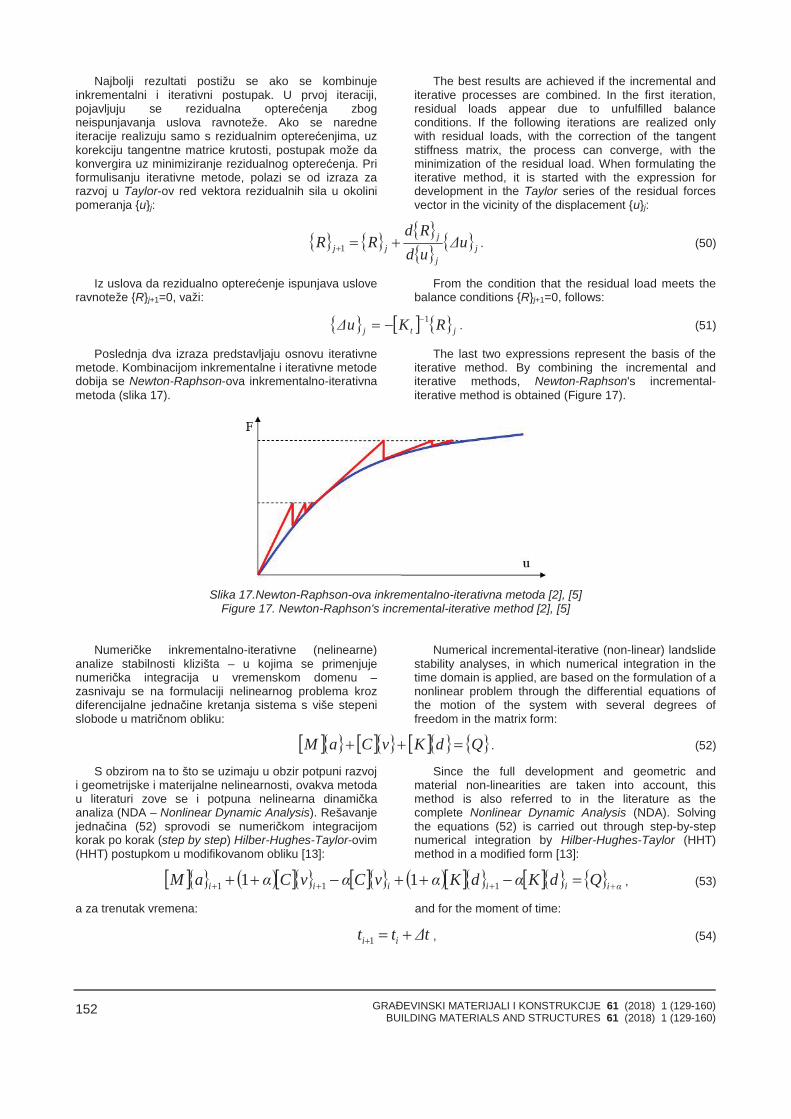
GRAĐEVINSKI MATERIJALI I KONSTRUKCIJE 61 (2018) 1 (129-160)BUILDING MATERIALS AND STRUCTURES 61 (2018) 1 (129-160)
152
Najbolji rezultati postižu se ako se kombinujeinkrementalni i iterativni postupak. U prvoj iteraciji,pojavljuju se rezidualna opterećenja zbogneispunjavanja uslova ravnoteže. Ako se naredneiteracije realizuju samo s rezidualnim opterećenjima, uzkorekciju tangentne matrice krutosti, postupak može dakonvergira uz minimiziranje rezidualnog opterećenja. Priformulisanju iterativne metode, polazi se od izraza zarazvoj u Taylor-ov red vektora rezidualnih sila u okolinipomeranja {u}j:
The best results are achieved if the incremental anditerative processes are combined. In the first iteration,residual loads appear due to unfulfilled balanceconditions. If the following iterations are realized onlywith residual loads, with the correction of the tangentstiffness matrix, the process can converge, with theminimization of the residual load. When formulating theiterative method, it is started with the expression fordevelopment in the Taylor series of the residual forcesvector in the vicinity of the displacement {u}j:
j
j
jjj uΔ
udRd
RR 1 . (50)
Iz uslova da rezidualno opterećenje ispunjava usloveravnoteže {R}j+1=0, važi:
From the condition that the residual load meets thebalance conditions {R}j+1=0, follows:
jtj RKuΔ 1 . (51)
Poslednja dva izraza predstavljaju osnovu iterativnemetode. Kombinacijom inkrementalne i iterativne metodedobija se Newton-Raphson-ova inkrementalno-iterativnametoda (slika 17).
The last two expressions represent the basis of theiterative method. By combining the incremental anditerative methods, Newton-Raphson's incremental-iterative method is obtained (Figure 17).
Slika 17.Newton-Raphson-ova inkrementalno-iterativna metoda [2], [5]Figure 17. Newton-Raphson's incremental-iterative method [2], [5]
Numeričke inkrementalno-iterativne (nelinearne)analize stabilnosti klizišta – u kojima se primenjujenumerička integracija u vremenskom domenu –zasnivaju se na formulaciji nelinearnog problema krozdiferencijalne jednačine kretanja sistema s više stepenislobode u matričnom obliku:
Numerical incremental-iterative (non-linear) landslidestability analyses, in which numerical integration in thetime domain is applied, are based on the formulation of anonlinear problem through the differential equations ofthe motion of the system with several degrees offreedom in the matrix form:
QdKvCaM . (52)
S obzirom na to što se uzimaju u obzir potpuni razvoji geometrijske i materijalne nelinearnosti, ovakva metodau literaturi zove se i potpuna nelinearna dinamičkaanaliza (NDA – Nonlinear Dynamic Analysis). Rešavanjejednačina (52) sprovodi se numeričkom integracijomkorak po korak (step by step) Hilber-Hughes-Taylor-ovim(HHT) postupkom u modifikovanom obliku [13]:
Since the full development and geometric andmaterial non-linearities are taken into account, thismethod is also referred to in the literature as thecomplete Nonlinear Dynamic Analysis (NDA). Solvingthe equations (52) is carried out through step-by-stepnumerical integration by Hilber-Hughes-Taylor (HHT)method in a modified form [13]:
αiiiiii QdKαdKαvCαvCαaM 111 11 , (53)
a za trenutak vremena: and for the moment of time:
tΔtt ii 1 , (54)
GRAĐEVINSKI MATERIJALI I KONSTRUKCIJE 61 (2018) 1 (129-160)BUILDING MATERIALS AND STRUCTURES 61 (2018) 1 (129-160)
153
gde je [M] matrica masa, {a} vektor ubrzanja, [C] matricaprigušenja, {v} vektor brzine, [K] matrica krutosti, {d}vektor pomeranja, {Q} vektor spoljašnjih generalisanihsila. Vektori pomeranja i brzine izražavaju se prema:
where [M] is the mass matrix, {a} acceleration vector, [C]damping matrix, {v} velocity vector, [K] stiffness matrix,{d} displacement vector, {Q} vector of externalgeneralized forces. The displacement and velocityvectors are expressed according to:
1
2
1 2212 iiiii aβaβtΔvtΔdd , (55)
11 1 iiii aγaγtΔvv , (56)
dok za vektor spoljašnjih generalisanih sila važi: while to the vector of external generalized forcesapplies:
αiαi tQQ , (57)
gde je: where:
tΔαttαtαt iiiαi 111 . (58)
HHT postupak postaje bezuslovno stabilan ukolikosu parametri α, β i γ izabrani u skladu s relacijama:
The HHT method becomes unconditionally stable ifthe parameters α, β and γ are selected in accordancewith the relations:
0
31 ,α , 21
41 αβ , αγ
21
. (59)
Vektori brzine {v}i+1 i ubrzanja {a}i+1 u trenutku ti+1izražavaju se preko vektora pomeranja na kraju intervala{d}i+1:
The velocity vector {v}i+1 and the acceleration vector{a}i+1 at the moment ti+1 are expressed by thedisplacement vector at the end of the interval {d}i+1:
iiiii aβγtΔv
βγdd
tΔβγv
1
2111 , (60)
iiiii aβ
vtΔβ
ddtΔβγa
1
211
121 . (61)
Unošenjem ovih izraza u jednačinu (53), dobija seekvivalentna jednačina ravnoteže:
Including these expressions into the equation (53)gives the equivalent equation of equilibrium:
αii QdK 1 , (62)
gde je: where:
CtΔβ
γαMtΔβ
KαK 111 2 , (63)
iiiαiαi a
βv
tΔβd
tΔβMQQ 1
2111
2
iiii dKαaβγαtΔv
βγαd
tΔβγαC
1
21111 . (64)
Ukoliko se vrednosti parametara α, β i γ usvoje dasu:
If the following values are accepted for parameters α,β and γ:
31
α ,94
β ,65
γ , (65)
tada su efektivna matrica krutosti i vektor efektivnogopterećenja:
then the effective stiffness matrix and the effectiveload vector are:
GRAĐEVINSKI MATERIJALI I KONSTRUKCIJE 61 (2018) 1 (129-160)BUILDING MATERIALS AND STRUCTURES 61 (2018) 1 (129-160)
154
CtΔ
MtΔ
KK4
54
932
2 , (66)
iiiαiαi av
tΔd
tΔMQQ
81
49
49
2
iiii dKatΔvdtΔ
C31
241
41
45
, (67)
gde je: where:
tΔttΔtt iiαi 32
31
1 , (68)
odnosno: i.e.:
tΔtQQ iαi 3
2. (69)
Sa određenim pomeranjima na kraju posmatranogintervala, rešavanjem jednačina (62), brzine i ubrzanjana kraju intervala dobijaju se prema izrazima:
With certain shifts at the end of the observed timeinterval by solving the equations (62), velocity andacceleration at the end of the time interval are obtainedaccording to the following expressions:
iiiii atΔvddtΔ
v161
87
815
11 , (70)
iiiii avtΔ
ddtΔ
a81
49
49
121 . (71)
Pre započinjanja algoritma korak po korak, potrebnoje da se početno ubrzanje sistema odredi izdiferencijalne jednačine kretanja prema:
Before starting the step-by-step algorithm, it isnecessary that the initial acceleration of the system isdetermined from the differential equation of motionaccording to:
0001
0 dKvCQMa . (72)
Korekcija matrice krutosti sistema sprovodi se poslesvakog apliciranog koraka vremena, a prema prethodnoprezentovanoj Newton-Raphson-ovoj metodi. PrimenomNDA analize sa HHT postupkom i NR metodom zaproračun 2D i 3D modela klizišta, dobijaju se najpouzda-nija rešenja za procenu nelinearnog odgovora sistema.Primenom ovakve metode, moguće je razmatrati uticajdinamičnosti povećanja nivoa podzemne i površinskevode, a takođe i dejstvo zemljotresa inkrementalnoskalirajući akcelerogram. Odgovor sistema (klizišta)predstavlja se kao funkcija promene faktora sigurnosti Fsu vremenu, a ne samo kao jedinstvena (diskretna)vrednost.
3.4 Kompleksno 3D geometrijsko modeliranje i numeričke metode proračuna stabilnostiklizišta
Standardni pristup u modeliranju terena i klizišta –inkorporiranog u terenu – zasniva se na korišćenjutehnike 2D prezentacije primenom situacionog plana ivertikalnih poprečnih preseka. Na osnovu definisanihtipova slojeva tla po dubini i njihovih fizičko-mehaničkih
The correction of the system stiffness matrix iscarried out after each applied time step, and accordingto the previously presented Newton-Raphson's method.Using the NDA analysis with the HHT method and theNR method for calculating the 2D and 3D landslidemodels, the most reliable solutions for estimating thenonlinear system response are obtained. Using thismethod allows us to consider the influence of the level ofunderground and surface water increase dynamics, aswell as the effect of the earthquake, incrementallyscaling the accelerometer. System (landslide) responseis represented as the function of change of the safetyfactor Fs in time, and not only as a unique (discrete)value.
3.4 Complex 3D geometric modelling andnumerical methods for landslides stabilitycalculations
The standard approach to modelling of the terrainand landslide, incorporated in the terrain, is based on theusage of the 2D presentation technique by applying asituational plan and vertical cross sections. Based on thedefined types of soil layers according to depth and their
GRAĐEVINSKI MATERIJALI I KONSTRUKCIJE 61 (2018) 1 (129-160)BUILDING MATERIALS AND STRUCTURES 61 (2018) 1 (129-160)
155
karakteristika, sprovodi se analitički i/ili numeričkiproračun stabilnosti kosina. U slučaju prostorno slože-nijeg modela terena i kompleksnije geometrije klizišta,pitanje 2D modeliranja i pouzdanosti odgovarajućihanaliza može biti diskutabilno. Međutim, i u situacijamakada se pouzdano može tvrditi da je tehnika 2Dprezentacije terena i klizišta, primenom situacionogplana i vertikalnih poprečnih preseka pouzdana, ostajuotvorena neka pitanja – da li se može dodatno poboljšatiprezentacija terena i klizišta u skladu sa savremeniminformacionim tehnologijama i da li se može pouzdanoodrediti zapremina tla koja formira klizište. Odgovori naova pitanja mogu se pronaći u 3D vizuelizaciji terena iklizišta, pri čemu se kao najsofisticiranije rešenje,primenom 4D vizuelizacije (3D + dinamičke simulacije)može predstaviti problem sanacije klizišta, od inicijalnogstanja, preko faznih rešenja, pa sve do finalnog rešenja.3D modeliranje terena i klizišta koristi se za geometrijskuprezentaciju i numeričku analizu primenom površi isolida. Geometrijska 3D prezentacija, u najvećem brojuslučajeva, ima veći stepen vizuelizacije konačnogrešenja, dok je cilj numeričke 3D analize da se prime-nom površi i solida modelira teren i klizište, tako da svakigeometrijsko-numerički element ima u sebi integrisanu imatematičku formulaciju problema. Podrazumeva se dase i prilikom numeričkog modeliranja terena i klizištamože dodatno postići realističan efekat geometrijskeprezentacije, međutim u ovakvim situacijama dodatno sepovećava vreme proračuna, tako da se – u veomasloženim modelima i s veoma velikim brojem konačnihelemenata – proračun svodi na primenu tehnike paralel-nog procesiranja. Međutim, geometrijsko 3D modeliranjeza prezentaciju terena i klizišta dosta je korisnije zaproračune zapremine tla, s obzirom na to što semodeliranjem klizišta kao solida može veoma brzoodrediti odgovarajuća zapremina, čak i u situacijamaveoma složenih solid modela. Postupak kompleksnog3D modeliranja terena i klizišta zasniva se na prethodnojidentifikaciji većeg broja kliznih ravni za odgovarajućibroj inženjersko-geoloških profila, njihovom integracijomsa 2D situacionim planom klizišta i konstrukcijom 3Dmodela klizišta u softveru za geometrijsku prezentaciju(CAD). Za integrisane klizne ravni formira se kliznapovrš u prostoru, dok se za modelirano klizište uprostoru formira solid model klizišta. Modeliranje kliznepovrši u prostoru zasniva se na primeni kompleksnezakrivljene površi koja formira mrežu četvorouglova, dokse solid model klizišta generiše primenom primitiva itehnika za editovanje primitiva: ekstrudiranje, sečenje,proširenje, ujedinjenje, ekstrakcija, intersekcija i slično.Na slici 18 prikazani su generisani kompleksni geome-trijsko-numerički 3D modeli terena za analizu stabilnostiklizišta.
Generalno razmatrajući modeliranje površi u prostorumože se sprovesti primenom matematičkih funkcija,mapiranja i diskretnih vrednosti. Najviše se koristi tehni-ka mapiranja terena s rasterskom mrežom (ortogonalna,poluortogonalna, radijalna i zakrivljena) za formiranjemape terena, ali je primena diskretnih vrednosti iformiranje polilinija, površi i solida u prednosti, pa se zaovakvu grafiku koristi termin vektorska grafika. Izohipseterena i klizne površi, u opštem slučaju, predstavljaju seprimenom polilinija i splajnova. Da bi se geometrijski imatematički modelirao skup tačaka koji formira jednukliznu površ u 2D koordinatnom sistemu, potrebno je
physico-mechanical characteristics, an analytical and/ornumerical calculation of the slope stability is carried out.In the case of a spatially slightly complex terrain modeland slightly complex landslide geometry, the question of2D modelling and the reliability of the correspondinganalyses can be debatable. However, even in situationswhere it can be reliably asserted that the 2Dpresentation of the terrain and landslide by using thesituational plan and vertical cross-sections is reliable, thefollowing questions remain open: can the presentation ofthe terrain and the landslide be further improved inaccordance with modern information technology andwhether the volume of the soil forming the landslide canbe reliably determined? The solution to these issues canbe found in 3D visualization of terrain and landslide,whereby the most sophisticated solution, by using 4Dvisualization (3D + dynamic simulation), can present theproblem of landslide sanation, from the initial state,through phase solutions to the final solution. 3Dmodelling of the terrain and landslide is used forgeometric presentation and numerical analysis throughusing surfaces and solids. Geometric 3D presentation, inmost cases, has a greater degree of visualization of thefinal solution, while numerical 3D analysis aims to usethe surfaces and solids to model the terrain andlandslide, so that each geometric-numerical elementalso has in itself an integrated mathematical formulationof the problem. It is presumed that the realistic effect ofthe geometric presentation can be additionally achievedin numerical modelling of the terrain and landslide,however, in these situations the time of the calculation isfurther increased, so that, in very complex models andwith a very large number of finite elements, thecalculation is reduced to the application of the parallelprocessing technique. However, geometric 3D modellingfor the presentation of terrain and landslides is muchmore useful for soil volume calculations, since modellingthe landslide as a solid can quickly determine theappropriate volume, even in situations of very complexsolid models. The process of complex 3D modelling theterrain and landslide is based on: the previous identifi-cation of a larger number of sliding planes for the cor-responding number of engineering-geological profiles,integration of these with the 2D situational plan of thelandslide and the construction of the landslide 3D modelin the geometric presentation software (CAD). For theintegrated sliding planes, a sliding surface is formed inspace, while for the modelled landslide in space a solidlandslide model is formed. The modelling of the slidingsurfaces in space is based on the application of complexcurved surface that forms a grid of quadrangles, whilethe solid model of the landslide is generated usingprimitives and techniques for editing primitives: extru-sion, cutting, expanding, unifying, extraction, intersec-tion, and the like. Figure 18 shows the generatedcomplex geometric-numerical 3D terrain models forlandslide stability analysis.
In general, modelling the surface in space can beconducted by using mathematical functions, mapping,and discrete values. The technique most widely used isterrain mapping with a raster mesh (orthogonal, semi-orthogonal, radial and curved) to form a map of theterrain, but the application of discrete values and theformation of polylines, surfaces and solids has morebenefits, so the term used for such a graphic is vector
GRAĐEVINSKI MATERIJALI I KONSTRUKCIJE 61 (2018) 1 (129-160)BUILDING MATERIALS AND STRUCTURES 61 (2018) 1 (129-160)
156
sprovesti interpolaciju. Jednostavniji modeli interpolacijazasnivaju se na primeni matematičkih funkcija uzatvorenom obliku. Međutim, interpolacija većeg brojatačaka – koje formiraju jednu kliznu površ u 2D koordi-natnom sistemu – zasniva se na primeni parametarskihfunkcija, gde rešenje nije definisano u zatvorenomobliku, već u skupu funkcija. Povezanost ovih funkcijauspostavlja se uslovima ekvivalencije tangente za krive sleve i desne strane u svakoj tački interpolacije. Na tajnačin, dobija se glatka interpolirana kriva, pa se međunajboljim parametarskim funkcijama pokazala primenasplajna.
U slučaju 3D modela terena i klizne ravni, tačnijeklizne površi, oni se u prostoru modeliraju primenomNURBS krivih (non-uniform rational basis spline).NURBS krive definisane su kontrolnim čvorovima ivektorom čvora. U opštem slučaju, NURBS krive i iodgovarajuće površi jesu generalizacija B-splajnova iBezier-ovih krivih i površi. Kontrolni čvorovi definišu oblikpovrši, u konkretnom slučaju klizne površi, dok vektorčvora određuje gde i kako površ dodiruje kontrolnečvorove. Međutim, i prilikom primene NURBS površimože se pojaviti problem u interpolaciji, ukoliko se zaodređene kontrolne čvorove – koji su diskretne vrednostiskupa kliznih površi – adekvatno ne izaberu parametriinterpolacije. Mogu se dobiti isuviše velika odstupanja uinterpolaciji, tako da 3D model terena i klizišta može bitiaproksimiran slično kao što se primenjuje princip uregresionim analizama, bilo da su one linearnog ilinelinearnog tipa. Minimiziranje prethodnog problemapostiže se progušćenjem mreže konačnih elemenata,uvođenjem novih međuelemenata. U opštem slučajunajpouzdanija, ali i isto tako i vizuelno grublja rešenjapostižu se primenom četvorouglova čiji čvorovi direktnopovezuju diskretne čvorove (linearna interpolacija)terena i klizišta. Rafiniranost mreže postiže seinterpolacijom trouglovima. Kao što je već prethodnonapisano, prezentacija terena sprovodi se, zapravo,primenom žičanog (wireframe) modela površi sadodavanjem 3D površi, dok se modeliranje klizištasprovodi primenom solida (3D geometrijsko telo).Diferencijacija klizišta u odnosu na ostale delove terenamože se sprovesti izdvajanjem i prikazom samo klizišta,nezavisno od terena, s mogućnošću 4D kontinualnetranslacije i rotacije u prostoru, i renderovanjem, tako dase terenu poveća transparentnost, u odnosu na klizište.
graphics. The terrain isohypse and sliding surfaces, ingeneral, are represented using polylines and splines. Inorder to geometrically and mathematically model the setof points that forms a single sliding surface in the 2Dcoordinate system, interpolation is required. Thosesimpler interpolation models are based on the applica-tion of mathematical functions in closed form. However,interpolation of a large number of points, that form asingle sliding surface in 2D coordinate system, is basedon the application of parametric functions, where thesolution is not defined in a closed form, but in a set offunctions. The connection of these functions isestablished by the conditions of the tangent equivalencefor curves on the left and right at each point ofinterpolation. This way, a smooth interpolated curve isobtained, so the application of the spline has turned outto be among the best parametric functions.
In the case of 3D terrain model and sliding plane,more precisely the sliding surface, they are modelled inthe space using NURBS curves (Non-Uniform RationalBasis Spline). NURBS curves are defined by the controlnodes and the node vector. In general, NURBS curvesand the corresponding surfaces are the generalization ofB-splines and Bezier's curves and surfaces. The controlnodes define the shape of the surface, in particular, thesliding surface, while the node vector determines whereand how the surface touches the control nodes.However, even with the application of NURBS surfaces,a problem may arise in interpolation, if the adequateinterpolation parameters are not selected for certaincontrol nodes, and which are discrete values of a set ofsliding planes. Excessive interpolation deviations canoccur so that the 3D terrain and landslide model can beapproximated in a similar manner as the principle inregression analysis applies, whether they are linear ornonlinear. Minimizing the previous problem is achievedby increase in the density of the mesh of finite elementsthrough the introduction of new inter elements. Ingeneral, the most reliable, but also visually roughersolutions are achieved by applying quadrangles whosenodes directly connect discrete nodes (linearinterpolation) of the terrain and landslide. The meshrefinement is achieved by interpolation by triangles. Aspreviously mentioned, the presentation of the terrain iscarried out, in fact, by using a wireframe plane modelwith the addition of 3D planes, while the landslidemodelling is carried out by using a solid (3D geometricbody). The differentiation of the landslide in relation toother parts of the terrain can be carried out by allocationand display of landslide only, irrespective of the terrain,with the possibility of 4D continuous translation androtation in space, and rendering, so that the terraintransparency is increased in relation to the landslide.
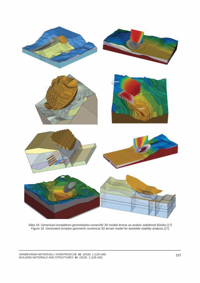
GRAĐEVINSKI MATERIJALI I KONSTRUKCIJE 61 (2018) 1 (129-160)BUILDING MATERIALS AND STRUCTURES 61 (2018) 1 (129-160)
157
Slika 18. Generisani kompleksni geometrijsko-numerički 3D modeli terena za analizu stabilnosti klizišta [17]Figure 18. Generated complex geometric-numerical 3D terrain model for landslide stability analysis [17]
GRAĐEVINSKI MATERIJALI I KONSTRUKCIJE 61 (2018) 1 (129-160)BUILDING MATERIALS AND STRUCTURES 61 (2018) 1 (129-160)
158
4 ZAVRŠNE NAPOMENE
Primenom sprovedene sistematizacije analitičkih inumeričkih metoda proračuna stabilnosti klizišta, možese efikasno razmotriti koji tip metode se može primeniti ufazama preliminarnih i finalnih analiza za naučnaistraživanja i stručne projekte. Autori su napravilisopstvenu sistematizaciju metoda proračuna stabilnostiklizišta, s tim što pojedine metode mogu pripadati iprelaznim kategorijama. Posebno je to slučaj kod onihmetoda koje se zasnivaju na direktnoj analizi stabilnostiza odgovarajuću kliznu površ i kod metoda koje koristeiteracije kliznih površi primenom optimizacionihalgoritama.
Ključni problemi u modeliranju i numeričkoj analiziklizišta današnjice mogli bi se prikazati iz nekolikoaspekata:
generalizacija nedovoljnog broja uzorkovanja idobijanja odgovarajućih kvalitetnih laboratorijskihispitivanja fizičko-mehaničkih karakteristika tla ikonstitutivnih modela ponašanja tla za kompletnoklizište;
primena geometrijsko-numeričke prezentacijeklizišta putem 3D modela (u određenim situacijama,mogu se dobiti i viši faktori sigurnosti usled zaklinjavanjaklizišta pri klizanju tla);
potreba da se dodatno unapredi metodologijaverifikacije stabilnosti klizišta na osnovu matematičkihmodela i analiza inkrementalnog pomeranja klizišta,monitoringom deformacija, a ne sila i momenata;
implementiranje tehnike paralelnog procesiranja upraktične svrhe (povećanje hardverskih kapaciteta –višejezgarnim procesiranjem i resursa – skladištenjemmemorije).
4 FINAL REMARKS
By applying the conducted systematization ofanalytical and numerical methods of landslide stabilitycalculation it can effectively be considered which type ofmethod can be applied in the phases of preliminary andfinal analyzes for scientific research and professionalprojects. The authors have made their ownsystematization of the methods of landslide stabilitycalculation, but some methods can also belong totransition categories. This is especially the case withthose methods that are based on a direct stabilityanalysis for the corresponding sliding surface and formethods using sliding surface iterations by applyingoptimization algorithms.
Key problems in modelling and numerical analysis ofnowadays landslides could be presented through severalaspects:
generalization of insufficient number of samplingand obtaining appropriate quality laboratory tests ofphysical-mechanical characteristics of soil andconstitutive models of soil behaviour for a completelandslide,
the application of the geometric-numericalpresentation of the landslide through 3D models (incertain situations, higher safety factors can be obtaineddue to the wedging of the landslide during the soilsliding),
it is necessary to further improve the methodologyof landslide stability verification based on mathematicalmodels and analysis of incremental displacement of thelandslide, by monitoring the deformations, but not theforces and moments,
implementing parallel processing techniques forpractical purposes (increasing: hardware capacitiesthrough multi-core processing and resources throughstorage of the memory).
5 LITERATURAREFERENCE
[1] Albataineh N.: Slope Stability Analysis Using 2Dand 3D Methods, University of Akron, 2016.
[2] Bathe K.: Finite Element Procedures, Prentice Hall,1037p, Upper Saddle River, USA, 1996.
[3] Bonilla Sierra V.: De la Photogrammetrie a laModelisation 3D: Evaluation Quantitative du Risqued’Eboulement Rocheux, Universite Grenoble Alpes,Docteur de l’Universite Grenoble Alpes, 2006.
[4] Chen X., Wub Y., Yu Y., Liu J., Frank X, Ren J.: ATwo-Grid Search Scheme for Large-Scale 3-DFinite Element Analyses of Slope Stability,Computers and Geotechnics, Vol. 62, 2014, pp.203-2015.
[5] Crisfield M.: Non-Linear Finite Element Analysis ofSolids and Structures, Volume 2: Essentials, JohnWiley & Sons, 345p, New York, USA, 2000.
[6] Dai F., Lee C., Ngai Y.: Landslide Risk Assessmentand Management: An Overview, EngineeringGeology, Vol. 64, No. 1, 2002, pp. 65 87.
[7] EN 1997-1:2004, Eurocode 7: Geotechnical Design– Part 1: General Rules, Brussels, Belgium, 2004.
[8] Fellipa C.: Advanced Finite Element Methods,University of Colorado, Boulder, 2007.
[9] Fredlund D.: Analytical Methods for Slope StabilityAnalysis, State of the Art, The 4th InternationalSymposium on Landslides, Toronto, Canada, 1984,pp. 229-250.
[10] GEO 5, User's Guide, Fine Ltd., 2016.[11] Geološka terminologija i nomenklatura VIII-2,
Inženjerska geologija, Zavod za regionalnu geolo-giju i paleontologiju Rudarsko-geološkog fakulteta,Univerzitet u Beogradu, Beograd, Srbija, 1978.
[12] Gustafsson J., Lindstrom M.: Applicability ofOptimised Slip Surfaces: Evaluation of a Software'sOptimisation Function for Generating CompositeSlip Surfaces, Applied on Stability Analysis of ClaySlopes, Chalmers University of Technology,Gothenburg, Sweden, 2014.
[13] Hilber H., Hughes T., Taylor R.: ImprovedNumerical Dissipation for Time IntegrationAlgorithms in Structural Dynamics, EarthquakeEngineering and Structural Dynamics, Vol. 5, No.3, pp. 283-292, 1977.
GRAĐEVINSKI MATERIJALI I KONSTRUKCIJE 61 (2018) 1 (129-160)BUILDING MATERIALS AND STRUCTURES 61 (2018) 1 (129-160)
159
[14] Ho I-H.: Parametric Studies of Slope StabilityAnalyses Using Three-Dimensional Finite ElementTechnique: Geometric Effect, Journal ofGeoengineering, Vol. 9, No. 1, 2014, pp. 33-43.
[15] http://geoliss.mre.gov.rs/beware/form/guest_page.php
[16] http://landslides.usgs.gov/learn/majorls.php[17] https://www.soilvision.com/products/svoffice5/svslo
pe[18] https://www.studyblue.com/notes/note/n/earth-
science-final-exam/deck/4839996[19] Janbu N.: Slope Stability Computations in
Embankment Dam Engineering, R. Hirschfeld andS. Poulos, eds., John Wiley and Sons, New York,USA, 1973, pp. 47-86.
[20] Kainthola A., Verma D., Thareja R., Singh T.: AReview on Numerical Slope Stability Analysis,International Journal of Science, Engineering andTechnology Research (IJSETR), Vol. 2, No. 6,2013, pp. 1315-1320.
[21] Kaur A., Sharma R.: Slope Stability AnalysisTechniques: A Review, International Journal ofEngineering Applied Sciences and Technology,Vol. 1, No. 4, 2016, pp. 52-57.
[22] Kong Y., Chen P., Yu H.: Analysis of Rock High-Slope Stability Based on a Particle Flow CodeStrength Reduction Method, Electronic Journal ofGeotechnical Engineering, Vol. 20, 2015, pp.13421-13430.
[23] Leong E., Rahardjo H.: Two and Three-Dimensional Slope Stability Reanalyses of BukitBatok Slope, Computers and Geotechnics, Vol. 42,pp. 81-88, 2012.
[24] Maksimović M.: Mehanika tla, Čigoja štampa,Beograd, Srbija, 2001.
[25] Memić M., Folć R., Ibrahimović A.: NumericalModeling and Slope Reparation Methods in anAltered and Unstable Serpentine Rock Mass,Building Materials and Structures, Vol. 55, No. 4,2012, pp. 23-45.
[26] Morgenstern N., Price V.: The Analysis of theStability of General Slip Surfaces. Géotechnique,Vol. 15, No. 1, 1965, pp.79-93.
[27] Pereira T, Robaina A., Peiter M., Braga F., RossoR.: Performance of Analysis Methods of SlopeStability for Different Geotechnical Classes Soil onEarth Dams, Journal of the Brazilian Association ofAgricultural Engineering, Vol. 36, No. 6, 2016,pp.1027-1036.
[28] Sarma S.: Stability Analysis of Embankments andSlopes, Géotechnique, Vol. 23, No. 3, 1973, pp.423-433.
[29] Schuster R.: The 25 Мost Catastrophic Landslidesof the 20th Century, in Chacon, Irigaray andFernandez (eds.), Landslides, Proc. Of the 8thInternational Conf. & Field Trip on Landslides,Granada, Spain, Rotterdam: Balkema, 1996.
[30] Spencer E.: A Method of Analysis of the Stability ofEmbankments Assuming Parallel Inter-SliceForces, Géotechnique, Vol. 17, No. 1, 1967, pp.11-26.
[31] Шахунянц Г.:Железнодорожный путь: учеб. длявузов ж.-д. трансп. /– 3-е изд., перераб. и доп. –М. : Транспорт, 1987.
[32] Tschuchnigg F., Schweiger H., Sloan S.: SlopeStability Analysis by Means of Finite Element LimitAnalysis and Finite Element Strength ReductionTechniques, Part II: Back Analyses of a CaseHistory, Computers and Geotechnics, Vol. 70 ,2015, pp. 178 189.
[33] Usluogullari O., Temugan A., Duman E.:Comparison of Slope Stabilization Methods byThreedimensional Finite Element Analysis, NaturalHazards, Vol. 81, No. 2, 2016, pp. 1027-1050.
[34] Wriggers P.: Computational Contact Mechanics,Springer-Verlag, New York, USA, 2006.
[35] Zhang L., Fredlund M., Fredlund D., Lub H., WilsonG.: The Influence of the Unsaturated Soil Zone on2-D and 3-D Slope Stability Analyses, EngineeringGeology, Vol. 193, 2015, pp. 374 383.
[36] Zhu D., Lee C., Qian Q., Chen G.: A ConciseAlgorithm for Computing the Factor of Safety Usingthe Morgenstern-Price Method, CanadianGeotechnical Journal, Vol. 42, No. 1, 2005,272-278.
GRAĐEVINSKI MATERIJALI I KONSTRUKCIJE 61 (2018) 1 (129-160)BUILDING MATERIALS AND STRUCTURES 61 (2018) 1 (129-160)
160
REZIME
SISTEMATIZACIJA ANALITIČKIH I NUMERIČKIHMETODA PRORAČUNA STABILNOSTI KLIZIŠTA
Kristina BOŽIĆ-TOMIĆNenad ŠUŠIĆMato ULJAREVIĆ
Na osnovu analize mnogih naučnih radova, autori sudali prikaz sopstvene originalne sistematizacijeanalitičkih i numeričkih metoda proračuna stabilnostiklizišta, pri čemu mnoge od njih tek treba dodatno da seunaprede, implementiraju i testiraju na kompleksnim 3Dmodelima klizišta. Metode proračuna stabilnosti klizištaklasifikovane su u pet grupa: analitičke jednokoračne,analitičke višekoračne (iteracije kliznih površi),numeričke višekoračne (iteracije kliznih površi),numeričke inkrementalno-iterativne (nelinearne) analize inumeričke inkrementalno-iterativne (nelinearne) analize,uz primenu numeričke integracije u vremenskomdomenu. Primenom sprovedene sistematizacije metodaproračuna stabilnosti klizišta, može se vrlo efikasnorazmotriti koji je tip metode optimalan za analizu klizišta ikoji tip metode je potrebno koristiti u fazi preliminarnih ifinalnih analiza za naučna istraživanja i stručne projekte.
Ključne reči: klizište, sistematizacija, analitičkemetode, numeričke metode, 2D i 3D modeliranje
SUMMАRY
THE SYSTEMATIZATION OF ANALYTICAL ANDNUMERICAL METHODS OF LANDSLIDE STABILITYCALCULATION
Kristina BOZIC-TOMICNenad SUSIC Mato ULJAREVIC
According to the analysis of a large number ofscientific papers, the authors of the paper presentedtheir own original systematization of the analytical andnumerical methods of landslide stability calculation, witha large part of them still to be further improved,implemented and tested on complex 3D landslidemodels. Methods for calculating the stability of thelandslide are classified into five groups: analytical single-step, analytical multi-step (iterations of sliding surfaces),numerical multi-step (iterations of sliding surfaces),numerical incremental-iterative (nonlinear) analysis andnumerical incremental-iterative (nonlinear) analysis,applying numerical integration in the time domain. Byusing the systematization method of calculating thestability of the landslide it can be very effective toconsider which type of method is optimal for landslideanalysis and which type of method should be consideredin the phase of preliminary and final analysis forscientific research and expert projects.
Keywords: landslide, systematization, analyticalmethods, numerical methods, 2D and 3D modelling
GRAĐEVINSKI MATERIJALI I KONSTRUKCIJE 61 (2018) 1 (161-178)BUILDING MATERIALS AND STRUCTURES 61 (2018) 1 (161-178)
161
PRIMER ZAŠTITE DUBOKE TEMELJNE JAME I SUSEDNIH OBJEKATA U SLOŽENIMURBANIM I GEOTEHNIČKIM USLOVIMA
EXAMPLE OF PROTECTION OF DEEP FOUNDATION PIT IN COMPLEX URBANAND GEOTECHNICAL CONDITIONS
Petar SANTRAČŽeljko BAJIĆ
STRUČNI RADPROFESSIONAL PAPER
UDK: 624.159.4doi:10.5937/GRMK1801161S
1 UVOD
Buduči stambeno-poslovni objekat „Pupinova palata”nalazi se na uglu ulice Narodnih heroja i BulevaraMihajla Pupina, u strogom centru Novog Sada. Objekatje moderno arhitektonsko rešenje, u kojem suobjedinjeni poslovni i uslužni sadržaji koje predviĆastroga urbana sredina grada, klasiđne stambenejedinice, elitni stambeni deo na najvišem spratu, sazelenim krovom (penthaus), trospratna podzemnagaraža sa 400 parking mesta za vlasnike objekta, sdirektnom lift-vezom do svakog sprata i javna podzemnagaraža za posetioce.
Ukupna površina objekta jeste oko 43.000 m2.Objekat ima razuĆenu spratnost – koja iznosi P+4, P+5,P+7, P+8 do P+12 na delu najviše kule – s tim što univou prizemlja ima i dva atrijuma za dodatnukomunikaciju, kao i vezu s kružnim požarnim putem.
S obzirom na to što je lokacija u strogom centru,okružena je starim postoječim objektima đija sespratnost kreče od P+1 do P+3, a konstruktivni sistem jezidani, s pruskom tavanicom, bez serklaža, dok samomanji deo objekata ima podrum. GraĆevinska linijanovog objekta – u skladu s lokacijskim uslovima – nalazise neposredno na liniji gabarita postoječih objekata, štoomogučava maksimalno iskoriščenje postoječe površinegraĆevinske parcele.
Petar Santrađ, v. prof. dr, Univerzitet u Novom Sadu,GraĆevinski fakultet Subotica, [email protected]Željko Bajič, mr, GeoExpert Subotica, DOO zaprojektovanje, nadzor, inženjering i geotehniku,[email protected]
1 INTRODUCTION
The future residential and commercial building"Pupin's Palace" is located on the corner of Narodnihheroja street and boulevard Mihajlo Pupin in the verycentre of Novi Sad. The building is a modernarchitectural solution that combines business andservice facilities that are planned by a strict urban citycentre, classic residential units, in elite residential areaon the highest floor with a green roof (pent house), athree-story underground garage with 400 parking spacesfor the owners of the facility with direct elevator-link toeach floor and a public underground garage for visitors.
The total area of the building is about 43,000m2. Thebuilding has different floors, which are 4, 5, 7, 8 to 12 onthe part of the highest tower, and two atriums at theground level for additional communication, and aconnection with a circular fire route.
Since the location is in the centre of the city, it issurrounded by old existing buildings, the floor of which isfrom 1 to 3, and the constructive system is masonry, witha Prussian ceiling, without stiffness rib, and only a smallpart of the building has a basement. The constructionline of the new facility is in line with the locationconditions directly on the line of the existing buildings,which allows the max utilization of the existing surface.
Petar Santrac, Associated prof. PhD, University of NoviSad, Faculty of Civil Engineering Subotica,[email protected] Bajic, MSc, GeoExpert Subotica, DOO for design,supervision, engineering and geotechnics,[email protected]
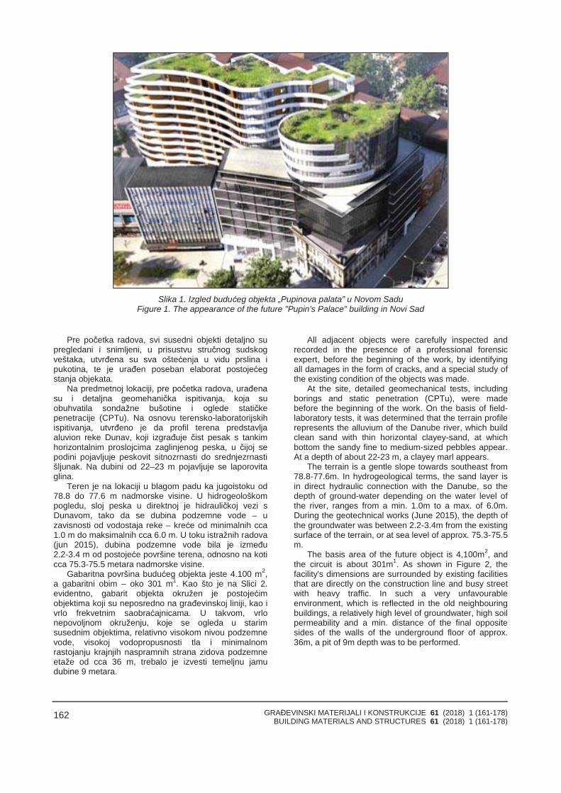
GRAĐEVINSKI MATERIJALI I KONSTRUKCIJE 61 (2018) 1 (161-178)BUILDING MATERIALS AND STRUCTURES 61 (2018) 1 (161-178)
162
Slika 1. Izgled budućeg objekta „Pupinova palata” u Novom SaduFigure 1. The appearance of the future "Pupin’s Palace" building in Novi Sad
Pre početka radova, svi susedni objekti detaljno supregledani i snimljeni, u prisustvu stručnog sudskogveštaka, utvrđena su sva oštećenja u vidu prslina ipukotina, te je urađen poseban elaborat postojećegstanja objekata.
Na predmetnoj lokaciji, pre početka radova, urađenasu i detaljna geomehanička ispitivanja, koja suobuhvatila sondažne bušotine i oglede statičkepenetracije (CPTu). Na osnovu terensko-laboratorijskihispitivanja, utvrđeno je da profil terena predstavljaaluvion reke Dunav, koji izgrađuje čist pesak s tankimhorizontalnim proslojcima zaglinjenog peska, u čijoj sepodini pojavljuje peskovit sitnozrnasti do srednjezrnastišljunak. Na dubini od 22–23 m pojavljuje se laporovitaglina.
Teren je na lokaciji u blagom padu ka jugoistoku od78.8 do 77.6 m nadmorske visine. U hidrogeološkompogledu, sloj peska u direktnoj je hidrauličkoj vezi sDunavom, tako da se dubina podzemne vode – uzavisnosti od vodostaja reke – kreće od minimalnih cca1.0 m do maksimalnih cca 6.0 m. U toku istražnih radova(jun 2015), dubina podzemne vode bila je između2.2-3.4 m od postojeće površine terena, odnosno na koticca 75.3-75.5 metara nadmorske visine.
Gabaritna površina budućeg objekta jeste 4.100 m2,a gabaritni obim – oko 301 m1. Kao što je na Slici 2.evidentno, gabarit objekta okružen je postojećimobjektima koji su neposredno na građevinskoj liniji, kao ivrlo frekvetnim saobraćajnicama. U takvom, vrlonepovoljnom okruženju, koje se ogleda u starimsusednim objektima, relativno visokom nivou podzemnevode, visokoj vodopropusnosti tla i minimalnomrastojanju krajnjih naspramnih strana zidova podzemneetaže od cca 36 m, trebalo je izvesti temeljnu jamudubine 9 metara.
All adjacent objects were carefully inspected andrecorded in the presence of a professional forensicexpert, before the beginning of the work, by identifyingall damages in the form of cracks, and a special study ofthe existing condition of the objects was made.
At the site, detailed geomechanical tests, includingborings and static penetration (CPTu), were madebefore the beginning of the work. On the basis of field-laboratory tests, it was determined that the terrain profilerepresents the alluvium of the Danube river, which buildclean sand with thin horizontal clayey-sand, at whichbottom the sandy fine to medium-sized pebbles appear.At a depth of about 22-23 m, a clayey marl appears.
The terrain is a gentle slope towards southeast from78.8-77.6m. In hydrogeological terms, the sand layer isin direct hydraulic connection with the Danube, so thedepth of ground-water depending on the water level ofthe river, ranges from a min. 1.0m to a max. of 6.0m.During the geotechnical works (June 2015), the depth ofthe groundwater was between 2.2-3.4m from the existingsurface of the terrain, or at sea level of approx. 75.3-75.5m.
The basis area of the future object is 4,100m2, andthe circuit is about 301m1. As shown in Figure 2, thefacility's dimensions are surrounded by existing facilitiesthat are directly on the construction line and busy streetwith heavy traffic. In such a very unfavourableenvironment, which is reflected in the old neighbouringbuildings, a relatively high level of groundwater, high soilpermeability and a min. distance of the final oppositesides of the walls of the underground floor of approx.36m, a pit of 9m depth was to be performed.
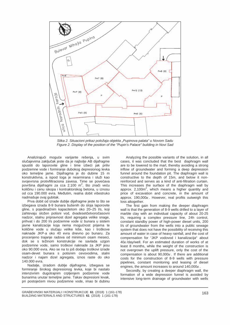
GRAĐEVINSKI MATERIJALI I KONSTRUKCIJE 61 (2018) 1 (161-178)BUILDING MATERIALS AND STRUCTURES 61 (2018) 1 (161-178)
163
Slika 2. Situacioni prikaz položaja objekta „Pupinova palata” u Novom SaduFigure 2. Display of the position of the "Pupin’s Palace" building in Novi Sad
Analizirajući moguće varijante rešenja, u svimslučajevima zaključak jeste da je najbolje AB dijafragmespustiti do laporovite gline i time izbeći jak prilivpodzemne vode i formiranje dubokog depresionog levkaoko temeljne jame. Dijafragma je do dubine 15 mkonstruktivna, a ispod toga je nearmirana i služi kaosvojevrsna protivfiltraciona zavesa. Time se povećavapovršina dijafragmi za cca 2.100 m2, što znači većukoličinu i cenu iskopa i kontraktorskog betona, u iznosuod cca 190.000 evra. Međutim, realna dobit višestrukonadmašuje ovaj gubitak.
Prva dobit od izrade dublje dijafragme jeste to što seizbegava izrada 8-9 bunara bušenih do sloja laporovitegline, s pojedinačnim kapacitetom oko 20–25 l/s, kojizahtevaju složen potisni vod, dvadesetčetvoročasovninadzor, stalnu pripravnost dizel agregata velike snage,prihvat i do 200 l/s podzemne vode iz bunara u sistemjavne kanalizacije koja nema mogućnost prijema tekoličine vode u slučaju velike kiše, kao i troškovenaknade JKP-a oko 40 evra dnevno po bunaru. Zaprocenjeno trajanje radova od minimum osam meseci,dok se s težinom konstrukcije ne savlada uzgonpodzemne vode, samo troškovi naknade za JKP jesuoko 90.000 evra. Ako se na to još dodaju troškovi izradeosam-devet bunara s potisnim cevovodima, stalninadzor i najam dizel agregata, iznos raste do oko140.000 evra.
Nadalje, izradom dublje dijafragme, izbegava seformiranje širokog depresionog levka, koje bi nastalointenzivnim dugotrajnim crpljenjem podzemne vodebunarima unutar temeljne jame. Takav depresioni levak,pri postojećem nivou podzemne vode, imao bi dubinu
Analyzing the possible variants of the solution, in allcases, it was concluded that the best diaphragm wallare to be lowered to the marl, thereby avoiding a stronginflow of groundwater and forming a deep depressionfunnel around the foundation pit. The diaphragm wall isconstructive to the depth of 15m, and below it non-reinforced and serves as a kind of anti-filtration curtain.This increases the surface of the diaphragm wall byapprox. 2,100m2, which means a higher quantity andprice of excavation and concrete, in the amount ofapprox. 190,000. However, real profits outweigh thisloss altogether.
The first gain from making the deeper diaphragmwall is that the generation of 8-9 wells drilled to a layer ofmarble clay with an individual capacity of about 20-25l/s, requiring a complex pressure line, 24h control,constant standby power of high-power diesel units, 200l/s of groundwater from the wells into a public sewagesystem that does not have the possibility of receiving thisamount of water in case of heavy rainfall, and the cost ofcompensation for “JKP vodovod i kanalizacija about40/day/well. For an estimated duration of works of atleast 8 months, while the weight of the construction isnot overgrown the uplift pressure, only the cost of thecompensation is about 90,000. If there are additionalcosts for the construction of 8-9 wells with pressurepipelines, constant monitoring and leasing of dieselengines, the amount increases to around 140,000.
Secondly, by creating a deeper diaphragm wall, theformation of a wide depression funnel is avoided byintensive long-term drainage of groundwater with wells
GRAĐEVINSKI MATERIJALI I KONSTRUKCIJE 61 (2018) 1 (161-178)BUILDING MATERIALS AND STRUCTURES 61 (2018) 1 (161-178)
164
oko 6 m, što bi prema proračunima izazvalo sleganja(zbog porasta efektivnih napona u tlu do 60 kPa) kojaiznose cca 4-5 cm nesposredno oko dijafragme, apostepeno bi se smanjivala udaljavajući od nje. Svisusedni objekti bili bi zahvaćeni depresionom zonomširine 15-30 m, u kojoj bi trpeli neravnomerna sleganjakoja bi – zbog njihovog kostruktivnog sklopa – izazvalavidna oštećenja u vidu cm-pukotina u zidovima, što jeneprihvatljivo.
Izrada bunara unutar temeljne jame ima i dodatanzahtev za posebnu obradu otvora u temeljnoj pločidebljine 80 cm, za prolaz bunarskih cevi, koje se poprestanku potrebe za crpljenjem vode moraju posebnimpostupkom hermetički zatvoriti. To je dodatni neizbežnideo koji se mora raditi vrlo pažljivo, uz postepenoisključivanje/uključivanje rada pojedinih bunara, sastalnom regulacijom proticaja, kako bi se sprečilonadiranje podzemne vode.
Nakon što je odlučeno da se urade dubokedijafragme, analizirana su konstruktivna rešenjarazupiranja. Poseban problem predstavljala je velikaširina temeljne jame, koja je na najužem delu široka oko36 metara. Ponuđene su tri varijante rešenja. Prvorešenje bila je tzv. Top-Down metoda. To je sistem kojije odavno poznat, a koristi se u urbanim sredinama, namalom prostoru, kada je potrebna brza gradnja. Sistempodrazumeva istovremenu gradnju i podzemnih inadzemnih etaža. Investitor – koji je ujedno bio i izvođačradova – procenio je da je ova metoda vrlo složena iskupa, jer dodatno zahteva izradu više stotina dubokihšipova velikog prečnika – kao oslonaca stubova objekta,podzemni iskop i transport, angažovanje obimne radnesnage na malom prostoru i vrlo složenu organizacijugradilišta.
Kao sledeće rešenje, detaljno je analizirana varijantaotkopa temeljne jame s paralelnom izradom prethodnonapregnutih sidara koje bi obezbeđivale stabilnostdijafragme pri velikim bočnim pritiscima tla i podzemnevode. Imajući u vidu aluvijalne sedimente kao sredinu ukojoj bi se formirala sidrišna zona, računski kapacitetsidara bio je relativno mali, oko 250-300 kN, što jezahtevalo vrlo velik broj sidara (oko 600 komada),postavljenih u dva nivoa; cena bi bila oko 500.000 evra.Mada je investitor bio spreman na tu investiciju, budućida se dobija široka, sigurna i otvorena temeljna jamabez razupirača i privremenih bermi, od ove varijanteodustalo se zbog zakonskih prepreka. Naime, premasrpskom zakonu, izradom ankera ulazi se u privatnovlasništvo suseda, od kojih investitor mora dobitioverenu pismenu saglasnost, a što je - s obzirom na većpostojeće odnose sa susedima - procenjeno kaonemoguće.
Na kraju, investitor se odlučio na varijantu faznogiskopa temeljne jame uz fazno razupiranje dijafragmehorizontalnim čeličnim razupiračima, pri čemu se kaoobostrani oslonci razupirača koriste dijafragme, a kaododatni jednostrani oslonci - već izvedeni podzemnidelovi objekta. Generalno, usvojeno je pet (V) fazaiskopa s razupiranjem, koji su u periodu od 6-7 meseciomogućili da se kompletira temeljna ploča na poslednjojfazi, pri čemu je na prvoj fazi objekat završen približnodo nivoa petog sprata.
Za potrebe crpljenja zarobljene podzemne vodeunutar gabarita dijafragme, urađena su dva bunarakapaciteta od oko 15 l/s. Ovi bunari su napravljeni i
inside the foundation pit. Such a depressed funnel wouldhave a depth of about 6m at the existing groundwaterlevel, which would have led to settlements according tothe calculations (due to an increase in the effectivevoltage in the soil to 60kPa), which would be about 4-5cm near to the diaphragm wall and gradually decreaseaway from it. All adjacent objects would be affected by adepression zone of 15-30m wide, in which they wouldsuffer uneven settlements that would cause visibledamages in the form of cm-cracks in the walls due totheir poor building structure, which is unacceptable.
The construction of the well inside the foundation pithas additional requirements for the special treatment ofopenings in the 80cm thick foundation slab for thepassage of well tubes which, after the need for waterextraction, must be sealed by a special procedure. Thisis an additional inevitable part, which must be done verycarefully, with the gradual shutdown-activation of thework of individual wells, with constant flow control inorder to prevent the overflow of groundwater.
After deciding to do deep diaphragm wall,constructive solutions of bracing were analyzed. Aspecial problem was the large width of the foundation pit,which is at the narrowest part about 36m. Three variantsof the solution are offered. The first solution was the so-called. method "Top-Down". It is a system that has beenknown for a long time, and is used in urban part, in asmall area, when rapid construction is required. Thesystem implies the simultaneous construction of bothunderground and above ground floors. The investor, whowas also the contractor, estimated that this method isvery complex and costly, as it additionally requires theproduction of hundreds of deep piles of large diameteras supports of the columns, underground excavation andtransport, engaging large workforce in a small space andvery complex organization of construction sites.
As the next solution, in detailed are analyzed thevariant of the excavation of the foundation pit withparallel production of pre-stressed anchors, which wouldensure the stability of the diaphragm wall at large lateralsoil and water pressures. Beyond a weak alluvialsediments as the anchor zone, the calculated capacity ofthe anchors was relatively small, about 250-300kN,which required a very large number of it, about 600,which would be placed in two levels, and the price it wasaround 500,000. Although the investor was ready forthis investment, which will give a wide, safe and open pitwithout braces and berms, this variant was abandoneddue to legal obstacles. Namely, according to the Serbianlaw, the anchor enters the private ownership of theneighbours, of which the investor must obtain a certifiedwritten consent, which, given the mutual relations isestimated as impossible.
In the end, the investor decided on a variant of thephase excavation of the foundation pit with horizontalsteel braces, relying on the diaphragm wall, and on thealready constructed underground parts of the building. Ingeneral, a five (5) phase of excavation was adopted,which in the period of about 6-7 months enabled thecompletion of the foundation slab at the last stage, withthe first stage being completed approximately to thelevel of 5 floors.
For the needs of the pumping of capturedgroundwater inside the circuit of diaphragm wall, twowells with capacity of about 15 l/s were made. These
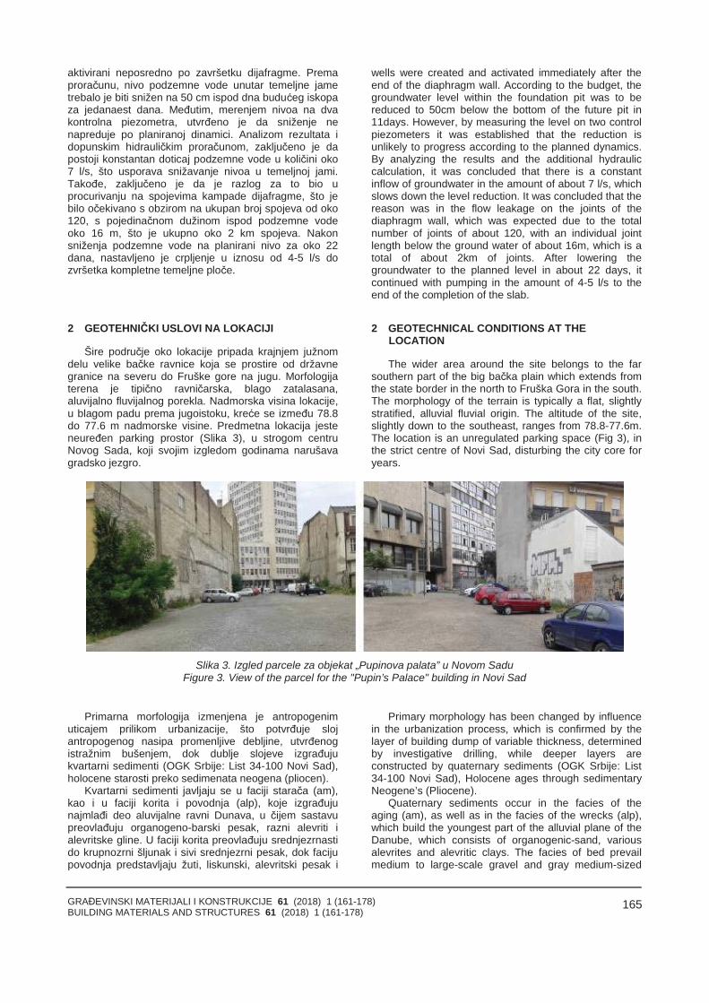
GRAĐEVINSKI MATERIJALI I KONSTRUKCIJE 61 (2018) 1 (161-178)BUILDING MATERIALS AND STRUCTURES 61 (2018) 1 (161-178)
165
aktivirani neposredno po završetku dijafragme. Premaproračunu, nivo podzemne vode unutar temeljne jametrebalo je biti snižen na 50 cm ispod dna budućeg iskopaza jedanaest dana. Međutim, merenjem nivoa na dvakontrolna piezometra, utvrđeno je da sniženje nenapreduje po planiranoj dinamici. Analizom rezultata idopunskim hidrauličkim proračunom, zaključeno je dapostoji konstantan doticaj podzemne vode u količini oko7 l/s, što usporava snižavanje nivoa u temeljnoj jami.Takođe, zaključeno je da je razlog za to bio uprocurivanju na spojevima kampade dijafragme, što jebilo očekivano s obzirom na ukupan broj spojeva od oko120, s pojedinačnom dužinom ispod podzemne vodeoko 16 m, što je ukupno oko 2 km spojeva. Nakonsniženja podzemne vode na planirani nivo za oko 22dana, nastavljeno je crpljenje u iznosu od 4-5 l/s dozvršetka kompletne temeljne ploče.
2 GEOTEHNIČKI USLOVI NA LOKACIJI
Šire područje oko lokacije pripada krajnjem južnomdelu velike bačke ravnice koja se prostire od državnegranice na severu do Fruške gore na jugu. Morfologijaterena je tipično ravničarska, blago zatalasana,aluvijalno fluvijalnog porekla. Nadmorska visina lokacije,u blagom padu prema jugoistoku, kreće se između 78.8do 77.6 m nadmorske visine. Predmetna lokacija jesteneuređen parking prostor (Slika 3), u strogom centruNovog Sada, koji svojim izgledom godinama narušavagradsko jezgro.
wells were created and activated immediately after theend of the diaphragm wall. According to the budget, thegroundwater level within the foundation pit was to bereduced to 50cm below the bottom of the future pit in11days. However, by measuring the level on two controlpiezometers it was established that the reduction isunlikely to progress according to the planned dynamics.By analyzing the results and the additional hydrauliccalculation, it was concluded that there is a constantinflow of groundwater in the amount of about 7 l/s, whichslows down the level reduction. It was concluded that thereason was in the flow leakage on the joints of thediaphragm wall, which was expected due to the totalnumber of joints of about 120, with an individual jointlength below the ground water of about 16m, which is atotal of about 2km of joints. After lowering thegroundwater to the planned level in about 22 days, itcontinued with pumping in the amount of 4-5 l/s to theend of the completion of the slab.
2 GEOTECHNICAL CONDITIONS AT THELOCATION
The wider area around the site belongs to the farsouthern part of the big bačka plain which extends fromthe state border in the north to Fruška Gora in the south.The morphology of the terrain is typically a flat, slightlystratified, alluvial fluvial origin. The altitude of the site,slightly down to the southeast, ranges from 78.8-77.6m.The location is an unregulated parking space (Fig 3), inthe strict centre of Novi Sad, disturbing the city core foryears.
Slika 3. Izgled parcele za objekat „Pupinova palata” u Novom SaduFigure 3. View of the parcel for the "Pupin’s Palace" building in Novi Sad
Primarna morfologija izmenjena je antropogenimuticajem prilikom urbanizacije, što potvrđuje slojantropogenog nasipa promenljive debljine, utvrđenogistražnim bušenjem, dok dublje slojeve izgrađujukvartarni sedimenti (OGK Srbije: List 34-100 Novi Sad),holocene starosti preko sedimenata neogena (pliocen).
Kvartarni sedimenti javljaju se u faciji starača (am),kao i u faciji korita i povodnja (alp), koje izgrađujunajmlađi deo aluvijalne ravni Dunava, u čijem sastavupreovlađuju organogeno-barski pesak, razni alevriti ialevritske gline. U faciji korita preovlađuju srednjezrnastido krupnozrni šljunak i sivi srednjezrni pesak, dok facijupovodnja predstavljaju žuti, liskunski, alevritski pesak i
Primary morphology has been changed by influencein the urbanization process, which is confirmed by thelayer of building dump of variable thickness, determinedby investigative drilling, while deeper layers areconstructed by quaternary sediments (OGK Srbije: List34-100 Novi Sad), Holocene ages through sedimentaryNeogene’s (Pliocene).
Quaternary sediments occur in the facies of theaging (am), as well as in the facies of the wrecks (alp),which build the youngest part of the alluvial plane of theDanube, which consists of organogenic-sand, variousalevrites and alevritic clays. The facies of bed prevailmedium to large-scale gravel and gray medium-sized
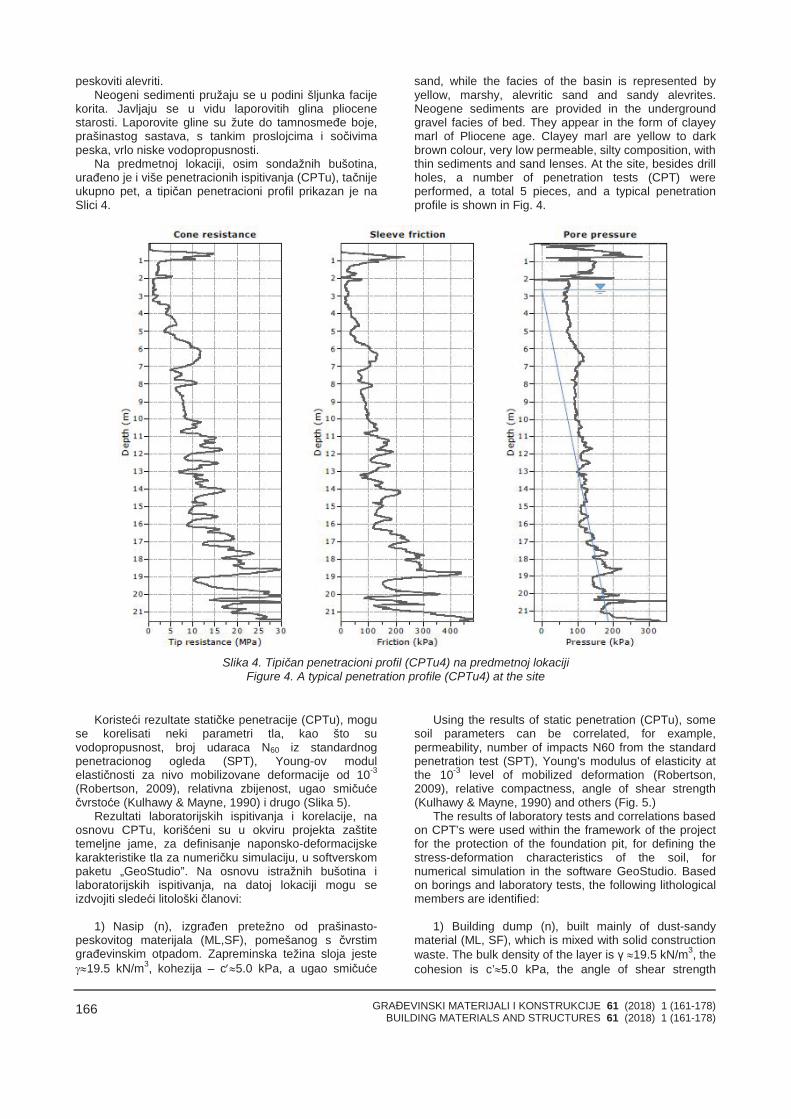
GRAĐEVINSKI MATERIJALI I KONSTRUKCIJE 61 (2018) 1 (161-178)BUILDING MATERIALS AND STRUCTURES 61 (2018) 1 (161-178)
166
peskoviti alevriti.Neogeni sedimenti pružaju se u podini šljunka facije
korita. Javljaju se u vidu laporovitih glina pliocenestarosti. Laporovite gline su žute do tamnosmeđe boje,prašinastog sastava, s tankim proslojcima i sočivimapeska, vrlo niske vodopropusnosti.
Na predmetnoj lokaciji, osim sondažnih bušotina,urađeno je i više penetracionih ispitivanja (CPTu), tačnijeukupno pet, a tipičan penetracioni profil prikazan je naSlici 4.
sand, while the facies of the basin is represented byyellow, marshy, alevritic sand and sandy alevrites.Neogene sediments are provided in the undergroundgravel facies of bed. They appear in the form of clayeymarl of Pliocene age. Clayey marl are yellow to darkbrown colour, very low permeable, silty composition, withthin sediments and sand lenses. At the site, besides drillholes, a number of penetration tests (CPT) wereperformed, a total 5 pieces, and a typical penetrationprofile is shown in Fig. 4.
Slika 4. Tipičan penetracioni profil (CPTu4) na predmetnoj lokacijiFigure 4. A typical penetration profile (CPTu4) at the site
Koristeći rezultate statičke penetracije (CPTu), moguse korelisati neki parametri tla, kao što suvodopropusnost, broj udaraca N60 iz standardnogpenetracionog ogleda (SPT), Young-ov modulelastičnosti za nivo mobilizovane deformacije od 10-3
(Robertson, 2009), relativna zbijenost, ugao smičućečvrstoće (Kulhawy & Mayne, 1990) i drugo (Slika 5).
Rezultati laboratorijskih ispitivanja i korelacije, naosnovu CPTu, korišćeni su u okviru projekta zaštitetemeljne jame, za definisanje naponsko-deformacijskekarakteristike tla za numeričku simulaciju, u softverskompaketu „GeoStudio”. Na osnovu istražnih bušotina ilaboratorijskih ispitivanja, na datoj lokaciji mogu seizdvojiti sledeći litološki članovi:
1) Nasip (n), izgrađen pretežno od prašinasto-peskovitog materijala (ML,SF), pomešanog s čvrstimgrađevinskim otpadom. Zapreminska težina sloja jeste19.5 kN/m3, kohezija – c5.0 kPa, a ugao smičuće
Using the results of static penetration (CPTu), somesoil parameters can be correlated, for example,permeability, number of impacts N60 from the standardpenetration test (SPT), Young's modulus of elasticity atthe 10-3 level of mobilized deformation (Robertson,2009), relative compactness, angle of shear strength(Kulhawy & Mayne, 1990) and others (Fig. 5.)
The results of laboratory tests and correlations basedon CPT’s were used within the framework of the projectfor the protection of the foundation pit, for defining thestress-deformation characteristics of the soil, fornumerical simulation in the software GeoStudio. Basedon borings and laboratory tests, the following lithologicalmembers are identified:
1) Building dump (n), built mainly of dust-sandymaterial (ML, SF), which is mixed with solid constructionwaste. The bulk density of the layer is γ 19.5 kN/m3, thecohesion is c’5.0 kPa, the angle of shear strength
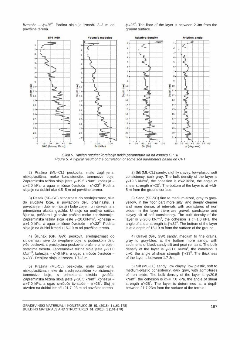
GRAĐEVINSKI MATERIJALI I KONSTRUKCIJE 61 (2018) 1 (161-178)BUILDING MATERIALS AND STRUCTURES 61 (2018) 1 (161-178)
167
čvrstoće – 250. Podina sloja je između 2–3 m odpovršine terena.
250. The floor of the layer is between 2-3m from theground surface.
Slika 5. Tipičan rezultat korelacije nekih parametara tla na osnovu CPTuFigure 5. A typical result of the correlation of some soil parameters based on CPT
2) Prašina (ML–CL) peskovita, malo zaglinjena,niskoplastična, meke konzistencije, tamnosive boje.Zapreminska težina sloja jeste 19.5 kN/m3, kohezija –c2.0 kPa, a ugao smičuće čvrstoće – 230. Podinasloja je na dubini oko 4.5–5 m od površine terena.
3) Pesak (SF–SC) sitnozrnast do srednjezrnast, sivedo sivožute boje, u povlatnom delu prašinastiji, spovećanjem dubine – čistiji i bolje zbijen, u intervalima sprimesama oksida gvožđa. U sloju su uočljiva sočivašljunka, peščara i glinovite prašine meke konzistencije.Zapreminska težina sloja jeste 20.0kN/m3, kohezija –c1.0 kPa, a ugao smičuće čvrstoće – 320. Podinasloja je na dubini između 15–19 m od površine terena.
4) Šljunak (GF, GW) peskovit, srednjezrnast dositnozrnast, sive do sivoplave boje, u podinskom deluviše peskovit, s proslojcima peskovite prašine crne boje iostacima treseta. Zapreminska težina sloja jeste 21.0kN/m3, kohezija – c0 kPa, a ugao smičuće čvrstoće –330. Debljina sloja je između 1.7–3 m.
5) Prašina (ML-CL) peskovita, malo zaglinjena,niskoplastična, meke do srednjeplastične konzistencije,tamnosive boje, s primesama oksida gvožđa.Zapreminska težina sloja jeste 20.5 kN/m3, kohezija –c7.0 kPa, a ugao smičuće čvrstoće – 280. Sloj jeutvrđen na dubini između 21.7–23 m od površine terena.
2) Silt (ML-CL) sandy, slightly clayey, low-plastic, softconsistency, dark gray. The bulk density of the layer isγ19.5 kN/m3, the cohesion is c’2.0kPa, the angle ofshear strength 230. The bottom of the layer is at 4.5-5 m from the ground surface.
3) Sand (SF-SC) fine to medium-sized, gray to gray-yellow, in the floor part more silty, and deeply cleanerand more dense, at intervals with admixtures of ironoxide. In the layer there are gravel, sandstone andclayey silt of soft consistency. The bulk density of thelayer is γ20.0 kN/m3, the cohesion is c’1.0 kPa, theangle of shear strength is 320. The bottom of the layeris at a depth of 15-19 m from the surface of the ground.
4) Gravel (GF, GW) sandy, medium to fine grains,gray to gray-blue, at the bottom more sandy, withsediments of black sandy silt and peat remains. The bulkdensity of the layer is γ21.0 kN/m3, the cohesion isc’0, the angle of shear strength 330. The thicknessof the layer is between 1.7-3m.
5) Silt (ML-CL) sandy, low clayey, low plastic, soft tomedium-plastic consistency, dark gray, with admixturesof iron oxide. The bulk density of the layer is γ20.5kN/m3, the cohesion is c’= 7.0 kPa, the angle of shearstrength ’280. The layer is determined at a depthbetween 21.7-23m from the surface of the terrain.
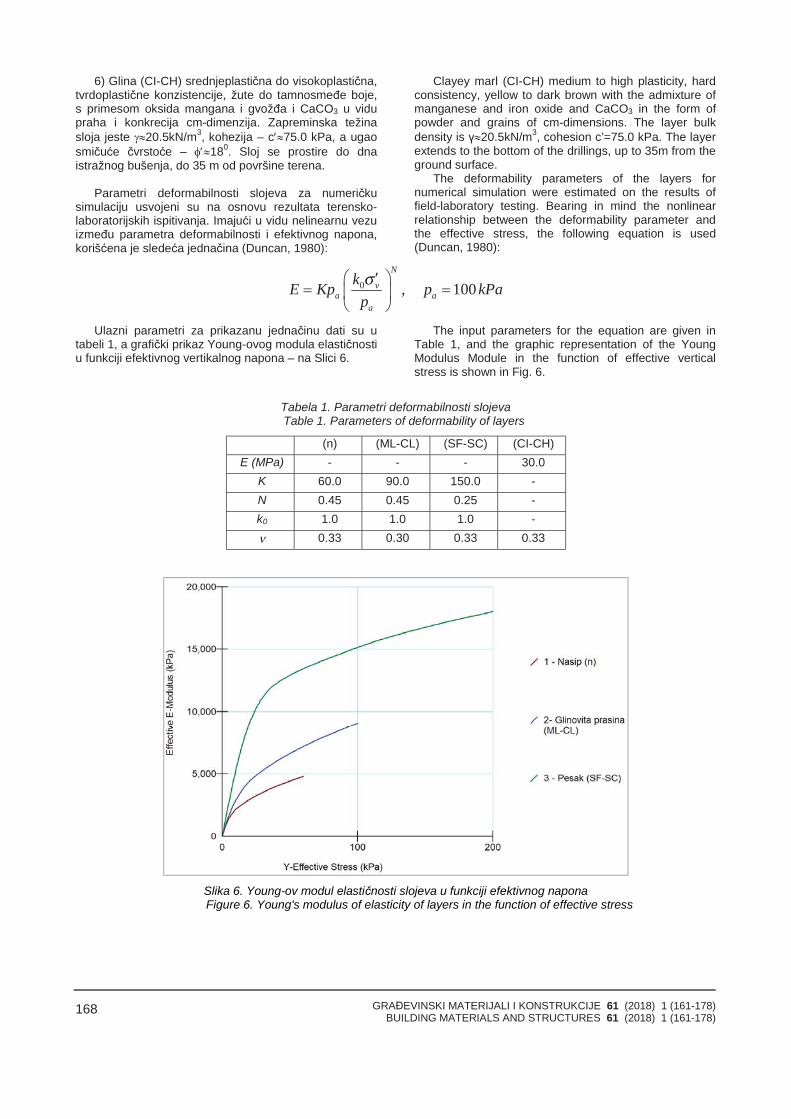
GRAĐEVINSKI MATERIJALI I KONSTRUKCIJE 61 (2018) 1 (161-178)BUILDING MATERIALS AND STRUCTURES 61 (2018) 1 (161-178)
168
6) Glina (CI-CH) srednjeplastična do visokoplastična,tvrdoplastične konzistencije, žute do tamnosmeđe boje,s primesom oksida mangana i gvožđa i CaCO3 u vidupraha i konkrecija cm-dimenzija. Zapreminska težinasloja jeste 20.5kN/m3, kohezija – c75.0 kPa, a ugaosmičuće čvrstoće – 180. Sloj se prostire do dnaistražnog bušenja, do 35 m od površine terena.
Parametri deformabilnosti slojeva za numeričkusimulaciju usvojeni su na osnovu rezultata terensko-laboratorijskih ispitivanja. Imajući u vidu nelinearnu vezuizmeđu parametra deformabilnosti i efektivnog napona,korišćena je sledeća jednačina (Duncan, 1980):
Clayey marl (CI-CH) medium to high plasticity, hardconsistency, yellow to dark brown with the admixture ofmanganese and iron oxide and CaCO3 in the form ofpowder and grains of cm-dimensions. The layer bulkdensity is γ20.5kN/m3, cohesion c’=75.0 kPa. The layerextends to the bottom of the drillings, up to 35m from theground surface.
The deformability parameters of the layers fornumerical simulation were estimated on the results offield-laboratory testing. Bearing in mind the nonlinearrelationship between the deformability parameter andthe effective stress, the following equation is used(Duncan, 1980):
0 , 100N
va a
a
kE Kp p kPapσ
Ulazni parametri za prikazanu jednačinu dati su utabeli 1, a grafički prikaz Young-ovog modula elastičnostiu funkciji efektivnog vertikalnog napona – na Slici 6.
The input parameters for the equation are given inTable 1, and the graphic representation of the YoungModulus Module in the function of effective verticalstress is shown in Fig. 6.
Tabela 1. Parametri deformabilnosti slojevaTable 1. Parameters of deformability of layers
(n) (ML-CL) (SF-SC) (CI-CH)E (MPa) - - - 30.0
K 60.0 90.0 150.0 -N 0.45 0.45 0.25 -k0 1.0 1.0 1.0 -ν 0.33 0.30 0.33 0.33
Slika 6. Young-ov modul elastičnosti slojeva u funkciji efektivnog naponaFigure 6. Young's modulus of elasticity of layers in the function of effective stress
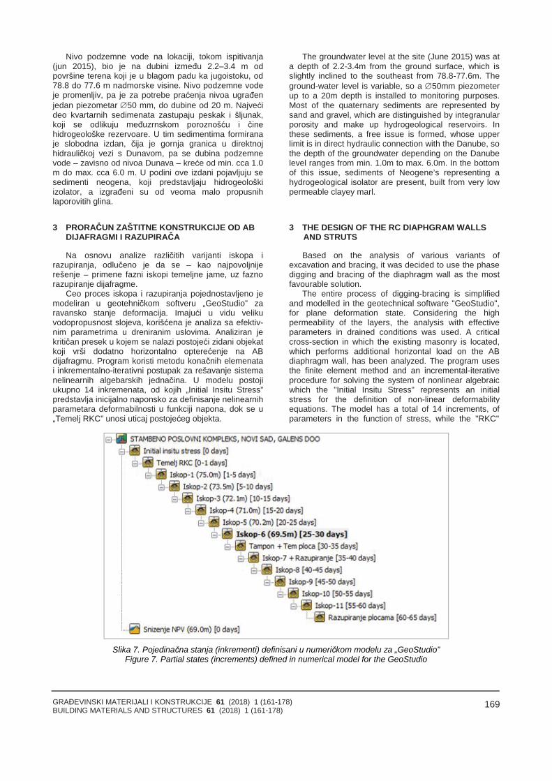
GRAĐEVINSKI MATERIJALI I KONSTRUKCIJE 61 (2018) 1 (161-178)BUILDING MATERIALS AND STRUCTURES 61 (2018) 1 (161-178)
169
Nivo podzemne vode na lokaciji, tokom ispitivanja(jun 2015), bio je na dubini između 2.2–3.4 m odpovršine terena koji je u blagom padu ka jugoistoku, od78.8 do 77.6 m nadmorske visine. Nivo podzemne vodeje promenljiv, pa je za potrebe praćenja nivoa ugrađenjedan piezometar 50 mm, do dubine od 20 m. Najvećideo kvartarnih sedimenata zastupaju peskak i šljunak,koji se odlikuju međuzrnskom poroznošću i činehidrogeološke rezervoare. U tim sedimentima formiranaje slobodna izdan, čija je gornja granica u direktnojhidrauličkoj vezi s Dunavom, pa se dubina podzemnevode – zavisno od nivoa Dunava – kreće od min. cca 1.0m do max. cca 6.0 m. U podini ove izdani pojavljuju sesedimenti neogena, koji predstavljaju hidrogeološkiizolator, a izgrađeni su od veoma malo propusnihlaporovitih glina.
3 PRORAČUN ZAŠTITNE KONSTRUKCIJE OD AB DIJAFRAGMI I RAZUPIRAČA
Na osnovu analize različitih varijanti iskopa irazupiranja, odlučeno je da se – kao najpovoljnijerešenje – primene fazni iskopi temeljne jame, uz faznorazupiranje dijafragme.
Ceo proces iskopa i razupiranja pojednostavljeno jemodeliran u geotehničkom softveru „GeoStudio” zaravansko stanje deformacija. Imajući u vidu velikuvodopropusnost slojeva, korišćena je analiza sa efektiv-nim parametrima u dreniranim uslovima. Analiziran jekritičan presek u kojem se nalazi postojeći zidani objekatkoji vrši dodatno horizontalno opterećenje na ABdijafragmu. Program koristi metodu konačnih elemenatai inkrementalno-iterativni postupak za rešavanje sistemanelinearnih algebarskih jednačina. U modelu postojiukupno 14 inkremenata, od kojih „Initial Insitu Stress”predstavlja inicijalno naponsko za definisanje nelinearnihparametara deformabilnosti u funkciji napona, dok se u„Temelj RKC” unosi uticaj postojećeg objekta.
The groundwater level at the site (June 2015) was ata depth of 2.2-3.4m from the ground surface, which isslightly inclined to the southeast from 78.8-77.6m. Theground-water level is variable, so a 50mm piezometerup to a 20m depth is installed to monitoring purposes.Most of the quaternary sediments are represented bysand and gravel, which are distinguished by integranularporosity and make up hydrogeological reservoirs. Inthese sediments, a free issue is formed, whose upperlimit is in direct hydraulic connection with the Danube, sothe depth of the groundwater depending on the Danubelevel ranges from min. 1.0m to max. 6.0m. In the bottomof this issue, sediments of Neogene’s representing ahydrogeological isolator are present, built from very lowpermeable clayey marl.
3 THE DESIGN OF THE RC DIAPHGRAM WALLSAND STRUTS
Based on the analysis of various variants ofexcavation and bracing, it was decided to use the phasedigging and bracing of the diaphragm wall as the mostfavourable solution.
The entire process of digging-bracing is simplifiedand modelled in the geotechnical software "GeoStudio",for plane deformation state. Considering the highpermeability of the layers, the analysis with effectiveparameters in drained conditions was used. A criticalcross-section in which the existing masonry is located,which performs additional horizontal load on the ABdiaphragm wall, has been analyzed. The program usesthe finite element method and an incremental-iterativeprocedure for solving the system of nonlinear algebraicwhich the "Initial Insitu Stress" represents an initialstress for the definition of non-linear deformabilityequations. The model has a total of 14 increments, ofparameters in the function of stress, while the "RKC"
Slika 7. Pojedinačna stanja (inkrementi) definisani u numeričkom modelu za „GeoStudio”Figure 7. Partial states (increments) defined in numerical model for the GeoStudio
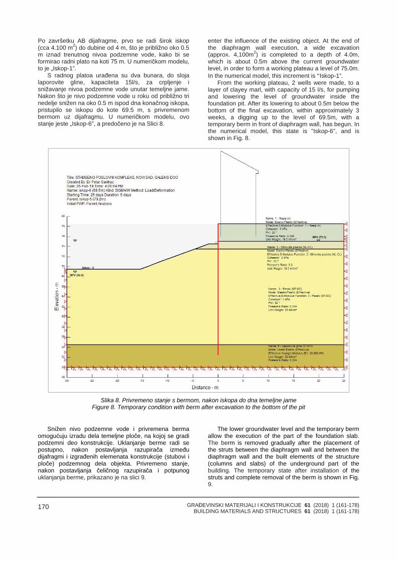
GRAĐEVINSKI MATERIJALI I KONSTRUKCIJE 61 (2018) 1 (161-178)BUILDING MATERIALS AND STRUCTURES 61 (2018) 1 (161-178)
170
Po završetku AB dijafragme, prvo se radi širok iskop(cca 4.100 m2) do dubine od 4 m, što je približno oko 0.5m iznad trenutnog nivoa podzemne vode, kako bi seformirao radni plato na koti 75 m. U numeričkom modelu,to je „Iskop-1”.
S radnog platoa urađena su dva bunara, do slojalaporovite gline, kapaciteta 15l/s, za crpljenje isnižavanje nivoa podzemne vode unutar temeljne jame.Nakon što je nivo podzemne vode u roku od približno trinedelje snižen na oko 0.5 m ispod dna konačnog iskopa,pristupilo se iskopu do kote 69.5 m, s privremenombermom uz dijafragmu. U numeričkom modelu, ovostanje jeste „Iskop-6”, a predočeno je na Slici 8.
enter the influence of the existing object. At the end ofthe diaphragm wall execution, a wide excavation(approx. 4,100m2) is completed to a depth of 4.0m,which is about 0.5m above the current groundwaterlevel, in order to form a working plateau a level of 75.0m.In the numerical model, this increment is Iskop-1”.
From the working plateau, 2 wells were made, to alayer of clayey marl, with capacity of 15 l/s, for pumpingand lowering the level of groundwater inside thefoundation pit. After its lowering to about 0.5m below thebottom of the final excavation, within approximately 3weeks, a digging up to the level of 69.5m, with atemporary berm in front of diaphragm wall, has begun. Inthe numerical model, this state is "Iskop-6", and isshown in Fig. 8.
Slika 8. Privremeno stanje s bermom, nakon iskopa do dna temeljne jameFigure 8. Temporary condition with berm after excavation to the bottom of the pit
Snižen nivo podzemne vode i privremena bermaomogućuju izradu dela temeljne ploče, na kojoj se gradipodzemni deo konstrukcije. Uklanjanje berme radi sepostupno, nakon postavljanja razupirača izmeđudijafragmi i izgrađenih elemenata konstrukcije (stubovi iploče) podzemnog dela objekta. Privremeno stanje,nakon postavljanja čeličnog razupirača i potpunoguklanjanja berme, prikazano je na slici 9.
The lower groundwater level and the temporary bermallow the execution of the part of the foundation slab.The berm is removed gradually after the placement ofthe struts between the diaphragm wall and between thediaphragm wall and the built elements of the structure(columns and slabs) of the underground part of thebuilding. The temporary state after installation of thestruts and complete removal of the berm is shown in Fig.9.
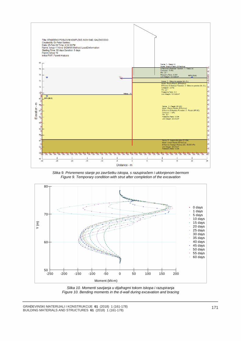
GRAĐEVINSKI MATERIJALI I KONSTRUKCIJE 61 (2018) 1 (161-178)BUILDING MATERIALS AND STRUCTURES 61 (2018) 1 (161-178)
171
Slika 9. Privremeno stanje po završetku iskopa, s razupiračem i uklonjenom bermomFigure 9. Temporary condition with strut after completion of the excavation
0 days1 days5 days10 days15 days20 days25 days30 days35 days40 days45 days50 days55 days60 days
Y(m
)
Moment (kN-m)
50
60
70
80
-50-100-150-200-250 0 50 100 150 200
Slika 10. Momenti savijanja u dijafragmi tokom iskopa i razupiranjaFigure 10. Bending moments in the d-wall during excavation and bracing
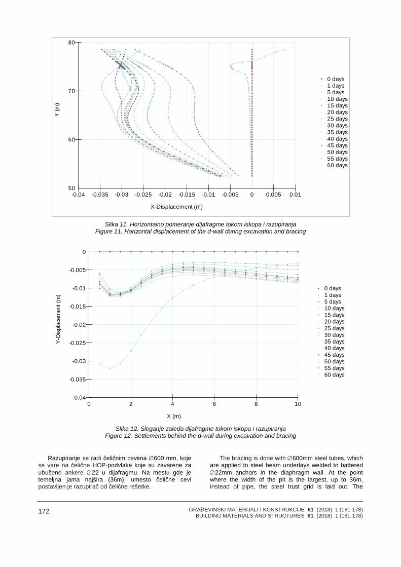
GRAĐEVINSKI MATERIJALI I KONSTRUKCIJE 61 (2018) 1 (161-178)BUILDING MATERIALS AND STRUCTURES 61 (2018) 1 (161-178)
172
0 days1 days5 days10 days15 days20 days25 days30 days35 days40 days45 days50 days55 days60 days
Y(m
)
X-Displacement (m)
50
60
70
80
-0.005-0.01-0.015-0.02-0.025-0.03-0.035-0.04 0 0.005 0.01
Slika 11. Horizontalno pomeranje dijafragme tokom iskopa i razupiranjaFigure 11. Horizontal displacement of the d-wall during excavation and bracing
0 days1 days5 days10 days15 days20 days25 days30 days35 days40 days45 days50 days55 days60 days
Y-D
ispl
acem
ent(
m)
X (m)
-0.005
-0.01
-0.015
-0.02
-0.025
-0.03
-0.035
-0.04
0
0 2 4 6 8 10
Slika 12. Sleganje zaleđa dijafragme tokom iskopa i razupiranjaFigure 12. Settlements behind the d-wall during excavation and bracing
Razupiranje se radi čeličnim cevima 600 mm, kojese vare na čelične HOP-podvlake koje su zavarene zaubušene ankere 22 u dijafragmu. Na mestu gde jetemeljna jama najšira (36m), umesto čelične cevipostavljen je razupirač od čelične rešetke.
The bracing is done with 600mm steel tubes, whichare applied to steel beam underlays welded to battered22mm anchors in the diaphragm wall. At the pointwhere the width of the pit is the largest, up to 36m,instead of pipe, the steel trust grid is laid out. The
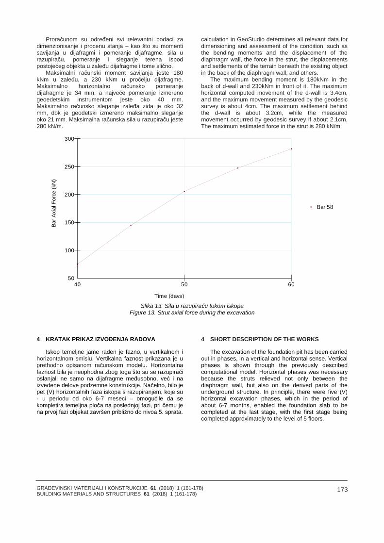
GRAĐEVINSKI MATERIJALI I KONSTRUKCIJE 61 (2018) 1 (161-178)BUILDING MATERIALS AND STRUCTURES 61 (2018) 1 (161-178)
173
Proračunom su određeni svi relevantni podaci zadimenzionisanje i procenu stanja – kao što su momentisavijanja u dijafragmi i pomeranje dijafragme, sila urazupiraču, pomeranje i sleganje terena ispodpostojećeg objekta u zaleđu dijafragme i tome slično.
Maksimalni računski moment savijanja jeste 180kNm u zaleđu, a 230 kNm u pročelju dijafragme.Maksimalno horizontalno računsko pomeranjedijafragme je 34 mm, a najveće pomeranje izmerenogeoedetskim instrumentom jeste oko 40 mm.Maksimalno računsko sleganje zaleđa zida je oko 32mm, dok je geodetski izmereno maksimalno sleganjeoko 21 mm. Maksimalna računska sila u razupiraču jeste280 kN/m.
calculation in GeoStudio determines all relevant data fordimensioning and assessment of the condition, such asthe bending moments and the displacement of thediaphragm wall, the force in the strut, the displacementsand settlements of the terrain beneath the existing objectin the back of the diaphragm wall, and others.
The maximum bending moment is 180kNm in theback of d-wall and 230kNm in front of it. The maximumhorizontal computed movement of the d-wall is 3.4cm,and the maximum movement measured by the geodesicsurvey is about 4cm. The maximum settlement behindthe d-wall is about 3.2cm, while the measuredmovement occurred by geodesic survey if about 2.1cm.The maximum estimated force in the strut is 280 kN/m.
Bar 58
BarA
xial
Forc
e(k
N)
Time (days)
50
100
150
200
250
300
40 50 60
Slika 13. Sila u razupiraču tokom iskopaFigure 13. Strut axial force during the excavation
4 KRATAK PRIKAZ IZVOĐENJA RADOVA
Iskop temeljne jame rađen je fazno, u vertikalnom ihorizontalnom smislu. Vertikalna faznost prikazana je uprethodno opisanom računskom modelu. Horizontalnafaznost bila je neophodna zbog toga što su se razupiračioslanjali ne samo na dijafragme međusobno, već i naizvedene delove podzemne konstrukcije. Načelno, bilo jepet (V) horizontalnih faza iskopa s razupiranjem, koje su- u periodu od oko 6-7 meseci – omogućile da sekompletira temeljna ploča na poslednjoj fazi, pri čemu jena prvoj fazi objekat završen približno do nivoa 5. sprata.
4 SHORT DESCRIPTION OF THE WORKS
The excavation of the foundation pit has been carriedout in phases, in a vertical and horizontal sense. Verticalphases is shown through the previously describedcomputational model. Horizontal phases was necessarybecause the struts relieved not only between thediaphragm wall, but also on the derived parts of theunderground structure. In principle, there were five (V)horizontal excavation phases, which in the period ofabout 6-7 months, enabled the foundation slab to becompleted at the last stage, with the first stage beingcompleted approximately to the level of 5 floors.
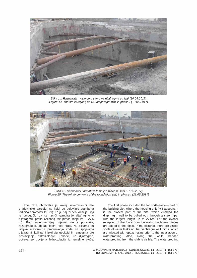
GRAĐEVINSKI MATERIJALI I KONSTRUKCIJE 61 (2018) 1 (161-178)BUILDING MATERIALS AND STRUCTURES 61 (2018) 1 (161-178)
174
Slika 14. Razupirači – oslonjeni samo na dijafragme u I fazi (10.05.2017)Figure 14. The struts relying on RC diaphragm wall in phase-I (10.05.2017)
Slika 15. Razupirači i armatura temeljne ploče u I fazi (21.05.2017)Figure 15. The reinforcements of the foundation slab in phase-I (21.05.2017)
Prva faza obuhvatila je krajnji severoistočni deograđevinske parcele, na kojoj se pojavljuje stambenajedinica spratnosti P+8(9). To je najuži deo lokacije, kojije omogućio da se izvrši razupiranje dijafragme odijafragmu, preko čeličnog razupirača (najduže – 27.5m). Radi ravnomernijeg prijema sile s podvlake,razupiraču su dodati bočni kosi kraci. Na slikama suvidljiva mestimična procurivanja vode na spojevimadijafragmi, koji se injektiraju epoksidnim smolama prepostavljanja hidroizolacije. Takođe, uz dijafragme,uočava se povijena hidroizolacija iz temeljne ploče.
The first phase included the far north-eastern part ofthe building plot, where the housing unit P+8 appears. Itis the closest part of the site, which enabled thediaphragm wall to be pulled out, through a steel pipe,with the largest length up to 27.5m. For the evenerreception of the force from the walls, the lateral piecesare added to the pipes. In the pictures, there are visiblespots of water leaks on the diaphragm wall joints, whichare injected with epoxy resins prior to the installation ofwaterproofing. Also, along the walls, bendedwaterproofing from the slab is visible. The waterproofing
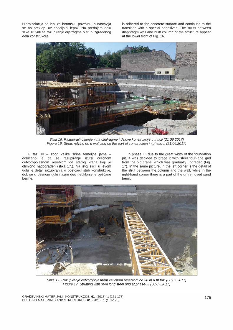
GRAĐEVINSKI MATERIJALI I KONSTRUKCIJE 61 (2018) 1 (161-178)BUILDING MATERIALS AND STRUCTURES 61 (2018) 1 (161-178)
175
Hidroizolacija se lepi za betonsku površinu, a nastavljase na preklop, uz specijalni lepak. Na prednjem deluslike 16 vidi se razupiranje dijafragme o stub izgrađenogdela konstrukcije.
is adhered to the concrete surface and continues to thetransition with a special adhesives. The struts betweendiaphragm wall and built column of the structure appearat the lower front of Fig. 16.
Slika 16. Razupirači oslonjeni na dijafragme i delove konstrukcije u II fazi (21.06.2017)Figure 16. Struts relying on d-wall and on the part of construction in phase-II (21.06.2017)
U fazi III – zbog velike širine temeljne jame –odlučeno je da se razupiranje izvrši čeličnomčetvoropojasnom rešetkom od starog krana koji jedlimično nadograđen (slika 17.). Na istoj slici, u levomuglu je detalj razupiranja o postojeći stub konstrukcije,dok se u desnom uglu nazire deo neuklonjene peščaneberme.
In phase III, due to the great width of the foundationpit, it was decided to brace it with steel four-lane gridfrom the old crane, which was gradually upgraded (Fig.17). In the same picture, in the left corner is the detail ofthe strut between the column and the wall, while in theright-hand corner there is a part of the un removed sandberm.
Slika 17. Razupiranje četvoropojasnom čeličnom rešetkom od 36 m u III fazi (08.07.2017)Figure 17. Strutting with 36m long steel grid at phase-III (08.07.2017)
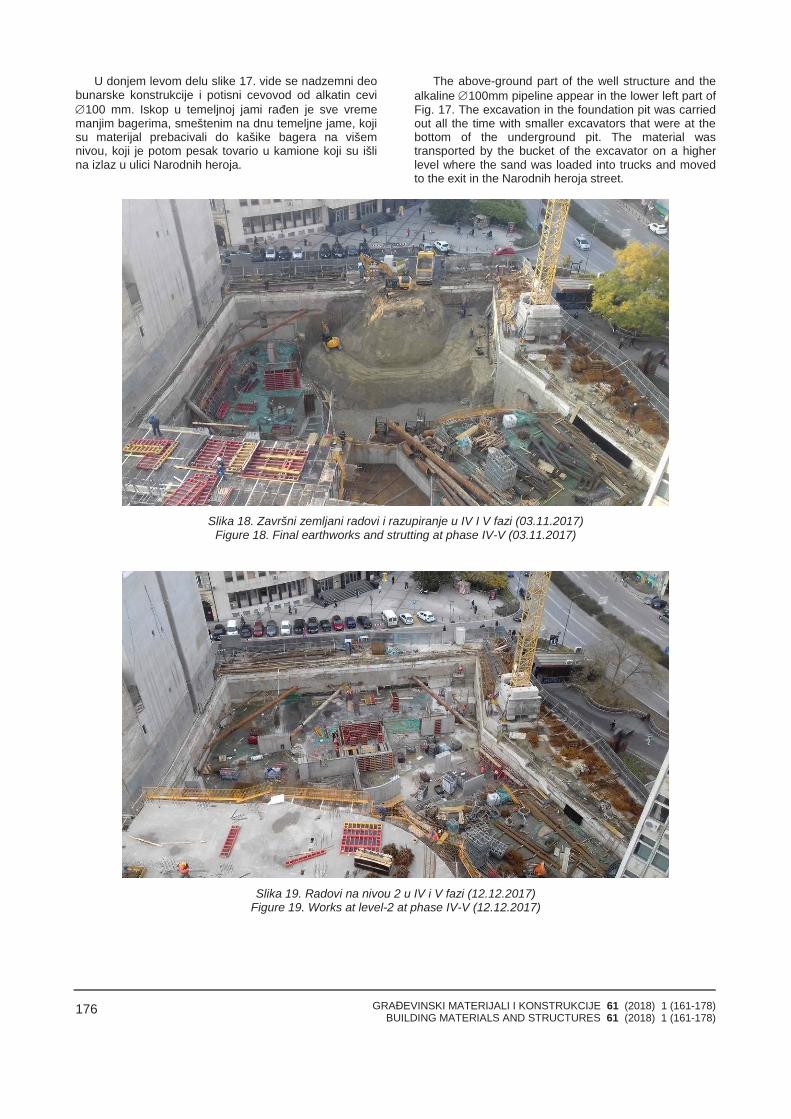
GRAĐEVINSKI MATERIJALI I KONSTRUKCIJE 61 (2018) 1 (161-178)BUILDING MATERIALS AND STRUCTURES 61 (2018) 1 (161-178)
176
U donjem levom delu slike 17. vide se nadzemni deobunarske konstrukcije i potisni cevovod od alkatin cevi100 mm. Iskop u temeljnoj jami rađen je sve vrememanjim bagerima, smeštenim na dnu temeljne jame, kojisu materijal prebacivali do kašike bagera na višemnivou, koji je potom pesak tovario u kamione koji su išlina izlaz u ulici Narodnih heroja.
The above-ground part of the well structure and thealkaline 100mm pipeline appear in the lower left part ofFig. 17. The excavation in the foundation pit was carriedout all the time with smaller excavators that were at thebottom of the underground pit. The material wastransported by the bucket of the excavator on a higherlevel where the sand was loaded into trucks and movedto the exit in the Narodnih heroja street.
Slika 18. Završni zemljani radovi i razupiranje u IV I V fazi (03.11.2017)Figure 18. Final earthworks and strutting at phase IV-V (03.11.2017)
Slika 19. Radovi na nivou 2 u IV i V fazi (12.12.2017)Figure 19. Works at level-2 at phase IV-V (12.12.2017)
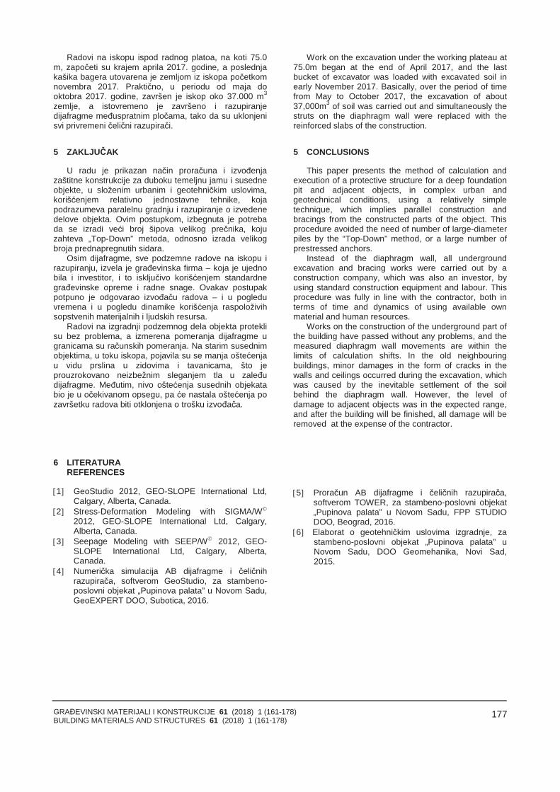
GRAĐEVINSKI MATERIJALI I KONSTRUKCIJE 61 (2018) 1 (161-178)BUILDING MATERIALS AND STRUCTURES 61 (2018) 1 (161-178)
177
Radovi na iskopu ispod radnog platoa, na koti 75.0m, započeti su krajem aprila 2017. godine, a poslednjakašika bagera utovarena je zemljom iz iskopa početkomnovembra 2017. Praktično, u periodu od maja dooktobra 2017. godine, završen je iskop oko 37.000 m3
zemlje, a istovremeno je završeno i razupiranjedijafragme međuspratnim pločama, tako da su uklonjenisvi privremeni čelični razupirači.
5 ZAKLJUČAK
U radu je prikazan način proračuna i izvođenjazaštitne konstrukcije za duboku temeljnu jamu i susedneobjekte, u složenim urbanim i geotehničkim uslovima,korišćenjem relativno jednostavne tehnike, kojapodrazumeva paralelnu gradnju i razupiranje o izvedenedelove objekta. Ovim postupkom, izbegnuta je potrebada se izradi veći broj šipova velikog prečnika, kojuzahteva „Top-Down” metoda, odnosno izrada velikogbroja prednapregnutih sidara.
Osim dijafragme, sve podzemne radove na iskopu irazupiranju, izvela je građevinska firma – koja je ujednobila i investitor, i to isključivo korišćenjem standardnegrađevinske opreme i radne snage. Ovakav postupakpotpuno je odgovarao izvođaču radova – i u pogleduvremena i u pogledu dinamike korišćenja raspoloživihsopstvenih materijalnih i ljudskih resursa.
Radovi na izgradnji podzemnog dela objekta proteklisu bez problema, a izmerena pomeranja dijafragme ugranicama su računskih pomeranja. Na starim susednimobjektima, u toku iskopa, pojavila su se manja oštećenjau vidu prslina u zidovima i tavanicama, što jeprouzrokovano neizbežnim sleganjem tla u zaleđudijafragme. Međutim, nivo oštećenja susednih objekatabio je u očekivanom opsegu, pa će nastala oštećenja pozavršetku radova biti otklonjena o trošku izvođača.
Work on the excavation under the working plateau at75.0m began at the end of April 2017, and the lastbucket of excavator was loaded with excavated soil inearly November 2017. Basically, over the period of timefrom May to October 2017, the excavation of about37,000m3 of soil was carried out and simultaneously thestruts on the diaphragm wall were replaced with thereinforced slabs of the construction.
5 CONCLUSIONS
This paper presents the method of calculation andexecution of a protective structure for a deep foundationpit and adjacent objects, in complex urban andgeotechnical conditions, using a relatively simpletechnique, which implies parallel construction andbracings from the constructed parts of the object. Thisprocedure avoided the need of number of large-diameterpiles by the “Top-Down” method, or a large number ofprestressed anchors.
Instead of the diaphragm wall, all undergroundexcavation and bracing works were carried out by aconstruction company, which was also an investor, byusing standard construction equipment and labour. Thisprocedure was fully in line with the contractor, both interms of time and dynamics of using available ownmaterial and human resources.
Works on the construction of the underground part ofthe building have passed without any problems, and themeasured diaphragm wall movements are within thelimits of calculation shifts. In the old neighbouringbuildings, minor damages in the form of cracks in thewalls and ceilings occurred during the excavation, whichwas caused by the inevitable settlement of the soilbehind the diaphragm wall. However, the level ofdamage to adjacent objects was in the expected range,and after the building will be finished, all damage will beremoved at the expense of the contractor.
6 LITERATURAREFERENCES
1 GeoStudio 2012, GEO-SLOPE International Ltd,Calgary, Alberta, Canada.
2 Stress-Deformation Modeling with SIGMA/W
2012, GEO-SLOPE International Ltd, Calgary,Alberta, Canada.
3 Seepage Modeling with SEEP/W 2012, GEO-SLOPE International Ltd, Calgary, Alberta,Canada.
4 Numerička simulacija AB dijafragme i čeličnihrazupirača, softverom GeoStudio, za stambeno-poslovni objekat „Pupinova palata” u Novom Sadu,GeoEXPERT DOO, Subotica, 2016.
5 Proračun AB dijafragme i čeličnih razupirača,softverom TOWER, za stambeno-poslovni objekat„Pupinova palata” u Novom Sadu, FPP STUDIODOO, Beograd, 2016.
6 Elaborat o geotehničkim uslovima izgradnje, zastambeno-poslovni objekat „Pupinova palata” uNovom Sadu, DOO Geomehanika, Novi Sad,2015.
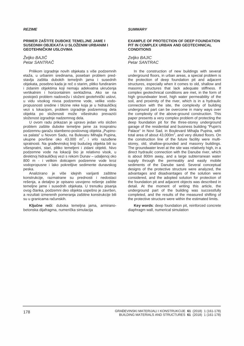
GRAĐEVINSKI MATERIJALI I KONSTRUKCIJE 61 (2018) 1 (161-178)BUILDING MATERIALS AND STRUCTURES 61 (2018) 1 (161-178)
178
REZIME
PRIMER ZAŠTITE DUBOKE TEMELJNE JAME I SUSEDNIH OBJEKATA U SLOŽENIM URBANIM I GEOTEHNIČKIM USLOVIMA
Željko BAJIĆPetar SANTRAČ
Prilikom izgradnje novih objekata s više podzemnihetaža, u urbanim sredinama, poseban problem pred-stavlja zaštita dubokih temeljnih jama i susednihobjekata, posebno kada je reč o starim, plitko fundiranimi zidanim objektima koji nemaju adekvatna ukrućenjavertikalnim i horizontalnim serklažima. Ako se napostojeći problem nadovežu i složeni geotehnički uslovi,u vidu visokog nivoa podzemne vode, velike vodo-propusnosti sredine i blizine reke koja je u hidrauličkojvezi s lokacijom, problem izgradnje podzemnog delaobjekta po složenosti može višestruko prevazićisloženost izgradnje nadzemnog dela.
U ovom radu prikazan je upravo jedan vrlo složenproblem zaštite duboke temeljne jame za trospratnupodzemnu garažu stambeno-poslovnog objekta „Pupino-va palata” u Novom Sadu, na Bulevaru Mihajla Pupina,ukupne površine oko 43.000 m2, i vrlo razuđenespratnosti. Na građevinskoj liniji budućeg objekta bili suvišespratni, stari, plitko temeljeni i zidani objekti. Nivopodzemne vode na lokaciji bio je relativno visok, udirektnoj hidrauličkoj vezi s rekom Dunav – udaljenoj oko800 m - i velikim doticajem podzemne vode krozvodopropusne i lako pokretljive sedimente dunavskogpeska.
Analizirano je više idejnih varijanti zaštitnekonstrukcije, razmatrane su prednosti i nedostacirešenja, a detaljno je opisano usvojeno rešenje zaštitetemeljne jame i susednih objekata. U trenutku pisanjaovog članka, podzemni deo objekta uspešno je završen,a rezultati izmerenih pomeranja zaštitne konstrukcije bilisu u granicama računskih.
Ključne reči: duboka temeljna jama, armirano-betonska dijafragma, numerička simulacija
SUMMАRY
EXAMPLE OF PROTECTION OF DEEP FOUNDATIONPIT IN COMPLEX URBAN AND GEOTECHNICALCONDITIONS
Zeljko BAJICPetar SANTRAC
In the construction of new buildings with severalunderground floors, in urban areas, a special problem isthe protection of deep foundation pit and adjacentstructures, especially when it comes to old, shallow andmasonry structures that lack adequate stiffness. Ifcomplex geotechnical conditions are met, in the form ofhigh groundwater level, high water permeability of thesoil, and proximity of the river, which is in a hydraulicconnection with the site, the complexity of buildingunderground part can be overcome in many ways overthe complexity of the above-ground construction. Thispaper presents a very complex problem of protecting thedeep foundation pit for the three-storey undergroundgarage of the residential and business building "Pupin'sPalace" in Novi Sad, in Boulevard Mihajla Pupina, withtotal area of about 43,000m2, and very diluted floors. Onthe construction line of the future facility were multi-storey, old, shallow-grounded and masonry buildings.The groundwater level at the site was relatively high, in adirect hydraulic connection with the Danube river, whichis about 800m away, and a large subterranean watersupply through the permeably and easily mobilesediments of the Danube sand. Several conceptualdesigns of the protective structure were analyzed, theadvantages and disadvantages of the solution wereconsidered, and the adopted solution for protection ofthe foundation pit and adjacent objects was described indetail. At the moment of writing this article, theunderground part of the building was successfullycompleted, and the results of the measured shifting ofthe protective structure were within the estimated limits.
Key words: deep foundation pit, reinforced concretediaphragm wall, numerical simulation
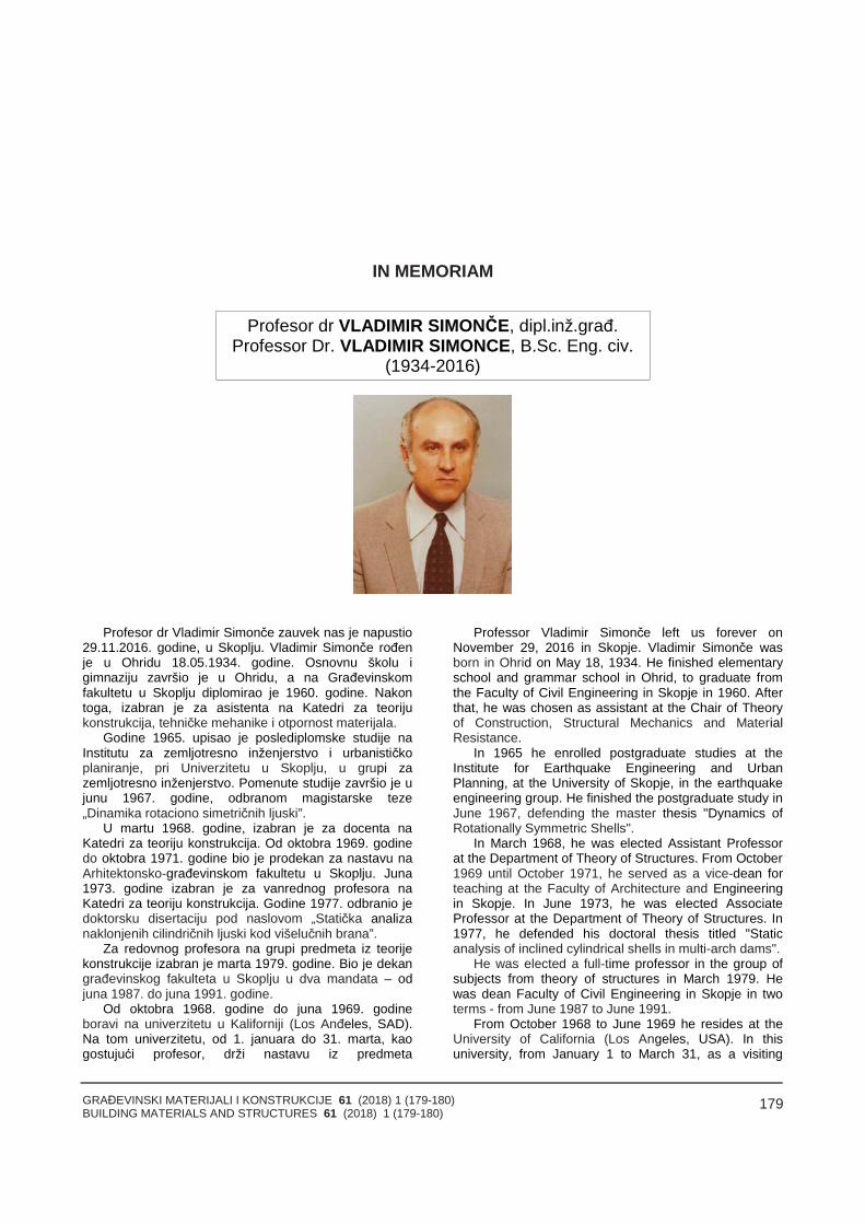
GRAĐEVINSKI MATERIJALI I KONSTRUKCIJE 61 (2018) 1 (179-180)BUILDING MATERIALS AND STRUCTURES 61 (2018) 1 (179-180)
179
IN MEMORIAM
Profesor dr VLADIMIR SIMONČE, dipl.inž.građ.Professor Dr. VLADIMIR SIMONCE, B.Sc. Eng. civ.
(1934-2016)
Profesor dr Vladimir Simonče zauvek nas je napustio29.11.2016. godine, u Skoplju. Vladimir Simonče rođenje u Ohridu 18.05.1934. godine. Osnovnu školu igimnaziju završio je u Ohridu, a na Građevinskomfakultetu u Skoplju diplomirao je 1960. godine. Nakontoga, izabran je za asistenta na Katedri za teorijukonstrukcija, tehničke mehanike i otpornost materijala.
Godine 1965. upisao je poslediplomske studije naInstitutu za zemljotresno inženjerstvo i urbanističkoplaniranje, pri Univerzitetu u Skoplju, u grupi zazemljotresno inženjerstvo. Pomenute studije završio je ujunu 1967. godine, odbranom magistarske teze„Dinamika rotaciono simetričnih ljuski”.
U martu 1968. godine, izabran je za docenta naKatedri za teoriju konstrukcija. Od oktobra 1969. godinedo oktobra 1971. godine bio je prodekan za nastavu naArhitektonsko-građevinskom fakultetu u Skoplju. Juna1973. godine izabran je za vanrednog profesora naKatedri za teoriju konstrukcija. Godine 1977. odbranio jedoktorsku disertaciju pod naslovom „Statička analizanaklonjenih cilindričnih ljuski kod višelučnih brana”.
Za redovnog profesora na grupi predmeta iz teorijekonstrukcije izabran je marta 1979. godine. Bio je dekangrađevinskog fakulteta u Skoplju u dva mandata – odjuna 1987. do juna 1991. godine.
Od oktobra 1968. godine do juna 1969. godineboravi na univerzitetu u Kaliforniji (Los Anđeles, SAD).Na tom univerzitetu, od 1. januara do 31. marta, kaogostujući profesor, drži nastavu iz predmeta
Professor Vladimir Simonče left us forever onNovember 29, 2016 in Skopje. Vladimir Simonče wasborn in Ohrid on May 18, 1934. He finished elementaryschool and grammar school in Ohrid, to graduate fromthe Faculty of Civil Engineering in Skopje in 1960. Afterthat, he was chosen as assistant at the Chair of Theoryof Construction, Structural Mechanics and MaterialResistance.
In 1965 he enrolled postgraduate studies at theInstitute for Earthquake Engineering and UrbanPlanning, at the University of Skopje, in the earthquakeengineering group. He finished the postgraduate study inJune 1967, defending the master thesis "Dynamics ofRotationally Symmetric Shells".
In March 1968, he was elected Assistant Professorat the Department of Theory of Structures. From October1969 until October 1971, he served as a vice-dean forteaching at the Faculty of Architecture and Engineeringin Skopje. In June 1973, he was elected AssociateProfessor at the Department of Theory of Structures. In1977, he defended his doctoral thesis titled "Staticanalysis of inclined cylindrical shells in multi-arch dams".
He was elected a full-time professor in the group ofsubjects from theory of structures in March 1979. Hewas dean Faculty of Civil Engineering in Skopje in twoterms - from June 1987 to June 1991.
From October 1968 to June 1969 he resides at theUniversity of California (Los Angeles, USA). In thisuniversity, from January 1 to March 31, as a visiting
GRAĐEVINSKI MATERIJALI I KONSTRUKCIJE 61 (2018) 1 (179-180)BUILDING MATERIALS AND STRUCTURES 61 (2018) 1 (179-180)
180
ENGINEERING 165A (Statika linijskih nosača). Odseptembra 1974. do avgusta 1975. godine boravi nauniverzitetu u Svonziju (Vels, Velika Britanija) i dvameseca u Londonu (Imperial College).
Bio je član u nekoliko republičkih i gradskih komisijaiz oblasti nauke i obrazovanja, kao i član višeprofesionalnih udruženja (Društvo građevinskihkonstruktera Makedonije, Društvo za mehanikuMakedonije, GAMM – Društvo za primenjenumatematiku i mehaniku Nemačke). Od 1991. godine,član je Američkog udruženja građevinskih inženjera(American Society of Civil Engineers), a od 1971. godinei Svetskog udruženja za mostove i visoke zgrade(International Association for Bridge and StructuralEngineering), sa sedištem u Cirihu.
Kao nastavnik Građevinskog fakulteta u Skoplju, držinastavu iz predmeta: teorija konstrukcija I i II, primenaračunara u građevinarstvu, numeričke metode ugrađevinarstvu, teorija površinskih nosača i dinamika istabilnost konstrukcija. Na poslediplomskim studijamadrži nastavu iz predmeta: metod konačnih elemenata,nelinearna analiza primenom MKE, betonske ljuske. Zaosnovni predmet teorija konstrukcija II napisao jeudžbenik „Matrična analiza konstrukcija”.
Osamdesetih godina prošlog veka, prof. VladimirSimonče držao je predavanja na Tehničkom fakultetuUniverziteta u Prištini iz oblasti teorije konstrukcija ivodio nekoliko diplomskih radova.
Autor je više naučnih radova, uglavnom iz oblastistatičke i dinamičke analize objekata visokogradnje iinženjerskih konstrukcija. Rad „Trodimenzionalneanalize višelučne brane Prilep” publikovan je nasimpozijumu u Svonziju 1975. godine. Bio je rukovodilaci učesnik brojnih naučnoistraživačkih projekata.
Takođe, bio je mentor i član u komisijama za višedoktorskih disertacija i magistarskih radova.
Na profesionalnom planu, radio je na mnogimprojektima (studije i projekti betonskih brana, statička iseizmička analiza objekata visokogradnje i inženjerskihobjekata, izrada aplikativnog softvera iz oblastigrađevinarstva). Njegov poslednji značajni projekat jesteGlavni projekat tanke lučne brane „Sv. Petka” na reciTreski, koja je puštena u rad 2012. godine.
Posebno treba napomenuti doprinos profesoraVladimira Simončeta u reformi obrazovnog procesaGrađevinskog fakulteta u Skoplju osamdesetih godinaXX veka, uvođenjem računara u nastavi i u građevinskojoperativi.
Aktivno je sarađivao s časopisom „Građevinskimaterijali i konstrukcije”, a poslednji, veoma zapažen rad– Lučna brana „Sv. Petka” u Republici Makedoniji (ArchDam „Sv. Petka” in R. Macedonia) – objavio je u broju 3za 2012. godinu (str. 37–54).
Prevremeni odlazak profesora Vladimira Simončetanajviše je pogodio njegovu porodicu – suprugu, kćerku iunuku. Neka počiva u miru. Večna mu slava i hvala mu.
professor, he held classes from the subject ofENGINEERING 165A (Static of Linear Bearings). FromSeptember 1974 to August 1975 he resides at theUniversity of Swansea (Wales, UK) and two months inLondon (Imperial College).
He was member of several republic and citycommissions in the field of science and education, aswell as member of several professional associations(Association of Macedonian Civil Engineers, Associationof Macedonian Mechanics, GAMM – GermanAssociation for Applied Mathematics and Mechanics).Since 1991, he has been a member of the AmericanSociety of Civil Engineers, and since 1971 also of theInternational Association for Bridge and StructuralEngineering, based in Zurich.
As a teacher at the Faculty of Civil Engineering inSkopje, he held lectures from the following subjects:Theory of structures 1 and 2, Application of computers incivil engineering, Numerical methods in civil engineering,Theory of surface supports and structural dynamics andstability. At the postgraduate studies, he held a coursefrom the following subjects: Finite element method,Nonlinear analysis using FEM, Concrete shells. For thebasic subject Theory of structures 2, he published thetextbook "Matrix Analysis of Structures".
During the 1980's Professor Vladimir Simončedelivered lectures at the Technical Faculty of theUniversity of Pristina in the field of theory of structuresand was a mentor of several graduate theses.
He was the author of several scientific papers,mainly in the field of static and dynamic analysis ofbuilding constructions and engineering structures. Thepaper "Three-dimensional Analysis of the Prilep MultiArch Dam" was published at the Symposium in Swanseain 1975. He was a leader and participant in a number ofscientific research projects.
He was also a mentor and member of committees forseveral doctoral dissertations and master theses.
On a professional level, he worked on many projects(studies and projects of concrete dams, static andseismic analysis of building constructions andengineering objects, development of applied software inthe field of civil engineering). His last significant projectwas the Main Project of the thin arch dam "Sv. Petka" onthe Treska River, which was let in operation in 2012.
The contribution of Professor Vladimir Simonče inthe reform of the educational process of the Faculty ofCivil Engineering in Skopje was particularly important inthe 1980's when computers were introduced in theteaching process and the engineering operations.
He actively cooperated with the journal "BuildingMaterials and Structures". His last, highly acclaimedpaper Arch Dam "Sv. Petka" in the Republic ofMacedonia was published in the issue 3/2012 (pages37-54) in the same magazine.
The early departure of Professor Vladimir Simončemost affected his family - his wife, daughter andgrandchild. May he rest in peace. Eternal glory andthanks to him.
Stanislav MilovanovićGrozde Aleksovski
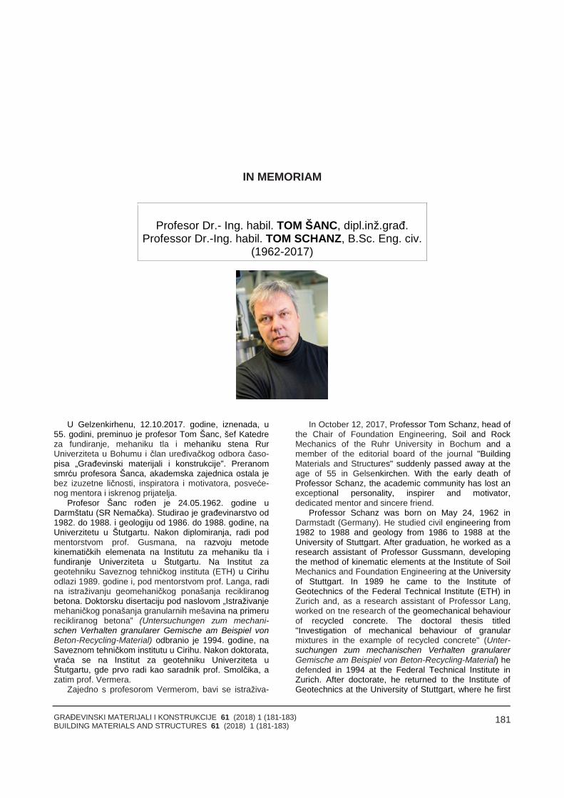
GRAĐEVINSKI MATERIJALI I KONSTRUKCIJE 61 (2018) 1 (181-183)BUILDING MATERIALS AND STRUCTURES 61 (2018) 1 (181-183)
181
IN MEMORIAM
Profesor Dr.- Ing. habil. TOM ŠANC, dipl.inž.građ.Professor Dr.-Ing. habil. TOM SCHANZ, B.Sc. Eng. civ.
(1962-2017)
U Gelzenkirhenu, 12.10.2017. godine, iznenada, u55. godini, preminuo je profesor Tom Šanc, šef Katedreza fundiranje, mehaniku tla i mehaniku stena RurUniverziteta u Bohumu i član uređivačkog odbora časo-pisa „Građevinski materijali i konstrukcije”. Preranomsmrću profesora Šanca, akademska zajednica ostala jebez izuzetne ličnosti, inspiratora i motivatora, posveće-nog mentora i iskrenog prijatelja.
Profesor Šanc rođen je 24.05.1962. godine uDarmštatu (SR Nemačka). Studirao je građevinarstvo od1982. do 1988. i geologiju od 1986. do 1988. godine, naUniverzitetu u Štutgartu. Nakon diplomiranja, radi podmentorstvom prof. Gusmana, na razvoju metodekinematičkih elemenata na Institutu za mehaniku tla ifundiranje Univerziteta u Štutgartu. Na Institut zageotehniku Saveznog tehničkog instituta (ETH) u Cirihuodlazi 1989. godine i, pod mentorstvom prof. Langa, radina istraživanju geomehaničkog ponašanja recikliranogbetona. Doktorsku disertaciju pod naslovom „Istraživanjemehaničkog ponašanja granularnih mešavina na primerurecikliranog betona” (Untersuchungen zum mechani-schen Verhalten granularer Gemische am Beispiel vonBeton-Recycling-Material) odbranio je 1994. godine, naSaveznom tehničkom institutu u Cirihu. Nakon doktorata,vraća se na Institut za geotehniku Univerziteta uŠtutgartu, gde prvo radi kao saradnik prof. Smolčika, azatim prof. Vermera.
Zajedno s profesorom Vermerom, bavi se istraživa-
In October 12, 2017, Professor Tom Schanz, head ofthe Chair of Foundation Engineering, Soil and RockMechanics of the Ruhr University in Bochum and amember of the editorial board of the journal "BuildingMaterials and Structures" suddenly passed away at theage of 55 in Gelsenkirchen. With the early death ofProfessor Schanz, the academic community has lost anexceptional personality, inspirer and motivator,dedicated mentor and sincere friend.
Professor Schanz was born on May 24, 1962 inDarmstadt (Germany). He studied civil engineering from1982 to 1988 and geology from 1986 to 1988 at theUniversity of Stuttgart. After graduation, he worked as aresearch assistant of Professor Gussmann, developingthe method of kinematic elements at the Institute of SoilMechanics and Foundation Engineering at the Universityof Stuttgart. In 1989 he came to the Institute ofGeotechnics of the Federal Technical Institute (ETH) inZurich and, as a research assistant of Professor Lang,worked on tne research of the geomechanical behaviourof recycled concrete. The doctoral thesis titled"Investigation of mechanical behaviour of granularmixtures in the example of recycled concrete" (Unter-suchungen zum mechanischen Verhalten granularerGemische am Beispiel von Beton-Recycling-Material) hedefended in 1994 at the Federal Technical Institute inZurich. After doctorate, he returned to the Institute ofGeotechnics at the University of Stuttgart, where he first
GRAĐEVINSKI MATERIJALI I KONSTRUKCIJE 61 (2018) 1 (181-183)BUILDING MATERIALS AND STRUCTURES 61 (2018) 1 (181-183)
182
njem konstitutivnog modeliranja granularnih materijala,prvenstveno peska i peskovitih materijala. U to vreme,Cam Clay model tla bio je široko prihvaćen konstitutivnimodel za gline, dok je odgovarajući model za peskovenedostajao. U tom periodu, profesor Šanc ostvarujeveoma značajne naučne doprinose. Na osnovu ranijihistraživanja prof. Vermera (Vermeer PA: A doublehardening model for sand, Géotechnique 28/4, 1978),formuliše konstitutivni model sa ojačanjem i poboljšanomkapom – Hardening Soil Model (HS). Veze izmeđuparametara HS modela definisane su na osnovu serijaizvedenih edometarskih i triaksijalnih eksperimenata,kao i analizom rezultata iz literature za različite tipovepeskova. Rezultati ovog istraživanja objavljeni su uprestižnom časopisu „Géotechnique” (Schanz T,Vermeer PA: Angles of friction and dilatancy of sand,Géotechnique 46/1, 1996; Schanz T, Vermeer PA: Onthe stiffness of sands, Géotechnique 48, 1998), čime jepotvrđen izuzetan kvalitet ostvarenih rezultata. Kasnijesu drugi autori implementirali HS model u PLAXIS,softverski paket za za numeričku geotehničku analizumetodom konačnih elemenata. HS Model je danas uupotrebi širom sveta.
Nakon habilitacije na Univerzitetu u Štutgartu 1998.godine, s tezom „Modeliranje mehaničkog ponašanjafrikcionih materijala” (Zur Modellierung des mechani-schen Verhaltens von Reibungsmaterialien), Tom Šancpostaje redovni profesor na BAUHAUS Univerzitetu uVajmaru. U to vreme, sa 37 godina, bio je najmlađiredovni profesor geotehnike u Nemačkoj. Potom, zapo-činje rad na istraživanju delimično zasićenog tla i razvojeksperimentalnih metoda ispitivanja hidrauličkog pona-šanja takvog tla. Takođe, započinje istraživačke projektena temu hidromehaničkog ponašanja veoma zbijenihglina. Svoju istraživačku grupu u Vajmaru povezuje saistraživačima širom sveta. U više istraživačkih projekata,bio je kodirektor s Radomirom Folićem na NATOprojektu – Science for Peace and Security ProgrammeNATO Advanced Research Workshop 983188 –Coupled site and soil – structure interaction effects. Ovajprojekat rezultirao je pomenutom radionicom, održanomu planinskom području Borovec (Bugarska), od 30.08.do 3.09. 2008. godine. Pored zbornika radova, u oblikudužeg apstrakta od po dve strane, odabrani radoviobjavljeni su u knjizi: Coupled Site and Soil-StructureInteraction Effects with Application to Seismic RiskMitigation, Springer Sciences+Business Media (ISBN987-90-481-2709-2). Radovi su uvršteni na Web ofSciences.
U 2009. godini, Tom Šanc prelazi na Rur Univerzitetu Bohumu i postaje šef Katedre za fundiranje, mehanikutla i mehaniku stena. Profesor Šanc uspešno povezujesvoje istraživačke grupe iz Vajmara i Bohuma, kao ibrojne nove studente i stipendiste iz inostranstva (npr.Iran, Irak, Kina, Vijetnam, Sirija) i tako formira među-narodno prepoznatljivu grupu istraživača u oblastigeotehnike, pokrivajući širok spektar oblasti istraživanja.Na Rur Univerzitetu u Bohumu, profesor Šanc imao jeključnu ulogu u naučnoistraživačkom projektu SFB 837 –Interactions Modelling in Mechanized Tunneling, gde jerukovodio potprojektima na teme adaptivnog konstitutiv-nog modeliranja i numeričkih metoda za analize parame-tara geotehničkih modela.
Profesor Šanc bio je istinski naučnik, sa obaveznimpitanjem: Zašto su rezultati takvi kakvi jesu? Njegov
worked as associate to Professor Smolčik, and thenProfessor Vermeer.
Together with Professor Vermeer, he wasresearching the constitutive modelling of granularmaterials, primarily sand and sandy materials. At thetime, the Cam Clay soil model was a widely acceptedconstitutive model for clays, while an adequate model forsands was missing. In that period, Professor Schanzmade significant scientific contributions. Based on theprevious research of Professor Vermeer (Vermeer PA: Adouble hardening model for sand, Géotechnique 28/4,1978) he formulated a hardening soil (HS) model withimproved cap. The relations between parameters of theHS model were defined on the basis of series ofedometric and triaxial experiments, as well as based onanalysis of results from the literature for different types ofsand. The results of this research were published in theprestigious journal Géotechnique (Schanz T, VermeerPA: Angles of friction and dilatancy of sand,Géotechnique 46/1, 1996; Schanz T, Vermeer PA: Onthe stiffness of sands, Géotechnique 48, 1998), whichconfirmed the exceptional quality of the results achieved.HS model was later implemented by other authors in thePLAXIS software for numerical geotechnical analysisusing FEM and today it is a worldwide used constitutivemodel.
After habilitation at the University of Stuttgart in 1998with the thesis "Modelling the Mechanical Behaviour ofFriction Materials" (Zur Modellierung des mechanischenVerhaltens von Reibungsmaterialien), Tom Schanzbecame a professor at BAUHAUS University in Weimarin 1999. At that time, at age 37, he was the youngestprofessor of geotechnics in Germany. After that, hestarted to research the unsaturated soil mechanics anddevelop experimental methods for testing the hydraulicbehaviour of such soil. He also set up research projectson the subject of hydromechanical behaviour of highlycompact clays. He linked his Weimar research groupwith researchers around the world. He co-ordinatedseveral research projects with Radomir Folic on theNATO project: Science for Peace and SecurityProgramme NATO Advanced Research Workshop983188 – Coupled site and soil – structure interactioneffects. This project resulted in the above mentionedworkshop, held in the mountainous region of Borovets(Bulgaria), from September 30 to October 3, 2008. Inaddition to proceedings in the form of a longer abstracton two pages each, the selected works were publishedin the book: Coupled Site and Soil-Structure InteractionEffects with Application to Seismic Risk Mitigation,Springer Sciences + Business Media (ISBN 987-90-481-2709- 2). Papers were listed in the Web of Sciences.
In 2009, Tom Schanz came to the Ruhr University inBochum and became a head of the Chair of FoundationEngineering, Soil and Rock Mechanics. ProfessorSchanz successfully connected his research groupsfrom Weimar and Bochum, as well as numerous newstudents and scholars from abroad (Iran, Iraq, China,Vietnam, Syria), thus forming an internationallyrecognizable group of researchers in the field ofgeotechnics, covering a wide range of research areas.At Ruhr University in Bochum, Professor Schanz playeda key role in the SFB 837 scientific-research projectInteraction Modeling in Mechanized Tunneling, where hemanaged subprojects on the topics of adaptive
GRAĐEVINSKI MATERIJALI I KONSTRUKCIJE 61 (2018) 1 (181-183)BUILDING MATERIALS AND STRUCTURES 61 (2018) 1 (181-183)
183
opus čini preko 200 naučnih publikacija u najistaknutijimnaučnim časopisima i s međunarodnih konferencija.Prof. Šanc održao je mnogobrojna predavanja iz oblastikojima se bavio, a jedno od poslednjih bilo je predavanječlanovima Srpskog društva za mehaniku tla igeotehničko inženjerstvo, na Građevinskom fakultetuUniverziteta u Beogradu, septembra 2017. godine. Bio jerecenzent i član uređivačkih odbora značajnih naučnihčasopisa. Pored izuzetnog naučnog doprinosa na poljugeotehnike, profesor Šanc ostaće upamćen i kaoposvećen mentor, koji je nesebično i snažno podržavaonaučnoistraživački rad na svojoj katedri. Motivisanjem,rukovođenjem i inspirisanjem, posvećenošću i entuzijaz-mom, stvaranjem otvorene, dobre atmosfere, poziva-njem i okupljanjem uspešnih naučnika iz drugihistraživačkih grupa, kao i stvaranjem mogućnosti svojimstudentima i saradnicima da posete druge iskusnenaučnike i institute, na svojoj katedri na Rur Univerzitetuu Bohumu stvorio je izuzetan ambijent za razvoj mladihnaučnika. Uvek otvoren za multidisciplinarnu saradnju inove ideje, kombinovanjem različitih istraživačkihmetoda, tragao je za naučnom istinom. Istovremeno,vodio je računa o stalnom napredovanju svojihstudenata i saradnika, kojima je bio podrška u teškimsituacijama, često i izvan poslovnih okvira. Ovakavpristup rezultovao je stvaranjem široke međunarodnemreže istraživača i velikim brojem naučnih publikacijavisokog kvaliteta. Njegova kreativnost, akademskamisao i nesebična podrška nedostajaće svima koji su gapoznavali i imali tu privilegiju da s njim sarađuju.
Prevremeni odlazak profesora Šanca najviše jepogodio njegovu porodicu – suprugu i troje dece. Nekapočiva u miru. Večna mu slava i hvala mu!
constitutive modeling and numerical methods for modelparameter identification.
Professor Schanz was a true scientist, with thecompulsory question: Why are the results the way theyare? His work comprised over 200 scientific publicationsin the most prominent scientific journals and internationalconferences. Professor Schanz delivered many lecturesin his scientific fields, and one of the last was a lecturedelivered to members of Society for Soil Mechanics andGeotechnical Engineering of Serbia at the Faculty ofCivil Engineering, University of Belgrade, in September2017. He was a reviewer and member of editorial boardsof prominent scientific journals. In addition to theexceptional scientific contribution in the field ofgeotechnics, Professor Schanz will be remembered as adedicated mentor, who unselfishly and stronglysupported the research work on his Chair. By motivating,managing and inspiring, dedication and enthusiasm,creating an open, good atmosphere, inviting andgathering successful scientists from other researchgroups, as well as creating opportunities for studentsand associates to visit other experienced scientists andinstitutes, at his Chair at the Ruhr University in Bochum,Professor Schanz created a remarkable environment forthe development of young scientists. Always open tomultidisciplinary collaboration and new ideas, combiningdifferent research methods, he was searching for thescientific truth. At the same time, he cared for theconstant progress of his students and associates andwas supportive in difficult situations, often beyond theprofessional framework. This approach resulted in thecreation of a wide international network of researchersand a large number of high-quality scientific publications.His creativity, academic mind and unselfish support aremissed by everyone who knew him and had the privilegeof cooperating with him.
The early departure of Professor Schanz mostaffected his family - his wife and three children. May herest in peace. Eternal glory and thanks to him!
Miloš MarjanovićRadomir Folić
GRAĐEVINSKI MATERIJALI I KONSTRUKCIJE 61 (2018) 1 (184-184)BUILDING MATERIALS AND STRUCTURES 61 (2018) 1 (184-184)
184
POVODOM 150 GODINA SAVEZA INŽENJERA I TEHNIČARA SRBIJE
Koreni srpske tehničke civilizacije počinju još usrednjem veku u doba Nemanjića. Začeci inženjerstvasu u rudarsko-metalurškim poduhvatima kao što jeznačajni rudnik Novo Brdo i građenju veličanstvenihsakralnih i drugih objekata.
Obnavljanjem srpske države posle viševekovneOtomanske vlasti i stvaranjem moderne države u 19.veku oživelo je i inženjerstvo u Srbiji. Inženjeri se tadapretežno školuju u Austrougarskom carstvu i uFrancuskoj. Već 1868. godine 3. februara bila jeosnovana „Tehničarska družina“ koja je pretečadanašnjeg Saveza inženjera i tehničara Srbije.
Inženjerski Savez je za svojih 150 godina prolaziokroz razne mene, ali je stalno bio aktivan i društvenoprepoznatljiv. Mnogi značajni inženjeri i naučnici svihstruka su bili i sada su aktivni članovi. Prvi predsednik jebio arhitekta i urbanista Emilijan Josimović, a istaknutipočasni član Nikola Tesla.
Vrlo značajan momenat u radu i afirmaciji Saveza jebila izgradnja zgrade Doma inženjera Srbije 1936.godine i novog Doma inženjera „Nikola Tesla“ 1967.godine. Sredstva za izgradnju domova su obezbeđivaliinženjeri, privrednici i dobrotvori čime je inženjerska
inteligencija iskazala značaj i volju za okupljanjem idelovanjem kroz formu udruženja i saveza kao izrazstručnog, naučnog i intelektualnog, te kritičkogangažovanja.
Savez danas ima preko četrdeset, što strukovnih,multidisciplinarnih, tematskih, gradskih i regionalnihčlanica. U njegovom sastavu je Razvojni centar, kao iInženjerska akademija Srbije. Aktivnosti su raznorazne:okupljanje, debate, konferencije, izdavaštvo, saradnja sadrugim strukama i udruženjima, održavanje stručnihispita, izložbe, rad sa studentima, srednjoškolcima,mladim istraživačima.
Članstvo Saveza broji više hiljada inženjera iz svihgradova i opština Srbije. Savez i njegove članice sunevladine organizacije, koje se samofinansiraju iz svojihaktivnosti i članarine.
Značaj i uloga Saveza u društvu su veliki i u Srbiji i uširoj evropskoj i svetskoj inženjerskoj zajednici, što seočituje kroz vidove članstva u međunarodnim, srodnim,organizacijama, te u domaćem ambijentu kroz afirmacijuznanja i saradnju sa drugim udruženjima, državnimorganima, privredom, školstvom i naročito po brojnosti ikvalitetu svojih članova.
GRAĐEVINSKI MATERIJALI I KONSTRUKCIJE 61 (2018) 1 (185-186)BUILDING MATERIALS AND STRUCTURES 61 (2018) 1 (185-186)
185
UPUTSTVO AUTORIMA*
Prihvatanje radova i vrste priloga
U časopisu Materijli i konstrukcije štampaće se neobja-vljeni radovi ili članci i konferencijska saopštenja sa odre-đenim dopunama, iz oblasti građevinarstva I srodnihdisciolina (geodezija I arhitektura). Vrste priloga autora isaradnika koji će se štampati su: originalni naučni radovi,prethodna saopštenja, pregledni radovi, stručni radovi,prikazi objekata i iskustava (studija slučaja), kao i diskusijepovodom objavljenih radova.
Originalni naučni rad je primarni izvor naučnih informa-cija i novih ideja i saznanja kao rezultat izvornih istraživanjauz primenu adekvatnih naučnih metoda. Dobijeni rezultatise izlažu sažeto, ali tako da poznavalac problema možeproceniti rezultate eksperimentalnih ili teorijsko numeričkihanaliza, tako da se istraživanje može ponoviti i pri tomedobiti iste ili rezultate u okvirima dopuštenih odstupanja,kako se to u radu navodi.
Prethodno saopštenje sadrži prva kratka obaveštenja orezultatima istraživanja ali bez podrobnih objašnjenja, tj.kraće je od originalnog naučnog rada.
Pregledni rad je naučni rad koji prikazuje stanje nauke uodređenoj oblasti kao plod analize, kritike i komentara izaključaka publikovanih radova o kojima se daju svi neop-hodni podaci pregledno i kritički uključujući i sopstveneradove. Navode se sve bibliografske jedinice korišćene uobradi tematike, kao i radovi koji mogu doprineti rezultatimadaljih istraživanja. Ukoliko su bibliografski podaci metodskisistematizovani, ali ne i analizirani i raspravljeni, takvipregledni radovi se klasifikuju kao stručni radovi.
Stručni rad predstavlja koristan prilog u kome se iznosepoznate spoznaje koje doprinose širenju znanja i prila-gođavanja rezultata izvornih istraživanja potrebama teorije iprakse.
Ostali prilozi su prikazi objekata, tj. njihove konstrukcije iiskustava-primeri u građenju i primeni različitih materijala(studije slučaja).
Da bi se ubrzao postupak prihvatanja radova zapublikovanje, potrebno je da autori uvažavaju Uputstva zapripremu radova koja su navedena u daljem tekstu.
Uputstva za pripremu rukopisa
Rukopis otkucati jednostrano na listovima А-4 samarginama od 31 mm (gore i dole) a 20 mm (levo i desno),u Wordu fontom Arial sa 12 pt. Potrebno je uz jednu kopijusvih delova rada i priloga, dostaviti i elektronsku verziju nanavedene E-mail adrese, ili na CD-u. Аutor je obavezan dačuva jednu kopiju rukopisa kod sebe.
Od broja 1/2010, prema odluci Upravnog odboraDruštva i Redakcionog odbora, radovi sa pozitivnimrecenzijama i prihvaćeni za štampu, publikovaće se nasrpskom i engleskom jeziku, a za inostrane autore naengleskom (izuzev autora sa govornog područjasrpskog I hrvatskog jezika).
Svaka stranica treba da bude numerisana, a optimalniobim članka na jednom jeziku, je oko 16 stranica (30000slovnih mesta) uključujući slike, fotografije, tabele i popisliterature. Za radove većeg obima potrebna je saglasnostRedakcionog odbora.
* Uputstvo autorima je modifikovano i treba ga, u pripremiradova, slediti.
GUIDELINES TO AUTHORS
Acceptance and types of contributions
The Building Materials and Structures journal willpublish unpublished papers, articles and conference reportswith modifications in the field of Civil Engineering andsimilar areas (Geodesy and Architecture).The followingtypes of contributions will be published: original scientificpapers, preliminary reports, review papers, professionalpapers, objects describe / presentations and experiences(case studies), as well as discussions on published papers.
Original scientific paper is the primary source of scien-tific information and new ideas and insights as a result oforiginal research using appropriate scientific methods. Theachieved results are presented briefly, but in a way toenable proficient readers to assess the results of experi-mental or theoretical numerical analyses, so that theresearch can be repeated and yield with the same or resultswithin the limits of tolerable deviations, as stated in thepaper.
Preliminary report contains the first short notifications onthe results of research but without detailed explanation, i.e.it is shorter than the original scientific paper.
Review paper is a scientific work that presents the stateof science in a particular area as a result of analysis, reviewand comments, and conclusions of published papers, onwhich the necessary data are presented clearly andcritically, including the own papers. Any reference unitsused in the analysis of the topic are indicated, as well aspapers that may contribute to the results of further research.If the reference data are methodically systematized, but notanalyzed and discussed, such review papers are classifiedas technical papers.
Technical paper is a useful contribution which outlinesthe known insights that contribute to the dissemination ofknowledge and adaptation of the results of original researchto the needs of theory and practice.
Other contributions are presentations of objects, i.e.their structures and experiences (examples) in the construc-tion and application of various materials (case studies).
In order to speed up the acceptance of papers forpublication, authors need to take into account theInstructions for the preparation of papers which can befound in the text below.
Instructions for writing manuscripts
The manuscript should be typed one-sided on A-4sheets with margins of 31 mm (top and bottom) and 20 mm(left and right) in Word, font Arial 12 pt. The entire papershould be submitted also in electronic format to e-mailaddress provided here, or on CD. The author is obliged tokeep one copy of the manuscript.
As of issue 1/2010, in line with the decision of theManagement Board of the Society and the Board of Editors,papers with positive reviews, accepted for publication, willbe published in Serbian and English, and in English forforeign authors (except for authors coming from the Serbianand Croatian speaking area).
Each page should be numbered, and the optimal lengthof the paper in one language is about 16 pages (30.000characters) including pictures, images, tables andreferences. Larger scale works require the approval of theBoard of Editors.
GRAĐEVINSKI MATERIJALI I KONSTRUKCIJE 61 (2018) 1 (185-186)BUILDING MATERIALS AND STRUCTURES 61 (2018) 1 (185-186)
186
Naslov rada treba sa što manje reči (poželjno osam, anajviše do jedanaeset) da opiše sadržaj članka. U naslovune koristiti skraćenice ni formule. U radu se iza naslova dajuime i prezime autora, a titule i zvanja, kao i ime institucije upodnožnoj napomeni. Аutor za kontakt daje telephon,adresu elektronske pošte I poštansku adresu.
Uz sažetak (rezime) od oko 150-250 na srpskom iengleskom jeziku daju se ključne reči (do sedam). To jejezgrovit prikaz celog članka i čitaocima omogućuje uvid unjegove bitne elemente.
Rukopis se deli na poglavlja i potpoglovlja uz numera-ciju, po hijerarhiji, arapskim brojevima. Svaki rad ima uvod,sadržinu rada sa rezultatima, analizom i zaključcima. Nakraju rada se daje popis literature.
Kod svih dimenzionalnih veličina obavezna je primenameđunarodnih SI mernih jedinica.
Formule i jednačine treba pisati pažljivo vodeći računa oindeksima i eksponentima. Аutori uz izraze u tekstu definšusimbole redom kako se pojavljuju, ali se može dati iposebna lista simbola u prilogu.
Prilozi (tabele, grafikoni, sheme i fotografije) rade se ucrno-beloj tehnici, u formatu koji obezbeđuje da prismanjenju na razmere za štampu, po širini jedan do dvastupca (8 cm ili 16,5 cm), a po visini najviše 24,5 cm, ostanujasni i čitljivi, tj. da veličine slova i brojeva budu najmanje1,5 mm. Originalni crteži treba da budu kvalitetni i upotpunosti pripremljeni za presnimavanje. Mogu biti i dobre,oštre i kontrastne fotokopije. Koristiti fotogrfije, u crno-belojtehnici, na kvalitetnoj hartiji sa oštrim konturama, kojeomogućuju jasnu reprodukciju.
U popisu literature na kraju rada daju se samo oniradovi koji se pominju u tekstu. Citirane radove trebaprikazati po abecednom redu prezimena prvog autora.Literaturu u tekstu označiti arapskim brojevima u uglastimzagradama, kako se navodi i u Popisu citirane literature,napr [1]. Svaki citat u tekstu mora se naći u Popisu citiraneliterature i obrnuto svaki podatak iz Popisa se mora citirati utekstu.
U Popisu literature se navode prezime i inicijali imenaautora, zatim potpuni naslov citiranog članka, iza toga slediime časopisa, godina izdavanja i početna i završna stranica(od - do). Za knjige iza naslova upisuje se ime urednika (akoih ima), broj izdanja, prva i poslednja stranica poglavlja ilidela knjige, ime izdavača i mesto objavljivanja, ako jenavedeno više gradova navodi se samo prvi po redu. Kadaautor citirane podatke ne uzima iz izvornog rada, već ih jepronašao u drugom delu, uz citat se dodaje «citiranoprema...».
Аutori su odgovorni za izneseni sadržaj i moraju samiobezbediti eventualno potrebne saglasnosti za objavljivanjenekih podataka i priloga koji se koriste u radu.
Ukoliko rad bude prihvaćen za štampu, autori su dužnida, po uputstvu Redakcije, unesu sve ispravke i dopune utekstu i prilozima.
Rukopisi i prilozi objavljenih radova se ne vraćaju. Svaeventualna objašnjenja i uputstva mogu se dobiti odRedakcionog odbora.
Radovi se mogu slati i na e-mail: [email protected] [email protected]
Veb sajt Društva I časopisa: www.dimk.rs
The title should describe the content of the paper usinga few words (preferably eight, and up to eleven). Ab-breviations and formulas should be omitted in the title. Thename and surname of the author should be provided afterthe title of the paper, while authors' title and position, as wellas affiliation in the footnote. The author should providehis/her phone number, e-mail address and mailing address.
The abstract (summary) of about 150-250 words inSerbian and English should be followed by key words (up toseven). This is a concise presentation of the entire articleand provides the readers with insight into the essentialelements of the paper.
The manuscript is divided into chapters and sub-chapters, which are hierarchically numbered with Arabicnumerals. The paper consists of introduction and contentwith results, analysis and conclusions. The paper ends withthe list of references. All dimensional units must bepresented in international SI measurement units. Theformulas and equations should be written carefully takinginto account the indexes and exponents. Symbols informulas should be defined in the order they appear, oralternatively, symbols may be explained in a specific list inthe appendix. Illustrations (tables, charts, diagrams andphotos) should be in black and white, in a format thatenables them to remain clear and legible when downscaledfor printing: one to two columns (8 cm or 16.5 cm) in height,and maximum of 24.5 cm high, i.e. the size of the lettersand numbers should be at least 1.5 mm. Original drawingsshould be of high quality and fully prepared for copying.They also can be high-quality, sharp and contrasting photo-copies. Photos should be in black and white, on qualitypaper with sharp contours, which enable clear reproduction.
The list of references provided at the end of the papershould contain only papers mentioned in the text. The citedpapers should be presented in alphabetical order of theauthors' first name. References in the text should benumbered with Arabic numerals in square brackets, asprovided in the list of references, e.g. [1]. Each citation inthe text must be contained in the list of references and viceversa, each entry from the list of references must be cited inthe text.
Entries in the list of references contain the author's lastname and initials of his first name, followed by the full title ofthe cited article, the name of the journal, year of publicationand the initial and final pages cited (from - to). If the doicode exists it is necessary to enter it in the references. Forbooks, the title should be followed by the name of the editor(if any), the number of issue, the first and last pages of thebook's chapter or part, the name of the publisher and theplace of publication, if there are several cities, only the firstin the order should be provided. When the cited informationis not taken from the original work, but found in some othersource, the citation should be added, "cited after ..."
Authors are responsible for the content presented andmust themselves provide any necessary consent for specificinformation and illustrations used in the work to bepublished.
If the manuscript is accepted for publication, the authorsshall implement all the corrections and improvements to thetext and illustrations as instructed by the Editor.
Writings and illustrations contained in published paperswill not be returned. All explanations and instructions can beobtained from the Board of Editors.
Contributions can be submitted to the following e-mails:[email protected] or [email protected]
Website of the Society and the journal: www.dimk.rs

GRAĐEVINSKI MATERIJALI I KONSTRUKCIJE 61 (2018) 1 (185-186)BUILDING MATERIALS AND STRUCTURES 61 (2018) 1 (185-186)
187
Izdavanje časopisa "Građevinski materijali i konstrukcije" finansijski su pomogli:
INŽENJERSKA KOMORA SRBIJE
REPUBLIKA SRBIJAMINISTARSTVO PROSVETE, NAUKE I TEHNOLOŠKOG RAZVOJA
UNIVERZITET U BEOGRADUGRAĐEVINSKI FAKULTET
DEPARTMAN ZA GRAĐEVINARSTVO I GEODEZIJUFAKULTET TEHNIČKIH NAUKA NOVI SAD
INSTITUT IMS AD, BEOGRAD
UNIVERZITET CRNE GOREGRAĐEVINSKI FAKULTET - PODGORICA
departman zagrađevinarstvo

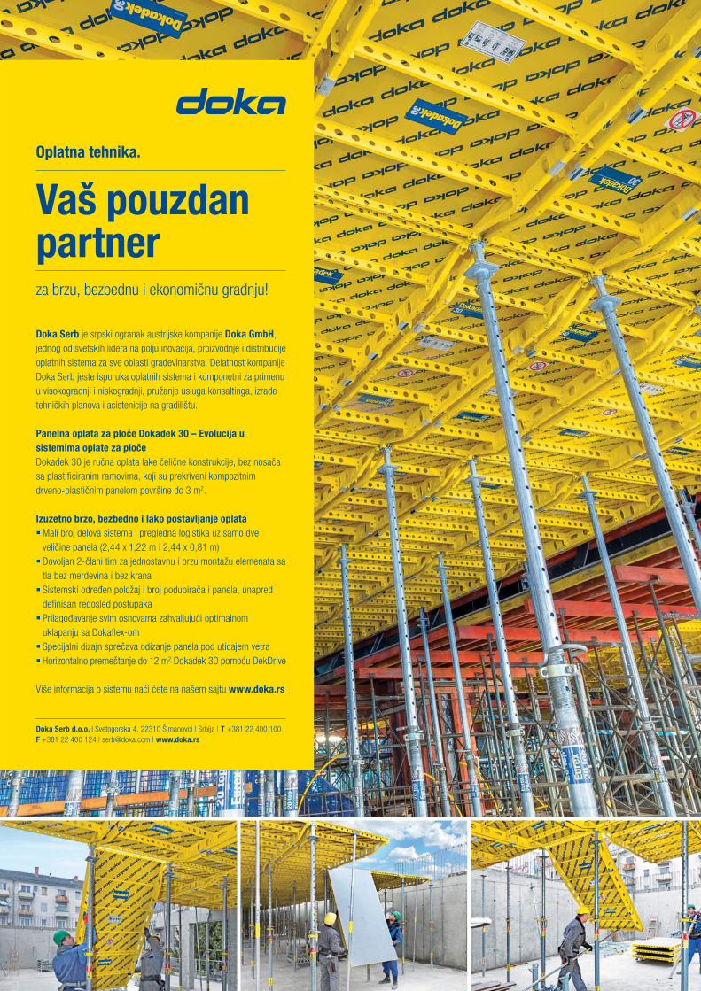
Oplatna tehnika.
Vaš pouzdan partnerza brzu, bezbednu i ekonomičnu gradnju!
Doka Serb je srpski ogranak austrijske kompanije Doka GmbH, jednog od svetskih lidera na polju inovacija, proizvodnje i distribucije oplatnih sistema za sve oblasti građevinarstva. Delatnost kompanije Doka Serb jeste isporuka oplatnih sistema i komponetni za primenu u visokogradnji i niskogradnji, pružanje usluga konsaltinga, izrade tehničkih planova i asistenicije na gradilištu.
Panelna oplata za ploče Dokadek 30 – Evolucija u sistemima oplate za pločeDokadek 30 je ručna oplata lake čelične konstrukcije, bez nosača sa plastifi ciranim ramovima, koji su prekriveni kompozitnim drveno-plastičnim panelom površine do 3 m2.
Izuzetno brzo, bezbedno i lako postavljanje oplata Mali broj delova sistema i pregledna logistika uz samo dve veličine panela (2,44 x 1,22 m i 2,44 x 0,81 m) Dovoljan 2-člani tim za jednostavnu i brzu montažu elemenata sa tla bez merdevina i bez krana Sistemski određen položaj i broj podupirača i panela, unapred defi nisan redosled postupaka Prilagođavanje svim osnovama zahvaljujući optimalnom uklapanju sa Dokafl ex-om Specijalni dizajn sprečava odizanje panela pod uticajem vetra Horizontalno premeštanje do 12 m2 Dokadek 30 pomoću DekDrive
Više informacija o sistemu naći ćete na našem sajtu www.doka.rs
Doka Serb d.o.o. l Svetogorska 4, 22310 Šimanovci | Srbija | T +381 22 400 100 F +381 22 400 124 | [email protected] | www.doka.rs

Gradite budućnost sapouzdanim partnerom.
Već osam decenija Mapei je vodeći svetski proizvođač hemijskih proizvoda za građevinar-
stvo. Mapei grupa danas ima 73 proizvodnih pogona na 5 kontinenata, 18 centara za raz-
voj, asortiman sa više od 1.600 proizvoda i preko 200 novih proizvoda svake godine. To su
pokazatelji koji čine Mapei vodećim međunarodnim proizvođačem u građevinskoj industriji.
Otkrijte svet Mapei na www.mapei.rs


INSTITUT IMS a. d.Bulevar vojvode Miši a 43
11 000 BeogradTel: 011 2651 949
Faks: 011 3692 [email protected]
Izvo enje radova sa pontona za novi most Beška,2007.god.
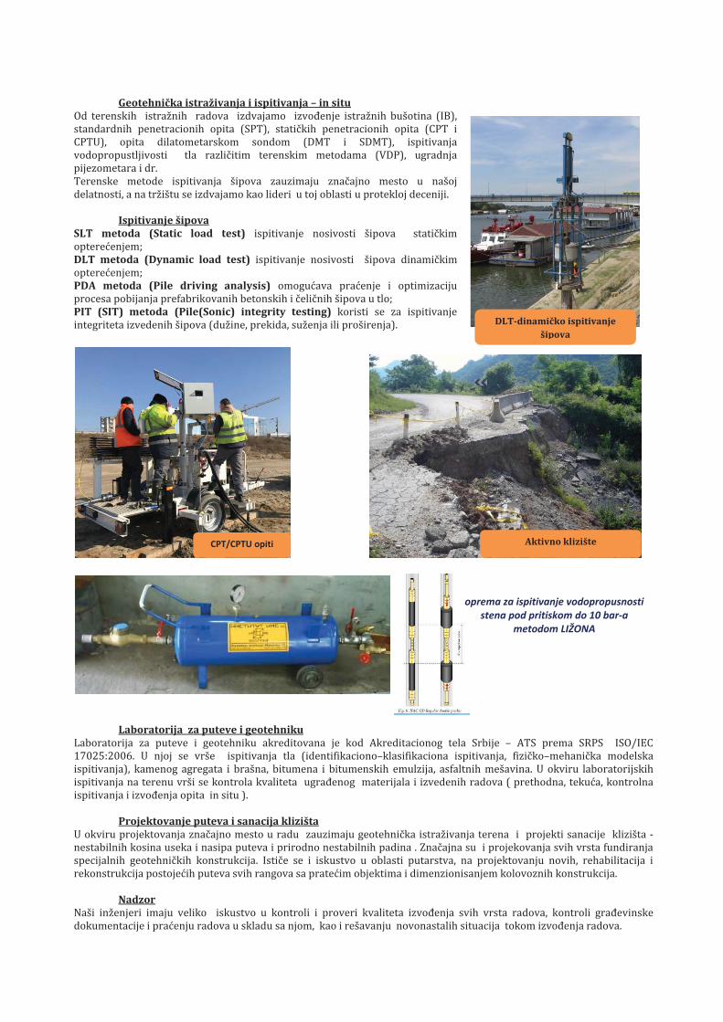
Geotehni ka i – in situ
SLT metoda (Static load test)
DLT metoda (Dynamic load test)
PDA metoda (Pile analysis)
PIT (SIT) metoda (Pile(Sonic)
za i
i klizišta
Nadzor
DLT dinami košip
klizište
oprema za ispitivanje vodopropusnostistena pod pritiskom do 10 bar a
metodom

PROIZVODNI PROGRAM
ADITIVI ZABETONE I MALTERE
SMESE ZA ZALIVANJE
REPARACIJA BETONA
INDUSTRIJSKI ISPORTSKI PODOVI
KITOVI
HIDROIZOLACIJE
ZAŠTITNI PREMAZI
PROTIVPOŽARNI MATERIJALI
GRAĐEVINSKA LEPILA
SMESE ZA IZRAVNAVANJE
DEKORATIVNIPREMAZI I MALTERI
PROIZVODI ZAGRAĐEVINARSTVO
Kompanija za proizvodnju hemijskihmaterijala za gradevinarsvo, od 1969
www.ading.rs
Adresa: Nehruova 82, 11070 Novi Beograd Tel/Fax: + 381 11 616 05 76 ; email: [email protected]

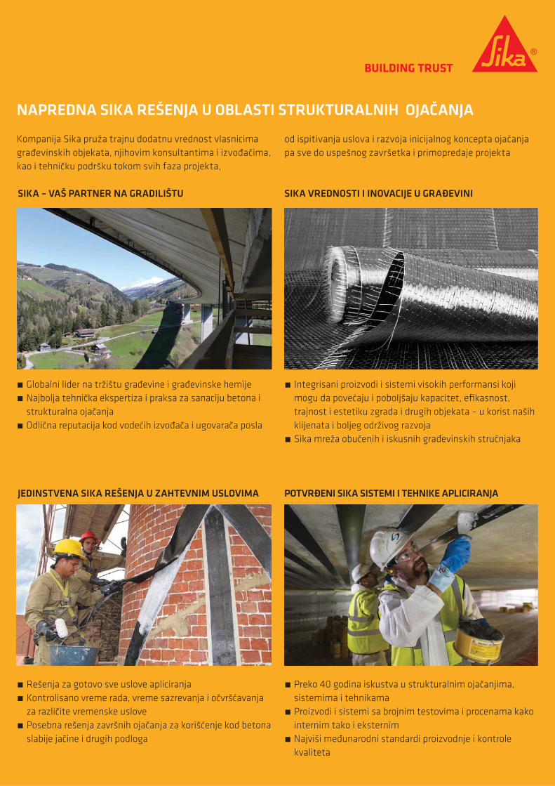
� Globalni lider na tržištu građevine i građevinske hemije � Najbolja tehnička ekspertiza i praksa za sanaciju betona i strukturalna ojačanja
� Odlična reputacija kod vodećih izvođača i ugovarača posla
� Integrisani proizvodi i sistemi visokih performansi koji mogu da povećaju i poboljšaju kapacitet, efikasnost, trajnost i estetiku zgrada i drugih objekata – u korist naših klijenata i boljeg održivog razvoja
� Sika mreža obučenih i iskusnih građevinskih stručnjaka
� Rešenja za gotovo sve uslove apliciranja � Kontrolisano vreme rada, vreme sazrevanja i očvršćavanja za različite vremenske uslove
� Posebna rešenja završnih ojačanja za korišćenje kod betona slabije jačine i drugih podloga
� Preko 40 godina iskustva u strukturalnim ojačanjima, sistemima i tehnikama
� Proizvodi i sistemi sa brojnim testovima i procenama kako internim tako i eksternim
� Najviši međunarodni standardi proizvodnje i kontrole kvaliteta
Kompanija Sika pruža trajnu dodatnu vrednost vlasnicima građevinskih objekata, njihovim konsultantima i izvođačima, kao i tehničku podršku tokom svih faza projekta,
NAPREDNA SIKA REŠENJA U OBLASTI STRUKTURALNIH OJAČANJA
SIKA – VAŠ PARTNER NA GRADILIŠTU
JEDINSTVENA SIKA REŠENJA U ZAHTEVNIM USLOVIMA POTVRĐENI SIKA SISTEMI I TEHNIKE APLICIRANJA
SIKA VREDNOSTI I INOVACIJE U GRAĐEVINI
od ispitivanja uslova i razvoja inicijalnog koncepta ojačanja pa sve do uspešnog završetka i primopredaje projekta
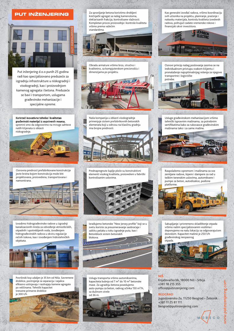


Related Documents