Icarus 164 (2003) 282–316 www.elsevier.com/locate/icarus Graben–fissure systems in Guinevere Planitia and Beta Regio (264 ◦ –312 ◦ E, 24 ◦ –60 ◦ N), Venus, and implications for regional stratigraphy and mantle plumes R.E. Ernst, a,∗ D.W. Desnoyers, a J.W. Head, b and E.B. Grosfils c a Geological Survey of Canada, 601 Booth St., Ottawa, ON K1A 0E8, Canada b Department of Geological Sciences, Brown University, Rhode Island, RI 02912, USA c Geology Department, Pomona College, Claremont, CA 91711, USA Received 11 October 2002; revised 13 March 2003 Abstract Detailed mapping in a 14,000,000 km 2 area of northwestern Guinevere Planitia and northern Beta Regio bounded by 264 ◦ –312 ◦ E, 24 ◦ – 60 ◦ N has revealed thousands of long extensional lineaments (graben, fissures and related fractures). These can be grouped into radiating, circumferential and linear systems. Thirty four radiating systems have been identified, of which 16 have radii greater than 300 km and eight have radii greater than 1000 km. Twenty six linear (straight) systems with a length greater than 300 km have been distinguished of which six have a length greater than 1000 km. Linear systems are generally associated with rifts, although some may represent distal portions of radiating systems. In addition, 19 circumferential systems, some associated with coronae, have been identified. The distribution of each system is compared with the host geology in order to place the graben–fissure systems in a regional stratigraphic framework. The majority of systems are: (1) younger than tesserae, ridge belts and densely fractured plains, (2) coeval with, and in many cases, define fracture belts, (3) partially flooded by wrinkle-ridged plains units, and (4) older than smooth and lobate plains units and young rifts. The inventory of radiating graben–fissure systems that we catalogue represents a database of tectono-magmatic centers that complements the centers defined using other criteria, e.g., large volcanoes, coronae, and shield fields. We have attempted to identify those systems that are underlain by dike swarms in order to evaluate their relationship to mantle plumes. At least 11 of the radiating systems extend well beyond any central topographic uplift and are therefore interpreted to be underlain by dike swarms. Crown Copyright 2003 Published by Elsevier Inc. All rights reserved. Keywords: Graben; Fissure; Fracture; Dike; Dyke; Mantle plume; Rift; Nova; Corona 1. Introduction Long narrow extensional lineaments (graben, fissures and fractures) are widespread on Venus (Grosfils and Head, 1991, 1994a; Head et al., 1991; McKenzie et al., 1992; Solomon et al., 1992; Ernst et al., 1995, 2001; Banerdt et al., 1997; Koenig and Pollard, 1998; Krassilnikov, 2001; Kras- silnikov and Head, in press). Graben have an observable floor, fissures are trough- or V-shaped and fractures have un- resolvable geometry. Some of the most intensively studied graben–fissure sys- tems are those that radiate. A global reconnaissance study using C1-MIDR (compressed-once, mosaicked image data * Corresponding author. E-mail address: [email protected] (R.E. Ernst). record) scale (225 m/pixel) maps revealed 163 radiating sys- tems of which 118 were interpreted to be underlain by dikes on the basis of evidence for underlying magma and the geo- metric similarity with terrestrial dike swarms (Grosfils and Head, 1994a, 1994b, 1995, 1996). The evidence for a dike origin includes volcanic flows emanating from graben and fissures, an association with pit chains and lines of small shield volcanoes, as well as a pattern of radiating graben and fissures extending well beyond any centralized topographic uplift. In addition, linear (straight) systems, often in cross- cutting sets, have been reported from many areas, and are generally interpreted to require extension of a thin brittle layer (e.g., Banerdt and Sammis, 1992; Banerdt et al., 1997). Circumferential systems (i.e., arcuate systems which sur- round volcanic/tectonic features) have been studied in the 0019-1035/$ – see front matter Crown Copyright 2003 Published by Elsevier Inc. All rights reserved. doi:10.1016/S0019-1035(03)00126-X

Welcome message from author
This document is posted to help you gain knowledge. Please leave a comment to let me know what you think about it! Share it to your friends and learn new things together.
Transcript
s
to radiating,and eightof which
tal portionson of eachmajority ofre belts, (3)
radiatinged using otherswarms in
phic uplift
Icarus 164 (2003) 282–316www.elsevier.com/locate/icaru
Graben–fissure systems in Guinevere Planitia and Beta Regio(264◦–312◦E, 24◦–60◦N), Venus, and implications for regional
stratigraphy and mantle plumes
R.E. Ernst,a,∗ D.W. Desnoyers,a J.W. Head,b and E.B. Grosfilsc
a Geological Survey of Canada, 601 Booth St., Ottawa, ON K1A 0E8, Canadab Department of Geological Sciences, Brown University, Rhode Island, RI 02912, USA
c Geology Department, Pomona College, Claremont, CA 91711, USA
Received 11 October 2002; revised 13 March 2003
Abstract
Detailed mapping in a 14,000,000 km2 area of northwestern Guinevere Planitia and northern Beta Regio bounded by 264◦–312◦E, 24◦–60◦N has revealed thousands of long extensional lineaments (graben, fissures and related fractures). These can be grouped incircumferential and linear systems. Thirty four radiating systems have been identified, of which 16 have radii greater than 300 kmhave radii greater than 1000 km. Twenty six linear (straight) systems with a length greater than 300 km have been distinguishedsix have a length greater than 1000 km. Linear systems are generally associated with rifts, although some may represent disof radiating systems. In addition, 19 circumferential systems, some associated with coronae, have been identified. The distributisystem is compared with the host geology in order to place the graben–fissure systems in a regional stratigraphic framework. Thesystems are: (1) younger than tesserae, ridge belts and densely fractured plains, (2) coeval with, and in many cases, define fractupartially flooded by wrinkle-ridged plains units, and (4) older than smooth and lobate plains units and young rifts. The inventory ofgraben–fissure systems that we catalogue represents a database of tectono-magmatic centers that complements the centers defincriteria, e.g., large volcanoes, coronae, and shield fields. We have attempted to identify those systems that are underlain by dikeorder to evaluate their relationship to mantle plumes. At least 11 of the radiating systems extend well beyond any central topograand are therefore interpreted to be underlain by dike swarms.Crown Copyright 2003 Published by Elsevier Inc. All rights reserved.
Keywords:Graben; Fissure; Fracture; Dike; Dyke; Mantle plume; Rift; Nova; Corona
andead,92;t al.,as-ablee un
sys-tud
data
s-ikesgeo-nddikendalland
phic
ss-d arettle97).sur-the
1. Introduction
Long narrow extensional lineaments (graben, fissuresfractures) are widespread on Venus (Grosfils and H1991, 1994a; Head et al., 1991; McKenzie et al., 19Solomon et al., 1992; Ernst et al., 1995, 2001; Banerdt e1997; Koenig and Pollard, 1998; Krassilnikov, 2001; Krsilnikov and Head, in press). Graben have an observfloor, fissures are trough- or V-shaped and fractures havresolvable geometry.
Some of the most intensively studied graben–fissuretems are those that radiate. A global reconnaissance susing C1-MIDR (compressed-once, mosaicked image
* Corresponding author.E-mail address:[email protected] (R.E. Ernst).
0019-1035/$ – see front matter Crown Copyright 2003 Published by Elseviedoi:10.1016/S0019-1035(03)00126-X
-
y
record) scale (225 m/pixel) maps revealed 163 radiating sytems of which 118 were interpreted to be underlain by don the basis of evidence for underlying magma and themetric similarity with terrestrial dike swarms (Grosfils aHead, 1994a, 1994b, 1995, 1996). The evidence for aorigin includes volcanic flows emanating from graben afissures, an association with pit chains and lines of smshield volcanoes, as well as a pattern of radiating grabenfissures extending well beyond any centralized topograuplift.
In addition, linear (straight) systems, often in crocutting sets, have been reported from many areas, angenerally interpreted to require extension of a thin brilayer (e.g., Banerdt and Sammis, 1992; Banerdt et al., 19Circumferential systems (i.e., arcuate systems whichround volcanic/tectonic features) have been studied in
r Inc. All rights reserved.
Graben–fissure systems on Venus 283
allylyingen-
of
ndad,00;Har-st,
, inus
ernby
, fis-roupm-ofnta
yingpirs(6)insso
CDt ofgy,
andianlf),
sendis-s,of
Re-ntwo
rm),y ae et
comandtest al.
andmeary
uresany
kmof
ideoussmallation
ten-abenude:riesolianr-
dedofbenl toillu-hslled
and
pit3l),en/all
enceres01).a-
gestsely,forkebe
ad-riketruerted
all
re-ionof
ures
s to, allnar-y to
context of coronae, and a purely tectonic origin is generassumed (e.g., Stofan et al., 1991), although an underdike swarm origin for some has been suggested by McKzie et al. (1992) and Bleamaster and Hansen (2001).
There has been only limited, mostly local, mappinggraben and fissure distributions using the full∼120 m res-olution Magellan radar data presented as 75 m/pixel F-MIDR (full-resolution, mosaicked image data record) aFMAP (full-resolution map) images (e.g., Grosfils and He1994b; Koenig and Pollard, 1998; DeShon et al., 20Ernst et al., 2001; Bleamaster and Hansen, 2001;ris and Ernst, 2001; Harris et al., 2002; Blair and Ern2002; Grosfils and Ernst, 2002; Krassilnikov and Headpress). We have undertaken a detailed mapping programing FMAP images over a large region in the northwestGuinevere Planitia/northern Beta Regio region boundedlongitudes 264◦E and 312◦E, and latitudes 24◦N and 60◦N,in order to: (1) map the extensional lineaments (grabensures and related fractures), (2) to the extent possible gthem into “systems” based on geometry (radiating, circuferential, or linear), (3) summarize the characteristicseach system, (4) assess evidence for controls on orietion related to regional stress, local stress, and underldikes, (5) assess the distribution of mantle plume/diabased on radiating and circumferential patterns, andcompare with topography and regional geologic unitsorder to date the graben–fissure systems and their aciated volcanic/tectonic centers. We mapped FMAPvolumes 52, 53, 37, 38, 23, 24 and the southern parCD volumes 13 and 14 (USGS Branch of Astrogeolohttp://nssdc.gsfc.nasa.gov/planetary/venusfmaps.html). Allthe image framelets from each volume were mosaickedreprojected in a sinusoidal projection to a central meridof 294◦E, the central longitude for volume 38 (western hawhere we began our mapping.
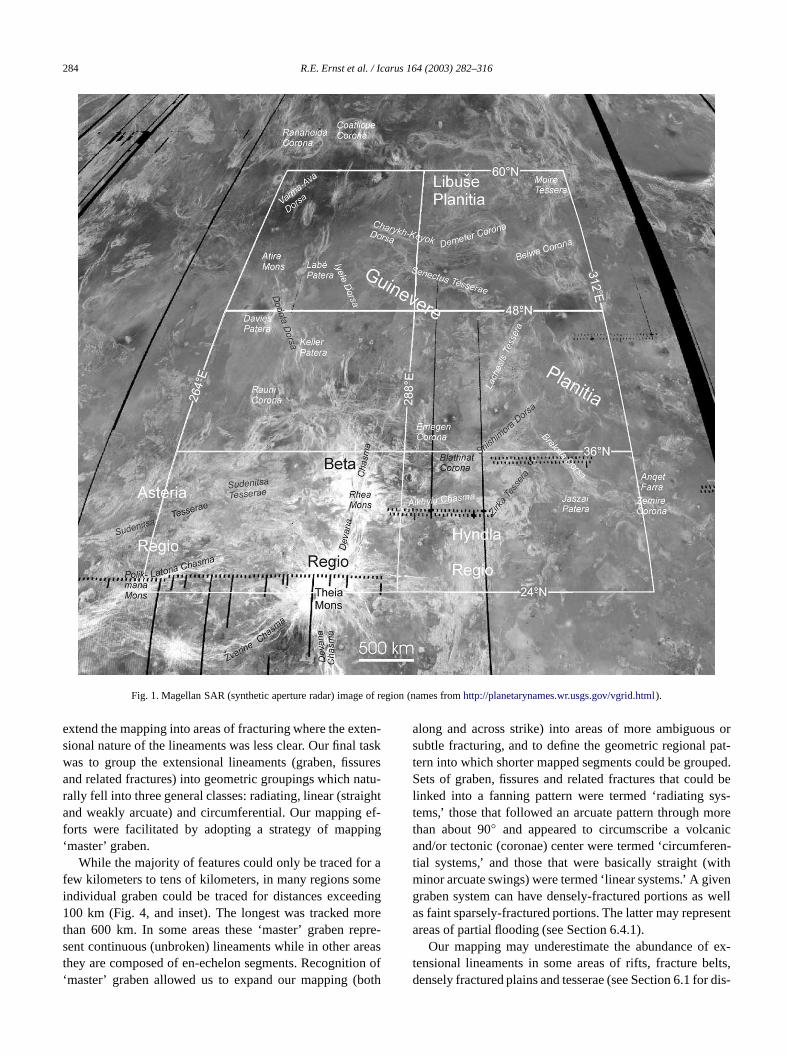
The area selected for our mapping (Fig. 1) was chobecause it was rich in graben–fissure systems. Twotinct kinds of terrains dominate: (1) lowland volcanic plainmainly Guinevere Planitia, and also the southern endLibuse Planitia (e.g., Banerdt et al., 1997), and (2) Betagio. Beta Regio is a broad uplift cut by a triple junctiorift system consisting of Devana Chasma (representingrift arms) and Žverine Chasma (representing the third awhich converge on the center of regional uplift marked bvolcano, Theia Mons (e.g., Solomon et al., 1992; Senskal., 1992; Stofan et al., 1995). Large areas of tesserae (plex ridged terrain), ridge belts (dorsa), fracture belts,various types of volcanic/tectonic centers (paterae, monfarra and coronae), are also present (Fig. 1; Basilevsky e1999; Ivanov and Head, 2001).
1.1. Recognition of extensional lineament systems
In our area of study (as elsewhere on Venus), grabenfissures exhibit a variety of patterns (Figs. 2 and 3). In socases they consist of segments with short lengths and v
-
-
-
-
,,
-
ing trends (Fig. 3a). More frequently the graben and fissgroup into sets with a consistent trend (Fig. 3b), and in mareas different sets cross-cut (Fig. 3c).
Individual graben and fissures are typically about 1or less wide with a depth roughly estimated to be tensmeters. However some graben are two or more km w(Fig. 3d). Individual graben and fissures can be continuover large distances, and distinct sets can intersect at aangle (Fig. 3e). Some also show en-echelon segment(Fig. 3f).
In other areas, sets of lineaments exhibit no clear exsional character, but can be traced into unambiguous grand fissure sets along strike (Figs. 3g–3k). These incl(1) radar-dark lineaments with fuzzy or sharp bounda(Figs. 3g and 3h), the latter perhaps representing aeinfilling of graben (M. Ivanov, pers. comm., 2000), (2) paallel fracture sets including intersecting sets termed gridplains (Fig. 3i) (Banerdt and Sammis, 1992), (3) pairsclosely-spaced lineaments interpreted either as twin gra(Koenig and Pollard, 1998) or as graben oriented parallethe radar beam so that both walls of a single graben areminated (Fig. 3j), and (4) lines of pit chains and pit troug(Figs. 3j, 3k and 3l). Some graben and fissures are also fiby younger (or associated) lava flooding (Figs. 3o, 3p,3q).
Various features, such as lines of pit chains andtroughs paralleling graben/fissures (Figs. 3j, 3k, andlava channels and rilles emanating from individual grabfissures (e.g., Figs. 3m and 3n), and alignment of smshield volcanoes along graben–fissure systems, are evidfor magma bodies (i.e., dikes) underlying graben/fissu(e.g., Grosfils and Head, 1994a, 1994b; Ernst et al., 20Local lava flooding in Figs. 3o, 3p, and 3q, which is sptially associated with graben–fissure systems, also sug(but does not require) underlying dikes. More speculativthe small shield volcano in Fig. 3q, may be the sourcethe local flooding, and may derive from an underlying dyin the manner that (a line of) volcanic cones on Earth canfed from an underlying dike (Ernst and Buchan, 1997). Indition, a few areas exhibit graben which grade along stinto apparent horst-like lineaments. The latter may beridge belts (e.g., Tanaka et al., 1997), tectonically invegraben (DeShon et al., 2000), or graben where the ‘left’ wremained undistinguished by the left-looking radar.
Preliminary results of our mapping were previouslyported in Ernst et al. (2001). In the present contributwe report the final results from our detailed mappingthousands of individual graben, fissure and related fract(Fig. 4).
1.2. Methodology
Our systematic approach in the map area (Fig. 1) wafirst trace the most distinctive graben and fissures (i.e.the features that could be unambiguously identified asrow long extensional lineaments). The next step was to tr
284 R.E. Ernst et al. / Icarus 164 (2003) 282–316
Fig. 1. Magellan SAR (synthetic aperture radar) image of region (names fromhttp://planetarynames.wr.usgs.gov/vgrid.html).
ten-taskuresatu-ightef-
ing
r amedingorepre
reason ooth
s orpat-ped.ld beys-ore
nicren-ith
venwellsent
ex-elts,r dis-
extend the mapping into areas of fracturing where the exsional nature of the lineaments was less clear. Our finalwas to group the extensional lineaments (graben, fissand related fractures) into geometric groupings which nrally fell into three general classes: radiating, linear (straand weakly arcuate) and circumferential. Our mappingforts were facilitated by adopting a strategy of mapp‘master’ graben.
While the majority of features could only be traced fofew kilometers to tens of kilometers, in many regions soindividual graben could be traced for distances excee100 km (Fig. 4, and inset). The longest was tracked mthan 600 km. In some areas these ‘master’ graben resent continuous (unbroken) lineaments while in other athey are composed of en-echelon segments. Recogniti‘master’ graben allowed us to expand our mapping (b
-
f
along and across strike) into areas of more ambiguousubtle fracturing, and to define the geometric regionaltern into which shorter mapped segments could be grouSets of graben, fissures and related fractures that coulinked into a fanning pattern were termed ‘radiating stems,’ those that followed an arcuate pattern through mthan about 90◦ and appeared to circumscribe a volcaand/or tectonic (coronae) center were termed ‘circumfetial systems,’ and those that were basically straight (wminor arcuate swings) were termed ‘linear systems.’ A gigraben system can have densely-fractured portions asas faint sparsely-fractured portions. The latter may repreareas of partial flooding (see Section 6.4.1).
Our mapping may underestimate the abundance oftensional lineaments in some areas of rifts, fracture bdensely fractured plains and tesserae (see Section 6.1 fo
Graben–fissure systems on Venus 285
ichnali,f pit
cedas
thistec-
sys-avethantheest,bleouton
ingpedsso
ther29,fur-
d atingThead,ys-avehis
eso-der-
ribeTa-
rommsostomeacketren-
et
theing
kmex-ght
30e in-
L6,ong.a-ent
NEt
ajord bygto
and13)on,lu-
sons arephy.nsnce.rearstne
ratedentns
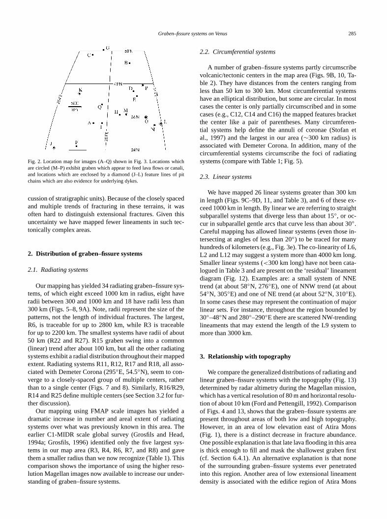
Fig. 2. Location map for images (A–Q) shown in Fig. 3. Locations whare circled (M–P) exhibit graben which appear to feed lava flows or caand locations which are enclosed by a diamond (J–L) feature lines ochains which are also evidence for underlying dykes.
cussion of stratigraphic units). Because of the closely spaand multiple trends of fracturing in these terrains, it woften hard to distinguish extensional fractures. Givenuncertainty we have mapped fewer lineaments in suchtonically complex areas.
2. Distribution of graben–fissure systems
2.1. Radiating systems
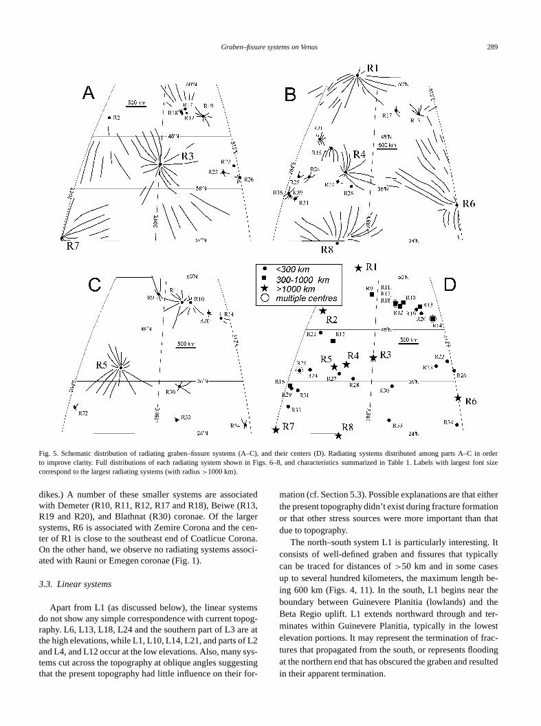
Our mapping has yielded 34 radiating graben–fissuretems, of which eight exceed 1000 km in radius, eight hradii between 300 and 1000 km and 18 have radii less300 km (Figs. 5–8, 9A). Note, radii represent the size ofpatterns, not the length of individual fractures. The largR6, is traceable for up to 2800 km, while R3 is traceafor up to 2200 km. The smallest systems have radii of ab50 km (R22 and R27). R15 graben swing into a comm(linear) trend after about 100 km, but all the other radiatsystems exhibit a radial distribution throughout their mapextent. Radiating systems R11, R12, R17 and R18, all aciated with Demeter Corona (295◦E, 54.5◦N), seem to con-verge to a closely-spaced group of multiple centers, rathan to a single center (Figs. 7 and 8). Similarly, R16/RR14 and R25 define multiple centers (see Section 3.2 forther discussion).
Our mapping using FMAP scale images has yieldedramatic increase in number and areal extent of radiasystems over what was previously known in this area.earlier C1-MIDR scale global survey (Grosfils and He1994a; Grosfils, 1996) identified only the five largest stems in our map area (R3, R4, R6, R7, and R8) and gthem a smaller radius than we now recognize (Table 1). Tcomparison shows the importance of using the higher rlution Magellan images now available to increase our unstanding of graben–fissure systems.
-
2.2. Circumferential systems
A number of graben–fissure systems partly circumscvolcanic/tectonic centers in the map area (Figs. 9B, 10,ble 2). They have distances from the centers ranging fless than 50 km to 300 km. Most circumferential systehave an elliptical distribution, but some are circular. In mcases the center is only partially circumscribed and in scases (e.g., C12, C14 and C16) the mapped features brthe center like a pair of parentheses. Many circumfetial systems help define the annuli of coronae (Stofanal., 1997) and the largest in our area (∼300 km radius) isassociated with Demeter Corona. In addition, many ofcircumferential systems circumscribe the foci of radiatsystems (compare with Table 1; Fig. 5).
2.3. Linear systems
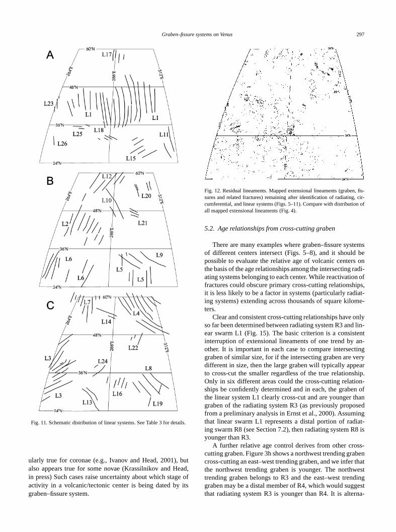
We have mapped 26 linear systems greater than 300in length (Figs. 9C–9D, 11, and Table 3), and 6 of theseceed 1000 km in length. By linear we are referring to straisubparallel systems that diverge less than about 15◦, or oc-cur in subparallel gentle arcs that curve less than about◦.Careful mapping has allowed linear systems (even thostersecting at angles of less than 20◦) to be traced for manyhundreds of kilometers (e.g., Fig. 3e). The co-linearity ofL2 and L12 may suggest a system more than 4000 km lSmaller linear systems (<300 km long) have not been catlogued in Table 3 and are present on the ‘residual’ lineamdiagram (Fig. 12). Examples are: a small system of Ntrend (at about 58◦N, 276◦E), one of NNW trend (at abou54◦N, 305◦E) and one of NE trend (at about 52◦N, 310◦E).In some cases these may represent the continuation of mlinear sets. For instance, throughout the region bounde30◦–48◦N and 280◦–290◦E there are scattered NW-trendinlineaments that may extend the length of the L9 systemmore than 3000 km.
3. Relationship with topography
We compare the generalized distributions of radiatinglinear graben–fissure systems with the topography (Fig.determined by radar altimetry during the Magellan missiwhich has a vertical resolution of 80 m and horizontal resotion of about 10 km (Ford and Pettengill, 1992). Compariof Figs. 4 and 13, shows that the graben–fissure systempresent throughout areas of both low and high topograHowever, in an area of low elevation east of Atira Mo(Fig. 1), there is a distinct decrease in fracture abundaOne possible explanation is that late lava flooding in this ais thick enough to fill and mask the shallowest graben fi(cf. Section 6.4.1). An alternative explanation is that noof the surrounding graben–fissure systems ever penetinto this region. Another area of low extensional lineamdensity is associated with the edifice region of Atira Mo
286 R.E. Ernst et al. / Icarus 164 (2003) 282–316
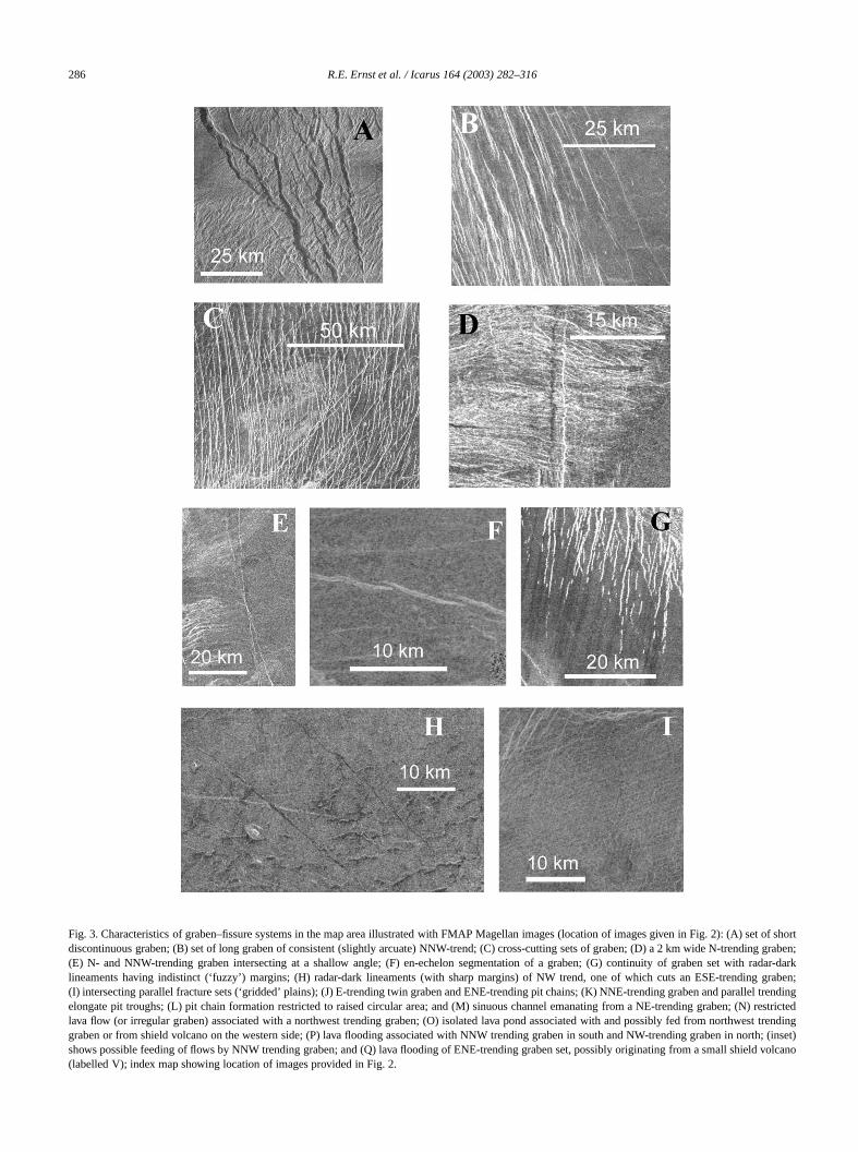
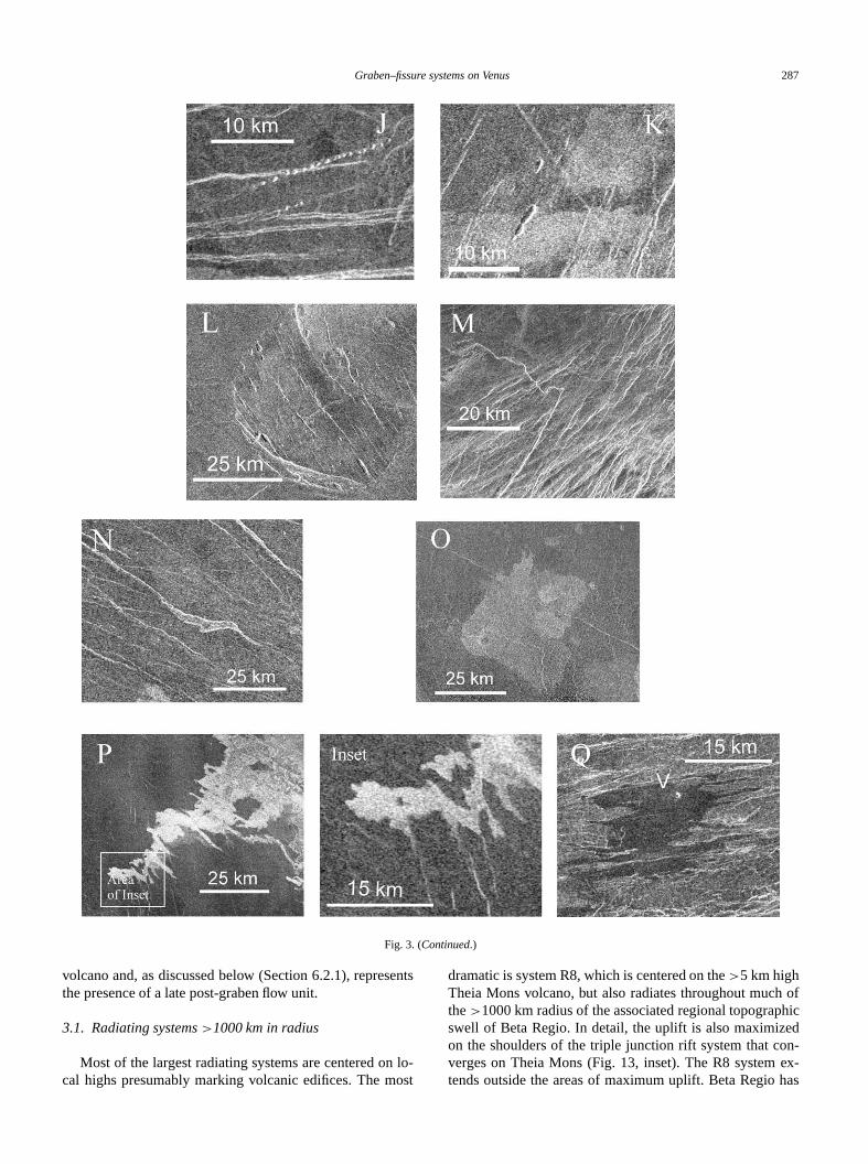
Fig. 3. Characteristics of graben–fissure systems in the map area illustrated with FMAP Magellan images (location of images given in Fig. 2): (A) set ofshortdiscontinuous graben; (B) set of long graben of consistent (slightly arcuate) NNW-trend; (C) cross-cutting sets of graben; (D) a 2 km wide N-trendinggraben;(E) N- and NNW-trending graben intersecting at a shallow angle; (F) en-echelon segmentation of a graben; (G) continuity of graben set with radar-darklineaments having indistinct (‘fuzzy’) margins; (H) radar-dark lineaments (with sharp margins) of NW trend, one of which cuts an ESE-trending graben;(I) intersecting parallel fracture sets (‘gridded’ plains); (J) E-trending twin graben and ENE-trending pit chains; (K) NNE-trending graben and parallel trendingelongate pit troughs; (L) pit chain formation restricted to raised circular area; and (M) sinuous channel emanating from a NE-trending graben; (N) restrictedlava flow (or irregular graben) associated with a northwest trending graben; (O) isolated lava pond associated with and possibly fed from northwest trendinggraben or from shield volcano on the western side; (P) lava flooding associated with NNW trending graben in south and NW-trending graben in north; (inset)shows possible feeding of flows by NNW trending graben; and (Q) lava flooding of ENE-trending graben set, possibly originating from a small shield volcano(labelled V); index map showing location of images provided in Fig. 2.
Graben–fissure systems on Venus 287
Fig. 3. (Continued.)
sent
lo-ost
h ofhic
edon-ex-has
volcano and, as discussed below (Section 6.2.1), reprethe presence of a late post-graben flow unit.
3.1. Radiating systems>1000 km in radius
Most of the largest radiating systems are centered oncal highs presumably marking volcanic edifices. The m
sdramatic is system R8, which is centered on the>5 km highTheia Mons volcano, but also radiates throughout mucthe>1000 km radius of the associated regional topograpswell of Beta Regio. In detail, the uplift is also maximizon the shoulders of the triple junction rift system that cverges on Theia Mons (Fig. 13, inset). The R8 systemtends outside the areas of maximum uplift. Beta Regio
288 R.E. Ernst et al. / Icarus 164 (2003) 282–316
or enl graben are
(Inset)
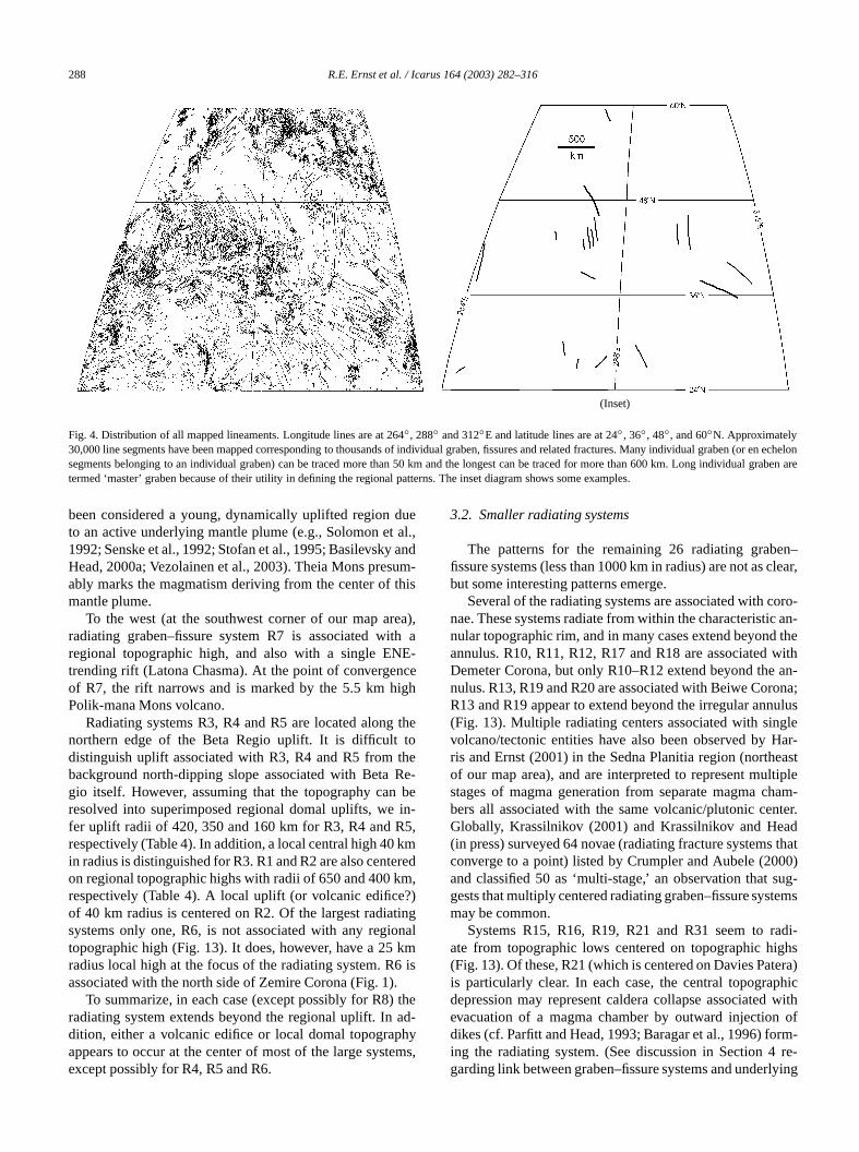
Fig. 4. Distribution of all mapped lineaments. Longitude lines are at 264◦, 288◦ and 312◦E and latitude lines are at 24◦ , 36◦, 48◦, and 60◦N. Approximately30,000 line segments have been mapped corresponding to thousands of individual graben, fissures and related fractures. Many individual graben (echelonsegments belonging to an individual graben) can be traced more than 50 km and the longest can be traced for more than 600 km. Long individuatermed ‘master’ graben because of their utility in defining the regional patterns. The inset diagram shows some examples.
dueal.,andum-this
ea),th aE-
nceigh
thetotheRe-bein-5,kmeredm,?)tingonalkm6 is.thead-hyems
en–clear,
oro-c an-
thewithan-
ona;ulusgleHar-easttipleham-nter.adthat
00)ug-
tems
adi-ighsera)phic
withof
rm-re-
lying
been considered a young, dynamically uplifted regionto an active underlying mantle plume (e.g., Solomon et1992; Senske et al., 1992; Stofan et al., 1995; BasilevskyHead, 2000a; Vezolainen et al., 2003). Theia Mons presably marks the magmatism deriving from the center ofmantle plume.
To the west (at the southwest corner of our map arradiating graben–fissure system R7 is associated wiregional topographic high, and also with a single ENtrending rift (Latona Chasma). At the point of convergeof R7, the rift narrows and is marked by the 5.5 km hPolik-mana Mons volcano.
Radiating systems R3, R4 and R5 are located alongnorthern edge of the Beta Regio uplift. It is difficultdistinguish uplift associated with R3, R4 and R5 frombackground north-dipping slope associated with Betagio itself. However, assuming that the topography canresolved into superimposed regional domal uplifts, wefer uplift radii of 420, 350 and 160 km for R3, R4 and Rrespectively (Table 4). In addition, a local central high 40in radius is distinguished for R3. R1 and R2 are also centon regional topographic highs with radii of 650 and 400 krespectively (Table 4). A local uplift (or volcanic edificeof 40 km radius is centered on R2. Of the largest radiasystems only one, R6, is not associated with any regitopographic high (Fig. 13). It does, however, have a 25radius local high at the focus of the radiating system. Rassociated with the north side of Zemire Corona (Fig. 1)
To summarize, in each case (except possibly for R8)radiating system extends beyond the regional uplift. Indition, either a volcanic edifice or local domal topograpappears to occur at the center of most of the large systexcept possibly for R4, R5 and R6.
,
3.2. Smaller radiating systems
The patterns for the remaining 26 radiating grabfissure systems (less than 1000 km in radius) are not asbut some interesting patterns emerge.
Several of the radiating systems are associated with cnae. These systems radiate from within the characteristinular topographic rim, and in many cases extend beyondannulus. R10, R11, R12, R17 and R18 are associatedDemeter Corona, but only R10–R12 extend beyond thenulus. R13, R19 and R20 are associated with Beiwe CorR13 and R19 appear to extend beyond the irregular ann(Fig. 13). Multiple radiating centers associated with sinvolcano/tectonic entities have also been observed byris and Ernst (2001) in the Sedna Planitia region (northof our map area), and are interpreted to represent mulstages of magma generation from separate magma cbers all associated with the same volcanic/plutonic ceGlobally, Krassilnikov (2001) and Krassilnikov and He(in press) surveyed 64 novae (radiating fracture systemsconverge to a point) listed by Crumpler and Aubele (20and classified 50 as ‘multi-stage,’ an observation that sgests that multiply centered radiating graben–fissure sysmay be common.
Systems R15, R16, R19, R21 and R31 seem to rate from topographic lows centered on topographic h(Fig. 13). Of these, R21 (which is centered on Davies Patis particularly clear. In each case, the central topogradepression may represent caldera collapse associatedevacuation of a magma chamber by outward injectiondikes (cf. Parfitt and Head, 1993; Baragar et al., 1996) foing the radiating system. (See discussion in Section 4garding link between graben–fissure systems and under
Graben–fissure systems on Venus 289
C in ort fo
Fig. 5. Schematic distribution of radiating graben–fissure systems (A–C), and their centers (D). Radiating systems distributed among parts A–derto improve clarity. Full distributions of each radiating system shown in Figs. 6–8, and characteristics summarized in Table 1. Labels with largesnt sizecorrespond to the largest radiating systems (with radius>1000 km).
iated13,rgercenona.soci
msog-at
L2ys-stinfor-
itherionthat
. Itallysbe-thetheer-stac-dingulted
dikes.) A number of these smaller systems are assocwith Demeter (R10, R11, R12, R17 and R18), Beiwe (RR19 and R20), and Blathnat (R30) coronae. Of the lasystems, R6 is associated with Zemire Corona and theter of R1 is close to the southeast end of Coatlicue CorOn the other hand, we observe no radiating systems asated with Rauni or Emegen coronae (Fig. 1).
3.3. Linear systems
Apart from L1 (as discussed below), the linear systedo not show any simple correspondence with current topraphy. L6, L13, L18, L24 and the southern part of L3 arethe high elevations, while L1, L10, L14, L21, and parts ofand L4, and L12 occur at the low elevations. Also, many stems cut across the topography at oblique angles suggethat the present topography had little influence on their
-
-
g
mation (cf. Section 5.3). Possible explanations are that ethe present topography didn’t exist during fracture formator that other stress sources were more important thandue to topography.
The north–south system L1 is particularly interestingconsists of well-defined graben and fissures that typiccan be traced for distances of>50 km and in some caseup to several hundred kilometers, the maximum lengthing 600 km (Figs. 4, 11). In the south, L1 begins nearboundary between Guinevere Planitia (lowlands) andBeta Regio uplift. L1 extends northward through and tminates within Guinevere Planitia, typically in the loweelevation portions. It may represent the termination of frtures that propagated from the south, or represents flooat the northern end that has obscured the graben and resin their apparent termination.
290 R.E. Ernst et al. / Icarus 164 (2003) 282–316
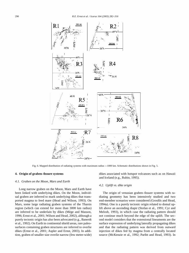
Fig. 6. Mapped distribution of radiating systems with maximum radius>1000 km. Schematic distributions shown in Fig. 5.
aveid-ns-
. Onarsisius)on,
gh aerdleoerlieddi-de)
waii
ra-twoead,up-anduldec-
e theikesard
ted. In
4. Origin of graben–fissure systems
4.1. Graben on the Moon, Mars and Earth
Long narrow graben on the Moon, Mars and Earth hbeen linked with underlying dikes. On the Moon, indivual graben are inferred to mark underlying dikes that traported magma to feed mare (Head and Wilson, 1993)Mars, some large radiating graben systems of the Thregion (which can extend for more than 3000 km radare inferred to be underlain by dikes (Mège and Mass1996; Ernst et al., 2001; Wilson and Head, 2002), althoupurely tectonic origin has also been advocated (e.g., Banet al., 1992). On Earth in continental shield areas, rare pasurfaces containing graben structures are inferred to ovdikes (Ernst et al., 2001; Aspler and Ernst, 2003). In ation, graben of smaller size overlie narrow (few meter-wi
t-
dikes associated with hotspot volcanoes such as on Haand Iceland (e.g., Rubin, 1995).
4.2. Uplift vs. dike origin
The origin of venusian graben–fissure systems withdiating geometry has been intensively studied andend-member scenarios were considered (Grosfils and H1994a). One is a purely tectonic origin related to domallift above an ascending diapir (Stofan et al., 1991; CyrMelosh, 1993), in which case the radiating pattern shonot continue much beyond the edge of the uplift. The sond model considers that the extensional lineaments arsurface expression of underlying laterally propagating dand that the radiating pattern was derived from outwinjection of dikes fed by magma from a centrally locasource (McKenzie et al., 1992; Parfitt and Head, 1993)
Graben–fissure systems on Venus 291
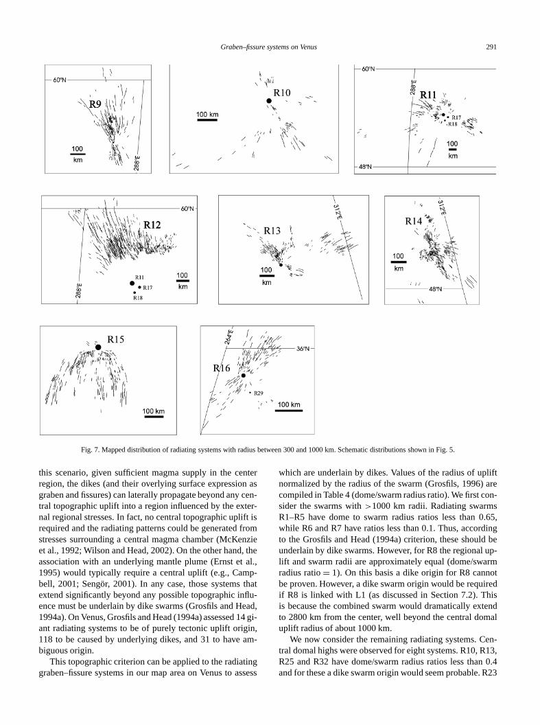
Fig. 7. Mapped distribution of radiating systems with radius between 300 and 1000 km. Schematic distributions shown in Fig. 5.
ntern ascen
er-ft isfromnzie
, theal.,p-tha
flu-ead,14 gin,am-
ingsses
liftareon-s.65,
dingd beup-rmotredhistend
al
en-13,0.4
R23
this scenario, given sufficient magma supply in the ceregion, the dikes (and their overlying surface expressiograben and fissures) can laterally propagate beyond anytral topographic uplift into a region influenced by the extnal regional stresses. In fact, no central topographic uplirequired and the radiating patterns could be generatedstresses surrounding a central magma chamber (McKeet al., 1992; Wilson and Head, 2002). On the other handassociation with an underlying mantle plume (Ernst et1995) would typically require a central uplift (e.g., Cambell, 2001; Sengör, 2001). In any case, those systemsextend significantly beyond any possible topographic inence must be underlain by dike swarms (Grosfils and H1994a). On Venus, Grosfils and Head (1994a) assessedant radiating systems to be of purely tectonic uplift orig118 to be caused by underlying dikes, and 31 to havebiguous origin.
This topographic criterion can be applied to the radiatgraben–fissure systems in our map area on Venus to a
-
t
i-
s
which are underlain by dikes. Values of the radius of upnormalized by the radius of the swarm (Grosfils, 1996)compiled in Table 4 (dome/swarm radius ratio). We first csider the swarms with>1000 km radii. Radiating swarmR1–R5 have dome to swarm radius ratios less than 0while R6 and R7 have ratios less than 0.1. Thus, accorto the Grosfils and Head (1994a) criterion, these shoulunderlain by dike swarms. However, for R8 the regionallift and swarm radii are approximately equal (dome/swaradius ratio= 1). On this basis a dike origin for R8 cannbe proven. However, a dike swarm origin would be requiif R8 is linked with L1 (as discussed in Section 7.2). Tis because the combined swarm would dramatically exto 2800 km from the center, well beyond the central domuplift radius of about 1000 km.
We now consider the remaining radiating systems. Ctral domal highs were observed for eight systems. R10, RR25 and R32 have dome/swarm radius ratios less thanand for these a dike swarm origin would seem probable.
292 R.E. Ernst et al. / Icarus 164 (2003) 282–316
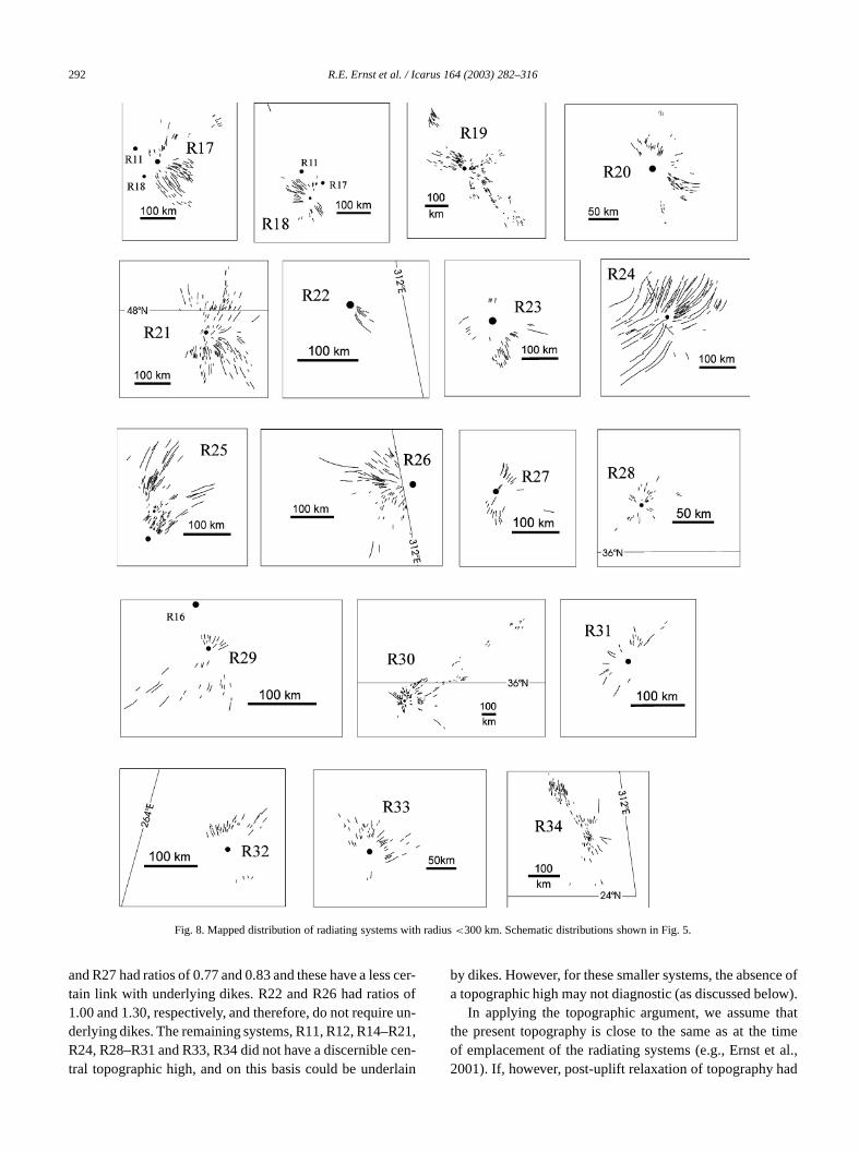
Fig. 8. Mapped distribution of radiating systems with radius<300 km. Schematic distributions shown in Fig. 5.
s ceofun-21,
cen-lain
ce oflow).thattime
t al.,ad
and R27 had ratios of 0.77 and 0.83 and these have a lestain link with underlying dikes. R22 and R26 had ratios1.00 and 1.30, respectively, and therefore, do not requirederlying dikes. The remaining systems, R11, R12, R14–RR24, R28–R31 and R33, R34 did not have a discernibletral topographic high, and on this basis could be under
r-by dikes. However, for these smaller systems, the absena topographic high may not diagnostic (as discussed be
In applying the topographic argument, we assumethe present topography is close to the same as at theof emplacement of the radiating systems (e.g., Ernst e2001). If, however, post-uplift relaxation of topography h
Graben–fissure systems on Venus 293
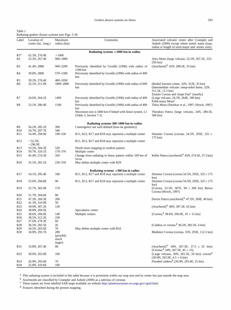
Table 1Radiating graben–fissure systems (see Figs. 5–8)
Label Location ofcenter (lat., long.)
Maximumradius (km)
Comments Associated volcanic center after Crumpler andAubele (2000) except where noted: name (type,radius or length of semi-major and -minor axes)
Radiating systems>1000 km in radiusR1a 62.3N, 276.9E >1000R2 52.3N, 267.4E 900–1800 Atira Mons (large volcano, 52.5N, 267.5E, 225–
250 km)R3 41.4N, 288E 900–2200 Previously identified by Grosfils (1996) with radius of
1300 km(Arachnoid,b 41N, 288.5E, 35 km)
R4 39.8N, 280E 570–1300 Previously identified by Grosfils (1996) with radius of 400km
R5 39.2N, 276.4E 400–1050R6 32.1N, 311.9E 1800–2800 Previously identified by Grosfils (1996) with radius of 600
km(Radial fracture center, 32N, 312E, 35 km)(Intermediate volcano: steep-sided dome, 32N,311.5E, 12.5 km)Zemire Corona and Anqet Farrc (nearby)
R7 24.6N, 264.1E 1400 Previously identified by Grosfils (1996) with radius of 400km
(Large volcano, 24.5N, 264E, 300 km)Polik-mana Monsc
R8 23.1N, 280.4E 1100 Previously identified by Grosfils (1996) with radius of 400km
Theia Mons (Smrekar et al., 1997; Hirsch, 1997)
Maximum size is 3400 km if linked with linear system, L1(Table 3, Section 7.2)
Theodora Patera (large volcano, 24N, 280.5E,500 km)
Radiating systems 300–1000 km in radiusR9 56.2N, 285.1E 390 Convergence not well defined (bow-tie geometry)R10 54.7N, 297.7E 340R11 54.4N, 294.9E 190–530 R11, R12, R17 and R18 may represent a multiple center Demeter Corona (corona, 54.5N, 295E, 325×
175 km)R12 ∼52.3N,
∼296.9ER11, R12, R17 and R18 may represent a multiple center
R13 53.2N, 304.2E 520 Needs more mapping to confirm patternR14 50.7N, 310.1E 170–370 Multiple centerR15 45.4N, 274.3E 350 Change from radiating to linear pattern within 100 km of
focusKeller Patera (arachnoid,b 45N, 274.5E, 37.5 km)
R16 35.1N, 265.1E 230–550 May define multiple center with R29
Radiating systems<300 km in radiusR17 54.1N, 295.4E 160 R11, R12, R17 and R18 may represent a multiple center Demeter Corona (corona 54.5N, 295E, 325×175
km)R18 53.6N, 294.8E 90 R11, R12, R17 and R18 may represent a multiple center Demeter Corona (corona 54.5N, 295E, 325×175
km)R19 52.7N, 302.9E 170 (Corona, 53.5N, 307E, 90× 200 km) Beiwe
Corona (Hirsch, 1997)R20 51.7N, 304.6E 80R21 47.3N, 269.3E 200 Davies Patera (arachnoid,b 47.5N, 269E, 40 km)R22 41.3N, 310.9E 50R23 39.9N, 307.2E 130 (Arachnoid,b 40N, 307.5E, 65 km)R24 38.8N, 269.5E Speculative centerR25 38.6N, 266.0E 140 Multiple centers (Corona,d 38.6N, 266.0E, 10× 15 km)R26 38.5N, 312.2E 230R27 37.6N, 278.3E 60R28 36.5N, 282.5E 45 (Caldera or corona,d 36.5N, 282.5E, 4 km)R29 34.5N, 265.6E 70 May define multiple center with R16R30 34.8N, 293.7E 280
(possiblymuchlarger)
Blathmet Corona (corona, 35N, 293E, 112.5 km)
R31 33.8N, 267.4E 80 (Arachnoid,b 34N, 267.5E, 37.5 × 25 km);(Corona,d 34N, 267.5E, 45× 15)
R32 30.0N, 265.9E 100 (Large volcano, 30N, 265.5E, 50 km); coronad
(30.0N, 265.9E, 4.5× 6 km)R33 26.9N, 293.0E 70 Flooded calderad (26.9N, 293.0E, 25 km)R34 25.8N, 310.6E 160
a This radiating system is included in this table because it is prominent within our map area and its center lies just outside the map area.b Arachnoids are classified by Crumpler and Aubele (2000) as a subclass of coronae.c These names are from labelled SAR maps available on websitehttp://planetarynames.wr.usgs.gov/vgrid.html.d Features identified during the present mapping.
294 R.E. Ernst et al. / Icarus 164 (2003) 282–316
.
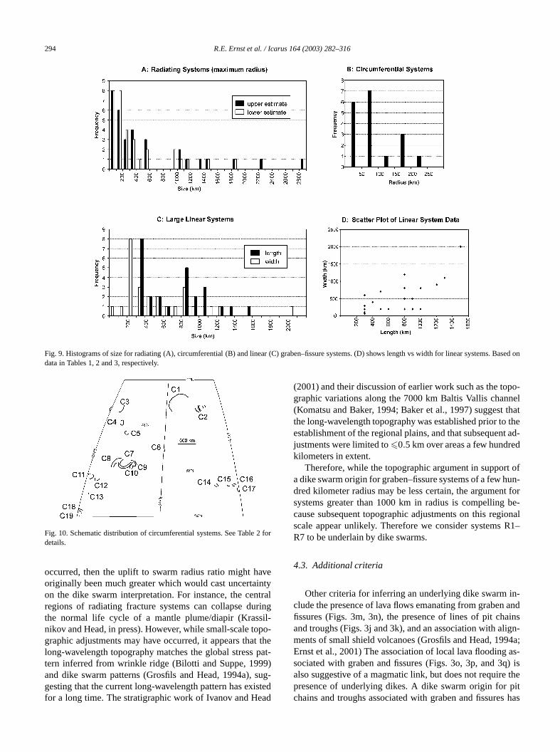
Fig. 9. Histograms of size for radiating (A), circumferential (B) and linear (C) graben–fissure systems. (D) shows length vs width for linear systemsBased ondata in Tables 1, 2 and 3, respectively.2 for
aveintytralringil-po-t thepat9)sug-istedad
po-nelthatthet ad-d
t ofun-t forbe-ionalR1–
n-and
ainsign-94a;as-q) isthe
pits has
Fig. 10. Schematic distribution of circumferential systems. See Tabledetails.
occurred, then the uplift to swarm radius ratio might horiginally been much greater which would cast uncertaon the dike swarm interpretation. For instance, the cenregions of radiating fracture systems can collapse duthe normal life cycle of a mantle plume/diapir (Krassnikov and Head, in press). However, while small-scale tographic adjustments may have occurred, it appears thalong-wavelength topography matches the global stresstern inferred from wrinkle ridge (Bilotti and Suppe, 199and dike swarm patterns (Grosfils and Head, 1994a),gesting that the current long-wavelength pattern has exfor a long time. The stratigraphic work of Ivanov and He
-
(2001) and their discussion of earlier work such as the tographic variations along the 7000 km Baltis Vallis chan(Komatsu and Baker, 1994; Baker et al., 1997) suggestthe long-wavelength topography was established prior toestablishment of the regional plains, and that subsequenjustments were limited to�0.5 km over areas a few hundrekilometers in extent.
Therefore, while the topographic argument in suppora dike swarm origin for graben–fissure systems of a few hdred kilometer radius may be less certain, the argumensystems greater than 1000 km in radius is compellingcause subsequent topographic adjustments on this regscale appear unlikely. Therefore we consider systemsR7 to be underlain by dike swarms.
4.3. Additional criteria
Other criteria for inferring an underlying dike swarm iclude the presence of lava flows emanating from grabenfissures (Figs. 3m, 3n), the presence of lines of pit chand troughs (Figs. 3j and 3k), and an association with alments of small shield volcanoes (Grosfils and Head, 19Ernst et al., 2001) The association of local lava floodingsociated with graben and fissures (Figs. 3o, 3p, and 3also suggestive of a magmatic link, but does not requirepresence of underlying dikes. A dike swarm origin forchains and troughs associated with graben and fissure
Graben–fissure systems on Venus 295
leror
E,
eds),
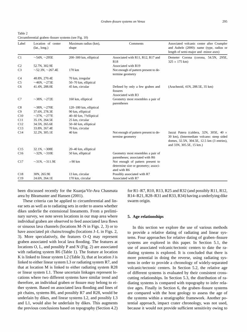
Table 2Circumferential graben–fissure systems (see Fig. 10)
Label Location of center(lat., long.)
Maximum radius (km),shape
Comments Associated volcanic center after Crumpand Aubele (2000): name (type, radiuslength of semi-major and -minor axes)
C1 ∼54N,∼295E 200–300 km, elliptical Associated with R11, R12, R17 andR18
Demeter Corona (corona, 54.5N, 295325× 175 km)
C2 52.7N, 302.9E Associated with R19C3 ∼52.3N, ∼267.4E 170 km Not enough of pattern present to de-
termine geometryC4 48.8N, 270.4E 70 km, irregularC5 ∼46N,∼273E 50–70 km, ellipticalC6 41.4N, 288.0E 45 km, circular Defined by only a few graben and
fissures(Arachnoid, 41N, 288.5E, 35 km)
Associated with R3C7 ∼38N,∼272E 160 km, elliptical Geometry most resembles a pair of
parenthesesC8 ∼38N,∼270E 120–180 km, ellipticalC9 37.6N, 278.3E 90 km, ellipticalC10 ∼37N,∼277E 40–60 km, ??ellipticalC11 35.1N, 264.5E 25 km, circularC12 34.5N, 265.6E 50–60 km, ellipticalC13 33.8N, 267.4E 70 km, circularC14 32.2N, 305.1E 40 km Not enough of pattern present to de-
termine geometryJaszai Patera (caldera, 32N, 305E, 40×30 km), (Intermediate volcano: steep siddomes, 32.5N, 304.5E, 12.5 km (3 entrieand 33N, 305.5E, 15 km.)
C15 32.1N,∼308E 20–40 km, ellipticalC16 ∼32N,∼310E 50 km, elliptical Geometry most resembles a pair of
parentheses; associated with R6C17 ∼31N,∼311.9E >90 km Not enough of pattern present to
determine size or geometry; associ-ated with R6
C18 30N, 265.9E 13 km, circular Possibly associated with R7C19 24.6N, 264.1E 170 km, circular Associated with R7
ata
lin-etheimi-hereowsr tos. 2,ents atted
ionis
and28t lo-andei-s o
d beL3nts4.2
12,ike
odsys-surethera-is
ys-tedageoss-ra-la-
emse of
po-sed,to
been discussed recently for the Kuanja/Vir-Ava Chasmarea by Bleamaster and Hansen (2001).
These criteria can be applied to circumferential andear sets as well as to radiating sets in order to assess whdikes underlie the extensional lineaments. From a prelnary survey, we note seven locations in our map area windividual graben are observed to feed associated lava flor sinuous lava channels (locations M–N in Figs. 2, 3) ohave associated pit chains/troughs (locations J–L in Fig3). More speculatively, the features O–Q may represgraben associated with local lava flooding. The featurelocations O, L, and possibly P and N (Fig. 2) are associawith radiating system R6 (Table 1). The feature at locatK is linked to linear system L2 (Table 3), that at location Jlinked to either linear system L3 or radiating system R7,that at location M is linked to either radiating system Ror linear system L1. Those uncertain linkages represencations where two different systems have similar trendtherefore, an individual graben or fissure may belong tother system. Based on associated lava flooding and linepit chains, systems R6, and possibly R7 and R28, woulunderlain by dikes, and linear systems L2, and possiblyand L1, would also be underlain by dikes. This augmethe previous conclusions based on topography (Section
r
f
)
for R1–R7, R10, R13, R25 and R32 (and possibly R11, RR14–R21, R28–R31 and R33, R34) having a underlying dswarm origin.
5. Age relationships
In this section we explore the use of various methto provide a relative dating of radiating and linear stems. Four approaches for relative dating of graben–fissystems are explored in this paper. In Section 5.1,use of associated volcanic/tectonic centers to date thediating systems is explored. It is concluded that theremore potential in doing the reverse, using radiating stems in order to provide a chronology of widely-separavolcanic/tectonic centers. In Section 5.2, the relativeof different systems is evaluated by their consistent crcutting relationships. In Section 5.3, the distribution ofdiating systems is compared with topography to infer retive ages. Finally in Section 6, the graben–fissure systare compared with the host geology to assess the agthe systems within a stratigraphic framework. Anothertential approach, impact crater chronology, was not ubecause it would not provide sufficient sensitivity owing
296 R.E. Ernst et al. / Icarus 164 (2003) 282–316
xt)
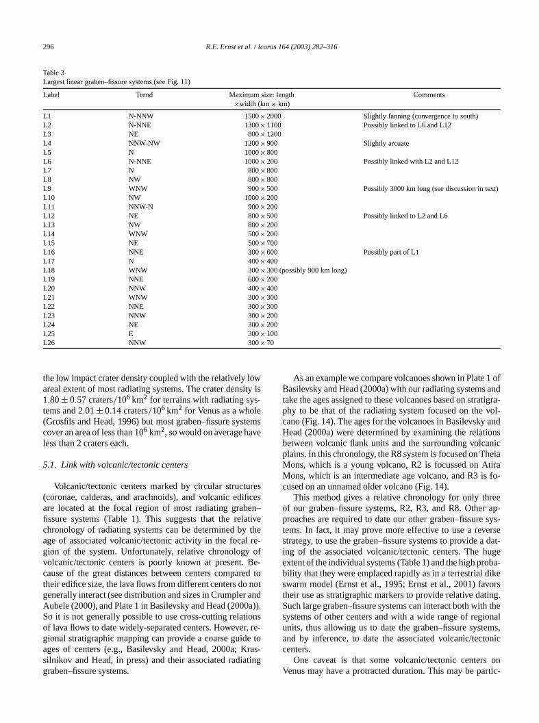
Table 3Largest linear graben–fissure systems (see Fig. 11)
Label Trend Maximum size: length Comments×width (km× km)
L1 N-NNW 1500×2000 Slightly fanning (convergence to south)L2 N-NNE 1300×1100 Possibly linked to L6 and L12L3 NE 800×1200L4 NNW-NW 1200×900 Slightly arcuateL5 N 1000×800L6 N-NNE 1000×200 Possibly linked with L2 and L12L7 N 800×800L8 NW 800×800L9 WNW 900×500 Possibly 3000 km long (see discussion in teL10 NW 1000×200L11 NNW-N 900×200L12 NE 800×500 Possibly linked to L2 and L6L13 NW 800×200L14 WNW 500×200L15 NE 500×700L16 NNE 300×600 Possibly part of L1L17 N 400×400L18 WNW 300×300 (possibly 900 km long)L19 NNE 600×200L20 NNW 400×400L21 WNW 300×300L22 NNE 300×300L23 NNW 300×200L24 NE 300×200L25 E 300×100L26 NNW 300×70
owity is-
teme
resificeen–ativethere-of
Be-ed tnotanda)).
ions, re-e torasting
1 ofand
atigra-vol-andionsnic
heiatirafo-
eer ap-
sys-rsedat-
ugeba-ikeors
ting.h theonalems,tonic
onrtic-
the low impact crater density coupled with the relatively lareal extent of most radiating systems. The crater dens1.80± 0.57 craters/106 km2 for terrains with radiating systems and 2.01± 0.14 craters/106 km2 for Venus as a whole(Grosfils and Head, 1996) but most graben–fissure syscover an area of less than 106 km2, so would on average havless than 2 craters each.
5.1. Link with volcanic/tectonic centers
Volcanic/tectonic centers marked by circular structu(coronae, calderas, and arachnoids), and volcanic edare located at the focal region of most radiating grabfissure systems (Table 1). This suggests that the relchronology of radiating systems can be determined byage of associated volcanic/tectonic activity in the focalgion of the system. Unfortunately, relative chronologyvolcanic/tectonic centers is poorly known at present.cause of the great distances between centers compartheir edifice size, the lava flows from different centers dogenerally interact (see distribution and sizes in CrumplerAubele (2000), and Plate 1 in Basilevsky and Head (2000So it is not generally possible to use cross-cutting relatof lava flows to date widely-separated centers. Howevergional stratigraphic mapping can provide a coarse guidages of centers (e.g., Basilevsky and Head, 2000a; Ksilnikov and Head, in press) and their associated radiagraben–fissure systems.
s
s
o
-
As an example we compare volcanoes shown in PlateBasilevsky and Head (2000a) with our radiating systemstake the ages assigned to these volcanoes based on strphy to be that of the radiating system focused on thecano (Fig. 14). The ages for the volcanoes in BasilevskyHead (2000a) were determined by examining the relatbetween volcanic flank units and the surrounding volcaplains. In this chronology, the R8 system is focused on TMons, which is a young volcano, R2 is focussed on AMons, which is an intermediate age volcano, and R3 iscused on an unnamed older volcano (Fig. 14).
This method gives a relative chronology for only throf our graben–fissure systems, R2, R3, and R8. Otheproaches are required to date our other graben–fissuretems. In fact, it may prove more effective to use a revestrategy, to use the graben–fissure systems to provide aing of the associated volcanic/tectonic centers. The hextent of the individual systems (Table 1) and the high probility that they were emplaced rapidly as in a terrestrial dswarm model (Ernst et al., 1995; Ernst et al., 2001) favtheir use as stratigraphic markers to provide relative daSuch large graben–fissure systems can interact both witsystems of other centers and with a wide range of regiunits, thus allowing us to date the graben–fissure systand by inference, to date the associated volcanic/teccenters.
One caveat is that some volcanic/tectonic centersVenus may have a protracted duration. This may be pa
Graben–fissure systems on Venus 297
ils.
butead,ge oits
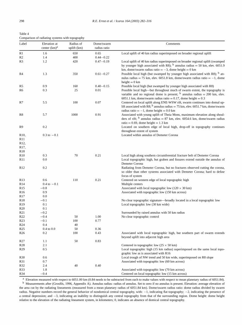
n, fis-, cir-n of
temsbe
s onradi-n ofips,at-me-
onlyd lin-tentan-tingeryarhip.
on-n of
thansedingiat-8 is
ss-ben
r thatestdinggestna-
Fig. 11. Schematic distribution of linear systems. See Table 3 for deta
ularly true for coronae (e.g., Ivanov and Head, 2001),also appears true for some novae (Krassilnikov and Hin press) Such cases raise uncertainty about which staactivity in a volcanic/tectonic center is being dated bygraben–fissure system.
f
Fig. 12. Residual lineaments. Mapped extensional lineaments (grabesures and related fractures) remaining after identification of radiatingcumferential, and linear systems (Figs. 5–11). Compare with distributioall mapped extensional lineaments (Fig. 4).
5.2. Age relationships from cross-cutting graben
There are many examples where graben–fissure sysof different centers intersect (Figs. 5–8), and it shouldpossible to evaluate the relative age of volcanic centerthe basis of the age relationships among the intersectingating systems belonging to each center. While reactivatiofractures could obscure primary cross-cutting relationshit is less likely to be a factor in systems (particularly radiing systems) extending across thousands of square kiloters.
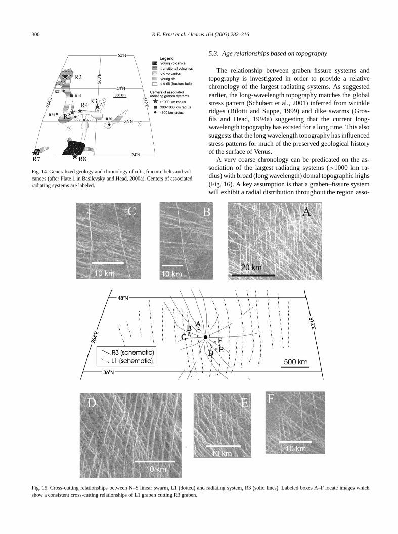
Clear and consistent cross-cutting relationships haveso far been determined between radiating system R3 anear swarm L1 (Fig. 15). The basic criterion is a consisinterruption of extensional lineaments of one trend byother. It is important in each case to compare intersecgraben of similar size, for if the intersecting graben are vdifferent in size, then the large graben will typically appeto cross-cut the smaller regardless of the true relationsOnly in six different areas could the cross-cutting relatiships be confidently determined and in each, the grabethe linear system L1 clearly cross-cut and are youngergraben of the radiating system R3 (as previously propofrom a preliminary analysis in Ernst et al., 2000). Assumthat linear swarm L1 represents a distal portion of rading swarm R8 (see Section 7.2), then radiating system Ryounger than R3.
A further relative age control derives from other crocutting graben. Figure 3h shows a northwest trending gracross-cutting an east–west trending graben, and we infethe northwest trending graben is younger. The northwtrending graben belongs to R3 and the east–west trengraben may be a distal member of R4, which would sugthat radiating system R3 is younger than R4. It is alter
298 R.E. Ernst et al. / Icarus 164 (2003) 282–316
Table 4Comparison of radiating systems with topography
Label Elevation at Radius of Dome/swarm Commentscenter (km)a uplift (km) radius ratio
R1 1.6 650 0.65 Local uplift of 40 km radius superimposed on broader regional upliftR2 1.4 400 0.44−0.22R3 1.2 420 0.47−0.19 Local uplift of 40 km radius superimposed on broader regional uplift (swamped
by younger high associated with R8);b annulus radius= 50 km, elev. 6051.9km, dome/swarm radius ratio= −3, dome height= 0 km
R4 1.3 350 0.61−0.27 Possible local high (but swamped by younger high associated with R8);b an-nulus radius= 75 km, elev. 6051.8 km, dome/swarm radius ratio= −1, domeheight= 0 km
R5 0.9 160 0.40−0.15 Possible local high (but swamped by younger high associated with R8)R6 0.3 25 0.01 Possible local high—but throughout much of swarm extent, the topography is
variable and no regional dome is present;b annulus radius= 200 km, elev.6051.1 km, dome/swarm radius ratio= 0.17, dome height= 0.3
R7 5.5 100 0.07 Centered on local uplift along ENE-WSW rift, swarm continues into domal up-lift associated with R8;b annulus radius= 75 km, elev. 6051.7 km, dome/swarmradius ratio= −1, dome height= 0.0 km
R8 5.7 1000 0.91 Associated with young uplift of Theia Mons, maximum elevation along shoul-ders of rift; b annulus radius= 87 km, elev. 6054.6 km, dome/swarm radiusratio= 0.69, dome height= 1.3 km
R9 0.2 Located on southern edge of local high, drop-off in topography continuesthroughout extent of system
R10,R11R12,R17,R18
0.3 to −0.1 Located within annulus of Demeter Corona
R10 0.3 70 0.21 Local high along southern circumferential fracture belt of Demeter CoronaR11 0.0 Local topographic high, but graben and fissures extend outside the annulus of
Demeter CoronaR12 0.2 Radiating from Demeter Corona, but no fractures observed cutting the corona,
so older than other systems associated with Demeter Corona; hard to definefocus of system
R13 0.6 110 0.21 Centered on western edge of local topographic highR14 0.4 to −0.1 Multiple centersR15 −0.8 Associated with local topographic low (120× 30 km)R16 0.9 Associated with topographic low (150 km across)R17 0.0R18 −0.1 No clear topographic signature—broadly located in a local topographic lowR19 0.1 Local topographic low (30 km wide)R20 0.1R21 −0.2 Surrounded by raised annulus with 50 km radiusR22 −0.4 50 1.00 No clear topographic controlR23 −0.1 100 0.77R24 0.4 40R25 0.4 to 0.0 50 0.36R26 0.2 100 0.43 Associated with local topographic high, but southern part of swarm extends
beyond uplift into adjacent high areaR27 1.1 50 0.83R28 2.1 Centered in topographic low (25× 50 km)R29 0.5 Local topographic high (15 km radius) superimposed on the same local topo-
graphic low as is associated with R16R30 0.6 Local trough of NW trend and 50 km wide, superimposed on R8 slopeR31 0.7 Associated with topographic low (60 km across)R32 2.4 40 0.40R33 1.8 Associated with topographic low (70 km across)R34 −0.4 Centered on local topographic low (15 km across)
a Elevation measured with respect to 6051.00 km (0.84 needs to be subtracted from each to make values with respect to mean planetary radius of 6051.84).b Measurements after (Grosfils, 1996, Appendix A). Annulus radius: radius of annulus. Set to zero if no annulus is present. Elevation: average elevation of
the area cut by the radiating lineaments (measured from a mean planetary radius of 6051.84 km). Dome/swarm radius ratio: dome radius divided by swarmradius. Negative numbers record the general behavior of nondomical central topography, with:−1, indicating flat topography;−2, indicating the presence ofa central depression; and−3, indicating an inability to distinguish any central topography from that of the surrounding region. Dome height: dome heightrelative to the elevation of the radiating lineament system, in kilometers; 0, indicates an absence of domical central topography.
Graben–fissure systems on Venus 299
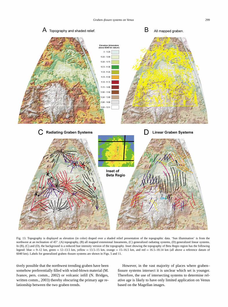
fromsystems.e folloof
Fig. 13. Topography is displayed as elevation (in color) draped over a shaded relief presentation of the topographic data. ‘Sun illumination’ isthenorthwest at an inclination of 45◦ . (A) topography, (B) all mapped extensional lineaments, (C) generalized radiating systems, (D) generalized linearIn (B), (C) and (D), the background is a reduced hue intensity version of the topography. Inset showing the topography of Beta Regio region has thwinglegend: blue= 9–12 km, green= 12–13.5 km, yellow= 13.5–15 km, orange= 15–16.5 km, and red= 16.5–18.14 km (all above a reference datum6040 km). Labels for generalized graben–fissure systems are shown in Figs. 5 and 11.
een.s,re-
n–ger.rel-
us
tively possible that the northwest trending graben have bsomehow preferentially filled with wind-blown material (MIvanov, pers. comm., 2002) or volcanic infill (N. Bridgewritten comm., 2003) thereby obscuring the primary agelationship between the two graben trends.
However, in the vast majority of places where grabefissure systems intersect it is unclear which set is younTherefore, the use of intersecting systems to determineative age is likely to have only limited application on Venbased on the Magellan images.
300 R.E. Ernst et al. / Icarus 164 (2003) 282–316
vol-ciate
andtivestedobalkleos-ng-
alsoncedtory
as-
ghstemo-
Fig. 14. Generalized geology and chronology of rifts, fracture belts andcanoes (after Plate 1 in Basilevsky and Head, 2000a). Centers of assoradiating systems are labeled.
d
5.3. Age relationships based on topography
The relationship between graben–fissure systemstopography is investigated in order to provide a relachronology of the largest radiating systems. As suggeearlier, the long-wavelength topography matches the glstress pattern (Schubert et al., 2001) inferred from wrinridges (Bilotti and Suppe, 1999) and dike swarms (Grfils and Head, 1994a) suggesting that the current lowavelength topography has existed for a long time. Thissuggests that the long wavelength topography has influestress patterns for much of the preserved geological hisof the surface of Venus.
A very coarse chronology can be predicated on thesociation of the largest radiating systems (>1000 km ra-dius) with broad (long wavelength) domal topographic hi(Fig. 16). A key assumption is that a graben–fissure syswill exhibit a radial distribution throughout the region ass
ages w
Fig. 15. Cross-cutting relationships between N–S linear swarm, L1 (dotted) and radiating system, R3 (solid lines). Labeled boxes A–F locate imhichshow a consistent cross-cutting relationships of L1 graben cutting R3 graben.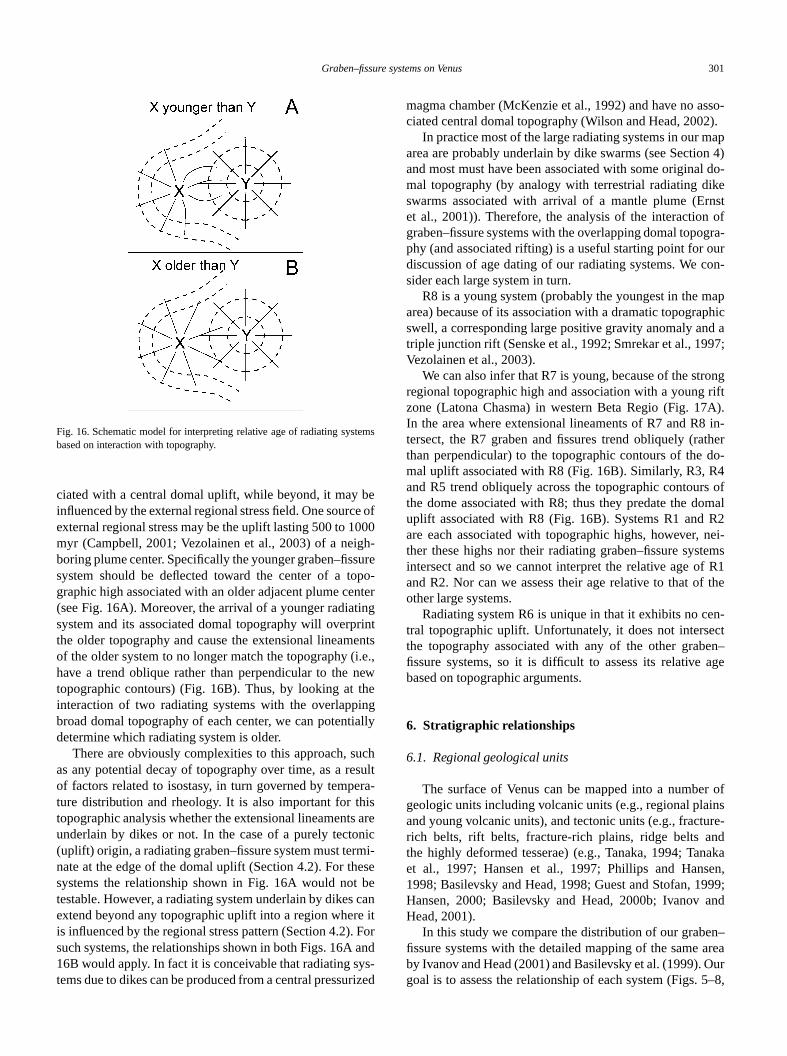
Graben–fissure systems on Venus 301
ems
bee of
000gh-surepo-nteringrintenti.e.,newtheingially
uchsult
era-is
s arenicmi-esebecane it. Forand
ys-rize
sso-2).apn 4)l do-ikernst
ofgra-ouron-
apphicd a97;
ongriftA).in-
therdo-4
s ofmalR2nei-
temsf R1f the
en-cten–age
r ofinsre-
ndnakaen,
999;and
n–areaOur5–8,
Fig. 16. Schematic model for interpreting relative age of radiating systbased on interaction with topography.
ciated with a central domal uplift, while beyond, it mayinfluenced by the external regional stress field. One sourcexternal regional stress may be the uplift lasting 500 to 1myr (Campbell, 2001; Vezolainen et al., 2003) of a neiboring plume center. Specifically the younger graben–fissystem should be deflected toward the center of a tographic high associated with an older adjacent plume ce(see Fig. 16A). Moreover, the arrival of a younger radiatsystem and its associated domal topography will overpthe older topography and cause the extensional lineamof the older system to no longer match the topography (have a trend oblique rather than perpendicular to thetopographic contours) (Fig. 16B). Thus, by looking atinteraction of two radiating systems with the overlappbroad domal topography of each center, we can potentdetermine which radiating system is older.
There are obviously complexities to this approach, sas any potential decay of topography over time, as a reof factors related to isostasy, in turn governed by tempture distribution and rheology. It is also important for thtopographic analysis whether the extensional lineamentunderlain by dikes or not. In the case of a purely tecto(uplift) origin, a radiating graben–fissure system must ternate at the edge of the domal uplift (Section 4.2). For thsystems the relationship shown in Fig. 16A would nottestable. However, a radiating system underlain by dikesextend beyond any topographic uplift into a region wheris influenced by the regional stress pattern (Section 4.2)such systems, the relationships shown in both Figs. 16A16B would apply. In fact it is conceivable that radiating stems due to dikes can be produced from a central pressu
s
d
magma chamber (McKenzie et al., 1992) and have no aciated central domal topography (Wilson and Head, 200
In practice most of the large radiating systems in our marea are probably underlain by dike swarms (see Sectioand most must have been associated with some originamal topography (by analogy with terrestrial radiating dswarms associated with arrival of a mantle plume (Eet al., 2001)). Therefore, the analysis of the interactiongraben–fissure systems with the overlapping domal topophy (and associated rifting) is a useful starting point fordiscussion of age dating of our radiating systems. We csider each large system in turn.
R8 is a young system (probably the youngest in the marea) because of its association with a dramatic topograswell, a corresponding large positive gravity anomaly antriple junction rift (Senske et al., 1992; Smrekar et al., 19Vezolainen et al., 2003).
We can also infer that R7 is young, because of the strregional topographic high and association with a youngzone (Latona Chasma) in western Beta Regio (Fig. 17In the area where extensional lineaments of R7 and R8tersect, the R7 graben and fissures trend obliquely (rathan perpendicular) to the topographic contours of themal uplift associated with R8 (Fig. 16B). Similarly, R3, Rand R5 trend obliquely across the topographic contourthe dome associated with R8; thus they predate the douplift associated with R8 (Fig. 16B). Systems R1 andare each associated with topographic highs, however,ther these highs nor their radiating graben–fissure sysintersect and so we cannot interpret the relative age oand R2. Nor can we assess their age relative to that oother large systems.
Radiating system R6 is unique in that it exhibits no ctral topographic uplift. Unfortunately, it does not intersethe topography associated with any of the other grabfissure systems, so it is difficult to assess its relativebased on topographic arguments.
6. Stratigraphic relationships
6.1. Regional geological units
The surface of Venus can be mapped into a numbegeologic units including volcanic units (e.g., regional plaand young volcanic units), and tectonic units (e.g., fracturich belts, rift belts, fracture-rich plains, ridge belts athe highly deformed tesserae) (e.g., Tanaka, 1994; Taet al., 1997; Hansen et al., 1997; Phillips and Hans1998; Basilevsky and Head, 1998; Guest and Stofan, 1Hansen, 2000; Basilevsky and Head, 2000b; IvanovHead, 2001).
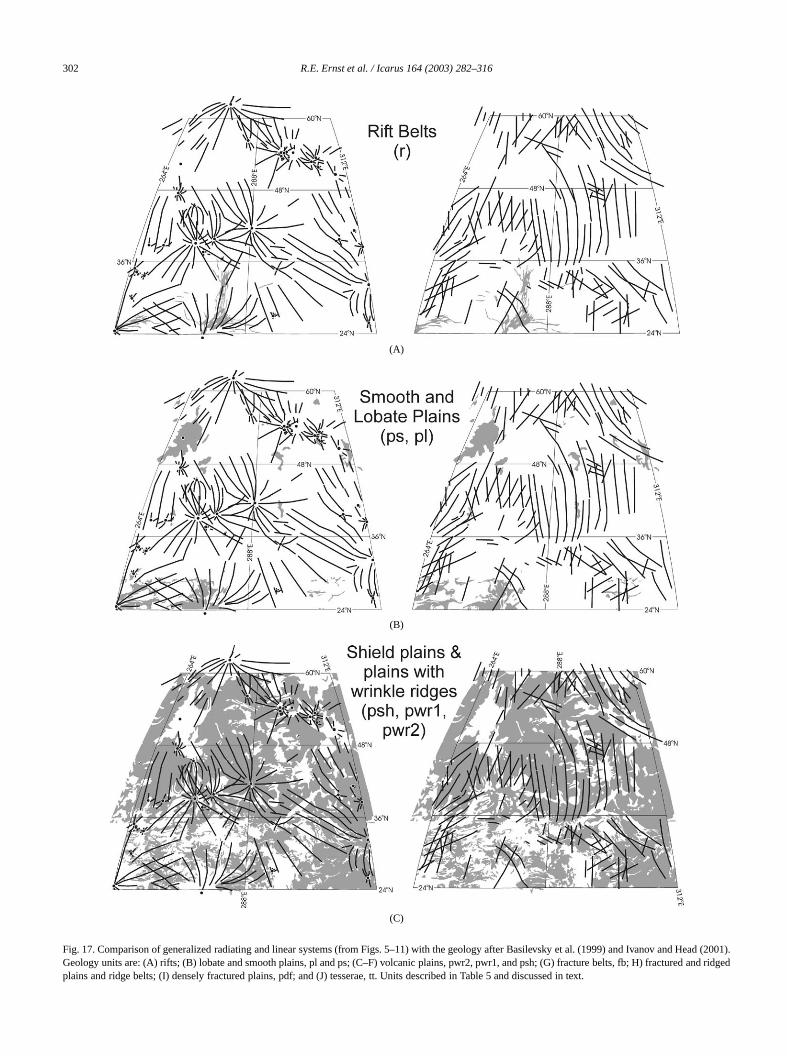
In this study we compare the distribution of our grabefissure systems with the detailed mapping of the sameby Ivanov and Head (2001) and Basilevsky et al. (1999).goal is to assess the relationship of each system (Figs.
302 R.E. Ernst et al. / Icarus 164 (2003) 282–316
(A)
(B)
(C)
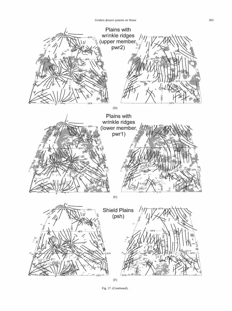
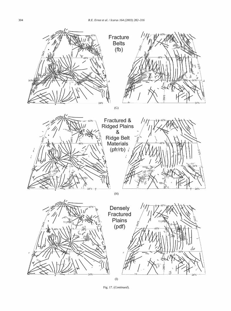
Fig. 17. Comparison of generalized radiating and linear systems (from Figs. 5–11) with the geology after Basilevsky et al. (1999) and Ivanov and Head (2001).Geology units are: (A) rifts; (B) lobate and smooth plains, pl and ps; (C–F) volcanic plains, pwr2, pwr1, and psh; (G) fracture belts, fb; H) fractured and ridgedplains and ridge belts; (I) densely fractured plains, pdf; and (J) tesserae, tt. Units described in Table 5 and discussed in text.
Graben–fissure systems on Venus 303
(D)
(E)
(F)
Fig. 17. (Continued).
304 R.E. Ernst et al. / Icarus 164 (2003) 282–316
(G)
(H)
(I)
Fig. 17. (Continued).
Graben–fissure systems on Venus 305
(J)
Fig. 17. (Continued).
ultstionhipsthe
ovrin-as-rialpi-af-01)ed)rac-b),eltsonssedten-
dnd
inriftsr, in997end
rac-thee)ains
thatoldng
gs ofreyp-ad,d inge
tict is
en–r inhic
t oficu-Oneof
-nly, C3ovnicd lo-onicem,
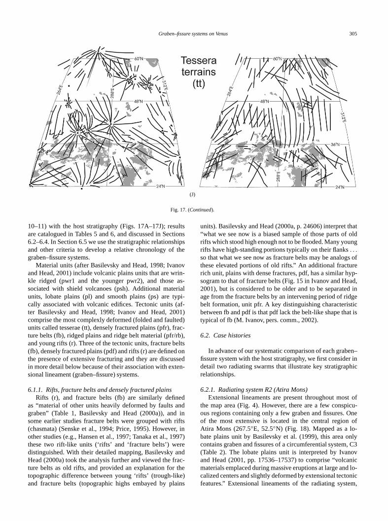
10–11) with the host stratigraphy (Figs. 17A–17J); resare catalogued in Tables 5 and 6, and discussed in Sec6.2–6.4. In Section 6.5 we use the stratigraphic relationsand other criteria to develop a relative chronology ofgraben–fissure systems.
Material units (after Basilevsky and Head, 1998; Ivanand Head, 2001) include volcanic plains units that are wkle ridged (pwr1 and the younger pwr2), and thosesociated with shield volcanoes (psh). Additional mateunits, lobate plains (pl) and smooth plains (ps) are tycally associated with volcanic edifices. Tectonic units (ter Basilevsky and Head, 1998; Ivanov and Head, 20comprise the most complexly deformed (folded and faultunits called tesserae (tt), densely fractured plains (pfr), fture belts (fb), ridged plains and ridge belt material (pfr/rand young rifts (r). Three of the tectonic units, fracture b(fb), densely fractured plains (pdf) and rifts (r) are definedthe presence of extensive fracturing and they are discuin more detail below because of their association with exsional lineament (graben–fissure) systems.
6.1.1. Rifts, fracture belts and densely fractured plainsRifts (r), and fracture belts (fb) are similarly define
as “material of other units heavily deformed by faults agraben” (Table 1, Basilevsky and Head (2000a)), andsome earlier studies fracture belts were grouped with(chasmata) (Senske et al., 1994; Price, 1995). Howeveother studies (e.g., Hansen et al., 1997; Tanaka et al., 1these two rift-like units (‘rifts’ and ‘fracture belts’) werdistinguished. With their detailed mapping, Basilevsky aHead (2000a) took the analysis further and viewed the fture belts as old rifts, and provided an explanation fortopographic difference between young ‘rifts’ (trough-likand fracture belts (topographic highs embayed by pl
s
)
units). Basilevsky and Head (2000a, p. 24606) interpret“what we see now is a biased sample of those parts ofrifts which stood high enough not to be flooded. Many yourifts have high-standing portions typically on their flanks. . .
so that what we see now as fracture belts may be analothese elevated portions of old rifts.” An additional fracturich unit, plains with dense fractures, pdf, has a similar hsogram to that of fracture belts (Fig. 15 in Ivanov and He2001), but is considered to be older and to be separateage from the fracture belts by an intervening period of ridbelt formation, unit pfr. A key distinguishing characterisbetween fb and pdf is that pdf lack the belt-like shape thatypical of fb (M. Ivanov, pers. comm., 2002).
6.2. Case histories
In advance of our systematic comparison of each grabfissure system with the host stratigraphy, we first considedetail two radiating swarms that illustrate key stratigraprelationships.
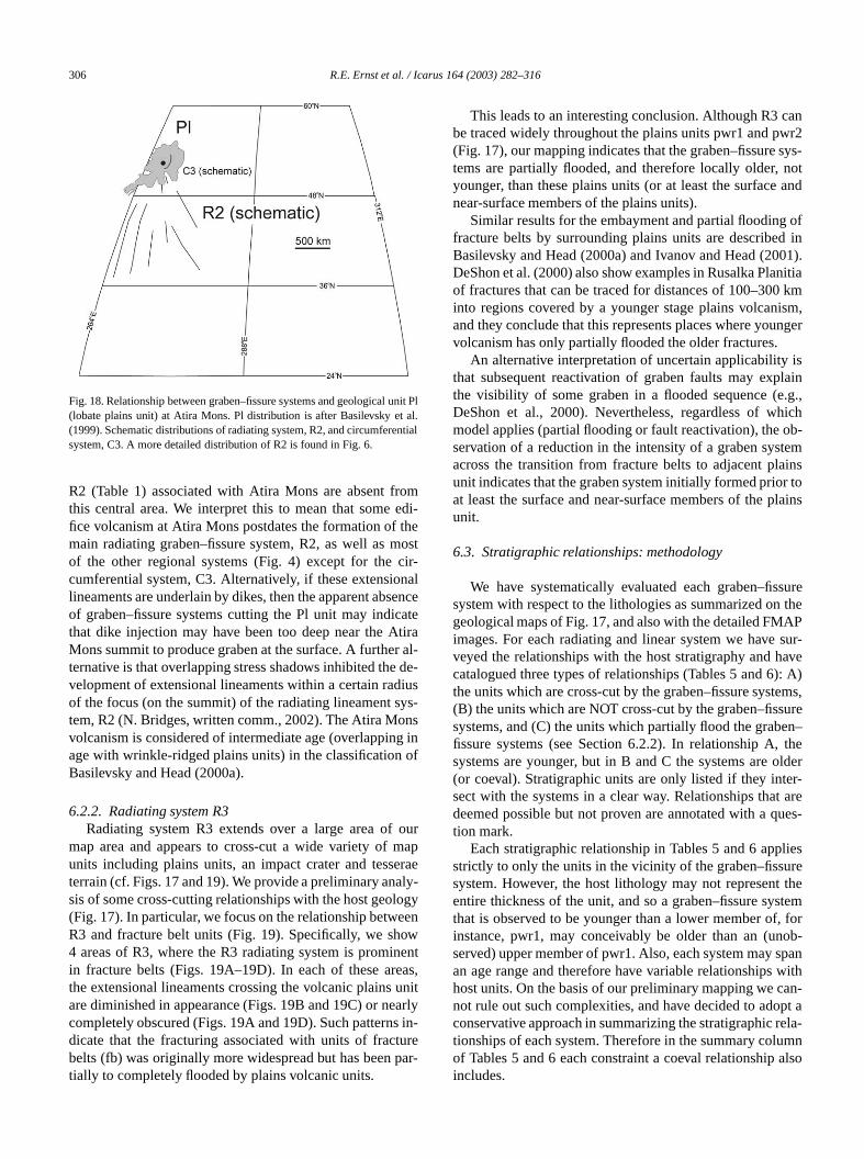
6.2.1. Radiating system R2 (Atira Mons)Extensional lineaments are present throughout mos
the map area (Fig. 4). However, there are a few conspous regions containing only a few graben and fissures.of the most extensive is located in the central regionAtira Mons (267.5◦E, 52.5◦N) (Fig. 18). Mapped as a lobate plains unit by Basilevsky et al. (1999), this area ocontains graben and fissures of a circumferential system(Table 2). The lobate plains unit is interpreted by Ivanand Head (2001, pp. 17536–17537) to comprise “volcamaterials emplaced during massive eruptions at large ancalized centers and slightly deformed by extensional tectfeatures.” Extensional lineaments of the radiating syst
306 R.E. Ernst et al. / Icarus 164 (2003) 282–316
unit Pal.ntial
omedi-themoscir-nalenc
catetira
r al-de-iusys-nsg inof
ourmaperaely-
logyeenownentas,unitarly
s in-urepar-
canwr2sys-notand
ofd in01).nitiakm
ism,nger
islain.g.,hichob-temainsr tolains
surethe
APsur-ave
): A)ems,ure
en–the
olderer-t areues-
liesrethe
stem, forob-
spanwithan-pt a
rela-umnalso
Fig. 18. Relationship between graben–fissure systems and geological(lobate plains unit) at Atira Mons. Pl distribution is after Basilevsky et(1999). Schematic distributions of radiating system, R2, and circumferesystem, C3. A more detailed distribution of R2 is found in Fig. 6.
R2 (Table 1) associated with Atira Mons are absent frthis central area. We interpret this to mean that somefice volcanism at Atira Mons postdates the formation ofmain radiating graben–fissure system, R2, as well asof the other regional systems (Fig. 4) except for thecumferential system, C3. Alternatively, if these extensiolineaments are underlain by dikes, then the apparent absof graben–fissure systems cutting the Pl unit may indithat dike injection may have been too deep near the AMons summit to produce graben at the surface. A furtheternative is that overlapping stress shadows inhibited thevelopment of extensional lineaments within a certain radof the focus (on the summit) of the radiating lineament stem, R2 (N. Bridges, written comm., 2002). The Atira Movolcanism is considered of intermediate age (overlappinage with wrinkle-ridged plains units) in the classificationBasilevsky and Head (2000a).
6.2.2. Radiating system R3Radiating system R3 extends over a large area of
map area and appears to cross-cut a wide variety ofunits including plains units, an impact crater and tessterrain (cf. Figs. 17 and 19). We provide a preliminary anasis of some cross-cutting relationships with the host geo(Fig. 17). In particular, we focus on the relationship betwR3 and fracture belt units (Fig. 19). Specifically, we sh4 areas of R3, where the R3 radiating system is promiin fracture belts (Figs. 19A–19D). In each of these arethe extensional lineaments crossing the volcanic plainsare diminished in appearance (Figs. 19B and 19C) or necompletely obscured (Figs. 19A and 19D). Such patterndicate that the fracturing associated with units of fractbelts (fb) was originally more widespread but has beentially to completely flooded by plains volcanic units.
l
t
e
This leads to an interesting conclusion. Although R3be traced widely throughout the plains units pwr1 and p(Fig. 17), our mapping indicates that the graben–fissuretems are partially flooded, and therefore locally older,younger, than these plains units (or at least the surfacenear-surface members of the plains units).
Similar results for the embayment and partial floodingfracture belts by surrounding plains units are describeBasilevsky and Head (2000a) and Ivanov and Head (20DeShon et al. (2000) also show examples in Rusalka Plaof fractures that can be traced for distances of 100–300into regions covered by a younger stage plains volcanand they conclude that this represents places where youvolcanism has only partially flooded the older fractures.
An alternative interpretation of uncertain applicabilitythat subsequent reactivation of graben faults may expthe visibility of some graben in a flooded sequence (eDeShon et al., 2000). Nevertheless, regardless of wmodel applies (partial flooding or fault reactivation), theservation of a reduction in the intensity of a graben sysacross the transition from fracture belts to adjacent plunit indicates that the graben system initially formed prioat least the surface and near-surface members of the punit.
6.3. Stratigraphic relationships: methodology
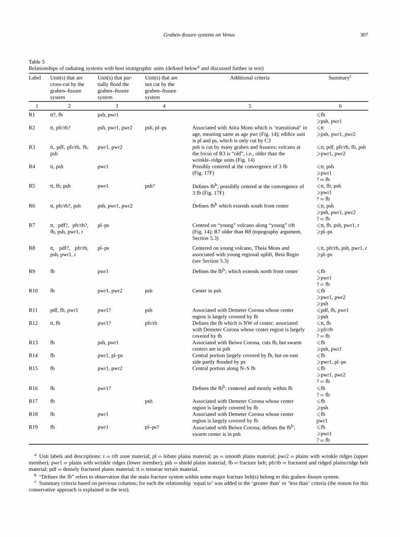
We have systematically evaluated each graben–fissystem with respect to the lithologies as summarized ongeological maps of Fig. 17, and also with the detailed FMimages. For each radiating and linear system we haveveyed the relationships with the host stratigraphy and hcatalogued three types of relationships (Tables 5 and 6the units which are cross-cut by the graben–fissure syst(B) the units which are NOT cross-cut by the graben–fisssystems, and (C) the units which partially flood the grabfissure systems (see Section 6.2.2). In relationship A,systems are younger, but in B and C the systems are(or coeval). Stratigraphic units are only listed if they intsect with the systems in a clear way. Relationships thadeemed possible but not proven are annotated with a qtion mark.
Each stratigraphic relationship in Tables 5 and 6 appstrictly to only the units in the vicinity of the graben–fissusystem. However, the host lithology may not represententire thickness of the unit, and so a graben–fissure sythat is observed to be younger than a lower member ofinstance, pwr1, may conceivably be older than an (unserved) upper member of pwr1. Also, each system mayan age range and therefore have variable relationshipshost units. On the basis of our preliminary mapping we cnot rule out such complexities, and have decided to adoconservative approach in summarizing the stratigraphictionships of each system. Therefore in the summary colof Tables 5 and 6 each constraint a coeval relationshipincludes.
Graben–fissure systems on Venus 307
Table 5Relationships of radiating systems with host stratigraphic units (defined belowa and discussed further in text)
Label Unit(s) that arecross-cut by thegraben–fissuresystem
Unit(s) that par-tially flood thegraben–fissuresystem
Unit(s) that arenot cut by thegraben–fissuresystem
Additional criteria Summaryc
1 2 3 4 5 6
R1 tt?, fb psh, pwr1 �fb�psh, pwr1
R2 tt, pfr/rb? psh, pwr1, pwr2 psh, pl–ps Associated with Atira Mons which is ‘transitional’ inage, meaning same as age pwr (Fig. 14); edifice unitis pl and ps, which is only cut by C3
�tt�psh, pwr1, pwr2
R3 tt, pdf, pfr/rb, fb,psh
pwr1, pwr2 psh is cut by many graben and fissures; volcano atthe focus of R3 is “old”, i.e., older than thewrinkle–ridge units (Fig. 14)
�tt, pdf, pfr/rb, fb, psh�pwr1, pwr2
R4 tt, psh pwr1 Possibly centered at the convergence of 3 fb(Fig. 17F)
�tt, psh�pwr1?= fb
R5 tt, fb, psh pwr1 psh? Defines fbb; possiblly centred at the convergence of3 fb (Fig. 17F)
�tt, fb, psh�pwr1?= fb
R6 tt, pfr/rb?, psh psh, pwr1, pwr2 Defines fbb which extends south from center �tt, psh�psh, pwr1, pwr2?= fb
R7 tt, pdf?, pfr/rb?,fb, psh, pwr1, r
pl–ps Centred on “young” volcano along “young” rift(Fig. 14); R7 older than R8 (topography argument,Section 5.3)
�tt, fb, psh, pwr1, r�pl–ps
R8 tt, pdf?, pfr/rb,psh, pwr1, r
pl–ps Centered on young volcano, Theia Mons andassociated with young regional uplift, Beta Regio(see Section 5.3)
�tt, pfr/rb, psh, pwr1, r�pl–ps
R9 fb pwr1 Defines the fbb; which extends north from center �fb�pwr1?= fb
R10 fb pwr1, pwr2 psh Center in psh �fb�pwr1, pwr2�psh
R11 pdf, fb, pwr1 pwr1? psh Associated with Demeter Corona whose centerregion is largely covered by fb
�pdf, fb, pwr1�psh
R12 tt, fb pwr1? pfr/rb Defines the fb which is NW of center; associatedwith Demeter Corona whose center region is largelycovered by fb
�tt, fb�pfr/rb?= fb
R13 fb psh, pwr1 Associated with Beiwe Corona, cuts fb, but swarmcenters are in psh
�fb�psh, pwr1
R14 fb pwr1, pl–ps Central portion largely covered by fb, but on eastside partly flooded by ps
�fb�pwr1, pl–ps
R15 fb pwr1, pwr2 Central portion along N–S fb �fb�pwr1, pwr2?= fb
R16 fb pwr1? Defines the fbb; centered and mostly within fb �fb?= fb
R17 fb psh Associated with Demeter Corona whose centerregion is largely covered by fb
�fb�psh
R18 fb pwr1 Associated with Demeter Corona whose centerregion is largely covered by fb
�fbpwr1
R19 fb pwr1 pl–ps? Associated with Beiwe Corona; defines the fbb;swarm center is in psh
�fb�pwr1?= fb
a Unit labels and descriptions: r= rift zone material; pl= lobate plains material; ps= smooth plains material; pwr2= plains with wrinkle ridges (uppermember); pwr1= plains with wrinkle ridges (lower member); psh= shield plains material; fb= fracture belt; pfr/rb= fractured and ridged plains/ridge beltmaterial; pdf= densely fractured plains material; tt= tesserae terrain material.
b “Defines the fb” refers to observation that the main fracture system within some major fracture belt(s) belong to this graben–fissure system.c Summary criteria based on previous columns; for each the relationship ‘equal to’ was added to the ‘greater than’ or ‘less than’ criteria (the reason for this
conservative approach is explained in the text).
308 R.E. Ernst et al. / Icarus 164 (2003) 282–316
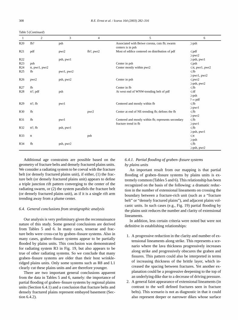
Table 5 (Continued)
1 2 3 4 5 6
R20 fb? psh Associated with Beiwe corona, cuts fb; swarmcenters is in psh
�psh
R21 pdf pwr2 fb?, pwr2 Most of edifice centered on distribution of pdf �pdf�pwr2
R22 psh, pwr1 �psh, pwr1R23 psh Center in psh �pshR24 tt, pwr1, pwr2 Center mostly within pwr2 �tt, pwr1, pwr2R25 fb pwr1, pwr2 �fb
�pwr1, pwr2R26 pwr2 psh, pwr2 Center in psh �pwr2
�psh, pwr2R27 fb Center in fb �fbR28 tt?, pdf psh At west end of WNW-trending belt of pdf �df
�psh?= pdf
R29 tt?, fb pwr1 Centered and mostly within fb �fb�pwr1
R30 fb pwr2 Center at end of NE-trending fb; defines the fb �fb�pwr2
R31 fb pwr1 Centered and mostly within fb; represents secondaryfracture trend in fb
�fb�pwr1
R32 tt?, fb psh, pwr1 �fb�psh, pwr1
R33 tt psh �tt�psh
R34 fb psh, pwr2 �fb�psh, pwr2
thenits.tureac-fine
thebeltrm
ncerivedfracso inrtialated
beanykle-
d L1
rente ofainsand(Sec
ialex-eenuc-the
tureol-by
onal
not
ex-sce-sesandrmsin-r ex-p ofure.s (intureuldrface
Additional age constraints are possible based ongeometry of fracture belts and densely fractured plains uWe consider a radiating system to be coeval with the fracbelt (or densely fractured plains unit), if either, (1) the frture belt (or densely fractured plains unit) appears to dea triple junction rift pattern converging to the center ofradiating swarm, or (2) the system parallels the fracture(or densely fractured plains unit), as if it is a single rift atrending away from a plume center.
6.4. General conclusions from stratigraphic analysis
Our analysis is very preliminary given the reconnaissanature of this study. Some general conclusions are defrom Tables 5 and 6. In many cases, tesserae andture belts were cross-cut by graben–fissure systems. Almany cases, graben–fissure systems appear to be paflooded by plains units. This conclusion was demonstrfor radiating system R3 in Fig. 19, but also appears totrue of other radiating systems. So we conclude that mgraben–fissure systems are older than their host wrinridged plains units. Only some systems such as R8 anclearly cut these plains units and are therefore younger.
There are two important general conclusions appafrom the data in Tables 5 and 6, namely: the importancpartial flooding of graben–fissure systems by regional plunits (Section 6.4.1) and a conclusion that fracture beltsdensely fractured plains represent embayed basementtion 6.4.2).
-
ly
-
6.4.1. Partial flooding of graben–fissure systemsby plains units
An important result from our mapping is that partflooding of graben–fissure systems by plains units istremely common (Tables 5 and 6). This relationship has brecognized on the basis of the following: a dramatic redtion in the number of extensional lineaments on crossingboundary between a fracture-rich unit (such as a “fracbelt” or “densely fractured plains”), and adjacent plains vcanic units. In such cases (e.g., Fig. 19) partial floodingthe plains unit reduces the number and clarity of extensilineaments.
In addition, less certain criteria were noted but weredefinitive in establishing relationships:
1. A progressive reduction in the clarity and number oftensional lineaments along strike. This represents anario where the lava thickness progressively increaalong strike and progressively obscures the grabenfissures. This pattern could also be interpreted in teof increasing thickness of the brittle layer, whichcreased the spacing between fractures. Yet anotheplanation could be a progressive deepening to the toan underlying dike due to a decrease of driving press
2. A general faint appearance of extensional lineamentcontrast to the well defined fractures seen in fracbelts). This scenario is not as diagnostic in that it coalso represent deeper or narrower dikes whose su
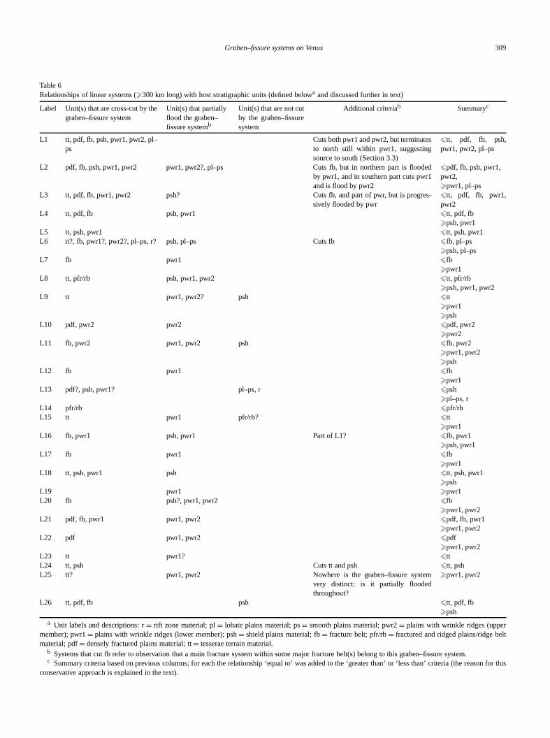
Graben–fissure systems on Venus 309
Table 6Relationships of linear systems (�300 km long) with host stratigraphic units (defined belowa and discussed further in text)
Label Unit(s) that are cross-cut by thegraben–fissure system
Unit(s) that partiallyflood the graben–fissure systemb
Unit(s) that are not cutby the graben–fissuresystem
Additional criteriab Summaryc
L1 tt, pdf, fb, psh, pwr1, pwr2, pl–ps
Cuts both pwr1 and pwr2, but terminatesto north still within pwr1, suggestingsource to south (Section 3.3)
�tt, pdf, fb, psh,pwr1, pwr2, pl–ps
L2 pdf, fb, psh, pwr1, pwr2 pwr1, pwr2?, pl–ps Cuts fb, but in northern part is floodedby pwr1, and in southern part cuts pwr1and is flood by pwr2
�pdf, fb, psh, pwr1,pwr2,�pwr1, pl–ps
L3 tt, pdf, fb, pwr1, pwr2 psh? Cuts fb, and part of pwr, but is progres-sively flooded by pwr
�tt, pdf, fb, pwr1,pwr2
L4 tt, pdf, fb psh, pwr1 �tt, pdf, fb�psh, pwr1
L5 tt, psh, pwr1 �tt, psh, pwr1L6 tt?, fb, pwr1?, pwr2?, pl–ps, r? psh, pl–ps Cuts fb �fb, pl–ps
�psh, pl–psL7 fb pwr1 �fb
�pwr1L8 tt, pfr/rb psh, pwr1, pwr2 �tt, pfr/rb
�psh, pwr1, pwr2L9 tt pwr1, pwr2? psh �tt
�pwr1�psh
L10 pdf, pwr2 pwr2 �pdf, pwr2�pwr2
L11 fb, pwr2 pwr1, pwr2 psh �fb, pwr2�pwr1, pwr2�psh
L12 fb pwr1 �fb�pwr1
L13 pdf?, psh, pwr1? pl–ps, r �psh�pl–ps, r
L14 pfr/rb �pfr/rbL15 tt pwr1 pfr/rb? �tt
�pwr1L16 fb, pwr1 psh, pwr1 Part of L1? �fb, pwr1
�psh, pwr1L17 fb pwr1 �fb
�pwr1L18 tt, psh, pwr1 psh �tt, psh, pwr1
�pshL19 pwr1 �pwr1L20 fb psh?, pwr1, pwr2 �fb
�pwr1, pwr2L21 pdf, fb, pwr1 pwr1, pwr2 �pdf, fb, pwr1
�pwr1, pwr2L22 pdf pwr1, pwr2 �pdf
�pwr1, pwr2L23 tt pwr1? �ttL24 tt, psh Cuts tt and psh �tt, pshL25 tt? pwr1, pwr2 Nowhere is the graben–fissure system
very distinct; is it partially floodedthroughout?
�pwr1, pwr2
L26 tt, pdf, fb psh �tt, pdf, fb�psh
a Unit labels and descriptions: r= rift zone material; pl= lobate plains material; ps= smooth plains material; pwr2= plains with wrinkle ridges (uppermember); pwr1= plains with wrinkle ridges (lower member); psh= shield plains material; fb= fracture belt; pfr/rb= fractured and ridged plains/ridge beltmaterial; pdf= densely fractured plains material; tt= tesserae terrain material.
b Systems that cut fb refer to observation that a main fracture system within some major fracture belt(s) belong to this graben–fissure system.c Summary criteria based on previous columns; for each the relationship ‘equal to’ was added to the ‘greater than’ or ‘less than’ criteria (the reason for this
conservative approach is explained in the text).
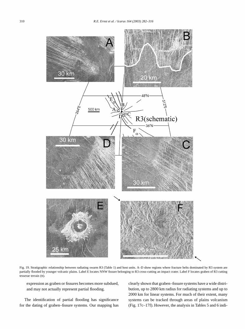
310 R.E. Ernst et al. / Icarus 164 (2003) 282–316
systemR3 cu
Fig. 19. Stratigraphic relationship between radiating swarm R3 (Table 1) and host units. A–D show regions where fracture belts dominated by R3arepartially flooded by younger volcanic plains. Label E locates NNW fissure belonging to R3 cross-cutting an impact crater. Label F locates graben oftting
tesserae terrain (tt).due
cehas
istri-p toanynismdi-
expression as graben or fissures becomes more suband may not actually represent partial flooding.
The identification of partial flooding has significanfor the dating of graben–fissure systems. Our mapping
d,clearly shown that graben–fissure systems have a wide dbution, up to 2800 km radius for radiating systems and u2000 km for linear systems. For much of their extent, msystems can be tracked through areas of plains volca(Fig. 17c–17f). However, the analysis in Tables 5 and 6 in
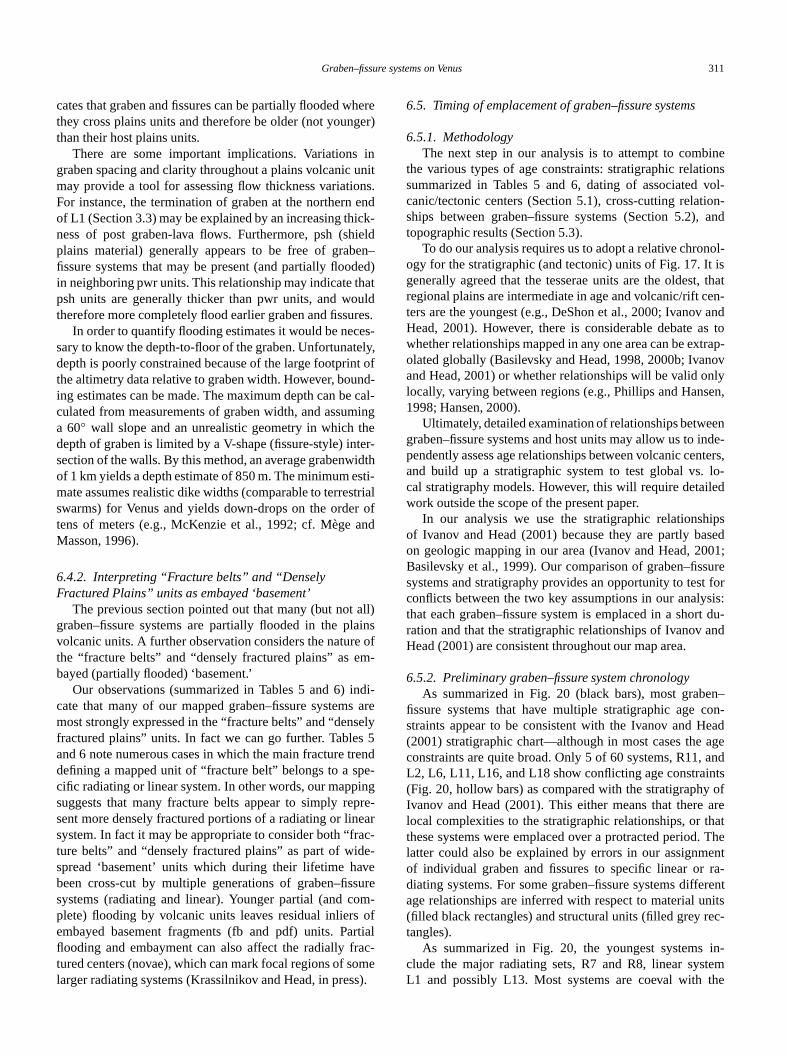
Graben–fissure systems on Venus 311
hereger)
inunitns.endick-ielden–ded)hatuldres.es-ely,t ofnd-caling
heter-idthsti-tria
r ofand
all)ainse ofm-
di-s arely
s 5rendpe-ingpre-earac-e-vesurem-ofrtialac-omes).
ineionsvol-ion-
and
nol-t is, thaten-ands totrap-novnlyen,
ennde-nters,lo-
led
ipssed01;uret forsis:t du-and
n–con-eadageand
ntsofare
hat. Theentra-rentnitsec-
in-temthe
cates that graben and fissures can be partially flooded wthey cross plains units and therefore be older (not younthan their host plains units.
There are some important implications. Variationsgraben spacing and clarity throughout a plains volcanicmay provide a tool for assessing flow thickness variatioFor instance, the termination of graben at the northernof L1 (Section 3.3) may be explained by an increasing thness of post graben-lava flows. Furthermore, psh (shplains material) generally appears to be free of grabfissure systems that may be present (and partially flooin neighboring pwr units. This relationship may indicate tpsh units are generally thicker than pwr units, and wotherefore more completely flood earlier graben and fissu
In order to quantify flooding estimates it would be necsary to know the depth-to-floor of the graben. Unfortunatdepth is poorly constrained because of the large footprinthe altimetry data relative to graben width. However, bouing estimates can be made. The maximum depth can beculated from measurements of graben width, and assuma 60◦ wall slope and an unrealistic geometry in which tdepth of graben is limited by a V-shape (fissure-style) insection of the walls. By this method, an average grabenwof 1 km yields a depth estimate of 850 m. The minimum emate assumes realistic dike widths (comparable to terresswarms) for Venus and yields down-drops on the ordetens of meters (e.g., McKenzie et al., 1992; cf. MègeMasson, 1996).
6.4.2. Interpreting “Fracture belts” and “DenselyFractured Plains” units as embayed ‘basement’
The previous section pointed out that many (but notgraben–fissure systems are partially flooded in the plvolcanic units. A further observation considers the naturthe “fracture belts” and “densely fractured plains” as ebayed (partially flooded) ‘basement.’
Our observations (summarized in Tables 5 and 6) incate that many of our mapped graben–fissure systemmost strongly expressed in the “fracture belts” and “densfractured plains” units. In fact we can go further. Tableand 6 note numerous cases in which the main fracture tdefining a mapped unit of “fracture belt” belongs to a scific radiating or linear system. In other words, our mappsuggests that many fracture belts appear to simply resent more densely fractured portions of a radiating or linsystem. In fact it may be appropriate to consider both “frture belts” and “densely fractured plains” as part of widspread ‘basement’ units which during their lifetime habeen cross-cut by multiple generations of graben–fissystems (radiating and linear). Younger partial (and coplete) flooding by volcanic units leaves residual inliersembayed basement fragments (fb and pdf) units. Paflooding and embayment can also affect the radially frtured centers (novae), which can mark focal regions of slarger radiating systems (Krassilnikov and Head, in pres
-
l
e
6.5. Timing of emplacement of graben–fissure systems
6.5.1. MethodologyThe next step in our analysis is to attempt to comb
the various types of age constraints: stratigraphic relatsummarized in Tables 5 and 6, dating of associatedcanic/tectonic centers (Section 5.1), cross-cutting relatships between graben–fissure systems (Section 5.2),topographic results (Section 5.3).
To do our analysis requires us to adopt a relative chroogy for the stratigraphic (and tectonic) units of Fig. 17. Igenerally agreed that the tesserae units are the oldestregional plains are intermediate in age and volcanic/rift cters are the youngest (e.g., DeShon et al., 2000; IvanovHead, 2001). However, there is considerable debate awhether relationships mapped in any one area can be exolated globally (Basilevsky and Head, 1998, 2000b; Ivaand Head, 2001) or whether relationships will be valid olocally, varying between regions (e.g., Phillips and Hans1998; Hansen, 2000).
Ultimately, detailed examination of relationships betwegraben–fissure systems and host units may allow us to ipendently assess age relationships between volcanic ceand build up a stratigraphic system to test global vs.cal stratigraphy models. However, this will require detaiwork outside the scope of the present paper.
In our analysis we use the stratigraphic relationshof Ivanov and Head (2001) because they are partly baon geologic mapping in our area (Ivanov and Head, 20Basilevsky et al., 1999). Our comparison of graben–fisssystems and stratigraphy provides an opportunity to tesconflicts between the two key assumptions in our analythat each graben–fissure system is emplaced in a shorration and that the stratigraphic relationships of IvanovHead (2001) are consistent throughout our map area.
6.5.2. Preliminary graben–fissure system chronologyAs summarized in Fig. 20 (black bars), most grabe
fissure systems that have multiple stratigraphic agestraints appear to be consistent with the Ivanov and H(2001) stratigraphic chart—although in most cases theconstraints are quite broad. Only 5 of 60 systems, R11,L2, L6, L11, L16, and L18 show conflicting age constrai(Fig. 20, hollow bars) as compared with the stratigraphyIvanov and Head (2001). This either means that therelocal complexities to the stratigraphic relationships, or tthese systems were emplaced over a protracted periodlatter could also be explained by errors in our assignmof individual graben and fissures to specific linear ordiating systems. For some graben–fissure systems diffeage relationships are inferred with respect to material u(filled black rectangles) and structural units (filled grey rtangles).
As summarized in Fig. 20, the youngest systemsclude the major radiating sets, R7 and R8, linear sysL1 and possibly L13. Most systems are coeval with
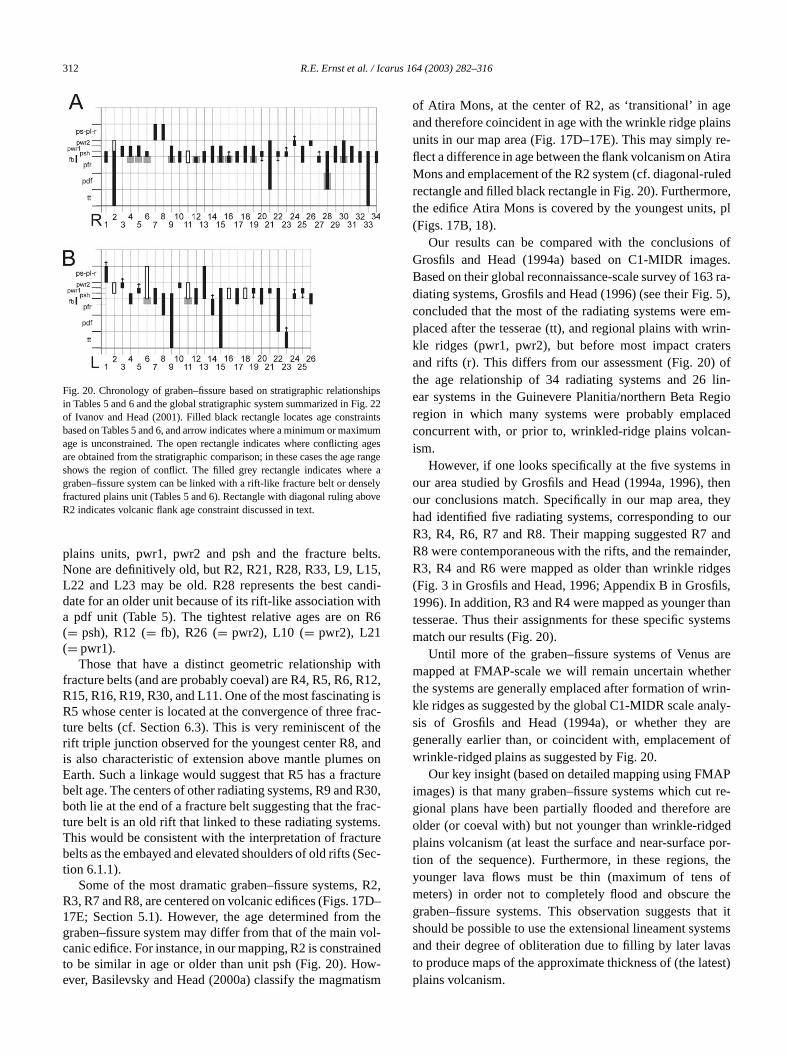
312 R.E. Ernst et al. / Icarus 164 (2003) 282–316
shipsig. 22aintsimumagerang
re asely
bove
lts.5,ndi-ithR6
ith12
g isfracthend
s ontureR30rac-ms.ureSec
, R27D–the
vol-inedw-tism
geinsre-tirauledore,, pl
ofes.3 ra-. 5),em-rin-ersoflin-egiocedn-
inthenheyourandder,gesls,thantems
areherrin-aly-aret of
APt re-are
edpor-
, theofthe
hat ittemsas
test)
Fig. 20. Chronology of graben–fissure based on stratigraphic relationin Tables 5 and 6 and the global stratigraphic system summarized in Fof Ivanov and Head (2001). Filled black rectangle locates age constrbased on Tables 5 and 6, and arrow indicates where a minimum or maxage is unconstrained. The open rectangle indicates where conflictingare obtained from the stratigraphic comparison; in these cases the ageshows the region of conflict. The filled grey rectangle indicates whegraben–fissure system can be linked with a rift-like fracture belt or denfractured plains unit (Tables 5 and 6). Rectangle with diagonal ruling aR2 indicates volcanic flank age constraint discussed in text.
plains units, pwr1, pwr2 and psh and the fracture beNone are definitively old, but R2, R21, R28, R33, L9, L1L22 and L23 may be old. R28 represents the best cadate for an older unit because of its rift-like association wa pdf unit (Table 5). The tightest relative ages are on(= psh), R12 (= fb), R26 (= pwr2), L10 (= pwr2), L21(= pwr1).
Those that have a distinct geometric relationship wfracture belts (and are probably coeval) are R4, R5, R6, RR15, R16, R19, R30, and L11. One of the most fascinatinR5 whose center is located at the convergence of threeture belts (cf. Section 6.3). This is very reminiscent ofrift triple junction observed for the youngest center R8, ais also characteristic of extension above mantle plumeEarth. Such a linkage would suggest that R5 has a fracbelt age. The centers of other radiating systems, R9 andboth lie at the end of a fracture belt suggesting that the fture belt is an old rift that linked to these radiating systeThis would be consistent with the interpretation of fractbelts as the embayed and elevated shoulders of old rifts (tion 6.1.1).
Some of the most dramatic graben–fissure systemsR3, R7 and R8, are centered on volcanic edifices (Figs. 117E; Section 5.1). However, the age determined fromgraben–fissure system may differ from that of the maincanic edifice. For instance, in our mapping, R2 is constrato be similar in age or older than unit psh (Fig. 20). Hoever, Basilevsky and Head (2000a) classify the magma
se
,
-
,
-
,
of Atira Mons, at the center of R2, as ‘transitional’ in aand therefore coincident in age with the wrinkle ridge plaunits in our map area (Fig. 17D–17E). This may simplyflect a difference in age between the flank volcanism on AMons and emplacement of the R2 system (cf. diagonal-rrectangle and filled black rectangle in Fig. 20). Furthermthe edifice Atira Mons is covered by the youngest units(Figs. 17B, 18).
Our results can be compared with the conclusionsGrosfils and Head (1994a) based on C1-MIDR imagBased on their global reconnaissance-scale survey of 16diating systems, Grosfils and Head (1996) (see their Figconcluded that the most of the radiating systems wereplaced after the tesserae (tt), and regional plains with wkle ridges (pwr1, pwr2), but before most impact cratand rifts (r). This differs from our assessment (Fig. 20)the age relationship of 34 radiating systems and 26ear systems in the Guinevere Planitia/northern Beta Rregion in which many systems were probably emplaconcurrent with, or prior to, wrinkled-ridge plains volcaism.
However, if one looks specifically at the five systemsour area studied by Grosfils and Head (1994a, 1996),our conclusions match. Specifically in our map area, thad identified five radiating systems, corresponding toR3, R4, R6, R7 and R8. Their mapping suggested R7R8 were contemporaneous with the rifts, and the remainR3, R4 and R6 were mapped as older than wrinkle rid(Fig. 3 in Grosfils and Head, 1996; Appendix B in Grosfi1996). In addition, R3 and R4 were mapped as youngertesserae. Thus their assignments for these specific sysmatch our results (Fig. 20).
Until more of the graben–fissure systems of Venusmapped at FMAP-scale we will remain uncertain whetthe systems are generally emplaced after formation of wkle ridges as suggested by the global C1-MIDR scale ansis of Grosfils and Head (1994a), or whether theygenerally earlier than, or coincident with, emplacemenwrinkle-ridged plains as suggested by Fig. 20.
Our key insight (based on detailed mapping using FMimages) is that many graben–fissure systems which cugional plans have been partially flooded and thereforeolder (or coeval with) but not younger than wrinkle-ridgplains volcanism (at least the surface and near-surfacetion of the sequence). Furthermore, in these regionsyounger lava flows must be thin (maximum of tensmeters) in order not to completely flood and obscuregraben–fissure systems. This observation suggests tshould be possible to use the extensional lineament sysand their degree of obliteration due to filling by later lavto produce maps of the approximate thickness of (the laplains volcanism.
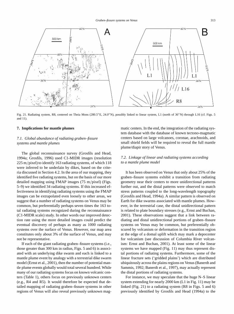
Graben–fissure systems on Venus 313
Fig. 21. Radiating system, R8, centered on Theia Mons (280.5◦E, 24.0◦N), possibly linked to linear system, L1 (north of 36◦N) through L16 (cf. Figs. 5and 11).
ead,ion8
rite-theyore
ef-APs, wy beto-
anceec-theting
areamay
i.e.,soci-o arman-ileen-tersde-therg-
sys-atic, and
tle
f thetingernsatchphyon
ow-ternchan,n ra-ureob-ionnteran-eart dis-the
tedandsent
nearbe6)
the
7. Implications for mantle plumes
7.1. Global abundance of radiating graben–fissuresystems and mantle plumes
The global reconnaissance survey (Grosfils and H1994a; Grosfils, 1996) used C1-MIDR images (resolut225 m/pixel) to identify 163 radiating systems, of which 11were inferred to be underlain by dikes, based on the cria discussed in Section 4.2. In the area of our mapping,identified five radiating systems, but on the basis of our mdetailed mapping using FMAP images (75 m/pixel) (Figs.5–9) we identified 34 radiating systems. If this increasedfectiveness in identifying radiating systems using the FMimages can be extrapolated even loosely to other areasuggest that a number of radiating systems on Venus macommon, but preferentially perhaps seven times the 163tal radiating systems recognized during the reconnaiss(C1-MIDR scale) study. In other words our improved dettion rate using the more detailed images could predicteventual discovery of perhaps as many as 1000 radiasystems over the surface of Venus. However, our mapconstitutes only about 3% of the surface of Venus, andnot be representative.
If each of the giant radiating graben–fissure systems (those greater than 300 km in radius, Figs. 5 and 6) is asated with an underlying dike swarm and each is linked tmantle plume event by analogy with a terrestrial dike swamodel (Ernst et al., 2001), then the number of potential mtle plume events globally would total several hundred. Whmany of our radiating systems focus on known volcanic cters (Table 1), others focus on previously unknown cen(e.g., R4 and R5). It would therefore be expected thattailed mapping of radiating graben–fissure systems in oregions of Venus will also reveal previously unknown ma
e
matic centers. In the end, the integration of the radiatingtem database with the database of known tectono-magmcenters based on large volcanoes, coronae, arachnoidssmall shield fields will be required to reveal the full manplume/diapir story of Venus.
7.2. Linkage of linear and radiating systems accordingto a mantle plume model
It has been observed on Venus that only about 25% ograben–fissure systems exhibit a transition from radiageometry near their centers to more unidirectional pattfurther out, and the distal patterns were observed to mstress patterns coupled to the long-wavelength topogra(Grosfils and Head, 1994a). A similar pattern is observedEarth for dike swarms associated with mantle plumes. Hever, in the terrestrial case, the distal unidirectional patis related to plate boundary stresses (e.g., Ernst and Bu2001). These observations suggest that a link betweediating and distal unidirectional portions of graben–fisssystems on Venus may be common, but preferentiallyscured by volcanism or deformation in the transition regat the edge of a domal uplift which may mark a depocefor volcanism (see discussion of Columbia River volcism: Ernst and Buchan, 2001). At least some of the linsystems we have mapped (Fig. 11) may thus represental portions of radiating systems. Furthermore, some oflinear fracture sets (‘gridded plains’) which are distribuubiquitously across the plains regions on Venus (BanerdtSammis, 1992; Banerdt et al., 1997), may actually reprethe distal portions of radiating systems.
For instance, we may speculate that the huge N–S lisystem extending for nearly 2000 km (L1 in Fig. 11) maylinked (Fig. 21) to a radiating system (R8 in Figs. 5 andpreviously identified by Grosfils and Head (1994a) to
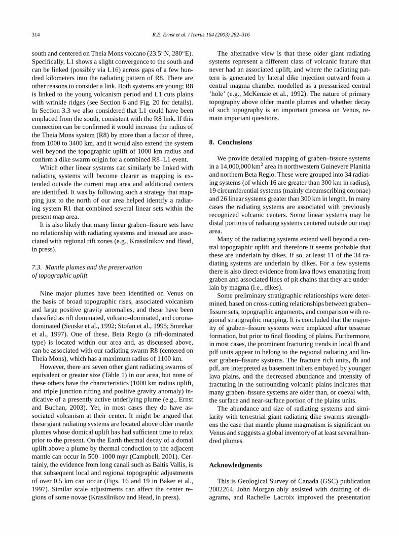
314 R.E. Ernst et al. / Icarus 164 (2003) 282–316
andun-are; R8insls).eenhiss ofree,temndt.ithex-
nterap-iat-the
avessoad,
onnismbeenona-ekatedoved on
s ofe ofpliftn-nstas
thatantllaxmalenter-, isental.,r re-
ingthatpat-
antralry
ecay, re-
emsitiadiat-ius),ae)any
ouslyy bemap
en-that
ra-emsromnder-
ter-ben–th re-jor-seraere,andlin-andngerity ofhatwith,
imi-th-t onhun-
iondi-tion
south and centered on Theia Mons volcano (23.5◦N, 280◦E).Specifically, L1 shows a slight convergence to the southcan be linked (possibly via L16) across gaps of a few hdred kilometers into the radiating pattern of R8. Thereother reasons to consider a link. Both systems are youngis linked to the young volcanism period and L1 cuts plawith wrinkle ridges (see Section 6 and Fig. 20 for detaiIn Section 3.3 we also considered that L1 could have bemplaced from the south, consistent with the R8 link. If tconnection can be confirmed it would increase the radiuthe Theia Mons system (R8) by more than a factor of thfrom 1000 to 3400 km, and it would also extend the syswell beyond the topographic uplift of 1000 km radius aconfirm a dike swarm origin for a combined R8–L1 even
Which other linear systems can similarly be linked wradiating systems will become clearer as mapping istended outside the current map area and additional ceare identified. It was by following such a strategy that mping just to the north of our area helped identify a rading system R1 that combined several linear sets withinpresent map area.
It is also likely that many linear graben–fissure sets hno relationship with radiating systems and instead are aciated with regional rift zones (e.g., Krassilnikov and Hein press).
7.3. Mantle plumes and the preservationof topographic uplift
Nine major plumes have been identified on Venusthe basis of broad topographic rises, associated volcaand large positive gravity anomalies, and these haveclassified as rift dominated, volcano-dominated, and cordominated (Senske et al., 1992; Stofan et al., 1995; Smret al., 1997). One of these, Beta Regio (a rift-dominatype) is located within our area and, as discussed abcan be associated with our radiating swarm R8 (centereTheia Mons), which has a maximum radius of 1100 km.
However, there are seven other giant radiating swarmequivalent or greater size (Table 1) in our area, but nonthese others have the characteristics (1000 km radius uand triple junction rifting and positive gravity anomaly) idicative of a presently active underlying plume (e.g., Erand Buchan, 2003). Yet, in most cases they do havesociated volcanism at their center. It might be arguedthese giant radiating systems are located above older mplumes whose domical uplift has had sufficient time to reprior to the present. On the Earth thermal decay of a douplift above a plume by thermal conduction to the adjacmantle can occur in 500–1000 myr (Campbell, 2001). Ctainly, the evidence from long canali such as Baltis Vallisthat subsequent local and regional topographic adjustmof over 0.5 km can occur (Figs. 16 and 19 in Baker et1997). Similar scale adjustments can affect the centegions of some novae (Krassilnikov and Head, in press).
s
-
r
,
,
-
e
s
The alternative view is that these older giant radiatsystems represent a different class of volcanic featurenever had an associated uplift, and where the radiatingtern is generated by lateral dike injection outward fromcentral magma chamber modelled as a pressurized ce‘hole’ (e.g., McKenzie et al., 1992). The nature of primatopography above older mantle plumes and whether dof such topography is an important process on Venusmain important questions.
8. Conclusions
We provide detailed mapping of graben–fissure systin a 14,000,000 km2 area in northwestern Guinevere Planand northern Beta Regio. These were grouped into 34 raing systems (of which 16 are greater than 300 km in rad19 circumferential systems (mainly circumscribing coronand 26 linear systems greater than 300 km in length. In mcases the radiating systems are associated with previrecognized volcanic centers. Some linear systems madistal portions of radiating systems centered outside ourarea.
Many of the radiating systems extend well beyond a ctral topographic uplift and therefore it seems probablethese are underlain by dikes. If so, at least 11 of the 34diating systems are underlain by dikes. For a few systthere is also direct evidence from lava flows emanating fgraben and associated lines of pit chains that they are ulain by magma (i.e., dikes).
Some preliminary stratigraphic relationships were demined, based on cross-cutting relationships between grafissure sets, topographic arguments, and comparison wigional stratigraphic mapping. It is concluded that the maity of graben–fissure systems were emplaced after tesformation, but prior to final flooding of plains. Furthermoin most cases, the prominent fracturing trends in local fbpdf units appear to belong to the regional radiating andear graben–fissure systems. The fracture rich units, fbpdf, are interpreted as basement inliers embayed by youlava plains, and the decreased abundance and intensfracturing in the surrounding volcanic plains indicates tmany graben–fissure systems are older than, or coevalthe surface and near-surface portion of the plains units.
The abundance and size of radiating systems and slarity with terrestrial giant radiating dike swarms strengens the case that mantle plume magmatism is significanVenus and suggests a global inventory of at least severaldred plumes.
Acknowledgments
This is Geological Survey of Canada (GSC) publicat2002264. John Morgan ably assisted with drafting ofagrams, and Rachelle Lacroix improved the presenta
Graben–fissure systems on Venus 315
deriesov7A–nd,r-ers,d.
ars:Con-b-
andnusent.
n the
nicsa
us.ol-
rsity
udi-tern
rati-
k-s: ance,95
nus:phys.
e for
on
rt ofSci-on,
co-nceX.
nst,gh
.n, H.727–
nea
of95.
heirantle
nti-s.),ety
log-
iant8.
map-nus:in-XI.
rth,
cale
s onori-net.
tureLu-tary
tinghys.
armressoon
encei. 43,
armand
esisienceb-
y of
yn-s II:niv.
net.
feds oflani-Sci-
act
singlnce,ct
aun-nitial
of Magellan images in Figs. 1, 3, 15 and 19. AlexanBasilevsky and Mikhail Ivanov generously provided copof their geological maps (Basilevsky et al., 1999; Ivanand Head, 2001) which were used to prepare Figs. 117J. Detailed comments on the manuscript by Tim BoMikhail Ivanov, Anton Krassilnikov, John Morgan, intenal GSC reviewer, Simon Hanmer, and journal reviewNathan Bridges and Donna Jurdy, are greatly appreciate
References
Aspler, L.B., Ernst, R.E., 2003. Dyke-induced graben on Venus and Manalogues for Earth’s rock record. In: Lunar and Planetary Scienceference, Vol. XXXIV. Lunar and Planetary Institute, Houston, TX. Astract 1711 (CD-ROM).
Baker, V.R., Komatsu, G., Gulick, V.C., Parker, T.J., 1997. Channelsvalleys. In: Bougher, S.W., Hunten, D.M., Phillips, R.J. (Eds.), VeII: Geology, Geophysics, Atmosphere, and Solar Wind EnvironmUniversity of Arizona Press, Tucson, pp. 757–793.
Banerdt, W.B., Sammis, C.G., 1992. Small-scale fracture patterns ovolcanic plains of Venus. J. Geophys. Res. 97, 16149–16166.
Banerdt, W.B., Golombek, M.P., Tanaka, K.L., 1992. Stress and tectoon Mars. In: Kieffer, H.H., et al. (Eds.), Mars. University of ArizonPress, Arizona, pp. 249–297.
Banerdt, W.B., McGill, G.E., Zuber, M.T., 1997. Plains tectonics on VenIn: Bougher, S.W., Hunten, D.M., Phillips, R.J. (Eds.), Venus II: Geogy, Geophysics, Atmosphere, and Solar Wind Environment. Univeof Arizona Press, Tucson, pp. 901–930.
Baragar, W.R.A., Ernst, R.E., Hulbert, L., Peterson, T., 1996. Longitnal petrochemical variation in the Mackenzie dyke swarm, northwesCanadian Shield. J. Petrol. 37, 317–359.
Basilevsky, A.T., Head, J.W., 1998. The geologic history of Venus: a stgraphic view. J. Geophys. Res. 103, 8531–8544.
Basilevsky, A.T., Burba, G.A., Ivanov, M.A., Bobina, N.N., Shashina, V.P., Head, J.W., 1999. Photogeologic map of northern Venuprogress report (1999). In: Lunar and Planetary Science ConfereVol. XXX. Lunar and Planetary Institute, Houston, TX. Abstract 12(CD-ROM).
Basilevsky, A.T., Head, J.W., 2000a. Rifts and large volcanoes on Veglobal assessment of their age relations with regional plains. J. GeoRes. 105, 24583–24611.
Basilevsky, A.T., Head, J.W., 2000b. Geologic units on Venus: evidenctheir global correlation. Planet. Space Sci. 48, 75–111.
Bilotti, F., Suppe, J., 1999. The global distribution of wrinkle ridgesVenus. Icarus 139, 137–157.
Blair, A., Ernst, R.E., 2002. Graben systems in the southwestern paNepthys Mons Quadrangle (V-54), Venus. In: Lunar and Planetaryence Conference, Vol. XXXIII. Lunar and Planetary Institute, HoustTX. Abstract no. 1628 (CD-ROM).
Bleamaster, L.F., Hansen, V.L., 2001. The Kuanja/Vir-Ava chasmata: aherent intrusive complex on Venus. In: Lunar and Planetary ScieConference, Vol. XXXII. Lunar and Planetary Institute, Houston, TAbstract 1316.
Campbell, I.H., 2001. Identification of ancient mantle plumes. In: ErR.E., Buchan, K.L. (Eds.), Mantle Plumes: Their Identification ThrouTime. Geological Society of America, pp. 5–21. Special Paper 352
Crumpler, L.S., Aubele, J.C., 2000. Volcanism on Venus. In: Sigurdsso(Ed.), Encyclopedia of Volcanoes. Academic Press, San Diego, pp.769.
Cyr, K.E., Melosh, H.J., 1993. Tectonic patterns and regional stressesvenusian coronae. Icarus 102, 175–184.
DeShon, H.R., Young, D.A., Hansen, V.L., 2000. Geologic evolutionsouthern Rusalka Planitia, Venus. J. Geophys. Res. 105, 6983–69
r
Ernst, R.E., Buchan, K.L., 1997. Layered mafic intrusions: a model for tfeeder systems and relationship with giant dyke swarms and mplume centres. S. Afr. J. Geol. 100, 319–334.
Ernst, R.E., Buchan, K.L., 2001. The use of mafic dike swarms in idefying and locating mantle plumes. In: Ernst, R.E., Buchan, K.L. (EdMantle Plumes: Their Identification Through Time. Geological Sociof America, pp. 247–265. Special Paper 352.
Ernst, R.E., Buchan, K.L., 2003. Recognizing mantle plumes in the geoical record. Ann. Rev. Earth Planet. Sci. 31, 469–523.
Ernst, R.E., Head, J.W., Parfitt, E., Grosfils, E.B., Wilson, L., 1995. Gradiating dyke swarms on Earth and Venus. Earth Sci. Rev. 39, 1–5
Ernst, R.E., Grosfils, E.B., Desnoyers, D., Head, J.W., 2000. Detailedping of fracture/graben systems in northern Guinevere Planitia, Veradiating dyke swarms identification and utility for stratigraphicterpretation. In: Lunar and Planetary Science Conference, Vol. XXLunar and Planetary Institute, Houston, TX. Abstract 1534.
Ernst, R.E., Grosfils, E.B., Mège, D., 2001. Giant dike swarms: EaVenus and Mars. Ann. Rev. Earth Planet. Sci. 29, 489–534.
Ford, P.G., Pettengill, G.H., 1992. Venus topography and kilometere-sroughness. J. Geophys. Res. 97, 13103–13114.
Grosfils, E.B., 1996. The emplacement of giant radiating dike swarmVenus: implications for magma stalling and reservoir formation, thegin of shallow stress fields and the recent geologic history of the plaPhD thesis. Brown University, p. 221.
Grosfils, E.B., Head, J.W., 1991. Relationship of volcanism and fracpatterns in a volcano-tectonic structure west of Alpha Regio. In:nar and Planetary Science Conference, Vol. XXII. Lunar and PlaneInstitute, Houston, TX, pp. 499–500.
Grosfils, E.B., Head, J.W., 1994a. The global distribution of giant radiadike swarms on Venus: implications for the global stress state. GeopRes. Lett. 21, 701–704.
Grosfils, E.B., Head, J.W., 1994b. Emplacement of a radiating dike swin western Vinmara Planitia, Venus: interpretation of the regional stfield orientation and subsurface magmatic configuration. Earth MPlanets 66, 153–171.
Grosfils, E.B., Head, J.W., 1995. Radiating dike swarms on Venus: evidfor emplacement at zones of neutral buoyancy. Planet. Space Sc1555–1560.
Grosfils, E.B., Head, J.W., 1996. The timing of giant radiating dike swemplacement on Venus: implications for resurfacing of the planetits subsequent evolution. J. Geophys. Res. 101, 4645–4656.
Grosfils, E.B., Ernst, R.E., 2002. Two radiating dike swarms in the NemTessera Quadrangle (V14) on Venus. In: Lunar and Planetary ScConference XXXIII. Lunar and Planetary Institute, Houston, TX. Astract 1102.
Guest, J.E., Stofan, E.R., 1999. A new view of the stratigraphic historVenus. Icarus 139, 55–66.
Hansen, V.L., Willis, J.J., Banerdt, W.B., 1997. Tectonic overview and sthesis. In: Bougher, S.W., Hunten, D.M., Phillips, R.J. (Eds.), VenuGeology, Geophysics, Atmosphere, and Solar Wind Environment. Uof Arizona Press, Tucson, pp. 797–844.
Hansen, V.L., 2000. Geologic mapping of tectonic planets. Earth PlaSci. Lett. 176, 527–542.
Harris, B.A., Ernst, R.E., 2001. Evidence for radiating dyke swarmsfrom multiple magma chambers located within the central regionvolcanic/magmatic centres: two examples from southern Sedna Ptia/northern Western Eistla Regio, Venus. In: Lunar and Planetaryence, Vol. XXXII. Lunar and Planetary Institute, Houston, TX. Abstr1836, (CD-ROM).
Harris, B.A., Ernst, R.E., Desnoyers, D.W., 2002. The potential of uthe largest radiating graben systems (>1500 km) on Venus as regionastratigraphic markers. In: Lunar and Planetary Science ConfereVol. XXXIII. Lunar and Planetary Institute, Houston, TX. Abstra1917.
Head, J.W., Campbell, D.B., Elachi, C., Guest, J.E., McKenzie, D., Sders, R.S., Schaber, G.G., Schubert, G., 1991. Venus volcanism: ianalysis from Magellan data. Science 252, 276–288.
316 R.E. Ernst et al. / Icarus 164 (2003) 282–316
rfacei. 41
nus.aleGeo-lsion
bal
ure
from
andnd
and
rsis
ment
ment, and
ses,
ci.,
arth
the.In:
ioncial
risesRe-
agel-tion
nce,46.s ons II:niv.
ula,G.,w ofatum,
991.. 96,
argeeo-
onaeM.,and65.ical
ge-her,eo-na
esi,mi-
rfaceand
Head, J.W., Wilson, L., 1993. Lunar graben formation due to near-sudeformation accompanying dike emplacement. Planet. Space Sc719–727.
Hirsch, D.D. (Ed.), 1997. Radar image and shaded relief map of VeIn: Atlas of Venus. I-2444 sheet 2 of 4, v50M 0/0 CMRN, 1997, sc1:50,000,000, prepared on behalf of NASA Planetary Geology andphysics Program, and the Magellan Project Office of the Jet PropuLaboratory, U.S. Geological Survey, Reston, Va.
Ivanov, M.A., Head, J.W., 2001. Geology of Venus: mapping of a glogeotraverse at 30◦ latitude. J. Geophys. Res. 106, 17515–17566.
Koenig, E., Pollard, D.D., 1998. Mapping and modeling of radial fractpatterns on Venus. J. Geophys. Res. 103, 15183–15202.
Komatsu, G., Baker, V.R., 1994. Plains tectonism on Venus: inferencecanali longitudinal profiles. Icarus 110, 275–286.
Krassilnikov, A.S., 2001. Novae on Venus: distribution, classificationevolution. In: Lunar and Planetary Science, Vol. XXXII. Lunar aPlanetary Institute, Houston. Abstract 1533, (CD-ROM).
Krassilnikov, A.S., Head, J.W. Novae on Venus: geology, classificationevolution. J. Geophys. Res. In press.
Mège, D., Masson, P., 1996. A plume tectonics model for the Thaprovince, Mars. Planet. Space Sci. 44, 1499–1546.
McKenzie, D., McKenzie, J.M., Saunders, R.S., 1992. Dyke emplaceon Venus and on Earth. J. Geophys. Res. 97, 15977–15990.
Parfitt, E.A., Head, J.W., 1993. Buffered and unbuffered dike emplaceon Earth and Venus: implications for magma reservoir size, depthrate of magma replenishment. Earth Moon Planets 61, 249–281.
Phillips, R.J., Hansen, V.L., 1998. Geological evolution of Venus: riplains, plumes and plateaus. Science 279, 1492–1497.
Price, M., 1995. Tectonic and Volcanic Map of Venus. Dept. of Geol. SPrinceton University, Princeton, NJ.
Rubin, A.M., 1995. Progagation of magma-filled cracks. Ann. Rev. EPlanet. Sci. 23, 287–336.
Schubert, G., Turcotte, D.L., Olson, P., 2001. Mantle Convection inEarth and Planets. Cambridge University Press, Cambridge. 940 p
Sengör, A.M.C., 2001. Elevation as indicator of mantle-plume activity.Ernst, R.E., Buchan, K.L. (Eds.), Mantle Plumes: Their IdentificatThrough Time. Geological Society of America, pp. 183–225. SpePaper 352.
,Senske, D.A., Schaber, G.G., Stofan, E.R., 1992. Regional topographic
on Venus: geology of western Eistla Regio and comparison to Betagio and Atla Regio. J. Geophys. Res. 97, 13395–13420.
Senske, D.A., Saunders, R.S., Stofan, E.R., and members of the Mlan Science Team, 1994. The global geology of Venus: classificaof landforms and geologic history. In: Lunar and Planetary ScieVol. XXV. Lunar and Planetary Institute, Houston, TX, pp. 1245–12
Smrekar, S.E., Kiefer, W.S., Stofan, E.R., 1997. Large volcanic riseVenus. In: Bougher, S.W., Hunten, D.M., Phillips, R.J. (Eds.), VenuGeology, Geophysics, Atmosphere, and Solar Wind Environment. Uof Arizona Press, Tucson, pp. 845–878.
Solomon, S.C., Smrekar, S.E., Bindschadler, D.L., Grimm, R.E., KaW.M., McGill, G.E., Phillips, R.J., Saunders, R.S., Schubert,Squyres, S.W., Stofan, E.R., 1992. Venus tectonics: an overvieMagellan observations. J. Geophys. Res. 97, 13199–13255. (Err97, 16381, 1992).
Stofan, E.R., Bindschadler, D.L., Head, J.W., Parmentier, E.M., 1Corona structures on Venus: models of origin. J. Geophys. Res20933–20946.
Stofan, E.R., Smrekar, S.E., Bindschadler, D.L., Senske, D.A., 1995. Ltopographic rises on Venus: implications for mantle upwelling. J. Gphys. Res. 100, 23317–23327.
Stofan, E.R., Hamilton, V.E., Janes, D.M., Smrekar, S.E., 1997. Coron Venus: morphology and origin. In: Bougher, S.W., Hunten, D.Phillips, R.J. (Eds.), Venus II: Geology, Geophysics, Atmosphere,Solar Wind Environment. Univ. of Arizona Press, Tucson, pp. 931–9
Tanaka, K.L., 1994. Venus Geologic Mappers’ Handbook. U.S. GeologSurvey Open File Report 94-438, 50 p.
Tanaka, K.L., Senske, D.A., Price, M., Kirk, R.L., 1997. Physiography,omorphic/geologic mapping, and stratigraphy of Venus. In: BougS.W., Hunten, D.M., Phillips, R.J. (Eds.), Venus II: Geology, Gphysics, Atmosphere, and Solar Wind Environment. Univ. of ArizoPress, Tucson, pp. 667–694.
Vezolainen, A.V., Solomatov, V.S., Head, J.W., Basilevsky, A.T., MorL.-N., 2003. The timing of formation of Beta Regio and its geodynacal implications. J. Geophys. Res. 108, 5002.
Wilson, L., Head, J.W., 2002. Tharsis-radial graben systems as the sumanifestation of plume-related dike intrusion complexes: modelsimplications. J. Geophys. Res. 107. doi:10.1029/2001JE001593.
Related Documents