Grab a Mug – Object Detection and Grasp Motion Planning with the Nao Robot Judith M¨ uller Udo Frese Thomas R¨ ofer Deutsches Forschungszentrum f¨ ur K¨ unstliche Intelligenz, Cyber Physical Systems, Enrique-Schmidt-Str. 5, 28359 Bremen, Germany Email: {judith.mueller, udo.frese, thomas.roefer}@dfki.de Abstract—In this paper we introduce an online grasping system for the Nao robot [1] manufactured by Aldebaran Robotics. The proposed system consists of an object detector and a grasp motion planner. Thereby, known objects are detected by a stereo contour-based object detector and hand motion paths are planned by an A*-based algorithm while avoiding obstacles. Compared to skilled robots such as Justin [2] or ASIMO [3] online grasping with the Nao constitute as particular problem due to the limited processing power and the hand design. The methods proposed allow detecting and grasping objects in real- time on an affordable humanoid robot. I. I NTRODUCTION Humans interact with their environment. Besides coun- tenance, speech, and gestures, humans can also manipulate their surroundings with their hands. For instance humans can lift a coffee cup in order to drink. Since hands are one of the most useful human features, it seems that robots also could benefit. In this paper we present an online grasping system that combines a stereo vision-based object detector and a grasp function for the affordable Nao robot [1]. The objects to grasp are ones that can be completely embraced by the robots finger and palm. We focus on small objects or objects with a handle, for instance a light standard-sized coffee cup or a pencil. We use a Nao V3.3 with a stereo vision head that was specifically designed for us by Aldebaran Robotics (based on the Nao V4 head). In the design of the stereo vision, the two cameras are mounted parallel in the eye holes of the robot’s head. The cameras are connected through an FPGA with an embedded PC mainboard equipped with an Intel Atom (1.6 GHz) processor. The acquisition of two images can be done in less than 33 ms. The recorded images overlap at approx. 10 cm outgoing of the center between the cameras. There are many different ways to grasp an object, but not every option is the best. In the approach of Borst et al. [4], grasps are distinguished in force-closure and form-closure grasps. Force-closure grasps are able to balance disturbances This work has been funded by the European Commission in the 7th Framework Programme for RTD in the context of the project ‘ECHORD – European Clearing House for Open Robotics Development” under the contract number FP7-231143 and by DFG under grant FR2620/1-1 and SFB/TR 8 Spatial Cognition. by the wrenches (fingers) at the contact points. With form- closure grasps an object is completely embraced by the fingers and palm with the result that there is no friction on the contact points, even if the grasp holds. Nao’s hands are underactuated [5], because they are con- structed with three flexible fingers per hand, which are controlled by a single motor (open / close). Unfortunately, the fingers are only really stiff if the hand is completely closed. Hence, experiments showed that solid objects such as coffee cups are only graspable if the grasp is form-closure. Furthermore, it seems that performing a force-closure grasp is not possible with this robot, since it is not able to move its fingers individually [6]. Most motion planners are operating either in Cartesian or in configuration space. While motion planners in configuration space as in [7] and [8] are able to guarantee a solution given there is one, planners in Cartesian space as in [9] are incomplete and difficult due to redundant kinematics. However, the integration of obstacle avoidance into a path planner operating in Cartesian space is simpler than in configuration space. Furthermore, motion path planning in Cartesian space can be a very expensive process particularly when the grasping hand is attached to a humanoid robot, which can move in order to reach certain objects. Thus, the reachability needs to be checked by inverse kinematics for many points in order to select a suitable grasp and to validate reachability along the path. This process can be speed up best by a pre- calculated table as the capability map in [10] and [11]. By defining the workspace and storing information about how a region can be reached by the hand, it is possible to quickly select possible grasp points without the direct use of inverse kinematics. In our work we use the predefined workspace to solve redundant kinematics as well as the reachability along the motion path, which enables our motion path planner to quickly operate in Cartesian space. In contrast to the work of Cotugno and Mellmann [12], the grasping function proposed plans and executes only single handed grasps using an A*- based algorithm. The first step of the general procedure of the grasp function proposed is to detect the object. Thereby edge detection is performed on the left and right stereo image by computing a contrast-normalized Sobel (cns) image instead of using color segmentation as in [13]. Afterwards the contrast images are

Welcome message from author
This document is posted to help you gain knowledge. Please leave a comment to let me know what you think about it! Share it to your friends and learn new things together.
Transcript

Grab a Mug – Object Detection andGrasp Motion Planning with the Nao Robot
Judith Muller Udo Frese Thomas RoferDeutsches Forschungszentrum fur Kunstliche Intelligenz, Cyber Physical Systems,
Enrique-Schmidt-Str. 5, 28359 Bremen, GermanyEmail: {judith.mueller, udo.frese, thomas.roefer}@dfki.de
Abstract—In this paper we introduce an online graspingsystem for the Nao robot [1] manufactured by AldebaranRobotics. The proposed system consists of an object detectorand a grasp motion planner. Thereby, known objects aredetected by a stereo contour-based object detector and handmotion paths are planned by an A*-based algorithm whileavoiding obstacles.
Compared to skilled robots such as Justin [2] or ASIMO [3]online grasping with the Nao constitute as particular problemdue to the limited processing power and the hand design. Themethods proposed allow detecting and grasping objects in real-time on an affordable humanoid robot.
I. INTRODUCTION
Humans interact with their environment. Besides coun-tenance, speech, and gestures, humans can also manipulatetheir surroundings with their hands. For instance humans canlift a coffee cup in order to drink. Since hands are one of themost useful human features, it seems that robots also couldbenefit.In this paper we present an online grasping system thatcombines a stereo vision-based object detector and a graspfunction for the affordable Nao robot [1]. The objects tograsp are ones that can be completely embraced by the robotsfinger and palm. We focus on small objects or objects witha handle, for instance a light standard-sized coffee cup or apencil.We use a Nao V3.3 with a stereo vision head that wasspecifically designed for us by Aldebaran Robotics (based onthe Nao V4 head). In the design of the stereo vision, the twocameras are mounted parallel in the eye holes of the robot’shead. The cameras are connected through an FPGA with anembedded PC mainboard equipped with an Intel Atom (1.6GHz) processor. The acquisition of two images can be donein less than 33 ms. The recorded images overlap at approx.10 cm outgoing of the center between the cameras.There are many different ways to grasp an object, but notevery option is the best. In the approach of Borst et al. [4],grasps are distinguished in force-closure and form-closuregrasps. Force-closure grasps are able to balance disturbances
This work has been funded by the European Commission in the 7thFramework Programme for RTD in the context of the project ‘ECHORD– European Clearing House for Open Robotics Development” under thecontract number FP7-231143 and by DFG under grant FR2620/1-1 andSFB/TR 8 Spatial Cognition.
by the wrenches (fingers) at the contact points. With form-closure grasps an object is completely embraced by thefingers and palm with the result that there is no friction onthe contact points, even if the grasp holds.Nao’s hands are underactuated [5], because they are con-structed with three flexible fingers per hand, which arecontrolled by a single motor (open / close). Unfortunately,the fingers are only really stiff if the hand is completelyclosed. Hence, experiments showed that solid objects such ascoffee cups are only graspable if the grasp is form-closure.Furthermore, it seems that performing a force-closure graspis not possible with this robot, since it is not able to moveits fingers individually [6].Most motion planners are operating either in Cartesian or inconfiguration space. While motion planners in configurationspace as in [7] and [8] are able to guarantee a solutiongiven there is one, planners in Cartesian space as in [9]are incomplete and difficult due to redundant kinematics.However, the integration of obstacle avoidance into a pathplanner operating in Cartesian space is simpler than inconfiguration space.Furthermore, motion path planning in Cartesian space canbe a very expensive process particularly when the graspinghand is attached to a humanoid robot, which can move inorder to reach certain objects. Thus, the reachability needsto be checked by inverse kinematics for many points inorder to select a suitable grasp and to validate reachabilityalong the path. This process can be speed up best by a pre-calculated table as the capability map in [10] and [11]. Bydefining the workspace and storing information about how aregion can be reached by the hand, it is possible to quicklyselect possible grasp points without the direct use of inversekinematics. In our work we use the predefined workspace tosolve redundant kinematics as well as the reachability alongthe motion path, which enables our motion path planner toquickly operate in Cartesian space. In contrast to the work ofCotugno and Mellmann [12], the grasping function proposedplans and executes only single handed grasps using an A*-based algorithm.The first step of the general procedure of the grasp functionproposed is to detect the object. Thereby edge detection isperformed on the left and right stereo image by computing acontrast-normalized Sobel (cns) image instead of using colorsegmentation as in [13]. Afterwards the contrast images are
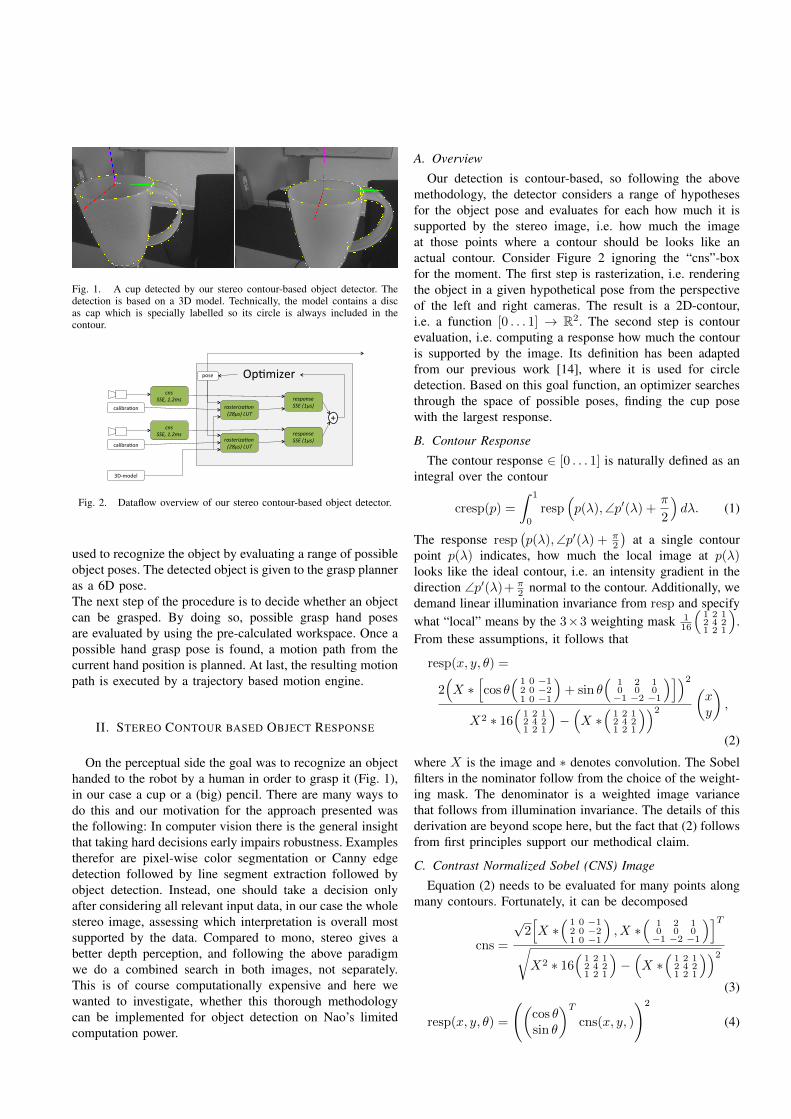
Fig. 1. A cup detected by our stereo contour-based object detector. Thedetection is based on a 3D model. Technically, the model contains a discas cap which is specially labelled so its circle is always included in thecontour.
Op#mizer pose
response SSE (1µs)
+ response SSE (1µs)
rasteriza2on (28µs) LUT
rasteriza2on (28µs) LUT
calibra#on
calibra#on
3D-‐model
cns SSE, 1.2ms
cns SSE, 1.2ms
Fig. 2. Dataflow overview of our stereo contour-based object detector.
used to recognize the object by evaluating a range of possibleobject poses. The detected object is given to the grasp planneras a 6D pose.The next step of the procedure is to decide whether an objectcan be grasped. By doing so, possible grasp hand posesare evaluated by using the pre-calculated workspace. Once apossible hand grasp pose is found, a motion path from thecurrent hand position is planned. At last, the resulting motionpath is executed by a trajectory based motion engine.
II. STEREO CONTOUR BASED OBJECT RESPONSE
On the perceptual side the goal was to recognize an objecthanded to the robot by a human in order to grasp it (Fig. 1),in our case a cup or a (big) pencil. There are many ways todo this and our motivation for the approach presented wasthe following: In computer vision there is the general insightthat taking hard decisions early impairs robustness. Examplestherefor are pixel-wise color segmentation or Canny edgedetection followed by line segment extraction followed byobject detection. Instead, one should take a decision onlyafter considering all relevant input data, in our case the wholestereo image, assessing which interpretation is overall mostsupported by the data. Compared to mono, stereo gives abetter depth perception, and following the above paradigmwe do a combined search in both images, not separately.This is of course computationally expensive and here wewanted to investigate, whether this thorough methodologycan be implemented for object detection on Nao’s limitedcomputation power.
A. Overview
Our detection is contour-based, so following the abovemethodology, the detector considers a range of hypothesesfor the object pose and evaluates for each how much it issupported by the stereo image, i.e. how much the imageat those points where a contour should be looks like anactual contour. Consider Figure 2 ignoring the “cns”-boxfor the moment. The first step is rasterization, i.e. renderingthe object in a given hypothetical pose from the perspectiveof the left and right cameras. The result is a 2D-contour,i.e. a function [0 . . . 1] → R2. The second step is contourevaluation, i.e. computing a response how much the contouris supported by the image. Its definition has been adaptedfrom our previous work [14], where it is used for circledetection. Based on this goal function, an optimizer searchesthrough the space of possible poses, finding the cup posewith the largest response.
B. Contour Response
The contour response ∈ [0 . . . 1] is naturally defined as anintegral over the contour
cresp(p) =
∫ 1
0
resp(p(λ),∠p′(λ) +
π
2
)dλ. (1)
The response resp(p(λ),∠p′(λ) + π
2
)at a single contour
point p(λ) indicates, how much the local image at p(λ)looks like the ideal contour, i.e. an intensity gradient in thedirection ∠p′(λ)+ π
2 normal to the contour. Additionally, wedemand linear illumination invariance from resp and specifywhat “local” means by the 3×3 weighting mask 1
16
(1 2 12 4 21 2 1
).
From these assumptions, it follows that
resp(x, y, θ) =
2(X ∗
[cos θ
(1 0 −12 0 −21 0 −1
)+ sin θ
(1 2 10 0 0−1 −2 −1
)])2X2 ∗ 16
(1 2 12 4 21 2 1
)−(X ∗
(1 2 12 4 21 2 1
))2 (xy
),
(2)
where X is the image and ∗ denotes convolution. The Sobelfilters in the nominator follow from the choice of the weight-ing mask. The denominator is a weighted image variancethat follows from illumination invariance. The details of thisderivation are beyond scope here, but the fact that (2) followsfrom first principles support our methodical claim.
C. Contrast Normalized Sobel (CNS) Image
Equation (2) needs to be evaluated for many points alongmany contours. Fortunately, it can be decomposed
cns =
√2[X ∗
(1 0 −12 0 −21 0 −1
), X ∗
(1 2 10 0 0−1 −2 −1
)]T√X2 ∗ 16
(1 2 12 4 21 2 1
)−(X ∗
(1 2 12 4 21 2 1
))2(3)
resp(x, y, θ) =
((cos θsin θ
)Tcns(x, y, )
)2
(4)
Fig. 3. Plot of the response (5) as a function of cns norm | cns(x, y)|and angular mismatch δ = θ − ∠ cns(x, y). The corresponding plot forthe response used in the classical Hough-transform is 1 inside a hand-tunedrectangle and 0 outside.
into the squared scalar product of the contour-normal(cos θsin θ
)and a contrast-normalized Sobel image (cns). The cns-imagedoes not depend on the contour and is only computed once(Fig. 2). The contour-normal is reused when searching atdifferent positions and only the squared scalar product needsto be computed for every point of every contour evaluated.
Also, (4) has a nice interpretation, as
resp(x, y, θ) = cos2 (θ − ∠ cns(x, y)) | cns(x, y)|2. (5)
This means that the detector gradually penalizes an angularmismatch between the desired and the observed gradientdirection as well as local images which do not look gradient-like as indicated by the cns-norm (Fig. 3). Since the latteris illumination invariant, it measures “gradient purity” asopposed to “gradient intensity” for the classical Sobel vector.
D. Efficient Implementation
The cns-computation (3) has been implemented using Sin-gle Instruction Multiple Data (SIMD) parallelism, here Intel’sSSE3 instruction set. Multi-core parallelism would also beeasy, but is not available on Nao’s Atom processor. Also thevarious filters were separated into X ∗ ( 1 2 1 ) ∗ (−1 0 1 )
T ,X ∗(−1 0 1 ) ∗( 1 2 1 )
T and X ∗( 1 2 1 ) ∗( 1 2 1 )T , reusing
the horizontal X ∗ ( 1 2 1 ) intermediate result. In order tomaximize parallelism, the filters are computed in 16 bit,converting to float for the reciprocal square root only. Also,a regularizer of 256 (1 intensity unit) is added in the squareroot to avoid 0/0.
The actual response evaluation (4) is most time-critical.Intel’s SSE3 includes an instruction pmaddubsw that mul-tiplies 2 × 16 bytes adding adjacent products (16 bit). Thiscomputes
(cos θsin θ
)Tcns(x, y) in (4). However, one operand is
unsigned, so we shift the cns image by 1, (technically 128),making it positive and correct the product by subtractingcosα+sinα. The result is squared (4) and accumulated (1).Overall, 6 instructions perform 8 evaluations of (2). The eval-uations correspond to an identical contour but 8 successive
pixels in the (cns-) image. To exploit this parallelism, wealways compute 8 × 8 (or even 16 × 16) responses of thesame contour shifted by [0 . . . 7]× [0 . . . 7].
III. 3D OBJECT SEARCH PROCESS
A. Rasterization
The rasterization (Fig. 2) takes a triangle mesh as 3Dobject model, a camera calibration and a hypothetical objectpose as input and renders the contour of the object at thegiven pose as viewed from the camera. The first step is todetermine which edges of the model form the contour. Atthe moment, we go through all edges and select those whereone adjacent face is viewed from the front and one from theback. This does not consider global occlusion, an extensionthat could be implemented in the future. As a special rule,faces can be marked by a color label and edges betweenvisible faces of different labels are also added. This featureis needed to make for instance the front edge in Figure 1part of the contour.
Contour-edge determination is expensive. Fortunately, itdepends only on the camera’s position relative to the object,not its orientation, so we precompute a 3D look-up-table.
Next, the vertices involved are perspectively projectedinto the image in an SSE implementation. The projectionignores distortion which is ≈ 1 pixel only for Nao. Theprecomputed edge list is sorted such that projected verticescan be used twice. In principle, one would raster each edge,e.g. with the Bresenham line-algorithm, then. However, tosave computation, time we only use the mid-point of eachedge in the contour and compute the contour orientationat that point from the two projected vertices. Instead ofθ, we directly compute sin θ and cos θ to avoid expensivetrigonometrical operations. Midpoints outside the image areskipped.
Overall, with these optimizations, computation time isreduced from 2× 600µs to 2× 28µs.
B. Local Search (Refinement and Tracking)
During local search, the optimizer (Fig. 2) changes thepose towards growing responses. This procedure is used fortracking as well as to refine a coarse initial pose obtainedby our global search heuristic presented later. We use thesimple approach to optimize DOFs round-robin one at a time,although there are of course more sophisticated optimizationalgorithms. However, we exploit that the response computa-tion provides an array of 8×8 responses for shifted contours(2D translation).
So, to refine one DOF, we compute 8×8 responses aroundthe original pose, around a pose changed on step in theconsidered DOF, and around the inversely changed pose.The subpixel-refined maximum of these 3× 8× 8 responsesdefines the new pose. Therefor the image translation mustbe converted into a change of pose. This is approximated bya rotation of the object around the camera which moves theobject’s center in the image according to the obtained imagetranslation.
As image translation is already covered, the 4 remainingDOFs are translation in viewing direction and object rotationaround X, Y and Z (skipped in case of symmetry). The stepsize is roughly determined to create 3 pixel changes in theimage based on object size and distance.
At first sight it may appear to be a waste of time to refineimage-translation each time one of the four DOF is refined.However, typical object movement creates large image move-ment but rather small change in shape, so this approachmakes the system capable of tracking faster movements andexploits the SSE-based 8× 8 block computation.
Finally, one remarkable finding was that the stereocontour-based object response has a rather large range ofconvergence as shown in Figures 7 and 9 in Section V. Thissupports our motivation that avoiding early hard decisionsimproves robustness.
C. Global Search HeuristicThe textbook solution for global object search would be to
find the maximum response of all poses within the graspingspace (6DOF). However, this is computationally beyondscope despite all the optimizations mentioned. Instead, weuse an application-specific heuristic. We search only for asingle cup orientation by assuming it is roughly verticallyaligned and by removing the handle, making it rotationallysymmetric. This orientation is obtained from the robot’s for-ward kinematic and the decision to use only one orientationwas motivated by the large range of convergence mentionedabove.
For the position, we go through the image in patches of64×48 pixels and rasterize the cup at several positions alongthe center pixel’s ray. For each contour 64 × 48 responsesare computed and the largest overall response is refined.
Then cup-rotation is determined by evaluating the responseof several rotated cups with handle. Finally, the full modelis refined and if the response exceeds a threshold (0.65) weswitch to tracking mode. If the response in tracking modefalls below 0.5 for 15 frames, we switch back.
The global search takes ≈ 320ms, so we spread it overseveral frames, evaluating only between one and two 64×48blocks in each frame (13− 26ms).
IV. OBJECT GRASPING
On the motion side, the goal is to successfully grasp anobject. More specific, the goal is to decide from which handpose the object can be grasped and to find a valid motionpath from the current hand pose. In addition, obstacles suchas the object itself or body parts that may be in the directpath between the target position and the start position haveto be avoided.We decided to implement a motion planner instead of areactive approach in order to foresee collisions with theobject or parts of the robot body. Since Nao’s processor islimited as well as the degrees of freedom (DOF) of Nao’sarms, we decided to pre-calculate the workspace and to usethis table in the motion planner for efficiency.
A. Overview
While most robotic arms have six or even seven DOF,Nao’s arms are constructed with only five DOF. The fifthDOF represents the wrist angle and has only minor influenceon the planning. So our approach ignores this DOF first,using only four DOF to define a certain hand pose, andhandles the wrist-DOF later. This leaves only one DOF offour for the lower arm direction while a fixed hand positionis commanded, less than the two possible DOF. Accordingto that, the reachability of Nao’s hand is clearly very limitedand the lower arm direction depends on the hand position.For that reason it is necessary to check for each grasp poseand each point on a motion path whether it can be reached.This leads to the problem that a large number of reachabilitychecks are necessary for motion planning. This can be speedup best by predefining the workspace in a reachability map.The reachability map is precomputed and used as the basisof the whole grasping process. The first step is to evaluatea range of grasp poses by using the map. Once a reachablegrasp pose is found, the grasp planner plans a path throughthe grid cells of the map. The planning procedure is toevaluate nodes starting with the goal node (grasp pose) inorder to find a path to the current hand pose. For each node tobe evaluated possible collisions are inspected. The resultingmotion plan is converted into a Bezier path and executed by atrajectory-based motion engine. During the motion execution,the motion plan is updated in each frame.
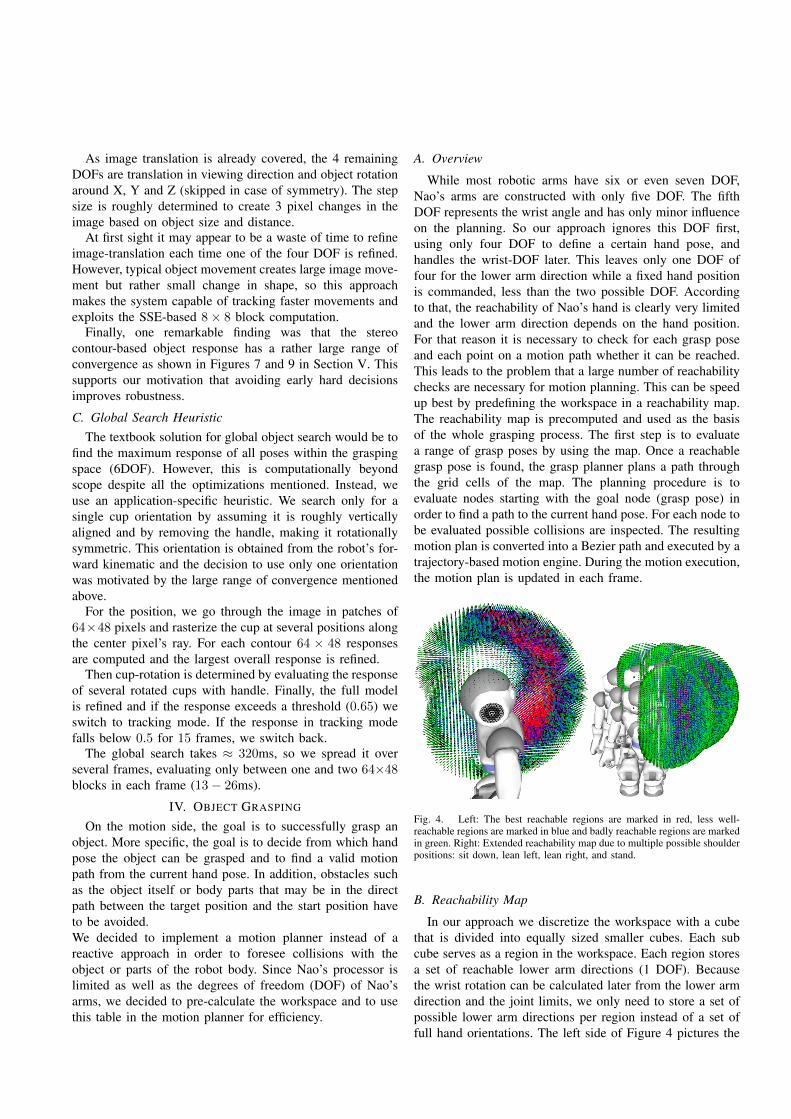
Fig. 4. Left: The best reachable regions are marked in red, less well-reachable regions are marked in blue and badly reachable regions are markedin green. Right: Extended reachability map due to multiple possible shoulderpositions: sit down, lean left, lean right, and stand.
B. Reachability Map
In our approach we discretize the workspace with a cubethat is divided into equally sized smaller cubes. Each subcube serves as a region in the workspace. Each region storesa set of reachable lower arm directions (1 DOF). Becausethe wrist rotation can be calculated later from the lower armdirection and the joint limits, we only need to store a set ofpossible lower arm directions per region instead of a set offull hand orientations. The left side of Figure 4 pictures the
reachability map used, where only reachable directions perregion are marked.The map is created offline by using forward kinematics foreach 0.5 degree angle of each arm joint. In that process wecalculate the position of the palm as well as the direction ofthe lower arm and mark them in the map. In order to keepthe memory footprint as small as possible, each lower armdirection calculated is rounded to a set of 512 directions,which are generated by using the spiral point algorithmproposed by Saff and Kuijlaars [15].The origin of the reachability map is located in the shoulderof the robot. Thus, it is possible to test with different shoulderpositions whether a certain hand position is reachable withoutthe use of inverse kinematics. The right side of Figure 4pictures how the workspace increases with only four possibleshoulder positions.
C. Grasp Selection
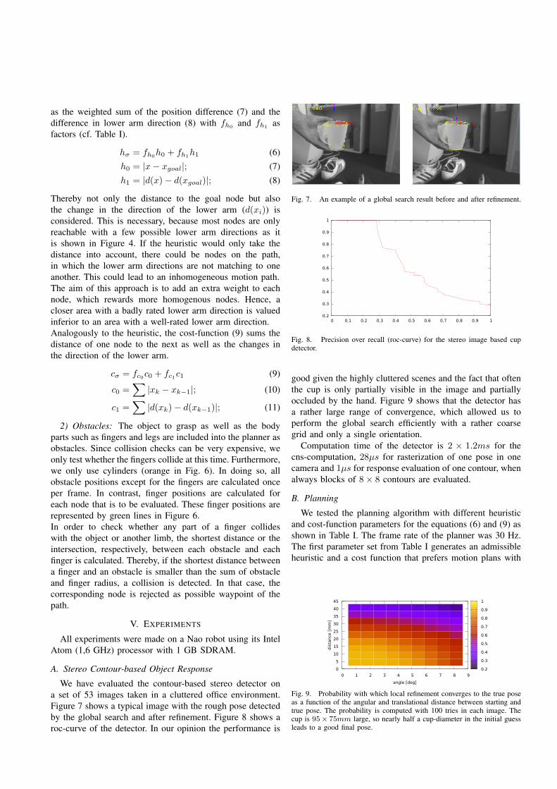
Before the motion plan can be constructed, a target posi-tion needs to be selected. In order to do this, we assign a setof predefined grasp rules to each object. Each rule is definedby a grasping point and a range of lower arm directionsrelative to the object. In Figure 5, grasp rules are markedwith blue triangles. The green dots constitute the positionwhere to grasp and the triangle defines a range of lower armdirections.In order to select a grasp, the grasp rules are matched withthe reachability map defined in Section IV-B. In this process,areas that include a grasping point are examined further inorder to check whether the corresponding possible lower armdirections are qualified for the grasp. This step is necessary,because the possible lower arm directions per area are verylimited (Fig. 4). In this process, the possible lower armdirections (red in Fig. 5) of the grasp areas are compared tothe angle ranges from the grasp rules (matching directionsare shown in yellow in Figure 5). The best match is selected.
Fig. 5. Each object has its own grasp map, which is generated from a set ofpredefined grasp rules. Each rule connects a range of lower arm directionsto a grasp position (blue). The reachability map (red) is matched to theobject’s grasp map. Matches are marked yellow.
D. Motion Planning
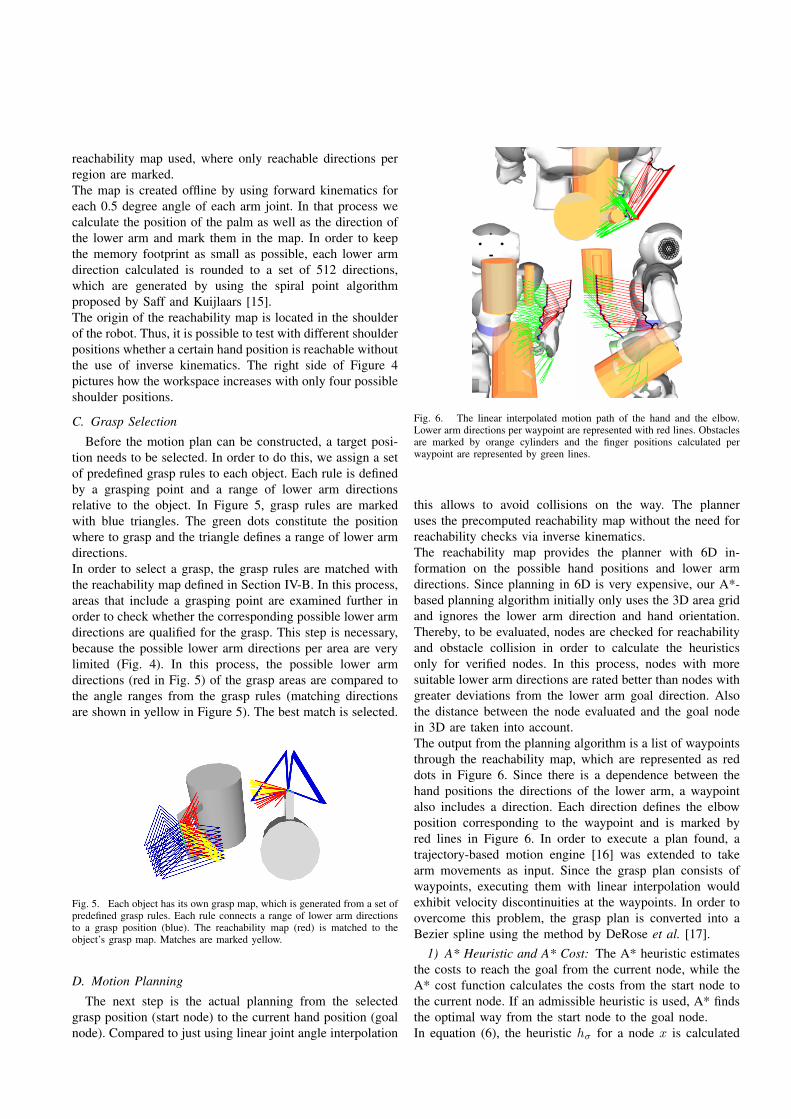
The next step is the actual planning from the selectedgrasp position (start node) to the current hand position (goalnode). Compared to just using linear joint angle interpolation
Fig. 6. The linear interpolated motion path of the hand and the elbow.Lower arm directions per waypoint are represented with red lines. Obstaclesare marked by orange cylinders and the finger positions calculated perwaypoint are represented by green lines.
this allows to avoid collisions on the way. The planneruses the precomputed reachability map without the need forreachability checks via inverse kinematics.The reachability map provides the planner with 6D in-formation on the possible hand positions and lower armdirections. Since planning in 6D is very expensive, our A*-based planning algorithm initially only uses the 3D area gridand ignores the lower arm direction and hand orientation.Thereby, to be evaluated, nodes are checked for reachabilityand obstacle collision in order to calculate the heuristicsonly for verified nodes. In this process, nodes with moresuitable lower arm directions are rated better than nodes withgreater deviations from the lower arm goal direction. Alsothe distance between the node evaluated and the goal nodein 3D are taken into account.The output from the planning algorithm is a list of waypointsthrough the reachability map, which are represented as reddots in Figure 6. Since there is a dependence between thehand positions the directions of the lower arm, a waypointalso includes a direction. Each direction defines the elbowposition corresponding to the waypoint and is marked byred lines in Figure 6. In order to execute a plan found, atrajectory-based motion engine [16] was extended to takearm movements as input. Since the grasp plan consists ofwaypoints, executing them with linear interpolation wouldexhibit velocity discontinuities at the waypoints. In order toovercome this problem, the grasp plan is converted into aBezier spline using the method by DeRose et al. [17].
1) A* Heuristic and A* Cost: The A* heuristic estimatesthe costs to reach the goal from the current node, while theA* cost function calculates the costs from the start node tothe current node. If an admissible heuristic is used, A* findsthe optimal way from the start node to the goal node.In equation (6), the heuristic hσ for a node x is calculated
as the weighted sum of the position difference (7) and thedifference in lower arm direction (8) with fh0 and fh1 asfactors (cf. Table I).
hσ = fh0h0 + fh1h1 (6)h0 = |x− xgoal|; (7)h1 = |d(x)− d(xgoal)|; (8)
Thereby not only the distance to the goal node but alsothe change in the direction of the lower arm (d(xi)) isconsidered. This is necessary, because most nodes are onlyreachable with a few possible lower arm directions as itis shown in Figure 4. If the heuristic would only take thedistance into account, there could be nodes on the path,in which the lower arm directions are not matching to oneanother. This could lead to an inhomogeneous motion path.The aim of this approach is to add an extra weight to eachnode, which rewards more homogenous nodes. Hence, acloser area with a badly rated lower arm direction is valuedinferior to an area with a well-rated lower arm direction.Analogously to the heuristic, the cost-function (9) sums thedistance of one node to the next as well as the changes inthe direction of the lower arm.
cσ = fc0c0 + fc1c1 (9)
c0 =∑|xk − xk−1|; (10)
c1 =∑|d(xk)− d(xk−1)|; (11)
2) Obstacles: The object to grasp as well as the bodyparts such as fingers and legs are included into the planner asobstacles. Since collision checks can be very expensive, weonly test whether the fingers collide at this time. Furthermore,we only use cylinders (orange in Fig. 6). In doing so, allobstacle positions except for the fingers are calculated onceper frame. In contrast, finger positions are calculated foreach node that is to be evaluated. These finger positions arerepresented by green lines in Figure 6.In order to check whether any part of a finger collideswith the object or another limb, the shortest distance or theintersection, respectively, between each obstacle and eachfinger is calculated. Thereby, if the shortest distance betweena finger and an obstacle is smaller than the sum of obstacleand finger radius, a collision is detected. In that case, thecorresponding node is rejected as possible waypoint of thepath.
V. EXPERIMENTS
All experiments were made on a Nao robot using its IntelAtom (1,6 GHz) processor with 1 GB SDRAM.
A. Stereo Contour-based Object Response
We have evaluated the contour-based stereo detector ona set of 53 images taken in a cluttered office environment.Figure 7 shows a typical image with the rough pose detectedby the global search and after refinement. Figure 8 shows aroc-curve of the detector. In our opinion the performance is
Fig. 7. An example of a global search result before and after refinement.
0.2
0.3
0.4
0.5
0.6
0.7
0.8
0.9
1
0 0.1 0.2 0.3 0.4 0.5 0.6 0.7 0.8 0.9 1
Fig. 8. Precision over recall (roc-curve) for the stereo image based cupdetector.
good given the highly cluttered scenes and the fact that oftenthe cup is only partially visible in the image and partiallyoccluded by the hand. Figure 9 shows that the detector hasa rather large range of convergence, which allowed us toperform the global search efficiently with a rather coarsegrid and only a single orientation.
Computation time of the detector is 2 × 1.2ms for thecns-computation, 28µs for rasterization of one pose in onecamera and 1µs for response evaluation of one contour, whenalways blocks of 8× 8 contours are evaluated.
B. Planning
We tested the planning algorithm with different heuristicand cost-function parameters for the equations (6) and (9) asshown in Table I. The frame rate of the planner was 30 Hz.The first parameter set from Table I generates an admissibleheuristic and a cost function that prefers motion plans with
0 1 2 3 4 5 6 7 8 9
angle [deg]
0
5
10
15
20
25
30
35
40
45
dis
tance
[m
m]
0.2
0.3
0.4
0.5
0.6
0.7
0.8
0.9
1
Fig. 9. Probability with which local refinement converges to the true poseas a function of the angular and translational distance between starting andtrue pose. The probability is computed with 100 tries in each image. Thecup is 95× 75mm large, so nearly half a cup-diameter in the initial guessleads to a good final pose.
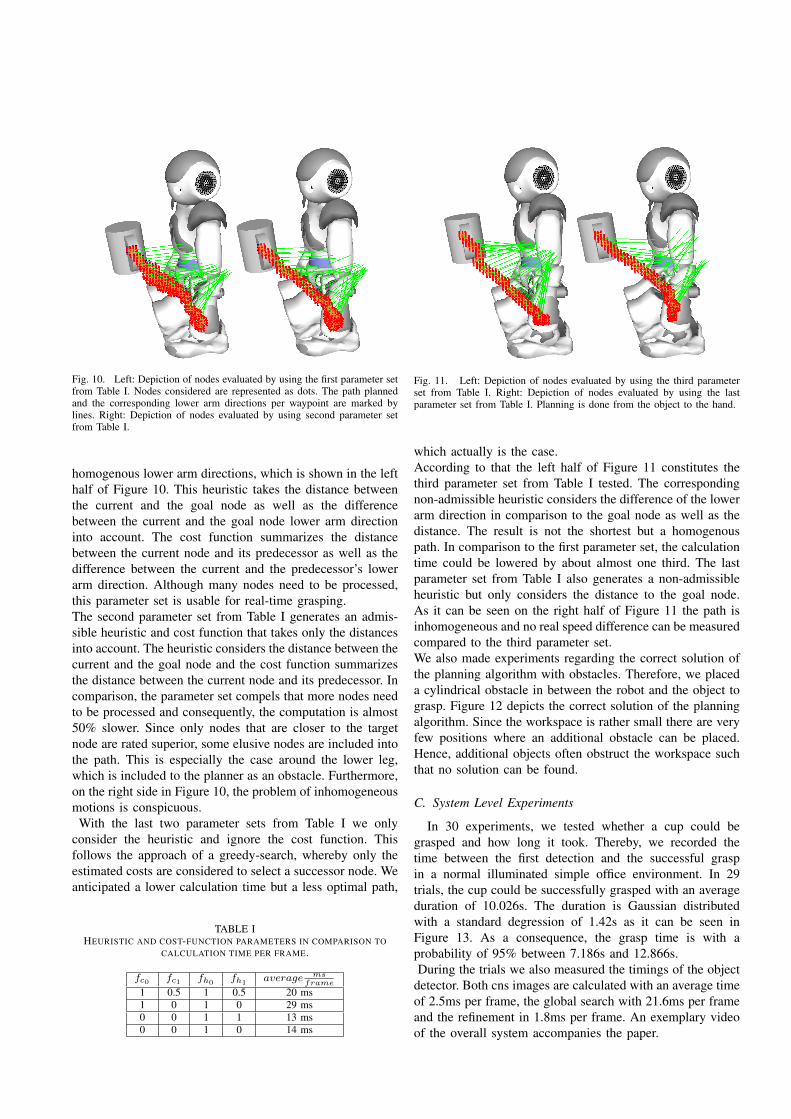
Fig. 10. Left: Depiction of nodes evaluated by using the first parameter setfrom Table I. Nodes considered are represented as dots. The path plannedand the corresponding lower arm directions per waypoint are marked bylines. Right: Depiction of nodes evaluated by using second parameter setfrom Table I.
homogenous lower arm directions, which is shown in the lefthalf of Figure 10. This heuristic takes the distance betweenthe current and the goal node as well as the differencebetween the current and the goal node lower arm directioninto account. The cost function summarizes the distancebetween the current node and its predecessor as well as thedifference between the current and the predecessor’s lowerarm direction. Although many nodes need to be processed,this parameter set is usable for real-time grasping.The second parameter set from Table I generates an admis-sible heuristic and cost function that takes only the distancesinto account. The heuristic considers the distance between thecurrent and the goal node and the cost function summarizesthe distance between the current node and its predecessor. Incomparison, the parameter set compels that more nodes needto be processed and consequently, the computation is almost50% slower. Since only nodes that are closer to the targetnode are rated superior, some elusive nodes are included intothe path. This is especially the case around the lower leg,which is included to the planner as an obstacle. Furthermore,on the right side in Figure 10, the problem of inhomogeneousmotions is conspicuous.
With the last two parameter sets from Table I we onlyconsider the heuristic and ignore the cost function. Thisfollows the approach of a greedy-search, whereby only theestimated costs are considered to select a successor node. Weanticipated a lower calculation time but a less optimal path,
TABLE IHEURISTIC AND COST-FUNCTION PARAMETERS IN COMPARISON TO
CALCULATION TIME PER FRAME.
fc0 fc1 fh0fh1
average msframe
1 0.5 1 0.5 20 ms1 0 1 0 29 ms0 0 1 1 13 ms0 0 1 0 14 ms
Fig. 11. Left: Depiction of nodes evaluated by using the third parameterset from Table I. Right: Depiction of nodes evaluated by using the lastparameter set from Table I. Planning is done from the object to the hand.
which actually is the case.According to that the left half of Figure 11 constitutes thethird parameter set from Table I tested. The correspondingnon-admissible heuristic considers the difference of the lowerarm direction in comparison to the goal node as well as thedistance. The result is not the shortest but a homogenouspath. In comparison to the first parameter set, the calculationtime could be lowered by about almost one third. The lastparameter set from Table I also generates a non-admissibleheuristic but only considers the distance to the goal node.As it can be seen on the right half of Figure 11 the path isinhomogeneous and no real speed difference can be measuredcompared to the third parameter set.We also made experiments regarding the correct solution ofthe planning algorithm with obstacles. Therefore, we placeda cylindrical obstacle in between the robot and the object tograsp. Figure 12 depicts the correct solution of the planningalgorithm. Since the workspace is rather small there are veryfew positions where an additional obstacle can be placed.Hence, additional objects often obstruct the workspace suchthat no solution can be found.
C. System Level Experiments
In 30 experiments, we tested whether a cup could begrasped and how long it took. Thereby, we recorded thetime between the first detection and the successful graspin a normal illuminated simple office environment. In 29trials, the cup could be successfully grasped with an averageduration of 10.026s. The duration is Gaussian distributedwith a standard degression of 1.42s as it can be seen inFigure 13. As a consequence, the grasp time is with aprobability of 95% between 7.186s and 12.866s.During the trials we also measured the timings of the object
detector. Both cns images are calculated with an average timeof 2.5ms per frame, the global search with 21.6ms per frameand the refinement in 1.8ms per frame. An exemplary videoof the overall system accompanies the paper.

Fig. 12. Topview of the smoothed Bezier path with only the object tograsp as obstacle (left) and with an additional obstacle (right).
0
0.6
1
8 9 10
Function
1%pTolerance
Distributionµ =p10.026,pο =p1.42
0.4
0.6
0.8
11 12 13
EmpiricalpDistribution
CumulativepGaussian
Fig. 13. We performed the Kolmogorov-Smirnov test with a confidencelevel of 0.1. The result proves with a probability of 99% the hypothesis ofGaussian distributed measurements.
VI. CONCLUSION
Summarizing, the online grasping system proposed is notonly able to plan and execute a grasp on the affordableNao robot, but it also is fast enough for a frame rate of30 Hz. It seems that a precomputed reachability map canhave very positive effects on the planning performance insuch a way that a sufficient amount of possible waypointscan be processed. Furthermore, the search space can bedecreased by including the evaluation of the lower armdirection into the heuristic as well as into the cost function.By using a non-admissible heuristic the planning speed canbe increased, which enables robots (i.e. older Nao models)with less processor power to also use the proposed graspfunction.Furthermore, we were able to analyze Nao’s new stereovision design and we discovered that the overlap of thecameras is sufficient to detect objects very near to the head.However, since the motion range of Nao’s head pitch jointis not high enough to view the area directly in front of itsbody the overlap of what can be detected and what can begrasped is rather small.
ACKNOWLEDGMENTS
We would especially like to thank Oliver Birbach forcalibrating the cameras of our Nao.
REFERENCES
[1] D. Gouaillier, V. Hugel, P. Blazevic, C. Kilner, J. Monceaux, P. Lafour-cade, B. Marnier, J. Serre, and B. Maisonnier, “Mechatronic design ofnao humanoid,” in Robotics and Automation, 2009. ICRA ’09. IEEEInternational Conference on, may 2009, pp. 769 –774.
[2] C. Borst, T. Wimbock, F. Schmidt, M. Fuchs, B. Brunner, F. Zacharias,P. R. Giordano, R. Konietschke, W. Sepp, S. Fuchs, C. Rink, A. Albu-Schaffer, and G. Hirzinger, “Rollin’ justin - mobile platform withvariable base,” in Robotics and Automation, 2009. ICRA ’09. IEEEInternational Conference on, may 2009, pp. 1597 –1598.
[3] Y. Sakagami, R. Watanabe, C. Aoyama, S. Matsunaga, N. Higaki, andK. Fujimura, “The intelligent asimo: system overview and integration,”in Intelligent Robots and Systems, 2002. IEEE/RSJ InternationalConference on, vol. 3, 2002, pp. 2478 – 2483 vol.3.
[4] C. Borst, M. Fischer, and G. Hirzinger, “Grasping the dice by dicingthe grasp,” in Intelligent Robots and Systems, 2003. (IROS 2003).Proceedings. 2003 IEEE/RSJ International Conference on, vol. 4, oct.2003, pp. 3692 – 3697 vol.3.
[5] K. Lalibertze, L. Birglen, and C. M. Gosselin, “Underactuation inrobotic grasping hands,” in Journal of Machine Intelligence andRobotic Control, vol. 4, no. 3, 2002, pp. 77 –87.
[6] G. Kragten, A. Kool, and J. Herder, “Ability to hold grasped objectsby underactuated hands: Performance prediction and experiments,”in Robotics and Automation, 2009. ICRA ’09. IEEE InternationalConference on, may 2009, pp. 2493–2498.
[7] L. Kavraki, P. Svestka, J.-C. Latombe, and M. Overmars, “Probabilisticroadmaps for path planning in high-dimensional configuration spaces,”Robotics and Automation, IEEE Transactions on, vol. 12, no. 4, pp.566 –580, aug 1996.
[8] K. Harada, K. Kaneko, and F. Kanehiro, “Fast grasp planning forhand/arm systems based on convex model,” in Robotics and Automa-tion, 2008. ICRA 2008. IEEE International Conference on, may 2008,pp. 1162 –1168.
[9] N. Vahrenkamp, T. Asfour, and R. Dillmann, “Simultaneous graspand motion planning: Humanoid robot armar-iii,” Robotics AutomationMagazine, IEEE, vol. 19, no. 2, pp. 43 –57, june 2012.
[10] F. Zacharias, C. Borst, and G. Hirzinger, “Object-specific grasp mapsfor use in planning manipulation actions,” in Advances in RoboticsResearch, T. Kroger and F. M. Wahl, Eds. Springer Berlin Heidelberg,2009, pp. 203–213.
[11] ——, “Capturing robot workspace structure: representing robot ca-pabilities,” in Intelligent Robots and Systems, 2007. IROS 2007.IEEE/RSJ International Conference on, 29 2007-nov. 2 2007, pp. 3229–3236.
[12] G. Cotugno and H. Mellmann, “Dynamic motion control: Adaptivebimanual grasping for a humanoid robot,” in Proceedings of theWorkshop on Concurrency, Specification, and Programming CS&P2010, vol. Volume 2, Bornicke (near Berlin), Germany, September2010.
[13] P. Azad, T. Asfour, and R. Dillmann, “Stereo-based 6d object localiza-tion for grasping with humanoid robot systems,” in Intelligent Robotsand Systems, 2007. IROS 2007. IEEE/RSJ International Conferenceon, 29 2007-nov. 2 2007, pp. 919 –924.
[14] O. Birbach, U. Frese, and B. Bauml, “Realtime perception for catchinga flying ball with a mobile humanoid,” in Proceedings of the IEEEInternational Conference on Robotics and Automation (ICRA), Shang-hai, China, 2011.
[15] E. Saff and A. Kuijlaars, “Distributing many points on a sphere,” TheMathematical Intelligencer, vol. 19, pp. 5–11, 1997.
[16] J. Muller, T. Laue, and T. Rofer, “Kicking a ball - modeling complexdynamic motions for humanoid robots,” in RoboCup 2010: RobotSoccer World Cup XIV, ser. Lecture Notes in Artificial Intelligence,J. R. del Solar, E. Chown, and P. G. Ploeger, Eds., vol. 6556. Springer;Heidelberg; http://www.springer.de/, 2011, pp. 109–120.
[17] T. D. DeRose and B. A. Barsky, “Geometric continuity, shape pa-rameters, and geometric constructions for catmull-rom splines,” ACMTrans. Graph., vol. 7, no. 1, pp. 1–41, Jan. 1988.
Related Documents
![ContactDB: Analyzing and Predicting Grasp Contact via ... › contactdb_paper.pdf(e.g. Stanford bunny and Utah teapot). Since object size has been shown to influence the grasp [11,8]](https://static.cupdf.com/doc/110x72/5f0cc6317e708231d437109f/contactdb-analyzing-and-predicting-grasp-contact-via-a-contactdbpaperpdf.jpg)