INSTRUCTION MANUAL GR8-1200 NI Multitasking Battery and Electrical Diagnostic Station May 2011 167-010EN-D

Welcome message from author
This document is posted to help you gain knowledge. Please leave a comment to let me know what you think about it! Share it to your friends and learn new things together.
Transcript
INSTRUCTION MANUAL
GR8-1200 NIMultitasking Battery and
Electrical Diagnostic Station
May 2011167-010EN-D

This page intentionally left blank.
GR8-1200 NI
Midtronics Inc. 7000 Monroe Street Willowbrook, IL 60527www.midtronics.com 3
Contents
ContentsSafety Guidelines 5
General Safety Precautions 5Personal Precautions 5Preparing To Charge The Battery 6Grounding And AC Power Cord Connection 6Charger Location 7DC Connection Precautions 7Installing The Battery 7Connecting To The Battery 8
Chapter 1: Before You Begin 9Assembling Your GR8 9
Attaching the Control Module 9Installing the Multitasker Module 10Multitasking 10
Wireless Multitasking 10Procedure Summary 10
Chapter 2: Overview 11Front of GR8 11Back of GR8 12Display and Keypad 13Data Entry Methods 14
Menu Icons 14Option Buttons 14Scrolling Lists 14Alphanumeric Entry 14Value Boxes 14Main Menu 15DMM Menu 15Admin Menu 16Info Menu 16
Chapter 3: Getting Started 17Powering Up 17
Selecting A Language 17Select Logo 17Clock Adjust 17User ID 17
Setting User Preferences 18Preparing to Charge 18
Inspecting the Battery 18Testing Out-of-Vehicle 18Testing In-Vehicle 18Connecting the Clamps 18Connecting to AC Power 18
Help Menu 18
Chapter 4: Diagnostic Charging 19Performing A Diagnostic Charge 19
Charging Modes 19Initial Analysis 19Diagnostic Mode 20Direction Time 20Top-Off Mode 20Recovery Mode 20Deep Scan Test 20
Aborting a Charge Session 20Completing a Charge Session 21Diagnostic Charge Results 21
State-of-Health (SOH) 21Vehicle Verification 21
Vehicle Verification Results 22Starter Test 22
Starter System Test Results 22Charging System Test 23
Charging System Test Results 23
Chapter 5: System Test 25Battery Test 25
Initial Analysis 25Deep Scan Test 26Battery Test Results 26
Starter Test 26Starter System Test Results 26
Charging System Test 27Charging System Test Results 27
Chapter 6: ECM Power Supply 29
Chapter 7: Jump Start 30
Chapter 8: Manual Charging 31
Chapter 9: Bench Test 32Deep Scan Test 32Bench Test Results 33
Chapter 10: Inventory Test 34Selecting Test Parameters 34Printing Additional Test Results 34Clearing Test Totals 34
Chapter 11: Customer Delivery 35Performing A Customer Delivery Test 35
GR8-1200 NI
Midtronics Inc. 7000 Monroe Street Willowbrook, IL 60527 www.midtronics.com4
Contents
Chapter 12: OK Verify 36Battery Test 36
Initial Analysis 36Deep Scan Test 36Battery Test Results 37
Starter Test 37Starter System Test Results 37
Charging System Test 38Charging System Test Results 38
Chapter 13: Check-In 40Performing A Check-In Test 40
Chapter 14: Info Menu 41View Test Battery 41View Test Charger 41View Cable Test 41Check-In 41View Inventory 41Customer Delivery 42Totals 42Transfer 43View Wireless 43Version 43
Chapter 15: Cable Drop Test 44Battery Ground Test 44
Battery Ground Test Results 44Starter Circuit 44
Starter Circuit Test Results 45Alternator Circuit 45
Alternator Circuit Test Results 45Other Circuit 45
Other Circuit Test Results 45
Chapter 16: DMM 46DC Volts 46AC Volts 46Scope 46DC AMP 46AC AMP 47Temp 47Ohm Meter 47Diode 47Volts/Amp 47
GR8 Multimeter Specifications 48
Chapter 17: Admin 49Clock 49
Mode 49Time 49Format 49
Shop 49Users 50
Creating A New User ID 50Deleting A User ID 50Editing a User ID 50
Display 51Contrast Level 51Backlight Time 51
Coupon 51Edit Coupon 51Temp 52Language 52Format 52Update 52Admin 52
Options 52Change Admin Pin 52Clear Test Totals 52Reset Defaults 52
Printer 53Buzzer 53GR8 Logos 53Wireless 53
Chapter 18: Maintenance & Troubleshooting 54Replacing the Paper Roll 54Test Cable Maintenance 54Attaching the Charger Cables 54Test Messages 56
Appendix: Templates 57Header Template 57Coupon Template 57
GR8-1200 NI
Midtronics Inc. 7000 Monroe Street Willowbrook, IL 60527www.midtronics.com 5
Safety Guidelines
1. General Safety Precautions1. IMPORTANT SAFETY INSTRUCTIONS. IT IS OF UTMOST
IMPORTANCE THAT BEFORE USING YOUR CHARGER, YOU READ THIS MANUAL AND FOLLOW THE SAFETY AND OPERATING INSTRUCTIONS EXACTLY. SAVE THESE INSTRUCTIONS.
Risk of explosive gasesBatteries generate explosive gases during normal opera-tion, and when discharged or charged.
1.1 To reduce risk of battery explosion, follow these safety in-structions and those published by the battery manufac-turer and the manufacturer of any equipment you intend to use in the vicinity of a battery. Review cautionary mark-ing on these products and on the engine, and on the ve-hicle or equipment containing the battery.
Charging a non-rechargeable battery may cause the battery to burst.To reduce the risk of injury, only charge rechargeable lead-acid type batteries including maintenance-free, low-maintenance, or deep-cycle batteries.
If you are uncertain as to the type of battery you are attempting to charge, or the correct procedure for checking the battery’s state of charge, contact the seller or battery manufacturer.
1.2 Use of an attachment not recommended or sold by the battery charger manufacturer may result in a risk of fire, electric shock, or injury to persons.
1.3 To reduce risk of damage to the electric plug and cord, pull by the plug rather than by the cord when disconnect-ing the charger.
1.4 Position the AC and DC leads to avoid tripping over them and to prevent damage by hood, doors, or moving engine parts; protect from heat, oil, and sharp edges.
1.5 Do not operate the charger if it has received a sharp blow, been dropped or otherwise damaged in any way; take it to a qualified service center.
1.6 Do not disassemble charger; take it to a qualified service center when repair is required. Incorrect reassembly may result in a risk of electric shock or fire.
1.7 To reduce risk of electric shock, unplug the charger from the AC outlet before attempting any maintenance or cleaning. Turning off the controls will not reduce this risk.
Remove marine “boat” batteries and charge them on shore.Charging marine batteries on-board requires specially designed equipment for marine use.
1.8 Connect and disconnect the battery leads only when the AC supply cord is disconnected.
1.9 Do not overcharge the battery. (See sections 3 and 10 in the safety instructions)
1.10 Charge the battery in a dry, well-ventilated area.
1.11 Never place articles on or around the charger, or locate the charger in a way that will restrict the flow of cooling air through the cabinet.
1.12 An extension cord should not be used unless absolutely necessary. (See paragraph 4.3.)
1.13 Have a damaged cord or plug replaced immediately.
1.14 Do not expose the charger to rain or snow.
2. Personal Precautions2.1 Always have someone within range of your voice, or close
enough to come to your aid, when working around flood-ed batteries.
2.2 Have plenty of fresh water and soap nearby in case battery acid contacts skin, clothing or eyes.
2.3 Wear complete eye protection, clothing protection, and wear rubber soled shoes. Place damp cloth over battery to protect against acid spray. When ground is very wet or covered with snow, wear rubber boots. Avoid touching eyes while working near battery.
2.4 If battery acid contacts skin or clothing, wash immediately with soap and water. If acid enters the eye, immediately flush with cold running water for at least 10 minutes, and seek medical attention.
2.5 NEVER smoke or allow a spark or flame in vicinity of a bat-tery or engine.
2.6 Be extra cautious to reduce risk of dropping a metal tool onto the battery. It might spark or short circuit the battery or other electrical part that may cause an explosion.
2.7 Before working with a flooded battery, remove personal metal items such as rings, bracelets, necklaces, watches, etc. A flooded battery can produce a short circuit current high enough to weld such items causing a severe burn.
! Safety Guidelines
GR8-1200 NI
Midtronics Inc. 7000 Monroe Street Willowbrook, IL 60527 www.midtronics.com6
Safety Guidelines
Non-rechargeable batteries may burst when charging causing personal injury and damage.To avoid electrical shock or burn, never alter the charger’s original AC cord and plug. Disconnect plug from outlet when charger is idle.
2.8 The charger is not intended to supply power to a low-voltage electrical system other than applications using re-chargeable, flooded type batteries. Do not use the battery charger for charging dry-cell batteries commonly used with home appliances. These batteries may burst and cause personal injury and property damage.
2.9 NEVER charge a frozen battery; thaw it out first.
3. Preparing To Charge The Battery3.1 If it is necessary to remove the battery from vehicle to
charge it, always remove the grounded terminal from the battery first. Make sure all accessories in the vehicle are off, so as not to cause an arc.
3.2 Be sure the area around the battery is well ventilated while the battery is being charged. Gas can be forcefully blown away by using a piece of cardboard or other non-metallic material as a fan.
3.3 Clean the battery terminals. Be careful to keep corrosion from coming into contact with your eyes.
3.4 Add distilled water in each cell until the battery acid reaches the level specified by the manufacturer. This helps purge excessive gas from the cells. Do not overfill. For a battery without caps, carefully follow the manufacturer’s recharging instructions
3.5 Study all battery manufacturer’s specific precautions such as removing or not removing cell caps while charging and recommended rates of charge.
3.6 Determine the voltage of the battery by referring to the car owner’s manual and make sure that the output voltage selector switch is set at the correct voltage. If the charger has an adjustable charge rate, charge the battery initially at lowest rate. If the charger has only one voltage, verify that the battery voltage matches the voltage of charger.
For a charger not having an output voltage selector switch, determine the voltage of the battery by referring to car owner’s manual and make sure it matches the output rating of the battery charger.
4. Grounding And AC Power Cord Connection
NOTE: When you start a new test, the last test results in memory are overwritten. Remember to record or print the results if you need to retain them.
4.1 The charger must be grounded to reduce risk of electric shock. The charger is equipped with an electric cord hav-
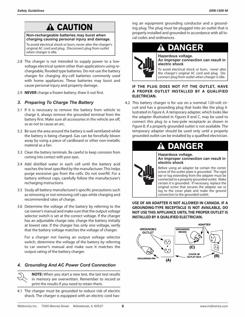
ing an equipment grounding conductor and a ground-ing plug. The plug must be plugged into an outlet that is properly installed and grounded in accordance with all lo-cal codes and ordinances.
Hazardous voltage. An improper connection can result in electric shockTo avoid electrical shock or burn, never alter the charger’s original AC cord and plug. Dis-connect plug from outlet when charger is idle.
IF THE PLUG DOES NOT FIT THE OUTLET, HAVE A PROPER OUTLET INSTALLED BY A QUALIFIED ELECTRICIAN.
4.2 This battery charger is for use on a nominal 120-volt cir-cuit and has a grounding plug that looks like the plug il-lustrated in Figure A. A temporary adapter, which looks like the adapter illustrated in Figures B and C, may be used to connect this plug to a two-pole receptacle as shown in Figure B, if a properly grounded outlet is not available. The temporary adapter should be used only until a properly grounded outlet can be installed by a qualified electrician.
Hazardous voltage. An improper connection can result in electric shockBefore using an adapter be certain the center screw of the outlet plate is grounded. The rigid ear or lug extending from the adapter must be connected to a properly grounded outlet. Make certain it is grounded. If necessary, replace the original screw that secures the adapter ear or lug to the cover plate and make the ground connection to the grounded outlet.
USE OF AN ADAPTER IS NOT ALLOWED IN CANADA. IF A GROUNDING-TYPE RECEPTACLE IS NOT AVAILABLE, DO NOT USE THIS APPLIANCE UNTIL THE PROPER OUTLET IS INSTALLED BY A QUALIFIED ELECTRICIAN.
GR8-1200 NI
Midtronics Inc. 7000 Monroe Street Willowbrook, IL 60527www.midtronics.com 7
Safety Guidelines
5. Charger Location5.1 Locate the charger as far away from the battery as the
charger cables permit.
5.2 Never place the charger directly above the battery being charged; gases from the battery will corrode and damage the charger.
5.3 Never allow battery acid to drip on the charger when tak-ing gravity readings or filling a battery.
5.4 Operate the charger only in a well-ventilated area that is free of dangerous vapors.
5.5 Store the charger in safe, dry location and maintain it in perfect condition.
5.6 Do not set the battery on top of the charger or where its acid might drip onto the charger.
6. DC Connection Precautions6.1 All switches should be set in the OFF position and AC cord
should be DISCONNECTED from electrical outlet before you connect and disconnect the charger clamps. Never allow the clamps to touch each other.
6.2 When attaching the charger clamps, be certain to make the best possible mechanical as well as electrical connec-tion. This will tend to prevent the clamps from slipping off the connections, avoid dangerous sparking, and assure safer and more efficient charging. The clamps should be kept clean.
Hazardous voltage. Can cause death or serious personal injury.Setting the switches to “OFF” does not always disconnect the charger electrical circuit from the AC power cord or the DC charger clamps.
7. Installing The Battery
Risk of explosive gases.A spark near the battery may cause a battery explosion. Follow these steps when the battery is installed in the vehicle to reduce the risk of explosion.
7.1 Before working on the vehicle, firmly apply the emergen-cy brake and place the gear shift to NEUTRAL—shift an automatic transmission to PARK.
7.2 Locate the charger as far away from the battery as the charger cords permit and position the AC and DC cords to avoid stepping on or tripping over them and to prevent damage by hood, doors, or moving engine parts.
7.3 Stay clear of fan blades, belts, pulleys, and any other parts that can cause physical injury.
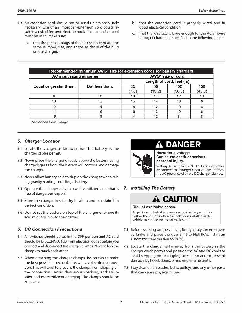
4.3 An extension cord should not be used unless absolutely necessary. Use of an improper extension cord could re-sult in a risk of fire and electric shock. If an extension cord must be used, make sure:
a. that the pins on plugs of the extension cord are the same number, size, and shape as those of the plug on the charger;
b. that the extension cord is properly wired and in good electrical condition;
c. that the wire size is large enough for the AC ampere rating of charger as specified in the following table.
Recommended minimum AWG* size for extension cords for battery chargersAC input rating amperes AWG* size of cord
Equal or greater than: But less than:Length of cord, feet (m)
25(7.6)
50(15.2)
100(30.5)
150(45.6)
8 10 18 14 12 1010 12 16 14 10 812 14 16 12 10 814 16 16 12 10 816 18 14 12 8 8
*American Wire Gauge
GR8-1200 NI
Midtronics Inc. 7000 Monroe Street Willowbrook, IL 60527 www.midtronics.com8
Safety Guidelines
7.4 Turn OFF all vehicle loads, including door lights, and cor-rect any defects in the vehicle’s electrical system that may have caused low battery.
7.5 Check the polarity of the battery posts. The POSITIVE (POS., P, +) post usually has a larger diameter than the NEGATIVE (NEG., N,–) post.
7.6 Determine which post of the battery is grounded (connect-ed) to the chassis. If the negative post is grounded (as in most vehicles), see paragraph 7.7. If the positive post is grounded, see paragraph 7.8.
7.7 For a negative-grounded vehicle, first connect the POSI-TIVE (RED) clamp from the charger to the POSITIVE (POS., P, +) ungrounded post of the battery. Then connect the NEGATIVE (BLACK) clamp to the NEGATIVE (NEG, N, -) post of the battery. Do not connect the clamp to the carburetor, fuel lines, or sheet-metal body parts. When dis-connecting the charger, always do so in reverse sequence of the connecting procedure; break the first connection while staying as far away from the battery as practical.
7.8 For positive-grounded vehicle, connect the NEGATIVE (BLACK) clamp from the charger to the NEGATIVE (NEG., N, –) ungrounded post of battery. Then connect the POSI-TIVE (RED) clamp to the POSITIVE (POS., P, +) post of the battery. Do not connect clamp to carburetor, fuel lines, or sheet-metal body parts. When disconnecting the charger, always do so in reverse sequence of the connecting proce-dure; break the first connection while staying as far away from the battery as practical.
CAUTION: WHEN POSITIVE (+) POST OF VEHICLE BATTERY IS GROUNDED, DOUBLE CHECK POLARITY.
8. Connecting To The Battery8. If it is necessary to remove the battery from the vehicle or
equipment, always remove the grounded terminal from the battery first.
Risk of explosive gases. Can cause death or serious personal injury.Always work in a well-ventilated area. Never smoke or allow a spark or flame in the vicinity of a battery. Batteries can produce a highly explosive mix of hydrogen gas and oxygen, even when the battery is not in operation.
Risk of explosive gases.Make sure all vehicle loads are OFF to prevent a possible arc..
8.1 Check the polarity of battery posts. POSITIVE (POS., P, +) post usually has larger diameter than NEGATIVE (NEG., N, –) post.
8.2 Connect the POSITIVE (RED) charger clamp to the POSI-TIVE (POS., P, +) post of battery.
8.3 Position yourself as far away from the battery as possi-ble—do not face the battery when making the final con-nection—then connect the NEGATIVE (BLACK) charger clamp to the NEGATIVE (NEG., N,–) post.
8.4 When disconnecting the charger, always do so in the re-verse sequence of the connecting procedure; break the first connection while staying as far away from the battery as practical.
8.5 MARINE “BOAT” BATTERIES MUST BE REMOVED AND CHARGED ON SHORE. TO SAFELY CHARGE THEM ON BOARD REQUIRES EQUIPMENT SPECIFICALLY DE-SIGNED FOR MARINE USE.
GR8-1200 NI
Midtronics Inc. 7000 Monroe Street Willowbrook, IL 60527www.midtronics.com 9
Chapter 1: Before You Begin
! Safety ReminderFor safe, efficient, and accurate charging and testing, review the safety and operating instructions in this manual before using the analyzer. In addition, follow all manufacturers’ instructions and BCI (Battery Council International) safety recommendations.
! Safety PrecautionsInspect the battery for damages and check the electrolyte level. If the electrolyte level is too low, replenish it and fully charge the battery. Always use the necessary safety precautions when working with batteries to prevent severe injury or death. Follow all manufacturers’ instructions and BCI (Battery Council International) safety recommendations, which include the following precautions:
Risk of explosive gases. Can cause death or serious personal injury.Always work in a well-ventilated area. Never smoke or allow a spark or flame in the vicinity of a battery. Batteries can produce a highly explosive mix of hydrogen gas and oxygen, even when the battery is not in operation.
Wash hands after handling.Battery posts, terminals, and related acces-sories contain lead and lead compounds, chemicals known to the state of California to cause cancer and birth defects or other reproductive harm.
Battery acid is highly corrosive. If acid enters your eyes, im-mediately flush them thoroughly with cold running water for at least 15 minutes and seek medical attention. If bat-tery acid gets on your skin or clothing, wash immediately with a mixture of water and baking soda.
Always wear proper safety glasses or face shield when working with or around batteries.
Keep hair, hands, and clothing as well as the analyzer cords and cables away from moving engine parts.
Remove any jewelry or watches before you start servicing the battery.
Use caution when working with metallic tools to prevent sparks or short circuits.
Never lean over a battery when testing, charging, or jump starting.
Never charge a frozen battery. Gases may form, cracking the case, and spray out battery acid.
Conventions Used in This ManualTo help you learn how to use your GR8, the manual uses these symbols and typographical conventions:
Convention Description
!The safety symbol indicates instructions for avoiding hazardous conditions and personal injury.
The safety symbol with the words CAUTION, WARNING, or DANGER indicates instructions for avoiding hazardous conditions and personal injury.
CAUTION The word CAUTION indicates instructions for avoiding equipment damage.
The wrench symbol indicates procedural notes and helpful information.
UP ARROW The text for keypad buttons are in BOLD capital letters.
CAPITAL LETTERS
The text for screen options are in regular capital letters.
BACK ARROW
The text for soft keys are in Bold capital letters.
Assembling Your GR8The GR8 is shipped with the control module and mounting bracket packed separately. For easy assembly, follow these steps:
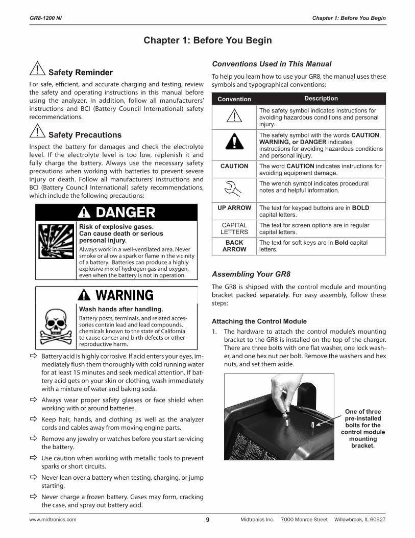
Attaching the Control Module1. The hardware to attach the control module’s mounting
bracket to the GR8 is installed on the top of the charger. There are three bolts with one flat washer, one lock wash-er, and one hex nut per bolt. Remove the washers and hex nuts, and set them aside.
One of three pre-installed bolts for the
control module mounting bracket.
Chapter 1: Before You Begin
GR8-1200 NI
Midtronics Inc. 7000 Monroe Street Willowbrook, IL 60527 www.midtronics.com10
Chapter 1: Before You Begin
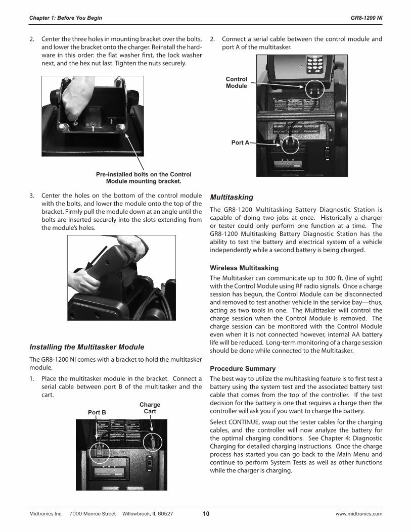
2. Center the three holes in mounting bracket over the bolts, and lower the bracket onto the charger. Reinstall the hard-ware in this order: the flat washer first, the lock washer next, and the hex nut last. Tighten the nuts securely.
Pre-installed bolts on the Control Module mounting bracket.
3. Center the holes on the bottom of the control module with the bolts, and lower the module onto the top of the bracket. Firmly pull the module down at an angle until the bolts are inserted securely into the slots extending from the module’s holes.
Installing the Multitasker ModuleThe GR8-1200 NI comes with a bracket to hold the multitasker module.
1. Place the multitasker module in the bracket. Connect a serial cable between port B of the multitasker and the cart.
Port BCharge
Cart
2. Connect a serial cable between the control module and port A of the multitasker.
Port A
Control Module
MultitaskingThe GR8-1200 Multitasking Battery Diagnostic Station is capable of doing two jobs at once. Historically a charger or tester could only perform one function at a time. The GR8-1200 Multitasking Battery Diagnostic Station has the ability to test the battery and electrical system of a vehicle independently while a second battery is being charged.
Wireless MultitaskingThe Multitasker can communicate up to 300 ft. (line of sight) with the Control Module using RF radio signals. Once a charge session has begun, the Control Module can be disconnected and removed to test another vehicle in the service bay—thus, acting as two tools in one. The Multitasker will control the charge session when the Control Module is removed. The charge session can be monitored with the Control Module even when it is not connected however, internal AA battery life will be reduced. Long-term monitoring of a charge session should be done while connected to the Multitasker.
Procedure SummaryThe best way to utilize the multitasking feature is to first test a battery using the system test and the associated battery test cable that comes from the top of the controller. If the test decision for the battery is one that requires a charge then the controller will ask you if you want to charge the battery.
Select CONTINUE, swap out the tester cables for the charging cables, and the controller will now analyze the battery for the optimal charging conditions. See Chapter 4: Diagnostic Charging for detailed charging instructions. Once the charge process has started you can go back to the Main Menu and continue to perform System Tests as well as other functions while the charger is charging.
GR8-1200 NI
Midtronics Inc. 7000 Monroe Street Willowbrook, IL 60527www.midtronics.com 11
Chapter 2: Overview
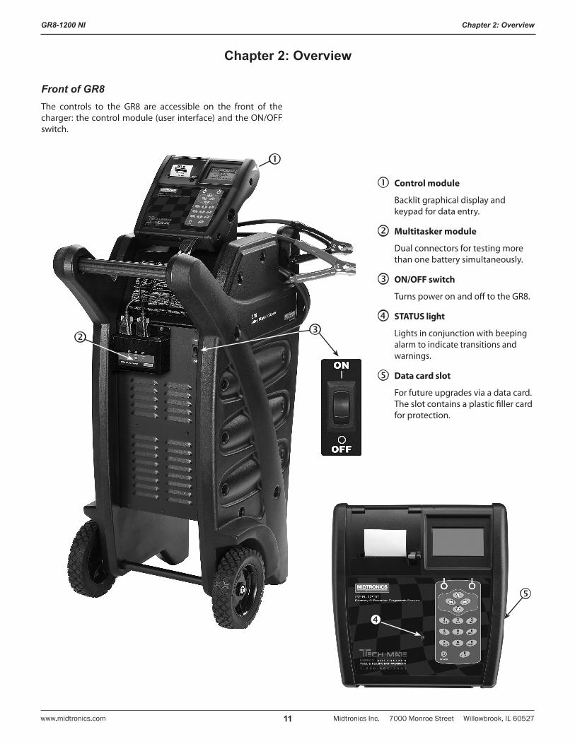
Front of GR8The controls to the GR8 are accessible on the front of the charger: the control module (user interface) and the ON/OFF switch.
Chapter 2: Overview
Control module
Backlit graphical display and keypad for data entry.
Multitasker module
Dual connectors for testing more than one battery simultaneously.
ON/OFF switch
Turns power on and off to the GR8.
STATUS light
Lights in conjunction with beeping alarm to indicate transitions and warnings.
Data card slot
For future upgrades via a data card. The slot contains a plastic filler card for protection.
GR8-1200 NI
Midtronics Inc. 7000 Monroe Street Willowbrook, IL 60527 www.midtronics.com12
Chapter 2: Overview
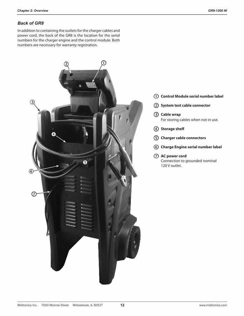
Back of GR8In addition to containing the outlets for the charger cables and power cord, the back of the GR8 is the location for the serial numbers for the charger engine and the control module. Both numbers are necessary for warranty registration.
Control Module serial number label
System test cable connector
Cable wrapFor storing cables when not in use.
Storage shelf
Charger cable connectors
Charge Engine serial number label
AC power cordConnection to grounded nominal 120 V outlet.
GR8-1200 NI
Midtronics Inc. 7000 Monroe Street Willowbrook, IL 60527www.midtronics.com 13
Chapter 2: Overview
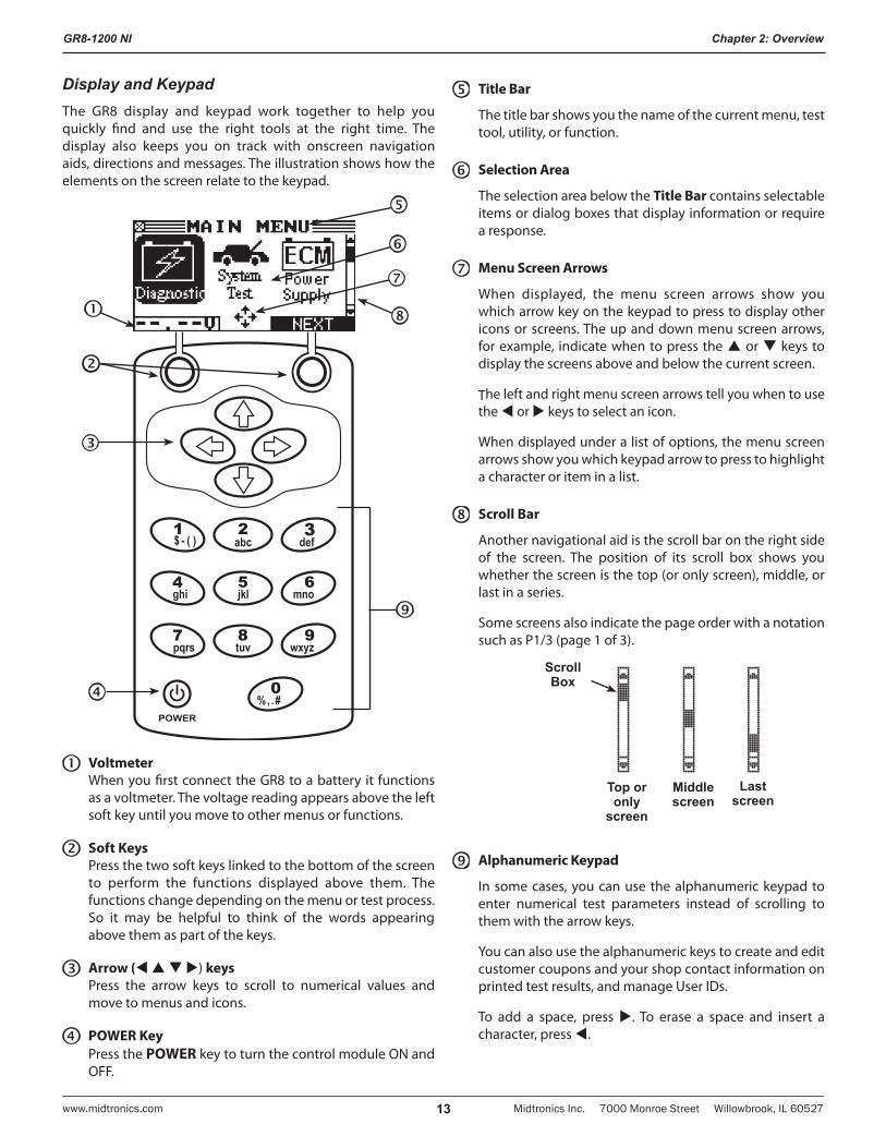
Display and KeypadThe GR8 display and keypad work together to help you quickly find and use the right tools at the right time. The display also keeps you on track with onscreen navigation aids, directions and messages. The illustration shows how the elements on the screen relate to the keypad.
VoltmeterWhen you first connect the GR8 to a battery it functions as a voltmeter. The voltage reading appears above the left soft key until you move to other menus or functions.
Soft KeysPress the two soft keys linked to the bottom of the screen to perform the functions displayed above them. The functions change depending on the menu or test process. So it may be helpful to think of the words appearing above them as part of the keys.
Arrow ( ) keysPress the arrow keys to scroll to numerical values and move to menus and icons.
POWER KeyPress the POWER key to turn the control module ON and OFF.
Title Bar
The title bar shows you the name of the current menu, test tool, utility, or function.
Selection Area
The selection area below the Title Bar contains selectable items or dialog boxes that display information or require a response.
Menu Screen Arrows
When displayed, the menu screen arrows show you which arrow key on the keypad to press to display other icons or screens. The up and down menu screen arrows, for example, indicate when to press the or keys to display the screens above and below the current screen.
The left and right menu screen arrows tell you when to use the or keys to select an icon.
When displayed under a list of options, the menu screen arrows show you which keypad arrow to press to highlight a character or item in a list.
Scroll Bar
Another navigational aid is the scroll bar on the right side of the screen. The position of its scroll box shows you whether the screen is the top (or only screen), middle, or last in a series.
Some screens also indicate the page order with a notation such as P1/3 (page 1 of 3).
Top or only
screen
Middle screen
Last screen
Scroll Box
Alphanumeric Keypad
In some cases, you can use the alphanumeric keypad to enter numerical test parameters instead of scrolling to them with the arrow keys.
You can also use the alphanumeric keys to create and edit customer coupons and your shop contact information on printed test results, and manage User IDs.
To add a space, press . To erase a space and insert a character, press .
GR8-1200 NI
Midtronics Inc. 7000 Monroe Street Willowbrook, IL 60527 www.midtronics.com14
Chapter 2: Overview
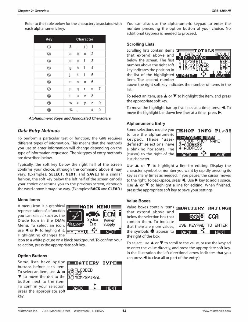
Refer to the table below for the characters associated with each alphanumeric key.
Key Character
$ - ( ) 1
a b c 2
d e f 3
g h i 4
j k l 5
m n o 6
p q r s 7
t u v 8
w x y z 9
% , . # 0
Alphanumeric Keys and Associated Characters
Data Entry MethodsTo perform a particular test or function, the GR8 requires different types of information. This means that the methods you use to enter information will change depending on the type of information requested. The six types of entry methods are described below.
Typically, the soft key below the right half of the screen confirms your choice, although the command above it may vary. (Examples: SELECT, NEXT, and SAVE.) In a similar fashion, the soft key below the left half of the screen cancels your choice or returns you to the previous screen, although the word above it may also vary. (Examples: BACK and CLEAR.)
Menu IconsA menu icon is a graphical representation of a function you can select, such as the Diode Icon in the DMM Menu. To select an icon, use or to highlight it. Highlighting changes the icon to a white picture on a black background. To confirm your selection, press the appropriate soft key.
Option ButtonsSome lists have option buttons before each item. To select an item, use or to move the dot to the button next to the item. To confirm your selection, press the appropriate soft key.
You can also use the alphanumeric keypad to enter the number preceding the option button of your choice. No additional keypress is needed to proceed.
Scrolling ListsScrolling lists contain items that extend above and below the screen. The first number above the right soft key indicates the position in the list of the highlighted item. The second number above the right soft key indicates the number of items in the list.
To select an item, use or to highlight the item, and press the appropriate soft key.
To move the highlight bar up five lines at a time, press . To move the highlight bar down five lines at a time, press .
Alphanumeric EntrySome selections require you to use the alphanumeric k e y p a d . T h e s e “u s e r -defined” selections have a blinking horizontal line (cursor) to the right of the last character.
Use or to highlight a line for editing. Display the character, symbol, or number you want by rapidly pressing its key as many times as needed. If you pause, the cursor moves to the right. To backspace, press . Use key to add a space. Use or to highlight a line for editing. When finished, press the appropriate soft key to save your settings.
Value BoxesValue boxes contain items that extend above and below the selection box that contain them. To indicate that there are more values, the symbols appear to the right of the box.
To select, use or to scroll to the value, or use the keypad to enter the value directly, and press the appropriate soft key. In the illustration the left directional arrow indicates that you can press to clear all or part of the entry.)
GR8-1200 NI
Midtronics Inc. 7000 Monroe Street Willowbrook, IL 60527www.midtronics.com 15
Chapter 2: Overview
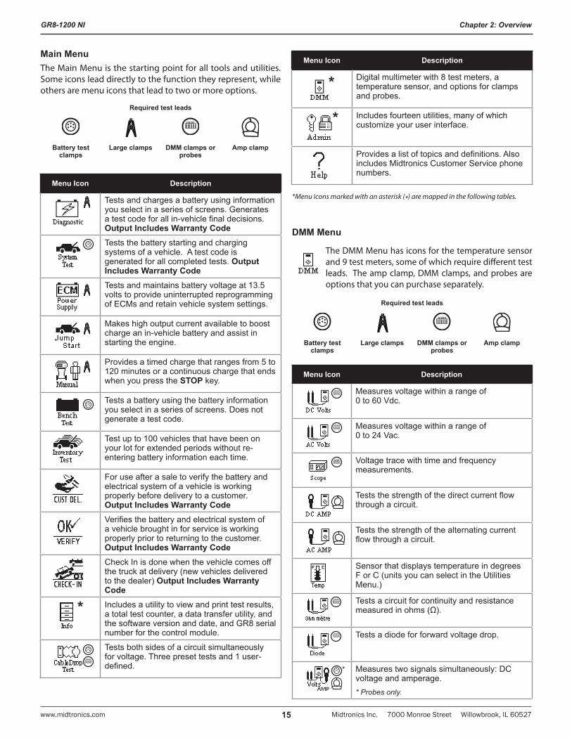
Main MenuThe Main Menu is the starting point for all tools and utilities. Some icons lead directly to the function they represent, while others are menu icons that lead to two or more options.
Required test leads
Battery test clamps
Large clamps DMM clamps or probes
Amp clamp
Menu Icon Description
Tests and charges a battery using information you select in a series of screens. Generates a test code for all in-vehicle final decisions. Output Includes Warranty CodeTests the battery starting and charging systems of a vehicle. A test code is generated for all completed tests. Output Includes Warranty CodeTests and maintains battery voltage at 13.5 volts to provide uninterrupted reprogramming of ECMs and retain vehicle system settings.
Makes high output current available to boost charge an in-vehicle battery and assist in starting the engine.
Provides a timed charge that ranges from 5 to 120 minutes or a continuous charge that ends when you press the STOP key.
Tests a battery using the battery information you select in a series of screens. Does not generate a test code.
Test up to 100 vehicles that have been on your lot for extended periods without re-entering battery information each time.
For use after a sale to verify the battery and electrical system of a vehicle is working properly before delivery to a customer. Output Includes Warranty CodeVerifies the battery and electrical system of a vehicle brought in for service is working properly prior to returning to the customer. Output Includes Warranty CodeCheck In is done when the vehicle comes off the truck at delivery (new vehicles delivered to the dealer) Output Includes Warranty Code
* Includes a utility to view and print test results, a total test counter, a data transfer utility, and the software version and date, and GR8 serial number for the control module.
Tests both sides of a circuit simultaneously for voltage. Three preset tests and 1 user-defined.
Menu Icon Description
* Digital multimeter with 8 test meters, a temperature sensor, and options for clamps and probes.
* Includes fourteen utilities, many of which customize your user interface.
Provides a list of topics and definitions. Also includes Midtronics Customer Service phone numbers.
*Menu icons marked with an asterisk (*) are mapped in the following tables.
DMM Menu
The DMM Menu has icons for the temperature sensor and 9 test meters, some of which require different test leads. The amp clamp, DMM clamps, and probes are options that you can purchase separately.
Required test leads
Battery test clamps
Large clamps DMM clamps or probes
Amp clamp
Menu Icon Description
Measures voltage within a range of 0 to 60 Vdc.
Measures voltage within a range of 0 to 24 Vac.
Voltage trace with time and frequency measurements.
Tests the strength of the direct current flow through a circuit.
Tests the strength of the alternating current flow through a circuit.
Sensor that displays temperature in degrees F or C (units you can select in the Utilities Menu.)
Tests a circuit for continuity and resistance measured in ohms (Ω).
Tests a diode for forward voltage drop.
* Measures two signals simultaneously: DC voltage and amperage.* Probes only.
GR8-1200 NI
Midtronics Inc. 7000 Monroe Street Willowbrook, IL 60527 www.midtronics.com16
Chapter 2: Overview
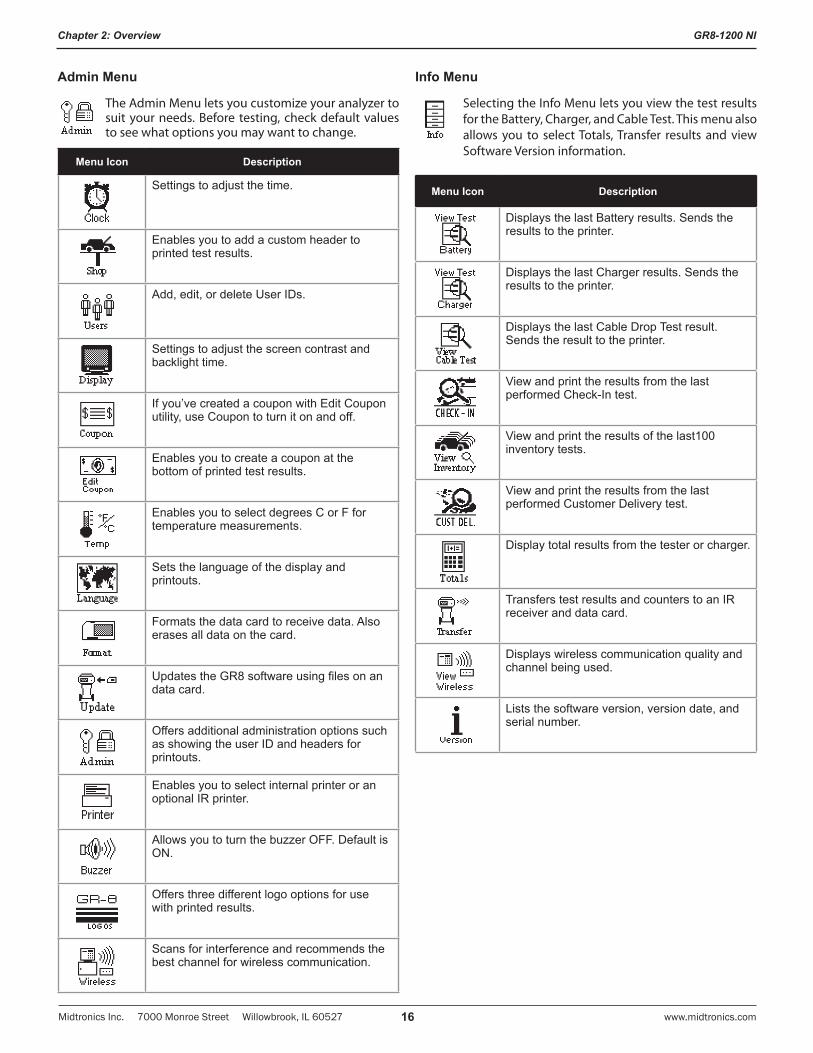
Admin Menu
The Admin Menu lets you customize your analyzer to suit your needs. Before testing, check default values to see what options you may want to change.
Menu Icon Description
Settings to adjust the time.
Enables you to add a custom header to printed test results.
Add, edit, or delete User IDs.
Settings to adjust the screen contrast and backlight time.
If you’ve created a coupon with Edit Coupon utility, use Coupon to turn it on and off.
Enables you to create a coupon at the bottom of printed test results.
Enables you to select degrees C or F for temperature measurements.
Sets the language of the display and printouts.
Formats the data card to receive data. Also erases all data on the card.
Updates the GR8 software using files on an data card.
Offers additional administration options such as showing the user ID and headers for printouts.
Enables you to select internal printer or an optional IR printer.
Allows you to turn the buzzer OFF. Default is ON.
Offers three different logo options for use with printed results.
Scans for interference and recommends the best channel for wireless communication.
Info Menu
Selecting the Info Menu lets you view the test results for the Battery, Charger, and Cable Test. This menu also allows you to select Totals, Transfer results and view Software Version information.
Menu Icon Description
Displays the last Battery results. Sends the results to the printer.
Displays the last Charger results. Sends the results to the printer.
Displays the last Cable Drop Test result. Sends the result to the printer.
View and print the results from the last performed Check-In test.
View and print the results of the last100 inventory tests.
View and print the results from the last performed Customer Delivery test.
Display total results from the tester or charger.
Transfers test results and counters to an IR receiver and data card.
Displays wireless communication quality and channel being used.
Lists the software version, version date, and serial number.
GR8-1200 NI
Midtronics Inc. 7000 Monroe Street Willowbrook, IL 60527www.midtronics.com 17
Chapter 3: Getting Started
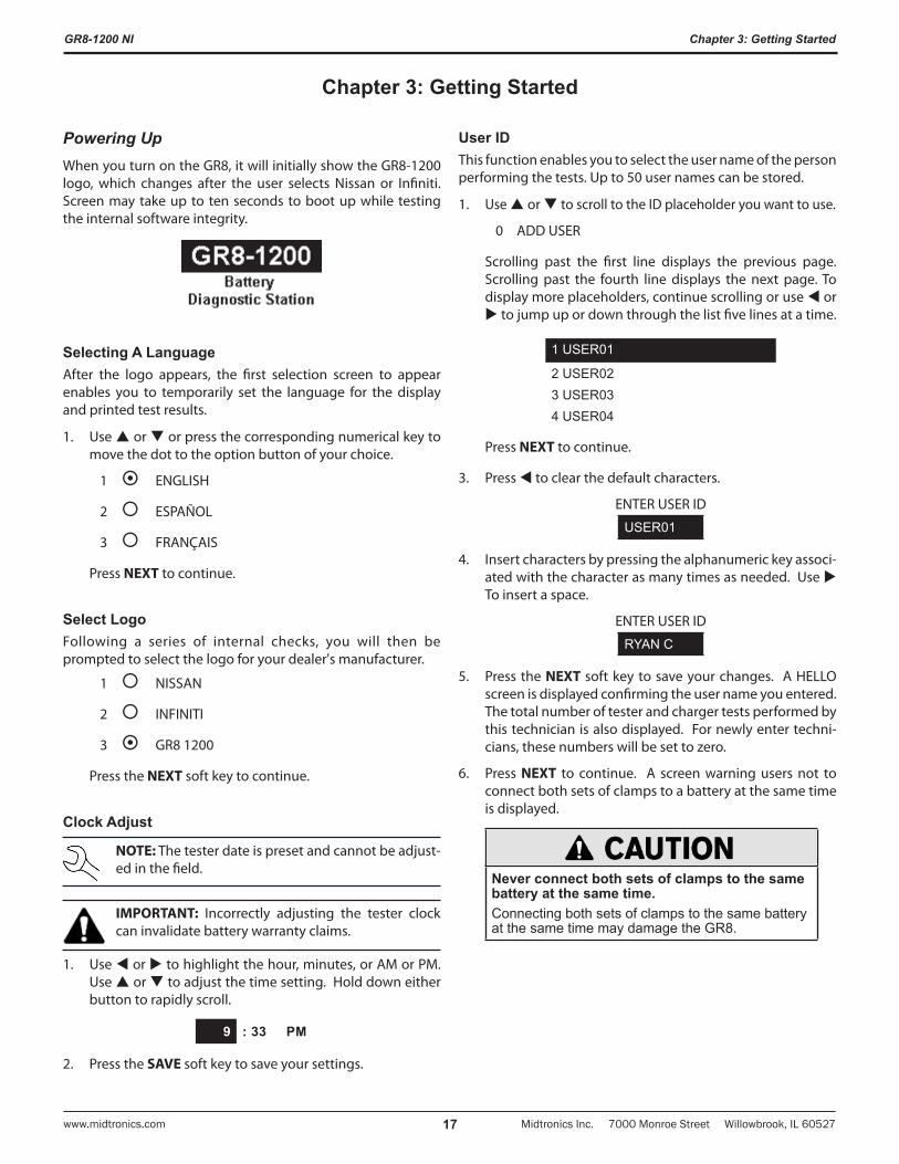
Powering UpWhen you turn on the GR8, it will initially show the GR8-1200 logo, which changes after the user selects Nissan or Infiniti. Screen may take up to ten seconds to boot up while testing the internal software integrity.
Selecting A LanguageAfter the logo appears, the first selection screen to appear enables you to temporarily set the language for the display and printed test results.
1. Use or or press the corresponding numerical key to move the dot to the option button of your choice.
1 ENGLISH
2 ESPAÑOL
3 FRANÇAIS
Press NEXT to continue.
Select LogoFollowing a series of internal checks, you will then be prompted to select the logo for your dealer's manufacturer.
1 NISSAN
2 INFINITI
3 GR8 1200
Press the NEXT soft key to continue.
Clock Adjust
NOTE: The tester date is preset and cannot be adjust-ed in the field.
IMPORTANT: Incorrectly adjusting the tester clock can invalidate battery warranty claims.
1. Use or to highlight the hour, minutes, or AM or PM. Use or to adjust the time setting. Hold down either button to rapidly scroll.
9 : 33 PM
2. Press the SAVE soft key to save your settings.
User IDThis function enables you to select the user name of the person performing the tests. Up to 50 user names can be stored.
1. Use or to scroll to the ID placeholder you want to use.
0 ADD USER
Scrolling past the first line displays the previous page. Scrolling past the fourth line displays the next page. To display more placeholders, continue scrolling or use or to jump up or down through the list five lines at a time.
1 USER01
2 USER023 USER034 USER04
Press NEXT to continue.
3. Press to clear the default characters.
ENTER USER ID
USER01
4. Insert characters by pressing the alphanumeric key associ-ated with the character as many times as needed. Use To insert a space.
ENTER USER ID
RYAN C
5. Press the NEXT soft key to save your changes. A HELLO screen is displayed confirming the user name you entered. The total number of tester and charger tests performed by this technician is also displayed. For newly enter techni-cians, these numbers will be set to zero.
6. Press NEXT to continue. A screen warning users not to connect both sets of clamps to a battery at the same time is displayed.
Never connect both sets of clamps to the same battery at the same time.Connecting both sets of clamps to the same battery at the same time may damage the GR8.
Chapter 3: Getting Started
GR8-1200 NI
Midtronics Inc. 7000 Monroe Street Willowbrook, IL 60527 www.midtronics.com18
Chapter 3: Getting Started
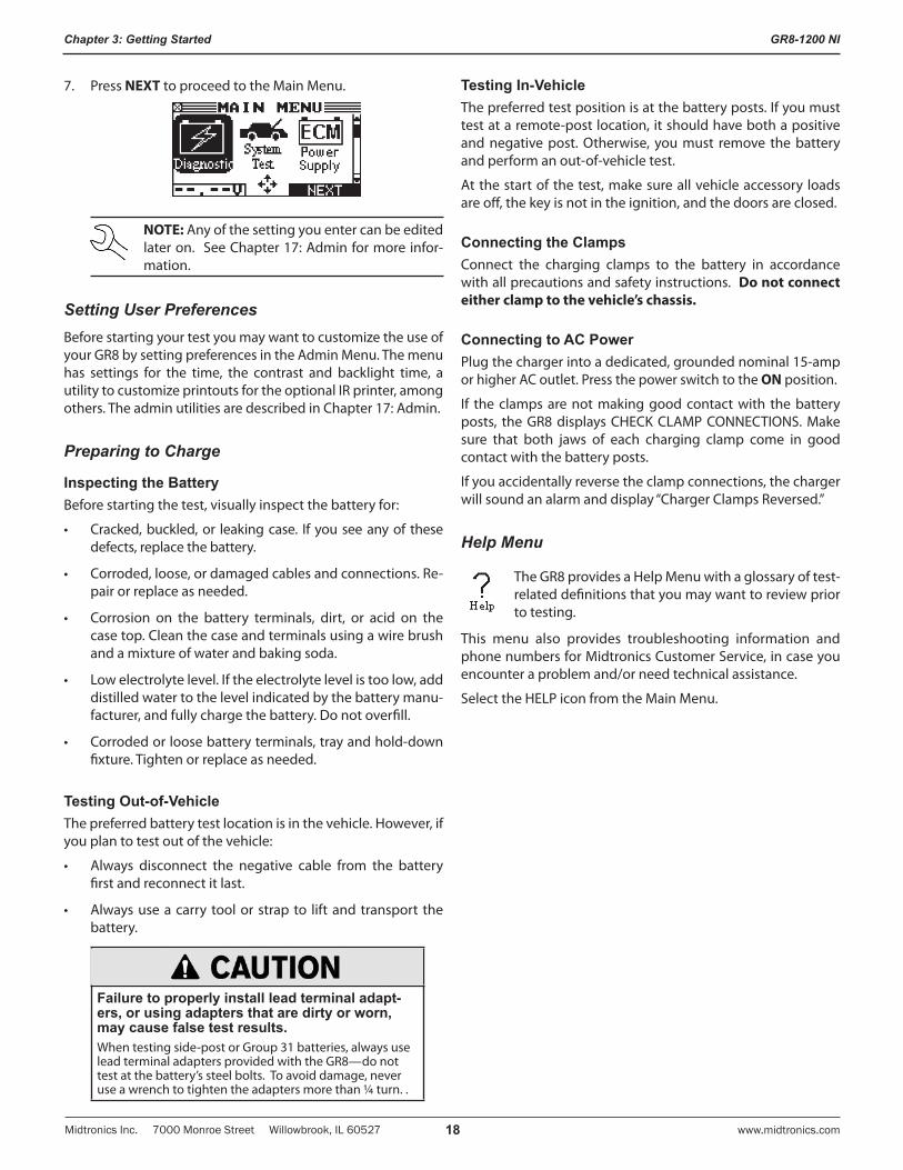
7. Press NEXT to proceed to the Main Menu.
NOTE: Any of the setting you enter can be edited later on. See Chapter 17: Admin for more infor-mation.
Setting User PreferencesBefore starting your test you may want to customize the use of your GR8 by setting preferences in the Admin Menu. The menu has settings for the time, the contrast and backlight time, a utility to customize printouts for the optional IR printer, among others. The admin utilities are described in Chapter 17: Admin.
Preparing to Charge
Inspecting the BatteryBefore starting the test, visually inspect the battery for:
• Cracked,buckled,or leakingcase. Ifyouseeanyof thesedefects, replace the battery.
• Corroded,loose,ordamagedcablesandconnections.Re-pair or replace as needed.
• Corrosion on the battery terminals, dirt, or acid on thecase top. Clean the case and terminals using a wire brush and a mixture of water and baking soda.
• Lowelectrolytelevel.Iftheelectrolytelevelistoolow,adddistilled water to the level indicated by the battery manu-facturer, and fully charge the battery. Do not overfill.
• Corrodedorloosebatteryterminals,trayandhold-downfixture. Tighten or replace as needed.
Testing Out-of-VehicleThe preferred battery test location is in the vehicle. However, if you plan to test out of the vehicle:
• Always disconnect the negative cable from the batteryfirst and reconnect it last.
• Alwaysuseacarry toolorstrap to liftandtransport thebattery.
Failure to properly install lead terminal adapt-ers, or using adapters that are dirty or worn, may cause false test results.When testing side-post or Group 31 batteries, always use lead terminal adapters provided with the GR8—do not test at the battery’s steel bolts. To avoid damage, never use a wrench to tighten the adapters more than ¼ turn. .
Testing In-VehicleThe preferred test position is at the battery posts. If you must test at a remote-post location, it should have both a positive and negative post. Otherwise, you must remove the battery and perform an out-of-vehicle test.
At the start of the test, make sure all vehicle accessory loads are off, the key is not in the ignition, and the doors are closed.
Connecting the ClampsConnect the charging clamps to the battery in accordance with all precautions and safety instructions. Do not connect either clamp to the vehicle’s chassis.
Connecting to AC PowerPlug the charger into a dedicated, grounded nominal 15-amp or higher AC outlet. Press the power switch to the ON position.
If the clamps are not making good contact with the battery posts, the GR8 displays CHECK CLAMP CONNECTIONS. Make sure that both jaws of each charging clamp come in good contact with the battery posts.
If you accidentally reverse the clamp connections, the charger will sound an alarm and display “Charger Clamps Reversed.”
Help Menu
The GR8 provides a Help Menu with a glossary of test-related definitions that you may want to review prior to testing.
This menu also provides troubleshooting information and phone numbers for Midtronics Customer Service, in case you encounter a problem and/or need technical assistance.
Select the HELP icon from the Main Menu.
GR8-1200 NI
Midtronics Inc. 7000 Monroe Street Willowbrook, IL 60527www.midtronics.com 19
Chapter 4: Diagnostic Charging
The GR8-1200 diagnostic charger will determine the internal condition of a battery before attempting to apply a charge to it.
Never connect both sets of clamps to the same battery at the same time.Connecting both sets of clamps to the same battery at the same time may damage the GR8. Only use the large clamps from the GR8 charge engine when performing a diagnostic charging.
NOTE: When you start a new charge session, the last test results in memory will be overwritten.
Performing A Diagnostic Charge1. Confirm that the large charging clamps are connected to
the battery. Then in the Main Menu, use or to high-light the DIAGNOSTIC icon and press the NEXT soft key.
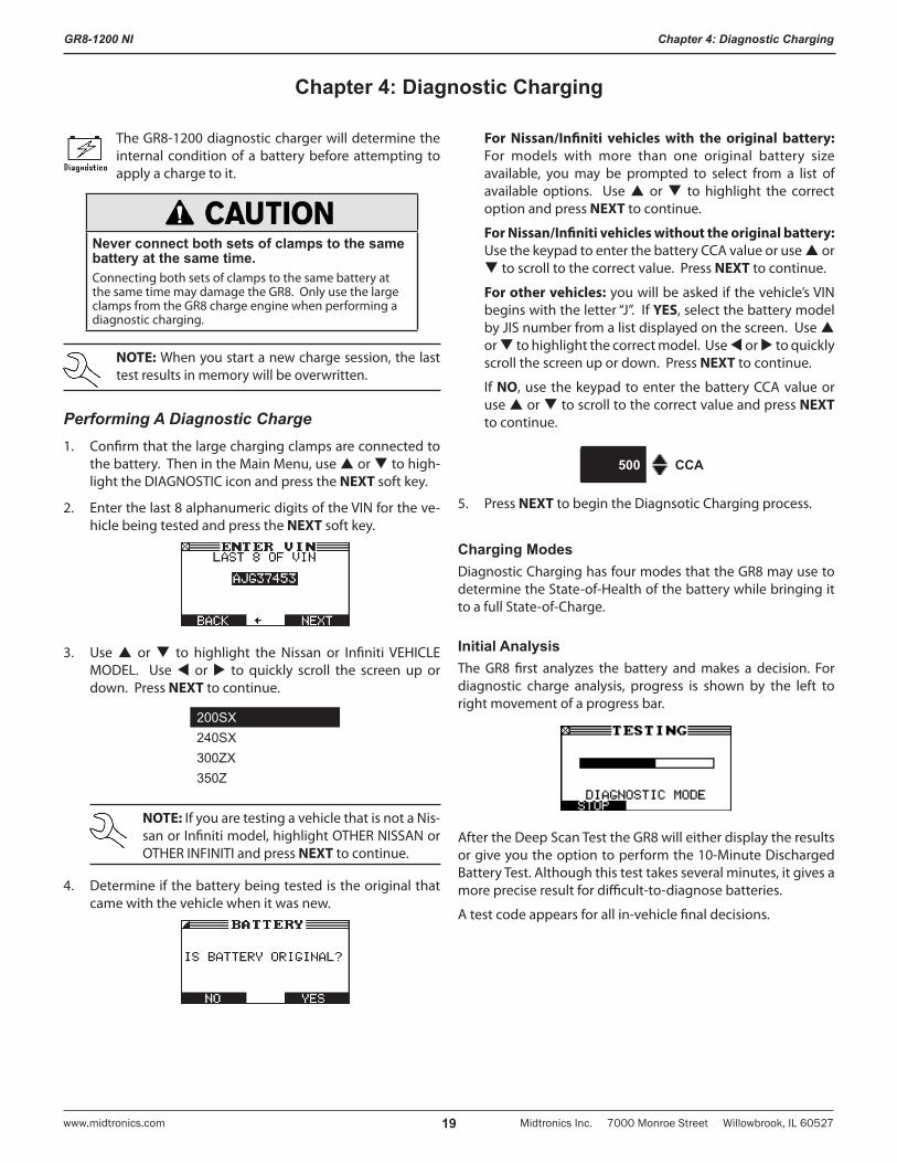
2. Enter the last 8 alphanumeric digits of the VIN for the ve-hicle being tested and press the NEXT soft key.
3. Use or to highlight the Nissan or Infiniti VEHICLE MODEL. Use or to quickly scroll the screen up or down. Press NEXT to continue.
200SX240SX300ZX350Z
NOTE: If you are testing a vehicle that is not a Nis-san or Infiniti model, highlight OTHER NISSAN or OTHER INFINITI and press NEXT to continue.
4. Determine if the battery being tested is the original that came with the vehicle when it was new.
For Nissan/Infiniti vehicles with the original battery: For models with more than one original battery size available, you may be prompted to select from a list of available options. Use or to highlight the correct option and press NEXT to continue.
For Nissan/Infiniti vehicles without the original battery: Use the keypad to enter the battery CCA value or use or to scroll to the correct value. Press NEXT to continue.
For other vehicles: you will be asked if the vehicle’s VIN begins with the letter “J”. If YES, select the battery model by JIS number from a list displayed on the screen. Use or to highlight the correct model. Use or to quickly scroll the screen up or down. Press NEXT to continue.
If NO, use the keypad to enter the battery CCA value or use or to scroll to the correct value and press NEXT to continue.
500 CCA
5. Press NEXT to begin the Diagnsotic Charging process.
Charging ModesDiagnostic Charging has four modes that the GR8 may use to determine the State-of-Health of the battery while bringing it to a full State-of-Charge.
Initial AnalysisThe GR8 first analyzes the battery and makes a decision. For diagnostic charge analysis, progress is shown by the left to right movement of a progress bar.
After the Deep Scan Test the GR8 will either display the results or give you the option to perform the 10-Minute Discharged Battery Test. Although this test takes several minutes, it gives a more precise result for difficult-to-diagnose batteries.
A test code appears for all in-vehicle final decisions.
Chapter 4: Diagnostic Charging
GR8-1200 NI
Midtronics Inc. 7000 Monroe Street Willowbrook, IL 60527 www.midtronics.com20
Chapter 4: Diagnostic Charging
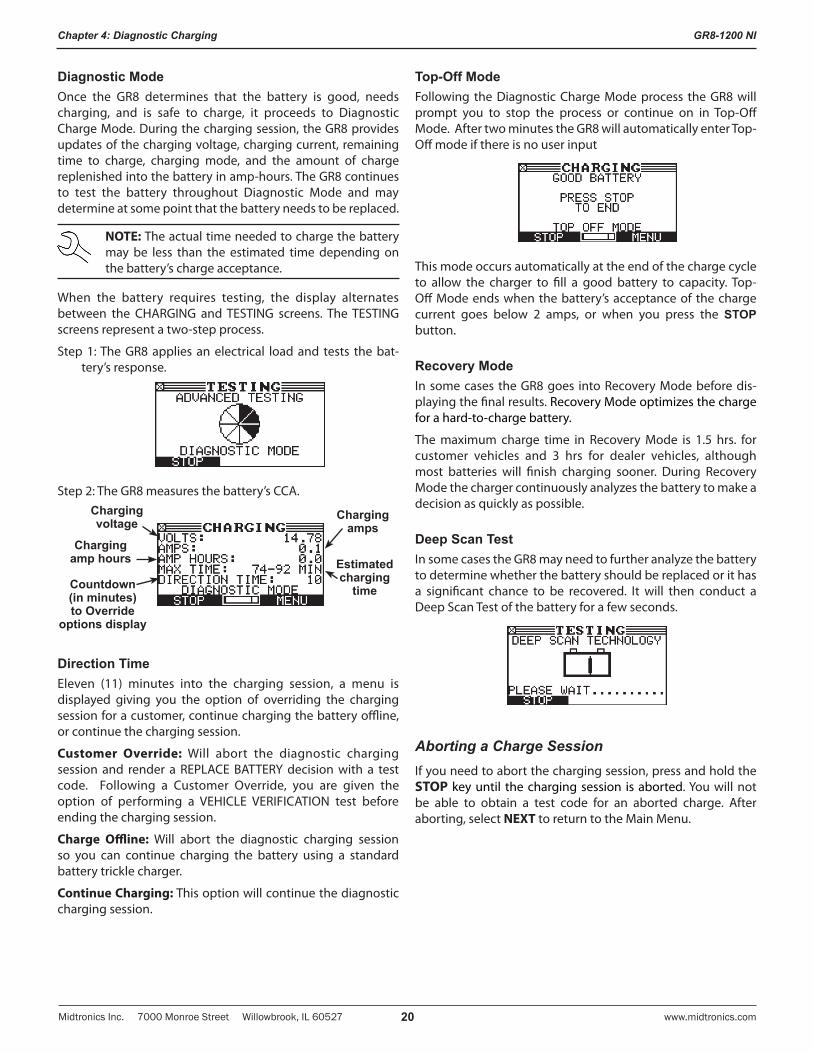
Diagnostic ModeOnce the GR8 determines that the battery is good, needs charging, and is safe to charge, it proceeds to Diagnostic Charge Mode. During the charging session, the GR8 provides updates of the charging voltage, charging current, remaining time to charge, charging mode, and the amount of charge replenished into the battery in amp-hours. The GR8 continues to test the battery throughout Diagnostic Mode and may determine at some point that the battery needs to be replaced.
NOTE: The actual time needed to charge the battery may be less than the estimated time depending on the battery’s charge acceptance.
When the battery requires testing, the display alternates between the CHARGING and TESTING screens. The TESTING screens represent a two-step process.
Step 1: The GR8 applies an electrical load and tests the bat-tery’s response.
Step 2: The GR8 measures the battery’s CCA.
Estimated charging
time
Charging amps
Charging amp hours
Charging voltage
Countdown (in minutes) to Override
options display
Direction TimeEleven (11) minutes into the charging session, a menu is displayed giving you the option of overriding the charging session for a customer, continue charging the battery offline, or continue the charging session.
Customer Override: Will abort the diagnostic charging session and render a REPLACE BATTERY decision with a test code. Following a Customer Override, you are given the option of performing a VEHICLE VERIFICATION test before ending the charging session.
Charge Offline: Will abort the diagnostic charging session so you can continue charging the battery using a standard battery trickle charger.
Continue Charging: This option will continue the diagnostic charging session.
Top-Off ModeFollowing the Diagnostic Charge Mode process the GR8 will prompt you to stop the process or continue on in Top-Off Mode. After two minutes the GR8 will automatically enter Top-Off mode if there is no user input
This mode occurs automatically at the end of the charge cycle to allow the charger to fill a good battery to capacity. Top-Off Mode ends when the battery’s acceptance of the charge current goes below 2 amps, or when you press the STOP button.
Recovery ModeIn some cases the GR8 goes into Recovery Mode before dis-playing the final results. Recovery Mode optimizes the charge for a hard-to-charge battery.
The maximum charge time in Recovery Mode is 1.5 hrs. for customer vehicles and 3 hrs for dealer vehicles, although most batteries will finish charging sooner. During Recovery Mode the charger continuously analyzes the battery to make a decision as quickly as possible.
Deep Scan TestIn some cases the GR8 may need to further analyze the battery to determine whether the battery should be replaced or it has a significant chance to be recovered. It will then conduct a Deep Scan Test of the battery for a few seconds.
Aborting a Charge SessionIf you need to abort the charging session, press and hold the STOP key until the charging session is aborted. You will not be able to obtain a test code for an aborted charge. After aborting, select NEXT to return to the Main Menu.
GR8-1200 NI
Midtronics Inc. 7000 Monroe Street Willowbrook, IL 60527www.midtronics.com 21
Chapter 4: Diagnostic Charging
Completing a Charge SessionThe charge session is complete when the proper amount of charge is put back into the battery or the remaining estimated time to charge counts down to zero.
If the GR8 finds that the battery is bad before the end of the estimated time to charge, it displays the decision. When the decision is GOOD BATTERY, the GR8 gives you the option of topping off the battery’s charge level before it displays the results.
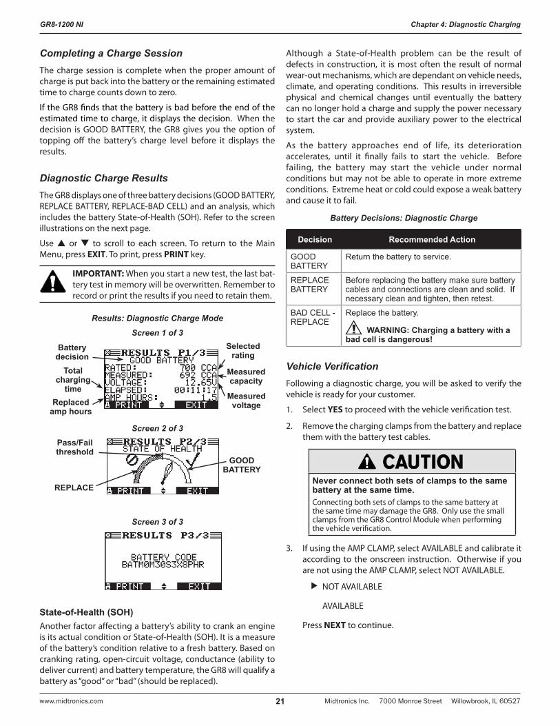
Diagnostic Charge ResultsThe GR8 displays one of three battery decisions (GOOD BATTERY, REPLACE BATTERY, REPLACE-BAD CELL) and an analysis, which includes the battery State-of-Health (SOH). Refer to the screen illustrations on the next page.
Use or to scroll to each screen. To return to the Main Menu, press EXIT. To print, press PRINT key.
IMPORTANT: When you start a new test, the last bat-tery test in memory will be overwritten. Remember to record or print the results if you need to retain them.
Results: Diagnostic Charge Mode
Screen 1 of 3
Measured voltage
Measured capacity
Selected rating
Total charging
time
Battery decision
Replaced amp hours
Screen 2 of 3
Pass/Fail threshold
REPLACE
GOOD BATTERY
Screen 3 of 3
State-of-Health (SOH)Another factor affecting a battery’s ability to crank an engine is its actual condition or State-of-Health (SOH). It is a measure of the battery’s condition relative to a fresh battery. Based on cranking rating, open-circuit voltage, conductance (ability to deliver current) and battery temperature, the GR8 will qualify a battery as “good” or “bad” (should be replaced).
Although a State-of-Health problem can be the result of defects in construction, it is most often the result of normal wear-out mechanisms, which are dependant on vehicle needs, climate, and operating conditions. This results in irreversible physical and chemical changes until eventually the battery can no longer hold a charge and supply the power necessary to start the car and provide auxiliary power to the electrical system.
As the battery approaches end of life, its deterioration accelerates, until it finally fails to start the vehicle. Before failing, the battery may start the vehicle under normal conditions but may not be able to operate in more extreme conditions. Extreme heat or cold could expose a weak battery and cause it to fail.
Battery Decisions: Diagnostic Charge
Decision Recommended Action
GOOD BATTERY
Return the battery to service.
REPLACE BATTERY
Before replacing the battery make sure battery cables and connections are clean and solid. If necessary clean and tighten, then retest.
BAD CELL - REPLACE
Replace the battery.
WARNING: Charging a battery with a bad cell is dangerous!
Vehicle VerificationFollowing a diagnostic charge, you will be asked to verify the vehicle is ready for your customer.
1. Select YES to proceed with the vehicle verification test.
2. Remove the charging clamps from the battery and replace them with the battery test cables.
Never connect both sets of clamps to the same battery at the same time.Connecting both sets of clamps to the same battery at the same time may damage the GR8. Only use the small clamps from the GR8 Control Module when performing the vehicle verification.
3. If using the AMP CLAMP, select AVAILABLE and calibrate it according to the onscreen instruction. Otherwise if you are not using the AMP CLAMP, select NOT AVAILABLE.
NOT AVAILABLE
AVAILABLE
Press NEXT to continue.
GR8-1200 NI
Midtronics Inc. 7000 Monroe Street Willowbrook, IL 60527 www.midtronics.com22
Chapter 4: Diagnostic Charging
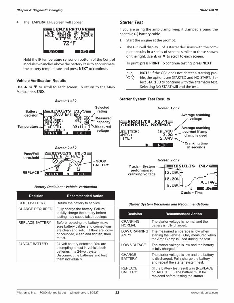
4. The TEMPERATURE screen will appear.
Hold the IR temperature sensor on bottom of the Control Module two inches above the battery case to approximate the battery temperature and press NEXT to continue.
Vehicle Verification ResultsUse or to scroll to each screen. To return to the Main Menu, press END.
Screen 1 of 2
Measured voltage
Measured capacity
Selected rating
Temperature
Battery decision
Screen 2 of 2
Pass/Fail threshold
REPLACE
GOOD BATTERY
Battery Decisions: Vehicle Verification
Decision Recommended Action
GOOD BATTERY Return the battery to service.
CHARGE REQUIRED Fully charge the battery. Failure to fully charge the battery before testing may cause false readings.
REPLACE BATTERY Before replacing the battery make sure battery cables and connections are clean and solid. If they are loose or corroded, clean and tighten, then retest.
24 VOLT BATTERY 24-volt battery detected. You are attempting to test in-vehicle both batteries in a 24-volt system. Disconnect the batteries and test them individually.
Starter TestIf you are using the amp clamp, keep it clamped around the negative (–) battery cable.
1. Start the engine at the prompt.
2. The GR8 will display 1 of 8 starter decisions with the com-plete results in a series of screens similar to those shown on the right. Use or to scroll to each screen.
To print, press PRINT. To continue testing, press NEXT.
NOTE: If the GR8 does not detect a starting pro-file, the options are STARTED and NO START. Se-lect STARTED to continue with the alternator test. Selecting NO START will end the test.
Starter System Test Results
Screen 1 of 2
Average cranking voltage
Average cranking current if amp clamp is used
Cranking time in seconds
Screen 2 of 2
Y axis = System performance:
cranking voltage
X axis = Time
Starter System Decisions and Recommendations
Decision Recommended Action
CRANKING NORMAL
The starter voltage is normal and the battery is fully charged.
LOW CRANKING AMPS
The measured amperage is low when starting the vehicle. Only measured when the Amp Clamp is used during the test.
LOW VOLTAGE The starter voltage is low and the battery is fully charged.
CHARGE BATTERY
The starter voltage is low and the battery is discharged. Fully charge the battery and repeat the starter system test.
REPLACE BATTERY
(If the battery test result was (REPLACE or BAD CELL.) The battery must be replaced before testing the starter.
GR8-1200 NI
Midtronics Inc. 7000 Monroe Street Willowbrook, IL 60527www.midtronics.com 23
Chapter 4: Diagnostic Charging
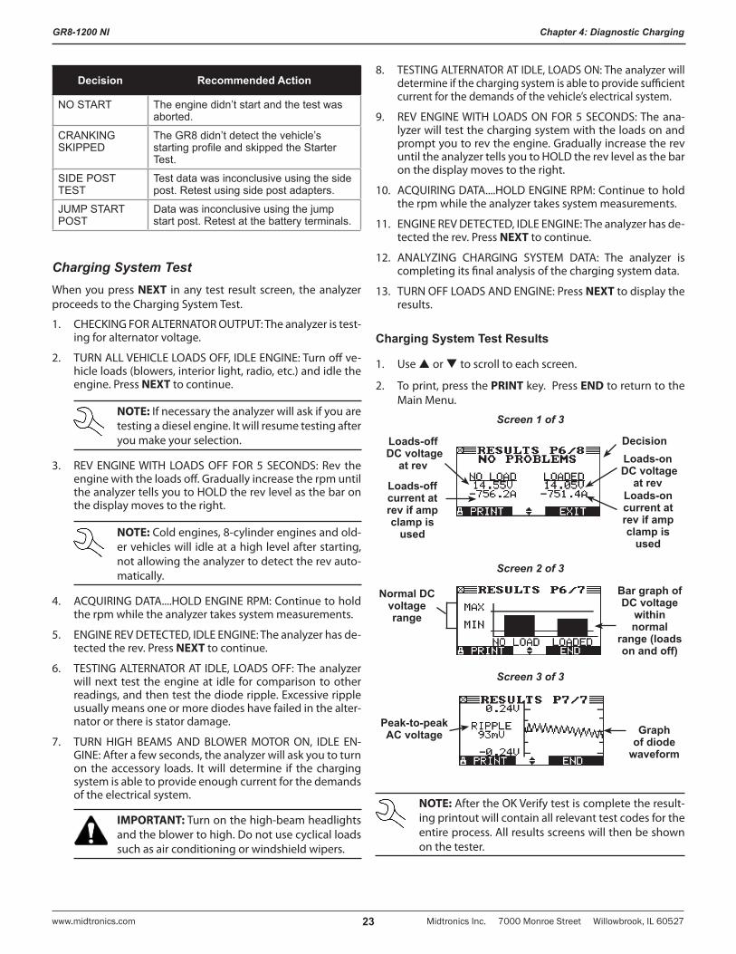
Decision Recommended Action
NO START The engine didn’t start and the test was aborted.
CRANKING SKIPPED
The GR8 didn’t detect the vehicle’s starting profile and skipped the Starter Test.
SIDE POST TEST
Test data was inconclusive using the side post. Retest using side post adapters.
JUMP START POST
Data was inconclusive using the jump start post. Retest at the battery terminals.
Charging System TestWhen you press NEXT in any test result screen, the analyzer proceeds to the Charging System Test.
1. CHECKING FOR ALTERNATOR OUTPUT: The analyzer is test-ing for alternator voltage.
2. TURN ALL VEHICLE LOADS OFF, IDLE ENGINE: Turn off ve-hicle loads (blowers, interior light, radio, etc.) and idle the engine. Press NEXT to continue.
NOTE: If necessary the analyzer will ask if you are testing a diesel engine. It will resume testing after you make your selection.
3. REV ENGINE WITH LOADS OFF FOR 5 SECONDS: Rev the engine with the loads off. Gradually increase the rpm until the analyzer tells you to HOLD the rev level as the bar on the display moves to the right.
NOTE: Cold engines, 8-cylinder engines and old-er vehicles will idle at a high level after starting, not allowing the analyzer to detect the rev auto-matically.
4. ACQUIRING DATA....HOLD ENGINE RPM: Continue to hold the rpm while the analyzer takes system measurements.
5. ENGINE REV DETECTED, IDLE ENGINE: The analyzer has de-tected the rev. Press NEXT to continue.
6. TESTING ALTERNATOR AT IDLE, LOADS OFF: The analyzer will next test the engine at idle for comparison to other readings, and then test the diode ripple. Excessive ripple usually means one or more diodes have failed in the alter-nator or there is stator damage.
7. TURN HIGH BEAMS AND BLOWER MOTOR ON, IDLE EN-GINE: After a few seconds, the analyzer will ask you to turn on the accessory loads. It will determine if the charging system is able to provide enough current for the demands of the electrical system.
IMPORTANT: Turn on the high-beam headlights and the blower to high. Do not use cyclical loads such as air conditioning or windshield wipers.
8. TESTING ALTERNATOR AT IDLE, LOADS ON: The analyzer will determine if the charging system is able to provide sufficient current for the demands of the vehicle’s electrical system.
9. REV ENGINE WITH LOADS ON FOR 5 SECONDS: The ana-lyzer will test the charging system with the loads on and prompt you to rev the engine. Gradually increase the rev until the analyzer tells you to HOLD the rev level as the bar on the display moves to the right.
10. ACQUIRING DATA....HOLD ENGINE RPM: Continue to hold the rpm while the analyzer takes system measurements.
11. ENGINE REV DETECTED, IDLE ENGINE: The analyzer has de-tected the rev. Press NEXT to continue.
12. ANALYZING CHARGING SYSTEM DATA: The analyzer is completing its final analysis of the charging system data.
13. TURN OFF LOADS AND ENGINE: Press NEXT to display the results.
Charging System Test Results
1. Use or to scroll to each screen.
2. To print, press the PRINT key. Press END to return to the Main Menu.
Screen 1 of 3
DecisionLoads-off DC voltage
at rev
Loads-off current at rev if amp clamp is
used
Loads-on DC voltage
at revLoads-on current at rev if amp clamp is
used
Screen 2 of 3
Normal DC voltage range
Bar graph of DC voltage
within normal
range (loads on and off)
Screen 3 of 3
Graph of diode
waveform
Peak-to-peak AC voltage
NOTE: After the OK Verify test is complete the result-ing printout will contain all relevant test codes for the entire process. All results screens will then be shown on the tester.
GR8-1200 NI
Midtronics Inc. 7000 Monroe Street Willowbrook, IL 60527 www.midtronics.com24
Chapter 4: Diagnostic Charging
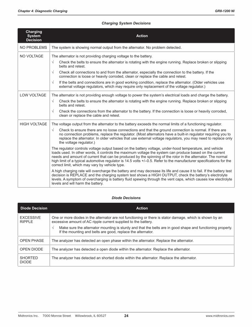
Charging System Decisions
Charging System
DecisionAction
NO PROBLEMS The system is showing normal output from the alternator. No problem detected.
NO VOLTAGE The alternator is not providing charging voltage to the battery. √ Check the belts to ensure the alternator is rotating with the engine running. Replace broken or slipping
belts and retest. √ Check all connections to and from the alternator, especially the connection to the battery. If the
connection is loose or heavily corroded, clean or replace the cable and retest. √ If the belts and connections are in good working condition, replace the alternator. (Older vehicles use
external voltage regulators, which may require only replacement of the voltage regulator.)
LOW VOLTAGE The alternator is not providing enough voltage to power the system’s electrical loads and charge the battery.√ Check the belts to ensure the alternator is rotating with the engine running. Replace broken or slipping
belts and retest.√ Check the connections from the alternator to the battery. If the connection is loose or heavily corroded,
clean or replace the cable and retest.
HIGH VOLTAGE The voltage output from the alternator to the battery exceeds the normal limits of a functioning regulator.√ Check to ensure there are no loose connections and that the ground connection is normal. If there are
no connection problems, replace the regulator. (Most alternators have a built-in regulator requiring you to replace the alternator. In older vehicles that use external voltage regulators, you may need to replace only the voltage regulator.)
The regulator controls voltage output based on the battery voltage, under-hood temperature, and vehicle loads used. In other words, it controls the maximum voltage the system can produce based on the current needs and amount of current that can be produced by the spinning of the rotor in the alternator. The normal high limit of a typical automotive regulator is 14.5 volts +/–0.5. Refer to the manufacturer specifications for the correct limit, which may vary by vehicle type. A high charging rate will overcharge the battery and may decrease its life and cause it to fail. If the battery test decision is REPLACE and the charging system test shows a HIGH OUTPUT, check the battery’s electrolyte levels. A symptom of overcharging is battery fluid spewing through the vent caps, which causes low electrolyte levels and will harm the battery.
Diode Decisions
Diode Decision Action
EXCESSIVE RIPPLE
One or more diodes in the alternator are not functioning or there is stator damage, which is shown by an excessive amount of AC ripple current supplied to the battery. √ Make sure the alternator mounting is sturdy and that the belts are in good shape and functioning properly.
If the mounting and belts are good, replace the alternator.
OPEN PHASE The analyzer has detected an open phase within the alternator. Replace the alternator.
OPEN DIODE The analyzer has detected a open diode within the alternator. Replace the alternator.
SHORTED DIODE
The analyzer has detected an shorted diode within the alternator. Replace the alternator.
GR8-1200 NI
Midtronics Inc. 7000 Monroe Street Willowbrook, IL 60527www.midtronics.com 25
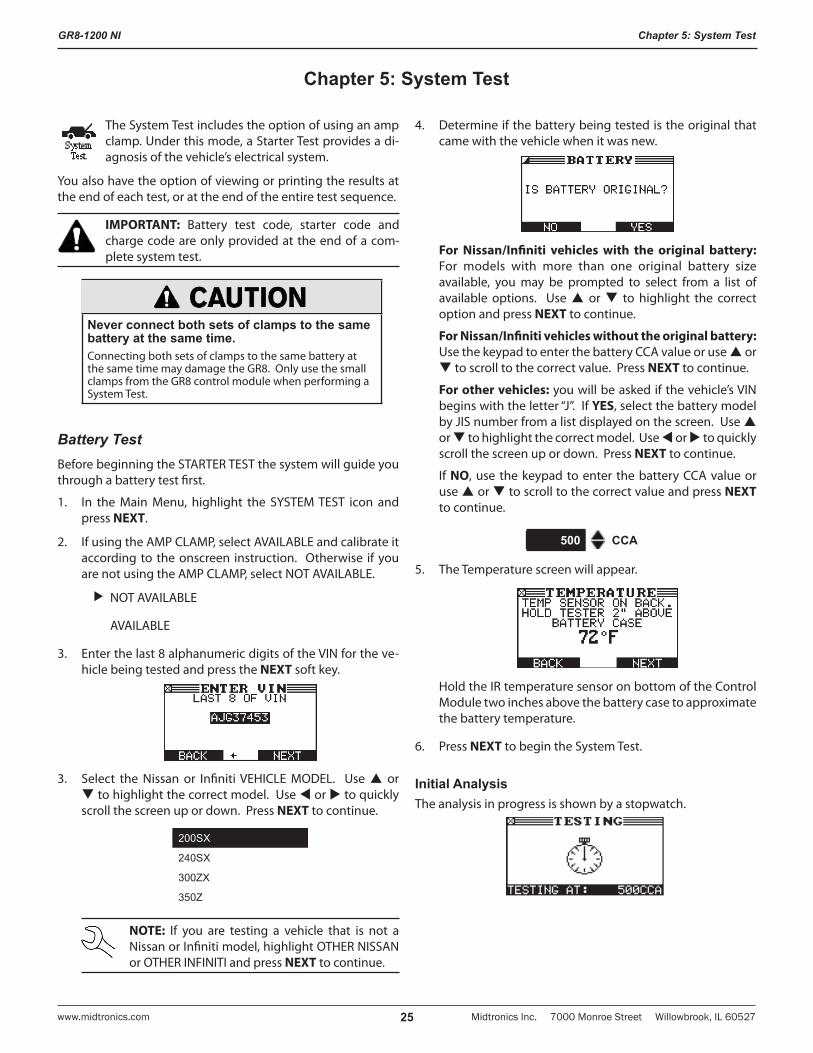
Chapter 5: System Test
The System Test includes the option of using an amp clamp. Under this mode, a Starter Test provides a di-agnosis of the vehicle’s electrical system.
You also have the option of viewing or printing the results at the end of each test, or at the end of the entire test sequence.
IMPORTANT: Battery test code, starter code and charge code are only provided at the end of a com-plete system test.
Never connect both sets of clamps to the same battery at the same time.Connecting both sets of clamps to the same battery at the same time may damage the GR8. Only use the small clamps from the GR8 control module when performing a System Test.
Battery TestBefore beginning the STARTER TEST the system will guide you through a battery test first.
1. In the Main Menu, highlight the SYSTEM TEST icon and press NEXT.
2. If using the AMP CLAMP, select AVAILABLE and calibrate it according to the onscreen instruction. Otherwise if you are not using the AMP CLAMP, select NOT AVAILABLE.
NOT AVAILABLE
AVAILABLE
3. Enter the last 8 alphanumeric digits of the VIN for the ve-hicle being tested and press the NEXT soft key.
3. Select the Nissan or Infiniti VEHICLE MODEL. Use or to highlight the correct model. Use or to quickly scroll the screen up or down. Press NEXT to continue.
200SX
240SX
300ZX
350Z
NOTE: If you are testing a vehicle that is not a Nissan or Infiniti model, highlight OTHER NISSAN or OTHER INFINITI and press NEXT to continue.
4. Determine if the battery being tested is the original that came with the vehicle when it was new.
For Nissan/Infiniti vehicles with the original battery: For models with more than one original battery size available, you may be prompted to select from a list of available options. Use or to highlight the correct option and press NEXT to continue.
For Nissan/Infiniti vehicles without the original battery: Use the keypad to enter the battery CCA value or use or to scroll to the correct value. Press NEXT to continue.
For other vehicles: you will be asked if the vehicle’s VIN begins with the letter “J”. If YES, select the battery model by JIS number from a list displayed on the screen. Use or to highlight the correct model. Use or to quickly scroll the screen up or down. Press NEXT to continue.
If NO, use the keypad to enter the battery CCA value or use or to scroll to the correct value and press NEXT to continue.
500 CCA
5. The Temperature screen will appear.
Hold the IR temperature sensor on bottom of the Control Module two inches above the battery case to approximate the battery temperature.
6. Press NEXT to begin the System Test.
Initial AnalysisThe analysis in progress is shown by a stopwatch.
Chapter 5: System Test
GR8-1200 NI
Midtronics Inc. 7000 Monroe Street Willowbrook, IL 60527 www.midtronics.com26
Chapter 5: System Test
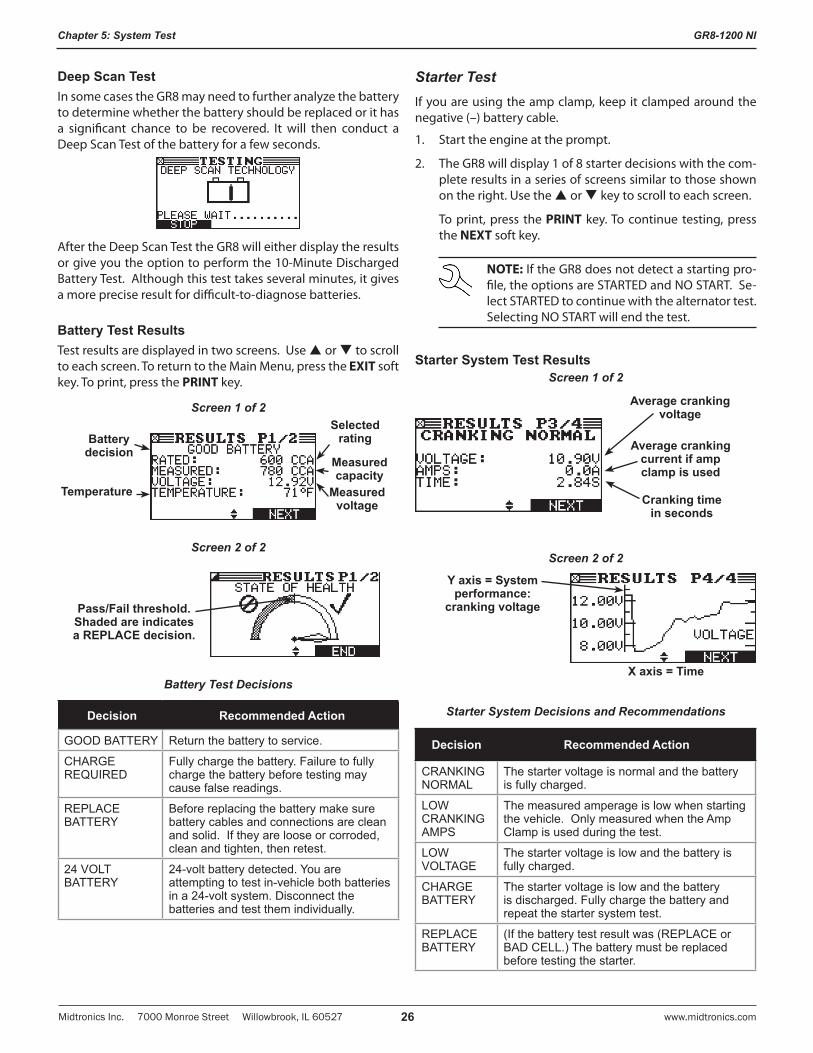
Deep Scan TestIn some cases the GR8 may need to further analyze the battery to determine whether the battery should be replaced or it has a significant chance to be recovered. It will then conduct a Deep Scan Test of the battery for a few seconds.
After the Deep Scan Test the GR8 will either display the results or give you the option to perform the 10-Minute Discharged Battery Test. Although this test takes several minutes, it gives a more precise result for difficult-to-diagnose batteries.
Battery Test ResultsTest results are displayed in two screens. Use or to scroll to each screen. To return to the Main Menu, press the EXIT soft key. To print, press the PRINT key.
Screen 1 of 2
Measured voltage
Measured capacity
Selected rating
Temperature
Battery decision
Screen 2 of 2
Pass/Fail threshold. Shaded are indicates a REPLACE decision.
Battery Test Decisions
Decision Recommended Action
GOOD BATTERY Return the battery to service.
CHARGE REQUIRED
Fully charge the battery. Failure to fully charge the battery before testing may cause false readings.
REPLACE BATTERY
Before replacing the battery make sure battery cables and connections are clean and solid. If they are loose or corroded, clean and tighten, then retest.
24 VOLT BATTERY
24-volt battery detected. You are attempting to test in-vehicle both batteries in a 24-volt system. Disconnect the batteries and test them individually.
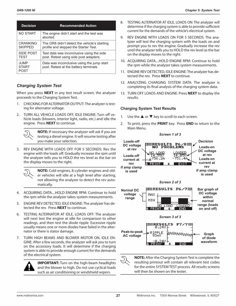
Starter TestIf you are using the amp clamp, keep it clamped around the negative (–) battery cable.
1. Start the engine at the prompt.
2. The GR8 will display 1 of 8 starter decisions with the com-plete results in a series of screens similar to those shown on the right. Use the or key to scroll to each screen.
To print, press the PRINT key. To continue testing, press the NEXT soft key.
NOTE: If the GR8 does not detect a starting pro-file, the options are STARTED and NO START. Se-lect STARTED to continue with the alternator test. Selecting NO START will end the test.
Starter System Test ResultsScreen 1 of 2
Average cranking voltage
Average cranking current if amp clamp is used
Cranking time in seconds
Screen 2 of 2
Y axis = System performance:
cranking voltage
X axis = Time
Starter System Decisions and Recommendations
Decision Recommended Action
CRANKING NORMAL
The starter voltage is normal and the battery is fully charged.
LOW CRANKING AMPS
The measured amperage is low when starting the vehicle. Only measured when the Amp Clamp is used during the test.
LOW VOLTAGE
The starter voltage is low and the battery is fully charged.
CHARGE BATTERY
The starter voltage is low and the battery is discharged. Fully charge the battery and repeat the starter system test.
REPLACE BATTERY
(If the battery test result was (REPLACE or BAD CELL.) The battery must be replaced before testing the starter.
GR8-1200 NI
Midtronics Inc. 7000 Monroe Street Willowbrook, IL 60527www.midtronics.com 27
Chapter 5: System Test
Decision Recommended Action
NO START The engine didn’t start and the test was aborted.
CRANKING SKIPPED
The GR8 didn’t detect the vehicle’s starting profile and skipped the Starter Test.
SIDE POST TEST
Test data was inconclusive using the side post. Retest using side post adapters.
JUMP START POST
Data was inconclusive using the jump start post. Retest at the battery terminals.
Charging System TestWhen you press NEXT in any test result screen, the analyzer proceeds to the Charging System Test.
1. CHECKING FOR ALTERNATOR OUTPUT: The analyzer is test-ing for alternator voltage.
2. TURN ALL VEHICLE LOADS OFF, IDLE ENGINE: Turn off ve-hicle loads (blowers, interior light, radio, etc.) and idle the engine. Press NEXT to continue.
NOTE: If necessary the analyzer will ask if you are testing a diesel engine. It will resume testing after you make your selection.
3. REV ENGINE WITH LOADS OFF FOR 5 SECONDS: Rev the engine with the loads off. Gradually increase the rpm until the analyzer tells you to HOLD the rev level as the bar on the display moves to the right.
NOTE: Cold engines, 8-cylinder engines and old-er vehicles will idle at a high level after starting, not allowing the analyzer to detect the rev auto-matically.
4. ACQUIRING DATA....HOLD ENGINE RPM: Continue to hold the rpm while the analyzer takes system measurements.
5. ENGINE REV DETECTED, IDLE ENGINE: The analyzer has de-tected the rev. Press NEXT to continue.
6. TESTING ALTERNATOR AT IDLE, LOADS OFF: The analyzer will next test the engine at idle for comparison to other readings, and then test the diode ripple. Excessive ripple usually means one or more diodes have failed in the alter-nator or there is stator damage.
7. TURN HIGH BEAMS AND BLOWER MOTOR ON, IDLE EN-GINE: After a few seconds, the analyzer will ask you to turn on the accessory loads. It will determine if the charging system is able to provide enough current for the demands of the electrical system.
IMPORTANT: Turn on the high-beam headlights and the blower to high. Do not use cyclical loads such as air conditioning or windshield wipers.
8. TESTING ALTERNATOR AT IDLE, LOADS ON: The analyzer will determine if the charging system is able to provide sufficient current for the demands of the vehicle’s electrical system.
9. REV ENGINE WITH LOADS ON FOR 5 SECONDS: The ana-lyzer will test the charging system with the loads on and prompt you to rev the engine. Gradually increase the rev until the analyzer tells you to HOLD the rev level as the bar on the display moves to the right.
10. ACQUIRING DATA....HOLD ENGINE RPM: Continue to hold the rpm while the analyzer takes system measurements.
11. ENGINE REV DETECTED, IDLE ENGINE: The analyzer has de-tected the rev. Press NEXT to continue.
12. ANALYZING CHARGING SYSTEM DATA: The analyzer is completing its final analysis of the charging system data.
13. TURN OFF LOADS AND ENGINE: Press NEXT to display the results.
Charging System Test Results
1. Use the or key to scroll to each screen.
2. To print, press the PRINT key. Press END to return to the Main Menu.
Screen 1 of 3
DecisionLoads-off DC voltage
at rev
Loads-off current at
rev if amp clamp
is used
Loads-on DC voltage
at revLoads-on current at
rev if amp clamp
is used
Screen 2 of 3
Normal DC voltage range
Bar graph of DC voltage
within normal
range (loads on and off)
Screen 3 of 3
Graph of diode
waveform
Peak-to-peak AC voltage
NOTE: After the Charging System Test is complete the resulting printout will contain all relevant test codes for the entire SYSTEM TEST process. All results screens will then be shown on the tester.
GR8-1200 NI
Midtronics Inc. 7000 Monroe Street Willowbrook, IL 60527 www.midtronics.com28
Chapter 5: System Test
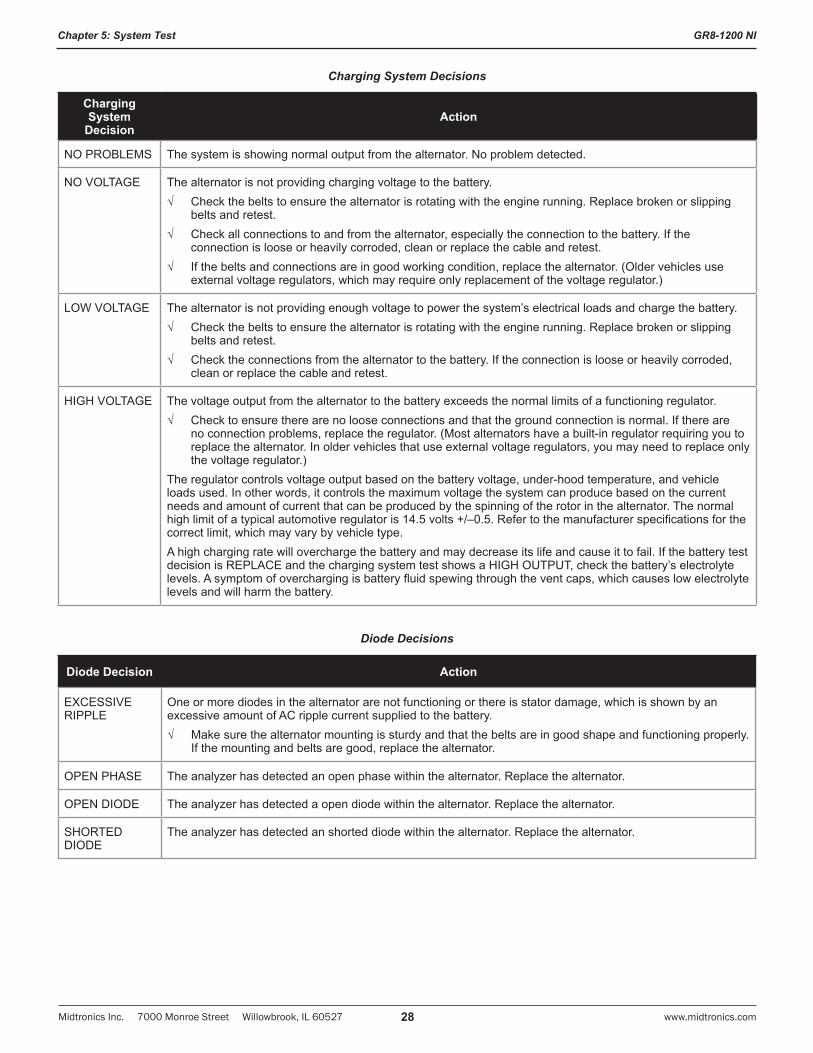
Charging System Decisions
Charging System
DecisionAction
NO PROBLEMS The system is showing normal output from the alternator. No problem detected.
NO VOLTAGE The alternator is not providing charging voltage to the battery. √ Check the belts to ensure the alternator is rotating with the engine running. Replace broken or slipping
belts and retest. √ Check all connections to and from the alternator, especially the connection to the battery. If the
connection is loose or heavily corroded, clean or replace the cable and retest. √ If the belts and connections are in good working condition, replace the alternator. (Older vehicles use
external voltage regulators, which may require only replacement of the voltage regulator.)
LOW VOLTAGE The alternator is not providing enough voltage to power the system’s electrical loads and charge the battery.√ Check the belts to ensure the alternator is rotating with the engine running. Replace broken or slipping
belts and retest.√ Check the connections from the alternator to the battery. If the connection is loose or heavily corroded,
clean or replace the cable and retest.
HIGH VOLTAGE The voltage output from the alternator to the battery exceeds the normal limits of a functioning regulator.√ Check to ensure there are no loose connections and that the ground connection is normal. If there are
no connection problems, replace the regulator. (Most alternators have a built-in regulator requiring you to replace the alternator. In older vehicles that use external voltage regulators, you may need to replace only the voltage regulator.)
The regulator controls voltage output based on the battery voltage, under-hood temperature, and vehicle loads used. In other words, it controls the maximum voltage the system can produce based on the current needs and amount of current that can be produced by the spinning of the rotor in the alternator. The normal high limit of a typical automotive regulator is 14.5 volts +/–0.5. Refer to the manufacturer specifications for the correct limit, which may vary by vehicle type. A high charging rate will overcharge the battery and may decrease its life and cause it to fail. If the battery test decision is REPLACE and the charging system test shows a HIGH OUTPUT, check the battery’s electrolyte levels. A symptom of overcharging is battery fluid spewing through the vent caps, which causes low electrolyte levels and will harm the battery.
Diode Decisions
Diode Decision Action
EXCESSIVE RIPPLE
One or more diodes in the alternator are not functioning or there is stator damage, which is shown by an excessive amount of AC ripple current supplied to the battery. √ Make sure the alternator mounting is sturdy and that the belts are in good shape and functioning properly.
If the mounting and belts are good, replace the alternator.
OPEN PHASE The analyzer has detected an open phase within the alternator. Replace the alternator.
OPEN DIODE The analyzer has detected a open diode within the alternator. Replace the alternator.
SHORTED DIODE
The analyzer has detected an shorted diode within the alternator. Replace the alternator.
GR8-1200 NI
Midtronics Inc. 7000 Monroe Street Willowbrook, IL 60527www.midtronics.com 29
Chapter 6: ECM Power Supply
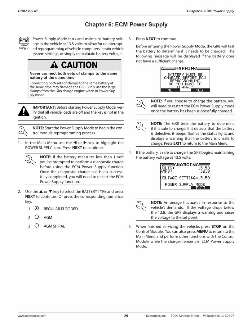
Power Supply Mode tests and maintains battery volt-age in the vehicle at 13.5 volts to allow for uninterrupt-ed reprogramming of vehicle computers, retain vehicle system settings, or simply to maintain battery voltage.
Never connect both sets of clamps to the same battery at the same time.Connecting both sets of clamps to the same battery at the same time may damage the GR8. Only use the large clamps from the GR8 charge engine when in Power Sup-ply mode.
IMPORTANT: Before starting Power Supply Mode, ver-ify that all vehicle loads are off and the key is not in the ignition.
NOTE: Start the Power Supply Mode to begin the con-trol module reprogramming process.
1. In the Main Menu use the or key to highlight the POWER SUPPLY icon. Press NEXT to continue.
NOTE: If the battery measures less than 1 volt you be prompted to perform a diagnostic charge before using the ECM Power Supply function. Once the diagnostic charge has been success-fully completed, you will need to restart the ECM Power Supply function.
2. Use the or key to select the BATTERY TYPE and press NEXT to continue. Or press the corresponding numerical key.
1 REGULAR FLOODED
2 AGM
3 AGM SPIRAL
3. Press NEXT to continue.
Before entering the Power Supply Mode, the GR8 will test the battery to determine if it needs to be charged. The following message will be displayed if the battery does not have a sufficient charge.
NOTE: If you choose to charge the battery, you will need to restart the ECM Power Supply mode once the battery has been successfully charged.
NOTE: The GR8 tests the battery to determine if it is safe to charge. If it detects that the battery is defective, it beeps, flashes the status light, and displays a warning that the battery is unsafe to charge. Press EXIT to return to the Main Menu.
4. If the battery is safe to charge, the GR8 begins maintaining the battery voltage at 13.5 volts.
NOTE: Amperage fluctuates in response to the vehicle’s demands. If the voltage drops below the 12.8, the GR8 displays a warning and raises the voltage to the set point.
5. When finished servicing the vehicle, press STOP on the Control Module. You can also press MENU to return to the Main Menu and perform other functions with the Control Module while the charger remains in ECM Power Supply Mode.
Chapter 6: ECM Power Supply
GR8-1200 NI
Midtronics Inc. 7000 Monroe Street Willowbrook, IL 60527 www.midtronics.com30
Chapter 7: Jump Start
Chapter 7: Jump Start
This charging mode makes high output current avail-able to boost charge an in-vehicle battery as well as as-sist in starting the engine. If you need to abort at any time, press the STOP key.
Never connect both sets of clamps to the same battery at the same time.Connecting both sets of clamps to the same battery at the same time may damage the GR8. Only use the large clamps from the GR8 charge engine when Jump Starting.
1. In the Main Menu, highlight the JUMP START icon and press NEXT to continue..
NOTE: The GR8 tests the battery to determine if it is safe to charge. If it detects that the battery is defective, it displays a warning that the battery is unsafe to charge. Press the EXIT soft key to return to the Main Menu.
2. Use or to select the BATTERY TYPE and press NEXT. Or press the corresponding numerical key.
1 REGULAR FLOODED
2 AGM
3 AGM SPIRAL
Press NEXT to begin the boost charge. Do not crank the engine at this time.
Use the BACK to return to the Main Menu.
3. When the GR8 displays “CRANK ENGINE NOW,“ beeps and flashes the status light, you can crank the engine for up to five seconds.
4. When the GR8 displays “JUMP START COMPLETE,” press STOP on the Control Module. (The alarm will sound every second until you press STOP.)
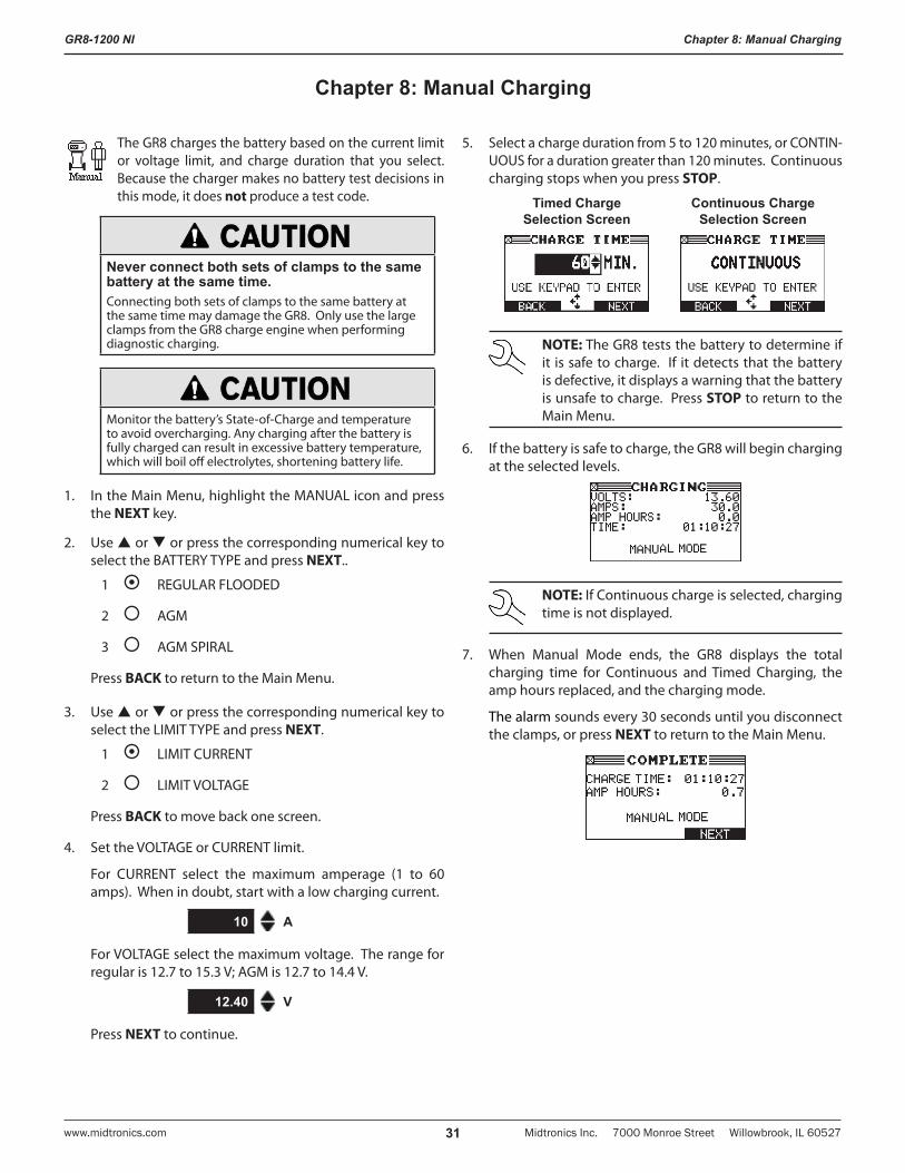
GR8-1200 NI
Midtronics Inc. 7000 Monroe Street Willowbrook, IL 60527www.midtronics.com 31
Chapter 8: Manual Charging
The GR8 charges the battery based on the current limit or voltage limit, and charge duration that you select. Because the charger makes no battery test decisions in this mode, it does not produce a test code.
Never connect both sets of clamps to the same battery at the same time.Connecting both sets of clamps to the same battery at the same time may damage the GR8. Only use the large clamps from the GR8 charge engine when performing diagnostic charging.
Monitor the battery’s State-of-Charge and temperature to avoid overcharging. Any charging after the battery is fully charged can result in excessive battery temperature, which will boil off electrolytes, shortening battery life.
1. In the Main Menu, highlight the MANUAL icon and press the NEXT key.
2. Use or or press the corresponding numerical key to select the BATTERY TYPE and press NEXT..
1 REGULAR FLOODED
2 AGM
3 AGM SPIRAL
Press BACK to return to the Main Menu.
3. Use or or press the corresponding numerical key to select the LIMIT TYPE and press NEXT.
1 LIMIT CURRENT
2 LIMIT VOLTAGE
Press BACK to move back one screen.
4. Set the VOLTAGE or CURRENT limit.
For CURRENT select the maximum amperage (1 to 60 amps). When in doubt, start with a low charging current.
10 A
For VOLTAGE select the maximum voltage. The range for regular is 12.7 to 15.3 V; AGM is 12.7 to 14.4 V.
12.40 V
Press NEXT to continue.
5. Select a charge duration from 5 to 120 minutes, or CONTIN-UOUS for a duration greater than 120 minutes. Continuous charging stops when you press STOP.
Timed Charge Selection Screen
Continuous Charge Selection Screen
NOTE: The GR8 tests the battery to determine if it is safe to charge. If it detects that the battery is defective, it displays a warning that the battery is unsafe to charge. Press STOP to return to the Main Menu.
6. If the battery is safe to charge, the GR8 will begin charging at the selected levels.
NOTE: If Continuous charge is selected, charging time is not displayed.
7. When Manual Mode ends, the GR8 displays the total charging time for Continuous and Timed Charging, the amp hours replaced, and the charging mode.
The alarm sounds every 30 seconds until you disconnect the clamps, or press NEXT to return to the Main Menu.
Chapter 8: Manual Charging
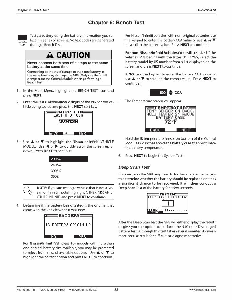
GR8-1200 NI
Midtronics Inc. 7000 Monroe Street Willowbrook, IL 60527 www.midtronics.com32
Chapter 9: Bench Test
Tests a battery using the battery information you se-lect in a series of screens. No test codes are generated during a Bench Test.
Never connect both sets of clamps to the same battery at the same time.Connecting both sets of clamps to the same battery at the same time may damage the GR8. Only use the small clamps from the Control Module when performing a Bench Test.
1. In the Main Menu, highlight the BENCH TEST icon and press NEXT.
2. Enter the last 8 alphanumeric digits of the VIN for the ve-hicle being tested and press the NEXT soft key.
3. Use or to highlight the Nissan or Infiniti VEHICLE MODEL. Use or to quickly scroll the screen up or down. Press NEXT to continue.
200SX
240SX
300ZX
350Z
NOTE: If you are testing a vehicle that is not a Nis-san or Infiniti model, highlight OTHER NISSAN or OTHER INFINITI and press NEXT to continue.
4. Determine if the battery being tested is the original that came with the vehicle when it was new.
For Nissan/Infiniti Vehicles: For models with more than one original battery size available, you may be prompted to select from a list of available options. Use or to highlight the correct option and press NEXT to continue.
For Nissan/Infiniti vehicles with non-original batteries use the keypad to enter the battery CCA value or use or to scroll to the correct value. Press NEXT to continue.
For non-Nissan/Infiniti Vehicles: You will be asked if the vehicle's VIN begins with the letter "J". If YES, select the battery model by JIS number from a list displayed on the screen and press NEXT to continue.
If NO, use the keypad to enter the battery CCA value or use or to scroll to the correct value. Press NEXT to continue.
500 CCA
5. The Temperature screen will appear.
Hold the IR temperature sensor on bottom of the Control Module two inches above the battery case to approximate the battery temperature.
6. Press NEXT to begin the System Test.
Deep Scan TestIn some cases the GR8 may need to further analyze the battery to determine whether the battery should be replaced or it has a significant chance to be recovered. It will then conduct a Deep Scan Test of the battery for a few seconds.
After the Deep Scan Test the GR8 will either display the results or give you the option to perform the 5-Minute Discharged Battery Test. Although this test takes several minutes, it gives a more precise result for difficult-to-diagnose batteries.
Chapter 9: Bench Test
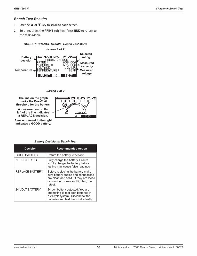
GR8-1200 NI
Midtronics Inc. 7000 Monroe Street Willowbrook, IL 60527www.midtronics.com 33
Chapter 9: Bench Test
Bench Test Results1. Use the or key to scroll to each screen.
2. To print, press the PRINT soft key. Press END to return to the Main Menu.
GOOD-RECHARGE Results: Bench Test Mode
Screen 1 of 2
Measured voltage
Measured capacity
Selected rating
Temperature
Battery decision
Screen 2 of 2
The line on the graph marks the Pass/Fail
threshold for the battery.A measurement to the
left of the line indicates a REPLACE decision.
A measurement to the right indicates a GOOD battery.
Battery Decisions: Bench Test
Decision Recommended Action
GOOD BATTERY Return the battery to service.
NEEDS CHARGE Fully charge the battery. Failure to fully charge the battery before testing may cause false readings.
REPLACE BATTERY Before replacing the battery make sure battery cables and connections are clean and solid. If they are loose or corroded, clean and tighten, then retest.
24 VOLT BATTERY 24-volt battery detected. You are attempting to test both batteries in a 24-volt system. Disconnect the batteries and test them individually.
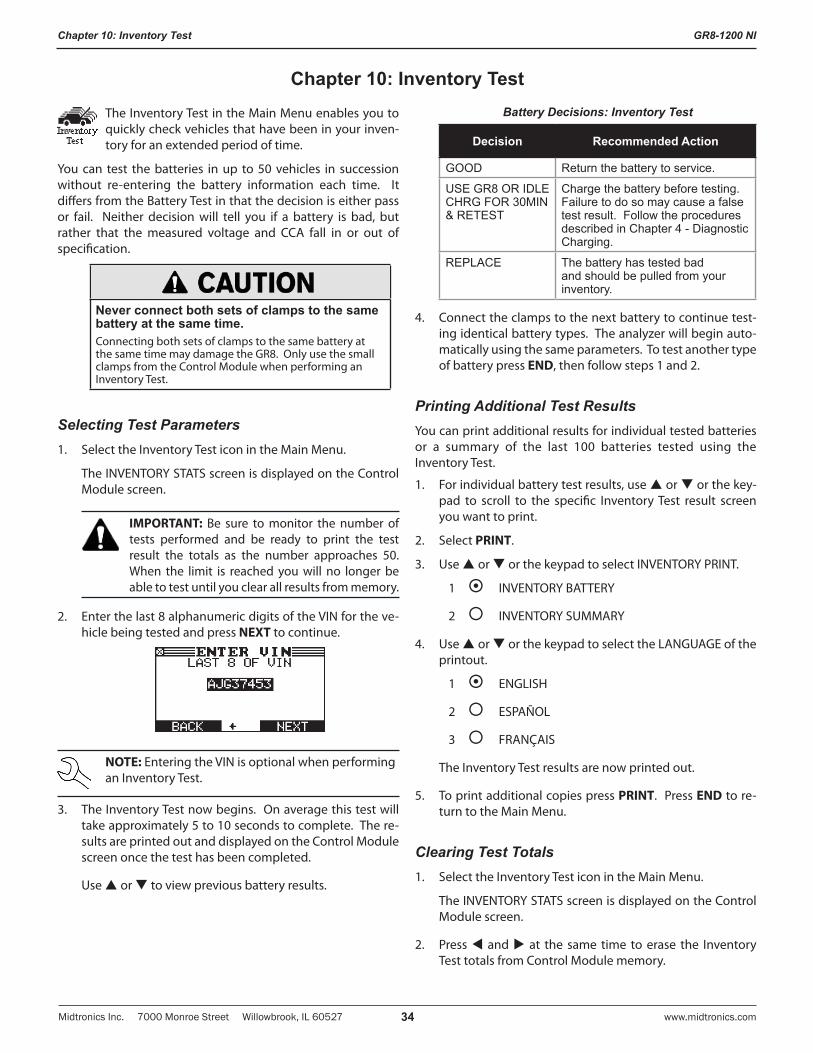
GR8-1200 NI
Midtronics Inc. 7000 Monroe Street Willowbrook, IL 60527 www.midtronics.com34
Chapter 10: Inventory Test
The Inventory Test in the Main Menu enables you to quickly check vehicles that have been in your inven-tory for an extended period of time.
You can test the batteries in up to 50 vehicles in succession without re-entering the battery information each time. It differs from the Battery Test in that the decision is either pass or fail. Neither decision will tell you if a battery is bad, but rather that the measured voltage and CCA fall in or out of specification.
Never connect both sets of clamps to the same battery at the same time.Connecting both sets of clamps to the same battery at the same time may damage the GR8. Only use the small clamps from the Control Module when performing an Inventory Test.
Selecting Test Parameters1. Select the Inventory Test icon in the Main Menu.
The INVENTORY STATS screen is displayed on the Control Module screen.
IMPORTANT: Be sure to monitor the number of tests performed and be ready to print the test result the totals as the number approaches 50. When the limit is reached you will no longer be able to test until you clear all results from memory.
2. Enter the last 8 alphanumeric digits of the VIN for the ve-hicle being tested and press NEXT to continue.
NOTE: Entering the VIN is optional when performing an Inventory Test.
3. The Inventory Test now begins. On average this test will take approximately 5 to 10 seconds to complete. The re-sults are printed out and displayed on the Control Module screen once the test has been completed.
Use or to view previous battery results.
Battery Decisions: Inventory Test
Decision Recommended Action
GOOD Return the battery to service.
USE GR8 OR IDLE CHRG FOR 30MIN & RETEST
Charge the battery before testing. Failure to do so may cause a false test result. Follow the procedures described in Chapter 4 - Diagnostic Charging.
REPLACE The battery has tested bad and should be pulled from your inventory.
4. Connect the clamps to the next battery to continue test-ing identical battery types. The analyzer will begin auto-matically using the same parameters. To test another type of battery press END, then follow steps 1 and 2.
Printing Additional Test ResultsYou can print additional results for individual tested batteries or a summary of the last 100 batteries tested using the Inventory Test.
1. For individual battery test results, use or or the key-pad to scroll to the specific Inventory Test result screen you want to print.
2. Select PRINT.
3. Use or or the keypad to select INVENTORY PRINT.
1 INVENTORY BATTERY
2 INVENTORY SUMMARY
4. Use or or the keypad to select the LANGUAGE of the printout.
1 ENGLISH
2 ESPAÑOL
3 FRANÇAIS
The Inventory Test results are now printed out.
5. To print additional copies press PRINT. Press END to re-turn to the Main Menu.
Clearing Test Totals1. Select the Inventory Test icon in the Main Menu.
The INVENTORY STATS screen is displayed on the Control Module screen.
2. Press and at the same time to erase the Inventory Test totals from Control Module memory.
Chapter 10: Inventory Test
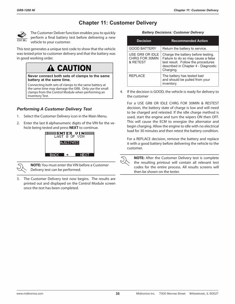
GR8-1200 NI
Midtronics Inc. 7000 Monroe Street Willowbrook, IL 60527www.midtronics.com 35
Chapter 11: Customer Delivery
The Customer Deliver function enables you to quickly perform a final battery test before delivering a new vehicle to your customer.
This test generates a unique test code to show that the vehicle was tested prior to customer delivery and that the battery was in good working order.
Never connect both sets of clamps to the same battery at the same time.Connecting both sets of clamps to the same battery at the same time may damage the GR8. Only use the small clamps from the Control Module when performing an Inventory Test.
Performing A Customer Delivery Test1. Select the Customer Delivery icon in the Main Menu.
2. Enter the last 8 alphanumeric digits of the VIN for the ve-hicle being tested and press NEXT to continue.
NOTE: You must enter the VIN before a Customer Delivery test can be performed.
3. The Customer Delivery test now begins. The results are printed out and displayed on the Control Module screen once the test has been completed.
Battery Decisions: Customer Delivery
Decision Recommended Action
GOOD BATTERY Return the battery to service.
USE GR8 OR IDLE CHRG FOR 30MIN & RETEST
Charge the battery before testing. Failure to do so may cause a false test result. Follow the procedures described in Chapter 4 - Diagnostic Charging.
REPLACE The battery has tested bad and should be pulled from your inventory.
4. If the decision is GOOD, the vehicle is ready for delivery to the customer
For a USE GR8 OR IDLE CHRG FOR 30MIN & RESTEST decision, the battery state of charge is low and will need to be charged and retested. If the idle charge method is used, start the engine and turn the wipers ON then OFF. This will cause the ECM to energize the alternator and begin charging. Allow the engine to idle with no electrical load for 30 minutes and then retest the battery condition.
For a REPLACE decision, remove the battery and replace it with a good battery before delivering the vehicle to the customer.
NOTE: After the Customer Delivery test is complete the resulting printout will contain all relevant test codes for the entire process. All results screens will then be shown on the tester.
Chapter 11: Customer Delivery
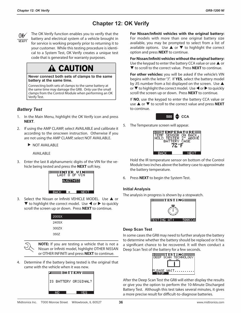
GR8-1200 NI
Midtronics Inc. 7000 Monroe Street Willowbrook, IL 60527 www.midtronics.com36
Chapter 12: OK Verify
The OK Verify function enables you to verify that the battery and electrical system of a vehicle brought in for service is working properly prior to returning it to your customer. While this testing procedure is identi-cal to a System Test, OK Verify creates a unique test code that is generated for warranty purposes.
Never connect both sets of clamps to the same battery at the same time.Connecting both sets of clamps to the same battery at the same time may damage the GR8. Only use the small clamps from the Control Module when performing an OK Verify Test.
Battery Test1. In the Main Menu, highlight the OK Verify icon and press
NEXT.
2. If using the AMP CLAMP, select AVAILABLE and calibrate it according to the onscreen instruction. Otherwise if you are not using the AMP CLAMP, select NOT AVAILABLE.
NOT AVAILABLE
AVAILABLE
3. Enter the last 8 alphanumeric digits of the VIN for the ve-hicle being tested and press the NEXT soft key.
3. Select the Nissan or Infiniti VEHICLE MODEL. Use or to highlight the correct model. Use or to quickly scroll the screen up or down. Press NEXT to continue.
200SX
240SX
300ZX
350Z
NOTE: If you are testing a vehicle that is not a Nissan or Infiniti model, highlight OTHER NISSAN or OTHER INFINITI and press NEXT to continue.
4. Determine if the battery being tested is the original that came with the vehicle when it was new.
For Nissan/Infiniti vehicles with the original battery: For models with more than one original battery size available, you may be prompted to select from a list of available options. Use or to highlight the correct option and press NEXT to continue.
For Nissan/Infiniti vehicles without the original battery: Use the keypad to enter the battery CCA value or use or to scroll to the correct value. Press NEXT to continue.
For other vehicles: you will be asked if the vehicle’s VIN begins with the letter “J”. If YES, select the battery model by JIS number from a list displayed on the screen. Use or to highlight the correct model. Use or to quickly scroll the screen up or down. Press NEXT to continue.
If NO, use the keypad to enter the battery CCA value or use or to scroll to the correct value and press NEXT to continue.
500 CCA
5. The Temperature screen will appear.
Hold the IR temperature sensor on bottom of the Control Module two inches above the battery case to approximate the battery temperature.
6. Press NEXT to begin the System Test.
Initial AnalysisThe analysis in progress is shown by a stopwatch.
Deep Scan TestIn some cases the GR8 may need to further analyze the battery to determine whether the battery should be replaced or it has a significant chance to be recovered. It will then conduct a Deep Scan Test of the battery for a few seconds.
After the Deep Scan Test the GR8 will either display the results or give you the option to perform the 10-Minute Discharged Battery Test. Although this test takes several minutes, it gives a more precise result for difficult-to-diagnose batteries.
Chapter 12: OK Verify
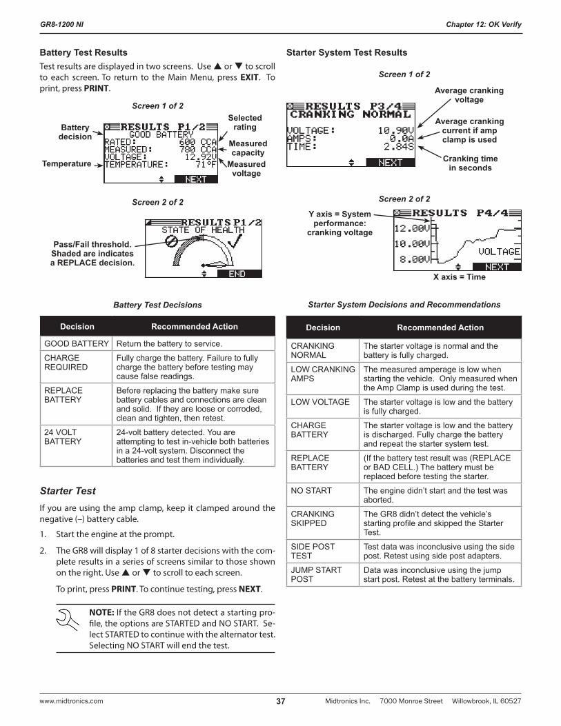
GR8-1200 NI
Midtronics Inc. 7000 Monroe Street Willowbrook, IL 60527www.midtronics.com 37
Chapter 12: OK Verify
Battery Test ResultsTest results are displayed in two screens. Use or to scroll to each screen. To return to the Main Menu, press EXIT. To print, press PRINT.
Screen 1 of 2
Measured voltage
Measured capacity
Selected rating
Temperature
Battery decision
Screen 2 of 2
Pass/Fail threshold. Shaded are indicates a REPLACE decision.
Battery Test Decisions
Decision Recommended Action
GOOD BATTERY Return the battery to service.
CHARGE REQUIRED
Fully charge the battery. Failure to fully charge the battery before testing may cause false readings.
REPLACE BATTERY
Before replacing the battery make sure battery cables and connections are clean and solid. If they are loose or corroded, clean and tighten, then retest.
24 VOLT BATTERY
24-volt battery detected. You are attempting to test in-vehicle both batteries in a 24-volt system. Disconnect the batteries and test them individually.
Starter TestIf you are using the amp clamp, keep it clamped around the negative (–) battery cable.
1. Start the engine at the prompt.
2. The GR8 will display 1 of 8 starter decisions with the com-plete results in a series of screens similar to those shown on the right. Use or to scroll to each screen.
To print, press PRINT. To continue testing, press NEXT.
NOTE: If the GR8 does not detect a starting pro-file, the options are STARTED and NO START. Se-lect STARTED to continue with the alternator test. Selecting NO START will end the test.
Starter System Test Results
Screen 1 of 2
Average cranking voltage
Average cranking current if amp clamp is used
Cranking time in seconds
Screen 2 of 2
Y axis = System performance:
cranking voltage
X axis = Time
Starter System Decisions and Recommendations
Decision Recommended Action
CRANKING NORMAL
The starter voltage is normal and the battery is fully charged.
LOW CRANKING AMPS
The measured amperage is low when starting the vehicle. Only measured when the Amp Clamp is used during the test.
LOW VOLTAGE The starter voltage is low and the battery is fully charged.
CHARGE BATTERY
The starter voltage is low and the battery is discharged. Fully charge the battery and repeat the starter system test.
REPLACE BATTERY
(If the battery test result was (REPLACE or BAD CELL.) The battery must be replaced before testing the starter.
NO START The engine didn’t start and the test was aborted.
CRANKING SKIPPED
The GR8 didn’t detect the vehicle’s starting profile and skipped the Starter Test.
SIDE POST TEST
Test data was inconclusive using the side post. Retest using side post adapters.
JUMP START POST
Data was inconclusive using the jump start post. Retest at the battery terminals.
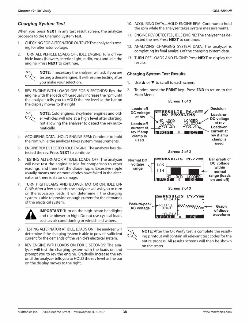
GR8-1200 NI
Midtronics Inc. 7000 Monroe Street Willowbrook, IL 60527 www.midtronics.com38
Chapter 12: OK Verify
Charging System TestWhen you press NEXT in any test result screen, the analyzer proceeds to the Charging System Test.
1. CHECKING FOR ALTERNATOR OUTPUT: The analyzer is test-ing for alternator voltage.
2. TURN ALL VEHICLE LOADS OFF, IDLE ENGINE: Turn off ve-hicle loads (blowers, interior light, radio, etc.) and idle the engine. Press NEXT to continue.
NOTE: If necessary the analyzer will ask if you are testing a diesel engine. It will resume testing after you make your selection.
3. REV ENGINE WITH LOADS OFF FOR 5 SECONDS: Rev the engine with the loads off. Gradually increase the rpm until the analyzer tells you to HOLD the rev level as the bar on the display moves to the right.
NOTE: Cold engines, 8-cylinder engines and old-er vehicles will idle at a high level after starting, not allowing the analyzer to detect the rev auto-matically.
4. ACQUIRING DATA....HOLD ENGINE RPM: Continue to hold the rpm while the analyzer takes system measurements.
5. ENGINE REV DETECTED, IDLE ENGINE: The analyzer has de-tected the rev. Press NEXT to continue.
6. TESTING ALTERNATOR AT IDLE, LOADS OFF: The analyzer will next test the engine at idle for comparison to other readings, and then test the diode ripple. Excessive ripple usually means one or more diodes have failed in the alter-nator or there is stator damage.
7. TURN HIGH BEAMS AND BLOWER MOTOR ON, IDLE EN-GINE: After a few seconds, the analyzer will ask you to turn on the accessory loads. It will determine if the charging system is able to provide enough current for the demands of the electrical system.
IMPORTANT: Turn on the high-beam headlights and the blower to high. Do not use cyclical loads such as air conditioning or windshield wipers.
8. TESTING ALTERNATOR AT IDLE, LOADS ON: The analyzer will determine if the charging system is able to provide sufficient current for the demands of the vehicle’s electrical system.
9. REV ENGINE WITH LOADS ON FOR 5 SECONDS: The ana-lyzer will test the charging system with the loads on and prompt you to rev the engine. Gradually increase the rev until the analyzer tells you to HOLD the rev level as the bar on the display moves to the right.
10. ACQUIRING DATA....HOLD ENGINE RPM: Continue to hold the rpm while the analyzer takes system measurements.
11. ENGINE REV DETECTED, IDLE ENGINE: The analyzer has de-tected the rev. Press NEXT to continue.
12. ANALYZING CHARGING SYSTEM DATA: The analyzer is completing its final analysis of the charging system data.
13. TURN OFF LOADS AND ENGINE: Press NEXT to display the results.
Charging System Test Results
1. Use or to scroll to each screen.
2. To print, press the PRINT key. Press END to return to the Main Menu.
Screen 1 of 3
DecisionLoads-off DC voltage
at rev
Loads-off current at rev if amp clamp is
used
Loads-on DC voltage
at revLoads-on current at rev if amp clamp is
used
Screen 2 of 3
Normal DC voltage range
Bar graph of DC voltage
within normal
range (loads on and off)
Screen 3 of 3
Graph of diode
waveform
Peak-to-peak AC voltage
NOTE: After the OK Verify test is complete the result-ing printout will contain all relevant test codes for the entire process. All results screens will then be shown on the tester.
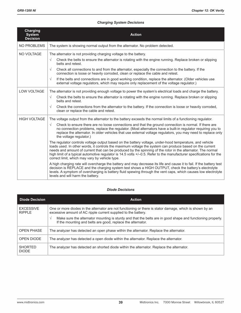
GR8-1200 NI
Midtronics Inc. 7000 Monroe Street Willowbrook, IL 60527www.midtronics.com 39
Chapter 12: OK Verify
Charging System Decisions
Charging System
DecisionAction
NO PROBLEMS The system is showing normal output from the alternator. No problem detected.
NO VOLTAGE The alternator is not providing charging voltage to the battery. √ Check the belts to ensure the alternator is rotating with the engine running. Replace broken or slipping
belts and retest. √ Check all connections to and from the alternator, especially the connection to the battery. If the
connection is loose or heavily corroded, clean or replace the cable and retest. √ If the belts and connections are in good working condition, replace the alternator. (Older vehicles use
external voltage regulators, which may require only replacement of the voltage regulator.)
LOW VOLTAGE The alternator is not providing enough voltage to power the system’s electrical loads and charge the battery.√ Check the belts to ensure the alternator is rotating with the engine running. Replace broken or slipping
belts and retest.√ Check the connections from the alternator to the battery. If the connection is loose or heavily corroded,
clean or replace the cable and retest.
HIGH VOLTAGE The voltage output from the alternator to the battery exceeds the normal limits of a functioning regulator.√ Check to ensure there are no loose connections and that the ground connection is normal. If there are
no connection problems, replace the regulator. (Most alternators have a built-in regulator requiring you to replace the alternator. In older vehicles that use external voltage regulators, you may need to replace only the voltage regulator.)
The regulator controls voltage output based on the battery voltage, under-hood temperature, and vehicle loads used. In other words, it controls the maximum voltage the system can produce based on the current needs and amount of current that can be produced by the spinning of the rotor in the alternator. The normal high limit of a typical automotive regulator is 14.5 volts +/–0.5. Refer to the manufacturer specifications for the correct limit, which may vary by vehicle type. A high charging rate will overcharge the battery and may decrease its life and cause it to fail. If the battery test decision is REPLACE and the charging system test shows a HIGH OUTPUT, check the battery’s electrolyte levels. A symptom of overcharging is battery fluid spewing through the vent caps, which causes low electrolyte levels and will harm the battery.
Diode Decisions
Diode Decision Action
EXCESSIVE RIPPLE
One or more diodes in the alternator are not functioning or there is stator damage, which is shown by an excessive amount of AC ripple current supplied to the battery. √ Make sure the alternator mounting is sturdy and that the belts are in good shape and functioning properly.
If the mounting and belts are good, replace the alternator.
OPEN PHASE The analyzer has detected an open phase within the alternator. Replace the alternator.
OPEN DIODE The analyzer has detected a open diode within the alternator. Replace the alternator.
SHORTED DIODE
The analyzer has detected an shorted diode within the alternator. Replace the alternator.
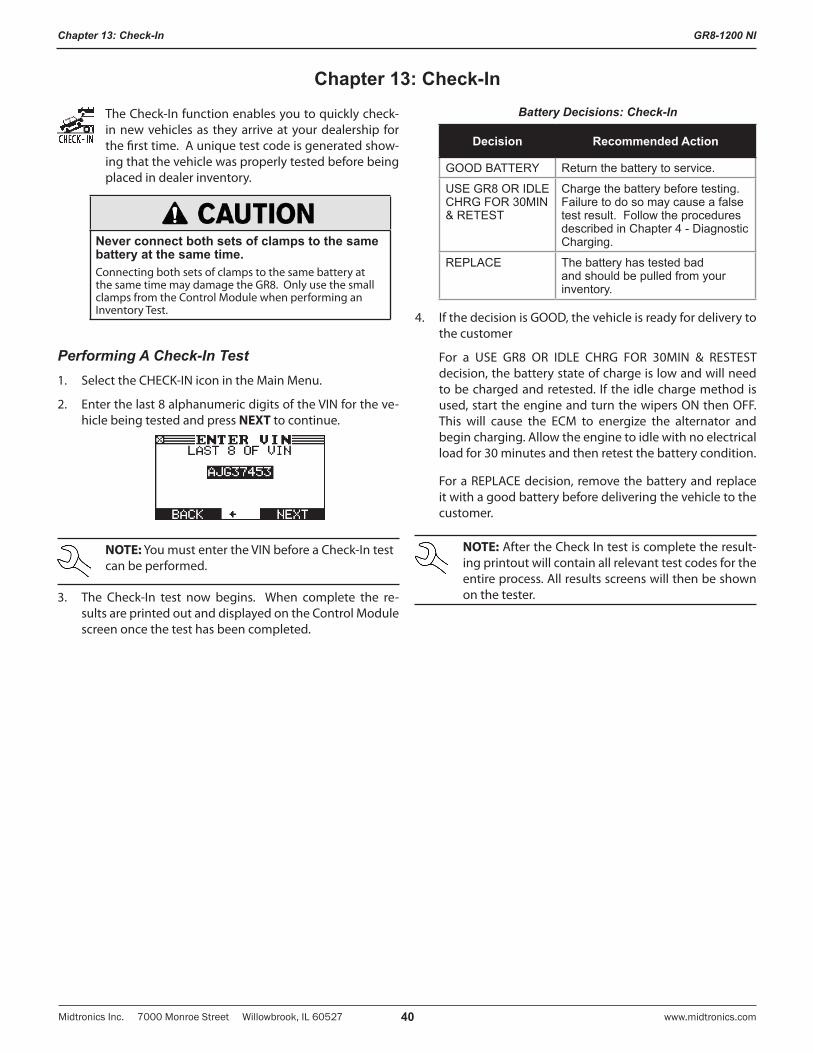
GR8-1200 NI
Midtronics Inc. 7000 Monroe Street Willowbrook, IL 60527 www.midtronics.com40
Chapter 13: Check-In
The Check-In function enables you to quickly check-in new vehicles as they arrive at your dealership for the first time. A unique test code is generated show-ing that the vehicle was properly tested before being placed in dealer inventory.
Never connect both sets of clamps to the same battery at the same time.Connecting both sets of clamps to the same battery at the same time may damage the GR8. Only use the small clamps from the Control Module when performing an Inventory Test.
Performing A Check-In Test1. Select the CHECK-IN icon in the Main Menu.
2. Enter the last 8 alphanumeric digits of the VIN for the ve-hicle being tested and press NEXT to continue.
NOTE: You must enter the VIN before a Check-In test can be performed.
3. The Check-In test now begins. When complete the re-sults are printed out and displayed on the Control Module screen once the test has been completed.
Battery Decisions: Check-In
Decision Recommended Action
GOOD BATTERY Return the battery to service.
USE GR8 OR IDLE CHRG FOR 30MIN & RETEST
Charge the battery before testing. Failure to do so may cause a false test result. Follow the procedures described in Chapter 4 - Diagnostic Charging.
REPLACE The battery has tested bad and should be pulled from your inventory.
4. If the decision is GOOD, the vehicle is ready for delivery to the customer
For a USE GR8 OR IDLE CHRG FOR 30MIN & RESTEST decision, the battery state of charge is low and will need to be charged and retested. If the idle charge method is used, start the engine and turn the wipers ON then OFF. This will cause the ECM to energize the alternator and begin charging. Allow the engine to idle with no electrical load for 30 minutes and then retest the battery condition.
For a REPLACE decision, remove the battery and replace it with a good battery before delivering the vehicle to the customer.
NOTE: After the Check In test is complete the result-ing printout will contain all relevant test codes for the entire process. All results screens will then be shown on the tester.
Chapter 13: Check-In
GR8-1200 NI
Midtronics Inc. 7000 Monroe Street Willowbrook, IL 60527www.midtronics.com 41
Chapter 14: Info Menu
The Info Menu has three utilities to help you print and view your test data and track the usage and history of your GR8. The Info menu also allows you to view total history and transfer information to another machine.
The View Menu enables you to view and print the results of the Battery, System, and Cable Drop Tests before you perform another test and overwrite the results in memory. Check-In and Customer Delivery test results are also overwritten every time a test is performed.
View Test Battery
VIEW TEST BATTERY gives you the option of viewing and printing the results of the Battery and System Tests. Press END to return to the Main Menu.
1. To print the results select PRINT.
2. Use or or the keypad to select the LANGUAGE of the printout.
1 ENGLISH
2 ESPAÑOL
3 FRANÇAIS
The test results are now printed out. To abort the printout press END.
View Test Charger
VIEW TEST CHARGER gives you the option of view-ing and printing the results of the Charger Test. Press END to return to the Main Menu.
1. To print the results select PRINT.
2. Use or or the keypad to select the LANGUAGE of the printout.
1 ENGLISH
2 ESPAÑOL
3 FRANÇAIS
The test results are now printed out. To abort the printout press END.
View Cable Test
VIEW CABLE TEST gives you the option of viewing and printing the results of the last performed Cable Drop Test. Results from previous tests are not saved and are therefore not viewable. Press END to return to the Main Menu.
1. To print the results select PRINT.
2. Use or or the keypad to select the LANGUAGE of the printout.
1 ENGLISH
2 ESPAÑOL
3 FRANÇAIS
The test results are now printed out. To abort the printout press END.
Check-In
CHECK-IN lets you view the results from the last new vehicle Check-In test including the test code. Results from previous tests are not saved and are therefore not viewable. Press END to return to the Main Menu.
1. To print the results select PRINT.
2. Use or or the keypad to select the LANGUAGE of the printout.
1 ENGLISH
2 ESPAÑOL
3 FRANÇAIS
The test results are now printed out. To abort the printout press END.
View Inventory
This report displays and prints the results for an in-dividual battery or for all batteries tested using the Inventory Test (see Chapter 10: Inventory Test). Press END to return to the Main Menu.
1. For individual battery test results, use or or the key-pad to scroll to the specific Inventory Test result screen you want to print.
2. Select the PRINT key.
3. Use or or the keypad to select INVENTORY PRINT.
1 INVENTORY BATTERY
2 INVENTORY SUMMARY
Chapter 14: Info Menu
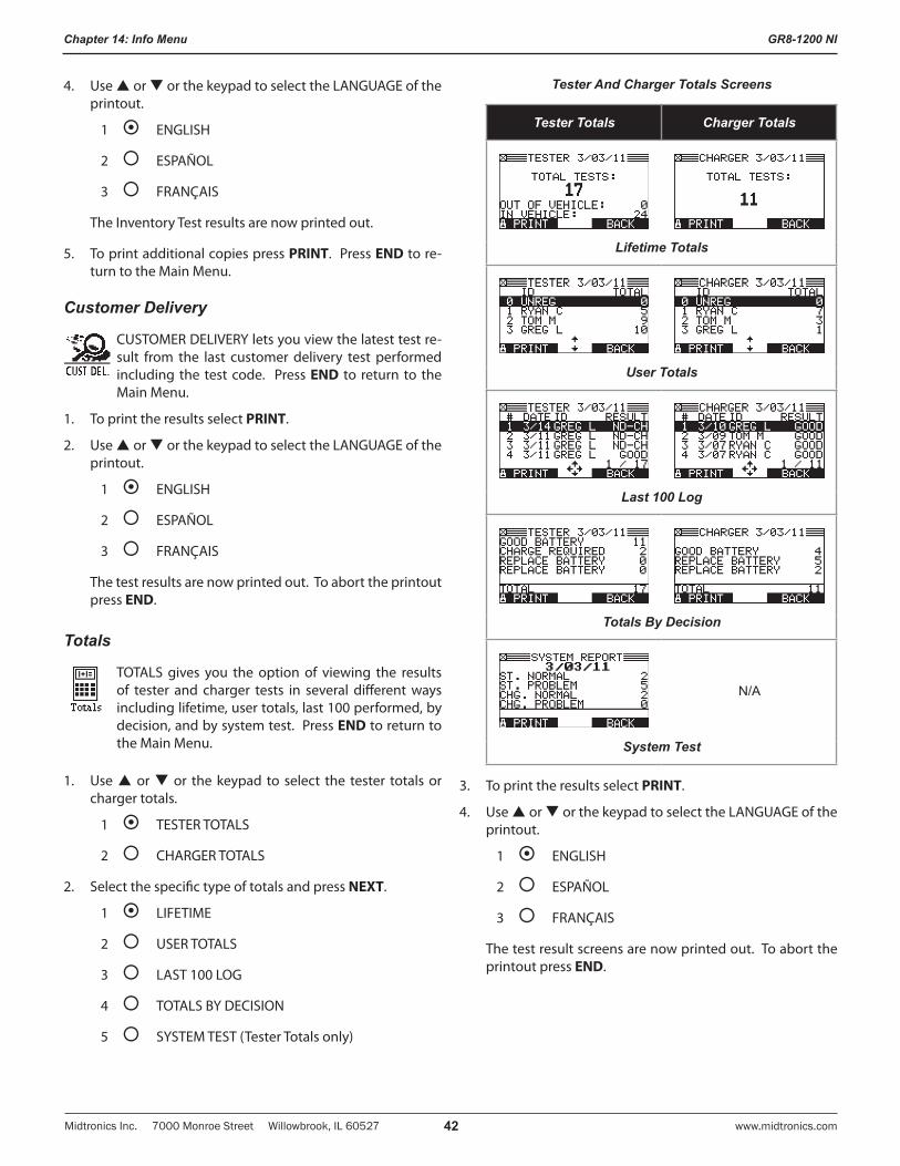
GR8-1200 NI
Midtronics Inc. 7000 Monroe Street Willowbrook, IL 60527 www.midtronics.com42
Chapter 14: Info Menu
4. Use or or the keypad to select the LANGUAGE of the printout.
1 ENGLISH
2 ESPAÑOL
3 FRANÇAIS
The Inventory Test results are now printed out.
5. To print additional copies press PRINT. Press END to re-turn to the Main Menu.
Customer Delivery
CUSTOMER DELIVERY lets you view the latest test re-sult from the last customer delivery test performed including the test code. Press END to return to the Main Menu.
1. To print the results select PRINT.
2. Use or or the keypad to select the LANGUAGE of the printout.
1 ENGLISH
2 ESPAÑOL
3 FRANÇAIS
The test results are now printed out. To abort the printout press END.
Totals
TOTALS gives you the option of viewing the results of tester and charger tests in several different ways including lifetime, user totals, last 100 performed, by decision, and by system test. Press END to return to the Main Menu.
1. Use or or the keypad to select the tester totals or charger totals.
1 TESTER TOTALS
2 CHARGER TOTALS
2. Select the specific type of totals and press NEXT.
1 LIFETIME
2 USER TOTALS
3 LAST 100 LOG
4 TOTALS BY DECISION
5 SYSTEM TEST (Tester Totals only)
Tester And Charger Totals Screens
Tester Totals Charger Totals
Lifetime Totals
User Totals
Last 100 Log
Totals By Decision
N/A
System Test
3. To print the results select PRINT.
4. Use or or the keypad to select the LANGUAGE of the printout.
1 ENGLISH
2 ESPAÑOL
3 FRANÇAIS
The test result screens are now printed out. To abort the printout press END.
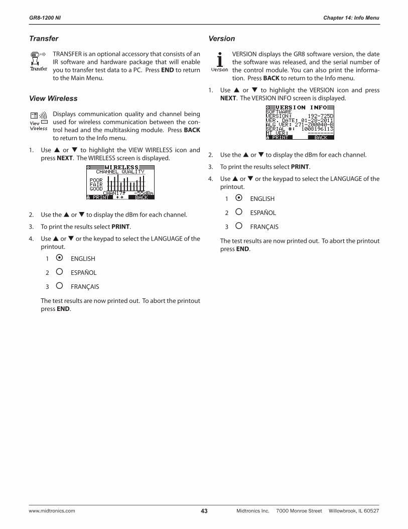
GR8-1200 NI
Midtronics Inc. 7000 Monroe Street Willowbrook, IL 60527www.midtronics.com 43
Chapter 14: Info Menu
Transfer
TRANSFER is an optional accessory that consists of an IR software and hardware package that will enable you to transfer test data to a PC. Press END to return to the Main Menu.
View Wireless
Displays communication quality and channel being used for wireless communication between the con-trol head and the multitasking module. Press BACK to return to the Info menu.
1. Use or to highlight the VIEW WIRELESS icon and press NEXT. The WIRELESS screen is displayed.
2. Use the or to display the dBm for each channel.
3. To print the results select PRINT.
4. Use or or the keypad to select the LANGUAGE of the printout.
1 ENGLISH
2 ESPAÑOL
3 FRANÇAIS
The test results are now printed out. To abort the printout press END.
Version
VERSION displays the GR8 software version, the date the software was released, and the serial number of the control module. You can also print the informa-tion. Press BACK to return to the Info menu.
1. Use or to highlight the VERSION icon and press NEXT. The VERSION INFO screen is displayed.
2. Use the or to display the dBm for each channel.
3. To print the results select PRINT.
4. Use or or the keypad to select the LANGUAGE of the printout.
1 ENGLISH
2 ESPAÑOL
3 FRANÇAIS
The test results are now printed out. To abort the printout press END.
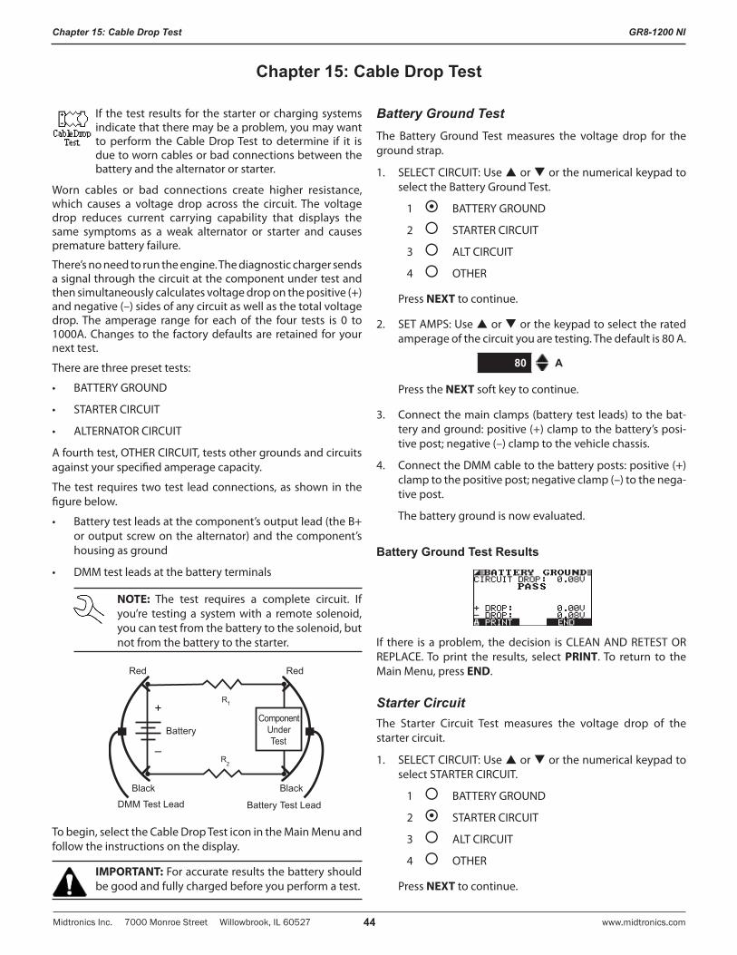
GR8-1200 NI
Midtronics Inc. 7000 Monroe Street Willowbrook, IL 60527 www.midtronics.com44
Chapter 15: Cable Drop Test
Chapter 15: Cable Drop Test
If the test results for the starter or charging systems indicate that there may be a problem, you may want to perform the Cable Drop Test to determine if it is due to worn cables or bad connections between the battery and the alternator or starter.
Worn cables or bad connections create higher resistance, which causes a voltage drop across the circuit. The voltage drop reduces current carrying capability that displays the same symptoms as a weak alternator or starter and causes premature battery failure.
There’s no need to run the engine. The diagnostic charger sends a signal through the circuit at the component under test and then simultaneously calculates voltage drop on the positive (+) and negative (–) sides of any circuit as well as the total voltage drop. The amperage range for each of the four tests is 0 to 1000A. Changes to the factory defaults are retained for your next test.
There are three preset tests:
• BATTERYGROUND
• STARTERCIRCUIT
• ALTERNATORCIRCUIT
A fourth test, OTHER CIRCUIT, tests other grounds and circuits against your specified amperage capacity.
The test requires two test lead connections, as shown in the figure below.
• Batterytestleadsatthecomponent’soutputlead(theB+or output screw on the alternator) and the component’s housing as ground
• DMMtestleadsatthebatteryterminals
NOTE: The test requires a complete circuit. If you’re testing a system with a remote solenoid, you can test from the battery to the solenoid, but not from the battery to the starter.
R
Battery
Battery Test LeadDMM Test Lead
ComponentUnderTest
1
R2
+
–
Red Red
Black Black
To begin, select the Cable Drop Test icon in the Main Menu and follow the instructions on the display.
IMPORTANT: For accurate results the battery should be good and fully charged before you perform a test.
Battery Ground TestThe Battery Ground Test measures the voltage drop for the ground strap.
1. SELECT CIRCUIT: Use or or the numerical keypad to select the Battery Ground Test.
1 BATTERY GROUND
2 STARTER CIRCUIT
3 ALT CIRCUIT
4 OTHER
Press NEXT to continue.
2. SET AMPS: Use or or the keypad to select the rated amperage of the circuit you are testing. The default is 80 A.
80 A
Press the NEXT soft key to continue.
3. Connect the main clamps (battery test leads) to the bat-tery and ground: positive (+) clamp to the battery’s posi-tive post; negative (–) clamp to the vehicle chassis.
4. Connect the DMM cable to the battery posts: positive (+) clamp to the positive post; negative clamp (–) to the nega-tive post.
The battery ground is now evaluated.
Battery Ground Test Results
If there is a problem, the decision is CLEAN AND RETEST OR REPLACE. To print the results, select PRINT. To return to the Main Menu, press END.
Starter CircuitThe Starter Circuit Test measures the voltage drop of the starter circuit.
1. SELECT CIRCUIT: Use or or the numerical keypad to select STARTER CIRCUIT.
1 BATTERY GROUND
2 STARTER CIRCUIT
3 ALT CIRCUIT
4 OTHER
Press NEXT to continue.
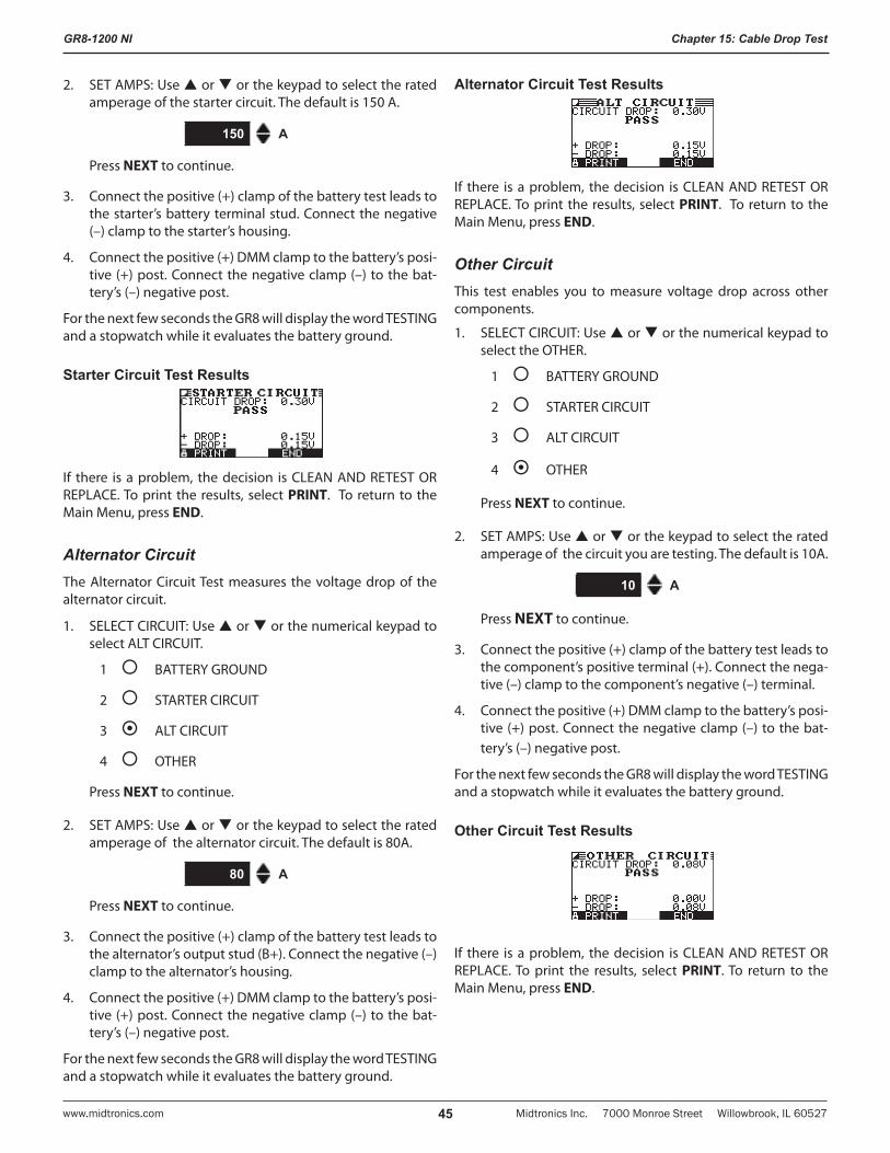
GR8-1200 NI
Midtronics Inc. 7000 Monroe Street Willowbrook, IL 60527www.midtronics.com 45
Chapter 15: Cable Drop Test
2. SET AMPS: Use or or the keypad to select the rated amperage of the starter circuit. The default is 150 A.
150 A
Press NEXT to continue.
3. Connect the positive (+) clamp of the battery test leads to the starter’s battery terminal stud. Connect the negative (–) clamp to the starter’s housing.
4. Connect the positive (+) DMM clamp to the battery’s posi-tive (+) post. Connect the negative clamp (–) to the bat-tery’s (–) negative post.
For the next few seconds the GR8 will display the word TESTING and a stopwatch while it evaluates the battery ground.
Starter Circuit Test Results
If there is a problem, the decision is CLEAN AND RETEST OR REPLACE. To print the results, select PRINT. To return to the Main Menu, press END.
Alternator CircuitThe Alternator Circuit Test measures the voltage drop of the alternator circuit.
1. SELECT CIRCUIT: Use or or the numerical keypad to select ALT CIRCUIT.
1 BATTERY GROUND
2 STARTER CIRCUIT
3 ALT CIRCUIT
4 OTHER
Press NEXT to continue.
2. SET AMPS: Use or or the keypad to select the rated amperage of the alternator circuit. The default is 80A.
80 A
Press NEXT to continue.
3. Connect the positive (+) clamp of the battery test leads to the alternator’s output stud (B+). Connect the negative (–) clamp to the alternator’s housing.
4. Connect the positive (+) DMM clamp to the battery’s posi-tive (+) post. Connect the negative clamp (–) to the bat-tery’s (–) negative post.
For the next few seconds the GR8 will display the word TESTING and a stopwatch while it evaluates the battery ground.
Alternator Circuit Test Results
If there is a problem, the decision is CLEAN AND RETEST OR REPLACE. To print the results, select PRINT. To return to the Main Menu, press END.
Other CircuitThis test enables you to measure voltage drop across other components.
1. SELECT CIRCUIT: Use or or the numerical keypad to select the OTHER.
1 BATTERY GROUND
2 STARTER CIRCUIT
3 ALT CIRCUIT
4 OTHER
Press NEXT to continue.
2. SET AMPS: Use or or the keypad to select the rated amperage of the circuit you are testing. The default is 10A.
10 A
Press NEXT to continue.
3. Connect the positive (+) clamp of the battery test leads to the component’s positive terminal (+). Connect the nega-tive (–) clamp to the component’s negative (–) terminal.
4. Connect the positive (+) DMM clamp to the battery’s posi-tive (+) post. Connect the negative clamp (–) to the bat-tery’s (–) negative post.
For the next few seconds the GR8 will display the word TESTING and a stopwatch while it evaluates the battery ground.
Other Circuit Test Results
If there is a problem, the decision is CLEAN AND RETEST OR REPLACE. To print the results, select PRINT. To return to the Main Menu, press END.
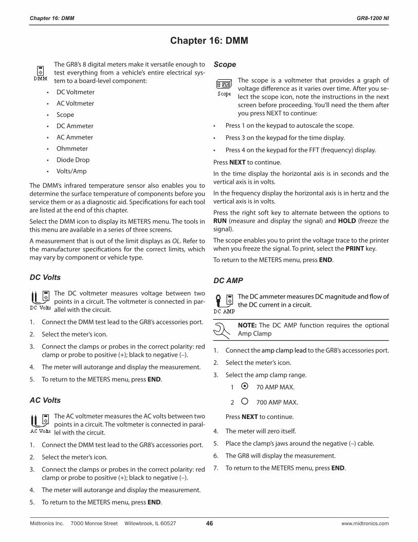
GR8-1200 NI
Midtronics Inc. 7000 Monroe Street Willowbrook, IL 60527 www.midtronics.com46
Chapter 16: DMM
The GR8’s 8 digital meters make it versatile enough to test everything from a vehicle’s entire electrical sys-tem to a board-level component:
• DCVoltmeter
• ACVoltmeter
• Scope
• DCAmmeter
• ACAmmeter
• Ohmmeter
• DiodeDrop
• Volts/Amp
The DMM’s infrared temperature sensor also enables you to determine the surface temperature of components before you service them or as a diagnostic aid. Specifications for each tool are listed at the end of this chapter.
Select the DMM icon to display its METERS menu. The tools in this menu are available in a series of three screens.
A measurement that is out of the limit displays as OL. Refer to the manufacturer specifications for the correct limits, which may vary by component or vehicle type.
DC Volts
The DC voltmeter measures voltage between two points in a circuit. The voltmeter is connected in par-allel with the circuit.
1. Connect the DMM test lead to the GR8’s accessories port.
2. Select the meter’s icon.
3. Connect the clamps or probes in the correct polarity: red clamp or probe to positive (+); black to negative (–).
4. The meter will autorange and display the measurement.
5. To return to the METERS menu, press END.
AC Volts
The AC voltmeter measures the AC volts between two points in a circuit. The voltmeter is connected in paral-lel with the circuit.
1. Connect the DMM test lead to the GR8’s accessories port.
2. Select the meter’s icon.
3. Connect the clamps or probes in the correct polarity: red clamp or probe to positive (+); black to negative (–).
4. The meter will autorange and display the measurement.
5. To return to the METERS menu, press END.
Scope
The scope is a voltmeter that provides a graph of voltage difference as it varies over time. After you se-lect the scope icon, note the instructions in the next screen before proceeding. You’ll need the them after you press NEXT to continue:
• Press1onthekeypadtoautoscalethescope.
• Press3onthekeypadforthetimedisplay.
• Press4onthekeypadfortheFFT(frequency)display.
Press NEXT to continue.
In the time display the horizontal axis is in seconds and the vertical axis is in volts.
In the frequency display the horizontal axis is in hertz and the vertical axis is in volts.
Press the right soft key to alternate between the options to RUN (measure and display the signal) and HOLD (freeze the signal).
The scope enables you to print the voltage trace to the printer when you freeze the signal. To print, select the PRINT key.
To return to the METERS menu, press END.
DC AMP
The DC ammeter measures DC magnitude and flow of the DC current in a circuit.
NOTE: The DC AMP function requires the optional Amp Clamp
1. Connect the amp clamp lead to the GR8’s accessories port.
2. Select the meter’s icon.
3. Select the amp clamp range.
1 70 AMP MAX.
2 700 AMP MAX.
Press NEXT to continue.
4. The meter will zero itself.
5. Place the clamp’s jaws around the negative (–) cable.
6. The GR8 will display the measurement.
7. To return to the METERS menu, press END.
Chapter 16: DMM
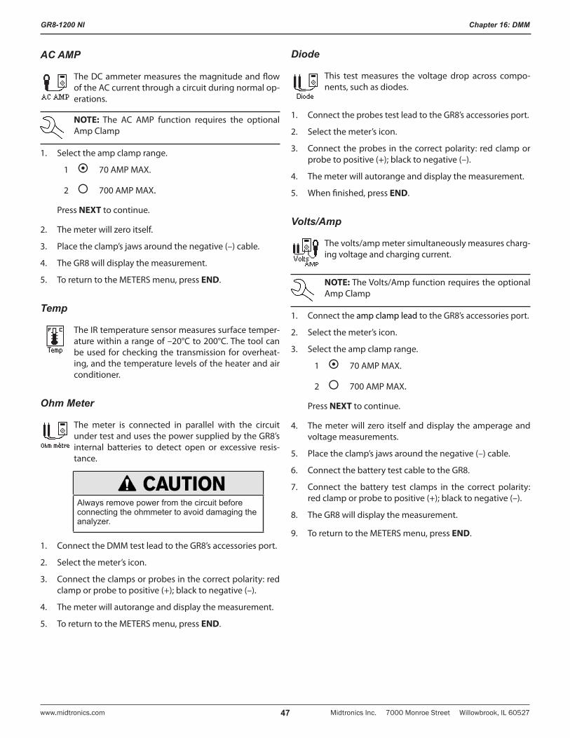
GR8-1200 NI
Midtronics Inc. 7000 Monroe Street Willowbrook, IL 60527www.midtronics.com 47
Chapter 16: DMM
AC AMP
The DC ammeter measures the magnitude and flow of the AC current through a circuit during normal op-erations.
NOTE: The AC AMP function requires the optional Amp Clamp
1. Select the amp clamp range.
1 70 AMP MAX.
2 700 AMP MAX.
Press NEXT to continue.
2. The meter will zero itself.
3. Place the clamp’s jaws around the negative (–) cable.
4. The GR8 will display the measurement.
5. To return to the METERS menu, press END.
Temp
The IR temperature sensor measures surface temper-ature within a range of –20°C to 200°C. The tool can be used for checking the transmission for overheat-ing, and the temperature levels of the heater and air conditioner.
Ohm Meter
The meter is connected in parallel with the circuit under test and uses the power supplied by the GR8’s internal batteries to detect open or excessive resis-tance.
Always remove power from the circuit before connecting the ohmmeter to avoid damaging the analyzer.
1. Connect the DMM test lead to the GR8’s accessories port.
2. Select the meter’s icon.
3. Connect the clamps or probes in the correct polarity: red clamp or probe to positive (+); black to negative (–).
4. The meter will autorange and display the measurement.
5. To return to the METERS menu, press END.
Diode
This test measures the voltage drop across compo-nents, such as diodes.
1. Connect the probes test lead to the GR8’s accessories port.
2. Select the meter’s icon.
3. Connect the probes in the correct polarity: red clamp or probe to positive (+); black to negative (–).
4. The meter will autorange and display the measurement.
5. When finished, press END.
Volts/Amp
The volts/amp meter simultaneously measures charg-ing voltage and charging current.
NOTE: The Volts/Amp function requires the optional Amp Clamp
1. Connect the amp clamp lead to the GR8’s accessories port.
2. Select the meter’s icon.
3. Select the amp clamp range.
1 70 AMP MAX.
2 700 AMP MAX.
Press NEXT to continue.
4. The meter will zero itself and display the amperage and voltage measurements.
5. Place the clamp’s jaws around the negative (–) cable.
6. Connect the battery test cable to the GR8.
7. Connect the battery test clamps in the correct polarity: red clamp or probe to positive (+); black to negative (–).
8. The GR8 will display the measurement.
9. To return to the METERS menu, press END.
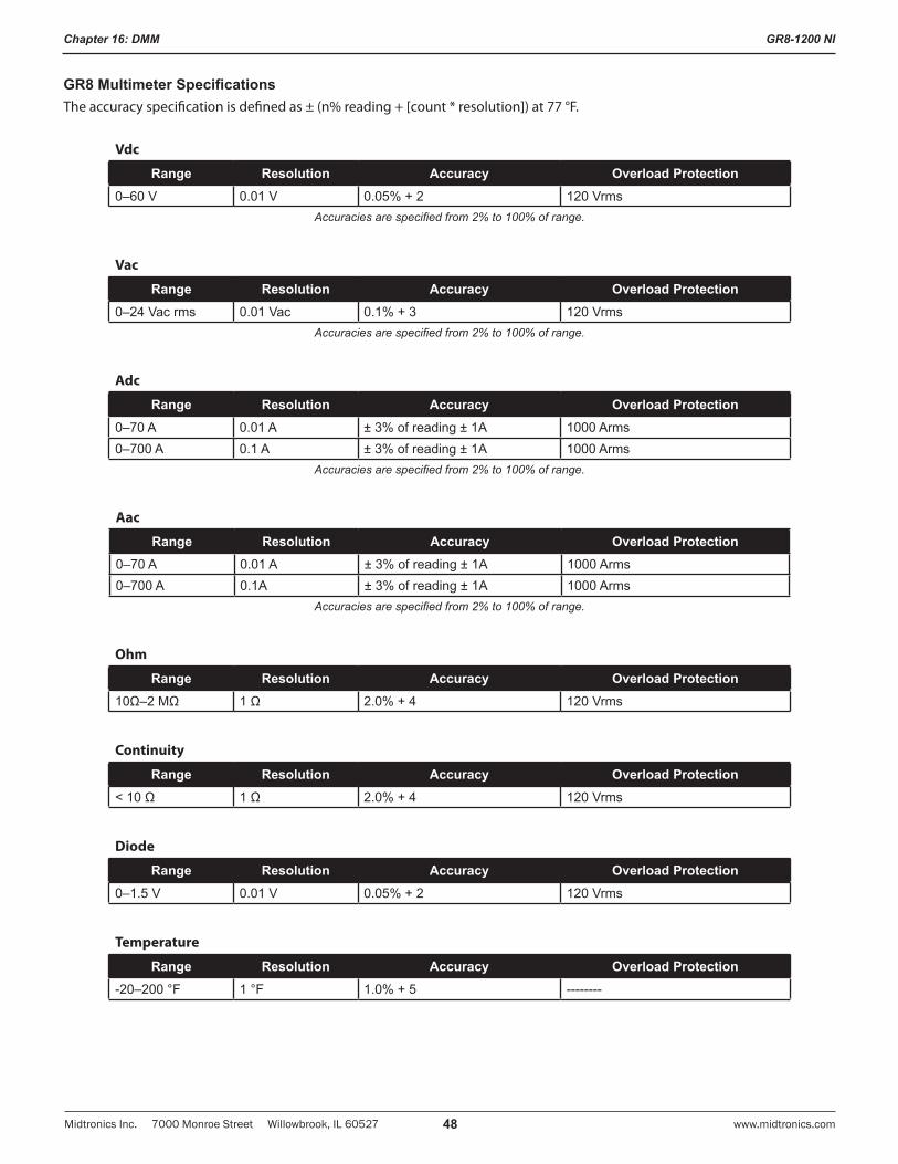
GR8-1200 NI
Midtronics Inc. 7000 Monroe Street Willowbrook, IL 60527 www.midtronics.com48
Chapter 16: DMM
GR8 Multimeter SpecificationsThe accuracy specification is defined as ± (n% reading + [count * resolution]) at 77 °F.
Vdc
Range Resolution Accuracy Overload Protection0–60 V 0.01 V 0.05% + 2 120 Vrms
Accuracies are specified from 2% to 100% of range.
Vac
Range Resolution Accuracy Overload Protection0–24 Vac rms 0.01 Vac 0.1% + 3 120 Vrms
Accuracies are specified from 2% to 100% of range.
Adc
Range Resolution Accuracy Overload Protection0–70 A 0.01 A ± 3% of reading ± 1A 1000 Arms0–700 A 0.1 A ± 3% of reading ± 1A 1000 Arms
Accuracies are specified from 2% to 100% of range.
Aac
Range Resolution Accuracy Overload Protection0–70 A 0.01 A ± 3% of reading ± 1A 1000 Arms0–700 A 0.1A ± 3% of reading ± 1A 1000 Arms
Accuracies are specified from 2% to 100% of range.
Ohm
Range Resolution Accuracy Overload Protection10Ω–2 MΩ 1 Ω 2.0% + 4 120 Vrms
Continuity
Range Resolution Accuracy Overload Protection< 10 Ω 1 Ω 2.0% + 4 120 Vrms
Diode
Range Resolution Accuracy Overload Protection0–1.5 V 0.01 V 0.05% + 2 120 Vrms
Temperature
Range Resolution Accuracy Overload Protection-20–200 °F 1 °F 1.0% + 5 --------
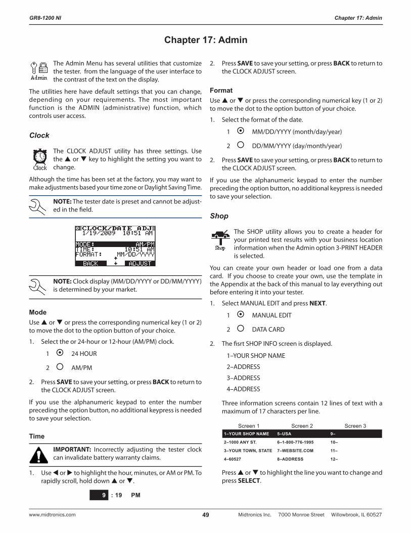
GR8-1200 NI
Midtronics Inc. 7000 Monroe Street Willowbrook, IL 60527www.midtronics.com 49
Chapter 17: Admin
The Admin Menu has several utilities that customize the tester. from the language of the user interface to the contrast of the text on the display.
The utilities here have default settings that you can change, depending on your requirements. The most important function is the ADMIN (administrative) function, which controls user access.
Clock
The CLOCK ADJUST utility has three settings. Use the or key to highlight the setting you want to change.
Although the time has been set at the factory, you may want to make adjustments based your time zone or Daylight Saving Time.
NOTE: The tester date is preset and cannot be adjust-ed in the field.
NOTE: Clock display (MM/DD/YYYY or DD/MM/YYYY) is determined by your market.
ModeUse or or press the corresponding numerical key (1 or 2) to move the dot to the option button of your choice.
1. Select the or 24-hour or 12-hour (AM/PM) clock.
1 24 HOUR
2 AM/PM
2. Press SAVE to save your setting, or press BACK to return to the CLOCK ADJUST screen.
If you use the alphanumeric keypad to enter the number preceding the option button, no additional keypress is needed to save your selection.
Time
IMPORTANT: Incorrectly adjusting the tester clock can invalidate battery warranty claims.
1. Use or to highlight the hour, minutes, or AM or PM. To rapidly scroll, hold down or .
9 : 19 PM
2. Press SAVE to save your setting, or press BACK to return to the CLOCK ADJUST screen.
FormatUse or or press the corresponding numerical key (1 or 2) to move the dot to the option button of your choice.
1. Select the format of the date.
1 MM/DD/YYYY (month/day/year)
2 DD/MM/YYYY (day/month/year)
2. Press SAVE to save your setting, or press BACK to return to the CLOCK ADJUST screen.
If you use the alphanumeric keypad to enter the number preceding the option button, no additional keypress is needed to save your selection.
Shop
The SHOP utility allows you to create a header for your printed test results with your business location information when the Admin option 3-PRINT HEADER is selected.
You can create your own header or load one from a data card. If you choose to create your own, use the template in the Appendix at the back of this manual to lay everything out before entering it into your tester.
1. Select MANUAL EDIT and press NEXT.
1 MANUAL EDIT
2 DATA CARD
2. The fisrt SHOP INFO screen is displayed.
1–YOUR SHOP NAME
2–ADDRESS
3–ADDRESS
4–ADDRESS
Three information screens contain 12 lines of text with a maximum of 17 characters per line.
Screen 1 Screen 2 Screen 31–YOUR SHOP NAME 5–USA 9–
2–1000 ANY ST. 6–1-800-776-1995 10–
3–YOUR TOWN, STATE 7–WEBSITE.COM 11–
4–60527 8–ADDRESS 12–
Press or to highlight the line you want to change and press SELECT.
Chapter 17: Admin
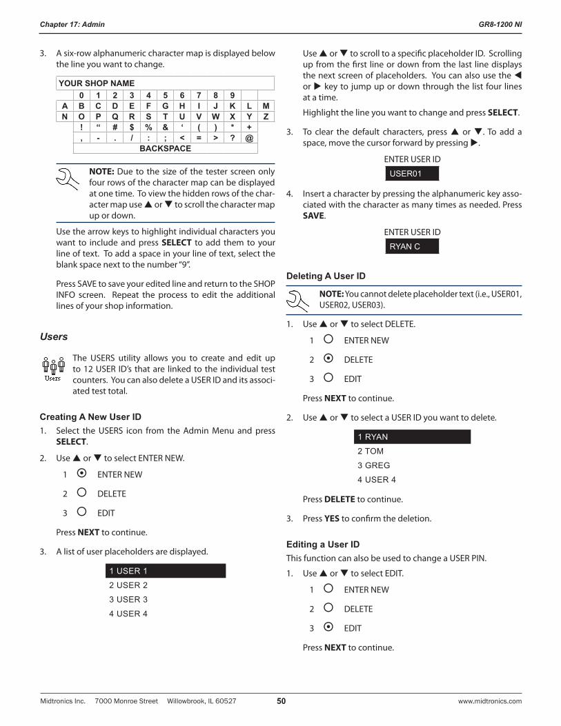
GR8-1200 NI
Midtronics Inc. 7000 Monroe Street Willowbrook, IL 60527 www.midtronics.com50
Chapter 17: Admin
3. A six-row alphanumeric character map is displayed below the line you want to change.
YOUR SHOP NAME0 1 2 3 4 5 6 7 8 9
A B C D E F G H I J K L MN O P Q R S T U V W X Y Z
! “ # $ % & ‘ ( ) * +, - . / : ; < = > ? @
BACKSPACE
NOTE: Due to the size of the tester screen only four rows of the character map can be displayed at one time. To view the hidden rows of the char-acter map use or to scroll the character map up or down.
Use the arrow keys to highlight individual characters you want to include and press SELECT to add them to your line of text. To add a space in your line of text, select the blank space next to the number “9”.
Press SAVE to save your edited line and return to the SHOP INFO screen. Repeat the process to edit the additional lines of your shop information.
Users
The USERS utility allows you to create and edit up to 12 USER ID’s that are linked to the individual test counters. You can also delete a USER ID and its associ-ated test total.
Creating A New User ID1. Select the USERS icon from the Admin Menu and press
SELECT.
2. Use or to select ENTER NEW.
1 ENTER NEW
2 DELETE
3 EDIT
Press NEXT to continue.
3. A list of user placeholders are displayed.
1 USER 1
2 USER 2
3 USER 3
4 USER 4
Use or to scroll to a specific placeholder ID. Scrolling up from the first line or down from the last line displays the next screen of placeholders. You can also use the or key to jump up or down through the list four lines at a time.
Highlight the line you want to change and press SELECT.
3. To clear the default characters, press or . To add a space, move the cursor forward by pressing .
ENTER USER ID
USER01
4. Insert a character by pressing the alphanumeric key asso-ciated with the character as many times as needed. Press SAVE.
ENTER USER ID
RYAN C
Deleting A User ID
NOTE: You cannot delete placeholder text (i.e., USER01, USER02, USER03).
1. Use or to select DELETE.
1 ENTER NEW
2 DELETE
3 EDIT
Press NEXT to continue.
2. Use or to select a USER ID you want to delete.
1 RYAN
2 TOM
3 GREG
4 USER 4
Press DELETE to continue.
3. Press YES to confirm the deletion.
Editing a User IDThis function can also be used to change a USER PIN.
1. Use or to select EDIT.
1 ENTER NEW
2 DELETE
3 EDIT
Press NEXT to continue.
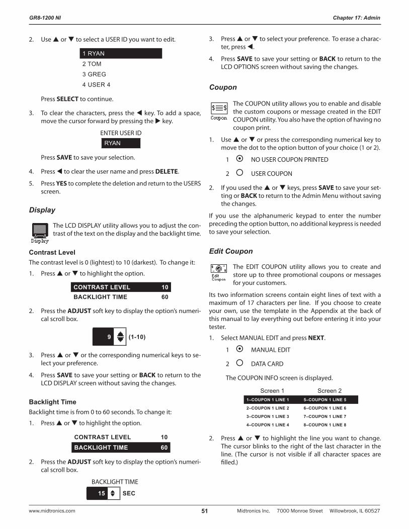
GR8-1200 NI
Midtronics Inc. 7000 Monroe Street Willowbrook, IL 60527www.midtronics.com 51
Chapter 17: Admin
2. Use or to select a USER ID you want to edit.
1 RYAN
2 TOM
3 GREG
4 USER 4
Press SELECT to continue.
3. To clear the characters, press the key. To add a space, move the cursor forward by pressing the key.
ENTER USER ID
RYAN
Press SAVE to save your selection.
4. Press to clear the user name and press DELETE.
5. Press YES to complete the deletion and return to the USERS screen.
Display
The LCD DISPLAY utility allows you to adjust the con-trast of the text on the display and the backlight time.
Contrast LevelThe contrast level is 0 (lightest) to 10 (darkest). To change it:
1. Press or to highlight the option.
CONTRAST LEVEL 10BACKLIGHT TIME 60
2. Press the ADJUST soft key to display the option’s numeri-cal scroll box.
9 (1-10)
3. Press or or the corresponding numerical keys to se-lect your preference.
4. Press SAVE to save your setting or BACK to return to the LCD DISPLAY screen without saving the changes.
Backlight TimeBacklight time is from 0 to 60 seconds. To change it:
1. Press or to highlight the option.
CONTRAST LEVEL 10BACKLIGHT TIME 60
2. Press the ADJUST soft key to display the option’s numeri-cal scroll box.
BACKLIGHT TIME
15 SEC
3. Press or to select your preference. To erase a charac-ter, press .
4. Press SAVE to save your setting or BACK to return to the LCD OPTIONS screen without saving the changes.
Coupon
The COUPON utility allows you to enable and disable the custom coupons or message created in the EDIT COUPON utility. You also have the option of having no coupon print.
1. Use or or press the corresponding numerical key to move the dot to the option button of your choice (1 or 2).
1 NO USER COUPON PRINTED
2 USER COUPON
2. If you used the or keys, press SAVE to save your set-ting or BACK to return to the Admin Menu without saving the changes.
If you use the alphanumeric keypad to enter the number preceding the option button, no additional keypress is needed to save your selection.
Edit Coupon
The EDIT COUPON utility allows you to create and store up to three promotional coupons or messages for your customers.
Its two information screens contain eight lines of text with a maximum of 17 characters per line. If you choose to create your own, use the template in the Appendix at the back of this manual to lay everything out before entering it into your tester.
1. Select MANUAL EDIT and press NEXT.
1 MANUAL EDIT
2 DATA CARD
The COUPON INFO screen is displayed.
Screen 1 Screen 21–COUPON 1 LINE 1 5–COUPON 1 LINE 5
2–COUPON 1 LINE 2 6–COUPON 1 LINE 6
3–COUPON 1 LINE 3 7–COUPON 1 LINE 7
4–COUPON 1 LINE 4 8–COUPON 1 LINE 8
2. Press or to highlight the line you want to change. The cursor blinks to the right of the last character in the line. (The cursor is not visible if all character spaces are filled.)
GR8-1200 NI
Midtronics Inc. 7000 Monroe Street Willowbrook, IL 60527 www.midtronics.com52
Chapter 17: Admin
3. Insert a character by pressing the alphanumeric key asso-ciated with the character as many times as needed. You can center text by inserting blank spaces with the key. If you pause momentarily, the cursor will automatically move to the right.
4. To erase a character, press.
IMPORTANT: Be sure to erase any default charac-ters on unused lines by pressing key.
5. Press SAVE to save your settings or BACK to return to the Admin Menu without saving your changes.
Temp
The TEMP. UNITS utility allows you to set the units of measurement to either Fahrenheit or Celsius.
To set your preference:
1. Use or or press the corresponding numerical key (1 or 2) to move the dot to the option button of your choice.
1 DEGREES F
2 DEGREES C
2. If you used or , press SAVE save your setting or BACK to return to the Admin Menu without saving the changes.
If you use the alphanumeric keypad to enter the number preceding the option button, no additional keypress is needed to save your selection.
Language
The LANGUAGE utility allows you to select a language for the display and printouts. To set your preference:
1. Use or or press the corresponding numerical key (1, 2, or 3) to move the dot to the option button of your choice.
1 ENGLISH
2 ESPAÑOL
3 FRANÇAIS
2. If you used the arrow keys, press SAVE to save your setting or BACK to return to the Admin Menu without saving the changes.
If you use the alphanumeric keypad to enter the number preceding the option button, no additional keypress is needed to save your selection.
Format
The FORMAT utility allows you to format a data card to receive data or erase all data on the card. The GR8 will warn you before formatting the disk and ask if you want to continue.
Update
The UPDATE utility allows you to update the GR8 soft-ware using a data card.
Admin
This section describes functions that clear test totals and restore settings to factory defaults.
Select the ADMIN icon to display a list of administrative functions:
1 OPTIONS
2 CHANGE ADMIN PIN
3 CLEAR TEST TOTALS
4 RESET DEFAULTS
OptionsThis function allows you to turn User ID , Unreg. User, and Print Header functions on or off.
Change Admin PinThis function allows you to enter a new Admin Pin.
Clear Test TotalsThis function allows you to clear the test totals by User ID and battery test decision. The GR8 will verify that you want the counter reset to 0 before it continues.
NOTE: This will not clear the LIFETIME total and the LAST 100 LOG.
Reset DefaultsThis function allows you to reset Administrative options to their original settings. It will clear all registered users.
GR8-1200 NI
Midtronics Inc. 7000 Monroe Street Willowbrook, IL 60527www.midtronics.com 53
Chapter 17: Admin
Printer
The PRINTER utility allows you to set your printer preference.
1. Use or or press the corresponding numerical key (1 or 2) to move the dot to the option button of your choice. The default is the internal printer.
1 INTEGRATED PRINTER
2 IR PRINTER
2. If you used the arrow keys, press SAVE to save your setting or BACK to return to the Admin Menu without saving the changes.
If you use the alphanumeric keypad to enter the number preceding the option button, no additional keypress is needed to save your selection.
Buzzer
The BUZZER utility allows you to enable or disable the chargers’ audible buzzer tone and LED indicator on control module (ON).
1. Use or or press the corresponding numerical key (1 or 2) to move the dot to the option button of your choice.
1 OFF
2 ON
2. If you used the arrow keys, press SAVE to save your setting or BACK to return to the Admin Menu without saving the changes.
If you use the alphanumeric keypad to enter the number preceding the option button, no additional keypress is needed to save your selection.
GR8 Logos
The logo that will appear at the top of your printed test results is determined by your dealer number. This utility allows you to select a different logo.
1. Use or or press the corresponding numerical key (1 or 2) to move the dot to the option button next to the logo of your choice.
1 NISSAN
2 INFINITI
3 GR8 1200
2. To select a logo, insert a check mark in the box by pressing the numerical key.
3. Press SAVE to save your setting.
Wireless
Scans for interference and recommends the best channel for wireless communication. Make sure the Control Module is connected to the Charge Engine before running the scan.
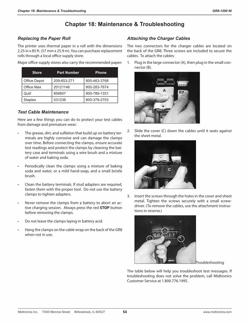
GR8-1200 NI
Midtronics Inc. 7000 Monroe Street Willowbrook, IL 60527 www.midtronics.com54
Chapter 18: Maintenance & Troubleshooting
Replacing the Paper RollThe printer uses thermal paper in a roll with the dimensions 2.25 in x 85 ft. (57 mm x 25.9 m). You can purchase replacement rolls through a local office supply store.
Major office supply stores also carry the recommended paper:
Store Part Number Phone
Office Depot 209-653-271 800-463-3768
Office Max 20121146 800-283-7674
Quill 856607 800-789-1331
Staples 531236 800-378-2753
Test Cable MaintenanceHere are a few things you can do to protect your test cables from damage and premature wear:
• Thegrease,dirt,andsulfationthatbuilduponbatteryter-minals are highly corrosive and can damage the clamps over time. Before connecting the clamps, ensure accurate test readings and protect the clamps by cleaning the bat-tery case and terminals using a wire brush and a mixture of water and baking soda.
• Periodically clean the clampsusing amixture of bakingsoda and water, or a mild hand-soap, and a small bristle brush.
• Cleanthebatteryterminals.Ifstudadaptersarerequired,fasten them with the proper tool. Do not use the battery clamps to tighten adapters.
• Neverremovetheclampsfromabatterytoabortanac-tive charging session. Always press the red STOP button before removing the clamps.
• Donotleavetheclampslayinginbatteryacid.
• HangtheclampsonthecablewraponthebackoftheGR8when not in use.
Attaching the Charger CablesThe two connectors for the charger cables are located on the back of the GR8. Three screws are included to secure the cables. To attach the cables:
1. Plug in the large connector (A), then plug in the small con-nector (B).
2. Slide the cover (C) down the cables until it seats against the sheet metal.
3. Insert the screws through the holes in the cover and sheet metal. Tighten the screws securely with a small screw-driver. (To remove the cables, use the attachment instruc-tions in reverse.)
Troubleshooting
The table below will help you troubleshoot test messages. If troubleshooting does not solve the problem, call Midtronics Customer Service at 1.800.776.1995.
Chapter 18: Maintenance & Troubleshooting
A B
C
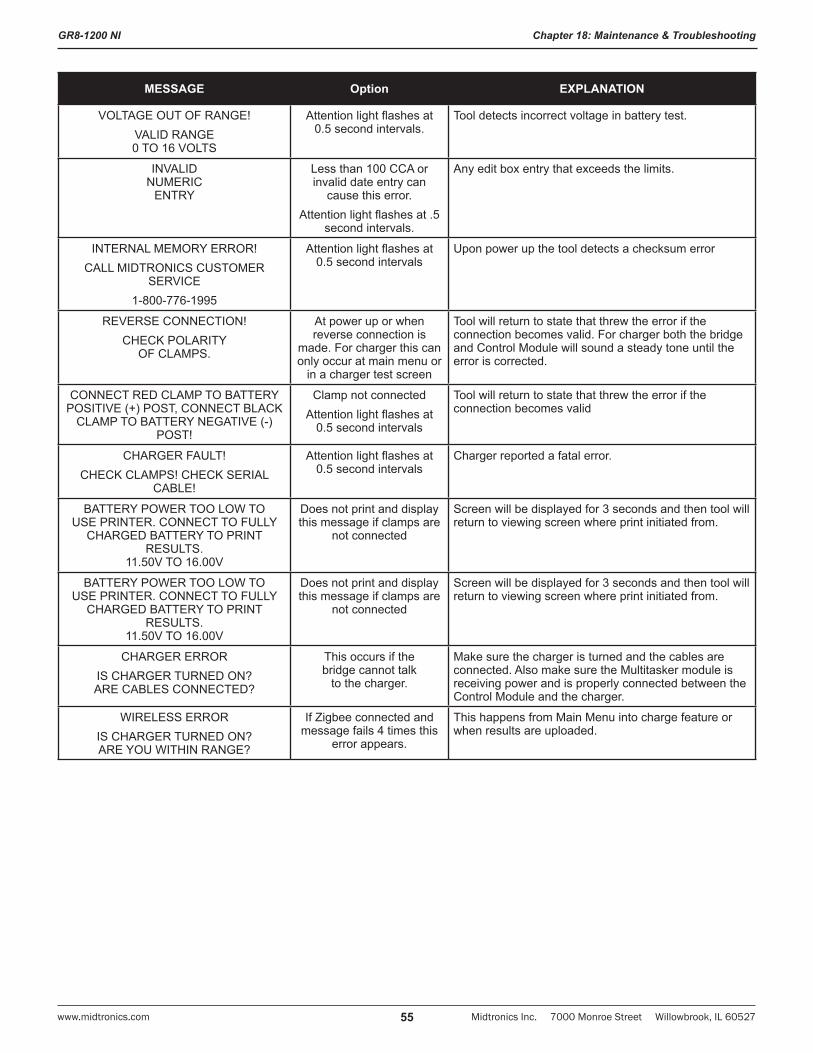
GR8-1200 NI
Midtronics Inc. 7000 Monroe Street Willowbrook, IL 60527www.midtronics.com 55
Chapter 18: Maintenance & Troubleshooting
MESSAGE Option EXPLANATION
VOLTAGE OUT OF RANGE!VALID RANGE 0 TO 16 VOLTS
Attention light flashes at 0.5 second intervals.
Tool detects incorrect voltage in battery test.
INVALID NUMERIC
ENTRY
Less than 100 CCA or invalid date entry can
cause this error.Attention light flashes at .5
second intervals.
Any edit box entry that exceeds the limits.
INTERNAL MEMORY ERROR!CALL MIDTRONICS CUSTOMER
SERVICE1-800-776-1995
Attention light flashes at 0.5 second intervals
Upon power up the tool detects a checksum error
REVERSE CONNECTION!CHECK POLARITY
OF CLAMPS.
At power up or when reverse connection is
made. For charger this can only occur at main menu or
in a charger test screen
Tool will return to state that threw the error if the connection becomes valid. For charger both the bridge and Control Module will sound a steady tone until the error is corrected.
CONNECT RED CLAMP TO BATTERY POSITIVE (+) POST, CONNECT BLACK
CLAMP TO BATTERY NEGATIVE (-) POST!
Clamp not connectedAttention light flashes at
0.5 second intervals
Tool will return to state that threw the error if the connection becomes valid
CHARGER FAULT!CHECK CLAMPS! CHECK SERIAL
CABLE!
Attention light flashes at 0.5 second intervals
Charger reported a fatal error.
BATTERY POWER TOO LOW TO USE PRINTER. CONNECT TO FULLY
CHARGED BATTERY TO PRINT RESULTS.
11.50V TO 16.00V
Does not print and display this message if clamps are
not connected
Screen will be displayed for 3 seconds and then tool will return to viewing screen where print initiated from.
BATTERY POWER TOO LOW TO USE PRINTER. CONNECT TO FULLY
CHARGED BATTERY TO PRINT RESULTS.
11.50V TO 16.00V
Does not print and display this message if clamps are
not connected
Screen will be displayed for 3 seconds and then tool will return to viewing screen where print initiated from.
CHARGER ERRORIS CHARGER TURNED ON? ARE CABLES CONNECTED?
This occurs if the bridge cannot talk
to the charger.
Make sure the charger is turned and the cables are connected. Also make sure the Multitasker module is receiving power and is properly connected between the Control Module and the charger.
WIRELESS ERRORIS CHARGER TURNED ON? ARE YOU WITHIN RANGE?
If Zigbee connected and message fails 4 times this
error appears.
This happens from Main Menu into charge feature or when results are uploaded.
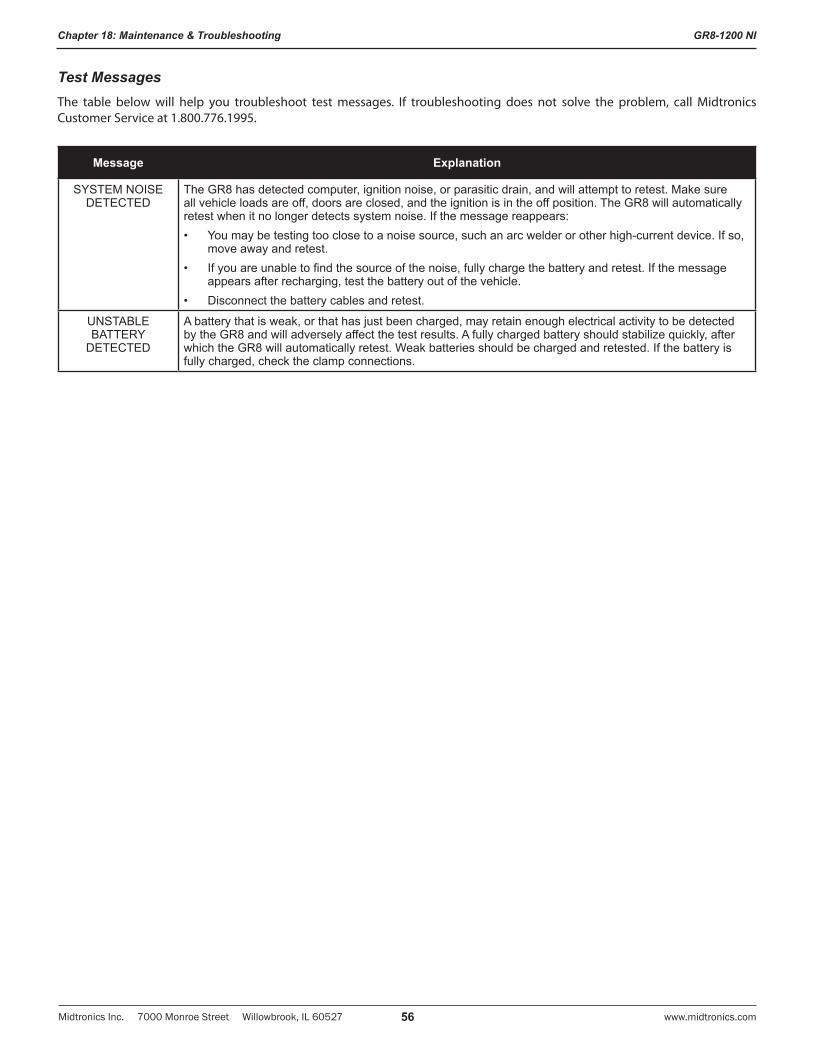
GR8-1200 NI
Midtronics Inc. 7000 Monroe Street Willowbrook, IL 60527 www.midtronics.com56
Chapter 18: Maintenance & Troubleshooting
Test MessagesThe table below will help you troubleshoot test messages. If troubleshooting does not solve the problem, call Midtronics Customer Service at 1.800.776.1995.
Message Explanation
SYSTEM NOISE DETECTED
The GR8 has detected computer, ignition noise, or parasitic drain, and will attempt to retest. Make sure all vehicle loads are off, doors are closed, and the ignition is in the off position. The GR8 will automatically retest when it no longer detects system noise. If the message reappears:• You may be testing too close to a noise source, such an arc welder or other high-current device. If so,
move away and retest.• If you are unable to find the source of the noise, fully charge the battery and retest. If the message
appears after recharging, test the battery out of the vehicle.• Disconnect the battery cables and retest.
UNSTABLE BATTERY
DETECTED
A battery that is weak, or that has just been charged, may retain enough electrical activity to be detected by the GR8 and will adversely affect the test results. A fully charged battery should stabilize quickly, after which the GR8 will automatically retest. Weak batteries should be charged and retested. If the battery is fully charged, check the clamp connections.

Header TemplateTo help you edit and center your header, use the template below to lay out your shop information below before entering it into the Battery Diagnostic Station.
Header Template
Line 1
Line 2
Line 3
Line 4
Line 5
Line 6
Line 7
Line 8
Line 9
Line 10
Line 11
Line 12
Coupon TemplateTo help you edit and center your coupon, use the template below to lay out your coupon information below before entering it into the Battery Diagnostic Station
Coupon Template
Line 1
Line 2
Line 3
Line 4
Line 5
Line 6
Line 7
Line 8
Appendix: Templates

GR8-1200 NI
Midtronics Inc. 7000 Monroe Street Willowbrook, IL 60527 www.midtronics.com58
Appendix: Templates

GR8-1200 NI
Midtronics Inc. 7000 Monroe Street Willowbrook, IL 60527www.midtronics.com 59
Appendix: Templates
PATENTSThe GR8-1200 NI is made by Midtronics, Inc., and is protected by one or more U.S. and foreign patents. For specific patent information, contact Midtronics, Inc. at +1 630 323-2800.
LIMITED WARRANTYThe charger is warranted to be free of defects in materials and workmanship for a period of two years from date of purchase. The charger cable is warranted to be free of defects in materials and workmanship for a period of one year from the date of purchase. The printer is warranted to be free of defects in materials and workmanship for a period of two years from date of purchase. Midtronics will, at our option, repair or replace the equipment with a remanufactured equipment. This limited warranty applies only to the specified equipment, and does not cover any other equipment, static damage, water damage, overvoltage damage, dropping the units, or damage resulting from extraneous causes including owner misuse. Midtronics is not liable for any incidental or consequential damages for breach of this warranty. The warranty is void if owner attempts to disassemble the GR8 or printer, or to modify the cable assembly.
SERVICETo obtain service, contact Midtronics for a Return Authorization number, and return the unit to Midtronics freight prepaid, Attention: RA# ________. Midtronics will service the GR8 and reship the next scheduled business day following receipt, using the same type carrier and service as received. If Midtronics determines that the failure was caused by misuse, alteration, accident, or abnormal condition of operation or handling, purchaser will be billed for the repaired product and it will be returned freight prepaid with freight charges added to the invoice. Any GR8 beyond the warranty period is subject to the repair charges in effect at that time. Optional remanufacturing service is available to return the tester to like-new condition. Out-of-warranty repairs will carry a 3-month warranty. Remanufactured units purchased from Midtronics are covered by a 6-month warranty.
167-010EN-D 5/11 ©2011 Midtronics, Inc. All rights reserved.
Related Documents